

Page 1
EVCO S.p.A. c-pro 3 | Hardware manual ver. 3.2 | Code 114CP3E324
c-pro 3
PROGRAMMABLE CONTROLLERS
ENGLISH
HARDWARE MANUAL ver. 3.2
CODE 114CP3E324
page 1 of 116
Page 2

EVCO S.p.A. c-pro 3 | Hardware manual ver. 3.2 | Codice 114CP3E324
Important
Important
Read this document carefully before the installation and before the use and follow all the additional information for the installation and
for the electrical connection; keep this document close to the devices for future consultations.
The following symbols support the reading of the document:
it indicates a suggestion
it indicates an additional information to be followed.
The devices must be disposed according to the local legislation about the collection for electrical and electronic equipment.
page 2 of 116
Page 3

EVCO S.p.A. c-pro 3 | Hardware manual ver. 3.2 | Codice 114CP3E324
Index
1.
INTRODUCTION ...................................................................................................................................................................... 5
1.1. Introduction ............................................................................................................................................................................... 5
2.
DESCRIPTION ......................................................................................................................................................................... 8
2.1. Description c-pro 3 hecto and c-pro 3 hecto+ ............................................................................................................................ 8
2.2. Description c-pro 3 mega .......................................................................................................................................................... 9
2.3. Description c-pro 3 mega+ ...................................................................................................................................................... 10
2.4. Description c-pro 3 NODE mega ............................................................................................................................................. 12
2.5. Description c-pro 3 EXP hecto and c-pro 3 EXP hecto+.......................................................................................................... 13
3.
SIZE AND INSTALLATION ..................................................................................................................................................... 14
3.1. Size c-pro 3 hecto, c-pro 3 hecto+, c-pro 3 EXP hecto and c-pro 3 EXP hecto+ .................................................................... 14
3.2. Size c-pro 3 mega and c-pro 3 mega+ .................................................................................................................................... 14
3.3. Size c-pro 3 NODE mega ....................................................................................................................................................... 15
3.4. Installation .............................................................................................................................................................................. 16
3.5. Additional information for installation....................................................................................................................................... 16
4.
ELECTRICAL CONNECTION ................................................................................................................................................. 17
4.1. Electrical connection c-pro 3 hecto and c-pro 3 hecto+ ........................................................................................................... 17
4.1.1.
Meaning of the connectors of c-pro 3 hecto and of c-pro 3 hecto+ ............................................................................... 17
4.1.2.
Example of electrical connection of c-pro 3 hecto ......................................................................................................... 24
4.2. Electrical connection c-pro 3 mega and c-pro 3 NODE mega ................................................................................................. 25
4.2.1.
Meaning of the connectors of c-pro 3 mega and of c-pro 3 NODE mega ...................................................................... 25
4.2.2.
Example of electrical connection of c-pro 3 mega ........................................................................................................ 33
4.3. Electrical connection c-pro 3 mega+ ....................................................................................................................................... 34
4.3.1.
Meaning of the connectors of c-pro 3 mega+ ............................................................................................................... 34
4.3.2.
Example of electrical connection of c-pro 3 mega+ ...................................................................................................... 44
4.4. Electrical connection c-pro 3 EXP hecto and c-pro 3 EXP hecto+ ........................................................................................... 46
4.4.1.
Meaning of the connectors of c-pro 3 EXP hecto and of c-pro 3 EXP hecto+ ............................................................... 46
4.4.2.
Example of electrical connection of c-pro 3 EXP hecto ................................................................................................. 51
4.5. Additional information for electrical connection ....................................................................................................................... 52
5.
USER INTERFACE ................................................................................................................................................................ 53
5.1. Keyboard ................................................................................................................................................................................ 53
5.2. Signalling LEDs ...................................................................................................................................................................... 53
5.2.1.
LEDs at the front of the device ..................................................................................................................................... 53
5.2.2.
LEDs on the RS-485 ports ........................................................................................................................................... 54
6.
CONFIGURATION ................................................................................................................................................................. 55
6.1. Configuring a programmable controller ................................................................................................................................... 55
6.1.1.
Configuring a built-in programmable controller ............................................................................................................. 55
6.1.2.
Configuring a blind programmable controller ................................................................................................................ 57
6.2. Configuring an I / O expansion ............................................................................................................................................... 58
6.3. Configuring a device through an user interface (Vgraph, Vtouch or Vroom) ........................................................................... 59
6.4. List of configuration parameters .............................................................................................................................................. 60
6.4.1.
List of configuration parameters of c-pro 3 hecto and of c-pro 3 hecto+ ........................................................................ 60
6.4.2.
List of configuration parameters of c-pro 3 mega and of c-pro 3 NODE mega .............................................................. 67
6.4.3.
List of configuration parameters of c-pro 3 mega+ ........................................................................................................ 77
6.4.4.
List of configuration parameters of c-pro 3 EXP hecto and of c-pro 3 EXP hecto+ ....................................................... 92
7.
USER INTERFACES .............................................................................................................................................................. 96
7.1. Preliminary information ........................................................................................................................................................... 96
7.2. Vgraph .................................................................................................................................................................................... 96
7.2.1.
Introduction .................................................................................................................................................................. 96
7.2.2.
Summarizing table of the main features and available models ..................................................................................... 96
7.2.3.
Size.............................................................................................................................................................................. 97
page 3 of 116
Page 4

EVCO S.p.A. c-pro 3 | Hardware manual ver. 3.2 | Codice 114CP3E324
7.3. Vtouch .................................................................................................................................................................................... 98
7.3.1.
Introduction .................................................................................................................................................................. 98
7.3.2.
Summarizing table of the main features and available models ..................................................................................... 98
7.3.3.
Size.............................................................................................................................................................................. 99
7.4. Vroom ................................................................................................................................................................................... 100
7.4.1.
Introduction ................................................................................................................................................................ 100
7.4.2.
Summarizing table of the main features and available models ................................................................................... 100
7.4.3.
Size............................................................................................................................................................................ 101
8.
ACCESSORIES.................................................................................................................................................................... 102
8.1. Programming kit EVIF20TUXI ............................................................................................................................................... 102
8.1.1.
Introduction ................................................................................................................................................................ 102
8.1.2.
Description ................................................................................................................................................................. 102
8.1.3.
Size............................................................................................................................................................................ 103
8.1.4.
Connection to the Personal Computer ........................................................................................................................ 103
8.2. Programming key EVKEY10 ................................................................................................................................................. 103
8.2.1.
Introduction ................................................................................................................................................................ 103
8.2.2.
Description ................................................................................................................................................................. 103
8.2.3.
Size............................................................................................................................................................................ 104
8.2.4.
Connection to the controller ....................................................................................................................................... 104
9.
TECHNICAL DATA ............................................................................................................................................................... 105
9.1. Technical data ...................................................................................................................................................................... 105
page 4 of 116
Page 5

EVCO S.p.A. c-pro 3 | Hardware manual ver. 3.2 | Codice 114CP3E324
1. INTRODUCTION
1.1. Introduction
c-pro 3 is a family of programmable controllers.
The family consists of:
- programmable controllers (c-pro 3 hecto, c-pro 3 hecto+, c-pro 3 mega, c-pro 3 mega+ and c-pro 3 NODE mega)
- I / O expansions (c-pro 3 EXP hecto and c-pro 3 EXP hecto+).
c-pro 3 hecto is available in blind version and can be used for example with an user interface such as Vgraph, Vtouch or Vroom.
The controllers have got:
- real time clock
- 3 analog inputs configurable via configuration parameter for PTC / NTC / Pt 1000 probes / 0-20 mA / 4-20 mA / 0-5 V
ratiometric / 0-10 V transducers
- 5 non optoisolated free of voltage digital inputs
- 3 analog outputs of which 1 non optoisolated PWM output and 2 non optoisolated outputs configurable via configuration
parameter for 0-20 mA / 4-20 mA / 0-10 V signal
- 6 digital outputs (electromechanical relays) of which five 5 res. A @ 250 VAC SPST outputs and one 8 res. A @ 250 VAC
SPDT output
- 3 non optoisolated communication ports of which 1 CAN port with CANbus communication protocol, 1 RS-485 port with
Modbus master / slave communication protocol (configurable via application software) and 1 programming and debugging
port.
Through the I / O expansion c-pro 3 EXP hecto or c-pro 3 EXP hecto+ it is possible to increase the number of inputs and outputs.
c-pro 3 hecto+ is available in the following versions:
- with 128 x 64 pixel single colour LCD graphic display (black with rearlighting through white LEDs) and with a 6 buttons (with
preset functions) keyboard made of silicone rubber integrated in the controller, hereinafter also called “built-in versions”
- blind (can be used for example with an user interface such as Vgraph, Vtouch or Vroom), hereinafter also called “blind
versions”.
The controllers have got:
- real time clock
- alarm buzzer (not available in the blind versions)
- 4 analog inputs of which 3 configurable via configuration parameter for PTC / NTC / Pt 1000 probes / 0-20 mA / 4-20 mA /
0-5 V ratiometric / 0-10 V transducers and 1 for NTC probes
- 5 optoisolated digital inputs at 24 VAC / DC
- 3 analog outputs of which 1 non optoisolated PWM output and 2 non optoisolated outputs configurable via configuration
parameter for 0-20 mA / 4-20 mA / 0-10 V signal
- 6 digital outputs (electromechanical relays) of which five 3 res. A @ 250 VAC SPST outputs and one 5 res. A @ 250 VAC
SPDT output
- 3 non optoisolated communication ports of which 1 CAN port with CANbus communication protocol, 1 RS-485 port with
Modbus master / slave communication protocol (configurable via application software) and 1 programming and debugging
port.
Through the I / O expansion c-pro 3 EXP hecto or c-pro 3 EXP hecto+ it is possible to increase the number of inputs and outputs.
c-pro 3 mega and c-pro 3 NODE mega are available in the following versions:
- with 122 x 32 pixel single colour LCD graphic display (black with rearlighting through white LEDs) and with a 6 buttons (with
preset functions) keyboard made of silicone rubber integrated in the controller, hereinafter also called “built-in versions”
- blind (can be used for example with an user interface such as Vgraph, Vtouch or Vroom), hereinafter also called “blind
versions”.
The controllers have got:
- real time clock
- alarm buzzer (not available in the blind versions)
page 5 of 116
Page 6

EVCO S.p.A. c-pro 3 | Hardware manual ver. 3.2 | Codice 114CP3E324
- 5 analog inputs configurable via configuration parameter for PTC / NTC / Pt 1000 probes / 0-20 mA / 4-20 mA / 0-5 V
ratiometric / 0-10 V transducers
- 7 optoisolated digital inputs at 24 VAC / DC
- 3 analog outputs of which 1 non optoisolated PWM output and 2 non optoisolated outputs configurable via configuration
parameter for 0-20 mA / 4-20 mA / 0-10 V signal
- 8 digital outputs (electromechanical relays) of which three 5 res. A @ 250 VAC SPST outputs, four 8 res. A @ 250 VAC SPST
outputs and one 8 res. A @ 250 VAC SPDT output
- 4 non optoisolated communication ports of which 1 CAN port with CANbus communication protocol, 1 RS-485 port with
Modbus slave communication protocol, 1 RS-485 port with Modbus master / slave communication protocol (configurable via
application software) and 1 programming and debugging port
- 1 non optoisolated communication port for gateway c-pro 3 plug-in (available in c-pro 3 NODE mega only).
Through the I / O expansion c-pro 3 EXP hecto or c-pro 3 EXP hecto+ it is possible to increase the number of inputs and outputs.
c-pro 3 mega+ is available in the following versions:
- with 122 x 32 pixel single colour LCD graphic display (black with rearlighting through white LEDs) and with a 6 buttons (with
preset functions) keyboard made of silicone rubber integrated in the controller, hereinafter also called “built-in versions”
- blind (can be used for example with an user interface such as Vgraph, Vtouch or Vroom), hereinafter also called “blind
versions”.
The controllers have got:
- real time clock
- alarm buzzer (not available in the blind versions)
- 8 analog inputs of which 3 configurable via configuration parameter for NTC / 0-20 mA / 4-20 mA transducers and 5
configurable via configuration parameter for PTC / NTC / Pt 1000 probes / 0-20 mA / 4-20 mA / 0-5 V ratiometric / 0-10 V
transducers
- 12 optoisolated digital inputs at 24 VAC / DC
- 5 analog outputs of which 1 non optoisolated PWM output, 2 non optoisolated outputs configurable via configuration
parameter for PWM / 0-10 V signal and 2 non optoisolated outputs configurable via configuration parameter for 0-20 mA /
4-20 mA / 0-10 V signal
- 10 digital outputs (electromechanical relays) of which five 5 res. A @ 250 VAC SPST outputs, four 8 res. A @ 250 VAC SPST
outputs and one 8 res. A @ 250 VAC SPDT output
- 5 non optoisolated communication ports of which 1 CAN port with CANbus communication protocol, 1 CAN port or MP-Bus
port (according to the model), 1 RS-485 port with Modbus slave communication protocol, 1 RS-485 port with Modbus master /
slave communication protocol (configurable via application software) and 1 programming and debugging port.
Through the I / O expansion c-pro 3 EXP hecto or c-pro 3 EXP hecto+ it is possible to increase the number of inputs and outputs.
c-pro 3 EXP hecto is available in blind version and can be used for example with a programmable controller such as c-pro 3 hecto,
c-pro 3 hecto+, c-pro 3 mega or c-pro 3 NODE mega.
The expansion has got:
- 3 analog inputs configurable via configuration parameter for PTC / NTC / Pt 1000 probes / 0-20 mA / 4-20 mA / 0-5 V
ratiometric / 0-10 V transducers
- 5 non optoisolated free of voltage digital inputs
- 3 analog outputs of which 1 non optoisolated PWM output and 2 non optoisolated outputs configurable via configuration
parameter for 0-20 mA / 4-20 mA / 0-10 V signal
- 6 digital outputs (electromechanical relays) of which five 5 res. A @ 250 VAC SPST outputs and one 8 res. A @ 250 VAC
SPDT output
- 2 non optoisolated communication ports of which 1 CAN port with CANbus communication protocol and 1 port to update the
firmware of the instrument.
page 6 of 116
Page 7

EVCO S.p.A. c-pro 3 | Hardware manual ver. 3.2 | Codice 114CP3E324
c-pro 3 EXP hecto+ is available in blind version and can be used for example with a programmable controller such as c-pro 3 hecto,
c-pro 3 hecto+, c-pro 3 mega or c-pro 3 NODE mega.
The expansion has got:
- 4 analog inputs of which 3 configurable via configuration parameter for PTC / NTC / Pt 1000 probes / 0-20 mA / 4-20 mA /
0-5 V ratiometric / 0-10 V transducers and 1 for NTC probes
- 5 optoisolated digital inputs at 24 VAC / DC
- 3 analog outputs of which 1 non optoisolated PWM output and 2 non optoisolated outputs configurable via configuration
parameter for 0-20 mA / 4-20 mA / 0-10 V signal
- 6 digital outputs (electromechanical relays) of which five 3 res. A @ 250 VAC SPST outputs and one 5 res. A @ 250 VAC
SPDT output
- 2 non optoisolated communication ports of which 1 CAN port with CANbus communication protocol and 1 port to update the
firmware of the instrument.
Through the development environment UNI-PRO 3 (to order separately) it is possible to realize the application software and through the
programming kit EVIF20TUXI (to order separately) it is possible to program the controllers.
The devices look in case 4 DIN modules (c-pro 3 hecto, c-pro 3 hecto+, c-pro 3 EXP hecto and c-pro 3 EXP hecto+), 10 DIN modules
(c-pro 3 mega and c-pro 3 mega+) or 14 DIN modules (c-pro 3 NODE mega).
Installation is in electrical panel, on DIN rail.
Through the programming key EVKEY 10 (to order separately) it is also possible to make the upload and the download of the
configuration parameters.
page 7 of 116
Page 8

EVCO S.p.A. c-pro 3 | Hardware manual ver. 3.2 | Codice 114CP3E324
2. DESCRIPTION
2.1. Description c-pro 3 hecto and c-pro 3 hecto+
The following drawing shows the aspect of c-pro 3 hecto and of c-pro 3 hecto+.
The following table shows the meaning of the parts of the controller.
Part Meaning
1 RS-485 port with Modbus master / slave communication protocol
micro-switch to:
2
3 CAN port
4 digital outputs
5 display and keyboard (available in c-pro 3 hecto+ only, not available in the blind versions)
6 analog outputs in c-pro 3 hecto, analog inputs and analog outputs in c-pro 3 hecto+
7 analog inputs
8 programming and debugging port
- plug in the termination of the RS-485 port
- polarize the network of the RS-485 port
- plug in the termination of the CAN port
9 power supply
10 digital inputs
11 signalling LEDs
page 8 of 116
Page 9

EVCO S.p.A. c-pro 3 | Hardware manual ver. 3.2 | Codice 114CP3E324
2.2. Description c-pro 3 mega
The following drawing shows the aspect of c-pro 3 mega.
The following table shows the meaning of the parts of the controller.
Part Meaning
1 RS-485 port with Modbus slave communication protocol (hereinafter also called first RS-485 port)
2 RS-485 port with Modbus master / slave communication protocol (hereinafter also called second RS-485 port)
micro-switch to:
3
4 CAN port
5 digital outputs
6 display and keyboard (not available in the blind versions)
7 analog outputs
8 digital inputs
- plug in the terminations of the RS-485 ports
- polarize the network of the second RS-485 port
- plug in the termination of the CAN port
9 analog inputs
10 programming and debugging port
11 power supply
12 signalling LEDs
page 9 of 116
Page 10

EVCO S.p.A. c-pro 3 | Hardware manual ver. 3.2 | Codice 114CP3E324
2.3. Description c-pro 3 mega+
The following drawing shows the aspect of c-pro 3 mega+.
The following table shows the meaning of the parts of the controller.
Part Meaning
1 RS-485 port with Modbus slave communication protocol (hereinafter also called first RS-485 port)
2 RS-485 port with Modbus master / slave communication protocol (hereinafter also called second RS-485 port)
micro-switch to:
3
4 first CAN port
5 digital outputs 1... 8
6 second CAN port or MP-Bus port (according to the model)
7 micro-switch to plug in the termination of the second CAN port
8 display and keyboard (not available in the blind versions)
- plug in the terminations of the RS-485 ports
- polarize the network of the second RS-485 port
- plug in the termination of the first CAN port
9 digital inputs 8... 12
10 analog outputs 1... 3
11 digital inputs 1... 7
12 analog inputs 1... 5
page 10 of 116
Page 11

EVCO S.p.A. c-pro 3 | Hardware manual ver. 3.2 | Codice 114CP3E324
13 programming and debugging port
14 power supply
15 analog inputs 6... 8
16 signalling LEDs
17 analog outputs 4 and 5
18 digital outputs 9 and 10
page 11 of 116
Page 12

EVCO S.p.A. c-pro 3 | Hardware manual ver. 3.2 | Codice 114CP3E324
2.4. Description c-pro 3 NODE mega
The following drawing shows the aspect of c-pro 3 NODE mega.
The following table shows the meaning of the parts of the controller.
Part Meaning
1 RS-485 port with Modbus slave communication protocol (hereinafter also called first RS-485 port)
2 RS-485 port with Modbus master / slave communication protocol (hereinafter also called second RS-485 port)
micro-switch to:
3
4 CAN port
5 digital outputs
6 display and keyboard (not available in the blind versions)
7 slot for gateway c-pro 3 plug-in
8 analog outputs
9 digital inputs
- plug in the terminations of the RS-485 ports
- polarize the network of the second RS-485 port
- plug in the termination of the CAN port
10 analog inputs
11 programming and debugging port
12 power supply
13 signalling LEDs
page 12 of 116
Page 13

EVCO S.p.A. c-pro 3 | Hardware manual ver. 3.2 | Codice 114CP3E324
2.5. Description c-pro 3 EXP hecto and c-pro 3 EXP hecto+
The following drawing shows the aspect of c-pro 3 EXP hecto and of c-pro 3 EXP hecto+.
The following table shows the meaning of the parts of the expansion.
Part Meaning
1 micro-switch to plug in the termination of the CAN port
2 CAN port
3 digital outputs
4 analog outputs in c-pro 3 EXP hecto, analog inputs and analog outputs in c-pro 3 EXP hecto+
5 analog inputs
6 port to update the firmware of the expansion
7 power supply
8 digital inputs
9 signalling LEDs
page 13 of 116
Page 14
EVCO S.p.A. c-pro 3 | Hardware manual ver. 3.2 | Codice 114CP3E324
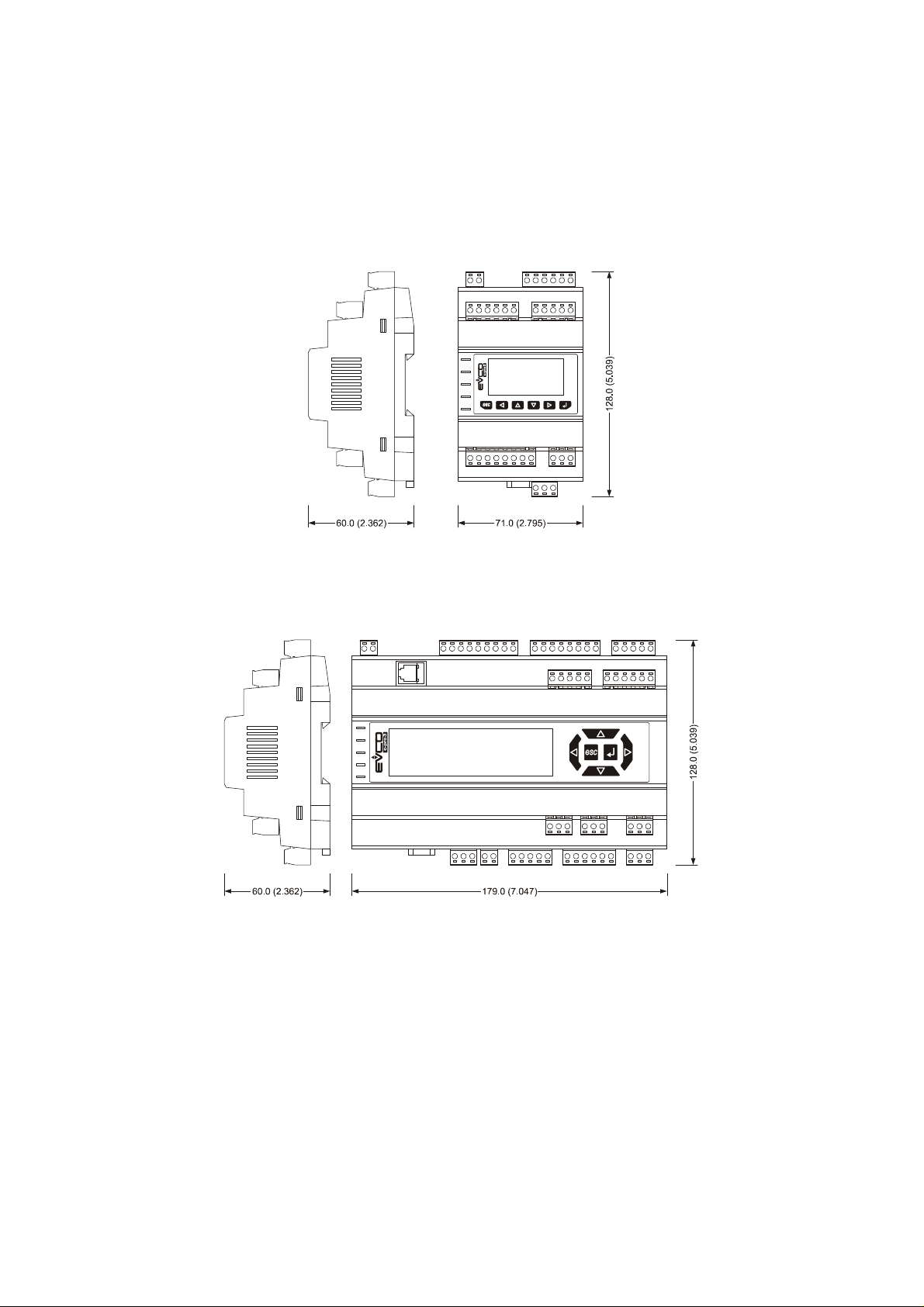
3. SIZE AND INSTALLATION
3.1. Size c-pro 3 hecto, c-pro 3 hecto+, c-pro 3 EXP hecto and
c-pro 3 EXP hecto+
4 DIN modules; size in mm (in).
3.2. Size c-pro 3 mega and c-pro 3 mega+
10 DIN modules; size in mm (in).
page 14 of 116
Page 15
EVCO S.p.A. c-pro 3 | Hardware manual ver. 3.2 | Codice 114CP3E324
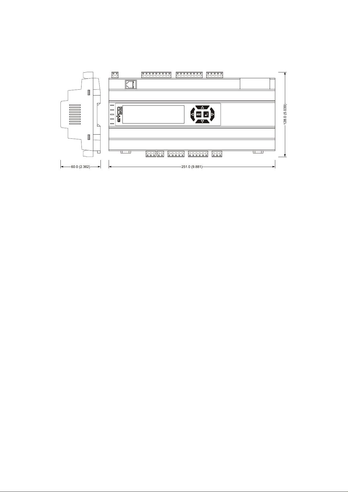
3.3. Size c-pro 3 NODE mega
14 DIN modules; size in mm (in).
page 15 of 116
Page 16

EVCO S.p.A. c-pro 3 | Hardware manual ver. 3.2 | Codice 114CP3E324
3.4. Installation
On DIN rail 35.0 x 7.5 mm (1.377 x 0.295 in) or 35.0 x 15.0 mm (1.377 x 0.590 in).
To install the devices operate as shown in the following drawing.
1 2
To remove the devices remove possible extractable screw terminal blocks plugged at the bottom first, then operate on the DIN rail clips
with a screwdriver as shown in the following drawing.
3 4
To install the devices again press the DIN rail clips to the end first.
3.5. Additional information for installation
- working conditions (working temperature, humidity, etc.) must be between the limits indicated in the technical data
- do not install the devices close to heating sources (heaters, hot air ducts, etc.), equipments provided with big magnetos (big
speakers, etc.), locations subject to direct sunlight, rain, humidity, dust, mechanical vibrations or bumps
- according to the safety legislation, the protection against electrical parts must be ensured by a correct installation of the
devices; the parts that ensure the protection must be installed so that you can not remove them if not by using a tool.
page 16 of 116
Page 17

EVCO S.p.A. c-pro 3 | Hardware manual ver. 3.2 | Codice 114CP3E324
4. ELECTRICAL CONNECTION
4.1. Electrical connection c-pro 3 hecto and c-pro 3 hecto+
4.1.1. Meaning of the connectors of c-pro 3 hecto and of c-pro 3 hecto+
The following drawing shows the connectors of c-pro 3 hecto and of c-pro 3 hecto.
The following tables show the meaning of the connectors.
MODBUS
RS-485 port with Modbus master / slave communication protocol (configurable via application software).
The following drawing shows the aspect of the RS-485 port.
The following table shows the meaning of the pins of the RS-485 port.
Pin Meaning
1 common
2 not connected
3 not connected
4 D0 = B = - (terminal 0 of the transceiver)
5 D1 = A = + (terminal 1 of the transceiver)
6 not connected
7 not connected
page 17 of 116
Page 18

EVCO S.p.A. c-pro 3 | Hardware manual ver. 3.2 | Codice 114CP3E324
8 not connected
The maximum length of the connecting cables of the RS-485 port is 1,000 m (3,280 ft); also look at the Modbus specifications
and implementation guides manual (the document is available on the internet site www.modbus.org).
Connect the RS-485 port using a twisted pair.
The following table shows the function codes supported by the controller.
Function
code
FC 01 read coils
FC 02 read discrete inputs
FC 03 read multiple registers
FC 04 read input registers
FC 05 write single coil
FC 06 write single register
FC 08 diagnostic
FC 15 write multiple coils
FC 16 write multiple registers
Meaning
FC 23 read write multiple registers
For the settings about the RS-485 port look at chapter 6 “CONFIGURATION”.
MICRO-SWITCH
Micro-switch to:
- plug in the termination of the RS-485 port (120 Ω, 0.25 W); position micro-switch 1 on position ON to plug in the termination of
the RS-485 port (plug in the termination of the first and of the last element of the network)
page 18 of 116
Page 19

EVCO S.p.A. c-pro 3 | Hardware manual ver. 3.2 | Codice 114CP3E324
- polarize the network of the RS-485 port (560 Ω, 0.25 W); position micro-switches 2 and 3 on position ON to polarize the
network of the RS-485 port (the network must be polarized by an element of the network same).
- plug in the termination of the CAN port (120 Ω, 0.5 W); position micro-switch 4 on position ON to plug in the termination of the
CAN port (plug in the termination of the first and of the last element of the network).
CAN BUS
CAN port.
Terminal Meaning
CAN + signal +
CAN - signal -
GND ground
The maximum number of devices that can make a CAN network (32) depends on the bus load; the bus load depends on the baud rate
of the CANbus communication and on the kind of device in the network.
For example: a CAN network can be made of a programmable controller, of four I / O expansions and of four user interfaces
with baud rate 500,000 baud.
The maximum length of the connecting cables of the CAN port depends on the baud rate of the CANbus communication, as
follows:
- 1,000 m (3,280 ft) with baud rate 20,000 baud
- 500 m (1,640 ft) with baud rate 50,000 baud
- 250 m (820 ft) with baud rate 125,000 baud
- 50 m (164 ft) with baud rate 500,000 baud.
Connect the CAN port using a twisted pair.
For the settings about the CAN port look at chapter 6 “CONFIGURATION”.
DIGITAL OUTPUTS
In c-pro 3 hecto.
Digital outputs 1, 2, 3, 4 and 5 (electromechanical relays).
Terminal Meaning
CO1/2 common digital outputs 1 and 2
NO1 normally open contact digital output 1
page 19 of 116
Page 20

EVCO S.p.A. c-pro 3 | Hardware manual ver. 3.2 | Codice 114CP3E324
NO2 normally open contact digital output 2
CO3 common digital output 3
NO3 normally open contact digital output 3
CO4/5 common digital outputs 4 and 5
NO4 normally open contact digital output 4
NO5 normally open contact digital output 5
Digital output 6 (electromechanical relay).
Terminal Meaning
CO6 common digital output 6
NO6 normally open contact digital output 6
NC6 normally closed contact digital output 6
The maximum length of the connecting cables of the digitalhecto:cuts is 100 m (328 ft).
The maximum current allowed on the loads is 10 A.
DIGITAL OUTPUTS
In c-pro 3 hecto+.
Digital outputs 1, 2, 3, 4 and 5 (electromechanical relays).
Terminal Meaning
CO1/2 common digital outputs 1 and 2
NO1 normally open contact digital output 1
NO2 normally open contact digital output 2
NO3 normally open contact digital output 3
CO3/4/5 common digital outputs 3, 4 and 5
CO3/4/5 common digital outputs 3, 4 and 5
NO4 normally open contact digital output 4
NO5 normally open contact digital output 5
page 20 of 116
Page 21

EVCO S.p.A. c-pro 3 | Hardware manual ver. 3.2 | Codice 114CP3E324
Digital output 6 (electromechanical relay).
Terminal Meaning
CO6 common digital output 6
NO6 normally open contact digital output 6
NC6 normally closed contact digital output 6
The maximum length of the connecting cables of the digital(6) non
hecto only)
Analog outputs.
Terminal Meaning
VDC power supply driving analog output 1 (24 VDC, 50 mA max.)
AO1 analog output 1 (PWM signal)
GND ground
AO2 analog output 2 (configurable via configuration parameter for 0-20 mA / 4-20 mA / 0-10 V signal)
AO3 analog output 3 (configurable via configuration parameter for 0-20 mA / 4-20 mA / 0-10 V signal)
The maximum length of the connecting cables of the PWM analog output is 1 m (3
280 ft); the one of the connecting cables of the 0-20 mA / 4-20 mA / 0-10 V analog outputs is instead of 30 m (98 ft).
For the settings about the analog outputs look at chapter 6 “CONFIGURATION”.
The analog output 1 is usable on condition that the controller is powered in alternate current and the phase powering the controller is the
same powering the user driven by the output.
ANALOG INPUTS/OUTPUTS (in c-pro 3 hecto+ only)
Analog inputs and analog outputs.
Terminal Meaning
AI4 analog input 4 (NTC probes)
AO1 analog output 1 (PWM signal)
GND ground
AO2 analog output 2 (configurable via configuration parameter for 0-20 mA / 4-20 mA / 0-10 V signal)
AO3 analog output 3 (configurable via configuration parameter for 0-20 mA / 4-20 mA / 0-10 V signal)
The maximum length of the connecting cables of the PWM analog output is 1 m (3.280 ft); the one of the connecting cables of
the 0-20 mA / 4-20 mA / 0-10 V analog outputs is instead of 30 m (98 ft).
page 21 of 116
Page 22

EVCO S.p.A. c-pro 3 | Hardware manual ver. 3.2 | Codice 114CP3E324
For the settings about the analog outputs look at chapter 6 “CONFIGURATION”.
The analog output 1 is usable on condition that the controller is powered in alternate current and the phase powering the controller is the
same powering the user driven by the output.
The analog output 1 and the analog output 2 are not independent each other but they work in the same way.
DIGITAL INPUTS
Free of voltage digital inputs.
Terminal Meaning
COM common digital inputs
DI1 digital input 1
DI2 digital input 2
DI3 digital input 3
DI4 digital input 4
DI5 digital input 5
The maximum length of the connecting cables of the digital inputs is 100 m (328 ft).
ANALOG INPUTS
Analog inputs.
Each analog input is configurable via configuration parameter for PTC / NTC / Pt 1000 probes / 0-20 mA / 4-20 mA / 0-5 V ratiometric /
0-10 V transducers.
Terminal Meaning
AI1 analog input 1
AI2 analog input 2
AI3 analog input 3
GND ground
+5V power supply 0-5 V ratiometric transducers (5 VDC, 40 mA max.)
+24V power supply 0-20 mA / 4-20 mA / 0-10 V transducers (24 VDC, 120 mA max.)
The maximum length of the connecting cables of the analog inputs and the one of the power supply of the transducers is
100 m (328 ft).
The controller incorporates a restorable thermal protection of the power supplies against the short circuit and the overload.
For the settings about the analog inputs look at chapter 6 “CONFIGURATION”.
PROG
Programming and debugging port.
page 22 of 116
Page 23

EVCO S.p.A. c-pro 3 | Hardware manual ver. 3.2 | Codice 114CP3E324
POWER SUPPLY
Power supply.
Terminal Meaning
V≅
V≅
The maximum length of the connecting cables of the power supply of the controller is 30 m (98 ft).
Protect the power supply with a fuse rated 0.8A-T 250 V.
If the controller is powered in direct current, one will not have to respect the polarity of the power supply voltage.
power supply controller (24 VAC / 20... 40 VDC)
power supply controller (24 VAC / 20... 40 VDC)
page 23 of 116
Page 24

EVCO S.p.A. c-pro 3 | Hardware manual ver. 3.2 | Codice 114CP3E324
4.1.2. Example of electrical connection of c-pro 3 hecto
The following shows an example of electrical connection of c-pro 3 hecto.
To reduce the reflections on the signal transmitted through the cables connecting the devices each other, plug in the
termination of the CAN port of the first and of the last element of the network.
page 24 of 116
Page 25

EVCO S.p.A. c-pro 3 | Hardware manual ver. 3.2 | Codice 114CP3E324
4.2. Electrical connection c-pro 3 mega and c-pro 3 NODE mega
4.2.1. Meaning of the connectors of c-pro 3 mega and of c-pro 3 NODE mega
The following drawing shows the connectors of c-pro 3 mega and of c-pro 3 NODE mega.
The following tables show the meaning of the connectors.
MODBUS1
RS-485 port with Modbus slave communication protocol.
The following drawing shows the aspect of the RS-485 port.
The following table shows the meaning of the pins of the RS-485 port.
Pin Meaning
1 common
2 not connected
3 not connected
4 D0 = B = - (terminal 0 of the transceiver)
5 D1 = A = + (terminale 1 of the transceiver)
6 not connected
7 not connected
page 25 of 116
Page 26

EVCO S.p.A. c-pro 3 | Hardware manual ver. 3.2 | Codice 114CP3E324
8 not connected
The maximum length of the connecting cables of the RS-485 port is 1,000 m (3,280 ft); also look at the Modbus specifications
and implementation guides manual (the document is available on the internet site www.modbus.org).
Connect the RS-485 port using a twisted pair.
The following table shows the function codes supported by the controller.
Function
code
FC 01 read coils
FC 02 read discrete inputs
FC 03 read multiple registers
FC 04 read input registers
FC 05 write single coil
FC 06 write single register
FC 08 diagnostic
FC 15 write multiple coils
FC 16 write multiple registers
Meaning
FC 23 read write multiple registers
For the settings about the RS-485 port look at chapter 6 “CONFIGURATION”.
MODBUS2
RS-485 port with Modbus master / slave communication protocol (configurable via application software).
The following drawing shows the aspect of the RS-485 port.
The following table shows the meaning of the pins of the RS-485 port.
Pin Meaning
1 common
2 not connected
page 26 of 116
Page 27

EVCO S.p.A. c-pro 3 | Hardware manual ver. 3.2 | Codice 114CP3E324
3 not connected
4 D0 = B = - (terminal 0 of the transceiver)
5 D1 = A = + (terminale 1 of the transceiver)
6 not connected
7 not connected
8 not connected
The maximum length of the connecting cables of the RS-485 port is 1,000 m (3,280 ft); also look at the Modbus specifications
and implementation guides manual (the document is available on the internet site www.modbus.org).
Connect the RS-485 port using a twisted pair.
The following table shows the function codes supported by the controller.
Function
code
FC 01 read coils
FC 02 read discrete inputs
FC 03 read multiple registers
FC 04 read input registers
FC 05 write single coil
FC 06 write single register
FC 08 diagnostic
FC 15 write multiple coils
FC 16 write multiple registers
Meaning
FC 23 read write multiple registers
For the settings about the RS-485 port look at chapter 6 “CONFIGURATION”.
page 27 of 116
Page 28
EVCO S.p.A. c-pro 3 | Hardware manual ver. 3.2 | Codice 114CP3E324
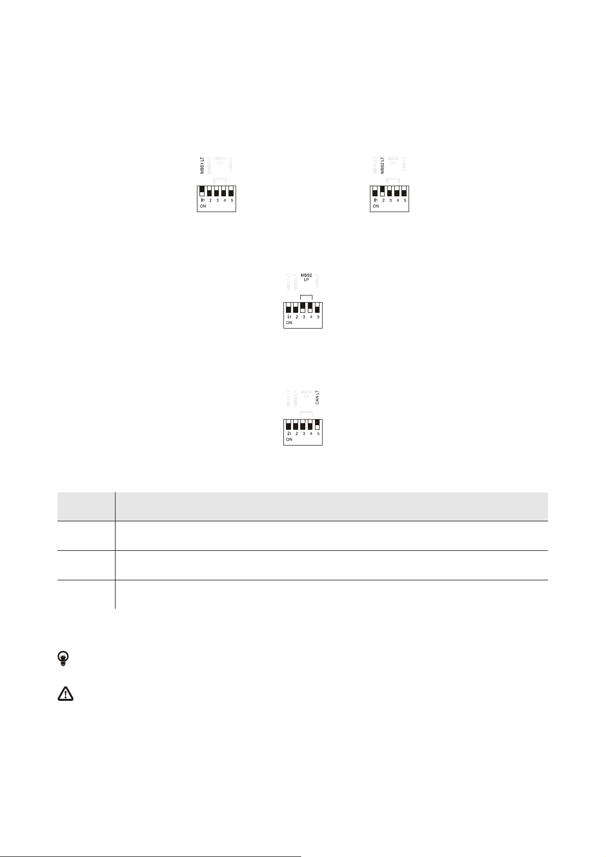
MICRO-SWITCH
Micro-switch to:
- plug in the terminations of the RS-485 ports (120 Ω, 0.25 W); position micro-switch 1 on position ON to plug in the termination
of the first RS-485 port and micro-switch 2 on position ON to plug in the termination of the second RS-485 port (plug in the
termination of the first and of the last element of the network)
- polarize the network of the second RS-485 port (560 Ω, 0.25 W); position micro-switches 3 and 4 on position ON to polarize
the network of the second RS-485 port (the network must be polarized by an element of the network same).
- plug in the termination of the CAN port (120 Ω, 0.5 W); position micro-switch 4 on position ON to plug in the termination of the
CAN port (plug in the termination of the first and of the last element of the network).
CAN BUS
CAN port.
Terminal Meaning
CAN + signal +
CAN - signal -
GND ground
The maximum number of devices that can make a CAN network (32) depends on the bus load; the bus load depends on the baud rate
of the CANbus communication and on the kind of device in the network.
For example: a CAN network can be made of a programmable controller, of four I / O expansions and of four user interfaces
with baud rate 500,000 baud.
The maximum length of the connecting cables of the CAN port depends on the baud rate of the CANbus communication, as
follows:
- 1,000 m (3,280 ft) with baud rate 20,000 baud
- 500 m (1,640 ft) with baud rate 50,000 baud
- 250 m (820 ft) with baud rate 125,000 baud
- 50 m (164 ft) with baud rate 500,000 baud.
Connect the CAN port using a twisted pair.
page 28 of 116
Page 29

EVCO S.p.A. c-pro 3 | Hardware manual ver. 3.2 | Codice 114CP3E324
For the settings about the CAN port look at chapter 6 “CONFIGURATION”.
Power supply user interface.
Terminal Meaning
GND ground
VDC power supply user interface (24 VDC, 120 mA max.)
The maximum length of the connecting cables of the power supply of the user interface is 30 m (98 ft).
The controller incorporates a restorable thermal protection of the power supplies against the short circuit and the overload.
DIGITAL OUTPUTS
Digital outputs 1, 2 and 3 (electromechanical relays).
Terminal Meaning
CO1/2 common digital outputs 1 and 2
NO1 normally open contact digital output 1
NO2 normally open contact digital output 2
CO3 common digital output 3
NO3 normally open contact digital output 3
Digital outputs 4, 5, 6 e 7 (electromechanical relays).
Terminal Meaning
CO4/5 common digital outputs 4 and 5
NO4 normally open contact digital output 4
NO5 normally open contact digital output 5
CO6/7 common digital outputs 6 and 7
NO6 normally open contact digital output 6
NO7 normally open contact digital output 7
Digital output 8 (electromechanical relay).
Terminal Meaning
CO8 common digital output 8
page 29 of 116
Page 30

EVCO S.p.A. c-pro 3 | Hardware manual ver. 3.2 | Codice 114CP3E324
NO8 normally open contact digital output 8
NC8 normally closed contact digital output 8
The maximum length of the connecting cables of the digital outputs is 100 m (328 ft).
The maximum current allowed on the loads is 10 A.
BMS CONNECTIVITY SLOT (in c-pro 3 NODE mega only)
Slot for gateway c-pro 3 plug-in; also look at the User guide of c-pro 3 plug-in.
ANALOG OUTPUTS
Analog outputs.
Terminal Meaning
VDC power supply driving analog output 1 (24 VDC, 50 mA max.)
AO1 analog output 1 (PWM signal)
GND ground
AO2 analog output 2 (configurable via configuration parameter for 0-20 mA / 4-20 mA / 0-10 V signal)
AO3 analog output 3 (configurable via configuration parameter for 0-20 mA / 4-20 mA / 0-10 V signal)
The maximum length of the connecting cables of the PWM analog output is 1 m (3.280 ft); the one of the connecting cables of
the 0-20 mA / 4-20 mA / 0-10 V analog outputs is instead of 30 m (98 ft).
For the settings about the analog outputs look at chapter 6 “CONFIGURATION”.
The analog output 1 is usable on condition that the controller is powered in alternate current and the phase powering the controller is the
same powering the user driven by the output.
DIGITAL INPUTS
Digital inputs.
Terminal Meaning
DI1 digital input 1
DI2 digital input 2
DI3 digital input 3
DI4 digital input 4
DI5 digital input 5
DI6 digital input 6
page 30 of 116
Page 31
EVCO S.p.A. c-pro 3 | Hardware manual ver. 3.2 | Codice 114CP3E324
DI7 digital input 7
COM common digital inputs
The maximum length of the connecting cables of the digital inputs is 100 m (328 ft).
The digital inputs can be used on condition that they are powered at 24 VAC / DC.
ANALOG INPUTS
Analog inputs.
Each analog input is configurable via configuration parameter for PTC / NTC / Pt 1000 probes / 0-20 mA / 4-20 mA / 0-5 V ratiometric /
0-10 V transducers.
Terminal Meaning
GND ground
AI1 analog input 1
AI2 analog input 2
AI3 analog input 3
AI4 analog input 4
AI5 analog input 5
GND ground
+5V power supply 0-5 V ratiometric transducers (5 VDC, 40 mA max.)
+24V power supply 0-20 mA / 4-20 mA / 0-10 V transducers (24 VDC, 120 mA max.)
The maximum length of the connecting cables of the analog inputs and the one of the power supply of the transducers is
100 m (328 ft).
The controller incorporates a restorable thermal protection of the power supplies against the short circuit and the overload.
For the settings about the analog inputs look at chapter 6 “CONFIGURATION”.
PROG
Programming and debugging port.
POWER SUPPLY
Power supply.
Terminal Meaning
V≅
V≅
page 31 of 116
power supply controller (24 VAC / 20... 40 VDC)
power supply controller (24 VAC / 20... 40 VDC)
Page 32

EVCO S.p.A. c-pro 3 | Hardware manual ver. 3.2 | Codice 114CP3E324
The maximum length of the connecting cables of the power supply of the controller is 30 m (98 ft).
Protect the power supply with a fuse rated 2.5A-T 250 V.
If the controller is powered in direct current, one will not have to respect the polarity of the power supply voltage.
page 32 of 116
Page 33
EVCO S.p.A. c-pro 3 | Hardware manual ver. 3.2 | Codice 114CP3E324
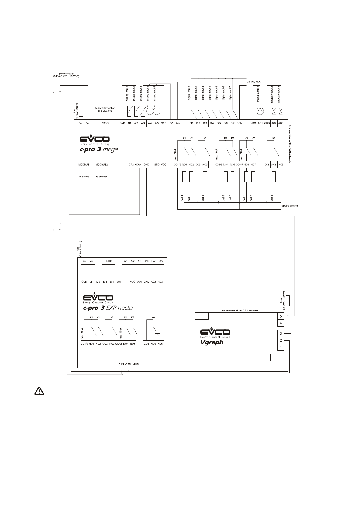
4.2.2. Example of electrical connection of c-pro 3 mega
The following drawing shows an example of electrical connection of c-pro 3 mega.
To reduce the reflections on the signal transmitted through the cables connecting the devices each other, plug in the
termination of the CAN port of the first and of the last element of the network.
page 33 of 116
Page 34
EVCO S.p.A. c-pro 3 | Hardware manual ver. 3.2 | Codice 114CP3E324
4.3. Electrical connection c-pro 3 mega+
4.3.1. Meaning of the connectors of c-pro 3 mega+
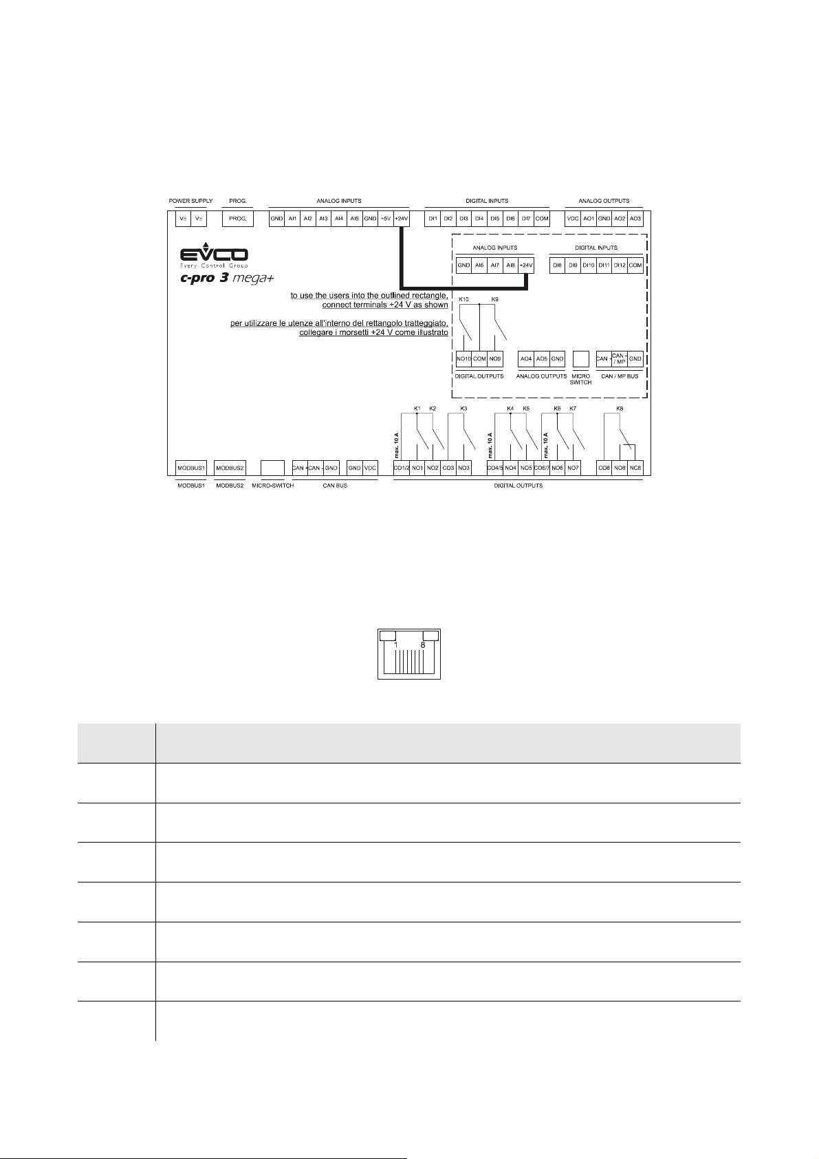
The following drawing shows the connectors of c-pro 3 mega+.
The following tables show the meaning of the connectors.
MODBUS1
RS-485 port with Modbus slave communication protocol.
The following drawing shows the aspect of the RS-485 port.
The following table shows the meaning of the pins of the RS-485 port.
Pin Meaning
1 common
2 not connected
3 not connected
4 D0 = B = - (terminal 0 of the transceiver)
5 D1 = A = + (terminale 1 of the transceiver)
6 not connected
7 not connected
page 34 of 116
Page 35
EVCO S.p.A. c-pro 3 | Hardware manual ver. 3.2 | Codice 114CP3E324
8 not connected
The maximum length of the connecting cables of the RS-485 port is 1,000 m (3,280 ft); also look at the Modbus specifications
and implementation guides manual (the document is available on the internet site www.modbus.org).
Connect the RS-485 port using a twisted pair.
The following table shows the function codes supported by the controller.
Function
code
FC 01 read coils
FC 02 read discrete inputs
FC 03 read multiple registers
FC 04 read input registers
FC 05 write single coil
FC 06 write single register
FC 08 diagnostic
FC 15 write multiple coils
FC 16 write multiple registers
Meaning
FC 23 read write multiple registers
For the settings about the RS-485 port look at chapter 6 “CONFIGURATION”.
MODBUS2
RS-485 port with Modbus master / slave communication protocol (configurable via application software).
The following drawing shows the aspect of the RS-485 port.
The following table shows the meaning of the pins of the RS-485 port.
Pin Meaning
1 common
2 not connected
page 35 of 116
Page 36
EVCO S.p.A. c-pro 3 | Hardware manual ver. 3.2 | Codice 114CP3E324
3 not connected
4 D0 = B = - (terminal 0 of the transceiver)
5 D1 = A = + (terminale 1 of the transceiver)
6 not connected
7 not connected
8 not connected
The maximum length of the connecting cables of the RS-485 port is 1,000 m (3,280 ft); also look at the Modbus specifications
and implementation guides manual (the document is available on the internet site www.modbus.org).
Connect the RS-485 port using a twisted pair.
The following table shows the function codes supported by the controller.
Function
code
FC 01 read coils
FC 02 read discrete inputs
FC 03 read multiple registers
FC 04 read input registers
FC 05 write single coil
FC 06 write single register
FC 08 diagnostic
FC 15 write multiple coils
FC 16 write multiple registers
Meaning
FC 23 read write multiple registers
For the settings about the RS-485 port look at chapter 6 “CONFIGURATION”.
page 36 of 116
Page 37
EVCO S.p.A. c-pro 3 | Hardware manual ver. 3.2 | Codice 114CP3E324
MICRO-SWITCH
Micro-switch to:
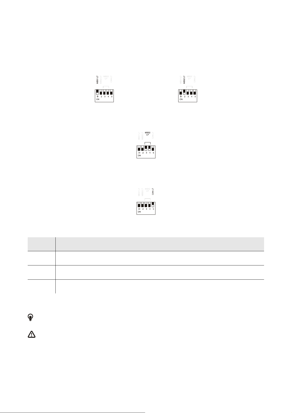
- plug in the terminations of the RS-485 ports (120 Ω, 0.25 W); position micro-switch 1 on position ON to plug in the termination
of the first RS-485 port and micro-switch 2 on position ON to plug in the termination of the second RS-485 port (plug in the
termination of the first and of the last element of the network)
- polarize the network of the second RS-485 port (560 Ω, 0.25 W); position micro-switches 3 and 4 on position ON to polarize
the network of the second RS-485 port (the network must be polarized by an element of the network same).
- plug in the termination of the first CAN port (120 Ω, 0.5 W); position micro-switch 4 on position ON to plug in the termination of
the CAN port (plug in the termination of the first and of the last element of the network).
CAN BUS
First CAN port.
Terminal Meaning
CAN + signal +
CAN - signal -
GND ground
The maximum number of devices that can make a CAN network (32) depends on the bus load; the bus load depends on the baud rate
of the CANbus communication and on the kind of device in the network.
For example: a CAN network can be made of a programmable controller, of four I / O expansions and of four user interfaces
with baud rate 500,000 baud.
The maximum length of the connecting cables of the CAN port depends on the baud rate of the CANbus communication, as
follows:
- 1,000 m (3,280 ft) with baud rate 20,000 baud
- 500 m (1,640 ft) with baud rate 50,000 baud
- 250 m (820 ft) with baud rate 125,000 baud
- 50 m (164 ft) with baud rate 500,000 baud.
Connect the CAN port using a twisted pair.
page 37 of 116
Page 38
EVCO S.p.A. c-pro 3 | Hardware manual ver. 3.2 | Codice 114CP3E324
For the settings about the CAN port look at chapter 6 “CONFIGURATION”.
Power supply user interface.
Terminal Meaning
GND ground
VDC power supply user interface (24 VDC, 120 mA max.)
The maximum length of the connecting cables of the power supply of the user interface is 30 m (98 ft).
The controller incorporates a restorable thermal protection of the power supplies against the short circuit and the overload.
DIGITAL OUTPUTS
Digital outputs 1, 2 and 3 (electromechanical relays).
Terminal Meaning
CO1/2 common digital outputs 1 and 2
NO1 normally open contact digital output 1
NO2 normally open contact digital output 2
CO3 common digital output 3
NO3 normally open contact digital output 3
Digital outputs 4, 5, 6 e 7 (electromechanical relays).
Terminal Meaning
CO4/5 common digital outputs 4 and 5
NO4 normally open contact digital output 4
NO5 normally open contact digital output 5
CO6/7 common digital outputs 6 and 7
NO6 normally open contact digital output 6
NO7 normally open contact digital output 7
Digital output 8 (electromechanical relay).
Terminal Meaning
CO8 common digital output 8
page 38 of 116
Page 39
EVCO S.p.A. c-pro 3 | Hardware manual ver. 3.2 | Codice 114CP3E324
NO8 normally open contact digital output 8
NC8 normally closed contact digital output 8
The maximum length of the connecting cables of the digital outputs is 100 m (328 ft).
The maximum current allowed on the loads is 10 A.
ANALOG OUTPUTS
Analog outputs 1, 2 and 3.
Terminal Meaning
VDC power supply driving analog output 1 (24 VDC, 50 mA max.)
AO1 analog output 1 (PWM signal)
GND ground
AO2 analog output 2 (configurable via configuration parameter for 0-20 mA / 4-20 mA / 0-10 V signal)
AO3 analog output 3 (configurable via configuration parameter for 0-20 mA / 4-20 mA / 0-10 V signal)
The maximum length of the connecting cables of the PWM analog output is 1 m (3.280 ft); the one of the connecting cables of
the 0-20 mA / 4-20 mA / 0-10 V analog outputs is instead of 30 m (98 ft).
For the settings about the analog outputs look at chapter 6 “CONFIGURATION”.
The analog output 1 is usable on condition that the controller is powered in alternate current and the phase powering the controller is the
same powering the user driven by the output.
DIGITAL INPUTS
Digital inputs 1, 2, 3, 4, 5, 6 and 7.
Terminal Meaning
DI1 digital input 1
DI2 digital input 2
DI3 digital input 3
DI4 digital input 4
DI5 digital input 5
DI6 digital input 6
DI7 digital input 7
COM common digital inputs
page 39 of 116
Page 40
EVCO S.p.A. c-pro 3 | Hardware manual ver. 3.2 | Codice 114CP3E324
The maximum length of the connecting cables of the digital inputs is 100 m (328 ft).
The digital inputs can be used on condition that they are powered at 24 VAC / DC.
ANALOG INPUTS
Analog inputs 1, 2, 3, 4 and 5.
Each analog input is configurable via configuration parameter for PTC / NTC / NTC 2 / NTC 3 / Pt 1000 probes / 0-20 mA / 4-20 mA /
0-5 V ratiometric / 0-10 V transducers, but the analog input 2 of the models with second CAN port which is configurable via configuration
parameter for PTC / NTC / NTC 2 / NTC 3 / Pt 1000 probes.
Terminal Meaning
GND ground
AI1 analog input 1
AI2 analog input 2
AI3 analog input 3
AI4 analog input 4
AI5 analog input 5
GND ground
+5V power supply 0-5 V ratiometric transducers (5 VDC, 40 mA max.)
+24V power supply 0-20 mA / 4-20 mA / 0-10 V transducers (24 VDC, 120 mA max.)
The maximum length of the connecting cables of the analog inputs and the one of the power supply of the transducers is
100 m (328 ft).
The controller incorporates a restorable thermal protection of the power supplies against the short circuit and the overload.
For the settings about the analog inputs look at chapter 6 “CONFIGURATION”.
PROG
Programming and debugging port.
POWER SUPPLY
Power supply.
Terminal Meaning
V≅
V≅
The maximum length of the connecting cables of the power supply of the controller is 30 m (98 ft).
Protect the power supply with a fuse rated 2.5A-T 250 V.
If the controller is powered in direct current, one will not have to respect the polarity of the power supply voltage.
page 40 of 116
power supply controller (24 VAC / 20... 40 VDC)
power supply controller (24 VAC / 20... 40 VDC)
Page 41
EVCO S.p.A. c-pro 3 | Hardware manual ver. 3.2 | Codice 114CP3E324
DIGITAL OUTPUTS
Digital outputs 9 and 10 (electromechanical relays).
Terminal Meaning
NO10 normally open contact digital output 10
COM common digital outputs 9 and 10
NO9 normally open contact digital output 9
The maximum length of the connecting cables of the digital outputs is 10 m (32 ft).
The maximum current allowed on the loads is 10 A.
ANALOG OUTPUTS
Analog outputs 4 and 5.
Terminal Meaning
AO4 analog output 4 (configurable via configuration parameter for PWM / 0-10 V signal)
AO5 analog output 5 (configurable via configuration parameter for PWM / 0-10 V signal)
The maximum length of the connecting cables of the PWM analog output is 1 m (3.280 ft); the one of the connecting cables of
the 0-10 V analog outputs is instead of 10 m (32 ft).
For the settings about the analog outputs look at chapter 6 “CONFIGURATION”.
MICRO-SWITCH
Micro-switch to plug in the termination of the second CAN port (120 Ω, 0.5 W); position micro-switch 1 on position ON to plug in the
termination of the second CAN port (plug in the termination of the first and of the last element of the network).
CAN BUS / MP BUS
For the models with second CAN port the connectors have the following meaning.
Terminal Meaning
CAN + signal +
CAN - / MP signal -
GND ground
The maximum number of devices that can make a CAN network (32) depends on the bus load; the bus load depends on the baud rate
of the CANbus communication and on the kind of device in the network.
page 41 of 116
Page 42
EVCO S.p.A. c-pro 3 | Hardware manual ver. 3.2 | Codice 114CP3E324
For example: a CAN network can be made of a programmable controller, of four I / O expansions and of four user interfaces
with baud rate 500,000 baud.
The maximum length of the connecting cables of the CAN port depends on the baud rate of the CANbus communication, as
follows:
- 1,000 m (3,280 ft) with baud rate 20,000 baud
- 500 m (1,640 ft) with baud rate 50,000 baud
- 250 m (820 ft) with baud rate 125,000 baud
- 50 m (164 ft) with baud rate 500,000 baud.
Connect the CAN port using a twisted pair.
For the settings about the CAN port look at chapter 6 “CONFIGURATION”.
For the models with MP-Bus port the connectors have the following meaning.
Terminal Meaning
CAN + not connected
CAN - / MP signal
GND ground
The maximum number of devices that can make a MP-Bus network is 8.
To the MP-Bus port can be connected the Belimo’s devices that manage correctly the commands MP_Get_SeriesNo,
MP_Set_MP_Address (that allow the configuration of the network) and MP_Set_Relative (that allows to drive the position of the
actuator).
If you want to connect a probe (or a relay) to the actuator, the device must also manage the commands MP_AD_Convert (that allows to
read the probe value) and/or MP_Get_Forced_Control (that allows to read the relay status).
The maximum length of the connecting cables of the MP-Bus port is 10 m (32 ft).
Connect the CAN port using a twisted pair.
For the settings about the CAN port look at chapter 6 “CONFIGURATION”.
DIGITAL INPUTS
Digital inputs 8, 9, 10, 11 and 12.
Terminal Meaning
DI8 digital input 8
DI9 digital input 9
DI10 digital input 10
DI11 digital input 11
DI12 digital input 12
COM common digital inputs
The maximum length of the connecting cables of the digital inputs is 10 m (32 ft).
The digital inputs can be used on condition that they are powered at 24 VAC / DC.
page 42 of 116
Page 43
EVCO S.p.A. c-pro 3 | Hardware manual ver. 3.2 | Codice 114CP3E324
ANALOG INPUTS
Analog inputs 6, 7 and 8.
Each analog input is configurable via configuration parameter for NTC / 0-20 mA / 4-20 mA transducers.
Terminal Meaning
GND ground
AI6 analog input 6
AI7 analog input 7
AI8 analog input 8
+24V power supply 0-20 mA / 4-20 mA transducers (24 VDC, 120 mA max.)
The maximum length of the connecting cables of the analog inputs and the one of the power supply of the transducers is
10 m (32 ft).
The controller incorporates a restorable thermal protection of the power supplies against the short circuit and the overload.
For the settings about the analog inputs look at chapter 6 “CONFIGURATION”.
page 43 of 116
Page 44
EVCO S.p.A. c-pro 3 | Hardware manual ver. 3.2 | Codice 114CP3E324
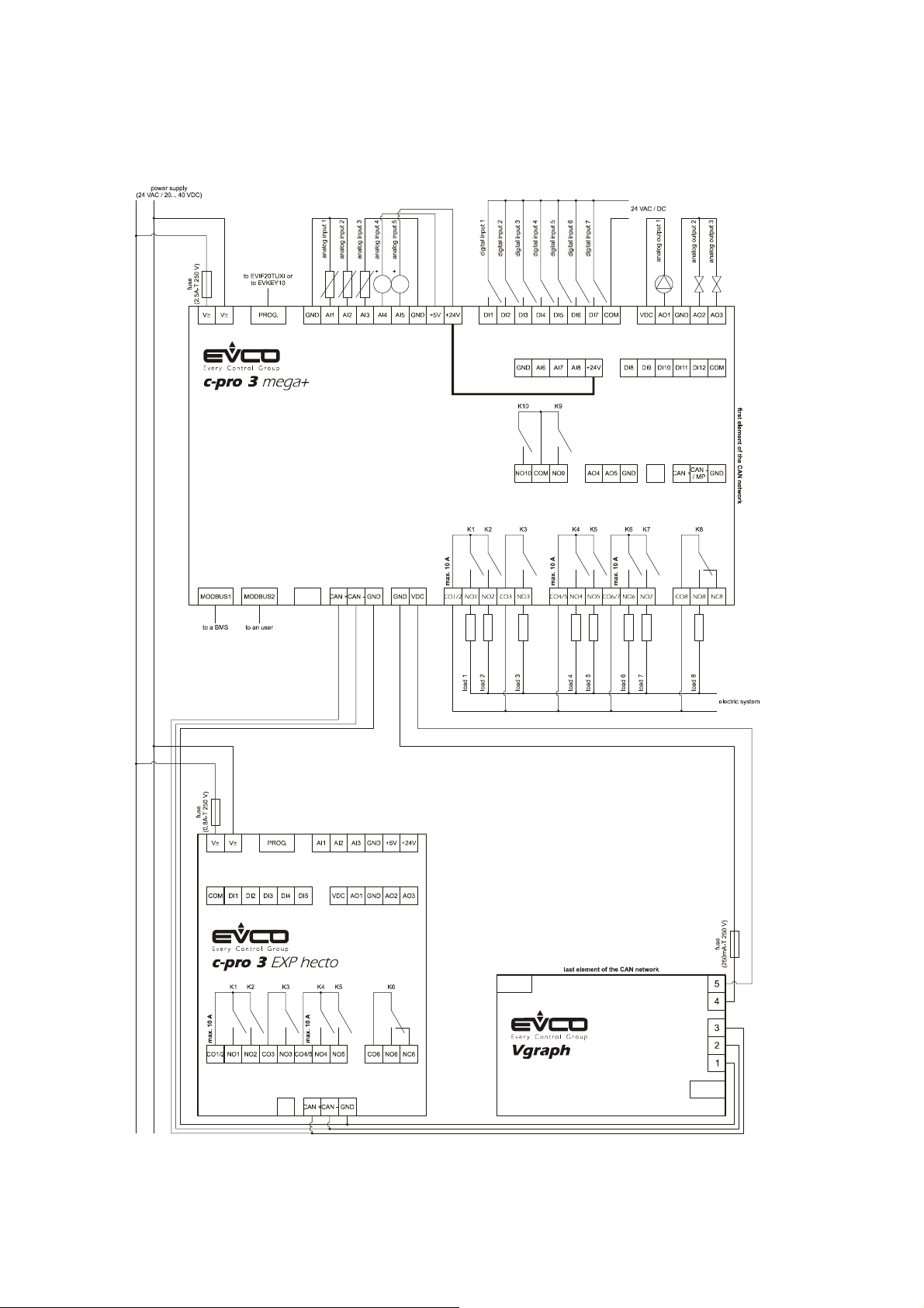
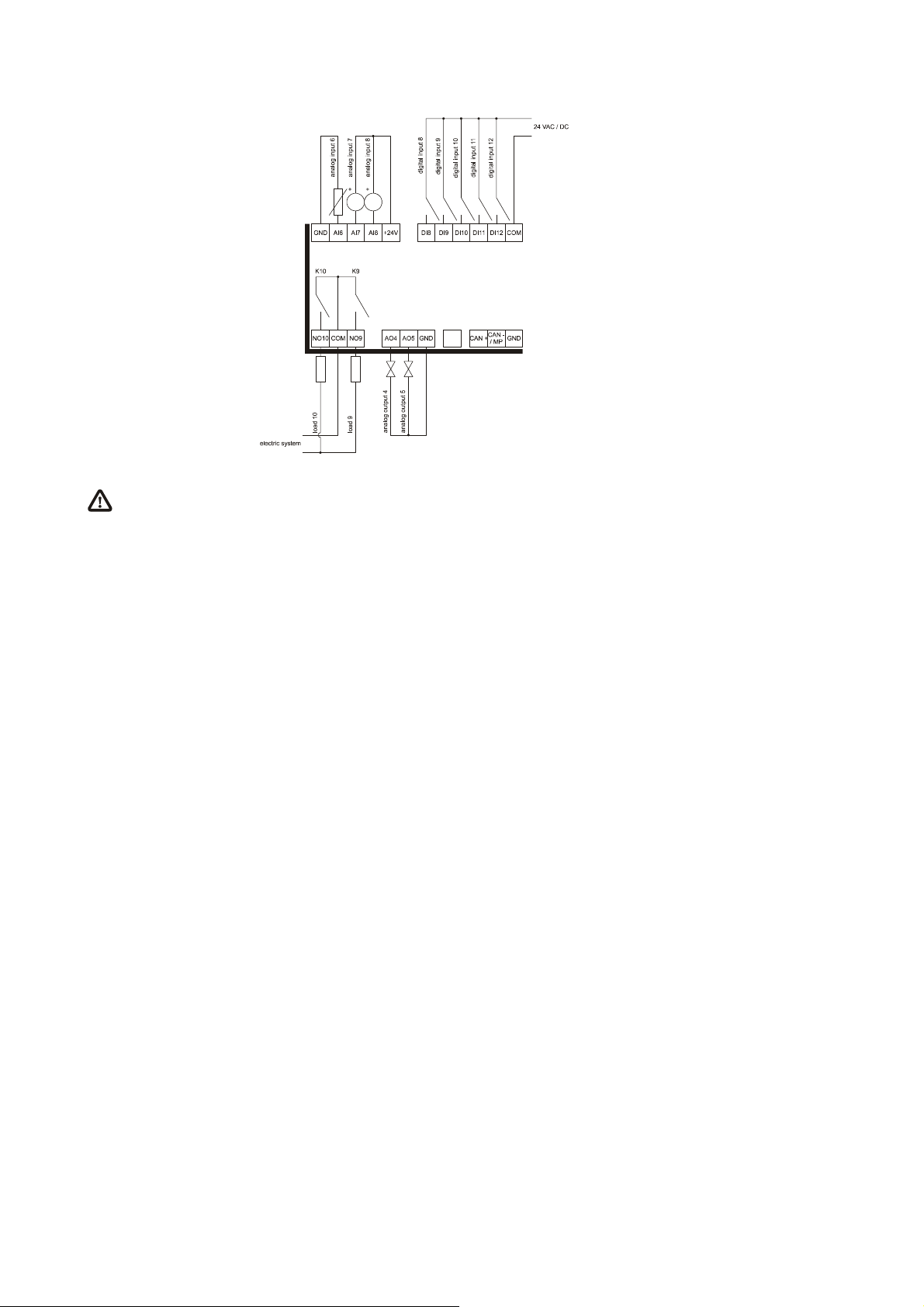
4.3.2. Example of electrical connection of c-pro 3 mega+
The following drawing shows an example of electrical connection of c-pro 3 mega+.
It continues in the following page.
page 44 of 116
Page 45
EVCO S.p.A. c-pro 3 | Hardware manual ver. 3.2 | Codice 114CP3E324
To reduce the reflections on the signal transmitted through the cables connecting the devices each other, plug in the
termination of the CAN port of the first and of the last element of the network.
page 45 of 116
Page 46
EVCO S.p.A. c-pro 3 | Hardware manual ver. 3.2 | Codice 114CP3E324
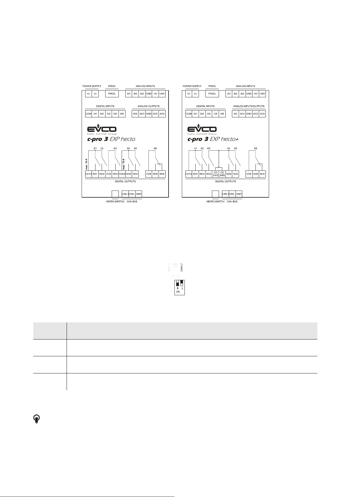
4.4. Electrical connection c-pro 3 EXP hecto and c-pro 3 EXP hecto+
4.4.1. Meaning of the connectors of c-pro 3 EXP hecto and of c-pro 3 EXP hecto+
The following drawing shows the connectors of c-pro 3 EXP hecto and of c-pro 3 EXP hecto+.
The following tables show the meaning of the connectors.
MICRO-SWITCH
Micro switch to plug in the termination of the CAN port (120 Ω, 0.5 W); position micro-switch 2 on position ON to plug in the termination
of the CAN port (plug in the termination of the first and of the last element of the network).
CAN BUS
CAN port.
Terminal Meaning
CAN + signal +
CAN - signal -
GND ground
The maximum number of devices that can make a CAN network (32) depends on the bus load; the bus load depends on the baud rate
of the CANbus communication and on the kind of device in the network.
For example: a CAN network can be made of a programmable controller, of four I / O expansions and of four user interfaces
with baud rate 500,000 baud.
page 46 of 116
Page 47
EVCO S.p.A. c-pro 3 | Hardware manual ver. 3.2 | Codice 114CP3E324
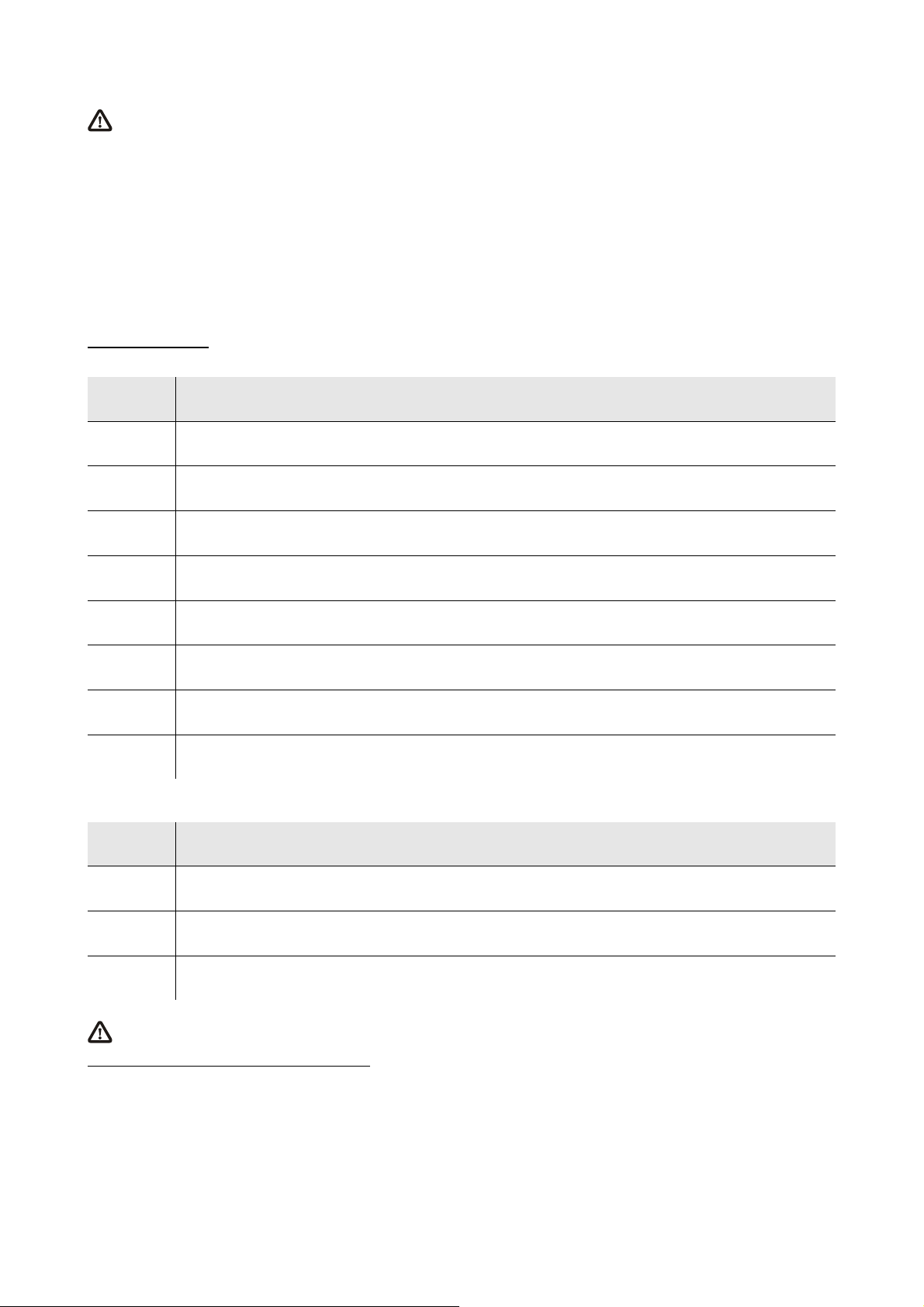
The maximum length of the connecting cables of the CAN port depends on the baud rate of the CANbus communication, as
follows:
- 1,000 m (3,280 ft) with baud rate 20,000 baud
- 500 m (1,640 ft) with baud rate 50,000 baud
- 250 m (820 ft) with baud rate 125,000 baud
- 50 m (164 ft) with baud rate 500,000 baud.
Connect the CAN port using a twisted pair.
For the settings about the CAN port look at chapter 6 “CONFIGURATION”.
DIGITAL OUTPUTS
In c-pro 3 EXP hecto.
Digital outputs 1, 2, 3, 4 and 5 (electromechanical relays).
Terminal Meaning
CO1/2 common digital outputs 1 and 2
NO1 normally open contact digital output 1
NO2 normally open contact digital output 2
CO3 common digital output 3
NO3 normally open contact digital output 3
CO4/5 common digital outputs 4 and 5
NO4 normally open contact digital output 4
NO5 normally open contact digital output 5
Digital output 6 (electromechanical relay).
Terminal Meaning
CO6 common digital output 6
NO6 normally open contact digital output 6
NC6 normally closed contact digital output 6
The maximum length of the connecting cables of the digital outputs is 100 m (328 ft).
The maximum current allowed on the loads is 10 A.
page 47 of 116
Page 48
EVCO S.p.A. c-pro 3 | Hardware manual ver. 3.2 | Codice 114CP3E324
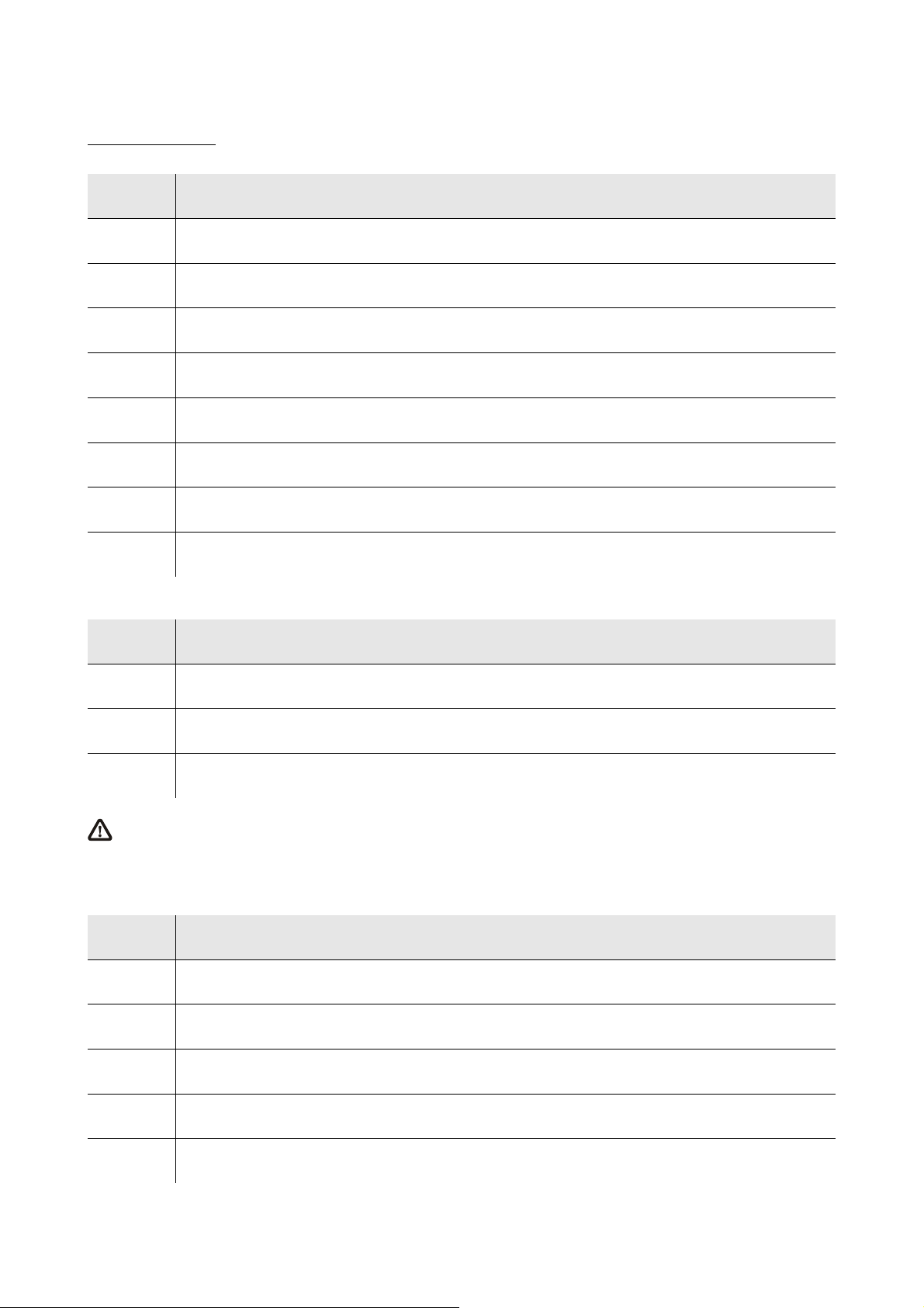
DIGITAL OUTPUTS
In c-pro 3 EXP hecto+.
Digital outputs 1, 2, 3, 4 and 5 (electromechanical relays).
Terminal Meaning
CO1/2 common digital outputs 1 and 2
NO1 normally open contact digital output 1
NO2 normally open contact digital output 2
NO3 normally open contact digital output 3
CO3/4/5 common digital outputs 3, 4 and 5
CO3/4/5 common digital outputs 3, 4 and 5
NO4 normally open contact digital output 4
NO5 normally open contact digital output 5
Digital output 6 (electromechanical relay).
Terminal Meaning
CO6 common digital output 6
NO6 normally open contact digital output 6
NC6 normally closed contact digital output 6
The maximum length of the connecting cables of the digital outputs is 100 m (328 ft).
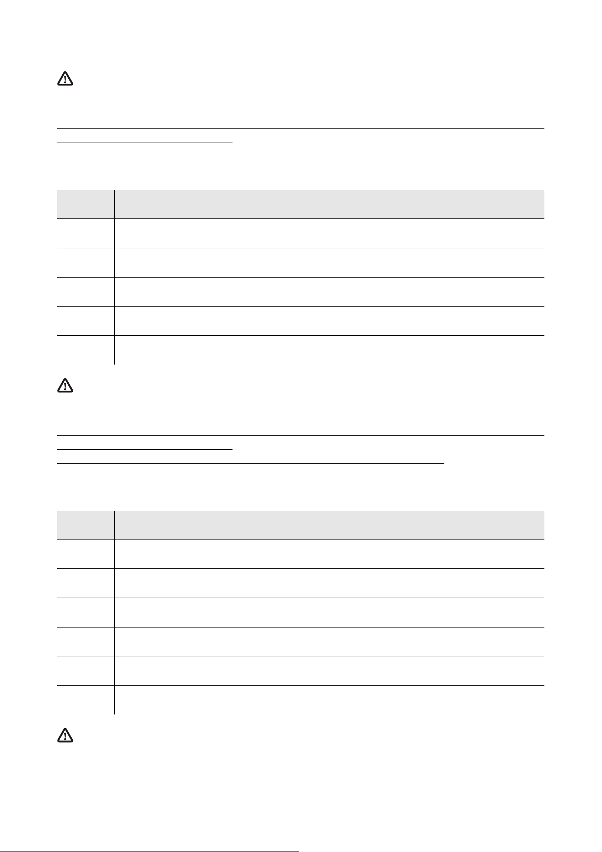
ANALOG OUTPUTS (in c-pro 3 EXP hecto only)
Analog outputs.
Terminal Meaning
VDC power supply driving analog output 1 (24 VDC, 50 mA max.)
AO1 analog output 1 (PWM signal)
GND ground
AO2 analog output 2 (configurable via configuration parameter for 0-20 mA / 4-20 mA / 0-10 V signal)
AO3 analog output 3 (configurable via configuration parameter for 0-20 mA / 4-20 mA / 0-10 V signal)
page 48 of 116
Page 49
EVCO S.p.A. c-pro 3 | Hardware manual ver. 3.2 | Codice 114CP3E324
The maximum length of the connecting cables of the PWM analog output is 1 m (3.280 ft); the one of the connecting cables of
the 0-20 mA / 4-20 mA / 0-10 V analog outputs is instead of 30 m (98 ft).
For the settings about the analog outputs look at chapter 6 “CONFIGURATION”.
The analog output 1 is usable on condition that the expansion is powered in alternate current and the phase powering the controller is
the same powering the user driven by the output.
ANALOG INPUTS/OUTPUTS (in c-pro 3 EXP hecto+ only)
Analog inputs and analog outputs.
Terminal Meaning
AI4 analog input 4 (NTC probes)
AO1 analog output 1 (PWM signal)
GND ground
AO2 analog output 2 (configurable via configuration parameter for 0-20 mA / 4-20 mA / 0-10 V signal)
AO3 analog output 3 (configurable via configuration parameter for 0-20 mA / 4-20 mA / 0-10 V signal)
The maximum length of the connecting cables of the PWM analog output is 1 m (3.280 ft); the one of the connecting cables of
the 0-20 mA / 4-20 mA / 0-10 V analog outputs is instead of 30 m (98 ft).
For the settings about the analog outputs look at chapter 6 “CONFIGURATION”.
The analog output 1 is usable on condition that the expansion is powered in alternate current and the phase powering the controller is
the same powering the user driven by the output.
The analog output 1 and the analog output 2 are not independent each other but they work in the same way.
DIGITAL INPUTS
Free of voltage digital inputs.
Terminal Meaning
COM common digital inputs
DI1 digital input 1
DI2 digital input 2
DI3 digital input 3
DI4 digital input 4
DI5 digital input 5
The maximum length of the connecting cables of the digital inputs is 100 m (328 ft).
page 49 of 116
Page 50
EVCO S.p.A. c-pro 3 | Hardware manual ver. 3.2 | Codice 114CP3E324
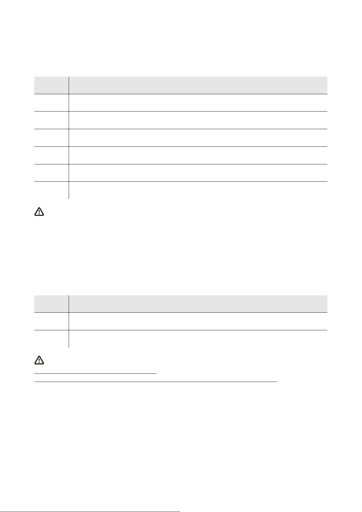
ANALOG INPUTS
Analog inputs.
Each analog input is configurable via configuration parameter for PTC / NTC / Pt 1000 probes / 0-20 mA / 4-20 mA / 0-5 V ratiometric /
0-10 V transducers.
Terminal Meaning
AI1 analog input 1
AI2 analog input 2
AI3 analog input 3
GND ground
+5V power supply 0-5 V ratiometric transducers (5 VDC, 40 mA max.)
+24V power supply 0-20 mA / 4-20 mA / 0-10 V transducers (24 VDC, 120 mA max.)
The maximum length of the connecting cables of the analog inputs and the one of the power supply of the transducers is
100 m (328 ft).
The expansion incorporates a restorable thermal protection of the power supplies against the short circuit and the overload.
For the settings about the analog inputs look at chapter 6 “CONFIGURATION”.
PROG
Port to update the firmware of the instrument.
POWER SUPPLY
Power supply.
Terminal Meaning
V≅
V≅
The maximum length of the connecting cables of the power supply of the expansion is 30 m (98 ft).
Protect the power supply with a fuse rated 0.8A-T 250 V.
If the expansion is powered in direct current, one will not have to respect the polarity of the power supply voltage.
power supply expansion (24 VAC / 20... 40 VDC)
power supply expansion (24 VAC / 20... 40 VDC)
page 50 of 116
Page 51
EVCO S.p.A. c-pro 3 | Hardware manual ver. 3.2 | Codice 114CP3E324
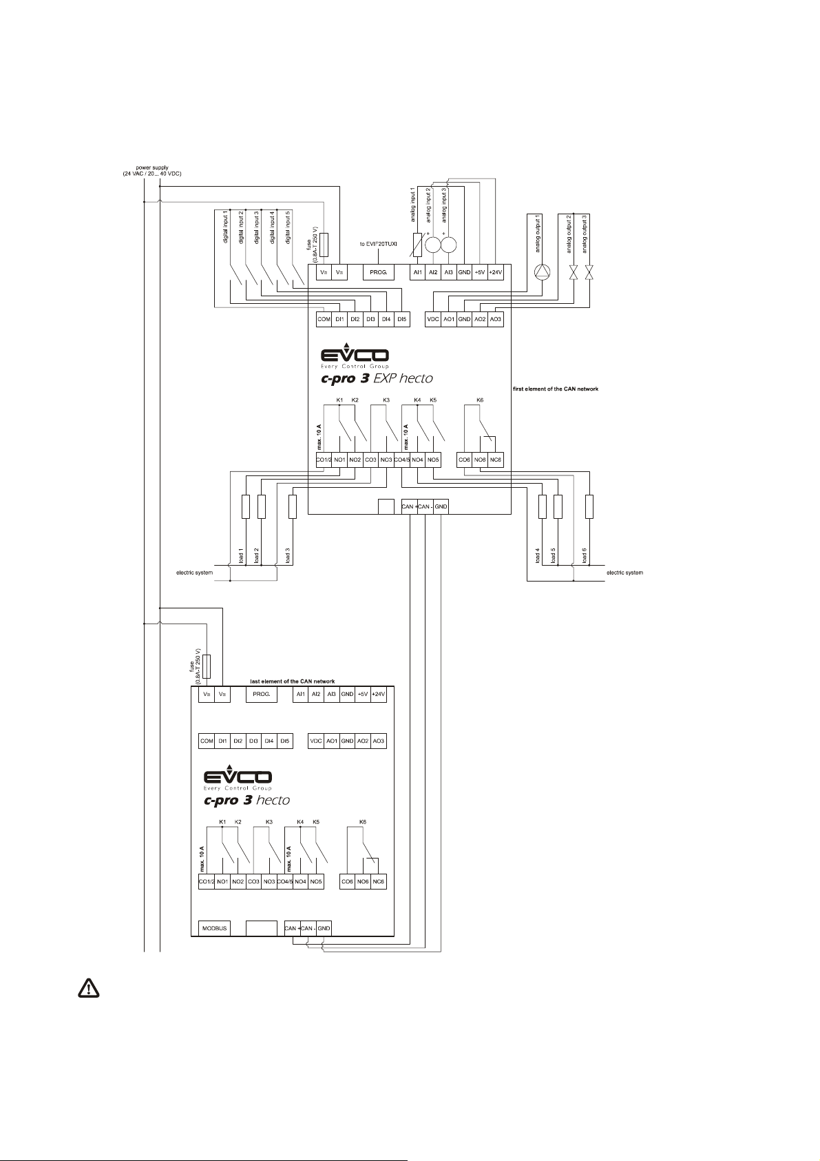
4.4.2. Example of electrical connection of c-pro 3 EXP hecto
The following drawing shows an example of electrical connection of c-pro 3 EXP hecto.
To reduce the reflections on the signal transmitted through the cables connecting the devices each other, plug in the
termination of the CAN port of the first and of the last element of the network.
page 51 of 116
Page 52

EVCO S.p.A. c-pro 3 | Hardware manual ver. 3.2 | Codice 114CP3E324
4.5. Additional information for electrical connection
- do not operate on the terminal blocks with electrical or pneumatic screwers
- if the device has been moved from a cold location to a warm one, the humidity could condense on the inside; wait about an
hour before powering it
- test the working power supply voltage, working electrical frequency and working electrical power of the controller; they must
correspond with the local power supply
- connect the device to the other devices using a twisted pair
- disconnect the local power supply before servicing the device
- do not use the device as safety device
- for repairs and information on the device please contact the EVCO’s sales network.
page 52 of 116
Page 53
EVCO S.p.A. c-pro 3 | Hardware manual ver. 3.2 | Codice 114CP3E324
5. USER INTERFACE
5.1. Keyboard
The following table shows the meaning of the keyboard.
Button Preset function
cancel, hereinafter also called “button ESC”
move to left, hereinafter also called “button LEFT”
increase, hereinafter also called “button UP”
decrease, hereinafter also called “button DOWN”
move to right, hereinafter also called “button RIGHT”
confIrmation, hereinafter also called “button ENTER”
The keyboard is not available in the blind versions.
5.2. Signalling LEDs
5.2.1. LEDs at the front of the device
The following table shows the meaning of the LEDs at the front of the device.
LED Meaning
LED power supply
ON
RUN
if it is lit, the device will be powered
if it is out, the device will not be powered
LED run
if it is lit, the application software will be compiled and running in release modality
if it flashes slowly, the application software will be compiled and running in debug modality (condition not allowed in
c-pro 3 EXP hecto and in in c-pro 3 EXP hecto+)
if it flashes quickly, the application software will be compiled, running in debug modality and stopped in a breakpoint
(condition not allowed in c-pro 3 EXP hecto and in in c-pro 3 EXP hecto+)
if it is out (condition not allowed in c-pro 3 EXP hecto and in in c-pro 3 EXP hecto+):
- the controller will not be compatible with the application software
- the controller will not be enabled to work with the Special ABL (Application Block Libraries)
LED system alarm
if it is lit, an alarm system not restorable via software will be running
if it flashes slowly, a system alarm with automatic reset will be running
if it flashes quickly, a system alarm with manual reset will be running
if it is out, no alarm system will be running
page 53 of 116
Page 54
EVCO S.p.A. c-pro 3 | Hardware manual ver. 3.2 | Codice 114CP3E324
LED CANbus communication
if it is lit, the device will be configured to communicate via CANbus with another device but the CAN communication
CAN
will not have been set up
if it flashes slowly, the CANbus communication will have been set up but it will not be completely correct
if it flashes quickly, the CANbus communication will have been set up and will be correct
if it is out, no CANbus communication will be running
L1
LED auxiliary (not used in c-pro 3 hecto, in c-pro 3 hecto+, in c-pro 3 EXP hecto and in c-pro 3 EXP hecto)
The operation of this LED can be programmed through the development environment UNI-PRO 3
5.2.2. LEDs on the RS-485 ports
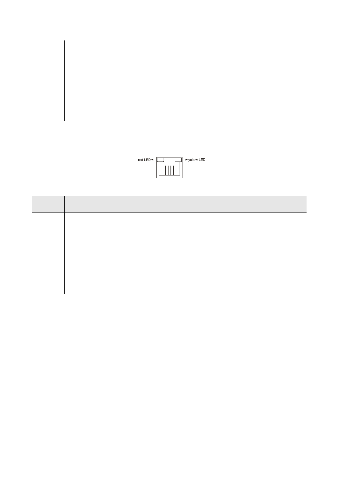
The following drawing shows the aspect of a RS-485 port.
The following table shows the meaning of the LEDs on the RS-485 ports.
LED Meaning
LED error
red LED
yellow LED
if it is lit, an internal error will have arisen
if it flashes quickly, a configuration error will have arisen
if it is out, no error will be running
LED Modbus communication
if it is lit, no Modbus communication will be running
if it flashes quickly, the Modbus communication will have been set up and will be correct
if it is out, the controller will not be configured to communicate via Modbus
page 54 of 116
Page 55
EVCO S.p.A. c-pro 3 | Hardware manual ver. 3.2 | Codice 114CP3E324
English
Parameter Key
6. CONFIGURATION
6.1. Configuring a programmable controller
6.1.1. Configuring a built-in programmable controller
To gain access to the procedure operate as follows:
1. Make sure the power supply is switched on.
2. Keep pressed 2 s buttons UP and DOWN: the display will show the following menu (hereinafter called Main menu).
<CPro 3 Mega LCD>
Info
Parameters
...
Diagnostic
Debug
It is also possible to configure the controller using an user interface; look at paragraph 6.3 “Configuring a device through en
user interface”.
To gain access to a submenu operate as follows:
3. Press and release button UP or button DOWN to select the submenu.
4. Press and release button ENTER.
The access to the Parameters submenu, to the Networks submenu, to the Password submenu and to the Parameter Key
submenu is protected by password.
To gain access to the Parameters submenu, to the Networks submenu, to the Password submenu and to the Parameter Key submenu
operate as follows:
5. From step 2, press and release button UP or button DOWN to select the submenu.
6. Press and release button ENTER.
7. Press and release button ENTER again to set the password value.
8. Press and release button DOWN over and over again to set “-19”.
9. Press and release button ENTER again.
To modify a parameter operate as follows:
10. From step 9, press and release button UP or button DOWN to select the parameter (some parameters belong to a possible
submenu; press and release button ENTER to gain access to them).
11. Press and release button ENTER.
12. Press and release button UP or button DOWN to modify the value.
13. Press and release button ENTER to confirm the value.
14. Press and release button ESC over and over again to go back to the Main menu.
To modify the language of the application software pages operate as follows:
15. From step 2, press and release button UP or button DOWN to select the voice Language (according to the factory setting it
has value “English”).
16. Press and release button ENTER.
17. Press and release button UP or button DOWN to modify the language.
18. Press and release button ENTER to confirm the value.
page 55 of 116
Page 56
EVCO S.p.A. c-pro 3 | Hardware manual ver. 3.2 | Codice 114CP3E324
To modify the real date and time operate as follows:
19. From step 2, press and release button UP or button DOWN to select the voice Data e ora reale.
20. Press and release button ENTER.
21. Press and release button UP or button DOWN to modify the value.
22. Press and release button ENTER or button RIGHT to confirm the value and modify the following field (press and release
button LEFT or button RIGHT to move among the fields).
23. Repeat steps 21 and 22.
To copy the parameters from the controller to the programming key EVKEY10 operate as follows:
24. Make sure the power supply is switched on.
25. Connect the key to the controller; look at paragraph 8.2.4 “Connection to the controller”.
26. Gain access to the submenu Parameter Key.
27. Press and release button UP or button DOWN to select “PAR APP” to copy the application software parameters or “PAR
DRV” to copy the configuration parameters.
28. Press and release button UP or button DOWN to select “SAVE”.
29. Press and release button ENTER: the parameters will be copied from the controller to the key (this operation usually takes a
few seconds; if an error had to arise the LED system alarm (look at paragraph 5.2.1 “LEDs at the fron of the device”) will light
up and parameter Key Par (it belongs to the Diagnostic submenu) will assume value Err.
30. Disconnect the programming key.
To copy the parameters from the programming key EVKEY10 to the controller operate as follows:
31. Make sure the power supply is switched on.
32. Connect the key to the controller; look at paragraph 8.2.4 “Connection to the controller”.
33. Gain access to the submenu Parameter Key.
34. Press and release button UP or button DOWN to select “RESTOR”.
35. Press and release button ENTER: the parameters will be copied from the key to the controller (this operation usually takes a
few seconds; if an error had to arise the LED system alarm (look at paragraph 5.2.1 “LEDs at the fron of the device”) will light
up and parameter Key Par (it belongs to the Diagnostic submenu) will assume value Err.
36. Disconnect the programming key.
The copy of the parameters from the programming key EVKEY10 to the controller is allowed on condition that the
firmware of the controllers coincides.
To quit the procedure operate as follows:
37. Press and release button ESC over and over again: possible modifications will not be saved.
Switch off the power supply after the modification of the configuration.
page 56 of 116
Page 57

EVCO S.p.A. c-pro 3 | Hardware manual ver. 3.2 | Codice 114CP3E324
English
Parameter Key
6.1.2. Configuring a blind programmable controller
The following procedures show an example of configuration of a blind programmable controller through a built-in programmable
controller (in the example it is c-pro 3 mega) and through its user interface.
It is also possible to configure the controller using an user interface; look at paragraph 6.3 “Configuring a device through an
user interface”.
Operate as follows:
1. Switch off the power supply of the controllers.
2. Connect the blind controller to the built-in controller through the CAN port; look at chapter 4 “ELECTRICAL CONNECTION”.
3. Switch on the power supply of the controllers.
4. Keep pressed 2 s buttons UP and DOWN: the display will show the following menu.
<CPro 3 Mega LCD>
Info
Parameters
...
Diagnostic
Debug
5. Press and release button UP or button DOWN to select “Networks”.
6. Press and release button ENTER.
7. Press and release button ENTER again to set the password value.
8. Press and release button DOWN over and over again to set “-19”.
9. Press and release button ENTER again.
10. Press and release button UP or button DOWN to select “CAN Bus”.
11. Press and release button ENTER again.
12. Set parameter NetworkNode using button UP or button DOWN to select the parameter and using button ENTER to modify
and to confirm the value.
According to the factory setting the address of the CAN node of a programmable controller has value 1 (therefore operate on
the controller to set parameter NetworkNode to [ 1 ] 1).
13. Press and release button UP or button DOWN to select “>”.
14. Press and release button ENTER again: the display will show the Main menu of the blind controller.
15. Operate as shown in paragraph 6.1.1 “Configuring a built-in programmable controller”.
page 57 of 116
Page 58

EVCO S.p.A. c-pro 3 | Hardware manual ver. 3.2 | Codice 114CP3E324
<CPro 3 Mega LCD>
Parameters
Diagnostic
6.2. Configuring an I / O expansion
The following procedures show an example of configuration of an I / O expansion through a built-in programmable controller (in the
example it is c-pro 3 mega) and through its user interface.
It is also possible to configure the expansion using an user interface; look at paragraph 6.3 “Configuring a device through an
user interface”.
Operate as follows:
1. Switch off the power supply of the controller and of the expansion.
2. Connect the controller to the expansion through the CAN port; look at chapter 4 “ELECTRICAL CONNECTION”.
3. Switch on the power supply of the controller and of the expansion.
4. Keep pressed 2 s buttons UP and DOWN: the display will show the following menu.
Info
English
...
Parameter Key
Debug
5. Press and release button UP or button DOWN to select “Networks”.
6. Press and release button ENTER.
7. Press and release button ENTER again to set the password value.
8. Press and release button DOWN over and over again to set “-19”.
9. Press and release button ENTER again.
10. Press and release button UP or button DOWN to select “CAN Bus”.
11. Press and release button ENTER again.
12. Set parameter NetworkNode using button UP or button DOWN to select the parameter and using button ENTER to modify
and to confirm the value.
According to the factory setting the address of the CAN node of an I / O expansion has value 2 (therefore operate on the
controller to set parameter NetworkNode to [ 2 ] 2).
13. Press and release button UP or button DOWN to select “>”.
14. Press and release button ENTER again: the display will show the Main menu of the expansion.
15. Operate as shown in paragraph 6.1.1 “Configuring a built-in programmable controller”.
page 58 of 116
Page 59

EVCO S.p.A. c-pro 3 | Hardware manual ver. 3.2 | Codice 114CP3E324
Vgraph
CAN Network
Loc 99 OK > >
2 2 OK > >
4 0 - > >
6.3. Configuring a device through an user interface (Vgraph, Vtouch or
Vroom)
The following procedures show an example of configuration of a device through an user interface (in the example Vgraph) and through
its user interface.
For further information please consult the hardware manual of the user interface.
Operate as follows:
1. Switch off the power supply of the device and of the interface.
2. Connect the device to the interface through the CAN port; look at chapter 4 “ELECTRICAL CONNECTION”.
3. Keep pressed 2 s buttons ESC and RIGHT.
4. Switch on the power supply of the device and of the interface.
5. When the display of the interface will show the following menu release buttons ESC and RIGHT.
Parameters
Contrast
Modbus
Info
Real date and time
6. Press and release button UP or button DOWN to select “CAN Network”.
7. Press and release button ENTER.
8. Press and release button ENTER again to set the password value.
9. Press and release button DOWN over and over again to set “-19”.
10. Press and release button ENTER again.
11. Set parameter NW Node using button UP or button DOWN to select the parameter and using button ENTER to modify and to
confirm the value.
According to the factory setting the address of the CAN node of a programmable controller has value 1 (therefore operate on
the interface to set parameter NW Node to [ 1 ] 1) and the address of the CAN node of an I / O expansion has value 2
(therefore operate on the interface to set parameter NW Node to [ 2 ] 2).
12. Switch off the power supply of the interface.
13. Switch on the power supply of the interface.
14. Keep pressed 2 s buttons LEFT and ENTER: the display will show the following menu.
Network Status
1 1 OK > >
3 0 - > >
5 0 - > >
15. Press and release button UP or button DOWN to select the device.
16. Press and release button ENTER: the display will show the Main menu of the device.
17. Operate as shown in paragraph 6.1.1 “Configuring a built-in programmable controller”.
page 59 of 116
Page 60
EVCO S.p.A. c-pro 3 | Hardware manual ver. 3.2 | Codice 114CP3E324
6.4. List of configuration parameters
6.4.1. List of configuration parameters of c-pro 3 hecto and of c-pro 3 hecto+
Submenu Parameter Min. Max. Unit Preset Description
Info PROJ parameter available in read only modality
Info FW parameter available in read only modality
Info HW parameter available in read only modality
Info SW parameter available in read only modality
Info SN parameter available in read only modality
Info MASK parameter available in read only modality
Info date and time parameter available in read only modality
information about the application project
(project, version and revision)
information about the firmware (project,
version, revision and subrevision)
information about the hardware (version,
revision, generic (G) or special (S))
information about UNI-PRO 3 (version and
revision)
information about the serial number and the
result of the productive test
information baout the mask (it depends on
the builder’s coding system)
date and time of the last compilation of the
application project
Parameters (1) AI1 - - - - - - - - - NTC
Parameters (1) AI2 - - - - - - - - - NTC
kind of probe analog input 1
PTC = PTC probe
NTC = NTC probe
0-20mA = 0-20 mA transducer
4-20mA = 4-20 mA transducer
0-5V = 0-5 V ratiometric transducer
0-10V = 0-10 V ratiometric transducer
PT1000 = Pt 1000 probe
kind of probe analog input 2
PTC = PTC probe
NTC = NTC probe
0-20mA = 0-20 mA transducer
4-20mA = 4-20 mA transducer
0-5V = 0-5 V ratiometric transducer
0-10V = 0-10 V ratiometric transducer
PT1000 = Pt 1000 probe
page 60 of 116
Page 61

EVCO S.p.A. c-pro 3 | Hardware manual ver. 3.2 | Codice 114CP3E324
kind of probe analog input 3
PTC = PTC probe
NTC = NTC probe
Parameters (1) AI3 - - - - - - - - - NTC
0-20mA = 0-20 mA transducer
4-20mA = 4-20 mA transducer
0-5V = 0-5 V ratiometric transducer
0-10V = 0-10 V ratiometric transducer
PT1000 = Pt 1000 probe
analog inputs time-out (after this time without
Parameters (1) AI Err Time 0 240 s 2
communication with an analog input, the
controller signals the analog input error)
Parameters (1) AO1 - - - - - - - - - PWM
kind of signal analog input 1
PWM = PWM (Pulse With Modulation)
kind of signal analog input 2
Parameters (1) AO2 - - - - - - - - - 0-10V
0-20mA = 0-20 mA
4-20mA = 4-20 mA
0-10V = 0-10 V
kind of signal analog input 3
Parameters (1) AO3 - - - - - - - - - 0-10V
0-20mA = 0-20 mA
4-20mA = 4-20 mA
0-10V = 0-10 V
Parameters (1) CosPhi 10us - - - - - - - - - - - - reserved
Parameters (2)
[ press button
RIGHT to
show it ]
I/O Timeout 1 240 s 60
time-out of the CANbus communication for
the test of the remote values of the I / O
(after this time without CANbus
communication, the I / O of the controller is
disabled)
enabling the access to the first level page
pressing a combination of buttons
YES = yes, operating as follows:
- keep pressed 3 s button
ENTER to gain access
Parameters (2)
[ press button
RIGHT to
show it ]
En. Prg Level - - - - - - - - - NO
- keep pressed 3 s
to the first page of
level 1
buttons ENTER and
ESC to gain access to
the first page of level 2
- keep pressed 3 s
buttons LEFT and
RIGHT to gain access to
the first page of level 3
page 61 of 116
Page 62

EVCO S.p.A. c-pro 3 | Hardware manual ver. 3.2 | Codice 114CP3E324
connection among the passwords to gain
access to the levels
Parameters (2)
[ press button
RIGHT to
show it ]
Password Indi - - - - - - - - - NO
NO = one has not to set any
password to gain access to
levels lower than the one one
has already gained access
YES = one has to set a password to
gain access to each level
baud rate for the debug
Parameters (2)
[ press button
RIGHT to
show it ]
Debug Baud - - - - - - - - - - - - 19200
19200 = 19,200 baud
28800 = 28,800 baud
38400 = 38,400 baud
57600 = 57,600 baud
76800 = 76,800 baud
115K2 = 115,200 baud
Networks / CAN
Bus
Networks / CAN
Bus
Networks / CAN
Bus
Networks / CAN
Bus
Networks / CAN
Bus
MyNode 1 127 - - - 1 local (or of the controller) CAN node address
enabling the operation as master in a CAN
Master - - - - - - - - - YES
network
YES = yes
CANbus communication baud rate
20K = 20,000 baud
Baud - - - - - - - - - 20K
50K = 50,000 baud
125K = 125,000 baud
500K = 500,000 baud
remote (or with a device in the network)
Timeout 1 60 s 5
CANbus communication time-out (after this
time without CANbus communication with a
device, it is excluded by the network)
address of a remote (or of a device in the
NetworkNode [ 1 ] 0
[ 32 ]
127
- - - [ 1 ] 99
network) CAN node; example for [ 1 ] 2:
[ 1 ] = node
2 = node’s address
Networks / CAN
Bus
[ press button
TSEG1 0 63 - - - 31 reserved
RIGHT to
show it ]
page 62 of 116
Page 63

EVCO S.p.A. c-pro 3 | Hardware manual ver. 3.2 | Codice 114CP3E324
Networks / CAN
Bus
[ press button
TSEG2 1 7 - - - 7 reserved
RIGHT to
show it ]
Networks / CAN
Bus
[ press button
SJW 0 3 - - - 0 reserved
RIGHT to
show it ]
Networks / CAN
Bus
[ press button
BTR(1) 1 15 - - - 15 reserved
RIGHT to
show it ]
Networks /
UART1 (1)
Networks /
UART1 (1)
Networks /
UART1 (1)
Address 1 247 - - - 1
Baud Rate - - - - - - - - - 9600
Parity - - - - - - - - - EVEN
local (or of the controller) Modbus node
address in a RS-485 network wired on the
RS-485 port
Modbus communication baud rate in a
RS-485 network wired on the RS-485 port
1200 = 1,200 baud
2400 = 2,400 baud
4800 = 4,800 baud
9600 = 9,600 baud
19200 = 19,200 baud
28800 = 28,000 baud
38400 = 38,400 baud
57600 = 57,600 baud
Modbus communication parity in a RS-485
network wired on the RS-485 port
NONE = no parity
ODD = odd
EVEN = even
Modbus communication stop bit number in a
Networks /
UART1 (1)
Stop - - - - - - - - - 1 BIT
RS-485 network wired on the RS-485 port
1 BIT = 1 bit
2 BIT = 2 bit
page 63 of 116
Page 64

EVCO S.p.A. c-pro 3 | Hardware manual ver. 3.2 | Codice 114CP3E324
Modbus communication time-out in a
RS-485 network wired on the RS-485 port
Networks /
UART2 (1)
Timeout 2 240 s 10
for the test of the remote values of the I / O
(after this time without Modbus
communication, the request is considered
not sent and the controller moves to the
following request) (1)
Password Level 1:
Password Level 2:
-32768 32767 - - - 0
- - - - - - - - - ON
-32768 32767 - - - 0
- - - - - - - - - ON
-32768 32767 - - - 0
value of the password to gain access to
level 1
enabling the password to gain access to
level 1
OFF = to gain access to level 1 one
has not to set any password
ON = to gain access to level 1 one
has to set a password
value of the password to gain access to
level 2
enabling the password to gain access to
level 2
OFF = to gain access to level 2 one
has not to set any password
ON = to gain access to level 2 one
has to set a password
value of the password to gain access to
level 3
Password Level 3:
- - - - - - - - - ON
-32768 32767 - - - 0
Password Level 4:
- - - - - - - - - ON
page 64 of 116
enabling the password to gain access to
level 3
OFF = to gain access to level 3 one
has not to set any password
ON = to gain access to level 3 one
has to set a password
value of the password to gain access to
level 4
enabling the password to gain access to
level 4
OFF = to gain access to level 4 one
has not to set any password
ON = to gain access to level 4 one
has to set a password
Page 65

EVCO S.p.A. c-pro 3 | Hardware manual ver. 3.2 | Codice 114CP3E324
-32768 32767 - - - 0
Password Level 5:
- - - - - - - - - ON
Password Timeout 0 240 s 240
Diagnostic FRAM parameter available in read only modality
Diagnostic RTC parameter available in read only modality
value of the password to gain access to
level 5
enabling the password to gain access to
level 5
OFF = to gain access to level 5 one
has not to set any password
ON = to gain access to level 5 one
has to set a password
time-out of the passwords to gain access to
the levels (after this time since the last
operation with the buttons, to gain access to
the level one has to set a password again, if
foreseen)
non volatile memory status
ok = not in error
err = in error
clock status
ok = not in error
err = in error
low = loss of data
Diagnostic STACK parameter available in read only modality
Diagnostic Power Supply parameter available in read only modality
Diagnostic 5V Ratio parameter available in read only modality
Diagnostic 24V Sensor parameter available in read only modality
stack status
ok = not in error
err = in error (because of overflow)
power supply voltage status
ok = not in error
err = in error (because of out of
range voltage)
status of the power supply voltage of the
ratiometric transducers
ok = not in error
err = in error (because of out of
range voltage)
status of the power supply voltage of the
0-20 mA / 4-20 mA / 0-10 V transducers
ok = not in error
err = in error (because of out of
range voltage)
page 65 of 116
Page 66

EVCO S.p.A. c-pro 3 | Hardware manual ver. 3.2 | Codice 114CP3E324
Math status
ok = not in error
Diagnostic Math parameter available in read only modality
Diagnostic Key Par parameter available in read only modality
err = in error (because of overflow,
underflow, division by zero or
NaN)
result of the copy of the parameters from the
controller to the programming key EVKEY10
and vice versa
ok = operation successful
completed
err = operazione failed
Main time parameter available in read only modality
Debug
[ Algo ]
Int. time parameter available in read only modality
Debug
[ CAN bus ]
Debug
[ CAN bus ]
Debug 5VP parameter available in read only modality
Debug 24VP parameter available in read only modality
Debug
rx parameter available in read only modality number of packages in transmission
tx parameter available in read only modality number of packages in reception
err parameter available in read only modality number of packages in error
ovf parameter available in read only modality number of packages in overflow
Stack parameter available in read only modality minimum free stack
Buf parameter available in read only modality number of free buffers
main cycle time of the application software
(in milliseconds)
interrupt cycle time of the application
software (in milliseconds)
reading the power supply voltage of the
ratiometric transducers
reading the power supply voltage of the
0-20 mA / 4-20 mA / 0-10 V transducers
Notes:
(1) the submenu is visible on condition that the application software expects the RS-485 port is configured to support the Modbus
communication protocol.
page 66 of 116
Page 67
EVCO S.p.A. c-pro 3 | Hardware manual ver. 3.2 | Codice 114CP3E324
6.4.2. List of configuration parameters of c-pro 3 mega and of c-pro 3 NODE mega
Submenu Parameter Min. Max. Unit Preset Description
Info PROJ parameter available in read only modality
Info FW parameter available in read only modality
Info HW parameter available in read only modality
Info SW parameter available in read only modality
Info SN parameter available in read only modality
Info MASK parameter available in read only modality
Info date and time parameter available in read only modality
information about the application project
(project, version and revision)
information about the firmware (project,
version, revision and subrevision)
information about the hardware (version,
revision, generic (G) or special (S))
information about UNI-PRO 3 (version and
revision)
information about the serial number and the
result of the productive test
information baout the mask (it depends on
the builder’s coding system)
date and time of the last compilation of the
application project
Parameters (1) AI1 - - - - - - - - - NTC
Parameters (1) AI2 - - - - - - - - - NTC
kind of probe analog input 1
PTC = PTC probe
NTC = NTC probe
0-20mA = 0-20 mA transducer
4-20mA = 4-20 mA transducer
0-5V = 0-5 V ratiometric transducer
0-10V = 0-10 V ratiometric transducer
PT1000 = Pt 1000 probe
kind of probe analog input 2
PTC = PTC probe
NTC = NTC probe
0-20mA = 0-20 mA transducer
4-20mA = 4-20 mA transducer
0-5V = 0-5 V ratiometric transducer
0-10V = 0-10 V ratiometric transducer
PT1000 = Pt 1000 probe
page 67 of 116
Page 68

EVCO S.p.A. c-pro 3 | Hardware manual ver. 3.2 | Codice 114CP3E324
kind of probe analog input 3
PTC = PTC probe
NTC = NTC probe
Parameters (1) AI3 - - - - - - - - - NTC
Parameters (1) AI4 - - - - - - - - - NTC
0-20mA = 0-20 mA transducer
4-20mA = 4-20 mA transducer
0-5V = 0-5 V ratiometric transducer
0-10V = 0-10 V ratiometric transducer
PT1000 = Pt 1000 probe
kind of probe analog input 4
PTC = PTC probe
NTC = NTC probe
0-20mA = 0-20 mA transducer
4-20mA = 4-20 mA transducer
0-5V = 0-5 V ratiometric transducer
0-10V = 0-10 V ratiometric transducer
PT1000 = Pt 1000 probe
Parameters (1) AI5 - - - - - - - - - NTC
Parameters (1) AI Err Time 0 240 s 2
Parameters (1) AO1 - - - - - - - - - PWM
Parameters (1) AO2 - - - - - - - - - 0-10V
kind of probe analog input 5
PTC = PTC probe
NTC = NTC probe
0-20mA = 0-20 mA transducer
4-20mA = 4-20 mA transducer
0-5V = 0-5 V ratiometric transducer
0-10V = 0-10 V ratiometric transducer
PT1000 = Pt 1000 probe
analog inputs time-out (after this time without
communication with an analog input, the
controller signals the analog input error)
kind of signal analog input 1
PWM = PWM (Pulse With Modulation)
kind of signal analog input 2
0-20mA = 0-20 mA
4-20mA = 4-20 mA
0-10V = 0-10 V
kind of signal analog input 3
Parameters (1) AO3 - - - - - - - - - 0-10V
Parameters (1) CosPhi 10us - - - - - - - - - - - - reserved
page 68 of 116
0-20mA = 0-20 mA
4-20mA = 4-20 mA
0-10V = 0-10 V
Page 69

EVCO S.p.A. c-pro 3 | Hardware manual ver. 3.2 | Codice 114CP3E324
Parameters (2)
[ press button
RIGHT to
show it ]
Parameters (2)
[ press button
RIGHT to
show it ]
I/O Timeout 1 240 s 60
En. Prg Level - - - - - - - - - NO
time-out of the CANbus communication for
the test of the remote values of the I / O
(after this time without CANbus
communication, the I / O of the controller is
disabled)
enabling the access to the first level page
pressing a combination of buttons
YES = yes, operating as follows:
- keep pressed 3 s button
ENTER to gain access
to the first page of
level 1
- keep pressed 3 s
buttons ENTER and
ESC to gain access to
the first page of level 2
- keep pressed 3 s
buttons LEFT and
RIGHT to gain access to
the first page of level 3
Parameters (2)
[ press button
RIGHT to
show it ]
Parameters (2)
[ press button
RIGHT to
show it; not
available in the
blind versions ]
Parameters (2)
[ press button
RIGHT to
show it; not
available in the
blind versions ]
Password Indi - - - - - - - - - NO
Backlight - - - - - - - - - TIME
B. Time 0 60 s 240
connection among the passwords to gain
access to the levels
NO = one has not to set any
password to gain access to
levels lower than the one one
has already gained access
YES = one has to set a password to
gain access to each level
kind of backlight
OFF = the backlight is never lit
ON = the backlight is always lit
TIME = the backlight is lit the time one
has set with parameter
B. Time since the last
operation with the buttons
backlight duration (only if parameter
Backlight has value TIME)
page 69 of 116
Page 70

EVCO S.p.A. c-pro 3 | Hardware manual ver. 3.2 | Codice 114CP3E324
Parameters (2)
[ press button
RIGHT to
show it; not
Contrast 0 100 - - - 50 display contrast
available in the
blind versions ]
Parameters (2)
[ press button
RIGHT to
show it; not
Date Char Sep - - - - - - - - - / date separator (ASCII character)
available in the
blind versions ]
Parameters (2)
[ press button
RIGHT to
show it; not
available in the
Year format - - - - - - - - - YY
year format
YY = two numbers (for example 10)
YYYY = four numbers (for example
2010)
blind versions ]
Parameters (2)
[ press button
RIGHT to
show it; not
available in the
blind versions ]
Parameters (2)
[ press button
RIGHT to
show it; not
available in the
blind versions ]
Parameters (2)
[ press button
RIGHT to
show it; not
available in the
blind versions ]
date format
Date format - - - - - - - - - D-M-Y
D-M-Y = day, month and year
M-D-Y = month, day and year
Y-M-D = year, month and day
Time Char Sep - - - - - - - - - : time separator (ASCII character)
Time With Sec - - - - - - - - - YES
showing the seconds in the real time
YES = yes
Parameters (2)
[ press button
RIGHT to
show it; not
Time AM/PM - - - - - - - - - NO
available in the
blind versions ]
page 70 of 116
time format
NO = 24 h (for example 15:20)
YES = 12 h (for example 3:20 PM)
Page 71

EVCO S.p.A. c-pro 3 | Hardware manual ver. 3.2 | Codice 114CP3E324
baud rate for the debug
Parameters (2)
[ press button
RIGHT to
show it ]
Debug Baud - - - - - - - - - - - - 19200
19200 = 19,200 baud
28800 = 28,800 baud
38400 = 38,400 baud
57600 = 57,600 baud
76800 = 76,800 baud
115K2 = 115,200 baud
Networks / CAN
Bus
Networks / CAN
Bus
Networks / CAN
Bus
Networks / CAN
Bus
Networks / CAN
Bus
MyNode 1 127 - - - 1 local (or of the controller) CAN node address
enabling the operation as master in a CAN
Master - - - - - - - - - YES
network
YES = yes
CANbus communication baud rate
20K = 20,000 baud
Baud - - - - - - - - - 20K
50K = 50,000 baud
125K = 125,000 baud
500K = 500,000 baud
remote (or with a device in the network)
Timeout 1 60 s 5
CANbus communication time-out (after this
time without CANbus communication with a
device, it is excluded by the network)
address of a remote (or of a device in the
NetworkNode [ 1 ] 0
[ 32 ]
127
- - - [ 1 ] 99
network) CAN node; example for [ 1 ] 2:
[ 1 ] = node
2 = node’s address
Networks / CAN
Bus
[ press button
TSEG1 0 63 - - - 31 reserved
RIGHT to
show it ]
Networks / CAN
Bus
[ press button
TSEG2 1 7 - - - 7 reserved
RIGHT to
show it ]
Networks / CAN
Bus
[ press button
SJW 0 3 - - - 0 reserved
RIGHT to
show it ]
page 71 of 116
Page 72

EVCO S.p.A. c-pro 3 | Hardware manual ver. 3.2 | Codice 114CP3E324
Networks / CAN
Bus
[ press button
BTR(1) 1 15 - - - 15 reserved
RIGHT to
show it ]
Networks / BMS
(4)
Networks / BMS
(4)
Networks / BMS
(4)
Networks / BMS
(4)
Networks / BMS
(4)
Networks /
UART1 (1)
local (or of the controller) BACnet MS/TP
MAC ID -1 127 - - - -1
node address
-1 = not enabled
BACnet MS/TP communication baud rate
9600 = 9,600 baud
Baud Rate - - - - - - - - - 19200
19200 = 19,200 baud
38400 = 28,000 baud
76800 = 76,800 baud
Max Master 0 127 - - - 127
Max InfoFram 1 127 - - - 3
maximum number of master in a BACnet
MS/TP network
maximum number of packages transmitted
as master before giving the token
Device ID 1 4194303 - - - 108 identity in a BACnet MS/TP multinetwork
local (or of the controller) Modbus node
Address 1 247 - - - 1
address in a RS-485 network wired on the
first RS-485 port
Networks /
UART1 (1)
Networks /
UART1 (1)
Baud Rate - - - - - - - - - 9600
Parity - - - - - - - - - EVEN
Modbus communication baud rate in a
RS-485 network wired on the first RS-485
port
1200 = 1,200 baud
2400 = 2,400 baud
4800 = 4,800 baud
9600 = 9,600 baud
19200 = 19,200 baud
28800 = 28,000 baud
38400 = 38,400 baud
57600 = 57,600 baud
Modbus communication parity in a RS-485
network wired on the first RS-485 port
NONE = no parity
ODD = odd
EVEN = even
page 72 of 116
Page 73

EVCO S.p.A. c-pro 3 | Hardware manual ver. 3.2 | Codice 114CP3E324
Modbus communication stop bit number in a
Networks /
UART1 (1)
Stop - - - - - - - - - 1 BIT
RS-485 network wired on the first RS-485
port
1 BIT = 1 bit
2 BIT = 2 bit
Networks /
UART2 (2)
Networks /
UART2 (2)
Networks /
UART2 (2)
Address 1 247 - - - 1
Baud Rate - - - - - - - - - 9600
Parity - - - - - - - - - EVEN
local (or of the controller) Modbus node
address in a RS-485 network wired on the
second RS-485 port
Modbus communication baud rate in a
RS-485 network wired on the second
RS-485 port
1200 = 1,200 baud
2400 = 2,400 baud
4800 = 4,800 baud
9600 = 9,600 baud
19200 = 19,200 baud
28800 = 28,000 baud
38400 = 38,400 baud
57600 = 57,600 baud
Modbus communication parity in a RS-485
network wired on the second RS-485 port
NONE = no parity
ODD = odd
EVEN = even
Networks /
UART2 (2)
Networks /
UART2 (2)
Stop - - - - - - - - - 1 BIT
Timeout 2 240 s 10
Password Level 1: -32768 32767 - - - 0
Modbus communication stop bit number in a
RS-485 network wired on the second
RS-485 port
1 BIT = 1 bit
2 BIT = 2 bit
Modbus communication time-out in a
RS-485 network wired on the second
RS-485 port for the test of the remote values
of the I / O (after this time without Modbus
communication, the request is considered
not sent and the controller moves to the
following request) (3)
value of the password to gain access to
level 1
page 73 of 116
Page 74

EVCO S.p.A. c-pro 3 | Hardware manual ver. 3.2 | Codice 114CP3E324
enabling the password to gain access to
level 1
- - - - - - - - - ON
OFF = to gain access to level 1 one
has not to set any password
ON = to gain access to level 1 one
has to set a password
Password Level 2:
Password Level 3:
-32768 32767 - - - 0
- - - - - - - - - ON
-32768 32767 - - - 0
- - - - - - - - - ON
-32768 32767 - - - 0
value of the password to gain access to
level 2
enabling the password to gain access to
level 2
OFF = to gain access to level 2 one
has not to set any password
ON = to gain access to level 2 one
has to set a password
value of the password to gain access to
level 3
enabling the password to gain access to
level 3
OFF = to gain access to level 3 one
has not to set any password
ON = to gain access to level 3 one
has to set a password
value of the password to gain access to
level 4
Password Level 4:
- - - - - - - - - ON
-32768 32767 - - - 0
Password Level 5:
- - - - - - - - - ON
page 74 of 116
enabling the password to gain access to
level 4
OFF = to gain access to level 4 one
has not to set any password
ON = to gain access to level 4 one
has to set a password
value of the password to gain access to
level 5
enabling the password to gain access to
level 5
OFF = to gain access to level 5 one
has not to set any password
ON = to gain access to level 5 one
has to set a password
Page 75

EVCO S.p.A. c-pro 3 | Hardware manual ver. 3.2 | Codice 114CP3E324
time-out of the passwords to gain access to
the levels (after this time since the last
Password Timeout 0 240 s 240
Diagnostic FRAM parameter available in read only modality
Diagnostic RTC parameter available in read only modality
Diagnostic STACK parameter available in read only modality
operation with the buttons, to gain access to
the level one has to set a password again, if
foreseen)
time-out of the passwords to gain access to
the levels (after this time since the last
operation with the buttons, to gain access to
the level one has to set a password again, if
foreseen)
non volatile memory status
ok = not in error
err = in error
clock status
ok = not in error
err = in error
low = loss of data
Diagnostic Power Supply parameter available in read only modality
Diagnostic 5V Ratio parameter available in read only modality
Diagnostic 24V Sensor parameter available in read only modality
Diagnostic 24V CAN bus parameter available in read only modality
stack status
ok = not in error
err = in error (because of overflow)
power supply voltage status
ok = not in error
err = in error (because of out of
range voltage)
status of the power supply voltage of the
ratiometric transducers
ok = not in error
err = in error (because of out of
range voltage)
status of the power supply voltage of the
user interface
ok = not in error
err = in error (because of out of
range voltage)
Diagnostic Math parameter available in read only modality
page 75 of 116
Math status
ok = not in error
err = in error (because of overflow,
underflow, division by zero or
NaN)
Page 76

EVCO S.p.A. c-pro 3 | Hardware manual ver. 3.2 | Codice 114CP3E324
result of the copy of the parameters from the
controller to the programming key EVKEY10
Diagnostic Key Par parameter available in read only modality
and vice versa
ok = operation successful
completed
err = operazione failed
Debug
[ Algo ]
Debug
[ CAN bus ]
Debug
[ CAN bus ]
Debug
Debug
Main time parameter available in read only modality
Int. time parameter available in read only modality
rx parameter available in read only modality number of packages in transmission
tx parameter available in read only modality number of packages in reception
err parameter available in read only modality number of packages in error
ovf parameter available in read only modality number of packages in overflow
24VPS parameter available in read only modality misura della tensione di alimentazione
5VP parameter available in read only modality
24VP parameter available in read only modality
24VE parameter available in read only modality
main cycle time of the application software
(in milliseconds)
interrupt cycle time of the application
software (in milliseconds)
reading the power supply voltage of the
ratiometric transducers
reading the power supply voltage of the
0-20 mA / 4-20 mA / 0-10 V transducers
reading the power supply voltage of the user
interface
Stack parameter available in read only modality minimum free stack
Debug
Buf parameter available in read only modality number of free buffers
Notes:
(1) the submenu is visible on condition that the application software expects the first RS-485 port is configured to support the
Modbus communication protocol
(2) the submenu is visible on condition that the application software expects the second RS-485 port is configured to support the
Modbus communication protocol
(3) the parameter is meaningful on condition that the second RS-485 port is configured to support the Modbus master
communication protocol
(4) the parameter is visible only in c-pro 3 NODE mega.
page 76 of 116
Page 77
EVCO S.p.A. c-pro 3 | Hardware manual ver. 3.2 | Codice 114CP3E324
6.4.3. List of configuration parameters of c-pro 3 mega+
Submenu Parameter Min. Max. Unit Preset Description
Info PROJ parameter available in read only modality
Info FW parameter available in read only modality
Info HW parameter available in read only modality
Info SW parameter available in read only modality
Info SN parameter available in read only modality
Info MASK parameter available in read only modality
Info date and time parameter available in read only modality
information about the application project
(project, version and revision)
information about the firmware (project,
version, revision and subrevision)
information about the hardware (version,
revision, generic (G) or special (S))
information about UNI-PRO 3 (version and
revision)
information about the serial number and the
result of the productive test
information baout the mask (it depends on
the builder’s coding system)
date and time of the last compilation of the
application project
Parameters (1) AI1 - - - - - - - - - NTC
Parameters (1) AI2 - - - - - - - - - NTC
kind of probe analog input 1
PTC = PTC probe
NTC = NTC probe
0-20mA = 0-20 mA transducer
4-20mA = 4-20 mA transducer
0-5V = 0-5 V ratiometric transducer
0-10V = 0-10 V ratiometric transducer
PT1000 = Pt 1000 probe
NTC2 = NTC 2 probe
NTC3 = NTC 3 probe
kind of probe analog input 2
PTC = PTC probe
NTC = NTC probe
0-20mA = 0-20 mA transducer (6)
4-20mA = 4-20 mA transducer (6)
0-5V = 0-5 V ratiometric transducer
(6)
0-10V = 0-10 V ratiometric transducer
(6)
PT1000 = Pt 1000 probe
NTC2 = NTC 2 probe
NTC3 = NTC 3 probe
page 77 of 116
Page 78

EVCO S.p.A. c-pro 3 | Hardware manual ver. 3.2 | Codice 114CP3E324
kind of probe analog input 3
PTC = PTC probe
NTC = NTC probe
0-20mA = 0-20 mA transducer
Parameters (1) AI3 - - - - - - - - - NTC
Parameters (1) AI4 - - - - - - - - - NTC
4-20mA = 4-20 mA transducer
0-5V = 0-5 V ratiometric transducer
0-10V = 0-10 V ratiometric transducer
PT1000 = Pt 1000 probe
NTC2 = NTC 2 probe
NTC3 = NTC 3 probe
kind of probe analog input 4
PTC = PTC probe
NTC = NTC probe
0-20mA = 0-20 mA transducer
4-20mA = 4-20 mA transducer
0-5V = 0-5 V ratiometric transducer
0-10V = 0-10 V ratiometric transducer
PT1000 = Pt 1000 probe
NTC2 = NTC 2 probe
NTC3 = NTC 3 probe
Parameters (1) AI5 - - - - - - - - - NTC
Parameters (1) AI6 - - - - - - - - - NTC
Parameters (1) AI7 - - - - - - - - - NTC
kind of probe analog input 5
PTC = PTC probe
NTC = NTC probe
0-20mA = 0-20 mA transducer
4-20mA = 4-20 mA transducer
0-5V = 0-5 V ratiometric transducer
0-10V = 0-10 V ratiometric transducer
PT1000 = Pt 1000 probe
NTC2 = NTC 2 probe
NTC3 = NTC 3 probe
kind of probe analog input 6
NTC = NTC probe
0-20mA = 0-20 mA transducer
4-20mA = 4-20 mA transducer
kind of probe analog input 7
NTC = NTC probe
0-20mA = 0-20 mA transducer
4-20mA = 4-20 mA transducer
Parameters (1) AI8 - - - - - - - - - NTC
page 78 of 116
kind of probe analog input 8
NTC = NTC probe
0-20mA = 0-20 mA transducer
4-20mA = 4-20 mA transducer
Page 79

EVCO S.p.A. c-pro 3 | Hardware manual ver. 3.2 | Codice 114CP3E324
analog inputs time-out (after this time without
Parameters (1) AI Err Time 0 240 s 2
Parameters (1) AO1 - - - - - - - - - FAN
Parameters (1) AO2 - - - - - - - - - 0-10V
Parameters (1) AO3 - - - - - - - - - 0-10V
communication with an analog input, the
controller signals the analog input error)
kind of signal analog input 1
PWM = PWM (Pulse With Modulation)
cut phase to drive fans
kind of signal analog input 2
0-20mA = 0-20 mA
4-20mA = 4-20 mA
0-10V = 0-10 V
kind of signal analog input 3
0-20mA = 0-20 mA
4-20mA = 4-20 mA
0-10V = 0-10 V
kind of signal analog input 4
Parameters (1) AO4 - - - - - - - - - 0-10V
Parameters (1) AO5 - - - - - - - - - 0-10V
Parameters (1) CosPhi 10us - - - - - - - - - - - - reserved
Parameters (2)
[ press button
RIGHT to
show it ]
I/O Timeout 1 240 s 60
0-10V = 0-10 V
PWM = PWM (Pulse With Modulation;
kind of signal analog input 5
0-10V = 0-10 V
PWM = PWM (Pulse With Modulation;
time-out of the CANbus communication for
the test of the remote values of the I / O
(after this time without CANbus
communication, the I / O of the controller is
disabled)
5... 2,000 Hz)
5... 2,000 Hz)
page 79 of 116
Page 80
EVCO S.p.A. c-pro 3 | Hardware manual ver. 3.2 | Codice 114CP3E324
enabling the access to the first level page
pressing a combination of buttons
YES = yes, operating as follows:
- keep pressed 3 s button
ENTER to gain access
Parameters (2)
[ press button
RIGHT to
show it ]
En. Prg Level - - - - - - - - - NO
- keep pressed 3 s
to the first page of
level 1
buttons ENTER and
ESC to gain access to
the first page of level 2
- keep pressed 3 s
buttons LEFT and
RIGHT to gain access to
the first page of level 3
connection among the passwords to gain
access to the levels
Parameters (2)
[ press button
RIGHT to
show it ]
Password Indi - - - - - - - - - NO
NO = one has not to set any
password to gain access to
levels lower than the one one
has already gained access
YES = one has to set a password to
gain access to each level
Parameters (2)
[ press button
RIGHT to
show it; not
available in the
blind versions ]
Parameters (2)
[ press button
RIGHT to
show it; not
available in the
blind versions ]
Parameters (2)
[ press button
RIGHT to
show it; not
available in the
blind versions ]
kind of backlight
OFF = the backlight is never lit
ON = the backlight is always lit
Backlight - - - - - - - - - TIME
B. Time 0 60 s 240
TIME = the backlight is lit the time one
backlight duration (only if parameter
Backlight has value TIME)
Contrast 0 100 - - - 50 display contrast
has set with parameter
B. Time since the last
operation with the buttons
page 80 of 116
Page 81

EVCO S.p.A. c-pro 3 | Hardware manual ver. 3.2 | Codice 114CP3E324
Parameters (2)
[ press button
RIGHT to
show it; not
Date Char Sep - - - - - - - - - / date separator (ASCII character)
available in the
blind versions ]
Parameters (2)
[ press button
RIGHT to
show it; not
available in the
Year format - - - - - - - - - YY
year format
YY = two numbers (for example 10)
YYYY = four numbers (for example
2010)
blind versions ]
Parameters (2)
[ press button
RIGHT to
show it; not
available in the
Date format - - - - - - - - - D-M-Y
date format
D-M-Y = day, month and year
M-D-Y = month, day and year
Y-M-D = year, month and day
blind versions ]
Parameters (2)
[ press button
RIGHT to
show it; not
available in the
blind versions ]
Parameters (2)
[ press button
RIGHT to
show it; not
available in the
blind versions ]
Parameters (2)
[ press button
RIGHT to
show it; not
available in the
blind versions ]
Time Char Sep - - - - - - - - - : time separator (ASCII character)
Time With Sec - - - - - - - - - YES
showing the seconds in the real time
YES = yes
time format
Time AM/PM - - - - - - - - - NO
NO = 24 h (for example 15:20)
YES = 12 h (for example 3:20 PM)
Parameters (2)
[ press button
RIGHT to
Debug Baud - - - - - - - - - - - - 19200
show it ]
page 81 of 116
baud rate for the debug
19200 = 19,200 baud
28800 = 28,800 baud
38400 = 38,400 baud
57600 = 57,600 baud
76800 = 76,800 baud
115K2 = 115,200 baud
Page 82

EVCO S.p.A. c-pro 3 | Hardware manual ver. 3.2 | Codice 114CP3E324
Networks / CAN
Bus
Networks / CAN
Bus
Networks / CAN
Bus
Networks / CAN
Bus
Networks / CAN
Bus
MyNode 1 127 - - - 1 local (or of the controller) CAN node address
enabling the operation as master in a CAN
Master - - - - - - - - - YES
network
YES = yes
CANbus communication baud rate
20K = 20,000 baud
Baud - - - - - - - - - 20K
50K = 50,000 baud
125K = 125,000 baud
500K = 500,000 baud
remote (or with a device in the network)
Timeout 1 60 s 5
CANbus communication time-out (after this
time without CANbus communication with a
device, it is excluded by the network)
address of a remote (or of a device in the
NetworkNode [ 1 ] 0
[ 32 ]
127
- - - [ 1 ] 99
network) CAN node; example for [ 1 ] 2:
[ 1 ] = node
2 = node’s address
Networks / CAN
Bus
[ press button
RIGHT to
show it ]
Networks / CAN
Bus
[ press button
RIGHT to
show it ]
Networks / CAN
Bus
[ press button
RIGHT to
show it ]
Networks / CAN
Bus
[ press button
RIGHT to
show it ]
TSEG1 0 63 - - - 31 reserved
TSEG2 1 7 - - - 7 reserved
SJW 0 3 - - - 0 reserved
BTR(1) 1 15 - - - 15 reserved
page 82 of 116
Page 83

EVCO S.p.A. c-pro 3 | Hardware manual ver. 3.2 | Codice 114CP3E324
Networks /
CAN2 Bus (4)
Networks /
CAN2 Bus (4)
Networks /
CAN2 Bus (4)
Networks /
CAN2 Bus (4)
Networks /
CAN2 Bus (4)
MyNode 1 127 - - - 1 local (or of the controller) CAN node address
enabling the operation as master in a CAN
Master - - - - - - - - - YES
network
YES = yes
CANbus communication baud rate
20K = 20,000 baud
Baud - - - - - - - - - 20K
50K = 50,000 baud
125K = 125,000 baud
500K = 500,000 baud
remote (or with a device in the network)
Timeout 1 60 s 5
CANbus communication time-out (after this
time without CANbus communication with a
device, it is excluded by the network)
address of a remote (or of a device in the
NetworkNode [ 1 ] 0
[ 32 ]
127
- - - [ 1 ] 99
network) CAN node; example for [ 1 ] 2:
[ 1 ] = node
2 = node’s address
Networks /
CAN2 Bus
[ press button
RIGHT to
show it ] (4)
Networks /
CAN2 Bus
[ press button
RIGHT to
show it ] (4)
Networks /
CAN2 Bus
[ press button
RIGHT to
show it ] (4)
Networks /
CAN2 Bus
[ press button
RIGHT to
show it ] (4)
TSEG1 0 63 - - - 31 reserved
TSEG2 1 7 - - - 7 reserved
SJW 0 3 - - - 0 reserved
BTR(1) 1 15 - - - 15 reserved
Networks / MP
Bus (5)
Dev1 0 9953 - - - - - -
page 83 of 116
serial number of the first Belimo device (first
part of the label)
Page 84

EVCO S.p.A. c-pro 3 | Hardware manual ver. 3.2 | Codice 114CP3E324
0 65535 - - - - - -
0 255 - - - - - -
Networks / MP
Bus (5)
Dev2 0 9953 - - - - - -
0 65535 - - - - - -
0 255 - - - - - -
Networks / MP
Bus (5)
Dev3 0 9953 - - - - - -
0 65535 - - - - - -
serial number of the first Belimo device
(second part of the label)
serial number of the first Belimo device
(fourth part of the label)
serial number of the second Belimo device
(first part of the label)
serial number of the second Belimo device
(second part of the label)
serial number of the second Belimo device
(fourth part of the label)
serial number of the third Belimo device (first
part of the label)
serial number of the third Belimo device
(second part of the label)
0 255 - - - - - -
Networks / MP
Bus (5)
Dev4 0 9953 - - - - - -
0 65535 - - - - - -
0 255 - - - - - -
Networks / MP
Bus (5)
Dev5 0 9953 - - - - - -
0 65535 - - - - - -
0 255 - - - - - -
serial number of the third Belimo device
(fourth part of the label)
serial number of the fourth Belimo device
(first part of the label)
serial number of the fourth Belimo device
(second part of the label)
serial number of the fourth Belimo device
(fourth part of the label)
serial number of the fifth Belimo device (first
part of the label)
serial number of the fifth Belimo device
(second part of the label)
serial number of the fifth Belimo device
(fourth part of the label)
Networks / MP
Bus (5)
Dev6 0 9953 - - - - - -
0 65535 - - - - - -
page 84 of 116
serial number of the sixth Belimo device (first
part of the label)
serial number of the sixth Belimo device
(second part of the label)
Page 85

EVCO S.p.A. c-pro 3 | Hardware manual ver. 3.2 | Codice 114CP3E324
0 255 - - - - - -
Networks / MP
Bus (5)
Dev7 0 9953 - - - - - -
0 65535 - - - - - -
0 255 - - - - - -
Networks / MP
Bus (5)
Dev8 0 9953 - - - - - -
0 65535 - - - - - -
0 255 - - - - - -
serial number of the sixth Belimo device
(fourth part of the label)
serial number of the seventh Belimo device
(first part of the label)
serial number of the seventh Belimo device
(second part of the label)
serial number of the seventh Belimo device
(fourth part of the label)
serial number of the eighth Belimo device
(first part of the label)
serial number of the eighth Belimo device
(second part of the label)
serial number of the eighth Belimo device
(fourth part of the label)
operation status of the first Belimo device
Networks / MP
Bus Debug
[press button
RIGHT to
show it ] (5)
Dev1 parameter available in read only modality
0 = NotUsed
1 = NotExist
2 = ToConfig
3 = OffLine
4 = InConfig
5 = OnLine
parameter available in read only modality errors counter of the first Belimo device
operation status of the second Belimo
Networks / MP
Bus Debug
[press button
RIGHT to
show it ] (5)
Dev2 parameter available in read only modality
device
0 = NotUsed
1 = NotExist
2 = ToConfig
3 = OffLine
4 = InConfig
5 = OnLine
parameter available in read only modality errors counter of the second Belimo device
page 85 of 116
Page 86

EVCO S.p.A. c-pro 3 | Hardware manual ver. 3.2 | Codice 114CP3E324
operation status of the third Belimo device
Networks / MP
Bus Debug
[press button
RIGHT to
show it ] (5)
Dev3 parameter available in read only modality
0 = NotUsed
1 = NotExist
2 = ToConfig
3 = OffLine
4 = InConfig
5 = OnLine
parameter available in read only modality errors counter of the third Belimo device
operation status of the fourth Belimo device
Networks / MP
Bus Debug
[press button
RIGHT to
show it ] (5)
Dev4 parameter available in read only modality
0 = NotUsed
1 = NotExist
2 = ToConfig
3 = OffLine
4 = InConfig
5 = OnLine
parameter available in read only modality errors counter of fourth first Belimo device
operation status of the fifth Belimo device
Networks / MP
Bus Debug
[press button
RIGHT to
show it ] (5)
Dev5 parameter available in read only modality
0 = NotUsed
1 = NotExist
2 = ToConfig
3 = OffLine
4 = InConfig
5 = OnLine
parameter available in read only modality errors counter of the fifth Belimo device
operation status of the sixth Belimo device
Networks / MP
Bus Debug
[press button
RIGHT to
show it ] (5)
Dev6 parameter available in read only modality
0 = NotUsed
1 = NotExist
2 = ToConfig
3 = OffLine
4 = InConfig
5 = OnLine
parameter available in read only modality errors counter of the sixth Belimo device
Networks / MP
Bus Debug
[press button
Dev7 parameter available in read only modality
RIGHT to
show it ] (5)
page 86 of 116
operation status of the seventh Belimo
device
0 = NotUsed
1 = NotExist
2 = ToConfig
3 = OffLine
4 = InConfig
5 = OnLine
Page 87

EVCO S.p.A. c-pro 3 | Hardware manual ver. 3.2 | Codice 114CP3E324
parameter available in read only modality errors counter of the seventh Belimo device
operation status of the eighth Belimo device
Networks / MP
Bus Debug
[press button
RIGHT to
show it ] (5)
Dev8 parameter available in read only modality
0 = NotUsed
1 = NotExist
2 = ToConfig
3 = OffLine
4 = InConfig
5 = OnLine
parameter available in read only modality errors counter of the eighth Belimo device
Networks /
UART1 (1)
Networks /
UART1 (1)
Networks /
UART1 (1)
Address 1 247 - - - 1
Baud Rate - - - - - - - - - 9600
Parity - - - - - - - - - EVEN
local (or of the controller) Modbus node
address in a RS-485 network wired on the
first RS-485 port
Modbus communication baud rate in a
RS-485 network wired on the first RS-485
port
1200 = 1,200 baud
2400 = 2,400 baud
4800 = 4,800 baud
9600 = 9,600 baud
19200 = 19,200 baud
28800 = 28,000 baud
38400 = 38,400 baud
57600 = 57,600 baud
Modbus communication parity in a RS-485
network wired on the first RS-485 port
NONE = no parity
ODD = odd
EVEN = even
Modbus communication stop bit number in a
Networks /
UART1 (1)
Stop - - - - - - - - - 1 BIT
RS-485 network wired on the first RS-485
port
1 BIT = 1 bit
2 BIT = 2 bit
Networks /
UART2 (2)
Address 1 247 - - - 1
local (or of the controller) Modbus node
address in a RS-485 network wired on the
second RS-485 port
page 87 of 116
Page 88

EVCO S.p.A. c-pro 3 | Hardware manual ver. 3.2 | Codice 114CP3E324
Modbus communication baud rate in a
RS-485 network wired on the second
RS-485 port
1200 = 1,200 baud
Networks /
UART2 (2)
Baud Rate - - - - - - - - - 9600
2400 = 2,400 baud
4800 = 4,800 baud
9600 = 9,600 baud
19200 = 19,200 baud
28800 = 28,000 baud
38400 = 38,400 baud
57600 = 57,600 baud
Modbus communication parity in a RS-485
Networks /
UART2 (2)
Parity - - - - - - - - - EVEN
network wired on the second RS-485 port
NONE = no parity
ODD = odd
EVEN = even
Networks /
UART2 (2)
Networks /
UART2 (2)
Stop - - - - - - - - - 1 BIT
Timeout 2 240 s 10
Password Level 1:
-32768 32767 - - - 0
- - - - - - - - - ON
Modbus communication stop bit number in a
RS-485 network wired on the second
RS-485 port
1 BIT = 1 bit
2 BIT = 2 bit
Modbus communication time-out in a
RS-485 network wired on the second
RS-485 port for the test of the remote values
of the I / O (after this time without Modbus
communication, the request is considered
not sent and the controller moves to the
following request) (3)
value of the password to gain access to
level 1
enabling the password to gain access to
level 1
OFF = to gain access to level 1 one
has not to set any password
ON = to gain access to level 1 one
has to set a password
Password Level 2: -32768 32767 - - - 0
value of the password to gain access to
level 2
page 88 of 116
Page 89

EVCO S.p.A. c-pro 3 | Hardware manual ver. 3.2 | Codice 114CP3E324
enabling the password to gain access to
level 2
- - - - - - - - - ON
OFF = to gain access to level 2 one
has not to set any password
ON = to gain access to level 2 one
has to set a password
Password Level 3:
Password Level 4:
-32768 32767 - - - 0
- - - - - - - - - ON
-32768 32767 - - - 0
- - - - - - - - - ON
-32768 32767 - - - 0
value of the password to gain access to
level 3
enabling the password to gain access to
level 3
OFF = to gain access to level 3 one
has not to set any password
ON = to gain access to level 3 one
has to set a password
value of the password to gain access to
level 4
enabling the password to gain access to
level 4
OFF = to gain access to level 4 one
has not to set any password
ON = to gain access to level 4 one
has to set a password
value of the password to gain access to
level 5
Password Level 5:
- - - - - - - - - ON
Password Timeout 0 240 s 240
Diagnostic FRAM parameter available in read only modality
page 89 of 116
enabling the password to gain access to
level 5
OFF = to gain access to level 5 one
has not to set any password
ON = to gain access to level 5 one
has to set a password
time-out of the passwords to gain access to
the levels (after this time since the last
operation with the buttons, to gain access to
the level one has to set a password again, if
foreseen)
time-out of the passwords to gain access to
the levels (after this time since the last
operation with the buttons, to gain access to
the level one has to set a password again, if
foreseen)
Page 90

EVCO S.p.A. c-pro 3 | Hardware manual ver. 3.2 | Codice 114CP3E324
non volatile memory status
Diagnostic RTC parameter available in read only modality
Diagnostic STACK parameter available in read only modality
Diagnostic Power Supply parameter available in read only modality
Diagnostic 5V Ratio parameter available in read only modality
ok = not in error
err = in error
clock status
ok = not in error
err = in error
low = loss of data
stack status
ok = not in error
err = in error (because of overflow)
power supply voltage status
ok = not in error
err = in error (because of out of
range voltage)
Diagnostic 24V Sensor parameter available in read only modality
Diagnostic 24V CAN bus parameter available in read only modality
Diagnostic Math parameter available in read only modality
Diagnostic Key Par parameter available in read only modality
status of the power supply voltage of the
ratiometric transducers
ok = not in error
err = in error (because of out of
range voltage)
status of the power supply voltage of the
user interface
ok = not in error
err = in error (because of out of
range voltage)
Math status
ok = not in error
err = in error (because of overflow,
underflow, division by zero or
NaN)
result of the copy of the parameters from the
controller to the programming key EVKEY10
and vice versa
ok = operation successful
completed
err = operazione failed
Main time parameter available in read only modality
Debug
[ Algo ]
Int. time parameter available in read only modality
page 90 of 116
main cycle time of the application software
(in milliseconds)
interrupt cycle time of the application
software (in milliseconds)
Page 91

EVCO S.p.A. c-pro 3 | Hardware manual ver. 3.2 | Codice 114CP3E324
Debug
[ CAN bus ]
Debug
[ CAN bus ]
Debug
Debug
Debug
rx parameter available in read only modality number of packages in transmission
tx parameter available in read only modality number of packages in reception
err parameter available in read only modality number of packages in error
ovf parameter available in read only modality number of packages in overflow
24VPS parameter available in read only modality misura della tensione di alimentazione
5VP parameter available in read only modality
24VP parameter available in read only modality
24VE parameter available in read only modality
Stack parameter available in read only modality minimum free stack
Buf parameter available in read only modality number of free buffers
reading the power supply voltage of the
ratiometric transducers
reading the power supply voltage of the
0-20 mA / 4-20 mA / 0-10 V transducers
reading the power supply voltage of the user
interface
Notes:
(1) the submenu is visible on condition that the application software expects the first RS-485 port is configured to support the
Modbus communication protocol
(2) the submenu is visible on condition that the application software expects the second RS-485 port is configured to support the
Modbus communication protocol
(3) the parameter is meaningful on condition that the second RS-485 port is configured to support the Modbus master
communication protocol
(4) the parameter is visible only in the models with second CAN port
(5) the parameter is visible only in the models with MP-Bus port
(6) not available in the models with second CAN port.
page 91 of 116
Page 92
EVCO S.p.A. c-pro 3 | Hardware manual ver. 3.2 | Codice 114CP3E324
6.4.4. List of configuration parameters of c-pro 3 EXP hecto and of
c-pro 3 EXP hecto+
Submenu Parameter Min. Max. Unit Preset Description
Info PROJ parameter available in read only modality
Info FW parameter available in read only modality
Info HW parameter available in read only modality
Info SW parameter available in read only modality
Info SN parameter available in read only modality
Info MASK parameter available in read only modality
Info date and time parameter available in read only modality
information about the application project
(project, version and revision)
information about the firmware (project,
version, revision and subrevision)
information about the hardware (version,
revision, generic (G) or special (S))
information about UNI-PRO 3 (version and
revision)
information about the serial number and the
result of the productive test
information baout the mask (it depends on
the builder’s coding system)
date and time of the last compilation of the
application project
Parameters (1) AI1 - - - - - - - - - NTC
Parameters (1) AI2 - - - - - - - - - NTC
kind of probe analog input 1
PTC = PTC probe
NTC = NTC probe
0-20mA = 0-20 mA transducer
4-20mA = 4-20 mA transducer
0-5V = 0-5 V ratiometric transducer
0-10V = 0-10 V ratiometric transducer
PT1000 = Pt 1000 probe
kind of probe analog input 2
PTC = PTC probe
NTC = NTC probe
0-20mA = 0-20 mA transducer
4-20mA = 4-20 mA transducer
0-5V = 0-5 V ratiometric transducer
0-10V = 0-10 V ratiometric transducer
PT1000 = Pt 1000 probe
page 92 of 116
Page 93

EVCO S.p.A. c-pro 3 | Hardware manual ver. 3.2 | Codice 114CP3E324
kind of probe analog input 3
PTC = PTC probe
NTC = NTC probe
Parameters (1) AI3 - - - - - - - - - NTC
0-20mA = 0-20 mA transducer
4-20mA = 4-20 mA transducer
0-5V = 0-5 V ratiometric transducer
0-10V = 0-10 V ratiometric transducer
PT1000 = Pt 1000 probe
analog inputs time-out (after this time without
Parameters (1) AI Err Time 0 240 s 2
communication with an analog input, the
expansion signals the analog input error)
Parameters (1) AO1 - - - - - - - - - PWM
Parameters (1) AO2 - - - - - - - - - 0-10V
Parameters (1) AO3 - - - - - - - - - 0-10V
Parameters (2)
[ press button
RIGHT to
I/O Timeout 1 240 s 60
show it ]
Networks / CAN
Bus
MyNode 1 127 - - - 2
kind of signal analog input 1
PWM = PWM (Pulse With Modulation)
kind of signal analog input 2
0-20mA = 0-20 mA
4-20mA = 4-20 mA
0-10V = 0-10 V
kind of signal analog input 3
0-20mA = 0-20 mA
4-20mA = 4-20 mA
0-10V = 0-10 V
time-out of the CANbus communication for
the test of the remote values of the I / O
(after this time without CANbus
communication, the I / O of the expansion is
disabled)
local (or of the expansion) CAN node
address
Networks / CAN
Bus
Networks / CAN
Bus
Networks / CAN
Bus
Master - - - - - - - - - YES
Baud - - - - - - - - - 20K
NetworkNode [ 1 ] 0
[ 32 ]
127
- - - [ 1 ] 99
page 93 of 116
enabling the operation as master in a CAN
network
YES = yes
CANbus communication baud rate
20K = 20,000 baud
50K = 50,000 baud
125K = 125,000 baud
500K = 500,000 baud
address of a remote (or of a device in the
network) CAN node; example for [ 1 ] 2:
[ 1 ] = node
2 = node’s address
Page 94

EVCO S.p.A. c-pro 3 | Hardware manual ver. 3.2 | Codice 114CP3E324
Networks / CAN
Bus
[ press button
TSEG1 0 63 - - - 31 reserved
RIGHT to
show it ]
Networks / CAN
Bus
[ press button
TSEG2 1 7 - - - 7 reserved
RIGHT to
show it ]
Networks / CAN
Bus
[ press button
SJW 0 3 - - - 0 reserved
RIGHT to
show it ]
Networks / CAN
Bus
[ press button
BTR(1) 1 15 - - - 15 reserved
RIGHT to
show it ]
Diagnostic FRAM parameter available in read only modality
Diagnostic 5V Ratio parameter available in read only modality
Diagnostic 24V Sensor parameter available in read only modality
non volatile memory status
ok = not in error
err = in error
status of the power supply voltage of the
ratiometric transducers
ok = not in error
err = in error (because of out of
range voltage)
status of the power supply voltage of the
0-20 mA / 4-20 mA / 0-10 V transducers
ok = not in error
err = in error (because of out of
range voltage)
main cycle time of the application software
(in milliseconds)
interrupt cycle time of the application
software (in milliseconds)
Debug
[ Algo ]
Debug
[ CAN bus ]
Main time parameter available in read only modality
Int. time parameter available in read only modality
rx parameter available in read only modality number of packages in transmission
tx parameter available in read only modality number of packages in reception
page 94 of 116
Page 95

EVCO S.p.A. c-pro 3 | Hardware manual ver. 3.2 | Codice 114CP3E324
Debug
[ CAN bus ]
Debug 5VP parameter available in read only modality
Debug 24VP parameter available in read only modality
Debug
err parameter available in read only modality number of packages in error
ovf parameter available in read only modality number of packages in overflow
Stack parameter available in read only modality minimum free stack
Buf parameter available in read only modality number of free buffers
reading the power supply voltage of the
ratiometric transducers
reading the power supply voltage of the
0-20 mA / 4-20 mA / 0-10 V transducers
page 95 of 116
Page 96
EVCO S.p.A. c-pro 3 | Hardware manual ver. 3.2 | Codice 114CP3E324
7. USER INTERFACES
7.1. Preliminary information
The controllers in blind version can be used for example with an user interface such as Vgraph, Vtouch or Vroom.
7.2. Vgraph
7.2.1. Introduction
Vgraph is a new and innovative user interface for the programmable controllers of the family c-pro 3.
The main features of the interface are the possibility to communicate to the user a great deal of information and the remarkable ease of
control; these features are due to the use of a 128 x 64 pixel single colour LCD graphic display (black with rearlighting through white
LEDs), to the 6 buttons (with preset functions) membrane keyboard and to the CAN bus (for the connection to the controllers).
This last also allows the use of the interface in multimaster networks.
Thanks to its constructive features, Vgraph offers several mounting typologies; this is possible:
- by panel, at the front of units, of machines for refrigeration or for air conditioning, of electrical panels and as well as in all those
applications where a frontal protection degree IP65 is required
- built-in by wall, in traditional box (like "506" by BTicino)
- by wall, on the support CPVW00 by EVCO (to order separately).
Also the necessity to customize the interface, in order to integrate it aesthetically in residential and commercial environments, is
satisfied by Vgraph since at the front of the interface one can apply both the plates CPVP* by EVCO (to order separately, made in
plastic material and available in two different colorations, white and black) and the numerous plates series "Living" and "Light" by
BTicino.
Vgraph also has got:
- real time clock
- alarm buzzer.
For further information consult the Hardware manual of Vgraph.
7.2.2. Summarizing table of the main features and available models
Vgraph
Power supply
Real time clock
Alarm buzzer
Display
Communication ports
a) CAN port with CANbus
communication protocol
b) programming port
Code
For further models please contact the EVCO’s sales network at the address [email protected].
24 VAC / 20... 40 VDC not isolated 12... 24 VAC / 15... 40 VDC isolated
incorporated incorporated
incorporated incorporated
128 x 64 pixel
LCD graphic display
2
a + b
EPV4GBR EPV3GBR
128 x 64 pixel
LCD graphic display
2
a + b
page 96 of 116
Page 97
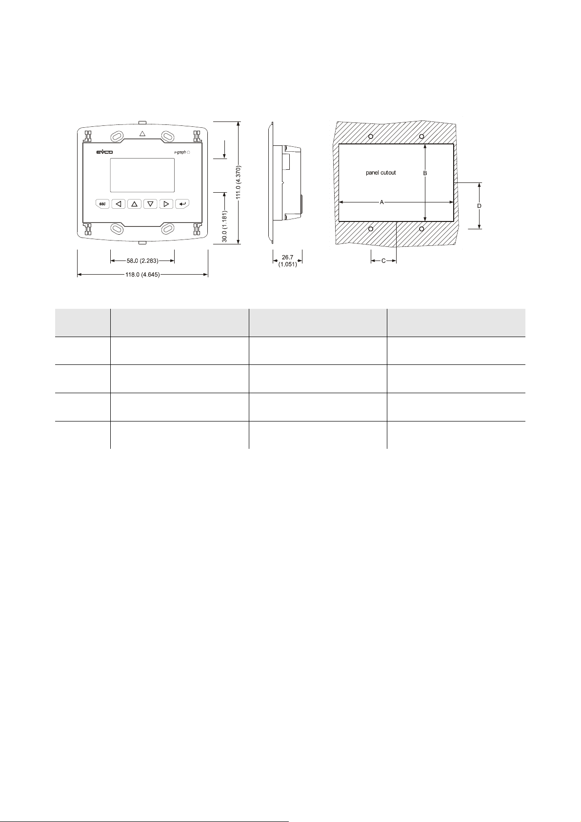
EVCO S.p.A. c-pro 3 | Hardware manual ver. 3.2 | Codice 114CP3E324
7.2.3. Size
Size in mm (in).
Size Minimum Typical Maximum
A 104.0 (4.094) 104.0 (4.094) 104.8 (4.125)
B 70.0 (2.755) 70.0 (2.755) 70.8 (2.787)
C 22.0 (0.866) 23.0 (0.905) 24.0 (0.944)
D 40.8 (1.606) 41.8 (1.645) 42.8 (1.685)
page 97 of 116
Page 98
EVCO S.p.A. c-pro 3 | Hardware manual ver. 3.2 | Codice 114CP3E324
7.3. Vtouch
7.3.1. Introduction
Vtouch is a new and innovative user interface for the programmable controllers of the family c-pro 3.
The main features of the interface are the possibility to communicate to the user a great deal of information and the remarkable ease of
control; these features are due to the use of a 240 x 140 pixel single colour touch-screen LCD graphic display (black with rearlighting
through white LEDs), to the 6 buttons (with preset functions) membrane keyboard and to the CAN bus (for the connection to the
controllers).
This last also allows the use of the interface in multimaster networks.
Thanks to its constructive features, Vtouch offers several mounting typologies; this is possible:
- by panel, at the front of units, of machines for refrigeration or for air conditioning, of electrical panels and as well as in all those
applications where a frontal protection degree IP65 is required
- built-in by wall, in traditional box (like "506" by BTicino)
- by wall, on the support CPVW00 by EVCO (to order separately).
Also the necessity to customize the interface, in order to integrate it aesthetically in residential and commercial environments, is
satisfied by Vtouch since at the front of the interface one can apply both the plates CPVP* by EVCO (to order separately, made in
plastic material and available in two different colorations, white and black) and the numerous plates series "Living" and "Light" by
BTicino.
Vtouch also has got:
- real time clock
- alarm buzzer.
For further information consult the Hardware manual of Vtouch.
7.3.2. Summarizing table of the main features and available models
Vtouch
Power supply
Real time clock
Alarm buzzer
Display
Communication ports
a) CAN port with CANbus
communication protocol
b) programming port
Code
For further models please contact the EVCO’s sales network at the address [email protected].
24 VAC / 20... 40 VDC not isolated 12... 24 VAC / 15... 40 VDC isolated
incorporated incorporated
incorporated incorporated
240 x 140 pixel
touch-screen LCD graphic display
2
a + b
EPV4TBR EPV3TBR
touch-screen LCD graphic display
240 x 140 pixel
2
a + b
page 98 of 116
Page 99
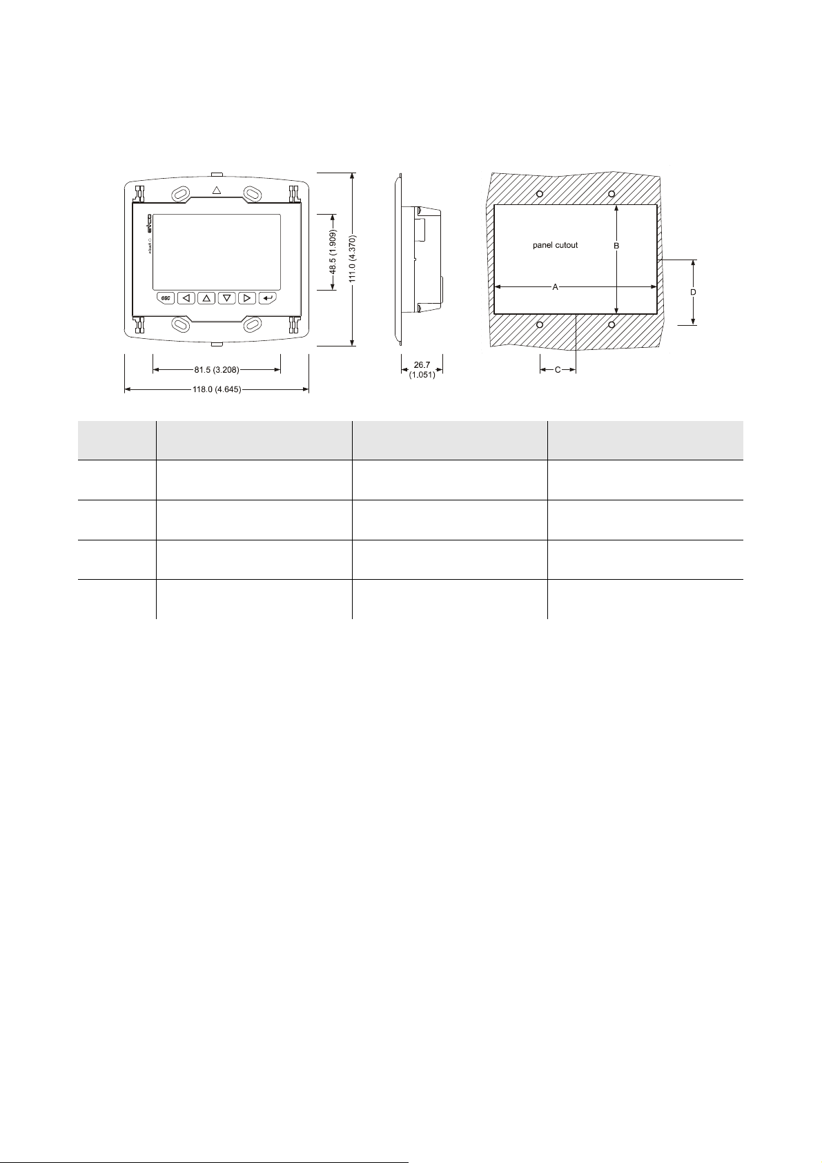
EVCO S.p.A. c-pro 3 | Hardware manual ver. 3.2 | Codice 114CP3E324
7.3.3. Size
Size is in mm (in).
Size Minimum Typical Maximum
A 104.0 (4.094) 104.0 (4.094) 104.8 (4.125)
B 70.0 (2.755) 70.0 (2.755) 70.8 (2.787)
C 22.0 (0.866) 23.0 (0.905) 24.0 (0.944)
D 40.8 (1.606) 41.8 (1.645) 42.8 (1.685)
page 99 of 116
Page 100
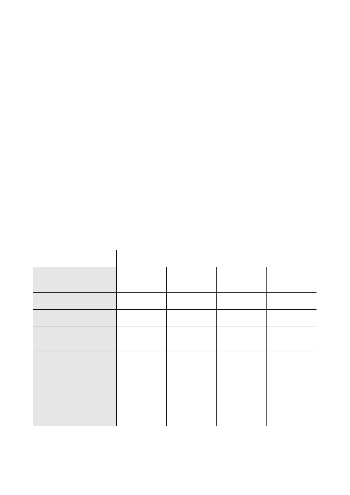
EVCO S.p.A. c-pro 3 | Hardware manual ver. 3.2 | Codice 114CP3E324
7.4. Vroom
7.4.1. Introduction
Vroom is a new and innovative user interface for the programmable controllers of the family c-pro 3.
The main features of the interface are the possibility to communicate to the user a great deal of information and the remarkable ease of
control; these features are due to the use of a 128 x 64 pixel single colour LCD graphic display (black with rearlighting through white
LEDs), to the 6 buttons (with preset functions) membrane keyboard and to the CAN bus (for the connection to the controllers).
This last also allows the use of the interface in multimaster networks.
The user interface incorporates a temperature sensor or a temperature and humidity one; the values read by these sensors are
transmitted via CAN bus, making easier the wiring.
Thanks to its constructive features, Vroom offers several mounting typologies; this is possible:
- by panel, at the front of units, of machines for refrigeration or for air conditioning, of electrical panels and as well as in all those
applications where a frontal protection degree IP65 is required
- built-in by wall, in traditional box (like "506" by BTicino)
- by wall, on the support CPVW00 by EVCO (to order separately).
Also the necessity to customize the interface, in order to integrate it aesthetically in residential and commercial environments, is
satisfied by Vroom since at the front of the interface one can apply both the plates CPVP* by EVCO (to order separately, made in
plastic material and available in two different colorations, white and black) and the numerous plates series "Living" and "Light" by
BTicino.
Vroom also has got:
- real time clock
- alarm buzzer.
For further information consult the Hardware manual of Vroom.
7.4.2. Summarizing table of the main features and available models
Vroom
Power supply
Real time clock
Alarm buzzer
Alarm buzzer
Display
Communication ports
a) CAN port with CANbus
communication protocol
b) programming port
24 VAC / 20... 40
VDC not isolated
incorporated incorporated incorporated incorporated
incorporated incorporated incorporated incorporated
temperature
128 x 64 pixel
LCD graphic display
2
a + b
24 VAC / 20... 40
VDC not isolated
temperature and
humidity
128 x 64 pixel
LCD graphic display
2
a + b
12... 24 VAC / 15...
40 VDC isolated
temperature
128 x 64 pixel
LCD graphic display
2
a + b
12... 24 VAC / 15...
40 VDC isolated
temperature and
humidity
128 x 64 pixel
LCD graphic display
2
a + b
Code
EPV4QBR EPV4RBR EPV3QBR EPV3RBR
For further models please contact the EVCO’s sales network at the address [email protected].
page 100 of 116
 Loading...