

Page 1
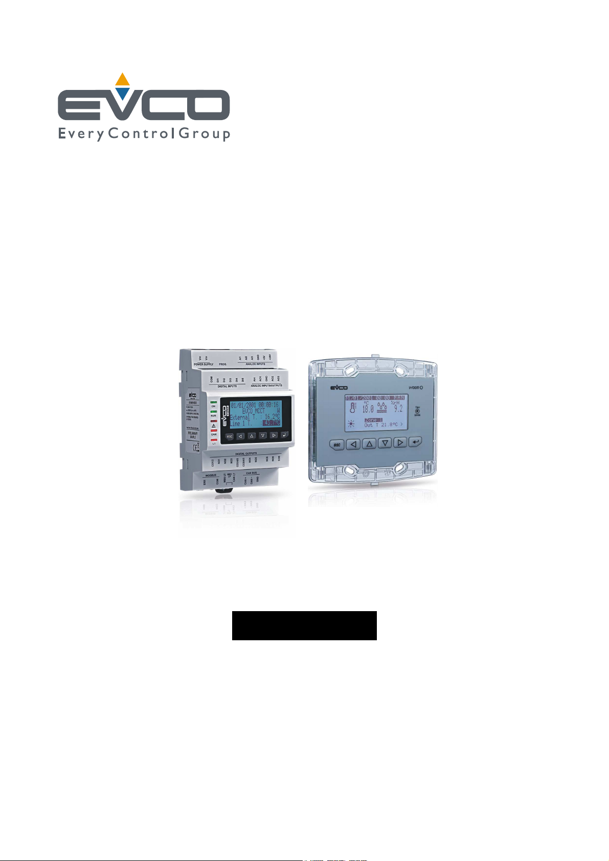
Evco S.p.A. c-pro 3 CLIMA sistema | Installer manual ver.1.1 | Code 144CP3CSE114
C-PRO 3 CLIMA sistema+
Climatic modules for the air conditioning
and heating of buildings
ENGLISH
INSTALLER MANUAL ver. 1.1
CODICE 144CP3CSE114
page 1 of 74
Page 2
Evco S.p.A. c-pro 3 CLIMA sistema | Installer manual ver.1.1 | Code 144CP3CSE114
Important
Important
Read this document thoroughly before installation and before use of the device and follow all recommendations; keep
this document with the device for future consultation.
The following symbols support reading of the document:
indicates a suggestion
indicates a warning.
The device must be disposed of in compliance with local Standards regarding the collection of electric and electronic
equipment.
page 2 of 74
Page 3

Evco S.p.A. c-pro 3 CLIMA sistema | Installer manual ver.1.1 | Code 144CP3CSE114
Index
1 GENERALITIES ........................................................................................................................................ 6
1.1
2 APPLICATIONS ........................................................................................................................................ 7
3 INSTALLATION ........................................................................................................................................ 8
3.1
3.2
3.3
3.4
3.5
4 USER INTERFACE .................................................................................................................................. 21
4.1
4.2
5 c-pro 3 hecto+ MCCT regulator ............................................................................................................... 23
5.1
5.2
5.3
5.4
Description..................................................................................................................................... 6
Dimensions .................................................................................................................................... 8
3.1.1 Thermal power plant (MCCT), zone modules (MCZN) and solar panels (MCPS) dimensional drawing. ..... 8
3.1.2 Graphical display dimensional drawing (Vroom). ............................................................................. 8
Assembly ....................................................................................................................................... 9
3.2.1 Assembly of thermal power plant modules (MCCT), Zone (MCZN) and solar panels (MCPS) .................. 9
3.2.2 Display Assembly (Vroom) ......................................................................................................... 10
Electric connections ....................................................................................................................... 11
3.3.1 Thermal power plant electric connections (MCCT) hecto + ............................................................. 11
3.3.2 Zones electric connections (MCZN). ............................................................................................ 13
3.3.3
Return temperature control ............................................................................................................. 14
3.3.4 Richiesta Chiller/pompa di calore ................................................................................................ 14
3.3.5
Configuration Options ................................................................................................................... 14
3.3.6 Solar panels electric connections (MCPS). .................................................................................... 15
Regulators network configuration .................................................................................................... 16
3.4.1 MCCT thermal power plant controller network configuration ........................................................... 17
3.4.2 Network Configuration zone modules MCZN ................................................................................. 17
3.4.3 MCPS solar panels controller network configuration ....................................................................... 17
Displays network configuration ....................................................................................................... 17
3.5.1 Public terminal ......................................................................................................................... 18
3.5.2 Module private terminal ............................................................................................................. 19
3.5.3 Zone private terminal ................................................................................................................ 20
Display and keyboard .................................................................................................................... 21
4.1.1 Built-in interface ....................................................................................................................... 21
Navigation through the applications making up the system ................................................................ 22
4.2.1 Access a c-pro 3 hecto+ MCZN zone regulator .............................................................................. 22
4.2.2 Access the regulator for c-pro 3 hecto MCPS solar panels .............................................................. 22
List of pages ................................................................................................................................ 23
Menu ........................................................................................................................................... 23
5.2.1 Home page: ............................................................................................................................. 23
5.2.2 Status page ............................................................................................................................. 24
5.2.3 Menu page ............................................................................................................................... 25
5.2.4 Network .................................................................................................................................. 25
5.2.5 Maintenance menu .................................................................................................................... 26
5.2.6 Installer menu .......................................................................................................................... 26
5.2.7 Manufactor menu ...................................................................................................................... 26
Alarms/log menu .......................................................................................................................... 27
5.3.1 Alarms log ............................................................................................................................... 27
5.3.2 Reset active alarms ................................................................................................................... 27
5.3.3 Reset alarms log ....................................................................................................................... 27
5.3.4 Table of alarms ........................................................................................................................ 27
Clock menu .................................................................................................................................. 30
page 3 of 74
Page 4

Evco S.p.A. c-pro 3 CLIMA sistema | Installer manual ver.1.1 | Code 144CP3CSE114
5.5
User menu ................................................................................................................................... 30
5.6
Maintenance menu ........................................................................................................................ 30
5.7
Installer menu .............................................................................................................................. 30
5.8
Manufactor menu .......................................................................................................................... 30
5.9
Main OFF page.............................................................................................................................. 31
5.10 Main ON page ............................................................................................................................... 31
5.11 State pages .................................................................................................................................. 31
5.11.1
State page supply lines L1 to L6 ............................................................................................. 31
5.11.2
State page and access to the MCPS solar panels module ........................................................... 31
5.11.3
State and access page of the MCZN zone regulators modules ..................................................... 31
5.12 Configuration parameters .............................................................................................................. 32
5.12.1
List of configuration parameters ............................................................................................. 32
5.13 State of the unit ........................................................................................................................... 36
5.13.1
OFF state due to alarm .......................................................................................................... 37
5.14 Summer/winter functioning mode ................................................................................................... 37
6 c-pro 3 hecto MCZN regulator ................................................................................................................. 39
6.1
List of pages ................................................................................................................................ 39
6.2
Menu ........................................................................................................................................... 39
6.2.1 Main Screen area ...................................................................................................................... 39
6.2.2 Configuration screen area .......................................................................................................... 39
6.2.3 Screenshot setpoint area ........................................................................................................... 40
6.2.4 Screen time zones .................................................................................................................... 40
6.2.5 Screenshot holiday ................................................................................................................... 41
6.3
Main menu accessible by MCCT ....................................................................................................... 41
6.3.1 Alarm menu ............................................................................................................................. 41
6.3.2 Maintainer menu....................................................................................................................... 41
6.3.3 Installer menu .......................................................................................................................... 41
6.3.4 Manufactor menu ...................................................................................................................... 42
6.4
Pages On/Off ................................................................................................................................ 42
6.5
Configuration Parameters............................................................................................................... 42
6.5.1 List of configuration parameters ................................................................................................. 42
6.6
Unit status ................................................................................................................................... 48
6.7
Zones status ................................................................................................................................ 48
7 c-pro 3 hecto MCPS regulator ................................................................................................................. 49
7.1
List of pages ................................................................................................................................ 49
7.2
Main page .................................................................................................................................... 50
7.3
State pages .................................................................................................................................. 50
7.3.1 Functioning state of DHW circuit (boiler) ...................................................................................... 50
7.3.2 Functioning state of solar panels circuit 1 and 2 ............................................................................ 50
7.3.3 Functioning state of auxiliary circuit ............................................................................................ 50
7.4
Main menu ................................................................................................................................... 51
7.4.1 Alarms/log menu ...................................................................................................................... 51
7.4.2 Alarms log ............................................................................................................................... 51
7.4.3 Reset active alarms ................................................................................................................... 51
7.4.4 Reset alarms log ....................................................................................................................... 51
7.4.5 Set-point menu ........................................................................................................................ 51
7.4.6 Maintenance menu .................................................................................................................... 51
7.4.7 Installer menu .......................................................................................................................... 52
7.5
System Network page ................................................................................................................... 53
page 4 of 74
Page 5

Evco S.p.A. c-pro 3 CLIMA sistema | Installer manual ver.1.1 | Code 144CP3CSE114
7.6
Configuration parameters .............................................................................................................. 53
7.6.1 List of MAINTENANCE menu configuration parameters ................................................................... 53
30 ............................................................................................................................................................... 55
7.6.2 List of INSTALLER menu configuration parameters ........................................................................ 56
7.7
Unit status ................................................................................................................................... 57
8 Regulations .......................................................................................................................................... 57
8.1
Regulation of the zone temperature (MCZN, MCCT modules) .............................................................. 57
8.1.1 Regulation principle .................................................................................................................. 57
8.1.2 Management of the zone heating/cooling manifolds (MCZN module) ............................................... 58
8.1.3 Fan Coil ................................................................................................................................... 58
8.1.4 Zone work set-point (MCZN module) ........................................................................................... 59
8.1.5 Zone anti-freeze protection (MCZN module) ................................................................................. 60
8.1.6 "Heating/cooling integration" function (MCZN modules) ................................................................. 61
8.2
Regulation of the delivery temperature (MCCT modules) .................................................................... 61
8.2.1 Management of the delivery circulation pumps (MCCT module) ...................................................... 61
8.2.2 Management of the utilities set-up for heating delivery water: boiler (and heat pump (MCCT module) . 61
8.2.3 Management of the utility set-up for cooling delivery water: the chiller (MCCT module) ..................... 62
8.2.4 Delivery work set-point (MCCT module) ....................................................................................... 62
8.2.5 Output of the delivery mixing valve (MCCT module) ...................................................................... 62
8.2.6 Mixing valve delivery work set-point (MCCT module) ..................................................................... 63
8.2.7 Dew point control (MCCT, MCZN modules) ................................................................................... 63
8.2.8 Control of the high and low delivery temperature (MCCT module) ................................................... 64
8.3
Regulation of the zone humidity (MCZN, MCCT modules) ................................................................... 64
8.3.1 Regulation principle .................................................................................................................. 64
8.3.2 Management of the dehumidification manifold/valve (MCZN module) .............................................. 64
8.3.3 Zone humidity work set-point (MCZN module) .............................................................................. 64
8.3.4 Management of digital on/off dehumidifier ................................................................................... 65
8.4
Regulation of the DHW tank temperature for the DHW water (MCPS module) ....................................... 65
8.4.1 Regulation principle .................................................................................................................. 65
8.4.2 Management of the DHW circuit circulation pump (MCPS module) ................................................... 65
8.4.3 DHW tank work set-point (MCPS module) With DHW setpoint mode ................................................ 66
8.4.4 Management of the AUX1 auxiliary circuit circulation pump (MCPS module) .................................... 66
8.4.5 Control of the high and low temperature of the auxiliary circuit AUX1 (MCPS module) ....................... 67
8.4.6 Management and setting of the periodic antilegionella cycle for the DHW tank (MCPS module) ........... 67
8.5
Management and configuration of the heating solar panel circuits (MCPS module) ................................ 68
8.5.1 With DHW setpoint.................................................................................................................... 68
8.5.2 con tipo setpoint pannelli ........................................................................................................... 68
8.5.3 Management of the solar panels circuits circulation (MCPS module) ................................................ 69
8.5.4 Control of the high and low temperature of the solar panel circuits (MCPS module) ........................... 69
8.5.5 Management and setting the stagnation emergency for solar panels circuits (MCPS module) .............. 69
8.6
Other regulations .......................................................................................................................... 71
8.6.1 Management and setting of the periodic anti-grip cycle (MCCT, MCPS modules) ............................... 71
8.6.2 Management of the circulation pumps protection digital input (MCCT, MCPS modules) ....................... 71
8.6.3 Manual functioning mode (MCCT, MCZN, MCPS modules) ............................................................... 72
page 5 of 74
Page 6

Evco S.p.A. c-pro 3 CLIMA sistema | Installer manual ver.1.1 | Code 144CP3CSE114
1 GENERALITIES
1.1 Description
The climatic modules of the c-pro 3 CLIMA sistema series are devices studied for the air conditioning and the heating
of buildings.
They make use of the programmable controllers belonging to the c-pro 3 series and of the user interfaces belonging
to the same series.
They are available in built-in and in blind version with remote user interface (according to the kind of module).
They can be powered both in alternating and in direct current (24 VAC/20... 40 VDC).
The modules allow realizing an expandable and modular control device network distributed in the main rooms of the
building reducing the wiring work to a minimum: the modules c-pro 3 hecto MCCT can manage the thermal power
plant, the c-pro 3 hecto MCZN ones the air conditioning and the heating of two zones instead and the c-pro 3 hecto
MCPS ones finally the thermal solar panels.
The central module thermal MCCT is indispensable for the functioning of the system, it can be connected from one to
eight zones MCZN control modules, each of which can handle up to a maximum of six zones.
In total, thanks to this system can be operated up to a maximum of 48 zones in temperature and humidity.
The user interfaces can easily be integrated in residential and commercial rooms (at the front of the interfaces it is
possible to apply the plates CPVP or the plates belonging to the series “Living” and to the series “Light” Bticino).
All the modules have communication ports (programming, CAN, RS-485, with MODBUS communication protocol, etc.).
Through the programming port it is possible to make the upload and the download of the configuration parameters
(using the programming key EVKEY10); through the RS-485 one, with MODBUS communication protocol, it is possible
to connect the devices to the set-up software system Parameters Manager or to the plants monitoring and supervision
one RICS (through a serial interface) instead.
Through the CAN communication port it is possible to connect the devices among them.
page 6 of 74
Page 7
Evco S.p.A. c-pro 3 CLIMA sistema | Installer manual ver.1.1 | Code 144CP3CSE114
2 APPLICATIONS
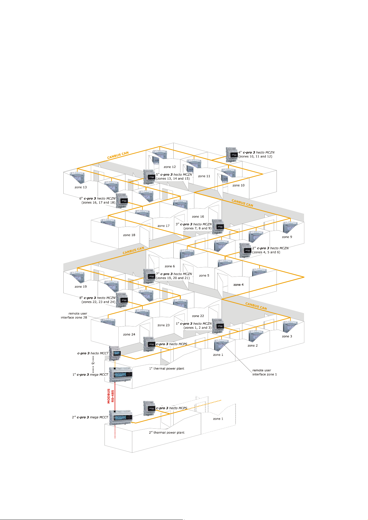
Example of maximum configuration
- n. 1 thermal power plant module c-pro 3 mega MCCT or c-pro 3 hecto
- n. 8 zone modules c-pro 3 hecto MCZN
- n. 1 thermal solar panels c-pro 3 hecto MCPS
- n. 1 remote user interface for each zone
Up to n. 48 zones (with temperature control only) or n. 24 zones (both with temperature and humidity control)
page 7 of 74
Page 8
Evco S.p.A. c-pro 3 CLIMA sistema | Installer manual ver.1.1 | Code 144CP3CSE114
3 INSTALLATION
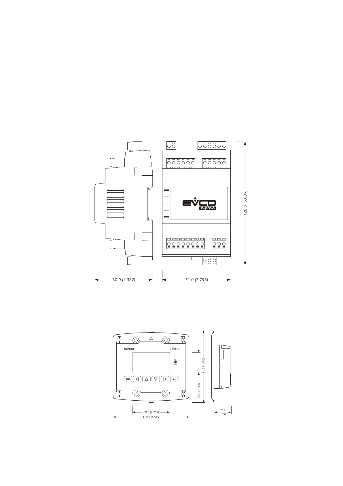
Below we will show the dimensions, assembly and electric connections of the c-pro 3 CLIMA sistema, made up from
thermal power plant modules (MCCT), Zones (MCZN), solar panels (MCPS) and graphical displays (Vroom).
3.1 Dimensions
3.1.1 Thermal power plant (MCCT), zone modules (MCZN) and solar
panels (MCPS) dimensional drawing.
3.1.2 Graphical display dimensional drawing (Vroom).
page 8 of 74
Page 9
Evco S.p.A. c-pro 3 CLIMA sistema | Installer manual ver.1.1 | Code 144CP3CSE114
3.2 Assembly
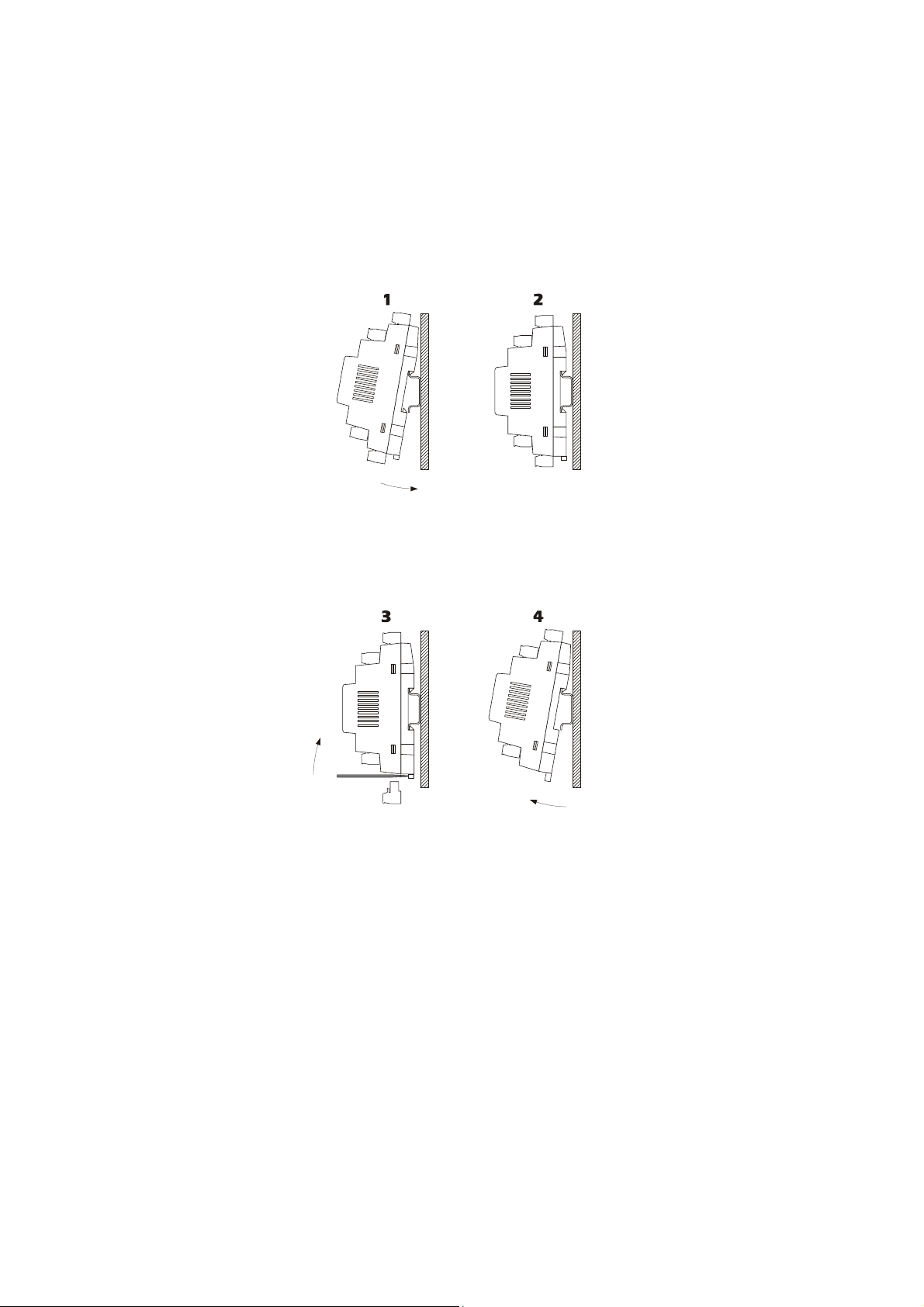
3.2.1 Assembly of thermal power plant modules (MCCT), Zone (MCZN)
and solar panels (MCPS)
To install the thermal power plant, zone and solar panels module, operate as indicated in the diagrams (points 1 and
2).
To remove thermal power plant, zone and solar panels module, use a screwdriver and operate as indicated in the
diagrams (points 3 and 4).
page 9 of 74
Page 10
Evco S.p.A. c-pro 3 CLIMA sistema | Installer manual ver.1.1 | Code 144CP3CSE114
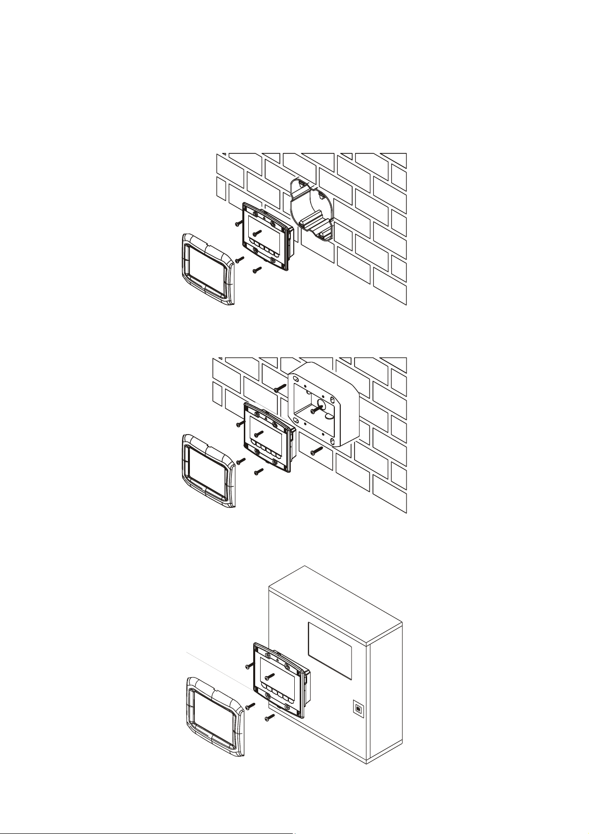
3.2.2 Display Assembly (Vroom)
There are three possibilities for assembly of the Vroom graphical display:
3.2.2.1 Wall recessed in 506E box
3.2.2.2 Wall-installation, on Evco CPVW00 support
3.2.2.3 Panel installation
page 10 of 74
Page 11
Evco S.p.A. c-pro 3 CLIMA sistema | Installer manual ver.1.1 | Code 144CP3CSE114
3.3 Electric connections
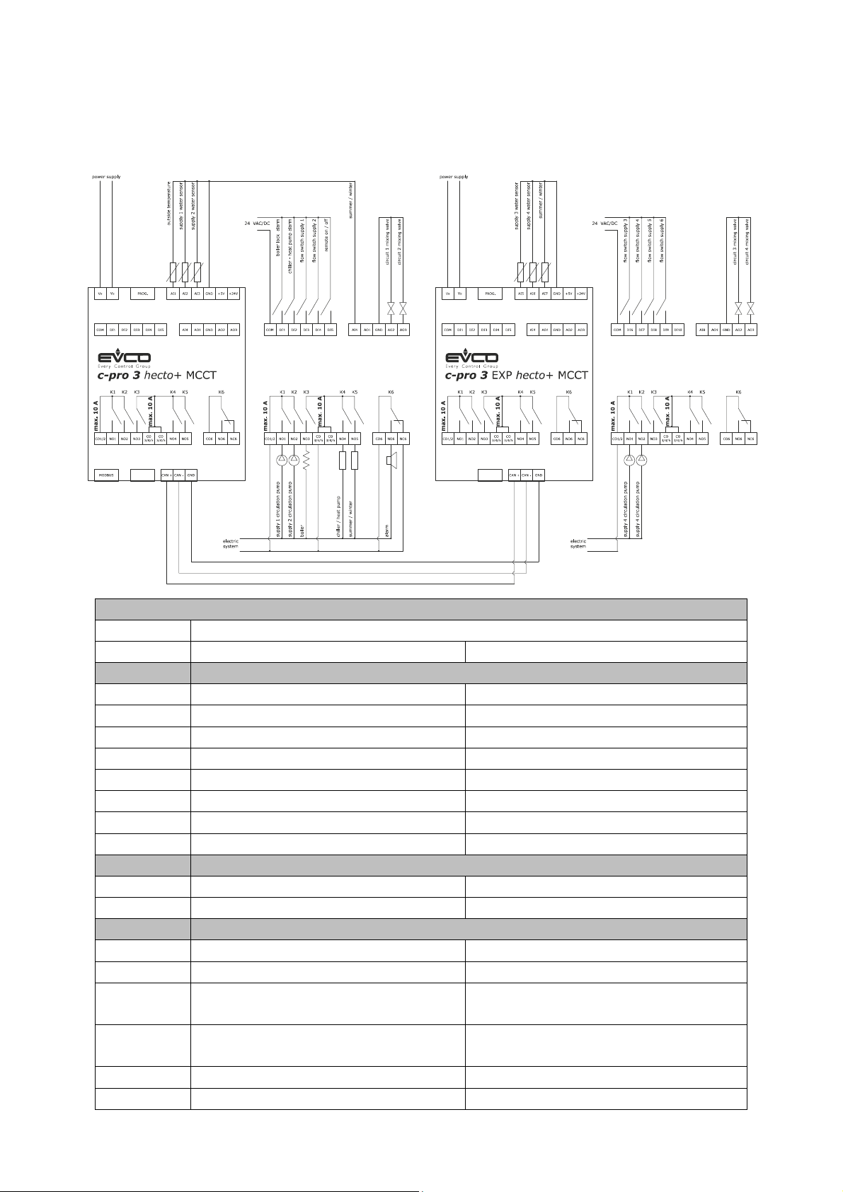
3.3.1 Thermal power plant electric connections (MCCT) hecto +
c-pro 3 hecto+ Thermal plant controller
I/O Description
1 or 2 delivery lines (PL01 = 1 or 2) 3 or more delivery lines (PL01 = from 3 to 6)
Analog inputs (NTC / 0-5V / 4-20mA)
A/I 1 CT External air temperature – NTC External air temperature – NTC
A/I 2 CT Delivery temperature 1 – NTC Delivery temperature 1 – NTC
A/I 3 CT Delivery temperature 2 – NTC Delivery temperature 2 – NTC
A/I 4 CT Summer/Winter Summer/Winter
A/I 5 EXP Not used Delivery temperature 3 – NTC
A/I 6 EXP Not used Delivery temperature 4 – NTC
A/I 7 EXP Not used Summer/Winter
A/I 8 EXP Not used Not used
Serial ports
Rs485 RS485 modbus RTU (su RJ45) RS485 modbus RTU (su RJ45)
CANbus Ai moduli c-pro 3 CLIMA sistema Ai moduli c-pro 3 CLIMA sistema
Digital inputs (ON-OFF 24V)
D/I 1 CT Alarm (block) Boiler Alarm (block) Boiler
D/I 2 CT Alarm chiller – heat pump Alarm chiller – heat pump
D/I 3 CT Delivery pump 1 flow switch (and/or thermal
switch)
D/I 4 CT Delivery pump 2 flow switch (and/or thermal
switch)
D/I 5 CT ON-OFF remote ON-OFF remote
D/I 6 EXP Not used Delivery pump 3 flow switch (and/or thermal
Delivery pump 1 flow switch (and/or thermal
switch)
Delivery pump 2 flow switch (and/or thermal
switch)
page 11 of 74
Page 12
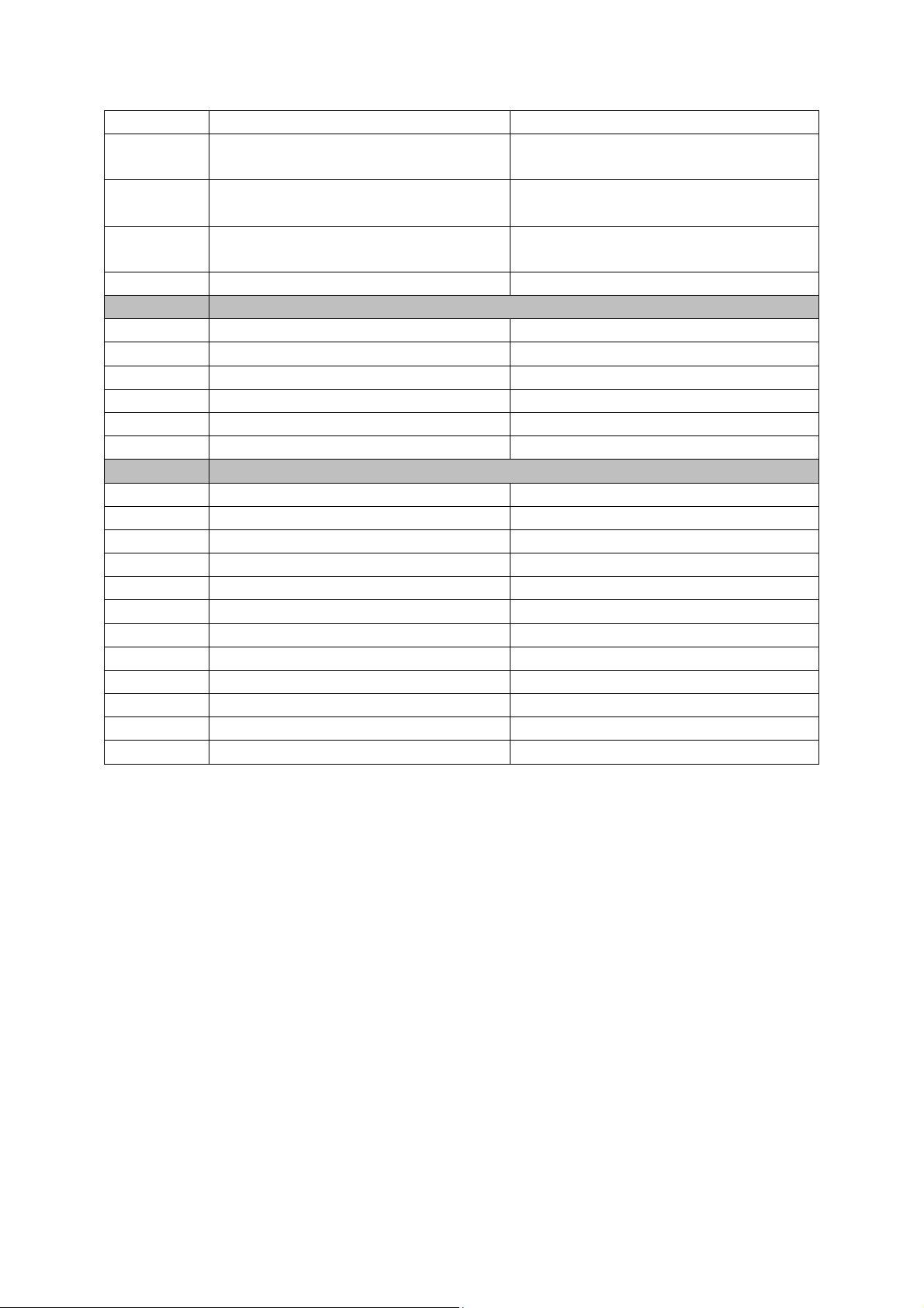
Evco S.p.A. c-pro 3 CLIMA sistema | Installer manual ver.1.1 | Code 144CP3CSE114
switch)
D/I 7 EXP Not used Delivery pump 4 flow switch (and/or thermal
switch)
D/I 8 EXP Not used Delivery pump 5 flow switch (and/or thermal
switch)
D/I 9 EXP Not used Delivery pump 6 flow switch (and/or thermal
switch)
D/I 10 EXP Not used Not used
Analog outputs (PWM / 0-10 V / 4-20mA)
A/O 1 CT Not used Not used
A/O 2 CT Delivery 1 modulating valve control (0-10 V) Delivery 1 modulating valve control (0-10 V)
A/O 3 CT Delivery 2 modulating valve control (0-10 V) Delivery 2 modulating valve control (0-10 V)
A/O 4 EXP Not used Not used
A/O 5 EXP Not used Delivery 3 modulating valve control (0-10 V)
A/O 6 EXP Not used Delivery 4 modulating valve control (0-10 V)
Digital outputs (Relay)
D/O 1 CT Delivery 1 circulation pump Delivery 1 circulation pump
D/O 2 CT Delivery 2 circulation pump Delivery 2 circulation pump
D/O 3 CT Boiler Boiler
D/O 4 CT Chiller/Heat pump Chiller/Heat pump
D/O 5 CT Summer/winter Summer/winter
D/O 6 CT Alarm Alarm
D/O 7 EXP Not used Delivery 3 circulation pump
D/O 8 EXP Not used Delivery 4 circulation pump
D/O 9 EXP Not used Not used
D/O 10 EXP Not used Not used
D/O 11 EXP Not used Not used
D/O 12 EXP Not used Not used
page 12 of 74
Page 13
Evco S.p.A. c-pro 3 CLIMA sistema | Installer manual ver.1.1 | Code 144CP3CSE114
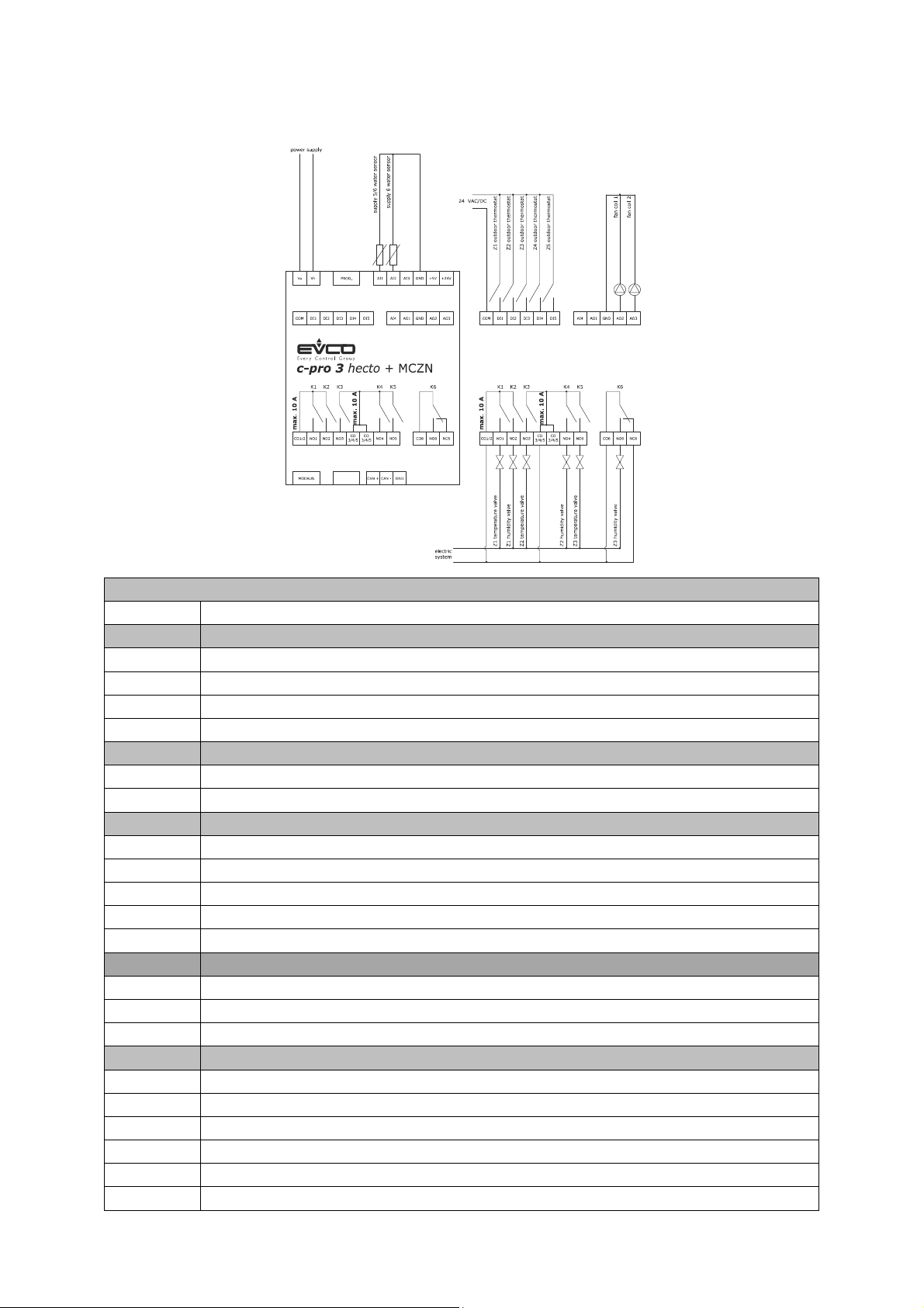
3.3.2 Zones electric connections (MCZN).
c-pro 3 hecto+ zones controller
I/O Description
Analog inputs (NTC / 0-5V / 4-20mA)
A/I 1 ZN Delivery temperature 5/6 – NTC
A/I 2 ZN Delivery temperature 6 – NTC
A/I 3 ZN Not used
A/I 4 ZN Not used
Serial ports
TTL (485) Rs485 modbus RTU (RJ45)
CANbus At the c-pro 3 CLIMA sistema
Digital inputs (ON-OFF pocoverial-free contact)
D/I 1 ZN Z1 external thermostat
D/I 2 ZN Z2 external thermostat
D/I 3 ZN Z3 external thermostat
D/I 4 ZN Z4 external thermostat
D/I 5 ZN Z5 external thermostat
Analog outputs (PWM / 0-10 V / 4-20mA)
A/O 1 ZN Not used
A/O 2 ZN Fan coil 1 (0-10V)
A/O 3 ZN Fan coil 2 (0-10V)
Digital outputs (Relay)
D/O 1 ZN Z1 temperature valve
D/O 2 ZN Z1 humidity valve
D/O 3 ZN Z2 temperature valve
D/O 4 ZN Z2 humidity valve
D/O 5 ZN Z3 temperature valve
D/O 6 ZN Z3 humidity valve
page 13 of 74
Page 14

Evco S.p.A. c-pro 3 CLIMA sistema | Installer manual ver.1.1 | Code 144CP3CSE114
3.3.3 Return temperature control
The return temperature is monitored so as to avoid, for example in summer mode, that if cooling is required and the
water that arrives at Vmix is hot heads are activated by heating the environment rather than cool it. A check is done
after verifying that a time from the opening of the parameter Vmix the return water temperature (in cold weather) is
not higher than the flow temperature setpoint active plus a delta parameter, in case of higher temperature will be the
Vmix closed and an alarm signaled the return temperature. Conversely for the heating mode, the return temperature
should not be lower than the flow temperature setpoint less active as a delta parameter.
3.3.4 Richiesta Chiller/pompa di calore
You have the option of dehumidification with cold water or not regulated and enabling command request chiller / heat
pump based on the regulation band / opening Vmix MAX / MIN opening Vmix.
3.3.5 Configuration Options
Depending on the configuration chosen for each digital output is assigned a function, as in the table below.
Priority assignment DO
Pump Discharge Line 5
Pump Discharge Line 6
Fancoil V1
Fancoil V2
Fancoil V3
Fancoil 1 Valve C/F
Fancoil 1 Valve C
Fancoil 1 Coil
Fancoil 2 Valve C/F
Fancoil 2 Valve C
Fancoil 2 Coil
Z1 Valve T
Z1 Valve H
Z1 Booster
Z2 Valve T
Z2 Valve H
Z2 Booster
Z3 Valve T
Z3 Valve H
Z3 Booster
Z4 Valve T
Z4 Valve H
Z4 Booster
Z5 Valve T
Z5 Valve H
Z5 Booster
Z6 Valve T
Z6 Valve H
Z6 Booster
page 14 of 74
Page 15
Evco S.p.A. c-pro 3 CLIMA sistema | Installer manual ver.1.1 | Code 144CP3CSE114
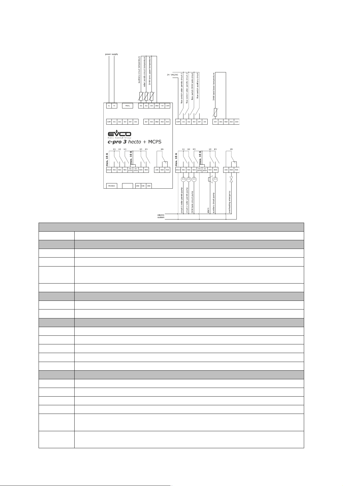
Solar panels 1 circuit pump (thermal) flow switch
3.3.6 Solar panels electric connections (MCPS).
c-pro 3 hecto+ solar panels controller
I/O Description
Analogue inputs (NTC / 0-5V / 4-20mA)
A/I 1 PS DHW tank temperature (upper) (NTC)
A/I 2 PS DHW tank lower temperature (NTC)
A/I 3 PS Auxiliary temperature 1 (NTC)
Solar panel 2 temperature (4-20 mA).
A/I 4 PS Solar panel 1 temperature (4-20 mA).
Serial ports
TTL (485) Rs485 modbus RTU (RJ45)
CANbus At the c-pro 3 CLIMA sistema
Digital inputs (ON-OFF pocoverial-free contact)
D/I 1 PS
D/I 2 PS Solar panels 2 circuit pump (thermal) flow switch
D/I 3 PS DHW circuit pump (thermal) flow switch
D/I 4 PS Auxiliary system circuit pump (thermal) flow switch
D/I 5 PS Not used
Digital outputs (Relay)
D/O 1 PS Solar panels 1 circuit pump
D/O 2 PS Solar panels 2 circuit pump
D/O 3 PS DHW circuit pump
D/O 4 PS Alarm (that can be configured)
D/O 5 PS Auxiliary 1 circuit pump
Anti-stagnation emergency (cover opening)
D/O 6 PS Anti-stagnation emergency (heat disposal/cover opening)
Anti-stagnation emergency (cover closing)
page 15 of 74
Page 16
Evco S.p.A. c-pro 3 CLIMA sistema | Installer manual ver.1.1 | Code 144CP3CSE114
3.4 Regulators network configuration
The c-pro 3 CLIMA sistema is based on the CANbus communication between the various control modules present in
the network, with the following maximum configuration:
• N° 1 c-pro 3 hecto+ MCCT thermal power plant regulator regulator and c-pro 3 EXP hecto+ by request
• N° 8 c-pro 3 hecto+ MCZN zone regulators
• N° 1 regulator for c-pro 3 hecto+ MCPS solar panels
Every controller present in the network must be assigned with a different and specific CANbus address, according to
the logic position of the controller inside the c-pro 3 CLIMA sistema, following the layout given below:
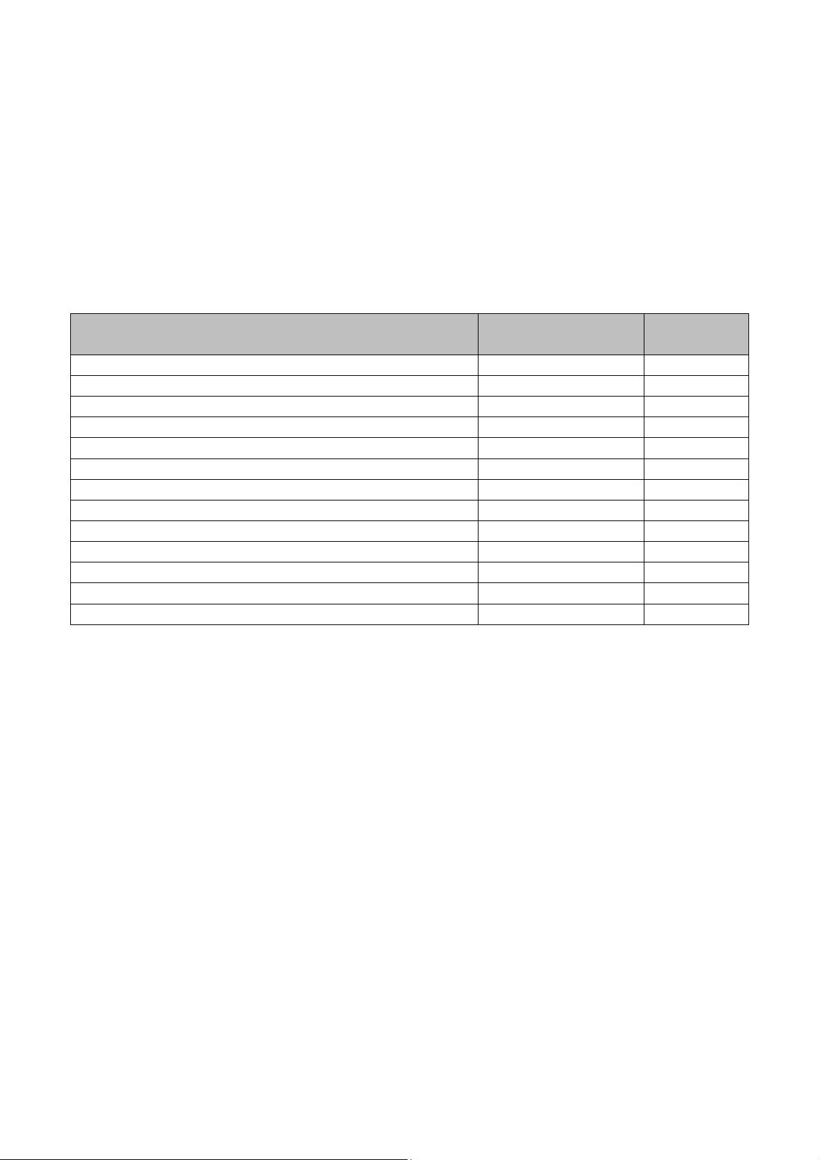
Type of controller Controller code CANbus
address
Thermal power plant regulator c-pro 3 hecto+ MCCT 1 (default)
Expansion c-pro 3 EXP hecto+ MCCT 11
Zone 1 regulator (zones 1-2) c-pro 3 hecto+ MCZN 2 (default)
Zone 2 regulator (zones 3-4) c-pro 3 hecto+ MCZN 3
Zone 3 regulator (zones 5-6) c-pro 3 hecto+ MCZN 4
Zone 4 regulator (zones 7-8) c-pro 3 hecto+ MCZN 5
Zone 5 regulator (zones 9-10) c-pro 3 hecto+ MCZN 6
Zone 6 regulator (zones 11-12) c-pro 3 hecto+ MCZN 7
Zone 7 regulator (zones 13-14) c-pro 3 hecto+ MCZN 8
Zone 8 regulator (zones 15-16) c-pro 3 hecto+ MCZN 9
Regulator for solar panels c-pro 3 hecto+ MCPS 17 (default)
As highlighted in the previous table, the controllers are set by default to be automatically recognised in network as:
• thermal power plant regulator CANbus 1 address
• zone 1 regulator CANbus 2 address
• regulator for solar panels CANbus 17 address
page 16 of 74
Page 17

Evco S.p.A. c-pro 3 CLIMA sistema | Installer manual ver.1.1 | Code 144CP3CSE114
3.4.1 MCCT thermal power plant controller network configuration
The controller of thermal power plant (the logical center of the controlled), you must first set the number of zone
controllers MCZN will be present in the system, using the following procedure:
1. Enter the Installer General parameters menu of the MCCT regulator
2. Set the total number of zones controlled and the number of MCZN zone regulators present in the system
3. To set the communication speed (125k suggested) go to the menu
Installer -> general parameters and modify the baud rate parameter.
3.4.2 Network Configuration zone modules MCZN
The zone regulator leaves the factory configured as zone 1 module (therefore with CANbus 2 address).
Whenever it is necessary to install more than one zone controller in the system, it will be necessary to configure the
regulators present as zone regulators 2, 3, etc…up to a maximum of 8.
To change the network configuration of the MCZN zone module network, follow the procedure below:
1. Connect a zone regulator to the CANbus network (leaving all of the other zone regulators disconnected from
the network);the controller connected will be recognised as zone 1 controller
2. Access the MCZN zone regulator application
3. Enter the Installer General parameters menu
4. Set the number of local zones managed by the MCZN regulator
5. Set the number of the last zone regulator that is to be inserted in the system managed (e.g. zone 4 regulator).
6. The controller will automatically assume the appropriate CANbus address
7. Repeat the operation, connecting the next to last zone controller to the CANbus network and so on, until the
second zone regulator is connected (zone 2 regulator).
3.4.3 MCPS solar panels controller network configuration
The controller for solar panels MCPS is the sole controller of this type can be installed in the plant, for its configuration
will be sufficient to enable the presence of the regulator MCPS by the application of thermal power plant, with the
following procedure:
1. Enter the Installatore Parametri generali (Installer, General parameters) menu of the MCCT regulator
2. Enable the presence of the MCPS regulator in the system
3.5 Displays network configuration
For the final user, the c-pro 3 CLIMA sistema envisions the use of a series of user terminals installed in zone, from
which it is possible to display temperature, humidity, state of the zone and set the work set-points, time bands, etc.
The maximum number of user terminals that can be set in the system depends mainly on the configuration of the
terminal selected by the installer, from the following possibilities:
• Public terminal Vgraph (maximum n°1 display for the entire system)
• Module private terminal (maximum n°8 displays for the entire system)
• Zone private terminal
Depending on the type of terminal desired, settings must be made in the MCZN zone controller and in the Vroom user
terminal, illustrated in the following paragraphs.
page 17 of 74
Page 18
Evco S.p.A. c-pro 3 CLIMA sistema | Installer manual ver.1.1 | Code 144CP3CSE114
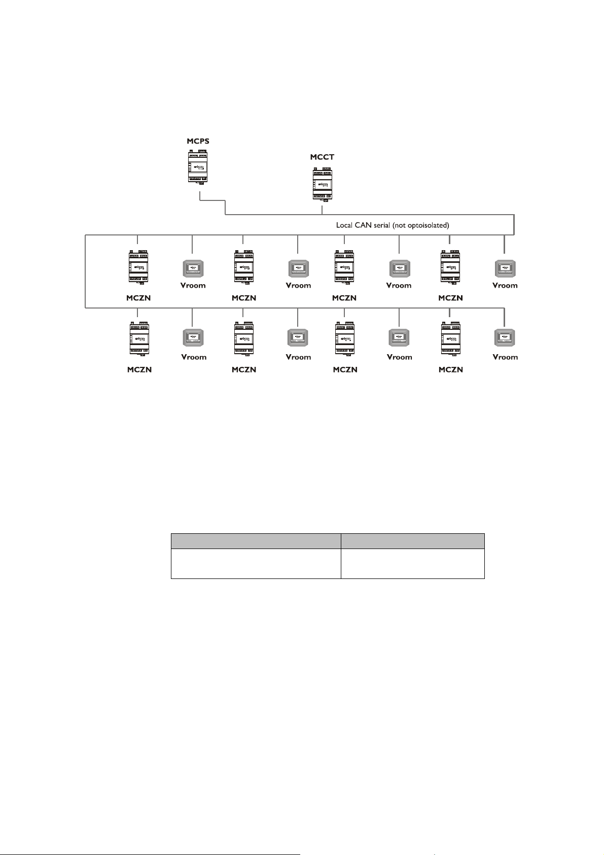
3.5.1 Public terminal
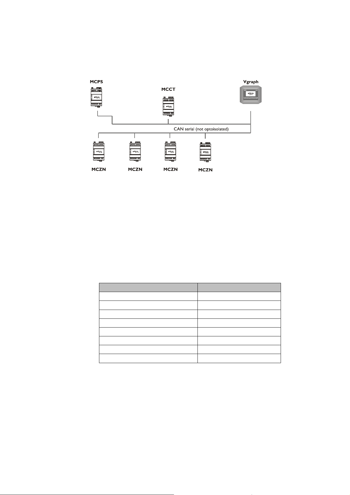
If the viewer is configured as a terminal Vgraph public (universal), will be able to view all zone controllers MCZN in
the system and all areas managed by the controllers MCZN to 6 zones.
A hotel is given as an example.
The unique Vgraph display will be installed in an area with access to authorised staff only, which will establish the
temperatures and time bands predefined for every Zone (hotel room) managed.
The hotel client will only have the possibility to change the room temperature, using the EVSET remote set-point
variator (installed in the room), by ±3-5°C (from parameter).
Vgraph settings:
Below find the network settings to be made on Vgraph to make it a public terminal (for the setting procedures,
consult the Vgraph hardware manual):
CANbus address: 100
CANbus map:
MCCT thermal power plant controller settings:
Below find the settings to make on the MCCT regulator to make Vgraph a public terminal:
From the Installer Other parameters, enable the presence of the public Vgraph display via Enab. Vgraph -
parameter
MCZN zone controllers settings:
Below find the settings to make on the MCZN regulators to make Vgraph a public terminal:
From the Installer General parameters menu, enable the presence of the public Vgraph display by setting the
Vgraph mode parameter in UNIV.
Network node Address
1 2
2 3
3 4
4 5
5 6
6 7
7 8
8 9
page 18 of 74
Page 19
Evco S.p.A. c-pro 3 CLIMA sistema | Installer manual ver.1.1 | Code 144CP3CSE114
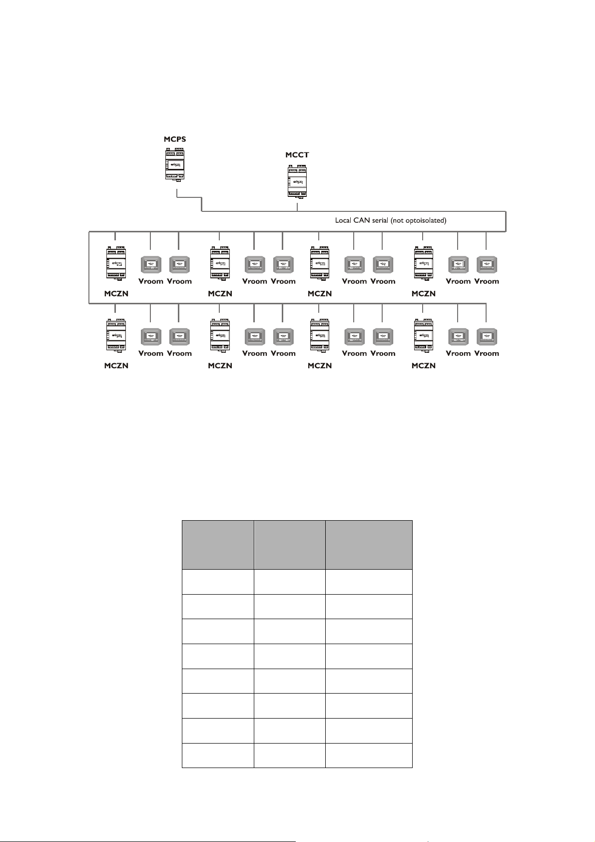
3.5.2 Module private terminal
If the viewer is configured as a private terminal of separate zones, each viewer will be able to display only the
regulator MCZN chosen area, managing the areas controlled by the controller MCZN.
A condominium is given as an example.
A Vroom display will be installed in every apartment, which will establish temperatures and time bands for the Zones
present in the apartment, without the possibility to display or modify the settings of the other apartments present.
Vroom settings:
Below find the network settings to be made on Vroom to make it a private module terminal (for the setting
procedures, consult the Vroom hardware manual):
CANbus address: 40 + address of the MCZN zone regulator to which the connection is to be made
CANbus map:
MCCT thermal power plant controller settings:
Below find the settings to make on the MCCT regulator to make Vgraph a private module:
From the Installer Other parameters enable public Vgraph
MCZN zone controllers settings:
Below find the settings to make on the MCZN regulators to make Vgraph a private module:
From the Installer Other parameters enable public Vroom
1:Separate zones
2: All zones in 1 V-room only
Network node Address
1 MCZN associated controller
address
page 19 of 74
Page 20
Evco S.p.A. c-pro 3 CLIMA sistema | Installer manual ver.1.1 | Code 144CP3CSE114
3.5.3 Zone private terminal
If the viewer Vroom is configured as a private terminal areas separated, every Vroom display will be able to only
show the preselected MCZN zone regulator, and only the zone selected managed by the MCZN controller.
As an example, an individually owned villa on two floors.
A Vroom display will be installed for each zone controlled (living room, bedroom, bathroom), which will establish
temperatures and time bands for the Zone where the display is installed, without possibility of displaying or modifying
the settings of the other zones present.
Vroom settings:
Below find the network settings to be made on Vroom to make it a private zone terminal (for the setting procedures,
consult the Vroom hardware manual):
CANbus map:
Modulo
Zona
Indirizzo
CAN
Vroom
Zone 1 2
Zone 2 3
Zone 3 4
Zone 4 5
Zone 5 6
Zone 6 7
Zone 7 8
Zone 8 9
Z1: Addr42
Z2: Addr 52
Z1: Addr43
Z2: Addr 53
Z1: Addr44
Z2: Addr 54
Z1: Addr45
Z2: Addr 55
Z1: Addr46
Z2: Addr 56
Z1: Addr47
Z2: Addr 57
Z1: Addr48
Z2: Addr 58
Z1: Addr49
Z2: Addr 59
page 20 of 74
Page 21
Evco S.p.A. c-pro 3 CLIMA sistema | Installer manual ver.1.1 | Code 144CP3CSE114
MCZN zone controllers settings:
Below find the settings to make on the MCZN regulators to make Vroom a private zone terminal:
From the Installer Other parameters menu, enable the presence of the private zone Vroom display by setting
Separate Zone
4 USER INTERFACE
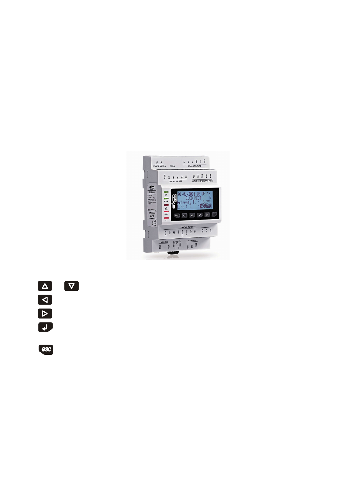
4.1 Display and keyboard
For the application there is a graphic LCD display and 6 dedicated keys.
4.1.1 Built-in interface
The built-in interface is integrated directly onto the MCCT.
There are 6 navigation and value editing pages present in the keyboard with the following meaning:
- and (UP and DOWN): when editing it modifies the parameters; otherwise moves the cursor.
- (LEFT): moves the cursor to the left or takes to the previous menu.
- (RIGHT): moves the cursor to the right.
- (ENTER): in editing it confirms the value; otherwise it sends any controls associated to the text where the
cursor is present.
- (ESC): in editing it annuls the value; otherwise request of the default page eventually associated to the
current page. If the ESC key is held for about 2 seconds, the machine can be switched on/off,
page 21 of 74
Page 22

Evco S.p.A. c-pro 3 CLIMA sistema | Installer manual ver.1.1 | Code 144CP3CSE114
4.2 Navigation through the applications making up the
system
The c-pro 3 hecto+ MCCT controller represents the heart of the c-pro 3 CLIMA sistema, also from a user interface
point of view.
To access the other system components, the procedure given in the following paragraphs must be followed.
4.2.1 Access a c-pro 3 hecto+ MCZN zone regulator
To access one of the c-pro 3 hecto+ MCZN zone regulators present in the system, access the “Regulators state in
serial network” page present in the “States” section and select the regulator to which access is to be made from the
list of regulators available.
4.2.2 Access the regulator for c-pro 3 hecto MCPS solar panels
To access the regulator for c-pro 3 hecto+ MCPS solar panels present in the system, the “Solar panels functioning
state” page must be accessed, present in the “States” section and select to access the MCPS regulator (if configured).
page 22 of 74
Page 23
Evco S.p.A. c-pro 3 CLIMA sistema | Installer manual ver.1.1 | Code 144CP3CSE114
5 c-pro 3 hecto+ MCCT regulator
Through the module, you can manage the circulation pumps, boiler and chiller-heat pump.
It is able to manage up to two discharge lines (expandable to four by using the expansion I / O c-pro 3 hecto + EXP),
eight modules and a module area of solar thermal panels.
5.1 List of pages
This paragraph presents the main pages and menus found in the MCCT application. As shown previously, the main
menu is divided into 3 levels: user, maintenance technician and installer.
A “States” section is also present that can be consulted freely, also necessary for navigation between modules.
5.2 Menu
The menu interface from the controller or from 128x64 V-Graph public (as above). The new interface will match the
standard EVCO
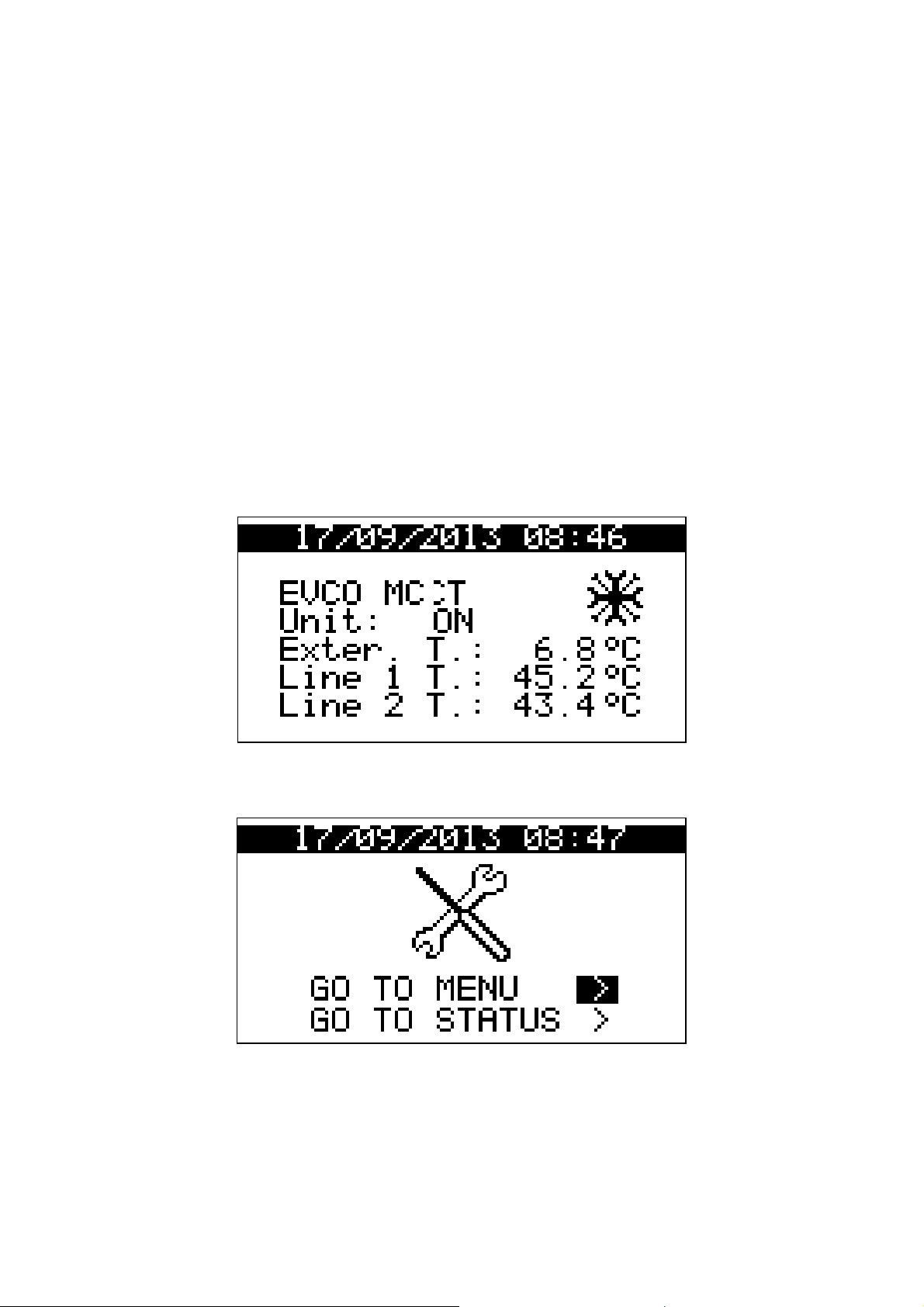
5.2.1 Home page:
From the home by pressing ESC will display the screen below that allow you to access the menu or to the various
states
page 23 of 74
Page 24
Evco S.p.A. c-pro 3 CLIMA sistema | Installer manual ver.1.1 | Code 144CP3CSE114
5.2.2 Status page
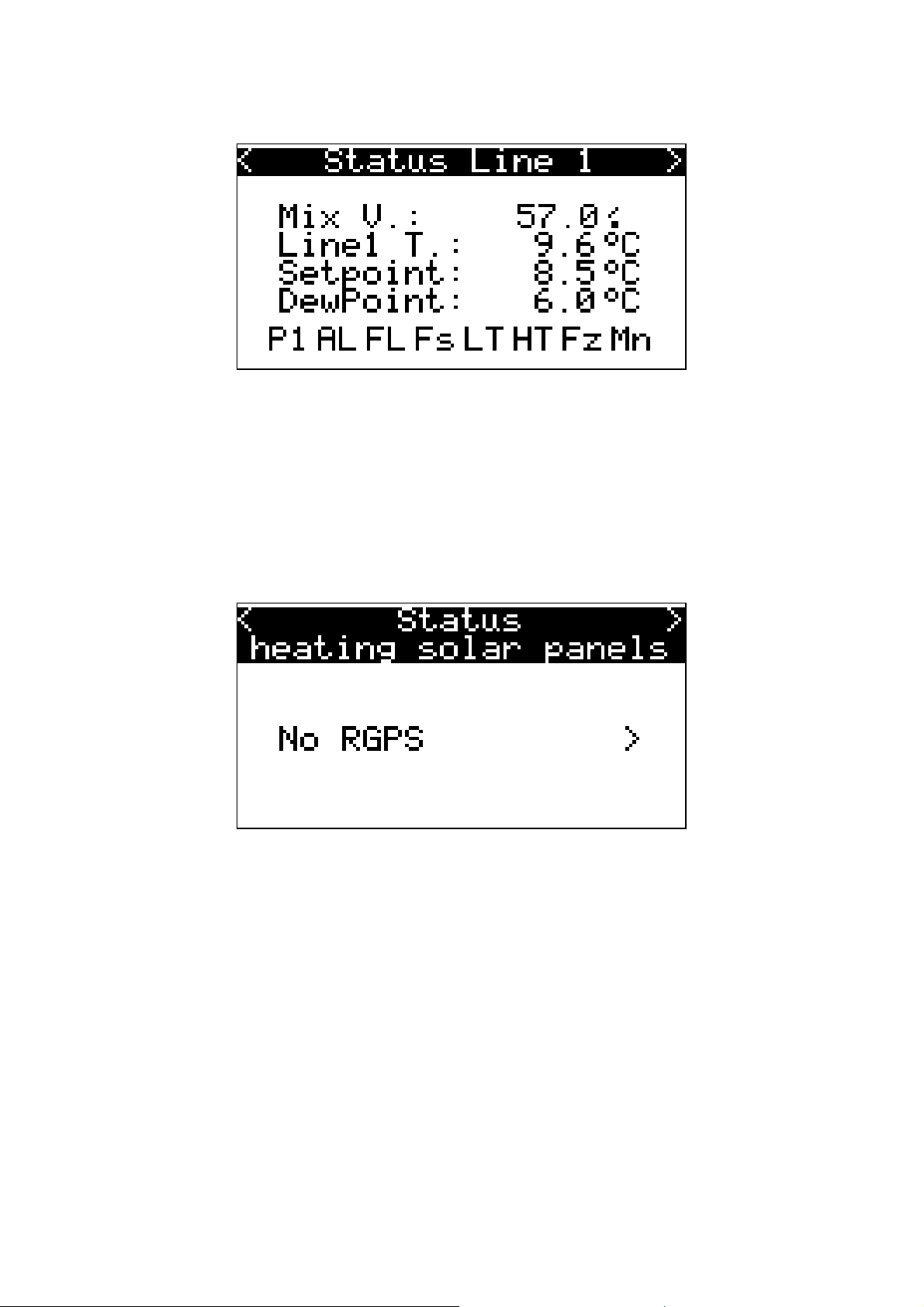
P1: Pump discharge line on
AL : Pump lock
FL: Flow alarm
Fs: Reached maximum number flow alarms
LT: Low temperature alarm sent
HT: High temperature alarm sent
Fz: Forcing pump antifreeze flow
Mn: Pump Manual
Scrolling with the RIGHT button to the right will display the states of the lines up to 6. Finally you will see the screen
Sliding the screen that is displayed with the DOWN button, you switch to the next screen
page 24 of 74
Page 25
Evco S.p.A. c-pro 3 CLIMA sistema | Installer manual ver.1.1 | Code 144CP3CSE114
5.2.3 Menu page
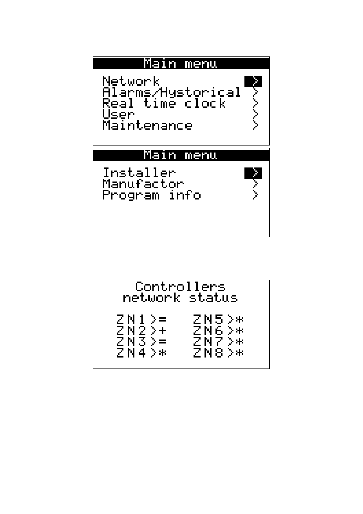
5.2.4 Network
*: Zone not configured
A: Zone in alarm
!: Zone disabled
?: Zone offline
=: Zone OK
+: Zone request with C / F
page 25 of 74
Page 26
Evco S.p.A. c-pro 3 CLIMA sistema | Installer manual ver.1.1 | Code 144CP3CSE114
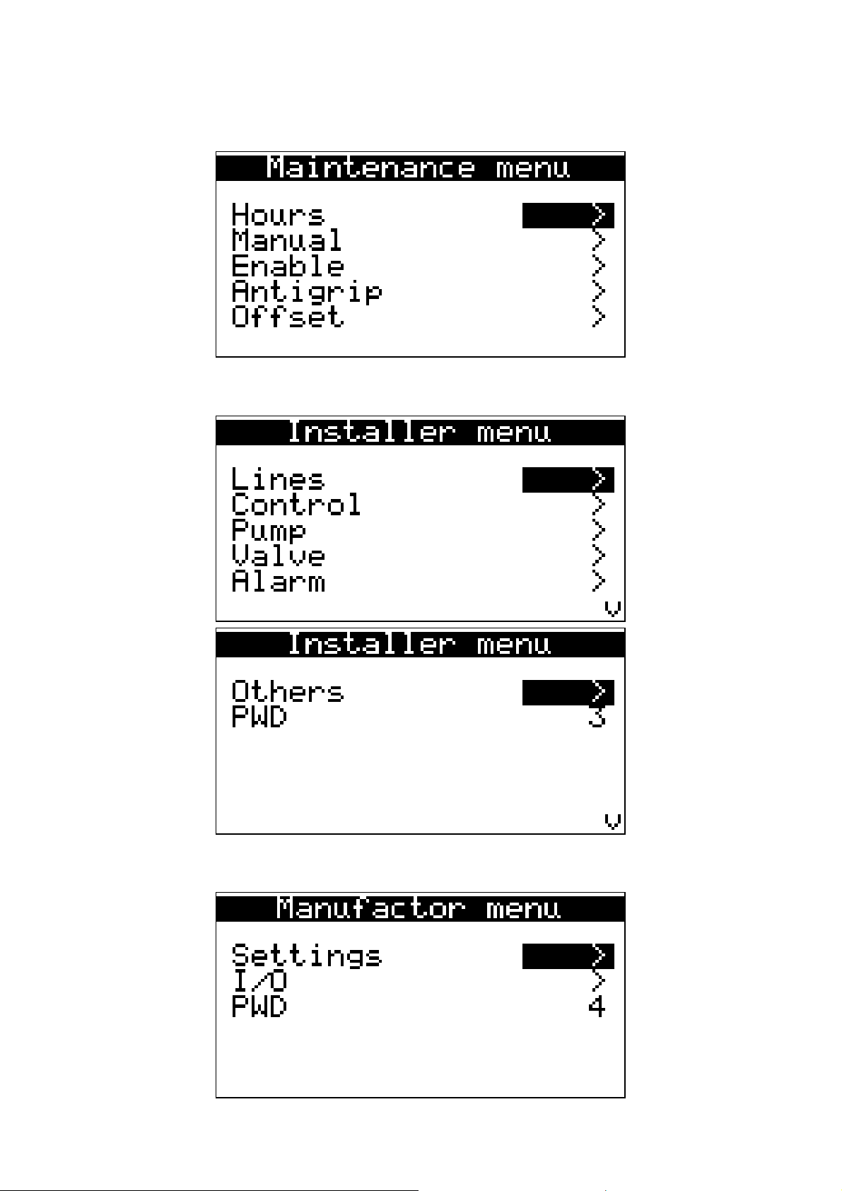
5.2.5 Maintenance menu
5.2.6 Installer menu
5.2.7 Manufactor menu
page 26 of 74
Page 27
Evco S.p.A. c-pro 3 CLIMA sistema | Installer manual ver.1.1 | Code 144CP3CSE114
5.3 Alarms/log menu
This menu contains the functionality linked to the controller alarms and the alarms log of the system.
5.3.1 Alarms log
To view the system alarms log (MCCT regulator and MCZN regulators), press ENTER on “hystorical alarms”.
In order to see the previous item, press ENTER on ">>". Repeating this procedure will cycle through all the elements
of the center until you get to the first element inserted, from here, to request the next item, the last item stored is
proposed: the display of the log is circular.
To exit from the pages of historical press the ESC key or wait the 60 seconds timeout. This level is not password
protected.
5.3.2 Reset active alarms
To view the active alarms of the MCCT regulator, press ENTER on “Rst running alarms”.
If there are no alarms present, “no alarms is displayed, otherwise a series of pages appear containing all possible
alarms present in the controller with relative codes and description.
The alarm or the alarms present, will be highlighted by flashing "Rst ALARM”.
If the ESC key is pressed from an alarm page or 60 timeout seconds are allowed to pass, you go back to the main
page of the application. This level is not protected by a password.
5.3.3 Reset alarms log
To reset the memorised alarms log, press ENTER on “Rst hyst. alarms” and take the value of the “Do you want to
erase hystorical alarms memory?” parameter to the “Yes” value.
To exit the alarms log reset pages, press the ESC key or wait 60 timeout seconds. This level is not protected by a
password.
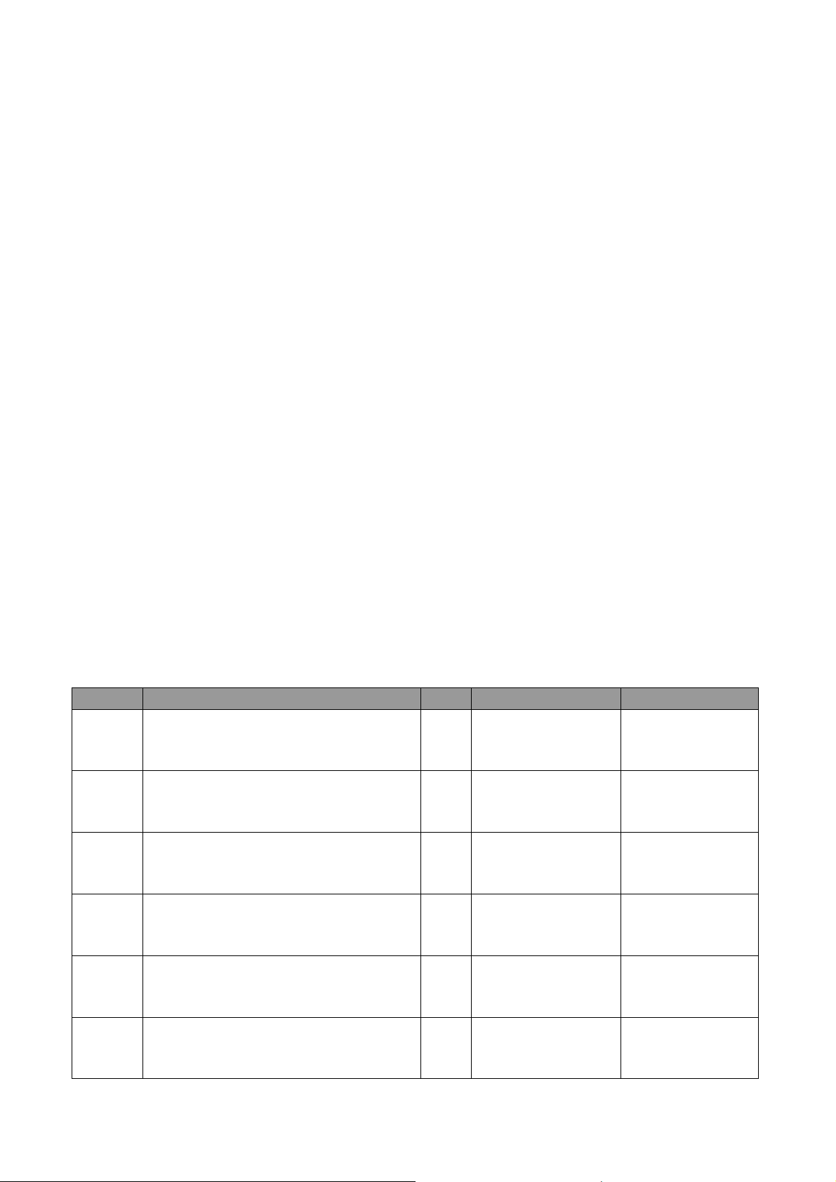
5.3.4 Table of alarms
Code Alarms description Kind Effect Notes
AL01 Outdoor temperature probe A
AL02 Supply Temperature probe L1 A
AL03 Supply Temperature probe L2 A
AL04 Supply Temperature probe L3 A
Disable supply on
T. regulation
Disable supply on
T. regulation
Disable supply on
T. regulation
Disable supply on
T. regulation
AL05 Supply Temperature probe L4 A
AL06 Supply Temperature probe L5 A
page 27 of 74
Disable supply on
T. regulation
Disable supply on
T. regulation
Page 28

Evco S.p.A. c-pro 3 CLIMA sistema | Installer manual ver.1.1 | Code 144CP3CSE114
Disable return on
AL07 Supply Temperature probe L6 A
T. regulation
Disable supply on
AL08 Return Temperature probe A
T. control
Closed mixing
AL09 Return temperature alarm A
PAR retard
valves
AL10 Alarm lock pump L1 A Line Lock PAR retard
AL11 Alarm pump operating hours L1 Signaling only
AL12 Alarm lock pump L2 A Line Lock PAR retard
AL13 Alarm pump operating hours L2 Signaling only
AL14 Alarm lock pump L3 A Line Lock PAR retard
AL15 Alarm pump operating hours L3 Signaling only
AL16 Alarm lock pump L4 A Line Lock PAR retard
AL17 Alarm pump operating hours L4 Signaling only
AL18 Alarm lock pump L5 A Line Lock PAR retard
AL19 Alarm pump operating hours L5 Signaling only
AL20 Alarm lock pump L6 A Line Lock PAR retard
AL21 Alarm pump operating hours L6 Signaling only
AL22 Flow switch alarm L1 A/M Line Lock PAR retard
page 28 of 74
Page 29

Evco S.p.A. c-pro 3 CLIMA sistema | Installer manual ver.1.1 | Code 144CP3CSE114
AL23 Flow switch alarm L2 A/M Line Lock PAR retard
AL24 Flow switch alarm L3 A/M Line Lock PAR retard
AL25 Flow switch alarm L4 A/M Line Lock PAR retard
AL26 Flow switch alarm L5 A/M Line Lock PAR retard
AL27 Flow switch alarm L6 A/M Line Lock PAR retard
AL28 Lock boiler alarm A Line Lock
AL29 Alarm boiler operating hours Signaling only
AL30 Alarm lock chiller-heat pump A CH-HP Lock
Alarm hours operating chiller-heat
AL31
Signaling only
pump
AL32 Zone alarm OFFLINE A Signaling only
AL33 RTC alarm A Signaling only
30 seconds
retard
page 29 of 74
Page 30

Evco S.p.A. c-pro 3 CLIMA sistema | Installer manual ver.1.1 | Code 144CP3CSE114
5.4 Clock menu
From this menu you can set/change the value of the date and time that the module c-pro 3 MCCT extends to the
whole c-pro 3 CLIMA sistema.
To set/modify the date and/or real time, press ENTER on “Real time clock” and set the desired value.
If the ESC key is pressed from a setting page or 60 timeout seconds are allowed to pass, you go back to the main
page of the application. This level is not protected by a password.
5.5 User menu
The user menu level 1, that is used to enter the password of the user level to be able to view/edit the parameters in
this branch.
From the menu you can view ON/OFF button from the system and change the operating mode (Summer and Winter).
5.6 Maintenance menu
The menu is level 2, that is used to enter the password level of maintenance to be able to view/edit the parameters in
this branch.
In this menu you can view the hours of operation of utilities and it is also possible to change the operating mode
(auto-manual), select the zones to enable, set the anti-grip operation and finally the calibration of the probes.
5.7 Installer menu
The Installer menu is level 3, that is used to enter the password installer level to be able to view/edit the parameters
in this branch.
From this menu you can view and set the configuration of the system managed by the MCCT.
Below is a list of the menus can be set:
- Lines Menu: we define the main characteristics relating to discharge lines present and enabled on the system such as
the type of controlled delivery lines present, the presence of the mixing valve, how to manage the circulation pumps
and the definition of their type of digital input protection.
- Control Menu: you can set the configuration of the system (boiler, chiller, heat pump and antifreeze system).
- Pumps Menu: we define the timing of the pumps of all the lines
- Valves Menu: you define the offset of the heating curve, valid for all lines in the system. From this menu you access
the operating parameters of the mixing valves.
- Alarms Menu: you can enable and set the various alarms of the thermal plant.
- Others Menu: finally, it is possible to set the general parameters.
5.8 Manufactor menu
The menu manufactor is level 4, that is used to insert the manufactor level password in order to view/edit the
parameters in this branch.
From this menu you can select the elements of the installation and configure Input/Output.
Below is a list of the menus can be set:
- Settings Menu: entering the settings you define the main features present in the controlled such as the presence and
type of heating elements/cooling elements (boiler, chiller, heat pump), the number of lines of output and the number
of zone controllers MCZN present, the presence of the module for the management MCPS tank ACS and/or plant solar
panels.
- Menu I/O: enter this menu, you can set the logic of the digital inputs/outputs
page 30 of 74
Page 31

Evco S.p.A. c-pro 3 CLIMA sistema | Installer manual ver.1.1 | Code 144CP3CSE114
5.9 Main OFF page
The main OFF page changes depending on the reason for which the unit is off.
The unit in OFF alarm can be switched off completely using the key, digital input or supervisor.
This type of display is temporary. When the 30 seconds time-out has passed, the controller will go back to the display
of the main ON page, however indicating the OFF state of the unit.
5.10 Main ON page
The main page is displayed during the ON state:
Pressing the DOWN key, it is possible to scroll all information contained in the page (External Temperature,
Temperature of all the supply lines). Pressing the ESC key, you can access Main Menu and by States Pages.
5.11 State pages
By accessing the state pages from the ON main page, access the following four screens representing the machine
states of the c-pro 3 mega MCCT controller and the entire controlled system.
5.11.1 State page supply lines L1 to L6
The status pages Supply line from 1 to 6 show, and the status of the line described in the above illustration, the
percentage of opening of the mixing valve, the water temperature of the flow line, the working setpoint active and
calculation the dew point for the corresponding line.
Press RIGHT on the ">" to go to the next page of state, corresponding to the Supply line 2.
Pressing RIGHT on the ">" to go to the next page of state, ie the status page/access SOLAR PANELS.
After the expiration of time-out of 30 seconds or by pressing ESC controller will return to the main page is displayed
ON.
5.11.2 State page and access to the MCPS solar panels module
The status page and access to the module solar panels MCPS shows the status of the network.
Pressing ENTER on the state of the module MCPS (with MCPS module enabled and online), you can access the
controller MCPS.
After the expiration of time-out of 30 seconds or by pressing ESC controller will return to the main page is displayed
ON.
5.11.3 State and access page of the MCZN zone regulators modules
The status page and access regulator modules MCZN area shows the status of the network of regulators MCZN
described in the above illustration.
Pressing ENTER on the ">" at the top right of the screen to return to the status page SUPPLY LINE L1.
Pressing ENTER on the state of the module MCZN selected (with module MCZN present, enabled and online), you can
access the corresponding application MCZN.
After the expiration of time-out of 30 seconds or by pressing ESC controller will return to the main page is displayed
ON.
page 31 of 74
Page 32
Evco S.p.A. c-pro 3 CLIMA sistema | Installer manual ver.1.1 | Code 144CP3CSE114
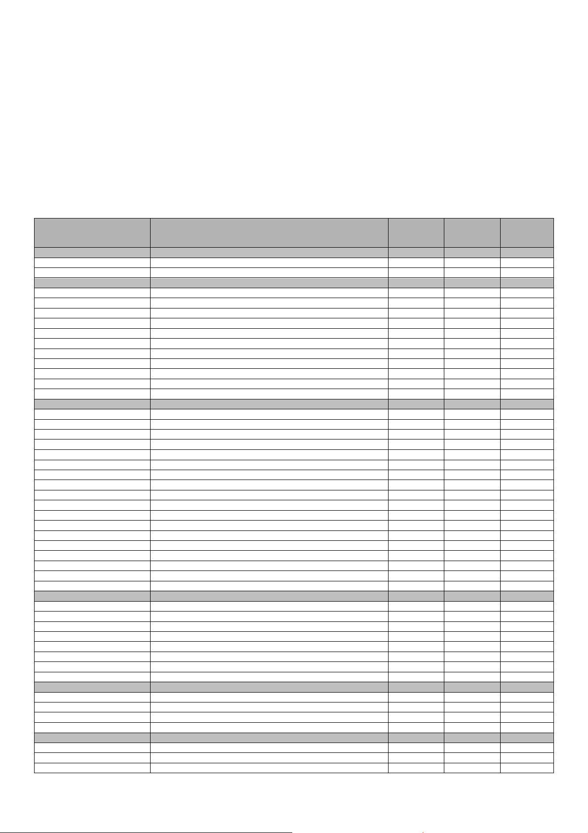
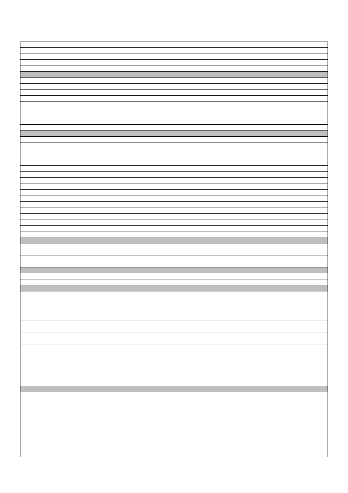
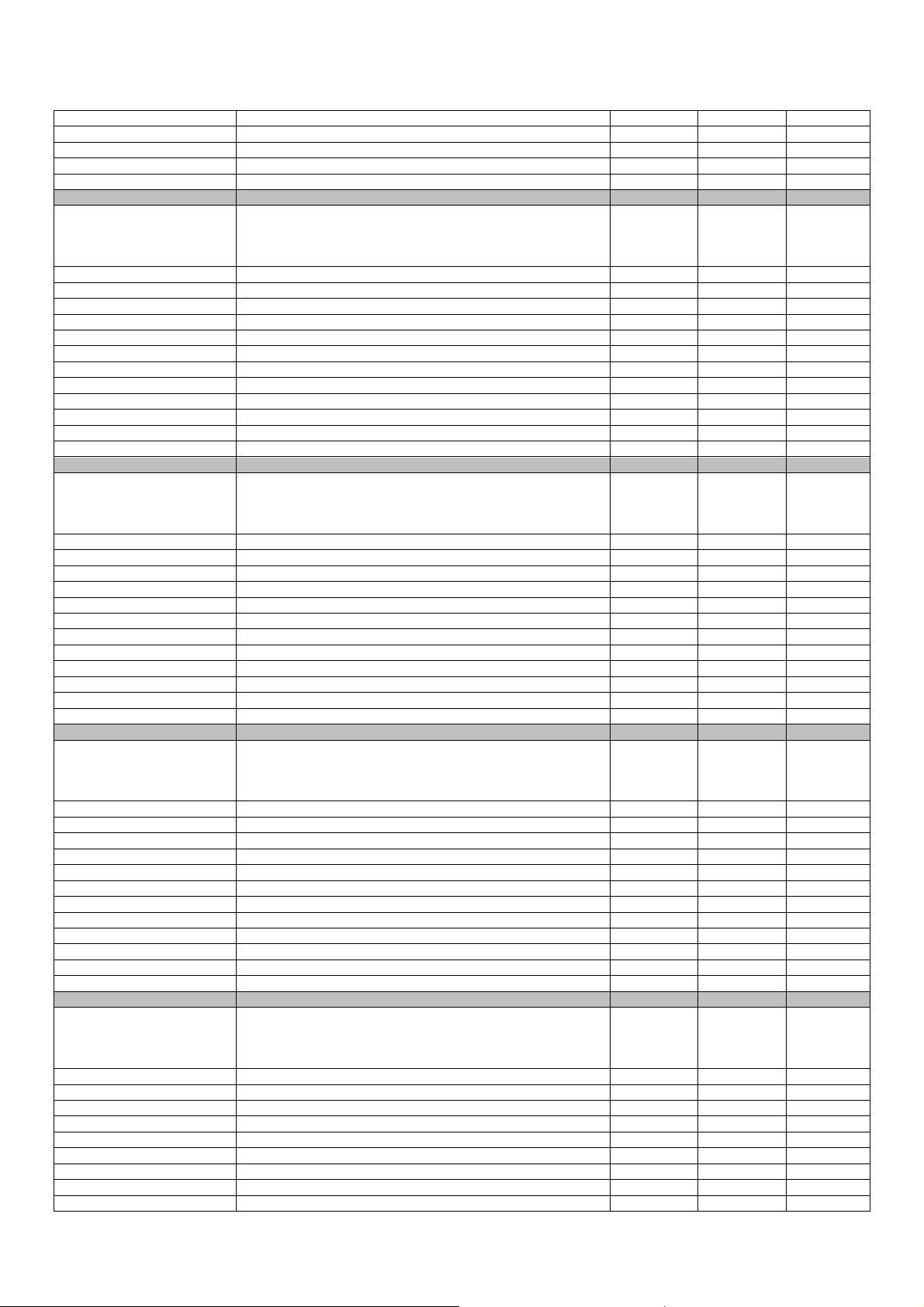
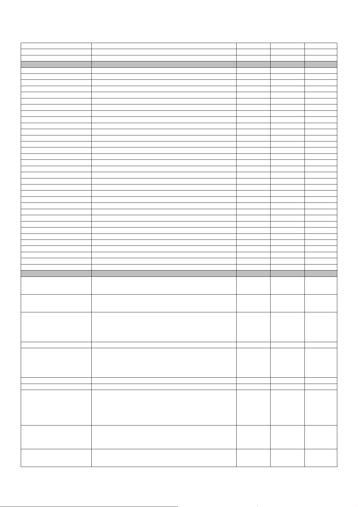
5.12 Configuration parameters
The following task map lists all the configuration parameters contained in the user menu, maintainer, installer and
manufacturer.
For each parameter is also provided a brief description, the range of permissible values, the unit of measure and the
default value proposed.
The menus are structured according to the logic stated in the corresponding sections described above.
5.12.1 List of configuration parameters
Label
USER PARAMETERS
ONOFF State of the unit OFF 0: OFF 1: ON
Mode Season mod. Winter 0:Winter 1:Summer
MAINTENANCE PARAMETERS: HOURS
PM01 Pump operation time alarm 20000 0 65535
PM02 Line 1 pump operation time 0 0 65535
PM03 Line 2 pump operation time 0 0 65535
PM04 Line 3 pump operation time 0 0 65535
PM05 Line 4 pump operation time 0 0 65535
PM06 Line 5 pump operation time 0 0 65535
PM07 Line 6 pump operation time 0 0 65535
PM08 Boiler operation time alarm 20000 0 65535
PM09 Boiler operation time 0 0 65535
PM10 Chiller-Heat pump operation time alarm 20000 0 65535
PM11 Chiller-Heat pump operation time 0 0 65535
MAINTENANCE PARAMETERS: MANUAL
PM30 Enable manual operation line 1 pump Disab. 0:Disab. 1:Enab.
PM31 Force manual line 1 pump OFF OFF ON
PM32 Enable manual operation line 2 pump Disab. 0:Disab. 1:Enab.
PM33 Force manual line 2 pump OFF OFF ON
PM34 Enable manual operation line 3 pump Disab. 0:Disab. 1:Enab.
PM35 Force manual line 3 pump OFF OFF ON
PM36 Enable manual operation line 4 pump Disab. 0:Disab. 1:Enab.
PM37 Force manual line 4 pump OFF OFF ON
PM38 Enable manual operation line 5 pump Disab. 0:Disab. 1:Enab.
PM39 Force manual line 5 pump OFF OFF ON
PM40 Enable manual operation line 6 pump Disab. 0:Disab. 1:Enab.
PM41 Force manual line 6 pump OFF OFF ON
PM42 Enable manual HP Disab. 0:Disab. 1:Enab.
PM43 Force manual HP OFF OFF ON
PM44 Enable manual boiler Disab. 0:Disab. 1:Enab.
PM45 Force manual boiler OFF OFF ON
PM46 Enable manual chiller Disab. 0:Disab. 1:Enab.
PM47 Force manual chiller OFF OFF ON
MAINTENANCE PARAMETERS: ENABLING
PM51 Enabling MCZN1 YES NO YES
PM52 Enabling MCZN2 YES NO YES
PM53 Enabling MCZN3 YES NO YES
PM54 Enabling MCZN4 YES NO YES
PM55 Enabling MCZN5 YES NO YES
PM56 Enabling MCZN6 YES NO YES
PM57 Enabling MCZN7 YES NO YES
PM58 Enabling MCZN8 YES NO YES
MAINTENANCE PARAMETERS: ANTIGRIP
PM20 Enable pumps antigrip Enab. Disab. Enab.
PM21 Enable mixing valve antigrip Enab. Disab. Enab.
PM22 Week day for antigrip Ven. Dom. Sab.
PM23 Hour for antigrip 2 0 23
MAINTENANCE PARAMETERS: OFFSET
PM80 Offset delivery 1 0.0 -10.0 10.0
PM81 Offset delivery 2 0.0 -10.0 10.0
PM82 Offset delivery 3 0.0 -10.0 10.0
Parameter description Default Min Max
page 32 of 74
Page 33
Evco S.p.A. c-pro 3 CLIMA sistema | Installer manual ver.1.1 | Code 144CP3CSE114
PM83 Offset delivery 4 0.0 -10.0 10.0
PM84 Offset delivery 5 0.0 -10.0 10.0
PM85 Offset delivery 6 0.0 -10.0 10.0
PM86 Offset external 0.0 -10.0 10.0
PM87 Offset return 0.0 -10.0 10.0
INSTALLER PARAMETERS: LINES
PL01 Number of lines 1 0 6
PL02 Line 5 assignment on zone 0 0 8
PL03 Line 6 assignment on zone 0 0 8
PL04 Numero f zone modules 1 0 8
CH-HP regulation:
PL05
0: Band
1: Valve max
Band Band Valve min
2: Valve min
PL06 CH-HP switching off delay (active request) [minutes] 1 0 30
INSTALLER PARAMETERS: CONTROL
PR01 Enabling boiler YES NO YES
Kind of refrigeration unit:
PR02
0: Boiler
1: Chiller
Chiller Boiler Chiller+HP
2: Chiller+HP
PR04 Summer/Winter switching limit 5.0 -30.0 30.0
PR05 Winter/Summer switching limit 30.0 -30.0 30.0
PR06 Summer/Winter switching delay [h] 1 0 255
PR10 Enabling antifreeze Enab. Disab. Enab.
PR11 Antifreeze temperature ignition pumps -5.0 -15.0 15.0
PR12 Antefreeze set cycling pump -1.0 -15.0 15.0
PR13 Antifreeze offset cycling pump 2.0 0.0 20.0
PR14 ON time of cycling pump [min] 10 0 999
PR15 OFF time of cycling pump [min] 360 0 999
PR16 External temperature set for HP to boiler switching 7.0 -20.0 30.0
PR17 External temperature offset for HP to boiler switching 5.0 0.0 10.0
PR18 Maximum number of HP functioning hours 3 0 65535
INSTALLER PARAMETERS: PUMPS
PP01 ON lines pump delay [sec] 30 0 255
PP02 OFF lines pump delay [sec] 30 0 255
PP03 Mixing valve delay from lines pump ON [sec] 30 0 255
PP04 CH-HP delay from lines pump ON [sec] 60 0 255
INSTALLER PARAMETERS: VALVES
PV01 Climatic curve summer offset 5.0 0.0 90.0
PV02 Climatic curve winter offset 5.0 0.0 90.0
INSTALLER PARAMETERS: MIXING VALVE1
Mode
PV03
0:Closed
1:Modul.
Modul. Closed Fix
2:Fix
PV04 Fix opening 20 0 100
PV05 Proportional band 5.0 0.0 10.0
PV06 Integral time [sec] 0 0 65535
PV07 Dew point offset 3.0 -10.0 10.0
PV08 Climatic curve min. external temperature (summer) 10.0 0.0 30.0
PV09 Climatic curve max. external temperature (summer) 30.0 10.0 60.0
PV10 Climatic curve setpoint (summer) 7.0 0.0 40.0
PV11 Climatic curve min. external temperature (winter) -5.0 -30.0 30.0
PV12 Climatic curve max. external temperature (winter) 10.0 0.0 30.0
PV13 Climatic curve setpoint (winter) 35.0 0.0 90.0
PV70 Min. value 0 0 100
PV71 Max. value 100 0 100
INSTALLER PARAMETERS: MIXING VALVE2
Mode
PV14
0:Closed
1:Modul.
Modul. Closed Fix
2:Fix
PV15 Fix opening 20 0 100
PV16 Proportional band 5.0 0.0 10.0
PV17 Integral time [sec] 0 0 65535
PV18 Dew point offset 3.0 -10.0 10.0
PV19 Climatic curve min. external temperature (summer) 10.0 0.0 30.0
PV20 Climatic curve max. external temperature (summer) 30.0 10.0 60.0
PV21 Climatic curve setpoint (summer) 7.0 0.0 40.0
page 33 of 74
Page 34
Evco S.p.A. c-pro 3 CLIMA sistema | Installer manual ver.1.1 | Code 144CP3CSE114
PV22 Climatic curve min. external temperature (winter) -5.0 -30.0 30.0
PV23 Climatic curve max. external temperature (winter) 10.0 0.0 30.0
PV24 Climatic curve setpoint (winter) 35.0 0.0 90.0
PV72 Min. value 0 0 100
PV73 Max. value 100 0 100
INSTALLER PARAMETERS: MIXING VALVE3
Mode
PV25
0:Closed
1:Modul.
Modul. Closed Fix
2:Fix
PV26 Fix opening 20 0 100
PV27 Proportional band 5.0 0.0 10.0
PV28 Integral time [sec] 0 0 65535
PV29 Dew point offset 3.0 -10.0 10.0
PV30 Climatic curve min. external temperature (summer) 10.0 0.0 30.0
PV31 Climatic curve max. external temperature (summer) 30.0 10.0 60.0
PV32 Climatic curve setpoint (summer) 7.0 0.0 40.0
PV33 Climatic curve min. external temperature (winter) -5.0 -30.0 30.0
PV34 Climatic curve max. external temperature (winter) 10.0 0.0 30.0
PV35 Climatic curve setpoint (winter) 35.0 0.0 90.0
PV74 Min. value 0 0 100
PV75 Max. value 100 0 100
INSTALLER PARAMETERS: MIXING VALVE4
Mode
PV36
0:Closed
1:Modul.
Modul. Closed Fix
2:Fix
PV37 Fix opening 20 0 100
PV38 Proportional band 5.0 0.0 10.0
PV39 Integral time [sec] 0 0 65535
PV40 Dew point offset 3.0 -10.0 10.0
PV41 Climatic curve min. external temperature (summer) 10.0 0.0 30.0
PV42 Climatic curve max. external temperature (summer) 30.0 10.0 60.0
PV43 Climatic curve setpoint (summer) 7.0 0.0 40.0
PV44 Climatic curve min. external temperature (winter) -5.0 -30.0 30.0
PV45 Climatic curve max. external temperature (winter) 10.0 0.0 30.0
PV46 Climatic curve setpoint (winter) 35.0 0.0 90.0
PV76 Min. value 0 0 100
PV77 Max. value 100 0 100
INSTALLER PARAMETERS: MIXING VALVE5
Mode
PV47
0:Closed
1:Modul.
Modul. Closed Fix
2:Fix
PV48 Fix opening 20 0 100
PV49 Proportional band 5.0 0.0 10.0
PV50 Integral time [sec] 0 0 65535
PV51 Dew point offset 3.0 -10.0 10.0
PV52 Climatic curve min. external temperature (summer) 10.0 0.0 30.0
PV53 Climatic curve max. external temperature (summer) 30.0 10.0 60.0
PV54 Climatic curve setpoint (summer) 7.0 0.0 40.0
PV55 Climatic curve min. external temperature (winter) -5.0 -30.0 30.0
PV56 Climatic curve max. external temperature (winter) 10.0 0.0 30.0
PV57 Climatic curve setpoint (winter) 35.0 0.0 90.0
PV78 Min. value 0 0 100
PV79 Max. value 100 0 100
INSTALLER PARAMETERS: MIXING VALVE6
Mode
PV58
0:Closed
1:Modul.
Modul. Closed Fix
2:Fix
PV59 Fix opening 20 0 100
PV60 Proportional band 5.0 0.0 10.0
PV61 Integral time [sec] 0 0 65535
PV62 Dew point offset 3.0 -10.0 10.0
PV63 Climatic curve min. external temperature (summer) 10.0 0.0 30.0
PV64 Climatic curve max. external temperature (summer) 30.0 10.0 60.0
PV65 Climatic curve setpoint (summer) 7.0 0.0 40.0
PV66 Climatic curve min. external temperature (winter) -5.0 -30.0 30.0
PV67 Climatic curve max. external temperature (winter) 10.0 0.0 30.0
page 34 of 74
Page 35
Evco S.p.A. c-pro 3 CLIMA sistema | Installer manual ver.1.1 | Code 144CP3CSE114
PV68 Climatic curve setpoint (winter) 35.0 0.0 90.0
PV80 Min. value 0 0 100
PV81 Max. value 100 0 100
INSTALLER PARAMETERS: ALARMS
PA01 Enabling pumps operation time hours alarm Enab. Disab. Enab.
PA02 Enabling boiler operation time hours alarm Enab. Disab. Enab.
PA03 Enabling CH-HP operation time hours alarm Enab. Disab. Enab.
PA04 Pumps alarm delay [sec] 0 0 999
PA05 Flow switch alarm delay at start [sec] 30 0 255
PA06 Flow switch alarm delay [sec] 5 0 255
PA07 Max. alarm flow alarm for manual 3 0 255
PA08 Return for alarm delta temperature 3.0 0.0 20.0
PA09 Return temperature alarm delay 180 0 999
PA10 Set HT linea1 45.0 0.0 90.0
PA11 Diff. HT linea1 5.0 0.0 10.0
PA12 Set LT linea1 10.0 -10.0 40.0
PA13 Diff. LT linea1 5.0 0.0 10.0
PA14 Set HT linea2 80.0 0.0 90.0
PA15 Diff. HT linea2 5.0 0.0 10.0
PA16 Set LT linea2 4.0 -10.0 40.0
PA17 Diff. LT linea2 5.0 0.0 10.0
PA18 Set HT linea3 45.0 0.0 90.0
PA19 Diff. HT linea3 5.0 0.0 10.0
PA20 Set LT linea3 10.0 -10.0 40.0
PA21 Diff. LT linea3 5.0 0.0 10.0
PA22 Set HT linea4 80.0 0.0 90.0
PA23 Diff. HT linea4 5.0 0.0 10.0
PA24 Set LT linea4 4.0 -10.0 40.0
PA25 Diff. LT linea4 5.0 0.0 10.0
PA26 Set HT linea5 45.0 0.0 90.0
PA27 Diff. HT linea5 5.0 0.0 10.0
PA28 Set LT linea5 10.0 -10.0 40.0
PA29 Diff. LT linea5 5.0 0.0 10.0
PA30 Set HT linea6 80.0 0.0 90.0
PA31 Diff. HT linea6 5.0 0.0 10.0
PA32 Set LT linea6 4.0 -10.0 40.0
PA33 Diff. LT linea6 5.0 0.0 10.0
INSTALLER PARAMETERS: OTHERS
Language
PH01
0:English
English English Italian
1:Italian
Kind of unit On/Off
PH02
0:DI
DI DI BMS
1:BMS
Kind of changeover
0: None
PH03
1: BMS
Auto --- Auto
2: DI
3: Automatic
PH05 CAN address 1 1 127
CAN Baudrate
0:20K
PH06
1:50K
50K 20K 500K
2:125K
3:500K
PH07 Enable public V-Graph YES NO YES
PH11 Modbus address 1 1 247
Modbus Baud [Kbit]
0:1200
PH12
1:2400
2:4800
9600 1200 19200
3:9600
4:19200
Modbus parity
PH13
0:None
1:Odd
Even None Even
2:Even
Modbus Stopbit
PH14
0:1 bit
1 bit 1 bit 2 bit
1: 2 bit
page 35 of 74
Page 36
Evco S.p.A. c-pro 3 CLIMA sistema | Installer manual ver.1.1 | Code 144CP3CSE114
MANUFACTOR PARAMETERS: SETTINGS
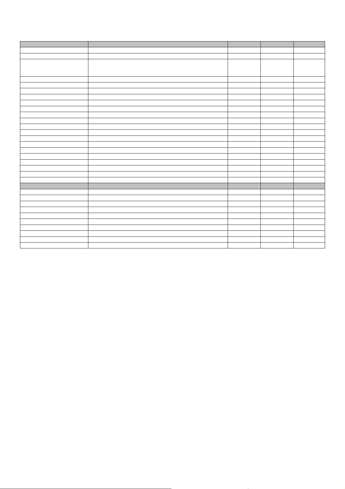
PG00 Enable MCPS Disab. Disab. Enab.
PG01 Enable external temperature probe Enab. Disab. Enab.
PG02
PG03 Enable mixing valv1 Enab. Disab. Enab.
PG04 Enable mixing valv2 Enab. Disab. Enab.
PG05 Enable mixing valv3 Enab. Disab. Enab.
PG06 Enable mixing valv4 Enab. Disab. Enab.
PG07 Enable mixing valv5 Enab. Disab. Enab.
PG08 Enable mixing valv6 Enab. Disab. Enab.
PG09 Line 1 pump mode Thermo. Cont. Thermo.
PG10 Line 2 pump mode Thermo. Cont. Thermo.
PG11 Line 3 pump mode Thermo. Cont. Thermo.
PG12 Line 4 pump mode Thermo. Cont. Thermo.
PG13 Line 5 pump mode Thermo. Cont. Thermo.
PG14 Line 6 pump mode Thermo. Cont. Thermo.
PG15 Kind of protection line1 Lock Lock Flow
PG16 Kind of protection line2 Lock Lock Flow
PG17 Kind of protection line3 Lock Lock Flow
PG18 Kind of protection line4 Lock Lock Flow
PG19 Kind of protection line5 Lock Lock Flow
PG20 Kind of protection line6 Lock Lock Flow
MANUFACTOR PARAMETERS: I/O
PH30 Boiler alarm logic N.O. N.O. N.C.
PH31 CH-HP alarm boiler N.O. N.O. N.C.
PH32 Pump L1 flow/thermal alarm logic N.O. N.O. N.C.
PH33 Pump L2 flow/thermal alarm logic N.O. N.O. N.C.
PH34 Remote ON/OFF logic N.O. N.O. N.C.
PH35 Pump L3 flow/thermal alarm logic N.O. N.O. N.C.
PH36 Pump L4 flow/thermal alarm logic N.O. N.O. N.C.
PH37 Pump L5 flow/thermal alarm logic N.O. N.O. N.C.
PH38 Pump L6 flow/thermal alarm logic N.O. N.O. N.C.
PH39 Summer/Winter logic N.O. N.O. N.C.
Assignment AI4 probe
0: DI summer/winter
1:Return temperature
DI E/I DI E/I Return t.
5.13 State of the unit
There are several procedures for switching the unit on/off:
1) Via the relative On/Off key
Switch-on: press the relative key for about 2 seconds: if all of the other conditions enabled are present, the
machine goes to "ON".
Switch-off: press the relative key for about 2 seconds: the machine goes to "OFF" mode.
2) Via the relative controlling On/Off key from digital input (parameter PH2)
Switch-on: close contact of the remote On/Off: If all other conditions are enabled, the machine switches to
"ON".
Switch-off: if the contact of remote On/Off is open, the machine switches to "OFF from digital input" (marked
with the words "OFF in. Digital").
3) Via supervision protocol
Switch-on: to activate the switch-on state from protocol: if all of the other conditions enabled are present, the
machine goes to "ON".
Switch-off: if the ignition state is deactivated from protocol, the machine goes to “OFF from supervision
protocol” (also indicated by “OFF supervisor”).
The On/Off state from key has priority with respect to the other two. In fact, the On/Off states from digital input and
supervision protocol can only be reached with machine on from key.
page 36 of 74
Page 37
Evco S.p.A. c-pro 3 CLIMA sistema | Installer manual ver.1.1 | Code 144CP3CSE114
The machine On/Off key is the ESC key, pressed for about 2 seconds.
The remote On/Off input (when present) can be configured via the parameters:
- PH02: Enables the function
- PH34 : Sets the NC, NO logic for the digital contact
5.13.1 OFF state due to alarm
When the machine is on, a further state exists OFF due to alarm, which switches the nit and all devices off until the
alarm condition has been reset. If digital consent is missing in this state from supervisor or switch-off is requested
from key, the power plant goes into the relative OFF state. The alarms that cause this state are:
- Delivery 1 probe alarm
- Delivery 2 probe alarm
The machine works normally again when the alarm has been reset.
5.14 Summer/winter functioning mode
The operational mode can assume the following values:
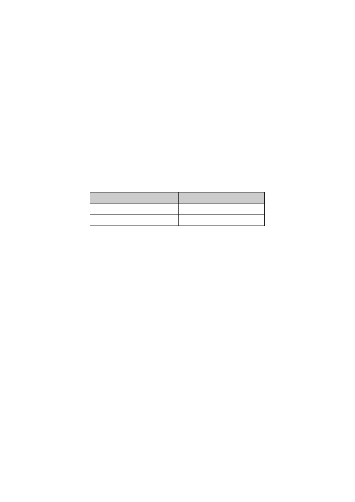
E/I keyboard parameter Description
S= SUMMER Summer functioning mode
W= WINTER Winter functioning mode
There are procedures that allow to set the c-pro 3 CLIMA sistema functioning mode:
1) Via the parameter regarding S/W keyboard in the maintenance menu
Setting - Be positioned on the S/W keyboard parameter and, pressing the ENTER key, modify the value using
the UP and DOWN keys. Confirm by pressing ENTER again.
2) Via supervision protocol (function enabled by parameter PH03)
Setting - Send the operational mode change control via relative state from protocol.
This control has priority with respect to the S/W control from keyboard
3) Using the Summer/Winter from digital input control PH03
Setting - With contact open the unit is in “winter” functioning mode, with contact closed in “summer”
functioning mode.
4) Using Summer/Winter automatic switch-over function PH03
Setting - Switch-over from summer to winter takes place when the external temperature remains above the
value established with the PH05 parameter for the time established by the PH06 parameter
Conversely, switch-over from winter to summer takes place when the external temperature remains below
the value established with the PH04 parameter for the time established by the PH06 parameter
This control has priority with respect to the S/W control from digital input
page 37 of 74
Page 38
Evco S.p.A. c-pro 3 CLIMA sistema | Installer manual ver.1.1 | Code 144CP3CSE114
As well as selection of the operational mode, a digital output is linked to the summer/winter functioning mode, which
functions as follows:
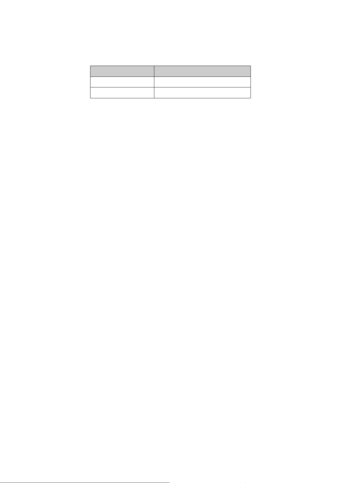
Functioning mode State of the digital input
S= SUMMER Summer/Winter output ACTIVE
W= WINTER Summer/Winter output OFF
A typical application of the summer/winter relay is to automatically inform the chiller/heat pump unit of the system
functioning mode.
Note. For the two manual summer/winter change modes (procedures 1 and 2) it is recommended to carry out the
summer/winter change with the machine off.
page 38 of 74
Page 39
Evco S.p.A. c-pro 3 CLIMA sistema | Installer manual ver.1.1 | Code 144CP3CSE114
6 c-pro 3 hecto MCZN regulator
Via the form you can manage the collectors of heating/cooling and dehumidification of those, for its management is
necessary to use a remote user interface.
It is able to handle up to six zones (with only temperature control) or three areas (both with control of temperature
and humidity).
6.1 List of pages
This paragraph presents the main pages and menus on the form MCZN. As stated previously the general menu is
divided into two levels: maintainer, manufacturer and installer, and there are sections: section of alarms and info and
free consultation.
6.2 Menu
6.2.1 Main Screen area
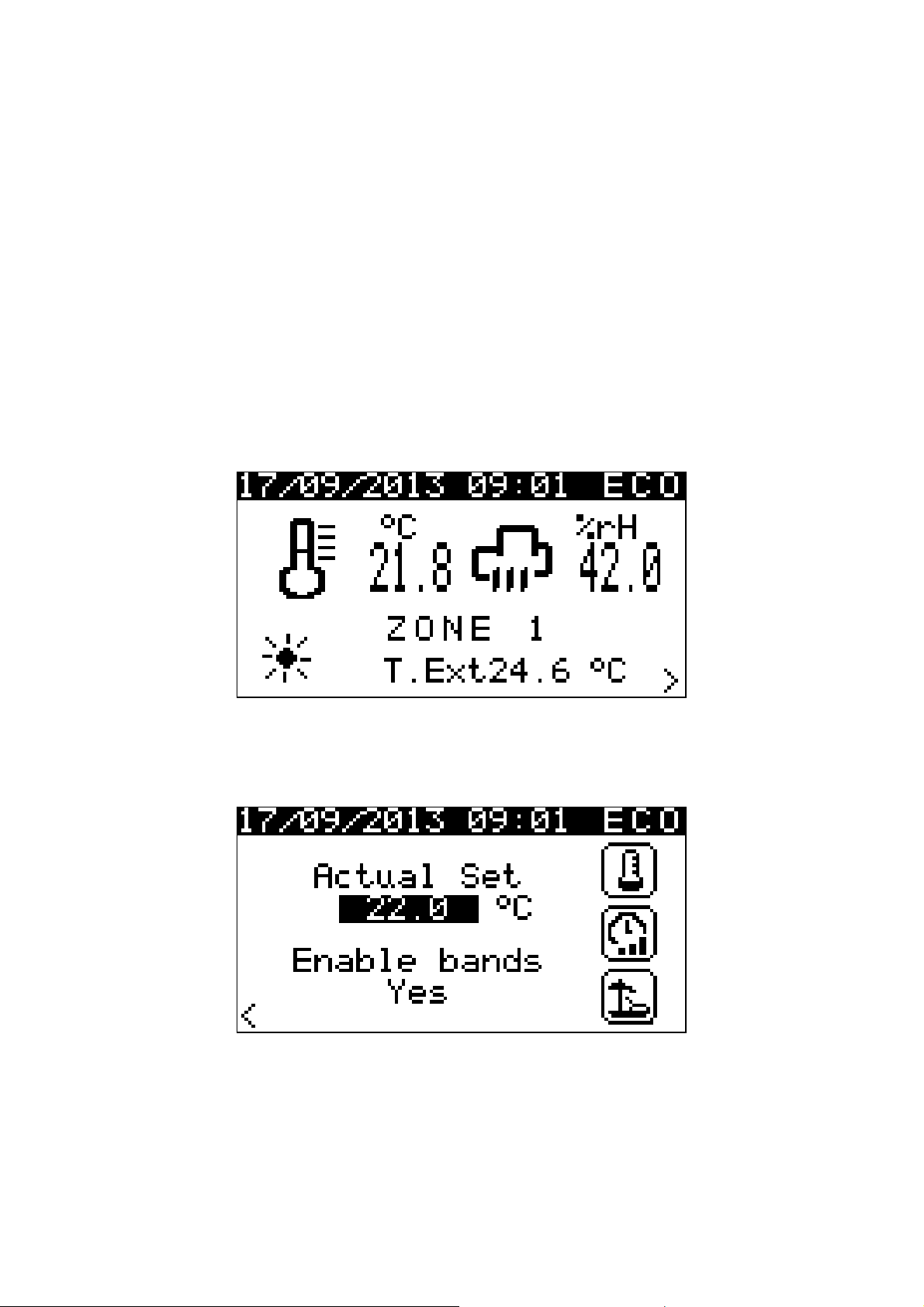
Main screen that displays date, time, time slot current, temperature, humidity, outside temperature, season and zone
name. Press RIGHT to access the configuration screen area.
6.2.2 Configuration screen area
In this screen you can see and change the current setpoint by pressing DOWN and also select one of the 3 icons on
the right that will allow you to access the following screens:
1 - Setpoint area
2 - Set time slots
3 - Setting the holiday function
page 39 of 74
Page 40
Evco S.p.A. c-pro 3 CLIMA sistema | Installer manual ver.1.1 | Code 144CP3CSE114
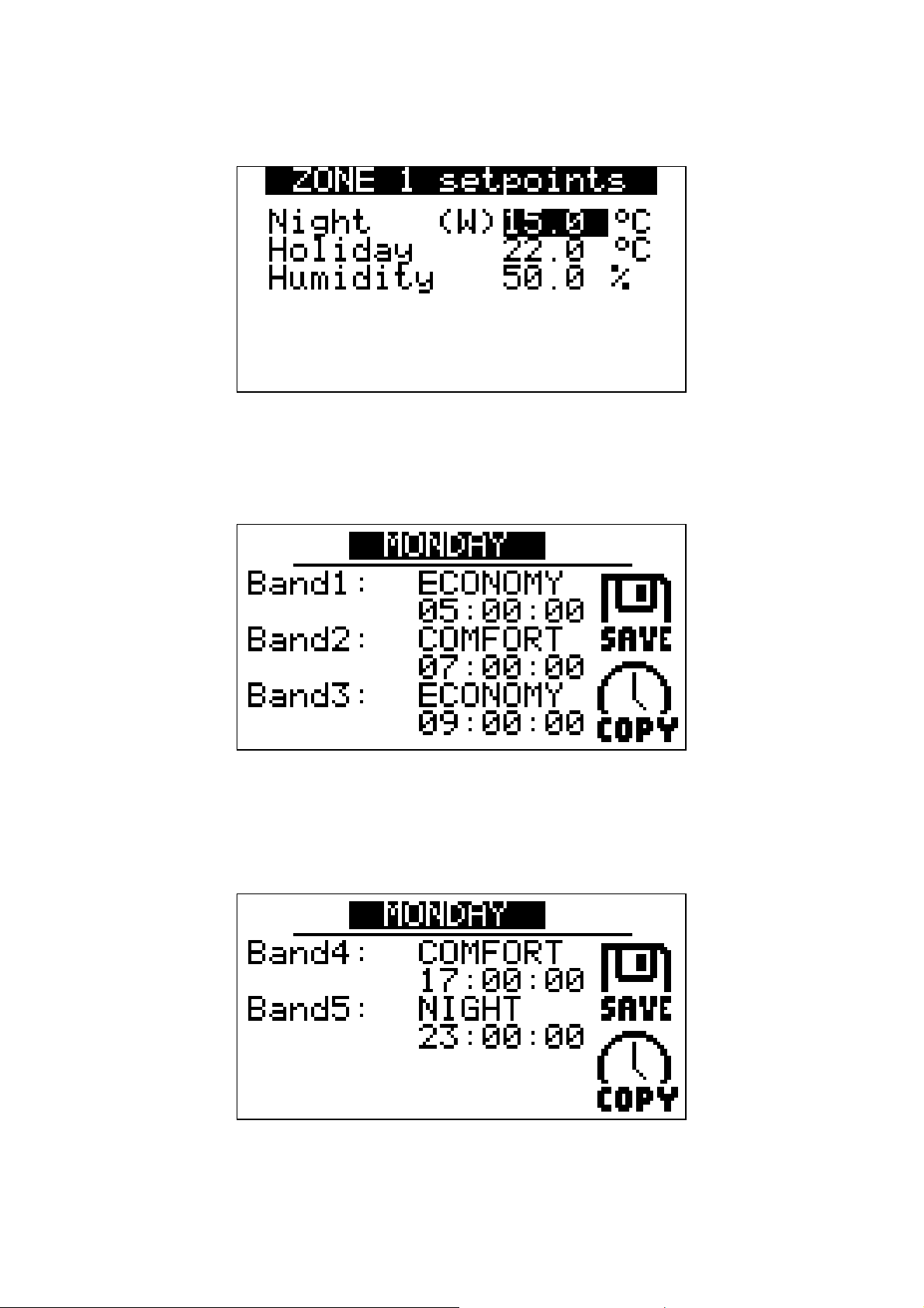
6.2.3 Screenshot setpoint area
Configuration Screen 1
6.2.4 Screen time zones
The time slots are available for each day 5 and for each of them can be configured setpoint "night", "economy",
"comfort" and a start time.
The time slot set to continue until the next time is reached, if there are no set time periods subsequent to the current
time slot will continue indefinitely.
It 'also a facility "COPY" setting that allows you to copy all the settings of the time slots of the day preceding the day
edited. At the end of the SAVE position settings and confirm the save.
page 40 of 74
Page 41
Evco S.p.A. c-pro 3 CLIMA sistema | Installer manual ver.1.1 | Code 144CP3CSE114
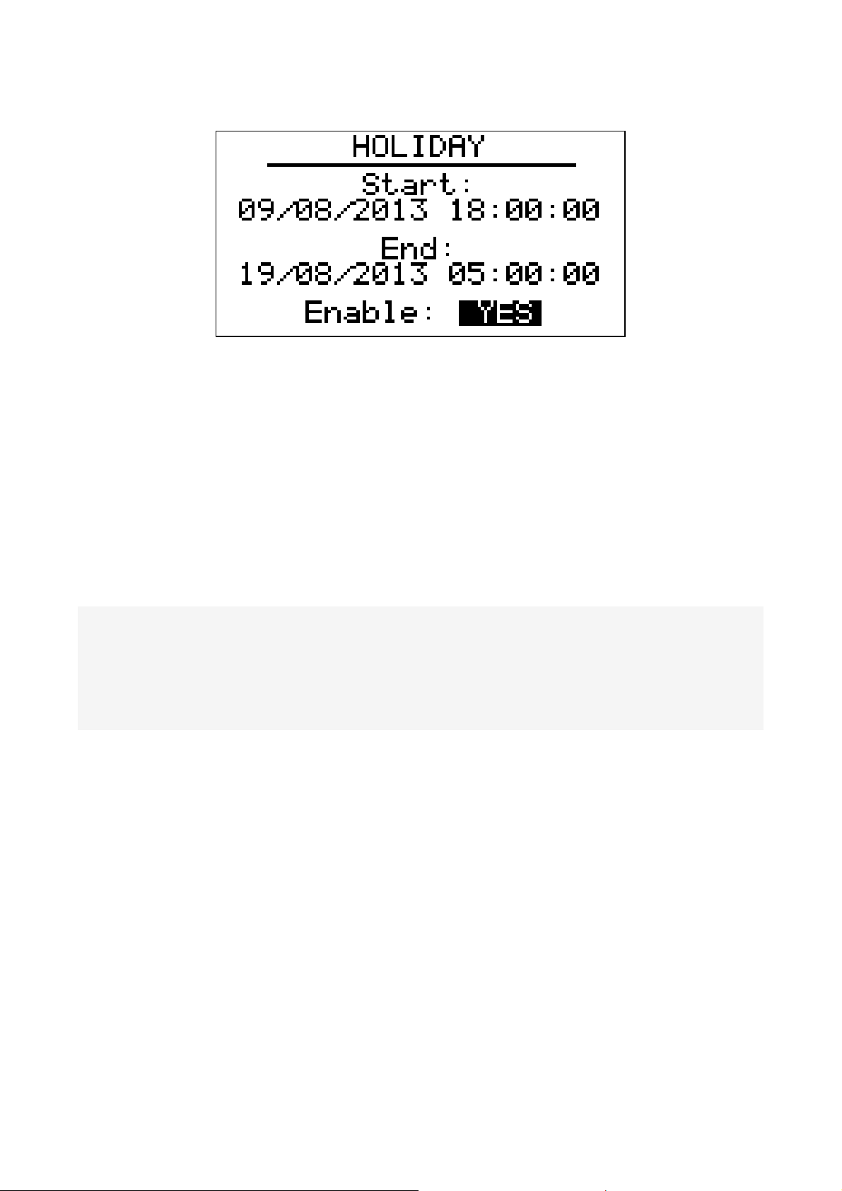
6.2.5 Screenshot holiday
You can set the start date and end and enabling the vacation mode.
6.3 Main menu accessible by MCCT
Under Network Module MCCT you can access the setup pages of all the operating parameters of the controller are
organized in the following sub-menus:
6.3.1 Alarm menu
This menu contains information related to the MCZN alarms present/active in the controller.
For more details refer to the section of the form MCCT, Menu alarms.
6.3.2 Maintainer menu
The maintenance menu is level 2, enter the password that is used for maintenance level or higher to view/edit the
parameters in this branch.
From this menu you can change the operating mode (auto-manual), the calibration probes and finally setting the
drive's remote setpoint.
For submenu in the Setup menu for the module maintainer explained previously MCCT.
6.3.3 Installer menu
The Installer menu is level 3, that is used to enter the password installer level to be able to view / edit the parameters
in this branch.
From this menu you can view and set the configuration of the system managed by the MCZN.
- Menu ZONE: entering areas in the menu you can set the address of the CAN module MCZN, set the number of zones
of the module and enable the adaptive adjustment.
At this point you can access the parameters dedicated to each of the 6 zones and set the control type, the supply line
and associated probes associated.
- Menu CLIMATE: Climate entering the menu you can configure the parameters of the temperature curve for each
zone.
- Menu DEHUMIDIFY: entering the menu you can enable dehumidification operation of the water supply for the
dehumidification function and configure the dehumidification function.
- Menu fancoils: fancoils entering the menu you can set the number and type of fan coil units can be managed and
how they work.
- Menu ALARM: entering in the alarm menu you can configure the general parameters.
page 41 of 74
Page 42
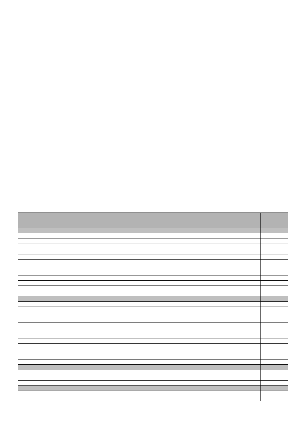
Evco S.p.A. c-pro 3 CLIMA sistema | Installer manual ver.1.1 | Code 144CP3CSE114
6.3.4 Manufactor menu
The menu manufactor is level 4, that is used to enter the password level builder to be able to view/edit the parameters
in this branch.
- Menu AI: AI entering the menu you can configure the types of sensors.
- Menu DI: entering the menu you can configure the function associated with each DI, its logic and the assignment to
the desired zone.
- Menu DO: DO entering the menu you can then configure the logic of use.
6.4 Pages On/Off
By accessing the pages of On/Off Controller MCZN you have the ability to view the system status (On/Off), the season,
the state of the network module MCCT and the presence of alarms.
6.5 Configuration Parameters
The following task map lists all the configuration parameters contained in the maintenance menu, installer and
manufacturer MCZN managed by the application.
For each parameter is also provided a brief description, the range of permissible values, the unit of measure and the
default value proposed.
The menus are structured according to the logic stated in the respective paragraphs of description.
6.5.1 List of configuration parameters
Label
MAINTENANCE PARAMETERS: MANUAL
PM10 Enable manual mode DO1 Disab. 0:Disab. 1:Enab.
PM11 Force manual DO1 OFF OFF ON
PM12 Enable manual mode DO2 Disab. 0:Disab. 1:Enab.
PM13 Force manual DO2 OFF OFF ON
PM14 Enable manual mode DO3 Disab. 0:Disab. 1:Enab.
PM15 Force manual DO3 OFF OFF ON
PM16 Enable manual mode DO4 Disab. 0:Disab. 1:Enab.
PM17 Force manual DO4 OFF OFF ON
PM18 Enable manual mode DO5 Disab. 0:Disab. 1:Enab.
PM19 Force manual DO5 OFF OFF ON
PM20 Enable manual mode DO6 Disab. 0:Disab. 1:Enab.
PM21 Force manual DO6 OFF OFF ON
MAINTENANCE PARAMETERS: CALIBRATION
PM80 Offset T. Z1 0.0 -10.0 10.0
PM81 Offset T. Z2 0.0 -10.0 10.0
PM82 Offset T. Z3 0.0 -10.0 10.0
PM83 Offset T. Z4 0.0 -10.0 10.0
PM84 Offset T. Z5 0.0 -10.0 10.0
PM85 Offset T. Z6 0.0 -10.0 10.0
PM86 Offset H. Z1 0.0 -10.0 10.0
PM87 Offset H. Z2 0.0 -10.0 10.0
PM88 Offset H. Z3 0.0 -10.0 10.0
PM89 Offset H. Z4 0.0 -10.0 10.0
PM90 Offset H. Z5 0.0 -10.0 10.0
PM91 Offset H. Z6 0.0 -10.0 10.0
INSTALLER PARAMETERS: ZONES
PZ01 Zone module logic position in the CAN network 1 0 8
PZ02 Zones number inside the module 3 1 6
PZ03 Enable auto adaptative control Enab. Disab. Enab.
INSTALLER PARAMETERS: ZONE 1
PZ04
Parameter description Default Min Max
Kind of regulation
0: OFF
S/W OFF S/W
page 42 of 74
Page 43
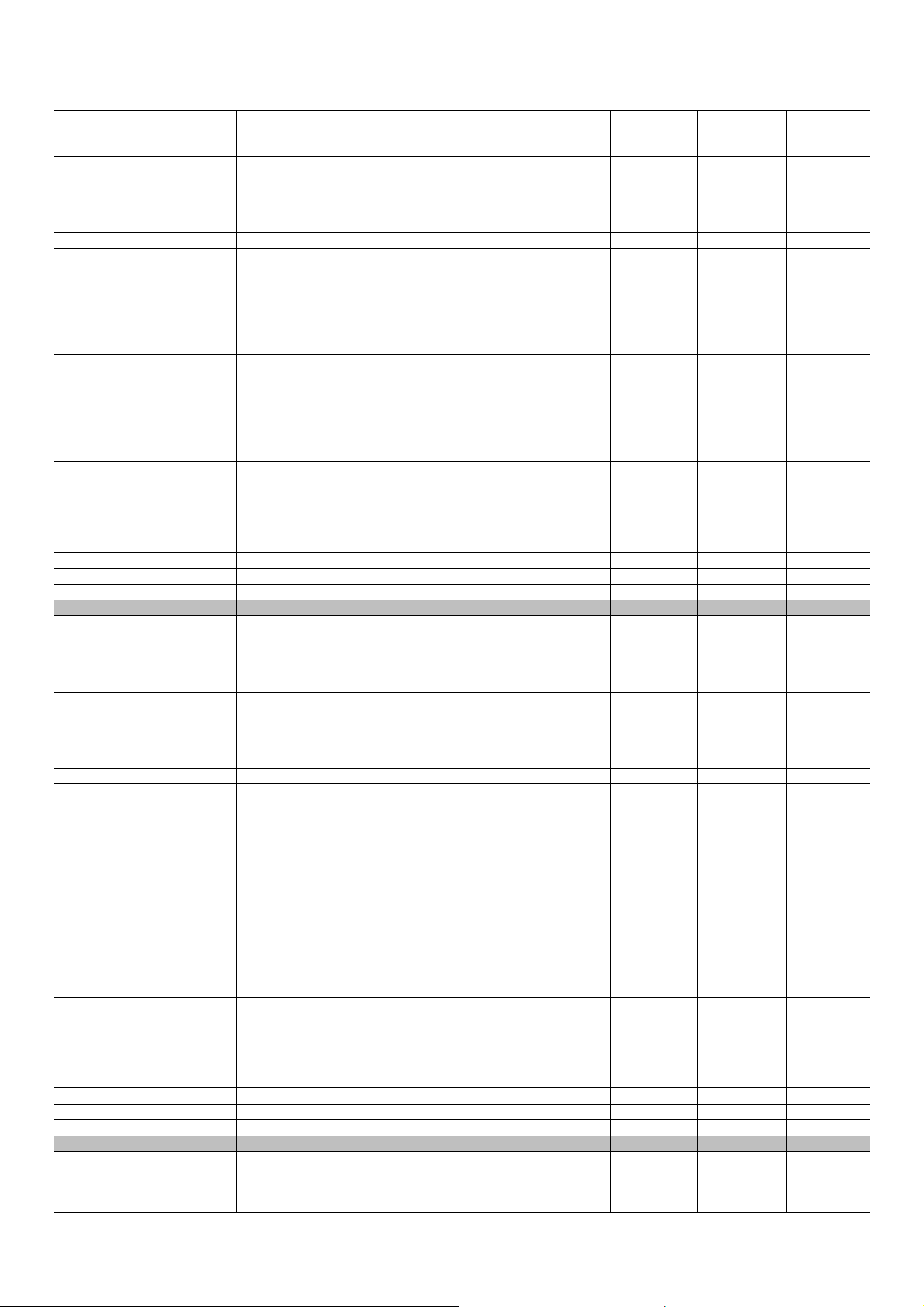
Evco S.p.A. c-pro 3 CLIMA sistema | Installer manual ver.1.1 | Code 144CP3CSE114
1: Summer
2: Winter
3: Summer/Winter
Kind of booster
0: OFF
PZ05
1: Summer
--- OFF S+W
2: Winter
3: Summer + Winter
PZ16 Delivery line associated (CT) 1 1 6
Temperature probe
0: --1: Vroom
PZ22
2: AI1
Vroom --- AI4
3: AI2
4: AI3
5: AI4
Humidity transducer
0: --1: Vroom
PZ23
2: AI1
Vroom --- AI4
3: AI2
4: AI3
5: AI4
Humidity transducer
0: ---
PZ24
1: AI1
2: AI2
--- --- AI4
3: AI3
4: AI4
PZ40 Enable regulator Enab. Disab. Enab.
PZ46 Diff. Temperature valve regulation 1.0 0.0 99.9
PZ52 Diff. Humidity valve regulation 5 0 99
INSTALLER PARAMETERS: ZONE 2
Kind of regulation
0: OFF
PZ06
1: Summer
E/I OFF E/I
2: Winter
3: Summer/Winter
Kind of booster
0: OFF
PZ07
1: Summer
--- OFF E+I
2: Winter
3: Summer + Winter
PZ17 Delivery line associated (CT) 1 1 6
Temperature probe
0: --1: Vroom
PZ25
2: AI1
Vroom --- AI4
3: AI2
4: AI3
5: AI4
Humidity transducer
0: --1: Vroom
PZ26
2: AI1
Vroom --- AI4
3: AI2
4: AI3
5: AI4
Humidity transducer
0: ---
PZ27
1: AI1
2: AI2
--- --- AI4
3: AI3
4: AI4
PZ41 Enable regulator Enab. Disab. Enab.
PZ47 Diff. Temperature valve regulation 1.0 0.0 99.9
PZ53 Diff. Humidity valve regulation 5 0 99
INSTALLER PARAMETERS: ZONE 3
Kind of regulation
PZ08
0: OFF
1: Summer
E/I OFF E/I
2: Winter
page 43 of 74
Page 44
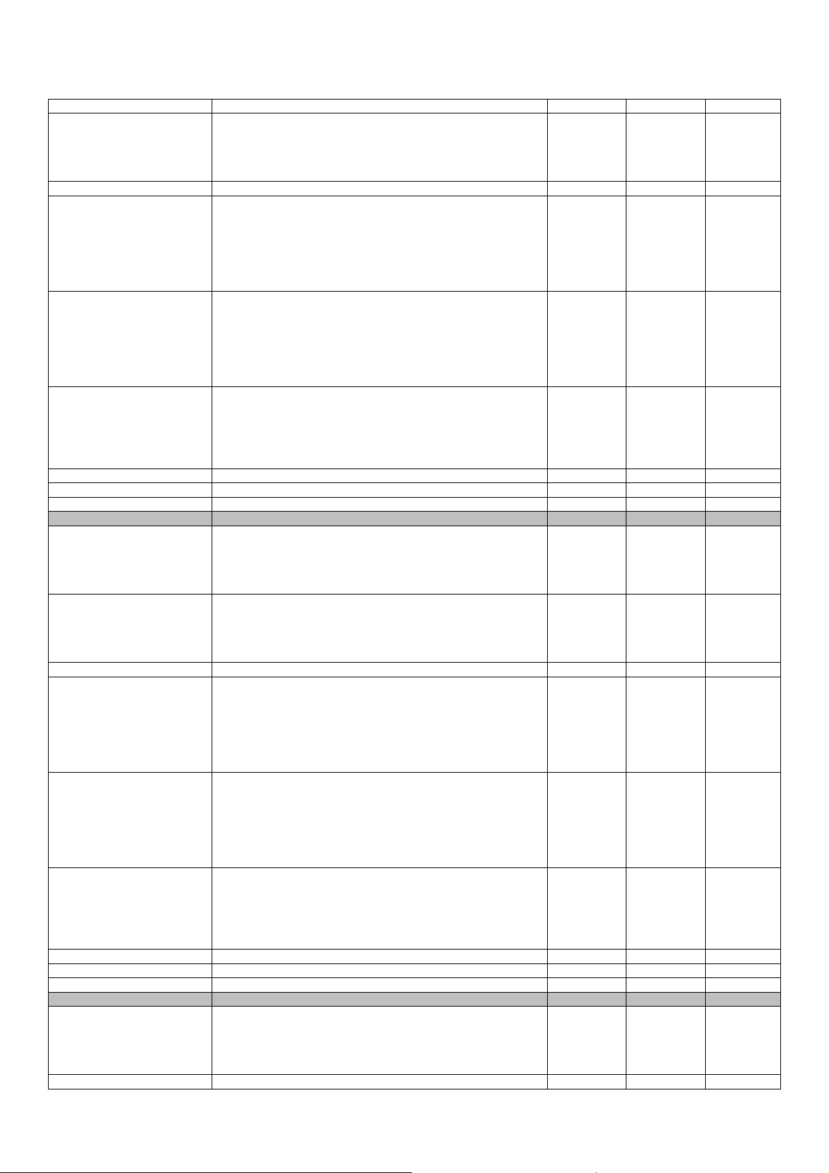
Evco S.p.A. c-pro 3 CLIMA sistema | Installer manual ver.1.1 | Code 144CP3CSE114
3: Summer/Winter
Kind of booster
0: OFF
PZ09
1: Summer
--- OFF E+I
2: Winter
3: Summer + Winter
PZ18 Delivery line associated (CT) 1 1 6
Temperature probe
0: --1: Vroom
PZ28
2: AI1
Vroom --- AI4
3: AI2
4: AI3
5: AI4
Humidity transducer
0: --1: Vroom
PZ29
2: AI1
Vroom --- AI4
3: AI2
4: AI3
5: AI4
Humidity transducer
0: ---
PZ30
1: AI1
2: AI2
--- --- AI4
3: AI3
4: AI4
PZ42 Enable regulator Enab. Disab. Enab.
PZ48 Diff. Temperature valve regulation 1.0 0.0 99.9
PZ54 Diff. Humidity valve regulation 5 0 99
INSTALLER PARAMETERS: ZONE 4
Kind of regulation
0: OFF
PZ10
1: Summer
E/I OFF E/I
2: Winter
3: Summer/Winter
Kind of booster
0: OFF
PZ11
1: Summer
--- OFF E+I
2: Winter
3: Summer + Winter
PZ19 Delivery line associated (CT) 1 1 6
Temperature probe
0: --1: Vroom
PZ31
2: AI1
Vroom --- AI4
3: AI2
4: AI3
5: AI4
Humidity transducer
0: --1: Vroom
PZ32
2: AI1
Vroom --- AI4
3: AI2
4: AI3
5: AI4
Humidity transducer
0: ---
PZ33
1: AI1
2: AI2
--- --- AI4
3: AI3
4: AI4
PZ43 Enable regulator Enab. Disab. Enab.
PZ49 Diff. Temperature valve regulation 1.0 0.0 99.9
PZ55 Diff. Humidity valve regulation 5 0 99
INSTALLER PARAMETERS: ZONE 5
Kind of regulation
0: OFF
PZ12
1: Summer
E/I OFF E/I
2: Winter
3: Summer/Winter
PZ13 Kind of booster --- OFF E+I
page 44 of 74
Page 45
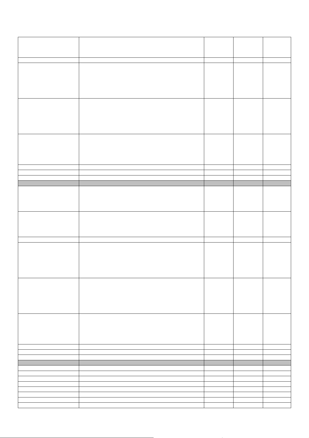
Evco S.p.A. c-pro 3 CLIMA sistema | Installer manual ver.1.1 | Code 144CP3CSE114
0: OFF
1: Summer
2: Winter
3: Summer + Winter
PZ20 Delivery line associated (CT) 1 1 6
Temperature probe
0: --1: Vroom
PZ34
2: AI1
Vroom --- AI4
3: AI2
4: AI3
5: AI4
Humidity transducer
0: --1: Vroom
PZ35
2: AI1
Vroom --- AI4
3: AI2
4: AI3
5: AI4
Humidity transducer
0: ---
PZ36
1: AI1
2: AI2
--- --- AI4
3: AI3
4: AI4
PZ44 Enable regulator Enab. Disab. Enab.
PZ50 Diff. Temperature valve regulation 1.0 0.0 99.9
PZ56 Diff. Humidity valve regulation 5 0 99
INSTALLER PARAMETERS: ZONE 6
Kind of regulation
0: OFF
PZ14
1: Summer
E/I OFF E/I
2: Winter
3: Summer/Winter
Kind of booster
0: OFF
PZ15
1: Summer
--- OFF E+I
2: Winter
3: Summer + Winter
PZ21 Delivery line associated (CT) 1 1 6
Temperature probe
0: --1: Vroom
PZ37
2: AI1
Vroom --- AI4
3: AI2
4: AI3
5: AI4
Humidity transducer
0: --1: Vroom
PZ38
2: AI1
Vroom --- AI4
3: AI2
4: AI3
5: AI4
Humidity transducer
0: ---
PZ39
1: AI1
2: AI2
--- --- AI4
3: AI3
4: AI4
PZ45 Enable regulator Enab. Disab. Enab.
PZ51 Diff. Temperature valve regulation 1.0 0.0 99.9
PZ57 Diff. Humidity valve regulation 5 0 99
INSTALLER PARAMETERS: CLIMATIC
PC01 Min external temp. curve Z1 (Summer) 12.0 0.0 60.0
PC02 Min external temp. curve Z1 (Winter) -5.0 -30.0 60.0
PC03 Max external temp curve Z1 (Summer) 35.0 0.0 60.0
PC04 Max external temp curve Z1 (Winter) 12.0 -30.0 60.0
PC05 Delta curve Z1 0.0 -10.0 10.0
PC06 Min external temp. curve Z2 (Summer) 12.0 0.0 60.0
PC07 Min external temp. curve Z2 (Winter) -5.0 -30.0 60.0
PC08 Max external temp curve Z2 (Summer) 35.0 0.0 60.0
page 45 of 74
Page 46
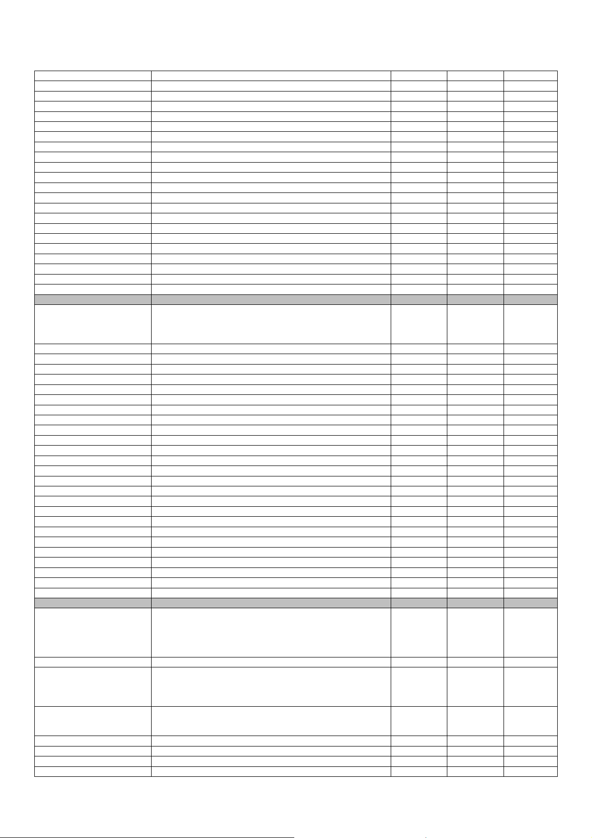
Evco S.p.A. c-pro 3 CLIMA sistema | Installer manual ver.1.1 | Code 144CP3CSE114
PC09 Max external temp curve Z2 (Winter) 12.0 -30.0 60.0
PC10 Delta curve Z2 0.0 -10.0 10.0
PC11 Min external temp. curve Z3 (Summer) 12.0 0.0 60.0
PC12 Min external temp. curve Z3 (Winter) -5.0 -30.0 60.0
PC13 Max external temp curve Z3 (Summer) 35.0 0.0 60.0
PC14 Max external temp curve Z3 (Winter) 12.0 -30.0 60.0
PC15 Delta curve Z3 0.0 -10.0 10.0
PC16 Min external temp. curve Z4 (Summer) 12.0 0.0 60.0
PC17 Min external temp. curve Z4 (Winter) -5.0 -30.0 60.0
PC18 Max external temp curve Z4 (Summer) 35.0 0.0 60.0
PC19 Max external temp curve Z4 (Winter) 12.0 -30.0 60.0
PC20 Delta curve Z4 0.0 -10.0 10.0
PC21 Min external temp. curve Z5 (Summer) 12.0 0.0 60.0
PC22 Min external temp. curve Z5 (Winter) -5.0 -30.0 60.0
PC23 Max external temp curve Z5 (Summer) 35.0 0.0 60.0
PC24 Max external temp curve Z5 (Winter) 12.0 -30.0 60.0
PC25 Delta curve Z5 0.0 -10.0 10.0
PC26 Min external temp. curve Z6 (Summer) 12.0 0.0 60.0
PC27 Min external temp. curve Z6 (Winter) -5.0 -30.0 60.0
PC28 Max external temp curve Z6 (Summer) 35.0 0.0 60.0
PC29 Max external temp curve Z6 (Winter) 12.0 -30.0 60.0
PC30 Delta curve Z6 0.0 -10.0 10.0
INSTALLER PARAMETERS: DEHUMID
Enable delivery water for dehumidification
PD01
0: No
1: Yes
Yes No Solo CHHP
2: Solo CH-HP
PD02 Booster/dehumidificator bond Enab. Disab. Enab.
PD04 Delta integration Z1 (Winter) 1.0 0.0 10.0
PD05 Delay integration Z1 (Winter) [min] 5 1 255
PD06 Delta integration Z1 (Summer) 0.0 0.0 10.0
PD07 Delay integration Z1 (Summer) [min] 5 1 255
PD08 Delta integration Z2 (Winter) 1.0 0.0 10.0
PD09 Delay integration Z2 (Winter) [min] 5 1 255
PD10 Delta integration Z2 (Summer) 0.0 0.0 10.0
PD11 Delay integration Z2 (Summer) [min] 5 1 255
PD12 Delta integration Z3 (Winter) 1.0 0.0 10.0
PD13 Delay integration Z3 (Winter) [min] 5 1 255
PD14 Delta integration Z3 (Summer) 0.0 0.0 10.0
PD15 Delay integration Z3 (Summer) [min] 5 1 255
PD16 Delta integration Z4 (Winter) 1.0 0.0 10.0
PD17 Delay integration Z4 (Winter) [min] 5 1 255
PD18 Delta integration Z4 (Summer) 0.0 0.0 10.0
PD19 Delay integration Z4 (Summer) [min] 5 1 255
PD20 Delta integration Z5 (Winter) 1.0 0.0 10.0
PD21 Delay integration Z5 (Winter) [min] 5 1 255
PD22 Delta integration Z5 (Summer) 0.0 0.0 10.0
PD23 Delay integration Z5 (Summer) [min] 5 1 255
PD24 Delta integration Z6 (Winter) 1.0 0.0 10.0
PD25 Delay integration Z6 (Winter) [min] 5 1 255
PD26 Delta integration Z6 (Summer) 0.0 0.0 10.0
PD27 Delay integration Z6 (Summer) [min] 5 1 255
PARAMETRI INSTALLATORE: FANCOILS
Fancoils number
0: ---
PF00
1: 1 DO
0 0 2
2: 1 AO
3: 2 AO
PF01 Fancoil 1 tubes 2 2 4
Kind of fancoil 1
PF02
0: --1: Post heating
--- --- PR+R
2: Post heating + heating
Priority of fancoil 1
PF03
0: Temp.
Temp. Temp. Humid.
1: Humid.
PF04 fancoil 2 tubes 2 2 4
PF05 Kind of fancoil 2 --- --- PR+R
PF06 Priority of fancoil 2 Temp. Temp. Humid.
PF07 Heating fancoil 1 delta 1.0 0.0 10.0
page 46 of 74
Page 47
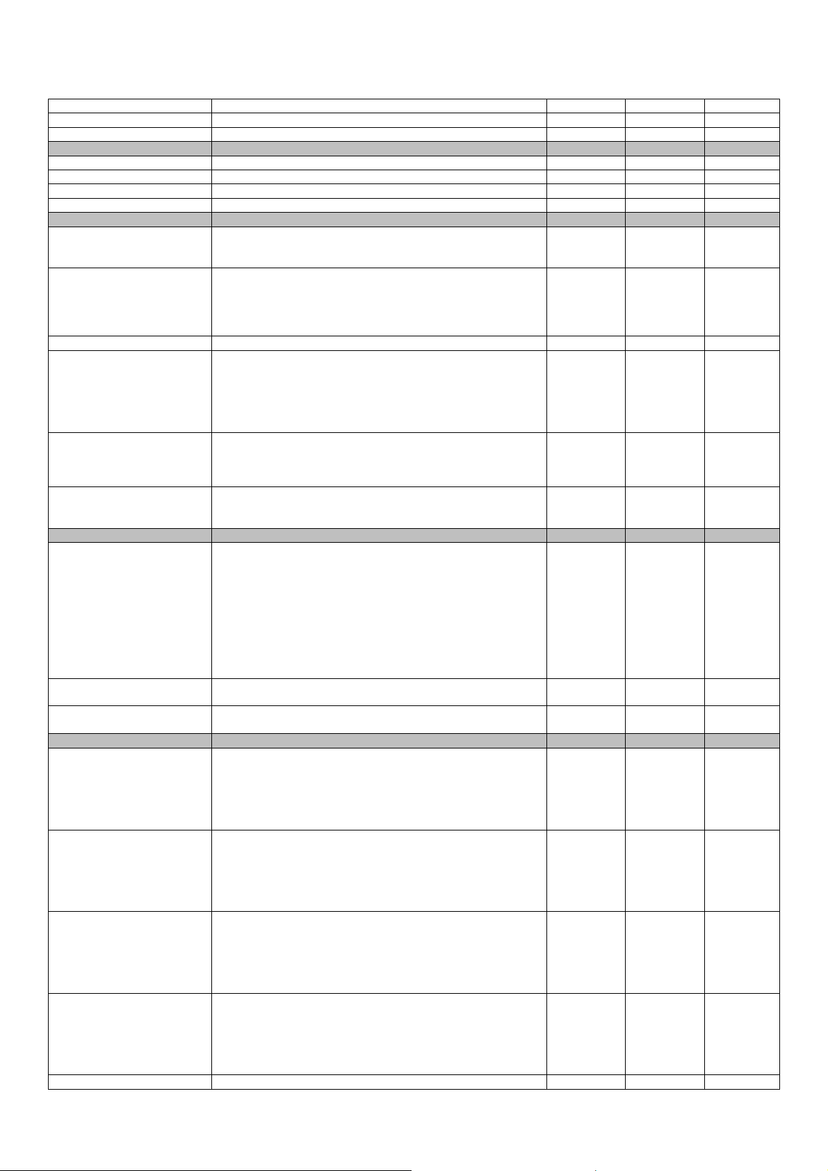
Evco S.p.A. c-pro 3 CLIMA sistema | Installer manual ver.1.1 | Code 144CP3CSE114
PF08 Heating fancoil 1 delay [min] 5 1 255
PF09 Heating fancoil 2 delta 1.0 0.0 10.0
PF10 Heating fancoil 2 delay [min] 5 1 255
INSTALLER PARAMETERS: ALARMS
PA01 Dehumidificator alarm delay [sec] 0 0 65535
PA02 Kind of dehumidificator alarm Auto auto Manu
PA03 Anti-freeze setpoint 3.0 -10.0 30.0
PA04 Anti-freeze band 1.0 -10.0 30.0
INSTALLER PARAMETERS: OTHERS
Kind of V-room visualizations
PH05
1: Separate zones
Zone sep. Zone sep. All
2: all zones in a single V-room
Baudrate CAN
0:20K
PH06
1:50K
50K 20K 500K
2:125K
3:500K
PH11 Modbus address 1 1 247
Baud Modbus[Kbit]
0:1200
PH12
1:2400
2:4800
9600 1200 19200
3:9600
4:19200
Modbus parity
PH13
0:None
1:Odd
Even None Even
2:Even
Stopbit Modbus
PH14
0:1 bit
1 bit 1 bit 2 bit
1: 2 bit
MANUFACTOR PARAMETERS: AI
Sensor AI1:
1: PTC
2: NTC
3: 0-20mA
PH50
4: 4-20mA
5: 0-5V
NTC PTC
NTC 10K-
3
6: 0-10V
7: PT1000
8: NTC 10K-2
9: NTC 10K-3
PH51 Sensor AI2 NTC PTC
PH52 Sensor AI3 NTC PTC
NTC 10K-
3
NTC 10K-
3
MANUFACTOR PARAMETERS: DI
Kind of DI1:
0: ---
PH53
1: Zone ON/OFF
2: Zone alarm
Termo.T. --- Termo.U.
3: Zone temperature external thermostat
4: Zone humidity external thermostat
Kind of DI2:
0: ---
PH54
1: Zone ON/OFF
2: Zone alarm
Termo.T. --- Termo.U.
3: Zone temperature external thermostat
4: Zone humidity external thermostat
Kind of DI3:
0: ---
PH55
1: Zone ON/OFF
2: Zone alarm
Termo.T. --- Termo.U.
3: Zone temperature external thermostat
4: Zone humidity external thermostat
Kind of DI4:
0: ---
PH56
1: Zone ON/OFF
2: Zone alarm
Termo.T. --- Termo.U.
3: Zone temperature external thermostat
4: Zone humidity external thermostat
PH57 Kind of DI5: Termo.T. --- Termo.U.
page 47 of 74
Page 48
Evco S.p.A. c-pro 3 CLIMA sistema | Installer manual ver.1.1 | Code 144CP3CSE114
0: --1: Zone ON/OFF
2: Zone alarm
3: Zone temperature external thermostat
4: Zone humidity external thermostat
PH58 Assignment DI1 1 --- 6
PH59 Assignment DI2 2 --- 6
PH60 Assignment DI3 3 --- 6
PH61 Assignment DI4 4 --- 6
PH62 Assignment DI5 5 --- 6
PH63 Logic DI1 N.O. N.O. N.C.
PH64 Logic DI2 N.O. N.O. N.C.
PH65 Logic DI3 N.O. N.O. N.C.
PH66 Logic DI4 N.O. N.O. N.C.
PH67 Logic DI5 N.O. N.O. N.C.
MANUFACTOR PARAMETERS: DO
PH68 Logic DO1 N.O. N.O. N.C.
PH69 Logic DO2 N.O. N.O. N.C.
PH70 Logic DO3 N.O. N.O. N.C.
PH71 Logic DO4 N.O. N.O. N.C.
PH72 Logic DO5 N.O. N.O. N.C.
PH73 Logic DO6 N.O. N.O. N.C.
6.6 Unit status
The state controller MCZN is given by the state regulator central heat MCCT.
6.7 Zones status
There are two ways to change the status of regulation of the 6 areas:
1) Using Remote On/Off Keyboard
Through the pages of the installer parameters.
2) Using the commands On/Off from digital input for all 6 zones
Switch On: close contact with On/Off Remote zone: enabled if all other conditions are present, the regulation of the
zone switches to "ON".
Power Off: If the contact of the On/Off remote zone is open, the control zone goes OFF.
page 48 of 74
Page 49

Evco S.p.A. c-pro 3 CLIMA sistema | Installer manual ver.1.1 | Code 144CP3CSE114
7 c-pro 3 hecto MCPS regulator
7.1 List of pages
This paragraph presents the main pages and menus found in the MCPS application. As shown previously, the main
menu is divided into 2 levels: maintenance technician and installer are also present along with "States” and "System
Network" sections for free consultation. The latter is also necessary for navigation among modules.
The menus have the following structure:
• States
- Functioning state of DHW circuit (boiler)
- Functioning state of solar panels 1 circuit
- Functioning state of solar panels 2 circuit
- Functioning state of auxiliary circuit (aux1)
• Main menu
- Alarms/Log
- Alarms log
- Reset active alarms
- Reset alarms log
- Set-point
- Setting DHW tank set-point (boiler)
- Setting auxiliary circuit set-point (aux1)
- Maintenance (maintenance technician menu)
- general parameters
- Panels maintenance
- Auxiliary circuit management (aux1)
- DHW tank management (boiler)
- Flow switches
- Manual
- Timer
- Installer
- I/O configuration
- general parameters
- Solar panels
- Initialisation
- Program info
• System Network
- MCPS system local network
page 49 of 74
Page 50

Evco S.p.A. c-pro 3 CLIMA sistema | Installer manual ver.1.1 | Code 144CP3CSE114
7.2 Main page
The main page is displayed during the ON state:
By pressing the DOWN key it is possible to select whether to access the State, pages, the Main Menu or the System
Network, described below.
By pressing ESC key, the controller will go back to the main display of the MCCT thermal power plant controller.
7.3 State pages
By accessing the STATUS menu from the “Main Page” access the state pages relative to the DHW circuit (boiler), the
two solar panels circuits and the auxiliary circuit (aux1) managed by the MCPS regulator.
7.3.1 Functioning state of DHW circuit (boiler)
The DHW circuit state page (boiler) will contain the following information:
The DHW (boiler) circuit state pages show, as well as the state of the line described in the previous illustration, the
regulation temperature of the DHW tank (i.e. the lower of the two), the DHW tank work set-point, the upper and lower
temperature of the DHW tank and the days missing to the next planned running of the antilegionella cycle.
Pressing ENTER on the “>” access the next state page, corresponding with the SOLAR PANELS CIRCUIT 1.
By pressing ENTER on the “<” access the last state page, i.e. the AUXILIARY 1 CIRCUIT state page.
When the 60 seconds time-out has passed or by pressing ESC, the controller will go back to the display of the main ON
page.
7.3.2 Functioning state of solar panels circuit 1 and 2
The functioning state page of the solar panels circuits 1 and 2 will contain the following information:
The state page of the solar panels circuit 1-2 shows, as well as the state of the line described in the previous
illustration, the temperature of the water in the solar panels circuit and the maximum temperature accepted before
the high temperature alarm is signalled
Pressing ENTER on the “>” access the next state page, corresponding with the SOLAR PANELS CIRCUIT 2.
By pressing ENTER on the “<” access the previous state page, i.e. the DHW CIRCUIT state page.
When the 60 seconds time-out has passed or by pressing ESC, the controller will go back to the display of the main ON
page.
7.3.3 Functioning state of auxiliary circuit
The auxiliary circuit state page will contain the following information:
The state page of the auxiliary circuit shows, as well as the state of the line described in the previous illustration, the
temperature of the water of the auxiliary circuit and its work set-point set.
Pressing ENTER on the “>” access the next initial state page, corresponding with the DHW CIRCUIT.
By pressing ENTER on the “<” access the previous state page, i.e. the SOLAR PANELS 2 state page.
When the 60 seconds time-out has passed or by pressing ESC, the controller will go back to the display of the main ON
page.
page 50 of 74
Page 51

Evco S.p.A. c-pro 3 CLIMA sistema | Installer manual ver.1.1 | Code 144CP3CSE114
7.4 Main menu
By accessing the pages of the main menu from the “Main Page” of the MCPS regulator, access the setting pages of all
regulator functioning parameters organised in the following sub-menu:
7.4.1 Alarms/log menu
This menu contains the functionality linked to the controller alarms and the alarms log of the system.
7.4.2 Alarms log
To view the MCPS regulator alarms log, press ENTER on “storico allarmi (alarms log)”.
If there are no elements present, “NO ALLARMI” (NO ALARMS) is displayed, otherwise the following page is proposed,
where the information of the last element memorised in the log is given:
To view the previous element, press ENTER on “>>”. By repeating this procedure, scroll all log elements until the first
element inserted is reached. From here, on request of the next element, the last element memorised is re-proposed:
the log display is circular.
To exit the log pages, press the ESC key or wait 60 timeout seconds. This level is not protected by a password.
7.4.3 Reset active alarms
To view the active alarms of the MCPS regulator, press ENTER on “Rst running alarms” .
If there are no alarms present, “no alarms” is displayed, otherwise a series of pages appear containing all possible
alarms present in the controller with relative codes and description.
The alarm or the alarms present, will be highlighted by flashing "Rst ALARM”.
If the ESC key is pressed from an alarm page or 60 timeout seconds are allowed to pass, you go back to the main
page of the application. This level is not protected by a password.
7.4.4 Reset alarms log
To reset the memorised alarms log, press ENTER on “Rst storico allarmi” (Rest alarms log) and take the value of the
“Cancellazione totale elementi storico in memoria (Total cancellation of log elements in memory)” parameter to the
“Yes” value.
To exit the alarms log reset pages, press the ESC key or wait 60 timeout seconds. This level is not protected by a
password.
7.4.5 Set-point menu
From this menu it is possible to display and set the temperature work set-point for the DHW tank and for the AUX1
auxiliary circuit.
If the ESC key is pressed from a setting page or 240 timeout seconds are allowed to pass, you go back to the main
page of the application. This level is not protected by a password.
7.4.6 Maintenance menu
The maintenance menu is level 1, i.e. used to insert the maintenance level password or higher in order to
display/modify the parameters present in this branch.
From this menu it is possible to enable and set all features relative to the functions linked to the DHW tank and the
DHW circuits, solar panels and auxiliaries, contained in the MCPS application and precisely.
page 51 of 74
Page 52

Evco S.p.A. c-pro 3 CLIMA sistema | Installer manual ver.1.1 | Code 144CP3CSE114
Entering the GENERAL PARAMETERS menu, it is possible to enable/disable and set the parameters relative to the
execution of the Antigrip and Antilegionella cycles, as well as the calibration of the signals coming from the
temperature probes.
From the PANELS MAINTENANCE menu, it is possible to enable/disable and set the parameters relative to the periodic
activation cycles of the solar panels heat pumps and the solar panels Antistagnation function. The
activation/deactivation differentials of the pumps are set as well as the minimum and maximum temperature limits for
the two circuits.
The AUX 1 MANAGEMENT menu allows to set the parameters relative to the management of the Auxiliary, defining the
circulation pump activation mode, the plant type where it is placed, the water work set-point, its differential and the
calibration of the auxiliary probe.
Entering the DHW MANAGEMENT menu, it is possible to set an activation delay of the DHW circuit circulation pump.
For all flow switches present in the MCPS application, the FLOW SWITCHES menu allows to set a delay time from
machine ON, a delay time in normal conditions and the number of alarms with manual rearm in order to pass to the
necessity for automatic rearm of the alarm.
The MANUAL menu allows to set the functioning of the utilities managed by the application in manual/automatic mode,
thus forcing the state, to test its functionality.
Finally, the TIME COUNTER menu allows to display, enable, set and reset the functioning hours and the maintenance
requests for the users to manage the MCPS application.
7.4.7 Installer menu
The installer menu is level 2, i.e. used to insert the installer level password or higher in order to display/modify the
parameters present in this branch.
From this menu it is possible to view and set the configuration of the DHW system, the solar panels system/s and the
auxiliary system and their controls.
Entering the I/O CONFIGURATION menu it is possible to view the type of analogue inputs set in the application and set
the polarity of the digital inputs used.
Entering the GENERAL PARAMETERS menu, it is possible to define the main features present in the regulator for solar
panels, i.e. the name of the MCPS regulator, the number of solar panel circuits present in the system, the presence or
not of the auxiliary circuit, the number of temperature probes present in the DHW tank, the type of digital inputs for
protection of the circulation pumps and the features of the serial communication parameters both CANbus (c-pro 3
CLIMA sistema controllers network) and Modbus (towards the RICS supervision system or other BMS systems).
Entering the SOLAR PANELS menu it is possible to set the calibration of the solar panels temperature transducers, also
defining their minimum and maximum calibration values.
Finally the PASSWORDS menu allows to display and modify the 3 password levels present in the application.
page 52 of 74
Page 53

Evco S.p.A. c-pro 3 CLIMA sistema | Installer manual ver.1.1 | Code 144CP3CSE114
7.5 System Network page
From page network system controller MCPS you have the option to return to the application of thermal power plant
MCCT, as follows:
By pressing ESC key, the controller will go back all the same to the main display of the MCCT thermal power plant
controller.
7.6 Configuration parameters
Below find a list of all configuration parameters contained in the MAINTENANCE menu (maintenance technician) and
INSTALLER managed by the MCPS application.
A brief description is supplied for every parameter, the range of acceptable values, unit of measurement and the
default value proposed.
7.6.1 List of MAINTENANCE menu configuration parameters
Label
GENERAL PARAMETERS
General parameters
Antigrip
Execution day
General parameters
Antigrip
Execution hour
General parameters
Probes offset
Upper DHW tank
General parameters
Probes offset
Lower DHW tank
General parameters
Antilegionella
Enable
General parameters
Antilegionella
Mode
General parameters
Antilegionella
Start hour
General parameters
Antilegionella
Day week
General parameters
Antilegionella
Day month
Parameter description Default Min Max
Antigrip function start day Monday Sunday Saturday
Antigrip function start time 2:00 0:00 23:00
Boiler upper probe calibration (offset)
(expressed in °C)
Boiler lower probe calibration (offset)
(expressed in °C)
Enabling of antilegionella cycle
Antilegionella cycle activation mode
- MONTH = Monthly
- WEEK = Weekly
- DAY = Daily
Time of antilegionella cycle start
(expressed in hours:minutes)
Day of the week for antilegionella cycle start
(if weekly activation enabled)
Day of the month for antilegionella cycle start
(if monthly activation enabled)
0.0 -10.0 10.0
0.0 -10.0 10.0
No No Yes
WEEK MONTH DAY
16:00 0:00 23:00
Wednes-
day
15 1 28
Sunday Saturday
page 53 of 74
Page 54
Evco S.p.A. c-pro 3 CLIMA sistema | Installer manual ver.1.1 | Code 144CP3CSE114
General parameters
Antilegionella
Setpoint
General parameters
Antilegionella
Duration
Water temperature set-point during the antilegionella
cycle
(expressed in °C)
Duration of the antilegionella cycle
(expressed in minutes)
70.0 0.0 150.0
60 0 255
MAINTENANCE
Panels Maintenance
Periodic cycle
Interval
Panels MAINTENANCE
Periodic cycle
Duration
Interval between two periodic activation cycles of the
solar panels circulation pumps
(expressed in minutes)
Duration of the periodic activation cycle of the solar
panels circulation pumps
(expressed in minutes)
30 0 255
10 0 255
Anti-stagnation emergency management mode
- ON/OFF = via a heat disposal ON-OFF valve
Panels maintenance
Stag.emergency
- Cover1 = via cover opening closing management (on
same relay contact)
ON/OFF ON/OFF Cover2
- Cover2 = via cover opening closing management (on
two relay contacts)
Panels maintenance
ON hyst.
Panels maintenance
OFF hyst.
Panels maintenance
Temperature limits
HT setpoint
Panels maintenance
Temperature limits
HT hyst.
Panels maintenance
Temperature limits
LT setpoint
Panels maintenance
Temperature limits
LT hyst.
Offset (differential) solar panels pump connection,
relative to work set-point.
(expressed in °C)
Offset (differential) solar panels pump disconnection,
relative to work set-point.
(expressed in °C)
Solar panels circuit water high temperature alarm set-
point
(expressed in °C)
Solar panels circuit water high temperature alarm set-
point differential, relative to the high temperature
alarm set-point
(expressed in °C)
Solar panels circuit water low temperature alarm set-
point
(expressed in °C)
Solar panels circuit water low temperature alarm set-
point differential, relative to the low temperature
alarm set-point
(expressed in °C)
10.0 0.0 50.0
5.0 -50.0 50.0
130.0 0.0 200.0
20.0 0.0 50.0
5.0 -10.0 40.0
5.0 0.0 10.0
AUX 1 MANAGEMENT
Aux 1 Maintenance
Mode
Aux 1 Maintenance
Contr. probe
Auxiliary circuit 1 circulation pump regulation mode:
- CONT. = Continuous
- T.RICH. = On temperature request
Circuit connected with AUX1 for differential
temperature control for AUX1circulation pump
activation:
T.RICH. CONT. T.RICH.
SOL DHW SOL
page 54 of 74
Page 55
Evco S.p.A. c-pro 3 CLIMA sistema | Installer manual ver.1.1 | Code 144CP3CSE114
- DHW = heat exchange with DHW tank
- SOL = heat exchange with solar panel
Aux1 Maintenance
Setpoint
Aux1 Maintenance
Hysteresis
Auxiliary 1 circuit water temperature set-point
(expressed in °C)
Hysteresis (differential) for auxiliary circuit circulation
pump start
(expressed in °C)
60.0 35.0 80.0
5.0 0.0 20.0
Temperature differential between control probe and
Aux1 Maintenance
Offset ON
AUX1 probe for auxiliary circuit circulation pump
activation
10.0 -50.0 50.0
(expressed in °C)
Temperature differential between control probe and
Aux1 Maintenance
Offset OFF
AUX1 probe for auxiliary circuit circulation pump
deactivation
5.0 -50.0 50.0
(expressed in °C)
Aux1 Maintenance
Probe offset
Aux1 Maintenance
HT setpoint
Aux1 Maintenance
HT hyst.
Aux1 Maintenance
LT setpoint
Auxiliary circuit 1 probe calibration (offset)
(expressed in °C)
Auxiliary circuit 1 high temperature alarm set-point
(expressed in °C)
High temperature alarm differential (Hysteresis)
relative to the high temperature alarm set-point
(expressed in °C)
Auxiliary circuit 1 low temperature alarm set-point
(expressed in °C)
0.0 -10.0 10.0
70.0 0.0 90.0
5.0 0.0 10.0
10.0 -10.0 40.0
Low temperature alarm differential (Hysteresis)
Aux1 Maintenance
LT hyst.
relative to the low temperature alarm set-point
(expressed in °C)
5.0 0.0 10.0
Aux 1 Maintenance
Mode
Auxiliary circuit 1 circulation pump regulation mode:
- CONT. = Continuous
- T.RICH. = On temperature request
T.RICH. CONT. T.RICH.
DHW MANAGEMENT
DHW maintenance
Delay
Delay on activation of the DHW circuit pump
(expressed in seconds)
30 0 255
FLOW SWITCHES
Flow switches
Alr ON delay
Flow switches
Alr RUN delay
Flow switches
Auto reset n°
Delay on activation of the flow switch alarm from
system start-up
(expressed in seconds)
Delay on activation of the flow switch alarm with
system in normal conditions
(expressed in seconds)
Maximum number of flow switch alarms with
automatic rearm for passage to manual rearm
3
0
0 255
5 0 255
3 0 255
page 55 of 74
Page 56
Evco S.p.A. c-pro 3 CLIMA sistema | Installer manual ver.1.1 | Code 144CP3CSE114
7.6.2 List of INSTALLER menu configuration parameters
Label
I/O CONFIGURATION
I/O configuration
AIn 1
I/O configuration
AIn 2
I/O configuration
AIn 3
I/O configuration
AIn 4
I/O configuration
DIn
GENERAL PARAMETERS
General parameters
Solar panels
General parameters
Aux 1 circuit
General parameters
DHW probes
Upper probe en.
General parameters
DHW probes
Upper probe en.
General parameters
Pumps alarm setup
Solar pump 1
General parameters
Pumps alarm setup
Solar pump 2
General parameters
Pumps alarms cfg
DHW pump
General parameters
Pumps alarms cfg
AUX1 pump
General parameters
CANbus address
General parameters CANbus communication speed (baud rate) 125Kbit 20Kbit 500Kbit
Parameter description Default Min Max
Type of analogue input configured for AIn2:
read only parameter
Type of analogue input configured for AIn2:
read only parameter
Type of analogue input configured for AIn3:
read only parameter
Type of analogue input configured for AIn4:
read only parameter
NTC NTC NTC
NTC NTC NTC
NTC NTC 4-20mA
4-20mA 4-20mA 4-20mA
Type of contact for digital inputs:
NO = normally open
N.C. N.C. N.O.
NC = normally closed
Number of solar panel circuits present in the plant 1 0 2
Enabling of auxiliary circuit 1 (aux1) No No Yes
Enabling of DHW tank upper probe (boiler) Yes No Yes
Enabling of DHW tank lower probe (boiler) Yes No Yes
Type of digital input for protection of solar panel circuit
circulation pump 1:
THERMAL = Protection input
FLOW THER-MAL FLOW
FLOW = Flow switch
Type of digital input for protection of solar panel circuit
circulation pump 2:
THERMAL = Protection input
FLOW THER-MAL FLOW
FLOW = Flow switch
Type of digital input for protection of DHW circuit
circulation pump:
THERMAL = Protection input
FLOW THER-MAL FLOW
FLOW = Flow switch
Type of digital input for protection of AUX1 circuit
circulation pump:
THERMAL = Protection input
FLOW THER-MAL FLOW
FLOW = Flow switch
CANbus serial address 17 0 255
page 56 of 74
Page 57

Evco S.p.A. c-pro 3 CLIMA sistema | Installer manual ver.1.1 | Code 144CP3CSE114
Baud rate -20Kbit
-50Kbit
-125Kbit
-500Kbit
General parameters
MODBUS network
Idx
General parameters
MODBUS network
Baud
General parameters
MODBUS network
Parity
General parameters
MODBUS network
Stop
SOLAR PANELS
Solar panels
Probes offset
Panel 1
Solar panels
Probes offset
Panel 2
Modbus serial address 1 1 247
Modbus communication speed (baud rate)
- 1200Kb
- 2400Kb
- 4800Kb
- 9600Kb
- 19200Kb
Type of Modbus communication parity
- NO
- ODD
- EVEN
Modbus communication Bit Stop position 1b 1b 2b
Solar panel 1 water temperature transducer (offset)
calibration
(expressed in °C)
Solar panel 2 water temperature transducer (offset)
calibration
(expressed in °C)
9600Kb 1200Kb 19200Kb
EVEN NO EVEN
0.0 -10.0 10.0
0.0 -10.0 10.0
7.7 Unit status
The state of ON-OFF controller MCPS is given by the state regulator central heat MCCT.
8 Regulations
In this chapter you will find all the major adjustments made by the c-pro 3 CLIMA sistema.
At the side of the title of every paragraph, in brackets find the control module or modules involved in these
regulations.
It can therefore be immediately understood from which application to set the function and if the function is available or
not in the system available, depending on the presence or not of the control modules indicated.
8.1 Regulation of the zone temperature
8.1.1 Regulation principle
Depending on the system functioning mode (summer or winter) and the time band active in every zone regulated by
the system (manual, night, holiday, economy, comfort in summer and manual, anti-freeze, comfort in winter), when
the temperature detected by the room probe is over (summer) or below (winter) the active zone set-point value plus
(MCZN, MCCT modules)
page 57 of 74
Page 58

Evco S.p.A. c-pro 3 CLIMA sistema | Installer manual ver.1.1 | Code 144CP3CSE114
the value of the differential for that zone, the MCZN regulator will activate the corresponding zone heating/cooling
manifold.
The activation of the manifold automatically generates an activation request for the delivery circulation pump in the
MCCT controller that serves the requesting zone which, after a delay time that can be set from the parameter,
activates the circulation of water in the system and the management of the mixing valve.
After activation of the circulation pump the delivery water temperature control is performed.
Whenever the temperature of the delivery water does not satisfy the delivery set-point (or the mixing valve set-point,
if present) after a delay time that can be set from parameter, the heat pump/boiler can be activated in winter mode
(depending on the settings made) or the chiller is activated in summer mode.
To regulate the delivery water temperature of the mixing valve and the relative utilities for heating/cooling of the
water, consult the relative paragraphs.
8.1.2 Management of the zone heating/cooling manifolds (MCZN
module)
The zone heating/cooling manifold is activated when:
- Winter functioning mode: the value of the room set-point is lower that the active room set-point - hysteresis
value (differential)
- Summer functioning mode: the value of the room set-point is higher that the active room set-point +
hysteresis value (differential)
Every zone heating/cooling manifold present in the system works independently and, once activated, generates an
activation request of the delivery circulation pump to which it is associated using the relevant parameter.
There is also the adaptive management of valve, this feature allows you to disable the valve in advance of the zone
temperature setpoint temperature is reached, so as to guarantee an optimal comfort zone avoiding excessive
temperature fluctuations as well as switching in advance.
8.1.3 Fan Coil
In the case of fan coil system that provides a setting other than serving both in temperature and moisture (summer
mode). For the characteristics of the zone module it is possible to predict the speed control of the fans is a 3-step is
modulating.
Are manage the following loads:
- ON-OFF water valve (one for heating/cooling) or free water – cooling function / dehumidification
- ON-OFF hot water valve – heating / post-heating function
- Post-heating electric coil / heating support – dehumidification / heating function
- 3 fan speed – cooling / heating / dehumidification function
- Modular fan speed regulation – cooling / heating / dehumidification function.
Depending on the configuration will be activated on the valve as a function of the set and of the control band. May also
be activated also the electric battery configured as support for the heating according to its own offset and a delay for
the activation of the resource.
Both the cooling and the dehumidification will be activated, according to its set and individual regulation proportional
band, the cold water valve. To manage the dehumidification request when there is not request of cooling, there will be
the following possibilities:
page 58 of 74
Page 59
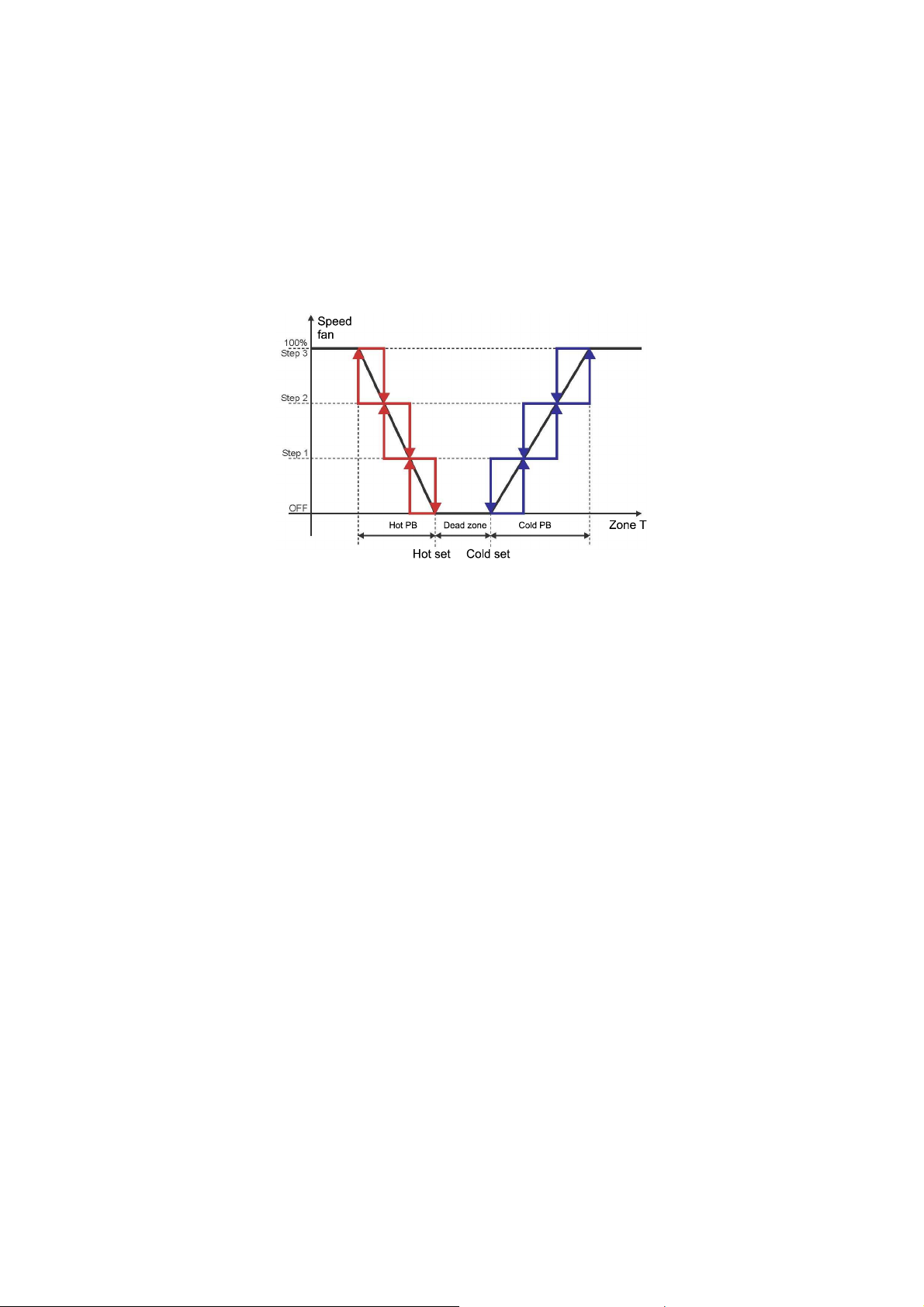
Evco S.p.A. c-pro 3 CLIMA sistema | Installer manual ver.1.1 | Code 144CP3CSE114
If it is NOT configured an electric battery or hot water with the function of post-heating the request of temperature or
humidity will take precedence in accordance with the priorities defined by parameter. If it IS configured a battery
electric or hot water function with re-heating it will be activated to prevent excessive cooling environment.
The post heating will be activated when it is in stock the dehumidification function without cooling demand.
Will be deactivated with the request for activation of the dehumidification or cooling demand.
The fan could be 3 speed or modulare and will be pilot as the figure:
For the ventilation 3 step activation will be divided the proportional band in equal parts (will be the same of the zone
valve).
8.1.4 Zone work set-point (MCZN module)
The working setpoint of the area is decided, depending on the working mode, either manually or automatically (time
slots scheduled weekly), again through the use of the viewer area Vroom.
There are also the additional possibility of changing the working setpoint established by MCCT, in the ways listed
below.
8.1.4.1 Variation of the zone work set-point for "climatic curves" (MCZN, MCCT
modules)
By activating the work set-point variation function for “climatic curve”, depending on the external temperature it is
possible (available on the MCCT regulator) to vary the active zone work set-point value within the minimum and
maximum limits that can be set from parameter, in order to adapt the room temperature to the external climatic
conditions, as follows:
- set the minimum and maximum external temperature limits specific for summer functioning and winter
functioning, within which the variation function of the room set-point is active
- the room work set-point minimum and maximum variation values are set
- set the direction of the compensation if direct or inverse for increase or decrease compensation of the work
set-point.
page 59 of 74
Page 60
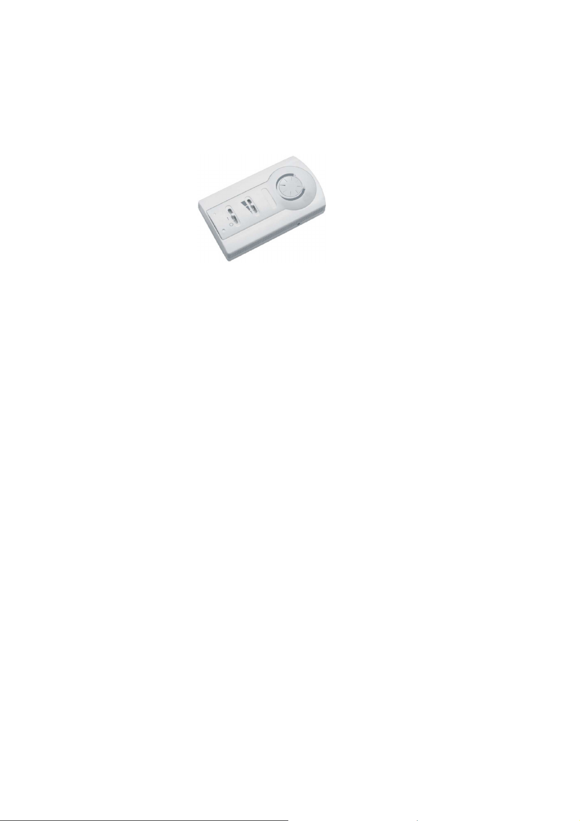
Evco S.p.A. c-pro 3 CLIMA sistema | Installer manual ver.1.1 | Code 144CP3CSE114
8.1.4.2 Variation of the zone work set-point for "manual compensation" (MCZN
module)
By activating the work set-point variation function for “manual compensation” by installing a remote set-point variator
it is possible (e.g. the EVTP010V01 accessory), to allow the final user to increase/lower the active zone work set-point
within the pre-established limits, by simply acting on the pocoveriometer distinguished by the + / - indication.
Remote set-point variator
EVTP010V01
The system installer/maintenance technician must enable and set the function features from parameter, i.e.:
- set the room work set-point minimum and maximum variation values
- enable and set the presence of the remote set-point variator
- calibrate the movement of the potentiometer for 3 basic positions, i.e. maximum negative variation, neutral
(0°C variation) and maximum positive variation.
Calibration procedure
- access the remote set-point variator calibration screen
MCZN: Installer Menu Zone A(B) Zone A(B) setup R.Set calibr.
- position the cursor on position P1
- move the pocoveriometer into the negative set-point maximum variation position (the display will show the
number of points read by the pocoveriometer)
- press ENTER to calibrate the first calibration point
- position the cursor on position P2
- move the pocoveriometer into the neutral position (variation of 0°C set-point, the display will show the
number of points read by the pocoveriometer)
- press ENTER to calibrate the second calibration point
- position the cursor on position P3
- move the pocoveriometer into the positive set-point maximum variation position (the display will show the
number of points read by the pocoveriometer)
- press ENTER to calibrate the third and last calibration point
8.1.5 Zone anti-freeze protection (MCZN module)
During the winter functioning mode when the system is not running (i.e. in OFF state or with time bands enabled but
in a day when the system is off), however an zone anti-freeze protection control remains active
If the zone room temperature goes below the anti-freeze set-point, the system will however function (activating the
zone manifolds, the circulation pump of the associated delivery line, the heat pump or the boiler if necessary), in order
to guarantee a minimum temperature in the room and so as not to risk compromising the good functioning of the
system due to frozen piping.
page 60 of 74
Page 61

Evco S.p.A. c-pro 3 CLIMA sistema | Installer manual ver.1.1 | Code 144CP3CSE114
8.1.6 "Heating/cooling integration" function (MCZN modules)
You can activate the "auxiliary heating/cooling" (also referred to by the term "booster").
This function allows the use of the battery housed in the dehumidifier for adjustment of temperature, through an air
system in support of that regularly checked by the system. This function is used to compensate for the transient
adjustment in steps of first heating up or adjustment conditions for switching between very distant from each other.
The auxiliary heating/cooling may be summer or winter, and is defined as a delta from setpoint work environment.
When the ambient temperature is above/below the temperature setpoint of the delta value for a continuous time
defined by parameter, then you will be given the activation of the booster hot/cold.
Should be set to the dependence of integration or booster by one or more zones by assigning the function from
specific parameter maintainer.
The setting is separate for hot and cold booster in order to be flexible to accommodate the adjustment of the set
temperature in the different zones.
8.2 Regulation of the delivery temperature
(MCCT modules)
8.2.1 Management of the delivery circulation pumps (MCCT module)
The controller of thermal power station is able to handle up to 6 delivery lines, each with the corresponding circulation
pump.
As previously mentioned, each controlled area should be associated with the discharge line from which it is served.
Through the appropriate parameter circulation pumps can be operated in the following way:
- CONTINUOUS: the circulation pump discharge will remain continuously active system with ON and
no alarms blockers.
- REQUEST FOR TEMPERATURE: the circulation pump discharge will be activated at the request of at least one
of the manifolds heating/cooling zone associated with the discharge line itself.
The activation / deactivation of circulating pumps will follow the timing delay at power on / off established through the
appropriate parameters.
In addition to the demand from collectors for heating / cooling zone, the circulation pumps discharge will be activated
for the following special cycles:
- Protection of low temperature flow line
- Frost protection system
- Cycle anti-grip
The correct functioning of the circulation pumps is controlled via a digital input that can be configured as pump
protection input (block) or delivery flow switch (consult the relative explanatory paragraph).
8.2.2 Management of the utilities set-up for heating delivery water:
boiler (and heat pump (MCCT module)
During winter regulation, once the water has been put into circulation in the system, whenever the delivery work set-
point is not satisfied, the c-pro 3 CLIMA sistema will send a request to the thermal power plant controller for the
activation of the utilities set-up for heating of the delivery water.
The request will remain active until the satisfaction of the set point or stays open until the mixing valve (selected by
parameter PL05 ). If PL05 = 0 , the demand for hot/cold is deactivated to the achievement of the set flow; PL05 if = 1,
the demand for hot/cold is switched off with a delay defined by parameter PL06, complete closure of the mixing valve.
The regulator of central heat MCCT is able to control two different utilities for heating water flow : heat pump and a
water heater.
Depending on the type of system the two utilities of heating may be present separately or simultaneously and will be
handled in the following way:
page 61 of 74
Page 62

Evco S.p.A. c-pro 3 CLIMA sistema | Installer manual ver.1.1 | Code 144CP3CSE114
• Management of the water heater (boiler): correct operation of the boiler is controlled by a digital
input block heater that, if activated, will immediately block the user
• Management of the heat pump : the correct operation of the heat pump is controlled by a digital
input alarm chiller-heat pump that, when activated, will immediately block the user.
• Management of the water heater and the heat pump, the heat pump will always have priority with
respect to the activation of boiler, which will be activated in the following cases, simultaneously
with the deactivation of the heat pump:
1) Activation of digital input alarm chiller-heat pump
2) Outdoor temperature below the set value with the appropriate parameter (for then poor performance of the
heat pump due to low outdoor temperature)
3) Achieved number of hours of continuous activation of the heat pump
The correct operation of the boiler is always controlled via the digital input block heater that, if activated, will
immediately block the user.
In case N°3, the intervention of the digital input boiler block will cause the automatic reactivation of the heat pump
utility.
8.2.3 Management of the utility set-up for cooling delivery water: the
chiller (MCCT module)
During summer regulation, once water has been made to circulate in the system, whenever the delivery temperature
is above the Summer delivery work set-point of the hysteresis value, then a chiller activation request will be sent.
Correct chiller functioning is controlled via a chiller-heat pump digital input alarm which, whenever activated, will block
the utility immediately.
8.2.4 Delivery work set-point (MCCT module)
The working setpoint discharge summer/winter is set to manual mode during installation of the system by authorized
personnel.
The working setpoint flow corresponds to the actual setpoint adjustment only in the case in which there is no flow in
the mixing valve.
8.2.5 Output of the delivery mixing valve (MCCT module)
The thermal power plant controller can regulate a mixing valve for every delivery line, via two 0-10V proportional
analogue outputs.
If the mixing valve check is enabled, the regulation set-point of the delivery line will be given by the regulation set-
point calculated for the valve
The mixing valve control can be enabled individually for each delivery line.
Normally the mixing valve is used for low temperature delivery lines in high-low temperature systems.
It is possible to set the functioning mode of the mixing valve for the distinct summer and winter functioning mode
among the following possibilities:
- Valve forced closed: the valve remains always closed during the entire functioning independently from the
system functioning conditions.
- Valve forced open: the valve remains open at the percentage set until the regulation is active, with regulation
off the valve is closed.
- Valve in modulation: the opening of the mixing valve is controlled on the measurement of the delivery water
temperature with respect to the regulation set-point.
page 62 of 74
Page 63

Evco S.p.A. c-pro 3 CLIMA sistema | Installer manual ver.1.1 | Code 144CP3CSE114
In the installation phase it is necessary to set a proportional regulation band and, if necessary, an integration
constant for a PI control, on the basis of system features.
8.2.6 Mixing valve delivery work set-point (MCCT module)
The summer/winter delivery mixing valve work set-point only has effect if the mixing valve is present and if the
modulation valve regulation is enabled.
If the mixing valve check is enabled, the regulation set-point of the delivery line will be given by the regulation set-
point calculated for the valve.
The regulation set-point can be the fixed type or linked to the linear calculation on the external air temperature
measurement.
If the external air temperature probe is present and functioning, the regulation set-point is calculated according to a
climatic curve.
If the external air temperature probe is not present or broken, the regulation set-point is fixed. It is established via a
relevant maintenance level parameter.
The climatic curve for calculation of the set-point envisions the setting of two pairs of External-Set-point temperature
values.
This two pairs determine a linearisation line of the two set-point values. All intermediate values relative to the external
temperature conditions included between the minimum and maximum values set are calculated between the two set-
point values.
The two climatic curves and set-points differ due to Summer and Winter functioning modes, separating the functioning
of the valve in the two seasons
8.2.7 Dew point control (MCCT, MCZN modules)
During the SUMMER functioning mode, the work set-point of the mixing valve (or delivery valve) will be continuously
monitored and if necessary modified in order to check the dew point of each individual active Zone.
The dew point is the temperature at which a mass of air must be cooled at constant pressure, so that it becomes
saturated (i.e. when the percentage of water vapour reaches 100%) and can therefore start to condense if further
heat is lost.
This would lead to the formation of dew in the cooled floor, thus compromising the integrity of the controlled room.
Every active Zone, equipped with room temperature and humidity sensor, calculates the temperature of its own dew
point and sends this data to the thermal power plant.
Given the different zones associated to the specific delivery line the thermal power plant regulator will consider the
highest dew point value sent by the individual zones as the dew point of the entire delivery line.
To consider the construction features of the system, the dew point will be raised by a predefined offset that can be set
by parameter.
The regulation set-point of the mixing valve (or delivery line) will be limited to the minimum value given by the
“delivery dew point + offset” calculated whenever necessary.
page 63 of 74
Page 64

Evco S.p.A. c-pro 3 CLIMA sistema | Installer manual ver.1.1 | Code 144CP3CSE114
8.2.8 Control of the high and low delivery temperature (MCCT module)
Whenever the temperature of the delivery water exceeds or drops below the minimum and maximum temperature
values accepted for the system of the hysteresis value, then the c-pro 3 mega MCCT thermal power plant will start
special management cycles for these emergencies:
- High temperature protection: the high temperature protection intervention will force the immediate closure of
the mixing valve in order to prevent overtemperatures in the controlled system, until the temperature returns
to the maximum values accepted for the system.
- Low temperature protection: After a fixed delay of 60 seconds, the intervention of the low temperature
protection will cause the activation of the delivery circulation pump in order to ease heating of the water in
the system. The pump will remain on until the minimum temperature conditions are recovered.
8.3 Regulation of the zone humidity
(MCZN, MCCT modules)
8.3.1 Regulation principle
Whenever the function is enabled and a room humidity transducer is present in zone, during SUMMER functioning
mode when the relative humidity detected by the room humidity transducer is over the active zone humidity set-point
value plus the value of the differential, the MCZN regulator will activate the corresponding manifold/zone
dehumidification valve.
Whenever dehumidification makes use of the delivery water for its action (established via the relative parameter), the
activation of the manifold/zone dehumidification valve generates the same sequence of activations/controls triggered
with zone heating/cooling.
For its functioning, consult the zone temperature regulation part.
8.3.2 Management of the dehumidification manifold/valve (MCZN
module)
The manifold/zone dehumidification valve is activated when the value of the room relative humidity is over the active
room humidity set-point + hysteresis value (differential).
8.3.2.1 Valve closed in advance
This function (enabled from the parameter), thanks to a self-learning allow to disable the valve zone temperature early
with respect to the setpoint temperature is reached, so as to ensure optimum comfort zone avoiding excessive
temperature fluctuations.
8.3.3 Zone humidity work set-point (MCZN module)
The zone humidity work set-point is decided in manual mode via the relative maintenance technical parameters
present in the MCZN module or automatically, set by the final user via programmed weekly time bands.
To set the automatic humidity work set-points (Economy and Comfort set-points), consult the c-pro 3 CLIMA sistema
user manual.
page 64 of 74
Page 65

Evco S.p.A. c-pro 3 CLIMA sistema | Installer manual ver.1.1 | Code 144CP3CSE114
8.3.4 Management of digital on/off dehumidifier
The zone controller c-pro 3 hecto MCZN has two digital inputs (one for each zone) on/off dehumidifiers.
If the digital input is at logic level "disabled", the corresponding additional dehumidifier will be considered in the OFF
state and all of its settings are disabled.
In order to make such control active, the inputs must be activated through the appropriate parameters maintainer.
8.4 Regulation of the DHW tank temperature for the DHW
water
(MCPS module)
8.4.1 Regulation principle
Whenever the c-pro 3 hecto MCPS module is present and enabled in the system, the system will automatically
consider the presence of a DHW storage tank in the system for the DHW.
With the presence of the DHW tank, the temperature regulation principle of the entire system will change significantly
in the following way:
- WINTER REGULATION Via its utilities proposed for heating, the c-pro 3 CLIMA sistema, always keeps the
DHW tank at the pre-fixed temperature.
The delivery hot water for any heating requests of the Zones is withdrawn directly from the DHW tank.
- SUMMER REGULATION: Via its utilities proposed for heating EXCEPT the heat pump, the c-pro 3 CLIMA
sistema, always keeps the DHW tank at the pre-fixed temperature.
The cool delivery water for any cooling requests from the Zones will be supplied by the chiller unit, obviously
without the use of the DHW tank.
8.4.2 Management of the DHW circuit circulation pump (MCPS
module)
The MCPS solar panels controller can manage a DHW tank with relative circulation pump.
The circulation pump is activated on temperature request of the DHW tank, whenever the heat pump or boiler utilities
are used to heat the DHW. When the use of the solar panel circuit/s for heating is sufficient, the DHW circulation
pump will not be used.
The activation of the DHW circulation pump will follow the delay times on switch-on established via the relevant
parameter.
As well as the request by the DHW tank, the DHW circulation pump can be activated during a special anti-grip or
antilegionella cycle.
The correct functioning of the circulation pumps is controlled via a digital input that can be configured as pump
protection input (thermal switch) or delivery flow switch (consult the relative explanatory paragraph).
page 65 of 74
Page 66

Evco S.p.A. c-pro 3 CLIMA sistema | Installer manual ver.1.1 | Code 144CP3CSE114
8.4.2.1 DHW circuit circulation pump management (MCPS module) with setpoint
panel mode.
The controller for solar panels MCPS is able to manage a DHW tank with circulation pump.
The circulation pump is activated by temperature request of the DHW tank (upper DHW tank probe), if are used for
domestic water heating the heat pump or the boiler.
The pump activation of DHW circulation pump follows the power on delay time established by the appropriate
parameter.
In addition to the request of the DHW tank, the DHW circulation pump can be activated during a spcial anti-grip or
antilegionella cycle.
The correct functioning of the circulation pumps is controller by a digital input which can be configured as pump
protection or supply flow-switch.
8.4.3 DHW tank work set-point (MCPS module) With DHW setpoint
mode
The DHW working setpoint is manual established from the setpoint menu on the c-pro 3 hecto MCPS main menu.
According to the plant dimensions, the DHW tank can use only one temperature probe (DHW tank probe) or 2
temperature probes (upper and lower DHW tank probes).
If the DHW tank use two probes, the regulation of the temperature will be made when the lower and the upper water
reaches the working setpoint.
The DHW tank regulation differential is fixed and is -1°C.
8.4.3.1 DHW tank working setpoint (MCPS module) with panels setpoint type
The DHW tank working setpoint is manual established from the setpoint menu in the c-pro 3 hecto MCPS module
main menu.
The regulation of the temperature will be made when the upper DHW tank water reaches the working setpoint.
The DHW tank regulation differential is fixed and is -1°C.
8.4.4 Management of the AUX1 auxiliary circuit circulation pump
(MCPS module)
The MCPS solar panels controller can manage an AUX1 hot water auxiliary circuit with relative circulation pump.
Via the relevant parameter, the circulation pump can be managed as follows:
- CONTINUOUS: the auxiliary circuit circulation pump will remain constantly activated with system ON and in
absence of blocking alarms.
- TEMPERATURE REQUEST: with heating request by the AUX1 circuit (depending from work set-point and
differential), when the temperature of the DHW tank or of the solar panels circuit (depending on the value of
Control probe parameter) is over a value set by the (Offset ON) parameter at the temperature of the AUX1
circuit, then the AUX1 water circulation pump will be switched on, in a way to contribute with the heating of
the AUX1 circuit.
Whenever the difference between DHW tank (or solar panels circuit) temperature and AUX1 becomes lower
than a value set by (Offset OFF) parameter, the AUX1 circulation pump will be switched off.
page 66 of 74
Page 67

Evco S.p.A. c-pro 3 CLIMA sistema | Installer manual ver.1.1 | Code 144CP3CSE114
As well as the request by the AUX 1 circuit, the solar panels circuit circulation pump
will be activated for the following special cycles:
- auxiliary circuit low temperature protection
- anti-grip cycle
The correct functioning of the circulation pump is controlled via a digital input that can be configured as pump
protection input (thermal switch) or delivery flow switch (consult the relative explanatory paragraph).
N.B.
The AUX1 auxiliary circuit can be managed only in systems with individual heating solar panels circuits. If this is not
the case, all other enablings and settings made will have no effect.
8.4.5 Control of the high and low temperature of the auxiliary circuit
AUX1 (MCPS module)
Whenever the temperature of the AUX1 auxiliary circuit water exceeds or drops below the minimum and maximum
temperature values accepted for the system of the hysteresis value, then the c-pro 3 hecto MCPS solar panels
regulator will start special management cycles for these emergencies:
- High temperature protection: the high temperature protection intervention will trigger a simple signal to the
maintenance staff.
- Low temperature protection: the low temperature protection will trigger the activation of the circulation pump
of the auxiliary circuit in order to ease heating of the circuit water. The pump will remain on until the
minimum temperature conditions are recovered.
8.4.6 Management and setting of the periodic antilegionella cycle for
the DHW tank (MCPS module)
In order to disinfect the DHW tank from the proliferation of legionella bacteria due to the deposit of DHW, the
c-pro 3 CLIMA sistema envisions the periodic management of anti-legionella cycles.
Depending on the type of system, it is possible to select daily, weekly or monthly antilegionella cycles.
An anti-legionella cycle consists in taking, the temperature of the DHW tank to a temperature such to destroy bacteria
(standard to 70°C, but which can be set from parameter) for a long enough period of time (standard at 60 minutes,
but can be set from parameter) by activation of the boiler and the DHW circulation pump.
These periodic cycles will help with respect to the Standards in force on the subject.
page 67 of 74
Page 68

Evco S.p.A. c-pro 3 CLIMA sistema | Installer manual ver.1.1 | Code 144CP3CSE114
8.5 Management and configuration of the heating solar panel
circuits (MCPS module)
8.5.1 With DHW setpoint
Whenever the c-pro 3 hecto MCPS module for solar panels is present and enabled in the system, one or two heating
solar panel circuits management can be enabled, with the function of heating the DHW in the DHW tank.
The heating solar panels circuits will be added to the other utilities set-up for heating the DHW tank, with PRIMARY
importance with respect to the other utilities, with the following functioning principle:
- with heating request by the DHW tank, when the temperature of the solar panels circuit is over a value set by
the (Offset ON) (ON Offset) parameter at the temperature of the DHW tank, then the solar panels circuit will
start its own water circulation pump, in a way to contribute with the heating of the DHW tank.
Whenever the contribution of the solar panels circuits is sufficient to reach the DHW set-point, at this point the
solar panels circuit circulation pump will be switched off.
Whenever the difference between solar panels and DHW tank temperature becomes lower than a value set by
( OFF Offset) parameter, the solar panels circulation pump will be switched off and the other utilities set-up
for heating will be activated (heat pump or boiler, with the rules and times described in the previous points),
in order to reach the work set-point set for the DHW tank.
The presence of the second circuit of solar hating panels automatically disables the presence of the AUX1 auxiliary
circuit and of the management of the anti-stagnation emergency in Tenda2 (Cover2) mode.
8.5.2 con tipo setpoint pannelli
If it is present and enabled in the plant the c-pro 3 hecto MCPS module for solar panels, is possible to enable the
management of one or two circuits of solar panels, with the fuction to heat the the domestic water of the DHW tank.
The heating panel circuit will be added to the other heating loads of the DHW tank, with integrative priority on other
loads, with the following functioning:
- with heating request from the DHW tank, when the temperature of the solar panels circuit is higher of a set
value (Offset ON) of the lower temperature od DHW tank, the solar panel circuit will start the water
circulation pump, to help to the DHW tank heating.
If the difference between the solar panel temperature and the DHW tank lower temperature is lower than the
value set by parameter (Offset ON), the solar panels water circulation pump will stop.
The presence of the second solar panel circuit will automatically disable the presence of the AUX1 auxiliary circuit and
the emergency anti-stagnation in Tenda2 mode.
page 68 of 74
Page 69

Evco S.p.A. c-pro 3 CLIMA sistema | Installer manual ver.1.1 | Code 144CP3CSE114
8.5.3 Management of the solar panels circuits circulation (MCPS
module)
The controller for the MCPS solar panels can manage up to 2 thermal solar panel circuits, each with relative circulation
pump.
The circulation pump is activated on temperature request of the DHW tank, whenever the conditions described in
previous paragraph 9.5.4. are satisfied.
As well as the request by the DHW tank, the solar panels circuits circulation pumps
will be activated for the following special cycles:
- periodic activation cycle for uniformity of temperatures
- solar panels circuits low temperature protection
- anti-stagnation emergency
- anti-grip cycle
The correct functioning of the circulation pumps is controlled via a digital input that can be configured as pump
protection input (thermal switch) or delivery flow switch (consult the relative explanatory paragraph).
8.5.4 Control of the high and low temperature of the solar panel
circuits (MCPS module)
Whenever the temperature of one of the solar panels circuits exceeds or drops below the minimum and maximum
temperature values accepted for the system of the hysteresis value, then the c-pro 3 hecto MCPS solar panels
regulator will start special management cycles for these emergencies:
- High temperature protection: after a fixed delay of 60 seconds, the high temperature protection intervention
will start an anti-stagnation emergency cycle (described in the following paragraph), in order to dispose of the
overheated water and to take the temperature of the water back within the system safety conditions.
- Low temperature protection: after a fixed delay of 60 seconds, the intervention of the low temperature
protection will cause the activation of the solar panels circuit circulation pump in order to ease heating of the
water in the circuit. The pump will remain on until the minimum temperature conditions are recovered.
8.5.5 Management and setting the stagnation emergency for solar
panels circuits (MCPS module)
Whenever the temperature of the water in one of the solar panels circuits exceeds the maximum temperature value
accepted for the system of the hysteresis value, then the regulator for c-pro 3 hecto MCPS solar panels will start a
special stagnation emergency cycle.
The emergency condition must remain at least for a fixed time of 60 seconds and will be managed in the following
way, according to the value set for the Stagnation emergency parameter:
- ON/OFF: the stagnation emergency will be managed via the activation of a solenoid vent valve, which will
dispose of the hot water.
The heat disposal relay will remain enabled until the temperature of the solar panels circuit has gone back
below the maximum temperature value accepted of the hysteresis value (differential).
As well as the heat disposal relay, the circulation pump of the corresponding solar panels circuit is activated
at the same.
- Cover1: the stagnation emergency will be managed by the opening of a motorised cover (servomotor with
spring return) which will cover the surface of the solar panels from solar exposure.
The cover opening relay will remain enabled until the temperature of the solar panels circuit has gone back
below the maximum temperature value accepted of the hysteresis value (differential).
page 69 of 74
Page 70

Evco S.p.A. c-pro 3 CLIMA sistema | Installer manual ver.1.1 | Code 144CP3CSE114
As well as the cover opening relay, the circulation pump of the corresponding solar panels circuit is activated
at the same.
- Cover2: the stagnation emergency will be managed by the opening/closing of a motorised cover (servomotor
with separate opening and closing controls) which will cover the surface of the solar panels from solar
exposure.
The cover opening relay will remain enabled until the temperature of the solar panels circuit temperature has
returned below the maximum temperature value accepted of the hysteresis value (differential). If this is not
the case, the cover closing relay will remain active for all periods in which the cover must be closed.
As well as management of the cover opening/closing relays, the circulation pump of the solar panels circuit is
activated at the same.
N.B.
Setting the parameter at the Cover2 value will not have any effect if the system has been configured to manage the
second solar panels circuit or if the Aux1 auxiliary circuit is present.
page 70 of 74
Page 71

Evco S.p.A. c-pro 3 CLIMA sistema | Installer manual ver.1.1 | Code 144CP3CSE114
8.6 Other regulations
8.6.1 Management and setting of the periodic anti-grip cycle (MCCT,
MCPS modules)
The function has the purpose of preventing the blocking of the pumps and valves present in the c-pro 3 CLIMA
sistema during system standstill due to any deposits present in the system or due to the formation of crystalline
aggregates (lime scale or other) on the mechanical seals of the pumps and valves.
The function automatically activates all pumps and valves in sequence once a week, which have been at a standstill for
at least a week.
The day and time of weekly activation can be set by the user via the relevant Maintenance technician parameters.
The sequence scans the various utilities in the system every minute (pumps and valves): the cycle leads to the
activation of the element considered for 30 seconds.
The enabling and setting of the periodic anti-grip cycle is set separately on the thermal power plant c-pro 3 mega
MCCT controller and on the c-pro 3 hecto MCPS module for solar panels, respectively for the following utilities:
MCCT regulator anti-grip : delivery 1 circulation pump if enabled from parameter
delivery 1 mixing valve if enabled from parameter
delivery 2 circulation pump if enabled from parameter
delivery 2 mixing valve if enabled from parameter
MCPS regulator anti-grip : DHW circuit circulation pump always enabled
AUX1 circuit circulation pump always enabled
solar panels 1 circuit circulation pump always enabled
solar panels 2 circuit circulation pump always enabled
8.6.2 Management of the circulation pumps protection digital input
(MCCT, MCPS modules)
Every circulation pump present in the c-pro 3 CLIMA sistema has a protection digital input.
Every protection digital input linked to a circulation pump can be associated to one of the following functionalities,
depending on the value selected via the relevant parameters.
- THERMAL SWITCH: every activation of the digital input will cause the immediate deactivation of the relative
circulation pump.
Once the digital input is deactivated, the circulation pump will start to work according to its own regulation
(automatic rearm).
- FLOW: every activation of the digital input, after a delay time or from the activation of the pump (start) or
from the activation of the input itself (normal conditions), will cause the deactivation of the relative circulation
pump.
Once the digital input is deactivated, the circulation pump will start to work according to its own regulation
(automatic rearm) unless the maximum number of flow switch alarms is not reached for automatic rearm,
however the deactivation of the alarm will be possible only with manual procedure (manual rearm).
The regulation parameters relative to the delivery 1 and 2 circulation pumps are present in the MCCT thermal power
plant controller while the parameters relative to the circulation pumps of the auxiliary DHW circuit, solar panels 1 and
2 are present in the MCPS controller for solar panels.
page 71 of 74
Page 72

Evco S.p.A. c-pro 3 CLIMA sistema | Installer manual ver.1.1 | Code 144CP3CSE114
8.6.3 Manual functioning mode (MCCT, MCZN, MCPS modules)
The c-pro 3 CLIMA sistema allows to set manual functioning for the various uses.
In this state the devices are not governed by the automatic functions, but are however sensitive to any alarms.
The manual activation of the devices replaces the regulation for the determined device, therefore from now on gives
origin to all automatic controllers for the activation of the system.
For example, if the zone valve is controlled manually, it will be interpreted by the system as thermostatic activation
causing the activation of the relative delivery circulation pump, the mixing valve and the boiler/chiller etc.
The manual functioning of the devices is useful for the execution of functional tests on system start-up or in case or
probe breakage or other.
page 72 of 74
Page 73

Evco S.p.A. c-pro 3 CLIMA sistema | Installer manual ver.1.1 | Code 144CP3CSE114
c-pro 3 CLIMA sistema
Installer manual ver. 1.1
EB - 37 / 13
Code 144CP3CSE114
This document is exclusive property of EVCO. Reproduction and disclosure are prohibited without express authorisation
from EVCO.
EVCO is not liable for any features, technical data and possible errors stated in this document or deriving from use of
the same.
EVCO cannot be considered liable for damage caused by failure to comply with warnings given in this document.
EVCO reserves the right to make any changes without forewarning, without jeopardising the basic safety and
operating feature.
page 73 of 74
Page 74

Evco S.p.A. c-pro 3 CLIMA sistema | Installer manual ver.1.1 | Code 144CP3CSE114
EVCO S.p.A.
Via Feltre 81, 32036 Sedico Belluno ITALIA
Tel. 0437 / 84.22
Fax 0437 / 83.648
www.evco.it
page 74 of 74
 Loading...