

EVCO S.p.A.
Vcolor 338 L | Installer manual ver. 2.0 | Code 144VC338LE204
Vcolor 338 L
Controller for "top-class" electric ovens for
gastronomy and pastry, with 7 inch TFT
graphic display colour touch-screen, in split
version that can be integrated into the unit.
Installer manual | ENGLISH
Code 144VC338LE204
page 1 of 66

EVCO S.p.A.
Important
Read this document thoroughly before installation and before
use of the device and follow all recommendations; keep this
document with the device for future consultation.
Only use the device in the way described in this document; do
not use the same as a safety device.
Disposal
The device must be disposed of in compliance with local
standards regarding the collection of electric and electronic
equipment.
Vcolor 338 L | Installer manual ver. 2.0 | Code 144VC338LE204
page 2 of 66

EVCO S.p.A.
Indice
1
1.1
1.2
2
2.1
2.2
2.3
3
3.1
3.2
4
4.1
4.2
5
5.1
6
6.1
6.2
6.3
6.4
6.5
6.6
6.7
6.8
6.9
6.10
7
7.1
7.2
8
8.1
8.2
8.3
8.4
9
9.1
9.2
9.3
9.4
10
10.1
10.2
11
11.1
11.2
12
12.1
12.2
12.3
13
INTRODUCTION ............................................... 4
Introduction .................................................... 4
Summary table of the models available, the main
features and the purchase codes........................ 5
DIMENSIONS AND INSTALLATION ..................... 8
User interface dimensions ................................. 8
Installation of user interface .............................. 8
Installation warnings ...................................... 10
ELECTRIC CONNECTION ................................. 11
Electric connection ......................................... 11
Warnings for the electric connection ................. 15
DESCRIPTION ............................................... 16
Description of the user interface ...................... 16
Description of the control module .................... 18
COMMISSIONING........................................... 20
Commissioning .............................................. 20
MANAGEMENT OF UTILITIES ........................... 22
Preliminary notes ........................................... 22
Temperature regulation .................................. 22
Steam injection ............................................. 22
Air Vent ........................................................ 22
Room light .................................................... 22
Technical compartment fan ............................. 22
Fan .............................................................. 22
Cooking fumes reduction ................................ 23
Outputs management for special cleaning cycles 23
User interface variant for ROTOR ovens
management ................................................. 26
USER INTERFACE ........................................... 27
Switching the device on/off ............................. 27
Silencing the buzzer ....................................... 27
COOKING CYCLE ............................................ 28
Preliminary notes ........................................... 28
Setting the cooking cycle ................................ 29
Starting the cooking cycle ............................... 31
Stopping the cooking cycle .............................. 31
“MY COOKBOOK” FUNCTION ........................... 32
Preliminary notes ........................................... 32
Saving a recipe .............................................. 32
Starting a recipe ............................................ 33
Deleting a recipe............................................ 33
“SPECIAL CYCLES” FUNCTION ......................... 33
Preliminary notes ........................................... 33
Starting a special cycle ................................... 34
“FAVOURITE CYCLES” FUNCTION ..................... 35
Preliminary notes ........................................... 35
Starting a favourite cycle ................................ 35
"WEEKLY PROGRAMMED SWITCH-ON" FUNCTION
................................................................... 36
Preliminary notes ........................................... 36
Setting the "weekly programmed switch-on"
function ........................................................ 36
Enabling the "Weekly programmed switch-on"
function ........................................................ 37
OTHER FUNCTIONS ........................................ 38
Vcolor 338 L | Installer manual ver. 2.0 | Code 144VC338LE204
13.1
Display of the alarms status ............................38
13.2
Display of the process variables value and of the
machine status ..............................................38
13.3
Setting the language used for the screens .........38
14
14.1
14.2
14.3
15
15.1
15.2
15.3
15.4
15.5
16
16.1
16.2
16.3
17
17.1
17.2
17.3
17.4
17.5
18
18.1
19
19.1
19.2
19.3
19.4
20
20.1
BOILER EXPANSION .......................................39
Activation of the expansion .............................39
Electrical connection .......................................39
Operation ......................................................39
BURNERS EXPANSION ....................................41
Expansion activation .......................................41
Electrical connection .......................................41
Application scheme.........................................42
Operation ......................................................42
Errors handling ..............................................43
CONFIGURATION ...........................................44
Setting the time, date and day of the week .......44
Setting the configuration parameters ................45
List of configuration parameters .......................46
USE OF THE USB PORT ...................................55
Preliminary information ...................................55
Upload of the settings contained in the programs
...................................................................55
Download of the settings contained in the
programs ......................................................55
Upload of the settings contained in the
configuration parameters ................................55
Download of the settings contained in the
configuration parameters ................................55
ALARMS ........................................................56
Alarms ..........................................................56
ACCESSORIES ...............................................59
Optoisolated RS-485/USB serial interface ..........59
USB cap for panel installation ..........................59
Connection cables 0810500018/0810500020 .....59
4 GB USB pen drive EVUSB4096M ....................59
TECHNICAL DATA ...........................................60
Technical data ...............................................60
page 3 of 66

EVCO S.p.A.
1 INTRODUCTION
1.1 Introduction
Vcolor 338 L is a controller with elegant design for managing
“top-class” electric ovens for gastronomy and confectionery
(including rotary ones).
It is available in split version and can be integrated both
mechanically and aesthetically into the unit, the user interface
is composed of a 7 inch TFT touch-screen colour graphic
display and guarantees an IP65 protection rating, for easy
cleaning.
It is able to manage ventilation in "on / off" and modulating
mode (in this case it is necessary to also use an external
speed regulator), with inversion of the direction of rotation of
the fan.
It also manages the steam (injection and air vent), both in
automatic and manual mode, the cleaning, with liquid
detergent or tablet, and the “weekly programmed switch-on”
and “programs” functions (the latter to memorise the cooking
settings in a program, with the purpose of successively
selecting and performing it).
This is to be installed on the back of the panel, with studs, for
flush mounting
Vcolor 338 L | Installer manual ver. 2.0 | Code 144VC338LE204
page 4 of 66

EVCO S.p.A.
Vcolor 338 L | Installer manual ver. 2.0 | Code 144VC338LE204
1.2 Summary table of the models available, the main features and the purchase
codes
The following table illustrates the models available.
Models available Vcolor 338 L
The following table illustrates the main features of the device.
“ / “ indicates the feature can be set via a configuration parameter.
Power supply Vcolor 338 L
12 VAC •
Analogue inputs (J/K o Pt 100, according to model) Vcolor 338 L
Environment probe •
Needle probe •
Cooking fumes probe •
Digital inputs (for NO/NC contact) Vcolor 338 L
Door micro switch •
Rack rotation limit switch •
Fan circuit breaker protection (230 VAC) •
Circuit breaker protection (230 VAC) •
Electric absorption (230 VAC) •
Analogue outputs Vcolor 338 L
0-10 V (fan) •
Digital outputs (electromechanical relays; A res. @ 250
VAC)
Temperature adjustment 1 A
Vcolor 338 L
Air vent 1 A
Direct steam injection 1 A
Room light 1 A
Technical compartment fan 1 A
Configurable (fan left rotation default) (1) 1 A
page 5 of 66

EVCO S.p.A.
Configurable (fan right rotation default) (1) 1 A
Configurable (fan speed default) (1) 1 A
Rack rotation 1 A
Configurable (cleaning water valve by default) (2) 1 A
Configurable (liquid detergent injection by default) (2) 1 A
Configurable (cleaning liquids discharge by default) (2) 1 A
Configurable (rinse aid injection during cleaning by default) (2) 1 A
Communication port Vcolor 338 L
RS-485 MODBUS •
USB •
Vcolor 338 L | Installer manual ver. 2.0 | Code 144VC338LE204
Other features Vcolor 338 L
Clock •
Alarm buzzer •
Management of ventilation both in "On/off" mode and
modulating mode, with inversion of fan rotation direction
Management of cleaning cycle with both liquid detergent and
tablet
"Weekly programmed switch-on" function •
“Programs” function •
Notes
(1)
(2)
Options available
None.
For further information, see chapter 20 “TECHNICAL DATA”.
configurable for:
-
- management of ventilation both in "On/off" mode at single speed, with inversion of fan rotation direction
- management of ventilation both in "On/off" mode at double speed, with inversion of fan rotation direction
- management of ventilation in modulating mode, with inversion of fan rotation direction
configurable for:
- of cleaning cycle with liquid detergent
- management of cleaning cycle with tablet detergent
management of ventilation in "On/off" mode and at single speed
•
•
page 6 of 66

EVCO S.p.A.
The following table illustrates the purchase codes.
Purchase codes
For further models, contact the EVCO sales network.
Vcolor 338 L | Installer manual ver. 2.0 | Code 144VC338LE204
EVCLC33DJ2 for J/K thermocouples
EVCLC33DC2 Pt 100 2 wires
page 7 of 66
EVCO S.p.A.
Vcolor 338 L | Installer manual ver. 2.0 | Code 144VC338LE204
2 DIMENSIONS AND INSTALLATION
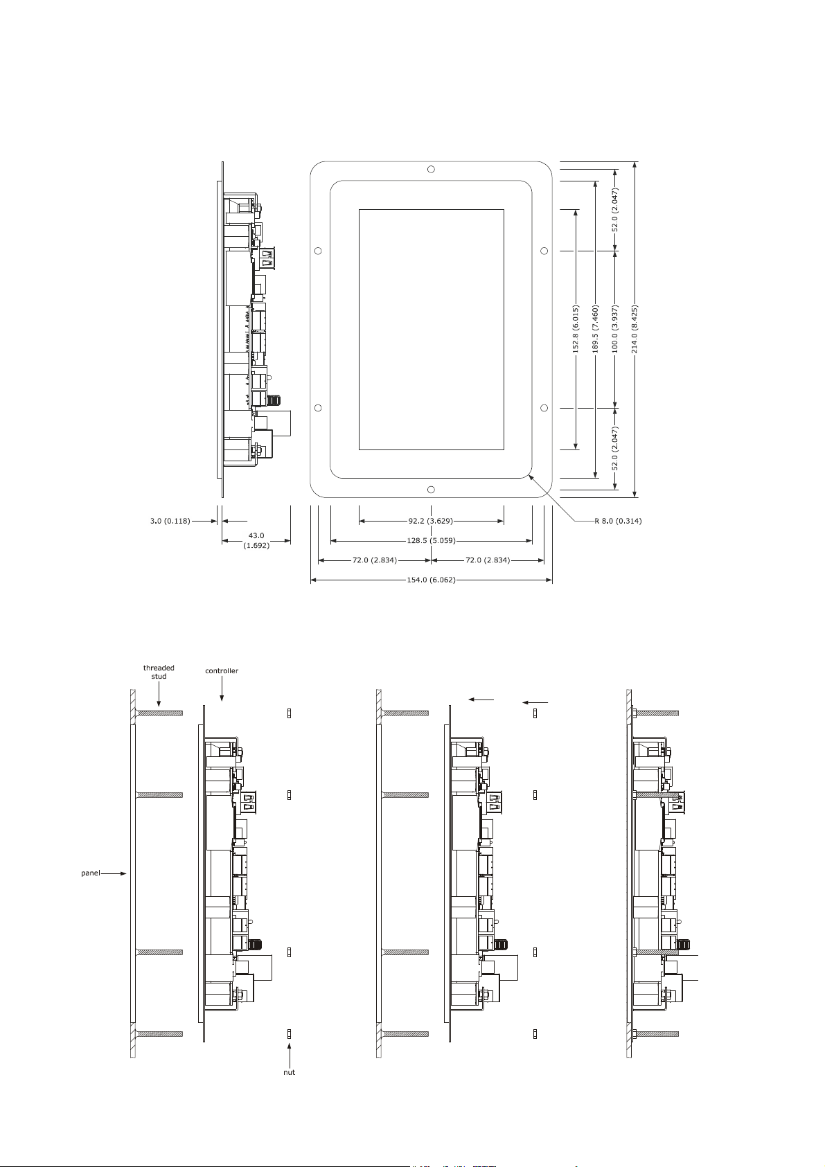
2.1 User interface dimensions
The following drawing illustrates the device's user interface dimensions; these are expressed in mm (in).
2.2 Installation of user interface
The following drawing illustrates the installation of the device user interface.
This is to be installed on the back of the panel, with studs and allows flush mounting.
page 8 of 66
EVCO S.p.A.
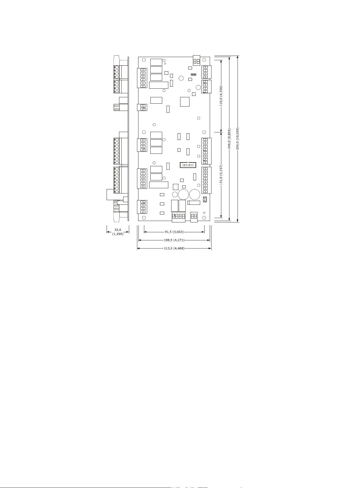
Control module dimensions and installation
The following drawing illustrates the device's control module dimensions; these are expressed in mm (in).
Vcolor 338 L | Installer manual ver. 2.0 | Code 144VC338LE204
The control module is to be installed on a flat surface, with spacers.
page 9 of 66

EVCO S.p.A.
2.3 Installation warnings
-
-
-
-
make sure that the device work conditions (temperature of use, humidity, etc.) lie within the limits indicated; see chapter
20 “TECHNICAL DATA”
do not install the device near to any heat sources (heating elements, hot air ducts etc.), equipment containing powerful
magnets (large diffusers, etc.), areas affected by direct sunlight, rain, humidity, excessive dust, mechanical vibrations or
shocks
any metal parts in proximity of the control module must be at a distance such that they do not compromise the safety
distances.
in compliance with Safety Standards, the device must be installed correctly and in a way to protect against any contact with
electric parts; all parts that ensure protection must be fixed in a way that they cannot be removed without the use of tools.
Vcolor 338 L | Installer manual ver. 2.0 | Code 144VC338LE204
page 10 of 66
EVCO S.p.A.
Vcolor 338 L | Installer manual ver. 2.0 | Code 144VC338LE204
3 ELECTRIC CONNECTION
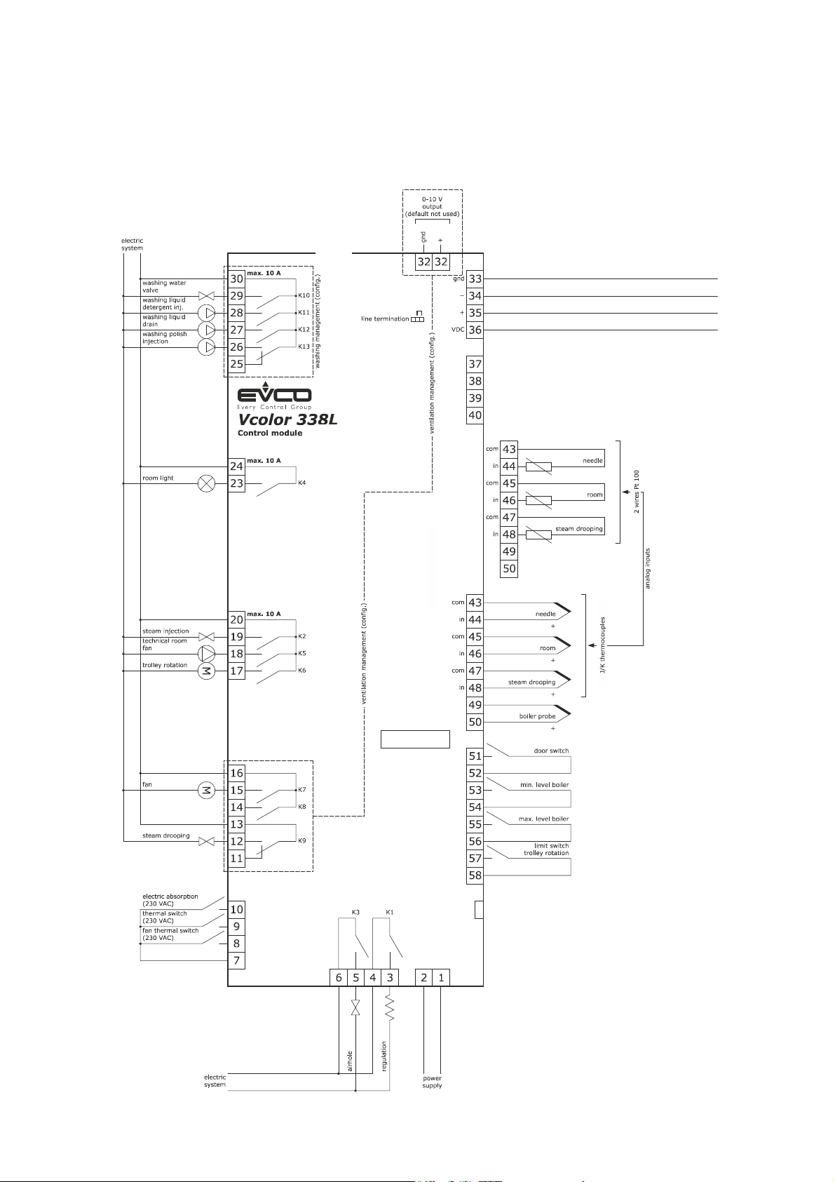
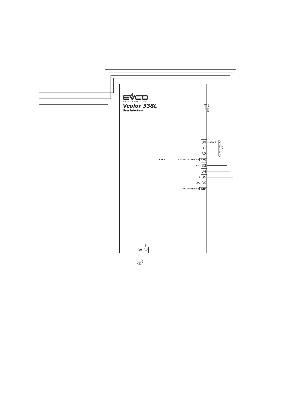
3.1 Electric connection
The following drawing illustrates the device's electric connection.
For further information on ventilation management please refer to the following drawings.
max. 4 A
max. 4 A
max. 3 A
page 11 of 66
EVCO S.p.A.
GND
Vcolor 338 L | Installer manual ver. 2.0 | Code 144VC338LE204
+
VDC
page 12 of 66
EVCO S.p.A.
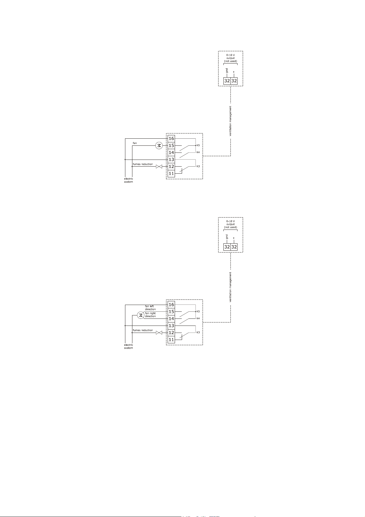
Management of the ventilation in "on/off" mode and with single speed (parameter F0 = 0).
Management of the ventilation in "on/off" mode and with single speed and inversion of the fan rotation direction (parameter
F0 = 1).
Vcolor 338 L | Installer manual ver. 2.0 | Code 144VC338LE204
page 13 of 66
EVCO S.p.A.
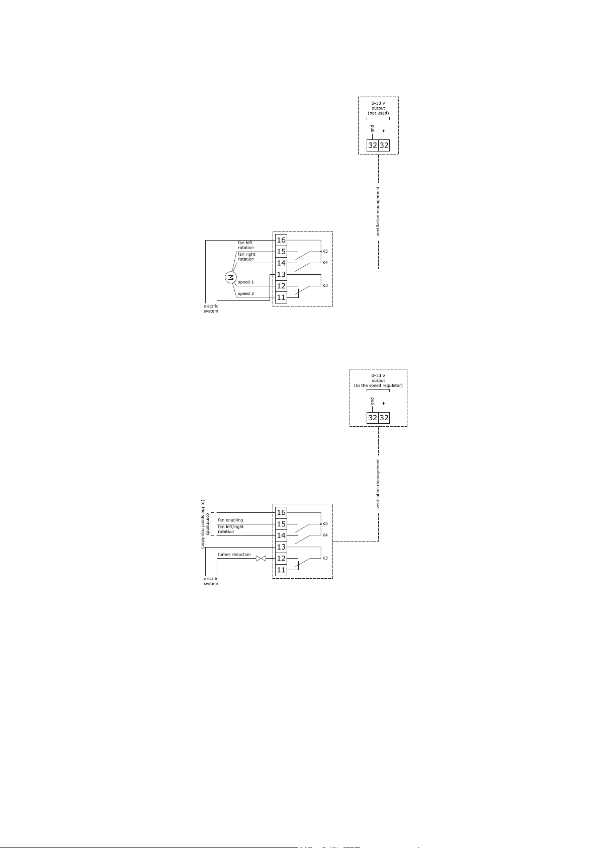
Management of the ventilation in "on/off" mode and with dual speed and inversion of the fan rotation direction (parameter
F0 = 2).
Management of the ventilation in modulating mode and with inversion of the fan rotation direction (parameter
F0 = 3).
Vcolor 338 L | Installer manual ver. 2.0 | Code 144VC338LE204
The RS-485 MODBUS port is the communication port with the following EVCO products:
-
-
The USB communication port that allows the upload and download of the device settings, through a common USB pen drive.
Parameters Manager set-up software system
CloudEvolution plants monitoring and surveillance systems (via Web)
page 14 of 66
EVCO S.p.A.
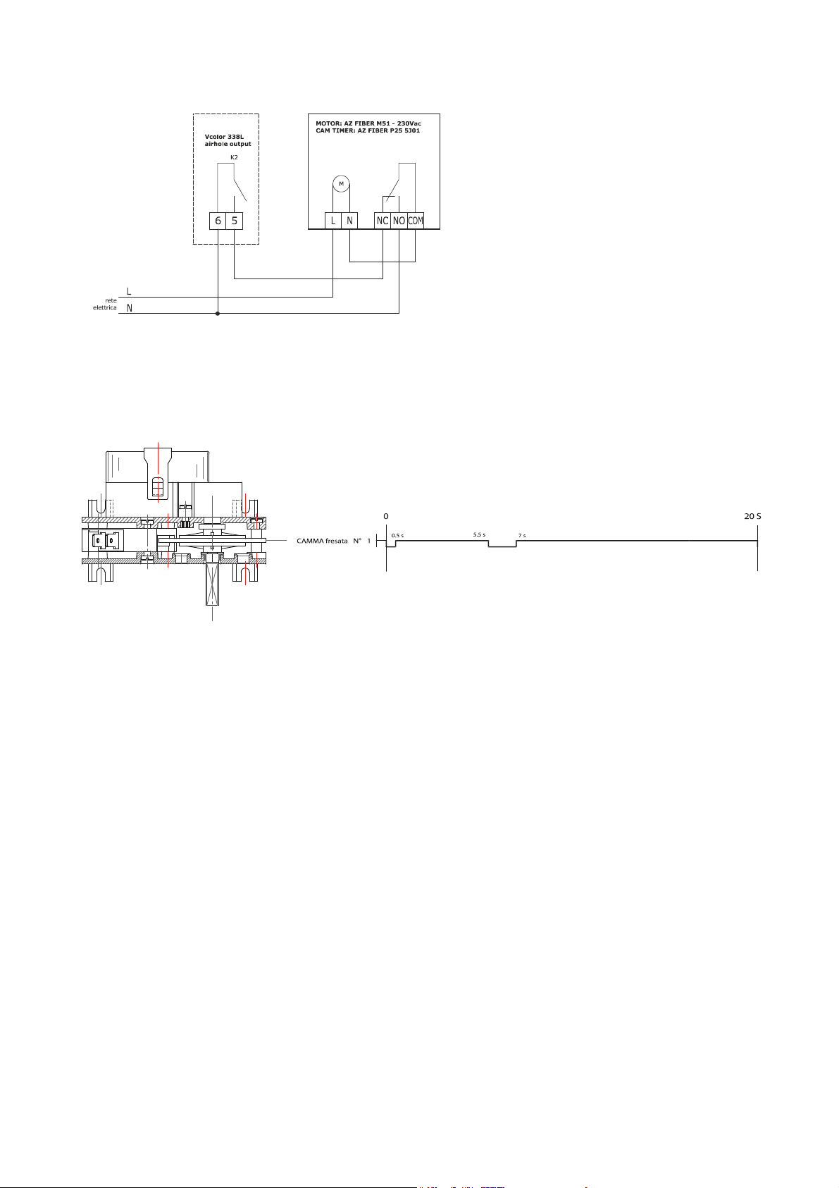
Example of connection for motorized air vent cam timer, such as FIBER Pxx series.
Vcolor 338 L | Installer manual ver. 2.0 | Code 144VC338LE204
The following scheme is an example of parameters set up for the cam timer below
u2 = 140 (14 seconds) time-delay for cam rotation
u3 = 10 (1 second) motor activation time for limit switch rearm (short milling)
u4 = 30 (3 seconds) motor activation time for limit switch rearm (long milling)
3.2 Warnings for the electric connection
-
-
-
-
-
-
-
do not use electric or pneumatic screwdrivers on the device terminal board
if the device has been taken from a cold to hot place, humidity could condense inside; wait about 1 hour before powering it
make sure that the power supply voltage, the frequency and the device electric power, correspond to those of the local
power supply; see chapter 20 “TECHNICAL DATA”
disconnect the device power supply before proceeding with any type of maintenance
position the power cables as far away as possible from the signal cables
the terminating resistor must be connected in order to reduce the reflections on the signal transmitted along the cables that
connect the user interface to the control module.
for repairs and information regarding the device, contact the EVCO sales network.
page 15 of 66
EVCO S.p.A.
Vcolor 338 L | Installer manual ver. 2.0 | Code 144VC338LE204
4 DESCRIPTION
4.1 Description of the user interface
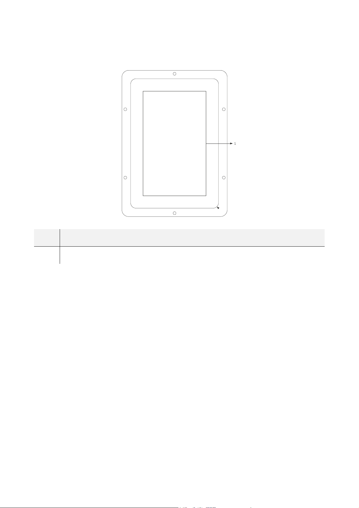
The following drawing illustrates the layout of the device user interface front panel.
The following table illustrates the meaning of the front parts of the device user interface.
PART MEANING
1 display
page 16 of 66
EVCO S.p.A.
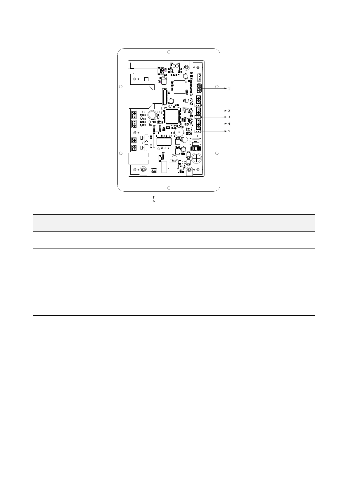
The following drawing illustrates the layout of the device user interface rear panel.
Vcolor 338 L | Installer manual ver. 2.0 | Code 144VC338LE204
The following table illustrates the meaning of the rear parts of the device user interface.
PART MEANING
1 USB port
2 MODBUS communication port
3 dip switch to activate the MODBUS RS-485 port terminal resistor
4 communication port with the user interface (power supply)
5 dip switch
6 ground
For further information, see the next chapters.
page 17 of 66
EVCO S.p.A.
4.2 Description of the control module
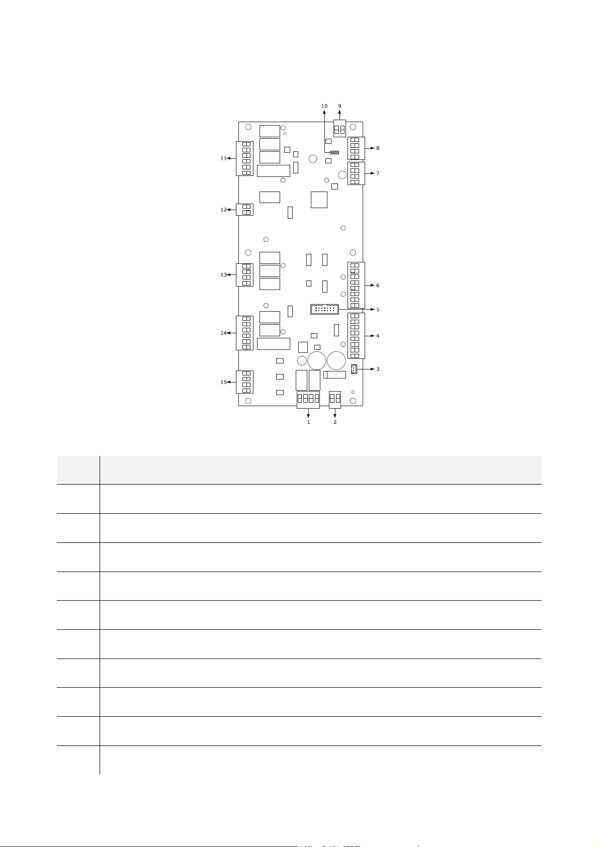
The following drawing illustrates the layout of the device's control module.
Vcolor 338 L | Installer manual ver. 2.0 | Code 144VC338LE204
The following table illustrates the meaning of the device control module parts.
PART MEANING
1 digital outputs K1 and K2
2 power supply
3 external buzzer output
4 digital inputs for clean contact
5 reserved
6 analogue inputs
7 reserved
8 user interface communication port
9 analogue output
10 dip switch to activate the terminal resistor
page 18 of 66

EVCO S.p.A.
For further information, see the next chapters.
11 digital outputs K10... K13
12 digital output K9
13 digital outputs K6... K8
14 digital outputs K3... K5
15 high voltage digital inputs
Vcolor 338 L | Installer manual ver. 2.0 | Code 144VC338LE204
page 19 of 66

EVCO S.p.A.
Vcolor 338 L | Installer manual ver. 2.0 | Code 144VC338LE204
5 COMMISSIONING
5.1 Commissioning
Operate as indicated:
1.
2.
3.
4.
5.
PARAM. MEANING FACTORY SETTING
Install the device using the methods illustrated in chapter 2 “DIMENSIONS AND INSTALLATION”, following all warnings
given in paragraph 2.3 “Installation warnings”.
Connect the device electrically using the methods illustrated in chapter 3 “ELECTRIC CONNECTION”, following all warnings
given in paragraph 3.2 “Warnings for the electric connection”, without connecting the power supply and the mains
electricity.
Connect the device power supply: a splash screen will be displayed for a few seconds.
Set the time, the date and the day of the week; see paragraph 16.1 “Setting the time, date and day of the week”.
Configure the device with the procedure illustrated in the paragraph 16.2 “Setting the configuration parameters”.
The following table illustrates the meaning of the configuration parameters; the parameters are listed according to the
appropriate configuration sequence.
Probe type
P0
0 = thermocouple J (only in the J/K versions)
1 = thermocouple K (only in the J/K versions)
2 = Pt 100 (only in the Pt 100 versions)
0
P1
P2
F0
t0
Unit of measurement
0 = °C
1 = °F
Enabling the needle probe
1 = YES
Type of fan management
0 = in “on/off” mode and at single speed
1 = in “on/off” mode, with single speed and with inversion of the direction of
rotation of the fan
2 = in “on/off” mode, with dual speed and with inversion of the direction of
rotation of the fan
3 = in modulating mode and with inversion of the direction of rotation of the
fan
Steam generation mode
0 = direct
1 = with an external humidifier
2 = combined (i.e. direct and with external humidifier)
0
0
0
0
u0
u1
Air vent output contact type
0 = normally open (air vent opens when the contact is closed)
1 = normally closed (air vent opens when the contact is open)
Utility managed by the air vent output
0 = ELECTROVALVE ON/OFF
=
MOTORISED ELECTROVALVE - in this case the u2, u3 and u4 parameters
1
will assume significance
page 20 of 66
0
0

EVCO S.p.A.
Successively, check that the remaining settings are appropriate; see paragraph 16.3 “List of configuration parameters”
6.
7.
For further information, see the next paragraphs.
K0 Enables rotor 0
Cleaning type
W17
0 = disabled
1 = with liquid detergent, no recycling
2 = with tablet detergent and recycling
Connect to the electric mains.
Switch the device on; see the paragraph 7.1 “Switching the device on/off”.
Vcolor 338 L | Installer manual ver. 2.0 | Code 144VC338LE204
1
page 21 of 66

EVCO S.p.A.
Vcolor 338 L | Installer manual ver. 2.0 | Code 144VC338LE204
6 MANAGEMENT OF UTILITIES
6.1 Preliminary notes
This paragraph illustrates the activity of the utilities during
normal operation.
To know the main consequences of an alarm, see chapter 16
“ALARMS”.
6.2 Temperature regulation
The output is on until the environment temperature reaches
the work set-point and is switched back on when the
temperature drops below the value established with the
parameter r0 (i.e. "working set-point - r0").
To set the work set-point, see paragraph 8.2 “Setting the
cooking cycle”; to set the configuration parameters, see
paragraph 16.2 “Setting the configuration parameters”.
6.3 Steam injection
The steam generation mode depends on parameter t0, as
follows:
-
-
-
The parameter t1 establishes the cycle time for the injection of
the steam generated in direct mode and the parameter t2 the
duration of the injection of the steam generated with the same
mode corresponding to the maximum humidification.
The parameter t6 establishes the cycle time for the injection of
the steam generated with external humidifier and the
parameter t7 the duration of the injection of the steam
generated with the same mode corresponding to the maximum
humidification.
To set the humidification, see paragraph 8.2 “Setting the
cooking cycle”; to set the configuration parameters, see
paragraph 16.2 “Setting the configuration parameters”.
if the parameter t0 is set at 0, the steam will be
generated in direct mode.
if the parameter t0 is set at 1, the steam will be
generated with an external humidifier
if the parameter t0 is set at 2, the steam will be
generated in combined mode (i.e. direct and with
external humidifier); in this case the temperature
established with parameter t12 determines the
temperature above which the steam generated in
direct-mode will be injected and below which the
steam generated with an external humidifier will
be injected (referring to the temperature detected
by the environment probe).
6.4 Air Vent
The utility managed by the air vent output depends on
parameter u1, as follows:
-
-
if the parameter u1 is set at 0, the utility will be
an on/off electrovalve
if the parameter u1 is set at 1, the utility will be a
motorised electrovalve
The air vent is opened automatically on conclusion of each
phase of a cooking cycle.
To set the duration of the automatic air vent opening, see the
paragraph 8.2 “Setting the cooking cycle”.
The air vent is also opened/closed by touching the “manual”
area.
6.5 Room light
The environment light is switched on/off by touching the
reference area: .
6.6 Technical compartment fan
The technical compartment fan is on until the temperature of
use of the control module reaches the temperature established
with parameter F6 and is switched back on when the
temperature rises above that established with parameter F7
(i.e. “F6 + F7”).
To set the configuration parameters, see paragraph 16.2
“Setting the configuration parameters”.
6.7 Fan
The type of ventilation management depends on parameter
F0, in the following way:
-
-
-
-
If parameter F0 is set at 0, 1 or 2, parameter F1 will establish
the duration of fan switch off due to the inversion of the
direction of rotation of the same and parameter F2 that of fan
switch-on for every direction of rotation.
If parameter F0 is set at 3, the parameters F4 and F5 will
establish the minimum and the maximum fan speed, the
parameter F8 will establish the minimum fan speed that can
be set on a cooking cycle.
To set the fan speed, see paragraph 8.2 “Setting the cooking
cycle”; to set the configuration parameters, see paragraph
16.2 “Setting the configuration parameters”.
if the parameter F0 is set at 0, ventilation will be
managed in “on/off” mode and at single speed
if the parameter F0 is set at 1, ventilation will be
managed in “on/off” mode and at single speed and
with inversion of the fan rotation direction
if the parameter F0 is set at 2, ventilation will be
managed in “on/off” mode and at dual speed and
with inversion of the fan rotation direction
if the parameter F0 is set at 3, ventilation will be
managed in modulating mode and with inversion
of the fan rotation direction
page 22 of 66

EVCO S.p.A.
Vcolor 338 L | Installer manual ver. 2.0 | Code 144VC338LE204
6.8 Cooking fumes reduction
The cooking fumes reduction is active until the temperature
detected by the fumes probe reaches the temperature
established with parameter t13 and is turned back on when
the temperature rises above the one established with the
parameter t14 (i.e. "t13 + t14", only if the fumes probe is
enabled, i.e.if parameter P3 is set at 1).
To set the configuration parameters, see paragraph 15.2
“Setting the configuration parameters”.
6.9 Outputs management for
special cleaning cycles
The controller has 4 relay outputs to manage two different
types of cleaning:
-
-
-
At the start of every cleaning cycle the room light turns on
automatically, and can be turned off and back on again at any
time with the dedicated switch.
Below is a detailed description of the two types of cleaning:
Cleaning cycle with liquid detergent, with no water
recycling:
There are 4 management relays, each with a different
function:
-
-
-
-
The cleaning cycle goes through 4 linked phases in cascade.
Phase 1 - Precleaning:
The oven temperature is raised to the precleaning level (w0
parameter) If the room temperature is lower, the heating
output will be activated together with the ventilation, while at
the same time closing the air vent.
If the temperature is higher than the set one, the controller
will keep only the ventilation on, the air vent will remain open
and a pop-up message will request the door to be opened in
order to facilitate the cooling of the chamber.
When the temperature lies within the "precleaning w0 -
precleaning activation hysteresis authorisation (w1)"setpoint
range , the air vent closes, the door must be closed (if
previously opened) and the controller will activate the K13
relay (mains water solenoid valve) for w2 minutes.
At the same time, the K11 relay: water drain pump will also be
activated. Ventilation remains active for the whole duration of
the phase, the heating output will keep the set temperature
constant.
Cleaning cycle with liquid detergent, with no
water recycling;
Cleaning cycle with tablet detergent, with
water recycling;
Cleaning cycle disabled.
K13 Relay: Mains water solenoid valve;
K12 Relay: Liquid detergent injection pump;
K11 Relay: Water drain pump;
K10 Relay: Liquid rinse aid injection pump;
At the end of the w2 time, the resistors, ventilation, water
solenoid valve and, after a w16 delay the water drain pump
will be turned off.
Phase 2 -Cleaning:
The cleaning phase starts at the end of the precleaning. After
time F1 (fan deceleration) has elapsed, the K12 (liquid
detergent injection) relay is activated for w4 seconds.
After the w4 time has elapsed, there is a w5 minutes pause to
allow the detergent to act.
After the w5 time has elapsed, the machine starts heating
again, with active ventilation, bringing the chamber up to the
cleaning temperature (parameter w3); after the t11 time has
elapsed, the controller will start injecting steam in the
chamber (with 100% setting) for a total time of w6 minutes.
After the w6 time has elapsed, the controller commands a
brief rinse of the chamber by activating the K13 (mains water
solenoid valve) relay for w7 seconds.
The K11 and K13 relays are activated for 32 seconds.
Phase 2 of the cleaning cycle can be repeated:
-
-
-
according to the settings input by the final user during the
cycle selection/setting phase.
Phase 3 - Rinse aid:
The "Rinse aid" phase starts after the end of the cleaning
cycle.
The K10 relay: "liquid rinse aid injection pump" is activated
for w9 seconds, followed by a pause of w10 seconds to allow
the rinse aid to become effective.
After the w10 time has elapsed, the machine starts heating
again, with active ventilation, bringing the chamber up to the
rinse aid action temperature (parameter w8); after the t11
time has elapsed, the controller will start injecting steam into
the chamber (with 100% setting) for a total time of w11
minutes.
1 time (soft cleaning)
2 times (medium cleaning)
3 times (hard cleaning)
page 23 of 66

EVCO S.p.A.
Vcolor 338 L | Installer manual ver. 2.0 | Code 144VC338LE204
Important: with the w9=0 setting the "rinse aid" phase
is bypassed entirely.
Phase 4 - Rinse:
The rinse phase starts at the end of the Rinse aid cycle.
The machine (with active ventilation) will be brought to the
rinse temperature (parameter w12), the controller will activate
relay K10 (mains water solenoid valve) for w13 minutes. At
the same time, the K2 relay (water discharge pump) will also
be activated.
Ventilation remains active for the whole duration of the phase,
the heating output will keep the set temperature constant.
After the w13 time has elapsed, the mains water solenoid
valve will be turned off and after a w16 delay the water drain
pump will be deactivated.
Phase 5 - Drying:
The drying phase starts at the end of the rinse cycle.
The machine (with active ventilation) will be brought to the
drying temperature (parameter w14) for w15 minutes and the
air vent will open. After this time has elapsed, the cleaning
cycle will end, all outputs will be turned off, including the room
light and the machine will go to the ON screen.
Cleaning cycle stop
If the cycle is stopped manually during the precleaning, rinse
or drying phase, the cycle stops immediately.
If the cycle is stopped manually during the cleaning or rinse
aid phase, the machine will go to the rinse cycle and stop at
the end of that phase.
During any phase, the black-out alarm will reset the ongoing
phase.
If the door is opened at any time, the cycle is paused and
starts again when the door is closed.
Cleaning cycle with tablet detergent, with water
recycling;
There are 4 management relays, for:
-
-
-
-
This kind of cleaning can also be supported by a dedicated
probe to check the drain temperature of the water used for
cleaning, as it should not exceed 60-75°C in order to be
drained into the sewers (national regulation).
To enable the water drain temperature control, the relevant
probe (rather than the fumes one) must be turned on with
parameter P3=2.
K13 relay: condenser mains water solenoid valve
K12 relay: water recirculation pump
K11 relay: condenser water drain pump
K10 relay: not used
The cleaning cycle with tablet allows a choice to be made
among 4 different types:
-
-
-
-
The "Rinse" cleaning type is a special sequence cycle, while
the other cycle types differ in the number of repetitions of the
cleaning phase carried out.
The following picture shows the "CLEANING" selection screen,
where it will be possible to select one of the four types of
cleaning
Cycle selection and start
If a RINSE cycle is selected and started, the machine will go
immediately into pre cleaning mode.
If one of the other three available types is selected, instead,
the controller will ask for the input of the number of detergent
doses to be injected in the chamber:
-
-
-
After injecting the detergent (the machine does not check
whether the detergent has actually been injected), press the
START button again to start the precleaning phase.
Phase 1 - Precleaning:
The oven temperature is raised to the precleaning level (w0
parameter) If the room temperature is lower, the heating
output will be activated together with the ventilation, while at
the same time closing the air vent.
If the temperature is higher than the set one, the controller
will keep only the ventilation on, the air vent will remain open
and a pop-up message will request the door to be opened in
order to facilitate the cooling of the chamber.
Rinse
SOFT cleaning.
MEDIUM cleaning.
HARD cleaning.
2 doses = SOFT cleaning
4 doses = MEDIUM cleaning
6 doses = HARD cleaning
page 24 of 66

EVCO S.p.A.
Vcolor 338 L | Installer manual ver. 2.0 | Code 144VC338LE204
When the temperature lies within the "precleaning w0 -
precleaning activation hysteresis authorisation (w1)"setpoint
range , the air vent closes, the door must be closed (if
previously opened) and the controller will activate the K13
relay (mains water solenoid valve) for w2 minutes, during
which the condenser will be charged with water and filled to
allow the recirculation pump to collect the water needed for
the various cleaning phases.
Ventilation remains active for the whole duration of the phase,
the heating output will keep the set temperature constant.
After the w2 time has elapsed, the machine operation will vary
according to the type of cycle selected: RINSE or CLEANING
cycle.
Phase 2A - RINSE
The selected cycle is performed at the end of the Pre cleaning
phase.
The counting of one w10 minutes cycle starts now: during this
time, the "condenser mains water inflow solenoid valve",
"Direct steam injection" and "water recirculation pump"
outputs will be activated with the ventilation on at maximum
speed.
After the w10 time has elapsed, the machine will go back to
the HOME screen and keep the Water Discharge Pump output
in operation for the time w9 in order to empty the condenser.
If the door is opened or the STOP key pressed, the cycle will
be immediately interrupted and the machine will go back to
the HOME screen.
Phase 2B - Cleaning Preparation
The oven is brought to the cleaning preparation temperature
(parameter w8) with 100% humidification for w11 minutes,
and in the meanwhile the K13 (condenser mains water inflow
solenoid valve) relay will also be activated.
Once the correct temperature is reached, all the outputs
except the ventilation one will de deactivated until the
temperature has fallen below the w18 temperature; then the
regulation, steam injection and mains water injection tasks will
be taken up again. After the w11 time has elapsed, the cycle
will go on to the next phase.
Phase 3B - Cleaning
At the end of the cleaning Preparation phase, the cycle will
launch the cleaning phase.
The cleaning phase sets a w5 time during which the oven is
brought to the cleaning temperature (parameter w3),
ventilation is always active at full speed, the recirculation
pump is started and will pump the hot water from the
condenser into the chamber flooding the detergent tablets.
In this phase there is no steam injection.
After w5, a w6 time is set. The machine disconnects all utilities
(except power) to allow the detergent to act.
The Duty Cycle comprising w5 and w6 will be repeated:
-
-
-
During the entire cleaning phase, if enabled through the P3
parameter and if the value of the Water Drain probe exceeds
the maximum water drain set point (parameter w19), the
controller will activate the Mains Water Injection output to
allow the condenser temperature to drop.
The differential for this adjustment is fixed and equal to -10°C,
that is to say, water inflow stops when the temperature read
by the Water Drain sensor drops by 10°C as against the
maximum water drain e set point (parameter w19).
At the end of the number of cycles set for the current one, the
machine will go on to the next phase.
Phase 4B - Rinse
This phase has a duration of w13, during which time the
condenser mains water injection, the direct steam injection
and the maximum speed ventilation will be active.
No heating phase and no recycling phase are entailed. After
the w13 time has elapsed, the cycle will go on to the next
phase.
Phase 5B - Drying
The drying phase starts at the end of the rinse cycle.
The machine is brought to the drying temperature (parameter
w14) and with the ventilation on at maximum speed for w15
minutes, after which the cycle ends and the machine goes
back to the HOME screen.
Cleaning cycle stop:
If the cycle is stopped manually during the 1, 2A, 2B or 5B
phases, the machine will stop immediately.
If the cycle is stopped manually during the 3B phase, the
machine will go on to the 4B phase and then will stop at the
end of the 4B phase. If the cycle is stopped manually during
the 4B phase, the cycle will continue with the ongoing phase
and then will stop.
If the door is opened at any time, (from the moment in which
the desired temperature has been attained during phase one
with the closing of the air vent at the end of phase 5), this will
immediately interrupt the cycle and reset the machine to the
HOME screen.
A black-out alarm triggered during any phase will reset the
running phase
3 times if the cleaning cycle is
SOFT;
6 times if the cleaning cycle is
MEDIUM;
9 times if the cleaning cycle is
HARD;
page 25 of 66

EVCO S.p.A.
62%
62%
64 min
70 min
AUTO
STOP
STOP
Vcolor 338 L | Installer manual ver. 2.0 | Code 144VC338LE204
6.10 User interface variant for
ROTOR ovens management
The ROTOR management controller differs from a COMBI one
due to the additional presence of:
-
-
Management of the motor rotation control relay output
and rack limit switch digital input
The motor rotation output is activated automatically at the
start of the oven preheating phase .
It will be possible to stop or restart the rotation at any
moment, with the relevant motor rotation/stop key in the user
interface; the motor will stop at the next forthcoming
activation of the limit switch input, which indicates the position
allowing the rack to be extracted after opening the door.
If the limit switch input is fault, incorrectly wired or not
installed (e.g., for rotor ovens with non removable rack), the
rack will stop after a maximum time determined by parameter
k2.
If the door is opened while the rack is rotating, the output
stops immediately (without waiting the limit switch activation
and the expiration of the maximum time period), to avoid any
hazard for the operator.
With the door closed, parameter k1 will establish whether the
rack starts to rotate again automatically or remains still in the
position it was before the door opening.
rack rotation motor control relay
rack limit switch digital input that determines the
STOP position
COTTURA 6minfase 1/3
175°C
180°C
page 26 of 66

EVCO S.p.A.
7 USER INTERFACE
7.1 Switching the device on/off
Operate as follows to switch the device on:
1.
Operate as follows to switch the device off:
2.
3.
If there is a power cut when the device is on or off, when the
power supply is restored the device will back to the prior
status.
If there is a power cut during the cooking cycle and the
duration of said interruption is lower than the time established
with parameter r12, when the power supply is restored, the
cycle will be re-proposed from the start of the phase during
which the power cut occurred (if the duration of the
interruption is longer than the time established with parameter
r12, when the power supply is restored, the cycle will be
interrupted).
Touch .
Make sure no procedures are in progress.
Touch .
7.2 Silencing the buzzer
Operate as follows to silence the buzzer:
1.
2.
Make sure no procedures are in progress.
Touch a sensitive area of the display.
Vcolor 338 L | Installer manual ver. 2.0 | Code 144VC338LE204
Device switch-on.
Device switch-off.
page 27 of 66

EVCO S.p.A.
Vcolor 338 L | Installer manual ver. 2.0 | Code 144VC338LE204
8 COOKING CYCLE
8.1 Preliminary notes
Every cooking cycle is preceded by preheating (on condition
that Delta T cooking has not been set; the work set-point is
relative to the work set-point during the first phase of the
cooking cycle, i.e. "work set-point during the first phase of the
cooking cycle + work set-point during preheating").
During pre-heat, the fan is switched-on at maximum speed.
When the temperature detected by the environment probe
reaches the work set-point, the buzzer is activated for 3 s.
The opening and closing of the door causes the passage to the
first phase of the cooking cycle.
Every cooking cycle is made up from a minimum of one to a
maximum of six phases; on conclusion of a phase, the device
moves automatically to the next.
For every phase, the device can manage the following
settings:
-
-
-
-
-
-
-
-
-
-
-
the type of cooking:
timed (the phase has duration for the time set and
the work set-point is an absolute value)
with Delta T (only if the needle probe is enabled,
i.e. if parameter P2 is set at 1; the phase has
duration until the temperature detected by the
needle probe reaches the core set-point and the
work set-point is a delta referred to the
temperature detected by the needle probe, i.e.
“temperature detected by the needle probe +
Delta T set-point)
core (only if the needle probe is enabled, i.e. if the
parameter P2 is set at 1; the phase has duration
until the temperature detected by the needle
probe reaches the core set-point and the work set-
point is an absolute value)
the work set-point (only if timed or core cooking
has been set)
the Delta T set-point (only if Delta T cooking has
been set)
the humidification
the duration of the phase (only if timed cooking
has been set)
the core set-point (only if Delta T or core cooking
has been set)
the fan speed (only if fan management has been
set in “on/off” mode with dual speed or in
modulating mode, i.e. if the parameter F0 is set at
2 or 3)
anticipation time of the air vent automatic opening
before phase conclusion (only if timed cooking has
been set).
page 28 of 66

EVCO S.p.A.
manual
aggiungi fase
termina ricetta
AUTO
67 min
MODIFICA VALORE
8.2 Setting the cooking cycle
Operate as follows to set the cooking type:
1.
2.
3.
Operate as follows to set the work set-point:
4.
5.
6.
Operate as follows to set the Delta T set-point:
7.
8.
Operate as follows to set the humidification:
9.
10.
Operate as follows to set the duration of the phase:
11.
12.
Operate as follows to set the core set-point:
13.
14.
Operate as follows to set the fan speed:
15.
16.
Operate as follows to set the duration of the automatic air vent
opening:
17.
18.
Ensure that the device is switched on and that no
other procedure is in progress.
Touch the “manual” key:
Touch to set:
- the cooking time:
- the cooking at Delta T :
- the core cooking:
Touch the key
Touch the “slide bar”
see also parameters r1 and r2.
Touch the green icon: to confirm,
or the red one: to exit.
Touch the key
Repeat points 5. and 6.; see also parameters r7
and r8.
Touch the key
Repeat points 5. and 6.
Touch the key
Repeat points 5. and 6.
Touch the key
Repeat points 5. and 6.; see also parameters r4
and r5.
Touch the key and select the desired
speed
Repeat points 5. and 6.
Touch the key and
select
Repeat points 5. and 6.
Vcolor 338 L | Installer manual ver. 2.0 | Code 144VC338LE204
Setting the cooking cycle.
FASE 1
15°C
60%
elimina fase
Setting the cooking type.
175°C
Setting the work set-point.
page 29 of 66

EVCO S.p.A.
aggiungi fase
termina ricetta
AUTO
FASE 1
20.
24.
15°C
19.
26.
27.
To select/scroll the cooking cycle phases, proceed as follows:
19.
Touch the reference bar
Operate as follows to add a phase to the cooking cycle:
20.
Touch the "add phase" key
Operate as follows to eliminate the last phase from the
cooking cycle:
21.
22.
Select the phase.
Touch the "Delete phase" key
To terminate the setting of a program, proceed as follows:
23.
24.
From any phase in the cycle ...
Touch the "Delete Recipe" key
Once the program has been set, the controller will display a
summary of the set cycle.
From this screen it is possible to:
25.
26.
27.
28.
back to cycle settings:
Key or
key
Save the set cycle, touching the relevant
key:
Start the set cycle, touching the relevant
Vcolor 338 L | Installer manual ver. 2.0 | Code 144VC338LE204
60%
67 min
22.
25.
Cycle setting screen
RIEPILOGO CICLO
1
175°C
62%
75m
30%
3
10°C
62%
80°C
30%
5
2
120°C
62%
55°C
50%
4
6
key:
Note: The duration of an infinite time cycle cannot be
modified during the cooking. The duration of a finite time cycle
can be modified during the cooking but cannot be set to
infinite time.
SALVA
START
START
28.
Set cycle summary screen
page 30 of 66

EVCO S.p.A.
PROLUNGA ?
STOP
STOP
3.
2.
8.3 Starting the cooking cycle
Once the cooking cycle has been launched, preheating will
start.
Opening and closing the door or pressing on the status bar
causes the machine to start the first phase of the cooking
cycle.
During preheat and during the cooking cycle, the display
shows the value of the variables affected by the process and
the relative setting.
To modify the settings; see the paragraph 8.2 “Setting the
cooking cycle”.
Touch:
-
-
-
On conclusion of the cooking cycle, the buzzer is activated for
the time established with parameter c0.
Operate as follows to extend the cooking cycle:
3.
A screen enabling the extension of the cooking
cycle is displayed.
4.
5.
to open/close the air vent
to switch the environment light on/off
to display the value of the process variables
and machine status.
Touch .
Touch the slide bar
to set the desired value
Touch the green icon to confirm.
8.4 Stopping the cooking cycle
Operate as follows to stop the cooking cycle:
1.
2.
Make sure no procedures are in progress.
Touch for 1 s.
Vcolor 338 L | Installer manual ver. 2.0 | Code 144VC338LE204
Starting the cooking cycle and Pre-heat
FINE COTTURA 125minfase 3/3
End or interruption of the cooking cycle
Extension of the cooking cycle.
page 31 of 66

EVCO S.p.A.
Vcolor 338 L | Installer manual ver. 2.0 | Code 144VC338LE204
9 “MY COOKBOOK” FUNCTION
9.1 Preliminary notes
The “MY COOKBOOK" function allows to memorise the settings
of a cooking cycle in a recipe; when starting up the recipe, the
device will function with the memorised settings.
It is possible to save up to max. 99 recipes.
9.2 Saving a recipe
With the device on and in "Cycle recap" mode it is possible to
save a recipe, proceeding as follows:
1.
2.
This allows to access the "MY COOKBOOK" screen, where it will
be possible to select the recipe to be saved.
3.
4.
5.
6.
7.
If the name of the recipe needs to be changed, proceed as
follows:
4.
5.
Set the cooking cycle; see the paragraph 8.2
“Setting the cooking cycle”.
Touch “SAVE”
"My Cookbook" screen.
Touch or to scroll through the pages
with list of recipes.
Touch the name of the relevant recipe to
save it.
Touch the display to associate a new name to the
recipe.
Touch to exit the procedure without
overwriting
Touch to confirm.
Touch the name of the selected recipe
Touch to confirm.
Recipe overwriting screen
Cycle recap screen to access "My Cookbook"
page 32 of 66
Memorising a recipe

EVCO S.p.A.
ricette
speciali
2.
P01
LASAGNE A ALLA BOLOGNESE
3.
3.
4.
Vcolor 338 L | Installer manual ver. 2.0 | Code 144VC338LE204
9.3 Starting a recipe
Operate as follows to start a recipe:
1.
Ensure that the device is switched on and that no
other procedure is in progress.
2.
3.
4.
5.
6.
Touch the "Recipes" key
Touch or to select the recipe.
Touch the display next to the relevant recipe
Touch : the recipe will be activated.
Touch to enter the recipe settings and change
them
9.4 Deleting a recipe
Operate as follows to delete a recipe:
1.
From item 4. of paragraph 9.3 “Starting a recipe”,
touch “delete” to delete the reference recipe.
manuale
10 “SPECIAL CYCLES” FUNCTION
10.1 Preliminary notes
The “Special cycles” function allows to use the work cycles
made available by EVCO.
One of the following work cycles can be started:
-
-
-
-
The following table illustrates the factory settings of the core
regeneration cycle.
SETTING DEFAULT
work set-point 110 °C 20... 180 °C
humidification 70 %. 40... 100 %.
core set-point 70 °C 20... 100 °C
core regeneration cycle (only if the needle probe is
enabled, i.e. if parameter P2 is set at 1)
timed regeneration cycle
timed proofing cycle
environment cooling cycle.
MINIMUM...
MAXIMUM
fan speed minimum
air vent opening on conclusion of the cycle
preferiti
The following table illustrates the factory settings of the timed
regeneration cycle.
MINIMUM...
MAXIMUM
Access to a recipe.
SETTING DEFAULT
work set-point 110 °C 20... 180 °C
humidification 70 %. 40... 100 %.
LE MIE RICETTE
P02
GNOCCHI ALLA ROMANA
P03
POLLO ALLA CACCIATORA
P04 <free>
P05 <free>
P06 <free>
P07 <free>
P08 <free>
P09 <free>
P10 <free>
duration of the
phase
25 min 1... 90 min
fan speed minimum
air vent opening on conclusion of the cycle
page 33 of 66

EVCO S.p.A.
Vcolor 338 L | Installer manual ver. 2.0 | Code 144VC338LE204
The following table illustrates the factory settings of the timed
proofing cycle.
SETTING DEFAULT
work set-point 30 °C 20... 50 °C
humidification 80 %. 40... 100 %.
duration of the
phase
fan speed minimum
air vent opening on conclusion of the cycle
The following table illustrates the factory settings of the
environment cooling cycle; the opening and closing of the door
does not cause any consequence.
SETTING DEFAULT
120 min 1... 300 min
MINIMUM...
MAXIMUM
MINIMUM...
MAXIMUM
10.2 Starting a special cycle
Operate as follows to start a special cycle:
1.
2.
3.
4.
Note: In the picture on the left (Start a special cycle) the
Ensure that the device is switched on and that no
other procedure is in progress.
Touch the "specials" key
Touch the identification icon of the special cycle.
Then touch to start the
cycle
special cycle refers to leavening, but the procedure is
the same as that for the start of all the remaining
special cycles: regeneration, cooling and cleaning.
work set-point
fan speed
air vent opening
50 °C
(param. r11)
maximum, without inversion of
rotation direction (if envisioned)
at the start of the cycle, for the
entire duration of the same
0... 500 °C
Access to a special cycle.
Starting a special cycle.
page 34 of 66

EVCO S.p.A.
11 “FAVOURITE CYCLES”
FUNCTION
11.1 Preliminary notes
The “Favourite cycles” function allows to start one of the last
10 work cycles performed.
One of the following types of work cycle can be started:
-
-
-
cooking cycles set with the procedure illustrated in
the paragraph 8.2 “Setting the cooking cycle” (in
this case, the last cycle performed can be started)
recipes from the “MY COOKBOOK” function
“Special cycles” function work cycles.
11.2 Starting a favourite cycle
Operate as follows to start a favourite cycle:
1.
2.
3.
Ensure that the device is switched on and that no
other procedure is in progress.
Touch the “favourites” icon
Touch the identification icon of the interested
special cycle
Vcolor 338 L | Installer manual ver. 2.0 | Code 144VC338LE204
Access to a favourite cycle.
4.
Touch : the favourite cycle will be
started.
Starting a favourite cycle.
page 35 of 66

EVCO S.p.A.
12 "WEEKLY PROGRAMMED
SWITCH-ON" FUNCTION
12.1 Preliminary notes
The “Weekly programmed switch-on” function allows to
program up to a maximum of 9 weekly switch-ons of the
device and simultaneously start a recipe; see chapter 9 ““MY
COOKBOOK” FUNCTION”.
12.2 Setting the "weekly
programmed switch-on"
function
Operate as follows to access the procedure:
1.
2.
Operate as follows to set the switch-on day:
Ensure that at least one recipe is memorised, that
the device is on and that no other procedure is in
progress.
Touch the key .
Vcolor 338 L | Installer manual ver. 2.0 | Code 144VC338LE204
Access to the setting procedure of the function
3.
The "Scheduling" screen will be displayed, and from there it is
possible to proceed with the settings.
4.
5.
Operate as follows to set the switch-on time:
6.
7.
8.
9.
To select the recipe to be launched, from the main screen
proceed as follows:
10.
11.
Touch .
Touch or (within 15 s) to reduce or
increase the relevant value.
Touch the key to confirm the input value.
Touch .
To set the time, touch or (within 15 s)
to reduce or increase the relevant value.
To set the minutes, touch the display near the
centre, , touch or (within 15 s) to
reduce or increase the relevant value.
Touch the key to confirm the input
value.
Touch the "Recipes" key .
Repeat item 3. ... 5. of paragraph 9.3 “Starting a
recipe”.
Setting the start time and the functions time
page 36 of 66

EVCO S.p.A.
12.3 Enabling the "Weekly
programmed switch-on"
function
Operate as follows to access the procedure:
1.
2.
Operate as follows to select a switch-on:
3.
Operate as follows to modify a switch-on:
4.
Operate as follows to activate the function:
5.
Operate as follows to deactivate the function:
6.
Ensure that at least one switch-on is set, that the
device is on and that no other procedure is in
progress.
Touch for 1 s.
Touch or .
Repeat. Points from 3 to 11 of paragraph 12.2
“Setting the "weekly programmed switch-on"
function”.
Touch .
Touch before point 4.
Vcolor 338 L | Installer manual ver. 2.0 | Code 144VC338LE204
Access to the function activation procedure
“Weekly programmed switch-on”.
Selection of a switch-on and activation of the function
“Weekly programmed switch-on”.
page 37 of 66

EVCO S.p.A.
13 OTHER FUNCTIONS
13.1 Display of the alarms status
Operate as follows to access the procedure:
1.
2.
3.
Ensure that the device is switched on and that no
other procedure is in progress.
Touch .
Touch “LIST OF ALARMS”.
13.2 Display of the process variables
value and of the machine status
Operate as follows to access the procedure:
1.
2.
3.
Ensure that the device is switched on and that no
other procedure is in progress.
Touch .
Touch “INTERNAL VALUES”.
13.3 Setting the language used for
the screens
Operate as follows to access the procedure:
1.
2.
3.
4.
Ensure that the device is switched on and that no
other procedure is in progress.
Touch .
Touch “LANGUAGES” to select the language.
Touch the desired language on the display.
Vcolor 338 L | Installer manual ver. 2.0 | Code 144VC338LE204
page 38 of 66

EVCO S.p.A.
pansion
EVCLE305XXE
Enable the boiler through parameter
Set the steam generation mode with external or mixed
Electrical connection
ed and kept above
level is not reached within the expected time
If the maximum required level is not reached within the expected time
When the device is ON, the water is heated and
cleaning the boiler or the room, the water is heated and
When water is not sufficient (minimum level not reac
It is possible to access the BOILER menu from the settings menu.
| Installer manual ver. 2
T0 (T0 = 1 o 2)
MIN
the alarm “MAX BOILER WATER LEV”
be reset and a new water
” (paramet
at “Boiler steam working temperature”
14 BOILER EXPANSION
Vcolor 338 L
.0 | Code 144VC338LE204
14.1 Activation of the ex
To enable the boiler expansion
1.
2.
3. Turn the device on
14.2
, it will be necessary to respect the following conditions.
T15 (T15 = 1)
humidification through parameter
14.3 Operation
14.3.1 Water charge management
When the device is ON, the water is charg
If the minimum required
activated.
activated.
These alarms can be manually reset from
will be started.
14.3.2 Water heating management
14.3.3 Boiler rinse
the maximum level.
(parameter t27), the alarm “
(parameter t28),
key., pressing the alarm will
maintained at “Boiler steam holding temperature
maintained
hed), the control is deactivated.
BOILER WATER LEV” will be
will be
charge cycle
er t18). While cooking,
(parameter T17).
page 39 of 66

EVCO S.p.A.
In the BOILER menu, it will be possible to select the function
the following phases will be performed
If the maximum required level is not reached within the expected time
activated and it will be possible to reset it from
MAX BOILER WATER LEV
to stop the cycle during an alarm, keep pushed the
It is possible to access the BOILER menu from the settings menu.
it will be possible to select the function CLEANING
will be requested
Starting this cycle, the following phases will be performed:
charge
its duration depends on parameter
its duration depends on parameter
Boiler
| Installer manual ver. 2
the alarm “MAX BOILER WATER LEV”
temporarily stop until the cause is removed.
key for 4 seconds.
key.
while the water heating to a certain temperature depends
while the water heating to a certain temperature depends
be performed a certain number of times according to
Starting this cycle,
1. Water charge to maximum level.
2. Water drain.
3. Water charge to maximum level.
4. Water drain.
If the drain fails, the alarm “BOILER DRAIN”
In the event of “BOILER DRAIN” or “
To exit, press the key;
14.3.4 Boiler cleaning
RINSE
:
will be activated and it will be possible to reset it from
key.
” alarms, the rinse will
Vcolor 338 L
(parameter t28),
.0 | Code 144VC338LE204
key.
will be
In the BOILER menu,
When pressing CLEANING, a password
1. Water charge to maximum level.
2. Water drain.
3. Descaler charge request: the
4. Water charge to maximum level.
5. Descaler action activation:
on parameter t23.
6. Water drain.
7. Water charge to maximum level.
8. Cleaning action activation:
on parameter t25.
9. Next step is point 6. The cleaning
t26. The cleaning ends with the
(default “1”).
will be manually performed, to proceed press the
t22,
t24,
phase (points 6,7,8) will
water drain.
parameter
page 40 of 66

EVCO S.p.A.
If the drain fails, the alarm “BOILER DRAIN” will be activated and it will be possible to reset it from key.
If the maximum required level is not reached within the expected time (parameter t28), the alarm “MAX BOILER WATER LEV” will be
activated and it will be possible to reset it from key.
In the event of “BOILER DRAIN” or “MAX BOILER WATER LEV” alarms, the rinse will temporarily stop until the cause is removed.
To exit, press the key; to stop the cycle during an alarm, keep pushed the key for 4 seconds.
Vcolor 338 L | Installer manual ver. 2.0 | Code 144VC338LE204
15 BURNERS EXPANSION
15.1 Expansion activation
To enable the burners expansion, it will be necessary to set the parameter b14 = 1 (gas oven).
15.2 Electrical connection
page 41 of 66

EVCO S.p.A.
Vcolor 338 L | Installer manual ver. 2.0 | Code 144VC338LE204
15.3 Application scheme
The burner module EVCLE302XXE interacts with electronic ignition control boards for atmospheric burners such as "Honeywell
4565"series (and similar) and with variable speed centrifugal fans with PWM control signal+ feedback (HALL sensor).
15.4 Operation
During the heating phase, the controller will activate the relevant room or boiler heating outputs, as well as the relevant burner, whose
heating power is managed proportionally to the work set point trough the centrifugal fan speed control.
The burner activation procedure is the following:
1. Pre-ventilation phase: the burner speed will rise to the value determined by parameter b2 for the room burner or by
parameter b9 for the boiler burner and it will remain constant for k 10 seconds.
2. Ignition phase: once pre-ventilation time is over, the speed stability is checked through the feedback of the Hall sensor and
the burner control unit is activated by starting the relevant relay (room or boiler heating). The flame will be detected through
the digital input and the heating phase will start.
3. Heating phase: the burner speed will rise to the value required by the regulation to heat the oven.
Such speed is proportional to the difference between the temperature and the work set point inside the proportional band
given by parameter b3 for the room or b10 for the boiler. The speed may vary from a minimum value given by parameter b1
for the room or b8 for the boiler, to a maximum value given by b0 for the room or b7 for the boiler.
page 42 of 66

EVCO S.p.A.
Vcolor 338 L | Installer manual ver. 2.0 | Code 144VC338LE204
15.5 Errors handling
Ignition phase:
If no flame is detected during ignition phase, the burner will maintain the ignition speed.
Heating phase:
If no flame is detected during heating phase, the activation relay is turned off, the fan returns to the ignition speed for 10 seconds and
after 20 seconds the ignition attempt is repeated.
Room/boiler burner fault alarm:
If the ignition control board activates the room/boiler burner fault digital input, a recovery procedure is performed. The procedure
consists in 3 ignition attempts before signalling the alarm.
Room burner alarm
The room burner fan speed is constantly checked through the Hall input. If the speed set for the room fan burner differs more than
parameter b5 from the Hall sensor feedback for a time longer than parameter b6, the alarm is signalled.
Boiler burner alarm:
The boiler burner fan speed is constantly checked through the Hall input. If the speed set for the boiler fan burner differs more than
parameter b12 from the Hall sensor feedback for a time longer than parameter b13, the alarm is signalled.
page 43 of 66

EVCO S.p.A.
16 CONFIGURATION
16.1 Setting the time, date and day
of the week
Operate as follows to access the procedure:
1.
2.
Operate as follows to select a value:
3.
Operate as follows to set a value:
5.
6.
Ensure that the device is switched on and that no
other procedure is in progress.
Touch .
Touch repeatedly until the green rectangle
shows the desired value.
Touch or to change the value.
Touch after changing the desired values to
confirm the change.
Vcolor 338 L | Installer manual ver. 2.0 | Code 144VC338LE204
Time, date and day of the week setting procedure.
page 44 of 66

EVCO S.p.A.
16.2 Setting the configuration
parameters
Operate as follows to access the procedure:
1.
2.
3.
4.
5.
Operate as follows to select a parameter:
6.
Operate as follows to set a parameter:
7.
8.
9.
Ensure that the device is switched on and that no
other procedure is in progress.
Touch .
Touch “SERVICE”.
Touch or to set the password
“-19”.
Touch to confirm.
Touch or to select the relevant parameter.
Touch the relevant parameter
Touch or to set the value.
Touch to confirm.
Vcolor 338 L | Installer manual ver. 2.0 | Code 144VC338LE204
Access to the configuration parameters setting procedure.
Access to the configuration parameters setting procedure.
page 45 of 66

EVCO S.p.A.
Vcolor 338 L | Installer manual ver. 2.0 | Code 144VC338LE204
16.3 List of configuration parameters
The following table illustrates the meaning of the device configuration parameters.
PARAM. MIN. MAX. U.M. DEF. ANALOGUE INPUTS
probe type
P0 0 2 - - - 0
P1 0 1 - - - 0
0 = thermocouple J (only in the J/K versions)
1 = thermocouple K (only in the J/K versions)
2 = Pt 100 (only in the Pt 100 versions)
temperature unit of measurement (1)
0 = °C
1 = °F
P2 0 1 - - - 0
P3 0 2 - - - 0
CA1 -25/-50 25/50 °C/°F (2) 0 environment probe offset
CA2 -25/-50 25/50 °C/°F (2) 0 needle probe offset
CA3 -25/-50 25/50 °C/°F (2) 0 fumes probe offset
PARAM. MIN. MAX. U.M. DEF. MAIN REGULATOR
r0 1 99 °C/°F (2) 5
r1 0 r2 °C/°F (2) 0
enabling the needle probe
1 = YES
enabling the cooking fumes /condenser water drain probe
0 = probe disabled
1 = fumes probe
2 = water drain probe
work set-point differential (referring to the temperature detected by
the environment probe)
work set-point differential (referring to the temperature detected by
the environment probe)
r2 r1 500 °C/°F (2) 300
r3 r1 r2 °C/°F (2) 130
r4 0 r5 °C/°F (2) 0
r5 r4 500 °C/°F (2) 100
r6 r4 r5 °C/°F (2) 30
maximum work set-point (referring to the temperature detected by
the environment probe)
work set-point for factory setting (referring to the temperature
detected by the environment probe); see also r0
minimum set-point at the core (referring to the temperature
detected by the needle probe)
maximum set-point at the core (referring to the temperature
detected by the needle probe)
work set-point at the core for factory setting (referring to the
temperature detected by the needle probe)
page 46 of 66

EVCO S.p.A.
Vcolor 338 L | Installer manual ver. 2.0 | Code 144VC338LE204
r7 0 r8 °C/°F (2) 0
r8 r7 150 °C/°F (2) 30
r9 r7 r8 °C/°F (2) 5
r10 -199 199 °C/°F (2) 10
r11 0 500 °C/°F (2) 50
r12 0 240 min 240
minimum delta T set-point (referring to the temperature detected by
the needle probe)
maximum delta T set-point (referring to the temperature detected
by the needle probe)
delta T set-point for factory setting (referring to the temperature
detected by the needle probe)
work set-point during preheat (relative to the work set-point during
the first phase of the cooking cycle, i.e. “work set-point during the
first phase of the cooking cycle + r10”; referring to the temperature
detected by the environment probe); see also parameter r0
work set-point during cooling (referring to the temperature detected
by the environment probe)
duration of a power supply cut-off (3), occurring during a cooking
cycle, that may cause interruption
PARAM. MIN. MAX. U.M. DEF. VARIOUS
c0 -1 120 s 10
c1 0 1 - - - 0
c2 0 240 min 60
c3 0 99 °C/°F (2) 10
c4 0 99 °C/°F (2) 10
duration of buzzer activation on conclusion of the cooking cycle
-1 = until it is silenced by hand
activation of the buzzer (for 1 s) on conclusion of a cooking cycle
phase
time that must elapse without operations on the device (from
activation of the “Weekly programmed switch-on”) until this
switches off
temperature above which the display of the temperature detected by
the environment probe is locked (relative to the work set-point, i.e.
“work set-point + c3”)
0 = function absent
temperature above which the display of the temperature detected by
the environment probe is locked (relative to the work set-point, i.e.
“work set-point - c4”)
0 = function absent
page 47 of 66

EVCO S.p.A.
PARAM. MIN. MAX. U.M. DEF. FAN
F0 0 3 - - - 0
Vcolor 338 L | Installer manual ver. 2.0 | Code 144VC338LE204
type of fan management
0 = in “on/off” mode and at single speed
1 = in “on/off” mode, with single speed and with inversion of the
direction of rotation of the fan
2 = in “on/off” mode, with dual speed and with inversion of the
direction of rotation of the fan
3 = in modulating mode and with inversion of the direction of
rotation of the fan
F1 5 120 s 15
F2 5 600 s 120
F3 0 1 - - - 0
F4 0 F5 % 0
F5 F4 100 % 100
F6 20/65 65/150 °C/°F (2) 60
duration of the fan switch-off due to the inversion of the direction of
rotation of the same (only if F0 = 1, 2 or 3); see also F2
duration of the fan switch-on for every direction (only if F0 = 1, 2 or
3); see also F1
temperature regulation output switch-off during fan switch-off due
to the effect of the inversion of the fan rotation direction (only if F0
= 1, 2 or 3)
0 = YES
minimum fan speed (intended as a percentage of the maximum
speed; only if F0 = 3)
maximum fan speed (intended as a percentage of the maximum
speed; only if F0 = 3)
temperature above which the technical compartment fan is
switched-on (referring to the temperature used by the control
module); see also F7
F7 1 99 °C/°F (2) 10 differential of F6
F8 0 100 % 10
PARAM. MIN. MAX. U.M. DEF. STEAM INJECTION
t0 0 2 - - - 0
t1 t2 999 s 60 cycle time for injection of the steam generated in direct mode
t2 0 t1 s 30
Minimum speed that can be set by the fan user (intended as a
percentage of maximum speed; only if F0=3)
steam generation mode
0 = direct
1 = with an external humidifier
2 = combined (i.e. direct and with external humidifier)
duration of the injection of the steam generated in direct mode
corresponding to the maximum humidification
page 48 of 66

EVCO S.p.A.
Vcolor 338 L | Installer manual ver. 2.0 | Code 144VC338LE204
t3 0 999 s 60
t4 0 1 - - - 0
t5 0 1 - - - 0
t6 t7 999 s 60
injection delay of the steam generated in direct mode from start of a
cooking cycle phase
enabling of the restriction between the injection of the steam
generated in direct mode and the fan
1 = YES - the injection stops when the fan is off
If the fan is off when the steam has to be injected, the
injection will be made on the next fan switch-on and if the
fan has to stop during steam injection, it will be switched-
off after the conclusion of the injection
enabling of the restriction between the injection of the steam
generated in direct mode and the output for temperature regulation.
1 = YES - if the output is off when the steam is injected, the
injection will be made on successive output switch-on and if
the output has to stop during steam injection, it will be
switched-off after the conclusion of the injection
cycle time for injection of the steam generated with an external
humidifier
t7 0 t6 s 30
t8 0 999 s 60
t9 0 1 - - - 0
t10 0 1 - - - 0
duration of the injection of the steam generated with external
humidifier corresponding to the maximum humidification
injection delay of the steam generated with external humidifier from
start of a cooking cycle phase
enabling of the restriction between the injection of the steam
generated with external humidifier and the fan
1 = YES - if the fan is off when the steam has to be injected, the
injection will be made on successive fan switch-on and if the
fan has to stop during steam injection, it will be switched-off
on conclusion of the injection
enabling of the restriction between the injection of the steam
generated with external humidifier and the output for temperature
regulation.
1 = YES - if the output is off when the steam is injected, the
injection will be made on successive output switch-on and if
the output has to be closed during steam injection, it will be
switched-off on conclusion of the injection
t11 0 240 s 5
steam injection delay time from temperature regulation output
switch-on or from fan switch-on
page 49 of 66

EVCO S.p.A.
temperature above which the injection of steam generated in direct
t12 0 500 °C/°F (2) 120
t13 0 500 °C/°F (2) 90
t14 1 99 °C/°F (2) 5 differential of t13
mode is activated and below which the injection of steam generated
with external humidifier is activated (referring to the temperature
detected by the environment probe; only if t0 = 2)
temperature above which cooking fumes reduction is activated
(referring to the temperature detected by the fumes probe); see
also t14
Vcolor 338 L | Installer manual ver. 2.0 | Code 144VC338LE204
t15 0 1 --- 0
t16 1 500 °C/°F (2) 80
t17 1 500 °C/°F (2) 95 boiler steam working temperature
t18 1 500 °C/°F (2) 70 boiler steam holding temperature
t19 1 99 °C/°F (2) 2 hysteresis for t17, t18
t20 0 240 s 2 time delay for boiler water charge
t21 0 240 min 2 time delay for boiler water drain
t22 0 240 min 25 descaler action time for Cleaning phase 1
t23 1 500 °C/°F (2) 60 descaler action temperature for Cleaning phase 1
enabling the Boiler expansion
1 = YES
boiler temperature above which the injection of boiler steam is
enabled
t24 0 240 min 20 cleaning action time for phase 2
t25 1 500 °C/°F (2) 60 cleaning action temperature for phase 2
t26 1 10 --- 3 number of cleaning cycles phase 2
t27 0 240 s 5 minimum water level alarm delay
t28 0 240 min 3 maximum water level alarm delay
PARAM. MIN. MAX. U.M. DEF. TEMPERATURE ALARMS
A0 1 99 °C/°F (2) 10 differential of A1
page 50 of 66

EVCO S.p.A.
temperature above which the maximum temperature alarm is
A1 0 500 °C/°F (2) 0
A2 0 240 min 0 maximum temperature alarm delay
A3 0 2 - - - 0
A4 0 80/175 °C/°F (2) 70
PARAM. MIN. MAX. U.M. DEF. DIGITAL INPUTS
activated (referring to the temperature detected by the environment
probe); see also A0 and A3
maximum temperature alarm type
0 = no alarm
1 = absolute (i.e. A1)
2 = relative to the work set-point (i.e. “work set-point + A1”)
temperature above which the use temperature alarm is activated
(referring to the temperature of use of the control module)
0 = no alarm
Vcolor 338 L | Installer manual ver. 2.0 | Code 144VC338LE204
type of door micro switch input contact
i0 0 1 - - - 0
i1 0 1 - - - 0
i2 0 1 - - - 0
i3 0 1 - - - 0
i4 0 1 - - - 0
PARAM. MIN. MAX. U.M. DEF. DIGITAL OUTPUTS
0 = normally open (input active with closed contact)
1 = normally closed (input active with open contact)
type of circuit breaker protection input
0 = normally open (input active with closed contact)
1 = normally closed (input active with open contact)
reserved
type of safety thermal protection input
0 = normally open (input active with closed contact)
1 = normally closed (input active with open contact)
type of electric absorption input contact
0 = normally open (input active with closed contact)
1 = normally closed (input active with open contact)
u0 0 1 - - - 0
u1 0 1 - - - 0
type of air vent output contact
0 = normally open (air vent opens with closed contact)
1 = normally closed (air vent opens with open contact)
utility managed by the air vent output
0 = ELECTROVALVE ON/OFF
=
MOTORISED ELECTROVALVE - in this case the u2, u3 and u4
1
parameters will assume significance
page 51 of 66

EVCO S.p.A.
u2 0 600 ds (s/10) 120
Vcolor 338 L | Installer manual ver. 2.0 | Code 144VC338LE204
air vent output inhibition duration from the conclusion of the brief
impulse for air vent opening and from the conclusion of the long
impulse for air vent closure (only if u1 = 1); see also u3 and u4
u3 0 600 ds (s/10) 10
u4 0 600 ds (s/10) 30
PARAM. MIN. MAX. U.M. DEF. SERIAL NETWORK
LA 1 247 - - - 247 device address
Lb 0 3 - - - 2
LP 0 2 - - - 2
duration of the brief impulse for air vent opening (only if u1 = 1);
see also u2 and u4
duration of the long impulse for air vent closure (only if
u1 = 1); see also u2 and u3
baud rate
0 = 2.400 baud
1 = 4.800 baud
2 = 9.600 baud
3 = 19.200 baud
parity
0 = none (no parity)
1 = odd
2 = even
PARAM. MIN. MAX. U.M. DEF. ROTOR
k0 0 1 - - - 0 enables rotor
door action on rotor: the door opening stops the rotation When the
k1 0 1 - - - 1
k2 0 100 s 10
k3 0 1 - - - 0
PARAM. MIN. MAX. U.M. DEF. CLEANING
w0 0 500 °C/°F (2) 60 working set point for the precleaning phase
door is closed afterwards,
0 = the motor remains still
1 = it restarts as before the interruption
maximum motor activation duration. k2=0 immediately stops the
motor when opening the door.
type of rack limit switch input contact
0 = normally open (input active with closed contact)
1 = normally closed (input active with open contact)
page 52 of 66

EVCO S.p.A.
w1 1 99 °C/°F (2) 10 hysteresis authorisation for precleaning activation
w2 0 240 min 10 precleaning time
w3 0 500 °C/°F (2) 70 working set point for the cleaning phase
w4 0 240 s 5 liquid detergent inflow time
Vcolor 338 L | Installer manual ver. 2.0 | Code 144VC338LE204
w5 0 240 min 10
w6 0 240 min 10
w7 0 240 s 10 short rinse time
w8 0 500 °C/°F (2) 70
w9 0 240 s 5
w10 0 240 min 10
w11 0 240 min 10
w12 0 500 °C/°F (2) 60 working set point for the rinse phase
w13 0 240 min 5 rinse phase duration
liquid detergent action time
cleaning time (cleaning with tablet)
steam injection time for liquid detergent action
detergent action time (cleaning with tablet)
working set point for the rinse aid phase
working set point for cleaning preparation (cleaning with tablet)
rinse aid injection time
water drain pump activation time after cycle end (cleaning
with tablet)
rinse aid action time
RINSE phase time (cleaning with tablet)
steam injection time for rinse aid action
cleaning preparation time (cleaning with tablet)
w14 0 500 °C/°F (2) 100 working set point for the drying phase
w15 0 240 min 10 drying phase duration
w16 0 240 sec 15 water discharge pump activation delay
cleaning type
w17 0 1 s 1
w18 r0 99 °C/°F (2) 7
w19 0 500 °C/°F (2) 70 cleaning drain probe set point (cleaning with tablet)
W20 0 1 --- 1
0 = disabled
1 = with liquid detergent, no recycling
2 = with tablet detergent and recycling
consent band for cleaning preparation activation (cleaning with
tablet)
relation between detergent/rinse aid output and Mains water
solenoid valve
0 = no relation
1 = Mains water solenoid valve will be activated in parallel
page 53 of 66

EVCO S.p.A.
PARAM. MIN. MAX. U.M. DEF. BURNERS
b0 2500 6000 RPM 5000 room burner fan maximum RPM
b1 1500 4000 RPM 2500 room burner fan minimum RPM
b2 1000 3000 RPM 1000 room burner fan ignition RPM
b3 1 99 °C/°F (2) 10 proportional band for room temperature regulation
b4 2 10 sec 3 room burner fan ramp time
b5 200 1000 RPM 200 room burner fan RMP feedback alarm threshold
b6 10 120 sec 10 room burner fan RMP feedback alarm delay
b7 2500 6000 RPM 5000 boiler burner fan maximum RPM
Vcolor 338 L | Installer manual ver. 2.0 | Code 144VC338LE204
b8 1500 4000 RPM 2500 boiler burner fan minimum RPM
b9 1000 3000 RPM 1000 boiler burner fan ignition RPM
b10 1 99 °C/°F (2) 10 proportional band for boiler temperature regulation
b11 2 10 sec 3 boiler ramp time
b12 200 1000 RPM 200 boiler burner fan RMP feedback alarm threshold
b13 10 120 sec 10 boiler burner fan RMP feedback alarm delay
b14 0 1 --- 0 oven type 0 = electric, 1 = gas
Notes
(1)
(2)
(3)
Properly set the parameters corresponding to the regulators after setting parameter P1
the unit of measurement depends on P1
if the duration of the power cut is shorter than the time established with parameter r12, when the power supply is restored,
the cycle will be re-proposed from the start of the phase running during power cut.
page 54 of 66

EVCO S.p.A.
Vcolor 338 L | Installer manual ver. 2.0 | Code 144VC338LE204
17 USE OF THE USB PORT
17.1 Preliminary information
Through the USB port it is possible to make the following
operations:
-
-
The operations are guaranteed with the use of the USB flash
drive EVUSB4096M.
The upload operations are allowed on condition that the
firmware of the device of origin is the same as that of the
device of destination.
upload and download of the settings contained in
the recipes from the “MY COOKBOOK” function
and from the “Special cycles” function work cycles
(hereinafter called “programs”)
upload and download of the settings contained in
the configuration parameters.
17.2 Upload of the settings
contained in the programs
To make the upload of the settings contained in the programs,
operate as follows:
1.
2.
3.
4.
5.
Ensure that the device is switched off and that no
other procedure is in progress.
Plug in a USB flash drive containing a proper text
document called “prog.txt” in the USB port of the
device and wait a few seconds.
Touch “UPLOAD PROGRAMS”.
Touch to confirm.
At the end of the upload remove the USB flash
drive from the USB port of the device.
17.3 Download of the settings
contained in the programs
To make the download of the settings contained in the
programs, operate as follows:
1.
2.
3.
4.
Ensure that the device is switched off and that no
other procedure is in progress.
Plug in a USB flash drive in the USB port of the
device and wait a few seconds.
Touch “DOWNLOAD PROGRAMS”.
Touch to confirm.
17.4 Upload of the settings
contained in the configuration
parameters
To make the upload of the settings contained in the programs,
operate as follows:
1.
2.
3.
4.
5.
Ensure that the device is switched off and that no
other procedure is in progress.
Plug in a USB flash drive containing a proper text
document called “prog.txt” in the USB port of the
device and wait a few seconds.
Touch “UPLOAD PARAMETERS”.
Touch to confirm.
To the end of the upload remove the USB flash
drive from the USB port of the device.
17.5 Download of the settings
contained in the configuration
parameters
To make the download of the settings contained in the
programs, operate as follows:
1.
2.
3.
4.
Ensure that the device is switched off and that no
other procedure is in progress.
Plug in a USB flash drive in the USB port of the
device and wait a few seconds.
Touch “DOWNLOAD PARAMETERS”.
Touch to confirm.
page 55 of 66

EVCO S.p.A.
Vcolor 338 L | Installer manual ver. 2.0 | Code 144VC338LE204
18 ALARMS
18.1 Alarms
A buzzer is activated if an alarm occurs, the display shows the icon and an alarm code. Touch the display in the centre to silence the
buzzer and restore normal display.
The following table illustrates the meaning of the device alarm codes.
ALARM CODE MEANING
chamber probe alarm
solutions:
-
Chamber probe
ALARM
-
-
main consequences:
-
-
-
check the type of probe; see parameter P0
check the device-probe connection
check the temperature of the chamber
if the alarm occurs when the device is on, a cooking cycle cannot be started
if the alarm occurs during a cooking cycle, the cycle will be interrupted
the output for temperature regulation will be switched-off
Core probe
ALARM
Cooking fumes
probe offset
alarm
No voltage
ALARM
core probe alarm
solutions:
-
main consequences:
-
-
cooking fumes probe alarm
solutions:
-
main consequences:
-
power supply cut-off alarm
solutions:
-
main consequences:
-
-
the same as the preceding case but with respect to the core probe
if the alarm occurs when the device is on, a Delta T and a core cooking cycle cannot be allowed
if the alarm occurs during a Delta T or core cooking cycle, the cycle will be interrupted
the same as the preceding case but with respect to the fumes probe
the output for management of fumes reduction will be switched off
check the device-power supply connection
if the alarm occurs when the device is on or off, once the power supply is restored, the device
will be switched off.
if the alarm occurs during the cooking cycle and the duration of said interruption is lower than
the time established with parameter r12, when the power supply is restored, the cycle will be re-
proposed from the start of the phase during which the power cut occurred (if vice versa the
duration of the interruption is longer than the time established with parameter r12, when the
power supply is restored, the cycle will be interrupted).
page 56 of 66

EVCO S.p.A.
No connection
ALARM
Temperature
ALARM
Board
temperature
alarm
ALARM
user interface-control module communication alarm
solutions:
-
main consequences:
-
-
maximum temperature alarm
solutions:
-
main consequences:
-
use temperature alarm.
solutions:
-
main consequences:
-
-
-
check user interface-control module connection
if the alarm occurs when the device is on, a cooking cycle cannot be started
if the alarm occurs during a cooking cycle, no consequence
check the temperature detected by the environment probe; see parameters A0, A1 and A3
no consequence
check the use temperature of the control module; see parameter A4
if the alarm occurs when the device is on, a cooking cycle cannot be started
if the alarm occurs during a cooking cycle, the cycle will be interrupted
the air vent will be opened, the technical compartment fan will be switched on and the remaining
outputs will be switched off.
Vcolor 338 L | Installer manual ver. 2.0 | Code 144VC338LE204
Circuit breaker
protection ALARM
Peak absor.
ALARM
Boiler probe
ALARM
door micro switch input alarm
solutions:
-
main consequences:
-
fan circuit breaker protection input alarm
solutions:
-
main consequences:
-
electric absorption input alarm
solutions:
-
main consequences:
-
boiler probe alarm
solutions:
- check the probe type; see parameter P0
- check the device-probe connection
- check the boiler temperature
main consequences:
- the boiler temperature regulation output will be deactivated
check the causes of the input activation; see parameter i0
if the alarm occurs during a cooking cycle, the temperature regulation output, the fan and the
steam injection output will be switched off and the vent will be opened
check the causes of the input activation; see parameters i1 and i2
if the alarm occurs during a cooking cycle, the temperature regulation output and the fan will be
switched off
check the causes of the input activation; see parameter i4
if the alarm occurs during a cooking cycle, the outputs will be switched off
page 57 of 66

EVCO S.p.A.
water level ALARM
water level ALARM
Minimum boiler
Maximum boiler
Boiler drain
ALARM
Boiler
communication
ALARM
Vcolor 338 L | Installer manual ver. 2.0 | Code 144VC338LE204
minimum boiler water level alarm
solutions:
- check boiler input; see parameter t27
main consequences:
- the boiler temperature regulation output will be deactivated
cooking fumes probe alarm
solutions:
- check boiler input; see parameter t28
main consequences:
- the boiler temperature regulation output will be deactivated
boiler drain alarm
solutions:
- check Min, Max H2O Boiler inputs; see parameter t21
main consequences:
- the boiler temperature regulation output will be deactivated
control module-boiler expansion module communication alarm
solutions:
- check the control module-boiler expansion module connection
main consequences:
- all boiler regulation outputs will be deactivated
boiler safety alarm
ALLARME
sicurezza boiler
Room/boiler
burner fault
ALARM
Room burner
ALARM
When the problem that caused the error disappears, the device is restored to normal operation.
solutions:
- check the reasons that caused the input activation
main consequences:
- all boiler regulation outputs will be deactivated
room/boiler burner fault alarm
solutions:
- check the reasons that caused the burner fault
main consequences:
- the room/boiler burner will be deactivated
Room/boiler burner alarm
solutions:
- check the correct operation of the respective centrifugal fan, the hall sensor feedback signal and
parameters b5/b6 (room) or b12/b13 (boiler)
main consequences:
- the room/boiler burner will be deactivated
page 58 of 66

EVCO S.p.A.
Vcolor 338 L | Installer manual ver. 2.0 | Code 144VC338LE204
19 ACCESSORIES
19.1 Optoisolated RS-485/USB serial interface
The interface can be used to connect the device to the Parameters Manager set-up software system.
19.2 USB cap for panel installation
The cap can be used to make the device USB communication port more accessible.
To connect the cap to the device, connection cable 0810500018 or 0810500020 must be used (to be ordered separately).
19.3 Connection cables 0810500018/0810500020
The cables can be used to connect the USB cap for panel installation 0812000002 to the device.
The cable 0810500018 measures 2.0 m; the cable 0810500020 measures 0.5 m.
19.4 4 GB USB pen drive EVUSB4096M
Using the pen drive it is possible to upload and download the settings and data recorded by the device.
page 59 of 66

EVCO S.p.A.
20 TECHNICAL DATA
20.1 Technical data
Purpose of the command device: operating command device.
Construction of the command device: built-in electronic device.
user interface user interface
Case:
black self-extinguishing. board without cover.
user interface control module
Vcolor 338 L | Installer manual ver. 2.0 | Code 144VC338LE204
Dimensions:
Command device mounting method:
Protection rating:
Connections:
154.0 x 214.0 x 46.0 mm (6.062 x
8.425 x 1.810 in; L x H x P).
user interface control module
on the back of the panel, with studs,
and ensures flush mounting
user interface control module
IP40. IP00.
user interface control module
removable screw terminal board
(control module and RS-485
MODBUS port), USB type A connector
(USB port).
The maximum length of the analogue inputs and analogue output connection
cables must be less than 10 m (32,808 ft).
The maximum length of the user interface-control module connection cables
must be less than 10 m (32,808 ft).
113.5 x 255.0 x 33.0 mm (4.468 x
10.039 x 1.299 in; L x H x P).
on flat surface, with spacers.
removable screw terminal board (user
interface, power supply, inputs and
outputs).
Use Temperature: from 0 to 55 °C (from 32 to 131 °F).
Storage temperature: from -10 to 70 °C (from 14 to 158 °F).
Humidity: from 10% to 90 % relative humidity without condensate.
Command device pollution situation: 2.
user interface control module
Power:
supplied from the control module.
page 60 of 66
12 VAC (±15%), 50 / 60 Hz (±3 Hz),
20 VA max.

EVCO S.p.A.
Rated impulse voltage: 4 KV.
Overvoltage category: III.
Class and structure of software: A.
incorporated.
Vcolor 338 L | Installer manual ver. 2.0 | Code 144VC338LE204
Clock:
Analogue inputs
autonomy in the event of a power-cut: 24 h when fully charged.
battery charging time: 2 min (the battery is charged by the device power
supply).
3 inputs (environment probe, needle probe and fumes probe), can be set via
configuration parameter for J/K thermocouples or
Pt 100 2 wire probes.
thermocouple J type analogue inputs
Type of sensor:
Field of measurement: from -50 to 700°C (from -58 to 1.292 °C).
Resolution:
Protection:
thermocouple K type analogue inputs
Type of sensor:
Field of measurement: from -50 to 1.100°C (from -58 to 2.012 °C).
Resolution:
Protection:
iron/constantan.
1 °C (1 °F).
none.
chromel/alumel.
1 °C (1 °F).
none.
Digital inputs:
Pt 100 analogue inputs
Type of sensor:
Field of measurement: from -50 to 550°C (from -58 to 1.022 °C).
Resolution:
Protection:
5 inputs:
-
-
digital inputs for potential-free contact
Power supply:
Protection:
Pt 100 class A.
2 (door micro switch and rotor rack limit switch) which can be set
via configuration parameter due to normally open contact/normally
closed contact (potential-free contact, 5 VDC, 0,5 mA)
3 (fan circuit breaker protection, thermal protection and current
draw) which can be set via configuration parameter due to
normally open contact/normally closed contact (live contact, 230
VAC)
1 °C (1 °F).
none.
none.
none.
page 61 of 66

EVCO S.p.A.
digital inputs for high voltage contact
Power supply:
Protection:
Vcolor 338 L | Installer manual ver. 2.0 | Code 144VC338LE204
230 VAC.
none.
Analogue outputs:
Digital outputs:
1 0-10 V output for fan management (in this case, an external speed regulator
must be used).
13 outputs (electromechanical relays):
-
-
-
-
-
-
-
-
-
-
-
-
-
The maximum current allowed on the loads is 3 or 4 A (please refer to the
wiring diagram).
1 x 1 A res. @ 250 VAC SPST type (K1) for environment
temperature regulation management
1 x 1 A res. output @ 250 VAC SPST type (K2) for air vent
management
1 x 1 A res. output @ 250 VAC SPDT type (K8) for direct steam
injection management
1 x 4 A res. output @ 250 VAC SPST type (K9) for environment
light management
1 x 1 A res. output @ 250 VAC SPST type (K7) for management of
the technical compartment fan
1 x 1 A res. output @ 250 VAC SPST type (K5) configurable
(default setting, for fan left drive management)
1 x 1 A res. output @ 250 VAC SPST type (K4) configurable
(default setting, for fan right drive management)
1 x 1 A res. output @ 250 VAC SPST type (K3) configurable
(default setting, for fan speed management)
1 x 1 A res. output @ 250 VAC SPST type (K6) for rack rotation
management
1 x 1 A res. output @ 250 VAC SPST type (K13) configurable
(default setting, for cleaning water valve management)
1 x 1 A res. output @ 250 VAC SPST type (K12) configurable
(default setting, for liquid detergent injection management)
1 x 1 A res. output @ 250 VAC SPST (K11) configurable (default
setting, for cleaning fluid discharge management)
1 x 1 A res. output @ 250 VAC SPDT (K10) configurable (default
setting, for rinse aid injection management).
Displays:
Type 1 or Type 2 actions: Type 1.
Complementary features of Type 1 or Type 2
actions:
7 inch, 16k colour TFT touch-screen graphical display with
800 x 480 pixel resolution.
C.
page 62 of 66

EVCO S.p.A.
Communication port:
Signal buzzer and alarm: integrated.
2 ports:
-
-
Vcolor 338 L | Installer manual ver. 2.0 | Code 144VC338LE204
1x RS-485 MODBUS port
1x USB port.
page 63 of 66

EVCO S.p.A.
Vcolor 338 L | Installer manual ver. 2.0 | Code 144VC338LE204
page 64 of 66

EVCO S.p.A.
Vcolor 338 L
Controller for "top-class" electric ovens for gastronomy and
confectionery, with 7 inch TFT graphic display colour touch-
screen, in split version and can be integrated into the unit.
Installer manual ver. 1.0
PT - 26/14
Code 144VC338LE104
This document is exclusive property of EVCO. EVCO does not
assume any liability regarding possible errors stated.
The customer (manufacturer, installer or final user) assumes
all liability regarding configuration of the device.
EVCO does not take any responsibility for damages coming by
the non-observance of additional information.
EVCO reserves the right to make any change without prejudice
the basic safety and operating features.
Vcolor 338 L | Installer manual ver. 2.0 | Code 144VC338LE204
page 65 of 66

EVCO S.p.A.
Vcolor 338 L | Installer manual ver. 2.0 | Code 144VC338LE204
EVCO S.p.A.
Via Feltre 81, 32036 Sedico Belluno ITALIA
Phone 0437/8422 | Fax 0437/83648
info@evco.it | www.evco.it
page 66 of 66
 Loading...