

Page 1

Vigor 3300 Series
Broadband VoIP/Security/Load Balance Router
User’s Guide
Version: 2.1
Date: 2006/08/02
Page 2

Copyright Information
Copyright
Declarations
Trademarks
Copyright 2006 All rights reserved. This publication contains information that is
protected by copyright. No part may be reproduced, transmitted, transcribed,
stored in a retrieval system, or translated into any language without written
permission from the copyright holders. The scope of delivery and other details
are subject to change without prior notice.
The following trademarks are used in this document:
z Microsoft is a registered trademark of Microsoft Corp.
z Windows, Windows 95, 98, Me, NT, 2000, XP and Explorer are
trademarks of Microsoft Corp.
z Apple and Mac OS are registered trademarks of Apple Computer Inc.
z Other products may be trademarks or registered trademarks of their
respective manufacturers.
ii
Vigor3300 Series User’s Guide
Page 3

TTaabbllee ooff CCoonntteennttss
1
Preface ...............................................................................................................1
1.1 LED Indicators and Connection..............................................................................................2
1.1.1 LED Indicators and Connectors for Vigor3300V .............................................................. 2
1.1.2 LED Indicators and Connectors for Vigor3300................................................................. 4
1.1.3 LED Indicators and Connectors for Vigor3300B+ ............................................................ 6
1.2 Hardware Installation .............................................................................................................. 8
1.2.1 Detailed Explanation for the Connector............................................................................ 9
2
Configuring Basic Settings ............................................................................11
2.1 Changing Password...............................................................................................................11
2.2 Quick Setup........................................................................................................................... 13
2.2.1 Adjusting WAN Connection Mode.................................................................................. 13
2.2.2 Static Mode..................................................................................................................... 15
2.2.3 DHCP Mode.................................................................................................................... 17
2.2.4 PPPoE ............................................................................................................................ 18
2.2.5 PPTP............................................................................................................................... 20
3
Advanced Configuration...................................................................................22
3.1 System setup ........................................................................................................................ 22
3.1.1 Status.............................................................................................................................. 22
3.1.2 Time................................................................................................................................ 26
3.1.3 Syslog............................................................................................................................. 27
3.1.4 Access Control................................................................................................................ 28
3.1.5 Configuration Setup........................................................................................................ 29
3.1.6 Firmware Upgrade Setup................................................................................................ 30
3.1.7 Reboot ............................................................................................................................ 33
3.1.8 Diagnostic Tools............................................................................................................. 34
3.2 Network Setup....................................................................................................................... 37
3.2.1 WAN and Internet Access Setup.................................................................................... 37
3.2.2 LAN................................................................................................................................. 44
3.2.3 Load Balance Policy.......................................................................................................47
3.2.4 High Availability .............................................................................................................. 48
3.2.5 Static DHCP.................................................................................................................... 50
3.3 Advanced Setup.................................................................................................................... 51
3.3.1 Static Route Setup.......................................................................................................... 52
3.3.2 NAT Setup...................................................................................................................... 54
3.3.3 RADIUS Setup................................................................................................................ 60
3.3.4 Port Block ....................................................................................................................... 62
3.3.5 DDNS Setup................................................................................................................... 62
3.3.6 Call Schedule Setup.......................................................................................................65
3.3.7 WAN Port Mirroring Setup.............................................................................................. 67
Vigor3300 Series User’s Guide
iii
Page 4

3.3.8 LAN Port Mirroring Setup................................................................................................ 68
3.3.9 LAN VLAN Setup............................................................................................................68
3.3.10 SNMP............................................................................................................................ 71
3.4 Firewall Setup ....................................................................................................................... 76
3.4.1 IP Filter............................................................................................................................ 76
3.4.2 DoS................................................................................................................................. 81
3.4.3 URL Filter........................................................................................................................ 83
3.5 Quality of Service Setup........................................................................................................ 88
3.5.1 Incoming/Outgoing Class Setup..................................................................................... 90
3.5.2 Incoming/Outgoing Class Filter ...................................................................................... 90
3.6 VPN and Remote Access Setup........................................................................................... 93
3.6.1 IPSec .............................................................................................................................. 94
3.6.2 PPTP............................................................................................................................. 104
3.7 VoIP Setup..........................................................................................................................107
3.7.1 Protocol......................................................................................................................... 107
3.7.2 Port Settings................................................................................................................. 110
3.7.3 Speed Dial.................................................................................................................... 114
3.7.4 Advanced Speed Dial................................................................................................... 115
3.7.5 Miscellaneous...............................................................................................................116
3.7.6 Tone Settings................................................................................................................ 117
3.7.7 QoS............................................................................................................................... 119
3.7.8 NAT Traversal............................................................................................................... 120
3.7.9 Incoming Call Barring ................................................................................................... 121
3.7.10 Call History ................................................................................................................. 123
3.7.11 Status.......................................................................................................................... 124
4
Trouble Shooting...........................................................................................127
4.1 Checking If the Hardware Status Is OK or Not....................................................................127
4.2 Checking If the Network Connection Settings on Your Computer Is OK or Not................. 128
4.3 Pinging the Router from Your Computer............................................................................. 131
4.4 Checking If the ISP Settings Are OK or Not........................................................................ 132
4.5 Backing to Factory Default Setting If Necessary ................................................................ 135
4.6 Contacting Your Dealer ....................................................................................................... 136
Appendix A Application for 802.1 VLAN ......................................................................137
A.1 Block LAN-to-LAN Communication .................................................................................... 137
A.2 How to Check/Edit VLAN ID on Your PC?.......................................................................... 138
A.3 Applications......................................................................................................................... 145
A.3.1 Four VLANs for Different Departments in A Company ................................................ 145
A.3.2 Two VLANs for Different Departments in A Company................................................. 147
A.3.3 Example for the Companies in the Same Building....................................................... 149
A.3.4 Example for A Company and Guest............................................................................. 151
A.3.5 Example for Trunk Usage............................................................................................. 153
iv
Vigor3300 Series User’s Guide
Page 5
1
Prreeffaaccee
P
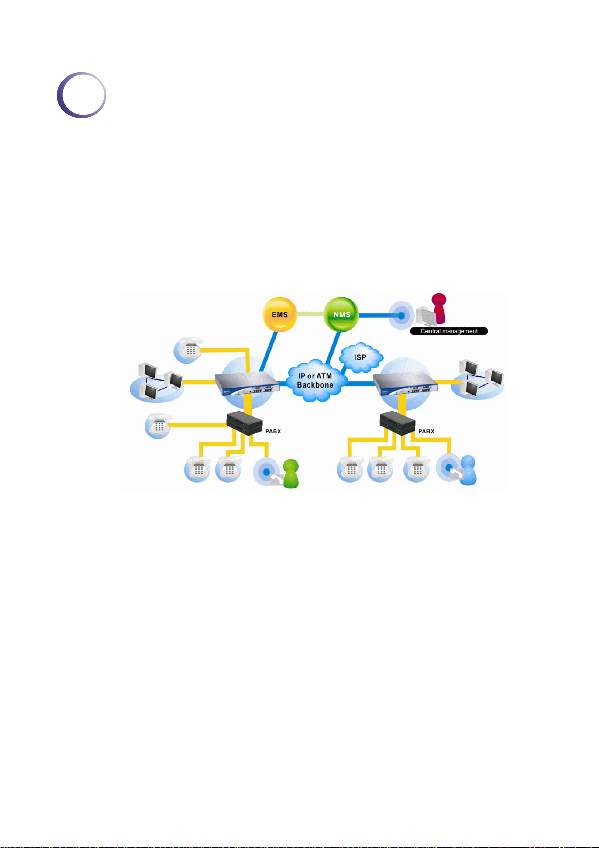
The Vigor3300 Series integrates a rich suite of functions, including NAT, firewall, VPN, load
balance, bandwidth management, and VoIP capability. These products are very suitable for
providing multi-integrated solutions to SME markets. An application scenario for the
Vigor3300 Series is depicted in Figure 1-1, which illustrates interconnections among branch
offices through the Internet via the Vigor3300 Series routers. By combining with an existing
PABX, an Internet phone from a remote branch can also access any extension number on a
local PABX or a traditional phone via PSTN. Also, by combining load balancing, data security,
and Internet phone features, the company can benefit from reducing operation fees.
A Virtual Private Network (VPN) is an extension of a private network that encompasses links
across shared or public networks like an Intranet. A VPN enables you to send data between
two computers across a shared public Internet network in a manner that emulates the
properties of a point-to-point private link. The DrayTek Vigor3300 Series VPN router
supports Internet-industry standards technology to provide customers with open, interoperable
VPN solutions such as X.509, DHCP over Internet Protocol Security (IPSec) up to 200 tunnels,
and Point-to-Point Tunneling Protocol (PPTP).
Internet Telephony, also known as Voice over Internet Protocol (VoIP), is a technology that
allows you to make telephone calls using a broadband Internet connection instead of a regular
(analog) phone line. Combining a PABX with a V3300V allows you to call anyone who has
an Internet phone or a traditional telephone number – including local, long distance, mobile,
and international numbers. Internet Telephony offers features and services that are unavailable
with a traditional phone at no additional cost. Because Internet Telephony requires strictly
minimal packet delay and jitter (since voice quality is intolerant of packet loss), the
Vigor3300V integrates VoIP feature with QoS and packet loss concealment mechanisms to
effectively transport high priority voice traffic over IP with low latency. Another feature is
Vigor3300 Series User’s Guide
1
Page 6
T.38 fax relay. By enabling and configuring fax rate on a dial peer, the originating and the
terminating V3300V can enter fax relay transfer mode. By using the T.38 function, customers
can also save on fax expenses. Lastly, by enabling the load balance feature on multiple WAN
ports, lease lines can be replaced to provide a cost-effective method for network infrastructure.
11..11 LLEEDD IInnddiiccaattoorrss aanndd CCoonnnneeccttiioonn
The Vigor3300V has 4 WAN interfaces and Vigor3300/3300B+ has 3 WAN interfaces that
support load balancing. This allows the system to reach peak performance and reduces the cost
of maintaining a single high-speed trunk by sharing the load amongst the multiple WAN
interfaces. Each interface can be connected to an individual Internet Service Provider. The
Vigor3300 Series also supports a backup function for WAN interfaces– a user can select one
WAN interface to be a backup interface. If the master interface fails, the backup interface will
take the place of the master interface immediately. Lastly, the Vigor3300V has a DMZ
function can be applied to any LAN or WAN interface.
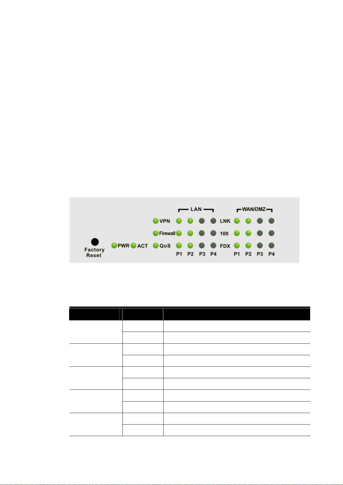
11..11..11 LLEEDD IInnddiiccaattoorrss aanndd CCoonnnneeccttoorrss ffoorr VViiggoorr33330000VV
Factory Reset:
Used to restore the default settings. Turn on the router (ACT LED is blinking). Press the hole
and hold for more than 5 seconds. When you see the ACT LED begins to blink rapidly than
usual, release the button. Then the router will restart with the factory default configuration.
LED Status Explanation
On The router is powered on. PWR
Off The router is powered off.
On/Blinking The system is active. ACT
Off The system is hanged.
On The VPN tunnel is launched. VPN
Off The VPN tunnel is closed.
On The Firewall function is active. Firewall
Off The Firewall function is inactive.
On The QoS function is active. QoS
Off The QoS function is inactive.
2
Vigor3300 Series User’s Guide
Page 7
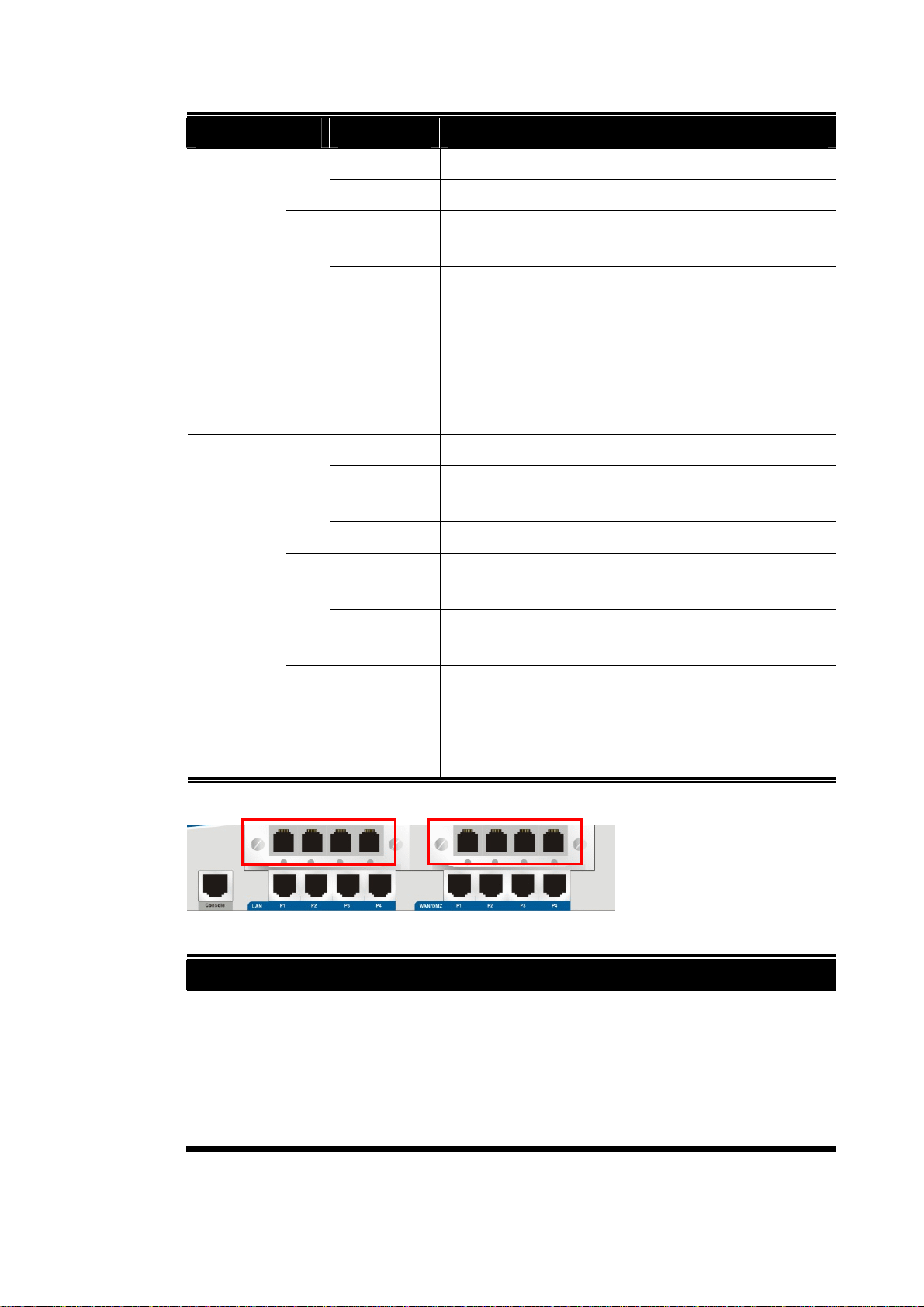
LNK
F
L
F
LED Status Explanation
On The Ethernet link is established on corresponding port.
Off No Ethernet link is established.
LAN
(1, 2, 3, 4)
100
On It means that a normal 100 Mbps connection is
through its corresponding port.
Off It means that a normal 10 Mbps connection is through
its corresponding port.
On It means a full duplex connection on corresponding
DX
port.
Off It means a half duplex connection on corresponding
port.
NK
On The Ethernet link is established.
WAN/DMZ
(1, 2, 3, 4)
Blinking The data transmission is done through the
corresponding port.
Off No Ethernet link is established.
100
On It means that a normal 100Mbps connection is through
its corresponding port.
Off It means that a normal 10Mbps connection is through
its corresponding port.
On It means a full duplex connection on corresponding
DX
port.
Off It means a half duplex connection on corresponding
port.
FXS FXO
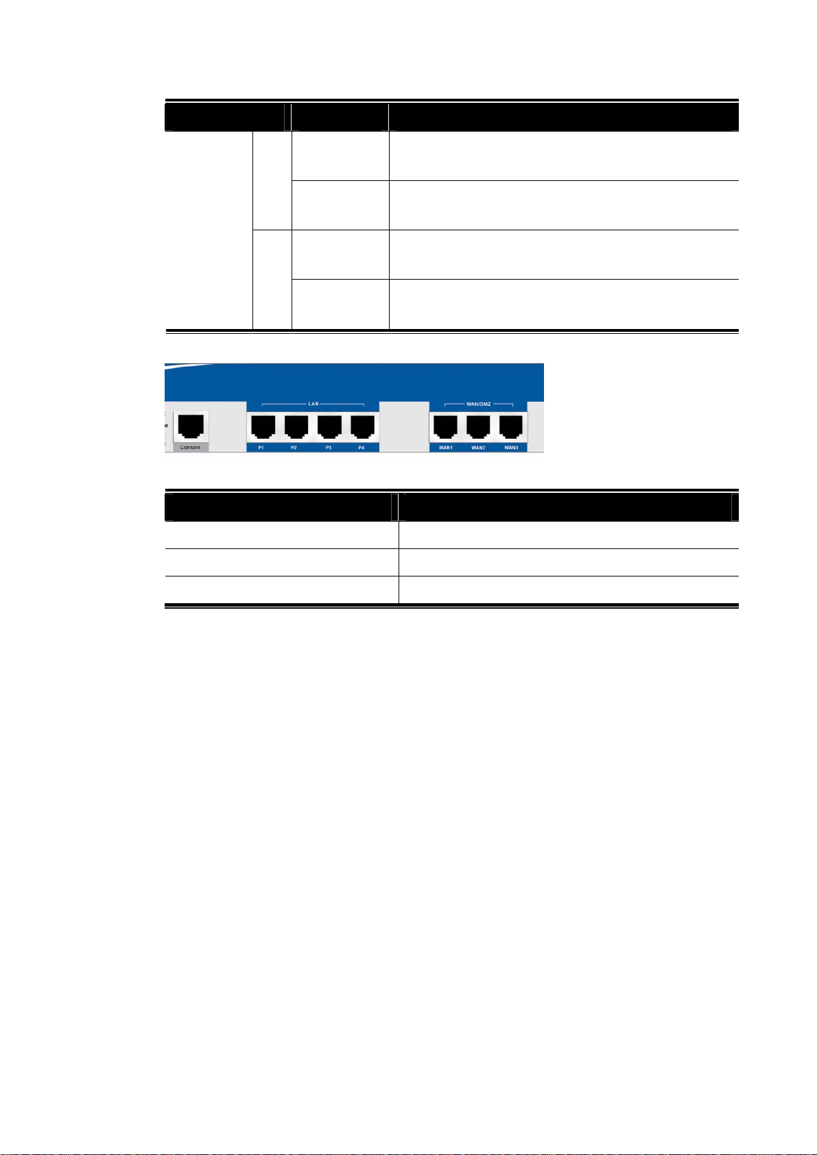
Interface Description
Console Provided for technician use.
LAN (P1 ~ P4) Connecter for local networked devices.
WAN/DMZ (P1 ~ P4) Connecter for remote networked devices.
FXS Connecter for telephone set.
FXO Connecter for FXS interface of PABX.
Vigor3300 Series User’s Guide
3
Page 8
LNK
F
LNK
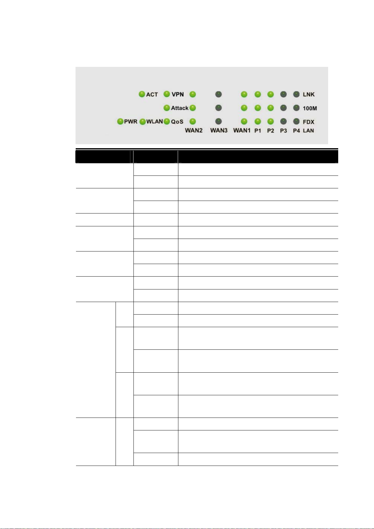
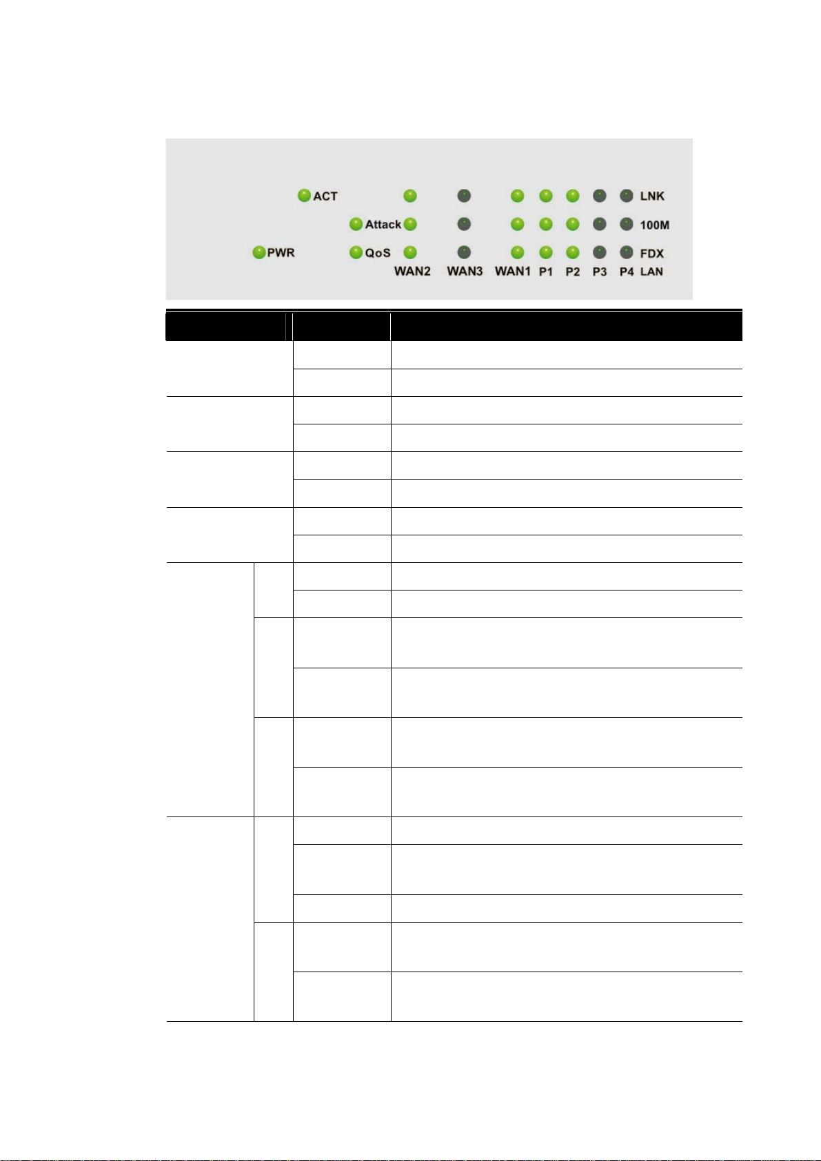
11..11..22 LLEEDD IInnddiiccaattoorrss aanndd CCoonnnneeccttoorrss ffoorr VViiggoorr33330000
LED Status Explanation
On The router is powered on. PWR
Off The router is powered off.
On/Blinking The system is active. ACT
Off The system is hanged.
WLAN No Reserved for future use.
On The VPN tunnel is launched. VPN
WAN
(2, 3, 1)
100M
DX
Off The VPN tunnel is closed.
On The Attack function is active. Attack
Off The Attack function is inactive.
On The QoS function is active. QoS
Off The QoS function is inactive.
On The Ethernet link is established on corresponding port.
Off No Ethernet link is established.
On It means that a normal 100 Mbps connection is
through its corresponding port.
Off It means that a normal 10 Mbps connection is through
its corresponding port.
On It means a full duplex connection on corresponding
port.
Off It means a half duplex connection on corresponding
port.
On The Ethernet link is established.
LAN
(1, 2, 3, 4)
Blinking The data transmission is done through the
corresponding port.
Off No Ethernet link is established.
4
Vigor3300 Series User’s Guide
Page 9
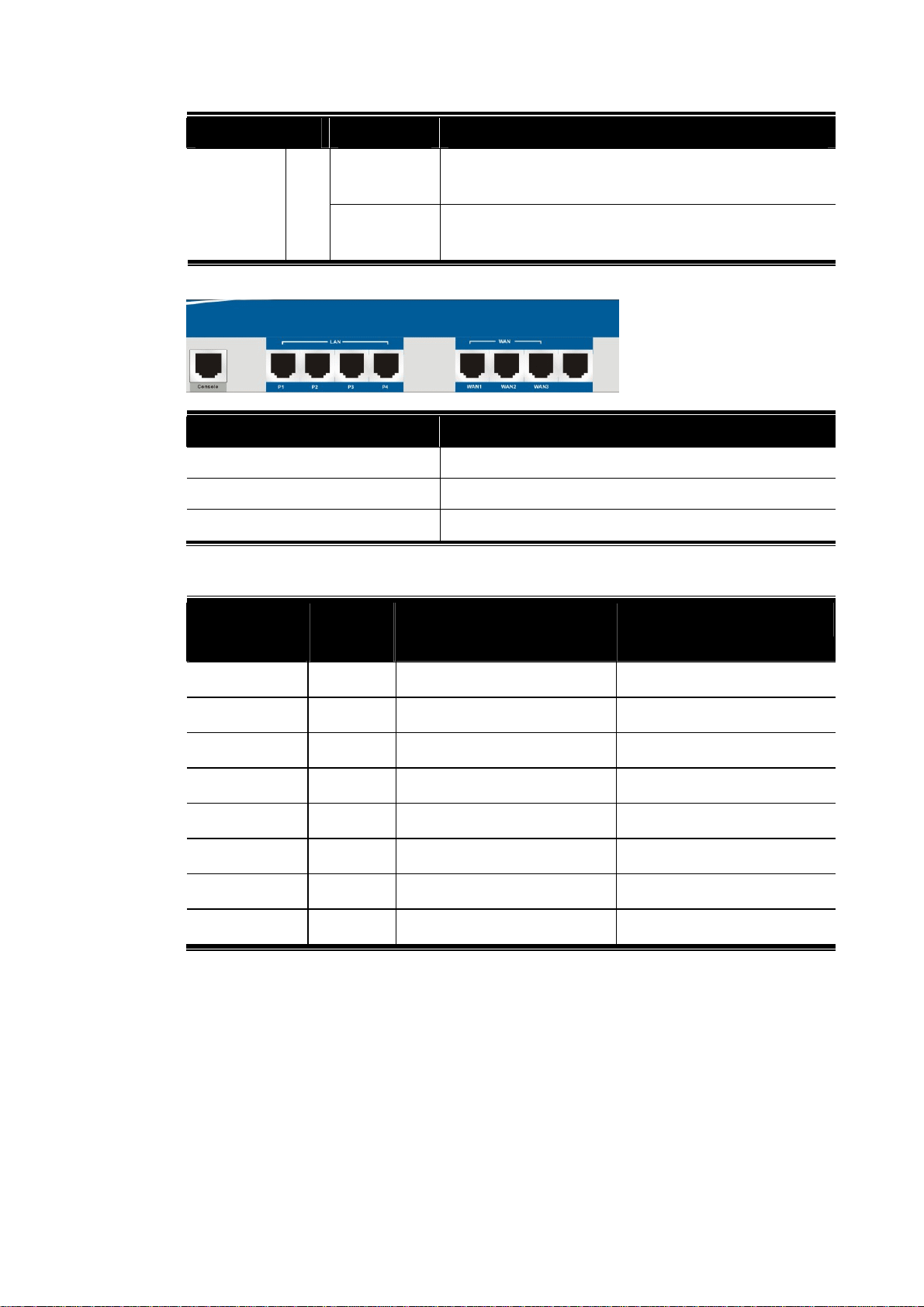
F
LED Status Explanation
100M
Interface Description
Console Provided for technician use.
On It means that a normal 100Mbps connection is through
its corresponding port.
Off It means that a normal 10Mbps connection is through
its corresponding port.
On It means a full duplex connection on corresponding
DX
port.
Off It means a half duplex connection on corresponding
port.
LAN (P1 ~ P4) Connecter for local networked devices.
WAN/DMZ (WAN1 ~ WAN3) Connecter for remote networked devices.
Vigor3300 Series User’s Guide
5
Page 10
LNK
F
LNK
11..11..33 LLEEDD IInnddiiccaattoorrss aanndd CCoonnnneeccttoorrss ffoorr VViiggoorr33330000BB+
LED Status Explanation
On The router is powered on. PWR
Off The router is powered off.
On/Blinking The system is active. ACT
Off The system is hanged.
On The Attack function is active. Attack
Off The Attack function is inactive.
+
WAN
(2, 3, 1)
LAN
(1, 2, 3, 4)
100M
DX
On The QoS function is active. QoS
Off The QoS function is inactive.
On The Ethernet link is established on corresponding port.
Off No Ethernet link is established.
On It means that a normal 100 Mbps connection is
through its corresponding port.
Off It means that a normal 10 Mbps connection is through
its corresponding port.
On It means a full duplex connection on corresponding
port.
Off It means a half duplex connection on corresponding
port.
On The Ethernet link is established.
Blinking The data transmission is done through the
corresponding port.
Off No Ethernet link is established.
100M
On It means that a normal 100Mbps connection is through
its corresponding port.
Off It means that a normal 10Mbps connection is through
its corresponding port.
6
Vigor3300 Series User’s Guide
Page 11
F
LED Status Explanation
On It means a full duplex connection on corresponding
DX
port.
Off It means a half duplex connection on corresponding
port.
Interface Description
Console Provided for technician use.
LAN (P1 ~ P4) Connecter for local networked devices.
WAN1 ~ WAN3 Connecter for remote networked devices.
CCoonnnneecctteerr SSppeecciiffiiccaattiioonn
Auxiliary
Cables
Power Cord Black AC Outlet 90-264VAC
Serial (Console) RS232, Grey PC RS232 port --
Ethernet (LAN) RJ-45, Blue Ethernet switch or hub --
Ethernet (DMZ) RJ-45, Blue Server
Ethernet (WAN1) RJ-45, Blue DSL/Cable/Fiber Modem --
Ethernet (WAN2) RJ-45, Blue DSL/Cable/Fiber Modem
Ethernet (WAN3) RJ-45, Blue DSL/Cable/Fiber Modem
Ethernet (WAN4) RJ-45, Blue DSL/Cable/Fiber Modem
Type,
Color
Connected to Remarks
Vigor3300 Series User’s Guide
7
Page 12
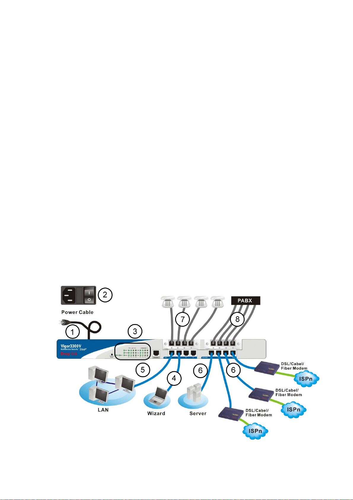
11..22 HHaarrddwwaarree IInnssttaallllaattiioonn
Before starting to configure the router, you have to connect your devices correctly.
1. Connect the power cord to the power port of Vigor3300 router on the rear panel, and the
other side into a wall outlet.
2. Power on the device by pressing the power switch on the rear panel. The PWR LED
should be ON.
3. The system starts to initiate. After completing the system test, the ACT LED will light
up and start blinking.
4. Connect one end of an Ethernet cable (RJ-45) to one of the LAN ports of Vigor3300.
5. Connect the other end of the cable (RJ-45) to the Ethernet port on your computer (that
device also can connect to other computers to form a small area network). The LAN
LED for that port on the front panel will light up.
6. Connect a server/modem/router (depends on your requirement) to any available WAN
port of the device with Ethernet cable (RJ-45). The WAN LED will light up.
7. Connect telephone sets to the FXS ports of Vigor3300V with telephone lines (RJ-11 to
RJ-11). For the users of Vigor3300 and Vigor3300B+, please skip this step.
8. Connect the FXO ports to PABX with telephone lines (RJ-11 to RJ-11). For the users of
Vigor3300 and Vigor3300B+, please skip this step.
Below shows an outline of the hardware installation for your reference (take Vigor3300V as
an example).
8
Vigor3300 Series User’s Guide
Page 13
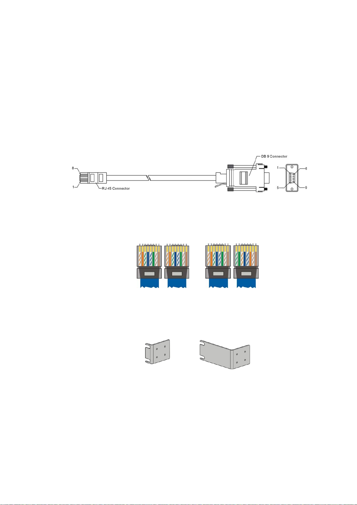
11..22..11 DDeettaaiilleedd EExxppllaannaattiioonn ffoorr tthhee CCoonnnneeccttoorr
Here provides you detailed explanation for some specific connectors that you have to be
familiar.
TThhee RRSS223322 CCoonnnneeccttoorr
The RJ45 connection jet is used for CLI commands for system configuration and control
functions in the Vigor3300 Series. The jet is used for initialization of the Vigor3300 Series
during preliminary installation. The “management cable”, as shown in Figure 1-5, converts the
RJ45 to the RS232 interface. The RJ45 jet connects to a console interface in theVigor3300
Series, while the RS232 DB9 connects to a console port on the computer. The default setting
of the console port is “baud rate 57600, no parity, and 8 bit with 1 stop bit.”
SSttaannddaarrdd 1100//110000 BBaassee--TT EEtthheerrnneett IInntteerrffaaccee CCoonnnneeccttoorr
RJ45 jets provide 10/100 Base-T Ethernet interfaces. The interface supports MDI/MDIX
auto-detection of either straight or crossover RJ45 cables. These cables are used on WAN,
LAN, and DMZ interfaces.
CChhaassssiiss CCoonnnneeccttiioonnss
The Vigor3300 Series can be mounted on a rack by using standard brackets in a 19-inch rack
or optional larger brackets on 23-inch rack (not included). The bracket for 19- and 23-inch
racks are shown below.
Attach the brackets to the chassis of a 19- or a 23-inch rack (as shown in the Figures 1-8 and
1-9). Repeat the above procedure for the second bracket, which attaches the other side of the
chassis.
Vigor3300 Series User’s Guide
9
Page 14
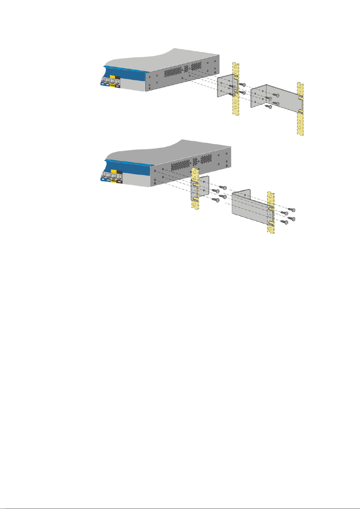
X
Y
After the bracket installation, the Vigor3300 Series chassis can be installed in a rack by using
four screws for each side of the rack.
DDeesskkttoopp TTyyppee IInnssttaallllaattiioonn
Rubber pads are included with the Vigor3300 Series. These rubber pads improve the air
circulation and decrease unnecessary rubbing on the desktop.
10
Vigor3300 Series User’s Guide
Page 15
2
Coonnffiigguurriinngg
C
For use the router properly, it is necessary for you to change the password of web
configuration for security and adjust primary basic settings.
This chapter explains how to setup a password for an administrator and how to adjust basic
settings for accessing Internet successfully.
22..11 CChhaannggiinngg PPaasssswwoorrdd
To change the password for this device, you have to access into the web browser with default
password first.
1. Make sure your computer connects to the router correctly.
Notice: You may either simply set up your computer to get IP dynamically from the
router or set up the IP address of the computer to be the same subnet as the default
IP address of Vigor router 192.168.1.1. For the detailed information, please refer
to the later section - Trouble Shooting of this guide.
Baassiicc
B
Seettttiinnggss
S
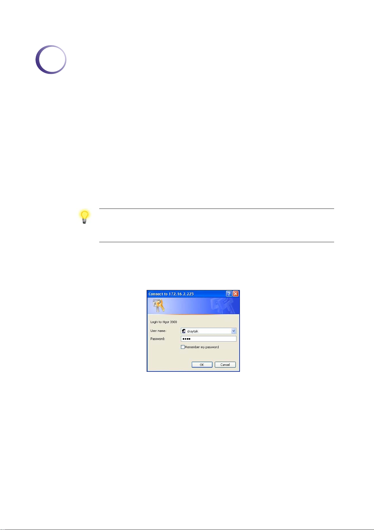
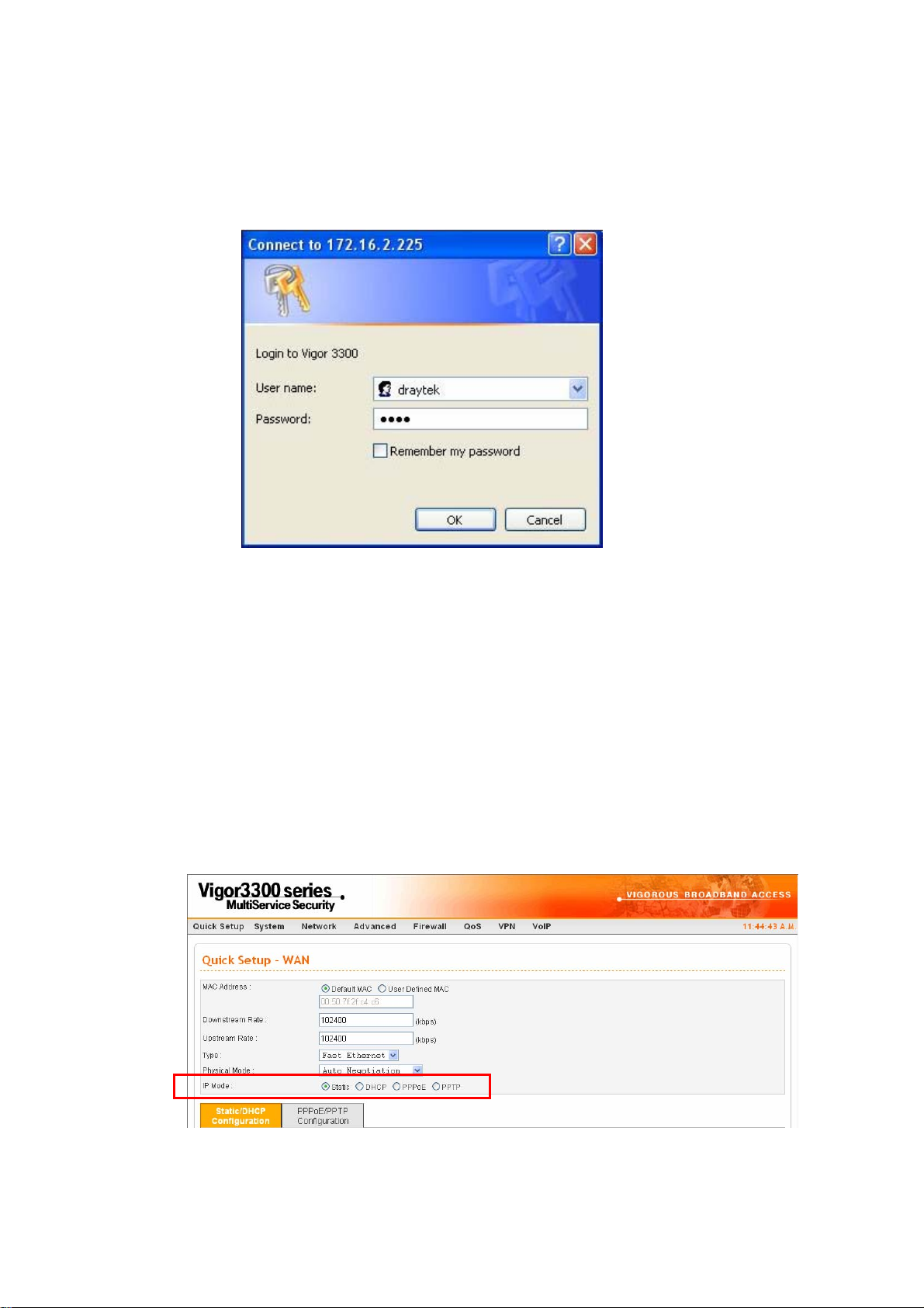
2. Open a web browser on your PC and type http://192.168.1.1. A pop-up window will
open to ask for username and password. Please type default values on the window for the
first time accessing. The default value for user name is draytek and the password is 1234.
Next, click OK.
Vigor3300 Series User’s Guide
11
Page 16
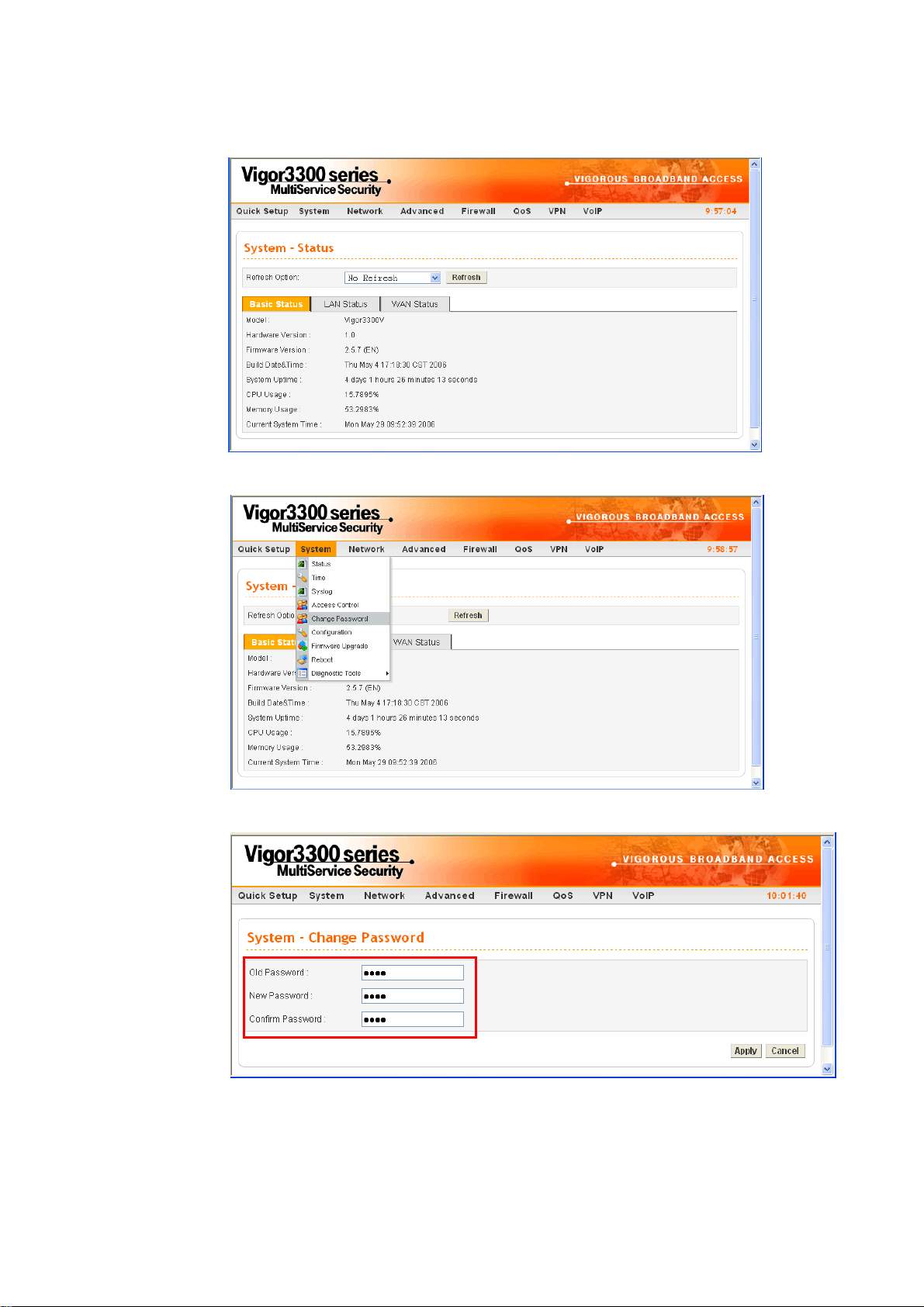
3. Now, the Main Screen will pop up.
4. Go to System page and choose Change Password.
12
5. The following screen will appear.
6. Enter the login password (1234) on the field of Old Password. Type a new one in the
field of New Password and retype it on the field of Confirm Password. Then click Apply
to continue.
Vigor3300 Series User’s Guide
Page 17
7. Now, the password has been changed. Next time, use the new password to access the
Web Configurator for this router.
8. Next, you will see the login screen after clicking Apply. Please use new password to
re-enter the system configuration.
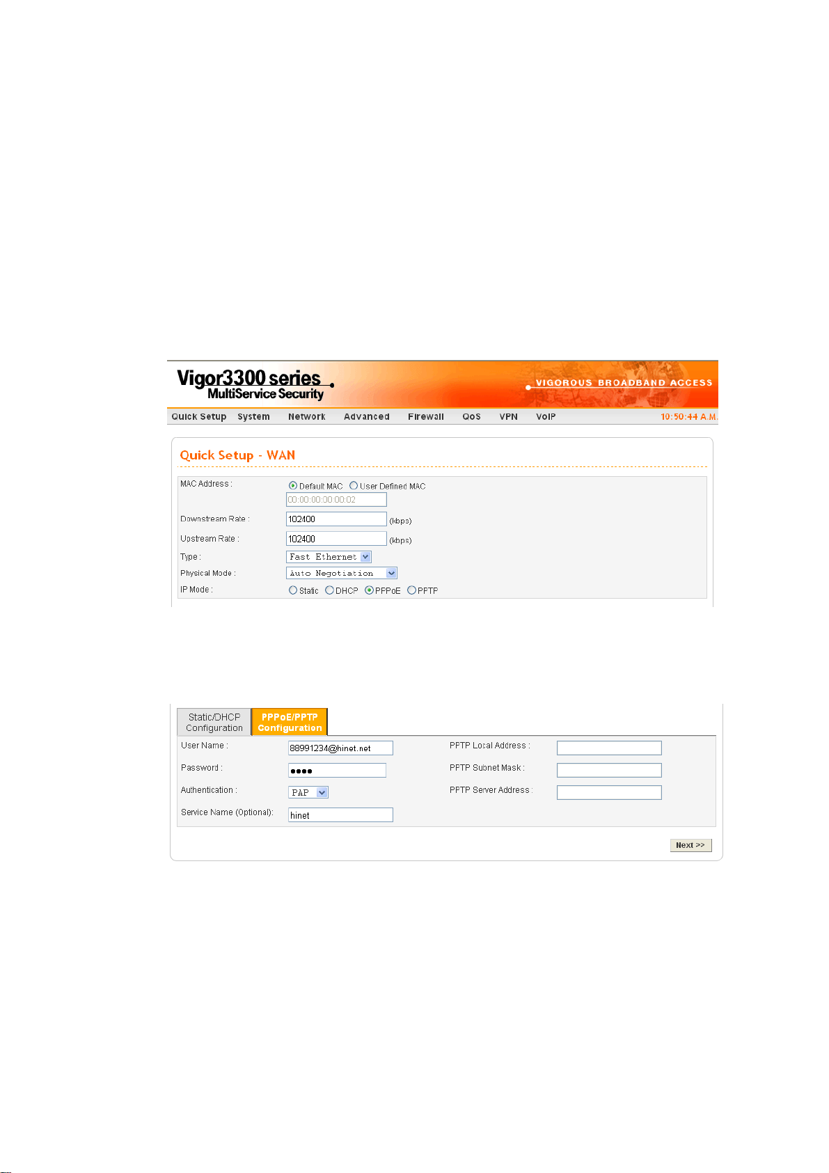
22..22 QQuuiicckk SSeettuupp
Quick Setup is designed for configuring your broadband router accessing Internet with simply
steps. There are two phases of quick setup, one is WAN configuration and the other is LAN
configuration.
22..22..11 AAddjjuussttiinngg WWAANN CCoonnnneeccttiioonn MMooddee
In the Quick Setup group, you can configure the router to access the Internet with different
modes such as Static, DHCP, PPPoE, or PPTP modes. For most users, Internet access is the
primary application. The router supports the Ethernet WAN interface for Internet access. The
following sections will explain in more detail the various broadband access configurations. All
settings in this section will be applied in the first WAN1 interface.
Now, you have to select an appropriate WAN connection type for connecting to the Internet
through this router according to the settings that your ISP provided.
Vigor3300 Series User’s Guide
13
Page 18

MAC Address Router Default-
Use the default Mac address stored originally in router.
User Definition-
Use a MAC address defined by the user.
Downstream Rate Assign the downstream rate for this WAN interface. The default
value is 102400 kbps (100 Megabit). This setting is very important
for Vigor3300 Series incoming buffer adjustment. If you use a DSL
subscriber service with a 2Mbps downstream, please set the
downstream rate setting with 2Mbps.
Upstream Rate Assign the transmission rate for this WAN interface. The default
value is 102400 kbps (100 Megabit). This setting is very important
for Vigor3300 Series outgoing buffer adjustment. If you use a DSL
subscriber service with a 256Kbps downstream, please set the
downstream rate setting with 256Kbps.
Type Select a connection type for this WAN interface. Currently, there is
only one setting offered for you to choose - Fast Ethernet.
Physical Mode Select connection speed mode for this WAN interface. There are
auto negotiation, full duplex, and half duplex of either 10M or
100M speed options for the WAN Interface.
IP Mode Select an IP mode for this WAN interface. There are four available
modes for Internet access, Static, DHCP, PPPoE, and PPTP. On
this page you may configure the WAN interface to use Static (fixed
IP), DHCP (dynamic IP address), PPPoE or PPTP. Most of the
cable users will use the DHCP mode to get a globally reachable IP
address from the cable host system.
14
Vigor3300 Series User’s Guide
Page 19
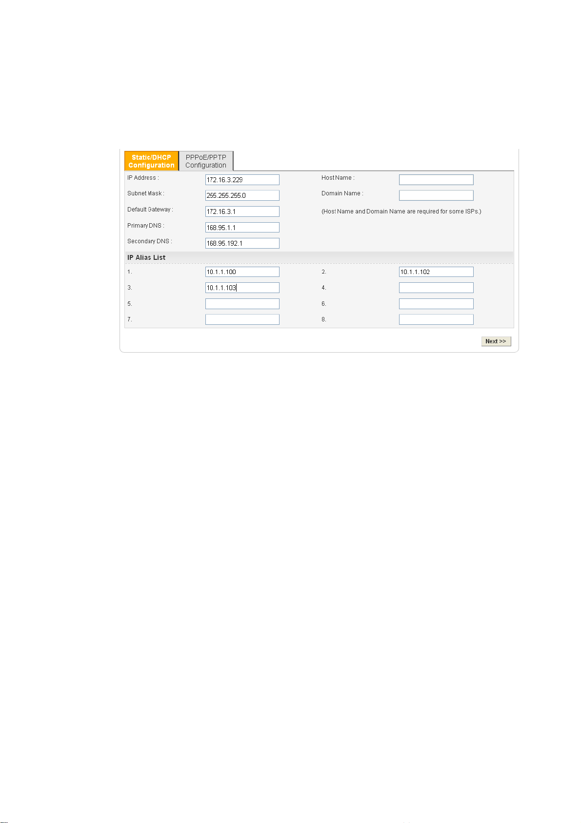
22..22..22 SSttaattiicc MMooddee
You can manually assign a static IP address to the WAN interface and complete the
configuration by applying the settings and rebooting your router. Choosing Static as the IP
mode, you will see the following page:
All the settings here are set by privately. Your ISP will not provide these settings.
IP Address Assign a private IP address to the WAN interface.
Subnet Mask Assign a subnet mask value to the WAN interface.
Default Gateway Assign a private IP address to the gateway.
Primary DNS Assign a private IP address to the primary DNS.
Secondary DNS Assign a private IP address to the secondary DNS.
IP Alias List Assign other IP addresses to be bound to this interface. This
setting is optional. If you have typed addresses here, you can
see and choose it in later web page settings (e.g., Advanced >>
NAT>>Port Redirection/DMZ Host). Thirty-two IP addresses
settings are allowed at one time.
After setting up the WAN interface, the user can click Next to setup the LAN interface
continuously.
Vigor3300 Series User’s Guide
15
Page 20
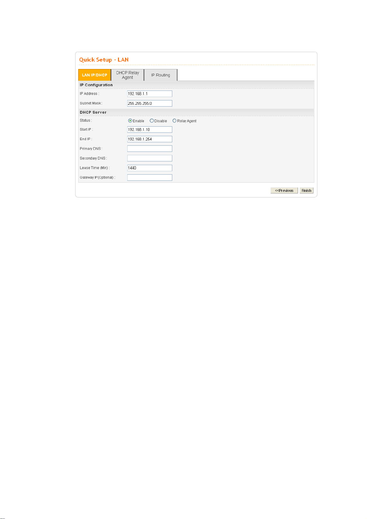
IP Address Assign an IP address for the LAN interface.
Subnet Mask Assign the subnet mask for the LAN interface.
Status Click Enable to use DHCP server; click Disable to close
DHCP server; click Relay Agent to activate relay agent
function.
Start IP Assign the start IP address of the IP pool that DHCP server can
use for clients in LAN.
End IP Assign the end IP address of the IP pool that DHCP sever can
use for clients in LAN.
Primary DNS Type the IP address for primary DNS.
When you finished the above required settings, please click Finish. A system reboot page will
appear. Click Apply to activate the static mode configuration.
16
Vigor3300 Series User’s Guide
Page 21
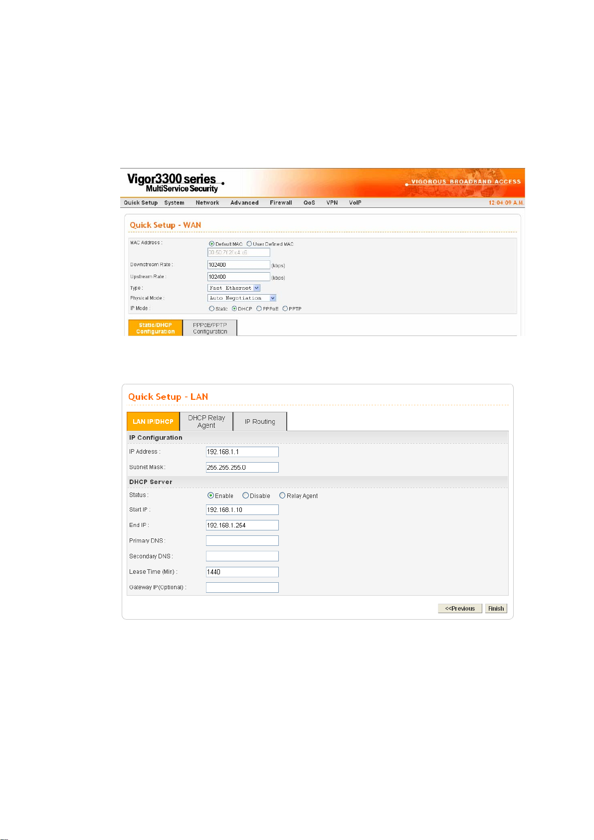
22..22..33 DDHHCCPP MMooddee
DHCP allows a user to obtain an IP address automatically from a DHCP server on the Internet.
If you choose DHCP mode, the DHCP server of your ISP will assign a dynamic IP address for
Vigor3300 automatically. It is not necessary for you to assign any setting. (Host Name and
Domain Name are required for some ISPs). S imply click Next to setup LAN interface.
After setting up the WAN interface, the user can click Next to setup the LAN interface
continuously.
IP Address Assign an IP address for the LAN interface.
Subnet Mask Assign the subnet mask for the LAN interface.
Status Click Enable to use DHCP server; click Disable to close
Start IP Assign the start IP address of the IP pool that DHCP server can
Vigor3300 Series User’s Guide
DHCP server; click Relay Agent to activate relay agent
function.
use for clients in LAN.
17
Page 22
End IP Assign the end IP address of the IP pool that DHCP sever can
use for clients in LAN.
Primary DNS Type the IP address for primary DNS.
When you finished the above required settings, please click Finish. A system reboot page will
appear. Click Apply to activate the DHCP mode configuration.
22..22..44 PPPPPPooEE
This mode is used for most of DSL modem users. All local users can share one PPPoE
connection to access the Internet. Your service provider will give you the user name, password,
and authentication mode for PPPoE settings.
If your ISP provides you the PPPoE (Point-to-Point Protocol over Ethernet) connection,
please select PPPoE for this router to get the following page. Enter the username and
password provided by your ISP on the web page.
18
User Name Assign a specific valid user name provided by the ISP.
Password Assign a valid password provided by the ISP.
Authentication Select PAP or CHAP protocol for PPP authentication. The
default value is PAP.
Service Name Assign a service name required from ISP service.
After setting up the WAN interface, the user can click Next to setup the LAN interface
continuously.
Vigor3300 Series User’s Guide
Page 23
IP Address Assign an IP address for the LAN interface.
Subnet Mask Assign the subnet mask for the LAN interface.
Status Click Enable to use DHCP server; click Disable to close
DHCP server; click Relay Agent to activate relay agent
function.
Start IP Assign the start IP address of the IP pool that DHCP server can
use for clients in LAN.
End IP Assign the end IP address of the IP pool that DHCP sever can
use for clients in LAN.
Primary DNS Type the IP address for primary DNS.
When you finished the above required settings, please click Finish. A system reboot page will
appear. Click Apply to activate the PPPoE mode configuration.
Vigor3300 Series User’s Guide
19
Page 24
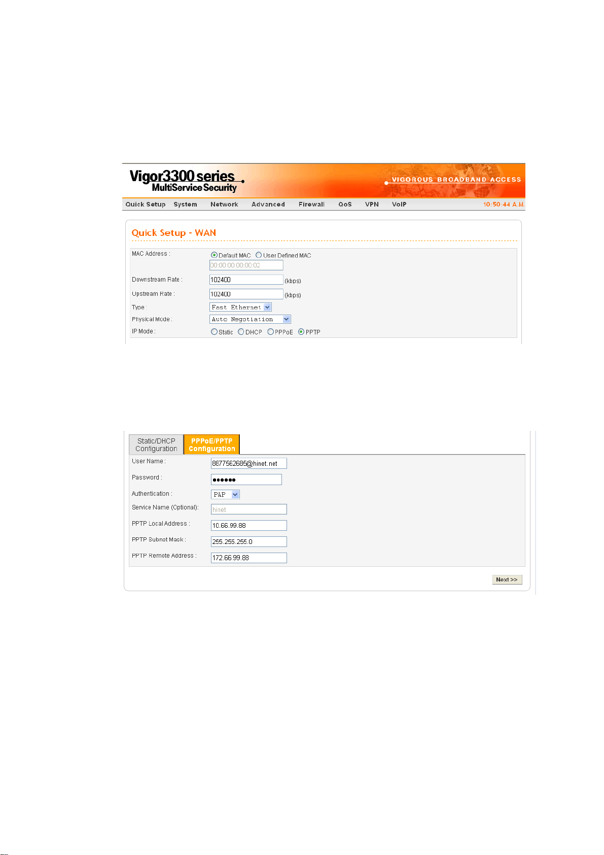
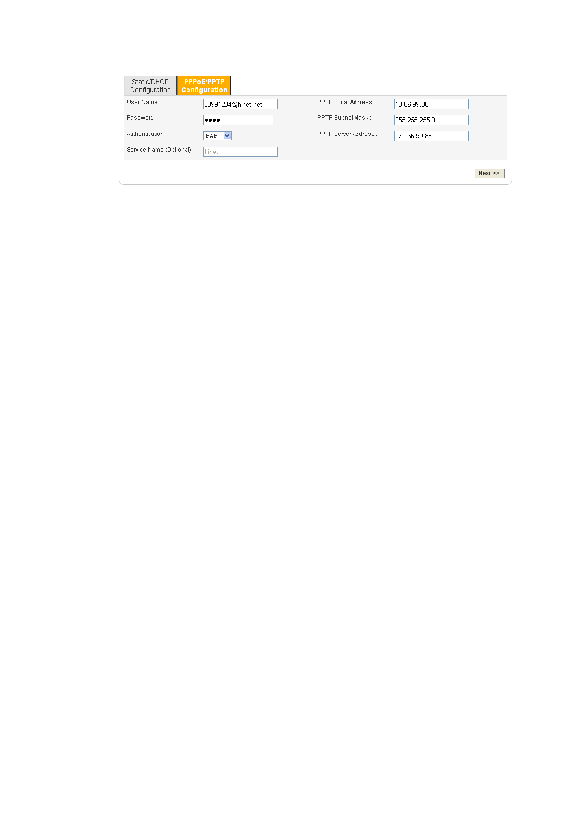
22..22..55 PPPPTTPP
This mode lets user get the IP group information by a DSL modem with PPTP service from
ISP. Your service provider will give you user name, password, and authentication mode for a
PPTP setting.
If your ISP offers you PPTP (Point-to-Point Tunneling Protocol) mode, please select PPTP
for this router. Next, enter the PPTP Subnet Mask (e.g., 255.255.255.0), PPTP Local
Address (e.g., 10.66.99.88) and PPTP Remote Address (e.g., 172.66.99.88) provided by
your ISP on the web page.
20
PPTP Local Address Assign a local IP address of PPTP.
PPTP Subnet Mask Assign a net mask value for IP address of PPTP.
PPTP Remote Address Assign a remote IP address of PPTP server.
After setting up the WAN interface, the user can click Next to setup the LAN interface
continuously.
Vigor3300 Series User’s Guide
Page 25
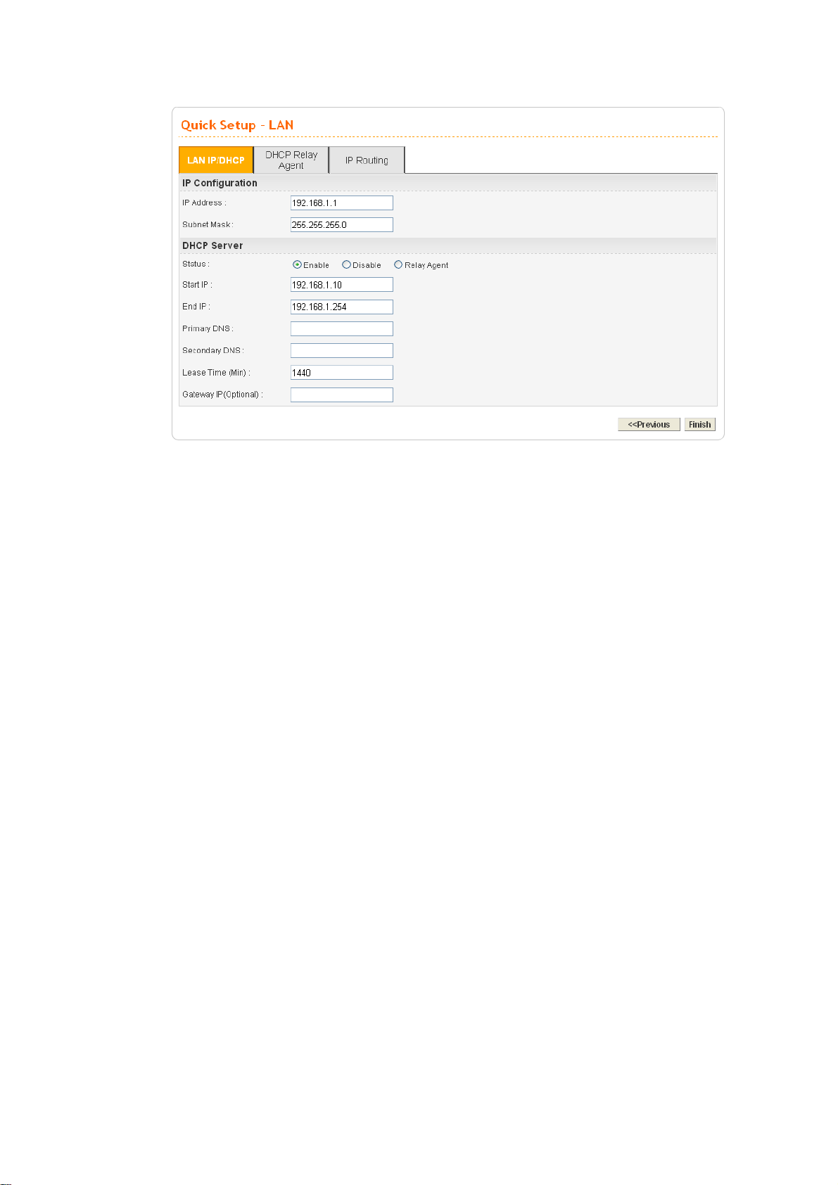
IP Address Assign an IP address for the LAN interface.
Subnet Mask Assign the subnet mask for the LAN interface.
Status Click Enable to use DHCP server; click Disable to close
DHCP server; click Relay Agent to activate relay agent
function.
Start IP Assign the start IP address of the IP pool that DHCP server can
use for clients in LAN.
End IP Assign the end IP address of the IP pool that DHCP sever can
use for clients in LAN.
Primary DNS Type the IP address for primary DNS.
When you finished the above required settings, please click Finish. A system reboot page will
appear.
Vigor3300 Series User’s Guide
21
Page 26
3
Addvvaanncceedd
A
After finished basic configuration of the router, you can access Internet with ease. For the user
who wants to adjust more setting for suiting his/her request, please refer to this chapter for
getting detailed information about the advanced configuration of this router.
33..11 SSyysstteemm sseettuupp
For the system setup, there are several items that you have to know the way of configuration:
Status, Time Setup, Syslog Setup, Access Control Setup, Reboot and Firmware Upgrade Setup,
Diagnostic Tools and Configuration Setup.
Coonnffiigguurraattiioonn
C
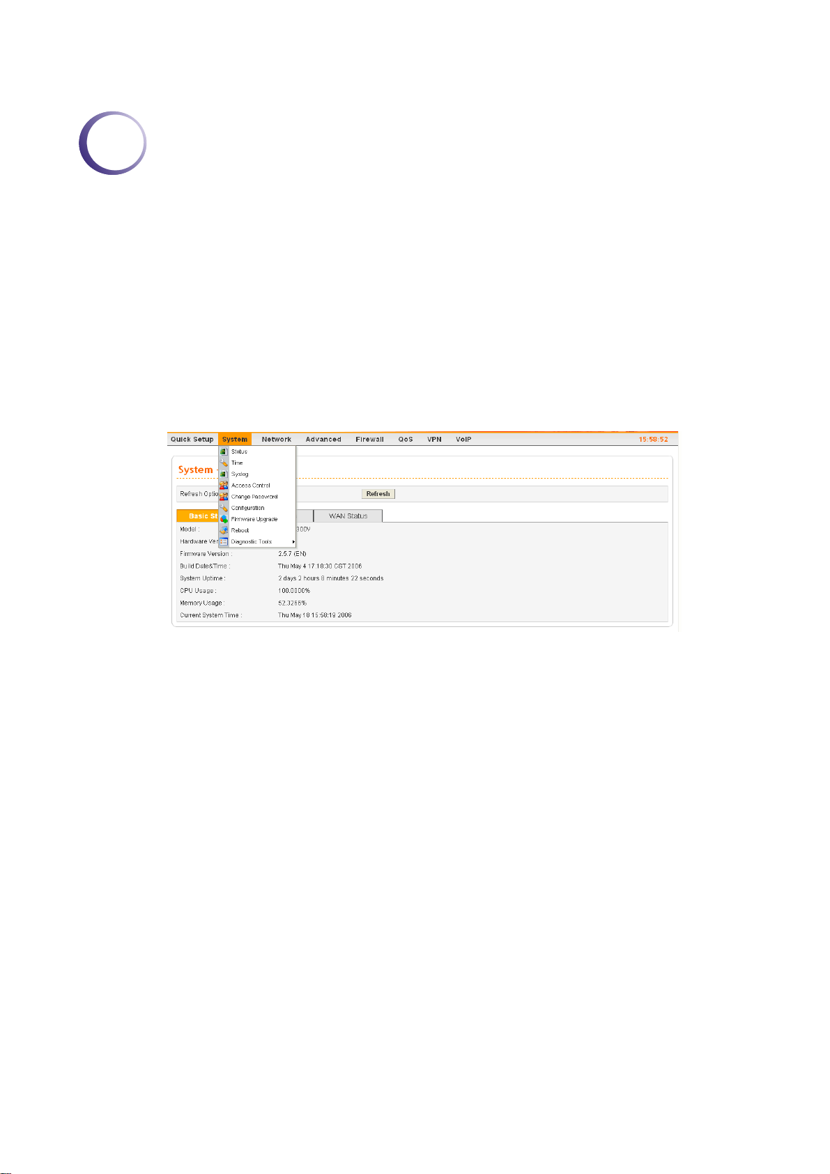
33..11..11 SSttaattuuss
The online Status function provides some useful system information on the current status of
the Vigor3300 Series. A user can observe the system status on this Web page and determine
which setting needed to be changed in corresponding web pages. In the System group, click
the Status option. The online Status Web page contains three parts: Basic Status, LAN
Status, and WAN Status.
Refresh Option You can choose to automatically refresh the Web page information.
There are four options given as shown below.
No Refresh: Static information page.
Every 10 Seconds: Refreshes the page every 10 seconds.
Every 20 Seconds: Refreshes the page every 20 seconds.
Every 30 Seconds: Refreshes the page every 30 seconds.
22
Vigor3300 Series User’s Guide
Page 27
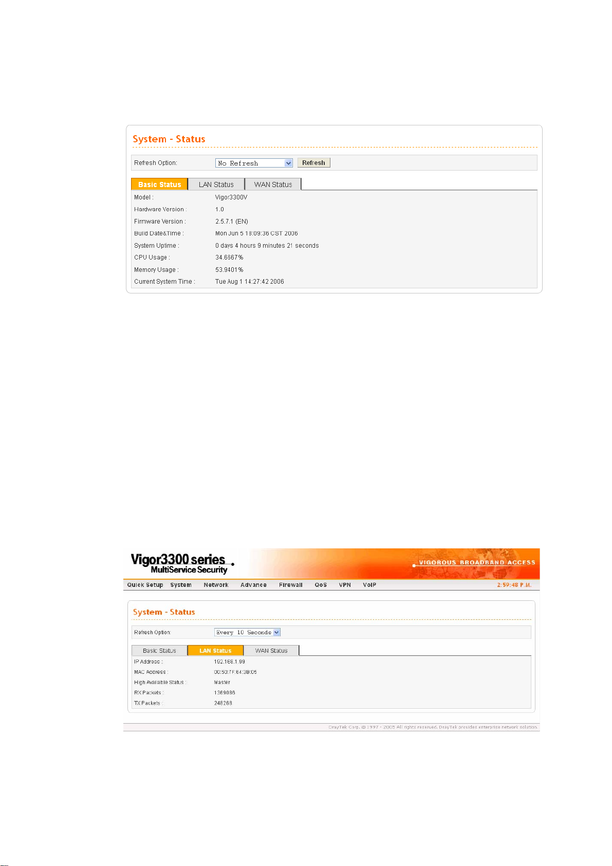
BBaassiicc SSttaattuuss
General status of this router will be displayed on Basic Status page.
Model Displays the model name of the router.
Hardware Version Displays the hardware version of the router.
Firmware Version Displays the firmware version of the router.
Build Date&Time Displays the date and time of the current firmware build.
System Uptime Displays the amount of time that the router has been online.
CPU Usage Displays the average percentage of the CPU being used.
Memory Usage Displays the percentage of memory being used.
Current System Time Displays the current local system time.
s
LLAANN SSttaattuus
The status of LAN connection is shown in this page. Simply click LAN Status tag to get the
detailed.
IP Address Displays the IP address of the LAN interface.
MAC Address Displays the MAC address of the LAN Interface.
Vigor3300 Series User’s Guide
23
Page 28

High Available Status The High Available Status is shown when the function is
enabled. When there are two Vigor3300 devices in the same
LAN, one can be set as Master device and the other can be set
as Slave device.
Master - It means that Vigor3300 plays the Master role in high
availability feature.
Slave - It means that Vigor3300 plays the Slave role in high
availability feature.
If there is only one Vigor3300 used in LAN, this line will be
blank.
RX Packets Displays the total number of received packets at the LAN
interface.
TX Packets Displays the total transmitted packets at the LAN interface.
24
Vigor3300 Series User’s Guide
Page 29
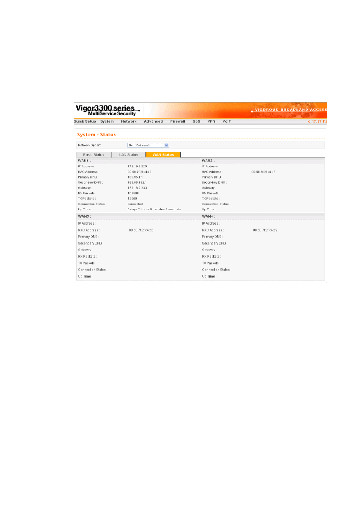
WWAANN SSttaattuuss
The status of WAN interface (Static, DHCP, PPPoE, PPTP or DMZ) is shown in this page.
Simply click WAN Status tag to get the detailed. There are four sets of WAN status can be
shown in this page at one time. The sample below just lists one set of WAN status for only
WAN1 interface is used.
IP Address Displays the IP address of the WAN interface.
MAC Address Displays the MAC address of the WAN Interface.
Primary DNS Displays the IP address of the primary DNS.
Secondary DNS Displays the IP address of the secondary DNS.
Gateway Displays the IP address of the default gateway.
RX Packets Displays the total received packets for each WAN interface.
TX Packets Displays the total transmitted packets for each WAN interface.
Connection Status Displays the connection status of the WAN interface.
Up Time Displays the total system uptime of the interface.
Vigor3300 Series User’s Guide
25
Page 30
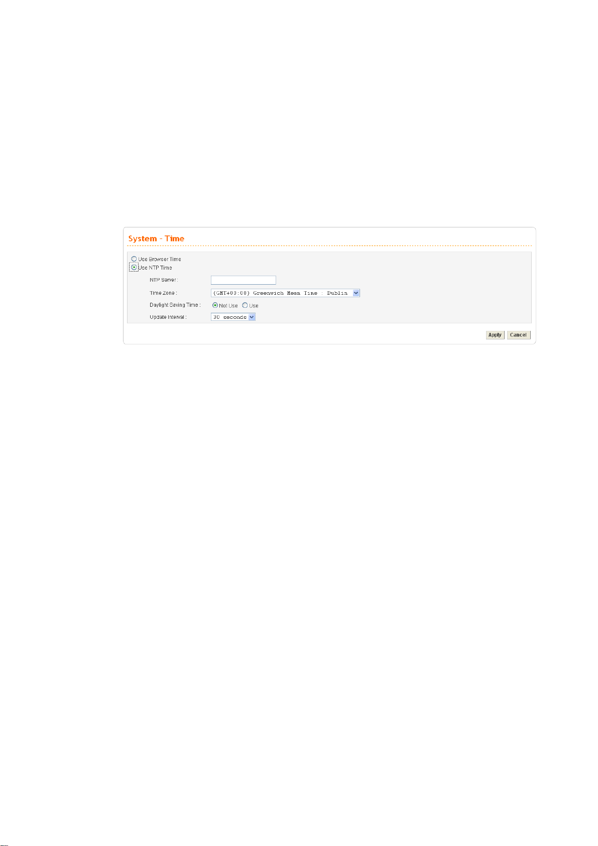
33..11..22 TTiimmee
As an NTP (Network Time Protocol) client, the router gets standard time from the time server.
Some time-based functions, such as Call Schedule and URL Content filtering, cannot work
properly until the system time functions run successfully. Typically, NTP achieves high
accuracy and reliability with multiple redundant servers and diverse network paths.
The Vigor3300 Series supports synchronization with a specific NTP server or the remote PC
host of the administrator. In the System group, click the Time option. The Time page is
shown below:
Use Browser Time Click this option to use the browser time from the remote
administrator PC host as router’s system time.
Use NTP Time Click this option to use the time from an NTP server as router’s
system time.
NTP Server Assign a public IP address or domain name of the NTP server.
Time Zone Select the time zone where the Vigor3300 is located.
Daylight Savings Time Select Use to activate this function. This function is useful for some
areas.
Update Interval Select a time interval for updating from the NTP server.
Apply Click Apply to save these settings.
26
Vigor3300 Series User’s Guide
Page 31

33..11..33 SSyysslloogg
The Vigor3300 Series supports a Syslog function to keep a record of abnormal conditions. The
router will send Syslog packets to a Syslog server on the remote site. The administrator can
observe any abnormal events from Vigor3300. In the System group, click the Syslog option.
The Syslog web page is shown below:
Status Click Enable to activate this function. The router will send system
Syslog Server IP The IP address of the Syslog server. If a user assigns an IP address
log message for your reference. If you click Disable, the router will
not send out any message about system log.
of “0.0.0.0”, the Syslog function will be disabled. Then, Vigor3300
will not send Syslog packets to the Syslog server.
Syslog Server Port Assign a port for the Syslog protocol.
Apply Click Apply to save these settings.
Vigor3300 Series User’s Guide
27
Page 32

33..11..44 AAcccceessss CCoonnttrrooll
This page allows you to determine which services (HTTP/Telnet/SSH) is used for the user to
access Vigor3300 Series. In addition, you can also limit some hosts to access Vigor3300
Series with specified IP address.
In the System group, click the Access Control option. You will get the following page:
28
Management Method There are three management methods provided here for you to
choose for your router. Check HTTP/Telnet/SSH for the router.
Allow Management from
the WAN
Disable - Disable the management from the WAN interface.
Enable All - Enable all management (through
HTTP/Telnet/SSH) from the WAN interface.
Enable User Defined WAN IP - System can be managed by
these three IP addresses via WAN.
Allowed IP1(to 3) - Type in IP address (up to three) for
managing the system.
Management Port Default Ports - Use the default ports for HTTP and Telnet if
you choose HTTP and Telnet as management methods.
Vigor3300 Series User’s Guide
Page 33

User Defined Ports - Or you can assign new port numbers for
HTTP, Telnet and SSH respectively.
PING Restriction Disable PING from the LAN -Choose this function to reject
all ICMP packets from LAN side.
Disable PING from the WAN - Choose this function to reject
all ICMP packets from WAN side.
33..11..55 CCoonnffiigguurraattiioonn SSeettuupp
Most of the settings can be saved locally as a configuration file, and can be applied to another
router. The Vigor3300 Series supports the restore and upload functions of the configuration
files. In the System group, click the Configuration Setup option. And you can see the
following page.
Select a Configuration File Please click the Browse… button to find out the location of the
configuration file to be uploaded to the router and click Apply.
Backup Configuration File
Push Backup Button
Download the configuration file to a local host. The default
file name is “v3300.cfg”.
Vigor3300 Series User’s Guide
29
Page 34

33..11..66 FFiirrmmwwaarree UUppggrraaddee SSeettuupp
Vigor3300 Series allows users to upgrade firmware through a Web interface. In the System
group, click the Firmware Upgrade option. You can see the following page then. Before you
execute the firmware upgrade, please download the newest firmware from Draytek’s website
(www.draytek.com) or FTP site (ftp.draytek.com) on the computer first.
Caution Displays a caution for your reference.
Current Version Displays current firmware version that you are using.
Location Local means upgrade firmware from browser.
Remote means upgrade firmware from a remote TFTP server.
Firmware Specify the location of the firmware file if you want to upgrade
the firmware locally
TFTP Server IP If you want to upgrade the firmware of this router from remote
side, please type the IP address of the TFTP server.
Remote File Name The default filename will be shown here. If you have use
another name to save the firmware file, please type the new
name in this field.
Apply After finished your selection, please click Apply to execute the
firmware upgrade.
FFiirrmmwwaarree UUppggrraaddee ffrroomm aa CCoonnssoollee PPoorrtt
Firmware upgrade can be done from a console port, too. The following example was run on a
Windows environment.
1. Download the newest firmware from the DrayTek Website (www.draytek.com.tw) or FTP
site (ftp.draytek.com) on your computer first.
30
2. Connect the RJ45 connector of console cable to the console port on Vigor3300 and the
DB9 connector of the console cable to the RS232 port on the PC.
Vigor3300 Series User’s Guide
Page 35

The default setting of the console port is “baud rate 57600, no parity, and 8 bit with 1 stop
bit.”
3. Power on Vigor3300, then press ENTER before the system reboots completely.
Open Hyper Terminal on the PC. Now, Vigor3300 can accept a TFTP download and will
4.
display the following message:
****************************
* DrayTek V3300 Bootloader *
****************************
Press [ENTER] key within 5 sec. to download image...2
Current LAN IP is 192.168.1.1
New IP:
Prepare downloading.
5. Type the path name of the firmware image and activate the TFTP Client from the PC to
download the image. The corresponding message is shown as follows:
Vigor3300 Series User’s Guide
TFTP -i 192.168.1.1 PUT [Vigor3300 image file name]
31
Page 36

6.
Now in the Console you will find the following information. When Updating flash
block at bfXXXXXX appears, it means the firmware is under downloading.
32
7. When set flash0_0 "780000:800000:general" appears, it means the firmware
downloading has been completed. The router will reboot itself and you will see the
Firmware version: V2.5.7. Please wait about 70 seconds to relogin the router. The
procedure is finished now.
Vigor3300 Series User’s Guide
Page 37

33..11..77 RReebboooott
The Vigor3300 Series system can be restarted from a Web browser. Reboot screen can appear
after you finish the changing of WAN and LAN settings. You have to reboot the router to
invoke the configured settings that you made before. Besides, you can select Reset to factory
default to reboot the device and retrieve the default settings.
In the System group, choose the Reboot option. In the web page of Reboot, a user must either
keep the current configuration settings or use the default configuration after the Vigor3300
Series system has been rebooted.
Click Apply to reboot the whole system. The rebooting procedure usually takes 70 or more
seconds.
Vigor3300 Series User’s Guide
33
Page 38

33..11..88 DDiiaaggnnoossttiicc TToooollss
In some cases, a user may need to know some information about the router, such as static or
dynamic databases, or other routing information. The Vigor3300 Series supports four
functions, Routing Table, ARP Cache Table, DHCP Assignment Table, and NAT Active
Sessions Table for the user to review such information.
In the System group, click the Diagnostic Tools option
z Select View Routing Table to get the following page:
34
Destination Displays the destination IP address for various routings.
Gateway Displays the default gateway.
Subnet Mask Displays the subnet mask for various routings.
Flags Displays the status of the routing entries.
Interface Denoted by eth0 if it is a LAN interface and eth1 if it is a
WAN interface.
Refresh Click Refresh to re-display this web page for getting newest
routing information.
Vigor3300 Series User’s Guide
Page 39

z Select View ARP Cache Table to get the following page:
IP Address Displays the IP address for different ARP cache.
MAC Address Displays the MAC address for different ARP cache.
Interface Denoted by eth0 if it is a LAN interface and eth1 if it is a
WAN interface.
Refresh Click Refresh to re-display this web page for getting newest
ARP information.
z Select View DHCP Assignment Table to get the following page:
Assigned IP Displays the IP address of the static DHCP server.
MAC Address Displays the MAC address of the static DHCP server.
Time Left Displays the remaining time for this IP address assigned by
Refresh Click Refresh to re-display this web page for getting newest
Vigor3300 Series User’s Guide
DHCP server. When the time expired, such IP address would
not be kept for this client and might be assigned to other client.
routing information.
35
Page 40

z Select View NAT Active Sessions Table to get the following page. This table can
display about 30000 sessions with 20 pages.
Type Displays the protocol used for the active session.
Expire in Displays the remaining time (second) of this session.
State Displays the condition of this session.
Source IP Displays the source IP address of the packet transmitted.
Dest IP Displays the destination IP address of the packet transmitted.
sPort Displays the source port of the packet transmitted.
dPort Displays the destination port of the packet transmitted.
Rep Source IP Displays the source IP address of the packet replied.
Rep Dest IP Displays the destination IP address of the packet replied.
sPort Displays the source port of the packet replied.
dPort Displaysthe destination port of the packet replied.
36
Vigor3300 Series User’s Guide
Page 41

33..22 NNeettwwoorrkk SSeettuup
For Internet access, it is necessary for you to set WAN and LAN interfaces for the router.
p
33..22..11 WWAANN aanndd IInntteerrnneett AAcccceessss SSeettuupp
The Vigor3300 Series supports four WAN interfaces (Static, DHCP, PPPoE and PPTP), which
share the same setting page. In the Network group, please click the WAN option. The
following page will be shown.
Note: Vigor3300/3300V supports four WAN interfaces, yet Vigor3300B+ supports three
WAN interfaces. That is, #WAN4 will be disabled for Vigor3300B+.
Load Balance Enables or disables the WAN load balance function. The Auto Weight
Backup Enables or disables backup function for WAN interfaces. If you enable
Vigor3300 Series User’s Guide
option becomes available if Enable mode is selected. Load Balance
allows the router distributing data in and out of the Internet by using
different WAN interfaces at the same time.
this function, the backup-master/backup-slave will execute the job of
master/slave device when the master/slave device fails to work.
37
Page 42

Edit Open the configuration page of this WAN interface.
IP Mode Displays current mode of this WAN interface. There are five options:
Static, DHCP, PPPoE, PPTP and DHCP.
Active Activates/closes this WAN interface.
Default Route Sets this WAN interface as default route interface.
Load Balance Adds this WAN interface to the load balance group.
Weight Sets the weight load (10-90%) for this WAN interface for load balance.
This selection is available only when Auto Weight is unchecked.
Backup-Master Sets this WAN interface as a master interface. WAN1 must be assigned
as Master interface if Backup function is enabled.
Backup-Slave Sets this WAN interface as a slave interface.
VoIP Sets this WAN interface as VoIP default interface.
Most users will use their routers primarily for Internet access. The Vigor3300 Series supports
broadband Internet access and provides multiple WAN interfaces. The following sections will
give a detailed illustration to broadband access methods.
Click the “Edit” icon to bring up the WAN configuration page for the corresponding interface.
Default MAC Uses the default Mac address.
User Defined MAC Uses a MAC address defined by users. If you select this item, you
have to type the MAC address in the box below.
Downstream Rate Sets downstream rate for this WAN interface. The default value is
102400 kbps (100 Megabit).
Upstream Rate Sets transmission rate for this WAN interface. The default value is
102400 kbps (100 Megabit).
38
Type Sets connection type for this WAN interface.
Physical Mode Sets connection speed mode. There are five options including Auto
negotiation, full duplex, half duplex, 10M and 100M.
Vigor3300 Series User’s Guide
Page 43

IP Mode Sets an IP Mode with Static (fixed IP), DHCP (dynamic IP
address), PPPoE, PPTP or DMZ and creates the IP group
information. Most cable modem users will use DHCP to get a
globally reachable IP address from the cable head-end system.
Different mode will lead different configuration and will be
explained in later section.
Before you connect a broadband access device e.g. a DSL/Cable modem to Vigor3300 Series,
you need to know what kind of Internet access your ISP provides. The following sections
introduce four widely used broadband access services: Static, PPPoE, PPTP for DSL, DHCP
for Cable modem and DMZ. In most cases, you will get a DSL or cable modem from the
broadband access service provider. Vigor3300 Series is connected behind the broadband
device i.e. DSL/cable modem and works as a NAT or IP router for broadband connections.
Next, we will introduce each WAN mode in detailed.
SSttaattiicc IIPP SSeettuupp
It means that the IP group information for WAN interface is manually assigned by the user.
IP Address Sets the private IP address of WAN interface.
Subnet Mask Sets the subnet mask value of WAN interface.
Default Gateway Sets the private IP address of gateway.
Primary DNS Sets the private IP address of primary DNS.
Secondary DNS Sets the private IP address of secondary DNS.
Vigor3300 Series User’s Guide
39
Page 44

Host Name Some ISP may ask you to type your host name. Please type in if
necessary.
Domain Name Some ISP may ask you to type your domain name. Please type
in if necessary.
Detect Type Select a detecting type for this WAN interface. There are three
ways Send ARP to Gateway, Send PING and Send HTTP
Request supported in 3300.
Detect Interval (sec) Assign an interval period of time for each detecting. The
minimum value is 3 and no limit for maximum value.
No-Reply Count Assign detecting times to ensure the connection of the WAN.
After passing the times you set in this field and no reply
received by the router, the connection of WAN interface will be
regarded as breaking down.
Detect Destination Host
(IP or Domain Name)
Assign an IP address or Domain name as a destination to be
detected whether the host is active (sending reply to the
router) or not. If not, the connection of WAN interface will be
regarded as breaking down. This function is available when
Detect Type is set with Send PING or Send Http Request.
IP Alias List Sets other IP addresses binding in this interface. You can set up
to 32 sets of IP alias settings. If you have typed addresses here,
you can see and choose it in later web page settings (e.g.,
Advanced >> NAT>>Port Redirection/DMZ Host).
Apply Click Apply to go back to the WAN Interface Configuration
page. To apply all settings, click Apply on the WAN Interface
Configuration page and reboot your router.
Reset Click this button to clear all the configurations for this page.
40
Vigor3300 Series User’s Guide
Page 45

DDHHCCPP CClliieenntt SSeettuupp
If the WAN interface is set as a DHCP client, the Vigor3300 Series will ask for IP network
settings from the DHCP server or DSL modem automatically. It is not necessary for users to
manually configure the router.
Detect Type Select a detecting type for this WAN interface. There are three
ways Send ARP to Gateway, Send PING and Send HTTP
Request supported in the router.
Detect Interval (sec) Assign an interval period of time for each detecting. The
minimum value is 3 and no limit for maximum value.
No-Reply Count Assign detecting times to ensure the connection of the WAN.
After passing the times you set in this field and no reply
received by the router, the connection of WAN interface will be
regarded as breaking down.
Detect Destination Host
(IP or Domain Name)
Assign an IP address or Domain name as a destination to be
detected whether the host is active (sending reply to the
router) or not. If not, the connection of WAN interface will be
regarded as breaking down. This function is available when
Detect Type is set with Send PING or Send Http Request.
Vigor3300 Series User’s Guide
41
Page 46

Apply Click Apply to go back to the WAN Interface Configuration
page. To apply all settings, click Apply on the WAN Interface
Configuration page and reboot your router.
Reset Click this button to clear all the configurations for this page.
PPPPPPooEE wwiitthh aa DDSSLL MMooddeemm SSeettuupp
Most DSL modem users will use this mode. All the local users can share one PPPoE
connection to access the Internet.
User Name Assign a specific valid user name provided by local ISP.
Password Assign a valid password provided by local ISP.
Authentication Select PAP or CHAP protocol according to the feature that
your ISP provided for widest compatibility. The default value is
PAP. The password will be encrypted in CHAP but not in RAP.
Service Name
Detect Interval
Assign a service name required for some ISP services.
Assign an interval time for detecting if the WAN connection is
on or off.
No-Reply Count Assign detecting times to ensure the connection of the WAN.
After passing the times you set in this field and no reply
received by the router, the connection of WAN interface will be
regarded as breaking down.
Apply Click Apply to go back to the WAN Interface Configuration
page. To apply all settings, click Apply on the WAN Interface
Configuration page and reboot your router.
Reset Click this button to clear all the configurations for this page.
42
Vigor3300 Series User’s Guide
Page 47

PPPPTTPP wwiitthh aa DDSSLL MMooddeemm SSeettuupp
The service provider must provide the exact settings for this mode.
User Name Assign a specific valid user name provided by local ISP.
Password Assign a valid password provided by local ISP.
Authentication Select PAP or CHAP protocol for widest compatibility. The
default value is PAP. The password will be encrypted in CHAP
but not in RAP.
Service Name
PPTP Local Address Assign a local IP address.
PPTP Subnet Mask Assign a subnet mask value of IP address.
PPTP Remote Address Assign a remote IP address of PPTP server.
Detect Interval
No-Reply Count Assign detecting times to ensure the connection of the WAN.
Apply Click Apply to go back to the WAN Interface Configuration
Reset Click this button to clear all the configurations for this page.
Assign a service name required for some ISP services.
Assign an interval time for detecting if the WAN connection is
on or off.
After passing the times you set in this field and no reply
received by the router, the connection of WAN interface will be
regarded as breaking down.
page. To apply all settings, click Apply on the WAN Interface
Configuration page and reboot your router.
Vigor3300 Series User’s Guide
43
Page 48

33..22..22 LLAANN
In the Network group, select LAN option. The following page for LAN IP/DHCP will be
shown.
FFoorr LLAANN IIPP//DDHHCCPP
In the Vigor3300 Series router, there are some IP address settings for the LAN interface. The
IP address/subnet mask is for private users or NAT users. The IP address of the default
gateway on other local PCs should be set as the Vigor3300 Series’ server IP address. When
the DSL connection between the DSL and the ISP has been established, each local PC can
directly route to the Internet. The IP address/subnet mask can also be used to connect to other
private users (PCs). On this page you will see the private IP address defined in RFC-1918.
Usually we use the 192.168.1.0/24 subnet for the route.
IP Address Type the IP address for LAN/DHCP.
Subnet Mask Type the subnet mask for the LAN IP/DHCP.
Status Click Enable the DHCP server; click Disable to close DHCP
Start IP Sets the starting IP address of the IP address pool for DHCP
server; click Relay Agent to close DHCP sever and do the job
of DHCP server. Corresponding settings for Relay Agent can be
configured in the page of DHCP Relay Agent.
server.
44
End IP Sets the ending IP address of the IP address pool for DHCP
server.
Primary DNS Sets the private IP address of the primary DNS.
Vigor3300 Series User’s Guide
Page 49

Secondary DNS Sets the private IP address of the secondary DNS.
Lease Time (Min) Sets a lease time for the DHCP server. The time unit is minute.
Gateway IP (Optional) Sets a gateway IP address for the DHCP server.
Click Apply to reboot the system and apply the settings.
Note: If both the Primary and Secondary DNS fields are left empty, the router will
assign its own IP Address to local users as a DNS proxy server and maintain a DNS
cache. If the IP address of a domain name is already in the DNS cache, the router will
resolve the domain name immediately. Otherwise, the router forwards the DNS query
packet to the external DNS server by establishing a WAN (e.g. DSL/Cable)
connection.
FFoorr DDHHCCPP RReellaayy AAggeenntt
This page allows users to specify which subnet that DHCP server is located the relay agent
should redirect the DHCP request to.
WAN Interface Choose the WAN interface for applying relay agent.
DHCP Server IP Address Type the IP address for the DHCP server.
Vigor3300 Series User’s Guide
45
Page 50

FFoorr IIPP RRoouuttiinngg
This page allows users to type in secondary IP address for connecting to a subnet. You can set
IP routing for each WAN interface respectively.
Status Click Enable or Disable to activate or close the IP routing of
specific WAN interface.
IP Address Type an IP address for the WAN interface
(WAN1/WAN2/WAN3/WAN4).
Subnet Mask Type the subnet mask for the WAN interface
(WAN1/WAN2/WAN3/WAN4).
LAN Interface Select a proper LAN interface for WAN interface
(WAN1/WAN2/WAN3/WAN4).
Note: Vigor3300V supports four WAN interfaces, yet Vigor3300/Vigor3300B+ support three
WAN interfaces. That is, #WAN4 will be disabled for Vigor3300/Vigor3300B+.
46
Vigor3300 Series User’s Guide
Page 51

33..22..33 LLooaadd BBaallaannccee PPoolliiccyy
Vigor3300 Series supports a load balancing function. It can assign traffic with protocol type,
IP address for specific host, a subnet of hosts, and port range to be allocated in WAN interface.
User can assign traffic category and force it to go to dedicate network interface based on the
following web page setup. VoIP and VPN traffic can also be assigned to specific WAN ports.
In the Network group, click the Load Balance Policy option. You will get the following
page.
Protocol Displays the protocol used for this entry.
Source IP Displays the source IP address specified for this entry.
Subnet Mask Displays the subnet mask address specified for the source IP of
this entry.
Dest IP Displays the destination IP address specified for this entry.
Subnet Mask Displays the subnet mask address specified for the destination
IP of this entry.
Dest Port Start Displays the start point specified in the Dest Port Range for
this entry.
Dest Port End Displays the end point specified in the Dest Port Range for this
entry.
Network Interface Displays the interface specified for this entry.
Edit Click this button to open the edit page for adjusting the settings.
Vigor3300 Series User’s Guide
47
Page 52

Delete/Delete All Click this button to delete the selected setting or all settings. A
confirmation dialog box will appear. Click OK to delete this
entry from the Load Balance Policy table. In addition, click
Delete All in the Load Balance Policy page to delete all of 10
entries on this page.
To edit an entry, select it by clicking the radio button (from 1 to 10). Then click the Edit
button on the bottom to bring up the following Web page.
Protocol Select the desired protocol for the selected entry.
Source IP/Subnet Mask Assign a source IP address and subnet of certain host in LAN
for applying load balance policy.
Dest IP/Subnet Mask
Dest Port Range
Network Interface Select an interface (WAN1 to WAN4) to be forwarded to.
Assign a destination IP address and subnet of certain host in
LAN for applying load balance policy.
Assign a destination port number range. The port range is from
1 to 65535.
33..22..44 HHiigghh AAvvaaiillaabbiilliittyy
The High Availability (HA) feature refers to the awareness of component failure and the
availability of backup resouces. The complexity of HA is determined by the availability needs
and the tolerance of system interruptions. Systems, that provides nearly full-time availability,
typically have redundant hardware and software that makes the system available despite
failures.
The high availability of the V3300 Series is designed to avoid single points-of-failure. When
failures occur, the failover process moves processing performed by the failed component (the
48
Vigor3300 Series User’s Guide
Page 53

“Master”) to the backup component (the “Slave”). This process remains system-wide
resources, recovers partial of failed transactions, and restores the system to normal within a
matter of microseconds.
Take the following picture as an example. The left V3300 Series is regarded as Master device,
the right V3300 Series is regarded as Slave device. When Master V3300 Series is broken
down, the Slave device could replace the Master role to take over all jobs as soon as possible.
However, once the original Master is working again, the Slave would be changed to original
role to stand by.
In the Network group, click the High availability option.
Vigor3300 Series User’s Guide
49
Page 54

High Availability Disables or enables this function. When the master device fails
down, the slave device will take its work over.
Group Number Assign a group number. The range is from 1 to 255. PCs on the
same group (in LAN) can support for each other.
Role Select a role for this device as Master or Slave.
Virtual IP Assign an IP address as a virtual IP.
Click Apply to reboot the system and apply the settings.
33..22..55 SSttaattiicc DDHHCCPP
This page can assign static IP address for specified clients in LAN.
50
MAC Address Displays the MAC address of the static DHCP server.
Assign IP Address Displays the IP address of the static DHCP server.
Vigor3300 Series User’s Guide
Page 55

Edit Click this button to open the edit page for adjusting the settings.
Delete/Delete All Click this button to delete the selected setting or all settings. A
confirmation dialog box will appear. Click OK to delete this
entry from the Load Balance Policy table. In addition, click
Delete All in the Load Balance Policy page to delete all of 10
entries on this page.
To edit an entry, select it by clicking the radio button (from 1 to 10). Then click the Edit
button on the bottom to bring up the following Web page.
MAC Address Type the MAC Address for the host that you want to set as
Assign IP Address Type the IP address for that host.
Apply After finishing the configuration, please click this button to
33..33 AAddvvaanncceedd SSeettuupp
In the Advanced menu, there are several items offered here for you to adjust for the router.
static DHCP server.
invoke these settings.
Vigor3300 Series User’s Guide
51
Page 56

33..33..11 SSttaattiicc RRoouuttee SSeettuupp
When you have several subnets in your LAN, sometimes a more effective and quicker way for
connection is the Static routes function rather than other methods. You may simply set rules to
forward data from one specified subnet to another specified subnet without the presence of
RIP.
This function allows users to assign static routing information. In the Advanced group, choose
Static Route. You will get the following page.
Network Interface Displays the network interface (LAN, WAN1, 2, 3 or 4).
Destination IP Displays the destination IP of the static route.
Gateway IP Displays the gateway address of the static route.
Mask Displays the subnet mask of this route.
Edit Allows users to edit the selected static route settings.
Delete/Delete All Removes one or all the selected static route settings.
The system allows users to set up to 10 static routes for the router.
EEddiitt tthhee SSttaattiicc RRoouuttee
To edit static route for certain item, select the radio button of the item and click Edit on the
bottom of the page. The following web page will be displayed:
52
Vigor3300 Series User’s Guide
Page 57

Network Interface Select a network interface as a destination to be sent. It includes
LAN, and WAN1~WAN4.
Gateway IP Assign an IP address of the gateway for the interface selected
above.
Destination IP Assign the IP address of the destination that data will be
transferred to. Packets ready to destination will be sent out
through the network interface chosen in this page.
Subnet Mask Assign a value of subnet mask for destination IP address.
Click Apply to reboot the system and apply the settings.
DDeelleettee tthhee SSttaattiicc RRoouuttee
Select the radio button of the item that you want to delete and click Delete on the bottom of
the page. The following web page will be displayed:
Click OK to delete the entry in static route table.
Users can click Delete All to remove all entries in static route table.
Vigor3300 Series User’s Guide
53
Page 58

33..33..22 NNAATT SSeettuupp
NAT (Network Address Translation) is a method of mapping one or more IP addresses and/or
service ports into different specified services. It allows the internal IP addresses of many
computers on a LAN to be translated to one public address to save costs and resources of
multiple public IP addresses. It also plays a security role by obscuring the true IP addresses of
important machines from potential hackers on the Internet. The Vigor 3300 Series is
NAT-enabled by default and gets one globally routable IP addresses from the ISP by Static,
PPPoE, or DHCP mechanism. The Vigor3300 Series assigns private network IP addresses
according to RFC-1918 protocol and translates the private network addresses to a globally
routable IP address so that local hosts can communicate with the router and access the
Internet.
In the Advanced group, click the NAT option.
There are four functions that NAT provides – Port Redirection, Address Mapping, DMZ
Host and Well-Known Parts List.
PPoorrtt RReeddiirreeccttiioonn
Port Redirection means port forwarding. It may be used to expose internal servers to the
public domain or open a specific port to internal hosts. Internet hosts can use the WAN IP
address to access internal network services, such as FTP, WWW and etc. The internal FTP
server is running on the local host addressed as 192.168.1.2. When other users send this type
of request to your network through the Internet, the router will direct these requests to an
appropriate host inside. A user can also translate the port to another port by configuration. For
example, port number with 1024 can be transferred into IP address of 192.168.1.100 of LAN.
The packet is forwarded to a specific local host if the port number matches that defined in the
table. In the Advanced group, move to NAT option and choose Port Redirection to get the
corresponding page.
54
Vigor3300 Series User’s Guide
Page 59

Comment
Protocol Displays the protocol used for the entry.
Public Port Start Displays the start point in the range of public port.
Public Port End Displays the end point in the range of public port.
Private IP Displays the private IP used for this entry.
Private Port Start Displays the start point in the range of private port.
Private Port End Displays the end point in the range of private port.
Edit Allows users to edit the selected port redirection settings.
Delete/Delete All Removes one/all the selected port redirection settings.
To edit an item, click the radio button of the item that you want to modify. Then click Edit on
the bottom of the page to add a new rule entry or modify an existed rule entry.
Displays the name of the entry.
Comment
Vigor3300 Series User’s Guide
Assign a name for this entry. The maximum is 20 characters.
55
Page 60

Protocol Assign the transport layer protocol with TCP or UDP.
Public Port Range Assign a port range from starting to end public port number.
The port range is from 1 to 65535.
Private IP Assign a local IP address to be transferred into.
Private Port Range Assign a port range from starting to end private port number.
Use IP Alias “Disable” option uses IP address of WAN interface, “Enable”
option uses IP alias addresses.
WAN Interface It is a pull-down window; user can select one specific WAN
interface.
IP Alias It is a pull-down window; user can select one specific IP
address assigned in IP Alias group of WAN interfaces.
Click Apply to reboot the system and apply the settings.
Note: The port forwarding function could redirect the Internet traffic, which has the
destination port within the public port range and has the same IP address as WAN
Interface or IP Alias that you set. Please redirect only the ports that you have to
forward rather than forward all ports. Otherwise, the intrinsic firewall type security of
NAT facility will be affected.
By the way, user can click Delete to remove one current existed NAT entry in the Advanced –
NAT – Port Redirection page and click Delete All to remove all entries.
56
Vigor3300 Series User’s Guide
Page 61

AAddddrreessss MMaappppiinngg
If you have a group of static IP addresses, then you can use the address-mapping feature to
multiple open ports hosts in the Vigor3300 Series of broadband security routers. The
following session will show you how to setup address-mapping feature.
In the Advanced group, move to NAT option and choose Address Mapping to get the
corresponding page.
Protocol Display the protocol used for this address mapping.
Public IP Display the public IP address selected for this entry.
Private IP Display the private IP set for this address mapping.
Mask Display the subnet mask selected fro this address mapping.
Edit Allow users to edit the selected address mapping settings.
Delete/Delete All Remove one/all the selected address mapping settings.
To edit an item, click the radio button of the item that you want to modify. Then click Edit on
the bottom of the page to add a new rule entry or modify an existed rule entry.
Vigor3300 Series User’s Guide
57
Page 62

Protocol Select the transport layer protocol. It could be TCP, UDP, or
All for selection.
Public IP Select an IP address (the selections provided here are set in IP
Alias List of Network >>WAN interface). Local host can use
this IP to connect to Internet.
If you want to choose any on of the Public IP settings, you must
specify some IP addresses in the IP Alias List of the
Static/DHCP Configuration page first. If you did not type in any
IP address in the IP Alias List, the Public IP setting will be
empty in this field. And when you click Apply, a message will
appear to inform you.
Private IP Assign an IP address or a subnet to be compared with the
source IP address for incoming packets.
Subnet Mask
Select a value of subnet mask for private IP address.
Click Apply to reboot the system and apply the settings.
By the way, user can click Delete to remove one current existed NAT entry in the Advanced –
NAT – Address Mapping page and click Delete All to remove all entries.
DDMMZZ HHoosstt
In computer networks, a DMZ (De-Militarized Zone) is a computer host or small network
inserted as a neutral zone between a company’s private network and the outside public
network. It prevents outside users from getting direct access to company network. A DMZ is
an optional and more secure approach to a firewall and effectively acts as a proxy server as
well. In a typical DMZ configuration for a small company, a separate computer (or host in
network terms) receives requests from users within the private network for access to Web sites
or other companies accessible on the public network. The DMZ host then initializes sessions
for these requests on the public networks. However, the DMZ host is not able to initiate a
session back into the private network. It can only forward packets that have already been
requested. Users of the public network outside the company can access only the DMZ host.
The DMZ may typically also have the company’s Web pages so these could be served to
the outside world. If an outside user penetrated the DMZ host’s security, only the Web pages
will be corrupted but other company information would not be exposed.
58
Vigor3300 Series User’s Guide
Page 63

In the Advanced group, move to NAT option and choose DMZ Host to get the corresponding
page.
WAN Interface Display the WAN interface chosen for this entry.
Private IP Display the private IP address of this entry.
Use IP Alias Display the activation status (enable or disable) of this DMZ
host.
IP Alias Display the WAN IP address.
Edit Allow users to edit the selected DMZ host settings.
Delete/Delete All Remove one/all the selected DMZ host settings.
To edit an item, click the radio button of the item that you want to modify. Then click Edit on
the bottom of the page to add a new rule entry or modify an existed rule entry.
WAN Interface Select a WAN interface as the channel for DMZ host.
Private IP Assign an IP address of DMZ server to be permitted for access
Vigor3300 Series User’s Guide
from outside.
59
Page 64

Use IP Alias Disable option uses WAN interface, Enable option uses IP
Alias addresses.
IP Alias Select an IP address which are set within the list of IP Alias
configured in Network >>WAN interface.
Apply Click Apply to reboot the system and apply the settings.
CCoommmmoonn PPoorrttss LLiisstt
This page lists common ports used in Internet. The information includes service/application,
protocol for that service and port number of that service.
33..33..33 RRAADDIIUUSS SSeettuupp
A RADIUS (Remote Authentication Dial-In User Service) is a security authentication
client/server protocol widely used by Internet service providers on other remote access service.
A RADIUS is the most common means of authenticating and authorizing dial-up and tunneled
network users. The built-in RADIUS client function allows you to extend the remote dial-in
user accounts to the RADIUS server. Your user accounts will not be limited by built-in
accounts (in VPN>>PPTP>>User Profile). It also lets you centralize remote access
authentication for network management.
Radius is a server for remote user authentication and accounting. Its primary use is for Internet
Service Providers, though it may as well be used on any network that needs a centralized
authentication and/or accounting service. A Radius supports a wide variety of authentication
schemes. A user supplies his authentication data to the server either directly by answering the
terminal server’s login/password prompts, or using PAP of CHAP protocols.
The Vigor 3300 Series support Radius client function. A user can configure some
authentication information to do an authentication with Radius server. In Vigor3300 Series, it
is only applied by VPN->PPTP function.
In the Advanced group, click the Radius option. You will get the following page.
60
Vigor3300 Series User’s Guide
Page 65

Enable/Disable Click Disable to disable this function. Click Enable to activate
this function.
Server IP Address Assign an IP address of a Radius server.
Destination Port Assign a destination port number used for Radius function.
Shared Secret Assign a code for authentication to server. The RADIUS server
and client share a secret which is used to authenticate the
messages sent between them. Both sides must be configured to
use the same shared secret.
Confirm Shared Secret Confirm the code assigned in Shared Secret field.
WAN Interface Select one specific WAN interface to be used.
Click Apply to reboot the system and apply the settings.
Vigor3300 Series User’s Guide
61
Page 66

33..33..44 PPoorrtt BBlloocckk
The Port Block function provides a user to set lots of proprietary port numbers. Packets will
be dropped if destination ports (both TCP and UCP) of packets with these assigned port
numbers are on WAN and LAN. The advantage of this feature is to filter some unnecessary
packets or attacking packets on Internet environment or LAN network. Vigor3300 Series
supports ten port numbers to be blocked.
In the Advanced group, click Port Block option. You will get the following page.
Index The number of each entry.
Status User can Disable or Enable this port to be blocked.
Port Number Assign a port number to be blocked in system.
Click Apply to finish this setting. The default port setting for V3300B and 3300B+ is 135.
33..33..55 DDDDNNSS SSeettuupp
The Dynamic DNS function allows the router to update its online WAN IP address, which
assigned by ISP or other DHCP server to the specified Dynamic DNS server. Once the router
is online, you will be able to use the registered domain name to access the router or internal
virtual servers from the Internet. DDNS is more popular on dynamic IP users, who typically
receive dynamic, frequently-changing IP addresses from their service provider.
Before you set up the Dynamic DNS function, you have to subscribe free domain names from
the Dynamic DNS service providers. The router provides up to ten accounts for the function
and supports the following providers: www.dynsns.org, www.no-ip.com, www.dtdns.com,
www.changeip.com, www.ddns.cn. You should visit their websites for registering your own
domain name on the router.
62
Vigor3300 Series User’s Guide
Page 67

In the Advanced group, click DDNS option. You will get the following page.
Domain Name Display the domain name set for the entry.
Service Provider Display the service provider that supports DDNS.
Service Type Display the service type for the entry.
Active Display the activation status (disable or enable) for this entry.
Status Display the connection status of this entry.
Click Refresh to re-display the whole page information.
To modify DDNS setting, click an entry number to get into edit mode.
Status Click Disable to disable this function. Click Enable to activate
Interface Select a specific interface for registering on DDNS server. The
Vigor3300 Series User’s Guide
this function.
Interface should be any WAN port on V3300 series.
63
Page 68

Server Provider Assign a provider name to support DDNS server. The
Vigor3300 supports 7 domain server providers as default.
Server Type Select Static, Dynamic or Custom type for this entry of DDNS
settings.
Domain Name Assign a private domain name to be accessed.
Login Name Assign a name to login into DDNS server.
Login Password Assign a password to login into DDNS server.
Wild Card If you want anything-here.yourhost.dyndns.org to work (EX. To
make things like www.yourhost.dyndns.org work), click
“Enable” to active this function.
Backup MX MX stands for Mail Exchanger. Mail Exchangers are used for
directing mail to specific servers other than the one a hostname
points at.
Mail Extender Assign an email address.
Click Apply to finish these settings and return to previous page.
Note:
1. The Wildcard and Backup MX features are not supported for all Dynamic DNS
providers. You could get more detailed information from their websites.
2. Backup MX provides a secondary mail server to hold your e-mail if your main
email server go offline for any reason. Once you go back online, your email will be
delivered to you.
64
Vigor3300 Series User’s Guide
Page 69

33..33..66 CCaallll SScchheedduullee SSeettuupp
These call schedule profiles will control the up or down time of the router’s dialer or
connection manager. In order to do the proper call schedule function, a user must have to setup
time function and arrange schedules for specified Internet access profile or LAN-to-LAN
profile. Vigor3300 Series support lots of profiles for call schedule usage. In the Advanced
group, click the Call Schedule option.You will get the following page.
Status Display the activation status (enable or disable) for this entry.
Date & Time Display the start date and time for this schedule.
Action Display the action that this schedule adopts.
How often Display the using frequency (once or specific day in a week) of
this schedule.
Week Option Display the specific day in a week if you choose Weekdays as
the How often setting.
WAN Display the WAN interface used for this entry.
Edit Allow users to edit the selected call schedule settings.
Delete/Delete All Remove one/all the selected call schedule settings.
EEddiitt CCaallll SScchheedduullee
To edit an item, click the radio button of the item that you want to modify. Then click Edit on
the bottom of the page to add a new rule entry or modify an existed rule entry.
Vigor3300 Series User’s Guide
65
Page 70

Enable/Disable Click Disable to disable this function. Click Enable to activate
this function.
Start Date Assign a date for starting this profile.
Start Time Assign a time for starting this profile.
Action Force down means to inactivate the Network Interface. Force
up means to activate the Network Interface.
How often Once means only for one time. Weekdays means that user can
select some weekdays to apply.
Network Interface Select one specific WAN interface to be applied.
Click Apply to finish this setting.
DDeelleettee CCaallll SScchheedduullee
To delete an item, click the radio button of the item that you want to delete. Then click Delete
on the bottom of the page to remove the entry.
66
Vigor3300 Series User’s Guide
Page 71

Also, users can click Delete All to remove all entries in the table.
33..33..77 WWAANN PPoorrtt MMiirrrroorriinngg SSeettuupp
Vigor 3300 Series supports port mirroring function in WAN interfaces. Generally speaking,
this function copies traffic from one or more specific ports to a target port. This mechanism
helps user track the network errors or abnormal packets transmission without interrupting the
flow of data access the network. By the way, user can apply this function to monitor all
traffics which user needs to check.
There are some advantages supported in this feature. Firstly, it is more economical without
other detecting equipments to be set up. Secondly, it may be able to view traffic on one or
more ports within a VLAN at the same time. Thirdly, it can transfer all data traffics to be
mirrored to one analyzer connect to the mirroring port. Last, it is more convenient and easy to
configure in user’s interface.
In the Advanced group, click the WAN Port Mirroring option. You will see the following
page.
Enable/Disable Click Disable to disable this function. Click Enable to activate
this function.
Mirroring Port Select a port to view traffic sent from mirrored ports.
Mirrored Port(s) Click which ports are necessary to be mirrored.
After finishing the settings, please click Apply.
Vigor3300 Series User’s Guide
67
Page 72

33..33..88 LLAANN PPoorrtt MMiirrrroorriinngg SSeettuupp
Port mirror can be applied for the users in LAN. It has the same mechanism like WAN port
mirroring.
In the Advanced group, click the LAN Port Mirroring option.
Enable/Disable Click Disable to disable this function. Click Enable to activate
this function.
Mirroring Port Select a port to view traffic sent from mirrored ports.
Mirrored Port(s) Click which ports are necessary to be mirrored.
After finishing the settings, please click Apply.
33..33..99 LLAANN VVLLAANN SSeettuupp
Virtual LANs (VLANs) are logical, independent workgroups within a network. These
workgroups communicate as if they had a physical connection to the network. However,
VLANs are not limited by the hardware constraints that physically connect traditional LAN
segments to a network. As a result, VLANs allow the network manager to segment the
network with a logical, hierarchical structure. VLANs can define a network by application or
department. For instance, in the enterprise, a company might create one VLAN for multimedia
users and another for e-mail users; or a company might have one VLAN for its Engineering
Department, another for its Marketing Department, and another for its guest who can only use
Internet not Intranet. VLANs can also be set up according to the organization structure within
a company. For example, the company president might have his own VLAN, his executive
staff might have a different VLAN, and the remaining employees might have yet a different
VLAN. VLANs can also set up according to different company in the same building to save
the money and reduce the device establishment.
This router supports Virtual LAN only in LAN site. User can select some ports to add into a
VLAN group. In one VLAN group, the port number can be single one or more.
68
The purpose of VLAN is to isolate traffic between different users and it can provide better
security application.
Vigor3300 Series User’s Guide
Page 73

FFoorr PPoorrtt BBaassee VVLLAANN
In the Advanced group, click the LAN VLAN option. There are two VLAN settings offered
here for you to configure. If you click Disable, no configuration can be completed. Please
choose Port Base VLAN to open the following page.
P1 – P4 Check the box to make the computer connecting to the port
being grouped in the specified VLAN. Be aware that each port
can be grouped in different VLAN at the same time only if you
check the box. For example, if you check the boxes of
VLAN0-P1 and VLAN1-P1, you can make P1 to be grouped
under VLAN0 and VLAN1 simultaneously.
VLAN 0- 3 This router allows you to set 4 groups of virtual LAN.
Apply After finishing the settings, please click Apply.
Reset In addition, you can click Reset to reset the VLAN setting as
default. A dialog will be prompted for you to ask confirmation.
Click OK.
Vigor3300 Series User’s Guide
69
Page 74

FFoorr 880022..11QQ VVLLAANN
Another way to set VLAN is based on 802.1Q. Please choose 802.1Q VLAN to open the
following page. This page is available only for the PCs with certain network cards which
support 802.1Q VLAN feature. It is useless for general network cards.
Active Check this box to activate the settings of this entry. If you check
the Management Port box below, Index 4 will be
unchangeable and locked. And, you have to set Port VLAN ID
for P4 previously before you check Management Port.
Name Specify the name for the four groups of VLAN.
VLAN ID Type a number used for identification on VLAN for your
computer. Later, you have to type the same ID number for each
PC which wants to be grouped within the same VLAN group.
In addition, if you type wrong ID number, the following
message will appear to warn you. Please type correct number.
By the way, if you don’t know how to configure a VLAN
setting on your computer, please refer to How to Check/Edit
VLAN ID on Your PC below for more detailed information.
70
Member To make the hosts (with the same VLAN ID) of different ports
communicating with each other, please check the port box (P1
to P4) according to your necessity.
Vigor3300 Series User’s Guide
Page 75

Frame Tag Operation Basically, the default settings for tagged or untagged VLAN
will be shown automatically when you type VLAN ID/Name
and check the Active box. By the way, you can modify the tag
operation for each VLAN in this page for obtaining proper
control. Use the drop down list to choose a tag operation for
each port.
Tagged – All the computers behind that port must support
VLAN and are tagged with certain VLAN groups with specified
ID numbers.
Untagged - All the computers behind that port do not support
VLAN feature.
Note: It is recommended to group computers that do not
support VLAN feature or support VLAN feature but their
Untagged VLAN settings are checked in one port with untagged.
This device will tag proper port VLAN ID for untagged PC
respectively for making them communicating with the router.
Management Port It can help users to communicate with router still even though
configuring the wrong setting in the 802.1Q VLAN tag. The
management port will lock index 4. We recommend that users
enable the management port to fix the fourth VLAN settings
unless users want to use the fourth VLAN and ensure the
settings are correct. You have to set Port VLAN ID for P4
previously before you check Management Port.
Port VALN ID Type the ID for each port used for identification on VLAN.
33..33..1100 SSNNMMPP
The Simple Network Management Protocol (SNMP) is an application layer protocol that
facilitates the exchange of management information between network devices. There is a set
of protocols for managing complex networks. SNMP works by sending messages, called
protocol data units (PDUs), to different parts of a network. SNMP enables network
administrators to manage network performance, find and solve network problems, and plan for
network growth.
A SNMP-managed network consists of three key components, managed devices, agents, and
network-management systems (NMSs).
When the tag operation for each port (representing for different
computers connected to this router) is marked by untagged, to
avoid conflict occurred, the system will apply the ID listed in
these boxes automatically for each port (P1 to P4) to ensure
proper and correct network operation.
A managed device is a network node that contains an SNMP agent and that resides in a
managed network. Managed devices collect and store management information and make this
Vigor3300 Series User’s Guide
71
Page 76

information available to NMSs by using SNMP. Managed devices, sometimes called network
elements, can be routers and access servers, switches and bridges, computers hosts, or printers.
This function is to define a community string name. An agent is a network-management
software module that resides in a managed device. An agent has local knowledge of
management information and translates that information into a form compatible with SNMP.
An NMS executes applications that monitor and control managed devices. NMSs provide the
bulk of the processing and memory resources required for network management. One or more
NMSs must exist on any managed network.
In the Advanced group, click the SNMP option. There are two items for SNMP – SNMP
Community and SNMP Traps.
SSNNMMPP CCoommmmuunniittyy
. Generally speaking, NMSs which are within the community exist within the same
administrative domain.
72
Community Display the community string used for the specified entry.
Host/mask Display the mask address for the host.
Max Access Display the authority (read only or read/write)for this entry.
Edit Allow users to edit the selected SNMP community settings.
Delete/Delete All Remove one/all the selected SNMP community settings. A
dialog will be prompted for you to ask confirmation. Click OK.
To edit an item, click the radio button of the item that you want to modify. Then click Edit on
the bottom of the page to add a new rule entry or modify an existed rule entry.
Vigor3300 Series User’s Guide
Page 77

Community Type the community string (e.g., public) for SNMP.
Host/mask Assign a value of subnet mask for host IP address.
Vigor3300 Series User’s Guide
73
Page 78

Max Access Select the authority as Read only or Read/Write.
Read only means user only can monitor managed devices.
Read/Write means user can control managed devices including
change the values of variable stored within managed devices.
Apply Click Apply to save this setting and return the previous page.
To delete an item, click the radio button of the item that you want to delete. Then click Delete
on the bottom of the page to remove the entry. A dialog will be prompted for you to ask
confirmation. Click OK.
SSNNMMPP TTrraappss
In managed network by SNMP protocol, agent will send a specific packet as an attention for
administrator, called Trap. Trap is the only PDU(Protocol data unit) sent by an agent on its
own initiative. It is used to notify the management station of an unusual event that may
demand further attention (like a link down).
Choose SNMP Traps option to see the following page.
74
Trap Server Display the IP address of the trap server.
Trap Community Display the community string of the trap server.
Trap server port Display the port number used for the trap server.
Edit Allow users to edit the selected SNMP traps settings.
Delete/Delete All Remove one/all the selected SNMP traps settings. A dialog will
be prompted for you to ask confirmation. Click OK.
To edit an item, click the radio button of the item that you want to modify. Then click Edit on
the bottom of the page to add a new rule entry or modify an existed rule entry.
Vigor3300 Series User’s Guide
Page 79

Trap server Assign an IP address of trap server.
Trap community Assign a community string for Trap packet using.
Trap server port Assign a port number for Trap server using.
Apply Click Apply to save this setting and return the previous page.
Vigor3300 Series User’s Guide
75
Page 80

33..44 FFiirreewwaallll SSeettuupp
The firewall controls the allowance and denial of packets through the router. The
Firewall Setup in the Vigor 3300 Series mainly consists of packet filtering, Denial of Service
(DoS) and URL (Universal Resource Locator) content filtering facilities. These firewall filters
help to protect your local network against attack from outsiders. A firewall also provides a
way of restricting users on the local network from accessing inappropriate Internet content and
can filter out specific packets, which may trigger unexpected outgoing connection such as a
Trojan.
The following sections will explain how to configure the Firewall. Users can select General
Setup, IP Filter, DoS and URL Filter options from Firewall menu. The DoS facility can
detect and mitigate the DoS attacks. The URL Filter can block inappropriate websites for
SME.
33..44..11 IIPP FFiilltteerr
76
First, you should create at least one Group in the IP Filter >> Group Table. Then you can
enable the Data Filter and select a Start Filter Group in General Setup. The following
sections explain IP Filter functions with details.
GGeenneerraall SSeettuupp
The page allows you to set general settings such as enabling the data filter function and
choosing proper filter group.
Vigor3300 Series User’s Guide
Page 81

Data Filter Disable or Enable the firewall function. This firewall can only
be enabled if at least one filter group exists. The default is
Disable.
Start Filter Group Default group names provided here are Pass and Block. Select
the first filter group to begin filtering mechanism. The group in
this list must exist and had been pre-configured. The system
provides three types of filter for you to choose in default. The
available settings provided here can be added or edited in
Firewall>>IP Filter>>Group Table.
GGrroouupp TTaabbllee
Group Table allows you to set definitions for different groups of the filters that will be applied
for the function of IP filter.
Index Allows you to change current IP filter table or add new rule for
current group. Click the number link to get into the IP filter
table page for editing.
Group Name Displays the group name.
Next Group Displays next group name.
Comment Displays the notice for current group.
Add Allows you to add a new IP filter table.
Edit Allows you to edit selected IP filter table.
Vigor3300 Series User’s Guide
77
Page 82

Delete Allows you to delete selected IP filter table configuration. If
this entry is assigned as the started filter group already, it
cannot be deleted.
To add a new group, please click Add on the Group Table page to access into the following
page. In this page, you can type in new group name and decide the next group name. Also, you
can type in your comment for such group. After you click Apply, the new group will be added
and you will see it from the drop down menu of Start Filter Group.
Group Name Type in the name of the group.
Next Group Name Select next group to filter packets.
Comment Type in your comment or description for the group.
To edit a select group, please click the number link to open the following page. You can
change the next group name and modify the comment for your necessity. When you finish the
modification, simply click Apply.
78
Besides, you can add new filter rule for the group. On the edit page of IP Filter Table, click
the Add Rule button. The following page will be shown.
Vigor3300 Series User’s Guide
Page 83

Source IP It means the source IP address. Placing the symbol “!” before a
particular IP address will prevent this rule from being applied to
that IP address. It is equal to the logical NOT operator.
Subnet Mask It means the subnet mask for the source IP.
Source Port It means the port for the source IP. Type the values in the boxes
of start port and end port. As for the operators
If the Start Port column is empty, the Start Port and the End
Port column will be ignored. The filter rule will filter out any
port number.
(=) - If the End Port column is empty, the filter rule will set the
port number to be the value of the Start Port column.
Otherwise, the port number ranges from the Start Port to the
End Port including the Start Port and the End Port.
(!=) - If the End Port column is empty, the port number is not
equal to the value of the Start Port column. Otherwise, this
port number is not between the Start Port and the End Port
including the Start Port and End Port.
(>) - Specifies the port number is larger than or equal to the
Start Port.
(<) - Specifies the port number is less than or equal to the Start
Port.
Vigor3300 Series User’s Guide
79
Page 84

Between - Specifies the port number is between the Start Port
and End Port.
Destination IP It means the destination IP address for this filter rule. Placing
the symbol “!” before a particular IP address will prevent this
rule from being applied to that IP address. It is equal to the
logical NOT operator.
Destination Mask It means the subnet mask for the destination IP.
Destination Port It means the port for the destination IP.
Group Name It means the filter group for the current rule.
Protocol It is the protocol(s) for this filter rule.
Direction The direction of packet flow VPN In is for incoming packets.
VPN Out is for outgoing packets, and Any is for both
directions.
Fragments It is the response to fragmented packets. There are three options
as below.
Do not care - Specifies no fragment options.
Unfragment - Applies the rule to unfragment packets.
Fragmented - Applies the rule to fragmented packets.
80
Block or Pass The action to be taken when packets match the rule. There are
four options:
Block immediately - Block the packet immediately.
Vigor3300 Series User’s Guide
Page 85

Pass immediately - Pass the packet immediately.
Block if no further match - means to locks the packet if no
further rules are matched.
Pass if no further match - means to passes the packet if no
further rules are matched.
Note: It is recommended placing pass rules in “pass” group and
block ones be in “block” group.
Next Group Name It indicates the next filter group. If the option Block if no
further match or Pass if no further match of Block or Pass
parameter is selected, the unmatched packets will be compared
with rules in Next Group. The option None must be chosen
while Block or Pass is selected as Block or Pass.
Apply Click this button to return to IP Filter Table setting page. The
new added rule information will be displayed on this page too.
Refer to the following graphic.
33..44..22 DDooSS
Vigor3300 Series User’s Guide
The DoS function helps to detect and mitigates DoS attacks. These include flooding-type
attacks and vulnerability attacks. Flooding-type attacks attempt to use up all your system's
resources while vulnerability attacks try to paralyze the system by offending the vulnerabilities
of the protocol or operation system.
In the Firewall group, click the DOS option. You will see the following page. The DoS
Defense Engine inspects each incoming packet against the attack signature database. Any
packet that may paralyze the host in the security zone is blocked. The DoS Defense Engine
also monitors traffic behavior. Any anomalous situation violating the DoS configuration is
reported and the attack is mitigated.
81
Page 86

DoS Defense Enables or disables the DoS Defense function. The default
value is Disable.
Enable SYN Flood Defense Activates the SYN flood defense function. If the amount of
TCP SYN packets from the Internet exceeds the user-defined
threshold value, the router will be forced to randomly discard
the subsequent TCP SYN packets within the user-defined
timeout period. The default setting for threshold and timeout are
300 packets per second and 10 seconds, respectively.
Enable UDP Flood Defense Activates the UDP flood defense function. If the amount of
UDP packets from the Internet exceeds the user-defined
threshold value, the router will be forced to randomly discard
the subsequent UDP packets within the user-defined timeout
period. The default setting for threshold and timeout are 300
packets per second and 10 seconds, respectively.
Enable ICMP Flood
Defense
Activates the ICMP flood defense function. If the amount of
ICMP echo requests from the Internet exceeds the
user-defined threshold value, the router will discard the
subsequent echo requests within the user-defined timeout
period. The default setting for threshold and timeout are 300
packets per second and 10 seconds, respectively.
82
Enable Port Scan Detection Activates the Port Scan detection function. Port scan sends
packets with different port numbers to find available services,
which respond. The router will identify it and report a warning
message if the port scanning rate in packets per second exceeds
the user-defined threshold value. The default threshold is 300
pps (packets per second).
Vigor3300 Series User’s Guide
Page 87

Enable Block IP Options Activates the Block IP options function. The router will ignore
any IP packets with IP option field appearing in the datagram
header.
Enable Block Land Activates the Block Land function. A Land attack occurs when
an attacker sends spoofed SYN packets with
identical source address, destination addresses and port number
as those of the victim.
Enable Block Smurf Activates the Block Smurf function. The router will reject any
ICMP echo request destined for the broadcast address.
Enable Block Trace Route Activates the Block trace route function. The router will not
forward any trace route packets.
Enable Block SYN
Fragment
Enable Block Fraggle
Attack
Enable TCP Flag Scan Activates the Block TCP flag scan function. Any TCP packet
Enable Tear Drop Activates the Block Tear Drop function. This attack involves
Enable Ping of Death Activates the Block Ping of Death function. Many machines
Activates the Block SYN fragment function. Any packets
having the SYN flag and fragmented bit sets will be dropped.
Activates the Block fraggle Attack function. Any broadcast
UDP packets received from the Internet are blocked.
with an anomalous flag setting is dropped. These scanning
activities include no flag scan, FIN without ACK scan, SYN
FIN scan, Xmas scan and full Xmas scan.
the perpetrator sending overlapping packets to the target hosts
so that target host will hang once they re-construct the packets.
The routers will block any packets resembling this attacking
activity.
may crash when receiving an ICMP datagram that exceeds the
maximum length. The router will block any fragmented ICMP
packets with a length greater than 1024 octets.
Enable Block ICMP
Fragment
Enable Block Unknown
Protocol
Click Apply to apply the settings when you finish the configuration.
33..44..33 UURRLL FFiilltteerr
The Internet contains a wide range of offenses or illegal materials. Unlike traditional media,
the Internet does not have any obvious tools to segregate materials based on URL strings or
content. URL content filtering systems are seen as tools that would provide the cyberspace
equivalent of the physical separations that are used to limit access to particular materials. By
Vigor3300 Series User’s Guide
Activates the Block ICMP fragment function. Any ICMP
packets with fragmented bit sets are dropped.
Activates the Block Unknown Protocol function. The router
will block any packets with unknown protocol types.
83
Page 88

rating a site as objectionable, and refusing to display it on user's browser, URL content filter
can prevent employee on SME from accessing inappropriate Internet resources.
Instead of traditional firewall inspects packets based on the fields of TCP/IP headers, the URL
content filter checks the URL strings or the payload of TCP/IP packets.
The URL content filter in the series of broadband security routers inspects every URL string in
the HTTP requestt. If the entire or part of the URL string (for instance,
http://www.draytek.com, as shown above) matches any activated rule, the first and the
following associate HTTP request will be blocked. The system will discard any request, which
tries to retrieve the malicious code.
Notice that you must clear your browser cache first so that the URL content filter operates
properly on a Web page that you visited before.
The URL content filter consists of the following functions: URL Access Control,
SurfControl, Restrict Web Feature and Filter Schedule.
UURRLL AAcccceessss CCoonnttrrooll
The URL Access Control controls Web site access by inspecting the URL string against
user-defined keywords. In the Firewall group, click the URL Filter option. You will see the
following page.
84
Vigor3300 Series User’s Guide
Page 89

Enable/Disable Disable or Enable URL Filter function.
Keyword The keyword(s) used to filter URLs. Keywords can be partial
words or complete URLs. The router will reject any Website
which whole or partial URL matches any keywords.
Keyword List The list of keywords.
Block Direct IP Web
Access
Deny any Web surfing activity that directly uses an IP
address.
Enable Exception List Click it to allow specified IP addresses or subnets to be passed
through.
IP Address The allowed IP address.
Subnet Mask The allowed subnet mask of IP address.
Exception List The list of IP addresses where content filter rules are not
applied.
SSuurrffCCoonnttrrooll
SurfControl can help to avoid your employees accessing into improper websites and affecting
the work efficiency; protect your children from viewing inappropriate websites and accessing
chat rooms; and monitor and control web access from all computers connected to your router.
Vigor3300 Series User’s Guide
85
Page 90

CPA Server Enable or Disable URL A ccess Control.
Select a CPA Server The domain name is used to as a CPA server. The name should
be filled when enable CPA Server, otherwise it will impact
performance.
Permitted Categories List The permitted categories are obtained from the selected CPA
server.
Forbidden Categories List The forbidden categories are obtained from the selected CPA
server.
URL The URL domain name.
Option Allow or Deny the selected URL.
Exception URL List The list of filtered URLs.
It is recommended for you to refer to Web Content Filter user’s guide for more information
about SurfControl.
RReessttrriicctt WWeebb FFeeaattuurree
86
This feature blocks malicious codes hidden in Web pages, such as Java Applet, Active X,
Cookies, Proxy, compressed files, and executable files. It is also able to block all downloads
of multimedia files from Web pages in order to control the bandwidth usage.
Vigor3300 Series User’s Guide
Page 91

Malicious code may be embedded in some executable objects, such as ActiveX, Java Applet,
compressed files, executable files, Proxy, and Multimedia. For example, an ActiveX object
with malicious code may gain unlimited access to the system.
Java Activates the Block Java object function. The router will
discard Java objects from the Internet.
ActiveX Activates the Block ActiveX object function. The router will
discard ActiveX object from the Internet.
Compressed Files Activates the Block Compressed file function to prevent from
downloading of any compressed file. These following types of
compressed files are blocked by the router.
.zip / .rar /.arj /.ace / .cab /.sit
Execution Files Activates the Block Executable file function to prevent from
downloading of any executable file. The following types of
executable files are blocked by the router.
.exe /.com /.scr /.pif /.bas /.bat /.inf / .reg
Cookie Activates the Block Cookie function. Cookies are used by many
websites to create “stateful” sessions for tracking Internet users,
which would violate the users’ privacy. The router will filter out
all cookies-related transmissions.
Proxy Activates the Block Proxy function. The router will filter out all
proxy-related transmissions.
Multimedia Files Activates the Block Multimedia function. The router will filter
out multimedia from any website.
FFiilltteerr SScchheedduullee
Filter Schedule function controls what times the URL content filter should be active. It can
specify what times the URL content filtering facility should be active.
Vigor3300 Series User’s Guide
87
Page 92

Always Block The URL content filtering facility is always active.
Block only at The URL content filtering facility is active during the specified
times from H1:M1 to H2:M2 in one day, where H1 and H2
indicate the hours and M1 and M2 represent the minutes.
Days of Week - The URL content filtering facility is active
during the specified days of the week. The default value is 8:00
to 18:00 from Monday to Friday.
WWaarrnniinngg PPaaggee
After the configuration of URL Filter is configured properly, an alert page will appear in the
browser when an HTTP request is denied. Refer to the following graphic.
33..55 QQuuaalliittyy ooff SSeerrvviiccee SSeettuupp
88
The QoS (Quality of Service) guaranteed technology in the Vigor 3300 Series allows the
network administrator to monitor, analyze, and allocate bandwidth for various types of
network traffic in real-time and/or for business-critical traffic. Thus, timing-sensitive
applications will not be impacted by web surfing traffic or other non-critical applications, such
as file transfer. Without QoS-guaranteed control, there would be virtually no way to prioritize
Vigor3300 Series User’s Guide
Page 93

users/services or guarantee allocation of finite bandwidth resources to network or servers for
supporting timing-sensitive and mission-critical network applications, such as VoIP (Voice
over IP) and online gaming applications.
Differentiated quality of service is therefore one of the most important issues over the Internet
infrastructure. In the Vigor 3300 Series, DSCP (Differentiated Service Code Point) support is
also taken into consideration in the design of theQoS-guaranteed control module.
The QoS function handles incoming and outgoing classes independently. Users can configure
incoming or outgoing separately without any impact on the other.
For the web pages for incoming class setup and outgoing class setup (incoming class filter and
outgoing class filter) are similar, they will be explained in the same sections.
Vigor3300 Series User’s Guide
89
Page 94

33..55..11 IInnccoommiinngg//OOuuttggooiinngg CCllaassss SSeettuupp
Incoming/Outgoing Class Setup allows you to configure bandwidth percentage for data and
voice signals transmission. Click the QoS option and choose Incoming Class
Setup/Outgoing Class Setup. There are eight queues that can be configured. The total sum of
bandwidth has to be 100 percent for all configured queues. Any leftover bandwidth is assigned
to eight queues to meet 100 percent totally.
Disable/Enable Click Disable to close this setting. Click Enable to activate this
setting.
Index It represents the number for each queue.
Class Name Please type the name for each queue.
Bandwidth Please type the usage percentage for each queue.
Apply Click this button to apply all the settings set in this page.
33..55..22 IInnccoommiinngg//OOuuttggooiinngg CCllaassss FFiilltteerr
Click the QoS option and choose Incoming Class Filter/Outgoing Class Filter.
90
Vigor3300 Series User’s Guide
Page 95

Priority You are allowed to set ten filters. The priority for the filter of
number 1 is the highest; and the priority for number 10 is the
lowest.
Source IP Displays the source IP address for the filter.
Destination IP Displays the destination IP address for the filter.
Service Type Status Displays the service type that you choose for the filter.
DiffServ CodePoint Status Displays the setting for DiffServ CodePoint.
Class Displays the class name that you specified for the
incoming/outgoing class filter.
Edit Click this button to open the edit page for adjusting the settings.
Delete/Delete All Click this button to delete the selected setting or all settings.
To edit an incoming class filter, please choose one of the radio buttons under Priority and click
Edit. The following page will be shown automatically.
Source IP Type the source IP address with subnet mask value to be
Destination IP Type the destination IP address with subnet mask value to be
Service Type Status There are three options for you to choose:
Vigor3300 Series User’s Guide
applied for this filter.
applied for this filter.
Basic – Only the Service Type field is allowed to be configured.
Advanced – The Protocol and Port fields are allowed to be
configured.
None – No field is allowed to be configured.
91
Page 96

Service Type Select the service type that you want to use. There are
thirty-five service types provided.
Protocol There are three options: TCP, UDP, and TCP/UDP. Choose
the one you need.
Port Type the port number for this filter.
DiffServ CodePoint Status There are three options:
Basic – Only the DiffServ CodePoint Type field can be
configured.
Advanced – Only the DiffServ CodePoint field can be
configured.
None –No field is allowed to be configured.
DiffServ CodePoint Type There are twenty-one types supported.
92
DiffServ CodePoint The number (by hex mode) to be applied.
Class Choose a filtering condition to be applied. All the class names
set in Incoming/Outgoing Class Setup page will be displayed
in this field.
Vigor3300 Series User’s Guide
Page 97

33..66 VVPPNN aanndd RReemmoottee AAcccceessss SSeettuupp
This page allows you to setup the configuration of VPN and Remote Access to create a virtual
private network for security in the Internet.
A Virtual Private Network (VPN) is an extension of a private network that encompasses links
across shared or public networks like the Intranet. A VPN enables you to send data between
two hosts across a shared or public network in a manner that emulates the properties of a
point-to-point private link.
There are two types of VPN connections: remote dial-in access and LAN-to-LAN connection.
The “Remote dial-In Access” facility allows a remote access node, a NAT router or a single
computer to dial into a VPN router through the Internet to access the network resources of the
remote network. The “LAN-to-LAN Access” facility connects two independent LANs for
mutual sharing of network resources. For example, the head office network can access the
branch office network, and vice versa.
The VPN technology implemented in the Vigor3300 Series of broadband security routers
supports Internet-industry standards to provide customers with interoperable VPN solutions,
such as X.509 and DHCP over Internet Protocol Security (IPSec). This VPN feature is only
supported for Vigor 3300, Vigor3300V routers. IPSec is the security architecture for IP
networks. IPSec provides security services at the IP layer by enabling a system to select
required security protocols. It determines the algorithms to use for the services, and puts in
place any cryptographic keys required to provide the requested services. IPSec can be used to
protect one or more "paths" between a pair of hosts, between a pair of security gateways, or
between a security gateway and a host.
The Vigor3300 Series supports ESP Tunnel mode with IKE for key management. Internet Key
Exchange (IKE) Protocol, a key protocol in the IPSec architecture, is a hybrid protocol using
part of Oakley and part of SKEME in conjunction with ISAKMP to obtain authenticated
Vigor3300 Series User’s Guide
93
Page 98

keying material for use with ISAKMP, and for other security associations such as AH and ESP
for the IPsec DOI.
33..66..11 IIPPSSeecc
The IPSec services can provide access control, connectionless integrity, data origin
authentication, rejection of replayed packets that is a form of partial sequence integrity, and
confidentiality by encryption. These objectives are met through the use of two traffic security
protocols, the Authentication Header (AH) and the Encapsulating Security Payload (ESP), and
through the use of cryptographic key management procedures and protocols.
PPoolliiccyy TTaabbllee
To create a VPN IPSec policy, click the Policy Table option under the IPSec menu.
94
Refresh Refresh the page information.
Edit Configure an entry. Clicking this button can guide you
accessing into editing page for that IPSec tunnel. For detailed
information, refer to the following section of For Default
Configuration.
Delete Delete a designated entry.
Delete All Delete all entries in the table.
Vigor3300 Series User’s Guide
Page 99

z For Default Configuration
To edit or add a policy table, please click one of the radio buttons and click Edit. The
following page of default configuration will be shown:
Profile Status Set the initialization of IPSec Tunnel with this profile settings.
Enable – Choose this one to invoke this profile manually. In
addition to select Enable, you have to click Initiate under the
page of VPN-IPSec Tunnel-Policy Table.
Always On – Choose this one to invoke this profile
automatically by the system for every 30 seconds.
Disable – Choose this one to inactivate this profile.
Name The name for VPN connection (ex. “VPN1”). The maximum
length of name is 20 characters including spaces.
Authentication The authentication to be used by PreShared Key or RSA
Signature.
PreShared Key The shared key for peer identification. The maximum length is
Vigor3300 Series User’s Guide
40 characters, including spaces.
95
Page 100

Security Protocol AH - Specify the IPSec protocol for the Authentication Header
protocol. The data will be authenticated but not be encrypted.
ESP - Specify the IPSec protocol for the Encapsulating Security
Payload protocol. The data will be encrypted and authenticated.
NAT Traversal Click Enable to let multi IPSec tunnels passing through this
router.
Click Disable to close this function.
WAN Interface The WAN interface to be used.
Local Certificate The local certificate is active for authentication if the RSA
Signature option is selected in the Authentication field. These
options come from the user certificate file.
Security Gateway The IP address of the local gateway's public-network interface.
The keyword “default” can be used to represent the IP Address
of the selected “WAN Interface”.
Network IP /
The subnet behind the local gateway.
Subnet Mask
Next Hop The IP address of the next hop. The keyword default can be
used to represent the gateway IP address of the selected WAN
Interface.
Remote ID The identification number for the remote gateway.
DHCP-over-IPSEC Turns this function ON or OFF.
Security Gateway The IP address of the remote client/gateway. This field is
mandatory. The setting for 0.0.0.0 is used for the road-warrior
with a dynamic IP address.
96
Network IP /
Subnet Mask
The subnet behind the remote gateway. If the remote gateway
IP address is 0.0.0.0, this field can be omitted, but you can
specify it as 0.0.0.0/32 for clarity.
z For Advanced Configuration
Vigor3300 Series User’s Guide
 Loading...