

Page 1
V7
Page 2

Record of Revisions
Reference numbers are shown at the bottom left corner on the back cover of each manual.
Printing Date Reference No. Revised Contents
September, 2002 2010NE0 First edition
Page 3

Page 4
Preface
Thank you for selecting the MONITOUCH V7 series.
For correct set-up of MONITOUCH, you are requested to read through this manual to understand
more about the product.
For more information about the V7 series, refer to the following related manuals.
Manual Name Contents Reference No.
Reference Manual (Operation) The V-SFT operating procedure is described. 1043NE
Reference Manual (Function) The functions and instructions of the V7/V6 series are
Universal Serial Connection Manual Universal serial specifications and commands are
Temperature Control Network The temperature control network function is explained. 1033NE
Specifications for Communication
Unit CC-LINK
Specifications for Communication
Unit PROFIBUS-DP
M-CARD SFTE Operation Manual The operating procedure of the memory card editor is
explained.
described.
Instructions for CC-LINK are contained. 1028NE
Instructions for PROFIBUS-DP are contained. 1036NE
described.
For further details about PLCs (programmable logic controllers), see the manual attached to each
PLC.
1044NE
1021NE
1023NE
Notes:
1. This manual may not, i n whole or in p art, be prin ted or reproduc ed with out the prior w ritte n
consent of Hakko Electronics Co., Ltd.
2. Information in this manual is subject to change without prior notice.
3. Windows and Excel are registered trademarks of Microsoft Corporation in the United
States and other countries.
4. All other company names or product names are trademarks or registered trademarks of
their respective holders.
5. This manual is intended to give accurate information about MONITOUCH hardware. If
you have any questions, please contact your local distributor.
Page 5
Notes on Safe Use of
MONITOUCH
In this manual, you w ill fin d va rious notes categorize d un der t he fo ll owing levels with the s ign al words
“DANGER,” and “CAUTION.”
DANGER
CAUTION
Note that there is a possibility that the item listed with may have serious
ramifications.
Indicates an imm inentl y haz ardous situat ion w hich, if not av oided , will re sult in
death or serious injury.
Indicates a potentially hazardous situation which, if not avoided, may result in
minor or moderate injury and could cause property damage.
CAUTION
DANGER
• Never use the input function of MONITOUCH for operations that may threaten human life or to
damage the system, such as switches to be used in case of emergency. Please design the
system so that it can cope with malfunction of a touch switch.
• Turn off th e powe r suppl y when yo u se t up the un it, conn ect ca bles or perfo rm m ainten ance an d
inspection. Failure to do so could cause an electric shock or damage to the unit.
• Never touch any terminals while the power is on. An electric shock may occur.
• You must put a cover on the terminals on the unit when you turn the power on and operate the
unit. Without the terminal cover in place, an electric shock may occur.
• The liquid crystal in the LCD panel is a hazardous substance. If the LCD panel is damaged,
never swallow the leaked liquid crystal. If the liquid crystal spills on your skin or clothing, use
soap and wash off thoroughly.
Page 6

CAUTION
[Notes on System Design]
• Never bundle co ntrol cabl es and inp ut/output c ables with high-vol tage an d large- current ca rrying
cables such as power supply cables. Keep these cables at least 200 mm away from the power
supply or high-voltage cables. Otherwise, malfunction may occur due to noise.
• For use in a nuclear energy facility, or other facility of such official importance, please consult
your local distributor.
[Notes on Installation]
• Operate (or store) MONITOUCH under the conditions indicated in this manual and related
manuals. Failure to do so could cause fire, malfunction, physical damage or deterioration.
• Understand the following environmental limits for use and sto r ag e of MO NITOUCH. Otherwise ,
fire or damage to the unit may result.
- Avoid locations where there is a possibility that water, corrosive gas, flammable gas,
solvents, grinding fluids or cutting oil can come into contact with the unit.
- Avoid high tempe rature, hi gh hu midit y, and out sid e weather co ndi tions, such as w ind, rain or
direct sunlight.
- Avoid locations where excessive dust, salt, and metallic particles are present.
- Avoid installing the unit in a location where vibration or physical shock may be transmitted.
• Equipment must be correctly mounted so that the main terminal of MONITOUCH will not be
touched inadvertently.
• Tighten the MONITOUCH mounting screws to the specified torque. Excessive tightening may
distort the panel surface. Loose tightening may cause MONITOUCH to come off, malfunction or
be short-circuited.
• Tighten terminal screws on the power input terminal block equally to a torque of 0.5 N•m.
• Check the appearance of MONITOUCH when it is unpacked. Do not use the unit if any damage
or deformation is found.
• MONITOUCH has a glass screen. Do not drop or give physical shock to the unit.
[Notes on Cable Connection]
• Connect the cables correctly to the terminals of MONITOUCH in accordance with the specified
voltage and wa ttag e. O ver-vol tag e, ov er-watt age or inc orrect ca ble conn ectio n cou ld cau se fi re,
malfunction or damage to the unit.
• Be sure to establish a ground of MONITOUCH. The FG terminal must be used exclusively for
the unit with the level of grounding resist an ce les s tha n 100 Ω.
• Prevent any conductive particles from entering into MONITOUCH. Failure to do so may lead to
fire, damage or malfunction.
(To be continued)
Page 7
CAUTION
[Notes on Maintenance and Operation]
• Hakko Electronics Co., Lt d. is not responsibl e for any damage s resulting from rep air, overhaul or
modification of MONITOUCH that was performed by an unauthorized person.
• Do not use thinners for cleaning because they may discolor the MONITOUCH surface. Use
alcohol or benzine commercially available.
• Do not use a sharp-pointed tool when pressing a touch switch.
• Only experts are authorized to set up the unit, connect the cables or perform maintenance and
inspection.
• MONITOUCH is equipped with a lithium battery. Lithium batteries contain combustible material
such as lithium or organic solvent. Mishandling may cause heat, explosion or ignition resulting
in fire or injury. Read this manual and related manuals carefully and handle the lithium battery
correctly as instructed.
• If a data receive error occurs when MONITOUCH and the counterpart (PLC, temperature
controller , etc.) are s tarted at the same time, read th e manual for th e counterp art unit and ha ndle
the error correctly.
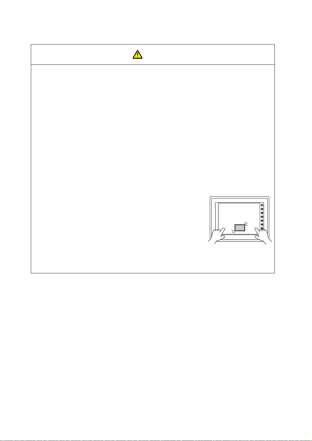
• Switch resolution of the MONITOUCH V7 series is determined by
the analog-type resistance film. Do not press two or more
positions on the screen at the same time.
If two or more positions are pressed at the same time, the switch
located between the pressed positions activates. Please take
note of this.
[Notes on Disposal]
• At the time of disposal, MONITOUCH must be treated as industrial waste.
SWITCH
POWER
Pressing two positions at the same time
activates the switch in the center.
SYSTEM
F1
F2
F3
F4
F5
F6
F7
Page 8

Contents
Chapter 1 Hardware Specifications
1. Features..........................................................................................................................1-1
2. Models and Peripheral Equipment..................................................................................1-2
MONITOUCH Models ............................................................................................... .... .... .. .... .. ...1-2
Peripheral Equipmen t..................... ...................................... ....................................................... 1-3
3. System Composition.......................................................................................................1-7
System Composition of V7 (Standard)......................................................................................... 1-7
System Composition of V7i (High-performance)...... .................................................................... 1-8
4. Specifications.................................................................................................................. 1-9
General Specifications.................................................................................................. .... .. ......... 1-9
Display Specifications................................................................................................................ 1-10
Touch Panel Specifications........................................................................................................ 1-10
Function Switch Specifications..................................................................................................1-11
Interface Specifications.............................................................................................................. 1-11
Clock and Backup Memory Specifications................................................................................. 1-11
Drawing Environment.................................................................................................................1-12
Display Function Specifications.................................................................................................1-12
Function Performance Specifications........................................................................................1-13
5. Dimensions and Panel Cut-out......................................................................................1-14
V708/V708i External View and Dimensions............................................................................... 1-14
V710/V710i External View and Dimensions............................................................................... 1-15
V712/V712i External View and Dimensions............................................................................... 1-16
6. Names and Functions of Components.......................................................................... 1-17
7. Mounting Procedure...................................................................................................... 1-20
Mounting Procedure. ............................................................... ................................................... 1-20
Mounting Angle....................................................................... ...................................................1-20
8. Power Supply Cable Connection................................................................................... 1-21
Power Supply Cable Connection ............................................................................................... 1-21
Notes on Usage of 100-240 VAC Specifications .......................................................... .. .... .... ...1-22
Grounding.................................................................................................................................. 1-22
9. Coin-type Lithium Battery.............................................................................................. 1-23
Battery Mounting Procedure ......................................................................................................1-23
Battery Replacement .................................................................................................................1-24
10. DIP Switch Setting......................................................................................................... 1-26
DIP Switch (DIPSW) Setting......................................................................................................1-26
11. Serial Connector (CN1).................................................................................................1-28
Serial Connector for PLC Connection........................................................................................ 1-28
Page 9

12. Modular Jack (MJ1/MJ2)................................................................................................1-29
Modular Jack 1 (MJ1)/2 (MJ2) .................................................................................. ................. 1-29
V-SFT Setting............. ......................... ................................................... ...................................1-30
Transferring Screen Data....................................................................................................... .... 1-32
Barcode Reader Connection........................................................ .. .... ....... .... .. .... .. ......... .. .... .. ....1-32
13. 10BASE-T (LAN)............................................................................................................1-33
10BASE-T Connector ................................................................................................................ 1-33
Notes on Wiring......................................................................................................................... 1-34
14. CF Card (CF).................................................................................................................1-35
Recommended CF Card............................................................................................................ 1-35
Mounting and Dismounting the CF Card....................................................................................1-35
Notes on Handling the CF Card ................................................................................................. 1-36
15. Printer Connection (PRINTER)..................................... ...... .................................. ..... ....1-37
Printer Connector (PRINTER).................................................. .... .. .. ......... .. .. .... .. .... ....... .... .. .. ....1-37
Connection with Printer through Serial Interface .......................................................................1-38
Chapter 2 MONITOUCH Operations
1. Operation of V7 Main Menu.............................................................................................2-1
Initial Screen................................................................................................. ............................... 2-1
1. Main Menu Screen..............................................................................................................2-2
2. I/O Test............ ................................................................................................................... 2-4
2-1. Self-loop Test...................................................................................................................... 2-5
2-2. Print Check............. .............................................................................. ...............................2-8
2-3. SYSTEM & Function Switch Test......... ............................................................................... 2-8
2-4. Touch Switch Test............. .................................................................................................. 2-9
3. Card Menu Screen............................................................................................................ 2-11
3-1. CREC Menu Screen................................................................................... .... ......... .. .... ....2-12
3-2. Transferring Screen Data from a CF Card.................... ....................................................2-15
3-3. Saving Backup Copies of SRAM....................................................................................... 2-21
3-4. Messages during Data Transfer........................................................................................ 2-23
4. Ethernet.............................................................................................................................2-24
5. SRAM/Clock...................................................................................................................... 2-27
6. Extension Program Information.........................................................................................2-28
7. Extended Function Setting................................................................................................ 2-29
2. Function Switches..........................................................................................................2-30
Types......................................................................................................................................... 2-30
[SYSTEM] Switch....................................................................................................................... 2-30
3. Errors Displayed on the V7 Series.................................................................................2-32
1. Communication Erro r........................................................................................................ 2-32
2. Check ................................................................................................................................2-36
3. Warning............................................................................................................................. 2-36
4. SYSTEM ERROR.............................................................................................................2-37
5. Touch Switch is Active........................... ...........................................................................2-37
Page 10

Chapter 3 S erial Communications
1. 1 : 1 Connection.............................................................................................................. 3-1
1 : 1 Connection................................................... .... ..... .. .. .... .. .. .. .. ....... .. .. .. .... .. .. ..... .... .. .. .. ........... 3-1
Wiring........................................................................................................................................... 3-2
V-SFT Setting.............................................................................................................................. 3-4
2. 1 : n Connection (Multi-drop)........................................................................................... 3-9
1 : n Connection................................................... .... ..... .. .. .... .. .. .. .. ....... .. .. .. .... .. .. ..... .... .. .. .. ........... 3-9
Wiring (RS-422/485) ....................................................................................................................3-9
V-SFT Setting............................................................................................................................ 3-10
Notes on Communication Errors.................... ............................................................................3-10
3. n : 1 Connection (Multi-link 2)........................................................................................ 3-11
Multi-link 2..................................................................... .............................................................3-11
Wiring......................................................................................................................................... 3-12
V-SFT Setting............................................................................................................................ 3-14
Communication Error................................................................................................................. 3-15
4. n : 1 Connection (Multi-link)...........................................................................................3-16
Multi-link..................................................................................................................................... 3-16
Wiring......................................................................................................................................... 3-17
V-SFT Setting............................................................................................................................ 3-18
5. Universal Serial Communicatio ns.................................. ...... ..... ...... ..... .........................3-20
Universal Serial Communications.............. ................................................................................ 3-20
6. V-Link............................................................................................................................ 3-21
V-Link......................................................................................................................................... 3-21
Wiring......................................................................................................................................... 3-22
V-SFT Setting............................................................................................................................ 3-24
Protocol...................................................................................................................................... 3-25
NAK: Error Codes ...................................................................................................................... 3-29
1-byte Character Code List........................................................................................................3-30
7. PLC2Way......................................................................................................................3-31
PLC2Way...................................................................................................................................3-31
Limitations on Connection at the MJ Port .............................................. .... ...... ........... ...... .... .....3-32
PLCs Compatible with PLC2 W a y Connection a t MJ Port..................... .. ............. .. .............. ...... 3-32
Wiring......................................................................................................................................... 3-33
V-SFT Setting – System Setting................................................................................................3-35
V-SFT Setting – When the temperature control network/PLC2Way table is used:.................... 3-38
Indirect Memory Designation .....................................................................................................3-45
User Log Read for YOKOGAWA’s PLC..................................................................................... 3-46
Processing Cycle....................................................................................................................... 3-47
Notes on Screen Data Transfer ................................................................................................. 3-48
System Memory.........................................................................................................................3-49
8. Temperature Control Network....................................................................................... 3-52
Temperature Control Network....................................................................................................3-52
Page 11

Chapter 4 Net work Communications
1. Ethernet...........................................................................................................................4-1
Ethernet.......................................................................................................................................4-1
Notes on Ethernet Communications............................................................................................4-3
IP Address for the V7 Series................................................................... ..................................... 4-3
Communication Interface Unit CU-03.......................................................................................... 4-3
Wiring...........................................................................................................................................4-5
Transferring Screen Data....................................................................................................... ......4-8
V-SFT Setting (PLC Type/Communication Parame te r)............. ......................... .......................4-10
V-SFT Setting (Network Ta b l e Editing)....................... ...............................................................4-14
V-SFT Setting (Macro)......................................................... ...................................... ................ 4-19
System Memory......................................................................................................................... 4-22
Ethernet Access Functions (HKEtn10.DLL)............................................................................... 4-26
Server Communication Procedure............................................................................................. 4-44
Error Display..............................................................................................................................4-45
2. FL-net (OPCN-2)............................................................................................................4-48
FL-net (OPCN-2)........................................................................................................................ 4-48
3. MELSECNET/10............................................................................................................4-49
MELSECNET/10........................................................................................................................ 4-49
4. CC-Link..........................................................................................................................4-51
CC-Link......................................................................................................................................4-51
5. OPCN-1.........................................................................................................................4-52
OPCN-1 ..................................................................................................................................... 4-52
6. T-LINK............................................................................................................................ 4-53
T-LINK........................................................................................................................................ 4-53
7. PROFIBUS-DP..............................................................................................................4-54
PROFIBUS................................................................................................................................. 4-54
Page 12

Chapter 5 Connection to PLCs
1. MITSUBISHI PLC............................................................................................................5-1
Available PLCs............................................................................................................................. 5-1
Communication Setting................................................................................................................5-4
A Series Link, QnA Series Link: Switch Setting........................................................................... 5-6
Available Memory........................................................................................................................5-8
Wiring......................................................................................................................................... 5-11
A Link + Net10........................................................................................................................... 5-15
V-MDD (Dual Port Interface)......................................................................................................5-17
Ladder Transfer Function...........................................................................................................5-18
2. OMRON PLC...................................... ..... ...... ................................................................5-22
Available PLCs........................................................................................................................... 5-22
Communication Setting..............................................................................................................5-24
Available Memory......................................................................................................................5-25
Wiring......................................................................................................................................... 5-26
SYSMAC CS1 DNA...................................................................................................................5-29
3. SHARP PLC..................................................................................................................5-30
Available PLCs........................................................................................................................... 5-30
Communication Setting..............................................................................................................5-30
JW Series: Link Unit Switch Setting............................................................. .............................. 5-31
JW100/70H COM Port, JW20 COM Port: System Memory Setting........................................... 5-31
Available Memory......................................................................................................................5-32
Wiring......................................................................................................................................... 5-33
4. HITACHI PLC................................................................................................................5-35
Available PLCs........................................................................................................................... 5-35
Communication Setting..............................................................................................................5-36
HIDIC-H: Switch Setting.............................................................................................................5-37
Available Memory......................................................................................................................5-37
Wiring......................................................................................................................................... 5-39
5. MATSUSHITA PLC....................................................................................................... 5-41
Available PLCs........................................................................................................................... 5-41
Communication Setting..............................................................................................................5-41
MEWNET: Link Unit Switch Setting........................................................................................... 5-42
Available Memory......................................................................................................................5-42
Wiring......................................................................................................................................... 5-43
6. YOKOGAWA PLC......................................................................................................... 5-45
Available PLCs........................................................................................................................... 5-45
Communication Setting..............................................................................................................5-46
Available Memory......................................................................................................................5-47
Wiring......................................................................................................................................... 5-48
7. YASKAWA PLC............................................................................................................. 5-50
Available PLCs........................................................................................................................... 5-50
Communication Setting..............................................................................................................5-50
Available Memory......................................................................................................................5-51
Wiring......................................................................................................................................... 5-52
Page 13

8. Toyopuc PLC.................................................................................................................5-55
Available PLCs.................................................................................................. ......................... 5-55
Communication Setting.............................................................................................................. 5-55
Switch Setting............................................................................................................................ 5-55
Available Memory........... .................................................................................................... ....... 5-56
Screen Editing (Memory Input) ..................................................................................................5-56
Wiring.........................................................................................................................................5-57
9. FUJI PLC.......................................................................................................................5-58
Available PLCs.................................................................................................. ......................... 5-58
Communication Setting.............................................................................................................. 5-58
MICREX-F Series, FLEX-PC Series: Switch Setting................................................................. 5-59
Available Memory........... .................................................................................................... ....... 5-60
Wiring.........................................................................................................................................5-62
10. KOYO PLC.....................................................................................................................5-64
Available PLCs.................................................................................................. ......................... 5-64
Communication Setting.............................................................................................................. 5-65
Available Memory........... .................................................................................................... ....... 5-66
Switch Setting............................................................................................................................ 5-67
Wiring.........................................................................................................................................5-69
11. Allen-Bradley PLC..........................................................................................................5-72
Available PLCs.................................................................................................. ......................... 5-72
Communication Setting.............................................................................................................. 5-73
Available Memory........... .................................................................................................... ....... 5-74
PLC-5 Series: Switch Setting.....................................................................................................5-76
SLC500 Series, Micro Logix 100: Transmission Parameter Setting.......................................... 5-78
Wiring.........................................................................................................................................5-79
12. GE Fanuc PLC...............................................................................................................5-82
Available PLCs.................................................................................................. ......................... 5-82
Communication Setting.............................................................................................................. 5-82
Available Memory........... .................................................................................................... ....... 5-83
Wiring.........................................................................................................................................5-84
13. TOSHIBA PLC...............................................................................................................5-86
Available PLCs.................................................................................................. ......................... 5-86
Communication Setting.............................................................................................................. 5-86
Available Memory........... .................................................................................................... ....... 5-87
Wiring.........................................................................................................................................5-87
14. TOSHIBA MACHINE PLC..............................................................................................5-88
Available PLCs.................................................................................................. ......................... 5-88
Communication Setting.............................................................................................................. 5-88
Available Memory........... .................................................................................................... ....... 5-88
Wiring.........................................................................................................................................5-89
15. SIEMENS PLC...............................................................................................................5-90
Available PLCs.................................................................................................. ......................... 5-90
Communication Setting.............................................................................................................. 5-90
Available Memory........... .................................................................................................... ....... 5-92
Wiring.........................................................................................................................................5-95
Page 14

16. SHINKO PLC................................................. ...... ................................. ...... ...... ..... ...... ..5-98
Available PLCs........................................................................................................................... 5-98
Communication Setting..............................................................................................................5-98
Available Memory......................................................................................................................5-98
Wiring......................................................................................................................................... 5-99
17. SAMSUNG PLC..........................................................................................................5-100
Available PLCs......................................................................................................................... 5-100
Communication Setting............................................................................................................5-100
Available Memory....................................................................................................................5-100
Wiring....................................................................................................................................... 5-101
18. KEYENCE PLC...........................................................................................................5-102
Available PLCs......................................................................................................................... 5-102
Communication Setting............................................................................................................5-103
Available Memory....................................................................................................................5-104
Wiring....................................................................................................................................... 5-106
19. LG PLC........................................................................................................................5-108
Available PLCs......................................................................................................................... 5-108
Communication Setting............................................................................................................5-108
Available Memory....................................................................................................................5-109
Wiring....................................................................................................................................... 5-111
20. FANUC PLC................................................................................................................5-113
Available PLCs......................................................................................................................... 5-113
Communication Setting............................................................................................................5-113
Available Memory....................................................................................................................5-113
Wiring....................................................................................................................................... 5-114
21. FATEK AUTOMATION PLC........................................................................................5-116
Available PLCs......................................................................................................................... 5-116
Communication Setting............................................................................................................5-116
Available Memory....................................................................................................................5-116
Wiring....................................................................................................................................... 5-117
22. IDEC PLC....................................................................................................................5-118
Available PLCs......................................................................................................................... 5-118
Communication Setting............................................................................................................5-118
Available Memory....................................................................................................................5-118
Wiring....................................................................................................................................... 5-119
23. MODICON PLC...........................................................................................................5-120
Available PLCs......................................................................................................................... 5-120
Communication Setting............................................................................................................5-120
Available Memory....................................................................................................................5-120
Wiring....................................................................................................................................... 5-121
24. YAMATAKE PLC......................................................................................................... 5-122
Available PLCs......................................................................................................................... 5-122
Communication Setting............................................................................................................5-122
Available Memory....................................................................................................................5-122
Wiring....................................................................................................................................... 5-123
Page 15

25. TAIAN PLC ........................................................ ...... ..... ...... .........................................5-124
Available PLCs.................................................................................................. .......................5-124
Communication Setting............................................................................................................5-124
Available Memory........... .................................................................................................... .....5-124
Wiring....................................................................................................................................... 5-125
26. SAIA PLC........................................................... ...... ..... ...... ...... ...................................5-126
Available PLCs.................................................................................................. .......................5-126
Communication Setting............................................................................................................5-126
S-BUS Configuration................................................................................................................ 5-126
Available Memory........... .................................................................................................... .....5-126
Wiring....................................................................................................................................... 5-127
27. MOELLER PLC............................................................................................................5-128
Available PLCs.................................................................................................. .......................5-128
Communication Setting............................................................................................................5-128
Available Memory........... .................................................................................................... .....5-128
Wiring....................................................................................................................................... 5-129
28. Telemecanique PLC....................................................................................................5-130
Available PLCs.................................................................................................. .......................5-130
Communication Setting............................................................................................................5-130
Available Memory........... .................................................................................................... .....5-130
Wiring....................................................................................................................................... 5-131
29. Automationdirect PLC..................................................................................................5-132
Available PLCs.................................................................................................. .......................5-132
Communication Setting............................................................................................................5-132
Available Memory........... .................................................................................................... .....5-133
Wiring....................................................................................................................................... 5-133
Page 16

Hardware Specifications
1. Features
2. Models and Peripheral Equipment
3. System Composition
4. Specifications
5. Dimensions and Panel Cut-out
6. Names and Functions of Components
7. Mounting Procedure
8. Power Supply Cable Connection
9. Coin-type Lithium Batter y
10. DIP Switch Setting
11. Serial Connector (CN1)
12. Modular Jack (MJ1/MJ2)
13. 10BASE-T (LAN)
14. CF Card (CF)
15. Printer Connection (PRINTER)
Page 17

Page 18

1. Features 1-1
1. Features
The V7 series inherits and heightens th e features of the V6 series as described below.
1. 32k-color Display
32,768-color display makes colorful expression possible. Bitmap files are clearly
displayed in brilliant colors.
2. CF Card Interface as Standard
The CF card can be used for saving multiple screen data, sampling data, recipe data,
hard copy images, and other vario us usage s. Large-si zed vide o capture im ages, JPEG
or WAV files can be saved.
3. Connector for 10BASE-T (for high-performance type only)
This connector enables Ethernet connection with a host computer. High-speed
communications are possible via Ethernet for uploading/downloading screen data and
reading/writing data from/to the server.
4. Video Display Upgraded (for high-performance type only, optional)
The video display function is upgraded drastically to allow: saving the current video
screen, taking snapshots of multiple exposures, superimposing a semi-transparent
operation screen on a v ideo disp lay, showing four video c hannels at the same tim e, and
so on.
5. Web Server Function (for high-performance type only)
The V7i screens are converted into HTML files and displayed on the WWW browser
using the Ethernet.
1
Hardware Specifications
6. Animation Function
The animation function enables representation of the field close to the real image.
7. Play of WAV File (for high-performance type only, optional)
WAV files c an be pl ay ed with ease simp ly by c onn ec tin g th e opti on unit to the spe ak er.
It is possible to use sound for notifying the field conditions, such as an occurrence of an
error. The monitoring operator can work from a distance.
Page 19

1-2 2. Models and Peripheral Equipment
2. Models and Peripheral
Equipment
MONITOUCH Models
The model name consists of the following information.
V 7
Power supply specification
D: 24 VDC specification (in compliance with CE/UL/cUL)
None: 100-240 VAC specification
Device specification
S: TFT color LCD (SVGA)
T: TFT color LCD (VGA)
C: STN color LCD (VGA)
Functional specification
i: High-performance type
None: Standard type
Screen size
08: 8-inch
10: 10-inch
12: 12-inch
Page 20
2. Models and Peripheral Equipment 1-3
Series and
Size
V708 series
8-inch
V710 series
10-inch
V712 series
12-inch
The following models are available.
Model
Name
V708SD TFT color, 800 × 600 dots, standard, DC power supply Compliant with CE/UL/cUL
V708iSD TFT color, 800 × 600 dots, high-performance, DC power
supply
V708CD STN color, 640 × 480 dots, standard, DC power supply Compliant with CE/UL/cUL
V710T TFT color, 640 × 480 dots, standard, AC power supply
V710TD TFT color, 640 × 480 dots, standard, DC power supply Compliant with CE/UL/cUL
V710iT TFT color , 640 × 480 dots, high-performance, AC power
supply
V710iTD TFT color, 640 × 480 dots, high-performance, DC power
supply
V710S TFT col or, 800 × 600 dots, standard, AC power supply
V710SD TFT color, 800 × 600 dots, standard, DC power supply Compliant with CE/UL/cUL
V710iS TFT color, 800 × 600 dots, high-performance, AC power
supply
V710iSD TFT color, 800 × 600 dots, high-performance, DC power
supply
V712S TFT col or, 800 × 600 dots, standard, AC power supply
V712SD TFT color, 800 × 600 dots, standard, DC power supply Compliant with CE/UL/cUL
V712iS TFT color, 800 × 600 dots, high-performance, AC power
supply
V712iSD TFT color, 800 × 600 dots, high-performance, DC power
supply
Specifications Remarks
Compliant with CE/UL/cUL
Compliant with CE/UL/cUL
Compliant with CE/UL/cUL
Compliant with CE/UL/cUL
1
Hardware Specifications
Peripheral Equipment
The following options are available for using the V7 series more effectively.
V-SFT (drawing software: English version)
Application software for editing display data for the V series.
(Windows98/NT4.0/Me/2000/XP compatible) The V7 series is
supported with ver. 2.00 and later.
Page 21
1-4 2. Models and Peripheral Equipment
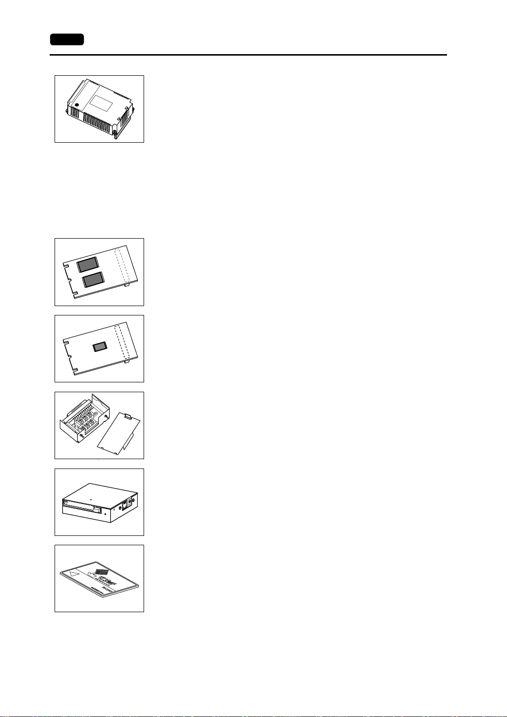
EU-xx (option unit)
(* This option unit can only be mounted on the V7i model.)
xx: 00 → Video input + sound output unit
Video images can be displayed on V7i directly. WAV files can be
played at an external speaker.
xx: 01 → RGB input + sound output unit
Screen images displayed on a CRT display can be shown on V7i.
WAV files can be played at an external speaker.
xx: 02 → RGB output + sound output unit
Screen images displayed on V7i can be shown on a CRT display.
WAV files can be played at an external speaker.
xx: 03 → Sound output unit
WAV files can be played at an external speaker.
V7EM-F (FLASH memory cassette)
Extension print circuit board to extend the memory for screen data.
The capacity of FLASH memory is 8 Mbyte.
V7EM-S (SRAM cassette)
Extension print circuit board to back-up the memory for sampling data,
V7 internal memory and memo pad. The capacity of an SRAM
cassette is 512 kbyte.
CN1
SW1
TB1
TC485 (terminal converter)
Used for connection between the V7 series and a PLC at the
RS-422/485 terminal block.
CREC (card recorder)
The card recorder crea tes a ba ckup c opy of scre en dat a or works as an
external memory storage system for memory manager and data
logging functions.
REC-MCARD (memory card) compliant with JEIDA ver. 4.0
Used with the card reco rder when h aving a b ackup copy of screen data
or saving data on an external medium for memory manager and data
logging functions.
SRAM 256 k, 512 k, 1 M, 2 M, 4 Mbyte
FLASH ROM 256 k, 512 k, 1 M, 2 M, 4 M, 16 Mbyte
Page 22
2. Models and Peripheral Equipment 1-5
1 2 3
D
C
2
4
F
GI
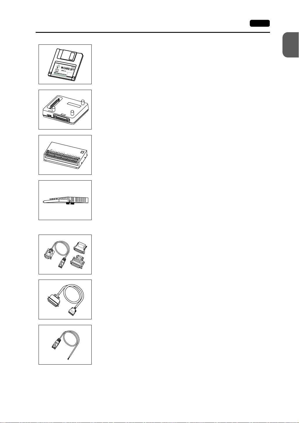
M-CARD SFTE (memory card editor)
1
Application software for editing data stored on a memory card.
(Windows98/NT4.0/Me/2000/XP compatible)
Hardware Specifications
V-MDD (ACPU/QnACPU/FXCPU dual port interface)
P
P
V
-
M
G
D
D
GD
Add-on connector with two ports, specifically designed for the
connector on the MITSU BISHI’s ACPU/QnAC PU/FXCPU programm er.
Operability can be improved when directly connecting the V7 series to
the ACPU/QnACPU/FXCPU programmer.
V-I/O (serial extension I/O)
V
I
N
1
I
N
3
I
N
5
N
0
I
N
7
I
N
I
2
N
9
I
N
I
4
N
1
1
IN
I
N
6
1
3
IN
I
8
N
I
N
1
0
I
N
1
2
I
N
1
4
C
O
M
J
1
5
M
+
O
U
1
O
U
T
1
O
U
T
3
O
U
T
5
O
T
U
0
T
7
O
U
O
T
U
2
T
8
O
U
O
T
U
4
T
1
0
O
U
O
T
U
6
T
1
2
C
O
O
M
U
1
T
1
4
O
U
C
T
O
9
M
2
O
U
T
1
1
O
U
T
1
3
O
U
T
1
5
Used as an external I/O unit for PLC. It has 16 inputs and 16 outputs.
CU-xx [xx: 00 → OPCN-1, 01 → T-LINK, 02 → CC-Link,
03 → Ethernet/FL-net (OPCN-2), 04 → PROFIBUS-DP,
05 → MELSECNET/10] (communication interface unit)
Used for communications with each network. This unit enables
connection of multiple V7 series to a single PLC. Since other devices
on the same network can be connecte d, it brings abou t the reduction in
costs of the whole system.
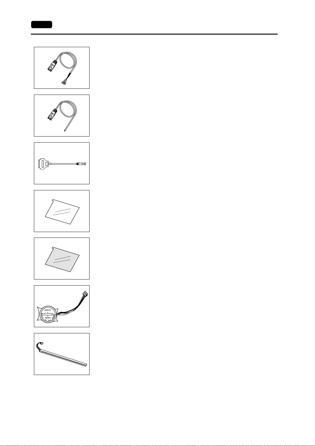
V6-CP (screen data transfer cable) 3 m
Used for connection between the V7 series and a personal computer,
or a personal computer and the card recorder (CREC).
V7-PT (printer cable) 2.5 m
Used for connection between the V7 series and a printer.
V6-BCD (barcode reader connection cable) 3 m
Used for connection between the V7 series and a barcode reader.
Page 23
1-6 2. Models and Peripheral Equipment
V6-MLT (multi-link 2 master cable) 3 m
Used for Multi-Link 2 connection between the V7 master station and
the V7slave station.
V6-TMP (temperature controller connection cable) 3 m
Used for connection between the V7 series and a temperature
controller or a PLC via PLC2Way.
MJ-D25 (MJ-to-D-sub conversion cable) 0.3 m under development
Used for connection between the V7 series and a PLC via PLC2Way.
V7xx-GS [xx: 08 → V708/V708i, 10 → V710/V710i, 12 → V712/V712i]
(protective sheet)
This sheet protects the operation panel surface. (5 sheets/set)
V7xx-GSN10 [xx: 08 → V708/V708i, 10 → V710/V710i,
12 → V712/V712i] (protective sheet)
This anti-glare sheet protects the operation panel surface.
(5 sheets/set)
V7-BT (battery for replacement)
Replacement lithium battery for the V7 series.
V708S-FL → V708S/V708iS
V6xxx-FL [xxx: 08C → V708C, 10T → V710T/V710iT,
10S → V710S/V710iS, 12S → V712S/V712iS]
(backlight for replacement)
Replacement backlight parts for the V7 series.
Page 24
3. System Composition 1-7
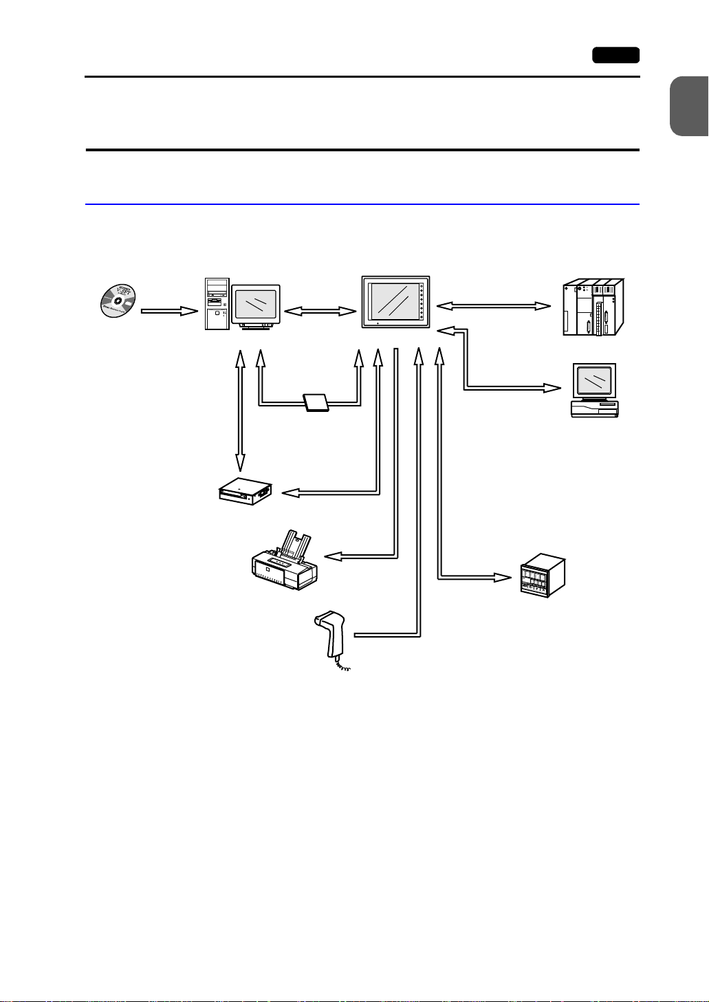
3. System Composition
System Composition of V7 (Standard)
The following illustration shows possible system configurations using the V7 series
(standard).
V series
Panel Editor
V-SFT
Creating screens
disc
Personal computer (PC)
Transferring screen data
Transferring other data
V6-CP
Card recorder
CREC
Transferring
screen data
V6-CP
RESET
POWER
V7 (standard)
Transferring screen da ta
Transferring recipe data
Saving sampling data
etc.
CompactFlash
Card
CF card
Transferring screen data
Memory manager
Data logging function
CREC cable
Printer cable
V7-PT
Printer
Cable
V6-BCD
SYSTEM
F1
F2
F3
F4
F5
F6
F7
During operation
(Link communication)
RS-232C/RS-422
During operation
(Universal serial
communication)
RS-232C/RS-422
Cable
V6-TMP
Temperature controller,
inverter
Link unit
General-purpose
computer
1
Hardware Specifications
Barcode reader
Page 25
1-8 3. System Composition
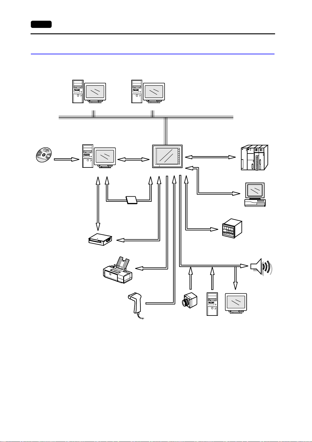
System Composition of V7i (High-performance)
The following illustration shows possible system configurations using the V7i series
(high-performance).
V series
Panel Editor
V-SFT
disc
RESET
Personal computer (PC) Personal computer (PC)
Creating screens
disc
Personal computer (PC)
Transferring screen data
Transferring other data
V6-CP
Card recorder
CREC
disc
RESET
Ethernet
Transferring
screen data
RESET
V6-CP
POWER
V7i (high-performance)
Transferring screen data
Transferring recipe da ta
Saving sampling data
etc.
CompactFlash
Card
CF card
Transferring screen data
Memory manager
Data logging function
CREC cable
Printer cable
V7-PT
SYSTEM
F1
F2
F3
F4
F5
F6
F7
*1
During operation
(Link communication)
RS-232C/RS-422
During operation
(Universal serial
communication)
RS-232C/RS-422
Cable
V6-TMP
T emperature controller,
inverter
Link unit
General-purpose
computer
Printer
Barcode reader
*1 The option unit (EU-xx) is required.
Cable
V6-BCD
Video camera
(Video input)
Personal
computer
(RGB input)
Display
(RGB output)
Speaker
(Sound output)
Page 26
4. Specifications 1-9
4. Specifications
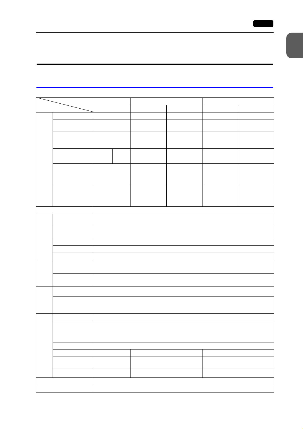
General Specifications
Model V708 V710 V712
Item DC power supply AC power supply DC power supply AC power supply DC power supply
Rated Voltage 24 VDC 100 - 240 VAC 24 VDC 100 - 240 VAC 24 VDC
Permissible Range
of Voltage
24 VDC ±10%
Permissible
Momentary Power
Failure
Power Consumption
(Maximum Rating)
Power Supply
Rush Current 25 A, 0.7 ms
Within 1 ms Within 20 ms Within 1 ms Within 20 ms Within 1 ms
V708C
V708S/iS
15 W or
less
22 W or
DC external
Withstand Voltage
terminals to FG:
500 VAC,
1 minute
Insulation Resistance 500 VDC, 10 MΩ or above
Ambient
Temperature
Storage Ambient
Temperature
Ambient Humidity 85%RH or less (without dew condensation)
Solvent Resistance No cutting oil or organic solvent attached to the unit
Physical Environment
Atmosphere No corrosive gas or conductive dust
Vibration Resistance
Working
Shock Resistance
Conditions
Mechanical
Vibration frequency: 10 to 150 Hz, Acceleration: 9.8 m/s
Single amplitude: 0.075 mm, X, Y, Z: 3 directions for one hour
Pulse shape: Sine half wave
Peak acceleration: 147 m/s
Noise Resistance 1500Vp-p (pulse width 1 µs, rising time: 1 ns)
Static Electricity
Discharge
Working
Electrical
Conditions
Resistance
Grounding Grounding resistance: less than 100 Ω
Protection structure: front panel compliant with IP65 (when using gasket)
Structure
Form: in a body
Mounting procedure: inserted in a mounting panel
Cooling System Cooling naturally
Weight (kg) Unit: approx. 1.5 Unit: approx. 2.4 Unit: approx. 2.7
Dimensions
Mounting Conditions
W × H × D (mm)
Panel Cut-out (mm)
233 × 178 × 66.1 303.8 × 231.0 × 72.0 326.4 × 259.6 × 72.0
+0.5
220.5 ×
165.5
−0
Case Color Black (Munsell N2.0)
Material PC/PS resin (Tarflon)
less
+0.5
−0
100 - 240 VAC
±10%
24 VDC ±10%
100 - 240 VAC
±10%
24 VDC ±10%
60 VA or less 30 W or less 60 VA or less 30 W or less
For 100 VAC:
16 A, 6 ms
For 200 VAC:
32 A, 7 ms
AC external
terminals to FG:
1500 VAC,
1 minute
30A, 1 ms
DC external
terminals to FG:
500 VAC,
1 minute
For 100 VAC:
16 A, 6 ms
For 200 VAC:
32A, 7 ms
AC external
terminals to FG:
1500 VAC,
1 minute
30 A, 1 ms
DC external
terminals to FG:
500 VAC,
1 minute
0°C to +50°C
−10°C to +60°C
2
(1.0G)
2
(15G), X, Y, Z: 3 directions six times each
Compliant with IEC1000-4-2, contact: 6 kV, air: 8 kV
rear case: compliant with IP20
+0.5 +0.5
289.0 × 216.2 313.0 × 246.2
−0
+0.5
−0
+0.5
−0
1
Hardware Specifications
Page 27
1-10 4. Specifications
Display Specificati ons
Model
Item
Display Device
Effective Display
Area
Colors
Resolution
W × H (dots)
Dot Pitch
W × H (mm)
Brightness (cd/m
Contrast Ratio 25 : 1 250 : 1 300 : 1 300 : 1 350 : 1
Angle of Vertical
Visibility (°)
Angle of Horizontal
Visibility (°)
Backlight Cold cathode rectifier (exchangeable by users)
Backlight Average
*1
Life
Backlight
Auto OFF Function
Contrast Adjustment P rovided
Brightness
Adjustment
Surface Sheet Material: Polycarbonate, 0.3 mm thick
POWER Lamp ON when the power is supplied
2
) 200 350 350 280 350
V708C V708S V708iS V710T V710iT V710S V710iS V712S V712iS
STN
color LCD
7.7-inch 8.4-inch 10.4-inch 12.1-inch
128 colors
+16-color blinks
640 × 480 800 × 600 640 × 480 800 × 600
0.246 × 0.246 0.213 × 0.213 0.33 × 0.33 0.264 × 0.264 0.3075 × 0.3075
+40, −30 +35, −55 +45, −55 +35, −45 +40, −45
±50 ±50 ±70 ±50 ±55
Approx.
40,000 h
Always ON, random setting
*2
Not provided 3 levels
TFT color LCD
32,768 colors
+16-color blinks
Approx. 50,000 h
Not provided
*2
*1 When the normal temperature is 25°C, and the surface luminance of the display is 50% of the
initial s e tting.
*2 Adjustable with function switches
Touch Panel Specifications
Item Specifications
Method Analog resistance film type
Switch Resolution 1024 (W) × 1024 (H)
Mechanical Life One million activations or more
Surface Treatment Hard-coated, anti-glare treatment 5%
Page 28
4. Specifications 1-11
Function Switch Specifications
Item Specifications
Number of Switches 8
Method Pressure sensitive
Mechanical Life One million activations or more
Interface Specifications
Item Specifications
Serial Interface for PLC
Connection
(D-sub 25-pin, female)
Serial Interface 1, 2 for Screen
Data Transfer/External
Connection
(Modular jack, 8-pin)
Printer Interface for Printer
Connection
CF Card Interface Compliant with CompactFlash
10BASE-T for Ethernet
Connection
(Standard with V7i)
RS-232C, RS-422/485
Asynchronous type
Data length: 7, 8 bits
Parity: even, odd, none
Stop bit: 1, 2 bits
Baud rate: 4800, 9600, 19200, 38400, 57600, 76800, 115 kbps
RS-232C, RS-422/485 (2-wire connection)
CREC, Barcode, V-I/O, Multi-link 2,
Temperature control network/PLC2Way, V-link, etc.
Compliant with Centronics, half-pitch 36-pin
NEC: PR201
EPSON: ESC/P-J84, ESC/ P super func ti on, ESC / P24-J 84
CBM292/293 printer
Barcode printer MR400
Compliant with IEEE802.3
Baud rate: 10 Mbps
Cables: 100 Ω unshielded twist-pair,
Category 5, maximum length = 100 m
*1
1
Hardware Specifications
, HP PCL Level 3
TM
*1 The CBM292/293 printer cannot print screen hard copies.
Clock and Backup Memory Specifications
Item Specifications
Battery Specification Coin-type lithium primary cell
Battery type: Sanyo CR2450-CN21
Backup Memory SRAM 64 kbyte
Backup Time Period 5 years (ambient temperature at 25°C)
Battery Voltage Drop Detection Provided (internal memory allocated)
Calendar Accuracy Monthly deviation ±90 sec (ambient temperature at 25°C)
Page 29
1-12 4. Specifications
Drawing Environment
Item Specifications
Drawing Method Exclusive drawing software
Drawing Tool Name of exclusive drawing software: V -SFT (Ver. 2.00 and later)
Personal computer: Pentium II 450 MHz or above recommended
OS: Windows98/Me/NT Ver. 4.0/2000/XP
Capacity of hard disk required: Free space of approx. 460 Mbyte or more
Display: Resolution 800 × 600 or above recommended
(For minimum installation: approx. 105 Mbyte)
Display Function Specifications
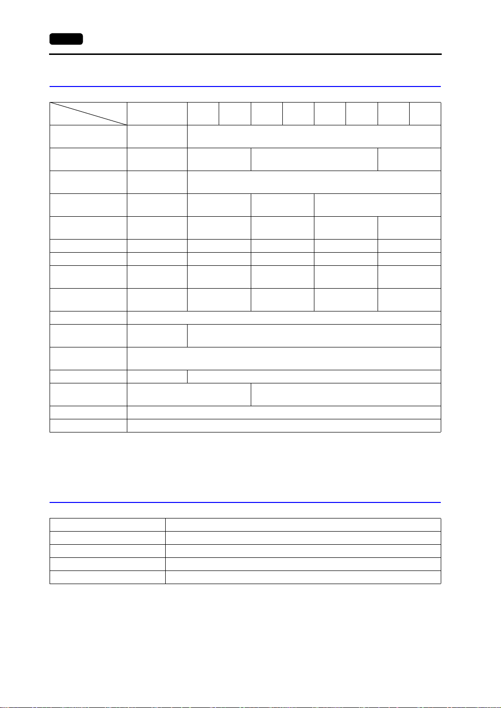
Item Specifications
Display Language* Japanese English/
Characters 1/4-size
1-byte
2-byte
16-dot
2-byte
32-dot
Character Size 1/4-size: 8 × 8 dots
Number of
Displayable
Characters
Characters
Properties
Graphics Lines: Line, continuous line, box, parallelogram, polygon
Graphic Properties Line types: 6 (thin, thick, dot, chain, broken, two-dot chain)
ANK code Latin 1 ASCII code ASCII code ASCII code
JIS #1, #2 level −−−− Chinese
JIS #1 level −−−− −−−− −−−− −−−−
1-byte: 8 × 16 dots
2-byte: 16 × 16 dots or 32 × 32 dots
Enlarge: W: 1 to 8 times, H: 1 to 8 times
Resolution 640 × 480 800 × 600
1/4-size 80 columns × 60 lines 100 columns × 75 lines
1-byte 80 columns × 30 lines 100 columns × 37 lines
2-byte 40 columns × 30 lines 50 columns × 37 lines
Display properties: Normal, reverse, blink, bold, shadow
Colors: 32,768 colors + blink 16 colors (V708C: 128 colors + blink 16 colors)
Circles: Circle, arc, sector, ellipse, elliptical arc
Others: Tile patterns
Tile patterns: 16 (incl. user-definable 8 patterns)
Display properties: Normal, reverse, blink
Colors: 32,768 colors + blink 16 colors (V708C: 128 colors + blink 16 colors)
Color selection: Foreground, background, boundary (line)
European
Chinese Chinese
(Simplified)
Chinese
(simplified)
Korean
Hangul
(without Kanji)
* Refer to the Reference Manual (Operation) for HK fonts.
Page 30
4. Specifications 1-13
Function Performance Specifications
Item Specifications
Screens Max. 1024
Screen Memory Flash memory: Appox. 4,992 kbyte (varies depending on the font)
Switches 768 per screen
Switch Actions Set, reset, momentary, alternate, to light
(Possible to press a function switch and a display switch at the same time)
Lamps Reverse, blink, exchange of graphics
Graphs Pie, bar, panel meter and closed area graph: No limitation within 256 kbyte
Numerical Data Display No limitation within 256 kbyte per screen *
Character Display No limitation within 256 kbyte per screen *
Message Display Resolution: 640 × 480, max. 80 characters (1-byte)
Data Setting
Sampling Sampling display of buffer data
Graphic Library Max. 1024
Multi-Overlaps Max. 1024
Data Blocks Max. 2560
Messages Max. 6144 lines
Patterns Max. 1024
Macro Blocks Max. 1024
Page Blocks Max. 1024
Direct Blocks Max. 1024
Screen Blocks Max. 1024
Data Sheets Max. 1024
Screen Library Max. 1024
Animation (Frames) Max. 1023
Temperature Control Network/
PLC2Way Table
Time Display Time display function: provided
Hard Copy Screen hard copy function: provided
Buzzer Buzzer: provided, 2 sounds (short beep, long beep)
Auto OFF Function Always ON, random setting
Self-diagnostic Function Switch self-test function
768 per screen
per screen *
Statistics and trend graphs: Max. 256 per layer *
1
1
800 × 600, max. 100 characters (1-byte)
No limitation within 256 kbyte per screen *
(Constant sample, bit synchronize, bit sample, relay sample, alarm function)
Max. 32
Communication parameter setting check function
Communication check function
1
1
2
1
Hardware Specifications
*1 The number of setting memory locations is limited to 1024 per screen.
*2 Layer: 4 per screen (base + 3 overlaps)
Page 31

1-14 5. Dimensions and Panel Cut-out
5. Dimensions and
Panel Cut-out
V708/V708i External View and Dimensions
(Unit: mm)
• Side View • Front View
66.1
233
165
POWER
6.6
• Rear View • Bottom View
220
165
CN6
See operating or maintenance
instruction for type of battery
to be used.
Battery replacement.
24VDC
- +
MJ1
PRINTER
CN5
CN1
MJ2
MEMORY
LAN
CF
220
24.3
SYSTEM
F1
F2
F3
F4
F5
F6
F7
178
• Panel Cut-out Dimensions
+0.5
220.5
-0
+0.5
-0
165.5
Page 32

5. Dimensions and Panel Cut-out 1-15
V710/V710i External View and Dimensions
(Unit: mm)
• Side View • Front View
72
8
215.2
POWER
• Rear View • Bottom View
288.0
303.8
SYSTEM
1
Hardware Specifications
F1
F2
F3
F4
F5
F6
F7
231
215.2
100-240VAC
L N
CN6
CN5
LAN
MEMORY
See operating or maintenance
instruction for type of battery
to be used.
Battery replacement.
MJ1 MJ2
CN1
CF
PRINTER
288.0
35.2
• Panel Cut-out Dimensions
+0.5
289
-0
+0.5
-0
216.2
Page 33

1-16 5. Dimensions and Panel Cut-out
V712/V712i External View and Dimensions
(Unit: mm)
• Side View • Front View
72
8
326.4
245.2
259.6
SYSTEM
• Rear View • Bottom View
312
CN6
CN5
MEMORY
See operating or maintenance
instruction for type of battery
to be used.
Battery replacement.
CF
245.2
PRINTERMJ2MJ1
100-240VAC
L N
CN1
LAN
63.8
F1
F2 F3
POWER
F4
F5 F6 F7
312
• Panel Cut-out Dimensions
+0.5
313
-0
+0.5
-0
246.2
Page 34

6. Names and Functions of Components 1-17
6. Names and Functions of
Components
V708/V708i
13
LAN
MEMORY
CF
14
1
8
4
POWER
2
10
SYSTEM
3
F1
F2
F3
F4
F5
F6
F7
12
15
11
CN6
See operating or maintenance
instruction for type of battery
to be used.
Battery replacement.
24VDC
- +
CN5
PRINTER
MJ1
CN1
MJ2
1
Hardware Specifications
V710/V710i
4
6
7
5
13
POWER
2
10
56 789
SYSTEM
9
11 12 13
CN6
F1
F2
F3
F4
F5
F6
F7
100-240VAC
L N
CN5
LAN
MEMORY
See operating or maintenance
instruction for type of battery
to be used.
Battery replacement.
MJ1 MJ2
CN1
CF
PRINTER
14 15
Page 35

1-18 6. Names and Functions of Components
V712/V712i
1
4
10
F4
F5 F6 F7
F1 F2 F3
SYSTEM
POWER
2
56 789
1. Display
This is the display unit.
11 12 13
CN6
CN5
3
100-240VAC
L N
LAN
MEMORY
See operating or maintenance
instruction for type of battery
to be used.
Battery replacement.
CN1
CF
PRINTERMJ2MJ1
14 15
2. Power Lamp (POWER)
Illuminates (green) when the power is supplied to the V7 series.
3. Function switches
Used for RUN /STOP selection, contrast adjustment, brightness adjustment and
backlight ON/OFF (according to the setting). These switches can be used as user
switches in the RUN mode.
4. CF card connector (CF)
This is the connector where the CF card is inserted.
5. Printer connector (PRINTER)
Used for printer connection.
6. Modular jack connectors (MJ1, MJ2)
Used for screen data transfer and connection with temperature controller, barcode
reader, CREC, etc.
7. PLC communication connector (CN1)
Used for connection between the V7 series and a PLC or an external control unit
(computer, custom controller, etc).
8. 10BASE-T connector (LAN) ................ V7i only
Used for Ethernet connection.
9. Power input terminal block
Supplies the power to the V7 series (100 to 240 VAC, 24 VDC)
Page 36

6. Names and Functions of Components 1-19
10.Mounting holes
Used for inserting fixtures when securing the V7 series to the mounting panel.
11. Communication interface unit connector (CN5)
This is the connector where the communication unit (CU-xx, optional) for OPCN-1,
T-LINK, CC-Link, Ethernet, FL-net (OPCN-2), PROFIBUS-DP or MELSECNET/10 is
mounted.
12.Option unit connector (CN6).....................V7i only
This is the connector where the option unit (EU-xx) for video, sound, RGB IN or RGB
OUT is mounte d.
13.Add-on memory connector (MEMORY)
This is the connector where the optional FLASH memory cassette (V7EM-F) or SRAM
cassette (V7EM-S) is mounted.
14.DIP swit ch
8-bit DIP switch used for setting terminating resistance of the CN1 signal line and the
MJ1/MJ2 RS-422/485 signal line.
15.Battery holder
Contains a backup battery for SRAM and clock. When the battery voltage drops,
replace the battery with a new one (V7-BT).
1
Hardware Specifications
Page 37

1-20 7. Mounting Procedure
7. Mounting Procedure
Mounting Procedure
1. Cut out the mounting panel (max. thick: 5 mm) to match the dimensions shown below.
Panel cut-out hole
Mounting panel
5
.
0
+
0
9
−
8
2
• Panel cut-out dimensions
(Unit: mm)
+0.5
220.5
−0
V708/V708i
0.5
+
−0
165.5
M
E
T
S
SY
0
0.5
+
−
216.2
R
E
W
PO
F1
2
F
F3
4
F
F5
6
F
F7
+0.5
289
−0
V710/V710i
0.5
+
−0
216.2
+0.5
313
−0
V712/V712i
0.5
+
−0
246.2
2. Insert four fixtures attached to the V7 series into the mounting holes, and tighten them
with the locking screws.
Tightening torque
V708/V708i/V710/V710i: 0.3 to 0.5 N•m
V712/V712i: 0.5 to 0.7 N•m
Fixture dimensions
(Unit: mm)
30.0
* When the V7 unit is attached to the
mounting pane l, the fixtures and frame
grounds (FG) are connected. To prevent
static elec tricity, be sure to connect the
mounting pane l to the frame ground.
10.5
17.8
Mounting hole
Fixtures
Mounting hole
V7 series
6
N
C
F
C
R
E
T
N
I
R
Mounting panel
Y
R
O
M
E
M
5
N
C
2P
J
M
1
J
M
1
N
NC
A
L
C
A
V
0
4
2
0
0
1
N
L
Fixtures
3. Mount the gasket in contact with the mounting panel so that it will be sandwiched
securely between the unit and the mounting plate.
Mounting Angle
Install the unit within the angle of 15° to 135° degrees as
shown on the right.
135°
90°
y
a
l
p
s
i
D
y
a
l
p
s
i
15°
D
0°
Page 38

8. Power Supply Cable Connection 1-21
8. Power Supply Cable
Connection
DANGER
Power Supply Cable Connection
• Connect the power supply cable to the terminal on the backside of the unit.
Electric shock hazard
Shut the power off before connecting the power supply cable.
- V708/V708i - V710/V710i/V712/V712i
CN1
MEMORY
Seeoperatingormaintenance
instructionfortypeofbattery
tobeused.
Batteryreplacement.
MJ1 MJ2
CN6
CN6
CN5
24VDC
- +
PRINTER
MJ2
MJ1
LAN
MEMORY
CF
CN1
100-240VAC
CN5
LAN
L N
CF
PRINTER
1
Hardware Specifications
24 VDC specification
24 VDC
Power supply
24 VDC ± 10%
Grounding
• When connecting the power supply cable, tighten the terminal screws to the following
torque.
Terminal Screw
Model
V708/V708i M3.5 0.5 N•m
V710/V710i/V712/V712i M4 0.5 N•m
Screw Size Tightening Torque Crimp-style Terminal (Unit: mm)
• The power source must be within the allowable voltage fluctuation.
• Use a power source with low noise between the cables or between the ground and the
cable.
• Use as thick a power supply cable as possible to minimize drop in voltage.
100-240 VAC specification
LN + −
Power supply
100-240 VAC
Grounding
7.1 MAX 7.1 MAX
7.9 MAX 7.0 MAX
24 VDC specification
24VDC
Power supply
24 VDC ± 10%
Grounding
Page 39

1-22 8. Power Supply Cable Connection
• Keep cables of 100 VAC and 24 VDC s uf f ic ien tly away fr om high -vo lt a ge, large - cu rren t
carrying cables.
• Be sure to attach the terminal cover to the terminal block.
- For V708/V708i:
Attach the terminal cover
(supplied) to the terminal block.
Terminal cover
- For V710/V710i/V712/V712i:
When closing the terminal cover, hold
one end of the cover as shown below.
Press either end.
Notes on Usage of 100-240 VAC Specifications
• Generally, an isolating transformer improves noise resistance. However, if the display
unit is far away from the secondary port of the transformer and noise gets mixed in, an
isolatin g transformer becomes unnecessary.
• If any power voltage fluctuation caused by noise is expected, it is recommended that a
voltage stabilizer (effective in noise resistance) be used.
Power
supply
Insulation tra n sformer
or
Stabilized transformer
To V710/V710i/V712/V712i
Grounding
CAUTION
• An independent earth pole must be used for
MONITOUCH.
• Use a cable which has a nominal cross section of more
than 2 mm
• Set the grounding point near the MONITOUCH to shorten
the distance of grounding cable s.
• When the unit is grounded along with other machines or is grounded to a part of a
building, it may be adversely affected.
• If any input-output error occurs due to the grounding, detach the FG terminal (*) from
the ground.
* When the V7 unit is at tac hed to t he m ounting p anel, t he f ixtures and fr ame g rounds ( FG)
1.25 mm
2
Twist the cables.
Be sure to establish a ground of MONITOUCH. (The level of grounding
resistance should be less than 100 Ω.)
V7 series unit
2
for grounding.
are connected. To detach the FG terminal from the ground, attach the insulating sheet
to the fixtures and the mounting panel for insulation.
Other
equipment
Page 40

9. Coin-type Lithium Battery 1-23
9. Coin-type Lithium
Battery
CAUTION
Battery Mounting Procedure
DANGER
1. A coin-type lithium battery is attached to the battery holder without connection in the
backside of the unit before delivery.
2. Turn the unit off. Open the battery holder cover. To open the cover, press the end of
the cover in the direction of the arrow as shown in the left illustration below.
Be sure to set the battery when using the calendar function or the SRAM
cassette. Without a bat tery, the co ntents in the SRAM o r calenda r data wi ll not
be retained.
Electric shock hazard
Steps 2 to 5 must be performed while the power is not supplied to the V7 unit.
1
Hardware Specifications
Battery holder
n
M
O
2
-
L
i
C
S
CR2450
E
A
L
L
N
3
Y
V
O
O
L
T
S
J
A
P
N
A
Battery connector
n
M
O
2
-
L
i
C
S
CR2450
E
A
L
L
N
3
Y
V
O
O
L
T
S
J
A
P
N
A
100-240VAC
L N
CN6
CN5
LAN
MEMORY
See operating or maintenance
instruction for type of battery
to be used.
Battery replacement.
MJ1 MJ2
CN1
CF
PRINTER
3. Check that the battery is securely attached to the backside of the cover, and connect
the battery connector.
4. Close the battery holder cover.
5. Enter a date five years from now for “Batte ry Rep lacemen t” on the
sticker on the battery holder.
* The battery status is output to the internal memory $s167 of the
V7 series. If the battery voltage drops before five years has
elapsed, replace the battery immediately.
See operating or maintenance
instruction for type of battery
to be used.
Battery replacement.
Enter a date five
years from now.
Page 41

1-24 9. Coin-type Lithium Battery
MSB LSB
15 14 13 12 11 10 09 08 07 06 05 04 03 02 01 00
$s167
0000000000 0
Reserved for memory cassette
information (setting: 0)
6. Check that the battery i s correctl y connected
on the Main Menu screen.
When the battery is not connected, the
[SRAM/Clock] switch blink s and the
message “Battery not s et” i s displ ayed at the
bottom left corner. When the battery is
correctly connected, the [SR AM/Clock]
switch goes out and the message is cleared.
When the battery voltage has dropped, the
message “Brownout Battery” is displayed.
0: Battery OK
1: Battery voltage drop
2: No battery
0: No memory cassette mounted
1: FROM 2 Mby te (V6)
2: FROM 4 Mby te (V6)
3: SRAM 512 kbyte (V7/V6)
4: FROM 8 Mby te (V7)
Reserved for memory cassette information
(setting: 0)
V710iTD
Main Menu
System Information
SYSTEM PROG. VER. 1.000
Screen Data
Information
Size : 5111808
Editor:MJ1
POWER
FONT
VER.1.300 / 1.000 / 1.000
ENGLISH
PLC Type : MITSUBISHIA series Link
Comment :
Connection :
Signal Level :
PLC Stat. No. :
1:1
RS232C
0
I/F DRV VER.1.300
MELSEC AnA/N/U
Time-Out: 1.00 sec
Baud Rate:
Data Length :
Stop Bit:
Parity: Odd
Send Delay: 2
SRAM/Clock
Ethernet
Card
Menu
Error : Stop
Retry: 3
19200
8
1
0msec
I/O Test
Battery Replacement
Safety Instructions on Handling the Battery
Lithium batteries contain combustible material such as lithium or organic solvent.
Mishandling may cause heat, explosion or ignition resulting in fire or injury. To prevent
accidents, pay attention to the following cautions when handling the lithium battery.
CAUTION
• Be sure to discharge static electricity from your body before battery
replacement.
• Use the battery “V7-BT” (replacement battery for the V7 series) for
replacement.
• Rough handling of the battery may cause a fire or chemical burn hazard.
• Do not disassemble, incinerate or heat the battery above 212°F.
• Observe the local and governmental regulations when disposing of waste
batteries.
• Keep batteries out of reach of ch ildren (If swallow ed, immedia tely consult a
doctor.)
• Never re-charge the battery.
• When the battery lea ks or smel ls, the leak ing ba ttery elec trolyte may catch
a fire. Keep from heat or flame.
Page 42
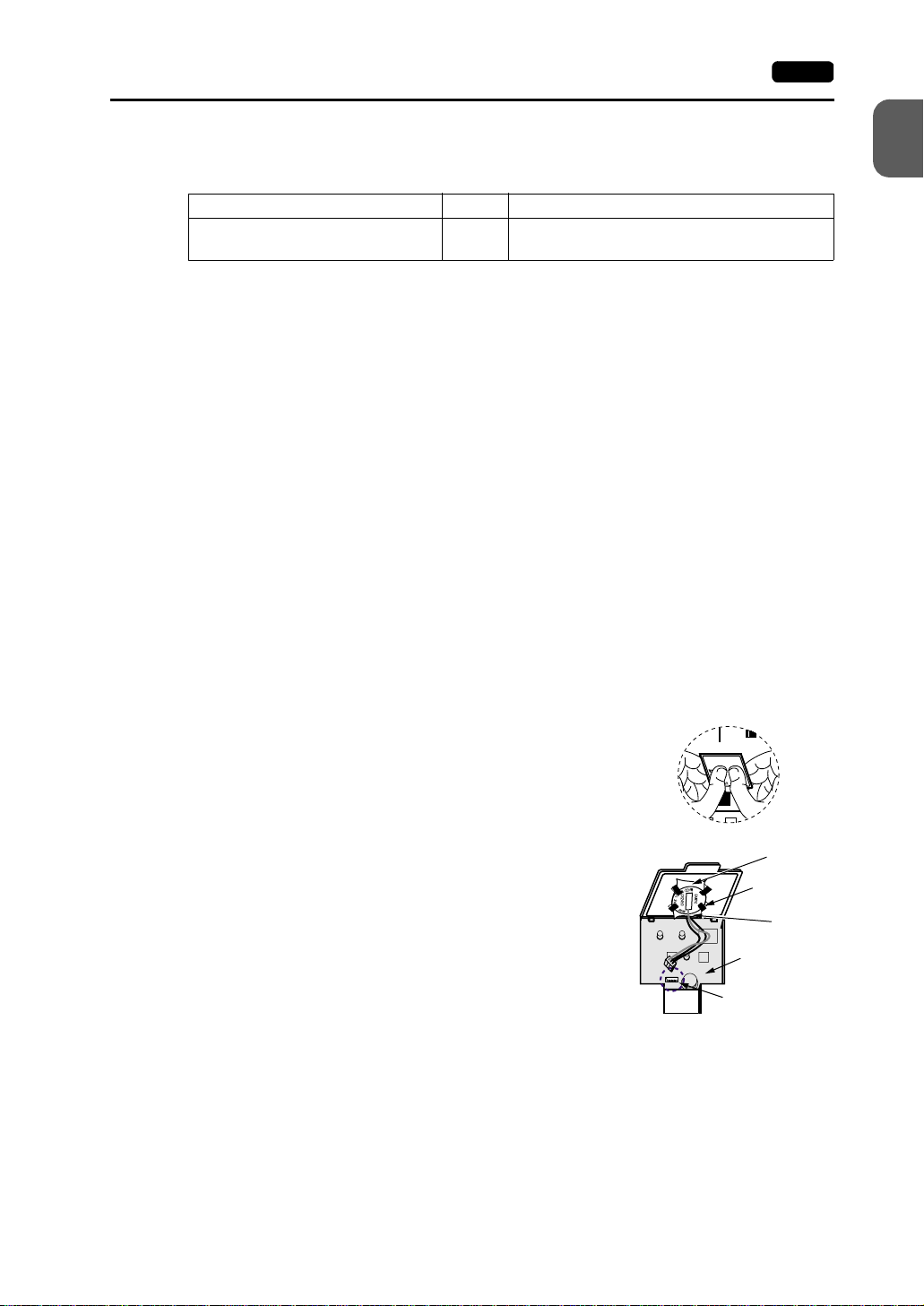
9. Coin-type Lithium Battery 1-25
Battery Replacement Procedure
Replacement batteries are available from Hakko Electronics.
Name Type Contents
Replacement battery for the V7 series V7-BT • Coin-type lithium primary cell (Sanyo) 1 pce
1. Replace the battery “V7-BT” within three minutes after the V7 unit is turned off. If it is
not possible to replace within three minutes, use the V-SFT editor (cable: V6-CP) or a
CF card and make a backup copy of data in the SRAM cassette.
• When using the V-SFT editor:
1) Start the V-SFT editor.
2) Click the [Transfer] icon. The [Transfer] dialog is displayed.
3) Select [Display] for [Transfer Device], and [SRAM Data] for [Transfer Data]. To
save a backup copy from the V-SFT editor on the server via Ethernet, check
[Transfer through Ethernet/IP Address of the V7 Equipped with SRAM]. Keep
[Use Simulator] and [Read Comments in Data Transfer] unchecked.
4) Click the [PC ←] under [Transfer Mode].
5) Save the read data in the “*.RAM” file.
• When using a CF card:
For the backup procedure with a CF card, refer to “Chapter 2 MONITOUCH
Operations.”
1
Hardware Specifications
• Cautions sticker 1 pce
2. Turn the unit off, and open the battery holder. A battery is set at the socket.
3. Unplug the battery connector, and remove the battery
from the socket. When removing the battery, push the
center of the battery holder cover as shown on the right.
4. Set a new batter y. Hold the battery wit h it s red cabl e si de
(marked with SANYO) facing towards the printed circuit
board and the cable h anging do wn, and i nsert t he batt ery
See operating or maintenance
instruction for type of battery
to be used.
Battery replacement.
Battery holder
MJ2
“b” side
Socket
into the socket. I ns ert the battery in the “a” side first, and
push it down to “a” while inserted in the “b” side.
5. Plug the battery connector and close the battery holder
cover.
“a” side
Printed circuit
board
Battery connector
6. Remove the existing caution sticker. Enter a date five years from now for “Battery
Replacement” on the new caution sticker, and attach it to the backside of the V7 unit.
7. When a RAM file is s aved i n step 1, turn t he V7 un it on a nd load the R AM fil e to the unit.
Page 43

1-26 10. DIP Switch Setting
10. DIP Switch Setting
DIP Switch (DIPSW) Setting
Set the terminating resistance for RS-422/485 connection with the DIP switch. When
setting the DIP switch, turn the power off.
- For V708/V708i: - For V710/V710i/V712/V712i:
Side View Rear View
CN5
DIP switch
CN6
MEMORY
CF
100-240VAC
L N
ON
12345678
MJ2 (modular jack 2) terminating resistance
CF auto load
Not used
CN1 RD terminating resistance at pins 24 and 25
MJ1 (modular jack 1) terminating resistance
* Set DIPSW2 to 5 (not used) to the OFF position.
Terminating Resistance Setting (DIPSW6, 7, 8)
• When connecting the PLC at CN1 via RS-422/485 interface, set DIPSW7 to the ON
position.
• For the following connections at modular jack 1 (2), set DIPSW 6 (DIPSW8) to the ON
position.
- Master station for multi-link 2 connection
- Temperature controller network/PLC2Way connection via RS-485
- Connection with the card recorder CREC (optional)
- Connection with the serial extension I/O V-I/O (optional)
- Connection to the V7 unit at the termination of V-link connection via RS-485
PRINTER
LAN
MJ1 MJ2
CN1
Page 44

10. DIP Switch Setting 1-27
CF Auto Load (DIPSW1)
A screen data file saved on a CF card can be auto-loaded as described below.
1. Transfer screen data from the computer to a CF card. (Refer to the Reference Manual
for more information.)
2. Set DIP SW1 in the ON position, and insert the CF card that contains the screen data
file.
3. Turn the V7 unit on. The screen data is automatically loaded into the FLASH memory
of the unit.
1
Hardware Specifications
Page 45

1-28 11. Serial Connector (CN1)
11. Serial Connector (CN1)
Serial Connector for PLC Connection
1. To communicate with the PLC (RS-232C, RS-422/485), connect the cable to the serial
connector (CN1) at the bottom of the V7 unit.
- For V708/V708i: - For V710/V710i/V712/V712i:
Bottom View Bottom View
2. The serial connector pins correspond to signals as given below.
CN1 (D-sub 25-pin, female) Pin No. Signal Name Contents
1 FG Frame ground
2 SD RS-232C send data
3 RD RS-232C receive data
4 RS RS-232C request to send
5 CS RS-232C clear to send
6 Not used
7 SG Signal ground
8 Not used
9 +5V Use prohibited
14
25
1
13
10 0 V Use prohibited
11 Not used
12 +SD RS-422 send data (+)
13 −SD RS-422 send data (−)
14 +RS RS-422 RS send data (+)
15 Not used
16 Not used
17 −RS RS-422 RS send data (−)
18 −CS RS-422 CS receive data (−)
19 +CS RS-422 CS receive data (+)
20 Not used
21 − Use prohibited (V708: not used)
22 − Use prohibited (V708: not used)
23 Not used
24 +RD RS-422 receive data (+)
25 −RD RS-422 receive data (−)
3. The following connector is recommended.
DDK-make 17JE23250-02 (D8A) D-sub 25-pin, female, metric thread, with hood
Page 46
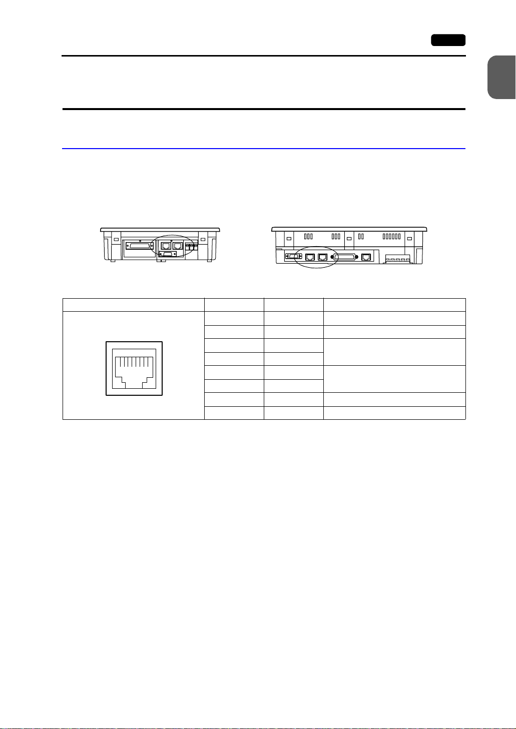
12. Modular Jack (MJ1/MJ2) 1-29
12. Modular Jack (MJ1/MJ2)
Modular Jack 1 (MJ1)/2 (MJ2)
1. This is a modular connector used for connection for screen data transfer, temperature
controller, barcode reader, card recorder (CREC) or serial extension I/O (V-I/O).
- For V708/V708i: - For V710/V710i/V712/V712i:
Bottom View Bottom View
2. Pins of modular jacks 1 and 2 correspond to signals as given below.
MJ1/2 Pin No. Signal Name Contents
1 +SD/RD RS-485 + data
12345678
2 −SD/RD RS-485 − data
3+5V
4+5V
5SG
6SG
7 RD RS-232C receive data
8 SD RS-232C send data
Externally supplied +5 V
MAX 150 mA
Signal ground
1
Hardware Specifications
Page 47

1-30 12. Modular Jack (MJ1/MJ2)
V-SFT Setting
1. The use of modular jacks 1 and 2 can be set on the V-SFT editor.
2. Select [Modular] from the [System Setting] menu. The [Modular Jack] dialog is
displayed. Select the use of modular jacks 1 and 2 from the following options.
Modular Jack 1 Modular Jack 2
[Editor Port]
[Memory Card]
[Barcode]
[V-I/O]
[Multi-Link]
[Temp. CTRL/PLC2 Way]
[V-Link]
[Touch Switch]
[Ladder Tool]
[Modbus Slave]
[Printer (Serial Port)]
*1
*3
*4
*5
*7
[Not used]
*2
[Memory Card]
[Barcode]
*4
[V-I/O]
[Multi-Link]
*6
[Temp. CTRL/PLC2Way]
[V-Link]
*8
*9
*10
*11
[Touch Switch]
[Ladder Tool]
[Modbus Slave]
[Serial Printer (Serial Port)]
*2
*3
*5
*6
*7
*8
*9
*10
*11
*1 Refer to the next section “Transferring Screen Data.”
*2 Select this option when connecting the card recorder (CREC).
*3 Refer to the next section “Barcode Reader Connection.”
*4 Select this option when connecting the serial extension I/O (V-I/O).
*5 Select this open when “Multi-link 2” is selected for [Connection] and “1” is set for [Local Port]
on the [Comm. Parameter] dialog.
*6 Select this option when connecting the temperature controller network or PLC2Way.
*7 Select this option for V-Link connection.
*8 Refer to “EU-01 (RGB input + sound output unit).”
*9 Select [Ladder Tool] when using the ladder transfer function with MITSUBISHI’s QnHCPU
port (Q mode) selected for the PLC type.
*10 Select this option for Modbus slave connection.
*11 Select this option when connecting the printer with serial interface. Refer to page 1-37.
Page 48

12. Modular Jack (MJ1/MJ2) 1-31
3. Do not select [Multi-link] and [Temp. CTRL/PLC2Way] for [Modular Jack 1/2] at the
same time.
• Combination of MJ1 and MJ2 Functions
O: Usable at the same time, : Usable from system program Ver. 1.010, ×: Not usable at the same time
MJ1
MJ2
MultiLink 2
CREC O OOOOOOO
BarcodeOO OOOOOO
V-I/O OOO OOOOO
Temp.
CTRL/PLC
2Way
V-Link OOOOO OOO
Touch
Switch
Ladder
Tool
Printer
(Serial Port)
Multi-
Link 2
OOOOOO OO
× OOOOOO O
OOOOOOOO
CREC Barcode V-I/O
OOO
OOO OOOO
Temp .
CTRL/PLC
2Way
V-Link
OO× O
Touch
Switch
Ladder
Tool
Printer
(Serial Port)
1
Hardware Specifications
Supplemental Remark: Multi-link communication and temperature control network/PLC2Way
can be used at the same time.
• Combination of Communication Unit (CU-xx) and Modular Jack Function
O: Usable at the same time, ×: Not usable at the same time
MJ
Multi-Link
Communication Unit
CU-00 OPCN-1 × OOOOOOOOO
CU-01 T-LINK × OOOOOOOOO
CU-02 CC-Link × OOOOOOOOO
CU-03 Ethernet (FL-net)
CU-04 PROFIBUS-DP × OOOOOOOOO
CU-05 MELSECNET/10 × OOOOOOOOO
CREC Barcode V-I/O
2
*1
OOOOOOOO×
*1 This is not possible when the V7 series and the PLC are connected via Ethernet.
Tem p.
CTRL/PL
C2Way
V-Link
Touch
Switch
Ladder
Tool
Printer
(Serial
Port)
Built-in
Ethernet
Page 49

1-32 12. Modular Jack (MJ1/MJ2)
Transferring Screen Data
• Use modular jack 1 (MJ1) when transferring screen data.
• When [Editor Port] is selected for [Modular Jack 1] on the V-SFT editor, it is possible to
transfer data in the RUN mode because the RUN/STOP mode (on the Main Menu
screen) can be automatically selected. Also RUN/STOP mode is automatically
selected for on-line editing and simulation.
• When an option other than [Editor Port] is selected for [Modular Jack 1], select the
STOP mode (on the Mai n Menu sc reen) and tran sfer screen d ata. Sim ulation or o n-line
editing is not available.
• When transferring screen da t a, use Ha kko Ele ctronics ’ dat a transf er cable (V6-CP) 3 m
to connect the V7 series to a personal computer.
Barcode Reader Connection
• It is possible to receive the signal from a barcode reader by connecting the barcode
reader at the modular jack (MJ1/2) of the V7 series.
• To connect a barcode reader to the modular
jack (MJ1/2), use Hakko Electronics’ optional
cable (V6 -BCD).
Length: 3 m
with modular plug
• Notes on Connection
- In the case of barcode readers with CTS and RTS control, it may be necessary to
install a jumper to RTS and CTS. Otherwise the barcode reader may not work
correctly.
- The external power supply (+5 V) is max. 150 mA. (Refer to page 1-29.)
12345678
Brown: +5V
Red: 0V
Orange: RXD
Yellow: TXD
• When using the barcode reader that was connected to V4 (MONITOUCH’s old version),
connect it to the D-sub 9-pin female connector using the V6-BCD cable as shown
below.
CTS
RXD
TXD
RTS
SG
12345678
Orange:RXD
Yellow: TXD
* Install a jumper between
CTS and RTS.
Red: 0 V
Signal
Name
RTS
TXD
RXD
CTS
SG
+5V
D-sub 9-pin (female)Barcode reader
Pin No
Signal
Name
1
2
3
4
5
6
7
8
+5V
Brown: +5 V
9
Page 50

13. 10BASE-T (LAN) 1-33
13. 10BASE-T (LAN)
The connector for 10BASE-T is provided as standard on V7i (high-performance). To
connect Ethernet with V7 (standard), use the communication unit “CU-03.” If CU-03 is
attached to V7i, it has priority over the built-in 10BASE-T; 10BASE-T cannot be used.
10BASE-T Connector
• Use this connector for Ethernet connection.
- For V708i: - For V710i/V71 2i:
Side View Bottom View
1
Hardware Specifications
CAUTION
• The LAN (10BASE-T) pins correspond to signals as given below.
12345678
MJ1/2 and LAN co nnector a re 8-pin modular jacks. Check th e nam e plate an d
insert the connector in the correct position.
LAN Pin No. Signal Name Contents
1 TX+ Ethernet send signal (+)
2 TX- Ethernet send signal (−)
3 RX+ Ethernet receive signal (+)
4 NC Not used
5 NC Not used
6RX− Ethernet receive signal (−)
7 NC Not used
8 NC Not used
Page 51

1-34 13. 10BASE-T (LAN)
Notes on Wiring
CAUTION
When using the LAN port, keep the LAN cable away from the power supply
cable as much as possible.
PLC
Ethernet
unit
HUB
UTP cable
Straight
CU-03
UTP cable
Straight or cross cable
(For more information, refer the HUB specifications.)
V7iV7
Node
Distance between the node and the HUB: 100 m maximum
Maximum network nodes: 100 sets
Cable Connection Diagram
Straight cable (with HUB) Cross cable (without HUB)
10BASE-T
RJ-45 8Pin
1
2
3
6
4
5
7
8
10BASE-T
RJ-45 8Pin
1
2
3
6
4
5
7
8
10BASE-T
RJ-45 8Pin
1
2
3
6
4
5
7
8
HUB
Node
10BASE-T
RJ-45 8Pin
3
6
1
2
5
4
8
7
* Unshielded twist-pair cable * Unshielded twist-pair cable
Notes on Cables
Use the following recommended cable.
Recommended cable (10BASE-T)
Type: Twist-pair cable, cat egory 5
Page 52

14. CF Card (CF) 1-35
Side Vi
Side Vi
14. CF Card (CF)
Recommended CF Card
CF cards in compliance with CompactFlashTM can be used. The following card is
recommended.
Manufacturer Type Capacity
TDK TC032HS 32 MB
Kodak KPCN-32 32 MB
SanDisk SDCFB-64-505 64 MB
I-O Data Devic e
Mounting and Dismounting the CF Card
1. The CF card interface is provided on the side of the unit.
- For V708/V708i: - For V710/V710i/V712/V712i:
PCCF-H128MS 128 MB
PCCF-xxxMS (xxx: 16, 32, 48, 64, 96, 128, 192) 16 to 192 MB
ew
1
Hardware Specifications
ew
2. Insert the card securely into the interface with the card backside outwards viewed from
the rear of the unit as shown below.
When the card is
inserted, the eject
button pops out.
CF
MJ2
PRINTER
●使用上の注意●
的に取りましょう。
を避けてご使用ください。
高温・多湿・強い衝撃・磁力
データのバックアップは定期
MJ2
Card backside
CF
PRINTER
3.
3. To remove the card, pre s s the eject button. The card pops out.
Page 53

1-36 14. CF Card (CF)
Notes on Handling the CF Card
1. Do not insert or remove the CF card during access. Doing so may destroy data on the
CF card. The CF card can be inserted or removed safely when the Main Menu screen
is displayed. However, if the [Card Menu] switch is pressed on the Main Menu screen
and the CF card operation sc ree n is dis pl ay ed, it is not p os sib le to ins ert or remov e the
CF card. Before mounting or removing the CF card, be sure to check that the CF card
is not being accessed.
2. Do not turn the power off or on during access to the CF card.
3. Make a backup copy of the CF card at regular intervals.
4. If a disk error occurs and data read/write operation is disabled, perform a scan disk on
Windows and try to restore the disk. If not restored, initialize the CF card. (For
information on scan disk and Windows operations, refer to the manual for Windows.)
5. The number of writing times per CF card is limited (approx. 300,000 times).
Consequently , frequent writi ng at short in tervals may s horten service l ife of the CF ca rd.
To use the CF card for s aving sampl ing dat a, ch eck the sett ing for sam pling ti me. Also ,
avoid repeated writing using a CYCLE macro command.
Page 54

15. Printer Connection (PRINTER) 1-37
15. P rinter Connection
(PRINTER)
When the V7 series is connected to a printer, a screen hard copy, data sheet or sampling
data can be printed. To connect a printer with parallel interface, insert the cable into the
printer connector (PR INTER ); to c onn ect a pri nte r w it h s eri al in terfa ce , i ns ert the ca bl e i nto
a modular jack (MJ1/MJ2).
CAUTION
Printer Connector (PRINTER)
• This is the printer connector for parallel interface.
Be sure to turn the printer off when the V7 unit is turned off.
- For V708/V708i: - For V710/V710i/V712/V712i:
Bottom View Bottom View
1
Hardware Specifications
• The printer interface pins correspond to signals as given below.
PRINTER (half-pitch 20-pin) Pin No. Signal Name Contents
1 STB# Strobe
2 PD0 Data 0
3 PD1 Data 1
4 PD2 Data 2
5 PD3 Data 3
6 PD4 Data 4
11 20
110
7 PD5 Data 5
8 PD6 Data 6
9 PD7 Data 7
10 GND
11 BUSY# Busy
12 GND
13 SELECT
14 INTP# INP PROME#
15 PFAT# FAULT#
16 GND
17 GND
18 P+ 5V PRN+5
19 GND
20 GND
Page 55
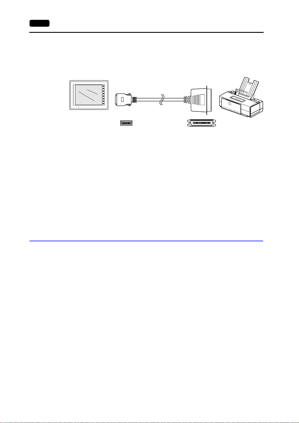
1-38 15. Printer Connection (PRINTER)
Connecting Cable
• To connect the V7 series to a printer, use Hakko Electronics’ printer cable “V7-PT” 2.5
m for 20-pin parallel interface.
V7 series Printer
SYSTEM
F1
F2
F3
F4
F5
F6
POWER
F7
V7-PT
Half-pitch, 20-pin Centronics, 36-pin
Compatible Printer Models
Control code system:
• NEC PC-PR201 series compatible with MS-DOS computer
• EPSON ESC/P24-J84, ESC/P-J84, ESC/super function compatible with
MS-DOS computer
• CBM292/293 CBM’s line thermal printer (Screen hard copying is not possible.)
Barcode printers:
(It is not possible to print a screen hard copy, data sheet or sampling data.)
• MR400 Sato’s barcode printer “MR400 series”
Connection with Printer through Serial Interface
• To connect a printer through serial interface, connect the cable to a modular jack
(MJ1/MJ2).
• Refer to the specification sheet of the printer to be used for the connecting cable for
serial interface. For information on MJ1/MJ2 signals, refer to page 1-29.
• When two printers are c onnec ted th rough p ara llel i nterfac e and serial interfa ce, th e one
connected to MJ1/MJ2 (refer to page 1-29 for the setting) takes precedence.
• Printer models and avail abl e pri nt functions are the sam e as tho se for p a ral lel interface.
Page 56

MONITOUCH Operations
1. Operation of V7 Main Menu
Initial Screen
1. Main Menu Screen
2. I/O Test
3. Card Menu Screen
4. Ethernet
5. SRAM/Clock
6. Extension Program Information
7. Extended Function Setting
2. Function Switches
Types
[SYSTEM] Switch
3. Errors Displayed on the V7 Series
1. Communication Error
2. Check
3. Warning
4. SYSTEM ERROR
5. Touch Switch is Active
Page 57

Page 58

1. Operation of V7 Main Menu 2-1
1. Operation of V7 Main
Menu
Initial Screen
When the power of MONITOUCH is turned on for the first time, the Main Menu screen
shown below on the left is displayed.
Initial screen displayed when power is
turned on for the first time
Transferring Screen Data for the First Time
There are four methods for transferring screen data for the first time.
Main Menu screen after transferring screen data
Main Menu V710iTD
System Information
SYSTEM PROG. VER. 1.000
Screen Data
PLC Type : MITSUBISHIQnH(Q) series CPU
Information
Comment :
Size : 5783552
Multi-Link2
Multi-Link2
Own Stat. No. : 1
Own Stat. No. :
1
Total: 2
Total :
2
Retry : 10
Retry :
10
Baud Rate : 115200
Baud Rate :
115200
Editor:MJ1
FONT
VER.1.300 / 1.000 / 1.000
ENGLISH
Connection :
Signal Level :
PLC Stat. No. :
Ethernet Information
Trans.Speed :
Stat. No. :
PORT : 10000
MAC : 050FF000035
Multi-Link
RS232C
0
10BASE-T
192.168.1.68
2002-4 -1 07:23:30
I/F DRV VER.1.240
MELSEC QnH Q
CPU Port
Time-Out :
Baud Rate :
Data Length :
Stop Bit :
Parity :
Send Delay :
SRAM/Clock
Ethernet
Card
Menu
2
MONITOUCH Operations
Error :
Stop
1.00 sec
Retry :
3
19200
8
1
Odd
0msec
2
Extension
RGB
Adjustment
I/O Test
• Transferring screen data via the V6-CP cable
Transfer screen data while the initial screen is displayed.
• Transferring screen data using the CF card or the memory card and the card recorder
(CREC)
1) Connect the personal compute r with the card recorder and s ave sc ree n da ta on the
memory card.
2) Insert the CF card into the V7 unit or connect the card recorder and insert the
memory card into the card recorder.
3) Press the [CF Card (English)] switch. The “Card Menu”
screen is di splayed.
4) Follow the instructions as described in “Card Menu Screen”
(page 2-11) and transfer screen data.
• Transferring screen data via Ethernet
1) Press the [IP Address (English)] switch.
2) The “Ethernet” screen is displayed.
3) Follow the instruc tions as de scribed i n “Etherne t” (p age 2-24)
and set the IP address.
4) Press the [Setting Finished] switch. The initial screen displayed again.
5) Transfer screen data from the computer via Ethernet.
Page 59
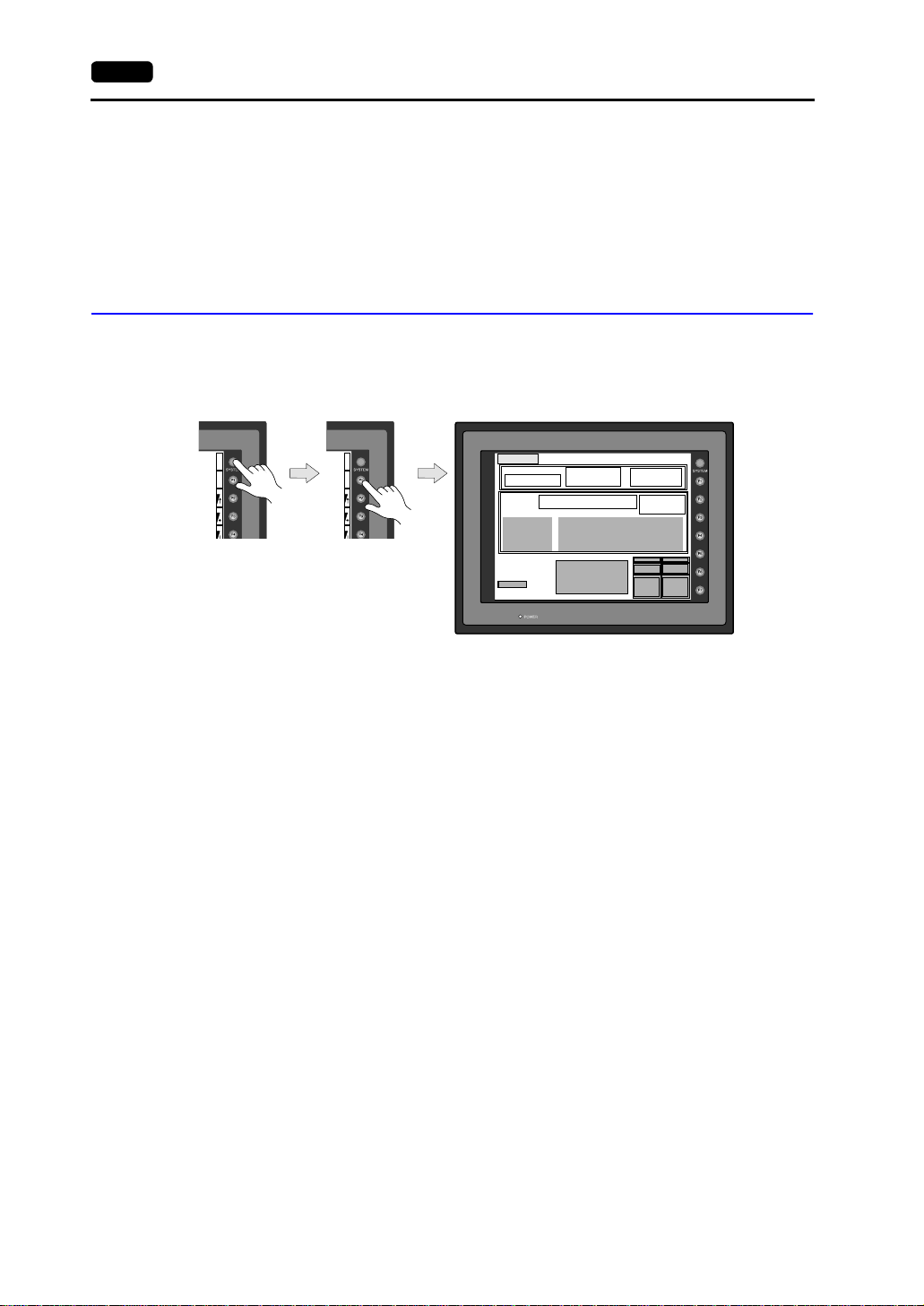
2-2 1. Operation of V7 Main Menu
• Auto-uploading screen data from the CF card to the V7 unit
1) Transfer screen data from the computer to a CF card.
2) Turn the V7 unit off. Set the DIPSW1 on the V7 unit to the ON position, and insert
the CF card.
3) Turn the V7 unit on. The screen data is automatic ally up loaded from the CF ca rd to
the V7 unit.
1. Main Menu Screen
• To bring up the Main Menu screen in the RUN mode, press the [SYSTEM] switch and
the [F1] switch.
Main Menu screen
S
Y
S
T
E
M
M
O
D
E
BR
BR
BR
B
A
C
K
L
T
S
Y
S
T
E
M
M
O
D
E
BR
BR
BR
B
A
C
K
L
T
Main Menu V 71 0 iT D
System Information
SYSTEM PROG. VER. 1.000
Screen Data
PLC Type : MITSUBISHIQnH(Q) series CPU
Information
Comment :
Size : 5111808
Multi-Link2
Own Stat. No. :
1
Total :
2
Retry :
10
Baud Rate :
115200
Editor:MJ1
FONT
VER.1.300 / 1.000 / 1.000
ENGLISH
Connection :
Signal Level :
PLC Stat. No. :
Ethernet Information
Trans.Speed :
Stat. No. :
PORT : 10000
MAC : 050FF000035
Multi-Link
RS232C
0
10BASE-T
192.168.1.68
2002-4 -1 07:23:30
I/F DRV VER.1.240
MELSEC QnH Q
CPU Port
Time-Out :
Baud Rate :
Data Length :
Stop Bit :
Parity :
Send Delay :
SRAM/Clock
Ethernet
Card
Menu
Error :
Stop
1.00 sec
Retry :
3
19200
8
1
Odd
0msec
2
Extension
RGB
Adjustment
I/O Test
• The Main Menu screen indicates the V7 series model, system information, and screen
data information.
• The Main Menu screen is the syst em menu scre en for trans ferring scre en data between
a personal computer an d the V7 s eries. When trans ferring scre en da ta from a pers onal
computer to the V7 series, this Main Menu screen must be displayed. (However, if
[Editor Port] is selected for [Modular Jack 1] or on-line editing is used, it is not
necessary to bring up this screen.)
Page 60

1. Operation of V7 Main Menu 2-3
V7 series model
Main Menu V710iTD
System program version
Screen memory
Multi-link 2 or multi-link
setting
* Displayed wh en [Multi Li nk] or
[Multi Link 2] is selected for
[Connection] on the [Comm.
Parameter] dialog
System Information
SYSTEM PROG. VER. 1.000
Screen Data
Information
Size : 5111808
Own Stat. No. :
Baud Rate :
Port name used for data
transfer
PLC model and file comment set
for the screen data file
Editor:MJ1
SRAM/Clock
Initializes SRAM and adjusts calendar
data. (See page 2-27.)
Ethernet
Sets the IP address. (See page 2-23.)
Card Menu
Transfers screen data between the CF
card and the V7 series. (See page 2-11.)
Multi-Link2
Total :
Retry :
Font data versions,
country/local/font
2002-4 -1 07:23:30
FONT
VER.1.300 / 1.000 / 1.000
ENGLISH
PLC Type : MITSUBISHIQnH(Q) series CPU
Comment :
Connection :
1
2
10
115200
PLC Stat. No. :
Trans.Speed :
PORT : 10000
MAC : 050FF000035
Multi-Link
Signal Level :
RS232C
0
Ethernet Information
10BASE-T
Stat. No. :
192.168.1.68
Ethernet setting
* Displayed for V7i or communication interface unit (CU-03)
I/F DRV VER.1.240
MELSEC QnH Q
CPU Port
Error : Stop
Time-Out : 1.00 sec
Retry : 3
Baud Rate :
Data Length :
Stop Bit :
Parity :
Send Delay :
SRAM/Clock
Ethernet
Card
Menu
19200
8
1
Odd
0msec
2
Extension
RGB
Adjustment
I/O Test
PLC I/F dri ver v ers ion
and model
Communication parameter
setting
Extension
Indicates the driver setting and parameter setting for temperature
controller/PLC2Way communication, ladder transfer function, Modbus slave
communication, etc. (See page 2-28.)
RGB Adjustment
Appears when the option unit EU-01 is provided. For more information, refer
to the instruction manual for the EU-01 option unit.
I/O Test
Checks the V7 interfaces and performs a touch switch test. (See page 2-4.)
2
MONITOUCH Operations
Page 61

2-4 1. Operation of V7 Main Menu
2. I/O Test
When the [I/O Test] switch on the Main Menu screen is pressed, the following “I/O Test”
screen appears. This screen is used to check that there is no problem with the V7
interfaces and touch switch operation.
Performs a printer interface check.
(See page 2-8.)
Moves back to the Main Menu screen.
(See page 2-2.)
Moves to the “Touch Switch” screen.
(See page 2-9.)
I/O Test
Ext. I/O Check
*1
Self-Loop Test
Please refer to the manual, "Hardware Specifications".
CTS
Self-Loop Test
RTS
NG OK
Performs a CN1/MJ1/MJ2 interface check.
(See page 2-5.)
*1 When the serial extension I/O (V-I/O) is connected, use this button to check that the V-I/O works
correctly. The [Ext. I/O Check] switch appears only when [V -I/O] is selected for a modular jack on
the V-SFT editor.
Printer Check
Communication Port
CN1
MJ1 RS485
MJ2
Main Menu
Switch Check
RS232C
SYS
F - 1
F - 2
F - 3
F - 4
F - 5
F - 6
F - 7
Performs a function switch test.
(See page 2-8.)
Page 62
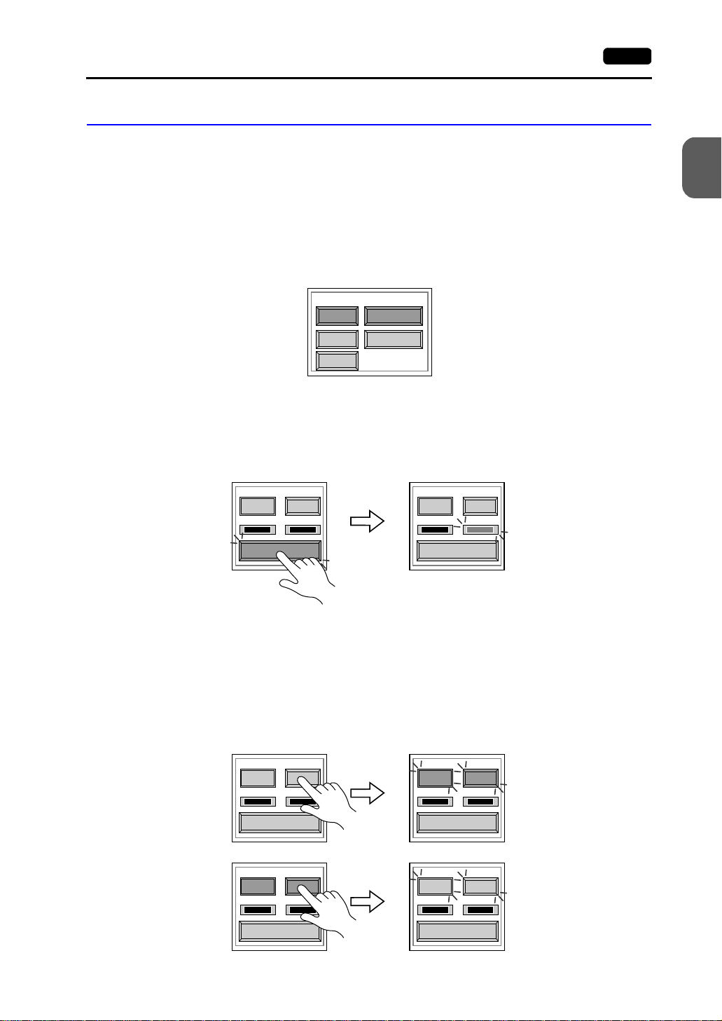
2-1. Self-loop Test
This is a signal test for communications through the CN1, MJ1 or MJ2 connector. Perform
this test if the commu nicat ion is not succe ssful when tran sfe rring scree n d ata t hrough M J1,
connecting the PLC using CN1, or selecting multi-link 2, temperature controller/PLC2Way
or PLC for MJ1/2, or connecting the card recorder or serial extension I/O.
CN1: RS-232C Signal Test
Turn the [CN1] and [RS232C] switches on.
• SD/RD Test
Check the signals [SD] and [RD].
1. Install a jumper between pins 2 and 3 of CN1 on the backside of the V7 unit.
2. Press the [Self-Loop Test] switch. When the [OK] lamp lights up, the test is
successfully completed.
Communication Port
CN1
MJ1 RS485
MJ2
RS232C
1. Operation of V7 Main Menu 2-5
2
MONITOUCH Operations
CTS RTS
NG OK
Self-Loop Test
* If the [NG] lamp lights up, consult your local distributor.
CTS RTS
NG OK
Self-Loop Test
• CTS/RTS Test
Check the signals [CTS] and [RTS].
1. Install a jumper between pi ns 4 (R TS) and 5 (CTS) of CN1 on t he backsid e of the V7
unit.
2. Press the [RTS] switch and check that both [RTS] and [CTS] lamps light up at the
same time. Press the [RTS] switch again and check that both [RTS] and [CTS]
lamps go off at the same time.
CTS RTS
NG OK
Self-Loop Test
CTS RTS
NG OK
Self-Loop Test
CTS RTS
NG OK
Self-Loop Test
CTS RTS
NG OK
Self-Loop Test
Page 63

2-6 1. Operation of V7 Main Menu
CN1: RS-485 Signal Test
Turn the [CN1] and [RS485] swi tches on.
• SD/RD Test
Check the signals [SD] and [RD].
1. Install a j um per be tw een p ins 12 an d 24 and between pin s 13 a nd 25 of CN1 on the
backside of the V7 unit.
2. Press the [Self-Loop Test] switch. When the [OK] lamp lights up, the test is
successfully completed.
Communication Port
CN1
MJ1 RS485
MJ2
RS232C
CTS RTS
NG OK
Self-Loop Test
CTS RTS
NG OK
Self-Loop Test
* If the [NG] lamp lights up, consult your local distributor.
• CTS/RTS Test
Check the signals [CTS] and [RTS] .
1. Install a jumper between pins 14 (+RTS) and 19 (+CTS) of CN1 and between pins
17 (−RTS) and 18 (−CTS) on the backside of the V7 unit.
2. Press the [RTS] switch and check that both [RTS] and [CTS] lamps light up at the
same time. Press the [RTS] switch again and check that both [RTS] and [CTS]
lamps go off at the same time.
CTS RTS
NG OK
Self-Loop Test
CTS RTS
NG OK
Self-Loop Test
CTS RTS
NG OK
Self-Loop Test
CTS RTS
NG OK
Self-Loop Test
Page 64

MJ1/2: RS-232C Signal Test
Turn the [MJ1] (or [MJ2]) and [RS232C] switches on.
1. Operation of V7 Main Menu 2-7
Communication Port
CN1
MJ1 RS485
MJ2
RS232C
• RS-232C Self-loop Test
Check the signals [SD] and [RD]. Connect the data transfer cable (V6-CP) to CN1 for
the test.
ADP25-9
V6-CP
CN1 MJ1/2
1. Set the adaptor ADP25-9 (attached to V6-CP) to the cable V6-CP. Connect the
modular jack side of the cable to MJ1 (or MJ2) and the ADP25-9 side to CN1.
2. Press the [Self-Loop Test] switch. When the [OK] lamp lights up, the test is
successfully completed.
CTS RTS
NG OK
Self-Loop Test
CTS RTS
NG OK
Self-Loop Test
2
MONITOUCH Operations
* If the [NG] lamp lights up, consult your local distributor.
MJ1/2: RS-485 Signal Test
If you would like to perform MJ1/2 RS-485 signal test, consult your local distributor.
Page 65

2-8 1. Operation of V7 Main Menu
2-2. Print Check
Check that the V7 series transmits the signals to the printer correctly.
1. Connect the V7 series to the printer.
2. Press the [Printer Chec k] sw it ch . The test is succe ssful w hen a tes t page is printed out
without problem.
I/O Test
Ext. I/O Check
Printer Check
Example:
!"#$%&@ 0123456789 ABCDEFGHIJKLMNO
!"#$%&@ 0123456789 ABCDEFGHIJKLMNO
!"#$%&@ 0123456789 ABCDEFGHIJKLMNO
!"#$%&@ 0123456789 ABCDEFGHIJKLMNO
!"#$%&@ 0123456789 ABCDEFGHIJKLMNO
!"#$%&@ 0123456789 ABCDEFGHIJKLMNO
!"#$%&@ 0123456789 ABCDEFGHIJKLMNO
2-3. SYSTEM & Function Switch Test
Check operations of eight switches provided vertically on the right side of the V7 panel.
Press the switch, and check that the lamp on the screen lights up while the switch is held
down.
Main Menu
Switch Check
SYS
F - 1
F - 2
-
Page 66

2-4. Touch Switch Test
If a touch switch does n ot activat e at all or if an op eration is p erforme d without pr essing any
touch switch, check that the touch switches on the V7 panel are working properly.
1. Press the [Switch Check] switch. Grids appear on the screen as shown below.
1. Operation of V7 Main Menu 2-9
2
MONITOUCH Operations
X: Y:
Printer Check
Main Menu
Switch Check
SYS
F - 1
F - 2
F - 3
2. Press a position on the panel, and check that the pressed position turns white. The
white color means that the touch switch activates correctly. To move back to the “I/O
Test” screen, press the [F4] switch. To delete white dots press the [F5] switch.
X:348 Y:337
Return
Erase
Return
Erase
3. If a position different from the pressed position turns white, refer to “Touch Switch
Adjustment” on the next page and adju st the touc h swit ch pos iti on.
Page 67

2-10 1. Operation of V7 Main Menu
Touch Switch Adjustment
If a position different from the pressed position turns white on the touch switch test screen,
follow the steps described below to adju st the touch switch position.
1. Hold down the [SYSTEM] switch and press the [F2] switch on the touch switch test
screen. The “Touch Switch Adjustment” screen appears.
X: Y:
SYSTEM
F2
Return
Erase
2. Press on “1” that is fl as hin g at the corner on
the touch switch adjustment sc reen . When
the finger is released, a beep sounds and
the position is set. “2” flashes.
3. Press on “2” that is flashing at the corner.
When the finger is released, a bee p sou nd s
and the position is set. “3” flashes.
4. Press on “3” that is flashing at the corner.
When the finger is released, a bee p sou nd s
and the position is set. “4” flashes.
5. Press on “4” that is flashing at the corner.
When the finger is released, a bee p sou nd s
and the position is set.
3
Touch Switch Adjustment
Touch the flickering corner.
The last position you touched is the setting value.
12
Touch the flickering corner.
The last position you touched is the setting value.
12
Touch the flickering corner.
The last position you touched is the setting value.
12
3
Touch Switch Adjustment
3
Touch Switch Adjustment
4
Reset
Return
4
4
Fix
Fix
Fix
6. To re-set the positions, press the [F2]
switch and follow step 2 and later.
7. Press the [F1] switch. A long beep
sounds and the posi tions are determine d.
The touch switch te st sc r een is d is pla yed
again.
8. To cancel the setting, press the [F3]
switch. The touch switch test screen is
displayed again.
3
Touch Switch Adjustment
X: 986 Y: 984
Touch the flickering corner.
The last position you touched is the setting value.
12
4
Return
Fix
Reset
F1
F2
F3
Page 68

3. Card Menu Screen
When the [Card Menu] switch on the Main Menu screen is pressed, the following “Card
Menu” screen appears. Thi s sc ree n is used to tra ns fer sc ree n data between the V7 serie s
and a CF card or a memory card.
Moves back to the Main Menu screen or the initial screen.
1. Operation of V7 Main Menu 2-11
2
MONITOUCH Operations
Card Menu
1.
2.
3.
CREC Menu
Data Selection
Screen Data
SRAM
Transfer Menu
Display
Display
Display
Return
Card
Card
Card
1. [CREC Menu] switch
Press this switch w hen c onnec ting t he car d reco rder to t he MJ p ort of th e V7 s eries and
transferring screen data between the V7 series and a memory card.
2. [Screen Data] switch
Press this switch when transferring screen data between the V7 series and a CF card.
3. [SRAM] switch
Press this switch when saving backup copies of the SRAM memory or V7EM-S (SRAM
cassette) or when uploading the backup data from the CF card to the V7 series.
Page 69

2-12 1. Operation of V7 Main Menu
3-1. CREC Menu Screen
When the [CREC Me nu] switc h on the “Ca rd Menu” s creen is pressed , the f ollowing “CR EC
Menu” screen appears. This screen is used to transfer screen data between the V7 series
and a memory card. The procedure for transferring data is described below.
CREC Menu
Port Selection
Modular Jack
MJ1
Data Selection
Screen Data Font Data
I/F Driver Sys. Program
Display
Display
Display
Return
Transfer
Card
Card
Card
Start
Cancel
1. Connecting the CREC
Check on the “Port Selection” field that the CREC cable (CREC-CP) is connected to a
modular jack port.
• MJ1: Connect the CREC to the MJ1 port. Normally MJ1 is
selected.
• MJ2: Connect the CREC to the MJ2 port. Only when
Port Selection
Modular Jack
MJ1
[Memory Card] is selected for [Modular Jack 2], “MJ2”
is indicated in the “Port Selection” field.
2. Mounting the Memory Card
Insert a memory card into the card recorder (CREC).
Page 70

1. Operation of V7 Main Menu 2-13
3. Memory Card Information
Press the [Modular Jack MJ1 (MJ2)] swi tch. The me mory ca rd info rmatio n con tai ned in
the inserted memory card is indicated. Switches in the “Data Selection” field and
“Transfer” field become active.
Port Selection
Modular Jack
MJ1
CREC Menu
Memory-Card Information
Sys. Program
Version
Font Date
Version
I/F Driver
Version
Screen PLC Type
Screen Comment
:
: -.--:
: -.--- / -.--- / -.--: YOKOGAWA FA
: 1.250
: YOKOGAWAFA-M3
:
Data Selection
Close
Transfer
Display
Display
Display
4. Data Selection and Transfer Selection
In the “Transfer” field, select [Display <-- Card], [Display --> Card] or [Display <-->
Card]. Press the desire d switch to turn the sw itch on. Multiple switche s can be pr essed
in the “Data Selection” field.
Data selection Transfer selection
2
Return
MONITOUCH Operations
Card
Card
Card
CREC Menu
Memory-Card Information
Sys. Program
Version
Font Date
Version
I/F Driver
Version
Screen PLC Type
Screen Comment
:
: -.--:
: -.--- / -.--- / -.--: YOKOGAWA FA
: 1.250
: YOKOGAWAFA-M3
:
Data Selection
Screen Data Font Data
I/F Driver Sys. Program
Close
Display
Display
Display
Transfer
Start
Cancel
Return
Card
Card
Card
CREC Menu
Memory-Card Information
Sys. Program
Version
Font Date
Version
I/F Driver
Version
Screen PLC Type
Screen Comment
:
: -.--:
: -.--- / -.--- / -.--: YOKOGAWA FA
: 1.250
: YOKOGAWAFA-M3
:
Data Selection
Screen Data Font Data
I/F Driver Sys. Program
Close
Display
Display
Display
Return
Card
Card
Card
Start
Cancel
Page 71

2-14 1. Operation of V7 Main Menu
5. Starting Data Transfer
Press the [S tart] swit ch. Dat a t ransfer i s st arted. Du ring data transfer, the [S t art ] switch
changes i nto [Busy] and flashes. When data is transferred, the following message is
displayed.
CREC Menu
Memory-Card Information
Sys. Program
Version
Font Date
Version
I/F Driver
Version
Screen PLC Type
Screen Comment
:
: -.--:
: -.--- / -.--- / -.--: YOKOGAWA FA
: 1.250
: YOKOGAWAFA-M3
:
Data Selection
Screen Data Font Data
I/F Driver Sys. Program
Close
Display
Display
Display
Start
Cancel
Return
Card
Card
Card
CREC Menu
Memory-Card Information
Sys. Program
Version
Font Date
Version
I/F Driver
Version
Screen PLC Type
Screen Comment
:
: -.--:
: -.--- / -.--- / -.--: YOKOGAWA FA
: 1.250
: YOKOGAWAFA-M3
:
Data Selection
Screen Data Font Data
I/F Driver Sys. Program
Close
Display
Display
Display
Return
Card
Card
Card
Start
Cancel
CREC Menu
Memory-Card Information
Sys. Program
Version
Font Date
Version
I/F Driver
Version
Screen PLC Type
Screen Comment
Work normally finished.
:
: -.--:
: -.--- / -.--- / -.--: YOKOGAWA FA
: 1.250
: YOKOGAWAFA-M3
:
Data Selection
Screen Data Font Data
I/F Driver Sys. Program
Close
OK
Display
Display
Display
Return
Card
Card
Card
Start
Cancel
Press the [OK] switch.
6. Press the [Close] switch. The “Card Menu” screen is displayed again.
Page 72

1. Operation of V7 Main Menu 2-15
3-2. Transferring Screen Data from a CF Card
CF Card Folder Configuration
Folders in the CF card are configured as shown below.
*1 *2
Folder Name Folder Name File Name
CF card
AAAAAAAA
BBBBBBBB
FFFFFFFF
*1 These are access folders set by the
V-SFT editor. Any folder name within
eight 1-byte characters can be given.
*2 These folders are automatically created
when access folders are created. The
folder name cannot be changed.
*3 The folder name for screen data auto
uploading cannot be changed.
*3
DSPDEF
DAT0000 (access folder)
Folder Name Contents F older Name Contents
BITMAP Saves pattern data (bitmap data) to
RECIPE Reads and writes recipe data.
reduce the screen data capacity.
CARD Write recipe data from the V7 series
SAMPLE Saves history data of the data logging
using the V6-compatible memory
manager function.
DSP Reads and writes screen data. SNAP Saves video snap images.
FONT Saves Gothic fonts or language data
SRAM S aves backup data of SRAM.
to reduce the screen data capacity.
HDCOPY Writes hard copy images in the JPEG
WAV Saves WAV files for sound output to
file format from the V7 series (for
V708C: BIN file).
JPEG Saves JPEG files for display on the
WEBSERV Saves files to be accessed from the
screen (except for V708C).
MEMO Saves memo pad data drawn with the
V7 series.
DSP
CARD
SRAM
MEMO
RECIPE
SAMPLE
HDCOPY
BITMAP
JPEG
SNAP
WAV
FONT
WEBSERV
DSP
Same as access folders
function.
reduce the screen data capacity.
Web browser.
DSP0000.BIN
MCMHEAD.BIN
MCMxxxx.BIN
SRM0000.BIN
MEMxxxx.BIN
RECxxxx.CSV
SMPxxxx.BIN
SMPxxxx.CSV
HDxxxx.JPG
HDxxxx.BIN
BMPxxxx.BIN
xxxx.JPG
JPxxxx.JPG
VDxxxx.JPG
WAxxxx.WAV
xxxx.FTD
xxxxxxxx.SHT
xxxxxxxx.HTML
xxxxxxxx.TXT
DSPDEF.BIN
2
MONITOUCH Operations
DSPDEF (screen data auto upload folder)
Folder Name Contents
DSP Automatically reads screen data in this folder when the CF card is inserted in the V7 unit after
the DIP switch is set.
(Other folders are the same as access folders.)
Page 73

2-16 1. Operation of V7 Main Menu
Transferring Screen Data from a CF Card
The procedure of transferring data between the V7 series and a CF card is described
below.
1. Mounting the CF Card
Insert the CF card into the CF card connector at the side of the V7 unit.
* Do not remove or insert the CF card in the later steps.
2. Data selection
Select [Screen Data]. When the lamp is red, it is selected.
3. Transfer selec tio n
Select [Display <-- Card], [Display --> Card] or [Display <--> Card].
Card Menu
CREC Menu
Data Selection
Screen Data
SRAM
Transfer Menu
Display
Display
Display
Return
Card
Card
Card
Data selection Transfer selection
When [Display <-- Card] is Selected:
Transfer screen data from the computer to the CF card.
1. When [Display <-- Card] is selected, the “Card Transfer” screen is displayed.
Flashes during communication with the CF card.
Card Transfer
CF Card File Infomation
DSP0000.BIN 2002-03-20 10:58:56
Sys. Program
Version
Font Date
Version
I/F Driver
Version
Screen PLC Type
Screen Comment
Access
: V710/V712
: 1.010
: ENGLISH
: 1.300 / 1.010 / 1.000
: GENERAL
: 1.240
: GENERAL
:
Folder Name: AAAAAAAA
Rest Size: 29437KB
Select Folder
Display
Card
Select Data
Return
Card Menu
CREC Menu
Data Selection
Screen Data
SRAM
Transfer Menu
Display
Display
Display
Return
Card
Card
Card
Indicates the name of the currently selected
folder. The access folder that is set for
screen data defaults. If there is no screen
data, “DAT0000” defaults.
Indicates the free space in the CF card.
Used for checking or renaming folder
names.
Starts transferring data [Display <-- Card].
Moves back to the previous screen.
Indicates the information of the currently selected folder.
Page 74

1. Operation of V7 Main Menu 2-17
2. Check the folder name, free space, and CF card file inform ati on. If the co rrec t folder is
selected, move to step 4.
• Folder Name
Indicates the name of th e c urre ntly s ele cte d fo lde r. The acce ss fol der that is set for
screen data defaults. If there is no screen data, “DAT0000” defaults.
2
• Rest Size
Indicates the free space in the CF card.
• CF Card File Information
Indicates the information of the currently selected folder.
3. To change to another folder, press the [Select Folder] switch. The “Select Folder”
screen is displayed.
Select Folder
Folder Name: AAAAAAAA
Folder
Selection
AAAAAAAA
BBBBBBBB
CCCCCCCC
Rest Size: 29437KB
Folder Detail
OK
Moves the cursor.
Indicates the details of the folder.
Determines the folder selection.
• Select the desired folder using the [↑] / [↓] switch, and press the [OK] switch. The
Card Transfer screen is displayed again and the CF card file information of the
selected file is indicated.
• To see the details of the folder, press the [Folder Detail] switch. The “Folder Detail”
screen is di splayed.
MONITOUCH Operations
Scrolls with the
[↑] / [↓] switch.
JPEG
SNAP
WAV
FONT
WEBSERV
Folder Detail
Folder Name : AAAAAAAA
DSP
CARD
SRAM
MEMO
RECIPE
SAMPLE
HDCOPY
BITMAP
Rest Size: 29437KB
DSP0000.BIN
Folder Selection
Moves the cursor.
Moves back to the
“Select Folder” screen.
Page 75

2-18 1. Operation of V7 Main Menu
4. Press the [Select Data] switch. The [Data Selection] window is displayed and the
[Select Data] switch changes to [Start].
Card Transfer
CF Card File Infomation
DSP0000.BIN
Sys. Program
Version
Font Date
Version
I/F Driver
Version
Screen PLC Type
Screen Comment
Access
2002-03-20
: V710/V712
: 1.010
: ENGLISH
: 1.300 / 1.010 / 1.000
: GENERAL
: 1.240
: GENERAL
:
10:58:56
Select the desired data, and press the [Select Data] switch.
Card Transfer
CF Card File Infomation
DSP0000.BIN 2002-03-20 10:58:56
Sys. Program
Version
Font Date
Version
I/F Driver
Version
Screen PLC Type
Screen Comment
Access
Data Selection
Select All
Screen Data
: V710/V712
I/F Driver
: 1.010
: ENGLISH
Font Data
: 1.300 / 1.010 / 1.000
: GENERAL
Sys. Program
: 1.240
: GENERAL
:
Folder Name: AAAAAAAA
Rest Size: 29437KB
Select Folder
Display
Card
Select Data
Return
Folder Name: AAAAAAAA
Rest Size: 29437KB
Select Folder
Card
Display
Return
Card Transfer
CF Card File Infomation
DSP0000.BIN
Sys. Program
Version
Font Date
Version
I/F Driver
Version
Screen PLC Type
Screen Comment
Card Transfer
CF Card File Infomation
DSP0000.BIN
Sys. Program
Version
Font Date
Version
I/F Driver
Version
Screen PLC Type
Screen Comment
2002-03-20 10:58:56
: V710/V712
: 1.010
: ENGLISH
: 1.300 / 1.010 / 1.000
: GENERAL
: 1.240
: GENERAL
:
Access
Access
Data Selection
Select All
2002-03-20 10:58:56
Screen Data
: V710/V712
: 1.010
I/F Driver
: ENGLISH
Font Data
: 1.300 / 1.010 / 1.000
: GENERAL
Sys. Program
: 1.240
: GENERAL
:
Access
Data Selection
Select All
Screen Data
I/F Driver
Font Data
Sys. Program
Folder Name: AAAAAAAA
Rest Size: 29437KB
Select Folder
Display
Card
Select Data
Return
Folder Name: AAAAAAAA
Rest Size: 29437KB
Select Folder
Display
Card
Select DataSelect Data
Return
To cancel the [Data Selection] window, press the [Return] switch.
5. During data transfe r, the [Start] switc h cha nges i nto [Bus y] and flash es. Wh en dat a h as
been transferred succ es sfu ll y, the fol low i ng window is displaye d. Ho w eve r, when [Sy s.
Program] or [Select All] is selected, the “Main Menu” screen is displayed without this
message window on completion of data transfer.
Work normally finished.
OK
Press the [OK] switch. The “Card Menu” screen is displayed. If any other message is
displayed, refer to page 2-23.
Page 76

When [Display --> Card] is Selected:
1. When [Display --> Card] is selected, the “Card Transfer” screen is displayed.
Flashes during communication with the CF card.
1. Operation of V7 Main Menu 2-19
2
Card Transfer
CF Card File Infomation
DSP0000.BIN
Sys. Program
Version
Font Date
Version
I/F Driver
Version
Screen PLC Type
Screen Comment
: V710/V712
: 1.010
: ENGLISH
: 1.300 / 1.010 / 1.000
: GENERAL
: 1.240
: GENERAL
:
Access
2002-03-20 10:58:56
Folder Name: AAAAAAAA
Rest Size: 29437KB
Display
Card
Start
Return
Indicates the name of the currently
selected folder.
Indicates the free space in the CF card.
Starts transferring data
[Display --> Card].
Moves back to the previous screen.
Indicates the information of the currently selected folder.
If there is no screen data, this field becomes blank.
2. Check the folder name and CF card file information, and press the [Start] switch.
* When the access folder name of screen data is the same as that in the CF card, the CF
card file information is indicated on the screen, and data in the V7 series overwrites the
CF card data. Note that the CF card data is lost when data in the V7 series overwrites.
When the CF card file information is blank, a new file “DSP0000.BIN” is created in the
DSP folder.
3. During data trans fer, the [Start] sw itch chang es in to [Busy ] and f lashe s. Whe n dat a has
been transferred successfully, the following window is displayed.
MONITOUCH Operations
Work normally finished.
OK
Press the [OK] switch. The CF card file information shows data that has been
transferred. If any other message is displayed, refer to page 2-23.
4. Press the [Return] switch. The “Card Menu” screen is displayed again.
Page 77

2-20 1. Operation of V7 Main Menu
When [Display <--> Card] is Selecte d :
1. When [Display <--> Card] is selected, the “Card Transfer” screen is displayed. Screen
data used for comparison is that in the DSP folder under the folder having the same
name as the access folder that is set by the V-SFT editor.
Flashes during communication with the CF card.
Card Transfer
CF Card File Infomation
DSP0000.BIN 2002-03-20 10:58:56
Sys. Program
Version
Font Date
Version
I/F Driver
Version
Screen PLC Type
Screen Comment
Access
: V710/V712
: 1.010
: ENGLISH
: 1.300 / 1.010 / 1.000
: GENERAL
: 1.240
: GENERAL
:
Folder Name: AAAAAAAA
Rest Size: 29437KB
Display
Card
Start
Return
Indicates the name of the currently
selected folder.
Indicates the free space in the CF card.
Starts transferring dat a
[Display <--> Card].
Moves back to the previous screen.
Indicates the information of the currently selected folder.
If there is no screen data, this field becomes blank.
2. Press the [Start] switch.
3. During data transfe r, the [Start] switc h cha nges i nto [Bus y] and flash es. Wh en dat a h as
been transferred successfully, the following window is displayed.
Work normally finished.
OK
Press the [OK] switch. If any other message is displayed, refer to page 2-23.
4. Press the [Return] switch. The “Card Menu” screen is displayed again.
Page 78

1. Operation of V7 Main Menu 2-21
3-3. Saving Backup Copies of SRAM
In this section, the procedure for saving backup copies of the SRAM memory or V7EM-S
(SRAM cassette) for battery replacement is explained.
1. Press the [SRAM] switch on the “Card Menu” screen. When the lamp is red, it is
selected.
2. Select [Display <-- Card], [Display --> Card] or [Display <--> Card].
Data selection Transfer selection
Card Menu
Return
Card Menu
2
MONITOUCH Operations
Return
CREC Menu
Data Selection
Screen Data
SRAM
3. The “SRAM Transfer” screen is displayed.
• When [Display --> Card] or [Display <--> Card] is selected, the following screen is
displayed. Sel ect th e CF c ard fo lder h aving the sa me n ame a s the a cces s fol der for
screen data i n the V7 series. The name is shown on the screen. The transferred
file is named as “SRAM0000.BIN.”
Flashes during communication
with the CF card.
SRAM Transfer
CF Card File Infomation
SRM0000.BIN
Access
2002-04-01 12:51:26
CREC Menu
Transfer Menu
Display
Display
Display
Card
Card
Card
Data Selection
Screen Data
SRAM
Indicates the name of the currently selected file.
Indicates the name of the currently
Folder Name:CCCCCCCC
Rest Size: 29954KB
selected folder.
Indicates the free space in the CF
card.
Transfer Menu
Display
Display
Display
Card
Card
Card
Display
Card
Start
Return
Starts transferring data
[Display --> Card].
Moves back to the previous screen.
Shows [Display <--> Card] when [Display <--> Card] is selected.
Page 79

2-22 1. Operation of V7 Main Menu
• When [Display <-- Card] is selected, the following screen is displayed.
Flashes during communication
with the CF card.
SRAM Transfer
CF Card File Infomation
SRM0000.BIN2002-04-01
Access
12:51:26
1) To change another folder, press the [Select Folder] switch. (The folder name
must be “SRAM0000.BIN.”)
2) The “Select Folder” screen is displayed as shown on page 2-17. Select the
desired folder (refer to page 2-17), and press the [OK] switch.
3) Moves back to the “SRAM Transfer” screen.
Indicates the name of the currently selected file.
Indicates the name of the currently
Folder Name:CCCCCCCC
Rest Size: 29954KB
selected folder.
Indicates the free space in the CF card.
Select Folder
Display
Return
Card
Start
Used for checking or renaming folder
names.
Starts transferring data
[Display <-- Card].
Moves back to the previous screen.
4. Starting Data Transfer
Check the folder na me , free sp ace a nd tra nsf er sel ectio n, pres s the [Start] s witch. Da ta
transfer is started.
5. Ending Data Tr ans fer
When data has been transferred successfully, the following window is displayed.
Work normally finished.
OK
Press the [OK] switch. If any other message is displayed, refer to the next page.
6. Pressing the [Return] switch moves back to the “Card Menu” screen.
Page 80

3-4. Messages during Data Transfer
1. Operation of V7 Main Menu 2-23
If an error occurs during data transfer, the
message window sho wn on the righ t is displa yed.
Data discrepant
OK
The kinds and the contents of the messages are shown below. The same messages are
used for the memory ca rd and CF c ard. Whe n usin g the CF c ard, the “memo ry card” in the
explanation should read as the “CF card.”
Messages Contents
Work normally finished. The specified operation has been concluded normally.
CREC not connecting CREC is not connecting when selecting a modular jack.
CREC Communication Error A communication error occurred between V7 and CREC when selecting a
Memory-Card not setting A memory card is not inserted.
Memory-Card Capacity over Cannot write the data into a memory card because the data size in V7 is
Write Protect: ON Cannot write data into a memory card because the write protect switch in
Writing Error occurred. The error occurred while writing data into a memory card.
Selected data does not exist. The data in the reading target does not exist.
V7 type is different. The specified type of the data in V7 is different from the type of the
Selected data can not be read. The data in a memory card cannot be read.
Reading Error occurred. The error occurred during writing data into a flash ROM of V7.
Data discrepant T here is some discrepancy in data, when comparing data between a
Screen data on V7 will be broken. W arning about data destruction in V7 that may occur when transferring the
Undefined Error occurred. The error occurred due to some cause other than mentioned above.
modular jack.
larger than the capacity of a memory card.
a memory card is ON.
memory card data.
memory card and V7.
font data larger than the present data from a memory card to V7. (The
[OK] switch continues transferring; the [Cancel] switch stops transferring.)
2
MONITOUCH Operations
Page 81

2-24 1. Operation of V7 Main Menu
*1
4. Ethernet
The “Ethernet” screen is displayed by pressi ng the [IP Addres s (Engl is h)] sw it ch on the
initial screen when transferring screen data via Ethernet for the first time, or by pressing the
[Ethernet] switch on t he Ma in Me nu screen w hen tr ansferri ng sc reen d ata to the V7 series .
This screen is used for setti ng the IP ad dress (a nu mber tha t ide ntifies th e V7 serie s on the
network) that is indispensable for Ethernet communications.
Depending on whether the LAN (10BASE-T) connector at V7i or the communication
interface unit CU-03 for V7 is used, the “Ethernet” screen contents and the required
settings vary as described below.
Connection with LAN (10BASE-T) Connector at V7i
Selects [Not Use Network Table] or [Use Network Table].
Moves back to the Main Menu screen or
Ethernet
Not Use Network Table
It is not used when the gate way or the sub-mask is zero.
IP Address:
Gate Way:
Sub-mask:
00 0
00000
Port No.
10000
000
Return
0
<-
->
the initial screen.
Cursor switches
[Increment/Decrement] switch for the value
in the cursor position
Connect
Used for checking the 10BASE-T interface.
Normal: Connect
Error: Disconnect
*1 Network Table
Register IP addresses and other information for the V series, PLCs or computers that should be
included for Ethernet communications on the V-SFT editor. ([System Setting]
→ [Ethernet] → Edit Network Table) The registered network table can be used or not
Setting]
used depending on the [Not Use Network Table/Use Network Table] switch.
Network table
number
Setting
Finished
Determines the setting such as IP address,
and moves back to the Main Menu screen.
→ [Network Table
Page 82

1. Operation of V7 Main Menu 2-25
Not Use Network Table
In the following cases, select [Not Use Network Table].
• Screen data is transferred for the first time via Ethernet.
• The network table is not set for screen data of the V7 series.
• If the network table is set for screen data of the V7 series but you would like to use an
IP address that is different from that se t on the network table te nt a tiv el y, pre ss th e [Us e
Network Table] switch to select [Not Use Network Table].
When the network table is not set or is not used
Not Use Network Table
It is not used when the gate way or the sub-mask
is zero.
IP Address:
Gate Way:
Sub-mask:
Port No.
00 0
00000
000
10000
: The cursor moves only in these sections for settings.
1. Set the IP address. (If necessary, set the default gateway and subnet mask.)
2. Press the [Setting Finished] switch. The IP address is determined.
3. The Main Menu screen is displayed again. (If the “Ethernet” screen is displayed from
the initial screen, the initial screen is display ed again.)
0
<- ->
2
MONITOUCH Operations
Use Network Table
In the following cases, select [Use Network Table].
• The network table is set for screen data of the V7 series and you would like to change
the network table number.
When the network table is used:
Use Network Table
It is not used when the gate way or the sub-mask
is zero.
IP Address:
Gate Way:
Sub-mask:
Port No.
Network Table No.:
Set the network table number.
00 0
00000
0
10000
0
1. Set the network table number.
2. Press the [Setting Finished] switch. The IP address is determined.
3. The Main Menu screen is displayed again.
0
00
<- ->
Indicates the contents of the selected
network table number.
Page 83

2-26 1. Operation of V7 Main Menu
Connection with CU-03 on V7
IP address, gateway and sub-mask settings
Ethernet
Moves back to the Main Menu screen.
Return
It is not used when the gate way or the sub-mask is zero.
IP Address:
Gate Way:
Sub-mask:
Connect
Port No.
00 0
0000
000
10000
0
0
10BASE-T
<- ->
Setting
Finished
Selects [10BASE-T] or [AUI].
Cursor switches
[Increment/Decrement] switch for the value
in the cursor position
Determines the setting such as IP address,
and moves back to the Main Menu screen.
Used for checking the 10BASE-T interface.
Normal: C onnect
Error: Disconnect
1. Select either [10BASE-T] or [AUI] for the connecting method.
2. Set the IP address. (If necessary, set the default gateway and subnet mask.)
3. Press the [Setting Finished] switch. The settings are determined.
4. The Main Menu screen is displayed again.
• Rotary Switch and Network Table
Register IP addresses and other information for the V series, PLCs or computers that
should be included for Eth ernet commu nications on the V-SFT editor. ([System Setti ng]
→ [Network Tab le Setti ng] → [Eth ern et] → [Edi t Netwo rk Table]) Set the ne twork t ab le
number with the rotary switch on the communication interface unit CU-03.
Port number to be set
with the rotary switch on
the communication
interface unit CU-03
Page 84

5. SRAM/Clock
• To use the built-in clock of the V7 series or to use the SRAM memory or cassette, it is
necessary to select [SRAM/Clock Setting] from the [System Setting] menu and make
the SRAM/clock setting. For the setting procedure, refer to the Reference Manual.
1. Operation of V7 Main Menu 2-27
2
• Be sure to set the battery when using the built-in clock of the V7 series or the SRAM
memory or cassette. With out battery, th e content s in the SRAM or clock da ta will no t be
retained. When t he battery i s not connec ted, the m essage “Batter y not set” i s displaye d
and the [SRAM/Clock] switch flashes on the Main Menu screen. Connect the battery
immediately. When the battery is to be replaced, the message “Brownout Battery” is
displayed.
2002-4 -1
I/F DRV VER.1.240
MELSEC QnH Q
CPU Port
Error : Stop
Time-Out : 1.00 sec
Retry : 3
Baud Rate :
Data Length :
Stop Bit :
Parity : Odd
Send Delay : 2
SRAM/Clock
Ethernet
Card
Menu
19200
8
1
0msec
07:23:30
Extension
RGB
Adjustment
I/O Test
[SRAM/Clock] switch
Indicates the message, such as
“Battery not set” or “Brownout Battery .”
Main Menu V 710iTD
System Information
SYSTEM PROG. VER. 1.000
Screen Data
Information
Battery not set
PLC Type : MITSUBISHIQnH(Q) series CPU
Comment :
Size : 5111808
Multi-Link2
Own Stat. No. : 1
Total : 2
Retry : 10
Baud Rate : 115200
Editor:MJ1
FONT
VER.1.300 / 1.000 / 1.000
ENGLISH
Connection :
Multi-Link
Signal Level : RS232C
PLC Stat. No. :
0
Ethernet Information
Trans.Speed : 10BASE-T
Stat.No. : 192.168.1.68
PORT : 10000
MAC : 0050FF000035
• When the [SRAM/Clock] switch on the Main Menu screen is pressed, the following
“SRAM/Clock Adjustment” screen appears. This screen is used for adjusting the
built-in calendar and for initializing the SRAM area.
MONITOUCH Operations
SRAM/Clock Adjustment
Date and Time Adjustment
Date:
Time:
Format of SRAM
Formats SRAM in the present screen data type.
Format Execute
2002-2-19 18 : 3 : 44
2002
219
:
17 18 0
Format Completed
Main Menu
:
Set
Built-in
V7EM-S mounted: Extension
V7EM-S not mounted: Built-in
The above is displayed.
Page 85

2-28 1. Operation of V7 Main Menu
Temp. Control / PLC2Way
Comm. Parameter
Date and Time Setting
1. Move the cursor using the [←] / [→] switch, and change the value by pressing the [+] /
[−] switch.
2. When the desired date and time are set , pres s the [Set] s w itc h to de term ine the s etti ng.
3. The calendar data is updated as set.
Initializing SRAM
When the SRAM memory or cassette is initialized, the data contained is cleared.
Double-check before initializing the SRAM memory or cassette.
1. “Extension” is shown when V7EM-S (SRAM cassette) is mounted; “Built-in” is shown
when it is not mounted.
2. Press the [Format] switch and the [Ex ecute ] switch. The SRAM area is initi alize d in the
current screen data format. When initialization has been completed, the message
“∗∗Format Completed∗∗” is displayed.
6. Extension Program Information
When the [Extension] swi tch on the Mai n Menu screen is pressed , the foll owin g “Extens ion
Program Info.” screen appears. The driver setting and parameter setting for temperature
controller/PLC2Way communication, ladder transfer function, Modbus slave
communication, etc. are displayed.
Extension Program Info.
Temp./PLC2Way Control Drv
VER. 1.100 RKC SR-Mini/CB
Editor:MJ1
Main Menu
Temp. Control / PLC2Way
Comm. Parameter
Signal Level : RS485
Baud Rate : 9600
Data Length : 8
Stop Bit : 1
Parity : None
Retry Time : 3
Time-out : 100 msec
Send Delay : 0 msec
Return Time : 10 sec
Page 86

7. Extended Function Setting
Retry : 10
E
8
Tras.Speed :
10BASE-
1
When the [Editor: MJ1] switch on the Main Menu screen is pressed, the following
“Extended Function Setting” screen appears. Set the baud rate to be used when
transferring screen data betw e en the V7 series and a modem.
1. Operation of V7 Main Menu 2-29
2
1. Select the desired b aud rate usin g the [↑] / [↓] switch, and press the [Setting Finished]
switch. (Setting range: 4800, 9600, 19200, 38400, 57600, 115200)
* The function switches and switches on the Main Menu screen are not valid for 15
seconds after the [Setting Finished] switch is pressed.
* When the [Setting Finished] switch is pressed, an AT command is automatically sent to
the modem and the baud rate used between the V7 series and the modem is set.
2. The Main Menu screen is displayed automatically, and “Modem Connect Mode” is
displayed below the [Editor: MJ1] switch.
3. To transfer screen data without a modem, select “Not used” for [Modem Comm. Baud
Rate]. To transfer screen data by connecting the V7 series and the computer via
V6-CP, select “Not used” for [Modem Comm. Baud Rate].
192.168.
Stat. No. :
Editor:MJ1
Pressing the [Editor: MJ1] switch brings up
the “Extended Function Setting” screen.
PORT : 10000
MAC : 050FF000035
Extended Function Setting
Modem Comm. Baud Rate: Not used
Up Down
Main Menu
Setting Value
Up
Down
Setting
Finished
MONITOUCH Operations
Pressing the [Setting Finished] switch
moves back to the Main Menu screen.
Baud Rate : 115200
Ethernet Information
Trans.Speed : 10BAS
Stat. No. : 192.16
Editor:MJ1
Modem Connect Mode
PORT: 10000
MAC: 0050FF000035
Page 87

2-30 2. Function Switches
2. Function Switches
Types
• There are eight function switches provided.
[SYSTEM], [F1], [F2], [F3], [F4], [F5], [F6], [F7]
[SYSTEM] Switch
The [SYSTEM] switch works in “alternate” operations. When this switch is pressed once,
the switch menu is displayed at the side of the function switches [F1] to [F5], and each
function switch corresponds to the menu item displayed in the switch menu. When the
[SYSTEM] switch is pressed again , the switch men u disapp ears, an d the funct ion switc hes
[F1] to [F7] work as defined by the user.
User-defined function switches
Function switches for switch menu selection
S
Y
S
T
E
M
M
O
D
E
BR
BR
BR
B
A
C
K
L
T
User-defined function switches
For V710T, V710iT, V710S, V710iS, V710iS, V712S and V712T
For V708S/V708iS: For V708C:
S
Y
S
T
E
M
M
O
D
E
B
A
C
K
L
T
S
Y
S
T
E
M
M
O
D
E
CT
CT
CT
B
A
C
K
L
T
Page 88

User-defined Function Switches [F1] to [F7]
• User-defined function switches [F1] to [F7] do not work in the STOP mode.
2. Function Switches 2-31
• When the V7 series is in the RUN mode and the switch menu by the [SYSTEM] switch
is not displayed, the function switches can be defined by the user.
• User-defined function switches should be set in the following dialogs of the V-SFT
editor.
- Settings for each screen
[Edit] → [Local Function Switch Setting] → [Function Switch Setting] dialog
- Setting for all screens
[System Setting] → [Function Switch Setting] → [Function Switch Setting] dialog
[F1] to [F5] Switch Functions with Switch Menu
Functions Contents
F1 Mode Selects the operation mode between STOP ↔ RUN.
Contrast Adjustment Brightness Adjustment
Adjust the contrast. Holding down
the switch for one second or more
changes the contract rapidly.
V708C
F2 F3 F4
Dark Medium Pale
[Unit Setting] → [Unit Setting] dialog, [Backlight] tab window)
• When the [F5] switch is pressed,
the backlight goes off even before
the setting OFF time is reached.
• This is valid when the backlight
control bit (bit 1 1) in t he read area
“n + 1” in the system memory is
reset (OFF: 0).
F2
Contrast
F3
Brightness
F4
F5 Backlight
Item
Applicable
models
Adjustment
Turn the backlight on and off.
Backlight control should be set on the V-SFT editor.
([System Setting] →
Always ON Auto 1/Auto 2 Manual/Manual 2
Ignored
Adjusts the screen brightness in
three levels.
V710T, V710iT, V710S, V710iS,
• The [F5] switch turns the
• [Backlight Power ON Time
V712S, V712T
*1
F2 F3
1
Bright2Medium
backlight on and off.
Control] that determines the
backlight status at power-up
becomes valid.
When the power is turned on:
ON → Backlight ON
OFF → Backlight OFF
The backlight will be in the
above status.
F4
Dark
3
2
MONITOUCH Operations
*1
*1 When a medium or dark brightness is set, the backlight service life may become shorter.
Page 89

2-32 3. Errors Displayed on the V7 Series
3. Errors Displayed on the
V7 Series
There are five kinds of error messages displayed on the V series:
1. Communication Error
2. Check
3. Warning
4. SYSTEM ERROR
5. Touch switch is active
1. Communication Error
* When you go to [Comm. Parameter],
bring up the [Detail] tab window and set
[Continue] for [Comm. Error Handling],
Communication Error
Time-Out
Screen No. : Received Code No. :
Retry
a screen like the one shown below is
displayed.
Communication Error
Time-Out
Error Message Contents Solution Remarks
Time-Out Although a request to send is given
to the PLC, no answer is returned
within the specified time.
Parity An error occurred in parity check. 1) Check the cables and wiring. 1
Framing Although the stop bit must be [1], it
is detected as [0].
Overrun After one character is received, the
next character is received before
internal processing is completed.
Check Code The check code in the PLC
response was not correct.
* If the above error messages are displayed on the V7 series without establishing
communication between V7 and PLC, test the solution of remark “1.”
If the error occurs suddenly in communication, test the solution of remark “2.”
1) Check the communication parameters.
2) Check the cables and wiring.
3) Data may be disrupted because of noise.
Fix noise.
2) Data may be disrupted because of noise.
Fix noise.
1) Check the communication parameters.
2) Check the cables and wiring.
3) Data may be disrupted because of noise.
Fix noise.
1) Check the communication parameters. 1
2) Data may be disrupted because of noise.
Fix noise.
1) Check the communication parameters. 1
2) Data may be disrupted because of noise.
Fix noise.
1
2
2
1
2
2
2
Page 90

3. Errors Displayed on the V7 Series 2-33
Error Message Contents Soluti on
Error code received An error code was sent to the
link unit by the CPU of the PLC.
Break The PLC’s SD (TXD) remains at
Invalid memory
(applicable to MITSUBISHI CPU)
Invalid CPU model
(applicable to MITSUBISHI CPU)
Format The code of the received data is
Compare
(applicable to HIDIC S10)
NAK
(applicable to Allen-Bradley PLC)
TNS discrepant
(applicable to Allen-Bradley PLC)
Communication Error An unclear communication error
Count error
(applicable to MITSUBISHI
CPU/Q link unit)
Command error
(applicable to MITSUBISHI
CPU/Q link unit)
Invalid cassette
(applicable to MITSUBISHI
ACPU)
Password error
(applicable to MITSUBISHI
QCPU)
the low level.
You specified an address that
exceeds the memory range of
the PLC that you are linked to.
The PLC currently being
supported does not have a
corresponding CPU.
invalid.
Transmission data and received
data are different.
A NAK code is received. Check 1, 2, 3 described below.
Transmitted TNS data and
received TNS data are not in
agreement.
is detected.
The expected data amount is
different from the count value.
The response code differs from
the expected code.
This cassette is not included in
the memory cassettes currently
being supported.
The password is incorrect. Contact your local distributor.
Examine the CPU error code and solve
the problem.
Examine the connection between the
PLC’s SD (TXD) and the V7’s RD (RXD).
Check the type and range of memory
that you set.
Confirm whether or not the CPU that you
are using can be used with the V Series.
Check 1, 2, 3 described below.
Check 1, 2, 3 described below.
Check 1, 2, 3 described below.
Check 1, 2, 3 described below.
Check 1, 2, 3 described below.
Check 1, 2, 3 described below.
Contact your local distributor.
2
MONITOUCH Operations
Solution
1. Confirm link unit settings. (After making settings, cut power to the PLC.)
2. Go to the editor (V-SFT) and confirm the settings in the [Comm. Parameter] dialog in
the [System Setting] menu.
3. If errors only occur from time to time, it is possible that there is a noise-based
communication error.
* If you still cannot solve the error even after following the suggestions above, contact your
local distributor.
Page 91

2-34 3. Errors Displayed on the V7 Series
Error Messages for Network Communication
• Ethernet
Error Message Contents Solution
Ethernet Error: XXXX The Ethernet status is saved at system
memory address $s518 and a code other
than “0” (normal) is received.
XXXX: Error No.
• MELSECNET/10
Error Message Contents Solution
I/F Board Err The I/F unit for NET/10 has an error. Contact your local distributor.
Request Code Err The request command from NET/10 has
an error.
Request Data Err The request data from NET/10 has an
error.
Word Writing to S p. Relay
(MITSUBISHI: A Series)
Word writing to a special relay (M9000
and later) is attempted.
(Notes: Only bit writing is possible for
special relays when connecting with
NET/10.)
For the contents and solution to each
error number, refer to “Chapter 4
Network Communications/Error Display.”
Do not attempt to perform word writing to
specia l r elays.
• CC-LINK
Error Message Contents Solution
I/F Board Err The I/F unit for CC-LINK has an error. Contact your local distributor.
No. of Occupy Setting Err The number of occupy in [Comm.
Parameter] is different from the number
of occupy by switches.
Network I/O Access Err MONITOUCH is about to access
exceeding the set number of input/output
words.
Station Number Err The port number set by a switch is not
within the setting range (1 to 64).
Word Writing to Sp. Relay Word writing to a special relay (M9000
and later) is attempted.
(Notes: Only bit writing is possible for
special relays when connecting with
CC-LINK.)
Check the setting of the number of
occupy.
Check the memory for the network I/O in
the screen data file.
Specify the port number within the setting
range.
Do not attempt to perform word writing to
specia l r elays.
Page 92

3. Errors Displayed on the V7 Series 2-35
• OPCN-1
Error Message Contents Solution
I/F Board Err The I/F unit for OPCN-1 has an error. Contact your local distributor.
Stat. No. out of range The port number set by a switch is not
Network Link Error Cannot connect to the master station in
Network I/O Access Err MONITOUCH is about to access
Waiting for Reply 1) Less than “Max_int” time
Word Writing to S p. Relay
(MITSUBISHI: A Series)
within the setting range (1 to 127).
the network.
exceeding the set number of input/output
words.
(communication monitoring time for
salve station) set on the PLC for
OPCN-1 communications
2) Timeout on the V-SFT editor
(The timeout time can be set from
[System Setting] → [Comm.
Parameter] on the V-SFT editor.)
This error is indicated when the above 1)
and 2) are present.
Word writing to a special relay (M9000
and later) is attempted.
(Notes: Only bit writing is possible for
special relays when connecting with
OPCN-1.)
Specify the port number within the setting
range.
Check the condition of the master station
(PLC). Check the network connection.
Check the memory for the network I/O in
the screen data file.
When the “Max_int” time is too long
(infinite, for example) on the PLC, it is not
possible to know whether or not the
response from the PLC is correctly
made. This error message disappears
when a response from the PLC is
received within the “Max_int” time.
Do not attempt to perform word writing to
special relays.
2
MONITOUCH Operations
• T-LINK
Error Message Contents Solution
T-LINK I/F Board Err The I/F unit for T-LINK has an error. Contact your local distributor.
Network I/O Access Err MONITOUCH is about to access
Access denied by Loader The PLC loader is being accessed so
Communication Error
Received Code No. 36
exceeding the set number of input/output
words.
that processing is not performed on V7.
(This error occurs during program
transfer from the PLC loader for most
cases.)
The number of monitor registration points
is too small.
Check the memory for the network I/O in
the screen data file.
Wait for the PLVC loader to finish
processing, and press the [RETRY]
switch on the V7 screen.
Correct the number of monitor
registration points. For monitor
registration, refer to the user manual of
the PLC you are using.
• PROFIBUS-DP
Error Message Contents Solution
Time-Out “Check” is displayed 2 or 3 seconds
before this error occurs when connecting
V7 and PROFIBUS-DP in the RUN
mode.
A screen is displayed instantaneously (=
communications performed) before this
error occurs when connecting V7 and
PROFIBUS-DP in the RUN mode.
The setting for [Own Stat. No.] on V7 is
discrepant with that for [Address] for [V7
series] on the SIMATIC Manager. Check
and correct the setting.
The DB address set on the V7 screen
may not exist on the PLC (memory over).
Check the setting.
Page 93

2-36 3. Errors Displayed on the V7 Series
2. Check
Error Message Contents Solution
Screen No. Error There is no setting for
the received screen.
Data has some error.
Error : XX (XX : XXX)
Check
Screen No. Error
There is an error in the
created screen data.
At the start of communications, the V7 series regards
the value in the read area “n + 2” as the screen
number. Check that this value is an existing screen
number on the PLC.
“Error : XX (XX : XXX)” indicates the edited screen and
the contents of the error. For the error details and
solutions, refer to “Reference Manual” and correct
screen data.
Communication Error
Check I/F driver
Check
Error Message Contents Solution
Communication Error
Check I/F driver
Although a request to
send is given to the
computer, no answer is
The I/F driver for simulator is transferred. If you don’t
use the simulator, uncheck [Use Simulator] before
transferring data.
returned within the
specified time.
3. Warning
An error may be displayed on the Main Menu
screen during data transfer. This is a warning
message. For the warni ng det ails and s olutions,
refer to the Reference Manual and correct
screen data.
Main Menu V710iT
System Information
SYSTEM PROG. VER. 1.000
Screen Data
Information
Size : 5111808
Data has some error.
Warning:207
Editor:MJ1
FONT
VER.1.300/1.000/1.000
ENGLISH
PLC Type : MITSUBISHI QnH(Q) series CPU
Comment :
Connection :
Signal Level :
PLC Stat. No. :
Ethernet Information
Trans.Speed : 10BASE-T
Stat. No. : 192.168.1.68
PORT : 10000
MAC : 0050FF000035
Warning message
1 : 1
RS232C
0
2002-4 -1 21:52:36
I/F DRV VER.1.250
MELSEC QnH Q
CPU Port
Error : Stop
Time-Out : 1.00 sec
Retry : 3
Baud Rate :
Data Length :
Stop Bit :
Parity : Odd
Send Delay : 2
SRAM/Clock
Ethernet
Card
Menu
19200
8
1
0msec
I/O Test
Page 94

4. SYSTEM ERROR
When a system error is detected, the following error screen is displayed.
SYSTEM ERROR : 32
TEA : XXXXXXXX
R0 : XXXXXXXX
R4 : XXXXXXXX
R8 : XXXXXXXX
R12 : XXXXXXXX
ERROR: XX
1: Watch dock timer error
11: Switch table error
30: Request for displaying full error
31: Memory allocation system error
32: General exceptions/MMU address system error
33: RTOS system error
34: Memory error
35: Inaccurate memory error
EXPEVT : XXXXXXXX
R1 : XXXXXXXX
R5 : XXXXXXXX
R9 : XXXXXXXX
R13 : XXXXXXXX
3. Errors Displayed on the V7 Series 2-37
SSR : XXXXXXXX
R2 : XXXXXXXX
R6 : XXXXXXXX
R10 : XXXXXXXX
R14 : XXXXXXXX
SPC : XXXXXXXX
R3 : XXXXXXXX
R7 : XXXXXXXX
R11 : XXXXXXXX
R15 : XXXXXXXX
2
MONITOUCH Operations
The source of the error could be one of the following three problems. Contact your local
distributor.
1) Program crash due to noise
2) Hardware problem
3) Bad program
5. Touch Switch is Active
If the power is turned off while a touch switch is
activated, the fol lowing e rror sc reen is displ ayed.
Remove your finger from the screen.
Check
Touch Switch is active.
Keep hand off the screen.
Page 95

2-38 3. Errors Displayed on the V7 Series
Please use this page freely.
Page 96

Serial Communications
1. 1 : 1 Connection
2. 1 : n Connection (Multi-drop)
3. n : 1 Connection (Multi-link 2)
4. n : 1 Connection (Multi-link)
5. Universal Serial Communications
6. V-Link
7. PLC2Way
8. Temperature Control Network
Page 97

Page 98

1. 1 : 1 Connection
1 : 1 Connection
1. 1 : 1 Connection 3-1
• One set of the V7 series is connected to one PLC (1 : 1 connection).
V7 series
POWER
SYSTEM
F1
F2
F3
F4
CN1
F5
F6
F7
RS-232C or RS-422 (RS-485)
PLC
run
stop
・・・
・・・
・・・
・・・
・・・
・・・
・・・
・・・
・・・
・・・
・・・
・・・
・・・
・・・
・・・
・・・
• The host link u nit of the PLC or the C PU po rt i s us ed and th e V7 s erie s (ma ste r s t at ion )
establishes communications according to the protocol of the PLC. Consequently, it is
not necessary to have the dedicated communication program on the PLC (slave
station). The V7 ser ies rea ds the PLC m em ory for screen display. It i s a ls o po ss ib le t o
write switch data or numerical data entered through the keypad directly to the PLC
memory.
V7 series
POWER
Read
SYSTEM
F1
F2
F3
F4
F5
F6
F7
Write
PLC
3
Serial Communications
Page 99

3-2 1. 1 : 1 Connection
Wiring
DANGER
Electric shock hazard
Shut the power off before connecting cables.
Prepare the communication cable with the PLC on your side. Refer to the following
information for the cable. For m ore informa tion on the co nnection to res pective PLCs , refer
to “Chapter 5 Connection to PLCs.”
RS-232C Connection
• Connect the shielded cable either to the V7 series or PLC side. This connection
diagram shows the case where the shielded cable is connected on the V7 series side.
When connecting the shielded cable to the V7 series side, connect it to pin 1 of the
connector or the connector case cover.
• Twisted pairs of 0.3 mm sq. or above are recommended.
V7(CN1)
Signal Name Pin No.
FG
SD
RD
RS
To the PLC’s
Shield
1
2
3
4
RS232C port
Receive data
Send data
CS
SG 7
5
SG
• If noise disturbs communications, use twist-pai r cables between SD/SG and RD/SG.
V7(CN1)
Signal Name Pin No.
FG
SD
RD
RS
CS
SG 7
1
2
3
4
5
Shield
To the PLC’s
RS232C port
Receive data
SG
SG
Send data
Page 100

RS-422/485 Connection
• Connect twist-pair cables between +SD/−SD and +RD/−RD.
• If the PLC has the terminal for signal ground (SG), be sure to connect a wire.
• Connect the shielded cable either to the V7 series or PLC side. This connection
diagram shows the case where the shielded cable is connected on the V7 series side.
When connecting the shielded cable to the V7 series side, connect it to pin 1 of the
connector or the connector case cover.
1. 1 : 1 Connection 3-3
3
• To use a terminal block for connection, use Hakko Electronics’ “TC485” optionally
available.
• For the terminating resistance on the V7 series, turn the DIP switch (DIPSW7) to the
ON position on the side towards the rear.
• Twist-pair cables of 0.3 mm sq. or above are recommended.
4-wire system:
V7 (CN1)
Signal Name Pin No.
FG
+SD
-
SD
+RD
-
RD
SG 7
1
12
13
24
25
Shield
To the PLC’s
RS422 port
Receive data (+)
Receive data (−)
Send data (+)
Send data (−)
SG
2-wire system:
V7 (CN1)
Signal Name Pin No.
Shield
To the PLC’s
RS422 port
Serial Communications
FG
+SD
-
SD
+RD
-
RD
SG 7
V-SFT Setting
For serial communications, the following settings on the V-SFT editor are required. The
settings in the [Select PLC Type] and [Comm. Parameter] dialogs are shown on the Main
Menu screen of the V7 series. (Refer to “Chapter 2 MONITOUCH Operations.”)
12
13
24
25
1
Send/receive data (+)
Send/receive data (−)
SG
 Loading...