

Page 1
EPSON
EPSON
EPSON France S.A.
TM-H5000II
SERVICE MANUAL
Page 2
Confidential
technical manual
TM-H5000II Series
Copied Date 199 , ,
Copied by
EPSON
English
4008612
Page 3

Confidential
CONFIDENTIALITY AGREEMENT
BY USING THIS DOCUMENT, YOU AGREE TO ABIDE BY THE TERMS OF THIS
AGREEMENT. PLEASE RETURN THIS DOCUMENT IMMEDIATELY IF YOU DO NOT AGREE
TO THESE TERMS.
1. This document contains confidential, prop rietary informat ion of Seiko Epson Corporation or
its affiliates. You must keep such information confidential. If the user is a business entity or
organization, you must limit disclosure to those of your employees, agents and contractors
who have a need to know and who are also bound by obligations of confidentiality.
2. On the earlier of (a) termination of your relationship with Seiko Epson, or (b) Seiko Epson’s
request, you must stop using the confidential information. You must then return or destroy
the information, as directed by Seiko Epson.
3. If a court, arbitrator, government agency or the like orders you to disclose any confidential
information, you must immediately notify Seiko Epson. You agree to give Seiko Epson
reasonable cooperation and assistance in resisting disclosure.
4. You may use confidential information only for the purpose of operating or servicing the
products to which the document relates, unless you obtain the pr ior written consent of Seik o
Epson for some other use.
5. Seiko Epson warrants that it has the right to disclose the confidential information. SEIKO
EPSON MAKES NO OTHER WARRANTIES CONCERNING THE CONFIDENTIAL
INFORMATION OR ANY OTHER INFORMATION IN THE DOCUMENT, INCLUDING
(WITHOUT LIMITATION) ANY WARRANTY OF TITLE OR NON-INFRINGEMENT.
Seiko Epson has no liability for loss or damage arising from or relating to your use of or
reliance on the information on the document.
6. You may not reproduce, store or transmit the confidential information in any form or by any
means (electronic, mechanical, photocopying, recording, or otherwise) without the prior
written permission of Seiko Epson.
7. Your obligations under this Agreement are in addition to any other legal obligations. Seiko
Epson does not waive any right under this Agreement by failing to exercise it. The laws of
Japan apply to this Agreement.
Page 4

Confidential
TM-H5000II SeriesTechnical Manual
FCC CLASS A
FCC Compliance Statement
For American Users
This equipment has been tested an d found to comply wi th the limits for a Class A dig ital dev ice, purs uant to Part 15 of
the FCC Rules. These limits are designed to provide reasonable protection against harmful interference when the
equipment is operated in a commercial environment.
This equipment generates, uses, and can radiate radio frequency energy and, if not installed and used in accordance
with the instruction manual, may cause harmful interference to radio communications. Operation of this equipment in
a residential area is likely to cause harmful interference, in which case the user will be required to correct the
interference at his own expense.
WARNING
The connection of a non-shielded printer interface cable to this printer will invalidate the FCC Verification of this
device and may cause interference levels which exceed the limits established by the FCC for this equipment.
You are cautioned that changes or modifications not expr essly approved by the party respon sible for compliance could
void your authority to operate the equipment.
FOR CANADIAN USERS
This Class A digital apparatus meets all requirements of the Canadian Interference-Causing Equipment regulations.
Cet appareil numérique de la classe A respecte toutes les exdgences du Règlement sur le matériel brouilleur du
Canada.
GEREÄUSCHPEGEL
Gemäß der Dritten Ve rordr ung z um Ger ätesi ch erheit sgecsetz (Masc hinen lärminf orm ation s- Vero rdnun g-3. GS GV) i st
der arbeitsplatzbezogene Geräusch-Emissionswert kleiner als 70 dB(A) (basierend auf ISO 7779).
Modular type connectors
You see the following caution label near the modular type connectors on the back panel of the
product.
Caution:
The product uses a modular type connector exclusively for the DM display. Never plug a
telephone line into this connector.
Rev. A i
Page 5

Confidential
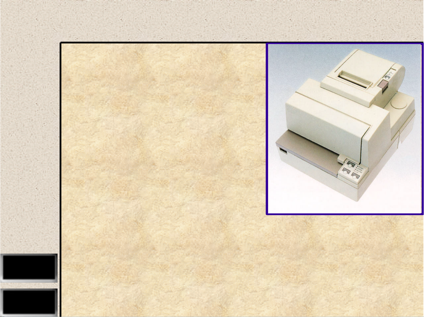
Introduction
The TM-H5000II Series is a high-quality POS printer that can print on slip and receipt paper (paper roll). The printer
has the following features:
Slip Section
❏
Wide slip paper capability (maximum characters per line: 88 with 7 x 9 font).
❏
Copy printing is possible.
❏
High throughput using bidirectional, minimum distance printing.
❏
Optional Magnetic Ink Character Recognition (MICR) reader that enables the printer to
perform consecutive reading and processing of MICR characters and printing
endorsements.
Receipt Section
❏
High speed printing with collective printing.
❏
The standard auto-cutter provides easy user operation.
❏
Ladder bar code printing is possible by using a bar code command.
❏
New paper handling enables easy paper roll loading.
Both Receipt and Slip
❏
EPSON customer display series connection (DM-D102-012/DM-D203-012). (Available only
for serial interfac e model.)
❏
Selectable receive buffer size (45 bytes or 4K bytes).
❏
Command protocol based on the ESC/POS
❏
Automatic status Back (ASB) function that automatically transmits changes in the printer
status.
❏
Available non-volatile bit image buffer (384K bytes).
®
standard.
ii Rev. A
Page 6

Confidential
Warnings, Cautions and Notes
WARNING:
Warnings must be followed carefully to avoid bodily injury.
CAUTION:
Cautions must be observed to avoid damage to your equipment.
Note:
Notes have important information and useful tips on the operation of your printer.
Rev. A iii
Page 7

Confidential
Revision Sheet
Revision Page Altered Item and Contents
Rev. A
iv Rev. A
Page 8

Confidential
Contents
Chapter 1
Printer Parts . . . . . . . . . . . . . . . . . . . . . . . . . . . . . . . . . . . . . . . . . . . . . . . . . . . . . . . . . . . . . . . . . . . . . . . . . . . . . . . . . . . . . . . 1-1
Slip Section . . . . . . . . . . . . . . . . . . . . . . . . . . . . . . . . . . . . . . . . . . . . . . . . . . . . . . . . . . . . . . . . . . . . . . . . . . . . . . . . . . . . . . . . 1-2
Printing Specifications . . . . . . . . . . . . . . . . . . . . . . . . . . . . . . . . . . . . . . . . . . . . . . . . . . . . . . . . . . . . . . . . . . . . . . . . . . 1-2
Character Specifications . . . . . . . . . . . . . . . . . . . . . . . . . . . . . . . . . . . . . . . . . . . . . . . . . . . . . . . . . . . . . . . . . . . . . . . . . 1-2
Ribbon . . . . . . . . . . . . . . . . . . . . . . . . . . . . . . . . . . . . . . . . . . . . . . . . . . . . . . . . . . . . . . . . . . . . . . . . . . . . . . . . . . . . . . . . 1-2
Paper Feed and Paper Specification . . . . . . . . . . . . . . . . . . . . . . . . . . . . . . . . . . . . . . . . . . . . . . . . . . . . . . . . . . . . . . 1-3
Printable Area . . . . . . . . . . . . . . . . . . . . . . . . . . . . . . . . . . . . . . . . . . . . . . . . . . . . . . . . . . . . . . . . . . . . . . . . . . . . . . . . . 1-5
MICR Reader (when the printer is used with the MICR reader) . . . . . . . . . . . . . . . . . . . . . . . . . . . . . . . . . . . . . . . 1-6
Notes on using the MICR reader (only when the printer is used with MICR) . . . . . . . . . . . . . . . . . . . . . . . . . . . 1-7
Receipt Section . . . . . . . . . . . . . . . . . . . . . . . . . . . . . . . . . . . . . . . . . . . . . . . . . . . . . . . . . . . . . . . . . . . . . . . . . . . . . . . . . . . . . 1-8
Printing Specifications . . . . . . . . . . . . . . . . . . . . . . . . . . . . . . . . . . . . . . . . . . . . . . . . . . . . . . . . . . . . . . . . . . . . . . . . . . 1-8
Character Specifications . . . . . . . . . . . . . . . . . . . . . . . . . . . . . . . . . . . . . . . . . . . . . . . . . . . . . . . . . . . . . . . . . . . . . . . . . 1-9
Auto Cutter . . . . . . . . . . . . . . . . . . . . . . . . . . . . . . . . . . . . . . . . . . . . . . . . . . . . . . . . . . . . . . . . . . . . . . . . . . . . . . . . . . . . 1-9
Paper Roll Supply Device . . . . . . . . . . . . . . . . . . . . . . . . . . . . . . . . . . . . . . . . . . . . . . . . . . . . . . . . . . . . . . . . . . . . . . . . 1- 9
Paper Specification . . . . . . . . . . . . . . . . . . . . . . . . . . . . . . . . . . . . . . . . . . . . . . . . . . . . . . . . . . . . . . . . . . . . . . . . . . . . . 1-10
Printable Area . . . . . . . . . . . . . . . . . . . . . . . . . . . . . . . . . . . . . . . . . . . . . . . . . . . . . . . . . . . . . . . . . . . . . . . . . . . . . . . . . 1-11
Printing and Cutting Positions . . . . . . . . . . . . . . . . . . . . . . . . . . . . . . . . . . . . . . . . . . . . . . . . . . . . . . . . . . . . . . . . . . . 1-12
General Section (for both receipt and slip) . . . . . . . . . . . . . . . . . . . . . . . . . . . . . . . . . . . . . . . . . . . . . . . . . . . . . . . . . . . . . 1-12
Internal Buffer . . . . . . . . . . . . . . . . . . . . . . . . . . . . . . . . . . . . . . . . . . . . . . . . . . . . . . . . . . . . . . . . . . . . . . . . . . . . . . . . . 1-12
Electrical Specifications . . . . . . . . . . . . . . . . . . . . . . . . . . . . . . . . . . . . . . . . . . . . . . . . . . . . . . . . . . . . . . . . . . . . . . . . . . 1-12
EMI and Safety Standards Applied (EMC is tested using the EPSON PS-170 power supply) . . . . . . . . . . . . . . 1-13
Reliability . . . . . . . . . . . . . . . . . . . . . . . . . . . . . . . . . . . . . . . . . . . . . . . . . . . . . . . . . . . . . . . . . . . . . . . . . . . . . . . . . . . . . 1-13
Environmental Conditions . . . . . . . . . . . . . . . . . . . . . . . . . . . . . . . . . . . . . . . . . . . . . . . . . . . . . . . . . . . . . . . . . . . . . . . 1-15
Major Component Specifications . . . . . . . . . . . . . . . . . . . . . . . . . . . . . . . . . . . . . . . . . . . . . . . . . . . . . . . . . . . . . . . . . . . . . 1-16
M-U590 Printer Mechanism . . . . . . . . . . . . . . . . . . . . . . . . . . . . . . . . . . . . . . . . . . . . . . . . . . . . . . . . . . . . . . . . . . . . . . 1-16
M-T88II Printer Mechanism . . . . . . . . . . . . . . . . . . . . . . . . . . . . . . . . . . . . . . . . . . . . . . . . . . . . . . . . . . . . . . . . . . . . . . 1-17
Connectors . . . . . . . . . . . . . . . . . . . . . . . . . . . . . . . . . . . . . . . . . . . . . . . . . . . . . . . . . . . . . . . . . . . . . . . . . . . . . . . . . . . . . . . . 1-18
Power Supply Connector . . . . . . . . . . . . . . . . . . . . . . . . . . . . . . . . . . . . . . . . . . . . . . . . . . . . . . . . . . . . . . . . . . . . . . . . 1-18
Drawer Kick-out Connector (Modular Connector) . . . . . . . . . . . . . . . . . . . . . . . . . . . . . . . . . . . . . . . . . . . . . . . . . . 1-18
Customer Display Connector . . . . . . . . . . . . . . . . . . . . . . . . . . . . . . . . . . . . . . . . . . . . . . . . . . . . . . . . . . . . . . . . . . . . 1-21
Interface . . . . . . . . . . . . . . . . . . . . . . . . . . . . . . . . . . . . . . . . . . . . . . . . . . . . . . . . . . . . . . . . . . . . . . . . . . . . . . . . . . . . . . . . . . . 1-22
RS-232 serial interface . . . . . . . . . . . . . . . . . . . . . . . . . . . . . . . . . . . . . . . . . . . . . . . . . . . . . . . . . . . . . . . . . . . . . . . . . . . 1-22
Notes on setting DIP switch 2-1 to ON . . . . . . . . . . . . . . . . . . . . . . . . . . . . . . . . . . . . . . . . . . . . . . . . . . . . . . . . . . . . 1-25
Notes on Resetting the Printer Using the Interface . . . . . . . . . . . . . . . . . . . . . . . . . . . . . . . . . . . . . . . . . . . . . . . . . . 1-26
Buttons and Switches . . . . . . . . . . . . . . . . . . . . . . . . . . . . . . . . . . . . . . . . . . . . . . . . . . . . . . . . . . . . . . . . . . . . . . . . . . . . . . . 1-27
Power Switch . . . . . . . . . . . . . . . . . . . . . . . . . . . . . . . . . . . . . . . . . . . . . . . . . . . . . . . . . . . . . . . . . . . . . . . . . . . . . . . . . . 1-27
Panel Button . . . . . . . . . . . . . . . . . . . . . . . . . . . . . . . . . . . . . . . . . . . . . . . . . . . . . . . . . . . . . . . . . . . . . . . . . . . . . . . . . . . 1-27
DIP Switches . . . . . . . . . . . . . . . . . . . . . . . . . . . . . . . . . . . . . . . . . . . . . . . . . . . . . . . . . . . . . . . . . . . . . . . . . . . . . . . . . . . 1-28
Panel LEDs . . . . . . . . . . . . . . . . . . . . . . . . . . . . . . . . . . . . . . . . . . . . . . . . . . . . . . . . . . . . . . . . . . . . . . . . . . . . . . . . . . . . 1-31
Self-test . . . . . . . . . . . . . . . . . . . . . . . . . . . . . . . . . . . . . . . . . . . . . . . . . . . . . . . . . . . . . . . . . . . . . . . . . . . . . . . . . . . . . . . . . . . 1-33
Buffer Full Printing . . . . . . . . . . . . . . . . . . . . . . . . . . . . . . . . . . . . . . . . . . . . . . . . . . . . . . . . . . . . . . . . . . . . . . . . . . . . . . . . . 1-33
Hexadecimal Dump . . . . . . . . . . . . . . . . . . . . . . . . . . . . . . . . . . . . . . . . . . . . . . . . . . . . . . . . . . . . . . . . . . . . . . . . . . . . . . . . 1-33
Hexadecimal Dumping Function . . . . . . . . . . . . . . . . . . . . . . . . . . . . . . . . . . . . . . . . . . . . . . . . . . . . . . . . . . . . . . . . . 1-33
Performing a Hexadecimal Dump . . . . . . . . . . . . . . . . . . . . . . . . . . . . . . . . . . . . . . . . . . . . . . . . . . . . . . . . . . . . . . . . 1-33
Ending hexadecimal dumping . . . . . . . . . . . . . . . . . . . . . . . . . . . . . . . . . . . . . . . . . . . . . . . . . . . . . . . . . . . . . . . . . . . 1-34
Paper Sensors . . . . . . . . . . . . . . . . . . . . . . . . . . . . . . . . . . . . . . . . . . . . . . . . . . . . . . . . . . . . . . . . . . . . . . . . . . . . . . . . . . . . . . 1-34
Sensors and LED Indicators . . . . . . . . . . . . . . . . . . . . . . . . . . . . . . . . . . . . . . . . . . . . . . . . . . . . . . . . . . . . . . . . . . . . . 1-34
Sensors and Printing . . . . . . . . . . . . . . . . . . . . . . . . . . . . . . . . . . . . . . . . . . . . . . . . . . . . . . . . . . . . . . . . . . . . . . . . . . . . 1-35
Printer Cover Sensors . . . . . . . . . . . . . . . . . . . . . . . . . . . . . . . . . . . . . . . . . . . . . . . . . . . . . . . . . . . . . . . . . . . . . . . . . . . 1-35
Standard Accessories . . . . . . . . . . . . . . . . . . . . . . . . . . . . . . . . . . . . . . . . . . . . . . . . . . . . . . . . . . . . . . . . . . . . . . . . . . . . . . . 1-36
Options . . . . . . . . . . . . . . . . . . . . . . . . . . . . . . . . . . . . . . . . . . . . . . . . . . . . . . . . . . . . . . . . . . . . . . . . . . . . . . . . . . . . . . . . . . . 1-37
Consumables . . . . . . . . . . . . . . . . . . . . . . . . . . . . . . . . . . . . . . . . . . . . . . . . . . . . . . . . . . . . . . . . . . . . . . . . . . . . . . . . . . . . . . 1-37
External Power Supply PS-170 Specifications . . . . . . . . . . . . . . . . . . . . . . . . . . . . . . . . . . . . . . . . . . . . . . . . . . . . . . . . . . . 1-38
Features and General Specifications
Rev. A v
Page 9

Confidential
Chapter 2
Component Connection Diagram . . . . . . . . . . . . . . . . . . . . . . . . . . . . . . . . . . . . . . . . . . . . . . . . . . . . . . . . . . . . . . . . . . . . . 2-1
Circuit Block Diagram . . . . . . . . . . . . . . . . . . . . . . . . . . . . . . . . . . . . . . . . . . . . . . . . . . . . . . . . . . . . . . . . . . . . . . . . . . . . . . .2-2
Memory Map . . . . . . . . . . . . . . . . . . . . . . . . . . . . . . . . . . . . . . . . . . . . . . . . . . . . . . . . . . . . . . . . . . . . . . . . . . . . . . . . . . . . . . 2-3
M-U590 Printer Mechanism . . . . . . . . . . . . . . . . . . . . . . . . . . . . . . . . . . . . . . . . . . . . . . . . . . . . . . . . . . . . . . . . . . . . . . . . . . 2-4
Printer Mechanism . . . . . . . . . . . . . . . . . . . . . . . . . . . . . . . . . . . . . . . . . . . . . . . . . . . . . . . . . . . . . . . . . . . . . . . . . . . . . . 2-4
Detector Mechanisms . . . . . . . . . . . . . . . . . . . . . . . . . . . . . . . . . . . . . . . . . . . . . . . . . . . . . . . . . . . . . . . . . . . . . . . . . . . 2-6
Paper Feed Mechanism . . . . . . . . . . . . . . . . . . . . . . . . . . . . . . . . . . . . . . . . . . . . . . . . . . . . . . . . . . . . . . . . . . . . . . . . . . 2-10
Ribbon Feed Mechanism . . . . . . . . . . . . . . . . . . . . . . . . . . . . . . . . . . . . . . . . . . . . . . . . . . . . . . . . . . . . . . . . . . . . . . . . . 2-14
MICR Reader Mechanism (Factory Option) . . . . . . . . . . . . . . . . . . . . . . . . . . . . . . . . . . . . . . . . . . . . . . . . . . . . . . . . . 2-15
M-T88II Printer Mechanism . . . . . . . . . . . . . . . . . . . . . . . . . . . . . . . . . . . . . . . . . . . . . . . . . . . . . . . . . . . . . . . . . . . . . . . . . . 2-17
Paper Feed Mechanism . . . . . . . . . . . . . . . . . . . . . . . . . . . . . . . . . . . . . . . . . . . . . . . . . . . . . . . . . . . . . . . . . . . . . . . . . . 2-17
Paper Supply Mechanism . . . . . . . . . . . . . . . . . . . . . . . . . . . . . . . . . . . . . . . . . . . . . . . . . . . . . . . . . . . . . . . . . . . . . . . . 2-20
Printer Mechanism . . . . . . . . . . . . . . . . . . . . . . . . . . . . . . . . . . . . . . . . . . . . . . . . . . . . . . . . . . . . . . . . . . . . . . . . . . . . . . 2-22
Cutter Mechanism . . . . . . . . . . . . . . . . . . . . . . . . . . . . . . . . . . . . . . . . . . . . . . . . . . . . . . . . . . . . . . . . . . . . . . . . . . . . . . 2-24
Cover Mechanism . . . . . . . . . . . . . . . . . . . . . . . . . . . . . . . . . . . . . . . . . . . . . . . . . . . . . . . . . . . . . . . . . . . . . . . . . . . . . . 2-27
Display Mechanism. . . . . . . . . . . . . . . . . . . . . . . . . . . . . . . . . . . . . . . . . . . . . . . . . . . . . . . . . . . . . . . . . . . . . . . . . . . . . . 2-29
Main Circuit Board Unit . . . . . . . . . . . . . . . . . . . . . . . . . . . . . . . . . . . . . . . . . . . . . . . . . . . . . . . . . . . . . . . . . . . . . . . . . . . . . 2-30
CPU and CPU Peripheral Logic Circuits . . . . . . . . . . . . . . . . . . . . . . . . . . . . . . . . . . . . . . . . . . . . . . . . . . . . . . . . . . . 2-31
M-U590 Control Circuits . . . . . . . . . . . . . . . . . . . . . . . . . . . . . . . . . . . . . . . . . . . . . . . . . . . . . . . . . . . . . . . . . . . . . . . . . 2-38
M-T88II Control Circuit . . . . . . . . . . . . . . . . . . . . . . . . . . . . . . . . . . . . . . . . . . . . . . . . . . . . . . . . . . . . . . . . . . . . . . . . . . 2-41
Control Panel Control Circuit . . . . . . . . . . . . . . . . . . . . . . . . . . . . . . . . . . . . . . . . . . . . . . . . . . . . . . . . . . . . . . . . . . . . . 2-42
DIP Switch Read Circuit . . . . . . . . . . . . . . . . . . . . . . . . . . . . . . . . . . . . . . . . . . . . . . . . . . . . . . . . . . . . . . . . . . . . . . . . . 2-43
Malfunction Protection Circuit . . . . . . . . . . . . . . . . . . . . . . . . . . . . . . . . . . . . . . . . . . . . . . . . . . . . . . . . . . . . . . . . . . . . 2-43
Customer Display Interface Circuit . . . . . . . . . . . . . . . . . . . . . . . . . . . . . . . . . . . . . . . . . . . . . . . . . . . . . . . . . . . . . . . . 2-43
Drawer Kick Control Circuit . . . . . . . . . . . . . . . . . . . . . . . . . . . . . . . . . . . . . . . . . . . . . . . . . . . . . . . . . . . . . . . . . . . . . 2-44
Power Supply Circuit . . . . . . . . . . . . . . . . . . . . . . . . . . . . . . . . . . . . . . . . . . . . . . . . . . . . . . . . . . . . . . . . . . . . . . . . . . . 2-45
I/F Circuit Board Assembly . . . . . . . . . . . . . . . . . . . . . . . . . . . . . . . . . . . . . . . . . . . . . . . . . . . . . . . . . . . . . . . . . . . . . . . . . . 2-46
I/F Circuit Board Assembly Types . . . . . . . . . . . . . . . . . . . . . . . . . . . . . . . . . . . . . . . . . . . . . . . . . . . . . . . . . . . . . . . . 2-46
Interface Board Structure . . . . . . . . . . . . . . . . . . . . . . . . . . . . . . . . . . . . . . . . . . . . . . . . . . . . . . . . . . . . . . . . . . . . . . . .2-46
Switchboard A . . . . . . . . . . . . . . . . . . . . . . . . . . . . . . . . . . . . . . . . . . . . . . . . . . . . . . . . . . . . . . . . . . . . . . . . . . . . . . . . . . . . .2-46
Switchboard B . . . . . . . . . . . . . . . . . . . . . . . . . . . . . . . . . . . . . . . . . . . . . . . . . . . . . . . . . . . . . . . . . . . . . . . . . . . . . . . . . . . . . .2-47
Intermit Circuit Board Assembly . . . . . . . . . . . . . . . . . . . . . . . . . . . . . . . . . . . . . . . . . . . . . . . . . . . . . . . . . . . . . . . . . . . . . . 2-47
Mechanisms and Operation
Chapter 3
Handling . . . . . . . . . . . . . . . . . . . . . . . . . . . . . . . . . . . . . . . . . . . . . . . . . . . . . . . . . . . . . . . . . . . . . . . . . . . . . . . . . . . . . . . . . . 3-1
Transport Precautions . . . . . . . . . . . . . . . . . . . . . . . . . . . . . . . . . . . . . . . . . . . . . . . . . . . . . . . . . . . . . . . . . . . . . . . . . . . 3-1
Setup Precautions . . . . . . . . . . . . . . . . . . . . . . . . . . . . . . . . . . . . . . . . . . . . . . . . . . . . . . . . . . . . . . . . . . . . . . . . . . . . . . . 3-1
Operational Precautions . . . . . . . . . . . . . . . . . . . . . . . . . . . . . . . . . . . . . . . . . . . . . . . . . . . . . . . . . . . . . . . . . . . . . . . . . 3-2
General . . . . . . . . . . . . . . . . . . . . . . . . . . . . . . . . . . . . . . . . . . . . . . . . . . . . . . . . . . . . . . . . . . . . . . . . . . . . . . . . . . . . . . . . 3-2
Paper Precautions . . . . . . . . . . . . . . . . . . . . . . . . . . . . . . . . . . . . . . . . . . . . . . . . . . . . . . . . . . . . . . . . . . . . . . . . . . . . . . . 3-3
Printing on Slip Paper . . . . . . . . . . . . . . . . . . . . . . . . . . . . . . . . . . . . . . . . . . . . . . . . . . . . . . . . . . . . . . . . . . . . . . . . . . . 3-7
Check Paper Magnetic Character Recognition (MICR READER) . . . . . . . . . . . . . . . . . . . . . . . . . . . . . . . . . . . . . . .3-8
Installing and Removing the Ribbon Cassette . . . . . . . . . . . . . . . . . . . . . . . . . . . . . . . . . . . . . . . . . . . . . . . . . . . . . . . 3-9
Problem Solving . . . . . . . . . . . . . . . . . . . . . . . . . . . . . . . . . . . . . . . . . . . . . . . . . . . . . . . . . . . . . . . . . . . . . . . . . . . . . . . . . . . . 3-11
Errors . . . . . . . . . . . . . . . . . . . . . . . . . . . . . . . . . . . . . . . . . . . . . . . . . . . . . . . . . . . . . . . . . . . . . . . . . . . . . . . . . . . . . . . . . 3-11
Clearing Paper Jams . . . . . . . . . . . . . . . . . . . . . . . . . . . . . . . . . . . . . . . . . . . . . . . . . . . . . . . . . . . . . . . . . . . . . . . . . . . . . . . . . 3-13
Clearing a Receipt Paper Jam . . . . . . . . . . . . . . . . . . . . . . . . . . . . . . . . . . . . . . . . . . . . . . . . . . . . . . . . . . . . . . . . . . . . . 3-13
Clearing a Slip or Check Paper Jam . . . . . . . . . . . . . . . . . . . . . . . . . . . . . . . . . . . . . . . . . . . . . . . . . . . . . . . . . . . . . . . . 3-14
Inspection and Maintenance . . . . . . . . . . . . . . . . . . . . . . . . . . . . . . . . . . . . . . . . . . . . . . . . . . . . . . . . . . . . . . . . . . . . . . . . . . 3-14
Maintenance Procedures . . . . . . . . . . . . . . . . . . . . . . . . . . . . . . . . . . . . . . . . . . . . . . . . . . . . . . . . . . . . . . . . . . . . . . . . . 3-15
Cleaning . . . . . . . . . . . . . . . . . . . . . . . . . . . . . . . . . . . . . . . . . . . . . . . . . . . . . . . . . . . . . . . . . . . . . . . . . . . . . . . . . . . . . . . 3-16
Lubricants . . . . . . . . . . . . . . . . . . . . . . . . . . . . . . . . . . . . . . . . . . . . . . . . . . . . . . . . . . . . . . . . . . . . . . . . . . . . . . . . . . . . . . . . . 3-19
Lubrication Standard . . . . . . . . . . . . . . . . . . . . . . . . . . . . . . . . . . . . . . . . . . . . . . . . . . . . . . . . . . . . . . . . . . . . . . . . . . . . 3-19
Type of Lubricants . . . . . . . . . . . . . . . . . . . . . . . . . . . . . . . . . . . . . . . . . . . . . . . . . . . . . . . . . . . . . . . . . . . . . . . . . . . . . . 3-20
Handling, Maintenance, and Repairs
vi Rev. A
Page 10

Confidential
Chapter 4
Self-test . . . . . . . . . . . . . . . . . . . . . . . . . . . . . . . . . . . . . . . . . . . . . . . . . . . . . . . . . . . . . . . . . . . . . . . . . . . . . . . . . . . . . . . . . . . 4-1
Performing the Receipt Mechanism Self-test . . . . . . . . . . . . . . . . . . . . . . . . . . . . . . . . . . . . . . . . . . . . . . . . . . . . . . . . 4-1
Performing the Slip Mechanism Self-test . . . . . . . . . . . . . . . . . . . . . . . . . . . . . . . . . . . . . . . . . . . . . . . . . . . . . . . . . . . 4-1
Self-test End . . . . . . . . . . . . . . . . . . . . . . . . . . . . . . . . . . . . . . . . . . . . . . . . . . . . . . . . . . . . . . . . . . . . . . . . . . . . . . . . . . . 4-1
Troubleshooting Flowcharts . . . . . . . . . . . . . . . . . . . . . . . . . . . . . . . . . . . . . . . . . . . . . . . . . . . . . . . . . . . . . . . . . . . . . . . . . 4-2
Error Types and Processing . . . . . . . . . . . . . . . . . . . . . . . . . . . . . . . . . . . . . . . . . . . . . . . . . . . . . . . . . . . . . . . . . . . . . . . . . . 4-11
Error types . . . . . . . . . . . . . . . . . . . . . . . . . . . . . . . . . . . . . . . . . . . . . . . . . . . . . . . . . . . . . . . . . . . . . . . . . . . . . . . . . . . . 4-11
Chapter 5
Before starting disassembly, assembly, and adjustment . . . . . . . . . . . . . . . . . . . . . . . . . . . . . . . . . . . . . . . . . . . . . . . . . . 5-1
Small Parts . . . . . . . . . . . . . . . . . . . . . . . . . . . . . . . . . . . . . . . . . . . . . . . . . . . . . . . . . . . . . . . . . . . . . . . . . . . . . . . . . . . . . . . . 5-1
Using This Manual . . . . . . . . . . . . . . . . . . . . . . . . . . . . . . . . . . . . . . . . . . . . . . . . . . . . . . . . . . . . . . . . . . . . . . . . . . . . . . . . . 5-2
Titles . . . . . . . . . . . . . . . . . . . . . . . . . . . . . . . . . . . . . . . . . . . . . . . . . . . . . . . . . . . . . . . . . . . . . . . . . . . . . . . . . . . . . . . . . 5-2
Disassembly, Assembly, and Adjustment Procedures . . . . . . . . . . . . . . . . . . . . . . . . . . . . . . . . . . . . . . . . . . . . . . . 5-2
Names of Parts and Blocks . . . . . . . . . . . . . . . . . . . . . . . . . . . . . . . . . . . . . . . . . . . . . . . . . . . . . . . . . . . . . . . . . . . . . . . 5-2
TM-H5000II Disassembly, Assembly, and Adjustment . . . . . . . . . . . . . . . . . . . . . . . . . . . . . . . . . . . . . . . . . . . . . . . . . . . 5-3
Level 1 Disassembly and Assembly . . . . . . . . . . . . . . . . . . . . . . . . . . . . . . . . . . . . . . . . . . . . . . . . . . . . . . . . . . . . . . . 5-3
Level 2 Disassembly and Assembly. . . . . . . . . . . . . . . . . . . . . . . . . . . . . . . . . . . . . . . . . . . . . . . . . . . . . . . . . . . . . . . . 5-27
Adjustment . . . . . . . . . . . . . . . . . . . . . . . . . . . . . . . . . . . . . . . . . . . . . . . . . . . . . . . . . . . . . . . . . . . . . . . . . . . . . . . . . . . . 5-33
M-U590 Printer Mechanism Disassembly, Assembly, and Adjustment . . . . . . . . . . . . . . . . . . . . . . . . . . . . . . . . . . . . . 5-37
Level 1 Disassembly and Assembly . . . . . . . . . . . . . . . . . . . . . . . . . . . . . . . . . . . . . . . . . . . . . . . . . . . . . . . . . . . . . . . 5-37
Level 2 Disassembly and Assembly . . . . . . . . . . . . . . . . . . . . . . . . . . . . . . . . . . . . . . . . . . . . . . . . . . . . . . . . . . . . . . . 5-47
Level 3 Disassembly and Assembly . . . . . . . . . . . . . . . . . . . . . . . . . . . . . . . . . . . . . . . . . . . . . . . . . . . . . . . . . . . . . . . 5-68
Level 4 Disassembly and Assembly . . . . . . . . . . . . . . . . . . . . . . . . . . . . . . . . . . . . . . . . . . . . . . . . . . . . . . . . . . . . . . . 5-76
Adjustment . . . . . . . . . . . . . . . . . . . . . . . . . . . . . . . . . . . . . . . . . . . . . . . . . . . . . . . . . . . . . . . . . . . . . . . . . . . . . . . . . . . . 5-77
M-T88II Printer Mechanism Disassembly and Assembly . . . . . . . . . . . . . . . . . . . . . . . . . . . . . . . . . . . . . . . . . . . . . . . . . 5-79
Level 1 Disassembly and Assembly . . . . . . . . . . . . . . . . . . . . . . . . . . . . . . . . . . . . . . . . . . . . . . . . . . . . . . . . . . . . . . . 5-79
Level 2 Disassembly and Assembly. . . . . . . . . . . . . . . . . . . . . . . . . . . . . . . . . . . . . . . . . . . . . . . . . . . . . . . . . . . . . . . . 5-94
Troubleshooting Guide
Disassembly, Assembly, and Adjustment
Appendix
Updating the Flash ROM . . . . . . . . . . . . . . . . . . . . . . . . . . . . . . . . . . . . . . . . . . . . . . . . . . . . . . . . . . . . . . . . . . . . . . . . . . . . A-1
Preparation . . . . . . . . . . . . . . . . . . . . . . . . . . . . . . . . . . . . . . . . . . . . . . . . . . . . . . . . . . . . . . . . . . . . . . . . . . . . . . . . . . . . A-1
The way to update . . . . . . . . . . . . . . . . . . . . . . . . . . . . . . . . . . . . . . . . . . . . . . . . . . . . . . . . . . . . . . . . . . . . . . . . . . . . . . A-1
IEEE 1284 Parallel Interface . . . . . . . . . . . . . . . . . . . . . . . . . . . . . . . . . . . . . . . . . . . . . . . . . . . . . . . . . . . . . . . . . . . . . . . . . . A-2
RS-485 Serial Interface . . . . . . . . . . . . . . . . . . . . . . . . . . . . . . . . . . . . . . . . . . . . . . . . . . . . . . . . . . . . . . . . . . . . . . . . . . . . . . . A-5
XON/XOFF Transmit Timing . . . . . . . . . . . . . . . . . . . . . . . . . . . . . . . . . . . . . . . . . . . . . . . . . . . . . . . . . . . . . . . . . . . . A-8
Data Format When Using RS-485 . . . . . . . . . . . . . . . . . . . . . . . . . . . . . . . . . . . . . . . . . . . . . . . . . . . . . . . . . . . . . . . . . A-8
Main Circuit Board Unit Parts Layout (parts side) . . . . . . . . . . . . . . . . . . . . . . . . . . . . . . . . . . . . . . . . . . . . . . . . . . . . . . . A-10
Main Circuit Board Unit Parts Layout (solder side) . . . . . . . . . . . . . . . . . . . . . . . . . . . . . . . . . . . . . . . . . . . . . . . . . . . . . . A-11
RS-232 Serial Interface Circuit Board Parts Layout . . . . . . . . . . . . . . . . . . . . . . . . . . . . . . . . . . . . . . . . . . . . . . . . . . . . . . A-12
IEEE 1284 Parallel Interface Circuit Board Parts Layout . . . . . . . . . . . . . . . . . . . . . . . . . . . . . . . . . . . . . . . . . . . . . . . . . . A-13
RS-485 Serial Interface Circuit Board Parts Layout . . . . . . . . . . . . . . . . . . . . . . . . . . . . . . . . . . . . . . . . . . . . . . . . . . . . . . A-14
Intermit Circuit Board Assembly Parts Layout . . . . . . . . . . . . . . . . . . . . . . . . . . . . . . . . . . . . . . . . . . . . . . . . . . . . . . . . . . A-14
Switch Circuit Board Assembly-A . . . . . . . . . . . . . . . . . . . . . . . . . . . . . . . . . . . . . . . . . . . . . . . . . . . . . . . . . . . . . . . . . . . . A-15
Switch Circuit Board Assembly-B . . . . . . . . . . . . . . . . . . . . . . . . . . . . . . . . . . . . . . . . . . . . . . . . . . . . . . . . . . . . . . . . . . . . . A-15
Case Unit Parts Name List . . . . . . . . . . . . . . . . . . . . . . . . . . . . . . . . . . . . . . . . . . . . . . . . . . . . . . . . . . . . . . . . . . . . . . . . . . . A-16
M-U590 Printer Mechanism Parts Name List . . . . . . . . . . . . . . . . . . . . . . . . . . . . . . . . . . . . . . . . . . . . . . . . . . . . . . . . . . . A-18
M-T88II Printer Mechanism Parts Name List . . . . . . . . . . . . . . . . . . . . . . . . . . . . . . . . . . . . . . . . . . . . . . . . . . . . . . . . . . . A-22
Overall Exploded Diagram . . . . . . . . . . . . . . . . . . . . . . . . . . . . . . . . . . . . . . . . . . . . . . . . . . . . . . . . . . . . . . . . . . . . . . . . . . A-25
Case Unit . . . . . . . . . . . . . . . . . . . . . . . . . . . . . . . . . . . . . . . . . . . . . . . . . . . . . . . . . . . . . . . . . . . . . . . . . . . . . . . . . . . . . . A-25
M-U590 Printer Mechanism . . . . . . . . . . . . . . . . . . . . . . . . . . . . . . . . . . . . . . . . . . . . . . . . . . . . . . . . . . . . . . . . . . . . . . A-26
M-T88II Printer Mechamism . . . . . . . . . . . . . . . . . . . . . . . . . . . . . . . . . . . . . . . . . . . . . . . . . . . . . . . . . . . . . . . . . . . . . A-27
Lubrication Points Diagram . . . . . . . . . . . . . . . . . . . . . . . . . . . . . . . . . . . . . . . . . . . . . . . . . . . . . . . . . . . . . . . . . . . . . . . . . . A-28
M-U590 Printer Mechanism . . . . . . . . . . . . . . . . . . . . . . . . . . . . . . . . . . . . . . . . . . . . . . . . . . . . . . . . . . . . . . . . . . . . . . A-28
M-T88II Printer Mechanism . . . . . . . . . . . . . . . . . . . . . . . . . . . . . . . . . . . . . . . . . . . . . . . . . . . . . . . . . . . . . . . . . . . . . . A-29
Circuit Board Diagram . . . . . . . . . . . . . . . . . . . . . . . . . . . . . . . . . . . . . . . . . . . . . . . . . . . . . . . . . . . . . . . . . . . . . . . . . . . . . . A-30
Rev. A vii
Page 11

Confidential
Main Circuit Board Unit . . . . . . . . . . . . . . . . . . . . . . . . . . . . . . . . . . . . . . . . . . . . . . . . . . . . . . . . . . . . . . . . . . . . . . . . .A-30
I/F circuit Board Assembly . . . . . . . . . . . . . . . . . . . . . . . . . . . . . . . . . . . . . . . . . . . . . . . . . . . . . . . . . . . . . . . . . . . . . . A-40
Intermit Circuit Board Assembly . . . . . . . . . . . . . . . . . . . . . . . . . . . . . . . . . . . . . . . . . . . . . . . . . . . . . . . . . . . . . . . . . . A-44
Switch circuit board assembly-A . . . . . . . . . . . . . . . . . . . . . . . . . . . . . . . . . . . . . . . . . . . . . . . . . . . . . . . . . . . . . . . . . .A-45
Switch circuit board assembly-B . . . . . . . . . . . . . . . . . . . . . . . . . . . . . . . . . . . . . . . . . . . . . . . . . . . . . . . . . . . . . . . . . .A-46
viii Rev. A
Page 12
Chapter 1
Confidential
Features and General Specifications
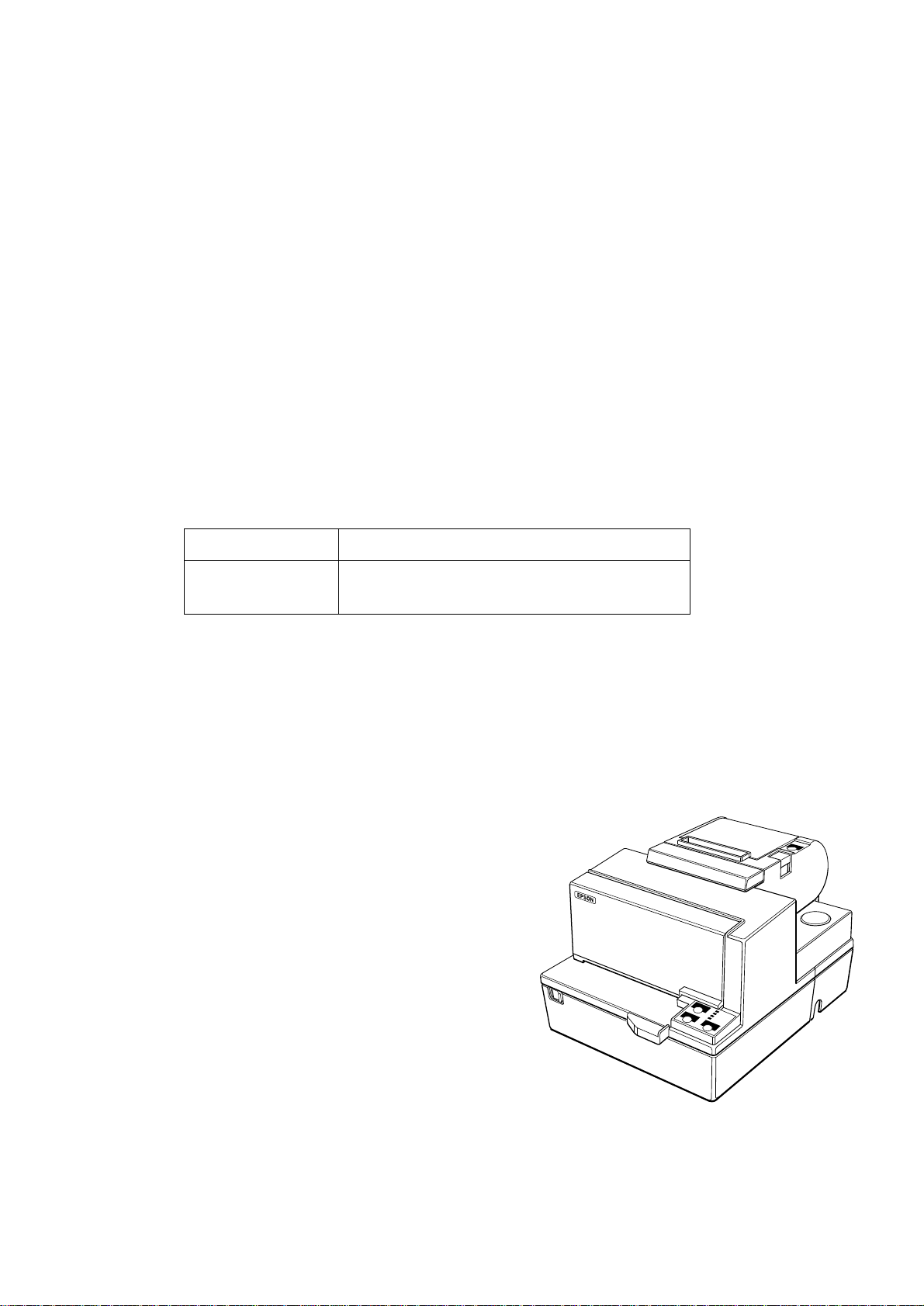
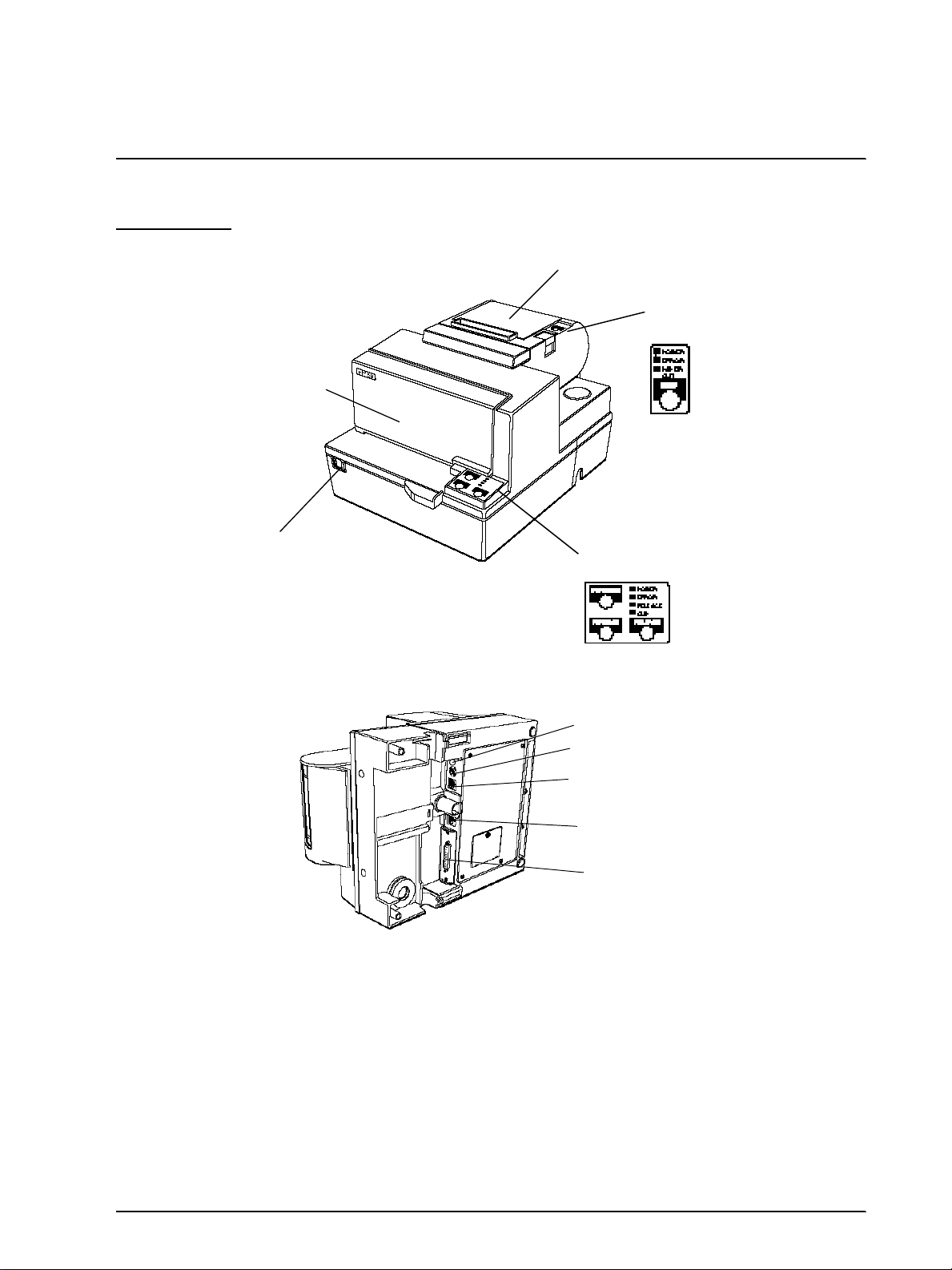
Printer Parts
Paper roll cover
Front cover
TM-H5000II Series Technical Manual
Paper roll
control panel
On/Off switch
Slip paper
control panel
Grounding screw
Power supply connector
Drawer kick-out connector
Display module connector
Interface connector
Rev. A Features and General Specifications 1-1
Page 13

Slip Section
Confidential
Printing Specifications
Printing method: Serial impact dot matrix
Head wire configuration: 9-pin vertical line, wire pitch 1/72 inch
Head wire diameter: 0.29 mm (.01")
Printing direction: Bidirectional, minimum distance printing
Character Specifications
Number of characters: Alphanumeric characters: 95
Internati onal charac ters: 32
Extended graphics: 128 × 10 pages
(including one space page)
Kanji characters: JIS Level 1, Level 2
(JIS X0208−1990)
(with two-pass printing)
Character structure: Font A: 9 × 9 3-dot spacing (in half dot units)
Font B: 7 × 9 2-dot spacing (in half dot units)
Kanji: 16× 16 Left 0-dot, Right 2-dot spacing (in half dot
units)
Larger spacing can be set by using ESC SP or FS S.
Characters per inch, characters per second, characters per line, character size
Character Structure
(Horizontal dots
×
vertical dots)
9 × 9 3 dots 12.5 233 66 1.6 × 3.1 (.06" × .12")
7 × 9 2 dots 16.7 311 88 1.3 × 3.1 (.05" × .12")
16× 16 (*) 2 dots 3.06 45 44 2.7 × 2.9 (1.06" × 1.14")
Character
Spacing
(half dots)
Characters
Per Inch
(CPI)
Characters Per Second
(CPS)
(Carriage moving speed)
Characters
Per Line
(CPL)
Characters Size
(units: mm)
Width × Height
(*) Kanji character spacing at default setting is 2 half dots. (Kanji character spacing can be
changed by FS S.) Printing speed for kanji characters shown in table above is in the case of
full column printing with two-pass printing .
Ribbon
Type: Exclusive cassette ribbon
Ribbon cassette specifications: Part number: ERC-31 (P)
1-2 Features and General Specifications Rev. A
Color: Purple
Ribbon life (*): 7,000,000 characters
(*): when one character consists of 18 dots
Page 14
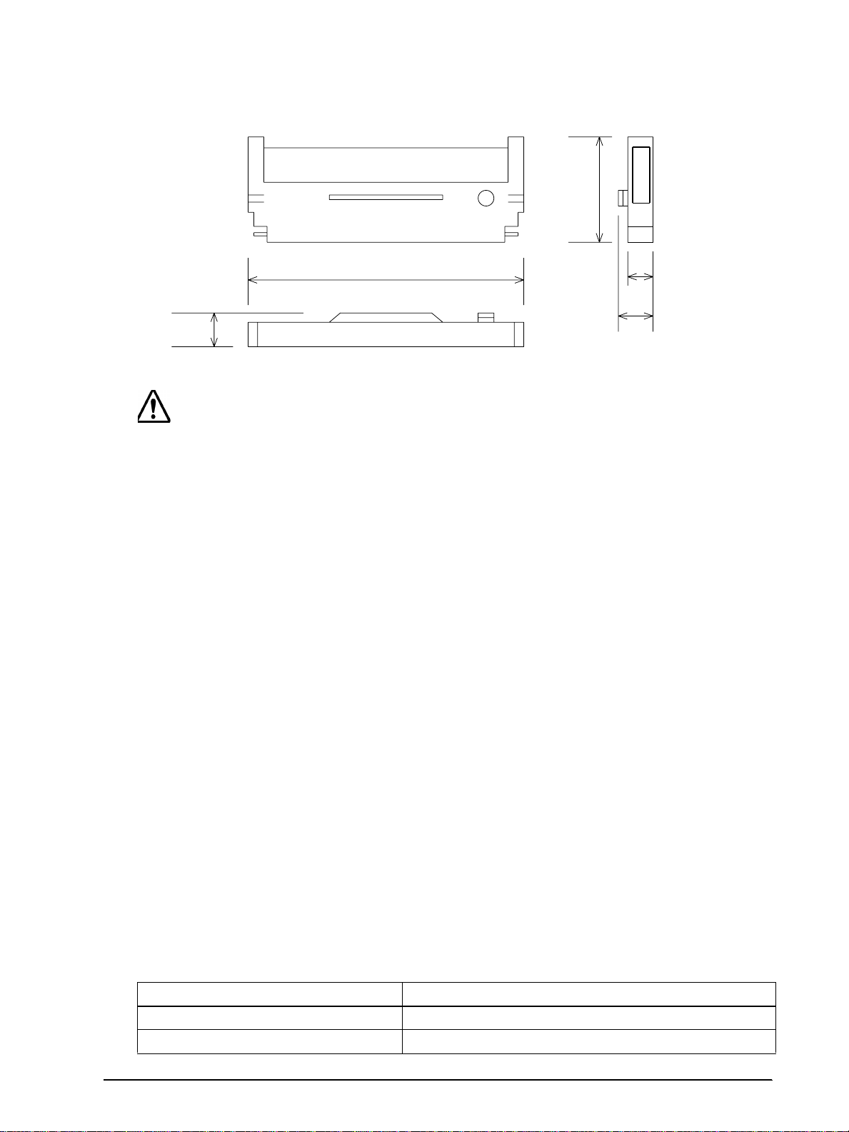
Ribbon cassette overall dimensions:
Confidential
TM-H5000II Series Technical Manual
85.5
200
28
Figure 1-1 Ribbon cassette overall dimensions
CAUTION
If you use ribbon cassettes other than t hose specifi ed, damage may occur. Seiko
Epson will not be held responsible for problems arising from the above.
Papaer Feed and Paper Specification
Paper feed method:
Paper feed pitch:
Paper feed speed:
Paper size:
Friction feed
Default 1/6 inch
Approximately 60.3 msec/line (1/6 inch feeding)
Approximately 3.4 inches/second (continuous feeding)
17
28
[ Units: mm (All the numeric values are typical.) ]
Relationship between ambient temperature and number of copies
Number of copies Ambient temperature
Original + 4 copies Approx. 20° to 45°C (68° to 113°F)
Original + 1 to 3 copies 5° to 45°C (41° to 113°F)
Rev. A Features and General Specifications 1-3
Paper type: ❏
Total thickness:
Size (W × L):
Ambient temperature and
copy capability
Normal paper
❏
Carbon copy paper
❏
Pressure sensitive paper
0.09 to 0.36 mm (.0035 to .0141")
70 mm × 70 mm to 210 mm × 297 mm (A4)
(2.76" × 2.76" to 8.27" × 11.69")
Copy capability is greatly influenced by the ambient
temperature, so printing must be performed under the
conditions described in the table below.
Page 15

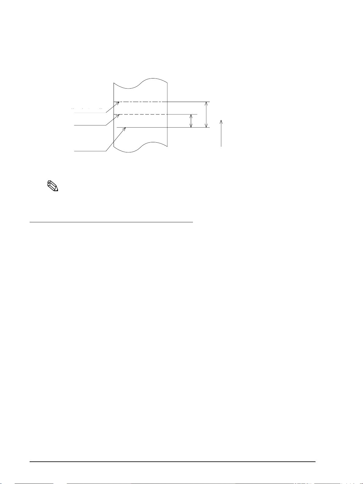
Copy capability and paper thickness:
Glued ponion
Paper feed direction
Confidential
Normal paper (single-ply): 0.09 to 0.2 mm (.0035 to .0079")
Carbon copy paper
combination:
Pressure sensitive paper: 5 sheets maximum [original + 4 copies, at 20° to 45°C
Note:
When using multi-ply paper that consists of an original and three copies, be sure to print with a 9 × 9
font. If a 7 × 9 font is used, some characters on some of the copies may not be readable.
In the same way, when printing Kanji characters which consist of many lines, be sure to consider that
some of characters may not be readable regardless of number of the copies.
Notes on slip paper
Notes:
❏ The slip paper must be flat, without curls or wrinkles, especially at the top edges.
Otherwise, the paper may rub against the ribbon and become dirty.
❏ There must be no glue on the bottom edge of slip paper. Choose slip paper carefully
when the glue is on the right or top edge, since paper feeding and insertion are affected
by gluing conditions (e.g., glue quality, method, and length) and glue location (refer to
the illustration below titled “Slip paper glued area”). Be especially careful when slip
paper is wide and has the glue on the left edge, since skewing may occur.
5 sheets maximum [original + 4 copies, at 20° to 45°C
(68° to 113°F)]
(68° to 113°F)]
❏ Since the slip insertion sensor uses a photo sensor, do not u se pap er that has hol es at the
sensor position, or is translucent (refer to the illustration in the next section titled “Slip
sensor position”).
❏ Since the slip ejection sensor uses a refl ective photo sensor and it detects from the back of
slip paper, do not use paper that has holes or dark portions with low reflection (less than
40% reflection) at the sensor position (refer to the illustration in the next section titled
“Paper holes and low reflection prohibited area”).
❏ Use thinner paper (N30 or equivalent) between the top and bottom sheets of multi-ply
paper. If thick paper is used, the copy capability is lowered.
Figure 1-2 Slip paper glued area
1-4 Features and General Specifications Rev. A
Page 16
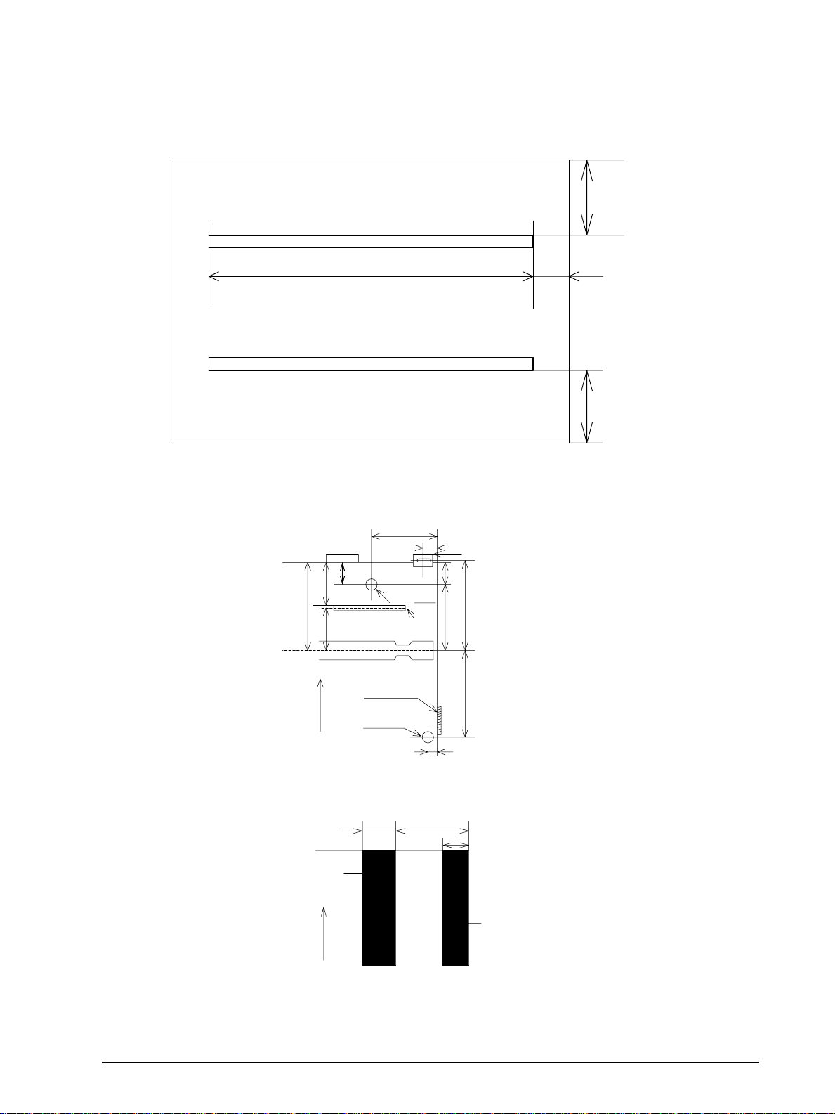
Printable Area
Confidential
ABC XYZ
TM-H5000II Series Technical Manual
Top margin
Top margin
18.9
18.9 +1/–3
135.6
abc xyz
[ Units: mm (All the numeric values are typical.)]
Figure 1-3 Slip paper printable area
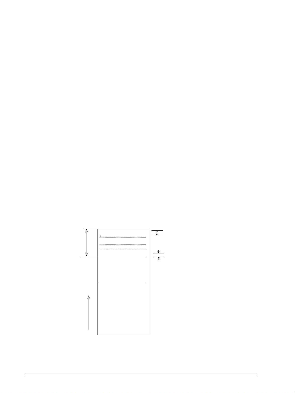
30.1
31
1.3
Center of the print head
Slip side guide
BOF sensor
8
TOF sensor
position
MICR head
1.8
39
37.2
21.9
3.6
[Units: mm (All the numeric values are typical.)]
Form stopper position
38.5
Slip feeding roller
position
Paper feed direction
18.9
18
5.0
Bottom mar g in
Bottom margin
18.4 ± 2
18.4
Rev. A Features and General Specifications 1-5
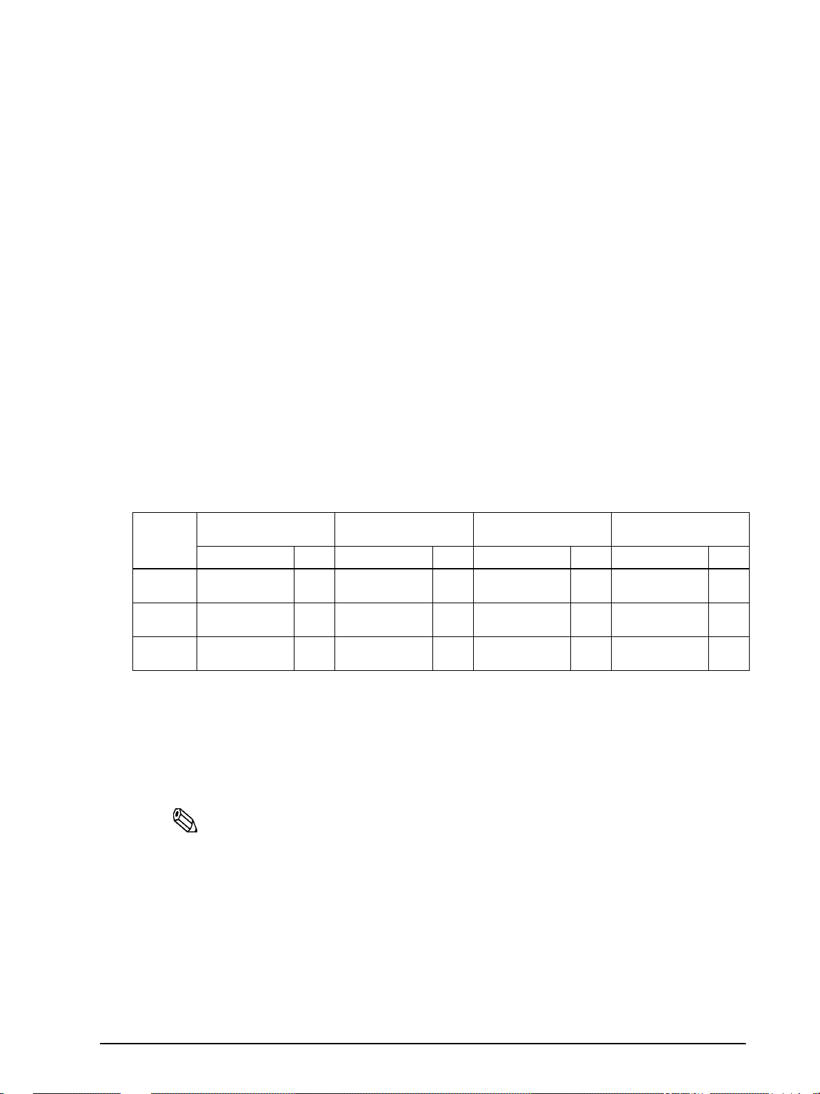
Figure 1-4 Slip sensor position
Area where paper holes are prohibited
and reflection rate for the back of
paper should be 40% or more.
Paper feed direction
15 29
10
Paper holes and translucence
prohibited area.
[ Units: mm (All the numeric values are typical.) ]
Figure 1-5 Paper holes and low reflection prohibited area
Page 17
MICR Reader (when the printer is used with the MICR reader)
Confidential
Reading method: Magnetic bias
Recognition rating: 98 % or more (at 25°C [77°F])
Recognition rating is defined as follows:
Recognition rating (%) = [Total number of checks –
(number of sheets misread or not identified.)/Total
number of checks] × 100
❏ Check paper used for test is EPSON standard check
paper.
❏ Checks must be flat, without cu rl s, folds, or wri n kl es.
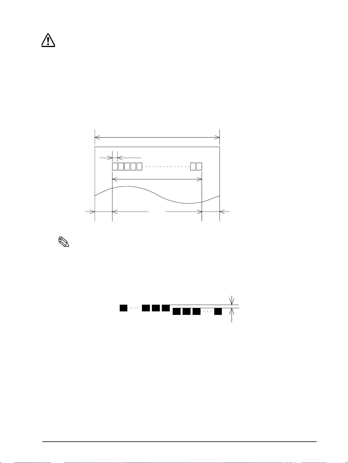
Inserting direction and
endorsement printing
38.1
Specified printing area
ENDORSE CHECK HERE :
"DO NOT SIGN WRITE STAMP BELOW THIS LINE
FOR FINANCIAL INSTITUTION USAGE ONLY"
Insert the check with the surface printed with the
magnetic ink downward, following the table guide.
Endorsement printing can be performed continuously
after check reading. In this case, the print starting
position is point A in the illustration below.
❏ To print endorsements in the specified area (within
38.1 mm [1.5"] from the top), set the print position for
the last line so t hat it is printed at least 3 mm (0.11 8")
above the bottom of the printable area.
8.7
A
3
1-6 Features and General Specifications Rev. A
Inserting direction
[Units: mm (All the numeric values are typical.)]
Figure 1-6 Endorsement printing
Page 18

TM-H5000II Series Technical Manual
Confidential
EPSON
TEST SAMPLE
Pay to the
order of
19
$
90-7172/132
3222
Area where recognition is impossible.
45.0
49.0 (1.9 3 ")
Dollars
9 2 5
[Units: mm ( All the numeric values are typical. )]
Figure 1-7 MICR character recognition impossible area of personal check
Notes on using the MICR reader (only when the printer is used with MICR)
Note:
The personal checks must be flat, without curls, folds, or wrinkles (especially at the edges).
Otherwise, the check may rub against the ribbon and become ink-stained.
WARNING
Do not insert checks that have clips or staples. This may cause paper jams, MICR reading errors,
and damage to the MICR head.
Note:
Let go of the check immediately as soon as the printer starts feeding it. Otherwise, the paper is not
fed straight, causing paper jams and MICR reading errors.
Rev. A Features and General Specifications 1-7
Page 19

Receipt Section
Confidential
Printing Specifications
Printing method: Thermal line printing
Dot density: 180 dpi × 180 dpi. The number of dots per 25.4 mm (1")
Printing direction: Unidirectional with friction feed
Printing width: 72 mm (2.83"), 512 dot positions
Characters per line (default): 42 (font A)
56 (font B)
Character spacing (default): 0.28 mm (.01") (2 dots) (font A)
0.28 mm (.01") (2 dots) (font B)
Programmable by control command.
Printing speed:
High speed mode: 28.4 lines/second maximum (1/6 inch feed)
(at 24V, 20°C, Density level 2)
120 mm/second maximum (approximately
4.72 inches/second)
Speeds are switched automatically depending on the
voltage applied to the printer and the head temperature.
Low power consumption
mode:
Paper feed speed: Approximately 120 mm/second (approximately 4.72
Line spacing (default): 4.23 mm (1/6 inch)
Approximately 16.5 lines/second (1/6 inch feed)
Approximately 70 mm/second (approximately 2.76
inches/second)
Approximately 42 mm/second (approximately 1.7
inches/second) when a ladder bar code is printed.
NOTE: Printing speed may be slower depending on the data
transmission speed and the combination of control
commands.
inches/second) (continuous printing)
Programmable by control command
1-8 Features and General Specifications Rev. A
Page 20
TM-H5000II Series Technical Manual
Confidential
Character Specifications
Number of characters:
Alphanumeric characters: 95
Extended graphics: 128 × 7 pages (including one space page)
Internati onal charac ters: 32
Kanji characters: JIS-Level 1, Level 2
( JIS X0208-1990)
Character structure: 12 × 24 (font A) (including 2-dot spacing in horizontal)
9 × 17(font B) (including 2-dot spacing in horizontal)
24 × 24 (Kanji)
Font A is selected as the default
Character size:
Character size
21
28
10
Double-width/
Double-height
2.82
× 6.77
× .27")
(.11"
1.98
× 4.80
× .19")
(.08"
6.77
× 6.77
× .27")
(.27"
Standard Double-height Double-width
× H (mm) CPL W × H (mm) CPL W × H (mm) CPL W × H (mm) CPL
W
Font A
12
× 24
Font B
9
× 17
Kanji
24
× 24
Space between characters is not included.
Characters can be scaled up to 64 times as large as the standard sizes.
CPL = Characters per line
1.41
(.06"
0.99
(.04"
3.39
(.13"
× 3.39
× .13")
× 2.40
× .09")
× 3.39
× .13")
42
56
21
1.41
(.06"
0.99
(.04"
3.39
(.13"
× 6.77
× .27")
× 4.80
× .19")
× 6.77
× .27")
42
56
21
2.82
(.11"
1.98
(.08"
6.77
(.27"
× 3.39
× .13")
×2.40
× .09")
×3.39
× .13")
Auto Cutter
Partial cut: Cutting with one point left uncut (selectable by GS V)
Note:
To prevent dot displacement, after cutting, paper must be fed approximately 1 mm (14/360
inches) or more before printing.
21
28
10
Paper Roll Supply Device
Supply method: Drop-in paper roll
Near-end sensor
Rev. A Features and General Specifications 1-9
Page 21

Detection method: Microswitch
Confidential
Paper roll spool diameter: Inside: 12 mm (.47")
Outside: 18 mm (.71")
Near-end adjustment: Adjusting screw
Remaining amount: Fixed position #1 (approximately 23 mm (0.9”))
#2 (approximately 27 mm (1.06”)
(The adjusting screw has two positions.)
Note:
You can use a command to stop printing upon detection of a paper near-end.
Paper Specification
Paper type: Specified thermal roll paper, NTP080-80
In Japan: Nakagawa, Seisakujo
In U.S.A.: Nakagawa Mfg. (USA) Inc.
In Europe: Nakagawa Mfg. (Europe) GmbH
In Southeast Asia: N.A.K. Mfg. (Malaysia) SDN BHD
Original paper: TF50KS E Nippon Paper Industries
Co.,Ltd.
The following paper can be used instead of the specified
paper above:
Original paper: PD 160R New Oji Paper Mfg. Co. Ltd.
Original paper: AF50KS-E Jujo Thermal Oy (Finland)
Original paper: P350 (F380) Kanzaki Specialty Papers,
Inc. (U.S.A.)
Form: Paper roll
Paper width: 79.5 ±0.5 mm (3.13" ± 0.02")
Paper roll size:
Roll diameter: Maximum 83 mm
Take-up paper roll width: 80 + 0.5/-1.0 mm (3.15" + 0.02"/-0.04")
Paper roll spool diameter: Inside: 12 mm (.47")
1-10 Features and General Specifications Rev. A
Outside: 18 mm (.71")
Page 22
TM-H5000II Series Technical Manual
a
b
c
de
Approximately 0.07mm (0.0028")
1 256
257 512
Confidential
CAUTION
Paper must not be pasted to the paper roll spool.
Printable Area
Paper roll The printable area of a paper wi th width of 79.5 ± 0.5 mm
(3.13" ± 0.02") is 72.2 ± 0.2 mm (2.84" ± 0.008") (512 dots)
and the space on the right and left sides are
approximately 3.7 ±2 mm (0.15" ± 0.079”).
a = 79.5 ± 0.5 mm (3.13" ± 0.02")
b = 1. 41 mm ± 0.05 mm (.056" ± .002")
c = 72.2 mm ± 0.2 mm (2.84 ± .008")
d = 3.7 ±2 mm (0.15" ± 0.079”)
e = 3.7 ±2 mm (0.15" ± 0.079”)
[All the numeric values are typical.]
Figure 1-8 Paper roll printable area
Note:
The print position within the printable area of the thermal elements for dots 257 to 512 is shifted
approximately 0.07 mm (.003") in the paper feed direction from the position for dots 1 to 256. Be
sure not to print a ladder bar code across both printable areas, as this can cause variations in
printing which are difficult to read. However, when the ladder bar code is printed with level 2 of
print density, the difference is only approximately 0.04 ~ 0.05mm (.0015 ~ .0019").
Approximately 0.07 mm (0.0028")
Figure 1-9 Shifting of the print position
Rev. A Features and General Specifications 1-11
Page 23
Printing and Cutting Positions
Paper feed direction
[ Units: mm (All the numeric values are typical.) ]
Center of the print dotline
Auto-cutter blade position
Manual-cutter position
14.8
26.3
Confidential
Manual-cutter position
Approx. 15
Approx.
29
Figure 1-10 Printing and cutting positions
Note:
Numeric values used here are typical values; the values may vary slightly as a result of paper slack
or variations in the paper.
General Section (for both receipt and slip)
Internal Buffer
Receive buffer selectable as 45 or 4K bytes using the DIP switch.
User-defined buffer (both for user-defined characters and user-defined bit images)
Receipt: 12K bytes Slip: 5K bytes
Macro buffer: 2K bytes
Non-volatile bit image buffer 384K bytes
Electrical Specifications
Supply voltage: +24 VDC ± 10% (optional power supply: EPSON PS-170)
Current consumption (at 24V except for drawer kickout driving)
Operating: Slip Mean:
1-12 Features and General Specifications Rev. A
Ripple voltage: 300 mVpp or less (only when the printer
is used with t he MICR read er)
Approximately 1.9A
(Character font A α-N all columns prin ting)
Peak:
Approximately 8.0A (20 msec)
When the print platen is released: 2.0A (200 msec)
Page 24

Operating: Receipt Mean:
Confidential
Approximately 1.7A
(Character font A α-N all columns prin ting)
Peak:
Approximately 7.7A (20 msec)
TM-H5000II Series Technical Manual
Low power consumption
mode:
Mean:
Approximately 1.2A
(Character font A α-N all columns prin ting)
Peak:
Approximately 6.6A
Standby: Mean:
Approximately 0.3A
EMI and Safety Standards Applied
(EMC is tested using the EPSON PS-170 power supply)
Europe: CE marking: EN55022
Safety Standard: TÜV (EN60950)
North America: EMI: FCC Class A
Safety standards: UL1950-2TH-D3
Japan: EMI: VCCI Class 1
China
(The people’s
Republic of China):
Oceania: EMI: AS/NZS 3548
Safety standards: GB4943-1995
EN50082-1
EN45501
C-UL
Class B
Reliability
Slip
Rev. A Features and General Specifications 1-13
Life (when printing alphanumeric characters)
Mechanism: 12,000,000 lines
Print head: 200 million characters
(when printing with font B)
MICR reader mechanism (only when the printer is used with the MICR reader):
240,000 passes
The MICR reader is defin ed to have r eached the end of it s
life when it reaches the beginning of the Wearout Period.
MTBF: 180,000 hours
Failure is defined as Random Failure occurring at the
time of the Random Failure Period.
Page 25

MCBF 29,000 ,000 li nes
Confidential
Receipt:
Life:
Mechanism: 15 ,000 ,000 li nes
Thermal head: 100 million pulses, 100 Km
Auto cutter: 1,500,000 cuts
MTBF 180,000 hours
MCBF 37,000 ,000 li nes
Acoustic noise:
This is an average failure interval based on failures
relating to wearout and r andom failures up to the life of
12 million lines.
Operating: Receipt: Approximately 52 dB
(Bystander position) (including
Auto-cutter operation)
Approximately 45 dB
(Bystander position) (not
including Auto-cutter operation)
External Dimensions and Weight
Height: 201 mm (7.91")
Width: 252 mm (9.92") (except for the protrusi on)
Depth: 331 mm (13.03")
Weight: Approximately 6.5 kg (14.3 lbs)
(All the numeric values are typical.)
Slip: App ro xi m ately 65 dB
(Bystander position)
1-14 Features and General Specifications Rev. A
Page 26
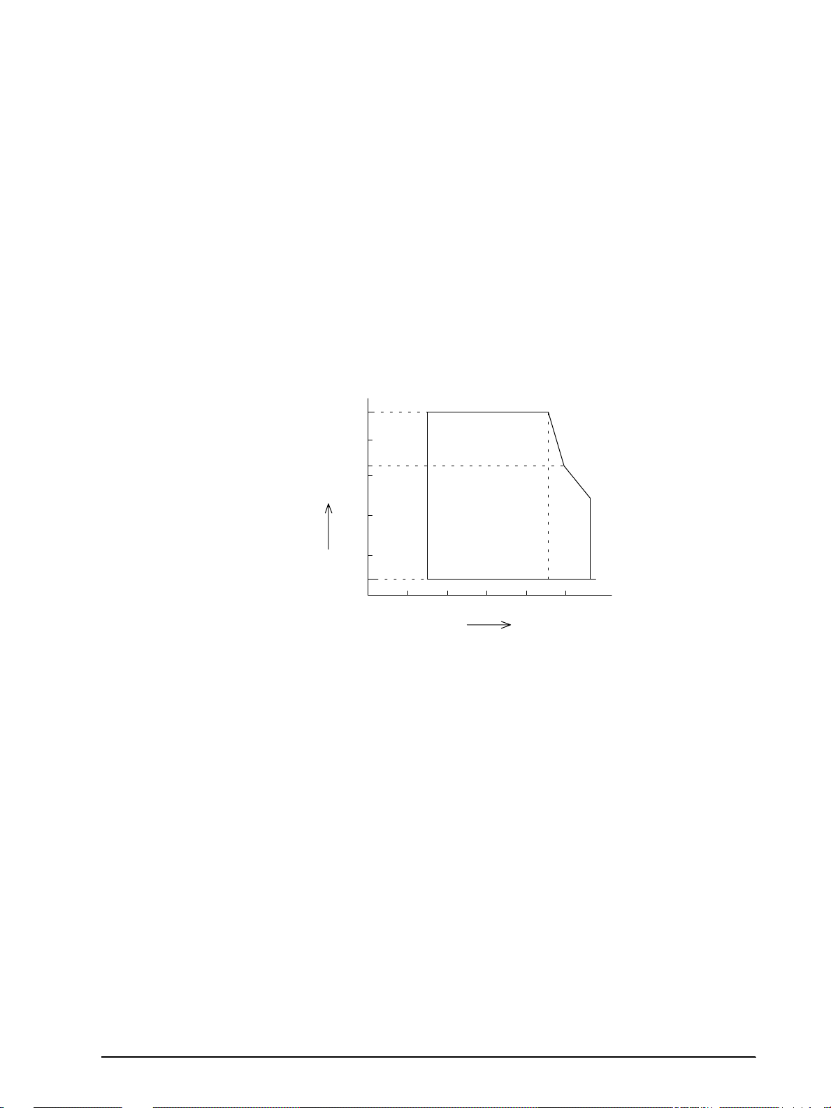
Environmental Conditions
Ambient
temperature
[˚C]
[% RH]
Relative humidity
Operating environment
range
34 ˚C, 90 %
40 ˚C, 65 %
45 ˚C, 50 %
90
80
60
20
40
10
0
0 10 20 30 40 50
Confidential
Temperature:
Operating: 5° to 45°C (41° to 113°F)
Storage: –10° to 50°C (14° to 122°F) (except for paper)
Humidity:
Operating: 10 to 90% RH
Storage: 10 to 90% RH (except for paper)
TM-H5000II Series Technical Manual
Rev. A Features and General Specifications 1-15
Figure 1-11 Operating temperature and humidity range
Page 27

Major Component Specifications
Confidential
M-U590 Printer Mechanism
Paper Feed Motor
Type: 4-phase, 48-polarity, PM type stepping motor
Drive voltage: 24V DC ± 10%
Winding resistance: 35 Ω ± 5% at 25° C (77° F), per phase
Carriage Mo tor
Type: 4-phase, 48-polarity, PM type stepping motor
Drive voltage: 24V DC ± 10%
Winding resistance: 9 Ω ± 5% at 25° C (77° F), per phase
Print Head Unit
Solenoid number: 9
Drive voltage: 24V DC ± 10%
Resistance 6.65 Ω ± 4% at 25° C (77° F)
T.O.F. Sensor/B.O.F Sensor
Type: Photo sensor
Voltage: 5V DC ± 5%
Home Position Sensor
Type: Photo sensor
Voltage: 5V DC ± 5%
Carriage Sensor
Type: Photo sensor
Voltage: 5V DC ± 5%
Cover Open Sensor
Type: Photo sensor
Voltage: 5V DC ± 5%
1-16 Features and General Specifications Rev. A
Page 28

TM-H5000II Series Technical Manual
Confidential
M-T88II Printer Mechanism
Paper Feed Motor
Type: 4-phase, 48-polarity, PM type stepping motor
Drive Voltage: 24 V DC ± 10%
Winding resistance: 11.5 Ω ± 10% at 25° C (77° F), per phase
Print Head Unit
Dot number: 512 dots
Dot density: 0.141 mm/dot (180 DPI)
Resistance: 657 Ω ± 4.6%
Paper-end Sensor
Type: Reflection type photo sensor
Paper Roll Near-end Sensor
Type: Microswitch
Auto-cutter Unit
Type: DC brush moto r
Cutter motor voltage: 24 V DC ± 7%
Current consumption: 700 mA peak (at starting, low temperature)
70 mA average (room temperature)
Rev. A Features and General Specifications 1-17
Page 29
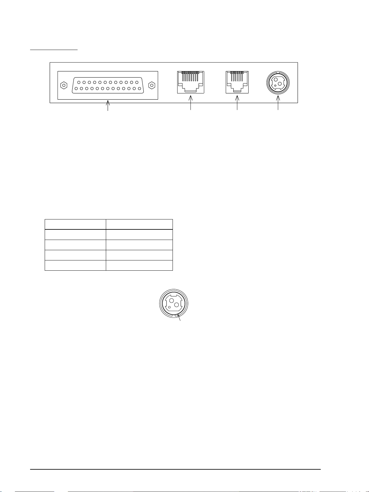
Connectors
Shell
2
31
Confidential
14 25
113
Interface connector Customer display(DM-D)
(*)The shape of the interface connector is different from the illustration above if the printer has a parallel interface.
18 16
Customer display (DM-D)
connector
connector
Drawer kick-out
connector
2
31
Power supply connector
Figure 1-12 Connector panel external appearance
Power Supply Connector
This connector is used to connect the printer to an external power source.
Model: Hosiden TCS7960-532010 or equivalent
Power supply connector pin assignments
Pin number Signal name
1 +24 VDC
2GND
3NC
Shell Frame GND
Drawer Kick-out Connector (Modular Connector)
The pulse specified by ESC p is output to this connector. The host can confirm the status of the
input signal by using the DLE EOT, GS r, or GS a (ASB) commands.
Connector model:
Printer side: MOLEX 52065-6615 or equivalent
User side: 6-position 6-contact (RJ12 telephone jack)
1-18 Features and General Specifications Rev. A
Figure 1-13 Power supply connector
Page 30
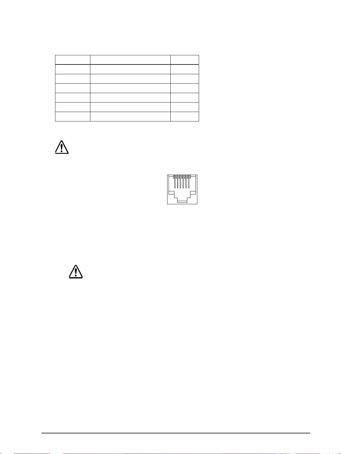
Drawer kick-out connector pin assignments
16
Confidential
Pin Number Signal Name Direction
1Frame GND —
2 Drawer Kick-out drive signal 1 Output
3 Drawer open/close signal Input
4+24 V —
5 Drawer Kick-out drive signal 2 Output
6Signal GND —
+24 V is always output through pin 4.
CAUTION
Pin 4 must be used only for the drawer
.
TM-H5000II Series Technical Manual
Figure 1-14 Drawer kick-out connector
Drawer kick-out drive signal
Output signal: Output voltage: Approximately 24 V
Output current: 1A or less
CAUTION:
To avoid an overcurrent, the r esistance of the drawe r kick-out solenoid must be
24
Ω
or more
Output waveform: Outputs the waveforms in Figure 1-16 to the points A
.
and B in Figure 1-17.
t1 (ON time) and t2 (OFF time) are specified by ESC p.
Rev. A Features and General Specifications 1-19
Page 31

Figure 1-15 Drawer kick-out drive signal output waveform
t 1x 2 msec
t 1x 2 msec
Confidential
Drawer open/close signal
t 1x2 m sec t 2x2 m sec
Input signal level
(connector pin 3):
F. G
A
P-GND
B
P-GND
"L" = 0 to 0.8 V
"H" = 2 to 5 V
Drawer kick-out connector
+24V
1
2
3
4
5
6
With shielded
Drawer kick-out solenoid
Drawer open/close switch
Notes:
Two driver transistors cannot be energized simultaneously.
The driver must not be energized continuously.
1-20 Features and General Specifications Rev. A
Printer side User side (Drawer kick-out side)
Figure 1-16 Drawer circuitry
Page 32

18
Confidential
CAUTIONS:
Do not connect a telephone line to the drawer kick-out connector, otherwise the
printer and the telephone line may be damaged.
Be sure to use the printer power supply (connector pin 4) for th e drawer power source.
The resistance of the drawer kick-out solenoid must not be less than the specified
(24
Ω
). Otherwise, an overcurrent could damage the solenoid.
Customer Display Connector
CAUTION:
Be sure not to use customer displays other than Seiko Epson DM-DXX
Model:
Receptacle: MOLEX 52065-8845 or equivalent
TM-H5000II Series Technical Manual
.
Pin assignments:
Customer display connector pin assignments
+24 V is alway s output through pin 7. The driving capability is 350 mA or less.
Pin Number Signal Name Direction
1FG—
2N.C.—
3TXDOutput
4 DTR Output
5 DSR Input
6SG—
7+24—
8PG—
Rev. A Features and General Specifications 1-21
Figure 1-17 DM-D connector
Page 33

Interface
Confidential
Note:
See the appendix for the information about the IEEE 1284 parallel interface and the RS-485 serial
interface.
RS-232 serial interface
Specifications
Data transmission: Serial
Synchronization: Asynchronous
Handshaking: DTR/DSR or XON/XOFF control
Signal levels: MARK = –3 to –15 V: Logic "1"
Stop bits: 1 or more
Connector (printer side): Female DSUB-25 pin connector
The data word length, baud rate, and parity depend on the DIP switch settings.
SPACE = +3 to +15 V: Logic "0"
Switching between on -line and off-line
The printer does not have an on-line/off-line switch. The
printer goes off-line:
❏ Between when the power is turned on (including
reset using the interface) and when the printer is
ready to receive data
❏ During the self-test
❏ When the cover is open (the cover for the p aper sheet
selected by ESC c 0)
❏ During paper feeding using the paper feed switch
❏ When the printer stops printing due to a paper-end
(only when the paper roll is not present)
❏ When an error has occurred
Interface connector terminal assignments and signal functions are described in the table
below.
1-22 Features and General Specifications Rev. A
Page 34

TM-H5000II Series Technical Manual
Confidential
Printer status and signals
Pin number Signal name Signal direction Function
1FG— Frame ground
2 TXD Output Transmit data
3 RXD Input Receive data
4 RTS Output DIP SW 2-2 OFF: Same as DTR signal (Pin 20)
DIP SW 2-2 ON: Logical product of DTR signals of DM-D and TM
(If both are SPACE, the printer can receive data
(SPACE).)
6 DSR Input This signal indicates whether the host computer can receive data.
SPACE indicates that the host computer can receive data, and
MARK indicates that the host comput er can not receiv e da t a.
When DTR/DSR control is selected, the printer transmits data after
confirming this si g nal (except when transmitting da ta by DLE EOT
and GS a).
When XON/XOFF control is selected, the printer does not check this
signal.
Changing the DIP switch setti ng enables this signal to be used as a
reset signal for the printer.
The printer is reset when the signal remains MARK for 1 ms or more.
7 SG — Signal ground
,
Rev. A Features and General Specifications 1-23
Page 35

Printer status and signals
Confidential
Pin number Signal name Signal direction Function
20 D TR Output 1) When DTR/DSR control is se lect ed , this signal indicat es whether
the printer is busy. SPACE indicates that the printer is ready to
receive data, and MARK indicates that the printer is busy. The busy
condition can be changed by using DIP SW 2-1 as follows:
DIP SW 2-1 sta tus
Printer
1. During the period from when the
power is turned on (including
resetting using the inter face) to when
the printer is read y to receive data.
2. During the self-test. BUSY BUSY
Off-line
3. When the cover is open. - BUSY
4. During paper feeding usin g the
paper feed switch.
5.When the pri nte r stop s prin ting due t o
a paper-end.
6. When an error has occurred. - BUSY
7. When the receive buffer becomes
full.
ON OFF
BUSY BUSY
-BUSY
-BUSY
BUSY BUSY
2) When XON/XOFF control is selected:
The signal indicates whether the printer is correctly connected and
is ready to receive d ata. S PACE indicat es th at the p rinter is rea dy to
receive data. The s ignal is always SPACE except in the following
cases:
• During the period from when the power is turned on to when
the printer is read y to receive data
• During the self-test
25 INIT Input Changing the DIP switch settin g enables this signal to be used as a
reset signal for the printer.
The printer is reset when the signal remains SPACE for 1 ms or more.
Notes:
When the remaining space in the receive buffer drops to 16 bytes, the printer status becomes "buffer
full" and it remains "buffer full" until the space in the receive buffer increases to 26 bytes.
The printer ignores the data received when the remaining space in the receive buffer is 0 bytes.
XON/XOFF transmit timing When XON/XOFF control is selected, the printer
transmits XON or XOFF signals as follows. Transmit
timing differs depending on the DIP SW1-3 setting.
1-24 Features and General Specifications Rev. A
Page 36

TM-H5000II Series Technical Manual
Confidential
XON/XOFF transmit timing
Printer status
XON transmission 1) When the printer goes on-line after turning on the power (or
reset using interface)
2) When the receive buffer is released from the buffer full state Transmit Transmit
3) When the printer switches from off-line to on-line — Transmit
4) When the printer recovers from an error using the DLE ENQ 1 or
DLE ENQ 2 commands
XOFF Transmission 5) When the receive buffer becomes full Transmit Transmit
6) When the printer switches from on-line to off-line — Transmit
DIP SW 1-3 status
ON OFF
Transmit Transmit
—Transmit
Notes:
• The XON code is <11>H and the XOFF code is <13>H.
• In case 3, XON is not transmitted when the receive buffer is full.
• In case 6, XOFF is not transmitted when the receive buffer is full.
• When the DIP SW2-1 is set to OFF, XON is not transmitted if the printer is in off-line state in
case 6.
Notes on setting DIP switch 2-1 to ON
The printer mechanism stops but does not become busy when: an error has occurred, the cover
is open, printing stops due to a paper-end, or paper is fed using the paper feed switch.
When setting DIP switch 2-1 to ON to enable handshaking with the printer , be sure to check t he
printer status using the GS a command and the ASB function. In this setting, the default value
of n for GS a is 2. The printer automatically transmits the printer status, depending on on-line/
off-line changes.
When using DLE EOT and DLE ENQ, be sure that the receive buffer does not become full.
❏ When using a host that cannot transmit data when the printer is busy:
If an error has occurred, DLE EOT and DLE ENQ cannot be used when the printer is busy
due to a receive buffer-full state.
❏ When using a host that can transmit data when the printer is busy:
When the receive buffer becomes full while transmitting bit-image data, DLE EOT or
DLE ENQ used while sending the bit-image data is processed as bit-image data. The data
transmitted when the receive buffer is full may be lost.
Example: Check the printer status using GS I or GS r after transmitting each line of data
Rev. A Features and General Specifications 1-25
and use the 4K byte receive buffer. Transmit one line of data so that the receive
buffer does not become full.
Page 37

Notes on Resetting the Printer Using the Interface
Confidential
The printer can be reset using interface pins 6 and 25 by changing the DIP switch setting.
Reset switching
Signal Line DIP Switch Reset Condition
Pin 6 (DSR) DSW 2-7: ON MARK level input
Pin 25 (INIT) DSW 2-8: ON SPACE or TTL-HIGH level input
To reset the printer, the following requirements must be satisfied.
❏ DC characteristics:
Reset DC characteristics
Pin 6 (DSR) Pin 25 (INIT)
Input HIGH voltage V
Input LOW v oltage V
Input HIGH current: I
Input LOW c urrent: I
Input impedance: R
+3 to +15 V +2 to +15 V
IH
-15 to + -3 V -15 to + 0.8 V
IL
5 mA (maximum) 1 mA (maximum)
IH
-5.3 mA (maximum) -2 mA (maximum)
IL
3 KΩ (minimum)
IN
❏ AC characteristics:
Minimum reset pulse width: TRS 1 msec (minimum)
❏ When using pin 6 (DSR) (DIP switch 2-7 is ON):
TRS
H
L
Figure 1-18 Minimum reset pulse width (pin 6)
❏ When using pin 25 (INIT) (DIP switch 2-8 is ON):
TRS
H
L
Figure 1-19 Minimum reset pulse width (pin 25)
1-26 Features and General Specifications Rev. A
Page 38

Notes:
Confidential
When a signal that does not satisfy the requirements above is input, printer operation is not
guaranteed. When a signal is input to pin 25 (INIT) at the TTL level, the requirements above
must also be satisfied. Although a signal is input to pin 6 (DSR) at the TTL level, according to the
DC characteristics described above, the operation is not guaranteed and pin 6 cannot be controlled.
When pin 6 (DSR) and pin 25 (INIT) are open, the printer is operating.
Buttons and Switches
Power Switch
Type: Rocker switch
Function: The power switch turns the power on or off.
Note:
Turn on the power only after connecting the power supply.
TM-H5000II Series Technical Manual
Panel Button
There are panel buttons on both the slip and receipt sections. All the panel buttons are disabled
by ESC c 5.
Slip
Release button (non-locking push button)
[Function] Release paper
Reverse button (non-locking push button)
[Function] Reverse paper feeding for the line spacing set by ESC 2 and ESC 3
Forward button (non-locking pu sh button)
[Function] Feed paper for the line spacing set by ESC 2 and ESC 3
Paper feed is not executed without paper.
Note:
When the printer cover is open, the printer will not operate.
Rev. A Features and General Specifications 1-27
Page 39

Receipt
Confidential
Feed (FEED) button: Non-locking push button
[Function] If you push this button once and release it, the printer
feeds paper for one line based on the line spacing set by
ESC 2 and ESC 3. If you hold down the button, the
printer will feed paper continuously.
Paper feeding using the FEED button cannot be
performed under the following conditions:
1. The paper roll end sensor detects a paper end
2. When the printer cover is open.
If you push this button when the printer is in the
macro execution standby state, the defined macro is
executed.
During self-test printing, you can stop the self test
temporarily by pressing this button and restart it by
pressing the button again.
DIP Switches
For the serial interface model
The DIP switches are located at the bottom of the case.
DIP switch 1
DIP Switch Function ON OFF
1 Data reception error Ignored Prints “?”
2 Receive buffer capacity Data buffer 45 bytes Data buffer 4 KB
3 Handshaking XON/XOFF DTR/DSR
4 Data word le ngth 7 bits 8 bits
5 Parity check Yes No
6 Parity selec ti on Ev en Odd
7
8
Transmission speed selection
Refer to Transmission Speed Table
1-28 Features and General Specifications Rev. A
Page 40

TM-H5000II Series Technical Manual
Confidential
Transmission Speed
Transmission Speed (BPS) SW 1-7 SW 1-8
2400 ON ON
4800 OFF ON
9600 ON OFF
19200 OFF OF F
BPS: Bits Per Second
DIP switch 2
SW 2 Function ON OFF
1 Handshaking (BUSY condition) Receive buffer full
2 Customer display (DM-D) connection Connected Not connected
3
Selects print density Refer to Print Density Selection Table
4
5 Internal use Fixed to Off
6 Internal use Fixed to Off
7 I/F pin 6 reset signal Enabled Disabled
8 I/F pin 25 reset signal Enabled Disabled
Off line or receive
buffer full
Print Density Selection
Function SW 2-3 SW 2-4
Receipt low power consump t ion mode ON ON
1 Print density (Normal) OFF OFF
2ONOFF
3 Print density (Dark) OFF ON
Notes:
❏ When pin 6 of the interface connector is used for the reset signal, the printer is reset at MARK on
the RS-232 level.
❏ When pin 25 of the interface connector is used for the reset signal, the printer is reset at SPACE
on the RS-232 level or at HIGH on the TTL level.
❏ Changes in DIP switch settings (excluding switches 2-7 and 2-8 interface reset signals) are
recognized only when the printer power is turned on or when the printer is reset by using the
interface. If the DIP switch setting is changed after the printer power is turned on, the change
does not take effect until the printer is turned on again or is reset.
❏ If you turn on DIP switch 2-7 or 2-8 while the printer power is turned on, the printer may be
reset, depending on the signal state. DIP switches should not be changed while the printer
power is on.
❏ If the print density is set to level 2 or 3, printing speed is inclined to be low speed.
❏ In low power consumption, printing speed is fixed to 70 mm/sec.
Rev. A Features and General Specifications 1-29
Page 41

For parallel interface model
Confidential
DIP switch 1
DIP Switch Function ON OFF
1 Auto line feed Always enabled Always disabled
2 Receive buffer capacity Data buffer 45 bytes Data buffer 4kB
3-8 Not defined — —
DIP switch 2
DIP Switch Function ON OFF
1 Handshaking (BUSY condition)
2
3 Selects print density Refer to print density selection table
4
5-7
8
Reserved (do not change the
setting)
Reserved (do not change the
setting)
I/F pin 31 reset signal (do not
change the setting)
• Receive buffer full
• Data reading
Fixed to ON
• Off-line
• Receive buffer full
• Data reading
Fixed to OFF
Fixed to OFF
Print Density Selection
Function SW 2-3 SW 2-4
Receipt low power consumption mo de ON ON
1 Print density (Normal) OFF OFF
2ONOFF
3 Print density (Dark) OFF ON
Notes:
❏ Changes in DIP switch setting (excluding 2-8, interface reset signal) are recognized only when the
printer power is turned on or when the printer is reset by using the interface. If the DIP switch
setting is changed after the printer power is turned on, the change does not take effect until the
printer is turned on again or is reset.
❏ If you turn on DIP switch 2-8 while the printer power is turned on, the printer may be reset,
depending on the signal state. DIP switches should not be changed while the printer power is on.
❏ If the print density is set to level 2 or 3, printing speed is inclined to be low speed.
❏ In low power consumption, printing speed is fixed to 70 mm/sec.
1-30 Features and General Specifications Rev. A
Page 42

Panel LEDs
POWER
FORWARD
ERROR
RELEASE
SLIP
REVERSE RELEASE
Confidential
Slip
Figure 1-20 Panel Switches and Indicators
Power supply
(POWER) LED:
Off: Power is not stable.
Error (ERROR) LED: Red
Green
On: Power is stable.
On: Off-line (except during paper feeding using the
FORWARD and the REVERSE buttons and during
self test printing)
TM-H5000II Series Technical Manual
Off: Normal condition.
Blinking: Error
RELEASE LED: Green
On: The print platen and paper feed roller are released.
Off: The print platen and paper feed roller are clamped
Blinking: Waiting for con tinuous self test printing or macro
Slip LED: Green
On: When slip paper is selected.
Off: When slip paper is not selected. (Receipt is
Blinking Slip in sertion waiting state, slip remo val waiting
together. (During printing on slip paper.)
execution standby state
selected.)
state, or personal check waiting state.
Rev. A Features and General Specifications 1-31
Page 43

The blinking pattern below is the slip insertion waiting state.
Confidential
Approximately 160
Figure 1-21 Blinking Pattern in Slip Mode (slip insertion waiting state)
[Units: msec]
The blinking pattern below is the slip removal waiting state or personal check removal
waiting state (when the printer is used with the MICR reader).
Approximately 160
Approximately 2080 [Units: msec]
Approximately 800
Figure 1-22 Blinking Pattern in Slip Mode (slip removal waiting state)
The blinking pattern below is the personal check waiting state (when printer is used with
the MICR reader.
Approximately 160
Approximately 1760
[Units: msec]
Figure 1-23 Blinking Pattern in MICR Mode (when the printer is used with the MICR reader)
Receipt
Power (POWER) LED: Green
On: Power is stable.
Off: Power is not stable.
Error (ERROR) LED: Red
On: Off line (except during paper feeding using the
FEED button and during test printing)
Off: Normal condition.
Blinking: Error
Paper roll end (PAPER
Red
OUT) LED:
On: The paper roll near end or paper end of the receipt
is detected.
1-32 Features and General Specifications Rev. A
Off: Paper is loaded (Normal condition)
Page 44

Blinking Self-test standby state (See Chapter 4) or macro
ERROR
PAPER
OUT
POWER
FEED
Confidential
standby state
Figure 1-24 Panel Switches and Indicators
Self-test
The printer has a self-test function that checks the following:
❏ Control circuit functions
TM-H5000II Series Technical Manual
❏ Printer mechanisms
❏ Print qual ity
❏ Control Software version
❏ DIP switch settings.
See Chapter 4 for instructions on running a self-test.
Buffer Full Printing
When subsequent data is received after the printer pr ocesses one line of data in th e print bu ffer,
the printer automatically prints the processed data and feeds the paper one line.
Hexadecimal Dump
Hexadecimal Dumping Function
This function prints the data transmitted from the host computer in hexadecimal numbers and
in their corr esponding ch aracters.
Performing a Hexadecimal Dump
Open the cover and turn the power on whil e pressing the FEED button; then cl ose the cover.
The printer first prints "Hex adecimal Dump " on paper roll and pri nts the received pr int data
in hexadecimal numbers and in its corresponding characters.
Rev. A Features and General Specifications 1-33
Page 45

Notes:
Confidential
If no characters correspond to the data received, the printer prints ".".
During hexadecimal dumping, any commands other than D L E EOT and DLE ENQ do not
function.
Ending hexadecimal dumping
Hexadecimal dumping ends by turning the power off or resetting the printer after printing
has finished.
<Printing example>
1B 21 00 1B 26 02 40 40 : . ! . . & .@ @
1B 25 01 1B 63 34 00 1B : . % . . c4 . .
41 42 43 44 45 46 47 48 : ABCDEFGH
Paper Sensors
The printer has 4 paper sensors as follows:
Slip:
• TOF (Top of Form) sensor
• BOF (Bottom of Form) sensor
Receipt:
• Paper roll near-end sensor
• Paper roll end sensor
Sensors and LED Indicators
1. Paper roll near-end sensor
The near-end sensor is located on the roll paper supply device on the receipt side. It detects
the near-end of the paper roll by detecting the paper roll diameter.
2. Paper roll end sensor
The paper sensor is located in the paper path on the receipt side. It detects the presence of
paper from the paper roll in the paper path of the printer mechanism.
When there is no paper in the paper path (paper end status), the PAPER OUT LED indica t or
lights.
1-34 Features and General Specifications Rev. A
Page 46

TM-H5000II Series Technical Manual
Confidential
3. TOF sensor
The slip insertion sensor is located in the slip paper path and detects the presence of slip
paper in the pa per path. The SLIP LED indicator lig hts accordin gly.
4. BOF sensor
The slip ejection sensor is located in the slip entrance and detects whether the paper is set
correctly and whether it is removed or not. The printer does not proceed to the next
operation until the paper has been removed. (The SLIP LED indicator continues blinking.)
Sensors and Printing
When the printer detects a paper near-end, it either stops or continues printing depending on
the ESC c 4 setting. The corresponding sensors are as follows:
The paper roll near-end sensor is en abled only when pa per rol l i s se lect ed as the p rint sheet and
the slip BOF and TOF sensors are enabled only when slip is selected as the print sheet.
However, since the paper roll end sensor is used for paper-end detection, the printer stops
printing. Use the paper roll near-end sensor for detecting a roll paper end, and also use the
paper roll end sensor, if necessary.
The printer behaves as follows in the paper-end state:
1. When the receipt is selected
When printing stop is enabled, the paper roll near-end sensor detects a paper near end and
the printer automatically goes off line after printing the line being printed when the paper
near end is detected. To restart printing, load the paper and set the printer back on line by
closing the printer cov er . The pr int er star ts i n it ia li zi ng a nd c onti nues pri n ti ng data stored in
the print buffer.
2. When the slip is selected
When the slip BOF sensor is selected for printing stop, the slip BOF sensor detects a paperend and the printer prin ts dat a up to the end o f the prin table ar ea, ejec ts the sli p when a ll the
next print dat a are transmitte d, and then waits for the slip to be removed. Afte r the slip is
removed, the printer enters the paper waiting state.
When the slip TOF sensor is selected for printing stop, the slip TOF sensor detects a paperend. Then the slip TOF sensor ejects the slip when all the next data are transmitted with the
status of reverse paper feed until the paper is removed from the print head.
Printer Cover Sensors
Cover Open Sensor in the Slip Section
The sensor detects opening/closing of the front cover. When the cov er op en i s det ect ed, the
printer releases the print platen immediately and stops the carriage movements. The printer
goes off line automatically. The printer is in the recovery error state and the error LED
blinks.
Rev. A Features and General Specifications 1-35
Page 47

The printer goes on-line by closing the front cover. Even i f the front cover i s closed, the err or
Confidential
LED blinks. The printer can recover by sending an error recovery command. If the printer
continues printing, it starts printing the beginning of the line it was printing when the front
cover was opened. In this case, printing position may shift; therefore, it is recommended to
initialize the printer and resend the print data.
Opening/Closing the Front Cover of the Slip Section
The cover can be opened by pulling a hook on the left of the cover toward you. When you
close the cover, push the cover backward.
When the cover open is detected by the cover open sensor, the printer releases the print
platen and stops carriage movements. If the front cover is opened during printing, data
lines are cut. Be sure not to open the front cover.
Cover Open Sensor in th e Receipt Section
The cover-open sensor monitors the printer cover. When the sensor detects a cover open, the
printer automatically goes off line and stops printing. The error LED (automatic recovery error)
blinks when the cover is open. When the printer cover is closed, the error LED goes off and the
printer goes on line and starts initializing automa tically and begins printing at the begin ning of
the line it was printing when the cover was opened.
Note:
Whether the cover is open or not does not affect the status reported by the paper roll end detector.
Opening/Closing the Cover in the Receipt Sect ion
When the cover open button is pressed, the printer cover is opened. When the cover is closed,
the cover open button is latched.
CAUTIONS:
Be sure to use the cover open button to open the printer cover.
Because the printer mechanism is re initialized after the printer cover is opened and
closed, the cover must not be opened during printing or an incorrect pitch may be
caused. Opening the cover during the auto-cutter operation may damage the printer.
Standard Accessories
❏ Paper roll (dia meter 50 mm [1. 96"]) ´ 1 roll
❏ Exclusive ribbon cassette ERC-31(P)
❏ Operator's Manual
❏ I/F fixing scre w (hexagonal mi llimeter screw) (for serial inte rface model onl y)
❏ Power switch cover
❏ Slip label
1-36 Features and General Specifications Rev. A
Page 48

TM-H5000II Series Technical Manual
Confidential
Options
❏ External powe r supply PS-170
❏ MICR reader (factory-i nstal led option)
❏ Direct connection customer display DM-D102-012/DM-D203-012 (Available only for serial
interface model)
❏ Front extended table
Consumables
Specified thermal roll paper: NT P08 0-80
In Japan: Nakagawa Seisakujo
In U.S.A.: Nakagawa Mfg. (USA) Inc.
In Europe: Nakagawa Mfg. (Eu rope) GmbH
In Southeast Asia: N.A.K. Mfg. (Malaysia) SDN BHD
[Original paper: TF50KS-E Nippon Paper Industries Co., L td.]
The following paper can be used instead of the specified paper above:
Original paper: PD160R New Oji Paper Mfg. Co., Ltd.
AF50KS-E Jujo Thermal Oy (Finland)
P350 (F380) Kanzaki Specialty Papers, Inc. (U.S.A.)
Note:
Do not use any paper other than these specified above. Otherwise, print head reliability and print
quality are affected adversely.
Ribbon Cassette
ERC-31(P)
In Japan: EPSON HANBAI Co., LTD.
In U.S.A.: EPSON America Inc.
In Europe: EPSON Europe B.V.
Rev. A Features and General Specifications 1-37
Page 49

External Power Supply PS-170 Specifications
Confidential
Input specifica tio ns
Rated input voltage 90 to 264 V AC
Rated frequency 50/60 Hz ± 3 Hz
Rated input current less than 100 V A
Power switch None
Power LED None
Output specifications
Output voltage 24 VDC ± 5%
Rated output current 2.0 A
Rated output power Approximately 48 W
Output peak current 4.5 A (within 300ms duty 1/6)
1-38 Features and General Specifications Rev. A
Page 50

Confidential
Chapter 2
Mechanisms and Operation
Component Connection Diagram
This printer is made up of the following major components:
❏ M-U590 Printer Mechanism (MICR head: factory option)
❏ M-T88II Printer Mechanism (Switch circuit board assembly-B)
❏ I/F circuit board assembly
❏ Main circuit board unit
❏ Switch circuit board assembly-A
❏ Intermit circuit board assemb ly
The block diagram for this printer is shown below.
TM-H5000II Series Technical Manual
MICR
head
(option)
Switch circuit board
assembly-A
Host computer
CN1
I/F circuit board assembly
CN2
CN4
CN
7
CN
501
CN6
CN1
Figure 2.1.1 Component connection diagram
Customer
display
DM-D
CN3
CN502
Main circuit board unit-A
CN9 CN8
Slip printer mechanism
M-U590 printer mechanism
Drawer
CN2
Power
supply
unit
CN1
CN
5
Power
switch
CN
CN
3
1
Intermit circuit
board assembly-A
CN2CN
4
M-T88 printer mechanism
Thermal
head
Auto cutter
CN
Switch circuit board assembly- B
1
CN2
Receipt paper
feed motor
Receipt paper
near-end
cover open
CN3
CN5 CN6
sensor
Receipt
sensor
CN4
Receipt
paper
sensor
Rev. A Mechanisms and Operation 2-1
Page 51

Confidential
Circuit Block Diagram
The control circuitry of this printer is made up of the following major components:
❏ Main circuit board unit
❏ Switch circuit board assembly-A
❏ Switch circuit board assembly-B
❏ Intermit circuit board assemb ly
❏ I/F circuit board assembly
UB-S01: RS-232 Serial Universal Board
UB-P02: IEEE 1284 Parallel Universal Board
UB-S02: RS-485 Serial Universal Board
The component connection diagram for the electrical circuitry components is shown below.
Host
interface
I/F circuit
board
assembly
CN1
Host
interface
circuit
CN2
Customer
display
Drawer
Power
supply unit
CN4
CN3
CN2
CN1
ROM
(for M
compatibility)
ROM
RAM
Reset
circuit
Customer
display
interface
circuit
Drawer
circuit
Power
supply
circuit
CN5
Address bus
kick
Power switch
CPU
Gate
array
DIP switches
Analog
signal
switching
circuit
Malfunction
protection
circuit
Main circuit board unit-A
Slip control
panel circuit
MICR signal
detection circuit
Impact head
driver circuit
Platen open-closer/
MICR solenoid
drive circuit
Carriage motor
drive circuit
Slip feed motor
drive circuit
Slip sensor
circuit
Receipt sensor
circuits
Auto cutter
drive circuit
Thermal head
drive circuit
Receipt feed
motor
drive circuit
Receipt
control
panel circuit
CN6 CN1
CN7
CN9
CN8
CN502
CN501
Switch circuit board
assembly-A
MICR head
M-U590 printer
mechanism
CN3CN1
Intermit
circuit
CN3 CN4
board
assembly-A
M-T88
printer
mechanism
CN2 CN5
CN1
Receipt paper
feed motor
Switch circuit board assembly-B
CN3
CN4
CN6
Receipt paper
near-end sensor
LED, SW
Auto cutter
Cover
sensor
Receipt
paper
sensor
Figure 2.2.1 Electrical circuitry component connection diagram
2-2 Mechanisms and Operation Rev. A
Page 52

Confidential
TM-H5000II Series Technical Manual
Memory Map
The following components are mapped in the memory map of this printer:
❏ CPU
❏ FLASH memory (program U6, sub UN10)
❏ PS-RAM (pseudo static RAM)
000000H
00007FH
000080H
01FFFFH
200000H
3FFFFFH
400000H
4000FFH
400100H
7FFFFFH
800000H
87FFFFH
880000H
8FFFFFH
900000H
CPU on-chip I/O
RAM
receive buffer,
printer buffer, etc.
Gate arrays
(I/O, other)
Undefined
Flash memory
(UN10: 4M bits)
multi-lingual
character
generator,etc.
Undefined
Undefined
Flash memory
(UN10: 8M bits)
Undefined
multi-lingual
character
generator,etc.
Chip select signal
(automatic selection by CPU)
CS1 = 0
CS0 = 0
CS3 = 0
EFFFFFH
F00000H
F7FFFFH
F80000H
FFFFFFH
Undefined
Flash memory
(U6: 4M bits)
program
character
generator,
etc.
Flash memory
(U6: 8M bits)
program
character
generator,
etc.
CS2 = 0
Figure 2.3.1 Memory map
Rev. A Mechanisms and Operation 2-3
Page 53

Confidential
M-U590 Printer Mechanism
This impact dot matrix printer is made up of the following mechanisms:
❏ Printer mechanism
❏ Detector mechanisms
❏ Paper feed mechanism
❏ Ribbon advance mechanism
❏ MICR mechanism (factory option)
Printer Mechanism
This mechanism consists of a print head unit with nine wires arranged vertically in a straight
line, a head carriage assembly, a platen sub-assembly, and carriage motor, a carriage feed
pulley, a carriage guid e shaft, and a carriage transmission pulley stand assembly.
Carriage feed pulley
Print head unit
Platen sub-assembly
Carriage motor
Head carriage set
Carriage guide shaft
Carriage
transmission
pulley stand
assembly
Figure 2.4.1 Printer mechanism
2-4 Mechanisms and Operation Rev. A
Page 54

Confidential
Platen sub-set
TM-H5000II Series Technical Manual
Print head unit movement
The drive power of the carriage motor rotates the carriage motor gear in the direction of the
small white arrow in Figure 2.4. 2. This operati onal force is transfer red to the carria ge feed pulley
and then to the carriage feed belt, which moves the head carriage assembly that is fixed to the
carriage feed belt to move in the direction of the large white arrow. The head carriage assembly
moves in the direction of the large black arrow when the carriage motor gear rotates in the
direction of the small black arrow.
Print head unit
Carriage feed pulley
Carriage feed belt
Head carriage set
carriage motor gear
Figure 2.4.2 Print head unit movement
Printing operation
Wire operation for printing of one dot
1. Application of the prescribed pulse to the drive coil causes its ferrite core to become
magnetized, which pulls the act uator plate in the direction of a rr ow (a) i n Fi gur e 2.4.3. Since
the dot wire is being pushed by the actuator plate with a force that is stronger than the
spring force of the wire return spring, the wire is pushed in the direction of the platen
assembly in the direction of arrow (b).
2. The dot wire is pr essed through the ink ribbon and paper int o the platen sub-assembly, and
prints a single dot.
3. When energizing of the drive coil is ended, the dot wire and actuator plate are returned to
their home positions by the wire return spring and the actuate plate spring.
Actuator plate
(a)
Wire return spring
(b)
Drive coil
Ferrite core
Ink ribbon
Dot wire
Wire guide
Paper
Figure 2.4.3 Dot wire operation
Rev. A Mechanisms and Operation 2-5
Page 55

Confidential
Print operation for formation of one character (9 x 9 dot matrix)
Using the carriage mo tor p hase swi tc hing si gnal a s the reference signal, ener gi zi ng o f each print
solenoid is timed to correspond with head carriage movement to form individual characters. A
1-step rotat ion (7.5°) of the carriage motor moves the print head unit approximately 0.339 m m.
To print the figure “2”, first pri nt solenoids 2 and 9 are energ ized in accord ance with the carriage
motor phase switching signal. Next, the print solenoid 8 is energized in accordance with the
half-dot timing delayed TnH, and so on as shown in Figure 2.4.4.
Tn4 (H)
TnH
Carriage motor
phase switching
timing
Print solenoids
Tn + 1 Tn + 3
Tn
1
2
3
4
5
6
7
8
9
Tn + 2
Tn + 4
Tn + 5
Figure 2.4.4 Print timing chart
Detector Mechanisms
The following table lists the slip printer’s vario us sensor mechanisms and describes the functio n
of each.
Sensor mechanisms and their functions
Sensor Function
Home positio n sensor mechani sm Printer initial setting
Carriage sensor mechanism Detects head carriage operation abnormalities
B.O.F. sensor mechanism Detects if slip paper is loaded
T.O.F. sensor mechanism Detects if slip paper is loaded
Cover open sensor mechanism Detects printer cover status
2-6 Mechanisms and Operation Rev. A
Page 56

Confidential
T.O.F. sensor
TM-H5000II Series Technical Manual
Carriage sensor
Home position sensor
Cover open sensor
B.O.F. sensor
Figure 2.4.5 Detector mechanisms
Home position sensor mechanism
The home position sensor mechanism establishes the left side stroke of the head carriage
assembly. This mechanism keeps track of the movement position of the head carriage assembly
and detects any operational a b normality. U nder initial settings, this is performed by detecting
the sensing plate at the back of the head carriage assembly.
The home position sensor is made up of an LED and photo IC, and movement of the head
carriage assembly causes the sensor plate to pass between the LED and photo IC. This cuts the
optic axis, which causes a change in the output level of the photo IC. The output level change is
read as a head carriage assembly movement position sensor signal.
Printer
+5V
Open
A
Head carriage sensor plate
A
GND
High
Blocked
GND Low
Signal level at point
Figure 2.4.6 Home position sensor circuit diagram
Rev. A Mechanisms and Operation 2-7
Page 57

Confidential
Carriage sensor mechanism
The carriage sensor mechanism detects carriage motor operation abnormalities using the
carriage motor gear and a rotary encoder. This mechanism consists of a carriage sensor gear
installed ab ove the carriage motor gear train and a carriage sensor.
The carriag e sensor consists of an LED a nd photo IC. Drive power is transmitted from the
carriage motor to t he carr ia ge motor g e ar , t he ri bbon ad vanc e i nter mediat e g e ar, and then to the
carriage sensor gear, which is equipped with six equally spaced light blocking fins. Rotation of
the carriage sensor gear by the p ower transmitted from the carria ge motor causes th e fins to pass
between the LED and photo IC. This cuts the optic axis, which causes a change in the output
level of the photo IC. The output level change is read as a carriage motor rotation sensor signal.
Carriage sensor
Ribbon advance
intermediate gear
Light blocking fin
Carriage sensor gear
Carriage motor gear
Figure 2.4.7 Carriage sensor mechanism
Printer
+5V
Blocked
Open
Low
A
Light blocking fin
A
GND
High
GND
Signal level at point
Figure 2.4.8 Carriage sensor circuit diagram
B.O.F. sensor mechanism
The B.O.F. sensor mechanism detects whether or not paper is present or not when slip paper is
inserted into the printer, and it also detects the end of the paper during printing. It is located
near the right side of the paper set position so it can accurately check whether or not paper is
present in the printer.
The B.O.F. sensor consists of an LED and phototransistor. Inserting slip paper into the printer
cuts the optic axis between the LED and phototransistor, which causes a change in the output
level of the phototransistor. The output level change is read as a slip paper detect sensor signal.
Slip paper
Paper guide
Document table
B.O.F. sensor
Figure 2.4.9 Slip paper and B.O.F. sensor mechanism
2-8 Mechanisms and Operation Rev. A
Page 58

Confidential
Slip paper
Printer
+5V
A
Signal level at point
GND
High
GND
TM-H5000II Series Technical Manual
Open
Blocked
Low
A
Figure 2.4.10 B.O.F. sensor circuit diagram
T.O.F. sensor mechanism
The T.O.F. sensor mechanism detects whether or not paper is present or not when slip paper is
inserted into the printer. It is located near th e top of the pape r set position (before the form
stopper) so it can accurately check whether or not paper is present in the printer.
The T.O.F. sensor consists of an LED and phototransistor. The presence of paper is determined
based upon light reflection, and modulation is performed in order to eliminate the effects of
ambient light. The LED is swit ched on and off by applicatio n of a 2KHz p ulse, so phototra nsistor
output is extracted using a 2KHz filter in order to eliminate the effects of ambient light.
Slip paper
+5V
A
Applied pulse
Printer
No
paper
Threshold
value
GND
Signal level at poin t
Filter circuit
Paper
present
A
Figure 2.4.11 T.O.F. sensor circuit diagram
Cover open sensor mechanism
The cover open sensor mechanism uses a light blocking plate installed on the printer cover and
cover open sensor to detect whether the printer cover is open or closed.
Rev. A Mechanisms and Operation 2-9
Page 59

Confidential
The printer cover open sensor co nsists of an LED and phototransisto r. When the pr int er cov er is
closed (black arrow in Figure 2.4.12), the cover open sensor plate (light blocking plate) installed
on the front cover’s frame is p ositioned between the L ED and phototr ansistor. This cu ts the optic
axis, which causes a change in the outp ut lev el of t he photot ransisto r. The ou tput level change is
read as a printer cover status sensor signal.
Immediately after detection of a printer open cond ition, the head carria ge assembly moves to the
far right side of its stroke and enters the wait state.
Front cover frame
Figure 2.4.12 Cover open sensor plate and cover open sensor
Paper Feed Mechanism
Cover open sensor plate
Light
Printer
+5V
A
GND
Cover open sensor plate
Cover open
sensor
High
Blocked
GND
Signal level at point
Open
Low
A
Figure 2.4.13 Cover open sensor circuit diagram
The major components that make up the paper feed mechanism are a paper feed motor, a
transfer gear, a deceleration gear, a middle gear, a platen frame assembly (paper feed roller
sub-assembly), a paper hold roller sub-assembly, a platen open and shut slider assembly
(platen open and shut solenoid), and a form stopper.
2-10 Mechanisms and Operation Rev. A
Page 60

Confidential
TM-H5000II Series Technical Manual
The paper feed operation is performed through operation of the platen open and shut solenoid
and paper feed motor drive.
Form stopper
Platen open and shut solenoid
Paper hold roller
sub-assembly
Platen frame assembly
Paper feed roller
sub-assembly
Platen open and shut
slider assembly
Transfer gear
Middle gear
Deceleration gear
Paper feed motor
Figure 2.4.14 Paper feed mechanism
Paper feed mechanism wait state
The form stopper bar, which is located pe rpendicul ar to the sl ip paper pa th, is mainta ined by the
form stopper spring in a position that blocks the paper path (Figure 2.4.15). The platen frame
assembly is kept pressed down by the platen open and shut shaft. The platen open and shut
shaft is attached to the platen open and shut slider, which is linked to the ferrite core of the
platen open and shut solenoid (Figure 2.4.15).
The permanent magnet built into the platen open and shut solenoid maintains it in a pulled
state, while the platen frame is kept in contact with the platen op en and shut shaft by the platen
frame spring (Figure 2.4.15).
The head carriage assembly waits on the far left of the carriage stroke, and the wait state is
maintained until the slip paper top of f orm operation is complete .
Slip paper top of form operation
When slip paper is inserted along the right edge of the document table (case component) in the
direction of the white arrow in Figure 2.4.15, it enters up to the form stopper and then
positioning is performed. After the presence of paper is detected by both the B.O.F. and T.O.F.
sensors, release current is applied to t he platen open and shu t solenoid, releasi ng the ferrite co re,
which causes the platen open and shut slider to move in the direction of arrow (a). At the same
time, the movement of the platen open and shut shaft linked to the platen open and shut slider
rotates the platen frame assembly in the direction of arrow (b), so the paper feed roller applies
pressure against the paper holding roller, sandwiching the slip paper between them. While this
is happening, the platen open and shut shaft presses down the form stopper in the direction of
arrow (c), moving the form stopper out of the paper path to prepare for paper feed (Figure
2.4.15).
Rev. A Mechanisms and Operation 2-11
Page 61

Confidential
Next, the paper feed motor rotates counterclockwise (forward paper feed) viewed from the
paper feed motor gear side, or clockwise (reverse paper feed). The number of steps fed is in
accordance with the slip paper format. The resulting rotary force is transmitted to the transfer
gear, deceleration gear, middle gear, and on to the paper feed roller sub-assembly, and the slip
paper top of form operation is performed (Figure 2.4.16).
Platen open and
B.O.F. sensor
Slip paper
Form stopper spring
Paper feed roller
shut slider
Paper holding roller
Platen
open
and shut
shaft
Platen frame spring
Platen frame set
T.O.F. sensor
Form stopper
Platen open and shut sol enoid
Figure 2.4.15 Slip paper top of form operation (1)
Paper holding ro ller
Forward paper
feed
(Paper holding roller gear)
Paper guide
Paper feed roller
(Paper feed roller gear)
Reverse paper
feed
CW direction
CCW
direction
Paper feed
motor gear
Middle gear
Deceleration gear
Transfer gear
Figure 2.4.16 Slip paper top of form operation (2)
Paper feed oper ation
Following the slip paper top of form operation, the printer enters the printing mode. After one
line is printed, the paper feed motor operates to rotate the slip feed roller and feed the paper a
prescribed amount.
Though slip paper forward feed and reverse feed can be selected by controlling electrical signal
applied to the paper feed motor, basic operation generally calls for forward feed during the
printing operation and reverse feed to eject the slip paper.
2-12 Mechanisms and Operation Rev. A
Page 62

Confidential
TM-H5000II Series Technical Manual
The paper feed mechanism’s gear train consists of a paper feed motor gear, a transmission gear,
a deceleration gear, a paper feed roller sub-assembly paper feed roller gear, and a paper hold
roller assembly paper hold roller gear (Figure 2.4.17). The output of the paper feed motor is
simultaneously transmitted to the paper feed rol ler and pa per hol d roller throug h the gea r train,
so paper feed force is generated on both sides of the slip paper.
During forward feed, the gears rotate in the directions of arrows (a), (b), (c), and (d), so the paper
feed roller rotates in the direction of arrow (e) and the paper hold roller rotates in the direction
of arrow (f), feeding the slip paper in the direction of the white arrow.
The directions of all the arrows are reversed during the reverse feed operation.
Immediately after the paper ej ect oper ation i s finished , attra ction curr ent is applied to the p laten
open and shut solenoid, which releases the pressure between the paper feed roller and paper
hold roller, and the pape r feed mechan ism returns to the wait state.
Paper holding roller
Slip paper
Paper feed roller
Transfer gear
Deceleration gear
Paper feed motor gear
Figure 2.4.17 Paper feed operation
Middle gear
Rev. A Mechanisms and Operation 2-13
Page 63

Confidential
Ribbon Feed Mechanism
This mechanism consists of a ribbon feed transmission gear located on the right side of the
carriage frame, a ribbon feed planet lever, planetary gear train, and a ribbon feed gear. It uses
the drive force of the carriage motor to advance the ribbon.
Planetary gear
Ribbon feed transmission gear
Ribbon feed gear
Ribbon feed planet lever
Figure 2.4.18 Ribbon advance mechanism
Ribbon feed operation
When carriage motor operat ion cau ses th e carriag e motor gear t o rota te in the directio n of arr ow
(a) in Figure 2.4.19, the force is transmitted to the ribbon feed transmission gear and planetary
gear train. Planetary gears (1) and (2 ) shift as they are rot ated in the direction of arr ow (b) by the
small gear on the hub of the ribbon feed transmission gear. This shift causes the ribbon feed
planet lever to rotate in the direction of arrow (c) until planet gear (2) meshes with planet gear
(3). Since planet gear (3) is constantly meshed with the ribbon feed gear, the ribbon feed gear
rotates in the direction of arrow (d).
When carriage motor gear rotation is in the direction of arrow (e), the ribbon feed transmission
gear rotates in the direction of black arrow (f), and the planet gears (1) and (2) shift as they rotate
in the direction of arrow (g).
Along with this shift, the ribbon feed planet ge ar lever rotat es in the directio n of arrow (h) until
planetary gear 1 meshes with the ribbon feed gear, causing the ribbon feed gear to rotate in the
direction of arrow (d).
2-14 Mechanisms and Operation Rev. A
Page 64

Confidential
TM-H5000II Series Technical Manual
This operation causes the ribbon feed gear to rotate in the direction of arrow (d), regardless of
the direction of carriage motor rotation. The ribbon feed roller that is meshed with the ribbon
feed gear and the ribbon holding roller are rotated, which advances the ribbon.
Ribbon
Planetary gear (1)
Ribbon advance
intermediate gear
f
b
Planetary gear (2)
Ribbon advance pla net lever
Carriage motor gear
g
e
a
c
h
Ribbon advance roller
d
Ribbon advance gear
Planetary gear (3)
Figure 2.4.19 Ribbon advance operation
MICR Reader Mechanism (Factory Option)
The major components that make up the MICR reader mechanism are an MICR frame, an MICR
head set, and MICR solenoid, and MICR lever, and an MICR roller, all of which are integrated
into a single unit. This mechanism can be installed in the paper path of the paper feed
mechanism (where the MICR character s on checks p ass) as a facto ry option. Feed ing of the check
paper is performed by the paper feed mechanism.
MICR reader mechanism wait state
A permanent magnet built into the MICR solenoid inside the MICR unit maintains the solenoid
in a pulled state, and the MICR r oll er, whose axle runs through the MI CR rol le r, which i s l ink ed
to the ferrite core of the solenoid, is separated from the MICR head assembly. The gap between
the MICR head assembly and MICR roller is the paper path (Figure 2.4.20). This wait state is
maintained at all times except when an MICR read operation is being performed.
MICR read and endorsement print ing operation
Inserting check paper into the printer is performed the same way as slip paper insertion. When
check paper is inserted along the right edge of the document table (case component), it enters up
to the form stopper where positioning is performed. After the presence of paper is detected by
both the B.O.F. and T.O.F. sensors, the top of form operation described for the paper feed
mechanism is performed and then the printer prepares to feed the check paper (Figure 2.4.21).
Next, the paper feed motor rotates at the same speed of slip paper feeding and feeds the check
paper forward (in the direction of the white arrow) with a prescribed number of steps.
Rev. A Mechanisms and Operation 2-15
Page 65

Confidential
Next, release current is applied to the MICR sol enoid, releas ing the ferrite core, whi ch causes the
MICR lever linked to the ferrite core to be rotated by the spring force of the MICR lever spring.
The MICR roller, whose supporting axis runs through the MICR lever, presses down on the
check paper against the MICR head assembly (Figure 2.4.21) arrow (a) direction).
Next, the paper feed motor reverse feeds the check paper a prescribed number of steps at the
MICR read speed and performs MICR reading.
After reading is complete, attraction current is applied to the MICR solenoid, rotating the MICR
lever and releasing the MICR roller pressure (Figure 2.4.21 arrow (b) direction). After the check
paper is forward fed to the endorsement printing position with a prescribed number of steps,
the validity of the check i s checked. If the MICR charac ters were not re cognized, t he check p aper
is forward fed without endorsement printing. In this case, repeat the read operation.
Once the check is judged to be valid, endorsement printing is performed according to a
prescribed format. After endorsement printing, the check paper is reverse fed and ejected from
the printer, and the operation is ended.
The paper feed required by this mechanism during the check paper MICR read and
endorsement printing series is performed by the standard slip paper feed mechanism. The only
difference is the operation speed during MICR reading.
MICR lever spring
MICR head set
Document table
Check paper
MICR roller
Figure 2.4.20 MICR mechanism
B.O.F. sensor
MICR frame
Paper
holding roller
T.O.F.
sensor
MICR lever
Ferrite core
MICR solenoid
MICR roller
MICR lever spring
MICR lever
MICR solenoid
Form
stopper
Paper feed motor
MICR frame
MICR head set
Figure 2.4.21 MICR read and endorsement printing operation
2-16 Mechanisms and Operation Rev. A
Page 66

Confidential
TM-H5000II Series Technical Manual
M-T88II Printer Mechanism
This printer consists of six mechanisms: a paper feed mechanism, a paper supply mechanism, a
printer mechanism, a cutter mechanism, a cover mechanism, and a display mechanism. The
following illustration shows the external configuration of the M-T88II.
Figure 2.5.1 M-T88II external configuration
Paper Feed Mechanism
Paper feed is per f ormed by a power transfer mechanism that rotates the platen , a nd a head
holding mechanism that presses the thermal head against the platen.
Power transfer mechanism
On the frame cover, the platen is supported by the platen shaft holder so it turns freely. Closing
the frame cover causes the platen gear affixed to the platen shaft to mesh with the deceleration
gear equipped on the main frame. The rotary force (in the direction of arrow (1)) of the receipt
paper feed motor affixed to the main frame is transferred in sequence to the motor gear (press fit
to the motor shaft), the deceleration gear, and the platen gear, which rotates the platen in the
direction of arrow (2).
A PM type stepping motor is used for the receipt paper motor.
A separate type gear train is used for this mechanism. When the motor rotates in reverse, the
pressure angle relationship causes power to w ork in the dire ction that the gear train is
separated, so rev erse motor operation is impossible.
Cover, frame
Gear, platen
2
Shaft holder platen
Platen
Gear, reduction
Gear, motor
1
Figure 2.5.2 Power transfer mechanism
Shaft holder platen
Motor, paper, receipt
Rev. A Mechanisms and Operation 2-17
Page 67

Confidential
Head holding mechanism
Spring pins, which act as beari ngs, are press fit o nto either side of the the rmal head . The thermal
head bearings are inserted into sl ots equi pped i n the mai n frame. T he head hold ing pl ate affi xed
to the main frame has two head holding springs that apply pressure to the back of the thermal
head. While the frame cover is open, the thermal head is in contact with the stopper equipped on
the main frame.
Thermal head
Spring, head holding
Shaft holder platen
Plate, head holdin g
Frame, main
Figure 2.5.3 Head holding mechanism
Closing the frame cover causes the top of the heat shield to come into contact with the platen as
shown in Figure 2.5.4. The thermal head separat es from the stopp er in the dir ection of ar row (3),
and the thermal head tip comes into contact with the platen.
Radiation plate
3
Spring, head holding
Platen
Cover, frame
Head tip
Paper guide
Figure 2.5.4 Platen and thermal head contact
The pressure being applied to the platen by the thermal head acts as downward force on the
frame cover, and the platen is fixed in the positioning slot in the main frame. At this time, the
slots that support the thermal head bearings open i n the di rect ion of the back of t he head, so the
thermal head can move along the platen applying constant pressure along the print line.
Paper feed oper ation
Opening the frame cover, installing roll paper, and re-closing the frame cover causes the roll
paper to be sandwiched between the thermal head and pla ten. When the platen is rotated by the
power of the motor, friction generated between the platen and the paper feeds the roll paper in
2-18 Mechanisms and Operation Rev. A
Page 68

Confidential
TM-H5000II Series Technical Manual
the direction of arrow (3). The paper feed speed is set depending on the print pattern,
environmental temperature, power supply voltage and DIP SW settings. The stepping motor
has a 2-2 phase drive for a speed over 70 mm/sec, and 1-2 phase drive for a speed of 70 mm/sec
or less. This maintains torque while suppressing motor heat and acoustic noise generation.
Paper feed direction
Thermal head
Plate, head holding
Spring,
head
holding
Platen
Paper
sensor
(paper
end)
Cover, frame
Roll paper
Paper guide
Figure 2.5.5 Paper feed mechanism
Head open mechanism
The printer uses a drop-in paper roll system, and the thermal head is exposed whenever the
frame cover is open (head open mechanism). In addition to simplifying paper loading, this
design also makes paper jam clearing and platen cleaning quicker and easier.
Platen
Thermal head
Main frame
Frame cover
Paper guide
Figure 2.5.6 Frame cover open
Rev. A Mechanisms and Operation 2-19
Page 69

Confidential
The paper outlet of the printer is covered, an d even if paper output becomes blocked for some
reason, there is enough room in the space between the platen and frame cover for accumulation
of two or three normal length receipts (the length of one sheet is assumed to be 80mm or less).
This reduces the chance of receip t paper becoming be nt and of t he print p itch becomin g uneven.
Paper that accumulates can be easily pulled out of the printer after the paper outlet is opened.
Thermal
head
Platen
Paper guide
Figure 2.5.7 Roll paper behavior during paper output blockage
Roll paper
Paper Supply Mechanism
The roll paper guide, which holds the paper roll, is affixed to the main frame. The side walls of
the paper guide are shaped so they co ntinue up to t he the rmal head to l imit later al movement o f
the paper as it is being fed. The paper guide is also equipped with a near end sensor mechanism
that detects when the amount of remaining roll paper drops below a prescribed level, and a
paper end sensor mechanism that detects the end of the roll paper.
near end sensor tab
paper guide inner
paper end sensor
Figure 2.5.8 Paper guide
2-20 Mechanisms and Operation Rev. A
Page 70

Confidential
Sensor
TM-H5000II Series Technical Manual
Near end sensor mechanism
The near end (N.E.) sensor lever is supported by the N.E. sensor holder so it can move. The
spring force of the microswitch fixed by a screw to the N. E. sensor holder p resses the N.E. sensor
lever in the direction of arrow (1) in Figure 2.5.9. The microswitch is linked to the switch circuit
board assembly-B by the N.E. sensor lead wire. The N.E. sensor holder is attached to the paper
guide by the sensor adjustment screw.
When the paper roll is larger than the prescribed roll paper diameter, the pressure of the outer
surface of the paper roll on the N.E. sensor lever causes the lever to press the microswitch,
maintaining it in an ON state.
When the remaining paper on the roll is below the prescribed diameter, contact between the tip
of the N.E. sensor lever and the paper roll surface is broken, causing the lever to move in the
direction of arrow (1), into th e core of the paper roll. This causes the micros witch to turn off,
indicating near end of the roll paper.
The prescribed near end roll paper amount can be changed between two different levels: one
with the N.E. sensor tab fixed in a raised position, and one with the N.E. sensor tab fixed in a
lowered posi tion.
N.E. sensor
holder
Microswi
N.E.
sensor
lever
1
Large diameter roll
adjustment
screw
Paper roll
Core
Paper roll
Core
1
Small diameter roll
Figure 2.5.9 Near end sensor mechanism
Paper end sensor mechanism
A reflective type photosensor, which consists of an LED and phototransistor, is mounted on the
paper sensor board and located in the paper guide pa per path. When the end of th e roll paper
passes the sensor, the volume of light from the LED that makes it to the phototra nsistor changes.
Because the reflectance ratios of the paper and the rubber platen surface are different, a change
in the output level of the phototransistor is detected as the end of the paper.
Rev. A Mechanisms and Operation 2-21
Page 71

Confidential
The shield plate provided around the sensor is grounded to the main frame. This printer is
designed so that the sensors are exposed when the frame cover is open, but the shield plate acts
as a lightning rod to protect sensors against electrostatic damage. The paper sensor board is
linked to the switch circuit board assembly-B by the paper sensor lead.
Paper guide
Photosensor
Shield plate
Figure 2.5.10 Paper end sensor mechanism
Main frame (bottom)
Printer Mechanism
The thermal head is designed so its heating element is positioned where it comes into contact
with the platen. The roll paper wrapped around the platen is kept in contact with the thermal
head’s heating element at a prescribed pressure, and printing is performed when heat is
generated by the heating element.
This printer employs a thick-film t hermal head that consists of a head ti p with a heating ele ment,
a driver IC for driver control of the heating element, a ther mistor that monitors the temperature
of the thermal head, a heat shiel d that protects the head ti p agai nst abnormal hea t, a pr int ci rcuit
board that is link ed to the signal line, and head suppor t shafts (spring pin s ).
The thermal head is connected to the inter mit circuit board assembly-A located at the back of the
slip printer by an FFC connected to the connector. Figure 2.5.12 shows a cross section of the
thermal head heating unit and the (thermal) roll paper.
Printing is performed according to the following steps:
1. The print signal sends a prescribed energizing pulse to the electrodes that correspond to
each dot to be printed.
2. Resistors at each electrode generate heat.
2-22 Mechanisms and Operation Rev. A
Page 72

Confidential
TM-H5000II Series Technical Manual
3. The heat energy generated by the resistors is transmitted to the roll paper surface through
the protect ive layer to th e paper’s heat sensitive lay er, causing coloration of the paper.
Head tip
Radiation plate
Spring pin
Print circuit board
Spring pin
Connector
Figure 2.5.11 Thermal head configuration
Heat
sensitive
layer
Electrode
Resistor
Board
Base
Protective
layer
Figure 2.5.12 Thermal paper and thermal head
Data input and printing
Serial print data input from DATA IN is synchronized with the clock, transferred to the shift
register, and the print data is stored in the latch in accordance with the latch signal. The stored
print data turns on the gate in accordance with the STROBE signal, which energizes the heating
element.
There are two strobe pins, STROBE 1 and STROBE 2, and the drive operation i s divided between
them.
Rev. A Mechanisms and Operation 2-23
Page 73

Confidential
1
The width of the energizing pulse is set to the optimum value in accordance wit h the paper feed
speed, the temperature picked up by the thermistor, the head supply voltage, whether or not a
dot was printed at the previous position, and the print pattern.
uh
0.1 ˚F
50V
GND
dot216dot217dot512
dot
rh
bkj
k‘s
rsqQ
rsqP
udd
fmc
sl
sl
0.1 ˚F 50V
T[~X^
Thermistor
PQRSTUVW
Figure 2.5.13 Thermal head block diagram
Cutter Mechanism
This printer is equipped with an auto cutter mechanism for cutting of the roll paper, and an
emergency cutter for manual cutting.
Auto cutter mechanism
The auto cutter has two op posing c utter blades tha t oper ate li ke a scisso rs to cut the pa per. I t is a
separate cutter blade type mechanism that do es not requir e passage of the rol l paper thr ough an
auto cutter mechanism slit. Opening the frame cover causes the stationary blade to separate
completely from the moving blade. The stationary blade is fixed to the frame cover, while the
moving blade is attached to the main frame.
Stationary blade (lower) Stationary blade
holding spring
Movable blade
holding spring
Movable blade
(upper)
Figure 2.5.14 Scissors type cutter mechanism
2-24 Mechanisms and Operation Rev. A
Page 74

Confidential
TM-H5000II Series Technical Manual
Stationary blade mechanism
The stationary blade is attached to the frame cover, and the stationary blade holding spring
presses the stationary blade against the frame cover. A blade shutter is installed on the frame
cover, where it is pulled by the shutter spring. The blade shutter is a safety mechanism that
keeps the stationary blade covered whenever the frame cover is open.
Blade shutter
Stationary blade
Figure 2.5.15 Stationary blade mechanism
Stationary blade
holding spri ng
Shutter spring
Frame
cover
Movable blade mechanism
A paper cutter motor is fixed inside the paper cutter cover, and the cutter motor gear is press fit
onto the motor shaft. The paper cutter motor is a DC brush motor. The drive gear is supported
by the gear drive shaft (caulked to the paper cutter cover) so it can rotate. The drive gear is
retained on the paper cutter cover by a push nut. The rotary force of the paper cutter motor is
reduced by the paper cutter motor gear and the drive gear, and then rotates a drive pin that is
press fit to the drive gear.
A microswitch is fixed to the paper cutter cover in order to sense the position of the stationary
blade. A cam is molded onto the driver gear , and engagement wit h this cam rep eatedly turns the
microswitch on and off. The paper cutter motor and microswitch are connected to the switch
circuit board assembly-B by the paper cutter lead.
Rev. A Mechanisms and Operation 2-25
Page 75

Confidential
Stationary blade
The movable blade support, spacer, movable blade, movable blade holding spring , and movable
blade spring washer are equipped on the movable blade shaft, which is caulked to the paper
cutter frame. The drive pin fits into an oblong hole in the movable blade, and rotation of the
drive pin causes the movable blade to rotate left and right on the movable blade shaft. The
microswitch is off (open) when the movable blade is in the wait state.
Paper cutter cover
Drive gear
Lead
Drive pin
Paper cutter motorMicroswitch
Figure 2.5.16 Movable blade mechanism
Movable bl ade
shaft
Movable
blade
Auto cutter operation
The frame cover can be closed while the movable blade is in the home position. Closing the
frame cover causes a shaft in the main frame to push up the blade shutter, exposing the
stationary blade. Also, the stationary blade is brought into partial contact with the paper cutter
frame, and the stationary blade and movable blade are put into opposition. This is the auto
cutter enabled state.
The following is a step-by-step description of an auto cut operation:
1. Application of voltage between paper cutter motor terminals causes the motor to rotate
clockwise.
2. The drive pin moves the movable blade towards the stationary blade.
3. The movable blade and stationary blade intersect to cut the paper from right to left.
4. An uncut portion is retained on the left and the movable blade returns.
5. The microswitch detects when the movable blade returns to the home position, motor
operation is stopped, and movable blade operation is stopped.
Cutter blade knob
The movable blade is in the home positi on whenever c utter o perati on is not bein g performed . In
addition to safety considerations, this enables a mechanism in which the frame cover cannot be
opened or closed while the movable blade is not in the home position.
2-26 Mechanisms and Operation Rev. A
Page 76

Confidential
TM-H5000II Series Technical Manual
When the stationary blade is not in the home position during normal use, the paper cutte r motor
rotates in reverse to move the stati onary bl ade to the home positi on. The cutter motor gear has a
knob that makes it possible to move the movable blade when the drive force of the motor is
unable to return the stationary blade to the home position.
A window is provided in the paper cutter cover in order to make it possible to check whether
the movable blade has returned to the home position.
Emergency cutter
Window
Cutter
blade knob
Paper cutter cover
Figure 2.5.17 Cutter blade knob external view
Emergency cutter
The emergency cutter can be used to cut paper manually whenever the auto cutter mechanism
does not operate properly because of some problem. The emergency cutter is affixed to the
paper cutter cover by screws.
Paper cutter cover
Movable
blade
Emergency cutter
Stationary blade
Figure 2.5.18 Emergency cutter cross section
Cover Mechanism
A roll paper cover is fixed to the frame cover. The roll paper cover ensures the strength of the
cover section. The frame cover passes through the cover shaft, allowing the roll paper cover to
hinge on the main frame. A cover spring affixed to the main frame comes into contact with the
shaft on the frame cover, providing optimum load when the frame cover is opened and closed.
Rev. A Mechanisms and Operation 2-27
Page 77

Confidential
switch circuit board assembly-BSince the printer mechanism, including the auto cutter, will not
operate properly if the frame cover is not closed correctly, a cover open sensor mechanism is
equipped to detect when the frame cover is not closed correctly. A cover open button
mechanism is also provided to partially open the cover.
Shaft
Switch circuit
board assembly-B
Cover spring
Frame
Main frame
Cover shaft
Figure 2.5.19 Cover spring external configuration
Cover open sensor mechanism
A transmissive type photosensor, consisting of an LED and phototransistor, is mounted on the
cover open board, and affixed to the main frame. The frame cover is shaped so it fits into the
photosensor, and closing of the frame cover causes the cover to enter into the photosensor slit,
cutting the optic axis. When the frame cover is raised, on the other hand, photosensor light
passes through the slit. This makes it possible to detect whether or not the cover is open by
monitoring the output level of the photo transistor.
Frame cover
Main frame
Photosensor
Figure 2.5.20 Cover open sensor mechanism
2-28 Mechanisms and Operation Rev. A
Page 78

Confidential
TM-H5000II Series Technical Manual
Cover open button me ch anism
The cover open lever is supported by the main frame sha ft. The co ver open but ton al ong wit h its
return spring is supported by the side of the paper guide. Pressing the cover open button while
the frame cover is closed causes part of the cover open button to link with the cover open lever,
which rotates the cover open lever. The cover open lever pushes up the shutter blade, which
pushes up the frame cover. The platen pushes up the thermal head, separating them. This
removes the force stopping the frame cover, making it possible to open the frame cover with
little power. When the operator releases the cover open button, the cover open button is
returned to its prescribed position by the return spring.
The cover can also be opened by directly pulling up on the thermal cover AA (plastic cover)
with strong force.
Thermal cover AA
Display panel
Blade shutter
Figure 2.5.21 Cover open button mechanism
Cover open button
Display Mechanism
The display panel, which is located inside the paper guide, has three LEDs (
PAPER OUT
) and one push-button (
FEED
).
Cover open lever
POWER, ERROR
,
Rev. A Mechanisms and Operation 2-29
Page 79

Confidential
In order to simplify maintenance, signal lines such as motors and sensors (except for the thermal
head signals) are all connected to the switch circuit board assembly-B by the leads and
connectors, and switch circuit board assembly-B is connected by FFC to the main board via the
junction board located at the back of the slip printer. The switch circuit board assembly-B is
affixed to the arm coming out of the main frame. The control panel LEDs and push-button are
mounted on switch circuit board assembly-B.
Display panel
LED
Push-button
Switch board assembly-B
Figure 2.5.22 Switch circuit board assembly-B external configuration
Main Circuit Board Unit
The main circuit board unit is made up of the following electrical circuits:
❏ CPU and CPU Peripheral Logic Circuits
CPU
RAM
ROM
Gate array
Reset circuit
❏ M-U590 Control Circuits
Impact head drive circuit
Platen open and close/MICR solenoid drive circuit
Carriage m otor driver ci rcuit
Paper feed motor drive circuit
Detector circuits
MICR signal sensor circuit
❏ M-T88II Control Circuits
Thermal head drive circuit
Paper feed motor drive circuit
Auto cutter drive circuit
Detector circuits
2-30 Mechanisms and Operation Rev. A
Page 80

Confidential
❏ Operation Panel Control Circuits
M-U590 control panel control circuit
M-T88II control panel control circuit
❏ DIP Switch Read Circuit
❏ Analog Signal Switching Circuit
❏ Malfunction Protection Circuit
❏ Customer Display Interface Circuit
❏ Drawer Kick Control Circuit
❏ Power Supply Circuits
Filter circuit
+24V output circuit
+5V output circuit
CPU and CPU Peripheral Logic Circuits
TM-H5000II Series Technical Manual
CPU
The CPU (U4) of this printer has a 16-bit external data bus, a 16-bit internal data bus, and a
24.57MHz external clock. The CPU (U4) controls the printer in accordance with the printer
control program writt en in fl ash ROM (U6). The followi ng table shows th e function of ea ch CPU
pin.
CPU signal assignments and functions
No. Pin name Signal name Function I/O Level
1 P65 RPF_PH2 Receipt side paper feed motor driv e con trol current
flow direction switching 2
2 P70 SCR_1 Carriage motor control signal; A, B phas e O TTL
3 P71 SCR_2 Carriage motor control signal; C, D ph ase O TTL
4 P72 SCR_HL Carriage motor control sign al; H: hold O TTL
5 P73 SCR_NM Carriage mo tor con tr ol sig nal; H: normal rotation O TTL
6 P74 RPF_I01 Receipt side O TTL
7 P75 RPF_I11 Paper feed motor drive control: 2-2 phase drive O TTL
8 P76 RPF_I02 OR 1-2 phase drive O TTL
9 P77 RPF_I12 Current valve switching O TTL
10 NMI
11 P80/TXD0 TXD HOST I/F SD L:O N O TTL
12 P81/RXDO RXD HOST I/F RD L:ON I TTL
13 P82/
SCLKO
14 P83 CLK REQ HOST I/F CLK REQ O/I TTL
15 P84 CTS HOST I/F CTS L:ON O TTL
NMI Not used. +5V direct connection I TTL
CLK IN/DTR HO ST I/F CL K IN/D TR O TTL
OTTL
Rev. A Mechanisms and Operation 2-31
Page 81

Confidential
CPU signal assignments and functions (continued)
No. Pin name Signal name Function I/O Level
16 P85 DET HOST I/F DET I TTL
17 AGND AGND (A/D converter) GND terminal I (0V)
18 VREF VREF A/D converter reference voltage I (+5V)
19 VC C VCC Main power supply terminal (+5V) I (+5V)
20 P90/AN0 AN0OUT V DTC: +24V power supply voltag e valu e de tecti on I Analog
SBOF: Used for slip BOF det ect signal/select
21 P90/AN1 AN1OUT RRE: Receipt paper detect signal I Analog
MIRD: Used for MICR head read signal/select
22 P90/AN2 AN2OUT THR: receipt head temperature detect signal
23 P90/AN3 AN3OUT STOP: slip TO F de tec t sig nal I Analog
24 AM8/16
25 CLK CLK Not used. Open O TTL
26 GND GND GND terminal I (0V)
27 X1 X1 Crystal connection I ---28 X2 X2 Crystal connection O ---29 EA
30 RESET
31 WDTOUT
32 PAO AD_A Analog signal switching circuit control signal A O TTL
33 PA1 AD_B Analog signal switching circuit contr ol signal B O TTL
34 PA2/TO1 STOF_K Slip TOF sensor LED drive signal; H: ON O TTL
35 PA3 AD_C Analog signal switching circuit control signal C O TTL
36 PB0/INT4 SCR_DE Carriage print position detect signal I TTL
37 PB1 MID_2 MICR solenoid drive signal 2 O TTL
38 PB2 MID_1 MICR solenoid drive signal 1 O TTL
39 PB3 RPFCOM Receipt paper feed motor common power supply;
40 PB4/INT6 SCR_DE Carriage print position detect signal I TTL
41 PB5 AC_1 Auto cutter drive signal 1 O TTL
42 PB6 AC_2 Auto cutter drive signal 2 O TTL
43 PB7 AC_RST Auto cutter position detect (reset) I TTL
44 VC C VCC Main power supply terminal (+5V) I (+5V)
AM8/16 G ND direct connecti on I TTL
EA GND direct connection I TTL
RESET CPU reset input; L: ON I ---WDTOUT Watchdog timer error detect; L: error O T TL
(thermal head)
THS: slip head temperature detect signal (impact
head)/select
H: ON
IAnalog
OTTL
2-32 Mechanisms and Operation Rev. A
Page 82

Confidential
TM-H5000II Series Technical Manual
CPU signal assignments and functions (continued)
No. Pin name Signal name Function I/O Level
45
D0
46
D1
47
D2
48
D3
49
D4
50
D5
51
D6
52
D7
53
D8
54
D9
55
D10
56
D11
57
D12
58
D13
59
D14
60
D15
6162GND GND GND terminal I (0V)
64
A23
65
A22
66
A21
67
A20
68
A19
69
A18
70
A17
71
A16
72
A15
73
A14
74
A13
75
A12
76
A11
77
A10
78
A9
79
A8
80
A7
81
A6
82
A5
83
A4
84
A3
85
A2
86
A1
87
A0
88 RD
89 WR
90 HWR
91 P53 SFRD_SW Slip forward paper feed switch; L: ON I TTL
92 P54 SRVS_SW Slip reverse feed switch; L: ON I TTL
93 P55 SREL_SW Slip release switch; L: ON I TTL
94 CSO CSO Gate array select signal; L: ON O TTL
95 VC C VCC Main power supply terminal (+5V) I (+5V)
96 CS1 CS1 RAM chip select signal; L: ON O TTL
D0
D1
D2
D3
D4
D5
D6
D7
D8
D9
D10
D11
D12
D13
D14
D15
A23
A22
A21
A20
A19
A18
A17
A16
A15
A14
A13
A12
A11
A10
A9
A8
A7
A6
A5
A4
A3
A2
A1
A0
RD External data read signal O TTL
WRL External data write signal (D0~D7) O TTL
WRH External data write signal (D8~D15) O TTL
Data bus 3 state TTL
Address bus. Not used. Open
Address (A20 to A23)
Address bus O TTL
OTTL
Rev. A Mechanisms and Operation 2-33
Page 83

Confidential
CPU signal assignments and functions (continued)
No. Pin name Signal name Function I/O Level
97 CS2 CS2 ROM (U6) chip select signal; L: ON O TTL
98 CS3 CS3 ROM (UN10) chip select signal; L: ON O TTL
99 P64 RPF_PH1 Receipt side paper feed motor drive control current
flow direction switching 1
100 GND GND GND terminal I (0V)
RAM (1M bit)
RAM is used for temporary storage of the following:
❏ Data received from the interface (receive buffer)
❏ Pattern data printed by the print head unit (printer buffer)
❏ Data used for CPU (U4) routines (flags, pointers, etc.)
FLASH MEMORY (4M or 8M bits)
A printer control program and character generator data is written into FLASH MEMORY (U6).
The control program controls basic printer operations, and all CPU (U4) control is performed in
accordance with this program. Another FLASH MEMORY (UN10) works as a sub-memory for
such items as expanding character generator data.
OTTL
Gate array
The gate array (U5) of this printer controls power to the impact head and thermal head. It is
equipped with four 8-bit I/O ports, PS-RAM controller, and a +24V control time-limit circuit.
The gate array has its own independent 8MHz external clock. The table below shows the
function of each gate array pin.
Gate array signal assignments and functions
No. Pin name Signal name Function I/O Level
1 TEST TEST Connected to GND I TTL
2RAMCS
3GACS
4WR
5RD
6PSCE
7 VD D VDD Main power supply termin a l (+5V) I (+5V)
8
A6
9
A5
10
A4
11
A3
12
A2
13
A1
14
A0
RAMCS RAM chip select signal; L: ON I TTL
GACS Gate array select signal; L: ON I TTL
WR Data write signal I TTL
RD Data read signal I TTL
PSCE PS-RAM (U-7) chip select sign al; L: ON O TTL
A6
A5
A4
A3
A2
A1
A0
Address bus I TTL
2-34 Mechanisms and Operation Rev. A
Page 84

Confidential
TM-H5000II Series Technical Manual
Gate array signal assignments and functions (continued)
No. Pin name Signal name Function I/O Level
15 VSS VSS GND terminal I (0V)
16
D7
17
D6
18
D5
19
D4
20
D3
21
D2
22
D1
23
D0
24 VSS VSS GND terminal I (0V)
25 VDD VDD Main power suppl y termina l (+5V) I (+5V)
26 PB7 HEAD9 Impact head #9 drive signal; L: ON O TTL
27 SW24V_1 SW24V1 Slip +24V time-limit power; H: ON O TTL
28 SW24V_2 SW24V2 Receipt +24V time-limit power; H: ON O TTL
29 RTS RTS HOST I/F RTS L:ON O TTL
30 SCLK CLK IN/DTR H O ST I/F CLK IN/D TR I TTL
31 RESET
32 VSS VSS GND terminal I (0V)
33 HEAD1 HEAD1 Impact head #1 drive signal; L: ON O TTL
34 HEAD2 HEAD2 Impact head #2 drive signal; L: ON
35 HEAD3 HEAD3 Impact head #3 drive signal; L: ON
36 HEAD4 HEAD4 Impact head #4 drive signal; L: ON
37 HEAD5 HEAD5 Impact head #5 drive signal; L: ON
38 HEAD6 HEAD6 Impact head #6 drive signal; L: ON
39 HEAD7 HEAD7 Impact head #7 drive signal; L: ON
40 VSS VSS GND terminal I (0V)
41 VDD VDD Main power sup pl y termin a l (+5) I (+5V)
42 HEAD8 HEAD8 Impact head #8 drive signal; L: ON O TTL
43 HEADCOM HEADCOM Impact head common drive signal; L: ON O TTL
44 P13 MISEL MI CR ins t al led / n ot inst alled switch; L: insta lled I TT L
45 P12 P12 Not used. Open I TTL
46 P11 S_COVER Slip side
47 P10 P10 Not used
48 VSS VSS GND terminal I (0V)
49 XOUT XOUT Crystal connection. O
50 XIN XIN Crystal connection I ------51 VDD VDD Main power sup pl y termin a l (+5) I (+5V)
D7
D6
D5
D4
D3
D2
D1
D0
RESET Reset input; L: ON I -------
Data bus 3 state TTL
Rev. A Mechanisms and Operation 2-35
Page 85

Confidential
Gate array signal assignments and functions (continued)
No. Pin name Signal name Function I/O Level
52 PC7 DSW18 DIP switch setting signal DSW1-8 I TTL
53 PC6 DSW17 DIP switch setting signal DSW1-7
54 PC5 DSW16 DIP switch setting signal DSW1-6
55 PC4 DSW15 DIP switch setting signal DSW1-5
56 PC3 DSW14 DIP switch setting signal DSW1-4
57 PC2 DSW13 DIP switch setting signal DSW1-3
58 PC1 DSW12 DIP switch setting signal DSW1-2
59 PC0 DSW11 DIP switch setting signal DSW1-1
60 VSS VSS GND terminal I (0V)
61 PD7 MSL2 Thermal (receipt) printer connected/not connected ; H:
connected
62 PD6 MSL1 Slip printer connected/not connected; H: connected I TTL
63 PD5 DSW26 DIP switch setting signal DSW2-6 I TTL
64 PD4 DSW25 DIP switch setting signal DSW2-5
65 PD3 DSW24 DIP switch setting signal DSW2-4
66 VSS VSS GND terminal I (0V)
67 VDD VDD Main power sup pl y termin a l (+5) I (+5V)
68 PD2 DSW23 DIP switch setting signal DSW2-3 I TTL
69 PD1 DSW22 DIP switch setting signal DSW2-2
70 PD0 DSW21 DIP switch setting signal DSW2-1
71 PE7 PTLED_COM2 Slip side photo sensor LED O TTL
72 PE6 SPL_1 Platen open/close solenoid drive signal 1 O TTL
73 PE5 SPL_2 Platen open/close solenoid drive signal 2 O TTL
74 PE4 SPFCOM Slip paper feed motor common power supply; L: ON O TTL
75 PE3 SPF_-B Slip paper feed motor drive control 2-2 phase drive O TTL
76 PE2 SPF_-B All pins ON (L): hold O TTL
77 PE1 SPF_-B OTTL
78 PE0 SPF_-B OTTL
79 VSS VSS GND terminal I (0V)
80 PF7 SERR_LED Slip error LED; L: ON O TTL
81 PF6 SLIP_LED Slip slip LED; L: ON O TTL
82 PF5 SREL_LED Slip release LED; L: ON O TTL
83 PF4 PTLED_COM Paper sensor LED drive signa l for receipt ; L: ON O TTL
84 PF3 RERR_LED Receipt side error LED; L: ON O TTL
85 PG4 SHP_DT Carriage home position sensor I TTL
86 PG3 DKDSS Drawer open/close; L: Ope n I TTL
ITTL
2-36 Mechanisms and Operation Rev. A
Page 86

Confidential
TM-H5000II Series Technical Manual
Gate array signal assignments and functions (continued)
No. Pin name Signal name Functio n I/O Level
87 PG2 RCPT_FD_SW Receipt side paper feed switch; L: ON I TTL
88 PG1 R_COVER Receipt side cover open sensor; L: Close I TTL
89 PG0 RNE Receipt side paper near-end sensor; H: No paper I TTL
90 VSS VSS GND terminal I (0V)
91 VDD VDD Main power sup pl y termin a l (+5) I (+5V)
92 RSCLK RSCLK Thermal head c l ock signal O TTL
93 RSI RSI Thermal head serial data signal
94 RLT RLT Thermal head latch signal
95 RSTB2 RSTB2 Thermal head strobe signal 2
96 RSTB1 RSTB1 Thermal head strobe signal 1
97 PF2 PF2 Not used. Open O TTL
98 PF1 DKD2 Drawer kick driver signal 2; L: ON O TTL
99 PF0 DKD1 Drawer kick driver signal 1; L: ON O TTL
100 VSS VSS GND t ermina l I (0V)
Reset circuit
The reset circuit protects against runaway CPU processing during unstable voltages
immediately after power up, abnormal printing, and other unforeseen operation. Output of the
OUT pin (PIN 6) of the reset IC (Us) is supplied to the CPU (U4) as a RESET input signa l (PIN
30). The reset ICC (U2) monitors +5V voltage, and release the CPU reset when voltage rises
above 4.5V, which enable printer operat io n. The r eset I C (U2) C termina l (PI N 5) is con nected to
the reset signal (DSR signal or P IN 25 inp ut signa l) from t he host i nter face, v i a DI P swi tch 2-7 or
2-8. Reset sign als can be supplied power to cause reset IC outpu t to become low, which resets
the CPU.
Reset from the host interface differs in accordance with interface specifi cati ons, as shown be low.
RS-232C interface specifications
Selection between two signals (DSR signal or PIN 25 input signal) is possible.
1284 parallel interface spe cifications
Always use the #25 RESET signal. DIP switch 2-8 is always on. With the 1284 parallel interface,
this printer can be reset from the host interface signal’s nInit signal (PIN 3 1).
Rev. A Mechanisms and Operation 2-37
Page 87

Confidential
M-U590 Control Circuits
Impact head drive circuit
The slip printer mechanism’s impact printer head consists of nine pins, each of which is driven
by a solenoid. Energizing signals (SHEAD1 to SHE AD 9) are out pu t to each print head solenoid
from the gate array (U5) ports (HEAD 1 to HEAD 9), and a solenoid common control signal
(SHDCOM) is output from HDCOM. Current flows to the solenoids when signals SHEAD 1
through 9 turn on sink transistors QM2, QM3, and Q22, and SHDCOM signal turns on source
transistor Q17. When the source transistor is off, the energy stored in the solenoids flows
through flywheel diodes D11 and D12. When the sink transistor is OFF, current flowing to the
solenoids is cut off.
Head temperature is detected by inputting thermistor voltage and R92 split voltage (signal THS)
to the analog port of the CPU, via the analog switch IC (U17).
+20
µs
714
- 0
Carriage motor phase
switching timing
SHEAD 1~9
330±5µs
SHD COM
Peak current 2.45A
Solenoid current
waveform per one
solenoid
(24V DC, normal temperature)
Figure 2.6.1 Print head timing chart
Platen open-close / MI CR solenoid (factory option) drive circuit
The platen open-close solenoid and MICR solenoid (factory option) is constant-current driven
by a special-purpose IC. Since the circuit is configured for common use of both solenoids, the
following explanation covers the platen open-close solenoid drive circuit only. The specialpurpose IC switches the energizing direction from the gate array (U5) to the solenoids, and
signals SPL_1 and SPL_2 are applied. The special-purpose IC switches the energizing current to
the solenoids in accordance with these signals, and performs opening and closing of the platen.
Platen open-close solenoid operation
SPL_1 SPL_2 Operation
1 1 Waiting state
1 0 Platen roller open
0 1 Platen roller close
MICR solenoid operation
MID_1 MID_2 Operation
1 1 Waiting state
1 0 Head Position Res e t
0 1 Head position set
2-38 Mechanisms and Operation Rev. A
Page 88

Confidential
TM-H5000II Series Technical Manual
Carriage motor drive c ircuit
The carriage motor is c onstant-current dri ven by the specia l-purpose IC. Phase swit ching signa ls
SCR_1 and SCR_2, and fixed-current value switching signals SCR_HL, and SCR_NM are
applied by the CPU to the special-purpose IC. In accordance with these signals, the specialpurpose IC controls the carriage motor through terminals OUT A, OUT A, OUT B, and OUT B.
SCR_HL SCR_NM Operation
0 0 Slow up/slow down
0 1 Normal rota tion
10Hold
Rush Hold
Phase switching timing
Step
Carriage
motor
Counterclockwise
rotation
SCR 1 (energize phase)
1234
(A) (A) (B) (B) (A)
Final
1234
(A) (B)(B) (A)(A)
SCR 2 (energize phase)
SCR QHL
SCR QNM
(C) (D) (D) (C) (C) (D) (C)(D) (D)(C)
Figure 2.6.2 Carriage motor timing chart
Paper feed motor drive circuit
The paper feed motor has a precise angle of rotation (highly precise movement amount), and
allows control of motor speed. When pin PE4 of the gate array (U5) goes low, +24V are applied
to the COM terminal of the paper feed motor co il, and SPF_A, SP F_B, SPF_ A, and SPF_B change
between H and L. The H/L change speed of SPF_A, SPF_B, SPF_A, and SPF_B determines the
speed of the motor. Pin PE4 of the gate array (U5) changes back to H after the paper feed
operation is complete.
Detector circuits
Slip TOF sensor circuit
The slip TOF sensor circuit is a reflective type photosensor, so a 2KHz frequency modulation
system is employed to eliminate the effects of ambient light. The STOF_K signal (emit) is added
to the signal which turns on or off on 2kHz from the CPU (U4). The STOF (pickup) signal passes
through the filter circuit and amplifier circuit. These signals are read by the CPU (U4) from the
analog port to determine whether or not paper is present.
Rev. A Mechanisms and Operation 2-39
Page 89

Confidential
Slip BOF sensor circuit
The slip BOF sensor becomes enabled when the PTLED_COM2 signal output from the gate
array (U5) is on. BOF sensor signal SBOF is input to the CPU analog port via the analog switch
IC (U17).
Cover open sensor
The cover open sensor is l ocated next to th e slip printer mechani sm. Detect or sig nal S_COVER i s
input to the CPU (U4).
Home position sensor, carriage positi on sensor
These sensors are located inside the slip printer mechanism. Home position sensor signal
SHP_DT is input to the gate array (U5) and carriage position sensor signal SCR_DE is input to
the CPU (U4), both via the CR integrating circuit.
MICR signal detection/analo g signal switching circuit
MICR head read signal MIRD is input to the CPU analog port via the analog switch IC (U17).
MICR reader operating principles
MICR stands for “magnetic ink character recognition.” Unlike conventional printing ink,
magnetic ink includes iron powder or some other magnetic element, which give the ink itself
magnetic properties.
Application of a magnetic field on one side of characters printed with magnetic ink on a check
cause the characters to become magnetized as shown in the illustration below. Though this
example uses a bar magnetic, actual reading of magnetic i nk char act ers i s performed by pa ssing
current through a coil in the read head, creating an electromagnetic field.
N
Check paper movement
S
S
S
S
S
S
S
S
S
N
N
N
N
N
N
N
S
S
S
S
S
S
S
S
S
S
S
N
S
N
S
N
S
N
S
N
S
N
N
N
N
N
N
N
N
N
Figure 2.6.3 Magnetization of magnetic ink characters
2-40 Mechanisms and Operation Rev. A
Page 90

Confidential
TM-H5000II Series Technical Manual
The magnetic reader head recognizes the magnetized characters as shown below.
10
SSNN S SNN
I
V
Figure 2.6.4 Operation of the magnetic reading head
The voltage waveform output from the magnetic read head is different for each characters,
making is possible to recognize each individual character.
V
Figure 2.6.5 Voltage waveform output from the magnetic reading head
01
t
M-T88II Control Circuit
Thermal head drive cir cui t
The print head of the receipt printer mechanism is a thermal type print head with 512 dots per
line. All print head control is performed by a gate array. A driver is built into the print head, and
sending of print signal RSI, which is synchronized with the RSCKL signal, to the driver sets the
print/non-print status of each dot. Data is confi rmed by latch signal RLT. Pr int time control is
performed by RSTB1 and RSTB2, while energizing time is controlled by the gate array.
Changes in head temperature causes fluctuation of the resistance value of the thermistor built
into the head, which is output as temperature signal THR via the analog switch IC (U17). This
signal is read by the analog port of the CPU (U4).
Paper feed motor drive circuit
The paper feed motor is constant-current driven by a special-purpose IC. The energizing
direction switching signals (RPF_PH1 and RPF_PH2) from the CPU and the constant-current
switching signals (RPF_01, RPF_11, RPF_I02 and RPF_12) are supplied to the special-purpose
IC. The special-purpose IC controls t he pa per feed mot or i n acco rd ance wi th t hese sig nals u sing
OUT1A, OUT1B, OUT2A, and OUT2B signals.
Rev. A Mechanisms and Operation 2-41
Page 91

Confidential
Auto cutter drive cir cui t
The auto cutter drive uses a TA84 28K DC moto r dedicated IC. Signals AC_1 and AC_2 from the
CPU (U4) performs clockwise and counterclockwise operation, and braking of the auto cutter.
AC_1 AC_2 Operation
LLOff
HL Clockwise
L H Counterclockwise
H H Brake
Detector circuits
Paper end sensor circuit
The thermal printer mechanism is equipped with a paper end sensor, which is connected via
switch circuit board assembly-B and the intermit circuit board assembly-A to the main circuit
board unit-A. The paper end sensor is enabled when the PTLED_COM signal output from the
CPU (U4) is on, and paper end signal RRE is input to the CPU’s analog port via the analog
switch IC (U17).
Cover open sensor circuit
The cover open sensor is located next to the thermal printer mechanism, and it is connected via
switch circuit board assembly-B and the intermit circuit board assembly-A to the main circuit
board unit-A. Detector signal R_COVER is input to the gate array (U5).
Near end sensor circuit
The near end sensor is located next to the thermal printer mechanism and the roll paper holder.
It is connected via switch circuit board assembly-B and the i ntermit circuit board assembly-A to
the main circuit board unit-A. Detector signal RNE is input to the gate array (U5).
Control Panel Control Circuit
There are two control panels: one for slips and one for receipts.
M-U590 control panel contr ol cir cu it
This control panel is locat ed on switch board set A. I t has four LEDs (P
SLIP
) and three switches (
are supplied from the power supply circuit. The
by the LED gate array (U5).
the CPU (U4) (switch sensing signals are input to CPU ports).
FORWARD, REVERSE, RELEASE
ERROR, RELEASE
FORWARD, REVERSE
, and
RELEASE
). The
M-T88II control panel co n trol circuit
OWER, ERROR, RELEASE,
POWER
switch sensing is performed by
LED lights when +5V
SLIP
and
LEDs are controlled
This control panel is located on swit ch board se t B. It has three LEDs (
OUT
) and one switch (
circuit. The
is performed by the gate array (U5) (switch sensing signal is input to the gate array port).
2-42 Mechanisms and Operation Rev. A
ERROR
FEED
RECEIPT OUT
and
). The
POWER
LED drives when +5V is supplied by the power
LEDs are controlled by the gate array (U5). Switch sensing
POWER, ERROR, RECEIPT
Page 92

Confidential
TM-H5000II Series Technical Manual
DIP Switch Read Circuit
There are a total of 14 DIP switches in banks DSW1 (switches 1 to 8) and DSW2 (switches 1 to 6).
Low level is read when a switch is ON and high level is read when a switch is off.
Malfunction Protection Circuit
The malfunction protection circuit protects against continuous energizing of the printer
mechanism due to runaway processing by the CP U, etc. T he foll owi ng ar e the causes to activate
the malfunction protection circuit:
❏ Output of the WDTOUT
❏ Output of SW24V_1 and SW24V_2 signals from the gate array (U5) due to runaway
processing by the CPU.
❏ TIMI signal output when a bnormal continu ous output t o paper feed motor drive circuit (slip
side only) and driver is detected.
❏ TIMI signal output when print head (both slip and receipt) temperature is abnormally high.
When any of the above triggers occur s, power supp ly to the recei pt pr inter mecha nism is tur ned
off (Q5 OFF) and the power signal at the stage before the slip printer mechanism drive circuit is
turned off (Q12 OFF), in order to protect the printer mechanisms.
signal due to runaway processing by the CPU.
Customer Display Interface Circuit
Note
The customer display can be connected only when the host computer is equipped with an RS-232
interface.
This printer has a DM interface for connection of a customer display (DM). The driver/receiver
IC (U1) converts the RS-232 and customer display interface signal (TTL <--> 12V).
In configuration (b), the DM’s pass-through function is employed to allow printing on the this
printer (TM).
In configuration (c), in order to make is possible to send data to DM via TM, the host interface
connector’s RXD signal (PIN3) is also connected to the RXD signal pin (PIN3) of customer
display interface connector CN3.
Connection of the EPSON customer display is selected when DIP switch 2-2 is ON. When this
printer is inst alled, the DTR si gnal from the cu stomer display a nd the logical product signal o f
this printer’s DTR signal logi cal a re out put for the RTS signal of the TM host inte rface connector .
Rev. A Mechanisms and Operation 2-43
Page 93

Confidential
The RTS signal must not be SPACE when both the customer display and this printer are not in
the SPACE state. When DIP switch 2-2 is OFF, the same signal as this printer’s DTR signal is
output for the RTS signal.
PC(a)
TXD
DSR
RXD
DTR
(b)
PC TM
TXD
DSR
RXD
DTR
(c)
PC
TXD
DSR
RXD
DTR
CTS
RS-232
RS-232 RS-232
DM-D series DM connection connector
RXD
DTR
DM-D series
RXD
DTR
HOST I/F connector
RXD
DTR
TXD
DSR
RTS
RD
ER
TM
RXD
DTR
TXD
DSR
TXD
DSR
TM
RXD
DTR
TXD
DSR
To internal circuit
To internal circuit
To internal circuit
To internal circuit
OFF
DIPSW2-2
ON
DM internal processing
DM internal through
Figure 2.6.6 Equipment connection block diagram
Drawer Kick Control Circuit
Signals DKD1 and DKD2 from gate array (U5) g oing active cause transistors Q7 and Q6 to turn
on, which in turn turns on transistor array QM1, outputting the drawer drive signal. The DK_S
signal, which indicates whether or not the drawer is open, is input to the gate array (U5), and
this status can be obtained from the host interface. The drawer power supply of +24V is suppl ied
via the regulator IC (U8), and the power supply is cut whenever over current or over duty
occurs.
2-44 Mechanisms and Operation Rev. A
Page 94

Confidential
Power Supply Circuit
The table below shows supply voltage values and their applications.
Power Supply Voltage Values and Applications
Voltage Value Main Applications
+5V (Vcc) Logic circuit power supply
Interface board power supply
Control panel circuit power supply (slip, receipt)
Detector power supply (slip, receipt)
Thermal head logic circuit po wer sup ply
Malfunction circuit logic power supply
Cover open sensor power supply (slip, receipt)
+24V Printer mechanism power supply (slip, receipt)
Carriage motor
Paper feed motor (slip, receipt)
Impact head unit
Thermal head (receipt)
Auto cutter (receipt)
Platen open-clo se/MICR solenoid (sli p)
Drawer kick driver power supply
Customer display powe r suppl y
TM-H5000II Series Technical Manual
Filter Circuit
A +24C DC (24 ±10%) power supply is input from connector CN1 after passing through the
filter circuit. The filter circuit reduces external noise and protects against noise that is generated
internally from escaping through the +24V DC power supply.
+24V Control Circuit
The +24V power supply that from the filter is split between the printer power supply and +5V
(regulator circuit).
M-U590 Power Supply
The +24V power supply is supplied di rect ly to the pri n t er mechani sm. The outpu t cond it io ns of
drive circuits of the impact head, paper feed motor, carriage motor, and platen open-close
solenoid/MICR solenoid printer mechanisms are controlled by the SW24V_1 signal, which is
output from the gate array (U5). SW24V_1 is the +24V circuit protection signal. If abnormal
voltage is detected, if the CPU detects an error, if the system resets, or if a CPU abnormality is
detected, the power signal at the sta ge before th e drive circui t is t urned off, and sup ply o f power
to the printer mechanism is stopped.
M-T88II Power Supply
The power supply is supplied through a FET (Q5). The FET (Q5) controls the output condition
(+24V output on/off) in accordance with signal SW24V_2, which is output from the gate array
(U5). The signal SW24V_2 is a circuit protection signal for the +24V system.
Rev. A Mechanisms and Operation 2-45
Page 95

Confidential
If abnormal voltage is detected, if the CPU detects an error, or if a CPU abnormality is detected,
the FET automatically turns off and +24V outp ut is stopped. +24V output is OF F during system
reset and if +24V is not being used by the printer mechanism.
+5V Control Circuit
A +5 regulator circuit switches the input +24V power supply and converts it to +5V. The
switching regulator IC (U9) switches the input +24V, C50 and L3 perform smoothing, and +5V
voltage is output.
The RS-232 power supply is generated by a charge up circuit built into the RS-232 interface’s
onboard driver.
I/F Circuit Board Assembly
This printer uses a TM Series universal interface, which allows support of a variety of different
interfaces by changing the interface board.
I/F Circuit Board Assembly Types
❏ EIA-TIA RS-232 Interface
❏ IEEE 1284 Interface*
❏ EIA/TIA RS-485 Interface
* Copyright 1994 by the Institute of Electrical and Electronic Engineers, Inc.
Interface Board Structure
The I/F circuit board assembly has the following built-in electrical circuits:
❏ Reset circuit (except RS-485 interface)
❏ Host interface circuit
For details on each type of interface, see the interface board circuit diagrams in the appendix at
the end of this document.
Switchboard A
Switchboard set A has the following built-in electrical circuits :
❏ Paper feed switch (forward , reverse)
❏ LED (power, error, release, slip)
❏ Release switch
2-46 Mechanisms and Operation Rev. A
Page 96

Confidential
TM-H5000II Series Technical Manual
Switchboard B
Switchboard set B has the following built-in electrical circuits:
❏ Paper feed switch
❏ LED (power, error, roll paper out)
❏ Receipt mechanism interface (wired junction only)
Intermit Circuit Board Assembly
The intermit circuit board assembly-A has the following built-in electrical circuits:
❏ Receipt mechanism interface (wired junction only)
❏ Thermal head interface (wired junction only)
Rev. A Mechanisms and Operation 2-47
Page 97

Confidential
2-48 Mechanisms and Operation Rev. A
Page 98

Confidential
TM-H5000II Series Technical Manual
Chapter 3
Handling, Maintenance, and Repairs
Handling
Transport Precautions
Take the following steps to protect the unit against vibration and impact whenever
transporting it:
CAUTIONS:
We recommend that each unit be packed individually in the boxes supplied by
❏
EPSON.
Remove the paper and the ink cassette from the unit.
❏
Make sure that the receipt and slip covers ar e securely closed.
❏
Insert the transport damper into the slip mechanism as shown in the nearby figure.
❏
When inserting the trans port damper, press the release switch located above the
panel switch in order to separate the rollers.
Setup Precautions
Note:
Transport dampers are inserted to protect the printer during shipping. Also, the covers of the unit
are secured in place with tape. Remove the transport dampers and the tape before using the unit.
Figure 3-1
Rev. A Handling, Maintenance, and Repairs 3-1
Page 99

Confidential
Operational Precautions
Observing the following operational precautions protects the unit against damage.
CAUTIONS:
General
❏ The bottom frame of the unit is equipped with a grounding screw. Be sure to use this screw
to ground the u nit before using it.
❏ Connect the interface cable, power cable, and drawer cable to the applicable connectors of
the unit. Do not use undue force when plugging cables into connectors.
❏ Do not turn u nit power off during normal operation. Be especially careful to avoid turning
power off while a paper cut operation is being performed. Doing so can result in the cutter
blade being ex posed, which will make it impossible to open th e roll paper cover.
Receipt mechanism
❏ Never pull out receipt paper while the receipt roll paper cover is open.
❏ During normal operation, never open the cutter cover and rotate the cutter manual knob by
hand. Doing so can cause the cutter blade to be exposed, making it impossible to open the
roll paper cover.
❏ The heating element of the printer mechanism’s thermal head and the driver IC are easily
damaged. Never allow these components to come into contact with metal or other hard
objects.
❏ Never touch the printer mechanism’s (thermal head’s) heating element with your hand.
Doing so can soil the heating element and affect proper operation.
❏ The head and motor areas are ver y hot du ri ng and immediat ely after pr int ing . Do n ot t ouch
components in these areas directly with your hand.
Slip mechanism
❏ Always instal l a ribbon cassett e and load pape r before printin g.
●
If the paper runs out, be sure to load new paper before you resume printing.
●
If you try to print when there is no paper or no ribbon cassette in the printer, the print
quality of subsequent print jobs may suffer (the printing color may become uneven,
some dots may not be printed, or the paper may tear) because of damage to the surface
of the platen, printing wires, or ribbon.
❏ Since the areas around the print head and motor surface become very hot during and just
after printing, do not touch them directly with your fingers.
3-2 Handling, Maintenance, and Repairs Rev. A
Page 100

Confidential
TM-H5000II Series Technical Manual
MICR
❏ The MICR magnetic head surface is easily damaged. Never allow it to come into contact
with metal or other hard objects.
❏ Never allow the MICR magnetic head surfa ce to come into con tact with dir ty paper, clot h, or
other objects. Foreign matter on the magnetic head surface or the MICR pressure roller can
make correct recognition of magnetic characters impossible.
Paper Precautions
CAUTIONS:
Receipt paper
❏ Be sure to use only paper that conforms with the specifications in the preceding section of
this manual. Thermal paper t hat inclu des Na, K, or C1 ions c an affect prop er operation of the
thermal head’s heating element.
❏ Thermal paper starts to color at around 70°C. Take care to protect unused and printed
thermal paper against the effects of heat, light, and humidity, which can cause the paper to
color and characters on the paper to fade.
❏ Take the roll paper out of the printer when you will not use the printer for a long time in a
high temperature and humidity environment.
❏ Do not use this unit to print on label paper.
Slip paper
❏ Be sure to use only paper that conforms to the specifications in the preceding section of this
manual. Slip paper thickness and configuration (presence of holes, etc.) affect print quality
and function.
Printer Parts
Front cover
Paper roll cover
Paper roll
control panel
POWER
ERROR
PAPER
OUT
FEED
On/Off switch
Slip paper
control panel
POWER
FORWARD
ERROR
RELEASE
SLIP
REVERSE RELEASE
Figure 3-2
Rev. A Handling, Maintenance, and Repairs 3-3
 Loading...