


Extended I/F
Technical Reference Guide
Series Series
Overview
Extended I/F Specification
M00099302
Rev.C

Cautions
• No part of this document may be reproduced, stored in a retrieval system, or transmitted in any form or by
any means, electronic, mechanical, photocopying, recording, or otherwise, without the prior written permission of Seiko Epson Corporation.
• The contents of this document are subject to change without notice. Please contact us for the latest information.
• While every precaution has taken in the preparation of this document, Seiko Epson Corporation assumes no
responsibility for errors or omissions.
• Neither is any liability assumed for damages resulting from the use of the information contained herein.
• Neither Seiko Epson Corporation nor its affiliates shall be liable to the purchaser of this product or third par-
ties for damages, losses, costs, or expenses incurred by the purchaser or third parties as a result of: accident,
misuse, or abuse of this product or unauthorized modifications, repairs, or alterations to this product, or
(excluding the U.S.) failure to strictly comply with Seiko Epson Corporation’s operating and maintenance
instructions.
• Seiko Epson Corporation shall not be liable against any damages or problems arising from the use of any
options or any consumable products other than those designated as Original EPSON Products or EPSON
Approved Products by Seiko Epson Corporation.
Trademarks
EPSON is a registered trademark of Seiko Epson Corporation.
Exceed Your Vision and ESC/Label are registered trademarks or trademarks of Seiko Epson Corporation.
All other trademarks are the property of their respective owners and used for identification purpose only.
©Seiko Epson Corporation 2016-2018. All rights reserved.
2

Restriction of Use
When this product is used for applications requiring high reliability/safety such as transportation devices
related to aviation, rail, marine, automotive etc.; disaster prevention devices; various safety devices etc; or functional/precision devices etc, you should use this product only after giving consideration to including fail-safes
and redundancies into your design to maintain safety and total system reliability. Because this product was not
intended for use in applications requiring extremely high reliability/safety such as aerospace equipment, main
communication equipment, nuclear power control equipment, or medical equipment related to direct medical
care etc, please make your own judgment on this product’s suitability after a full evaluation.
About this Manual
Aim of the Manual
This manual was created to provide information on development, design, and installation of systems and development and design of printer applications for developers.
Manual Content
The manual is made up of the following sections:
Chapter 1
Chapter 2 Extended I/F Specification
Overview
Key to Symbols
The symbols in this manual are identified by their level of importance, as defined below. Read the following carefully before
handling the product.
Provides important information and useful tips.
3

Contents
■ Restriction of Use ....................................................................................................................3
■ About this Manual ..................................................................................................................3
Aim of the Manual ............................................................................................................................................................. 3
Manual Content .................................................................................................................................................................. 3
Key to Symbols.................................................................................................................................................................... 3
■ Contents....................................................................................................................................4
Overview...........................................................................................................5
Functionality ........................................................................................................................................................................ 5
Target options ..................................................................................................................................................................... 5
Extended I/F Specification ..............................................................................6
■ I/F Signal ...................................................................................................................................6
■ Command .................................................................................................................................7
Print end ................................................................................................................................................................................ 8
Paper back feed ..................................................................................................................................................................9
Ink cartridge .......................................................................................................................................................................10
Paper out.............................................................................................................................................................................11
Printer error ........................................................................................................................................................................12
Pause.....................................................................................................................................................................................13
Acquires the "Pause" signal's mode...........................................................................................................................14
■ Pin Arrangement of Connector ......................................................................................... 15
■ Electrical characteristic .......................................................................................................16
Absolute maximum ratings ..........................................................................................................................................16
Electrical characteristics.................................................................................................................................................16
■ Signal Logic ........................................................................................................................... 17
■ External Device Connection Method ............................................................................... 18
Roll Rewinder or Roll Unwinder ..................................................................................................................................18
■ Interface circuit..................................................................................................................... 19
Input Connector ...............................................................................................................................................................19
Output Connector............................................................................................................................................................19
■ Timing chart.......................................................................................................................... 20
Continuous Printing ........................................................................................................................................................20
Pause Command During Printing ..............................................................................................................................22
4
Chapter 1 Overview
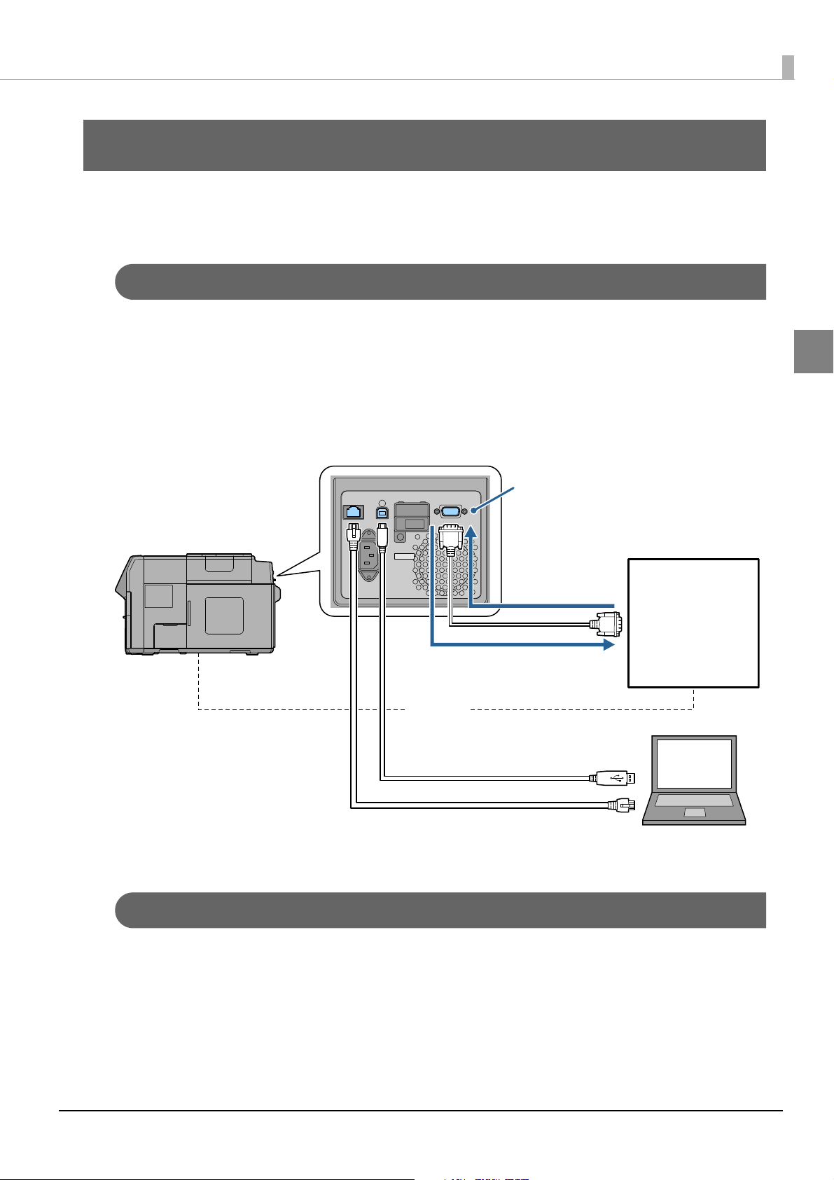
Extended I/F (D-Sub15)
Input signal
(Control of the printer)
Output signal
(check the printer status)
Synchronize
USB or Ethernet (Used to transmit commands)
External device
Overview
This specification describes the extended I/F specifications for the TM-C7500 series / C7500G series. Please
develop your device to match these specifications.
Functionality
Using the extended I/F signal allows the user to perform synchronous control of the printer and external
devices and to check the printer status.
Signal transmission between the printer and external device uses a D-Sub15 cable.
Also, use a USB cable or Ethernet cable to send ESC/Label commands, which set the operation for the extended
I/F, from the host PC.
1
Target options
The following external devices can be connected.
• Rewinder (including large diameter roll)
• Unwinder (including large diameter roll)
• Other than above listed options needed to work with Color inkjet printer.
5
Extended I/F Specification
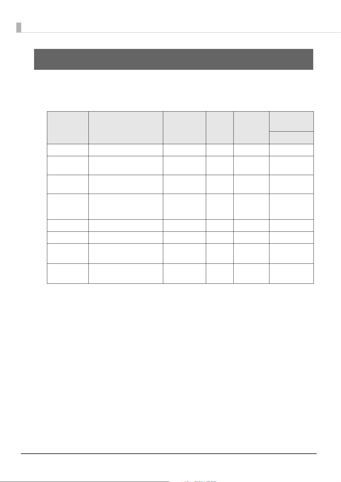
I/F Signal
The following lists the signal specifications for the extended I/F.
Signal Explanation
Paper out Output paper out. OUT Level Open Drain Available
Input-Output
(From printer)
Signal
Wave
Electrical
Condition
Input-output
Connector
D-Sub 15
Ink cartridge Output replace ink cartridge, or
ink low, for each ink cartridge.
Printer error Output error, such as printer
error, cover open, pause.
Print end Output upon printer paper
feed or completion of continuous printing.
Paper back feed Output paper back feed. OUT Level Open Drain Available
Reserved - OUT Level Open Drain Available
Pause This signal input toggles the
pause status.
Reserved - IN Level CMOS
OUT Level Open Drain Available
OUT Level Open Drain Available
OUT Level/
Pulse
IN Level/
Pulse
Open Drain Available
CMOS
input
input
Available
Available
6
Command
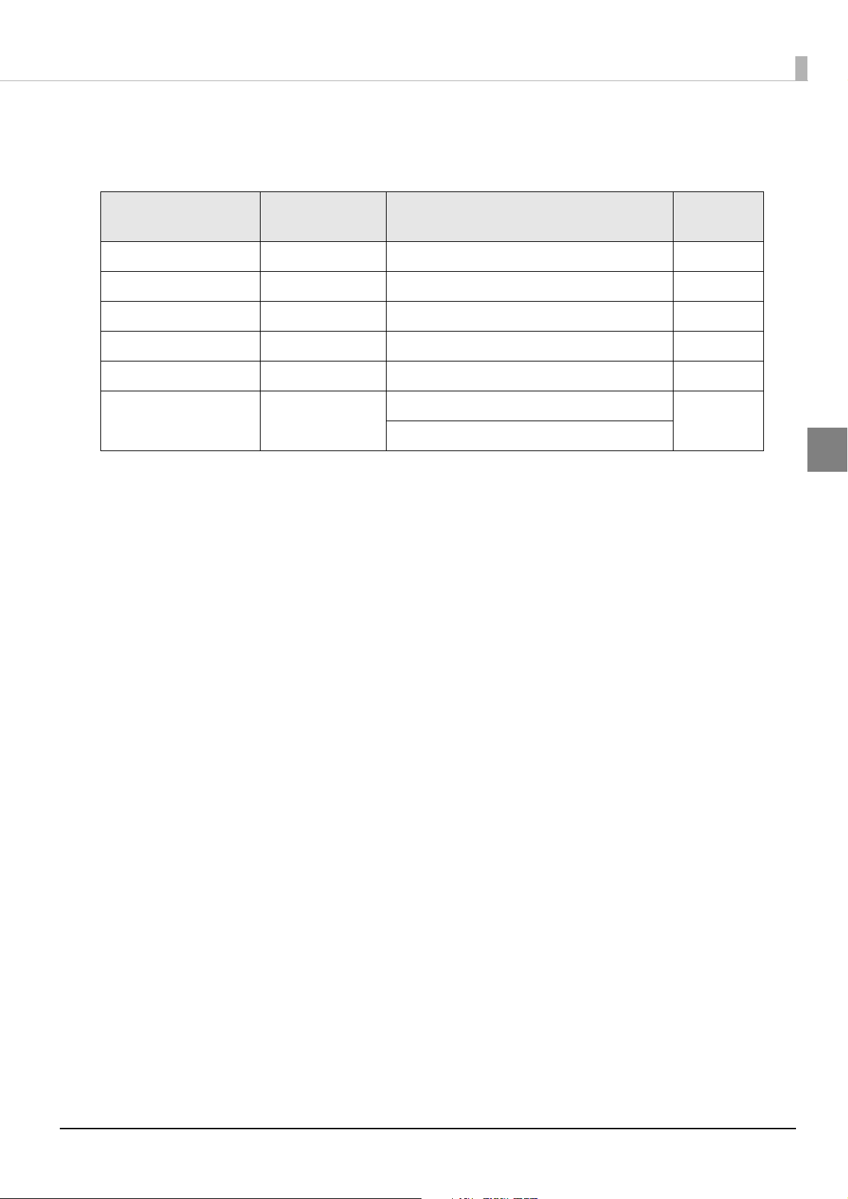
The following lists the commands (ESC/Label) which set the operation of the extended I/F.
Chapter 2 Extended I/F Specification
Signal
Print end OUT ^S(CNA, B, b = D/E/N/0/1/2/3/4 page 8
Paper back feed OUT ^S(CNA, R, b = D/E/0/1/2 page 9
Ink cartridge OUT ^S(CNA, I, b = D/E/N/0/1/2/3/4 page 10
Paper out OUT ^S(CNA, P, b = D/E/0/1/2 page 11
Printer error OUT ^S(CNA, E, b = D/E/0/1/2 page 12
Pause IN ^S(CNI, P, b = 0/1/2/3/4 page 13
Input-Output
(From printer)
~H(CNI, P
Commands and Parameters
that control the extended I/F
Page
2
7

Print end
[Input-Output] <OUT>
[Format] ^S(CNA, B, b
[Parameter]
Description Definition range
b = mode D/E/N/0/1/2/3/4
[Function]
“Print end” signal is set to the mode that is specified by parameter b.
Parameter b Mode description
D/0 “Print end” signal is not output.
1 “Print end” signal is high in normal status, low in paper feeding.
E/2 “Print end” signal is low in normal status, high in paper feeding.
3 “Print end” signal is high in normal status, when continuous printing end Low for 20 msec.
N/4 “Print end” signal is low in normal status, when continuous printing end High for 20 msec.
[Initial value] 0
[EX]"Print end" signal is set to the mode that is high in normal status, low in paper feeding.
^XA
^S(CNA,B,1
^JUS
^XZ
• The ^JUS command is required to save settings to the non-volatile memory of the printer unit.
• Use a USB cable or Ethernet cable to send ESC/Label commands from the host PC.
• For the signal output timing, see
"Timing chart" on page 20.
8

Chapter 2 Extended I/F Specification
Paper back feed
[Input-Output] <OUT>
[Format] ^S(CNA, R, b
[Parameter]
Description Definition range
b = mode D/E/0/1/2
[Function]
“Paper back feed” signal is set to the mode that is specified by parameter b.
Parameter b Mode description
D/0 “Paper back feed” signal is not output.
1 “Paper back feed” signal is high in normal status and low in back feeding.
E/2 “Paper back feed” signal is low in normal status and high in back feeding.
2
[Initial value] 0
[EX] "Paper back feed" signal is set to the mode that is high in normal status, low in back feeding.
^XA
^S(CNA,R,1
^JUS
^XZ
• The ^JUS command is required to save settings to the non-volatile memory of the printer unit.
• Use a USB cable or Ethernet cable to send ESC/Label commands from the host PC.
• For the signal output timing, see
"Timing chart" on page 20.
9

Ink cartridge
[Input-Output] <OUT>
[Format] ^S(CNA, I, b
[Parameter]
Description Definition range
b = mode D/E/N/0/1/2/3/4
[Function]
“Ink cartridge” signal is set to the mode that is specified by parameter b.
Parameter b Mode description
D/0 “Ink cartridge” signal is not output.
1 “Ink cartridge” signal is high in normal status and low in replace ink cartridge *
E/2 “Ink cartridge” signal is low in normal status and high in replace ink cartridge *
3 “Ink cartridge” signal is high in normal status and low in ink low *
N/4 “Ink cartridge” signal is low in normal status and high in ink low *
2
or replace ink cartridge *1.
2
or replace ink cartridge *1.
1
.
1
.
∗1 Printer status: “NO INK CARTRIDGE”, “INK CARTRIDGE EMPTY”, “INK CARTRIDGE READ ERROR”
∗2 Printer status: “INK CARTRIDGE NEAR EMPTY”
[Initial value] 0
[EX] "Ink cartridge" signal is set to the mode that is low in normal status and high in replace ink cartridge.
^XA
^S(CNA,I,E
^JUS
^XZ
• The ^JUS command is required to save settings to the non-volatile memory of the printer unit.
• Use a USB cable or Ethernet cable to send ESC/Label commands from the host PC.
• For the signal output timing, see
"Timing chart" on page 20.
10

Chapter 2 Extended I/F Specification
Paper out
[Input-Output] <OUT>
[Format] ^S(CNA, P, b
[Parameter]
Description Definition range
b = mode D/E/0/1/2
[Function]
“Paper out” signal is set to the mode that is specified by parameter b.
Parameter b Mode description
D/0 “Paper out” signal is not output.
1 “Paper out” signal is high in normal status and low in paper out *.
E/2 “Paper out” signal is low in normal status and high in paper out *.
2
∗ Printer status: “NO PAPER”, “NO PAPER ERROR”
[Initial value] 0
[EX] "Paper out" signal is set to the mode that is low in normal status and high in paper out.
^XA
^S(CNA,P,E
^JUS
^XZ
• The ^JUS command is required to save settings to the non-volatile memory of the printer unit.
• Use a USB cable or Ethernet cable to send ESC/Label commands from the host PC.
• For the signal output timing, see
"Timing chart" on page 20.
11

Printer error
[Input-Output] <OUT>
[Format] ^S(CNA, E, b
[Parameter]
Description Definition range
b = mode D/E/0/1/2
[Function]
“Printer error” signal is set to the mode that is specified by parameter b.
“Printer error” signal shows printer's unrecoverable error, recoverable error and pause status.
Parameter b Mode description
D/0 “Printer error” signal is not output.
1 “Printer error” signal is high in normal status and low in printer error *.
E/2 “Printer error” signal is low in normal status and high in printer error *.
∗ Printer status: “MEDIA DETECTION ERROR”, “MEDIA SIZE ERROR”, “PAPER JAM ERR”, “NO PAPER”,
“NO PAPER ERROR”, “PAPER PATH ERROR”, “PAPER REMOVAL ERROR”, “INK COVER OPEN”,
“NO INK CARTRIDGE”, “INK READ ERROR”, “M/B COVER OPEN”, “NO M/B”, “M/B READ ERROR”,
“REPLACE INK”, “REPLACE M/B”, “ROLL PAPER COVER OPEN”, “PAPER COVER OPEN”,
“FRONT COVER OPEN”, “MEMORY FULL”, “PRINTER ERROR”, “SERVICE REQD.”
[Initial value] 0
[EX] "Printer error" signal is set to the mode that is low in normal status and high in printer error.
^XA
^S(CNA,E,E
^JUS
^XZ
12
• The ^JUS command is required to save settings to the non-volatile memory of the printer unit.
• Use a USB cable or Ethernet cable to send ESC/Label commands from the host PC.
• For the signal output timing, see
"Timing chart" on page 20.

Chapter 2 Extended I/F Specification
Pause
[Input-Output] <IN>
[Format] ^S(CNI, P, b
[Parameter]
Description Definition range
b = mode 0/1/2/3/4
[Function]
When the “Pause” signal is input, the printer is set to the mode specified by parameter b.
Parameter b Mode description
0 “Pause” signal is ignored.
1 Switches the Pause status *
error” signal is not asserted for the “Pause” signal input.
2 Switches the Pause status *
error” signal is not asserted for the “Pause” signal input.
3 The printer is paused while the “Pause” signal is low asserted.
4 The printer is paused while the “Pause” signal is high asserted.
∗1 Assert to the printer input (#1) requires edge input (high to low, or low to high).As the “Printer error” signal
changes once the printer enters the pause status, assert the “Pause” signal before then.
∗2 When paused, the printer switches to unpaused. When unpaused, the printer switches to paused.
2
when low asserted *1 more than 20 msec or until the “Printer
2
when high asserted *1 more than 20 msec or until “Printer
[Initial value] 0
[Limitation]
Printer firmware version WAI31000 or higher is required to use this function.
[EX] The printer is paused while the "Pause" signal is low asserted.
^XA
^S(CNI,P,3
^JUS
^XZ
2
• The ^JUS command is required to save settings to the non-volatile memory of the printer unit.
• Use a USB cable or Ethernet cable to send ESC/Label commands from the host PC.
• For the signal input timing, see
"Timing chart" on page 20.
13

Acquires the "Pause" signal's mode
[Format] ~H(CNI, P
[Parameter]
none
[Function]
The mode of “Pause” signal set to the printer is acquired.
[Response]
<STX> ^S(CNI,P,<mode><ETX>
<STX>: Control code that means Start of text (02H by the hexadecimal number expression).
<ETX>: Control code that means End of text (03H by the hexadecimal number expression).
<mode>: Either of 0/1/2/3/4 that shows mode of “Pause” set to printer.
14

Pin Arrangement of Connector
The following lists the pin arrangement for the D-Sub connector.
Chapter 2 Extended I/F Specification
Pin No. Signal
1Pause IN
2 Reserved IN
3 Reserved OUT
4GND GND
5GND GND
6GND GND
7GND GND
8GND GND
9 OPEN -
10 GND GND
11 Paper out OUT
12 Ink cartridge OUT
13 Paper back feed OUT
Input-Output
(From printer)
2
14 Print end OUT
15 Printer error OUT
15

Electrical characteristic
The followings list the electrical characteristics.
Absolute maximum ratings
Item Symbol Min. Typ. Max. Units Note
Input voltage
(H level)
Input voltage
(L level)
Output voltageVO--30[V]*
Output current IO(max) - - 10 [mA] *
VIH(max)--30[V]
VIL(min) -0.5 - - [V]
Electrical characteristics
Item Symbol Min. Typ. Max. Units Note
Input voltage
(H level)
Input voltage
(L level)
Output voltage
(L level)
VIH2.6--[V]
VIL--0.45[V]
VOL - 0.05 0.1 [V] IO=10 mA
16
Output leakage
current
∗ Because the output type is open drain, be sure to set the pull-up voltage and pull-up resistor less than the maxi-
mum ratings of output voltage and output current.
ILK--1.0[uA]VO=30 V

Signal Logic
The following lists the signal logic.
Chapter 2 Extended I/F Specification
Pin No. Signal
1 Pause IN Assert while 20 msec *
2 Reserved IN - -
3 Reserved OUT - -
4GND GND - -
5GND GND - -
6GND GND - -
7GND GND - -
8GND GND - -
9OPEN---
10 GND GND - -
11 Paper out OUT Paper out *
12 Ink cartridge OUT Replace ink cartridge or Ink low *2/ With ink left *
Input-Output
(From printer)
Low High-Z
Signal level: Level/ Pulse
Signal Logic
1, 2
2
/ Paper remaining *
2
2
2
13 Paper back feed OUT Back feeding *2/ No back feeding *
14 Print end OUT Feeding paper *2 or Continuous printing end *
/ No feeding paper *
Signal level: Level/ Pulse (20 msec)
15 Printer error OUT Error *
2
/ No error *
2
2
2
∗1 Assert while 20 msec, or until asserted “Printer error” signal (#15).
∗2 Enable to change assert logic by command.
2
17

External Device Connection Method
Extended I/F connector
Roll rewinder
Roll unwinder
Roll rewinder
Roll unwinder
Use a D-Sub15 cable to connect with an external device. Connect the cable to the extended I/F connector on the
printer rear.
Roll Rewinder or Roll Unwinder
Connect the rewinder's I/F to the Extended I/F connector.
Prepare a power supply for the roll rewinder that is separate from the printer's power supply.
Connect the roll unwinder's I/F to the Extended I/F connector.
Prepare a power supply for the roll unwinder that is separate from the printer's power supply.
Connect the rewinder's I/F to the Extended I/F connector.
Connect the roll unwinder to the roll rewinder.
18

Interface circuit
Input port
TM-C7500 side
4-8,10pin
Output signal
device side
TM-C7500 side
Output port
Input signal
FET
4-8,10pin
V
pull-up
R
pull-up
device side
Prepare a circuit like the one below on the device side.
Input Connector
Chapter 2 Extended I/F Specification
2
• An open drain signal is input to the TM-C7500.
• When inputting a level signal, set high to 2.6 V or higher and low to 0.45 V or lower.
• Because the TM-C7500 does not have a terminal for providing power to a device, prepare a drive power
supply for the circuit on the device side.
Output Connector
• V
: Perform the pull-up using 30 V or lower.
pull-up
• Because the TM-C7500 does not have a terminal for providing power to a device, prepare a power supply for
on the device side.
pull-up
: Set a resistance value to ensure 10 mA or lower.
• R
the V
pull-up
19

Timing chart
ABCD
TM-C7500 Paper Feeding Timing Chart
Printing (forward feed)
Back feed
I/F signal
Print end signal
Level *
1
*
2
*
3
*
4
Back feed signal
Logic can be
reversed using
commands
Device operation
1) Roll rewinder
2) Roll unwinder
Rewinding
Unwinding
Back feeding
Pulse *
1
Set a timing chart for the printer and device like the one below.
Continuous Printing
∗1 Switch using command. See "Print end" on page 8.
∗2 If paper is being fed in the normal feeding direction. / If paper feeding is done by the panel.
∗3 If continuous printing ended. (Including stops due to head cleaning or nozzle checks.)
∗4 If paper is being fed in the reverse feeding direction.
Print speed A B C D
20
300 mm/s 224.7 ms ±20% 253.8 ms ±20% 224.7 ms ±20% 253.8 ms ±20%
150 mm/s 160.5 ms ±20% 194.0 ms ±20% 224.7 ms ±20% 253.8 ms ±20%

Chapter 2 Extended I/F Specification
I/F Signal
Paper out
Ink cartridge
Printer error
Pause
Logic can be
reversed using
commands
When the paper out
is cleared
When a paper out occurs
When the ink replacement
status is cleared
When the ink replacement
status occurs
When the printer error is cleared When a printer error occurs When paused
2
21

Pause Command During Printing
TM-C7500 Paper Feeding Timing Chart
Back feed
I/F Signal
*
2
*
3
*
5
Logic can be
reversed using
commands
Print end signal
Back feed signal
*
6
Printing
(forward feed)
Printer error signal
Pause signal
Level *
1
Pulse *
1
Level *
7
Pulse *
7
*
2
*
3
*
8
*
9
*
4
*
4
A ABCD
∗1 Switch using command. See "Pause" on page 13.
∗2 After “Pause” signal is input, it enters a pause status after finishing printing of the current page.
∗3Pause cancelled.
∗4 Create an interval (more than one second) when toggle the pause status.
∗5 Enters into a pause status when the page currently being printed is ended without being completed.
∗6 If paper is being fed in the normal feeding direction. / If paper feeding is done by the panel.
∗7 Switch using command. See
∗8 If continuous printing ended. (Including stops due to head cleaning or nozzle checks.)
"Print end" on page 8.
∗9 If paper is being fed in the reverse feeding direction.
22

Chapter 2 Extended I/F Specification
Print speed A B C D
300 mm/s 224.7 ms ±20% 253.8 ms ±20% 224.7 ms ±20% 253.8 ms ±20%
150 mm/s 160.5 ms ±20% 194.0 ms ±20% 224.7 ms ±20% 253.8 ms ±20%
2
23
 Loading...