

Page 1
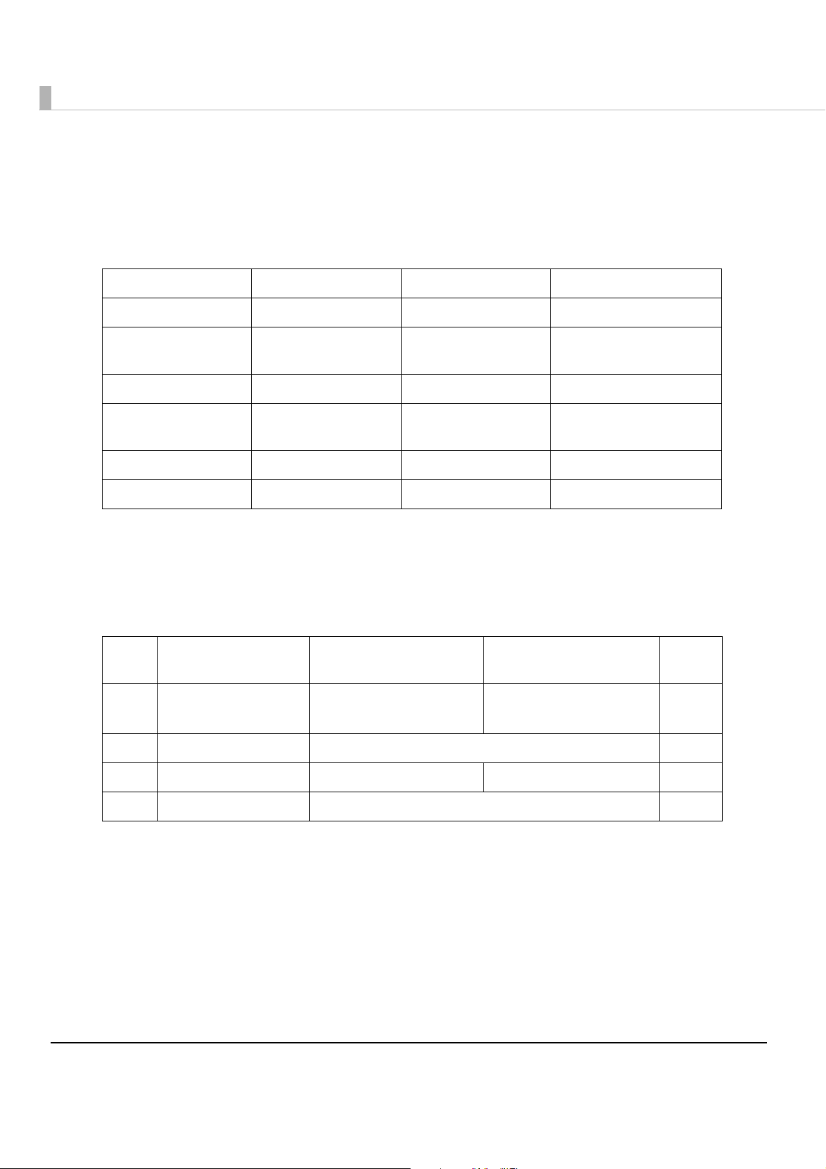
Technical Reference Guide
Describes features and general specifications for the product.
Describes setup and installation of the product.
Describes how to control the printer and necessary information
when you develop applications.
Describes how to handle the product.
Describes to administrator for necessary information to administer
TM-C710 in the system such as installing new printer or
replacing the printer.
Product Overview
Setup
Application Development Information
Handling
Maintenance of the TM-C710
M00063201
Rev.B
Page 2

Cautions
• No part of this document may be reproduced, stored in a retrieval system, or transmitted in any form
or by any means, electronic, mechanical, photocopying, recording, or otherwise, without the prior
written permission of Seiko Epson Corporation.
• The contents of this document are subject to change without notice. Please contact us for the latest
information.
• While every precaution has taken in the preparation of this document, Seiko Epson Corporation
assumes no responsibility for errors or omissions.
• Neither is any liability assumed for damages resulting from the use of the information contained
herein.
• Neither Seiko Epson Corporation nor its affiliates shall be liable to the purchaser of this product or third
parties for damages, losses, costs, or expenses incurred by the purchaser or third parties as a result of:
accident, misuse, or abuse of this product or unauthorized modifications, repairs, or alterations to this
product, or (excluding the U.S.) failure to strictly comply with Seiko Epson Corporation’s operating
and maintenance instructions.
• Seiko Epson Corporation shall not be liable against any damages or problems arising from the use of
any options or any consumable products other than those designated as Original Epson Products or
Epson Approved Products by Seiko Epson Corporation.
Trademarks
Microsoft, Windows, and Windows Vista are either registered trademarks or trademarks of Microsoft Corporation in the United States and/or other countries.
EPSON is a registered trademark of Seiko Epson Corporation.
Exceed Your Vision is a registered trademark or trademark of Seiko Epson Corporation.
All other trademarks are the property of their respective owners and used for identification purpose
only.
Copyright
The Ethernet interface model of this product includes software developed by the University of California, Berkeley, and its contributors.
© Seiko Epson Corporation 2013 - 2014. All rights reserved.
2
Page 3
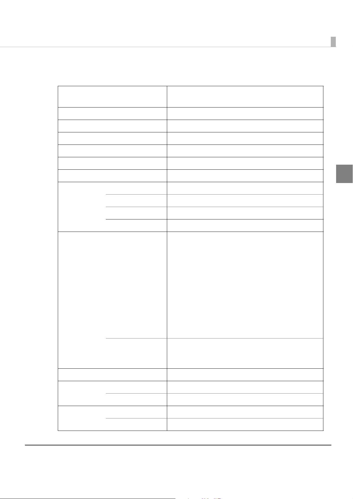
For Safety
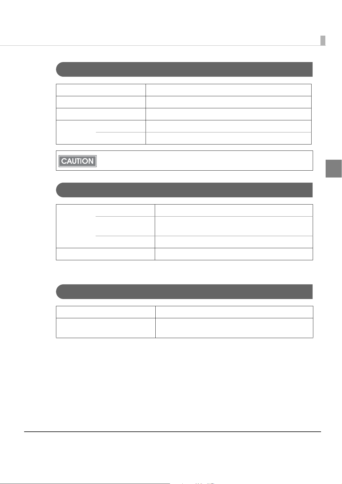
Key to Symbols
The symbols in this manual are identified by their level of importance, as defined below. Read
the following carefully before handling the product.
You must follow warnings carefully to avoid serious bodily injury.
WARNING
Provides information that must be observed to prevent damage to the equipment or loss of
data.
CAUTION
Possibility of sustaining physical injuries.
Possibility of causing physical damage.
Possibility of causing information loss.
Provides information that must be observed to avoid damage to your equipment or a
malfunction.
Provides important information and useful tips.
3
Page 4

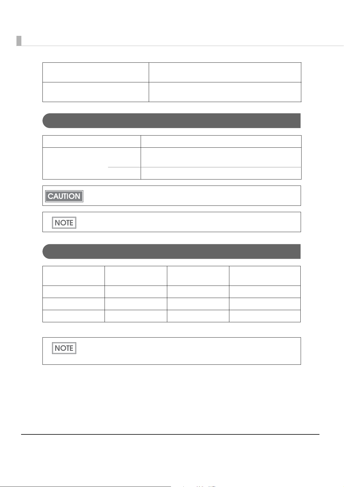
Warnings
WARNING
To avoid risk of electric shock, do not set up this product or handle cables during
a thunderstorm.
Be sure to use as power cable that complies with safety standards with a PE
(power earth) terminal on the plug, and make sure to ground the product before
use.
Ignoring this may result in severe shock.
Never insert or disconnect the power plug with wet hands.
Doing so may result in severe shock.
Handle the power cable with care.
Improper handling may lead to fire or electric shock.
Do not modify or attempt to repair the cable.
Do not place any heavy object on top of the cable.
Avoid excessive bending, twisting, and pulling.
Do not place the cable near heating equipment.
Check that the plug is clean before plugging it in.
Be sure to push the plug all the way in.
Be sure to use the specified power source.
Connection to an improper power source may cause fire or shock.
Do not place multiple loads on the power outlet.
Overloading the outlet may lead to fire.
Shut down your equipment immediately if it produces smoke, a strange odor, or
unusual noise.
Continued use may lead to fire. Immediately unplug the equipment and contact your
dealer or a Seiko Epson service center for advice.
Never attempt to repair this product yourself.
Improper repair work can be dangerous.
Never disassemble or modify this product.
Tampering with this product may result in injury or fire.
Do not allow foreign matter to fall into the equipment.
Penetration by foreign objects may lead to fire.
If water or other liquid spills into this equipment, do not continue to use it.
Continued use may lead to fire. Unplug the power cord immediately and contact your
dealer or a Seiko Epson service center for advice.
If you open the DIP switch cover, be sure to close the cover and tighten the screw
after adjusting the DIP switch.
Using this product with the cover open may cause fire or electric shock.
Do not use aerosol sprayers containing flammable gas inside or around this
product.
Doing so may cause fire.
4
Page 5

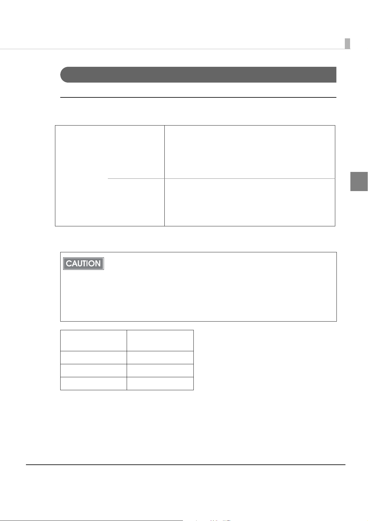
Cautions
Do not connect cables in ways other than those mentioned in this manual.
Different connections may cause equipment damage or fire.
CAUTION
Be sure to set this equipment on a firm, stable, horizontal surface.
The product may break or cause injury if it falls.
Do not use this product in locations subject to high humidity or dust levels.
Excessive humidity and dust may cause equipment damage or fire.
Do not place heavy objects on top of this product. Never stand or lean on this
product.
Equipment may fall or collapse, causing breakage and possible injury.
To ensure safety, unplug this product before leaving it unused for an extended
period.
Do not remove the ink cartridge during transportation of the printer.
Restriction of Use
When this product is used for applications requiring high reliability/safety, s uch as
transportation devices related to aviation, rail, marine, automotive, etc.; disaster prevention
devices; various safety devices, etc.; or functional/precision
product only after giving consideration to including fail-safes and redundancies into your
design to maintain safety and total system reliability. B ec ause this product was not intended for
use in applications requiring extremely high reliability/safety, s uch as aerospace equipment,
main communication equipment, nuclear power control equipment, or medical equipment
related to direct medical care, etc., please make your own judgment on this product’s suitability
after a f
ull evaluation.
devices, etc., you should use this
5
Page 6

About this Manual
Aim of the Manual
This manual was created to provide information on development, design, and installation of
POS systems and development and design of printer applications for developers.
Manual Content
The manual is made up of the following sections:
Chapter 1 Product Overview
Chapter 2 Setup
Chapter 3 Application Development Information
Chapter 4 Handling
Chapter 5 Maintenance of the TM-C710
6
Page 7

Contents
■ For Safety .............................................................................................................................. 3
Key to Symbols........................................................................................................................................ 3
Warnings.................................................................................................................................................. 4
Cautions ..................................................................................................................................................5
■ Restriction of Use.................................................................................................................. 5
■ About this Manual................................................................................................................ 6
Aim of the Manual .................................................................................................................................6
Manual Content.....................................................................................................................................6
■ Contents................................................................................................................................ 7
Product Overview........................................................................11
■ Features............................................................................................................................... 11
■ Product Configuration........................................................................................................ 13
Interface ................................................................................................................................................13
Color ......................................................................................................................................................13
Accessories ...........................................................................................................................................13
■ Parts Name and Function.................................................................................................. 14
Front Panel.............................................................................................................................................14
Rear Panel.............................................................................................................................................15
Buttons and Indicators .........................................................................................................................16
■ Status/Error Indications...................................................................................................... 18
■ Offline .................................................................................................................................. 19
■ Paper End Detection.......................................................................................................... 19
■ Ink Replacement Request Detection............................................................................... 19
■ Paper Jam Detection......................................................................................................... 19
■ Buzzer Function................................................................................................................... 20
■ DIP Switches........................................................................................................................ 20
■ Product Specifications....................................................................................................... 21
Operating Environment .......................................................................................................................22
Printing Speed.......................................................................................................................................22
Barcodes/Two-Dimensional Symbols..................................................................................................23
Ink Cartridge .........................................................................................................................................27
Print Area and Cut Positions ................................................................................................................28
Electrical Characteristics .....................................................................................................................29
Reliability................................................................................................................................................29
Environmental Specifications ..............................................................................................................29
External Dimensions..............................................................................................................................31
■ Precautions......................................................................................................................... 32
To Handle the Ink Cartridge ................................................................................................................32
To Prevent Ink Waste.............................................................................................................................32
7
Page 8

■ Restrictions.......................................................................................................................... 33
Setup .............................................................................................35
■ Flow of Setup ...................................................................................................................... 35
■ Installing the Printer............................................................................................................ 36
Important Notes on Installation.......................................................................................................... 36
■ Connecting the USB/Ethernet Cable................................................................................ 38
■ Connecting the AC Adapter............................................................................................. 40
■ Loading the Roll Paper ...................................................................................................... 41
■ Loading the Ink Cartridge ................................................................................................. 43
■ Setting the Lane ID .............................................................................................................45
■ Setting the Printer IP Address ............................................................................................ 46
■ Adding a TCP/IP Port.......................................................................................................... 47
■ Installing the Printer Driver................................................................................................. 50
For USB Interface Model...................................................................................................................... 50
For Ethernet Interface Model ............................................................................................................. 51
■ Installing Status API ............................................................................................................ 52
■ Setting the DIP Switches..................................................................................................... 53
Application Development Information......................................55
■ Overview............................................................................................................................. 55
■ Printer Driver ....................................................................................................................... 55
■ Status API ............................................................................................................................ 56
■ Sample Program ................................................................................................................ 56
■ Software .............................................................................................................................. 58
Printer Driver.......................................................................................................................................... 58
Administering network printers ........................................................................................................... 58
Developing applications..................................................................................................................... 59
Handling .......................................................................................61
■ Replacing the Ink Cartridge ............................................................................................. 61
■ Replacing the Roll Paper................................................................................................... 62
■ Removing Jammed Paper ................................................................................................ 64
■ How to Use the Printer Driver............................................................................................. 65
How to Display the Printer Driver ........................................................................................................ 65
Registering User Defined Media ......................................................................................................... 66
8
Page 9

Favorite Setting .................................................................................................................................... 67
Information for User Definition ............................................................................................................ 70
Buzzer Setting at the Time of Errors .................................................................................................... 71
Autocutting after Printing ................................................................................................................... 72
Barcode Printing .................................................................................................................................. 73
2D Symbol Printing ............................................................................................................................... 82
Barcode and 2D Symbol Font Printing on .NET Environment .......................................................... 87
Functions of the Printer Driver............................................................................................................. 89
■ Uninstallation.......................................................................................................................93
Uninstalling the Printer Driver .............................................................................................................. 93
Uninstalling Status API.......................................................................................................................... 95
■ Self-test ................................................................................................................................98
Procedure for the Self-test .................................................................................................................. 98
■ Nozzle Check......................................................................................................................99
Nozzle Check Using the Self-test ........................................................................................................ 99
Nozzle Check Using the Printer Driver................................................................................................ 99
■ Cleaning............................................................................................................................100
Cleaning the Printer Case ................................................................................................................ 100
Head Cleaning .................................................................................................................................. 100
■ Preparing for Transport .....................................................................................................102
■ Storing Long-term .............................................................................................................103
Before Long-term Storage ................................................................................................................ 103
After Long-term Storage ................................................................................................................... 103
■ Troubleshooting ................................................................................................................105
Lighting and Flashing Error LED......................................................................................................... 105
Maintenance of the TM-C710...................................................107
■ Necessary Information for an Administrator of the Printer ...........................................108
Printer Driver Functions ...................................................................................................................... 108
Destination for the Printer Driver Setting.......................................................................................... 109
Installing Multiple Printer Drivers on One Client Computer ........................................................... 110
■ Maintenance ....................................................................................................................111
Adding a Client Computer (for the Ethernet Interface Model) ................................................... 111
Adding a Printer ................................................................................................................................. 112
Adding a Paper Type/Changing the Print Setting......................................................................... 113
Replacing the Printer......................................................................................................................... 113
9
Page 10

10
Page 11

Chapter 1 Product Overview
Product Overview
This chapter describes features and functions of the product.
Features
The TM-C710 is a 4-color ink jet printer that offers high speed, full-color printing with the ease of
operability and high reliability required for commercial applications. Its compact size fits easily
on a counter.
Printing
•High-speed printing
130 mm/s {5.12"/s} (printing width 53 mm {2.09"}, 360 dpi × 180 dpi, unidirectional)
100 mm/s {3.94"/s} (printing width 53 mm {2.09"}, 360 dpi × 360 dpi, bidirectional)
90 mm/s {3.54"/s} (printing width 53 mm {2.09"}, 360 dpi × 720 dpi, bidirectional)
•Full color printing
CMYK 4-color printing
Each color has 4 gradations
Print resolution: 360 dpi × 180 dpi, 360 dpi × 360 dpi, 720 dpi × 360 dpi
[dpi: dots per 25.4 mm (dots per inch)]
Handling
•Front operation (when replacing roll paper and ink cartridges)
•Drop-in roll paper method
•An autocutter as standard equipment
Reliability
• Uses pigment ink for excellent light-fastness and water resistance
1
•Fitted with automatic nozzle check system and automatic recovery function for missing dots
Printer driver
•Printing with a Windows printer driver.
•The printer has a built-in barcode font, which is available from .NET application.
•Supported OS
For detailed information on supported operating systems, see the release note for the printer driver.
11
Page 12

Status API
•Can transmit the printer status (such as printer and ink cartridge status, and print job informa-
tion) to your applications, and can set the buzzer to beep when an error such as a cover open
occurs.
•Dedicated sample program using Status API (program language: C + +, VB.NET, C#)
pared.
Other features
•Compact size that fits unobtrusively on a counter
Main unit footprint: W: 140 mm × D: 210 mm {5.51" × 8.27"}
•Ethernet interface and USB interface as standard equipment
•A buzzer as standard equipment
is pre-
12
Page 13

Chapter 1 Product Overview
Product Configuration
Interface
USB interface (USB 2.0 high speed) and Ethernet interface (100 Base-TX/10 Base-T)
Color
EDG (Epson Dark Gray)
Accessories
Unpacking
•Ink cartridge (Model number: SJIC25P) (STARTER CARTRIDGE)
•Ink cartridge (Model number: SJIC25P)
• Roll paper
•AC Adapter (Model: Adapter, K)
•AC cable
•TM-C710 Documents Disc
•Setup Guide
1
13
Page 14
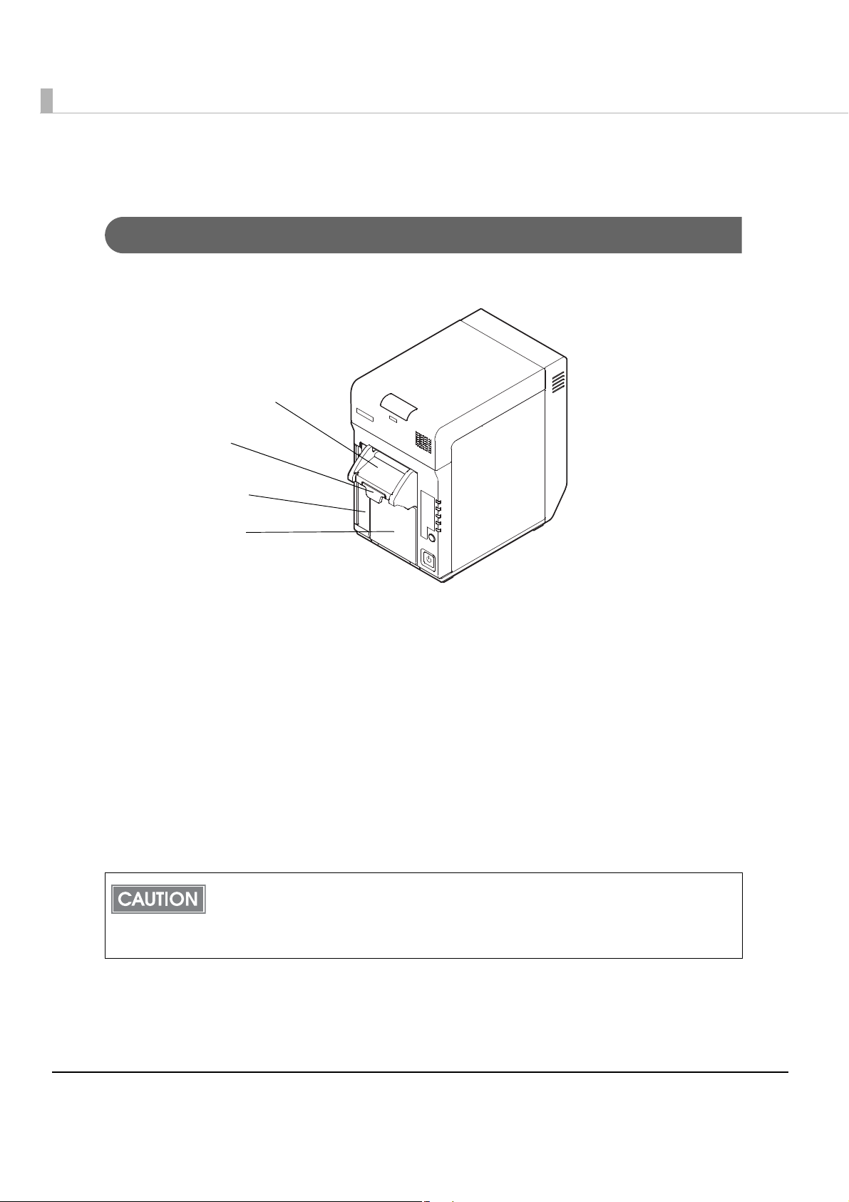
Parts Name and Function
Roll paper cover
Release lever
Paper ejection guide
Ink cartridge slot
Front Panel
Paper ejection guide:
Printed coupons are ejected along the paper ejection guide.
Release lever:
Pull the release lever to open the roll paper cover.
Ink cartridge slot:
Ink cartridge is loaded.
Roll paper cover:
Open the roll paper cover to load or replace roll paper.
Do not open the roll paper cover during printer operation. When the roll paper cover is
opened during printing, printing stops, the printer automatically goes offline, and the Error
LED lights. The data being printed is lost. When the cover is closed, the printer returns to
online and the printable state.
14
Page 15
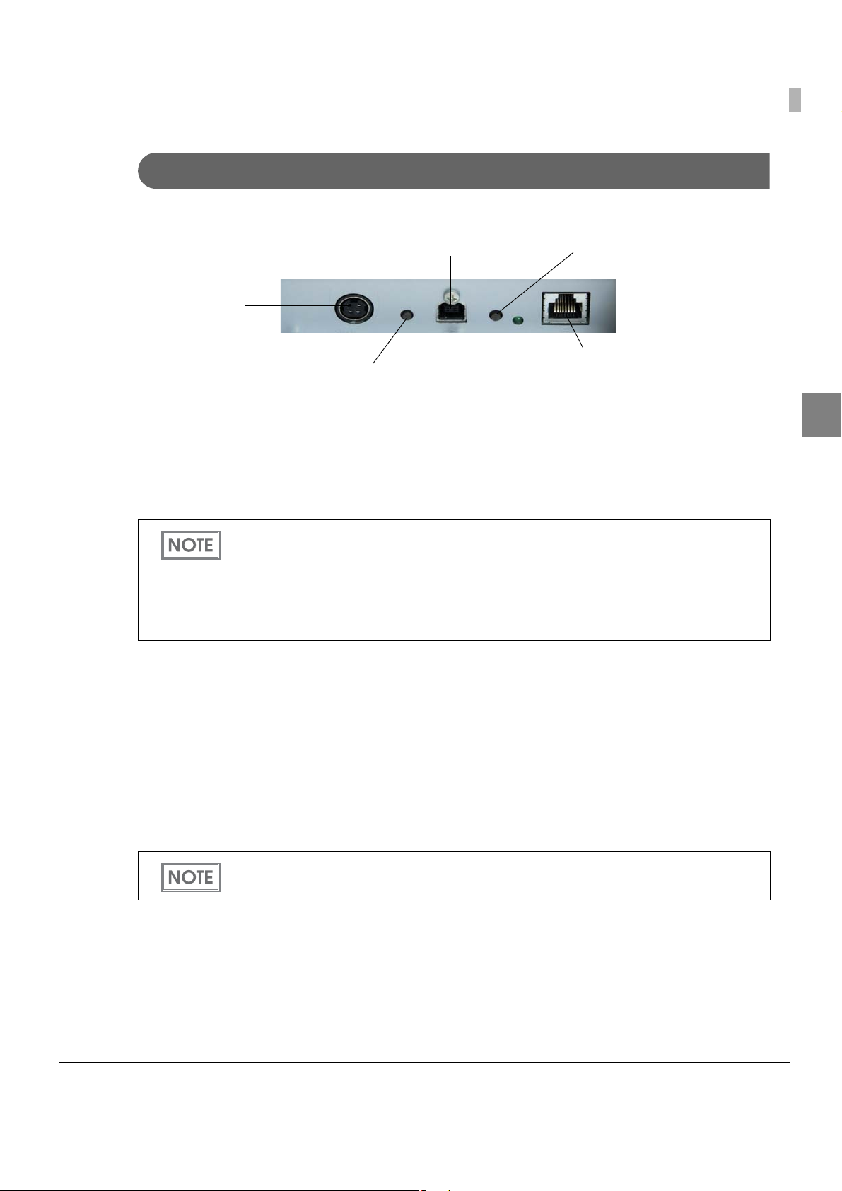
Rear Panel
Power connector
Lane setting button
Self-test button
USB interface connector
Ethernet interface connector
Power connector:
Connect a DC cable for the accessory AC adapter.
Self-test button:
Press the button to perform a self-test.
Chapter 1 Product Overview
1
You can check the printer status with the following items the self-test prints out.
Printer configuration
IP address
Firmware version
Serial number
Nozzle check pattern
USB interface connector:
Connect a USB cable when USB interface is used.
Lane setting button:
The printer executes the lane setting function after this button is held down for 5 seconds or
longer continuously.
Ethernet interface connector:
Connect a LAN cable.
For details how to connect the interface and power supply connector, see "Connecting the
USB/Ethernet Cable" on page 38 and "Connecting the AC Adapter" on page 40.
15
Page 16
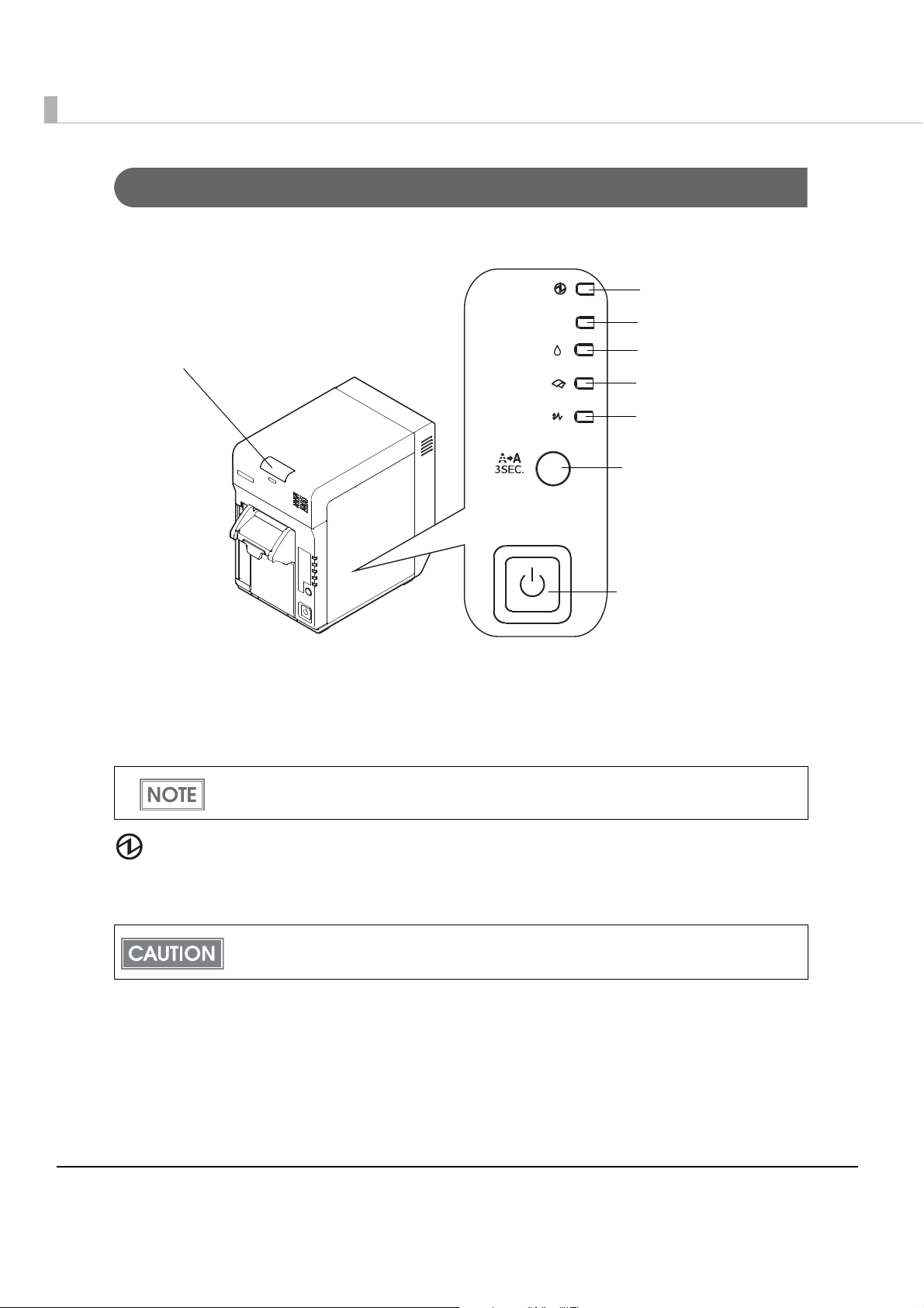
Buttons and Indicators
Error
Replace Ink
Check Paper
Paper Jam
Power LED
Cleaning button
Error LED
Replace Ink LED
Check Paper LED
Paper Jam LED
Status LED
Power button
Status LED (Green/Orange)
•The green LED lights when there is no error.
•The orange LED flashes when there is an error.
The buzzer beeps when the Status LED flashes. For details on the buzzer function, see
"Buzzer Function" on page 20.
Power LED (Green)
•Lights when the power is on.
•Flashes when the printer is initializing, cleaning, printing, or during an error state.
Before turning off the printer, wait more than 10 seconds (so that the print head cap closes)
after the printer finishes operating.
Error LED (Orange)
•Lights when the printer is in the error state.
•Flashes when a fatal error or maintenance requirement occurs.
16
Page 17
Chapter 1 Product Overview
Replace Ink LED (Orange)
•Lights when no ink cartridge has been loaded or when the printer is requesting replacement of
the ink cartridge.
Check Paper LED (Orange)
•Lights when no paper has been loaded.
Paper Jam LED (Orange)
•Lights when the paper is jammed.
The printer status is also displayed with combinations of lighting and flashing of LEDs. See
"Status/Error Indications" on page 18 for details.
Cleaning button
•When printing is faint or dots are missing, press the Cleaning button for 3 seconds or more
continuously to perform the print head cleaning.
Do not press the cleaning button unless there is a problem with print quality. Unnecessary
cleaning wastes ink.
Power button
•When DIP switch 1 is Off, the power is turned on after the Power button has been pressed
while the power is off.
•When DIP switch 1 is Off, the power is turned off after the Power button has been pressed for
3 seconds or more while the power is on.
•When DIP switch 1 is On, the printer settings are reset after the Power button has been pressed
for 3 seconds or more.
For 30 seconds after a reset, the printer and host cannot communicate.
After resetting, the printer is in the same state as when the power is turned on.
For details on the DIP switches, see "DIP Switches" on page 20.
1
17
Page 18
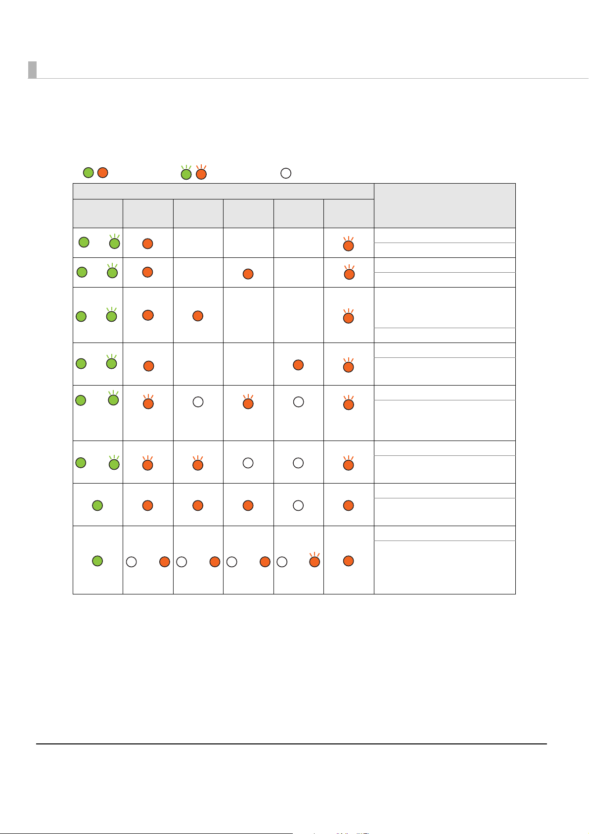
Status/Error Indications
: On
: Flashing : Off
or
or
or
ororor
or
or
or
or
The printer status is displayed by a combination of lighting and flashing of LEDs.
Power Error
LED
Replace
Ink
———
——
——
Check
Paper
——
Paper
Jam
Status
Status/
Action
Roll paper cover is open.
Close the roll paper cover.
No roll paper is loaded.
Load new roll paper.
No ink cartridge is loaded or
ink cartridge needs to be
replaced.
Load new ink cartridge.
Paper jam occurred.
Remove jammed paper and
load roll paper.
Fatal error occurred.
Reset the printer. If the printer
does not recover, the printer
needs to be repaired.
Maintenance is required.
The printer needs to be
repaired.
Software updating
Wait for the updating to be
completed.
Lane setting
Complete the lane setting.
After the time-out of 30
seconds, the printer recovers
from the lane setting mode.
Concerning the “—” column, this depends on the combination with other states.
18
Page 19
Chapter 1 Product Overview
Offline
The printer does not have an online/offline switch. Offline occurs:
•Between when the power is turned on (including the printer reset through the interface) and
when the printer is ready to receive data.
•During a self-test.
•When the roll paper cover is open.
•During an error state.
•When the printer stops printing due to a paper-end.
•When the printer stops printing due to ink replacement request.
•When the printer is waiting for recovery from a high-temperature error.
The printer can transmit or receive data from/to the host PC even when the printer is offline.
Paper End Detection
When roll paper is used up, printing stops, the printer automatically goes offline, and the Check
Paper LED lights. The data being printed is lost.
When roll paper is replaced with a new roll, the printer returns to online and the printable state.
Ink Replacement Request Detection
When an ink cartridge is not loaded, the printer goes offline, and the Replace Ink LED lights.
When the ink replacement request is detected, the Replace Ink LED lights.
When the ink cartridge is replaced with a new one, the printer returns to online and
state.
the printable
1
Paper Jam Detection
When a roll paper jam occurs, the printer automatically goes offline, and the Paper Jam LED
lights.
When you remove the jammed paper, never pull out the paper forcibly. When roll paper is
replaced and roll paper cover is closed, the printer returns to online and the printable state.
19
Page 20
Buzzer Function
The printer records the buzzer sound file in the NV memory, and beeps the file when the printer
event occurs according to the table below.
Vo l ume control: 2 levels (On/Off)
Printer event Frequency Beeping period Pattern
Fatal error 2.0 KHz Approx. 1.0 seconds 1 time
Maintenance
requirement
Cover open 3.0 KHz Approx. 1.0 seconds Continuous
Time to replace ink
cartridge
Roll paper out 3.0 KHz Approx. 1.0 seconds Continuous
Paper jam error 3.0 KHz Approx. 1.0 seconds Continuous
2.5 KHz Approx. 1.0 seconds 1 time
3.0 KHz Approx. 1.0 seconds Continuous
DIP Switches
Setting the DIP switches to On or Off switches the following functions. See "Setting the DIP
Switches" on page 53 for how to set the DIP switches.
Switch
no.
1 Operation of the
Function On Off Default
power button
Reset
(Power button is disabled)
Power On/ Off
(Power button is enabled)
Off
20
2 Internal use Do not change Off
3 Cleaning at power on Disabled Enabled Off
4 Internal use Do not change On
Page 21
Product Specifications
Print method Serial inkjet, dot matrix
Four-color printing
Print direction Bidirectional/unidirectional printing
Paper feed Forward direction feed
Print width 53 mm {2.09"} maximum
Autocutting method By separated-blade scissors
Autocut type Partial cut (one center point uncut)
Chapter 1 Product Overview
Roll paper supply method Drop-in roll paper
Roll paper Paper width 58 mm {2.28"} (57.5 ± 0.5 mm {2.26 ± 0.02"})
Maximum diameter 90 mm {3.54"}
Paper core Outside diameter: 18 mm {0.71"} or larger
Paper type Plain paper, Light Matte Coated paper
Interface Ethernet Specification: IEEE 802.3-compliant
Communication speed: 100BASE-TX/10BASE-T
Supporting communication protocols:
ARP, ICMP, IP, UDP, TCP, HTTP, DHCP, ENPC, SNMP, Port 9100,
APIPA (Microsoft Automatic Private IP Addressing)
Factory setting:
IP address setting mode: Manual
IP address: 192.168.192.168
Lane number: 168
Host name: TM-C710-xxxxxx
(xxxxxx sets the lowest 6 digits of MAC address.)
Domain name: None
USB Specification: USB 2.0-compliant
Communication speed: High-speed
Device type: Self-powered device
1
Power supply Power supplied by accessory AC adapter
AC adapter Input voltage (rated) 100 to 240 V
Frequency (rated) 50 to 60 Hz
Power
consumption
Operating Average approximately 30 W
Idling Average approximately 3 W
21
Page 22
Main unit size (W D H) 140 210 222 mm {5.51 8.27 8.74"} (excluding the
protrusion)
Mass Approx. 5.2 kg [11.4 lb] (excluding ink cartridge and roll
paper)
Operating Environment
Computers PC/AT-compatible
System requirements CPU Computers with a processor clock speed of 1 GHz or higher
are recommended.
RAM RAM of 512 MB or more is recommended.
If the minimum configuration system requirements as shown above are not met, the printer
may not perform well.
For detailed information about supported operating systems, see the release note for
the printer driver.
Printing Speed
Input resolution
(horizontal vertical)
180 180 dpi 360 180 dpi Unidirectional printing 130 mm {5.12"/s}
360 360 dpi 360 360 dpi Bidirectional printing 100 mm {3.94"/s}
360 360 dpi 720 360 dpi Bidirectional printing 90 mm {3.54"/s}
[dpi: dots per 25.4 mm (dots per inch)]
The printer speeds above are for continuous printing except during print head cleaning,
Printing speed may be slower, depending on the data transmission speed.
Graphic resolution
(horizontal vertical)
autocutting, or starting/ending a job.
Print direction
Printing speed
(53 mm printing width)
22
Page 23
Chapter 1 Product Overview
Barcodes/Two-Dimensional Symbols
Barcodes/Two-dimensional symbols encodable by the printer
driver
Barcode/twodimensional
symbol printing
Barcodes
Identification rate:
ANSI rank D (based
on Seiko Epson
Corporation
standard)
Two-dimensional
symbols
UPC-A, UPC-E, JAN 8 (EAN 8), JAN 13 (EAN 13), CODE 39, CODE
128, GS1-128, GS1 DataBar Omnidirectional,
GS1 DataBar Truncated, GS1 DataBar Limited,
GS1 DataBar Expanded
Stack type:
PDF417, GS1 DataBar Stacked, GS1 DataBar Stacked Omni-
directional, GS1 DataBar Expanded Stacked
Matrix type:
QR Code
If you want to create graphic data for barcodes/two-dimensional symbols, create data which
meet the following conditions.
Use black as the print color of the barcode on blank paper (not pre-printed).
When creating barcode/2-dimensional symbol data as the graphic data, use the input
resolution in the table below. At other resolutions, the barcode reader may return errors.
Because of the characteristics of the ink, it may penetrate the paper, and bars of printed
barcodes may become thicker. This depends on the paper. Users can maintain the barcode recognition rate by methods such as ± 1 correction, reducing the data in a bar by
one pixel and increasing the blank space by one pixel. Be sure not to use this method for
the two-dimensional symbols.
1
Input resolution
(horizontal vertical)
180 180 dpi 360 180 dpi
360 360 dpi 360 360 dpi
360 360 dpi 720 360 dpi
Graphic resolution
(horizontal vertical)
23
Page 24
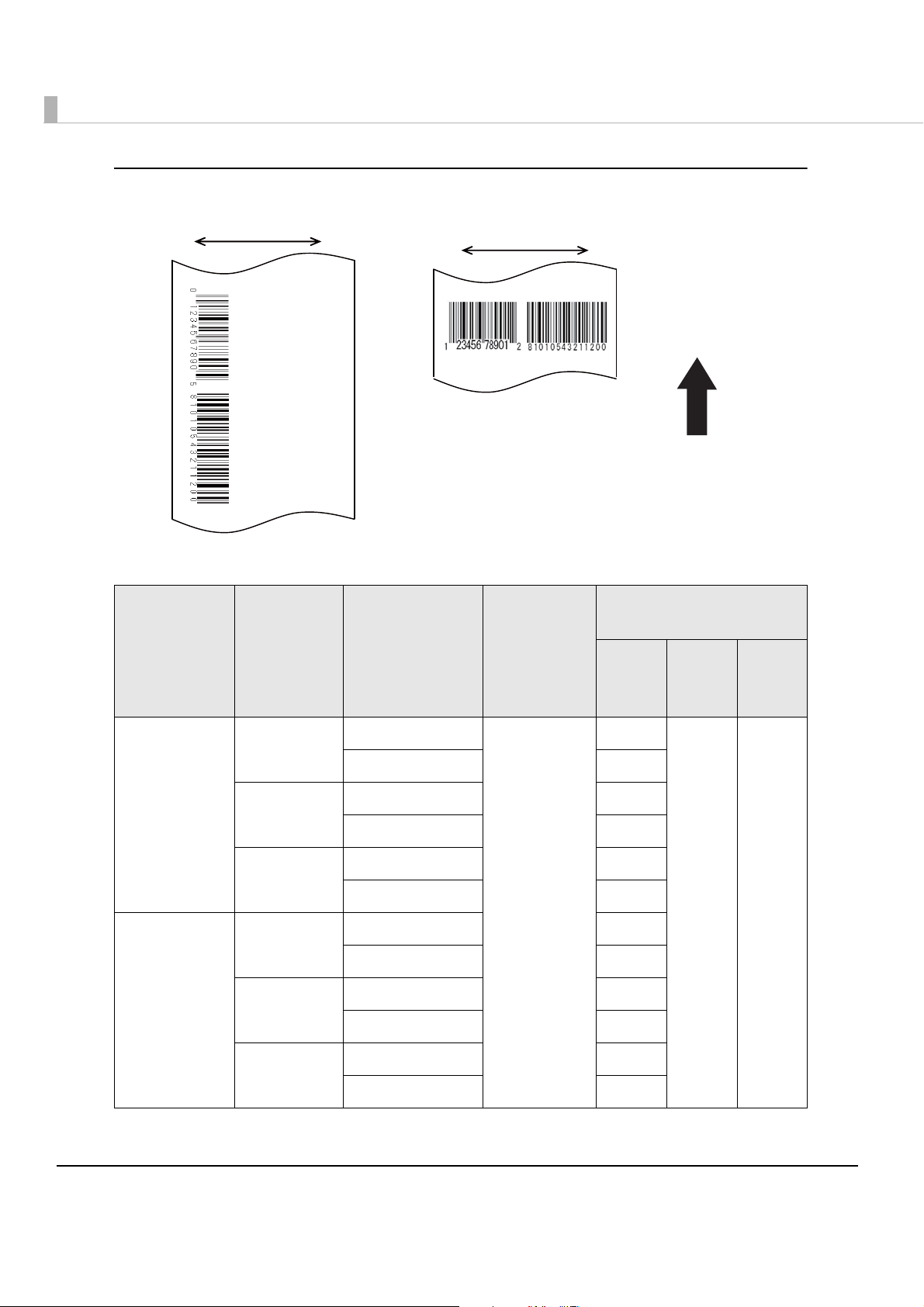
Creating the graphic data for barcode
Paper feeding direction
Carriage move directionCarriage move direction
Ladder Barcode
Fence Barcode
The following table shows the recommended value.
Paper type Resolution Barcode type
Bar width
adjustment
Minimum module
(by 360 dpi)
ANSI
Grade D
or
higher
ANSI
Grade C
or
higher
ANSI
Grade B
or
higher
Plain
Light matte
coated
-: Not supported
360 180 dpi
360 360 dpi
720 360 dpi
360 180 dpi
360 360 dpi
720 360 dpi
Fence barcode
Ladder barcode 6 dots
Fence barcode 4 dots
Ladder barcode 6 dots
Fence barcode 4 dots
Ladder barcode 6 dots
Available
Fence barcode 4 dots
Ladder barcode 6 dots
Fence barcode 4 dots
Ladder barcode 6 dots
Fence barcode 4 dots
Ladder barcode 6 dots
4 dots
--
24
Page 25
Chapter 1 Product Overview
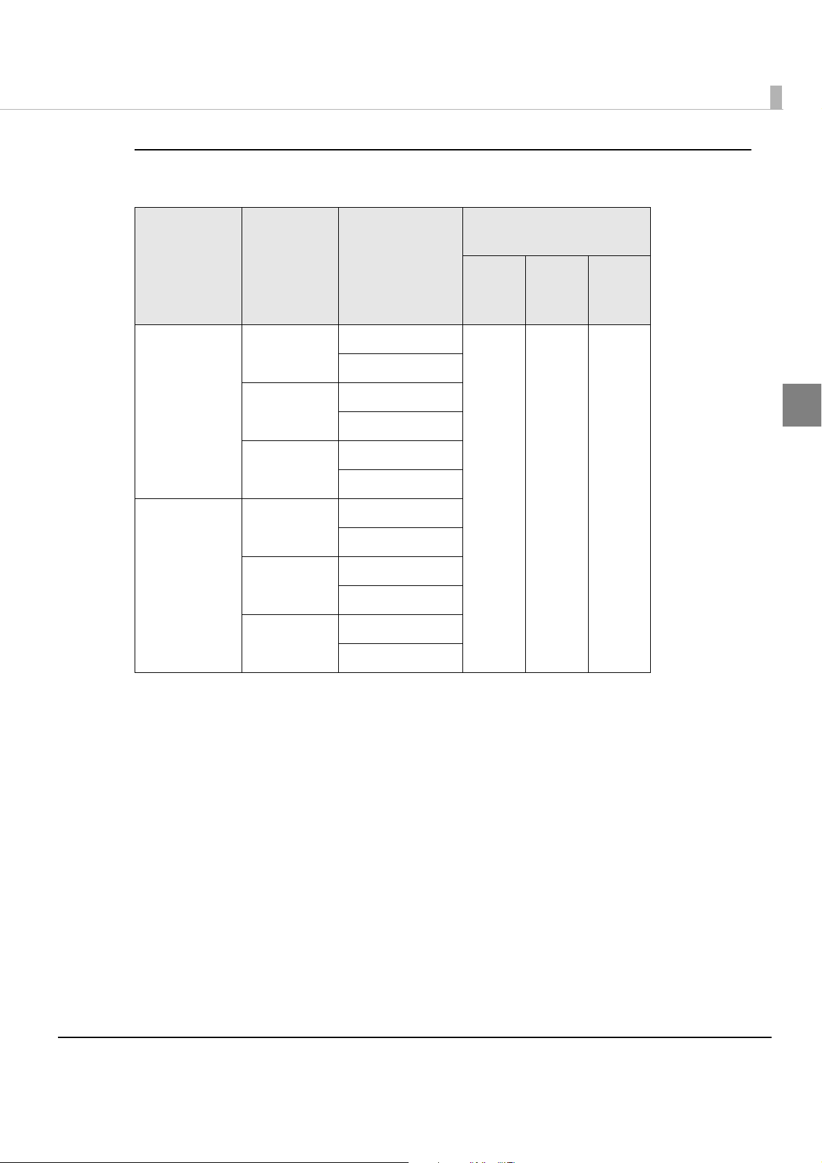
Creating the graphic data for two-dimensional symbol (stack type)
The following table shows the recommended value.
Minimum module
(by 360 dpi)
Paper type Resolution Print status
No paper feed
360 180 dpi
With paper feed
No paper feed
Plain
Light matte
coated
360 360 dpi
With paper feed
No paper feed
720 360 dpi
With paper feed
No paper feed
360 180 dpi
With paper feed
No paper feed
360 360 dpi
With paper feed
No paper feed
720 360 dpi
With paper feed
ANSI
Grade D
or
higher
6 dots - -
ANSI
Grade C
or
higher
ANSI
Grade B
higher
or
1
-: Not supported
25
Page 26

Creating the graphic data for two-dimensional symbol (matrix type)
The following table shows the recommended value.
Minimum module
(by 360 dpi)
Paper type Resolution Print status
No paper feed 6 dots
360 180 dpi
With paper feed 8 dots
No paper feed 6 dots
Plain
Light matte
coated
360 360 dpi
With paper feed 8 dots
No paper feed 6 dots
720 360 dpi
With paper feed 8 dots
No paper feed 6 dots
360 180 dpi
With paper feed 8 dots
No paper feed 6 dots
360 360 dpi
With paper feed 8 dots
No paper feed 6 dots
720 360 dpi
With paper feed 8 dots
ANSI
Grade D
or
higher
ANSI
Grade C
or
higher
--
ANSI
Grade B
or
higher
-: Not supported
26
Page 27
Chapter 1 Product Overview
203.2 mm {8.00"}
53.0 mm {2.09"}
Paper feed
direction
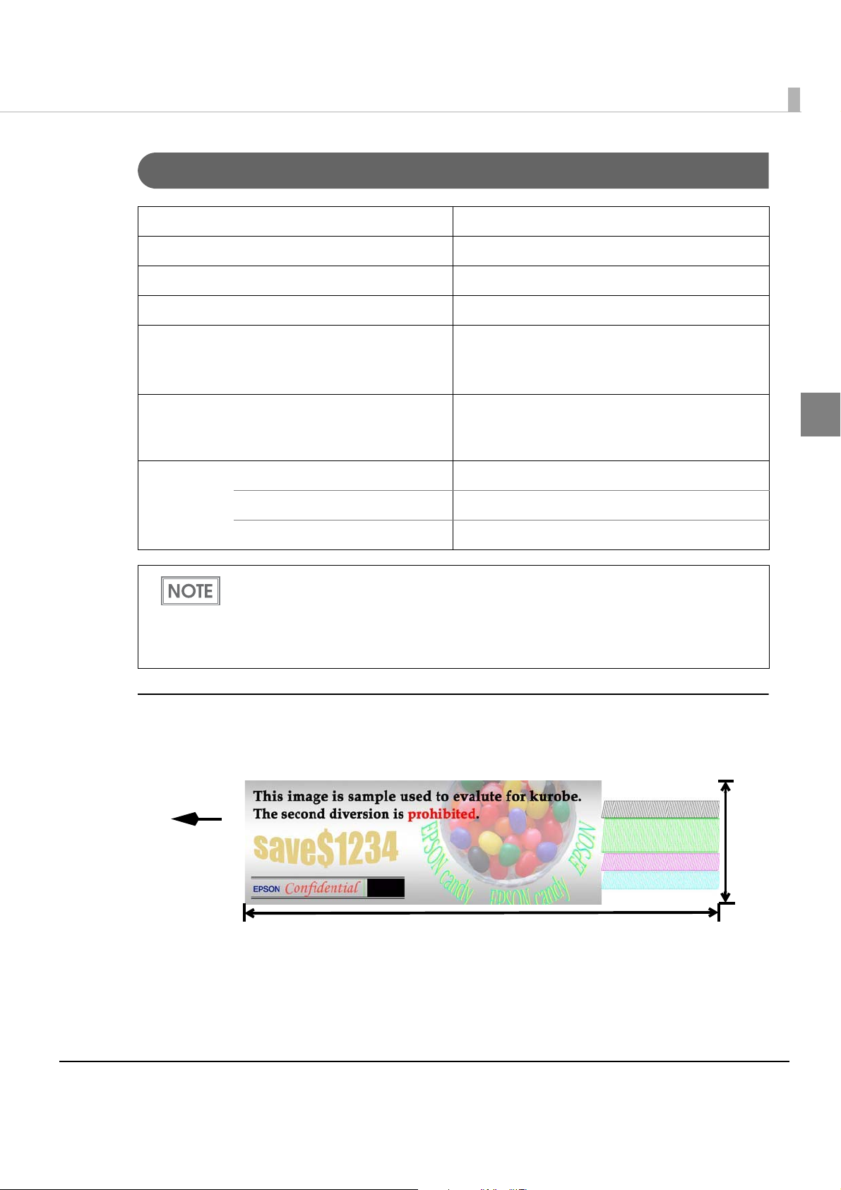
Ink Cartridge
Type 4-color integrated exclusive ink cartridge
Model number SJIC25P
Ink color Cyan, magenta, yellow, black
Ink type Pigment ink
Number of sheets printable 4000 coupons per cartridge
(Print area: 53.0 203.2 mm {2.09 8.00"}, total
803,000 shots, 360 dpi 180 dpi on plain paper)
Ink cartridge expiration 6 months after installation in a printer and 2 years
after the production date, including a six-month
expiration after installation in a printer.
1
Storage
temperature
Transported in the individual box -20 to 60C {-4 to 140F}
Stored in the individual box -20 to 40C {-4 to 104F}
Installed on the printer -20 to 40C {-4 to 104F}
The number of sheets printable is calculated in a case when printing an average of 52
sheets in a 12-hour day (1 sheet per approximately 14 minutes) after replacing the ink
cartridge with a new one.
The number of sheets printable depends on the environment and conditions in use
(content to print, print settings, paper type, print frequency, ambient temperature, etc.).
Printable area
The illustration below shows a sample coupon used to calculate the end of life for the
mechanism and the ink cartridge.
27
Page 28
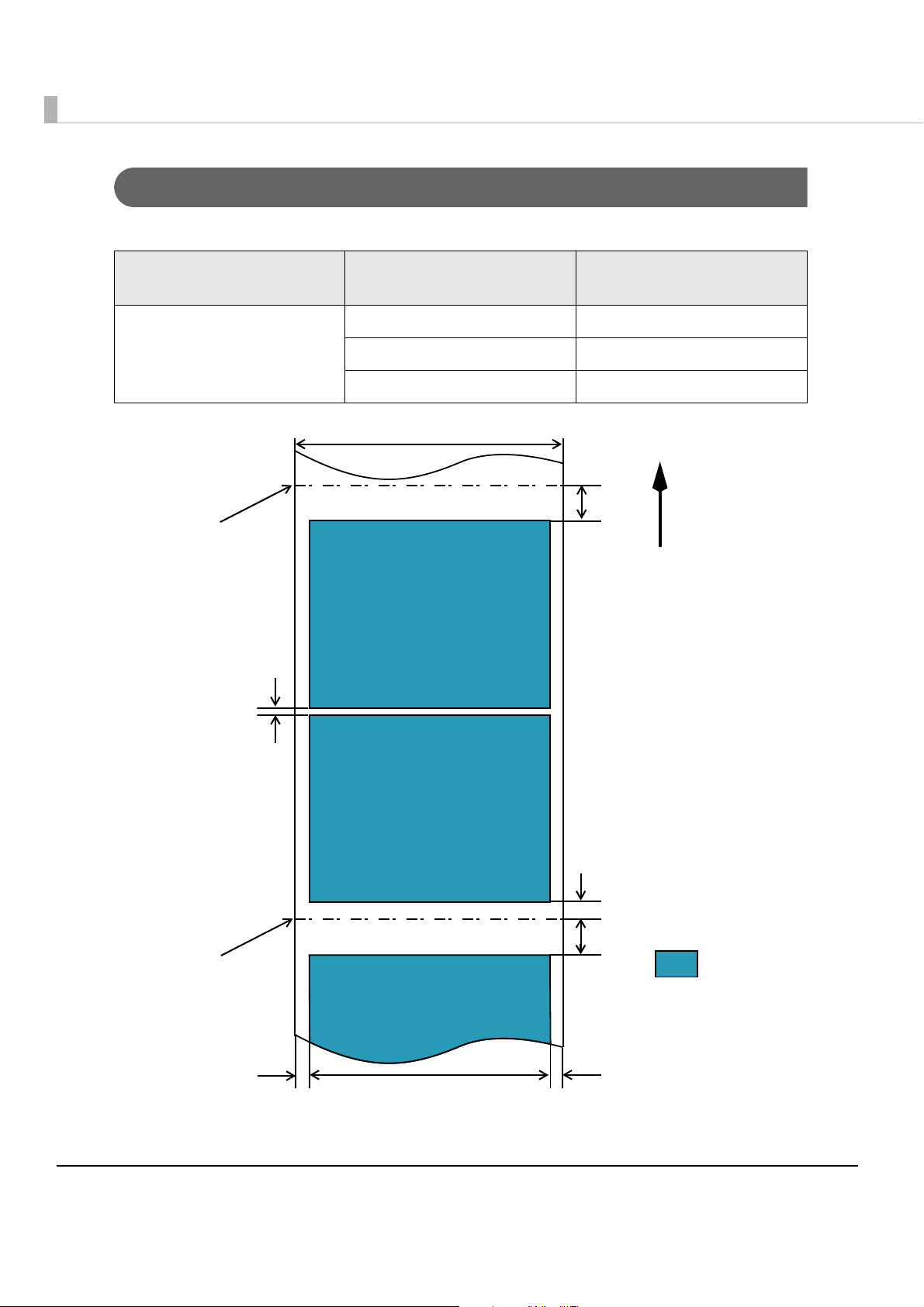
Print Area and Cut Positions
Paper width: 57.5
14
A
14
2
2.25532.25
Feed direction
Coupon 1
Coupon 2
Coupon 3
Autocutting position
Autocutting position
Print area
[The values given are typical values. Units: mm]
The length of each coupon must be 66.8 mm or longer.
The print area and cut positions are shown below.
the previous printing
360 dpi 180 dpi
360 dpi 360 dpi
720 dpi 360 dpi
Resolution of
Resolution of
the next printing
360 dpi 180 dpi 0 mm
360 dpi 360 dpi 0.21 mm {0.0083"}
720 dpi 360 dpi 0.21 mm {0.0083"}
Minimum top margin A
28
Page 29
Chapter 1 Product Overview
Electrical Characteristics
Power supply Power supplied by dedicated AC adapter
Input voltage (rated) AC 100 to 240V
Frequency (rated) 50/60 Hz
Power
consumption
Operating Approximately 30 W
Stand-by Approximately 3 W
Be sure to use the dedicated AC adapter included in the product package.
Reliability
Life Mechanism 4 million passes (Corresponds to 500,000 coupons issued*
Print head 6,000 million shots/nozzle (Corresponds to 10,760,000
coupons issued*
Autocutter 500,000 cuts
MTBF Approximately 180,000 hours
*1: When printing the coupon shown on page 27.
1
)
Environmental Specifications
1
1
)
Absolute maximum rated 70C {150F}*
Pressure (Operating/not operating) 700 to 1060 hPa (Corresponds to 0 to 2500 m {approximately
0 to 8202’} above sea level)
1
29
Page 30

Temperature/
10
20
55
80
27
35
Temperature (C)
Humidity ()
humidity
Printing 10 to 35C {50 to 95F}, 20 to 80% RH (no condensation)
Barcode printing 15 to 35C {59 to 95F}, 20 to 80% RH (no condensation)
Storage When packed: -20 to 60C {-4 to 140F}, 5 to 85% RH (no
condensation, ink not loaded) (At -20C or 60C {-4F or
140F}: up to 120 hours)
Ink loaded: -20 to 40C {-4 to 104F}
(At -20C {-4F}: up to 120 hours)
(At 0 to 30C {32 to 86F}: up to 6 months)
(At 40C {104F}: up to 1 month)
*1: This temperature must NOT be exceeded during operation or storage.
30
Page 31

External Dimensions
210
140
222
[Units: mm]
•Height: 222 mm {8.74"}
•Width: 140 mm {5.51“}
•Depth: 210 mm {8.27”}
Chapter 1 Product Overview
1
31
Page 32

Precautions
To Handle the Ink Cartridge
•Keep ink cartridges out of the reach of children.
•Do not disassemble or refill the ink cartridge. Spills can result, and tampering with the
cartridge may cause a malfunction of the printer.
•Ink can permanently stain clothing.
•Do not strike the ink supply opening. Doing so may cause ink to leak from the cartridge.
•Once you begin using an ink cartridge, there will be a residue of ink around the ink supply
opening. Avoid touching the ink supply opening, and be careful where you put the cartridge
to avoid g
•Do not touch the green circuit board at the upper side of the ink cartridge. Doing so may affect
the normal operation of the ink cartridge.
•Do not remove the ink cartridge from the printer, except when replacing it.
•Aft
er installing an ink cartridge, use it up within 6 months. Leaving the same ink cartridge in
the printer too long may affect the normal operation of that ink cartridge.
etting ink on yourself or something else.
•Use the ink cartridge by the expiration date, which is indi
cartridge and on the ink cartridge itself.
•The ink in the cartridge may freeze if stored at temperatures under -20C{-4F}, but once
thawed at temperatures over 10C{50F}, it can be used normally.
•Do not subject the ink cartridge to strong shocks or vibration.
•Ink life differs, depending on printer conditions, such as printing.
•Do not apply benzene, paint thinner, toluene, or ketone-based solvents to the ink cartridge.
These solvents may damage the plastic.
•Disposal of the ink car
and regulations.
•Do not transport a partially used ink cartridge. Doing so could result in leaking of ink.
tridge must comply with all relevant national or local laws, ordinances,
cated on the box containing the ink
To Prevent Ink Waste
Observe the following precautions to prevent ink waste.
•Do not plug in/pull out the power cable or push the Power button unnecessarily.
•Do not press the Cleaning button unless there is a problem with print quality.
32
Page 33

Chapter 1 Product Overview
Restrictions
Printer environment
•Drivers for TM printers (APD, OPS/JavaPOS) of Seiko Epson Corporation cannot be used for
this printer.
The TM-C710 printer driver can be installed and used on a computer with the APD and OPS/
JavaPOS installed.
Installation environment for the printer driver
•When the printer driver is installed using point and print, printing can be performed but the
printer status cannot be obtained.
•When setting the printer driver using point and print, setting may be made by accessing the
server via a network. Be sure to make the setting with the printer connected.
•Whe
•When using this printer in the same environment as a version of the APD earlier than APD
n using a shared printer and a local printer on one client computer, install the printer
driver for the local printer before installing the printer driver for the shared printer.
4.03, Install the APD first, a
nd then install the printer driver for this printer.
Install package of the printer driver
• The following settings are not reflected in the install package.
- [Select the folder] in [Driver Preferences] in the [Driver Utilities] tab.
- All information in [EPSON Log File Settings] in the [Driver Utilities]
- Whether or not [Always show current settings.] in the [Current settings] screen is checked
1
33
Page 34

Printing
•For the USB interface model, it takes time for the next printing if you turn the printer off and
on after printing.
•The ink cartridge contains 4 colors of ink. Even when one particular color is specified, all 4 col-
ors of ink are used for printing and for keeping the print head in good condition. When the in
level of even one color reaches the lowest limit, the printer stops printing.
•The colors of printouts may become abnormal if you tilt this printer or subject the printer to
any shocks. When you move this printer after ink charging, check the colors by performing a
test print.
If the colors of printouts are not normal, perform head cleaning. See "Head Cleaning" o
100 for how to perform head cleaning.
•When printing image data, white lines (lines shown in white) or black lines (overlapping of
image parts) may appear at about 1 inch intervals in the print result. By setting [Print Head
Alignment] - [Media Feed Adjustment] in [Maintenance And Utilities] tab, this can be
reduced but cannot be removed completely.
k
n page
•When printing image dat
result.
a, change of color tone may appear at 1 inch intervals in the print
34
Page 35

Setup
3. Connecting the AC Adapter (page 40)
4. Loading the Roll Paper (page 41)
5. Loading the Ink Cartridge (page 43)
2. Connecting the USB/Ethernet Cable (page 38)
1. Installing the Printer (page 36)
6. Setting the Lane ID (page 45)
7. Setting the Printer IP Address (page 46)
This step is not necessary for the USB interface model.
8. Adding a TCP/IP Port (page 47)
This step is not necessary for the USB interface model.
9. Installing the Printer Driver (page 50)
10. Installing Status API (page 52)
This step is not necessary if you do not use Status API.
11. Setting the DIP Switches (page 53)
This step is not necessary if you do not need to change the settings.
This chapter describes setup and installation of the product.
Flow of Setup
This chapter consists of the following sections along with the setup flow of the product.
Follow the flow of setup in order to prevent ink leakage.
Chapter 2 Setup
2
35
Page 36

Installing the Printer
Install the printer in an appropriate location with sufficient space around it.
Important Notes on Installation
Do not place the printer in a dusty place.
Make sure no cables or other objects are caught under the printer.
Do not put objects heavier than 700 g {1.5 lb} (two paper rolls) on the printer.
Do not put beverages or vases on the printer.
Do not tilt the printer during initial ink filling, printing, or head cleaning. Otherwise, ink
may leak out of the printer.
•You must place the printer horizontally (back to front: ±10, right to left: ±10).
•Place the printer where the roll paper cover can open fully and the ink cartridge can be ejected,
and be careful not to place an obstacle in front of the printer, especially when you install the
printer on a mounting
table.
•Be sure to avoid bumping the printer so that it is not exposed to strong impact during
operation.
36
Page 37

Chapter 2 Setup
Bracket
Screw M4
Rubber foot
15 to 20 mm
Bracket
1 mm or more
To pre vent the printer from falling, use a bracket as shown below to secure the printer.
2
37
Page 38

Connecting the USB/Ethernet Cable
USB interface model
Ethernet interface model
Ethernet interface model
USB interface model
For the USB interface model, connect the USB cable, for the Ethernet interface model, connect the
Ethernet cable to the printer.
Direct connection to an aerial LAN cable located outside may cause induced lightning to
damage devices. When you use such cables, connect via devices that protect against
surges.
Do not plug an ordinary telephone line into the Ethernet connector.
Make sure the power is turned off for both the printer and the host
1
computer.
For the USB interface model, connect the USB cable to the connector.
2
For the Ethernet interface model, connect the Ethernet cable to the
connector until it clicks.
Secure the cable with the hook.
3
38
Page 39

Chapter 2 Setup
For the USB interface model, connect the other side of the USB cable to
4
a host computer. For the Ethernet interface model, connect the other
side of the Ethernet cable to a network hub.
2
39
Page 40

Connecting the AC Adapter
Always use the included AC adapter.
Using a nonstandard power supply can result in electric shock or fire.
WARNING
Follow the steps below to connect the AC adapter.
Plug the accessory AC cable into the accessory AC adapter.
1
Should a fault ever occur in the AC adapter, immediately turn off the power to the
printer and remove the AC cable from the outlet.
Unplug the power cable of the AC adapter from the outlet before you plug/unplug
the AC adapter into the printer.
Make sure the wall socket power supply satisfies the rated voltage requirements
of the AC adapter. Never insert the AC cable into a socket that does not meet the
rated voltage requirements of the AC adapter.
Doing so may result in damage to both the AC adapter and the printer.
40
Plug the DC cable of the AC adapter into the printer’s power connector
2
(stamped “42V”).
Plug the AC cable into the outlet.
3
Page 41

Loading the Roll Paper
Follow the steps below to load the roll paper.
Do not touch the autocutter blade when you open the roll paper cover.
Otherwise, you may be injured.
Turn the power on.
1
Make sure the Power LED is on.
Pull the release lever to the front to open the roll paper cover.
2
Do not touch the release lever during printing, paper feeding, or cleaning.
Do not touch the gears on the roll paper cover when you open it.
Chapter 2 Setup
Load the roll paper in the orientation shown below.
3
2
41
Page 42

Pull out the paper end to the paper exit, and then close the roll paper
4
cover.
When the roll paper cover is closed, roll paper is automatically fed about
5
10 cm {3.9"}, and then autocutting is performed.
42
After loading the roll paper, head cleaning may start automatically. Wait for cleaning to be
completed.
Page 43

Loading the Ink Cartridge
Green circuit board
Follow the steps below to load the ink cartridge.
When you start to use the printer, it takes about 4 minutes for initial ink filling. Never
open the covers, press the Power button, or turn the printer off during initial ink filling
(while the Power LED is flashing). Otherwise, initial ink filling will be performed again
from the beginning. This wastes ink.
Do not tilt the printer during initial ink filling. Otherwise, ink may leak out of the printer.
Do not touch the inside of the ink cartridge slot. Doing so may cause ink adhesion or
printer malfunction.
Use only the ink cartridge specified by Seiko Epson, SJIC25P. Operation with another
ink cartridge is not guaranteed.
Do not touch the green circuit board at the side of the ink cartridge. Doing so may affect
the normal operation of the ink cartridge.
Chapter 2 Setup
When install the ink cartridge for the first time, use the STARTER CARTRIDGE included
with the printer.
When using the product for the first time, ink filling also uses up some ink to make the
product ready for printing.
An ink cartridge has 4 different colors. Even when one specific color is specified for
printing, ink of all colors is spent in printing and operations to maintain the print head in a
good condition. If remaining ink of any of the ink cartridge reaches its lower limit amount,
the printer stops printing.
Since ink cartridges are designed to stop the operation before ink runs out completely to
maintain the quality of the print head, some ink remains in the used ink cartridge.
The used cartridge has a red line drawn through its label on the top.
2
43
Page 44

Turn the power on.
1
Make sure that the Power LED is on.
Insert the ink cartridge arrow-side-up into the ink cartridge slot until it
2
stops.
When the ink cartridge is installed for the first time, the (Power) LED starts flashing,
and ink charging starts. When ink charging finishes, the (Power) LED stays on (not
flashing).
44
Page 45

Chapter 2 Setup
500 ms 1.5 s
Repeats flashing as many times as the set value
Setting the Lane ID
Yo u can set the printer lane ID manually or through the printer driver.
Follow the steps below to set the lane ID manually. When the lane ID is set manually, the value of
the bottom byte in the IP address is automatically set to the same as the value of the set lane ID.
Push the Lane setting button for at least 5 seconds when the printer is in
1
the idle mode.
The printer prints the following message and enters the lane ID setting mode.
Lane ID Mode Started
Current ID: xxx
Set the third digit of the lane ID assuming decimal expression by pushing
2
the Self-test button.
Assuming the in itial setting value to be 0, the value increases by 1 in the following
progression each time the Self-test button is pushed.
0 1 2 3 4 5 6 7 8 9 0
The following Paper Jam LED pattern enables you to confirm the selected value.
2
Push the Lane setting button to fix the setting.
3
The printer moves on to the setting mode for the next digit.
Repeat steps 2 and 3 for the second and then the first digit.
4
After the first digit is set, the printer prints the following message.
Lane ID is xxx
Press the Lane button to confirm
Press the SelfTest button to cancel
If the set lane ID is out of the range of 1-254, the following message is printed. The printer
discards the set value and ends the lane ID setting mode.
Lane ID Mode Cancel
ID Range error
ID xxx
45
Page 46

If the printed lane ID is correct, push the Lane setting button.
5
The printer stores the set lane ID and the IP address and ends the lane ID setting mode.
Push the Self-test button to cancel the set lane ID. Then the printer ends the lane ID
mode.
If 30 seconds or more elapses without any operations while the printer waits for user
operation in the lane ID setting mode, the printer discards the set value and ends the
lane ID setting mode.
Setting the Printer IP Address
This setting is necessary only for the Ethernet interface model.
Connect the printer to the network via a hub using the Ethernet cable.
Set an IP address to the printer with EpsonNet Config.
Yo u can download EpsonNet Config from the following URL.
CAUTION
http://download.epson-b
When Ethernet cables are installed outdoors, make sure devices without proper
surge protection are cushioned by being connected through devices that do have
surge protection. Otherwise, the devices can be damaged by lightning.
Do not plug an ordinary telephone line into the Ethernet connector.
Make sure the Ethernet cable is connected to the printer, and the printer is turned on.
iz.com/?service=pos
46
Page 47

Adding a TCP/IP Port
This procedure is necessary only for Ethernet model, and unnecessary for the USB interface
model.
Follow the steps below to add a TCP/IP Port.
Make sure the Ethernet cable is connected to the printer, and the printer is turned on.
Select [Start] - [Control Panel] - [Printer] on the computer.
1
Menus to select are different for each OS.
Select [File] - [Add Printer] from the menu.
2
Select [Add a local printer].
3
Chapter 2 Setup
2
47
Page 48

Select [Create a new port:], select [Standard TCP/IP Port] in “Type of
4
port,” and click [Next].
Set the items by referring to the table below, and click [Next].
5
48
Item Setting value
Device type TCP/IP Device
Hostname or IP address
Por t nam e
Query the printer and automatically
select the driver to use
IP address set for the printer
Setting values in “Hostname or IP address” are
automatically input.
Uncheck the checkbox.
Page 49

Chapter 2 Setup
Select [Standard], and [Generic Network Card] in “Device Type.” Then
6
click [Next].
Click [Cancel].
7
Do not install the printer driver in this step.
The addition of the TCP/IP port is completed.
2
49
Page 50

Installing the Printer Driver
Yo u can download Printer Driver for TM-C710 from the following URL.
http://download.epson-biz.com/?service=pos
The installation procedure is different between the USB interface model and the Ethernet
interface model.
Make sure to log on as an administrator to install the printer driver.
Before installing, check the hardware requirements. (See "Operating Environment" on
page 22.)
For USB Interface Model
Follow the steps below to install the printer driver.
Connect the printer to the computer.
1
Turn off the printer before installing. You need to turn it on during installation by following
the instructions.
For a 32bit OS, double-click the icon “c71d32_xxxx.exe.”
2
For a 64bit OS, double-click the icon “c71d64_xxxx.exe.”
If the “User Account Control” screen is displayed, click [OK].
3
Select [EPSON TM-C710], and click [OK].
4
Complete the installation by following the instructions displayed.
5
To display the printer driver, follow the steps below.
1. Click [Start] - [Control Panel] - [Printer] (or [Printers or Faxes]).
2. Right-click on [EPSON TM-C710] and click [Printing Preferences].
For details on how to use the printer driver, see the printer driver help or "How to Use the
Printer Driver" on page 65.
50
Page 51

Chapter 2 Setup
For Ethernet Interface Model
Before installing the printer driver, set an IP address to the printer, and add a TCP/IP port.
(See "Setting the Printer IP Address" on page 46 and "Adding a TCP/IP Port" on page 47.)
The printer driver for the Ethernet interface model cannot be installed with a USB inter-
face model printer connected. In this case, turn off the USB interface model printer
before installing the printer driver for the Ethernet interface model.
Make sure the Ethernet cable is connected to the printer, and the printer is turned on.
Follow the steps below to install the printer driver.
For a 32bit OS, double-click the icon “c71d32_xxxx.exe.”
1
For a 64bit OS, double-click the icon “c71d64_xxxx.exe.”
If the “User Account Control” screen is displayed, click [OK].
2
Select [EPSON TM-C710], and click [OK].
3
2
Complete the installation by following the instructions displayed.
4
To display the printer driver, follow the steps below.
1. Click [Start] - [Control Panel] - [Printer] (or [Printers or Faxes]).
2. Right-click on [EPSON TM-C710] and click [Printing Preferences].
For details on how to use the printer driver, see the printer driver help or "How to Use the
Printer Driver" on page 65.
51
Page 52

Installing Status API
If you want to use Status API, install Status API after installing the printer driver.
Programming Status API enables you to acquire the printer status with your application.
The Status API and the sample programs are provided as the Epson TM-C710 SDK.
Yo u can download it from the following URL.
ttp://download.epson-biz.com/?service=pos
h
Install the printer driver before installing Status API. ("Installing the Printer Driver" on page
50.)
To install it without displaying the window, add the command (/s /v"/qn") to the install file
name for Status API.
e.g: c71sapi_xx.exe /s /v"/qn"
Follow the steps below to install Status API.
Double-click the icon “c71sapi_xx.exe.”
1
The "EPSON TM-C710 StatusAPI - InstallShield Wizard“ screen is displayed.
2
Click [Next].
Complete the installation by following the instructions displayed.
3
52
Page 53

Setting the DIP Switches
Screw
Screw
Rear cover
Follow the steps below to change the DIP switch settings.
Turn the power off before removing the cover.
Otherwise, a short-circuit may cause the printer to malfunction.
CAUTION
DIP switch setting becomes enabled after turning the power on or completing reset by the
interface.
Make sure that the printer is turned off.
1
Unscrew the screws to remove the rear cover.
2
The DIP switches are on the right side of the printer.
Chapter 2 Setup
Set the DIP switches, using the tip of a tool, such as a small screwdriver.
3
Attach the rear cover.
4
For the DIP switch settings, see "DIP Switches" on page 20.
2
53
Page 54

54
Page 55

Chapter 3 Application Development Information
Application Development Information
This chapter describes how to control the printer and gives information useful for printer
application development.
Overview
The following is provided for use of this printer.
❏ A dedicated printer driver for Windows is available. For details on how to use the printer
driver, see the printer driver help or "How to Use the Printer Driver" on page 65.
❏ A Status API that can be used with your applications is available.
❏ Va ri
❏ Dedicated sample programs for the TM-C710 are available.
ous utilities and user’s manuals are available.
Use them as a reference for developing applications.
This printer cannot use the APD or OPOS/JavaPOS provided by Epson.
Printer Driver
The printer driver has the following functions, so it is not necessary to implement them in
applications.
❏ Barcode and 2D symbol fonts are implemented. The barcode and 2D symbol fonts can be
printed using the font replacement function for .NET environment.
The barcode and 2D symbol font must be set in advance
tion. (See "Barcode Printing" on page 73 and "2D Symbol Printing" on page 82 for details of
how to make the setting.)
In the .NET environment, a TrueType font is specified to be replaced by barcode and 2D sym-
bol fonts. The barcodes and 2D symbols can be printed by specifying a replaced TrueType font
from the applica
page 87 for details about the font replacement function.)
tion. (See "Barcode and 2D Symbol Font Printing on .NET Environment" on
in the printer driver to use this func-
3
55
Page 56

Status API
With Status API, you can transmit the printer status (such as printer and ink cartridge status and
print job information) to your applications, and can set the buzzer to beep when an error such as
a cover open occurs.
(Header files and assembly files for .Net are included
in the sample programs.)
Sample Program
Refer to the TM-C710 sample programs to develop the application using this printer.
❏ Features of TM-C710 sample programs
•Programs are provided in the step-up method from the basic ones to the advanced ones.
This helps you to learn how to control the printer.
•Program files are provided in the exe format and the source format.
•Header files and assembly files for .Net are provided.
(The assembly files for .Net are necessary to build a Status API-based application in the .Net
environment.)
• Development environment: Visual Studio 2005/Visual Studio 6.0
• Development language: C++, VB.NET, C# (C# is not provided for some programs.)
❏ Structure of TM-C710 sample programs
The following is the structure and language used for TM-C710 sample program.
Language
Level Program name Specification
C++
Step 1.
Printing characters
Step 2.
Printing barcodes
Basic
Step 3.
Printing graphics
Step 4. Confirming the
printer status
Basic print program
Sets barcode font in advance to use
for print program.
The program to print graphics
Checks the printer condition before
printing and executes error handling.
C#
VB.NET
—
—
—
56
Page 57

Chapter 3 Application Development Information
Level Program name Specification
Language
C++
C#
VB.NET
Basic
Advanced
Step 5.
Call-back process
Complete basic
features
Monitoring the printer
status and controlling
print jobs
DEVMODE Executes a 90-degree rotation or
Obtaining the print completion
When the condition of the printer
changes, the printer can cause
actions to occur in the application,
and executes error handling.
The program from Step 1 to 5
Cancels a print job when a paper
end is detected.
changes the number of copies in the
application.
Changes the number of copies in
the application.
Acquires the print completion.
—
—
—
—
3
57
Page 58

Software
Var ious utilities are provided to system administrators and application developers.
Printer Driver
Software Package Explanation
Printer driver for
Windows
Printer Driver for TMC710
32 bit version and 64 bit version are available.
Administering network printers
Software Package Explanation
The user can set/check the network printer.
Settings can be applied simultaneously to
multiple printers.
The user can set/check the network information
of the printer by entering IP address of the printer
to the address bar of the Web browser.
One printer can be set/checked.
This cannot be used for a printer in the default
condition since the IP address is not available.
EpsonNet Config
EpsonNet Config
(Web version)
EpsonNet Config
(for Windows OS)
N/A (included in the
printer firmware)
58
Page 59

Chapter 3 Application Development Information
Developing applications
Software Package Explanation
Transmits the printer information (such as status
of the printer and the ink cartridge, and print job
Status API
information), and sets the buzzer to beep when
an error occurs.
Status API Reference Guide is included in the
package.
Epson TM-C710 SDK
Sample Program
Yo u can download the above software from the following URL.
http://download.epson-biz.com/?service=pos
Sample programs for using the TM-C710.
(VB.NET and C++ for all programs. C# for some
programs.)
Header files and assembly files for .Net are
included in the sample programs. (The assembly
files for .Net are necessary to build a Status API
based application in the .Net environment.)
3
59
Page 60

60
Page 61

Chapter 4 Handling
Green circuit board
Handling
This chapter describes basic handling of the printer.
Replacing the Ink Cartridge
Printing is not possible if any of the four color inks needs replacement.
When the Replace Ink LED lights, the ink cartridge needs to be replaced. Follow the steps below
to replace the ink cartridge.
Do not touch the inside of the ink cartridge slot. Doing so may cause ink adhesion or
printer malfunction.
Use only the ink cartridge specified by Seiko Epson, SJIC25P. Operation with another
ink cartridge is not guaranteed.
Do not touch the green circuit board at the side of the ink cartridge. Doing so may affect
the normal operation of the ink cartridge.
When the time to replace the ink cartridge has come, the ink cartridge is automatically
ejected.
An ink cartridge has 4 different colors. Even when one specific color is specified for
printing, ink of all colors is spent in printing and operations to maintain the print head in a
good condition. If remaining ink of any of the ink cartridge reaches its lower limit amount,
the printer stops printing.
Since ink cartridges are designed to stop the operation before ink runs out completely to
maintain the quality of the print head, some ink remains in the used ink cartridge.
The used cartridge has a red line drawn through its label on the top.
61
4
Page 62

Turn the power on.
1
Make sure the Power LED is on.
Pull out the used ink cartridge to remove it.
2
Insert the new ink cartridge arrow-side-up into the ink cartridge slot until
3
it stops.
When the ink replacement is finished, the Replace Ink LED goes out and the printer is
ready for normal printing.
Replacing the Roll Paper
When the roll paper is out, the Check Paper LED and the Error LED light.
Follow the steps below to replace the roll paper.
Do not touch the autocutter blade when you open the roll paper cover.
Otherwise, you may be injured.
Turn the power on.
1
Make sure the Power LED is on.
Pull the release lever to the front to open the roll paper cover.
2
Do not touch the release lever during printing, paper feeding, or cleaning.
Do not touch the gears on the roll paper cover when you open it.
62
Page 63

Remove the used roll paper core, if any.
3
Load the roll paper in the orientation shown below.
4
Chapter 4 Handling
Pull out the paper end to the paper exit, and then close the roll paper
5
cover.
4
63
Page 64

When the roll paper cover is closed, roll paper is automatically fed about
6
10 cm {3.9"}, and then autocutting is performed.
After loading the roll paper, head cleaning may start automatically. Wait for cleaning to be
completed.
Removing Jammed Paper
When a roll paper jam occurs, the printer automatically goes offline, and the Paper Jam LED
lights. Open the roll paper cover, and remove the jammed paper. When you remove the jammed
paper, never pull out the paper forcibly.
When roll paper is reloaded and roll paper cover is closed, the printer returns to online and the
printable state. For loading the roll paper, see "Loading the Roll Paper" on page 41.
64
Page 65

Chapter 4 Handling
How to Use the Printer Driver
The printer driver allows you to change the print settings and also provides some utilities such
as checking the printer status and cleaning the print head.
How to Display the Printer Driver
Select [Start] - [Control Panel] - [Printer] on the computer.
1
Menus to select are different in each OS.
Right-click [EPSON TM-C710], and click [Printing References].
2
The printer driver screen is displayed.
The above icon name is displayed when the printer’s name registered as [EPSON
TM-C710].
65
4
Page 66

Registering User Defined Media
Registered
paper
➁
➂
➃
If the paper size to use is not in [Media Layout], register user defined media.
The registered layout will be stored in [Favorite Setting] to use from user applications.
Registering User Defined Media
Click [Add/Del] of [Media Size] on the [General] tab.
1
Enter [Media Size Name] on the displayed [User Defined Media Size]
2
screen.
This is registered as a user defined media name.
Enter the size of the paper.
3
Click [Add]. The user defined media will be registered and displayed in
4
the list of [Media Size].
66
Page 67

Chapter 4 Handling
[General] tab Favorite setting
[Page Layout] tab
Favorite Setting
[Favorite Setting] is the function to administer several printer driver settings into one.
The settings from the [General] and [Page Layout] tabs such as Media Type, Media Layout
(including User Defined Media) are included.
4
67
Page 68

Features
•When printing from your application, the print setting registered in [Favorite Setting] can be
selected as the default setting.
It is recommended to register the setting in favorite setting after executing print setting by
clicking [Save As Favorite Setting].
•A number of settings can be registered in [Favorite Setting].
For example, if the print se
coupon, the print setting can be completed by changing [Favorite Setting] when the coupon
is changed. This prevents an error of setting change when changing the paper length.
tting is registered in [Favorite Setting] for each defined-size
Registering print setting in [Favorite Setting]
Set the printer driver depending on paper to print.
1
Set settings on [General] and [Page Layout] tab. To set the paper of User Defined Media,
select it from [Media Size].
Click [Save As Favorite Setting] to display [Save/Delete Favorite Setting].
2
The current setting will be displayed in the list on the right side.
Enter a print setting name.
3
Click [Add].
4
The print setting will be registered in [Favorite Setting].
68
Page 69

Chapter 4 Handling
Current Settings
➁
➂
➃
➀
User Defined Media
Registered in the Favorite Setting.
[Favorite Setting] includes the following settings.
•Default Settings: The default setting when installing the printer driver.
•Current Settings: The contents set in the [General] and [Page Layout] tabs.
•User Defined Setting:The print setting def
These contents are displayed in the current settings in [Current Set-
ting] and the [Save/Delete Favorite Setting] window.
4
ined by the user.
69
Page 70

Information for User Definition
The user definition includes the following.
•User Defined Media
•Registering barcode font
•Replacing font in the .NET environment
The user definition is set on each client computer. When a number of TM-C710 printer drivers
are installed in one computer, these are used mutually.
70
Page 71

Chapter 4 Handling
Buzzer Setting at the Time of Errors
Whether the buzzer beeps when an error occurs can be set.
Follow the steps below to make the setting.
Turn on the printer.
1
Display the printer driver.
2
(For how to display, see "How to Use the Printer Driver" on page 65.)
Select the [Maintenance And Utilities] tab, and click [Notification Set-
3
tings].
The following screen is displayed. Select the item to set, and click [OK].
4
The following screen is displayed, and setting is completed.
5
Click [OK] to exit.
4
71
Page 72

Autocutting after Printing
Whether autocutting is performed after printing can be set in [Post-printing Operation
Settings] in the [General] tab of the printer driver.
(For how to display the printer driver, see "How to Use the Printer Driver" on page 65.)
[Post-printing Operation Settings] includes the following settings.
•Autocut:After Every Page/Only After Last Page
The printer feeds paper to the position where autocutting can
be performed, and stops after autocutting.
72
Page 73

Chapter 4 Handling
Barcode Printing
The printer driver has a built-in barcode font. Barcode printing is available if a barcode is not
created on the application side.
Setting the barcode font
Barcode print settings can be changed on [Barcode and 2D Symbol] on [Driver Utilities] tab.
Change settings of the following.
1
•Display: Select [Barcodes].
•Font Name: Input an arbitrary character string. ASCII characters only.
•Type: Select a barcode type from the following. The displayed items are
changed accordingly. The following types are selectable.
UPC-A UPC-E
JAN13(EAN) JAN8(EAN)
Code39 Code128
GS1-128 GS1 DataBar Omnidirectional
GS1 DataBar Truncated GS1 DataBar Expanded
73
4
Page 74

UPC-A UPC-E
GS1 DataBar Limited
•Rotation Settings: Select a setting when printing the barcode rotated by the specified
rate.
• Hexadecimal Entry Mode:
Turn on the check box when the data for barcode is specified on
Hexadecimal Entry Mode.
•Composite: Turn on the check box to print barcode with a composite symbol.
Separate the data specified to a composite symbol and a barcode with “\ |” or “| \”. Describe
the data in the order of the composite symbol and the barcode.
Example: 1234567890\ |012345678905
•Use a Quiet Zone: Leaves a blank margin on the rig
ht and left side of barcodes for bet-
ter readability.
The barcode printing position is moved based on the amount of the margin.
•Module: Sets the thin element width in dots.
Category
Graphic
resolution
(dpi)
Rotation
Settings
Adjust
Bar
Width*
Grade D
or higher
Plain
360 180
360 360
Normal,
Rotate180
Rotate90,
Rotate270
Normal,
Rotate180
Rotate90,
Rotate270
Available
4 dots - -
6 dots - -
4 dots - -
6 dots - -
Upper Line: Minimum Module
[by 360 dpi]
ANSI
ANSI
Grade C
or higher
ANSI
Grade B
or higher
74
720 360
Rotate90,
Rotate270
4 dots - -
6 dots - -
Page 75

Category
Graphic
resolution
(dpi)
Rotation
Settings
Adjust
Bar
Width*
Chapter 4 Handling
Upper Line: Minimum Module
[by 360 dpi]
ANSI
Grade D
or higher
ANSI
Grade C
or higher
Grade B
or higher
ANSI
Light matte
coated
360 180
360 360
720 360
Normal,
Rotate180
Rotate90,
Rotate270
Normal,
Rotate180
Rotate90,
Rotate270
Rotate90,
Rotate270
Available
4 dots - -
6 dots - -
4 dots - -
6 dots - -
4 dots - -
6 dots - -
- : Not supported
* : Bars of the printed barcode may be thickened since ink soaks into the paper.
It is recommended to check [Adjust Bar Width].
When “Module” is set to an odd number and the resolution is changed by changing [Print
Resolution], the printed barcode size may be changed. The barcode size can be checked
by using the [Size Display] button.
•Bar Height:Sets the element height with dots. Specified dots indicate the actual
print size.
4
•Adjust Bar Width: Narrows the element width when printing. Make sure
to select it
only when the barcode is not clear enough to be read.
•HRI Character Position: Select the position of the HRI characters. Select [Do Not Print] when
not desired.
The printing position is limited for some types.
•HRI Font: Select the HRI character font size.
• Element Ratio: Sets the thick element width by the ratio to the thin element width.
•Character Spacing:Sets the character spacing (interval) by the ratio to the thin element
width.
Click [Add].
2
The selected barcode font is saved and the font name is added to the font list.
75
Page 76

Up to 30 barcode fonts can be registered.
The barcode font setting can be overwritten by clicking [Save] after selecting the font
name from the font list and changing the setting.
The barcode font setting can be deleted by clicking [Delete] after selecting the font
name from the font list.
Execute a test print according to the setting by clicking [Print] after inputting the text in
the box.
Specifying the barcode data
Specify the barcode data by referring to the following descriptions.
About the composite symbol:
The composite component type is selected automatically depending on the digit number of
the data.
Composite Component Type Encodable Digit Number
CC-A 1 ~ 56 digits
CC-B 1 ~ 338 digits
About the HRI character:
When the total width of the HRI character is larger than that of the barcode, the HRI charac
width is set as the barcode width.
UPC-A
❏ Normal
•Specify the data of 11 to 12 digits.
•The first digit is an unchecked number system character.
•For data of 11 digits, a check digit is automatically added.
•For data of 12 digits, the 12th digit is regarded as a check digit, but not proved.
❏ Composite (difference from Normal)
•For data of 12 digits, the 12th digit is ignored, and a check digit is automatically added.
UPC-E
❏ Normal
•Specify the data of 6 to 8, or 11 to 12 digits.
•For data of 6 digits, the specified data is not changed, and a check digit is automatically
added.
ter
76
•For data of 7 digits, the 2nd to 7th digits become the data characters, and a check digit is
automatically added.
Page 77

Chapter 4 Handling
•For data of 8 digits, the 2nd to 7th digits become the data characters, and the 8th digit is
regarded as a check digit, but not proved.
•For data of 11 digits, a check digit is automatically added.
•For data of 12 digits, the 12th digit is regarded as a check digit, but not proved.
•For data of 7 digits or more, specify “0” for the first digit, since it is regarded as a
system character.
❏ Composite (differences from Normal)
•For data of 8 digits, the 8th digit is ignored, and a check digit is automatically added.
•For data of 12 digits, the 12th digit is ignored, and a check digit is automatically added.
JAN13(EAN)
❏ Normal
•Specify the data of 12 to 13 digits.
•For data of 12 digits, a check digit is automatically added.
•For data of 13 digits, the 13th digit is regarded as a check digit, but not proved.
❏ Composite (difference from Normal)
•For data of 13 digits, the 8th digit is ignored, and a check digit is automatically added.
JAN8(EAN)
❏ Normal
•Specify the data of 7 to 8 digits.
number
•For data of 7 digits, a check digit is automatically added.
•For data of 8 digits, the 8th digit is regarded as a check digit, but not proved.
❏ Composite (difference from Normal)
•For data of 8 digits, the 8th digit is ignored, and a check digit is automatically added.
Code39
❏ A maximum of 256 digits can be specified.
❏ When both or either one of start/stop code (‘*’) is not specified, it is automatically added.
4
77
Page 78

Code128
❏ Specify the data of 2 to 255 digits.
❏ Specify either one of the code selection characters (CODE A, CODE B, CODE C) as a start code
of the first 2 digits.
❏ A special character is indicated by combining ‘{‘ and the next character.
❏ When [Auto Convert to Minimize Entire Symbol Width] is checked, conversion is automati-
cally performed so as to minimize the entire Code128 symbol width. With this function, there
is no need to specify a code set; barcode printing can be performed simply by inputting data
you want to convert into symbols.
When [Auto Convert to Minimize Entire Symbol Width] is unchecked, a code set must be
nually specified. When code set C is specified, assume a generated two-digit number as an
ma
ASCII character decimal number and specify the corresponding ASCII character.
Example: 37": Specify as "%".
"65": Specify as "A".
"979899": Specify as "abc".
❏ When the character right after ‘{‘ is not any of the following, an error occurs.
Control
Character
SHIFT {S CODE C {C FNC3 {3
CODE A {A FNC1 {1 FNC4 {4
CODE B {B FNC2 {2 ‘{’ {{
ASCII
❏ The HRI characters of the special charac
Control Character HRI Character
SHIFT Not printed
CODE A/B/C Not printed
FNC1~ 4 Space is printed
Control character (00h ~1Fh, 7Fh) Space is printed
Control
Character
ASCII
Control
Character
ter are described as below.
ASCII
78
Page 79

Chapter 4 Handling
GS1-128
❏ Specify the data of 2 to 255 digits.
❏ ‘()’ is the delimiter for the application identifiers. (printed as the HRI character, but not
encoded.)
❏ The start codes (CODE A, CODE B, CODE C) and the stop code are added automatically.
❏ A symbol character FNC1, that is described after the start code, is automatically added.
❏ When ‘*’ is specif
❏ 2 digits of consecutive numbers must be specified as the application identifier. If it is not spec-
ified correctly, an error occurs.
❏ When ‘(01)’ is specified as the application identifier, the 14th digit becomes a check digit, how-
it is not proved when the check digit is specified. When the 14th digit is ‘*,’ the check
ever,
digit is automatically calculated, and replaced with ‘*.’
❏ A special character is indicated by combining ‘{‘ and the next character.
❏ When the character right after ‘{‘ is not any of the following, an error occurs.
Control Character (00h ~ 1Fh, 7Fh) Space is printed.
ied, a check digit is automatically calculated, and replaced with ‘*.’
Control Character ASCII HRI Character
FNC1 {1 Space is printed.
FNC3 {3 Space is printed.
‘{’ {{ ‘{‘ is printed.
‘(’ {( ‘(‘ is printed.
‘)’ {) ‘)‘ is printed.
4
‘*’ {* ‘*‘ is printed.
Left parenthesis for the application identifier ( ‘(‘ is printed.
Right parenthesis for the application identifier ) ‘)‘ is printed.
Check digit position * Check digit is printed.
79
Page 80

GS1 DataBar Omnidirectional/GS1 DataBar Truncated/GS1 DataBar Limited
❏ The first application identifier ‘01’ is not included in the data.
❏ When printing the HRI characters, the first application identifier ‘01’ is printed as ‘(01)’ before
the packing identification code.
❏ A check digit need not to be attached to the barcode data.
❏ When printing the HRI character, a check digit is printed after a product code.
❏ For GS1 DataBar Limited, specify ‘0’ or ‘1’ for the first digit.
GS1 DataBar Expanded
❏ Specify the data of 2 to 255 digits.
❏ ‘()’ is the delimiter for the application identifiers. (printed as the HRI character, but not
encoded.)
❏ Be sure to include all the application identifiers in the data.
❏ When the first data i s ‘01’ after deleting application identifiers, left and right parenthesis, and
‘*’ from the specified data, the 14th digit from the next of ‘01’ is checked as a check digit. When
it is not correct, an error occurs.
❏ When the next data of ‘01’ is fewer than 14 digits, a check digit is not checked.
(The check digit is no
is ignored, and the rest of the data is shifted by 1 digit.)
t automatically calculated, nor replaced with ‘*.’ When ‘*’ is specified, ‘*’
❏ Specify the special character using the following format.
Control Character ASCII HRI Character
FNC1 {1 Space is printed.
Left parenthesis for the application identifier ( '(‘ is printed.
Right parenthesis for the application identifier ) ‘)’ is printed.
‘*’ {* Error
Skipped character * Not printed.
80
Page 81

Chapter 4 Handling
Printing method
Specify the selected barcode font, specified point and language to the printing data, and then
print it.
The font size of the barcode cannot be changed by [Specified Point] value. The barcode is
not printed when other values are selected.
4
81
Page 82

2D Symbol Printing
The printer driver has built-in 2D symbol fonts. 2D symbol printing is available if the 2D symbol
is not created on the application side.
Setting the 2D Symbol font
2D symbol printing settings can be changed on [Barcode and 2D Symbol] on [Driver Utilities]
tab.
Change settings of the following.
1
•Display: Select [2D Symbols].
•Font Name: Input an arbitrary character string. ASCII characters only.
•Type: Select a 2D symbol type. The displayed items are changed accord-
ingly.
•Rotation Settings: Select a setting when printing the 2D symbol rotated by the specified
amount.
• Hexadecimal Entry Mode:
Turn on the check box when the data for 2D symbol is specified on
Hexadecimal Entry Mode.
•Composite: Turn on the check box to print the 2D symbol with a composite sym-
bol.
82
Page 83

Chapter 4 Handling
Separate the data specified to a composite symbol and a 2D symbol with “\ |” or “| \”.
Describe the data in the order of the composite symbol and the 2D symbol.
Example: 1234567890\ |012345678905
•Use a Quiet Zone: Leaves a blank margin on the right and left side of 2D symbols for
better readability.
The 2D symbol printing position is moved based on the amount of margin.
Make settings of the following items according to the selected [Type].
2
•PDF417
Module Width: Makes settings of the module width for PDF417.
Module Height: Makes settings of the module height for PDF417 by the ratio to the module
width.
Column: Input the number of columns for PDF417.
Step: Input the number of steps for PDF417.
Truncation Symbol: Turn on this check box when making a symbol without the stop code.
Error Correction Level: Select an error correction level for PDF417. The data can be read even if the
part of the symbol is broken, and restoration ratio becomes higher for bigger
numbers.
•QRCode
Model: Select a QRCode model.
Module: Select the width of cell (module) for QRCode.
Version: Specify the version for QRCode. The number of characters that can be con-
verted into 2D symbols is different depending on the version of QRCode.
Error Correction Level: Select an error correction level for QRCode. The data can be read if the part
of the symbol is broken and restoration ratio becomes higher in the order of
level L, M, Q, H.
•GS1 DataBar Stacked
Module: Sets the module width for GS1 DataBar Stacked.
•GS1 DataBar Stacked Omnidirectional
Module: Sets the module width for GS1 DataBar Stacked Omnidirectional.
•GS1 DataBar Expanded Stacked
Module: Sets the module width for GS1 DataBar Expanded Stacked.
Num Of Chars: Sets the maximum width for GS1 DataBar Expanded Stacked.
❏ The recommended values for the 2D symbols.
4
83
Page 84

Recommended value for setting the barcode/2D symbol font (2D symbol of stack type)
Minimum Module [by 360 dpi]
Graphic
Category
Plain
resolution
(dpi)
360 180
360 360
720 360
360 180
Print Status*
ANSI
Grade D
or higher
No Paper feed 6 dots - -
With Paper feed 6 dots - -
No Paper feed 6 dots - -
With Paper feed 6 dots - -
No Paper feed 6 dots - -
With Paper feed 6 dots - -
No Paper feed 6 dots - -
With Paper feed 6 dots - -
ANSI
Grade C
or higher
ANSI
Grade B
or higher
Light matte
coated
360 360
720 360
No Paper feed 6 dots - -
With Paper feed 6 dots - -
No Paper feed 6 dots - -
With Paper feed 6 dots - -
- : Not supported
* : Whether paper feed is performed during printing 2D symbol can be checked in [Display
Media Feed Position] - [Display Print Preview] in the Print Preview function. For this
function, see "Print Preview" on page 89.
Click [Add].
3
The selected 2D symbol font is saved and the font name is added to the font list.
Up to 30 2D symbol fonts can be registered.
The 2D symbol font setting can be overwritten by clicking [Save] after selecting the font
name from the font list and changing the setting.
The 2D symbol font setting can be deleted by clicking [Delete] after selecting the font
name from the font list.
Execute a test print according to the setting by clicking [Print] after inputting the text in
the box.
84
Page 85

Chapter 4 Handling
Specifying the 2D symbol data
See the following description to specify the 2D symbol data.
For the composite symbol and the HRI character, see "Specifying the barcode data" on
page 76.
PDF417
❏ Calculated automatically when the digit number and the line number are 0.
❏ To s pec ify other number than 0, make sure the multiplication of the digit number and the line
number is under 928.
QRCode
❏ Size is determined by the specified version. If it does not fit in the specified version, it is
changed automatically to the appropriate version.
GS1 DataBar Stacked /GS1 DataBar Stacked Omnidirectional
❏ Up to 13 digits of data can be specified.
❏ Do not specify the application identifier ‘01’ for the head of the data.
❏ A check digit need not to be attached to the data.
GS1 DataBar Expanded Stacked
❏ Multiple line symbol version of GS1 DataBar Expanded. How to specify the data is the same
as GS1 DataBar Expanded. (For details, see "GS1 DataBar Expanded" on page 80.)
4
85
Page 86

Printing method
Specify the selected 2D symbol font, specified point and language to the printing data, and print
it.
The font size of the 2D symbol cannot be changed by [Specified Point] value.
The 2D symbol is not printed when other values are selected.
86
Page 87

Chapter 4 Handling
Barcode and 2D Symbol Font Printing on .NET Environment
Since .NET Framework supports only TrueType fonts and Open Type f o nts, the barcode and 2D
symbol fonts that are registered in the printer driver cannot be printed from an application.
Therefore, TrueType fonts are replaced with barcode and 2D symbol fonts with the font
replacement function of the printer driver. Barcode and 2D symbol fonts can be printed from
applicatio
The name of the print data in the application remains as a TrueType font name, but changes to
barcode and 2D symbol font when it is printed.
ns under .NET Framework environment by this replacement function.
Font Replacement
Font Replacement is executed from [Font Replacement] on the [Driver Utilities] tab.
Make the following setting.
1
•Replacement TrueType Font
Select the original TrueType Font.
•Replacement Target Font
Select the target barcode and 2D symbol.
Click [OK].
2
TrueType font is replaced by barcode and 2D symbol font.
4
87
Page 88

Printing barcodes and 2D symbols
Sets specified number of point, language of the replaced TrueType font by barcode and 2D
symbol font to the print data.
The number of point for barcode and 2D symbol is specified; check it from [Barcode
and 2D Symbol] on [Driver Utilities]. The barcode and 2D symbol cannot be printed if a
value other than those specified is set.
The original TrueType font can be used only for specifying barcode and 2D symbol;
therefore, if other characters are specified, they cannot be printed. Make sure to use a
TrueType font that will not be used for other printing.
88
Page 89

Chapter 4 Handling
Functions of the Printer Driver
The printer driver has “General,” “Page Layout,” “Driver Utilities,” and “Maintenance And
Utilities” tabs to change various settings and for adjustments.
[General] tab
Favorite Setting
Selects one of the registered print settings from the list. This is the default setting when printing.
Changes to setting when installing the printer driver if [Default settings] is selected.
Print Settings
Makes setting of Media Type, Media Size, Print Resolution, Color and Color Correction.
The user definition paper can be registered in Media Size.
Select print quality from [Normal] [High] and the following is the resolution of the printing.
Paper type Print Resolution
Draft 360 180
Plain
Light matte coated
Fine 360 360
Super fine 720 360
Draft 360 180
Fine 360 360
Super fine 720 360
Resolution (dpi)
(Horizontal × vertical)
Media Source Settings
Changes settings of Paper Source and Roll Paper Option setting.
Post-printing Operation Settings
Sets whether autocutting is performed after printing.
Print Preview
Displays the print preview before printing if this check box is turned on.
4
89
Page 90

[Page Layout] tab
Favorite Setting
Selects one of the registered print settings from the list. This is the default setting when printing.
Changes to setting when installing the printer driver if [Default Settings] is selected.
Orientation
Changes settings of the printing direction (Portrait, Landscape, Rotate 180).
Copies
Sets the number of prints.
Layout
Adjusts the printing position.
Watermark
By turning on this check box, text such as “Important” or a graphic can be printed as a
watermark.
The checkbox is grayed out unless [Roll Media Option] in the [General] tab is set to “Cut
Sheet Mode”.
Since the watermark is printed on top of the printed data, a barcode cannot be read when
the barcode and the watermark overlap each other.
90
Page 91

Chapter 4 Handling
[Driver Utilities] tab
Barcode and 2D Symbol
Changes various settings of barcode fonts and 2D symbol fonts. This is user definition
information.
See "Barcode Printing" on page 73 or "2D Symbol Printing" on page 82 for the procedure of
each printing.
Font Replacement
Makes settings to replace TrueType font with barcode and 2D symbol fonts under .NET
environment.
Use this to print the barcode and 2D symbol font in the .NET environment. One TrueType
font is specified to use for printing barcodes and 2D symbol fonts.
Driver Preferences
Changes settings for various functions related to the printer driver.
EPSON Log File Settings
Changes settings for the saving method for quick analysis when an error occurs.
Import/Export Settings
Imports or exports all the settings on the printer driver as a file.
This makes it easier to use the same settings for other printers.
4
91
Page 92

[Maintenance And Utilities] tab
Makes the following settings to the printer.
Notification Settings
Sets whether the buzzer beeps when an error occurs.
Head Cleaning
Performs head cleaning. The result of the head cleaning can be checked by the nozzle check
pattern printing.
See "Head Cleaning" on page 100 for the operating procedure of head cleaning.
Nozzle Check
Prints a nozzle check pattern to check if any nozzle is clogged or not.
Print Head Alignment
Adjusts misalignment of vertical lines, barcodes and paper feed during bidirectional printing.
This is to check the adjustment value using the roll paper included in the product package.
Normally this is not necessary for the user to make this adjustment since th
factory before shipping.
is is adjusted in the
Daily Nozzle Check Service
Performs daily nozzle check at the specified time.
92
Page 93

Uninstallation
To uninstall the printer driver, uninstall the printer driver and Status API separately.
•To uninstall the printer driver page 93
•To uninstall Status API page 95
Uninstalling the Printer Driver
Follow the steps below to uninstall the printer driver.
Finish other operations on the computer.
1
Select [Start] - [Control Panel] - [Uninstall a program].
2
Menus to select are different in each OS.
Chapter 4 Handling
Select [EPSON Printer Software], and click [Uninstall/Change].
3
The following screen is displayed. Select the printer driver to be
4
uninstalled from the [Printer Model] tab.
4
93
Page 94

Check [EPSON Network Utility] in the [Utilities] tab, and click [OK].
5
If you are using other Epson printers and more than one [EPSON Network Utility] is displayed, do not delete them. If they are displayed even if you are not using other Epson
printers, check all of them to delete.
The screen to confirm uninstallation is displayed. Click [Yes ].
6
The confirmation screen to delete the personal setting information is dis-
7
played.
Click [Yes] to delete it, or click [No] to leave it.
If you have set the TM-C710 as the usual printer, another printer to be set
8
for the usual printer after uninstalling is displayed. Click [OK].
94
Page 95

“Uninstallation complete.” is displayed. Click [OK].
9
The uninstallation of the printer driver is completed.
Uninstalling Status API
Follow the steps below to uninstall Status API.
To uninstall without displaying the screen, add the command (/s /v"/qn REMOVE=ALL") to
the installation file name of Status API.
e.g: c71sapi_xx.exe /s /v"/qn REMOVE=ALL"
Chapter 4 Handling
Finish other operations on the computer.
1
Double-click the icon "c71sapi_xx.exe."
2
Click [Next].
3
4
95
Page 96

Select [Remove], and click [Next].
4
Click [Remove].
5
Status API is uninstalled.
96
Page 97

The uninstall completion screen is displayed. Click [Finish].
6
The uninstallation of Status API is completed.
Chapter 4 Handling
97
4
Page 98

Self-test
-
1
0
E
PSSOO
N
N
ett
wwoo
r
kk
h
eeett**
M
AA
C
0
:
8
:
C
0
B
3
B
I
P
1
2
.
8
1
6
8
L
N11
233
I
Fiill
tee
rDDiissaabbll
e
P
tteerr
S
heeee tt**
Z
TCC
755
8QQPP
011660000
J
KK22GG0000
0
1
----------
Cut
-------------
• MAC address
• IP address
•Lane number
•IP filtering function status
•Firmware version
•Printer serial number
• Nozzle check pattern
Procedure for the Self-test
Check the following points before performing the self-test.
1
• The roll paper is correctly set.
• The roll paper cover is closed.
Press the self-test button.
2
There are two types of self-test, as described below.
•Self-test without notification
Press the self-test button at the back of the printer for less than 5 seconds.
•Self-test with notification
Press the self-test button at the back of the printer for 5 seconds or longer continuously.
The self-test
result is printed.
TTMM-
**E
P
M
I
P
L
N
I
PP F
Z
T
J
C
CC771
1
**P
00 7
000
992
2
0
N
:
.
t
rr ii nn
00 8
0
N
e
0000::448
11668
r
00001
..1
00 0
r
SSh
:
C
DD::0
9922..116
e
S
h
e
B
::3
B
8
When the self-test with notification is performed, the fact that the self-test was performed can be
detected from the host PC. When the host PC detects the self-test information, the printer prints
a test coupon including t
communication functions.
98
he host PC information. The user can verify the host PC system and
Page 99

Chapter 4 Handling
Nozzle Check
Printing the nozzle check pattern enables you to check whether the nozzles are clogged or not.
The nozzle check can be performed in two methods: by the self-test, and by the printer driver.
Nozzle Check Using the Self-test
Perform the self-test referring to "Self-test" on page 98.
1
Check the printed nozzle check pattern.
2
If dots are missing, perform a head cleaning. (See "Head Cleaning" on page 100.)
Nozzle Check Using the Printer Driver
Turn on the printer.
1
Set the roll paper correctly.
2
Display the print setting screen of the printer driver.
3
(For how to display, see "How to Display the Printer Driver" on page 65.)
Click [Nozzle Check] in the [Maintenance And Utilities] tab.
4
Click [Print].
5
Check the printed nozzle check pattern.
6
If dots are missing, perform a head cleaning. (See "Head Cleaning" on page 100.)
4
99
Page 100

Cleaning
Cleaning the Printer Case
To cl ean the printer case, wipe the dirt off the printer case with a dry cloth or a damp cloth. Be
sure to turn off the printer before cleaning.
Never clean the product with alcohol, benzine, thinner, or other such solvents. Doing so
may damage or break the parts made of plastic and rubber.
Head Cleaning
Perform a print head cleaning only when the printout is faint or dots are missing.
Head cleaning can be performed using two methods; the Cleaning button, or the printer driver.
Do not turn off the printer or open the roll paper cover.
When ink is low, head cleaning may not start or may stop during cleaning. In this case,
head cleaning starts after a new ink cartridge is installed.
100
 Loading...