

Page 1
Technical Reference Guide
Describes features and general specifications for the product.
Describes setup and installation of the product and peripherals.
Describes how to control the printer and necessary information
when you develop applications.
Describes how to handle the product.
Describes to administrator for necessary information to administer
TM-C610 in the system such as distributing driver or installing
new printer or replacing the printer.
Product Overview
Setup
Application Development Information
Handling
Maintenance of the TM-C610
M00022701
Rev.B
Page 2

Cautions
• No part of this document may be reproduced, stored in a retrieval system, or transmitted in any form
or by any means, electronic, mechanical, photocopying, recording, or otherwise, without the prior
written permission of Seiko Epson Corporation.
• The contents of this document are subject to change without notice. Please contact us for the latest
information.
• While every precaution has taken in the preparation of this document, Seiko Epson Corporation
assumes no responsibility for errors or omissions.
• Neither is any liability assumed for damages resulting from the use of the information contained
herein.
• Neither Seiko Epson Corporation nor its affiliates shall be liable to the purchaser of this product or third
parties for damages, losses, costs, or expenses incurred by the purchaser or third parties as a result of:
accident, misuse, or abuse of this product or unauthorized modifications, repairs, or alterations to this
product, or (excluding the U.S.) failure to strictly comply with Seiko Epson Corporation’s operating
and maintenance instructions.
• Seiko Epson Corporation shall not be liable against any damages or problems arising from the use of
any options or any consumable products other than those designated as Original EPSON Products or
EPSON Approved Products by Seiko Epson Corporation.
Trademarks
EPSON is a registered trademark of Seiko Epson Corporation.
Exceed Your Vision and ESC/Label are registered trademarks or trademarks of Seiko Epson Corporation.
®
Microsoft
soft Corporation in the United States and other countries.
All other trademarks are the property of their respective owners and used for identification purpose
only.
, Windows®, and Windows Server® are either registered trademarks or trademarks of Micro-
Copyright
The Ethernet interface model of this product includes software developed by the University of California, Berkeley, and its contributors.
© Seiko Epson Corporation 2014-2016. All rights reserved.
2
Page 3

3
Page 4
For Safety
Key to Symbols
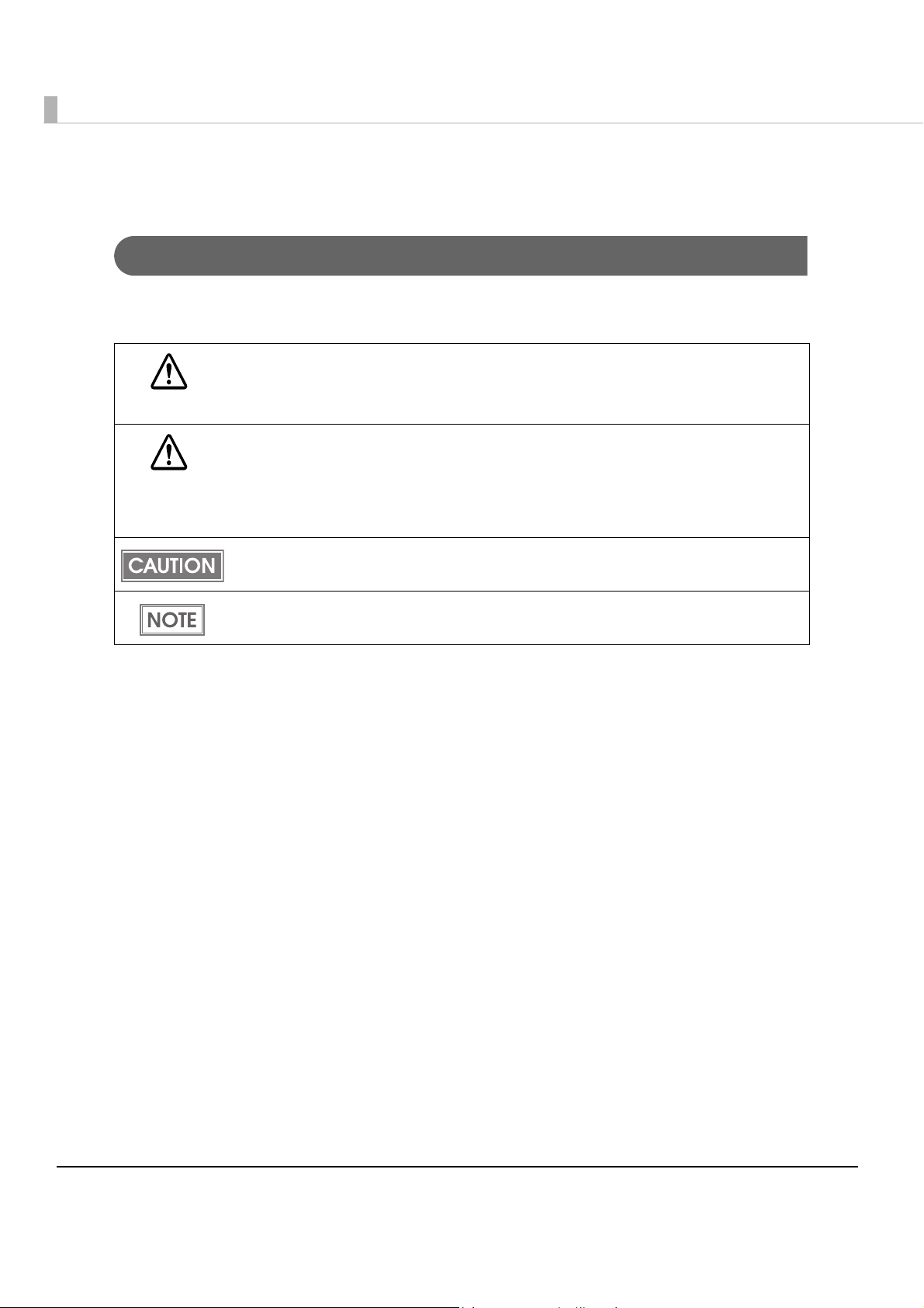
The symbols in this manual are identified by their level of importance, as defined below. Read
the following carefully before handling the product.
You must follow warnings carefully to avoid serious bodily injury.
WARNING
Provides information that must be observed to prevent damage to the equipment or loss of
data.
CAUTION
Possibility of sustaining physical injuries.
Possibility of causing physical damage.
Possibility of causing information loss.
Provides information that must be observed to avoid damage to your equipment or a
malfunction.
Provides important information and useful tips.
4
Page 5

Warnings
WARNING
To avoid risk of electric shock, do not set up this product or handle cables during
a thunderstorm
Be sure to use the power cable complied with safety standards with a PE (power
earth) terminal on the plug, and make sure to ground the product before use.
Ignoring this may result in severe shock.
Never insert or disconnect the power plug with wet hands.
Doing so may result in severe shock.
Handle the power cable with care.
Improper handling may lead to fire or electric shock.
Do not modify or attempt to repair the cable.
Do not place any heavy object on top of the cable.
Avoid excessive bending, twisting, and pulling.
Do not place the cable near heating equipment.
Check that the plug is clean before plugging it in.
Be sure to push the plug all the way in.
Be sure to use the specified power source.
Connection to an improper power source may cause fire or shock.
Do not place multiple loads on the power outlet.
Overloading the outlet may lead to fire.
Shut down your equipment immediately if it produces smoke, a strange odor, or
unusual noise.
Continued use may lead to fire. Immediately unplug the equipment and contact your
dealer or a Seiko Epson service center for advice.
Never attempt to repair this product yourself.
Improper repair work can be dangerous.
Never disassemble or modify this product.
Tampering with this product may result in injury or fire.
Do not allow foreign matter to fall into the equipment.
Penetration by foreign objects may lead to fire.
If water or other liquid spills into this equipment, do not continue to use it.
Continued use may lead to fire. Unplug the power cord immediately and contact your
dealer or a Seiko Epson service center for advice.
Do not use aerosol sprayers containing flammable gas inside or around this
product.
Doing so may cause fire.
5
Page 6

Cautions
Do not connect cables in ways other than those mentioned in this manual.
Different connections may cause equipment damage or fire.
CAUTION
Do not connect cables in ways other than those mentioned in this manual.
Different connections may cause equipment damage or fire.
Be sure to set this equipment on a firm, stable, horizontal surface.
The product may break or cause injury if it falls.
Do not use this product in locations subject to high humidity or dust levels.
Excessive humidity and dust may cause equipment damage or fire.
Do not place heavy objects on top of this product. Never stand or lean on this
product.
Equipment may fall or collapse, causing breakage and possible injury.
To ensure safety, unplug this product before leaving it unused for an extended
period.
Do not remove the ink cartridge during transportation of the printer.
Restriction of Use
When this product is used for applications requiring high reliability/safety such as
transportation devices related to aviation, rail, marine, automotive etc.; disaster prevention
devices; various safety devices etc.; or functional/precision
product only after giving consideration to including fail-safes and redundancies into your
design to maintain safety and total system reliability. B ec a use this product was not intended for
use in applications requiring extremely high reliability/safety such as aerospace equipment,
main communication equipment, nuclear power control equipment, or medical equipment
related to direct medical care etc., please make your own judgment on this product’s suitability
after a f
ull evaluation.
devices etc., you should use this
6
Page 7

About this Manual
Aim of the Manual
This manual was created to provide information on development, design, and installation of
POS systems and development and design of printer applications for developers.
Manual Content
The manual is made up of the following sections:
Chapter 1
Chapter 2 Setup
Chapter 3 Application Development Information
Chapter 4 Handling
Chapter 5 Maintenance of the TM-C610
Product Overview
7
Page 8

8
Page 9

Contents
■ For Safety .............................................................................................................................. 4
Key to Symbols........................................................................................................................................4
Warnings.................................................................................................................................................. 5
Cautions ..................................................................................................................................................6
■ Restriction of Use.................................................................................................................. 6
■ About this Manual................................................................................................................ 7
Aim of the Manual .................................................................................................................................7
Manual Content.....................................................................................................................................7
■ Contents................................................................................................................................ 9
Product Overview........................................................................13
■ Features............................................................................................................................... 13
■ Product Configuration........................................................................................................ 15
Interface ................................................................................................................................................15
Color ......................................................................................................................................................15
Accessories ...........................................................................................................................................15
■ Parts Name and Function.................................................................................................. 16
Control Panel ........................................................................................................................................17
Connectors ...........................................................................................................................................20
■ Offline .................................................................................................................................. 20
■ Status/Error Indications...................................................................................................... 21
■ Buzzer .................................................................................................................................. 22
■ Software .............................................................................................................................. 23
■ Product Specifications....................................................................................................... 24
Hardware Requirements......................................................................................................................25
Printing Specifications ..........................................................................................................................25
Paper Specifications ............................................................................................................................26
Barcode.................................................................................................................................................26
Print Area and Cutting Position...........................................................................................................28
Ink Cartridge .........................................................................................................................................29
Electrical Characteristics ..................................................................................................................... 30
Reliability................................................................................................................................................30
Environmental Conditions....................................................................................................................31
External Dimensions.............................................................................................................................. 32
■ Restrictions.......................................................................................................................... 33
9
Page 10

Setup .............................................................................................35
■ Flow of Setup ...................................................................................................................... 35
■ Installing the Printer............................................................................................................ 36
Important Notes on Installation.......................................................................................................... 36
■ Connecting the USB/Ethernet cable ................................................................................ 38
■ Connecting the Power Supply .......................................................................................... 39
■ Arranging the Cables ........................................................................................................ 40
■ Loading the Roll Paper ...................................................................................................... 42
■ Loading the Ink Cartridge ................................................................................................. 44
■ Setting the Printer IP Address ............................................................................................ 45
■ Adding a TCP/IP Port.......................................................................................................... 46
■ Installing the Printer Driver................................................................................................. 49
For USB Interface Model...................................................................................................................... 49
For Ethernet Interface Model ............................................................................................................. 51
■ Installing Status API ............................................................................................................ 54
Application Development Information......................................57
■ Overview............................................................................................................................. 57
■ Printer Driver ....................................................................................................................... 57
■ Status API ............................................................................................................................ 58
■ Sample Program ................................................................................................................ 58
■ Utilities and Manuals.......................................................................................................... 60
Handling .......................................................................................61
■ Replacing the Ink Cartridge ............................................................................................. 61
■ Replacing the Roll Paper................................................................................................... 63
Replacing the Roll Paper .................................................................................................................... 63
■ Removing Jammed Paper ................................................................................................ 65
■ How to Use the Printer Driver............................................................................................. 66
How to Display the Printer Driver ........................................................................................................ 66
Registering User Defined Media ......................................................................................................... 67
Favorite Setting..................................................................................................................................... 68
Information for User Definition............................................................................................................. 70
Buzzer Setting at the Time of Errors..................................................................................................... 71
Autocutting and Buzzer Setting after Printing...................................................................................72
Barcode Printing .................................................................................................................................. 73
2D Symbol Printing ............................................................................................................................... 79
Barcode and 2D Symbol Font Printing on .NET Environment .......................................................... 83
Functions of the Printer Driver ............................................................................................................. 85
10
Page 11

■ Uninstallation ...................................................................................................................... 89
Uninstalling the Printer Driver ...............................................................................................................89
Uninstalling Status API...........................................................................................................................91
■ Self-test................................................................................................................................ 94
Procedure for the Self-test...................................................................................................................94
■ Nozzle Check ..................................................................................................................... 97
Nozzle Check using the Self-test .........................................................................................................97
Nozzle Check Using the Printer Driver ................................................................................................97
■ Cleaning ............................................................................................................................. 98
Cleaning the Printer Case ...................................................................................................................98
Head Cleaning .....................................................................................................................................98
■ Transporting the Printer .................................................................................................... 100
■ Storing Long-term............................................................................................................. 101
Before Long-term Storage .................................................................................................................101
After Long-term Storage....................................................................................................................101
■ Troubleshooting ................................................................................................................ 102
Lighting and Flashing ERROR LED .....................................................................................................102
Maintenance of the TM-C610................................................... 103
■ Necessary Information for an Administrator of the Printer........................................... 104
Printer Driver Functions.......................................................................................................................104
Destination for the Printer Driver Setting ..........................................................................................105
Installing Multiple Printer Drivers on One Client Computer............................................................106
Using One Network Printer with Multiple Client Computers ..........................................................110
■ Distributing the Printer Driver and Making Printer Settings ........................................... 111
Utility .....................................................................................................................................................111
Preparation for the Administrator .....................................................................................................112
Distribution of the Printer Driver.........................................................................................................113
Setup of the Printer............................................................................................................................. 114
■ Maintenance.................................................................................................................... 115
Adding a Client Computer (for the Ethernet Interface Model)....................................................115
Adding a Printer..................................................................................................................................116
Adding a Paper Type/Changing the Print Setting..........................................................................117
Replacing the Printer .........................................................................................................................117
11
Page 12

12
Page 13

Chapter 1 Product Overview
Product Overview
This chapter describes features and specifications of the product.
Features
The TM-C610 is a 3-color ink jet printer that offers high-speed, easy operability, a nd high
reliability required for commercial applications.
Printing
•High-speed printing
100 mm/s (printing width 50 mm, 360 dpi × 180 dpi, bi-directional printing)
•Color printing
CMY 3-color printing
Print resolution: 360 dpi × 180 dpi, 360 dpi × 360 dpi dpi: dots per 25.4 mm (dots per inch)
Each color has 4 gradations
Handling
•Replacing the roll paper and the ink cartridge can be done from the front of the printer.
•Easy drop-in paper loading
Reliability
•Autocutter is installed for greater paper versatility.
• Uses pigment ink for excellent light-fastness and water-resistance.
1
13
Page 14

Printer driver
•Can print easily with Windows printer driver.
•The printer driver has a built-in barcode font, which is available from .NET application.
•Supported OS
Microsoft Windows Server 2008 R2 (64bit)
Microsoft Windows Server 2008 SP2 (32/64bit)
Microsoft Windows Server 2003 R2 SP2 (32/64bit)
Microsoft Windows 7 (32/64bit)
Microsoft Windows Vista SP2 (32/64bit)
Microsoft Windows XP SP3 (32bit)
Microsoft Windows XP SP2 (64bit)
Status API
•Can transmit the printer status (such as printer and ink cartridge status, and print job informa-
tion) to your applications, and can set the buzzer to beep when an error such as a cover open
occurs. (Though Status API is prepared with the printer driver, you need to in
rately.)
•Dedicated sample program using Status API (program language: C + +, VB.NET, C#, VB6.0) is
prepared.
stall it sepa-
Others
•Compact size fits unobtrusively on a counter.
(Main unit footprint: W 185 mm D 200 mm {7.28 7.87"})
•Includes a buzzer.
14
Page 15

Product Configuration
Interface
•USB interface model (USB 2.0 high speed)
•Ethernet interface model (100 Base-TX/10 Base-T)
Color
White
Accessories
Chapter 1 Product Overview
1
Unpacking
• Roll paper
•Ink cartridge (Model number: SJIC15P)
•AC Adapter
• User’s Manual
15
Page 16
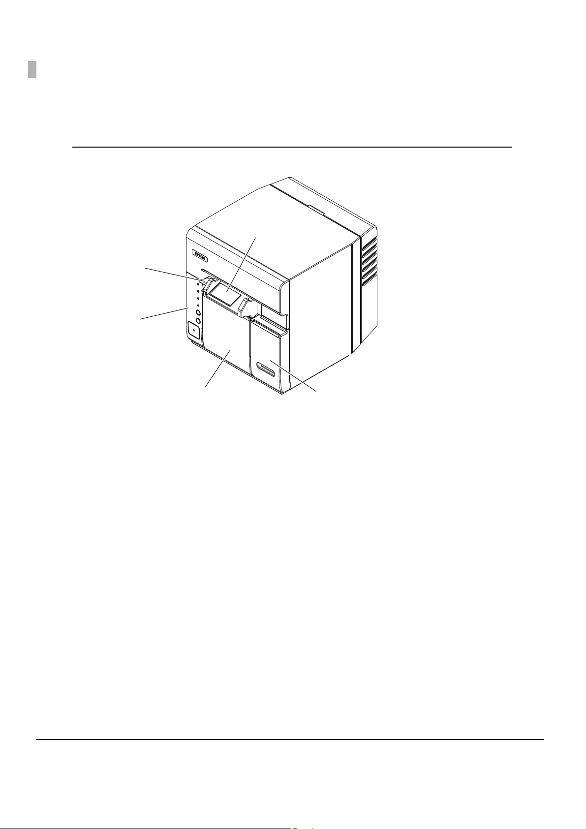
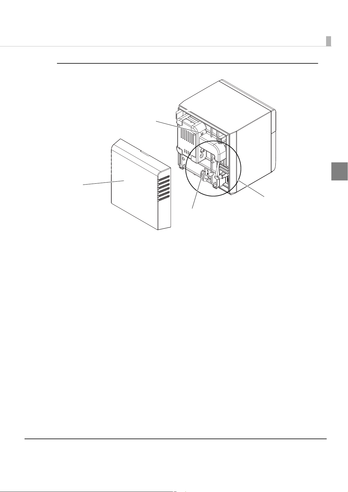
Parts Name and Function
Ink cartridge cover
Roll paper cover
Control panel
Release lever
Paper ejection
guide
Front
Paper ejection guide
Printed coupons are ejected through the paper ejection guide.
Ink cartridge cover
Open the ink cartridge cover to load or replace the ink cartridge.
Roll paper cover
Open the roll paper cover to load or replace roll paper.
Control panel
See "Control Panel" on page 17.
Release lever
Press the release lever to open the roll paper cover.
16
Page 17
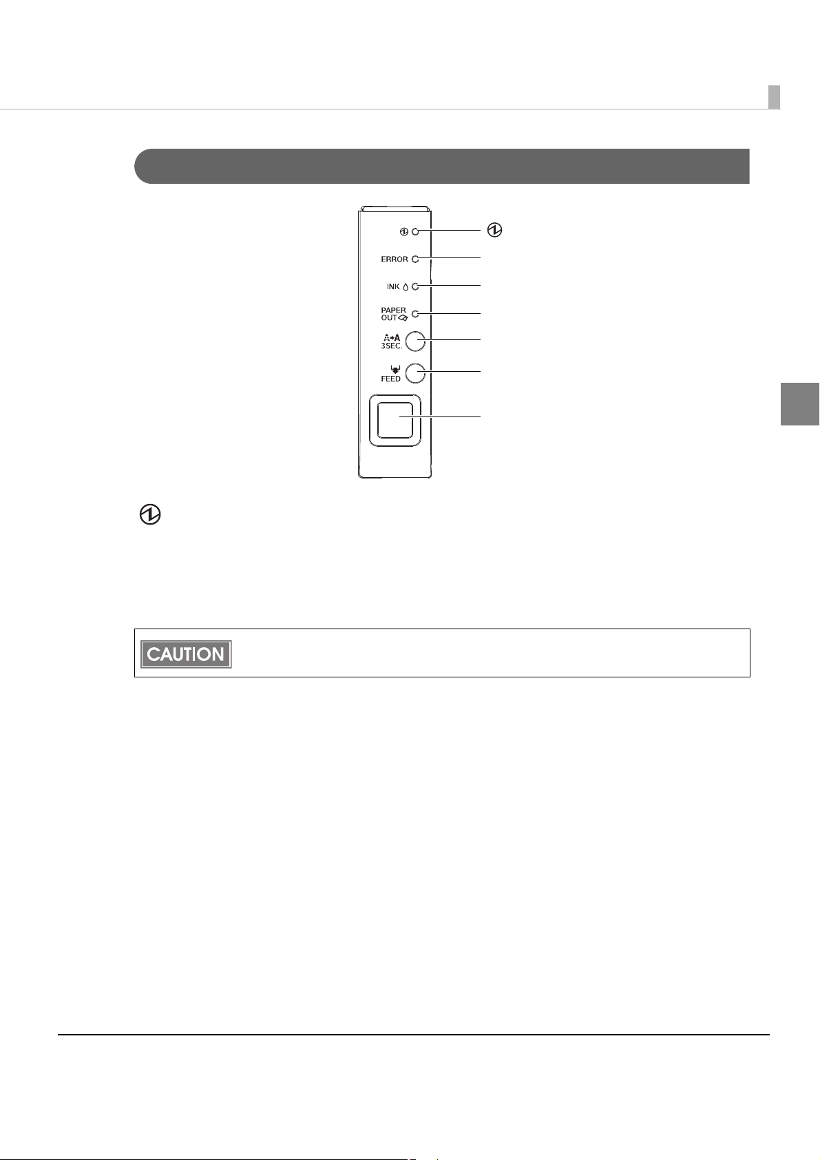
Control Panel
PAP E R O U T L E D
ERROR LED
INK LED
CLEANING button
FEED button
Powe r swi tch
(Power) LED
Chapter 1 Product Overview
1
(Power) LED: Green
•Lights when the power is on.
•Off when the power is off.
•Flashes when the printer is operating (initializing, charging ink, head cleaning, or printing) or
in an error state.
Before turning off the printer, wait more than 10 seconds (so that the print head cap closes)
after the printer finishes operating.
ERROR LED: Red
•Lights or flashes when the printer is offline.
•Off during normal operation (online).
17
Page 18
INK LED: Red
•Flashes when the ink is low or waste ink in the ink cartridge is nearly full.
•Lights when it is time to replace the ink cartridge, when the ink cartridge is not installed or is
not correctly installed, and when waste ink in the ink cartridge is full.
•Off when ink in the ink cartridge is adequate.
PAPER OUT LED: Red
•Lights when the remaining roll paper is near the end (ERROR LED is off), the paper is not
installed or is not correctly installed (ERROR LED is on).
•Off when the paper is correctly installed.
The printer status is also displayed with combinations of lighting and flashing of LEDs. See
"Status/Error Indications" on page 21 for details.
CLEANING button
When the printout is faint or dots are missing, pressing this button for 3 seconds or more
performs print head cleaning.
To prevent ink waste, do not press the CLEANING button unless there is a problem with
print quality.
FEED button
Feeds the roll paper. After feeding, autocutting is automatically performed.
The paper is fed 41.4 mm if the FEED button is pressed once.
If the FEED button is held down, the paper is continuously fed until the button is released.
(15 seconds maximum)
Power switch
•Turns on the printer.
•Turns off the printer if pressed for 3 seconds or more.
18
Page 19
Back
Rear cover
Connectors
Cable hook
Self-test button
Chapter 1 Product Overview
1
Rear cover
Remove it to connect the cables, or perform the self-test (only for the Ethernet interface model).
Cable hook
Hooks the cables to fix them.
Self-test button (only for the Ethernet interface model)
For the Ethernet interface model, press this button to print the network setting information and
the nozzle check pattern. For details, see
"Self-test" on page 94.
19
Page 20
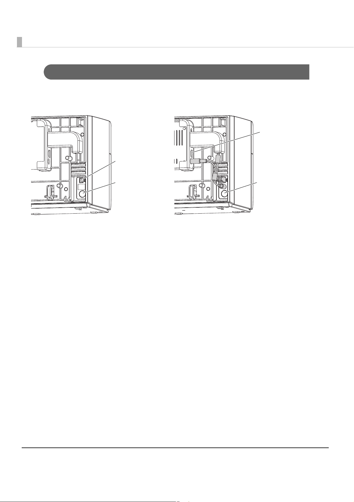
Connectors
USB connector
Power connector
Power connector
Ethernet
connector
USB interface model Ethernet interface model
All cables are connected to the connector on the lower rear of the printer.
USB/Ethernet connector
Connects the printer with the host computer via each interface.
Power connector
Connects the cable of the AC adapter.
Offline
The printer does not have an online/offline switch.
Offline occurs under the following conditions. Though the printer cannot print while it is offline,
it can communicate with the host computer.
•During the printer mechanism is initializing after the printer is turned o
reset
•During the self-test
•When the ink cartridge cover or the roll paper cover is open.
•During paper feeding using the FEED button.
•When the printer stops printing because the roll paper is out.
•When the printer stops printing because the ink cartridge n
•When the printer is waiting for recovery from a high-temperature error.
eeds to be replaced.
n or the interface is
20
Page 21
Chapter 1 Product Overview
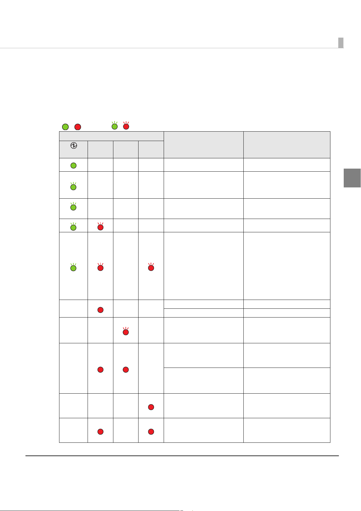
/ : Lights / : Flashes — : No change
Status/Error Indications
The printer status is displayed with combination of lighting and flashing of LEDs.
When an error occurs, you can find out the cause and the remedy from the LED indication for
the error.
LED
Status Remedy
(Power)
ERROR INK
PAP ER
OUT
———
———
———
(Hi-Speed)
——
—
———
—— —
——
———
——
Power on
Charging ink
Closing roll paper cover
Saving or printing data
Power in g off
Maintenance requirement The printer needs repair.
Fatal error
Ink cartridge cover open Close the ink cartridge cover.
Roll paper cover open Close the roll paper cover.
Ink is low
Waste ink cartridge is nearly
full
Time to replace ink cartridge
Waste ink cartridge is full
Ink cartridge is not installed
Ink cartridge is not installed
correctly
Roll paper is nearly out
Roll paper out
—
—
—
1. Turn the power off.
2. Open the roll paper cover
and remove the jammed
paper if any. (See
Jammed Paper" on page 65.)
3. Turn the power on.
If the same error persists, the
printer needs repair.
The time to replace the ink
cartridge is close. Prepare a
new ink cartridge.
Replace the ink cartridge with
a new one. (See
Ink Cartridge" on page 61.
Install the ink cartridge
correctly. (See
Ink Cartridge" on page 61.)
The time to replace the roll
paper is close. Prepare new roll
paper.
Replace the roll paper. (See
"Replacing the Roll Paper" on
page 63
.)
"Removing
"Replacing the
)
"Replacing the
1
21
Page 22
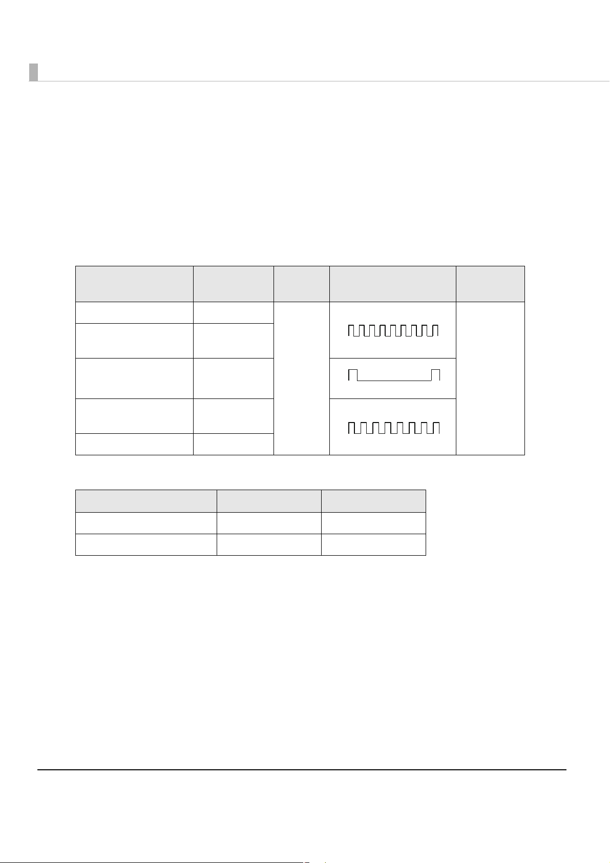
Buzzer
0.2 s
0.2 s
7 s
1 s
0.5 s
0.5 s
The buzzer beeps when an error occurs (when the ERROR LED lights or flashes).
Also, you can change whether or not the buzzer beeps for an error (see
"Buzzer Setting at the
Time of Errors" on page 71), and can set the buzzer to beep when printing finishes (see
"Autocutting and Buzzer Setting after Printing" on page 72).
Frequency, volume, pattern, and repeat count can be changed for each printer status using
control commands.
The default settings are described in the table below.
Printer status Frequency Vol ume Pattern
Fatal error 1200 Hz
Maintenance
requirement
Cover open 1200 Hz
Time to replace ink
cartridge
Roll paper out 840 Hz
840 Hz
Loud Unlimited
1200 Hz
Repeat
count
For the relationship between the buzzer frequency and volume, see the table below.
Frequency Vol u m e : S of t Vol u m e : L ou d
840Hz 50 dB 62.5 dB
1200Hz 38 dB 52 dB
*The above values are the center values of the measurement.
22
Page 23
Chapter 1 Product Overview
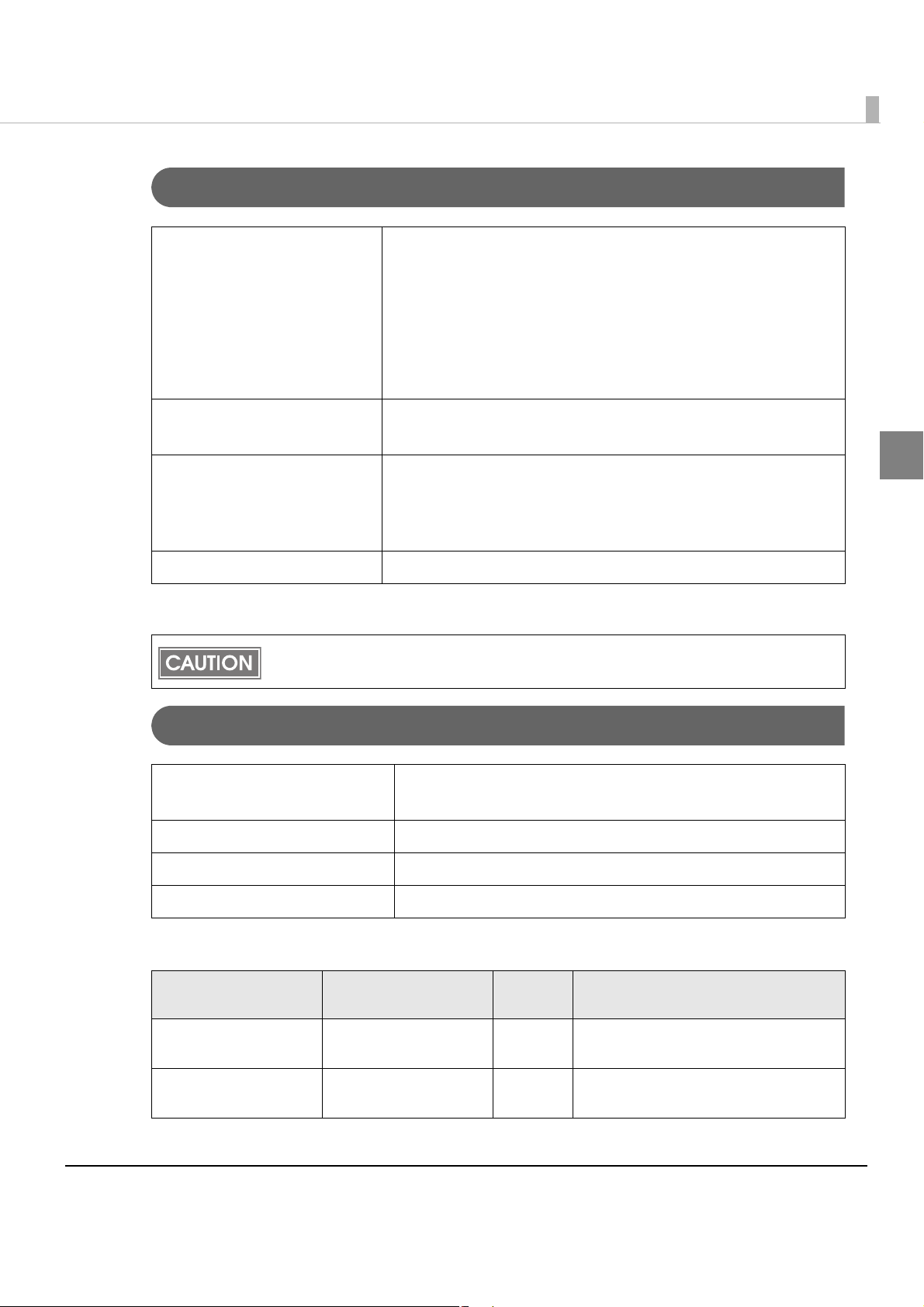
Software
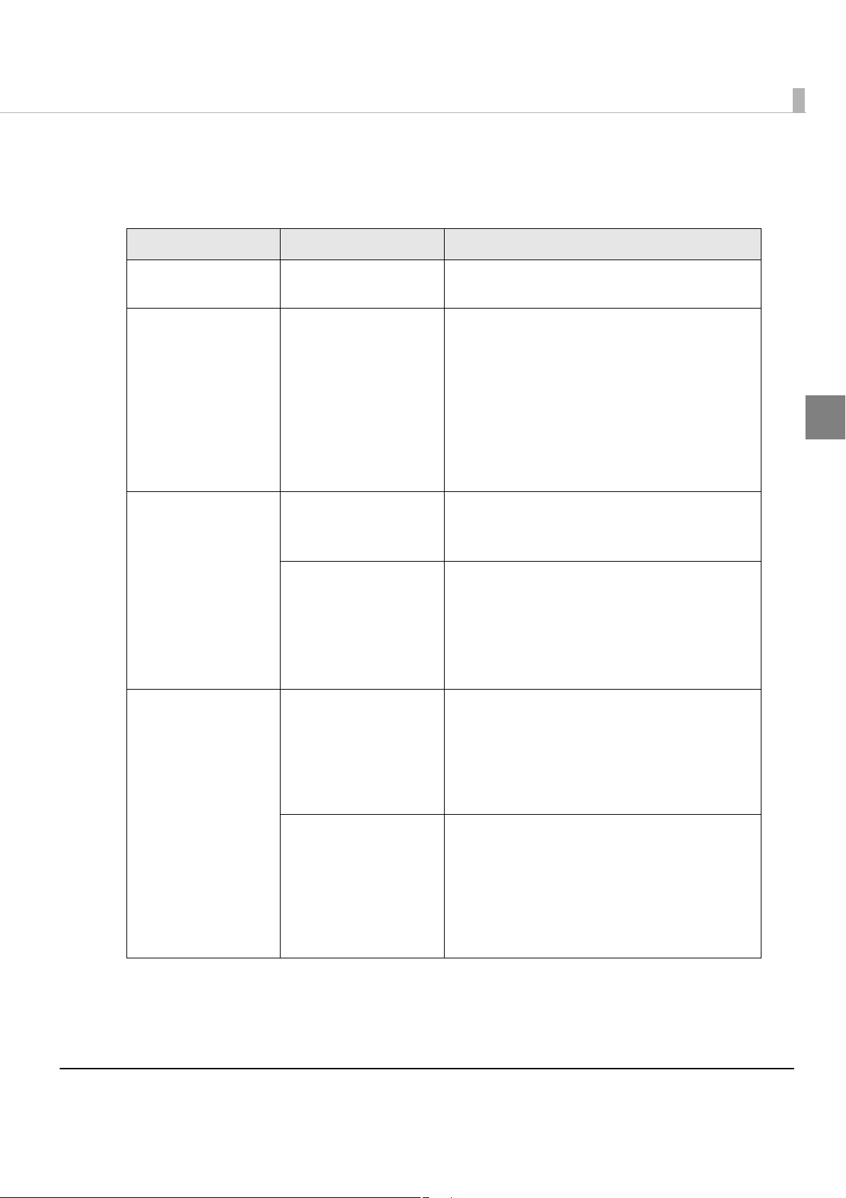
Var ious utilities are provided to system administrators and application developers.
Purpose Name Specifications
Installing the printer
driver
Distributing the printer
driver and setting
Administering
network printers
Printer Driver
Install Assistant
EPSON TMNet
WinConfig
EPSON Net Config
(Function of the printer)
Installs printer driver and executes port setting.
Creates an install package file for installing and
setting the printer driver and executing the port
setting.
Activating the install package file automatically
executes installing the printer driver, setting the
printer driver and executing the port setting. The
printer setting is not executed.
Creates an install package for each printer for
network printers.
The user can set/check the network printer.
Settings can be applied simultaneously to
multiple printers.
The user can set/check the network information
of the printer by entering IP address of the printer
to the address bar of the Web browser.
One printer can be set/checked.
This cannot be used for a printer in the default
condition since the IP address is not available.
1
Developing
applications
Status API
Sample Program
Transmits the printer information (such as status
of the printer and the ink cartridge, and print job
information), and sets the buzzer to beep when
an error occurs.
Though Status API is prepared with the printer
driver, you need to install it separately.
Sample programs for using the TM-C610. (VB.NET
++ for all programs. VB 6.0 and C# for
and C
some programs.)
Header files and assembly files for .Net are
included in the sample programs. (The assembly
files for .Net are necessary to build a Status APIbased application in the .Net environment.)
23
Page 24
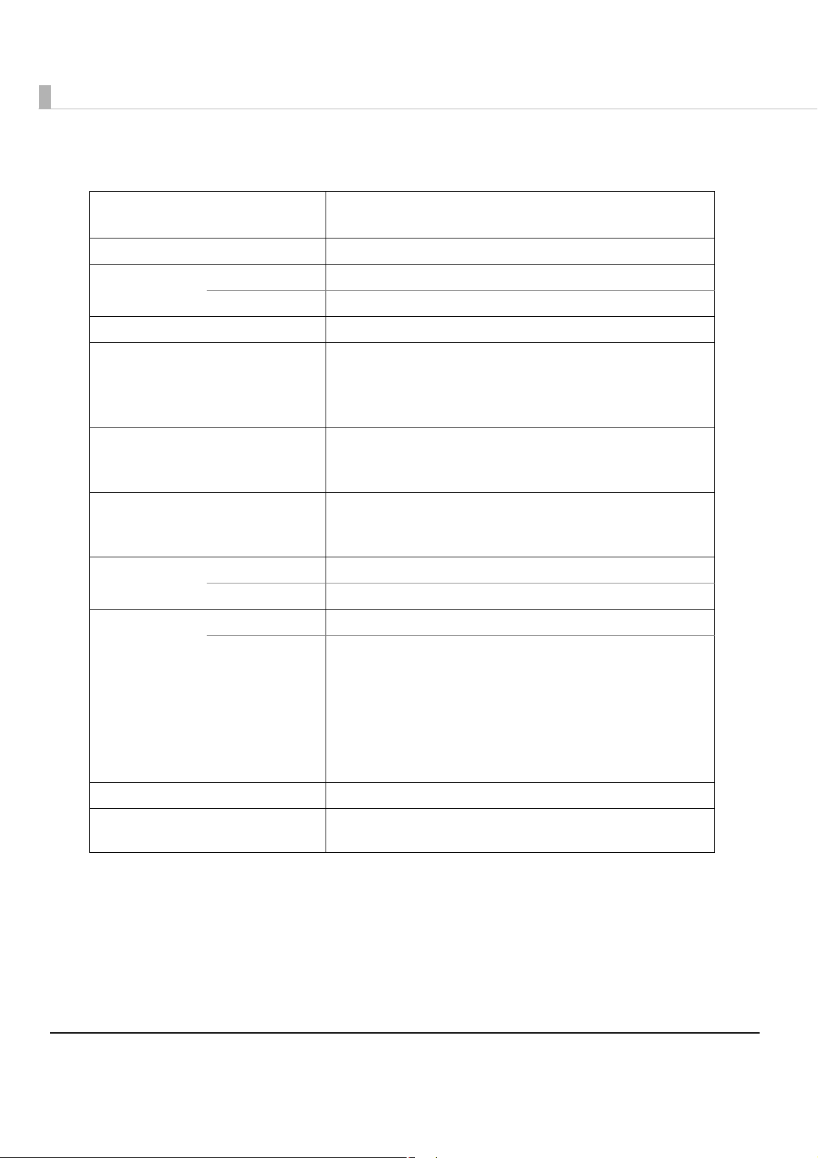
Product Specifications
Printing method Serial ink jet, dot matrix
Three-color (CMY) printing
Paper feed Forward friction feed
Autocutter Cutting method By separated-blade scissors
Autocut type Partial cut (one center point uncut)
Graphic resolution 360 dpi × 180 dpi, 360 dpi × 360 dpi
Print speed 96 mm/s (printing width 53 mm, 360 dpi × 180 dpi)
49.8 mm/s (printing width 53 mm, 360 dpi × 360 dpi)
The print speed is different depending on the resolution and the
printing width.
Roll paper
(See "Paper Specifications" on page
for details)
26
Ink cartridge
"Ink Cartridge" on page 29 for
(See
details.)
Interface USB model USB 2.0 high speed
Ethernet model Ethernet (100 Base-TX/10 Base-T)
Temperatures/
humidity
(See
"Environmental
Conditions" on
page 31
details.)
Overall dimensions (H × W × D) 185 × 200 × 195 mm {7.28 × 7.87 × 7.68 in}
Weight (mass) Approximately 4 kg {8.8 lb}
for
Printing 10 to 35C, {50 to 95F80%RH (no condensation)
Storage When packed (ink not installed): -20 to 60C {-4 to 140F, 5 to
Normal paper (single ply)
3-color exclusive integrated ink cartridge
(Model number: SJIC15P)
85%RH (no condensation)
-20C or 60C {-4 or 140F: up to 120 hours
Ink installed: -20 to 40C {-4 to 104F
-20C {-4 F: up to 120 hours
0 to 30C {32 to 86F: up to 6 months
40C {104 F: up to a month
(Except for ink cartridge, roll paper, paper ejection tray)
24
Page 25
Chapter 1 Product Overview
Hardware Requirements
OS Microsoft Windows Server 2008 R2 (64bit)
Microsoft Windows Server 2008 SP2 (32/64bit)
Microsoft Windows Server 2003 R2 SP2 (32/64bit)
Microsoft Windows 7 (32/64bit)
Microsoft Windows Vista SP2 (32/64bit)
Microsoft Windows XP SP3 (32bit)
Microsoft Windows XP SP2 (64bit)
Computer Must support computers that run the above operating systems.
PC/AT compatible
CPU * Computers with a processor of 1 GHz or better are
recommended.
Intel Pentium/Celeron series, AMD Athlon/Duron family, or
processors that are compatible with these are recommended.
Memory* 512 MB or larger is recommended
*: Must meet the system requirements for the supported OS.
Up to 20 printers are supported on the network . If the minimum requirements above are
not met, the printer may not be able to come up to its standard.
Printing Specifications
Printing method Serial ink jet, dot matrix
Three-color (CMY) printing
Print direction Bi-directional
Paper feed Forward friction feed
Print width 53 mm {2.09”} max.
1
Print mode
Input resolution
(horizontal vertical)
180 180 dpi 360 180 dpi Bi-d
360 dpi 360 360 dpi Bi-d
360
dpi : dots per 25.4 mm (dots per inch)
Graphic resolution
(horizontal vertical)
Print
direction
Print speed
Print width 53 mm: 96 mm/s+10%-15%
Print width 50 mm: 100 mm/s
Print width 53 mm: 49.8 mm/s+10%-15%
Print width 50 mm: 51.4 mm/s
25
Page 26

Paper Specifications
Type Normal paper (single-ply)
Form Paper roll
Size Outside diameter 90 mm {3.54”} max.
Paper core diameter Inside: 12 mm {0.47”}, Outside: 18 mm {0.71”}
Paper width 57.5 {2.26”} ± 0.5 mm {0.02”}
Barcode
Barcodes encodable by the printer driver
Barcode/
two-dimensional
code printing
Barcode
Identification rate:
ANSI rank D
(based on Seiko
Epson Corporation
standard)
Two-dimensional
code printing
UPC-A, UPC-E, JAN 8 (EAN 8), JAN 13 (EAN 13),
GS1 DataBar Omnidirectional, GS1 DataBar Truncated,
GS1 DataBar Limited, GS1 DataBar Expanded
GS1 DataBar Stacked,
GS1 DataBar Stacked Omnidirectional,
GS1 DataBar Expanded Stacked
26
Page 27
Chapter 1 Product Overview
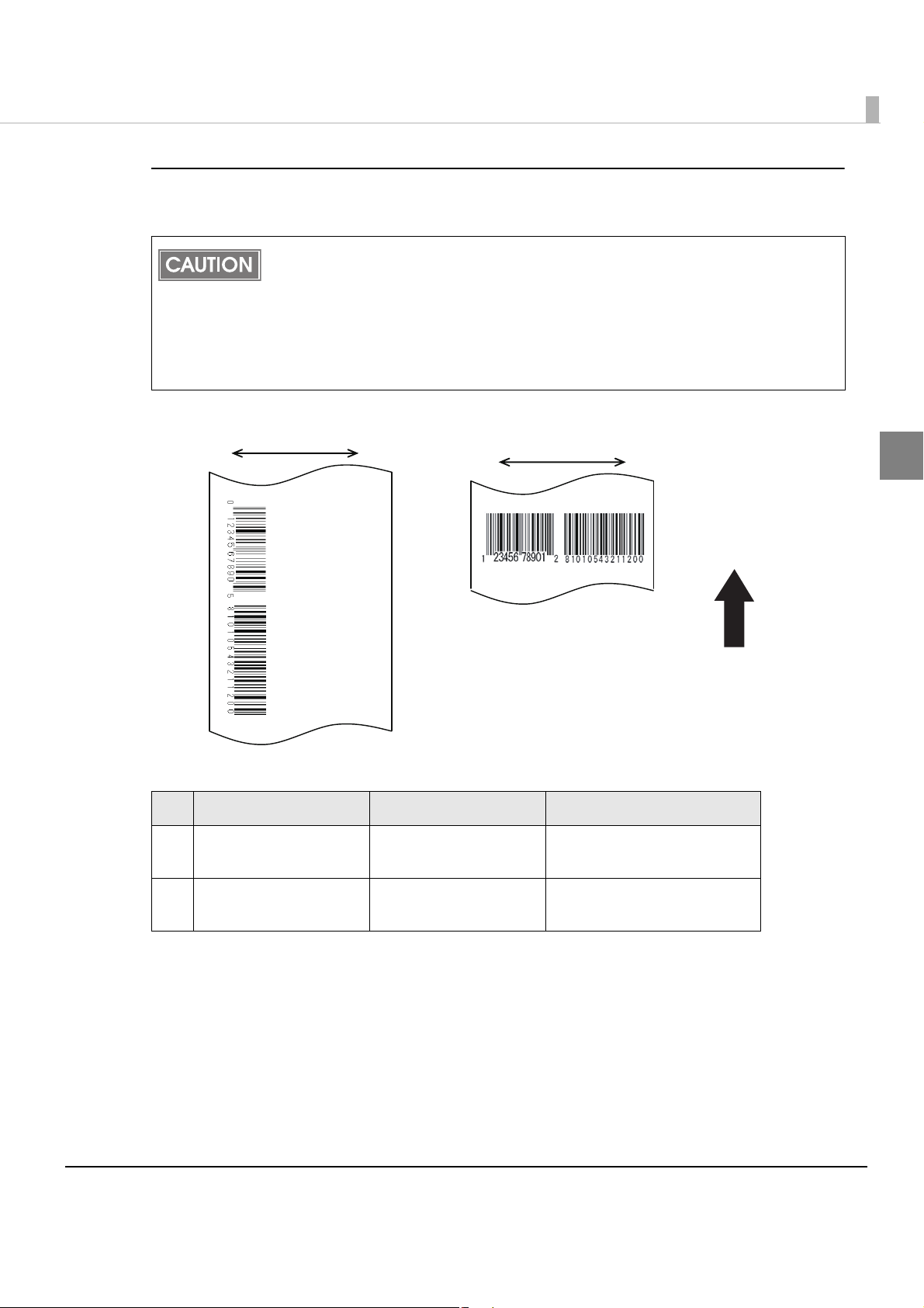
Paper feeding direction
Carriage move directionCarriage move direction
a. Ladder Barcode
b. Fence Barcode (BLACK)
Creating the graphic data for barcode
If you want to create graphic data for barcodes, create data which meet the following conditions.
Use black as the print color of the barcode on blank paper (not pre-printed).
Barcode data should be created at 180 dpi 180 dpi. At other resolutions, the barcode
reader may return errors.
Because of the characteristics of the ink, it may penetrate the paper, and bars of printed
bar codes may become thicker. This depends on the paper. Users can maintain the bar
code recognition rate by methods such as ± 1 correction, reducing the data in a bar by
one pixel (180 dpi) and increasing the blank space by one pixel (180 dpi).
1
Barcode type Detail Module value
Ladder barcode 360 180 dpi
a
Fence barcode
b
360 360 dpi, BLACK
0.282 mm or more
(180 dpi, 2 dots)
0.212 mm or more
(360 dpi, 3 dots)
27
Page 28
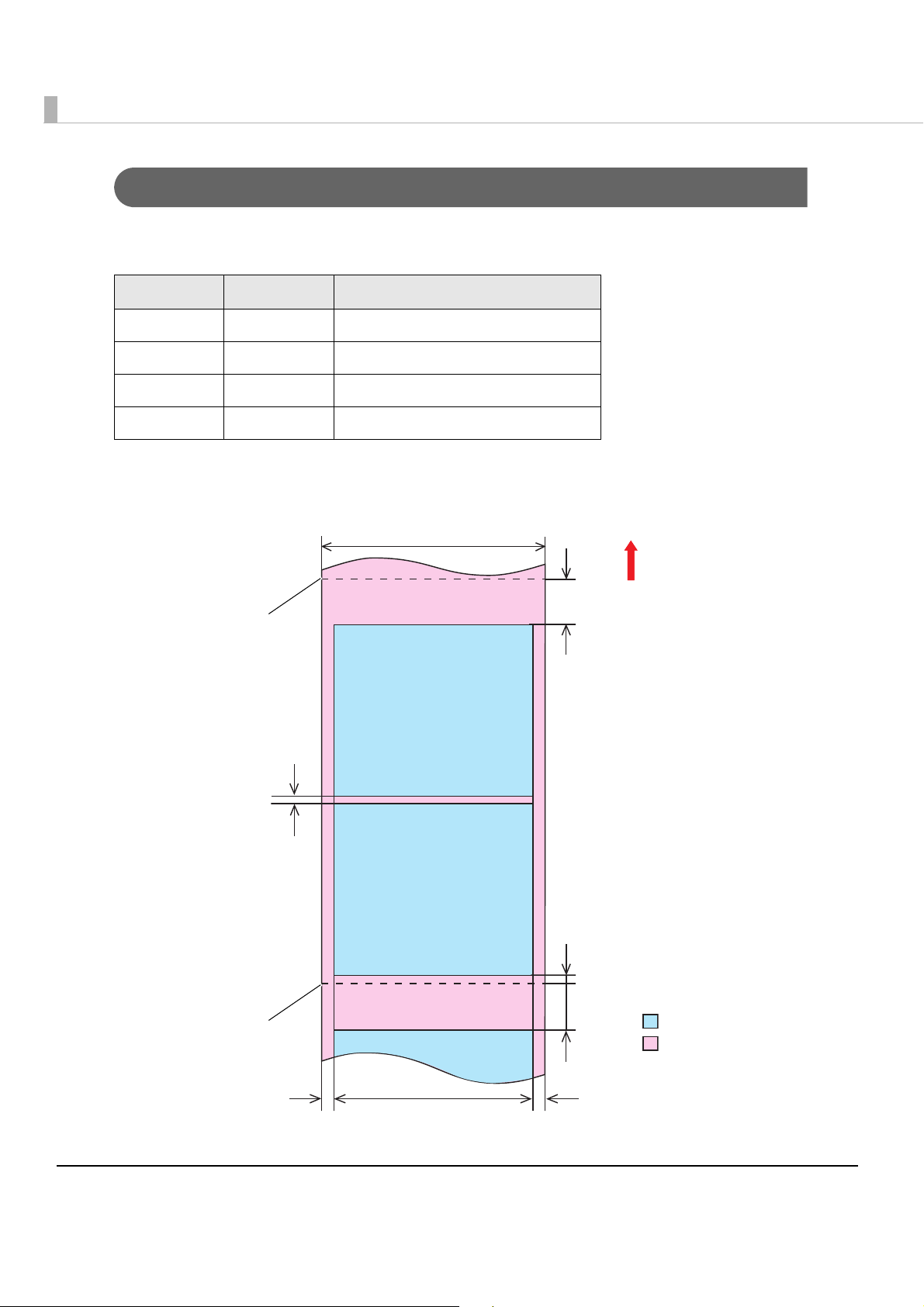
Print Area and Cutting Position
Paper width: 57 ± 0.5 mm
14 mm
Autocut position
Paper feeding direction
Print area
Print area width: 53 mm
Paper
2 mm
14 mm
2.25 mm
A
Autocut position
Coupon 1
Coupon 2
Coupon 3
The minimum top margin (indicated as “A” in the illustration below) of a coupon after a
previously printed one is described in the table below.
a b Minimum top margin A
180 180 0
360 180 0
180 360 0.14
360 360 0.14
a: Resolution in paper feed direction of the previous printing
b: Resolution in paper feed direction of the next printing
28
Page 29
Chapter 1 Product Overview
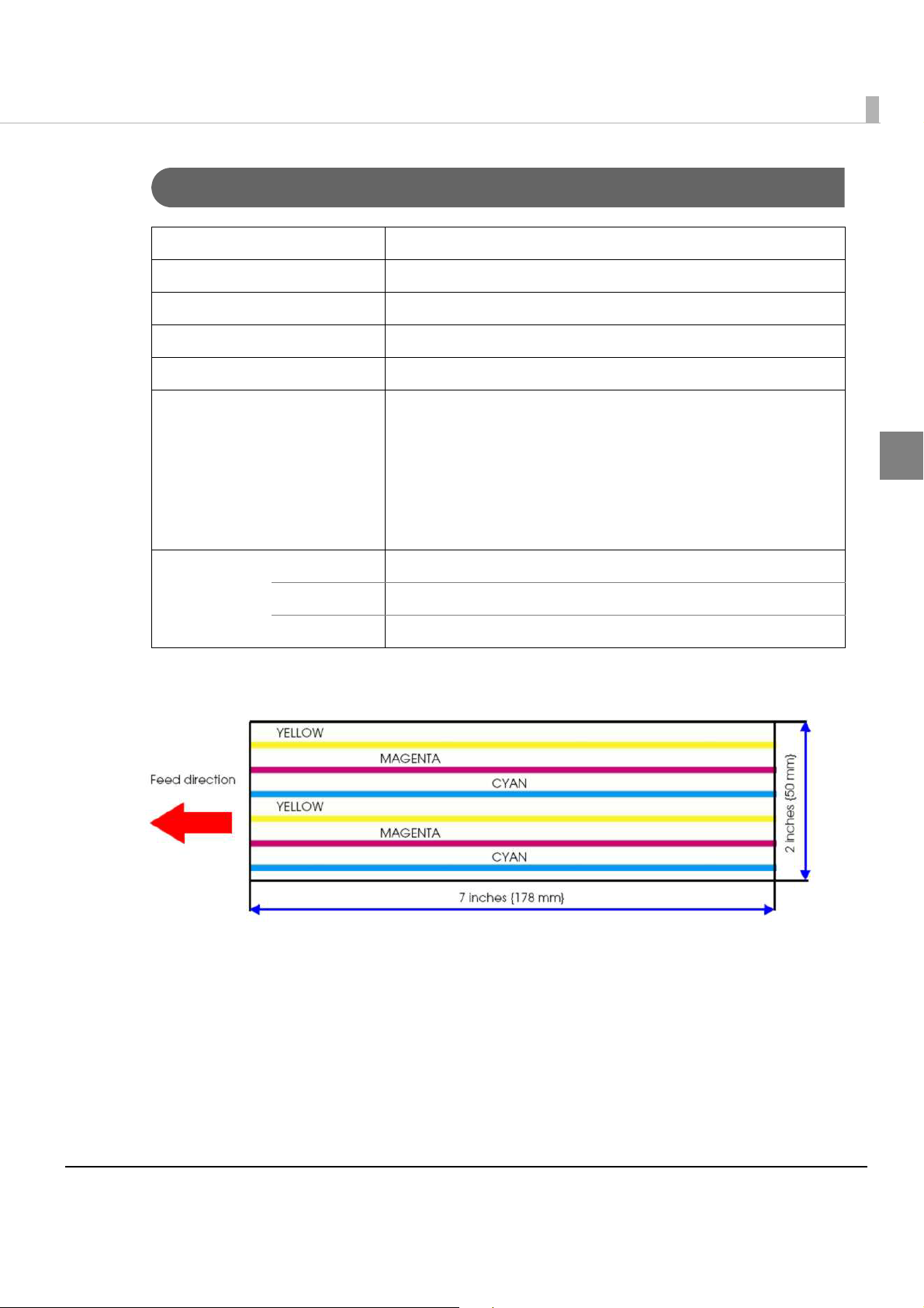
Standard coupon
Ink Cartridge
Model number SJIC15P
Type 3-color exclusive integrated ink cartridge
Ink color Cyan, magenta, yellow
Ink type Pigment ink
Ink life 6 months after loading to the printer, 2 years after manufacturing
Number of sheets printable 3700 coupons/cartridge
*(Print area 50 178 mm {1.97 7.01"} (as shown below),
coverage of each color on the page: 25% 3 shots (Total 676,000
shots), when printing in 360 dpi 180 dpi)
* This figure is calculated based on printing an average of 52
sheets 24 hours a day (approximately 1 sheet per 28 minutes)
after replacing the ink cartridge with a new one.
1
Temperatures Transport -20 to 60C {-4 to 140F(up to 5 days for 60C {140F)
Storage -20 to 40C{-4 to 104F (up to a month for 40C {104F)
Installation -20 to 40C {-4 to 104F(up to a month for 40C {104F)
29
Page 30
Electrical Characteristics
Power supply Power supplied by dedicated AC adapter
Input voltage (rated) AC 100 to 240V
Frequency (rated) 47 Hz to 63 Hz
Power
consumption
Operating Approximately 13 W
Idling Approximately 3 W
Be sure to use the dedicated AC adapter included in the product package.
Reliability
Life Print head 6,000 million shots/nozzle
Autocutter
mechanism
Carriage
mechanism
MTBF Approximately 180,000 hours
MCBF Approximately 9,800,000 passes
MPBF 750 coupons (when printing standard coupons)
500,000 cuts
4 million passes (2 million carriage returns)
30
Page 31

Environmental Conditions
:
Humidity (%)
Temperatures (C)
Item Specification
Chapter 1 Product Overview
Temperatures/
humidity
Printing 10 to 35C {50 to 95F, 20 to 80%RH (no condensation)
34 °C, 90%RH
31 °C, 90%RH
90
80
70
Barcode
34 °C, 75%RH
60
Relative
Humidity
50
[%RH]
40
30
20
10
0
10 20 30 40
Ambient temperature [°C]
15 to 35C {50 to 95F, 20 to 80%RH (no condensation)
40 °C, 65%RH
40 °C, 43%RH
Specified original paper
P300, P310, P350
Specified original paper
other than above
printing
Storage When packed (ink not loaded): -20 to 60C {-4 to 140F, 5 to
85%RH
(no condensation)
-20C or 60C {-4 or 140F: up to 120 hours
Ink loaded: -20 to 40C {-4 to 104F
-20C {-4F: up to 120 hours
0 to 30C {32 to 86F: up to 6 months
40C {104F: up to a month
1
Pressure
(elevation)
Operating 700 to 1060 hPa (approximately 0 to 2500 m above sea level)
Not operating
(including in
transportation)
Acoustic noise During
operation
(including using
the autocutter)
700 to 1060 hPa (approximately 0 to 2500 m above sea level)
Approximately 53 dB (ANSI Bystander position)
(Based on Epson evaluation conditions including the use of the
autocutter)
31
Page 32

External Dimensions
200 mm
185 mm
195 mm
•Height: 185 mm {7.28"}
•Width: 200 mm {7.87“}
•Depth: 195 mm {7.68”}
32
Page 33

Chapter 1 Product Overview
Restrictions
Printer environment
•Drivers for TM printers (APD, OPS/JavaPOS) of Seiko Epson Corporation cannot be used for
this printer.
The TM-C610 printer driver can be installed and used on a computer with the APD and OPS/
JavaPOS installed.
Installation environment for the printer driver
•The printer driver for the Ethernet interface model cannot be installed with a USB interface
model printer connected. In this case, turn off the USB interface model printer before installing
the printer driver for the Ethernet interface model.
•When the printer driver is installed using point and print, printing can be performed b
printer status cannot be obtained.
•When setting the printer driver using point and print, setting may be made by accessing the
server via a network. Be sure to make the setting with the printer connected.
ut the
1
•When using a shared printer and a local printer on one client computer, install the print
driver for the local printer before installing the printer driver for the shared printer.
•When using this printer in the same environment as a version of the APD earlier than APD
4.03, Install the APD first, and then install the printer driver for this printer.
er
Install package of the printer driver
•When the printer driver is installed using the install package of the USB interface model, the
status of other computers on the network cannot be acquired, even if the setting for sharing
this printer is made. And the status cannot be acquired with Status API or other application
however, printing is possible. To avoid the limitations, install the printer driver without using
the install package, and make the settings.
• The following settings are not reflected in the install package
- [Select the folder] in [Driver Preferences] in the [Driver Utilities] tab.
- All informa
- Whether or not [Always show current settings.] in the [Current settings] screen is checked
tion in [EPSON Log File Settings] in the [Driver Utilities]
s;
33
Page 34

Printing
•For the USB interface model, it takes time for the next printing if you turn the printer off and
on after printing.
•The ink cartridge contains 3 colors of ink. Even when one particular color is specified, all 3 col-
ors of ink are used for printing and for keeping the print head in good condition. When the in
level of even one color reaches the lowest limit, the printer stops printing.
•The colors of printouts may become abnormal if you tilt this printer or subject the printer to
any shocks. When you move this printer after ink charging, check the colors by performing a
test print.
If the colors of printouts are not normal, perform head cleaning. See "Head Cleaning" o
for how to perform head cleaning.
98
•When printing image data, white lines (lines shown in white) or black lines (overlapping of
image parts) may appear at about 1 inch intervals in the print result. By setting [Print Head
Alignment] - [Media Feed Adjustment] in [Maintenance And Utilities] tab, thi s can be
reduced but cannot be removed completely.
k
n page
•When printing image data, change of color to
result.
ne may appear at 1 inch intervals in the print
34
Page 35
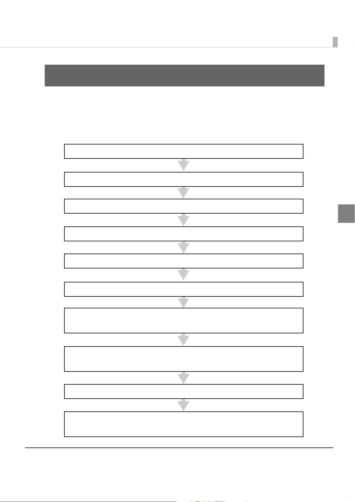
Chapter 2 Setup
3. Connecting the Power Supply (page 39)
7. Setting the Printer IP Address (page 45)
This step is not necessary for the USB interface model.
6. Loading the Ink Cartridge (page 44)
4. Arranging the Cables (page 40)
5. Loading the Roll Paper (page 42)
2. Connecting the USB/Ethernet cable (page 38)
8. Adding a TCP/IP Port (page 46)
This step is not necessary for the USB interface model.
1. Installing the Printer (page 36)
9. Installing the Printer Driver (page 49)
10. Installing Status API (page 54)
This step is not necessary if you do not use Status API.
Setup
This chapter describes setup and installation of the product and peripherals.
Flow of Setup
This chapter consists of the following sections along with the setup flow of the product and peripherals.
2
35
Page 36

Installing the Printer
Install the printer in an appropriate location with sufficient space around it.
Important Notes on Installation
•Do not place the printer in a dusty location.
•The printer must be installed horizontally.
•Leave enough space in front of the printer for the ink cartridge cover and the roll paper cover
to be fully opened, and be careful not to place an obstacle in front of the printer, especially
when you install t
he printer on a mounting table.
•If you install the printer in a location where it could fall during operation, make sure to secure
the printer with screws.
36
Page 37

Chapter 2 Setup
Screw holes
Rubber foot
Printer
7 ~ 10 mm
Mounting table
85 mm
•When installing the printer on a mounting table, secure the printer with two screws (M4) or fix
it with affixing tape. Use screws between 7 and 10 mm {0.28 and 0.39"} long from the ground
point of the rubber foot on the printer.
•Do not allow cables to catch or foreign matter to accumulate under the printer.
•Do not subject the printer to impact during operation. Otherwise, print problems may occur.
2
37
Page 38

Connecting the USB/Ethernet cable
Groove
Ethernet cable
USB cable
USB interface model Ethernet interface model
For the USB interface model, connect the USB cable, for the Ethernet interface model, connect the
Ethernet cable to the printer.
When Ethernet cables are installed outdoors, make sure devices without proper
surge protection are cushioned by being connected through devices that do have
CAUTION
Put your finger on the groove in the upper part of the rear cover, and pull
1
it backward to remove it.
surge protection. Otherwise, the devices can be damaged by lightning.
Never attempt to connect a standard telephone line cable to the 10/100BASE-T
LAN connector.
For the USB interface model, connect the USB cable to the connector, as
2
shown below. For the Ethernet interface model, connect the Ethernet
cable to the connector until it clicks.
38
Page 39

Connecting the Power Supply
USB interface model Ethernet interface model
Connect the included AC adapter to the printer.
Always use the included AC adapter.
Using a nonstandard power supply can result in electric shock or fire.
WARNING
Insert the connector of the AC cable to the inlet of the AC adapter.
1
Connect the DC cable of the AC adapter to the power connector of
2
the printer.
Use an AC cable that meets safety standards of each country.
Should a fault ever occur, immediately turn off the power to the printer and
remove the power supply cable from the wall socket.
Chapter 2 Setup
2
39
Page 40

Arranging the Cables
cable hook
Tabs
Hook all the connected cables on the cable hook.
1
Align the 2 tabs at the bottom of the printer back with the holes in the
2
rear cover, and close the rear cover.
40
Page 41

Chapter 2 Setup
Make sure the cables pass through the notch at the bottom of the rear
3
cover, and are not pinched.
Be sure to use the printer with the rear cover attached.
Insert the power plug of the AC cable into the wall socket.
4
Be sure to remove the AC cable from the wall socket whenever connecting or dis-
connecting the AC cable to the printer.
CAUTION
Failure to do so may result in damage to the AC adapter or the printer.
Make sure the wall socket power supply satisfies the rated voltage requirements
of the AC adapter. Never insert the AC cable into a socket that does not meet the
rated voltage requirements of the AC adapter.
Doing so may result in damage to both the AC adapter and the printer.
2
41
Page 42

Loading the Roll Paper
Follow the steps below to load the roll paper.
Turn on the printer.
1
Press down the release lever, and pull it to the front to open the roll
2
paper cover.
Load the roll paper in the orientation shown below.
3
42
Page 43

Chapter 2 Setup
Paper ejection guide
Pull out the paper end to the paper exit along the paper ejection guide.
4
Close the roll paper cover.
5
Roll paper is automatically fed about 10 cm {3.9”}, and then autocutting is performed.
2
43
Page 44
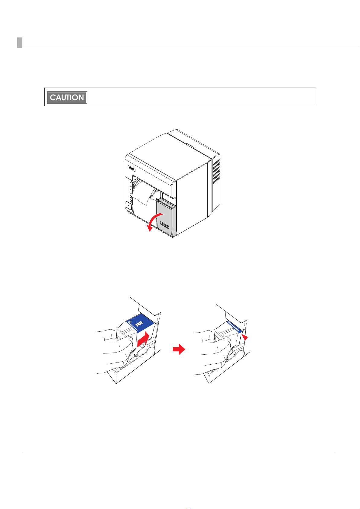
Loading the Ink Cartridge
Always use the EPSON SJIC15P ink cartridge.
Do not open the package of the ink cartridge until you are ready to load it in the printer.
Pull the ink cartridge cover to the front to open it.
1
Shake the new ink cartridge package 4 or 5 times before opening it and
2
then take the ink cartridge out of the package.
Push the ink cartridge gently into the cartridge holder as shown below.
3
Insert with the arrow side up.
44
Page 45
Chapter 2 Setup
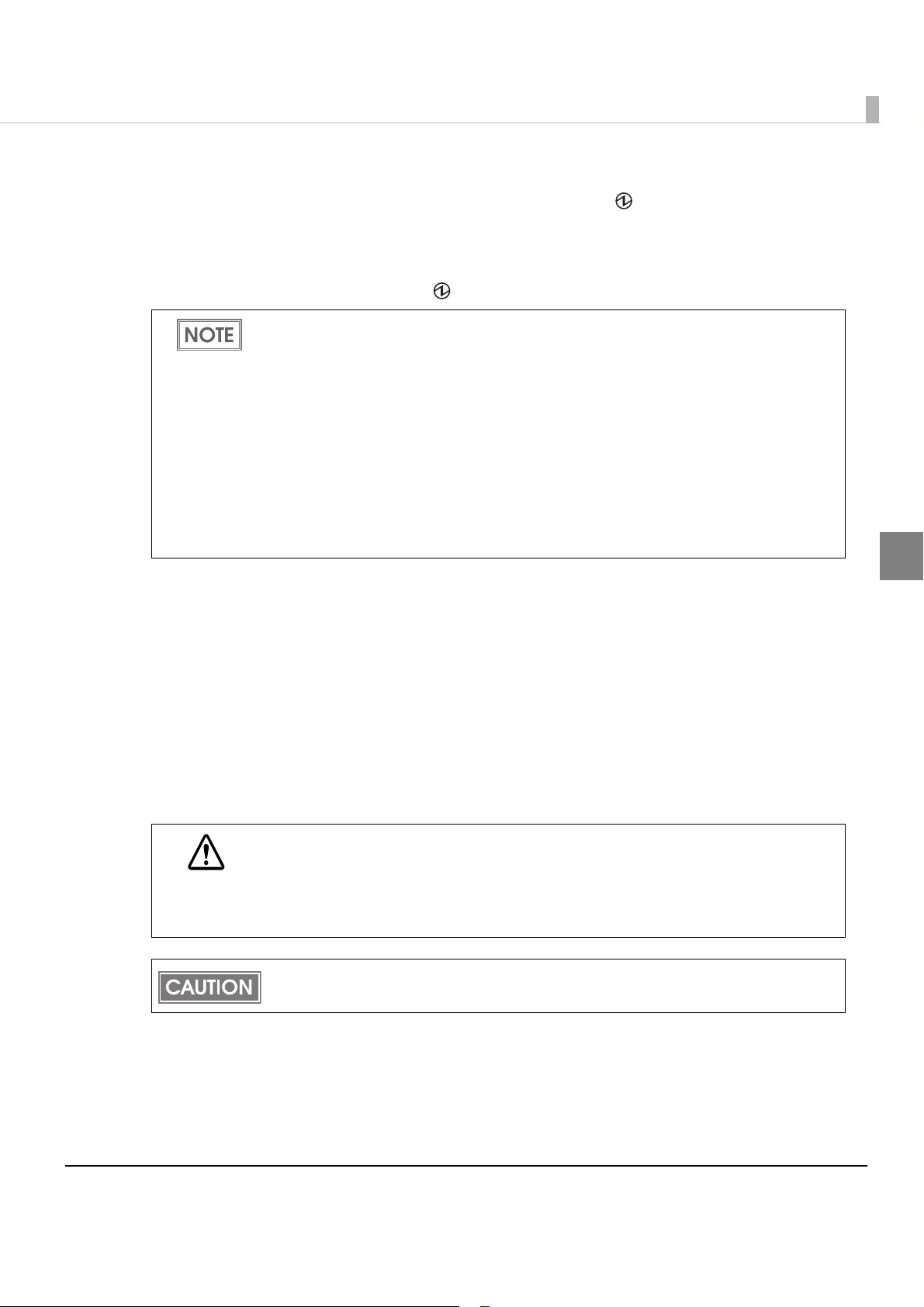
Close the ink cartridge cover.
4
When the ink cartridge i s installed for the first time, the (Power) LED starts flashing,
and ink charging starts. Ink charging takes approximately 4 minutes. In the meantime, do
not turn off the printer or open the roll paper cover or the ink cartridge cover. Doing so
wastes ink signif
When ink charging finishes, the (Power) LED stays on (not flashing).
icantly.
When the ink cartridge is loaded for the first time, the printer uses ink to prepare for
printing (initial ink charge), therefore, the first replacement period is shorter than normal.
The colors of printouts may become abnormal if you tilt this printer or subject the printer
to any shocks after ink is charged. When you move this printer after ink charging, check
the colors by performing a test print.
If the colors of printouts are not normal, perform head cleaning. See
page 98 for how to perform head cleaning.
Ink consumption differs, depending on printer conditions, such as printing and cleaning.
To prevent ink waste, do not insert and remove the ink cartridge other than when
replacing it.
To maintain the quality of print head, the INK LED lights even though some ink remains
in the cartridge.
"Head Cleaning" on
2
Setting the Printer IP Address
This setting is necessary only for the Ethernet interface model.
Connect the printer to the network via a hub using the Ethernet cable.
Set an IP address to the printer with EPSON TMNet Config.
Yo u can download EPSON TMNet Config from the following URL.
http://www.epson.jp/business/
When Ethernet cables are installed outdoors, make sure devices without proper
surge protection are cushioned by being connected through devices that do have
CAUTION
surge protection. Otherwise, the devices can be damaged by lightning.
Never attempt to connect a standard telephone line cable to the 10/100BASE-T
LAN connector.
Make sure the Ethernet cable is connected to the printer, and the printer is turned on.
45
Page 46

Adding a TCP/IP Port
This procedure is necessary only for Ethernet model, and unnecessary for the USB interface
model.
Follow the steps below to add a TCP/IP Port.
Make sure the Ethernet cable is connected to the printer, and the printer is turned on.
Select [Start] - [Control Panel] - [Printer] on the computer.
1
Menus to select are different for each OS. For details, see below.
Windows Vista
[Start] - [Control Panel] - [Printers]
Windows XP
[Start] - [Control Panel] - [Printers and Faxes]
Select [File] - [Add Printer] from the menu.
2
Select [Add a local printer].
3
46
Page 47

Chapter 2 Setup
Select [Create a new port:], select [Standard TCP/IP Port] in “Type of
4
port,” and click [Next].
Set the items by referring to the table below, and click [Next].
5
Item Setting value
Device type TCP/IP Device
Hostname or IP address
IP address set to the printer
2
Por t nam e
Query the printer and automatically
select the driver to use
Setting values in “Hostname or IP address” are
automatically input.
Uncheck the checkbox.
47
Page 48

Select [Standard], and [Generic Network Card] in “Device Type.” Then
6
click [Next].
Click [Cancel].
7
Do not install the printer driver in this step.
The addition of the TCP/IP port is completed.
48
Page 49

Installing the Printer Driver
The installation procedure is different between the USB interface model and the Ethernet
interface model.
Make sure to log on as an administrator to install the printer driver.
Before installing, check the hardware requirements. (See
page 25.
)
For USB Interface Model
Follow the steps below to install the printer driver.
Connect the printer to the computer.
1
Turn off the printer before installing. You need to turn it on during installation by following
the instructions.
"Hardware Requirements" on
Chapter 2 Setup
For a 32bit OS, double-click the icon “c61d32_xxxx.exe.”
2
For a 64bit OS, double-click the icon “c61d64_xxxx.exe.”
If the “User Account Control” screen is displayed, click [OK].
3
Select [EPSON TM-C610], and click [OK].
4
2
49
Page 50

Read the Licence Agreement, and click [Accept].
5
Make sure the printer is connected to the computer, and turn on the printer.
6
50
The following screen is displayed, and installation of the driver starts.
Page 51

Chapter 2 Setup
When the installation finishes, the following screen is displayed.
7
Click [OK] to close the screen.
The installation of the printer driver is completed.
For Ethernet Interface Model
Before installing the printer driver, set an IP address to the printer, and add a TCP/IP port.
(See "Setting the Printer IP Address" on page 45 and "Adding a TCP/IP Port" on page 46.)
The printer driver for the Ethernet interface model cannot be installed with a USB inter-
face model printer connected. In this case, turn off the USB interface model printer
before installing the printer driver for the Ethernet interface model.
Make sure the Ethernet cable is connected to the printer, and the printer is turned on.
2
Follow the steps below to install the printer driver.
For a 32bit OS, double-click the icon “c61d32_xxxx.exe.”
1
For a 64bit OS, double-click the icon “c61d64_xxxx.exe.”
If the “User Account Control” screen is displayed, click [OK].
2
Select [EPSON TM-C610], and click [OK].
3
51
Page 52

Read the Licence Agreement, and click [Accept].
4
Click [Manual].
5
52
Page 53
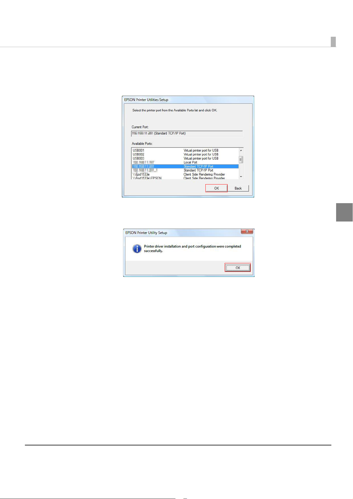
Chapter 2 Setup
From “Available Ports,” select the port added in "Adding a TCP/IP Port"
6
on page 46, and click [OK].
The installation of the printer driver starts.
When the installation finishes, the following screen is displayed.
7
Click [OK] to close the screen.
2
The installation of the printer driver is completed.
53
Page 54

Installing Status API
If you want to use Status API, install Status API after installing the printer driver.
Programming Status API enables you to acquire the printer status with your application.
Install the printer driver before installing Status API. ("Installing the Printer Driver" on page
.)
49
To install it without displaying the window, add the command (/s /v"/qn") to the install file
name for Status API.
e.g: c61sapi32_10.exe /s /v"/qn"
Follow the steps below to install Status API.
For a 32bit OS, double-click the icon “c61sapi32_xx.exe.”
1
For a 64bit OS, double-click the icon “c61sapi64_xx.exe.”
Destination for “c61sapi32_xx.exe”:
<execution folder for "c61d32_xxxx.exe”>/c61d32_xxxx/WINVISTA_XP_2K/STATUSAPI
Destination for “c61sapi64_xx.exe”:
<execution folder for "c61d64_xxxx.exe”>/c61d64_xxxx/WINVISTA_XP_2K/STATUSAPI
The "EPSON TM-C610 StatusAPI - InstallShield Wizard“ screen is displayed.
2
Click [Next].
54
Page 55

Chapter 2 Setup
The “License Agreement" screen is displayed. Read the Licence Agree-
3
ment, and select [I accept the terms in the license agreement].
Then Click [Next].
The "Ready to Install the Program" screen is displayed. Click [Install] to
4
start the installation.
2
55
Page 56

If the "User Account Control" screen is displayed, click [Continue].
5
The "InstallShield Wizard Completed" screen is displayed. Click [Finish].
6
The installation of Status API is completed.
56
Page 57

Chapter 3 Application Development Information
Application Development Information
This chapter describes how to control the printer and gives information useful for printer
application development.
Overview
The following is provided for use of this printer.
❏ A dedicated printer driver for Windows is available. For details on how to use the printer
driver, see "How to Use the Printer Driver" on page 66.
❏ A Status API that can be used with your applications is available.
Though Status API is prepared with the printer driver, you need to install it separately.
❏ Va rious utilities and user’s manuals are available.
❏ Dedicated sample programs for the TM-C610 are available.
Use them as a reference for developing applications.
This printer cannot use the APD or OPOS/JavaPOS provided by EPSON.
Printer Driver
The printer driver has the following functions, so it is not necessary to implement them in
applications.
❏ Barcode and 2D symbol fonts are implemented. The barcode and 2D symbol fonts can be
printed using the font replacement function for.NET environment.
The barcode and 2D symbol font must be set in advance
tion. (See
how to make the setting.)
In the .NET environment, a TrueType font is specified to be replaced by barcode and 2D sym-
bol fonts. The barcodes and 2D symbols can be printed by specifying a replaced TrueType font
from the application. (See
page 83
"Barcode Printing" on page 73 and "2D Symbol Printing" on page 79 for details of
"Barcode and 2D Symbol Font Printing on .NET Environment" on
for details about the font replacement function.)
in the printer driver to use this func-
3
57
Page 58
Status API
With Status API, you can transmit the printer status (such as printer and ink cartridge status and
print job information) to your applications, and can set the buzzer to beep when an error such as
a cover open occurs.
(Header files and assembly files for .Net are included
in the sample programs.)
Sample Program
Refer to the TM-C610 sample programs to develop the application using this printer.
❏ Features of TM-C610 sample programs
•Programs are provided in the step-up method from the basic ones to the advanced ones.
This helps you to learn how to control the printer.
•Program files are provided in the exe format and the source format.
•Header files and assembly files for .Net are provided.
(The assembly files for .Net are necessary to build a Status API-based application in the .Net
environment.)
• Development environment: Visual Studio 2005/Visual Studio 6.0
• Development language: C++, VB.NET, C#, VB6.0 (C# and VB6.0 are not provided for some
programs.)
❏ Structure of TM-C610 sample pro
grams
The following is the structure and language used for TM-C610 sample program.
Language
Level Program name Specification
C++
C#
VB.NET
Step 1.
Printing characters
Step 2.
Printing bar codes
Basic
Step 3.
Printing graphics
Step 4. Confirming the
printer status
Basic print program
Sets barcode font in advance to use
for print program.
The program to print graphics
Checks the printer condition before
printing and executes error handling.
—
—
—
VB6.0
—
—
—
58
Page 59

Chapter 3 Application Development Information
Level Program name Specification
Language
C++
C#
VB.NET
VB6.0
Basic
Advanced
Step 5.
Call-back process
Complete basic
features
Monitoring the printer
status and controlling
print jobs
DEVMODE Executes a 90-degree rotation or
Obtaining the print completion
When the condition of the printer
changes, the printer can cause
actions to occur in the application,
and executes error handling.
The program from Step 1 to 5
Cancels a print job when a paper
end is detected.
changes the number of copies in the
application.
Changes the number of copies in
the application.
Acquires the print completion.
—
—
—
—
—
—
—
—
3
59
Page 60

Utilities and Manuals
Several kinds of utilities and manuals other than the printer driver and this manual are available
for this printer.
Install Assistant
This is the utility to put together the setting information of the installed driver and the installer
of the driver as a package file.
The driver is installed with the same settings as the original computer when the package is
executed on a different computer, and thi
several computers.
When reinstalling the Install Assistant in an environment where the Install Assistant has
already been installed, uninstall the existing Install Assistant first, then install it again.
Only the driver settings saved in the computer can be copied. The driver settings saved
in the NV memory in the printer cannot be copied.
See the Install Assistant User’s Manual for details.
EPSON TMNet WinConfig
s makes it easy to install the printer driver on the
Sets/Changes the network setting for the EPSON printers in the network.
Some EPSON printers are not supported.
EPSONNet Web Config
Sets/Checks the network information of the printer by entering the IP address of the printer to
the address bar of the Web browser. One printer can be set and checked.
Sample Programs
These is the sample programs to use with the TM-C610. (C++, VB.NET, C#, and VB6.0 are
prepared as development languages. However, C# and VB6.0 are not provided for some
programs.)
60
Page 61

Chapter 4 Handling
Handling
This chapter describes basic handling of the printer.
Replacing the Ink Cartridge
Printing is not possible if any of the three color inks needs replacement.
When the INK LED (red) lights, the ink cartridge needs to be replaced. Follow the steps below to
replace the ink cartridge.
Always use the EPSON SJIC15P the ink cartridge.
Do not open the package of the ink cartridge until you are ready to install it in the printer.
Ink consumption differs depending on printer conditions, such as printing and cleaning.
To maintain the quality of print head, the INK LED lights even though some ink remains
in the cartridge.
Turn the power on and make sure the INK LED lights.
1
Pull down the ink cartridge cover to the front to open it.
2
4
61
Page 62

Pull out the used ink cartridge to remove it.
3
Do not leave the printer without an ink cartridge installed.
Otherwise, the print head may dry and clog.
CAUTION
Shake the new ink cartridge package 4 or 5 times before opening it and
4
take out the ink cartridge out of the package.
Push the ink cartridge gently into the cartridge holder at the position
5
shown below.
Insert it with arrow side up.
Close the ink cartridge cover.
6
The INK LED turns off.
62
Page 63

Replacing the Roll Paper
When the roll paper is out, the PAP E R O U T L E D (red) and the ERROR LED (red) light.
Follow the steps below to replace the roll paper.
Do not open the roll paper cover or touch the paper during printing.
Otherwise, the printer may be damaged.
WARNING
Replacing the Roll Paper
Press down the release lever, and pull it to the front to open the roll
1
paper cover.
Chapter 4 Handling
Remove the used paper roll core.
2
Load the roll paper in the orientation shown below.
3
4
63
Page 64

Pull out the paper end to the paper exit along the paper ejection guide.
Paper ejection guide
4
Close the roll paper cover.
5
When the printer power is on, roll paper is automatically fed about 10 cm {3.9”}, and then
autocutting is performed.
64
Page 65

Chapter 4 Handling
Triangle mark
Knob
Removing Jammed Paper
When a paper jam occurs, never pull out the paper forcibly. Open the roll paper cover, and
remove the jammed paper.
If the roll paper cover cannot open, follow the steps below.
Turn off the printer.
1
Remove the autocutter cover by pulling the part of the autocutter cover
2
indicated in the circle in the illustration below.
Turn the knob upward or downward until a triangle mark appears in the
3
hole in the frame.
Close the autocutter cover.
4
Open the roll paper cover, and remove the jammed paper.
5
4
65
Page 66

How to Use the Printer Driver
The printer driver allows you to change the print settings and also provides some utilities such
as checking the printer status and cleaning the print head.
How to Display the Printer Driver
Select [Start] - [Control Panel] - [Printer] on the computer.
1
Menus to select are different in each OS. For details, see below.
Windows 7
[Start] - [Control Panel] - [Hardware and Sound] - [Devices and Printers]
Windows Vista
[Start] - [Control Panel] - [Printers]
Windows XP
[Start] - [Control Panel] - [Printers and Faxes]
Right-click [EPSON TM-C610], and click [Printing References].
2
The printer driver screen is displayed.
The above icon name is displayed when the printer’s name registered as [EPSON
TM-C610].
66
Page 67

Chapter 4 Handling
Registered paper
➁
➂
➃
Registering User Defined Media
If the paper size to use is not in [Media Layout], register user defined media.
The registered layout will be stored in [Favorite Setting] to use from user applications.
Registering User Defined Media
Click [Add/Del] of [Media Size] on the [General] tab.
1
Enter [Media Size Name] on the displayed [User Defined Media Size]
2
screen.
This is registered as a user defined media name.
Enter the size of the paper.
3
Click [Add]. The user defined media will be registered and displayed in
4
the list of [Media Size].
4
67
Page 68

Favorite Setting
[General] tab Favorite setting
[Page Layout] tab
[Favorite Setting] is the function to administer several printer driver settings into one.
The settings from the [General] and [Page Layout] tabs such as Media Type, Media Layout
(including User Defined Media) are included.
68
Page 69

Chapter 4 Handling
Features
•When printing from your application, the print setting registered in [Favorite Setting] can be
selected as the default setting.
It is recommended to register the setting in favorite setting after executing print setting by
clicking [Save As Favorite Setting].
•A number of settings can be registered in [Favorite Setting].
For example, if the print se
coupon, the print setting can be completed by changing [Favorite Setting] when the coupon
is changed. This prevents an error of setting change when changing the paper length.
tting is registered in [Favorite Setting] for each defined-size
Registering print setting in [Favorite Setting]
Set the printer driver depending on paper to print.
1
Set settings on [General] and [Page Layout] tab. To set the paper of User Defined Media,
select it from [Media Size].
Click [Save As Favorite Setting] to display [Save/Delete Favorite Setting].
2
The current setting will be displayed in the list on the right side.
Enter a print setting name.
3
Click [Add].
4
The print setting will be registered in [Favorite Setting].
4
69
Page 70

[Favorite Setting] includes the following settings.
Current Settings➁
➂
➃
➀
User Defined Media
Registered in the Favorite Setting.
•Default Settings: The default setting when installing the printer driver.
•Current Settings: The contents set in the [General] and [Page Layout] tabs.
•User Defined Setting:The print setting defined by the user.
Information for User Definition
The user definition includes the following.
•User Defined Media
•Registering barcode font
•Replacing font in the .NET environment
The user definition is set on each client computer. When a number of TM-C610 printer drivers
are installed in one computer, these are used mutually.
These contents are displayed in the current settings in [Current Set-
ting] and the [Save/Delete Favorite Setting] window.
70
Page 71

Chapter 4 Handling
Buzzer Setting at the Time of Errors
Whether the buzzer beeps when an error occurs can be set.
Follow the steps below to make the setting.
Turn on the printer.
1
Display the printer driver.
2
(For how to display, see "How to Use the Printer Driver" on page 66.)
Select the [Maintenance And Utilities] tab, and click [Notification Set-
3
tings].
The following screen is displayed. Select the item to set, and click [OK].
4
The following screen is displayed, and setting is completed.
5
Click [OK] to exit.
4
71
Page 72

Autocutting and Buzzer Setting after Printing
Whether autocutting is performed and whether the buzzer beeps after printing can be set in
[Post-printing Operation Settings] in the [General] tab of the printer driver.
(For how to display the printer driver, see
[Post-printing Operation Settings] includes the following settings.
•Autocut:After Every Page/Only After Last Page
The printer feeds paper to the position where autocutting can
be performed, and stops after autocutting.
"How to Use the Printer Driver" on page 66.)
•Completion Beeper Settings: Only After Last Page
The buzzer beeps after printing is completed.
72
Page 73

Chapter 4 Handling
Barcode Printing
The printer driver has a built-in barcode font. Barcode printing is available if a barcode is not
created on the application side.
Setting the barcode font
Barcode print settings can be changed on [Barcode and 2D Symbol] on [Driver Utilities] tab.
Change settings of the following.
1
•Display: Select [Barcodes].
•Font Name: Input an arbitrary character string. ASCII characters only.
•Type: Select a barcode type from the following. The displayed items are
changed accordingly. The following types are selectable.
UPC-A UPC-E
JAN13(EAN) JAN8(EAN)
GS1 DataBar Omnidirectional GS1 DataBar Truncated
GS1 DataBar Expanded GS1 DataBar Limited
73
4
Page 74

•Rotation Settings: Select a setting when printing the barcode rotated by the specified
rate.
• Hexadecimal Entry Mode:
Turn on the check box when the data for barcode is specified on
Hexadecimal Entry Mode.
•Composite: Turn on the check box to print barcode with a composite symbol.
Separate the data specified to a composite symbol and a barcode with “\ |” or “| \”. Describe
the data in the order of the composite symbol and the barcode.
Example: 1234567890\ |012345678905
•Use a Quiet Zone: Leaves a blank margin on the rig
ht and left side of barcodes for bet-
ter readability.
The barcode printing position is moved based on the amount of the margin.
•Module: Sets the thin element width in dots.
Category
Graphic
resolution
(dpi)
Rotation
Settings
Adjust
Bar
Width*
Lower Line: Minimum Element Ratio
Grade D
or higher
Normal,
Rotate180
360x180
Rotate90,
Rotate270
Plain Media
Normal,
Rotate180
360x360
Rotate90,
Rotate270
Available
Upper Line: Minimum Module
[by 360 dpi]
ANSI
4 dot
2.5
6 dot
2.5
4 dot
2.5
6 dot
2.5
ANSI
Grade C
or higher
--
--
--
--
ANSI
Grade B
or higher
- : Not supported
* : Bars of the printed barcode may be thickened since ink soaks into the paper.
It is recommended to check [Adjust Bar Width].
74
Page 75

Chapter 4 Handling
When “Module” is set to an odd number and the resolution is changed by changing [Print
Resolution], the printed barcode size may be changed. The barcode size can be checked
by using the [Size Display] button.
•Bar Height:Sets the element height with dots. Specified dots indicate the actual
print size.
•Adjust Bar Width: Narrows the element width when printing. Make sure to select it
only when the barcode is not clear enough to be read.
•HRI Character Position: Select the positio
not desired.
The printing position is limited for some types.
•HRI Font: Select the HRI character font size.
• Element Ratio: Sets the thick element width by the ratio to the thin element width.
•Character Spacing:Sets the character spacing (interval) by the ratio to the thin element
h.
widt
Click [Add].
2
The selected barcode font is saved and the font name is added to the font list.
Up to 30 barcode fonts can be registered.
The barcode font setting can be overwritten by clicking [Save] after selecting the font
name from the font list and changing the setting.
The barcode font setting can be deleted by clicking [Delete] after selecting the font
name from the font list.
Execute a test print according to the setting by clicking [Print] after inputting the text in
the box.
n of the HRI characters. Select [Do Not Print] when
4
Specifying the barcode data
Specify the barcode data by referring to the following descriptions.
About the composite symbol:
The composite component type is selected automatically depending on the digit number of
the data.
Composite Component Type Encodable Digit Number
CC-A 1 ~ 56 digits
CC-B 1 ~ 338 digits
About the HRI character:
75
Page 76

When the total width of the HRI character is larger than that of the barcode, the HRI character
width is set as the barcode width.
UPC-A
❏ Normal
•Specify the data of 11 to 12 digits.
•The first digit is an unchecked number system character.
•For data of 11 digits, a check digit is automatically added.
•For data of 12 digits, the 12th digit is regarded as a check digit, but not proved.
❏ Composite (difference from Normal)
•For data of 12 digits, the 12th digit is ignored, and a check digit is automatically added.
UPC-E
❏ Normal
•Specify the data of 6 to 8, or 11 to 12 digits.
•For data of 6 digits, the specified data is not changed, and a check digit is automatically
added.
•For data of 7 digits, the 2nd to 7th digits become the data characters, and a check digit is
automatically added.
•For data of 8 digits, the 2nd to 7th digits become the data characters, and the 8th digit is
regarded as a check digit, but not proved.
•For data of 11 digits, a check digit is automatically added.
•For data of 12 digits, the 12th digit is regarded as a check digit, but not proved.
•For data of 7 digits or more, specify “0” for the first digit, since it is regarded as a number
system character.
❏ Composite (differences from Normal)
•For data of 8 digits, the 8th digit is ignored, and a check digit is automatically added.
•For data of 12 digits, the 12th digit is ignored, and a check digit is automatically added.
JAN13(EAN)
❏ Normal
•Specify the data of 12 to 13 digits.
•For data of 12 digits, a check digit is automatically added.
•For data of 13 digits, the 13th digit is regarded as a check digit, but not proved.
❏ Composite (difference from Normal)
•For data of 13 digits, the 8th digit is ignored, and a check digit is automatically added.
76
Page 77

Chapter 4 Handling
JAN8(EAN)
❏ Normal
•Specify the data of 7 to 8 digits.
•For data of 7 digits, a check digit is automatically added.
•For data of 8 digits, the 8th digit is regarded as a check digit, but not proved.
❏ Composite (difference from Normal)
•For data of 8 digits, the 8th digit is ignored, and a check digit is automatically added.
GS1 DataBar Omnidirectional/GS1 DataBar Truncated/GS1 DataBar Limited
❏ The first application identifier ‘01’ is not included in the data.
❏ When printing the HRI characters, the first application identifier ‘01’ is printed as ‘(01)’ before
the packing identification code.
❏ A check digit need not to be attached to the barcode data.
❏ When printing the HRI character, a check digit is printed after a product code.
❏ For GS1 DataBar Limited, specify ‘0’ or ‘1’ for the first digit.
GS1 DataBar Expanded
❏ Specify the data of 2 to 255 digits.
❏ ‘()’ is the delimiter for the application identifiers. (printed as the HRI character, but not
encoded.)
❏ Be sure to include all the application identifiers in the data.
❏ When the first data i s ‘01’ after deleting applica
‘*’ from the specified data, the 14th digit from the next of ‘01’ is checked as a check digit. When
it is not correct, an error occurs.
❏ When the next data of ‘01’ is fewer than 14 digits, a check digit is not checked.
(The check digit is no
is ignored, and the rest of the data is shifted by 1 digit.)
❏ Specify the special character using the following format.
Control Character ASCII HRI Character
Left parenthesis for the application identifier ( '(‘ is printed.
t automatically calculated, nor replaced with ‘*.’ When ‘*’ is specified, ‘*’
FNC1 {1 Space is printed.
tion identifiers, left and right parenthesis, and
4
Right parenthesis for the application identifier ) ‘)’ is printed.
‘*’ {* Error
Skipped character * Not printed.
77
Page 78

Printing method
Specify the selected barcode font, specified point and language to the printing data, and then
print it.
The font size of the barcode cannot be changed by [Specified Point] value. The barcode is
not printed when other values are selected.
78
Page 79

Chapter 4 Handling
2D Symbol Printing
The printer driver has built-in 2D symbol fonts. 2D symbol printing is available if the 2D symbol
is not created on the application side.
Setting the 2D Symbol font
2D symbol printing settings can be changed on [Barcode and 2D Symbol] on [Driver Utilities]
tab.
Change settings of the following.
1
•Display: Select [2D Symbols].
•Font Name: Input an arbitrary character string. ASCII characters only.
•Type: Select a 2D symbol type. The displayed items are changed accord-
ingly.
•Rotation Settings: Select a setting when printing the 2D symbol rotated by the specified
amount.
• Hexadecimal Entry Mode:
Turn on the check box when the data for 2D symbol is specified on
Hexadecimal Entry Mode.
79
4
Page 80

•Composite: Turn on the check box to print the 2D symbol with a composite sym-
bol.
Separate the data specified to a composite symbol and a 2D symbol with “\ |” or “| \”.
Describe the data in the order of the composite symbol and the 2D symbol.
Example: 1234567890\ |012345678905
•Use a Quiet Zone: Leaves a blank margin on the right and left side of 2D symbols for
better readability.
The 2D symbol printing position is moved based on the amount of margin.
Make settings of the following items according to the selected [Type].
2
•GS1 DataBar Stacked
Module: Sets the module width for GS1 DataBar Stacked.
•GS1 DataBar Stacked Omnidirectional
Module: Sets the module width for GS1 DataBar Stacked Omnidirectional.
•GS1 DataBar Expanded Stacked
Module: Sets the module width for GS1 DataBar Expanded Stacked.
Num Of Chars: Sets the maximum width for GS1 DataBar Expanded Stacked.
❏ The recommended values for the 2D symbols.
Recommended value for setting the barcode/2D symbol font (2D symbol of stack type)
Minimum Module [by 360 dpi]
Graphic
Category
Plain Media
resolution
(dpi)
360x180
360x360
Print Status*
No Paper feed 6 dot - -
With Paper feed 6 dot - -
No Paper feed 6 dot - -
With Paper feed 6 dot - -
ANSI
Grade D
or higher
ANSI
Grade C
or higher
ANSI
Grade B
or higher
- : Not supported
* : Whether paper feed is performed during printing 2D symbol can be checked in [Display
Media Feed Position] - [Display Print Preview] in the Print Preview function. For this
function, see
"Print Preview" on page 85.
80
Page 81

Click [Add].
3
The selected 2D symbol font is saved and the font name is added to the font list.
Up to 30 2D symbol fonts can be registered.
The 2D symbol font setting can be overwritten by clicking [Save] after selecting the font
name from the font list and changing the setting.
The 2D symbol font setting can be deleted by clicking [Delete] after selecting the font
name from the font list.
Execute a test print according to the setting by clicking [Print] after inputting the text in
the box.
Specifying the 2D symbol data
See the following description to specify the 2D symbol data.
Chapter 4 Handling
For the composite symbol and the HRI character, see
page 75
.
"Specifying the barcode data" on
GS1 DataBar Stacked /GS1 DataBar Stacked Omnidirectional
❏ Up to 13 digits of data can be specified.
❏ Do not specify the application identifier ‘01’ for the head of the data.
❏ A check digit need not to be attached to the data.
GS1 DataBar Expanded Stacked
❏ Multiple line symbol version of GS1 DataBar Expanded. How to specify the data is the same
as GS1 DataBar Expanded. (For details, see
"GS1 DataBar Expanded" on page 77.)
4
81
Page 82

Printing method
Specify the selected 2D symbol font, specified point and language to the printing data, and print
it.
The font size of the 2D symbol cannot be changed by [Specified Point] value.
The 2D symbol is not printed when other values are selected.
82
Page 83

Chapter 4 Handling
Barcode and 2D Symbol Font Printing on .NET Environment
Since .NET Framework supports only TrueType fonts and Open Type f o nts, the barcode and 2D
symbol fonts that are registered in the printer driver cannot be printed from an application.
Therefore, TrueType fonts are replaced with barcode and 2D symbol fonts with the font
replacement function of the printer driver. Barcode and 2D symbol fonts can be printed from
applicatio
The name of the print data in the application remains as a TrueType font name, but changes to
barcode and 2D symbol font when it is printed.
ns under .NET Framework environment by this replacement function.
Font Replacement
Font Replacement is executed from [Font Replacement] on the [Driver Utilities] tab.
Make the following setting.
1
•Replacement TrueType Font
Select the original TrueType Font.
•Replacement Target Font
Select the target barcode and 2D symbol.
Click [OK].
2
TrueType font is replaced by barcode and 2D symbol font.
4
83
Page 84

Printing barcodes and 2D symbols
Sets specified number of point, language of the replaced TrueType font by barcode and 2D
symbol font to the print data.
The number of point for barcode and 2D symbol is specified; check it from [Barcode
and 2D Symbol] on [Driver Utilities]. The barcode and 2D symbol cannot be printed if a
value other than those specified is set.
The original TrueType font can be used only for specifying barcode and 2D symbol;
therefore, if other characters are specified, they cannot be printed. Make sure to use a
TrueType font that will not be used for other printing.
84
Page 85

Chapter 4 Handling
Functions of the Printer Driver
The printer driver has “General,” “Page Layout,” “Driver Utilities,” and “Maintenance And
Utilities” tabs to change various settings and for adjustments.
[General] tab
Favorite Setting
Selects one of the registered print settings from the list. This is the default setting when printing.
Changes to setting when installing the printer driver if [Default settings] is selected.
Print Settings
Makes setting of Media Type, Media Size, Print Resolution and Color Correction.
The user definition paper can be registered in Media Size.
Select print quality from [Normal] [High] and the following is the resolution of the printing.
Paper type Print Resolution
Normal 360 × 180
Normal paper
High 360 × 360
Resolution (dpi)
(Horizontal × vertical)
Media Source Settings
Changes settings of Paper Source and Roll Paper Option setting.
Post-printing Operation Settings
Sets whether autocutting is performed and whether the buzzer beeps after printing.
Print Preview
Displays the print preview before printing if this check box is turned on.
4
85
Page 86
[Page Layout] tab
Favorite Setting
Selects one of the registered print settings from the list. This is the default setting when printing.
Changes to setting when installing the printer driver if [Default Settings] is selected.
Orientation
Changes settings of the printing direction (Portrait, Landscape, Rotate 180).
Copies
Sets the number of prints.
Layout
Adjusts the printing position.
Watermark
By turning on this check box, text such as “Important” or a graphic can be printed as a
watermark.
The checkbox is grayed out unless [Roll Media Option] in the [General] tab is set to “Cut
Sheet Mode”.
Since the watermark is printed on top of the printed data, a barcode cannot be read when
the barcode and the watermark overlap each other.
86
Page 87

Chapter 4 Handling
[Driver Utilities] tab
Barcode and 2D Symbol
Changes various settings of barcode fonts and 2D symbol fonts. This is user definition
information.
See "Barcode Printing" on page 73 or "2D Symbol Printing" on page 79 for the procedure of
each printing.
Font Replacement
Makes settings to replace TrueType font with barcode and 2D symbol fonts under .NET
environment.
Use this to print the barcode and 2D symbol font in the .NET environment. One TrueType
font is specified to use for printing barcodes and 2D symbol fonts.
Driver Preferences
Changes settings for various functions related to the printer driver.
EPSON Log File Settings
Changes settings for the saving method for quick analysis when an error occurs.
Import/Export Settings
Imports or exports all the settings on the printer driver as a file. This is used for Install Assistant
to create the install package of the printer driver.
This makes it easier to use the same settings for other printers.
4
87
Page 88

[Maintenance And Utilities] tab
Makes the following settings to the printer.
Notification Settings
Sets whether the buzzer beeps when an error occurs.
Head Cleaning
Performs head cleaning. The result of the head cleaning can be checked by the nozzle check
pattern printing.
See "Head Cleaning" on page 98 for the operating procedure of head cleaning.
Nozzle Check
Prints a nozzle check pattern to check if any nozzle is clogged or not.
Print Head Alignment
Adjusts misalignment of vertical lines, barcodes and paper feed during bi-directional printing.
This is to check the adjustment value using the roll paper included in the product package.
Normally this is not necessary for the user to make this adjustment since th
factory before shipping.
is is adjusted in the
88
Page 89

Uninstallation
To uninstall the printer driver, uninstall the printer driver and Status API separately.
•To uninstall the printer driver page 89
•To uninstall Status API page 91
Uninstalling the Printer Driver
Follow the steps below to uninstall the printer driver.
Finish other operations on the computer.
1
Select [Start] - [Control Panel] - [Uninstall a program].
2
Menus to select are different in each OS. For details, see below.
Windows 7 / Vista
[Start] - [Control Panel] - [Uninstall a program]
Windows XP
[Start] - [Control Panel] - [Add or Remove Programs]
Chapter 4 Handling
Select [EPSON Printer Software], and click [Uninstall/Change].
3
The following screen is displayed. Select the printer driver to be
4
uninstalled from the [Printer Model] tab.
4
89
Page 90

Check [EPSON Network Utility] in the [Utilities] tab, and click [OK].
5
If you are using other EPSON printers and more than one [EPSON Network Utility] is displayed, do not delete them. If they are displayed even if you are not using other EPSON
printers, check all of them to delete.
The screen to confirm uninstallation is displayed. Click [Yes ].
6
The confirmation screen to delete the personal setting information is dis-
7
played.
Click [Yes] to delete it, or click [No] to leave it.
If you have set the TM-C610 as the usual printer, another printer to be set
8
for the usual printer after uninstalling is displayed. Click [OK].
90
Page 91

“Uninstallation complete.” is displayed. Click [OK].
9
The uninstallation of the printer driver is completed.
Uninstalling Status API
Follow the steps below to uninstall Status API.
To uninstall without displaying the screen, add the command (/s /v"/qn REMOVE=ALL") to
the installation file name of Status API.
e.g: c61sapi32_10.exe /s /v"/qn REMOVE=ALL"
Chapter 4 Handling
Finish other operations on the computer.
1
For a 32bit OS, double-click the icon "c61d32_xxxx.exe."
2
For a 64bit OS, double-click the icon "c61d64_xxxx.exe."
Directory of c61sapi32_xx.exe:
< The folder to execute c61d32_xxxx.exe>/ c61d32_xxxx/WINVISTA_XP_2K /
STATUSAPI
Directory of c61sapi64_xx.exe:
< The folder to execute c61d64_xxxx.exe>/ c61d64_xxxx/WINVISTA_XP_2K /
STATUSAPI
Click [Next].
3
4
91
Page 92

Select [Remove], and click [Next].
4
Click [Remove].
5
Status API is uninstalled.
92
Page 93

The uninstall completion screen is displayed. Click [Finish].
6
The uninstallation of Status API is completed.
Chapter 4 Handling
93
4
Page 94

Self-test
WTK xxxxx QP xxxxxx
Firmware version
Nozzle check pattern
The self-test is performed by using the control panel.
For the Ethernet interface model, using the self-test button on the printer back enables you to
check the printer setting such as IP address.
Procedure for the Self-test
Yo u can check the following items by performing the self-test using the control panel.
•Firmware version
• Nozzle check pattern
Follow the steps below to perform the self-test.
Check the following points.
1
• The roll paper is correctly set.
• The roll paper cover is closed.
Turn off the printer.
2
While pressing down the FEED button, press the power switch.
3
The self-test result is printed.
94
The values for “X” in the above print result are different from each printer.
Page 95

Chapter 4 Handling
Self-test button
Self-test using the self-test button (only for the Ethernet interface model)
For the Ethernet interface model, You can check the following items by performing the self-test
using the self-test button.
•Printer setting information
•Firmware version
• Nozzle check pattern
Follow the steps below to perform the self-test.
Check the following points.
1
•The (Power) LED is on (not flashing).
• The roll paper is correctly set.
• The roll paper cover is closed.
Remove the rear cover of the printer.
2
For how to remove the rear cover, see "Connecting the USB/Ethernet cable" on page 38.
Press the self-test button on the back of the printer with something
3
pointed.
Do not press the self-test button for longer than 2 seconds. If the button is held down longer, detailed information for an internal check is printed.
4
95
Page 96

The self-test result is printed.
★ EPSON Network Sheet ★
MAC xx:xx:xx:xx:xx:xx
HW/SW XX.XX/XX.XX
IP
XXX.XXX.XXX.XXX
LN TM-C610-xxxxxx
★ Printer Sheet ★
WTK xxxxx QP xxxxxx
IP address
Nozzle check pattern
MAC address
Firmware version
96
The values for “X” in the above print result are different from each printer.
Page 97

Chapter 4 Handling
Nozzle Check
Printing the nozzle check pattern enables you to check whether the nozzles are clogged or not.
The nozzle check can be performed in two methods: by the self-test, and by the printer driver.
Nozzle Check using the Self-test
Perform the self-test referring to "Self-test" on page 94.
1
Check the printed nozzle check pattern.
2
If dots are missing, perform a head cleaning. (See "Head Cleaning" on page 98.)
Nozzle Check Using the Printer Driver
Turn on the printer.
1
Set the roll paper correctly.
2
Display the print setting screen of the printer driver.
3
(For how to display, see "How to Display the Printer Driver" on page 66.)
Click [Nozzle Check] in the [Maintenance And Utilities] tab.
4
Click [Print].
5
Check the printed nozzle check pattern.
6
If dots are missing, perform a head cleaning. (See "Head Cleaning" on page 98.)
4
97
Page 98

Cleaning
Cleaning the Printer Case
To cl ean the printer case, wipe the dirt off the printer case with a dry cloth or a damp cloth. Be
sure to turn off the printer before cleaning.
Never clean the product with alcohol, benzine, thinner, or other such solvents. Doing so
may damage or break the parts made of plastic and rubber.
Head Cleaning
Perform a print head cleaning only when the printout is faint or dots are missing.
Head cleaning can be performed using two methods; the CLEANING button, or the printer
driver.
Do not turn off the printer or open the roll paper cover or the ink cartridge cover.
When ink is low, head cleaning may not start or may stop during cleaning. In this case,
head cleaning starts after a new ink cartridge is installed.
When head cleaning is performed continuously, the printer may stop operating for
approximately a minute at a maximum to protect the motor from the heat. The printer
restarts operating after the motor cools down.
98
Page 99

Head cleaning Using the CLEANING button
CLEANING button
Turn on the printer.
1
Press the CLEANING button for 3 seconds or more.
2
Head cleaning starts. The (Power) LED flashes during the head cleaning.
Chapter 4 Handling
When head cleaning finishes, the (Power) LED stays on.
Perform a nozzle check to confirm the print result.
3
(For how to perform the nozzle check, see "Nozzle Check" on page 97.)
Head cleaning using the printer driver
Turn on the printer.
1
Display the print setting screen of the printer driver.
2
(For how to display, see "How to Display the Printer Driver" on page 66.)
Click [Head Cleaning] in the [Maintenance And Utilities] tab.
3
Perform the nozzle check to confirm the print result.
4
(For how to perform the nozzle check, see "Nozzle Check" on page 97.)
4
99
Page 100

Transporting the Printer
Ta pe
Ink cartridge cover
For transporting the printer, be sure to follow the instructions below to prevent ink leakage
under the reduced pressure occurring during air transportation.
Make sure the (POWER) LED is turned on. (Wait about 10 seconds
1
after the printer has finished its operations.
Open the ink cartridge cover.
2
The valve inside the printer is closed by opening the ink cartridge cover while the
printer is turned on. To prevent ink leakage during transportation, be sure to perform
CAUTION
Disconnect the power cable from the inlet while the ink cartridge cover
3
is open.
Disconnect the power cable from the printer.
4
this procedure.
Make sure the (POWER) LED is turned off.
5
Close the ink cartridge cover.
6
Fix the ink cartridge cover with tape, as shown in the illustration below, to
7
prevent the ink cartridge cover from opening during transportation.
Do not turn the printer upside down or on its side when packed and
8
being transported.
Be sure to transport the printer with an ink cartridge installed.
100
CAUTION
 Loading...