

Page 1
Technical Reference Guide
Describes features for the product.
Describes setup and installation of the product and peripherals.
Describes how to control the printer and necessary information
when you develop applications.
Describes how to handle the product.
Describes the ecient management method of multiple printers
and client computers, targeted at the administrators.
Series
Describes general specications for the product.
Product Overview
Setup
Handling
Application Development Information
Maintenance
Appendix
M00066608
Rev.I
Page 2

Cautions
• No part of this document may be reproduced, stored in a retrieval system, or transmitted in any form or by any means,
electronic, mechanical, photocopying, recording, or otherwise, without the prior written permission of Seiko Epson Corpo-
ration.
• The contents of this document are subject to change without notice. Please contact us for the latest information.
• While every precaution has been taken in the preparation of this document, Seiko Epson Corporation assumes no respon-
sibility for errors or omissions.
• Neither is any liability assumed for damages resulting from the use of the information contained herein.
• Neither Seiko Epson Corporation nor its affiliates shall be liable to the purchaser of this product or third parties for dam-
ages, losses, costs, or expenses incurred by the purchaser or third parties as a result of: accident, misuse, or abuse of this
product or unauthorized modifications, repairs, or alterations to this product, or (excluding the U.S.) failure to strictly com-
ply with Seiko Epson Corporation’s operating and maintenance instructions.
• Seiko Epson Corporation shall not be liable against any damages or problems arising from the use of any options or any
consumable products other than those designated as Original Epson Products or Epson Approved Products by Seiko
Epson Corporation.
Trademarks
EPSON is a registered trademark of Seiko Epson Corporation.
Exceed Your Vision is a registered trademark or trademark of Seiko Epson Corporation.
®
Microsoft
States and other countries.
All other trademarks are the property of their respective owners and used for identification purpose only.
, Windows®, Windows Vista®, and Windows Server® are registered trademarks of Microsoft Corporation in the United
Copyright
This product includes software developed by the University of California, Berkeley, and its contributors.
©Seiko Epson Corporation 2013-2018. All rights reserved.
2
Page 3
For Safety
Key to Symbols
The symbols in this manual are identified by their level of importance, as defined below. Read the following
carefully before handling the product.
You must follow warnings carefully to avoid serious bodily injury.
WARNING
Provides information that must be observed to prevent damage to the equipment or loss of data.
• Possibility of sustaining physical injuries.
CAUTION
• Possibility of causing physical damage.
• Possibility of causing information loss.
Provides information that must be observed to avoid damage to your equipment or a malfunction.
Provides important information and useful tips.
Warnings
WARNING
• Shut down your equipment immediately if it produces smoke, a strange odor, or unusual
noise.
Continued use may lead to fire. Immediately unplug the equipment and contact qualified service
personnel for advice.
• Never attempt to repair this product yourself. Improper repair work can be dangerous.
• Never disassemble or modify this product. Tampering with this product may result in injury
or fire.
• Be sure to use the specified AC adapter.
Connection to an improper power source may cause fire.
• Be sure your power code meets the relevant safety standards and includes a power-system
ground terminal (PE terminal).
Otherwise electric shock may result. If you acquire a system with different safety standards, use an
AC cable that meets the acquired safety standards.
• Do not allow foreign matter to fall into the equipment. Penetration by foreign objects may
lead to fire.
• If water or other liquid spills into this equipment, unplug the power cord immediately, and
then contact qualified service personnel for advice. Continued usage may lead to fire.
• Do not use aerosol sprayers containing flammable gas inside or around this product. Doing
so may cause fire.
3
Page 4

Cautions
CAUTION
• Do not connect cables in ways other than those mentioned in this manual. Different connections
may cause equipment damage and burning.
• Be sure to set this equipment on a firm, stable, horizontal surface. The product may break or cause
injury if it falls.
• Do not use in locations subject to high humidity or dust levels. Excessive humidity and dust may
cause equipment damage or fire.
• Do not place heavy objects on top of this product. Never stand or lean on this product. Equipment
may fall or collapse, causing breakage and possible injury.
• Protect the printer from heavy impacts. They may cause defective print.
• To ensure safety, unplug this product before leaving it unused for an extended period.
• Do not remove the ink cartridge from the product when you ship it.
• Be sure to note the following when using the ink cartridge:
∗ Do not turn off the product or open the ink cartridge cover while charging ink (Power light is
flashing). Opening the cover may cause the ink to be recharged, resulting in more ink being consumed. Also, it may cause printing malfunction.
∗ Do not disassemble the ink cartridge. Doing so may cause ink to adhere eyes and skin.
∗ Do not disassemble and remodel the ink cartridge. Doing so may cause printing malfunction.
∗ Keep ink cartridges out of the reach of children.
• If ink contacts your skin, eyes, or mouth, take the following actions.
∗ When ink gets onto your skin, immediately wash the area with soap and water.
∗ When ink gets into your eyes, immediately flush them with water.
∗ Leaving the ink as is may result in bloodshot eyes or mild inflammation. If something is wrong,
immediately consult with a doctor.
∗ When ink gets into your mouth, immediately spit it and consult with a doctor.
• Be sure to note the following when using the maintenance box:
∗ Do not dismantle the Maintenance box.
∗ Do not touch the IC chip on the cartridge.
∗ Keep out of reach of children, and do not drink.
∗ Do not reuse a maintenance box which was removed and detached for a long period.
4
Page 5

Restriction of Use
When this product is used for applications requiring high reliability/safety such as transportation devices
related to aviation, rail, marine, automotive etc.; disaster prevention devices; various safety devices etc.; or
functional/precision devices etc., you should use this product only after giving consideration to including fail-
safes and redundancies into your design to maintain safety and total system reliability.
5
Page 6

About this Manual
Aim of the Manual
This manual was created to provide information on development, design, and installation of systems and
development and design of printer applications for developers.
The specifications of the supported paper sizes are different for the firmware covered in this manual and the
firmware that has been upgraded.
Manual Content
The manual is made up of the following sections:
Chapter 1
Chapter 2 Setup
Chapter 3 Handling
Chapter 4 Application Development Information
Chapter 5 Maintenance
Chapter 6 Appendix
Product Overview
6
Page 7

Contents
■ For Safety.......................................................................................................................................... 3
Key to Symbols..........................................................................................................................................................................................3
Warnings...................................................................................................................................................................................................... 3
Cautions.......................................................................................................................................................................................................4
■ Restriction of Use............................................................................................................................. 5
■ About this Manual ...........................................................................................................................6
Aim of the Manual....................................................................................................................................................................................6
Manual Content ........................................................................................................................................................................................6
■ Contents ...........................................................................................................................................7
Product Overview................................................................................ 11
■ Features..........................................................................................................................................11
Easy Setup.................................................................................................................................................................................................13
How to Print..............................................................................................................................................................................................13
Other Features.........................................................................................................................................................................................13
■ Parts Name and Function..............................................................................................................14
Power Switch............................................................................................................................................................................................16
Paper FEED button.................................................................................................................................................................................16
CUT button................................................................................................................................................................................................17
Cleaning button......................................................................................................................................................................................17
STATUS SHEET button...........................................................................................................................................................................17
LCD contrast adjustment button......................................................................................................................................................17
Connectors................................................................................................................................................................................................18
■ Status/Error Indications ................................................................................................................19
Ink Cartridge and Maintenance Box Status...................................................................................................................................21
Beeper.........................................................................................................................................................................................................22
■ Auto nozzle check system .............................................................................................................23
■ Drivers, Utilities .............................................................................................................................26
Drivers.........................................................................................................................................................................................................26
Utilities........................................................................................................................................................................................................27
Setup .................................................................................................... 29
■ Work Flow.......................................................................................................................................29
■ Checking the Items Included in the Package...............................................................................30
■ Installing the Printer......................................................................................................................31
Important Notes on Installation........................................................................................................................................................31
■ Attaching the Power Switch Cover ...............................................................................................32
■ Setting Up the Printer ...................................................................................................................34
Media Layout Creation .........................................................................................................................................................................36
Shutter Adjustment...............................................................................................................................................................................40
■ Ejection Angle of Printed Paper ...................................................................................................42
7
Page 8

■ How to Display the Printer Driver ................................................................................................ 43
■ Registering the Media Layout...................................................................................................... 44
■ Attaching the Paper Ejection Tray ...............................................................................................45
■ Setting the DIP Switches............................................................................................................... 47
Setting Procedure.................................................................................................................................................................................. 47
Function of the DIP Switches ............................................................................................................................................................ 48
■ Setting the Printer Driver ............................................................................................................. 49
Banding Reduction ............................................................................................................................................................................... 49
TM-C3500 PrinterSetting .................................................................................................................................................................... 51
Setting EPSON Status Monitor 3 ......................................................................................................................................................53
Handling............................................................................................... 61
■ Replacing the Ink Cartridge ......................................................................................................... 61
■ Replacing Maintenance Box......................................................................................................... 64
■ Replacing Roll Paper with Fanfold Paper .................................................................................... 66
■ Replacing Fanfold Paper with Roll Paper .................................................................................... 75
■ Setting the Printer Driver ............................................................................................................. 82
Favorite Setting...................................................................................................................................................................................... 82
Information for User Definition ........................................................................................................................................................ 85
Exporting/Importing Printer Driver Settings............................................................................................................................... 86
Barcode Printing .................................................................................................................................................................................... 88
2D Symbol Font Settings .................................................................................................................................................................. 100
Barcode and 2D Symbol Font Printing on .NET Environment .............................................................................................107
Print Preview..........................................................................................................................................................................................109
Settings For Paper Handling After Print ......................................................................................................................................110
Beeper...................................................................................................................................................................................................... 112
■ Setting the Printer....................................................................................................................... 113
Media detection settings..................................................................................................................................................................113
Nozzle Check Mode Settings...........................................................................................................................................................116
Paper Loading Settings .....................................................................................................................................................................117
Notification Settings........................................................................................................................................................................... 120
Panel Button Settings.........................................................................................................................................................................122
Operating Time Settings ...................................................................................................................................................................123
Paper Feed Adjustment.....................................................................................................................................................................125
Sensor Adjustment..............................................................................................................................................................................132
Print Head Alignment ........................................................................................................................................................................133
■ Network Interface ....................................................................................................................... 134
Factory settings....................................................................................................................................................................................134
How to initialize the settings to the factory settings.............................................................................................................. 134
■ Troubleshooting.......................................................................................................................... 135
Trouble Recovery Method ................................................................................................................................................................135
Error Recovery Method......................................................................................................................................................................147
When the print result is faint or white lines or black lines are printed.............................................................................149
When the printer is not found even if EpsonNet Config is started....................................................................................151
HELP for EPSON Printers....................................................................................................................................................................152
■ Setting Check Modes .................................................................................................................. 154
Self-test Mode.......................................................................................................................................................................................154
8
Page 9

Status Sheet Printing (LAN interface model only)................................................................................................................... 156
■ Reset .............................................................................................................................................157
■ Cleaning the Printer ....................................................................................................................157
Cleaning the platen ............................................................................................................................................................................157
Cleaning the Autocutter ...................................................................................................................................................................159
■ Media arrangement.....................................................................................................................160
Media arrangement when feeding media for printing from the first sheet ..................................................................160
Media arrangement for printing on the last sheet.................................................................................................................. 162
■ Setting the label size and paper layout for borderless printing..............................................165
Requirement..........................................................................................................................................................................................165
Setting example...................................................................................................................................................................................165
■ How to Make Media Settings ......................................................................................................167
Application Development Information ........................................... 169
■ Printer Control Method ...............................................................................................................169
■ Printer Driver ...............................................................................................................................169
■ Using Epson Inkjet Label Printer SDK ........................................................................................170
Operating environment....................................................................................................................................................................170
Where to download............................................................................................................................................................................ 170
■ Utilities and Manuals...................................................................................................................171
Download...............................................................................................................................................................................................174
Maintenance...................................................................................... 175
■ Necessary Information for an Administrator of the Printer .....................................................177
Utility........................................................................................................................................................................................................ 177
Setting the Printer...............................................................................................................................................................................178
Setting the Printer Driver.................................................................................................................................................................. 179
■ System Configuration..................................................................................................................181
Installing the Printer........................................................................................................................................................................... 181
Distributing the Printer Driver........................................................................................................................................................ 182
■ Maintenance.................................................................................................................................183
Changing the Printer Settings ........................................................................................................................................................183
Changing the Printer Driver Settings........................................................................................................................................... 188
Monitoring the Network Printer.....................................................................................................................................................189
Replacing the Printer.......................................................................................................................................................................... 190
■ For Inquiries .................................................................................................................................192
Appendix............................................................................................ 193
■ Product Specifications ................................................................................................................193
Hardware Requirements...................................................................................................................................................................194
Printing Specifications.......................................................................................................................................................................194
Paper Specifications ...........................................................................................................................................................................195
9
Page 10

Print Area and Cutting Position...................................................................................................................................................... 206
Paper Ejection Tray..............................................................................................................................................................................226
Ink Cartridge..........................................................................................................................................................................................226
Maintenance Box.................................................................................................................................................................................227
Electrical Characteristics ...................................................................................................................................................................227
Environmental Conditions ...............................................................................................................................................................228
External Dimensions........................................................................................................................................................................... 229
■ Restrictions.................................................................................................................................. 230
10
Page 11

Chapter 1 Product Overview
Product Overview
This chapter describes features and specifications of the product.
Features
The TM-C3500 series (TM-C3500/ TM-C3510/ TM-C3520) are a 4-color ink jet printer that offers high speed
easy operability and high reliability required for on-demand label printing.
Printing
•High-speed printing
∗ 103 mm/s (printing width 56 mm, 360 dpi × 360 dpi, bidirectional printing)
∗ 52 mm/s (printing width 56 mm, 720 dpi × 360 dpi, bidirectional printing)
The print speed is different depending on the resolution and the printing width.
•Color printing
∗ KCMY 4-color printing
∗ Print resolution: Plain, Plain label 360 dpi × 360 dpi
: Others 360 dpi × 360 dpi, 720 dpi × 360 dpi
dpi: dots per 25.4 mm (dots per inch)
• Supports printing on various types of paper
∗ Roll paper, Fanfold paper
∗ Continuous paper, Continuous paper (Blackmark), Full-page label, Transparent full-page label, Die-cut label, Transpar-
ent die-cut label
(Detects positions of black marks and gaps between labels)
∗ Plain, Matte, Plain label, Matte label, Synthetic label, Glossy label
∗ Wristband
• System to prevent ink from smearing out of the printable area such as on the backing paper of Die-cut Label.
1
• System to prevent missing read or missing color caused by missing dots.
Handling
• Replacing the roll paper and the ink cartridge can be done only by operation in the front.
• Multiple printed sheets can be stored in the paper ejection tray. The paper ejection tray cannot store multiple
sheets of roll paper.
11
Page 12

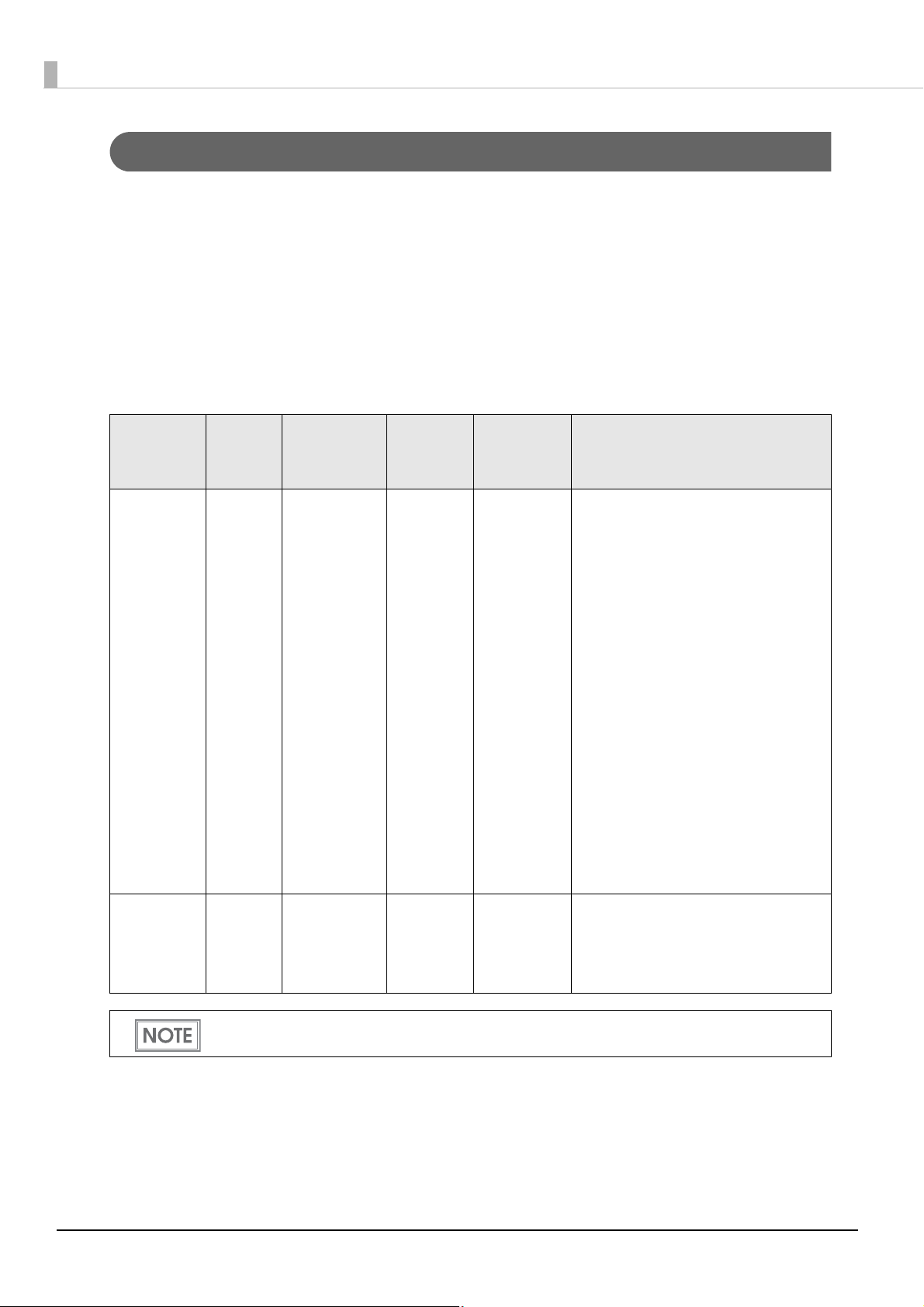
Reliability
Life Print head 6 billion shots/nozzle
Paper feed
mechanism
Autocutter
mechanism
1,500,000 pages or the number of pages that reaches the following paper
length fed.
• Plain Media: 150 km
• Matte Media: 75 km
• Wrist band (WB-S/M/L series): 30 km
• Die-cut label (Plain Media): 150 km
• Die-cut label (Matte Media): 150 km
• Die-cut label (Synthetic Media): 100 km
• Die-cut label (Glossy Media): 100 km
• Continuous label paper (Plain Media): 100 km
• Continuous label paper (Matte Media): 50 km
• Continuous label paper (Synthetic Media): 10 km
• Continuous label paper (Glossy Media): 30 km
• Plain Media: 1,500,000 cuts
• Matte Media: 750,000 cuts
• Wrist band (WB-S/M/L series): 200,000 cuts
• Die-cut label backing paper (Plain Media): 1,500,000 cuts
• Die-cut label backing paper (Matte Media): 1,500,000 cuts
Die-cut label backing paper (Synthetic Media): 500,000 cuts
•
• Die-cut label backing paper (Glossy Media): 1,500,000 cuts
• Continuous label paper (Plain Media): 750,000 cuts
(Add extra 250,000 cuts with cleaning the cutter blade)
• Continuous label paper (Matte Media): 500,000 cuts
• Continuous label paper (Synthetic Media): 100,000 cuts
• Continuous label paper (Glossy Media): 300,000 cuts
Carriage
mechanism
MTBF 88,000 hours
MCBF 9,800,000 passes
12
6 million passes
(3 million carriage returns)
Page 13

Chapter 1 Product Overview
Easy Setup
Using the CD-ROM that came with the product, you can follow the dialogic instructions on the screen and
easily setup a printer driver, install software, or perform media settings and settings of this product.
How to Print
• Windows printer drivers that can be used from Windows applications (except for the above label printing
applications) are available.
• The printer driver has a built-in barcode font and can print high quality barcodes with superior readability. It
can also be used from a .NET environment application.
• EPSON Inkjet Label Printer SDK (using a Windows printer driver) that supports the customer's printing
application development is available.
1
Other Features
• USB interface and Ethernet interface are equipped by default. This product can be used as a local printer of a
computer or a network printer.
• The auto-cutter is equipped by default. Paper can be cut by a command from applications or panel switch
operations.
• A beeper is equipped by default. Notifications are available for no media or low ink, error, end of printing,
etc.
• When using a USB printer, because a new print queue is generated when the damaged printer is replaced
with another printer, you need to set the application or driver again. However for this product, we provide
the service (USB printer class device replacing service) to replace a printer without changing the settings of a
computer or printer driver.
13
Page 14
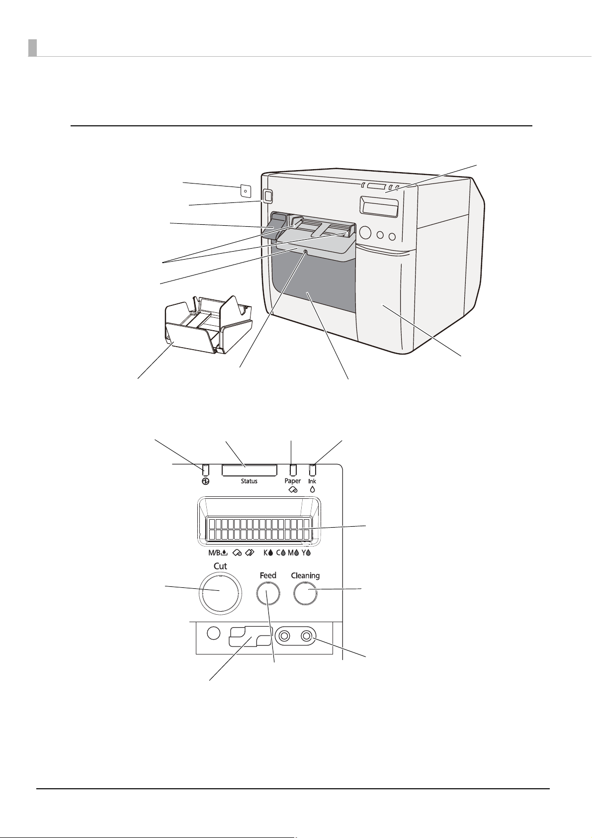
Parts Name and Function
Power switch cover
Power switch
Release lever
Paper ejection
guide
Ink cartridge cover
Control panel
Roll paper cover
Paper ejection
guide lock
Paper ejection tray
Paper ejection
table
Paper LED
Power LED
Paper FEED button
Status LED Ink LED
LCD
Cleaning button
LCD contrast adjustment button
DIP switches
CUT button
Front
Control panel
14
Page 15
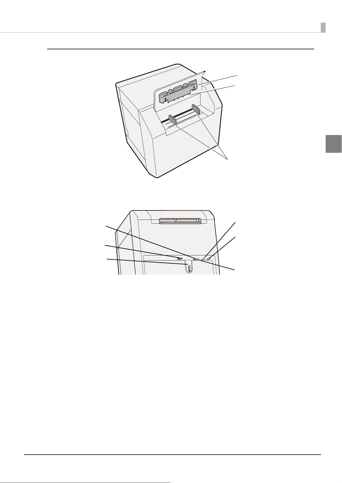
Back
Fanfold paper guide
Paper feed guide
Fanfold paper cover
Status sheet button
LAN Connector
Power connector
Cable hook
USB connector
Link LED
Chapter 1 Product Overview
1
Connector (lower rear)
15
Page 16
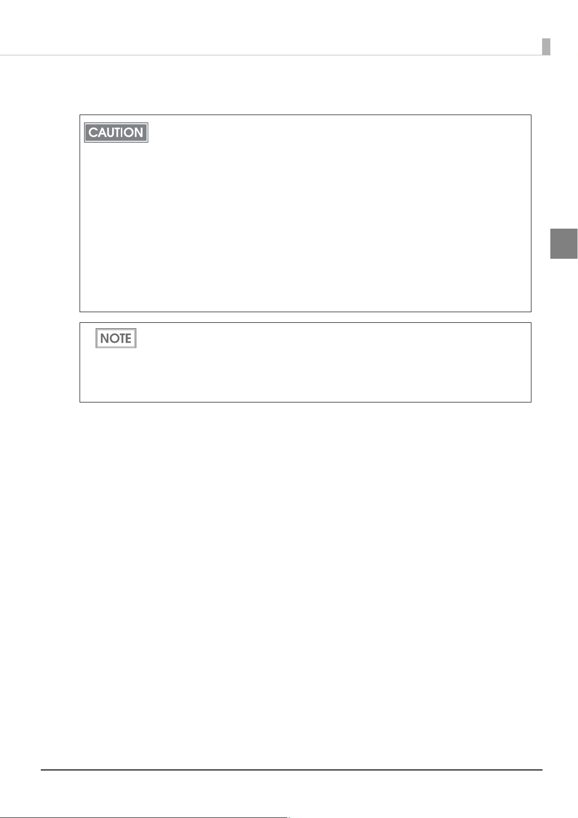
Power Switch
Before turning on the printer, be sure to check that the AC adapter is connected to the power
supply.
CAUTION
❏ When DIP switch 1 is OFF:
• Turns the power on after the POWER button has been pressed while the power is OFF.
• Turns the power off after the POWER button has been pressed for approximately 0.5 seconds while
the power is ON.
❏ When DIP switch 1 is ON:
• Resets the printer after POWER button has been pressed for approximately 0.5 seconds.
"Setting the DIP Switches" on page 47 for DIP switch setting.
See
Paper FEED button
❏ If "Media detection settings" is set to "Full-page label/Continuous paper/Transparent full-page label", feeds
the paper continuously.
• The paper is fed by 15 mm if FEED button is pressed once.
• If the FEED button is held down, the paper is continuously fed until the button is released.
(6 seconds at a maximum)
❏ If "Media detection settings" is set to "Die-cut label (Blackmark)", "Continuous paper (Blackmark)", or
"Die-cut label (Gap)/Transparent die-cut label", feeds the paper to the print starting position.
When the printer is in the power saving mode when its vacuum fan is stopped, starting up and
stabilizing the rotation of the vacuum fan requires some time. Approximately 2 seconds is required
from the point when the paper FEED button is pressed until the point when paper feed starts.
16
Page 17
Chapter 1 Product Overview
CUT button
❏ If "Media detection settings" is set to "Full-page label/Continuous paper/Transparent full-page label", feeds
the paper to the autocutting position for the top of the next page, and performs autocutting.
❏ If "Media detection settings" is set to "Die-cut label (Blackmark)", "Continuous paper (Blackmark)", or
"Die-cut label (Gap)/Transparent die-cut label", feeds the paper to the autocutting position
the black mark or the gap between labels, and performs autocutting.
• However, in order to prevent errors due to pieces of paper, even if you press the cut button again,
cutting is not performed in a position where cutting was already performed.
• Approximately 2 seconds is required from the point when the CUT button is pressed until the point
when paper cut starts.
according to
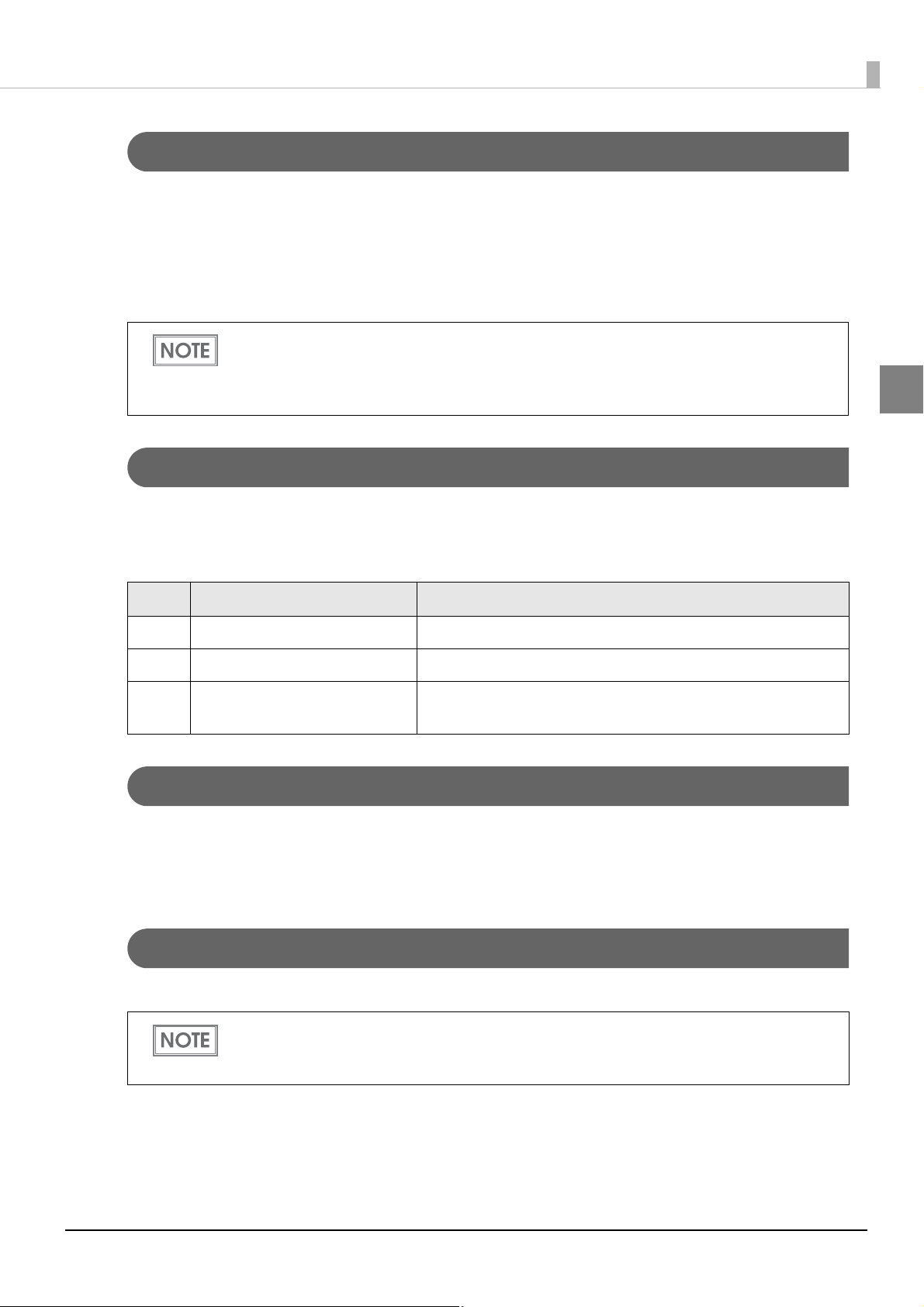
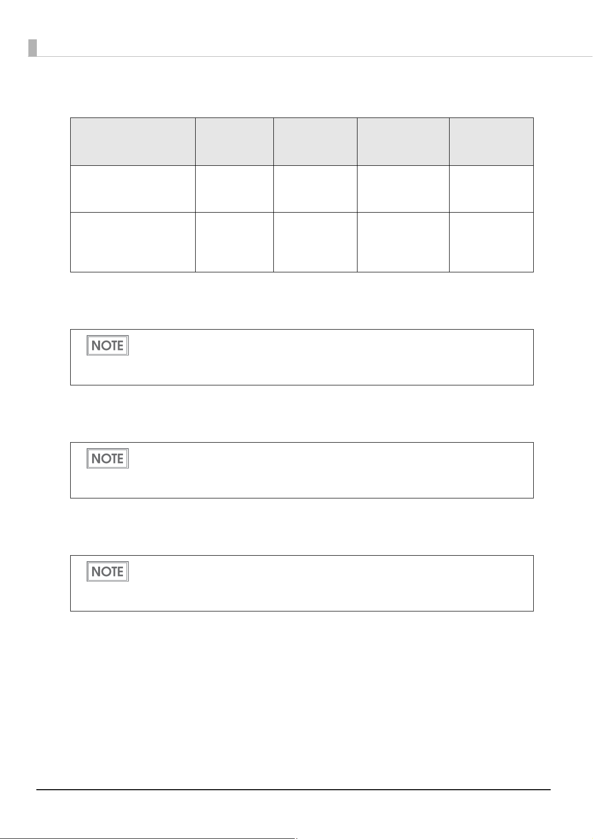
Cleaning button
If the cleaning button is held down for approximately 3 seconds, head cleaning is performed.
1
The following settings are possible from the driver regarding cleaning operations when the cleaning button is
held down.
No. During stand-by During printing
1 Disabled Disabled
2 Head cleaning performed Disabled
3 Head cleaning performed
Printing canceled -> head cleaning performed ->
printing resumed
STATUS SHEET button
Press the status sheet button to print the status sheet.
If you turn on the power while holding the status sheet button, and continue to hold it for 10 seconds or more,
you can return the LAN interface settings to factory default settings.
LCD contrast adjustment button
Adjusts the LCD contrast.
• The LCD contrast adjustment button is located under the ink cartridge cover.
• The adjusted value is saved in the non-volatile memory. Even after the power is turned on again,
the adjusted value saved last time is applied.
17
Page 18

Connectors
All cables are connected to the connector on the lower rear of the printer.
• Power supply connector: Connects cable of the AC adapter.
• USB/LAN Connector: Connects the printer with the host computer via interface.
• Link LED: Indicates the printer network status.
Printer status Link LED
Power off Off
Not connected to the network Off
Network established On
Receiving data Blinking
18
Page 19

Chapter 1 Product Overview
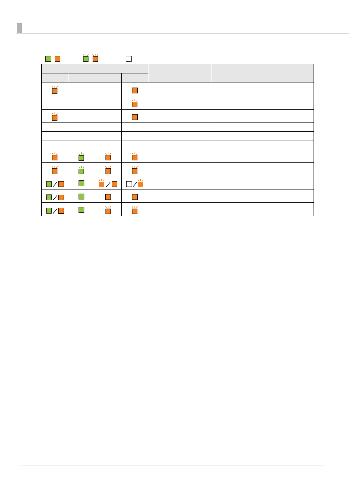
/ : Lit up / : Blinking : Off — : No change ## : Error code
Status/Error Indications
The printer status is indicated by a combination of LED lighting/flashing and LCD indication.
When an error occurs, you can find out the cause and the remedy from the LED & LCD indication for the error.
• The LCD display language can be switched with the DIP switches. See "Setting the DIP Switches" on
page 47.
• For error recovery methods, see
details on how to display HELP for EPSON Printers, see
"Troubleshooting" on page 135 or the help for the driver. (For
"HELP for EPSON Printers" on page 152.)
LED
Status Power Paper Ink
——
——
——
(Fast)
——
——
——
——
——
——
——
——
LCD Printer Status
READY In ready
INITIALIZING In initializing
POWER OFF In power off sequence
PRINTING In printing
INK CHARGING In ink charging
WORKING In working
HEAD MAINTENANCE In print head maintenance state
MEDIA FORM ERROR Media form error (*)
MEDIA SIZE ERROR Media size error (*)
PAPER JAM ERR ## Paper jam error (*)
PAPER REMOVAL ER Paper removal error (*)
1
—— —
——
——
——
——
——
——
——
——
———
PAPE R OUT Pa per ou t (*)
PAPER OUT ERROR Paper out error (*)
ROLL COVER OPEN Roll paper cover open (*)
INK COVER OPEN Ink cartridge cover open (*)
NO INK CARTRIDGE No ink cartridge (*)
INK READ ERROR Ink cartridge read error (*)
M/B COVER OPEN Maintenance box cover open (*)
NO MAINT BOX No maintenance box (*)
M/B READ ERROR Maintenance box read error (*)
INK LOW Ink cartridge low
19
Page 20
LED
/ : Lit up / : Blinking : Off — : No change ## : Error code
Status Power Paper Ink
LCD Printer Status
——
———
——
————
————
————
* Recovery method: See "Troubleshooting" on page 135.
REPLACE INK Replace ink cartridge (*)
M/B NEAR FULL Maintenance box near full
REPLACE MAINT B Replace maintenance box (*)
NOZZLE CLOGGED Print head nozzle clogged (*)
CUT UNAVAILABLE In cutter unavailable state (*)
SERVICE SOON ## In service mode (*)
PRINTER ERROR ## Printer error (*)
SERVICE REQD. ## Service required (*)
UPDATING In firmware updating (*)
UPDATING Complete the firmware updating (*)
UPDATING Failure in firmware updating (*)
20
Page 21
Chapter 1 Product Overview
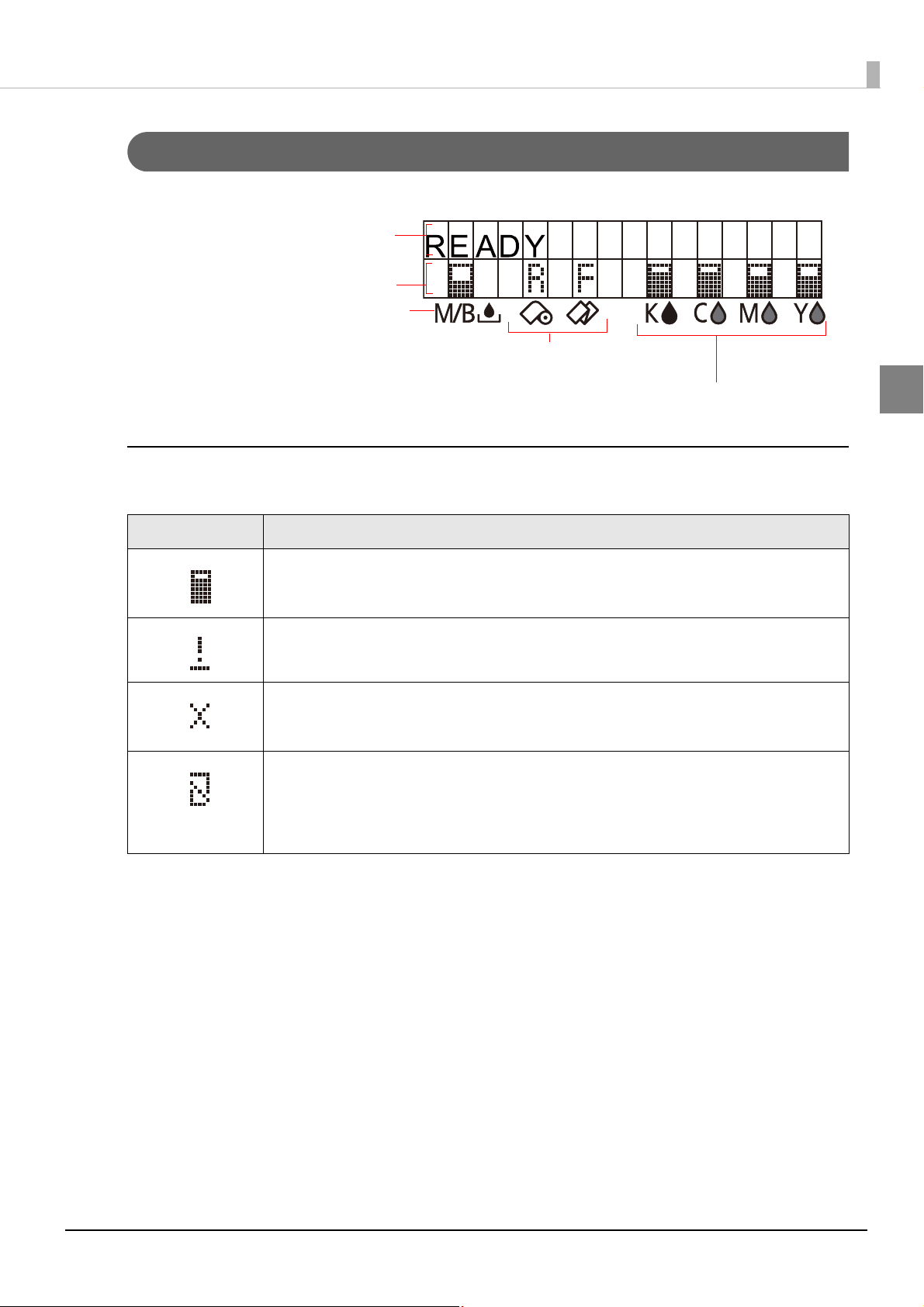
Amount remaining for the ink cartridge
(black ink, cyan ink, magenta ink, yellow ink)
Amount used for the maintenance box
Row 1 displays the printer's status
Row 2 displays the status of the ink
cartridges and maintenance box.
Media source settings of the printer
(R: Roll paper, F: Fanfold paper)
Ink Cartridge and Maintenance Box Status
You can check the status of the printer, the ink cartridges of each color, and the maintenance box from the LCD.
Display of the ink cartridge, maintenance box status
Displays the status of ink cartridges and maintenance box with icons.
1
Icon Status
• Display of amount remaining for the ink cartridge
• Display of amount used for the maintenance box
• Display for "Ink cartridge low"
• Display for "Maintenance box near full"
• Display for "Replace ink cartridge"
• Display for "Replace maintenance box"
• Display for "No ink cartridge"
• Display for "Ink cartridge read error"
• Display for "No maintenance box"
• Display for "Maintenance box read error"
21
Page 22
Beeper
When an error occurs while “Beep Notification Setting at an Error” is enabled, the beeper performs “Sound the
beeper on an error” shown in the below table. The beeper continues to beep until all the causes of error are
removed.
When "Settings For Paper Handling After Print" - "Notification" is enabled, the printer performs “Beeper sound
when the printer is not in an error state” shown in the below table.
❏ Frequency: Fixed to approximately 2.5 kHz
❏ Volume control: 2 levels on the hardware
Sounding
period
500ms 300ms 3 5 seconds
Silent
period
Number of
the pattern
repeated
Overall
time
Number of
times
repeated
Until the
error factor is
removed.
Printer event
Sound the beeper on an error
• Service required
• Printer error
• Roll paper cover open
• Ink cartridge cover open
• Replace ink cartridge
• No ink cartridge
• Ink cartridge read error
• Maintenance box cover open
• Replace maintenance box
• No maintenance box
• Maintenance box read error
• Media form error
• Media size error
• Paper jam error
• Paper removal error
• Paper out error
22
300ms - None - 1
• The volume can be set using the DIP switch. See
• When the paper is in “Paper out” status, which is without printing data, the beeper does not sound.
Beeper sound when the printer is not in
an error state
• Every page
• The final page only
"Setting the DIP Switches" on page 47.
Page 23

Chapter 1 Product Overview
Auto nozzle check system
This product has an “Auto nozzle check system” that detects missing dots. You can select the “Nozzle check
mode” depending on level of requirement for missing dots.
The following table shows the timing for auto nozzle check for each nozzle check mode (printing operation
mode).
Timing for auto nozzle
check
At printer power-on Performed Performed Performed Not Performed
During a pause Performed Performed Performed Not Performed
After printing page Not Performed Not Performed Not Performed Not Performed
Regular check during
continuous printing
After cleaning the print head Performed Performed Performed Not Performed
After closing the roll paper
cover
After closing the ink cartridge
cover
After closing the maintenance
box cover
After detecting a shock Performed Performed Performed Not Performed
Anti-missing
Dot Mode
Performed Performed Performed Not Performed
Performed Performed Performed Not Performed
Performed Performed Performed Not Performed
Performed Performed Performed Not Performed
Anti-missing
Read Mode
(default)
Anti-missing
Color Mode
No Missing Dot
Detection Mode
1
23
Page 24
The following table shows the conditions for permitted missing dots and auto cleaning for each nozzle check
mode.
Condition
Permitted missing dots None
Auto cleaning conditions
Anti-missing
Dot Mode
1 missing dot or
more
Anti-missing
Read Mode
(Default)
1 missing dot or
less
2 missing dots or
more
Anti-missing
Color Mode
No 2 consecutive
missing dots and less
than 9 missing dots
3 or more
consecutive dots or
10 or more missing
dots
No Missing Dot
Detection Mode
-
-
• Anti-missing Dot Mode
The auto nozzle check is performed at each timing, and by performing the auto head cleaning when neces-
sary, missing dots are prevented.
• Because the nozzle check is performed periodically during continuous printing, printing may be
interrupted for approximately 8 seconds.
• If more than 1 missing dot is detected, the auto head cleaning is performed to resolve the missing
dot.
• Anti-missing Read Mode
The auto nozzle check is performed at each timing, and by performing the auto head cleaning when neces-
sary, missing reads due to missing dots are prevented.
• Because the nozzle check is performed periodically during continuous printing, printing may be
interrupted for approximately 8 seconds.
• If more than 2 missing dot is detected, the auto head cleaning is performed to resolve the missing
dot.
• Anti-missing Color Mode
The auto nozzle check is performed at each timing, and by performing the auto head cleaning when neces-
sary, missing colors due to missing dots are prevented.
• Because the nozzle check is performed periodically during continuous printing, printing may be
interrupted for approximately 8 seconds.
• If 3 or more consecutive missing dots or 10 missing dots or more are detected, the auto head cleaning is performed to resolve the missing dots.
24
Page 25
• No Missing Dot Detection Mode
The auto nozzle check and the auto head cleaning are not performed.
• This "Auto nozzle check" system cannot detect 100% of dot missing cases.
• In cases extremely high reliability and safety is required, Epson recommends the use of font con-
structed of 3 vertical dots or more in "Anti-missing Dot Mode" or "Anti-missing Read Mode" to prevent misreadings due to missing dots or ink drop distortions.
• If an unfixable clogged nozzle occurs during auto cleaning after missing dot detection, the follow-
ing operations will be performed.
∗ If missing dots are not less than the auto cleaning conditions even after auto cleaning is
repeated , "Print head nozzle clogged" warning occurs.
∗ Auto cleaning conditions during the "Print head nozzle clogged" warning status are available
only when a new missing dot error occurs.
• Printer behavior during "Print head nozzle clogged" warning status
∗ When the number of missing dots is within the permitted amount, printing can be continued.
The LCD displays [NOZZLE CLOGGED].
∗ When the number of missing dots exceeds the permitted amount, a printer error occurs and
printing is disabled.
Chapter 1 Product Overview
1
• A very small amount of ink is used in the missing dot detection.
• After detecting a missing dot, cleaning is performed automatically and ink is also used in the clean-
ing.
• In [Anti-missing Dot Mode], [Anti-missing Read Mode], and [Anti-missing Color Mode] the auto
nozzle check is performed at certain intervals, so the auto nozzle check may occur even during
printing.
25
Page 26

Drivers, Utilities
Various utilities are provided to system administrators and application developers.
For details on how to get the software, see "Download" on page 174
.
Drivers
Category Name Description
Driver for printing from the application using Windows
spooler service.
The following functions are available besides the print
function:
TM-C35xx Printer Driver
Windows
Epson Inkjet Label Printer SDK
• Checking the printer status
(EPSON Status Monitor)
• Changing the printer settings
(TM-C3500 PrinterSetting)
This driver is included in the supplied CD-ROM.
Information and software (SDK) necessary for developing
applications that use this product.
The following information and functions are available:
• Changing the printer driver’s print settings
(Epson Printer Driver Interface/EPDI)
• Checking the printer status
(EpsonNet SDK)
• Sample program for printing by this printer
(Epson Inkjet Label Printer Sample Program)
26
Page 27

Utilities
Category Name Description
Utility that carries out setting up this printer on one host
PC.
Deployment Install Navi
EPSON Deployment Tool
Deployment
EpsonNet SetupManager
Performs the initial settings of the host PC and this product
in a wizard format.
This utility is included in the supplied CD-ROM.
Utility for installing multiple printers efficiently.
The following functions are available:
• Batch initial setting of multiple printers
(EPSON Printer Deployment)
• Batch initial setting of multiple host PCs
(EPSON Driver Deployment)
Utility for creating a driver installation package that can be
distributed to multiple host PCs.
Start this from the EPSON Deployment Tool.
Chapter 1 Product Overview
1
Management
Maintenance
EpsonNet Config
EPSON Monitoring Tool
USB Printer Class Device
Replacement Service
Utility for changing the printer's network settings.
This utility is included in the supplied CD-ROM.
Utility for managing multiple printers that are installed.
The following functions are available:
• Monitoring the printer
• Changing the printer settings
• Supporting when the printer malfunctions
Utility that supports replacement work when the printer
malfunctions.
The host PC settings can be passes on to the newly
connected product.
This utility is included in the supplied CD-ROM.
27
Page 28

28
Page 29
Setup
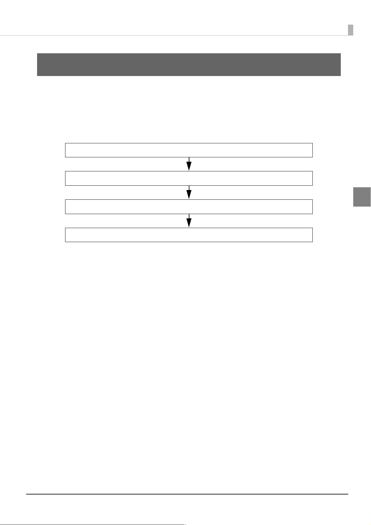
3.Attaching the Power Switch Cover (page 32)
2.Installing the Printer (page 31)
1.Checking the Items Included in the Package (page 30)
4.Setting Up the Printer (page 34)
This chapter describes setup and installation of the product and peripherals.
Work Flow
This chapter consists of the following sections along with the setup flow of the product and peripherals.
Chapter 2 Setup
2
29
Page 30
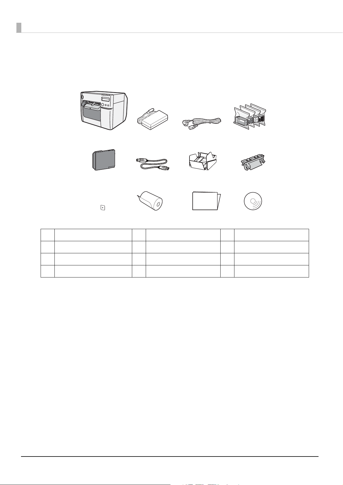
Checking the Items Included in the Package
When using the printer for the first time, check the items included in the package.
The items included in the package are as follows:
ADCB
EHGF
User’ s Manual
IKJ
A TM-C3500 Series B Dedicated AC adapter C AC cable *1
D Ink cartridge E Maintenance box F USB cable
G Paper ejection tray H Paper feed guide *2 I Power switch cover
J Label roll paper K User’s Manual L CD-ROM
*1 The AC cable may not be included with the product.
*2 Attached on the rear of the fanfold paper cover.
L
30
Page 31

Installing the Printer
10 cm (3.93 inch)
10 cm (3.93 inch)
Install the printer in an appropriate location with sufficient space around it.
Important Notes on Installation
Chapter 2 Setup
2
• The printer must be installed horizontally.
• Leave enough space in front of the printer for the ink cartridge cover and the roll paper cover to be fully
opened.
• Do not place the printer in a dusty location.
• Do not allow cables to get caught or foreign matter to accumulate under the printer.
• Make sure that there is at least 100 mm of space behind the printer back when installing.
• Do not put a heavy object (of 10 kg or more) or an object that vibrates on the printer.
31
Page 32

Attaching the Power Switch Cover
Attaching the power switch cover prevents accidental pressing of the power switch.
Before attaching the power switch cover, set DIP switch 1 to ON. (For details, see “Setting the DIP
switches”
the AC supply on and off, and you can also control the printer power with a device such as a
distribution board. In this case, the power switch is used to reset the printer.
To prevent the power switch from being pressed
Attach the power switch cover as it is (without punching a hole in it).
Set DIP switch 1 to ON.
1
Push the power switch cover onto the power switch of the printer.
2
Setting the DIP Switches on page 47.) The printer power can then be switched by turning
32
Page 33

To operate the power switch by inserting a long, thin object into a hole
Attach the power switch cover after punching the hole in it.
The hole cannot be punched in the power switch cover after it is attached to the printer.
Punch a hole in the power switch cover by pushing the middle of it with a hard, fine-
1
tipped object.
Push the power switch cover onto the power switch of the printer.
2
Chapter 2 Setup
2
33
Page 34

Setting Up the Printer
Set up the printer using Install Navi. Install Navi is included in the supplied CD-ROM.
Turn on the computer to be connected to the printer.
1
Make sure that the printer is turned off.
2
Be sure to turn the printer off.
Set the CD-ROM in the computer, and Launcher automatically starts up.
3
Click [Setup] to start InstallNavi.exe.
When Install Navi is executed, the following window appears. Agree to the license agree-
4
ment and click [Next], and the software installation starts. Set up the printer according
to the displayed instruction.
34
Page 35

Later in the setup procedure, "Media Layout Creation" window appears.
5
When "Media Layout Creation" window appears, if you do not use the roll paper
included in the package, you have to create a new media layout. For the procedure to
create a new media layout, see Media Layout Creation on page 36.
To use the supplied roll paper, select [No].
Chapter 2 Setup
Set up the printer according to the steps. If test printing finishes successfully, the proce-
6
dure is finished.
2
35
Page 36

Media Layout Creation
On "Media Layout Creation" window, select [Yes] and Click [Next].
1
The following window appears.
2
Select either [Roll Paper] or [Fanfold Paper] and click [Next].
36
Page 37

The following window appears.
3
Select the media to be used and click [Next].
When fanfold paper is selected, you can select [Die-cut label (Gap)], [Die-cut label (Blackmark)], [Continuous paper (Blackmark)], or [Transparent die-cut label (Gap)].
Chapter 2 Setup
2
The following window appears. Enter each item and click [Next].
4
Item Description
Media Layout Name Enter any name.
Unit Select the unit.
Media Layout
Enter the width and length of the media to be used.
The information to be entered is different depending on the media type selected in Step 3.
37
Page 38

The following window appears. Enter each item and click [Next].
5
Item Description
Media Type Select the media type.
Print Quality Select the print quality.
Auto Cut Select whether to enable/disable autocut.
"Confirming the Media Layout” screen appears.
6
The newly set media layout information is displayed. Confirm the settings and click
[Next].
38
Page 39

"Restarting the Printer” screen appears.
7
Restart the printer to apply the new settings.
Chapter 2 Setup
2
39
Page 40

Shutter Adjustment
Close
Open
Turn the printer OFF.
1
Press down the release lever, and pull it to the front to open the roll paper cover.
2
Refer to the shutter adjustment method label on the top of the printer, and open or
3
close the shutters on the platen to match the width of the paper. If the shutter is set
incorrectly, paper may be jammed or get dirty.
Paper/backing width (mm) Shutter open/close status
30 mm {1.18"} or more, less than 62 mm {2.44"} Close all shutters.
62 mm {2.44"} or more, less than 79 mm {3.11"} Open only the most inward shutters.
79 mm {3.11"} or more, less than 97 mm {3.82"} Open only the 2 most inward shutter rows.
97 mm {3.82"} or more, less than 112 mm {4.41"} Open only the 3 most inward shutter rows.
112 mm {4.41"} Open all shutters.
40
Page 41

Close the roll paper cover.
4
Chapter 2 Setup
2
41
Page 42

Ejection Angle of Printed Paper
Make sure paper is ejected straight from the paper ejection guides, as shown in the illustration. If paper is not
ejected straight due to such causes as an obstruction, the print result may be distorted.
42
Page 43

How to Display the Printer Driver
Open the [Devices and Printers].
1
• For Windows 10:
Right click [Start] - [Control Panel] - [Hardware and Sound] - [Devices and Printers].
• For Windows 8.1/Windows 8:
Select [Control Panel] of Sidebar [Settings] on [Desktop], and click [Hardware and Sound],
then [Devices and Printers].
• For Windows 7:
Click [View devices and printers] of [Control Panel] on [Start] menu.
• For Windows Vista:
Click [Printers] of [Control Panel] on [Start] menu.
• For Windows XP Professional:
Click [Printers and Faxes] on [Start] menu.
• For Windows XP Home Edition:
Click [Control Panel] on [Start] menu, and click [Printers and Faxes].
• For Windows 2000:
Click [Settings] on [Start] menu, and click [Control Panel].
• For Windows Server 2003 R2:
Click [Printers and Faxes] on [Start] menu.
Chapter 2 Setup
2
Right-click [EPSON TM-C3500], and click [Printing Preferences].
2
The printer driver screen is displayed.
Registered name of this product to display in the case of the [EPSON TM-C3500].
43
Page 44

Registering the Media Layout
(5)(3)
(4)
(6)
Registered paper(2)
If the paper size to use is not in Media Layout, register the user defined media.
The registered layout will be stored in [Favorite Setting] to use from application of users.
(For details on how to register the favorite setting, see Favorite Setting on page 82
Display the printer driver window.
1
(See How to Display the Printer Driver on page 43.)
From [Print Settings], click [User Defined...].
2
"User Defined Media Layout" screen appears.
Enter Media Layout Name. This is User Defined Media.
3
If there is an existing defined media layout, you can create a new layout based on the defined media layout.
Select [Media Type].
4
Enter the size of the paper (unit: mm).
5
To extend the printable area, selecting [Borderless Printing] will set no margins.
When the margin is zero, printing may occur out of the paper/label. Use this option according to the
usage.
.)
Click [Save]. User Defied Media will be registered and displayed on the list of [Defined
6
Media Layout].
44
Page 45

Attaching the Paper Ejection Tray
If you attach the paper ejection tray, you can temporarily store the printed paper in the tray.
Follow the steps below to install/adjust the ejection tray.
• Paper may not stay in the paper ejection tray depending on the paper curl and length.
• When the fanfold paper is used, the several printed papers can be stored in the ejection tray. See
Paper Ejection Tray on page 226 for the numbers of the fanfold paper that can be stored in the
ejection tray.
Attach the paper ejection tray to the hooks under the paper ejection table.
1
Chapter 2 Setup
2
Pull the lever at the bottom-right of the paper ejection tray to unlock it.
2
45
Page 46

Slide the bottom tray to align it with the paper length.
3
Pull up the lever at the bottom-right of the paper ejection tray to lock it.
4
46
Page 47

Setting the DIP Switches
Change the DIP switch settings in the following cases.
• When attaching the power switch cover to prevent the power switch from being pressed
• When changing the LCD display language
• When changing the volume of the buzzer
Setting Procedure
Follow the steps below to change the DIP switch settings.
Turn the power off before removing the DIP switch cover.
Otherwise, a short-circuit may cause the printer to malfunction.
CAUTION
DIP switch setting becomes enabled after turning the power on or completing reset by the interface.
Chapter 2 Setup
2
Make sure the power supply for the printer is turned OFF.
1
Open the ink cartridge cover and remove the DIP switch cover.
2
Set the DIP switches, using the tip of a tool, such as a small screwdriver.
3
Attach the DIP switch cover, and close the ink cartridge cover.
4
47
Page 48

Function of the DIP Switches
SW Function ON OFF
1 Operation of the power switch Reset Power ON/OFF OFF
2 Internal use Fixed to OFF (Do not change) OFF
4 Internal use Fixed to OFF (Do not change) OFF
5
LCD display language settings See the table below
6 OFF
7 OFF
8 Buzzer volume High Low OFF
When attaching the power switch cover to prevent the power switch to be pressed, set DIP switch 1 to
ON.
LCD display language settings
Switch No.
Language settings
5 6 7
Fac tory
settings
OFF
OFF OFF OFF Japanese (Kana)
OFF OFF ON English
OFF ON OFF French
OFF ON ON Italian
ON OFF OFF German
ON OFF ON Spanish
ON ON OFF Portuguese
ON ON ON Dutch
48
Page 49

Chapter 2 Setup
Setting the Printer Driver
In addition to the printing preferences, the printer driver also provides the printer settings and various utility
functions.
•Banding Reduction
• TM-C3500 PrinterSetting
• Setting for EPSON Status Monitor 3
Banding Reduction
You can reduce banding (extraneous lines in printing) to obtain better print quality. This function, however,
lowers the print speed.
Follow the steps below to reduce banding.
Display the printer driver window.
1
(See How to Display the Printer Driver on page 43.)
On "General" window, select [Advanced] under [Print Settings]. Then click [Advanced...].
2
2
49
Page 50

"Advanced" screen appears. Check [Banding Reduction], and click [Close].
3
The screen returns to "General" window. Click [OK].
4
50
Page 51

TM-C3500 PrinterSetting
TM-C3500 PrinterSetting is used to change various printer settings.
Chapter 2 Setup
2
51
Page 52

From TM-C3500 PrinterSetting, you can change the following printer settings:
Item Description
General
Advanced
Printer Adjustment
Media source settings
Printer Operation Settings
Notification Settings
Panel Button Settings
Operating Time Settings
Paper Feed Adjustment
Sensor Adjustment
• Media source settings
• Media detection settings
• Nozzle Check Mode
• Paper Loading Settings
• Beep Notification Setting at an Error
• LED Notification Setting at Ink Low
• Notification Setting at a Media Size Error
• Enable/Disable the Feed Button
• Enable/Disable the Cut Button
• Enable/Disable the Cleaning Button
• Platen Vacuum Operation Pause Time Settings
• Data Standby Time Settings
• Cut Position Adjustment
• Print Start Position Adjustment
(Vertical Direction)
• Print Start Position Adjustment
(Horizontal Direction)
• Adjust the Label Gap Detection Sensor
• Adjust the Black Mark Detection Sensor
Print Head Alignment
Setting Save and Restore
Option • Media source Settings Option
• Banding Adjustment
• Bidirectional Printing Adjustment
Save the printer settings to the backup file and apply the
settings in the backup file to the printer.
52
Page 53
Chapter 2 Setup
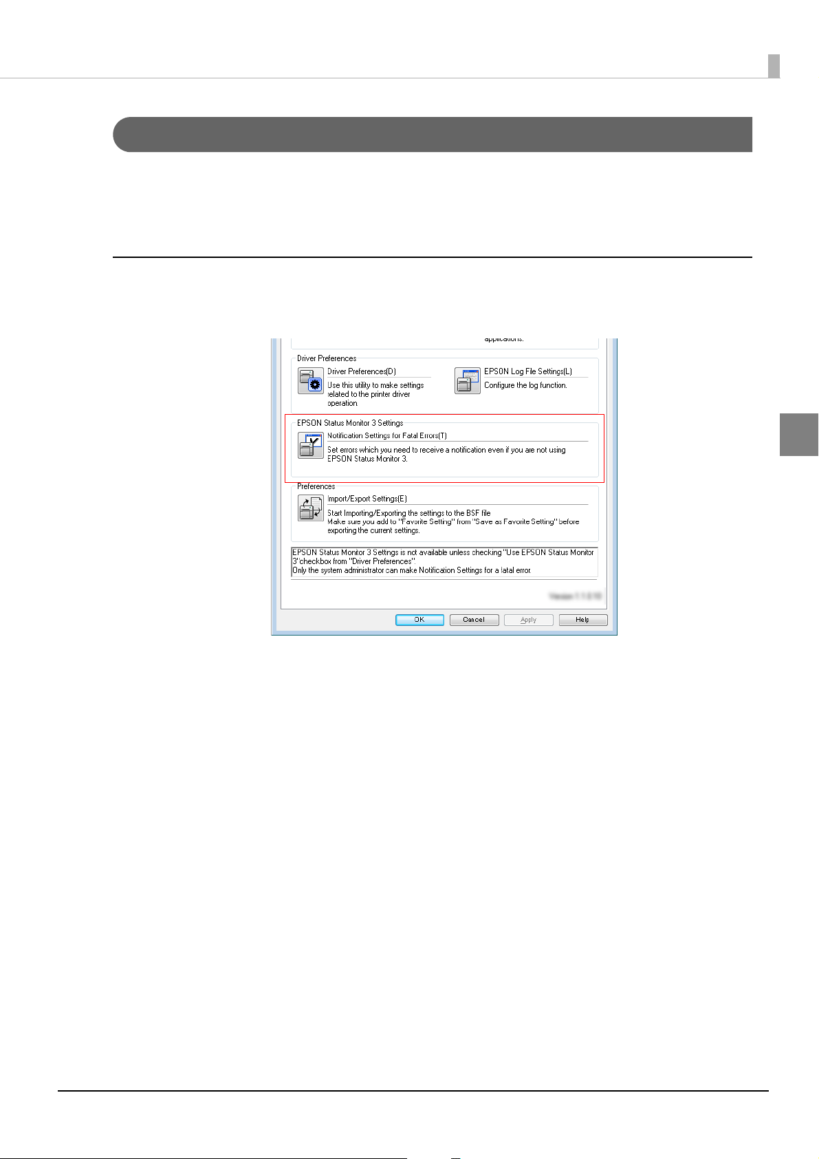
Setting EPSON Status Monitor 3
When EPSON Status Monitor 3 is used, the paper type and the ink level are displayed on a pop-up window
when printing. In addition, when a fatal error occurs, an error window is displayed.
[Not use] is set by default setting; however, if a fatal error occurs, an error window can be displayed.
Use/Not use EPSON Status Monitor 3
[Not use EPSON Status Monitor 3] is set by default setting. [Notification Settings for Fatal Errors] is displayed
on the EPSON Status Monitor 3 Settings window in Driver Utilities.
2
53
Page 54

Follow the steps below to change to [Use EPSON Status Monitor 3].
Turn the printer ON.
1
Display the printer driver window.
2
(See How to Display the Printer Driver on page 43.)
Select [Driver Utilities] tab and click [Driver Preferences] under [Driver Preferences].
3
The [Driver Preferences] window is displayed.
4
Check the box of [Use EPSON Status Monitor 3] and click [OK].
[EPSON Status Monitor 3] and [Monitoring Preferences] are displayed in [EPSON Status
5
Monitor 3 Settings] on the Driver Utilities window.
54
Page 55

Chapter 2 Setup
Display window for EPSON Status Monitor 3
Icon on task tray
Use EPSON Status Monitor 3
When [Use EPSON Status Monitor 3] is set, the following operations will be performed:
• When printing, a window automatically appears, allowing you to check the printer status and the ink level.
• Error information is displayed when an error occurs during printing.
The EPSON Status Monitor 3 will not be activated if an error occurs when not printing.
• Clicking the icon for [EPSON Status Monitor 3] on the task tray allows you to display [EPSON Status Moni-
tor 3] at any time.
Displaying the icon on page 59 for how to display the icon.)
(See
2
55
Page 56

• The following items can be set in [Monitoring preferences].
Selecting error indications:
(See Error notification setting for [Not use EPSON Status Monitor 3] on page 57
Displaying the [EPSON Status Monitor 3] icon on the task bar:
Displaying the icon on page 59.)
(See
.)
56
Page 57
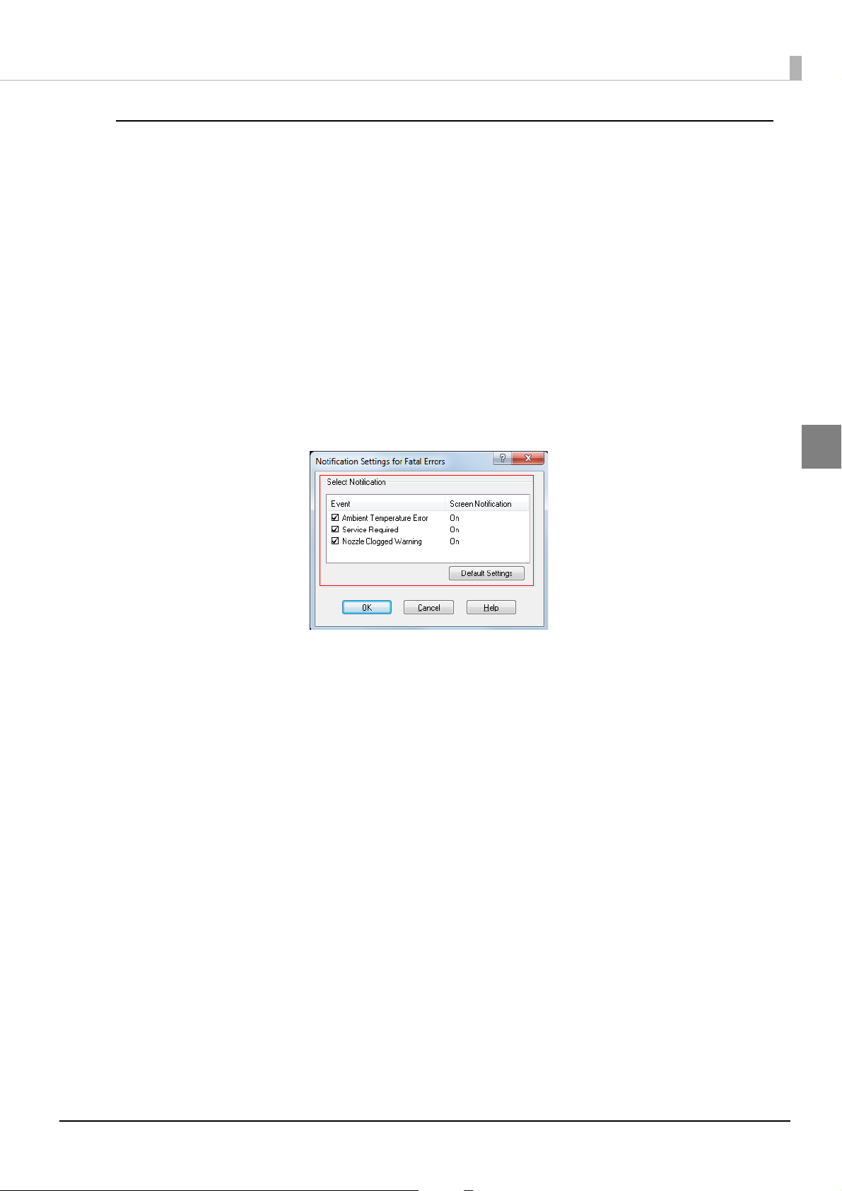
Error notification setting for [Not use EPSON Status Monitor 3]
Follow the steps below to set error notification for [Not use EPSON Status Monitor 3].
Turn the printer on.
1
Display the printer driver window.
2
(See How to Display the Printer Driver on page 43.)
Select [Driver Utilities] tab and click [Driver Preferences].
3
When EPSON Status Monitor 3 is enabled, [Notification Settings for Fatal Errors] is not displayed. (Disable EPSON Status Monitor 3 by referring to
The [Notification Settings for Fatal Errors] window is displayed. Select the items you
4
want to display when an error occurs, and click [OK].
Use/Not use EPSON Status Monitor 3 on page 53.)
Chapter 2 Setup
2
•Ambient Temperature Error: When the printer temperature is high
(Default: Screen Notification [On] )
• Service Required: When a no-print error or service-required error occurs
(Default: Screen Notification [On] )
• Nozzle Clogged Warning: When the nozzle is clogged
(Default: Screen Notification [On] )
57
Page 58

Error notification setting for [Use EPSON Status Monitor 3]
Follow the steps below to set error notification for [Use EPSON Status Monitor 3].
Turn the printer ON.
1
Display the printer driver window.
2
(See How to Display the Printer Driver on page 43.)
Select [Driver Utilities] tab and click [Monitoring Preferences].
3
When EPSON Status Monitor 3 is disabled, the [Monitoring Preferences] is not displayed. (Enable
EPSON Status Monitor 3 by referring to
The [Monitoring Preferences] window is displayed. Click on the box of your choice, and
4
click [OK].
Use/Not use EPSON Status Monitor 3 on page 53.)
58
• Error: When paper/ink replacement is required
(Default: Screen Notification [On] )
• Communication Error: When the printer power is off
(Default: Screen Notification [Off] )
• Ink Low: When the ink amount is low
(Default: Screen Notification [Off])
• Service Required: When a printer error occurs
(Default: Screen Notification [On] )
Page 59

Chapter 2 Setup
Displaying the icon
Keeps icon on the task tray so that user can check as needed. The icon is not displayed when default setting.
Follow the steps below to display the icon.
Turn the printer ON.
1
Display the printer driver window.
2
(See How to Display the Printer Driver on page 43.)
Select [Driver Utilities] tab and click [Monitoring Preferences].
3
The [Monitoring Preferences] window is displayed. Check the box of [Shortcut Icon] and
4
select the icon to display on the task bar. Click [OK].
2
59
Page 60

60
Page 61

Chapter 3 Handling
Handling
This chapter describes basic handling of the printer.
Replacing the Ink Cartridge
When any of the four color ink cartridges is expended, the INK LED lights. Follow the steps below to replace
the ink cartridge.
Turn the power on and make sure that the INK LED lights.
1
Pull down the ink cartridge cover to the front to open it.
2
Open the ink cartridge cover, and wait at least 4 seconds until internal operations stop. If you take out
the ink cartridge in less than 4 seconds, there is a risk that the ink may spurt out.
If there is a used ink cartridge that requires replacement, slowly push the ink cartridge,
3
check that the lock is released, and pull the ink cartridge out towards you.
Shake new ink cartridge package 4 or 5 times before opening it and take out the ink car-
4
tridge from the package.
Do not shake the ink cartridge too hard. The ink cartridge may leak if you shake it around too much or
push the sides strongly.
3
61
Page 62

With the label facing upwards, insert the new ink cartridge, and push it in slowly until it
5
clicks into place.
Close the ink cartridge cover.
6
When the ink cartridge replacement is completed, the INK LED turns off, and printing
7
can be performed.
Cautions on using ink cartridges
❏ Do not touch the IC chip on the cartridge. Doing so may cause operating/printing malfunction.
❏ This product uses ink cartridges equipped with an IC chip that monitors the amount of ink used by each
cartridge. Cartridges are usable even if they are removed and reinstalled. However, if an ink cartridge in
which little amount of ink remains is removed and reinstalled, it may not be usable. Some ink is consumed
each time cartridges are installed because the product automatically checks their reliability.
❏ Install all ink cartridges. Printing is not possible even if only one ink cartridge is missing.
❏ Since ink cartridges are designed to stop the operation before ink runs out completely to maintain the
quality of the print head, some ink remains in the used ink cartridge.
❏ All the ink colors are consumed also for the maintenance operations when an ink cartridge is replaced and
for print head cleaning.
❏ Even for monochrome printing, all the ink colors are used in an operation designed to maintain the
printing and print head quality.
❏ Use of an old ink cartridge may result in reduced print quality. Use it up within six months after opening
the package. The usage period for ink cartridges is printed on the packaging of individual ink cartridges.
❏ There may be some ink around the ink supply port on the removed ink cartridge. Take care so that it does
not stain the desk or other surface.
❏ Do not remove the ink cartridge, except when you replace it.
❏ Do not open the ink cartridge package until you are ready to install it in the product.
❏ Do not allow foreign objects to fall into the cartridge installation section. Doing so may cause printer
malfunction.
62
Page 63

Chapter 3 Handling
❏ When ink is charged for the first time (right after purchase), ink is consumed for filling the print head
nozzle (ink discharge holes) to get ready for printing. That is why the number of the printable sheets may
be fewer than for the cartridges to be installed later.
❏ Epson recommends the use of genuine Epson ink cartridges. For the best performance of the printer, it is
recommended to use genuine Epson ink cartridges. Use of non-genuine Epson ink cartridges can
adversely affect the printing quality and prevent the printer from realizing its maximum performance.
Epson cannot guarantee the quality and reliability of non-genuine Epson products. Repairs for any
damage or breakdown of this product due to the use of non-genuine Epson
charge even if the warranty period is still valid.
❏ Color adjustment of the product is based on the use of genuine Epson ink cartridges. Use of non-genuine
ink cartridges may result in reduced print quality. Use of genuine Epson ink cartridges is recommended.
❏ A cool and dark place is recommended to store ink cartridges.
❏ If the ink cartridge is stored in a cold place for a long period of time, let it warm up at least 3 hours before
using it.
❏ If moving or transporting the product after the ink cartridges are installed, leave them installed during the
moving or transporting process.
products will not be free of
3
63
Page 64

Replacing Maintenance Box
• Do not dismantle the Maintenance box.
• Do not touch the IC chip on the cartridge.
• Keep out of reach of children, and do not drink.
• Do not reuse a maintenance box which was removed and detached for a long period.
• When using the printer for the first time, the replacement interval for the maintenance box is
shorter than usual as ink charging consumes the ink.
Follow the steps below to replace the maintenance box.
Turn the printer OFF.
1
Open the maintenance box cover towards you.
2
Pull out the used maintenance box towards you.
3
64
Page 65
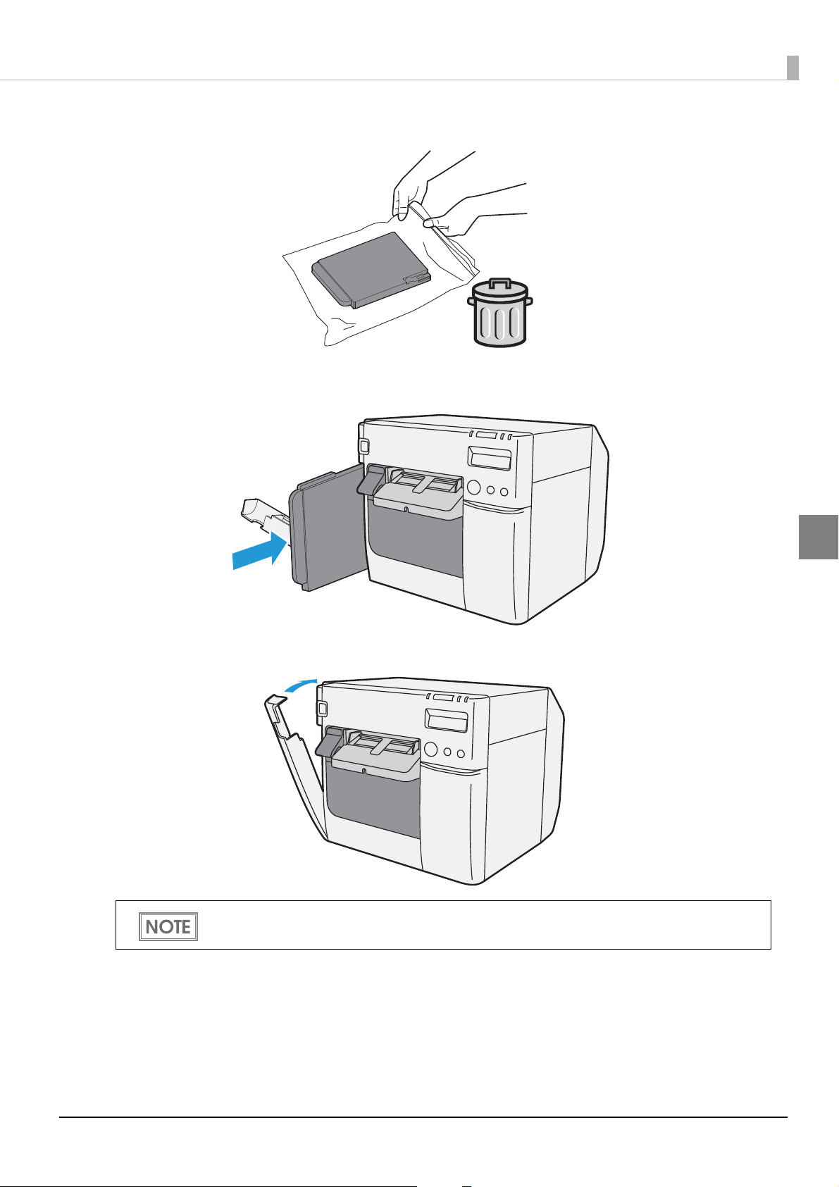
Put the maintenance box into the plastic bag for disposal of used maintenance box.
4
Slowly insert the new maintenance box.
5
Chapter 3 Handling
Close the maintenance box cover.
6
After replacing the maintenance box, we recommend that you clean the platen.
(See the
"Cleaning the platen" on page 157.)
3
65
Page 66

Replacing Roll Paper with Fanfold Paper
Follow the steps below to replace the roll paper with fanfold paper.
Press down the release lever, and pull it to the front to open the roll paper cover.
1
Remove the used roll paper.
Turn the printer ON.
2
Display the printer driver window.
3
(See "How to Display the Printer Driver" on page 43.)
Display TM-C3500 PrinterSetting. Select [Printer Utilities] tab and click [Printer Prefer-
4
ences] - [Printer Setting Utility].
66
Page 67

Chapter 3 Handling
From TM-C3500 PrinterSetting, specify the media source and the media detection
5
method. Then, click [Apply Settings].
After setting [Media source], set [Media detection settings].
Item Description
Media source Select [Fanfold paper].
Select the media type.
Media detection settings
The confirmation window appears. Click [Yes] to send the settings to the printer.
6
The following window appears. Click [OK].
7
• Die-cut label (Blackmark)
• Continuous paper (Blackmark)
• Die-cut label (Gap), Transparent die-cut label
3
67
Page 68

The completion window appears. Click [OK].
8
On the printer driver window, select [General] tab. Specify the media settings and click
9
[OK].
Item Description
Print Settings
Settings For Paper Handling After
Print
Turn the printer OFF.
10
Changes in the Media detection settings are saved in the memory in the printer when the printer is
turned off.
Media Type Select the media type.
Print Quality Select the print quality.
Select the media layout.
Media Layout
Auto Cut Select this to enable autocut after printing.
No Auto Cut Select this to disable autocut after printing.
If the media layout to be used is not included in the list, create a new layout.
See the "Registering the Media Layout" on page 44.
68
Page 69

Open the fanfold paper cover and take out the paper feed guide.
11
Pull the release lever to the front to open the roll paper cover.
12
Chapter 3 Handling
Insert the paper feed guide for fanfold paper into the groove inside the roll paper cover
13
to install it.
3
69
Page 70

Refer to the shutter adjustment method label on the top of the printer, and open or
Open
Close
14
close the shutters on the platen to match the width of the roll paper. If the shutter is set
incorrectly, paper may be jammed or get dirty.
Paper/backing width (mm) Shutter open/close status
30 mm {1.18"} or more, less than 62 mm {2.44"} Close all shutters.
62 mm {2.44"} or more, less than 79 mm {3.11"} Open only the most inward shutters.
79 mm {3.11"} or more, less than 97 mm {3.82"} Open only the 2 most inward shutter rows.
97 mm {3.82"} or more, less than 112 mm {4.41"} Open only the 3 most inward shutter rows.
112 mm {4.41"} Open all shutters.
Close the roll paper cover.
15
70
Page 71

Release the lock of the paper ejection guide with a fine-tipped tool.
16
Slide the paper ejection guide to the very left end, and lock it.
17
Chapter 3 Handling
Open the cover at the back of the printer, and unlock the fanfold paper guide.
18
3
71
Page 72

Adjust the fanfold paper guide to the fanfold paper width.
19
Lock the fanfold paper guide.
20
Turn the printer ON.
21
72
Page 73

Chapter 3 Handling
Insert the fanfold paper into the paper slot, facing the print surface upward. Insert the
22
paper until it is pulled into inside the printer (approximately 100 mm {3.94"}). The printer
detects the edge of the fanfold paper, pulls it inside, and then starts feeding it to the
print starting position.
When "Paper loading at roll paper cover close" is set to "With cutting", the paper is automatically cut
after fed. (See "Paper Loading Settings" on page 117.)
Place the stack of fanfold paper straight at least 40 mm {1.57"} away from the back of the
23
printer.
3
73
Page 74

Close the fanfold paper cover.
24
• To prevent liquid and dust from getting into the printer, keep the fanfold paper cover closed when
using the printer.
• To prevent paper jams from occurring, insert fanfold paper into the fanfold paper slot on the back
of the printer with the roll paper cover closed.
Confirm that the LCD displays an "F".
25
This is the end of loading of the fanfold paper.
74
Page 75

Replacing Fanfold Paper with Roll Paper
Follow the steps below to replace the fanfold paper with roll paper.
Open the fanfold paper cover at the back of the printer.
1
Chapter 3 Handling
Remove the used fanfold paper.
2
Turn the printer ON.
3
Display the printer driver window.
4
(See "How to Display the Printer Driver" on page 43.)
Display TM-C3500 PrinterSetting. Select [Printer Utilities] tab and click [Printer Prefer-
5
ences] - [Printer Setting Utility].
3
75
Page 76

From TM-C3500 PrinterSetting, specify the media source and the media detection
6
method. Then, click [Apply Settings].
After setting [Media source], set [Media detection settings].
Item Description
Media source Select [Roll paper].
Select the media type.
• Full-page label, Continuous paper, Transparent full-page label
Media detection settings
The confirmation window appears. Click [Yes] to send the settings to the printer.
7
The following window appears. Click [OK].
8
• Die-cut label (Blackmark)
• Continuous paper (Blackmark)
• Die-cut label (Gap), Transparent die-cut label
76
Page 77

Chapter 3 Handling
The completion window appears. Click [OK].
9
On the printer driver window, select [General] tab. Specify the media settings and click
10
[OK].
Item Description
Print Settings
Settings For Paper Handling After
Print
Turn the printer OFF.
11
Changes in the Media detection settings are saved in the memory in the printer when the printer is
turned off.
Media Type Select the media type.
Print Quality Select the print quality.
Select the media layout.
Media Layout
Auto Cut Select this to enable autocut after printing.
No Auto Cut Select this to disable autocut after printing.
If the media layout to be used is not included in the list, create a new layout.
See the "Registering the Media Layout" on page 44.
3
77
Page 78

Press down the release lever, and pull it to the front to open the roll paper cover.
12
Remove the paper feed guide for fanfold paper.
13
Unlock the roll paper guide.
14
78
Page 79

Chapter 3 Handling
Move the left paper guide toward the direction of the arrow in the illustration below,
15
and insert the roll paper all the way in with the print surface facing upward.
Lock the roll paper guide.
16
3
79
Page 80

Refer to the shutter adjustment method label on the top of the printer, and open or
Open
Close
17
close the shutters on the platen to match the width of the roll paper. If the shutter is set
incorrectly, paper may be jammed or get dirty.
Paper/backing width (mm) Shutter open/close status
30 mm {1.18"} or more, less than 62 mm {2.44"} Close all shutters.
62 mm {2.44"} or more, less than 79 mm {3.11"} Open only the most inward shutters.
79 mm {3.11"} or more, less than 97 mm {3.82"} Open only the 2 most inward shutter rows.
97 mm {3.82"} or more, less than 112 mm {4.41"} Open only the 3 most inward shutter rows.
112 mm {4.41"} Open all shutters.
Release the lock of the paper ejection guide with a fine-tipped tool.
18
80
Page 81

Adjust the paper ejection guide to the roll paper width.
19
Lock the paper ejection guide and close the roll paper cover.
20
Chapter 3 Handling
Turn the printer ON. After this, the printer feeds the paper automatically to remove any
21
slack in the roll paper.
Confirm that the LCD displays an "R".
22
This is the end of loading of the roll paper.
3
81
Page 82
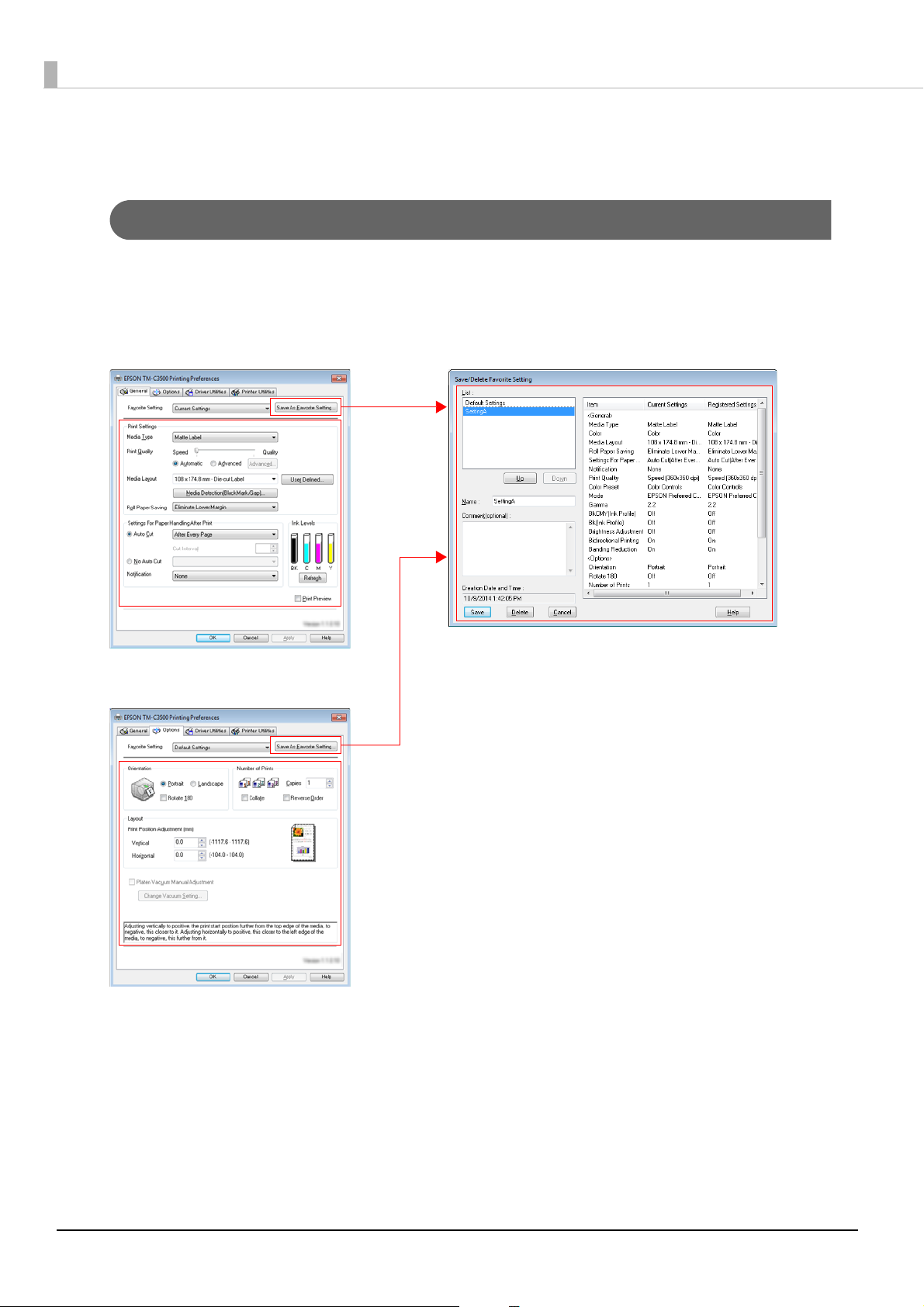
Setting the Printer Driver
[General] tab
[Options] tab
Favorite Setting
Favorite Setting
[Favorite Setting] is the function to administer print setting of the printer driver into one.
The setting from [General] and [Options] tab such as Media Type, Media Layout (including User Defined
Media) are included.
82
Page 83

Chapter 3 Handling
Features
• When printing from application, the print setting registered on [Favorite Setting] can be selected as default
setting.
It is recommended to register the setting in favorite setting after executing print setting by clicking [Save As
Favorite Setting].
• A number of setting can be registered on [Favorite Setting].
For example, if the print setting is registered on [Favorite Setting] for each document, the print setting can be
completed by changing [Favorite Setting] when the document is changed. This prevents an error of setting
change when changing the paper.
(It is necessary to change Media detection settings of the printer when the document is changed.)
3
83
Page 84

Registering print setting on [Favorite Setting]
User Defined Media
(1) (2)
(3)
Current Settings
(4)
Registered to Favorite Setting
Set the printer driver depending on paper to print.
1
Set settings on [General] and [Options] tab. Select from Media Layout when using User Defined Media.
Click [Save As Favorite Setting] to display [Save/Delete Favorite Setting].
2
The current setting will be displayed on the list of the right side.
Enter print name.
3
Click [Add].
4
Print setting will be registered on [Favorite Setting].
84
Page 85

Chapter 3 Handling
[Favorite Setting] includes the following setting.
• Default Settings: The default setting when installing the printer driver.
• Current Settings: The contents set on [General] and [Options] tab.
These contents are displayed in the current settings on [Current Setting] and
[Save/Delete Favorite Setting] window.
• User Defined Setting: The print setting defined by the user.
Information for User Definition
The user definition includes the following.
•User Defined Media
•Registering barcode font
• Replacing font on .NET environment
The user definition is set on each client computer. When a number of TM-C3500 printer drivers are installed in
one computer, these are used mutually.
3
85
Page 86

Exporting/Importing Printer Driver Settings
You can export the printing references, favorite setting, user-defined information (paper layout, barcode) and
printer driver operation settings into a BSF file (extension of ".BSF"). You can also import the settings from a
BSF file to set up the printer driver.
Export Settings
Follow the steps below to export the settings.
Select [Driver Utilities] tab. Click [Import/Export Settings].
1
• Export in a BSF file from the current setting. If you export it from the general setting, a different content will be exported.
Current setting:
Properties of the printer driver-[General]-[Printing References]-[Driver Utilities]-[Import/
Export Settings]
General setting:
Properties of the printer driver-[Advanced]-[Printing Defaults]-[Driver Utilities]-[Import/
Export Settings]
• Be sure to register the settings on the [General] tab to "favorite setting".
If not registered, the initial settings of the printer driver are applied.
"Import/Export Settings" window appears. Click [Export Settings].
2
86
Page 87

The window to save a file appears. Specify a name and save the BSF file.
3
The process completion window appears. Click [OK].
4
To the BSF file, the print settings in "favorite setting" defined by the user are applied. The print
settings in "Current settings" are not applied.
Import Settings
When the settings are imported from a BSF file, the printer driver settings are overwritten.
Therefore, to retain the existing settings for the items listed below, create a BSF including the existing
settings.
∗ Favorite List
∗ User Defined Media List
∗ Barcode Font List
∗ Barcode Font Replacement List
Follow the steps below to import the settings.
Chapter 3 Handling
Select [Driver Utilities] tab. Click [Import/Export Settings].
1
"Import/Export Settings" window appears. Click [Import Settings].
2
The confirmation window appears. Click [OK].
3
The window to open a file appears. Select the file to be imported.
4
The process completion window appears. Click [OK].
5
3
87
Page 88

Barcode Printing
The printer driver has the built-in barcode font. Barcode printing is available if the barcode is not created on the
application side.
Setting the barcode font
Barcode print settings can be changed on [Barcode and 2D Symbol] on [Driver Utilities] tab.
88
Page 89

Chapter 3 Handling
Change settings of the following.
1
• Display: Select [Barcodes].
• Font Name: Input an arbitrary character string. ASCII characters only.
• Type: Select a barcode type from the following. The displayed items are changed
accordingly.
UPC-A UPC-E JAN13(EAN)
JAN8(EAN) CODE39 ITF
Codabar CODE93 CODE128
GS1-128M GS1-128 GS1 DataBar
Omnidirectional
GS1 DataBar
Truncate d
GS1 DataBar
Limited
• Rotation Settings: Select a setting when printing the barcode rotated by the specified rate.
• Hexadecimal Entry Mode:
Turn on the check box when the data for barcode is specified on Hexadecimal
Entry Mode.
• Composite: Turn on the check box to print barcode with a composite symbol.
Separate the data specified to a composite symbol and a barcode with “\ |” or “| \”. Describe the data in
the order of the composite symbol and the barcode.
Example: 1234567890\ |012345678905
• Use a Quiet Zone: Leaves a blank margin around barcodes.
The barcode printing position is moved based on the amount of margin.
GS1 DataBar
ExpandedM
GS1 DataBar
Expanded
3
89
Page 90

• Module: Sets the thin element width in dots.
Category
Graphic resolu-
tions
(Horizontal x ver-
Print direc-
tion *1
Adjust
Bar Width
tical) (dpi)
*2
Upper Line: Minimum Module
[by 360 dpi]
Lower Line: Minimum Element
Ratio
ANSI
Grade D
or
higher
ANSI
Grade C
or
higher
ANSI
Grade B
or
higher
4 dot
2.5
6 dot
2.5
3 dot
2.5
6 dot
2.5 (*3)
3 dot
2.5
6 dot
2.5 (*3)
--
--
4 dot
2.5
- (*3) -
4 dot
2.5
- (*3) -
Plain,
Plain label
Synthetic label
Matte
Matte label
Glossy label
Wristband
360 x 360
360 x 360
720 x 360
Fence
Ladder
Fence
Required
Ladder
Fence
Ladder
- : Not supported
*1: In some cases, dot missing and irregularity in ink shots may occur when printing ladder barcodes (when
the barcodes from the start to stop are printed in a vertical direction), lowering the ANSI grade to F and
making barcodes unrecognizable. Therefore, fence barcodes (when the barcodes from the start to stop
are printed in a horizontal direction) are recommended to use. To use ladder barcodes, make
consideration such as printing HRI characters.
*
2: Ink may penetrate the paper due to its characteristics, and bars of printed barcodes tend to become
thicker. This tendency is more prominent with some papers. To maintain the barcode recognition rate,
use methods such as reducing the data in a bar by 1 pixel and increasing the blank space by 1 pixel (Bar
width adjustment). However, do not apply this method to two-dimensional symbols.
*
3: By the combination of the specific paper type and the Symbol, the following conditions are available.
Wristband & CODE128 : Element = 5 dots (D-grade)
Wristband & Codabar : Element = 5 dots,
Element ratio = 2.5 (C-grade)
• Bar Height: Sets the element height with dots. Specified dots indicate the actual print size.
• Adjust Bar Width: Narrows the element width when printing. Make sure to select it only when the
barcode is not clear enough to be read.
90
Page 91

Chapter 3 Handling
• HRI Character Position: Select the position of the HRI characters. Select [Do Not Print] when not print-
ing.
The printing position is limited for some types.
• HRI Font: Select the HRI character font size.
• Element Ratio: Sets the thick element width by the ratio to the thin element width.
• Character Spacing: Sets the character spacing (interval) by the ratio to the thin element width.
• Auto Convert to Minimize Entire Symbol Width:
Selectable when CODE128 is specified. This function minimizes the number of
symbol characters required to express the given data string.
Click [Add].
2
The selected barcode font is saved and the font name is added to the font list.
• The barcode font can be registered up to 30.
• The barcode font setting can be overwritten by clicking [Save] after selecting the font name from
the font list and changing the setting.
• The barcode font setting can be deleted by clicking [Delete] after selecting the font name from the
font list.
• Test print is executed according to the setting by clicking [Print] after inputting the text in the box.
3
91
Page 92

Specifying the barcode data
Specify the barcode data by referring to the following descriptions.
About the composite symbol:
The composite component type is selected automatically depending on the digit number of the data. (CC-C
is selected only when GS1-128 is set.)
Composite Component Type Encodable Digit Number
CC-A 1 ~ 56 digits
CC-B 1 ~ 338 digits
CC-C 1 ~ 2361 digits
About the HRI character:
When the total width of the HRI character is larger than that of the barcode, the HRI character width is set
as the barcode width.
UPC-A
❏ Normal
• Specify the data of 11 to 12 digits.
• The first digit is an unchecked number system character.
• For data of 11 digits, a check digit is automatically added.
• For data of 12 digits, the 12th digit is regarded as a check digit, but not proved.
❏ Composite (difference from Normal)
• For data of 12 digits, the 12th digit is ignored, and a check digit is automatically added.
UPC-E
❏ Normal
• Specify the data of 11 to 12 digits.
• For data of 6 digits, the specified data is not changed, and a check digit is automatically added.
• For data of 7 digits, the 2nd to 7th digits become the data characters, and a check digit is automatically
added.
• For data of 8 digits, the 2nd to 7th digits become the data characters, and the 8th digit is regarded as a
check digit, but not proved.
• For data of 11 digits, a check digit is automatically added.
• For data of 12 digits, the 12th digit is regarded as a check digit, but not proved.
• For data of 7 digits or more, specify “0” for the first digit, since it is regarded as a number system character.
❏ Composite (differences from Normal)
• For data of 8 digits, the 8th digit is ignored, and a check digit is automatically added.
• For data of 12 digits, the 12th digit is ignored, and a check digit is automatically added.
92
Page 93

JAN13(EAN)
❏ Normal
• Specify the data of 11 to 12 digits.
• For data of 12 digits, a check digit is automatically added.
• For data of 13 digits, the 13th digit is regarded as a check digit, but not proved.
❏ Composite (difference from Normal)
• For data of 8 digits, the 8th digit is ignored, and a check digit is automatically added.
JAN8(EAN)
❏ Normal
• Specify the data of 7 to 8 digits.
• For data of 7 digits, a check digit is automatically added.
• For data of 8 digits, the 8th digit is regarded as a check digit, but not proved.
❏ Composite (difference from Normal)
Chapter 3 Handling
• For data of 8 digits, the 8th digit is ignored, and a check digit is automatically added.
CODE39
❏ A maximum of 256 digits can be specified.
❏ When both or either one of start/stop code (‘*’) is not specified, it is automatically added.
ITF
❏ A maximum of 256 digits can be specified.
❏ When data of odd digit number is specified, “0” is automatically added to the head.
Codabar
❏ A maximum of 256 digits can be specified.
❏ When the start code is not specified, ‘A’ is automatically added as a start code.
❏ When the stop code is not specified, the same value as a start code is added as a stop code.
❏ When the start/stop code is input in lower case letters, they are automatically converted into upper case let-
ters.
3
93
Page 94

CODE93
❏ Specify the data of 1 to 255 digits.
❏ A start code, 2 check digits, stop code is automatically added.
❏ A character () that indicates a start code is printed for the head of the HRI character.
❏ A character () that indicates a stop code is printed for the end of the HRI character.
❏ HRI characters of the control characters (00h ~1Fh, 7Fh) are printed combining ‘■’ and an alphabetical char-
acter.
Control
Character
ASCII
NULL 00 ■UVT0B ■KSYN16 ■V
COH 01
STX 02
ETX 03 ■CSO0E ■NEM19 ■Y
EOT 04
ENQ 05
ACK 06
BEL 07
BS 08
HT 09
LF 0A
Hexadec-
imal
HRI
Character
■AFF0C ■LETB17 ■W
■BCR0D ■MCAN18 ■X
■DSI0F ■OSUB1A ■Z
■EDLE10 ■P ESC 1B ■A
■FDC111 ■QFS1C ■B
■GDC212 ■RGS1D ■C
■HDC313 ■SRS1E ■D
■IDC414 ■TUS1F ■E
■JNAK15 ■UDEL7F ■F
Character
ASCII
Control
Hexadec-
imal
HRI
Character
Character
ASCII
Control
Hexadec-
HRI
Character
imal
94
Page 95

Chapter 3 Handling
CODE128
❏ Specify the data of 2 to 255 digits.
❏ Specify either one of the code selection characters (CODE A, CODE B, CODE C) as a start code of the first 2
digits.
❏ A special character is indicated by combining ‘{‘ and the next character.
❏ When [Auto Convert to Minimize Entire Symbol Width] is checked, conversion is automatically performed
so as to minimize the entire CODE128 symbol width. With this function, there is no need to specify a code
set; barcode printing can be performed simply by inputting data you want to convert into symbols.
When [Auto Convert to Minimize Entire Symbol Width] is unchecked, a code set must be manually speci-
fied. When code set C is specified, assume a generated two-digit number as an ASCII character decimal
number and specify the corresponding ASCII character.
Example: 37": Specify as "%".
"65": Specify as "A".
"979899": Specify as "abc".
❏ When the character right after ‘{‘ is not any of the following, an error occurs.
Control
Character
SHIFT {S CODE C {C FNC3 {3
CODE A {A FNC1 {1 FNC4 {4
CODE B {B FNC2 {2 ‘{’ {{
❏ The HRI characters of the special character are described as below.
ASCII
Control Character HRI Character
SHIFT Not printed
CODE A/B/C Not printed
FNC1~ 4 Space is printed
Control character (00h ~1Fh, 7Fh) Space is printed
Control
Character
ASCII
Control
Character
ASCII
3
95
Page 96

GS1-128
❏ Specify the data of 2 to 255 digits.
❏ ‘()’ is the delimiter for the application identifiers. (printed as the HRI character, but not encoded.)
❏ The start codes (CODE A, CODE B, CODE C) and the stop code are added automatically.
❏ A symbol character FNC1, that is described after the start code, is automatically added.
❏ When ‘*’ is specified, a check digit is automatically calculated, and replaced with ‘*.’
❏ 2 digits of consecutive numbers must be specified as the application identifier. If it is not specified correctly,
an error occurs.
❏ When ‘(01)’ is specified as the application identifier, the 14th digit becomes a check digit, however, it is not
proved when the check digit is specified. When the 14th digit is ‘*,’ the check digit is automatically calcu-
lated, and replaced with ‘*.’
❏ A special character is indicated by combining ‘{‘ and the next character.
❏ When the character right after ‘{‘ is not any of the following, an error occurs.
Control Character ASCII HRI Character
Control Character (00h ~ 1Fh, 7Fh) Space is printed.
FNC1 {1 Space is printed.
FNC3 {3 Space is printed.
‘{’ {{ ‘{‘ is printed.
‘(’ {( ‘(‘ is printed.
‘)’ {) ‘)‘ is printed.
‘*’ {* ‘*‘ is printed.
Left parenthesis for the application identifier ( ‘(‘ is printed.
Right parenthesis for the application identifier ) ‘)‘ is printed.
Check digit position * Check digit is printed.
96
Page 97

Chapter 3 Handling
GS1-128M
❏ Specify the data of 38 to 66 digits.
❏ ‘()’ is the delimiter for the application identifiers. (printed as the HRI character, but not encoded.)
❏ The start codes (CODE A, CODE B, CODE C) and the stop code are added automatically.
❏ A symbol character FNC1, which is described after the start code, is automatically added.
❏ When FNC1 is not at the end of the data followed by the application identifier ‘(30)’, FNC1 is automatically
added.
❏ FNC1 must not be at the end of the data followed by the application identifier ‘(10)’ or ‘(21)’. In this case, an
error occurs.
❏ When ‘(01)’ is specified as the application identifier, the 14th digit becomes a check digit, however, it is not
proved when the check digit is specified. When the 14th digit is ‘*,’ the check digit is automatically calcu-
lated, and replaced with ‘*.’
❏ When the character right after ‘{‘ is not ‘1’, an error occurs.
❏ Specify the special character as the following format.
Control Character ASCII HRI Character
FNC1 {1 Space is printed.
Left parenthesis for the application identifier ( '(‘ is printed.
Right parenthesis for the application identifier ) ‘)’ is printed.
Check digit position * Check digit is printed.
❏ An error occurs when the format identifiers do not meet the following condition.
Format Identifier Format
01 Numbers of 14 digits
10 Alphanumerics of 1 ~ 20 digits
17 Numbers of 6 digits (YYMMDD)
21 Alphanumerics of 1 ~ 20 digits
30 Numbers of 1 ~ 8 digits
3
97
Page 98

GS1 DataBar Omnidirectional/GS1 DataBar Truncated/GS1 DataBar Limited
❏ The first application identifier ‘01’ is not included in the data.
❏ When printing the HRI characters, the first application identifier ‘01’ is printed as ‘(01)’ before the packing
identification code.
❏ A check digit need not to be attached to the barcode data.
❏ When printing the HRI character, a check digit is printed after a product code.
❏ For GS1 Databar Limited, specify ‘0’ or ‘1’ for the first digit.
GS1 DataBar ExpandedM
❏ Specify the data of 38 to 66 digits that does not include ‘*’.
❏ ‘()’ is the delimiter for the application identifiers. (printed as the HRI character, but not encoded.)
❏ When FNC1 is not at the end of the data followed by the application identifier ‘(10)’ or ‘(21),’ FNC1 is auto-
matically added.
❏ When FNC1 is not at the end of the data followed by the application identifier ‘(30)’, FNC1 is automatically
added.
❏ FNC1 must not be at the end of the data followed by the application identifier ‘(10)’ or ‘(21)’. In this case, an
error occurs.
❏ When ‘(01)’ is specified as the application identifier, the 14th digit becomes a check digit. When the check
digit is not correct, an error occurs.
(Unlike GS1-128, the check digit is not automatically calculated, nor replaced with ‘*.’)
❏ '*’ is skipped.
❏ When the character right after ‘{‘ is not ‘1,’ an error occurs.
❏ Specify the special character using the following format.
Control Character ASCII HRI Character
FNC1 {1 Space is printed.
‘(’ {( '(‘ is printed.
‘)’ {) ‘)’ is printed.
Left parenthesis for the application identifier ( '(‘ is printed.
Right parenthesis for the application identifier ) ‘)’ is printed.
‘*’ {* '*’ is printed.
Skipped character * Not printed.
98
Page 99

Chapter 3 Handling
GS1 DataBar Expanded
❏ Specify the data of 2 to 255 digits.
❏ ‘()’ is the delimiter for the application identifiers. (printed as the HRI character, but not encoded.)
❏ Be sure to include all the application identifiers in the data.
❏ When the first data is ‘01’ after deleting application identifiers, left and right parenthesis, and ‘*’ from the
specified data, the 14th digit from the next of ‘01’ is checked as a check digit. When it is not correct, an error
occurs.
❏ When the next data of ‘01’ is fewer than 14 digits, a check digit is not checked.
(Unlike GS1-128, the check digit is not automatically calculated, nor replaced with ‘*.’ When ‘*’ is specified,
‘*’ is ignored, and the rest of the data is shifted by 1 digit.)
❏ Specify the special character using the following format.
Control Character ASCII HRI Character
FNC1 {1 Space is printed.
Left parenthesis for the application identifier ( '(‘ is printed.
Right parenthesis for the application identifier ) ‘)’ is printed.
‘*’ {* Error
Skipped character * Not printed.
Printing method
Specify the selected barcode font, specified point and language to the printing data, and then print it.
3
The font size of the barcode can not be changed by [Specified Point] value. The barcode is not printed
when other values are selected.
99
Page 100

2D Symbol Font Settings
The printer driver has the built-in 2D symbol font. 2D symbol printing is available if the 2D symbol is not
created on the application side.
Setting the 2D Symbol font
2D symbol printing settings can be changed on [Barcode and 2D Symbol] on [Driver Utilities] tab.
100
 Loading...