

Developer’s Guide
Series
Before use
Functions and Operating
Procedures of the Printer
How to Use the Printer Driver
Application Development
Information
Media Design
Printer Management
Appendix
M00107502
Rev.C
Before use
This chapter describes information you should know before using the product.
Manuals for This Product
Paper manual
Manual viewable
with PC
Manual viewable
with PC
Start Here
Describes precautions on handling the product. Be sure to read the
precautions before use in order to ensure safe and proper use, and to prevent
personal injury to you and other persons and damage to property. This also
gives instructions for unpacking and installing the product.
User's Guide
Describes details about the functions and operating procedures of the
product and software, maintenance information, and troubleshooting.
Developer's Guide (This Manual)
Provides information necessary for developing a system using the product.
It can be viewed from the supplied CD.
Downloading the Latest Version
The latest versions of the printer driver, utilities, and manuals can be downloaded from the
following URLs.
For customers in North America, go to the following web site:
<www.epson.com/support/>
For customers in other countries, go to the following web site:
<www.epson-biz.com/>
2
Symbols Used in This Guide
The following symbols are used in this guide to indicate important information.
Handling the product improperly by ignoring this symbol can lead to
CAUTION
c IMPORTANT
injury and property damage.
Indicates information with which you must comply when using the
product. Mishandling due to ignoring this information may cause the
product to fail or malfunction.
Q NOTE
U Indicates a reference page containing related information.
Indicates supplementary explanations and information you should know.
3
Product and Driver Versions
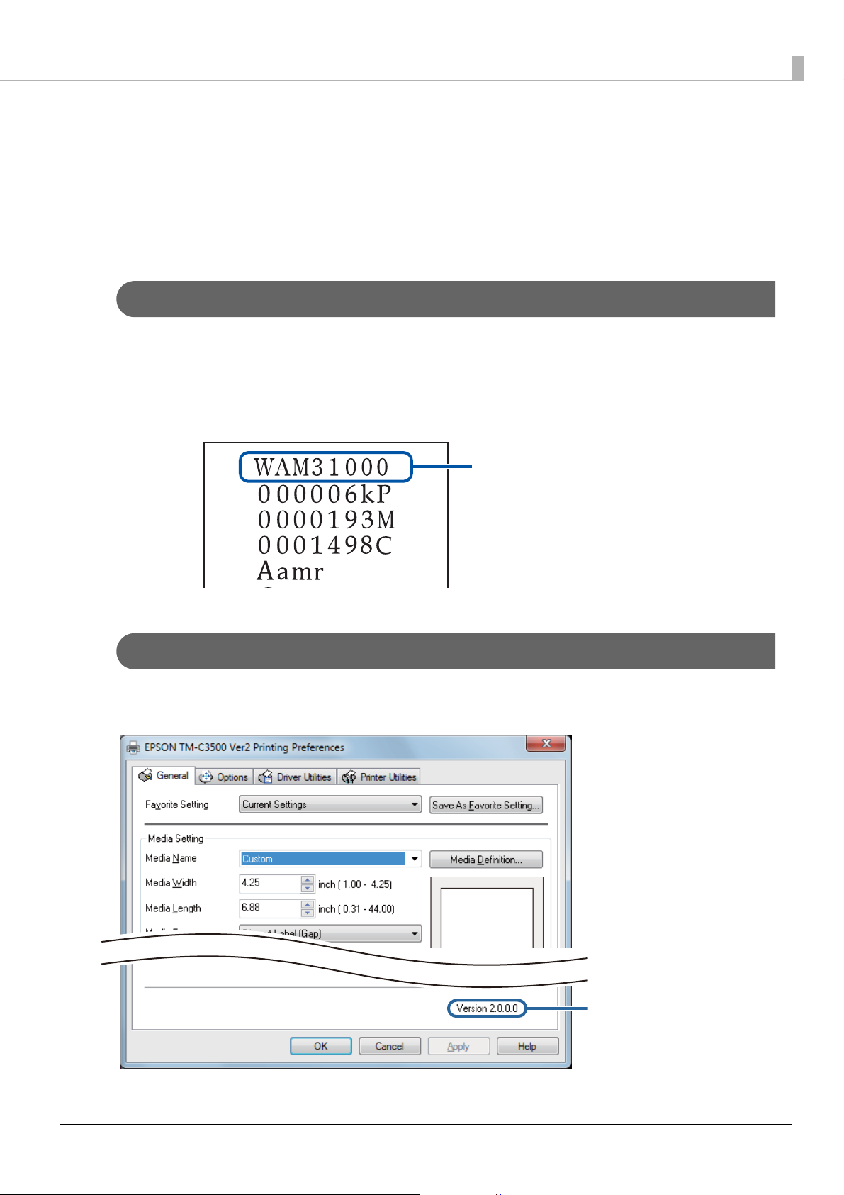
Firmware version
Printer driver version
Unless otherwise specified, the explanations in this manual are for the following versions.
Product firmware: WAM31000
Printer driver: Ver.2.0.0.0
How to Check the Product Version
You can check the version of the product firmware being used by performing self test printing.
Check the first line of the self test print results. For the procedure for the self-test printing, see
the User’s Guide.
How to Check the Printer Driver Version
You can check the version in the printer driver screen.
4

Screens in This Manual
The screens in this manual and the screens actually displayed in Windows may differ depending on the
product used and operating system. Unless otherwise specified, the screens in this manual are those
when using TM-C3500 in Windows 7.
5

Contents
Before use ..................................... 2
■ Manuals for This Product ................................2
Downloading the Latest Version.........................................2
Symbols Used in This Guide .................................................3
■ Product and Driver Versions...........................4
How to Check the Product Version....................................4
How to Check the Printer Driver Version .........................4
■ Screens in This Manual ....................................5
■ Contents ...........................................................6
Functions and Operating
Procedures of the Printer............. 8
■ Preventing Mistaken Operation of the Power
Button ...............................................................8
■ Disabling the Power Button............................9
■ Saving and Restoring PrinterSetting
Settings.......................................................... 11
Saving Settings....................................................................... 12
Restoring Settings................................................................. 13
How to Use the Printer Driver....14
■ Printing Barcodes/2-Dimensional Symbols 14
Barcodes/2-Dimensional Symbol Settings................... 15
Font Replacement................................................................. 23
Printing from an Application............................................. 25
Checking the Feeding Position......................................... 35
■ Favorites........................................................ 36
Favorites Screen Configuration ........................................ 36
Registering Favorites............................................................ 37
■ Importing/Exporting Settings Files ............ 39
Settings that can be Exported to a BSF File ................. 39
Settings that cannot be Exported to a BSF File .......... 39
Exported Settings.................................................................. 40
Importing Settings................................................................ 41
Application Development
Information.................................42
■ Epson Inkjet Label Printer SDK.....................42
Media Design.............................. 43
■ Types of Media that can be Used..................43
Paper that cannot be Used................................................. 44
■ Paper Loading Detection ..............................45
Detection Methods ...............................................................45
Paper Limitations...................................................................46
■ Paper Specifications......................................48
Continuous Paper..................................................................48
Continuous Paper (Black Marks)....................................... 49
Full-page Label .......................................................................51
Die-cut label (Gap)................................................................. 52
Die-cut label (black marks).................................................54
Wristband .................................................................................58
■ Print Position and Cut Position.....................60
Continuous Paper and Roll Paper ....................................60
Continuous Paper (Black Marks) and Roll Paper......... 62
Continuous Paper (Black Marks) and Fanfold Paper..64
Full-page Label and Roll Paper..........................................66
Die-cut Label (Gaps) and Roll Paper................................ 68
Die-cut Labels (Black Marks) and Roll Paper ................70
Die-cut Labels (Black Marks) and Fanfold Paper......... 72
Wristband and Roll Paper (WB-S Series)........................74
Wristband and Roll Paper (WB-M Series) ...................... 76
Wristband and Roll Paper (WB-L Series) ........................ 79
■ Paper Handling to Prevent Unprinted
Labels .............................................................83
Printing from the First Label at Paper Loading ........... 83
Printing the Final Label........................................................ 86
6

Printer Management.................. 89
■ Software ........................................................ 89
■ Efficiently Setting Up a Printer .................... 90
Specify Printer Settings Before Ink Charging............... 90
Efficiently Setting up Multiple Printers.......................... 91
■ Efficiently Setting up the Printer Driver ..... 92
Creating an Installation Package ..................................... 92
Client Computer Procedures............................................. 92
■ Efficient System Management..................... 93
Printer Monitoring................................................................. 93
Changing Printer Settings.................................................. 95
Changing Printer Driver Settings..................................... 96
Automatically Changing a Printer Driver USB Port.... 97
Appendix ..................................101
■ Notes............................................................ 101
■ Trademarks.................................................. 101
7
Functions and Operating Procedures of the Printer
This chapter describes the functions of and how to use the printer.
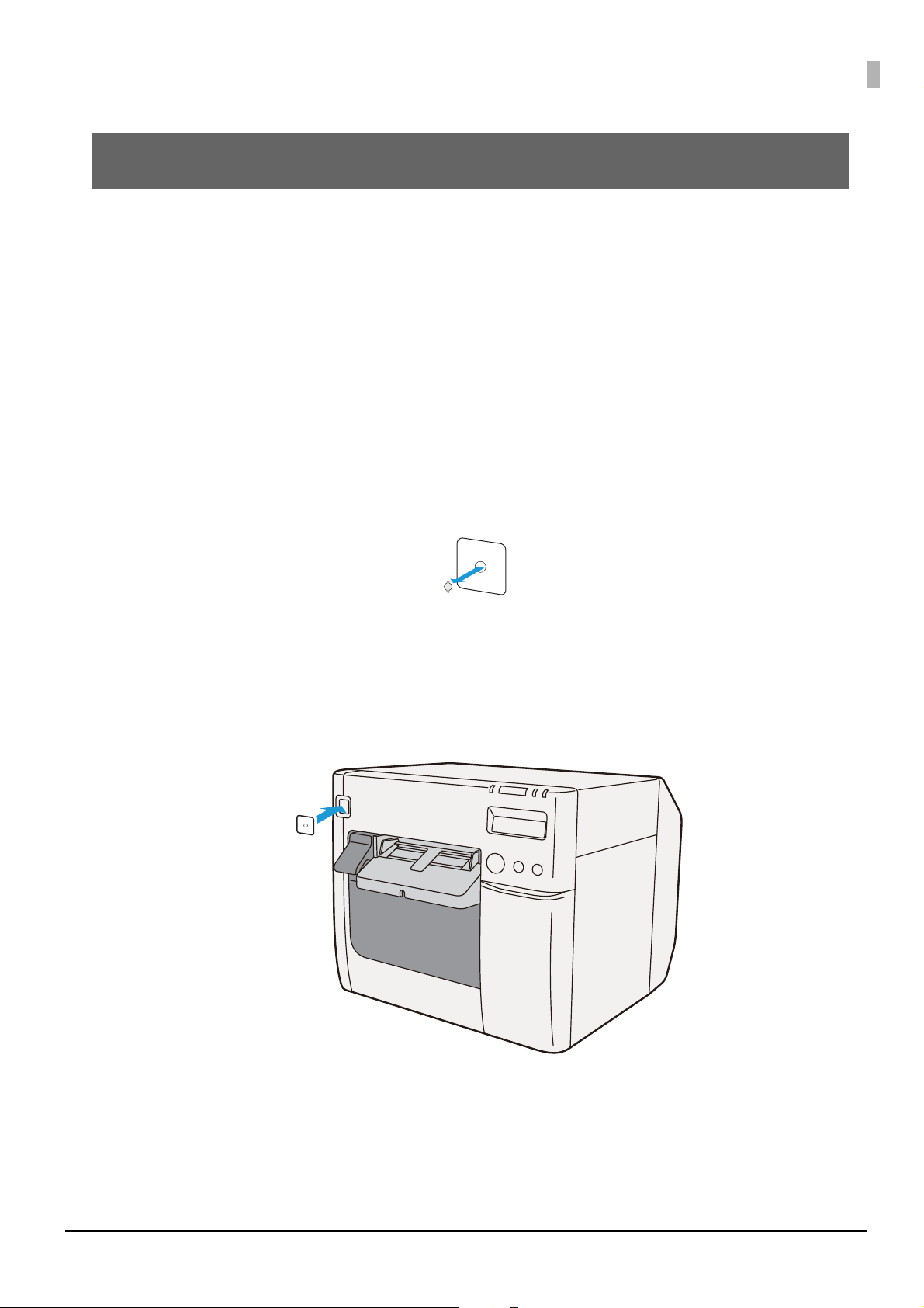
Preventing Mistaken Operation of the Power Button
Attach the supplied power switch cover to prevent users from mistakenly pressing the power button.
You can turn the printer power on and off by inserting a ballpoint pen or similar item with a thin tip
into the hole of the power switch cover.
Attach the power switch cover by following the procedures below.
Pierce the middle of the power switch cover with a thin-tipped hard object
1
to open the hole.
Peel off the backing of the double-sided tape of the power switch cover.
2
Affix the power switch cover over the printer power button.
3
8
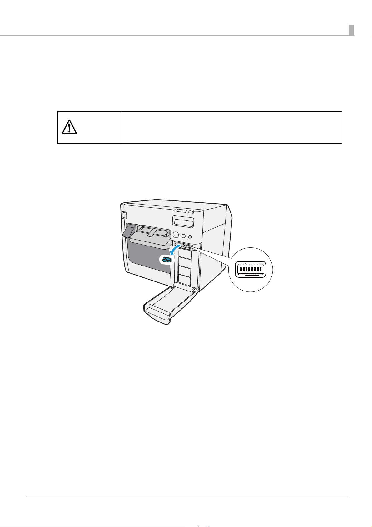
Disabling the Power Button
You can disable power button operation so that the power remains constantly on. Pressing the power
button with the power disabled does not turn the power off but rather resets the printer.
Disable the power button by following the procedures below.
Turn the printer off before removing the dip switch cover.
CAUTION
Check that the printer is powered off.
1
Open the ink cartridge cover and remove the dip switch cover.
2
Removing the cover while the power is on may cause the printer to fail
due to a short circuit.
9
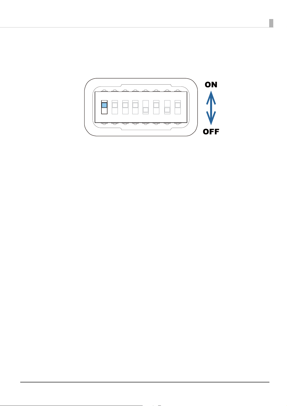
Use an object with a sharp tip to operate the dip switches.
1 23456
7
8
3
The dip switches are numbered in order from the left. Up is the ON state
and down is the OFF state. Turn on dip switch 1.
Attach the dip switch cover and close the ink cartridge cover.
4
10
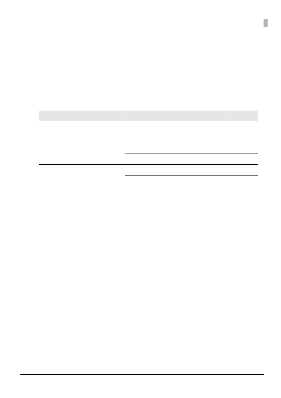
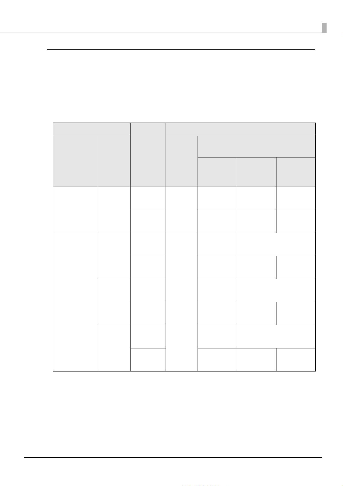
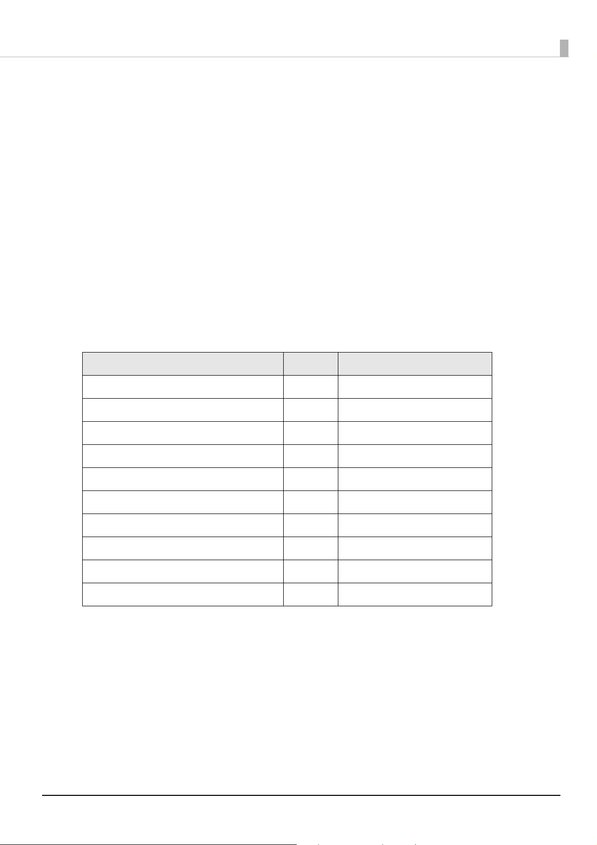
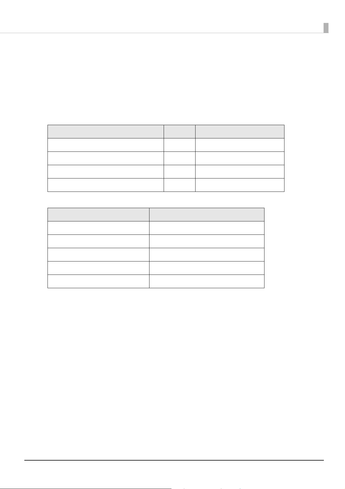
Saving and Restoring PrinterSetting Settings
PrinterSetting is a utility to set the printer from a Windows computer. You can save settings made
using PrinterSetting in a settings file. A settings file can be used as a backup file or master file when
operating multiple printers.
✓: Can be saved
-: Cannot be saved
Menu Setting item Savable
General Media Settings Media source settings ✓
Media detection settings ✓
Advanced
Settings
Printer
Adjustment
Printer Operation
Settings
Notification
Settings
Panel Button
Settings
Operating Time
Settings
Paper Feed
Adjustment
Nozzle Check Mode Settings ✓
Paper Loading Settings ✓
Beep Notification Setting at an Error ✓
LED Notification Setting at Ink Low ✓
Notification Setting at a Media Size Error ✓
Panel Button Settings ✓
Platen Vacuum Operation Pause Time Settings
Data Standby Time Settings
Cut Position Adjustment
Print Start Position Adjustment (Vertical
Direction)
Print Start Position Adjustment (Horizontal
Direction)
✓
✓
Sensor
Adjustment
Print Head
Alignment
Option Media Source Settings Option -
Adjust the Label Gap Detection Sensor
Adjust the Black Mark Detection Sensor
Banding Adjustment
Bi-directional Printing Adjustment
-
-
11

Saving Settings
Save settings by following the procedures below.
Display the printer driver.
1
Select the Printer Utilities tab and then click Printer Setting.
2
The TM-C3500 PrinterSetting screen appears.
Select Settings Save and Restore.
3
The Settings Save and Restore screen appears.
If set values can be acquired from this printer, the values acquired from the
4
current settings will be displayed.
Click Save Settings.
5
The Save as screen appears
Specify a file name and saving location, and then click Save.
6
The successful operation message is displayed to indicate that settings have been saved.
12

Restoring Settings
Restore settings by following the procedures below.
Display the printer driver.
1
Select the Printer Utilities tab and then click Printer Setting.
2
The TM-C3500 PrinterSetting screen appears.
Select Settings Save and Restore.
3
The Settings Save and Restore screen appears.
Click Restore Settings.
4
The Open screen appears.
Select the settings file you want to restore and click Open.
5
A confirmation screen appears.
Click OK. File restoration starts.
6
A message is displayed when restoration is completed. Click OK.
7
The successful operation message is displayed to indicate that settings have been restored.
13

How to Use the Printer Driver
This chapter describes the functions and operating procedures of the printer driver.
Printing Barcodes/2-Dimensional Symbols
This section describes how to use the fonts for barcodes/2-dimensional symbols of the printer driver,
and how to print barcodes/2-dimensional symbols. Using a font for barcodes/2-dimensional symbol
allows you to print barcodes/2-dimensional symbols with a high level of readability that is suitable for
the resolution of this printer.
The settings flow is as follows.
Barcodes/2-Dimensional Symbol Settings
Set the type and size of barcodes/2-dimensional symbols in the font for barcodes/
2-dimensional symbols of the printer driver.
Font Replacement
You can replace the printer driver fonts to replace the font for barcodes/2-dimensional symbols with a True Type font.
Printing from an Application
Use an application to create values for barcodes/2-dimensional symbols and
print accordingly.
14
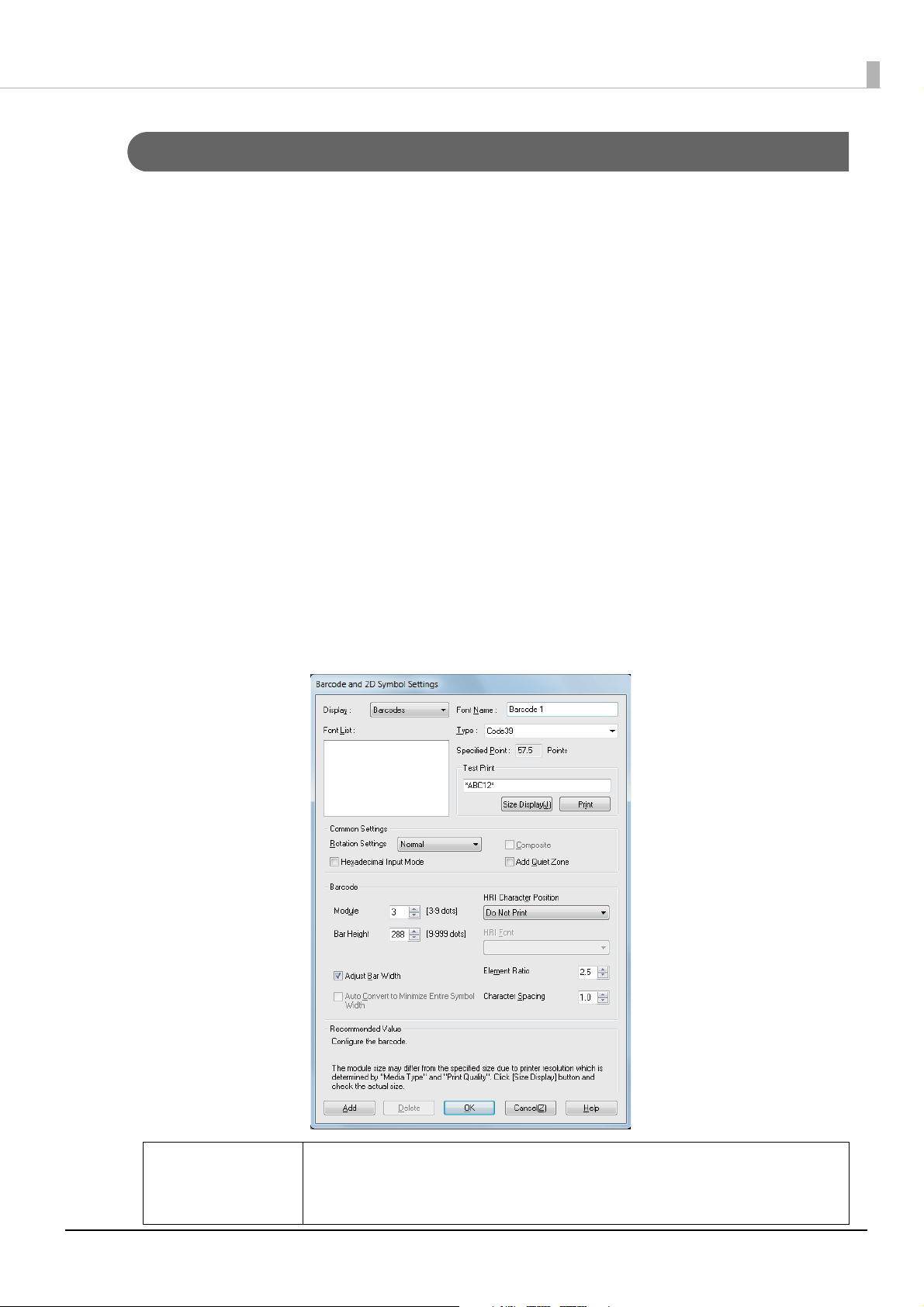
Barcodes/2-Dimensional Symbol Settings
Set items such as the type, size, and print direction of barcodes/2-dimensional symbols, and set
the font for barcodes/2-dimensional symbols.
You can specify a total of 30 items for a barcodes and 2-dimensional symbols font.
Specify settings by following the procedures below.
Display the printer driver.
1
Click Barcodes/2-Dimensional Symbols Settings on the Driver Utilities
2
tab.
The Barcode and 2D Symbol Settings screen appears.
From Type, select the barcode/2-dimensional symbol you want to specify.
3
Setting items change depending on the type.
Set the displayed items. Right-click an item and then click Help to display
4
an explanation of the setting item.
Q NOTE
Setting point displays a point value corresponding to the size of the barcodes/2-dimensional symbols. Specify this value when printing from an
application.
15
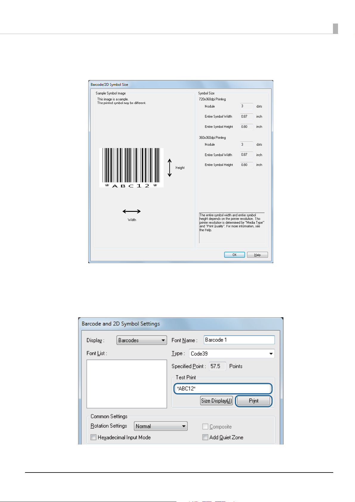
Click Size Display and check the printing size of the barcodes/2-dimen-
5
sional symbols.
Input a character string into Test print and then click Print. After printing
6
barcodes/2-dimensional symbols, use a scanner to check that they can be
read.
16
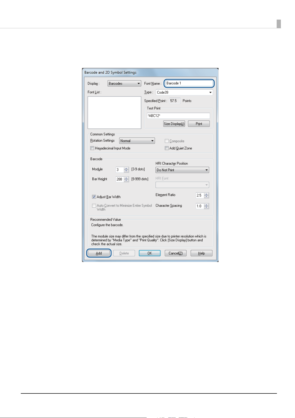
Input the name of the font for barcodes/2-dimensional symbols into Font
7
name and then click Add on the lower left.
Check that the font for barcodes/2-dimensional symbols has been added to
8
the Font list and then click OK. Close the Barcode and 2D Symbol Settings screen.
Setting of the barcodes/2-dimensional symbols is now completed.
17
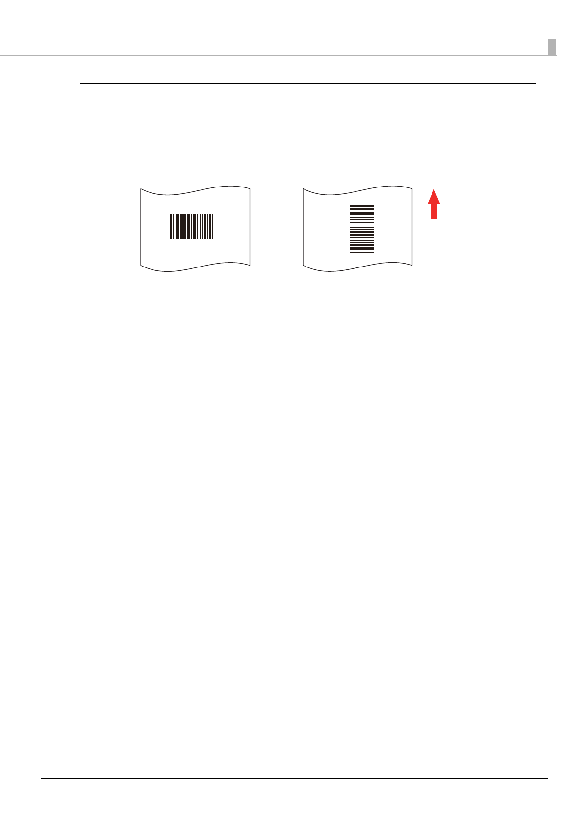
Barcode Print Direction
8 1 0 1 0 5 4 3 2 1 1 2 0 0
8 1 0 1 0 5 4 3 2 1 1 2 0 0
Paper feed direction
Fence barcode
Ladder barcode
Barcode print direction and name are as follows.
When printing ladder barcodes, it may not be possible to read the barcode with a barcode
reader if printed straddling the feeding position. (U“Checking the Feeding Position” on page
35) For this reason, it is recommended to use fence barcodes or set the Print Quality to
Quality (Mode2).
18
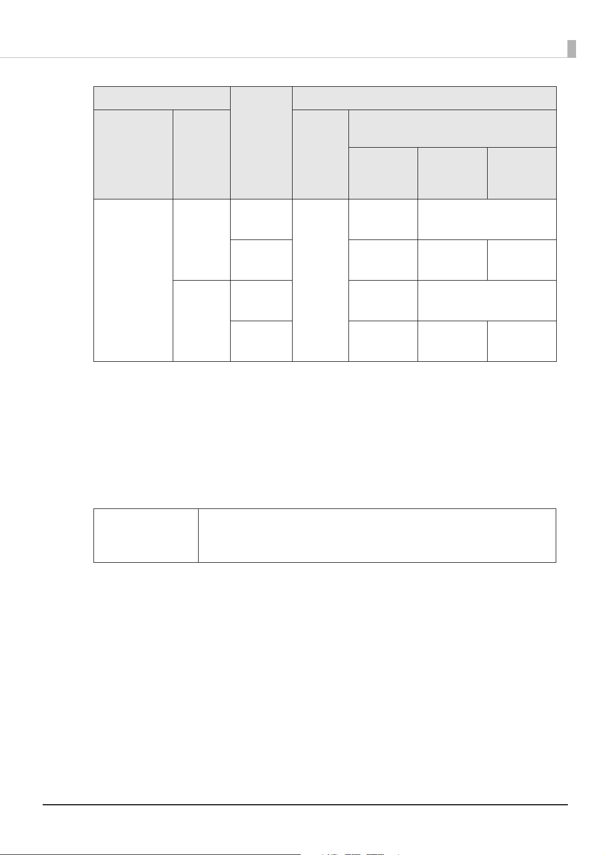
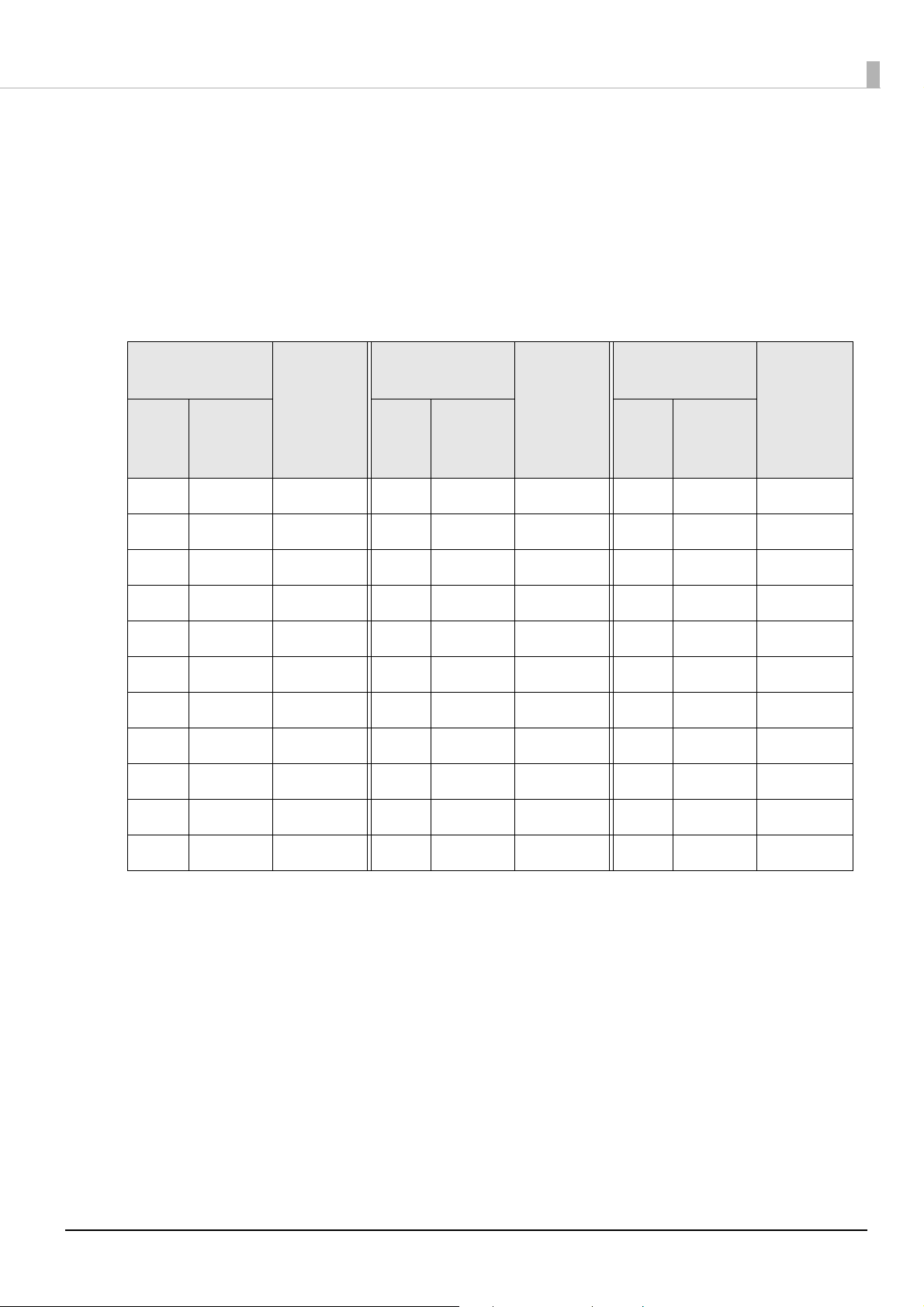
Printing with ANSI Print Quality Grade
You can print with ANSI print quality grade depending on the media type, printer driver
settings, and direction and size of barcodes/2-dimensional symbols. The setting items are as
follows.
Barcodes
-: Not guaranteed
General settings
Print
Media type
Plain paper Speed Fence Yes 4 dot
Synthetic
paper
Matte paper
Glossy
Print
quality
Speed Fence Yes 3 dot
Quality
(Mode1)
direction
*1
Ladder 6 dot
Ladder 6 dot
Fence 3 dot
Font settings of barcodes/2-dimensional symbols
Upper line: Minimum module (dot)
Adjust
Bar
Width
*2
Lower line: Minimum element ratio
grade D or
higher
2.5
2.5
2.7
2.5
2.7
ANSI
ANSI
grade C or
higher
--
--
4 dot
2.5
--
4 dot
2.5
ANSI
grade B or
higher
Quality
(Mode2)
Ladder 6 dot
2.5
Fence 3 dot
2.7
Ladder 6 dot
2.5
--
4 dot
2.5
--
19
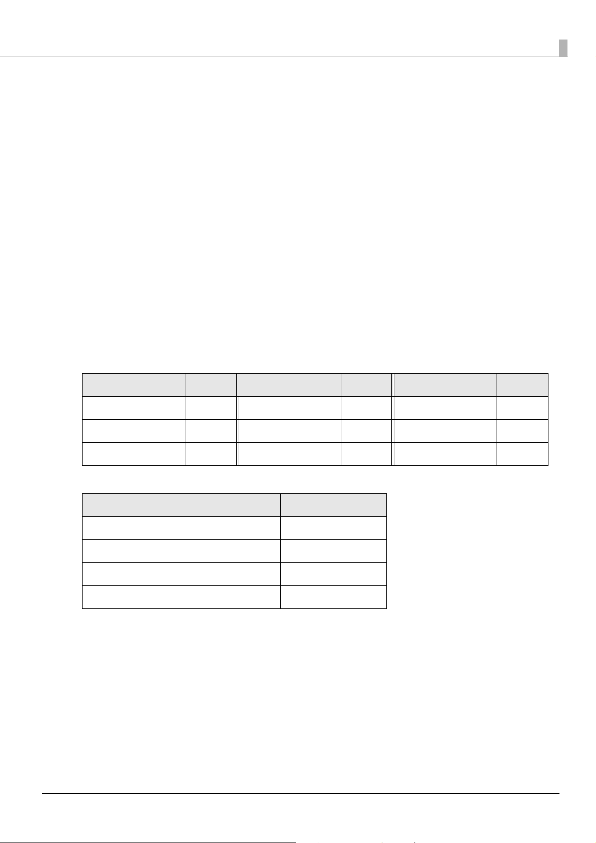
General settings
Font settings of barcodes/2-dimensional symbols
Print
Media type
Wristbands Speed Fence Yes 3 dot
*1: In some cases, missing dots and irregularity in ink shots may occur when printing ladder barcodes,
resulting in the ANSI grade being lowered to F and making barcodes unreadable. Apply an
innovative method such as printing HRI characters.
*2: Ink may penetrate the paper due to its characteristics, causing the bars of printed barcodes to
become thicker. In such cases, reduce the data in a bar by one pixel and increase the blank space
by one pixel (Adjust Bar Width).
*3: The recommended values for specified media types and barcodes are as follows.
For wristbands and Code 128: Five-dot module and ANSI grade D
For wristbands and Codabar: Four-dot module, minimum element ratio of 2.5, and ANSI grade C
Print
quality
Quality
(Mode1)
direction
*1
Ladder 6 dot
Fence 3 dot
Ladder 6 dot
Adjust
Bar
Width
*2
Upper line: Minimum module (dot)
Lower line: Minimum element ratio
ANSI
grade D or
higher
2.7
*3
2.5
2.7
*3
2.5
ANSI
grade C or
higher
4 dot
2.5
*3
-
4 dot
2.5
*3
-
grade B or
higher
-
-
ANSI
Q NOTE
If an odd number value is set for the Module, changing the Media Type
and Print Quality causes the resolution to change, resulting in a change in
the size of the printed barcode.
20
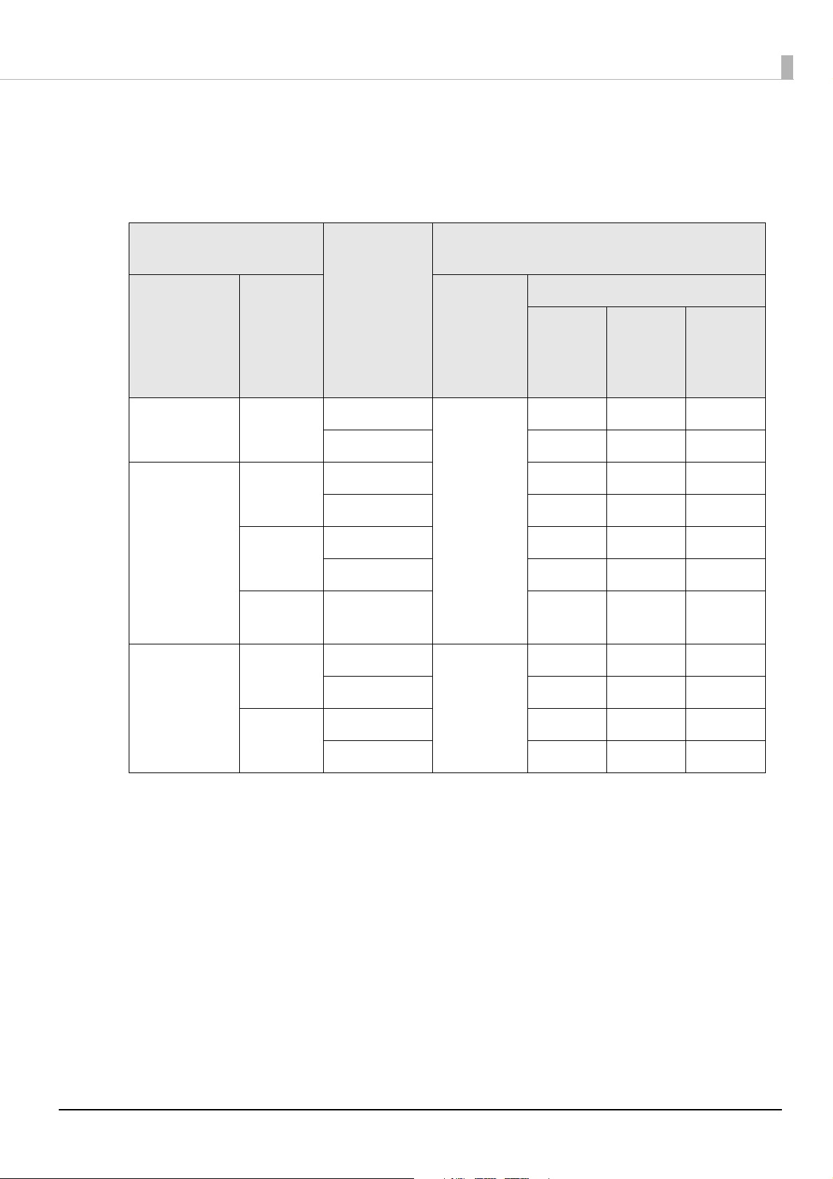
Stacked Type 2-Dimensional Symbols Fonts
Symbols: PDF417, GS1 DataBar Stacked, GS1 DataBar Stacked Omnidirectional, GS1 DataBar
Expanded Stacked
-: Not guaranteed
General settings
Straddling
Font settings of barcodes/2-dimensional sym-
bols
Minimum module (dot)
paper
Media type
Print
quality
feeding
1
*
Module
height
2
*
ANSI
grade D
or
higher
ANSI
grade C
or
higher
Plain paper Speed No 3 6 dot - -
Yes 6 do t - -
Synthetic
paper
Speed No 4 dot - -
Yes 4 do t - -
Matte paper
Glossy
Quality
No 4 dot - -
(Mode1)
Yes 4 do t - -
Quality
-4 dot--
(Mode2)
ANSI
grade B
or
higher
Wristbands Speed No 3 4 dot - -
Yes 4 do t - -
Quality
(Mode1)
No 4 dot - -
Yes 4 do t - -
*1: To check whether a 2-dimensional symbol is straddling paper feeding, use Display Media Feed
Position of the print preview function. For the print preview function, refer to "Checking the
Feeding Position" on page 35
.
*2: Recommended value when using PDF417
21
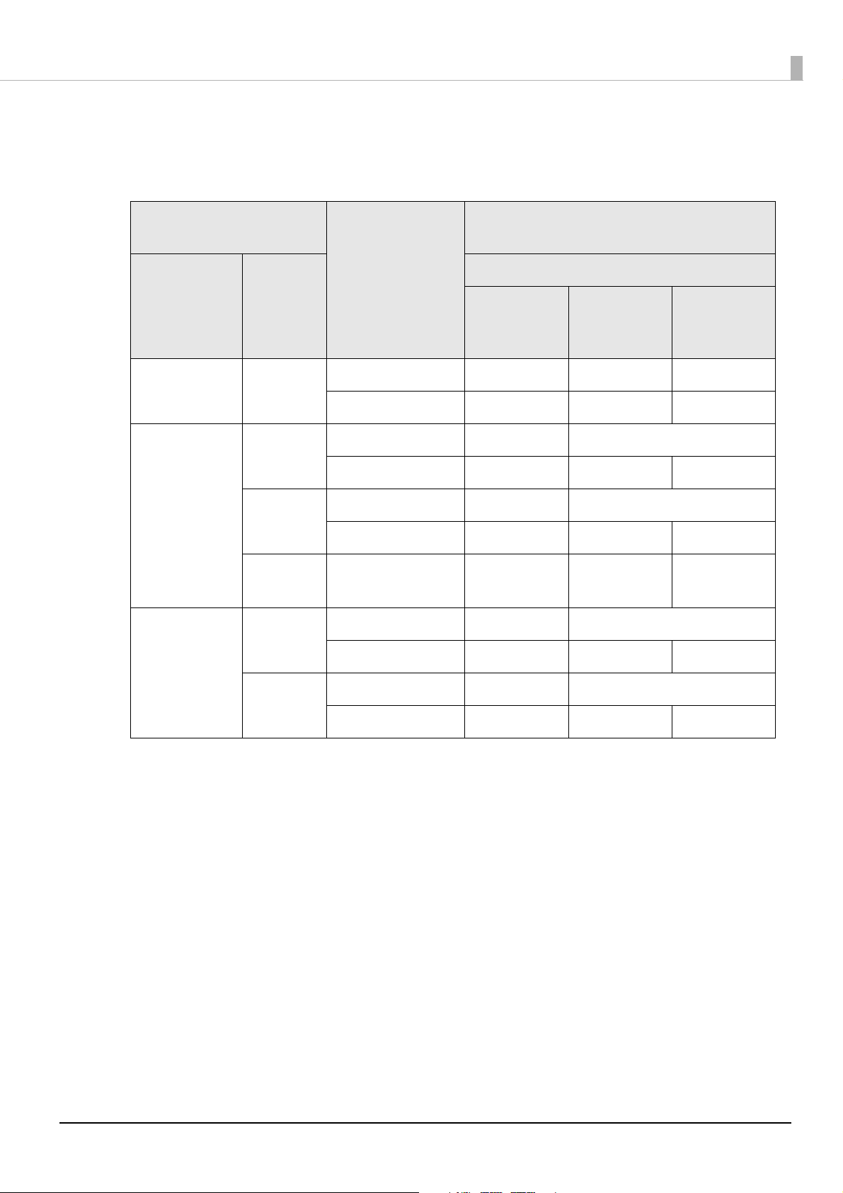
Matrix Type 2-Dimensional Symbols Fonts
Symbols: QR Code, DataMatrix
-: Not guaranteed
General settings
Media type
Print
quality
Straddling paper
feeding
*1
Font settings of barcodes/2-dimensional
symbols
Minimum cell size (unit: 360 dpi)
ANSI
grade D or
higher
ANSI
grade C or
higher
Plain paper Speed No 6 dot - -
Yes 8 dot - -
Synthetic
paper
Speed No 5 dot 6 dot
Yes 6 dot 7 dot -
*2
Matte paper
Glossy
Quality
(Mode1)
Quality
No 5 dot 6 dot
Yes 6 dot 7 dot -
- 6 dot 7 dot -
*2
(Mode2)
Wristbands Speed No 5 dot 6 dot
*2
ANSI
grade B or
higher
Yes 6 dot 7 dot -
Quality
No 5 dot 6 dot
*2
(Mode1)
Yes 6 dot 7 dot -
*1: To check whether a 2-dimensional symbol is straddling paper feeding, use Display Media Feed
Position of the print preview function. For the print preview function, refer to "Checking the
Feeding Position" on page 35
.
*2: QR Code only
22

Font Replacement
The Windows .NET application cannot be used to specify printer driver fonts for barcodes/2dimensional symbols. For this reason, you must replace the font for barcodes/2-dimensional
symbols set in the previous procedure with a Windows True Type font.
For True Type fonts replacing barcode fonts, select fonts that are not being
c IMPORTANT
Replace fonts by following the procedures below.
Display the printer driver.
1
Select the Driver Utilities tab and then click Font Replacement. The Font
2
Replacement screen appears.
From the True Type Font Name, click the True Type font you want to
3
replace.
The selected font is displayed in the Replacement True Type Font.
used as print data.
23
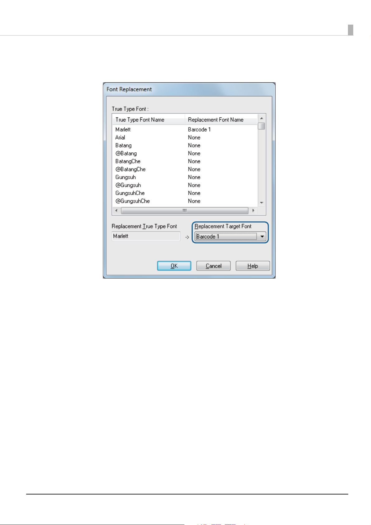
From the Replacement Target Font, select the previously set barcodes/2-
4
dimensional symbols font.
Click OK to close the Font Replacement screen.
5
Font replacement is now completed.
24

Printing from an Application
This section describes how to create character strings of barcodes/2-dimensional symbols and
print using a specified True Type font.
Creating Character Strings of Barcodes/2-Dimensional Symbols
Refer to the following to create character strings of barcodes/2-dimensional symbols.
UPC-A
• Specify a character string of 11 to 12 digits.
• Although the first digit is the number system character, the bar code font is not checked.
• For 11 digits: The check digit is automatically added.
• For 12 digits: The 12th digit is processed as the check digit but the barcode font is not verified.
If the composite is checked, the 12th digit is ignored and the check digit is automatically added.
UPC-E
• Specify a character string of six to eight or 11 to 12 digits.
• For six digits: The check digit is automatically added.
• For seven digits: Digits two to seven are data digits and the check digit is automatically added.
• For eight digits: Digits two to seven are data digits and the eighth digit is processed as the check
digit but the barcode font is not verified.
If the composite is checked, the eighth digit is ignored and the check digit is automatically
added.
• For 11 digits: The check digit is automatically added.
• For 12 digits: The 12th digit is processed as the check digit but the barcode font is not verified.
If the composite is checked, the 12th digit is ignored and the check digit is automatically added.
• For seven digits or more: Specify 0 (zero) because the first digit is processed as the number
system digit.
JAN13(EAN)
• Specify a character string of 12 to 13 digits.
• For 12 digits: The check digit is automatically added.
• For 13 digits: The 13th digit is processed as the check digit but the barcode font is not verified.
If the composite is checked, the 13th digit is ignored and the check digit is automatically added.
25

JAN8(EAN)
• Specify a character string of 7 to 8 digits.
• For seven digits: The check digit is automatically added.
• For eight digits: The 8th digit is processed as the check digit but the barcode font is not verified.
If the composite is checked, the eighth digit is ignored and the check digit is automatically
added.
CODE39
• Specify a character string with a maximum of 256 digits.
• If one or both of the start and stop codes (“*”) are not specified, they are automatically added.
ITF
• Specify a character string with a maximum of 256 digits.
• If odd-digit data is specified, 0 (zero) is automatically added at the beginning of the string.
Codabar
• Specify a character string with a maximum of 256 digits.
• If a start code is not specified, ‘A’ is automatically added as the start code.
• If a stop code is not specified, a stop code that is the same as the start code is automatically
added.
• If the start or stop code is input with lower-case characters, they are automatically converted to
upper-case characters.
26
CODE93
• Specify a character string of 1 to 255 digits. awd
• A start code, two check digits, and a stop code are automatically added.
• Print characters indicating a start code (n) at the beginning of the HRI characters.
• Print characters indicating a stop code (n) at the end of the HRI characters.
• Print a combination of ■ and one alphabet character for the HRI control characters (00h to
1Fh, and 7Fh).
Control
characters
HRI char-
Hexa-
ASCII
NULL 00 ■U VT 0B ■K SYN 16 ■V
SOH 01 ■A FF 0C ■L ETB 17 ■W
STX 02 ■B CR 0D ■M CAN 18 ■X
ETX 03 ■C SO 0E ■N EM 19 ■Y
EOT 04 ■D SI 0F ■O SUB 1A ■ Z
ENQ 05 ■E DLE 10 ■P ESC 1B ■A
ACK 06 ■F DC1 11 ■Q FS 1C ■B
BEL 07 ■G DC2 12 ■R GS 1D ■C
BS 08 ■H DC3 13 ■S RS 1E ■D
decimal
number
acters
Control
characters
ASCII
Hexa-
decimal
number
HRI char-
acters
Control
characters
ASCII
HRI char-
Hexadecimal
number
acters
HT 09 ■I DC4 14 ■T US 1F ■E
LF 0A ■J NAK 15 ■U DEL 7F ■F
27
CODE128
• Specify a character string of 2 to 255 digits.
• Specify either a start code or code selection characters (CODE A, CODE B, or CODE C) for the
first two digits.
• Indicate special characters with a combination of ‘{’ followed immediately by a single character.
• Adding a check mark to Automatically Convert Symbol Overall Width to Minimum results
in the overall width of the Code 128 symbol being automatically converted to the minimum.
Use this function when it is not necessary to specify a code set and you want to print barcodes
by only inputting data for a desired symbol.
Manually specify the code set if not checked.
If code set C is specified, consider the two created digits as ASCII decimal numbers and specify
the corresponding ASCII character(s).
Example) “37”: Specify as “%”.
“65”: Specify as “A”.
“979899”: Specify as “abc”.
• An error occurs if the data immediately following ‘{’ is not as indicated below.
Control characters ASCII Control characters ASCII Control characters ASCII
SHIFT {S CODE C {C FNC3 {3
CODE A {A FNC1 {1 FNC4 {4
CODE B {B FNC2 {2 '{' {{
• Special HRI characters are expressed as follows.
Control characters HRI characters
SHIFT Not printed
CODE A/B/C Not printed
FNC1-4 Space is printed
Control characters (00h to 1Fh, and 7Fh) Space is printed
28
GS1-128
• Specify a character string of 2 to 255 digits.
• The delimiter of the application identifier is separated by “()” (parenthesis). (Although printed
as HRI characters, they are not encoded.)
• A start code (CODE A, CODE B, or CODE C) and stop code are automatically added.
• Symbol characters FNC1 are automatically added following the start code.
• Specifying ‘*’ results in the check digit being automatically calculated and converted to ‘*’.
• Specify two consecutive digits for the application identifier. An error occurs if not correctly
specified.
• If the application identifier is (01), the 14th digit of data is made the check digit but if the check
digit is specified, the barcode font is not verified. The check digit being automatically calculated
and converted to ‘*’ if the 14th digit is “*”.
• Indicate special characters with a combination of ‘{’ followed immediately by a single character.
• An error occurs if the data immediately following ‘{’ is not as indicated below.
Control characters ASCII HRI characters
Control characters (00h to 1Fh, and 7Fh) Space is printed
FNC1 {1 Space is printed
FNC3 {3 Space is printed
'{' {{ { is printed
'(' {( ( is printed
')' {) ) is printed
'*' {* * is printed
Left parenthesis of application identifier ( ( is printed
Right parenthesis of application identifier ) ) is printed
Check digit position * Check digit is printed
GS1-128M
• Specify a character string of 38 to 66 digits.
• The delimiter of the application identifier is separated by “()” (parenthesis). (Although printed
as HRI characters, they are not encoded.)
• A start code (CODE A, CODE B, or CODE C) and stop code are automatically added.
• Symbol characters FNC1 are automatically added following the start code.
• FNC1 is automatically added if FNC1 is not present at the end of the data following application
identifier (30).
29
• An error occurs if FNC1 is present at the end of the data following application identifier (10) or
(21) because FNC1 is not necessary.
• If the application identifier is (01), the 14th digit of the data section is made the check digit but
if the check digit is specified, the barcode font is not verified. The check digit is automatically
calculated and converted to ‘*’ if the 14th digit is “*”.
• An error occurs if the data immediately following the { is not a 1.
• Specify special characters according to the following formats.
Control characters ASCII HRI characters
FNC1 {1 Space is printed
Left parenthesis of application identifier ( ( is printed
Right parenthesis of application identifier ) ) is printed
Check digit position * Check digit is printed
• An error occurs if not according to the following formats.
Application identifier Format
01 14-digit number
10 1 to 20 alphanumeric characters
17 6-digit number (YYMMDD)
21 1 to 20 alphanumeric characters
30 1 to 8 digit number
GS1 DataBar Omnidirectional/GS1 DataBar truncated
/GS1 DataBar Limited
• Leading application identifier 01 is not included in the character string.
• When printing HRI characters, leading application identifier 01 is printed as “(01)” before the
packing identification code.
• Do not add a check digit to the bar code data.
• When printing HRI characters, the check digit is printed after the product code.
• Specify ‘0’ or ‘1’ as the first digit if using GS1 DataBar Limited.
30

GS1 DataBar Expanded M
• Specify a character string of 38 to 66 digits (numbers not including ‘*’).
• The delimiter of the application identifier is separated by “()” (parenthesis). (Although printed
as HRI characters, they are not encoded.)
• FNC1 is automatically added if FNC1 is not present before application identifier (10) or (21).
• FNC1 is automatically added if FNC1 is not present at the end of the data following application
identifier (30).
• An error occurs if FNC1 is present at the end of the data following application identifier (10) or
(21) because FNC1 is not necessary.
• If the application identifier is (01), the 14th digit of the data section is made the check digit. If
the check digit is not correct, an error occurs.
(Different than the case of GS1-128 in that the check digit is not automatically calculated and
added due to ‘*’.)
• ‘*’ is skipped.
• An error occurs if the data immediately following the character string { is not a 1.
• Specify special characters according to the following formats.
Control characters ASCII HRI characters
FNC1 {1 Not printed
'(' {( ( is printed
')' {) ) is printed
Left parenthesis of application identifier ( ( is printed
Right parenthesis of application identifier ) ) is printed
'*' {* * is printed
Skipped character * Not printed
31

GS1 DataBar Expanded
• Specify a character string of 2 to 255 digits.
• The delimiter of the application identifier is separated by “()” (parenthesis). (Although printed
as HRI characters, they are not encoded.)
• Be sure to include all application identifiers in the character string.
• If the first data is 01 after deleting the application identifier, left and right parenthesis, and ‘*’
from the specified data, checking is performed using the 14th digit counting from the digit
following 01 as the check digit. An error occurs if not correct.
• If the data counting the digit following 01 is less than 14 digits, the check digit is not checked.
(Different than the case of GS1-128 in that the check digit is not automatically calculated and
added due to ‘*’. If ‘*’ is specified, ‘*’ is ignored and the following data is shifted by one digit
each.)
• Specify special characters according to the following formats.
Control characters ASCII HRI characters
FNC1 {1 Not printed
Left parenthesis of application identifier ( ( is printed
Right parenthesis of application identifier ) ) is printed
'*' {* Error
Skipped character * Not printed
PDF417
• Automatic calculation is performed if the number of digits and rows is 0 (zero).
• If anything other than 0 (zero) is specified, specify so that the product of the number of digits
and rows is 928 or less.
QRCode
• The size is determined according to the specified version. If not embedded in the specified
version, it is automatically changed to the embedded version.
32

MaxiCode
• The header and secondary message can be omitted if using Mode 2 or 3.
• Specify special characters according to the following formats.
Control characters Hexadecimal number notation
SHIFT 0x7B,0x53
CODE B 0x7B,0x42
CODE C 0x7B,0x43
FNC1 0x7B,0x31
FNC2 0x7B,0x32
FNC3 0x7B,0x33
FNC4 0x7B,0x34
GS1 DataBar Stacked / GS1 DataBar Stacked Omnidirectional
• You can specify a character string up to 13 digits.
• Do not include application identifier 01 at the beginning of the character string.
• Do not add a check digit to the character string.
GS1 DataBar Expanded Stacked
• It is a multi-row symbol version of GS1 DataBar Expanded. Data specification procedures are
the same as that for GS1 DataBar Expanded.
AztecCode
• Both full-range and compact modes are supported.
DataMatrix
• Both square and rectangular shapes of version ECC200 are supported.
33

Specifying and Printing True Type Font
Specify the following in character strings of barcodes/2-dimensional symbols and print.
True Type Font
Use Font Replacement to specify the selected True Type font.
Point
Separately specify the point for each font for barcodes/2-dimensional symbols. Check the
specified points of the fonts for barcodes/2-dimensional symbols.
(U“Barcodes/2-Dimensional Symbol Settings” on page 15)
34

Checking the Feeding Position
Feeding position
Feeding is
straddled
If Speed or Quality (Mode1) is specified for the Print Quality, it may not be possible to read
the barcodes/2-dimensional symbols if they are printed straddling the feeding position. Adjust
the print data so that they are not straddling the feeding position. It is not necessary to check
the feeding position or adjust it if Quality (Mode2) is specified for the Print Quality because
the feeding position does not affect the reading accuracy of barcodes/2-dimensional symbols.
You can use Print Preview of the General tab to check an image of the print results before
printing. The feeding position is not displayed if Quality (Mode2) is specified for the Print
Quality.
35

Favorites
1
234
You can use the favorites functions to register basic and extended settings of the printer driver together
in one location.
Favorites Screen Configuration
Right-click an item and then click Help to display an explanation of the setting item.
1 List
This is a list of your favorites.
The initial settings are those specified when the printer driver is installed.
The first setting at the top of the list is the default setting when the printer driver is started.
Click Up/Down to switch the order of the list.
36

2Item
The favorites setting items.
3Current Settings
Set value when you click Save As Favorite Setting.
4 Registered Settings
Favorite set value selected from the list.
Registering Favorites
Register favorites by following the procedures below
Set the printer driver to match the paper being used for printing.
1
Click Save As Favorite Setting of the General or Options tab.
2
The Save/Delete Favorite Setting screen appears.
The contents of the General and Options tabs are displayed under Current Settings.
Input the settings name into Name and then click Add.
3
The Save/Delete Favorite Setting screen closes.
37

The added settings name is Favorite Setting of the General or Options
4
tab.
Registering favorites is now completed.
38

Importing/Exporting Settings Files
Printer driver settings can be exported to a BSF file. A BSF file can be used as a backup file or master
file.
If the printer driver of another computer is specified by using a BSF file, the file
Q NOTE
Settings that can be Exported to a BSF File
• Media definition
• Favorites
• Fonts of barcodes/2-dimensional symbols
• Font replacement
• Driver operation settings
• Epson log file settings
• Fatal error notification settings/Monitoring function settings
cannot be imported if the printer driver version is not the same.
Settings that cannot be Exported to a BSF File
• Items set for this printer by using PrinterSetting
• Printer driver port settings (printer IP address and computer port)
39

Exported Settings
Exported settings by following the procedures below.
Display the printer driver.
1
Register favorites. (U“Registering Favorites” on page 37)
2
If no favorites are registered, only the initial settings when the printer driver
was installed are registered.
Click Import/Export Settings on the Driver Utilities tab.
3
The Import/Export Settings screen appears.
Click Export Settings.
4
The Save As screen appears.
Name and save the BSF file.
5
When the file has been saved, Processing Completed is displayed.
Click OK.
6
Exporting of settings is now complete.
40

Importing Settings
You can import settings from a BSF file to overwrite printer driver settings
Q NOTE
Import settings by following the procedures below.
Display the printer driver.
1
Click Import/Export Settings on the Driver Utilities tab.
2
The Import/Export Settings screen appears.
Click Import Settings.
3
The Overwrite confirmation screen appears.
Click OK.
4
The Open screen appears.
Select the file to be imported.
5
Processing Completed is displayed.
and save them.
Click OK.
6
Importing of settings is now complete.
41

Application Development Information
This chapter provides information required for application development using this printer.
Epson Inkjet Label Printer SDK
The Epson Inkjet Label Printer SDK is a software development kit (SDK) for developing TMC3500 applications.
The Epson Inkjet Label Printer SDK contains the following tools. For use procedures, refer to
the Epson Inkjet Label Printer SDK User’s Guide.
Name Overview
EPDI
(EPSON Printer Driver Interface)
EpsonNet SDK The EpsonNet SDK provides the API used for acquiring the status of Epson
Sample programs These are sample programs for label printing. They also include sample
The Epson Driver Printer Interface (EPDI) provides the Application Programming Interface (API) for Epson printer drivers. Use the EPDI to directly
control the printer driver settings from your own developed applications.
inkjet label printers.
Use the EpsonNet SDK to acquire the status of network printers from your
own developed applications.
programs using the EPDI and EpsonNet SDK. Application execution files
and program source files are also provided.
42

Media Design
This chapter describes the required procedures for designing and arranging media (paper) that can be
used with this printer.
Types of Media that can be Used
The types of media that can be used with this printer are as follows.
For detailed specifications, refer to “Paper Specifications” on page 48.
Adhesive Typ e Category
Roll paper
Fanfold paper
c IMPORTANT
Full-page labels
Ye s
No
Yes Die-cut labels (with black marks)
No Continuous paper (with black marks)
Depending on the shape of die-cut labels, the labels may peel off their
backing paper inside the printer. When you want to use die-cut labels that
do not meet the specifications, contact qualified service personnel for
advice.
Die-cut labels (with black marks)
Die-cut labels (with gaps)
Continuous paper
Continuous paper (with black marks)
Plain paper
Matte paper
Synthetic paper
Glossy
Plain paper
Matte paper
Wristbands
Plain paper
Matte paper
43

Paper that cannot be Used
Thermal paper
Paper joined together or
lengthened by tape, etc.
Paper joined to the core by tape,
etc.
Paper of A size, B size, etc.
Do not load paper like the following. Such paper will cause paper jams and print stains.
44

Paper Loading Detection
This printer is equipped with a paper loading detection function. This section describes detection
methods and paper limitations.
Detection Methods
Black Mark Detection
Sensors are positioned facing the backside of the paper to detect paper loading from the optical
reflectance of the paper.
(The black mark reflectance rate must be 10% or lower, and the white reflectance rate must be
70% or higher.)
In order to accurately detect black marks, use paper having black marks printed at the positions
indicated for each black mark of the paper specifications.
Gap Detection
Transmission-type sensors are positioned along the paper path to detect paper loading from
differences in the light transmission rates between the backing paper and labels.
(The light transmission rate of the backing label must be 40% or more and that of the label
must be 23% or less.)
Light transmission rate: Light transmission rate (%) = Light transmission amount/Amount of
irradiation light x 100
45

Paper Limitations
Paper width center
13 mm
Preprinting prohibited area
Paper feed direction
Back side
8.5 mm
Preprinting Prohibited Area of Paper
Do not use paper preprinted in the following area if using paper preprinted on the back because
it negatively affects detection. (Excluding black marks.)
46

Holes Prohibited Areas of Paper
Paper width center
Holes prohibited areas
Paper feed direction
Print side
8.5 mm
6.0 mm
Do not use make holes in the following areas if it is necessary to use paper with holes such as
wristbands because it negatively affects detection.
47

Paper Specifications
The specifications of paper that can be used with this printer are as follows.
Continuous Paper
Paper type Plain paper / matte paper
Form Roll paper
Paper width 30 to 108 mm
Paper thickness 0.084 to 0.124 mm
Roll paper core Outer diameter: 44.1 mm or more
Outer diameter Max. 101.6 mm
Winding direction Printing surface must be facing outside.
c IMPORTANT
Paper with holes or cutouts cannot be used.
48

Continuous Paper (Black Marks)
Mark width
Mark center position
Mark length
Mark interval
Paper width center
Perforation position
0.5 mm or more
Fanfold paper
<Back side> <Print side>
Paper width center
Paper feed
direction
Paper
Paper type Plain paper / matte paper
Form Roll paper
Paper width 30 to 108 mm
Black mark width 13 mm or more
Label length 15 to 1117.6 mm
Black mark length 4 mm or more (margin part 4 mm or more)
Black mark center position 8.5 ± 1 mm
Black mark interval 8 to 1117.6 mm
Paper thickness 0.084 to 0.124 mm
Roll paper core Outer diameter: 44.1 mm or more
Outer diameter Max. 101.6 mm
Winding direction Printing surface must be facing outside.
c IMPORTANT
Paper with holes or cutouts cannot be used.
49

Paper type Plain paper / matte paper
Form Fanfold paper
Paper width 50 to 108 mm
Black mark width 13 mm or more
Black mark length 4 mm or more (margin part 4 mm or more)
Black mark center position 8.5 ± 1 mm
Black mark interval 8 to 304.8 mm
Paper thickness 0.124 to 0.128 mm
Perforated line interval 203.2 to 304.8 mm
Perforated line form Plain paper label: 1 mm uncut, 5 mm cut
Matte paper: 1 mm uncut, 5 mm cut
Number of folds 500 or less
• Paper with holes or cutouts cannot be used.
• When fanfold paper is used, the black marks must be at least 0.5 mm away
from the perforated lines.
• Set the auto cut position of fanfold paper to a position 0.5 to 1 mm away
behind the perforated line.
c IMPORTANT
• Use uncut perforations on both sides of the paper.
• Make sure the position of the black marks is kept the same in relation to
the perforated lines (position in which can be detection by the black mark
sensor) when inserting paper from either direction to ensure paper can be
used even if inserted in the reverse direction.
50

Full-page Label
Backing paper width
Label width
Waste part
Waste part
Backing paper
Label
Paper type Plain paper label / matte paper label / synthetic paper label /
glossy paper label
Form Roll paper
Backing paper width 30 to 112 mm
Label width 25.4 to 108 mm
Waste part on the left and right 2 ± 0.5 mm
Paper thickness Plain paper label / matte paper label / synthetic paper label:
0.129 to 0.195 mm
Glossy paper label:
0.184 mm
Roll paper core Plain paper label / matte paper label / synthetic paper label:
Outer diameter: 44.1 mm or more
Outer diameter Max. 101.6 mm
Winding direction Printing surface must be facing outside.
Glossy paper label:
Outer diameter: 56.8 mm or more
c IMPORTANT
• Paper with holes or cutouts cannot be used.
• To prevent adhesive from adhering to the roll paper supply unit, use label
paper from which the left and right wasted parts are removed.
51

Die-cut label (Gap)
Label width
Backing paper width
Gap between labels
Corner R
Label length
Backing paper
Label
Waste part
Waste part
Paper type Plain paper label / matte paper label / synthetic paper label /
glossy paper label
Form Roll paper
Backing paper width 30 to 112 mm
Label width 25.4 to 108 mm
Label length 8 to 1117.6 mm
Gap between labels 3 to 6 mm
Waste part on the left and right 2 ± 0.5 mm
Label corner R 1.5 mm or less
Paper thickness Plain paper label / matte paper label / synthetic paper label:
0.129 to 0.195 mm
Glossy paper label:
0.184 mm
Roll paper core Plain paper label / synthetic paper label:
Outer diameter: 44.1 mm or more
Matte paper label / glossy paper label:
Outer diameter: 56.8 mm or more
Outer diameter Max. 101.6 mm
Winding direction Printing surface must be facing outside.
52

c IMPORTANT
Q Note
• Paper with holes or cutouts cannot be used.
• If the backing is synthetic paper or film, cutting by hand will be difficult
even if there are perforated lines, so do not use perforated lines.
Depending on the shape of die-cut labels, the labels may peel off their
backing paper inside the printer. When you want to use die-cut labels that do
not meet the specifications, contact qualified service personnel for advice.
53

Die-cut label (black marks)
Label width
Waste part
Backing paper width
Label length
Gap between labels
Corner R
Paper without waste part
Waste part
Paper without the left and right waste parts
Waste part
Waste part
Waste width
Waste width
Label length
Gap between
labels
Corner R
Backing paper width
Label part
Label width
Backing paper
Label
Waste part
Mark width
Mark center position
Mark length
Mark interval
Paper width center
Perforation position
2 mm or more
Fanfold paper
<Back side> <Print side>
Paper width center
Paper feed
direction
Backing paper
Label
54

Paper type Plain paper label / matte paper label / glossy paper label:
Form Roll paper
Backing paper width 30 to 112 mm
Label width 25.4 to 108 mm
Label length 8 to 1117.6 mm
Gap between labels 3 to 6 mm
Waste part on the left and right 2 ± 0.5 mm
Waste width 1.5 mm or more
Label corner R 1.5 mm or less
Black mark width 13 mm or more
Black mark length 4 mm or more (margin part 4 mm or more)
Black mark center position 8.5 ± 1 mm
Black mark interval 11 to 1123.6 mm
Paper thickness Plain paper label / matte paper label:
0.129 to 0.143 mm
Glossy paper label:
0.184 mm
Roll paper core Plain paper label:
Outer diameter: 44.1 mm or more
Matte paper label / glossy paper label:
Outer diameter: 56.8 mm or more
Outer diameter Max. 101.6 mm
Winding direction Printing surface must be facing outside.
• Paper with holes or cutouts cannot be used.
• For the black mark position of the die-cut label paper, match the label
c IMPORTANT
leading edge to the black mark leading edge.
• Both types, paper without waste part and paper without the left and right
waste parts, can be used.
Q Note
Depending on the shape of die-cut labels, the labels may peel off their
backing paper inside the printer. When you want to use die-cut labels that do
not meet the specifications, contact qualified service personnel for advice.
55

Paper type Plain paper label / matte paper label:
Form Fanfold paper
Backing paper width 50 to 112 mm
Label width 46 to 108 mm
Label length 8 to 301.8 mm
Gap between labels 3 to 6 mm
Waste part on the left and right 2 ± 0.5 mm
Waste width 1.5 mm or more
Label corner R 1.5 mm or less
Black mark width 13 mm or more
Black mark length 4 mm or more (margin part 4 mm or more)
Black mark center position 8.5 ± 1 mm
Black mark interval 11 to 304.8 mm
Paper thickness 0.161 to 0.164 mm
Perforated line interval 203.2 to 304.8 mm
Perforated line form Plain paper label: 1 mm uncut, 5 mm cut
Matte paper label: 1 mm uncut, 5 mm cut
Number of folds 500 or less
56

c IMPORTANT
Mark width
Mark center position
Mark length
Mark interval
Paper width center
Per foratio n
position
2 mm or
more
Fan fold
paper
<Back side> <Print side>
Paper width
center
Paper feed
direction
Normal black
mark position
Black mark
position
when
inserted in
reverse
direction
Backing paper
Label
• Paper with holes or cutouts cannot be used.
• Auto cutting on the perforated lines will generate scraps of paper that may
cause problems. Also, auto cutting ahead of the perforated line may cause
problems when feeding paper. Therefore, perform auto cutting 0.5 to
1 mm behind the perforated line.
• Set the black mark position 2 mm or more from the perforated line.
• For the black mark position of the die-cut label paper, match the label
leading edge to the black mark leading edge.
• Use uncut perforations on both sides of the paper.
• Both types, paper without waste part and paper without the left and right
waste parts, can be used.
• Providing a black mark on both sides enables the paper to be used even
when inserted from either side.
Depending on the shape of die-cut labels, the labels may peel off their
Q Note
backing paper inside the printer. When you want to use die-cut labels that do
not meet the specifications, contact qualified service personnel for advice.
57

Wristband
Mark width
Mark center position
Mark length
Mark interval
Paper width
center
<Back side> <Print side>
Paper feed
direction
Paper width
center
Paper
58

Paper type Wristband
Specified dedicated paper WB-S series, WB-M series, WB-L series
Form Roll paper
Paper width 36 mm
Black mark width 13 mm or more
Black mark length 4 mm or more (margin part 4 mm or more)
Black mark center position 8.5 ± 1 mm
Black mark
interval
Paper thickness 0.225 mm
Roll paper core Outer diameter: 56.8 mm or more
Outer diameter Max. 101.6 mm
Winding direction Printing surface must be facing outside.
Holes and cutouts Hole diameter: 2.5 mm or more
c IMPORTANT
WB-S series 184.1 mm
WB-M series 292.1 mm
WB-L series 292.1 mm
When printing a barcode, check that the barcode can be read in actual
operation, including the quiet zone.
59

Print Position and Cut Position
Paper width
15.0 mm or more
(When not auto cutting,
8.0 mm or more)
Auto cut position
Auto cut position
Paper feed
direction
Print area
Print area width
Paper width
center
Paper
Continuous Paper and Roll Paper
When Borderless Printing Enabled
Margins at top, bottom, right, and left: 0 mm (typical value)
Q Note
The maximum value of the print area width is 104 mm.
60

When Borderless Printing Disabled
Paper width
1.5 mm
12.0 mm or more *1
15.0 mm or more *2
1.5 mm
1.5 mm
1.5 mm
Auto cut position
Auto cut position
Paper feed
direction
Print areaPrint area width
Paper width
center
Paper
*1: When not auto cutting,
5.0 mm or more
*2: When not auto cutting,
8.0 mm or more
Margins at top, bottom, right, and left: 1.5 mm (typical value)
61

Continuous Paper (Black Marks) and Roll Paper
Paper width
15.0 mm or more
(When not auto cutting, 8.0 mm
or more)
Auto cut position
Auto cut position
Paper feed
direction
Print area
Print area width
Paper width
center
Paper
Black mark position
(back side)
When Borderless Printing Enabled
Margins at top, bottom, right, and left: 0 mm (typical value)
Q Note
The maximum value of the print area width is 104 mm.
62

When Borderless Printing Disabled
Paper width
1.5 mm
12.0 mm or more*1
15.0 mm or more*2
1.5 mm
1.5 mm
1.5 mm
Auto cut position
Auto cut position
Paper feed
direction
Print area
Print area width
Paper width
center
Paper
Black mark position
(back side)
*1: When not auto cutting,
5.0 mm or more
*2: When not auto cutting,
8.0 mm or more
Margins at top, bottom, right, and left: 1.5 mm (typical value)
63

Continuous Paper (Black Marks) and Fanfold Paper
Paper width
0.5 to 1.0 mm
Issuing interval (Ph)
Auto cut position
Auto cut position
Paper feed
direction
Print area
Print area width
Perforated line interval (Pm)
Perforated line
Auto cut position
Perforated line
Paper width
center
Black mark position
(back side)
15.0 mm or more
(When not auto cutting, 8.0
mm or more)
When Borderless Printing Enabled
Margins at top, bottom, right, and left: 0 mm (typical value)
c IMPORTANT
Q Note
Set the perforated line interval so that it becomes an integral multiple of the
issuing interval.
The maximum value of the print area width is 104 mm.
64

When Borderless Printing Disabled
Paper width
0.5 to 1.0 mm
12.0 mm or more*1
Issuing interval (Ph)
1.5 mm
Auto cut position
Auto cut position
Paper feed
direction
Print area
Print area width
1.5 mm
1.5 mm
1.5 mm
1.5 mm
Perforated line interval (Pm)
Perforated line
Auto cut position
Perforated line
Paper width
center
1.5 mm
Paper
Black mark position
(back side)
*1: When not auto cutting, 5.0 mm or more
*2: When not auto cutting, 8.0 mm or more
15.0 mm or more*2
Margins at top, bottom, right, and left: 1.5 mm (typical value)
c IMPORTANT
Adjust the issuing interval (Pm) and perforated line interval so that the
relationship becomes as shown below.
Pm = Ph x integral multiple
65

Full-page Label and Roll Paper
Backing paper width
15.0 mm or more
(When not auto cutting, 8.0 mm
or more)
Auto cut position
Paper feed
direction
Print area
Print area width
2.0 mm
2.0 mm
Label
Paper width center
Backing paper
Waste part
Waste part
Paper width center
When Borderless Printing Enabled
Margins at top, bottom, right, and left (inside label): 0 mm (typical value)
Q Note
The maximum value of the print area width is 104 mm.
66

When Borderless Printing Disabled
Backing paper width
1.5 mm
12.0 mm or more*1
15.0 mm or more*2
1.5 mm
1.5 mm
Auto cut position
Auto cut position
Paper feed
direction
Print area
Print area width
1.5 mm
Label
Paper width
center
Backing paper
Waste part
2.0 mm
Waste part
2.0 mm
*1: When not auto cutting,
5.0 mm or more
*2: When not auto cutting,
8.0 mm or more
Margins at top, bottom, right, and left (inside label): 1.5 mm (typical value)
67

Die-cut Label (Gaps) and Roll Paper
Backing paper width
0.5 to 1.0 mm
15.0 mm or more*1
1.5 mm
Waste part
Auto cut position
Auto cut position
Paper feed
direction
Print area
Print area width
2.0 mm
2.0 mm
Waste part
Label
1.5 mm
3.0 mm
Paper width
center
Backing paper
18.0 mm or more*2
Perforation position
*1: When not auto cutting,
8.0 mm or more
*2: When not auto cutting,
11.0 mm or more
When Borderless Printing Enabled
Margins at top, bottom, right, and left (inside label): 0 mm (typical value)
Q Note
The maximum value of the print area width is 104 mm.
68

When Borderless Printing Disabled
Backing paper width
0.5 to 1.0 mm
12.0 mm or more*1
15.0 mm or more*2
1.5 mm
1.5 mm
Auto cut position
Auto cut position
Paper feed
direction
Print area
Print area width
2.0 mm
2.0 mm
1.5 mm
Label
1.5 mm
1.5 mm
3.0 mm
Paper width
center
Backing paper
18.0 mm or more*3
Perforation position
Waste part Waste part
Between
labels
1.5 mm
*1: When not auto cutting,
5.0 mm or more
*2: When not auto cutting,
8.0 mm or more
*3: When not auto cutting,
11.0 mm or more
Margins at top, bottom, right, and left (inside label): 1.5 mm (typical value)
69

Die-cut Labels (Black Marks) and Roll Paper
Backing paper width
0.5 to 1.0 mm
15.0 mm or more*1
18.0 mm or more*2
1.5 mm
Auto cut position
Paper feed
direction
Print area
Print area width
Label
1.5 mm
Paper width
center
Waste part
2.0 mm
1.5 mm
Auto cut position
Backing paper
Waste part 2.0 mm
Auto cut position
Perforation position
Black mark position
(back side)
*1: When not auto cutting,
8.0 mm or more
*2: When not auto cutting,
11.0 mm or more
When Borderless Printing Enabled
Margins at top, bottom, right, and left (inside label): 0 mm (typical value)
Q Note
The maximum value of the print area width is 104 mm.
70

When Borderless Printing Disabled
Backing paper width
0.5 to 1.0 mm
15.0 mm or more*2
18.0 mm or more*3
1.5 mm
Auto cut position
Paper feed
direction
Print area
Print area width
1.5 mm
Label
1.5 mm
1.5 mm
Paper width
center
Waste part 2.0 mm
1.5 mm
Auto cut position
Backing paper
1.5 mm
Waste part 2.0 mm
12.0 mm or more*1
Auto cut position
Perforation position
Black mark position
(back side)
1.5 mm
*1: When not auto cutting,
5.0 mm or more
*2: When not auto cutting,
8.0 mm or more
*3: When not auto cutting,
11.0 mm or more
Margins at top, bottom, right, and left (inside label): 1.5 mm (typical value)
71

Die-cut Labels (Black Marks) and Fanfold Paper
Backing paper width
15.0 mm or more*1
Auto cut position
Auto cut position
Paper feed
direction
Print area
Print area width
Label
1.5 to 3.0 mm
0.5 to 1.0 mm
1.5 to 3.0 mm
Perforated line interval (Pm)
Perforated line
Auto cut position
Perforated line
Paper width
center
1.5 to 3.0 mm
Backing paper
Waste part 2.0 mm
Waste part 2.0 mm
18.0 mm or more*2
Issuing interval (Ph)
Black mark position
(back side)
*1: When not auto cutting, 8.0 mm or more
*2: When not auto cutting, 11.0 mm or more
When Borderless Printing Enabled
Margins at top, bottom, right, and left (inside label): 0 mm (typical value)
c IMPORTANT
• Set the perforated line interval so that it becomes an integral multiple of
the issuing interval.
• To prevent unstable printing due to the perforated line and print area
overlapping or shortening of the cutter life due to the perforated line and
auto cut line positions overlapping, use paper with black marks on the
back to align the paper position.
Q Note
The maximum value of the print area width is 104 mm.
72

When Borderless Printing Disabled
1.5 mm
15.0 mm or more*2
1.5 mm
Auto cut position
Auto cut position
Paper feed
direction
Print area
Print area width
Label
1.5 to 3.0 mm
0.5 to 1.0 mm
1.5 to 3.0 mm
Perforated line interval (Pm)
Perforated line
Auto cut position
Perforated line
Paper width
center
1.5 to 3.0 mm
Backing paper
1.5 mm
Waste part 2.0 mm
1.5 mm
Waste part 2.0 mm
12.0 mm or more*1
18.0 mm or more*3
Issuing interval (Ph)
Black mark position
(back side)
Backing paper width
*1: When not auto cutting, 5.0 mm or more
*2: When not auto cutting, 8.0 mm or more
*3: When not auto cutting, 11.0 mm or more
Margins at top, bottom, right, and left (inside label): 1.5 mm (typical value)
c IMPORTANT
• Set the perforated line interval so that it becomes an integral multiple of
the issuing interval.
• To prevent unstable printing due to the perforated line and print area
overlapping or shortening of the cutter life due to the perforated line and
auto cut line positions overlapping, use paper with black marks on the
back to align the paper position.
73

Wristband and Roll Paper (WB-S Series)
Paper width
Auto cut position
Paper feed
direction
Printable area
Paper
Auto cut position
Paper width center
5.5 mm
184.2 mm
11.0 mm
14.6 mm
81.5 mm
157.2 mm
105.9 mm
Recommended print
area for text or barcode
72.5 mm
15.0 mm
12.4 mm
30.2 mm
70.4 mm
7.9 mm
Black mark position
(back side)
36 mm
When Borderless Printing Enabled
Margins at top, bottom, right, and left: 0 mm (typical value)
c IMPORTANT
• Do not print over holes for attaching snaps and within a distance of 2 mm
from the holes.
• When using the WB-S/M/L series, use an attachment (OT-WA34).
74

When Borderless Printing Disabled
Paper width
1.5 mm
Auto cut position
Paper feed
direction
Paper
1.5 mm
1.5 mm
Printable area
Paper width center
5.5 mm
184.2 mm
11.0 mm
14.6 mm
81.5 mm
157.2 mm
105.9 mm
Recommended print area
for text or barcode
72.5 mm
15.0 mm
12.4 mm
1.5 mm
30.2 mm
70.4 mm
7.9 mm
Black mark position
(back side)
Black mark position
(back side)
Auto cut position
36 mm
Margins at top, bottom, right, and left: 1.5 mm (typical value)
c IMPORTANT
• Do not print over holes for attaching snaps and within a distance of 2 mm
from the holes.
• When using the WB-S/M/L series, use an attachment (OT-WA34).
75

Wristband and Roll Paper (WB-M Series)
Paper width
Auto cut position
Paper feed
direction
Printable area
Paper
Paper width center
5.5 mm
11.0 mm
Recommended print area
for text or barcode
30.6 mm
292.1 mm
156.5 mm105.0 mm
15.0 mm
265.0 mm
14.6 mm
12.5 mm
138.9 mm
142.4 mm
Auto cut position
10.8 mm
36 mm
Black mark position
(back side)
When Borderless Printing Enabled
Margins at top, bottom, right, and left: 0 mm (typical value)
76

c IMPORTANT
• Do not print over holes for attaching snaps and within a distance of 2 mm
from the holes.
• When using the WB-S/M/L series, use an attachment (OT-WA34).
77

When Borderless Printing Disabled
Paper width
1.5 mm
Auto cut position
Paper feed
direction
Printable area
1.5 mm
Paper
Paper width center
5.5 mm
11.0 mm
1.5 mm
Recommended print area
for text or barcode
1.5 mm
30.6 mm
292.1 mm
156.5 mm105.0 mm
15.0 mm
265.0 mm
14.6 mm
12.5 mm
138.9 mm
142.4 mm
Auto cut position
10.8 mm
36 mm
Black mark position
(back side)
Margins at top, bottom, right, and left: 1.5 mm (typical value)
c IMPORTANT
• Do not print over holes for attaching snaps and within a distance of 2 mm
from the holes.
• When using the WB-S/M/L series, use an attachment (OT-WA34).
78

Wristband and Roll Paper (WB-L Series)
Paper width
Auto cut position
Paper feed
direction
Printable area
Paper
Auto cut position
Paper width center
5.5 mm
183.0 mm
15.0 mm
71.0 mm
265.0 mm
158.4 mm
122.9 mm
Recommended print area
for text or barcode
38.1 mm
292.1 mm
28.0 mm
24.0 mm
14.6 mm
12.5 mm
10.8 mm
36 mm
Black mark position (back side)
When Borderless Printing Enabled
Margins at top, bottom, right, and left: 0 mm (typical value)
79

c IMPORTANT
• Do not print over holes for attaching snaps and within a distance of 2 mm
from the holes.
• When using the WB-S/M/L series, use an attachment (OT-WA34).
80

When Borderless Printing Disabled
Paper width
1.5 mm
Auto cut position
Paper feed
direction
Printable area
2.0 mm
Paper
Auto cut position
Paper width center
5.5 mm
183.0 mm
15.0 mm
1.5 mm
71.0 mm
265.0 mm
158.4 mm
122.9 mm
Recommended print area
for text or barcode
38.1 mm
292.1 mm
28.0 mm
24.0 mm
14.6 mm
12.5 mm
1.5 mm
10.8 mm
36 mm
Black mark position
(back side)
Margins at top, bottom, right, and left: 1.5 mm (typical value)
81

c IMPORTANT
• Do not print over holes for attaching snaps and within a distance of 2 mm
from the holes.
• When using the WB-S/M/L series, use an attachment (OT-WA34).
82

Paper Handling to Prevent Unprinted Labels
Auto cut position
Paper leading edge position
Leading edge of roll
paper cover
Paper leading edge position area
If using die-cut or continuous paper (black marks), the first label of paper may not be printed when fed
or printable label may still remain when paper out is detected. This section explains paper handling
and setting to prevent such types of paper from causing these problems.
Printing from the First Label at Paper Loading
As this printer can detect the leading edge of a page, fixed-quantity feeding is performed after
the paper is loaded. As a result, it may not be possible to print the first sheet of labels. This
section describes the paper loading methods and paper handling in order to prevent this
problem and print from the first labels.
Loading Paper
When loading paper, check that the leading edge of roll paper is between the auto cut position
and leading edge of the discharge table, and then close the roll paper cover.
83

Roll Paper
Black mark width leading edge
172.5 to 200 mm
Paper feed direction
Black mark width leading edge
172.5 to 200 mm
Paper feed direction
Compatible paper formats are as follows.
• Continuous paper (black marks)
• Die-cut labels (black marks)
• Die-cut labels (gaps)
• Die-cut labels with transparent backing paper
Paper Handling Method
• Continuous paper (black marks)
Set the leading edge of the first black mark so that it is located at 172.5 to 200 mm from the
leading edge of the paper.
Do not set the black mark so that it is located at less than 172.5 mm from the leading edge of the
paper.
• Die-cut labels (black marks and gaps) and die-cut labels (gaps) with transparent backing paper
Set the leading edge of the first label so that it is located at 172.5 to 200 mm from the leading
edge of the paper.
Do not set the label or black mark so that it is located at less than 172.5 mm from the leading
edge of the paper. This area must only consist of backing paper.
84

Fanfold Paper
Black mark width leading edge
25 mm or more
Paper feed direction
Black mark width leading edge
25 mm or more
Paper feed direction
Compatible paper formats are as follows.
• Continuous paper (black marks)
• Die-cut labels (black marks)
Paper Handling Method
• Continuous paper (black marks)
Set the leading edge of the first black mark so that it is located at 25 mm or more away from the
leading edge of the paper.
Do not set the black mark so that it is located at less than 25 mm from the leading edge of the
paper.
• Die-cut labels (black marks)
Set the leading edge of the first label so that it is located at 25 mm or more from the leading
edge of the paper.
Do not set the label or black mark so that it is located at less than 25 mm from the leading edge
of the paper. This area must only consist of backing paper.
85

Printing the Final Label
Printable label may still remain when paper out is detected. This section describes the printer
driver and this printer’s settings, and paper handling in order to print on the last label of loaded
paper.
Check Printer Driver Settings
Check that No Auto Cut (Feed to Peel Off Position) is not selected for the printer driver.
Check the printer driver settings by following the procedures below.
Display the printer driver.
1
Select the General tab and select Media Definition.
2
Select the media definition you want to use and then click Edit.
3
Check that No Auto Cut (Feed to Peel Off Position) is not selected in
4
Settings for Paper Handling After Print.
Printer Settings
Use PrinterSetting to enable notification settings at a Media Size Error Settings. Specify the
printer settings by following the procedures below.
Display the printer driver.
1
Select the Printer Utilities tab and then click Printer Settings.
2
The TM-C3500 PrinterSetting screen appears.
Select Advanced Settings - Notification Settings.
3
The Notification Settings screen appears.
From the Notification Settings at a Media Size Error Settings pull-down
4
menu, select Error Notification.
Click Apply Settings.
5
Enabling of this setting is now complete.
86

Roll Paper Handling
Max. 11 mm
5 ±0.5 mm
Max. 11 mm
5 ±0.5 mm
107.5 mm or more
107.5 mm or more
Roll paper core
Roll paper core
End edge of last label
End edge of last label
Paper feed direction
Paper feed direction
Continuous paper (black marks)
Die-cut labels (black marks)
Paper formats that can be handled are as follows.
• Continuous paper (black marks)
• Die-cut labels (black marks)
• Die-cut labels (gaps)
• Die-cut labels with transparent backing paper
Paper Handling Procedures
• Continuous paper (black marks) and die-cut labels (black marks)
Set a margin of 107.5 mm or more between the end edge of the paper and the end edge of the
final ticket or label printed. Do not set the label so that it is located less than 107.5 mm from the
end edge of the paper. This area must only consist of backing paper. Affix two black marks
behind the final ticket or label printed.
If new print data is sent to this printer after print processing (including auto
Q NOTE
cut) of the final ticket or label has completed normally, a Media Size Error
will occur, and the printer will stop with the print data retained.
87

• Die-cut labels (gaps) and die-cut label with transparent backing paper
Paper feed
107.5 to 120 mm
End edge of last label
Roll paper core
Max. 11 mm
5 ±0.5 mm
Max. 11 mm
5 ±0.5 mm
150 mm or more
Paper feed direction
Paper feed direction
150 mm or more
End edge of last ticket
End edge of last label
Continuous paper (black marks)
Die-cut labels (black marks)
Set a margin of 107.5 to 120 mm between the end edge of the paper and the end edge of the
final ticket or label printed. Do not set the label so that it is located less than 107.5 mm from the
end edge of the paper. This area must only consist of backing paper.
A No Paper Error occurs after printing of the last ticket or label is com-
Q NOTE
pleted and the printer stops.
Fanfold Paper Handling
Compatible paper formats are as follows.
• Continuous paper (black marks)
• Die-cut labels (black marks)
Paper Handling Method
Set a margin of 150 mm or more between the end edge of the paper and the end edge of the
final ticket or label printed. Do not set the label so that it is located less than 150 mm from the
end edge of the paper. This area must only consist of backing paper.
Affix two black marks behind the final ticket or label printed.
If new print data is sent to this printer after print processing (including auto
Q NOTE
cut) of the final ticket or label has completed normally, a Media Size Error
will occur, and the printer will stop with the print data retained.
88

Printer Management
This chapter is directed at administrators operating multiple printers and client computers. It
describes efficient set-up and management procedures.
Software
Administrators must prepare the following software.
Name Overview
Install Navi Software for setting up this printer. Allows you to install the
printer driver and set up the printer (initial settings) by using
the wizard format.
TM-C3500 Printer Driver/
TM-C3510 Printer Driver/
TM-C3520 Printer Driver
EpsonNet Config Software for changing the network settings of the product.
USB Printer Class Device Replacement Service
EPSON Deployment Tool Software that supports set-up and settings changes of the
EPSON Monitoring Tool Software that monitors the status of network printers and
EpsonNet SetupManager Software for creating driver settings information and a new
Driver for printing from Windows applications. The utility
(PrinterSetting) for configuring the printer settings can be
started from the driver.
Software that provides assistance for replacing the product in
the event that the printer fails. The printer driver USB port is
automatically changed when connecting a new printer with a
client computer that is permanently in use.
printer and print driver.
printers connected to computers, and for changing their settings.
installation package based on the printer driver.
89

Efficiently Setting Up a Printer
This section describes the procedures for efficiently setting up a printer when first introducing it to a
system.
Specify Printer Settings Before Ink Charging
This section describes the procedures for specifying printer settings before ink charging.
The following software is required for the administrator's computer.
• Printer driver
• EpsonNet Config (Required if setting up network printers.)
Specify the printer settings by following the procedures below.
Connect this printer to the administrator's computer and turn on the
1
power.
Start PrinterSetting of the printer driver, and specify the settings of the
2
media source and media detection method.
If using as a network printer, start EpsonNet Config and specify network set-
3
tings such as the IP address.
Turn the printer off.
4
Settings for before ink charging are now complete.
For set-up procedures following these, refer to the user’s guide.
90

Efficiently Setting up Multiple Printers
This section describes the procedures for efficiently setting up multiple printers.
The following software is required for the administrator's computer.
• Printer driver
• EPSON Deployment Tool
Perform setup by following the procedures below.
Obtain the PrinterSetting settings file and network information such as the
1
IP address if using a network computer.
Register the settings file and network settings in the Printer Deployment of
2
the EPSON Deployment Tool. For registration procedures, refer to the user’s
manual included with the EPSON Deployment Tool.
Connect the printer and select Settings from the EPSON Deployment Tool
3
list, and then click Start Setup. Printer and network settings are completed
automatically.
Setting up of the printer is now complete. If setting up multiple printers, return to procedure 3
and perform the procedures again.
For set-up procedures following these, refer to the user’s guide.
91

Efficiently Setting up the Printer Driver
This section describes how to create a driver installation package that specifies media
definitions and the network printer port, and procedures for distributing it to client computers.
Creating an Installation Package
This section describes the procedures for creating a printer driver installation package on a
administrator's computer.
The following software is required for the administrator's computer.
• Printer driver
• EPSON Deployment Tool
• EpsonNet SetupManager
Create an installation package by following the procedures below.
Prepare a BSF file of the printer driver and the printer’s IP address (if using a
1
network printer) in the administrator's computer.
From Driver Deployment of the EPSON Deployment Tool, select the
2
TM-C3500 printer driver and start the EpsonNet SetupManager.
Select the BSF file, set the IP address if using a network printer, and create
3
the printer driver installation package.
For creation procedures, refer to the user’s manual included with the EPSON
Deployment Tool.
Creation of an installation package is now complete.
Client Computer Procedures
Perform client computer procedures by following the procedures below.
Copy the installation package file to the client computer.
1
Double-click the file.
2
Printer driver installation and set-up is now complete.
92

Efficient System Management
This section describes how to efficiently perform the following from an administrator's computer:
monitor and change settings of system printers, and change printer driver settings, and replace system
printers.
Printer Monitoring
You can monitor the status of network printers and printers connected to the client computer.
The following software is required.
• EPSON Monitoring Tool
Printer Registration
Start the EPSON Monitoring Tool to display the network printers. Register the local printers
connected to the client computer by following the procedures below.
Start the EPSON Monitoring Tool.
1
Select Tool - Add Device to List.
2
The Add Device to List screen appears.
Select PC IP Address and input the IP address of the client computer.
3
Click Find to display the printer in the list.
93

Select the printer added to the list and then click OK to close the
Client computer port name@IP address
Printer status
Amount of remaining ink
4
Add Device to List screen. The local printers connected to the client computer are displayed in the EPSON Monitoring Tool screen.
The registration of local printers connected to the client computer is now complete.
Checking Printer Status
Double-click the printer displayed in the list of the EPSON Monitoring Tool to display the
EPSON Status screen. You can check printer status and amount of remaining ink.
94

Changing Printer Settings
You can change the settings of network printers and printers connected to the client computer
from the administrator's computer.
The following software is required.
• EPSON Monitoring Tool
Change settings by following the procedures below.
Prepare a PrinterSetting settings file.
1
Register local printers connected to the client computer in the EPSON
2
Monitoring Tool. For registration procedures, refer to
“Printer Monitoring”
on page 93
From the EPSON Monitoring Tool screen, select the printer for which you
3
want to change the settings. Register the PrinterSetting settings file and
change settings according to the instructions displayed on the screen.
Changing of the printer settings is now complete.
.
95

Changing Printer Driver Settings
Create a settings change package for changing the settings of the client computer printer driver
if you want to add media definitions, change ports due to changing a network printer, and
similar tasks.
The following software is required for the administrator's computer.
• Printer driver
• EPSON Deployment Tool
Creating a Settings Package
Create a settings package by following the procedures below.
Prepare a printer driver settings file (BSF file) in the administrator's com-
1
puter.
Create a settings change package by using Driver Deployment of
2
the EPSON Deployment Tool. For creation procedures, refer to the
user’s manual of the EPSON Deployment Tool.
Creation of a settings change package is now complete.
Client Computer Procedures
Perform client computer procedures by following the procedures below.
Copy the installation package file to the client computer.
1
Double-click the file.
2
Changing of the printer driver settings is now complete.
96

Automatically Changing a Printer Driver USB Port
If using USB connection, a new cue is created when a new printer is connected to the computer.
To print in a new printer from an existing driver, it is necessary to specify the port of the
printer driver in the new printer.
Previously installing a USB Printer Class Device Replacement Service to the client computer
enables automatic changing of the driver USB port when a printer is changed. The client
computer user does not have to change the settings.
It is not necessary to reset the driver if using a network computer because
Q NOTE
Installing
Install the USB Printer Class Device Replacement Service by following the procedures below.
Unzip the USBRepSv file and extract to a folder of your choice.
1
the IP address of the existing printer is specified in the new printer.
Double-click SETUPxx.exe of the USBRepSv-UsbRepSv_xx_xxxx folder.
2
Installation of the USB Printer Class Device Replacement Service is now complete.
97

Uninstalling
The USB Printer Class Device Replacement Service is not displayed in the programs list on the
control panel. Uninstall the USB Printer Class Device Replacement Service by following the
procedures below.
Close all applications on the computer that are currently open.
1
Open Uninstall a program (or Add or Remove Programs).
2
• Windows 10:
Right-click Start and then select Control Panel. Click Uninstall a program.
• Windows 8.1 or Windows 8:
Select Control Panel from the Settings sidebar of the desktop. Click Uninstall a
program.
• Wi ndows 7 :
Click Control Panel in the Start menu. Click Uninstall a program.
• Windows Vista:
Click Control Panel in the Start menu. Click Uninstall a program.
• Windows XP Professional:
Click Control Panel in the Start menu and then click Add or Remove Programs.
• Windows XP Home Edition:
Click Control Panel in the Start menu and then click Add or Remove Programs.
Select EPSON Printer Driver Utilities. Click Uninstall and Update.
3
The EPSON Printer Utility Uninstall screen appears.
98

Select the Utility tab.
4
Place a check mark next to the USB Replacement Service and click OK.
5
Click OK to start the uninstall process.
The Uninstall Complete screen is displayed.
Click OK.
6
Uninstallation of the USB Printer Class Device Replacement Service is now complete.
99

Restrictions of the USB Printer Class Device Replacement Service
After replacing a printer, the green check mark on the “View devices and printers” screen
indicating [Default Printer] may still be displayed for the previous printer that was replaced.
Or, the check mark might not be displayed at all. In such cases, you can correct the check mark
by performing the following procedure.
• Return to the desktop screen and open the View devices and printers screen again.
• Right-click the printer driver and select Set as Default Printer.
• Log off the user’s account and restart the operating system.
100
 Loading...