

Technical Reference Guide
Describes features and general specications for the product.
Describes setup and installation of the product and peripherals.
Describes how to control the printer and necessary information
when you develop applications.
Describes how to handle the product.
Describes to administrator for necessary information to administer
TM-C3400 in the system such as distributing driver or installing
new printer or replacing the printer.
Product Overview
Setup
Application Development Information
Handling
Maintenance of the TM-C3400
M00008312
Rev.M

Cautions
• No part of this document may be reproduced, stored in a retrieval system, or transmitted in any form or by any means,
electronic, mechanical, photocopying, recording, or otherwise, without the prior written permission of Seiko Epson Corpo-
ration.
• The contents of this document are subject to change without notice. Please contact us for the latest information.
• While every precaution has been taken in the preparation of this document, Seiko Epson Corporation assumes no respon-
sibility for errors or omissions.
• Neither is any liability assumed for damages resulting from the use of the information contained herein.
• Neither Seiko Epson Corporation nor its affiliates shall be liable to the purchaser of this product or third parties for
damages, losses, costs, or expenses incurred by the purchaser or third parties as a result of: accident, misuse, or abuse of
this product or unauthorized modifications, repairs, or alterations to this product, or (excluding the U.S.) failure to strictly
comply with Seiko Epson Corporation’s operating and maintenance instructions.
• Seiko Epson Corporation shall not be liable against any damages or problems arising from the use of any options or any
consumable products other than those designated as Original Epson Products or Epson Approved Products by Seiko
Epson Corporation.
Trademarks
EPSON is a registered trademark of Seiko Epson Corporation.
Exceed Your Vision is a registered trademark or trademark of Seiko Epson Corporation.
Microsoft
marks of Microsoft Corporation.
All other trademarks are the property of their respective owners and used for identification purpose only.
®, Windows®, Windows Vista®, Windows Server®, Visual Basic®, Visual C++®, and Visual C#® are registered trade-
Copyright
The Ethernet model of this product includes software developed by the University of California, Berkeley, and its contributors.
©Seiko Epson Corporation 2009-2018. All rights reserved.
2
For Safety
Key to Symbols
The symbols in this manual are identified by their level of importance, as defined below. Read the following
carefully before handling the product.
You must follow warnings carefully to avoid serious bodily injury.
WARNING
Provides information that must be observed to prevent damage to the equipment or loss of data.
• Possibility of sustaining physical injuries.
CAUTION
• Possibility of causing physical damage.
• Possibility of causing information loss.
Provides information that must be observed to avoid damage to your equipment or a
malfunction.
Provides important information and useful tips.
3

Warnings
WARNING
• To avoid risk of electric shock, do not set up this product or handle cables during a
thunderstorm
• Be sure to use the power cable complied with safety standards with a PE (power earth)
terminal on the plug, and make sure to ground the product before use.
Ignoring this may result in severe shock.
• Never insert or disconnect the power plug with wet hands.
Doing so may result in severe shock.
• Handle the power cable with care.
Improper handling may lead to fire or electric shock.
∗ Do not modify or attempt to repair the cable.
∗ Do not place any heavy object on top of the cable.
∗ Avoid excessive bending, twisting, and pulling.
∗ Do not place the cable near heating equipment.
∗ Check that the plug is clean before plugging it in.
∗ Be sure to push the plug all the way in.
• Be sure to use the specified AC adapter.
Connection to an improper power source may cause fire or shock.
• Do not place multiple loads on the power outlet.
Overloading the outlet may lead to fire.
• Shut down your equipment immediately if it produces smoke, a strange odor, or unusual
noise.
Continued use may lead to fire. Immediately unplug the equipment and contact qualified
service personnel for advice.
• Never attempt to repair this product yourself.
Improper repair work can be dangerous.
• Never disassemble or modify this product.
Tampering with this product may result in injury or fire.
• Do not allow foreign matter to fall into the equipment.
Penetration by foreign objects may lead to fire.
• If water or other liquid spills into this equipment, do not continue to use it.
Continued use may lead to fire. Unplug the AC cable immediately and contact qualified
service personnel for advice.
• If you open the DIP switch cover, be sure to close the cover and tighten the screw after
adjusting the DIP switch.
Using this product with the cover open may cause fire or electric shock.
4

Cautions
CAUTION
• Do not connect cables in ways other than those mentioned in this manual.
Different connections may cause equipment damage or fire.
• Do not connect cables in ways other than those mentioned in this manual.
Different connections may cause equipment damage or fire.
• Be sure to set this equipment on a firm, stable, horizontal surface.
The product may break or cause injury if it falls.
• Do not use this product in locations subject to high humidity or dust levels.
Excessive humidity and dust may cause equipment damage or fire.
• Do not place heavy objects on top of this product. Never stand or lean on this product.
Equipment may fall or collapse, causing breakage and possible injury.
• Do not use aerosol sprayers containing flammable gas inside or around this product.
Doing so may cause fire.
• Do not use this product in the presence of silicon gas (silicon adhesive, silicon oil, silicon
powder, etc.) including siloxane and of malignant gas (nitric acid, hydrosulfuric,
ammonia, chlorine, etc.).
Doing so may cause a product failure in a short time.
• To ensure safety, unplug this product before leaving it unused for an extended period.
• Do not remove the ink cartridge during transportation of the printer.
Restriction of Use
When this product is used for applications requiring high reliability/safety such as transportation devices
related to aviation, rail, marine, automotive etc.; disaster prevention devices; various safety devices etc.; or
functional/precision devices etc., you should use this product only after giving consideration to including fail-
safes and redundancies into your design to maintain safety and total system reliability.
5

About this Manual
Aim of the Manual
This manual was created to provide information on development, design, and installation of POS systems and
development and design of printer applications for developers.
Manual Content
The manual is made up of the following sections:
Chapter 1
Chapter 2 Setup
Chapter 3 Application Development Information
Chapter 4 Handling
Chapter 5 Maintenance of the TM-C3400
Product Overview
6

Contents
■ For Safety......................................................................................................................................... 3
Key to Symbols .......................................................................................................................................................................................... 3
Warnings......................................................................................................................................................................................................4
Cautions....................................................................................................................................................................................................... 5
■ Restriction of Use ............................................................................................................................ 5
■ About this Manual........................................................................................................................... 6
Aim of the Manual....................................................................................................................................................................................6
Manual Content ........................................................................................................................................................................................6
■ Contents........................................................................................................................................... 7
Product Overview................................................................................ 11
■ Features ......................................................................................................................................... 11
■ Product Configuration.................................................................................................................. 13
Models....................................................................................................................................................................................................... 13
Color........................................................................................................................................................................................................... 13
Accessories............................................................................................................................................................................................... 13
■ Parts Name and Function ............................................................................................................. 14
Power Switch........................................................................................................................................................................................... 16
Power Switch Cover ..............................................................................................................................................................................17
Button ........................................................................................................................................................................................................ 18
LED.............................................................................................................................................................................................................. 18
Connectors............................................................................................................................................................................................... 19
Paper ejection tray ................................................................................................................................................................................ 19
■ Status/Error Indications................................................................................................................ 20
■ Post-Printing Verification Settings .............................................................................................. 22
When an Unrecoverable Missing Dot Occurs.............................................................................................................................. 25
■ Software......................................................................................................................................... 27
■ Product Specifications.................................................................................................................. 29
Hardware Requirements..................................................................................................................................................................... 31
Printing Specifications......................................................................................................................................................................... 32
Paper Specifications.............................................................................................................................................................................. 33
Print Area and Cutting Position........................................................................................................................................................ 47
Paper Ejection Tray................................................................................................................................................................................ 55
Ink Cartridge............................................................................................................................................................................................ 55
Electrical Characteristics ..................................................................................................................................................................... 56
Reliability .................................................................................................................................................................................................. 57
Environmental Conditions ................................................................................................................................................................. 58
External Dimensions............................................................................................................................................................................. 59
Power Supply Unit (PS-180)............................................................................................................................................................... 60
■ Restrictions.................................................................................................................................... 61
7

Setup .................................................................................................... 63
■ When You Use This Product for the First Time............................................................................. 63
■ Flow of Setup................................................................................................................................. 64
■ Installing the Printer..................................................................................................................... 65
Important Notes on Installation....................................................................................................................................................... 65
■ Connecting the Power Supply Unit (PS-180) .............................................................................. 66
Connecting the AC Cable ................................................................................................................................................................... 66
■ Loading/Replacing the Ink Cartridge .......................................................................................... 67
■ Connecting the Printer to the Host Computer............................................................................ 69
For USB Model ........................................................................................................................................................................................ 69
For Ethernet Model............................................................................................................................................................................... 70
■ Installing the Driver...................................................................................................................... 71
Installation using Easy setup ............................................................................................................................................................. 71
■ Setting the DIP Switches............................................................................................................... 78
Setting Procedure.................................................................................................................................................................................. 78
Function of the DIP Switches ............................................................................................................................................................ 79
■ Loading/Replacing the Paper....................................................................................................... 80
Loading/Replacing the Roll Paper................................................................................................................................................... 80
Loading/Replacing Fanfold Paper ...................................................................................................................................................90
■ Attaching/Adjusting the Paper Ejection Tray ........................................................................... 100
■ Attaching the Power Switch Cover............................................................................................. 102
■ Setting the Printer Driver ........................................................................................................... 104
Post-Printing Verification Settings.................................................................................................................................................104
Notification Settings........................................................................................................................................................................... 110
Media Loading Settings ....................................................................................................................................................................112
Media Position Detection ................................................................................................................................................................. 114
Panel Button Settings.........................................................................................................................................................................115
Sensor Adjustment..............................................................................................................................................................................117
Setting EPSON Status Monitor 3 ....................................................................................................................................................119
Setting the Post-Printing Movements..........................................................................................................................................125
Application Development Information ........................................... 129
■ Overview...................................................................................................................................... 129
■ Printer Driver............................................................................................................................... 129
■ Sample Program.......................................................................................................................... 130
■ EpsonNet SDK.............................................................................................................................. 132
Environmental Setting for EpsonNet SDK .................................................................................................................................. 132
■ Utilities and Manuals .................................................................................................................. 133
Download...............................................................................................................................................................................................135
8

■ Printer Driver and Utility Function List ......................................................................................136
Network Setting of the Printer........................................................................................................................................................137
Setting the Printer...............................................................................................................................................................................141
Acquiring Printer Status.................................................................................................................................................................... 142
■ Application Specification to Develop ........................................................................................143
Character Size to Print........................................................................................................................................................................143
Print Barcode / 2D Symbol Data on the Graphic Data........................................................................................................... 143
When Extremely High Reliability and Safety are Required...................................................................................................144
Handling ............................................................................................ 145
■ Replacing the Ink Cartridge ........................................................................................................145
■ Replacing the Paper.....................................................................................................................147
Replacing the Roll Paper................................................................................................................................................................... 147
Replacing the Fanfold Paper............................................................................................................................................................ 149
■ Ejection Angle of Printed Paper .................................................................................................150
■ Removing Jammed Paper ...........................................................................................................151
For Roll Paper........................................................................................................................................................................................ 151
For Fanfold Paper................................................................................................................................................................................. 152
■ How to Use the Printer Driver.....................................................................................................154
How to Display the Printer Driver.................................................................................................................................................. 154
Registering User Defined Media ....................................................................................................................................................156
Favorite Setting....................................................................................................................................................................................157
Information for User Definition ...................................................................................................................................................... 159
Barcode Printing .................................................................................................................................................................................. 159
2D Symbol Font Settings.................................................................................................................................................................. 172
Barcode and 2D Symbol Font Printing on .NET Environment............................................................................................. 178
Functions of the Printer Driver........................................................................................................................................................180
■ Uninstalling the Printer Driver ...................................................................................................186
■ Setting Check Modes...................................................................................................................189
Self-test Mode....................................................................................................................................................................................... 189
Status Sheet Printing (Ethernet model only).............................................................................................................................191
■ Cleaning the Printer ....................................................................................................................192
Cleaning the Printer Case................................................................................................................................................................. 192
Manual Head Cleaning ......................................................................................................................................................................192
Manual Head Cleaning during printing ......................................................................................................................................193
Nozzle Check......................................................................................................................................................................................... 193
■ Cleaning the Autocutter..............................................................................................................194
■ Changing the Interface for Ethernet Model ..............................................................................195
■ Removing the AC Adapter...........................................................................................................197
Removing the AC Adapter................................................................................................................................................................197
Installing the AC Adapter..................................................................................................................................................................198
■ Preparing for Transport...............................................................................................................199
■ Troubleshooting ..........................................................................................................................200
Lighting and Flashing the Error LED............................................................................................................................................. 200
9

Maintenance of the TM-C3400 .........................................................201
■ Necessary Information for an Administrator of the Printer..................................................... 202
Printer Driver Functions .................................................................................................................................................................... 202
Destination for the Printer Driver Setting................................................................................................................................... 203
Printer Setting....................................................................................................................................................................................... 204
Installing Multiple Printer Drivers in One Client Computer .................................................................................................206
Using One Network Printer with Multiple Client Computers..............................................................................................210
Updating the Printer Driver .............................................................................................................................................................210
Printer Driver cannot be Installed (Windows 2000)................................................................................................................211
Printer Driver is Already Installed (Windows 2000).................................................................................................................211
■ Distributing the Printer Driver and Setting the Printer ........................................................... 212
Utility........................................................................................................................................................................................................212
Preparation for the Administrator.................................................................................................................................................213
Setup Procedure ..................................................................................................................................................................................217
Examples of Usage.............................................................................................................................................................................. 218
■ Maintenance................................................................................................................................ 227
Adding a Client Computer (for the Ethernet Model).............................................................................................................. 227
Adding a Printer................................................................................................................................................................................... 228
Adding a paper type/changing the print setting ....................................................................................................................229
Replacing the Printer..........................................................................................................................................................................229
■ Managing the Printer.................................................................................................................. 231
Monitoring the Network Printer.....................................................................................................................................................231
■ For Inquiries................................................................................................................................. 232
10

Chapter 1 Product Overview
Product Overview
s
This chapter describes features and specifications of the product.
Features
The TM-C3400 is a 3-color ink jet printer that offers high speed easy operability and high reliability required
for on-demand label printing.
Printing
•High-speed printing
∗ 92 mm/s (printing width 56 mm, 360 dpi × 180 dpi, bi-directional printing)
∗ 47 mm/s (printing width 56 mm, 360 dpi × 360 dpi, bi-directional printing)
The print speed is different depending on the resolution and the printing width.
•Color printing
∗ CMY 3-color printing
∗ Print resolution: Plain Media, Plain Media Label 360 dpi × 180 dpi, 360 dpi × 360 dpi
: Others 360 dpi × 360 dpi, 720 dpi × 360 dpi
dpi: dots per 25.4 mm (dots per inch)
∗ Each color has 4 gradations
• Supports printing on various types of paper
∗ Roll paper, Fan-fold paper
∗ Receipt, Black Mark Receipt, Full-page Label, Die-cut Label, Black Mark Die-cut Label
(Detects positions of black marks and gaps between labels)
∗ Plain Media, Plain Media Label, Fine Media, PET Film, Synthetic Media Label
∗ Wrist Band
• System to prevent ink from smearing out of the printable area such as on the backing paper of Die-cut Label.
1
• System to prevent missing read or missing color caused by missing dots.
Handling
• Replacing the roll paper and the ink cartridge can be done only by operation in the front.
•Easy drop-in paper loading
• Multiple printed sheets can be stored in the paper ejection tray. The paper ejection tray cannot store multiple
sheets of roll paper.
11

Reliability
• Pigment ink for excellent light-fastness and water-resistance.
• High reliability system to prevent missing dots with auto nozzle check system installed.
Software
•Windows® printer driver is available.
• The printer driver has the built-in barcode font, and available from Microsoft® .NET * application.
• Reprint function allows printing to the page that was not printed after solving paper jam error or an error of
paper out.
• The printer status can be obtained in network environment by EpsonNet SDK.
(SDK is provided as API to make original application for obtained printer status.)
• Dedicated sample program using EpsonNet SDK is prepared.
Development languages are as follows.
∗ Microsoft Visual Basic .NET
∗ Microsoft Visual C#
∗ Microsoft Visual C++
∗ Microsoft Visual Basic 6.0
* The Microsoft .Net Framework is the window developer platform that connects the information, people,
system and devices.
Others
• Detects black marks and gaps between labels (for Die-cut Label)
• Auto-cutter
•Buzzer
12

Product Configuration
Models
• USB model (USB 2.0 high speed)
• Ethernet model (100 Base-TX/10 Base-T)
Color
Chapter 1 Product Overview
White (ENN8.5)
Accessories
Unpacking
• Roll paper (for checking initial movement)
• Ink cartridge (Model number: SJIC15P)
• Paper ejection tray
• Power switch cover
• Paper feed guide (for fanfold paper: attached on the rear of the fanfold paper cover)
• AC Adapter (PS-180)
•AC cable
•USB cable (USB model only)
• Instruction sheet
• User’s Manuals (for printer and AC adapter)
1
• The AC adapter is embedded in the printer.
• The AC cable may not be included with the printer.
• Printer Drivers and utilities are not included with this product. Download them from the home
page of Seiko Epson Corporation.
13
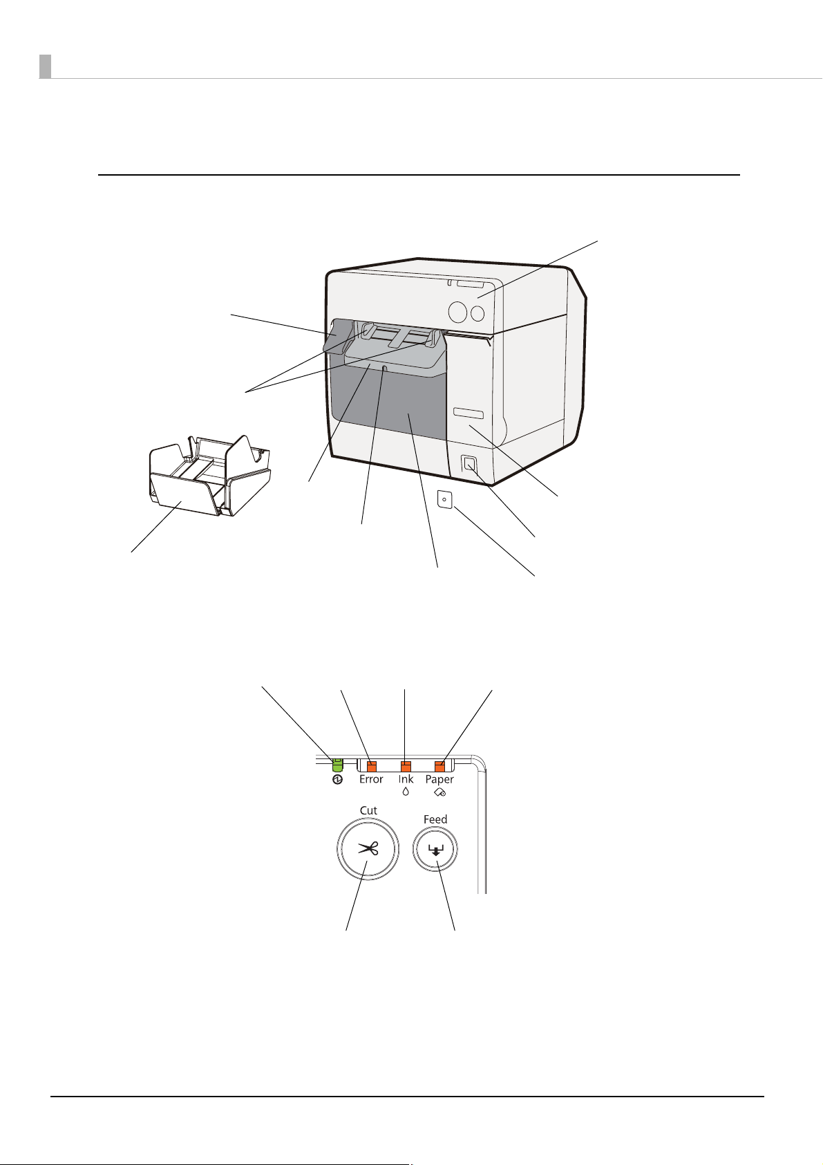
Parts Name and Function
Roll paper cover
Power switch
Paper ejection
table
Ink cartridge cover
Release lever
Paper ejection
guide
Paper ejection tray
Control panel
Paper ejection
guide lock
Power switch cover
Power LED
FEED button
Error LED Ink LED
Paper LED
CUT button
Front
Control panel
14
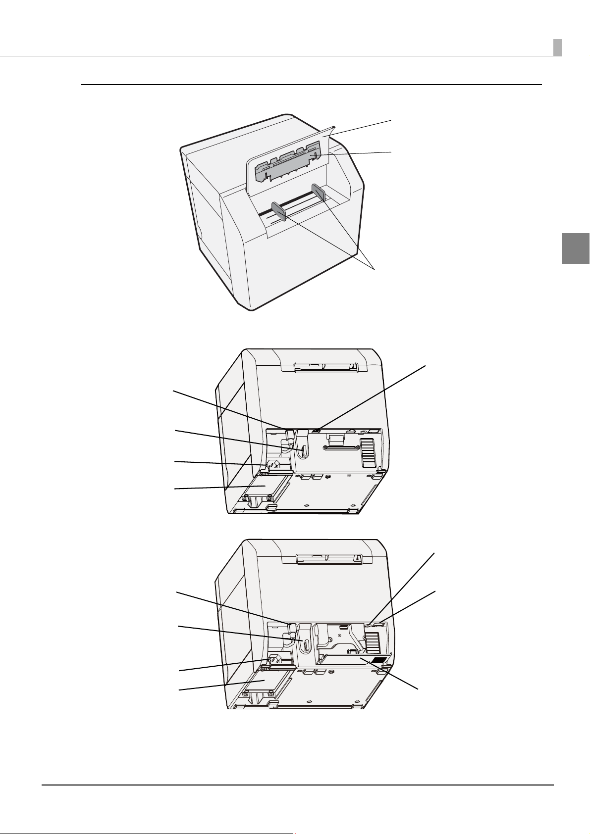
Back
Fanfold paper cover
Fanfold paper guide
Paper feed guide
Power connector
USB connector
Cable hook
Inlet (AC Adapter)
AC Adapter
Power connector
Status sheet button
Ethernet Connector
Connector cover
Cable hook
Inlet (AC Adapter)
AC Adapter
Connector (lower rear)
USB Model
Chapter 1 Product Overview
1
Ethernet Model
15
Power Switch
Before turning on the printer, be sure to check that the AC adapter is connected to the
power supply.
CAUTION
When DIP switch 1 is OFF:
• Press the POWER switch to turn ON the printer power.
• When the power is already ON, press and hold the POWER switch for approximately 3 seconds to turn the
printer power OFF.
When DIP switch 1 is ON:
When the power is already ON, press and hold the POWER switch for approximately 3 seconds to reset the
printer.
The printer power cannot be turned ON or OFF by using the POWER switch. In such cases, use the AC circuit
breaker to turn the printer power ON or OFF.
Check that the printer is not operating before turning OFF the power.
See
"Setting the DIP Switches" on page 78 for DIP switch setting.
Power Switch Cover
Attaching the power switch cover prevents accidental pressing of the power switch.
∗ To prevent the power switch from being pressed:
Attach the power switch cover as it is (without punching a hole in it).
∗ To prevent the power switch from being pressed unless a long, thin object is pressed into a hole in the power switch
cover:
Attach the power switch cover after punching a hole in it.
For details about attaching the power switch cover, see
page 102
Be sure to change the DIP switch setting when you want to attach the power switch cover
without punching a hole in it. (See
Make sure to pull out the AC cable if the printer is damaged when attaching the power
switch cover. Using it as it is may cause a fire.
.
"Setting the DIP Switches" on page 78.)
"Attaching the Power Switch Cover" on
16
WARNING

Chapter 1 Product Overview
Button
FEED button
• Feeds the paper continuously when media position detection is set to “No Detection”.
∗ The paper is fed by 15 mm if FEED button is pressed once.
∗ If the FEED button is held down, the paper is continuously fed until the button is released.
(6 seconds at a maximum)
• Feeds the paper to the print starting position when media position detection is set to “Detects Black Marks”
or “Detects Margins Between Labels”.
CUT button
• Feeds the paper to the first auto cut position on the next page and cuts the paper automatically when media
position detection is set to “No Detection”.
• Feeds the paper to the autocut position by detecting the gap between the black marks or labels and cuts the
paper automatically when media position detection is set to “Detects Black Marks” or “Detects Margins
Between Labels”.
Status sheet button (Ethernet model only)
Prints status sheet.
It is recommended to use Plain Media Roll paper with the width of 108 mm for printing the status sheet.
• The media position detection setting is set on [Maintenance And Utilities] tab on the printer
driver.
"Status Sheet Printing (Ethernet model only)" on page 191 for the status sheet.
• See
LED
POWER (power) LED: Green
1
• Lights when the power is on.
• Lights off when the power is off.
• Flashes when the printer is operating (initializing, charging ink, head cleaning, Closing roll paper cover, or
printing) or in an error state.
ERROR (error) LED: Red
• Lights or flashes when the printer is offline.
• Lights off when the printer is normal operation (online).
17
INK (ink) LED: Red
• Flashes when the ink is low or waste ink in the ink cartridge is nearly full.
• Lights when it is time to replace the ink cartridge, when the ink cartridge is not installed or is not correctly
installed, and when waste ink in the ink cartridge is full.
• Lights off when ink in the ink cartridge is adequate.
PAPER (paper out) LED: Red
• Lights when the paper is not installed or is not correctly installed.
• Lights off when the paper is correctly installed.
• The INK LED does not flash even if the ink is low when the “LED Notification Setting at Ink
Low” is set not to appear on [Notification Settings] on [Maintenance And Utilities] tab of the
printer driver.
• The printer status is also displayed with combination of lighting and flashing of LED’s. See
"Status/Error Indications" on page 19 for details.
Connectors
All cables are connected to the connector on the lower rear of the printer.
• Power connector: Connects cable of the AC adapter. Connected when shipped from the factory.
• USB Connector: Connects the printer with the host computer.
• Ethernet Connector: Connects the printer with the network.
• Inlet (AC Adapter): Connects the AC cable.
Paper ejection tray
Installing the paper ejection tray enables you to accumulate printed paper temporarily in it.
• For how to attach the paper ejection tray, see
page 100
• For maximum capacity for ejected paper of the paper ejection tray, see
on page 54
Paper may fall from the paper ejection tray due to a curl or the length of the paper.
.
.
"Attaching/Adjusting the Paper Ejection Tray" on
"Paper Ejection Tray"
18
Chapter 1 Product Overview
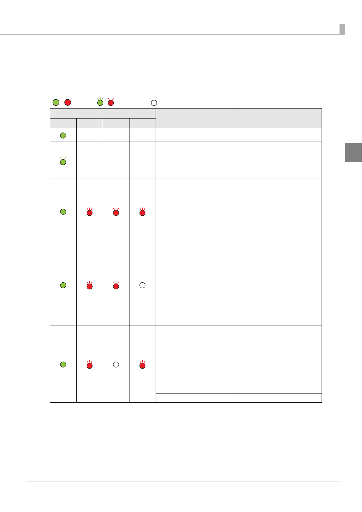
/ : Lights / : Flashes : Off —: No change
Status/Error Indications
The printer status is displayed with combination of lighting and flashing of LEDs.
When an error occurs, you can find out the cause and the remedy from the LED indication for the error.
LED
Power Error Ink Paper
———
———
Status Remedy
Power on
Powering off
Charging ink
Closing roll paper cover
Saving or printing data
The ambient temperature may be
too low or too high.
Turn OFF the printer power, and
AID temperature error
Maintenance requirement The printer needs repair.
Unrecoverable nozzle clogging
error
(Missing Dot Acceptable Print
Mode)
Fatal error
Cutter error
turn the printer ON in a location
with an ambient temperature of 10
to 35°C.
"Environmental Conditions"
(See
on page 57.
This condition occurs when
turning on the printer after a fatal
error resulting from unrecoverable
nozzle clogging. In this mode,
printing is performed even with a
missing dot. The printer needs
repair. (See
Unrecoverable Missing Dot Occurs"
on page 24.
1. Turn the power off.
2. Open the roll paper cover and
remove the jammed paper if any.
(See "Removing Jammed Paper" on
page 151.
3. Turn the power on.
If the same error persists, the
printer needs repair.
—
—
—
)
"When an
)
)
1
19
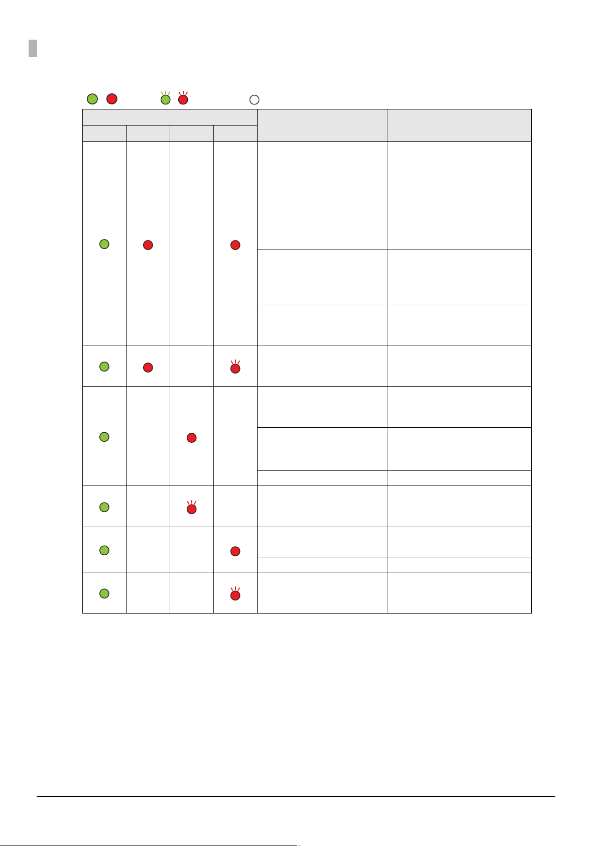
LED
/ : Lights / : Flashes : Off —: No change
Power Error Ink Paper
—
—
——
——
——
——
Status Remedy
Set specified papers. (See
"Loading/Replacing the Paper" on
page 80.)
Paper size error
Paper path error
Paper jam error
Paper type error
Ink cartridge is expended
Waste ink cartridge is full
Ink cartridge is not loaded
Ink cartridge is not loaded
correctly
Ink cartridge cover is open Close the ink cartridge cover.
Ink cartridge is running low
Waste ink cartridge is nearly full
Paper empty
Paper out error
Roll paper cover is open Close the roll paper cover.
Paper removal error
When the specified paper is not
available, cancel the print job from
the spooler. If no print job is in the
spooler, turn off and on the printer
to recover from the error.
Set DIP switch 3 setting to paper
feeding method in the printer
driver. (See
Switches" on page 78
Remove the jammed paper. (See
"Removing Jammed Paper" on
page 151.
Set specified papers. (See
"Loading/Replacing the Paper" on
page 80
Replace the ink cartridge with a
new one. (See
Cartridge" on page 145.)
Load the ink cartridge correctly.
(See
on page 145.)
The time to replace the ink
cartridge is close. Prepare a new
ink cartridge.
Set the papers. (See
Paper" on page 147
Remove the fanfold paper
remaining. (See "For Fanfold Paper"
on page 152
"Setting the DIP
)
)
.)
"Replacing the Ink
"Replacing the Ink Cartridge"
"Replacing the
.)
)
20
Chapter 1 Product Overview
Post-Printing Verification Settings
This product monitors dot missing periodically with the auto nozzle check system, and performs the auto head
cleaning if any dots are missing. Select from 6 modes that are available for different levels of requirements for
print quality and movement.
When extremely high reliability and safety are required, be sure to detect dot missing using an application in
addition to the printer driver setting. For the details, see
Required" on page 144
Sets this function from [Post-Printing Verification Settings] on [Maintenance And Utilities] of the printer
driver. The printer's Post-Printing Verification Settings can be checked using Self-test Mode. For the details, see
"Self-test Mode" on page 189.
• High Reliability Mode (Void Image Print)
Missing dots check is performed after printing each page to check that dot missing has not occurred. When
dot missing is detected, the Void Image Print is performed at the bottom of the previous page. And after the
dot missing is resolved by the auto head cleaning, reprinting starts from the corresponding page.
The Void Image is printed in solid black by default; however, other image files can also be
registered. Since dots are missing for the page on which the Void Image is printed, take proper action such as
discarding it.
.
"When Extremely High Reliability and Safety are
1
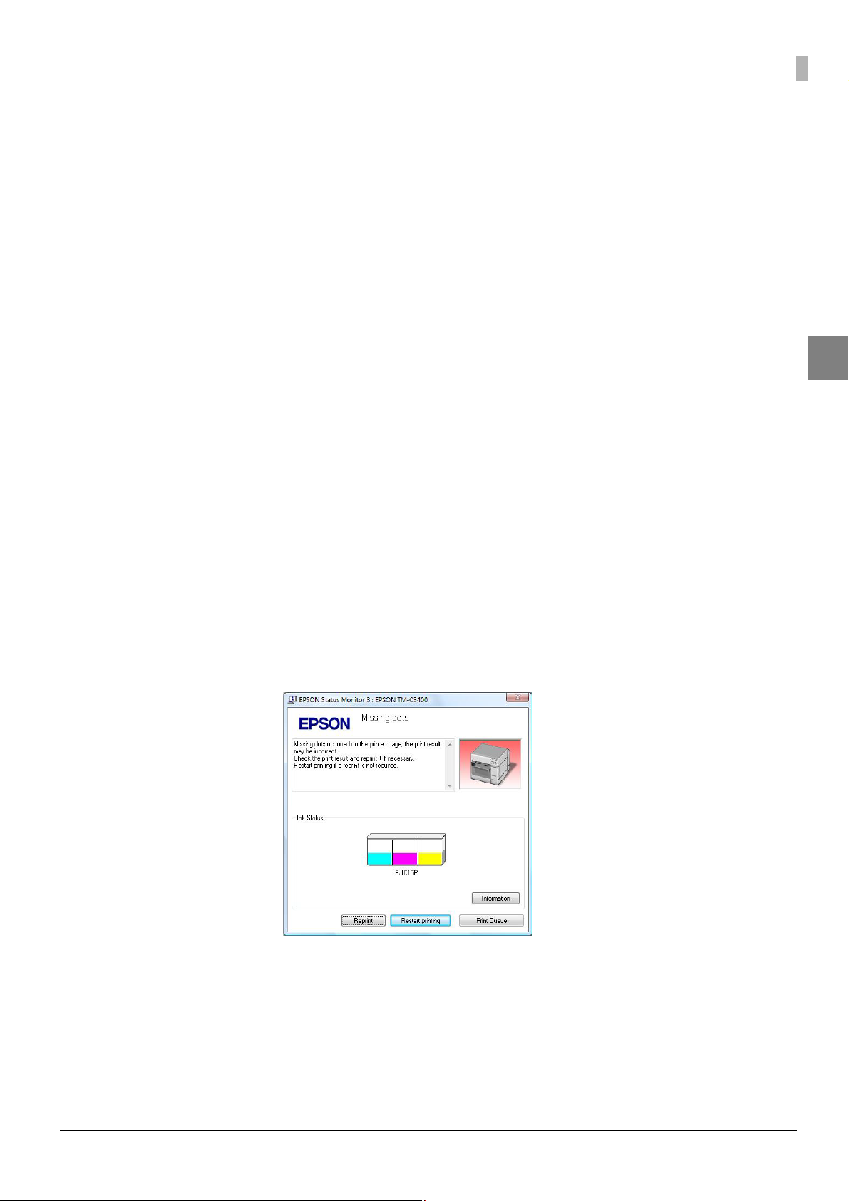
• High Reliability Mode (Reprint)
Missing dots check is performed after printing each page to check that dot missing has not occurred. When
dot missing is detected, the following screen of the EPSON Status Monitor 3 is displayed. Select the next
operation from [Restart printing] (printing the next data) and [Reprint] (reprinting after dot missing is
resolved by the auto head cleaning.)
When customer want to select this mode, do NOT uncheck [Use EPSON Status Monitor 3] of [Driver
Preferences] in [Driver Utilities] tab.
21

• Economy Mode for Low Print Volume (Void Image Print)
Missing dots check is performed after printing each page with removing the timer cleaning.
When dot missing (more than neighboring 2 dots missing) is detected, the Void Image Print is performed at
the bottom of the previous page. And after the dot missing is resolved by the auto head cleaning, reprinting
starts from the corresponding page.
The Void Image is printed in solid black by default; however, other image files can also be registered.
• Economy Mode for Low Print Volume (Reprint)
Missing dots check is performed after printing each page with removing the timer cleaning.
When dot missing (more than neighboring 2 dots missing) is detected, the EPSON Status Monitor 3 is
displayed. Select the next operation from [Restart printing] (printing the next data) and [Reprint] (reprinting
after dot missing is resolved by the auto head cleaning).
When customer want to select this mode, do NOT uncheck [Use EPSON Status Monitor 3] of [Driver
Preferences] in [Driver Utilities] tab.
• Anti-missing Read Mode
Does not perform missing dots check after printing each page, but checks missing dots while not printing.
• Anti-missing Color Mode
Does not perform missing dots check after printing each page, but checks missing dots while not printing.
The condition for preventing missing colors due to missing dots is different, depending on the firmware versions as follows:
Except firmware version AAExxxxx: Prevents missing colors due to missing dots on the condition with
adjoining 2 dots in above and below or 3 dots in all nozzles. Does not perform head cleaning to missing dots
with less than 2 dots that are not adjoining.
Firmware version AAExxxxx: Prevents missing colors due to missing dots on the condition with adjoining 3
dots in above and below or 10 dots in all nozzles.
* “x” of firmware version AAExxxxx shows any one alphanumeric character.
22
Chapter 1 Product Overview
In the High Reliability Mode or Economy Mode for Low Print Volume, printing takes more time
since the missing dots check is performed after printing each page.
Economy Mode for Low Print Volume has been added in Ver.WSN00180 or later of the printer
firmware. The firmware version can be checked using Self-test Mode. (
189)
When the printer driver’s version is Ver.1.3.0.0 or earlier, the mode cannot be changed to
Economy Mode for Low Print Volume, and the mode cannot be changed from Economy Mode for
Low Print Volume to another mode.
• These functions do not guarantee a 100 percent prevention of dot missing.
• Small amount of ink is used for detecting nozzle clogging.
• The auto head cleaning is performed automatically after nozzle clogging is detected. Ink is
expended during the head cleaning.
• Nozzle clogging detect function cannot be disabled.
• When you want to select [High Reliability Mode (Reprint)] or [Economy Mode for Low Print
Volume (Reprint)], do not uncheck [Use EPSON Status Monitor 3] of [Driver Preferences] in
[Driver Utilities] tab.
"Self-test Mode" on page
1
When an unrecoverable missing dot occurs, the printer operates differently for each mode as shown below.
High Reliability Mode
Post-Printing Verifi-
cation Settings
/ Anti-missing Read Mode
/Economy Mode for Low Print
Anti-missing Color Mode
Volume
Number of Unrecov-
erable Missing Dots
Indications
Printer Usability
1 dot 2 or more dots Except firmware version
AAExxxxx:
1 dot/2 dots except for
adjoining dots
Firmware version
AAExxxxx:
Adjoining 2 dots
/9 or fewer dots
Fatal error Maintenance
requirement
√
(Missing Dot
Acceptable Print
Mode *)
(The printer
needs repair)
X
No error (power on) Maintenance
√
Except firmware
version AAExxxxx:
Adjoining 2 dots
/3 or more dots
Firmware version
AAExxxxx:
Adjoining 3 dots
/10 or more dots
requirement
X
(The printer needs
repair)
* For details on the Missing Dot Acceptable Print Mode, refer to
on page 24.
"When an Unrecoverable Missing Dot Occurs"
23
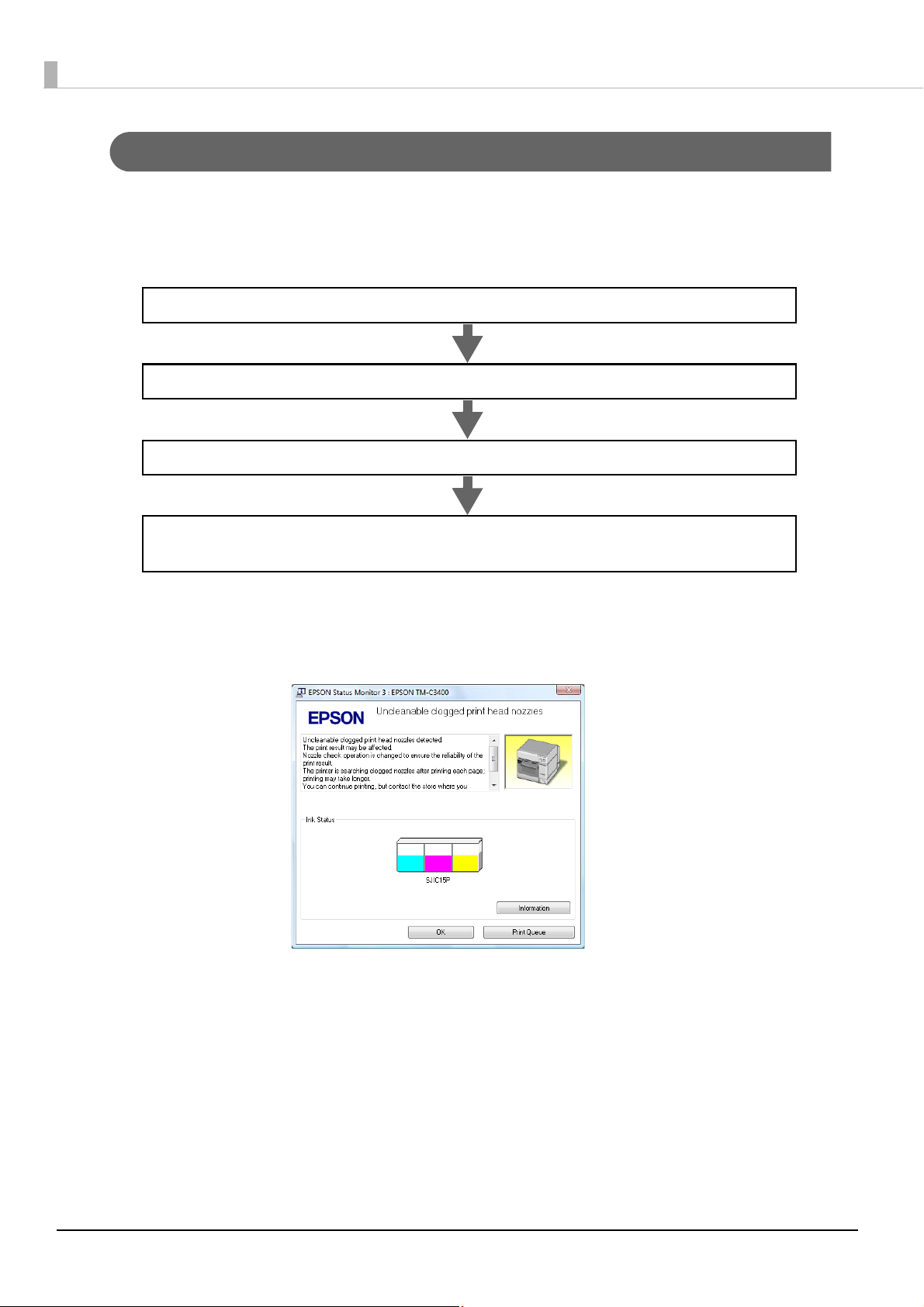
When an Unrecoverable Missing Dot Occurs
The operator turns off and on the printer.
The printer starts up in the Missing Dot Acceptable Print Mode
(LED indication: page 19)
A fatal occurs (LED indication: page 19)
Missing dots check detects an unrecoverable missing dot.
When 1 dot of unrecoverable missing dot is detected with the Post-Printing Verification Settings for the printer
driver set to the High Reliability Mode /Economy Mode for Low Print Volume /Anti-missing Read Mode, the
printer becomes in fatal error status. To continue printing, turn off and on the printer and change the mode to
the Missing Dot Acceptable Print Mode.
In the Missing Dot Acceptable Print Mode, it takes long to complete printing because missing dots check is
performed after printing each page. The EPSON Status Monitor 3 appears each time of printing until the
missing dot error is resolved. (The window may not appear depending on the printer driver version.)
24

Chapter 1 Product Overview
• The procedure to check the Missing Dot Acceptable Print Mode is different depending on the
printer driver version. See the following:
∗ Printer Driver Ver1.1.0.0 or earlier
The procedure is not displayed in the EPSON Status Monitor 3. Check the LED indication.
"Unrecoverable nozzle clogging error (Missing Dot Acceptable Print Mode)" on page 19)
(
∗ Printer Driver Ver1.2.0.0 or later
The procedure is displayed in the EPSON Status Monitor 3.
• In the Missing Dot Acceptable Print Mode, EPSON Status Monitor 3 is displayed even if [Use
EPSON Status Monitor 3] is not selected in [Driver Preferences] from the [Driver Utilities] tab.
• When 2 or more dots of unrecoverable missing dot is detected in the Missing Dot Acceptable
Print Mode, maintenance is requested and the printer needs repair.
1
25

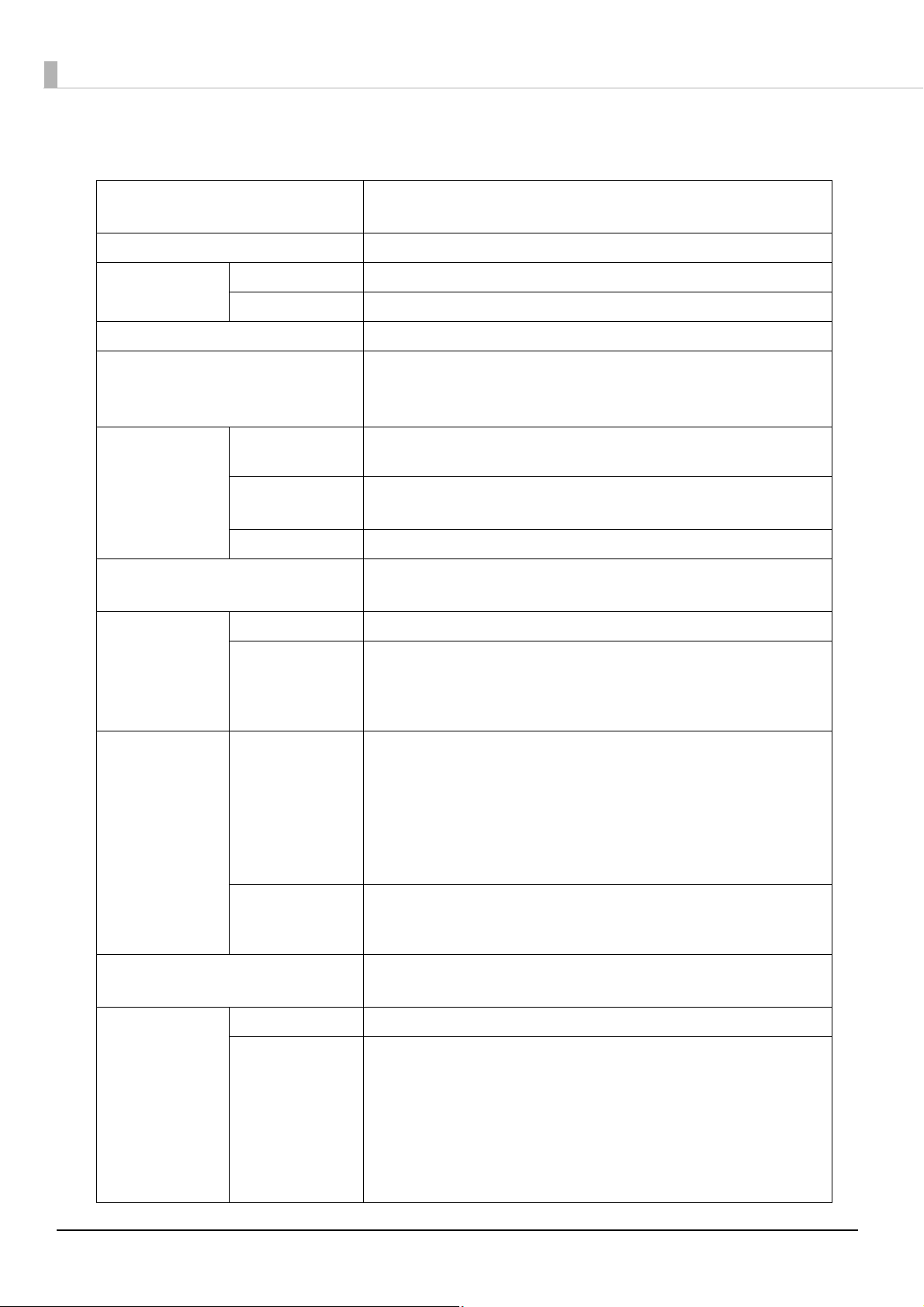
Software
Various utilities are provided to system administrators and application developers.
For details on how to get the software, see "Download" on page 135
Purpose Name Specifications
Printer Driver Installs printer driver and executes port setting.
Installing the printer
driver
Monitoring the printer EPSON Status Monitor 3
Distributing the printer
driver and setting
Easy setup
Install Assistant
Installs printer driver, executes port setting and network
setting of the printer.
Displayed on front of the application while printing. Installed
simultaneously with the printer driver, and selects from
enable or disable.
(The default setting when installed: Disable)
Creates an install package file for installing and setting the
printer driver and executing the port setting.
The computer with activating the install package file
automatically executes installing the printer driver, setting
the printer driver and executing port setting. The printer
setting is not executed.
Creates an install package for each printer for the network
printer.
.
Printer Setting
Replacing the USB model USB Replacement Service
Epson Monitoring Tool
EpsonNet Config
Administering the
network printer
WebConfig
(Function of the printer)
Executes printer setting. Creates a setting file and applies it
simultaneously to a number of printers.
“Printer Setting” can not be executed in computer without
installing the printer driver.
Service installed as a resident program on the computer
When the TM-C3400 is replaced for service or other reason,
this detects the printer connection and automatically
changes the output printer of the printer driver.
This allows the printer to be replaced without changing
settings in the application. (The printer is not replaced if a
port is specified for the application output destination. The
printer is only replaced if the printer driver is specified.)
There is no need to change the USB serial number of the TMC3400 before replacement.
The user can check status of Epson printer on network with
this. The setting can not be executed.
The user can check and executes the network printer.
Applies it simultaneously to a number of printers.
The user can execute and check the network information of
the printer by entering IP address of the printer to address bar
of the Web browser.
One printer can be set and checked.
This can not be used for the printer with default condition
since IP address is not available.
26

Chapter 1 Product Overview
Purpose Name Specifications
Developing the
application
EpsonNet SDK
Sample Program
The software development kit for monitoring the printer via
network.
This is the sample programs for using TM-C3400. (Visual Basic
.NET and Visual C++ is prepared for all programs. Visual Basic
6.0 and Visual C# is prepared for some programs.)
1
27
Product Specifications
Printing method Serial ink jet, dot matrix
Three-color (CMY) printing
Paper feed Forward and reverse friction feed
Autocutter Cutting method By separated-blade scissors
Auto-cut type Full cut
Graphic resolution 360 dpi × 180 dpi, 360 dpi × 360 dpi, 720 dpi × 360 dpi
Print speed 92 mm/s {3.82"/s} (printing width 56 mm, 360 dpi × 180 dpi)
82 mm/s {3.23"/s} (printing width 72 mm, 360 dpi × 180 dpi)
The print speed is different depending on the resolution and the printing width.
Type Plain Media, Plain Media Label, Fine Media, PET Film,
Paper
(See "Paper
Specifications" on
page 32
for details)
Classification Receipt, Black Mark Receipt, Full-page Label
Form Roll paper, Fanfold paper
Synthetic Media, Wrist Band
Die-cut Label, Black Mark Die-cut Label
Ink cartridge
"Ink Cartridge" on page 54 for details.)
(See
USB model USB 2.0 high speed
Ethernet model Ethernet (100 Base-TX/10 Base-T)
Interface
Barcode/
two-dimensional
code printing
Power supply AC 100 to 240 V
Temperatures/
humidity
"Environmental
(See
Conditions" on page
for details.)
57
Barcode
Barcode
identification rate
ANSI rank D
(based on Seiko
Epson Corporation
standard)
Two-d imen sional
code printing
Printing 10 to 35°C {50 to 95°F}, 20 to 80%RH (no condensation)
Storage When packed (ink not loaded): -20 to 60°C {-4 to 140°F},
3-color exclusive integrated ink cartridge
(Model number: SJIC15P)
USB 2.0 high speed
(For the Ethernet model, USB connection is also available. Ethernet connection
and USB connection cannot be used simultaneously.)
UPC-A, UPC-E, JAN 8 (EAN 8), JAN 13 (EAN 13), Code 39, ITF, Codabar, Code 93,
Code 128, GS1-128,
GS1 DataBar Omnidirectional, GS1 DataBar Truncated,
GS1 DataBar Limited, GS1 DataBar Expanded
PDF417, QR code, Maxi Code, S1 DataBar Stacked,
GS1 DataBar Stacked Omnidirectional,
GS1 DataBar Expanded Stacked, Composite Symbology, DataMatrix, Aztec
AC adapter PS-180
5 to 85%RH (no condensation)
-20°C or 60°C {-4°F or 140°F}: up to 120 hours
Ink loaded: -20 to 40°C {-4 to 104°F}
-20°C {-4°F}: up to 120 hours
0 to 30°C {32 to 86°F}: up to 6 months
40°C {104°F}: up to a month
28

Overall dimensions (H × W × D) 261 × 255 × 275 mm {10.27 x 10.08 x 10.82"}
(excluding protrusions)
Weight (mass) Approximately 10.0 kg {22.05 lb}
(Except for ink cartridge, roll paper, paper ejection tray)
Chapter 1 Product Overview
1
29

Hardware Requirements
OS Microsoft Windows 10 (32 bit/ 64 bit)
Microsoft Windows 8.1 (32 bit/ 64 bit)
Microsoft Windows 8 (32 bit/ 64 bit)
Microsoft Windows 7 SP1 (32 bit/ 64 bit)
Microsoft Windows Vista SP2 (32 bit/ 64 bit)
Microsoft Windows XP SP3 (32 bit)
Microsoft Windows XP SP2 (64 bit)
Microsoft Windows 2000 SP4 (32 bit)
Microsoft Windows Server 2008 R2 SP1
Microsoft Windows Server 2008 SP2 (32 bit/ 64 bit)
Microsoft Windows Server 2003 R2 SP2 (32 bit/ 64 bit)
Computer Must support the following computers that run the above operating systems.
• PC/AT compatible
CPU Computers with a processor of 1 GHz or better are recommended.
Intel Pentium/Celeron series, AMD Athlon/Duron family, or processors that are
compatible with these are recommended.
RAM 256 MB or larger is recommended
(For Windows 2000)
512 MB or larger is recommended
(For Windows 10/ Windows 8.1/ Windows 8/ Windows 7/ Windows Vista
/Windows XP /Windows Server 2008 and Windows Server 2003)
HDD Free space must be 250 MB or larger
• The minimum requirements of the above system may not satisfy the minimum requirements of the
OS. In this case, satisfy the minimum requirements of the OS.
• The printers on the network is supported up to 64 printers. In that case, if the minimum require-
ments above are not met, the printer may not be able to come up to its standard.
30

Printing Specifications
Printable area Roll paper Minimum width 26 mm {1.02”},
Maximum width 104 mm {4.09”}
Fanfold paper Minimum width 46 mm {1.81”},
Maximum width 104 mm {4.09”}
Chapter 1 Product Overview
Print speed 360 × 180 dpi
(horizontal × vertical)
360 × 360 dpi
(horizontal × vertical)
720 × 360 dpi
(horizontal × vertical)
dpi : dots per 25.4 mm (dots per inch)
Printing width 56 mm {2.20"} : 92 mm/s {3.62"/s}
72 mm {2.83"} : 82 mm/s {3.23"/s}
104 mm {4.09"} : 68 mm/s {2.68"/s}
Printing width 56 mm {2.20"} : 47 mm/s {1.85"/s}
72 mm {2.83"} : 42 mm/s {1.65"/s}
104 mm {4.09"} : 35 mm/s {1.38"/s}
Printing width 56 mm {2.20"} : 23 mm/s {0.91"/s}
72 mm {2.83"} : 21 mm/s {0.83"/s}
104 mm {4.09"} : 17 mm/s {0.67"/s}
1
31

Paper Specifications
The following is the type and the size of paper specified for this product.
When using paper other than specified paper, paper feed accuracy, barcode detection accuracy, printing quality
may be degraded or frequent paper jam may occur.
As for black mark die-cut label (synthetic media label), use paper whose outer edges are removed only on the
right and left.
Do not use the label paper with synthetic media labels on the paper backing (liner). Depending on the
temperature and humidity, the synthetic media labels and paper backing have different ratios of expansion and
contraction, and this causes the paper to curl. If the paper curls, the paper may be rubbed by the print head and
become contaminated, or the paper may jam.
Paper type Category Form Width
Receipt
(Continuous paper)
Black Mark Receipt
(Continuous paper with black marks)
Black Mark Receipt
(Continuous paper with black marks)
Full-page Label Plain Media Label
Die-cut Label Plain Media Label
Black Mark Die-cut Label
(Die-cut label with black marks)
Plain Media
Fine Media
PET Film
Plain Media
Fine Media
PET Film
Plain Media
Fine Media
PET Film
Fine Media Label
Synthetic Media Label
Fine Media Label
Synthetic Media Label
Plain Media Label
Fine Media Label
Synthetic Media Label
Roll paper 30 to 108 mm
{1.18 to 4.25"}
(Paper width)
Roll paper 30 to 108 mm
{1.18 to 4.25"}
(Paper width)
Fanfold paper 50 to 108 mm
{1.97 to 4.25"}
(Paper width)
Roll paper 25.4 to 108 mm
{1 to 4.25"}
(Label width)
Roll paper 25.4 to 108 mm
{1 to 4.25"}
(Label width)
Roll paper 25.4 to 108 mm
{1 to 4.25"}
(Label width)
Black Mark Die-cut Label
(Die-cut label with black marks)
Wrist Band Synthetic Media Roll paper 30 mm {1.18"}
Plain Media Label
Fine Media Label
Fanfold paper 46 to 108 mm
32
{1.81 to 4.25"}
(Label width)
28.6 mm
(Paper width)

Receipt
This is continuous paper.
Paper type Plain Media, Fine Media, PET Film
Form Roll paper
Paper width 30 to 108 mm {1.18 to 4.25"}
Paper thickness 0.085 to 0.151 mm {0.003 to 0.006"}
Roll paper core Outside diameter: 44.1 mm {1.74"}
External diameter Maximum 101.6 mm {4.0"}
Winding direction Printing face must be facing outside.
Do not use the paper with a hole or cutout.
Chapter 1 Product Overview
1
33

Black Mark Receipt
Perforation position
0.5 mm or more
(When using fanfold
paper)
Black mark width
Center of black marks
Black mark
length
Interval of
black marks
Center of paper width
<Back side> <Printing side>
Center of paper
width
Paper feeding
direction
Black mark
receipt
Paper type Plain Media, Fine Media, PET Film
Form Roll paper
Paper width 30 to 108 mm {1.18 to 4.25"}
Black mark width 13 mm {0.51"} or more
Black mark length 5 mm {0.19"} or more
Black mark centering position 8.5 ± 1 mm {0.33 ± 0.039"}
Black mark interval 15 to 1117.6 mm {0.59 to 44.0"}
Paper thickness 0.085 to 0.151 mm {0.0034 to 0.0059"}
Roll paper core Outside diameter: 44.1 mm {1.74"}
External diameter Maximum 101.6 mm {4.0"}
Winding direction Printing face must be facing outside.
Do not use the paper with a hole or cutout.
34

Paper type Plain Media, Fine Media, PET Film
Form Fanfold paper
Paper width 50 to 108 mm {0.2 to 4.25"}
Black mark width 13 mm {0.51"} or more
Black mark length 5 mm {0.19"} or more
Black mark centering position 8.5 ± 1 mm {0.33 ± 0.039"}
Black mark interval 15 to 304.8 mm {0.59 to 12.0"}
Paper thickness 0.119 to 0.151 mm {0.0047 to 0.0059"}
Pitch of perforated line: 203.2 to 304.8 mm {8.0 to 12.0"}
Form of perforated line Plain media : 1 mm {0.039"} uncut, 5 mm {0.19"} cut
Fine media : 1 mm {0.039"} uncut, 5 mm {0.19"} cut
PET film : 0.6 mm {0.024"} uncut, 8.4 mm {0.33"} cut
Number of folds 500 or less
Chapter 1 Product Overview
1
• Do not use the paper with a hole or cutout.
• When using fanfold paper, the black marks must be at least 0.5 mm from the perforated lines.
• Make sure to keep the same position of the black marks to the perforated lines (position that
can be detected by black mark sensor) when inserting the paper from either side in order to
use the paper inserting from reverse direction.
35

Full-page Label
Backing paper width
Label width
Edge cutoff
Edge cutoff
Backing paper
Label area
Paper type Plain Media Label, Fine Media Label, Synthetic Media Label
Form Roll paper
Backing paper width 30 to 112 mm {1.18 to 4.41"}
Label width 25.4 to 108 mm {1.0 to 4.25"}
Edge cutoff on left/right side 2 ± 0.5 mm {0.079 ± 0.02"}
Paper thickness 0.128 to 0.195 mm {0.005 to 0.008"}
Roll paper core Outside diameter: 44.1 mm {1.74"}
External diameter Maximum 101.6 mm {4.0"}
Winding direction Printing face must be facing outside.
Do not use the paper with a hole or cutout.
36

Die-cut Label
Label width
Edge cutoff Edge cutoff
Paper width
Paper width
Edge cutoff (edge)
Edge cutoff (edge)
Label length
Gap between
labels
Label length
Edge R
Edge R
Label
Gap between
labels
Label width
When removing all the fringes
When removing right and left fringes only
(Black Mark Die-cut Label)
Backing paper
Label area
Label chaff
Edge cutoff
width
Edge cutoff width
Chapter 1 Product Overview
1
Paper type Plain Media Label
Form Roll paper
Backing paper width 30 to 112 mm {1.18 to 4.41"}
Label width 25.4 to 108 mm {1.0 to 4.25"}
Label length When removing all
Gap between labels 3 to 6 mm {0.12 to 0.24"}
Edge cutoff on left/right side 2 ± 0.5 mm {0.079 ± 0.02"}
Edge cutoff width 1.5 mm {0.059"} or more
Label edge R 2 mm {0.079"} or less
Paper thickness 0.128 mm {0.005"}
Roll paper core Outside diameter: 44.1 mm {1.74"}
External diameter Maximum 101.6 mm {4.0"}
the fringes
When removing
right and left
fringes only
25.4 to 1117.6 mm {1.0 to 44.0"}
15 to 1117.6 mm {0.59 to 44.0"}
Winding direction Printing face must be facing outside.
Do not use the paper with a hole or cutout.
37

Paper type Fine Media
Form Roll paper
Backing paper width 30 to 112 mm {1.18 to 4.41"}
Label width 25.4 to 108 mm {1.0 to 4.25"}
Label length When removing all
the fringes
When removing
right and left
fringes only
Gap between labels 3 to 6 mm {0.12 to 0.24"}
Edge cutoff on left/right side 2 ± 0.5 mm {0.079 ± 0.02"}
Edge cutoff width 1.5 mm {0.059"} or more
Label edge R 2 mm {0.079"} or less
Paper thickness 0.145 mm {0.006"}
Roll paper core Outside diameter: 56.8 mm {2.24"}
External diameter Maximum 101.6 mm {4.0"}
Winding direction Printing face must be facing outside.
Do not use the paper with a hole or cutout.
25.4 to 1117.6 mm {1.0 to 44.0"}
15 to 1117.6 mm {0.59 to 44.0"}
38

Paper type Synthetic Media Label
Form Roll paper
Backing paper width 30 to 112 mm {1.18 to 4.41"}
Label width 25.4 to 108 mm {1.0 to 4.25"}
Chapter 1 Product Overview
Label length When removing all
the fringes
When removing
right and left
fringes only
Gap between labels 3 to 6 mm {0.12 to 0.24"}
Edge cutoff on left/right side 2 ± 0.5 mm {0.079 ± 0.02"}
Edge cutoff width 1.5 mm {0.059"} or more
Label edge R 2 mm {0.079"} or less
Paper thickness 0.195 mm {0.0077"}
Roll paper core Outside diameter: 44.1 mm {1.74"}, or 56.8 mm {2.24"} or more
External diameter Maximum 101.6 mm {4.0"}
Winding direction Printing face must be facing outside.
roll paper core of 44.1 mm {1.74"} or more:
50.8 to 1117.6 mm {2 to 44.0"}
roll paper core of 56.8 mm {2.24"} or more:
32 to 1117.6 mm {1.26 to 44.0"}
15 to 1117.6 mm {0.59 to 44.0"}
1
Do not use the paper with a hole or cutout.
39

Black Mark Die-cut Label
Perforation position
2 mm or more
(When using
fanfold paper)
Black mark width
Center of black marks
Black mark
length
Interval of
black marks
Center of paper
width
<Back side>
<Printing side>
Center of paper width
Paper feeding
direction
Label width
Edge cutoff Edge cutoff
Paper width
Paper width
Edge cutoff (edge)
Edge cutoff (edge)
Label length
Gap between
labels
Label length
Edge R
Edge R
Label
Gap between
labels
Label width
When removing all the fringes
When removing right and left fringes only
(Black Mark Die-cut Label)
Backing paper
Label area
Backing paper
Label area
Label chaff
Edge cutoff
width
Edge cutoff width
40

Paper type Plain Media
Form Roll paper
Backing paper width 30 to 112 mm {1.18 to 4.41"}
Label width 25.4 to 108 mm {1 to 4.25"}
Chapter 1 Product Overview
Label length When removing all
the fringes
When removing
right and left
fringes only
Gap between labels 3 to 6 mm {0.12 to 0.24"}
Edge cutoff on left/right side 2 ± 0.5 mm {0.079 ± 0.02"}
Edge cutoff width 1.5 mm {0.059"} or more
Label edge R 2 mm {0.079"} or less
Black mark width 13 mm {0.51"} or more
Black mark length 5 mm {0.19"} or more
Black mark centering position 8.5 ± 1 mm {0.33 ± 0.039"}
Black mark interval 15 to 1117.6 mm {0.59 to 44"}
Paper thickness 0.128 mm {0.005"}
Roll paper core Outside diameter: 44.1 mm {1.74"}
25.4 to 1117.6 mm {1.0 to 44.0"}
15 to 1117.6 mm {0.59 to 44.0"}
1
External diameter Maximum 101.6 mm {4.0"}
Winding direction Printing face must be facing outside.
• Do not use the paper with a hole or cutout.
• when using this type of paper, the label end and the black mark end of the black mark position on
the die-cut label must be matched.
41

Paper type Fine Media Label
Form Roll paper
Backing paper width 30 to 112 mm {1.18 to 4.41"}
Label width 25.4 to 108 mm {1 to 4.25"}
Label length When removing all
the fringes
When removing
right and left
fringes only
Gap between labels 3 to 6 mm {0.12 to 0.24"}
Edge cutoff on left/right side 2 ± 0.5 mm {0.079 ± 0.02"}
Edge cutoff width 1.5 mm {0.059"} or more
Label edge R 2 mm or less {0.079"}
Black mark width 13 mm {0.51"} or more
Black mark length 5 mm {0.19"} or more
Black mark centering position 8.5 ± 1 mm {0.33 ± 0.039"}
Black mark interval 15 to 1117.6 mm {0.59 to 44"}
Paper thickness 0.145 mm {0.0057"}
Roll paper core Outside diameter: 56.8 mm {2.24"}
25.4 to 1117.6 mm {1.0 to 44.0"}
15 to 1117.6 mm {0.59 to 44.0"}
External diameter Maximum 101.6 mm {4.0"}
Winding direction Printing face must be facing outside.
• Do not use the paper with a hole or cutout.
• when using this type of paper, the label end and the black mark end of the black mark position on
the die-cut label must be matched.
42

Paper type Synthetic Media Label
Form Roll paper
Backing paper width 30 to 112 mm {1.18 to 4.41"}
Label width 25.4 to 108 mm {1.0 to 4.25"}
Label length When removing right and left fringes only:
15 to 1117.6 mm {0.59 to 44.0"}
Gap between labels 3 to 6 mm {0.12 to 0.24"}
Edge cutoff on left/right side 2 ± 0.5 mm {0.079 ± 0.02"}
Chapter 1 Product Overview
Edge cutoff width 1.5 mm {0.059"} or more
Label edge R 2 mm or less {0.079"}
Black mark width 13 mm {0.51"} or more
Black mark length 5 mm {0.19"} or more
Black mark centering position 8.5 ± 1 mm {0.33 ± 0.039"}
Black mark interval 15 to 1117.6 mm {0.59 to 44"}
Paper thickness 0.195 mm {0.0077"}
Roll paper core Outside diameter: 44.1 mm {1.74"}
External diameter Maximum 101.6 mm {4.0"}
Winding direction Printing face must be facing outside.
• Do not use the paper with a hole or cutout.
• when using this type of paper, the label end and the black mark end of the black mark position on
the die-cut label must be matched.
1
43

Paper type Plain Media Label, Fine Media Label
Form Fanfold paper
Backing paper width 50 to 112 mm {1.97 to 4.41"}
Label width 46 to 108 mm {1.81 to 4.25"}
Label length When removing right and left fringes only:
15 to 301.8 mm {0.59 to 11.88"}
Gap between labels 3 to 6 mm {0.12 to 0.24"}
Edge cutoff on left/right side 2 ± 0.5 mm {0.079 ± 0.02"}
Label edge R 2 mm {0.079"} or less
Black mark width 13 mm {0.51"} or more
Black mark length 5 mm {0.19"} or more
Black mark centering position 8.5 ± 1 mm {0.33 ± 0.039"}
Black mark interval 15 to 304.8 mm {0.59 to 12.0"}
Paper thickness 0.145 to 0.161 mm {0.0057 to 0.0063"}
Perforated line pitch: 203.2 to 304.8 mm {8.0 to 12.0"}
Perforated line form: Plain media label : 1 mm {0.039"} uncut, 5 mm {0.19"} cut
Fine media label : 1 mm {0.039"} uncut, 5 mm {0.19"} cut
Number of folds: 500 or less
• Do not use the paper with a hole or cutout.
• When using fanfold paper, the black marks must be at least 2 mm from the perforated lines.
• when using this type of paper, the label end and the black mark end of the black mark position on
the die-cut label must be matched.
• Make sure to keep the same position of the black marks to the perforated lines (position that can
be detected by black mark sensor) when inserting the paper from either side in order to use the
paper inserting from reverse direction.
44

Wrist Band
Black mark width
Center of black marks
Black mark length
Interval of black marks
Center of paper width
<Back side>
<Printing side>
Center of paper width
Paper feeding
direction
Black mark paper
Chapter 1 Product Overview
1
Paper type Synthetic Media
Specified original paper PDC Compucolor 8000 Series 7.5 mil Rectangular Band (Code: 8000-11-
Form Roll paper
Backing paper width 8000-11-PDL: 30 mm {1.18"}
Black mark width 13 mm {0.51"} or more
Black mark length 9 mm {0.35"} or more
Black mark centering position 8.5 ± 1 mm {0.33 ± 0.039"}
Black mark interval 8000-11-PDL: 290 mm {11.42"}
Paper thickness 8000-11-PDL: 0.19 mm {0.075"}
Roll paper core Outside diameter: 56.8 mm {2.24"} or more
External diameter Maximum 101.6 mm {4.0"}
Winding direction Printing face must be facing outside.
Hole, notch Diameter: 2.5 mm {0.098"} or less
PDL)
45

Print Area and Cutting Position
Paper width
11.0 mm {0.43"} or more
15.0 mm {0.59"} or more
(When auto-cutting)
2.0 mm
{0.079"}
Auto-cut position
Auto-cut position
Paper feeding direction
Print area
Print area width
Paper
Center of paper width
2.0 mm
{0.079"}
2.0 mm
{0.079"}
2.0 mm
{0.079"}
Receipt / Roll paper
Top margin: 2.0 mm {0.079"} (typical value)
Left and right margin: 2.0 mm {0.079"} (typical value)
Bottom margin: 2.0 mm {0.079"} (typical value)
When the roll paper option is set to “Banner Mode,” a top margin is set only on the first page of
the print job, and not on the rest. A bottom margin is set on the last page of the print job.
46

Full-page Label / Roll paper
Paper width
11.0 mm {0.43"} or more
15.0 mm {0.59"} or more
(When auto-cutting)
Auto-cut position
Auto-cut position
Paper feeding direction
Print area
Label area
Center of paper width
Backing paper
Print area width
2.0 mm
{0.079"}
2.0 mm
{0.079"}
2.0 mm
{0.079"}
2.0 mm
{0.079"}
2.0 mm
{0.079"}
2.0 mm
{0.079"}
Top margin (inside the label): 2.0 mm {0.079"} (typical value)
Left and right margin (inside the label): 2.0 mm {0.079"} (typical value)
Bottom margin (inside the label): 2.0 mm {0.079"} (typical value)
Chapter 1 Product Overview
1
When the roll paper option is set to “Banner Mode,” a top margin is set only on the first page of
the print job, and not on the rest. A bottom margin is set on the last page of the print job.
47

Die-cut Label / Roll paper
Paper width
11.0 mm {0.43"}
or more
18.0 mm {0.71"} or more
(When auto-cutting)
Auto-cut position
Auto-cut position
Paper feeding direction
Print area
Label area
1.5 mm {0.06"}
1.5 mm {0.06"}
3.0 mm {0.12"}
Center of paper width
Backing paper
Print area width
2.0 mm
{0.079"}
2.0 mm {0.079"}
2.0 mm
{0.079"}
2.0 mm
{0.079"}
2.0 mm
{0.079"}
2.0 mm {0.079"}
Top margin (inside the label): 2.0 mm {0.079"} (typical value)
Left and right margin (inside the label): 2.0 mm {0.079"} (typical value)
Bottom margin (inside the label): 2.0 mm {0.079"} (typical value)
48

Black Mark Receipt / Roll paper
Paper width
11.0 mm {0.43"} or more
15.0 mm {0.59"} or more
(When auto-cutting)
Auto-cut position
Auto-cut position
Paper feeding direction
Print area
Center of paper width
Paper
Print area width
2.0 mm
{0.079"}
2.0 mm
{0.079"}
2.0 mm
{0.079"}
2.0 mm
{0.079"}
Top margin: 2.0 mm {0.079"} (typical value)
Left and right margin: 2.0 mm {0.079"} (typical value)
Bottom margin: 2.0 mm {0.079"} (typical value)
Chapter 1 Product Overview
1
49

Black Mark Receipt / Fanfold paper
Paper width
0.5 to 1.0 mm {0.02 to 0.039"}
Auto-cut position
Auto-cut position
Paper feeding
direction
Print area
Interval of perforated lines: 203.2 to 304.8 mm {8 to 12"}
Perforated line
Auto-cut position
Perforated line
Center of paper width
Paper
Print area width
2.0 mm
{0.079"}
2.0 mm
{0.079"}
2.0 mm
{0.079"}
2.0 mm {0.079"}
2.0 mm {0.079"}
2.0 mm {0.079"}
11.0 mm {0.43"}
or more
Issuing pitch: 15.0 mm {0.59"} or more
(When auto-cutting)
Top margin: 2.0 mm {0.079"} (typical value)
Left and right margin: 2.0 mm {0.079"} (typical value)
Bottom margin: 2.0 mm {0.079"} (typical value)
50

Black Mark Die-cut Label / Roll paper
Paper width
18.0 mm {0.71"} or more
(When auto-cutting)
Auto-cut position
Auto-cut position
Paper feeding direction
Print area
2.0 mm {0.079"}
Label area
1.5 mm {0.06"}
Center of paper width
Edge cutoff 2.0 mm
{0.079"}
Auto-cut position
Backing paper
Print area width
2.0 mm {0.079"}
Edge cutoff 2.0 mm
{0.079"}
2.0 mm
{0.079"}
1.5 mm {0.06"}
2.0 mm
{0.079"}
1.5 mm
{0.06"}
11.0 mm {0.43"}
or more
Top margin (inside the label): 2.0 mm {0.079"} (typical value)
Left and right margin (inside the label): 2.0 mm {0.079"} (typical value)
Bottom margin (inside the label): 2.0 mm {0.079"} (typical value)
Chapter 1 Product Overview
1
51

Black Mark Die-cut Label / Fanfold paper
Paper width
Issuing pitch: 18.0 mm or
more (When auto-cutting)
Auto-cut position
Auto-cut position
Paper feeding
direction
Print area
Label area
Perforated line
Auto-cut position
Perforated line
Center of paper width
Backing paper
Print area width
2.0 mm {0.079"}
Edge cutoff 2.0 mm
{0.079"}
2.0 mm {0.079"}
Edge cutoff 2.0 mm
{0.079"}
0.5 to 1.0 mm {0.02 to 0.039"}
2.0 mm {0.079"}
0.5 to 1.0 mm {0.02 to 0.039"}
0.5 to 1.0 mm
{0.02 to 0.039"}
0.5 to 1.0 mm
{0.02 to 0.039"}
2.0 mm {0.079"}
Interval of perforated lines: 203.2 to 304.8 mm {8 to 12"}
11.0 mm {0.43"}
or more
Top margin (inside the label): 2.0 mm {0.079"} (typical value)
Left and right margin (inside the label): 2.0 mm {0.079"} (typical value)
Bottom margin (inside the label): 2.0 mm {0.079"} (typical value)
• Make sure to adjust perforated lines to an integral multiple of issuing pitch.
• The perforated line and print area overlap each other to destabilize printing or perforated line
and the auto-cut position are misaligned to shorten the life of the autocutter if paper without
black marks is used. Use paper with black marks on the back of the paper to adjust the paper
position.
52

Wrist Band / Roll paper
Paper width
290 mm {11.42"}
Auto-cut position
Auto-cut position
Paper feeding direction
Print area
284 mm {11.18"}
Center of paper width
Paper
Print area
width
2.0 mm {0.079"}
2.0 mm {0.079"}
2.0 mm
{0.079"}
2.0 mm
{0.079"}
Top margin: 2.0 mm {0.079"} (typical value)
Left and right margin: 2.0 mm {0.079"} (typical value)
Bottom margin: 2.0 mm {0.079"} (typical value)
Chapter 1 Product Overview
1
53

Paper Ejection Tray
Black Mark
Receipt
Black Mark Diecut Label
Ink Cartridge
Paper type Plain Media, Fine Media, PET Film
Paper form Fanfold paper
Paper size Width 76 to 105 mm {2.99 to 4.13"} × length 54 to 148 mm {2.12 to 5.83"}
Paper thickness 0.119 to 0.151 mm {0.005 to 0.006"}
Paper type Plain Media, Fine Media
Paper form Fanfold paper
Paper size Width 76 to 105 mm {2.99 to 4.13"} × length 54 to 148 mm {2.12 to 5.83"}
Paper thickness 0.145 to 0.161 mm {0.0057 to 0.0063"}
• The paper ejection tray cannot store multiple sheets of roll paper.
• The paper ejection tray may not hold the paper perfectly, depending on the condition of the
paper or printing.
Model number SJIC15P
Type 3-color exclusive integrated ink cartridge
Ink color Cyan, magenta, yellow
Ink type Pigment ink
Ink life 6 months after loading to the printer, 2 years after manufacturing
Temperatures Transport -20 to 60°C {-4 to 140°F} (up to 5 days for 60°C {140°F})
Storage -20 to 40°C {-4 to 104°F} (up to a month for 40°C {104°F})
Installation -20 to 40°C {-4 to 104°F} (up to a month for 40°C {104°F})
54

Electrical Characteristics
Power supply Power supplied by AC adapter accessory
Input voltage (rated) North America / Japan: AC 100 to 125 V
Other countries: AC 100 to 240 V
Frequency (rated) 50 to 60 Hz
Chapter 1 Product Overview
Power
consumption
Operating Approximately 26 W
Stand-by Approximately 5 W
When power is OFF Approximately 0.5 W
• Use the dedicated AC adapter included in the product package.
• For the Ethernet cable, use cable with CAT5e or higher shielding.
1
55

Reliability
Life Print head 6,000 million shots/nozzle
Paper feed
mechanism
Autocutter
mechanism
1,500,000 pages or the number of pages that reaches the following paper
length fed.
• Plain Media: 150 km
• Fine Media: 75 km
• PET Film: 50 km
• Continuous label paper (Plain Media): 100 km
• Continuous label paper (Fine Media): 50 km
• Continuous label paper (Synthetic Media): 10 km
• Die-cut label (Plain Media): 150 km
• Die-cut label (Fine Media): 150 km
• Die-cut label (Synthetic Media): 50 km
• Wrist band (8000-11-PDL): 60 km
• Plain Media: 1,500,000 cuts
• Fine Media: 750,000 cuts
• PET Film: 500,000 cuts
• Continuous label (Plain Media): 750,000 cuts
(Add extra 250,000 cuts with cleaning the cutter blade)
• Continuous label (Fine Media): 500,000 cuts
• Continuous label (Synthetic Media): 100,000 cuts
• Die-cut label backing paper (Plain Media): 1,500,000 cuts
• Die-cut label backing paper (Fine Media): 1,500,000 cuts
• Die-cut label backing paper (Synthetic Media): 500,000 cuts
• Wrist band (8000-11-PDL): 200,000 cuts
Carriage
mechanism
MTBF 75000 hours
MCBF 9,800,000 passes
6 million passes (3 million carriage returns)
Maintenance is requested when it reaches 20,000,000 passes (the printer will
stop)
(For details on the LED lighting/flashing patterns when maintenance is
requested, see
"Status/Error Indications" on page 19.)
56

Environmental Conditions
Humidity (%)
Temperatures (°C)
Item Specification
Chapter 1 Product Overview
Temperatures/
humidity
Pressure
(elevation)
Printing 10 to 35°C {50 to 95°F}, 20 to 80%RH (no condensation)
80
55
20
10
Barcode printing 15 to 35°C {59 to 95°F}, 20 to 80%RH (no condensation)
Storage When packed (ink not loaded): -20 to 60°C {-4 to 140°F},
5 to 85%RH (no condensation)
-20°C or 60°C {-4°F or 140°F}: up to 120 hours
Ink loaded: -20 to 40°C {-4 to 104°F}
-20°C {-4°F}: up to 120 hours
0 to 30°C {32 to 86°F}: up to 6 months
40°C {104°F}: up to a month
Operating 700 to 1060 hPa (approximately 0 to 2500 m above sea level)
Not operating
(including in
transportation)
700 to 1060 hPa (approximately 0 to 2500 m above sea level)
27
35
1
Acoustic noise During operation
(including using
the autocutter)
Approximately 54 dB (ANSI Bystander position)
(Based on Epson evaluation conditions including the use of the
autocutter)
57

External Dimensions
[Unit: mm]
300 {11.81"}
255 {10.4"}
261
{10.27"}
300 {11.81"}
275 {10.83"}
457 {17.99"} (when the paper ejection tray is stretched)
388 {15.28"} (when the paper ejection tray is folded)
• Height: 261 mm {10.27"}
• Width: 255 mm {10.4"}
• Depth: 275 mm {10.83"}
58

Power Supply Unit (PS-180)
[Unit: mm]
68
{2.68"}
136 {5.35"}
32 {1.26"}
Electric characteristics Input conditions Input voltage (rated): AC 100 to 240 V
Frequency (rated): 50 to 60 Hz
Chapter 1 Product Overview
1
Power consumption (rated): 100 VA
Output conditions Output voltage (rated): DC 24 V
Output current (rated): 2.0 A
Output electric power (rated): 48 VA
Output peak current: 4.5 A
Case specifications Dimensions
(H × W × D)
Weight Approximately 0.4 kg {0.88 lb} (excluding the AC cable)
Color Black (matte)
68 × 136 × 32 mm {2.68 × 5.35 × 1.26"}
(excluding protrusions)
Material
No specific brominated flame retardants, such as PBBE and PBB, are used in this product.
AC cable selection
Select an AC cable that satisfies the following conditions.
• Safety standard product
•Plug with PE terminal
Ground connections
Be sure to ground for safety
59

Restrictions
Printer environment
• Drivers for TM printers EPSON Advanced Printer Driver (APD), EPSON OPOS ADK (OPOS), EPSON
OPOS ADK for .NET (OPOS for .NET), and EPSON JavaPOS ADK (JavaPOS) of Seiko Epson Corporation
cannot be used for this product.
The TM-C3400 printer driver can be installed and used on a computer with the APD, OPOS, OPOS for
.NET, and JavaPOS installed.
Installation environment for the printer driver
• The printer driver for Ethernet model cannot be installed with a USB model printer connected.
In this case, turn off the USB model printer before installing the printer driver for Ethernet model.
• When the printer driver is installed using point and print, printing can be performed but obtaining the
printer status can not be executed.
• When setting the printer driver using point and print, setting may be made by accessing the server via a network. Be sure to make the setting with the printer connected.
• When using shared printer and local printer on one client computer, install the printer driver for the local
printer before installing the printer driver for the shared printer.
• When using this product in the same environment as a version of the APD earlier version than APD 4.03,
Install the APD first, and then install the printer driver for this product.
Install package of the printer driver
• When the printer driver is installed using the install package of the USB model, the status of other computers
on the network cannot be acquired, even if the setting for sharing this printer is made. And the status cannot
be acquired with the EPSON Status Monitor 3 or other applications; however, printing is possible. To avoid
the limitations, install the printer driver without using the install package, and make the settings.
• The settings of [Monitoring Preferences] in [Driver Utilities] tab is not reflected for the install package. The
default setting is the error display of the EPSON Status Monitor 3 (Notifies when printing is impossible and
maintenance is requested.) When changing the setting, make the setting for each installation environment.
• In a Windows 2000 environment, if the printer driver can not be installed when the install package is executed, it is possible that the printer is registered as an “Unknown device”. Delete the “Unknown device” and
then execute the install package.
("Printer Driver cannot be Installed (Windows 2000)" on page 211)
• In a Windows 2000 environment, if the TM-C3400 printer driver is already installed and the version is different from the version of the printer driver of the install package, the settings of the existing printer driver may
change. (This does not affect other printer drivers that are not for the TM-C3400.)
To keep the existing settings, you must save the settings before executing the install package, and then restore
the settings after the install package is executed. (
page 211
)
"Printer Driver is Already Installed (Windows 2000)" on
Paper
• When using a full-page label, remove the ejected label each time the printing is finished. Otherwise, a part of
printed label may be cut, or a cutter error may occur. (See "Status/Error Indications" on page 19.)
60

Chapter 1 Product Overview
• When cutting the full-page label, adhesive from labels may stick to the fixed blade of the autocutter, which
may prevent the autocutter from cutting paper cleanly. If this happens, clean the cutter blade. For details, see
"Cleaning the Autocutter" on page 194.
Turning on/off the power switch
• If you turn the printer off without using the power switch, the print head may not return to its home position.
In this case, the next time the printer is turned on, auto head cleaning is performed, which wastes ink.
Printing
• For the USB model, it takes time for the next printing if you turn the printer off and on after printing.
• The ink cartridge contains 3 colors of ink. Even when one particular color is specified, all 3 colors of ink are
used for printing and for keeping the print head in good condition. When the ink level of even one color
reaches the lowest limit, the printer stops printing.
• The colors of printouts may become abnormal if you tilt this product or subject the printer to any shocks.
When you move this product after ink charging, check the colors by performing a test print.
If the colors of printouts are not normal, perform head cleaning. See
for how to perform head cleaning.
"Manual Head Cleaning" on page 192
1
• When printing image data, white lines (lines shown in white) or black lines (overlapping of image) may
appear at about 1 inch intervals in the print result. By setting [Print Head Alignment] - [Media Feed Adjust-
ment] in [Maintenance And Utilities] tab, this can be reduced but cannot be removed completely.
• When printing image data, change of color tone may appear at 1 inch intervals in the print result.
61

62

Setup
This chapter describes setup and installation of the product and peripherals.
When You Use This Product for the First Time
Do not turn on the printer power until installation of the printer driver is completed.
Ink charging and media position detection setting are necessary before you use this product for the first
time.
Follow the steps below.
Load the roll paper.
1
For details, see Loading/Replacing the Roll Paper on page 80.
Chapter 2 Setup
2
Turn on the printer.
2
Load a new ink cartridge.
3
For details, see Loading/Replacing the Ink Cartridge on page 67.
• Ink charging starts after the ink cartridge cover is closed.
• When the ink cartridge is installed for the first time, the printer takes
approximately 8 minutes for ink charging.
The POWER LED flashes during ink charging. Do not turn off
the printer or open the roll paper cover or the ink cartridge cover.
If the power is turned off, the roll paper cover is opened, or the
ink cartridge cover is opened during ink charging, ink charging
will restart from the beginning and an extremely large amount of
ink will be consumed.
• When ink charging finishes, the POWER LED stops flashing and stays on.
Set the media position detection of the printer for the paper type you will be using.
4
For details, see 2. Setting for media position detection on page 83.
• The colors of printouts may become abnormal if you tilt this product or subject the printer to
any shocks. When you move this product after ink charging, check the colors by performing a
test print.
• If the colors of printouts are not normal, perform head cleaning. See
on page 192
• If you turn the printer off without using the power switch, the print head may not return to its
home position. In this case, the next time the printer is turned on, the auto head cleaning is
performed, which wastes ink.
for how to perform head cleaning.
Manual Head Cleaning
63

Flow of Setup
3. Loading/Replacing the Ink Cartridge (page 67)
7. Loading/Replacing the Paper (page 80)
6. Setting the DIP Switches (page 78)
4. Connecting the Printer to the Host Computer (page 69)
5. Installing the Driver (page 71)
2. Connecting the Power Supply Unit (PS-180) (page 66)
8. Attaching/Adjusting the Paper Ejection Tray (page 100)
1. Installing the Printer (page 65)
9. Attaching the Power Switch Cover (page 102)
10. Setting the Printer Driver (page 104)
This chapter consists of the following sections along with the setup flow of the product and peripherals.
64

Installing the Printer
261
255
275
[Unit: mm]
100
Install the printer in an appropriate location with sufficient space around it.
Important Notes on Installation
Chapter 2 Setup
2
• The printer must be installed horizontally.
• Leave enough space in front of the printer for the ink cartridge cover and the roll paper cover to be fully
opened.
• Do not place the printer in a dusty location.
• Protect the printer from heavy impacts. They may cause defective print.
• Do not allow cables to get caught or foreign matter to accumulate under the printer.
• Make sure that there is at least 100 mm of space behind the printer back when installing.
• Do not put a heavy object (of 10 kg or more) or an object that vibrates on the printer.
65

Connecting the Power Supply Unit (PS-180)
Use the specified AC adapter PS-180 as the power source.
• Be sure to use the specified AC adapter only.
Using a nonstandard power supply can result in electric shock or fire.
WARNING
Use the AC cable that meets safety standards of each country.
Connecting the AC Cable
Make sure the printer is off.
1
Insert the connector of the AC cable into the inlet of the AC adapter.
2
Insert the power plug of the AC cable into the wall socket.
3
• Should a fault ever occur in the AC adapter, immediately turn off the power to the printer and
remove the power supply cable from the wall socket.
66
CAUTION
• Be sure to remove the AC cable from the wall socket whenever connecting or disconnecting the AC cable to the printer.
Failure to do so may result in damage to the AC adapter or the printer.
• Make sure the wall socket power supply satisfies the rated voltage requirements of the
AC adapter. Never insert the AC cable into a socket that does not meet the rated voltage
requirements of the AC adapter.
Doing so may result in damage to both the AC adapter and the printer.

Loading/Replacing the Ink Cartridge
• When the ink cartridge is installed for the first time, be sure to install the roll paper first, and
turn on the printer, and then install the ink cartridge. See
for how to load the roll paper.
page 80
• Always use the Epson SJIC15P as the ink cartridge.
• Do not open the package of the ink cartridge until you are ready to load it in the printer.
Load the roll paper included in the product package.
1
See Loading/Replacing the Roll Paper on page 80 for details.
Pull down the ink cartridge cover to the front to open it.
2
Chapter 2 Setup
Loading/Replacing the Roll Paper on
2
Remove the used ink cartridge if any.
3
Shake new ink cartridge package 4 or 5 times before opening it and take out the ink car-
4
tridge from the package.
Push the ink cartridge gently into the cartridge holder as shown below.
5
Insert with the arrowed side up.
67

Close the ink cartridge cover.
6
When the ink cartridge is loaded for the first time, it takes approximately 8 minutes for ink charging. Do
not open the roll cover or the ink cartridge cover of the printer, or press the Power switch or the FEED
button.
The INK LED (red) turns off.
The POWER LED (green) starts flashing when the ink charge starts. Charging is finished when the
POWER LED flashing becomes lighting.
• When the ink cartridge is loaded for the first time, the printer uses ink to prepare for printing
(initial ink charge), therefore, the first replacement period is shorter than normal.
• Ink consumption differs, depending on printer conditions, such as printing and cleaning.
• To maintain the quality of print head, the INK LED lights before using up all the ink even some
ink remains in the cartridge.
Turn the printer on.
7
If you turn the printer off without using the power switch, the print head may not return to its
home position. In this case, the next time the printer is turned on, the auto head cleaning is
performed, which wastes ink.
68

Chapter 2 Setup
Cable hook: Prevents cable from coming unplugged.
Connecting the Printer to the Host Computer
For USB Model
Connect this product to the host computer by the USB cable.
• Do not turn the power on until the printer driver is installed.
• Make sure to use the USB cable included with the printer.
Insert the USB cable to the USB connector on the lower rear of the printer and arrange it as shown below.
Make sure to put the USB cable through the cable hook as shown in the figure below to prevent the cable from
coming unplugged.
2
69

For Ethernet Model
Cable hook: Prevents cable from coming unplugged.
Connect this product to a network by a LAN cable via a hub.
• When LAN cables are installed outdoors, make sure devices without proper surge protection are cushioned by being connected through devices that do have surge protec-
CAUTION
Open the connector cover on the rear of the printer.
1
Connect a LAN cable to the LAN connector by pressing firmly until the connector clicks
2
into place and arrange it as shown below.
Make sure to put the USB cable through the cable hook as shown in the figure below to prevent the cable
from coming unplugged.
tion.
Otherwise, the devices can be damaged by lightning.
• Never attempt to connect the standard telephone line cable to the LAN connector.
70
Close the connector cover.
3

Installing the Driver
The following two methods can be selected when installing the printer driver.
• Installation using Easy setup:
Described in this manual.
• Installation from the printer driver file:
Not described in this manual. Execute the installer of the printer
driver, and follow the instructions on the screen to install the printer
driver.
For Ethernet model whose network setting has not changed from the
factory default value, make such settings as the IP address using the
EpsonNet Config, to enable the IP communication.
Installation using Easy setup
Chapter 2 Setup
[Easy setup] makes it easy to install the printer driver and set the network (for Ethernet model).
• Make sure to logon as an administrator to install the printer driver.
• More than one printer cannot be set up by [easy setup]. Use [EPSONNetConfig] for setting up
more than one printer on the network.
• For information on how to use the printer driver, see
154.
Installation procedure is different between USB Model and Ethernet Model.
•For USB Model (see
•For Ethernet Model (see page 73)
page 71)
How to Use the Printer Driver on page
For USB Model
Follow the steps below to install the printer driver.
Double-click the icon for Easy Setup “EPSetup.exe”.
1
2
71

Click [Local] for USB model.
2
Click [Install].
3
Make sure of the connection to the computer when the following window appears, then
4
turn the power on.
Click [Exit].
5
This is the end of driver installation.
72

For Ethernet Model
When the network setting such as IP address setting on TM-C3400 was already made, the setting
is applied. The setting can not be changed.
Follow the steps below to install the printer driver and execute the network setting.
Turn the printer on.
1
Double-click the icon for Easy Setup “EPSetup.exe”.
2
Click [Network] for Ethernet Model.
3
Chapter 2 Setup
2
Click [Install].
4
73

The printers available are displayed. Select the printer to install,
5
and click [Next].
When the IP address was already set in the printer, go to step 9.
The method for acquiring IP address is displayed. Select the method you want to take,
6
and click [Next].
When you select “Manual”, enter the IP address.
74

Checking the settings is displayed. If the settings are correct, click [Next].
7
If you want to change IP address setting, click [Back].
Chapter 2 Setup
2
Completed notice of the communication setting is displayed. Click [Next].
8
75

Enter the Printer Name and click [Next].
9
Do not check the box of [Print test page].
Select which installed printer driver to use as a default printer, and click [Next].
10
The printer driver will be installed after clicking [Next].
76

Click [Finish].
11
It terminates “EpsonNet EasyInstall”.
Chapter 2 Setup
2
Click [Exit].
12
This is the end of driver installation and network setting.
77

Setting the DIP Switches
Change the DIP switch settings in the following cases.
• When attaching the power switch cover to prevent the power switch from being pressed
• When switching the paper type between roll paper and fanfold paper (The default setting is roll paper)
• When changing the volume of the buzzer
Setting Procedure
Follow the steps below to change the DIP switch settings.
Turn the power off before removing the DIP switch cover.
Otherwise, a short-circuit may cause the printer to malfunction.
CAUTION
DIP switch setting becomes enabled after turning the power on or completing reset by the
interface.
Make sure the power supply for the printer is turned off.
1
Open the ink cartridge cover and remove the DIP switch cover.
2
Set the DIP switches, using the tip of a tool, such as a small screwdriver.
3
Attach the DIP switch cover, and close the ink cartridge cover.
4
78

Function of the DIP Switches
Chapter 2 Setup
SW Function ON OFF
1 Operation of the power switch Reset Power ON/OFF OFF
2 Internal use Fixed to OFF (Do not change) OFF
3 Paper selection Fanfold paper Roll paper OFF
7 Internal use Fixed to OFF (Do not change) OFF
8 Buzzer volume High Low OFF
When attaching the power switch cover to prevent the power switch to be pressed, set DIP
switch 1 to ON.
Fac tory
settings
2
79

Loading/Replacing the Paper
3. Removing the paper feed guide (page 84)
4. Adjusting roll paper guide/paper ejection guide (page 85)
5. Loading the paper and turning on the printer (page 88)
2. Setting for media position detection (page 83)
1. Removing the paper (page 81)
Follow the steps below to load the paper for the first time, change classification or type of the paper (roll paper
or fanfold paper) or replace the paper.
Loading the paper is different depending of the type of the paper to use roll paper or fanfold paper.
• For roll paper/ wrist band, see Loading/Replacing the Roll Paper on page 80
• For fanfold paper, see
Loading/Replacing Fanfold Paper on page 90.
• Use paper that meets the printer specification. For details about paper specification, see Paper
Specifications on page 32.
• When exchanging paper without changing paper type, media position detection, or paper
width, see
Paper Specifications on page 32.
Loading/Replacing the Roll Paper
Follow the steps below to load the roll paper/ wrist band.
• Loading the paper for the first time: 2 to 5
• Using up the paper completely (loads same type of paper): 1, 5
• Changing paper type or classification: 1 to 5
.
80
Before loading or replacing the roll paper, make sure that the DIP switch 3 (paper selection) setting
is OFF (roll paper). See
Setting the DIP Switches on page 78
for DIP switches settings.

1. Removing the paper
This procedure is not required when the paper is initially loaded to the printer.
For roll paper
Press down the release lever, and pull it to the front to open the roll paper cover.
1
Remove the roll paper or the roll paper core if any.
Chapter 2 Setup
2
Close the roll paper cover.
2
81

For fanfold paper
Open the fanfold paper cover.
1
Remove the remaining paper.
2
82

2. Setting for media position detection
This procedure is not required when media position detection is not changed.
When paper remains in the printer, media position detection cannot be set.
Be sure to remove the paper before turning on the printer.
Turn the power on.
1
Remove the paper in the printer.
2
Display the printer driver window. (See How to Use the Printer Driver on page 154 for
3
how to display the driver window.)
Change [Media position detection] on [Maintenance And Utilities] tab of the printer
4
driver depending on the paper to use.
Roll paper type Media position detection setting
Chapter 2 Setup
2
Receipt/Full-page Label/Transparent Full-page Label Not applied
Black Mark Die-cut Label Detects black marks of die-cut label
Black Mark Receipt/Wrist Band Detects black marks of receipt
Die-cut Label/Black Mark Die-cut Label
/Transparent Die-cut Label
Turn the power off.
5
The changed setting of the media position detection is saved in the NV memory of the printer
when the printer is turned off. Be sure to turn off the printer to enable the setting.
Detects the gap between labels
83

3. Removing the paper feed guide
This procedure is not required when the paper is initially loaded to the printer or the paper type is not changed
(roll paper/fanfold paper).
Attach the paper feed guide to the printer only when using the fanfold paper. Be sure to remove
the paper feed guide when using the roll paper.
Press down the release lever, and pull it to the front to open the roll paper cover.
1
If the paper feed guide is attached into the grooves inside of the roll paper cover,
2
remove it.
84
Close the roll paper cover.
3

4. Adjusting roll paper guide/paper ejection guide
This procedure is not required when paper width is not changed.
Press down the release lever, and pull it to the front to open the roll paper cover.
1
Chapter 2 Setup
Unlock the roll paper guide.
2
Push the paper guide on the left in the direction of the arrow, and load the roll paper
3
with the printing side up.
2
85

Lock the roll paper guide.
4
Release the lock of the paper ejection guide with a fine-tipped object.
5
Align the paper ejection guide with the roll paper width.
6
86

Lock the paper ejection guide.
7
Close the roll paper cover.
8
Chapter 2 Setup
2
87

5. Loading the paper and turning on the printer
Steps 1 to 3 below are not necessary after performing Step 4. Adjusting roll paper guide/paper ejection guide on
page 85
1
2
.
Press down the release lever, and pull it to the front to open the roll paper cover.
Load the roll paper with the printing side up.
88

Close the roll paper cover while aligning the roll paper with the paper ejection guide.
3
Turn the power on.
4
The roll paper is automatically fed.
When paper set operation at the roll paper cover close is set as “Media Loading Method (with
Cutting)” of [Media Loading Settings] on [Maintenance And Utilities] tab on the printer driver,
paper is automatically cut after the paper is fed.
Chapter 2 Setup
2
This is the end of loading of the roll paper.
89

Loading/Replacing Fanfold Paper
3. Attaching the paper feed guide (page 94)
4. Adjusting paper ejection guide/fanfold paper guide (page 96)
5. Loading the fanfold paper and turning on the printer (page 98)
2. Setting for media position detection (page 93)
1. Removing the paper (page 91)
Follow the steps below to load the fanfold paper.
• Loading the paper for the first time: 2 to 5
• Using the paper completely (loads same type of paper): 1, 5
• Changing paper type or classification: 1 to 5
Make sure that the DIP switch 3 (paper selection) setting is ON (fanfold paper) before loading or
replacing the fanfold paper. See
Setting the DIP Switches on page 78 for DIP switches settings.
90

1. Removing the paper
This procedure is not required when the paper is initially loaded to the printer.
For roll paper
Press down the release lever, and pull it to the front to open the roll paper cover.
1
Remove the roll paper or the roll paper core if any.
Chapter 2 Setup
2
Close the roll paper cover.
2
91

For fanfold paper
Open the fanfold paper cover.
1
Remove the paper left.
2
92
2. Setting for media position detection
This procedure is not required when media position detection is not changed.
• When paper remains in the printer, media position detection cannot be set.
Be sure to remove the paper before turning on the printer.
• The changed setting of the media position detection is saved in the NV memory of the printer
when the printer is turned off. Be sure to turn off the printer to enable the setting.
Turn the power on.
1
Remove the paper in the printer.
2
Display the printer driver window. (See How to Use the Printer Driver on page 154 for
3
how to display the driver window.)
Chapter 2 Setup
Change [Media Position Detection] on [Maintenance And Utilities] tab of the printer
4
driver depending on the paper to use.
Paper type to use Media position detection setting
Black Mark Die-cut Label Detects black marks of die-cut label
Black Mark Receipt Detects black marks of receipt
Black Mark Receipt/Wrist Band Detects black marks of receipt
Die-cut Label/Black Mark Die-cut Label
/Transparent Die-cut Label
Turn the power off.
5
Detects the gap between labels
2
93

3. Attaching the paper feed guide
This procedure is not required when paper type (roll paper/fanfold paper) is not changed.
Make sure to attach the paper feed guide when using fanfold paper.
Open the fanfold paper cover and take out the paper feed guide.
1
Press down the release lever, and pull it to the front to open the roll paper cover.
2
94
Insert the paper feed guide into the grooves inside of the roll paper cover to attach it.
3

Close the roll paper cover.
4
Chapter 2 Setup
2
95

4. Adjusting paper ejection guide/fanfold paper guide
This procedure is not required when paper type (roll paper/fanfold paper) is not changed.
Release the lock of the paper ejection guide with a fine-tipped object.
1
Slide the paper ejection guide as wide as possible.
2
Lock the paper ejection guide.
3
96

Open the fanfold paper cover and release the lock of the fanfold paper guide.
4
Align the fanfold paper guide with the fanfold paper width.
5
Chapter 2 Setup
2
Lock the fanfold paper guide.
6
97

5. Loading the fanfold paper and turning on the printer
40 mm
Turn the power on.
1
After the Power LED stops flashing and lights, insert the paper into the paper slot with
2
the print surface facing upward until it is pulled into inside the printer (approximately
100 mm). The paper is automatically fed.
When paper set operation at the roll paper cover close is set as “Media Loading Method (with
Cutting)” of [Media Loading Settings] on [Maintenance And Utilities] tab on the printer driver,
paper is automatically cut after the paper is feed.
Place the paper straight at least 40 mm from the printer.
3
98

Close the fanfold paper cover.
4
This is the end of loading of the fanfold paper.
Chapter 2 Setup
2
99

Attaching/Adjusting the Paper Ejection Tray
If you attach the paper ejection tray, you can temporarily store the printed paper in the tray.
Follow the steps below to install/adjust the ejection tray.
• Paper may not stay in the paper ejection tray depending on the paper curl and length.
• When the fanfold paper is used, the several printed papers can be stored in the ejection tray.
See Paper Ejection Tray on page 54
the ejection tray.
Attach the paper ejection tray to the hooks under the paper ejection table.
1
for the numbers of the fanfold paper that can be stored in
Pull the lever at the bottom-right of the paper ejection tray to unlock it.
2
Slide the bottom tray to align it with the paper length.
3
100
 Loading...