

Page 1
SERVICE MANUAL
Color Inkjet Printer
EPSON Stylus Photo R240/R245/R250
EPSON ME PHOTO 20
SEIJ05011
Page 2

PRECAUTIONS
Precautionary notations throughout the text are categorized relative to 1)Personal injury and 2) damage to equipment.
DANGER Signals a precaution which, if ignored, could result in serious or fatal personal injury. Great caution should be exercised in performing
procedures preceded by DANGER Headings.
WARNING Signals a precaution which, if ignored, could result in damage to equipment.
The precautionary measures itemized below should always be observed when performing repair/maintenance procedures.
DANGER
1. ALWAYS DISCONNECT THE PRODUCT FROM THE POWER SOURCE AND PERIPHERAL DEVICES PERFORMING ANY MAINTENANCE OR
REPAIR PROCEDURES.
2. NO WORK SHOULD BE PERFORMED ON THE UNIT BY PERSONS UNFAMILIAR WITH BASIC SAFETY MEASURES AS DICTATED FOR ALL
ELECTRONICS TECHNICIANS IN THEIR LINE OF WORK.
3. WHEN PERFORMING TESTING AS DICTATED WITHIN THIS MANUAL, DO NOT CONNECT THE UNIT TO A POWER SOURCE UNTIL INSTRUCTED
TO DO SO. WHEN THE POWER SUPPLY CABLE MUST BE CONNECTED, USE EXTREME CAUTION IN WORKING ON POWER SUPPLY AND
OTHER ELECTRONIC COMPONENTS.
4. WHEN DISASSEMBLING OR ASSEMBLING A PRODUCT, MAKE SURE TO WEAR GLOVES TO AVOID INJURIER FROM METAL PARTS WITH
SHARP EDGES.
WARNING
1. REPAIRS ON EPSON PRODUCT SHOULD BE PERFORMED ONLY BY AN EPSON CERTIFIED REPAIR TECHNICIAN.
2. MAKE CERTAIN THAT THE SOURCE VOLTAGES IS THE SAME AS THE RATED VOLTAGE, LISTED ON THE SERIAL NUMBER/RATING PLATE. IF
THE EPSON PRODUCT HAS A PRIMARY AC RATING DIFFERENT FROM AVAILABLE POWER SOURCE, DO NOT CONNECT IT TO THE POWER
SOURCE.
3. ALWAYS VERIFY THAT THE EPSON PRODUCT HAS BEEN DISCONNECTED FROM THE POWER SOURCE BEFORE REMOVING OR REPLACING
PRINTED CIRCUIT BOARDS AND/OR INDIVIDUAL CHIPS.
4. IN ORDER TO PROTECT SENSITIVE MICROPROCESSORS AND CIRCUITRY, USE STATIC DISCHARGE EQUIPMENT, SUCH AS ANTI-STATIC
WRIST STRAPS, WHEN ACCESSING INTERNAL COMPONENTS.
5. REPLACE MALFUNCTIONING COMPONENTS ONLY WITH THOSE COMPONENTS BY THE MANUFACTURE; INTRODUCTION OF SECONDSOURCE ICs OR OTHER NON-APPROVED COMPONENTS MAY DAMAGE THE PRODUCT AND VOID ANY APPLICABLE EPSON WARRANTY.
6. WHEN USING COMPRESSED AIR PRODUCTS; SUCH AS AIR DUSTER, FOR CLEANING DURING REPAIR AND MAINTENANCE, THE USE OF
SUCH PRODUCTS CONTAINING FLAMMABLE GAS IS PROHIBITED.
Page 3

About This Manual
This manual describes basic functions, theory of electrical and mechanical operations, maintenance and repair procedures of the printer. The instructions and
procedures included herein are intended for the experienced repair technicians, and attention should be given to the precautions on the preceding page.
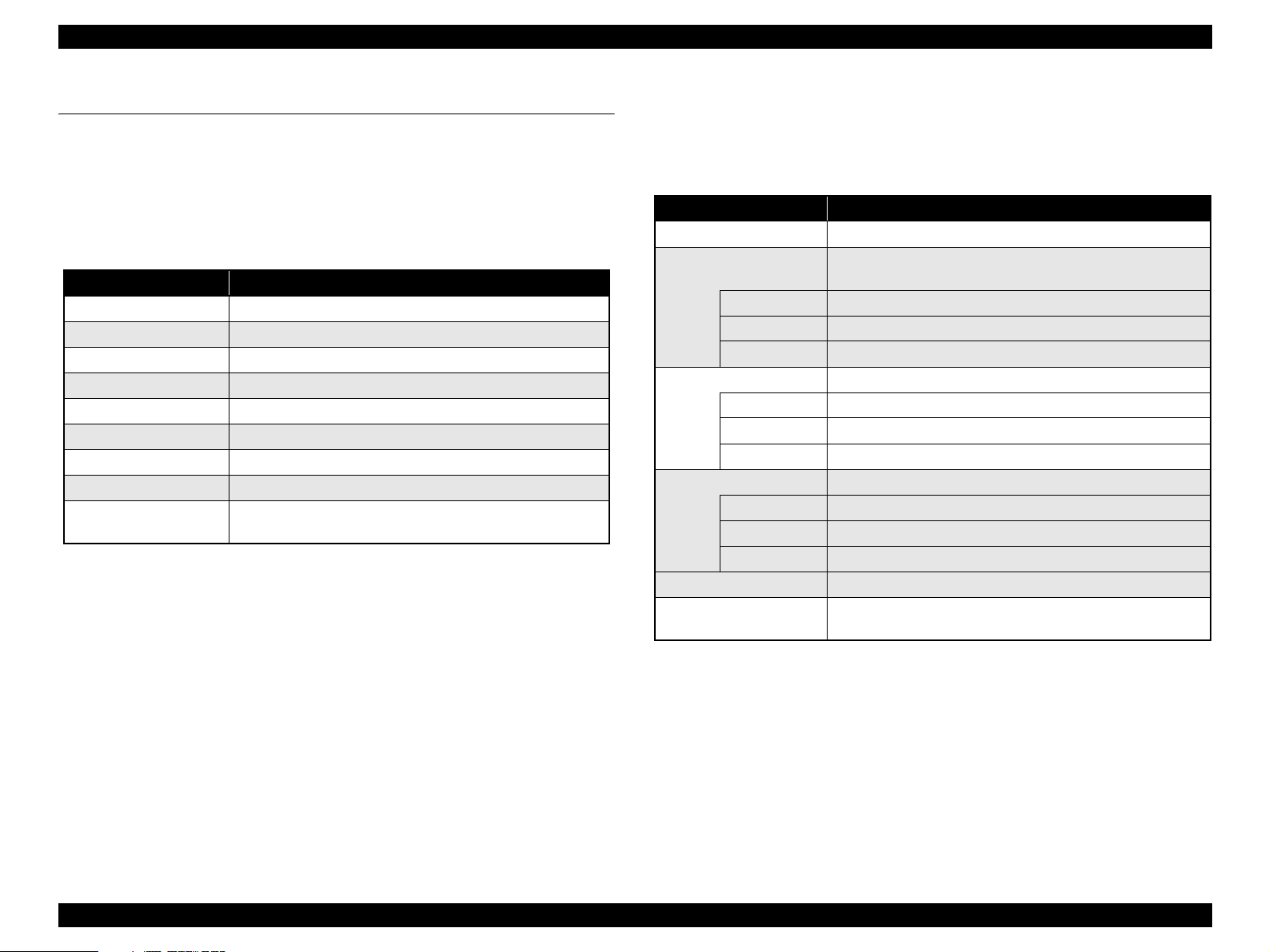
Manual Configuration
This manual consists of six chapters and Appendix.
CHAPTER 1. PRODUCT DESCRIPTIONS
Provides a general overview and specifications of the product.
CHAPTER 2. OPERATING PRINCIPLES
Describes the theory of electrical and mechanical operations of
the product.
CHAPTER 3. TROUBLESHOOTING
Describes the step-by-step procedures for the troubleshooting.
CHAPTER 4. DISASSEMBLY/ASSEMBLY
Describes the step-by-step procedures for disassembling and
assembling the product.
CHAPTER 5. ADJUSTMENT
Provides Epson-approved methods for adjustment.
CHAPTER 6. MAINTENANCE
Provides preventive maintenance procedures and the lists of
Epson-approved lubricants and adhesives required for
servicing the product.
CHAPTER 7. APPENDIX
Provides the following additional information for reference:
• Connector Summary
• Exploded Diagram
• Electrical Circuits
Symbols Used in this Manual
Various symbols are used throughout this manual either to provide additional
information on a specific topic or to warn of possible danger present during a
procedure or an action. Be aware of all symbols when they are used, and
always read NOTE, CAUTION, or WARNING messages.
A D J U S T M E N T
R E Q U I R E D
C A U T I O N
C H E C K
P O I N T
W A R N I N G
Indicates an operating or maintenance procedure, practice or
condition that, if not strictly observed, could result in injury or loss
of life.
Indicates an operating or maintenance procedure, practice, or
condition that, if not strictly observed, could result in damage to,
or destruction of, equipment.
May indicate an operating or maintenance procedure, practice or
condition that is necessary to accomplish a task efficiently. It may
also provide additional information that is related to a specific
subject, or comment on the results achieved through a previous
action.
Indicates an operating or maintenance procedure, practice or
condition that, if not strictly observed, could result in injury or loss
of life.
Indicates that a particular task must be carried out according to a
certain standard after disassembly and before re-assembly,
otherwise the quality of the components in question may be
adversely affected.
Page 4

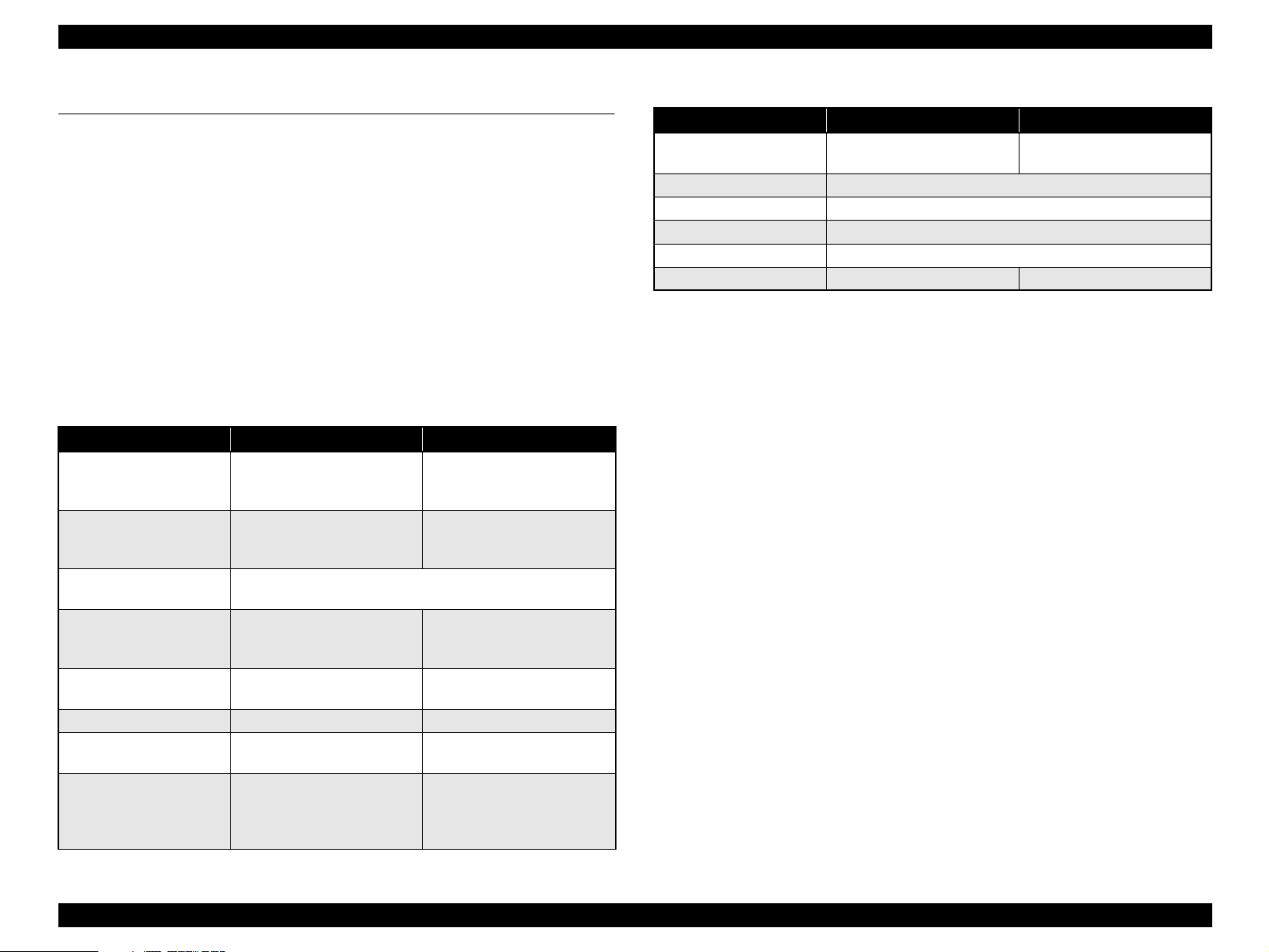
Revision Status
Revision Date Item Description
A October 7, 2005 --- First Release
B March 10, 2006 5.1.2 Adjustments Required After Part
Replacement (p.129)
C October 6, 2006 All EPSON ME PHOTO 20 is added.
1.2.1.3 Paper Support (p.11) Table 1-3 “Exclusive Papers” is modified.
1.2.1.5 Ink Cartridge Specification (p.15) EPSON ME PHOTO 20 is added.
1.6.3 Control Panel Appearance (p.31) EPSON ME PHOTO 20 is added.
5.1.2 Adjustments Required After Part
Replacement (p.129)
PW Sensor Adjustment (PW Deterioration Adjustment) added after Main
Board Replacement(Read OK)
Error correction
Page 5

EPSON Stylus Photo R240/R245/R250/ME PHOTO 20 Revision C
Contents
Chapter1 PRODUCT DESCRIPTION
1.1 Overview........................................................................................................... 10
1.1.1 Features .................................................................................................... 10
1.2 Specifications.................................................................................................... 11
1.2.1 Printer specifications................................................................................ 11
1.2.1.1 Physical Specification....................................................................... 11
1.2.1.2 Printing Specification........................................................................ 11
1.2.1.3 Paper Support.................................................................................... 11
1.2.1.4 Printing Area..................................................................................... 13
1.2.1.5 Ink Cartridge Specification............................................................... 15
1.2.1.6 Electric Specification........................................................................ 15
1.2.1.7 Environmental Performance ............................................................. 16
1.2.1.8 Durability .......................................................................................... 16
1.2.1.9 Safety Standards: EMC..................................................................... 16
1.2.1.10 CE Marking....................................................................................... 16
1.3 Interface ............................................................................................................ 17
1.3.1 USB Interface........................................................................................... 17
1.3.2 Standard Card Slots.................................................................................. 18
1.3.2.1 Memory card..................................................................................... 18
1.3.2.2 Supported power supply voltage....................................................... 18
1.3.2.3 Multi-slot operations......................................................................... 19
1.4 Memory Card Print ........................................................................................... 20
1.4.1 Basic Specifications ................................................................................. 20
1.4.1.1 File system ........................................................................................ 20
1.4.1.2 Media format..................................................................................... 20
1.4.1.3 File formats ....................................................................................... 20
1.4.1.4 Valid image size................................................................................ 20
1.4.1.5 Maximum number of photo data files............................................... 21
1.4.1.6 Thumbnail image data....................................................................... 21
1.4.1.7 File sorting ........................................................................................ 21
1.4.1.8 File sorting rules ............................................................................... 21
1.4.1.9 Rules for acquisition of date/time data ............................................. 21
1.4.1.10 Number of sheets which can be printed in total................................ 21
1.4.2 Functions .................................................................................................. 22
1.4.2.1 List of functions ................................................................................ 22
1.4.2.2 Memory card printing mode ............................................................. 22
1.4.3 Layout and Paper Type, Paper Size ......................................................... 23
1.4.4 Trimming Function .................................................................................. 23
1.4.5 Assignment Rules for Photo Frame Numbers and Rotation .................... 24
1.4.6 Layout Drawings...................................................................................... 25
1.4.6.1 Border free ........................................................................................ 25
1.4.6.2 1-up with borders.............................................................................. 25
1.4.6.3 20-up ................................................................................................. 26
1.4.6.4 30-up ................................................................................................. 26
1.4.6.5 80-up ................................................................................................. 27
1.4.7 Relation between Paper Type and Quality............................................... 27
1.5 USB Direct-Print/PictBridge Functions ........................................................... 28
1.5.1 Supported Device..................................................................................... 28
1.5.2 Functions Available from DSC................................................................ 28
1.5.3 Operation.................................................................................................. 28
1.5.3.1 Preparation........................................................................................ 28
1.5.3.2 Standard Operations.......................................................................... 28
1.5.3.3 Display when DSC is Connected...................................................... 29
1.5.3.4 Cancel Print....................................................................................... 29
1.5.3.5 Operation when the Printing is Completed....................................... 29
1.5.3.6 Exclusive Control Specifications for Paper Type, Size, and Layout 29
1.5.3.7 Camera direct error executing other processing (error).................... 29
1.6 Control Panel .................................................................................................... 30
1.6.1 Buttons ..................................................................................................... 30
1.6.2 Indicators.................................................................................................. 30
1.6.3 Control Panel Appearance ....................................................................... 31
1.6.4 The method of changing mode................................................................. 32
1.6.5 Operations ................................................................................................ 33
1.6.5.1 Memory card mode/Setup mode/DSC direct mode.......................... 33
1.6.5.2 Memory Card Insertion/Ejection ...................................................... 35
1.6.5.3 Connection/Removal of DSC ........................................................... 35
1.6.5.4 Low Power Panel Mode.................................................................... 35
1.6.5.5 Paper Thickness Lever Function....................................................... 35
1.6.6 Printer Condition and Panel Status .......................................................... 36
6
Page 6

EPSON Stylus Photo R240/R245/R250/ME PHOTO 20 Revision C
Chapter2 OPERATING PRINCIPLES
2.1 Overview........................................................................................................... 40
2.2 Printer Mechanism ............................................................................................ 40
2.2.1 Printer Mechanism ................................................................................... 40
2.2.2 Print Head................................................................................................. 41
2.2.2.1 Printing Process ................................................................................ 42
2.2.2.2 Printing Method ................................................................................ 42
2.2.3 Carriage Mechanism ................................................................................ 43
2.2.3.1 Carriage Mechanism ......................................................................... 43
2.2.3.2 Carriage Home Position Detection ................................................... 44
2.2.3.3 Sequence Used for PW Detection..................................................... 44
2.2.4 Paper Loading/Feeding Mechanism......................................................... 45
2.2.4.1 Paper Loading Mechanism ............................................................... 46
2.2.4.2 Paper Feeding Mechanism................................................................ 49
2.2.5 Ink System Mechanism............................................................................ 50
2.2.5.1 Capping Mechanism ......................................................................... 51
2.2.5.2 Pump Unit Mechanism ..................................................................... 52
2.2.6 Ink Sequence ............................................................................................ 53
2.3 Electrical Circuit Operating Principles ............................................................. 54
2.3.1 C610 PSB/PSE Board .............................................................................. 55
2.3.2 C606 Main Board..................................................................................... 56
2.3.2.1 Main Elements .................................................................................. 56
Chapter3 TROUBLESHOOTING
4.3.2 Stacker Assy............................................................................................. 86
4.3.3 Printer Cover ............................................................................................ 87
4.3.4 Panel Unit................................................................................................. 88
4.3.5 Upper Housing ......................................................................................... 90
4.3.6 Print Head ................................................................................................ 91
4.3.7 Main Board Unit ...................................................................................... 93
4.3.8 Head Cable Frame.................................................................................... 95
4.3.9 Printer Mechanism ................................................................................... 96
4.3.10 PS Board Unit .......................................................................................... 99
4.3.11 Waste Ink Pad ........................................................................................ 100
4.3.12 ASF Unit ................................................................................................ 101
4.3.13 CR Motor ............................................................................................... 103
4.3.14 PF Motor and PF Encoder Sensor .......................................................... 104
4.3.15 Carriage Unit, CR Encoder Board, PW Sensor Board, Head FFC ........ 106
4.3.16 Shaft Holder Unit ................................................................................... 110
4.3.17 Spur Gear 36.8, Extension Spring 0.143, Clutch ................................... 112
4.3.18 PE Sensor Board and PE Sensor Lever.................................................. 113
4.3.19 Upper Paper Guide Unit......................................................................... 114
4.3.20 CR Guide Frame .................................................................................... 115
4.3.21 Paper Eject Frame Unit .......................................................................... 116
4.3.22 Ink System Unit ..................................................................................... 118
4.3.23 Front Paper Guide Unit .......................................................................... 120
4.3.24 PF Scale/PG Sensor ............................................................................... 121
4.3.25 PF Roller Unit ........................................................................................ 123
3.1 Overview........................................................................................................... 59
3.2 Error Indications and Fault Occurrence Causes ............................................... 59
3.3 Troubleshooting ................................................................................................ 60
3.3.1 Superficial Phenomenon-Based Troubleshooting.................................... 74
Chapter4 DISASSEMBLY AND ASSEMBLY
4.1 Overview........................................................................................................... 82
4.1.1 Precautions ............................................................................................... 82
4.1.2 Tools......................................................................................................... 82
4.1.3 Work Completion Checklist..................................................................... 83
4.2 Cautions on Disassembly/Reassembly of Printer Mechanism & How to Ensure
Quality of Reassembled Printers 84
4.3 Disassembly Procedure..................................................................................... 85
4.3.1 Paper Support Assy. ................................................................................. 86
Chapter5 ADJUSTMENT
5.1 Adjustment Items Summary ........................................................................... 126
5.1.1 List of Adjustment Items........................................................................ 126
5.1.2 Adjustments Required After Part Replacement ..................................... 129
5.2 Adjustments by Adjustment Program............................................................. 131
5.2.1 Top margin adjustment .......................................................................... 131
5.2.2 Head Angular Adjustment ..................................................................... 131
5.2.3 Bi-D Adjustment .................................................................................... 132
5.2.4 First Dot Adjustment.............................................................................. 132
5.2.5 PW Sensor Adjustment .......................................................................... 133
5.2.6 PF Adjustment........................................................................................ 134
5.2.7 PF Band Adjustment .............................................................................. 135
5.3 Adjustment Except Adjustment Program ....................................................... 136
5.3.1 PG adjustment ........................................................................................ 136
7
Page 7

EPSON Stylus Photo R240/R245/R250/ME PHOTO 20 Revision C
Chapter6 MAINTENANCE
6.1 Overview......................................................................................................... 141
6.1.1 Cleaning ................................................................................................. 141
6.1.2 Service Maintenance .............................................................................. 141
6.1.3 Lubrication ............................................................................................. 143
Chapter7 APPENDIX
7.1 Connector Summary ....................................................................................... 149
7.1.1 Major Component Unit .......................................................................... 149
7.2 Exploded Diagram .......................................................................................... 150
7.3 Electrical Circuits ........................................................................................... 151
8
Page 8

PRODUCT DESCRIPTION
CHAPTER
1
Page 9
EPSON Stylus Photo R240/R245/R250/ME PHOTO 20 Revision C
1.1 Overview
The major features of EPSON color inkjet dot matrix printer EPSON Stylus Photo
R240/R245/R250/ME PHOTO 20 are:
1.1.1 Features
Printer functions
As a printer, this unit achieves high-quality output at high speed on plain paper,
and uses new inks for improved light fastness, water fastness, gas fastness, rubbing
fastness. It includes the following features.
Maximum print resolution: 5760 (H) x 1440 (V) dpi
Separate ink cartridge for each color
ASF (Auto Sheet Feeder) holds up to 100 cut sheets (64g/m
Borderless printing
Reduced noise level
Fast and thick draft mode with the combination of real black and composite
black
Card reader functions
This unit includes memory card slots that support CompactFlash, SmartMedia,
Memory Stick, Memory Stick PRO, Microdrive, SD Memory Card,
and xD-Picture Card standards.
2
)
Easy operation panel
The unit has a simple operation panel equipped with 1.5 inch LCD and 11 buttons
including power button, 10 LEDs and provides basic functions only for easy
operation.
Exterior design
This unit has operation panel on the front side, which becomes more distinctive
but still easier to use.
Memory card print functions
This unit can print images from the memory card in memory card slots
in stand-alone mode.
USB DIRECT-PRINT/PictBridge functions
This unit can print from Digital Still Camera that is compliant with “USB
DIRECT-PRINT”/”CIPA DC-001-2003 Digital Photo Solutions for Imaging
Devices” and that is connected by USB cable.
Simultaneous use of functions
Printer functions and card reader functions are independent and can therefore be
operated simultaneously from a connected computer.
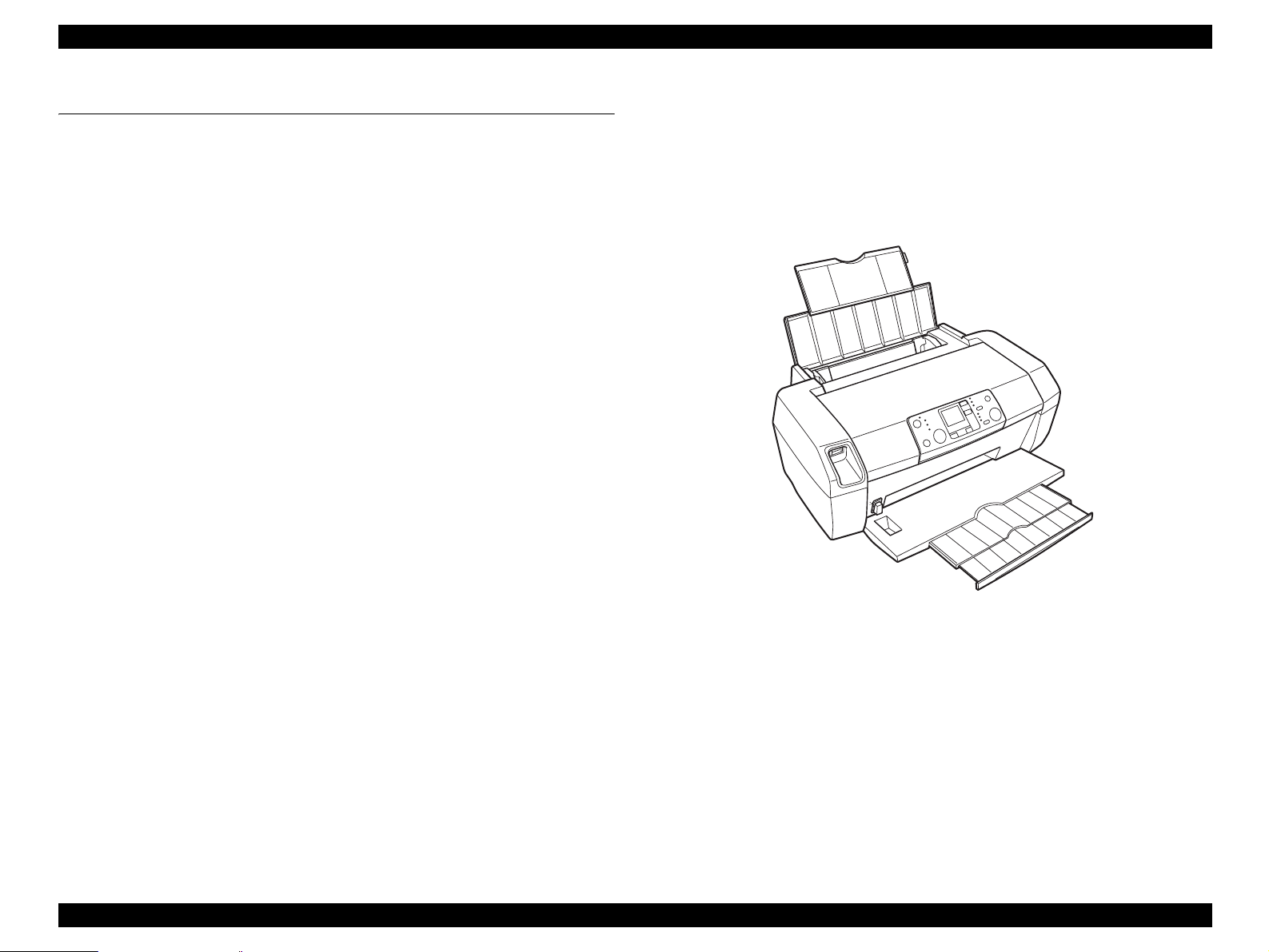
Figure 1-1. Product’s external view
PRODUCT DESCRIPTION Overview 10
Page 10
EPSON Stylus Photo R240/R245/R250/ME PHOTO 20 Revision C
1.2 Specifications
1.2.1 Printer specifications
This section covers specifications of the printer.
1.2.1.1 Physical Specification
Weight
5.0kg (without the ink cartridges)
Dimension (Including rubber feet, not including loading tray)
435.9mm (W) x 268.2mm (D) x 171.2mm (H)
1.2.1.2 Printing Specification
Print Method
On demand ink jet
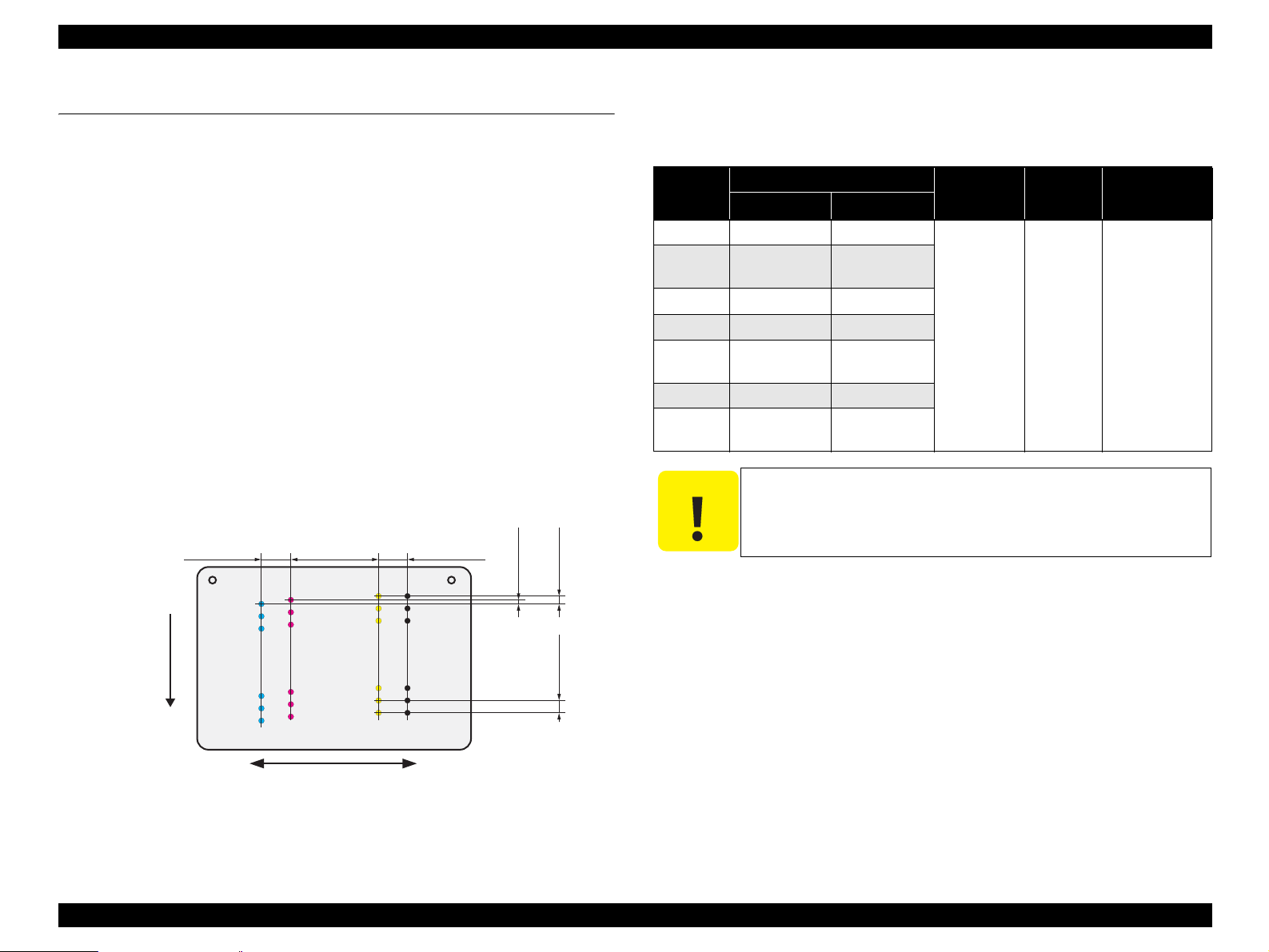
Nozzle Configuration
Black: 90 nozzles
Color: 90 nozzles x 3 (Cyan, Magenta, Yellow)
Paper Feed Direction
2.822
(40/360inch)
#A90
#A89
#A88
A row B row C row D row
#A3
#A2
#A1
8.467
(120/360inch)
#C90
#B90
#C89
#B89
#C88
#B88
#B3
#B2
#B1
#C3
#C2
#C1
2.822
(40/360inch)
#D90
#D89
#D88
#D3
#D2
#D1
BlackCyan Magenta Yellow
0.07055
(1/360inch)
0.1411
(2/360inch)
0.2117
(3/360inch)
1.2.1.3 Paper Support
Cut sheets
Table 1-1. Cut Sheets
(7.25")
(5.5")
the form.
Dimensions
266.7 mm
(10.5")
215.9 mm
(8.5")
Paper size
Width (PW) Length (PL)
A4 210 mm 297 mm
Executive 184.2 mm
B5 182 mm 257 mm
A5 148 mm 210 mm
Half Letter 139.7 mm
A6 105 mm 148 mm
User
50.8-329 mm 127-1117.6 mm
Defined
C A U T I O N
It is necessary that there is no wrinkle, nap, tear, fold, so on in
The curve of form must be 5mm or below.
Thickness Weight Paper type
0.08-0.11 mm
64-90 g/m
(17-24(lb))
2
Plain paper
Recycled paper
Carriage Moving Direction
Figure 1-2. Nozzle configuration
PRODUCT DESCRIPTION Specifications 11
Page 11
EPSON Stylus Photo R240/R245/R250/ME PHOTO 20 Revision C
Envelopes
Table 1-2. Envelopes
Paper size
*
No.10
*
DL
*
C6
220 x 132
*
Note * : Check that the flap is on the long edge and can be folded.
C A U T I O N
Poor quality paper may reduce print quality and cause paper
Dimensions
Thickness Weight Paper type
Width (PW) Length (PL)
104.8mm
(4.125")
241.3mm
(9.5")
N/A 75-90g/m
(20-24(lb))
110mm 220mm
114mm 162mm
132mm 220mm 0.1 82g/m
(22(lb))
jams or other problems. If you encounter problems, switch to a
higher grade of paper.
It is necessary that there is no wrinkle, nap, tear, fold, so on in
the form.
Don’t use the adhesive envelopes.
Don’t use sleeve insert envelopes and cellophane window
envelopes.
The curve and swell of the form must be 3mm or below
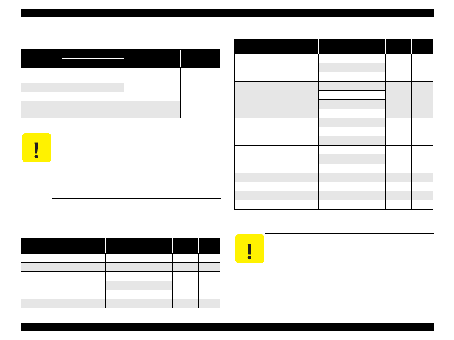
Exclusive papers
2
2
Bond paper
Air mail
PPC
Table 1-3. Exclusive Papers
Item Size
Photo Paper A4
Width
(PW)
*1
210 297 0.23 194
4" x 6" 101.6 152.4
Photo Stickers 4/16 A6 105 148 0.19 N/A
Premium Glossy Photo Paper A4 210 297 0.27 255
*1
5" x 7"
127 178
4" x 6" 101.6 152.4
*2
3R
Glossy Photo Paper A4 210 297 0.25 258
*1
5" x 7"
127 178
4" x 6" 101.6 152.4
Premium Semigloss Photo Paper A4 210 297 0.27 250
4" x 6" 101.6 152.4
Matte Paper-Heavyweight A4 210 297 0.23 167
Double-sided Matte Paper A4 210 297 0.25 178
Economy Photo Paper
*2
A4 210 297 0.23 188
Iron-On Cool Peel Transfer Paper A4 210 297 0.14 130
Photo Quality Ink Jet paper A4 210 298 0.12 102
Length
(PL)
89 127
Thickness
(mm)
Weight
(g/m
2
)
Quality: EPSON Exclusive paper
Transparency printing is only available at normal temperature.
Note *1 : Only for Stylus Photo R240/R245.
*2: Only for Stylus Photo R250/ME PHOTO 20.
Table 1-3. Exclusive Papers
It is necessary that there is no wrinkle, nap, tear, fold, so on in
the form.
The curve of form must be 5mm or below.
Item Size
Premium Ink Jet Plain Paper
Width
(PW)
*1
A4 210 297 0.11 80
Length
(PL)
Thickness
(mm)
Weight
(g/m
Bright White Ink Jet Paper A4 210 297 0.13 92.5
Photo Quality Ink Jet Cards 8" x 10" 203.2 254 0.21 180
5" x 8" 127 203.2
A6 105 148
Photo Quality Self Adhesive Sheets A4 210 297 0.19 167
C A U T I O N
2
)
PRODUCT DESCRIPTION Specifications 12
Page 12
EPSON Stylus Photo R240/R245/R250/ME PHOTO 20 Revision C
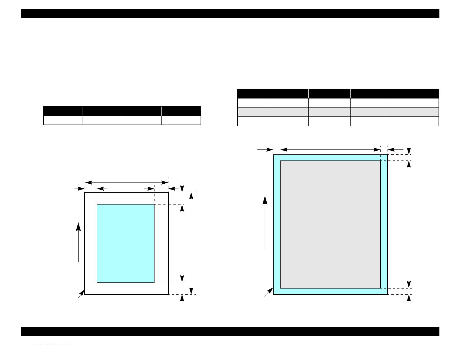
1.2.1.4 Printing Area
Cut sheet (standard printing)
Printable area
The print quality is guaranteed for the print area above the 3mm bottom
margin. For paper width (PW) and paper length (PL), refer to “1.2.1.3 Paper
Support” (p.11).
Refer to the following table.
As for each margin area, refer to Figure 1-3 (p.13).
Table 1-4. Printing Area
Left Margin Right Margin Top Margin Bottom Margin
3mm (0.12") 3mm (0.12") 3mm (0.12") 3mm (0.12")
NOTE: Printouts may get dirt with a bottom margin of less than 28.3mm or a top
margin of less than 32.1mm because of an unexpected contact of the
Printhead.
In addition, with a bottom margin of less than 28.3mm, printed image
near the bottom may be distorted.
PW
LM RM
TM
Cut sheet (border-free printing)
Printable area
For paper width (PW) and paper length (PL), refer to “1.2.1.3 Paper Support ”
(p.11).
Refer to the following table.
As for each overhang area, refer to Figure 1-4 (p.13).
Table 1-5. Printing Area
Paper size Left Overhang Right Overhang Top Overhang Bottom Overhang
Photo card 1.83 mm 1.83 mm 2.54 mm 3.53 mm
4hx6h/10x15 2.54 mm 2.54 mm 1.34 mm 2.54 mm
Other 2.54 mm 2.54 mm 2.96 mm 4.02 mm
LO RO
PW
TO
PL
Printable area
PL
Paper size
Paper Feed Direction
Paper Feed Direction
BM
Paper size
Figure 1-3. Printable area Cut sheet (standard printing)
Printable area
Figure 1-4. Printable area for Cut sheet (border-free printing)
BO
PRODUCT DESCRIPTION Specifications 13
Page 13
EPSON Stylus Photo R240/R245/R250/ME PHOTO 20 Revision C
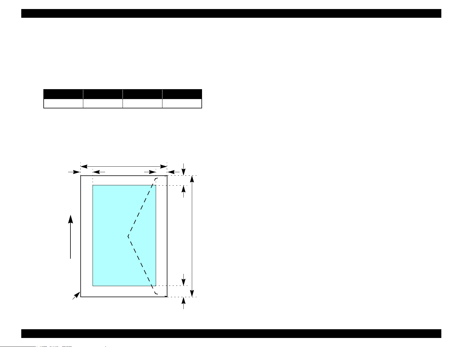
Envelopes
Printable area
For paper width (PW) and paper length (PL), refer to “ 1.2.1.3 Paper Support ”
(p.11).
Refer to the following table.
As for each margin area, refer to Figure 1-5 (p.14).
Table 1-6. Printing Area
Left Margin Right Margin Top Margin Bottom Margin
3mm (0.12") 3mm (0.12") 5mm (0.20") 20mm (0.79")
NOTE: Printouts may get dirt with a bottom margin of less than 20.0mm or a top
margin of less than 32.1mm because of an unexpected contact of the
Printhead.
In addition, with a bottom margin of less than 20.0mm, printed image
near the bottom may be distorted.
PW
LM
RM
TM
Printable area
PL
Paper Feed Direction
BM
Paper size
Figure 1-5. Printable area for envelopes
PRODUCT DESCRIPTION Specifications 14
Page 14
EPSON Stylus Photo R240/R245/R250/ME PHOTO 20 Revision C
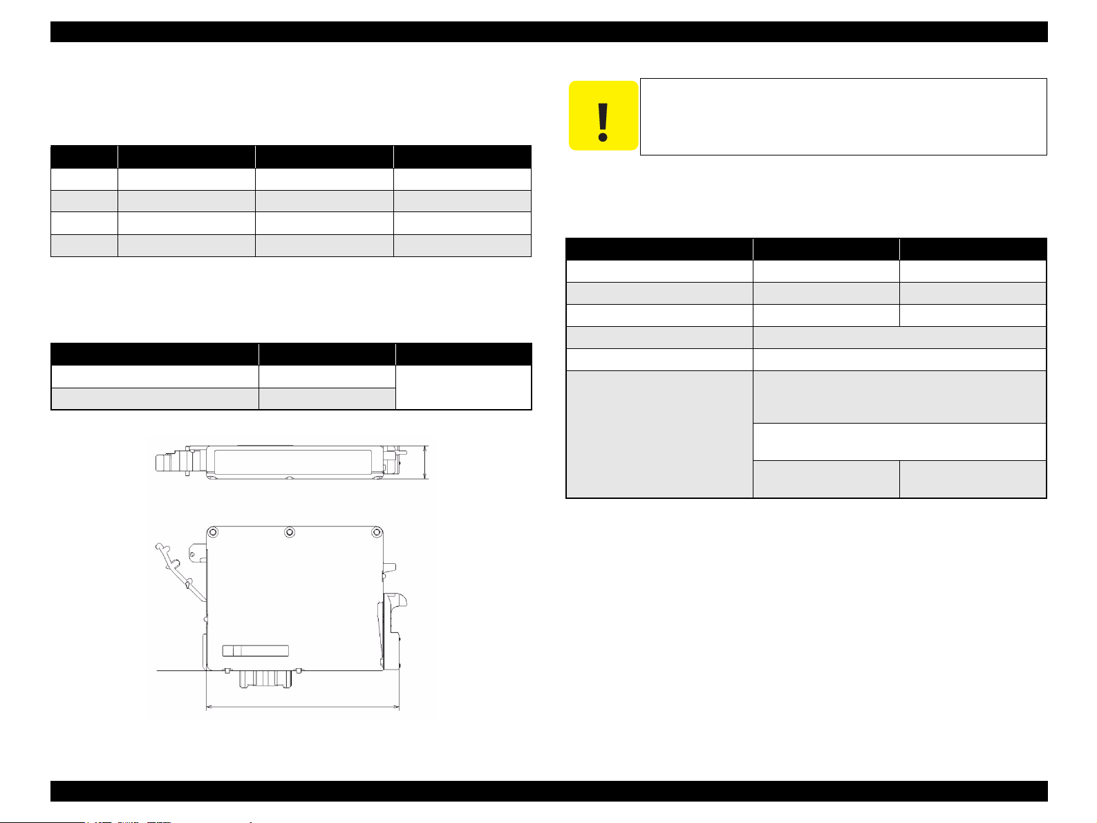
1.2.1.5 Ink Cartridge Specification
Type/color: EPSON-brand special ink cartridges
Table 1-7. Ink Cartridge
Color Stylus Photo R240/R245 Stylus Photo R250 ME PHOTO 20
Black T0551 T0561 T0841
Cyan T0552 T0562 T0842
Magenta T0553 T0563 T0843
Yellow T0554 T0564 T0844
Shelf life: After packing is opened, it is assumed 6 months, and
assumes two years including this.
Storage Temperature
Table 1-8. Storage Temperature
Situation Storage Temperature Limit
When stored in individual boxes -30 oC ~ 40 oC 1 month max. at 40 oC
When installed in main unit -20 oC ~ 40 oC
Dimension: 12.7mm (W) x 73.46mm (D) x 55.25mm (H)
12.7mm
C A U T I O N
The ink in the ink cartridge freezes when leaving it in the
environment of -16°C or under. It takes 3 hours that the frozen ink
becomes usable when moving it from the environment of -20°C to
the environment of 25°C.
1.2.1.6 Electric Specification
Primary power input
Table 1-9. Primary power input
100-120V model 220-240V model
Rated power supply voltage (VAC) 100 ~ 120 220 ~ 240
Input voltage range (VAC) 90 ~ 132 198 ~ 264
Rated current (A) 0.4 (Max. 0.7) 0.2 (Max. 0.3)
Rated frequency (Hz) 50 ~ 60
Input frequency range (Hz) 49.5 ~ 60.5
Power consumption (W) Approx. 10W
(Standalone copying, ISO10561 Letter Patter,
Plain Paper - Text)
Approx. 1.5W
(Sleep Mode)
Approx. 0.2W
(Power Off Mode)
Approx. 0.4W
(Power Off Mode)
NOTE 1: This product complies with the “Energy Star” standards.
2: If the printer is not operated at all for at least three minutes, the standby function
reduces the current to the motor to conserve power.
3: If the panel button is not operated at all for at least 13 minutes, the LCD panel is go
out.s
Base View
73.46mm
Figure 1-6. Ink cartridge
PRODUCT DESCRIPTION Specifications 15
Page 15
EPSON Stylus Photo R240/R245/R250/ME PHOTO 20 Revision C
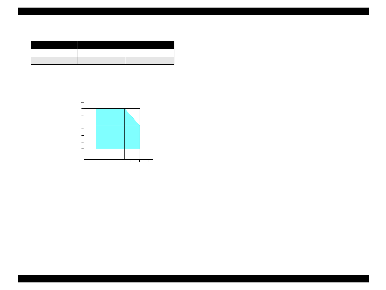
1.2.1.7 Environmental Performance
Table 1-10. Environmental Performance
Condition Temperature Humidity
Operating 10 ~ 35°C
Not operating
Note *1 : After unpacking (storage)
*2: No condensation
*3: Under the following conditions
*4: One month when at 40°C
Humidity (%)
*1
90
80
70
60
50
40
30
20
-20 ~ 40°C
10
Temperature (°C)
Figure 1-7. Temperature/Humidity range
1.2.1.8 Durability
Total print life: 10,000 pages (black only, A4), or five years
*2
*3
*4
20 ~ 80%
5 ~ 85%
*3
Print Head Life: Six billion shots (per nozzle) or five years
(whichever comes first)
(whichever comes first)
1.2.1.9 Safety Standards: EMC
220-240V model
Safety standards: EN 60950
EMI: EN 55022(CISPR Pub.22) class B
AS/NZS CISPR22 class B
1.2.1.10 CE Marking
220-240V model
Low Voltage Directive 73/23/EEC: EN60950
20
27
35
30
40
EMC Directive 89/336/EEC: EN55022 Class B
EN61000-3-2
EN61000-3-3
EN55024
PRODUCT DESCRIPTION Specifications 16
Page 16
EPSON Stylus Photo R240/R245/R250/ME PHOTO 20 Revision C
1.3 Interface
The EPSON Stylus Photo R240/R245/R250/ME PHOTO 20 provides the following
interface.
1.3.1 USB Interface
Standards
“Universal Serial Bus Specifications Revision 2.0”
“Universal Serial Bus Device Class Definition for Printing Devices Version
1.1” (printer unit)
“Universal Serial Bus Mass Storage Class Bulk-Only Transport Revision 1.0”
(storage unit)
Transfer rate: 480 Mbps (High Speed Device)
Data format: NRZI
Compatible connector: USB Series B
Recommended cable length: 2 [m] or less
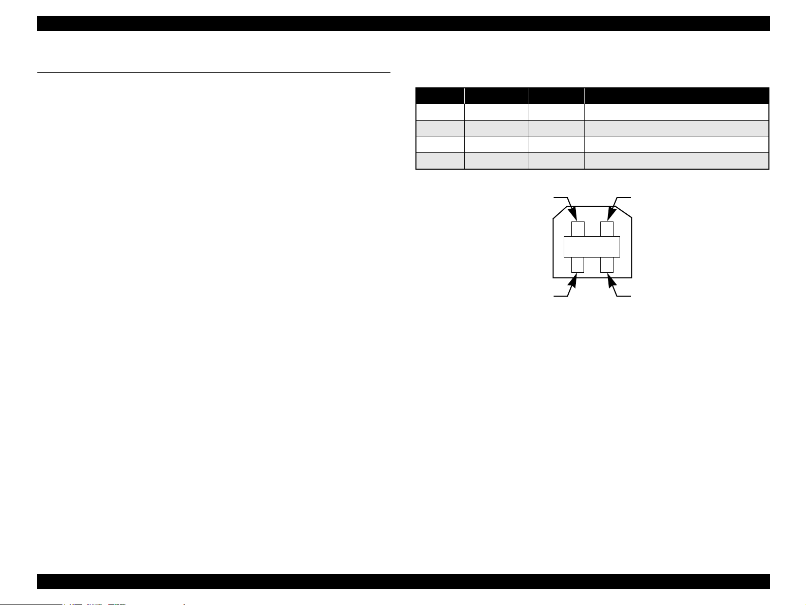
Connector signal layout
Table 1-11. Connector pin assignment and signals
Pin No. Signal name I/O Function description
1 VCC --- Cable power. Max. power consumption is 2mA.
2 -Data Bi-D Data
3 +Data Bi-D Data, pull up to +3.3V via 1.5K ohm resistor.
4 Ground --- Cable ground
Pin #2
Pin #3
Figure 1-8. USB pin Assignment
Pin #1
Pin #4
PRODUCT DESCRIPTION Interface 17
Page 17
EPSON Stylus Photo R240/R245/R250/ME PHOTO 20 Revision C
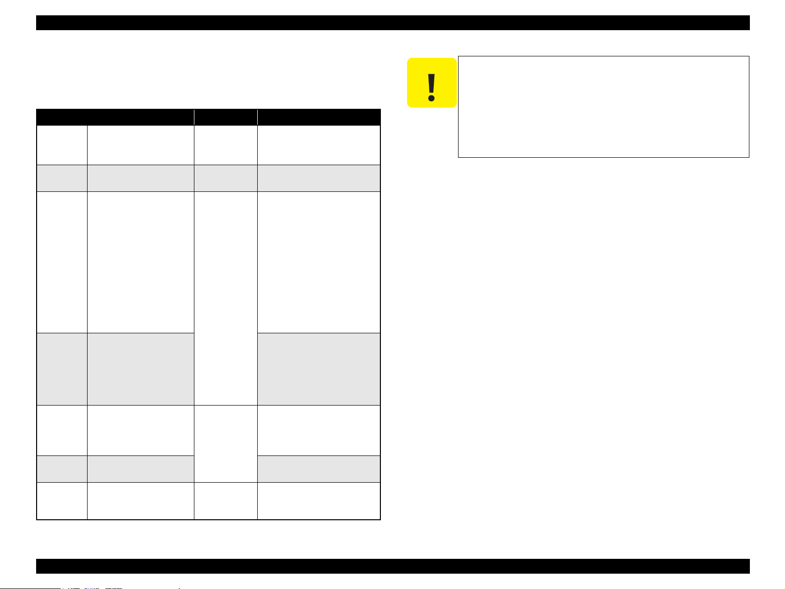
1.3.2 Standard Card Slots
1.3.2.1 Memory card
Table 1-12. Memory card
Memory card standards Slots Supported memory cards
Compact
Flash
SmartMedia SmartMedia Standard 2003
Memory
Stick
Memory
Stick PRO
SD SD Memory Card
MultiMedia
Card
xD-Picture
Card
CF+ and CompactFlash
Specification Revision 1.4
compliant
compliant
Memory Stick Standard
version 1.3 compliant
MemoryStick Standard
Memory Stick PRO Format
Specifications version 1.0
compliant
Specifications/PART1.
Physical Layer Specification
Version 1.0 compliant
MultiMediaCard Standard
compliant
xD-Picture CardTM Card
Specification Version 1.20
Type M compliant
CF Type II slot • CompactFlash
(memory card only)
• Microdrive
SmartMedia slot •SmartMedia
(maximum capacity: 128 MB)
Memory Stick/
Memory Stick
PRO slot
SD/MMC slot • SD (Secure Digital) memory
xD-Picture Card
slot
• Memory Stick
(maximum capacity: 128 MB,
including versions with
memory select function)
• MagicGate Memory Stick
(maximum capacity: 128 MB,
copy protection function is not
supported)
• Memory Stick Duo
(requires Memory Stick Duo
adapter)
• MagicGate Memory Stick Duo
• Memory Stick PRO
(copy protection function is not
supported)
• Memory Stick PRO Duo
(requires Memory Stick Duo
adapter)
card
•miniSD card
(requires SD adapter)
MultiMediaCard
• xD-Picture Card
• xD-Picture Card Type M
C A U T I O N
Note the following caution points when handling the memory card.
Since the SD card and Memory Stick share the same slot, only
one can be inserted at a time.
Since the SmartMedia and xD-Picture Card share the same
slot, only one can be inserted at a time.
When a memory card is being accessed, be sure to keep the
memory card slot’s cover closed and do not touch the memory
card.
1.3.2.2 Supported power supply voltage
3.3V/5V (both)
3.3V (only)
NOTE 1: 3.3V power is supplied to media that support both 3.3V and 5V.
2: Maximum current to memory card is 500mA.
3: 5V type memory cards are not supported.
PRODUCT DESCRIPTION Interface 18
Page 18

EPSON Stylus Photo R240/R245/R250/ME PHOTO 20 Revision C
1.3.2.3 Multi-slot operations
Overview
There is only one type of card that can be used to simultaneously access both
a connected computer and the direct printing function.
The slots have assigned priority to determine which slot will be accessed first
when cards are inserted in several slots at once.
To select a card that has been inserted in a non-active slot, the card in the
active slot must first be removed.
• Direct printing
Only the image files in the active slot are valid and have assigned frame
numbers. The number of images will not change if a card is also inserted in
a non-selected slot.
• Connection to computer (Windows)
Only one drive is displayed at a time as a “removable disk” and only the
card that is in the active slot can be accessed via the removable disk. A card
that has been inserted into a non-selected slot cannot be accessed.
• Connection to computer (Macintosh)
Only the card in the active slot can be mounted on the desktop. A card that
has been inserted into a non-selected slot cannot be mounted on the desktop.
Details
Access priority
The access priority among slots is assigned as:
1: CF (Microdrive)
2: SmartMedia/xD-Picture Card
3: Memory Stick (Memory Stick PRO)/SD (MMC)
Slot selection when power is turned on
If cards are inserted in several slots when the power is turned on, the active
slot is determined by the priority ranks listed above.
Example: If Smart Media and Memory Stick are both inserted at power-on,
the SmartMedia slot becomes the active slot.
Slot selection after power is turned on
When a card is removed from the active slot, the slot with the next-highest
priority becomes the active slot (if a card has been inserted into it). There is no
need to re-insert any card before accessing it. If no slots contain any cards, the
highest-priority slot (CF Microdrive) again becomes the active slot.
Cards can be removed from non-selected slots in any order.
Example: If a memory stick and CF card are inserted while SmartMedia is
selected, CF becomes selected (active) once SmartMedia is
removed.
PRODUCT DESCRIPTION Interface 19
Page 19

EPSON Stylus Photo R240/R245/R250/ME PHOTO 20 Revision C
1.4 Memory Card Print
1.4.1 Basic Specifications
1.4.1.1 File system
DCF Version 1.0 or 2.0 is the file system that can be used with this unit’s stand-alone
printing functions. Operation is not guaranteed when any other file system is used.
The file system used by the card reader function depends on the host’s specifications.
For a detailed description of the DCF specifications, see the “Design Rule for Camera
File System Standard, DCF Version 2.0, JEIDA-CP-3461”.
1.4.1.2 Media format
Media must be formatted according to the DCF Version 1.0 or 2.0 standard.
DOS FAT formats (FAT12, FAT16) and single partition (basic partition)
1.4.1.3 File formats
The file formats supported by this unit are described below.
JPEG files (*.JPG)
These are photo data files that comply with the Exif Version 2.21 standard. (Exif
version 1.0/2.0/2.1/2.2/2.21)
Camera specification files (*.MRK)
These are definition files used when in camera specification mode. An
“AUTOPRINT.MRK” file whose full path name is no longer than 32 characters is
valid.
PRINT Image Framer (P.I.F.) definition file (*.USD)
File to define the layout in accordance with the PRINT Image Framer
specifications. Files only in the “¥EPUDL¥” directory are available. Compatible
with Print Image Framer Rev.2.1.
PRINT Image Framer (P.I.F.) definition file (*.FD2)
File to define the layout in accordance with the PRINT Image Framer
specifications. All files in the memory card are targeted for search.
Compatible with Print Image Framer Rev 3.1.
File contents are divided into complete type and template type.
Template type: The frame only on which image data is printed is specified.
Provides nearly identical functions as those supported with
the current P.I.F. Rev.3.1.
Complete type: Print layout information, image data and frame data is
contained in one package. Printing is performed using this file
only without specifying photos.
Note: As a general rule, this unit will support up to level 1 of P.I.F. Rev.3.1
Note, however, any file that is saved in the following directories or their sub-directories
cannot be included as files to be printed.
Directories containing system properties or hidden properties
“RECYCLED”
Windows directory for deleted files
“PREVIEW”
Directories containing CASIO’s DSC thumbnail images
“SCENE”
Directories containing data for CASIO’s DSC Best Shot function
“MSSONY”
Directories containing SONY’s DSC e-mail image data, voice memos, video files,
or non-compressed images
“DCIM¥ALBUM¥IMAGE”
CASIO DSC album data save directory
1.4.1.4 Valid image size
The maximum image size handled by this unit is:
Horizontal: 80 ≤ X ≤ 9200 (pixels)
Vertical: 80 ≤ Y ≤ 9200 (pixels)
PRODUCT DESCRIPTION Memory Card Print 20
Page 20

EPSON Stylus Photo R240/R245/R250/ME PHOTO 20 Revision C
1.4.1.5 Maximum number of photo data files
This unit can handle up to 999 photo data files. If the amount of photo data to be
recorded exceeds the capacity of one memory card, this unit uses file sorting rules to
sort the photo data into valid photo data in frames numbered from 1 to 999. Although it
is possible to print photo data files with frame numbers over 999 that have been
specified for printing by camera specification files, the maximum number of frames
that can be specified is 999 frames.
If you insert a memory card that contains over 999 photo data files, only files up to 999
will be printed by the “Print All” or “Print index sheet” functions.
1.4.1.6 Thumbnail image data
This unit handles thumbnail image data in the DCF Version 1.0 or 2.0 format (Exif
format, 160 x 120 pixels).
During this unit’s Index sheet and memory card printing modes, the layout is 80
thumbnails per sheet (when using plain paper or special paper in high-speed print
mode).
1.4.1.7 File sorting
This unit stores all photo data files in the memory, using the photo data files’ full-path
file names (for example, “¥DCIM¥100EPSON¥EPSN0000.JPG”), and assigned photo
frame numbers. Since photo frame numbers are assigned based on this unit’s own
proprietary file sorting rules, the assigned frame numbers do not necessarily match
those indicated by digital cameras.
1.4.1.9 Rules for acquisition of date/time data
The following priorities are used to fetch date and time information from photo data
files.
1. Date/time data that complies with the standard format (Exif) for digital
cameras
2. Date/time data that complies with the DOS standard file system (file time
stamps)
3. Fixed values (01/01/1980, 00:00:00)
Note that the date/time data assigned to individual photo data files does not necessarily
match the date/time when the photo was actually taken. The photo date/time may be
modified due to the digital camera’s calendar settings (presence/absence of functions,
incorrect date/time settings, etc.), processing of the photo data after the photo was
taken, or subsequent saving of data. In such cases, this unit performs the relevant
processing based on the most recently modified date/time data.
1.4.1.10 Number of sheets which can be printed in total
Printing sum total number of sheets presupposes that it is possible to 999 sheets.
Moreover, the printing sum total number of sheets per sheet is possible to 99 sheets.
1.4.1.8 File sorting rules
This unit sorts photo data files based on the following prioritization rule.
File name is sorted in ASCII order as full path name.
Note: Sorting results are not guaranteed if two files have matching full-
path file names. (Matching full-path file names are not allowed
under the DOS specification.)
PRODUCT DESCRIPTION Memory Card Print 21
Page 21
EPSON Stylus Photo R240/R245/R250/ME PHOTO 20 Revision C
1.4.2 Functions
1.4.2.1 List of functions
The memory card print menu and its settings are listed in the following table. The
values shown in this table indicate the total number of options and the number of pages
or copies that can be printed consecutively.
Table 1-13. List of functions
Memory card
printing
Print selected
*1
image
Print all images Print All/
*2
DPOF
Print index sheet Print Index Sheet None Plain Paper 1 1
Note *1 : “Print selected image” will be selected as default function of Memory Card Print.
*2: It is available only “DPOF” file exists in the memory card.
Mode selection Layout Paper type
Print Select • Standard
• Border free
• Border free
• Standard
PictBridge
Print Select • Standard
• Border free
• Border free
• Border free
• Border free
• Plain Paper
• Photo Paper
• Matte Paper
• Plain Paper
• Photo Paper
• Matte Paper
• Plain Paper
• Photo Paper
• Matte Paper
1.4.2.2 Memory card printing mode
Print selected image
This function prints selected image file stored in the memory card. As shown
below, the number of printed pages depends on the number of copies to be printed.
Print all images
This function prints all of the image files stored in the memory card. As shown
below, the number of printed pages depends on the number of copies to be printed.
DPOF printing
In this mode, the photo frame numbers previously specified via the camera are
printed in the number of pages specified via the camera. Only the paper type and
layout are specified on the printer side. If the layout assigned multiple photos per
output sheet, photos that have different frame sizes are automatically assigned in
the specified number of pages in numerical order (of the specified photo frame
Paper
size
3 1
3 1
3 1 to 99
Page/
copies
numbers). If index print mode was set via the camera, this unit will print in DPOF
index layout. (When in DPOF print mode, the mode cannot be switched by writing
the print file specification from the host after inserting the memory card.)
Print index sheet printing
This function prints thumbnail images (stored in the memory card) onto an order
sheet (form) that is marked for selecting images.
Table 1-14. Memory card printing mode
Setting Memory card printing mode Description Option, setting range, etc.
Layout
(no menu)
Paper type • Print selected image
Paper size • Print selected image
Pages/
copies
Quality • Print selected image
• Print selected image
• Print all images
• DPOF printing
• Print all images
• DPOF printing
Print index sheet printing Fixed Plain Paper
• Print all images
• DPOF printing
Print index sheet printing Fixed A4
Print selected image Sets number
Print all images 1
DPOF printing The number of copies specified via
Print index sheet printing Fixed Fixed as 1 page (can vary according
• Print all images
• DPOF printing
Print index sheet printing Fixed Prints it by the quality of Plain Paper.
Sets print
layout
Sets paper
type
Sets paper
size
of printout
Sets print
quality
Fixed in combination with paper type
and paper size (refer to “1.4.3 Layout
and Paper Type, Paper Size” (p.23))
Plain Paper, Photo Paper or Matte
paper
A4, 10x15/4”x6” or 13x18/5”x7”
1 to 99 copies (default is 1 copy).
the camera is used.
The setting range is 1 to 99 copies
(default is 1 copy).
to the number of image files)
Fixed according to paper type (refer
to “1.4.7 Relation between Paper
Type and Quality” (p.27))
Only the Color print is
supported.
PRODUCT DESCRIPTION Memory Card Print 22
Page 22
EPSON Stylus Photo R240/R245/R250/ME PHOTO 20 Revision C
1.4.3 Layout and Paper Type, Paper Size
The layout/paper type and size combinations that can be selected are listed below.
Table 1-15. Layout and Paper Type, Paper Size
Layout Paper type Paper size Description
Border free Photo Paper A4
10x15
13x18
1-up with
borders
20-up --- 10x15
30-up --- 13x18 Prints 30 frames per page, laid out in 5 columns and
80-up --- 10x15
Plain Paper A4
10x15
13x18
13x18
13x18
Prints with no margins along top, bottom and both
sides
Prints with 3mm margins along top, bottom and
both sides
Prints 20 frames per page, laid out in 5 columns and
4 rows (For DPOF index print only)
4 rows (For DPOF index print only)
Prints 80 frames per page, laid out in 10 columns
and 8 rows (For DPOF index print only)
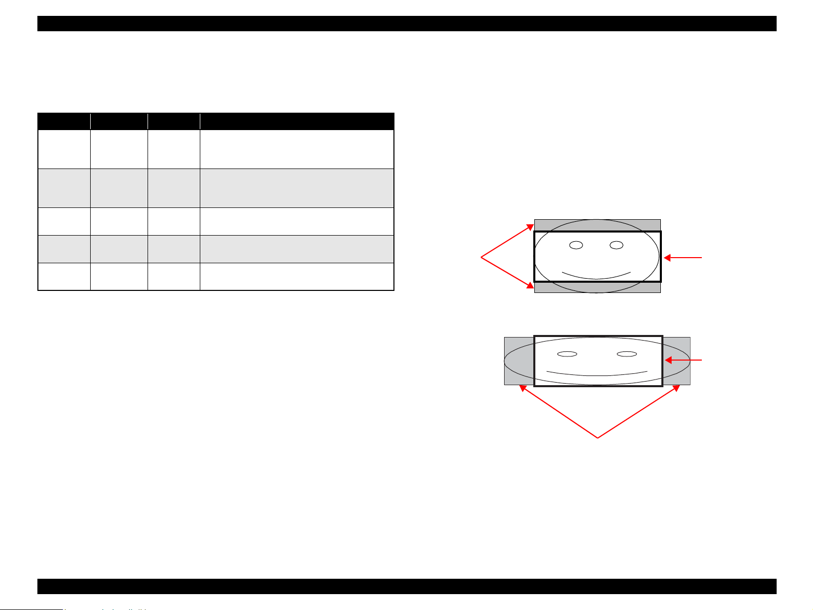
1.4.4 Trimming Function
A trimming function is provided as a means of coordinating photo data with the types
of photo frames handled by this unit. This function is always activated so that printing
photo data is in shapes that fit these photo frames.
This function is described briefly below.
The printed photo frame and the photo to be printed are matched in length along one
side and the photo is resized along the perpendicular side to fit the frame on that side.
Any part of the photo that does not fit within the photo frame is trimmed away (not
printed).
The image below shows an example in which the photo data is aligned vertically
with the photo frame.
These parts are
trimmed.
The image below shows an example in which the photo data is aligned
horizontally with the photo frame.
Photo frame
(print area)
Photo frame
(print area)
These parts are trimmed.
Figure 1-9. Trimming Function
PRODUCT DESCRIPTION Memory Card Print 23
Page 23
EPSON Stylus Photo R240/R245/R250/ME PHOTO 20 Revision C
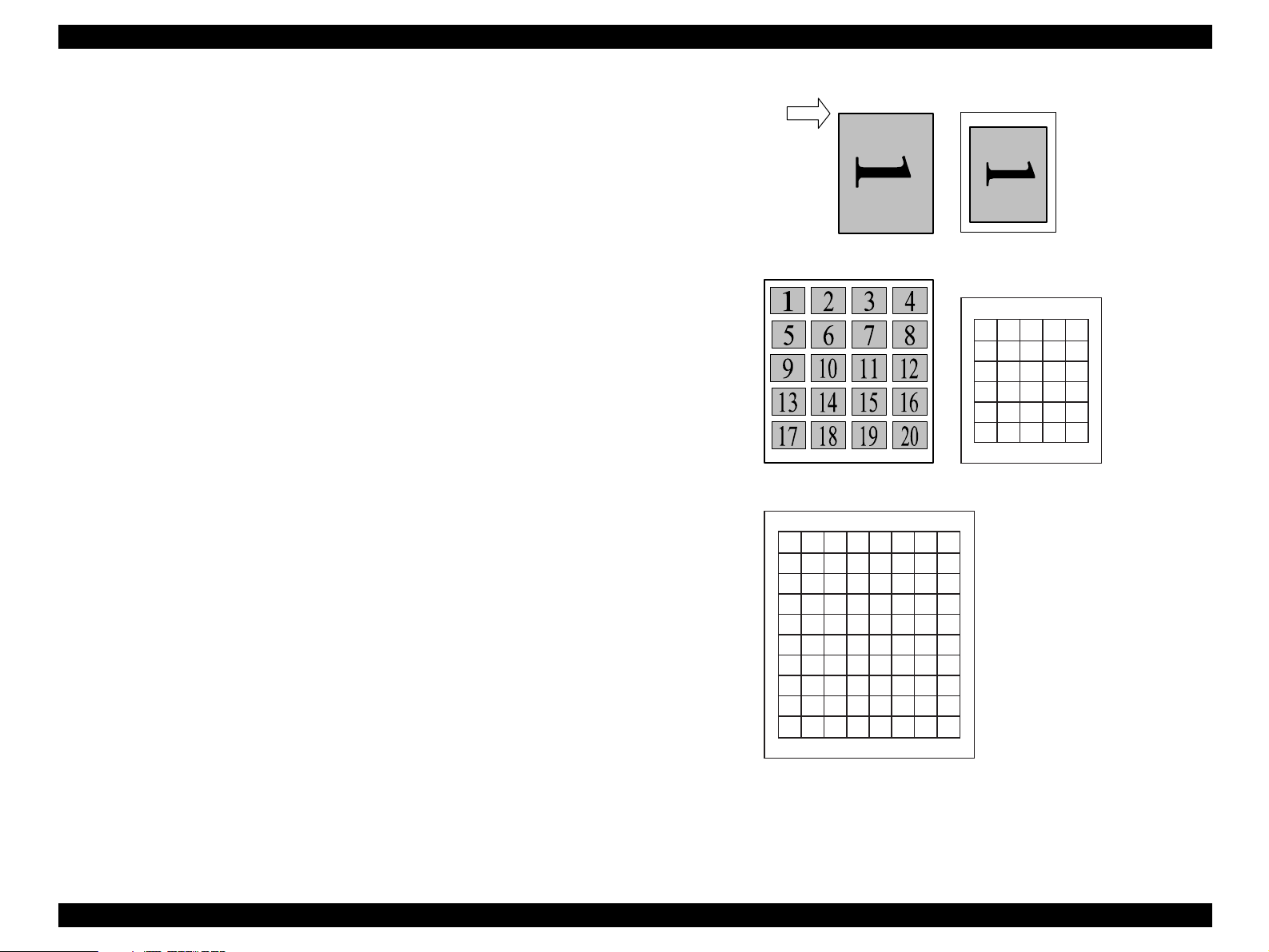
1.4.5 Assignment Rules for Photo Frame Numbers and Rotation
Top edge
The rules concerning photo frame numbers that are referenced when assigning photos
are described below. The numbers shown in each diagram and photo frame below
indicate the photo frame numbers used for various types of layout.
The direction of the number shown in each photo frame matches the direction of the
printed photo to which the horizontal photo data was allocated. When there are more
pixels vertically than horizontally, the vertical photo data is allocated instead, and the
number shown in the figure below is then rotated 90° before being printed. In Index
printing mode, the numbers are printed as they are shown below, regardless of the
shape of the photo data.
However, when the photo data has an equal number of pixels vertically and
horizontally the photos are printed without rotation, regardless of the layout.
NOTE: The vertical photo data refers to when the photo data file itself is set for a
vertical (portrait) orientation. Photo data is defined as the vertical photo
data if it is taken by a digital camera with a portrait position detecting
function.)
<Border-free> <1 sheet with borders>
12345
678910
11 12 13 14 15
16 17 18 19 20
21 22 23 24 25
25 26 27 28 30
<20-up>
12345678
9 10 111213141516
17 18 19 20 21 22 23 24
25 26 27 28 29 30 31 32
33 34 35 36 37 38 39 40
41 42 43 44 45 46 47 48
49 50 51 52 53 54 55 56
57 58 59 60 61 62 63 64
65 66 67 68 69 70 71 72
73 74 75 76 77 78 79 80
<80-up>
<30-up>
Figure 1-10. Assignment Rules for Photo Frame Numbers and Rotation
PRODUCT DESCRIPTION Memory Card Print 24
Page 24
EPSON Stylus Photo R240/R245/R250/ME PHOTO 20 Revision C
1.4.6 Layout Drawings
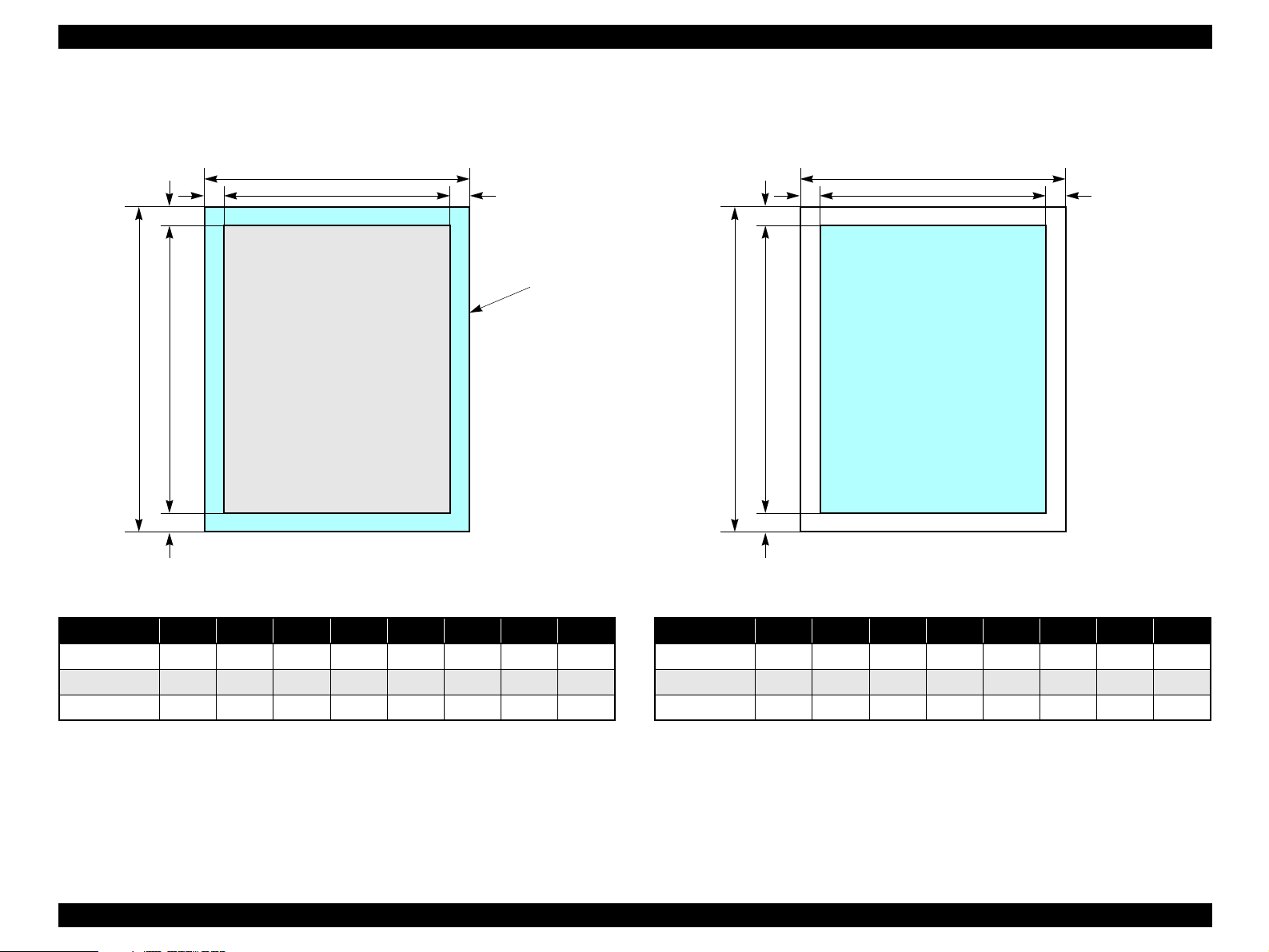
1.4.6.1 Border free
BD
H
C
A
Paper
Figure 1-11. Border free
Table 1-16. Border free (unit: mm)
FEG
Printable
area
1.4.6.2 1-up with borders
DB
H
Figure 1-12. 1-up with borders
Table 1-17. 1-up with borders (unit: mm)
A
C
Printable area
FEG
Paper type A B C D E F G H
A4 210 297 215.08 305.04 2.54 2.54 2.96 4.02
10x15 101.6 152.4 106.68 160.53 2.54 2.54 2.82 3.6
13x18 127 178 132.08 186.04 2.54 2.54 2.96 4.02
Paper type A B C D E F G H
A4 210 297 204 291 3 3 3 3
10x15 101.6 152.4 95.6 146.4 3 3 3 3
13x18 127 178 121 172 3 3 3 3
PRODUCT DESCRIPTION Memory Card Print 25
Page 25
EPSON Stylus Photo R240/R245/R250/ME PHOTO 20 Revision C
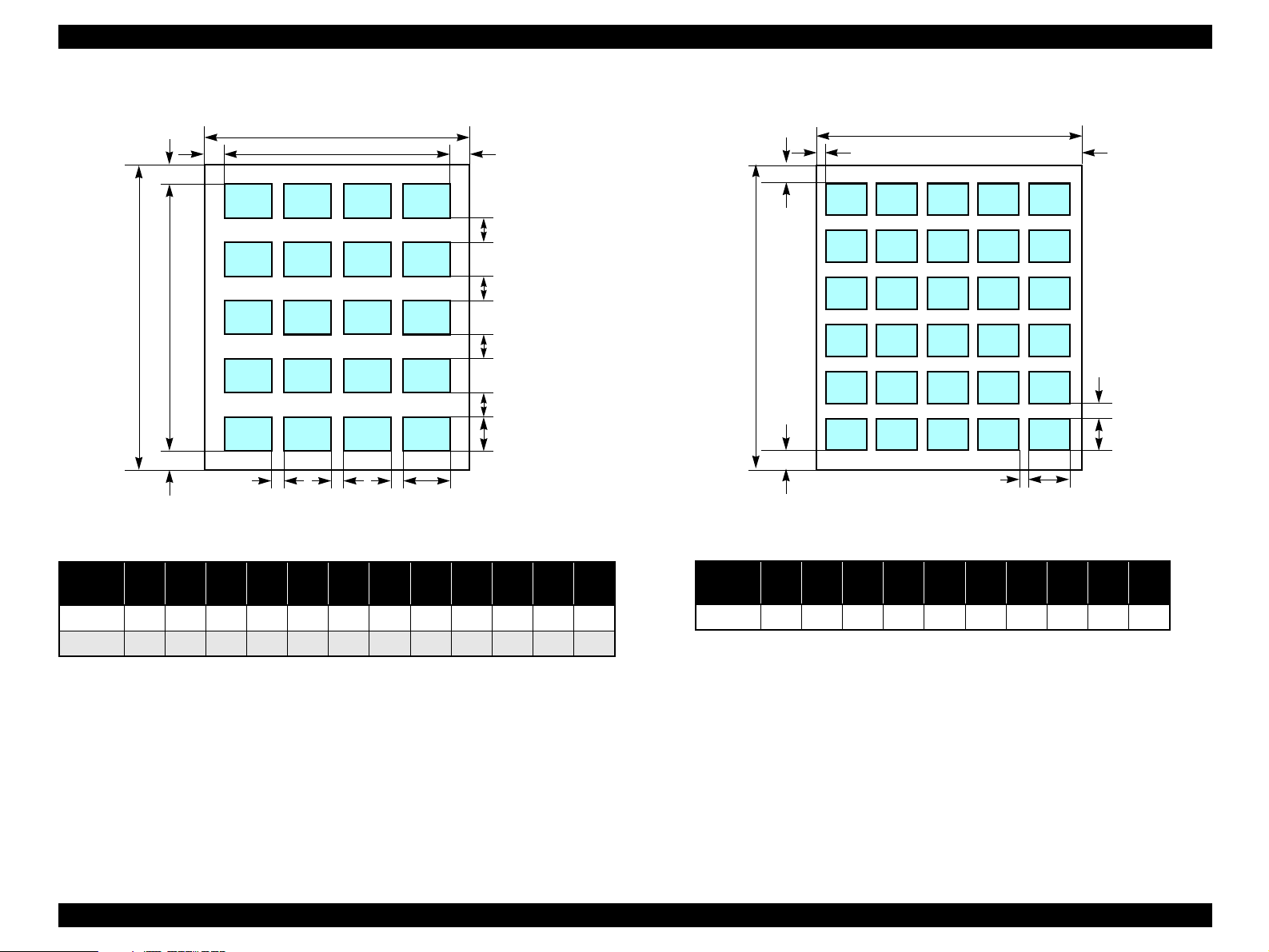
1.4.6.3 20-up
A
K
LB
H
IIIC
Figure 1-13. 20-up
Table 1-18. 20-up (unit: mm)
Paper
type
10x15 101.6 152.4 20 20 6.1 6.3 19.8 20.3 3 3 89.3 112.3
13x18 127 178 29 24.6 3 3 5 10 1.7 10 121 163
A B C D E F G H I J K L
FEG
J
J
J
J
D
1.4.6.4 30-up
A
B
H
Figure 1-14. 30-up
Table 1-19. 30-up (unit: mm)
Paper
type
13x18 127 178 20 20 4.5 4.5 14 14 4.5 6
A B C D E F G H I J
IC
FEG
J
D
PRODUCT DESCRIPTION Memory Card Print 26
Page 26
EPSON Stylus Photo R240/R245/R250/ME PHOTO 20 Revision C
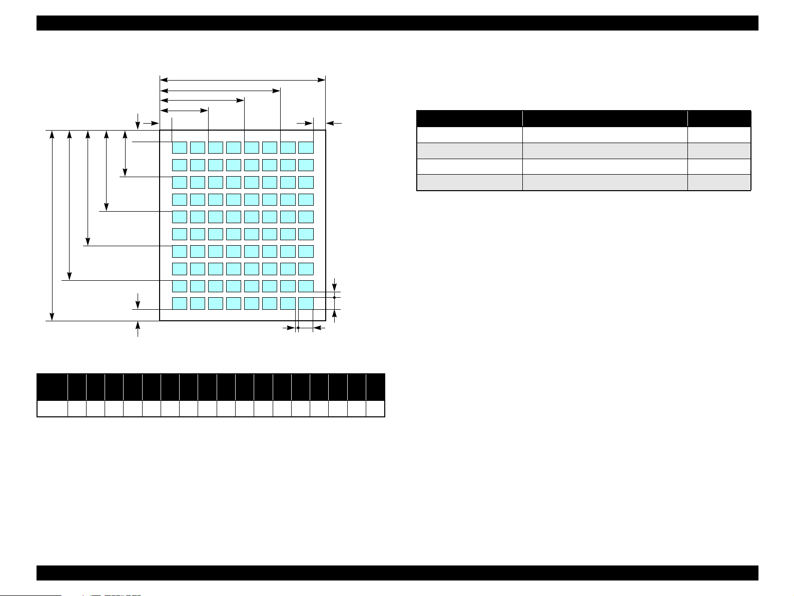
1.4.6.5 80-up
N
O
P
B
1.4.7 Relation between Paper Type and Quality
A
J
I
H
KGL
M
F
D
Q
EC
Figure 1-15. 80-up
Table 1-20. 80-up (unit: mm)
In this mode, printing is always in color (CMYK), not black ink only.
Table 1-21. Relation between Paper Type and Quality
Paper type Print resolution (H x V dpi) Dot size
Plain Paper 720 x 720 VSD3
Photo Paper 1440 x 720 VSD3
Matte Paper 1440 x 720 VSD3
Index sheet (Plain Paper) 360 x 360 VSD1
Paper
A4 210 297 20 20 2 5 18 62 106 150 18 26 76 126 176 226 26
A B C D E F G H I J K L M N O P Q
type
PRODUCT DESCRIPTION Memory Card Print 27
Page 27
EPSON Stylus Photo R240/R245/R250/ME PHOTO 20 Revision C
1.5 USB Direct-Print/PictBridge Functions
The printer can print from Digital Still Camera that is compliant with the following
specifications.
1.5.1 Supported Device
USB DIRECT-PRINT
The device that is compliant with “USB DIRECT-PRINT” specification.
CIPA DC-001-2003 Digital Photo Solutions for Imaging Device
The device that is compliant with “CIPA DC-001-2003 Digital Photo Solutions for
Imaging Devices” specification.
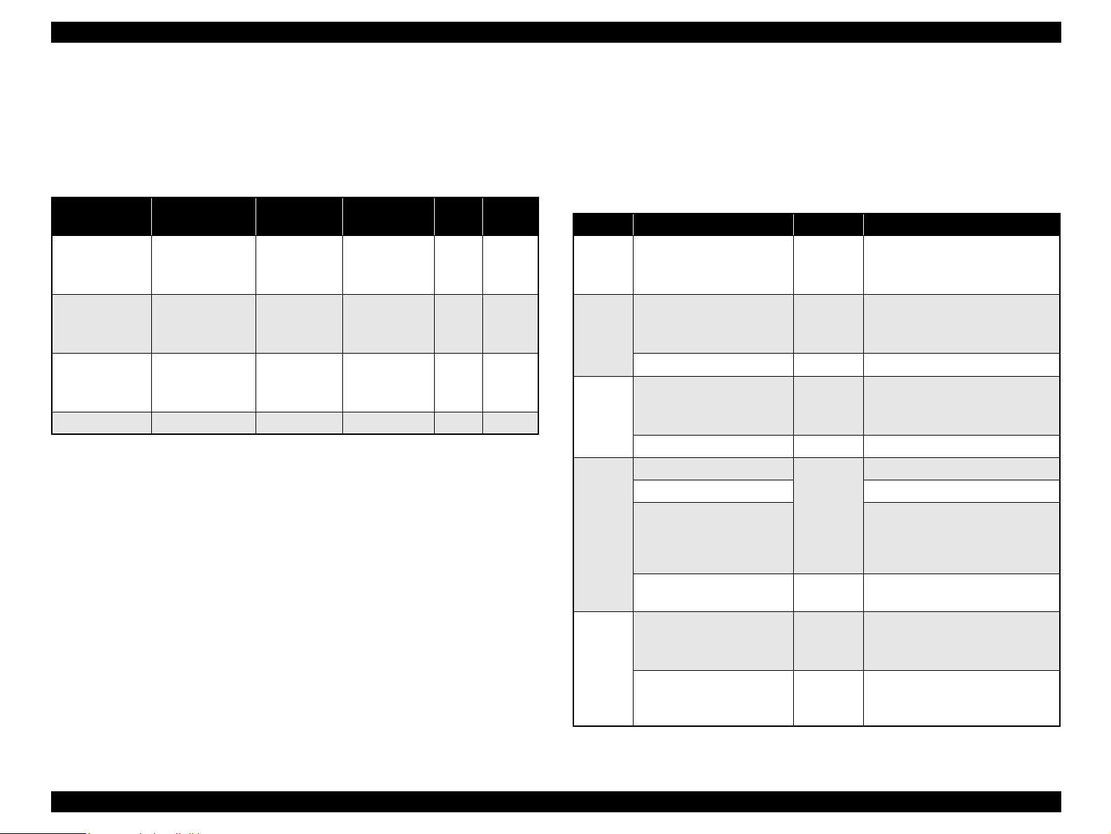
1.5.2 Functions Available from DSC
Following functions are available.
Implementation of each function depends on the DSC.
Table 1-22. Functions Available from DSC
Function USB Direct-Print Functions PictBridge Functions
Specify picture OK
(single picture or DPOF)OK(single picture, multiple pictures
or DPOF)
Specify paper type OK
(Plain paper, Photo paper,
Glossy paper and Matte paper)
Specify paper size OK
(A4, 5x7in., 4x6in., 8x10in. and Letter)
Specify layout OK
(borderless, Single. 2up, 4up,
8up are available for DPOF)
Specify date print OK
(Enable or Disable)
Specify print quality NG OK
Automatic correction OK
(Enable or Disable)
Cropping OK
(Any area of rectangle. This
function is available for Single
picture print only)
(Plain paper and Glossy paper)
(borderless, Single, 2up, 4up,
8up, 20up and Index)
(Any area of rectangle)
OK
OK
OK
NG
OK
Table 1-22. Functions Available from DSC
Function USB Direct-Print Functions PictBridge Functions
PRINT Image Framer OK
(Enable or Disable)
Status acquisition OK
Start print OK
Stop print immediately OK
Stop print at the end of page OK
Reset printer OK ---
---
1.5.3 Operation
1.5.3.1 Preparation
Conditions described below are required before starting printing.
The printer is not printing from the PC.
The printer is not printing from the memory card slot.
The printer is not performing the backup of the memory card.
The error (paper empty, ink end, etc.) is cleared.
Note *: PictBridge only.
1.5.3.2 Standard Operations
Standard operations are described below. These operations depends on the DSC.
1. Preparation at the printer
Some settings are required before connecting with the DSC. If your DSC can set
these settings, preparation at the printer is not required.
1-1. Choose the Paper Type, Paper Size and Layout to the desired setting.
1-2. Change More Options if necessary (e.g. Automatic Correction, Filter and
Date print)
2. Preparation at the DSC
Some operations are necessary before connecting to the printer.
2-1. Set the DPOF (or select pictures*) if printing multiple picture.
*
PRODUCT DESCRIPTION USB Direct-Print/PictBridge Functions 28
Page 28

EPSON Stylus Photo R240/R245/R250/ME PHOTO 20 Revision C
2-2. Choose the picture when Single picture print and set area to crop if
necessary.
2-3. Choose the Paper Type, Paper Size, Quality and Layout if these settings can
be specified from DSC.
Note *: PictBridge only.
3. Start printing
3-1. Connect the DSC to the printer with a USB cable. The cable that works well
with the DSC is recommended.
3-2. Start print by operating form the DSC.
3-3. The Printer print by printing conditions from DSC, if the DSC dose not
designate the printing parameter, the printer prints it by using the printing
condition that is registered to the printer.
When this unit is connected to a DSC that supports the USB DIRECT-PRINT protocol
(Revision 1.0), print settings, image selection, status monitoring, and print start/stop
commands can be controlled from the DSC.
Note *1: USB Direct-Print only.
*2: PictBridge only.
*1
*2
1.5.3.3 Display when DSC is Connected
When DSC is connected with the above conditions, “Camera Connected” icon will be
displayed on the LCD and the “Print All” LED will be turned on.
1.5.3.6 Exclusive Control Specifications for Paper Type, Size, and
Layout
Depending upon the DSC and printer settings, there may be some combinations of
paper type, size, and layout settings that are not supported by this printer.
In such a case, the paper type is given priority; paper size and layout are changed to
settings that will allow printing (the initial settings made on the printer’s operation
panel for the paper type given priority) and the document is printed.
1.5.3.7 Camera direct error executing other processing (error)
When unsupport equipment are connected during the other processing is executed
(error), the camera direct error is displayed after other processing execution (error).
When the unsupport equipment is connected and other processing ends, it doesn't
become a camera direct mode and the camera direct error is not displayed.
1.5.3.4 Cancel Print
This unit can be canceled from the DSC. The “Stop” button of the printer is also
available.
1.5.3.5 Operation when the Printing is Completed
Disconnect the USB cable after the printing is completed if you’d like to print from the
memory card
PRODUCT DESCRIPTION USB Direct-Print/PictBridge Functions 29
Page 29
EPSON Stylus Photo R240/R245/R250/ME PHOTO 20 Revision C
1.6 Control Panel
1.6.1 Buttons
The control panel contains following 11 buttons, which are used to set and execute
various operations.
All of them are non-lock type buttons.
Table 1-23. Buttons
Button Function
Power Button Execute turning on/off this unit.
Mode Button Selects one of memory card print mode.
Setup/Utilities Button Make transition from “Memory Card mode” to “Setup mode”.
Up/Down Button sets number of copies.
Left/Right Button Select print image.
Paper Type Button Select paper type.
Paper Size Button Select paper size.
Start Button Start card print.
Stop/Clear Button Stop job of printing or sometimes work at the printing.
Clear the setting value at the non-printing
Refer to “1.6.5.1 Memory card mode/Setup mode/DSC direct mode ” (p.33) for details
about each button.
1.6.2 Indicators
The control panel contains 1.5” LCD and 10 LEDs, and one LED is located near the
card slot, which are used to indicate various status.
Table 1-24.
LED Function
Power LED [Green] Light at stand-by. Blink while some operation is proceeding.
Mode LED 1-3 Light one of them while some memory card print function
showing below is ready or proceeding.
1st [Green] Print Select
2nd [Green] Print All/PictBridge
3rd [Green] Print Index Sheet
Paper Type LED 1-3 Light one of them showing which paper type below is selected.
1st [Green] Plain Paper
2nd [Green] Photo Paper
3rd [Green] Matte paper
Paper Size LED 1-3 Light one of them showing which paper size below is selected.
1st [Green] A4
2nd [Green] 10x15/4"x6"
3rd [Green] 13x18/5"x7"
1.5inch LCD Display photo, print number, error, setting, etc.
Card Access LED [Green]* Light when available memory card is in a slot. Blink when
accessing to the card.
Note * : An another LED is located near the memory card slot and the printer status is
indicated with the LED.
PRODUCT DESCRIPTION Control Panel 30
Page 30
EPSON Stylus Photo R240/R245/R250/ME PHOTO 20 Revision C
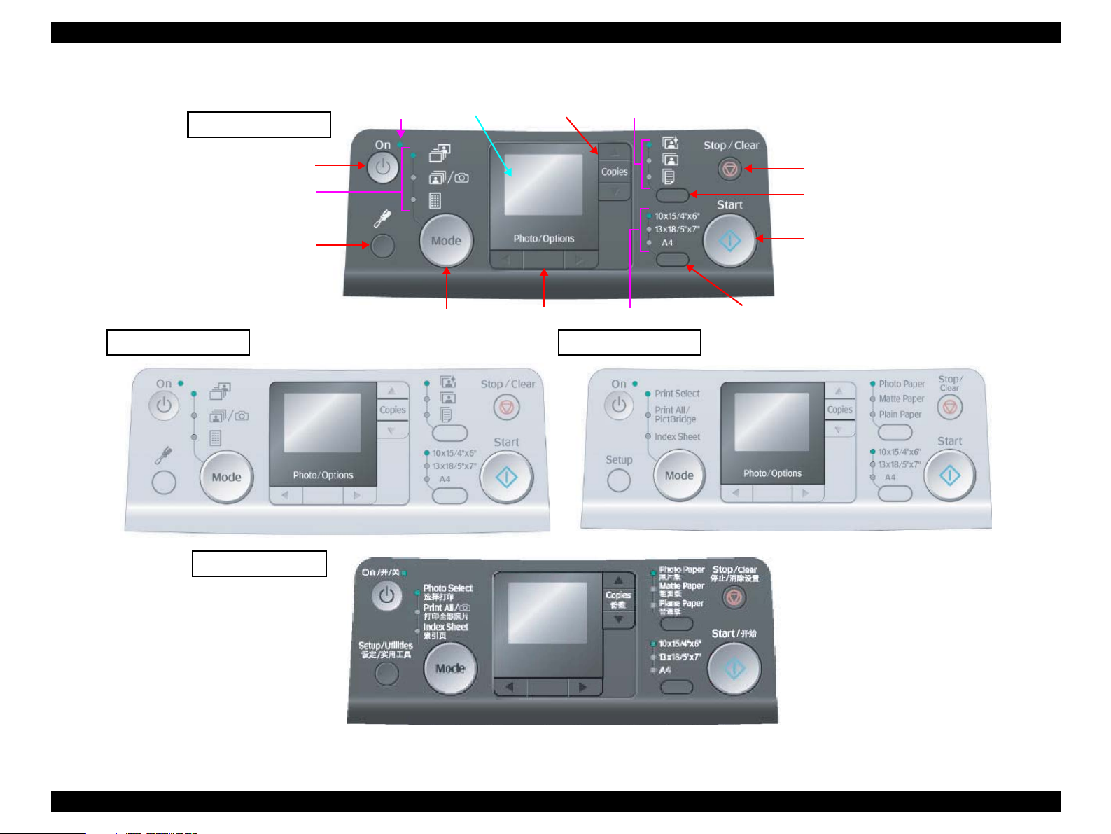
1.6.3 Control Panel Appearance
Paper Type LED 1-3
Standard version
Power LED
1.5inch LCD
Up/Down Button
Setup/Utilities Button
Premium version
ME PHOTO 20
Power Button
Mode LED 1-3
Mode Button
Left/Right Button
Paper Size LED 1-3
Asia version
Stop/Clear Button
Paper Type Button
Start Button
Paper Size Button
Figure 1-16. Control panel
PRODUCT DESCRIPTION Control Panel 31
Page 31

EPSON Stylus Photo R240/R245/R250/ME PHOTO 20 Revision C
1.6.4 The method of changing mode
This printer has the following four modes:
Memory card mode
Setup mode
*1
DSC direct mode
If a memory card is not inserted at power-on, Memory card mode is selected in default
configuration.
Note *1: It is possible to enter respective modes by pressing the button with the same
name as each mode.
*2: This unit moves to a DSC direct mode after a device is confirmed for DSC direct,
when a device is connected to EXT. I/F (USB Host).
Factory settings of each mode are shown below.
Paper Type Photo paper Plain paper
Paper Size 4"x6" or 10x15/4"x6" A4
Sheet 1 ---
*1
*2
Table 1-25. Factory Settings of Each Mode
Item Memory card mode Setup mode
Refer to “1.6.5.1 Memory card mode/Setup mode/DSC direct mode ” (p.33) for details
about DSC direct mode.
PRODUCT DESCRIPTION Control Panel 32
Page 32

EPSON Stylus Photo R240/R245/R250/ME PHOTO 20 Revision C
1.6.5 Operations
1.6.5.1 Memory card mode/Setup mode/DSC direct mode
The functions of this unit caused by each button in stand-alone copy mode or memory card print mode are described in the following table.
Table 1-26. Operations
Button
Power Button • Turn off this unit.
Memory Card
Button
Setup/Utilities
Button
Left/Right Button • Select print image. • Select setup menu. • Invalid.
Up/Down Button • Set number of copies incrementally/decrementally. • Select adjustment value or setting value. • Invalid.
Paper Type
Button
Paper Size Button • Alternate paper size of “A4”, “4x6/10x15” and “5x7/13x18”, which
• Change to next “Memory card print” function.
Case
• [Print Select]
Change to “Print All/PictBridge”.
• [Print All/PictBridge]
Change to “Print Index Sheet”, and change paper type and paper size
to “Plain Paper” and “A4”.
• [Print Index Sheet]
Change to “Print Select”, and change paper type and paper size to the
one last set in “Print All/PictBridge” or “Print Select”.
• Invalid while printing, cleaning head, stopping printing, exchanging I/C, or in error status except for memory card error, PG error.
• Make transition from “Memory card print” mode to “Setup” mode and
light off all mode LEDs.
• Invalid while printing, cleaning head, stopping printing, exchanging I/C, or in error status except for memory card error, PG error.
• Invalid while printing, cleaning head, stopping printing, exchanging I/C, or in error status.
• Invalid while printing, cleaning head, stopping printing, exchanging I/C, or in error status.
• Alternate paper type of “Plain Paper”, “Photo Paper” and “Matte
Paper”, which will be used in “Print All/PictBridge” or “Print Select”.
• Invalid in “Print Index Sheet”, and then it is fixed to “Plain Paper”.
• Invalid while printing, cleaning head, stopping printing, exchanging I/
C, or in error status.”
will be used in “Print All/PictBridge” or “Print Select”.
• Invalid in “Print Index Sheet”, and then it is fixed to “A4”.
• Invalid while printing, cleaning head, stopping printing, exchanging I/
C, or in error status.
Memory Card Print Setup mode DSC direct mode
• Make transition from “Setup” mode to “Memory card print”
mode and select and light “Print Select”.
• Select paper type and paper size those are memorized.
• Return to the original mode selected before “setup” mode. • Make transition to “Setup” mode and
• Invalid. • Same as “Paper Type Button” of Memory
• Invalid. • Same as “Paper Size Button” of Memory
Function
• Invalid.
light off all mode LEDs.
Card Print.
Card Print.
*1, 2
PRODUCT DESCRIPTION Control Panel 33
Page 33

EPSON Stylus Photo R240/R245/R250/ME PHOTO 20 Revision C
Table 1-26. Operations
Button
Memory Card Print Setup mode DSC direct mode
Start Button • Start memory card print.
• Invalid with no card in slots.
• Move to memory card error status when incompatible memory card is
inserted or no images found in the card.
• Invalid while printing, cleaning head, stopping printing, exchanging I/C, or in ink out error.
• Load paper in paper out error or double feed error and eject paper in paper jam error.
• Move to PG error status when platen gap is large. But when this button is pressed again in that status, that print will start.
Stop/Clear
Button
Not printing situation
• Reset the setting value (paper size, paper type, number of copies).
• Light all paper type and paper size LEDs for 1 second.
Printing situation
• Stop job of printing.
• Eject paper when paper exists or may exist in the paper path.
• Invalid while cleaning head and exchanging I/C.
• Clear some of error status.
Note *1 : Start print by operating form the DSC
• Start job of printing by conditions from DSC, if the DSC dose not designate the
printing parameter, the printer prints it by using the printing condition that is
registered to the printer.
• Invalid while printing, cleaning head, stopping printing, exchanging I/C, or in ink
out error, or without “A4” is selected.
• Move to PG error status when platen gap is large.
*2: Start print by operating form the DSC
Not copying or printing situation
• Invalid.
Copying or printing situation
• Stop job of printing.
• Eject paper when paper exists or may exist in the paper path.
• Invalid while cleaning head and exchanging I/C.
• Clear some of error status.
Function
*1, 2
• Execute procedure or Start print. Invalid but for cleaning some error
status.
(See below)
• Load paper in paper out error or double
feed error and eject paper in paper jam
error.
• Move to PG error status when platen gap
is large. But when this button is pressed
again in that status, that print will start.
Not printing situation
• Reset the setting value when the setup menu is “Auto
• Same as “Stop/Clear Button” of Memory
Card Print.
Correct” or “Borderless setting”.
• Light all paper type and paper size LEDs for 1 second and
return to “Check Ink Levels” screen.
Printing situation
• Stop job of printing.
• Eject paper when paper exists or may exist in the paper path.
• Invalid while cleaning head and exchanging I/C.
• Clear some of error status.
PRODUCT DESCRIPTION Control Panel 34
Page 34

EPSON Stylus Photo R240/R245/R250/ME PHOTO 20 Revision C
1.6.5.2 Memory Card Insertion/Ejection
The functions of this unit caused by memory card insertion or ejection are described in
the following table.
Table 1-27. Memory Card Insertion/Ejection
Action Function
Card Insertion • Recognize the card and light Card Access LED if it is right.
• The LED blinks while memory access occurs to the memory card.
• The Power LED blinks during the card recognition.
• Return from the low power panel mode.
Card Ejection • Turn off Card Access LED.
• Stop print job while memory card print is in process and eject paper.
• Clear memory card error if memory card is wrong.
1.6.5.3 Connection/Removal of DSC
Table 1-28. Connection/Removal of DSC
Action Function
Connect the
DSC to this unit
by USB cable
Remove the
DSC from this
unit
• This unit moves to a DSC direct mode after a device is confirmed for DSC
direct, when a device is connected to EXT. I/F (USB Host). It won’t move to
DSC direct mode when it shows general printing mode or error. It moves to
DSC direct mode when it finished printing or error status has been resolved.
(Errors that is related with memory card, order sheet or PG will be
automatically canceled and it moves to DSC direct mode. Ink-low status will
be also ignored.).
• “Camera Connected” icon will be displayed with LCD and Change to “Print
Select” when connection was confirmed, not when it moves to DSC direct
mode. If the DSC direct device was connected to EXT I/F and any error has
occurred on confirmation, it shows DSC direct error.
• If this unit was on power save mode and DSC direct device was connected,
this unit will be back to usual status and then it confirms connection.
• This unit moves to “Memory card print” mode and select and light “Print
Select” when condition where device recognition was carried out normally
for DSC direct.
• During the printing from a device for DSC direct, this unit stops a printing
and moves to “Memory card print” mode and select and light “Print Select”.
• When this unit is displaying “DSC direct error”, this unit cancel it error. And
this unit returns it in condition of before connection.”
1.6.5.4 Low Power Panel Mode
Without any panel operation for 3 minutes while the printer unit is in standby status,
this unit moves into the low power panel mode in which power consumption for the
panel decreases.
This unit recovers from that mode by pushing any button but Power Button or printing
by PC.
This unit is turned off by pushing Power Button in that mode.
Table 1-29. Low Power Panel Mode
Action Function
Transition to low
power mode
Recovery from low
power mode
• Turn off all LEDs except for Power LED and Card Access LED.
• No move in error status except for memory card error and PG error.
• Inserting or ejecting of memory card or accessing it by PC has no effect
on low power mode.
• Recall the panel status as that before moving to low power panel mode.
• Inserting or ejecting of memory card or accessing it by PC has no effect
on low power mode.
1.6.5.5 Paper Thickness Lever Function
Paper thickness lever is wrong position, the printer displays “PG position” warning.
Table 1-30. Paper Thickness Lever Function
Paper thickness
lever status
PG open
(“H” to “L”)
PG close
(“L” to “H”)
• “Paper thickness lever was changed” or this image icon will be
displayed with LCD.
• “Paper thickness lever was changed” or this image icon will be
displayed with LCD.
• Clear the PG error and print job suspended by PG error when the Paper
thickness lever is changed to “L: Cut sheet position” in the PG error
status.
Function
PRODUCT DESCRIPTION Control Panel 35
Page 35

EPSON Stylus Photo R240/R245/R250/ME PHOTO 20 Revision C
1.6.6 Printer Condition and Panel Status
Note : “–”: Don’t care
Fast blink: 0.2sec. On + 0.2sec. Off repetition
Blink: 0.5sec. On + 0.5sec. Off repetition
Blink 2: Blink on and off along with access to a memory card.
Indicators (Normal ready mode)
Printer status Power LED
Power on (Initializing operation) Blink --- --- --- --- --- --- --- --- --- ---
Power on (Data Processing) Blink --- --- --- --- --- --- --- --- --- ---
Power off (Power-off in progress) Fast blink Off Off Off Off Off Off Off Off Off ---
Memory card mode (Print All/DPOF) --- Blink --- --- Selected type is On Selected type is On ---
Memory card mode (Print select) --- --- Blink --- Selected type is On Selected type is On ---
Memory card mode (Print index sheet) --- --- --- Blink Blink --- --- Blink --- --- ---
Setup mode --- Off Off Off Blink --- --- Blink --- --- ---
DSC direct mode --- --- --- --- Selected type is On Selected type is On ---
1 2 3 1 2 3 1 2 3
Mode LED Paper Type LED Paper Size LED
Card Access
LED
Indicators (Normal printing mode)
Printer status Power LED
Memory card mode (Print All/DPOF) Blink Blink --- --- Selected type is On Selected type is On ---
Memory card mode (Print select) Blink --- Blink --- Selected type is On Selected type is On ---
Memory card mode (Print index sheet) Blink --- --- Blink Blink --- --- Blink --- --- ---
DSC direct mode Blink Off Off Off Selected type is On Selected type is On ---
Printing by a computer Blink --- --- --- --- --- --- --- --- --- ---
Reading a memory card is in progress Blink --- --- --- --- --- --- --- --- --- Blink
Ink sequence processing Blink --- --- --- --- --- --- --- --- --- ---
Receiving setting clear request --- --- --- --- On (1sec.) On (1sec.) On (1sec.) On (1sec.) On (1sec.) On (1sec.) ---
Check ink nozzles, Clean print head,
Align print head
--- Off Off Off Blink --- --- Blink --- --- ---
1 2 3 1 2 3 1 2 3
Mode LED Paper Type LED Paper Size LED
Card Access
LED
PRODUCT DESCRIPTION Control Panel 36
Page 36

EPSON Stylus Photo R240/R245/R250/ME PHOTO 20 Revision C
Indicators (Other)
Printer status Power LED
No memory card --- --- --- --- --- --- --- --- --- --- Off
Memory card processing --- --- --- --- --- --- --- --- --- --- Blink
Reading memory card --- --- --- --- --- --- --- --- --- --- Blink 2
Power on (Initializing operation) On Off Off Off Off Off Off Off Off Off ---
1 2 3 1 2 3 1 2 3
Mode LED Paper Type LED Paper Size LED
Card Access
LED
PRODUCT DESCRIPTION Control Panel 37
Page 37

EPSON Stylus Photo R240/R245/R250/ME PHOTO 20 Revision C
LCD
Printer status Error status ID Priority
Power off (Power-off in progress) --- --- 1
Fatal error (Fatal error) Mechanical or internal trouble occurs. E-90 2
Maintenance request (Fatal error) Waste ink pad saturated. E-91 2
Power on (Initializing operation) --- --- 3
Receiving setting clear request --- --- 4
Paper jam (General error) Paper stays in the paper path after paper ejection. E-04 5
Card loading error --- E-05 5
Ink out, No I/C, Incorrect I/C (General error) Ink is out in some I/C or no I/C is set or incorrect I/C is set. E-01/E-02 6
Ink Change --- I-02 7
Ink sequence in progress --- --- 8
Paper out (General error) Failure to load paper to print. E-03 8
Double feed (General error) Double feed during double sided printing. --- 10
PG open (Warning) Platen gap is at open position while standalone function. W-30 11
PG lever low --- I-41 12
PG lever high --- I-40 12
Stop printing & Cancel job --- --- 13
Printing (PC connected, PictBridge, DirectPrint) --- --- 14
Reading memory card (counting up image data) --- --- 15
DSC Direct mode --- I-20/I-21 15
DSC Direct error (Warning) A device not supported is connected to the port for the connection of external memory devices. W-20 15
Memory card error (Incompatible memory card) (Warning) That memory card is not available with this unit.
Or no image can be found in that card when memory card print is started.
Memory card error (No memory card) (Warning) Memory card is not inserted. I-10 16
Memory card mode --- --- 17
Borderless setting alert --- I-30 18
Unable cleaning error (General error) Unable head cleaning. E-50 18
Ink low (Warning) Some ink is near end. --- 18
Maintenance request
Power on --- --- 19
*
(Warning) Waste ink pad will be soon saturated. W-01 18
W-10/W-11 16
Note * : Waste ink pad will soon saturated.
PRODUCT DESCRIPTION Control Panel 38
Page 38

OPERATING PRINCIPLES
CHAPTER
2
Page 39

EPSON Stylus Photo R240/R245/R250/ME PHOTO 20 Revision C
2.1 Overview
This section describes the operating principles of the Printer Mechanism, Mechanism
and Electrical Circuit Boards.
Main Board
C606 Main Board
Power Supply Board
C610 PSB/PSE Board
Panel Board
C606 PNL Board
2.2 Printer Mechanism
2.2.1 Printer Mechanism
This printer consists of the Print Head, Carriage Mechanism, Paper Loading
Mechanism, Paper Feeding Mechanism, Ink System.
Like the previous printers, the Stylus R240/R245/R250 is equipped with two DC
motors; one for the Paper Loading/Feeding Mechanism and the Pump Mechanism with
the CR Lock Mechanism, and one for the CR Mechanism. The ASF Unit for the Paper
Loading Mechanism uses rear entry front eject system. The Paper Feeding Mechanism
uses the LD Roller and Retard Roller to feed paper to the Printer Mechanism in the
same way as previous printers.
PG Sensor
PF Roller
Star Wheel
PW Sensor
Carriage Unit
EJ Roller
Change Lever
PF ScalePF Encoder Sensor
CR Motor
PF Motor
Timing Belt
CR Encoder
Sensor
LD Roller
Retard Roller
Compression
Spring
PE Sensor
Clutch Mechanism
Cap Unit
Pump Unit
Figure 2-1. Printer Mechanism Block Diagram
OPERATING PRINCIPLES Overview 40
Page 40

EPSON Stylus Photo R240/R245/R250/ME PHOTO 20 Revision C
2.2.2 Print Head
The Print Head is the same D4-CHIPS type, and makes it possible to perform economy
dot printing and variable dot printing.
The Print Head nozzle configuration is as follows.
Nozzle layout
Black: 90 nozzles x 1 row
Color: 90 nozzles x 3 row/color (Cyan, Magenta, Yellow)
The nozzle layout when viewed from the back surface of the Print Head is shown
below.
Paper Feed Direction
2.822
(40/360inch)
#A90
#A89
#A88
A row
#A3
#A2
#A1
8.467
(120/360inch)
#B90
#B89
#B88
B row C row D row
#B3
#B2
#B1
Carriage Moving Direction
#C90
#C89
#C88
#C3
#C2
#C1
Figure 2-2. Nozzle Layout
(40/360inch)
#D90
#D89
#D88
#D3
#D2
#D1
BlackCyan Magenta Yellow
2.822
0.07055
(1/360inch)
0.1411
(2/360inch)
0.2117
(3/360inch)
The basic operating principles of the Print Head, which plays a major role in printing,
are the same as the previous printer; on-demand method which uses PZT (Piezo
Electric Element). In order to uniform the ejected ink amount, the Print Head has its
own Head ID (13-digits code for this Print Head for Stylus Photo R240/R245/R250)
which adjusts PZT voltage drive features.
So, you are required to store the Head ID pasted on the Print Head into the EEPROM
by using the Adjustment Program when replacing the Print Head, the Main Board Unit,
the Printer Mechanism with new one. (Note: there are no resistor arrays to determine
the Head ID on the Main Board.) And then, based on the stored Head ID into the
EEPROM, the Main Board generates appropriate PZT drive voltage.
Following explains the basic components for the Print Head.
PZT
PZT is an abbreviation of Piezo Electric Element. Based on the drive waveform
generated on the Main Board, the PZT selected by the nozzle selector IC on the
Print Head pushes the top of the ink cavity, which has ink stored, to eject the ink
from each nozzle on the nozzle plate.
Electric poles for CSIC
This Electric Poles connects the CSIC chip mounted on the Ink Cartridge. By
using this poles, current ink consumption amount data is red out from the CSIC
chip. And, the latest ink consumption amount data is written into the CSIC chip.
Nozzle Plate
The plate with nozzle holes on the Print Head surface is called Nozzle Plate.
Filter
When the Ink Cartridge is installed, if any dirt or dust around the cartridge needle
is absorbed into the Print Head, there is a great possibility of causing nozzle clog
and disturbance of ink flow, and alignment failure and dot missing finally. To
prevent this problem, a filter is set under the cartridge needle.
The Print Head has the Electric Poles (CSIC Connectors) to store the ink consumption
amount data into the CSIC chip mounted on the Ink Cartridge. By storing the ink
consumption amount data, this printer can detect the ink consumption status, such as
Ink Low/Out condition.
OPERATING PRINCIPLES Printer Mechanism 41
Page 41

EPSON Stylus Photo R240/R245/R250/ME PHOTO 20 Revision C
Ink Cavity
The ink absorbed from the Ink Cartridge goes through the filter and then is stored
temporarily in this tank called “ink cavity” until PZT is driven.
Electric poles for CSIC
Needle
Filter
Nozzle selector board
CSIC Memory chip
* Head ID for the Print Head is
stored to the EEPROM.
PZT
Nozzle plate
Ink cartridge
Cavity
Figure 2-3. Print Head Sectional Drawing
2.2.2.1 Printing Process
This section explains the process which the Print Head of On-Demand inkjet printers
eject ink from each nozzle.
1. Normal state
When the printing signal is not output from the Main Board (C606 Main), or the
PZT drive voltage is not applied, the PZT does not change the shape. Therefore,
the PZT does not push the ink cavity. The ink pressure inside the ink cavity is kept
normal. (refer to Figure 2-4 (p.42): Normal state)
2. Ejecting state
When the print signal is output from Main Board (C606 Main), the nozzle selector
IC located on the Print Head latches the data once by 1-byte unit. Based on the
drive waveform (common voltage) generated on the Main Board, the PZT selected
by the nozzle selector IC pushes the top of the ink cavity. By this operation, the ink
stored in the ink cavity is ejected from nozzles. (refer to Figure 2-4 (p.42):
Ejecting state)
Ink path PZT Ink cavity
Normal state
Nozzle Nozzle plate
PZT drive voltage
Ejecting state
Figure 2-4. Print Head Printing Process
2.2.2.2 Printing Method
The dot printing systems of Stylus Photo R240/R245/R250 are variable dot printing
systems.
Variable dot printing
This printing mode is developed to improve the print quality on exclusive paper.
This mode is basically the same as variable dot printing mode used on other
products; micro dot, middle dot and large dot compose this mode. The printing dot
size varies according to the print data and this mode enables to output even sharper
image on exclusive paper.
Economy dot printing
Economy dot printing is basically used only during Economy mode printing. The
reason is that the resolution is low during Economy mode printing, so that the dot
size needs to be bigger.
OPERATING PRINCIPLES Printer Mechanism 42
Page 42

EPSON Stylus Photo R240/R245/R250/ME PHOTO 20 Revision C
2.2.3 Carriage Mechanism
The Carriage Mechanism consists of Carriage Unit (including the Print Head, CR
Encoder Board and PW Sensor), CR Motor, Timing Belt and CR Scale etc.
Following figure shows you each component for the CR Mechanism.
2.2.3.1 Carriage Mechanism
The following DC motor controls the CR Mechanism on this printer.
Table 2-1. CR Motor Specification
Items Specifications
Type DC motor with brushes
Drive Voltage 42V (DC) ± 5% (voltage applied to driver)
Armature resistance 29.1 Ω ± 10% (per phase at 25 degrees)
Inductance 20.1mH ± 25% (1KH 1Vrms)
Drive Method PWM, constant-current chopping
Driver IC A6627
Close loop control based on the CR Motor (DC Motor) and CR Encoder has
advantages in stabilized print quality.
Heat generation control
Using low-cost DC motors, this product grasps the variations of the torque
constants, coil resistances and power supply voltages of the individual DC motors
adequately to carry out heat generation control according to individual differences.
CR measurement sequence
To set the appropriate drive current value according to the variation of the CR
mechanical load, the mechanical load is measured in a CR measurement sequence
and saved into the EEPROM in a power-on or I/C change sequence. A fatal error
will occur if too much load is applied to the CR drive system.
The above control and sequences correct the drive current value of the CR Motor
according to not only the mechanical load but also the variations of the motor and like.
In addition, the resultant CR drive current value is used to calculate a heating value,
and when the specified heating value is reached, wait time is provided per CR path for
printing.
CR Motor
CR Scale CR Encoder SensorPW Sensor
CR variation measurement sequence
The variations of the torque constant, coil resistance and power supply voltage of
the motor are measured in a CR variation measurement sequence when the CR
Carriage Guide ShaftTiming Belt
Figure 2-5. Carriage Mechanism
Carriage Unit
mechanical load is in the initial status and saved into the EEPROM. According to
the variations (individual differences) measured in this sequence, the voltage is
corrected to make the drive current value constant (without an individual
difference).
OPERATING PRINCIPLES Printer Mechanism 43
Page 43

EPSON Stylus Photo R240/R245/R250/ME PHOTO 20 Revision C
2.2.3.2 Carriage Home Position Detection
Like other conventional models, the carriage home position is detected using the CR
Motor drive current and the CR Encoder speed/position signals. Fundamental home
position detection sequence is described below.
1. Current position temporary detection sequence determines if the carriage is in the
carriage lock position and releases the carriage if it is locked.
2. The carriage is moved to the left frame hit position and the carriage motor is
stopped.
3. The position that is specified steps right from the stopping place is defined as an
origin, and from that time, positional information is monitored by the linear
encoder.
If the positional information could not be gained during detecting carriage home
position due to the following causes, fatal error occurs.
Obstructions on the carriage path or other factors are giving too much pressure on
the CR motor.
CR Encoder failure, CR Scale defect, etc.
2.2.3.3 Sequence Used for PW Detection
The PW (paper width detection) Sensor installed on the Carriage Unit bottom is used to
control the printer according to various sequences.
The following briefly describes the PW Sensor operating principle.
A dark voltage is measured by the PW Sensor in three places on the right end plane
(area without the absorber) of the Front Paper Guide every time power is switched on,
and the measurement values are saved into the EEPROM as threshold values.
Threshold value > detection voltage: Paper present
Threshold value < detection voltage: Paper absent
The following sequences are performed.
Paper Left/Right Edge Detection Control
Before start of printing (immediately after the end of paper locating), or during
printing, whether paper is present or not is detected to prevent off-paper printing
on the Paper Guide by borderless printing used in a wrong way.
Paper Top Edge Detection Control
Detects paper leading edge at start of printing. Also sets the amount of extension
for the paper leading edge during borderless printing.
Paper Bottom Edge Detection Control
Sets the amount of extension for the paper trailing edge during printing.
OPERATING PRINCIPLES Printer Mechanism 44
Page 44

EPSON Stylus Photo R240/R245/R250/ME PHOTO 20 Revision C
2.2.4 Paper Loading/Feeding Mechanism
The following DC motor controls the Paper loading/feeding mechanism on this printer.
Table 2-2. PF Motor Specifications
Item Description
Motor type DC motor with brushes
Drive voltage 42V (DC) ± 5% (voltage applied to driver)
Armature resistance 27.5 Ω ± 10% (per phase at 25 degrees)
Inductance 21.4mH ± 25% (1KH 1Vrms)
Driving method PWM, constant-current chopping
Driver IC A6627
Left side view
PF Motor
Spur Gear 30.8
PF Scale
PF Encoder Sensor
Spur Gear 30.8
The drive of the PF Motor is transmitted to the LD Roller Shaft and the PF Roller
through gears for the Paper loading/feeding mechanism. The Paper loading mechanism
plays a role in loading a paper from the ASF Unit to the PF Roller. And also, the Paper
feeding mechanism plays a role in feeding a paper loaded from the ASF Unit. The
functions of the Paper loading/feeding mechanism varies depending on the rotational
direction of the PF Motor as the table below.
Table 2-3. ASF Unit Function & PF Motor Rotational Direction
Directions
Clockwise • Pick up and feed a paper
Counterclockwise • Release the Change Lever from the Clutch mechanism
Note * : The PF Motor pinion gear rotation direction = seen from the left side of the printer.
*
Corresponding functions
• Set the Change Lever on the Clutch mechanism
Following shows you the transmission path of the PF Motor drive to the LD Roller, the
PF Roller and the EJ Roller.
(The numbers in the following figure show you the order of transmission path.)
Left side view
PE Sensor
Spur Gear 13.5
(PF Roller)
Combination
Gear 27.2, 19.2
Spur Gear 36.8
Paper
Absent
Paper
Present
7
1
PF Motor
pinion gear
2
Spur Gear 32.4
(PF Roller)
3
Spur Gear 36
(EJ Roller)
4
Combination
Gear 21.24
EJ Roller
PF Roller
2
3
Spur Gear 27.2
4
Spur Gear 16
(Change Lever)
6
5
PE Sensor
Lever
Low signal
Paper
High signal
Note : The Clutch gear is molded on the backside of the Spur Gear 36.8 such as Combination gear.
Figure 2-6. Paper Loading/Feeding Mechanism
OPERATING PRINCIPLES Printer Mechanism 45
Page 45

EPSON Stylus Photo R240/R245/R250/ME PHOTO 20 Revision C
For your reference, the top or the end of a paper is usually detected with the PE Sensor.
In case that the PE Sensor cannot detect the top of a paper in the paper loading
sequence, the printer indicates the “Paper Out error”. If the PE Sensor cannot detect the
end of a paper in the paper feeding sequence, the printer indicates the “Paper Jam
error”. As for the details, refer to Chapter 3 “Troubleshooting” (p.58).
2.2.4.1 Paper Loading Mechanism
The Paper loading mechanism consists of the Change Lever in the Pump Unit, the
Holder Shaft Unit (including the Clutch mechanism) and the ASF Unit.
The Change Lever and the Clutch mechanism play a major role in the Paper loading
mechanism as follows.
1. ASF home position detection function
The ASF Unit on this printer does not have the ASF Home Position Sensor.
Instead of the ASF Home Position Sensor, the Change Lever and the Clutch
mechanism is used to detect the ASF home position.
When the Change Lever is set on the Clutch mechanism with the counterclockwise
rotation of the PF Motor pinion gear, the ASF home position is detected by this
lever for the paper loading operation. In this time, the printer cannot load a paper
from ASF Unit because the drive of the PF Motor is not transmitted to the LD
Roller Shaft.
2. Paper loading function
When the Change Lever is released from the Clutch mechanism with the
clockwise rotation of the PF Motor pinion gear, the ASF home position detection
function is changed over to the paper loading function. Therefore, the printer can
load a paper from ASF Unit because the drive of the PF Motor is transmitted to LD
Roller Shaft.
During paper loading, paper is transported from the ASF Unit into the printer by the
rotation of the 2 cams of the LD Roller.
Cam (Large): Hopper release
Cam (Small): Paper Back Lever release
When 1 page paper is loaded, the cams mentioned above prepare the Hopper and Paper
Back Lever for the next paper loading operation, and the remaining paper is returned to
the standby position.
Figure 2-7 (p.47) and Figure 2-8 (p.48) show you the ASF paper loading sequence and
the operation of each mechanism.
OPERATING PRINCIPLES Printer Mechanism 46
Page 46

EPSON Stylus Photo R240/R245/R250/ME PHOTO 20 Revision C
When the PF Motor
pinion gear rotates CCW
direction (right side
view), the Change Lever
pushes down the Clutch
lever as right figure and
the Clutch lock tooth is
disengaged from the
Clutch Gear. As the
result, the LD Roller
Shaft dose not rotate at
all because the drive of
the PF Motor is not
transmitted. In this time,
the Hopper is also
pushed down by the two
cams on the LD Roller
Shaft, and the Paper
Back Lever is set to
avoid that papers are
slipped down from the
paper set position.
This position is the ASF
home position.
Step 1 (ASF Home position) Step 2
Hopper & Paper Back Lever condition
Hopper release cam
LD Roller Shaft
LD Roller
Paper Back Lever
Torsion Spring 6.45
Gear rotation direction (Right side view)
Spur Gear 13.5
(PF Roller)
<PF Motor drive transmission path for ASF home position setting>
PF Motor pinion gear (CCW) → Spur Gear 30.8 (CW) →
Spur Gear 32.4 (PF Roller) (CCW) → Spur Gear 13.5 (PF Roller ) (CCW) →
Combination Gear 21.24 (CW) → Spur Gear 27.2 (CCW) →
Spur Gear 16 (CW) → Change Lever (CW) →
Combination Gear 27.2, 19.2 (CCW) → Spur Gear 36.8 (CW)
* Above transmission pass = seen from the right side of the printer
Hopper
Change
Lever
Clutch
lever
Compression
Spring 5.58
ASF Frame
Clutch Clutch
gear
Clutch lock tooth
Hopper & Paper Back Lever condition
Gear rotation direction (Right side view)
To Front side
<PF Motor drive transmission path for ASF home position setting>
PF Motor pinion gear (CW) → Spur Gear 30.8 (CCW) →
Spur Gear 32.4 (PF Roller) (CW) → Spur Gear 13.5 (PF Roller) (CW) →
Combination Gear 21.24 (CCW) → Spur Gear 27.2 (CW) →
Spur Gear 16 (CCW) → Change Lever (CCW) →
Combination Gear 27.2, 19.2 (CW) → Spur Gear 36.8 (CCW)
* Above transmission pass = seen from the right side of the printer
Extension Spring
0.143
When a paper is loaded
from the ASF Unit, the
Change Lever moves to
the front side of the
printer with the CW
rotation (right side view)
of the PF Motor pinion
gear and releases the
Clutch lever. As the
result, the Clutch turns
back to the engagement
position by the tension
force of the Extension
Spring 0.143.
And, the Clutch gear is
engaged with the Clutch
lock tooth to transmit the
drive of the PF Motor as
left figure. In this time,
the Change Lever is
locked instantaneously
by the protrusion on the
backside
of the Carriage
Unit to change over from
the ASF home position
detection function to the
paper loading function
surely.
Figure 2-7. ASF Paper Loading Sequence (Step 1, 2)
OPERATING PRINCIPLES Printer Mechanism 47
Page 47

EPSON Stylus Photo R240/R245/R250/ME PHOTO 20 Revision C
The PF Motor pinion
gear rotates CCW
direction (right side
view), and the drive of
the PF Motor is
transmitted to the LD
Roller Shaft through the
Clutch lock tooth and the
Clutch gear.
After the LD Roller
pushes down the Paper
Back Lever into the ASF
Frame, the Hopper is
released by the tension
force of the
Compression Spring
5.58. And, a paper is
picked up with the
frictional force between
the LD Roller and the
Pad Hopper.
Step 3 Step 4
Hopper & Paper Back Lever condition
Hopper release cam
1
3
Compression
2
Gear rotation direction (Right side view)
Hopper release cam
<PF Motor drive transmission path for ASF home position setting>
PF Motor pinion gear (CCW) → Spur Gear 30.8 (CW) →
Spur Gear 32.4 (PF Roller) (CCW)
Combination Gear 21.24 (CW) → Spur Gear 27.2 (CCW)
Spur Gear 16 (CW) → Change Lever (CW)
Combination Gear 27.2, 19.2 (CCW) → Spur Gear 36.8 (CW)
* Above transmission pass = seen from the right side of the printer
→
Spur Gear 13.5 (PF Roller) (CCW)
→
Spring 5.58
LD Roller Shaft
→
→
Hopper & Paper Back Lever condition
1
3
ASF Frame
Paper Back Lever
Gear rotation direction (Right side view)
<PF Motor drive transmission path for ASF home position setting>
PF Motor pinion gear (CCW) → Spur Gear 30.8 (CW) →
Spur Gear 32.4 (PF Roller) (CCW)
Combination Gear 21.24 (CW) → Spur Gear 27.2 (CCW)
Spur Gear 16 (CW) → Change Lever (CW)
Combination Gear 27.2, 19.2 (CCW) → Spur Gear 36.8 (CW)
* Above transmission pass = seen from the right side of the printer
2
→
Spur Gear 13.5 (PF Roller) (CCW)
→
→
While the LD Roller
rotates CCW direction
(right side view)
continuously, the top of
a paper is loaded to the
PF Roller. In this
rotation, the Hopper
returns to the open
position and the Paper
Back Lever is pushed up
by the cam of the LD
Roller. In this time, this
lever returns papers to
the stand-by position in
ASF Unit for next paper
loading operation.
Then, when the rolling
LD Roller & the Clutch
come at the above “Step
1” position, the Clutch
lever is locked with the
Change Lever again.
In this time, the drive of
the PF Motor is
interrupted and the drive
is transmitted only to the
PF Roller side for the
→
paper feeding sequence.
Figure 2-8. ASF Paper Loading Sequence (Step 3, 4)
OPERATING PRINCIPLES Printer Mechanism 48
Page 48

EPSON Stylus Photo R240/R245/R250/ME PHOTO 20 Revision C
2.2.4.2 Paper Feeding Mechanism
The Paper feeding mechanism consists of PF Motor, PF Roller, EJ Roller, PE Sensor,
PF Encoder Sensor and PF Scale etc. The Paper feeding mechanism feeds a paper
loaded from ASF Unit by using pairs of rollers.
1. One pair is the PF Roller and the Paper Guide Roller which is assembled in the
Paper Guide Upper Unit. The drive of the PF Motor is transmitted to the Paper
Guide Roller through the PF Roller.
2. Another pair is the EJ Roller and the Star Wheel which is assembled on the EJ
Frame Unit. The drive of the PF Motor is transmitted to the Star Wheel through the
EJ Roller.
Left side view
Spur Gear 30.8
PF Encoder Sensor
Paper Guide Roller
Spur Gear 30.8
Star Wheel
Following figure shows you the transmission path for the PF Roller & the Paper Guide
Roller and the EJ Roller & the Star Wheel.
The top of a paper is loaded to the PF Roller from the ASF Unit in the paper loading
sequence. And then, when the PF Motor pinion gear rotates CW direction (left side
view), a paper is fed by the PF Roller & the Paper Guide Roller and the EJ Roller & the
Star Wheel in the printing operation & the paper feed sequence.
PF Motor
PF Motor
pinion gear
Spur Gear 32.4
(PF Roller)
Transmission path (left side view)
• PF Motor pinion gear (CW) → Spur Gear 30.8 (CCW) → Spur gear 32.4 (PF Roller) (CW)
• PF Motor pinion gear (CW) → Spur Gear 30.8 (CCW) → Spur gear 32.4 (PF Roller) (CW) → Spur Gear 30.8 (CCW) → Spur Gear 36 (EJ Roller) (CW)
PF Scale
Spur Gear 36
(EJ Roller)
PF Roller
EJ Roller
Figure 2-9. Paper Feeding Mechanism
OPERATING PRINCIPLES Printer Mechanism 49
Page 49

EPSON Stylus Photo R240/R245/R250/ME PHOTO 20 Revision C
2.2.5 Ink System Mechanism
The Ink System Mechanism consists of Pump mechanism with Carriage lock
mechanism and Capping mechanism with Wiper mechanism. Following table lists the
function for each mechanism.
Table 2-4. Function For Each Mechanism
Mechanism Function
Capping mechanism
Wiper mechanism This is to remove the foreign material and unnecessary ink on
Pump mechanism This is to eject the ink from the Ink Cartridge, the ink cavity and
Carriage lock mechanism This is to lock the Carriage Unit with the Change Lever while
*
This is to cover the surface of the Print Head with the cap in
order to prevent the nozzle from increasing viscosity.
the nozzle plate of the Print Head.
the cap to the Waste Ink Pad.
the Carriage Unit is at the home position.
OPERATING PRINCIPLES Printer Mechanism 50
Page 50

EPSON Stylus Photo R240/R245/R250/ME PHOTO 20 Revision C
2.2.5.1 Capping Mechanism
The Capping mechanism covers the Print Head with the Cap to prevent the nozzle from
increasing viscosity when the printer is in stand-by state or when the printer is off.
When the Carriage Unit is in the
home position, the hook of the Slider
Lock Lever is not latched to the dent
of the Cap Frame.
In this time, the protrusion of the Cap
Slider Lever does not reach the
rightmost position of the Cap Frame.
Capping position (CR home position)
Step 1
Protrusion
Not latched
Wiper with the Cap unit
The wiping operation is controlled by the Carriage Unit movement. This operation
is usually performed with every CL sequence which is to absorb the ink from the
ink cartridge, the ink cavity by the Pump unit. Following figure shows you the
mechanism for the wiping operation.
Step 2
The Carriage Unit moves to the Wiper
setting position on the rightmost
position of the Cap Frame with keeping
the Cap covered.
In this time, the hook of the Slider Lock
Lever is latched to the dent of the Cap
Frame.
Latched
Wiper setting position
When the Carriage Unit moves to the
left side from the Wiper setting
position, the Cap Unit is pulled back
by the tension force of the
Spring 0.788
.
Extension
In this time, the Cap Unit is
automatically set to the wiping
position because the hook on the
Slider Lock Lever is latched to dent
of the Cap Frame. And, the wiping
operation is performed according to
the Carriage Unit movement.
Step 3 Step 4
Protrusion of the Carriage Unit
Wiping position
Latched
Released
Released position (Bottom position)
When the wiping operation is
finished and the Carriage unit
moves further to the left side,
the hook of the Carriage unit
hits to the Slider Lock Lever.
In this time, the Slider Lock
Lever is released and the Cap
slider returns to the bottom
position completely.
(The broken line is the
position of the Carriage Unit
& the Slider Lock Lever just
before being released.)
Figure 2-10. Wiper Mechanism
OPERATING PRINCIPLES Printer Mechanism 51
Page 51

EPSON Stylus Photo R240/R245/R250/ME PHOTO 20 Revision C
2.2.5.2 Pump Unit Mechanism
The PF Motor also controls the Pump Unit mechanism (including the Change Lever) as
well as the Paper loading/feeding mechanism. The drive of the PF Motor is always
transmitted to the Pump Unit. (And also, its drive is transmitted to the LD Roller
through the Clutch mechanism & the Change Lever.)
On this printer, the Pump Unit mechanism including the Change Lever plays a major
role expecting the ink eject operation. And, these operations control depending on the
PF Motor rotational direction as the following table below.
Table 2-5. PF Motor Rotational Direction & Ink System Mechanism
Directions
Clockwise • Pump release
Counterclockwise • Absorbs the ink
Note * : The PF Motor rotational direction = seen from the left side of the printer.
Spur Gear 30.8
*
Functions
• Release the Change Lever from the Clutch mechanism
Left side view
1. Ink eject operation (usual operation)
The ink is absorbed from the Ink Cartridge, the ink cavity and is ejected to the
Waste Ink Pad from the Cap when the Ink Tube is pressed by a roller in the Pump
Unit.
Following figure shows you the overview of the Pump Unit mechanism operation.
Cap Unit
side
Waste Ink
Pad side
Note : The PF Motor rotational direction = seen from the right side of the printer.
Figure 2-11. Pump Mechanism
Pump Unit
Spur Gear 27.2
(Pump Unit gear)
Right side view
PF Motor
pinion gear
Spur Gear 32.4
(PF Roller)
Cap Unit
Spur Gear 13.5
(PF roller)
Combination
Gear 21.24
Transmission Path: PF Motor pinion gear (CW) → Spur Gear 30.8 (CCW) → Spur Gear 32.4 (PF Roller) (CW) → Spur Gear 13.5 (PF Roller) (CW) →
Combination Gear 21.24 (CCW) → Spur Gear 27.2 (Pump Unit gear) (CW)
(Above transmission pass = seen from the right side of the printer)
Figure 2-12. PF Motor Drive Transmission Path To The Pump Unit
OPERATING PRINCIPLES Printer Mechanism 52
Page 52

EPSON Stylus Photo R240/R245/R250/ME PHOTO 20 Revision C
2. Carriage lock operation by the Change Lever
This printer does not have the Carriage Lock Lever with the Wiper.
Instead of the Carriage Lock Lever, the Change Lever is set to the right side of the
printer while the Carriage Unit is in the CR home position.
(As for the detailed mechanism for setting the Change Lever, refer to Figure 2-7
(p.47) Step 2)
2.2.6 Ink Sequence
Initial Ink Charge
After the printer is purchased and the power is turned on for the first time, the
printer must perform the Initial Ink Charge to charge the ink inside the ink cavity.
When the Initial Ink Charge is completed properly, the printer releases the flag
inside the EEPROM. The Stylus Photo R240/R245/R250 takes about 114 seconds
to complete the initial ink charge sequence. If the power is turned off during the
Initial Ink Charge, the CL3 will be performed at next power on timing.
Manual Cleaning
The Stylus Photo R240/R245/R250 has three types of manual cleaning to remove
blockages in the nozzles caused by the thick ink and to remove any other foreign
substances. All the three types of cleaning consume ink. CL3 consumes the largest
of ink, then CL2, and CL1 uses the least ink among them.
Independently of the printing path after the previous CL, perform manual CL from
CL1 to CL3 in order if the cumulative printing timer counter is less than has not
reached a preset value. Only when the cumulative printing timer counter is more
than has not reached a preset value, execute only CL1.
Additionally, if the I/C is Ink Low or Out condition, any manual cleaning is
prohibited and it is displayed on the LED indicators.
Timer Cleaning
The RTC mounted on the Main Board works as a timer. It counts time interval
from when the printer is powered off to the next power-on. According to the
counted time interval, the printer, automatically performs the Timer Cleaning.
Flashing
Two different flushing operations are executed for the following reasons.
Pre-printing flushing
This is done before a start of printing to eliminate ink viscosity in the Print
Head nozzles.
Periodic flushing
This is done during printing to prevent ink viscosity in the Print Head nozzles
from increasing.
OPERATING PRINCIPLES Printer Mechanism 53
Page 53

EPSON Stylus Photo R240/R245/R250/ME PHOTO 20 Revision C
2.3 Electrical Circuit Operating Principles
The electric circuit of the Stylus Photo R240/R245/R250 consists of the following
boards.
Main Board (CPU-ASIC 2 in 1 + Soldering Flash ROM)
C606 Main Board
Power Supply Board
C610 PSB/PSE Board
NOTE: CPU and ASIC is integrated as one chip (IC8) on the Main Board.
This section provides operating principles of C606 Main Board and C610 PSB/PSE
Board. Refer to Figure 2-13 (p.54) for the major connection of the each boards and
their roles.
C606 PNL Board
Printer Mechanism
CR Motor
PF Motor
Head Driver Board
Sensors
C606
Main Board
Memory Card
+42VDCPower Off
C610 PSB/PSE
Board
Figure 2-13. Electric Circuit
OPERATING PRINCIPLES Electrical Circuit Operating Principles 54
Page 54

EPSON Stylus Photo R240/R245/R250/ME PHOTO 20 Revision C
2.3.1 C610 PSB/PSE Board
In the PSB/PSE Board of Stylus Photo R240/R245/R250, the simulated oscillating
stimulation flyback converter circuit method is used, and it supplies +42VDC to the
drive line. The application of the output voltage is described below.
Table 2-6. Application Of The DC Voltages
Voltage Application
+42VDC • Motors (CR Motor, PF Motor)
• Print Head common voltage
• Print Head nozzle selector 42V drive voltage
AC voltage input from AC inlet first goes through filter circuit that removes high
frequency components and is then converted to DC voltage via the rectifier circuit and
the smoothing circuit. DC voltage is then lead to the switching circuit and FET Q1
preforms the switching operation. By the switching operation of the primary circuit,
+42VDC is generated and stabilized at the secondary circuit.z
OPERATING PRINCIPLES Electrical Circuit Operating Principles 55
Page 55

EPSON Stylus Photo R240/R245/R250/ME PHOTO 20 Revision C
2.3.2 C606 Main Board
The logic circuit of the C606 Main Board is composed of the follows;
Logic line (CPU-ASIC 2 in 1, SDRAM, P-ROM and so on)
Motor control/drive circuit (CR Motor, PF Motor)
Head control/drive circuit
USB Interface control circuit
Sensor circuit
Combination circuit (RTC circuit, Reset circuit, EEPROM circuit)
The printer mechanism is controlled by the above circuits. Following explains the
major characteristics of this Main Board.
Adoption of 3.3V/1.5V drive logic circuit components
The 5V formed by the Combination Motor Driver (IC5) of C606 Main Board is
stepped down to 3.3V by the Regulator (IC6), and it is then used as drive voltage
for many elements. In addition, when the printer shifts to low power mode, the
3.3V that was stepped down by the Regulator (IC6) is stepped down to 1.5V by the
Combination Motor Driver (IC5) and elements that had been driven by 3.3V are
driven by 1.5V for suppression of power consumption.
2.3.2.1 Main Elements
Table 2-7. 3.3V/1.5V & 5V Drive Components
5VDC 3.3VDC 3.3/1.5VDC
• RTC (IC4) • Flash ROM (IC1)
• SDRAM (IC2)
Table 2-8 (p.56) shows the function of the each main elements on C606 Main Board.
Table 2-8. Main Elements
IC Location Function
Flash ROM IC1
SDRAM IC2 Bus= 16 bit, 256Mbit DRAM
RTC IC4
Motor Driver IC5
Regulator IC6 Dropping 5V line to 3.3V
Common Driver IC7
CPU-ASIC IC8
Card ASIC IC9 Control the Memory Card slot.
16Mbit
• Firmware storage
•EEPROM
Default settings, backup for all parameters
• Reset function
• Timer function
• CR/PF motor drive IC
• Dropping 42V line to 5V
• Dropping 3.3V line to 1.5V
Head drive control HIC
• Generates head common voltage.
CPU mounted on the MAIN board is driven by clock
frequency 48 MHz, 96MHz and controls the printer and
SDRAM.
• CPU-ASIC (IC8)
• Motor driver (IC5)
• Common driver (IC7)
OPERATING PRINCIPLES Electrical Circuit Operating Principles 56
Page 56

EPSON Stylus Photo R240/R245/R250/ME PHOTO 20 Revision C
Card Slot
(CN14)
Card Slot
(CN15)
Card ASIC
(IC9)
C606 Panel Board
Flash-ROM
(IC1)
SDRAM
(IC2)
RTC
(IC4)
CN12
USB
(CN2)
CN16USB I/F Board
CN1C610 PSB/PSE Board
Data
Address
CPU-ASIC 2 in 1
(IC8)
CN8
Motor
Driver
(IC5)
CN19 PF Encoder Sensor
CN3
CN4
Head
Driver
(IC7)
Q3, Q4
CN9
PE Sensor
PG Sensor
CN5
CN6
CN7
CR Motor
PF Motor
Print Head
CR Encoder Sensor
PW Sensor
CSIC Board
Figure 2-14. Block Diagram For The C606 Main Board
OPERATING PRINCIPLES Electrical Circuit Operating Principles 57
Page 57

TROUBLESHOOTING
CHAPTER
3
Page 58

EPSON Stylus Photo R240/R245/R250/ME PHOTO 20 Revision C
3.1 Overview
This chapter describes unit-level troubleshooting. Refer to the flowchart in this chapter
to identify the defective unit and perform component level repair if necessary. This
chapter also explains sensor specification and error indication.
START
Unit-level troubleshooting
Unit repair
Assemble & Adjustment
END
Figure 3-1. Troubleshooting Flowchart
Table 3-1. Sensor Check Point
Sensor name Location Check point Signal level Switch mode
PE Sensor CN3 Pin 1 and 2 Less than 0.4V Off: No paper
More than 2.4V On: Detect the paper
PG Sensor CN4 Pin 1 and 2 Less than 0.4V Off: PG normal
More than 2.4V On: PG large
3.2 Error Indications and Fault Occurrence Causes
This section describes the LCD indication and fault occurrence causes at occurrence of
the following errors during any sequence/operation (e.g. power-on sequence, paper
feeding/loading sequence, ink sucking sequence).
Printer Status
Fatal error E-90 Mechanical or internal trouble has
Maintenance request E-91 Waste ink pad is saturated. Table 3-3.
Paper jam E-04 Paper stays in the paper path after paper
Card loading error E-05 Card-sized paper is loaded horizontally. Table 3-5.
Ink out,
No I/C,
Incorrect I/C
Paper out E-03 Failure to load paper to print. Table 3-7.
Double feed --- Double feed during double sided printing. Table 3-8.
PG open W-30 Platen gap is at open position while
DSC Direct error W-20 A device not supported is connected to the
Memory card error
(Incompatible memory card)
Memory card error
(No memory card)
Unable cleaning error E-50 Unable head cleaning Table 3-12.
Communication error --- This error is detected when the printer
Error
Code
occurred.
ejection.
E-01/
Ink is out in some I/C or no I/C is set or
E-02
incorrect I/C is set.
standalone function.
port for the connection of external memory
devices.
W-10/
That memory card is not available with
W-11
this unit. Or no image can be found in that
card when memory card print is started.
I-10 Memory card is not inserted.
cannot communicate with the PC
correctly.
Fault Occurrence Cause
Reference
Table
Table 3-2.
Table 3-4.
Table 3-6.
Table 3-9.
Table 3-10.
Table 3-11.
Table 3-13.
TROUBLESHOOTING Overview 59
Page 59

EPSON Stylus Photo R240/R245/R250/ME PHOTO 20 Revision C
3.3 Troubleshooting
You can identify the troubles by using the checklist in this section after confirming the LCD indication on the printer. If you connect the printer to your PC and see an error message
on the STM3, you can short the total repair time. And, when you find out the defective parts, replace them by referring the Chapter 4 “DISASSEMBLY AND ASSEMBLY” (p.81).
The following tables describe the error check points.
Table 3-2. Check point for the Fatal error according to each phenomenon
Occurrence timing
CR position
• Power on
• Anywhere
Detailed phenomenon
When turning on the power, the CR
Motor does not operate at all.
When turning on the power, the PF Motor
does not operate at all.
Defective
unit/part name
CR Motor 1. Check if the CR Motor Connector Cable is connected to
CN8 on the Main Board.
CN8
2. Check if the CR Motor Connector Cable is not damaged. 2. Replace the CR Motor with a new one.
3. Check if the CR Motor operates. 3. Replace the CR Motor with a new one.
PF Motor 1. Check if the PF Motor Connector Cable is connected to
CN9 on the Main Board.
Check point Remedy
CR Motor Connector Cable
Main Board
1. Connect the CR Motor Connector Cable to
CN8 on the Main Board.
1. Connect the PF Motor Connector Cable to
CN9 on the Main Board.
PF Motor Connector Cable
CN9
Main Board
2. Check if the PF Motor Connector Cable is not damaged. 2. Replace the PF Motor with a new one.
3. Check if the PF Motor operates. 3. Replace the PF Motor with a new one.
TROUBLESHOOTING Troubleshooting 60
Page 60

EPSON Stylus Photo R240/R245/R250/ME PHOTO 20 Revision C
Table 3-2. Check point for the Fatal error according to each phenomenon
Occurrence timing
CR position
• Power on
• Anywhere
Detailed phenomenon
When turning on the power, the Carriage
Unit collides to the Change Lever located
to the front side of the printer.
Defective
unit/part name
PF Motor 1. Check if the PF Motor Connector Cable is connected to
CN9 on the Main Board.
2. Check if the PF Motor Connector Cable is not damaged. 2. Replace the PF Motor with a new one.
3. Check if the PF Motor operates. 3. Replace the PF Motor with a new one.
Ink System Unit 1. Check if the Compression Spring 2.36 does not come off in
the Change Lever.
Compression Spring 2.36
Check point Remedy
Change Lever
1. Connect the PF Motor Connector Cable to
CN9 on the Main Board.
1. Replace the Ink System Unit with a new one.
The Carriage Unit collides with the Guide
Upper Unit when power is turned on.
Paper Guide
Upper Unit
1. Check if the Paper Guide Upper Unit is correctly
assembled.
Paper Guide Upper Unit
1. Reassemble the Paper Guide Upper Unit to the
Main Frame correctly.
TROUBLESHOOTING Troubleshooting 61
Page 61

EPSON Stylus Photo R240/R245/R250/ME PHOTO 20 Revision C
Table 3-2. Check point for the Fatal error according to each phenomenon
Occurrence timing
CR position
• Power on
• Anywhere
Detailed phenomenon
When turning on the power, the Carriage
Unit collides to the right side of the Main
Frame.
Defective
unit/part name
CR Scale 1. Check if the CR Scale does not come off or it properly
passes through the slit of the CR Encoder Board.
Slit of the CR
Encoder Board
2. Check if the CR Scale is not damaged or contaminated. 2. Replace the CR Scale with a new one or clean
Check point Remedy
CR Scale
1. Reassemble the CR Scale correctly.
it completely.
CR Encoder Board 1. Check if the Encoder FFC is connected to the CR Encoder
Board.
Encoder FFCCR Encoder Board
2. Check if the Encoder FFC is not damaged. 2. Replace the Encoder FFC with a new one.
3. Check if the CR Encoder Board is not damaged. 3. Replace the CR Encoder Board with a new
1. Connect the Encoder FFC to the CR Encoder
Board.
one.
* If this does not solve the problem, replace the
Main Board with a new one.
TROUBLESHOOTING Troubleshooting 62
Page 62

EPSON Stylus Photo R240/R245/R250/ME PHOTO 20 Revision C
Table 3-2. Check point for the Fatal error according to each phenomenon
Occurrence timing
CR position
• Power on
• Anywhere
• Operation
• Anywhere
Detailed phenomenon
The eject rollers are rotating at high speed
when power is turned on. (For about 1
cycle.)
The paper feeding sequence is performed
without loading a paper in the paper
loading sequence.
Defective
unit/part name
PF Scale/
1. Check if the PF Scale is not damaged or contaminated. 1. Replace the PF Scale with a new one.
Check point Remedy
Main Board Unit
PF Encoder Sensor
PF Scale
2. Check if the PF Encoder Sensor is not damaged. 2. Replace the Main Board Unit with a new one.
Holder Shaft Unit 1. Check if the PE Sensor Connector Cable is connected to
CN3 on the Main Board.
PE Sensor Connector Cable
Main Board
1. Connect the PE Sensor Connector Cable to
CN3 on the Main Board.
CN3
2. Check if the PE Sensor Connector Cable is not damaged. 2. Replace the PE Sensor with a new one.
3. Check if the PE Sensor is not damaged. 3. Replace the PE Sensor with a new one.
The Carriage Unit climbs over the Slider
Lock Lever set to the wiping position and
Ink System Unit 1. Check if the Slider Lock Lever is correctly released by the
CR movement.
1. Replace the Ink system Unit with a new one.
the Carriage Unit collides to its lever.
Slider Lock Lever
TROUBLESHOOTING Troubleshooting 63
Page 63

EPSON Stylus Photo R240/R245/R250/ME PHOTO 20 Revision C
Table 3-3. Check point for the Maintenance request according to each phenomenon
Occurrence timing
CR position
• Operation
•---
Occurrence timing
CR position
• Operation
• Outside HP
Detailed phenomenon
An error is indicated on the LCD. Waste ink pads 1. Check if the Waste Ink Pads is saturated. 1. .Change the Waste Ink Pads and initialize the
Table 3-4. Check point for the paper jam error according to each phenomenon
Detailed phenomenon
The paper feeding sequence is performed
without loading paper in the paper
loading sequence.
Defective
unit/part name
Defective
unit/part name
ASF Unit 1. Check if the ASF Unit is properly installed. 1. Install the ASF Unit properly.
2. Check if the Paper Back Lever operates correctly in the
paper loading sequence.
Check point Remedy
Waste Ink Pad Counter.Refer to Chapter 5
“ADJUSTMENT” (p.125).
Check point Remedy
2. Set the Torsion Spring 6.45 between the ASF
Frame and the Paper Back Lever.
Paper Back LeverTorsion Spring 6.45
Holder Shaft Unit 1. Check if the Torsion Spring 0.22 is properly installed. 1. Set the Torsion Spring 0.22 between the
PE Sensor
Torsion
Spring 0.22
PE Sensor Lever
Holder Shaft and the PE Sensor Lever.
TROUBLESHOOTING Troubleshooting 64
Page 64

EPSON Stylus Photo R240/R245/R250/ME PHOTO 20 Revision C
Table 3-4. Check point for the paper jam error according to each phenomenon
Occurrence timing
CR position
• Operation
• Outside HP
Detailed phenomenon
Paper is being resent during paper feeding
operation.
Defective
unit/part name
ASF Unit 1. Check if the Extension Spring Retard operates correctly in
the paper loading sequence.
Check point Remedy
Extension Spring Retard
1. Set the Extension Spring Retard between the
Retard Roller Unit and the ASF Frame.
When turning on the power, the Carriage
Unit move to the home position correctly.
But, the paper feeding sequence is
performed without loading paper in the
paper loading sequence.
• Operation
•---
Note *: In case that the paper jam error occurs in each operation, the jammed paper contacts the nozzle surface of the Print Head and the Print Head may be damaged.
The leading edge of paper does not go
through between the EJ Roller Unit and
the Star Wheel.
Holder Shaft Unit 1. Check if the Torsion Spring 0.22 is properly installed. 1. Set the Torsion Spring 0.22 between the
Holder Shaft and the PE Sensor Lever.
EJ Frame Unit*1. Check if the EJ Frame Unit is correctly assembled. 1. Reassemble the EJ Frame Unit correctly.
EJ Frame Unit
2. Check if the EJ Roller Unit is correctly assembled. 2. Reassemble the EJ Roller Unit correctly.
EJ Roller UnitSpur Gear 36
TROUBLESHOOTING Troubleshooting 65
Page 65

EPSON Stylus Photo R240/R245/R250/ME PHOTO 20 Revision C
Table 3-4. Check point for the paper jam error according to each phenomenon
Occurrence timing
CR position
• Operation
•---
The leading edge of paper does not go
through between the EJ Roller Unit and
Detailed phenomenon
the Star Wheel.
The leading edge of paper is not loaded to
the PF Roller Unit.
Note *: In case that the paper jam error occurs in each operation, the jammed paper contacts the nozzle surface of the Print Head and the Print Head may be damaged.
Defective
unit/part name
Check point Remedy
EJ Frame Unit*3. Check if the Star Wheel Holders does not come off. 3. Reassemble the Star Wheel Holders correctly.
Star Wheel Holders
4. Check if the Spur Gear 36 is not damaged. 4. Replace the EJ Frame Unit with a new one.
Paper Guide Upper
*
Unit
1. Check if the Paper Guide Upper Unit is correctly
assembled.
Paper Guide Upper Unit
1. Reassemble the Paper Guide Upper Unit to the
Main Frame correctly.
Table 3-5. Check point for the card loading error according to each phenomenon
Occurrence timing
CR position
• Operation
•---
Detailed phenomenon
A card cannot be fed properly with an
error indicated on the LCD.
Check if a paper jam has occurred. PW Sensor 1. Check if the PW Sensor FFC is disconnected. 1. Correctly connect the PW Sensor FFC to the
Defective
unit/part name
Check point Remedy
--- 1. Check if a paper jam has occurred. 1. Load a piece of paper of the same size as the
jammed paper in portrait orientation, and press
the Start button.
connector on the PW Sensor Board.
PW Sensor Board
Connector
PW Sensor FFC
2. Check if the PW Sensor FFC is broken. 2. Replace the PW Sensor and its FFC with a
new one.
3. Check if the PW Sensor is damaged. 3. Replace the PW Sensor with a new one.
Main Board 1. Check if any of the circuit components on the Main Board
1. Replace the Main Board with a new one.
are damaged.
TROUBLESHOOTING Troubleshooting 66
Page 66

EPSON Stylus Photo R240/R245/R250/ME PHOTO 20 Revision C
Table 3-6. Check point for the No ink cartridge/CSIC error/Incorrect ink cartridge according to each phenomenon
Occurrence timing
CR position
• Power on
•Inside HP
Detailed phenomenon
After the Carriage has detected the HP, an
error is displayed.
Defective
unit/part name
Check point Remedy
Ink Cartridge 1. Check if Ink Cartridge is properly installed. 1. Install the Ink Cartridge properly.
2. Check if the Memory Chip is not disconnected or not
2. Replace the Ink Cartridge with a new one.
chipped.
Memory Chip
CSIC Board 1. Check if the Head FFC is connected to connector on the
CSIC Board.
Head FFC
Connector
1. Connect the Head FFC to connector on the
CSIC Board.
2. Check if the CSIC Board is not damaged. 2. Replace the Carriage Unit with a new one.
CSIC Connector 1. Check if the CSIC Connector is not damaged. 1. Replace the Carriage Unit with a new one.
CSIC Board
CSIC Connectors
TROUBLESHOOTING Troubleshooting 67
Page 67

EPSON Stylus Photo R240/R245/R250/ME PHOTO 20 Revision C
Table 3-7. Check point for the paper out error according to each phenomenon
Occurrence timing
CR position
• Operation
•---
Detailed phenomenon
The LD Roller cannot pick up paper
although the LD Roller attempt to rotate
correctly.
Defective
unit/part name
Holder Shaft Unit 1. Check if any paper dust is not adhered to the surface of the
LD Roller.
Check point Remedy
LD Roller
1. Turn a cleaning sheet, upside down on the
ASF Unit. While holding the top edge of the
sheet hard, send a print command from printer
driver to start feeding of the sheet.
The Hopper does not operate during the
paper loading sequence although the LD
Roller rotates to load paper from the ASF
Unit.
ASF Unit 1. Check if the Hopper operates correctly in the paper loading
sequence.
Hopper
Compression Spring 2.51
1. Reassemble the Compression Spring 2.51
between the ASF Frame and the Hopper.
TROUBLESHOOTING Troubleshooting 68
Page 68

EPSON Stylus Photo R240/R245/R250/ME PHOTO 20 Revision C
Table 3-7. Check point for the paper out error according to each phenomenon
Occurrence timing
CR position
• Operation
•---
Detailed phenomenon
The drive of the PF Motor is not
transmitted to the LD Roller Shaft.
Defective
unit/part name
Check point Remedy
Holder Shaft Unit 1. Check if the Extension Spring 0.143 does not come off in
the Clutch mechanism.
Extension Spring 0.143
1. Reassemble the Extension Spring 0.143 in the
Clutch mechanism.
The LD Roller is not set to the ASF home
position and paper is always loaded from
the ASF Unit during the paper loading
sequence.
2. Check if the Clutch does not come off from the dowel of
the LD Roller Shaft.
Clutch tooth
Dowel
2. Reassemble the round portion of the Clutch on
the dowel of the LD Roller Shaft.
3. Check if the Clutch tooth is not damaged. 3. Replace the Holder Shaft Unit with a new one.
4. Check if the Clutch is not damaged. 4. Replace the Holder Shaft Unit with a new one.
Ink System Unit 1. Check if the Compression Spring 2.36 does not come off in
1. Replace the Ink System Unit with a new one.
the Change Lever.
Change Lever
Compression Spring 2.36
Ink System Unit 1. Check if the tip of the Change Lever is not damaged. 1. Replace the Ink System Unit with a new one.
TROUBLESHOOTING Troubleshooting 69
Page 69

EPSON Stylus Photo R240/R245/R250/ME PHOTO 20 Revision C
Table 3-8. Check point for the Double feed error according to each phenomenon
Occurrence timing
CR position
• Operation
•---
Detailed phenomenon
After both surfaces were printed, the
paper was ejected but an error is
displayed.
Defective
unit/part name
ASF Unit 1. Check if the Extension Spring Retard operates correctly in
the paper loading sequence.
Check point Remedy
Extension Spring Retard
1. Set the Extension Spring Retard between the
Retard Roller Unit and the ASF Frame.
Occurrence timing
CR position
• Operation
•---
Table 3-9. Check point for the PG error according to each phenomenon
Detailed phenomenon
This error is generated when using standalone copy.
2. Check if the Paper Back Lever operates correctly in the
paper loading sequence.
Paper Back LeverTorsion Spring 6.45
Defective
unit/part name
PG Sensor 1. Check if the PG Sensor is not damaged. 1. Replace the PG Sensor with a new one.
Main Board 1. Check if the Main Board is not damaged. 1. Replace the Main Board with a new one.
Check point Remedy
PG Sensor
2. Set the Torsion Spring 6.45 between the ASF
Frame and the Paper Back Lever.
TROUBLESHOOTING Troubleshooting 70
Page 70

EPSON Stylus Photo R240/R245/R250/ME PHOTO 20 Revision C
Table 3-10. Check point for the DSC Direct error according to each phenomenon
Occurrence timing
CR position
• Operation
•---
Occurrence timing
CR position
• Operation
•---
Occurrence timing
CR position
• Operation
•---
Detailed phenomenon
An error is indicated on the LCD. USB Cable 1. Check if the USB Cable is not damaged. 1. Replace the cable with another USB cable.
Table 3-11. Check point for the Memory Card error according to each phenomenon
Detailed phenomenon
The Memory Card is unrecognized and an
error is displayed.
Table 3-12. Check point for the Unable head cleaning according to each phenomenon
Detailed phenomenon
An error is indicated with LCD. Ink Cartridge 1. Check if the ink is remaining in the Ink Cartridge. 1. Replace the Ink Cartridge with a brand-new
Defective
unit/part name
Digital Camera 1. Confirm whether the digital camera is compliant with the
printer.
Defective
unit/part name
Memory Card 1. Check if the Memory Card is acceptable. 1. Replace the Memory Card with an acceptable
2. Check if the Memory Card is not damaged. 2. Replace the card with another Memory Card.
Main Board Unit 1. Check if the Memory Card slot pins on the Main Board is
not bent.
Defective
unit/part name
Check point Remedy
1. Replace the digital camera with the one that is
compliant with the printer.
Check point Remedy
one.
1. Change the Main Board Unit with a new one.
Check point Remedy
one.
TROUBLESHOOTING Troubleshooting 71
Page 71

EPSON Stylus Photo R240/R245/R250/ME PHOTO 20 Revision C
Table 3-13. Check point for the communication error according to each phenomenon
Occurrence timing
CR position
• Power on
• Anywhere
Detailed phenomenon
When turning on the power, the printer
does not operate at all.
Defective
unit/part name
Check point Remedy
Panel Unit 1. Check if the Panel FFC is connected to the CN1 on the
Panel Board.
1. Connect the Panel FFC to CN1 on the Panel
Board.
Panel FFC
CN1
Panel Board
2. Check if the Panel FFC is not damaged. 2. Replace the Panel FFC with new one.
3. Check if the Panel Board is not damaged. 3. Replace the Panel Board with new one.
PS Board Unit 1. Check if the PS Board Connector Cable is connected to
the CN1 on the Main Board.
PS Board Connector Cable
CN1
Main Board
2. Check if the PS Board Connector Cable/PS Board is not
damaged.
PS Board Connector Cable
1. Connect the PS Board Connector Cable to CN1
on the Main Board.
2. Replace the PS Board Unit with new one.
* If the problem is not solved, replace the Main
Board with new one.
PS Board Unit
TROUBLESHOOTING Troubleshooting 72
Page 72

EPSON Stylus Photo R240/R245/R250/ME PHOTO 20 Revision C
Table 3-13. Check point for the communication error according to each phenomenon
Occurrence timing
CR position
• Operation
•---
Occurrence timing
CR position
• Power on
•Inside HP
• Power on
• Anywhere
Detailed phenomenon
When turning on the power, the power on
sequence is performed correctly. But,
when any printer job is sent to the printer,
a communication error is indicated with
STM3.
Table 3-14. Check point for the error before the initial ink charge according to each phenomenon
Detailed phenomenon
The printer does not perform the initial
ink charge and the error message is
displayed on the computer screen.
(EPW3)
The printer does not start cleaning after
replacing the ink cartridges and the error
message is displayed on the computer
screen. (EPW3)
The printer does not print at all and the
error message is displayed on the
computer screen. (EPW3)
Defective
unit/part name
USB Cable 1. Check if the USB Cable is connected between the printer
and the PC.
Main Board Unit 1. Check if an incorrect model name is not stored into the
address of the EEPROM on the Main Board.
2. Check if the Panel FFC is connected to the CN12 on the
Main Board.
Panel FFC
Defective
unit/part name
Ink Cartridge 1. Check if the Ink Cartridge can be used by installing it to
other printer.
Main Board 1. Check if an incorrect data is not stored into the address of
the EEPROM on the Main Board.
Ink Cartridge 1. Check if the Ink Cartridge can be used by installing it to
other printer.
Ink Cartridge 1. Check if the ink is remaining in the Ink Cartridge. 1. Replace the Ink Cartridge with a brand-new
2. Check if the Ink Cartridge can be used by installing it to
other printer.
Check point Remedy
1. Connect the USB Cable to the printer and the
PC.
1. Use the Adjustment Program to write the
correct value to the EEPROM address.
2. Connect the Panel FFC to the CN12 on the
Main Board.
Main Board
CN12
Check point Remedy
1. Replace the Ink Cartridge with a brand-new
one.
1. Set the proper destination by using Adjustment
Program.
1. Replace the Ink Cartridge with a brand-new
one.
one.
2. Replace the Ink Cartridge with a brand-new
one.
TROUBLESHOOTING Troubleshooting 73
Page 73

EPSON Stylus Photo R240/R245/R250/ME PHOTO 20 Revision C
3.3.1 Superficial Phenomenon-Based Troubleshooting
This section explains the fault locations of the error states (print quality and abnormal noise) other than the error states (LCD and STM3) in the previous section.
Table 3-15. Check point for multiple sheets of paper are always loaded without LCD and STM3
Occurrence timing
CR position
• Operation
•---
Detailed phenomenon
The LCD and STM3 are not indicating
error conditions. But, multiple sheets of
paper are always loaded from the ASF
Unit.
Defective
unit/part name
ASF Unit 1. Check if the Extension Spring Retard operates correctly in
the paper loading sequence.
Check point Remedy
Extension Spring Retard
1. Set the Extension Spring Retard between the
Retard Roller Unit and the ASF Frame.
2. Check if the Paper Back Lever operates correctly in the
paper loading sequence.
Paper Back LeverTorsion Spring 6.45
2. Set the Torsion Spring 6.45 between the ASF
Frame and the Paper Back Lever.
TROUBLESHOOTING Troubleshooting 74
Page 74

EPSON Stylus Photo R240/R245/R250/ME PHOTO 20 Revision C
Table 3-16. Check point for the abnormal noise
Occurrence timing
CR position
• Anytime
• Anywhere
Print Quality State Detailed phenomenon
• Dot missing and
mixed colors
The abnormal noise occurs at the first
power on timing and during each
operation although the printing operation
is performed.
The bottom of the Carriage Unit contacts
the surface of the EJ Frame Unit.
The Carriage Unit collides to the Paper
Guide Upper Unit during each operation.
Ink is scarcely ejected to the Cap from the
Print Head.
Detailed phenomenon
Defective
unit/part name
Carriage Unit 1. Check if the grease on the Carriage Guide Shaft is
sufficient.
CR Guide Frame 1. Check if the grease on the CR Guide Frame is sufficient. 1. Wipe off the remaining grease (G-71 Grease)
Ink System Unit 1. Check if the Change Lever moves smoothly. 1. Replace the Ink System Unit with a new one.
EJ Frame Unit 1. Check if the EJ Frame Unit is not bent up. 1. Replace the EJ Frame Unit with a new one.
Paper Guide Upper
Unit
1. Check if the Paper Guide Upper Unit is attached securely.
(check if it interferes with the Carriage Unit)
Check point Remedy
1. Wipe off the remaining grease (G-71 Grease)
on the Carriage Guide Shaft and lubricate it on
its shaft. (Refer to Chapter 6
“MAINTENANCE” (p.140).)
on the CR Guide Frame and lubricate it on its
frame. (Refer to Chapter 6
“MAINTENANCE” (p.140).)
1. Reassemble the Paper Guide Upper to the
Main Frame.
Table 3-17. Check point for the poor printing quality
Defective
unit/part name
Ink System Unit
(Cap Unit)
1. Check if there is not any foreign material/damage around
the seal rubber part on the Cap Unit.
Check point Remedy
1. Remove the foreign material around the seal
rubber parts carefully.
Seal rubber part
* If the seal rubber is damaged, replace the Ink
System.
Compression
Spring 1.47
Ink is ejected to the Cap from the Print
Head, but the printer does not recover
from the error after cleaning or ink
change.
2. Check if the Compression Spring 1.47 is correctly
mounted on the Cap Unit.
Print Head 1. Check if it returns to normal by performing CL operation
or replacing the Ink Cartridge.
2. Check if the Print Head is not damaged. 2. Replace the Print Head with a new one.
Cleaner Blade 1. Check if the Cleaner Blade does not have paper dust or
bending.
Main Board 1. Check if the Main Board is not damaged. 1. Replace the Main Board with a new one.
2. Replace the Ink System Unit with a new one.
1. Perform CL operation and the Ink Cartridge
replacement specified times.
If it doesn’t work, change the Print Head with
a new one.
1. Replace Ink System Unit with a new one.
TROUBLESHOOTING Troubleshooting 75
Page 75

EPSON Stylus Photo R240/R245/R250/ME PHOTO 20 Revision C
Table 3-17. Check point for the poor printing quality
Print Quality State Detailed phenomenon
• Abnormal ink
discharge/Blank
pages
Ink is ejected to the Cap from the Print
Head, but printing is not done at all after
cleaning or ink change, or abnormal
discharge occurs.
Defective
unit/part name
Check point Remedy
Head FFC 1. Check if the Head FFC is securely connected to the Print
Head Connectors and the Main Board Connectors (CN5,
CN6, CN7).
Print Head
Connectors
1. Connect the Head FFC to the Print Head and
the Main Board Connectors.
CN7
CN5
CN6
Head FFC
Main Board
2. Check if the Head FFC is not damaged. 2. Replace the Head FFC with a new one.
Print Head 1. Check if it returns to normal by performing CL operation
or replacing the Ink Cartridge.
1. Perform CL operation and the Ink Cartridge
replacement specified times.
If it doesn’t work, change the Print Head with
a new one.
Main Board Unit 1. Check if the Main Board is not damaged. 1. Replace the Main Board Unit with a new one.
TROUBLESHOOTING Troubleshooting 76
Page 76

EPSON Stylus Photo R240/R245/R250/ME PHOTO 20 Revision C
Table 3-17. Check point for the poor printing quality
Print Quality State Detailed phenomenon
• White streak/color
unevenness
occurrence
Vertical banding appears against the CR
movement direction. And, it looks like
uneven printing.
CR movement
direction
[Note]
If the problem is not solved, replace the
CR Motor with a new one.
Defective
unit/part name
Check point Remedy
Print Head 1. Check if each segment is printed correctly in the Nozzle
Check Pattern.
Adjustment 1. For printing in the Bi-D mode, check if Bi-D Adjustment
has been performed properly.
Carriage Unit/
Carriage Guide
Shaft
1. Check if there is not any foreign material on the surface of
the Carriage Guide Shaft.
2. Check if the Carriage Guide Shaft is properly secured to
Main Frame by the CR Guide Shaft Torsion Spring and the
CR Guide Shaft Pressing Spring.
1. Perform Head Cleaning and check the Nozzle
Check Pattern. (Refer to Chapter 5
“ADJUSTMENT” (p.125).)
* If the problem is not solved, replace the Print
Head with a new one.
1. Perform Bi-D Adjustment to eliminate
displacements between the upper and lower
rules. (Refer to Chapter 5 “ADJUSTMENT”
(p.125).)
1. Remove foreign objects from surface of the
Carriage Guide Shaft.
2. Reassemble the Carriage Guide Shaft
correctly.
CR Guide Shaft
Torsion Spring
3. Check if the grease is enough on the surface of the
Carriage Guide Shaft.
CR Guide Shaft
Pressing Spring
3. After wiping the grease on the Carriage Guide
Shaft and the Carriage with a dry, soft cloth,
coat it with grease (G-71 Grease). (Refer to
Chapter 6 “MAINTENANCE” (p.140).)
4. Check if any damage is not observed on the surface of the
Carriage Guide Shaft.
CR Guide Frame 1. Check if there is not any foreign material on the surface of
the CR Guide Frame.
2. Check if the CR Guide Frame is lubricated with enough
grease.
4. Replace the Carriage Guide Shaft with a new
one.
1. Remove foreign matter from the CR Guide
Frame.
2. After wiping the grease on the CR Guide
Frame with a dry, soft cloth, coat it with grease
(G-71 Grease). (Refer to Chapter 6
“MAINTENANCE” (p.140).)
3. Check if the CR Guide Frame has not been deformed. 3. Replace the CR Guide Frame with a new one.
TROUBLESHOOTING Troubleshooting 77
Page 77

EPSON Stylus Photo R240/R245/R250/ME PHOTO 20 Revision C
Table 3-17. Check point for the poor printing quality
Print Quality State Detailed phenomenon
• White streak/
color unevenness
occurrence
Micro banding appears horizontally
against the CR movement direction and it
appears with the same width.
CR movement
direction
[Note]
If the problem is not solved, replace the
PF Motor with a new one.
The Star wheel mark against the CR
movement direction.
Defective
unit/part name
Print Head 1. Check if each segment is printed correctly in the Nozzle
Check Pattern.
Printer driver &
exclusive paper
PF Roller Unit 1. Check if there is not any foreign material on the surface of
EJ Frame Unit 1. Check if the Star Wheel Holder does not come off. 1. Reassemble the Star Wheel Holder correctly.
1. Check if the suitable paper is used according to the printer
driver setting.
the PF Roller Unit.
2. Check if the PF Roller Unit is not damaged. 2. Replace the PF Roller Unit with a new one.
2. Check if the surface of the EJ Frame Unit is flat. 2. Replace the EJ Frame Unit with a new one.
Check point Remedy
1. Perform the Head Cleaning and check the
Nozzle Check Pattern. (Refer to Chapter 5
“ADJUSTMENT” (p.125).)
* If the problem is not solved, replace the Print
Head with a new one.
1. Use the suitable paper according to the printer
driver setting.
1. Clean the surface of the PF Roller Unit
carefully with the soft cloth.
PF Roller Unit
Printing is blurred. Printer driver &
exclusive paper
Print Head 1. Check if the correct Head ID is stored into the EEPROM
1. Check if the suitable paper is used according to the printer
driver setting.
by using the Adjustment Program.
1. Use the suitable paper according to the printer
driver setting.
1. Input 13 digits code of the Head ID into the
EEPROM by using the Adjustment Program.
TROUBLESHOOTING Troubleshooting 78
Page 78

EPSON Stylus Photo R240/R245/R250/ME PHOTO 20 Revision C
Table 3-17. Check point for the poor printing quality
Print Quality State Detailed phenomenon
•Print start
position slip
The printing operation is correctly
performed. But, the top margin is
insufficient than usual one.
Defective
unit/part name
Holder Shaft Unit 1. Check if any paper dust is not adhered to the surface of the
LD Roller.
Check point Remedy
LD Roller
1. Set a cleaning sheet in the ASF up side down.
Then holding the top edge, try to load the
paper from the Printer driver. The micro pearl
on the LD Roller surface is removed. To
remove severe smear, staple a cloth moistened
with alcohol to a post card and clean the roller
in the same manner. As for the cleaning sheet,
refer to “Remedy of the Paper out error” page
68.
* If the problem is not solved, replace the
Holder Shaft Unit with a new one.
• Ink stain of paper Ink stain occurs at the back, top end or
bottom end of the print paper.
Paper Guide Front
Unit
EJ Frame Unit 1. Check if the EJ Roller Unit does not have the ink stain. 1. Clean the EJ Roller Unit with a soft cloth.
PF Roller Unit 1. Check if the PF Roller Unit does not have the ink stain. 1. Clean the PF Roller Unit with a soft cloth.
1. Check if the Paper Guide Front Unit does not have the ink
stain.
Porous Pad Paper Guide Front
Paper Guide Front Unit
2. Check if heaps of ink are not formed on Porous Pad Paper
Guide Front.
1. Clean the Paper Guide Front Unit with a soft
cloth.
2. Replace the Paper Guide Front Unit with a
new one.
TROUBLESHOOTING Troubleshooting 79
Page 79

EPSON Stylus Photo R240/R245/R250/ME PHOTO 20 Revision C
Table 3-17. Check point for the poor printing quality
Print Quality State Detailed phenomenon
• Ink stain of paper Ink sticks to other than the print area of
the paper, resulting in contamination
Defective
unit/part name
Print Head 1. Check if the Print Head Cover does not have the ink drop. 1. Perform a manual cleaning.
Paper Guide Upper
Unit
EJ Frame Unit 1. Check if the Star Wheel Rollers does not have the ink
1. Check if the Paper Guide Upper Unit does not have the ink
stain.
stain.
Check point Remedy
1. Clean the Paper Guide Upper Unit with a soft
cloth.
1. Clean the Star Wheel Rollers with a soft cloth.
Star Wheel Rollers
TROUBLESHOOTING Troubleshooting 80
Page 80

DISASSEMBLY AND ASSEMBLY
CHAPTER
4
Page 81

EPSON Stylus Photo R240/R245/R250/ME PHOTO 20 Revision C
4.1 Overview
This chapter describes procedures for disassembling the main components of the
EPSON Stylus Photo R240/R245/R250/ME PHOTO 20. Unless otherwise specified,
disassembled units or components can be reassembled by reversing the disassembly
procedure.
Procedures which, if not strictly observed, could result in personal injury are described
under the heading “WARNING”.
“CAUTION” signals a precaution which, if ignored, could result in damage to
equipment.
Important tips for procedures are described under the heading “CHECK POINT”.
If the assembly procedure is different from the reversed disassembly procedure, the
correct procedure is described under the heading “REASSEMBLY”.
Any adjustments required after reassembly of components or parts are described under
the heading “ADJUSTMENT REQUIRED”.
When you have to remove any parts or components that are not described in this
chapter, refer to the exploded diagram in the Appendix.
Read the precautions described in the next section before starting.
4.1.1 Precautions
The precautions in the two lists below (WARNING and CAUTION) must always be
followed during disassembly and assembly.
W A R N I N G
Disconnect the power cable before disassembling or assembling
the printer.
If you need to work on the printer with power applied, strictly
follow the instructions in this manual.
Always wear goggles to protect your eyes from splattering of
ink. If ink gets in your eye, flush the eye with fresh water and
see a doctor immediately.
Always wear gloves for disassembly and reassembly to avoid
injury from sharp metal edges.
Use static discharge equipment such as anti-static wrist straps
when accessing internal components to protect sensitive
electronic components and circuitry.
Never touch the ink or wasted ink with bare hands. If ink comes
into contact with your skin, wash it off with soap and water
immediately. If irritation occurs, contact a physician.
C A U T I O N
When transporting the printer on which the ink cartridges
have been installed, secure the cartridges with pieces of tape to
the printer cover so that they do not move from the home
position.
Use only recommended tools for disassembly, assembly or
adjustment of the printer.
When tightening screws, be sure to observe the specified
tightening torque.
Use only specified grease.
(See Chapter 6 “MAINTENANCE” (p140)for details.)
Make the specified adjustments when you disassemble the
printer. (See Chapter 5 “ADJUSTMENT” (p136) for details.)
Make sure the tip of the waste ink tube is located at correct
position when reassembling the waste ink tube, or it will cause
ink leakage.
When using compressed air products; such as air duster, for
cleaning during repair and maintenance, the use of such
products containing flammable gas is prohibited.
4.1.2 Tools
Use only specified tools to avoid damaging the printer.
Table 4-1. Tools
Tool Supplier
Phillips Screw Driver (No.1) EPSON 1080530
Phillips Screw Driver (No.2) EPSON 1080532
Flat-blade ScrewDriver EPSON 1080527
Precision Screw Driver #1 (flat-blade) EPSON 1080525
Tweezers EPSON 1080561
Long-nose pliers EPSON 1080564
Acetate tape EPSON 1003963
Note *: Commercially available
*
Tool Code
DISASSEMBLY AND ASSEMBLY Overview 82
Page 82

EPSON Stylus Photo R240/R245/R250/ME PHOTO 20 Revision C
4.1.3 Work Completion Checklist
Whenever the printer is serviced, use the checklist shown below to confirm all work is complete properly and the printer is ready to be returned to the user.
Classification Item Check Point Status
Main Unit Self-Test Is the operation normal? OK/NG
On-line Test Is the printing attempt successful? OK/NG
Printhead (print the Nozzle Check Pattern) Is ink discharged normally from all the nozzles? OK/NG
Carriage Mechanism Does it move smoothly? OK/NG
Is there any abnormal noise during its operation? OK/NG
Paper Feeding Mechanism Is paper advanced smoothly? OK/NG
No paper jamming? OK/NG
No paper skew? OK/NG
No multiple-sheet feeding? OK/NG
No abnormal noise? OK/NG
Is the paper path free of obstructions? OK/NG
On-line Test On-line Test Is the operation normal? OK/NG
Adjustment Specified Adjustments Are all the adjustments correctly completed? OK/NG
Lubrication Specified Lubrication Has lubrication been applied at the specified points? OK/NG
Is the amount of lubrication correct? OK/NG
Function Firmware Version The latest version: ______ OK/NG
Packing Ink Cartridges Are the ink cartridges installed correctly? OK/NG
Waste Ink Pad Is the remaining life of the Waste Ink Pad enough? OK/NG
Protection for Transportation Is the Printer Carriage at its capping position? OK/NG
Others Attachments, Accessories Have all the relevant items been included in/returned to the package? OK/NG
DISASSEMBLY AND ASSEMBLY Overview 83
Page 83

EPSON Stylus Photo R240/R245/R250/ME PHOTO 20 Revision C
4.2 Cautions on Disassembly/Reassembly of
Printer Mechanism & How to Ensure Quality
of Reassembled Printers
Removing the Lower Housing from the Printer Mechanism has been basically
prohibited for the conventional low-end printers. Because the Main Frame of those
printers is not so strong that it may be deformed due to the force exerted on it during
removing parts such as Ink System from the Printer Mechanism without removing the
Lower Housing.
Whenever replacing any parts which require the Printer Mechanism to be removed, we
have recommended to replace the Printer Mechanism together with the Lower
Housing.
To replace the Waste Ink Pad, however, the Lower Housing must be separated from the
Printer Mechanism.
This section describes cautions on reassembling the Printer Mechanism separated from
the Lower Housing to ensure quality of reassembled printers.
[Cautions on Disassembly/Reassembly of Printer Mechanism]
1. Main Frame
(a) Printer Mechanism Positioning Requirements
[Purpose]
• The correct installation positions of the parts comprising the Printer
Mechanism are ensured by carefully checking the specified points in
relation to the Lower Housing.
[Positioning Requirements]
• To ensure the installation accuracy, the position of the Printer Mechanism
must be checked in X, Y, and Z directions as described below.
[X direction]
• The Main Frame of the Printer Mechanism should be correctly set into the
groove of the Lower Housing.
• There should be no gap between the Main Frame and the Lower Housing.
[Y direction]
• The Main Frame of the Printer Mechanism should be correctly set into the
groove of the Lower Housing.
• There should be no gap between the Main Frame and the Lower Housing.
[Z direction]
• The positioning holes of the Main Frame should be set into the guide pins of
the Lower Housing so that the frame and housing are in close contact with
each other.
(b) Cautions on Reassembling the ASF Unit and Upper Paper Guide Unit
[Purpose]
• To prevent deformation of the Printer Mechanism (Main Frame) due to an
excess force exerted on it during reinstalling the above three units. Any
deformation of the Printer Mechanism (Main Frame) will adversely affect
the printing result or can cause the printer to malfunction.
[Handling Requirement]
• When attaching any of the three units, be sure to support the Main Frame or
components behind the unit with your hand so that the force to attach the
unit is not exerted on the frame from only one direction.
2. Carriage Unit
(a) Cautions on Handling the Carriage Unit
[Purpose]
• To avoid damaging the Carriage Unit during disassembly/reassembly work.
Any damage of the Carriage Unit can cause fatal errors during the printer is
used by the user.
[Handling Requirement]
• Be extremely careful in handling the Carriage Unit not to damage it during
disassembly/reassembly work.
[Ensuring Quality of Reassembled Printers]
Make some test prints using the Adjustment Program. The quality of the reassembled
printer is ensured if the test print results are satisfactory.
DISASSEMBLY AND ASSEMBLY Cautions on Disassembly/Reassembly of Printer Mechanism & How to Ensure Quality of Reassembled Printers 84
Page 84

EPSON Stylus Photo R240/R245/R250/ME PHOTO 20 Revision C
4.3 Disassembly Procedure
The flowchart below lists the step-by-step disassembly procedures. When disassembling each unit, refer to the page number shown in the figure.
Start
"4.3.1 Paper Support Assy."
(p86)
"4.3.5 Upper Housing"
(p90)
"4.3.6 Print Head" (p91)
"4.3.8 Head Cable Frame"
(p95)
"4.3.17 Spur Gear 36.8, Extension
Spring 0.143, Clutch" (p112)
"4.3.18 PE Sensor Board and
"4.3.7 Main Board Unit"
(p93)
"4.3.9 Printer Mechanism"
(p96)
"4.3.12 ASF Unit" (p101)
"4.3.16 Shaft Holder Unit"
(p110)
PE Sensor Lever" (p113)
"4.3.2 Stacker Assy." (p86)"4.3.3 Printer Cover" (p87) "4.3.4 Panel Unit" (p88)
C H E C K
P O I N T
"4.3.13 CR Motor" (p103)
"4.3.15 Carriage Unit, CR Encoder Board, PW
Sensor Board, Head FFC" (p106)
"4.3.22 Ink System Unit"
(p118)
"4.3.23 Front Paper Guide
Unit" (p120)
"4.3.14 PF Motor and PF
Encoder Sensor" (p104)
"4.3.20 CR Guide Frame"
Since a prototype was used to illustrate these disassembly and
assembly procedures, the appearance of some parts may differ
from those on an actual product. The procedures themselves,
however, are accurate for the retail model.
(p115)
"4.3.21 Paper Eject
Frame Unit" (p116)
"4.3.10 PS Board Unit"
(p99)
"4.3.19 Upper Paper Guide
Unit" (p114)
"4.3.11 Waste Ink Pad"
(p100)
"4.3.24 PF Scale/PG
Sensor" (p121)
"4.3.25 PF Roller Unit"
(p123)
Figure 4-1. Disassembly Flowchart
DISASSEMBLY AND ASSEMBLY Disassembly Procedure 85
Page 85

EPSON Stylus Photo R240/R245/R250/ME PHOTO 20 Revision C
4.3.1 Paper Support Assy.
Illustration
Paper Support Assy. Upper Housing
Guide Pins
Figure 4-2. Removing the Paper Support ASSY.
Parts/Components must be removed to remove the Paper Support Assy.
None
Disassembly Procedure
1. Release the two guide pins ( ) that secure the Paper Support Assy., and
remove the Paper Support Assy. from the Upper Housing.
4.3.2 Stacker Assy.
Illustration
Lower Housing
12
Stacker Assy.
Guide Pin
Figure 4-3. Removing the Stacker Assy.
Parts/Components must be removed to remove the Stacker Assy.
None
Disassembly Procedure
1. Open the Stacker Assy.
2. Release the left guide pin ( ) of the Stacker Assy. with a precision
screwdriver (flat-blade) or a similar tool.
3. Release the right guide pin of the Stacker Assy. and remove the Stacker Assy.
Install the Stacker Assy. in the order shown in Figure 4-3.
DISASSEMBLY AND ASSEMBLY Disassembly Procedure 86
Page 86

EPSON Stylus Photo R240/R245/R250/ME PHOTO 20 Revision C
4.3.3 Printer Cover
Illustration
Printer Cover Upper Housing
Guide Pins
Figure 4-4. Removing the Printer Cover
Parts/Components must be removed to remove the Printer Cover.
None
Disassembly Procedure
1. Release the two guide pins ( ) that secure the Printer Cover, and remove the
Printer Cover from the Upper Housing.
DISASSEMBLY AND ASSEMBLY Disassembly Procedure 87
Page 87

EPSON Stylus Photo R240/R245/R250/ME PHOTO 20 Revision C
4.3.4 Panel Unit
Illustration (1)
Inside of the printer
Tabs
Panel FFC
CN1
Panel Unit
Grounding Plate
C.B.P. 3x14 F/Zn (4±1kgfcm)
Parts/Components must be removed to remove the Panel Unit.
None
Disassembly Procedure
Removing the Panel Unit
C A U T I O N
Care should be taken not to force the Panel Unit to become
detached, or the hooked tabs of the Upper Housing may be
damaged.
1. Open the Printer Cover and push the Panel Unit in the direction of the arrow.
2. Release the two tabs ( ) that secure the Panel Unit from the inside of the
printer, and remove the Panel Unit.
3. Disconnect the Panel FFC from CN1 connector on the Panel Board, and
remove the Panel Unit.
Removing the Panel Board
1.
Remove the four screws ( ) that secure the Grounding Plate and remove it.
2. Disconnect the LCD FFC from CN2 connector on the Panel Board, and
remove the Panel Board.
Panel Board
CN2
LCD FFC
Figure 4-5. Removing the Panel Unit
DISASSEMBLY AND ASSEMBLY Disassembly Procedure 88
Page 88

EPSON Stylus Photo R240/R245/R250/ME PHOTO 20 Revision C
Illustration (2)
Panel Housing
LCD UnitLCD Board
CN1 FFC
C.B.P. 2.5x5 F/Zn (4±1kgfcm)
Guide Pin
Button UnitUpper ButtonLower Button
Removing the LCD Unit and Button Unit
1. Remove the two screws ( ) that secure the LCD Unit.
2. Disconnect the FFC from CN1 connector on the LCD Board, and remove the
LCD Unit.
3. Remove the Upper Button, Lower Button and two Button Lenses from the
Panel Housing.
When reinstalling the LCD Unit, set the guide pin ( ) of the
Panel Housing into the positioning hole of the LCD Unit.
When reinstalling the Panel Board to the Panel Housing, set the
guide pin (
) of the Panel Housing into the positioning hole of
the Panel Board.
Guide Pins
Figure 4-7. Removing the Panel Board
When reinstalling the Panel Unit, push the two hooked tabs
(
) of the Panel Unit into the slots of the Lower Housing until
they click.
Button LensPanel Housing
Figure 4-6. Removing the Panel Unit (2)
Tabs
Figure 4-8. Reinstalling the Panel Unit
DISASSEMBLY AND ASSEMBLY Disassembly Procedure 89
Page 89

EPSON Stylus Photo R240/R245/R250/ME PHOTO 20 Revision C
4.3.5 Upper Housing
Illustration
USB Cover
Tabs
Panel FFC
Tabs
1 2
Upper Housing
USB Cover
Parts/Components must be removed to remove the Upper Housing.
Paper Support Assy./Printer Cover/Panel Unit
Disassembly Procedure
1. Remove the screw ( ) that secures the Grounding Spring and remove it.
2. Remove the two screws ( ) that secure the Upper Housing.
3. Push up the bottom of the Card Slot Cover from the inside the printer and
slide the cover toward you to remove it from the Upper Housing.
4. Release the two tabs ( ) on the rear of the printer with a flat-blade
screwdriver, and lift the Upper Housing to remove it.
5. Release the tab ( ) of the PB Cover, and remove the PB Cover from the
Upper Housing.
6. Release the two tabs ( ) of the USB Cover, and remove the USB Cover from
the Upper Housing.
Be careful not to get the Panel FFC caught under the Upper
Housing.
Insert the Grounding Spring between the frame and the Upper
Housing and screw the spring.
Upper Housing
Frame
C.B.P. 3x8 F/Zn (4±1kgfcm)
C.B.S. 3x6 F/Zn (7±1kgfcm)
Grounding Spring
Figure 4-10. Reattaching the Grounding Spring
Hooked tabPB Cover
Card Slot CoverPB Cover
Tighten the screws in the order shown in the figure.
When attaching the Card Slot Cover, push the cover into the
place until it clicks.
3
Grounding Spring
Figure 4-9. Removing the Upper Housing
DISASSEMBLY AND ASSEMBLY Disassembly Procedure 90
Page 90

EPSON Stylus Photo R240/R245/R250/ME PHOTO 20 Revision C
4.3.6 Print Head
Illustration
Head Cable Cover
Tabs
Connector
Hooked Tab
Rib
Tab
Sub FFC Guide
Carriage Lock
C.B.P. 2.5x8 F/Zn
(3±1kgfcm)
Guide Pins Print Head
2
3
1
Parts/Components must be removed to remove the Printer Head.
Paper Support Assy./Printer Cover/Panel Unit/Upper Housing
Disassembly Procedure
1. Unlock the carriage lock with a flat-blade screwdriver and move the Carriage
Unit to the center.
2. Remove the all Ink Cartridges from the Carriage Unit.
C A U T I O N
Carry out the disassembly exactly as described here, or the two
hooked tabs (
) of the Head Cable Cover may break.
3. Release the lower tab ( ) of the Head Cable Cover with a flat-blade precision
screwdriver, and slide the Head Cable Cover downward to remove it.
4. Release the tab ( ) that secures the Sub FFC Guide with a flat-blade
precision screwdriver, and remove the Sub FFC Guide.
C A U T I O N
Be extremely careful not to touch and damage the nozzles on the
Print Head and Ink Supply Needles.
5. Remove the three screws ( ) that secure the Print Head and lift the Print
Head with long-nose pliers or a similar tool.
6. Disconnect the two Head FFCs from the two connectors ( ) on the Print
Head, and remove the Print Head.
7. Temporarily secure the two Head FFCs with tape.
C H E C K
P O I N T
If you forgot to tape the Head FFCs and they became disorganized,
correctly route them as shown in Figure 4-37 (p108).
Head FFC
Figure 4-11. Removing the Print Head
DISASSEMBLY AND ASSEMBLY Disassembly Procedure 91
Page 91

EPSON Stylus Photo R240/R245/R250/ME PHOTO 20 Revision C
Connect the Head FFCs to the Print Head as shown in the
figure below.
Head FFC
Figure 4-12. Reconnecting the Head FFC
A D J U S T M E N T
R E Q U I R E D
When installing the Sub FFC Guide, put its rib into the notch of
the Carriage Unit as shown in the figure below.
Rib
Figure 4-13. Reinstalling the Sub FFC Guide
Whenever the Print Head is once removed or replaced, be sure
to perform the required adjustments in the order given below.
(See Chapter 5 “ADJUSTMENT” (p136) for details.)
1. PG Adjustment
2. Disenable PF deterioration offset
3. Head ID input (only when the Print Head is replaced)
4. Ink charge (only when the Print Head is replaced)
5. Top margin adjustment
6. Head Angular Adjustment
7. Bi-D Adjustment
8. First Dot Adjustment
9. PW Sensor Adjustment (PW Deterioration Adjustment)
10. PF Adjustment
11. PF Band Adjustment
When installing the Print Head to the Carriage Unit, set the
two guide pins (
) of the Carriage Unit into the two
positioning holes of the Print Head.
Tighten the screws in the order shown in Figure 4-11.
DISASSEMBLY AND ASSEMBLY Disassembly Procedure 92
Page 92

EPSON Stylus Photo R240/R245/R250/ME PHOTO 20 Revision C
4.3.7 Main Board Unit
Illustration
PG Sensor Connector Cable
Hooked tabs
1
4
Figure 4-14. Removing the Main Board Unit
CN19 CN4
3
Ribs
2
Main Board Unit
CN7 CN6
CN9
CN1
CN3CN8CN5
C.B.S. 3x6 F/Zn (7±1kgfcm)
C.B.S. 3x6 F/Zn (4±1kgfcm)
Guide Pin
Parts/Components must be removed to remove the Main Board Unit.
Paper Support Assy./Printer Cover/Panel Unit/Upper Housing
Disassembly Procedure
C A U T I O N
Before removing the Main Board, be sure to disconnect all cables
and FFCs from the Main Board.
1. Disconnect the following cables and FFCs from the Main Board.
• CN1: PS cable
• CN3: PE Sensor cable
• CN4: PG Sensor cable
• CN5: Head FFC
• CN6: Head FFC
• CN7: Head FFC
• CN8: CR Motor cable
• CN9: PF Motor cable
• CN19: PF Sensor FFC
2. Release the PG Sensor cable from the two hooked tabs ( ) of the Main Board
Unit.
3. Remove the four screws ( ) that secure the Main Board Unit and remove
it from the Printer Mechanism.
Set the two ribs ( ) of the Main Frame onto the two hooked
tabs of the Main Board Unit.
Set the three guide pins ( ) of the Main Frame into the
positioning holes of the Main Board Unit.
Tighten the screws in the order shown in the figure.
DISASSEMBLY AND ASSEMBLY Disassembly Procedure 93
Page 93

EPSON Stylus Photo R240/R245/R250/ME PHOTO 20 Revision C
A D J U S T M E N T
R E Q U I R E D
Whenever the Main Board is replaced, be sure to perform the
required adjustments in the order given below.
(See Chapter 5 “ADJUSTMENT” (p136) for details.)
When retrieving the ID data from the previous main board is
possible
1. EEPROM data copy
When the ID data cannot be read out from the previous main
board
1. Destination setting
2. Disenable PF deterioration offset
3. Head ID input
4. Top margin adjustment
5. Head Angular Adjustment
6. Bi-D Adjustment
7. First Dot Adjustment
8. PW Sensor Adjustment (PW Deterioration Adjustment)
9. PF Adjustment
10. PF Band Adjustment
11. CR Offset
If retrieving the data from the previous main board is impossible,
the Waste Ink Pad must be replaced (p100).
DISASSEMBLY AND ASSEMBLY Disassembly Procedure 94
Page 94

EPSON Stylus Photo R240/R245/R250/ME PHOTO 20 Revision C
4.3.8 Head Cable Frame
Illustration
Acetate tape
Head FFC Head Cable Frame
C.B.S. 3x6 F/Zn
(7±1kgfcm)
Notch
Guide Pin
Tab
Carriage Unit
Figure 4-15. Removing the Head Cable Frame
Parts/Components must be removed to remove the Head Cable Frame.
Carriage Lock
Set the guide pin ( ) of the Main Frame into the positioning
hole of the Head Cable Frame.
Insert the tab ( ) of the Head Cable Frame into the slot of the
Main Frame.
Attach the CR Motor cable and the PF Motor cable on the
Head Cable Frame with a piece of acetate tape aligning the
cables with the lines marked on the frame.
See Figure 4-15 (p95) also for the correct acetate tape attaching
position.
Line Marked
Figure 4-16. Routing the Cables
Attach the three Head FFCs to the Head Cable Frame with
two-sided tape aligning the FFCs with the line marked on the
frame.
Two-sided Tape Position
Paper Support Assy./Printer Cover/Panel Unit/Upper Housing/Main Board Unit
Disassembly Procedure
C A U T I O N
Hold the bunch of the three Head FFCs to remove them. If you pull
Figure 4-17. Routing the Head FFC
Line Marked
the FFCs individually, they may become damaged.
1. Remove the three Head FFCs from the Head Cable Frame.
2. Remove the two pieces of acetate tape from the Head Cable Frame and release
the cables of the PE Sensor, CR Motor and the PF Motor.
3. Unlock the carriage lock with a flat-blade screwdriver and move the Carriage
Unit to the notch ( ) of the Head Cable Frame.
4. Remove the two screws ( ) that secure the Head Cable Frame, and slide the
frame rearward to remove it.
DISASSEMBLY AND ASSEMBLY Disassembly Procedure 95
Page 95

EPSON Stylus Photo R240/R245/R250/ME PHOTO 20 Revision C
4.3.9 Printer Mechanism
Illustration
6
C.B.P. 3x8 F/Zn
(4±1kgfcm)
Guide Pin
Parts/Components must be removed to remove the Printer Mechanism.
Paper Support Assy./Printer Cover/Panel Unit/Upper Housing/Main Board Unit
Disassembly Procedure
Carriage UnitCarriage Lock
1. Unlock the carriage lock with a flat-blade screwdriver and move the Carriage
Unit to the center.
2. Place the PG Lever in the “H” position.
3. Remove the six screws ( ) that secure the Printer Mechanism.
C A U T I O N
When lifting the Printer Mechanism, be sure to hold it by the
handling positions shown below to prevent the Main Frame from
deforming.
1
3
4
Printer Mechanism
Lower Housing
Figure 4-19. Handling Positions of the Printer Mechanism
2
5
PG Lever
4. Remove the Printer Mechanism from the Lower Housing.
Figure 4-18. Removing the Printer Mechanism
DISASSEMBLY AND ASSEMBLY Disassembly Procedure 96
Page 96

EPSON Stylus Photo R240/R245/R250/ME PHOTO 20 Revision C
The correct installation positions of the parts comprising the Printer
Mechanism are ensured by carefully checking the specified points in
relation to the Lower Housing.
To ensure the installation accuracy, the installation positions must be
checked in X, Y, and Z directions as described below.
[X direction]
• The Main Frame of the Printer Mechanism should be
correctly set into the groove of the Lower Housing without
any gaps.
• Make sure there is no gap between the Main Frame and the
Lower Housing.
[Y direction]
• The Main Frame of the Printer Mechanism should be
correctly set into the groove of the Lower Housing without
any gaps.
• Make sure that the notches of the Main Frame are properly
set into the grooves on the Lower Housing.
[Z direction]
Make sure that the notches of the Main Frame are properly
engaged with the protrusions on the Lower Housing.
Y direction
Z direction
(Vertical direction)
X direction
X direction: Four places
Y direction: One place
Z direction: One place
Figure 4-20. Ensuring the Correct Position of the Printer Mechanism
DISASSEMBLY AND ASSEMBLY Disassembly Procedure 97
Page 97

EPSON Stylus Photo R240/R245/R250/ME PHOTO 20 Revision C
W A R N I N G
When installing the Printer Mechanism to the Lower Housing,
insert the Waste Ink Tube between the Waste Ink Pads. Improper
installation of the tube may cause ink leakage.
Make sure the four legs of the Front Paper Guide Porous Pad
are facing inward before installing the Printer Mechanism to
the Lower Housing. The legs must be placed on the Waste Ink
Pad, or ink leakage may result. (p120)
Reinstalling the Printer Mechanism
1. Set the guide pin ( ) of the Lower Housing into the positioning
hole of the Printer Mechanism.
2. Remove the Rear Cover.
Rear Cover
Figure 4-21. Removing the Rear Cover
3. Route the Waste Ink Tube between the Waste Ink Pads.
A D J U S T M E N T
R E Q U I R E D
Make sure the ferrite core of the PF Motor cable is attached to
the slot of the ASF Unit. (p101)
After installing the Printer Mechanism to the Lower Housing,
move the PG Lever up and down to check if the Front Paper
Guide moves correspondingly.
Whenever the Printer Mechanism is replaced, be sure to perform
the required adjustments in the order given below.
(See Chapter 5 “ADJUSTMENT” (p136) for details.)
1. PG Adjustment
2. Initialize PF deterioration offset
3. Head ID input
4. Ink charge
5. Top margin adjustment
6. Head Angular Adjustment
7. Bi-D Adjustment
8. First Dot Adjustment
9. PW Sensor Adjustment (PW Deterioration Adjustment)
10. PF Adjustment
11. PF Band Adjustment
12. CR Offset
Waste Ink Pad
Routing the Waste Ink Tube
Waste Ink Tube
Figure 4-22. Routing the Waste Ink Tube
4. Tighten the screws in the order shown in Figure 4-18.
5. Reattach the Rear Cover.
DISASSEMBLY AND ASSEMBLY Disassembly Procedure 98
Page 98

EPSON Stylus Photo R240/R245/R250/ME PHOTO 20 Revision C
4.3.10 PS Board Unit
Illustration
C.B.P. 3x8 F/Zn (4±1kgfcm)
Hooked tabs
Rib
Figure 4-23. Removing the PS Board Unit
Parts/Components must be removed to remove the PS Board Unit.
Paper Support Assy./Printer Cover/Panel Unit/Upper Housing/Main Board Unit/
Printer Mechanism
Disassembly Procedure
1. Release the PS cable from the six hooked tabs ( ) of the Lower Housing.
2. Remove the screw ( ) that secures the PS Board Unit.
3. Lift the right side of the PS Board Unit to release it from the rib ( ) of the
Lower Housing and remove the PS Board Unit.
PS Board Unit
A D J U S T M E N T
R E Q U I R E D
Follow the procedure below to install the PS Board Unit.
1. Set the rib ( ) of the Lower Housing into the left notch of the
PS Board Unit.
2. Set the ferrite core into the space between the PS Board Unit
and the frame of the Lower Housing.
3. Route the PS cable under the PS Board Unit and screw the PS
Board Unit.
Routing the Cable
Ferrite core
Figure 4-24. Routing the PS Cable
4. Route the PS cable through the six hooked tabs ( ) of the
Lower Housing.
Whenever the PS Board Unit is replaced, be sure to perform the
following adjustment.
(See Chapter 5 “ADJUSTMENT” (p136) for details.)
CR Offset
DISASSEMBLY AND ASSEMBLY Disassembly Procedure 99
Page 99

EPSON Stylus Photo R240/R245/R250/ME PHOTO 20 Revision C
4.3.11 Waste Ink Pad
Illustration
Ink Pad Protection Sheet
Lower Housing Waste Ink Pad
Figure 4-25. Removing the Waste Ink Pads
Parts/Components must be removed to remove the Waste Ink Pads.
Attach the eight Waste Ink Pads in the order shown in below.
(
, : Two-sided tape positions)
7
9
Step 1
3
2
1
4
Step 2
8
5
Step 3
6
7
10
9
Paper Support Assy./Printer Cover/Panel Unit/Upper Housing/Main Board Unit/
Printer Mechanism
Disassembly Procedure
1. Remove the eight Waste Ink Pads from the Lower Housing.
A D J U S T M E N T
R E Q U I R E D
Make sure that the Ink Pad Protection Sheet is attached with its
wider side facing upward and is placed against the edge of the
Waste Ink Pad as shown in Figure 4-25.
A D J U S T M E N T
R E Q U I R E D
Whenever the Waste Ink Pads are replaced, be sure to perform the
required adjustment shown below.
(See Chapter 5 “ADJUSTMENT” (p136) for details.)
Figure 4-26. Reinstalling the Waste Ink Pads
Waste Ink Pad counter
DISASSEMBLY AND ASSEMBLY Disassembly Procedure 100
Page 100

EPSON Stylus Photo R240/R245/R250/ME PHOTO 20 Revision C
4.3.12 ASF Unit
Illustration (1)
Front of the printer
Rib
Guide Pin
Ferrite core (PF Motor) and Slot
ASF Unit
PS Cable
Hooked tab
Parts/Components must be removed to remove the ASF Unit.
Paper Support Assy./Printer Cover/Panel Unit/Upper Housing/Main Board Unit/
Printer Mechanism
Disassembly Procedure
C H E C K
P O I N T
Make sure to hold the home side of the ASF Unit as shown below
while removing or reinstalling the unit.
Figure 4-28. Holding the ASF Unit
1. Remove the ferrite core of the PF Motor cable from the slot ( ) of the ASF
Unit.
2. Remove the five screws ( ) that secure the ASF Unit.
3. Remove the ASF Unit from the Printer Mechanism and release the PS cable
1
Ink System Unit
C.B.S. 3x6 F/Zn (8±1kgfcm)
C.B.S. 3x6 F/Zn (7±1kgfcm)
C.B.S.(P2) 3x6 F/Zn (10±1kgfcm)
C.B.P. 3x8 F/Zn (4±1kgfcm)
Shaft and Slot
2
4
3
5
from the hooked tab ( ) of the ASF Unit.
Be extremely careful not to touch the PF Scale with your hand
while installing the ASF Unit.
Route the PS cable through the hooked tab ( ) of the ASF
Unit.
Set the guide pin ( ) and rib ( ) of the ASF Unit into the
positioning holes of the Main Frame.
Figure 4-27. Removing the ASF Unit (1)
Put the shaft of the ASF Unit into the slot ( ) of the Ink System
Unit.
Tighten the screws in the order shown in the figure.
DISASSEMBLY AND ASSEMBLY Disassembly Procedure 101
 Loading...