

Page 1
SERVICE MANUAL
Color Inkjet Printer
EPSON Stylus Photo R1900/R2880/R2000
Confidential
SEIJ07010
Page 2

Notice:
All rights reserved. No part of this manual may be reproduced, stored in a retrieval system, or transmitted in any form or by any means, electronic, mechanical,
photocopying, recording, or otherwise, without the prior written permission of SEIKO EPSON CORPORATION.
The contents of this manual are subject to change without notice.
All effort have been made to ensure the accuracy of the contents of this manual. However, should any errors be detected, SEIKO EPSON would greatly appreciate being
informed of them.
The above not withstanding SEIKO EPSON CORPORATION can assume no responsibility for any errors in this manual or the consequences thereof.
EPSON is a registered trademark of SEIKO EPSON CORPORATION.
General Notice: Other product names used herein are for identification purpose only and may be trademarks or registered trademarks of their
respective owners. EPSON disclaims any and all rights in those marks.
Copyright © 2011 SEIKO EPSON CORPORATION.
Imaging & Information CS Quality Assurance Department
Confidential
Page 3

PRECAUTIONS
Precautionary notations throughout the text are categorized relative to 1)Personal injury and 2) damage to equipment.
DANGER Signals a precaution which, if ignored, could result in serious or fatal personal injury. Great caution should be exercised in performing procedures preceded by
DANGER Headings.
WARNING Signals a precaution which, if ignored, could result in damage to equipment.
The precautionary measures itemized below should always be observed when performing repair/maintenance procedures.
DANGER
1. ALWAYS DISCONNECT THE PRODUCT FROM THE POWER SOURCE AND PERIPHERAL DEVICES PERFORMING ANY MAINTENANCE OR REPAIR
PROCEDURES.
2. NO WORK SHOULD BE PERFORMED ON THE UNIT BY PERSONS UNFAMILIAR WITH BASIC SAFETY MEASURES AS DICTATED FOR ALL ELECTRONICS
TECHNICIANS IN THEIR LINE OF WORK.
3. WHEN PERFORMING TESTING AS DICTATED WITHIN THIS MANUAL, DO NOT CONNECT THE UNIT TO A POWER SOURCE UNTIL INSTRUCTED TO DO
SO. WHEN THE POWER SUPPLY CABLE MUST BE CONNECTED, USE EXTREME CAUTION IN WORKING ON POWER SUPPLY AND OTHER ELECTRONIC
COMPONENTS.
4. WHEN DISASSEMBLING OR ASSEMBLING A PRODUCT, MAKE SURE TO WEAR GLOVES TO AVOID INJURIER FROM METAL PARTS WITH SHARP EDGES.
WARNING
1. REPAIRS ON EPSON PRODUCT SHOULD BE PERFORMED ONLY BY AN EPSON CERTIFIED REPAIR TECHNICIAN.
2. MAKE CERTAIN THAT THE SOURCE VOLTAGES IS THE SAME AS THE RATED VOLTAGE, LISTED ON THE SERIAL NUMBER/RATING PLATE. IF THE
EPSON PRODUCT HAS A PRIMARY AC RATING DIFFERENT FROM AVAILABLE POWER SOURCE, DO NOT CONNECT IT TO THE POWER SOURCE.
3. ALWAYS VERIFY THAT THE EPSON PRODUCT HAS BEEN DISCONNECTED FROM THE POWER SOURCE BEFORE REMOVING OR REPLACING PRINTED
CIRCUIT BOARDS AND/OR INDIVIDUAL CHIPS.
4. IN ORDER TO PROTECT SENSITIVE MICROPROCESSORS AND CIRCUITRY, USE STATIC DISCHARGE EQUI PMENT, SUCH AS ANTI-STATIC WRIST
STRAPS, WHEN ACCESSING INTERNAL COMPONENTS.
5. REPLACE MALFUNCTIONING COMPONENTS ONLY WITH THOSE COMPONENTS BY THE MANUFACTURE; INTRODUCTION OF SECOND-SOURCE ICs OR
OTHER NON-APPROVED COMPONENTS MAY DAMAGE THE PRODUCT AND VOID ANY APPLICABLE EPSON WARRANTY.
6. WHEN USING COMPRESSED AIR PRODUCTS; SUCH AS AIR DUSTER, FOR CLEANING DURING REPAIR AND MAINTENANCE, THE USE OF SUCH
PRODUCTS CONTAINING FLAMMABLE GAS IS PROHIBITED.
Confidential
Page 4
About This Manual
This manual describes basic functions, theory of electrical and mechanical operations, maintenance and repair procedures of the printer. The instructions and procedures included
herein are intended for the experienced repair technicians, and attention should be given to the precautions on the preceding page.
Manual Configuration
This manual consists of six chapters and Appendix.
CHAPTER 1.PRODUCT DESCRIPTIONS
Provides a general overview and specifications of the product.
CHAPTER 2.OPERATING PRINCIPLES
Describes the theory of electrical and mechanical operations of the
product.
CHAPTER 3.TROUBLESHOOTING
Describes the step-by-step procedures for the troubleshooting.
CHAPTER 4.DISASSEMBLY / ASSEMBLY
Describes the step-by-step procedures for disassembling and assembling
the product.
CHAPTER 5.ADJUSTMENT
Provides Epson-approved methods for adjustment.
CHAPTER 6.MAINTENANCE
Provides preventive maintenance procedures and the lists of Epsonapproved lubricants and adhesives required for servicing the product.
APPENDIX Provides the following additional information for reference:
• Connector pin assignments
Stylus Photo R2000
Provides information of Stylus Photo R2000
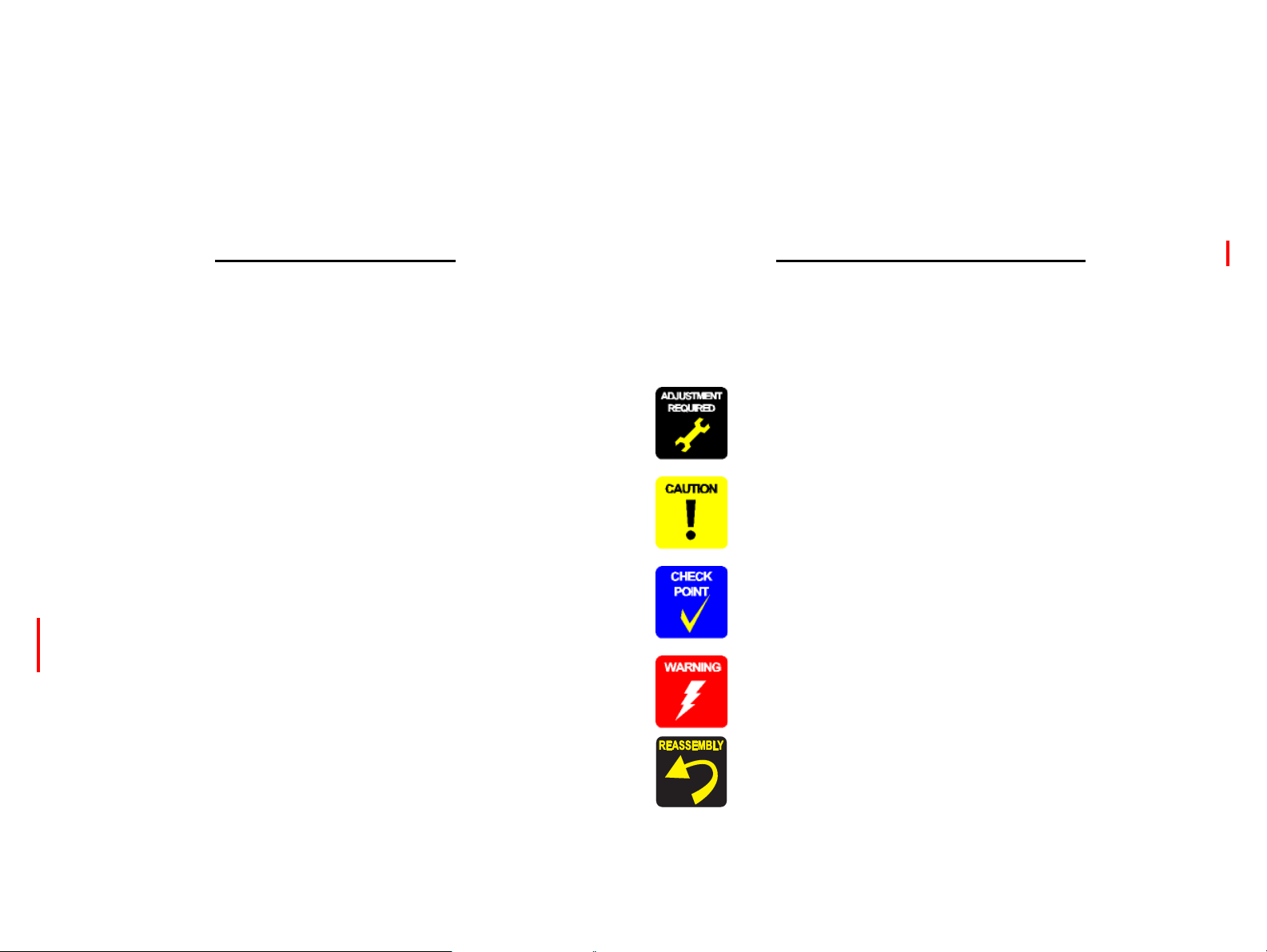
Symbols Used in this Manual
Various symbols are used throughout this manual either to provide additional
information on a specific topic or to warn of possible danger present during a
procedure or an action. Be aware of all symbols when they are used, and always read
NOTE, CAUTION, or WARNING messages.
Indicates an operating or maintenance procedure, practice or condition
that is necessary to keep the product’s quality.
Indicates an operating or maintenance procedure, practice, or condition
that, if not strictly observed, could result in damage to, or destruction of,
equipment.
May indicate an operating or maintenance procedure, practice or
condition that is necessary to accomplish a task efficiently. It may also
provide additional information that is related to a specific subject, or
comment on the results achieved through a previous action.
Indicates an operating or maintenance procedure, practice or condition
that, if not strictly observed, could result in injury or loss of life.
Indicates that a particular task must be carried out according to a certain
standard after disassembly and before re-assembly, otherwise the
quality of the components in question may be adversely affected.
Confidential
Page 5

Revision Status
Revision Date of Issue Description
A October 20, 2007 First Release
B February 29, 2008 Revised Contents
4.4.4 Lower Housing / Printer Mechanism (p96)
Disassembly procedure is revised.
4.4.8 Waste Ink Pad / Waste Ink Tube Left/Right (p110)
Description and figure are revised.
6.1.2.2 Maintenance Request (p163)
Description is revised.
C April 25, 2008 Revised Contents
Descriptions about Stylus Photo R2880 are added.
Chapter 1
Descriptions have been added in 1.1.1 Features (p10).
Made changes in Table 1-1"Printer Specifications"(p 11).
Made changes in Table 1-2"Product No. of Ink Cartridges"(p 11).
T able 1-6"Print Mode (Color)"(p 14) has been added.
T able 1-7"Print Mode (Monochrome)"(p 15) has been added.
Made changes in Table 1-8"Supported Paper"(p 16).
Made changes in Table 1-9"Printing Area (Margins)"(p 20).
Table 1-10"Printing Area (Margins)"(p 20) has been added.
Made changes in Table 1-12"Device ID"(p 21).
Made changes in Table 1-13"Primary Power Specifications"(p 21).
Made changes in Table 1-17"Operation Button Functions"(p 24).
Figure 1-6, "Nozzle Check Pattern (Stylus Photo R2880)" (p 25) has been added.
Made changes in Table 1-18"Indicators (LEDs) Function"(p 26).
Made changes in Table 1-19"Errors & Remedies"(p 27).
Chapter 2
Figure 2-3, "Nozzle Arrangement (Stylus Photo R2880)" (p 30) has been added.
Made changes in
Table2-3"Nozzle Lines and the Corresponding Ink Color (Stylus Photo R2880)"(p 30).
Confidential
Page 6

Revision Date of Issue Description
C April 25, 2008
Chapter 3
Made changes in
Table 3-1"List of Error Messages"(p 34).
Table3-10"Troubleshooting of Ink Color Error (Stylus Photo R2880 only)"(p 48) has been added.
Made changes in
Table 3-13"Troubleshooting of Maintenance Request"(p 50).
Chapter 4
CHECK POINT" has been added in Figure 4-6, "Disassembly Flowchart" (p 75).
4.2.5 Panel Unit (p78) has been added.
"ADJUSTMENT REQUIRED" has been added in 4.2.7 Upper Housing / Printer Cover (p81)
"ADJUSTMENT REQUIRED" has been added in 4.3.3 High Voltage Module (p87)
Made changes in 4.4.4 Lower Housing / Printer Mechanism (p96).
Chapter 5
Made changes in 5.1.1 Servicing Adjustment Item List (p138).
Made changes in 5.1.2 Replacement Part-Based Adjustment Priorities (p142).
Made changes in 5.1.3 Required Adjustment Tools (p143).
Made changes in 5.2.2 PG Adjustment (p145).
Made changes in 5.2.4 Colorimetric Calibration (p153).
Chapter 6
Made changes in 6.1.2 Service Maintenance (p162).
Made changes in 6.1.3 Lubrication (p164).
D December 18, 2009 Revised Contents
Chapter 1
Made changes in Table 1-10"Printing Area (Margins)"(p 20).
Chapter 4
Made changes in 4.4.6 ASF Assy (p106).
Chapter 5
Made changes in 5.1.1 Servicing Adjustment Item List (p138).
Made changes in 5.1.2 Required Adjustments (p141)
5.2.5 ASF Guide Roller LDs Position Adjustment (p159) has been added.
E April 11, 2011 Added Chapter
Chapter 8
.
Confidential
Page 7

EPSON Stylus Photo R1900/R2880/R2000 Revision E
CONTENTS
Chapter 1 Product Description
1.1 Product Description............................................................................................. 10
1.1.1 Features ...................................................................................................... 10
1.2 Printing Specifications........................................ ................................................. 11
1.2.1 Basic Specifications ................................................................................... 11
1.2.2 Ink Cartridge .............................................................................................. 11
1.2.3 Print Mode ................................................................................................. 12
1.2.4 Supported Paper ......................................................................................... 16
1.2.5 Printing Area ............................................................................................. 20
1.3 Interface............................................................................................................... 21
1.4 General Specifications......................................................................................... 21
1.4.1 Electrical Specifications ............................................................................ 21
1.4.2 Environmental Conditions ......................................................................... 22
1.4.3 Durability ................................................................................................... 22
1.4.4 Acoustic Noise ............................................. .............................................. 22
1.4.5 Safety Approvals (Safety standards/EMI) ................................................. 22
1.5 Operation Buttons & Indicators (LEDs).............................................................. 23
1.5.1 Operation Buttons ......................................................... ............................. 23
1.5.2 Indicators (LEDs) .................... ................................................ .................. 23
1.5.3 Operation Buttons & LEDs Functions ...................................................... 24
1.5.4 Errors & Remedies .................................................................................... 27
Chapter 2 Operating Principles
2.1 Overview ............................................................................................................. 29
2.2 Printer Mechanism............................................................................................... 29
2.3 Printhead Specifications...................................................................................... 30
2.4 PG Setting............................................................................................................ 31
2.5 Motors & Sensors................................................................................................ 32
Chapter 3 Troubleshooting
3.1 Overview ............................................................................................................. 34
3.1.1 Troubleshooting according to Error Messages .......................................... 34
3.1.2 Troubleshooting based on Observed Faults .............................................. 60
Chapter 4 Disassembly And Assembly
4.1 Overview........................... ................................................ .................................. 70
4.1.1 Precautions ................................................................................................ 70
4.1.2 Tools ...................................................................................... .................... 71
4.1.3 Screws .................................................................................................... ... 71
4.1.4 Making a Special Tool for CSIC Board .................................................... 71
4.1.5 Work Completion Checklist ............................................ .......................... 72
4.1.6 Locking/Unlocking the Carriage and Opening/Closing the CDR Tray Base
73
4.1.7 Disassembly ...................................... ......................................................... 75
4.2 Removing the Housings ...................................................................................... 76
4.2.1 Paper Support Assy ................................................................................... 76
4.2.2 Stacker Assy .............................................................................................. 76
4.2.3 Front Decoration Plate Left/Right ............................................................. 77
4.2.4 Rear Housing ............................................................................................. 77
4.2.5 Panel Unit .................................................................................................. 78
4.2.6 Decoration Plate Left/Right ....................................................................... 80
4.2.7 Upper Housing / Printer Cover .................................................................. 81
4.2.8 Upper Housing Support Assy .................................................................... 83
4.3 Removing the Boards.......................................................................................... 84
4.3.1 Board Assy (Main Board/Power Supply Board ) ....................................... 84
4.3.2 LED Board ........................................................ ........................................ 86
4.3.3 High Voltage Module ................................................................................ 87
4.4 Disassembling the Printer Mechanism................................................................ 89
4.4.1 APG Assy .................................................................................................. 89
4.4.2 CR Scale .................................................................................................... 90
4.4.3 Printhead / CSIC Assy ............................................................................... 92
4.4.4 Lower Housing / Printer Mechanism ............................................ ............ 96
4.4.5 Carriage Shaft / Carriage Unit ................................. .................................. 98
4.4.6 ASF Assy ................................................................................................. 106
4.4.7 Front Paper Guide Pad ....................................................... ..................... 109
Confidential
7
Page 8

EPSON Stylus Photo R1900/R2880/R2000 Revision E
4.4.8 Waste Ink Pad / Waste Ink Tube Left/Right ........................................... 110
4.4.9 Foot .......................................................................................................... 111
4.4.10 PictBridge Holder Assy ......................................................................... 111
4.4.11 Paper EJ Frame Assy / Front Cover / CDR Tray Base .......................... 112
4.4.12 CDR Release Lever Sub Assy ............................................................... 114
4.4.13 Ink System Unit ..................................................................................... 116
4.4.14 Front Paper Guide / Paper EJ Roller /
Front Paper Guide Pad Tray ............................................................................. 119
4.4.15 PF Roller Shaft ...................................................................................... 122
4.4.16 Release Holder Assy .............................................................................. 125
4.4.17 FLAG Release Assy .............................................................................. 126
4.4.18 Upper Paper Guide Assys ...................................................................... 127
4.5 Removing the Motors........................................................................................ 129
4.5.1 CR Motor ................................................................................................. 129
4.5.2 PF Motor .................................................................................................. 130
4.5.3 ASF Motor ............................................................................................... 131
4.6 Removing the Sensors....................................................................................... 132
4.6.1 CR Encoder ............................................................................................. 132
4.6.2 PF Encoder .............................................................................................. 132
4.6.3 Ink Mark Sensor / PW sensor .................................................................. 133
4.6.4 CDR Sensor ............................................................................................. 134
4.6.5 PE Sensor Holder .................................................................................... 135
4.6.6 Cover Open Sensor .................................................................................. 136
Chapter 5 Adjustment
5.1 Adjustment Items and Overview....................................................................... 138
5.1.1 Servicing Adjustment Item List ............................................................... 138
5.1.2 Required Adjustments ............................................................................. 141
5.1.3 Required Adjustment Tools ..................................................................... 143
5.2 Adjustment ........................................................................................................ 144
5.2.1 PF Belt Tension Adjustment ................................................................... 144
5.2.2 PG Adjustment ........................................................................................ 145
5.2.3 PF Roller Shaft Center Support Position Adjustment ............................. 149
5.2.4 Colorimetric Calibration .......................................................................... 153
5.2.5 ASF Guide Roller LDs Position Adjustment .......................................... 159
6.1 Overview........................... ................................................ ................................ 162
6.1.1 Cleaning ...................................... ............................................................. 162
6.1.2 Service Maintenance ............................................................................... 162
6.1.3 Lubrication ............................................. ................................................ . 164
Chapter 7 Appendix
7.1 Connector Summary............................. ............................................................. 171
7.2 Exploded Diagram / Parts List .......................................................................... 171
Chapter 8 Stylus Photo R2000
8.1 Product Description........................................................................................ 173
8.2 Features .............................................. ............................................................... 174
8.2.1 Casing specifications ............................................ ................................... 174
8.2.2 NetWork Interface ................................................................................... 175
8.2.3 Ink Cartridge ................................................................................ 177
8.2.4 Nozzle Configuration ............................. ................................................. 178
8.2.5 Ink Scrambling Sequence ................................................ ........................ 178
8.2.6 Operation Buttons & Indicators (LEDs) ................................................. 179
8.3 Disassembly..................................................................................... .................. 183
8.3.1 Summary ................................................................................................. 183
8.3.2 Procedure of Disassembly .......................................................... ............. 184
8.4 Adjustment ...................................... ................................................ .................. 190
8.4.1 Summary ................................................................................................. 190
8.4.2 Sevicing Adjusment Item List (For Stylus Photo R2000) ....................... 190
8.4.3 Required Adjustments .............. .. ................................................ ............. 191
8.4.4 Adjusment Procedure ................................ .............................................. 193
Chapter 6 Maintenance
8
Confidential
Page 9

PRODUCT DESCRIPTION
CHAPTER
1
Confidential
Page 10
EPSON Stylus Photo R1900/R2880/R2000 Revision E
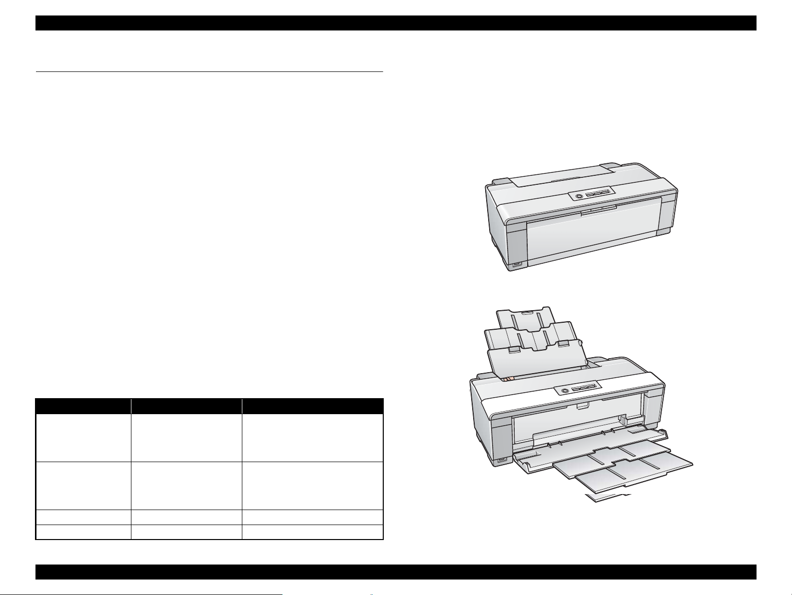
Paper Support & Stacker are Closed
Paper Support & Stacker are Opened
1.1 Product Description
1.1.1 Features
EPSON Stylus Photo R1900/R2880/R2000 is a color ink-jet printer that supports A3+
size.
The main features are;
High speed & High quality
Maximum print resolution: SMGA 5760 (H) x 1440 (V) dpi
F8 Mach print head are mounted.
Newly developed pigment ink cartridges enable high quality photo printing.
CD and DVD label printing are supported.
High-speed borderless printing is available.
Direct printing (PictBridge)
Two USB ports for PC connection
New exterior design
Control panel
Simple design with four buttons and three indicators (LED).
Differences between Stylus Photo R1900 and Stylus Photo R2880
Stylus Photo R2880 is designed based on the Stylus Photo R1900 printer
mechanism, however, there are some differences between them such as ink color
configuration. The table below lists the major differences.
Dimensions
Dimensions: 616 mm (W) x 322 mm (D) x 214 mm (H)
(Paper support and stacker are closed. Rubber feet are included)
Weight: 12.2 kg (Stylus Photo R1900)
12.3 kg (Stylus Photo R2880)
(without ink cartridges, CDR Tray, Roll paper holders and
Single sheet guide)
Item Stylus Photo R1900 Stylus Photo R2880
Photo Black, Matte Black,
Ink colors
Simultaneous
installation of Photo
Black and Matte Black
cartridges
Board paper printing Not supported Supported
Print Mode 4 modes 5 modes
Cyan, Magenta, Yellow,
Red, Orange, Gloss
Optimizer
Supported Not supported
Photo Black, Matte Black, Light
Black, Light Light Black, Cyan,
Light Cyan, Vivid Magenta, Vivid
Light Magenta, Yellow
Figure 1-1. External View
Product Description Product Description 10
Confidential
Page 11
EPSON Stylus Photo R1900/R2880/R2000 Revision E
C A U T I O N
1.2 Printing Specifications
1.2.1 Basic Specifications
Table 1-1. Printer Specifications
Item Specifications
Print method On-demand ink jet
Nozzle configuration
Print direction
Print resolution Horizontal x Vertical (dpi)
Control code
Internal font Character code:Alphanumeric with expanded graphics (PC437)
Input buffer size T.B.D. Kbytes
Paper feed method Friction feed, using one ASF (Auto Sheet Feeder)
Paper path 2-way feed
Paper feed rates 170 msec (at 25.4 mm feed)
PF interval Programmable in 0.01764 mm (1/1440 inch) steps
Note *1: Stylus Photo R2880 has only one slot for black ink cartridge. Switching between the
Photo Black and Matte Black can be made by replacing the cartridge.
*2: Stylus Photo R2880 does not support the resolution.
Stylus Photo R1900
Black: 180 nozzles x 2 (Photo Black, Matte Black)
Color: 180 nozzles x 5
(Cyan, Magenta, Yellow, Red, Orange)
Gross Optimizer:
180 nozzles x 1
Stylus Photo R2880
1
Black*
: 180 nozzles x 1 (Photo Black, Matte Black)
Gray: 180 nozzles x 2 (Light Black, Light Light Black)
Color: 180 nozzles x 5
(Cyan, Light Cyan, Vivid Magenta, Vivid Light
Magenta, Yellow)
Bi-directional minimum distance printing, unidirectional printing
• 360 x 180*
• 360 x 360 • SMGA 5760 x 1440
• 720 x 720
• ESC/P Raster command
• ESC/P-R (RGB) command
• EPSON Remote command
ASCII, 20H to 7FH only
Font: EPSON original font
Alphanumeric font: Courier
2
• 1440 x 720
• 1440 x 1440 (Stylus Photo R2880 only)
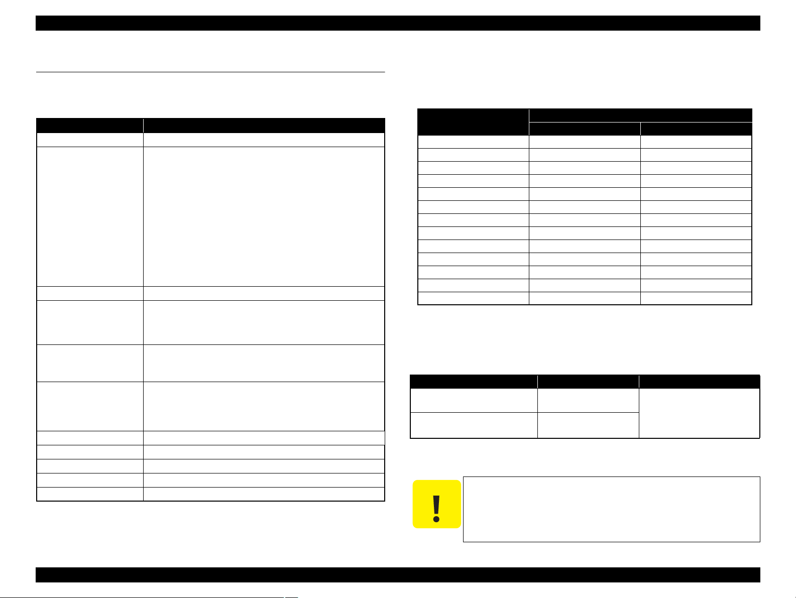
1.2.2 Ink Cartridge
The product numbers of the EPSON ink cartridges for this printer are shown below.
Table 1-2. Product No. of Ink Cartridges
Color
Photo Black T0871 T0961
Matte Black T0878 T0968
Light Black -- T0967
Light Light Black -- T0969
Cyan T0872 T0962
Light Cyan -- T0965
Magenta T0873 --
Vivid Magenta -- T0963
Vivid Light Magenta -- T0966
Yellow T0874 T0964
Orange T0879 --
Red T0877 --
Gloss Optimizer T0870 --
Stylus Photo R1900 Stylus Photo R2880
Shelf life
Two years from production date (if unopened), six months after opening package.
Storage Temperature
Table 1-3. Storage Temperature
Situation Storage Temperature Limit
o
-20
When stored in individual boxes
When installed in main unit
C to 40 oC
(-4oF to 104oF)
o
-20
C to 40 oC
(-4oF to 104oF)
Dimension
12.7 mm (W) x 68 mm (D) x 47 mm (H)
The ink cartridge cannot be refilled.
Do not use expired ink cartridges.
The ink in the ink cartridge freezes at -16 °C (3.2 oF). It takes
about three hours under 25 °C (77
becomes usable.
Code
1 month max. at 40
o
F) until the ink thaws and
o
C (104oF)
Product Description Printing Specifications 11
Confidential
Page 12
EPSON Stylus Photo R1900/R2880/R2000 Revision E
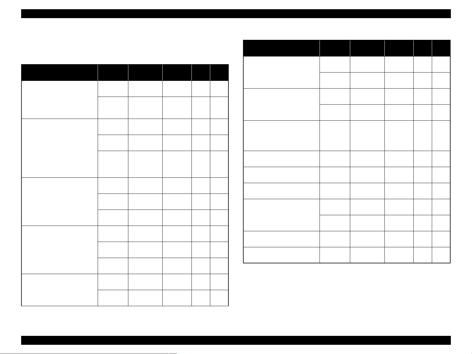
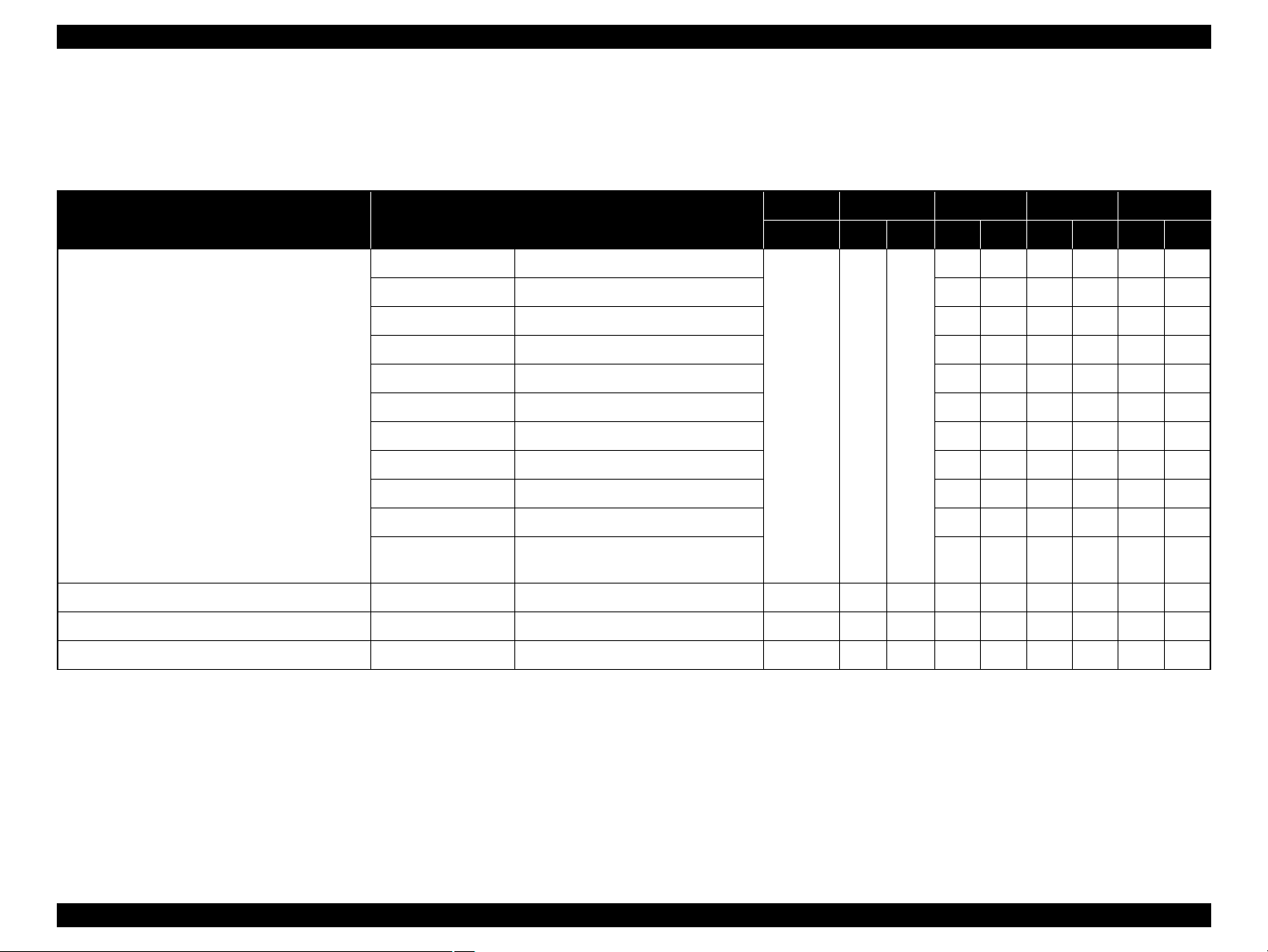
1.2.3 Print Mode
Stylus Photo R1900
Media
• Plain paper
• Premium Bright White Paper
(EAI)
• Bright White Inkjet Paper
(others)
• Premium Photo Paper Glossy
(EAI)
• Premium Glossy Photo Paper
(others)
• Premium Photo Paper Semigloss (EAI)
• Premium Semigloss Photo
Paper (others)
• Premium Luster Photo Paper
• Photo Paper Glossy (EAI)
• Glossy Photo Paper (others)
• Premium Presentation Paper
Matte (EAI)
• Matte Paper Heavy-weight
(others)
Table 1-4. Print Mode (Color)
Print
Mode
Draft/
Economy
Fine 720x720
Fine 720x720
Photo 1440x720
Super
Photo
Fine 720x720
Photo 1440x720
Super
Photo
Fine 720x720
Photo 1440x720
Super
Photo
Photo 1440x720
Super
Photo
Resolution
(H x V) dpi
360x360
5760x1440
5760x1440
5760x1440
5760x1440
Dot Size
(cps*)
Eco
(240cps)
VSD1,2
(220cps)
VSD1,2
(220cps)
VSD2
(200cps)
VSD3
(200cps)
VSD1,2
(220cps)
VSD2
(200cps)
VSD3
(200cps)
VSD1,2
(220cps)
VSD2
(200cps)
VSD3
(200cps)
VSD2
(200cps)
VSD3
(200cps)
Bi-d
Micro
Weave
ON OFF
ON ON
ON ON
ON ON
ON ON
ON ON
ON ON
ON ON
ON ON
ON ON
ON ON
ON ON
ON ON
Table 1-4. Print Mode (Color)
Media
• Archival Matte Paper (EAI)
• Enhanced Matte Paper (others)
• Double-sided Matte Paper
• Presentation Paper Matte
(EAI)
• Photo Quality Inkjet Paper
(others)
• W atercolor Paper - Radiant
White
• Velvet Fine Art Paper Super
• Ultra Smooth Fine Art Paper Super
• PremierArt Matte Scrapbook
Photo Paper
• CD/DVD Super
• CD/DVD Premium Surface Super
Note : The default is indicated by boldface.
Note * : cps = character per second
Print
Mode
Photo 1440x720
Super
Photo
Photo 1440x720
Super
Photo
Photo 1440x720
Super
Photo
Photo
Photo
Photo 1440x720
Super
Photo
Photo
Photo
Resolution
(H x V) dpi
5760x1440
5760x1440
5760x1440
5760x1440
5760x1440
5760x1440
5760x1440
5760x1440
Dot Size
(cps*)
VSD2
(200cps)
VSD3
(200cps)
VSD2
(200cps)
VSD3
(200cps)
VSD2
(200cps)
VSD3
(200cps)
VSD3
(200cps)
VSD3
(200cps)
VSD2
(200cps)
VSD3
(200cps)
VSD3
(200cps)
VSD3
(200cps)
Bi-d
Micro
Weave
ON ON
ON ON
ON ON
ON ON
ON ON
ON ON
ON ON
ON ON
ON ON
ON ON
ON ON
ON ON
Product Description Printing Specifications 12
Confidential
Page 13
EPSON Stylus Photo R1900/R2880/R2000 Revision E
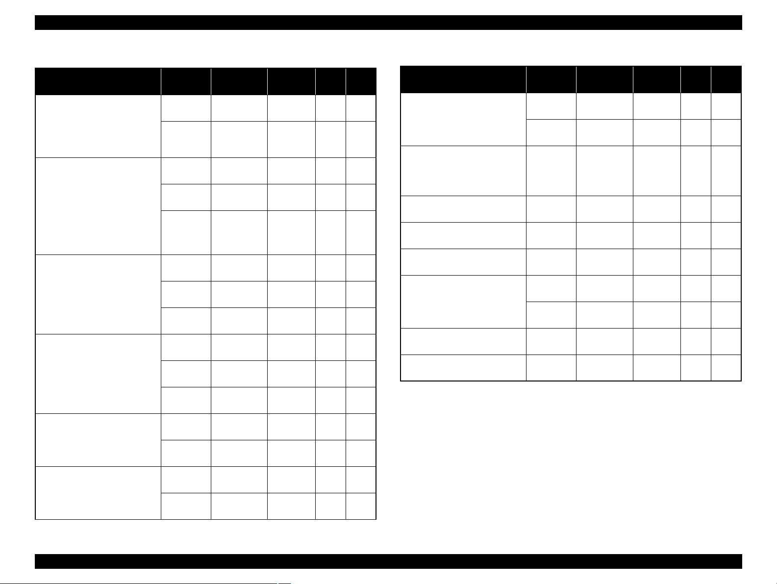
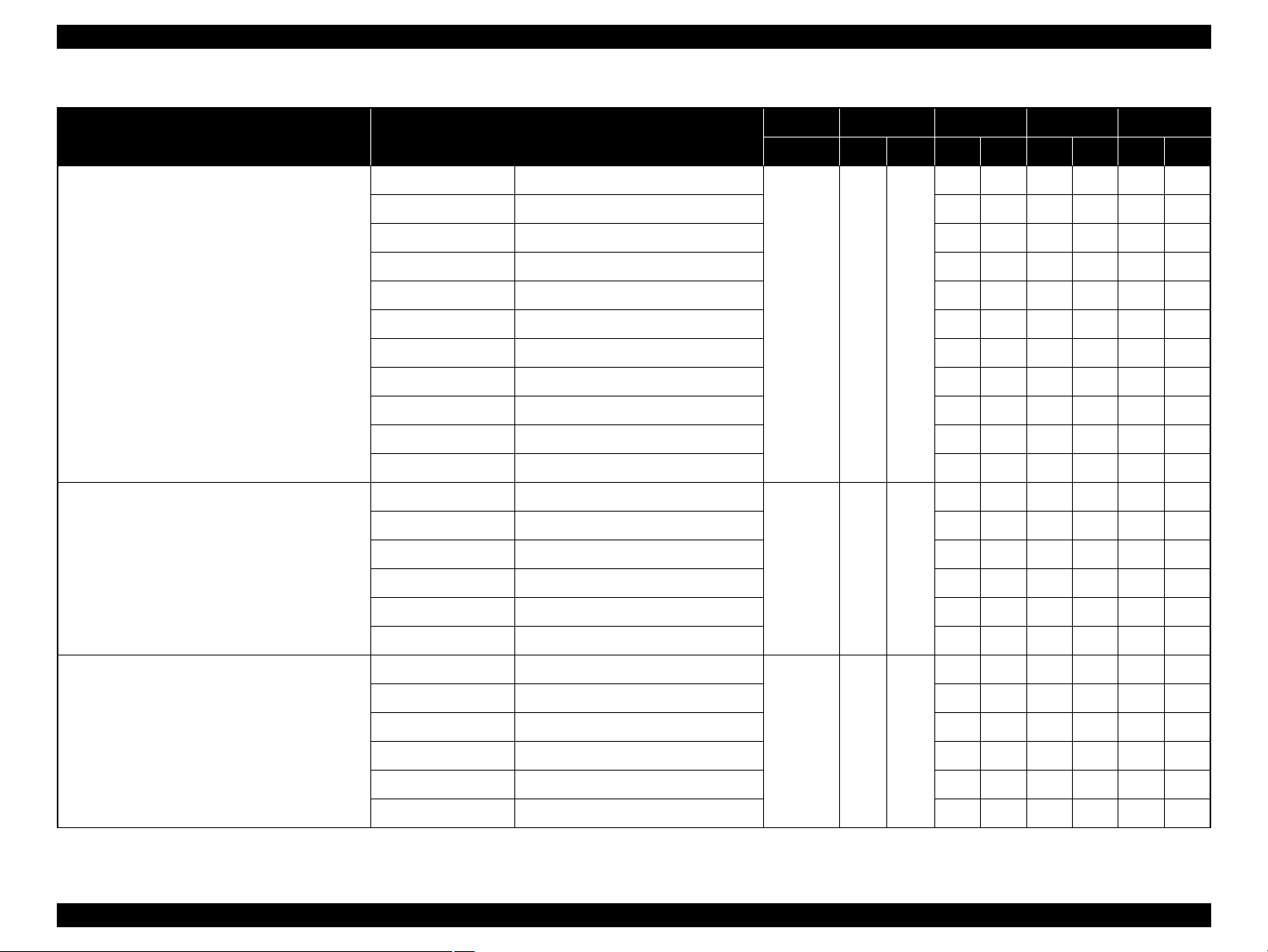
Table 1-5. Print Mode (Monochrome)
Media
• Plain paper
• Premium Bright White Paper
(EAI)
• Bright White Inkjet Paper
(others)
• Premium Photo Paper Glossy
(EAI)
• Premium Glossy Photo Paper
(others)
• Premium Photo Paper Semigloss (EAI)
• Premium Semigloss Photo
Paper (others)
• Premium Luster Photo Paper
• Photo Paper Glossy (EAI)
• Glossy Photo Paper (others)
• Premium Presentation Paper
Matte (EAI)
• Matte Paper Heavy-weight
(others)
• Archival Matte Paper (EAI)
• Enhanced Matte Paper (others)
Print
Mode
Draft/
Economy
Fine 720x720
Fine 720x720
Photo 1440x720
Super
Photo
Fine 720x720
Photo 1440x720
Super
Photo
Fine 720x720
Photo 1440x720
Super
Photo
Photo 1440x720
Super
Photo
Photo 1440x720
Super
Photo
Resolution
(H x V) dpi
360x180
5760x1440
5760x1440
5760x1440
5760x1440
5760x1440
Dot Size
(cps*)
Eco
(240cps)
VSD1,2
(220cps)
VSD1,2
(220cps)
VSD2
(200cps)
VSD3
(200cps)
VSD1,2
(220cps)
VSD2
(200cps)
VSD3
(200cps)
VSD1,2
(220cps)
VSD2
(200cps)
VSD3
(200cps)
VSD2
(200cps)
VSD3
(200cps)
VSD2
(200cps)
VSD3
(200cps)
Bi-d
Micro
Weave
ON OFF
ON ON
ON ON
ON ON
ON ON
ON ON
ON ON
ON ON
ON ON
ON ON
ON ON
ON ON
ON ON
ON ON
ON ON
Table 1-5. Print Mode (Monochrome)
Media
• Double-sided Matte Paper
• Presentation Paper Matte
(EAI)
• Photo Quality Inkjet Paper
(others)
• W atercolor Paper - Radiant
White
• Velvet Fine Art Paper Super
• Ultra Smooth Fine Art Paper Super
• PremierArt Matte Scrapbook
Photo Paper
• CD/DVD Super
• CD/DVD Premium Surface Super
Note : The default is indicated by boldface.
Note * : cps = character per second
Print
Mode
Photo 1440x720
Super
Photo
Photo 1440x720
Super
Photo
Photo
Photo
Photo 1440x720
Super
Photo
Photo
Photo
Resolution
(H x V) dpi
5760x1440
5760x1440
5760x1440
5760x1440
5760x1440
5760x1440
5760x1440
Dot Size
(cps*)
VSD2
(200cps)
VSD3
(200cps)
VSD2
(200cps)
VSD3
(200cps)
VSD3
(200cps)
VSD3
(200cps)
VSD2
(200cps)
VSD3
(200cps)
VSD3
(200cps)
VSD3
(200cps)
Bi-d
Micro
Weave
ON ON
ON ON
ON ON
ON ON
ON ON
ON ON
ON ON
ON ON
ON ON
ON ON
Product Description Printing Specifications 13
Confidential
Page 14
EPSON Stylus Photo R1900/R2880/R2000 Revision E
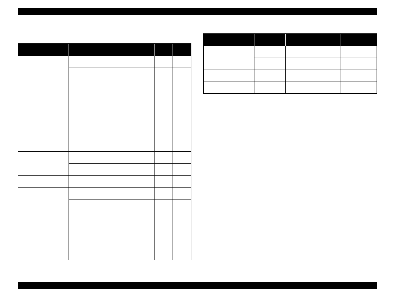
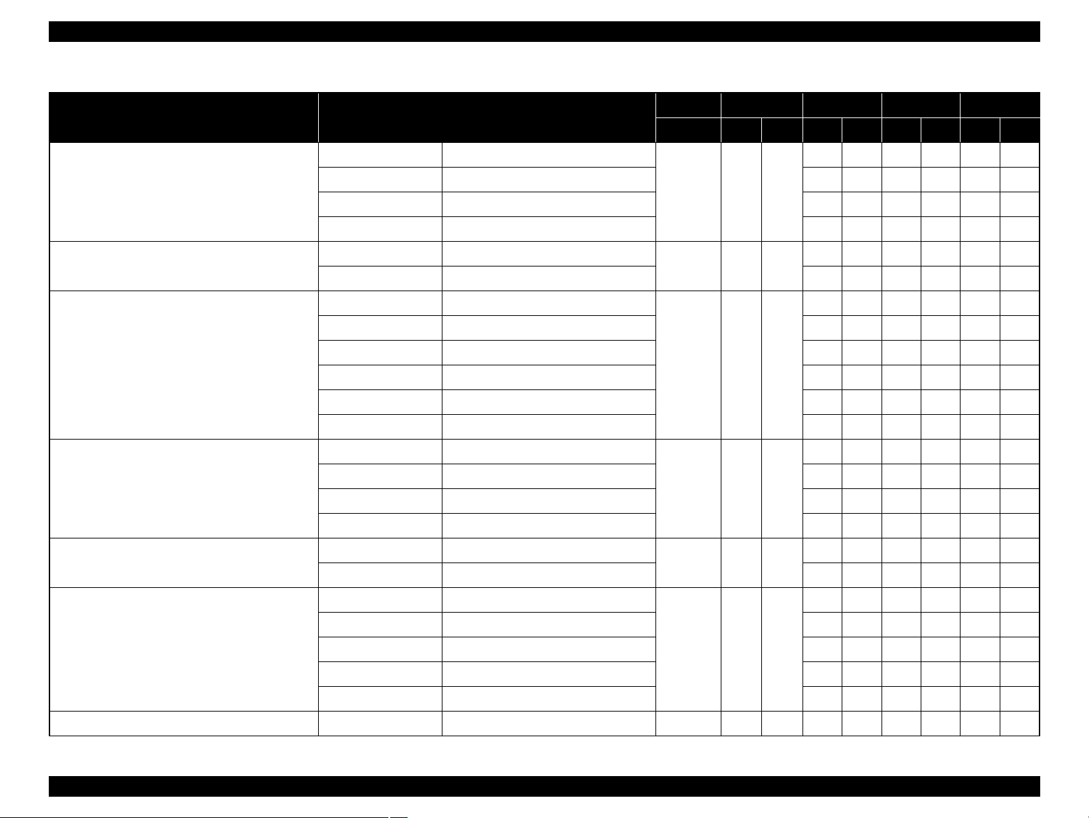
Stylus Photo R2880
Media Print Mode
• Plain paper
• Premium Bright White
Paper (EAI)
• Bright White Inkjet
Paper (others)
• Ultra Premium Glossy
Photo Paper
• EPSON Glossy Photo
Paper
• Premium Semigloss
Photo Paper
• Ultra Premium Photo
Paper Luster
• Glossy Photo Paper
Photo Paper Glossy
(EAI)
•Matte Paper
Heavyweight
• Double-sided Matte
Paper
• Photo Quality Inkjet
Paper
• Watercolor Paper Radiant White
• Velvet Fine Art Paper
• Ultra Smooth Fine Art
Paper
• Enhanced Matte Paper
• Archival matte paper
(EAI)
•Matte Paper
Heavyweight
• Double-sided Matte
Paper
Table 1-6. Print Mode (Color)
Resolution
(H x V) dpi
Draft/Economy 360x360
Fine 720x720
Super Photo 5760x1440
Fine 720x720
Photo 1440x720
Super Photo 5760x1440
Photo 1440x720
Super Photo 5760x1440
Photo 1440x720
Photo 1440x720
Super Photo 5760x1440
Dot Size
(cps*)
Economy
(240cps)
VSD2
(220cps)
VSD2
(220cps)
VSD2
(220cps)
VSD2
(220cps)
VSD2
(220cps)
VSD2
(220cps)
VSD2
(220cps)
VSD2
(220cps)
VSD2
(220cps)
VSD2
(220cps)
Bi-d
ON OFF
ON ON
ON ON
ON ON
ON ON
ON ON
ON ON
ON ON
ON ON
ON ON
ON ON
Micro
Weave
Table 1-6. Print Mode (Color)
Media Print Mode
• PremierArt Matte
Scrapbook Photo Paper
(EAI only)
• CD/DVD
• CD/DVD Premium
Surface
Note : The default is indicated by boldface.
Note * : cps = character per second
Photo 1440x720
Super Photo 5760x1440
Super Photo 1440x1440
Super Photo 1440x1440
Resolution
(H x V) dpi
Dot Size
(cps*)
VSD2
(220cps)
VSD2
(220cps)
VSD3
(220cps)
VSD3
(220cps)
Bi-d
ON ON
ON ON
ON ON
ON ON
Micro
Weave
Product Description Printing Specifications 14
Confidential
Page 15
EPSON Stylus Photo R1900/R2880/R2000 Revision E
Media Print Mode
• Plain paper
• Premium Bright White
Paper (EAI)
• Bright White Inkjet
Paper (others)
• Ultra Premium Glossy
Photo Paper
• EPSON Glossy Photo
Paper
• Premium Semigloss
Photo Paper
• Ultra Premium Photo
Paper Luster
• Glossy Photo Paper
Photo Paper Glossy
(EAI)
•Matte Paper
Heavyweight
• Double-sided Matte
Paper
• Photo Quality Inkjet
Paper
• Watercolor Paper Radiant White
• Velvet Fine Art Paper
• Ultra Smooth Fine Art
Paper
• Enhanced Matte Paper
• Archival matte paper
(EAI)
•Matte Paper
Heavyweight
• Double-sided Matte
Paper
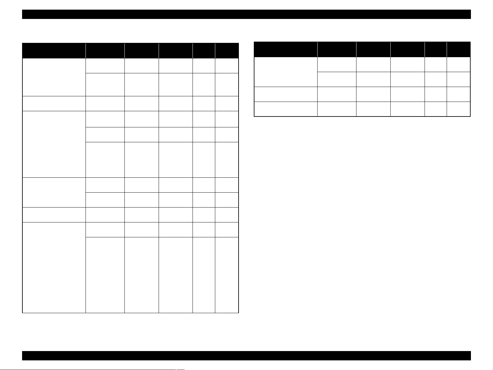
Table 1-7. Print Mode (Monochrome)
Resolution
(H x V) dpi
Draft/Economy 360x360
Fine 720x720
Super Photo 5760x1440
Fine 720x720
Photo 1440x720
Super Photo 5760x1440
Photo 1440x720
Super Photo 5760x1440
Photo 1440x720
Photo 1440x720
Super Photo 5760x1440
Dot Size
(cps*)
Economy
(240cps)
VSD2
(220cps)
VSD2
(220cps)
VSD2
(220cps)
VSD2
(220cps)
VSD2
(220cps)
VSD2
(220cps)
VSD2
(220cps)
VSD2
(220cps)
VSD2
(220cps)
VSD2
(220cps)
Bi-d
ON OFF
ON ON
ON ON
ON ON
ON ON
ON ON
ON ON
ON ON
ON ON
ON ON
ON ON
Micro
Weave
Table 1-7. Print Mode (Monochrome)
Media Print Mode
• PremierArt Matte
Scrapbook Photo Paper
(EAI only)
• CD/DVD
• CD/DVD Premium
Surface
Note : The default is indicated by boldface.
Note * : cps = character per second
Photo 1440x720
Super Photo 5760x1440
Super Photo 1440x1440
Super Photo 1440x1440
Resolution
(H x V) dpi
Dot Size
(cps*)
VSD2
(220cps)
VSD2
(220cps)
VSD3
(220cps)
VSD3
(220cps)
Bi-d
ON ON
ON ON
ON ON
ON ON
Micro
Weave
Product Description Printing Specifications 15
Confidential
Page 16
EPSON Stylus Photo R1900/R2880/R2000 Revision E
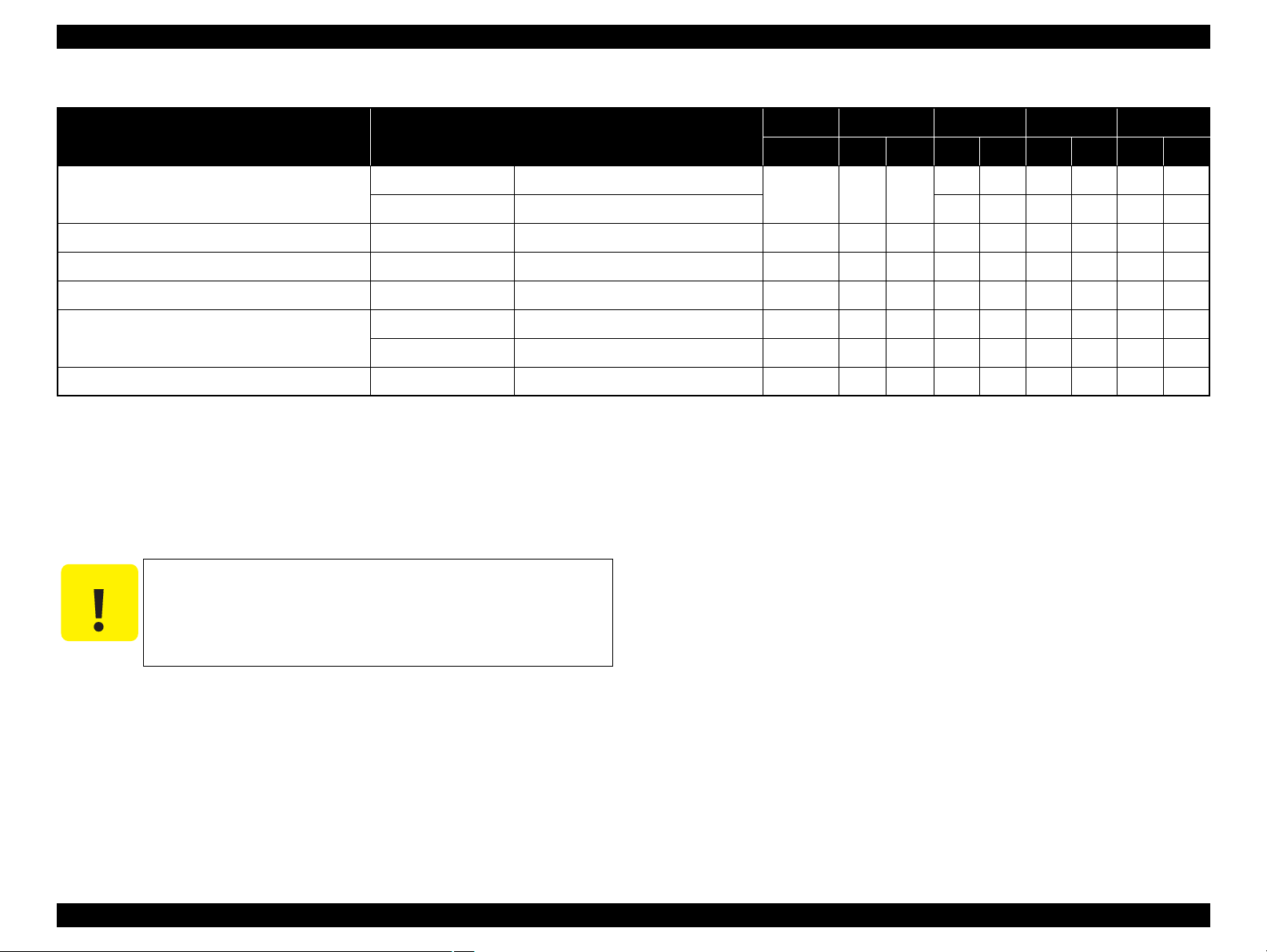
1.2.4 Supported Paper
The table below lists the paper type and sizes supported by the printer. The Supported paper type and sizes vary depending on destinations (between EAI, EUR, and Asia).
Table 1-8. Supported Paper
Paper Name Paper Size
A3 297 x 420 mm
US B 279.4 x 431.8 mm (11” x 17”) Y - - - - B4 257 x 364 mm Y - Y - Y Legal 215.9 x 355.6 mm (8.5”x14”) Y - Y - Y Letter 215.9 x 279.4 mm (8.5”x11”) Y - Y - Y -
Plain paper
Premium Inkjet Plain Paper A4 210 x 297 mm (8.3”x11.7”) 0.11 80 21 - - Y - Y Premium Bright White Paper Letter 215.9 x 279.4 mm (8.5”x11”) 0.11 90 24 Y - - - - Bright White Inkjet Paper A4 210 x 297 mm (8.3”x11.7”) 0.13 92.5 25 - - Y - Y -
A4 210 x 297 mm (8.3”x11.7”) Y - Y - Y B5 182 x 257 mm (7.2”x10.1”) - - Y - Y A5 148 x 210 mm (5.8”x8.3”) - - Y - Y Half Letter 139.7 x 215.9 mm (5.5”x8.5”) Y - - - - A6 105 x 148 mm (4.1”x5.8”) Y - Y - Y -
User Defined
89 x 127- 329 x 1117.6 mm
(3.56”x 5.08” - 13.16”x44.7”)
Thickness Weight EAI EUR Asia
mm g/m2lb. P*1B*2P*1B*2P*1B*
Y-Y-Y-
0.08-0.11 64-90 17-24
Y-Y-Y-
2
Product Description Printing Specifications 16
Confidential
Page 17
EPSON Stylus Photo R1900/R2880/R2000 Revision E
Table 1-8. Supported Paper
Paper Name Paper Size
Premium Photo Paper Glossy (EAI)
Premium Glossy Photo Paper (others)
Photo Paper Glossy (EAI)
Glossy Photo Paper (others)
Thickness Weight EAI EUR Asia
mm g/m2lb. P*1B*2P*1B*2P*1B*
A3+/SuperA3 329 x 483 mm
YYYYYY
US B 279.4 x 431.8 mm (11” x 17”) Y Y - - - A3 297 x 420 mm Y Y Y Y Y Y
11” x 14” 279.4 x 355.6 mm Y Y - - - Letter 215.9 x 279.4 mm (8.5”x11”) Y Y - - - A4 210 x 297 mm (8.3”x11.7”) Y Y Y Y Y Y
0.27 255 68
8” x 10” 203.2 x 254 mm Y Y - - - 5” x 7” 127 x 178 mm Y Y Y Y Y Y
”
x 6
”
4
101.6 x 152.4 mm Y Y Y Y Y Y
16:9 wide 102 x 181 mm (4”x7.11”) - - Y Y - Roll paper 329 x 1,000 mm Y Y Y Y Y Y
A3+/SuperA3 329 x 483 mm
YY---US B 279.4 x 431.8 mm (11” x 17”) Y Y - - - Letter 215.9 x 279.4 mm (8.5”x11”) Y Y - - - -
0.25 258 68
A4 210 x 297 mm (8.3”x11.7”) Y Y Y Y Y Y
3
3
5” x 7” 127 x 178 mm Y*
Y*
YYY*3Y*
2
3
4” x 6” 101.6 x 152.4 mm Y Y Y Y Y Y
A3+/SuperA3 329 x 483 mm
YYYYYY
A3 297 x 420 mm Y Y Y Y Y Y
Premium Photo Paper Semi-gloss (EAI)
Premium Semigloss Photo Paper (others)
Letter 215.9 x 279.4 mm (8.5”x11”) Y Y - - - -
0.27 250 66
A4 210 x 297 mm (8.3”x11.7”) - - Y Y Y Y
4” x 6” 101.6 x 152.4 mm Y Y Y Y Y Y
Roll paper 329 x 1,000 mm - - Y Y Y Y
Product Description Printing Specifications 17
Confidential
Page 18
EPSON Stylus Photo R1900/R2880/R2000 Revision E
Table 1-8. Supported Paper
Paper Name Paper Size
Ultra Premium Photo Paper Luster
Premium Luster Photo Paper
Premium Presentation Paper Matte (EAI)
Matte Paper Heavy-weight (others)
Archival Matte Paper (EAI)
Enhanced Matte Paper (others)
Thickness Weight EAI EUR Asia
mm g/m2lb. P*1B*2P*1B*2P*1B*
A3+/SuperA3 329 x 483 mm
YY---A3 297 x 420 mm Y Y - - - -
0.27 250 66
Letter 215.9 x 279.4 mm (8.5”x11”) Y Y - - - Roll paper 329 x 1,000 mm Y Y - - - Roll paper 329 x 1,000 mm
0.27
250 66
Y*4Y*
Roll paper 210 x 10,000 mm Y*4Y*
A3+/SuperA3 329 x 483 mm
YYYYYY
4
----
4
----
A3 297 x 420 mm Y Y Y Y Y Y
11” x 14” 279.4 x 355.6 mm Y Y - - - -
0.23 167 44
Letter 215.9 x 279.4 mm (8.5”x11”) Y Y - - - A4 210 x 297 mm (8.3”x11.7”) - - Y Y Y Y
8” x 10” 203.2 x 254 mm Y Y - - - A3+/SuperA3 329 x 483 mm
YYYYYY
A3 297 x 420 mm Y Y Y Y Y Y
0.26 192
Letter 215.9 x 279.4 mm (8.5”x11”) Y Y - - - -
2
A4 210 x 297 mm (8.3”x11.7”) - - Y Y Y Y
Double-sided Matte Paper
Letter 215.9 x 279.4 mm (8.5”x11”)
0.22 185 49
Y----A4 210 x 297 mm (8.3”x11.7”) - - Y - Y A3+/SuperA3 329 x 483 mm
Y-Y-YA3 297 x 420 mm Y - Y - Y -
Presentation Paper Matte (EAI)
Photo Quality Inkjet Paper (others)
US B 279.4 x 431.8 mm (11” x 17”) Y - - - - -
0.12 102 27
Letter 215.9 x 279.4 mm (8.5”x11”) Y - - - - A4 210 x 297 mm (8.3”x11.7”) Y - Y - Y -
Watercolor Paper - Radiant White A3+/SuperA3 329 x 483 mm 0.29
190 51
YYYYYY
Product Description Printing Specifications 18
Confidential
Page 19
EPSON Stylus Photo R1900/R2880/R2000 Revision E
C A U T I O N
Table 1-8. Supported Paper
Paper Name Paper Size
Velvet Fine Art Paper
Ultra Smooth Fine Art Paper A3+/SuperA3 329 x 483 mm 0.46
PremierArt Matte Scrapbook Photo Paper 12” x12” 305 x 305 mm 0.30
Photo Quality Self Adhesive Sheet A4 210 x 297 mm (8.3”x11.7”) 0.19
CD/DVD
CD/DVD Premium Surface
Enhanced Matte Posterboard*
Note *1: “Y” in the “P” column stands for “the paper type/size is Supported”.
*2: “Y” in the “B” column stands for “Borderless printing is available”.
*3: Stylus Photo R2880 only.
*4: Not supported by Stylus Photo R2880.
*5: Guaranteed under certain conditions.
*6: Only front manual feed is available.
6
A3+/SuperA3 329 x 483 mm
Letter 215.9 x 279.4 mm (8.5”x11”) Y Y - - - -
ø 12cm ø 12cm - - Y - Y - Y ø 8cm ø 8cm - - Y - Y - Y A3+ 329 x 483 mm 1.2 - - Y*
Thickness Weight EAI EUR Asia
Make sure the paper is not wrinkled, fluffed, torn, or folded.
The curve of paper must be 5 mm or below.
When printing on an envelope, be sure the flap is folded neatly.
Do not use the adhesive envelopes.
Do not use double envelopes and cellophane window envelopes.
mm g/m2lb. P*1B*2P*1B*2P*1B*
0.48
260 69
325 86
205 52
167 44
YYYY- -
YY----
Y*5Y*
Y-Y-Y-
5
----
5
---
2
Product Description Printing Specifications 19
Confidential
Page 20
EPSON Stylus Photo R1900/R2880/R2000 Revision E
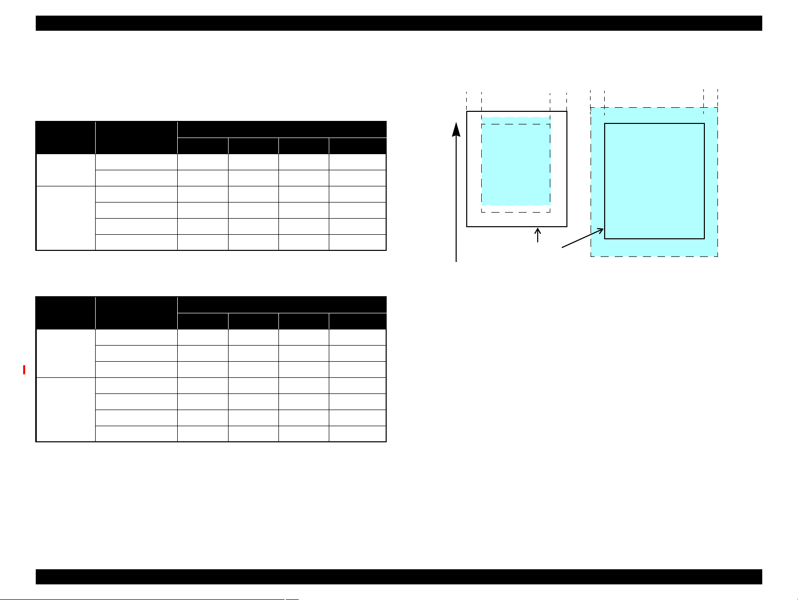
Print Area
LM RM
TM
BM
BM
Cut Sheet (Standard)
Cut Sheet (Borderless)
Print Area
LM
RM
Paper Size
TM
Paper Feed Direction
1.2.5 Printing Area
The printing area for this printer is shown below.
Stylus Photo R1900
Table 1-9. Printing Area (Margins)
Print Mode Paper Size
Standard print Any size 3 mm 3 mm 3 mm 3 mm
Roll paper 3 mm* 3 mm* 30 mm* 21 mm*
Borderless
print
A3/A3+/SuperA3 3.5 mm* 3.5 mm* 3 mm* 4.52 mm*
A4/Letter to 5” x 7” 2.5 mm* 2.5 mm* 3 mm* 4.02 mm*
4” x 6” 2.54 mm* 2.54 mm* 1.34 mm* 2.54 mm*
Roll paper 0 mm 0 mm 30 mm 21 mm
Left (LM)
Right (RM)
Stylus Photo R2880
Margin
Top (TM)
Bottom (BM)
Table 1-10. Printing Area (Margins)
Print Mode Paper Size
Standard print Any size 3 mm 3 mm 3 mm 3 mm
Roll paper 3 mm 3 mm 40 mm 21 mm
Board paper 3 mm 3 mm 20 mm 20 mm
Borderless
print
Note *: The margins for Borderless print are margins that bleed off the edges of paper.
Product Description Printing Specifications 20
A3/A3+/SuperA3 3.5 mm* 3.5 mm* 3 mm* 4.52 mm*
A4/Letter to 5” x 7” 2.5 mm* 2.5 mm* 1.34 mm* 2.54 mm*
4” x 6” 2.54 mm* 2.54 mm* 1.34 mm* 2.54 mm*
Roll paper 0 mm 0 mm 40 mm 21 mm
Left (LM)
Right (RM)
Margin
Top (TM)
Bottom (BM)
Figure 1-2. Printing Area
Confidential
Page 21
EPSON Stylus Photo R1900/R2880/R2000 Revision E
1.3 Interface
This printer has two USB device ports on the rear side to connect the printer with
computers or the like, and one USB host port on the front side to connect an external
device such as a DSC (digital still camera) with the printer. The table below describes
the specifications of each USB port.
Table 1-11. USB Interface Specifications
Item USB Device port USB Host port*
• Universal Serial Bus
Specifications Revision 2.0
Compatible standards
Transfer rate 480 Mbps (High Speed)
Data format NRZI
Compatible connector USB Series B USB Series A
Max. cable length 2 [m] or less 1.8 [m] or less
Note * : External devices that can be connected to the USB device port are:
DSC compliant with the USB Direct Print Protocol specification Rev 1.0
DSC compliant with the CIPA DC-001-2003 (PictBridge) specifications
• Universal Serial Bus Device
Class Definition for Printing
Devices Version 1.1
Table 1-12. Device ID
Prod-
uct
Stylus Photo R1900
Stylus Photo R2880
When IEEE 1284.4 is Enabled When IEEE 1284.4 is Disabled
@EJL<SP>ID<CR><LF>
MFG:EPSON;
CMD:ESCPL2,BDC,D4,D4PX,ESCPR1;
MDL:Stylus[SP]Photo[SP]R1900;
CLS:PRINTER;
DES:EPSON[SP]Stylus[SP]Photo [SP]R1900;
@EJL<SP>ID<CR><LF>
MFG:EPSON;
CMD:ESCPL2,BDC,D4,D4PX,ESCPR1;
MDL:Stylus[SP]Photo[SP]R2880;
CLS:PRINTER;
DES:EPSON[SP]Stylus[SP]Photo [SP]R2880;
@EJL<SP>ID<CR><LF>
MFG:EPSON;
CMD:ESCPL2,BDC;
MDL:Stylus[SP]Photo[SP]R1900;
CLS:PRINTER;
DES:EPSON[SP]Stylus[SP]Photo [SP]R1900;
@EJL<SP>ID<CR><LF>
MFG:EPSON;
CMD:ESCPL2,BDC;
MDL:Stylus[SP]Photo[SP]R2880;
CLS:PRINTER;
DES:EPSON[SP]Stylus[SP]Photo [SP]R2880;
• Universal Serial Bus
Specifications Revision 2.0
1.4 General Specifications
1.4.1 Electrical Specifications
Primary power input
Table 1-13. Primary Power Specifications
Item
Rated power supply voltage
Input voltage range 90 to 132 VAC
Rated current
Rated frequency 50 to 60 Hz
Input frequency range 49.5 to 60.5 Hz
Insulation resistance AC1000Vrms (for one minute)
Energy conservation International Energy Star Program compliant
Printing
Power
consumption
Note : If the printer is not operated for more than three minutes, the printer shifts into the
Sleep mode
Standby mode
(power-off)
standby mode and reduces the current to the motors to save power.
Stylus Photo R1900 Stylus Photo R2880
100-120V 220-240V 100-120V 220-240V
100 to 120 VAC 220 to 240 VAC 100 to 120 VAC 220 to 240 VAC
198 to 264 VAC 90 to 132 VAC 198 to 264 VAC
0.6 A
(max. 1.0 A)
Approx. 20 W Approx. 20 W
Approx. 3.1 W Approx. 4.0 W
Approx. 0.2 W Approx. 0.5 W
0.3 A
(max. 0.5 A)
0.5 A
(max. 1.0 A)
50 to 60 Hz
49.5 to 60.5 Hz
AC1000Vrms (for one minute)
Approx. 20 W Approx. 21 W
Approx. 4.0 W Approx. 4.0 W
Approx. 0.2 W Approx. 0.4 W
0.3 A
(max. 0.5 A)
Product Description Interface 21
Confidential
Page 22
EPSON Stylus Photo R1900/R2880/R2000 Revision E
C A U T I O N
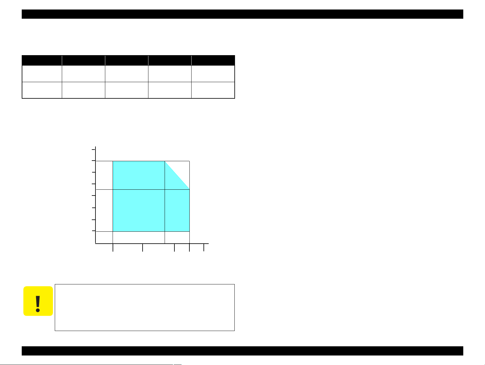
10/50
27/80
30/86 35/95 40/10420/68
Temperature (°C/°F)
20
30
40
50
90
80
70
60
Humidity (%)
1.4.2 Environmental Conditions
Table 1-14. Environmental Conditions
Condition Temperature
Operating
Storage*3
(unpacked)
Note *1: The combined Temperature and Humidity conditions must be within the blue-shaded
range in Figure 1-3.
*2: No condensation
*3: Non-operating with unpacked.
*4: Must be less than 1 month under 40°C.
10 to 35°C
(50 to 95°F)
-20 to 40°C*
(-4°F to 104°F)
Figure 1-3. Temperature/Humidity Range
When returning the repaired printer to the customer, make sure
the Printhead is covered with the cap and the ink cartridge is
installed.
If the Printhead is not covered with the cap when the printer is off,
*1
4
Humidity
20
5
turn on the printer with the ink cartridge installed, make sure the
Printhead is covered with the cap, and then turn the printer off.
to 80%
to 85%
*1,2
Shock Vibration
1G
(1 msec or less)
2G
(2 msec or less)
0.15G,
10 to 55Hz
0.50G,
10 to 55Hz
1.4.3 Durability
Total print life: Black 16,000 pages (A4, 3.5% duty),
Color 10,000 pages (A4, 5% duty),
or five years which ever comes first
Printhead: Six billions shots (per nozzle) or five years which ever comes
first
1.4.4 Acoustic Noise
T.B.D. dB (when printing from PC, on Premium Glossy Photo Paper, in highest
quality)
1.4.5 Safety Approvals (Safety standards/EMI)
USA UL60950-1
FCC Part15 Subpart B Class B
Canada CAN/CSA-C22.2 No.60950-1
CAN/CSA-CEI/IEC CISPR 22 Class B
Mexico NOM-019-SCFI-1998
Taiwan CNS13438 Class B
CNS14336
EU EN60950-1
EN55022 Class B
EN61000-3-2, EN61000-3-3
EN55024
Germany EN60950-1
Russia GOST-R (IEC60950-1, CISPR 22)
Singapore IEC60950-1
Korea K60950-1
KN22 Class B
KN61000-4-2/-3/-4/-5/-6/-11
China GB4943
GB9254 Class B, GB17625.1
Argentina IEC60950-1
Australia AS/NZS CISPR22 Class B
Hong Kong IEC60950-1
Product Description General Specifications 22
Confidential
Page 23
EPSON Stylus Photo R1900/R2880/R2000 Revision E
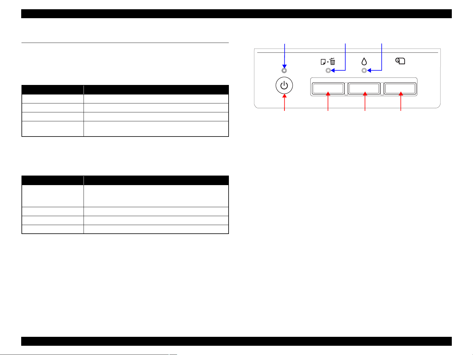
Power Button Paper ButtonInk Button
Power LED Ink LEDPaper LED
Roll Paper Button
1.5 Operation Buttons & Indicators (LEDs)
1.5.1 Operation Buttons
The printer has the following four operation buttons.
Table 1-15. Operation Buttons
Button Function
Power Turns the power ON/OFF.
Paper Feeds or ejects paper.
Ink Runs a sequence of ink cartridge replacement or cleaning.
Roll Paper
1.5.2 Indicators (LEDs)
Eleven indicators (LEDs) are provided to indicate settings or printer status.
LED Function
Power LED (green)
Ink LED (orange)*
Paper LED (orange)*
Cartridge LED (red) x 8 Indicates an ink-related error of each ink cartridge.*
Note *1: The Ink LED and Paper LED stay OFF when printing from PC.
*2: See Table 1-18 "Indicators (LEDs) Function" for the LED status at error occurrence.
1
Prints the cutting line on the roll paper or feeds the paper
backwards out of the printer.
Table 1-16. Indicators (LEDs)
Lights at power-on.
Flashes during some sequence is in progress.
Flashes at high speed during power-OFF sequence.
Lights or flashes when an ink-related error occurs.*
1
Lights or flashes when an paper- or CDR-related error occurs.*
Figure 1-4. Buttons & LEDs
2
2
2
Product Description Operation Buttons & Indicators (LEDs) 23
Confidential
Page 24
EPSON Stylus Photo R1900/R2880/R2000 Revision E
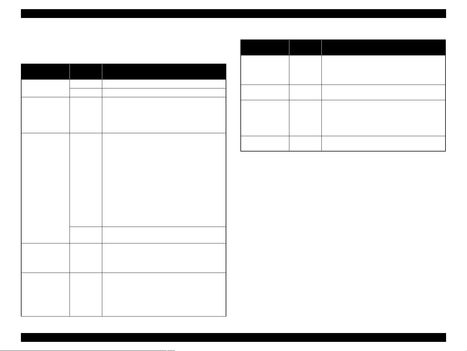
1.5.3 Operation Buttons & LEDs Functions
Detailed information on the buttons and LEDs functions are listed below.
Table 1-17. Operation Button Functions
Button
Power
Ink On
Paper
Ink
(when held for three
seconds or longer)
Roll Paper On
Printer
Status
Off • Turns the power on.
On • Turns the power off.
• Runs a sequence of ink cartridge replacement. The
carriage moves to set the ink cartridge to the position
for replacement.
• When an ink cartridge has been set in the ink replacement
position, moves the carriage to the home position.
• Feeds or ejects paper.*
• Recovers from a multi-feed error and feeds paper to
restart the print job.
• Feeds paper when paper is loaded after a no-paper
error occurs.
• Ejects a jammed paper when a paper jam error occurs.
On
• Cancels the print job during printing.
• Runs a sequence of ink cartridge replacement when
an ink-out, or ink color error*
moves to set the ink cartridge to the position for
replacement.
• When an ink cartridge has been set in the ink replacement
position, moves the carriage to the home position.
During CDR
printing
• Recovers from a paper jam error.
• Cancels the print job during printing.
• Runs a head cleaning.
On
• Runs a sequence of ink cartridge replacement when
ink level low, ink out, no ink cartridge, or ink color
2
has occurred.
error*
• Feeds the roll paper to the cutting position and prints
a cutting line.
• Returns the cutting position.
• When an ink cartridge has been set in the ink
replacement position, moves the carriage to the home
position.
Function
1
2
occurs. The carriage
Table 1-17. Operation Button Functions
Button
Roll Paper
(when held for three
seconds or longer)
Power + Ink *
2
(combination)
Power + Ink *
2
(combination)
(Hold down the Ink
button for 7 sec or
longer)
Power + Paper *
1
(combination)
Note 1: The paper cannot be fed or ejected if the CDR Tray Base is open.
2: Stylus Photo R2880 only.
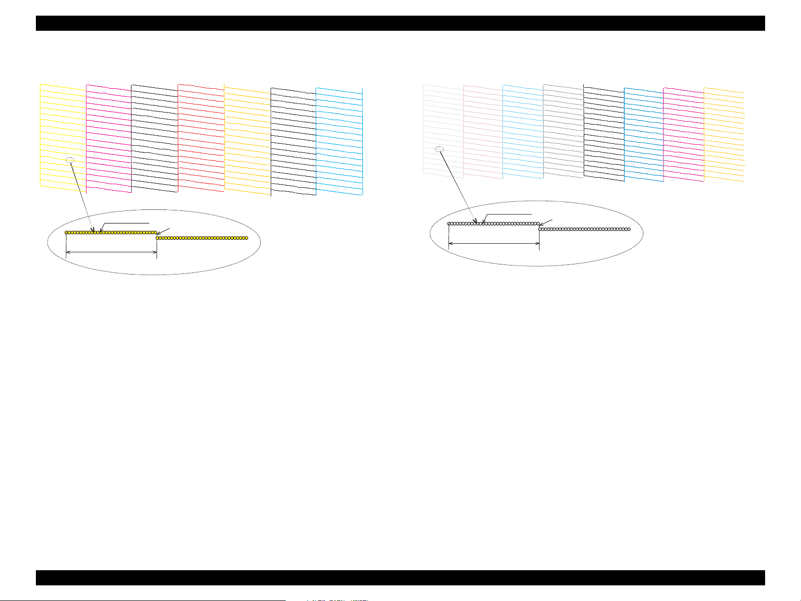
3: The nozzle check pattern printed by the printer is shown in Figure 1-5 and Figure 1-6.
Printer
Status
On
At power on
On
At power on
Function
• Ejects the paper backwards out of the printer.
• When an ink cartridge has been set in the ink
replacement position, moves the carriage to the home
position.
• Turns the power on in rub reduction mode when
connected to DSC (digital still camera).
• Forcefully turns the power off.
• Prints a nozzle check pattern*2 when not connected to
the PC.*
3
Product Description Operation Buttons & Indicators (LEDs) 24
Confidential
Page 25
EPSON Stylus Photo R1900/R2880/R2000 Revision E
1
1
2
2
359
360
359
360
1
1
2
359
360
359
Note : The numbers shown in the figure are nozzle numbers. The numbers and color names
are not printed on an actual nozzle check pattern.
720 dpi VSD1
32 dots
0.141 mm (1/180 inch)
Yellow Magenta Matte Black Red Photo BlackCyanOrange
1
1
1
1
1
1
1
180
180
180
180
180
180 180
1
180
720 dpi VSD2
32 dots
0.141 mm (1/180 inch)
Note : The numbers shown in the figure are nozzle numbers. The numbers and color names
are not printed on an actual nozzle check pattern.
Light Light
Black
Light
Magenta
Light
Black
Black Magenta
Yellow
Light
Cyan
Cyan
Product Description Operation Buttons & Indicators (LEDs) 25
Figure 1-5. Nozzle Check Pattern (Stylus Photo R1900)
Figure 1-6. Nozzle Check Pattern (Stylus Photo R2880)
Confidential
Page 26
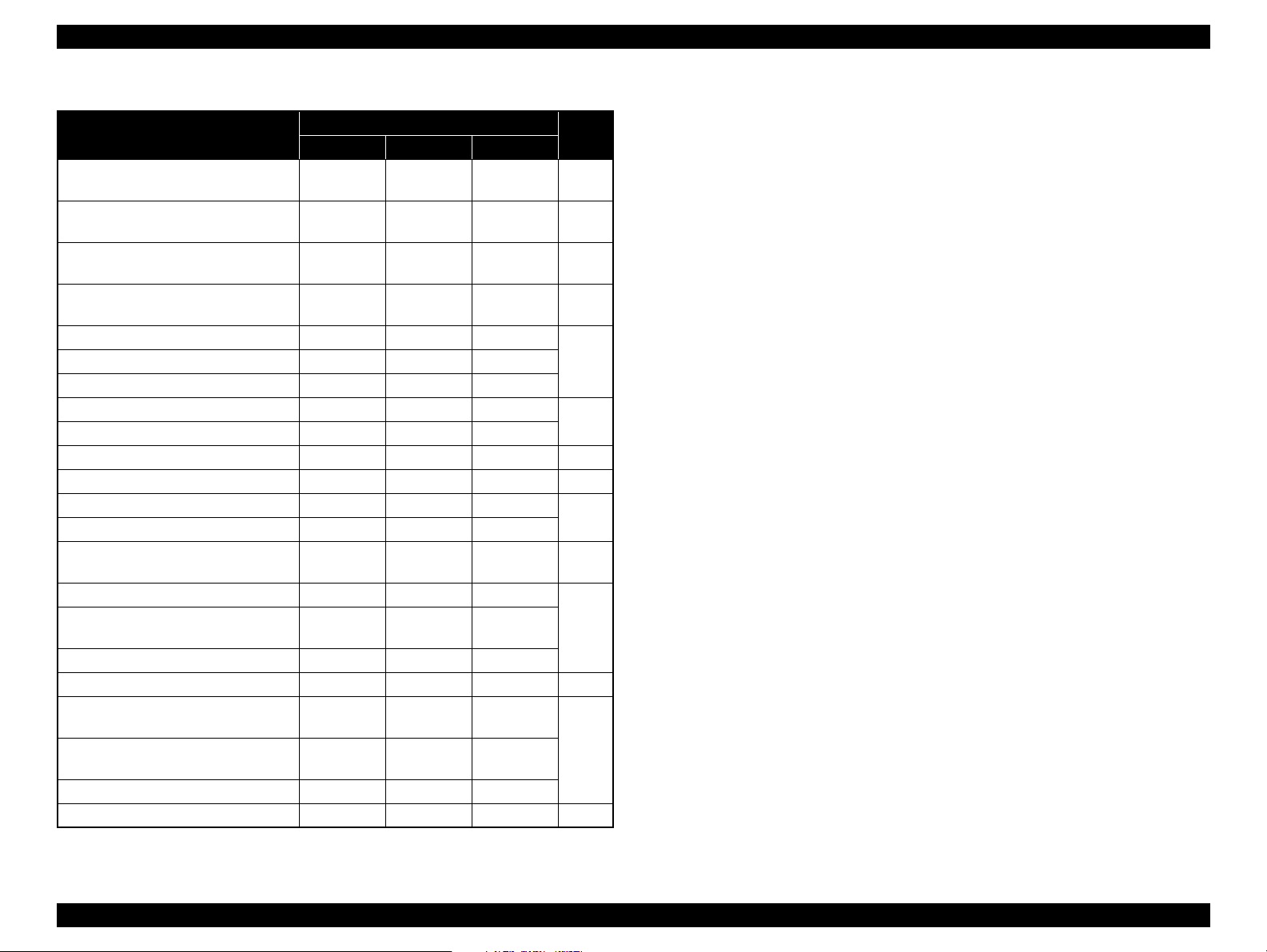
EPSON Stylus Photo R1900/R2880/R2000 Revision E
Table 1-18. Indicators (LEDs) Function
Printer Status
Power OFF
Power Paper Ink
Flashes at
high speed
Fatal error OFF
Maintenance request OFF
CDR guide error -- Flashes 2
Indicators (LEDs)
OFF OFF 1
Flashes at
high speed
Flashes at
high speed
Flashes
alternately 1
alternately 2
Flashes at
high speed
Flashes
Paper path error -- Flashes --
Cover open error -- Flashes -Multi-feed error -- ON -No paper error -- ON -Ink cartridge replacement is in progress Flashes -- -- 7
Ink sequence is in progress Flashes -- -- 8
CSIC error -- -- ON*
No ink cartridge error or ink-out error -- -- ON*
Ink Color error*
4
-- --
Flashes at
high speed*
Data processing/Printing from camera Flashes -- -Connected to non-supported external
device
-- Flashes 2 Flashes 3
Connected to USB hub -- Flashes 4 Flashes
Ink level low -- -- Flashes*
Connected to camera
(with rubbing reduction)
(without rubbing reduction)
Flashes 4 -- --
Flashes 2 -- --
Power ON Flashes -- -Reset request*
3
ON ON ON --
Pri-
ority*
2
2
2
2
10
11
12
13Connected to camera
*2: The cartridge LED corresponding to each ink cartridge lights.
*3: The all LEDs light for 0.2 seconds when a reset request is received.
1
*4: Stylus Photo R2880 only.
Note : --: No change
Flash: Repeats turning On and Off every 1.25 seconds.
Flash 2: Repeats On for 0.5 seconds, Off for 0.5 seconds,
2
On for 0.5 seconds, and Off for 1.0 second.
Flash 3: Repeats Off for 0.5 seconds, On for 0.5 seconds,
3
Flash 4: Repeats On for 2.0 seconds and Off for 0.5 seconds.
Off for 0.5 seconds, and On for 1.0 second.
Flash at high speed: Repeats turning On and Off every 0.5 seconds.
4
Flashes alternately 1:Same as the “Flash”
Flashes alternately 2:Repeats turning Off and On every 1.25 seconds.
5Paper (CDR) jam -- Flashes --
6
9
Note *1: When two or more errors occur at the same time, the one with high er priority will be indicated.
Product Description Operation Buttons & Indicators (LEDs) 26
Confidential
Page 27
EPSON Stylus Photo R1900/R2880/R2000 Revision E
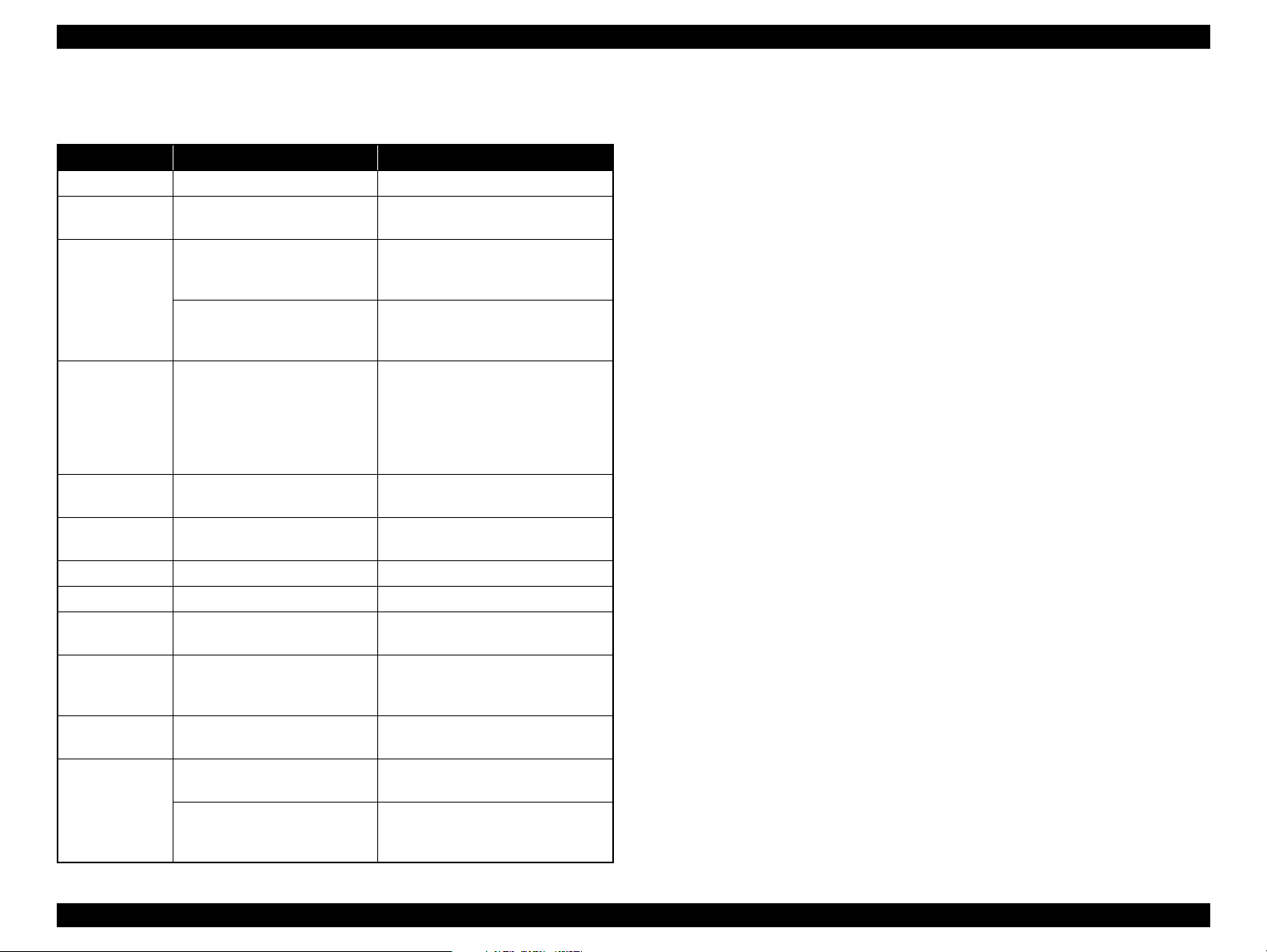
1.5.4 Errors & Remedies
Table 1-19. Errors & Remedies
Error Error Remedies
Fatal error A mechanical error has occurred. Turn the power Off and back it On.
Maintenance
request
CDR guide error
Paper jam
No paper
Multi-feed
Ink-out The cartridge has run out of ink.
No ink cartridge Ink cartridge(s) was not detected.
Wrong ink
cartridge
Paper path error
Cover open error
Ink Color error*
Waste ink pads need to be
replaced.
• The CDR Tray Base was open
Replace the waste ink pads and reset
the counter.
Close the CDR Tray Base.
when receiving or printing a
ASF print job.
• The CDR Tray Base was
Open the CDR Tray Base.
closed when receiving or
printing a CDR print job.
A paper jam has occurred. <When printing on paper>
Remove the jammed paper and press
the Paper button.*
1
<When printing on CDR>
Remove the jammed CDR tray and
press the Paper button.
Failed to feed paper. Load paper correctly and press the
1
1
Multiple sheets of paper were fed
at the same time.
Paper button.*
Press the Paper button to eject the
multiple sheets.*
Replace the cartridge with a new one.*
Replace the cartridge with a new one.*
Incorrect ink cartridge(s) was
detected.
The paper was loaded in a
different way from the specified
one.
Printing was executed with the
Replace the cartridge with the correct
2
one.*
Eject the fed paper and press the Paper
button after loading paper in the
specified way.
Close the Printer Cover.
Printer Cover open.
The black ink cartridge was
replaced during printing.
3
Cleaning after black ink
replacement cannot be
performed.
Replace the cartridge with the one
used before the error.
Replace the black ink cartridge with
the one used before the error, or the
one that has sufficient amount of ink.
Note : For more information on the remedies, see "3.1.1 Troubleshooting according to
Error Messages" (p.34).
Note *1: When the CDR Tray Base is opened, close the CDR Tray Base and press the Paper
button.
*2: When the CDR tray has been inserted, remove the CDR tray and press the Ink button.
*3: Stylus Photo R2880 only.
2
2
Product Description Operation Buttons & Indicators (LEDs) 27
Confidential
Page 28

OPERATING PRINCIPLES
CHAPTER
2
Confidential
Page 29
EPSON Stylus Photo R1900/R2880/R2000 Revision E
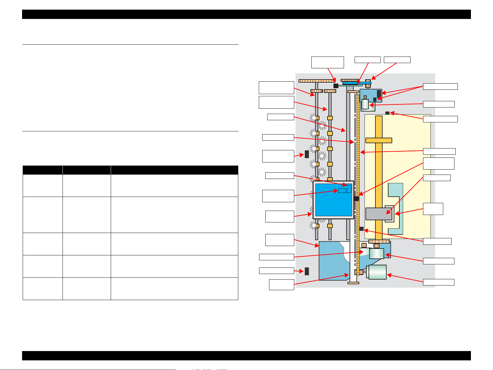
Rear Paper
Eject Roller
Front Paper
Eject Roller
Ink Mark
Sensor
PW Sensor
CR Scale
PF Roller
PF Encoder
Sensor
PF Scale
PF Motor
Carriage
Unit
Ink System
Unit
Pump Motor
CD-R Sensor
Carriage
Shaft
APG Sensors
APG Motor
APF Sensor
Timing Belt
CR Encoder
Sensor
LD Roller
Retard
Roller
PE Sensor
ASF Motor
CR Motor
PF Roller
Cover Open
Sensor
2.1 Overview
This chapter explains the operating principles of the mechanical sections and electrical
circuits in this product. The main components of this product are as follows.
Control circuit board : C698 MAIN
Power supply circuit board : C698 PSB/PSE
Control panel board : C698 PNL
LED board : C698 PNL-B
2.2 Printer Mechanism
Like the conventional model, this product uses DC motors and stepping motors as
power sources. The following table describes the motor types and their applications.
Motor Name Type Applications/Functions
CR Motor
PF Motor
APG Motor
DC motor with
brushes
DC motor with
brushes
DC motor with
brushes
4-phase, 48-pole
ASF Motor
PM type stepping
motor
4-phase, 48-pole
Pump Motor
PM type stepping
motor
Table 2-1. Motors
Used for carriage driving. Makes little noise during
driving. The CR linear scale and CR encoder sensor
are used to control the motor.
Drives the Paper loading rollers at the time of fixedvalue paper loading or paper feed/eject operation. To
grasp the paper feed pitch, the precision gear surface
is fitted with the PF scale and the PF encoder sensor
is used to control the motor.
Drives the Carriage Unit at the time of PG setting.
The two APG Sensors are driven vertically to control
the motor.
Drives the paper feed operation of the ASF. Since
this is a stepping motor, any scales or photo sensors
to know the driving conditions are not required.
Drives the pump, wiper, etc. of the Ink System . Since
this is a stepping motor, any scales or photo sensors
to know the driving conditions are not required.
The basic mechanism is almost same as the Stylus Photo R1800.
The schematic diagram below shows the printer mechanism.
Figure 2-1. Printer Mechanism Outline
Operating Principles Overview 29
Confidential
Page 30
EPSON Stylus Photo R1900/R2880/R2000 Revision E
31.89mm
41.66mm
Carriage moving direction
Paper feeding
direction
0.071mm
(1/360inch)
0.141mm
(1/180inch)
Line A
Line B
7.620mm
(216/720inch)
2.258mm
(64/720inch)
2.258mm
(64/720inch)
2.258mm
(64/720inch)
2.258mm
(64/720inch)
7.620mm
(216/720inch)
7.620mm
(216/720inch)
Line C
Line D
Line E
Line F
Line G
Line H
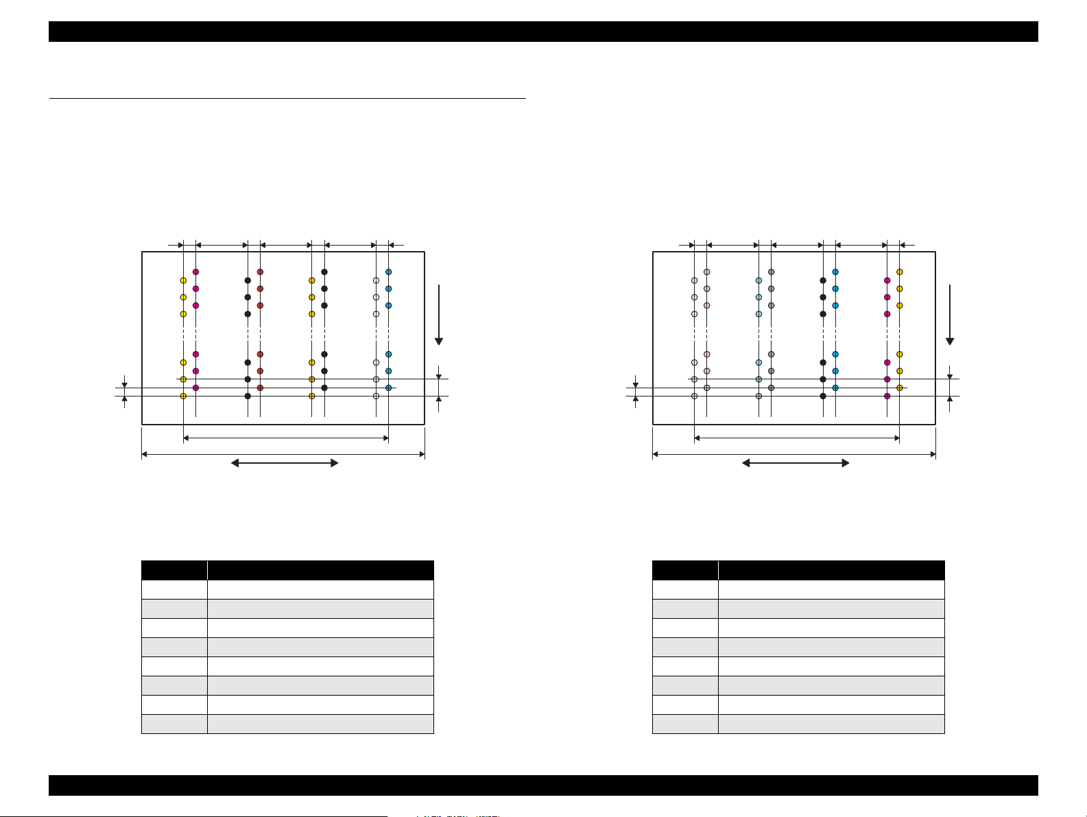
2.3 Printhead Specifications
The Printhead of this product is a F-Mach head.
The following shows the arrangement of the nozzles and the color arrangement of each nozzle line when viewed the Print Head from behind.
Stylus Photo R1900
Stylus Photo R2880
Figure 2-2. Nozzle Arrangement (Stylus Photo R1900)
Table 2-2. Nozzle Lines and the Corresponding Ink Color (Stylus Photo R1900)
Line Ink
AYellow
B Magenta
CMatte Black
E Orange
D Red
F Photo Black
G Gloss Optimizer
H Cyan
Operating Principles Printhead Specifications 30
Table 2-3. Nozzle Lines and the Corresponding Ink Color (Stylus Photo R2880)
Figure 2-3. Nozzle Arrangement (Stylus Photo R2880)
Line Ink
A Light Light Black
B Vivid Light Magenta
C Light Cyan
D Light Black
E Matte Black/Photo Black
F Cyan
G Vivid Magenta
H Yellow
Confidential
Page 31

EPSON Stylus Photo R1900/R2880/R2000 Revision E
2.4 PG Setting
As this printer uses an Auto PG (APG), an appropriate PG position is set according to the used paper type.
The following table indicates the PG positions, the main applications of each position, and the relationships between the two sensors used with the APG.
Table 2-4.
Application
Printing • Photo paper
Non-printing
PG value 1.05mm 1.20mm 1.70mm 2.10mm 4.50mm –
Sensor PG (– –) PG (–) PG (Typ) PG (+) PG (++) Release
APG Sensor 1* Low Low Low Low Low Low
APG Sensor 2 Low Low Low Low High High
PG (– –) PG (–) PG (Typ) PG (+) PG (++) Release
(A4,Letter)
• Roll paper
• Photo Matte paper
––
• Plain paper
• Exclusive paper
• PG (-) rub avoidance
• Standby position after
power-on (When the
CDR Tray Base is
closed.)
• At power-off
• Ink Mark Sensor reading.
(Auto Bi-D)
PG Position
• Envelope
• PG (Typ) rub avoidance
• Ink Mark Sensor reading.
(Detection of dot
missing)
• CD/DVD
• Initialization at power-on
• Cleaning (wiping)
• Ink Cartridge
replacement
–
• Standby state for CD/
DVD feeding
• Paper jam removal
Note "*": The signal output is “High” while the PG positions are changed.
Operating Principles PG Setting 31
Confidential
Page 32

EPSON Stylus Photo R1900/R2880/R2000 Revision E
1
2
3
4
7
9
6
E
D
C
A
10
B
5
8
2.5 Motors & Sensors
Motors
Fig. Name Specific
Type: DC Motor Drive voltage: 42VDC±5%
Armature resistance: 21.2 ±10%
Type: DC Motor Drive voltage: 42VDC±5%
Armature resistance: 64.7 ±15%
Type: 4-phase 48-pole PM type stepping motor Drive voltage: 42VDC±5%
Winding resistance: 7.0 ±10% (per phase at 25°C)
Type: DC Motor Drive voltage: 42VDC±5%
Armature resistance: 23.6 ±10%
Type: 4-phase 48-pole PM type stepping motor Drive voltage: 42VDC±5%
Winding resistance: 10.3 ±10% (per phase at 25°C)
A PF Motor
B APG Motor
C ASF Motor
DCR Motor
EPump Motor
Sensors
Fig. Name Specific
1 PF Encoder sensor Type: Rotary Encoder Drive voltage: 3.3VDC±5%
2 APG Sensor (1)
3 APG Sensor (2)
4 ASF Sensor
5PE Sensor
6 CR Encoder sensor Type: Linear Encoder Drive voltage: 3.3VDC
7 PW Sensor
Table 2-5. List of Motors
Table 2-6. List of Sensors
Type: Transmissive photo interrupter Drive voltage: 3.3VDC±5%
Sensor output:
• High: In the domain of each PG position
• Low: Between PG positions
Type: Transmissive photo interrupter Drive voltage: 3.3VDC
Sensor output:
• High: In the domain of large PG
• Low: In the domain of small PG
Type: Transmissive photo interrupter Drive voltage: 3.3VDC
Sensor output:
• High: Home position
• Low: Other than home position
Type: Transmissive photo interrupter Drive voltage: 3.3VDC
Sensor output:
• High (2.4V or more): No paper
• Low (0.4V or less): Paper exists
Type: Reflective photo interrupter Drive voltage: 3.3VDC±5%
Sensor output:
• High: No paper
• Low: Paper exists
±5%
±5%
±5%
±5%
Table 2-6. List of Sensors
Fig. Name Specific
8 Ink Mark Sensor Type: Diffuse reflective photo interrupter Drive voltage: 3.3(5)VDC±5%
Type: Mechanical contact Drive voltage: 3.3VDC±5%
9CDR Sensor
Cover Open
10
Sensor
Sensor output:
• High: CDR Tray Base open
• Low: CDR Tray Base closed
Type: Mechanical contact Drive voltage: 3.3VDC±5%
Sensor output:
• High: Cover closed
• Low: Cover open
Figure 2-4. Motors and Sensors Layout
Operating Principles Motors & Sensors 32
Confidential
Page 33

TROUBLESHOOTING
CHAPTER
3
Confidential
Page 34

EPSON Stylus Photo R1900/R2880/R2000 Revision E
3.1 Overview
This chapter describes unit-level troubleshooting.
3.1.1 Troubleshooting according to Error Messages
After checking the printer LED and STM3 error indications, you can grasp the fault location using the check list in this section. When you find the fault location, refer to Chapter 4
“Disassembly and Reassembly” and change the corresponding part and/or unit. The following table indicates the check point reference tables corresponding to the error states (LED
and STM3).
Table 3-1. List of Error Messages
Error Status
Communication error
Model Difference
Printer cover open
error
CDR Guide error
Paper out error
Paper (CDR) jam
Power Paper Ink
LED Indications
Communication error
---
---
-Flash-
-Flash 2
- Light -
-Flash-
Flashes at
high speed
Check all connections and make sure all devices are on. If the power was
turned off during printing, cancel the print job. If the error does not clear,
see your printer documentation.
Different device from specified
Attempting to connect to a different device from that specified in the driver.
Check the driver settings and the device.
Printer cover open
Close the printer cover.
Front paper feed guide open
Remove the CD/DVD tray, then close the front paper feed guide.
Media out or not loaded correctly
For sheets of paper, reload the paper correctly, then press the Paper button
on the printer.
For roll paper or velvet paper, insert the end of the paper into the printer.
For a CD or DVD, load the CD/DVD tray correctly, then press the Paper
button on the printer.
Paper jam or CD/DVD tray jam
For sheets of paper, turn off the printer and then remove any jammed paper
by hand.
For a CD or DVD, remove the CD/DVD tray. Next, press the Paper button
on the printer or click the Eject button if it appears on this screen.
STM3 Message See the table for Troubleshooting
Refer to Table 3-2 "Troubleshooting of Communication
Error" (P.37)
Refer to Table 3-3 "Troubleshooting of Printer Cover
Open Error" (P.39)
Refer to Table 3-4 "Troubleshooting of CDR Guide
Error" (P.40)
Refer to Table 3-5 "Troubleshooting of Paper Out
Error" (P.41)
Refer to Table 3-6 "Troubleshooting of Paper Jam
Error" (P.45)
Troubleshooting Overview 34
Confidential
Page 35

EPSON Stylus Photo R1900/R2880/R2000 Revision E
Table 3-1. List of Error Messages
Error Status
Paper Mismatch Error
Multi-feed error
Ink low
Ink Color error*
1
Power Paper Ink
LED Indications
Paper Source setting not selected correctly
For sheets of paper, remove the roll paper or velvet paper and print again.
-Flash-
For roll paper, select Roll Paper as the Paper Source setting in the printer
driver and print again.
For velvet paper, select Velvet Fine Art Paper as the Paper Source setting in
the printer driver and print again.
Page not printed or multi-page error
- Light -
A page has not been printed, multiple pages have been fed into the printer at
once, or the wrong paper size has been fed into the printer. Remove and
reload the paper. Press the Paper button if necessary.
Ink low
Black: XXXX
Color: XXXX
--Light*
2
You may continue printing, or click the How to button to
change the ink cartridge now.
Ink cartridges cannot be replaced
There are two possible causes.
Because there is only a small amount of ink remaining,
you cannot replace it with a different type of black ink cartridge.
(However, you may be able to replace it with the same type of black ink
cartridge.)
--
Flashes at
high speed*
Replace it with a new ink cartridge. We recommend using genuine Epson
2
ink cartridges.
Or, the currently installed black ink differs to the type of cartridge used
when printing started.
Replace the currently installed black ink cartridge with the same type of
previously installed black ink cartridge.
Once it is replaced, printing will resume automatically. If you do not want to
replace the ink cartridge, click the Cancel button.
2
*
...................
STM3 Message See the table for Troubleshooting
Refer to Table 3-7 "Troubleshooting of Paper Mismatch
Error" (P.46)
Refer to Table 3-8 "Troubleshooting of Multi-feed
error" (P.48)
Refer to Table 3-9 "Troubleshooting of Ink Low" (P.48)
Refer to Table 3-10 "Troubleshooting of Ink Color Error
(Stylus Photo R2880 only)" (P.48)
Troubleshooting Overview 35
Confidential
Page 36

EPSON Stylus Photo R1900/R2880/R2000 Revision E
Table 3-1. List of Error Messages
Error Status
Power Paper Ink
LED Indications
STM3 Message See the table for Troubleshooting
Ink-out error
No ink cartridge/
CSIC error
Maintenance request
Fatal error
--Light*
--Light*
Off
Off
Flashes
alternately 1
Flashes at
high speed
Flashes
alternately 2
Flashes at
high speed
Note *1: Stylus Photo R2880 only.
*2: The cartridge LED corresponding to each ink cartridge lights.
*3: The “XXXX” represents the part number of the Ink Cartridge.
Refer to "1.2.2 Ink Cartridge" (p11).
Note : --: No change
Flash: Repeats turning On and Off every 1.25 seconds.
Flash 2: Repeats On for 0.5 seconds, Off for 0.5 seconds,
On for 0.5 seconds, and Off for 1.0 second.
Flash at high speed: Repeats turning On and Off every 0.5 seconds.
Flashes alternately 1: Same as the “Flash”
Flashes alternately 2: Repeats turning Off and On every 1.25 seconds.
Replace Cartridge
Black: XXXX*
Color: XXXX
2
2
...................
Epson recommends the genuine Epson cartridges listed above. Click the
How to button for ink cartridge replacement instructions.
Ink cartridges cannot be recognized
Black: XXXX*
Color: XXXX
2
2
...................
Epson recommends the genuine Epson cartridges listed above. Click the
How to button for ink cartridge installation instructions.
Service required
Parts inside your printer are at the end of their service life. See your printer
documentation.
General error
Delete all print jobs and turn the printer off. Remove any foreign objects
from inside the printer. After a few minutes, turn the printer back on.
Refer to Table 3-12 "Troubleshooting of No Ink
Cartridge/CSIC Error" (P.49)
Refer to Table 3-13 "Troubleshooting of Maintenance
Request" (P.50)
Refer to Table 3-14 "Troubleshooting of Fatal Error"
(P.51)
Troubleshooting Overview 36
Confidential
Page 37

EPSON Stylus Photo R1900/R2880/R2000 Revision E
Panel FFC
CN4
Panel Board
connector
Panel FFC
Blue line
1Pin side
Connector cable of the
Power Supply Board
CN60
Table 3-2. Troubleshooting of Communication Error
Occurrence
Timing
Phenomenon Detail
Faulty Part/
Part Name
Check Point Remedy
At power-on The printer does not operate at all. Panel FFC 1. Check that the Panel FFC is connected to the Panel Board
connector and Main Board connector.
2. Check the Panel FFC for damages. 2. Replace the Panel FFC with a new one.
Panel Board 1. Check the Panel Board for damages. 1. Replace the Panel Board with a new one.
Power Supply
Board
1. Check that the connector cable of the Power Supply Board is
connected to the Main Board connector CN60.
1. Connect the Panel FFC to the Panel Board and
Main Board connectors.
1. Connect the connector cable of the Power
Supply Board to the Main Board connector
CN60.
Troubleshooting Overview 37
2. Check that the blue colored pin of the Power Supply Board
connector cable is inserted into the 1 Pin of the Main Board
connector CN60 as shown in the above picture.
2. Reconnect the Power Supply Board connector
cable so that the blue colored pin is inserted
into the 1 Pin.
Confidential
Page 38

EPSON Stylus Photo R1900/R2880/R2000 Revision E
Fuse F1
Power Supply
Board
Relay connector of
the Pump Motor
Relay connector of
the ASF Motor
Table 3-2. Troubleshooting of Communication Error
Occurrence
Timing
Phenomenon Detail
Faulty Part/
Part Name
At power-on The printer does not operate at all. Power Supply
Board
After the power-on sequence has
Main Board 1. Check that the Relay connector of the ASF Motor and the Relay
started, the LED turns off and the
printer does not operate.
Check Point Remedy
3. Check that the Fuse F1 on the Power Supply Board has not
blown.
3. Replace the Power Supply Board with a new
one.
4. Check the components on the Power Supply Board for damage. 4. Replace the Power Supply Board with a new
one.
1. Connect the Relay connector of the ASF Motor
connector of the Pump Motor are not connected to the wrong
connector causing a short circuit.
and the Relay connector of the Pump Motor
correctly, and replace the Main Board with a
new one.
At operation Operation at power-on is normal,
Troubleshooting Overview 38
but the error appears when the
print job is sent to the printer.
Interface cable 1. Check that the Interface cable is connected between the PC and
printer.
2. Check the Interface cable for breaking. 2. Replace the Interface cable with a new one.
1. Connect the Interface cable to the PC and
printer.
Confidential
Page 39

EPSON Stylus Photo R1900/R2880/R2000 Revision E
Connector of the Cover
Open Sensor
CN4
Panel Unit
Table 3-2. Troubleshooting of Communication Error
Occurrence
Timing
At operation Operation at power-on is normal,
Occurrence
Timing
During printing A Printer Cover Open Error is
Phenomenon Detail
but the error appears when the
print job is sent to the printer.
Phenomenon Detail
indicated during printing.
Faulty Part/
Part Name
USB 1. Check that the PC and printer are connected via the USB hub. 1. Configure the USB ID setting.
Printer Driver 1. Check that the printer driver for Stylus Photo R1900 has already
been installed.
2. Check that the connected printer is Stylus Photo R1900. 2. Connect the Stylus Photo R1900 printer.
Main Board 1. Check that a wrong model name has not been input to the
EEPROM on the Main Board.
Check Point Remedy
Refer to Chapter 5 "Adjustment".
1. Install the printer driver for Stylus Photo
R1900.
1. Make the initial setting using the Adjustment
Program.
Refer to Chapter 5"Adjustment".
Table 3-3. Troubleshooting of Printer Cover Open Error
Faulty Part/
Part Name
Cover Open
Sensor
1. Check that the Printer Cover is not open. 1. Close the Printer Cover.
2. Check that the connector cable of the Cover Open Sensor is
connected to the Cover Open Sensor and connector CN4 on the
Panel Board.
Check Point Remedy
2. Connect the connector cable of the Cover Open
Sensor to the Cover Open Sensor and
connector CN4 on the Panel Board correctly.
3. Using a tester, check that the Cover Open Sensor is normal.
• Paper absent:0V
• Paper present:3.3V
4. Replace the Panel Unit with a new one.
Troubleshooting Overview 39
Confidential
Page 40

EPSON Stylus Photo R1900/R2880/R2000 Revision E
OK NG
Connector on the
Panel Board
CDR Sensor
Connector cable of
the CDR Sensor
Table 3-4. Troubleshooting of CDR Guide Error
Occurrence
Timing
At operation CDR Guide Error is indicated on
Phenomenon Detail
the LED and STM3 when CD/
DVD printing is executed after
the CDR Tray Base is opened and
the CDR Tray is inserted.
Faulty Part/
Part Name
CDR Sensor 1. Check that the CDR Sensor is installed correctly. 1. Install the CDR Sensor correctly.
2. Check that the connector cable of the CDR Sensor is connected
to the CDR Sensor and the connector on the Panel Board.
3. Using a tester, check that the CDR Sensor is normal.
• CDR Tray Base open: 3.3V
• CDR Tray Base closed: 0V
4. Check the CDR Sensor or connector cable for damages. 4. Replace the CDR Sensor with a new one.
Check Point Remedy
2. Connect the connector cable of the CDR
Sensor to the CDR Sensor and the Panel Board.
3. Replace the CDR Sensor with a new one.
Troubleshooting Overview 40
Confidential
Page 41

EPSON Stylus Photo R1900/R2880/R2000 Revision E
Cleaning sheet Postcard used
as mount
Non-adhesive part
Adhesive part
This side down
Stapling
Cloth damped
with alcohol
Table 3-5. Troubleshooting of Paper Out Error
Occurrence
Timing
Phenomenon Detail
At operation When the Paper Switch is
pressed, the LD Roller attempt to
feed paper but the paper is not
fed.
Faulty Part/
Part Name
Check Point Remedy
ASF Assy. 1. Check the LD Roller or Retard Rol ler of the ASF Assy for pape r
dust and foreign matter.
1. Using a cleaning sheet, clean the LD Roller
and Retard Roller. The procedure is as follows.
(1) Place the cleaning sheet upside down and
put it into the ASF Assy.
(2) Press the Paper Switch to start paper feed.
(3) Repeat the above steps several times.
* To remove persistent contamination, staple
an alcohol-dampened cloth to a postcard
and clean the rollers in the following
method.
(1) Place the alcohol-dampened cloth toward
the LD Roller surface of the ASF Assy.
(2) Hold the mount top end securely and press
the Paper Switch.
(3) Repeat the paper feed sequence several
times to clean the LD Roller surface of the
ASF Assy.
Troubleshooting Overview 41
Confidential
Page 42

EPSON Stylus Photo R1900/R2880/R2000 Revision E
CN2
PW Sensor connector
Sensor Holder
Detection Lever
Torsion Spring
Table 3-5. Troubleshooting of Paper Out Error
Occurrence
Timing
At operation Paper Mismat ch Error is indicated
Phenomenon Detail
even the paper path of the media
to be printed is correct.
Faulty Part/
Part Name
PE Sensor 1. Check that the connector cable of the PE Sensor is securely
connected to the PE Sensor and Relay Board connector CN2.
2. Check that the Sensor Holder is mounted to the Mechanical
frame correctly.
Check Point Remedy
1. Connect the connector cable of the PE Sensor
to the PE Sensor and connector CN2 on the
Relay Board correctly.
2. Install the Sensor Holder correctly.
3. Move the Detection Lever manually as when the paper passes,
and check that the Detection Lever returns to the original
position automatically by the Torsion Spring when released.
Refer to the above photo.
4. Using a tester, check that the PE Sensor is normal.
Paper absent : 2.4V or more
Paper present : 0.4V or less
3. Replace the PE Sensor Holder Unit with a new
one.
4. Replace the PE Sensor Holder Unit with a new
one.
Troubleshooting Overview 42
Confidential
Page 43

EPSON Stylus Photo R1900/R2880/R2000 Revision E
White Markings
HP detection
position
PW sensor
Carriage Unit Bottom
Table 3-5. Troubleshooting of Paper Out Error
Occurrence
Timing
The Paper Switch
was pressed at the
setting of the CDR
Tray.
The Paper Switch
was pressed at the
setting of the CDR
Tray.
Phenomenon Detail
The CDR Tray HP detection
sequence stops and the Tray is
ejected.
Though the CDR Tray is fed
toward the ASF Assy, but is
ejected immediately.
Faulty Part/
Part Name
CDR Tray 1. Check the HP detection position or white markings of the CDR
Tray for paper dust and foreign matter.
2. Check the Driven Roller surface for contamination such as paper
dust and CDR coating material.
3. Check that the HP detection position or white markings of the
CDR Tray are not chipped.
PW sensor 1. Check the PW Sensor for paper dust, ink, etc. 1. Clean the PW Sensor surface.
Check Point Remedy
1. Remove paper dust and/or foreign matter from
the detection position.
2. Feed A4-size sheets of plain paper from the
ASF Assy several times to remove the
contamination.
3. Replace the CDR Tray with a new one.
Troubleshooting Overview 43
2. Compare the EEPROM values in two places (50<H> and
51<H>) and check that they are not approximate to each other.
2. Replace the PW Sensor with a new one.
Confidential
Page 44

EPSON Stylus Photo R1900/R2880/R2000 Revision E
PW Sensor
connector
FFC
CR Encoder Board
connector
Table 3-5. Troubleshooting of Paper Out Error
Occurrence
Timing
The Paper Switch
was pressed at the
setting of the CDR
Tray.
Phenomenon Detail
The CDR Tray moves toward the
ASF and the posterior edge of it
reaches to the Driven Roller on
the Upper Paper Guide.Then the
CDR Tray tries to go farther, but
it is ejected.
Faulty Part/
Part Name
PW sensor 1. Check that the PW Sensor FFC is placed in the specified routing
positions and does not make contact with any parts.
2. Check that the PW Sensor FFC is connected to the CR Encoder
Board and PW Sensor connectors. Refer to the above photo.
3. Check the PW Sensor or PW Sensor FFC for damages. 3. Replace the PW Sensor (or the PW Sensor
Check Point Remedy
1. Place the PW Sensor FFC in the specified
routing positions correctly.
2. Connect the FFC to the CR Encoder Board and
PW Sensor connectors correctly.
FFC) with a new one.
Troubleshooting Overview 44
Confidential
Page 45

EPSON Stylus Photo R1900/R2880/R2000 Revision E
Paper EJ Frame Assy.
Star Wheel Units
Spur Gear 16; B
Spur Gear 68
Table 3-6. Troubleshooting of Paper Jam Error
Occurrence
Timing
At operation At the time of paper ejection, the
Phenomenon Detail
PF Roller advances the paper but
cannot eject it completely.
Paper is not ejected completely
and causes a jam near the Paper
Eject Frame.
Faulty Part/
Part Name
– 1. Check that the size of the fed paper is not larger than that of the
paper specified by the driver.
ASF Assy. 1. Check that the paper is fed along the Right Edge Guide. 1. Feed the paper along the Right Edge Guide.
Paper EJ Frame
Assy.
Spur Gear 68
Spur Gear 16; B
Paper EJ Roller
Assy.(front/rear)
1. Check that the Star Wheel Units have not come off the Paper EJ
Frame Assy.
2. Check the Paper EJ Frame Assy for deformation or damages. 2. Replace the Paper EJ Frame Assy with a new
1. Check the Spur Gear 68 or Spur Gear 16; B for damages. 1. Replace the Front (or Rear) Paper EJ Roller
Check Point Remedy
1. Tell the user that the paper size specified by the
driver is not available for the printer.
1. Securely install the Star Wheel Units to the
Paper EJ Frame Assy.
one.
Assy with a new one.
Troubleshooting Overview 45
Confidential
Page 46

EPSON Stylus Photo R1900/R2880/R2000 Revision E
CN2
PW Sensor connector
PW Sensor connector
Sensor Holder
Detection Lever
Torsion Spring
Table 3-7. Troubleshooting of Paper Mismatch Error
Occurrence
Timing
During printing Paper Mismatch Error is
Phenomenon Detail
indicated even the paper path of
the media to be printed is
correct.
Faulty Part/Part
Name
PE Sensor 1. Check that the connector cable of the PE Sensor is securely
connected to the PE Sensor and Relay Board connector CN2.
2. Check that the Sensor Holder is mounted to the Mechanical
frame correctly.
Check Point Remedy
1. Connect the connector cable of the PE Sensor
to the PE Sensor and connector CN2 on the
Relay Board correctly.
2. Install the Sensor Holder correctly.
3. Move the Detection Lever manually as when the paper passes,
and check that the Detection Lever returns to the original
position automatically by the Torsion Spring when released.
Refer to the above photo.
4. Using a tester, check that the PE Sensor is normal.
Paper absent : 2.4V or more
Paper present : 0.4V or less
3. Replace the PE Sensor Holder Unit with a new
one.
4. Replace the PE Sensor Holder Unit with a new
one.
Troubleshooting Overview 46
Confidential
Page 47

EPSON Stylus Photo R1900/R2880/R2000 Revision E
OK NG
Connector on the
Panel Board
CDR Sensor
Connector cable of
the CDR Sensor
Table 3-7. Troubleshooting of Paper Mismatch Error
Occurrence
Timing
During printing Paper Mismatch Error is
Phenomenon Detail
indicated even the paper path of
the media to be printed is
correct.
Faulty Part/Part
Name
CDR Sensor 1. Check that the CDR Sensor is installed correctly. 1. Install the CDR Sensor correctly.
2. Check that the connector cable of the CDR Sensor is connected
to the CDR Sensor and the connector on the Panel Board.
3. Using a tester, check that the CDR Sensor is normal.
• CDR Tray Base open: 3.3V
• CDR Tray Base closed: 0V
Check Point Remedy
2. Connect the connector cable of the CDR
Sensor to the CDR Sensor and the Panel
Board.
3. Replace the CDR Sensor with a new one.
4. Check the CDR Sensor or connector cable for damages. 4. Replace the CDR Sensor with a new one.
Troubleshooting Overview 47
Confidential
Page 48

EPSON Stylus Photo R1900/R2880/R2000 Revision E
Extension Spring
Retard Roller
Assy
Bottom of
the ASF Assy
ASF Assy
Table 3-8. Troubleshooting of Multi-feed error
Occurrence
Timing
Any time During manual double-sided
Occurrence
Timing
At operation or
during printing
Phenomenon Detail
printing, multiple sheets are fed
at a time.
Phenomenon Detail
A message is displayed on the
LED and STM3 during printing.
Faulty Part/Part
Name
ASF Assy 1. Check that the Retard Roller Assy is moving properly during the
feeding operation.
2. Check that the position of the ASF Guide Roller LDs has been
adjusted correctly.
Check Point Remedy
Table 3-9. Troubleshooting of Ink Low
Faulty Part/Part
Name
Ink Cartridge 1. Look at the remaining ink indication of the STM3 to check the
amount of the ink remaining in the Ink Cartridge.
Check Point Remedy
1. Attach the Extension Spring on the back side
of the Retard Roller Assy correctly.
2. Adjust the position of the ASF Guide Roller
LDs.
Refer to Chapter 4 ASF Assy (P.106).
1. Prepare a new Ink Cartridge.
Table 3-10. Troubleshooting of Ink Color Error (Stylus Photo R2880 only)
Occurrence
Timing
During printing A message is displayed on the
Phenomenon Detail
LED and STM3 after replacing
ink cartridge.
Faulty Part/Part
Name
Ink Cartridge 1. Check if the installed black ink cartridge is different in color
(photo or matte) from the previous one.
2. Check if the installed cartridge is nearly empty by checking the
ink level displayed on the STM3.
Check Point Remedy
1. Install the same type of black ink cartridge as
the one previously used.
2. Prepare a new Ink Cartridge.
Troubleshooting Overview 48
Confidential
Page 49

EPSON Stylus Photo R1900/R2880/R2000 Revision E
Tab
Memory Chip
Memory Chip
Table 3-11. Troubleshooting of Ink Out Error
Occurrence
Timing
During printing After the Carriage has detected
Occurrence
Timing
At power-on After the Carriage has detected
Phenomenon Detail
the HP, an error is displayed on
the LED and STM3.
Phenomenon Detail
the HP, an error is displayed on
the LED and STM3.
Faulty Part/Part
Name
Ink Cartridge 1. Look at the remaining ink indication of the STM3 to check
whether the ink remains in the Ink Cartridge.
Check Point Remedy
1. Replace the Ink Cartridge with a new one.
Table 3-12. Troubleshooting of No Ink Cartridge/CSIC Error
Faulty Part/
Part Name
Ink Cartridge 1. Check that the Ink Cartridge is installed correctly. 1. Install the Ink Cartridge correctly.
2. Check that the tab of the Ink Cartridge is not broken. 2. Replace the Ink Cartridge with a new one.
Check Point Remedy
Troubleshooting Overview 49
3. Check that the Memory Chip is not disconnected or not
damaged.
3. Replace the Ink Cartridge with a new one.
Confidential
Page 50

EPSON Stylus Photo R1900/R2880/R2000 Revision E
CN22
CSIC FFC
CSIC Board
connector
CSIC Board
Table 3-12. Troubleshooting of No Ink Cartridge/CSIC Error
Occurrence
Timing
At power-on After the Carriage has detected
Phenomenon Detail
the HP, an error is displayed on
the LED and STM3.
Faulty Part/
Part Name
CSIC FFC 1. Check that the CSIC FFC is connected to the CSIC Board
connector and Main Board connector CN22.
2. Check the CSIC FFC for damage. 2. Replace the CSIC FFC with a new one.
CSIC Board 1. Check the CSIC Board for damage. 1. Replace the CSIC Board with a new one.
Check Point Remedy
1. Connect the CSIC FFC to the CSIC Board
connector and Main Board connector CN22.
Table 3-13. Troubleshooting of Maintenance Request
Occurrence
Timing
At power-on At power-on, the printer does not
Troubleshooting Overview 50
Phenomenon Detail
operate at all.
Faulty Part/
Part Name
Waste Ink Pads 1. Using the Adjustment Program, check if the values of the
Protection Counter A and B have exceeded the values shown
below.
• Protection Counter A : 21,500 (Stylus Photo R1900)
• Protection Counter B : 7,030
Check Point Remedy
: 22,500 (Stylus Photo R2880)
1. Replace the Waste Ink Pads and reset the
Protection Counter A and B value with the
Adjustment Program.
Confidential
Page 51

EPSON Stylus Photo R1900/R2880/R2000 Revision E
CR Motor
Relay connector
CN15
Table 3-14. Troubleshooting of Fatal Error
Occurrence
Timing
At power-on At power-on, the CR Motor does
Phenomenon Detail
not operate at all.
Faulty Part/
Part Name
CR Motor 1. Check that the CR Motor connector cable is connected to the
Relay connector.
2. Check the CR Motor connector cable for damages. 2. Replace the CR Motor with a new one.
3. Check if the CR Motor operates normally. 3. Replace the CR Motor with a new one.
Relay connector
cables
(for the CR
Motor)
1. Check that the Relay connector cable is connected to the Main
Board connector CN15.
Check Point Remedy
1. Connect the CR Motor connector to the Relay
connector.
1. Connect the Relay connector cable to the Main
Board connector CN15.
2. Check the Relay connector cable for damages. 2. Replace the Relay connector cable with a new
one.
Troubleshooting Overview 51
Confidential
Page 52

EPSON Stylus Photo R1900/R2880/R2000 Revision E
Carriage Shaft
CN116
Table 3-14. Troubleshooting of Fatal Error
Occurrence
Timing
At power-on The power-on sequence is
Phenomenon Detail
executed but Fatal error is
displayed.
At power-on, the PF Motor does
not operate at all.
Faulty Part/
Part Name
CR drive
mechanism
PF Motor 1. Check that the connector cable of the PF Motor is connected to
1. Check that the Carriage Shaft is lubricated with grease. 1. Wipe the surface of the Carriage Shaft with a
the Main Board connector CN116.
Check Point Remedy
dry, soft cloth, and lubricate the Carriage Shaft
with grease G-71.
Refer to Chapter 6 "Maintenance".
1. Connect the PF Motor connector cable to the
Main Board connector CN116.
2. Check the PF Motor connector cable for damages. 2. Replace the PF Motor with a new one.
3. Check if the PF Motor operates normally. 3. Replace the PF Motor with a new one.
Troubleshooting Overview 52
Confidential
Page 53

EPSON Stylus Photo R1900/R2880/R2000 Revision E
CN118
Relay connector
Table 3-14. Troubleshooting of Fatal Error
Occurrence
Timing
At power-on At power-on, the APG Motor
Phenomenon Detail
does not operate at all.
At power-on, the Pump Motor
does not operate at all.
Faulty Part/
Part Name
APG Motor 1. Check that the connector cable of the APG Motor is connected to
the Main Board connector CN118.
2. Check the APG Motor connector cable for damage. 2. Replace the APG Motor with a new one.
3. Check if the APG Motor operates normally. 3. Replace the APG Motor with a new one.
Pump Motor 1. Check that the Pump Motor connector cable is connected to the
Relay connector.
Check Point Remedy
1. Connect the APG Motor connector cable to the
Main Board connector CN118.
1. Connect the Pump Motor connector cable to
the Relay connector.
2. Usin g a t ester, check the resistance value of the Pump Motor.
Value of resistance: 10.3 ±10%
3. Check the Pump Motor connector cable for damages. 3. Replace the Ink System Unit with a new one.
Troubleshooting Overview 53
2. If the resistance value is abnormal, replace the
Ink System Unit with a new one.
Confidential
Page 54

EPSON Stylus Photo R1900/R2880/R2000 Revision E
CN117
CN4
CN5
APG Sensors
Table 3-14. Troubleshooting of Fatal Error
Occurrence
Timing
At power-on At power-on, the Pump Motor
Phenomenon Detail
does not operate at all.
While the power-on sequence is
being executed, Fatal error is
displayed.
Faulty Part/
Part Name
Relay connector
cables (for Pump
Motor)
APG Sensor 1. Check that the APG Sensor connector cables are connected to
1. Check that the Relay connector cable is connected to the Main
Board connector CN117.
2. Check the Relay connector cable for damages. 2. Replace the Relay connector cable with a new
the APG Sensors and Relay Board connector CN4 and CN5.
Check Point Remedy
1. Connect the Relay connector cable to the Main
Board connector CN117.
one.
1. Connect the APG Sensor connector cables to
the APG Sensors and Relay Board connector
CN4 and CN5.
2. Check the APG Sensors for damages. 2. Replace the APG Sensors with new ones.
Troubleshooting Overview 54
Confidential
Page 55

EPSON Stylus Photo R1900/R2880/R2000 Revision E
Relay connector
ASF Motor
CN119
Table 3-14. Troubleshooting of Fatal Error
Occurrence
Timing
At power-on While the power-on sequence is
Phenomenon Detail
being executed, Fatal error is
displayed.
Faulty Part/
Part Name
ASF Motor 1. Check that the connector cable of the ASF Motor is connected to
the Relay connector.
2. Usin g a t ester, check the resistance value of the ASF Motor.
Value of resistance: 7.0 ±10%
3. Check the ASF Motor connector cable for damages. 3. Replace the ASF Motor with a new one.
Relay connector
cable
(for the ASF
Motor)
1. Check that the Relay connector cable is connected to the Main
Board connector CN119.
Check Point Remedy
1. Connect the connector cable of the ASF Motor
to the Relay connector.
2. If the resistance value is abnormal, replace the
ASF Motor with a new one.
1. Connect the Relay connector cable to the Main
Board connector CN119.
2. Check the Relay connector cable for damages. 2. Replace the Relay connector cable with a new
one.
Troubleshooting Overview 55
Confidential
Page 56

EPSON Stylus Photo R1900/R2880/R2000 Revision E
CN1
CN15
Relay FFC
CR Scale
CR Encoder
Sensor Board
Table 3-14. Troubleshooting of Fatal Error
Occurrence
Timing
At power-on While the power-on sequence is
Phenomenon Detail
being executed, Fatal error is
displayed.
At power-on, the Carriage Unit
moves away from the home
position and bumps against the
right of the Frame, then hits the
left of the Frame.
Faulty Part/
Part Name
Relay FFC 1. Check that the Relay FFC is connected to the Relay Board
connector CN1 and Main Board connector CN15.
2. Check the Relay FFC for damages. 2. Replace the Relay FFC cable with a new one.
CR Scale 1. Check that the CR Scale is inserted in t he sl it of th e CR E ncod er
Sensor.
Check Point Remedy
1. Connect the Relay FFC to the Relay Board
connector CN1 and Main Board connector
CN15.
1. Insert the CR Scale into the slit of the CR
Encoder Sensor.
2. Check the CR Scale for damages and dirt. 2. Wipe off the dirt completely or replace the CR
Scale with a new one.
CR Encoder
Troubleshooting Overview 56
Sensor Board
1. Check the CR Encoder Sensor for paper dust, etc. 1. Remove the paper dust, etc. from the CR
Encoder Sensor.
2. Check the CR Encoder Sensor Board for damages. 2. Replace the CR Encoder Sensor Board with a
new one.
Confidential
Page 57

EPSON Stylus Photo R1900/R2880/R2000 Revision E
CN9
CR Encoder Sensor
Board connector
CN6
PF Encoder Sensor
Board connector
Table 3-14. Troubleshooting of Fatal Error
Occurrence
Timing
At power-on At power-on, the Carriage Unit
Phenomenon Detail
moves away from the home
position and bumps against the
right of the Frame, then hits the
left of the Frame.
At power-on, the PF Roller
rotates fast about a half turn.
Faulty Part/
Part Name
Sensor FFC 1. Check that the Sensor FFC is connected to the CR Encoder
Sensor Board connector and Main Board connector CN9.
2. Check the Sensor FFC for damages. 2. Replace the Sensor FFC with a new one.
PF Encoder
Sensor Holder
1. Check that the PF Encoder Sensor Holder is mounted correctly. 1. Install the PF Encoder Sensor Holder correctly.
2. Check that the FFC of the PF Encoder Sensor is securely
connected to the PF Encoder Sensor Board connector and Relay
Board connector CN6.
Check Point Remedy
1. Connect the Sensor FFC to the CR Encoder
Sensor Board connector and Main Board
connector CN9.
2. Connect the PF Encoder Sensor FFC to the PF
Encoder Sensor Board and Relay Board
connector CN6.
3. Check the PF Encoder Sensor for paper dust, etc. 3. Remove the paper dust, etc. from the PF
Encoder Sensor.
4. Check if the PF Encoder or the FFC is damaged. 4. Replace the PF Encoder with a new one.
Troubleshooting Overview 57
Confidential
Page 58

EPSON Stylus Photo R1900/R2880/R2000 Revision E
Slit
PF Scale
CN9, CN11, CN12, CN13, CN14
Table 3-14. Troubleshooting of Fatal Error
Occurrence
Timing
At power-on At power-on, the PF Roller
During printing After receiving a prin t data , or
Phenomenon Detail
rotates fast about a half turn.
while performing the CDR Tray
home position detection
sequence, an error is displayed on
the LED and STM3.
Faulty Part/
Part Name
PF Scale 1. Check that the PF Scale is inserted in the slit of the PF Encoder
Sensor.
2. Check the PF Scale for damages and dirt. 2. Replace the PF Scale with a new one.
Head FFC
Sensor FFC
1. Check that the Head FFC and the Sensor FFC are securely
connected to the Main Board connectors CN9, CN11, CN12,
CN13, and CN14.
Check Point Remedy
1. Install the PF Scale in the slit of the PF
Encoder Sensor correctly.
1. Connect the Head FFC and the Sensor FFC to
the Main Board connectors CN9, CN11, CN12,
CN13, and CN14.
Troubleshooting Overview 58
Confidential
Page 59

EPSON Stylus Photo R1900/R2880/R2000 Revision E
Head FFC
Print Head
connector
Table 3-14. Troubleshooting of Fatal Error
Occurrence
Timing
During printing After starting to print, ink is not
Phenomenon Detail
ejected and paper stops midway.
Ink is not ejected from most
nozzles.
Faulty Part/
Part Name
Head FFC 1. Check that the Head FFC is securely connected to the Print Head
connector and Main Board connectors CN11, CN12, CN13, and
CN14.
2. Check the Head FFC for damages. 2. Replace the Head FFC with a new one.
Print Head 1. Check for occurrence of Head Hot. 1. Replace the Print Head with a new one.
Check Point Remedy
1. Connect the Head FFC to the Print Head
connector and Main Board connectors CN11,
CN12, CN13, and CN14.
Troubleshooting Overview 59
Confidential
Page 60

EPSON Stylus Photo R1900/R2880/R2000 Revision E
Seal Rubbers
Extension Spring, 1.19 IS
Ink Tubes Pump Tube
Connection point
3.1.2 Troubleshooting based on Observed Faults
This section provides troubleshooting procedures based on observed faults such as print quality troubles and abnormal noise.
Table 3-15. Print Quality Troubles
Observed Faults Details of the Fault
Dot missing and
mixed colors
Inks are not ejected from the
Print Head to the Cap.
Faulty Part/
Part Name
Ink System Unit
(Cap)
Check Point Remedy
1. Check for foreign matter around the Seal Rubber on the Cap
Unit.
2. Check that the Ink Tube is connected to the Pump Tube. 2. Connect the Ink Tube to the Pump Tube
1. Remove the foreign matter around the Seal
Rubber completely.
securely.
3. Check that the Extension Spring 1.19 IS is correctly installed to
the Cap Unit.
Troubleshooting Overview 60
3. Replace the Ink System Unit with a new one.
Confidential
Page 61

EPSON Stylus Photo R1900/R2880/R2000 Revision E
Head FFC
Print Head
connector
Cleaner Blade
Table 3-15. Print Quality Troubles
Observed Faults Details of the Fault
Dot missing and
mixed colors
Although inks are ejected from
the Print Head to the Cap, the
trouble still occurs after
executing a cleaning cycle or
replacing the Ink Cartridges.
Faulty Part/
Part Name
Print Head 1. Run a Nozzle Check, and check the printed pattern if it has
broken lines or missing segments.
2. Check that the Head FFC is securely connected to the Pri nt Head
connector and Main Board connectors CN11, CN12, CN13, and
CN14.
3. Check if the Head FFC is not damaged. 3. Replace the Head FFC with a new one.
Ink System Unit
Cleaner Blade
1. Check if the Cleaner Blade is covered with paper dust or is bent. 1. Replace the Ink System Unit with a new one.
Check Point Remedy
1. After running a Head Cleaning, check the
Nozzle Check Pattern again.
2. Connect the Head FFC to the Print Head
connector and Main Board connectors CN11,
CN12, CN13, and CN14.
If the trouble still occurs after replacing it,
replace the Print Head with a new one.
Troubleshooting Overview 61
Main Board 1. Check the Main Board for damages. 1. Replace the Main Board with a new one.
Confidential
Page 62

EPSON Stylus Photo R1900/R2880/R2000 Revision E
Head FFC
Print Head
connector
Table 3-15. Print Quality Troubles
Observed Faults Details of the Fault
Horizontal or vertical
banding / Getting
smeared
Although inks are ejected from
the Print Head to the Cap, almost
nothing is printed or the print
gets smeared with excessive ink
after executing a cleaning cycle
or replacing the Ink Cartridges.
Faulty Part/
Part Name
Head FFC 1. Check that the Head FFC is securely connec ted to the P rint Head
connector and Main Board connectors CN10, CN12, CN13, and
CN14.
Print Head 1. Check if the print quality recovers after running a cleaning or
replacing the Ink Cartridges.
Main Board 2. Check the Main Board for damages. 2. Replace the Main Board with a new one.
Check Point Remedy
1. Connect the Head FFC to the Print Head
connector and Main Board connectors CN10,
CN12, CN13, and CN14.
1. Run the cleaning and replace the Ink Cartridges
several times. If the trouble still occurs, repla ce
the Print Head with a new one.
Troubleshooting Overview 62
Confidential
Page 63

EPSON Stylus Photo R1900/R2880/R2000 Revision E
Direction of CR
movement
Direction of CR
movement
Table 3-15. Print Quality Troubles
Observed Faults Details of the Fault
Vertical or horizontal
banding / Color
shading
The printout has banding vertical
to the CR moving direction and
is not evenly colored.
* If the trouble still occurs after
doing all measures described
in the right-hand columns,
replace the CR Motor with a
new one.
Narrow stripes of the same width
appear horizontally to the CR
moving direction.
Faulty Part/
Part Name
Adjustment 1. For printing in the Bi-D mode, check that the Bi-D Adjustment
has been performed properly.
Print Head 1. Run a Nozzle Check, and check the printed pattern if it has
broken lines or missing segments.
Carriage Shaft 1. Check the surfaces of the Carriage Shaft for foreign matter. 1. Remove foreign matter from the Carriage Shaft.
2. Check that the Carriage Shaft is fully lubricated with grease. 2. Wipe the grease applied to the Carriage Shaft
3. Check that the Carriage Shaft is mounted horizontally. 3. Reassemble the Carriage Shaft correctly.
4. Check the Carriage Shaft for damages. 4. Replace the Carriage Shaft with a new one.
Printer Driver and
the Paper
Print Head 1. Run a Nozzle Check, and check the printed pattern if it has
PF Roller Shaft 1. Check the surface of the PF Roller Shaft for foreign matter. 1. Clean the PF Roller surface carefully.
1. Check if appropriate paper is used in accordance with the Printer
Driver settings.
broken lines or missing segments.
2. Check the PF Roller Shaft for damages. 2. Replace the PF Roller with a new one.
Check Point Remedy
1. Perform Bi-D Adjustment to eliminate
displacements between the upper and lower
lines.
Refer to Chapter 5 "Adjustment".
1. Perform the Head Cleaning, then check the
Nozzle Check Pattern.
Refer to Chapter 5
If the trouble still occurs, replace the Print Head
with a new one.
with a dry, soft cloth, and then apply G-71
grease.
Refer to Chapter 6 "Maintenance".
1. Use the appropriate type of paper in accordance
with the Printer Driver.
1. Perform the Head Cleaning, then check the
Nozzle Check Pattern.
Refer to Chapter 5
If the trouble still occurs, replace the Print Head
with a new one.
"Adjustment"
"Adjustment"
.
.
* If the trouble still occurs after
doing all measures described
in the right-hand columns,
replace the PF Motor with a
new one.
Troubleshooting Overview 63
Confidential
Page 64

EPSON Stylus Photo R1900/R2880/R2000 Revision E
Star Wheel Rollers
Star Wheel Units
Table 3-15. Print Quality Troubles
Observed Faults Details of the Fault
Vertical or horizontal
banding / Color
shading
Paper EJ Roller
traces appear on the
printout.
When printing at 360 dpi,
horizontal banding and color
unevenness appears at a constant
frequency.
Star Wheel Rollers traces appear
in the CR moving direction.
Printout is faint or blurry.
The bottom of the printout is not
evenly colored.
Traces of the Paper EJ Roller
appear on the printed paper or
CDR.
Faulty Part/
Part Name
Adjustment 1. Check that PF Adjustment has executed properly. 1. Perform PF Adjustment properly.
2. Check for Dot missing. 2. Replace the Ink System Unit with a new one.
Paper EJ Frame
Assy.
Printer Driver and
the Paper
Print Head 1. Using the Adjustment Program, check that the correct Head ID has
Adjustment 1. Check if the Positioning Adjustment of PF Roller Shaft Reta iner
Printer Driver and
the Paper
Front and Rear
Paper EJ Roller
Assys.
1. Check that the Star Wheel Units have not come off or the Star
Wheel Rollers turns normally.
1. Check that adequate paper is used according to the setting of the
Printer Driver.
been written to the EEPROM.
has been performed properly.
1. Check if appropriate paper is used in accordance with the Printer
Driver settings.
1. Check if the Paper EJ Roller is clean or not. 1. Clean the Paper EJ Roller with a soft cloth.
Check Point Remedy
Refer to Chapter 5 "Adjustment".
1. Install the Star Wheel Units to the Paper EJ
Frame Assy correctly.
1. Use the appropriate type of paper in accordance
with the Printer Driver.
1. Using the Adjustment Program, enter the 29digit code of the Head ID to the EEPROM.
Refer to Chapter 5 "Adjustment".
1. Make adjustments according to the specified
adjustment priority.
Refer to Chapter 5 "Adjustment".
1. Use the appropriate type of paper in accordance
with the Printer Driver.
Troubleshooting Overview 64
Confidential
Page 65

EPSON Stylus Photo R1900/R2880/R2000 Revision E
Front Paper Guide Pad Front Paper Guide
Table 3-15. Print Quality Troubles
Observed Faults Details of the Fault
The printout is
stained with ink.
The non-printed side or the
bottom of the printout is dirty
with ink.
When the paper size in the sent
print data is larger than the size
of the fed paper, data are printed
on the Front Paper Guide,
extending off the paper.
Ink smudges appear on the blank
area of the printout.
Faulty Part/
Part Name
Front Paper
Guide Pad
PW sensor 1. Check that the PW Sensor FFC is connected. 1. Connect the PW Sensor FFC.
Paper EJ Frame
Assy.
Front Paper
Guide
Front Paper
Guide Pad
1. Check that heaps of ink are not formed on the Front Paper Guide
Pad and that the Front Paper Guide Pad is installed securely and
evenly in the setting position.
2. Check that the PW Sensor is not faulty. 2. Replace the PW Sensor with a new one.
1. Check the Star Wheel Rollers for ink stain. 1. Clean the Star Wheel Rollers with a soft cloth.
1. Check the Front Paper Guide for ink stain. 1. Clean the Front Paper Guide with a soft cloth.
1. Check if ink heaps are formed on the Front Paper Guide Pad. 1. Replace the Front Paper Guide with a new one.
Check Point Remedy
1. If heaps of ink are formed, replace the Front
Paper Guide. If it has been confirmed that the
Ink pads have risen, reinstall the Front Paper
Guide Pad correctly.
Troubleshooting Overview 65
Confidential
Page 66

EPSON Stylus Photo R1900/R2880/R2000 Revision E
Driven Roller Shaft
Rear Paper EJ Roller AssyFront Paper EJ Roller Assy
Cleaner Blade
Table 3-15. Print Quality Troubles
Observed Faults Details of the Fault
The printout is
stained with ink.
Ink smudges appear on the blank
area of the printout.
Faulty Part/
Part Name
Front and Rear
Paper EJ Roller
Assys
Driven Roller
Shaft
Ink System Unit 1. Check that wiping operation was performed properly. 1. Install the Cleaner blade correctly or replace it
1. Check the Front and Rear Paper EJ Roller Assys for ink stain. 1. Clean the Front and Rear Paper EJ Roller Assys
1. Check the Driven Roller Shaft for ink stain. 1. Clean the Driven Roller Shaft with a soft cloth.
Check Point Remedy
with a soft cloth.
with a new one.
Troubleshooting Overview 66
Confidential
Page 67

EPSON Stylus Photo R1900/R2880/R2000 Revision E
PF Roller Shaft
Table 3-15. Print Quality Troubles
Observed Faults Details of the Fault
The printout is
stained with ink.
The printout is
grainy.
Ink smudges appear on the blank
area of the printout.
Images are printed grainy in all
print modes. Or the image looks
rough.
When printed at 5760 dpi, the
printed images are poor or
grainy.
Faulty Part/
Part Name
PF Roller Shaft 1. Check the PF Roller Shaft for ink stain. 1. Clean the PF Roller Shaft with a soft cloth.
Adjustment
Main Board
Print Head
Adjustment
Main Board
Print Head
1. Check that PG, Bi-D and Head Angular Adjustments have been
made properly.
2. Print the adjustment check patterns and check if they are grainy. 2. If the images look still grainy after adjustment,
1. After making sure that PG, Bi-D and Head Angular Adjustments
have been made correctly, check whether PW Sensor has been
adjusted properly.
2. Print the adjustment check patterns and check if the printed
images are still poor or grainy.
Check Point Remedy
1. Make the adjustments according to the
specified adjustment priority.
Refer to Chapter 5 "Adjustment".
replace the Main Board with a new one.
1. Make the adjustment according to the specified
adjustment priority.
Refer to Chapter 5 "Adjustment".
2. If the image quality does not improve after the
adjustment, replace the Print Head and Main
Board in this order, and check the image
graininess.
Regarding hue of
images
Troubleshooting Overview 67
The whole image is reddish. Adjustment
Print Head
1. Check if the PG has been adjusted properly. 1. Make the adjustment according to the specified
adjustment priority.
Refer to Chapter 5 "Adjustment".
2. Check that Bi-D and Head Angular Adjustments have been
made properly.
3. Print the adjustment check patterns and check the image color. 3. If the image color does not change after
2. Make the adjustments according to the
specified adjustment priority.
Refer to Chapter 5 "Adjustment".
adjustment, replace the Print Head with a new
one.
Confidential
Page 68

EPSON Stylus Photo R1900/R2880/R2000 Revision E
Table 3-15. Print Quality Troubles
Observed Faults Details of the Fault
Borderless Printing Cannot make a borderless
printing (The printer prints with
margins despite the borderless
setting).
Occurrence Timing Details of the Fault
– Printing operation is performed
normally but abnormal noise is
produced at power-on or during
operations.
Faulty Part/
Part Name
PW sensor 1. Check if the paper dust or scrap of the paper is attached to the
Front Paper Guide.
2. Check that the PW Sensor is operating normally.
Print the adjustment check patterns with the Adjustment
Program, and check that the clip function is executed normally.
(The clip function is executed normally if an about 5mm margin
is provided on the left of the first gray band pattern in the
patterns.)
Check Point Remedy
1. Remove the paper dust or scrap of the paper.
2. If it is judged that the clip function is not
executed normally, replace the PW sensor with
a new one.
Refer to Chapter 5 "Adjustment".
Table 3-16. Abnormal Noise
Faulty Part/
Part Name
Adjustment 1. Check that PF Belt Tension Adjustment has been executed
properly.
Carriage Shaft 1. Check that the Carriage Shaft is fully lubricated with grease. 1. Wipe the grease applied to the Carriage Shaft
Check Point Remedy
1. Make the adjustment according to the specified
adjustment priority.
Refer to Chapter 5 "Adjustment".
with a dry, soft cloth, and then apply grease (G-
71).
Refer to Chapter 6 "Maintenance".
Troubleshooting Overview 68
Confidential
Page 69

DISASSEMBLY AND ASSEMBLY
CHAPTER
4
Confidential
Page 70

EPSON Stylus Photo R1900/R2880/R2000 Revision E
W A R N I N G
C A U T I O N
4.1 Overview
This chapter describes procedures for disassembling and assembling this product.
Unless otherwise specified, the disassembled units or main components can be
reassembled by reversing the disassembling procedure.
WARNINGs must be followed to avoid personal injury or death.
CAUTIONs must be followed to avoid damaging the printer or test equipment.
ADJUSTMENT REQUIRED indicates that specific mandatory adjustments must
be carried out to complete the repair.
CHECK POINTs emphasize a particularly important process or procedure.
REASSEMBLY notes provide helpful tips on reassembly procedures, especially
when correct reassembly differs from simple reverse-assembly.
When you need to disassemble any units or parts that are not described in this chapter,
refer to the exploded diagrams in the Appendix.
Before starting your work, always read the precautions described in the next section.
4.1.1 Precautions
Before starting the disassembling/reassembling work of this product, always read the
following "WARNING" and "CAUTION" carefully.
Before starting the disassembling/reassembling work of this
product, always disconnect the power cable.
When the power supply cable must be connected for voltage
measurement or like, be extremely careful not to get an electric
shock and follow the procedures in this manual to do your
work.
Wear protective goggles to protect your eyes from ink. If ink
gets in your eyes, wash your eyes with clean water and see a
doctor.
To prevent injury from sharp metal edges, always wear gloves
for disassembly and reassembly.
If ink has adhered to your skin, wash it with soap and water. If
it has caused skin irritation, see a doctor.
To protect the microprocessors and circuitry, use static
discharge equipment, such as anti-static wrist straps when
accessing the internal components.
Use only the recommended tools for disassembly, reassembly
and adjustment.
Refer to Table 4-1 "List of Tools".
Tighten screws to the specified torques.
Use the specified lubricants and adhesives.
Refer to Chapter 6 "Maintenance".
Make the necessary adjustments under the instructions given
for disassembling.
Refer to Chapter 5 "Adjustment".
When using compressed air products; such as air duster, for
cleaning during repair and maintenance, the use of such
products containing flammable gas is prohibited.
Disassembly And Assembly Overview 70
Confidential
Page 71

EPSON Stylus Photo R1900/R2880/R2000 Revision E
Clip
Handle part
7mm
25mm
50mm
Special Tool
Special Tool
4.1.2 Tools
The following table indicates the tools recommended for use for disassembly,
reassembly and adjustment.
Table 4-1. List of Tools
Tool Name Code
Phillips Screw Driver, No.1 1080530
Phillips Screw Driver, No.2 Flathead Screwdriver Tweezers Needle nose pliers Nipper Acetate Tape PF Tension Measuring Tool 1294120
Penlight -
Note : All of the tools listed above are commercially available. EPSON provides the tools
listed with EPSON tool code.
4.1.3 Screws
The following table lists the screws used in this product. When disassembling and
reassembling the printer, refer to the following table and use the specified screws in the
specified positions.
4.1.4 Making a Special Tool for CSIC Board
If using the special tool below, the CSIC Assy (refer to p.94) can be easily removed.
The method for making the tool is described below.
1. Prepare a handle part of a clip, or a similar metal wire piece.
Figure 4-1. Making the Special Tool for CSIC Board (1)
2. Bend the metal wire as shown below.
Table 4-2. List of Screw Types
No. Name No. Name
1) C.B.P. M3x10 2) C.B.S. M3x6
3) C.B.S. (P2) M3x10 4) C.B.P. M3x8
5) C.B.S. M3x8 6) C.B.S. (P4) M3x8
7) C.B.P. M2.6x8 8) C.B.S. (P4) M3x6
9) C.B.P. M3x6 10) C.B.S. M3x10
11) C.C. M3x4 12) C.P.B. (P1) M1.7x5
13) C.B.P. M2.6x5 14) C.B.P. M2.6x5
Figure 4-2. Making the Special Tool for CSIC Board (2)
Disassembly And Assembly Overview 71
Confidential
Page 72

EPSON Stylus Photo R1900/R2880/R2000 Revision E
4.1.5 Work Completion Checklist
Whenever the printer is serviced, use the checklist shown below to confirm all work is completed properly and the printer is ready to be returned to the user.
Table 4-3. Work Completion Check
Classification Item Check Point Check Field
Main Unit Self-test Is the operation normal?
On-line Test Is the printing attempt successful? Checked / Not necessary
Printhead Is ink discharged normally from all the nozzles? Checked / Not necessary
Carriage Mechanism Does it move smoothly?
Are there any abnormal noises during its operation? Checked / Not necessary
Are there any dirt or foreign objects on the CR Shaft? Checked / Not necessary
Is the CR Motor at the correct temperature? (Not too hot to touch?)
Paper Feeding
Mechanism
Adjustment Specified Adjustment Are all the adjus tm ent s correc tl y co mpl et ed? Checked / Not necessary
Lubrication Specified Lubrication Has lubrication bee n appli ed at the specified points?
Function ROM Version Version: Checked / Not necessary
Packing Ink Cartridge Have the ink cartridges been installed correctly?
Protective Materials Have all relevant protective materials been attached to the printer? Checked / Not necessary
Others CDR Tray Is the operation normal? Checked / Not necessary
Accessories Have all the accessories sent by the user been included in the
Is paper advanced smoothly? Checked / Not necessary
No paper jamming? Checked / Not necessary
No paper skew?
No multiple-sheet feeding? Checked / Not necessary
Is the PF Motor at correct temperature? (Not too hot to touch?) Checked / Not necessary
No abnormal noises?
Is the paper path free of obstructions? Checked / Not necessary
Is the amount of lubrication correct? Checked / Not necessary
package?
Checked / Not necessary
Checked / Not necessary
Checked / Not necessary
Checked / Not necessary
Checked / Not necessary
Checked / Not necessary
Checked / Not necessary
Checked / Not necessary
Disassembly And Assembly Overview 72
Confidential
Page 73

EPSON Stylus Photo R1900/R2880/R2000 Revision E
T.B.D
C H E C K
P O I N T
White Shaft
CCW
CW
4.1.5.1 Protection for Transportation (Securing the Carriage)
(T.B.D)
Before packing the printer to be returned to the user, attach several pieces of strong
tape to the carriage to prevent damage during transportation.
1. Attach one side of the 40mm-length portion of the tape without folded end to the
left side of the carriage aligning the tape’s corner with the carriage’s ribs as shown
below.
2. Move the carriage to the right until it hits the Carriage Lock and hold it as it is,
then attach the folded side of the tape to the housing.
4.1.6 Locking/Unlocking the Carriage and Opening/ Closing the CDR Tray Base
Locking/releasing the Carriage and opening/closing the CDR Tray Base are mutually
related. The CDR Tray Base cannot be opened when the Carriage Lock is released.
Lock the Carriage in the following procedure, when opening the CDR Tray Base.
1. Remove the Decoration Plate Right.
(p.80))
2. Insert a phillips screwdriver into the hole on the right side of the frame, and rotate
the white shaft of the Ink System Unit.
Table 4-4. Relationship between Carriage Lock/Release and CDR Tray Base
Direction of
Rotation
Clockwise (CW) Locked
Counterclockwise
(CCW)
(Refer to 4.2.6 Decoration Plate Left/Right
Carriage CDR Tray Base
Can be
opened/closed.
Unlocked Locked
Figure 4-3. Securing the Carriage
Figure 4-4. Unlock the Carriage
The CDR Tray Base and the Front Cover are opened/closed
Disassembly And Assembly Overview 73
together.
Confidential
Page 74

EPSON Stylus Photo R1900/R2880/R2000 Revision E
C A U T I O N
PG++ position
PG Cam (Right)
Paper EJ Frame
Point of
Interference
Carriage Unit
When moving the Carriage Unit with the Front Cover and CD- R
Tray Base opened, turn the PG CAM (Right) beforehand so that
PG++ points downwards to release the PG in order to prevent
interference between the Paper EJ Frame Assy and Carriage Unit.
Disassembly And Assembly Overview 74
Figure 4-5. Interference between the Frame and Carriage Unit
Confidential
Page 75

EPSON Stylus Photo R1900/R2880/R2000 Revision E
Rear Housing
(p.77)
Start
Front Decoration
Plate Left/Right
(p.77)
Panel Unit (p.78)
Paper Support Assy
(p.76)
Decoration Plate
Left/Right (p.80)
Panel Unit (p.78)
Front Decoration
Plate Left/Right
(p.77)
Cover Open Sensor
(p.136)
Upper Housing /
Printer Cover
(p.81)
Upper Housing
Support Assy
(p.83)
Lower Housing /
Printer Mechanism
(p.96)
Board Assy (Main
Board/Power Supply
Board) (p.84)
High Voltage Module
(p.87)
LED Board (p.86)
APG Assy (p.89)
CR Scale (p.90)
CR Motor (p.129)
PF Encoder (p.132)
Printhead /
CSIC Assy
(p.92)
Paper EJ Frame
Assy / Front Cover /
CDR Tray Base
(p.112)
CDR Release Lever
Sub Assy (p.114)
Ink System Unit
(p.116)
CDR Sensor (p.134)
Front Paper Guide / Paper
EJ Roller / Front Paper
Guide Pad Tray (p.119)
PF Encoder (p.132)
Upper Paper Guide
Assys (p.127)
PF Roller Shaft
(p.122)
Ink Mark Sensor /
PW sensor (p.133)
CR Encoder (p.132)
Carriage Shaft /
Carriage Unit
(p.98)
APG Assy (p.89)
LED Board (p.86)
CR Scale (p.90)
Upper Paper
Guide Assys
(p.127)
PE Sensor Holder
(p.135)
FLAG Release Assy
(p.126)
Release Holder Assy
(p.125)
APG Assy (p.89)
ASF Assy (p.106)
PE Sensor Holder
(p.135)
ASF Motor (p.131)
PF Motor (p.130)
Waste Ink Pad /
Waste Ink Tube Left/
Right (p.110)
Front Paper Guide
Pad (p.109)
Foot (p.111)
PictBridge Holder
Assy (p.111)
C H E C K
P O I N T
The boxes shown in a dotted-line are not the shortest
procedures, but are necessary to proceed to the next step.
Since a prototype was used to illustrate these disassembly
and assembly procedures, the appearance of some parts
may differ from those on an actual product.
Stylus Photo R1900 was used to illustrate these
disassembly and assembly procedures. The appearance of
some parts differ from those on Stylus Photo R2880,
however, there is no difference in the procedures.
Stacker Assy
(p.76)
4.1.7 Disassembly
The flowchart below lists the step-by-step disassembly procedures. When disassembling each unit, refer to the page number shown in the figure.
Figure 4-6. Disassembly Flowchart
Disassembly And Assembly Overview 75
Confidential
Page 76

EPSON Stylus Photo R1900/R2880/R2000 Revision E
Paper Support Assy
Guide pin
Guide pin
Stopper
Guide pins
Stacker Assy
Hole
Guide pin
4.2 Removing the Housings
4.2.1 Paper Support Assy
1. While pulling out the left and right guide pins of the Paper Support Assy, remove
the Paper Support Assy.
Figure 4-7. Removing the Paper Support Assy
4.2.2 Stacker Assy
1. To disengage the guide pin on the right of the Stacker Assy, push the Stopper in
the direction of the arrow with a flathead screwdriver or similar tool.
2. Pull out the left guide pin of the Stacker Assy, and remove the Stacker Assy.
Figure 4-8. Removing Stacker Assy
Disassembly And Assembly Removing the Housings 76
Confidential
Page 77

EPSON Stylus Photo R1900/R2880/R2000 Revision E
Front Decoration Plate Left
Hook
Hook
Tab
1) C.B.P. M3x10
Rear Housing
2) C.B.S. M3x6
Tab
4.2.3 Front Decoration Plate Left/Right
1. Open the Stacker Assy.
2. While releasing the hook on the Front Decoration Plate Left, open the plate in the
direction of the arrow, and remove it.
3. In the same way, remove the Front Decoration Plate Right.
Figure 4-9. Removing the Front Decoration Plate Left/Right
When installing the Front Decoration Plate L/R, insert the two
hooks at the bottom of them into the holes of the Lower housing,
then secure the Front Decoration Plate L/R with the other hooks.
4.2.4 Rear Housing
1. Remove the two C.B.P. M3 x 10 screws and the C.B.S. M3 x 6 screw that secure
the Rear Housing.
2. Disengage the two tabs from the Upper Housing and remove the Rear Housing.
Figure 4-11. Removing the Rear Housing
Figure 4-10. Reinstalling the Front Decoration Plate Left/Right
Disassembly And Assembly Removing the Housings 77
Confidential
Page 78

EPSON Stylus Photo R1900/R2880/R2000 Revision E
Positioning tab
Hook this to the
Upper Housing
Positioning tab
C A U T I O N
Panel Unit
Front Cover
Printer Cover
Align the positioning tabs (one each on the left/right) with the
positioning holes (one each on the left/right) on the Upper
Housing.
Align the positioning tabs (three each on the left/right) with the
positioning holes (three each on the left/right) on the Decoration
Plate Left/Right and the Lower Housing.
Figure 4-12. Reinstalling the Rear Housing
4.2.5 Panel Unit
1. Open the Printer Cover.
Before opening the Front Cover and CDR Tray Base, unlock the
Carriage. (Refer to "4.1.6 Locking/Unlocking the Carriage and
Opening/Closing the CDR Tray Base (p73)")
2. Open the Front Cover and CDR Tray Base.
Figure 4-13. Removing the Panel Unit (1)
Disassembly And Assembly Removing the Housings 78
Confidential
Page 79

EPSON Stylus Photo R1900/R2880/R2000 Revision E
Hook
Tab
Connector
CDR Sensor
cable
Panel FFC
Panel Unit
Panel FFC
CDR Sensor cable
Double-sided Tape
3. Disengage the nine hooks on the bottom of the Panel Unit, and remove the Panel
Unit while pulling out its tab.
4. Remove the Panel FFC from the Panel Unit. Refer to Figure 4-15.
5. Disconnect the Panel FFC and CDR Sensor cable from the Panel Board connectors
and remove the Panel Unit.
Be careful not to get the Panel FFC caught underneath the
hooks on the Panel Unit.
Secure the Panel FFC with double-sided Tape on the Panel
Unit.
Route the CDR Sensor cable as shown in the following figure.
Figure 4-15. Reinstalling the Panel Unit
Figure 4-14. Removing the Panel Unit (2)
Disassembly And Assembly Removing the Housings 79
Confidential
Page 80

EPSON Stylus Photo R1900/R2880/R2000 Revision E
Decoration Plate Right
Hook (x3)
Tab
Guide pin (x4)
Tab
Hooks and Ribs
Positioning hole
4.2.6 Decoration Plate Left/Right
1. Remove the Rear Housing. (p.77)
2. Remove the Front Decoration Plate Left/Right. (p.77)
3. Release the three hooks on the front of the Decoration Plate Right and lift the plate
a little to release the tab and the four guide pins on the upper side, then remove the
Decoration Plate Right.
4. In the same way, remove the Decoration Plate Left.
When installing the Decoration Plate L/R, first align the hooks of
the Decoration Plate L/R (two each) with the ribs of the Lower
Housing (two each on the left/right), and then align the tab inside
the Decotrative Plate L/R (one each) with the positioning hole on the
Upper Housing (one each on the left/right).
Figure 4-17. Reinstalling the Decoration Plate Left/Right
Figure 4-16. Removing the Decoration Plate Left/Right
Disassembly And Assembly Removing the Housings 80
Confidential
Page 81

EPSON Stylus Photo R1900/R2880/R2000 Revision E
C.B.P. M3x10
C.B.P. M3x10
C.B.P. M3x10
C.B.P. M3x10
C.B.P. M3x10
Upper Housing
CDR Sensor cable
Panel FFC
Upper Housing
Grounding Plate
4.2.7 Upper Housing / Printer Cover
1. Remove the Decoration Plate Left/Right. (p.80)
2. Remove the Panel Unit. (p.78)
3. Open the Front Cover and CDR Tray Base. (Refer to 4.1.6 Locking/Unlocking the
Carriage and Opening/Closing the CDR Tray Base (p.73))
4. Remove the seven C.B.P. M3 x 10 screws that secure the Upper Housing.
5. Remove the Upper Housing while pulling out the CDR Sensor cable and the Panel
FFC through the cutout of the Upper Housing.
Route the Panel FFC and CDR Sensor cable correctly as shown
in the following Figure.
Install the Upper Housing so that the Grounding Plate properly
protrudes through the cutout of the Upper Housing.
Figure 4-19. Routing Panel FFC and CDR Sensor Cable
Disassembly And Assembly Removing the Housings 81
Tighten the screws in the order shown in Figure 4-18.
Figure 4-18. Remove the Upper Housing
Confidential
Page 82

EPSON Stylus Photo R1900/R2880/R2000 Revision E
Tabs
Tabs
1) C.B.P. M3x10
(6±1 kgf.cm)
1) C.B.P. M3x10
(6±1 kgf.cm)
Upper Housing
Printer Cover Holder Right
Printer Cover Holder Left
C A U T I O N
Printer Cover Holder Right
Printer Cover
Upper Housing
Interfering Parts of Printer Cover Holder
Right and Upper Housing.
interfering part
Tab
REMOVING THE PRINTER COVER
1. Remove the Upper Housing / Printer Cover. (p.81)
2. Remove the two C.B.P. M3 x 10 screws that secure Printer Cover Holder Left/
Right.
Figure 4-20. Removing the Printer Cover Holder Left/Right
Be careful not to damage the surface in step 3 and later.
3. Remove the Printer Cover Holder Right following the steps below.
3-1. Open the Printer Cover and place the Upper Housing with its backside
down.
3-2. Pull the Printer Cover in the direction of the red arrow so as to prevent the
parts of the Printer Cover Holder Right and Upper Housing shown below
from interfering.
Insert the tabs (two each on the left/right) shown in Figure 4-20 into
the holes on the Upper Housing.
Disassembly And Assembly Removing the Housings 82
Figure 4-21. Removing the Printer Cover (1)
Confidential
Page 83

EPSON Stylus Photo R1900/R2880/R2000 Revision E
C A U T I O N
A D J U S T M E N T
R E Q U I R E D
Bearing
A
C.B.P. M3x8
C.B.P. M3x8
C.B.S. M3x8
Upper Housing Support Assy
CDR Sensor cable
Grounding Plate
Wind the CDR Sensor
cable around the rib one
time.
When performing the following steps, be careful not to damage the
tabs of the Printer Cover Holder Right.
3-3. Slide the Printer Cover Holder Right in the direction of the arrow while
pushing the part A, and pull out the Printer Cover Holder Right from the
bearing of the Printer Cover.
4.2.8 Upper Housing Support Assy
1. Remove the Upper Housing / Printer Cover. (p.81)
2. Remove the two C.B.S. M3 x 8 screws and two C.B.P. M3 x 8 screws that secure
the Upper Housing Support Assy, and remove the Upper Housing Support Assy.
Figure 4-23. Removing the Upper Housing Support Assy
Figure 4-22. Removing the Printer Cover (2)
Secure the Grounding Plate with one of the C.B.S. M3 x 8
screws together with the Upper Housing as shown below.
Route the CDR Sensor cable as shown in the figure below.
4. In the same way, remove the Printer Cover Holder Left and remove the Printer
Cover from the Upper Housing.
If the Printer Cover creaks when opening/closing it, make sure to
lubricate the Printer Cover Holder Left/Right.
“Chapter 6 Maintenance (p.161)”
Figure 4-24. Routing the CDR Sensor Cable
Disassembly And Assembly Removing the Housings 83
Confidential
Page 84

EPSON Stylus Photo R1900/R2880/R2000 Revision E
Board Assy
2
5
6
3) C.B.S. (P2) M3x10
(6±1 kgf.cm)
2) C.B.S. M3x6
(8±1 kgf.cm)
1 3 4
14) C.B.S. M3x10
(8±1 kgf.cm)
7
C A U T I O N
CN1
CN116
CN118
CN5
CN6
CN4
CN11
CN12
CN115
CN119
CN117
CN13
CN14
CN25
CN22
CN9
4.3 Removing the Boards
4.3.1 Board Assy (Main Board/Power Supply Board)
1. Remove the Upper Housing / Printer Cover. (p.81)
2. Remove the seven screws (four C.B.S. M3 x 6, two C.B.S. (P2) M3 x 10, and one
C.B.S. M3 x 10) that secure the Board Assy.
When performing the following procedure, prevent the FFC and the
cables from being scratched. If having trouble disassembling, remove
the High Voltage Module Cover to make the work easier. (refer to
4.3.3 High Voltage Module Step2 (p87) .)
3. Disconnect all the cables and FFCs connected on the Main Board from the near
side one by one.
No. Connector No. Connector
CN1 PictBridge CN14 Head FFC
CN4 Panel Bard, CDR Sensor, Cover
Open Sensor
CN5 Relay FFC (for sensor) CN25 High Voltage Module
CN6 LED Board CN115 CR Motor
CN9 Ink Mark Sensor, CR Encoder
Sensor, PW Sensor
CN11 Head FFC CN117 Pump Motor
CN12 Head FFC CN118 APG Motor
CN13 Head FFC CN119 ASF Motor
CN22 CSIC
CN116 PF Motor
Figure 4-25. Removing the Board Assy (1)
Tighten the screws in the order shown in Figure 4-25.
Disassembly And Assembly Removing the Boards 84
Figure 4-26. Connector Layout of the Main Board (130 Digit Side)
Confidential
Page 85

EPSON Stylus Photo R1900/R2880/R2000 Revision E
Board Assy
Grounding Plates
C A U T I O N
Lock
Unlock
2) C.B.S. M3x6
13) C.B.P. M2.6x5
CN60
Main Board
4. Pull out the Board Assy from the Printer.
Figure 4-27. Removing the Board Assy (2)
Confirm that the FFCs do not cross each other first, then
connect the FFCs and the cables to the Main Board while
paying attention to the edge of the Shield Plate.
Take care not to place the Board Assy onto the three Ground
Plates.
REMOVING THE MAIN BOARD
1. Remove the Board Assy (Main Board/Power Supply Board). (p.84)
When disconnecting the Power Board cable, be sure to unlock
CN60 on the Main Board.
Figure 4-29. Handling the Power Board cable (CN60)
2. Disconnect the Power Board cable from connector CN60 on the Main Board.
3. Remove the four C.B.S. M3 x 6 screws and two C.B.P. M2.6 x 5 screws that
secure the Main Board and remove the Main Board from the Board Assy.
Figure 4-28. Reinstalling the Board Assy
Figure 4-30. Removing the Main Board
Disassembly And Assembly Removing the Boards 85
Confidential
Page 86

EPSON Stylus Photo R1900/R2880/R2000 Revision E
C A U T I O N
A D J U S T M E N T
R E Q U I R E D
Lock
Unlock
2) C.B.S. M3x6
Power Board
Acetate Tape
LED Sheet
connector
LED Board
Tabs
LED FFC
LED Sheet
REMOVING THE POWER BOARD
1. Remove the Board Assy (Main Board/Power Supply Board). (p.84)
When disconnecting the Power Board cable, be sure to unlock
CN60 on the Main Board.
Figure 4-31. Handling the Power Board cable (CN60)
2. Disconnect the Power Board cable from connector CN60 on the Main Board. (p.85)
3. Remove the four C.B.S. M3 x 6 screws that secure the Power Board and remove
the Power Board from the Board Assy.
4.3.2 LED Board
1. Remove the Upper Housing / Printer Cover. (p.81)
2. Peel off the piece of acetate tape from the LED Sheet.
Figure 4-33. Removing the LED Board (1)
3. Release the three tabs from the LED sheet, and open the LED sheet.
4. Disconnect the LED FFC from the connector on the LED Board.
Figure 4-34. Removing the LED Board (2)
Figure 4-32. Removing the Power Board
After replacing or removing the Main Board and the Power Board,
Disassembly And Assembly Removing the Boards 86
always make the required adjustments referring to the following.
“Chapter 5 Adjustment (p.137)”
Confidential
Page 87

EPSON Stylus Photo R1900/R2880/R2000 Revision E
6) C.B.S. (P4) M3x8
(6±1 kgf.cm)
LED Board
Tabs and positioning holes
160mm
18mm
Attachment Position
Acetate Tape
W A R N I N G
High Voltage Module Cover
Hook and Positioning hole
4) C.B.P. M3x8
5. Remove the C.B.S. (P4) M3 x 8 screw that secures the LED Board, and remove
the LED Board.
Figure 4-35. Removing the LED Board (3)
-
Align the two tabs on the Upper Housing with the positioning
holes on the LED Board. (Refer to Figure 4-35.)
Attach acetate tape as shown in the figure below.
4.3.3 High Voltage Module
High voltage is applied in the High Voltage Module. The following
must be strictly observed when you handle the High Voltage
Module.
Do not turn the power on with the Upper Housing removed.
To avoid electrical shock, do not make or leave the High
Voltage Module Board uncovered when applying a voltage.
1. Remove the Upper Housing / Printer Cover. (p.81)
2. Remove the C.B.P. M3 x 8 screw and remove the High Voltage Module Cover.
Disassembly And Assembly Removing the Boards 87
Figure 4-36. Reinstalling the LED Board
Figure 4-37. Removing the High Voltage Module Board (1)
Before tightening the screw, make sure to engage the hook of
the High Voltage Module Cover with the positioning hole on the
Lower Housing.
When installing the High Voltage Module Cover, be careful not
to trap any of the cables underneath the cover.
Confidential
Page 88

EPSON Stylus Photo R1900/R2880/R2000 Revision E
4) C.B.P. M3x8
High Voltage
Module cable
Hook
CN1
Electrode cable terminal
Acetate Tape
Wind it on
the hook.
Electrode cable
55±2mm
A D J U S T M E N T
R E Q U I R E D
3. Pull off the connector of the electrode cable from its terminal on the High Voltage
Module Board with long-nose pliers or the like.
4. Disconnect the High Voltage Module cable from connector CN1 on the High
Voltage Module Board.
5. Remove the C.B.P. M3 x 8 screw and remove the High Voltage Module Board.
Figure 4-38. Removing the High Voltage Module Board (2)
Wind the High Voltage Module cable on the hook one time as
shown in Figure 4-38.
Route the electrode cable as shown in the figure below.
After replacing the High Voltage Module, always make the required
adjustments referring to the following.
“Chapter 5 Adjustment (p.137)”
Figure 4-39. Routing the Electrode Cable
Disassembly And Assembly Removing the Boards 88
Confidential
Page 89

EPSON Stylus Photo R1900/R2880/R2000 Revision E
Hook the APG Motor
cable on the two tabs
of the ASF Assy.
APG Assy
APG Motor
APG Sensor connectors
CN118
3
1
2
2) C.B.S. M3x6
(8±1 kgf.cm)
FLAG Release Assy
Released
Not Released
Upper Paper Guide
4.4 Disassembling the Printer Mechanism
4.4.1 APG Assy
1. Remove the Upper Housing / Printer Cover. (p.81)
2. Disconnect the APG Motor connector cable from connector CN18 (red) on the
Main Board, and Remove the cable from the ASF Assy.
3. Disconnect the cables from the two APG Sensor connectors.
4. Remove the three C.B.S. M3 x 6 screws that secure the APG Assy, and remove the
APG Assy from the Main Frame.
Figure 4-41. Removing the APG Assy
When installing the APG Assy, confirm the FLAG Release Assy
is not in the released state (with the Upper Paper Guide up).
Figure 4-40. Disconnecting the Cables
Referring to Figure 4-40, correctly route the APG connector cable.
Figure 4-42. Reinstalling the APG Assy
Disassembly And Assembly Disassembling the Printer Mechanism 89
Confidential
Page 90

EPSON Stylus Photo R1900/R2880/R2000 Revision E
Delta Marks
Spur Gear 16
Combination Gear,
22, 28.8, 32.4
Delta Marks
Tab
Spur Gear 16 PG Cam (Left)
C A U T I O N
Step 3
Step 4
Carriage Unit
Right CR Shaft Mounting Plate
CR Scale
Hook
Match the phase of the APG Assy in the following procedure.
1.Match the delta marks of Spur Gear 16 and Combination
Gear 22, 28.8, 32.4.
2. At the position where the tab can be identified through the
notch of the PG Frame, match the delta marks of Spur Gear
16 and PG Cam (Left).
4.4.2 CR Scale
1. Remove the Upper Housing / Printer Cover. (p.81)
2. Release the Carriage Lock, and move the Carriage Unit to the center.
(Refer to 4.1.6 Locking/Unlocking the Carriage and Opening/Closing the CDR
Tray Base (p.73))
When performing the following procedure, take care to prevent
both ends of the CR Scale from being broken.
3. Pull the right end of the CR Scale in the direction of the arrow, and remove the CR
Scale from the tab on the Right CR Shaft Mounting Plate.
4. Pull out the right end of the CR Scale towards the left direction from the rear of the
Carriage Unit.
Disassembly And Assembly Disassembling the Printer Mechanism 90
Figure 4-43. Phase Matching
Tighten the screws in the order shown in Figure 4-41
Figure 4-44. Pulling out the CR Scale
Confidential
Page 91

EPSON Stylus Photo R1900/R2880/R2000 Revision E
Left CR Shaft
Mounting Plate
Torsion Spring 24.7
Tab
Step 6-1
Step 6-2
Step 6-3
Foot 1
Notch
Tab
5. Remove the coil section of Torsion Spring 24.7 from the tab on the Left CR Shaft
Mounting Plate with tweezers.
Figure 4-45. Removing the Torsion Spring 24.7 (1)
6. Remove Torsion Spring 24.7 from the CR Scale by the following procedure:
6-1. Stand the coil section.
6-2. Lower the coil section downwards to remove Foot 1 from the notch on the
Left CR Shaft Mounting Plate.
6-3. Turn the coil section counterclockwise.
6-4. Remove Torsion Spring 24.7 from the hole on the CR Scale.
7. Turn the CR Scale 90º, and remove it from the tab on the Left CR Shaft Mounting
Plate.
Figure 4-47. Removing the CR Scale
Figure 4-46. Removing the Torsion Spring 24.7 (2)
Disassembly And Assembly Disassembling the Printer Mechanism 91
Confidential
Page 92

EPSON Stylus Photo R1900/R2880/R2000 Revision E
CR Encoder
CR Scale
CR Scale
Black Mark
CR Scale
Hooked Portion
OK
NG
C A U T I O N
Hinge, Cover Cartridge
lower part
Hook
Ink Cartridge Cover
Hinge, Cover
Cartridge upper part
Pass the CR Scale through the slot on the CR Encoder.
Figure 4-48. Reinstalling the CR Scale (1)
Set the left end of the CR Scale with the black mark facing
upwards.
4.4.3 Printhead / CSIC Assy
So as not to damage the FFC, do not use any tools with the sharp
ends when removing the Cable Holder.
1. Remove the Upper Housing / Printer Cover. (p.81)
2. Release the Carriage Lock, and move the Carriage Unit to the center.
(Refer to 4.1.6 Locking/Unlocking the Carriage and Opening/Closing the CDR
Tray Base (p.73))
3. Open the Ink Cartridge Cover.
4. Cut the Hinge, Cover Cartridge with a nipper or a similar tool and remove the
upper part of the Hinge, Cover Cartridge.
5. Remove the Ink Cartridge Cover from the Carriage Unit.
6. Disengage the hook from the lower part of the Hinge, Cover Cartridge using a pair
of Tweezers and remove the lower part of the Hinge, Cover Cartridge.
Disassembly And Assembly Disassembling the Printer Mechanism 92
Figure 4-49. Reinstalling the CR Scale (2)
Place the right end of the CR Scale correctly so that it is not
hooked onto the Right CR Shaft Mounting Plate.
Figure 4-50. Reinstalling the CR Scale (3)
Figure 4-51. Removing the Hinge, Cover Cartridge
Confidential
Page 93

EPSON Stylus Photo R1900/R2880/R2000 Revision E
C H E C K
P O I N T
Hinge, Cover
Cartridge
Dowels
Ink Cartridge Cover
Dowels
Installation holes
Ink Guide
Hook
The Hinge, Cover Cartridge can not be removed without damaging
it. Whenever replacing the Printhead, the Hinge, Cover Cartridge
must be also replaced with a new one.
Figure 4-52. Hinge, Cover Cartridge
Engage the two dowels of the Ink Cartridge Cover with the
installation holes on the Carriage Unit and Hinge, Cover Cartridge
(one each).
7. Disengage the two hooks that secure the Ink Guide and remove the Ink Guide from
the Cartridge Unit.
Figure 4-54. Removing the Ink Guide
Disassembly And Assembly Disassembling the Printer Mechanism 93
Figure 4-53. Reinstalling the Ink Cartridge Cover
Confidential
Page 94
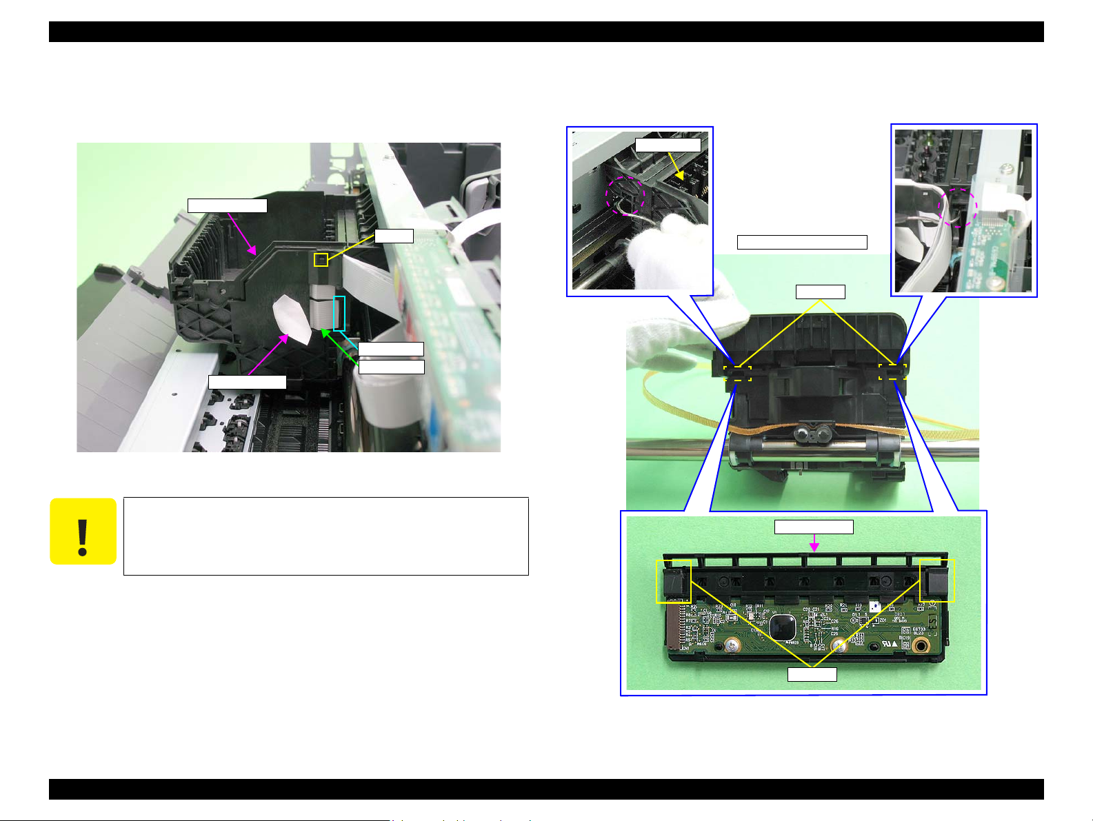
EPSON Stylus Photo R1900/R2880/R2000 Revision E
C A U T I O N
Cable Holder
Hook
Connector
CSIC FFC
Acetate tape
CSIC Assy
CSIC Assy
Hooks
Rear of Carriage Unit
Hooks
8. Peel off a piece of acetate tape and disconnect the CSIC FFC from the connector
on the CSIC Board.
9. Disengage the Cable Holder from the hook and remove it.
Figure 4-55. Removing the CSIC Assy (1)
10. Using the special tool (see p.71) disengage the two hooks of the CSIC Assy on the
right and left on the rear of the Carriage Unit and remove the CSIC Assy upward.
Before performing the following procedure, be sure to disconnect
the CSIC FFC from the connector on the CSIC board. If not, the
CSIC Assy can not be removed, and the CSIC FFC may be
damaged.
Figure 4-56. Removing the CSIC Assy (2)
Disassembly And Assembly Disassembling the Printer Mechanism 94
Confidential
Page 95

EPSON Stylus Photo R1900/R2880/R2000 Revision E
7) C.B.P. M2.6x8
(3±0.5 kgf.cm)
1
2
3
Head
Printhead
Head FFCs
A D J U S T M E N T
R E Q U I R E D
Pad
Guide pins
Positioning holes
11. Remove the three C.B.P. M2.6 x 8 that secure the Printhead using the Phillips
Screw Driver, No.1, and vertically lift the Printhead to remove it.
Figure 4-57. Removing the Printhead
12. Remove the two Head FFCs from the Printhead.
Confirm that the pad is attached at the position in Figure 4-59.
Figure 4-59. Attaching the Pad
The Printhead must be installed with its positioning holes
aligned with the guide pins of the Carriage Unit.
Figure 4-58. Remove the Head FFC
After replacing or removing the Printhead, always make the required
Figure 4-60. Reinstalling the Printhead (1)
adjustments referring to the following.
“Chapter 5 Adjustment (p.137)”
Disassembly And Assembly Disassembling the Printer Mechanism 95
Confidential
Page 96

EPSON Stylus Photo R1900/R2880/R2000 Revision E
C A U T I O N
PictBridge cable
CN1
CN25
High Voltage Module cable
1
3
4
4) C.B.P. M3x8
(6±1 kgf.cm)
Step 5
Fastener
Step 4
Waste Ink Tube
Ink Tube
Fastener
2
1) C.B.P. M3x10
(6±1 kgf.cm)
Printer Mechanism
Electrode cable
1) C.B.P. M3x10
(6±1 kgf.cm)
5
3) C.B.S. (P2) M3x10 &
P.W.,4.3 x 0.8 x 8
(6±1 kgf.cm)
Left Rear
Shield Plate Holder
Step 6
1) C.B.P. M3x10
(6±1 kgf.cm)
3) C.B.S. (P2) M3x10
(6±1 kgf.cm)
Right Rear
A
B
Lower Housing
4.4.4 Lower Housing / Printer Mechanism
1. Remove the Upper Housing / Printer Cover. (p.81)
following steps, be extremely careful not to If having trouble
disassembling, Module Cover to make the work easier. (refer to
4.3.3 High Voltage Module Step2 (p87) .)
2. Disconnect the PictBridge cable from connector CN1 on the Main Board.
3. Disconnect the High Voltage Module cable from connector CN25 on the Main
Board.
4. Grip both ends of the two Ink Tube Fasteners with your fingers, slide them in the
direction of the arrows, and pull out the Waste Ink Tubes from the two Ink Tubes.
5. Remove the C.B.P. M3 x 8 screw that secures the electrode cable on the Front
Paper Guide and remove the electrode cable.
6. Remove the C.B.P. M3 x 10 screw and the C.B.S. (P2) M3 x 10 screw that secure
the Shield Plate Holder, and remove the Shield Plate Holder.
7. Remove the five screws and one washer that secure the Printer Mechanism. (four
C.B.P. M3 x 10 screws, one P.W.,4.3 x 0.8 x 8 washer attached with one of the
C.B.P. screws, and one C.B.S. (P2) M3 x 10 screw)
Disassembly And Assembly Disassembling the Printer Mechanism 96
Figure 4-61. Removing the Lower Housing and Printer Mechanism
Figure 4-62. Screws that Secure the Printer Mechanism
Confidential
Page 97

EPSON Stylus Photo R1900/R2880/R2000 Revision E
C A U T I O N
Holding Positions
0 Digit Side Ink Tube joint
130 Digit Side Ink Tube
0 Digit Side Waste Ink Tube
(Longer)
130 Digit Side Waste Ink Tube
(Shorter)
Right Rear
Left Rear
Positioning hole
and guide pin
Positioning hole
and guide pin
When performing the following step, make sure to grasp the Printer
Mechanism by the specified positions shown below. Otherwise, the
frames may become deformed.
Figure 4-63. Handling the Printer Mechanism
8. Lift the Printer Mechanism grasping it by the holding positions with your hands,
and remove it from the Lower Housing.
Insert the Waste Ink Tube as shown in the figure below, and
secure it firmly with the Fastener. (refer to Figure 4-62 &
Figure 4-64)
Install the Printer Mechanism to the Lower Housing as follows.
(refer to Figure 4-62)
1. Align the guide pins (x2) with the positioning holes as shown
below.
Figure 4-65. Reinstalling the Printer Mechanism
2. Place the
Printer Mechanism
on the Lower Housing and
secure the Shield Plate Holder and the Printer Mechanism
with the screw (A).
3. Verify the Printer Mechanism and Lower Housing are
tightly engaged (no rattling), and then secure the Shield Plate
Holder to the Lower Housing.
4. Secure the Printer Mechanism and Lower Housing with
screws (x5). (Tighten the screws in the order shown in Figure
4-62)
5. Secure the electrode cable to the Front Paper Guide with the
screw.
Confirm that the PictBridge cable and the Waste Ink Tube do
Disassembly And Assembly Disassembling the Printer Mechanism 97
Figure 4-64. Installing the Ink Tubes
not get caught in the Printer Mechanism.
Confidential
Page 98

EPSON Stylus Photo R1900/R2880/R2000 Revision E
A D J U S T M E N T
R E Q U I R E D
6mm
2mm
Label, Ink Position;B
PG Cam (Right)
Attach the Label, Ink Position;B at the position in the figure
below.
Figure 4-66. Attaching the Label, Ink Position;B
After replacing the Printer Mechanism, always make the required
adjustments referring to the following.
“Chapter 5 Adjustment (p.137)”
4.4.5 Carriage Shaft / Carriage Unit
1. Remove the Printhead / CSIC Assy. (p.92)
2. Remove the CR Scale. (p.90)
3. Remove the LED Board. (p.86)
4. Remove the APG Assy. (p.89)
5. Rotate the PG Cam (Right) to adjust its positions other than PG++ downside.
Figure 4-67. Adjusting the PG Cam
Disassembly And Assembly Disassembling the Printer Mechanism 98
Confidential
Page 99

EPSON Stylus Photo R1900/R2880/R2000 Revision E
1
2
2) C.B.S. M3x6
(8±1 kgf.cm)
Tab
Tabs
Left Frame Support Plate
Paper EJ Frame Assy
Notch
Left PG Torsion Spring
Tab A
Tab B
Right PG Torsion Spring
Tab A
Tab B
6. Remove the two C.B.S. M3 x 6 screws that secure the Frame Support Plate (Left),
and remove it.
Figure 4-68. Removing the Left Frame Support Plate
Insert the Left Frame Support Plate into the notch on the Main
Frame. See Figure 4-68.
Align the two tabs on the Main Frame and the tab on the Paper
EJ Frame Assy with the three positioning holes on the Frame
Support Plate (Left). See Figure 4-68.
Align the tab (rear side) of the Left Frame Support Plate with the
outside of the Left CR Shaft Mounting Plate. See Figure 4-68.
Tighten the screws in the order shown in Figure 4-68
7. Remove the foot of Left PG Torsion Spring from tab A, and remove the coil
section from tab B to remove Left PG Torsion Spring from the Main Frame.
Figure 4-69. Removing the Left PG Torsion Spring
8. Remove the foot of Right PG Torsion Spring from tab A, and remove the coil
section from tab B to remove the Right PG Torsion Spring from the Main Frame.
Disassembly And Assembly Disassembling the Printer Mechanism 99
Figure 4-70. Removing the Right PG Torsion Spring
Confidential
Page 100

EPSON Stylus Photo R1900/R2880/R2000 Revision E
Foot
Left Side
Foot
Right Side
Tab
CR Shaft Mounting Plate Fixed Spring
Notch
Notch (rear side)
Tabs
Extension spring for the
Driven Pulley Holder
Driven Pulley Holder
Driven Pulley
Driven Pulley Holder
Place the feet of Left PG Torsion Spring and Right PG Torsion
Spring on the Carriage Shaft.
Figure 4-71. Reinstalling PG Torsion Springs
9. Remove CR Shaft Mounting Plate Fixed Spring from the tab and notch on the
Main Frame, and pull out the spring in the direction of the arrow.
10. Remove the extension spring for the Driven Pulley Holder from the Main Frame
and the tab on the Drive Pulley Holder with needle-nose pliers.
Figure 4-73. Removing the Extension Spring for the Driven Pulley Holder
11. Slide Driven Pulley Holder to the right end of the notch on the Main Frame, and
Remove the Driven Pulley Holder toward you.
Disassembly And Assembly Disassembling the Printer Mechanism 100
Figure 4-72. Removing CR Shaft Mounting Plate Fixed Spring
Insert the foot of CR Shaft Mounting Plate Fixed Spring into the
notch on the Main Frame (rear side). (See Figure 4-72.)
Figure 4-74. Removing the Driven Pulley Holder
Confidential
 Loading...