

Epson Stylus Photo PX710W, Stylus Photo PX810W, Stylus Photo TX710FW, Stylus Photo TX810FW, Artisan 710 Service Manual
...Page 1
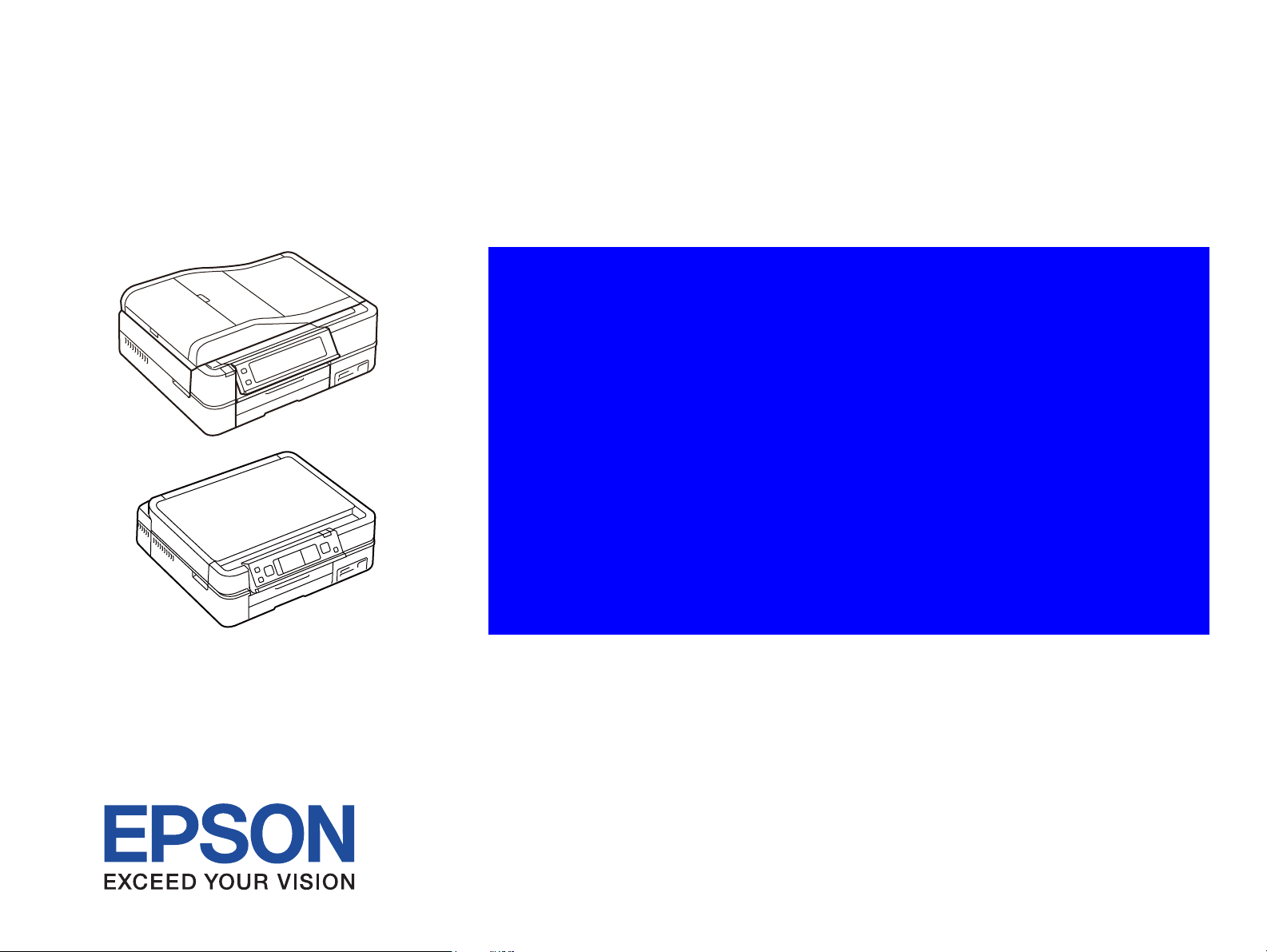
SERVICE MANUAL
Color Inkjet Printer
Epson Artisan 810/
Epson Stylus Photo PX810FW/
Epson Stylus Photo TX810FW/
Epson Artisan 710/
Epson Stylus Photo PX710W/
Epson Stylus Photo TX710W
Confidential
SEMF09-006
Page 2

Confidential
PRECAUTIONS
Precautionary notations throughout the text are categorized relative to 1) Personal injury and 2) damage to equipment.
DANGER Signals a precaution which, if ignored, could result in serious or fatal personal injury. Great caution should be exercised in performing procedures preceded by
DANGER Headings.
WARNING Signals a precaution which, if ignored, could result in damage to equipment.
The precautionary measures itemized below should always be observed when performing repair/maintenance procedures.
DANGER
1. ALWAYS DISCONNECT THE PRODUCT FROM THE POWER SOURCE AND PERIPHERAL DEVICES PERFORMING ANY MAINTENANCE OR REPAIR
PROCEDURES.
2. NO WORK SHOULD BE PERFORMED ON THE UNIT BY PERSONS UNFAMILIAR WITH BASIC SAFETY MEASURES AS DICTATED FOR ALL ELECTRONICS
TECHNICIANS IN THEIR LINE OF WORK.
3. WHEN PERFORMING TESTING AS DICTATED WITHIN THIS MANUAL, DO NOT CONNECT THE UNIT TO A POWER SOURCE UNTIL INSTRUCTED TO DO
SO. WHEN THE POWER SUPPLY CABLE MUST BE CONNECTED, USE EXTREME CAUTION IN WORKING ON POWER SUPPLY AND OTHER ELECTRONIC
COMPONENTS.
4. WHEN DISASSEMBLING OR ASSEMBLING A PRODUCT, MAKE SURE TO WEAR GLOVES TO AVOID INJURIER FROM METAL PARTS WITH SHARP EDGES.
WARNING
1. REPAIRS ON EPSON PRODUCT SHOULD BE PERFORMED ONLY BY AN EPSON CERTIFIED REPAIR TECHNICIAN.
2. MAKE CERTAIN THAT THE SOURCE VOLTAGES IS THE SAME AS THE RATED VOLTAGE, LISTED ON THE SERIAL NUMBER/RATING PLATE. IF THE
EPSON PRODUCT HAS A PRIMARY AC RATING DIFFERENT FROM AVAILABLE POWER SOURCE, DO NOT CONNECT IT TO THE POWER SOURCE.
3. ALWAYS VERIFY THAT THE EPSON PRODUCT HAS BEEN DISCONNECTED FROM THE POWER SOURCE BEFORE REMOVING OR REPLACING PRINTED
CIRCUIT BOARDS AND/OR INDIVIDUAL CHIPS.
4. IN ORDER TO PROTECT SENSITIVE MICROPROCESSORS AND CIRCUITRY, USE STATIC DISCHARGE EQUIPMENT, SUCH AS ANTI-STATIC WRIST
STRAPS, WHEN ACCESSING INTERNAL COMPONENTS.
5. REPLACE MALFUNCTIONING COMPONENTS ONLY WITH THOSE COMPONENTS BY THE MANUFACTURE; INTRODUCTION OF SECOND-SOURCE ICs OR
OTHER NON-APPROVED COMPONENTS MAY DAMAGE THE PRODUCT AND VOID ANY APPLICABLE EPSON WARRANTY.
6. WHEN USING COMPRESSED AIR PRODUCTS; SUCH AS AIR DUSTER, FOR CLEANING DURING REPAIR AND MAINTENANCE, THE USE OF SUCH
PRODUCTS CONTAINING FLAMMABLE GAS IS PROHIBITED.
Page 3
About This Manual
This manual describes basic functions, theory of electrical and mechanical operations, maintenance and repair procedures of the printer. The instructions and procedures included
herein are intended for the experienced repair technicians, and attention should be given to the precautions on the preceding page.
Manual Configuration
This manual consists of six chapters and Appendix.
CHAPTER 1.PRODUCT DESCRIPTIONS
Provides a general overview and specifications of the product.
CHAPTER 2.OPERATING PRINCIPLES
Describes the theory of electrical and mechanical operations of the
product.
CHAPTER 3.TROUBLESHOOTING
Describes the step-by-step procedures for the troubleshooting.
CHAPTER 4.DISASSEMBLY / ASSEMBLY
Describes the step-by-step procedures for disassembling and assembling
the product.
CHAPTER 5.ADJUSTMENT
Provides Epson-approved methods for adjustment.
CHAPTER 6.MAINTENANCE
Provides preventive maintenance procedures and the lists of Epsonapproved lubricants and adhesives required for servicing the product.
Symbols Used in this Manual
Various symbols are used throughout this manual either to provide additional
information on a specific topic or to warn of possible danger present during a
procedure or an action. Be aware of all symbols when they are used, and always read
NOTE, CAUTION, or WARNING messages.
A D J U ST M E N T
R E Q U I R E D
C A U T I O N
C H E C K
P O I N T
W A R N I N G
Indicates an operating or maintenance procedure, practice or condition
that is necessary to keep the product’s quality.
Indicates an operating or maintenance procedure, practice, or condition
that, if not strictly observed, could result in damage to, or destruction of,
equipment.
May indicate an operating or maintenance procedure, practice or
condition that is necessary to accomplish a task efficiently. It may also
provide additional information that is related to a specific subject, or
comment on the results achieved through a previous action.
Indicates an operating or maintenance procedure, practice or condition
that, if not strictly observed, could result in injury or loss of life.
Indicates that a particular task must be carried out according to a certain
standard after disassembly and before re-assembly, otherwise the
quality of the components in question may be adversely affected.
Confidential
Page 4

Revision Status
Revision Date of Issue Description
A July 29, 2009 First Release
Confidential
Page 5

Epson Artisan 810/Epson Stylus Photo PX810FW/TX810FW/Epson Artisan 710/Epson Stylus Photo PX710W/TX710W Revision A
Contents
Chapter 1 PRODUCT DESCRIPTION
1.1 Features. ............................................................................................................... 10
1.2 Printing Specifications. ........................................................................................ 11
1.2.1 Basic Specifications. ................................................................................... 11
1.2.2 Ink Cartridge. .............................................................................................. 11
1.2.3 Print Mode . ................................................................................................. 12
1.2.4 Supported Paper. ......................................................................................... 14
1.2.5 Printing Area. .............................................................................................. 17
1.3 Scanner Specifications......................................................................................... 17
1.3.1 Scanning Range . ......................................................................................... 18
1.4 General Specifications. ........................................................................................ 18
1.4.1 Electrical Specifications ............................................................................. 18
1.4.2 Safety Approvals (Safety standards/EMI).................................................. 19
1.4.3 Acoustic Noise. ........................................................................................... 19
1.4.4 Durability (TBD) . ....................................................................................... 19
1.4.5 Environmental Conditions. ......................................................................... 19
1.5 Interface. .............................................................................................................. 20
1.5.1 USB Interface ............................................................................................. 20
1.5.2 FAX Interface
(Epson Artisan 810/Epson Stylus Photo PX810FW/TX810FW only)........ 20
1.5.3 Network Interface . ...................................................................................... 20
1.5.4 Memory Card Slots..................................................................................... 22
1.6 Control Panel. ...................................................................................................... 23
1.6.1 Operation Buttons & LEDs ........................................................................ 23
1.6.2 Control Panel Functions in Each Mode ...................................................... 24
1.6.2.1 Control Panel Functions . ..................................................................... 24
1.7 Specification for Each Function . ......................................................................... 26
1.7.1 Stand-alone Copy Function (Copy Mode).................................................. 26
1.7.1.1 Supported Paper and Copy Mode........................................................ 26
1.7.1.2 Stand-alone Copy Menu. ..................................................................... 27
1.7.1.3 Copy Speed (TBD). ............................................................................. 27
1.7.1.4 Relation Between Original and Copy.................................................. 28
1.7.2 Memory Card Direct Print Function (Photos Mode).................................. 28
1.7.2.1 Supported Paper and Print Mode......................................................... 28
1.7.2.2 Supported File Type and Media Type................................................. 29
1.7.2.3 Automatic Detection of Images in Memory Card............................... 29
1.7.2.4 Specifications for Handling Image Data . ............................................ 29
1.7.2.5 Memory Card Direct Print Menu ........................................................ 30
1.7.2.6 Makes Prints from Index Sheet Function............................................ 31
1.7.2.7 Print Layout. ........................................................................................ 32
1.7.3 Camera Direct Print Function (PictBridge)................................................ 35
1.7.3.1 Available DSC. .................................................................................... 35
1.7.3.2 Print Settings Available from DSC . .................................................... 35
1.7.3.3 General Operation Procedure .............................................................. 36
1.7.3.4 Operations when a DSC is connected . ................................................ 36
1.7.4 Various Settings (Setup Mode). .................................................................. 37
1.7.5 FAX Function (FAX Mode)
(Epson Artisan 810/Epson Stylus Photo PX810FW/TX810FW only) ....... 39
1.7.5.1 Basic Specifications ............................................................................ 39
1.7.5.2 Supported Functions. ........................................................................... 39
1.7.6 Other Functions .......................................................................................... 42
1.7.6.1 Scan Mode. .......................................................................................... 42
1.7.6.2 Backup Data . ....................................................................................... 42
1.7.6.3 Print Ruled Papers. .............................................................................. 42
1.7.6.4 Coloring Book. .................................................................................... 42
Chapter 2 OPERATING PRINCIPLES
2.1 Overview . ............................................................................................................ 44
2.1.1 Printer Mechanism. ..................................................................................... 44
2.1.2 Printhead. .................................................................................................... 44
2.1.3 Motors & Sensors . ...................................................................................... 45
2.1.4 PG setting . .................................................................................................. 47
2.2 Power-On Sequence . ........................................................................................... 48
2.2.1 Simple Reset Sequence. .............................................................................. 49
2.2.2 All Reset Sequence. .................................................................................... 51
2.3 Printer Initialization. ............................................................................................ 54
Chapter 3 TROUBLESHOOTING
3.1 Overview . ............................................................................................................ 56
3.1.1 Specified Tools. .......................................................................................... 56
3.1.2 Preliminary Checks. .................................................................................... 56
6
Confidential
Page 6

Epson Artisan 810/Epson Stylus Photo PX810FW/TX810FW/Epson Artisan 710/Epson Stylus Photo PX710W/TX710W Revision A
3.2 Troubleshooting. .................................................................................................. 57
3.2.1 Motor and Sensor Troubleshooting ............................................................ 57
3.3 Troubleshooting by Error Message ..................................................................... 58
3.3.1 Error Message List. ..................................................................................... 58
3.3.2 Troubleshooting by Error Message ............................................................ 60
3.4 Troubleshooting without Error Message............................................................. 72
3.4.1 Troubleshooting Printer Mechanism Problems . ......................................... 72
3.4.2 Troubleshooting Electrical Problems ......................................................... 78
3.4.3 Troubleshooting I/F-related Problems........................................................ 78
3.5 Troubleshooting Duplex Unit Problems.............................................................. 80
3.6 Network Troubleshooting. ................................................................................... 81
3.7 FAX Troubleshooting
(Epson Artisan 810/Epson Stylus Photo PX810FW/TX810FW only) ................ 83
3.7.1 FAX Log. .................................................................................................... 83
3.7.2 Error Code/Superficial Phenomenon-Based Troubleshooting ................... 87
3.8 Fax Function/External Connection Function Check
(Epson Artisan 810/Epson Stylus Photo PX810FW/TX810FW only) ................ 89
3.8.1 Outline ........................................................................................................ 89
3.8.2 Fax Function and External Connection Function Check............................ 89
3.8.2.1 Fax Function Check by [Method A] and External Connection Function
Check ................................................................................................... 89
3.8.2.2 Fax Function Check by [Method B] and External Connection Function
Check ................................................................................................... 93
3.8.2.3 Fax Function Check by [Method C] and External Connection Function
Check ................................................................................................... 94
Chapter 4 DISASSEMBLY/ASSEMBLY
4.1 Overview . ............................................................................................................ 96
4.1.1 Precautions. ................................................................................................. 96
4.1.2 Tools . .......................................................................................................... 97
4.1.3 Work Completion Check . ........................................................................... 97
4.1.4 Additional Procedure/Procedural Differences............................................ 99
4.2 Disassembly Procedures.................................................................................... 101
4.2.1
Parts transferred from the old printer when replacing the Printer Mechanism
4.2.2 Replacing the Head Supply Assy ............................................................. 104
4.2.3 Removing the Housing ............................................................................. 105
4.2.3.1 ADF Unit (Artisan 810/PX810FW/TX810FW only)........................ 105
4.2.3.2 Scanner Unit. ..................................................................................... 106
4.2.3.3 Hinge ................................................................................................. 108
4.2.3.4 Upper Left Housing / Panel Lock Button.......................................... 109
103
4.2.3.5 Upper Housing .................................................................................. 110
4.2.3.6 Rear Left Housing . ............................................................................ 112
4.2.3.7 Left Housing / Decoration Belt L...................................................... 112
4.2.3.8 Stacker Assy. ..................................................................................... 113
4.2.3.9 Rear ASF Paper Guide Cover ........................................................... 114
4.2.3.10 Rear Right FAX Housing. ............................................................... 115
4.2.3.11 Right Housing / Card Cover............................................................ 116
4.2.3.12 Cassette Unit/EJ Cover Assy. .......................................................... 117
4.2.3.13 Paper Guide Top Assy. .................................................................... 118
4.2.4 Removing the Circuit Board..................................................................... 119
4.2.4.1 Panel Unit. ......................................................................................... 119
4.2.4.2 Main Board / Grounding Plate M/B. ................................................. 121
4.2.4.3 Power Supply Unit . ........................................................................... 124
4.2.4.4 Wireless LAN Board. ........................................................................ 125
4.2.4.5 Card Slot Assy. .................................................................................. 126
4.2.5 Disassembl
4.2.5.1 Printhead. ........................................................................................... 127
4.2.5.2 CR Scale. ........................................................................................... 133
4.2.5.3 PF Encoder . ....................................................................................... 134
4.2.5.4 Decompression Pump Unit. ............................................................... 135
.5.5 CSIC Assy. ........................................................................................ 136
4.2
.5.6 Ink Supply IC Holder Assy . .............................................................. 137
4.2
.5.7 Ink System. ........................................................................................ 140
4.2
.5.8 Lower ASF Paper Guide Assy . ......................................................... 142
4.2
.5.9 CDR Tray Assy . ................................................................................ 145
4.2
.5.10 Pick-up Roller . ................................................................................ 146
4.2
.5.11 Waste Ink Tray Assy. ...................................................................... 147
4.2
.5.12 Lower Paper Guide Waste Ink Pad Assy . ....................................... 149
4.2
4.2.6 Disassembling Scanner Unit..................................................................... 150
4.2.6.1 Scanner Upper Housing (Artisan 810/PX810FW/TX810FW) ......... 150
4.2.6.2 Scanner Motor Unit. .......................................................................... 151
4.2.6.3 Scanner Carriage Unit . ...................................................................... 152
4.2.6.4 Scanner CR Encoder Board............................................................... 155
4.2.6.5 Cover Open Sensor. ........................................................................... 156
4.2.7 Disassembly of the ADF Unit (Artisan 810/PX810FW/TX810FW only) 157
4.2.7.1 ADF Hinge . ....................................................................................... 157
4.2.7.2 ADF Cover Assy/ADF Cover L. ....................................................... 158
4.2.7.3 ADF LD Frame Assy ........................................................................ 159
4.2.7.4 ADF Right Cover/ADF Rear Cover. ................................................. 159
4.2.7.5 ADF Cover Stacker/ADF Document Support Cover. ....................... 161
4.2.7.6 ADF Front Cover . ............................................................................. 162
4.2.7.7 ADF Document Su
ing the Printer Mechanism . .................................................... 127
pport Assy. .......................................................... 162
7
Confidential
Page 7

Epson Artisan 810/Epson Stylus Photo PX810FW/TX810FW/Epson Artisan 710/Epson Stylus Photo PX710W/TX710W Revision A
4.2.7.8 ADF Frame Unit................................................................................ 163
4.2.7.9 ADF Motor Unit................................................................................ 164
4.2.7.10 ADF PF Roller................................................................................. 166
4.3
Disassembly/reassembly procedures specific to Artisan 710/PX710W/TX710W
4.3.1 Removing the Housing . ............................................................................ 168
4.3.1.1 Scanner Unit (Artisan 710/PX710W/TX710W) ............................... 168
4.3.1.2 Upper Left Housing (Artisan 710/PX710W/TX710W) .................... 170
4.3.1.3 Upper Housing (Artisan 710/PX710W/TX710W)............................ 171
4.3.1.4 Rear Left Housing (Artisan 710/PX710W/TX710W)....................... 173
4.3.1.5 Left Housing/Decoration Belt L (Artisan 710/PX710W/TX710W) . 174
4.3.1.6 Rear Right Housing (Artisan 710/PX710W/TX710W) .................... 175
4.3.1.7 Right Housing/Card Cover (Artisan 710/PX710W/TX710W) ......... 176
4.3.2 Removing the Circuit Board (Artisan 710/PX710W/TX710W) .............. 177
4.3.2.1 Panel Unit (Artisan 710/PX710W/TX710W) ................................... 177
4.3.2.2 Main Board/Grounding Plate M/B (Artisan 710/PX710W/TX710W) 179
4.3.2.3 Card Slot Assy (Artisan 710/PX710W/TX710W) . ........................... 182
4.3.3 Disassembling the Scanner Unit (Artisan 710/PX710W/TX710W) ........ 183
4.3.3.1 Document Cover................................................................................ 183
4.3.3.2 Scanner Upper Housing (Artisan 710/PX710W/TX710W)............. 183
4.4 Routing FFC/cables........................................................................................... 185
.. 168
Chapter 5 ADJUSTMENT
5.1 Adjustment Items and Overview....................................................................... 194
5.1.1 Servicing Adjustment Item List................................................................ 194
5.1.2 Required Adjustments .............................................................................. 200
5.2 Adjustment Using Adjustment Program ........................................................... 202
5.2.1 Top Margin Adjustment ........................................................................... 202
5.2.2 Bi-D Adjustment....................................................................................... 202
5.2.3 PW Adjustment/First Dot Position Adjustment ....................................... 203
5.2.4 Head Angular Adjustment . ....................................................................... 204
5.2.5 PF Adjustment . ......................................................................................... 205
5.2.6 MAC Address Setting............................................................................... 206
5.2.7 PG Offset Value Adjustment.................................................................... 208
5.2.8 Case Open Sensor Check.......................................................................... 209
5.2.9 AID inspection.......................................................................................... 212
5.2.10 Banding Reduction System (BRS) Adjustment / Paper Feed Amount Profile
(PFP) Correction........................................................................................ 213
5.2.10.1 BRS (Banding Reduction System) Adjustment .............................. 215
5.2.10.2 PFP Adjustment............................................................................... 216
5.3 Adjustment without Using Adjustment Program . ............................................. 218
5.3.1 PG Adjustment/PG Inspection.................................................................. 218
5.3.1.1 PG Adjustment . ................................................................................. 218
5.3.1.2 PG Inspection . ................................................................................... 222
5.3.2 CR Timing Belt Tension Inspection......................................................... 223
5.3.3 PF Timing Belt Tension Inspection.......................................................... 224
5.3.4 Touch Panel Adjustment
(Epson Artisan 810/Epson Stylus Photo PX810FW/TX810FW only) ..... 225
5.4 Other functions.................................................................................................. 227
5.4.1 I/S Decompress......................................................................................... 227
5.4.2 AID SHK Error Reset. .............................................................................. 228
Chapter 6 MAINTENANCE
6.1 Overview . .......................................................................................................... 231
6.1.1 Cleaning.................................................................................................... 231
6.1.2 Service Maintenance. ................................................................................ 231
6.1.2.1 Printhead cleaning............................................................................. 231
6.1.2.2 Service Call . ...................................................................................... 232
6.1.3 Lubrication. ............................................................................................... 232
Confidential
8
Page 8

PRODUCT DESCRIPTION
CHAPTER
1
Confidential
Page 9
Epson Artisan 810/Epson Stylus Photo PX810FW/TX810FW/Epson Artisan 710/Epson Stylus Photo PX710W/TX710W Revision A
1.1 Features
Epson Artisan 810/Epson Stylus Photo PX810FW/TX810FW/Epson Artisan 710/
Epson Stylus Photo PX710W/TX710W are color inkjet printers that have 4 in 1
functions (Printer for PC, Scanner for PC, Standalone copy, Memory card printing).
Common features
Printer
• Printing from a computer or directly printing from a memory card
• Auto duplex printing using Duplex Printing Unit (option for some destinations)
• Built-in CD/DVD tray
• Front double paper feeding function using a double-deck cassette
• Auto nozzle check (printhead cleaning) using AID
• Maximum print resolution: 5760 (H) x 1440 (V) dpi
• F6 Turbo II print head achieves higher print speed than ever
(Black: 180 nozzles x 1, Color: 180 nozzles x 5 per color)
• Six independent ink cartridges is installed (Dye inks)
• Borderless printing on specified EPSON brand paper is available
Scanner
• Scanning from a computer
• Offers a function that directly stores a scan data to a memory card
Copy
• High quality copy using the printing and scanning functions. Offers seven
preset copy layouts
USB interfaces
• Enables to print images in an external storage device
• Backup copy of a memory card can be made on an external media
• Offers camera direct print (PictBridge)
Network
• Available for printing, scanning, and memory card access via wired/wireless
network
Bluetooth
Features unique to Epson Artisan 810/Epson Stylus Photo PX810FW/
TX810FW
FAX
• Sending/receiving fax
ADF
• Continuous scanning using an ADF
Differences between the models
Epson Artisan 810/Epson Stylus Photo PX810FW/TX810FW/Epson Artisan 710/
Epson Stylus Photo PX710W/TX710W are different on ADF, FAX and the Panel
specifications as shown below.
Epson Artisan 810/Epson
Item
LCD display size 3.5 inch 2.5 inch
Panel operation Touch panel Button
Scanner resolution
(Main scan x Sub scan)
ADF Equipped ---
FAX function Supported ---
Note* : When scanning using ADF
Stylus Photo PX810FW/
TX810FW
4,800 dpi x 4,800 dpi
(1,200 dpi x 600 dpi)
Epson Artisan 710/Epson
Stylus Photo PX710W/
TX710W
2,400 dpi x 4,800 dpi
*
Dimensions
Epson Artisan 810/Epson Stylus Photo PX810FW/TX810FW
• Dimensions*1: 466 mm (W) x 385 mm (D) x 198 mm (H)
• Weight*2: 10.5 kg
Epson Artisan 710/Epson Stylus Photo PX710W/TX710W
• Dimensions*1: 466 mm (W) x 385 mm (D) x 150 mm (H)
• Weight*2: 9.0 kg
Note *1: Paper support and stacker are closed. Rubber feet are included.
*2 : Except ink cartridges and cables such as the AC cable, etc.
• Mounting the optional Bluetooth unit offers wireless communication with
an external device
PRODUCT DESCRIPTION Features 10
Confidential
Page 10
Epson Artisan 810/Epson Stylus Photo PX810FW/TX810FW/Epson Artisan 710/Epson Stylus Photo PX710W/TX710W Revision A
1.2 Printing Specifications
1.2.1 Basic Specifications
Table 1-1. Printer Specifications
Item Specification
Print method On-demand ink jet
Black: 180 nozzles x 1
Nozzle configuration
Print direction Bi-directional minimum distance printing, Unidirectional printing
Print resolution
Control code
Input buffer size 64 Kbytes
Paper feed method Friction feed, using the ASF (Auto Sheet Feeder)
Paper path Front feed, front out
Paper feed rates 86 msec. (at 25.4 mm feed)
PF interval Programmable in 0.01764 mm (1/1440 inch) steps
Color: 180 nozzles x 5
(Light Cyan, Magenta, Yellow, Cyan, Light Magenta)
Horizontal x Vertical (dpi)
• 360 x 180 • 720 x 720
• 360 x 360 • 5760 x 1440
• 720 x 360
• ESC/P Raster command
• ESC/P-R (RGB) command
• EPSON Remote command
1.2.2 Ink Cartridge
The product numbers of the EPSON ink cartridges for this printer are shown below.
Table 1-2. Product No. of Ink Cartridges
Color EAI CISMEA/Asia Euro
Black T0981 (S)
Cyan
Magenta
Yellow
Light Cyan
Light Magenta
T0982 (S)
T0992 (2S)
T0983 (S)
T0993 (2S)
T0984 (S)
T0994 (2S)
T0985 (S)
T0995 (2S)
T0986 (S)
T0996 (2S)
T0811N (S)
T0821N (2S)
T0812N (S)
T0822N (2S)
T0813N (S)
T0823N (2S)
T0814N (S)
T0824N (2S)
T0815N (S)
T0825N (2S)
T0816N (S)
T0826N (2S)
Shelf life
Two years from production date (if unopened), six months after opening package.
Storage Temperature
Table 1-3. Storage Temperature
Situation Storage Temperature Limit
When stored in individual boxes
When installed in main unit
-20 oC to 40 oC
(-4oF to 104oF)
-20 oC to 40 oC
(-4oF to 104oF)
1 month max. at 40 oC (104oF)
T0791 (S)
T0801 (2S)
T0792 (S)
T0802 (2S)
T0793 (S)
T0803 (2S)
T0794 (S)
T0804 (2S)
T0795 (S)
T0805 (2S)
T0796 (S)
T0806 (2S)
Dimension
12.7 mm (W) x 68 mm (D) x 47 mm (H)
C A U T I O N
Do not use expired ink cartridges.
The ink in the ink cartridge freezes at -16 °C (3.2 oF). It takes
about three hours under 25 °C (77oF) until the ink thaws and
becomes usable.
PRODUCT DESCRIPTION Printing Specifications 11
Confidential
Page 11
Epson Artisan 810/Epson Stylus Photo PX810FW/TX810FW/Epson Artisan 710/Epson Stylus Photo PX710W/TX710W Revision A
1.2.3 Print Mode
Media Print Mode
• Plain paper
• Premium Bright
White Paper (EAI)
• Premium Bright
White Inkjet Paper
(others)
• Ultra Premium Photo
Paper Glossy (EAI)
• Ultra Glossy Photo
Paper (others)
• Photo Paper Glossy
(EAI)
• Glossy Photo Paper
(others)
• Premium Photo Paper
Glossy (EAI)
• Premium Glossy
Photo Paper (others)
• Premium Photo Paper
Semi-Gloss (EAI)
• Premium Semigloss
Photo Paper (other)
• Ultra Premium Photo
Paper Luster (EAI)
• Photo Paper
• Premium Presentation
Paper Matte (EAI)
• Matte Paper Heavyweight (others)
• Presentation Paper
Matte (EAI)
• Photo Quality Inkjet
Paper*2 (others)
Table 1-4. Print Mode (Color)
Resolution
(H x V) dpi
Draft 360x180
Normal 360x360
Photo Fine 720x720
Photo
Photo
*2
*2
720x720
(1.0 pass)
720x720
(2.0 pass)
Super Photo 5760x1440
Fine 720x360
Photo
Photo
*2
*2
720x720
(1.0 pass)
720x720
(2.0 pass)
Super Photo 5760x1440
Photo
*2
720x720
(2.0 pass)
Super Photo 5760x1440
Photo
*2
720x720
(2.0 pass)
Dot Size
(cps*1)
(450cps)
MC2-1
(360cps)
MC1-1
(240cps)
MC1-2
(240cps)
MC2-2
(280cps)
MC1-5
(200cps)
MC1-2
(240cps)
MC1-2
(240cps)
MC2-2
(280cps)
MC1-5
(200cps)
MC2-2
(280cps)
MC1-5
(200cps)
MC2-2
(280cps)
Eco
Micro
Bi-d
Weave
Border-
less
ON OFF N/A
ON OFF N/A
ON ON N/A
ON ON OK
ON ON OK
ON ON OK
ON ON OK
ON ON OK
ON ON OK
ON ON OK
ON ON OK
ON ON OK
ON ON N/A
Table 1-4. Print Mode (Color)
Media Print Mode
Resolution
(H x V) dpi
Normal 360x360
Envelope
Photo Fine 720x720
• Premium Presentation
Paper Matte Doublesided (EAI)
• Double-sided Matte
Photo
*2
720x720
(2.0 pass)
Paper (Euro, Asia)
Photo stickers Photo
*2
720x720
(2.0 pass)
• Iron-On Transfer
Paper (EAI)
• Iron-On Cool Peal
Photo Fine 720x720
Transfer Paper
(others)
CD/DVD Label
High-quality CD/DVD
*3
Label
*3
Super Photo 5760x1440
Super Photo 5760x1440
Note *1: cps = character per second
*2 : Photo mode uses 1.0 pass or 2.0 pass depending on the paper size.
1.0 pass supported size: 4” x 6”
2.0 pass supported size: 5” x 7”, 8” x 10”, Letter, A4, 16:9 wide
*3 : Print quality is not guaranteed in the settings other than [type: “CDR Tray” & media:
“CD/DVD”] when carrying out CD/DVD printing from the PC.
Dot Size
(cps*1)
MC2-1
(360cps)
MC1-1
(240cps)
MC2-2
(280cps)
MC2-2
(280cps)
MC1-1
(240cps)
MC1-5
(200cps)
MC1-5
(200cps)
Micro
Bi-d
Weave
OFF OFF N/A
OFF ON N/A
ON ON N/A
ON ON N/A
OFF ON N/A
ON ON N/A
ON ON N/A
Border-
less
PRODUCT DESCRIPTION Printing Specifications 12
Confidential
Page 12
Epson Artisan 810/Epson Stylus Photo PX810FW/TX810FW/Epson Artisan 710/Epson Stylus Photo PX710W/TX710W Revision A
Media Print Mode
• Plain paper
• Premium Bright
White Paper (EAI)
• Premium Bright
White Inkjet Paper
(others)
• Ultra Premium Photo
Paper Glossy (EAI)
• Ultra Glossy Photo
Paper (others)
• Photo Paper Glossy
(EAI)
• Glossy Photo Paper
(others)
• Premium Photo Paper
Glossy (EAI)
• Premium Glossy
Photo Paper (others)
• Premium Photo Paper
Semi-Gloss (EAI)
• Premium Semigloss
Photo Paper (other)
• Ultra Premium Photo
Paper Luster (EAI)
• Photo Paper
• Premium Presentation
Paper Matte (EAI)
• Matte Paper Heavyweight (others)
• Presentation Paper
Matte (EAI)
• Photo Quality Inkjet
Paper*2 (others)
Table 1-5. Print Mode (Monochrome)
Resolution
(H x V) dpi
Draft 360x180
Normal 360x360
Photo Fine 720x720
Photo
Photo
*2
*2
720x720
(1.0 pass)
720x720
(2.0 pass)
Super Photo 5760x1440
Fine 720x360
Photo
Photo
*2
*2
720x720
(1.0 pass)
720x720
(2.0 pass)
Super Photo 5760x1440
Photo
*2
720x720
(2.0 pass)
Super Photo 5760x1440
Photo
*2
720x720
(2.0 pass)
Dot Size
(cps*1)
Eco
(450cps)
MC2-1
(360cps)
MC1-1
(240cps)
MC1-2
(240cps)
MC2-2
(280cps)
MC1-5
(200cps)
MC1-2
(240cps)
MC1-2
(240cps)
MC2-2
(280cps)
MC1-5
(200cps)
MC2-2
(280cps)
MC1-5
(200cps)
MC2-2
(280cps)
Micro
Bi-d
Weave
Border-
less
ON OFF N/A
ON OFF N/A
ON ON N/A
ON ON OK
ON ON OK
ON ON OK
ON ON OK
ON ON OK
ON ON OK
ON ON OK
ON ON OK
ON ON OK
ON ON N/A
Table 1-5. Print Mode (Monochrome)
Media Print Mode
Resolution
(H x V) dpi
Normal 360x360
Envelope
Photo Fine 720x720
• Premium Presentation
Paper Matte Doublesided (EAI)
• Double-sided Matte
Photo
*2
720x720
(2.0 pass)
Paper (Euro, Asia)
Photo stickers Photo
*2
720x720
(2.0 pass)
• Iron-On Transfer
Paper (EAI)
• Iron-On Cool Peal
Photo Fine 720x720
Transfer Paper
(others)
CD/DVD Label
High-quality CD/DVD
*3
Label
*3
Super Photo 5760x1440
Super Photo 5760x1440
Note *1: cps = character per second
*2 : Photo mode uses 1.0 pass or 2.0 pass depending on the paper size.
1.0 pass supported size: 4” x 6”
2.0 pass supported size: 5” x 7”, 8” x 10”, Letter, A4, 16:9 wide
*3 : Print quality is not guaranteed in the settings other than [type: “CDR Tray” & media:
“CD/DVD”] when carrying out CD/DVD printing from the PC.
Dot Size
(cps*1)
MC2-1
(360cps)
MC1-1
(240cps)
MC2-2
(280cps)
MC2-2
(280cps)
MC1-1
(240cps)
MC1-5
(200cps)
MC1-5
(200cps)
Micro
Bi-d
Weave
OFF OFF N/A
OFF ON N/A
ON ON N/A
ON ON N/A
OFF ON N/A
ON ON N/A
ON ON N/A
Border-
less
PRODUCT DESCRIPTION Printing Specifications 13
Confidential
Page 13
Epson Artisan 810/Epson Stylus Photo PX810FW/TX810FW/Epson Artisan 710/Epson Stylus Photo PX710W/TX710W Revision A
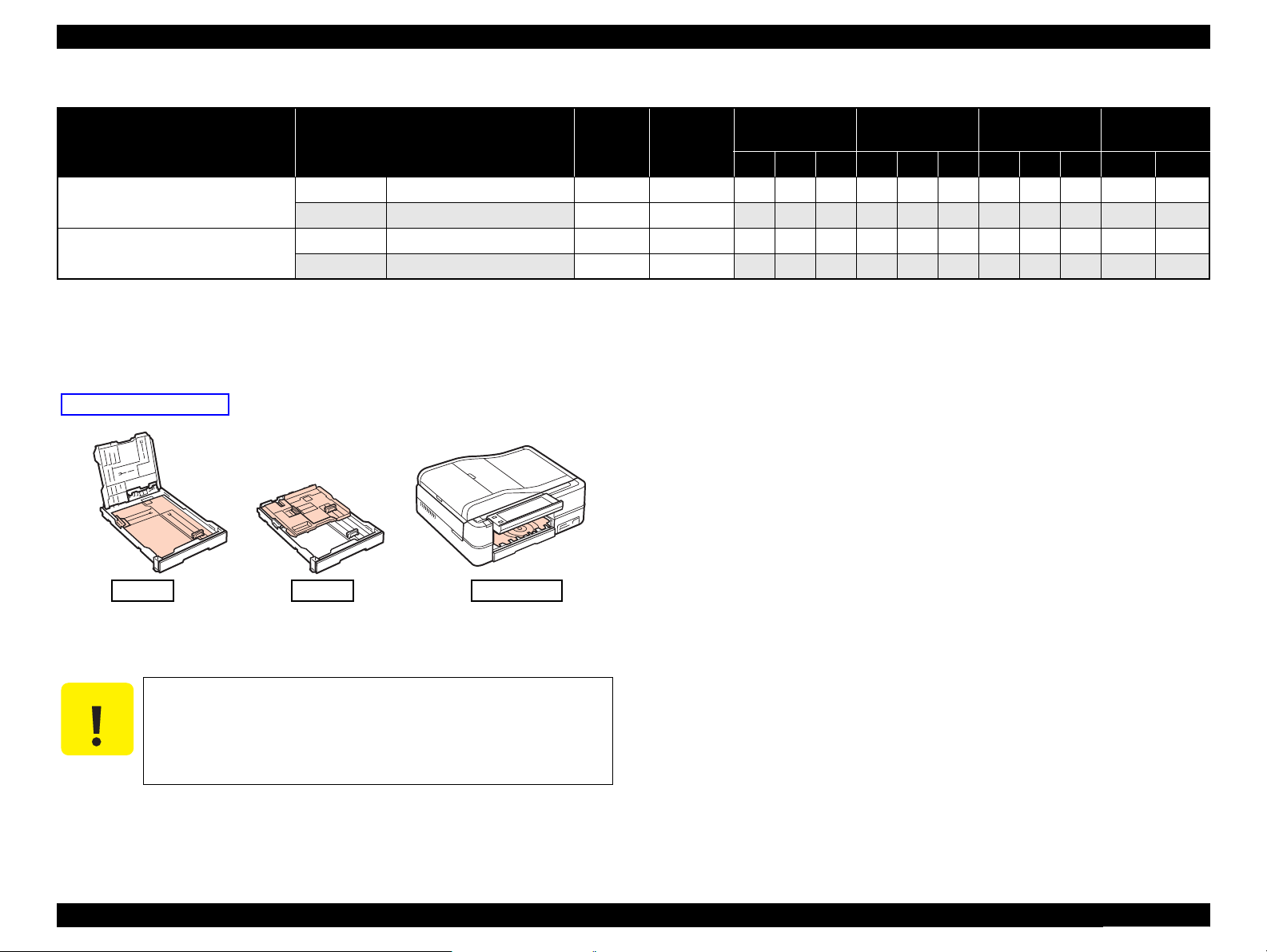
1.2.4 Supported Paper
The table below lists the paper type and sizes supported by the printer. The supported paper type and sizes vary depending on destinations (between EAI, EUR, and Asia).
Table 1-6. Supported Paper
Paper Name Paper Size
Thickness
(mm)
Legal 215.9 x 355.6 mm (8.5”x14”)
Letter 215.9 x 279.4 mm (8.5”x11”) Y - Y Y - Y Y - Y Y -
A4 210 x 297 mm (8.3”x11.7”) Y - Y Y - Y Y - Y Y -
B5 182 x 257 mm (7.2”x10.1”) - - - Y - Y Y - Y Y -
Plain paper
A5 148 x 210 mm (5.8”x8.3”) - - - Y - - Y - - Y -
0.08-0.11
Half Letter 139.7 x 215.9 mm (5.5”x8.5”) Y - - - - - - - - Y -
A6 105 x 148 mm (4.2”x5.8”) Y - - Y - - Y - - - Y
User Defined
89 x 127- 215.9 x 1117.6 mm
(3.5”x5” - 8.5”x44”)
Premium Inkjet Plain Paper A4 210 x 297 mm (8.3”x11.7”) 0.11
Premium Bright White Paper (EAI) Letter 215.9 x 279.4 mm (8.5”x11”) 0.11
Bright White Inkjet Paper (Euro, Asia) A4 210 x 297 mm (8.3”x11.7”) 0.13
Letter 215.9 x 279.4 mm (8.5”x11”)
Ultra Premium Photo Paper Glossy
(EAI)
Ultra Glossy Photo Paper (Euro, Asia)
A4 210 x 297 mm (8.3”x11.7”) - - - Y Y - Y Y - Y -
8” x 10” 203.2 x 254 mm Y Y - - - - - - - Y -
0.30
5” x 7” 127 x 178 mm Y Y - Y Y - - - - - Y
4” x 6” 101.6 x 152.4 mm Y Y - Y Y - Y Y - - Y
Letter 215.9 x 279.4 mm (8.5”x11”)
A4 210 x 297 mm (8.3”x11.7”) Y Y - Y Y - Y Y - Y -
Premium Photo Paper Glossy (EAI)
Premium Glossy Photo Paper (Euro,
Asia)
8” x 10” 203.2 x 254 mm Y Y - - - - - - - Y -
0.27
5” x 7” 127 x 178 mm Y Y - Y Y - Y Y - - Y
4” x 6
”
101.6 x 152.4 mm Y Y - Y Y - Y Y - - Y
16:9 wide 101.6 x 180.6 mm Y Y - Y Y - - - - - Y
Weight
64-90 g/m
(17-24 lb.)
80 g/m
(21 lb.)
90 g/m
(24 lb.)
92.5 g/m
(25 lb.)
290 g/m
(77 lb.)
255 g/m
(68 lb.)
EAI EUR Asia
*1B*2D*3P*1B*2
P
D*3P*1B*2D*3Tray 1 Tray 2
Y - - Y - - Y - - Y -
2
Y - - Y - - Y - - Y
2
- - - Y - Y - - - Y -
2
Y - Y - - - - - - Y -
2
- - - Y - Y Y - Y Y -
Y Y - - - - - - - Y -
2
Y Y - - - - - - - Y -
2
Paper feed tray
position
*5
*4
-
PRODUCT DESCRIPTION Printing Specifications 14
Confidential
Page 14
Epson Artisan 810/Epson Stylus Photo PX810FW/TX810FW/Epson Artisan 710/Epson Stylus Photo PX710W/TX710W Revision A
Table 1-6. Supported Paper
Paper Name Paper Size
Photo Paper Glossy (EAI)
Glossy Photo Paper (Euro, Asia)
Thickness
(mm)
Weight
Letter 215.9 x 279.4 mm (8.5”x11”)
A4 210 x 297 mm (8.3”x11.7”) Y Y - Y Y - Y Y - Y -
5” x 7” 127 x 178 mm - - - Y Y - - - - - Y
0.25
258 g/m
2
(68 lb.)
EAI EUR Asia
*1B*2D*3P*1B*2
P
D*3P*1B*2D*3Tray 1 Tray 2
Y Y - - - - - - - Y -
4” x 6” 101.6 x 152.4 mm Y Y - Y Y - Y Y - - Y
Premium Photo Paper Semi-Gloss
(EAI)
Premium Semigloss Photo Paper
(Euro, Asia)
Photo Paper
Letter 215.9 x 279.4 mm (8.5”x11”)
A4 210 x 297 mm (8.3”x11.7”) - - - Y Y - Y Y - Y -
0.27
250 g/m
(66 lb.)
Y Y - - - - - - - Y -
2
4” x 6” 101.6 x 152.4 mm Y Y - Y Y - Y Y - - Y
A4 210 x 297 mm (8.3”x11.7”)
5” x 7” 127 x 178 mm - - - Y Y - - - - - Y
0.24
190 g/m2
(51 lb.)
- - - Y Y - Y Y - Y -
4" x 6" 101.6 x 152.4 mm - - - Y Y - Y Y - - Y
Premium Presentation Paper Matte
(EAI)
Matte Paper Heavy-weight (Euro,
Asia)
Premium Presentation Paper Matte
Double-sided (EAI)
Double-sided Matte Paper (Euro, Asia)
Ultra Premium Photo Paper Luster
Presentation Paper Matte (EAI)
Photo Quality Inkjet Paper (Euro,
Asia)
Envelopes
Letter 215.9 x 279.4 mm (8.5”x11”)
A4 210 x 297 mm (8.3”x11.7”) - - - Y Y - Y Y - Y -
0.23
167 g/m
(44 lb.)
Y Y - - - - - - - Y -
2
8” x 10” 203.2 x 254 mm Y Y - - - - - - - Y -
Letter 215.9 x 279.4 mm (8.5”x11”)
A4 210 x 297 mm (8.3”x11.7”) - - - Y - - Y - - - -
0.22
Letter 215.9 x 279.4 mm (8.5”x11”) 0.27
Letter 215.9 x 279.4 mm (8.5”x11”)
0.13
A4 210 x 297 mm (8.3”x11.7”) Y - - Y - - Y - - Y -
#10
#DL 110 x 220 mm - - - Y - - Y - - Y -
104.8 x 241.3 mm
(4.125”x9.5”)
-
185 g/m
(49 lb.)
250 g/m
(66 lb.)
102 g/m
(27 lb.)
75-100 g/m
(20-27 lb.)
Y - - - - - - - - - -
2
2
Y Y - - - - - - - Y -
Y - - - - - - - - Y -
2
Y - - Y - - Y - - Y -
2
#C6 114 x 162 mm - - - Y - - Y - - Y -
Iron-On Cool Peal Transfer (EAI)
Iron-On Cool Peal Transfer Paper
(others)
Letter 215.9 x 279.4 mm (8.5”x11”)
A4 210 x 297 mm (8.3”x11.7”) - - - Y - - Y - - Y -
0.14
130 g/m
(35 lb.)
Y - - - - - - - - Y -
2
Photo Stickers 16 A6 105 x 148 mm (4.1”x5.8”) 0.19 --- - - - - - - Y - - - Y
Paper feed tray
position
*4
PRODUCT DESCRIPTION Printing Specifications 15
Confidential
Page 15
Epson Artisan 810/Epson Stylus Photo PX810FW/TX810FW/Epson Artisan 710/Epson Stylus Photo PX710W/TX710W Revision A
Tray 1 Tray 2 CDR Tray
Paper feed tray position
Table 1-6. Supported Paper
Paper feed tray
position
*6
*6
*6
*6
Paper Name Paper Size
CD/DVD
CD/DVD Premium Surface
ø12cm ø12cm --- --- Y - - Y - - Y - -
ø8cm ø8cm --- --- Y - - Y - - Y - -
ø12cm ø12cm --- --- Y - - Y - - Y - -
ø8cm ø8cm --- --- Y - - Y - - Y - -
Note *1 : “Y” in the “P” column stands for “the paper type/size is Supported”.
*2 : “Y” in the “B” column stands for “Borderless printing is available”.
*3 : “Y” in the “D” column stands for “Duplex printing is available”.
*4 : See below for the Paper feed tray position.
Thickness
(mm)
Weight
EAI EUR Asia
*1B*2D*3P*1B*2
P
D*3P*1B*2D*3Tray 1 Tray 2
*4
-
-
-
-
*5 : The paper other than the user definition range is not supported.
*6 : Front manual paper feeding with the built-in CDR Tray
C A U T I O N
Make sure the paper is not wrinkled, fluffed, torn, or folded.
The curve of paper must be 5 mm or below.
When printing on an envelope, be sure the flap is folded neatly.
Do not use the adhesive envelopes.
Do not use double envelopes and cellophane window envelopes.
PRODUCT DESCRIPTION Printing Specifications 16
Confidential
Page 16
Epson Artisan 810/Epson Stylus Photo PX810FW/TX810FW/Epson Artisan 710/Epson Stylus Photo PX710W/TX710W Revision A
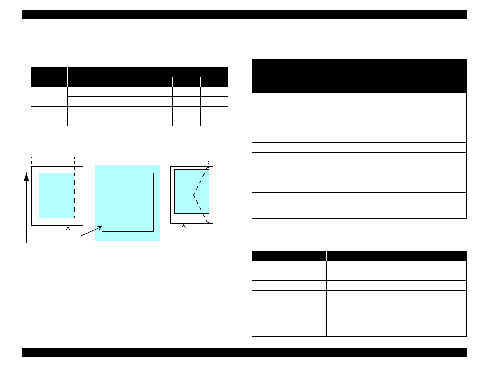
Print Area
LM RM
TM
BM
BM
Cut Sheet (Standard)
Cut Sheet (Borderless)
Paper SIze
LM
RM
TM
BM
Print Area
LM
RM
Print Area
Envelope
Paper Size
TM
Paper Feed Direction
1.2.5 Printing Area
The printing area for this printer is shown below.
Table 1-7. Printing Area (Margins)
*
Print Mode Paper Size
Standard print
Any size
Envelope
Borderless
print
4” x 6”
Others
Left Right Top Bottom
3 mm 3 mm 3 mm 3 mm
5 mm 5 mm 3 mm 20 mm
2.54 mm 2.54 mm
Note * : The margins for Borderless print are margins that bleed off the edges of paper.
Margin
1.34 mm 2.54 mm
2.96 mm 4.02 mm
1.3 Scanner Specifications
Table 1-8. Basic Specifications
Specification
Item
Epson Artisan 810/Epson
Stylus Photo PX810FW/
TX810FW
Scanner type Flatbed, color
Scanning method Moving carriage, stationary document
Home position The rear left corner
Photoelectric device CIS
Light source LED
Maximum document sizes A4 or US letter
Scanning range 8.5” x 11.7” (216 mm x 297 mm)
Main scan : 4,800 dpi
Maximum resolution
Sub scan : 4,800 dpi
(1,200 dpi*)
(600 dpi*)
Maximum effective pixels 40,800 x 56,160 pixels
Pixel depth 16 bit per pixel (input) and 1 bit or 8 bit per pixel (output).
Epson Artisan 710/Epson
Stylus Photo PX710W/
TX710W
Main scan : 2,400 dpi
Sub scan : 4,800 dpi
20,400 x 28,080 pixels
(with 2,400 dpi scanning)
PRODUCT DESCRIPTION Scanner Specifications 17
Figure 1-1. Printing Area
Note * : When scanning using ADF
Table 1-9. ADF Specifications
(Epson Artisan 810/Epson Stylus Photo PX810FW/TX810FW only)
Item Specification
Document loading Face-up
Maximum document sizes A4 or US letter or Legal
Supported paper type Plain paper only
Paper thickness 64 to 95 g/m
Maximum number of
documents which can be set
30 sheets (Xerox-P 64 g/m2) or 3 mm (A4, US Letter) /
10 sheet (Legal)
Document path Feeds from upper tray and ejects to lower tray
Document set position Left back
2
Confidential
Page 17
Epson Artisan 810/Epson Stylus Photo PX810FW/TX810FW/Epson Artisan 710/Epson Stylus Photo PX710W/TX710W Revision A
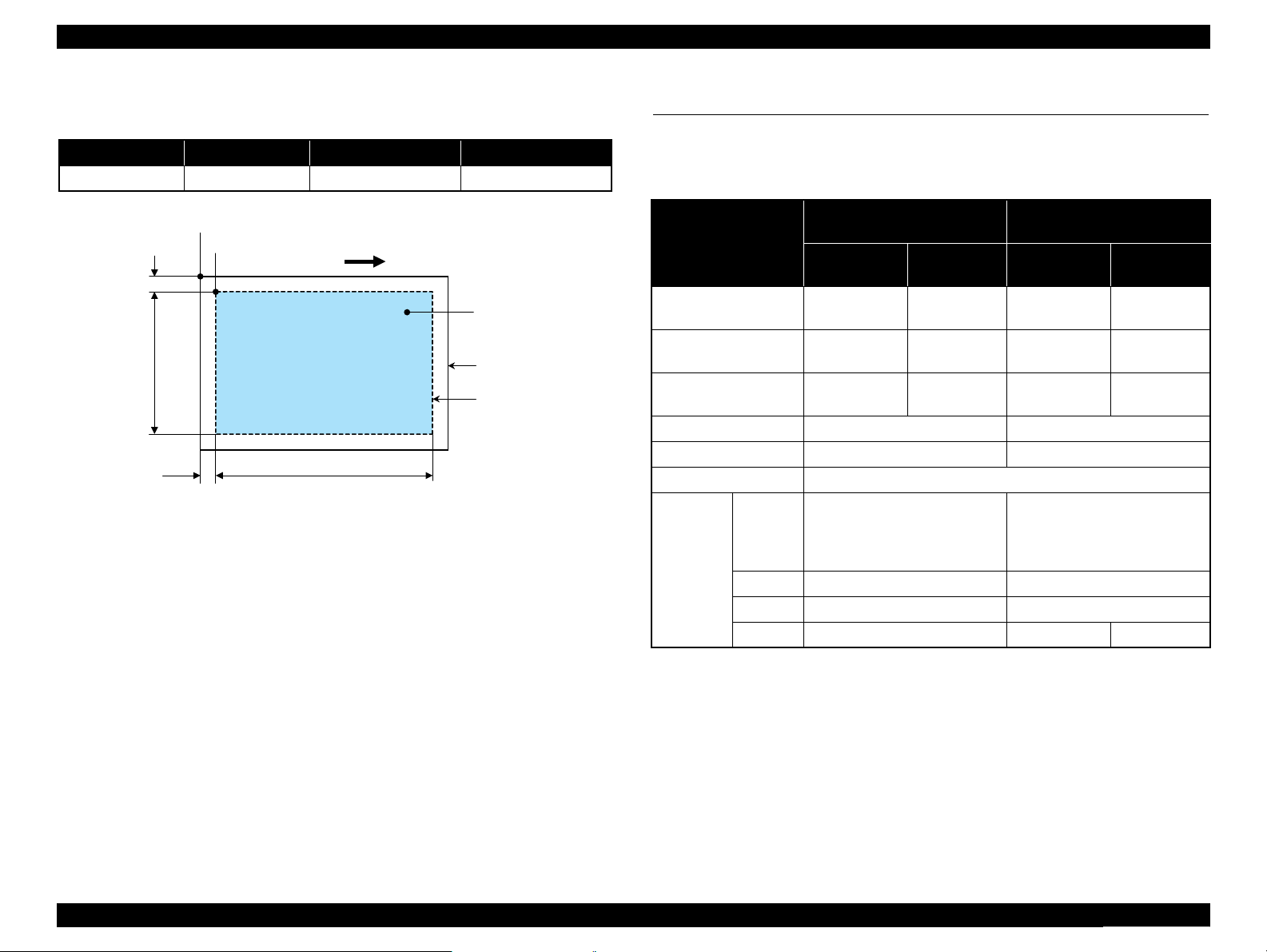
a
RW
RL
OTM
OLM
Scanning start position
Scanning range
Scan bed
Original
(face down)
Scanning direction
1.3.1 Scanning Range
Table 1-10. Scanning Range
RL (read length) RW (read width) OLM (left margin) OTM (top margin)
297 mm 216 mm 1.5 mm 1.5 mm
Figure 1-2. Scanning Range
1.4 General Specifications
1.4.1 Electrical Specifications
Table 1-11. Primary Power Specifications
Epson Artisan 810/Epson Stylus
Item
Rated power
supply voltage
Input voltage range
Rated current
(Max. rated current)
Rated frequency 50 to 60 Hz 50 to 60 Hz
Input frequency range 49.5 to 60.5 Hz 49.5 to 60.5 Hz
Energy conservation International Energy Star Program compliant
Copy
(ISO/
IEC24712
Power
consumption
Pattern)
Ready
Sleep
Off
Photo PX810FW/TX810FW
100-120 V
model
100 to 120
VAC
90 to 132
VAC
0.8 A
(1.6 A)
Approx. 26 W Approx. 25 W
Approx. 12 W Approx. 9.5 W
Approx. 5.5 W Approx. 5.0 W
Approx. 0.3 W Approx. 0.3 W Approx. 0.5 W
220-240 V
model
220 to 240
VAC
198 to 264
VAC
0.4 A
(0.8 A)
Epson Artisan 710/Epson Stylus
Photo PX710W/TX710W
100-120 V
model
100 to 120
VAC
90 to 132
VAC
0.8 A
(1.6 A)
220-240 V
220 to 240
198 to 264
model
VAC
VAC
0.4 A
(0.8 A)
Note : If the product has been idle status over 13 minutes, it goes into sleep mode within 2
minutes.
PRODUCT DESCRIPTION General Specifications 18
Confidential
Page 18
Epson Artisan 810/Epson Stylus Photo PX810FW/TX810FW/Epson Artisan 710/Epson Stylus Photo PX710W/TX710W Revision A
10/50
27/80
35/9520/68
Temperature (°C/°F)
20
30
40
50
90
80
70
60
Humidity (%)
30/86 40/104
1.4.2 Safety Approvals (Safety standards/EMI)
USA UL60950-1
FCC Part15 Subpart B Class B
Canada CAN/CSA-C22.2 No.60950-1
CAN/CSA-CEI/IEC CISPR 22 Class B
EU EN60950-1
EN55022 Class B
EN61000-3-2, EN61000-3-3
EN55024
Germany EN60950-1
Russia GOST-R (IEC60950, CISPR 22)
*
Australia AS/NZS CISPR22 Class B
Note* : Epson Artisan 710/Epson Stylus Photo PX710W/TX710W only.
1.4.3 Acoustic Noise
Epson Artisan 810/Epson Stylus Photo PX810FW/TX810FW
PC Printing*1: TBD dB
Scanning*2: TBD dB
Epson Artisan 710/Epson Stylus Photo PX710W/TX710W
PC Printing*1: TBD dB
Scanning*2: TBD dB
Note *1: Premium Glossy Photo Paper/Highest quality
*2 : default setting
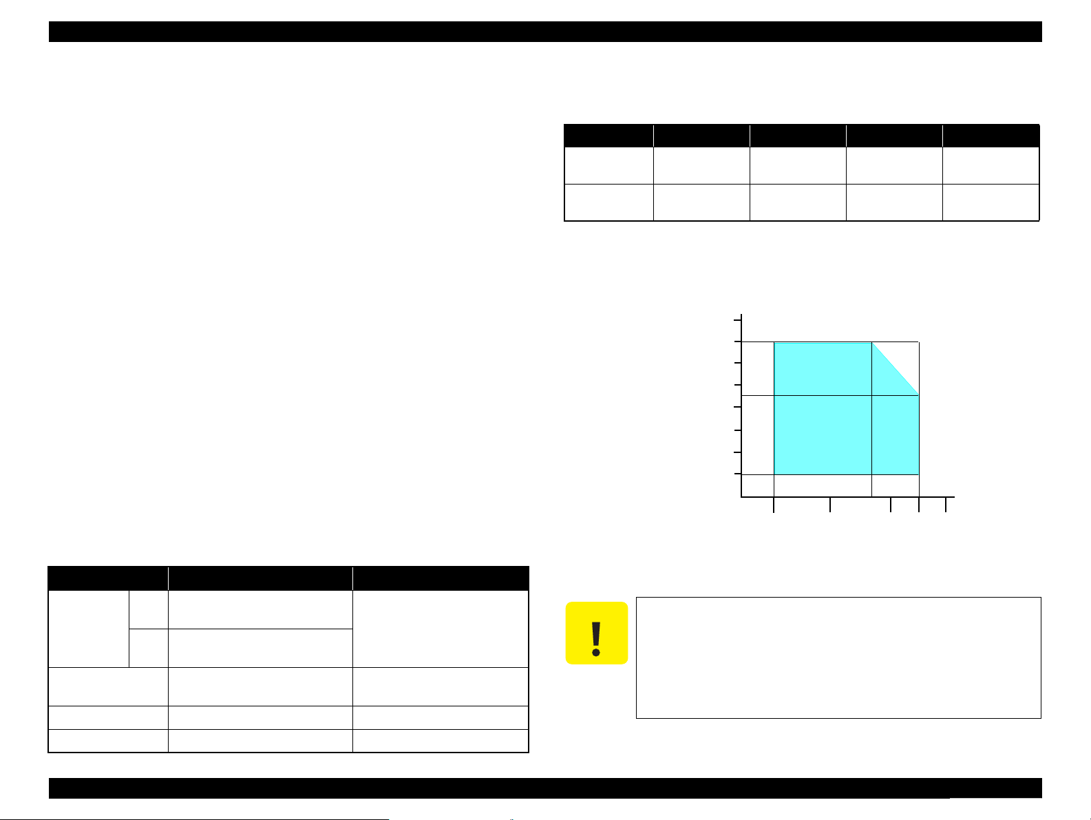
1.4.5 Environmental Conditions
Table 1-12. Environmental Conditions
*3
*1
Humidity
20 to 80%
Condition Temperature
Operating
Storage
(unpacked)
Note *1 : The combined Temperature and Humidity conditions must be within the blue-shaded
range in Fig.1-3.
*2 : No condensation
*3 : Must be less than 1 month at 40°C.
10 to 35°C
(50 to 95°F)
-20 to 40°C
(-4°F to 104°F)
5 to 85%
*1,2
Shock Vibration
1 G
(1 msec. or less)
2 G
(2 msec. or less)
10 to 55 Hz
10 to 55 Hz
0.15 G,
0.50 G,
1.4.4 Durability (TBD)
Item Durability Remark
Total print life
Printhead
Scanner carriage 30,000 cycles of carriage movement
Total ADF feeding*10,000 pages
Note * : Epson Artisan 810/Epson Stylus Photo PX810FW/TX810FW only.
PRODUCT DESCRIPTION General Specifications 19
16,000 pages, or five years
Black
whichever comes first
10,000 pages, or five years
Color
whichever comes first
Six billions shots (per nozzle) or
five years whichever comes first
• When printing A4 size sheet
• Black: 3.5% duty, Color: 5%
duty
C A U T I O N
Figure 1-3. Temperature/Humidity Range
When returning the repaired printer to the customer, make sure
the Printhead is covered with the cap and the ink cartridge is
installed.
If the Printhead is not covered with the cap when the printer is
off, turn on the printer with the ink cartridge installed, make
sure the Printhead is covered with the cap, and then turn the
printer off.
Confidential
Page 19
Epson Artisan 810/Epson Stylus Photo PX810FW/TX810FW/Epson Artisan 710/Epson Stylus Photo PX710W/TX710W Revision A
1.5 Interface
The following is the specifications of the USB Interface, Network Interface, FAX
Interface (Epson Artisan 810/Epson Stylus Photo PX810FW/TX810FW only), and
Memory Card Slot mounted on this printer.
1.5.1 USB Interface
The table below describes the specifications of the two USB ports; USB device port for
connecting with a host such as a computer, and the USB host port for connecting with
an external devices such as a DSC (digital still camera).
Table 1-13. USB Interface Specifications
Item USB Device port USB Host port*
• Universal Serial Bus
Specifications Revision 2.0
• Universal Serial Bus Device
Compatible standards
Transfer rate
Class Definition for Printing
Devices Version 1.1
• Universal Serial Bus Mass
Storage Class Bulk-Only
Transport Revision 1.0
480 Mbps (High Speed) 480 Mbps (Max.)
Data format
Compatible connector
Max. cable length
Note* : The following devices can be connected to the USB Host port.
• Devices compliant with DPS Version 1.0/1.1 (PictBridge)
• Devices compliant with Universal Serial Bus Mass Storage Class Bulk-Only Transport
Revision 1.0, and the Subclass code is one of the followings.
0x06 (SCSI transparent command set)
0x05 (SFF-8070i command set)
0x02 (SFF-8020i command set)
USB Series B USB Series A
Table 1-14. Device ID
When IEEE 1284.4 is Enabled When IEEE 1284.4 is Disabled
@EJL<SP>ID<CR><LF>
MFG:EPSON;
CMD:ESCPL2,BDC,D4,D4PX, ESCPR2;
MDL:Model Name;
CLS:PRINTER;
DES:EPSON<SP>Model Name;
CID:EpsonRGB;
@EJL<SP>ID<CR><LF>
MFG:EPSON;
CMD:ESCPL2,BDC, ESCPR2;
MDL:Model Name;
CLS:PRINTER;
DES:EPSON<SP>Model Name;
CID:EpsonRGB;
• Universal Serial Bus
Specifications Revision 2.0
NRZI
2 [m] or less
Note : The “Model Name” is replaced as shown in the following table.
Table 1-15. Model Names Indicated in the Device ID
Model Name
Destination
North America Artisan 810 Artisan 710
Euro Epson Stylus Photo PX810FW Epson Stylus Photo PX710W
Asia/Pacific Epson Stylus Photo TX810FW Epson Stylus Photo TX710W
Epson Artisan 810/Epson
Stylus Photo PX810FW/
TX810FW
Epson Artisan 710/Epson
Stylus Photo PX710W/
TX710W
1.5.2 FAX Interface (Epson Artisan 810/Epson Stylus Photo PX810FW/TX810FW only)
Port Name Connector Description
Line port RJ11 Connects to phone cable from modular wall jack.
EXT port RJ11 Connects to TAM or Telephone.
1.5.3 Network Interface
Epson Artisan 810/Epson Stylus Photo PX810FW/TX810FW/Epson Artisan 710/
Epson Stylus Photo PX710W/TX710W can be connected to the network via Wired
or Wireless LAN connection, however, they can not be used simultaneously.
The following describes each Interface.
Wired LAN
The following interface is equipped for the Wired LAN connection. The communication
mode can be selected from auto setting or fixed setting.
Table 1-16. Wired LAN
Item Content
Connector RJ-45 receptacle*: 1 port
Communication Speed For either 10Base-T or 100Base-TX, the Full Duplex or Half
Duplex can be selected.
Note* : 10Base-T/100Base-TX Ethernet is supported. MDI/MDI-X is selected automatically.
PRODUCT DESCRIPTION Interface 20
Confidential
Page 20
Epson Artisan 810/Epson Stylus Photo PX810FW/TX810FW/Epson Artisan 710/Epson Stylus Photo PX710W/TX710W Revision A
Table 1-17. Combination of the Wired LAN communication mode settings
Setting of this printer Setting of the connected device
Auto Setting (AUTO)
Auto Setting
100BASE-TX Full Duplex 100BASE-TX Full Duplex
100BASE-TX Half Duplex
10BASE-T Full Duplex 10BASE-T Full Duplex
10BASE-T Half Duplex
100BASE-TX Half Duplex
10BASE-T Half Duplex
Auto Setting (AUTO)
100BASE-TX Half Duplex
Auto Setting (AUTO)
10BASE-T Half Duplex
Wireless LAN
The following interface is equipped for the Wireless LAN connection.
Table 1-18. Wireless LAN
Item Content
Applied Standard
(2.4GHz spectrum band
wireless network
standards)
Wireless Operation Mode IEEE802.11b DS-SS (Half Duplex)
Communication Range
(line-of-sight distance)
Communication Mode Ad-hoc (IBSS) or Infrastructure (ESS)
Roaming Function Not supported
Output Signal Intensity 10 mW
Antenna Built-in antenna (Diversity function is supported)
Conforms to IEEE802.11b, IEEE802.11g
IEEE802.11g OFDM (Half Duplex)
IEEE802.11b (11 Mbps) • 60 m (indoor)
*
IEEE802.11g (54 Mbps) • 20 m (indoor)
• 220 m (outdoor)
• 100 m (outdoor)
Table 1-19. Available Channels and Standard
Frequency Band
(GHz)
2.400 - 2.4835 1 - 13 802.11b 11/5.5/2/1 M
2.400 - 2.4835 1 - 13 802.11g 54/48/36/24/18/12/9/6 M
2.471 - 2.497 14 802.11/11b 11/5.5/2/1 M
Note " * " : The communication speed will be changed automatically, depending on radio wave
strength. bps = bit per second.
Channel IEEE Standard
Communication Speed
(bps)*
Switching Wired/Wireless LAN
This printer can be connect to the network via either Wired LAN or Wireless LAN
connection only.
Enabling/disabling the Wireless LAN can be made from the Control Panel. When the
Wireless LAN is enabled, it gets priority over the Wired LAN regardless of whether
the LAN Cable is connected. The default Wireless LAN setting is “Disabled”.
Table 1-20. Wireless LAN Setting from the Control Panel
Setting from Control Panel
Wireless LAN Disabled
(Default)
Enabled
Note* : No service via network is available without connecting the LAN Cable (because
network communication is not established) except printing a status sheet or the like.
C H E C K
P O I N T
When changing the networks while the power is on, wait at least for
10 seconds between disconnecting and reconnecting.
LAN Cable Connection State
Connected Disconnected
Wired LAN ---
Wireless LAN
*
Wireless LAN
Note * : Referential value. It depends on surrounding conditions.
PRODUCT DESCRIPTION Interface 21
Confidential
Page 21
Epson Artisan 810/Epson Stylus Photo PX810FW/TX810FW/Epson Artisan 710/Epson Stylus Photo PX710W/TX710W Revision A
1.5.4 Memory Card Slots
If you insert a Memory Stick DUO to the Memory Card Slot
O NC A U T I
without using the adapter, make sure to turn off the printer first,
then remove the card using tweezers.
Table 1-21. List of Supported Memory Card
Priority Slot Compatible memory card Standard
1 Memory Stick/
Memory Stick
PRO
SD/MMC SD (Security Digital) SD Memory Card Specifications / PART1. Physical Layer Specification Ver.
xD-Picture card
2 CF Type II Compact Flash CompactFlash Specification Revision 2.1 compatible 32GB True-IDE compatible memory card only
Memory Stick MemoryStick Standard Format Specification Ver.1.43-00 compatible 128MB Includes versions with memory select function
MagicGate Memory Stick --- --- Copy protection function is not supported
MagicGate Memory Stick Duo --- --- The Memory Stick Duo adapter should be used.
Memory Stick PRO Memory Stick Pro Format Specifications Ver.1.02-00 compatible 32GB Copy protection function is not supported
Memory Stick Duo MemoryStick Duo Format Specification Ver.1.10-00 compatible --- The Memory Stick Duo adapter should be used
Memory Stick Pro Duo --- --- The Memory Stick Duo adapter should be used.
Memory Stick micro --- --- The Memory Stick adapter for standard size should be used.
Memory Stick Pro-HG Duo --- --- The Memory Stick Duo adapter should be used.
miniSD/microSD The SD adapter should be used
SDHC 32GB Speed Class is not supported
miniSDHC/microSDHC The SD adapter should be used
MultiMediaCard
MultiMediaCard Plus
MultiMediaCard mobile
MultiMediaCard micro
*
xD-Picture card xD-Picture Card Specification Ver.1.2 compatible 2GB Type M/H supported
Microdrive --- --- ---
2.0 compatible
MultiMediaCard Standard Ver. 4.2 compatible 4GB/32MB Only MultiMediaCard Plus supports up to 32GB.
Max.
capacity
2GB ---
Speed Class is not supported
The Multi Media Card adapter for standard size should be
used.
Remarks
Note* : FAT32 is not specified in the xD-Picture card standards. This printer supports only reading of xD-Picture card formatted in FAT32.
Note: • Memory Stick/PRO, SD/MMC and xD-Picture Card shares the same slot.
• When cards are inserted in the two slots at once, the slot which will be accessed first is determined according to the priority shown in the table.
• To select a card that has been inserted in a non-active slot, first remove the card in the active slot.
• In memory card direct printing mode, the image files in the active slot are valid and have assigned frame numbers. The number of images will not change if a card is inserted in another nonselected slot.
• When the card inserted in the slot is accessed from the PC, only one drive is displayed at a time as a removable disk* and only the card that is in the active slot can be accessed via the
removable disk. A card that has been inserted into a non-selected slot cannot be accessed. (This is for Windows. For Macintosh, the card in the active slot will be mounted on the desktop.)
• Does not support 5V type of memory cards.
• When a memory card is being accessed, do not touch the memory card.
• For detailed information on the supported file system and formatting the memory card, refer to “ 1.7.2 Memory Card Direct Print Function (Photos Mode) ( p. 28 ) ”.
PRODUCT DESCRIPTION Interface 22
Confidential
Page 22
Epson Artisan 810/Epson Stylus Photo PX810FW/TX810FW/Epson Artisan 710/Epson Stylus Photo PX710W/TX710W Revision A
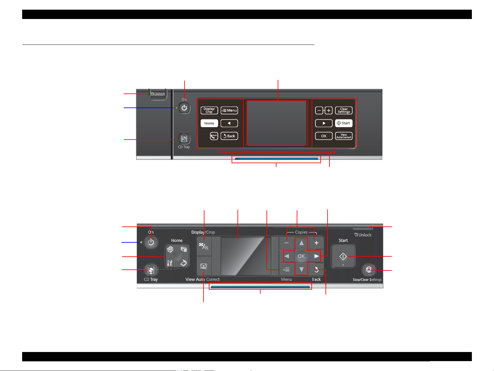
LCD
Power LED
Power Button
CD Tray button
Touch Panel
Unlock button
Blue status light
LCD
Home button
Display/Crop button
Cross Key and OK button
Menu button
Start button
Stop/Clear Settings button
-, + button
View Auto Correct button
Unlock button
CD Tray button
Power button
Power LED
Back button
Blue status light
1.6 Control Panel
1.6.1 Operation Buttons & LEDs
Figure 1-4. Control Panel for Epson Artisan 810/Epson Stylus Photo PX810FW/TX810FW (EAI version as a sample)
Figure 1-5. Control Panel for Epson Artisan 710/Epson Stylus Photo PX710W/TX710W (EAI version as a sample)
PRODUCT DESCRIPTION Control Panel 23
Confidential
Page 23
Epson Artisan 810/Epson Stylus Photo PX810FW/TX810FW/Epson Artisan 710/Epson Stylus Photo PX710W/TX710W Revision A
Table 1-22. Button Functions
(Epson Artisan 810/Epson Stylus Photo PX810FW/TX810FW)
Button Function
Power Turns the power ON/OFF.
Touch Panel Displays available buttons in each mode.
Unlock button
CD Tray Ejects/retracts the CDR Tray.
Release the lock of tilt adjustment of the Control Panel while
pressing.
Table 1-23. Button Functions
(Epson Artisan 710/Epson Stylus Photo PX710W/TX710W)
Button Function
Power
Display/Crop
-, + Sets pages to print
Unlock Release the lock of the Control Panel.
Start Starts printing.
Stop/Clear Settings
Back Cancels the previous operation.
Cross Key/OK
Menu Goes to the menu screen for each mode.
Auto Correct Changes the Auto Correct ON/OFF.
CD Tray Ejects/retracts the CDR Tray.
Home
Turns the power ON/OFF.
• Goes to the zoom setting screen for the selected image.
• Changes the image preview layout on the LCD.
• Stops operation and displays the menu screen.
• Stops printing and ejects paper.
• Returns the print settings in the current mode to their defaults
and displays the Top screen. (Returns to the previous screen
during printing maintaining the current settings)
• Selects a menu item or a setting value.
• Accepts the changed settings
Changes modes in the following order.
Copy/Print Photos/Scan/Setup
Table 1-24. LED
LED Function
• Flashes while powering ON/OFF.
• Flashes during some sequence is in progress.
Power (Green)
Blue status light Flashes or lights according to the printer status.
• Flashes when a fatal/maintenance error occurs.
• Lights when the status is other than above.
(Stand by mode/during setting on the Panel, etc.)
1.6.2 Control Panel Functions in Each Mode
1.6.2.1 Control Panel Functions
The table below shows the print setting menu items for each mode and their defaults,
and when the settings are saved or returned to their defaults. Explanations on detailed
control panel functions of the Epson Artisan 810/Epson Stylus Photo PX810FW/
TX810FW/Epson Artisan 710/Epson Stylus Photo PX710W/TX710W are omitted
here, because the LCD displays the detailed instruction.
Table 1-25. Timing of Saving or Initializing Control Panel Settings
Mode Print Setting Default Value
Copy Normal Copy Copy Type Color
Density ±0
Layout With Border
2-Sided Printing Off
Reduce/Enlarge Actual
Paper Size
Paper Type Plain Paper
Document Type Text & Image
Quality Standard Quality
Expansion Standard
Dry Time Standard
Binding Direction Vertical-Long
• EAI: Letter
• Euro/Asia: A4
PRODUCT DESCRIPTION Control Panel 24
Confidential
Page 24
Epson Artisan 810/Epson Stylus Photo PX810FW/TX810FW/Epson Artisan 710/Epson Stylus Photo PX710W/TX710W Revision A
Table 1-25. Timing of Saving or Initializing Control Panel Settings
Mode Print Setting Default Value
Copy Photo Copy Color Restoration Off
Paper Size 4” x 6” (10 x 15 cm)
Paper Type Prem. Glossy
Boderless On
Expansion Standard
Fix Photo
Enhance
Filter Off
CD/DVD Print CD Inner/Outer Standard
Print Type Print on a CD/DVD
Document Type Text & Image
Quality Best
Print Photo • View and Print Photos
• Print All Photos
Paper Size 4” x 6” (10 x 15 cm)
Paper Type Prem. Glossy
Borderless On
Layout Boderless
Quality Standard Quality
Expansion Standard
Date Off
Print Info. On Photos Off
Fit Frame On
Bidirectional On
Fix Photo
Enhance
Scene Detection Automatic
Fix Red-Eye Off
Filter Off
Brightness Standard
Contrast Standard
Sharpness Standard
Saturation Standard
Print Photo Print Photo Greeting Card Paper Size
Paper Type Prem. Glossy
*1
*2
*1
*2
Fix Photo Off
Enhance Off
Fix Photo On
PhotoEnhance
*3
• EAI: Letter
• Euro/Asia: 4” x 6” (10 x 15 cm)
Table 1-25. Timing of Saving or Initializing Control Panel Settings
Mode Print Setting Default Value
Print Photo Print Photo Greeting Card Layout
Frame Off
Fix Photo
Enhance
Scene Detection Automatic
Fix Red-Eye Off
Filter Off
Brightness Standard
Contrast Standard
Sharpness Standard
Saturation Standard
Photo Layout Sheet Layout 2-up
Paper Size 4” x 6” (10 x 15 cm)
Paper Type Prem. Glossy
Layout Method Automatic layout
Photo Layout Place this photo
Quality Standard Quality
Expansion Standard
Date Off
Print Info. On Photos Off
Fit Frame On
Bidirectional On
Print on CD/DVD Layout CD/DVD 1-up
Layout Method Automatic layout
Photo Layout Place this photo
CD Inner/Outer Standard
Print Type Print on a CD/DVD
CD Density Standard Density
Fix Photo
Enhance
Scene Detection Automatic
Fix Red-Eye Off - This photo
Filter Off
Brightness Standard
Sharpness Standard
Saturation Standard
*1
*2
*1
*2
•EAI: 3-up
• Euro/Asia: Borderless
Fix Photo On
PhotoEnhance
Fix Photo On
PhotoEnhance
PRODUCT DESCRIPTION Control Panel 25
Confidential
Page 25
Epson Artisan 810/Epson Stylus Photo PX810FW/TX810FW/Epson Artisan 710/Epson Stylus Photo PX710W/TX710W Revision A
Table 1-25. Timing of Saving or Initializing Control Panel Settings
1.7 Specification for Each Function
Mode Print Setting Default Value
Print Photo Print Index Sheet Expansion Standard
Print Proof Sheet Paper Size 4” x 6” (10 x 15 cm)
Paper Type Prem. Glossy
*1
*1
*2
File name
(Print 1 Frame)
• 12-up
(Print N Frame)
Fix Photo On
PhotoEnhance
Play Movie and Print Photos
(Epson Artisan 810/Epson
Stylus Photo PX810FW/
TX810FW only)
Infomation
Paper Size 4” x 6” (10 x 15 cm)
Paper Type Prem. Glossy
Layout • Borderless
Quality Standard Quality
Expansion Standard
Fit Frame On
Bidirectional On
Movie Enhance On
Fix Photo
Enhance
Filter Off
Brightness Standard
Contrast Standard
Sharpness Standard
Saturation Standard
Note : For the default value in FAX mode, refer to“ 1.7.5 FAX Function (FAX Mode)
(Epson Artisan 810/Epson Stylus Photo PX810FW/TX810FW only) ( p. 39 ) ”.
Note *1 : Supported only for EAI.
*2 : Supported only for Euro/Asia.
*3 : In “View and Print Photos” mode: “Off-This photo”
In “Print All Photos” mode: “Off-All photos”
1.7.1 Stand-alone Copy Function (Copy Mode)
1.7.1.1 Supported Paper and Copy Mode
Table 1-26. Supported Paper and Copy Mode
Paper Type
(UI notation)
Plain
Matte
Photo Paper
Glossy/
Glossy Paper
Prem. Glossy
Ultra Glossy
CD/DVD
Size
A4, A5*4 Letter
A4, Letter
A4, 5” x 7”
*4
(13 x 18 cm)*2,
4” x 6” (10 x 15 cm)
Letter*1, A4, 5” x 7”
(13 x 18 cm)*2,
4” x 6” (10 x 15 cm)
Letter*1, A4, 5” x 7”
(13 x 18 cm), 8”x 10”*1,
4” x 6” (10 x 15 cm)
Letter*1, A4,
5” x 7”(13 x 18 cm)*3,
8”x 10”*1,
4” x 6” (10 x 15 cm)
CD/DVD
*1
*1
Print
Quality
Draft
Standard
Best
Standard
Best
Standard
Standard
Best
Standard
Standard
Best
Standard
Standard
Best
Standard
Standard
Best
Best
Resolution
(H x V) dpi
Dot
Size
360x180 Eco ON OFF
360x360 MC2-1 ON OFF
720x720 MC1-1 ON ON
720x720 MC2-2 ON ON
5760x1440 MC1-5 ON ON
*5
720x720 MC1-2 ON ON
720x720 MC2-2 ON ON
5760x1440 MC1-5 ON ON
*5
720x720 MC1-2 ON ON
720x720 MC2-2 ON ON
5760x1440 MC1-5 ON ON
*5
720x720 MC1-2 ON ON
720x720 MC2-2 ON ON
5760x1440 MC1-5 ON ON
*5
720x720 MC1-2 ON ON
720x720 MC2-2 ON ON
5760x1440 MC1-5 ON ON
5760x1440 MC1-5 ON ON
Bi-d
Micro
Weave
Note *1 : Supported only for EAI.
*2 : Supported only for Euro.
*3 : Supported only for EAI/Euro.
*4 : Supported only for Euro/Asia.
*5 : In the case of 4” x 6”.
Note : In the case of copy using ADF, only the plain paper is available (Epson Artisan 810/
Epson Stylus Photo PX810FW/TX810FW only).
PRODUCT DESCRIPTION Specification for Each Function 26
Confidential
Page 26
Epson Artisan 810/Epson Stylus Photo PX810FW/TX810FW/Epson Artisan 710/Epson Stylus Photo PX710W/TX710W Revision A
1.7.1.2 Stand-alone Copy Menu
The stand-alone copy mode menu for the Epson Artisan 810/Epson Stylus Photo
PX810FW/TX810FW/Epson Artisan 710/Epson Stylus Photo PX710W/TX710W
(settable items) are shown in the following tables.
Table 1-27. Copy Menus
Menu Function
Number of copies Sets the number of copies within the range of 1 to 99.
Copy type Selects either color or monochrome.
Layout Selects from layouts shown in Table 1-28.
Double-sided printing*1Selects either “On” or “Off”.
Paper type Selects paper type from the options shown in Table 1-26.
Paper size Selects paper size from the options shown in Table 1-26.
Quality Selects print quality from the options shown in Table 1-26.
Selects zoom type from the following. The preset combination
differs depending on destinations.
•Actual
(Sets any zoom with +/- key (25% to 400%) after selecting “Actual”)
• Auto Fit Page
• Legal > Letter
• Letter > 4x6in
Print
setting
Zoom
Document Type Selects from “Text”, “Text & Image”, “Photo”
Density Selects from the nine density levels of -4 to +/-0 to +4.
Expansion
(for borderless print)
Binding Direction
Dry Time Selects from “Standard”, “Long”, “Longer”.
Note *1 : Available when the Double-sided Printing Unit is installed.
• 4x6in > Letter
• Letter > 5x7in
• 5x7in > Letter
• 4x6in (10x15cm) > A4
• A4 > 4x6in (10x15cm)
• 5x7in > A4
• A4 > 5x7in
• 4x6in > 8x10in
• 8x10in > 5x7in
• 13x18 cm > 10x15 cm
• 10x15 cm > 13x18 cm
•A5 > A4
•A4 > A5
Selects the margins level (margins bleed off the edges of paper)
from the Standard (100%), Mid. (50%) or Min. (25%).
*2
Selects from “Vertical-Long”, “Vertical-Short”, “Horizontal-Long”,
“Horizontal-Short”.
*2 : Percentages in parentheses indicate the proportion of the margin level to the
maximum which bleeds off the edges of paper.
Note : When selecting the photo copy, “color restoration/filter” settings become available in
addition to the above print settings.
Table 1-28. Copy Layout
Layout Description
With Border Makes a copy with 3mm of left/right/top/bottom white margins.
Borderless Makes a copy with no white margins.
2-Sided 1-up
Book/2-Sided
*
*
Makes a double-sided copy of two sheets.
Makes a double-sided copy of two pages of a book.
2-up Copy Make a scaling down copy of two sheets of A4 or B5 on one sheet.
2-Sided 2-up
Book/2-up
*
Make a scaling down double-sided copy of four sheets of A4 or B5.
Make a scaling down copy of two pages of an A4 or B5 book on
one sheet.
Note * : The layouts are available only when the duplex unit is installed.
Note : In the case of copy using ADF, only the plain paper is available.
(Epson Artisan 810/Epson Stylus Photo PX810FW/TX810FW only)
1.7.1.3 Copy Speed (TBD)
Not using ADF
Table 1-29. Copy Speed (Plain Paper)
Copy Conditions
Draft
360x180
Default
360x360
Monochrome copy TBD cpm
Color copy TBD cpm
Monochrome copy TBD cpm
Color copy TBD cpm
Using ADF
(Epson Artisan 810/Epson Stylus Photo PX810FW/TX810FW only)
Table 1-30. Copy Speed
Copy Conditions
Default
Best
Monochrome copy TBD cpm TBD cpm
Color copy TBD cpm TBD cpm
Monochrome copy TBD cpm TBD cpm
Color copy TBD cpm TBD cpm
Copy Speed
(eMemo3, A4/Letter size)
Copy Speed
per copy per five copies
PRODUCT DESCRIPTION Specification for Each Function 27
Confidential
Page 27
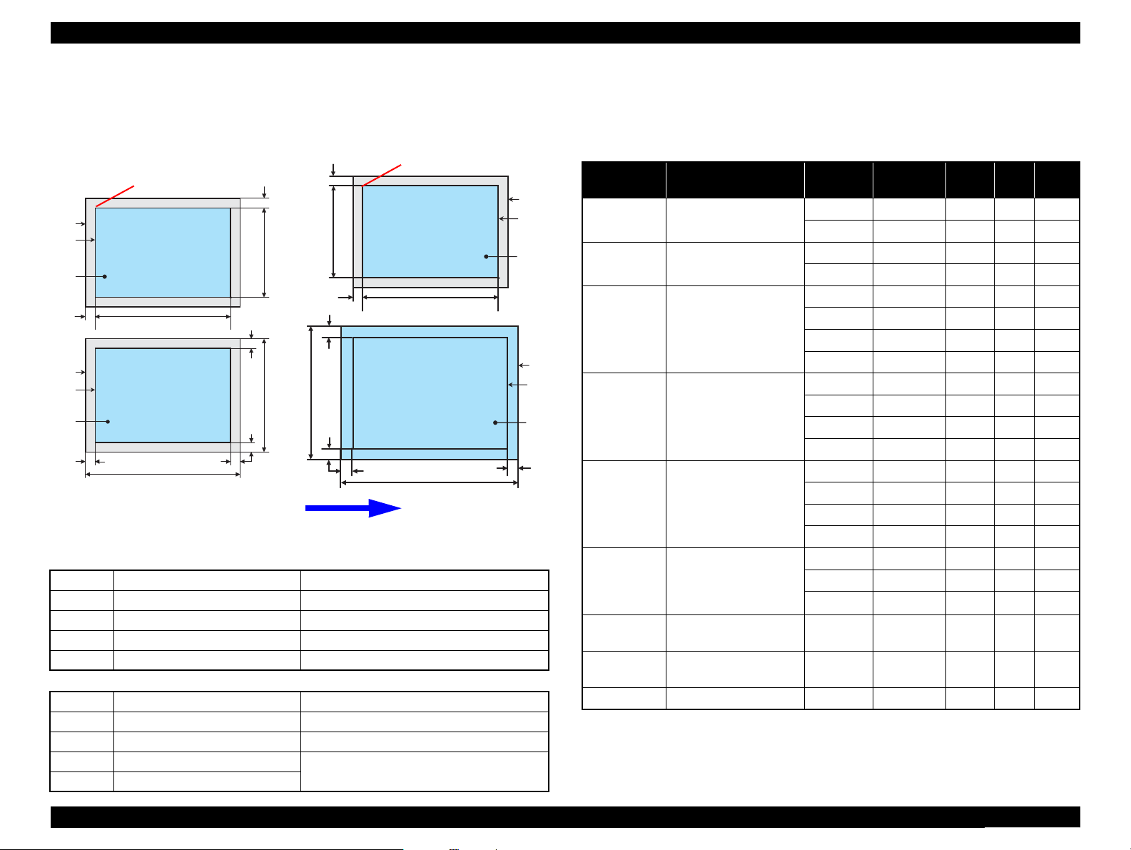
Epson Artisan 810/Epson Stylus Photo PX810FW/TX810FW/Epson Artisan 710/Epson Stylus Photo PX710W/TX710W Revision A
a
a
a
a
1.7.1.4 Relation Between Original and Copy
The scanning start position is located on the front right of the scan bed. The relations
between the original placed face down and its copy are as follows.
Standard copy Borderless copy
Home position
A
B
C
OTM
D
E
F
Figure 1-6. Relation Between Original and Copy (Borderless/With Borders)
Original Document
A Scan bed ---
B Scan area “ 1-10 Scanning Range ” (p.18)
C Original (face down) ---
OTM Top margin (out of scan range) “ 1-10 Scanning Range ” (p.18)
OLM Left margin (out of scan range) “ 1-10 Scanning Range ” (p.18)
Copied Document
D Copied paper ---
E Print area “ 1-7 Printing Area (Margins) ” (p.17)
F Copy ---
LM, RM Left margin, Right margin* “ 1-7 Printing Area (Margins) ” (p.17)
TM, BM Top margin, Bottom margin*
Readable Length
TM
Paper Length
Scan / Print direction
RM
LM
BM
OLM
OLM
Readable
Width
OTM
RM
Paper
Width
LM
Home position
Readable Length
TM
Paper Length
BM
1.7.2 Memory Card Direct Print Function (Photos Mode)
1.7.2.1 Supported Paper and Print Mode
Table 1-31. Supported Paper Type & Print Mode
Paper Type
A
B
C
E
D
F
(UI notation)
Plain/Plain
Paper
Matte Letter*1, A4
Photo Paper
Glossy/
Glossy Paper
Prem. Glossy
Ultra Glossy
Photo
Sticker1
Photo
Stickers
CD/DVD CD/DVD Best
Note *1 : Supported only for EAI.
*4
(13 x 18 cm)*2, 4” x 6”
(13 x 18 cm), 8” x 10”*1,
*4
*4
*2 : Supported only for Euro.
*3 : Supported only for EAI/Euro.
*4 : Supported only for Euro/Asia.
*5 : In the case of 4” x 6”.
Size
Letter*1, A4,
A4, 5” x 7”
(13 x 18 cm)*2,
4” x 6” (10 x 15 cm)
Letter*1, A4, 5” x 7”
(10 x 15 cm)
Letter*1, A4, 5” x 7”
4” x 6” (10 x 15 cm),
16:9wide
Letter*1, A4, 5” x 7”
(13 x 18 cm)*3,
8” x 10”*1, 4” x 6”
(10 x 15 cm)
A6 Standard
100 x 148 mm
(3.9” x 5.8”)
Print
Quality
Standard
Best
Standard
Best
Draft
Standard
Standard
Best
Draft
Standard
Standard
Best
Draft
Standard
Standard
Best
Standard
Standard
Best
Standard
Resolution
(H x V) dpi
360x360 MC2-1 ON OFF
720x720 MC1-1 ON ON
720x720 MC2-2 ON ON
5760x1440 MC1-5 ON ON
720x360 MC1-2 ON ON
*5
720x720 MC1-2 ON ON
720x720 MC2-2 ON ON
5760x1440 MC1-5 ON ON
720x360 MC1-2 ON ON
*5
720x720 MC1-2 ON ON
720x720 MC2-2 ON ON
5760x1440 MC1-5 ON ON
720x360 MC1-2 ON ON
*5
720x720 MC1-2 ON ON
720x720 MC2-2 ON ON
5760x1440 MC1-5 ON ON
*5
720x720 MC1-2 ON ON
720x720 MC2-2 ON ON
5760x1440 MC1-5 ON ON
720x720 MC2-2 ON ON
720x720 MC2-2 ON ON
5760x1440 MC1-5 ON ON
Dot
Size
Bi-d
Micro
Weave
PRODUCT DESCRIPTION Specification for Each Function 28
Confidential
Page 28
Epson Artisan 810/Epson Stylus Photo PX810FW/TX810FW/Epson Artisan 710/Epson Stylus Photo PX710W/TX710W Revision A
1.7.2.2 Supported File Type and Media Type
The followings describe the file system, media format, and file type supported by the
memory card direct function.
Table 1-32. Supported File System, Types and Media Format
Item Specification
• DCF Version 1.0 or 2.0
• “Backup” or “Scan in Memory” form created by this printer
File system
Memory card
Media format
File type
Note *1: Refer to the Camera File System Standard; “DCF Version 2.0, JEIDA-CP-3461” for
*2 : FAT32 is not specified in the xD-Picture card standards. This printer supports only
*3 : DVD that is formatted with only UDF is not supported.
CD-R ISO9660 Level1 (Joliet) format
DVD-R
JPEG (*.JPG)
Camera
definition file
(*.MRK)
P.I.F
definition file
(*.USD)
P.I.F
definition file
(*.FD2)
more details.
reading of xD-Picture card formatted in FAT32.
Other than those does not ensure proper operation. File
systems available with the card reader function are restricted
by the host’s specification.
• DCF Version 1.0 or 2.0 compliant
• DOS FAT format (FAT12/FAT16/FAT32*2) with single
partition (basic partitioned)
• ISO9660 Level1 (Joliet) format
• ISO9660 Level1 (Joliet) and UDF Bridge format
Image files conform to Exif Version 2.21. (Exif version 1.0/
2.0/2.1/2.2/2.21 are supported)
Camera definition files used for DPOF mode.
Valid if the full pass of the “AUTPRINT.MRK” is within 32
letters.
Print layout definition files compliant with PRINT Image
Framer Rev.2.1 specifications. Files in ”/EPUDL/” directory
are valid.
Print layout definition files compliant with PRINT Image
Framer Rev.3.1 specifications. Files in a memory card are
valid.
*1
compliant.
*3
C H E C K
P O I N T
The printer does not detect any files stored under the following
directories or their sub-directories.
• Directories containing system properties or hidden properties.
• “RECYCLED” (Windows directory for deleted files)
• “PREVIEW” (directories of CASIO DSC for thumbnail images)
• “SCENE” (directories of CASIO DSC for its Best Shot function)
• “MSSONY” (directories of SONY DSC for e-mail images, voice memos,
movies, or non-compressed images)
• “DCIM\ALBUM\IMAGE” (directories of CASIO DSC for its album
function)
1.7.2.3 Automatic Detection of Images in Memory Card
When a memory card is inserted in the card slot on the printer, or when a memory card
is detected at power-on, the printer automatically searches for all images stored in the
card. When the card is removed, the printer erases the information on the all detected
files.
1.7.2.4 Specifications for Handling Image Data
Table 1-33. Specifications for Handling Image Data
Item Specification Remarks
Image size (pixel)
Maximum number
of images
Maximum number
of copies
• Horizontal: 80 ≤ X ≤ 9200
• Vertical: 80 ≤ Y ≤ 9200
Up to 9,990 images When a memory card stores 9,990
or more images, the first 9,990
images are detected and become
valid in the printer. The detecting
order varies depending on the
folder configuration in the card, so
which images are included in the
first 9,991 cannot be defined.
However, images specified by
camera definition files can be
selected to be printed even when
the total number of images has
exceeded 9,990. Up to 999 camera
defined image files can be
specified.
99 copies for each image.
Up to 999 sheets in total.
---
---
PRODUCT DESCRIPTION Specification for Each Function 29
Confidential
Page 29
Epson Artisan 810/Epson Stylus Photo PX810FW/TX810FW/Epson Artisan 710/Epson Stylus Photo PX710W/TX710W Revision A
Table 1-33. Specifications for Handling Image Data
Item Specification Remarks
Valid date and time
Thumbnail image
data
File sorting
Acquisition of date
and time
information for
printing
01/01/1980 00:00:00 to
12/31/2099 23:59:59
Supports DCF Ver.1.0 or 2.0compatible data (Exif format,
160x120 pixels)
The printer sorts image files in
ascending ASCII order based on
their full-pathnames such as
“\DCIM\100EPSON\EPSN0000.
JPG”, and assigns a number to
each of them.
If over 1,000 files exist in the
memory card, up to 999 files can
be numbered and displayed on
LCD. You can select which 999
files should be displayed from the
menu on LCD.
The printer acquires date and time
information included in image
files in the order of precedence
shown below.
1. Date and time information in
digital camera standard format
(Exif)
2. Date and time information
applied on DOS-compliant file
system.
3. Fixed date and time
information (01/01/1980,
00:00:00)
Thumbnail images are used for the
Print Index Sheet function.
• The image number assigned by
the printer may be different from
that assigned by the camera.
• If two or more files have the
same full pathname, the sorting
function may not operate
properly. (existence of the same
full-pathname is not allowed
under DOS)
Date and time information included
in an image file is not always the
shooting date and time. It changes
each time the image is edited and
restored. The printer acquires the
latest date and time information.
---
1.7.2.5 Memory Card Direct Print Menu
The following describes the menu (settable items) in Photos Mode of Epson Artisan
810/Epson Stylus Photo PX810FW/TX810FW/Epson Artisan 710/Epson Stylus Photo
PX710W/TX710W.
Table 1-34. Memory Card Mode Menu
Menu Item Function
View and Print
*1,2
Photos
Print All
*1,2
Photos
Print Proof Sheet
Print on CD/
DVD
Print Photo
Greeting Card
Photo Layout
Sheet
Print Index
Sheet
Play Movie and
Print Photos
Slide Show
Note *1: 0 to 99 copies can be specified for each of the images. Up to 999 copies in total.
*2 : The images are listed in ASCII descending order.
*3 : Date and time information applied on DOS-compliant file system is used.
*4 : “Latest 60” and “Latest 90” are displayed on the LCD depending on the number of
images in the memory card.
*5 : Epson Artisan 810/Epson Stylus Photo PX810FW/TX810FW only.
Prints the selected images.
Prints all images in a memory card. Specified number of copies is applied
to the all images (the default is 1 copy). Specifying it for each of the images
independently also can be made in the preview screen.
Prints an index sheet of the images in a memory card. Refer to Figure 1-9
for layout of the index sheet.
Prints the specified image as a CD/DVD label. Test printing on an A4
paper is also available.
Prints a template with specified images, and combines the images with
handwritten messages and drawings on it by scanning them. The text styles
and text effects of the messages can be specified by marking on the printed
template.
Prints the images in a memory card with various layout. Refer to Figure 1-9
for layout.
Print Index Sheet
Prints an index sheet that prints images in a memory card in thumbnailed
form. The number of images to be included in the sheet can be selected
from the following four options.
“All photos”, “Latest 30”, “Latest 60”, “Latest 90”
Scan Completed Index Sheet to Print Photos
Scans the Index Sheet, and prints images according to markings written on
the sheet.
Displays and prints a movies file (MotionJPEG/MPEG1) taken by the
DSC, and stored in a memory card. Two types of printing, Print 1 Frame
*5
and Print N Frames are available.
Starts a slide show on the LCD. Images in a memory card is displayed one
by one in the order sorted by the printer. Printing one of the images can be
made from the paused screen.
*3
*4
PRODUCT DESCRIPTION Specification for Each Function 30
Confidential
Page 30

Epson Artisan 810/Epson Stylus Photo PX810FW/TX810FW/Epson Artisan 710/Epson Stylus Photo PX710W/TX710W Revision A
<OK example> <NG example>
(not enough)
(too much)
1.7.2.6 Makes Prints from Index Sheet Function
Print settings
Table 1-35. Print Settings
Item Print Index Sheet Makes Prints from Index Sheet
Layout ---
Paper Type Plain paper Premium Glossy Photo Paper
Paper Size Letter*1/A4
Date ---
EAI: File name or
MMM./DD./YYYY
Information
(Sep./21./2007)
Euro/Asia: YYYY.MM.DD
(2007.09.21)
Quality Standard (fixed) Standard (fixed)
Fix Red-Eye Off (fixed)
Filter Off (fixed)
Fix Photo Off (fixed)
Scene Detection ---
Brightness Standard (fixed)
Contrast Standard (fixed)
Sharpness Standard (fixed)
Saturation Standard (fixed)
Print Info. On Photos Off (fixed) Off (fixed)
Fit Frame Off (fixed) On (fixed)
Bidirectional On (fixed) On (fixed)
Expansion ---
Note *1 : Supported only for EAI.
*2 : Printing the file name or the date can be selected from the menu on the LCD.
According to the marking on the
index sheet.
According to the marking on the
index sheet.
*2
---
According to the setting made by
the control panel.
According to the setting made by
the control panel.
Rules on reading Index Sheet markings
The user can specify images to be printed and their print settings shown in Table
1-35 by putting marking on the Index Sheet. The printer reads the markings
according to the following rules.
Table 1-36. Rules on Reading Markings
Item
Left edge
(one each)
Right edge
(one each)
Block code
(36 pcs.)
Image selection
(30 pcs. x 3)
Paper type/size
(4 pcs.)
Layout (2 pcs.) Selects the layout. An error occurs if two or more markings are
Print all images Prints one copy of each
Date Prints the date information. When this marking is read, the date is
Note: • About 50% or more range of the mark area must be marked out to be read by the printer.
• The figure below shows the judgement example according to the rules described above.
Mark
Description Remarks
Reference position for
reading markings.
Reference position for
reading markings.
Sheet information
(memory card, page)
Selects the image to be
printed.
Selects the paper type/size. An error occurs if two or more markings are
image.
An error occurs if these markings cannot be
read due to ink stain or any other cause.
An error occurs if no image selection
marking is read.
read for one image.
read for one image. If no marking is read,
borderless layout is applied.
---
printed on the image.
Index Sheet errors
Table 1-37. Index Sheet Error List
Error Type Description
Incorrect sheet setting
Incorrect image selection marking Image selection markings are not correct.
Incorrect paper selection marking Paper selection markings are not correct.
Unmatch between memory card
and sheet
The Index Sheet is not properly placed on the document
glass.
The memory card may have been changed or some
images may have been added or deleted after the Index
Sheet is printed.
PRODUCT DESCRIPTION Specification for Each Function 31
Confidential
Page 31

Epson Artisan 810/Epson Stylus Photo PX810FW/TX810FW/Epson Artisan 710/Epson Stylus Photo PX710W/TX710W Revision A
1.7.2.7 Print Layout
The following table describes supported layout for each paper type when printing the images. For printing area/margins in border-less printing or in bordered printing, refer to “ 1.2.5
Printing Area ” (p.17). Other print layout are described in Figure 1-9.
Table 1-38. Supported Paper Type and Layout (1)
Corresponding Layout
*1
Paper Type
(UI notation)
2 up
Borderless
With Border
Upper 1/2
Lower 1/2
Plain/Plain Paper --- O --- --- O O O O --- --- --- O O O O O O O
Matte O O O O O O O O --- --- --- O --- --- --- O O O
4 up
8 up
20 up
16 up
Index-20 up
Index-30 up
Index-80 up
CD-4 up
CD-variety
Upper 1/2
Jewel Case-
CD (With Boarder)
Index
Jewel Case-
Picture Package
Photo Paper
Glossy/Glossy Paper O O O O O O O O --- O O
*2
O O O O O O O O --- O O O --- --- --- O O ---
*2
O --- --- --- O O O
Prem. Glossy O O O O O O O O --- O O O --- --- --- O O O
Ultra Glossy O O O O O O O O --- O O O --- --- --- O O O
PhotoSticker1
PhotoStickers
*2
*2
--- --- --- --- --- --- --- --- O --- --- --- --- --- --- --- --- ---
--- O --- --- O O O --- O --- --- --- --- --- --- --- --- ---
CD/DVD --- --- --- --- --- --- --- --- --- --- --- --- O O O --- --- ---
Note *1: Supported only for EAI.
*2: Supported only for Euro/Asia.
Note : Supported paper sizes differ depending on the types of paper.
PRODUCT DESCRIPTION Specification for Each Function 32
Confidential
Page 32

Epson Artisan 810/Epson Stylus Photo PX810FW/TX810FW/Epson Artisan 710/Epson Stylus Photo PX710W/TX710W Revision A
Table 1-39. Supported Paper Type and Layout (2)
Corresponding Layout
Paper Type
(UI notation)
*1
2
Photo ID
2
PIF-1 up*
PIF-n up*
Index Sheet/
Camera Text
3up-Greeting Card
Photo Greeting Card-
Photo Greeting Card Sheet
(Borderless/with Border)
Photo Greeting Card 1up
Upper 1/2
Photo Greeting Card-
Lower 1/2
Photo Greeting Card-
Reprint/Restore Photos
(Borderless/With Border)
Note Print
*3
Print 1 frame
(Borderless)
Play movie and Print Photos-
*3
Print 1 frame
(With Border)
Play movie and Print Photos-
*3
Upper 1/2
Print 1 frame
Play movie and Print Photos-
*3
*2*3
Lower 1/2
Print 1 frame
Play movie and Print Photos-
P.I.F
Print 1 frame
Play movie and Print Photos-
Play movie and Print Photos-
Plain/Plain Paper --- O O --- O --- --- --- --- --- O --- O --- --- --- O
Matte --- O O --- --- --- --- --- --- O --- O O O O O O
Photo Paper O O O O --- O O O O O --- O O O O O O
Glossy/Glossy Paper O O O O --- O O O O O --- O O O O O O
Prem. Glossy O O O O --- O O O O O --- O O O O O O
Ultra Glossy O O O O --- O O O O O --- O O O O O O
PhotoSticker1
PhotoStickers
*2
*2
--- --- --- --- --- --- --- --- --- --- --- --- --- --- --- --- ---
--- O O --- --- --- --- --- --- --- --- --- O --- --- --- ---
CD/DVD --- --- --- --- --- --- --- --- --- --- --- --- --- --- --- --- ---
*3
12-up
Print N frame
Note *1: Supported only for EAI.
*2: Supported only for Euro/Asia.
*3: Epson Artisan 810/Epson Stylus Photo PX810FW/TX810FW only.
Note : Supported paper sizes differ depending on the types of paper.
PRODUCT DESCRIPTION Specification for Each Function 33
Confidential
Page 33

Epson Artisan 810/Epson Stylus Photo PX810FW/TX810FW/Epson Artisan 710/Epson Stylus Photo PX710W/TX710W Revision A
Trimmed areas
Photo frame
(print area)
• When an image is aligned vertically with the photo frame.
• When an image is aligned horizontally with the photo frame.
Photo frame
(print area)
Trimmed
areas
Trimming On
Blank
area
Photo frame
(print area)
• When an image is aligned vertically with the photo frame.
• When an image is aligned horizontally with the photo frame.
Photo frame
(print area)
Blank area
Trimming Off
Trimming Function
A trimming function is provided as a means of coordinating an image with the
types of photo frames handled by the printer. This function can be switched On/
Off. This function is described briefly below.
The printed photo frame and an image to be printed are matched in length along
one side and the image is resized along the perpendicular side to fit the frame on
that side. Any part of the image that does not fit within the photo frame is trimmed
away (not printed). However, if the number of pixels of the longer side of the
image are more than twice as long as the shortest side, the trimming function is not
effective when printing even the trimming is set. The trimming function is always
set On if borderless or upper half layout is selected.
Rules on Numbering and Rotating Images
Figure 1-8. Trimming Function (when trimming is not operated)
The numbers shown in Figure 1-9 indicate the photo frame numbers used for the
print layout. Horizontally oriented images are printed as shown by the numbers.
Figure 1-7. Trimming Function (when trimming is being operated)
PRODUCT DESCRIPTION Specification for Each Function 34
Vertically oriented images, which has more pixels vertically than horizontally, the
vertical photo data is allocated instead, and the number shown in the figure below
is then rotated 90 degrees before being printed. In Index printing mode, the
numbers are printed as they are shown below, regardless of the shape of the photo
data.
However, when the photo data has an equal number of pixels vertically and
horizontally the photos are printed without rotation, regardless of the layout.
NOTE: The vertical photo data refers to when the photo data file itself is set for a
vertical (portrait) orientation. Photo data is defined as the vertical photo
data if it is taken by a digital camera with a portrait position detecting
function.)
Confidential
Page 34

Epson Artisan 810/Epson Stylus Photo PX810FW/TX810FW/Epson Artisan 710/Epson Stylus Photo PX710W/TX710W Revision A
1
2
3 4
5 6
7 8
1 2 3 4
5 6 7 8
9 10 11 12
13
14 15 16
17
18 19 20
1 2 3 4
5 6 7 8
9 10 11 12
13 14 15 16
1 2 3 4
5 6 7 8
9 10 11 12
1 2 3
4 5 6
7 8 9
10 11 12
13
14 15 16
17
18 19 20
13 14 15
16 17 18
19 20 21
22 23 24
2 3 4 5
6 7 8 9 10
11 12 13 14 15
16 17 18 19 20
5
6
1
21 22 23 24
26 27 28 29 30
25
2 3 4 5 6 7 81
10 11 12 13 14 15 169
18 19 20 21 22 23 2417
26 27 28 29 30 31 3225
34 35 36 37 38 39 4033
42 43 44 45 46 47 4841
50 51 52 53 54 55 5649
58 59 60 61 62 63 6457
66 67 68 69 70 71 7265
74 75 76 77 78 79 8073
1
2 3
4 5
6 7 8
9
Paper top edge
<Border-free> <1 sheet With Border> <Upper 1/2> <Lower 1/2> <2 up>
<4 up> <8 up> <20 up>
<Photo ID>
<Index-20 up> <Index-80 up> <Index-30 up>
<Photo Package>
<Jewel Case Index>
<Jewel Case Upper 1/
2>
<Greeting Card>
<PhotoSticker 16up>
1.7.3 Camera Direct Print Function (PictBridge)
Printing operations (selecting images to be printed, making print settings, starting/
canceling printing, and monitoring print process) can be carried out from a directly
connected DSC (Digital Still Camera) that conforms to the standard described below.
1.7.3.1 Available DSC
Those DSCs which are compliant with one of the following standards.
“CIPA DC-001-2003 Digital Photo Solutions for Imaging Devices”
(DPS Version 1.0)
“CIPA DC-001-2003 Rev.2.0, Digital Photo Solutions for Imaging Devices”
(DPS Version 1.1).
Figure 1-9. Rules on Numbering and Rotating Images
PRODUCT DESCRIPTION Specification for Each Function 35
1.7.3.2 Print Settings Available from DSC
The following print settings can be made from the DSC. However, depending on the
DSC, some of the settings may not be available.
Table 1-40. Print Settings Available from DSC
Item PictBridge
How to specify images Single Sheet / Multiple Sheet / DPOF specified / XHTML-Print
Paper type Plain Paper / Prem. Glossy
Paper size 4x6in (10x15cm), 5x7in (13x18cm), 8x10in*1, Letter*1, A4, 16:9 wide, CD/
DVD
Layout Borderless / With Border / 2-up / 4-up / 8-up / 20-up / CD/DVD-1 up
CD/DVD-4up
*2
/ CD/DVD Variety
*2
Date On / Off
Quality Draft / Standard Quality / Best
Auto Correct On / Off
Trimming Any specified area
Control of printer The following operations are available; Getting the printer status, starting a
print job or canceling it immediately or after printing the current page is
finished.
Note *1 : Supported only for EAI.
*2 : When “Print on CD/DVD” is selected on the print setting menu.
*2
/
Confidential
Page 35

Epson Artisan 810/Epson Stylus Photo PX810FW/TX810FW/Epson Artisan 710/Epson Stylus Photo PX710W/TX710W Revision A
1.7.3.3 General Operation Procedure
C H E C K
P O I N T
The DSC direct print procedure differs depending on the DSC specifications. The
following explains common procedure.
1. Setting on the printer
Before connecting a DSC with a USB cable, make the print settings such as paper
type/size, layout setting on the printer. This may not be required for some DSCs.
2. Setting on the DSC
Make the following settings on the DSC before connecting it to the printer. Some
DSCs may require to first connect to the printer for making the settings.
3. Starting to print
When the print settings on both the printer and the DSC is completed, follow the
procedure below to start printing.
Before connecting the DSC, check that the printer is in the
following status.
• No print job from a computer is processed or performed.
• Direct print from a memory card is not processed or performed.
• Stand alone copy using the scanner function is not operating.
• Backup of a memory card is not proceeded.
• No error is occurring such as paper out error or ink out error.
• When printing multiple images, specify images and number of copies using
the DPOF and Multiple Sheet menus. The menus may not be available on
some DSCs.
• When printing a single image, specify an image and the number of copies.
Specifying the number of copies may not be available on some DSCs.
• Select the paper type/size, layout, and make the Fit to Frame setting if
necessary. These settings may not be available on some DSCs.
1.7.3.4 Operations when a DSC is connected
Table 1-41. Operations during Connecting DSC
Operation Specifications
Connecting
DSC
(print start)
Canceling
printing
After printing
is completed
Exclusion
control
When a DSC is connected as described in “ 1.7.3.3 General Operation
Procedure ( p. 36 ) ” Step 3-1, Epson Artisan 810/Epson Stylus Photo
PX810FW/TX810FW/Epson Artisan 710/Epson Stylus Photo PX710W/
TX710W displays PictBridge logo on the LCD.
A print job can be canceled from the DSC.
The [Stop/Clear setting] button also cancels the print job.
When performing memory card direct print after printing from a DSC, the
USB cable connecting the DSC must be disconnected from the printer in
advance.
Print settings made on both the DSC and the printer can become impossible
settings for the printer due to unsupported combination of paper type, paper
size and layout. In such case, the print settings are automatically changed as
follows.
The settings made on the DSC are maintained. Any print setting items that are
not specified by the DSC are changed in accordance with the DSC settings.
When the paper type is changed, changed to Prem. Glossy, when the paper
size is changed, changed to 4 x 6 size. And when the layout is changed,
changed to Borderless layout.
1. Connect the printer and the DSC with a USB cable. Using a USB cable
included in the DSC package is recommended.
2. Operate the DSC to start printing.
3. Printing is carried out according to the settings made on the DSC. When some
print settings have not been made on the DSC, the corresponding settings
made on the printer are applied.
PRODUCT DESCRIPTION Specification for Each Function 36
Confidential
Page 36

Epson Artisan 810/Epson Stylus Photo PX810FW/TX810FW/Epson Artisan 710/Epson Stylus Photo PX710W/TX710W Revision A
1.7.4 Various Settings (Setup Mode)
Epson Artisan 810/Epson Stylus Photo PX810FW/TX810FW/Epson Artisan 710/
Epson Stylus Photo PX710W/TX710W provides various configuration and
maintenance. They can be done by selecting “Setup” from the menu on LCD. The
following explains the outline of these menu functions.
Table 1-42. Menu List for Setup Mode
Item Function
The current ink levels of each of the cartridges are
displayed in bar chart by the rules described below.
• The bar chart is displayed in the order of cyan, yellow,
Ink Levels
Maintenance
light cyan, black, magenta, and light magenta from the
left.
• When initial filling is completed, or after replacing the
cartridge, the ink level becomes 100% (full).
• The ink level is indicated in increments of 1%.
Runs various maintenance for the printer. The following
shows each menu.
• Nozzle Check
A nozzle check pattern to check the Printhead nozzles
status is printed. A head cleaning can be run if necessary.
(Refer to Figure 1-10 for nozzle check pattern.)
• Head Cleaning
Runs a printhead cleaning. The cleaning cannot be made
when low ink level is detected. In such case, an ink low
error is displayed instead of running the cleaning.
• Head Alignment
Adjustment to improve the bi-directional print quality.
Head alignment icon and the instructions for the
adjustment are displayed on the LCD.
• Automatic Head Maintenance
Selects On/Off of the auto head cleaning.
Item Function
Printer Setup
Network Settings
Table 1-42. Menu List for Setup Mode
Changes settings for the printer. The menu is described
below.
• CD/DVD Alignment
Makes the printing position adjustment for CD/DVD
label.
•Stickers
• Thick Paper
• Sound
• Screen Saver Settings
•Display Format
•Date/Time
• Daylight Saving Time
• Country/Region
• Language
Changes settings for Network.
• Confirm Network Settings
• General Network Setup
• Wireless LAN Setup
• File Sharing Setup
*2
Makes the printing position adjustment for Stickers.
Selects On/Off of friction reduction between paper and
printhead.
*1
Selects On/Off of the settings of beep sound, audio
output, and also selects the volume.
*2
If the panel is not used in stand-by mode, plays a slide
show using the images in a memory card as the screensaver.
The screen when displaying a photo can be selected from
the following three types.
1-up with Info
1-up without Info
View Thumbnail Images
*1
*1
*1
Displays the current settings. Status Sheet can be printed.
(Refer to Figure 1-11.)
Changes settings for printer name and TCP/IP (auto/
manual).
Enabling/disabling Wireless LAN.
Changes settings of the files in a memory card for file
sharing via network.
PRODUCT DESCRIPTION Specification for Each Function 37
Confidential
Page 37

Epson Artisan 810/Epson Stylus Photo PX810FW/TX810FW/Epson Artisan 710/Epson Stylus Photo PX710W/TX710W Revision A
32 dots
360dpi WF1 (MC2-1) LN2 dot
0.141mm (1/180inch)
Black MagentaCyan
Note : The numbers shown in the figure are nozzle numbers. The numbers and the color names
are not printed on an actual nozzle check pattern.
Yellow Light
Cyan
Light
Magenta
Table 1-42. Menu List for Setup Mode
Item Function
Makes the print settings via home networking using such as
Home Network Print Settings
Fax Setting
*1
Bluetooth Settings Changes settings for Bluetooth.
PictBridge Setup
Select Location
Restore Default Settings
*1
a digital TV or PC.
Changes settings for FAX. Refer to “ 1.7.5 FAX Function
(FAX Mode) (Epson Artisan 810/Epson Stylus Photo
PX810FW/TX810FW only) ( p. 39 ) ”.
The print settings and color correction to be used for the
camera direct print (PictBridge) can be selected and set.
When print conditions (paper type, paper size, layout,
quality, and auto correct) are specified from the DSC, the
DSC settings take priority over the settings made here. For
details, refer to “ 1.7.3 Camera Direct Print Function
(PictBridge) ( p. 35 ) ”.
Selects a folder when printing from an external device other
than DSC.
Restores the default settings for FAX and Network.
• Individual initialization of FAX or network settings is
available for Epson Artisan 810/Epson Stylus Photo
PX810FW/TX810FW.
• Individual initialization of network or other settings is
available for Epson Artisan 710/Epson Stylus Photo
PX710W/TX710W.
100
110
120
130
140
150
160
170
180
1
10
11
20
21
30
31
40
41
50
51
60
61
70
71
80
81
90
91
101
111
121
131
141
151
161
171
1
11
21
31
41
51
61
71
81
91
101
111
121
131
141
151
161
171
1
10
11
20
21
30
31
40
41
50
51
60
61
70
71
80
81
90
91
100
101
110
111
120
121
130
131
140
141
150
151
160
161
170
171
180
100
110
120
130
140
150
160
170
180
1
10
11
20
21
30
31
40
41
50
51
60
61
70
71
80
81
90
91
101
111
121
131
141
151
161
171
100
110
120
130
140
150
160
170
180
1
10
11
20
21
30
31
40
41
50
51
60
61
70
71
80
81
90
91
101
111
121
131
141
151
161
171
100
110
120
130
140
150
160
170
180
1
10
11
20
21
30
31
40
41
50
51
60
61
70
71
80
81
90
91
101
111
121
131
141
151
161
1
7
10
20
30
40
50
60
70
80
90
100
110
120
130
140
150
160
170
1
180
Figure 1-10. Nozzle Check Pattern
Note *1 : Epson Artisan 810/Epson Stylus Photo PX810FW/TX810FW only.
*2 : Supported only for Euro/Asia.
Note : When the settings for the network are changed, network connection may be
interrupted temporarily.
PRODUCT DESCRIPTION Specification for Each Function 38
Confidential
Page 38
Epson Artisan 810/Epson Stylus Photo PX810FW/TX810FW/Epson Artisan 710/Epson Stylus Photo PX710W/TX710W Revision A
HHHH EPSON Status Sheet HHHH
<General Information>
MAC Address XX:XX:XX:XX:XX:XX
Software (NONE).$$$$$$ (NONE)($$$$$$$$$1$$$$$/$$$$$$$$)
Printer Model $$$$$$$$$1$$$$$$$$$2$$$$$$$$$3$$
Printer Name $$$$$$$$$1$$$$$
<Ethernet>
Network Status Auto(100BASE-TX)
Port Type (NONE)
<Wireless>
Wireless Mode OFF
Communication Mode Infrastructure
Operation Mode IEEE802.11b/g
Communication Speed Auto(5.5Mbps)
SSID $$$$$$$$$1$$$$$$$$$2$$$$$$$$$3$$
Channel (NONE)
Security Level WEP-128bit(104bit)
AP Authentication Method Auto(Open System)
Link Status Disconnected
Access Point(MAC Address) XX:XX:XX:XX:XX:XX
Signal Strength No Good
SSID List E:$$$$$$$$$1$$$$$$$$$2$$$$$$$$$3$$/ 1/Security(OFF)
I:$$$$$$$$$1$$$$$$$$$2$$$$$$$$$3$$/ 2/Security(OFF)
E:$$$$$$$$$1$$$$$$$$$2$$$$$$$$$3$$/10/Security(OFF)
I:$$$$$$$$$1$$$$$$$$$2$$$$$$$$$3$$/11/Security(OFF)
E:$$$$$$$$$1$$$$$$$$$2$$$$$$$$$3$$/XX/Security(OFF)
Configuration Method WPS-PIN
<TCP/IP>
Obtain IP Address Manual
IP Address XXX.XXX.XXX.XXX
Subnet Mask XXX.XXX.XXX.XXX
Default Gateway XXX.XXX.XXX.XXX
APIPA Disable
Acquisition way of DNS ADDR Disable
Primary DNS Address XXX.XXX.XXX.XXX
Secondary DNS Address XXX.XXX.XXX.XXX
Proxy Use Disable
Proxy Address $$$$$$$$$1$$$$$$$$$2$$$$$$$$$3$$$$$$$$$4$$$$$$$$$5$$$$$$$$$6$$$
$$$$$$7$$$$$$$$$8$$$$$$$$$9$$$$$$$$$0$$$$$$$$$1$$$$$$$$$2$$$$$$
$$$3$$$$$$$$$4$$$$$$$$$5$$$$$$$$$6$$$$$$$$$7$$$$$$$$$8$$$$$$$$$
9$$$$$$$$$0$$$$$$$$$1$$$$$$$$$2$$$$$$$$$3$$$$$$$$$4$$$$$$$$$5$$
Proxy Port (NONE)
Universal Plug and Play Disable
Device Name $$$$$$$$$1$$$$$
Internet Connect State Enable, disconnected
Bonjour Disable
Bonjour Name $$$$$$$$$1$$$$$.local.
Bonjour Printer Name $$$$$$$$$1$$$$$
<Vista>
WSD Disable
<MS Network(R)> Disable
Host Name $$$$$$$$$1$$$$$
Workgroup Name $$$$$$$$$1$$$$$
File Share Name $$$$$$$$$1$$
File Sharing Mode Full Access
<Idle Timeout>
LPR XXXX[sec]
Port9100 XXXX[sec]
WSD Print XXXX[sec]
WSD Scan XXXX[sec]
HHHHHHHHHHHHHHHHHHHHHHHHHHHH
1.7.5 FAX Function (FAX Mode) (Epson Artisan 810/ Epson Stylus Photo PX810FW/TX810FW only)
The following shows the fax functions and specifications of this printer.
Note : The default settings are underlined in the following tables.
Figure 1-11. Sample of Network Status Sheet
PRODUCT DESCRIPTION Specification for Each Function 39
1.7.5.1 Basic Specifications
Table 1-43. Basic Specifications
Function Specification
FAX type
Supported line Telephone subscriber line
Modem speed Up to 33.6kbps
Error Correction Mode
Speed dials (Max.) 60 names & numbers
Document memory (Max.) 180 pages (ITU-T Chart No.1)
PC Fax Supported
Transmit speed Approx. 3 seconds per page
Desktop facsimile with sending/receiving
capabilities (Super G3, B&W and color scan)
CCITU/ITU Group 3 fax with Error
Correction Mode
1.7.5.2 Supported Functions
Scan
Function Specification
Standard: 8 pixel/mm x 3.85 lines/mm
Monochrome
Resolution
*
Color
Contrast 9 levels
Flatbed: Fixed to 216 mm x 297 mm
Scan size
ADF: 210 to 216 mm x 279 to 335.6 mm
Note* : When color fax fine or photo can be selected.
Fine: 8 pixel/mm x 7.7 lines/mm
Photo: 8 pixel/mm x 7.7 lines/mm
(with error diffusion)
Fine: 200 x 200 dpi
Photo: 200 x 200 dpi
Confidential
Page 39

Epson Artisan 810/Epson Stylus Photo PX810FW/TX810FW/Epson Artisan 710/Epson Stylus Photo PX710W/TX710W Revision A
Print
Function Specification
Paper size
Paper type Fixed to plain paper
Resolution Standard: 360 x 360 dpi
Dot size MC2-1
Bi-directional Available
Microweave N/A
Borderless printing N/A
Automatic reduction On/Off
Backup fax reception and
reprint
List
Size mismatch Print
Footer N/A
EAI/Latin: Letter/A4/legal
Others: A4
Available
*1
Type: Last transaction (off/send error/every send)
Fax log (last 30 transactions)
Speed dial list
Group Dial List
Power-fail report
Protocol trace
Font size: 12pt
Language:Depends on destination
*3
User Setting
Function Specification
Volume Buzzer: On/Off
Display*: dd.mm.yyyy/mm.dd.yyyy/yyyy.mm.dd
hh:mm (12h/24h)
Date and time
Pending job viewer N/A (cannot reserve)
Elapsed time Available (displays time to redial)
External memory N/A
Language Depends on destination
Audio monitor Available (buzzer)
Note* : The display format can be changed from the Printer Setup menu.
*2
Backup: N/A
Daylight time:Available
Note *1 : Volatile memory (approx. 2MB) to save FAX data is installed in this printer. When
received FAX data is reprinted from menu, it will print from latest data in the
memory. If the amount of memory is insufficient when receiving FAX, the oldest data
will be deleted in order to save the memory for receiving FAX.
*2 : Displaying on LCD is also available in addition to printing log.
*3 : The printer stops printing after printing the first page on the current paper. The
received fax images (data) can be reprinted.
PRODUCT DESCRIPTION Specification for Each Function 40
Confidential
Page 40

Epson Artisan 810/Epson Stylus Photo PX810FW/TX810FW/Epson Artisan 710/Epson Stylus Photo PX710W/TX710W Revision A
Dialing
Function Specification
Total registration 60 (Max.)
Characters available for
registering number
Total digits for
registering number
Speed/Group
dial
Characters available for
registering name
Total characters for
registering name
Options N/A
Selection method
Function Recalls fax numbers
One-touch dial N/A
Group dial Total registration 30 (Max.)
Direct dial Total digits 64 (Max.)
Busy
Redial
No answer
Buffer Last one number
Redial interval Fixed to one minute
Redial attempts Fixed to two times
EMO Tone/Pulse 10pps
Dial mode
Others Tone
PBX N/A
Dial prefix N/A
On-hook dialing N/A
Note *1: The fax numbers can be edited from the Fax settings menu.
*2 : Basically, only tone is available, but pulse can be selected with PC support tool for
some destinations. (TBD)
1-9, 0, space, *, #, - (pause), space
64 (Max.)
a-z, A-Z, 1-9, 0, @._-&/:;,?*()’=+#!%~, space
40 (Max.)
Press the Speed Dial/Group Dial button to
display the menu
*1
Fixed to two times
*2
Answering
Function Specification
Auto answer
DRD all/single/double/triple/double&triple
On/Off (with answer mode button)
Ring to answer: 1-9 times
*
*
TAM/IF Available
Easy receive N/A
Answer prefix N/A
Caller ID N/A
FAX/TEL mode N/A
Remote receive/remote telephone N/A
Note* : The default depends on destination.
Transmission
Function Specification
Sequential broadcast Available
Direct transmission Color only
Memory transmission Monochrome only
Delayed memory transmission
Multi-page transmission
Transmission reservation
Fax header
(Owner information)
Fax header
(Own number)
Overseas mode N/A
Poll to send N/A
Note* : The compression method is automatically selected depending on the receiver.
Available
Total pages 100 (Max.)
Data compression
Monochrome: MH/MR/MMR
Color: JPEG
N/A
Characters available
Total characters
Characters available
Total characters
a-z, A-Z, 1-9, 0, @._-&/
:;,?*()’=+#!%~, space
40
(Max.)
1-9, 0, +, space
40
(Max.)
*
PRODUCT DESCRIPTION Specification for Each Function 41
Confidential
Page 41

Epson Artisan 810/Epson Stylus Photo PX810FW/TX810FW/Epson Artisan 710/Epson Stylus Photo PX710W/TX710W Revision A
Reception
Function Specification
FAX forwarding N/A
Block junk faxes N/A
Block no-ID calls N/A
Poll to receive Available
Communication
Function Specification
ECM On/Off
V.34 On/Off
Region Depends on destination
JBIG N/A
Telephone
Function Specification
Jack: Available
Handset: N/A
External telephone
Hook detect: Available
Manual send: Available
Manual receive: Available
Others
Function Specification
Power save mode Available
Receive and print during power off N/A
Copy during faxing N/A
Scan during faxing N/A
Save received data during power off N/A
1.7.6 Other Functions
Epson Artisan 810/Epson Stylus Photo PX810FW/TX810FW/Epson Artisan 710/
Epson Stylus Photo PX710W/TX710W allows you to use various functions by
selecting one of the following modes from the menu on LCD.
1.7.6.1 Scan Mode
Scan to Email
Scan to Memory Card
Scan to PC
Scan to PDF
When “Scan to Memory Card” is selected, you can change settings for saving format,
scanning range, document type, and saving quality according to the instructions
displayed on the LCD. After scanning, the scanned data is saved in the memory card.
As for other menus, the Epson Scan installed in PC is activated and runs each function.
After selecting one of those above, the selection menu of the connected PC appears.
When connected via USB, “USB Connection” is displayed. When connected via a
wired network, the PC name connected via the network is displayed (selecting “Last
Used” can choose the PC connected last). Then the function is run on the selected PC.
1.7.6.2 Backup Data
You can save data as a back up from the file in the memory card to the file in the
externally-connected CDR drive, etc. or delete all the files in the memory card.
1.7.6.3 Print Ruled Papers
You can print ruled lines on A4 plain paper for use of a sheet of notebook or a letter by
operating according to the instructions displayed on the LCD. Ten types of ruled lines
are available.
1.7.6.4 Coloring Book
Scans the document on the document table or obtains the image data from the memory
card and traces the outline automatically, and then prints the outline as a coloring sheet.
You can select from “Photo or Drawing on the Scanner” or “Photo on Memory Card”
for making the coloring sheet.
Note : By selecting the menu in FAX mode or by running the function of the FAX utility
installed on your PC, you can self-diagnose the sending/receiving FAX functions. The
result will be printed as a report.
PRODUCT DESCRIPTION Specification for Each Function 42
Confidential
Page 42

OPERATING PRINCIPLES
CHAPTER
2
Confidential
Page 43

Epson Artisan 810/Epson Stylus Photo PX810FW/TX810FW/Epson Artisan 710/Epson Stylus Photo PX710W/TX710W Revision A
PF Encoder
PW Sensor
CR Encoder
PF Roller
EJ Roller
Carriage Assy
Printhead
Cartridge
Box Unit
Ink System Decompression
Motor
(2) Duplex Unit
Sensor
PF Motor
(1) Photo Tray
Sensor
CR Motor
PE Sensor
Carriage Shaft
(1)
(2)
CDR Tray
Intermediate
Roller
Cover Open
Sensor
EJ Frame Assy
LD Roller
Pick-up
Roller
Paper feed direction
Carriage movement direction
2.1 Overview
This section describes the operating principles of the Printer Mechanism of Epson
Artisan 810/Epson Stylus Photo PX810FW/TX810FW/Epson Artisan 710/Epson
Stylus Photo PX710W/TX710W.
2.1.1 Printer Mechanism
The following describes the mechanism, motors and sensors that construct the printer.
Figure 2-1. Printer Mechanism Block Diagram
2.1.2 Printhead
Printing method : On demand inkjet (F6-Shrink head)
Nozzle
Color Bk, C, M, Y, Lc, Lm (6 colors)
Nozzle 1,080 nozzle (Each color 180 nozzle x 6 lines)
Nozzle pitch 0.141 mm for each line (1/180 inch)
The nozzle layout as seen from behind the printhead is shown below.
A#180
A#179
A#178
A#3
A#2
A#1
B#180
C#180
B#179
C#179
B#178
C#178
B#3
C#3
B#2
C#2
B#1
C#1
Figure 2-2. Nozzle Layout
D#180
D#179
D#178
D#3
D#2
D#1
E#180
E#179
E#178
E#3
E#2
E#1
F#180
F#179
F#178
F#3
F#2
F#1
OPERATING PRINCIPLES Overview 44
Confidential
Page 44

Epson Artisan 810/Epson Stylus Photo PX810FW/TX810FW/Epson Artisan 710/Epson Stylus Photo PX710W/TX710W Revision A
1
A
6
5
4
2
B
3
Printhead
C
2.1.3 Motors & Sensors
The following describes the motors and sensors.
Table 2-1. Motors & Sensors (Printer)
Name Motors & Sensors name #
Printhead
CR Motor
Carriage mechanism
Paper feeding mechanism
Ink Supply mechanism Decompression Motor
Duplex Printing mechanism Duplex Unit Sensor
C H E C K
P O I N T
See “ 3.2.1 Motor and Sensor Troubleshooting ” (p.57) for the each
motor and sensor specification.
CR Encoder
PW Sensor
PF Motor
PF Encoder
PE Sensor
Photo Tray Sensor
---
A
1
2
B
3
4
5
C
6
Figure 2-3. Motors & Sensors (Printer)
OPERATING PRINCIPLES Overview 45
Confidential
Page 45

Epson Artisan 810/Epson Stylus Photo PX810FW/TX810FW/Epson Artisan 710/Epson Stylus Photo PX710W/TX710W Revision A
7
D
8
Scanner Carriage Unit
9
10
E
Table 2-2. Motors & Sensors (Scanner)
Name Motors & Sensors name #
Scanner Carriage Unit
Open/close detection
mechanism
Drive section of Scanner
Carriage mechanism
Name Motors & Sensors name #
Paper feeding mechanism
C H E C K
P O I N T
See “ 3.2.1 Motor and Sensor Troubleshooting ” (p.57) for the each
motor and sensor specification.
Cover Open Sensor
Scanner Motor
Scanner CR Encoder
Table 2-3. Motors & Sensors (ADF)
ADF Motor
ADF DOC Sensor
ADF PE Sensor
---
10
7
D
8
E
9
Figure 2-4. Motors & Sensors (Scanner)
Figure 2-5. Motors & Sensors (ADF)
OPERATING PRINCIPLES Overview 46
Confidential
Page 46

Epson Artisan 810/Epson Stylus Photo PX810FW/TX810FW/Epson Artisan 710/Epson Stylus Photo PX710W/TX710W Revision A
PG (-)
PG (Typ.)
PG (+)
PG (++)
Clockwise
2.1.4 PG setting
Following is the PG setting for Epson Artisan 810/Epson Stylus Photo PX810FW/TX810FW/Epson Artisan 710/Epson Stylus Photo PX710W/TX710W.
Figure 2-6. PG positions/Cam
PG
Type
PG measurement (mm) 1.2 1.7 2.35 5.8
Position name Home position Normal position PG large position PG max position
Printing EPSON brand paper
Description
Not printing
Rotating direction for PF Motor
Capping
Wiping
Ready position after
initialization
AID
Pos.1
PG (-) PG (Typ.) PG (+) PG (++)
→
Avoiding friction of PG (-)
Pos.2
→
Plain paper printing
Avoiding friction of PG (Typ)
Capping Capping
Pos.3
→
Envelope printing
Capping
EJ release
Pos.4
CD/DVD
OPERATING PRINCIPLES Overview 47
Confidential
Page 47

Epson Artisan 810/Epson Stylus Photo PX810FW/TX810FW/Epson Artisan 710/Epson Stylus Photo PX710W/TX710W Revision A
EJ Frame Assy
Carriage
Digit number of CR
Transmission
Arm
PF Roller
PG Position
This shows "PG-".
CR Lock
Red: Set
White: Released
Position change of
EJ Frame Assy
This shows EJ Frame Assy
is rising.
EJ Release Trigger
PG position change by APG Mechanism
This shows the change from "PG++" to
"PG-".
Rotation Direction of PF Motor
Clockwise: forward feeding
Counterclockwise: backward feeding
This shows clockwise rotation.
Switch Lever
Shows carriage movement.
CDR Tray Drive Position
(1)
Shows the PF Motor's drive force is
transmitted to the CDR Tray movement
mechanism.
ASF Drive Position (2)
Shows the PF Motor's drive force is
transmitted to the paper loading
mechanism.
APG Drive Position (4)
Shows the PF Motor's drive force is
transmitted to the APG mechanism.
Photo Tray Drive Position
(5)
Shows the PF Motor's drive force is
transmitted to the cassette's photo tray
movement mechanism.
Ink System Drive Position
(6)
Shows the PF Motor's drive force is
transmitted to the Ink System.
Intermediate Position
The Switch Lever is in the Intermediate
Position, where the transmitted PF
Motor's drive force is cut off from each
mechanism except for the paper feeding
mechanism.
PF Drive transmission
path is changing.
(Switching Position)
Shows the Switch Lever is in the
Switching Position and the
Transmission Arm is shifting; in this
case, from position (6) to (1) by the PF
Motor's drive force.
1
2
4
5
6
2.2 Power-On Sequence
Initializing operations of this printer at power-on differ between when powered off
normally (Simple Reset Sequence (p49)) and when powered off abnormally (All Reset
Sequence (p51)). This section describes how this printer operates in the Simple Reset
Sequence and in the All Reset Sequence under certain conditions.
C H E C K
P O I N T
From the next page on, simplified diagrams of the printer describe
operations in each sequence. The following shows how to use the
diagrams.
Printer Operation Status
C H E C K
P O I N T
PF Drive Shift Status
In this printer, the PF Motor drives five different mechanisms. The
mechanism driven by the PF motor is switched by changing the position
of the Transmission Arm
(See Figure 2-7.)
using the PF Motor's drive
force while the carriage presses the Switch Lever to the 0-digit side
(Switching Position). The following shows how to use the simplified
diagram which indicates the relationship between the position of the
Transmission Arm and the mechanism driven by the PF motor.
0HP80
PG++
PG-
OPERATING PRINCIPLES Power-On Sequence 48
Figure 2-7. Printer Operation Status
Figure 2-8. PF Drive Shift Status
Note : In power-on sequences, there is no operation using positions (2) and (5).
This printer does not use position (3).
Confidential
Page 48

Epson Artisan 810/Epson Stylus Photo PX810FW/TX810FW/Epson Artisan 710/Epson Stylus Photo PX710W/TX710W Revision A
PG++
PG-
0 HP80
6
PG++
PG-
0 HP80
6
PG++
PG-
0 HP80
6
PG++
PG-
0 HP80
1
PG++
PG-
0 HP80
PG++
PG-
0 HP80
1
PG++
PG-
0 HP80
1
PG++
PG-
0 HP80
1
PG++
PG-
0 HP80
1
PG++
PG-
0 HP80
PG++
PG-
0 HP80
2.2.1 Simple Reset Sequence
This sequence is executed at power-on under the following conditions:
After powered off normally without any paper jam or fatal error.
At power-on, the CDR Tray is retracted, and the carriage is in the home
position.
This section describes the printer operations in the Simple Reset Sequence under the
following preconditions in Table 2-4 "Detailed operations in Simple Reset Sequence".
Preconditions
Set to PG- and the EJ Frame is down.
No paper is on the paper path.
Scanner Open Error is not occurring.
Duplex Unit is not installed.
CR Stopper is removed.
Initial ink charge is completed.
Auto head cleaning: ON
No ink cartridge is in either ink low or ink end status.
Table 2-4. Detailed operations in Simple Reset Sequence
Operation Printer Operation Status
1. Check the Case Open Sensor/waste
ink over flow
1-1. Check the Case Open Sensor and
confirm the scanner is not open.
1-2. Readout the value of waste ink counter
to check if waste ink overflow is
occurring.
2. Seeking the home position
2-1. PF Motor rotates counterclockwise to
release the CR lock.
PF Drive
Shift
Status
Decompression
Pump
---
---
---
Table 2-4. Detailed operations in Simple Reset Sequence
Operation Printer Operation Status
2-2. The carriage moves to the 0-digit side
slowly and checks it touches the Right
Frame. If the amount of carriage
movement falls within the specified
steps when the carriage touches the
Right Frame, the home position is fixed.
Afterward, the carriage position is
monitored according to the signals from
the CR Encoder.
2-3. To detect the origin position of the
Transmission Arm, the PF Motor rotates
clockwise to confirm the Transmission
Arm touches the frame.
2-4. The PF Motor rotates counterclockwise
by the specified steps to shift the
Transmission Arm to the CDR Tray
Drive Position.
2-5. The carriage returns to the home
position.
2-6. To confirm the CDR Tray is retracted
fully, the PF Motor rotates
counterclockwise to detect the tray is
retracted to the full.
2-7. To shift the Transmission Arm to the Ink
System Drive Position, the carriage
moves to the Right Frame.
2-8. To detect the origin position of the
Transmission Arm, the PF Motor rotates
clockwise to confirm the Transmission
Arm touches the frame.
2-9. The PF Motor rotates counterclockwise
by the specified steps to shift the
Transmission Arm to the Ink System
Drive Position.
PF Drive
Shift
Status
Decom-
pression
Pump
---
---
---
---
---
---
---
---
(Continued to the next page...)
OPERATING PRINCIPLES Power-On Sequence 49
Confidential
Page 49

Epson Artisan 810/Epson Stylus Photo PX810FW/TX810FW/Epson Artisan 710/Epson Stylus Photo PX710W/TX710W Revision A
PG++
PG-
0 HP80
6
PG++
PG-
0 HP80
6
PG++
PG-
0 HP80
6
PG++
PG-
0 HP80
6
PG++
PG-
0 HP80
6
PG++
PG-
0 HP80
6
PG++
PG-
0 HP80
1
PG++
PG-
0 HP80
6
PG++
PG-
0 HP80
6
PG++
PG-
0 HP80
6
PG++
PG-
0 HP80
6
PG++
PG-
0 HP80
6
Table 2-4. Detailed operations in Simple Reset Sequence
Operation Printer Operation Status
2-10.The carriage returns to the home
position.
3. Low temperature operation sequence *
3-1. The carriage moves back and forth
between the 0-digit side and the 80-digit
side for two times.
4. Set to the Intermediate Position
4-1. To avoid applying excess load at the PF
Measurement next, the carriage moves
to the 0-digit side and sets the Switch
Lever to the Intermediate Position.
4-2. The carriage returns to the home
position.
5. PF Motor Measurement
5-1. The PF Motor rotates clockwise until
The PF Roller turns three times to
perform a load measurement.
6. Detecting ink cartridges and
initializing the ink system
6-1. After checking the ink end sensor,
detects the ink remaining.*
7. Printhead's clogged nozzle check by
AID
7-1. To release the Intermediate Position of
the Switch Lever and shift the
Transmission Arm to the Ink System
Drive Position, the carriage moves to the
Right Frame.
7-2. The carriage returns to the home
position.
2
Table 2-4. Detailed operations in Simple Reset Sequence
PF Drive
Shift
Status
1
Decompression
Pump
---
---
---
---
---
---
---
---
Operation Printer Operation Status
PF Drive
Shift
Status
Decom-
pression
Pump
7-3. After the necessary flushing is
completed, the Decompression Pump is
driven for about one second to suck ink
Decompressing
from the ink cartridges.
7-4. After checking the temperature of the
head thermistor, the carriage moves to
the position for empty suctions, then it
---
turns back to the home position.
7-5. After checking the Printhead for clogged
nozzles using the AID function*3,
detects the ink remaining.
---
8. CR lock setting
8-1. The PF Motor rotates clockwise to set
the CR lock.
---
Note *1 : Executed when the detected temperature is under 5 oC (41 oF) by the thermistor on
the Printhead.
*2 : A periodic empty suction may be performed depending on the status.
*3 : When the auto head cleaning setting is On
If clogged nozzles are detected, the clogged nozzle check using the AID function is
performed before starting printing once again. If clogged nozzles are detected again
after this check, the auto head cleaning is executed.
When the auto head cleaning setting is Off
The auto head cleaning is not carried out whether or not clogged nozzles are
detected.
OPERATING PRINCIPLES Power-On Sequence 50
Confidential
Page 50

Epson Artisan 810/Epson Stylus Photo PX810FW/TX810FW/Epson Artisan 710/Epson Stylus Photo PX710W/TX710W Revision A
PG++
PG-
0 HP80
6
PG++
PG-
0 HP80
6
PG++
PG-
0 HP80
6
PG++
PG-
0 HP80
1
PG++
PG-
0 HP80
PG++
PG-
0 HP80
1
PG++
PG-
0 HP80
1
PG++
PG-
0 HP80
1
2.2.2 All Reset Sequence
This sequence is executed at power-on under either of the following conditions:
After a power failure or a fatal error
Paper jam is occurring.
CDR Tray is not retracted.
The carriage is out of the home position.
This section describes the printer operations in the All Reset Sequence under the
following preconditions in Table 2-5 "Detailed operations in All Reset Sequence".
Preconditions
Primary power is abnormally turned off under the following conditions:
The carriage is in the home position.
CDR Tray is retracted.
Set to PG- and the EJ Frame is down.
No paper is on the paper path.
Scanner Open Error is not occurring.
Duplex Unit is not installed.
CR Stopper is removed.
Initial ink charge is completed.
Auto head cleaning: ON
No ink cartridge is in either ink low or ink end status.
Table 2-5. Detailed operations in All Reset Sequence
Operation Printer Operation Status
1. Check the Case Open Sensor/waste
ink over flow
1-1. Check the Case Open Sensor and
confirm the scanner is not open.
1-2. Readout the value of waste ink counter
to check if waste ink overflow is
occurring.
2. Seeking the home position
2-1. PF Motor rotates counterclockwise to
release the CR lock.
2-2. The carriage moves to the 0-digit side
slowly and checks it touches the Right
Frame. If the amount of carriage
movement falls within the specified
steps when the carriage touches the
Right Frame, the home position is fixed.
Afterward, the carriage position is
monitored according to the signals from
the CR Encoder.
2-3. To detect the origin position of the
Transmission Arm, the PF Motor rotates
clockwise to confirm the Transmission
Arm touches the frame.
2-4. The PF Motor rotates counterclockwise
by the specified steps to shift the
Transmission Arm to the CDR Tray
Drive Position.
2-5. The carriage returns to the home
position.
PF Drive
Shift
Status
Decom-
pression
Pump
---
---
---
---
---
---
---
2-6. To confirm the CDR Tray is retracted
fully, the PF Motor rotates
counterclockwise to detect the tray is
---
retracted to the full.
(Continued to the next page...)
OPERATING PRINCIPLES Power-On Sequence 51
Confidential
Page 51

Epson Artisan 810/Epson Stylus Photo PX810FW/TX810FW/Epson Artisan 710/Epson Stylus Photo PX710W/TX710W Revision A
PG++
PG-
0 HP80
1
PG++
PG-
0 HP80
PG++
PG-
0 HP80
PG++
PG-
0 HP80
6
PG++
PG-
0 HP80
6
PG++
PG-
0 HP80
6
PG++
PG-
0 HP80
6
PG++
PG-
0 HP80
1
PG++
PG-
0 HP80
PG++
PG-
0 HP80
PG++
PG-
0 HP80
4
PG++
PG-
0 HP80
4
PG++
PG-
0 HP80
PG++
PG-
0 HP80
4
PG++
PG-
0 HP80
4
PG++
PG-
0 HP80
4
PG++
PG-
0 HP80
4
Table 2-5. Detailed operations in All Reset Sequence
Operation Printer Operation Status
2-7. To shift the Transmission Arm to the Ink
System Drive Position, the carriage
moves to the Right Frame.
2-8. To detect the origin position of the
Transmission Arm, the PF Motor rotates
clockwise to confirm the Transmission
Arm touches the frame.
2-9. The PF Motor rotates counterclockwise
by the specified steps to shift the
Transmission Arm to the Ink System
Drive Position.
2-10.The carriage returns to the home
position.
3. PF Initialization
3-1. To initialize the Paper feed mechanism
while no drive force transmitted to any
mechanisms, the carriage moves to the
0-digit side to set the Switch Lever to
the Intermediate Position.
3-2. The carriage returns to the home
position.
3-3. The PF Motor rotates clockwise for
about two seconds.
4. Setting the APG to PG ++
4-1. To shift the Transmission Arm to the
APG Drive Position, the carriage moves
to the Right Frame.
4-2. To detect the origin position of the
Transmission Arm, the PF Motor rotates
clockwise to confirm the Transmission
Arm touches the frame.
PF Drive
Shift
Status
Decompression
Pump
---
---
---
---
---
---
---
---
---
Table 2-5. Detailed operations in All Reset Sequence
Operation Printer Operation Status
4-3. The PF Motor rotates counterclockwise
by the specified steps to shift the
Transmission Arm to the APG Drive
Position.
4-4. The carriage returns to the home
position.
4-5. The PF Motor rotates clockwise until
reaching the limit to set the PG position
to PG++.
5. EJ Frame Reset
5-1. To set the EJ Frame Assy to the default
position, the carriage moves to the 0-digit
side and set the Switch Lever to the
Intermediate Position.
5-2. The carriage returns to the home
position.
5-3. The PF Motor rotates counterclockwise
by the specified steps to move the EJ
Release Trigger to the position where
the carriage can press it to the 80-digit
side.
5-4. To transmit the PF Motor's drive force to
the EJ Frame mechanism, the carriage
moves quickly to the 80-digit side, and
presses the EJ Release Trigger to the
Left Frame with its left side to engage
the related gears.
5-5. The PF Motor rotates counterclockwise
until reaching the limit to move the EJ
Frame Assy up to the highest position.
PF Drive
Shift
Status
Decom-
pression
Pump
---
---
---
---
---
---
---
---
(Continued to the next page...)
OPERATING PRINCIPLES Power-On Sequence 52
Confidential
Page 52
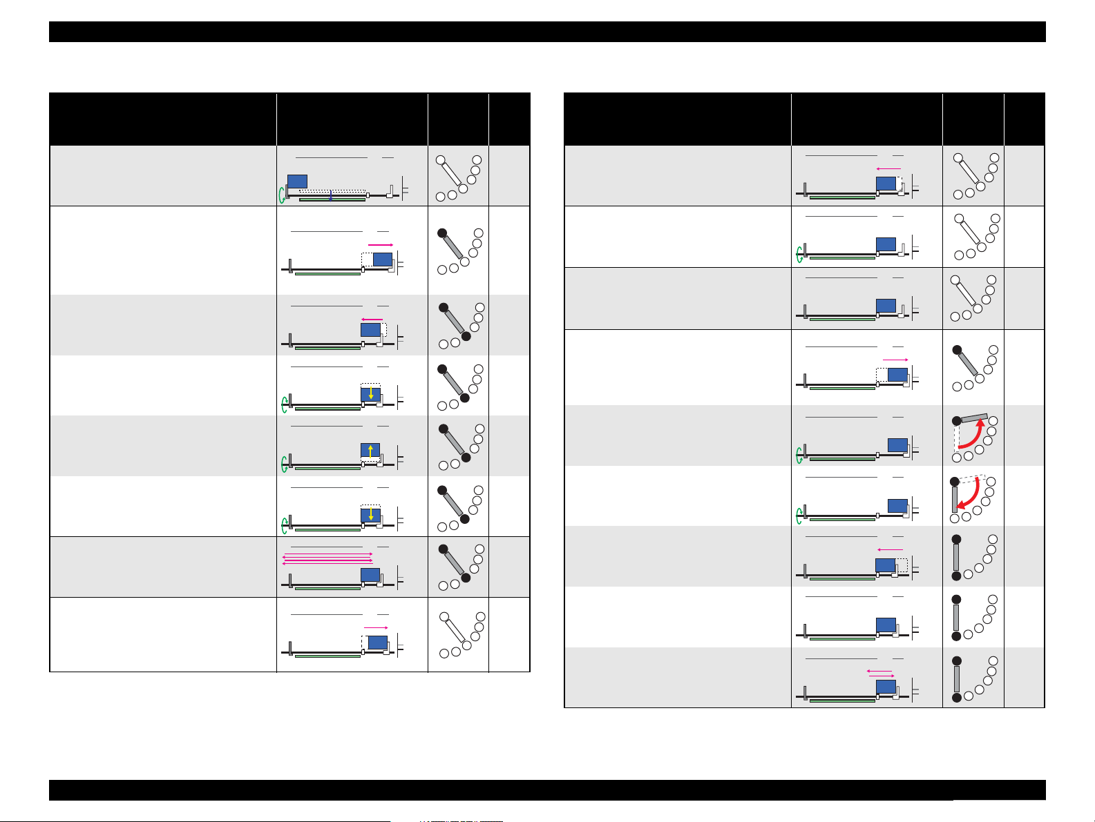
Epson Artisan 810/Epson Stylus Photo PX810FW/TX810FW/Epson Artisan 710/Epson Stylus Photo PX710W/TX710W Revision A
PG++
PG-
0 HP80
4
PG++
PG-
0 HP80
1
PG++
PG-
0 HP80
1
4
PG++
PG-
0 HP80
1
4
PG++
PG-
0 HP80
4
PG++
PG-
0 HP80
1
4
PG++
PG-
0 HP80
4
PG++
PG-
0 HP80
6
PG++
PG-
0 HP80
6
PG++
PG-
0 HP80
6
PG++
PG-
0 HP80
6
PG++
PG-
0 HP80
1
PG++
PG-
0 HP80
PG++
PG-
0 HP80
PG++
PG-
0 HP80
6
PG++
PG-
0 HP80
6
PG++
PG-
0 HP80
6
Table 2-5. Detailed operations in All Reset Sequence
Operation Printer Operation Status
5-6. The PF Motor rotates counterclockwise
until reaching the limit to move the EJ
Frame Assy up to the lowest position
(default).
6. APG Initialization
6-1. The carriage moves to the 0-digit side to
release the Switch Lever from the
Intermediate Position and shift the
Transmission Arm to the APG Drive
Position.
6-2. The carriage returns to the home
position.
6-3. The PF Motor rotates counterclockwise
until reaching the limit to set the PG
position to PG-.
6-4. The PF Motor rotates clockwise until
reaching the limit to set the PG position
to PG++.
6-5. The PF Motor rotates counterclockwise
until reaching the limit to set the PG
position to PG-; which is its default
position.
7. Low temperature operation sequence *
7-1. The carriage moves back and forth
between the 0-digit side and the 80-digit
side for two times.
8. Set to the Intermediate Position
8-1. To avoid applying excess load at the PF
Measurement next, the carriage moves
to the 0-digit side and sets the Switch
Lever to the Intermediate Position.
Table 2-5. Detailed operations in All Reset Sequence
PF Drive
Shift
Status
1
Decompression
Pump
---
---
---
---
---
---
---
---
Operation Printer Operation Status
8-2. The carriage returns to the home
position.
9. PF Motor Measurement
9-1. The PF Motor rotates clockwise until the
PF Roller turns three times to perform a
load measurement.
10.Detecting ink cartridges and
initializing the ink system
10-1. After checking the ink end sensor,
detects the ink remaining.*
2
11.Printhead's clogged nozzle check by
AID
11-1. To shift the Transmission Arm to the
Ink System Drive Position, the carriage
moves to the Right Frame.
11-2.To detect the origin position of the
Transmission Arm, the PF Motor rotates
clockwise to confirm the Transmission
Arm touches the frame.
11-3.The PF Motor rotates counterclockwise
by the specified steps to shift the
Transmission Arm to the Ink System
Drive Position.
11-4.The carriage returns to the home
position.
11-5.After the necessary flushing is
completed, the Decompression Pump is
driven for about one second to suck ink
from the ink cartridges.
11-6.After checking the temperature of the
head thermistor, the carriage moves to
the position for empty suctions, then it
turns back to the home position.
PF Drive
Shift
Status
Decom-
pression
Pump
---
---
---
---
---
---
---
Decompressing
---
(Continued to the next page...)
OPERATING PRINCIPLES Power-On Sequence 53
Confidential
Page 53

Epson Artisan 810/Epson Stylus Photo PX810FW/TX810FW/Epson Artisan 710/Epson Stylus Photo PX710W/TX710W Revision A
PG++
PG-
0 HP80
6
PG++
PG-
0 HP80
6
Table 2-5. Detailed operations in All Reset Sequence
PF Drive
Operation Printer Operation Status
11-7. After checking the Printhead for
clogged nozzles using the AID
function*3, detects the ink remaining.
12.CR lock setting
12-1. The PF Motor rotates clockwise to set
the CR lock.
Note *1 : Executed when the detected temperature is under 5 oC (41 oF) by the thermistor on
the Printhead.
*2 : A periodic empty suction may be performed depending on the status.
*3 : When the auto head cleaning setting is On
If clogged nozzles are detected, the clogged nozzle check using the AID function is
performed before starting printing once again. If clogged nozzles are detected again
after this check, the auto head cleaning is executed.
When the auto head cleaning setting is Off
The auto head cleaning is not carried out whether or not clogged nozzles are
detected.
Shift
Status
Decompression
Pump
---
---
2.3 Printer Initialization
There are four kinds of initialization method, and the following explains each
initialization
1. Hardware initialization
This printer is initialized when turning the printer power on, or printer recognized
the cold-reset command (remote RS command).
When printer is initialized, the following actions are performed.
(a) Initializes printer mechanism
(b) Clears input data buffer
(c) Clears print buffer
(d) Sets default values
2. Operator initialization
Initialization when resetting the USB software, and the following are performed
(a) Clears input data buffer
(b) Clears print buffer
(c) Sets default values
3. Software initialization
The ESC@ command also initialize the printer.
When printer is initialized, the following actions are performed.
(a) Clears print buffer
(b) Sets default values
4. IEEE 1284.4 “rs” command initialization
The printer recognized the IEEE 1284.4 “rs” command.
When printer is initialized, the following action is performed.
Initialization when an error occurs.
(a) Initializes printer mechanism
(b) Clears input data buffer
(c) Clears print buffer
(d) Sets default values
Initialization in normal operation
(a) Clears input data buffer
(b) Clears print buffer
(c) Sets default values
OPERATING PRINCIPLES Printer Initialization 54
Confidential
Page 54

TROUBLESHOOTING
CHAPTER
3
Confidential
Page 55

Epson Artisan 810/Epson Stylus Photo PX810FW/TX810FW/Epson Artisan 710/Epson Stylus Photo PX710W/TX710W Revision A
3.1 Overview
This chapter describes how to solve problems.
W A R N I N G
C H E C K
P O I N T
Be careful to avoid electric shocks when checking the electrical
circuit boards while the power is turned on.
Touching an FET, transistor or heat sink with one hand while
touching a metal part of the mechanism with the other hand
could result in an electric shock, so carefully avoid this.
After initial filling of ink has been repeated several times,
immediate moving or tilting of the printer could result in
leaking of ink that has not been completely absorbed by the
Waste Ink Pad. When initial filling of ink has been repeated
several times, check the ink remaining in the tip of the Waste
Ink Tube and the waste ink not absorbed by the Waste Ink Pad
before moving the printer.
Disassembly and reassembly of parts is often required when
identifying the causes of problems. The parts should be
disassembled and re-assembled correctly while referring to
“DISASSEMBLY/ASSEMBLY” (p.95) so that the operation
and status of each check item can be correctly verified.
Some individual part and units may require adjustment once
they are removed or replaced. If removing or replacing parts
which have specific instructions for adjustment included in
“DISASSEMBLY/ASSEMBLY” (p.95), be sure to make these
adjustments after repairing the problem location.
3.1.2 Preliminary Checks
Before starting troubleshooting, be sure to verify that the following conditions
are all met:
The power supply voltage must be within the specification limits. (Measure the
voltage at the wall socket.)
The power code must be free from damage, short circuit or breakage, or miswiring
in the power code.
The printer must be grounded properly.
The printer should not be located in a place where it can be exposed to too high or
low temperature, too high or low humidity, or abrupt temperature change.
The printer should not be located near waterworks, near humidifiers, near heaters
or near flames, in a dusty atmosphere or in a place where the printer can be
exposed to blast from an air conditioner.
The printer should not be located in a place where volatile or inflammable gases
are produced.
The printer should not be located in a place where it can be exposed to direct rays
of the sun.
The printer must be placed on a strong and steady level table (without an
inclination larger than five degrees).
Any vibrating equipment must not be placed on or under the printer.
The paper used must conform to the specification.
There is no error in handling of the printer.
3.1.1 Specified Tools
This printer does not require any specified tools for troubleshooting.
Check the inside of the printer, and remove foreign matters if any, such as paper
clips, staples, bits of paper, paper dust or toner.
Clean the inside of the printer and the rubber rolls.
TROUBLESHOOTING Overview 56
Confidential
Page 56

Epson Artisan 810/Epson Stylus Photo PX810FW/TX810FW/Epson Artisan 710/Epson Stylus Photo PX710W/TX710W Revision A
3.2 Troubleshooting
C H E C K
P O I N T
For the position of each sensor/motor, see 2.1.3 " Motors & Sensors "
(p.45).
3.2.1 Motor and Sensor Troubleshooting
Motors
The resistance values for the CR motor and the PF motor are given below, however, the values cannot be used to check the motors status since they are DC motor and the resistance
between the electric poles varies. Visually check the motors for abnormal operation and if it is hard to judge, replace the motor.
Table 3-1. Motor resistance and check point
Motor Motor Type Check point Resistance
CR motor
PF motor Main Board: Pin1-Pin2 of CN22 19.7 Ω ± 10%
Decompression motor Main Board: Pin1-Pin2 of CN24 88 Ω ± 15%
Scanner motor Main Board: Pin1-Pin2 of CN49 (TBD) Ω
ADF motor 4-phase, 96-pole PM stepping motor Main Board: Pin1-Pin3, Pin2-Pin4 of CN25 28.0 Ω ± 7%/phase (25 oC)
Sensors
Sensor name Check point Signal level Switch mode
PE Sensor
(Transmissive photo interrupter)
Scanner Cover Open Sensor (1)
(GMR sensor)
Scanner Cover Open Sensor (2)
(GMR sensor)
PW Sensor
(Reflective photo interrupter)
Duplex Unit Sensor
(Mechanical contact points)
Photo Tray Sensor
(Mechanical contact points)
DC motor with brush
Main Board: Pin1-Pin2 of CN9
Main Board: Pin1-Pin2 of CN10
Main Board: Pin2-Pin4 of CN10
Main Board: Pin2-Pin3 of CN6
Main Board: Pin1-Pin2 of CN13
Main Board: Pin1-Pin2 of CN12
Table 3-2. Sensor check point
Less than 0.4 V No paper
More than 2.4 V Detects the paper
Less than 0.4 V Scanner Closed
More than 2.4 V Scanner Open
Less than 0.4 V Carriage: at the origin position (where the carriage touches the right frame)
More than 2.4 V Carriage: at HP
0 V (for reference only) Detects the paper
3.3 V (for reference only) No paper
Less than 0.4 V Duplex Unit attached
More than 2.4 V No Duplex Unit
Less than 0.4 V Photo Tray in use
More than 2.4 V Photo Tray retracted
Main Board: Pin1-Pin2 of CN21 19.7 Ω ± 10%
Power Supply Voltage
Table 3-3. Power supply voltage and check point
Board Check point Output voltage
Power Supply Board
Pin1-Pin4 of CN2 42.0 V ± 5%
Pin2-Pin5 of CN2 42.0 V ± 5%
TROUBLESHOOTING Troubleshooting 57
Confidential
Page 57

Epson Artisan 810/Epson Stylus Photo PX810FW/TX810FW/Epson Artisan 710/Epson Stylus Photo PX710W/TX710W Revision A
3.3 Troubleshooting by Error Message
This sections explains about errors during each sequence/operation (power-on, paper feeding, ink sucking or the like), error/warning messages displayed on the LCD and their error
causes.
3.3.1 Error Message List
The following table lists the error messages displayed on the LCD with their possible cause and reference page for troubleshooting. If the error or warning indication is not found in
the table below, refer to the Users Guide and the displayed instructions, and carry out appropriate troubleshooting.
Table 3-4. Error Indications and Fault Occurrence Causes
Error Name LCD Message
*
Error Cause Reference
Fatal error
(printer mechanism)
Fatal error
(paper jam)
Fatal error
(Scanner)
Maintenance request
(waste ink over flow)
Paper jam error
Double feed error Multi-page feed error. Remove and reload the paper, then press [Start button]. Double feeding occurred during double sided printing.
Paper out error
Ink end error You need to replace the following ink cartridge(s). Ink is out in some I/C.
No ink cartridge error Install the following ink cartridge(s). I/C was not set.
Incorrect ink cartridge Cannot recognize the following ink cartridge(s). Install them correctly. Incorrect I/C was set.
Head cleaning
(Ink low error)
Scanner open error
A printer error has occurred. Turn power off and then on again. For details, see
your documentation or Epson.com.
Paper jam. Open the scanner unit, remove jammed paper in the product, then
power off and on again. For details, see your documentation or Epson.com
A scanner error has occurred. Turn power off and turn on again. If the error is
not fixed, visit Epson.com for technical support
The printer's ink pads are at the end of their service life. Please contact Epson
support.
Paper jam. Open the scanner unit. Remove the jammed paper, close the scanner
unit, then press [Start button].
Paper out or paper jam in the main tray, or the paper size is incorrect. Check the
paper size settings or clear the jam and press [Start button].
Replace the following ink cartridge(s) before cleaning the print head. Head cleaning was attempted in the Ink low status.
The scanner unit is open.
When replacing ink cartridge(s), close the scanner unit after replacing the
cartridge(s).
Mechanical trouble occurred.
The waste ink counter exceeds to capacity. Table 3-7. (p66)
Paper remained in the paper path after paper ejection.
Failure to load paper to print.
Scanner Unit was opened during printing. Table 3-11. (p69)
Table 3-5. (p60)
Table 3-6. (p66)
Table 3-8. (p67)
Table 3-9. (p68)
Table 3-10. (p69)
TROUBLESHOOTING Troubleshooting by Error Message 58
Confidential
Page 58

Epson Artisan 810/Epson Stylus Photo PX810FW/TX810FW/Epson Artisan 710/Epson Stylus Photo PX710W/TX710W Revision A
Table 3-4. Error Indications and Fault Occurrence Causes
Error Name LCD Message
*
Error Cause Reference
Photo tray error
Incorrect CD size error Without a computer, you can only print on standard size (12cm) CD/DVDs. One of the CD/DVD media other than 12 cm was set. Table 3-13. (p70)
Remaining maintenance media
error
ADF paper jam error
Duplex Unit open error The Auto Duplexer has been removed. Reattach it. Duplex Unit cannot be detected.
Duplex Unit paper jam error
Network related error --- A network related error occurred.
FAX error (Epson Artisan 810/
Epson Stylus Photo PX810FW/
TX810FW/Epson Artisan 710/
Epson Stylus Photo PX710W/
TX710W)
The paper cassette is not set correctly. Check for any objects in the cassette or
blocking the cassette path and insert it correctly. Then press [Start button].
Remove the CD/DVD from the tray. Automatic maintenance needs to be
performed. Press [CD tray button].
Paper jam in the automatic document feeder.
Remove the jammed paper.
Paper jam. Remove the Auto Duplexer. Remove the jammed paper, then
reattach the unit
A fax error occurred. A FAX error occurred.
• Photo Tray cannot operate.
• Cassette was not set.
A media on the CD/DVD tray was detected during
cleaning or the like.
Paper jam occurred in the ADF Unit. Table 3-15. (p71)
Paper jam occurred in the Duplex Unit.
Table 3-12. (p70)
Table 3-14. (p71)
" 3.5 Troubleshooting
Duplex Unit
Problems " (p.80)
" 3.6 Network
Troubleshooting "
(p.81)
" 3.7 FAX
Troubleshooting
(Epson Artisan 810/
Epson Stylus Photo
PX810FW/
TX810FW only) "
(p.83)
Note * : The messages are for Epson Artisan 810/Epson Stylus Photo PX810FW/TX810FW. As for Epson Artisan 710/Epson Stylus Photo PX710W/TX710W, some messages are different but have
the same meaning.
TROUBLESHOOTING Troubleshooting by Error Message 59
Confidential
Page 59

Epson Artisan 810/Epson Stylus Photo PX810FW/TX810FW/Epson Artisan 710/Epson Stylus Photo PX710W/TX710W Revision A
3.3.2 Troubleshooting by Error Message
The following tables provide troubleshooting procedures. Confirm the error message displayed on the LCD, and verify it in the following list for the corresponding troubleshooting
remedy. If some parts need to be replaced or repaired, make sure to follow the procedure given in Chapter 4 “DISASSEMBLY/ASSEMBLY”.
Table 3-5. Check point for Fatal error according to each phenomenon (Printer Mechanism)
Occurrence
Timing
Symptoms
The CR Motor does not
operate at all.
Failed Part /
Part Name
CR Motor
Check Point Remedy Reference
1. Is the CR Motor cable properly connected to CN21
connector on the Main Board?
2. Is the CR Motor cable damaged? 2. Replace the Printer Mechanism
3. Does the CR Motor operate normally? 3. Replace the Printer Mechanism
1. Connect the CR Motor cable
correctly to CN21 connector on
the Main Board.
with a new one.
with a new one.
4.2.4.2 " Main Board /
Grounding Plate M/B "
(p.121)
4.2.1 " Parts transferred
from the old printer when
replacing the Printer
Mechanism " (p.103)
At power-on
The Carriage Unit hits
against the right side of the
Main Frame.
The Carriage Unit hits
against the Upper Paper
Guide.
CR Encoder
CR Scale
Upper Paper Guide
1. Is the CR Encoder damaged? 1. Replace the Printer Mechanism
with a new one.
2. Is the FFC correctly connected to the connector on the
CR Encoder?
1. Is the CR Scale properly centered in the slit of the CR
Encoder?
2. Is the CR Scale surface clean? 2. Wipe any dirt off the surface of
3. Is the CR Scale damaged? 3. Replace the CR Scale with a new
4. Is the CR Scale correctly installed? 4. Install the CR Scale and the
1. Is the Upper
Paper Guide
correctly installed? 1. Replace the Printer Mechanism
2. Connect the Head FFC correctly.
1. Install the CR Scale correctly.
the CR Scale. When the
contamination is severe, replace
the CR Scale with a new one.
one.
torsion spring correctly.
with a new one.
4.2.1 " Parts transferred
from the old printer when
replacing the Printer
Mechanism " (p.103)
4.2.5.2 " CR Scale " (p.133)
4.2.1 " Parts transferred
from the old printer when
replacing the Printer
Mechanism " (p.103)
TROUBLESHOOTING Troubleshooting by Error Message 60
Confidential
Page 60

Epson Artisan 810/Epson Stylus Photo PX810FW/TX810FW/Epson Artisan 710/Epson Stylus Photo PX710W/TX710W Revision A
Table 3-5. Check point for Fatal error according to each phenomenon (Printer Mechanism)
Occurrence
Timing
Symptoms
Failed Part /
Part Name
Carriage Shaft
Check Point Remedy Reference
1. Is the Carriage Shaft free from dirt, and adequately
lubricated?
1. Clean the Carriage Shaft and
lubricate it as specified.
6.1.3 " Lubrication "
(p.232)
At power-on
The Carriage Unit
movement is too slow.
The Carriage Unit makes
abnormal noise during
operation (Slipping of CR
Timing belt)
PF Motor does not operate
at all.
CR Guide Plate
Ink Tube
Head FFC
---
CR Timing Belt,
Timing Driven
Pulley Assy
CR Timing Belt,
Driven Pulley Assy
PF Motor
1. Is the CR Guide Plate free from dirt, and adequately
lubricated?
1. Is the Ink Tube correctly routed? 1. Route the Ink Tube correctly. 4.2.5.6 " Ink Supply IC
1. Is the Head FFC correctly routed? 1. Route the Head FFC correctly. 4.4 " Routing FFC/cables "
1. Is the Carriage path contaminated with foreign material
(slip of paper)?
1. Is the CR Timing Belt correctly installed to Timing
Driven Pulley Assy?
2. Is the CR Timing Belt correctly installed to the Pinion
Gear of the CR Motor?
1. Is tension of the CR Timing Belt appropriate? 1. If the tension of the CR Timing
1. Is the PF Motor cable properly connected to CN22
connector on the Main Board?
2. Is the PF Motor cable damaged? 2. Replace the Printer Mechanism
3. Does the PF Motor operate normally? 3. Replace the Printer Mechanism
1. Clean the CR Guide Plate and
lubricate it as specified.
1. Remove any foreign material
from Carriage path.
1. Replace the Printer Mechanism
with a new one.
2. Replace the Printer Mechanism
with a new one.
Belt is still not appropriate,
replace the Printer Mechanism.
1. Connect the PF Motor cable
correctly to CN22 connector on
the Main Board.
with a new one.
with a new one.
6.1.3 " Lubrication "
(p.232)
Holder Assy " (p.137)
(p.185)
---
4.2.1 " Parts transferred
from the old printer when
replacing the Printer
Mechanism " (p.103)
• 4.2.1 " Parts transferred
from the old printer when
replacing the Printer
Mechanism " (p.103)
• 5.3.2 " CR Timing Belt
Tension Inspection "
(p.223)
4.2.4.2 " Main Board /
Grounding Plate M/B "
(p.121)
4.2.1 " Parts transferred
from the old printer when
replacing the Printer
Mechanism " (p.103)
CR lock is not released and
a fatal error occurs
Main Board 1. Check if the firmware is the latest. 1. Update the firmware to the latest. ---
Ink System
1. Check if the CR lock lever moves smoothly. 1. Replace the Ink System with a
new one.
4.2.5.7 " Ink System "
(p.140)
TROUBLESHOOTING Troubleshooting by Error Message 61
Confidential
Page 61

Epson Artisan 810/Epson Stylus Photo PX810FW/TX810FW/Epson Artisan 710/Epson Stylus Photo PX710W/TX710W Revision A
Table 3-5. Check point for Fatal error according to each phenomenon (Printer Mechanism)
Occurrence
Timing
At power-on
Symptoms
Cap does not move up or
down and the Carriage Unit
cannot move out of the
home position.
The PF Roller makes a
quick turn and then the
error occurs.
The PF Motor makes
abnormal noise during
operation (Slipping of PF
Timing Belt)
The Carriage Unit hits the
Switch Lever when it
moves to the 0 digit side.
Failed Part /
Part Name
Ink System
PF Encoder
PF Scale
PF Timing Belt, PF
Tensioner
Paper Guide Front
Assy
Check Point Remedy Reference
1. Check if the Ink System is installed evenly
(horizontally).
2. Check if the cap section of the Ink System works
smoothly.
1. Is the PF Encoder FFC correctly connected to CN8
connector on the Main Board and the connector on the
PF Encoder?
2. Is the PF Encoder correctly installed? 2. Install the PF Encoder correctly. 4.2.5.3 " PF Encoder "
3. Is the PF Encoder damaged? 3. Replace the PF Encoder with a
1. Is the PF Scale surface clean? 1. Wipe any dirt off the surface of
2. Is the PF Scale damaged? 2. Replace the Printer Mechanism
1. Is the PF Timing Belt damaged? 1. Replace the Printer Mechanism
2. Is the PF Timing Belt correctly installed to the PF
Tensioner?
3. Is the PF Timing Belt correctly installed to the PF
Motor?
4. Is tension of the PF Timing Belt appropriate? 4. If the tension of the PF Timing
1. Does the Switch Lever correctly move? 1. Replace the Printer Mechanism
1. Re-install the Ink System with
the cap section horizontally.
2. Replace the Ink System with a
new one.
1. Connect the PF Encoder FFC
correctly to CN8 connector on
the Main Board.
new one.
the PF Scale. When the
contamination is severe, replace
the Printer Mechanism with a
new one.
with a new one.
with a new one.
2. Install the PF Timing Belt to the
PF Tensioner correctly.
3. Install the PF Timing Belt
correctly.
Belt is still not appropriate,
replace the Printer Mechanism.
with a new one.
4.2.5.7 " Ink System "
(p.140)
4.2.4.2 " Main Board /
Grounding Plate M/B "
(p.121)
(p.134)
4.2.5.3 " PF Encoder "
(p.134)
4.2.1 " Parts transferred
from the old printer when
replacing the Printer
Mechanism " (p.103)
• 4.2.1 " Parts transferred
from the old printer when
replacing the Printer
Mechanism " (p.103)
• 5.3.3 " PF Timing Belt
Tension Inspection "
(p.224)
4.2.1 " Parts transferred
from the old printer when
replacing the Printer
Mechanism " (p.103)
TROUBLESHOOTING Troubleshooting by Error Message 62
Confidential
Page 62

Epson Artisan 810/Epson Stylus Photo PX810FW/TX810FW/Epson Artisan 710/Epson Stylus Photo PX710W/TX710W Revision A
Table 3-5. Check point for Fatal error according to each phenomenon (Printer Mechanism)
Occurrence
Timing
At power-on
• At power-on
• During CDR
printing
Symptoms
The error occurs at poweron before carrying out the
initial ink charge.
The error occurs after
cleaning.
EJ Frame Assy does not
move.
Failed Part /
Part Name
PW Sensor
Ink System
SUB Board (AID)
EJ Frame Assy
Fixing Plate R
Check Point Remedy Reference
1. Is the CR Encoder FFC correctly connected to CN6
connector on the Main Board?
2. Is the CR Encoder damaged? 2. Replace the Printer Mechanism
3. Is the PW Sensor damaged? 3. Replace the Printer Mechanism
1. Is the AID Cable correctly connected to the connector on
the SUB Board?
2. Is the AID Cable damaged? 2. Replace the Ink System with a
3. Is the AID Cable correctly routed? 3. Route the AID Cable correctly.
1. Is the FFC connecting the SUB Board to CN7 on the
Main Board connected correctly?
2. Is the FFC connecting the SUB Board to CN7 on the
Main Board damaged?
3. Is the SUB Board damaged? 3. Replace the Card Slot Assy with
1. Is the EJ Frame Assy correctly installed? 1. Replace the Printer Mechanism
2. Is the path of the EJ Frame Assy contaminated with
foreign material (slip of paper)?
3. Is the EJ Frame Assy adequately lubricated? 3. Lubricate the EJ Frame Assy as
1. Check if the Fixing Plate R works correctly in
conjunction with the PG cam.
1. Connect the CR Encoder FFC
correctly to CN6 on the Main
Board.
with a new one.
with a new one.
1. Connect the AID Cable correctly
to connector on the SUB Board.
new one.
1. Connect the FFC correctly. 4.2.4.2 " Main Board /
2. Replace the Printer Mechanism
with a new one.
a new one.
with a new one.
2. Remove any foreign material for
EJ Frame path.
specified.
1. Properly lubricate the slider
section to the frame.
4.2.4.2 " Main Board /
Grounding Plate M/B "
(p.121)
4.2.1 " Parts transferred
from the old printer when
replacing the Printer
Mechanism " (p.103)
4.2.5.7 " Ink System "
(p.140)
Grounding Plate M/B "
(p.121)
• 4.2.4.5 " Card Slot Assy "
(p.126)
• 4.3.2.3 " Card Slot Assy
(Artisan 710/PX710W/
TX710W) " (p.182)
• 4.2.1 " Parts transferred
from the old printer when
replacing the Printer
Mechanism " (p.103)
• 6.1.3 " Lubrication "
(p.232)
6.1.3 " Lubrication "
(p.232)
Front Paper Guide
Assy
1. Check the lubrication status of the EJ release trigger. 1. Wipe off the grease once, and
lubricate the part with the
specified amount of grease.
6.1.3 " Lubrication "
(p.232)
TROUBLESHOOTING Troubleshooting by Error Message 63
Confidential
Page 63

Epson Artisan 810/Epson Stylus Photo PX810FW/TX810FW/Epson Artisan 710/Epson Stylus Photo PX710W/TX710W Revision A
Table 3-5. Check point for Fatal error according to each phenomenon (Printer Mechanism)
Occurrence
Timing
• At power-on
• During CDR
printing
•Before
printing
• Cleaning
Symptoms
EJ Frame Assy does not
move.
CDR Tray is not retracted.
The error occurs before
printing or cleaning.
Failed Part /
Part Name
1. Check if there is dirt or foreign material attached on the
PF Scale
CDR Tray Assy
Spur Gear 1. Is the Spur Gear correctly installed? 1. Install the Spur Gear correctly.
CDR Guide Base
Assy
Print Head
Head FFC
PF Scale.
1. Are the dowels of the arms of the CDR Tray Assy
correctly attached with the grooves of the CDR Guide/
Lower Paper Guide Assy?
Tray Assy warps.
1. Check the lubrication status of the CDR Guide Base
Assy.
1. Is the Print Head damaged? 1. Replace the Print Head with a
1. Is the Head FFC correctly connected to CN1, CN2, CN3
and CN4 on the Main Board?
2. Is the Head FC damaged? 2. Replace the Head
Check Point Remedy Reference
1. Clean the PF Scale. If not
improved much, replace the
Printer Mechanism with a new
one.
1. Install the CDR Tray Assy
correctly.
2. Replace the CDR Tray Assy with
a new one.
1. Wipe off the grease once, and
lubricate the part with the
specified amount of grease.
new one.
1. Replace the Head
new one.
new one.
FFC
FFC
with a
with a
4.2.1 " Parts transferred
from the old printer when
replacing the Printer
Mechanism " (p.103)
4.2.5.9 " CDR Tray Assy "
(p.145)2. Check if the CDR Tray Assy or the arms of the CDR
6.1.3 " Lubrication "
(p.232)
4.2.5.1 " Printhead " (p.127)
TROUBLESHOOTING Troubleshooting by Error Message 64
Confidential
Page 64

Epson Artisan 810/Epson Stylus Photo PX810FW/TX810FW/Epson Artisan 710/Epson Stylus Photo PX710W/TX710W Revision A
CR Stopper
Table 3-5. Check point for Fatal error according to each phenomenon (Printer Mechanism)
Occurrence
Timing
Symptoms
Failed Part /
Part Name
Main Board
Check Point Remedy Reference
1. Is the Main Board damaged? 1. Replace the Main Board with a
new one.
1. Check if the CR Stopper is blocking the printer
operation because it has fallen into the mechanism.
1. Remove the CR Stopper.
4.2.4.2 " Main Board /
Grounding Plate M/B "
(p.121)
--- Others
---
• 4.1.3 " Work Completion
Check " (p.97)
• 4.2.3.5 " Upper Housing
" (p.110)
TROUBLESHOOTING Troubleshooting by Error Message 65
Confidential
Page 65

Epson Artisan 810/Epson Stylus Photo PX810FW/TX810FW/Epson Artisan 710/Epson Stylus Photo PX710W/TX710W Revision A
Table 3-6. Check point for Fatal error according to each phenomenon (Scanner)
Occurrence
Timing
Symptoms
Failed Part /
Part Name
Scanner Motor
Check Point Remedy Reference
1. Is the Scanner Motor cable properly connected to CN49
connector on the Main Board?
2. Is the coil resistance of the Scanner Motor TBD Ω
Check with the tester. (See Table 3-1)
3. Is the Scanner Motor Cable damaged? 3. Replace the Scanner Unit with a
1. Connect the Scanner Motor cable
correctly to CN49 connector on
the Main Board.
2. Replace the Scanner Unit with a
new one.
new one.
4.2.6.2 " Scanner Motor
Unit " (p.151)
At power-on
Occurrence
Timing
Any time
The Scanner Unit does not
initialize at power-on.
Symptoms
The Maintenance error is
displayed.
Scanner CR
Encoder
Scanner Carriage
FFC
Scanner Carriage
Unit
1. Is the Scanner CR Encoder FFC properly connected to
CN49 connector on the Main Board?
2. Is the Scanner CR Encoder FFC damaged? 2. Replace the Scanner CR Encoder
1. Is the Scanner Carriage FFC properly connected to
CN41 connector on the Main Board?
2. Is the Scanner Carriage FFC damaged? 2. Replace the Scanner Carriage
1. Is the Scanner Carriage Unit damaged? 1. Replace the Scanner Carriage
1. Connect the Scanner CR Encoder
FFC correctly to CN49 connector
on the Main Board.
FFC with a new one.
1. Connect the Scanner Carriage
FFC correctly to CN41 connector
on the Main Board.
FFC with a new one.
FFC with a new one.
Table 3-7. Check point for the Maintenance request according to each phenomenon
Failed Part /
Part Name
Waste Ink Tray
Assy/
Lower Paper Guide
Waste Ink Pad
Assy
Check Point Remedy Reference
Replace the Waste Ink Tray Assy
---
or/and the Lower Paper Guide
Waste Ink Pad Assy and reset the
waste ink counter.
4.2.6.4 " Scanner CR
Encoder Board " (p.155)
4.2.6.3 " Scanner Carriage
Unit " (p.152)
• 4.2.5.11 " Waste Ink Tray
Assy " (p.147)
• 4.2.5.12 " Lower Paper
Guide Waste Ink Pad
Assy " (p.149)
TROUBLESHOOTING Troubleshooting by Error Message 66
Confidential
Page 66

Epson Artisan 810/Epson Stylus Photo PX810FW/TX810FW/Epson Artisan 710/Epson Stylus Photo PX710W/TX710W Revision A
Table 3-8. Check point for Paper jam error according to each phenomenon
Occurrence
Timing
Symptoms
Failed Part /
Part Name
Rear Paper Guide
Assy
Check Point Remedy Reference
1. Is the Rear Paper Guide Assy correctly installed? 1. Replace the Printer Mechanism
with a new one.
4.2.1 " Parts transferred
from the old printer when
replacing the Printer
Mechanism " (p.103)
Any time
Paper feeding operation is
performed normally, but the
paper is not fed inside the
printer.
Multiple sheets of paper are
always fed at one time.
Lower ASF Paper
Guide Assy
LD Roller
Paper Guide Top
Assy
Upper Paper Guide
L/R Assy
Cassette Unit
Sub Transmission
Cam Holder
1. Is the Lower ASF Paper Guide Assy correctly Assy
installed?
2. Is the intermediate roller shaft correctly installed? 2. Install the intermediate roller
3. Is the surface of the intermediate roller contaminated
with micro pearl paper dust or greasy dirt?
4. Does the flap of the Lower ASF Paper Guide Assy come
off?
1. Is the LD Roller shaft correctly installed? 1. Replace the Printer Mechanism
2. Is the surface of the LD Roller contaminated with micro
pearl paper dust or greasy dirt?
1. Is the Paper Guide Top Assy correctly installed? 1. Install the Paper Guide Top Assy
1. Is the Upper Paper Guide L/R Assy correctly installed? 1. Replace the Printer Mechanism
1. Is the Cassette Cork damaged or worn? 1. Replace the Cassette Cork with a
2. Is the rear end of the Cassette Assy damaged? 2. Replace the Cassette Unit with a
1. Is the Sub Transmission Cam Holder correctly installed? 1. Replace the Printer Mechanism
1. Install the Lower ASF Paper
Guide Assy correctly.
shaft correctly.
3. Clean the intermediate roller.
4. Install the flap of the Lower ASF
Paper Guide Assy correctly.
with a new one.
2. Clean the LD Roller.
correctly.
with a new one.
new one.
new one.
with a new one.
4.2.5.8 " Lower ASF Paper
Guide Assy " (p.142)
4.2.1 " Parts transferred
from the old printer when
replacing the Printer
Mechanism " (p.103)
4.2.3.13 " Paper Guide Top
Assy " (p.118)
4.2.1 " Parts transferred
from the old printer when
replacing the Printer
Mechanism " (p.103)
4.2.3.12 " Cassette Unit/EJ
Cover Assy " (p.117)
4.2.1 " Parts transferred
from the old printer when
replacing the Printer
Mechanism " (p.103)
TROUBLESHOOTING Troubleshooting by Error Message 67
Confidential
Page 67

Epson Artisan 810/Epson Stylus Photo PX810FW/TX810FW/Epson Artisan 710/Epson Stylus Photo PX710W/TX710W Revision A
Table 3-8. Check point for Paper jam error according to each phenomenon
Occurrence
Timing
Symptoms
Failed Part /
Part Name
Check Point Remedy Reference
1. Is the Star Wheel Roller Holder disengaged? 1. Replace the Printer Mechanism
with a new one.
Any time
Occurrence
Timing
Any time
Leading edge of paper does
not go through between the
EJ Roller and the Star
Wheels.
Feeding is unstable, and
paper jam error occurs.
Symptoms
The LD Roller rotates
normally, but paper is not
fed.
The intermediate roller
rotates normally, but paper
is not fed.
The Pick-up Roller rotates
normally, but the paper is
not fed into the printer.
2. Is the EJ Frame Assy correctly installed? 2. Replace the Printer Mechanism
EJ Frame Assy
Upper Paper Guide
L/R Assy
3. Is there any abnormality on the drive section of the EJ
Frame Assy?
4. Is the EJ Frame Assy deformed protruding downward? 4. Replace the Printer Mechanism
1. Check if the torsion springs; two kinds securing the
Upper Paper Guide L/R Assy, are correctly installed.
2. Check if the attachment direction of the roller of the
Upper Paper Guide R Assy is correct.
with a new one.
3. Replace the Printer Mechanism
with a new one.
with a new one.
1. Replace the Printer Mechanism
with a new one.
2. Replace the Printer Mechanism
with a new one.
Table 3-9. Check point for the Paper Out Error according to each phenomenon
Failed Part /
Part Name
LD Roller
Intermediate roller
Pick-up Assy
1. Is the surface of the LD Roller contaminated with micro
pearl paper dust or greasy dirt?
1. Is the surface of the intermediate roller contaminated
with micro pearl paper dust or greasy dirt?
1. Is the surface of the Pick-up Rollers contaminated with
micro pearl paper dust or greasy dirt?
Check Point Remedy Reference
1. Clean the LD Roller.
1. Clean the intermediate roller.
1. Clean the Pick-up Roller.
4.2.1 " Parts transferred
from the old printer when
replacing the Printer
Mechanism " (p.103)
4.2.1 " Parts transferred
from the old printer when
replacing the Printer
Mechanism " (p.103)
6.1.3 " Lubrication "
(p.232)
4.2.5.8 " Lower ASF Paper
Guide Assy " (p.142)
4.2.5.10 " Pick-up Roller "
(p.146)
The PF Motor drive force is
not transmitted to the LD
Roller.
The PF Motor drive force is
not transmitted to the Pickup Roller.
Frame Assy L
Frame Assy R
1. Is the clutch of the Frame Assy L damaged? 1. Replace the Printer Mechanism
with a new one.
1. Is the clutch of the Frame Assy R damaged? 1. Replace the Printer Mechanism
with a new one.
4.2.1 " Parts transferred
from the old printer when
replacing the Printer
Mechanism " (p.103)
TROUBLESHOOTING Troubleshooting by Error Message 68
Confidential
Page 68

Epson Artisan 810/Epson Stylus Photo PX810FW/TX810FW/Epson Artisan 710/Epson Stylus Photo PX710W/TX710W Revision A
Table 3-9. Check point for the Paper Out Error according to each phenomenon
Occurrence
Timing
Any time
Occurrence
Timing
Symptoms
Paper is ejected just after
paper is fed.
Table 3-10. Check point for the Ink End Error / No Ink Cartridge Error / Incorrect Ink Cartridge Error according to each phenomenon
Symptoms
Failed Part /
Part Name
PE Sensor
Upper Paper
Guide R
Failed Part /
Part Name
Check Point Remedy Reference
1. Is the connector cable of the PE Sensor properly
connected to CN9 connector on the Main Board?
2. Is the PE Sensor damaged? 2. Replace the Printer Mechanism
1. Is the lumiler protecting the PE Sensor contaminated? 1. Replace the Printer Mechanism
Check Point Remedy Reference
1. Connect the connector cable of
the PE Sensor correctly to CN9
connector on the Main Board.
with a new one.
with a new one.
4.2.1 " Parts transferred
from the old printer when
replacing the Printer
Mechanism " (p.103)
At power-on
Occurrence
Timing
Any time
The error occurs after the
carriage detected the home
position.
Symptoms
The Printer Cover is closed,
but the cover open error is
displayed.
Ink Cartridge
CSIC FFC
CSIC Assy
1. Is the Memory chip on the Ink Cartridge disconnected or
damaged?
1. Is the CSIC FFC properly connected to CN5 connector
on the Main Board and the connector on the CSIC Assy?
1. Is the CSIC terminal damaged? 1. Replace the CSIC Assy with a
2. Is the CR contact module damaged? 2. Replace the CSIC Assy with a
1. Replace the Ink Cartridge with a
new one.
1. Connect the CSIC FFC correctly. 4.2.5.5 " CSIC Assy "
new one.
new one.
Table 3-11. Check point for the Scanner Open Error according to each phenomenon
Failed Part /
Part Name
Scanner Cover
Open Sensor FFC
Scanner Cover
Open Sensor
Carriage Unit
Upper Housing
1. Is the Scanner Cover Open Sensor FFC properly
connected to CN10 connector on the Main Board?
2. Is the Scanner Cover Open Sensor FFC damaged? 2. Replace the Scanner Unit with a
1. Is the Scanner Cover Open Sensor damaged? 1. Replace the Scanner Unit with a
1. Is the Sensor magnet of the Carriage Unit damaged? 1. Replace the Carriage Unit with a
1. Is the Sensor magnet of the Upper Housing damaged? 1. Replace the Upper Housing with
Check Point Remedy Reference
1. Replace the Scanner Unit with a
new one.
new one.
new one.
new one.
a new one.
---
(p.136)
4.2.5.5 " CSIC Assy "
(p.136)
• 4.2.6 " Disassembling
Scanner Unit " (p.150)
• 4.3.3 " Disassembling the
Scanner Unit (Artisan
710/PX710W/TX710W)
" (p.183)
4.2.6.3 " Scanner Carriage
Unit " (p.152)
4.2.3.5 " Upper Housing "
(p.110)
TROUBLESHOOTING Troubleshooting by Error Message 69
Confidential
Page 69

Epson Artisan 810/Epson Stylus Photo PX810FW/TX810FW/Epson Artisan 710/Epson Stylus Photo PX710W/TX710W Revision A
Table 3-12. Check point for the Photo Tray Error according to each phenomenon
Occurrence
Timing
Any time
Occurrence
Timing
Any time
Symptoms
Photo Tray does not move
at all.
Symptoms
The error occurs even the
12cm CD/DVD is not on
the CDR Tray.
Failed Part /
Part Name
Cassette
Photo Tray
Sensor
1. Is the Cassette Unit correctly installed? 1. Install the Cassette Unit
2. Is the Cassette Unit damaged? 2. Replace the Cassette Unit with a
1. Is the Photo Tray Sensor cable properly connected to
CN12 connector on the Main Board?
2. Is the Photo Tray Sensor cable damaged? 2. Replace the Printer Mechanism
3. Is the Photo Tray Sensor damaged? 3. Replace the Printer Mechanism
Check Point Remedy Reference
correctly.
new one.
1. Connect the Photo Tray Sensor
cable correctly to CN12 on the
Main Board.
with a new one
with a new one
Table 3-13. Check point for the CD size Error according to each phenomenon
Failed Part /
Part Name
PW Sensor
CDR Tray
1. Is the PW Sensor free from ink stain or paper dust? 1. Clean the surface of the PW
2. Is the PW Sensor connector cable properly connected to
the connector of the PW Sensor and CR Encoder board?
3. Is the PW Sensor connector cable damaged? 3. Replace the Printer Mechanism
4. Is the PW Sensor damaged? 4. Replace the Printer Mechanism
1. Is the white marking of the CDR Tray free from ink stain
or paper dust?
2. Is the CDR Tray correctly installed? 2. Install the CDR Tray correctly.
Check Point Remedy Reference
Sensor.
2. Connect the PW Sensor
connector cable correctly.
with a new one.
with a new one.
1. Clean the marking of the CDR
Tray.
4.2.3.12 " Cassette Unit/EJ
Cover Assy " (p.117)
4.2.4.2 " Main Board /
Grounding Plate M/B "
(p.121)
4.2.1 " Parts transferred
from the old printer when
replacing the Printer
Mechanism " (p.103)
4.2.1 " Parts transferred
from the old printer when
replacing the Printer
Mechanism " (p.103)
4.2.5.9 " CDR Tray Assy "
(p.145)
TROUBLESHOOTING Troubleshooting by Error Message 70
Confidential
Page 70

Epson Artisan 810/Epson Stylus Photo PX810FW/TX810FW/Epson Artisan 710/Epson Stylus Photo PX710W/TX710W Revision A
Table 3-14. Check point for the Maintenance Media Error according to each phenomenon
Occurrence
Timing
Any time
Occurrence
Timing
Symptoms
The error occurs even the
12cm CD/DVD is on the
CDR Tray.
Symptoms
Failed Part /
Part Name
PW Sensor
CDR Tray
1. Is the PW Sensor free from ink stain or paper dust? 1. Clean the surface of the PW
2. Is the PW Sensor connector cable properly connected to
the connector of the PW Sensor and CR Encoder board?
3. Is the PW Sensor connector Cable damaged? 3. Replace the Printer Mechanism
4. Is the PW Sensor damaged? 4. Replace the Printer Mechanism
1. Is the white marking of the CDR Tray free from ink stain
or paper dust?
2. Is the CDR Tray correctly installed? 2. Install the CDR Tray correctly.
Check Point Remedy Reference
Sensor.
2. Connect the PW Sensor
connector cable correctly.
with a new one.
with a new one.
1. Clean the marking of the CDR
Tray.
Table 3-15. Check point for the ADF Paper Jam Error according to each phenomenon
Failed Part /
Part Name
Check Point Remedy Reference
4.2.1 " Parts transferred
from the old printer when
replacing the Printer
Mechanism " (p.103)
4.2.5.9 " CDR Tray Assy "
(p.145)
At power-on
Any time
The error displays on the
LCD after initialization at
power-on.
The sheet is fed in the ADF
Unit, but reading does not
start, the error is displayed
instead.
ADF Cover Assy
ADF PE Sensor
ADF PE Sensor
Lever
ADF PF Roller
1. Is the ADF Cover Assy closed? 1. Close the ADF Cover Assy.
1. Is the ADF Sensor Cable properly connected to CN51 on
the Main Board?
2. Is the ADF Sensor Cable damaged? 2. Replace the ADF Frame Assy
1. Is the ADF Sensor Lever deformed? 1. Replace the ADF Frame Assy
1. Is the Spur Gear 6.4 correctly installed to the ADF PF
Roller?
1. Connect the ADF sensor cable to
CN51 on the Main Board
correctly.
with a new one.
with a new one.
1. Install the Spur Gear 6.4
correctly.
4.2.7.2 " ADF Cover Assy/
ADF Cover L " (p.158)
4.2.4.2 " Main Board /
Grounding Plate M/B "
(p.121)
4.2.7.8 " ADF Frame Unit "
(p.163)
4.2.7.8 " ADF Frame Unit "
(p.163)
4.2.7.10 " ADF PF Roller "
(p.166)
TROUBLESHOOTING Troubleshooting by Error Message 71
Confidential
Page 71

Epson Artisan 810/Epson Stylus Photo PX810FW/TX810FW/Epson Artisan 710/Epson Stylus Photo PX710W/TX710W Revision A
Planet gear
Base Frame
3.4 Troubleshooting without Error Message
3.4.1 Troubleshooting Printer Mechanism Problems
This section provides information for troubleshooting problems of printing mechanisms.
Abnormal Noises
Table 3-16. Troubleshooting Abnormal Noise Problems
Problem Possible Cause Check point Remedy
Check if the noise comes from the planet gear.
When feeding Matt paper
or the like, abnormal noise
is generated in the rear left
of the printer.
Paper feed error
Problem Possible Cause Check point Remedy
Paper is not fed.
Engagement of the planet gear in the
rear left of the Base Frame is incorrect.
Table 3-17. Troubleshooting Paper Feed Problems
Paper Guide Top Assy installation error Is the Paper Guide Top Assy correctly installed?
Contamination or wear of the Pick-up
Roller, intermediate rollers, LD Roller
Damage or wear of the cork of the
Cassette Unit
Abnormal operation of the paper feed
mechanism
Is the surface of each Rollers contaminated with micro
pearl paper dust or greasy dirt?
Is the Cassette Cork damaged or worn?
Is there any abnormality found in the paper feed
mechanism?
Replace the Printer Mechanism with a new one
(See 4.2.1 " Parts transferred from the old printer when replacing
the Printer Mechanism " (p.103).)
Install the Paper Guide Top Assy correctly.
(See 4.2.3.13 " Paper Guide Top Assy " (p.118).)
Wipe and clean the rollers with a cleaning sheet.
1. Attach the cleaning sheet to the Cassette Unit with a face
down.
2. Operate a copy without a sheet on the Scanner.
3. Repeat it several times.
Replace the cork of the Cassette Unit with a new one.
(See 4.2.3.12 " Cassette Unit/EJ Cover Assy " (p.117).)
• Install them correctly if there is any abnormality found.
• Remove dust if any.
TROUBLESHOOTING Troubleshooting without Error Message 72
Confidential
Page 72

Epson Artisan 810/Epson Stylus Photo PX810FW/TX810FW/Epson Artisan 710/Epson Stylus Photo PX710W/TX710W Revision A
Paper ejection error
Table 3-18. Troubleshooting Paper Ejecting Problems
Problem Possible Cause Check point Remedy
Paper get jammed before
being ejected
The CDR Tray does not
come out.
Carriage error
Problem Possible Cause Check point Remedy
Paper feed operation failure
EJ Roller operation failure Does the EJ Roller rotate normally?
EJ Frame operation failure Does the EJ Frame move normally?
CDR Tray operation failure
Does the PF Roller rotate normally and is the rotational
force transmitted to the EJ Roller correctly?
Are the dowels of the arms of the CDR Tray Assy correctly
attached with the grooves of the CDR Guide Base Assy/
Lower Paper Guide Assy?
Table 3-19. Troubleshooting Carriage Movement Problems
Is there any obstructions on the Carriage path? Remove the obstructions.
Install the PF Motor properly and apply proper tension to the PF
Timing Belt.
(See 5.3.3 " PF Timing Belt Tension Inspection " (p.224).)
Replace the Printer Mechanism with a new one.
(See 4.2.1 " Parts transferred from the old printer when replacing
the Printer Mechanism " (p.103).)
Install the CDR Tray Assy correctly.
(See 4.2.5.9 " CDR Tray Assy " (p.145).)
The movements of Carriage
Unit during printing is
abnormal
Something is obstructing the Carriage
movements.
Does the Carriage Unit move smoothly when it is manually
moved?
Does the Head FFC have an adequate slack and not
interrupting the Carriage movement? Check the FFC status
by manually moving the Carriage Unit from side to side.
Is the routing of the Ink Supply Tube Assy correct? Check
it and smoothness by manually moving the Carriage Unit
from side to side to both ends.
Is the CR Guide Plate correctly installed?
Is the PG adjustment appropriate?
Is the tension of the CR Timing Belt appropriate?
Clean the Carriage Shaft/CR Guide Plate and lubricate it as
specified. (See 6.1.3 " Lubrication " (p.232).)
Route the Head FFC correctly on the Main Frame.
(See 4.4 " Routing FFC/cables " (p.185).)
Route the Ink Supply Tube Assy.
(See 4.2.5.6 " Ink Supply IC Holder Assy " (p.137).)
Replace the Printer Mechanism with a new one.
(See 4.2.1 " Parts transferred from the old printer when replacing
the Printer Mechanism " (p.103).)
Carry out the PG adjustment again.
(See 5.3.1 " PG Adjustment/PG Inspection " (p.218).)
Carry out the CR belt tension inspection. If it is still not
appropriate, replace the Printer Mechanism with a new one. (See
5.3.2 " CR Timing Belt Tension Inspection " (p.223), 4.2.1 "
Parts transferred from the old printer when replacing the Printer
Mechanism " (p.103).)
TROUBLESHOOTING Troubleshooting without Error Message 73
Confidential
Page 73

Epson Artisan 810/Epson Stylus Photo PX810FW/TX810FW/Epson Artisan 710/Epson Stylus Photo PX710W/TX710W Revision A
Print quality problems
Table 3-20. Troubleshooting Print Quality Problems
Problem Possible Cause Check point Remedy
Run a cleaning and make a test print. Repeat it several
times.
Is the capping absorber deformed or damaged?
Run a cleaning and nozzle check. Repeat it several times. Clean the Printhead surface using a cotton-tipped swab.
Replace the ink cartridges with new ones, and run a nozzle
check.
Check the FFC using a tester. Does the result show
abnormality?
Clean the Printhead surface using a cotton-tipped swab.
Replace the Ink System with a new one.
(See 4.2.5.7 " Ink System " (p.140).)
Check if the Head FFC is damaged.
(See 4.2.5.1 " Printhead " (p.127).)
If the cleaning does not solve the problem, replace the Printhead
with a new one. (See 4.2.5.1 " Printhead " (p.127).)
Replace the Ink cartridges with new ones.
Replace the Head FFC with a new one.
(See 4.2.5.1 " Printhead " (p.127).)
Certain dots are always not
printed correctly
Dots are sometimes missing
Contamination of the Printhead surface
(dots are missing)
The capping absorber contacts with the
Printhead surface.
Head FFC failure Is the Head FFC damaged?
Printhead failure Run a cleaning and nozzle check. Repeat it several times.
Contamination of the Printhead surface
(dots are missing)
Ink cartridge failure
Poor connection of the Head FFC
If the cleaning does not solve the problem, replace the Printhead
with a new one. (See 4.2.5.1 " Printhead " (p.127).)
Connect the Head FFC correctly.
If no problem is found in the connection, replace the Printhead
with a new one. (See 4.2.5.1 " Printhead " (p.127).)
Carry out the Bi-D adjustment.
(See 5.2 " Adjustment Using Adjustment Program " (p.202).)
Attach the anti static cloth again so as to let it touch the paper. If
not improved much, replace the Printer Mechanism with a new
one. (See 4.2.1 " Parts transferred from the old printer when
replacing the Printer Mechanism " (p.103).)
Printout is totally abnormal
Vertical lines are not
straight
Ink mist is attached on the
paper.
Printhead failure Run a cleaning several times, and then run a nozzle check.
Poor connection of the Head FFC
Printhead failure Is the Head FFC securely connected to the Printhead?
Improper Bi-D adjustment Has the Bi-D adjustment been carried out properly?
Anti static cloth on the rear frame is
deformed.
Is the FFC securely connected to the boards and the
Carriage Unit?
Check if the anti static cloth is correctly formed to touch the
paper.
TROUBLESHOOTING Troubleshooting without Error Message 74
Confidential
Page 74

Epson Artisan 810/Epson Stylus Photo PX810FW/TX810FW/Epson Artisan 710/Epson Stylus Photo PX710W/TX710W Revision A
Table 3-20. Troubleshooting Print Quality Problems
Problem Possible Cause Check point Remedy
Contamination of the Carriage Shaft Is the Carriage Shaft free from dirt? Clean the Carriage Shaft surface with a soft dry cloth.
Contamination of the CR Guide Plate Is the CR Guide Plate free from dirt? Clean the CR Guide Plate surface with a soft dry cloth.
Is the PF Roller free from dirt? Carefully clean the PF Roller surface with a soft brush.
White bands appear on
printouts
PF Roller failure
Ink cartridge failure
Sliding operation failure of the
Carriage
Improper platen gap Is the platen gap setting correct?
Damage of gears
Due to contamination on the Printhead
surface, ink droplets are fired
diagonally.
Printhead failure Run a cleaning several times, and then make a test print.
Carriage Shaft failure
Is the PF Roller damaged?
Set new ink cartridges and make a test print. The problem
does not occur?
Is the backside of the Main Frame where the Carriage slides
against adequately lubricated?
Are the gears of the PF and ASF mechanisms free from
damage or deformation?
Run a cleaning and make a test print. Repeat it several
times.
Is the Head Cleaner free from dust or dirt?
Is the Carriage Shaft correctly installed?
Is the Carriage Shaft surface damaged?
Replace the Printer Mechanism with a new one.
(See 4.2.1 " Parts transferred from the old printer when replacing
the Printer Mechanism " (p.103).)
Replace the Ink cartridges with new ones.
Clean the Main Frame and apply G-71 grease as specified.
(See 6.1.3 " Lubrication " (p.232).)
Carry out the PG adjustment.
(See 5.3.1 " PG Adjustment/PG Inspection " (p.218).)
Replace the Printer Mechanism with a new one.
Clean the Printhead surface using a cotton-tipped swab.
Clean the Head Cleaner or replace it with a new one.
(See 4.2.5.7 " Ink System " (p.140).)
Replace the Printhead with a new one.
(See 4.2.5.1 " Printhead " (p.127).)
Replace the Printer Mechanism with a new one.
(See 4.2.1 " Parts transferred from the old printer when replacing
the Printer Mechanism " (p.103).)
Replace the Printer Mechanism with a new one.
(See 4.2.1 " Parts transferred from the old printer when replacing
the Printer Mechanism " (p.103).)
TROUBLESHOOTING Troubleshooting without Error Message 75
Confidential
Page 75

Epson Artisan 810/Epson Stylus Photo PX810FW/TX810FW/Epson Artisan 710/Epson Stylus Photo PX710W/TX710W Revision A
Ink is not supplied properly
Table 3-21. Troubleshooting Ink Supply Problems
Problem Possible Cause Check point Remedy
Ink cartridge failure
Incorrect connection of the Head FFC
Set new ink cartridges and make a test print. The problem
does not occur?
Is the Head FFC properly connected to the Printhead and
CN1, CN2, CN3 and CN4 connectors on the Main Board?
Replace the Ink cartridges with new ones.
Connect the Head FFC correctly.
(See 4.2.5.1 " Printhead " (p.127).)
The carriage moves
correctly, but the printout is
abnormal
Head Cleaner failure Is the Head Cleaner free from dust or dirt?
Poor connection of the Head FFC
Printhead failure
Ink leak or clogging
Check the FFC using a tester. Does the result show
abnormality?
Run a cleaning and make a test print. Repeat it several
times.
Is ink leakage observed on the Printhead/Cartridge Box
Unit?
Is the Ink Supply Tube Assy properly connected to the
Printhead and the Cartridge Box Unit?
Is the Decompression Tube properly connected to the
Cartridge Box Unit?
Clean the Head Cleaner or replace it with a new one.
(See 4.2.5.7 " Ink System " (p.140).)
Replace the Head FFC with a new one.
(See 4.2.5.1 " Printhead " (p.127).)
If the cleaning does not solve the problem, replace the Printhead
with a new one. (See 4.2.5.1 " Printhead " (p.127).)
Install the ink cartridges correctly. If this does not solve the
problem, replace the ink cartridges with new ones.
Connect Ink Supply Tube Assy to the Printhead and the
Cartridge Box Unit correctly. If the problem is not solved,
replace the Printhead, or the Ink Supply Tube Assy/Cartridge
Box Unit with new ones. (See 4.2.5.1 " Printhead " (p.127),
4.2.5.6 " Ink Supply IC Holder Assy " (p.137), 4.2.2 " Replacing
the Head Supply Assy " (p.104).)
If no problem is found in the connection, replace the
Decompression Tube with a new one.
(See 4.2.5.4 " Decompression Pump Unit " (p.135).)
TROUBLESHOOTING Troubleshooting without Error Message 76
Confidential
Page 76

Epson Artisan 810/Epson Stylus Photo PX810FW/TX810FW/Epson Artisan 710/Epson Stylus Photo PX710W/TX710W Revision A
Compression spring
Waste ink error
Table 3-22. Troubleshooting Waste Ink Problems
Problem Possible Cause Check point Remedy
The pump tube is partially compressed. Is there any flat portions in the tubes?
Contamination or damage of the cap. Is the Cap damaged or contaminated with foreign material?
Disconnection of the Ink Tube from the
cap.
Is the tube properly connected to the lower part of the Cap?
Replace the Ink System with a new one.
(See 4.2.5.7 " Ink System " (p.140).)
Remove any foreign material using a cotton bud, or replace the
Ink System with a new one if any damage is observed.
(See 4.2.5.7 " Ink System " (p.140).)
Connect the tubes correctly.
(See 4.2.5.7 " Ink System " (p.140).)
Ink is not properly
transported from the
Printhead to the cap, or
from the cap to the Ink
Tubes.
Cap movement failure
The tube between the Waste Ink Tray
Assy and the Ink System is partially
flat.
Valve failure
Is the compression spring of the cap section properly
engaged?
Is the tube properly routed between the Waste Ink Tray
Assy and the Ink System?
Is the compression spring of the valve section properly
engaged?
Replace the Ink System with a new one.
(See 4.2.5.7 " Ink System " (p.140).)
Securely connect the tube of the Waste Ink Pads and route the
tube correctly. (See 4.2.5.7 " Ink System " (p.140).)
Attach the compression spring correctly. If it is not improved,
replace the Ink System with a new one.
(See 4.2.5.7 " Ink System " (p.140).)
TROUBLESHOOTING Troubleshooting without Error Message 77
Confidential
Page 77

Epson Artisan 810/Epson Stylus Photo PX810FW/TX810FW/Epson Artisan 710/Epson Stylus Photo PX710W/TX710W Revision A
3.4.2 Troubleshooting Electrical Problems
Check the points described in the table below when the printer does not operate at all (LED does not light) at power-on.
Table 3-23. Troubleshooting Power Supply Problems
Problem Check Point Remedy
Power code failure
Replace the power code with another one, and check
whether the printer is normally powered or not.
Replace the power code with a new one.
Incorrect AC power supply
Poor connection of the connectors
The fuse is blown Is the fuse (F1) on the Power Supply Board blown? Replace the Power Supply Board.
Abnormal output of the Power Supply Board
Does the AC power source match with the requirement of
the printer?
Is the Power Supply Unit Cable properly connected to
CN501 connector on the Main Board?
Is a normal voltage being output from the Power Supply
Board? (See Table 3-3.)
Use the correct power source.
Connect the cable correctly.
Replace the Main Board when the output voltage is normal.
Replace the Power Supply Unit when the output voltage is
abnormal.
3.4.3 Troubleshooting I/F-related Problems
This section provides information for troubleshooting problems related to the USB interfaces and the Memory Card Slot.
USB Interface Error
Table 3-24. USB I/F Error
Problem Check Point Remedy
Click My Computer - Property - Device Manager on
Incorrect printer driver installation
USB cable failure
Poor connection Is the USB terminal free from foreign materials? Remove the foreign material, and clean the contact points.
Windows computer. Is the printer driver is included in the
Other Devices by mistake?
Replace the cable with another one. Does the problem still
occur?
Uninstall the driver and reinstall it correctly referring to the
Users Guide.
Replace the USB cable.
Main board failure Check the Main Board for any damage. Replace the Main Board.
Card board failure Check the STG Board for any damage. Replace the STG Board.
TROUBLESHOOTING Troubleshooting without Error Message 78
Confidential
Page 78

Epson Artisan 810/Epson Stylus Photo PX810FW/TX810FW/Epson Artisan 710/Epson Stylus Photo PX710W/TX710W Revision A
Troubleshooting Memory Card-related Problems
Table 3-25. Troubleshooting Memory Card-related problems
Problem Check Point Remedy
Memory Card data damage
Use unsupported Memory Card Check if the card is supported. Use a supported memory card.
Memory card failure Check if another Memory Card is recognized. Replace the Memory Card with a new one.
Is the data on the memory card damaged by static electricity
or the like?
Check if the card is readable with the computer. If not, format
the card.
Are the memory card or the slot free from foreign
Poor connection
Firmware error --- Update the firmware.
Memory card can not be ejected
Electrical noise Are the positions of the FFC and ferrite core appropriate?
Main board failure Check the Main Board for any damage. Replace the Main Board with a new one.
Card board failure Check the STG Board for any damage. Replace the STG Board.
materials?
Is the slot pin cracked or deformed? Replace the Card Board.
Is the memory card inserted without the memory card
adapter?
Remove the foreign material, and clean the contact points.
Turn the power off and remove the memory card with the
tweezers.
Replace the Main Board with a new one if there is no problem
with the routing.
TROUBLESHOOTING Troubleshooting without Error Message 79
Confidential
Page 79

Epson Artisan 810/Epson Stylus Photo PX810FW/TX810FW/Epson Artisan 710/Epson Stylus Photo PX710W/TX710W Revision A
3.5 Troubleshooting Duplex Unit Problems
This section provides troubleshooting information on the duplex unit. Find the problem
you face in Table 3-26, and troubleshoot the problem referring to the descriptions
given in the “Possible Cause” and “Remedy”.
Problems and reference table
Table 3-26. Duplex Unit Problems & Reference Table
Error Message Problem Reference
Duplex unit open error
Duplex unit paper jam error
Duplex unit open error
Table 3-27. Duplex unit open error
Symptom Possible Cause Remedy
The duplex unit open
error occurs when
duplex printing is
started.
The duplex unit cannot be detected
when it is working.
A paper jam error occurred in the
duplex unit.
1. The duplex unit is not
installed correctly.
2. Duplex unit sensor failure/
wrong connection
Install the duplex unit correctly.
Check if the duplex unit sensor
is correctly connected. If not,
replace the Printer Mechanism
with a new one.
Check if the duplex unit sensor
is damaged. If so, replace the
Printer Mechanism with a new
one.
Table 3-27
(p.80)
Table 3-28
(p.80)
Duplex unit paper jam error
Table 3-28. Duplex unit paper jam error
Symptom Possible Cause Remedy
1. A paper jam occurred in the
duplex unit.
2. A paper jam occurred in the
duplex unit or the printer
failed to detect the duplex
unit while reversing the
paper for printing on its
backside.
The duplex unit paper
jam error occurs when
duplex printing is
started.
3. PE sensor failure/wrong
connection
Note : If any of the above remedies cannot solve the problem, replace the duplex unit with a
new one.
Remove the duplex unit (open
the cover if necessary), and
remove the paper. Leave the
printer ON during the work.
Then reinstall the unit. (The
duplex printing is resumed
from the next page)
Cancel the duplex print job, and
remove the duplex unit (open
the cover if necessary), and
remove the paper.
Check if the PE sensor is
correctly connected. If not,
connect it correctly.
(See Table 3-2.)
Check if the PE sensor is
damaged. If so, replace the
PrinterMechanism with a new
one. (See Table 3-2.)
The duplex unit open
error occurs when
duplex printing is
started after recovering
from a duplex unit paper
jam error.
1. The duplex unit is not
installed correctly.
Install the duplex unit correctly.
(The duplex printing is
resumed from the next page)
Cancel the duplex print job.
TROUBLESHOOTING Troubleshooting Duplex Unit Problems 80
Confidential
Page 80

Epson Artisan 810/Epson Stylus Photo PX810FW/TX810FW/Epson Artisan 710/Epson Stylus Photo PX710W/TX710W Revision A
3.6 Network Troubleshooting
The following table describes the troubleshooting related to the Network function of
the Epson Artisan 810/Epson Stylus Photo PX810FW/TX810FW/Epson Artisan 710/
Epson Stylus Photo PX710W/TX710W.
Troubles in Network Settings
Table 3-29. Troubles in Network Settings
Symptom Check Point Remedy
Connection with
Access Point/
Detection of Access
Point can not be
made (Wireless
LAN)
Communication with
wired LAN can not
be made
1. Check if Access Point is ready
for the connection.
2. Check if Access Point is too far
from the printer or blocked by
obstruction.
3. Check if Access Point has any
limitation for the access.
4. Check if Access Point setting is
made for non-display of the
SSID (Network).
5. Check if WEP key or setting for
the password is correct.
1. Check if the Wireless LAN
Setting on the Control Panel is
“Disable”.
2. Check if the combination for
the HUB and router etc. and
Link Speed of the Printer is
proper.
3. Check if 10Base-T Repeater
HUB is used.
Check if the connection can
be made from the other
devices.
Move Access Point closer to
the printer or clear off the
obstruction.
Check Access Point and
change the setting for the
access by setting the MAC
Address or IP Address, etc.
of the printer.
Input the SSID from the
Control Panel.
Check the WEP key and the
password in a case-sensitive
manner.
Change the Wireless LAN
Setting into
because Wireless LAN and
Wired LAN can not be used
at the same time.
Correct the Link Speed
setting properly.
Try other HUBs (Switching
HUB etc.).
“Disable”
,
Troubles in installing a software
Table 3-30. Troubles in Installing a Software
Symptom Check Point Remedy
“Can not connect to
internet thru LAN” is
displayed.
1. In Wireless LAN’s case, check
if the network connection
between the PC and Access
Point is made.
2. In Wired LAN’s case, check if
the computer and the printer are
properly connected to a LAN
port such as a hub or a router.
3. Check the status of network
settings/connection by printing
the network status sheet.
4. Check if the link lamp on the
Access Point or hub connected
to the printer is lighting or
flashing.
5. Check is IP address is correctly
set.
6. For the setting of the Windows
Firewall or commercially
available security software,
check if the installed network
access is set to “Shut down” or
“Block” etc.
Correctly connect the
computer and the Access
Point.
Correctly connect the
computer and the printer to a
LAN port such as a hub or
router using a LAN cable.
Correctly set the network
connection again if the
network connection is not
made.
• Try using another port.
• Replace the LAN cable.
• Configure Wireless LAN
setting correctly.
Correctly set IP address.
Set the Windows Firewall or
commercially available
software as the exceptional
application.
*If the problem is not solved
when using the commercially
available security software,
restart it once.
TROUBLESHOOTING Network Troubleshooting 81
Confidential
Page 81

Epson Artisan 810/Epson Stylus Photo PX810FW/TX810FW/Epson Artisan 710/Epson Stylus Photo PX710W/TX710W Revision A
Troubles during printing and scanning from PC
Table 3-31. Troubles during printing and scanning from PC
Symptom Check Point Remedy
Print cannot be made
Scan cannot be made
EPSON Scan cannot
be started
1. In Wireless LAN’s case, check
if the network connection
between the PC and Access
Point is made.
2. In Wired LAN’s case, check if
the computer and the printer are
properly connected to a LAN
port such as a hub or router.
3. Check the status of network
settings/connection by printing
the network status sheet.
4. Check if the link lamp on the
Access Point or hub connected
to the printer is lighting or
flashing.
5. Check if the network settings
are correctly configured?
6. Check if the network setting
screen is displayed on the
Control Panel.
1. For EPSON Scan settings,
check if IP address is set
directly.
Correctly connect the
computer and the Access
Point.
Correctly connect the
computer and the printer to a
LAN port such as a hub or
router using a LAN cable.
Correctly set the network
connection again if the
network connection is not
made.
• Try using another port.
• Replace the LAN cable.
• Configure Wireless LAN
setting correctly.
Correctly configure the
network settings.
Close the screen.
If IP address is set using the
DHCP function, specify IP
address by searching address.
TROUBLESHOOTING Network Troubleshooting 82
Confidential
Page 82

Epson Artisan 810/Epson Stylus Photo PX810FW/TX810FW/Epson Artisan 710/Epson Stylus Photo PX710W/TX710W Revision A
Item Information
Communication
start date / time
Year/month/day/hour/minute
Communication
type
Sending/receiving/polling reception
Communication ID
Sending/polling reception:
• Destination name of speed dial
(first 20 characters)
• Telephone number (last 20 characters)
• Destination fax ID (20 characters)
Receiving:
• Destination fax ID (20 characters)
Airtime Hour/minute/second
Communication
pages
0 to 100
Communication
result
Common:
Normal/cancel/error code
*
Sending/polling reception:
No dial tone detected/No fax signal
detected/Busy tone detected
Item Information
Communication
start date / time
Year/month/day/hour/minute
Communication type
Sending/receiving/polling reception
Communication ID
Sending/polling reception:
• Destination name of speed dial
(first 20 characters)
• Telephone number (last 20 characters)
• Destination fax ID (20 characters)
Receiving:
• Destination fax ID (20 characters)
Airtime Hour/minute/second
Communication
pages
0 to 100
Communication
result
Common:
Normal/cancel/error code
Sending/polling reception:
No dial tone detected/No fax signal
detected/Busy tone detected
Diagnosing code 10 bytes
Protocol data
The latest 43 commands/responses*
• Time stamp
• Sending / receiving
• Command /response code
(See Table 3-35. Command/Response
Code (p.85))
• FCF/FIF (first 33 octets).
3.7 FAX Troubleshooting (Epson Artisan 810/ Epson Stylus Photo PX810FW/TX810FW only)
3.7.1 FAX Log
When an error related to fax occurs, it is not only indicated on the LCD but also saved
as a log file. The error code is recorded in it, and according to this log the contents of
the error can be confirmed
Table 3-32. FAX Log (1)
Log Name Description
Latest log
(Last Transaction)
Communication
log (Fax Log)
Power failure
log (Fax Log)
TROUBLESHOOTING FAX Troubleshooting (Epson Artisan 810/Epson Stylus Photo PX810FW/TX810FW only) 83
The latest communication log of sending / polling reception
The following information is stored.
Note * : For error codes, see Table 3-34. Error Code List
The information stored in this log is the same as the
communication log. However, since the airtime is
“Unknown” in this case, the result of it is recorded as
“power failure”.
(p.84).
Save
Destination
Nonvolatile
memory
Nonvolatile
memory
Nonvolatile
memory
C H E C K
P O I N T
The communication log is not stored under the following conditions:
When the sending operation is canceled while storing B&W
image or waiting for redialing.
In the case of a power failure during the operation of sending/
polling reception including waiting status for redial, or during
receive operation.
When the receiving operation is canceled before the fax signal is
detected.
If the fax signal is not detected during receiving operation.
Table 3-33. FAX Log (2)
Log Name Description
The following information of the latest communication is stored.
Protocol trace
Note * : If a large amount of FIF is received, the recorded
command/response may be less than 43.
Save
Destination
Volatile
memory
Confidential
Page 83

Epson Artisan 810/Epson Stylus Photo PX810FW/TX810FW/Epson Artisan 710/Epson Stylus Photo PX710W/TX710W Revision A
Error codes
Table 3-34. Error Code List
Error Code
(HEX)
000
C000 Successful completion (Color) Complete OK Color
400 Communication error Communication error Error code
401 Communication error Communication error Error code
402 Communication error Communication error Error code
403 Communication error Communication error Error code
404 Communication error Communication error Error code
405 Communication error Communication error Error code
407 Communication error Communication error Error code
408 Communication error Communication error Error code
409 Communication error Communication error Error code
410 Communication error Communication error Error code
412 Communication error Communication error Error code
416 Communication error Communication error Error code
417 Communication error Communication error Error code
418 Communication error Communication error Error code
420
421 Communication error Communication error Error code
422 Communication error Communication error Error code
427 Communication error Communication error Error code
433 Communication error Communication error Error code
434 Communication error Communication error Error code
436 Communication error Communication error Error code
459 Communication error Communication error Error code
490 Communication error Communication error Error code
494 Communication error Communication error Error code
495 Communication error Communication error Error code
496 Communication error Communication error Error code
501 Communication error Communication error Error code
502 Communication error Communication error Error code
503 Communication error Communication error Error code
504 Communication error Communication error Error code
Successful completion
(Monochrome)
Fax signal was not detected
during receive operation. (The
call was a telephone call)
Phenomenon LCD Display Print Example
Complete OK
Not displayed ---
Table 3-34. Error Code List
Error Code
(HEX)
505 Communication error Communication error Error code
540 Communication error Communication error Error code
541 Communication error Communication error Error code
542 Communication error Communication error Error code
543 Communication error Communication error Error code
544 Communication error Communication error Error code
550 Communication error Communication error Error code
554 Communication error Communication error Error code
620 Communication error Communication error Error code
621 Communication error Communication error Error code
623 Communication error Communication error Error code
624 Communication error Communication error Error code
630
631 Communication error Communication error Error code
632 Communication error Communication error Error code
633 Communication error Communication error Error code
634
637
638
700
706 System error System Error Error code
709 Communication error Communication error Error code
815 Communication error Communication error Error code
870 The image memory is full Memory Full Memory Full
871
873 Communication error Communication error Error code
874 Communication error Communication error Error code
875 Communication error Communication error Error code
880 System error System Error Error code
881 System error System Error Error code
Phenomenon LCD Display Print Example
A busy tone was detected after
dialing
A fax signal was not detected for
a given length of time after
dialing
A dial tone was not detected
before dialing
A power failure occurred during
communication
The communication was canceled
by an operation
The maximum number of files
was exceeded
Talking
(Line Busy)
No Answer No Answer
No Dial Tone No Dial Tone
Not displayed Power Fail
Canceled Canceled
Error code Error code
(Line Busy)
Talking
TROUBLESHOOTING FAX Troubleshooting (Epson Artisan 810/Epson Stylus Photo PX810FW/TX810FW only) 84
Confidential
Page 84

Epson Artisan 810/Epson Stylus Photo PX810FW/TX810FW/Epson Artisan 710/Epson Stylus Photo PX710W/TX710W Revision A
Table 3-34. Error Code List
Error Code
(HEX)
882 System error System Error Error code
883 System error System Error Error code
884 System error System Error Error code
928
F0B Communication error Communication error Error code
F1E Communication error Communication error Error code
F20 Communication error Communication error Error code
F21 System error System Error Error code
F23 Communication error Communication error Error code
F24 Communication error Communication error Error code
F25 Communication error Communication error Error code
F27 System error System Error Error code
F28 System error System Error Error code
F29 Communication error Communication error Error code
F2A Communication error Communication error Error code
F2B No image data for reprint exists No Image ---
F2F System error System Error Error code
F3A Communication error Communication error Error code
F51 System error System Error Error code
F57 Communication error Communication error Error code
F58 Communication error Communication error Error code
F59 System error System Error Error code
F60 A scanner fatal error occurs
F61 A printer fatal error occurs
F62 Reserved --- Error code
F63
F64
Collision (A call signal was
detected when shifting to dial
operation)
ADF misfeed or paper jam
occurred
The memory for printing received
image is full
Phenomenon LCD Display Print Example
Not displayed ---
See Table 3-4. Error
Indications and Fault
Occurrence Causes
(p.58)
See Table 3-4. Error
Indications and Fault
Occurrence Causes
(p.58)
--- Error code
Error code Error code
Error code
Error code
Command/response code
Table 3-35. Command/Response Code
Command/
response code
DIS 80 - Digital Identification Signal
CSI 40 - Called Subscriber Identification
NSF 20 - Non-Standard Facilities
DTC 81 - Digital Transmit Command
CIG 41 - CallInG subscriber identification
NSC 21 - Non-Standard facilities Command
PWD C1 - PassWorD
SEP A1 - Selective Polling
Reserved (PSA) 61 - Polled SubAddress
Reserved (CIA) E1 - Calling subscriber Internet Address
Reserved (ISP) 11 - Internet Selective Polling address
DCS 82 - Digital Command Signal
TSI 42 - Transmitting Subscriber Identification
NSS 22 - Non-Standard facilities Set-up
SUB C2 - SUBaddress
SID A2 - Sender IDentification
TRN E6 - Training
TCF F0 - Training Check
CTC 12 - Continue To Correct
Reserved (TSA) 62 - Transmitting Subscriber internet Address
Reserved (IRA) E2 - Internet Routing Address
CFR 84 - ConFirmation to Receive
FTT 44 - Failure To Train
CTR C4 - Response for Continue To correct
Reserved (CSA) 24 - Called Subscriber internet Address
EOM 8E - End Of Message
MPS 4E - MultiPage Signal
EOP 2E - End Of Procedure
PRI-EOM 9E - Procedure Interrupt-End Of Message
PRI-MPS 5E - Procedure Interrupt-MultiPage Signal
PRI-EOP 3E - Procedure Interrupt-End Of Procedure
Reserved (EOS) 1E - End Of Selection
PPS-EOM BE 8E Partial Page Signal-End Of Message
FCF value (HEX)
(LSB first: X=0)
First Second
Content
TROUBLESHOOTING FAX Troubleshooting (Epson Artisan 810/Epson Stylus Photo PX810FW/TX810FW only) 85
Confidential
Page 85

Epson Artisan 810/Epson Stylus Photo PX810FW/TX810FW/Epson Artisan 710/Epson Stylus Photo PX710W/TX710W Revision A
Table 3-35. Command/Response Code
Command/
response code
PPS-MPS BE 4E Partial Page Signal-MultiPage Signal
PPS-EOP BE 2E Partial Page Signal-End Of Procedure
PPS-PRI-EOM BE 9E
PPS-PRI-MPS BE 5E
PPS-PRI-EOP BE 3E
PPS-EOS BE 1E Partial Page Signal-End Of Selection
PPS-NULL BE 00 Partial Page Signal-partial page boundary
EOR-EOM CE 8E End Of Retransmission-End Of Message
EOR-MPS CE 4E End Of Retransmission-MultiPage Signal
EOR-EOP CE 2E End Of Retransmission-End Of Procedure
EOR-PRI-EOM CE 9E
EOR-PRI-MPS CE 5E
EOR-PRI-EOP CE 3E
EOR-EOS CE 1E End Of Retransmission-End Of Selection
EOR-NULL CE 00
RR 6E - Receive Ready
MCF 8C - Message ConFirmation
RTP CC - ReTrain Positive
RTN 4C - ReTrain Negative
PIP AC - Procedure Interrupt Positive
PIN 2C - Procedure Interrupt Negative
PPR BC - Partial Page Request
RNR EC - Receive Not Ready
ERR 1C - Response for End of Retransmission
Reserved (FDM) FC - File Diagnostic Message
DCN FA - DisCoNnect
CRP 1A - Command RePeat
Reserved (FNV) CA - Field Not Valid
FCF value (HEX)
(LSB first: X=0)
First Second
Content
Partial Page Signal-Procedure InterruptEnd Of Message
Partial Page Signal-Procedure InterruptMultiPage Signal
Partial Page Signal-Procedure InterruptEnd Of Procedure
End Of Retransmission-Procedure
Interrupt-End Of Message
End Of Retransmission-Procedure
Interrupt-MultiPage Signal
End Of Retransmission-Procedure
Interrupt-End Of Procedure
End Of Retransmission- partial page
boundary
Table 3-35. Command/Response Code
Command/
response code
PIX FF - PIXel image
Space Other combinations Unknown command/response
FCF value (HEX)
(LSB first: X=0)
First Second
Content
TROUBLESHOOTING FAX Troubleshooting (Epson Artisan 810/Epson Stylus Photo PX810FW/TX810FW only) 86
Confidential
Page 86

Epson Artisan 810/Epson Stylus Photo PX810FW/TX810FW/Epson Artisan 710/Epson Stylus Photo PX710W/TX710W Revision A
C H E C K
P O I N T
3.7.2 Error Code/Superficial Phenomenon-Based Troubleshooting
This section explains the troubleshooting procedures based on the error codes and
superficial phenomenon.
When an error occurs, it may be displayed on the LCD
panel with a message instead of an error code. To check
the error code, print out a fax log.
If the problem is not solved even after carrying out the
remedy shown in the Table 3-36, print out a protocol trace
to analyze the cause of the error.
Table 3-36. Troubleshooting based on the error code/superficial phenomenon
Error code (LCD Message)/Phenomenon Description Remedy
• Turn off v.34 and try again.
Communication Error
(The error is indicated with error code on the
fax log.)
Line Busy The line is busy. Try again later.
No answer
Power fail
706,880-884,F21,F27-F28,F2F,F51,F59 A system error (fax circuit failure) occurs Replace the Main board with a new one.
Memory full Out of Memory
871 Maximum number of files is exceeded
F60 A scanner fatal error occurred
F61 A printer fatal error occurred
F62-F63 Reserved ---
F64 The memory for printing received image is full Ask the sender to resend the fax in several batches.
Cannot receive faxes
TROUBLESHOOTING FAX Troubleshooting (Epson Artisan 810/Epson Stylus Photo PX810FW/TX810FW only) 87
Communication error
The other end of the line does not answer.
The other end of the line answered but no answer tone is
detected.
Power failure occurred during sending/receiving/
printing/redialing.
The telephone cable is not connected properly. Connect the telephone cable properly.
The telephone line is not working. Verify if the phone line works by connecting to a phone to it.
Auto answer is set to “N”. Set to “Y”.
DRD setting is incorrect.
Calling signal cannot be detected. Contact the telephone company or obtain the fax log for more analysis.
• Turn off ECM and try again.
• When using xDSL, check the connection from “Line” jack to the fax via the xDSL splitter.
• When using TAM, check the connection from “Line” jack to the TAM via the fax.
• Check if the telephone line makes any sounds.
Check the number and dial again.
Confirm the PS Board Connector Cable/PS Board is not damaged, and retry.
Ask the sender to resend the fax in several batches.
•See Table 3-5 " Check point for Fatal error according to each phenomenon (Printer
Mechanism) " (p.60).
•See Table 3-6 " Check point for Fatal error according to each phenomenon (Scanner) "
(p.66).
Set the setting to “ALL” and try again. Should other ring patterns be selected, contact the
telephone company.
Confidential
Page 87

Epson Artisan 810/Epson Stylus Photo PX810FW/TX810FW/Epson Artisan 710/Epson Stylus Photo PX710W/TX710W Revision A
Table 3-36. Troubleshooting based on the error code/superficial phenomenon
Error code (LCD Message)/Phenomenon Description Remedy
The telephone cable is not connected properly. Connect the telephone cable properly.
Cannot dial
Cannot receive/send faxes in color
Cannot print all the received data when printing
data stored in memory
Images run off the paper
The telephone line is not working. Verify if the phone line works by connecting to a phone to it.
Pulse/Tone dial setting error Turn the setting to the other one and try again.
ECM is set to off. Set to on and try again.
Fax mode is set to “B&W only”. Set to “B&W/Color”.
The size of the memory is 2.0 Mbyte. If the data
becomes over the set threshold, oldest data are deleted
to make room for new ones.
Auto reduction is set to off. Set auto reduction to on and reprint the data.
Paper size setting does not match the size of the
received data.
Paper size setting does not match the size of papers in
the tray.
Ask the sender to resend the data if necessary because the data deleted from the memory can
not be restored.
Choose the correct setting and reprint the data.
Choose the correct setting or load correct sized papers in the tray and reprint the data.
TROUBLESHOOTING FAX Troubleshooting (Epson Artisan 810/Epson Stylus Photo PX810FW/TX810FW only) 88
Confidential
Page 88

Epson Artisan 810/Epson Stylus Photo PX810FW/TX810FW/Epson Artisan 710/Epson Stylus Photo PX710W/TX710W Revision A
PC
Telephone line
simulator
Telephone
EXT port
Line port
Repaired/refurbished
Epson Artisan 810/Epson
Stylus Photo PX810FW/
TX810FW
Fax cable Fax cable
Fax cable
*Regarding FAX number, refer
to the telephone line simulator’s
manual.
*Repaired/refurbished Epson Artisan 810/Epson
Stylus Photo PX810FW/TX810FW is
represented by “R” unit from this.
*Select default setting to “R” unit before this
check referring to the following table.
3.8 Fax Function/External Connection Function Check (Epson Artisan 810/Epson Stylus Photo PX810FW/TX810FW only)
3.8.1 Outline
Fax function/External connection (EXT port) function must be checked in addition to
usual printing/scanning function after repairing/refurbishing the defective units. The
following table describes each check method. Select an applicable Fax Function check
method in your repair center and implement this operation.
Table 3-37. Fax Function/EXT port Function check
Checked
Function
Fax
Function
External
Connection
(EXT port)
Function
Note *1 : In case of these methods, you have to use telephone line simulator for checking fax
*2 : You have to check this test whether you select any check method above.
TROUBLESHOOTING Fax Function/External Connection Function Check (Epson Artisan 810/Epson Stylus Photo PX810FW/TX810FW only) 89
Check
Method
• PC (OS: Win XP)
(p.89)
(Only
(p.93)
(p.94)
*2
---
*1
• Repaired/Refurbished unit (1unit)
• Telephone line simulator*1 (1pcs.)
• Fax cable (2pcs.)
• Guaranteed unit
*1
(e.g. one of these models)
• Repaired/Refurbished unit (1unit)
• Telephone line simulator*1 (1pcs.)
• Fax cable (2pcs.)
• Guaranteed unit
(e.g. one of these models)
• Repaired/Refurbished unit (1unit)
• PBX in your office (internal phone)
• Fax cable (2pcs.)
• Telephone
(1pcs.)
• Fax cable
(1pcs.)
Method A
(PC FAX)
Method B
simulator)
Method C
(PBX FAX)
function. For your reference, web site address of the simulator is outlined below.
(as of August 2007)
http://www.telephonetribute.com/telco_line_simulators.html
http://www.skutchelectronics.com/sims.htm
Necessary Tools Check Point
[Sender’s check point]
Make sure that printer
send fax data correctly.
[Receiver’s check point]
Make sure that printer
receive fax data
correctly.
1. Check if you can hear ringing tone from
telephone before receiving fax. In this case,
the telephone sounds ringing.
2. Check if you can’t hear dial tone from the
telephone during receiving fax data. In this
case, the telephone doesn’t sound dial tone.
3.8.2 Fax Function and External Connection Function Check
The following shows the detailed check condition/procedure of each method.
3.8.2.1 Fax Function Check by [Method A] and External Connection Function Check
SETTING METHOD
Table 3-38. Default Settings of Repaired
Epson Artisan 810/Epson Stylus Photo PX810FW/TX810FW (“R”)
No Function Default Setting
1 Resolution Standard
2 Contrast Normal
3 Paper size
4 Automatic reduction On
5 Last transmission report Off
6 Dial mode Tone
7 DRD All
8 ECM On
9 V.34 On
10 Rings to answer “5”
For US, Canada:“Letter”
For other destinations:“A4”
Confidential
Page 89

Epson Artisan 810/Epson Stylus Photo PX810FW/TX810FW/Epson Artisan 710/Epson Stylus Photo PX710W/TX710W Revision A
CHECK PROCEDURE
[Sender: PC =>Receiver: “R” unit]
1. Install test chart (test chart name: “ITUT#1LTR.pdf”) to PC.
2. Open test chart and select “File” menu.
3. Select “Print...”.
4. Select “Fax” from “Printer Name”.
TROUBLESHOOTING Fax Function/External Connection Function Check (Epson Artisan 810/Epson Stylus Photo PX810FW/TX810FW only) 90
Confidential
Page 90

Epson Artisan 810/Epson Stylus Photo PX810FW/TX810FW/Epson Artisan 710/Epson Stylus Photo PX710W/TX710W Revision A
5. Input “Receiver Name” and “Fax Number”, and click “Next” button.
6. Click “Next” button.
7. Check as below screen, and click “Next” button.
8. Click “Finish” button to send fax data from PC to “R” unit.
9. Confirm if telephone rings correctly during calling tone of “R” unit rings.
10. Confirm if dial tone of telephone is lost during “R” unit receives fax data
without calling tone.
TROUBLESHOOTING Fax Function/External Connection Function Check (Epson Artisan 810/Epson Stylus Photo PX810FW/TX810FW only) 91
Confidential
Page 91

Epson Artisan 810/Epson Stylus Photo PX810FW/TX810FW/Epson Artisan 710/Epson Stylus Photo PX710W/TX710W Revision A
[Sender: “R” unit => Receiver: PC]
1. Select “Printer and Faxes” from Windows start menu.
2. Select “Fax console” window.
3. Select “Receiver a fax now...” from file menu.
4. Set test chart on the document glass of “R” unit.
TROUBLESHOOTING Fax Function/External Connection Function Check (Epson Artisan 810/Epson Stylus Photo PX810FW/TX810FW only) 92
Confidential
Page 92

Epson Artisan 810/Epson Stylus Photo PX810FW/TX810FW/Epson Artisan 710/Epson Stylus Photo PX710W/TX710W Revision A
Telephone line
simulator
Telephone
EXT port
Line port
Repaired/refurbished
Epson Artisan 810/Epson
Stylus Photo PX810FW/
TX810FW
Fax cable Fax cable
Fax cable
*Regarding FAX number,
refer to the telephone line
simulator’s manual.
*Repaired/refurbished Epson Artisan
810/Epson Stylus Photo PX810FW/
TX810FW is represented by “R” unit
from this.
*Refer to Table 3-38 on page 89 for
default setting.
Guaranteed
Unit
*Guaranteed unit means
FAX function and EXT
port perform correctly.
Guaranteed Epson Artisan
810/Epson Stylus Photo
PX810FW/TX810FW is
represented by “G” unit
from this.
5. Enter fax mode by pushing fax button.
6. Input fax number of PC on “R” unit. (Regarding FAX number, refer to the
telephone line simulator’s manual.)
7. Push “Start” button in “B&W” mode.
8. Push “Back” button after being displayed as “Send another page?” on LCD
panel to send fax data from “R” unit to PC.
CHECK POINT OF “R” UNIT
Checked
Function
Fax Function
External
Connection (EXT
port) Function
Check Timing Check Point
After sending of fax data
After receiving of fax
data
During calling of fax
(Step 9)
During receiving fax data
(Step 10)
Make sure that “R” unit sends fax data
correctly.
Make sure that “R” unit receives fax data
correctly.
Check if you can hear ringing tone from
telephone before receiving fax. In this
case, the telephone sounds ringing.
Check if you can’t hear dial tone from the
telephone during receiving fax data. In this
case, the telephone doesn’t sound dial tone.
3.8.2.2 Fax Function Check by [Method B] and External Connection Function Check
SETTING METHOD
CHECK PROCEDURE
[Sender: “R” unit => Receiver: “G” unit]
1. Set test chart on the document glass of “R” unit.
2. Enter fax mode by pushing fax button.
3. Input fax number of “G” unit on “R” unit. (Regarding FAX number, refer to
the telephone line simulator’s manual.)
4. Push “Start” button in “B&W” mode.
5. Push “Back” button after being displayed as “Send another page?” on LCD
panel to send fax data from “R” unit to “G” unit.
[Sender: “G” unit => Receiver: “R” unit]
1. Set test chart on the document glass of “G” unit.
2. Enter fax mode by pushing fax button.
3. Input fax number of “R” unit on “G” unit. (Regarding FAX number, refer to
the telephone line simulator’s manual.)
4. Push “Start” button in “B&W” mode.
5. Push “Back” button after being displayed as “Send another page?” on LCD
panel to send fax data from “G” unit to “R” unit.
6. Confirm if telephone rings correctly during calling tone of “R” unit rings.
7. Confirm if dial tone of telephone is lost during “R” unit receives fax data
without calling tone.
CHECK POINT OF “R” UNIT
TROUBLESHOOTING Fax Function/External Connection Function Check (Epson Artisan 810/Epson Stylus Photo PX810FW/TX810FW only) 93
Checked
Function
Fax Function
External
Connection (EXT
port) Function
Check Timing Check Point
After sending of fax data
After receiving of fax
data
During calling of fax
(Step 6)
During receiving fax data
(Step 7)
Make sure that “R” unit sends fax data
correctly.
Make sure that “R” unit receives fax data
correctly.
Check if you can hear ringing tone from
telephone before receiving fax. In this
case, the telephone sounds ringing.
Check if you can't hear dial tone from the
telephone during receiving fax data. In this
case, the telephone doesn't sound dial tone.
Confidential
Page 93

Epson Artisan 810/Epson Stylus Photo PX810FW/TX810FW/Epson Artisan 710/Epson Stylus Photo PX710W/TX710W Revision A
Telephone
EXT port
Line port
Repaired/refurbished
Epson Artisan 810/Epson
Stylus Photo PX810FW/
TX810FW
Fax cable
Fax cable
Fax cable
*Repaired/refurbished Epson Artisan 810/
Epson Stylus Photo PX810FW/
TX810FW is represented by “R” unit
from this.
*Refer to Table 3-38 on page 89 for default
setting.
*Guaranteed unit means FAX function and EXT
port perform correctly.
Guaranteed Epson Artisan 810/Epson Stylus
Photo PX810FW/TX810FW is represented by
“G” unit from this.
PBX
Guaranteed unit
3.8.2.3 Fax Function Check by [Method C] and External Connection Function Check
SETTING METHOD
CHECK PROCEDURE
[Sender: “R” unit => Receiver: “G” unit]
1. Set test chart on the document glass of “R” unit.
2. Enter fax mode by pushing fax button.
3. Input fax number of “G” unit on “R” unit. (Regarding FAX number, refer to
the telephone line simulator’s manual.)
4. Push “Start” button in “B&W” mode.
5. Push “Back” button after being displayed as “Send another page?” on LCD
panel to send fax data from “R” unit to “G” unit.
[Sender: “G” unit => Receiver: “R” unit]
1. Set test chart on the document glass of “G” unit.
2. Enter fax mode by pushing fax button.
3. Input fax number of “R” unit on “G” unit. (Regarding FAX number, refer to
the telephone line simulator’s manual.)
4. Push “Start” button in “B&W” mode.
5. Push “Back” button after being displayed as “Send another page?” on LCD
panel to send fax data from “G” unit to “R” unit.
6. Confirm if telephone rings correctly during calling tone of “R” unit rings.
7. Confirm if dial tone of telephone is lost during “R” unit receives fax data
without calling tone.
CHECK POINT OF “R” UNIT
Checked
Function
Fax Function
External
Connection (EXT
port) Function
Check Timing Check Point
After sending of fax data
After receiving of fax
data
During calling of fax
(Step 6)
During receiving fax data
(Step 7)
Make sure that “R” unit sends fax data
correctly.
Make sure that “R” unit receives fax data
correctly.
Check if you can hear ringing tone from
telephone before receiving fax. In this
case, the telephone sounds ringing.
Check if you can't hear dial tone from the
telephone during receiving fax data. In this
case, the telephone doesn't sound dial tone.
TROUBLESHOOTING Fax Function/External Connection Function Check (Epson Artisan 810/Epson Stylus Photo PX810FW/TX810FW only) 94
Confidential
Page 94

DISASSEMBLY/ASSEMBLY
CHAPTER
4
Confidential
Page 95

Epson Artisan 810/Epson Stylus Photo PX810FW/TX810FW/Epson Artisan 710/Epson Stylus Photo PX710W/TX710W Revision A
W A R N I N G
W A R N I N G
C A U T I O N
4.1 Overview
This section describes procedures for disassembling the main components of Epson
Artisan 810/Epson Stylus Photo PX810FW/TX810FW/Epson Artisan 710/Epson
Stylus Photo PX710W/TX710W. Unless otherwise specified, disassembled units or
components can be reassembled by reversing the disassembly procedure. Procedures
which, if not strictly observed, could result in personal injury are described under the
heading “WARNING”. “CAUTION” signals a precaution which, if ignored, could
result in damage to equipment. Important tips for procedures are described under the
heading “CHECK POINT”. If the assembly procedure is different from the reversed
disassembly procedure, the correct procedure is described under the heading
“REASSEMBLY”. Any adjustments required after reassembly of components or parts
are described under the heading “ADJUSTMENT REQUIRED”. When you have to
remove any components or parts that are not described in this chapter, refer to the
exploded diagrams in the appendix.
Read the following precautions before disassembling and assembling.
4.1.1 Precautions
See the precautions given under the heading “WARNING” and “CAUTION” in the
following columns when disassembling or assembling Epson Artisan 810/Epson Stylus
Photo PX810FW/TX810FW/Epson Artisan 710/Epson Stylus Photo PX710W/
TX710W.
Disconnect the power cable before disassembling or
assembling the printer.
If you need to work on the printer with power applied, strictly
follow the instructions in this manual.
Always wear gloves for disassembly and reassembly to protect
your eyes from ink. If any ink gets in your eyes, wash your
eyes with clean water and consult a doctor immediately.
Always wear gloves for disassembly and reassembly to avoid
injury from sharp metal edges.
To protect sensitive microprocessors and circuitry, use static
discharge equipment, such as anti-static wrist straps, when
accessing internal components.
Never touch the ink or wasted ink with bare hands. If ink
comes into contact with your skin, wash it off with soap and
water immediately. If you have a skin irritation, consult a
doctor immediately.
When powering this product, high-voltage current may be
applied on some parts. To prevent ELECTRIC SHOCK, do
not touch the following parts when the power is ON. If the
shock should happen, the flowing current is very tiny, about a
few hundreds μA, therefore it will not do any harm on the
human body.
• SUB Board
• Cap section of the Ink System
• The cables and terminals that connect above mentioned parts
When transporting the printer after installing the ink cartridge,
pack the printer for transportation without removing the ink
cartridge.
Use only recommended tools for disassembling, assembling or
adjusting the printer.
Observe the specified torque when tightening screws.
Apply lubricants as specified. (See Chapter 6
“MAINTENANCE” (p230) for details.)
Make the specified adjustments when you disassemble the
printer. (See Chapter 5 “ADJUSTMENT” (p193) for details.)
When reassembling the Waste Ink Tube, make sure that the
tip of waste ink tube is placed in the correct position, otherwise
ink may leak.
When using compressed air products; such as air duster, for
cleaning during repair and maintenance, the use of such
products containing flammable gas is prohibited.
Improper usage of the tool may adversely affect the quality
seriously. Make sure to strictly observe the procedures in this
manual to disassemble and assemble this product using proper
tools.
After disassembling/assembling, set the Transmission Arm to
the Ink System position to avoid a fatal error caused by the
locked Carriage. (See “ 4.2.5.7 Ink System (p140) ”.)
DISASSEMBLY/ASSEMBLY Overview 96
Confidential
Page 96

Epson Artisan 810/Epson Stylus Photo PX810FW/TX810FW/Epson Artisan 710/Epson Stylus Photo PX710W/TX710W Revision A
4.1.2 Tools
Use only specified tools to avoid damaging the printer.
Table 4-1. Tools
Name Availability EPSON Tool Code*
(+) Phillips screwdriver #1 O 1080530
(+) Phillips screwdriver #2 O ---
Flathead screwdriver O ---
Flathead Precision screwdriver #1 O ---
Tweezers O ---
Longnose pliers O ---
Acetate tape --- 1003963
Nippers O ---
Ink Supply Tube screwing tool --- 1508164
PG adjustment tool --- 1508165
Leak Check jig --- ---
Air Release jig --- ---
Carriage Stopper jig --- ---
Note *1 : Some of the tools listed above are commercially available.
*2 : EPSON provides the tools listed with EPSON tool code.
*3 : Consult IJP LP CS Quality Assurance Department for how to get the Leak Check jig,
the Air release jig and the Carriage stopper jig.
4.1.3 Work Completion Check
If any service is made to the printer, use the checklist shown below to confirm all
works are completed properly and the printer is ready to be returned to the user.
Table 4-2. Work Completion Check
Classification Item Check Point Status
Self-test Is the operation normal? OK / NG
ON-line Test Is the printing successful? OK / NG
Printhead (Nozzle
check pattern print)
Carriage Mechanism
Printer Unit
Paper Feeding
Mechanism
Is ink discharged normally from
all the nozzles?
Does it move smoothly? OK / NG
Is there any abnormal noise
during its operation?
Is the CR Motor at the correct
temperature? (Not too hot to
touch?)
Is paper advanced smoothly? OK / NG
No paper jamming? OK / NG
No paper skew? OK / NG
No multiple feeding? OK / NG
No abnormal noise? OK / NG
Is the paper path free of any
obstructions?
OK / NG
OK / NG
OK / NG
OK / NG
Case open sensor
check
Transmission Arm
position
Is the PF Motor at correct
temperature?
Does case open sensor operate
normally? (See Chapter 5
"ADJUSTMENT".)
Is the Transmission Arm set at
the Ink System position? (See
4.2.5.7 " Ink System " (p.140).)
OK / NG
OK / NG
OK / NG
DISASSEMBLY/ASSEMBLY Overview 97
Confidential
Page 97

Epson Artisan 810/Epson Stylus Photo PX810FW/TX810FW/Epson Artisan 710/Epson Stylus Photo PX710W/TX710W Revision A
Table 4-2. Work Completion Check
Classification Item Check Point Status
Is glass surface dirty? OK / NG
Scanner unit
*
ADF
Mechanism
CR mechanism
LED
Paper Feeding
Mechanism
Is any foreign substance mixed
in the CR movement area?
Does CR operate smoothly? OK / NG
Does CR operate together with
scanner unit?
Does CR make abnormal noise
during its operation?
Does LED turn on normally?
And is white reflection test done
near home position?
Is paper advanced smoothly? OK / NG
No paper jamming? OK / NG
No paper skew? OK / NG
No multiple feeding? OK / NG
No abnormal noise? OK / NG
Is the paper path free of any
obstructions?
OK / NG
OK / NG
OK / NG
OK / NG
OK / NG
Table 4-2. Work Completion Check
Classification Item Check Point Status
Ink Cartridge
Waste Ink pad
Packing
Protective materials
Securing Printer’s
Carriage
Others
Note * : Epson Artisan 810/Epson Stylus Photo PX810FW/Epson Stylus Photo TX810FW
Attachments,
Accessories
only.
Are the ink cartridges installed
correctly?
Are the waste ink pads adequate
to absorb?
Is the printer carriage placed at
the capping position?
Is the CR stopper placed at the
carriage securing position?
Have all the relevant items been
included in the package?
OK / NG
OK / NG
OK / NG
OK / NG
OK / NG
ON-line Test ON-line Test Is the operation normal? OK / NG
Copy Copy Is the local copy action normal? OK / NG
Adjustment
Lubrication
Function ROM Version Version: OK / NG
Specified
Adjustment
Specified
Lubrication
Are all the adjustment done
correctly
Are all the lubrication made at
the specified points?
Is the amount of lubrication
correct?
OK / NG
OK / NG
OK / NG
DISASSEMBLY/ASSEMBLY Overview 98
Confidential
Page 98

Epson Artisan 810/Epson Stylus Photo PX810FW/TX810FW/Epson Artisan 710/Epson Stylus Photo PX710W/TX710W Revision A
ADF Unit
Document
Cover
4.1.4 Additional Procedure/Procedural Differences
The disassembly/reassembly procedures of Epson Artisan 810/Epson Stylus Photo PX810FW/Epson Stylus Photo TX810FW and Epson Artisan 710/Epson Stylus Photo PX710W/
Epson Stylus Photo TX710W are different. Unless otherwise specified, this chapter describes Epson Artisan 810/Epson Stylus Photo PX810FW/Epson Stylus Photo TX810FW.
Refer to the pages mentioned below for the disassembly/reassembly procedures of Epson Artisan 710/Epson Stylus Photo PX710W/Epson Stylus Photo TX710W .
Each model is hereinafter called as follows.
Epson Artisan 810/Epson Stylus Photo PX810FW/Epson Stylus Photo TX810FW: Artisan 810/PX810FW/TX810FW
Epson Artisan 710/Epson Stylus Photo PX710W/Epson Stylus Photo TX710W : Artisan 710/PX710W/TX710W
Table 4-3. Procedure Differences
Parts name
Artisan 810/PX810FW/TX810FW Artisan 710/PX710W/TX710W
ADF Unit ADF mechanism No ADF mechanism
The Document Cover and Housing are different depend on the ADF mechanism or not.
Scanner Unit
Differences
Reference page
Artisan 810/PX810FW/TX810FW
4.2.3.1 " ADF Unit (Artisan 810/
PX810FW/TX810FW only) " (p.105)
Artisan 810/PX810FW/TX810FW
4.2.7 " Disassembly of the ADF Unit
(Artisan 810/PX810FW/TX810FW only) "
(p.157)
4.2.6 " Disassembling Scanner Unit "
(p.150)
Artisan 710/PX710W/TX710W
4.3.3.1 " Document Cover " (p.183)
4.3.3.2 " Scanner Upper Housing (Artisan
710/PX710W/TX710W) " (p.183)
Artisan 810/PX810FW/TX810FW
Panel Unit
7.8 inch touch panel
3.5 inch LCD
2.5 inch LCD
(no touch panel)
4.2.4.1 " Panel Unit " (p.119)
Artisan 710/PX710W/TX710W
4.3.2.1 " Panel Unit (Artisan 710/PX710W/
TX710W) " (p.177)
DISASSEMBLY/ASSEMBLY Overview 99
Confidential
Page 99

Epson Artisan 810/Epson Stylus Photo PX810FW/TX810FW/Epson Artisan 710/Epson Stylus Photo PX710W/TX710W Revision A
Table 4-3. Procedure Differences
Parts name
Artisan 810/PX810FW/TX810FW Artisan 710/PX710W/TX710W
Housing is different.
The numbers of the screws and positions are partially different.
Upper Housing
Left Housing
Rear Left Housing
Upper Left Housing
Right Housing
Rear Right Housing
Differences
Reference page
Artisan 810/PX810FW/TX810FW
4.2.3 " Removing the Housing " (p.105)
Artisan 710/PX710W/TX710W
4.3.1 " Removing the Housing " (p.168)
Main Board The specification of the Main Board is different as well as the positions of the connectors.
FAX FAX No FAX
Artisan 810/PX810FW/TX810FW
4.2.4 " Removing the Circuit Board "
(p.119)
Artisan 710/PX710W/TX710W
4.3.2 " Removing the Circuit Board
(Artisan 710/PX710W/TX710W) " (p.177)
DISASSEMBLY/ASSEMBLY Overview 100
Confidential
Page 100

Epson Artisan 810/Epson Stylus Photo PX810FW/TX810FW/Epson Artisan 710/Epson Stylus Photo PX710W/TX710W Revision A
C H E C K
P O I N T
Some pictures in this manual are for Artisan 800/Epson Stylus Photo
PX800FW/TX800FW and Artisan 700/Epson Stylus Photo PX700W/
TX700W; therefore, the shapes of the parts are different from those of
Artisan 810/PX810FW/TX810FW and Artisan 710/PX710W/TX710W,
but the differences does not affect the disassembly/reassembly procedures.
The colored blocks indicate the following.
• Red: Basically the disassembling procedures are in common with both
Artisan 810/PX810FW/TX810FW and Artisan 710/PX710W/
TX710W, but some parts differ in shape.
• Blue: Artisan 810/PX810FW/TX810FW only.
• Yellow: Artisan 710/PX710W/TX710W only.
The parts surrounded with dotted line are not the shortest ways of
removing them, but you need to remove the parts/units if they exist on the
way to the target part/unit.
When replacing the printer mechanism, see 4.2.1 "Parts transferred from
the old printer when replacing the Printer Mechanism" (p103) to transfer
the parts from the old printer to the new one.
“ 4.2.3.12 Cassette Unit/EJ
Cover Assy ” (p117)
“ 4.2.4.1 Panel Unit ”
(p119)(Artisan 810/
PX810FW/TX810FW)
“ 4.2.3.2 Scanner Unit ”
(p106)
“ 4.2.3.4 Upper Left
Housing / Panel Lock
Button ” (p109)
“ 4.2.3.13 Paper Guide
Top Assy ” (p118)
“ 4.2.3.6 Rear Left
Housing ” (p112)
“ 4.2.3.3 Hinge ” (p108)
“ 4.2.3.7 Left Housing /
Decoration Belt L ”
(p112)
“ 4.2.4.3 Power Supply
Unit ” (p124)
“ 4.2.5.8 Lower ASF Paper
Guide Assy ” (p142)
“ 4.2.3.9 Rear ASF Paper
Guide Cover ” (p114)
“ 4.2.3.10 Rear Right
FAX Housing ” (p115)
“ 4.2.3.11 Right Housing /
Card Cover ” (p116)
“ 4.2.4.2 Main Board /
Grounding Plate M/B ”
(p121)
“ 4.2.5.4 Decompression
Pump Unit ” (p135)
“ 4.2.5.5 CSIC Assy ”
(p136)
“ 4.2.5.6 Ink Supply IC
Holder Assy ” (p137)
“ 4.2.4.5 Card Slot Assy ”
(p126)
“ 4.2.3.13 Paper Guide
Top Assy ” (p118)
“ 4.2.3.9 Rear ASF Paper
Guide Cover ” (p114)
“ 4.2.5.11 Waste Ink Tray
Assy ” (p147)
“ 4.2.3.3 Hinge ” (p108)
“ 4.2.3.8 Stacker Assy ”
(p113)
“ 4.2.5.1 Printhead ”
(p127)
“ 4.2.5.2 CR Scale ” (p133)
“ 4.2.5.5 CSIC Assy ”
(p136)
“ 4.2.5.7 Ink System ”
(p140)
“ 4.2.5.9 CDR Tray Assy ”
(p145)
“ 4.2.5.12 Lower Paper
Guide Waste Ink Pad
Assy ” (p149)
“ 4.2.5.10 Pick-up
Roller ” (p146)
“ 4.2.3.4 Upper Left
Housing / Panel Lock
Button ” (p109)
“ 4.3.2.1 Panel Unit
(Artisan 710/PX710W/
TX710W) ” (p177)
“ 4.2.3.1 ADF Unit (Artisan
810/PX810FW/TX810FW
only) ” (p105)
“ 4.2.3.5 Upper Housing ”
(p110)
“ 4.2.4.4 Wireless LAN
Board ” (p125)
“ 4.2.4.4 Wireless LAN
Board ” (p125)
START
“ 4.2.5.1 Printhead ”
(p127)
See Flowchart 4-2 Disassembling Flowchart (2) (p102) for
disassembling procedures of the Scanner Unit and the ADF Unit.
“ 4.2.5.3 PF Encoder ”
(p134)
4.2 Disassembly Procedures
For disassembling each unit, refer to the pages in the following flowchart.
DISASSEMBLY/ASSEMBLY Disassembly Procedures 101
Flowchart 4-1. Disassembling Flowchart (1)
Confidential
 Loading...