

Page 1
0
3
SERVICE MANUAL
SERVICE MANUAL
SERVICE MANUALSERVICE MANUAL
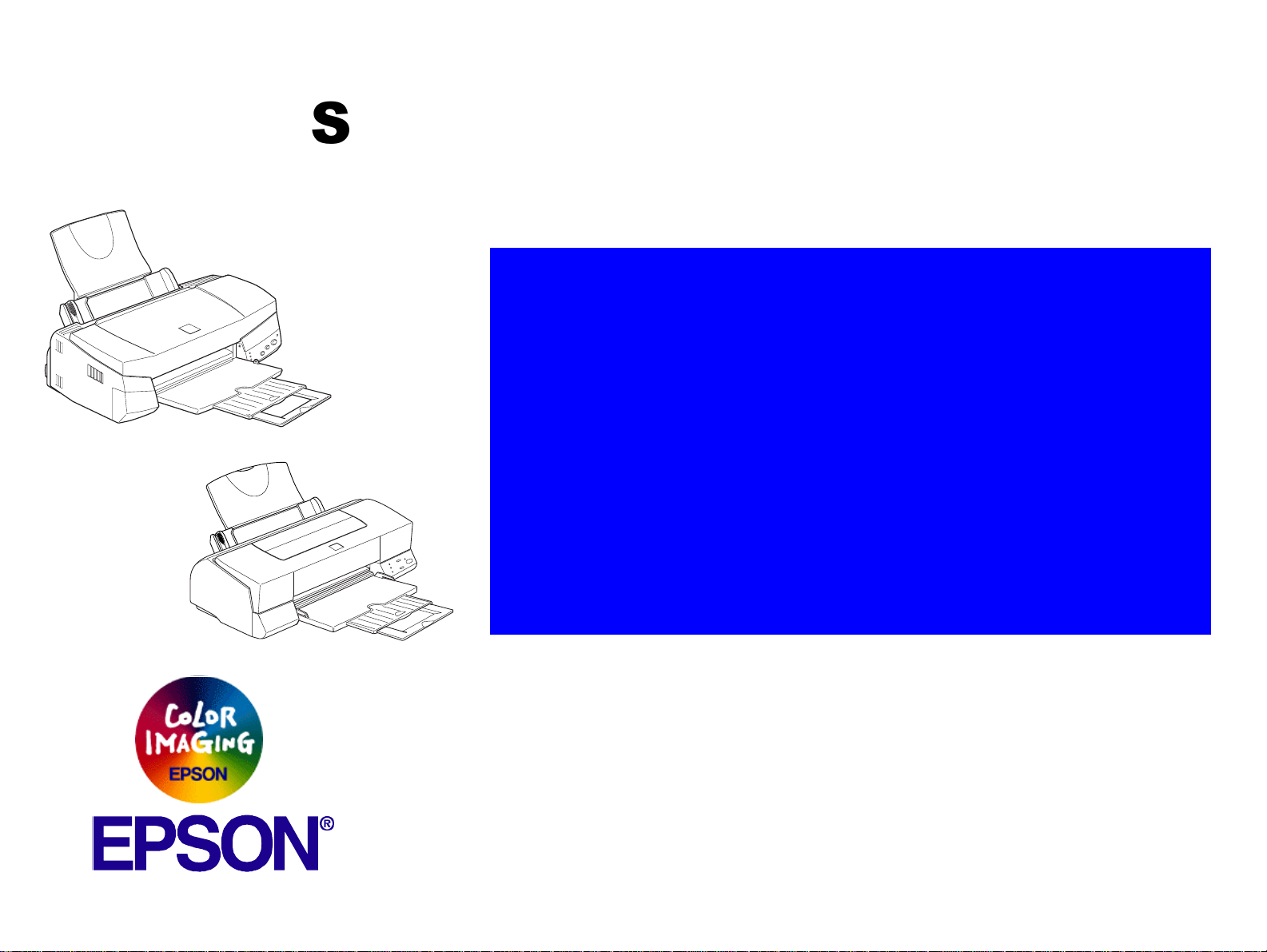
EPSONStylusPhoto72
Color Inkjet Printer
EPSON STYLUS PHOTO 720 / STYLUS PHOTO EX3
EPSONStylusPhotoEX
SEIJ00001
Page 2

PRECAUTIONS
Precautionary notations throughout the text are categorized relative to 1)Personal injury and 2) damage to equipment.
DANGER
WARNING
The precautionary measures itemized below should always be observed when performing repair/maintenance procedures.
Signals a precaution which, if ignored, could result in serious or fatal personal injury. Great caution should be exercised in
performing procedures preceded by DANGER Headings.
Signals a precaution which, if ignored, could result in damage to equipment.
DANGER
1. ALWAYS DISCONNECT THE PRODUCT FROM THE POWER SOURCE AND PERIPHERAL DEVICES PERFORMING ANY
MAINTENANCE OR REPAIR PROCEDURES.
2. NO WORK SHOULD BE PERFORMED ON THE UNIT BY PERSONS UNFAMILIAR WITH BASIC SAFETY MEASURES AS DICTATED
FOR ALL ELECTRONICS TECHNICIANS IN THEIR LINE OF WORK.
3. WHEN PERFORMING TESTING AS DICTATED WITHIN THIS MANUAL, DO NOT CONNECT THE UNIT TO A POWER SOURCE UNTIL
INSTRUCTED TO DO SO. WHEN THE POWER SUPPLY CABLE MUST BE CONNECTED, USE EXTREME CAUTION IN WORKING ON
POWER SUPPLY AND OTHER ELECTRONIC COMPONENTS.
WARNING
1. REPAIRS ON EPSON PRODUCT SHOULD BE PERFORMED ONLY BY AN EPSON CERTIFIED REPAIR TECHNICIAN.
2. MAKE CERTAIN THAT THE SOURCE VOLTAGES IS THE SAME AS THE RATED VOLTAGE, LISTED ON THE SERIAL NUMBER/
RATING PLATE. IF THE EPSON PRODUCT HAS A PRIMARY AC RATING DIFFERENT FROM AVAILABLE POWER SOURCE, DO NOT
CONNECT IT TO THE POWER SOURCE.
3. ALWAYS VERIFY THAT THE EPSON PRODUCT HAS BEEN DISCONNECTED FROM THE POWER SOURCE BEFORE REMOVING OR
REPLACING PRINTED CIRCUIT BOARDS AND/OR INDIVIDUAL CHIPS.
4. IN ORDER TO PROTECT SENSITIVE MICROPROCESSORS AND CIRCUITRY, USE STATIC DISCHARGE EQUIPMENT, SUCH AS
ANTI-STATIC WRIST STRAPS, WHEN ACCESSING INTERNAL COMPONENTS.
5. REPLACE MALFUNCTIONING COMPONENTS ONLY WITH THOSE COMPONENTS BY THE MANUFACTURE; INTRODUCTION OF
SECOND-SOURCE ICs OR OTHER NONAPPROVED COMPONENTS MAY DAMAGE THE PRODUCT AND VOID ANY APPLICABLE
EPSON WARRANTY.
Page 3

About This Manual
This manual describes basic functions, theory of electrical and
mechanical operations, maintenance and repair procedures of EPSON
Stylus Photo 720 / Stylus Photo EX3. The instructions and procedures
included herein are intended for the experienced repair technicians, and
attention should be given to the precautions on the preceding page.
Contents
This manual consists of six chapters and Appendix.
CHAPTER 1.PRODUCT DESCRIPTIONS
Provides a general overview and specifications of the
product.
CHAPTER 2.OPERATING PRINCIPLES
Describes the theory of electrical and mechanical
operations of the product.
CHAPTER 3.TROUBLESHOOTING
Provides the step-by-step procedures for the
troubleshooting.
CHAPTER 4.DISASSEMBLY AND ASSEMBLY
Describes the step-by-step procedures for
disassembling and assembling the product.
CHAPTER 5.ADJUSTMENTS
Provides Epson-approved methods for adjustment.
CHAPTER 6.MAINTENANCE
Provides preventive maintenance procedures and the
lists of Epson-approved lubricants and adhesives
required for servicing the product.
APPENDIXProvides the following additional information for
reference:
• Connector pin assignments
• Electric circuit boards components layout
• Exploded diagram
• Electrical circuit boards schematics
Symbols Used in This Manual
Various symbols are used throughout this manual either to provide
additional information on a specific topic or to warn of possible danger
present during a procedure or an action. Be aware of all symbols when
they are used, and always read WARNING, CAUTION or NOTE
messages.
W ARNING
CAUTION
CHECK
POIN T
Indicates an operating or maintenance procedure, practice
or condition that, if not strictly observed, could result in injury
or loss of life.
Indicates an operating or maintenance procedure, practice,
or condition that, if not strictly observed, could result in
damage to, or destruction of, equipment.
May indicate an operating or maintenance procedure,
practice or condition that is necessary to accomplish a task
efficiently. It may also provide additional information that is
related to a specific subject, or comment on the results
achieved through a previous action.
Page 4

Revision Status
Revision Issued Date Description
Rev. A April 6, 2000 First Release
Page 5

EPSON Stylus Photo 720 / EPSON Stylus Photo EX
3
A
6
Revision
Contents
Product Description
Overview ....................................................................................................... 9
Features ................................................................................................... 9
Basic Specification .................................................................................... 10
Printing Specification .............................................................................. 10
Paper Feed specification ........................................................................ 11
Input Data Buffer .................................................................................... 11
Electric Specification .............................................................................. 11
Environmental Conditions ...................................................................... 12
Reliability ................................................................................................ 12
Safety Approvals .................................................................................... 12
Acoustic Noise ........................................................................................ 12
CE Marking ............................................................................................. 12
Interface Specification .............................................................................. 13
IEEE-1284 Parallel I/F (Forward Channel) ............................................. 13
IEEE-1284 Parallel I/F (Reverse Channel) ............................................. 13
USB (Universal Serious Bus) ................................................................. 16
Miscellanea ............................................................................................ 16
Preventing Hosts from Data Transfer Time-out .................................. 16
Interface Selection .............................................................................. 16
IEEE 1284.4 protocol ......................................................................... 17
Control Specification ................................................................................ 18
Control Panel .......................................................................................... 18
Control Switches .................................................................................... 18
Code Page Selection/ Parallel I/F IEEE1284.4 Setting ...................... 19
Special Setting Mode ......................................................................... 20
LED Indications ...................................................................................... 20
Initialization ............................................................................................. 21
Errors ...................................................................................................... 21
Paper ........................................................................................................... 22
Paper handling ....................................................................................... 22
Paper Specification ................................................................................ 22
Printable Area ........................................................................................ 24
Ink Cartridge ........................................................................................... 26
Physical Specification .............................................................................. 27
Consumables and Options ....................................................................... 28
Operating Principles
Overview .................................................................................................... 30
Printer Mechanism ................................................................................. 30
Printhead ................................................................................................ 32
Printing Process ................................................................................. 33
Printing Method .................................................................................. 34
Carriage Mechanism .............................................................................. 35
Platen Gap (PG) Adjustment Mechanism .......................................... 35
Paper Feeding Mechanism .................................................................... 36
Paper Loading Mechanism (ASF Unit) ................................................... 37
Ink System Mechanism .......................................................................... 39
Pump Unit and CR Lock Mechanism ................................................. 39
Capping Mechanism .............................................................................. 40
Ink Sequence ......................................................................................... 41
Electrical Circuit Operating Principles .................................................... 42
C301PSB/PSE Board ............................................................................. 42
C301MAIN Board ................................................................................... 44
Main elements .................................................................................... 45
Printhead Driver Circuit ...................................................................... 45
PF Motor (PF/ PUMP/ ASF Motor) Driver Circuit ............................... 47
CR Motor Driver Circuit ...................................................................... 48
Reset Circuit ....................................................................................... 48
EEPROM Control Circuit .................................................................... 49
Sensor Circuit ..................................................................................... 50
Page 6

EPSON Stylus Photo 720 / EPSON Stylus Photo EX
3
A
7
Revision
Troubleshooting
Overview ..................................................................................................... 52
Unit Level Troubleshooting ...................................................................... 54
Printer does not operate at power on ..................................................... 54
Error is detected ..................................................................................... 55
Failure occurs during printing ................................................................. 55
Printer does not feed paper correctly ..................................................... 56
Control panel operation is abnormal ...................................................... 56
Unit Repair (Power Supply Board) ........................................................... 57
Unit Repair (Control Board) ...................................................................... 58
Unit Repair (Printer Mechanism) .............................................................. 60
Disassembly and Assembly
Overview ..................................................................................................... 65
Precautions ............................................................................................ 65
Tools ....................................................................................................... 65
Work Completion Check ......................................................................... 66
Disassembly ............................................................................................... 67
Housing Removal ................................................................................... 68
Circuit Board Assembly Removal ........................................................... 69
Control Panel Removal .......................................................................... 71
Ink Absorber Tray Assembly (Waste Ink Pad) Removal ........................ 72
Printer Mechanism Disassembly ............................................................ 73
Printhead Removal ............................................................................. 73
Pump Assembly / Cap Assembly Removal ........................................ 75
CR Motor Assembly Removal ............................................................ 77
PF Motor Assembly Removal ............................................................. 78
ASF Assembly Removal ..................................................................... 80
ASF LD Roller Assembly Removal ..................................................... 82
LD Roller Assembly Disassembly ....................................................... 87
CR Assembly Removal ...................................................................... 88
PE Sensor Assembly Removal .......................................................... 90
PF Roller Assembly Removal ............................................................. 91
CR HP Sensor Removal ..................................................................... 93
Adjustment
Overview .................................................................................................... 95
Required Adjustment .............................................................................. 95
Adjustment ................................................................................................. 96
PG Adjustment ....................................................................................... 96
Adjustment by Adjustment Program ....................................................... 98
Adjustment Program .............................................................................. 98
Adjustment Program Installation Procedure ........................................... 98
Adjustment Program Initial Setting Screen ............................................ 99
Market Destination Check .................................................................... 100
Head Voltage ID Input .......................................................................... 101
Head Angular Adjustment .................................................................... 103
Bi-Directional Adjustment ..................................................................... 106
USB ID Check/Input ............................................................................. 109
Head Cleaning ..................................................................................... 110
Initial Ink Charge .................................................................................. 111
Protection Counter Check/Clear .......................................................... 111
Print A4 Pattern .................................................................................... 113
Maintenance
Overview .................................................................................................. 115
Cleaning ............................................................................................... 115
Service Maintenance ............................................................................ 116
Lubrication ............................................................................................ 117
Appendix
Connector Summary ............................................................................... 122
Major Component Unit ......................................................................... 122
EEPROM Address Map ....................................................................... 125
Component Layout .................................................................................. 129
Exploded Diagram ................................................................................... 131
Parts List .................................................................................................. 139
Electric Circuit ......................................................................................... 149
Page 7

PRODUCT DESCRIPTION
CHAPTER
1
Page 8

E
PSON Stylus Photo 720 / EPSON Stylus Photo EX3 Revision A
p
9
1.1 Overview
Stylus Photo 720 and Stylus Photo EX3 is developed from Stylus Photo 700 and Stylus
Photo EX and allows a high resolution photographic high quality print enabled by
variable dot.
1.1.1 Features
Major features of this printer are as follows;
o
High color print quality
n
1440x720 (HxV) dpi printing
n
Photo-MACH technology (6 color printing. CMYKLmLc)
n
Traditional and New Microweave
o
Built-inASF(AutoSheetFeeder)
n
Holds 100 cut-sheets (64 g/m2)
n
Holds 10 envelopes
n
Holds 30 transparency films
o
Built-in 2 I/F
n
Bi-directional parallel I/F (IEEE-1284 level 1 device)
n
USB (Universal Serial Bus)
Stylus Photo 720
Stylus Photo EX3
o
Windows / Macintosh exclusive
Figure 1-1. External View
Product Descri
tion Overview
Page 9

E
PSON Stylus Photo 720 / EPSON Stylus Photo EX3 Revision A
p
1.2 Basic Specification
1.2.1 Printing Specification
PRINTING METHOD
o
On demand ink jet
NOZZLE CONFIGURATION
o
Black: 32 nozzle
o
Color: 32 nozzle x 5 colors
(Cyan, Magenta, Yellow, Light Cyan, Light Magenta)
Light
Cyan
#32
Black
Cyan
Magenta
Light
Magenta
Yellow
PRINTING SPEED AND PRINTABLE COLUMNS
o
Character mode: Refer to the table below.
Table 1-1. Printing Speed (Character Mode)
Character Pitch Printable Columns LQ speed
Stylus Photo 720 10 CPI (Pica) 80 200 CPS**
Stylus Photo EX3 10 CPI (Pica) 114 200 CPS**
NOTE: These figures are not described in the user’s guide.
** This value is the speed of normal-dot printing.
o
Raster graphics mode: Refer to the table below.
Table 1-2. Printing Speed (Raster Graphics Mode)
Stylus Photo 720
Horizontal
Resolution
180 dpi 8.26 inch 1488 508mm/s (20 IPS)
360 dpi 8.26 inch 2976 508mm/s (20 IPS)
720 dpi 8.26 inch 5952 508mm/s (20 IPS)
180 dpi 11.46 inch 2062 508mm/s (20 IPS)
Printable
Area
Available
Dot
CR Speed
Stylus Photo EX3
4 / 360"
#1
360 dpi 11.46 inch 4125 508mm/s (20 IPS)
720 dpi 11.46 inch 8250 508mm/s (20 IPS)
CONTROL CODE
o
ESC/P Raster command
nozzle
o
EPSON Remote command
Figure 1-2. Nozzle Configuration (Seen from the Back of the Head)
PRINTING DIRECTION
o
Bi-direction with logic seeking
Product Descri
tion Basic Specification 10
Page 10

E
PSON Stylus Photo 720 / EPSON Stylus Photo EX3 Revision A
p
CHARACTER TABLES
o
2 international character sets
n
PC437 (US, Standard Europe)
n
PC850 (Multilingual)
TYPEFACE
o
Bitmap LQ font
n
EPSON Courier 10 CPI
1.2.2 Paper Feed specification
o
Feeding Method: Friction feed with ASF
o
Paper path: Cut-sheet ASF (Top entry Front out)
o
Feed speed: 10.16mm feed: 110ms
Continuous feed: 114.3mm/s
1.2.3 Input Data Buffer
o
Buffer: 256 Kbytes
1.2.4 Electric Specification
o
120V version
n
Rated voltage: AC 100V
n
Input voltage range: AC 99 -132V
n
Rated frequency range: 50 - 60Hz
n
Input frequency range: 49.5-60.5 Hz
n
Rated current: 0.4A (Max. TBD)
n
Power consumption: Approx.18W (ISO10561 Letter pattern)
n
Insulation Resistance: 10 M ohms min.
n
Dielectric: AC 1000 V rms. 1 minute or
o
220-240V version
n
Rated voltage: AC 220 - 240V
n
Input voltage range: AC 198 - 264V
n
Rated frequency range: 50 - 60Hz
Approx. 2.5W in standby mode
Energy Star compliant
(between AC line and chassis, DC 500V)
AC 1200 V rms. 1 second
(between AC line and chassis)
n
Input frequency range: 49.5-60.5 Hz
n
Rated current: 0.2A (Max. TBD)
n
Power consumption: Approx.18W (ISO10561 Letter pattern)
Approx. 2.5W in standby mode
Energy Star compliant
n
Insulation Resistance: 10 M ohms min.
(between AC line and chassis, DC 500V)
n
Dielectric: AC 1500 V rms. 1 minute
(between AC line and chassis)
Product Descri
tion Basic Specification 11
Page 11

E
PSON Stylus Photo 720 / EPSON Stylus Photo EX3 Revision A
p
1.2.5 Environmental Conditions
o
Temperature
Operating: 10 to 35
Non-operating: -20 to 40°C
1monthat40°C, 120 hours at 60°C
o
Humidity
Operating: 20 to 80% RH
Non-operating: 5 to 85% RH
o
Resistance to shock
Operating: 1G, within 1ms
Non-operating: 2G, within 2ms
o
Resistance to vibration
Operating: 0.15G
Non-operating: 0.50G
NOTE: *1: with shipment container.
*2: without condensation.
*3: The environmental condition should be within the range shown in the
figure below.
(%)
80
*3
°C
*1
*2,*3
*1,*2
*1
*1
1.2.6 Reliability
o
Total print volume: 10,000 pages (A4, Letter)
o
Print Head Life: 3 billion dots / nozzle
Or 5 years at the normal temperature
(Whichever comes first.)
1.2.7 Safety Approvals
o
120V version:
n
Safety Standards: UL1950
CSA22.2 No.950
n
EMI: FCC part15 subpart B class B
CSA C108.8 class B
o
220 - 240V version:
n
Safety Standards: EN 60950 (VDE)
n
EMI: EN 55022 (CISPR Pub. 22) class B
AS/NZS 3548 class B
1.2.8 Acoustic Noise
o
Level: Approx. 47dB (A) (According to ISO7779)
1.2.9 CE Marking
220-240V version
55
20
10 27 35
(”C)
tmphumid
Figure 1-3. Environmental Condition
Product Descri
tion Basic Specification 12
o
Low Voltage Directive 73/23/EEC: EN60950
o
EMC Directive 89/336/EEC: EN55022 class B
EN61000-3-2
EN61000-3-3
EN50082-1
IEC801-2
IEC801-3
IEC801-4
Page 12

E
PSON Stylus Photo 720 / EPSON Stylus Photo EX3 Revision A
p
1.3 Interface Specification
This printer has IEEE-1284 parallel interface and USB interface as standard.
1.3.1 IEEE-1284 Parallel I/F (Forward Channel)
Forward channel is the mode to transfer the ordinary printing command to the printer
side from the PC side.
Table 1-3. Parallel I/F Specification (F-Channel)
Item Specification
Transmission mode 8bit parallel
Synchronization By STROBE pulse supplied from the external
Handshaking By BUSY and ACKNLG signal
Signal Level TTL level (IEEE-1284-Level 1 device)
Adaptable connector 36 pin 57-30360 (amphenol) or equivalent
NOTE: I/F cable is recommended to be in minimum length.
The connector pin assignment is described below. For these signals described in the
table, use the twist pair wire and connect the return side to the signal GND.
Table 1-4. Connector Pin Assignment and Signals (F-Channel)
Pin No.
1 19 -STROBE PC
2-9 20-27 Data0-7 PC
10 28 -ACKNLG Printer
Return
GND Pin
Signal
Name
From Function Description
The strobe pulse for the printer to read data.
Pulse width requires min. 0.5µs (500ns).
High at normal condition. Receives data after
shifting Low.
The DATA 1 through DATA8 signals
represent data bits 1-8, respectively.
A low signal indicates the printer can accept
data. Pulse width is 0.5 (default) or can be set
at 2µs.
Table 1-4. Connector Pin Assignment and Signals (F-Channel)
Pin No.
11 29 BUSY Printer
12 28 PE Printer A high signal indicates paper-out error.
13 28 SLCT Printer
14 30 -AFXT PC Not used.
31 30 -INIT PC
32 29 -ERROR PC A low signal indicates printer error condition.
36 30 -SLIN - Not used.
18 - Logic H -
35 - +5V -
17 - Chassis - Printer chassis GND.
16, 33
19-30
15, 34 - NC - Not used.
Return
GND Pin
- GND - Twist pair return GND.
Signal
Name
From Function Description
A high signal indicates that the printer cannot
receive data. The signal becomes high under
the condition below;
-Receiving data.
-Error.
-Other I/F receiving data.
Always at high level. Pulled up to +5V via
1.0KΩ resistor.
The printer is initialized by the width of min.
50µs Low pulse input.
Always at high level. Pulled up to +5V via
3.9KΩ resistor.
Always at high level. Pulled up to +5V via
1.0KΩ resistor.
1.3.2 IEEE-1284 Parallel I/F (Reverse Channel)
Reverse channel is used to transfer the information data from the printer side to the PC
side.
Product Descri
tion Interface Specification 13
Page 13

E
PSON Stylus Photo 720 / EPSON Stylus Photo EX3 Revision A
p
o
Table 1-5. Parallel I/F Specification (R-Channel)
Item Specification
Transmission mode IEEE-1284 nibble mode
Synchronization Comply with the IEEE-1284 specification
Handshaking Comply with the IEEE-1284 specification
Logic Level TTL level (IEEE-1284-Level 1 device)
Data trans. timing Comply with the IEEE-1284 specification
Extensibility request data The printer responds affirmatively when the extensibility request
values are 00H or 04H;
00H: Request Nibble Mode Reverse Channel Transfer.
04H: Request Device ID;
Return Data Using Nibble Mode Reverse Channel Transfer
Device ID
n
When IEEE-1284.4 protocol is effective:
[00H] [5AH]
MFG: EPSON;
CMD: ESCPL2, BDC, D4;
MDL: Stylus[SP]Photo[SP]720;
*1
CLS: PRINTER;
DES: EPSON[SP]Stylus[SP]Photo[SP]720;
n
When IEEE1284.4 protocol is NOT effective:
*1
[00H] [57H]
MFG: EPSON;
CMD: ESCPL2, BDC;
MDL: Stylus[SP]Photo[SP]720;
*1
CLS: PRINTER;
DES: EPSON[SP]Stylus[SP]Photo[SP]720;
*1
Note: *1 For Stylus Photo EX3, MDL: Stylus[SP]Photo[SP]EX3;
DES: EPSON[SP]Stylus[SP]Photo[SP]EX3, respectively.
The connector pin assignment is described in the table below. For these signals
described in the table, use the twist pair wire and connect the return side to the signal
GND.
Table 1-6. Connector Pin Assignment and Signals (F-Channel)
Pin No.
1 19 HostClk PC Host clock signal.
2-9 20-27 Data1-8 PC
10 28 PtrClk Printer Printer clock signal.
11 29
12 28
13 28
Product Descri
tion Interface Specification 14
Return
GND Pin
Signal Name From Function Description
The DATA 1 through DATA8 signals
represent data bits 1-8 respectively.
PtrBusy/
DataBit-3,7
AckDataReq/
DataBit-2,6
Xflag/DataBit-
1,5
Printer
Printer
Printer
Printer busy signal and reverse channel
transfer data bit 3 or 7.
Acknowledge data request signal and
reverse channel transfer data bit 2 or 6.
X-flag signal and reverse channel
transfer data bit 1 or 5.
Page 14

E
PSON Stylus Photo 720 / EPSON Stylus Photo EX3 Revision A
p
Table 1-6. Connector Pin Assignment and Signals (F-Channel)
Pin No.
14 30 HostBusy PC Host busy signal.
31 30 -INIT PC Not used.
32 29
36 30 1284-Active PC 1284 active signal.
18 - Logic H Printer Pulled up to +5V via 3.9K ohm resistor.
35 - +5V Printer Pulled up to +5V via 3.3 K ohm resistor.
17 - Chassis - Printer chassis GND.
16, 33
19-30
15, 34 - NC - Not used.
Following lists “Notes” when using the parallel interface.
o
“Return GND pin” in the table means twist pair return and is connected to the
signal GND level.
For each signal, use the twist pair wire and connect the return side.
Also, these cables are shielded wires and it is effective means to connect to each
chassis GND in the center machine and printer for electrostatic noise.
Return
GND Pin
Signal Name From Function Description
-DataAvail/
DataBit-0,4
Printer
Data available signal and reverse channel
transfer data bit 0 or 4.
- GND - Twist pair return GND.
DATA
/STROBE
BUSY
/ACKNLG
Data byte n Data byte n+1
t
hold
t
t
setup
ready
t
stb
t
busy
t
reply
Figure 1-4. Timing Chart
On the above timing chart, T
Parallel I/F Mode T
High speed (default) 0.5
Normal speed 2 µs
ratedperiodisshownbelow.
act
Table 1-7. t
act
t
ack
Rated Period
Rated Period
act
µs
t
nbusy
t
next
timechart
o
Conditions for interface are all based on TTL level. Rise and fall time should be
within 0.2
o
Refer to the timing chart for transmission timing of each signals.
o
Do not perform data transmission ignoring -ACK or BUSY signals. (Perform the
µs.
data transmission after confirming that either -ACK or BUSY signal is Low)
o
It is possible to perform the printing test including interface circuit without using
external equipment when 8-bit data signal (2-9 pin) is set to appropriate character
code (against GND, Open=”1”, Short=”0”) and connect then forcefully to -ACK
and -STRB. However, to perform this, “I/F selection” of EEPROM must be set to
“Auto”. Also, IEEE-1284.4 packet mode must be set Off.
The figure below shows the timing chart of the parallel interface.
Product Descri
tion Interface Specification 15
Page 15

E
PSON Stylus Photo 720 / EPSON Stylus Photo EX3 Revision A
p
1.3.3 USB (Universal Serious Bus)
Following shows specification.
o
Standard:
n
Universal Serial Bus Specifications Revision 1.0
n
Universal Serial Bus Device Class Definition for Printing Devices version 1.1
o
Bit rate: 12Mbyte (Full Speed Device)
o
Data encoding: NRZI
o
Adaptable connector: USB Series B
o
Recommended cable length: max. 2 meters
Table 1-8. Connector Pin Assignment and Signals
Pin.
No
1VCC --
2 -Data I/O Data
3 +Data I/O Data. Pull up to +3.3V via 1.5K ohm resistor.
4 Ground -- Cable ground.
Signal Name I/Out Function Description
Cable power. Maximum power consumption
is 2mA.
1.3.4 Miscellanea
1.3.4.1 Preventing Hosts from Data Transfer Time-out
Generally, hosts abandon data transfer to peripherals when a peripheral is in busy state
for dozens of seconds continuously. To prevent hosts from acting this kind of time-out,
when the open space of input buffer becomes 1024 byte, the printer receives data per
certain period of time (1 second) and avoid BUSY state continues for a long time. The
printer will be in busy state continuously when the input buffer finally gets full. This
operation is not performed while communicating by IEEE1284.4 protocol.
1.3.4.2 Interface Selection
IEEE-1284 parallel interface and USB interface is switched by auto select function.
The following explains the conditional shift of the I/F auto select function and the
operations when specific interface is set.
AUTOMATIC SELECTION
In this automatic interface selection mode, the printer is initialized to the idle state
scanning which interface receives data when it is powered on. Then the interface that
receives data first is selected. When the host stops data transfer and the printer is in the
stand-by state for the seconds, the printer is returned to the idle state. As long as the
host sends data or the printer interface is in the busy state, the selected interface is let as
is.
Pin #1Pin #2
Pin #3 Pin #4
usb
INTERFACE STATE AND INTERFACE SELECTION
o
When the parallel interface is not selected, the interface became to the busy state.
When the printer is initialized or returned to the idle state, the parallel interface
became to the ready state. Caution that the interrupt signal such as the -INIT signal
on the parallel interface is not effective while the inter face is not selected.
Figure 1-5. USB Interface Port
Product Descri
tion Interface Specification 16
Page 16

E
PSON Stylus Photo 720 / EPSON Stylus Photo EX3 Revision A
p
1.3.4.3 IEEE 1284.4 protocol
The packet protocol described by IEEE1284.4 standard always a device to carry on
multiple exchanges or conversations which contain data and/or control information
with another device at the same time across a single point-to-point link. The protocol is
not, however, a device control language. It does provide basic transport-level flow
control and multiplexing services. The multiplexed logical channels are independent of
each other and blocking of one has no effect on the others. The protocol operate over
IEEE1284.
o
Auto
An initial state is compatible interface and starts IEEE1284.4 communication
when the magic strings (1284.4 synchronous commands) are received.
o
On
An initial state is IEEE 1284.4 communication and data that received it by the time
it is able to take synchronization by magic string (1284.4 synchronous commands)
is discarded.
o
Off
An initial state is compatible interface and never starts IEEE1284.4
communication even if the magic strings (1284.4 synchronous commands) are
received.
For parallel I/F, regardless of the factory default setting, after initial ink charge
operation, the setting of the EEPROM must be set to “AUTO”. The change in this
setting will be effective when the power is back on after the initial ink charge
operation.
Product Descri
tion Interface Specification 17
Page 17

E
PSON Stylus Photo 720 / EPSON Stylus Photo EX3 Revision A
p
1.4 Control Specification
1.4.1 Control Panel
The control panel is at the front right of the printer and has 2 non-lock type push
switches and 1 lock type switch and 4 LEDs. The appearance of the control panel
differs between Stylus Photo 720 and Stylus Photo EX3, but the number of buttons and
LEDs is the same. So, this section explains names of the buttons using the Stylus Photo
720 control panel.
Power LED
Ink Maintenance Button
Paper Check LED
Black Ink End LED
Color Ink End LED
Power Button
Load/ Eject Button
Table 1-9. Panel Functions in Normal State
Button Function
Load/Eject
(Less than 2 seconds)
Load/ Eject
(for 3 seconds)
Ink maintenance
(for 3 seconds)
Ink maintenance
(Less than 2 seconds)
Load or eject paper
When the print head is at the ink replacement position, it returns to
the home position.
Start the ink cartridge replacement sequence.
Start cleaning the print head.
In the condition of “Ink Low”, “Ink End” or “No Ink Cartridge”,
start the ink cartridge replacement sequence.
When the print head is at the ink replacement position, it returns to
the home position.
Figure 1-6. Control Panel
1.4.2 Control Switches
Since this printer does not have so many switches, each button has several functions.
The tables below show their functions and how to enter those functions for each button.
Product Descri
tion Control Specification 18
Page 18

E
PSON Stylus Photo 720 / EPSON Stylus Photo EX3 Revision A
p
Table 1-10. Panel Function with Turning the Power On
Button Function
Load/Eject Start status-printing.*
Print “Firmware version”→ “CPU Mask version”→ “Waste
ink counter”→ “Code page setting”→ “Nozzle check pattern”.
Ink maintenance Code page.selection/ Parallel I/F IEEE 1284.4 setting (See
Section 1.4.2.1)
Load/Eject
+
Ink maintenance
Start special setting mode.
(See Table 1-13)
1
*Note
NOTE: Turning the power on = to turn on the printer power while specified
button is pressed down.
*1: Printer performs the following according to the value of 1BH in EEPROM.
Table 1-11. EEPROM 1BH Data and Function W
Bit 7, Bit 6 Action
00
11
01 Start hex-dump printing.
Print firmware version, ink counter, selected code page and nozzle
check pattern.
1.4.2.1 Code Page Selection/ Parallel I/F IEEE1284.4 Setting
On this setting mode, you can select code page table (PC437 or PC850) and parallel I/F
IEEE1284.4 mode (ON, AUTO, OFF).
o
Code Page Selection
You can select the code table PC437 or PC850 by the following panel operation.
1. Turn on the power while pressing the maintenance button.
2. Paper check LED starts blinking.
3. When you see the paper check LED starts blinking, release maintenance button.
4. After 2 seconds, the code page setting will be indicated by maintenance LED. See the
table below.
Table 1-12. Code Page Setting
Code page before this
function is performed.
PC437 PC850 Ink END (Color) ON
PC850 PC437 Ink END (Black) ON
NOTE: You can check current code page by status print.
Code page after this
function is performed.
LED Indication
10 Start self-test printing.
Product Descri
tion Control Specification 19
Page 19

E
PSON Stylus Photo 720 / EPSON Stylus Photo EX3 Revision A
p
2
1.4.2.2 Special Setting Mode
You can go to the special setting mode by the following operations.
1. Turn on the power while pressing the Load/ Eject button and ink maintenance button.
2. Paper check LED starts blinking. (3 seconds)
3. While the paper check LED is blinking (3 seconds), press the appropriate button. See
Table 1-13.
n
When maintenance error (protection counter over flow) is
happened, if you clear the error by this operation, be sure to
replace the waste ink absorber.
n
Whenever you replaced the waste ink counter (even when ink
maintenance error has not occurred), be sure to perform the
counter reset by this operation.
Table 1-13. Special Settings Mode
Buttons Function
Load/Eject Initialize EEPROM and reset timer IC.
This operation will reset the following items:
• Interface selection (04H)
• CL time (68/ 69H)
• Power OFF time (6C/ 6DH)
Reset the ink overflow counter.
Cleaning
(Pressed for 10 seconds)
NOTE: Hold the button pressed for 10 seconds.
This operation will reset the following items:
• Ink counter A0 (5C/ 5DH)
• Ink counter A80 (5E/ 5FH)
1.4.3 LED Indications
See the table below for more detailed LED indications. Since LED indicates the
various errors and current printer operations, LED indications enable to find out the
proper repair operation.
Table 1-14. Printer Status displayed on the control panel
Indicators
Printer Status
Power on condition On --
Ink sequence Blink -- -- -- 6
Ink cartridge exchange mode Blink -- -- -- 5
Data processing Blink -- -- -- 8
Paper check
Paper jam
No ink cartridge or Ink end
(black)
No ink cartridge or Ink end
(color)
Ink level low (black) -- -- Blink -- 7
Ink level low (color) -- -- -- Blink 7
EEPROM and Timer IC reset
Maintenance Request Blink Blink Blink Blink 2
Fatal Error
*1
*1
*1
*1
*2
*1
Power
-- On -- -- 4
-- Blink Off Off 3
-- -- On -- 7
-- -- -- On 7
--
Blink Blink On On 1
Paper
Check
*3
On
(for 1
second)
Ink End
(Black)
-- -- 9
On
(for 1
second)
Ink end
(Color)
On
(for 1
second)
Priority
--
NOTE: *1 For error condition, refer to “Fatal Error” under the “Errors” on
page 21.
*2 EEPROM clear does not mean to clear all address in
EEPROM. (See “Special Settings Mode” on page 20)
*3 -- in the table above means no change.
Product Descri
tion Control Specification
0
Page 20

E
PSON Stylus Photo 720 / EPSON Stylus Photo EX3 Revision A
p
2
1.4.4 Initialization
The printer have 3 types of initialization. The initialization operations executed by each
initialization method are described below.
o
Hardware Initialization
This printer initializes itself when it is turned on.
On this initialization, following actions are performed.
n
Initialize printer mechanism
n
Clear the input data buffer
n
Clear the print buffer
n
Set default values
o
Software initialization
Initialization command, “ESC@” also initializes the printer.
On this initialization, following actions are performed.
n
Clear the print buffer
n
Set default values
o
Panel initialization
This printer initializes itself when it is turned off and is turned on again within 10
seconds, or when it recognizes the -INIT signal input.
On this initialization, following actions are performed.
1.4.5 Errors
o
Ink Out
When the printer almost runs out the ink of any one color, it warns ink-low and
keeps printing. When the printer runs out the whole ink of any one color, it stops
printing and indicates ink-out error. User is requested to install a new ink-cartridge
in this state. A ink-cartridge once taken out should never used again. Reinstallation of the cartridge not filled fully upsets the ink level detection and may
cause a serious problem in the print head as a result.
o
Paper out
When the printer fails to load a sheet, it goes paper out error.
o
Paper jam
When the printer fails to eject a sheet, it goes paper jam error.
o
No ink-cartridge
When the printer detects that the ink-cartridge comes off, it goes no ink-cartridge
error.
o
Maintenance request
When the total quantity of ink wasted through the cleaning and flushing reaches to
the limit, the printer indicates this error and stops. The absorber in the printer
enclosure is needed to be replaced with new one by a service person.
o
Fatal errors
Carriage control error or CG access error.
n
Cap the print head (Mechanism initialization is not performed.)
n
Eject paper
n
Clear the input buffer
n
Clear the print buffer
n
Set default values
Product Descri
tion Control Specification
1
Page 21

E
PSON Stylus Photo 720 / EPSON Stylus Photo EX3 Revision A
p
2
o
1.5 Paper
1.5.1 Paper handling
Do not perform reverse feed more than 9.5mm (0.38”).
Envelope
n
Size:
No.10 (241.3 mm x 104.8 mm)
DL (220 mm x 110 mm)
C6 (162 mm x 114 mm)
n
Thickness: 0.16mm to 0.52mm(0.006 to 0.02”)
1.5.2 Paper Specification
STYLUS PHOTO 720
o
Cut Sheet
n
Paper Size:
A4 (210 x 297 mm)
Letter (216 x 279 mm)
B5 (182 x 257 mm)
Legal (216 x 356 mm)
Statement (139.7 x 215.9 mm)
Executive (184.2 x 266.7 mm)
A5 (148 x 210 mm)
A6 (105 x 148 mm)
n
Thickness: 0.08mm to 0.11mm(0.003 to 0.004”)
n
Weight: 64g/m2to 90g/m2(17lb to 24lb)
n
Paper quality: Exclusive paper, Bond paper, PPC
o
Transparency, Glossy paper
n
Size:
A4 (210 x 297 mm)
Letter (216 x 279 mm)
n
Weight: 45g/m2to 75g/m2(12lbto20lb)
n
Paper quality: Bond paper, Plain paper, Air mail
*Envelope printing is only available at normal temperature.
*Keep the longer side of the envelope horizontally at setting.
o
Index Card
n
Size:
A6(105x148mm)
A5(148x210mm)
5x8” index card (127 x 203 mm)
10x8” index card (254 x 203mm)
n
Thickness: 0.23 mm(0.0091”)
n
Thickness: 0.075mm to 0.085mm(0.003 to 0.0033”)
*Transparency printing is only available at normal temperature.
Product Descri
tion Paper
2
Page 22

E
PSON Stylus Photo 720 / EPSON Stylus Photo EX3 Revision A
p
2
n
STYLUS PHOTO EX3
Additional following items to the Stylus Photo 720 specification;
o
Cut Sheet
n
Paper size:
A3 (297 x 420 mm)
Letter (216 x 279 mm)
B5 (182 x 257 mm)
Legal (216 x 356 mm)
Statement (139.7 x 215.9 mm)
Executive (184.2 x 266.7 mm)
A5 (148 x 210 mm)
A6 (105 x 148 mm)
n
Thickness: 0.08mm to 0.11mm(0.003 to 0.004”)
n
Weight: 64g/m2to 90g/m2(17lb to 24lb)
n
Paper quality: Exclusive paper, Bond paper, PPC
o
Transparency, Glossy paper
n
Size:
A3 (297 x 420 mm)
A4 (210 x 297 mm)
Letter (216 x 279 mm)
o
Paper quality: Bond paper, Plain paper, Air mail
*Envelope printing is only available at normal temperature.
*Keep the longer side of the envelope horizontally at setting.
Index Card
n
Size:
A6(105x148mm)
A5(148x210mm)
5x8” index card (127 x 203 mm)
10x8” index card (254 x 203mm)
n
Thickness: 0.23 mm(0.0091”)
n
Thickness: 0.075mm to 0.085mm(0.003 to 0.0033”)
*Transparency printing is only available at normal temperature.
o
Envelope
n
Size:
No.10 (241.3 mm x 104.8 mm)
DL (220 mm x 110 mm)
C6 (162 mm x 114 mm)
n
Thickness: 0.16mm to 0.52mm(0.006 to 0.02”)
n
Weight: 45g/m2to 75g/m2(12lb to 20lb)
Product Descri
tion Paper
3
Page 23

E
PSON Stylus Photo 720 / EPSON Stylus Photo EX3 Revision A
p
2
1.5.3 Printable Area
o
Cut Sheet
LM RM
PW
Printable AreaPrintable Area
TM
PL
Table 1-15. Character Mode
Paper Size
A4 3mm (0.12”) 3mm (0.12”) 3mm (0.12”) 14 mm (0.54”)
Letter 3mm (0.12”) 9mm (0.35”) 3mm (0.12”) 14 mm (0.54”)
B5 3mm (0.12”) 3mm (0.12”) 3mm (0.12”) 14 mm (0.54”)
Legal 3mm (0.12”) 9mm (0.35”) 3mm (0.12”) 14 mm (0.54”)
Statement 3mm (0.12”) 3mm (0.12”) 3mm (0.12”) 14 mm (0.54”)
Exclusive 3mm (0.12”) 3mm (0.12”) 3mm (0.12”) 14 mm (0.54”)
LM (Left
Margin) min.
RM (Right
Margin) min.
TM (Top
Margin) min.
BM (Bottom
Margin) min.
Table 1-16. Raster Graphics Mode
Paper Size
A4 3mm (0.12”) 3mm (0.12”) 3mm (0.12”)
Letter 3mm (0.12”) 3mm (0.12”) 3mm (0.12”)
B5 3mm (0.12”) 3mm (0.12”) 3mm (0.12”)
LM (Left
Margin) min.
RM (Right
Margin) min.
TM (Top
Margin) min.
BM (Bottom
Margin) min.
14 mm (0.54”) /
3mm (0.12”)*
14 mm (0.54”) /
3mm (0.12”)*
14 mm (0.54”) /
3mm (0.12”)*
Legal 3mm (0.12”) 9mm (0.35”) 3mm (0.12”)
BM
Statement 3mm (0.12”) 3mm (0.12”) 3mm (0.12”)
Exclusive 3mm (0.12”) 3mm (0.12”) 3mm (0.12”)
14 mm (0.54”) /
3mm (0.12”)*
14 mm (0.54”) /
3mm (0.12”)*
14 mm (0.54”) /
3mm (0.12”)*
Figure 1-7. Cut Sheet Printable Area
NOTE: * Bottom margin can be set up to 3mm at minimum when the paper length
is designated with “ESC(S” command.) However, the printing quality is
not guaranteed in the area ranging from 3mm to 14mm, from the form
lower end. When the paper length is not designated, the bottom margin
must be wider than 14 mm.
Product Descri
tion Paper
4
Page 24
E
PSON Stylus Photo 720 / EPSON Stylus Photo EX3 Revision A
p
2
o
Envelope
LM
RM
TM
Printable AreaPrintable Area
BM
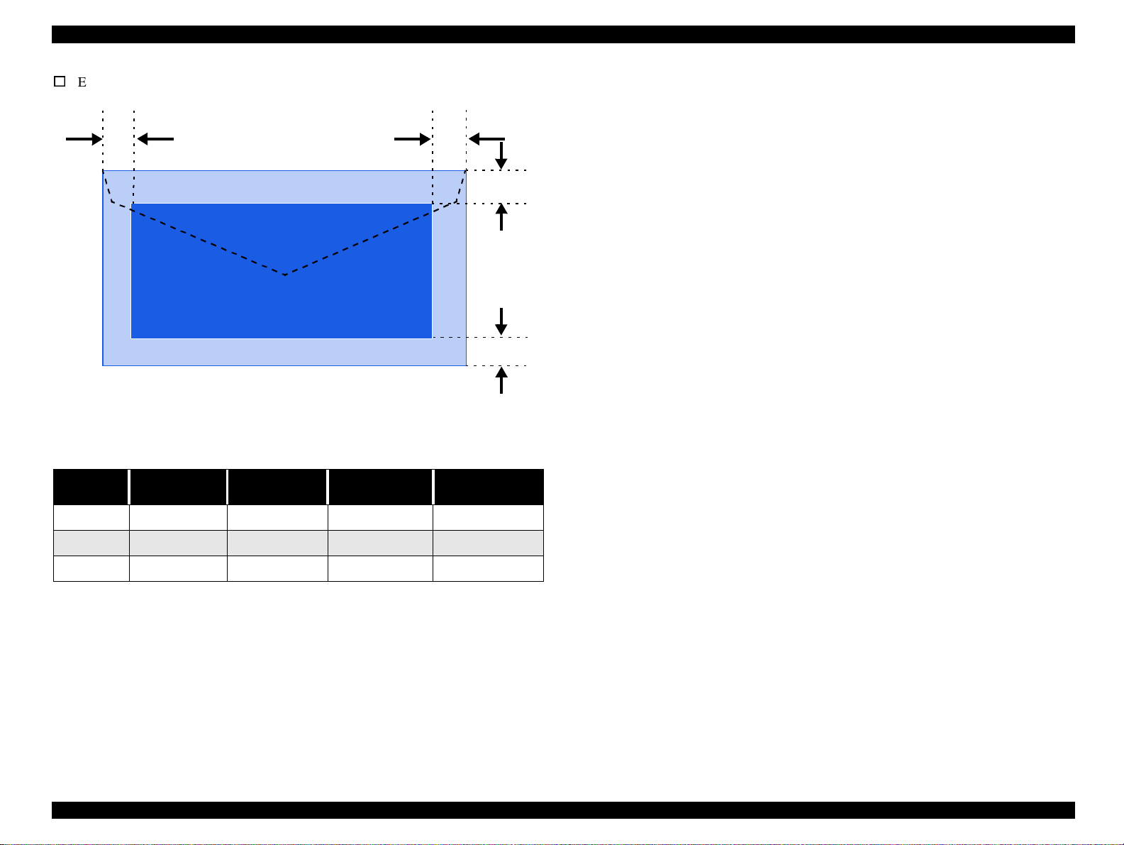
Figure 1-8. Printable Area for Envelopes
Table 1-17. Envelope Margin
Left Margin
Size
#10 3 mm (0.12”) 28 mm (1.10”) 3 mm (0.12”) 14 mm (0.55”)
(minimum)
Right Margin
(minimum)
Top Margin
(minimum)
Bottom Margin
(minimum)
DL 3 mm (0.12”) 7 mm (0.28”) 3 mm (0.12”) 14 mm (0.55”)
C6 3 mm (0.12”) 3 mm (0.12”) 3 mm (0.12”) 14 mm (0.55”)
Product Descri
tion Paper
5
Page 25

E
PSON Stylus Photo 720 / EPSON Stylus Photo EX3 Revision A
p
2
1.5.4 Ink Cartridge
INK CARTRIDGE (BLACK)
o
Type: Exclusive cartridge
o
Color: Black
o
Print capacity: 540 pages / A4 (ISO/IEC10561 Letter pattern at 360 dpi)
o
Ink life: 2 years from production date
o
Storage temperature:
n
-20°Cto40°C
Storage, within a month at 40
n
-30°Cto40°C
Packing storage, within a month at 40
n
-30°Cto60°C
Transit, within a month at 60
o
Dimension: 19.8mm (W) x 52.7 mm (D) x 38.5mm (H)
°
C
°
C
°
C
COLOR INK CARTRIDGE
o
Type: Exclusive cartridge
o
Color: Magenta, Cyan, Yellow
o
Print capacity: 300 pages/A4 (360 dpi, 5% duty each color)
o
Ink life: 2 years from production date
o
Storage temperature:
n
-20°Cto40°C
Storage, within a month at 40
n
-30°Cto40°C
Packing storage, within a month at 40
n
-30°Cto60°C
Transit, within a month at 60
o
Dimension: 42.9mm (W) x 52.7 mm (D) x 38.5mm (H)
°
C
°
C
°
C
Figure 1-10. Color Ink Cartridge
NOTE: Ink cartridges cannot be refilled, properly dispose of after use. Do not
Figure 1-9. Black Ink Cartridge
Product Descri
tion Paper
use the ink cartridge which is beyond its production date plus two years.
Ink will be frozen under -4
placing it more than 3 hours at room temperature.
°
C environment, however it will be usable after
6
Page 26

E
PSON Stylus Photo 720 / EPSON Stylus Photo EX3 Revision A
p
2
1.6 Physical Specification
o
Dimensions
n
Stylus Photo 720: 429 x 268 x 168 mm (WxDxH)
n
Stylus Photo EX3: 546 x 275 x 172 mm (WxDxH)
760.73
406
307.66
545.53
Figure 1-12. Stylus Photo EX3 Dimensions
o
Weight
n
Stylus Photo 720: approximately
Figure 1-11. Stylus Photo 720 Dimensions
Product Descri
tion Physical Specification
n
Stylus Photo EX3: approximately 7.0kg
5.2kg
7
Page 27

E
PSON Stylus Photo 720 / EPSON Stylus Photo EX3 Revision A
p
2
1.7 Consumables and Options
The consumables for this printer are following;
Table 1-18. Consumables
Classification No. Name
Consumables
S020187 Ink Cartridge (black)
S020193 Ink Cartridge (color)
Product Descri
tion Consumables and Options
8
Page 28

OPERATING PRINCIPLES
CHAPTER
2
Page 29

E
PSON Stylus Photo 720 / EPSON Stylus Photo EX3 Revision A
p
3
2.1 Overview
This section describes the operating principles of the printer mechanism and electrical
circuit boards. The Stylus Photo 720 / Stylus Photo EX3 has the following boards:
o
Main board: C301MAIN
o
Power supply board: C301PSB/PSE
o
Panel board: C209PNL Board (Stylus Photo 720)
C366PNL Board (Stylus Photo EX3)
2.1.1 Printer Mechanism
Stylus Photo 720 / Stylus Photo EX3 is based on Stylus Photo 700 / Stylus Photo EX
and the basic specifications for its mechanism are almost same as Stylus Photo 700 /
Stylus Photo EX.
This printer consists of Print Head, Carriage Mechanism, Paper Feeding Mechanism,
Paper Loading Mechanism, Ink System (Pump Mechanism, Cap Mechanism, and
Carriage Lock Mechanism).
Like other EPSON ink jet printers, the Stylus Photo 720 / Stylus Photo EX3 is
equipped with two stepping motors; one for ASF/ paper feeding/ pump mechanism,
and one for CR mechanism. ASF unit uses rear entry front eject system; this design is
the same as Stylus Photo 750 / Stylus Photo 1200.
The table below shows the compatibility of the mechanical units among Stylus Photo
700, Stylus Photo 750 and Stylus Photo 720.
Table 2-1. Mechanical Unit Compatibility
Stylus Photo 700 /
Stylus Photo EX
Printhead E-Chips U-Chips E-Chips +
CR motor
(coil resistance)
PF moto
(coil resistance)
ASF unit --- Quiet noise type Quiet noise type
Paper feeding
mechanism
Pump unit Type A Type B Type A
Capping unit Valve A Valve B Valveless
Frame parts Stylus Photo 700 type Stylus Photo 750 type Stylus Photo 750 type
Main board C233MAIN C259MAIN C301MAIN
PSB/PSE board C206PSB C257PSB C301PSB/PSE
7.8Ω 7.8Ω 7.8Ω
7.8Ω 8.8Ω 8.8Ω
Bottom edge: 14mm
Stylus Photo 750 /
Stylus Photo 1200
Bottom edge: 3mm
enabled
Stylus Photo 720 /
Stylus Photo EX3
Bottom edge: 3mm
enabled
For cap assembly, Stylus Photo 720 / Stylus Photo EX3 uses valveless mechanism;
new design for this model.
Figure 2-1 on page 31 shows the outline of the printer mechanism.
eratingPrinciples Overview
O
0
Page 30

E
PSON Stylus Photo 720 / EPSON Stylus Photo EX3 Revision A
p
3
Paper Loading
Mechanism
CR Unit
CR Mechanism
(Printhead)
CR Motor
PF Motor
Paper Feed
Trigger Lever
Position
Paper Feeding
Mechanism
Figure 2-1. Printer Mechanism Block Diagram
Capping Position
Ink System
Cap
Mechanism
CR Lock Mechanism
Pump
Mechanism
eratingPrinciples Overview
O
1
Page 31

E
PSON Stylus Photo 720 / EPSON Stylus Photo EX3 Revision A
p
3
2.1.2 Printhead
The printhead uses a new developed E-CHIPS+1 head method and Stylus Photo 720 /
Stylus Photo EX3 can perform multiple shot printing and variable printing. Printhead
nozzle configuration is as follows.
n
32 nozzles x 6 rows (nozzle pitch of each row: 1/90 inch)
n
Ink configuration: black, cyan, light cyan, magenta, light magenta, yellow
(aligned in this order)
The basic operating principles of the printhead, which plays a major role in printing,
are the same as previous models; on-demand method which uses PZT (Piezo Electric
Element). In order to uniform the amount of ejecting ink, each printhead has its own
head ID (10 figures for Stylus Photo 720 / Stylus Photo EX3) which adjust PZT
voltage drive features. The printhead stores the head ID to EEPROM and generates
appropriate PZT drive voltage to prevent amount of ink from varying by printheads.
Following explains printhead basic components.
o
PZT
PZT is an abbreviation of Piezo Electric Element. Certain amount of voltage
expands and contracts PTZ. The drive wave generated on MAIN board drives PZT
and PZT pushes the top cavity which has ink stored to discharge the ink from each
nozzle on the nozzle plate.
o
Ink Cavity
The ink absorbed from the ink cartridge goes through the filter and then is stored
temporarily in this tank called “cavity” until PZT is driven.
I/C Sensor Lever
Nozzle Plate
PZT
Ink Cartridge
Needle
Cavity
Nozzle Selector Board
Filter
Figure 2-2. Printhead Sectional Drawing
o
Nozzle Plate
The board with nozzle holes on the printhead surface is called Nozzle Plate.
o
Filter
When the ink cartridge is installed, if any dirt or dust around the cartridge needle is
absorbed into the head, there is a great possibility of causing nozzle clog and
disturbance of ink flow, and finally causing alignment failure and dot missing. To
prevent this problem, a filter is set below the cartridge needle, where ink is filtered.
eratingPrinciples Overview
O
2
Page 32

E
PSON Stylus Photo 720 / EPSON Stylus Photo EX3 Revision A
p
3
2.1.2.1 Printing Process
This section explains the process in which the printheads of On-Demand inkjet printers
eject ink from each nozzle.
1. Normal State:
When no printing signal is sent from PC, or no PZT drive voltage is applied, PZT
does not change shape, therefore PZT does not squeeze the cavity. Ink pressure
inside the cavity is kept normal.
(Refer to Figure 2-3.)
2) Ejecting State:
When the print signal is output from the C301MAIN board, IC (Nozzle Selector)
located on the printhead unit latches data once by 1-byte unit. An appropriate PZT
latched by the nozzle selector is pushed into the cavity by the common voltage
applied from the main board. By this operation, ink stored in the cavity spurts out
from nozzles.
(Refer to Figure 2-3.)
Ink Path Ink Cavity
PZT
Nozzle
PZT drive voltage
Nozzle Plate
Figure 2-3. Print Head
eratingPrinciples Overview
O
3
Page 33

E
PSON Stylus Photo 720 / EPSON Stylus Photo EX3 Revision A
p
3
2.1.2.2 Printing Method
For print dot system, Stylus Photo 720 / Stylus Photo EX3 has the following two types
of printing modes.
n
Multiple shot printing
n
Variable dot printing
The above two printing modes are automatically selected depending on the media and
the resolution setting. The following explains each printing mode.
o
Multiple shot printing
This printing mode is developed to improve the print quality on plain paper or
transparencies in low resolution. The multiple shot printing mode uses normal dot
and the number of dot shots varies from 1 shot to maximum 3 shots depending on
the print data to enable sharp image output even in a low resolution.
o
Variable dot printing
This printing mode is developed to improve the print quality on exclusive paper.
This mode is basically the same as variable dot printing mode used by Stylus
Photo 750 / Stylus Photo 1200; micro dot, middle dot, and large dot compose this
mode. Print dot size varies according to print data and this mode enables even
sharper image output on exclusive paper.
eratingPrinciples Overview
O
4
Page 34

E
PSON Stylus Photo 720 / EPSON Stylus Photo EX3 Revision A
p
3
2.1.3 Carriage Mechanism
The carriage mechanism consists of carriage motor (CR motor), carriage unit
(including printhead), CR timing belt, CR guide shaft, CR guide frame, CR home
detector (HP sensor) etc.
The carriage mechanism moves the carriage back and forth according to the drive from
the carriage motor. (See Figure 2-4)
The following stepping motor is mounted to drive CR mechanism. (See the table
below.)
Table 2-2. Carriage Motor Specification
Items Specifications
Type 4-Phase/ 200-Pole HB Stepping motor
Drive Voltage +42 V +/ - 5% (DRV IC voltage)
Coil Resistance 7.8 Ω +/ - 105 (per phase)
Inductance 14 m H +/ - 20%
Drive Method Bi-Polar drive
Driver IC LB11847
The drive from CR motor is transferred to the CR unit via CR timing belt.
2.1.3.1 Platen Gap (PG) Adjustment Mechanism
The PG adjustment mechanism is designed to keep the platen gap correct for the paper
thickness to prevent ink from smearing.
The PG support lever joins the CR guide shaft, which has an eccentricity toward PG
support lever. Switching the lever from “0” to “+” rotates the CR shaft and changes the
platen gap from narrow to wide (within the range of 1.14mm to 2.04mm).
Table 2-3. Platen Gap Adjust Lever Setting
Paper Lever Position PG adjustment value
All Media Front (0) 1.14mm between head and platen
If you find any print
problems or you use
thick paper.
Rear (+) 2.04mm between head and platen
Driven Pulley
PF Roller
Timing Belt
CR motor
Right
Parallel
Adjust
Bushing
PG Adjust
Lever
CR unit
Figure 2-4. Carriage Mechanism (Top view)
eratingPrinciples Overview
O
5
Page 35

E
PSON Stylus Photo 720 / EPSON Stylus Photo EX3 Revision A
p
3
2.1.4 Paper Feeding Mechanism
The paper feeding mechanism consists of paper feed motor (PF motor), PF roller, paper
eject roller, paper guide, and so on.
The paper feeding mechanism feeds paper loaded from ASF using the PF roller and
paper eject roller.
Combination
Gear 12.4, 28
Spur Gear 36
Spur Gear 73.6
Combination
Gear 16, 21.6
Pinion
Gear
PF motor
Figure 2-5. Paper Feeding Mechanism (Top View)
The following stepping motors are used to drive the paper feeding mechanism.
PF Roller
Paper Eject Roller
Front Paper Guide
When DE (disengage) lever is at normal position, torque from the PF motor is sent to
the PF roller and paper eject roller as described below.
o
To the PF roller:
PF motor pinion gear
→ Combination gear (16, 21.6) → Spur gear (73.6) → PF
roller
o
To the paper eject roller:
PF motor pinion gear
→ Combination gear (12.4, 28) → Spur gear (36) → Paper
eject roller
Stylus Photo 720 / Stylus Photo EX3 allows printing up to the last 3mm like Stylus
Photo 750 / Stylus Photo 1200. The star-wheel roller assembly has been shifted 5
degrees from directly on the top of the eject roller towards the paper feed roller. This
suppresses the tailing edge of the paper so that the old minimum margin of 14mm (ex.
for Stylus Photo 700 / Stylus Photo EX) has been reduced to only 3mm.
[Stylus Photo 700 / Stylus Photo EX]
Support Roller
Bottom margin 3 mm touches
the printhead surface.
PF Roller
Paper
Printhead
Star Wheel Assy.
Eject Roller
Platen
Table 2-4. PF Motor Specifications
Item Description
Motor type 4-Phase/ 200-Pole HB Stepping motor
Drive voltage +42 V +/ - 5% (DRV IC voltage)
Coil Resistance 7.8 Ω +/ - 105 (per phase)
Inductance 14 mH +/ - 20%
Driving method Bi-Polar drive
Driver IC LB11847
[Stylus Photo 720 / Stylus Photo EX3]
Five Degrees
Steady
Figure 2-6. Paper Transportation (Right side view)
eratingPrinciples Overview
O
6
Page 36

E
PSON Stylus Photo 720 / EPSON Stylus Photo EX3 Revision A
p
3
2.1.5 Paper Loading Mechanism (ASF Unit)
The paper loading mechanism is positioned at the printer rear and consists of paper
load roller, paper return lever, hopper, and so on. The paper loading mechanism loads
paper at the ASF unit and feeds paper to the PF roller. The ASF unit uses a PF motor.
Drive sent from this motor is switched between the ASF unit side and Pump/PF roller
side by the disengage mechanism when the CR unit moves to the left end of the CR
guide shaft.
Drive from the PF motor is transmitted to the ASF as described below:
o
Drive sent from PF motor is switched to ASF unit
The CR unit moves to the left end of the CR shaft
left end
→ the Spur gear 26.4 moves to the left side → the Spur gear 26.4 revolves
PF motor CCW (counterclockwise).
o
Drive transmission to the ASF unit
PF Motor pinion gear
→ Combination gear (16, 21.6) →
Spur gear (73.6) → Spur gear (26.4) → Combination gear (16,40.8) → Spur gear
(23.2)
→ Spur gear (34) → ASF paper load roller shaft
Figure 2-7 shows the disengage mechanism and the parts involved.
Spur Gear 34
→ the DE lever is pushed to the
Spur Gear 23.2
When the PF motor torque is switched to the ASF unit side by the disengage
mechanism, the function of the ASF mechanism varies depending on the rotational
direction of the PF motor, as shown in the table below.
Table 2-5. ASF unit function & PF Motor rotational direction
Directions Corresponding Functions
Clockwise (*1)
Counterclockwise (*1)
(*1): The PF Motor rotational direction = seen from the PF motor pinion gear.
ASF unit stops the paper loading operation when the PE sensor detects that the paper is
loaded to the PF roller.
• Picks up and loads paper
• Resets paper to the correct paper set position using
the Return Lever.
Combination Gear
16,40.8
Spur Gear 73.6
Spur Gear 26.4
PF Roller
DE lever
Figure 2-7. Disengage Mechanism (Top view)
eratingPrinciples Overview
O
7
Page 37

E
PSON Stylus Photo 720 / EPSON Stylus Photo EX3 Revision A
p
3
Torque sent from the ASF/Pump motor to the ASF unit via the disengage mechanism.
ASF paper loading sequence is described below.
o
Paper loading operation
Like Stylus Photo 750 / Stylus Photo 1200, ASF of this printer has the multiple paper
loading prevention mechanism to provide steady paper loading. This mechanism
prevents a sheet of paper from falling from the paper set position into the paper path.
After and before loading paper, by revolving the PF motor CCW, a paper return lever
in the mechanism pushes paper that may have fallen off back onto the hopper. After
this motion is completed, the LD roller starts loading paper. The paper loading
mechanism, including the multiple paper loading prevention mechanism, is described
in the following steps.
LD Roller
Hopper Hopper Spring
Cam
1. When the printer is powered on, the CR unit moves to the DE lever switching position
and switches DE position to the ASF side. PF motor revolves CW and ASF home
position is detected by ASF HP sensor. Then PF motor revolves CCW, drives paper
return lever and return the paper to the stand-by position.
2. When the print signal is sent from the PC or the Load/Eject button is pressed, CR unit
moves to the DE lever switching position and switches DE position to the ASF side. PF
motor revolves CW to let the LD roller load paper.
3. When PE sensor detects paper loaded from ASF is transported to the PF roller, the ASF
unit stops loading paper. LD roller of ASF stops at ASF HP when ASF HP sensor
detects ASF HP. CR unit switches from DE switching position to CR HP side and
disengages PD roller drive from ASF unit.
4. When the PF roller ejects paper, CR unit moves to the DE switching position and
switches DE lever to the ASF side. PF motor revolves CCW to drive paper return lever
and returns paper to the stand-by position.
2
Pinch Roller
3
Paper Return
Lever
[Stand-by State]
Pad
Pad Spring
[Paper Pickup State]
[PF Roller Paper Load State]
Figure 2-8. Multiple Paper Loading Prevention Mechanism (right side view)
eratingPrinciples Overview
O
8
Page 38

E
PSON Stylus Photo 720 / EPSON Stylus Photo EX3 Revision A
p
3
2.1.6 Ink System Mechanism
Ink system mechanism consists of pump unit (including CR lock mechanism) and
capping mechanism.
Ink system mechanism drives the pump unit that presses cap to the printhead and ejects
ink from ink cartridge, head cavity and cap to the waste ink pad.
CR lock mechanism assembled in the pump unit locks the printhead to prevent the head
from slipping off the capping position so that the printhead nozzle surface is kept clean
and wet.
2.1.6.1 Pump Unit and CR Lock Mechanism
The pump unit is driven by PF motor. PF motor drive is always transmitted to the paper
feeding mechanism and pump unit, and therefore pump unit and CR lock mechanism
drives according to the PF motor rotational direction, as shown in the table below.
Table 2-6. PF motor rotational direction & Ink System Mechanism
Directions Corresponding ASF Functions
Clockwise (*1)
Counterclockwise (*1)
• Retracts the wiper.
• Releases the CR lock lever.
• Absorbs ink by the pump unit
•Setsthewiper.
• Sets CR lock lever
Figure 2-9 shows the operating principles of the pump mechanism.
Counterclockwise
Tube squeezed
Clockwise
Tube released
Figure 2-9. Pump Mechanism
(*1): The PF Motor rotational direction = seen from the PF motor pinion gear.
eratingPrinciples Overview
O
9
Page 39

E
PSON Stylus Photo 720 / EPSON Stylus Photo EX3 Revision A
p
4
2.1.7 Capping Mechanism
The capping mechanism covers the printheads with the cap holder to prevent the ink
around the nozzles from increasing viscosity when the printer is in stand-by mode or
when the printer is off.
Capping mechanism moves up when the CR unit moves to the right end of the CR
guide shaft and covers the printhead nozzle plate.
Stylus Photo 750 / Stylus Photo 1200
Flag for Carri age
Negative pressure
Ink Eject Valve
Valve
Stylus Photo 750 / Stylus Photo 1200 has built-in air valves in the capping unit but
Stylus Photo 720 / Stylus Photo EX3 uses valveless system.
Air valve function used for the previous models pumps and ejects ink only inside the
cap by sucking ink with the valve open. Valveless system is developed by changing the
ink sequence.
When sucking ink only inside the cap (false absorption), Stylus Photo 720 / Stylus
Photo EX3 moves printhead to the left from the cap unit (out of the cap) and drives
pump to perform false absorption.
Stylus Photo 720 and Stylus Photo EX3
Flag for Carri age
Ink Eject Valve
Negative pressure
Released state
Closed state
The absorbing
power is low.
Flags for
Frame
Air valve is not assembled
in this portion.
Figure 2-10. Valveless Capping Mechanism
eratingPrinciples Overview
O
0
Page 40

E
PSON Stylus Photo 720 / EPSON Stylus Photo EX3 Revision A
p
4
n
2.1.8 Ink Sequence
o
Initial ink charge
After the product is purchased and the printer is turned on for the first time, the
printer performs the initial ink charge and charges ink inside the head cavity.
When the initial ink charge is completed properly, the printer releases the flag
inside the EEPROM and no initial ink charge will be performed next time the
power is turned on. Stylus Photo 720 / Stylus Photo EX3 takes 85 seconds to
complete initial ink charge sequence.
o
Manual cleaning
When the dot missing by printhead is occurred, Stylus Photo 720 / Stylus Photo
EX3 provides three types of manual CL to clean air bubbled or clogged ink with
viscosity or foreign substances.
The following manual CL sequences can be executed by panel operation or from
the printer driver utility.
n
CL1
- Ink absorption (Black Ink: 0.096ml, Color Ink: 0.48ml)
-Wiping operation (Wipes nozzle plate by the rubber part on the right half of the
wiper.)
-Flashing operation (Prevents color from mixing. Stabilizes ink surface inside the
nozzle)
The above mentioned manual CL is executed by performing nozzle check pattern and
manual CL alternately. The cleaning order is CL1
print is executed between each manual CL, only CL1 is to be performed. Like previous
models, when the power is turned ON, the printer executes power on CL automatically
according to power OFF period and the counter value of the cleaning timer. Power on
CL sequence is designed to prevent the ink viscosity and dot missing caused by foreign
substances. According to each counter value, certain amount of ink (Black: max.
0.12ml, Color: max. 0.58ml) is consumed by power on CL when the power is applied.
CL2
- Ink absorption (Black Ink: 0.21ml, Color Ink: 1.059ml)
-Wiping operation (Wipes nozzle plate by the rubber part on the right half of the
wiper.)
-Rubbing operation (Wipes nozzle plate by the felt part on the left half of the
wiper.)
-Flashing operation (Prevents color from mixing. Stabilizes ink surface inside the
nozzle)
→ CL1’→ CL2→ CL1. If no test
n
CL1’
- Ink absorption (Black Ink: 0.24ml, Color Ink: 1.19ml)
-Wiping operation (Wipes nozzle plate by the rubber part on the right half of the
wiper.)
-Flashing operation (Prevents color from mixing. Stabilizes ink surface inside the
nozzle)
eratingPrinciples Overview
O
1
Page 41

E
PSON Stylus Photo 720 / EPSON Stylus Photo EX3 Revision A
p
E
4
2.2 Electrical Circuit Operating Principles
The electric circuit of the Stylus Photo 720 / Stylus Photo EX3 consists of the
following boards.
o
Main board: C301MAIN Board
o
Power supply board: C301PSB/PSE Board
o
Panel board: C209PNL Board (Stylus Photo 720)
C366PNL Board (Stylus Photo EX3)
This section provides operating principles of C301PSB/PSE Board and C301MAIN
Board. Refer to Figure 2-11 for the major connection of the three boards and their
roles.
C209PNL Board (Stylus Photo 720)
C366PNL Board (Stylus Photo EX3)
C301MAIN Board
3.3V Driver IC 5V Driver IC
3.3V Regulator
Power Off
+5V DC
C301 PSB/PSE
Board
+42V DC
Printer Mechanism
CR Motor
PF Motor
Head Driver Board
Several Sensors
2.2.1 C301PSB/PSE Board
The power supply boards of Stylus Photo 720 / Stylus Photo EX3 use a RCC (Ringing
Chalk Converter) circuit, which generates +42VDC for drive line and +5VDC for logic
line to drive the printer. The application of the output voltage is described below.
Table 2-7. Application of the DC Voltages
Voltage Application
• Motors (CR Motor, ASF/Pump Motor, PF Motor)
+42VDC
+5VDC
Stylus Photo 720 / Stylus Photo EX3 uses the delay circuit (secondary side power
switch). Use of the secondary switch enables the circuit to keep supplying voltage to 5
V line and 24 V line for approximately 30 seconds if the printer power is turned off
through the panel switch. Even if the printer is turned off through the panel switch
while it is in operation, the printer turns the power supply off after performing the
capping operation to prevent ink leakage or dry printhead nozzles that may be caused
when the printhead is left without capping.
AC voltage input from AC inlet first goes through filter circuit that removes high
frequency components and is then converted to DC voltage via the rectifier circuit and
the smoothing circuit. DC voltage is then lead to the switching circuit and FET Q1
preforms the switching operation. By the switching operation of the primary circuit,
+42VDC is generated and stabilized at the secondary circuit. This +42VDC generated
by the secondary circuit is converted to +5VDC by the chopping regulator IC of the
secondary circuit.
• Printhead common voltage
• Printhead nozzle selector 42V drive voltage
• C301MAIN control circuit logic
• C301MAIN IC16 3.3V generating regulator
• C209PNL Board (Stylus Photo 720)
• C366PNL Board (Stylus Photo EX3)
•Sensors
Figure 2-11. Electric Circuit of Stylus Photo 720 /
Stylus Photo EX3
eratingPrinciples
O
lectrical Circuit OperatingPrinciples
2
Page 42

E
PSON Stylus Photo 720 / EPSON Stylus Photo EX3 Revision A
p
E
4
o
+5V line constant voltage control circuit:
+42 VD C
D51
+5 VD C
IC 5 1
+5V R egulator
ZD 81-86,ZD 51
+42V D C Line
C onstant C ontrol
C51
Sm oothing
Circuit
TRANS(T1)
C11
Sm oothing
Circuit
ZD53
+5V D C Line
O ver Voltage
Lim itation
ZD52,86
+42V D C Line
O ver Voltage
Lim itation
Q1
M a in S w itc h in g
Circuit
ZD90
C 84,Q 84
Power D rop
Delay Circuit
PSC S ignal
from M ain board
+42V D C Lin D rop
Lim itation C ircuit
PC1
Q2,Q3,Q31
Abnorm al
Feed back circuit
Photo
C oupler
The output level of the +5VDC line voltage is monitored by the regulator IC51. If
abnormal voltage is detected, the information is fed back to the internal
comparator.
o
+42VDC line over voltage protection circuit:
The output voltage line is monitored by two Zener diodes. If the output level of the
voltage level of +42VDC line exceeds +48V, this circuit halts the operation of the
switching FET and prevents high voltage from applied to the secondary side.
o
+5V line over voltage/ line over current protection circuit:
This protection circuit is in the same line as the +42V over voltage protection
circuit is located. The output voltage level of the +5V line is monitored by a Zener
diode. This circuit shuts down the +5V line forcefully when the voltage level
exceeds +9V.
o
+42VDC line over current protection circuit:
The output voltage is monitored by two transistors. When the output voltage is
dropped abnormally, this circuit regards this as short circuit and halts the operation
of the primary switching FET via photocoupler to prevent over current from
flowing.
AC Input
O ver C urrent
Protection
F1
F ilte r C ir c iu t
L1
Full W ave
R ectifier circuit
DB1
Figure 2-12. C301PSB/PSE Board Block Diagram
The C301PSB/PSE board has the various control circuits to stop voltage output if a
malfunction occurs on the power supply board or the main board while the printer
mechanism is on duty. Following explains each control and protection circuit.
o
+42V line constant voltage control circuit:
The output level of +42V line is monitored by a detection circuit composed of the
seven Zener diodes. When the output voltage becomes less than 35V, this circuit
prevents the voltage from dropping by driving the primary circuit switching FET.
eratingPrinciples
O
lectrical Circuit OperatingPrinciples
3
Page 43

E
PSON Stylus Photo 720 / EPSON Stylus Photo EX3 Revision A
p
E
4
2.2.2 C301MAIN Board
The printer mechanism is controlled by C301MAIN. The 3.3V regulator IC 16 is
mounted on the MAIN board and generates +3.3V from 5V. +3.3V is to drive the main
elements on the logic circuit.
See Figure 2-13 for the C301MAIN board block diagram.
CR Sensors
CN9 HD FFC
P-ROM
(IC3)
Head
CN8 HD FFC
CR Motor
Power
CN10
D-RAM
(IC17)
3.3V
Regulator
IC (IC16)
CPU
HD64F2328
F(IC1)
Q2 & Q3
Common
Driver
(IC15)
HP Sensor
Address
Data
USB I/F
ReceiverIC
(IC10)
CN3
CN1 Parallel
Parallel I/F
Receiver IC
74LV161284
(IC9)
ASIC
E05B70**
(IC2)
CR1
Batt1
Timer &
Reset IC
(IC5)
EEPROM
(IC6)
CN4
CN5
PE Sensor
CN11
CN6
Figure 2-13. Block Diagram for the C301MAIN Board
PF Motor
CN12
Motor
Driver
(IC13)
C209 PNL (Stylus Photo 720)
C366 PNL (Stylus Photo EX3)
CN7
Motor Driver
(IC14)
ASF HP Sensor
eratingPrinciples
O
lectrical Circuit OperatingPrinciples
4
Page 44

E
PSON Stylus Photo 720 / EPSON Stylus Photo EX3 Revision A
p
E
4
n
2.2.2.1 Main elements
Table 2-8 shows the main elements on C301MAIN.
Table 2-8. Main Elements
IC Location Function
CPU
HD64F/2328F
Gate Array
E05B70**
PROM IC3 (3.3V)
RAM IC17 (3.3V) Bus= 16 bit, 4Mbit DRAM
AT93C56 IC6 (5.0V)
IC1 (3.3V)
IC2
(3.3V & 5.0V)
16bit CPU mounted on the MAIN board is driven by
clock frequency 24MHz and controls the printer.
• Motor Control
• Head voltage control
• EEPROM control
• Sensor supervise
• Timer IC supervise
• Parallel I/F, USB I/F control
• Capacity 4/8/16MB, Bus= 16 bit EEPROM
• Program or program + CG (Character generator)
2kbit EEPROM
• Default value setting
• Parameter backup
The common driver (IC15) generates a reference drive waveform according to the
output signals from the ASIC (IC2). The reference drive waveform is amplified by the
transistors Q2 and Q3 and then transferred to the nozzle selector IC on the head board.
Print data is converted to serial data by the ASIC and then sent to the nozzle selector IC
on the head board. Based on the serial data, the nozzle selector IC determines the
nozzles to be actuated. The selected nozzles are driven by the drive waveforms
produced by the common driver. See Figure 2-14 for the printhead driver circuit block
diagram.
Head common driver circuit
(Common driver IC15 & Wave amplifier transistor Q2, 3)
n
Nozzle selector IC on the printhead driver board.
Reset/ Timer IC
• For +5V; reset when +4.3V is detected
RTC-9810SA IC5 (5.0V)
74V161284 IC9 (5V) IEEE1284 parallel I/F transceiver IC
PDIUSBP11A IC10 (3.3V) USB Rev1 transceiver
LB11847 IC13 CR motor drive IC
LB11847 IC14 PF/ PUMP/ ASF motor drive IC
CXA2128S IC15
• For +42V, reset when +35.5 is detected
• Timer function is attached powered by lithium
battery.
Head drive control HIC
• Generates head common voltage.
2.2.2.2 Printhead Driver Circuit
The printhead driver circuit consists of the following two components:
eratingPrinciples
O
lectrical Circuit OperatingPrinciples
5
Page 45

E
PSON Stylus Photo 720 / EPSON Stylus Photo EX3 Revision A
p
E
4
o
Head common driver circuit
The reference head drive waveform is produced in the common driver (IC15)
based on the following 12 signal lines output from the ASIC (IC2); A0-A4, CLK1,
CLK2, FLOOR, RST, DATA, DCLK, and E.
Based on the DATA signal output from the ASIC (IC2), the original data for the
head drive waveform is written in the memory in the common driver (IC15). The
addresses for the written data are determined by the A0 - A4 signals, and, of
among, data used to determine the waveform angles is selected and appropriate
head driver waveform is generated. Generated head driver waveform is transferred
to nozzle selector IC on the head driver board and applied to the nozzle PZT
specified by nozzle selector IC.
o
Head nozzle selector circuit
Printing data are allocated to the six rows, the number of the head nozzle rows, and
converted into serial data by the ASIC (IC2). Then the converted data is
transferred to the nozzle selector IC through the seven signal lines (SI0 to SI6).
Data transmission from the ASIC to the nozzle selector synchronizes with the
SCK clock signal and the LAT signal. Referring to the transferred data, nozzles to
be activated are selected, and the PZTs of the selected nozzles are driven by the
drive waveform output from the head common driver.
C XA 2128S (IC 15)
A0
A1
A2
A3
CLK1
CLK2
/FLOOR
/R S T
DATA
DCLK
/E
VOUTG ND
V C C 4 5
Vcc45_2
N P N B
F B
P N P B
VCC 5
28
27
26
25
3
4
5
6
29
30
1
E05B 70**(IC 2)
VHC TL
56
HW A0
58
HW A1
59
HW A2
62
HW A3
63
HW A4
50
HW CLK1
51
HW CLK2
52
/H W F L R
53
/H W R S T
55
HW SDATA
54
HW SCLK
49
/H W S L A T
H 064F 2328F
(IC 1 )
SW C0
SW C1
HNCHG
HSOCLK
HS01
HS02
HS03
HS04
HS05
HS06
HS0CM D
23
20
18
16
24
14
79
80
65
66
67
68
69
71
72
73
74
22
AN0
+5
105
F1
Q2
Q3
+42
+5V
GND
GND
GND
GND
GND
GND
10
VHV
VDD
COM
COM
COM
GND2
GND2
GND2
GND
GND
GND
GND
COB
COC
NCHG
SCK
SI1
SI2
SI3
SI4
SI5
SI6
SP
TH M
CN8
CN9
16
15
14
13
12
11
13
6
4
16
15
1
3
12
11
10
9
8
7
5
3
Figure 2-14. Printhead Driver Circuit
eratingPrinciples
O
lectrical Circuit OperatingPrinciples
6
Page 46

E
PSON Stylus Photo 720 / EPSON Stylus Photo EX3 Revision A
p
E
4
2.2.2.3 PF Motor (PF/ PUMP/ ASF Motor) Driver Circuit
The motor driver IC (IC14) on C301MAIN drives PF/ PUMP/ ASF motor. Stylus
Photo 720 / Stylus Photo EX3 uses 4-phase 200-pole hybrid type stepping motor and
performs constant current bi-polar drive.
ASIC (IC2) converts PF motor phase control signal to LB11847 micro step drive form
and outputs to motor driver IC (IC14) LB11847 from port 107, 118. Based on this
signal, IC14 determines the phase mode.
The current value on each phase is determined by ASIC (IC2) and outputs from port
109, 110, 111, 113, 114, 115 to driver IC (IC14). Motor driver IC generates motor
driver waveform based on these input signals and controls the motor.
E05B 70**
(IC 2 )
PFAI1
PFAI2
PFAI3
PFBI1
PFBI2
PFBI3
PFPHAA
PFPHAB
PFENBA
PFENBB
DA1
H D64F2328F
(IC 1 )
+5V
109
110
111
113
114
115
107
118
108
116
112
25
24
23
22
18
19
20
21
27
16
26
17
2
13
LB 11847
(IC 1 4 )
IA 1
IA 2
IA 3
IA 4
IB 1
IB 2
IB 3
IB 4
PHASE1
PHASE2
ENBL1
ENBL2
Vref1
Vref2
OUTA
OUTA-
OUTB
OUTB-
CN7
A
A/
B
B/
1
3
2
4
7
6
9
8
Rotor
Figure 2-15. PF Motor Driver Circuit Block Diagram
eratingPrinciples
O
lectrical Circuit OperatingPrinciples
7
Page 47

E
PSON Stylus Photo 720 / EPSON Stylus Photo EX3 Revision A
p
E
4
2.2.2.4 CR Motor Driver Circuit
Motor driver IC (IC13) on C301MAIN board drives CR motor.
Stylus Photo 720 / Stylus Photo EX3 uses 4-phase 200-pole hybrid type stepping motor
and performs constant current bi-polar drive.
ASIC (IC2) converts CR motor phase control signal to LB11847 micro step drive form
and outputs to motor driver IC (IC13) LB11847 from port 93, 105. Based on this
signal, IC13 determines the phase mode.
The current value on each phase is determined by ASIC (IC2) and outputs from port 95
- 112 to driver IC (IC13). Motor driver IC generates motor driver waveform based on
these input signals and controls the motor.
25
24
23
22
18
19
20
21
27
16
26
17
2
13
LB 11847
(IC 13)
IA 1
IA 2
IA 3
IA 4
IB 1
IB 2
IB 3
IB 4
PHASE1
PHASE2
ENBL1
ENBL2
Vref1
Vref2
OUTA
OUTA-
OUTB
OUTB-
CN12
A
A/
1
3
7
6
Rotor
2
B
9
B/
4
8
E05B 70**
(IC 2 )
CRIA0
CRIA1
CRIA2
CRIA3
CRIB0
CRIB1
CRIB2
CRIB3
CRPHAA
CRPHAB
CRENBA
CRENBB
DA0
H D64F2328F
(IC 1 )
Figure 2-16. CR Motor Driver Circuit Block Diagram
9 5
9 6
9 7
9 8
9 9
100
101
102
9 3
105
94
104
111
2.2.2.5 Reset Circuit
Reset circuits consist of reset/ timer IC (IC5) and peripheral elements. Reset circuits
are attached on the C301MAIN board to monitor the two voltages: +5V for the logic
line and +42V for the drive line. When each circuit detects abnormality on the
corresponding line, it outputs a reset signal to reset CPU (IC1) and ASIC (IC2). This
function is necessary to prevent the printer from operating abnormally. This IC
monitors both +5V and +45 lines but can reset them independently. The reset circuits
outputs reset signal when +5V line becomes 4.3V or lower or +42V line becomes
35.5V or lower.
Reset ICs have built-in timer function, which manages timer control based on lithium
battery.
IC1
HD64F2328F
/RES
IC5
RTC-9810SA
+42 VIN
+5V
BAT1
VDD
VBK
GN D
Figure 2-17. Reset Circuit Block Diagram
Main signal lines are explained below;
n
RST: Reset line
n
CE: Chip enable line
n
VIN: +42V line supervising line
n
VDD: +5V line supervising line
n
VBK: Lithium battery backup voltage line
n
DATA: Timer data line
/VDT
FRST
/RST
CE
SCLK
DATA
81
10
3
2
140
128
136
IC2
E05B570**
/NM I
MRES
/RESET
TCE
TCLK
TDA TA
op05
eratingPrinciples
O
lectrical Circuit OperatingPrinciples
8
Page 48

E
PSON Stylus Photo 720 / EPSON Stylus Photo EX3 Revision A
p
E
4
2.2.2.6 EEPROM Control Circuit
Since EEPROM is nonvolatile memory, it keeps written information if the printer
power is turned off. When the printer is turned ON, ASIC reads data from EEPROM
(IC6) and when the power is turned OFF it stores data to EEPROM.
Information stored in EEPROM is listed below.
n
Various ink counter (I/C consumption counter, waste pad counter, etc.)
n
Mechanical setting value (Head ID, Bi-D adjustment, USB ID, etc.)
n
Destination data (printable area setting, CG setting, etc.)
n
Option setting (CPSI password, etc.)
See Appendix for EEPROM Address Map that provides detailed information on the
values stored in EEPROM.
+5V
8
6
5
Vcc
ORG
GND
AT93C46
(IC6)
CS
SK
DI
DO
1
206
205
2
204
3
203
4
E05B58**
(IC2)
EECS
EECK
EECO
EECI
EEPROM is connected to ASIC with 4 lines and each line has the following function.
n
CS: Chipselectionsignal
n
CK: Data synchronism clock pulse
n
DI: Data writing line (serial data) at power off.
n
DO: Data reading line (serial data) at power on.
Figure 2-18. EEPROM Circuit Diagram
eratingPrinciples
O
lectrical Circuit OperatingPrinciples
9
Page 49

E
PSON Stylus Photo 720 / EPSON Stylus Photo EX3 Revision A
p
E
5
2.2.2.7 Sensor Circuit
C301MAIN is equipped with the following five sensors to detect the status of the
printer.
o
HP Sensor
HP sensor uses photo interrupter method. HP sensor detects the carriage HP (home
position). HP is the standard position for the print start position. When CR unit is
within the home position, the sensor outputs +5V: When CR unit is out of the
home position, the sensor outputs 0V.
o
PE sensor
PE sensor uses photo interrupter method. PE sensor detects paper on paper path of
the printer. If paper passes, PE sensor outputs 0V. If there is no paper, the sensor
outputs +5V. The signal output from this sensor and the stepping pulse of PF
motor determines the paper top position and the bottom position and it is reflected
to the printable area of paper feed direction.
o
ASF HP sensor
ASF HP sensor uses photo interrupter method. This sensor consists of the ASF HP
detector wheel, which is attached on the ASF LD roller shaft, and a photo sensor.
The ASF HP detector wheel has a small window and when this part is positioned
between photo sensor terminals, the sensor detects ASF HP. When this window is
within the ASF HP, the sensor outputs 0V, and when it is out of ASF HP, +5V is
output. This sensor detects the ASF return lever position at the power on and
detects standby state of the ASF LD roller.
o
Thermistor (TH)
The thermistor is attached directly on the printhead driver board. It monitors the
temperature around the printhead and determines the proper head drive voltage
according to the ink viscosity that varies by the temperature. This information is
fed back to the ASIC analog port. When the temperature rises, the head drive
circuit lowers the drive voltage: When the temperature lowers, the head drive
circuit rises the drive voltage.
The block diagram for the sensor circuit is shown below:
IC2
E05B70**
SW A2
SW A0
SW A1
SW C0
SW C1
IC1
H064F2328F
CPU
AN0
5
2
3
79
80
105
+5V
+5V
+5V
+5V
+5V
+5V
+5V
+5V
+5V
Figure 2-19. Sensor Circuit Diagram
ASFV
GND
ASF HP Sensor
ASF
HPV
GND
CR HP Sensor
HP
PEV
GND
PE
Black I/C sensor
Color I/C sensor
coc
GND
Head thermistor
THM
CN6
CN4
CN5
PE Sensor
CN9
Head FFC
o
Black/ Color cartridge sensor (COB/ COC)
Cartridge sensor uses mechanical method. This sensor detects whether a black or
color ink cartridge is installed in the CR unit. When an I/C is installed, this sensor
outputs 0V: When no I/C is installed, the sensor outputs +5V.
eratingPrinciples
O
lectrical Circuit OperatingPrinciples
0
Page 50

TROUBLESHOOTING
CHAPTER
3
Page 51

E
PSON Stylus Photo 720 / EPSON Stylus Photo EX3 Revision A
g
5
3.1 Overview
This chapter describes how to identify troubles in two levels: unit level repair and
component level repair. Refer to the flowchart in this chapter to identify the defective
unit and perform component level repair if necessary. This chapter also explains motor
coil resistance, sensor specification and error indication.
START
U n it L e v e l T ro u b le s h o o tin g
U nit R epair
(P S B /P S E )
U nit R epair
(M ain board)
D isassem ble and Adjustm ent
END
U nit R epair
(P rinter M echanism )
Table3-2. SensorCheckPoint
Sensor Name Check Point Signal Level Sw itch Mode
Open (Out of HP
range)
Close (Within HP
range)
Open (Paper feed
roller is at the home
position)
Close (Out of home
position)
HP Sensor CN4/Pin 1 and 2
PE Sensor CN5/Pin 1 and 2
ASF HP Sensor CN6/ Pin 1 and 2
Thermistor
(THM)
Black cartridge
sensor (COB)
Color cartridge
sensor (COC)
Head side CN9/ Pin
14 and 4
Head side CN9/ Pin
16 and 4
Head side CN9/ Pin
15 and 4
Less than 0.7V
More than 2.4V
Less than 0.7V Open (Paper exists)
More than 2.4V Close (No paper)
Less than 0.7V
More than 2.4V
Analog signal 10 K (at 24
Open (No Cartridge): High
Close (Cartridge is installed): Low
Open (No Cartridge): High
Close (Cartridge is installed): Low
°C)
Figure 3-1. Troubleshooting Flowchart
Table 3-1. Motor, Coil Resistance
Motor Location Check Point Resistance
CR Motor CN12
PF Motor CN7
Pin1and3
Pin2and4
Pin1and3
Pin2and4
7.8 Ohms
(at 25
8.8 Ohms ±10%
(at 25
Troubleshootin
± 10%
°C/ phase)
°C/ phase)
Overview
2
Page 52

E
PSON Stylus Photo 720 / EPSON Stylus Photo EX3 Revision A
g
5
Table 3-3. Error Indication
LED Indication
Condition
Power
No Paper -- On -- -- Set paper
Paper Jam -- Blink Off Off Remove jammed paper
Paper
Check
Ink End
(Black)
Ink End
(Color)
Remedy
Ink End /
No Cartridge
(black)
Ink End /
No Cartridge
(color)
Ink Low (black) -- -- Blink --
Ink Low (color) -- -- -- Blink
Maintenance
Request
Fatal Error Blink Blink On On
-- -- On --
-- -- -- On
Blink Blink Blink Blink
Close the cartridge cover
properly or replace the ink
cartridge with new one.
Close the cartridge cover
properly or replace the ink
cartridge with new one.
Replaceheinkcartridge
with new one.
Replaceheinkcartridge
with new one.
Replace the waste ink pad
and reset the waste ink
counter stored in
EEPROM. (See“Special
Settings Mode” on
page 20)
Turn off and back on the
printer. If the problem still
remains, repair the related
units.
Troubleshootin
Overview
3
Page 53

E
PSON Stylus Photo 720 / EPSON Stylus Photo EX3 Revision A
g
g
5
3.2 Unit Level Troubleshooting
You can identify the troubles, using flowcharts in this section and then find defective
unit. When you find out defective unit, refer to “Unit Repair (Printer Mechanism)” to
find defective components and replace them.
Table 3-4. Symptoms and Problems
Symptom Problem Flowchart No.
Printer does not operate at
power on.
Error is detected Error is indicated by LED indication. Flowchart 3-1
Failure occurs during
printing.
Printer does not feed paper
correctly.
Control panel operation is
abnormal.
LEDs do not light.
Printer mechanism does not operate.
Printing is not performed.
Abnormal printing (dot missing, etc.)
Print quality is poor.
No paper is fed.
Paper feed is irregular.
Paper jam occurs.
No response to button access. Flowchart 3-1
Flowchart 3-1
Flowchart 3-1
Flowchart 3-1
3.2.1 Printer does not operate at power on
Start
Yes
No
Check the output
voltage of CN2 on
the power supply.
Yes
Yes
Replace the MAIN
board.
No
Yes
Replace the fuse,
disconnect CN10 on
MAIN board, and
turn on power.
No
Check the motors,
printhead, and
other components.
No
Replace the power
supply.
Yes
End
Flowchart 3-1.
Troubleshootin
Unit Level Troubleshootin
4
Page 54

E
PSON Stylus Photo 720 / EPSON Stylus Photo EX3 Revision A
g
g
5
3.2.2 Error is detected
Start
Check the LCD error
message.
No
#
No
$%
Replace the waste ink
pad and reset the
EEPROM.
Check the ink cartridge
sensor and replace the
printhead if necessary.
Yes
Yes
Yes
Turn off the printer
and move the carriage
by hand.
Replace the ink
cartridge.
No
End
Yes
!
Yes
Replace MAIN
board if the CR
motor operates
properly.
"
No
Refer to “Unit
Repair (Printer
Mechanism)”
End
No
3.2.3 Failure occurs during printing
Start
Print a self test.
No
!
Yes
&!
No
Perform cleaning.
"
Yes
Yes
Perform
adjustment.
No
Replace the ink
cartridge and print
self test.
Yes
"
No
Refer to “Unit Repair
(Printer Mechanism)”.
Yes
"
No
$'
No
Connect them.
"
Yes
Replace the MAIN
board.
Yes
No
Refer to “Unit Repair
(Printer Mechanism)”.
No
"
Yes
End
End
End
Flowchart 3-1.
Flowchart 3-1.
Troubleshootin
Unit Level Troubleshootin
5
Page 55

E
PSON Stylus Photo 720 / EPSON Stylus Photo EX3 Revision A
g
g
5
3.2.4 Printer does not feed paper correctly
START
Paper
loaded correctly
in ASF?
Do PF roller
and platen
rotate?
YES
Removeany obstructionin
the paper path if there is
any.
Clean the roller of
paper path.
NO
Set the paper correctly.
NO
PF motor
running?
YES
Is the
NO
Check the PF motor.
No problem = replace the
MAIN board.
3.2.5 Control panel operation is abnormal
START
Control
panel connected
correctly?
YES
Replace the
control panel.
NO
Connect the
control panel
correctly.
Is the
problem
solved?
YES
NO
Control
panel connected
correctly?
YES
END
YES
Is the
problem
solved?
END
NO
Refer to “Unit Repair
(Printer Mechanism)”.
END
Flowchart 3-1.
Troubleshootin
Unit Level Troubleshootin
NO
Replace the
MAIN Board.
END
Flowchart 3-1.
6
Page 56

E
PSON Stylus Photo 720 / EPSON Stylus Photo EX3 Revision A
g
5
3.3 Unit Repair (Power Supply Board)
This section provides in-depth information for repairing the power supply board so that
you can repair the board to the small parts level. The table below lists the probable
causes for each symptom: you can select appropriate symptom from the table and
check each parts and its function as described in the checkpoint.
Table 3-5. Repair of the Power Supply Board
Symptom Condition Cause Check point Solution
Check F1 is normal or not by
using a multimeter.
Check T1 is normal or not by
using a multimeter.
Check the drain waveform.
Check the collector wave.
Replace F1.
Replace T1.
Replace
Q1.
The printer
does not
operate at
all.
F1 is open.
Trans T1 is
open.
FET(Q1) is
broken.
+42VDC
line does
not work.
Table 3-5. Repair of the Power Supply Board
Symptom Condition Cause Check point Solution
Check the output waveform (pin
8).
The printer
does not
operate at
all.
+5VDC
line does
not work.
IC51(FA363
5P) is
broken.
Replace
IC51.
Q2 or Q3 is
broken.
PC1 is
broken.
Troubleshootin
Replace Q2
or Q3.
Replace
PC1.
Unit Repair(PowerSupplyBoard)
7
Page 57

E
PSON Stylus Photo 720 / EPSON Stylus Photo EX3 Revision A
g
5
3.4 Unit Repair (Control Board)
This section provides in-depth information for repairing C301MAIN board so that you
can repair the board to the small parts level. The table below lists the probable causes
for each symptom: you can select appropriate symptom from the table and check each
parts and its function as described in the checkpoint.
Table 3-6. Repair of the Control Board
Symptom Condition Cause Check point Solution
Check+5VDCline(Pin7of
IC5) and resetsignal (Pin 2 of
IC5).
The printer
does not
operate at
all.
CPU does not
work.
Reset circuit
is broken.
ROM is not
selected
correctly.
5VײÝ
/RESET
Check that the waveform of
Pin11ofIC3reversesHigh/
Low.
Check the signal waveform
Pin86ofIC1.
Replace IC8.
Replace IC3.
Table 3-6. Repair of the Control Board
Symptom Condition Cause Check point Solution
CheckthePHASE(Pin16
and 27) of IC13 and signal
waveform of OUT (Pin
7,6,9,8).
If PHASEDATA is not
input, replace
IC2.
If OUT is not
output from
IC13, replace
IC13.
Carriage
does not
operate
correctly.
CR motor doesnot
operate properly.
IC2 is
broken.
IC13 is
broken.
Check if waveform of OUT
(Pin 7,6,9,8) is output from
IC13.
CPU is
broken.
Troubleshootin
Replace IC2.
Unit Repair (Control Board)
8
Page 58

E
PSON Stylus Photo 720 / EPSON Stylus Photo EX3 Revision A
g
5
Table 3-6. Repair of the Control Board
Symptom Condition Cause Check point Solution
Check the PHASE (Pin
16,27) of IC 14, and signal
waveform of OUT (Pin
7,6,9,8).
If PHASE
signal is not
input, replace
IC2.
Paper feed
operation is
abnormal.
IC2 is
broken.
PF motor does not
revolve.
Abnormal
printing
Printing is not
performed or the
print data is turned
to the set of
unrecognizable
characters.
IC14 is
broken.
IC2 is
broken.
IC15 is
broken.
Check if waveform of OUT
(Pin 7,6,9,8) is output from
IC14.
Check the signal waveform of
DATA (Pin 29) of IC15 and
Common NPNB/PNPB(Pin
20/16).
Check the output waveform
of NPNB/PNPB, FB of IC15.
If OUT is not
output from
IC14, replace
IC14.
If DATA is
not input,
replace IC2.
If no output
signal of
NPNB/
PNPB, FB
from IC15,
replace IC15.
Troubleshootin
Unit Repair (Control Board)
9
Page 59

E
PSON Stylus Photo 720 / EPSON Stylus Photo EX3 Revision A
g
3.5 Unit Repair (Printer Mechanism)
This section provides in-depth information for repairing the printer mechanism so that
you can repair the printer mechanism to the small parts level. The table below lists the
probable causes for each symptom: you can select appropriate symptom from the table
and check each parts and its function as described in the checkpoint.
Table 3-7. Repair of the Printer Mechanism
Symptom Condition Cause Check Point Solution
Manually drive the
PF drive gear and
check if it rotates
normally.
Check the inner coil
resistance and see if
there is any
disconnection of the
coil.
(Refer to Table 3-1,
“Motor, Coil
Resistance,” on
page 52.)
Check the tube
visually.
Check the cap
visually.
Remove any
foreign
substances.
Exchange the PF
motor.
Exchange the
tube.
Exchange the
cap mechanism.
Abnormal
pump
mechanism
Defective
pump
absorption
Abnormal PF
motor operation
when the power is
turned on.
-Dot missing is
not solved even
after cleaning
operation.
-Used ink is not
drained to the
waste ink pad.
Foreign
substances are
loaded in the PF
gears.
The PF motor is
defective.
The pump tube
is squashed.
The cap is
damaged or
deformed.
Table 3-7. Repair of the Printer Mechanism
Symptom Condition Cause Check Point Solution
-Does panel LED
indicate fatal error?
-Check if the
-Connect CR HP
sensor
connector.
-Exchange CR
HP sensor.
Exchangethe CR
motor.
Abnormal
carriage
operation
Carriageoperation
is abnormal when
tuning on the
power.
CR HP sensor is
defective.
The CR motor is
defective.
connector of CR HP
sensor is properly
connected to the
sensor or CN4 on
the MAIN board?
-Check if CR HP
sensor operates
properly.
Check the inner coil
resistance and see if
there is any
disconnection of the
coil.
(Refer to Table 3-1,
“Motor, Coil
Resistance,” on
page 52.)
Troubleshootin
Unit Repair (Printer Mechanism) 60
Page 60

E
PSON Stylus Photo 720 / EPSON Stylus Photo EX3 Revision A
g
Table 3-7. Repair of the Printer Mechanism
Symptom Condition Cause Check Point Solution
-Check if the drive
of PF motor is
transmitted to paper
eject roller.
Abnormal
carriage
operation.
Carriage operation
is abnormal when
tuning on the
power.
Carriage operation
is abnormal during
the printing
operation.
CR lock lever is
not released.
Carriage
movement is not
smooth.
-If paper eject roller
revolves by the
drive from PF
motor, check if the
pump unit, paper
eject roller and right
end gear are
engaged properly.
Manually move the
carriage and check
if it moves
smoothly.
Check the tension of
the timing belt.
Check if there is any
foreign substances
on the carriage path.
Clean the
carriage guide
shaft and
lubricate it.
Repair the
tension
mechanism or
replace it.
Remove any
foreign objects.
Table 3-7. Repair of the Printer Mechanism
Symptom Condition Cause Check Point Solution
Checkvisuallyif
the head FFC on the
carriage or on the
board is connected
properly.
Check the FFC by
using a multimeter
if there is any
electric
conductivity.
Install a new I/C
and perform the
self-test.
If the condition does
not improve even
after 2 or 3 times of
cleaning operation,
replace the head
unit and perform the
self-test.
Check the printing
quality after
performing the
cleaning several
times.
Connect FFC
properly.
Replace the FFC.
Replace I/C.
Replace the head
unit.
Perform
cleaning.
Printing is not
performed.
Head FFC is not
connected
properly.
FFC is
disconnected
inside.
Carriage moves
butnoprintingis
performed.
I/C is defective.
Head Unit is
defective.
Printhead
surface is not
clean.
Abnormal
printing
Troubleshootin
Unit Repair (Printer Mechanism) 61
Only a particular
dot causes
abnormal printing.
Head unit is
defective.
Absorber in the
cap is touching
the head surface.
Check the printing
quality after
performing the
cleaning several
times.
Visually check the
condition of the
head absorber.
Replace the
head, if the print
quality does not
recover.
Replace the
absorber in the
cap if it is
deformed.
Page 61

E
PSON Stylus Photo 720 / EPSON Stylus Photo EX3 Revision A
g
Table 3-7. Repair of the Printer Mechanism
Symptom Condition Cause Check Point Solution
Perform cleaning
several times and
check the print
quality.
Check the FFC by
using a multimeter
if there is any
electric
conductivity.
Check if head FFC
on the carriage or on
the board is
connected properly.
Perform cleaning
operation 2 or 3
times and perform
the self-test.
Install the new
I/C and perform
self-test.
Check the FFC by
using a multimeter
if there is any
electric
conductivity.
Check connection
with the head FFC.
Perform
cleaning.
Replace the head
FFC.
Connect Head
FFC firmly.
Replace the head
unit, if it does
not recover after
performing
cleaning.
Replace I/C.
Connect FFC
properly.
Replace the
head if there is
no connection
problem with the
FFC.
Abnormal
Printing
Sometimes
printing is not
performed.
The print data is
turned to the set of
unrecognizable
characters.
Printhead
surface is not
clean.
FFC is
disconnected
inside.
Head FFC is out
of connection.
Head Unit is
defective.
I/C is defective.
The head FFC is
out of
connection.
The head unit is
defective.
Table 3-7. Repair of the Printer Mechanism
Symptom Condition Cause Check Point Solution
Abnormal
Printing.
A vertical line is
not aligned.
White line appears
in the image data.
Print irregularity
appears along with
CR scanning
direction.
Bi-directional
alignment is not
adjusted.
Head angle is
not correct.
Platen gap is not
right.
Dot shooting
direction is
tilted because
head surface is
not clean.
I/C is defective.
Head unit is
defective.
-Abnormal CR
guide surface
-Top frame CR
holder rail is
deformed.
Perform Bi-D
adjustment.
Perform head angle
adjustment.
Perform Platen Gap
adjustment.
Perform cleaning
several times and
check the print
quality.
Install a new I/C
and perform selftest.
Head unit is broken.
-Check CR guide
surface.
-Check the form of
top frame CR holder
rail.
Refer to Chapter
5“Adjustment”.
Refer to Chapter
5“Adjustment”.
Refer to Chapter
5“Adjustment”.
Perform the
cleaning
operation.
Replace I/C.
Replace the head
unit.
Replace the CR
guide shaft and
top frame.
Troubleshootin
Unit Repair (Printer Mechanism) 62
Page 62

E
PSON Stylus Photo 720 / EPSON Stylus Photo EX3 Revision A
g
Table 3-7. Repair of the Printer Mechanism
Symptom Condition Cause Check Point Solution
Clean the LD
roller with the
cleaning sheet.
Replace the LD
roller if it does
not recover.
Replace the
ASF.
Replace the DE
lever and ASF
drive switching
gear.
Clean the PF
roller by the
cleaning sheet.
Replace the PF
roller if the
problem is not
solved.
-Replace the PE
sensor assembly.
-Re-assemble
each part and
remove foreign
substances.
Abnormal
Paper
Feeding.
Paper is not fed.
Page heading
position is wrong.
Friction of the
LD roller.
Abnormal
operation of the
hopper.
Malfunction of
ASF drive
switching
function.
Friction of PF
roller
PE sensor is
defective.
Load paper and
check if the LD
roller revolves
smooth when
pickinguppaper.
Check the
movement of the
ASF hopper
visually.
Insert DE lever to
the left side of the
CR shaft and check
if drive from PF
roller is transmitted
to the ASF.
Check if the PF
roller slips during
the paper feeding.
-Check if PE sensor
lever moves
smoothly.
-Check if the
assembly with the
right paper guide is
made correct and
check if there is any
foreign substances.
Table 3-7. Repair of the Printer Mechanism
Symptom Condition Cause Check Point Solution
Printer stops
during
initialization
Fatal error
appears.
ASF sensor is
defective.
HP sensor is
defective.
CR motor is
defective.
PF motor is
defective.
Check the signal
level of the ASF
sensor.
Check the signal
level of the HP
sensor.
Check theCR motor
cable is connected
properly.
Check if the PF
motor cable is
connected properly.
Replace ASF
sensor.
Replace HP
sensor.
Replace the CR
motor if there is
no problem in
the cable
connection.
Replace the PF
motor if there is
no problem in
the cable
connection.
Troubleshootin
Unit Repair (Printer Mechanism) 63
Page 63

DISASSEMBLY AND ASSEMBLY
CHAPTER
4
Page 64

E
PSON Stylus Photo 720 / EPSON Stylus Photo EX3 Revision A
D
y
4.1 Overview
This section describes procedures for disassembling the main components of Stylus
Photo 720 / Stylus Photo EX3. Unless otherwise specified, disassembly units or
components can be reassembled by reversing the disassembly procedure. Things, if not
strictly observed, could result in injury or loss of life are described under the heading
“Warning”. Precautions for any disassembly or assembly procedures are described
under the heading “Caution”. Chips for disassembling procedures are described under
the heading “Check Point”. Any adjustment required after disassembling the units are
described under the heading “Adjustment Required”. When you have to remove any
units or parts that are not described in this chapter, refer to the exploded diagrams in
the appendix.
Read precautions below before starting.
4.1.1 Precautions
A lithium battery is installed on the MAIN Board of this printer for backing up the
system clock. Mishandling the battery may cause explosion or short. Read carefully the
following precautions.
W ARNING
Danger of explosion if the battery is incorrectly replaced. Replace only
with the same or equivalent type recommended by the manufacture.
Dispose of used batteries according to government laws and
regulations.
4.1.2 Tools
Use only specified tools to avoid damaging the printer.
Table 4-1. Tools
Name Supplier Parts No.
Phillips Screw Driver (No.1) EPSON B743800100
Phillips Screw Driver (No.2) EPSON B743800200
Nipper EPSON B740500100
Tweezers EPSON B741000100
Thickness Gauge EPSON B776702201
CAUTION
isassemblyand Assembl
Risque d’explosion si la pile est remplacée incorrectment. Ne
remplacer que par une pile du même type ou d’un type équivalent
recommandé par le fabricant. Eliminer les piles déchargées selon les
lois et les règles de sécurité en vigueur.
Overview 65
Page 65

E
PSON Stylus Photo 720 / EPSON Stylus Photo EX3 Revision A
D
y
4.1.3 Work Completion Check
If any service is made to the printer, use the checklist shown below to confirm all
works are completed properly and the printer is ready to be returned to the user.
Table 4-2. Check List
Classifi-
cation
Main Unit
Adjustment
Item Check Point Status
Self-test Is the operation normal?
On-line Test Is the printing successful?
Printhead
Carriage
Mechanism
Paper Feeding
Mechanism
Specified
Adjustment
Is ink discharged normally from
all the nozzles?
Does it move smoothly?
Is there any abnormal noise
during its operation?
Is there any dirt or foreign
objects on the CR Guide Shaft?
Is the CR Motor at the correct
temperature?
(Not too heated?)
Is paper advanced smoothly?
• No paper jamming?
• No paper skew?
• No multiple feeding?
• No abnormal noise?
Is the PF Motor at correct
temperature?
Is the paper path free of any
obstructions?
Are all the adjustment done
correctly?
o
Checked
o
Not necessary
o
Checked
o
Not necessary
o
Checked
o
Not necessary
o
Checked
o
Not necessary
o
Checked
o
Not necessary
o
Checked
o
Not necessary
o
Checked
o
Not necessary
o
Checked
o
Not necessary
o
Checked
o
Not necessary
o
Checked
o
Not necessary
o
Checked
o
Not necessary
Table 4-2. Check List
Classifi-
cation
Lubrication
Function ROM Version Version:
Packing
Others
Item Check Point Status
Areallthelubricationmadeat
Specified
Lubrication
Ink Cartridge
Protective
Materials
Attachments,
Accessories
the specified points?
Is the amount of lubrication
correct?
Are the ink cartridges installed
correctly?
Have all relevant protective
materialsbeenattachedtothe
printer?
Have all the relevant items been
included in the package?
o
Checked
o
Not necessary
o
Checked
o
Not necessary
o
Checked
o
Not necessary
o
Checked
o
Not necessary
o
Checked
o
Not necessary
o
Checked
o
Not necessary
isassemblyand Assembl
Overview 66
Page 66

E
PSON Stylus Photo 720 / EPSON Stylus Photo EX3 Revision A
D
y
D
y
4.2 Disassembly
The flowchart below shows step-by-step disassembly procedures. When disassembling
each unit, refer to the page number shown in the figure.
Housing
Removal
Page 68
Circuit Board Assy.
Removal
Page 69
Ink Absorber Tray Assy.
Removal
Page 72
Printer Mechanism
Disassembly
Page 73
Printhead
Removal
Page 73
Control Panel
Removal
Page 71
Pump/Cap Assy.
Removal
Page 75
ASF Assy.
Removal
Page 80
LD Roller Assy.
Removal
Page 82
LD Roller Assy.
Disassembly
Page 87
CR Motor Assy.
Removal
Page 77
PF Motor Assy.
Removal
Page 78
Figure 4-1. Flowchart
CR Assy.
Removal
Page 88
PE Sensor Assy.
Removal
Page 90
PF Roller Assy.
Removal
Page 91
CR HP Sensor
Removal
Page 93
isassemblyand Assembl
isassembl
67
Page 67

E
PSON Stylus Photo 720 / EPSON Stylus Photo EX3 Revision A
D
y
D
y
4.2.1 Housing Removal
Since this printer has no lower Housing, the Printer Mechanism is exposed just by
removing the Housing.
1. Open the Printer Cover and set the PG Adjust Lever to (+) position.
2. Remove 4 screws and remove the Housing.
CHECK
POINT
When removing the Housing, be sure to keep the Housing out of
carriage: Pull the Housing toward the printer front side and lift it
upward.
When installing the Housing, be careful not to pinch the cable with
the screw at the rear side of the Housing.
Make sure the Head FFC is set properly inside the rail on the back of
the Housing.
Housing
Figure 4-2. Housing Removal
isassemblyand Assembl
isassembl
68
Page 68

E
PSON Stylus Photo 720 / EPSON Stylus Photo EX3 Revision A
D
y
D
y
4.2.2 Circuit Board Assembly Removal
1. Remove the Housing. (“Housing Removal” on page 68)
2. Remove 5 screws securing the Printer Mechanism to the M/B Shield Plate.
(Stylus Photo EX3: remove 6 screws. 4 screws are located at the back of the printer.)
Screws
[C a b le H o ld e rs ]
6. When removing each board unit from M/B Shield Plate, remove screws securing each
board (C301MAIN Board: 10 screws, C301PSB/PSE: 4 screws) and remove the
boards respectively.
NOTE: When removing each board separately, release the lock of the connector
CN10 and pull the cable out of CN10.
.
MAIN Board
(C301MAIN)
Power Supply Board
(C301 PSB/PSE)
M/B Shield Plate
S H IE L D P L A T E , M /B
Screw
M/B Shield Plate
Figure 4-3. M/B Shield Plate Removal
3. Slightly pull out the M/B Shield Plate and remove the cable holder installed on the M/
B Shield Plate.
4. Disconnect all the cables from the connectors on the C301MAIN Board.
5. Remove the Circuit Board Assembly from the Printer Mechanism.
Figure 4-4. C301MAIN / C301PSB/PSE Removal
isassemblyand Assembl
isassembl
69
Page 69

E
PSON Stylus Photo 720 / EPSON Stylus Photo EX3 Revision A
D
y
D
y
ADJUSTMENT
REQUIRED
CHECK
POINT
After replacing C301MAIN Board, perform the following
adjustments.
n
Head ID Input (See “Head Voltage ID Input” on page 101)
n
Bi-D Adjustment (See “Bi-Directional Adjustment” on
page 106)
n
USB ID Input (See “USB ID Check/Input” on page 109)
When the MAIN Board is replaced, the value of Ink Cartridge
Consumption Counter and the Waste Pad Counter is reset.
So, replace the following parts as well.
(Refer to “Special Settings Mode” on page 20 and “Protection Counter
Check/Clear” on page 111.)
n
Ink Cartridge
n
Waste Ink Pad
isassemblyand Assembl
isassembl
70
Page 70

E
PSON Stylus Photo 720 / EPSON Stylus Photo EX3 Revision A
D
y
D
y
4.2.3 Control Panel Removal
1. Remove the Housing. (See“Housing Removal” on page 68)
2. Remove 2 screws securing the Control Panel, then remove the Control Panel from the
Printer Mechanism.
3. Remove the screw securing the Left Housing Panel to the Printer Mechanism. (Stylus
Photo EX3: remove 2 screws.)
4. Remove 2 screws securing the Panel Board Assembly to the Printer Mechanism, then
remove C209PNL Board from the Panel Assembly. (Stylus Photo EX3: C366PNL)
5. Remove FFC from the connector on the C209PNL Board.
(Stylus Photo EX3: C366PNL)
NOTE: The panel board of Stylus Photo EX3 is C366PNL.
CHECK
POINT
By removing the Control Panel, the Stacker Assembly can be also
detached from the Printer Mechanism, since it is held by the Control
Panel Assembly.
Panel Board Assy Securing Screw
S h ie ld P la t e , P a n e l
Panel Shield Plate
Board A ssem bly, Panel
Panel Assembly
Panel Assembly
Securing Screw
Panel Board
Assembly
Panel A ssem bly
Stacker Assembly
Stacker, Assem bly
Left Housing Panel
H ousing, Panel, Left
Left Housing Panel Securing Screw
Figure 4-5. Control Panel Removal
isassemblyand Assembl
isassembl
71
Page 71

E
PSON Stylus Photo 720 / EPSON Stylus Photo EX3 Revision A
D
y
D
y
4.2.4 Ink Absorber Tray Assembly (Waste Ink Pad)
Removal
1. Remove the Housing.(See “Housing Removal” on page 68)
2. Remove the Control Panel. (See “Control Panel Removal” on page 71)
3. Remove one screw securing the Ink Absorber Tray Assembly to the right side of the
Printer Mechanism.
4. Remove the Spacer Tray securing the Ink Absorber Tray Assembly at the left side of
the Printer Mechanism and remove the Ink Absorber Tray Assembly by pulling it
downward.
(Stylus Photo EX3: the Ink Absorber Tray Assembly and the Right / Left Side Cases
are combined. By removing the Ink Absorber Tray Assembly, therefore, the Right /
Left Side Cases are removed along with.)
CAUTION
Be sure to reset the Waste Ink Counter, when replacing the Ink
Absorber Tray Assembly or Ink Absorber (Ink Pad) inside.
The Waste Ink Counter is reset by the special setting mode of the
panel operation or by the adjustment program.
(See “Special Settings Mode” on page 20, “Protection Counter
Check/Clear” on page 111.)
Spacer, T ray
Waste Ink Pad Assembly
Securing Screw
Section (A)
W a ste In k P ad A sse m bly
[P ro je c tio n s ]
Figure 4-6. Ink Absorber Tray Assembly Removal
isassemblyand Assembl
isassembl
72
Page 72

E
PSON Stylus Photo 720 / EPSON Stylus Photo EX3 Revision A
D
y
D
y
4.2.5 Printer Mechanism Disassembly
4.2.5.1 Printhead Removal
1. Remove the Housing.(See “Housing Removal” on page 68)
2. Rotate Combination Gear, 12.4, 28 toward the front side of the printer and release the
CR Lock Lever from the CR Assembly. Then, move the CR Assembly to the left side.
3. Remove Black and Color Ink Cartridges.
4. Remove Black I/C Cover and Color I/C Cover from the CR Assembly.
5. Remove the Torsion Spring, 49 from the CR Assembly and remove 1 screw securing
Head Fastener from the right side of the CR Assembly.
6. Lift the Printhead upward and remove it from CR Assembly. Carefully remove 2 Head
FFCs from the connector on the Printhead Board.
Printhead
Head Fastener
Torsion Spring 49
CAUTION
n
When removing the Head FFCs from the Printhead Board, do
not pull two FFCs together. As shown in the figure below, one of
the Head FFCs is inserted to the connector on the Head Board
horizontally and if you pull this FFC upward, FFC may be
broken. (See Figure 4-8, "Head FFC Removal")
n
When removing the securing screw of the Head Fastener, be sure
to hold the CR Assembly by hand. If you do not hold CR
Assembly when loosing or tightening the screw, the Top Frame
may be deformed, resulting in low quality print.
Figure 4-8. Head FFC Removal
Figure 4-7. Printhead Removal
isassemblyand Assembl
isassembl
73
Page 73

E
PSON Stylus Photo 720 / EPSON Stylus Photo EX3 Revision A
D
y
D
y
n
CHECK
POINT
This protrusion
must be in the U
groove of the
printhead.
Positionning P in
Be sure that the Head Grounding Plate is installed to the
carriage correctly. (There are 2 position marking pins on the
carriage.)
n
After installing the printhead to the carriage, make sure that
the position marking pin at the carriage side is correctly located
into the cutoff of the printhead.
This part should
This should contact
contact with the
the C R bush
CR Bushing.
Grounding
CHECK
POINT
ADJUSTMENT
REQUIRED
Head
Plate
n
Install a new cartridge before sending back the printer to the
user, since the ink cartridge once taken out can not be used
again.
n
Installation of I/C must be carried out by I/C replacement
sequence. Otherwise, ink may not be ejected properly.
n
When you return the printer to the user, pack the printer with
ink cartridges installed.
n
When you return the printer to the user, make sure CR Lock
Lever is set properly and then pack the printer.
Perform the following adjustment after replacing the
printhead in the order below;
1. Ink Initial Charge (See “Initial Ink Charge” on page 111)
2. Head ID Input (See “Head Voltage ID Input” on page 101)
3. Head Angular Adjustment (See “Head Angular Adjustment” on
page 103)
Pinthead
Top View
Figure 4-9. Printhead Installation
isassemblyand Assembl
CR Assembly
CR Assembly
Printhead
Printhead U nit
Printhead Back View
These protrusions of CR must
be in the holes of the head
Positionning P in
grounding plate.
isassembl
74
Page 74

E
PSON Stylus Photo 720 / EPSON Stylus Photo EX3 Revision A
D
y
D
y
4.2.5.2 Pump Assembly / Cap Assembly Removal
1. Remove the Housing. (See “Housing Removal” on page 68)
2. Remove the Control Panel. (See “Control Panel Removal” on page 71)
3. Remove the Ink Absorber Tray Assembly (See “Ink Absorber Tray Assembly (Waste
Ink Pad) Removal” on page 72)
4. Remove screws securing the Front Frame. (See Figure 4-16.)
Loosen 2 screws at the R/L
Frame and lift up the Paper
Eject Frame Assembly.
5. Remove screws securing the Paper Eject Frame Assembly to the R/L Frame. (See
Figure 4-16.)
6. Shift the CR Assembly to the left end of the CR Shaft and remove it from the right side
of the Paper Eject Frame Assembly towards the front of the printer. Then shift CR
Assembly to the center of the CR Shaft and carefully remove the left side of the Paper
Eject Frame Assembly towards the front of the printer.
7. Remove 3 hooks securing the Cap Assembly at the right side of the frame. Remove 2
protrusions securing the Cap Assembly to the Middle Frame and release the
engagement with the frame by lifting up the right side of Cap Assembly.
8. Carefully pull out the Cap Assembly toward the top of the Printer Mechanism.
(However, Cap Assembly is still connected to the “Pump Assembly” by the ink tube.)
9. Remove the Ink Tube from the bottom of the Cap Assembly.
10. Stand up the Printer Mechanism so that you can see the bottom of the Printer
Mechanism.
11. Remove 2 screws securing the Pump Assembly to the frame and remove the Pump
Assembly.
CAUTION
Be careful when removing the Pump Assembly, because the spring
and gear of the Pump Assembly may pop out during the disassembly.
PUM P ASSEM BLY
Remove 1 hook from the
bottom of the Printer
Mechanism and pull out 2
protrusions from the Middle
Frame.
Figure 4-10. Cap Assembly and Pump Assembly Removal
.
n
CAUTION
Do not touch the rubber part and sponge part of the cap.
n
When handling the Head Cleaner installed at Pump Assembly,
be careful for the following points.
n
Do not touch the Head Cleaner by bare hand. Use globe and
tweezers.
Unhook 3 hooks and
remove the Right
Frame Assembly.
CAP ASSEM BLY
n
Install Head Cleaner as its black rubber side faces to the right side
of the frame.
isassemblyand Assembl
isassembl
75
Page 75

E
PSON Stylus Photo 720 / EPSON Stylus Photo EX3 Revision A
D
y
D
y
CHECK
POINT
n
n
H ead C leaner
Since the spring is included among the gears in the Pump
Assembly, be careful that the parts do not pop out during
disassembly and assembly. (Refer to the Figure 4-11 below.)
When assembling, be careful not to crush nor leave any stress
on the ink tube connecting the Pump Assembly and the Cap
Assembly. (Refer to the Figure 4-12.)
After installing the Pump Assembly, rotate the Combination
Gear, 12.4, 28 and check if the Head Cleaner moves back and
forth. (Perform this check while holding the Cap Assembly to
the right of the frame.)
Ink Tube R outing From
C ap A ssem bly
OK
(Ink tube goes behind of
the cap assem bly)
V ie w e d fro m fro n t
NG
(T he ink tube is on the part of
the cap assem bly)
Figure 4-12. Ink Tube Routing
Pum p C om ponents
Assem bly O rder
Figure 4-11. Components of Pump Assembly
isassemblyand Assembl
isassembl
76
Page 76

E
PSON Stylus Photo 720 / EPSON Stylus Photo EX3 Revision A
D
y
D
y
4.2.5.3 CR Motor Assembly Removal
1. Remove the Housing.(See “Housing Removal” on page 68)
2. Rotate Combination Gear, 12.4, 28 toward the front of the printer and disengage the
CR Lock Lever. Then, manually move the CR Assembly to the center of the platen.
3. Push the Driven Pulley Holder toward the interior of the Left Frame and loosen the
Timing Belt. Remove the Timing Belt from the CR Motor Pinion Gear or pull the
Driven Pulley Assembly diagonally from the Driven Pulley Holder to the top (refer to
the arrow in the figure below.).
Compression Spring 19.6
Driven Pulley Assembly
Timing Belt
To the Exterior
of Side Frame
TotheInteriorof
Side Frame
Driven Pulley
Holder
Figure 4-13. Timing Belt Removal
4. Remove 2 screws securing the CR Motor, and remove CR Motor Assembly.
CHECK
POINT
When installing CR Motor Assembly, be sure that 2 projections of
the Motor Bracket are inserted to the position marking holes of the
frame.
ADJUSTMENT
REQUIRED
Top Frame
The projections of m otor assem bly m ust
locate inside the holes
Figure 4-14. CR Motor Assembly Removal
After replacing CR Motor Assembly, perform
the Bi-D adjustment. (See “Bi-Directional Adjustment” on
page 106)
isassemblyand Assembl
isassembl
77
Page 77

E
PSON Stylus Photo 720 / EPSON Stylus Photo EX3 Revision A
D
y
D
y
4.2.5.4 PF Motor Assembly Removal
1. Remove the Housing. (See “Housing Removal” on page 68)
2. Remove the Ink Absorber Tray Assembly. (See “Ink Absorber Tray Assembly (Waste
Ink Pad) Removal” on page 72)
3. Remove the Plastic C Ring with tweezers and remove the Combination Gear 12.4, 28.
CombinationGear 12.4,
28
CRing
6.1x0.5x9.0
Paper Eject Frame Securing Screws (2 screws)
Front Frame S ecuring Screws ( 3 Screws)
Figure 4-16. Front Frame and Paper Eject Frame Removal
6. Release 2 hooks attaching the Front Paper Guide to the Paper Eject Roller and remove
the Front Paper Guide to the front side of the printer. (Refer to Figure 4-17.)
7. Release the hook of the Bushing 6 securing the Paper Eject Roller to the Printer
Mechanism, rotate the Bushing 6 to the top and remove the Paper Eject Roller. (Refer
to Figure 4-17.)
Figure 4-15. Combination Gear 12.4, 28 Removal
Front Paper Guide
4. Remove 3 screws and remove the Front Frame from the Printer Mechanism. (Refer to
Figure 4-16.)
5. Remove 2 screws and remove the Paper Eject Frame from the Printer Mechanism.
Bushing 6
(Refer to Figure 4-16.) When removing the Paper Eject Frame from the Printer
Mechanism, shift the CR Unit manually to the left side of the CR Shaft and remove it
from the right side of the Paper Eject Frame towards the front side of the printer. Then
move the CR Unit to the center of the CR Shaft and remove the left side of the Paper
Eject Frame towards the front side of the printer. (Refer to Figure 4-16.)
Front Paper Guide Securing Hook
Paper Eject Roller
Figure 4-17. Front Paper Guide and Paper Eject Roller Removal
isassemblyand Assembl
isassembl
78
Page 78

E
PSON Stylus Photo 720 / EPSON Stylus Photo EX3 Revision A
D
y
D
y
8. Remove 3 Hexagon Nuts and shift the PF Motor Assembly to the front side of the
printer to remove it. (Refer to Figure 4-18.)
PF Motor
(Behind the Frame)
3 Hexagon Nuts Securing
the PF Motor
Cable Direction
PF Motor Pinion Shaft
CHECK
POINT
PF Motor Pinion Gear
Figure 4-18. 3 Hexagon Nuts Securing the PF Motor
n
When removing the PF Motor Assembly, first slightly pull out
the PF Motor Assembly from the frame and slide the Motor
Shaft to a larger cutoff of the frame and remove it.
n
Be careful for the routing direction of the cable from the PF
Motor Assembly. (Refer to Figure 4-19.)
Small Hole
Large Hole
Figure 4-19. PF Motor Assembly Installation
isassemblyand Assembl
isassembl
79
Page 79

E
PSON Stylus Photo 720 / EPSON Stylus Photo EX3 Revision A
D
y
D
y
4.2.5.5 ASF Assembly Removal
1. Remove the Housing. (See “Housing Removal” on page 68)
2. Release the hook and remove the Spur Gear 34 from the Roller Shaft of the ASF
Assembly. The fixing hook position of Spur Gear 34 differs between Stylus Photo 720
andStylusPhotoEX3asshowninthefigurebelow.
Securing Screw with Washer
ASF Securing Screw
Stylus Photo 720
Spur Gear 34
Stylus Photo EX3
Spur Gear 34 Securing Hook
Spur Gear 34 Securing Hook
Cable Hook
Figure 4-20. Spur Gear 34
3. Remove the cable from the Cable Hook of the ASF Assembly.
(The Cable Hook is located at the right side seen from the back side of the printer.)
4. Remove 1 screw (with washer) securing the ASF Assembly to the Printer Mechanism
and ASF securing screw.
Figure 4-21. ASF Securing Screw Removal
5. Shift the ASF Assembly to the right (seen from the back side of the printer) and while
lifting the Sub Paper Support, remove the ASF Assembly to the back side of the
printer. (Stylus Photo EX3: 2 Sub Paper Supports are installed.)
Sub Paper Support
Shift the ASF to the right
Figure 4-22. ASF Assembly Removal
isassemblyand Assembl
isassembl
80
Page 80

E
PSON Stylus Photo 720 / EPSON Stylus Photo EX3 Revision A
D
y
D
y
n
CHECK
POINT
When installing the ASF Assembly, make sure that the
protrusion at the right side of ASF Assembly is firmly inserted
to the cutout of the Middle Frame.
n
Use the ASF Assembly securing screws at the specified
positions below. (The position is seen from the back side of the
printer.)
*ASF right side: ASF Securing Screw
*ASF left side: Screw with Washer
(Refer to Figure 4-21.)
CAUTION
n
When installing the ASF Assembly, be careful not to pinch any
motor or sensor cables under the ASF. Especially if the cables
from the motor are pinched, there is a danger of short-circuit
and possibly causes hazardous problem such as over-heating or
burning of components.
n
Head FFC goes under the ASF. When installing the ASF, be
careful not to damage FFC. (Refer to Figure 4-24.)
ASF Left Protrusion
Installation Point
Figure 4-23. ASF Assembly Installation Point
ASF Assembly
Head FFC
Figure 4-24. Head FFC Routing
isassemblyand Assembl
isassembl
81
Page 81

E
PSON Stylus Photo 720 / EPSON Stylus Photo EX3 Revision A
D
y
D
y
4.2.5.6 ASF LD Roller Assembly Removal
1. Remove the ASF Assembly. (See “ASF Assembly Removal” on page 80)
2. Remove the ASF LD Roller Shaft Fixing Bushing and remove the Right Hopper
Release Lever. (Stylus Photo EX3: ASF LD Roller Shaft is secured by E-Ring. Refer
to the figure below.)
Stylus Photo 720
Right Hopper Release Lever
LD Roller Shaft Fixing Bushing
Figure 4-25. LD Roller Shaft Fixing Bushing Removal
3. Shift the Left ASF LD Assembly on the left to the center and remove the Left ASF LD
Roller Shaft Fixing Bushing (white). (Refer to Figure 4-26.)
(Stylus Photo EX3: Left LD Roller Shaft Fixing E-Ring)
Stylus Photo EX3
LD Roller Shaft Fixing E-Ring
4. Push the LD Roller Shaft to the left and remove the ASF HP Detection Wheel from the
end of the shaft. (Refer to Figure 4-26.)
Stylus Photo 720
Left ASF LDRoller
Fixing Bushing
Stylus Photo EX3
LD Roller Shaft Fixing E-Ring
ASFHPDetectionWheel
Wheel Fixing Hook
Figure 4-26. ASF LD Roller Fixing Bushing
andASFHPDetectionWheel
isassemblyand Assembl
isassembl
82
Page 82

E
PSON Stylus Photo 720 / EPSON Stylus Photo EX3 Revision A
D
y
D
y
5. Release the protrusion of the ASF Frame from the ASF Hopper Assembly installation
point at the upper left.
ASF Hopper Upper Left
Installation Hole
ASF Frame
ASF Hopper Assembly
Figure 4-27. ASF Hopper Assembly Removal
6. Align the right cam part of the ASF Hopper Assembly to the cutoff (rectangle) of the
ASF Frame assembly. Lift the left side of the ASF Hopper Assembly and carefully
remove the ASF Hopper Assembly.
Right Hopper Cam Part
ASF Frame Assembly Cutoff
Figure 4-28. ASF Hopper Assembly Cam Part Aligning Point
CAUTION
When removing ASF Hopper Assembly from the ASF Frame
Assembly, be careful not to damage the Compression Spring 1.961 of
the LD Roller Assembly and transparent plastic film. Refer to Figure
4-34.
7. Carefully remove the Compression Spring 1.961. (Refer to Figure 4-34) from both
sides between the ASF Hopper Assembly and the R/L ASF LD Roller Assembly.
8. Shift the ASF LD Roller Shaft to the left and remove the LD Roller Shaft from the
ASF LD Roller Shaft hole of the right side of the ASF Frame.
9. Remove the LD Roller Assembly from the LD Roller Shaft.
isassemblyand Assembl
isassembl
83
Page 83

E
PSON Stylus Photo 720 / EPSON Stylus Photo EX3 Revision A
D
y
D
y
The following is the ASF Assembly exploded diagram.
Brake Lever
Torsion Spring 41.2
Left Hopper Lever
Stylus Photo 720:
Left LD Roller
Fixing Bushing
Stylus Photo EX3:
Left LD Roller
Fixing E-Ring
LD Roller Assembly
(White)
(Black)
LD Roller Shaft
Hopper Assembly
ASF Frame
Right Hopper
Release Lever
Stylus Photo 720:
Right LD Roller
Fixing Bushing
Stylus Photo EX3:
Right LD Roller
Fixing E-Ring
n
CHECK
POINT
During disassembly and assembly of the ASF Hopper Assembly,
do not let the grease on the cam parts touch other parts. Wipe off
any grease smeared on other parts.
n
Be careful of the direction of the Hopper Release Lever when
installing it. (Refer to Figure 4-30.)
n
Make sure the LD Roller Assembly is installed firmly to the rail
of the ASF Frame. (Refer to Figure 4-31.)
n
Make sure the Left Frame of the left LD Roller Assembly is set to
thecutoffofthePaperEdgeGuide.(RefertoFigure4-32.)
n
When installing the right and left LD Roller Fixing Bushings (for
Stylus Photo EX3, LD Roller Fixing E-rings), make sure the
bushings are firmly installed and do not slip off. Also, make sure
theBlackLDRollerAssemblygoesontherightsideoftheshaft.
(Refer to Figure 4-30 below.)
Right Hopper Release Lever
Figure 4-30. Hopper Release Lever Installation Direction
Figure 4-29. ASF Disassembly
isassemblyand Assembl
isassembl
84
Page 84

E
PSON Stylus Photo 720 / EPSON Stylus Photo EX3 Revision A
D
y
D
y
n
CHECK
POINT
Rail inside the ASF Frame
When installing the Right LD Roller Assembly to the ASF
Frame, make sure the Right LD Roller Assembly is locked by the
hook on the back of the right side of the ASF Frame. (Refer to
Figure 4-33.)
n
Before installing the ASF Hopper Assembly to the LD Roller
Assembly, set the Compression Spring 1.961 to the spring
installation hook of the LD Assembly temporarily. After
assembling, move the LD Roller Assembly to the hole on the back
of the ASF Frame and release the Compression Spring 1.961
from the Temporary Fixing Hook through the hole. (Refer to
Figure 4-34.)
Figure 4-31. LD Roller Assembly Installation Point
Right LD Roller
Assy. Fixing Hook
Figure 4-33. Right LD Roller Assembly Fixing Hook Position
Installation Point of the
Left LD Roller Assembly
and Edge Guide
Figure 4-32. Left LD Roller Assembly Installation Point
isassemblyand Assembl
isassembl
85
Page 85

E
PSON Stylus Photo 720 / EPSON Stylus Photo EX3 Revision A
D
y
D
y
Screw Fixing Hooks
Compression Spring 1.961
Figure 4-34. Compression Spring 1.961 Temporary Fixing Position
isassemblyand Assembl
isassembl
86
Page 86

E
PSON Stylus Photo 720 / EPSON Stylus Photo EX3 Revision A
D
y
D
y
4.2.5.7 LD Roller Assembly Disassembly
1. Remove the ASF Assembly. (See “ASF Assembly Removal” on page 80)
2. Remove the LD Roller Assembly. (See “ASF LD Roller Assembly Removal” on
page 82)
3. Release 2 hooks securing the LD Roller Cover to the LD Roller Assembly.
4. Remove 2 hooks securing the LD Roller Assembly to the frame around the shaft hole
of the LD Roller Assembly.
5. Remove the LD Roller Assembly.
LD Roller Cover
LD Roller Assembly
(Right and Left)
Paper Feed Assembly
(Right and Left)
During assembly, set the Compression
Spring 1.961 to the spring installation
hook of the LD Assembly and hang the
bent part of the spring on the hook.
LD Roller Cover
(Right and Left)
+
Paper Feed Holder
Sheet
Compression Spring 1.961
LD Roller Assembly
Fixing Hooks
Figure 4-35. LD Roller Assembly Removal Hook Position
CHECK
POINT
Figure 4-36. Disassembly of LD Roller Assembly
n
Before installing the ASF Hopper Assembly to the LD Roller
Assembly, set the Compression Spring 1.961 to the spring
installation hook of the LD Assembly and hang the bent part of
the spring on the hook. After assembling the unit, do not forget
to unhook the springs by rotating the spring from the holes
located at the back of the ASF Assembly.
n
DonottouchthesurfaceoftherolleroftheLDRoller
Assembly.
isassemblyand Assembl
isassembl
87
Page 87

E
PSON Stylus Photo 720 / EPSON Stylus Photo EX3 Revision A
D
y
D
y
4.2.5.8 CR Assembly Removal
1. Remove the Housing. (See “Housing Removal” on page 68)
2. Push the Driven Pulley Holder to the right (seen from the front side of the printer) to
loosen the Timing Belt and detach the Timing Belt from the CR Motor Pinion Gear.
Driven Pulley Holder
CR Timing Belt
CR Motor Pinion Gear
Figure 4-37. CR Timing Belt Removal
3. Take out the Compression Spring 19.6 from the Driven Pulley Holder.
4. Remove the Driven Pulley Assembly with the Timing Belt from the Driven Pulley
Holder. (Pull the Driven Pulley Assembly diagonally to the upper left.)
Compression
Spring 19.6
CR Timing Belt
6. Release 2 PG Lever securing hooks from the Right Frame and remove the PG Lever.
PG Lever
PG Lever Fixing Hook
Figure 4-39. PG Lever Hook Release
7. Release1 hook of Sub PG Lever and remove the Sub PG Lever and Spring Washer
from the right end of the CR Guide Shaft.
8. Remove 1 screw securing the Right Parallelism Adjust Bushing to the Right Frame.
Right Parallelism Adjust
Bushing Securing Screw
Right Parallelism Adjust
Bushing
Spring Washer
Driven Pulley Assembly
Sub PG Lever
Figure 4-40. Sub PG Lever and Spring Washer Removal
Figure 4-38. Driven Pulley Assembly Removal
5. Move the Driven Pulley Holder to the right and remove it from the frame.
isassemblyand Assembl
isassembl
9. Rotate the Right Parallelism Adjust Bushing to the front side of the printer to align the
cutoff of the frame and remove it.
88
Page 88

E
PSON Stylus Photo 720 / EPSON Stylus Photo EX3 Revision A
D
y
D
y
Right Parallelism Adjust
Bushing
CR Guide Shaft
Frame Right Cutoffs
Figure 4-41. Right Parallelism Adjust Bushing Removal
10. Shift the CR Guide Shaft to the right and remove the left end of the CR Guide Shaft
from the Left Parallelism Adjust Bushing. Remove the CR Assembly with CR Guide
Shaft.
ADJUSTMENT
REQUIRED
Perform following adjustments after removing the Carriage
Assembly.
n
PG Adjustment (See “PG Adjustment” on page 96)
n
Bi-D Adjustment (See “Bi-Directional Adjustment” on
page 106)
Also, when you have replaced the Carriage Assembly, perform Head
Angular Adjustment (See “Head Angular Adjustment” on page 103)
in addition to the adjustment items described above.
n
CHECK
POINT
isassemblyand Assembl
When installing the Spring Washer, convex side should face to
the Right Parallelism Adjust Bushing. Be careful not to install it
in wrong direction. (See Figure 4-40.)
n
When installing the CR Assembly to the CR Guide Shaft, make
sure the Oil Pad is set to the specified position of the CR
Assembly.
n
When the Oil Pad is especially dirty, replace the Oil Pad with a
new one which is lubricated with the specified amount of oil.
isassembl
89
Page 89

E
PSON Stylus Photo 720 / EPSON Stylus Photo EX3 Revision A
D
y
D
y
9
4.2.5.9 PE Sensor Assembly Removal
1. Remove the Housing. (See “Housing Removal” on page 68)
2. Remove the ASF Assembly. (See “ASF Assembly Removal” on page 80)
3. Release 2 PE Sensor Assembly Securing Hooks from the Top Frame Cutoffs and
remove PE Sensor Assembly by sliding it upward.
After releasing two hooks, remove the PF Sensor
Assembly, sliding it upward.
PE Sensor-Holder
(From back side of the
frame)
CHECK
POINT
When installing the PE Sensor Assembly, make sure that the sensor
lever is correctly inserted into the hole of Paper Guide Assembly.
Right Paper Guide Top Assembly
PE Sensor Lever Head
This side should be
installed on the
frame.
PE Sensor Board Assembly
PE Sensor Lever
Torsion Spring 0.22
Figure 4-43. PE Sensor Lever Head Setting Position
Figure 4-42. PE Sensor Assembly Removal
isassemblyand Assembl
isassembl
0
Page 90

E
PSON Stylus Photo 720 / EPSON Stylus Photo EX3 Revision A
D
y
D
y
9
4.2.5.10 PF Roller Assembly Removal
1. Remove the Housing.(See “Housing Removal” on page 68)
2. Remove the ASF Assembly. (See “ASF Assembly Removal” on page 80)
3. Remove the Torsion Spring117.6 from the rear side of the Top Frame and remove the
Upper Paper Guide Assembly toward the rear side of the printer. The number of the
Upper Paper Guide Assemblies differs between Stylus Photo 720 and Stylus Photo
EX3. (Stylus Photo 720: 5, Stylus Photo EX3:7)
When removing the Right Paper Guide Assembly, be careful for PE Sensor Lever
Head and remove it toward the front side of the printer.
Upper Right Paper
Guide Assembly
Front Side of the Printer
Spring Holders
Rear Side of the Printer
Figure 4-44. Paper Guide Assembly Removal
Paper Eject Frame
Fixing Screws
Front Frame Fixing Screws
Figure 4-45. Front Frame and Paper Eject Frame Removal
6. Release 2 hooks securing the Front Paper Guide to the Paper Eject Roller and remove it
to the front side of the printer.
4. Remove 3 screws and remove the Front Frame from the Printer Mechanism. (See
Figure 4-45.)
Front Paper Guide
5. Remove 2 screws to remove the Paper Eject Frame from the Printer Mechanism. When
removing the Paper Eject Frame from the Printer Mechanism, shift the CR Unit to the
CR Shaft left direction by hand and remove it from the Paper Eject Frame toward the
front side of the Printer Mechanism. Then shift the CR Unit to the center of the CR
Shaft and remove the left side of the Paper Eject Frame toward the front side of the
printer. (See Figure 4-45.)
Front Paper Guide
Securing Hooks
Figure 4-46. Front Paper Guide Removal
isassemblyand Assembl
isassembl
1
Page 91

E
PSON Stylus Photo 720 / EPSON Stylus Photo EX3 Revision A
D
y
D
y
9
7. Release hooks securing the Left Bushing 12 to the Left Frame and rotate the Left
Bushing 12 to the front side of the printer. Align the protrusion of the Left Bushing 12
and the cutoffs of the frame. Shift the bushing with PF roller to the left and remove the
PF roller.
CHECK
POINT
Left Bushing 12
Shift this toward the left.
Figure 4-47. Left Bushing 12 and PF Roller Removal
n
When reinstalling the Right Upper Paper Guide, let the head of
the PE Sensor Lever go through the cutoff of the Right Upper
Paper Guide from the front side of the printer.
n
Be careful not to damage the hook, when removing or installing
the Front Paper Guide.
n
Be careful not to damage the gray coated part of PF Roller
Assembly during disassembly and assembly.
n
Be careful not to damage any gears. Especially be careful at
handling the Spur Gear 73.6 installed at the left side of the PF
Roller Assembly because it is a precision gear.
Right Upper Paper Guide
Front Side of the Printer
Figure 4-48. Right Upper Paper Guide Installation
isassemblyand Assembl
isassembl
2
Page 92

E
PSON Stylus Photo 720 / EPSON Stylus Photo EX3 Revision A
D
y
D
y
9
4.2.5.11 CR HP Sensor Removal
1. Remove the Housing. (“Housing Removal” on page 68)
2. Disconnect the cable from the CR HP Sensor and remove it by releasing its hook.
CR HP Sensor
Sensor Securing Hook
Figure 4-49. HP Sensor Removal
isassemblyand Assembl
isassembl
3
Page 93

ADJUSTMENT
CHAPTER
5
Page 94

E
PSON Stylus Photo 720 / EPSON Stylus Photo EX3 Revision A
j
9
5.1 Overview
This chapter describes the procedure for adjustments required when the printer is
disassembled and assembled for repair or service.
5.1.1 Required Adjustment
Table 5-1 lists all the necessary adjustments for this printer. If any service listed in this
table is carried out, all adjustments corresponding to that service should be performed
to ensure proper operation of the printer.
Table 5-1. Required Adjustment
Performance Priority 1 2 3 4 4 5
Service/Replacing parts PG Adjustment Initial Ink Charge
Replacing the Printer Mechanism. NA
Replacing the MAIN Board. NA NA
Replacing the Printhead Unit. NA
Replacing the CR Motor. NA NA NA NA
Replacing or removing the CR Assembly.
Q
QR
QRST
NA NA
Head voltage ID
Input
Q
Head Angular
Adjustment
NA
NA
R
Bi-D Adjustment USB ID check/input
S
R S
Q
S
NOTE: “¡”: Required Adjustment. The number in the circle shows the required adjustment order.
“NA”: Not applicable.
NOTE: *: When the CR Assembly is replaced with a new one, Head Angular Adjustment is required. When the CR Assembly is removed but not replaced, only PG
Adjustment and Bi-d Adjustment are required.
NA
NA
NA
NA
ustment Overview
Ad
5
Page 95

E
PSON Stylus Photo 720 / EPSON Stylus Photo EX3 Revision A
j
9
5.2 Adjustment
This section describes the detailed procedures of each adjustment.
5.2.1 PG Adjustment
When replacing or removing the Carriage Assembly during Printer Mechanism
disassembly, perform the PG Adjustment when assembling it back to get the standard
distance from the printhead surface to the paper surface.
n
CAUTION
CHECK
POINT
o
Paper Gap Adjustment
Do not scratch special coated surface of the PF Roller and rib
surface of the Front Paper Guide.
n
Be careful not to leave any dirt or scars on the surface of the
printhead.
n
Never use a bent (curved or tilted) or rusty thickness gauge.
Such a thickness gauge may cause clogged printhead nozzle.
Thickness gauge = 1.14mm
Do not use 1.04mm thickness gauge used for Stylus Photo 700.
3. Move the carriage to the center and set the thickness gauge (1.14mm thick) on the flat
face of the specified rib of the Front Paper Guide as you see in the figure5-1. Perform
the PG Adjustment from the Right (HP side) Front Paper Guide.
Left
Avoid last two ribs
on left side
PF Roller Assembly
Front Paper Guide
Carriage
Assembly
Thickness Gauge
Put the gauge on a flat surface,
and then align the center of the
gauge with the ribs.
Front Paper Guide
Right,
HP side
Figure 5-1. PG Adjustment - Use of Thickness Gauge
4. Move the CR Unit to the position that the Printhead Nozzle Plate overlaps the
thickness gauge.
1. Install the Right and Left Parallelism Adjust Bushing for R/L Frame and align the
standard mark of Parallelism Adjust Bushing with the protrusion of the Upper Frame.
2. Set the PG Lever to front. (Gap: “0”)
ustment Adjustment
Ad
CHECK
POINT
5. Move the Right Parallelism Adjust Bushing to the rear until the thickness gauge starts
moving with the carriage when you move the carriage about 20mm right and left.
(When you move the Right Parallelism Adjust Bushing to the rear, gap will be
narrowed.)
If the thickness gauge already moves with the carriage, move the Right Parallelism
Adjust Bushing to the front (=gap will be widen).
n
Put the thickness gauge on the flat side of the rib of the Front
Paper Guide.
n
When you move the carriage, pull the timing belt by your hand.
6
Page 96

E
PSON Stylus Photo 720 / EPSON Stylus Photo EX3 Revision A
j
9
6. Adjust until the thickness gauge stars moving with the carriage. From the point where
the thickness gauge stars moving with the carriage, move the Right Parallelism Adjust
Bushing by one notch toward you. (Gap will be widen.)
At this point, make sure that the thickness gauge does not move.
Standard Position
Forward =
Gap widens
+side
Backward =
Gap narrows
-side
Right Parallelism
Adjustment Bushing
PG Lever
Side frame
Figure 5-2. Paper Gap Adjustment -Adjusting Method
7. Perform the same procedures above (from 1 to 6) for the Left Parallelism Adjust
Bushing.
o
Check the Gap
After completing the adjustment for Left Parallelism Adjust Bushing, check the
PG at the right side again.
o
Fixing Right/ Left Parallelism Adjust Bushing
After completing the PG Adjustment, fix the Right/ Left Parallelism Adjust
Bushing with screws.
ustment Adjustment
Ad
7
Page 97

E
PSON Stylus Photo 720 / EPSON Stylus Photo EX3 Revision A
j
9
5.3 Adjustment by Adjustment Program
For this printer, it is necessary to set each printer mechanism’s own adjusting
information in order to maintain consistent printing function and quality by eliminating
differences of each printer mechanism’s characteristics. Therefore, in case that the
combination of the printer mechanism and MAIN board changes or the printhead is
replaced during the repair service, you must set and save the correct information to the
MAIN board, using the exclusive adjustment program.
5.3.1 Adjustment Program
This adjustment program is exclusive for Windows: the OS that allows operation of
this program is Windows 95/98.
n
CHECK
POINT
No. Main Menu Service Item
1Adjustment
This adjustment program operates only under Windows 95/98:
This program does not operate under DOS or Windows 3.X.
n
This adjustment program automatically installs the appropriate
program according to your OS.
n
Perform this adjustment program using parallel I/F port.
Table 5-2. Adjustment Program
Head voltage ID input
Head angular adjustment
Bi-Directional adjustment
USB ID check/input
The following is the main menu UI of this program.
Figure 5-3. Main Menu
5.3.2 Adjustment Program Installation Procedure
This adjustment program is in the 3.5 2HD FD. The first FD is the installer disk. When
you execute Setup.exe, the installation of the program will be started under Windows
95/98. After installation is completed, the Stylus Photo 720 EX3 for Win95 (or Win98)
icon will be automatically made in the program menu. Go “Start”
“Adjustment Program” and click the icon to start this program.
→ “Program” →
Head cleaning
2 Maintenance
3 Print A4 pattern Print A4 pattern
ustment Adjustment byAdjustment Program
Ad
Initial ink charge
Protection counter check/clear
8
Page 98

E
PSON Stylus Photo 720 / EPSON Stylus Photo EX3 Revision A
j
9
5.3.3 Adjustment Program Initial Setting Screen
Before entering the main menu, you have to do the following.
o
Select the model name.
o
Select the market destination.
Follow the procedure below to do initial settings.
1. When you execute the program, the following screen appears. Select the appropriate
model in the screen below. If you select the wrong model name, the program will not
operate.
Figure 5-5. Adjustment Program Version Information
2. Click “OK” in the screen in Figure 5-4. When the screen below appears, select
“World” and click “OK”. Destination setting data will be stored in the specified
address of EEPROM.
Figure 5-4. Model Name Selection
To check the version of the program, click “Version”. The following screen appears to
provide you with version information.
NOTE: This printer stores its model name in the PROM. Therefore, even you
select the model name in the screen above, model name will NOT stored
in the EEPROM. Selecting model name in the screen above determines
special commands which differs between two models.
Figure 5-6. Destination Setting
ustment Adjustment byAdjustment Program
Ad
9
Page 99

E
PSON Stylus Photo 720 / EPSON Stylus Photo EX3 Revision A
j
3. When you click “OK” in the screen in Figure 5-6, the screen below appears.
If you want to check the model name, select “Check this model name” and click “OK”.
The new screen appears, saying “Resetting a hardware now“ and then the model name
appears in the screen after.
Figure 5-7. Start Program and Check the Model Name
5.3.4 Market Destination Check
You can read out the market destination determined in the initial setting screen from
EEPROM by this function.
1. From the adjustment program main menu (see the left frame in the figure below),
select “Market destination check”. “Market destination check” screen appears in the
right frame, and click “OK”. The left bottom frame of the screen shows you the market
destination setting. (See the figure below.)
4. To enter the main menu, select “Boot this program” and click “OK”.
Figure 5-8. Market Destination Check
ustment Adjustment byAdjustment Program 100
Ad
Page 100

E
PSON Stylus Photo 720 / EPSON Stylus Photo EX3 Revision A
j
5.3.5 Head Voltage ID Input
With this program, you can adjust the driving characteristics of the PZT for each head
to unify the amount of ejecting ink. Input the head voltage ID determined by the
measurement of PZT driving characteristics to EEPROM by this program.
n
CHECK
POINT
1. Select “Head voltage ID input” from the adjustment program main menu. The screen
below appears.
Perform this adjustment when the following repair / service is
made.
n
Replacing the Head
n
Replacing MAIN board
n
Replacing Printer Mechanism
n
Perform the adjustment items described in Table 5-1 according
to the replacement parts in the specified order.
2. Before replacing the MAIN board, select “Check present data” in the screen above and
click “OK”: You can check the present head voltage ID stored in EEPROM. If you
replace the MAIN board, go to the step 3.
Figure 5-10. Check Present Data
n
CHECK
POINT
Check the present head voltage ID before you replace the MAIN
board. If the logic circuit is normal, you can read out the present
data by this program. This allows efficient work since you do not
have to check the head Voltage ID visually.
n
When you read out the head voltage ID by executing “Check
present data” function, write down the head voltage ID and input
the data in EEPRM, using “Change data” function.
n
The head voltage ID is labeled on this printer: you can check the
head voltage ID by shifting the CR unit to the I/C replacement
position without executing “Check present data” function.
Figure 5-9. Head Voltage ID Input
ustment Adjustment byAdjustment Program 101
Ad
 Loading...