

Page 1
®
SERVICE MANUAL
Color Inkjet Printer
EPSON Stylus PHOTO 950
SEIJ01-015
Page 2

Notice
All rights reserved. No part of this manual may be reproduced, stored in a retrieval system, or transmitted in any form or by any means electronic, mechanical,
photocopying, or otherwise, without the prior written permission of SEIKO EPSON CORPORATION.
All effort have been made to ensure the accuracy of the contents of this manual. However, should any errors be detected, SEIKO EPSON would greatly
appreciate being informed of them.
The contents of this manual are subject to change without notice.
All effort have been made to ensure the accuracy of the contents of this manual. However, should any errors be detected, SEIKO EPSON would greatly
appreciate being informed of them.
The above not withstanding SEIKO EPSON CORPORATION can assume no responsibility for any errors in this manual or the consequences thereof.
EPSON is a registered trademark of SEIKO EPSON CORPORATION.
General Notice: Other product names used herein are for identification purpose only and may be trademarks or registered trademarks of their respective owners.
EPSON disclaims any and all rights in those marks.
Copyright © 2002 SEIKO EPSON CORPORATION.
Imaging & Information Product Division
TPCS Quality Assurance Department
Page 3

PRECAUTIONS
Precautionary notations throughout the text are categorized relative to 1)Personal injury and 2) damage to equipment.
DANGER : Signals a precaution which, if ignored, could result in serious or fatal personal injury. Great caution should be exercised in performing
procedures preceded by DANGER Headings.
WARNING : Signals a precaution which, if ignored, could result in damage to equipment.
The precautionary measures itemized below should always be observed when performing repair/maintenance procedures.
DANGER
1. ALWAYS DISCONNECT THE PRODUCT FROM THE POWER SOURCE AND PERIPHERAL DEVICES PERFORMING ANY MAINTENANCE OR REPAIR PROCEDURES.
2. NO WORK SHOULD BE PERFORMED ON THE UNIT BY PERSONS UNFAMILIAR WITH BASIC SAFETY MEASURES AS DICTATED FOR ALL ELECTRONICS
TECHNICIANS IN THEIR LINE OF WORK.
3. WHEN PERFORMING TESTING AS DICTATED WITHIN THIS MANUAL, DO NOT CONNECT THE UNIT TO A POWER SOURCE UNTIL INSTRUCTED TO DO SO. WHEN
THE POWER SUPPLY CABLE MUST BE CONNECTED, USE EXTREME CAUTION IN WORKING ON POWER SUPPLY AND OTHER ELECTRONIC COMPONENTS.
4. WHEN DISASSEMBLING OR ASSEMBLING A PRODUCT, MAKE SURE TO WEAR GLOVES TO AVOID INJURIER FROM METAL PARTS WITH SHARP EDGES.
WARNING
1. REPAIRS ON EPSON PRODUCT SHOULD BE PERFORMED ONLY BY AN EPSON CERTIFIED REPAIR TECHNICIAN.
2. MAKE CERTAIN THAT THE SOURCE VOLTAGES IS THE SAME AS THE RATED VOLTAGE, LISTED ON THE SERIAL NUMBER/RATING PLATE. IF THE EPSON PRODUCT
HAS A PRIMARY AC RATING DIFFERENT FROM AVAILABLE POWER SOURCE, DO NOT CONNECT IT TO THE POWER SOURCE.
3. ALWAYS VERIFY THAT THE EPSON PRODUCT HAS BEEN DISCONNECTED FROM THE POWER SOURCE BEFORE REMOVING OR REPLACING PRINTED CIRCUIT
BOARDS AND/OR INDIVIDUAL CHIPS.
4. IN ORDER TO PROTECT SENSITIVE MICROPROCESSORS AND CIRCUITRY, USE STATIC DISCHARGE EQUIPMENT, SUCH AS ANTI-STATIC WRIST STRAPS, WHEN
ACCESSING INTERNAL COMPONENTS.
5. DO NOT REPLACE IMPERFECTLY FUNCTIONING COMPONENTS WITH COMPONENTS WHICH ARE NOT MANUFACTURED BY EPSON. IF SECOND SOURCE IC OR
OTHER COMPONENTS WHICH HAVE NOT BEEN APPROVED ARE USED, THEY COULD CAUSE DAMAGE TO THE EPSON PRODUCT, OR COULD VOID THE
WARRANTY OFFERED BY EPSON.
Page 4
About This Manual
This manual describes basic functions, theory of electrical and mechanical operations, maintenance and repair procedures of the printer. The instructions and
procedures included herein are intended for the experienced repair technicians, and attention should be given to the precautions on the preceding page.
Manual Configuration
This manual consists of six chapters and Appendix.
CHAPTER 1. PRODUCT DESCRIPTIONS
Provides a general overview and specifications of the product.
CHAPTER 2. OPERATING PRINCIPLES
Describes the theory of electrical and mechanical operations of
the product.
CHAPTER 3. TROUBLESHOOTING
Describes the step-by-step procedures for the troubleshooting.
CHAPTER 4. DISASSEMBLY / ASSEMBLY
Describes the step-by-step procedures for disassembling and
assembling the product.
CHAPTER 5. ADJUSTMENT
Provides Epson-approved methods for adjustment.
CHAPTER 6. MAINTENANCE
Provides preventive maintenance procedures and the lists of
Epson-approved lubricants and adhesives required for
servicing the product.
APPENDIX Provides the following additional information for reference:
• Connector pin assignments
• Electrical circuit boards schematics
Symbols Used in this Manual
Various symbols are used throughout this manual either to provide additional
information on a specific topic or to warn of possible danger present during a
procedure or an action. Be aware of all symbols when they are used, and
always read NOTE, CAUTION, or WARNING messages.
A D J U S T M E N T
R E Q U I R E D
C A U T I O N
C H E C K
P O I N T
W A R N I N G
Indicates an operating or maintenance procedure, practice or
condition that is necessary to keep the product’s quality.
Indicates an operating or maintenance procedure, practice, or
condition that, if not strictly observed, could result in damage to,
or destruction of, equipment.
May indicate an operating or maintenance procedure, practice or
condition that is necessary to accomplish a task efficiently. It
may also provide additional information that is related to a
specific subject, or comment on the results achieved through a
previous action.
Indicates an operating or maintenance procedure, practice or
condition that, if not strictly observed, could result in injury or
loss of life.
Indicates that a particular task must be carried out according to a
certain standard after disassembly and before re-assembly,
otherwise the quality of the components in question may be
adversely affected.
Page 5

Revision Status
Revision Issued Date Description
A April 5, 2002 First Release
Page 6

CONTENTS
Chapter 1 PRODUCT DESCRIPTION
1.1 Overview................................................................................................................9
1.2 Specification........................................................................................................11
1.2.1 Printing specification ................................................................................. 11
1.2.2 Character specification .............................................................................. 12
1.2.3 Control code .............................................................................................. 12
1.2.4 Paper feeding ............................................................................................. 12
1.2.5 Paper specification ..................................................................................... 13
1.2.6 Printing area ............................................................................................... 14
1.2.7 Adjust Lever .............................................................................................. 15
1.2.8 Ink .............................................................................................................. 15
1.2.9 Input data buffer ........................................................................................ 16
1.2.10 Electrical specification ............................................................................ 16
1.2.11 Acoustic noise ......................................................................................... 17
1.2.12 CE Marking ............................................................................................. 17
1.2.13 Safety Approvals ..................................................................................... 17
1.2.14 Reliability ................................................................................................ 17
1.2.15 Environmental condition ......................................................................... 17
1.3 Printer Function .................................................................................................19
1.3.1 Operator controls ....................................................................................... 19
1.3.2 Operate switch ........................................................................................... 19
1.3.3 Indicators ................................................................................................... 19
1.3.4 Panel Functions ......................................................................................... 19
1.3.5 Special settings mode (*1) ......................................................................... 20
1.3.6 Printer condition and Panel status ............................................................. 21
1.3.7 Printer Initialization ................................................................................... 22
1.3.8 Default Values ........................................................................................... 23
1.3.9 Errors ......................................................................................................... 23
1.4 Physical specification..........................................................................................24
Chapter 2 OPERATING PRINCIPLES
2.1 Overview..............................................................................................................26
2.2 Printer Mechanism.............................................................................................26
2.2.1 Printhead .................................................................................................... 27
2.2.2 Carriage Mechanism .................................................................................. 28
2.2.3 Paper Feeding Mechanism ........................................................................ 30
2.2.4 Paper Loading Mechanism (ASF Unit) ..................................................... 34
2.3 Electrical Circuit Operating Principles............................................................43
2.3.1 Power Supply Circuit Operating Principles .............................................. 43
2.3.2 C456 Main Board ...................................................................................... 46
Chapter 3 TROUBLESHOOTING
3.1 Overview..............................................................................................................54
3.1.1 Communication Error ................................................................................ 55
3.1.2 Too Late Throughput ................................................................................. 55
3.1.3 Status Monitor does not operate ................................................................ 56
3.1.4 Troubleshooting with LED Error Indications ........................................... 57
3.1.5 Isolating the Faulty Part on the Power Supply Board ............................... 77
3.1.6 Isolating the Faulty Part according to the Phenomenon ............................ 79
Chapter 4 DISASSEMBLY AND ASSEMBLY
4.1 Overview..............................................................................................................92
4.1.1 Precautions ................................................................................................ 92
4.1.2 Tools .......................................................................................................... 93
4.1.3 Screws ....................................................................................................... 94
4.1.4 Work Completion Check ........................................................................... 95
4.2 Disassembly.........................................................................................................96
4.2.1 Housing Removal ...................................................................................... 97
4.2.2 Board Assembly Removal ....................................................................... 101
4.2.3 ASF Unit Removal .................................................................................. 105
Page 7

4.2.4 Ink System Unit Removal ....................................................................... 107
4.2.5 Printhead Removal .................................................................................. 108
4.2.6 Carriage Unit / CR Guide Shaft Removal ............................................... 110
4.2.7 Star Wheel Roller Unit Removal ............................................................. 116
4.2.8 Front Paper Guide Removal .................................................................... 117
4.2.9 EJ Roller Unit Removal ........................................................................... 118
4.2.10 Lower Paper Guide Unit Removal ........................................................ 119
4.2.11 Motor Removal ...................................................................................... 120
4.2.12 Sensor Removal ..................................................................................... 122
4.2.13 PF Roller Unit Removal ........................................................................ 124
4.2.14 ASF Unit Disassembly .......................................................................... 125
4.2.15 ASF Assembly Points ............................................................................ 130
Chapter 5 ADJUSTMENT
5.1 Overview............................................................................................................133
5.1.1 Conditions for Each Adjustment ............................................................. 133
5.2 Adjustment........................................................................................................135
5.2.1 Setup the Adjustment Program ................................................................ 135
5.2.2 Head ID Input .......................................................................................... 136
5.2.3 CR motor drive dispersion measurement sequence ................................. 138
5.2.4 Ink Charge ............................................................................................... 139
5.2.5 Head Angular Adjustment. ...................................................................... 140
5.2.6 Bi-D Adjustment ..................................................................................... 144
5.2.7 USB ID Readout (Checking) ................................................................... 147
5.2.8 EEPROM Initialization ........................................................................... 149
5.2.9 Platen Gap Adjustment (Mechanism Adjustment) .................................. 151
5.2.10 Head Cleaning Operation ...................................................................... 154
5.2.11 Protection Counter Clear (and Check) .................................................. 155
5.2.12 First Dot Position Adjustment ............................................................... 157
Chapter 7 APPENDIX
7.1 Connector Summary........................................................................................175
7.1.1 Connectors and Pin Layouts .................................................................... 175
7.1.2 EEPROM Address Map .......................................................................... 179
7.1.3 CSIC address map (All color) ................................................................. 186
7.2 Electrical Circuits.............................................................................................187
Chapter 6 MAINTENANCE
6.1 Overview............................................................................................................159
6.1.1 ROM Replacement .................................................................................. 159
6.1.2 Cleaning ................................................................................................... 159
6.1.3 Service Maintenance ............................................................................... 160
6.1.4 Lubrication and Adhesion ....................................................................... 161
6.1.5 Lubrication the Carriage Guide Shaft ...................................................... 162
6.1.6 Lubrication .............................................................................................. 165
Page 8

PRODUCT DESCRIPTION
CHAPTER
1
Page 9
EPSON Stylus PHOTO 950 Revision A
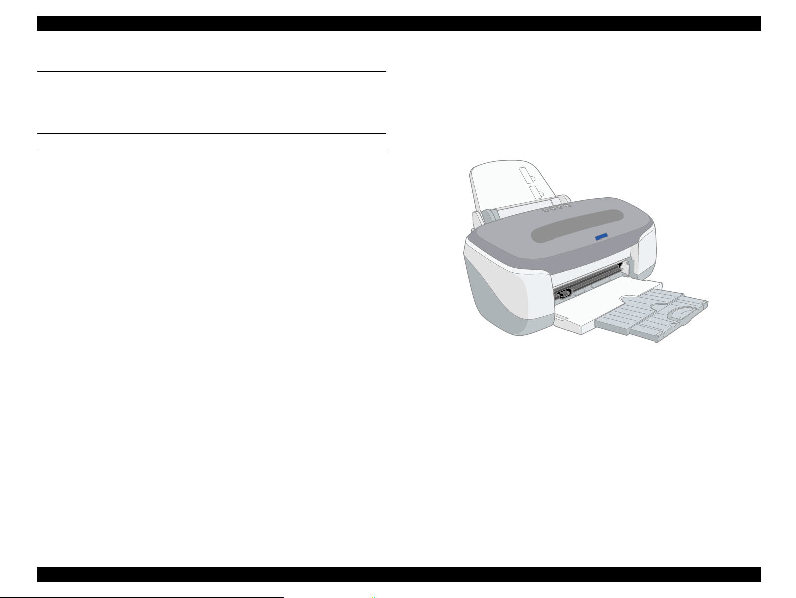
1.1 Overview
This photo printer is designed for a wide user range, from home use through to office
use. It provides even faster speed and higher quality than previous models.
The main features of this printer are:
Suitable for CD-R label direct printing
Direct printing onto CD-R labels is possible. In addition, the CD-R tray can be
inserted into the front of the printer, and the position of the star wheel roller can be
changed using a lever.
FEATURES
High color print quality
High-quality and high-speed bi-directional printing
High photo quality using Photo Mach technology
2880 (H) x 1440 (V) dpi printing
6 color printing
Traditional Microweave, New Microweave
High-speed print
Built-in 2 I/F
Bi-directional parallel I/F (IEEE-1284 level 1 device)
USB I/F
Small and Compact
Used for Windows or Macintosh
Multi-size supported ASF
Provided as standard with an ASF that can handle paper sizes up to A4
Can print on thick paper using front paper feeding
Prints without curling at corners of A4 pages
Roll paper is available
CSIC-compatible independent color ink cartridges
Status information such as ink life is recorded by ink cartridges
Can also be used as a pseudo 4-color printer
Auto Cutter for Roll Paper is available
Figure 1-1. Product's external view
PRODUCT DESCRIPTION Overview 9
Page 10

EPSON Stylus PHOTO 950 Revision A
ENCLOSED PARTS
User's manual
Ink Cartridges
CD-ROM (Printer Driver, Utility, Bundled Software)
Roll Paper Holder
Basket for Roll Paper
Front loading paper guide
Printing Kit for CD-R
Cutter Unit
OPTIONS
Ink cartridge
Black : T0331
Cyan : T0332
Light-cyan : T0333
Magenta : T0334
Light-magenta : T0335
Yellow : T0336
Various special paper
PRODUCT DESCRIPTION Overview 10
Page 11
EPSON Stylus PHOTO 950 Revision A
1.2 Specification
1.2.1 Printing specification
PRINT METHOD
On demand ink jet
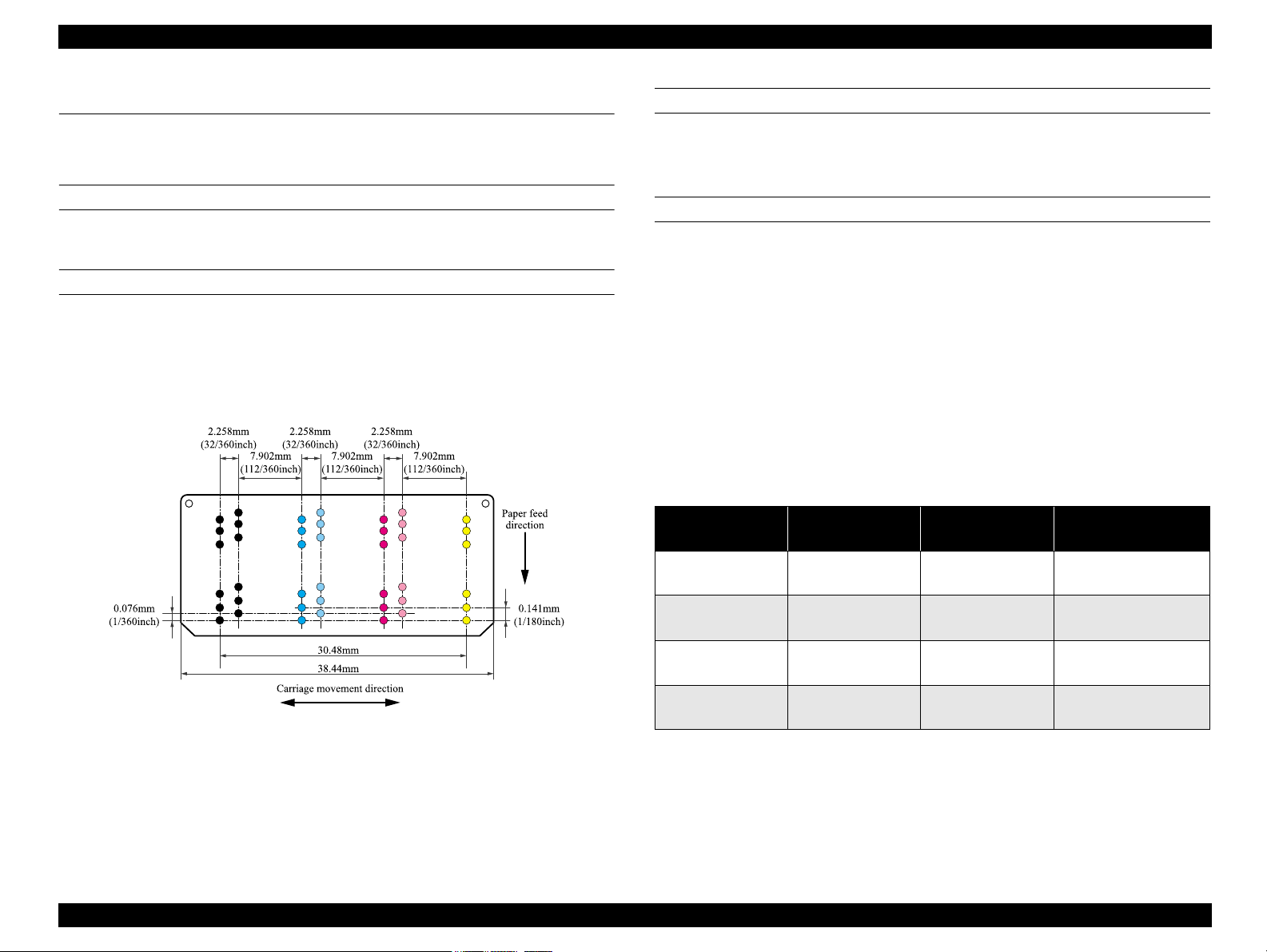
NOZZLE CONFIGURATION
Monochrome:96 nozzles x 2
Color :96 nozzles x 5
(Cyan, Magenta, Yellow, Light Cyan, Light Magenta)
The nozzle layout seen from behind the head is shown below.
PRINT DIRECTION
Text : Bi-directional shortest-direction printing, uni-directional printing
Graphics : Bi-directional shortest-direction printing, uni-directional printing
PRINT SPEED & PRINTABLE COLUMNS
Character mode
Print quality : Fine
Character pitch : 10 CPI (Pica)
Printable columns : 80
LQ speed : 240 CPS
(*)
NOTE: Do not mention this in the user's manual.
NOTE: This value
Raster graphics mode
(*)
is the speed of normal-dot printing.
Table 1-1. Printing Speed and Printing Resolution
Horizontal
resolution
360
Printable area Available dot CR Speed
220.9mm
(8.70inch)
2976
609.6mm/s
(24IPS)
Figure 1-2. Nozzle layout
720
1440
2880
220.9mm
(8.70inch)
220.9mm
(8.70inch)
220.9mm
(8.70inch)
5952
11904
23808
609.6mm/s
(24IPS)
609.6mm/s
(24IPS)
482.6mm/s
(19 IPS)
NOTE: Do not mention this in the user's manual.
PRODUCT DESCRIPTION Specification 11
Page 12

EPSON Stylus PHOTO 950 Revision A
1.2.2 Character specification
CHARACTER TABLES
2 international character sets
PC 437 (US, Standard Europe)
PC 850 (Multilingual)
NOTE: Do not mention this in the user's manual.
TYPEFACE
Bit map LQ font
EPSON Courier 10 CPI
NOTE: Do not mention this in the user's manual.
1.2.3 Control code
ESC/P Raster command
EPSON Remote command
1.2.4 Paper feeding
FEEDING METHOD
Friction feed with ASF
Table 1-2. Paper Specifications for Paper Feeder
Size : A6 to A4 (Portrait)
Paper types
Cut Sheet
ASF
Roll Paper 89/100/127/210 mm wide special paper
Front feed slot CD-R tray/mat board paper, thickness 2.5 mm or less
LINE PITCH
Programmable in units of 4.23 mm (1/6 inch) or 0.0706 mm (1/360 inch)
PAPER INSERTION
• Normal paper (0.08 to 0.11 mm thickness)
• Special paper (genuine printing)
(max. thickness 0.27 mm)
•#10, DL, C6
Friction feed
Friction feed
FEED SPEED
110mm/sec : (13.527mm feed)
304.8mm/sec : (12 inch/sec) (Fast, continuous feed)
PRODUCT DESCRIPTION Specification 12
Page 13

EPSON Stylus PHOTO 950 Revision A
1.2.5 Paper specification
CUT SHEET
Size
A4 (210mm x 297mm)
A5 (148mm x 210mm)
A6 (105mm x 148mm)
B5 (182mm x 257mm)
Letter (216mm x 279mm)
Half letter (139.7mm x 215.9mm)
Legal (216mm x 356mm)
Executive (184.2mm x 266.7mm)
2L (127mm x 177.8mm (5 x 7inch))
L (88.9mm x 127mm (3.5 x 5inch))
Quality
Plain paper, Bond paper
Thickness
0.08mm to 0.11mm (0.003 to 0.004inch)
ENVELOPE
Size
#10 (241.3mm x 104.8mm)
DL (220mm x 110mm)
C6 (162mm x 114mm)
Quality
Bond paper, PPC, Air mail
Weight
2
45g/m
to 75g/m2 (12lb to 20lb)
Flap shape
#10, DL, C6
Flap at lengthwise edge and should be folded closed
Weight
2
64g/m
to 90g/m2 (17lb to 24lb, 55kg to 78kg)
PRODUCT DESCRIPTION Specification 13
Page 14
EPSON Stylus PHOTO 950 Revision A
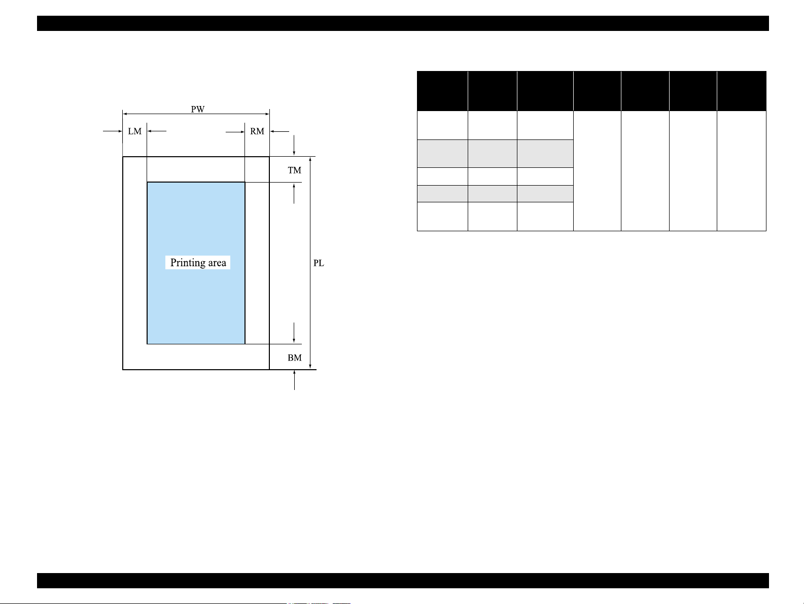
1.2.6 Printing area
The printing area for this printer is shown below.
Table 1-3. Printing area for Stylus PHOTO 950
PW
Paper size
US
Legal
US
Letter
A4 210mm 297mm
B5 182mm 257mm
Photo Card
(4" x 6")
(paper
width)
216mm 356mm
216mm 279mm
113.6mm 175.4mm
NOTE: (*1) Bottom margin can be reduced to 3mm when paper dimension is
defined by using a command, otherwise it remains 14mm.
From lower end 3 mm to 14 mm area may be printed in bad
condition.
NOTE: (*2) There can be set all 0mm using a special command.
PL
(paper
length)
LM
(Left
margin)
(*2)
3mm
RM
(Right
margin)
(*2)
3mm
TM
(Top
margin)
(*2)
3mm
(Bottom
margin)
14mm/
3mm
BM
(*1)(*2)
Figure 1-3. Printing area
PRODUCT DESCRIPTION Specification 14
Page 15
EPSON Stylus PHOTO 950 Revision A
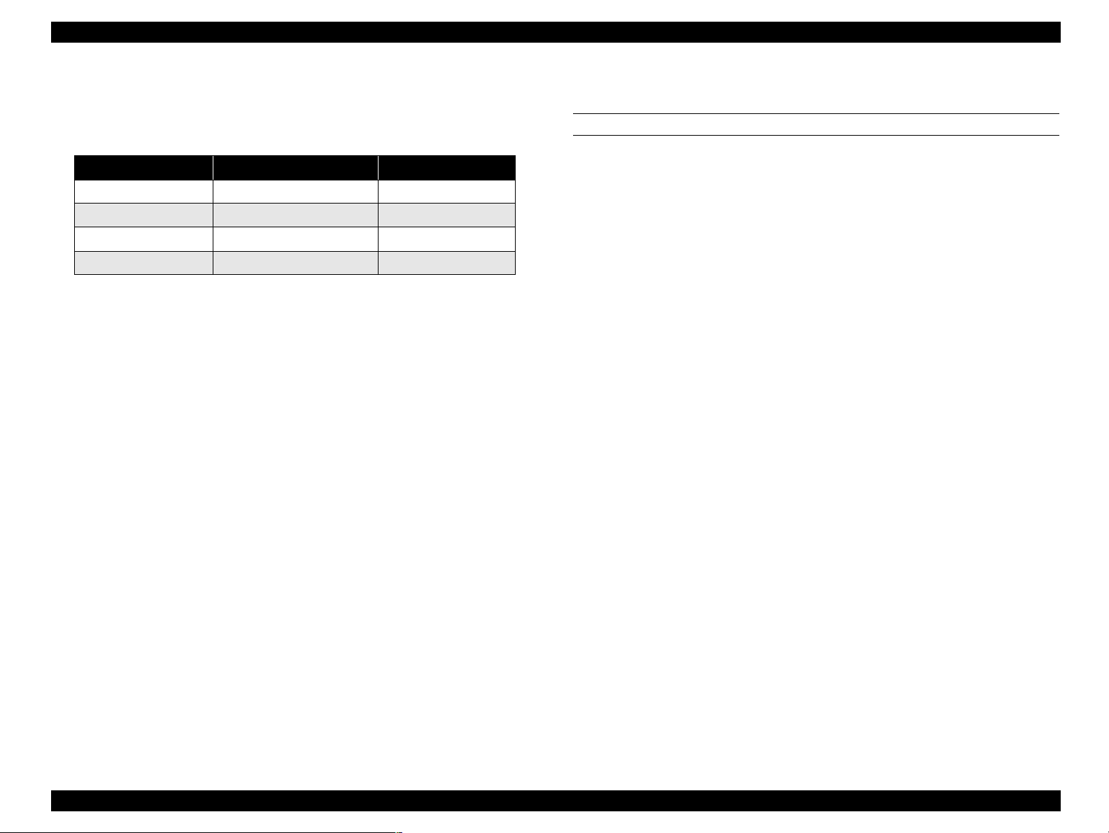
1.2.7 Adjust Lever
The adjust lever should be set as follows depending on the type of paper being used.
Table 1-4. Adjust Lever Settings
Paper Type Adjust Lever Gap adjust
Cut Sheet, OHP, Label First Front Position 0mm
Envelope, Cardboard Second Front Position +1.3mm
CDR Third Front Position +2.7mm
- Back Position
NOTE: (*1)Full release position
NOTE: If the lever is set to "CD-R Tray", the star wheel roller will lift up so as
not to scratch the CD-R.
(*1)
-
1.2.8 Ink
INK CARTRIDGE
Type
Exclusive cartridge for each Color (On Carriage Type)
Color
Black, Magenta, Cyan, Yellow, Light Cyan, Light Magenta
Print capacity (360dpi)
Black ink 570 pages / A4 (ISO/TEC10561 Letter Pattern at 360dpi)
Color ink 440 pages / A4 (360 dpi, 5% duty each color)
Ink life
2 years from production date
Storage temperature
-20°C to 40°C (Storage, within a month at 40 °C)
-30°C to 40°C (Packing storage, within a month at 40 °C)
-30°C to 60°C (Transit, within 120 hours at 60°C and within a month at 40°C)
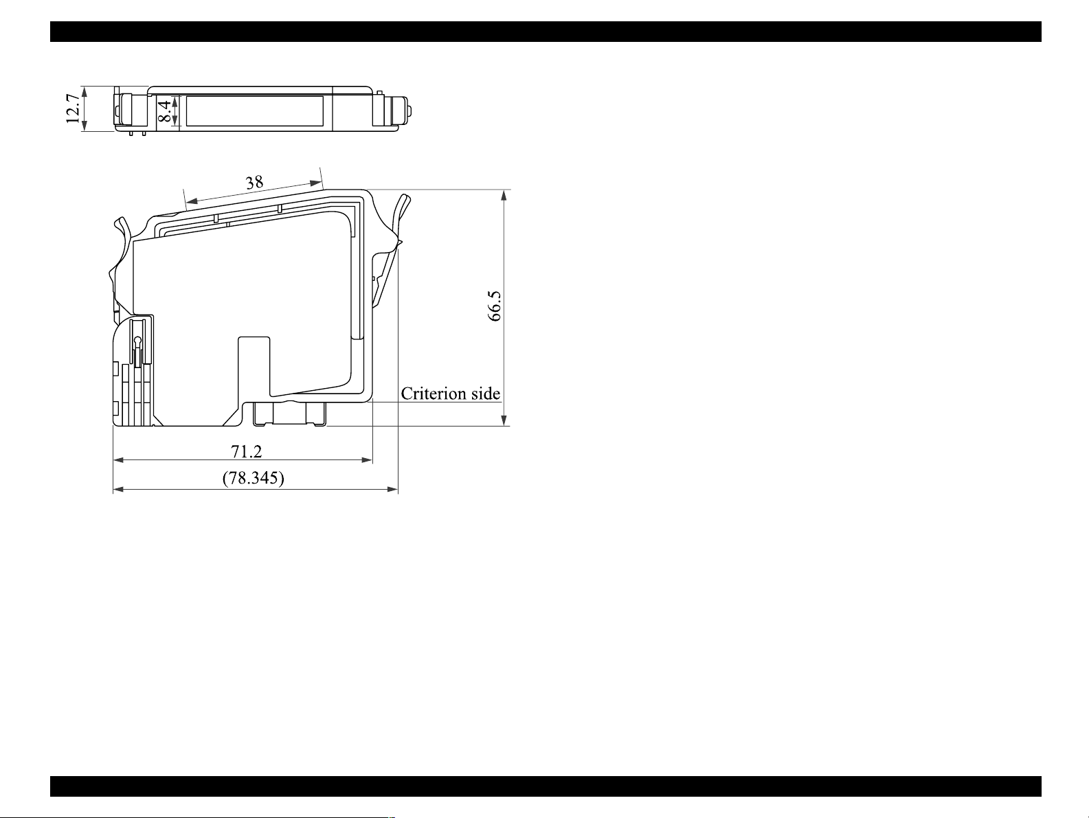
Dimension
12.7mm (W) x 71.2mm (D) x 66.5mm (H)
Weight
42g
PRODUCT DESCRIPTION Specification 15
Page 16
EPSON Stylus PHOTO 950 Revision A
1.2.9 Input data buffer
256kByte
1.2.10 Electrical specification
Rated voltage
AC 220 to 240V
Input voltage range
AC 198 to 264V
Rated frequency range
50 to 60Hz
Input frequency range
9.5 to 60.5Hz
Rated current
0.15A(Max 0.3A)
Power consumption
Approx. 12W (ISO10561 Letter Pattern)
Approx. 3W in standby mode
Energy Star compliant
Figure 1-4. Ink Cartridge Dimensions
Dielectric strength
AC1500V rms. 1 minute (between AC line and chassis)
PRODUCT DESCRIPTION Specification 16
Page 17
EPSON Stylus PHOTO 950 Revision A
1.2.11 Acoustic noise
Level : Approx. 45dB (A) (According to ISO 7779)
1.2.12 CE Marking
Low Voltage Directive 73/23/EEC : EN60950
EMC Directive 89/336/EEC : EN55022 class B
EN61000-3-2
EN61000-3-3
EN55024
1.2.13 Safety Approvals
Safety standards : EN 60950 (VDE)
EMI : EN 55022 (CISPR Pub.22) class B
AS/NZS 3548 class B
1.2.14 Reliability
Total print volume
25,000 pages (Black)/10,000 pages (Color) (A4, Letter)
Printhead Life
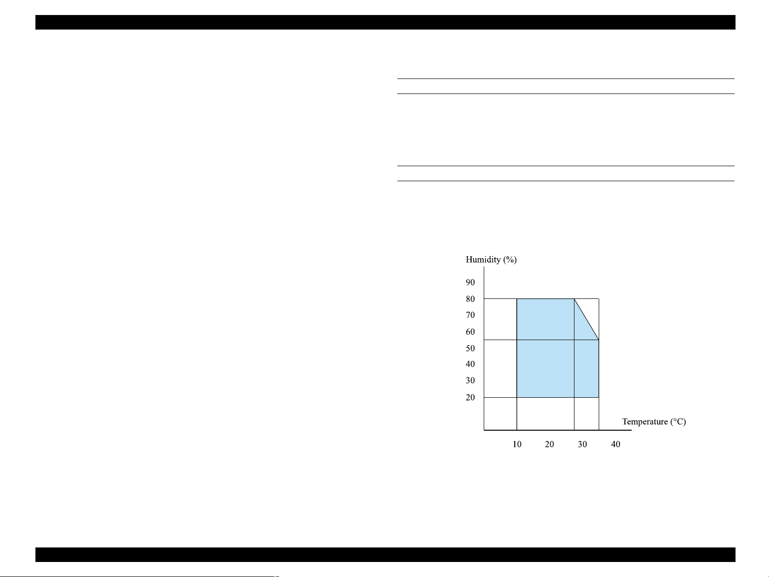
1.2.15 Environmental condition
TEMPERATURE
10 to 35°C (operating)
-20 to 60°C (non-operating)
NOTE: 1 month at 40
HUMIDITY
20 to 80% RH (operating)
5 to 85% RH (non-operating)
However, the conditions should be within the range of the graph as shown below.
°
C, 120 hours at 60°C
3000 million dots/nozzle
Figure 1-5. Temperature/Humidity Range
PRODUCT DESCRIPTION Specification 17
Page 18

EPSON Stylus PHOTO 950 Revision A
RESISTANCE TO SHOCK
1G, within 1ms (operating)
2G, within 2ms (non-operating)
RESISTANCE TO VIBRATION
0.15G (operating)
0.50G (non-operating)
NOTE 1: You should check that the printhead is capped during storage.
NOTE 2: You should check that the printhead is capped during
transportation, and the ink cartridges should still be installed to
the printer at this time.
NOTE 3: If the printhead is not capped while the power is turned off, you
should turn the power on while the ink cartridges are still installed
to the printer. Once the printhead has been capped, then turn the
power back off.
NOTE 4: If the printer is left to stand at ambient temperatures of -4
°
C or
less, the ink inside the printhead and inside the ink cartridges will
freeze. If the ink has frozen, the printer will need to be left to stand
at an ambient temperature of 25
°
C before the ink can be used.
PRODUCT DESCRIPTION Specification 18
Page 19
EPSON Stylus PHOTO 950 Revision A
1.3 Printer Function
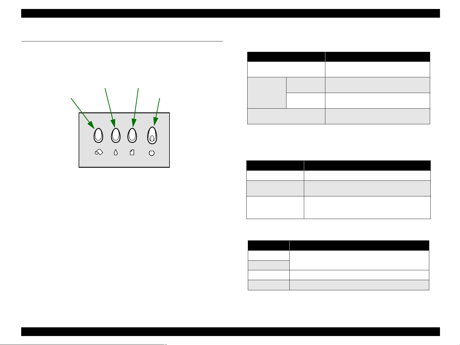
1.3.1 Operator controls
The control panel is shown in the figure below.
Paper switch
Roll Paper switch
Figure 1-6. Operator controls
1.3.2 Operate switch
Ink switch
Roll Paper switch
Paper switch
Power switch
1.3.3 Indicators
Power : Green
Paper Error : Red
Ink Error : Red
Ink switch
Power switch
1.3.4 Panel Functions
Table 1-5. Normal Panel Functions
Switch Function
Paper
No Cutter
Roll Paper
Use Cutter
Ink
NOTE: (*1) Tear OFF
→
Cut by Cutter → Tear Off Return
As for the Tear Off execute, and, Tear Off isn't done again right
after loading paper.
NOTE: (*2) Pushing for 3 seconds.
Table 1-6. Panel Function with Power on
Switch Functions
Paper
Roll Paper
Paper
+
Roll Paper
Starts status printings
Change code pages / Select IEEE1284.4 mode
for parallel I/F
Enters the special settings mode
NOTE: (*3) According to the content of 1BH of EEPROM, one of following
actions is carried out.
Table 1-7. The Content of 1BH of EEPROM
[bit7][bit6] Action
00(H)
11(H)
01(H)
10(H)
Print firmware version, ink counter, selected code page and
nozzle check pattern
Start hex-dump printing
Start self test printing
• Loads or Ejects the Paper
• Return from Error
• Tear Off feed and return
• Load or Eject (Back Out feed) Roll paper
•Tear Off
• Load or Eject (Back Out feed) Roll paper
• Start the Ink Cartridge change sequence
• Cleaning
(*1)
(*2)
(*3)
(*4)
(*5)
(*2)
(*2)
NOTE: (*4) Not described in the User's manual.
NOTE: (*5) Not described in the User's manual.
Refer to 1.3.5 "Special settings mode (*1)" page 20
PRODUCT DESCRIPTION Printer Function 19
Page 20
EPSON Stylus PHOTO 950 Revision A
1.3.5 Special settings mode
(*1)
Special demise mode is chosen by pushing the next switch in (three seconds) in the
time when error indicator blinks after the power supply is turned on with pushing paper
switch and roll paper switch.
Table 1-8. Special settings mode
Switch Functions
Paper Initialize EEPROM
Roll Paper
(Pushing for 10 seconds)
NOTE: (*1) Not described in the User's manual.
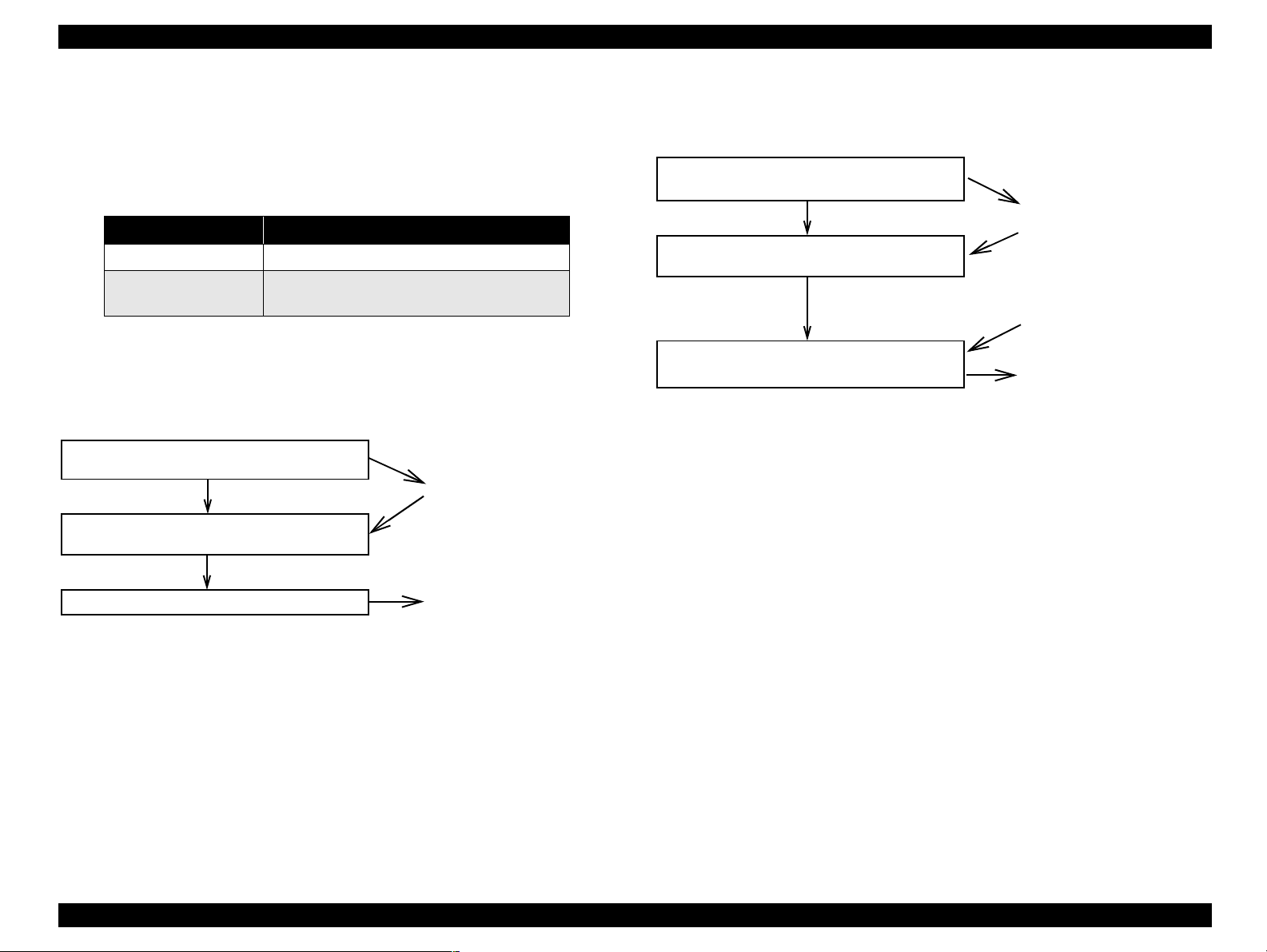
1. Initialize EEPROM
The operation procedure
Turn the printer on with the Roll Paper SW
pressed.
Release the Roll Paper SW.
Press the paper SW.
(*2)
Reset the ink overflow counter in EEPROM
ì
Response
Paper indicator and ink
indicator starts blinking
(blink 2).
2. Reset the ink overflow counter in EEPROM
The operation procedure
Response
Turn the printer on with the Roll Paper SW and
Paper SW pressed.
Paper indicator and ink
indicator starts blinking
Release the Roll Paper SW.
Press the Paper SW and keep it pressed.
(*2)
(blink 2).
(10 seconds later)
Power, paper and ink
indicators are lighted.
Paper and Ink indicators light for two
seconds.
Special setting mode is
finished, and printer restarts.
NOTE: (*2)Printer start normal mode if switch isn't pushed while LED is
blinking for 3 second.
Paper and Ink indicators light for one second.
Special setting mode is
finished, and printer restarts.
NOTE: (*2)Printer start normal mode if switch isn't pushed while LED is
blinking for 3 second.
PRODUCT DESCRIPTION Printer Function 20
Page 21
EPSON Stylus PHOTO 950 Revision A
−
"
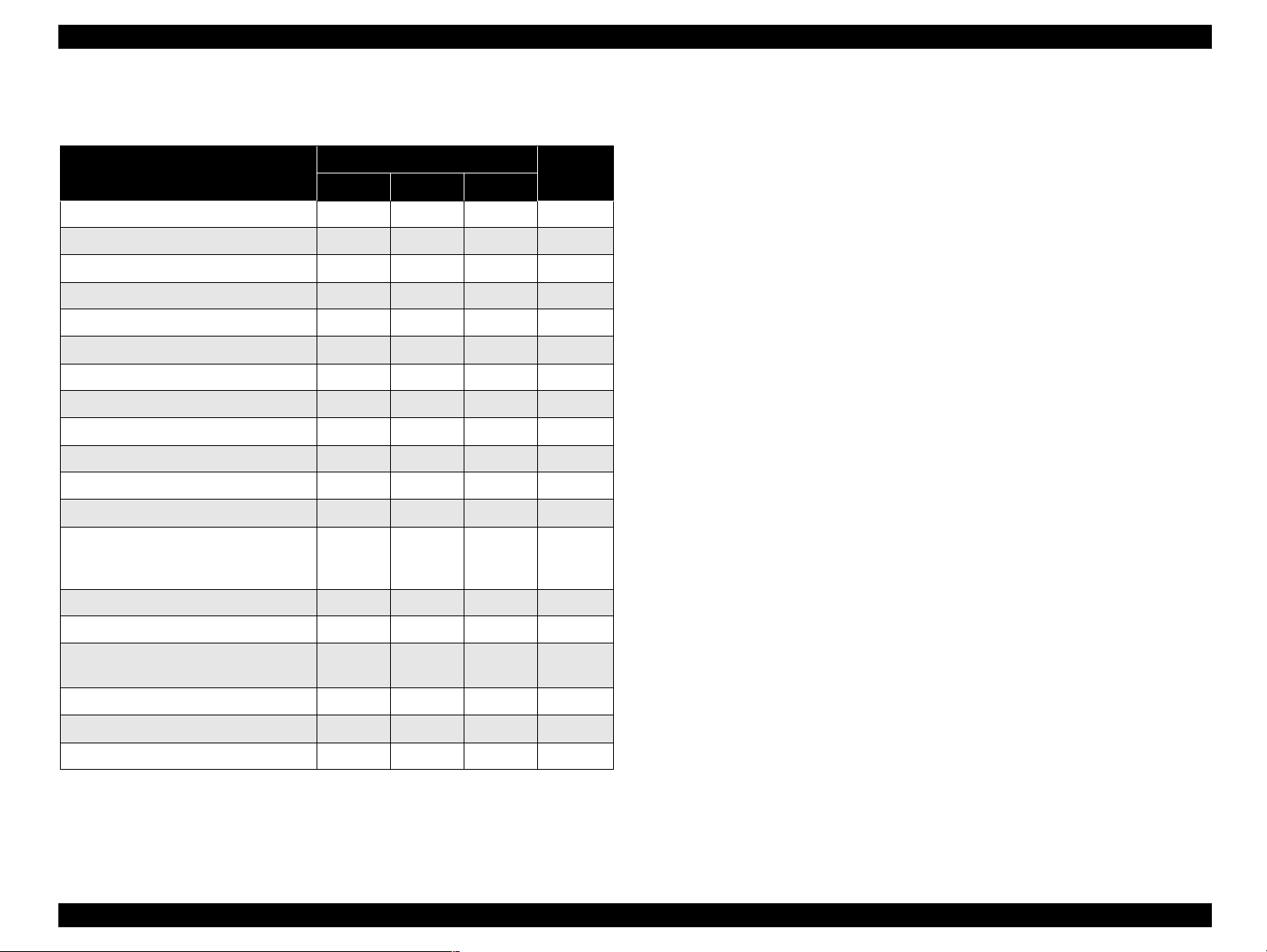
1.3.6 Printer condition and Panel status
Table 1-9. Panel status
Printer Status
Power Paper Ink
Power ON Condition On
Data processing Blink
Ink sequence Blink −−14
Indicator
Priority
−−
− −
16
15
" : Indicator status don't change.
Blink : The Redo of 0.5second On, 0.5second Off.
Blink 2 : The Redo of 0.2second On, 0.2second off, 0.2second On,
0.4second Off
High-speed Blink : The Redo of 0.1second On, 0.1second Off.
Alt Blink : The Redo of Paper and Ink Indicator.
(*1)Double feed error occur to Double-sided printing.
Ink cartridge change mode Blink
Ink level low (all colors) −−Blink 12
Paper out
Ink end (all colors) −−On 10
No Ink Cartridge (all colors)
Double feed error
Paper jam condition
Paper thickness error − On − 6
Cutter jam condition
Adjust lever error −
Cutter position error Off Blink On 3
Fatal error Off On On 2
Maintenance request
(Ink Overflow Counter error)
Reset, Timer IC reset, EEPROM clear On (1s) On (1s) On (1s) -
Ink Overflow Counter reset On (2s) On (2s) On (2s) -
Special setting Blink 2 Blink 2 Blink 2 -
(*1)
−
− −
−
−
−
Off Alt Blink Alt Blink 1
− −
On
On
Blink
Blink
Highspeed
Blink
−
On 9
−
−
−
− 4
13
11
8
7
5
PRODUCT DESCRIPTION Printer Function 21
Page 22

EPSON Stylus PHOTO 950 Revision A
1.3.7 Printer Initialization
There are four kinds of initialization method.
Power-on initialization
Power-on initialization
This printer is initialized when printer recognized the cold-reset command
(remote RS command).
When printer is initialized, the following actions are performed.
This printer is initialized when turning the printer power on.
When printer is initialized, the following actions are performed.
Initialize printer mechanism
Eject Paper
Clear input data buffer
Clear print buffer
Set default values
Software Initialization
The ESC @ command also initializes the printer.
When printer is initialized, the following actions are performed.
Clear print buffer
Set default values
Operator initialization
This printer is initialized when turning the printer power on again within 10
seconds from last power off, or printer recognized the -INIT signal (negative
pulse) of parallel interface.
When printer is initialized, the following actions are performed.
Cap the printhead
Initialize printer mechanism
Eject Paper
Clear input data buffer
Clear print buffer
Set default values
Clear input data buffer
Clear print buffer
Set default values
PRODUCT DESCRIPTION Printer Function 22
Page 23

EPSON Stylus PHOTO 950 Revision A
1.3.8 Default Values
Default Values described above are as follows:
A part of the memory contents remain their values in case of panel setting, DEFAULT
setting or Remote command.
Page Position : Now Position
Line Feed Values : 4.23mm (1/6inch)
Right Margin : 80columns
Left Margin : 1column
Character pitch : 10CPI
Printing Mode : Text Mode
1.3.9 Errors
Printer becomes error condition when the following conditions are detected.
Concerning I/F signals, ERROR is set to "low", BUSY is set to "high", and data input
is prohibited. Then, the printer stops its movement. Exceptionally, the printer continue
to move when it's communicating by the IEEE1284.4 protocol.
Ink out
When the printer has almost run out of ink in any cartridge, it indicates Ink
low warning and keeps printing.
When the printer has completely run out of ink in any cartridge, it indicates
Ink out error.
Paper out
When printer fails to load a sheet, it goes Paper out error.
Paper jam
When printer fails to eject a sheet, it goes Paper jam error.
Paper obstruction
A paper obstruction is considered, and made error at the time of power supply
on when the excretion of the form isn't made of the FF command or the Paper
SW when the excretion of the remaining paper can't do it by the paper feed
action of the number of provision step.
No Ink Cartridge/ Ink Cartridge error
When printer detects that ink-cartridge comes off, it goes this error mode.
When the printer can't read/write CSIC information of any ink cartridge, it
indicates Ink cartridge error.
Maintenance request
When the total quantity of wasted ink used for cleaning and flushing reaches
the limit, the printer indicates this error and stops printing. The absorber in the
printer enclosure is needed to be replaced with new one by a service person.
PRODUCT DESCRIPTION Printer Function 23
Page 24
EPSON Stylus PHOTO 950 Revision A
Fatal error
Carriage control error or CG access error.
Adjust lever position error
It is made error when Adjust lever is in the integrity of a release.
It is made error when printout mode isn't suitable toward the platen gap.
Panel should invalidate it at the time of the error, and printout becomes
cessation.
Paper thickness error
When the gap between the printer head and a piece of paper is too narrow
because the piece of paper set to the printer is thick, the printer indicates Paper
thickness error. And it stops printing.
Double feed error
When pieces of paper are piled up on ASF in double-side printing mode, or
when the printer detects paper deviation, it indicates Double feed error. And it
stops printing.
Cutter position error
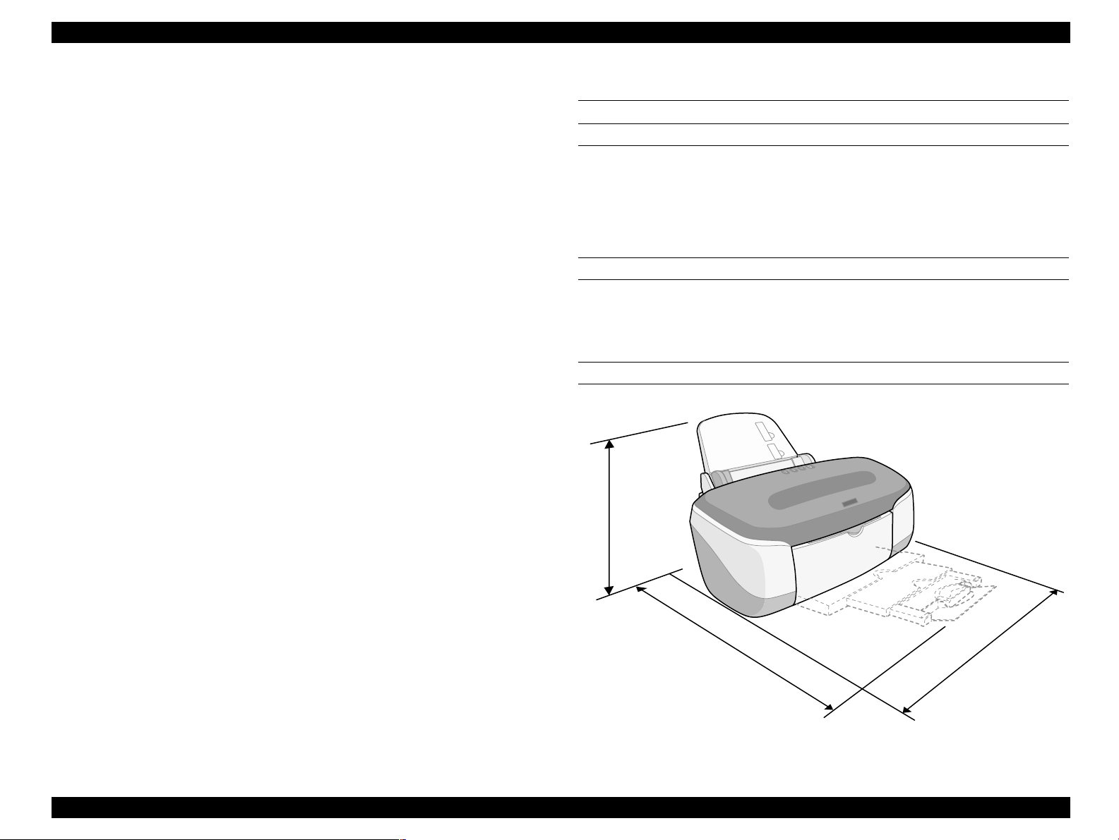
1.4 Physical specification
DIMENSIONS
515mm (W) × 332.8mm (D) × 209mm (H) : Storage
515mm (W) × 663mm (D) × 299mm (H) : Printing
515mm (W) × 626mm (D) × 299mm (H) : Used cutter
WEIGHT
Normal Weight : 7.6kg
Weight with Cutter : 8.6kg
PHYSICAL DIMENSIONS
It is made error when the cutter doesn't return to the Home position after the
cutter action or after Mechanical initializing.
Cutter jam error
When the printer can't cut paper in enabling cutter mode, it indicates Cutter
jam error.
NOTE: Refer to 1.3.6 "Printer condition and Panel status" for details on each
indicator.
299
663
515
Figure 1-7. Physical dimensions
PRODUCT DESCRIPTION Physical specification 24
Page 25

OPERATING PRINCIPLES
CHAPTER
2
Page 26
EPSON Stylus PHOTO 950 Revision A
2.1 Overview
This section describes the operating principles of the printer mechanism and electrical
circuit boards. The main components of the printer are as follows.
Printer Mechanism
Main board : C456MAIN
Power supply board : C456PSB/PSE
2.2 Printer Mechanism
One of the major features of this printer is that it uses DC motors as the devices that
provide movement. This results in improved printing accuracy and improved paper
feed accuracy, and greatly reduces the amount of extraneous noise during printing. The
types of motor used and their applications are given below.
Table 2-1. Motors
Motor Type Applications/Functions
This is used to drive the carriage. It makes almost no
CR motor
PF motor
Pump motor
DC motor
DC motor
4-phase 48-pole
PM-type
Stepping Motor
noise when the carriage is being driven. However, a
linear scale is provided so that the current drive
status can be ascertained.
This is used as the source of power to drive the paper
feed rollers during constant length feed and paper
eject operations. A loop scale is provided on the
surface of the high-precision gear so that the paper
feed pitch status can be ascertained.
This is used to drive the pump. Because it is a
stepping motor, it does not require scales or photo
sensors in order for the current drive status to be
ascertained.
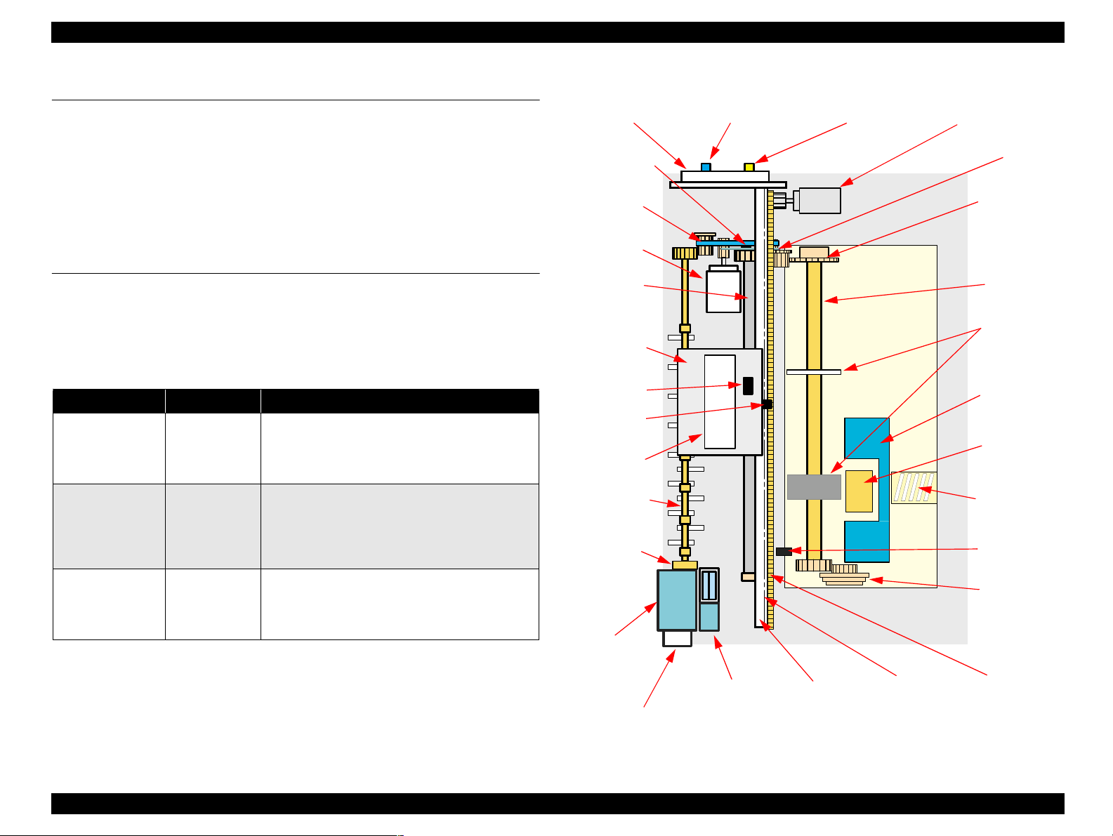
A general diagram of the printer mechanism is shown in the following figure.
Adjust lever
PG sensor Release sensor
CR motor
PF encoder
PF timing
belt
Clutch
mechanism
PF motor
PF roller
Carriage
LD roller
LD Roller
unit
PW sensor
Paper Back
CR sensor
Print
separation
head
Paper eject
roller
CR lock
lever
ASF hopper
spring
PE sensor
Silence cam
Pump
assembly
Rotary
scale
shaft
lever
Paper
pad
Pump
motor
Cap
assembly
CR guide
shaft
Linear
scale
Timing belt
Figure 2-1. Printer Mechanism block diagram
OPERATING PRINCIPLES Overview 26
Page 27
EPSON Stylus PHOTO 950 Revision A
2.2.1 Parenthood
The printhead uses a new developed G-MACH head and Stylus PHOTO 950 can
perform variable dot printing.
The CSIC-chip is mounted on the ink cartridge. By storing ink life data, this IC makes
it possible to control the ink in ink cartridge unit.
The basic operating principles of the printhead, which plays a major role in printing,
are the same as previous models; on-demand method which uses PZT (Piezo Electric
Element). In order to uniform the amount of ejecting ink, the printhead has its own
head ID (19 digits for this printhead) which adjust PZT voltage drive features.
The printhead stores the head ID to EEPROM and generates appropriate PZT drive
voltage to prevent amount of ink from varying by printheads.
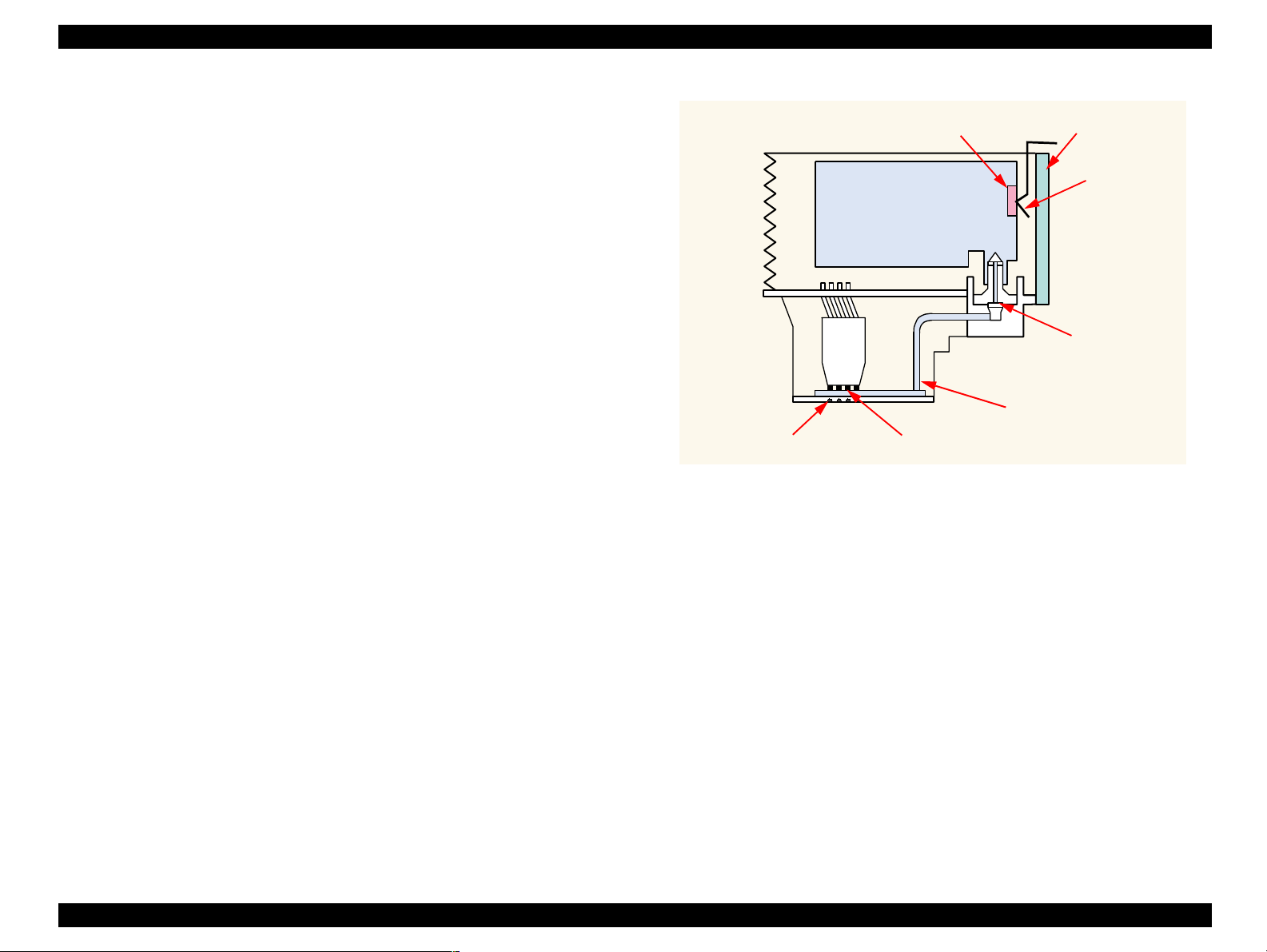
Following explains printhead basic components.
PZT
PZT is an abbreviation of Piezo Electric Element. Certain amount of voltage
expands and contracts PTZ. The drive wave generated on MAIN board drives PZT
and PZT pushes the top cavity which has ink stored to discharge the ink from each
nozzle on the nozzle plate.
Ink Cavity
The ink absorbed from the ink cartridge goes through the filter and then is stored
temporarily in this tank called “cavity” until PZT is driven.
CSIC
Ink Cartridge
Cavity
Nozzle Plate
PZT
Figure 2-2. Printhead Sectional Drawing (Image)
Nozzle Selector
Board
Electrodes for
CSIC-chip
Filter
Nozzle Plate
The board with nozzle holes on the printhead surface is called Nozzle Plate.
Electrodes for CSIC-chip
The communication between CSIC-chip and main unit is performing via the
electrodes on the carriage.
Filter
When the ink cartridge is installed, if any dirt or dust around the cartridge needle is
absorbed into the head, there is a great possibility of causing nozzle clog and
disturbance of ink flow, and finally causing alignment failure and dot missing. To
prevent this problem, a filter is set below the cartridge needle, where ink is filtered.
OPERATING PRINCIPLES Printer Mechanism 27
Page 28
EPSON Stylus PHOTO 950 Revision A
2.2.2 Carriage Mechanism
The carriage mechanism consists of components such as a carriage motor (CR motor),
carriage guide shaft, platen gap adjustment mechanism, parallelism adjustment
mechanism and a carriage lock mechanism.
2.2.2.1 Carriage Motor (CR Motor)
The carriage mechanism used in this printer uses a DC motor as the drive source, in the
same way as in previous models. The specifications for the DC motor used to drive the
carriage mechanism are shown below.
Table 2-2. Carriage Motor Specification
Items Specifications
Type
Drive Voltage
Coil Resistance
Inductance
Drive Method
Driver IC
+42 +/- 5 % (DRV IC voltage)
23.0Ω +/- 25 % (per phase at 25 degree)
24.0 mH +/- 25% (1KH 1VmA)
PWM drive, Constant current chopping
The CR motor in previous models was a stepping motor, and the position of the
carriage unit was controlled by means of open loop control. However, this printer
employs closed loop control via the DC motor and a linear encoder to control the
carriage speed and position in order to provide the same stable printing quality as the
EPSON Stylus PHOTO 890.
At the same time, the CR motor is also used to generate the basic signal (PTS signal)
that is used to regulate the ink ejection timing (See "CR Motor Driver Circuit" on page
50 for details on the CR motor control circuit.)
DC motor
A3958
Parallelism
adjustment
bushing
CR guide
shaft
Linear scale
CR motor
Platen surface Carriage
CR guide shaft
unit
Figure 2-3. Carriage Mechanism (TOP VIEW)
During printing, the carriage unit is moved within the printing area by the CR motor
along the carriage guide shaft of the printer mechanism.
OPERATING PRINCIPLES Printer Mechanism 28
Page 29

EPSON Stylus PHOTO 950 Revision A
2.2.2.2 Platen Gap Adjustment Mechanism and Parallelism Adjustment Mechanism
The adjust lever is installed to the left end of the carriage guide shaft.
The carriage guide shaft is an eccentric shaft that rotates when the adjust lever is
operated in order to increase or decrease the gap (platen gap or PG) between the platen
surface and the surface of the printhead. This mechanism allows the user to select the
optimum platen gap in accordance with the desired printing results or in accordance
with other printing conditions such as paper curl. (See Table 2-3.)
In addition, the parallelism adjustment levers that are installed to the left and right ends
of the carriage guide shaft adjust the degree of parallelism between the carriage guide
shaft and the platen.
Table 2-3. Adjust Lever Settings
Paper Type Adjust Lever Gap adjust
Cut Sheet, OHP, Label First Front Position 0mm
Envelope, Cardboard Second Front Position +1.3mm
CDR Third Front Position +2.7mm
- Back Position
NOTE: (*1)Full release position
The printer can detect the position of the adjust lever by means of the release sensor
and the PG sensor.
(*1)
-
2.2.2.3 Carriage Home Position Detection
The method used to detect the carriage home position is the same method used in
previous model (EPSON Stylus PHOTO 890) whereby the CR motor drive current and
the speed and position signals from the linear encoder are used to detect the position.
(See "CR Motor Driver Circuit" on page 50 for further details.)
OPERATING PRINCIPLES Printer Mechanism 29
Page 30
EPSON Stylus PHOTO 950 Revision A
2.2.3 Paper Feeding Mechanism
The Paper Feeding mechanism consists of components such as ASF, Manual Feed
Mechanism and Roll paper holder.
2.2.3.1 ASF Mechanism
The paper feeding mechanism consists of Paper feed motor (PF motor), PF roller,
Paper eject roller, Star wheel roller, and so on. The paper feeding mechanism feeds
paper loaded from ASF using the PF roller and Paper Eject Roller & Star wheel roller.
For this mechanism, the PF motor mentioned in the following Table 2-4 is used on this
product.
Table 2-4. PF Motor Specifications
Item Description
Motor type
Drive voltage
Coil Resistance
Inductance
Driving method
+42V +/- 5% (DRV IC voltage)
30.5Ω +/- 15% (per phase at 25 degree)
22.8mH +/- 15% (1kH 1Vrms)
PWM drive (PWM means Pulse Width Modulation)
DC motor
The paper feed motor used in previous models was a stepping motor and control was
carried out by means of open loop control. However, this printer employs closed loop
control via a DC motor and a rotary encoder to control the carriage speed and position
in order to improve the paper feeding accuracy. The rotary encoder is installed to the
left end of the PF roller shaft and controls the paper feeding amount. See "PF Motor
Driver Circuit" on page 50 of this chapter for details of the PF motor control circuit.
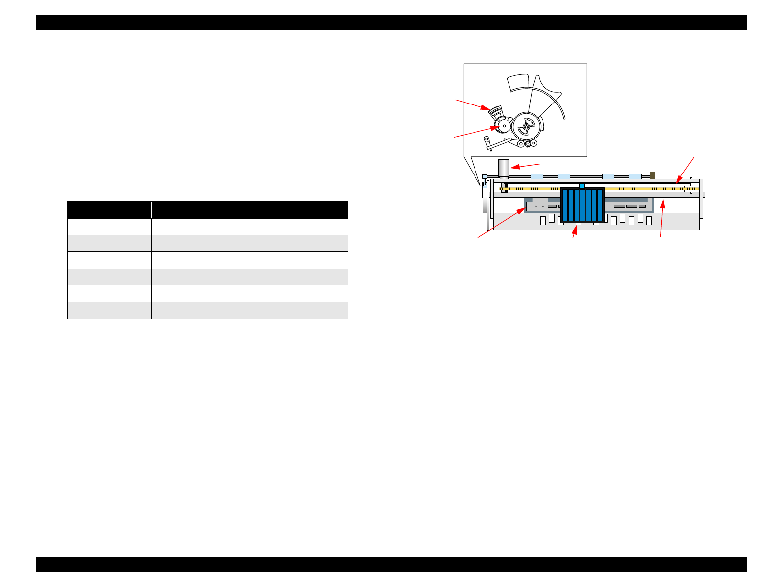
The PF motor drive force is transmitted to the PF roller and the paper eject roller along
the route described below.
PF roller drive force transmission route
PF motor pinion gear → PF rotary encoder → PF roller
Paper eject roller drive force transmission route
PF motor pinion gear → Combination gear 9.5, 14.7 → Paper eject roller
A diagram of the PF motor drive force transmission route, including the names of the
components included in this route, is shown on the following page. The paper is
transported along the following path by means of the above drive force transmission
routes.
Combination gear
12, 16
PF rotary
encoder
Spur gear 12
PF motor
pinion gear
Spur gear 21.5
Combination gear
9.5, 14.7
Figure 2-4. Paper Feeding Mechanism 1
OPERATING PRINCIPLES Printer Mechanism 30
Page 31

EPSON Stylus PHOTO 950 Revision A
When paper is fed from the ASF, the feeding of paper is detected by the PE sensor that
is located on the right side of the top frame, and the leading edge of the paper then
travels as far as the front-center part of the paper guide.
Then, in order to take up any slackness in the paper, the paper is moved back toward
the ASF by a preset number of steps, and it is then transported once more to the
specified starting position inside the front of the paper guide.
When printing starts, the paper is transported by the drive force of the PF roller and the
auxiliary roller. When the bottom edge of the paper (14 mm or more from the bottom
edge of the paper) is being printed and transported, the paper is transported by the drive
force of the paper eject roller and the star wheel roller.
See Figure 2-5 "Paper Feeding Mechanism 2" for details on the paper feed path and the
names of the various parts.
Previous product
Star wheel
roller
Paper
Paper eject roller
Platen surface
Printhead
Support roller
Bottom margin 3mm
PF roller
2.2.3.2 Manual Feed Mechanism
This printer uses a new method of manually feeding paper from the front of the printer
that enables the printer to print directly onto thicker types of paper and also onto CD-R
labels. The feeding path for the paper that is supplied to the printer in this way pulls the
paper once all the way through the printer from the front to the back in a straight line,
and then returns it to the front of the printer. See Figure 2-6 "Manual Feed Mechanism"
for details on the paper feed path and the names of the various parts.
Star wheel roller
Paper
Front paper
insertion slot
Paper eject roller
Figure 2-6. Manual Feed Mechanism
Platen surface
Stable transporting
Printhead
Support roller
PF roller
ASF
Stylus PHOTO 950
Stable transporting
Figure 2-5. Paper Feeding Mechanism 2
OPERATING PRINCIPLES Printer Mechanism 31
Page 32

EPSON Stylus PHOTO 950 Revision A
2.2.3.3 Carriage Lock
The carriage lock mechanism is used to prevent the printhead from becoming uncapped
for long periods as a result of vibration affecting the printer during transportation, and
also due to lack of care in handling by the user. If the printhead is left uncapped for
long periods, the ink on the surface of the printhead will gradually dry out, and this can
result in ink not being able to reach the nozzles. In addition to this, the nozzle holes can
become blocked with dried-out ink and normal head cleaning may not be able to
restore normal operation. The ink may also leak out at such times. In order to prevent
these things from happening, the printer locks the carriage unit in the following cases.
Mechanism
After the power turns off
If the power turns off while printing or other operations are in progress, the printer
is fully reinitialized and then the carriage is locked.
After the power turns on
After the power is turned on, timer cleaning is carried out automatically, and the
carriage is locked during this time.
Timer cleaning
1. The printer stores the date printing was last carried out in its EEPROM.
(The Stylus PHOTO 950 printer driver always appends the current date
reported by the computer's operating system to print commands when these
commands are sent to the printer.)
2. When printing is carried out at a subsequent time, the "previous printing
date" recorded in the EEPROM is compared with the date reported by the
computer's operating system that has been appended to the current print
command, and if the difference in the two dates is greater than a specified
length of time, timer cleaning is carried out.
Carriage lock lever
<Left side> <Right side>
Lock
Unlock
After paper is ejected
If no print data is sent to the printer after the maintenance switch has been pressed,
the printer locks the carriage unit and switches to standby mode. However, if paper
is fed into the printer, the carriage is not locked.
Figure 2-7. Carriage lock mechanism
OPERATING PRINCIPLES Printer Mechanism 32
Page 33

EPSON Stylus PHOTO 950 Revision A
2.2.3.4 Star Wheel Roller Release Mechanism
This printer is equipped with a new star wheel roller release mechanism that allows
printing of CD-R labels without leaving marks that look like a sewing machine seam
on the surface.
When the adjust lever is move to the CD-R printing position, the star wheel roller
mounting plate is lifted up, so that the star wheel roller that is mounted on this plate is
also lifted up.
Star Wheel Roller Mounting Plate
Figure 2-8. Star wheel roller release mechanism
OPERATING PRINCIPLES Printer Mechanism 33
Page 34

EPSON Stylus PHOTO 950 Revision A
2.2.4 Paper Loading Mechanism (ASF Unit)
The Paper loading mechanism is positioned at the printer rear. The Paper loading
mechanism loads paper at the ASF unit and feeds paper to the PF roller.
ASF Support Guide
Paper Back
Transmission Lever
Figure 2-9. ASF Support Guide
Purpose
CLUTCH MECHANISM
The Clutch mechanism is located at the rear of the printer inside the left part of the
ASF unit.
Unlike the previous products, this product dose not have a ASF HP sensor.
Instead of the ASF HP sensor, Change lever and the Clutch mechanism are used to
detect the ASF home position. Following figures describe the mechanism.
Paper feeding
1. When the print data is sent to the printer, paper feeding starts.
2. The Carriage unit moves to the left side of the printer and contacts the Change
lever, causing the hook of the Change lever to disengage from the projection on
the Clutch.
The projection
on the clutch
The hook of
the change lever
1. When the specification 150 sheets of plain paper have been set, the customer can
generally check whether 150 pages are loaded from the thickness of the ASF
marking. However, it can be assumed that some customers might try to force more
than 150 sheets in. The ASF guide is shaped like a key so that no more than 150
sheets can be placed into it so as to prevent paper feeding problems. The result is
that this key shape encourages the customer to remove the excess number of sheets
and to place them back into the hopper.
2. Another purpose of the ASF support guide is that when the paper back lever snaps
back into place during paper feeding, the paper back lever also brings the keyshaped ASF support guide back to prevent multiple sheets of paper from being fed
at once, thus improving the reliability of paper feeding.
Change lever
Figure 2-10. Paper feeding (1)
OPERATING PRINCIPLES Printer Mechanism 34
Page 35

EPSON Stylus PHOTO 950 Revision A
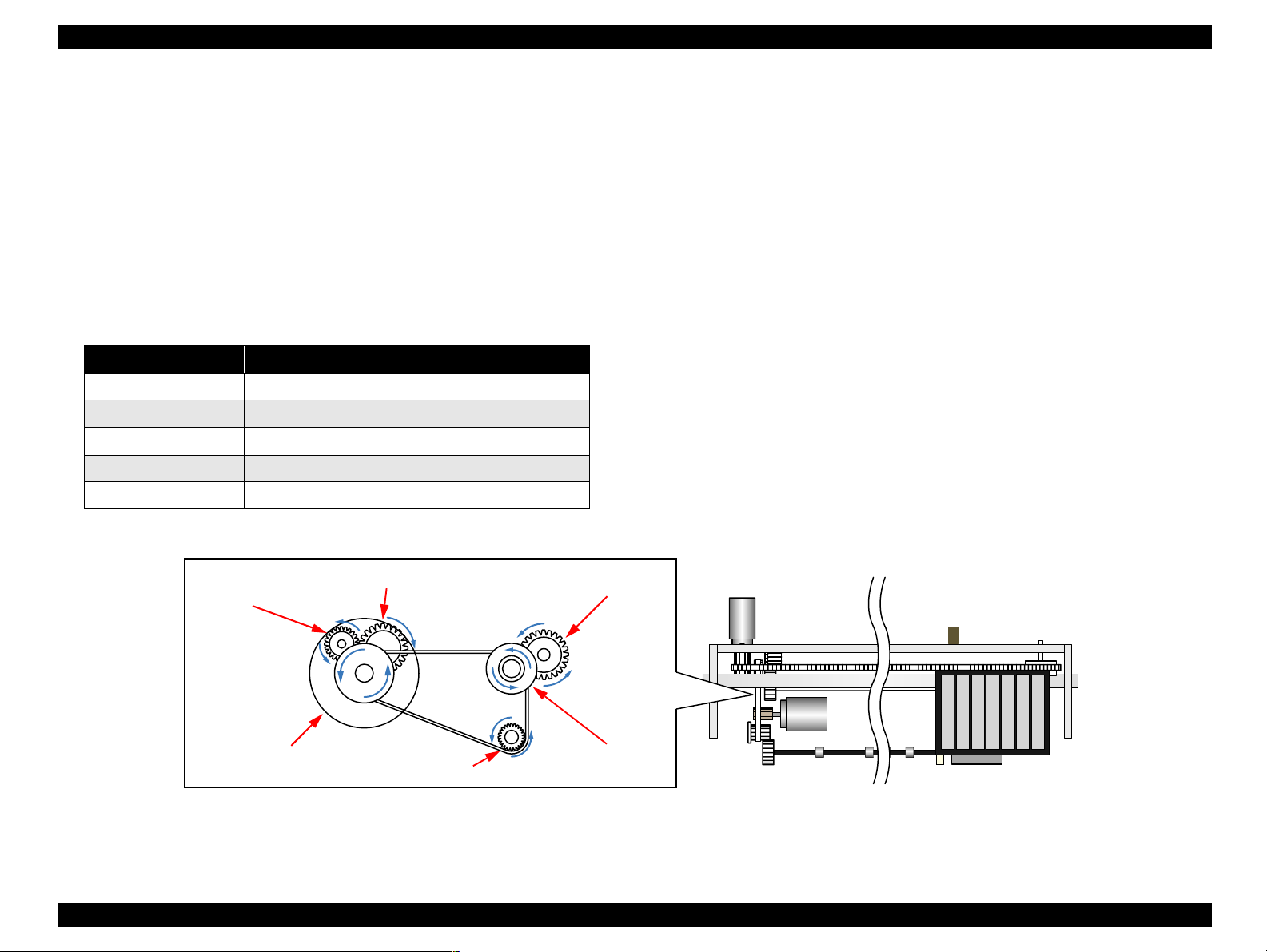
3. The driving force from the PF motor is transmitted via Combination gears 18.2
and 32.8, Spur gear 22.4, Spur gear 12 and Combination gear ratchet 33.4 in that
order, causing the clutch and the LD roller to rotate clockwise so that paper is fed.
Combination gear
ratchet 33.4
Spur gear 12
Combination gears
18.2, 32.8
LD roller
Spur gear 22.4
Figure 2-11. Paper feeding (2)
4. When the first sheet of paper has been fed, the second sheet is returned by the
paper back lever.
Standby condition
1. Print data is not sent to the printer for 3 seconds.
2. The carriage unit moves to the left side of the printer and contacts the change
lever, and the driving force from the PF motor causes the planetary unit to rotate
counterclockwise so that it contacts the projection on the change lever, and
prevents the change lever from returning.
The projection
on the change lever
Planetary unit
Figure 2-12. Standby condition (1)
OPERATING PRINCIPLES Printer Mechanism 35
Page 36

EPSON Stylus PHOTO 950 Revision A
3. The driving force from the PF motor is transmitted via combination gears 18.2 and
32.8, spur gear 22.4, the planetary gear set, spur gear 12 and the clutch body in that
order, causing the clutch and the LD roller to rotate counterclockwise.
Clutch body
LD roller
Spur gear 12
Combination gears
18.2, 32.8
Spur gear 22.4
Figure 2-13. Standby condition (2)
4. The hopper is moved back so that 150 sheets of paper can be loaded.
C H E C K
P O I N T
The silence cam and the silence lever on the ASF right frame apply a
large amount of torque from A to B in order to move the hopper back to
the standby mode position.
Silence cam
B
A
Silence lever
Figure 2-14. Standby condition (3)
During paper feeding, the LD roller is only rotated by combination gear
ratchet 33.4, but in standby mode, the planetary gear set drives the
drive LD and spur gear 12 drives combination gear ratchet 33.4, and
both cause the LD roller to rotate.
NOTE: Normally 20 to 30 sheets of paper should be loaded.
Combination gear
ratchet 33.4
Spur gear 12
Drive LD
Planetary gear set
Figure 2-15. Standby condition (4)
OPERATING PRINCIPLES Printer Mechanism 36
Page 37

EPSON Stylus PHOTO 950 Revision A
SILENCE CAM MECHANISM
Following is the operation principles mentioned how to operate the silence CAM to
drive ASF hopper quietly.
Step 1 : Initial Status for both Silence CAM and LD Roller
1. Usually, silence cam is in the following initial condition. And hopper is in standby condition to allow user to set the paper. (plain paper 150 max.)
2. Figure 2-16 shows initial condition for silence cam, and Figure 2-17 shows initial
condition for the hopper, LD roller, and paper return lever.
Coupling shaft
Silence cam
Slowdown nail
Coupling shaft
limitation lever
Figure 2-16. Silence Cam mechanism (1)
Paper return
lever
LD roller
Figure 2-17. Silence Cam mechanism (2)
3. As you can see pictures, hopper is in the stand-by condition depending on
"coupling shaft limitation lever" position, and this continues keeping by the
"slowdown nail".
4. On the other hands, user can install paper(s) onto the hopper under the initial
hopper status, and the "paper return lever" prevents unexpected paper loading into
the printer internal.
NOTE: To make ASF activate, CR unit moves to left end of the CR shaft to push
the ASF trigger lever(ASF change lever), which is coupling in the clutch
gear system.
OPERATING PRINCIPLES Printer Mechanism 37
Page 38

EPSON Stylus PHOTO 950 Revision A
Step 2 : Loading Sequence
5. Once the printing data is input or load/eject switch is pressed down, the silence
cam will rotate to counterclockwise direction in Figure 2-18 to bring the hopper to
the hopper-state. In this sequence, when the top of the "slow down nail" reaches at
top of the red row in Figure 2-18, hopper has already been located in hopping
state, and a first paper has already been loaded to the printer internal.
6. Figure 2-19 shows the hopper condition when the top of "slow dawn nail" locates
at top of red row in Figure 2-18. At this time, any clatter noise will not be occurred
caused by the shape of silence cam.
6-1. Hopper condition:
Hopper has already been in hopper-state.
6-2. Paper return lever condition:
Paper return lever is in laid to insert a first paper to the printer internal.
6-3. LD roller has already been on the way of rotating to the forward direction:
Therefore, some degrees area of a top paper has been loaded to the printer
internal.
C H E C K
P O I N T
Please note that paper return lever is operated by the cam gear
located at backside of the silence cam. Refer to Step 5 for details.
Hopper Up
Cam gear
Figure 2-18. Silence Cam mechanism (3)
Hopper Up
Laid Paper
Return Lever
Figure 2-19. Silence Cam mechanism (4)
OPERATING PRINCIPLES Printer Mechanism 38
Page 39

EPSON Stylus PHOTO 950 Revision A
Step 3 : Paper Return Sequence
7. Once a top paper is loaded to the printer internal, then the paper return sequence
will be performed to prevent double feeding after the 2
8. At point A, when the "slow down nail" passes over a step, the hopper will be
returned to the stand-by position from the hopper-state. That because the "upling
shaft limitation lever" pulls down the "coupling shaft".
C H E C K
P O I N T
But the stand-by position Step 8 says does not mean the initial
hopper-status which Step 1 shows. And this stand-by position
will be decided depending on the total thickness of the current
installed papers. (Figure 2-20 case, no paper or small quantity of
papers is (are) installed to the hopper.)
nd
papers.
This means, if the total thickness of current installed papers is
very thick, slow-down nail will pass over the another step
different from "Point A" as shown in Figure 2-20. The Figure
2-21 shows the case when user installs 150 sheets of plain papers
on the hopper.
Hopper down
9. Also, "paper return lever" will suddenly be jumped out as well as the "slow down
nail" passes over a step (Point A or Point B). This timing is managed and
controlled by the "CAM gear" located on backside of the "Silence CAM". The
jumped out "paper return lever" is the same condition to Step 4.
10. After the Step 9 operation completes, once loaded paper will more be loaded and
ejected by the friction between PF roller and PF support rollers without ASF
operation.
Point B
CCW
Hopper down
Point A
CCW
Figure 2-20. Silence Cam mechanism (5)
OPERATING PRINCIPLES Printer Mechanism 39
Figure 2-21. Silence Cam mechanism (6)
Page 40

EPSON Stylus PHOTO 950 Revision A
Step 4 : ASF Reset Operation
11. Once a loaded paper is completely printed and ejected, printer will perform the
ASF reset operation if the next printing data does not input for a few seconds. Note
that the printer will not perform the ASF reset operation if the printing data
continues transferring after a 1
details.
11-1. Stopping the Print Data for a few seconds
If the printer does not receive print data for a few seconds after ejecting a
1st paper, "silence cam" will rotate to counter clockwise direction, and
will soon change its direction to clockwise direction to make the ASF
return to its stand-by condition shown No.1.
After completing this reset operation, user can install more enough papers
from the front side of the current installed papers. (maximum 150 sheets
of normal plain papers) Because the hopper status is in the same
condition to Step 1.
11-2. For the Continue Printing
In case the print data continues transferring from PC as soon as 1
is ejected, LD roller will rotate to counter clockwise direction again and
same operation from Step 5 to Step 10 are performed until the print data
is completely printed.
st
paper is printed and ejected. Following is its
st
paper
Case of 11-2
12
1
Case of 11-1
2
Figure 2-22. Silence Cam mechanism (7)
OPERATING PRINCIPLES Printer Mechanism 40
Page 41

EPSON Stylus PHOTO 950 Revision A
Step 5 : How to Operate Paper Return Lever
2.2.4.1 Pump Mechanism
Following is the operation principles mentioned how to operate paper return lever.
12. Once you remove the "silence gear", you can see the "cam gear" which has a role
for pushing down the "paper return transmission lever.
13. This "cam lever" is always jointed with both the "silence gear" and "super gear
28.8" (for driving LD roller on ASF).
14. When the "silence cam" rotates to counter clockwise, the "cam gear" will rotate to
clockwise. And a part of circle arc (cam) on the "cam gear" pushes down the
"paper return transmission lever". And paper return lever will be laid to guide a top
paper to the printer internal.
C H E C K
P O I N T
There are two alignments on the right side of the ASF to get a
correct timing for driving paper load operation and ASF reset
operation.
Paper return transmission lever
Paper return
lever shaft
The pump mechanism draws up ink from the printhead and from the cap assembly. In
addition, there is also a head cleaning wiper located inside the cap assembly. An
outline of the operation of the pump mechanism is given below.
The drive force for the pump mechanism is provided by a 4-phase 48-pole PM-type
stepping motor which is used as the pump motor. The specifications for this pump
motor are given below.
Table 2-5. Pump motor Specifications
Item Description
Type 4-phase 48-pole PM-type Stepping Motor
Drive Method Bipolar 2-2 phase, 1-2 constant current drive
Drive Voltage +42V +/- 5% (DRV IC voltage)
Coil Resistance 10Ω +/- 10% (per phase at 25 degree)
Inductance 10.5mH +/- 20% (1kH 1Vrms)
The Pump unit and Wiper mechanism drives according to the Pump motor rotational
direction, as shown in the following table.
Table 2-6. Pump unit functions
Pump motor
rotational directions
Clockwise
Counterclockwise
(*1)
• Absorbs ink by the pump unit
•Sets the wiper
• Release ink by the pump unit
• Resets the wiper
Pump unit functions
NOTE: (*1) Pump operating direction : CW refers to clockwise operation when
looking from the motor output shaft.
Cam gear
A part of circle arc of
the “Silence cam”
Figure 2-23. Silence Cam mechanism (9)
OPERATING PRINCIPLES Printer Mechanism 41
Page 42

EPSON Stylus PHOTO 950 Revision A
Following figure shows the overview of the pump mechanism operation.
Tube
Roller
CW
Pressure on tube
CCW
Pressure released
Figure 2-24. Pump mechanism
1. When the pump unit is operating in the clockwise (CW) direction by means of the
pump motor, the rollers apply pressure to the tube, so that the ink from the cap unit
is sent in the waste ink pad direction.
2. When the pump unit is operating in the counterclockwise (CCW) direction, the
rollers release the tube so that no pressure is applied to the tube, and the ink is not
recovered.
2.2.4.2 Capping Mechanism
The capping mechanism covers the printheads with the cap holder to prevent the nozzle
from increasing viscosity when the printer is in stand- by mode or when the printer is
off. This product has valveless cap system. Air valve function used for the previous
models pumps and ejects ink only inside the cap by absorbing ink with the valve open.
By opening the Air valve, the negative pressure is decreased and only the ink inside the
cap is ejected. (the ink is not absorbed from Ink cartridge or head cavity.)
But, valveless cap system, this operation is done out side of the capping area. The CR
moves to left side of the Cap assembly and the pump absorbs the ink inside the cap.
1. Due to rationalization, there is no sponge inside the cap.
2. Previously the sponge was provided to prevent frothing during cleaning.
3. Now, since the shape of new cap prevents frothing by its- self, it is not necessary
to attach a sponge on the cap.
<Front side>
Carriage unit
Printhead
Cap
Slider cap
Slide up
Figure 2-25. Cap Mechanism
OPERATING PRINCIPLES Printer Mechanism 42
Page 43

EPSON Stylus PHOTO 950 Revision A
2.3 Electrical Circuit Operating Principles
The electric circuit of the Stylus PHOTO 950 consists of the following boards.
Main board : C456 MAIN
Power supply board : C456 PSB/PSE
Panel board : C456 PNL
This section provides operating principles of C456 Main Board, C456 PSB/ PSE and
C456 Panel Board. Refer to Figure 2-26 for the major connection of the each boards
and their roles.
C456 PNL Board
C456 MAIN Board
3.3V regulator
Printer Mechanism
CR Motor
PF Motor
Pump Motor
Head Drive Circuit
Sensors
2.3.1 Power Supply Circuit Operating Principles
The power supply boards (C456 PSB/PSE Board) of Stylus PHOTO 950 use a RCC
(Ringing Chalk Converter) circuit, which generates +42VDC for drive line and +5VDC for
logic line to drive the printer.
2.3.1.1 C456 PSB/PSE Board
The application of the output voltage is described below.
Table 2-7. Application of the DC Voltages
Voltage Application
• CR motor
+42 +/- 2VDC
Rated output current 0.5A
Max. 1.6A
+5 +/- 0.2VDC
Rated output current 0.5A
Max. 0.7A
NOTE: The +5VDC line applies only to the parts and locations in the above
table. Almost all logic chips on the C456 main circuit board (CPU, ASIC,
ROM and DRAM) are driven by the 3.3V line. Because of this, the
+5VDC voltage that is generated by the C456PSB/PSE power supply
circuit board do not drive these components. Each chip that is driven by
the 3.3V line are driven by the 3.3V voltage that is stepped down by the
3.3V regulator on the main circuit board.
•Pump motor
• PF motor
• Printhead drive voltage
• Printhead common voltage
• Logic sensor circuit
• Panel LEDs
• Nozzle select circuit (in printhead)
• I/F control circuit
Power Off
+5VDC
C456 PSB/PSE
Board
Figure 2-26. Electric Circuit
+42VDC
AC voltage input from AC inlet first goes through filter circuit that removes high
frequency components and is then converted to DC voltage via the rectifier circuit and
the smoothing circuit. DC voltage is then lead to the switching circuit and FET Q1
preforms the switching operation. By the switching operation of the primary circuit,
+42VDC is generated and stabilized at the secondary circuit. This +42VDC generated
by the secondary circuit is converted to +5VDC by the chopping regulator IC of the
secondary circuit.
OPERATING PRINCIPLES Electrical Circuit Operating Principles 43
Page 44

EPSON Stylus PHOTO 950 Revision A
The C456 PSB/PSE board has the various control circuits to stop voltage output if a
malfunction occurs on the power supply board or the main board while the printer
mechanism is on duty. Following explains each control and protection circuit.
+42VDC
D51
F1, TH1
+5VDC
IC51
+5V Regulator
Q91, ZD51
+42VDC Line
Constant
Control
C51
Smoothing
Circuit
C11
Smoothing
Circuit
Over Current
Protection
ZD53
+5VDC Line
Control Circuit
ZD52, 87
+42VDC Line
Over Voltage
Limitation
C84, Q84
Power Drop Delay
TRANS (T1)
Q1
Main
Switching
Circuit
Filter Circuit
L1, C1
PSC Signal from
Main board
ZD88
+42VDC Line
Drop Limitation
Circuit
PC1, PC2
Q2, Q31, Q32
Binomial Feed back
Full Wave
Rectifier
circuit
DB1
Photo Coupler
circuit
1. Regardless of the state of the power switch (On or OFF), the voltage is always
applied to the primary side of the power supply board from the moment or at the
state that AC-plug is plugged in. At this time, F1 plays a role of preventing AC120
to 220V from coming into the F1.
L1 also prevents high harmonic wave noise generated in the RC circuit filter
which consists of C1 from going out, and eliminates the noise from outside here.
2. The AC is full-wave rectified by the diode bridge DB1, and converted to x AC
2
in voltage by the smoothing electrolytic capacitor C11.
3. The pressured up direct current turns Q1 on through the starting resistor R18 and
R11 starts the primary side of the circuit.
4. When the primary side is On, the energy (current) led by the electromagnetic
induction through the trans (T1) does not flow to the secondary side since the
diode (D51) on the secondary side is installed in the opposite direction.
5. When the energy which is charged in the trans is reaching the saturated state, the
voltage which makes Q1 on becomes weak gradually. At the point that this voltage
drops at the certain voltage, C13 absorbs the current in the opposite direction and
Q1 is quickly shut off by the resulting sharp drop.
6. When the primary side is turned off, the energy charged in the T1 is opened
according to the diode(D51) direction which is installed on the secondary side.
Basically, 42 VDC is output by these circuit operations and the number of T1
spiral coil.
7. +5VDC is generated by pressured down this +42VDC as power supply. IC51
pressures down the +42VDC and generates precise +5VDC by chopping off the
output, forming the standard santooth wave form by the outer RCC integration
circuit.
AC Input
Figure 2-27. C456 PSB/PSE Board Block Diagram
OPERATING PRINCIPLES Electrical Circuit Operating Principles 44
Page 45

EPSON Stylus PHOTO 950 Revision A
2.3.1.2 Protection Circuit
The C456PSB/PSE board has the various control circuits to stop voltage output if a
malfunction occurs on the power supply board or the main board or while the printer
mechanism is on duty. Following explains each control and protection circuit.
+5V line over voltage protection circuit:
This protection circuit is in the same line as the +42V over voltage protection
circuit is located. The output voltage level of the +5V line is monitored by a Zener
diode.(ZD53) This circuit shuts down the +5V line forcefully when the voltage
level exceeds +7V.
+42VDC line drop limitation circuit:
This protection circuit is in the same line as +42V over voltage protection circuit is
located. The output voltage level of the +42V line is monitored by a Zener
diode.(ZD88) This circuit shuts down the +42V line forcefully when the voltage
level drops to +36V.
+42VDC line over voltage circuit:
This circuit is in the same line as +5V line over voltage protection circuit is
located. The output level is monitored by two Zener diodes.(ZD52, 87) If the
voltage level exceeds +48VDC, this circuit shuts down the +42V line forcefully.
+5V line control circuit:
The output current is monitored by the +5VDC generation switching control IC
(IC51), which also monitors the output voltage. This information is input to the
internal comparator and stabilizes +5V line.
2.3.1.3 PS Control Function
The power supply circuit is equipped with a secondary power supply, so that even if
the power is turned off by means of the power switch on the control panel, voltages can
still be supplied to the 5V line and to the 42V line for approximately 30 seconds. As a
result, the following operations are carried out even if the power switch is turned off
while the printer is operating.
If the printer is in the process of printing and the CR unit is not at the home
position, the CR unit finishes printing and returns to the home position. Once
the carriage has been locked, the power turns off.
Even if the printer is not currently in the process of printing but paper has
been fed from the ASF and is still inside the printer mechanism, the paper is
ejected and then the power is turned off.
2.3.1.4 Energy Save Mode
The power supply circuit switches to energy saving mode in response to the ESAVE
signal from the control circuit. When the power supply circuit is in energy save mode,
the +42V line repeatedly rises and falls within a lower limit of 20V and an upper limit
of 23V.
OPERATING PRINCIPLES Electrical Circuit Operating Principles 45
Page 46

EPSON Stylus PHOTO 950 Revision A
2.3.2 C456 Main Board
The C456 main circuit board consists of logic circuits (2-in-1 CPU-ASIC, PROM and
DRAM), control circuits and drive circuits for the various motors (CR motor, PF motor
and pump motor), the head control and drive circuits, the cutter unit control circuit,
interfaces (parallel and USB interface), sensor circuits, timer circuit, reset and
EEPROM circuits.
The three main difference between this circuit board and previous main circuit boards
are as follows.
Adoption of a 2-in-1 CPU-ASIC
This printer is equipped with a 2-in-1 CPU-ASIC (IC6) in which the ASIC is
integrated with the CPU in order to reduce mounting area and to provide greater
system simplification. In addition, more effective management of the RAM inside
the CPU allow all DC motors to be controlled by a single CPU.
Adoption of the 3.3V chips in the logic circuit
The 3.3V regulator (IC7) on the C456 Main produces 3.3V by pressuring down the
5.5VDC, also generated on this board, to drive several chips.
See the table below that separately shows the chips driven by the +5V and +3V.
Table 2-8. 3.3V Drive Chips & 5.5V Drive Chips
+5V +3.3V
• I/F circuit (IC3)
•PNL Board (LED)
• Motor Driver (IC8, 10, 11)
• Printhead Pre-Driver (IC9)
No timer IC used
• CPU-ASIC 2
• PROM (IC1)
• DRAM (IC2)
in
1 (IC6)
See Figure 2-28 for the C456 Main board block diagram.
Address
Data
CPUASIC
2 in 1
(IC6)
CR encoder
DRAM
(IC2)
CN4
Motor
driver
(IC8)
Motor
driver
(IC10)
Motor
driver
(IC11)
CN8
Common
Pre-Driver
(IC9)
sensor
Parallel I/F
PE sensor
PROM
(IC1)
CN1
EEPROM
(IC13)
Reset
(IC2)
IC3
CN2 USB
CN11
CN12
CN13
Release
sensor
PG
sensor
CN14
Auto cutter
C456 PNL Board
CR motor
CN5
PF motor
CN6
Pump motor
CN7
PF encoder
sensor
CN10 Head FFC
CN9 Head FFC
Head
In contrast to previous models, this printer does not have a timer IC on the main
circuit board. As a result of this, cleaning operations when the power is turned on
and timer cleaning are carried out based on time commands that are sent by the
Figure 2-28. Block Diagram for the C456 Main Board
printer driver.
OPERATING PRINCIPLES Electrical Circuit Operating Principles 46
Page 47

EPSON Stylus PHOTO 950 Revision A
Table 2-9 shows the function of the each main elements on C456 Main.
Table 2-9. Main Elements of the C456 Main
IC Location Function
208-pin QFP package
Operating frequency : 48.0MHz/24.0MHz
Power supply voltage : 3.3V
• Sending serial data to the printhead
• Setting pump motor current values
• Measuring head temperature
• Controlling the various motors
CPU-ASIC 2
E01A28CA
PROM
DRAM
RESET
BH6150F
EEPROM
in
1
IC6
IC1
IC2
IC12
IC13
• Carrying out various assignment functions
• Receiving sensor signals
• Generating the system clock
• Controlling interfaces
• Controlling the head drive pattern circuit
• Control panel operation control and receiving sensor
signals
• EEPROM operation
• Controlling encoder output signal detection
4/8/16Mbit
• Program and CG for CPU
4/16 Bit DRAM, Power supply voltage: 3.3V
• Buffers and work area
• Reset signal output by means of +42V line motor
2kbit (128 x 16bit)
• Default value setting
• Parameter backup
2.3.2.1 Parenthood Driver Circuit
The parenthood driver circuit consists of the following two components:
Common driver IC (IC9) directly attached to the C456 Main board.
Nozzle selector IC on the head board.
The common driver (IC9) generates a reference drive waveform according to the
output signals from the C456 Main board. The reference drive waveform is amplified
by the transistors Q12 and Q13 and then transferred to the nozzle selector IC on the
head board. Print data is converted to serial data by the CPU (IC6) and then sent to the
nozzle selector IC on the head board. Based on the serial data, the nozzle selector IC
determines the nozzles to be actuated. The selected nozzles are driven by the drive
waveforms produced by the common driver. See Figure 2-29 for the parenthood driver
circuit block diagram.
A0 to A4
IC6 CPU-
ASIC 2
in
E01A28CA
Amplifier
Q12, Q13
1
IC9
Common
driver IC
HS01 to HS07
CN9
Nozzle
selector
IC
CN10
Figure 2-29. Parenthood Driver Circuit
OPERATING PRINCIPLES Electrical Circuit Operating Principles 47
Page 48

EPSON Stylus PHOTO 950 Revision A
Head common driver circuit
The reference head drive waveform is produced in the common driver (IC9) based
on the following 10 signal lines output from the ASIC (IC6); A0-A4, CLK1,
CLK2, FLOOR, RST, and DATA.
By the DATA signal output from the CPU (IC6), the original data for the head
drive waveform is written in the memory in the IC11. The addresses for the written
data are determined by the A0 to A4 signals, and, of among, data used to
determine the waveform angles is selected. Then, setting the selected data,
producing trapezoid waveform value, and canceling the data are performed by the
rising edges of the CLK1 and CLK2 signals.
Head nozzle selector circuit
Printing data is converted into serial data by the CPU (IC6). Then the converted
data is allocated to the six rows, the number of the head nozzle rows, to be
transferred to the nozzle selector through the seven signal lines (HS01 to HS07).
Data transmission from the CPU (IC6) to the nozzle selector synchronizes with the
LAT signal and SCK clock signal. Referring to the transferred data, nozzles to be
activated are selected, and the Puts of the selected nozzles are driven by the drive
waveform output from the head common driver.
2.3.2.2 Reset / EEPROM Circuit
RESET CIRCUIT
Reset circuits consist of the rest IC (IC12). Reset circuits are mounted on the MAIN
board to monitor the two voltages: +5V for the logic line and +42V for the drive line.
When each circuit detects abnormality on the corresponding line, it outputs a reset
signal to reset CPU (IC6). This function is necessary to prevent the printer from
operating abnormally. This IC monitors both +5V and +45 lines but can reset them
independently. The reset circuits outputs reset signal when +5V line becomes 4.2V or
lower or +42V line becomes 36.3V or lower.
Unlike the previous products, Stylus PHOTO 950 has no timer IC and no Lithium
battery on the main board.
Main signal lines are explained below;
OUT1 : Interrupt
OUT2 : Reset line
IN : +42V line monitoring line
VCC : +5V line monitoring line
OPERATING PRINCIPLES Electrical Circuit Operating Principles 48
Page 49

EPSON Stylus PHOTO 950 Revision A
The following figure shows the structure of the reset circuit.
+42V
+5V
IC12
8H6150F
TP1
NC1
IN
NC2
GND
C23
0.1U
MAES
VCC
OUT1
OUT2
C25
0.1U
TP2
Figure 2-30. Reset Circuit Block Diagram
+5V line reset circuit
CPU-ASIC
E01A28CA
MAES
NMILVL
RESET
IC6
2 in 1
EEPROM CONTROL CIRCUIT
Since EEPROM is nonvolatile memory, it keeps written information if the printer
power is turned off. When the printer is turned ON, CPU (IC6) reads data from
EEPROM (IC13) via the RAM and when the power is turned OFF it stores data to
EEPROM via the RAM.
EEPROM is connected to CPU with 4 lines and each line has the following function.
CE : Chip selection signal
SK : Data synchronism clock pulse
DI : Data writing line (serial data) at power off.
DO : Data reading line (serial data) at power on.
IC6
CPU-ASIC
2 in 1
E01A28CA
C_P13/IEEEINT
C_P15/INT1_PFDCU
C_P16/INT0_PFDCU
C_P17/0_TMA3
EEPROM
VCC
NC
ORG
GND
IC13
CS
SK
DI
DO
The 5V line is monitored at the VCC port of IC12, and if an abnormal voltage
(4.2V or less) is detected, a reset signal for the 2-in-1 CPU-ASIC is output from
the OUT2 port.
+42V line reset circuit
The 42V line is monitored at the IN port of IC12, and if an abnormal voltage
C26
0.1U
Figure 2-31. EEPROM Circuit Diagram
(36.3V or less) is detected, a reset signal for the 2-in-1 CPU-ASIC is output from
the OUT1 port.
OPERATING PRINCIPLES Electrical Circuit Operating Principles 49
Page 50

EPSON Stylus PHOTO 950 Revision A
2.3.2.3 Motor Driver Circuit
This printer is equipped with three separate motors: a CR motor and a PF motor which
are DC motors, and a pump motor which is a stepping motor.
CR MOTOR DRIVER CIRCUIT
A diagram of the IC8 (A3958) driver for the CR motor is shown below.
CPU-ASIC 2 in 1
CN9
Head FFC
The motor driver IC (IC8) on the MAIN board drives CR motor. This product uses DC
motor and performs constant current PWM drive.
CPU (IC6) converts CR motor REF control signal to A3958 micro step drive form and
outputs to motor driver IC (IC8) A3958 from port 47, 61. Based on this signal, IC8
determines the REF mode.
The current value on each phase is determined by CPU (IC6) and outputs from port 41
pin to driver IC (IC8). Motor driver IC generates motor driver waveform based on a
input signal and controls the motor. If the printer dose not receive any data from PC for
5 minutes, CPU set the motor drive current to 0 via port 41 pin and the motor drive is
turned off to save the power consumption.
ENCA
ENCB
IC6
E01A28CA
Motor driver
IC
IC8
A3958
+42V
CR-A
CR-B
Figure 2-32. CR Motor Driver Circuit Block Diagram
CR
motor
PF MOTOR DRIVER CIRCUIT
A diagram of the IC10 (A3958) driver for the PF motor is shown below.
CN8
PF rotary
encoder
ENA
ENB
IC6
CPU-ASIC
2 in 1
E01A28CA
Motor driver
IC
IC10
A3958
+42V
PF-A
PF-B
PF
motor
Figure 2-33. PF Motor Driver Circuit Block Diagram
The motor driver IC (IC10) on the MAIN board drives PF motor. This product uses DC
motor and performs constant current PWM drive.
CPU (IC6) converts PF motor REF control signal to A3958 micro step drive form and
outputs to motor driver IC (IC10) A3958 from port 50, 62. Based on this signal, IC10
determines the REF mode.
The current value on each phase is determined by CPU (IC6) and outputs from port 41
pin to driver IC (IC10). Motor driver IC generates motor driver waveform based on a
input signal and controls the motor. If the printer dose not receive any data from PC for
5 minutes, CPU set the motor drive current to 0 via port 41 pin and the motor drive is
turned off to save the power consumption.
OPERATING PRINCIPLES Electrical Circuit Operating Principles 50
Page 51

EPSON Stylus PHOTO 950 Revision A
PUMP DRIVER CIRCUIT
The pump motor is a PM-type stepping motor. A block diagram of the drive circuit for
this motor is shown below.
Motor driver
IC6 CPU-
ASIC 2 in 1
E01A28CA
IC
IC11
LB1946
+42V
Pump-A
Pump-A
Pump-B
Pump-B
Pump
motor
Figure 2-34. Pump Motor Driver Circuit Block Diagram
2.3.2.4 Sensor Circuit
This printer is equipped with the following eight sensors that detect the status of the
printer.
PE sensor
PG sensor
Release sensor
Ink cartridge sensor
Head thermistor
PF rotary encoder
CR linear encoder
PW sensor
The block diagram for the sensor circuit is shown below
CN8
PF rotary
encoder
VCC
GND
ENA
ENB
ENCA
ENCB
C00
TH
PW
CN11
PE sensor
PEV
PE
GND
CN12
PG sensor
PG1
GND
CN13
Release
sensor
PG2
GND
+3.3V
+3.3V
C_P11/PE_PEDCU
C_P21/EDACK0
C_P22/WORDREN
C_P40/MODELAT
IC6
CPU-ASIC
2 in 1
ENCA_PF
ENCB_PF
ENCA_CR
ENCB_CR
C_P23/EDUCK2
C_P44/-
+3.3V
CN9
CR linear encoder, I/C sensor,
Head thermistor, PW sensor
+3.3V
+3.3V
Figure 2-35. Sensor Circuit Block Diagram
OPERATING PRINCIPLES Electrical Circuit Operating Principles 51
Page 52

EPSON Stylus PHOTO 950 Revision A
The functions and operating principles for each of the sensors are described blow.
PE sensor
This sensor uses photo interrupter method and detects the following status.
The photo interrupt component and detection levers consists of this sensor.
When the Paper is in the paper path, this sensor outputs the HIGH signal.
When the Paper is not in the paper path, this sensor outputs the LOW signal.
This status is always monitored during the printer is in the power on status with
this sensor.
PG sensor
This sensor is located underneath the adjust lever, and it detects whether the platen
gap (PG) is large or normal. The sensing method used by the PG sensor is a
mechanical contact. When the PG is normal, a Low signal is output to the CPU.
When the PG is large, a High signal is output to the CPU.
Release sensor
This sensor is located underneath the adjust lever, and it detects whether the paper
guide is open or not. The sensing method used by the release sensor is a
mechanical contact. When the paper guide is open, a Low signal is output to the
CPU. When the paper guide is not open, a High signal is output to the CPU.
Ink cartridge sensor (CSIC connector on head circuit board)
This detects whether the ink cartridges are installed or not. Sensing is carried out
by detecting whether the CSIC is connected or not. If an ink cartridge is installed,
a Low signal is output to the ASIC. If no ink cartridge is installed, a High signal is
output to the ASIC.
CR linear encoder
To make the current CR position manage, CR encoder always monitors the barcode on the linear scale during CR motor drivers. Also this model has no HP
sensor and judges the home position when the CR goes out of step at right side.
Paper width sensor
The paper width sensor is mounted on the head FFC. It is used in the control of the
home positioning operation when paper is fed manually from the front of the
printer, and also in detecting the leading edge of paper in rolls. When the sensor
detects the edge of the paper, it outputs a High signal to the CPU. When it does not
detect any paper, it outputs a Low signal.
Head thermistor
The thermistor is attached directly on the parenthood driver board. It monitors the
temperature around the parenthood and determines the proper head drive voltage
according to the ink viscosity that varies by the temperature. This information is
fed back to the CPU analog port. When the temperature rises, the head drive
circuit lowers the drive voltage. When the temperature lowers, the head drive
circuit rises the drive voltage. This circuit is different from head inside
temperature detection circuit.
PF rotary encoder
To make the paper feed pitch precisely. PF encoder always monitors the bar-code
on the rotary scale during PF motor drivers.
OPERATING PRINCIPLES Electrical Circuit Operating Principles 52
Page 53

TROUBLESHOOTING
CHAPTER
3
Page 54

EPSON Stylus PHOTO 950 Revision A
3.1 Overview
This chapter describes how to troubleshoot problems. It consists of the sections shown
in the flowchart below. When identifying and troubleshooting problems, be sure to
proceed to the correct section specified in the flowchart.
W A R N I N G
C H E C K
P O I N T
Be careful to avoid electric shocks when checking the electrical
circuit boards (C456 MAIN, PSE/PSE, and PNL circuit boards)
while the power is turned on.
When touching parts such as the FETs or the surface of the heat
sink on the transistor with one hand, never touch other metallic
parts of the mechanism with your other hand, as the chance of
receiving an electric shock at such times is extremely high.
Disassembly and reassembly of parts is often required when
identifying the causes of problems. The parts should be
disassembled and re-assembled correctly while referring to
"Chapter 4 Disassembly and Assembly" so that the operation and
status of each check item can be correctly verified.
Some individual part and units may require adjustment once they
are removed or replaced. If removing or replacing parts which
have specific instructions for adjustment included in "Chapter 4
Disassembly and Assembly", be sure to make these adjustments
after repairing the problem location.
No
Isolating the faulty
part on the Power
Supply Board.
(Section 3.1.5)
START
Is the printer power on?
Yes
Communication
Error
(Section 3.1.1)
Too Late Throughput
(Section 3.1.2)
Status Monitor does
not work
(Section 3.1.3)
Troubleshooting with
LED Error Indications
(Section 3.1.4)
Isolating the Faulty
Part according to the
Phenomenon
(Section 3.1.6)
Figure 3-1. Troubleshooting Flowchart
Following sections show detailed information on each step in the flowchart. Be sure to
perform troubleshooting without neglecting the correct order specified in each section.
TROUBLESHOOTING Overview 54
Page 55

EPSON Stylus PHOTO 950 Revision A
3.1.1 Communication Error
This section describes the procedures for solving the problem when no communication
at all is received from the computer after the printer power has been turned on, even
when initialization has completed normally and the printer is at the standby condition.
Table 3-1. Communication Error Checking Point
Step Check Point Remedy
1 Is the customer's
I/F cable broken?
2 Use the
adjustment
program to check
the 04H address
(interface
protocol setting)
for the EEPROM.
3 EPSON USB
Port
(Only for USB
User)
If communication is possible at all times while working, proceed
to the next step. If communication is not possible, change the
interface from parallel to USB or vice versa and check if
communication is then possible. If there is still no
communication, continue to the next step.
The relationship between the interface protocol setting status and
the setting values is given below.
00H : Auto (Default value; communication problems should
never occur with this setting.)
01H : Fixed to Parallel (Communication problems occur when
using USB)
03H : Fixed to USB (Communication problems occur when
using parallel)
To reset, use the Dump function of the adjustment software to
rewrite the setting to the default (00H). The relationship between
the interface protocol setting status and the setting values is given
below. For details, refer to Chapter 5.
NOTE: The Stylus PHOTO 950 has a default setting function,
but unlike previous models, interface protocol selection
is not possible. Even if the default value (00H) is
changed to 01H or 03H, the EEPROM data may
become corrupted, so even if the communication
problem is fixed, there is a high possibility that the
various adjustment values may be distorted. Because of
this, all parameter electrical adjustments should be
carried out afresh. Refer to Chapter 5 for details.
If no problems occur when the above two checks are carried out,
check with the customer whether the USB port has been installed
correctly or not, and if necessary get the customer to reinstall the
driver and re-check. (However, this is only for customers who are
using USB.)
3.1.2 Too Late Throughput
This section describes the procedures for checking printers that have been returned
because the printing speed suddenly became much slower after having operated
normally up until then. Basically this problem is unlikely to occur in Windows and
Macintosh environments because the printer driver is used to transmit data and
commands, but it is possible that customers using the printer in a DOS environment
may experience this problem.
Table 3-2. Too Late Throughput
Step Check Point Remedy
1 Use the adjustment
program to check
the 16H address for
the EEPROM.
NOTE: If the problem does not disappear or if it cannot be reproduced when
these checks are carried out, refer to "CR Motor Operation Abnormal" in
Section 3.1.6.10.
The relationship between the setting status and the setting values
is given below.
00H : Bi-D
01H : Uni-D
02H : Auto
To reset, use the Dump function of the adjustment software to
rewrite the setting to the default (02H). The relationship between
the interface protocol setting status and the setting values is
given below.
00H : Auto
(Default value; communication problems should never
occur with this setting.)
01H : Fixed to Parallel
(Communication problems occur when using USB)
03H : Fixed to USB
(Communication problems occur when using parallel)
To reset, use the Dump function of the adjustment software to
rewrite the setting to the default (00H). Refer to Chapter 5 for
details.
NOTE:The Stylus PHOTO 950 has a default setting function,
and it can be used for setting this item also, so that the
setting can be returned to the default without using the
adjustment software.
TROUBLESHOOTING Overview 55
Page 56

EPSON Stylus PHOTO 950 Revision A
3.1.3 Status Monitor does not operate
This section describes the procedures for checking printers when the Status Monitor
suddenly can no longer be used to check the printer status, even though the Status
Monitor has been operating normally before.
Table 3-3. Status Monitor Error Checking Point
Step Check Point Remedy
1Use the
adjustment
program to
check the 08H
address (IEEE
1284.4 for
parallel) for the
EEPROM.
The relationship between the IEEE 1284.4 for Parallel setting status
and the setting values is given below.
00H : Auto
(Status cannot be sent to the computer when the printer has
an error)
01H : On
(Default: Status can be sent to the computer even if the
printer has an error)
02H : Off
(Status cannot be sent to the computer regardless of the
printer status)
To reset, use the Dump function of the adjustment software to
rewrite the setting to the default (01H). Refer to Chapter 5 for
details.
NOTE:The Stylus PHOTO 950 has a default setting function, but
there is no function available for the customer to change the
setting for the 08H address. Even if the default value (01H)
is changed to 00H or 02H, the EEPROM data may become
corrupted, so even if the communication problem is fixed,
there is a high possibility that the various adjustment values
may be distorted. Because of this, all parameter electrical
adjustments should be carried out afresh. Refer to Chapter 5
for details.
Table 3-3. Status Monitor Error Checking Point
Step Check Point Remedy
2 Use the
adjustment
program to
check the 09H
address (IEEE
1284.4 for
USB) for the
EEPROM.
3 Has the printer
driver been
installed
correctly?
The relationship between the IEEE 1284.4 for Parallel setting status
and the setting values is given below.
00H : Auto
(Status cannot be sent to the computer when the printer has
an error)
01H : On
(Default: Status can be sent to the computer even if the
printer has an error)
02H : Off
(Status cannot be sent to the computer regardless of the
printer status)
To reset, use the Dump function of the adjustment software to
rewrite the setting to the default (01H). Refer to Chapter 5 for
details.
NOTE:The Stylus PHOTO 950 has a default setting function, but
there is no function available for the customer to change the
setting for the 09H address. Even if the default value (01H)
is changed to 00H or 02H, the EEPROM data may become
corrupted, so even if the communication problem is fixed,
there is a high possibility that the various adjustment values
may be distorted. Because of this, all parameter electrical
adjustments should be carried out afresh. Refer to Chapter 5
for details.
If the problem cannot be reproduced at the Service Center, get the
customer to reinstall the driver and re-check.
TROUBLESHOOTING Overview 56
Page 57

EPSON Stylus PHOTO 950 Revision A
3.1.4 Troubleshooting with LED Error Indications
This section describes how to troubleshoot the problem when the printer indicates an
error at power on and can not print. The Stylus PHOTO 950 can detect the following
nine errors and indicates them with the LEDs, as shown below.
Table 3-4. Error Indication
No. Error Status
1 Paper Out - On -
2 Double Feed - On -
3 Paper Jam - Blink -
4 Ink Cartridge Out (all colors) - - On
Ink end (all colors) - - On
5
Ink level low (all colors) - - Blink
6 Maintenance request Off Alt Blink Alt Blink
7 Fatal error Off On On
8 Adjust lever error
9 Paper thickness error - On -
Power Paper Ink
- High-speed
NOTE: No.5 ink low indication is not error, and it means just status indication
for the user.
NOTE: "-" means the LED is not affected by the error condition.
See the following tables which show the error conditions and corresponding possible
causes.
Indication
-
Blink
This section describes the procedures for solving the problem when an error is
displayed. Refer to the table below and carry out each check in the order given. If you
are unsure of the detailed procedures, refer to the section indicated in the table and use
the instructions given in that section as a reference.
Table 3-5. Relationship between Error Indication and Presumption Cause
No. Error status
1Paper Out
(Refer to Section
3.1.4.1)
2 Double Feed
(Refer to Section
3.1.4.1)
3Paper Jam
(Refer to Section
3.1.4.1)
1. The paper feed roller's ability to pick up the paper has
dropped.
2. One or both of the two hooks that secure the hopper to the
ASF are disengaged.
3. There is a piece of paper lodged in between a paper load
sub roller and the PF roller.
4. The bushing at the left of the PF roller is dislodged from the
mechanism and is not rotating smoothly.
5. The powder coating on the PF roller shaft is extremely dirty
or has sections that are missing powder.
6. The EJ roller holder is not secured to the paper eject roller
shaft and is loose.
7. The bushings 5 are not securing both ends of the paper eject
roller shaft and the whole shaft is loose, or the shaft rotation
is not stable.
8. Some of the toothed rollers (star wheels) on the paper eject
frame have fallen down or are not secured properly.
9. The PE lever for the PE sensor is not installed correctly, or
is loose, or the end of the lever is broken.
10.The PE lever for the PE sensor is installed correctly, but the
lever does not operate correctly.
11.The spring at the bottom of the separation pad on the ASF
has come off and fallen down, and the paper cannot travel
correctly.
12.The EJ grounding wire or the PF grounding wire has come
off and is obstructing the paper path.
13.The surface of the linear scale that passes through the
underside of the carriage is contaminated with paper dust.
14.The space between the emitter and receiver of the photo
sensor on the underside of the carriage is blocked by paper
dust, or the linear scale is not in the middle position and
when the carriage is moved manually, it touches against the
emitter or the receiver.
15.The FFC is disconnected from connector CN1 on the circuit
board underneath the carriage, or when you try to push it in
it feels as if it can go in further.
Probable cause
TROUBLESHOOTING Overview 57
Page 58

EPSON Stylus PHOTO 950 Revision A
Table 3-5. Relationship between Error Indication and Presumption Cause
No. Error status
3
Paper Jam
(Cont.)
(Refer to Section
3.1.4.1)
4 Ink end or
ink cartridge out
(Refer to Section
3.1.4.2)
16.The paper back lever has come off and fallen down, and
the paper back function does not work.
17.The projection on the ASF rib for inserting the paper
back lever is broken, and the paper back lever falls off
as soon as it is reinstalled.
18.The spring that applies tension to the paper return lever
has come off and fallen down.
19.One or more of the four points that secure and control
the hopper drive shaft have become loose, and the
hopper cannot operate according to control instructions.
20.Malfunction of the PE sensor.
21.Paper that is outside specifications or that is longer than
the currently-set paper size is being used.
NOTE:If paper out, double feed or a paper jam is detected,
they may all occur for the any of the above reasons,
and so the reasons are listed all together without
being separately classified.
1. The cartridge is not correctly inserted, and the cartridge
cannot be correctly detected.
2. The CSIC chip is not connected correctly, or it is
completely disconnected and communication with the
main unit is not possible.
3. The contact electrodes of the carriage CSIC chip are
broken or bent.
4. The FFC is disconnected from connector CN1 on the
circuit board underneath the carriage, or when you try to
push it in it feels as if it can go in further.
5. Connector CN9 on the main board is disconnected or
nearly disconnected.
6. A heat hot error has occurred.
7. The actual amount of ink remaining and the remaining
ink data recorded in the CSIC EEPROM are mismatched
as a result of a refilling operation.
8. The data in the CSIC EEPROM is corrupted.
Probable cause
Table 3-5. Relationship between Error Indication and Presumption Cause
No. Error status
5 Ink Low Indication
(Refer to Section
3.1.4.3)
6 Maintenance Error
(Refer to Section
3.1.4.4)
7 Fatal error
(Refer to Section
3.1.4.5)
8 Adjust Lever Error
(Refer to Section
3.1.4.6)
• Ink end detection is carried out for both black & white and
color printing.
• When the amount of ink remaining is becoming low, the
indicator illuminates. When a set amount of ink is then used
up from that point, an ink end error is displayed and
printing stops. An error is indicated when one color runs
out.
1. In addition, no error status is indicated, but an ink low
indication continually appears while the carriage is
returning to the home position even though the I/ C has
been replaced with a new I/ C.
(Example of actual question from the marketplace)
Ink overflow request always appears.
1. The linear scale is not moving in between the photo
sensor (photo coupler) parts on the underside of the
carriage.
2. The FFC for transmitting the carriage photo sensor
detection signal to the main board is disconnected or
almost disconnected from the relay board on the
underside of the carriage.
3. The rotary scale is not moving in between the PF
encoder (photo coupler) parts.
4. CN6 (white: 2-pin) on the main board is disconnected.
5. CN9 on the main board is disconnected or almost
disconnected.
6. The coil inside the CR motor has seized.
7. The coil inside the PF motor has seized.
8. The coil inside the Pump motor has seized.
9. Malfunction of motor driver IC
10.Malfunction of PF motor photo sensor
11.Malfunction of CR motor photo sensor
1. Adjust lever position is incorrect.
2. Connector CN13 (yellow: 2-pin) of main circuit board or
sensor connector is disconnected.
3. Sensor or actuator is malfunctioning.
4. Problem with release sensor.
Probable cause
TROUBLESHOOTING Overview 58
Page 59

EPSON Stylus PHOTO 950 Revision A
Table 3-5. Relationship between Error Indication and Presumption Cause
No. Error status
9 Paper Thickness
Error
(Refer to Section
3.1.4.7)
1. Adjust lever position is incorrect.
2. Connector CN11 (yellow: 3-pin) of main circuit board or
sensor connector is disconnected.
3. PE sensor or actuator is malfunctioning.
4. Problem with PE sensor.
5. Connector CN12 (blue: 2-pin) of main circuit board or
sensor connector is disconnected.
6. PG sensor or actuator is malfunctioning.
7. Problem with PG sensor.
Probable cause
3.1.4.1 Remedy when a paper out, double feed or paper jam error occurs
This section provides check points and corresponding actions which are necessary
when the Paper Out Error problem has occurred because of either of the following
reasons:
Paper is set in the ASF hopper but not fed.
Paper is fed but not detected by the printer.
Indicates the checks and remedies to be carried out if the paper feeds normally and the
printer can recognize this, but the paper jams during printing or when it is being
ejected.
The reason why possible causes of paper out and double feed errors are listed together
is because double feeding during duplex printing can cause problems with page
numbering and render the whole printing job useless, so that if it is judged that the
paper is longer than the normal length, the current page is fully ejected, and then a
paper out error is indicated straight away to prompt the customer to reset the paper.
Furthermore, it is also assumed that such double-feed errors will result in the paper
running out before the last page or the last few pages are printed, and so double feed
and paper out errors are handled in the same way. This is considered to be a refinement
of conventional paper jam detection.
Be sure to follow the steps in the order described in the tables.
NOTE: If the finding for the question is Yes, take the action described in the right
column. If "No", proceed to the next step.
TROUBLESHOOTING Overview 59
Page 60

EPSON Stylus PHOTO 950 Revision A
Table 3-6. Countermeasures when a paper out error occurs
Step Check Point Remedy
1 Is no paper loaded? Set a cleaning sheet in the ASF up side down. Then holding
the top edge, press the Load/Eject button, and the micro pearl
on the paper load roller (a semicircular roller) surface is
removed. To remove severe smear, staple a cloth moistened
with alcohol to a post card and clean the roller in the same
manner.
NOTE:Customers must never use cleaning sheets with this
printer. The procedures described here is for use
only by qualified technicians when carrying out
repairs.
(Use a post card
for the base sheet.)
Staplers
Cloth moistened
with alcohol
2 Has the hopper come
away from the ASF?
Non-adhesive Area
CL Sheet
Adhesive Area
This side down
If the two hooks that secure the hopper to the ASF are not
correctly attached, insert the hooks correctly into the holes in
the ASF.
Table 3-6. Countermeasures when a paper out error occurs
Step Check Point Remedy
3 Is there any paper
lodged in between a
paper load sub roller
and the PF roller?
4 Is the PF roller
bushing dislodged
from the mechanism
and not rotating
smoothly?
Clean away any paper or other foreign particles that may be
caught in the rollers.
Slip of paper or foreign substance.
Return the bushing to the correct position.
Correct Location
Busing for PF Roller Shaft
Hooks
5 Is the PF roller
bushing dislodged
from the mechanism
and not rotating
Use a cloth moistened with alcohol to clean away severe
contamination. If the PF roller is damaged, it should be
replaced.
smoothly?
Many Paper Powders or a Big Scratch Marks
on the PF Roller Shaft
TROUBLESHOOTING Overview 60
Page 61

EPSON Stylus PHOTO 950 Revision A
Table 3-6. Countermeasures when a paper out error occurs
Step Check Point Remedy
6 Is the EJ roller holder
not secured to the
paper eject roller shaft
and is it loose?
7 Has the bushing 5 that
secures the paper
eject roller shaft come
away from the hook
and is not rotating
smoothly?
Place the EJ roller holder in the correct position.
Lifted EJ Roller Holder
Place the bushing 5 in the correct position.
Bush 5
Correct Hook Point
Table 3-6. Countermeasures when a paper out error occurs
Step Check Point Remedy
9
Does the PE lever not
10
work correctly?
11
Move the PE lever at the rear of the printer manually and
check if it returns normally as soon as it is released. If it does
not return, the cause might be one of the following three
reasons.
1. The PE lever has come away from the base.
2. Scraps of paper have collected around the PE lever so that
the PE lever cannot operate correctly.
3. The PE lever itself is broken and cannot detect the paper
feed and paper eject timing correctly.
PE Sensor
(Photo Coupler Type)
Actuator for PE Sensor
If the tension spring for the PE lever has come off, reinstall it
while referring to the illustration below.
8 Have any of the star
Place the star wheels in the correct position.
PE Lever
wheels come away
from the paper eject
frame?
Torsion Spring
PE Lever Base
Incorrect Status
Correct Status
TROUBLESHOOTING Overview 61
Page 62

EPSON Stylus PHOTO 950 Revision A
Table 3-6. Countermeasures when a paper out error occurs
Step Check Point Remedy
12 Has one of the
grounding wires
become disconnected
and is blocking the
paper path?
13 Is the surface of the
linear scale that
passes through the
underside of the
carriage contaminated
with paper dust?
Check both the PF grounding wire and the EJ grounding
wire. If a wire is not in the correct position, pull it out and reinstall it in the correct position.
[PF Grounding Wire]
PF Grounding Wire
[EJ Grounding Wire]
EJ Grounding Wire
If the surface is dirty, remove the linear scale and clean it
with a cloth moistened with alcohol.
Table 3-6. Countermeasures when a paper out error occurs
Step Check Point Remedy
14 Is the inside of the CR
encoder on the
underside of the
carriage blocked with
paper or dust? Also, is
the position of the
linear scale correct?
15 Is the FFC
disconnected from
connector CN1 on the
circuit board
underneath the
carriage, or does it
look to be okay but
when you try to push
it in does it feel as if it
is slightly loose?
Look through the cut-away part of the mechanism at the
home position side of the carriage and check if the encoder
(photo coupler) is blocked with paper or dust. If it is blocked
with paper or dust, use a cotton swab or similar to clean away
the blockage.
In the same way as above, check the condition of the linear
scale. Ideally the linear scale should be in the middle of the
encoder, but it is okay if the carriage does not touch either
end when it is moved manually.
CR Encoder
CN1
Junction Board
CN1 is the connector that handles the input and output of
signals between the main board and the mechanism. It inputs
the various encoder signals to the main board from the
mechanism, and outputs head drive signals from the main
board.
Linear Scale
Dust or Smeared Points
TROUBLESHOOTING Overview 62
Page 63

EPSON Stylus PHOTO 950 Revision A
Table 3-6. Countermeasures when a paper out error occurs
Step Check Point Remedy
16 During paper back
(ASF reverse drive)
operation, does the
paper back lever not
operate because it
falls off, and does a
double feed error
always appear, or do
paper jams always
occur during paper
feeding?
Please Note that
"Paper back lever" is
located on backside of
"Silent CAM".
17 If the end of the paper back lever itself is broken, or if the
The paper back lever is inserted onto the ribbed shaft on the
ASF right frame as shown in the photograph. Because of this,
if the rib becomes broken, the paper back lever may fall off
during operation. If the rib on the paper back lever shaft
becomes broken, replace the ASF right frame or replace the
ASF unit.
Rib
Paper Back Lever
Shaft
other rib on the underside of the paper back lever (not shown
in the photograph) is broken and the two paper return levers
(back flaps) inside the ASF unit cannot be operated, replace
the paper back lever.
Table 3-6. Countermeasures when a paper out error occurs
Step Check Point Remedy
19 The shaft that drives
the ASF hopper is
secured in a total of
four places. Has it
come loose in one of
these places, so that
the incorrect timing or
incorrect operation is
occurring?
20 Problem with PE
sensor unit.
Check Point 1
Check Point 3
Check Point 2
Operate the actuator manually and check that the voltage at
connector CN11 (yellow: 3-pin) on the control circuit board
changes as follows.
• Paper : LOW
• No paper : HIGH
18 The spring that
applies tension to the
The photograph below shows the normal setting position for
the paper return lever tension spring.
paper return lever
inside the ASF has
Paper Return Lever
come off from its
normal position, and
so no tension is being
applied.
2-pin
(GND)
Tension Spring
1-pin
(PE)
TROUBLESHOOTING Overview 63
Page 64

EPSON Stylus PHOTO 950 Revision A
Table 3-6. Countermeasures when a paper out error occurs
Step Check Point Remedy
21 Malfunction of PE
sensor
21 If the customer uses
paper which is longer
than the set paper
length, no paper out
indication will appear
even though the
printer sends the
regular number of
pulses, so is this
causing a paper jam
error to be
recognized?
Because the only sensor check point is pin 22 of the ASIC
(IC6) port and the tester must be applied directly to the pin,
testing is dangerous and difficult. This printer has the PE
sensor directly installed, so it is recommended that checking
the PE sensor should be carried out by replacing the circuit
board and checking the operation. At this time, the head ID
only should first be input to the EEPROM on the main board
so that a head hot error does not occur. No other adjustments
are required when carrying out checking.
If the problem cannot be identified even after carrying out
steps 1 to 20 above, the customer may have installed the
printer driver incorrectly, so check the method of use and the
printer driver settings directly with the customer.
TROUBLESHOOTING Overview 64
Page 65

EPSON Stylus PHOTO 950 Revision A
3.1.4.2 Remedies for No I/C and Ink Out Errors
This section includes the check points and corresponding actions which are necessary
when the black ink (or color ink) LED comes on or blinks at power on despite the ink
cartridge has been replaced with a new one.
Be sure to follow the steps in the order described in the tables.
NOTE: If the finding for the question is Yes, take the action described in the
following. If "No", proceed to the next step.
Table 3-7. This section describes the procedures for solving the problem
when an ink out (cartridge out) error is displayed even
though a brand-new ink cartridge has been installed.
Step Check Point Remedy
1 Has the cartridge not
been correctly inserted,
so that the cartridge
cannot be correctly
detected?
Carry out the ink cartridge replacement operation and
check if an ink out or ink cartridge out error occurs no
matter which ink cartridge is used. Because the carriage
moves to the position of the marking on the carriage, it is
possible that an ink cartridge is not being detected. If a
particular cartridge is not being detected, lift this cartridge
up to the replacement position and then push it in firmly.
If the ink out indication disappears after the above
operation has been carried out and the carriage has returned
to the home position, the cause of the problem can be
assumed to be the reason given at left. If this does not solve
the problem, proceed to the next step.
NOTE: This printer has sus-plates installed to
the carriage in order to assist with
securing and removal of the ink
cartridges. The heights of the sus-plates
that apply tension to each color ink
cartridge can be changed in order to
alert the customer to the fact that the
cartridges have not been inserted
correctly because they are uneven.
TROUBLESHOOTING Overview 65
Page 66

EPSON Stylus PHOTO 950 Revision A
Table 3-7. This section describes the procedures for solving the problem
when an ink out (cartridge out) error is displayed even
though a brand-new ink cartridge has been installed.
Step Check Point Remedy
2 Is one or both of the two
hooks on the ink
cartridge broken so that
tension is not being
applied?
3 When the carriage CSIC
was mounted, did the
sus-plate for applying
tension to the CSIC fall
down?
NOTE:Even if one hook is broken, the electrodes on the
chip and the carriage will not contact correctly.
Because initial models did not have a cartridge clamp, the
sus-plates had a stepped section so that the customer could
check if the cartridges had been securely installed or not. If
the cartridge was not securely installed, the tops of the
various color cartridges would not be in a straight vertical
line, and this would notify the customer that a cartridge had
to be re-inserted. Correct installation of the ink cartridges is
only achieved when the two hooks in No. 1 above and the
tensions of the sus-plates mentioned here are normal.
Hooks
Table 3-7. This section describes the procedures for solving the problem
when an ink out (cartridge out) error is displayed even
though a brand-new ink cartridge has been installed.
Step Check Point Remedy
4 Has the IC chip
(EEPROM) that is
mounted to the CSIC
become detached or is it
becoming detached?
5 Are the contact
electrodes of the
carriage CSIC chip
broken or bent?
If the CSIC chip is even slightly dislocated, the electrodes
will not come into correct contact with the carriage
electrodes and the printer will not recognize the cartridge.
Correct Situation
NOTE:If an ink cartridge with no CSIC chip is installed,
not only will the ink cartridge fail to be recognized,
but it will also damage the carriage electrodes.
Incorrect Situation
Dislocated IC Chip
Hooks
Electrodes
Sus-Plate for pushing CSICs
from the bottom side.
CR Frame
TROUBLESHOOTING Overview 66
Page 67

EPSON Stylus PHOTO 950 Revision A
Table 3-7. This section describes the procedures for solving the problem
when an ink out (cartridge out) error is displayed even
though a brand-new ink cartridge has been installed.
Step Check Point Remedy
6 Is the FFC disconnected
from connector CN1 on
the circuit board
underneath the carriage,
or does it look to be
okay but when you try
to push it in does it feel
as if it is slightly loose?
Junction Board
CN1 is the connector that handles the input and output of
signals between the main board and the mechanism. It
inputs the various encoder signals to the main board from
the mechanism, and outputs head drive signals from the
main board
CN1
Table 3-7. This section describes the procedures for solving the problem
when an ink out (cartridge out) error is displayed even
though a brand-new ink cartridge has been installed.
Step Check Point Remedy
7Is CN9 on the main
board is disconnected or
almost disconnected?
Even though it is the same FFC, signals indicating the
cartridge installation condition are not input to CN10.
CN10
CN9
NOTE:If CN9 and CN10 are inserted at an angle or if they
are almost disconnected from the connector, there
is a high possibility that direct damage to the head
may occur, and in the worst case, the head driving
transistors (Q12 and Q13) on the main board and
the printhead itself may become damaged. Because
of this, handle the FFC very carefully while
working.
When CN10 is disconnected and then reconnected
and the power is turned back on, the fatal error is
cleared, but if CN9 is disconnected, and the power
is then turned back on, an unexpected Ink Out
indication will appear and all of the currentlyinstalled ink cartridges must be replaced. This is
because CN9 includes the signal that is used to
monitor the internal head temperatures, so that if
CN9 is disconnected the voltage becomes 0 V, or in
other words an abnormal temperature has been
detected. Accordingly, the power should not be
turned on while CN9 is disconnected in order to
avoid wastage of the ink cartridges.
TROUBLESHOOTING Overview 67
Page 68

EPSON Stylus PHOTO 950 Revision A
Table 3-7. This section describes the procedures for solving the problem
when an ink out (cartridge out) error is displayed even
though a brand-new ink cartridge has been installed.
Step Check Point Remedy
8 Has a head hot error
occurred?
1. Install a new ink cartridge and check if the problem
returns to normal. If it does return to normal, the head
hot error is probably the fault of the customer. The
approach to head hot errors has changed from the
EPSON Stylus COLOR 980, so that with this printer
there is no way to check the history of whether head hot
errors have occurred or not by checking the specified
address in the EEPROM. The differences in heat hot
errors between this printer and the EPSON Stylus
COLOR 980 are given below.
1.1 The sequence for setting a flag inside the
EEPROM to check if this is the 1st or 2nd
occurrence has been eliminated.
1.2 Because of the above, automatic cleaning does
not immediately occur when the first head hot
error occurs.
1.3 However, if a heat hot error really has occurred,
the ink consumption status is forced to 100% and
an ink out error is displayed so that the current
status of the ink cartridges can be checked.
2. Apart from head hot errors which are the fault of the
customer, there is a danger that these errors can occur as
a result of repair service activity.
2.1. When the head is replaced, the TG value in the
first digit of the head ID for the circuit board that
is currently installed is ignored, and the power is
turned on with the initial ink cartridges installed.
3. In conclusion, the ink cartridges must be replaced in the
case of either item No. 1 and No. 2 above, but for the
service problem in No. 2, use the adjustment program at
the stage before inserting the cartridges to write the head
ID for the currently-installed head to the EEPROM.
Table 3-7. This section describes the procedures for solving the problem
when an ink out (cartridge out) error is displayed even
though a brand-new ink cartridge has been installed.
Step Check Point Remedy
9 Have the cartridges
been refilled?
10 The data in the ink
cartridge CSIC chip
(EEPROM) is
corrupted.
Because this printer uses a new type of cartridge, traces of
whether the cartridges have been refilled can basically be
checked. The reasons are as follows.
1. In contrast to previous CSICs, there is no ventilation
hole at the top of the cartridge. There is no refill point
like previously.
2. If a syringe is inserted through the film to charge the
inside of the cartridge with ink, a hole is made in the
film, and so the customer must use measures such as
applying tape in order to prevent ink from leaking out.
Of the many items of data stored in the CSIC chips, the
only item that is updated by the printer is the ink
consumption counter. If 100% is written to this address, the
cause will be one of the following two reasons.
1. Corrupt data in the CSIC chip. The cause of this might be
as follows.
1.1 The data was recorded incorrectly when the CSIC
chip was shipped from the factory (data is
randomly corrupted).
1.2 The CSIC chip was shipped without being
initialized for some reason.
1.3 The hand of the customer touched the chip while
charged with static electricity, and this caused the
data in the EEPROM to be randomized, so that
the data became corrupted.
2. A head hot error as described in No. 7 occurred. In such
cases, the data is not randomized as described above,
but the only part of the CSIC data that is changed is the
ink consumption counter. No data in any of the other
addresses is affected.
NOTE:Previous printers which adopted the CSIC and
printers which used DC motors have a sequence
which forcibly changed the consumption status to
100% for currently-installed ink cartridges as a
result of customer error. However, this printer
does not have such a function. Accordingly, CSIC
problems relating to ink life should be analyzed
based on the above points.
TROUBLESHOOTING Overview 68
Page 69

EPSON Stylus PHOTO 950 Revision A
3.1.4.3 Countermeasures when an Ink Low indication appears.
This section describes the procedures for solving the problem when an Ink Low
indication is displayed unexpectedly. However, ink low indications can occur naturally
while printing is in progress. This section covers cases when the ink cartridges have
just been replaced but the Ink Low indication does not disappear, using an actual case
of a claim received by a subsidiary from a customer as an example.
Table 3-8. Countermeasures when an Ink Low indication does not
disappear (Check conditions with customer)
Step Check Point Remedy
1 Does the printer fail to
recognize new ink
cartridges immediately
after the customer has
installed new ink
cartridges?
When ink cartridges are replaced, the printer
recognizes the presence of brand-new ink cartridges
by the following procedure.
Step1. The customer presses the replace button to
move the carriage to the replacement
position.
Step2. The customer removes the cartridge which is
currently showing an Ink Low or Ink Out
status. If a cartridge showing an Ink Out
status is removed at this time, the Ink Out
indication does not change. If a cartridge
showing an Ink Low status is removed, the
Ink Out status (actually Cartridge Out) is
momentarily displayed.
Step3. A new ink cartridge is installed. At this time,
the following differences occur depending
on the situation.
[If the cartridge replaced showed an Ink Out
indication]
The Ink Out indication remains even when a
brand-new ink cartridge is installed.
[If the cartridge replaced showed an Ink Low
indication]
The Ink Low indication remains even when a
brand-new ink cartridge is installed.
If the printer cannot recognized the new ink
cartridge immediately after it is installed, it is
because the printer is designed so that
communication timing between the CSIC and the
main unit is not carried out when the carriage is at
the ink cartridge replacement position. If
communication is carried out at the ink cartridge
replacement position, removing and installing the
cartridge would not write the data correctly, with the
result that the data inside the EEPROM would be
unreliable.
TROUBLESHOOTING Overview 69
Page 70

EPSON Stylus PHOTO 950 Revision A
Accumulated power-off time:
3.1.4.4 Remedies for the Maintenance Error
The value for the Timer IC is reset.
If a maintenance error momentarily occurs, operation of the printer will not be
Timer CL:
possible. Because this is an error which occurs because the amount of ink discharged
up until this time is close to the total absorption capacity of the ink pad, if operation
continues past this point, there is the danger that the waste ink in the lower case may
leak out. Because the adjustment program supports IEEE 1284.4, it includes a function
for forcibly clearing this error. Accordingly, either a special panel operation at the
printer or a reset operation using the adjustment software can be used to clear this
maintenance error.
This is also called the firing standby counter. Its purpose is to prevent current from
being supplied to the head for a set period of time with the aim of reducing the
number of minute air bubbles near the surface of the head after the cleaning
operation has been carried out
I/F selection:
Selects "Auto", the factory default, from 4 I/F selection items: Auto, Parallel,
Serial, and Option.
Table 3-9. Countermeasures when a maintenance error occurs
Step Actions Correct LED condition
1 Turn the printer on with the Roll Paper
SW and Paper SW pressed.
2 Momentarily release the roll paper
switch, and then press and hold the switch
again for 10 seconds. When the printer
checks the maintenance error function,
the front LEDs will light for 2 seconds,
and the printer will then change to
standby mode.
Paper and Ink indicators will flash for
3 seconds. Step 2 must be started
during this time.
Check that the two LEDs light for 2
seconds and then turn off.
NOTE: Once the maintenance error has been cleared, the waste ink drain pad
must be replaced. If it is not replaced, ink may leak out while the
customer is using the printer.
NOTE: During the Step 2, if the Paper button is pressed, the Maintenance Error
is not cleared but the EEPROM initialization mode is activated instead.
The EEPROM initialization can be used to recover from conditions such
as the printer does not accept any data from the PC. The EEPROM
initialization mode initializes the following items:
TROUBLESHOOTING Overview 70
Page 71

EPSON Stylus PHOTO 950 Revision A
3.1.4.5 Remedies for Fatal Error
Fatal errors can occur with this printer for one of the following two reasons.
When the status of the signal from the sensor to the main board indicates that
there is a problem with the carriage motor operation and status.
When the status of the signal from the sensor to the main board indicates that
there is a problem with the paper feed motor operation and status.
The following tables show various causes of the error and corresponding solutions. Be
sure to follow the steps correctly to solve the problems.
NOTE 1: If the finding for the question is Yes, take the action described in
the right column. If "No", proceed to the next step.
NOTE 2: Once the fatal error occurs, the adjustment program cannnot
communicate with the printer. Therefore, please eliminate a factor
of the fatal error once, and then use the adjustment program if you
want to need.
Table 3-10. Countermeasures when a fatal error occurs
Step Check Point Remedy
1 Is the linear scale
not moving in
between the
photo sensor
(photo coupler)
parts on the
underside of the
carriage?
(or is the area
around the photo
sensor clear of
problems?)
NOTE:These countermeasures include ways to solve paper
loading problems when there is dirt or other foreign
materials on the linear scale, but paper jams may also
occur depending on the level of dirtiness, so processing
as a carriage error (fatal error) may also be required.
If the linear scale does not move inside the photo sensor, a fatal
error will occur. Check if the condition is as shown in the
illustration below or not. If the linear scale is not inside the
photo sensor, re-adjust the positions of the linear scale and
photo sensor.
Look through the cut-away part of the mechanism at the home
position side of the carriage and check if the encoder (photo
coupler) is blocked with paper or dust. If it is blocked with paper
or dust, use a cotton swab or similar to clean away the blockage.
If the surface is dirty, remove the linear scale and clean it with a
cloth moistened with alcohol.
CR Encoder
Linear Scale
Dust or Smeared Points
TROUBLESHOOTING Overview 71
Page 72

EPSON Stylus PHOTO 950 Revision A
Table 3-10. Countermeasures when a fatal error occurs
Step Check Point Remedy
2Is the FFC
disconnected or
almost
disconnected
from the junction
board on the
underside of the
carriage?
3 Is the rotary
scale not moving
in between the
PF encoder
(photo coupler)
parts?
(or is the area
around the photo
sensor clear of
problems?)
Junction Board
CN1 is the connector that handles the input and output of signals
between the main board and the mechanism. It inputs the
various encoder signals to the main board from the mechanism,
and outputs head drive signals from the main board.
If the rotary scale is not inside the photo sensor, the PF motor
will operate at high speed and the mechanism may become
overloaded, resulting in a fatal error. Check if the condition is as
shown in the illustration below or not. If the rotary scale is not
inside the photo sensor, re-adjust the rotary scale so that it is
inside the photo sensor. Furthermore, check if the connector that
transmits the signal from the rotary encoder to the main board is
disconnected.
Rotary Scale
CN1
Check Point 1
Table 3-10. Countermeasures when a fatal error occurs
Step Check Point Remedy
5 Is CN9 (FFC) on
the main board
disconnected or
almost
disconnected?
6 Is there a
malfunction of
the CR motor?
CN9 on the main board is a connector that transmits the
feedback signal from the carriage encoder to the main board as
well as transmitting the head drive signals. Accordingly, if this
connector is disconnected, the result is the same as if there is a
malfunction of the carriage encoder.
Use an ohmmeter to check the resistance value of the coil inside
the carriage motor.
Resistance value: 23.0ohms +/- 25% (DC)
NOTE:Look carefully at the whole of the coverings of the two
harnesses, and make sure that there are no holes
anywhere in the coverings. If a hole is found anywhere,
measure the internal coil resistance and replace just the
harness if the resistance value is normal. (However,
none of the harnesses for the spare parts motors are
supplied as single parts.)
4 Check if CN8
(white: 4-pin) on
the main board is
disconnected.
Check Point 2
CN8 on the main board is a connector that transmits the
feedback signal from the PF encoder to the main board.
Accordingly, if this connector is disconnected, the result is the
same as if there is a malfunction of the PF encoder.
Photo Coupler
TROUBLESHOOTING Overview 72
Page 73

EPSON Stylus PHOTO 950 Revision A
Table 3-10. Countermeasures when a fatal error occurs
Step Check Point Remedy
7 Is there a
malfunction of
the PF motor?
Use an ohmmeter to check the resistance value of the coil inside
the paper feed motor.
resistance value: 30.5ohms +/- 15% (DC)
NOTE:Look carefully at the whole of the coverings of the two
harnesses, and make sure that there are no holes
anywhere in the coverings. If a hole is found anywhere,
measure the internal coil resistance and replace just the
harness if the resistance value is normal. (However,
none of the harnesses for the spare parts motors are
supplied as single parts.)
Table 3-10. Countermeasures when a fatal error occurs
Step Check Point Remedy
8 Is there a
malfunction of
the Pump motor?
9 Is there a
malfunction of
the motor driver
IC (IC9) on the
main board?
Use an ohmmeter to check the resistance value of the coil inside
the Pump motor.
Resistance value: 10ohms +/- 10%
NOTE: There are two measurement locations. (See
the figure below.)
1
3-pin
4-pin
If the pins of IC9 are blackened, the main board and the motor
must both be replaced at the same time. Furthermore, in order to
determine which motor, check the internal coil resistance of the
motors as described in step 7 above, and replace whichever
motor does not give a normal resistance value measurement
(energization not possible, or abnormal current flow due to
short). In addition, if there are no visible problems with the IC,
replace the main board and then check the operation.
1-pin
2-pin
2
NOTE:When the main board is replaced, several adjustments
must be carried out, so refer to the "Adjustment" and
"Disassembly" sections for details on carrying out these
adjustments correctly.
10 Is there a
malfunction of
the PF motor
encoder (photo
sensor)?
Replace the junction board that the encoder is mounted on, and
check operation.
TROUBLESHOOTING Overview 73
Page 74

EPSON Stylus PHOTO 950 Revision A
Table 3-10. Countermeasures when a fatal error occurs
Step Check Point Remedy
11 Is there a
malfunction of
the CR motor
encoder (photo
sensor)?
Replace the junction board on the underside of the carriage that
the encoder is mounted on, and check operation.
NOTE:Once the carriage or the carriage guide shaft have been
removed, several adjustments must be carried out, so
refer to the "Adjustment" and "Disassembly" sections
for details on carrying out these adjustments correctly.
3.1.4.6 Remedy when an adjust lever error occurs
This section describes the check points to be carried out in order to remedy errors that
occur when the printer mechanism's paper guide is open.
The various causes of this error and how to remedy them are given below. You should
carry out the checks in the order specified. As a guide to understanding the table, if the
answer to the question for a check item is yes, then carry out the operation given next
to that question. If the answer is no, proceed to the next step.
Table 3-11. Countermeasures when an adjust lever error occurs
Step Check Point Remedy
1 Is the Adjust
lever set
correctly?
2 Is connector
CN13 (yellow:
3-pin) on the
main circuit
board or the
sensor connector
disconnected or
loose?
If the Adjust lever is set to the back position, move it to the
forward position.
Connector CN13 on the main circuit board is used to send the
feedback signals from the adjust lever to the main circuit board.
Therefore, if this connector is disconnected, the same operation
occurs as if there is a problem with the Release sensor itself.
TROUBLESHOOTING Overview 74
Page 75

EPSON Stylus PHOTO 950 Revision A
Table 3-11. Countermeasures when an adjust lever error occurs
Step Check Point Remedy
3 Is there a sensor
or actuator
problem?
4 Is there a release
sensor problem?
Try moving the actuator manually in the same was as if it were
being pushed by the Adjust lever. When the actuator is released,
check that it returns automatically to its original position.
Use a multimeter to check if there is a problem with the sensor.
Operate the actuator manually and check that the voltage at pin
1 of connector CN13 on the main circuit board changes as
follows.
• Paper guide open : LOW
• Paper guide closed : HIGH
2-pin
(GND)
1-pin
(Release)
3.1.4.7 Remedy when a paper thickness error occurs
This section describes the necessary check points and the related remedies to be carried
out when a paper thickness error occurs. Paper thickness errors are basically caused by
the following.
When the PE sensor cannot detect the paper thickness
When thick paper is being fed and the platen gap is judged to be too narrow
The various causes of this error and how to remedy them are given below. You should
carry out the checks in the order specified. As a guide to understanding the table, if the
answer to the question for a check item is yes, then carry out the operation given next
to that question. If the answer is no, proceed to the next step.
Table 3-12. Countermeasures when a paper thickness error occurs
Step Check Point Remedy
1 Is the Adjust
lever set
correctly?
2 Is connector
CN11 (yellow:
3-pin) on the
main circuit
board or the
sensor connector
disconnected or
loose?
If the Adjust lever is set to the forward position, move it to the
back position
Connector CN11 on the main circuit board is used to send the
feedback signals from the PE lever to the main circuit board.
Therefore, if this connector is disconnected, the same operation
occurs as if there is a problem with the PE sensor itself.
3 Is there a sensor
or actuator
problem?
Try moving the actuator manually in the same was as if it were
being pushed by the PE sensor. When the actuator is released,
check that it returns automatically to its original position.
TROUBLESHOOTING Overview 75
Page 76

EPSON Stylus PHOTO 950 Revision A
Table 3-12. Countermeasures when a paper thickness error occurs
Step Check Point Remedy
4 Is there a PE
sensor problem?
5Is connector
CN12 (blue: 2pin) on the main
circuit board or
the sensor
connector
disconnected or
loose?
Use a multimeter to check if there is a problem with the sensor.
Operate the actuator manually and check that the voltage at pin
1 of connector CN11 on the main circuit board changes as
follows.
• No thick paper : LOW
• Thick paper : HIGH
2-pin
(GND)
1-pin
(PE)
Connector CN12 on the main circuit board is used to send the
feedback signals from the PG sensor to the main circuit board.
Therefore, if this connector is disconnected, the same operation
occurs as if there is a problem with the PG sensor itself.
Table 3-12. Countermeasures when a paper thickness error occurs
Step Check Point Remedy
6 Is there a sensor
or actuator
problem?
7 Is there a release
sensor problem?
Try moving the actuator manually in the same was as if it were
being pushed by the adjust lever. When the actuator is released,
check that it returns automatically to its original position.
Use a multimeter to check if there is a problem with the sensor.
Operate the actuator manually and check that the voltage at pin
1 of connector CN12 on the main circuit board changes as
follows.
• Platen gap (PG) normal : LOW
• Platen gap (PG) large : HIGH
2-pin
(GND)
1-pin
(PG)
TROUBLESHOOTING Overview 76
Page 77

EPSON Stylus PHOTO 950 Revision A
3.1.5 Isolating the Faulty Part on the Power Supply Board
This section explains how to troubleshoot the following problems:
The printer is turned on, but the initialization is not performed and LED on the
control panel do not come on.
Be sure to perform troubleshooting in the order specified, because the parts involved
are mentioned in the disassembly procedure to facilitate servicing.
W A R N I N G
Be careful to avoid electric shocks when checking the electrical
circuit boards (C456 MAIN, PSE and B circuit boards) while the
power is turned on.
When touching parts such as the FETs or the surface of the heat
sink on the transistor with one hand, never touch other metallic
parts of the mechanism with your other hand, as the chance of
receiving an electric shock at such times is extremely high. The
locations of particular danger are shown below.
Heat Sink
Table 3-13. Isolating the Faulty Part on the Power Supply Board
Step Check Point Remedy
2 Is CN3 (white 8-
pin) on the main
board loose or
completely
disconnected?
3 Is the fuse (F1)
on the C456PSB/
PSE board
blown? (Visual
check is
possible.)
Check that CN3 is not loose or disconnected. If it is loose or
disconnected, reconnect it securely to the main board.
NOTE:CN3 on the C456PSB/PSE board is soldered on so that it
is not likely to come loose or be disconnected. However,
the soldered joint may become broken if the printer is
dropped or subjected to unexpectedly strong shocks, and
this may result in the connector becoming loose.
If overcurrent (due to lightning or other voltage abnormalities)
occurs, the fuse (F1) on the power supply board will blow. This
can be checked visually. If F1 is found to have blown, replace only
F1 and then check the operation again. If F1 blows again, there is
probably a problem with the power supply board, and so the board
should be replaced.
If F1 continues to blow even after the power supply board is
replaced, carry out the following steps.
F 1
1. Check the internal coil resistances of the CR/PF motors.
Table 3-13. Isolating the Faulty Part on the Power Supply Board
Step Check Point Remedy
1Is the power
supply stable?
When printers with a PSB board installed are used in countries
where the power supply voltage is 200V, the power supply board
may become damaged. Furthermore, even If printers with a PSB
board installed are used in countries where the power supply
voltage is 100-120V, the power supply board may not operate
correctly if the power supply voltage is too low.
2. Check that the printhead FFC connections at the main board
and the printhead are normal. Furthermore, when checking the
printhead side, check that there are no burn residues on the
head driver board.
3. If the check in No. 2 above indicates a problem at either end,
replace the main board, the power supply board, the printhead
and whichever motor showed a problem. Furthermore, if no
problems were found, there is probably a problem with the
main board, and so the main board and power supply board
should be replaced.
TROUBLESHOOTING Overview 77
Page 78

EPSON Stylus PHOTO 950 Revision A
Table 3-13. Isolating the Faulty Part on the Power Supply Board
Step Check Point Remedy
4 Are any of the
condenser
breaker valves
open (particularly
C11 or C51)?
5Are any
conductive
foreign particles
such as metal
shavings in
between the
power supply
board and the
shield plate?
C11 and C51 are the most likely places for this to happen. If the
breaker valves are open, replace the power supply board.
However, if problems with operation continue to occur after the
power supply board is replaced, carry out steps 1 to 3 in procedure
No. 2 above.
C11
C51
If insects get inside the printer, they can also cause problems with
the power supply board. Also check if there are any foreign
particles on the surface of the power supply board.
Table 3-13. Isolating the Faulty Part on the Power Supply Board
Step Check Point Remedy
6 Is a normal
voltage being
output from the
power supply
board?
7 Even though the
power supply
board is
supplying a
normal voltage, is
the 3.3VDC
power supply
voltage that is
used to control
the main board
normal?
Measurement points are shown below.
<+42 V measurement>
• Positive tester probe : Pin 1, pin 2
• Negative tester probe : Either pin 3, pin 6 or pin 7
<+5 V measurement>
• Positive tester probe : Pin 8
• Negative tester probe : Either pin 3, pin 6 or pin 7
42VDC: 1, 2pin
5VDC: 8pin
2-pin1-pin
8-pin
Check whether the +5VDC power supply voltage at IC7 on the
main board is being supplied correctly or not, and whether the
+3.3VDC is being output normally from IC7.
Check Point 1
(for +3.3VDC output)
Check Point 2
(for +5VDC input)
If the problem does not disappear or if it cannot be reproduced when these checks are
carried out, refer to "CR Motor Operation Abnormal" in Section 3.1.6.11.
TROUBLESHOOTING Overview 78
Page 79

EPSON Stylus PHOTO 950 Revision A
3.1.6 Isolating the Faulty Part according to the Phenomenon
Refer to this section if you could not solve the problem in Section 3.1.4 or Section
3.1.5 or need more information to isolate the cause according to the exhibited
phenomenon.
In models which use a DC motor, even if a problem occurs in the printer mechanism,
the motor will keep operating if the current is within the rated level and no problem
will be detected. The result of this is that the motor can keep operating without a fatal
error being detected and without any mechanism problem being detected, so that a
large amount of noise was produced. This section lists surface problems that occurred
during inspections at the prototype stage and which might be considered to occur in the
marketplace also.
Table 3-14. Troubleshooting for surface problems
Step Surface problem Reference page
1 [PF Motor Driver Abnormal 1]
PF motor rotary encoder feeds paper at high speed in
an unexpected manner that is different from normal
operation, or paper jams always occur around the
hopper.
2
[ASF Driver Abnormal 1]
The PF motor operates normally, but the ASF is not
being driven. (Paper is not being fed.)
3 [Unexpected Ink Out (Cartridge Out) Error]
Dot dropout appears to be happening a lot, and then
suddenly an Ink Out indication appears. However, the
ink cartridges are almost new or are still quite full.
4
[PF Motor Driver Abnormal 2]
Noise occurs around the PF motor each time the PF
motor operates.
Refer to Section 3.1.6.1.
Refer to Section 3.1.6.2.
Refer to Section 3.1.6.3.
Refer to Section 3.1.6.4.
Table 3-14. Troubleshooting for surface problems
Step Surface problem Reference page
7 [Dot Missing 2]
Specific nozzles are always missing or give an
alignment failure even though cleaning is carried out.
8
[Dot Missing 3]
All nozzles are firing, but printing is unstable.
9 [ASF Driver Abnormal 2]
The LD roller shaft inside the ASF rotates normally
when the PF motor operates, but the paper cannot be
fed properly, or a large amount of noise is heard.
10
[CR Motor Operation Abnormal]
A printer which has performed well up until a certain
time suddenly changes in printing speed so that
printing time becomes much longer.
Refer to Section 3.1.6.7.
Refer to Section 3.1.6.8.
Refer to Section 3.1.6.9.
Refer to Section 3.1.6.10.
5 [Carriage Operation Abnormal]
When the power is turned on, the carriage appears to
move slightly, but then a fatal error occurs. (The fatal
error always occurs at the same place.)
6
[Dot Missing 1]
The carriage operates normally, but printing is not
possible at all.
Refer to Section 3.1.6.5.
Refer to Section 3.1.6.6.
TROUBLESHOOTING Overview 79
Page 80

EPSON Stylus PHOTO 950 Revision A
3.1.6.1 PF Motor Driver Abnormal 1
This section describes the procedures for solving the problem when no error occurs,
but only the PF motor operates at high speed all the time even though this has not
happened before. The PF motor is different from the carriage motor in that it does not
generate a fatal error even if the rotary encoder cannot read at all, so that the firmware
checks the bar code signal on the rotary encoder and continues providing current to the
PF motor, causing it to operate at high speed. The methods of solving this problem are
given below in order starting from the easiest, so refer to them for the checking and
working procedures.
Table 3-15. PF Motor Driver Abnormal 1
Step Check Point Remedy
1 Is the rotary scale not
moving in between the PF
encoder (photo coupler)
parts?
(or is there a problem
around the photo sensor?)
If the rotary scale is not inside the photo sensor, a fatal
error will occur. Check if the condition is as shown in the
illustration below or not. If the rotary scale is not inside
the photo sensor, re-adjust the rotary scale so that it is
inside the photo sensor. Furthermore, check if the
connector that transmits the signal from the rotary
encoder to the main board is disconnected.
Rotary Scale
Check Point 2
Check Point 1
3.1.6.2 ASF Driver Abnormal 1
This section describes the procedures for solving the problem when no error occurs,
but the ASF is not driven at all even though the PF motor operates normally. This
problem occurs because the ASF and the printer mechanism are not engaged correctly.
The methods of solving this problem are given below in order starting from the easiest,
so refer to them for the checking and working procedures.
Table 3-16. ASF Driver Abnormal 1
Step Check Point Remedy
1Is the ASF
installed
correctly to the
printer
mechanism?
Check all of the following points.
1. Is the ASF change lever protruding from the cut-away part at
the front of the mechanism?
Carriage Motor
Cutting Part
2. Are the two protrusions at the left side of the ASF left side
frame correctly visible from the cut-away part of the
mechanism? (If it is not protruding, it needs to be reset.)
Protrusion 1
ASF Change Lever
2 Check if CN8 (white: 4-
pin) on the main board is
disconnected.
3 Is there a malfunction of
the photo coupler junction
board?
Photo Coupler
CN8 on the main board is a connector that transmits the
feedback signal from the PF encoder to the main board.
Accordingly, if this connector is disconnected, the result
is the same as if there is a malfunction of the PF encoder.
Replace the junction board shown in the above
photograph and then check the operation.
CR Motor
Front View
Left Side of the Printer
Mechanism
Protrusion 2
Bottom View
PF Motor
TROUBLESHOOTING Overview 80
Page 81

EPSON Stylus PHOTO 950 Revision A
Table 3-16. ASF Driver Abnormal 1
Step Check Point Remedy
1
(Cont.)
Is the ASF
installed
correctly to the
printer
mechanism?
3. The PF motor harness routed correctly? If the harness is
routed incorrectly as shown in the illustration below, there
will be a gap between the ASF and the printer mechanism,
and the gears will not engage correctly. Furthermore, the PF
motor harness may also develop an open circuit.
Correct Harness Condition
4. Are the two protrusions at the left side of the ASF left side
frame correctly visible from the cut-away part of the
mechanism?
Protrusion 1
Left Side of the Printer
Mechanism
Incorrect Harness Condition
3.1.6.3 Unexpected Ink Out Error 1 (During Print Operation)
This section describes the procedures for solving the problem when unexpected Ink
Out errors occur. However, the problem described here is separate to the problem
described before when an Ink Out error occurred even though the ink cartridges had
just been replaced with new ones. This section covers Ink Out errors caused by head
hot errors which can occur when printing continues while several of the nozzles are
missing. The only way to solve this problem is to replace the ink cartridges, so this
section mainly describes the process by which the error occurs.
Table 3-17. Unexpected Ink Out Error 1 (During Print Operation)
Explanation step Unexpected Ink Out Error 1 (During Print Operation)
1 A new head hot sensor function has been added to the Stylus COLOR
900/980. The background to this is given below.
1. Nozzles (number of internal PZTs) were added to cope with the
increase in printing speed.
2. The printhead drive frequency was increased.
Under the above conditions, the head becomes extremely hot when ink
cannot be supplied to the head, and in the worst case the PZTs can seize in
the same way as a vehicle engine.
2 The Stylus COLOR 900/980 does not have a CSIC, so removal and
reinstallation of prohibited ink cartridges caused the ink consumption
counter to become inaccurate, so that even if there was not even a single
drop of ink in a cartridge, the printer firmware would detect this
incorrectly and would cause printing characters to be generated at the
printhead with the danger of the condition in No. 1 above occurring, and
the result would be damage to the PZTs.
Right Side of the Printer
Front View
Mechanism
Protrusion 2
Bottom View
TROUBLESHOOTING Overview 81
Page 82

EPSON Stylus PHOTO 950 Revision A
Table 3-17. Unexpected Ink Out Error 1 (During Print Operation)
Explanation step Unexpected Ink Out Error 1 (During Print Operation)
3 To prevent this from happening, the Stylus COLOR 900/980 detected the
temperature at each color nozzle, and if more than half of the nozzles in a
nozzle line become blocked, and if printing is continuing, then the data
for this rise in temperature caused by this abnormal condition was
detected, causing the following sequence to occur.
1. Abnormal temperature is detected. (At this time the actual temperature
inside the head is approximately 100°C.)
2. Printing of the current character data is momentarily stopped.
3. After this, cleaning (CL1) starts automatically.
4. Printing of the current character data resumes. If no abnormal
temperature is detected after this and the power is then turned off, the
history data indicating that an abnormal temperature was detected is
cleared.
5. If printing is carried out again (before the power is turned off), and if a
high temperature is detected again at this time, it is judged that the ink
cartridges in the printer are completely empty and Ink End is set.
4 The Stylus PHOTO 950 have the same function written into their
firmware, but the following points are completely different to those for
the Stylus COLOR 900/980.
When an abnormal temperature is detected, an Ink Out condition is
immediately set, and the ink consumption counters for the currentlyinstalled ink cartridges are set to 100%, so that the only way to reset the
problem is to install new ink cartridges.
The reasons for changing the sequence in this way are as follows.
1. Actual market results show that problems related to heat hot errors and
customer confusion never occurred.
2. Points to note during head replacement were strictly observed by
Epson subsidiaries and their partners, and so no repair problems ever
occurred.
3. The Stylus COLOR 900/980 used conventional ink cartridges which
were not of a CSIC type, so that the amount of ink actually remaining
in ink cartridges and the amount of ink remaining as understood by the
printer firmware was liable to cause counter mismatches due to
incorrect operations carried out by customers, but with this product the
cartridges can be installed and removed freely.
5 Accordingly, the occurrence of head hot errors is extremely rare in the
new models, and basically the only problem that can be expected is
counter mismatches due to refilling.
3.1.6.4 PF Motor Driver Abnormal 2
This section describes the procedures for solving the problem when no error occurs,
but only the PF motor operates at high speed all the time even though this has not
happened before. The PF motor is different from the carriage motor in that it does not
generate a fatal error even if the rotary encoder cannot read at all, so that the firmware
checks the bar code signal on the rotary encoder and continues providing current to the
PF motor, causing it to operate at high speed. The methods of solving this problem are
given below in order starting from the easiest, so refer to them for the checking and
working procedures.
Table 3-18. PF Motor Driver Abnormal 2
Step Check Point Remedy
1 Is the belt tension
appropriate (is it
not too loose)
even though the
PF motor operates
normally?
If the belt tension cannot be checked to see if it is normal just by
touching it, reset the belt tension by the following procedure.
1. Remove the tension spring that is attached to the screw
securing the PF motor.
2. Loosen the two screws that are securing the PF motor.
(They do not need to be removed.)
3. Remove the timing belt from the pinion gear.
4. Set the timing belt onto the pinion gear.
5. Attach the tension spring to one of the screws securing the PF
motor.
6. Tighten the screw which was attached to the spring in the step
above.
7. Tighten the other screw.
PF Motor Pinion
2 Screws
Timing Belt
Tension Spring
TROUBLESHOOTING Overview 82
Page 83

EPSON Stylus PHOTO 950 Revision A
Table 3-18. PF Motor Driver Abnormal 2
Step Check Point Remedy
2Are the ASF
transmission gear
and the
combination gears
18.4 and 32.8 at
the ASF engaged
correctly?
When the combination gear is gently turned clockwise and
counterclockwise by hand, check that the ASF drive gear also
moves. To check a whole revolution, set the ASF change lever to
the active position and turn the timing belt or the PF motor pinion
gear to check the operation.
ASF Drive Gear
Combinatio n Gear
18.4, 32.8
3.1.6.5 Carriage Operation Abnormal
This section describes the procedures for solving the problem when a fatal error occurs
as soon as the power is turned on and the printer stops operating. The methods of
solving this problem are given below in order starting from the easiest, so refer to them
for the checking and working procedures.
Table 3-19. Carriage Operation Abnormal
Step Check Point Remedy
1Has PG adjustment
been carried out
correctly? (Service
problem)
2 Does the carriage lock
lever operate
normally?
While referring to "Chapter 5 Adjustment", carry out PG
adjustment if any parts or units which require PG
adjustment to be done have been replaced or removed.
If the carriage lock lever cannot be operated when it is still
in the active position, the carriage cannot move in the
printing area direction. When the power is turned on, check
that the carriage lock lever is moved to the unlock position
before the carriage starts moving.
[Cause 1]
The carriage lock lever is not correctly protruding from the
notch in the EJ frame.
[Cause 2]
The EJ roller shaft is not correctly secured by bushing 5, or
the PF motor drive is not being transmitted correctly.
TROUBLESHOOTING Overview 83
Page 84

EPSON Stylus PHOTO 950 Revision A
3.1.6.6 Dot Missing 1
This section describes the procedures for solving the problem when the printer is
printing, but no print actually appears on the paper. Because this covers situation when
the nozzles are not firing correctly for even one dot to be printed, and so it is separate
from cases where several dots are fired normally. In this case, you should refer to the
next section (3.1.6.7). The following symptoms for which results can be expected from
checking.
1. Only black ink is not firing at all.
2. Only colored inks are not firing at all.
3. None of the colors are printing at all.
Table 3-20. Dot Missing 1
Step Check Point Remedy
1 Is either CN9 or CN10
connected at an angle or
disconnected? (This is
difficult to ascertain
visually, so be sure to
re-seat the FFCs.)
2 Is the fuse (F1) that is
located in the 42 V line
that is supplied to the
printhead blown?
The illustrations below show connectors CN9 and CN10
which affect printing. Be sure to disconnect the AC cable
and then re-seat it. When re-seating the cable, press the
FFCs by hand to see if they can be pushed in any further. If
they can, then the FFC connections to CN9 and CN10 are
probably loose, even if they are not inserted at an angle. If
this is the case, problems with printing will occur.
Correct Condition
Use an ohmmeter to check the continuity of F1. If there is
no continuity, replace the circuit board or the fuse.
Incorrect Condition
F1
3 Are the FFC connected
to the printhead
normal? Check the FFC
by the procedure in step
1.
Check the insertion of the two FFCs while referring to
"Printhead" in Chapter 4. If there are traces of smoke on
the junction board on the head, that printhead cannot be
reused. Furthermore, in such cases, the printhead and the
main circuit board should be replaced together in order to
prevent the possibility of secondary damage.
TROUBLESHOOTING Overview 84
Page 85

EPSON Stylus PHOTO 950 Revision A
3.1.6.7 Dot Missing 2
This section describes the procedures for solving the problem when a specific nozzle is
not firing (dots are missing). If none of the nozzles are firing and nothing is printing,
refer to the previous section.
If a specific nozzle is not firing and the dots are missing, basically nozzle cleaning
should be carried out, so that the cleaner blade can clean the surfaces of the nozzles and
some ink can be drawn out of the ink cartridge. This is often an effective way to
remedy the problem. Therefore the procedure below should be followed.
Table 3-21. Dot Missing 2
Step Check Point Remedy
1 Press the Ink switch on
the printer to start
cleaning.
Check that the mis-firing nozzle(s) gradually return to
normal. If they do appear to be returning to normal, repeat
the cleaning process until they are fully clean. If they do not
appear to be returning to normal, proceed to step 2.
Furthermore, the dummy cleaning operation that was used
in older models is not supported by this model, so there is
no problem with carrying out cleaning operations
repeatedly.
Table 3-21. Dot Missing 2
Step Check Point Remedy
2 Can the cap unit
operate normally?
Press the part shown below by hand and check that it moves
and that the cap unit automatically returns.
Manually
Checking method if there is a problem with operation
1. Check that the two screws that are securing the cap unit
to the right side of the mechanism are correctly securing
the cap unit, and check that the positioning protrusion
and the hole at the top of the cap unit are aligned.
2. Check that the hooks of the cap unit are correctly
secured to the middle frame.
3. Check that the spring at the bottom of the cap unit is not
detached. Also check that the drain ink tube is attached
correctly to the bottom of the cap.
Automatically
Protrusion
Screw
Screw
Protrusion
Check for No. 1
TROUBLESHOOTING Overview 85
Page 86

EPSON Stylus PHOTO 950 Revision A
Table 3-21. Dot Missing 2
Step Check Point Remedy
2
Can the cap unit
(Cont.)
operate normally?
Hooks
Check for No. 2
Cap unit
Extension Spring
Table 3-21. Dot Missing 2
Step Check Point Remedy
3 Is there any dust or
other foreign matter on
the cap? And is the cap
free from damage and
deformation?
If there is any dust or foreign matter on the edge of the cap
as shown below, then the head and the cap will not seal
together correctly and ink will not be suctioned correctly. If
dust or other foreign matter is present, use a cotton swab or
similar to clean it all off.
Furthermore, if the edge of the cap has been damaged in
some way, it will interfere with suctioning of the ink, and
air may be drawn into the head. If this has happened,
replace the whole of the cap unit.
Damaged Area
After carrying out all checks, carry out cleaning once more
and check if the problem is solved.
Dust or some
foreign substances
Check for No. 3
Drain Ink Tube
4 Use the adjustment
program to carry out
forced cleaning (CL3)
and check if printing
returns to normal.
5 Use the adjustment
program to reset the
initial ink charge flag
to force cleaning using
the initial ink charge.
Check that the mis-firing nozzle(s) gradually return to
normal. If they do appear to be returning to normal, repeat
the CL3 cleaning procedure using the adjustment program
until the nozzles are all fully clean. If they do not appear to
be returning to normal, proceed to step 5.
Check that the mis-firing nozzle(s) gradually return to
normal. If they do appear to be returning to normal,
repeatedly reset the initial ink charge flag and turn the
power on using the adjustment program until the nozzles
are all fully clean. If they do not appear to be returning to
normal, proceed to step 6.
TROUBLESHOOTING Overview 86
Page 87

EPSON Stylus PHOTO 950 Revision A
Table 3-21. Dot Missing 2
Step Check Point Remedy
6 Let the printer stand
for a day (if time
permits).
7 Replace the printhead. —
After leaving the printer for a day, (In worst case, 3 to 4
days are required.) check if the missing printing appears to
be returning to normal. If it does appear to be returning to
normal, use the cleaning function on the panel, and the CL3
cleaning function and initial ink charge flag reset function
of the adjustment program and check the progress. If it does
not appear to be returning to normal, proceed to step 7.
3.1.6.8 Dot Missing 3
This section describes the procedures for checking the following factors which can
cause instability in printing even though all nozzles are firing ink normally. Carry out
the steps in the order given.
1. Characters are not sharply defined.
2. Horizontal and vertical lines are not straight.
3. White stripes or colored stripes are easily visible after high-speed printing.
TROUBLESHOOTING Overview 87
Page 88

EPSON Stylus PHOTO 950 Revision A
Table 3-22. Dot Missing 3
Step Check Point Remedy
1 Have any parts or units
relating to the carriage
guide shaft been removed
or replaced?
2 Has a head ID been
recorded?
3 Has the printhead ben
replaced?
4 Carry out Bi-D adjustment. Refer to Chapter 5 for details.
5 Do the uneven parts of
characters only appear in a
certain raster?
Carry out PG adjustment. Refer to Chapter 5 for details.
If this does not apply, proceed to step 2.
If no head ID has been input, the TG value combination
will fortunately not result in a head hot error, but the
voltages an frequency correction data that are
appropriate for that head will not be stored on the main
board, and so the control carried out will not match the
head's performance and unstable printing may result.
Refer to Chapter 5 for details.
If angle adjustment has not been carried out, it should be
carried out. Refer to Chapter 5 for details. If the head has
not been replaced, proceed to step 4.
Because it is possible that the printer has received a
severe shock in the case of a specified raster, check this
with the customer. If the carriage encoder receives a
severe shock and momentarily stops reading, it may
cause a direct ink firing timing fault even if it does not
result in a fatal error, and this can cause character
distortion for a particular raster.
If the printer has not received a severe shock and
printing can be carried out once more, the problem is not
reproduced again.
3.1.6.9 ASF Driver Abnormal 2
This section describes the ASF operation problems mentioned before in more depth.
The ASF problems that were mentioned previously dealt mainly with problems with
the structural parts on the right side of the ASF, but this section covers the procedures
for checking the causes of problems around the clutch mechanism. Most problems that
occur around the clutch mechanism involve noise. Follow the procedures below to
carry out the necessary checks.
Table 3-23. ASF Abnormal 2
Step Check Point Remedy
1 Does noise occur in
the ASF just as the
paper is being fed?
Does noise occur
during hopper reset
when the ASF is
driven in the
reverse direction to
paper feeding?
[Abnormal noise during paper feeding]
If the noise occurs at the point where the ASF starts operating
in the paper feed direction, carry out the checks in step 16 to
step 19 of Section 3.1.4.1 or 3.1.6.2.
[Abnormal noise during hopper reset (reverse drive)]
1. Check that the change lever for driving the ASF is correctly
installed to the shaft of the ASF. To check this, refer to the
illustrations below. If the end of the shaft is visible at point
A, then it is set correctly. If the end of the shaft is not
visible at point B, the ASF change lever has come loose
from the shaft, and it should be pushed back on again. Also
check that the torsion spring is not loose or disconnected.
Explanation: If the ASF change lever comes loose, the stopper
function for the clutch will not work at all, so the
LD roller shaft will keep turning but paper will
not be fed when required.
Correct Condition
Incorrect Condition
A
Torsion Spring
ASF Change Lever
B
TROUBLESHOOTING Overview 88
Page 89

EPSON Stylus PHOTO 950 Revision A
Table 3-23. ASF Abnormal 2
Step Check Point Remedy
1
(Cont.)
Does noise occur in
the ASF just as the
paper is being fed?
Does noise occur
during hopper reset
when the ASF is
driven in the
reverse direction to
paper feeding?
2. When the ASF is driven in the reverse direction to paper
feeding (during hopper reset and back feeding), check that
the planetary gear always lifts up.
[Analysis points]
A.The photograph shows the planetary gear lowered, and the
lever of the planetary gear set is obstructing the ASF change
lever, so that the planetary gear cannot move from this
position regardless of whether the motor is running in
forward or reverse.
B.However, when the carriage contacts the ASF change lever,
the lever of the planetary gear set is released, so that the
planetary gear is lifted up (yellow arrow).
C.At this time, the LD roller shaft is double driven by gear 1
and by gear 2 which is hidden behind gear 1.
D.In this case, the gear that drives gear 1 is the planetary gear,
and the gear that drives gear 2 is the transmission gear.
Planetary Gear Set
Transmission Gear
Drive Gear
Gear 1
Gear 2
Planetary
Gear
Table 3-23. ASF Abnormal 2
Step Check Point Remedy
2 Does the PF motor
operate without the
LD roller inside the
ASF unit rotating
regardless of the
ASF control
operations?
[Check for disconnected clutch (tension) spring]
While referring to the photograph below, check that the
tension spring is attached correctly to the clutch gear inside the
ASF unit. To check, turn off the power and turn the timing belt
that is attached to the pinion gear of the PF motor. At this time,
you must move the ASF change lever manually so that it is in
the same position as if the carriage is pressing against it. This
check can be carried out by looking into the left side of the
ASF unit from the right side of the printer with just the upper
case removed.
[Explanation]
For the check in step 1 above, if the ASF lever is at the normal
position, the LD roller will always rotate when the PF motor
operates regardless of whether ASF control is in progress or
not, even if the clutch tension spring is disengaged. In other
words, the operation is the same as if the carriage is always
pushing against the ASF change lever.B
When paper is being fed and when the power is turned on and
off, double feeding of the ASF is always carried out.
Furthermore, the angle of the above photograph is a view from
Tension Spring
the right side of the printer with the ASF mechanism removed,
to allow the mechanism to be checked easily. If the planetary
gear is not lifted up, the probable cause is one of the following.
[Cause 1]
The tension of the spring that applies a load inside the
Outer Gear
Clutch
Inner Gear
planetary gear is too strong and the planetary gear cannot lift
up.
[Cause 2]
The friction of the shafts that pass through the planetary gear
set is to strong and the planetary gear cannot lift up.
[Cause 3]
The ASF change lever is not installed correctly, so that even
when the carriage contacts the change lever, it does not move
and so the clutch remains engaged.
TROUBLESHOOTING Overview 89
Page 90

EPSON Stylus PHOTO 950 Revision A
3.1.6.10 CR Motor Operation Abnormal
This section describes the procedures for checking printers that have been returned
because the printing speed suddenly became much slower after having operated
normally up until then. This problem basically cannot be immediately reproduced
when carrying out repairs. This description concentrates on why problem occurs. To
remedy the problem, canceling the transmission of printing data or turning off the
power, wait about 15 minutes and then start printing again. Printing should then return
to normal speed. This resetting method should be taught to the customer.
Table 3-24. CR Motor Operation Abnormal
Step Check Point Remedy
1 Is no problem apparent
when printing is carried
out?
2 Check the customer's
usage environment.
If a problem is found, refer to the appropriate section of
surface problems and take the appropriate measures. If no
problem is found, continue to the next step.
When DC motors are continually used, they become hot, and if
they become too hot it can cause the coil inside the motor to
seize. To prevent this from happening, the Stylus PHOTO 950
carries out the following controls.
1. If continuous printing is carried out for 150 pages and
printing continues past this, the carriage drive speed does
not change but a 3-second waiting time is introduced after
each pass is completed. This always occurs when the
carriage moves from left to right or from right to left.
2. In addition to the above condition, the same operation is
performed if printing has been carried out continuously for
35 minutes, even if the number of continuous pages printed
does not reach 150.
NOTE:This operation causes the printing speed to remain at
the slow speed without returning to normal as long as
the current print job continues. If the speed does not
automatically return to normal, it is different from the
SIDM Printhead protection operation.
To return the printing speed to normal from the above,
momentarily pause the transmission of printing data from the
computer, or turn the printer's power off and wait 15 minutes.
The speed will then return to normal.
It's impossible for the user to know this carriage motor
protection control, that because user's guide does not mention.
Make sure to explain this control if you receive a question
from your user.
TROUBLESHOOTING Overview 90
Page 91

DISASSEMBLY AND ASSEMBLY
CHAPTER
4
Page 92

EPSON Stylus PHOTO 950 Revision A
4.1 Overview
This section describes procedures for disassembling the main components of the
product. Unless otherwise specified, disassembly units or components can be
reassembled by reversing the disassembly procedure. Things, if not strictly observed,
that could result in injury or loss of life are described under the heading "Warning".
Precautions for any disassembly or assembly procedures are described under the
heading "CAUTION". Chips for disassembling procedures are described under the
heading "CHECK POINT".
If the assembling procedure is different from the reversed procedure of the
disassembling, the procedure is described under the heading "REASSEMBLY".
Any adjustments required after disassembling the units are described under the heading
"ADJUSTMENT REQUIRED". When you have to remove any units or parts that are
not described in this chapter, refer to the exploded diagrams in the appendix.
Read precautions described in the next section before starting.
4.1.1 Precautions
See the precautions given under the handling "WARNING" and "CAUTION" in the
following column when disassembling or assembling the product.
W A R N I N G
W A R N I N G
Disconnect the power cable before disassembling or assembling
the printer.
If you need to work on the printer with power applied, strictly
follow the instructions in this manual.
Wear protective goggles to protect your eyes from ink. If ink gets
in your eye, flush the eye with fresh water and see a doctor
immediately.
Always wear gloves for disassembly and reassembly to avoid
iujury from sharp metal edges.
To protect sensitive microprocessors and circuitry, use static
discharge equipment, such as anti-static wrist straps, when
accessing internal components.
Never touch the ink or wasted ink with bare hands. If ink comes
into contact with your skin, wash it off with soap and water
immediately. If irritation occurs, contact a physician.
Avant de commencer, assurez vous que l’imprimante soit eteinte
et que le cordon d’alimentation soit debranche.
Veillez a jeter les piles usagees selon le reglement local.
DISASSEMBLY AND ASSEMBLY Overview 92
Page 93

EPSON Stylus PHOTO 950 Revision A
C A U T I O N
Models which use the HAV cartridges should be transported
with the cartridges removed. In particular, when transporting
by air, the drop in atmospheric pressure can cause ink to flow
through the head into the cap and result in ink leaking.
Therefore the ink cartridges should always be removed during
transportation.
Use only recommended tools for disassembling, assembling or
adjusting the printer.
Apply lubricants and adhesives as specified. (See Chapter 6 for
details.)
Make the specified adjustments when you disassemble the
printer. (See Chapter 5 for details.)
Make sure the tip of the waste ink tube is located at correct
position when reassembling the waste ink tube. Otherwise it will
cause ink leakage.
4.1.2 Tools
Use only specified tools to avoid damaging the printer.
Table 4-1. Special Tool List
Name
Upper Case Opener
Phillips Screw Driver (No.1)
Phillips Screw Driver (No.2)
Tweezers
DISASSEMBLY AND ASSEMBLY Overview 93
Page 94

EPSON Stylus PHOTO 950 Revision A
4.1.3 Screws
The screws used in the printer are as shown in Table 4-2. Make sure you always use the
correct type and number of screws for the assembling part.
Table 4-2. List of Screw Types
Appearance Specifications Appearance Specifications Appearance Specifications
1) C.B.P 3x12 6) C.B.S 3x6 11) C.P 3x6
2) C.B.S TiteR 3x6
3) C.B.S 3x8 8) C.B.P 3x8
4) C.B.P 3x10 9) C.P 3x4
5) C.B.P 4x12 10) PF mount
7) C.B.P 3x6
12) C.B.P
2.5x5
DISASSEMBLY AND ASSEMBLY Overview 94
Page 95

EPSON Stylus PHOTO 950 Revision A
4.1.4 Work Completion Check
If any service is made to the printer, use the checklist shown below to confirm all works are completed properly and the printer is ready to be returned to the user.
Table 4-3. Work Completion Check
Classification Item Check Point Status
Self-test Is the operation normal? Checked / Not necessary
On-line Test Is the printing successful?
Printhead Is ink discharged normally from all the nozzles? Checked / Not necessary
Does it move smoothly?
Is there any abnormal noise during its operation? Checked / Not necessary
Carriage Mechanism
Main Unit
Paper Feeding
Mechanism
Adjustment Specified Adjustment Are all the adjustment done correctly?
Lubrication Specified Lubrication
Function ROM Version Version:
Is there any dirt or foreign objects on the CR Guide Shaft?
Is the CR Motor at the correct temperature?
(Not too heated?)
Is paper advanced smoothly?
• No paper jamming?
• No paper skew?
• No multiple feeding?
• No abnormal noise?
Is the PF Motor at correct temperature?
Is the paper path free of any obstructions?
Are all the lubrication made at the specified points?
Is the amount of lubrication correct?
Checked / Not necessary
Checked / Not necessary
Checked / Not necessary
Checked / Not necessary
Checked / Not necessary
Checked / Not necessary
Checked / Not necessary
Checked / Not necessary
Checked / Not necessary
Checked / Not necessary
Checked / Not necessary
Ink Cartridge Are the ink cartridges installed correctly? Checked / Not necessary
Packing
Protective Materials
Others Attachments, Accessories Have all the relevant items been included in the package? Checked / Not necessary
Have all relevant protective materials been attached to the
printer?
Checked / Not necessary
DISASSEMBLY AND ASSEMBLY Overview 95
Page 96

EPSON Stylus PHOTO 950 Revision A
4.2 Disassembly
The flowchart below shows step-by-step disassembly procedures. When disassembling each unit, refer to the page number shown in the figure.
START
Upper Housing
Rear Housing
Printer Mechanism
Waste Ink Pad
Removal
(Page 101)
Main Board
Assembly Removal
(Page 101)
Removal
(Page 97)
Removal
(Page 98)
Removal
(Page 99)
ASF Unit
Removal
(Page 105)
Assembly Removal
PG / Release Sensor
Ink System Unit
Removal
(Page 107)
Power Supply Board
Assembly Removal
(Page 104)
Panel Board
(Page 104)
Removal
(Page 123)
Printhead
Removal
(Page 108)
Carriage Unit
Removal
(Page 110)
CR Guide Shaft
Star Wheel Roller
Unit Removal
(Page 116)
Removal
(Page 110)
PF Motor
Removal
(Page 120)
CR Motor
Removal
(Page 121)
Pump Motor
Removal
(Page 121)
PF Encoder Sensor
Removal
(Page 122)
PF Rotary Encoder
Removal
(Page 123)
PE Sensor unit
Removal
(Page 122)
Front Paper Guide
Removal
(Page 117)
EJ Roller Unit
Removal
(Page 118)
Lower Paper Guide
Removal
(Page 119)
PF Roller Unit
Removal
(Page 124)
Figure 4-1. Disassembling Flowchart
DISASSEMBLY AND ASSEMBLY Disassembly 96
Page 97

EPSON Stylus PHOTO 950 Revision A
4.2.1 Housing Removal
4.2.1.1 Upper Housing Removal
1. Remove the two screws 1) C.B.P 3x12 that are securing the Upper Housing.
Printer Cover
1) C.B.P 3x12
Upper Housing
Figure 4-2. Screws Securing the Upper Housing 1
2. Open the Printer Cover and Stacker Assembly.
3. Remove the two screws 2) C.B.S Tite-R 3x6 that are securing the Upper Housing.
1) C.B.P 3x12
4. Use the upper case removal tool to disengage the two hooks, and then remove the
upper housing.
C A U T I O N
Be careful not to break the two mounting hooks when removing
the upper housing.
Mounting hook
Figure 4-4. Mounting Hooks Securing the Upper Housing
2) C.B.S Tite-R 3x6
[Upper]
Stacker Assembly
2) C.B.S Tite-R 3x6
[Upper]
Figure 4-3. Screws Securing the Upper Housing 2
DISASSEMBLY AND ASSEMBLY Disassembly 97
Page 98

EPSON Stylus PHOTO 950 Revision A
5. Peel the double-sided tape off the panel circuit board that is secured to the
underside of the upper housing, and then disconnect the FFC.
FFC
Panel Board
Figure 4-5. FFC Removal
C A U T I O NC A U T I O NC A U T I O N
When connecting the FFC to the panel circuit board, be sure to
affix the double-sided tape that is attached to the FFC to the upper
housing.
4.2.1.2 Rear Housing Removal
1. Remove the Upper Housing. (Refer to Section 4.2.1.1.)
2. Remove the four screws 3) C.B.S 3x8 and the two screws 4) C.B.P 3x10 that are
securing the Rear Housing.
[Left-rear side]
4) C.B.P 3x10
Rear Housing
3) C.B.S 3x8
Figure 4-6. Screws Securing the Rear Housing
3. While pushing the left and right sides of the rear housing inward one by one,
remove the rear housing.
[Right-rear side]
4) C.B.P 3x10
Hokks
Figure 4-7. Rear Housing Removal
DISASSEMBLY AND ASSEMBLY Disassembly 98
Page 99

EPSON Stylus PHOTO 950 Revision A
4.2.1.3 Printer Mechanism Removal
C A U T I O N
Be careful not to clamp the cables when installing the rear housing.
1. Remove the Rear Housing. (Refer to Section 4.2.1.2.)
2. Use tweezers or similar to fold the carriage lock lever down toward the front, and
then move the carriage unit to the left.
C A U T I O NC A U T I O NC A U T I O N
Face the two clamps on the interface connector toward you
before installing the rear housing, so that they do not get caught
between the rear housing and the printer mechanism.
Clamps
[Rear-center of Printer Mechanism]
Figure 4-8. Rear Housing Installation
The four hooks at the left and right of the rear housing should
be securely inserted into the lower housing.
Carriage unit
Carriage Lock Lever
Figure 4-9. Moving the Carriage Unit
DISASSEMBLY AND ASSEMBLY Disassembly 99
Page 100

EPSON Stylus PHOTO 950 Revision A
3. Remove the four screws 5) C.B.P 4x12 and the two screw 6) C.B.S 3x8 that are
securing the Printer Mechanism.
[Left-upper Side]
5) C.B.P 4x12
6) C.B.S 3x8
[Left-front Side] [Right-front Side]
[Right-upper Side]
5. Disengage the two hooks of the roll paper support holder, and the lift the printer
mechanism upward to remove it.
[Left side]
Hook
[Right side]
HookRoll paper support holder
Figure 4-11. Hooks Securing the Roll Paper Support Holder
C A U T I O NC A U T I O NC A U T I O N
The two tabs on the lower housing should be inserted into the
printer mechanism.
Dowels
Figure 4-10. Screws Securing the Rear Housing
C A U T I O N
4. Return the carriage unit to the home position.
When installing the printer mechanism, be careful not to clamp
any of the cables in between the printer mechanism and the lower
housing.
[Left-upper side]
Figure 4-12. Printer Mechanism Installation
[Right-upper side]
DISASSEMBLY AND ASSEMBLY Disassembly 100
 Loading...