

Epson Stylus Photo 870, Stylus Photo 1270 Service Manual
®
SERVICE MANUAL
SERVICE MANUAL
SERVICE MANUALSERVICE MANUAL
Color ink jet printer
EPSON Stylus PHOTO 870/1270
SEIJ99013

EPSON Stylus PHOTO 870/1270 Revision B
Notice:
!
All rights reserved. No part of this manual may be reproduced, stored in a retrieval system, or transmitted in any form or by any
means, electronic, mechanical, photocopying, recording, or otherwise, without the prior written permission of SEIKO EPSON
CORPORATION.
!
The contents of this manual are subject to change without notice.
!
All effort have been made to ensure the accuracy of the contents of this manual. However, should any errors be detected, SEIKO
EPSON would greatly appreciate being informed of them.
!
The above not withstanding SEIKO EPSON CORPORATION can assume no responsibility for any errors in this manual or the
consequences thereof.
EPSON is a registered trademark of SEIKO EPSON CORPORATION.
General Notice: Other product names used herein are for identification purpose only and may be trademarks or registered trademarks
of their respective owners. EPSON disclaims any and all rights in those marks.
Copyright © 1999 SEIKO EPSON CORPORATION. Printed in Japan.
2

EPSON Stylus PHOTO 870/1270 Revision B
PRECAUTIONS
Precautionary notations throughout the text are categorized relative to 1)Personal injury and 2) damage to equipment.
DANGER
WARNING
The precautionary measures itemized below should always be observed when performing repair/maintenance procedures.
Signals a precaution which, if ignored, could result in serious or fatal personal injury. Great caution should be exercised in
performing procedures preceded by DANGER Headings.
Signals a precaution which, if ignored, could result in damage to equipment.
DANGER
1. ALWAYS DISCONNECT THE PRODUCT FROM THE POWER SOURCE AND PERIPHERAL DEVICES PERFORMING ANY MAINTENANCE
OR REPAIR PROCEDURES.
2. NOWORK SHOULD BE PERFORMED ON THE UNIT BY PERSONS UNFAMILIAR WITH BASIC SAFETY MEASURES AS DICTATED FOR
ALL ELECTRONICS TECHNICIANS IN THEIR LINE OF WORK.
3. WHEN PERFORMING TESTING AS DICTATED WITHIN THIS MANUAL, DO NOT CONNECT THE UNIT TO A POWER SOURCE UNTIL
INSTRUCTED TO DO SO. WHEN THE POWER SUPPLY CABLE MUST BE CONNECTED, USE EXTREME CAUTION IN WORKING ON
POWER SUPPLY AND OTHER ELECTRONIC COMPONENTS.
WARNING
1. REPAIRS ON EPSON PRODUCT SHOULD BE PERFORMED ONLY BY AN EPSON CERTIFIED REPAIR TECHNICIAN.
2. MAKE CERTAIN THAT THE SOURCE VOLTAGES IS THE SAME AS THE RATED VOLTAGE, LISTED ON THE SERIAL NUMBER/RATING
PLATE. IF THE EPSON PRODUCT HAS A PRIMARY AC RATING DIFFERENT FROM AVAILABLE POWER SOURCE, DO NOT CONNECT IT
TO THE POWER SOURCE.
3. ALWAYS VERIFY THAT THE EPSON PRODUCT HAS BEEN DISCONNECTED FROM THE POWER SOURCE BEFORE REMOVING OR
REPLACING PRINTED CIRCUIT BOARDS AND/OR INDIVIDUAL CHIPS.
4. IN ORDER TO PROTECT SENSITIVE MICROPROCESSORS AND CIRCUITRY, USE STATIC DISCHARGE EQUIPMENT, SUCH AS ANTISTATIC WRIST STRAPS, WHEN ACCESSING INTERNAL COMPONENTS.
5. REPLACE MALFUNCTIONING COMPONENTS ONLY WITH THOSE COMPONENTS BY THE MANUFACTURE; INTRODUCTION OF
SECOND-SOURCE ICs OR OTHER NONAPPROVED COMPONENTS MAY DAMAGE THE PRODUCT AND VOID ANY APPLICABLE EPSON
WARRANTY.
3

EPSON Stylus PHOTO 870/1270 Revision B
PREFACE
This manual describes basic functions, theory of electrical and mechanical operations, maintenance and repair procedures of EPSON Stylus
PHOTO 870/1270. The instructions and procedures included herein are intended for the experienced repair technicians, and attention
should be given to the precautions on the preceding page. The chapters are organized as follows:
CHAPTER 1. PRODUCT DESCRIPTIONS
Provides a general overview and specifications of the product.
CHAPTER 2. OPERATING PRINCIPLES
Describes the theory of electrical and mechanical operations of the product.
CHAPTER 3. TROUBLESHOOTING
Provides the step-by-step procedures for troubleshooting.
CHAPTER 4. DISASSEMBLY AND ASSEMBLY
Describes the step-by-step procedures for disassembling and assembling the
product.
CHAPTER 5. ADJUSTMENTS
Provides Epson-approved methods for adjustment.
CHAPTER 6. MAINTENANCE
Provides preventive maintenance procedures and the lists of Epson-approved
lubricants and adhesives required for servicing the product.
APPENDIX
Provides the following additional information for reference:
• EEPROM Address Map
• Connector Pin Assignments
• Component Layout
• Exploded Diagrams
• Electrical Board Circuit Diagrams
4
EPSON Stylus PHOTO 870/1270 Revision B
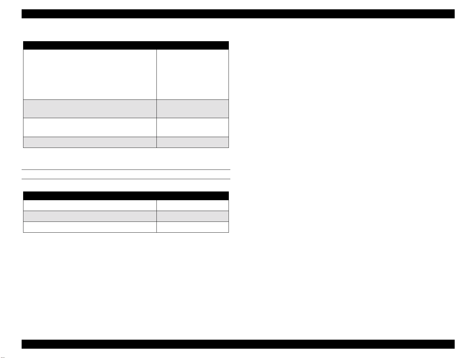
Revision Status
Revision Issued Date Description
A November 18, 1999 First Release
B January 5, 2000
• Information in Chapter 1 is fixed.
• Parts List for the Stylus Photo 1270 is included.
5

EPSON Stylus PHOTO 870/1270 Revision B
Table of Contents
PRODUCT DESCRIPTIONS
OVERVIEW ..................................................................................................10
Features ..................................................................................................10
Accessories, Consumable Products, and Options ..............................11
BASIC SPECIFICATIONS ............................................................................13
Printing Specification ............................................................................13
Paper Specifications ..............................................................................15
Printing Area ..........................................................................................16
Cut Sheet ........................................................................................16
Envelopes .......................................................................................17
Adjust Lever ...........................................................................................17
Ink Cartridge ...........................................................................................17
Input Data Buffer ...................................................................................18
Electric Specification .............................................................................18
Reliability ................................................................................................19
Safety, EMC ............................................................................................19
Acoustic Noise .......................................................................................19
CE marking .............................................................................................19
Environmental Condition ......................................................................20
INTERFACE ..................................................................................................21
Parallel Interface (Forward Channel) ...................................................21
Parallel Interface (Reserve Channel) ....................................................24
USB Interface .........................................................................................26
Prevention of Data Transfer Time-out .................................................27
Interface Selection .................................................................................27
IEEE1284.4 Protocol ...............................................................................27
OPERATIONS ..............................................................................................28
Buttons ...................................................................................................28
LED Indicators ........................................................................................28
Panel Functions .....................................................................................29
Special Setting Mode ............................................................................29
Printer Condition and Panel Status ......................................................30
Errors ......................................................................................................30
Printer Initialization ...............................................................................31
DIMENSION ................................................................................................31
OPERATING PRINCIPLES
OVERVIEW ..................................................................................................33
Printhead Mechanism ...........................................................................34
Carriage Mechanism .............................................................................35
Carriage Motor (CR Motor) ...........................................................35
Platen Gap (PG) /Parallelism Adjustment Mechanism ...............36
Carriage Home Position (HP) Detection .......................................36
Paper Feeding Mechanism ...................................................................36
CR Lock Mechanism ......................................................................38
Paper Loading Mechanism ...................................................................39
Drive Transmission to the ASF Unit .............................................39
Paper Loading Operation ..............................................................40
Pump Mechanism ..........................................................................41
Capping Mechanism ......................................................................42
ELECTRICAL CIRCUIT OPERATING PRINCIPLES .....................................43
C298PSB/PSE Board ..............................................................................43
Electrical Circuit .............................................................................43
Protection Circuits .........................................................................45
Power Supply Control Function ...................................................45
Energy Save Mode ........................................................................45
C304MAIN Board Circuit Operation Principles ...................................46
Printhead Driver Circuit .................................................................48
Reset Circuit ...................................................................................49
Motor Driver Circuit .......................................................................49
ASF/Pump Motor Driver Circuit ....................................................52
EEPROM Control Circuit ................................................................53
Sensor Circuit ................................................................................53
TROUBLESHOOTING
OVERVIEW ..................................................................................................56
Self-Diagnostic Function .......................................................................57
6

EPSON Stylus PHOTO 870/1270 Revision B
Troubleshooting with LED Error Indicators .................................57
Error Conditions .............................................................................58
Remedies for Paper Out Error ......................................................60
Remedies for the Paper Jam Error ...............................................62
Remedies for No Ink Cartridge Error/Ink Cartridge Problem .....63
Remedies for Maintenance Request Error ...................................63
Remedies for Fatal Error ...............................................................64
Isolating the Faulty Part on the Power Supply Board ........................67
Isolating the Faulty Part according to the Phenomenon ....................69
DISASSEMBLY AND ASSEMBLY
OVERVIEW ..................................................................................................74
Precaution for Disassembling the Printer ............................................74
Tools .......................................................................................................75
Specifications for Screws .....................................................................76
Service Checks After Repair .................................................................77
DISASSEMBLY PROCEDURES ..................................................................78
HOUSING Removal ...............................................................................79
Circuit Board Assembly Removal ........................................................80
Panel Unit Removal ...............................................................................83
Printhead Unit Removal ........................................................................85
TRAY, ABSORBER ASSEMBLY Removal ............................................87
Ink Unit Removal ...................................................................................89
MOTOR ASSEMBLY, CR Removal .......................................................92
MOTOR ASSEMBLY, ASF Removal .....................................................93
DE Unit Removal ...................................................................................94
ASF Unit Removal .................................................................................97
SHAFT, ROLLER, LD Removal ......................................................99
ROLLER ASSEMBLY, LD, RIGHT/LEFT Removal .......................104
Carriage Unit Removal ........................................................................105
BOARD ASSEMBLY, ENCODER Removal .........................................107
ROLLER, PF Removal ..........................................................................108
SCALE, PF Installation .................................................................111
MOTOR ASSEMBLY, PF Removal ......................................................114
PE Sensor Unit Removal .....................................................................115
ADJUSTMENT
OVERVIEW ................................................................................................117
Adjustment Items ................................................................................117
Adjustment Tools ................................................................................118
ADJUSTMENT ..........................................................................................119
Parallelism Adjsutment ......................................................................119
Backlash Adjsutment ..........................................................................121
Using the Adjustment Program .........................................................123
About the Adjustment Program .................................................123
How to Install the Program .........................................................123
How to Uninstall the Program ....................................................123
Starting the Service Program .....................................................124
Market destination check ...................................................................125
Head voltage ID input .........................................................................126
Where to Find the Head ID ..........................................................126
Check Present Data ......................................................................126
Change Data .................................................................................127
Head angular adjsutment ...................................................................128
Bi-Directional adjustment ..................................................................130
USB ID check/input .............................................................................132
Inputting/Checking the USB ID ...................................................132
Head cleaning ......................................................................................134
Initial ink charge ..................................................................................135
Protection counter check ...................................................................135
Check the Present Counter Value ...............................................135
Clear the Protection Counter Values ..........................................136
CSIC information .................................................................................137
Print A4 pattern ...................................................................................137
MAINTENANCE
OVERVIEW ................................................................................................139
Cleaning ...............................................................................................139
Service Maintenance ...........................................................................139
Head Cleaning ..............................................................................139
Maintenance Request Error Clear ..............................................139
Lubrication ...........................................................................................140
APPENDIX
CONNECTOR SUMMARY ........................................................................147
Connector Pin Assignment .................................................................147
7

EPSON Stylus PHOTO 870/1270 Revision B
EEPROM ADDRESS MAP .........................................................................151
CIRCUIT BOARD COMPONENT LAYOUT ...............................................155
EXPLODED DIAGRAMS ............................................................................158
Exploded Diagrams for Stylus PHOTO 870 .......................................158
Exploded Diagrams for Stylus PHOTO 1270 .....................................164
PARTS LIST ...............................................................................................170
Parts List for Stylus PHOTO 870 .........................................................170
Parts List for Stylus PHOTO 1270 .......................................................174
ELECTRICAL CIRCUIT BOARD DIAGRAMS ............................................178
8

PRODUCT DESCRIPTIONS
CHAPTER
1
EPSON Stylus PHOTO 870/1270 Revision B
1.1 Overview
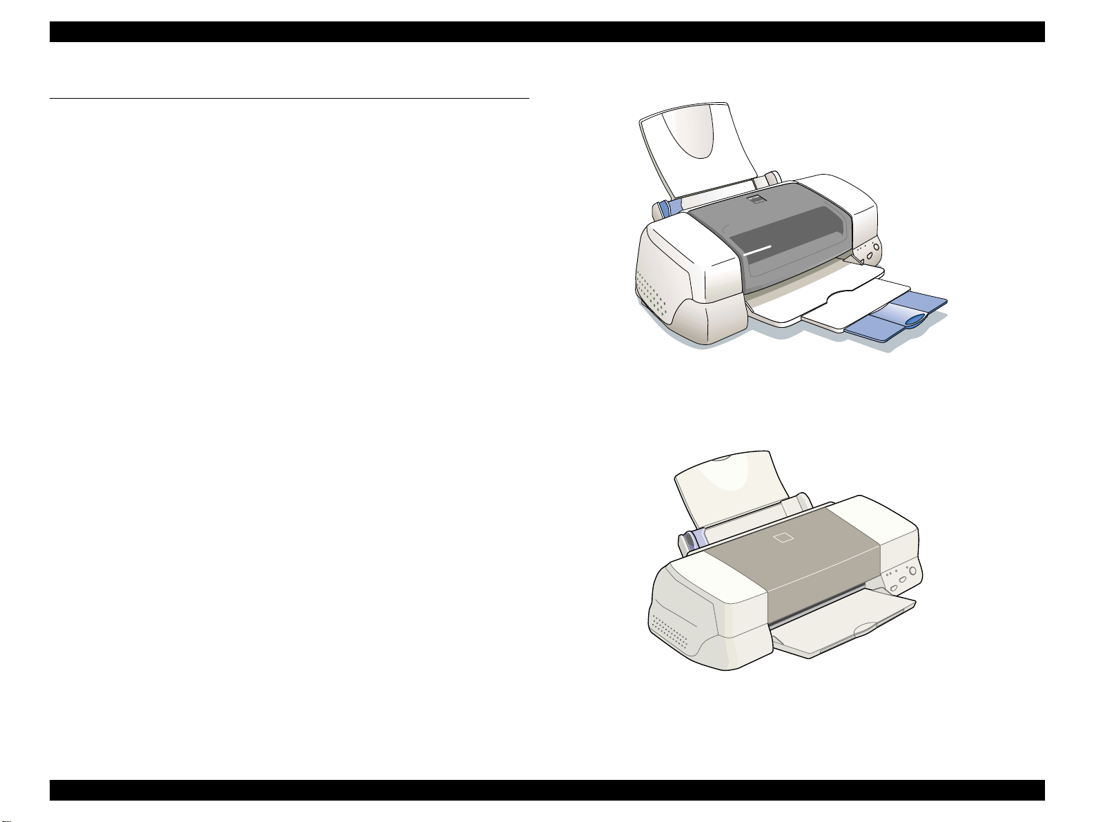
The EPSON Stylus PHOTO 870 and EPSON Stylus PHOTO 1270 are
designed for both home use and office use. As the enhanced models of
Stylus Photo 750 and Stylus Photo 1200, they offer greater performance in
both print speed and quality.
1.1.1 Features
The main features of the products are:
"
High-quality color print
!
High-speed 1440x720 dpi bidirectional printing
!
6 color printing
!
Traditional and New Microweave
"
Two built-in interfaces
!
Bi-directional parallel interface (IEEE-1284 level 1 device)
!
USB I/F
"
Windows/Macintosh exclusive
Figure 1-1. Stylus PHOTO 870
"
Built-in auto sheet feeder supports multiple sizes of paper.
!
Holds 100 cut sheets
!
Holds 10 envelopes
!
Holds 30 transparency films
"
CSIC keeps track of ink life information on the ink cartridge side.
Figure 1-2. Stylus PHOTO 1270
PRODUCT DESCRIPTIONS Overview 10
EPSON Stylus PHOTO 870/1270 Revision B
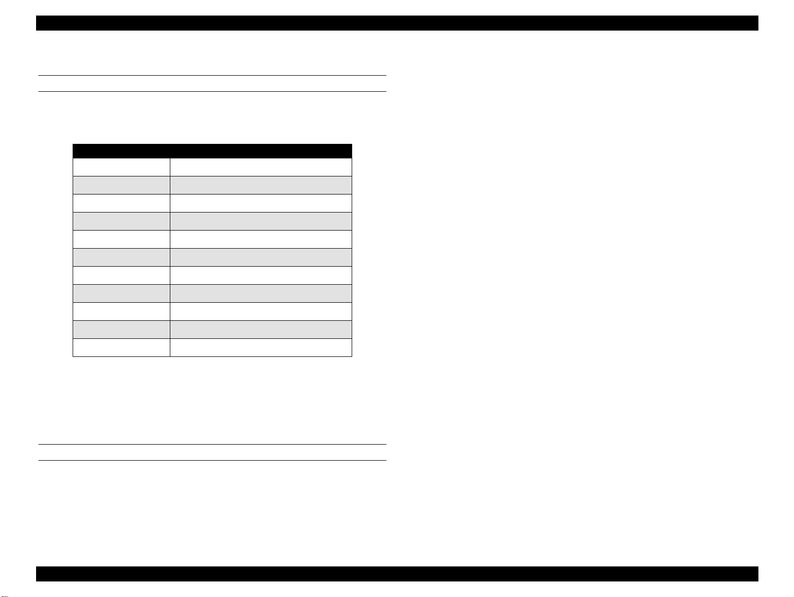
1.1.2 Accessories, Consumable Products, and Options
ACCESSORIES
"
Users guide
"
Ink cartridge
"
CD-ROM (printer driver and utilities)
CONSUMABLE PRODUCTS
NOTE: The product name of the ink cartridges may vary by location.
NOTE: The availability of special media varies by location.
NOTE: The products tailed with an asterisk are only available for
Stylus PHOTO 1270.
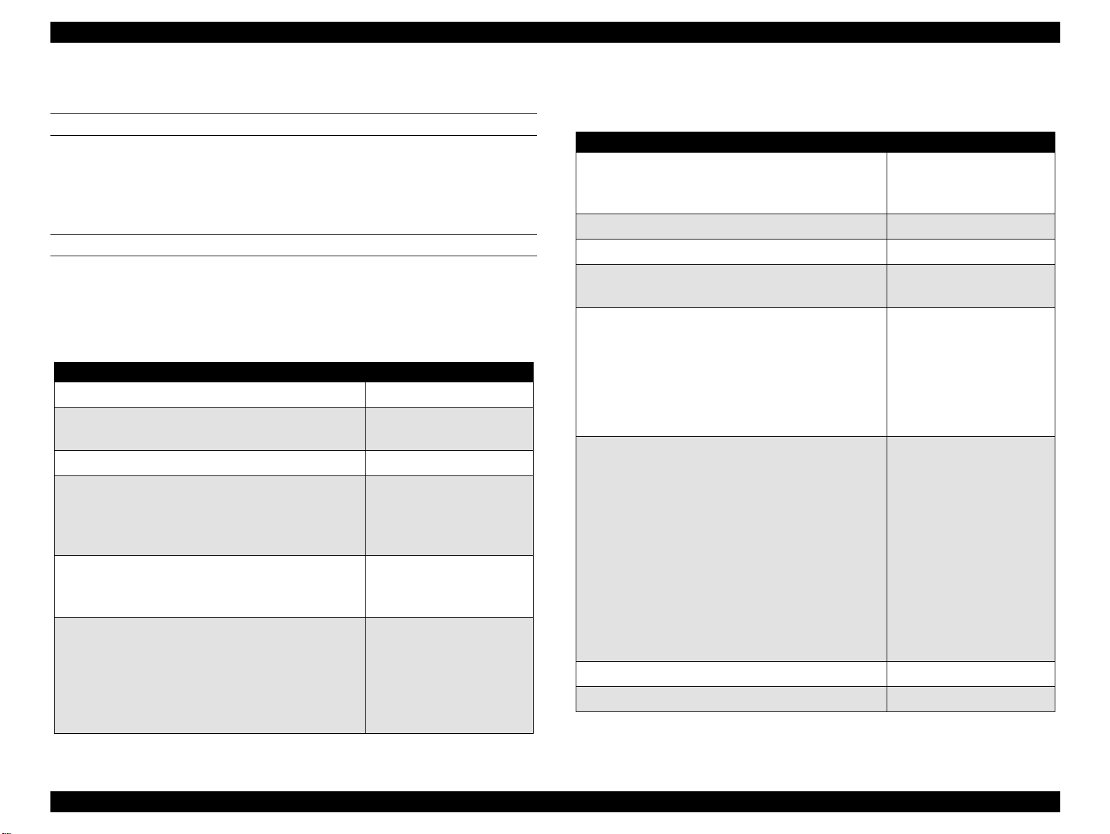
Table 1-1. Consumable Products
Name Code
Black ink cartridge T007
Color ink cartridge
EPSON Premium Ink Jet Plain Paper (A4) S041214
EPSON 360 dpi Ink Jet Paper (A4)
EPSON 360 dpi Ink Jet Paper (Letter)
EPSON 360 dpi Ink Jet Paper (A3)*
EPSON 360 dpi Ink Jet Paper (Super A3/B)*
EPSON Iron-On Cool Peel Transfer Paper (A4)
EPSON Iron-On Cool Peel Transfer Paper (Letter)
EPSON Iron-On Cool Peel Transfer Paper (A3)*
EPSON Photo Quality Ink Jet Paper (A4)
EPSON Photo Quality Ink Jet Paper (Letter)
EPSON Photo Quality Ink Jet Paper (Legal)
EPSON Photo Quality Ink Jet Paper (A3)*
EPSON Photo Quality Ink Jet Paper (Super A3/B)*
EPSON Photo Quality Ink Jet Paper (B)*
Stylus PHOTO 870: T008
Stylus PHOTO 1270: T009
S041059/S041025
S041060/S041028
S041065/S041046
S041066/S041047
S041154
S041153/S041155
S041238
S041061/S041026
S041062/S041029
S041067/S041048
S041068/S041045
S041069/S041043
S041070/S041044
Table 1-1. Consumable Products (continued)
Name Code
EPSON Photo Quality Ink Jet Card (A6)
EPSON Photo Quality Ink Jet Card (5x8”)
EPSON Photo Quality Ink Jet Card (8x10”)
EPSON Photo Quality Self Adhesive Sheet (A4) S041106
EPSON Ink Jet Note Cards A6 (with envelops) S041147
EPSON Ink Jet Greeting Cards 5x8” (with envelopes)
EPSON Ink Jet Greeting Cards 8x10” (with envelopes)
EPSON Mat Paper-Heavyweight (A4)
EPSON Mat Paper-Heavyweight (Letter)
EPSON Mat Paper-Heavyweight (A3)*
EPSON Mat Paper-Heavyweight (Super A3/Super B)*
EPSON Photo Paper (A4)
EPSON Photo Paper (Letter)
EPSON Photo Paper (A3)*
EPSON Photo Paper (Super A3/Super B)*
EPSON Photo Paper (B)*
EPSON Photo Paper (4x6”)
EPSON Photo Paper (100 x 150 mm)
EPSON Photo Paper (200 x 300 mm)
EPSON Photo Paper (89 mmx 7M)
EPSON Photo Paper (100 mm x 8M)
EPSON Photo Paper (210 mm x 10M)
EPSON Photo Paper (329 mm x 10M)*
EPSON Panoramic Photo Paper (210 x 594 mm) S041145
EPSON Photo Paper Cards (A4) S041177
S041054
S041121
S041122
S041148
S041149
S041456/S041258/
S041259
S041257
S041260/S041261/
S041262
S041263/S041264/
S041265
S041140
S041141
S041142
S041143
S041156
S041134
S041255
S041254
S0xxxxx
S0xxxxx
S0xxxxx
S041233
PRODUCT DESCRIPTIONS Overview 11
EPSON Stylus PHOTO 870/1270 Revision B
Table 1-1. Consumable Products (continued)
Name Code
Photo Quality Glossy Film (A4)
Photo Quality Glossy Film (Letter)
Photo Quality Glossy Film (A3)*
Photo Quality Glossy Film (Super A3/B)*
Photo Quality Glossy Film (B)*
Photo Quality Glossy Film (A6)
S041071
S041072
S041073
S041074
S041075
S041107
EPSON Photo Stickers 16 (A6)
EPSON Photo Stickers 4 (A6)
EPSON Ink Jet Transparencies (A4)
EPSON Ink Jet Transparencies (Letter)
EPSON Ink Jet Backlight Film (A3)* S041131
S041144
S041176
S041063
S041064
OPTIONS
Table 1-2. Options
Name Code
Parallel Interface cable (shielded) C83602*
USB I/F Interface cable (shielded) C83623*
Roll Paper Holder C81106*
*: The asterisk is as substitution for the last digit of the product name, which
varies by country.
PRODUCT DESCRIPTIONS Overview 12
EPSON Stylus PHOTO 870/1270 Revision B
1.2 Basic Specifications
1.2.1 Printing Specification
PRINT METHOD
On demand ink jet
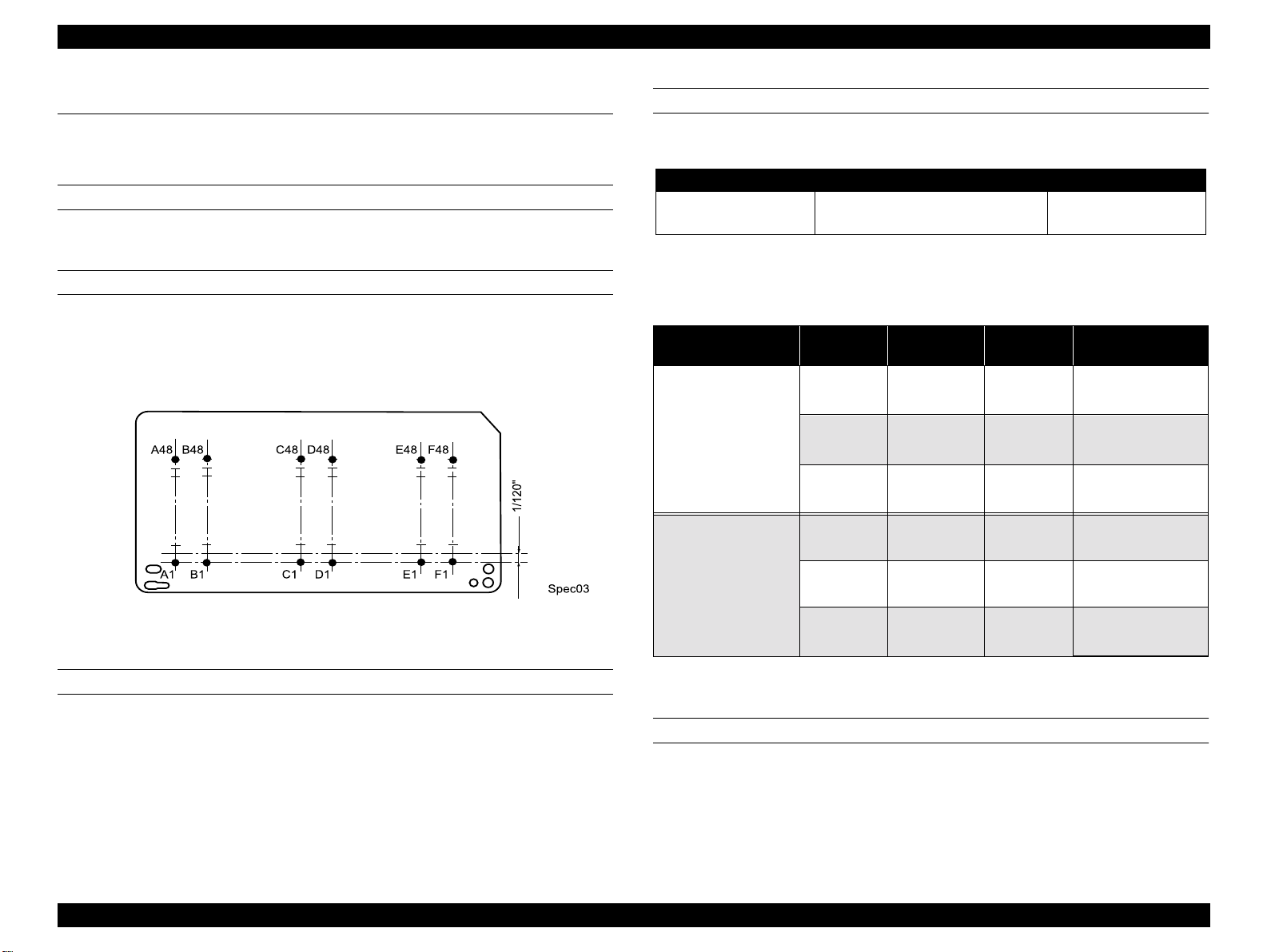
NOZZLE CONFIGURATION
48 nozzles x 6 (Black, Cyan, Magenta, Yellow, Light cyan, Light magenta)
The following figure shows nozzle configuration viewed from the back of
the printhead:
PRINT SPEED & PRINTABLE COLUMNS
Table 1-3. In the Character Mode
Character Pitch Printable coumns LQ Speed
10 CPI (Pica)
*1: Applies to normal dot printing.
• 80 (Stylus PHOTO 870)
• 127 (Stylus PHOTO 1270)
Table 1-4. In the Raster Graphics Mode
Model
Stylus PHOTO 870
Horizontal
Resolution
180 dpi
360 dpi
720 dpi
180 dpi
Printable
Area
209.8 mm
(8.26”)
209.8 mm
(8.26”)
209.8 mm
(8.26”)
322.986 mm
(12.716”)
Available
Dot
1488
2976
5952
2289
60.452/48.26 cm/s
(23.8/19 IPS)
60.452/48.26 cm/s
(23.8/19 IPS)
48.26 cm/s
(19 IPS)
60.452/48.26 cm/s
(23.8/19 IPS)
238 CPS
CR Speed
*1
Figure 1-3. Nozzle Configuration
Stylus PHOTO 1270
360 dpi
720 dpi
322.986 mm
(12.716”)
322.986 mm
(12.716”)
4578
9156
60.452/48.26 cm/s
(23.8/19 IPS)
48.26 cm/s
(19 IPS)
PRINT DIRECTION
Bi-direction with logic seeking
CONTROL CODE
!
ESC/P Raster command
!
EPSON remote command
PRODUCT DESCRIPTIONS Basic Specifications 13

EPSON Stylus PHOTO 870/1270 Revision B
CHARACTER TABLES
Two international character sets:
!
PC437 (US, Standard Europe
!
PC850 (Multilingual)
TYPEFACE
Bitmap LQ font
!
EPSON Courier 10 CPI
PAPER FEEDING
"
Feed method: Friction feed with ASF
"
Paper path: Cut-sheet ASF (top entry front out)
"
Feed speed: 110 msec (10.16 mm feed)
152.4 mm/second, 6.0”/second (fast, continues
feed)
INPUT DATA BUFFER
256KB
PRODUCT DESCRIPTIONS Basic Specifications 14
EPSON Stylus PHOTO 870/1270 Revision B
"
1.2.2 Paper Specifications
CUT SHEET
360dpi Ink Jet Paper
A3+*, A3*, A4, A6, B5, Letter, Legal, 5”x8”, 5”x10”
*: For Stylus PHOTO 1270 only.
"
Size: See the table below:
Table 1-5. Paper Specifications - Cut Sheet
Size Specifications (width x length)
A3* 297mm (11.7”) x 420mm (16.5”)
A4 210 mm (8.3”) x 297 mm (11.7”)
A5 148 mm x 210 mm
A6 105 mm x 148 mm
B* 279 mm x 432
B4* 257 mm x 364 mm
Letter 216 mm (8.5”) x 279 mm (11.0”)
B5 182 mm (7.2”) x 257 mm (10.1”)
Legal 216 mm (8.5”) x 356 mm (14.0”)
Half Letter 139.7 mm x 215.9 mm
Executive 184.2 mm (7.25”) x 266.7 mm (10.5”)
* For Stylus PHOTO 1270 Only
"
Quality: Normal paper, Recycled paper
"
Thickness: 0.08 mm (0.003”) - 0.11 mm (0.004”)
"
Weight: 64g/m2 (17Ib.) - 90g/m2 (24Ib.)
EPSON SPECIAL MEDIA
"
Ink Jet Transparencies
A4, Letter
"
PhotO Quality Glossy Film
A3+*, A4, A6, Letter
*: For Stylus PHOTO 1270 only.
"
Photo Paper 2
A3+*, A3*, A4, B*, B5, Letter, Photo Quality Card 2 (100 mm x 148
mm), Photo paper Card 2 (175.4 mm x 1136. mm), Panoramic Photo
Paper (210 mm x 594 mm)
*: For Stylus PHOTO 1270 only.
"
Label Sheet
A4
"
Backlight Film
A4 (Stylus PHOTO 870 only), A3 (Stylus PHOTO 1270 only)
"
Iron-on Cool Peel Transfer Paper
A4, Letter
"
Photo Paper Cards
A4
"
Photo Stickers
Photo Stickers A6 (16)
Photo Stickers A6 (4)
"
Photo Quality Ink Jet Paper
A3+*, A3*, A4, A6, B5, Letter, Legal, 5”x8”, 5”x10”
*: For Stylus PHOTO 1270 only.
PRODUCT DESCRIPTIONS Basic Specifications 15
EPSON Stylus PHOTO 870/1270 Revision B
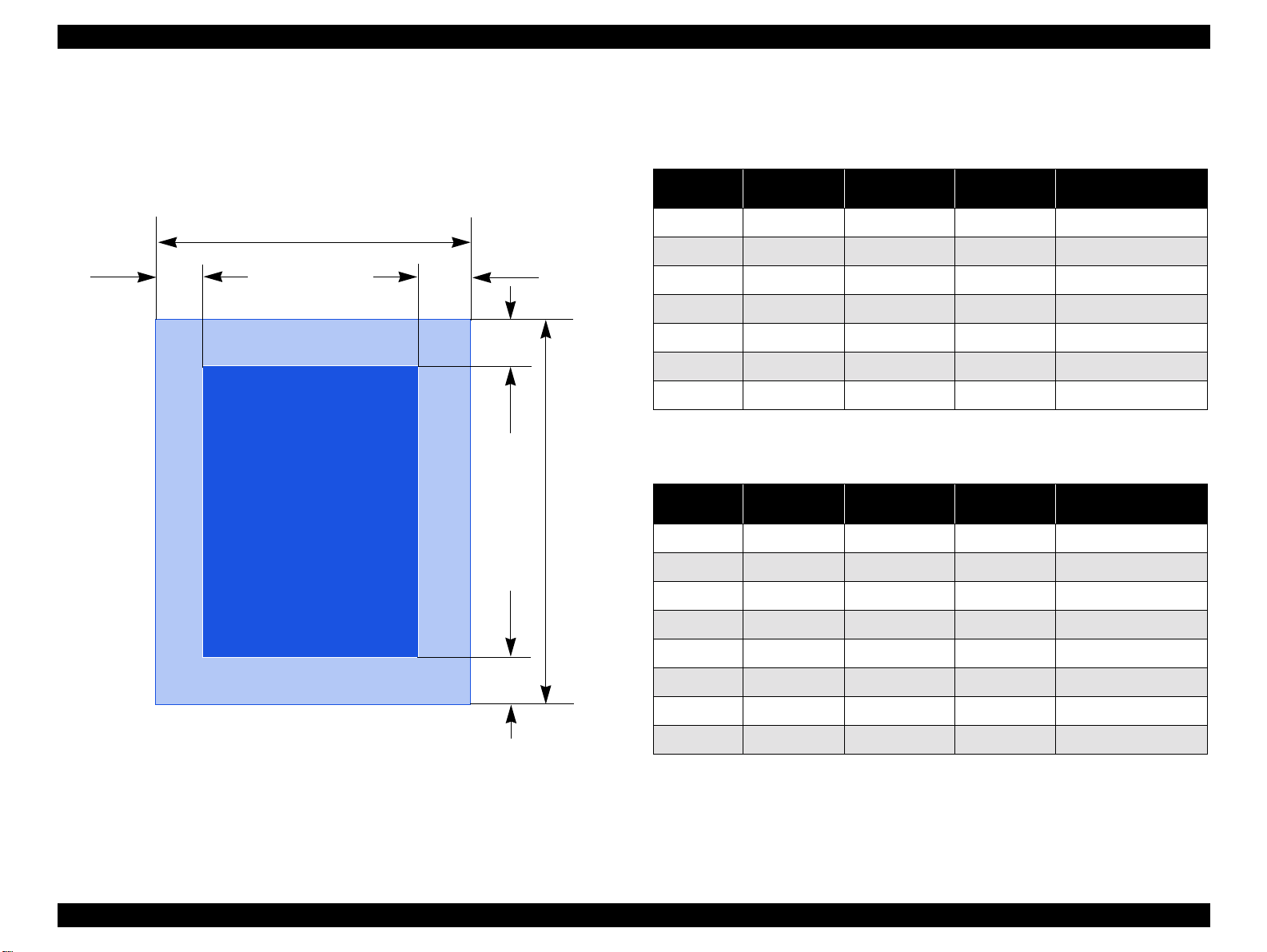
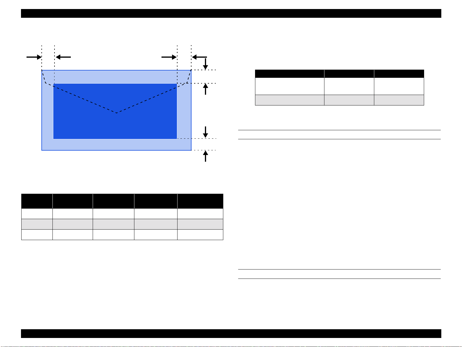
1.2.3 Printing Area
1.2.3.1 Cut Sheet
See the figure below and the following tables for the printing area for
Stylus PHOTO 870/Stylus PHOTO 1270.
PW
LM
RM
TM
Printable AreaPrintable Area
PL
Paper Size
*1
A3
A4 3 mm (0.12”) 3 mm (0.12”) 3 mm (0.12”) 14 mm (0.54”)/
Letter 3 mm (0.12”) 9 mm (0.35”) 3 mm (0.12”)
B5 3 mm (0.12”) 3 mm (0.12”) 3 mm (0.12”)
Legal 3 mm (0.12”) 9 mm (0.35”) 3 mm (0.12”)
Statement 3 mm (0.12”) 3 mm (0.12”) 3 mm (0.12”)
Executive 3 mm (0.12”) 3 mm (0.12”) 3 mm (0.12”)
*1: Stylus PHOTO 1270 only.
Paper Size
*2
A3+
*3
A3
Table 1-6. Printing Area - Character Mode
Left Margin
(minimum)
3 mm (0.12”) 3 mm (0.12”) 3 mm (0.12”) 14 mm (0.54”)/
Right Margin
(minimum)
Top Margin
(minimum)
Bottom Margin
(minimum)
14 mm (0.54”)
14 mm (0.54”)
14 mm (0.54”)
14 mm (0.54”)
14 mm (0.54”)
Table 1-7. Printing Area - Raster Graphics Mode
Left Margin
(minimum)
3 mm (0.12”) 3 mm (0.12”) 3 mm (0.12”) 14 mm (0.54”)/
3 mm (0.12”) 3 mm (0.12”) 3 mm (0.12”) 14 mm (0.54”)/
Right Margin
(minimum)
Top Margin
(minimum)
Bottom Margin
(minimum)
*1
A4 3 mm (0.12”) 3 mm (0.12”) 3 mm (0.12”) 14 mm (0.54”)/
14 mm (0.54”)
14 mm (0.54”)
14 mm (0.54”)
14 mm (0.54”)
14 mm (0.54”)
Figure 1-4. Printable Area for Cut Sheet
BM
Letter 3 mm (0.12”) 3 mm (0.12”) 3 mm (0.12”)
B5 3 mm (0.12”) 3 mm (0.12”) 3 mm (0.12”)
Legal 3 mm (0.12”) 3 mm (0.12”) 3 mm (0.12”)
Statement 3 mm (0.12”) 3 mm (0.12”) 3 mm (0.12”)
Executive 3 mm (0.12”) 3 mm (0.12”) 3 mm (0.12”)
*1: Bottom margin can be reduced to 3mm when paper dimension is defined
by using command, otherwise it remains 14mm. As for an area between
3mm and 14mm margin, print quality may decline.
*2: Stylus PHOTO 1270 only.
*3: Stylus PHOTO 1270 only.
PRODUCT DESCRIPTIONS Basic Specifications 16
EPSON Stylus PHOTO 870/1270 Revision B
1.2.3.2 Envelopes
LM
Printable AreaPrintable Area
Figure 1-5. Printable Area for Envelopes
Table 1-8. Envelope Margin
Left Margin
Size
#10 3 mm (0.12”) 28 mm (1.10”) 3 mm (0.12”) 14 mm (0.55”)
DL 3 mm (0.12”) 7 mm (0.28”) 3 mm (0.12”) 14 mm (0.55”)
C6 3 mm (0.12”) 3 mm (0.12”) 3 mm (0.12”) 14 mm (0.55”)
(minimum)
Right Margin
(minimum)
Top Margin
(minimum)
Bottom Margin
(minimum)
RM
TM
BM
1.2.4 Adjust Lever
Set the adjust lever according to the type of paper as shown in the
following table.
Table 1-9. Adjust Lever Setting Position
Paper Setting Position Gap
Cut sheet, OHP Sheet,
Label, Postcard
Envelope Rear +0.9 mm
Front 0 mm
1.2.5 Ink Cartridge
BLACK INK CARTRIDGE
The black ink cartridge specifications for Stylus PHOTO 870 and Stylus
PHOTO 1270 are common.
"
Type: Exclusive Cartridge
"
Color: Black
"
Print capacity: 540 pages/A4
(ISO/IEC 10561 Letter Pattern at 360 dpi)
"
Ink life: 2 years from the indicated date of production
"
Storage temperature
!
-20 to 60 oC (storage, within a month at 40oC)
!
-30 to 40 oC (packing storage, within a month at 40 oC)
!
-30 to 60 oC (transit, within 120 hours at 60 oC)
"
Dimension: 20.1 mm (W) x 66.85 mm (D) x 38.5 mm (H)
COLOR INK CARTRIDGE
"
Type: Exclusive Cartridge
"
Color: Cyan, Light cyan, Magenta, Light magenta,
Yellow
PRODUCT DESCRIPTIONS Basic Specifications 17

EPSON Stylus PHOTO 870/1270 Revision B
"
Print capacity:
Stylus PHOTO 870
Stylus PHOTO 1270
: 220 pages / A4 (360 dpi, 5% duty each color)
: 330 pages / A4 (360 dpi, 5% duty each color)
1.2.7 Electric Specification
120V VERSION
"
Ink life: 2 years from the indicated date of production
"
Storage temperature
!
-20 to 40 oC (storage, within a month at 40oC)
!
-30 to 40 oC (packing storage, within a month at 40 oC)
!
-30 to 60 oC (transit, within 120 hours at 60 oC)
"
Dimension:
Stylus PHOTO 870
Stylus PHOTO 1270 :
NOTE
1. Do not refill the ink cartridge. The ink cartridge is a consumable item.
2. Do not use a cartridge whose ink life has expired.
Ink freezes below -4
3.
for more than 3 hours at room temperature.
: 49.1 mm (W) x 66.85 mm (D) x 38.5 mm (H)
49.1 mm (W) x 84.05 mm (D) x 41.8 mm (H)
C; however it will be usable again after keeping it
°
1.2.6 Input Data Buffer
"
256KB
"
Rated voltage: AC120V
"
Input voltage range: AC99∼132V
"
Rated frequency range: 50∼ 60Hz
"
Input frequency range: 49.5∼ 60.5Hz
"
Rated current: 0.4A
"
Power consumption: Approx. 18W (ISO10561 Letter Pattern)
Approx. 3.5W in standby mode
Energy Star compliant
"
Insulation resistance: 10M ohms min.
(between AC line and chassis, DC 500V)
"
Dielectric strength: AC 1000V rms. 1 minute or
AC 1200V rms. 1 second
(between AC line and chassis)
220 - 240V VERSION
"
Rated voltage: AC220V
"
Input voltage range: AC198
"
Rated frequency range: 50
- 60Hz
- 240V
- 264V
"
Input frequency range: 49.5
"
Rated current: 0.2 A
"
Power consumption: Approx. 18W (ISO10561 Letter Pattern)
"
Insulation resistance: 10M ohms min.
"
Dielectric strength: AC 1500V rms. 1 minute
- 60.5Hz
Approx. 3.5W in standby mode
Energy Star compliant
(between AC line and chassis, DC 500V)
(between AC line and chassis)
PRODUCT DESCRIPTIONS Basic Specifications 18

EPSON Stylus PHOTO 870/1270 Revision B
1.2.8 Reliability
"
Total print volume: 25,000 pages (black, A4, Letter)
10,000 pages (color, A4, Letter)
"
Printhead life: 3 billion dots/nozzle
1.2.9 Safety, EMC
120 V VERSION
"
Safety standard: UL1950
CSAC22.2 No.950
"
EMI: FCC part 15 subpart B class B
CSA C108.8 class B
220 - 240 V VERSION
"
Safety standard: EN 60950 (VDE)
"
EMI: EN 55022 (CISPR Pub.22) class B
AS/NZS 3548 class B
1.2.10 Acoustic Noise
"
Level: Approximately 42 dB (according to ISO 7779)
1.2.11 CE marking
220-240 V version
Low voltage directive 73/23/EEC EN60950
EMC Directive 89/336/EEC EN55022 Class B
EN61000-3-2
EN61000-3-3
EN50082-1
IEC801-2
IEC801-3
IEC801-4
PRODUCT DESCRIPTIONS Basic Specifications 19
EPSON Stylus PHOTO 870/1270 Revision B
CAUTION
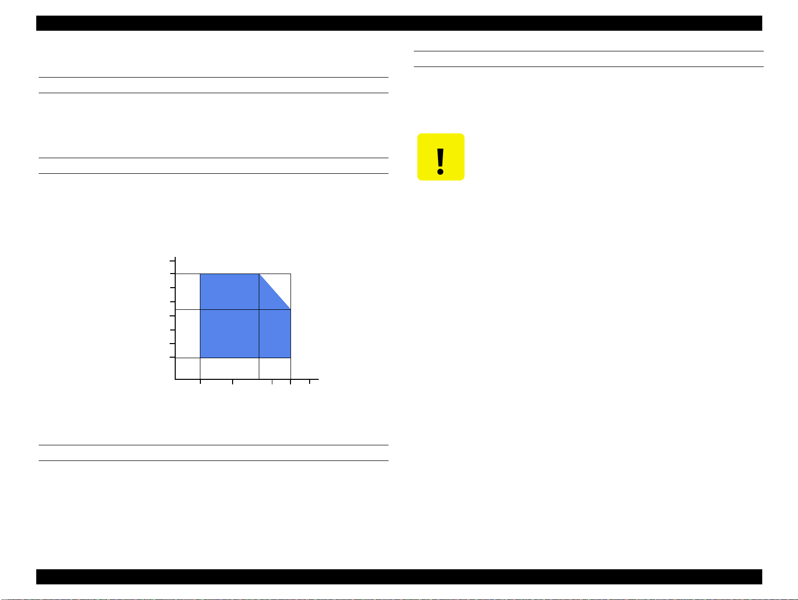
1.2.12 Environmental Condition
TEMPERATURE
"
Operating: 10 to 35°C (See the figure below.)
"
Non-operating: -20 to 60°C (in a shipment container)
1 month at 40°C and 120 hours at 60°C
HUMIDITY*
*: Without condensation
"
Operating: 20 to 80% RH (See the figure below.)
"
Non-operating: 5 to 85% RH (without condensation)
90
80
70
60
Humidity (%)
50
40
30
20
RESISTANCE TO VIBRATION
"
Operating: 0.15G
"
Non-operating: 0.50G (in a shipment container)
!
When storing the printer, make sure the printhead is
capped.
!
When transporting the printer, ensure the ink cartridges
are installed in the printer and the printhead is capped.
!
If the printer power is off with the printhead left
uncapped, turn the printer on with the ink cartridges
installed, cap the printhead, and turn the printer off.
!
Ink freezes at below -4°C. It will be usable again after
keeping it for about three hours at 25
C.
°
10
20
27
30
35
40
Temperature (°C)
Figure 1-6. Temperature/Humidity Range
RESISTANCE TO SHOCK
"
Operating: 1G, within 1 ms
"
Non-operating: 2G, within 2 ms (in a shipment container)
PRODUCT DESCRIPTIONS Basic Specifications 20
EPSON Stylus PHOTO 870/1270 Revision B
1.3 Interface
The EPSON Stylus PHOTO 870/1270 provide USB and parallel interface as
standard.
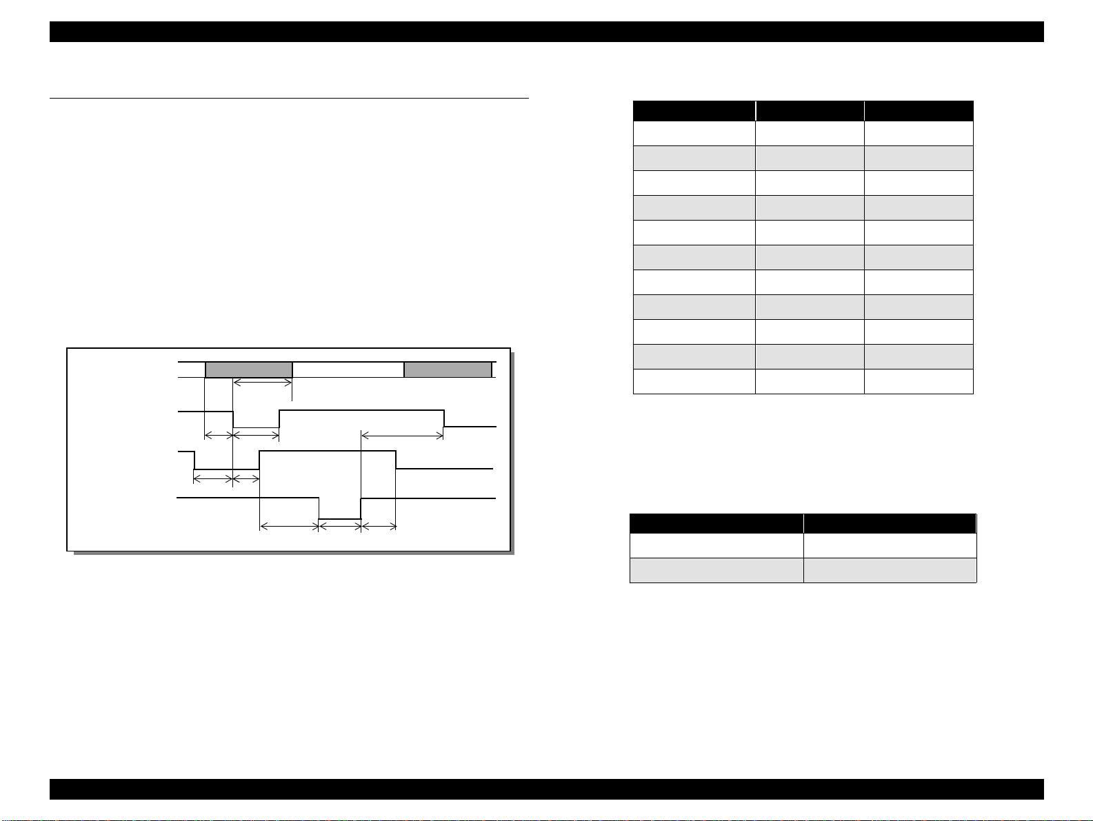
1.3.1 Parallel Interface (Forward Channel)
"
Transmission mode: 8 bit parallel, IEEE-1284 compatibility mode
"
Synchronization: By STROBE pulse
"
Handshaking: By BUSY and ACKNLG signal
"
Signal level: TTL compatible level
"
Adaptable connector: 57-30360 (amphenol) or equivalent
DATA
-STROBE
BUSY
tsetu
tread
data byte n
thold
tstb
tbusy
data byte n+1
tnext
Table 1-10. Parameters
Parameter Minimum Maximum
tsetup 500ns -
thold 500ns -
tstb 500ns -
tready 0 -
tbusy - 500ns
*1
tt-out
*2
tt-in
treply 0 -
tack 500ns 10us
tnbusy 0 -
tnext 0 -
Rise and fall time of every output signal.
*1:
Rise and fall time of every input signal.
*2:
Typical timing for tack is shown below.
- 120ns
- 200ns
-ACKNLG
treply
tack
tnbus
Table 1-11. Typical Time of Tack
Parallel I/F Mode Typical Time of tack
High Speed 1us
Normal Speed 3us
Figure 1-7. Data Transmission Timing
PRODUCT DESCRIPTIONS Interface 21
EPSON Stylus PHOTO 870/1270 Revision B
Table 1-12.
Signal Level: TTL Compatible (IEEE-1284 level 1 device)
Parameter Minimum Maximum Condition
VOH* - 5.5V
VOL* -0.5V -
IOH* - 0.32mA VOH = 2.4V
IOL* - 12mA VOL = 0.4V
CO - 50pF
VIH - 2.0V
VIL 0.8V -
IIH - 0.32mA VIH = 2.0V
IIL - 12mA VIL = 0.8V
CI - 50pF
* A low logic level on the Logic H signal is 2.0V or less when the printer
is powered off, and this signal is equal to or exceeding 3.0V when the
printer is powered on. The receiver shall provide an impedance
equivalent to 7.5K ohm to ground.
PRODUCT DESCRIPTIONS Interface 22

EPSON Stylus PHOTO 870/1270 Revision B
Table 1-13. Connector Pin Assignment and Signals
Pin No.
1 -STROBE 19 In
2-9 DATA0-7 20-27 In
10 -ACKNLG 28 Out
11 BUSY 29 Out A high signal indicates that the printer cannot receive data.
12 PE 28 Out A high signal indicates paper-out error.
13 SLCT 28 Out Always at high level when the printer is powered on.
14 -AFXT 30 In Not used.
15 NC - - Not connected
16 GND - - Signal GND
Signal
Name
Return
GND Pin
In/Out Functional Description
The strobe pulse. Read-in of data is performed at the falling edge of this
pulse.
The DATA0 through DATA7 signals represent data bits 0 to 7, respectively.
Each signal is at high level when data is logical 1 and low level when data is
logical 0.
This signal is a negative pulse indicating that the printer can accept data
again.
17
18 Logic H - Out Pulled up to +5V via 3.9 K ohm resistor.
19-30 GND - - Signal GND
31 -INIT 30 In
32 -ERROR 29 Out A low signal indicates printer error condition.
33 GND - - Signal GND
34 NC - - Not connected
35 +5V - Out Pulled up to +5V via 3.3K ohm resistor.
36 -SLIN 30 In Not used.
Chassis
GND
- - Chassis GND
The falling edge of a negative pulse or a low signal on this line causes the
printer to initialize. Minimum 50us pulse is necessary.
NOTE: In/Out refers to the direction of signal flow seen from the printer side.
PRODUCT DESCRIPTIONS Interface 23

EPSON Stylus PHOTO 870/1270 Revision B
1.3.2 Parallel Interface (Reserve Channel)
"
Transmission mode: IEEE-1284 nibble mode
"
Adaptable connector See forward channel.
"
Synchronization: Refer to the IEEE-1284 specification.
Table 1-14. Connector Pin Assignment and Signals
Pin No. Signal Name
1 HostClk 19 In Host clock signal.
2-9 DATA0-7 20-27 In
10 PtrClk 28 Out Printer clock signal.
11
12
13 Xflag / DataBit-1,5 28 Out X-flag signal and reverse channel transfer data bit 1 or 5.
14 HostBusy 30 In Host busy signal.
PtrBusy / DataBit-
3,7
AckDataReq /
DataBit-2,6
Return
GND Pin
29 Out
28 Out
"
Handshaking: Refer to the IEEE-1284 specification.
"
Data trans. timing: Refer to the IEEE-1284 specification.
"
Signal level: IEEE-1284 level 1 device (See forward
channel.)
In/Out Functional Description
The DATA0 through DATA7 signals represent data bits 0 to 7,
respectively. Each signal is at high level when data is logical 1
and low level when data is logical 0. These signals are used to
transfer the 1284 extensibility request values to the printer.
Printer busy signal and reverse channel transfer data bit 3 or
7.
Acknowledge data request signal and reverse channel
transfer data bit 2 or 6.
31 -INIT 30 In Not used.
32
36 1284-Active 30 In 1284 active signal.
18 Logic-H - Out Pulled up to +5V via 3.9K ohm resistor.
35 +5V - Out Pulled up to +5V via 3.3K ohm resistor.
17 Chassis GND - - Chassis GND
16,33, 19-30 GND - - Signal GND
15,34 NC - - Not connected
-DataAvail /
DataBit-0,4
29 Out
Data available signal and reverse channel transfer data bit 0
or 4.
NOTE: In/Out refers to the direction of signal flow from the printer’s point of view.
PRODUCT DESCRIPTIONS Interface 24

EPSON Stylus PHOTO 870/1270 Revision B
!
EXTENSIBILITY REQUEST
The printer responds affirmatively when the extensibility request values
are 00H or 04H, which means:
!
00H: Request Nibble Mode Reverse Channel Transfer.
!
04H: Request Device ID;
Return Data Using Nibble Mode Rev Channel Transfer.
NOTE 1:[00H] denotes a hexadecimal value of zero.
When IEEE1284.4 is disabled,
[00H][59H]
MFG:EPSON;
CMD:ESCPL2,BDC;
MDL:Stylus[SP]Photo[SP]1270;
CLS:PRINTER;
DES:EPSON[SP]Stylus[SP]Photo[SP]1270;
DEVICE ID
The printer sends the following device ID string when requested.
Stylus PHOTO 870
!
When IEEE1284.4 is enabled,
[00H][5AH]
MFG:EPSON;
CMD:ESCPL2,BDC,D4;
MDL:Stylus[SP]Photo[SP]870;
CLS:PRINTER;
DES:EPSON[SP]Stylus[SP]Photo[SP]870;
!
When IEEE1284.4 is disabled,
[00H][57H]
MFG:EPSON;
CMD:ESCPL2,BDC;
MDL:Stylus[SP]Photo[SP]870;
CLS:PRINTER;
DES:EPSON[SP]Stylus[SP]Photo[SP]870;
Stylus PHOTO 1270
!
When IEEE1284.4 is enabled,
NOTE 2:MDL value depends on the EEPROM setting.
NOTE 3:CMD value depends on the IEEE1284.4 setting.
[00H][5CH]
MFG:EPSON;
CMD:ESCPL2,BDC,D4;
MDL:Stylus[SP]Photo[SP]1270;
CLS:PRINTER;
DES:EPSON[SP]Stylus[SP]Photo[SP]1270;
PRODUCT DESCRIPTIONS Interface 25
EPSON Stylus PHOTO 870/1270 Revision B
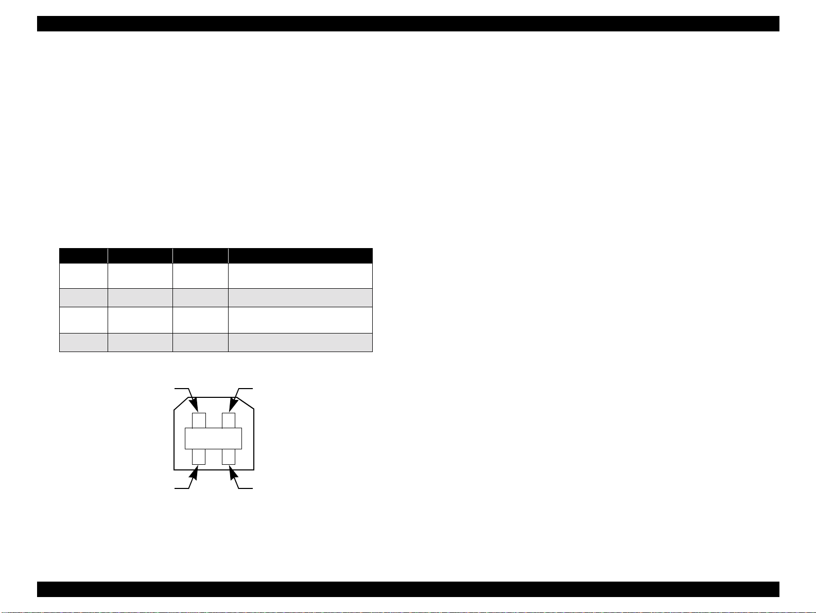
1.3.3 USB Interface
"
Standard: Based on:
“Universal Serial Bus Specifications Rev. 1.0”
“Universal Serial Bus Device Class Definition
for Printing Devices Version 1.0”
"
Bit rate: 12Mbps (Full Speed Device)
"
Data encoding: NRZI
"
Adaptable connector: USB Series B
"
Recommended cable length:2 meters
Table 1-15. Connector Pin Assignment and Signals
Pin No. Signal Name I/O Function Description
1VCC -
2 -Data Bi-D Data
3 +Data Bi-D
4 Ground - Cable ground
Cable power. Max. power
consumption is 2mA.
Data, pulled up to +3.3 V via
1.5K ohm resistor.
Pin #2
Pin #3
Pin #1
Pin #4
Figure 1-8. USB Pin Assignment
PRODUCT DESCRIPTIONS Interface 26

EPSON Stylus PHOTO 870/1270 Revision B
1.3.4 Prevention of Data Transfer Time-out
Generally, hosts abandon data transfer to peripherals when the peripheral
is in the busy state for dozens of seconds continuously. To prevent this
kind of time-out, the printer receives data very slowly, several bytes per
minute, even if the printer is in the busy state. The slowdown starts when
the remaining input buffer becomes several hundreds of bytes, and the
printer finally gets into the busy state continuously when the input buffer
is full.
USB and IEEE1284.4 on the parallel interface do not require such function.
1.3.5 Interface Selection
The printer has two built-in interfaces: the USB and parallel interface.
These interfaces are selected automatically.
"
Automatic Selection
In this automatic interface selection mode, the printer is initialized to
the idle state while scanning which interface receives data when it is
powered on. Then the interface which received data first is selected.
When the host stops data transfer and the printer is in the stand-by
state for seconds, the printer is returned to the idle state. As long as
the host sends data or the printer interface is in the busy state, the
selected interface is let as it is.
"
Interface State and Interface Selection
When the parallel interface is not selected, the interface gets into the
busy state. When the printer is initialized or returned to the idle state,
the parallel interface gets into the ready state. Note that the interrupt
signal such as the -INIT signal on the parallel interface is not effective
while that interface is not selected.
multiplexing services. The multiplexed logical channels are independent
of each other and blocking of one has no effect on the others. The
protocol operates over IEEE1284.
"
Automatic Selection
An initial state is compatible interface and starts IEEE1284.4
communication when magic strings (1284.4 synchronous commands)
are received.
"
On
An initial state is IEEE1284.4 communication and data that received it
by the time it is able to take synchronization by magic string (1284.4
synchronous commands) is discarded.
"
Off
An initial state is compatible interface and never starts IEEE1284.4
communication even if magic strings (1284.4 synchronous
commands) are received.
1.3.6 IEEE1284.4 Protocol
The packet protocol described by IEEE1284.4 standard allows a device to
carry on multiple exchanges or conversations which contain data and/or
control information with another device at the same time across a single
point-to-point link. The protocol is not, however, a device control
language. It does provide basic transport-level flow control and
PRODUCT DESCRIPTIONS Interface 27
EPSON Stylus PHOTO 870/1270 Revision B
1.4 Operations
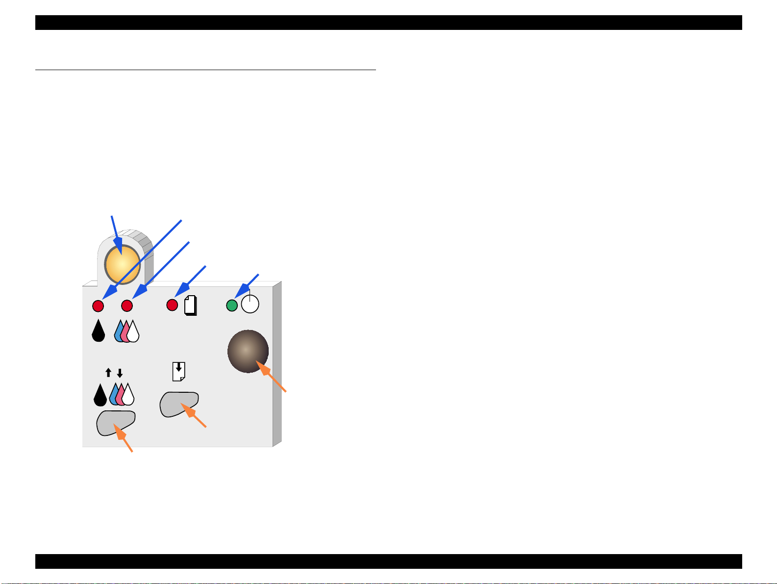
1.4.1 Buttons
"
Operating button
"
Load/Eject button
"
Cartridge replacement button
"
Cleaning button
Ink Cartridge Replacement Button
Ink Out (Black) LED
Ink Out (Color)LED
Paper Out LED
Power LED
1.4.2 LED Indicators
"
Power
Lights when the power switch is “ON” and AC power is supplied.
"
Paper Out
Lights during the paper out condition, and blinks during the paper jam
condition.
"
Ink Out (Black)
Lights during no black ink condition, and blinks during the black
ink low condition.
"
Ink Out (Color)
Lights during no color ink condition, and blinks during the color ink
low condition.
Power Button
Load/Eject Button
Cleaning Button
PRODUCT DESCRIPTIONS Operations 28
EPSON Stylus PHOTO 870/1270 Revision B
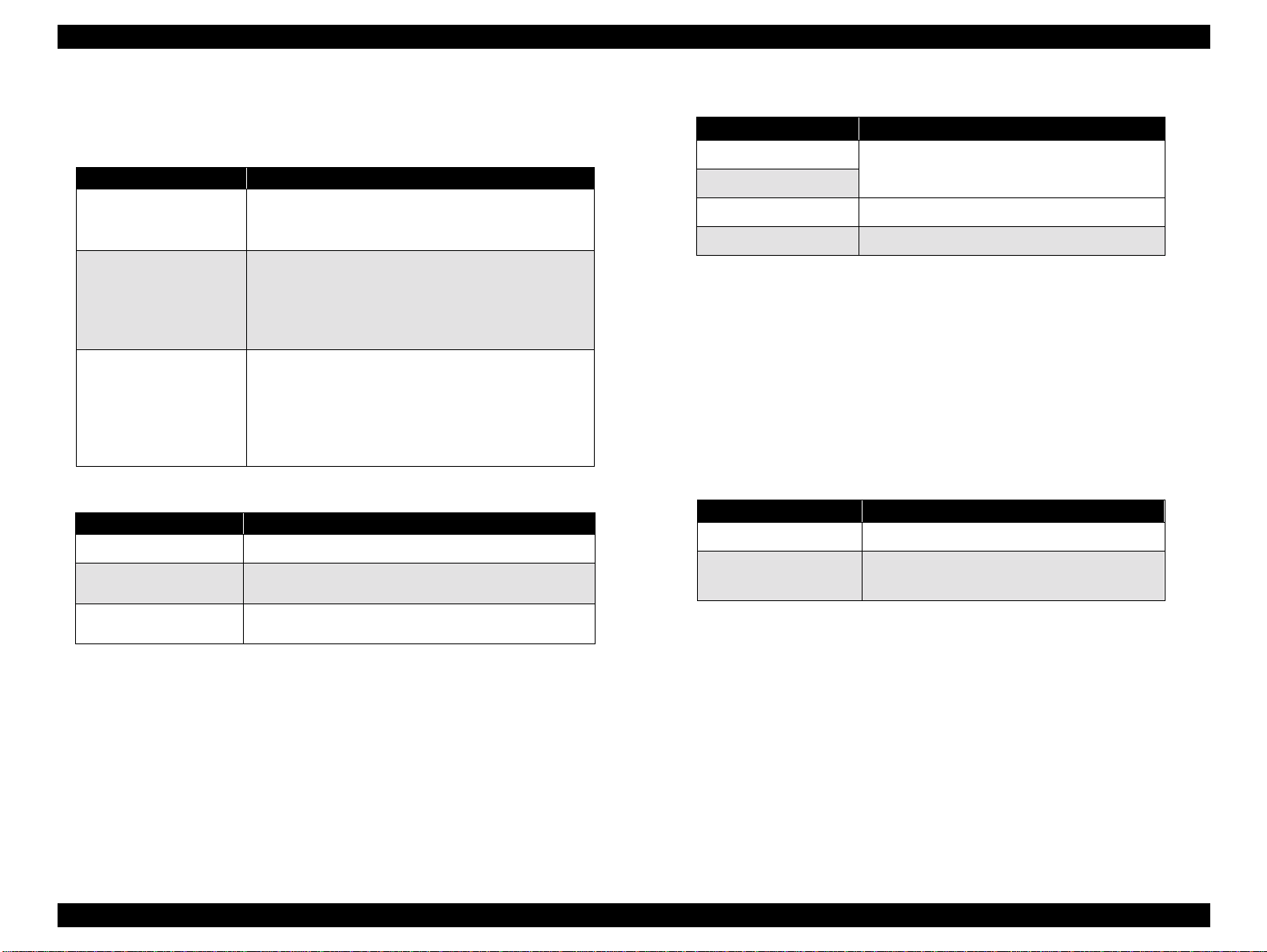
1.4.3 Panel Functions
Table 1-16. Panel Functions
Buttons Function
• Loads or ejects paper.
Load / Eject
Ink Cartridge
Replacement
Cleaning
(Push for 3 seconds)
Table 1-17. Power-on Panel Functions
Switch Pressing with Power On Function
Load / Eject
Cleaning
Load/Eject + Cleaning
*1: One of the actions in Table 1-18 is carried out according to the content
of 1BH of EEPROM.
*2: Not intended for users.
*3: See Section 1.4.4. (Not intended for users.)
• Returns the printhead from the ink cartridge
replacement position to the capping position.
• Starts the ink cartridge replacement sequence.
• Moves the carriage to the cartridge
replacement position.
• Returns the carriage from the ink cartridge
replacement position.
• Starts a head cleaning.
• In the condition of “Ink Low”, “Ink Out”, or
“No Ink Cartridge”, starts the ink cartridge
replacement sequence.
• Returns the carriage from the ink cartridge
replacement position.
• Starts status printing.
• Changes code pages / Selects IEEE1284.4 mode
for parallel I/F.
• Enters the special settings mode. (Factory use
only).
*3
*2
*1
Table 1-18. Content of 1BH of EEPROM
[bit7] [bit6] Actions
*1
00
11
01 Hex-dump mode
10 Self test mode
*1: Factory default setting
Print firmware version, ink counter,
selected code page and nozzle check
pattern.
1.4.4 Special Setting Mode
To enter the special setting mode, press Load/Eject button and Cleaning
button while turning on the printer. The Paper Out LED starts blinking.
While it is blinking (for three seconds), press the specified button to
activate the desirable setting mode.
NOTE: Special setting modes are not intended for users.
Table 1-19. Special Setting Modes
Switch Function
Load / Eject
Cleaning
(Push for 10 seconds)
"
EEPROM/Timer IC reset
The following is reset with this operation:
!
Interface selection (04H)
!
Power off timer (6CH, 6DH)
• Resets EEPROM and timer IC.
• Resets the ink overflow counter in
EEPROM.
"
Waste ink counter reset
The following is reset with this operation:
!
Ink counter A0 (50H, 5DH)
!
Ink counter A80 (5EH, 5FH)
PRODUCT DESCRIPTIONS Operations 29
EPSON Stylus PHOTO 870/1270 Revision B
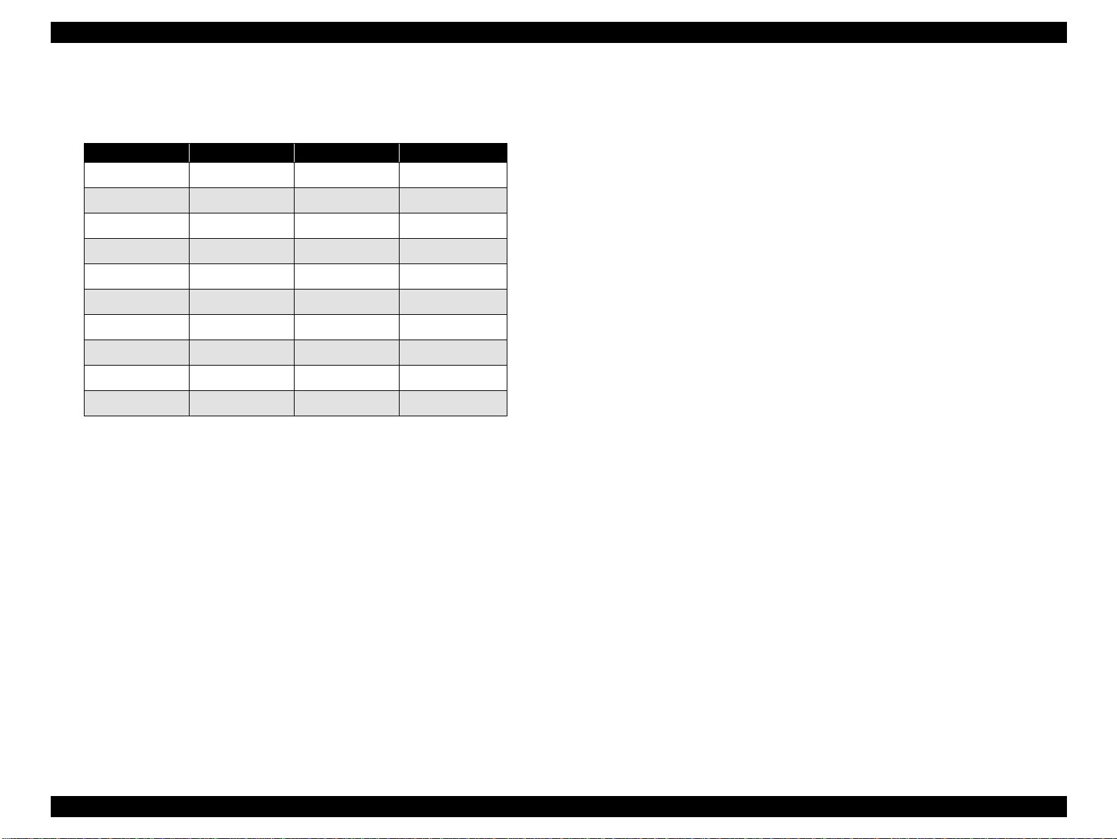
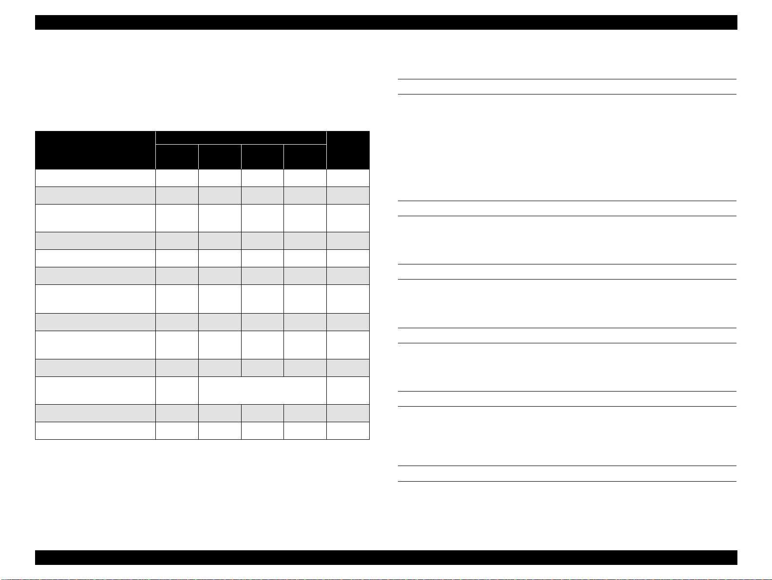
1.4.5 Printer Condition and Panel Status
Table 1-20 shows various errors and printer status.
Table 1-20. Printer Condition and Panel Status
Indicators
Printer Status
Power on condition On -- -- -- 9
Ink sequence Blinks -- -- -- 6
Ink cartridge replacement
mode
Data processing Blinks -- -- -- 8
Paper out -- -- -- On 4
Paper jam condition -- Off Off Blinks 3
No ink cartridge or ink end
(black)
Ink level low (black) -- Blinks -- -- 7
No ink cartridge or ink end
(color)
Ink level low (color) -- -- Blinks -- 7
Enter EEPROM and Timer
IC reset
Maintenance request Blinks Blinks Blinks Blinks 2
Fatal error Blinks On On Blinks 1
Power
Blinks -- -- -- 5
-- On -- -- 7
-- -- On -- 7
-- On (for one second only) -
Ink Out
(Black)
Ink Out
(Color)
Paper
Out
NOTE: “--” means “no effect”.
Priority
1.4.6 Errors
INK OUT
When the printer runs out most of the ink of any color, it warns of an ink
low condition and keeps printing. When the ink cartridge is completely
empty, the printer stops printing and generates Ink out error. In this
condition, the ink cartridge must be replaced with a new one. Note an ink
cartridge that is once taken out must not be used again. Reinstalling of ink
cartridges whose ink level is not full upsets the ink level detection and
may cause serious problems in the printheads.
PAPER OUT
When the printer fails to load a sheet of paper, it goes into the Paper Out
error condition.
PAPER JAM
When the printer fails to eject a sheet of paper, it goes into the Paper Jam
error condition.
NO INK CARTRIDGE
When the printer detects that an ink cartridge is missing, it goes into the
No Ink Cartridge error condition.
MAINTENANCE REQUEST
When the total quantity of waste ink collected during cleanings and
flushing reaches the limit, printer indicates the Maintenance Request
error and stops printing. The absorber must be replaced by a servicer.
FATAL ERRORS
When the printer detects a carriage control error or CG access error, it
goes into a fatal error condition.
PRODUCT DESCRIPTIONS Operations 30
 Loading...