

Page 1
®
SERVICE MANUAL
Color Inkjet Printer
EPSON Stylus PHOTO 2100/2200
SEIJ01-016
Page 2

Notice
! All rights reserved. No part of this manual may be reproduced, stored in a retrieval system, or transmitted in any form or by any means electronic, mechanical,
photocopying, or otherwise, without the prior written permission of SEIKO EPSON CORPORATION.
! All effort have been made to ensure the accuracy of the contents of this manual. However, should any errors be detected, SEIKO EPSON would greatly
appreciate being informed of them.
! The contents of this manual are subject to change without notice.
! All effort have been made to ensure the accuracy of the contents of this manual. However, should any errors be detected, SEIKO EPSON would greatly
appreciate being informed of them.
! The above not withstanding SEIKO EPSON CORPORATION can assume no responsibility for any errors in this manual or the consequences thereof.
EPSON is a registered trademark of SEIKO EPSON CORPORATION.
General Notice:Other product names used herein are for identification purpose only and may be trademarks or registered trademarks of their respective owners.
EPSON disclaims any and all rights in those marks.
Copyright © 2002 SEIKO EPSON CORPORATION.
Imaging & Information Product Division
TPCS Quality Assurance Center
TPCS Department
Page 3

PRECAUTIONS
Precautionary notations throughout the text are categorized relative to 1)Personal injury and 2) damage to equipment.
DANGER Signals a precaution which, if ignored, could result in serious or fatal personal injury. Great caution should be exercised in performing
procedures preceded by DANGER Headings.
WARNING Signals a precaution which, if ignored, could result in damage to equipment.
The precautionary measures itemized below should always be observed when performing repair/maintenance procedures.
DANGER
1. ALWAYS DISCONNECT THE PRODUCT FROM THE POWER SOURCE AND PERIPHERAL DEVICES PERFORMING ANY MAINTENANCE OR REPAIR PROCEDURES.
2. NO WORK SHOULD BE PERFORMED ON THE UNIT BY PERSONS UNFAMILIAR WITH BASIC SAFETY MEASURES AS DICTATED FOR ALL ELECTRONICS
TECHNICIANS IN THEIR LINE OF WORK.
3. WHEN PERFORMING TESTING AS DICTATED WITHIN THIS MANUAL, DO NOT CONNECT THE UNIT TO A POWER SOURCE UNTIL INSTRUCTED TO DO SO. WHEN
THE POWER SUPPLY CABLE MUST BE CONNECTED, USE EXTREME CAUTION IN WORKING ON POWER SUPPLY AND OTHER ELECTRONIC COMPONENTS.
4. WHEN DISASSEMBLING OR ASSEMBLING A PRODUCT, MAKE SURE TO WEAR GLOVES TO AVOID INJURIER FROM METAL PARTS WITH SHARP EDGES.
WARNING
1. REPAIRS ON EPSON PRODUCT SHOULD BE PERFORMED ONLY BY AN EPSON CERTIFIED REPAIR TECHNICIAN.
2. MAKE CERTAIN THAT THE SOURCE VOLTAGES IS THE SAME AS THE RATED VOLTAGE, LISTED ON THE SERIAL NUMBER/RATING PLATE. IF THE EPSON PRODUCT
HAS A PRIMARY AC RATING DIFFERENT FROM AVAILABLE POWER SOURCE, DO NOT CONNECT IT TO THE POWER SOURCE.
3. ALWAYS VERIFY THAT THE EPSON PRODUCT HAS BEEN DISCONNECTED FROM THE POWER SOURCE BEFORE REMOVING OR REPLACING PRINTED CIRCUIT
BOARDS AND/OR INDIVIDUAL CHIPS.
4. IN ORDER TO PROTECT SENSITIVE MICROPROCESSORS AND CIRCUITRY, USE STATIC DISCHARGE EQUIPMENT, SUCH AS ANTI-STATIC WRIST STRAPS, WHEN
ACCESSING INTERNAL COMPONENTS.
5. DO NOT REPLACE IMPERFECTLY FUNCTIONING COMPONENTS WITH COMPONENTS WHICH ARE NOT MANUFACTURED BY EPSON. IF SECOND SOURCE IC OR
OTHER COMPONENTS WHICH HAVE NOT BEEN APPROVED ARE USED, THEY COULD CAUSE DAMAGE TO THE EPSON PRODUCT, OR COULD VOID THE
WARRANTY OFFERED BY EPSON.
Page 4
About This Manual
This manual describes basic functions, theory of electrical and mechanical operations, maintenance and repair procedures of the printer. The instructions and
procedures included herein are intended for the experienced repair technicians, and attention should be given to the precautions on the preceding page.
Manual Configuration
This manual consists of six chapters and Appendix.
CHAPTER 1. PRODUCT DESCRIPTIONS
Provides a general overview and specifications of the product.
CHAPTER 2. OPERATING PRINCIPLES
Describes the theory of electrical and mechanical operations of
the product.
CHAPTER 3. TROUBLESHOOTING
Describes the step-by-step procedures for the troubleshooting.
CHAPTER 4. DISASSEMBLY / ASSEMBLY
Describes the step-by-step procedures for disassembling and
assembling the product.
CHAPTER 5. ADJUSTMENT
Provides Epson-approved methods for adjustment.
CHAPTER 6. MAINTENANCE
Provides preventive maintenance procedures and the lists of
Epson-approved lubricants and adhesives required for
servicing the product.
APPENDIX Provides the following additional information for
reference:
• Connector pin assignments
• Exploded diagram & Parts List
• Electric circuit boards components layout
• Electrical circuit boards schematics
Symbols Used in this Manual
Various symbols are used throughout this manual either to provide additional
information on a specific topic or to warn of possible danger present during a
procedure or an action. Be aware of all symbols when they are used, and
always read NOTE, CAUTION, or WARNING messages.
A D J U S T M E N T
R E Q U I R E D
C A U T I O N
C H E C K
P O I N T
W A R N I N G
Indicates an operating or maintenance procedure, practice or
condition that is necessary to keep the product’s quality.
Indicates an operating or maintenance procedure, practice, or
condition that, if not strictly observed, could result in damage to,
or destruction of, equipment.
May indicate an operating or maintenance procedure, practice or
condition that is necessary to accomplish a task efficiently. It
may also provide additional information that is related to a
specific subject, or comment on the results achieved through a
previous action.
Indicates an operating or maintenance procedure, practice or
condition that, if not strictly observed, could result in injury or
loss of life.
Indicates that a particular task must be carried out according to a
certain standard after disassembly and before re-assembly,
otherwise the quality of the components in question may be
adversely affected.
Page 5

Revision Status
Revision Issued Date Description
A May 24, 2002 First Release
B August 22, 2002
Page 212 Modify the wrong description on the A3+ size Photo Quality Ink Jet Paper Check pattern (first solid pattern)
Page 213 The description for A4 size Plain Paper check point was added.
Page 6

CONTENTS
Chapter 1 PRODUCTION DESCRIPTION
1.1 Overview 9
1.2 Basic Specifications 10
1.2.1 Specification Outline Comparison ............................................................ 10
1.2.2 Paper Specification .................................................................................... 15
1.2.3 Printing Area ............................................................................................. 17
1.2.4 Ink Type-based Medium Compatibility Specifications ............................. 23
1.2.5 Release Lever .............................................. .............................................. 25
1.3 Functions 26
1.3.1 Control Panel .......................................................... ................................... 26
1.3.2 Switches ..................................................................................................... 26
1.3.3 Indicators ................................................................................................... 26
1.3.4 Switch Functions ....................................................................................... 26
1.3.5 Default Setting Selection Function ............................................................ 28
1.3.6 Special Setting Mode Function ................................................................. 29
1.3.7 Status Printing ........................................................................................... 30
1.3.8 Panel Operation for Roll Paper Printing .................................................... 31
1.3.9 Panel Operation for CD-R Printing ................... ........................................ 33
1.3.10 Panel Operation for Thick Paper Printing ............................................... 33
1.3.11 Panel Operation in Roller Cleaning Mode .............................................. 34
1.3.12 Indicator Display in Normal Mode .......................................................... 35
1.3.13 Error Status .............................................................................................. 36
1.4 Casing Specifications 37
1.5 Accessories 37
1.6 Environment Specification Items 38
Chapter 2 OPERATING PRINCIPLES
2.1 Overview 40
2.2 Printer Mechanism 40
2.2.1 Carriage Mechanism .................................................................................. 41
2.2.2 Print Mode ........................................... ...................................................... 44
2.2.3 Paper Feeding Mechanism ................................................. ....................... 48
2.2.4 Paper Loading Mechanism ........................................................................ 54
2.2.5 Ink System Mechanism ............................................................................. 58
2.2.6 Ink Sequence ............................................................................................. 60
2.2.7 Paper Cutter Mechanism ........................................................................... 63
2.2.8 Power-On Sequence .................................................................................. 65
2.3 Electrical Circuitry Operating Principles 66
2.3.1 Power Supply Circuit Operating Principle ................................................ 67
2.3.2 C387MAIN Circuit Operating Principle ................................................... 68
Chapter 3 TROUBLESHOOTING
3.1 Overview 70
3.2 Error Indications and Fault Occurrence Causes 70
3.3 Troubleshooting 78
3.3.1 Superficial Phenomenon-Based Troubleshooting ................................... 104
3.4 EEPROM Data Analysis 114
Chapter 4 disassembly and assembly
4.1 Overview 116
4.1.1 Precautions .............................................................................................. 116
4.1.2 Tools to Be Used ..................................................................................... 117
4.1.3 Screw List .............................. .................................................................. 118
4.1.4 Pre-Shipment Checks ................................ .......................................... .... 119
4.2 Disassembly 120
4.2.1 Removing the Housings .......................................................................... 121
4.2.2 Removing the Board Assembly ............................................................... 127
4.2.3 Removing the Waste Ink Pads ................................................................. 131
4.2.4 Removing the ASF Unit .......................................................................... 132
4.2.5 Removing the Paper Eject Unit ............................................................... 140
Page 7

4.2.6 Removing the Paper Eject Roller B ......................................................... 144
4.2.7 Removing the Printhead .......................................................................... 146
4.2.8 Removing the Carriage Guide Shaft B .................................................... 149
4.2.9 Removing the Carriage Guide Shaft A and Carriage Unit ...................... 152
4.2.10 Removing the Ink System Unit ............................................................. 158
4.2.11 Removing the Release Lever Shaft ....................................................... 159
4.2.12 Removing the Sensors ........................................................................... 161
4.2.13 Removing the Motors ............................................................................ 168
4.2.14 Removing the DE Unit and ASF/Pump Motor ...................................... 171
4.2.15 Removing the PF Roller ........................................................................ 175
4.2.16 Removing the Paper Eject Roller Shaft A ............................................. 179
4.2.17 Removing the PF Roller Support .......................................................... 181
4.2.18 Disassembling the Cutter Unit ............................................................... 182
4.2.19 Fitting the Protective Materials ............................................................. 186
Chapter 5 Adjustment
5.1 Adjustment Items and Overview 188
5.1.1 Servicing Adjustment Item List ............................................................... 188
5.1.2 Priority of Adjustment Items ................................................................... 193
5.1.3 Replacement Part-Based Adjustment Priorities ...................................... 194
5.1.4 Required Jigs, Tools and Like ................................................................. 196
5.2 Adjustments 197
5.2.1 Servicing Program Usage Outline ........................................................... 197
5.2.2 Head ID Input Function ........................................................................... 199
5.2.3 CR motor drive torque dispersion measurement ..................................... 199
5.2.4 PG Adjustment ........................................................................................ 200
5.2.5 Head Angular Adjustment ....................................................................... 204
5.2.6 CR Tooth Skip Prevention Mechanism Adjustment ............................... 206
5.2.7 PF Adjustment ......................................................................................... 206
5.2.8 PW Sensor Adjustment ............................................................................ 207
5.2.9 Bi-D Adjustment ..................................................................................... 208
5.2.10 Pixel Shift Adjustment .......................................................................... 209
5.2.11 Cut Position Adjustment ........................................................................ 210
5.2.12 USB ID Input ......................................................................................... 210
5.2.13 IEEE-1394 ID Input .............................................................................. 211
5.2.14 First dot position adjsutment (Left/Right Margin Adjustment) ............ 211
5.2.15 .....A3+ Pho to Quality Ink Jet Paper 2 Print Pattern Printing Function 212
5.2.16 A4 Plain Paper print check pattern ........................................................ 213
Chapter 6 Maintenance
6.1 Overview 215
6.1.1 ROM Replacement .................................................................................. 215
6.1.2 Cleaning ...................................... ............................................................. 215
6.1.3 Service Maintenance ......................................... ...................................... 216
6.1.4 Lubrication .............................................................................................. 217
Chapter 7 APPENDIX
7.1 Connector Summary 227
7.1.1 Connectors and Pin Layouts .................................................................... 227
7.1.2 EEPROM Address Map .......................................................................... 231
7.2 Exploded Diagram 236
7.3 Parts List for EPSON Stylus Photo 2100 248
7.4 Circuit Diagram 253
Page 8

PRODUCTION DESCRIPTION
CHAPTER
1
Page 9
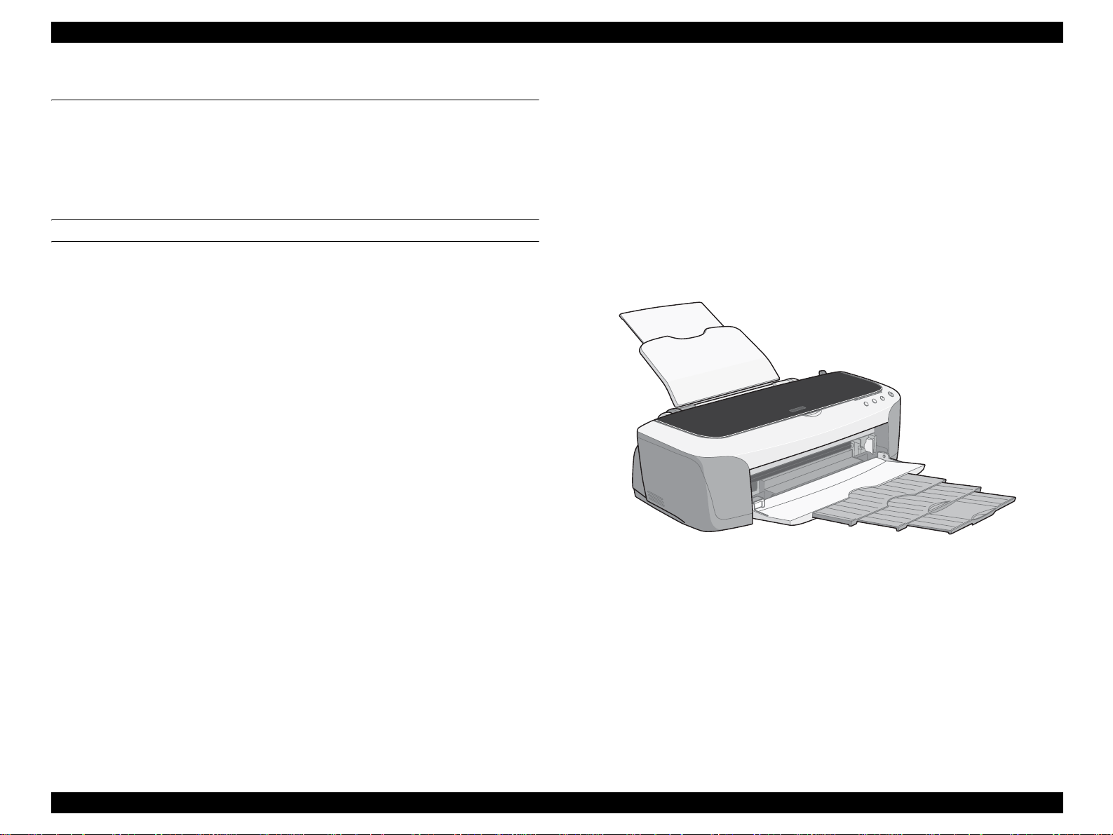
EPSON Stylus PHOTO 2100/2200 Revision B
1.1 Overview
The Stylus PHOTO 2100/2200 is a photo printer designed for a wide range of users
from individual users to commercial users. As a model to replace the Stylus PHOTO
2000P, this consumer high-end model is capable of pigment-independent CSIC, CD-R
printing, and roll paper cutter functions.
This product has the following features.
FEATURES
High Color Print Quality
!
" High photo quality thanks to Photo Mach technology
" Achievement of higher quality using microwaves and super microwaves
" High resolution printing of 2880 x 1440dpi
! Three Different Interfaces Supported
" IEEE-1284 parallel interface
" USB 2.0
" IEEE-1394
! Windows/Macintosh Exclusive
! Multi-size Capable ASF
ASF equipped as standard supports forms ranging up to A3+.
! Roll paper compatibility
! Thick paper/CD-R printing compatibility
! Auto cutter compatibility
! Frameless printing compatibility
! Two-sided printing compatibility
By addition of the standard-equipped CD-R print kit, direct printing can be done
on a CD-R label.
! CSIC-compatible Independent Ink Cartridge
Three different ink sets, Photo-Black & Light-black, and Matte-Black & Light-
black, can be changed.
Figure 1-1. Product Appearance
! Newly Developed Pigment Ink
" As compared to the conventional pigment ink, the color reproduction area of
the new ink has increased up to about 80% of the dye ink, improving color
development.
" The concentration of YMC has been increased, and the Light-black ink
adopted improves the Light-black balance and metamerism.
PRODUCTION DESCRIPTION Overview 9
Page 10
EPSON Stylus PHOTO 2100/2200 Revision B
1.2 Basic Specifications
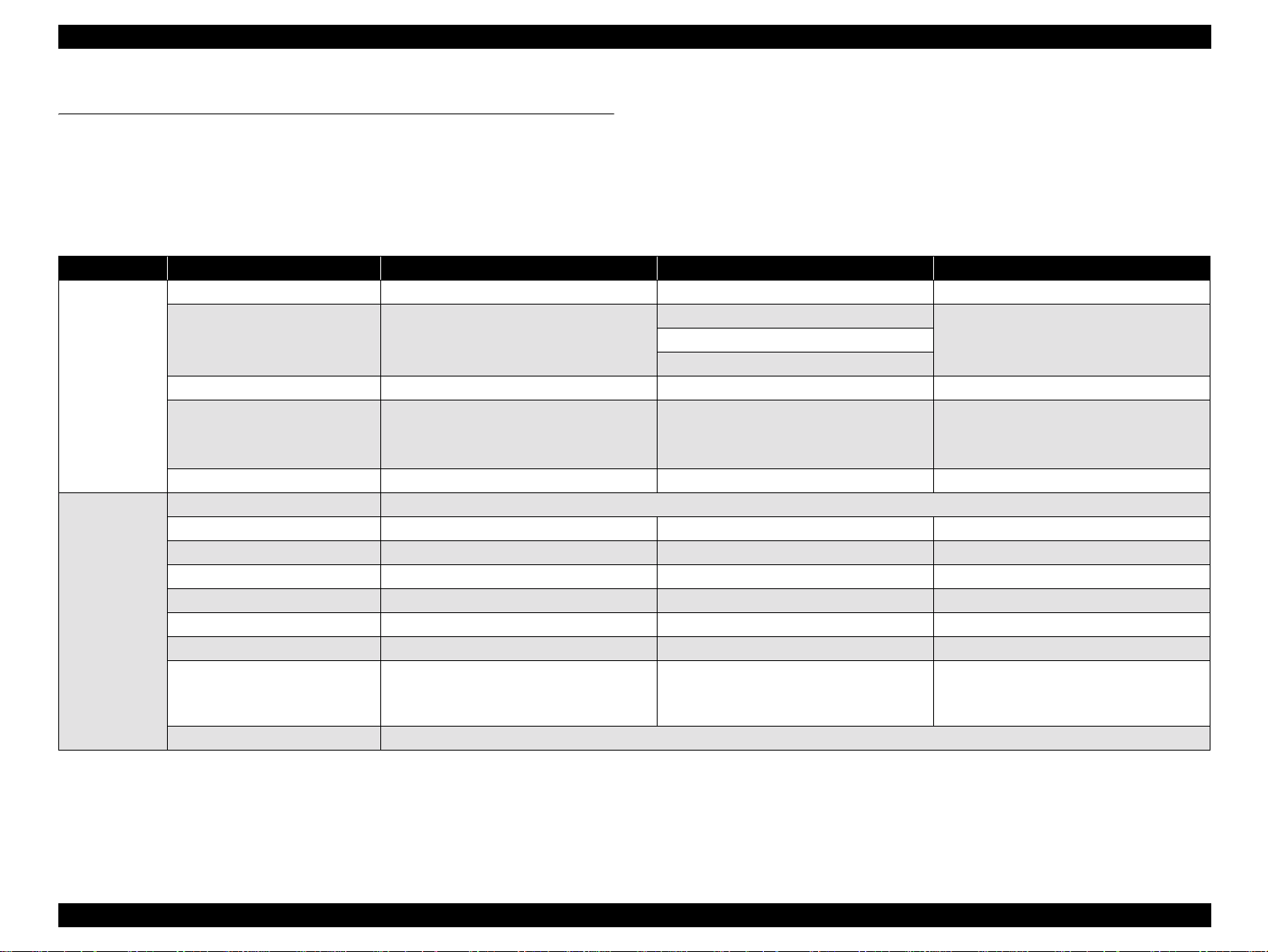
1.2.1 Specification Outline Comparison
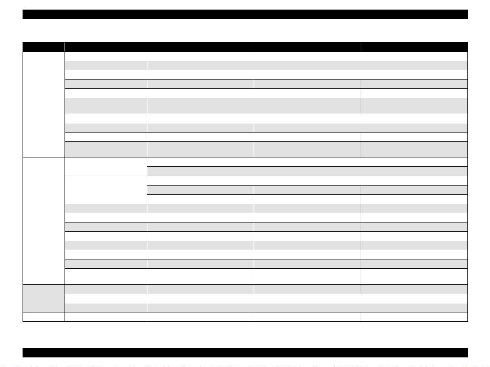
The following table gives the comparison of specifications between this product and similar conventional models.
Head
Table 1-1. Specification Outline Comparison
Item Stylus PHOTO 950 Stylus PHOTO 2100/2200 Stylus PHOTO 2000P
Location Successor to PM-920C Successor to Stylus PHOTO 2000P No corresponding model
7 colors
Number of colors
Resolution (H × V) 2880 × 1440 2880 × 1440 1440 × 720
Cut sheet size L/L2 size, A6 to A4
Roll paper compatibility 89/100/127/210mm width 89/100/210/329mm width
Number of Head Monochrome and color integrated type
Head type (black) G-Mach G-Mach E-Chips
Nozzle arrangement 96 nozzles × 1 line 96 nozzles × 2 lines 48 nozzles × 1 line
Nozzle pitch 180dpi 180dpi 120dpi
Head type (color) G-Mach G-Mach E-Chips
Nozzle arrangement 96 nozzles × 6 lines 96 nozzles × 5 lines 48 nozzles × 5 lines
Nozzle pitch 180dpi 180dpi 120dpi
Delivery (ng)
Head reliability/nozzle 3 billion shots/nozzle
(6 colors: 2 lines for BK, 1 line for each of C, LC,
M, LM, Y)
VSD1 : 13.8 + 27.6 + 41.5
VSD2 : 5.4 + 9.5 + 23.0
VSD4 : 2.5
7 colors (2 types for Bk + C, LC, M, LM, Y)
Matte-Black & Light-black
• A6 to Super A3
• Thickness : 0.08 to 0.11mm
• Envelope : #10, DL, C6
VSD1 : 13.8ng − 27.6ng − 41.5ng
VSD2 : 4.5ng − 9.5ng − 23.0ng
VSD4 : 4.5ng
6 colors (Bk, C, Lc, M, Lm, Y)Photo-Black & Matte-Black
• A6 to Super A3
• Thickness : 0.08 to 0.11mm
• Envelope : #10, DL, C6
ND :
PRODUCTION DESCRIPTION Basic Specifications 10
Page 11

EPSON Stylus PHOTO 2100/2200 Revision B
Table 1-1. Specification Outline Comparison
Item Stylus PHOTO 950 Stylus PHOTO 2100/2200 Stylus PHOTO 2000P
Ink type Dye Newly developed pigment Pigment
Ink cartridge type Color-separated CSIC Color-separated CSIC Black, color-individual CSIC type
Ink cartridges
• T0331 (Bk)
• T0332 (C)
• T0333 (LC)
I/C
(T code : Overseas)
Ink fill amount (black) 18.3g +/− 0.5g 18.3g +/− 0.5g
Effective ink amount 14.4g or more 14.4g or more
Remaining ink amount 3.4g or less 3.4g or less
Cartridge weight (black) 42g/each color 42g/each color
Number of printable sheets (black)
ISO/IEC 10561 Letter at 360dpi
Black ink end detection Dot counter (software counter)
Ink fill amount (color) 18.3g +/− 0.5g (Y/M/C/Lc/Lm) 18.3g +/− 0.5g (C/LC/M/Lm/Y)
Effective ink amount 14.4g or more (Y/M/C/Lc/Lm) 14.4g or more (C/LC/M/Lm/Y)
Remaining ink amount
*1 : Y/M/C,
*2 : Lc/Lm
Cartridge weight (color) 42g/each color 42g/each color
Number of printable sheets (black)
ECOMA ISO 10561 5% duty
Color ink end detection Dot counter (software counter)
• T0334 (M)
• T0335 (LM)
• T0336 (Y)
570 pages
(360dpi, A4)
3.4g or less (Y/M/C/Lc/Lm) 3.4g or more (C/LC/M/Lm/Y)
TBD
(360dpi, A4)
• T0341 (Photo Bk)
• T0342 (C)
• T0343 (M)
• T0344 (Y)
• T0345 (LC)
• T0346 (LM)
• T0347 (Light Black)
• T0348 (Matte Bk)
T.B.D
T.B.D
• T015 (Bk)
• T016 (Color)
PRODUCTION DESCRIPTION Basic Specifications 11
Page 12

EPSON Stylus PHOTO 2100/2200 Revision B
Table 1-1. Specification Outline Comparison
Item Stylus PHOTO 950 Stylus PHOTO 2100/2200 Stylus PHOTO 2000P
Mechanism
outline
Maximum number of print digits
(10CPI)
Number of motors
*1 : Optional cutter
CR motor armature resistance 23.0Ω +/− 25% (with DC brushes) 23.0Ω +/− 25% (with DC brushes) 31.1Ω +/− 25% (with DC brushes)
ASF/PUMP motor winding
resistance
PF motor armature resistance
(ASF)
Platen gap 1.35mm +/− 0.1mm 1.2mm +/− 0.1mm 1.14mm +/− 0.1mm
Reliability (except head) 5 years or black: 25000 pages, or color: 10000 pages
Operation noise (ISO 7779) 45dB (A)
Paper feeder
External dimensions (W × D × H)
*1 : When tucked
*2 : When used
Weight
4 motors (CR, PF, Pump, Cutter *1) 4 motors (CR, PF, Pump, Cutter *1) 3 motors (ASF, CR, PF)
10.0Ω +/− 10%: Per phase (PM stepping) 7.0Ω +/− 10%: Per phase (PM stepping) 10.4Ω +/− 10% : Per phase (PM stepping)
22.3Ω +/− 25% (with DC brushes) 23.0Ω +/− 25% (with DC brushes) 31.1Ω +/− 25% (with DC brushes)
•515 × 332.8 × 209mm *1
•515 × 526.3 × 229.4mm *2
(Cutter not included)
• 7.25kg (printer alone)
• Cutter: 950g
86.97 digits 127 digits
• ASF (Top entry front out)
• Roll paper feeder
• Matte board paper feeder
• CD-R printing tray
• 631 × 320 × 205mm *1
• 631 × 931 × 357mm *2
(Cutter not included)
• 11.7kg (printer alone)
• Cutter: 1.4kg
• 609 × 311 × 175mm *1
• 609 × 766 × 414mm *2
ASF (Top entry front out)
8.4kg
PRODUCTION DESCRIPTION Basic Specifications 12
Page 13
EPSON Stylus PHOTO 2100/2200 Revision B
Table 1-1. Specification Outline Comparison
Item Stylus PHOTO 950 Stylus PHOTO 2100/2200 Stylus PHOTO 2000P
CR encoder Linear scale + encoder sensor
PF encoder Loop scale + encoder sensor
PE detector Transparent photo interrupter
PE detector (rear) - - -
PG detector Mechanical contact (2 pcs.) -
Sensors
Main board
Power board
Panel board Panel board C456PNL C387PNL C304PNL
Paper leading edge/
paper width detector (PW sensor)
I/C detector CSIC
ASF HP detector Clutch detection Transparent photo interrupter
CDR tray detector Also us ed as PF sensor Mechanical contact -
Cutter CR position detector Transparent photo interrupter
Control code
Interface
USB (transfer speed) 12Mbps 12Mbps to 480Mbps 12Mbps
Main board C456Main−B C387Main C304Main/C298Main−B
Input buffer 256KB 112KB 256KB
PROM application Program Program & 2 Tables (PC437, PC850) Program & 2 Tables (PC437, PC850)
PROM type SOJ SOJ, 8Mbit, 3.3V DIC, 8M, 3.3V
Backup battery Installed Installed Installed
Backup battery type Capacitor Capacitor Lithium battery
Backup battery life
Power board C456PSB/PSE C387PSB/PSE C298PSB/PSE
Power switch Push switch with locking function
Output voltage 42V/5V
(electricity accumulated every power-on)
USB USB (2.0 compatibility) USB
- IEEE1394 (400Mbps) -
1 week
Transparent photo interrupter -
Transparent photo interrupter
(2 pcs.)
ESCP/2
ESCP remote
Panel (IEEE1284.4 compatibility)
1 week
(electricity accumulated every power-on)
5 years
-
PRODUCTION DESCRIPTION Basic Specifications 13
Page 14

EPSON Stylus PHOTO 2100/2200 Revision B
Table 1-1. Specification Outline Comparison
Item Stylus PHOTO 950 Stylus PHOTO 2100/2200 Stylus PHOTO 2000P
Market initial setting information EEPROM write EEPROM write EEPROM write
Head ID input 19 digits (21 digits on label) 25 digits 14 digits
Head inclination adjustment Mechanical lever inside CR
Head height adjustment No
Bi-D adjustment EEPROM write
USB ID input 18 digits (10 digits for input from adjustment program)
IEEE1394 ID input - 5 digits -
1.2mm +/− 0.1mm
No
predetermined)
O-12
1.14mm +/− 0.1mm
Yes
(within 0.1mm of standard)
Adjustment
Maintenance
Platen gap 1.27mm +/− 0.1mm
Pixel Shift Adjustment - EEPROM write -
Printout position adjustment
(CR scanning direction)
CR Measurement EEPROM automatic write EEPROM automatic write -
CR motor drive torque dispersion
measurement
PF Adjustment
(Band feed adjustment)
Top margin adjustment EEPROM (value basically fixed to all models)
PW sensor mounting position
adjustment
PF backlash adjustment
Lubricating oil/
grease
Waste ink pad 47325 points 60352 points 33900 points
(PF motor fixing screw tightening order
EEPROM write EEPROM write -
- EEPROM write -
- EEPROM write -
No
predetermined)
G-26 G26/G45/G56 G-26
Main shaft/sub shaft adjustment jig necessary
EEPROM (value basically fixed to each model)
(PF motor fixing screw tightening order
PRODUCTION DESCRIPTION Basic Specifications 14
Page 15
EPSON Stylus PHOTO 2100/2200 Revision B
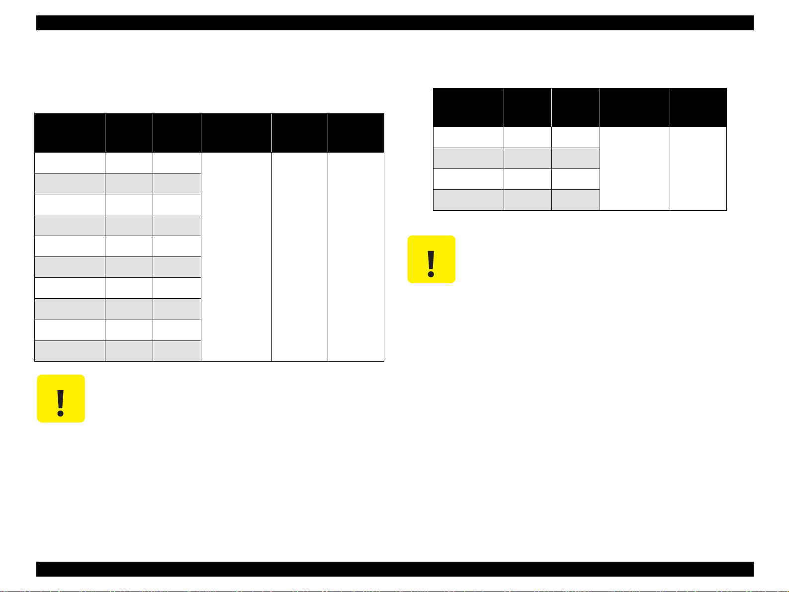
1.2.2 Paper Specification
1.2.2.1 Cut Sheet (Anti-EPSON special media)
Table 1-2. Cut Sheet
Paper
Paper size
A3 297 420
A4 210 297
A5 148 210
A6 105 148
B4 257 364
B5 182 257
Letter 216 279
Half letter 139.7 215.9
Legal 216 356
width mm
(inch)
Paper
length mm
(inch)
Quality
Plain paper,
Bond paper
Thickness
mm
(inch)
0.08 to 0.11
(0.003 to
0.004)
Weight
g/m2 (lb)
64 to 90
(17 to 24,
55 to 78)
1.2.2.2 Envelope (Anti-EPSON special media)
Table 1-3. Envelope
C A U T I O N
Paper
Paper size
*a
#10
*a
DL
*a
C6
220 × 132 220 132
width mm
(inch)
241.3 104.8
220 110
162 114
*a :The longer side has a flap that has been folded.
" For use in general room temperature environment only.
" No wrinkled, scuffed, torn or folded paper be used.
" No curled paper more than 5mm be used.
" No envelops glued in the flap and others be used.
" No doubled/windowed envelops be used.
Paper
length mm
(inch)
Quality
Bond paper, PPC,
Air mail
Weight
(g/m2)
45 to 75
(12 to 20lb)
Executive 184.2 266.7
C A U T I O N
" No wrinkled, scuffed, torn or folded paper be used.
" No curled paper more than 5mm be used.
PRODUCTION DESCRIPTION Basic Specifications 15
Page 16
EPSON Stylus PHOTO 2100/2200 Revision B
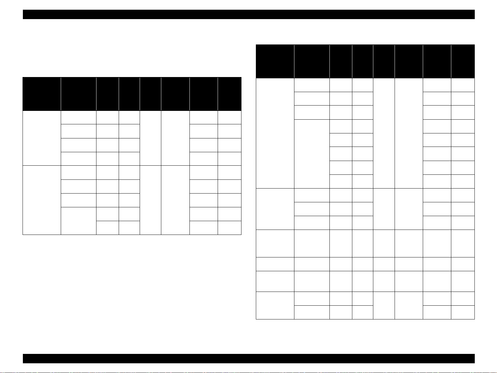
1.2.2.3 EPSON Special media
Quality: EPSON specifically designed media for ink jet printers
Table 1-4. EPSON Special media
EPSON
Special media
Photo Quality
Ink Jet Paper 2
Archival Matte
Paper
Paper
Paper size
Super A3 329 483
A3 297 420 65 ×
A4 210 297 65 ×
B5 182 257 65 ×
Super A3 329 483
A3 297 420 10 #
A4 210 297 20 #
Roll type
width
mm
(inch)
Paper
length
(inch)
89 7m - -
100 8m - -
Quality mmWeight
mm
g/m2 (Ib)
0.11 92(24)
0.25 189(50)
ASF
setting
65 ×
10 #
Support
sheet
EPSON
Special media
Premium Glossy
Photo paper
Glossy PaperPhoto Weight
Watercolor
Paper-Radiant
White
Table 1-4. EPSON Special media
Paper
Paper size
Super A3 329 483
A3 297 420 1 ×
A4 210 297 20 ×
Roll type
Super A3 329 483
A3 297 420 1 ×
A4 210 297 1 ×
Super A3/B 329 483 0.29 190(51) 1 ×
width
mm
(inch)
Paper
length
(inch)
89 7m - -
100 8m - -
127 8m - -
210 10m - -
329 10m - -
Quality mmWeight
mm
2
(Ib)
g/m
0.27 255(68)
0.22 217(58)
ASF
setting
1 ×
1 ×
Support
sheet
Matte Board A4 210 297 1.28 1100(293) - ×
Premium Ink
Jet Plain Paper
Bright White
Ink Jet Paper
(Bond Paper)
A4 210 297 0.11 80(21) 100 ×
A3 297 420
0.13 92.5(25)
A4 210 297 100 ×
100 ×
PRODUCTION DESCRIPTION Basic Specifications 16
Page 17
EPSON Stylus PHOTO 2100/2200 Revision B
EPSON
Special media
Matte Paper-
Heavyweight
C A U T I O N
Table 1-4. EPSON Special media
Paper
Paper size
Super A3/B 329 483
A3 297 420 10 #
A4 210 297 20 #
Roll type
width
mm
(inch)
Paper
length
(inch)
89 7m - -
100 8m - -
127 8m - -
Quality mmWeight
mm
2
(Ib)
g/m
0.23 167(44)
ASF
setting
10 #
Support
sheet
" For use in general room temperature environment only.
" No wrinkled, scuffed, torn or folded paper be used.
" No curled paper more than 5mm be used.
" Paper characteristics conform to the medium delivery
specification.
" The CD-R exclusive tray should be handled like board paper.
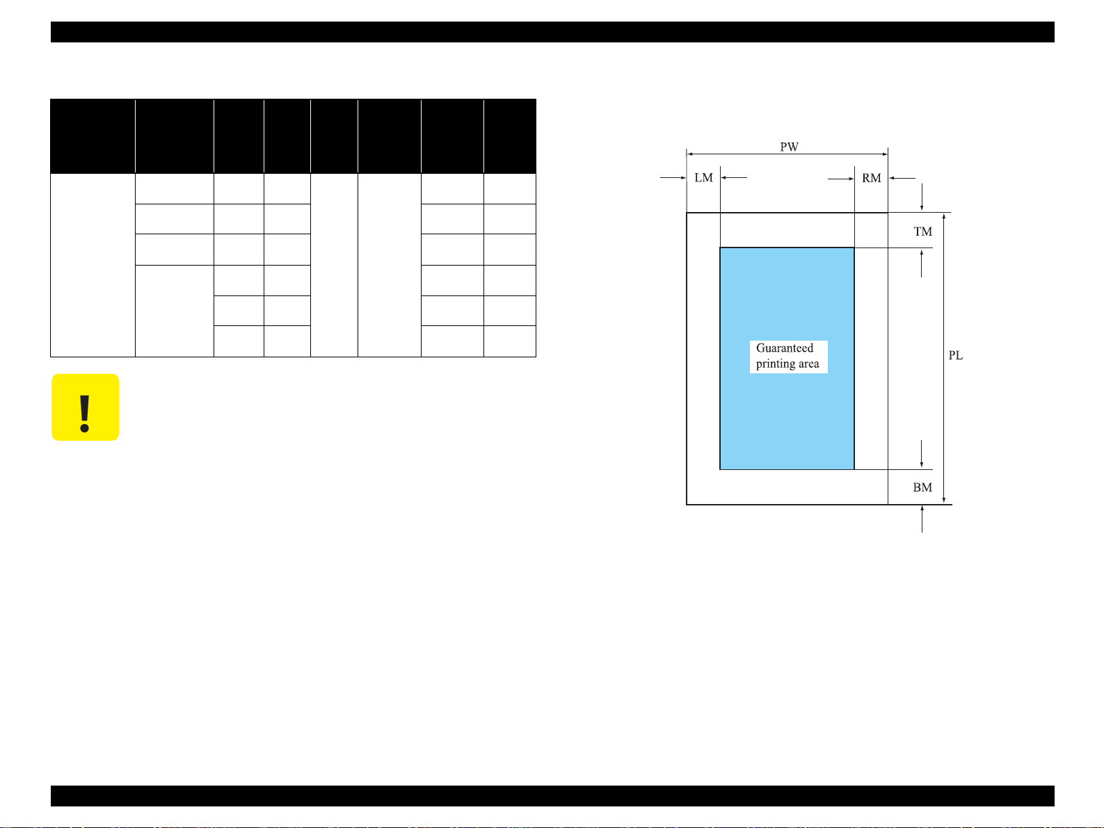
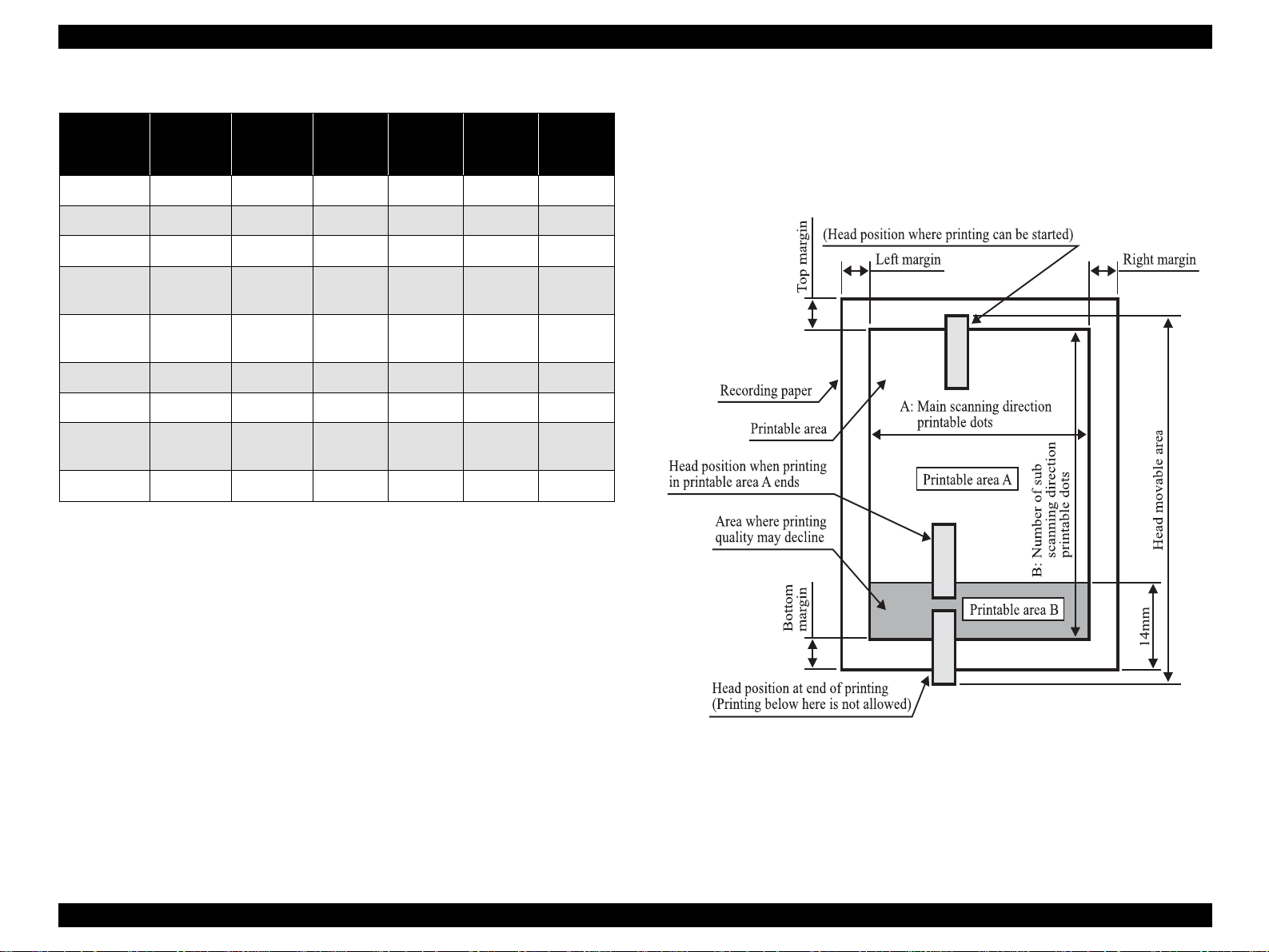
1.2.3 Printing Area
! The printing area guaranteed for this printer is shown below.
Figure 1-2. Printing Area
PRODUCTION DESCRIPTION Basic Specifications 17
Page 18
EPSON Stylus PHOTO 2100/2200 Revision B
!
Table 1-5. Printing Area (mm) of Stylus PHOTO 2100/2200
PW
Paper size
(paper
width)
A3 Wide 329 483 3
A3 297 420 3
US Legal 216 356 3
PL
(paper
length)
LM
(Left
margin)
*a
*a
*a
RM
(Right
margin)
*a
3
*a
3
*a
3
TM
(Top
margin)
*b
3
*b
3
*b
3
BM
(Bottom
margin)
*b*c
14/3
*b*c
14/3
*b*c
14/3
Printing area (Cut sheet)
" Printable area
The range made of the printable area A and printable area B shown in Figure
1-3. In the printable area B, printing quality may decline. The image quality
levels of the printing areas A, B are defined in the quality standard.
US Letter
(Landscape)
US Letter
(Portrait)
216 279 3
279 216 3
A4 210 297 3
B5 182 257 3
Photo Card
(4" x 6")
113.6 175.4 3
Roll paper - - 3
*a
*a
*a
*a
*a
*a
*a
3
*a
3
*a
3
*a
3
*a
3
*a
3
20
*b
3
*b
3
*b
3
*b
3
*b
3
*b
*a : Under specific conditions, the left and right margins can be zeroed.
*b : Under specific conditions, the top and bottom margins can be zeroed.
*c : When the paper length is specified with the ESC (S command, the bottom
margin can be reduced to the minimum of 3mm. However, printing quality
may decline in the range 3mm to 14mm from the paper bottom. When the
paper length is not specified, the bottom margin remains unchanged from
14mm or more.
14/3
14/3
14/3
14/3
14/3
*b*c
*b*c
*b*c
*b*c
*b*c
14
Figure 1-3. Printing Area
PRODUCTION DESCRIPTION Basic Specifications 18
Page 19
EPSON Stylus PHOTO 2100/2200 Revision B
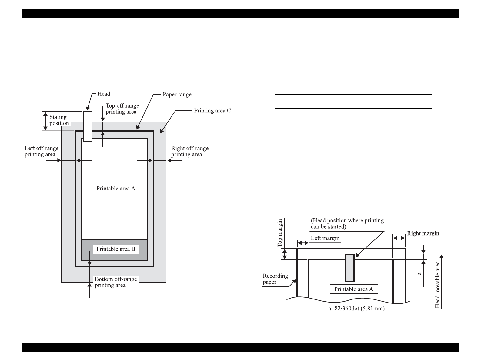
"
Printable area (Margin-less printing)
The range made of the printable areas A and B and the top, bottom, left and
right off-range printing areas C shown in Figure 1-4.The image quality levels
of the printing areas A, B are defined in the quality standard. The printing
areas C are trimmed areas, where printing may not be done. Note that the
paper width is limited to 89, 100, 127, 210 or 329mm or to 4, 5, 8, or 8.5
inches.
Starting position : 85/360 (6mm)
!
! Off-range printing areas
Table 1-6. Off-range Printing Areas
Top 42/360 (3mm) 42/360 (3mm)
Left, right 36/360 (2.5mm) 49/360 (3.5mm)
Bottom 72/360 (5mm) 72/360 (5mm)
Size Less than
in Right Field
11inch/A3/A3+
" Head movable areas
Set the head movable areas (areas where the nozzles may come out of the
printing range) relative to the printing area in the sub scanning direction
(paper feeding direction). Those areas are as shown in Figure 1-5 to Figure
1-9. The main scanning direction (carriage direction) is as shown in the A0
carriage operation area diagram.
1) Top head movable area
1. At the setting of top margin to 3mm or more
Figure 1-4. Printing Area (Margin-free Printing)
Figure 1-5. Head Movable Area for 3mm Top Margin
PRODUCTION DESCRIPTION Basic Specifications 19
Page 20
EPSON Stylus PHOTO 2100/2200 Revision B
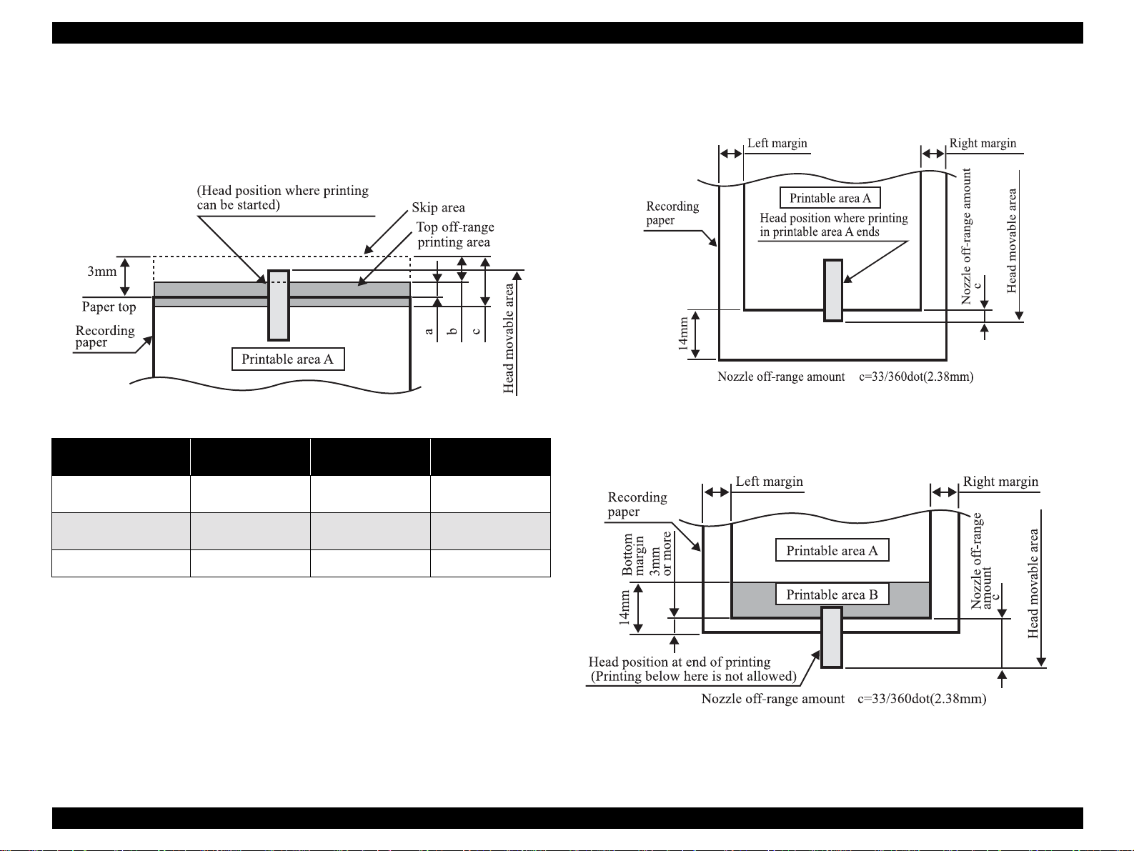
2. At the setting of top margin to 0mm
Top off-range printing prints the area a, and nozzle-restricted
printing prints the area c. After the #1 nozzle has passed through the
area c, nozzle restriction is canceled.
Paper Type Exclusive Paper
Recording paper width
(Main scanning method)
a = Off-range printing
area
b = Skip amount 17/360 (1.20mm) 17/360 (1.20mm) 4/360 (0.28mm)
Less than 150mm Less than 150mm 150mm or more
25/360 (1.76mm) 25/360 (1.76mm) 38/360 (2.68mm)
Other than
Exclusive Paper
Any Paper Type
c = 66/360 (4.7mm) Nozzle-restricted printing area
#1 to #22 A total of 22 nozzles Nozzle restriction
2) Bottom head movable area
1. At the setting of bottom margin to 14mm
Figure 1-7. Head Movable Area for 14mm Bottom Margin
2. At the setting of bottom margin to 3mm
Figure 1-6. Head Movable Area for 0mm Top Margin
Figure 1-8. Head Movable Area for 3mm Bottom Margin
PRODUCTION DESCRIPTION Basic Specifications 20
Page 21
EPSON Stylus PHOTO 2100/2200 Revision B
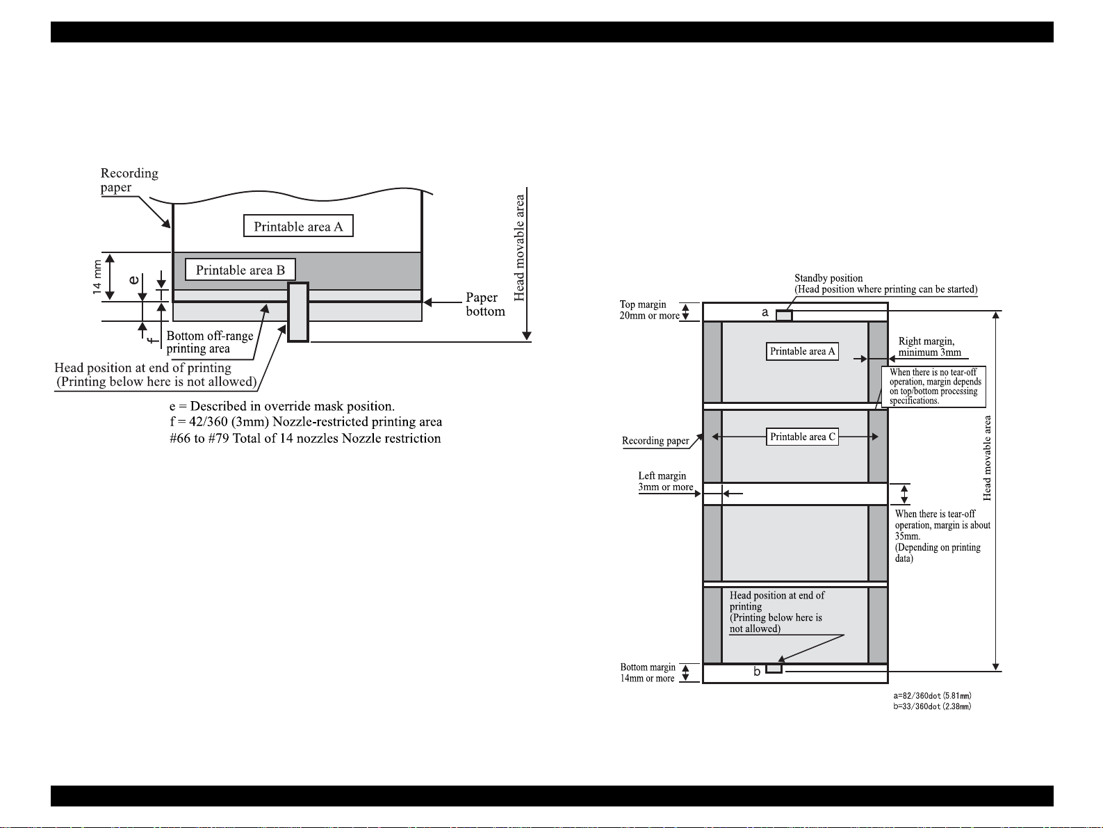
3. At the setting of bottom marg in to 0mm
Since printing is restricted in the bottom off-range area (e) after the
distance f from the paper bottom, only a total of 14 nozzles, #66 to
#79, are used per nozzle line to perform printing.
Figure 1-9. Head Movable Area for 0mm Bottom Margin
Printing area (Roll paper)
!
" Printing area
The range made of the printable area A or printing areas A + C shown in
Figure 1-10. Note that printing in the range of printing areas A + C is limited
to the paper width 89, 100, 127, 210 or 329mm or to 4.5 inches.
" Head movable area
Set the head movable area (area where the head may come out of the printing
range) relative to the printing area in the paper feeding direction. This area is
as shown in Figure 1-10 (roll paper).
Figure 1-10. Printing Area Diagram (Roll Paper)
PRODUCTION DESCRIPTION Basic Specifications 21
Page 22
EPSON Stylus PHOTO 2100/2200 Revision B
!
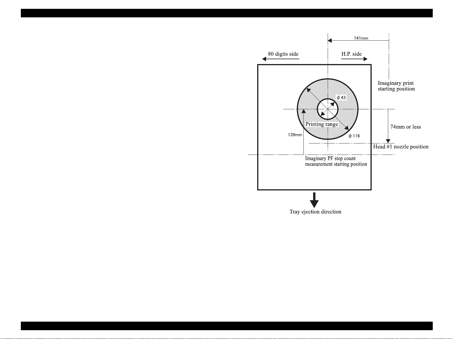
Printing area (CD-R)
" Printing area
Figure 1-11 shows a CD-R printing area. The printing area is in the inside of
∅116 and in the outside of ∅43.
1. The reference position of the carriage main scanning direction is 141mm
away from the center of a CD-R toward the home position. (The center of
the CD-R is identified by automatic detection.)
2. The reference position of the paper feeding direction is 139mm below the
center of the CD-R.
3. The CD-R center cannot be reversed more than 74mm from the head #1
nozzles.
Figure 1-11. Printing Area Diagram (CD-R)
PRODUCTION DESCRIPTION Basic Specifications 22
Page 23
EPSON Stylus PHOTO 2100/2200 Revision B
1.2.4 Ink Type-based Medium Compatibility
Specifications
On this product, the compatible media change depending on the black ink combination.
PIM compatibility also changes depending on the medium. The following describes the
compatible media, used LUT, and PIM compatibility that change depending on the black
ink combination.
! Photo-black + Light-black: Glossy
Standard ink combination/ink combination adequate for photo printing
Table 1-7. Photo-black + Light-black
Paper Type Support Used LUT
Plain Paper # Plain Paper Plain Paper Plain Paper #
Premium Ink
Jet Plain Paper
Bright White
Ink Jet Paper
Premium Luster
Photo Paper
(for U.S only)
Premium
Semigloss
photo paper
Premium
Glossy Photo
Paper
(for U.S only)
Glossy Paper-
Photo Weight
(Except U.S)
# Plain Paper × × #
# Plain Paper ××#
Premium
#
#
#
#
Semigloss
photo paper
Premium
Semigloss
photo paper
Premium
Semigloss
photo paper
Glossy Paper-
Photo Weight
Driver UI Description
US Other
Premium Luster
Photo Paper
Premium
Semigloss
photo paper
Premium
Semigloss
photo paper
×
× #
Premium
Semigloss
photo paper
× #
Glossy Paper-
Photo Weight
PIM
Support
#
#
Table 1-7. Photo-black + Light-black
Paper Type Support Used LUT
Velvet Fine Art
Paper
(for U.S only)
Watercolor
Paper-Radiant
White
CD-R × ----
Photo Quality
Ink Jet Paper
Matte Paper-
Heavyweight
Photo Paper × - - - -
Photo Quality
Glossy Film
Ink Jet
Transparencies
Iron-On Cool
Peel Transfer
Paper
Ink Jet
Backlight Film
Canvas × ----
360dpi Ink Jet
Paper
#
#
Archival Matte
Paper
Watercolor
Paper-Radiant
White
× - - - -
× ----
× ----
× - - - -
× ----
× - - - -
× - - - -
Driver UI Description
US Other
Velvet Fine Art
Paper
Watercolor
Paper-Radiant
White
× #
Watercolor
Paper-Radiant
White
PIM
Support
#
Archival Matte
Paper
#
Archival Matte
Paper
Archival Matte
Paper
Archival Matte
Paper
#
PRODUCTION DESCRIPTION Basic Specifications 23
Page 24
EPSON Stylus PHOTO 2100/2200 Revision B
!
Matte-black + Light-black: Matte-black is optional.
Good-looking ink combination for plain paper/matte-Light-black media
Table 1-8. Matte-black + Light-black
Paper Type Support Used LUT
Plain Paper # Plain Paper Plain Paper Plain Paper #
Premium Ink
Jet Plain Paper
Bright White
Ink Jet Paper
Premium Luster
Photo Paper
(for U.S only)
Premium
Semigloss
photo paper
Premium
Glossy Photo
Paper
(for U.S only)
Glossy Paper-
Photo Weight
(Except U.S)
Archival Matte
Paper
# Plain Paper × × #
# Plain Paper ××#
× - - - -
× ----
× - - - -
× ----
#
Archival Matte
Paper
Driver UI Description
US Other
Archival Matte
Paper
Archival Matte
Paper
PIM
Support
#
Paper Type Support Used LUT
Photo Quality
Ink Jet Paper
Matte Paper-
Heavyweight
Photo Paper × - - - -
Photo Quality
Glossy Film
Ink Jet
Transparencies
Iron-On Cool
Peel Transfer
Paper
Ink Jet
Backlight Film
Canvas × ----
360dpi Ink Jet
Paper
NOTE: When the PIM incompatible me diu m is selected, the "some PRINT
IMAGE Matching functions are not applied" message appears on bottom
right of the paper selection screen.
Table 1-8. Matte-black + Light-black
Driver UI Description
US Other
× - - - -
× ----
× ----
× - - - -
× ----
× - - - -
× - - - -
PIM
Support
Velvet Fine Art
Paper
(for U.S only)
Watercolor
Paper-Radiant
White
CD-R × ----
#
#
Archival Matte
Paper
Watercolor
Paper-Radiant
White
Velvet Fine Art
Paper
Watercolor
Paper-Radiant
White
××
Watercolor
Paper-Radiant
White
#
PRODUCTION DESCRIPTION Basic Specifications 24
Page 25
EPSON Stylus PHOTO 2100/2200 Revision B
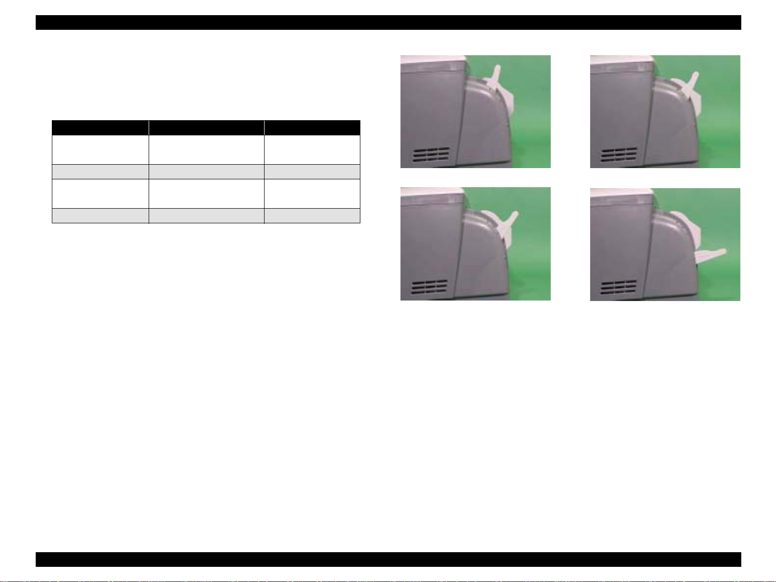
1.2.5 Release Lever
On this printer, set the Release lever as indicated in the following table depending on
the used paper type.
Table 1-9. Release lever Setting
Paper Release lever Position Gap Correction
Cut sheet, OHP, Label,
Roll paper
Envelope, Board paper First step from front position +1.3mm
CD-R tray
*a
- Far side position
*a : When the CD-R tray is loaded, any position other than the second
step from the front position will result in a release lever error.
*b : The far side position of the Release lever is used when placing
thick paper (board paper) or CD-R tray. After placing thick paper
or CD-R tray, move the release lever to the appropriate position.
Front side position 0mm
Second step from front
position
*b
+2.7mm
<Front side position>
-
<First step from front position>
<Second step from front position>
<Far side position>
Figure 1-12. Release Lever Positions
PRODUCTION DESCRIPTION Basic Specifications 25
Page 26
EPSON Stylus PHOTO 2100/2200 Revision B
1.3 Functions
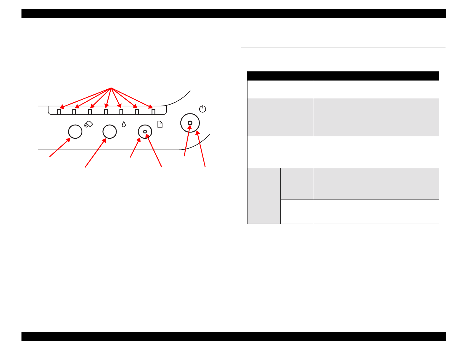
1.3.1 Control Panel
The appearance of the control panel is shown below.
Ink LEDs 1 to 7
Roll paper switch
Ink switch
Figure 1-13. Control Panel Appearance
1.3.2 Switches
! Power switch
! Paper switch
! Ink switch
! Roll paper switch
Paper switch
Power LED
Paper LED
Power switch
1.3.4 Switch Functions
FUNCTIONS IN NORMAL STATUS
Table 1-10. Normal-status Functions
Switch Function
Power switch
Paper switch
Ink switch
Without
cutter
Roll paper
switch
With cutter
*a : Turn on the power switch within 10 seconds.
*b : Hold down the switch for 3 seconds.
• Power on/off
•Panel reset
• Paper feed (Error is reset when paper is fed
successfully)
• Paper ejection
• Movement from cartridge replacement position to
home position
• Cleaning
• Movement to cartridge replacement position
• Movement from cartridge replacement position to
home position
• Tear Off execution/return from Tear Off
• Roll paper ejection (back-out)
• Movement from cartridge replacement position to
home position
• Roll paper ejection (back-out)
• Movement from cartridge replacement position to
home position
*a
*b
*b
*b
1.3.3 Indicators
! Power LED : Green
! Paper LED : Red
! Ink LEDs (1 to 7) : Red
PRODUCTION DESCRIPTION Functions 26
Page 27

EPSON Stylus PHOTO 2100/2200 Revision B
FUNCTIONS AT POWER-ON SPECIAL SETTING MODE
Table 1-11. Power-on Functions
Switch Function
Paper switch Status printing
Ink switch Roller cleaning mode
Roll paper switch
Paper switch
+
Roll paper switch
Code Page/parallel interface 1284.4
operation mode selection
Special setting mode
*a : Any of the following operations is performed according to the
value written to 5BH of the EEPROM. For details, refer to"Status
Printing" on Page 30.
00h
01h Hexadecimal dump mode
Firmware version, selected Code Page, Waste ink counter
and nozzle test pattern are printed.
*b : For details, refer to "Panel Operation in Roller Cleaning Mode" on
Page 34.
*c : For details, refer to "Default Setting Selection Function" on Page
28.
*d : For details, refer to "Special setting mode" on Page 27.
*a
*b
*c
*d
To select the special setting mode, hold down the Paper switch and Roll paper switch
and switch power on, and then press the following switches within the time when the
Paper error indicator is blinking (for about 3 seconds).
Table 1-12. Special Setting Mode
Switch Function
Paper switch EEPROM and Timer IC reset
Roll paper switch
(10 seconds)
Waste ink counter reset
*a
*b
*c
*a : This operation resets the following data at the corresponding
addresses of the EEPROM.
• 26<H>-27<H> Last cleaning time: 00<H>, 00<H>
• 28<H>-29<H> Power off time: 00<H>, 00<H>
• 44<H> Interface selection: 00<H> (Auto)
*b : For the initialized items, refer to "EEPROM Address Map" on
Page 231.
*c : The corresponding addresses of the EEPROM are 20<H>-21<H>.
PRODUCTION DESCRIPTION Functions 27
Page 28
EPSON Stylus PHOTO 2100/2200 Revision B
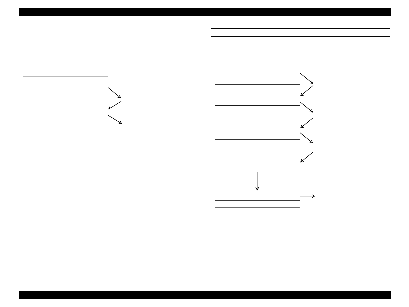
1.3.5 Default Setting Selection Function
CODE PAGE SELECTION FUNCTION
By operating the panel at power-on, you can select the default character code table.
Operating procedure
Hold down the Roll paper switch and
switch power on or reset the panel.
The Paper LED blinks.
When the blink of the Paper LED has
started, release the Roll paper switch.
Code Page is changed (changed
from PC437 to PC850 or from PC
850 to PC437 automatically) and
all LEDs are then lit for about 2
seconds.
Confirmation of the current Code Page
The currently selected Code Page can be confirmed by performing status printing.
PARALLEL INTERFACE 1284.4 OPERATION MODE SELECTION
By operating the panel at power-on, you can select the operation mode (On/Off/Auto)
of the IEEE1284.4 protocol in the parallel interface.
Operating procedure
Hold down the Roll paper switch and
switch power on.
When the blink of the Paper LED has
started, release the Roll paper switch
but keep pressing the Paper switch.
When the Power LED, Paper LED and
all Ink LEDs are lit, release the Paper
switch.
Press the Roll paper switch to select the
operation mode (every time you press
the switch, the operation mode changes
from Auto to On to Off to Auto ...).
*a
The Paper LED blinks.
*b
(About 10 seconds)
The Power LED, Paper LED and
all Ink LEDs are lit.
The operation mode currently
selected is indicated by the
corresponding Ink LED.
On : Ink LED 7 is lit.
Off : Ink LED 6 is lit.
Auto : Ink LED 5 is lit.
Switch power off.
or
Press the Paper switch.
*a : By initializing the panel, you cannot select the 1284.4 operation m ode. To
avoid panel initialization, the power must be left off for more than about 10
seconds or the power plug must be disconnected from the receptacle once
with power off.
*b : Note that if you do not press any switch for 2 or more seconds after you
released the Roll paper switch, Code Page selection will be executed.
The selected operation mode is
stored and power is switched off.
The selected operation mode is
stored and the printer starts.
PRODUCTION DESCRIPTION Functions 28
Page 29
EPSON Stylus PHOTO 2100/2200 Revision B
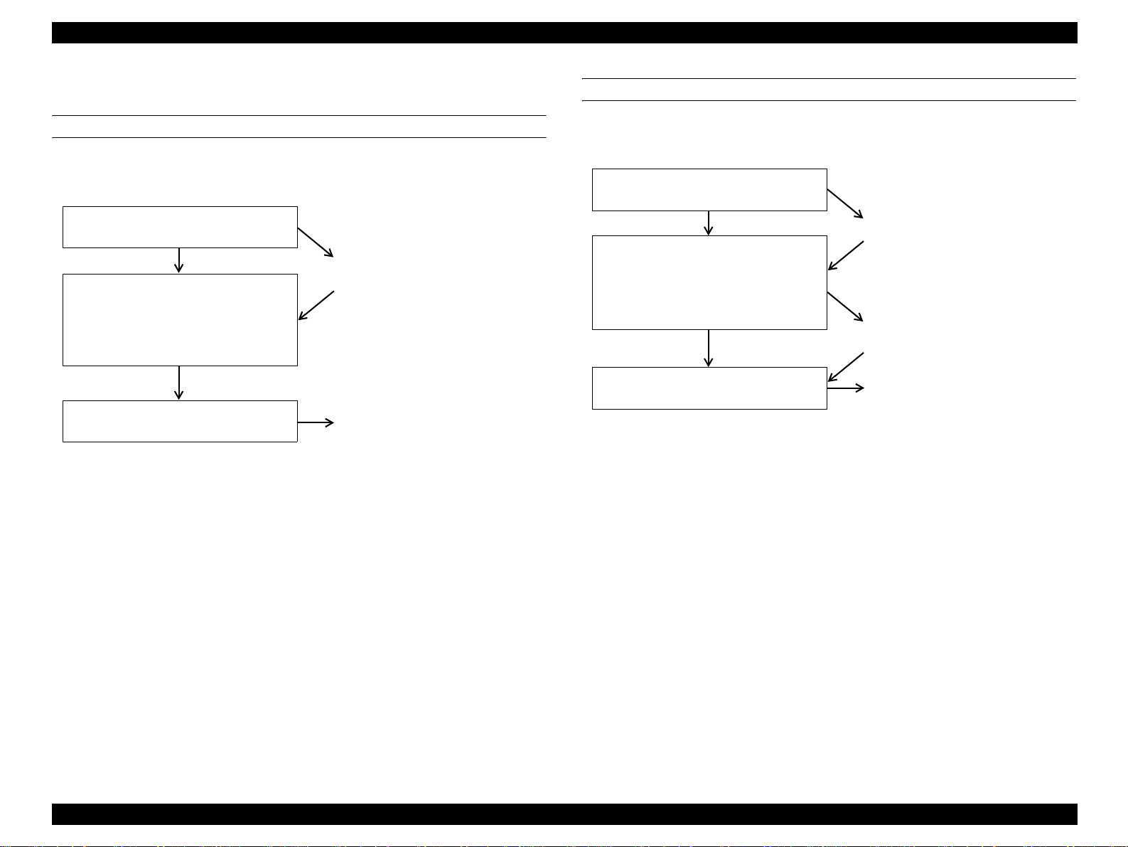
1.3.6 Special Setting Mode Function
EEPROM AND TIMER IC RESET
By operating the panel at power-on, you can reset the EEPROM and Timer IC.
Operating procedure
Hold down the Roll paper switch and
Paper switch, and switch power on.
The Power and Paper LEDs
When the blink 2 of the Power and
Paper LEDs and the blink of all Ink
LEDs have started, release the Roll
paper switch and Paper switch and
press the Paper switch.
The Power, Paper and all Ink LEDs are
lit for 1 second.
*a : If the switch is not pressed within the time when the Error LED is blinking
(for 3 seconds), the printer starts normally.
*a
blink 2 and all Ink LEDs blink.
EEPROM and Timer IC reset
ends and the printer starts.
WASTE INK COUNTER RESET
By operating the panel at power-on, reset the counter for waste ink.
Operating procedure
Hold down the Roll paper switch and
Paper switch, and switch power on.
The Power and Paper LEDs
When the blink 2 of the Power and
Paper LEDs and the blink of all Ink
LEDs have started, release the Roll
paper switch and Paper switch and
press the Roll paper switch.
The Power, Paper and all Ink LEDs are
lit for 2 seconds.
blink 2 and all Ink LEDs blink.
(About 10 seconds)
The Power LED, Paper LED and
all Ink LEDs are lit.
Waste ink counter reset ends and
the printer starts.
PRODUCTION DESCRIPTION Functions 29
Page 30
EPSON Stylus PHOTO 2100/2200 Revision B
1.3.7 Status Printing
PRINTING METHOD
Printing using remote command
!
Use the NC command of the remote commands.
! Status printing
Hold down the Paper switch and switch power on.
! Printing using D4 control command
On the D4 command channel, send the "nc" command.
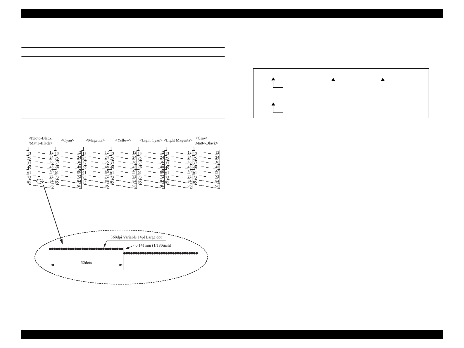
PRINTING RESULT DETAILS
NOTE: Differences between the character strings printed in panel Nozzle Check
pattern and driver Nozzle Check pattern (For the driver, the firmware
version and CPU mask version are also printed at top left of the print
result paper.)
EL071C IO301A 0490
Waste counter
value
PC437
Firmware version
Code table
CPU mask version
Figure 1-14. Printed Character Strings
NOTE: The values above the lines indicate nozzle numbers and are not pri nted
actually.
PRODUCTION DESCRIPTION Functions 30
Page 31

EPSON Stylus PHOTO 2100/2200 Revision B
1.3.8 Panel Operation for Roll Paper Printing
PANEL OPERATION IN ROLL PAPER MODE
(WITHOUT CUTTER, TEAR-OFF LINE PRINTING)
To shift to the paper roll mode, use the roll paper mode selection command of the
remote commands.
The following indicates the basic panel operating procedure for printing on roll paper.
Operating procedure
1. Insert roll paper from the roll paper
guide.
*
a
2. Receive the roll paper data and
perform printing until the end of the
job. After the printing is over, the
printer does not eject paper and
enters the switch waiting status.
*
b
3. Press the Roll paper switch to
execute Tear Off (with tear-off
line).
*
c
4. Cut off the paper along the tear-off
line.
5. Press the Roll paper switch to
execute return from Tear Off.
*
c
6. Press the Roll paper switch for 3
seconds to back out the paper.
*
Continued to the
d
right field.
With the Paper detection sensor on
for 2 seconds, the roll paper is fed
automatically. After the roll paper
is fed, the operation with the Paper
switch is masked.
If consecutive print jobs come, the
CR stops at the end of the last job,
and the printer does not eject the
paper and enters the switch
waiting status. At this time there
are no print margins between the
jobs.
If the next print jog comes at this
point, the printer does not print and
waits for return from Tear Off.
If there is a next print job, the
printer prints and Steps 2. to 5. are
repeated.
Continued to the right
field.
Continued from the
left field
After back-out, the Paper LED
blinks. The masked Paper switch is
Continued from the left field
de-masked. If the roll paper cannot
be removed after one back-out,
press the Roll paper switch or
7. When the roll paper cannot back out
any more, remove the roll paper
Paper switch for 3 seconds to
execute back-out again.
with your hands.
*
d
8. Press the Roll paper switch or Paper
switch to clear a paper jam. The
The Paper LED goes off.
printer returns to the normal mode.
*a : If power is switched off at this point, the panel feeding status is stored onto
the EEPROM. When power is switched on again, the printer does not eject
paper. The operation in Step 2. and later can be performed.
*b : If power is switched off at this point, the roll paper mode status is stored onto
the EEPROM. When power is switched on again, the printer does not eject
paper. The operation in Step 3. and later can be performed.
*c : If power is switched off at this point, the roll paper mode status is stored onto
the EEPROM. When power is switched on again, the printer does not eject
paper. The operation that follows can be performed.
*d : If power is switched off at this point, the roll paper mode is canceled and the
panel feeding cancel is stored. When power is switched on again next, the
printer enters the normal mode.
PRODUCTION DESCRIPTION Functions 31
Page 32

EPSON Stylus PHOTO 2100/2200 Revision B
PANEL OPERATION IN ROLL PAPER MODE (WITH CUTTER)
To shift to the paper roll mode, use the roll paper mode selection command of the
remote commands.
Specify the cutting position of the roll paper using the cutting po sition specifying
command of the remote commands. When the specified position comes to the cutting
position, the paper is cut automatically.
If the cutting position specifying command is not available for the roll paper, perform
the "Panel operation in roll paper mode (Without cutter, tear-off line printing)" on Page
31.
Operating procedure
1. Insert roll paper from the roll paper
guide.
*
a
2. Receive the roll paper data and
perform printing until the end of the
job. If the cutting specified position
reaches the cutter blade position
during printing, the roll paper is cut.
*
b
3. Press the Roll paper switch to
execute Tear Off cutting. Return
from Tear Off is then performed
automatically.
*
c
Continued to the right
field.
With the Paper detection sensor on
for 2 seconds, the roll paper is fed
automatically. After the roll paper
is fed, the operation with the Paper
switch is masked.
If consecutive print jobs come, the
CR stops at the end of the last job
and the printer does not eject nor
cut the paper and enters the switch
waiting status. At this time, there
are no print margins between the
jobs.
If there is a next print jog, the
printer prints and Steps 2. and 3.
are repeated.
Continued from the left field
4. Press the Roll paper switch for 3
seconds to back out the paper.
*
d
5. When the roll paper cannot back out
any more, remove the roll paper
with your hands.
*
d
After back-out, the Paper LED
blinks. The masked Paper switch is
de-masked. If the roll paper cannot
be removed after one back-out,
press the Roll paper switch or
Paper switch for 3 seconds to
execute back-out again.
6. Press the Roll paper switch or Paper
switch to clear a paper jam. The
The Paper LED goes off.
printer returns to the normal mode.
*a : If power is switched off at this point, the panel feeding status is stored onto
the EEPROM. When power is switched on again, the printer does not eject
paper. The operation in Step 2. and later can be performed.
*b : If power is switched off at this point, Tear Off is executed automatically to cut
the roll paper, and the roll paper mode status is stored onto the EEPROM.
When power is switched on again, the printer does not eject paper. The
operation in Step 3. and later can be performed.
*c : If power is switched off at this point, the roll paper mode status is stored onto
the EEPROM. When power is switched on again, the printer does not eject
paper. The operation in Step 3. and later can be performed.
*d : If power is switched off at this point, the roll paper mode is canceled and the
panel feeding cancel is stored. When power is switched on again next, the
printer enters the normal mode if the Paper detection sensor is off.
PRODUCTION DESCRIPTION Functions 32
Page 33

EPSON Stylus PHOTO 2100/2200 Revision B
1.3.9 Panel Operation for CD-R Printing
The following indicates the basic panel operating procedure for printing on CD-R.
Operating procedure
1. Move the Release lever to the
farthest position.
2. Along the paper feed guide, put the
CD-R tray folder into the printer
front and push the CD-R tray into
the specified position toward the
printer rear.
*
a
3. Return the Release lever to the
original position.
*
a
4. Press the Paper switch.
*
b
5. Send the print data.
*a : If power is switched off and then on again at this point, the CD-R tray is not
ejected and a paper jam error occurs. When you further press the Paper
switch, the CD-R tray is ejected to the front and the printer returns to the
normal mode.
*b : If power is switched off and then on again at this point, the CD-R tray is
ejected to the front and the printer returns to the normal mode.
The Paper LED blinks fast.
If the print data has already been
sent, print operation is stopped
temporarily.
The Paper LED stops blinking fast.
The CD-R tray is fed
automatically. If it is not fed
properly, the CD-R tray is ejected
to the front and a paper feed error
occurs.
After printing is over, the CD-R
tray is ejected.
1.3.10 Panel Operation for Thick Paper Printing
The following indicates the basic panel operating procedure for printing on thick paper.
Operating procedure
1. Move the Release lever to the
farthest position.
2. Along the paper feed guide, insert
the thick paper into the printer rear.
3. Return the Release lever to the
original position.
*
a
4. Press the Paper switch.
*
b
5. Send the print data.
*a : If power is switched off and then on again at this point, the thick paper is not
ejected and a paper jam error occurs. When you further press the Paper
switch, the thick paper is ejected and the printer then returns to the normal
mode.
*b : If power is switched off and then on again at this point, the thick paper is
ejected and the printer returns to the normal mode.
The Paper LED blinks fast.
If the print data has already been
sent, print operation is stopped
temporarily.
Insert the thick paper along the
right end of the paper feed guide.
The Paper LED stops blinking fast.
The thick paper is fed
automatically. If it is not fed
properly, a paper feed error occurs,
or if the CR interferes with the
thick paper, a paper thickness error
occurs.
After printing is over, the thick
paper is ejected.
PRODUCTION DESCRIPTION Functions 33
Page 34

EPSON Stylus PHOTO 2100/2200 Revision B
1.3.11 Panel Operation in Roller Cleaning Mode
If the ink concentration is increased within the printer driver detail setting, the ink
printed on the medium may be transferred to the rollers. In this case, the ink may be
transferred from the rollers to the print medium, making the print image dirty. If this
phenomenon has occurred, start this mode to clean the rollers. If ink is transferred to
the rollers heavily, start this mode and apply the cleaning pad packed with this product
to the rubber rollers to clean the rollers.
The following describes how to start and end the roller cleaning mode and operate the
panel during the roller cleaning mode.
OPERATING PROCEDURE
!
Roller cleaning mode starting procedure
1. Initial status: Power off
2. Hold down the Ink switch
and switch power on. → The Power LED is lit.
The Paper LED and all Ink LEDs blink 2.
3. Release the Ink switch. → The mechanism starts.
The Power LED blinks.
The Paper LED and all Ink LEDs go off.
↓
After the mechanism has ended starting,
the roller cleaning mode starts.
(Roller cleaning mode initial status)
The Power LED blinks 2.
The Paper LED blinks 2 and all Ink LEDs go off.
! Operating procedure in roller cleaning mode
1. Roller cleaning mode init ial status
Power LED : Blink 2
Paper LED : Blink 2
All Ink LEDs : Off
Pressing the Paper switch starts roller
cleaning.
If there is no paper on
the paper feed tray
NOTE: During the roller cleanin g mode, the In k switch and Roll paper switch
are invalid.
During roller cleaning execution, the Paper switch, Ink switch and Roll
paper switch are invalid.
2. Roller cleaning (paper feed) start
Power LED : Blink 2
Paper LED : Blink 2
All Ink LEDs : Off
If there is paper on the paper
feed tray
3. Roller cleaning execution
Power LED : Blink 2
Paper LED : Blink 2
All Ink LEDs : Off
Roller cleaning end
4. Roller cleaning end
Power LED : On
Paper LED : On
All Ink LEDs : Off
Pressing the Paper
switch restarts roller
cleaning.
! End of roller cleaning mode
" When you press the Power switch during the roller cleaning mode, the roller
cleaning mode ends and power switches off.
" When you press the Power switch during roller cleaning execution, the printer
ejects the roller cleaning paper, and then the roller cleaning mode ends and
power switches off.
PRODUCTION DESCRIPTION Functions 34
Page 35

EPSON Stylus PHOTO 2100/2200 Revision B
1.3.12 Indicator Display in Normal Mode
Table 1-13. Printer Condition and LED Status
blink
Blink
blink
Indicators
High speed
High speed
alternately 2
High speed
*a
*b
*b
*b
blink
*b
blink
*b
-4
Blink
blink
Printer status
Power on condition On - - 18
Data processing Blink - - 17
Ink sequence Blink - Special blink
Ink cartridge change mode Blink - - 15
Ink level low - - Blink
Paper out - On - 13
Ink end - - On
Ink color error - -
Ink combination error - -
No ink cartridge or
Ink cartridge error
Double feed error - On - 8
Paper jam condition - Blink - 7
Paper gap error - On - 6
Cutter jam error - Blink2 - 5
Release lever position error -
Cutter position error Off Blink2 Blink2 3
Maintenance request Off
Main board RAM Error On Slow blink Slow blink Slow blink
Fatal error Off
Power Paper Ink 1 - 7 priority
- - On
High speed
alternately 1
High speed
16
14
12
11
10
! "-" indicates no change.
! Blink : Repetition of On 0.5 sec + Off 0.5 sec
! Blink 2 : Repetition of On 0.2 sec + Off 0.2 sec + On 0.2 sec +
Off 0.4 sec
! High speed blink : Repetition of On 0.1 sec + Off 0.1 sec
! Blink alternately 1 : Same as blink
! Blink alternately 2 : Repetition of Off 0.5 sec + On 0.5 sec
! Special blink : TBD
9
2
1
*a : Indicated by all Ink LEDs.
*b : The Ink LEDs corresponding to the cartridge lines A, B, C, D, E, F, G turn
on or blink individually. When viewed from the printer front, the places of
inserting the ink cartridges are lines A, B, C, D, E, F, G from left to right
and correspond to LED1, LED2, LED3, LED4, LED5, LED6, and LED7.
PRODUCTION DESCRIPTION Functions 35
Page 36

EPSON Stylus PHOTO 2100/2200 Revision B
1.3.13 Error Status
If any of the following states is detected, this printer is put in an error status and turns
the interface signal -ERROR "Low" and BUSY "High" to inhibit data input. At this
time, the printer is automatically disabled from printing. However, when
communication is being made using the IEEE1284.4 protocol, communication with the
printer is enabled.
! Ink end
" Ink end detection is performed for the monochrome and color inks.
" When the ink is getting low, Ink Low is displayed. When the specified amount
is consumed, the printer displays Ink End and stops. For the color cartridges,
an Ink End error occurs if any one color ink ends.
! Paper Out
" This error occurs if paper is not fed by paper feeding operation.
! Paper jam
" When the residual paper cannot be ejected by the paper feeding operation of
the specified step count at power-on or when paper cannot be ejected using
the FF command or Paper feed/eject switch, it is regarded as a paper jam and
an error occurs.
! No Ink cartridge or Ink cartridge error
" The printer detected that any ink cartridge was not fitted or had come off.
" The printer cannot read or write the CSIC information of any ink cartridge
properly.
! Maintenance request
" When the waste ink reaches the specified level, the printer displays this error
and stops. The ink pad should be replaced by the service personnel, and this
error should not be reset until the necessary area of the nonvolatile memory is
rewritten.
! Fatal error
" When detecting a fatal error such as a carriage control error, the printer is
placed in an error status.
! Release lever position Error
" This error occurs if the Release lever is in the release position.
" This error occurs if the print mode is not adequate for the platen gap.
" When this error occurs, the panel is made invalid and printing stops.
! Paper Gap Error
" This error occurs if the printer judges that the gap between the head and paper
is narrow when thick paper is fed.
" When this error occurs, printing stops.
! Double feed error
" This error occurs if two or more pieces of paper are fed and printed together or
a paper feed displacement is detected in the double-sided printing mode.
" When this error occurs, printing stops.
! Cutter Position Error
" This error occurs if the printer detects that the cutter could not return to the
home position after cutter operation or mechanism initialization.
! Cutter Jam Error
" This error occurs if the printer detects that paper could not be cut properly
after cutter operation.
! Ink Color Error
" This error occurs if the printer detects that the new ink cartridge inserted
during printing differs from the old one in color/type.
" When this error occurs, printing stops.
! Ink Combination Error
" This error occurs if the printer detects that the color/type combination of the
ink cartridges inserted during ink replacement does not exist in the
specifications.
" When this error occurs, printing stops.
PRODUCTION DESCRIPTION Functions 36
Page 37

EPSON Stylus PHOTO 2100/2200 Revision B
1.4 Casing Specifications
EXTERNAL DIMENSIONS
When tucked : 631 (width) × 320 (depth) × 205 mm (height)
When used : 631 (width) × 864 (depth) × 409 mm (height)
WEIGHT
11.7kg
EXTERNAL DIMENSION DIAGRAM
1.5 Accessories
STANDARD ACCESSORIES
Instruction manual : 1 set
!
! Ink cartridge : 1 set
! CD-ROM (Printer driver utility) : 1 set
! Roll paper holder : 1 set
! Sheet : 1 pc.
! Customer information card : 1 pc.
! Warranty: : 1 pc.
! Free exclusive paper pack : 1 set
! CD-R tray guide : 1 pc.
! CD-R tray : 1 pc.
! Cleaning kit : 1 set
CONSUMABLES AND OPTIONS
!
Ink cartridges
Photo-black : T0341
Cyan : T0342
Magenta : T034 3
Yellow : T0344
Light cyan : T0345
Light magenta : T0346
Light-black : T0347
Matte-black : T0348
! Roll paper auto cutter
(Cutter, paper support basket, instruction manual): PMA3NRAC1
Figure 1-15. External Dimension Diagram
! Ink cartridge storage box : PMICBOX1
! USB cable : USBCB2
PRODUCTION DESCRIPTION Casing Specifications 37
Page 38

EPSON Stylus PHOTO 2100/2200 Revision B
1.6 Environment Specification Items
Table 1-14. Environment Specification Items
Class Details Results
Main unit
Resource
usage
reduction
Energy
saving
Recyclable
design and
use of
recycled
materials
Safety and
environment
al protection
Total amount of power consumption 52.2Wh
Compliance with the International Energy
Marking of materials to plastic parts Indicated
Percentage of parts using recycled material 20%
Prohibition of the use of substances banned
in EQS (EPSON Quality Standard) in the
Prohibition of the use of cadmium, lead,
Prohibition of the use of ozone-depleting
Reduction of release of harmful substances:
for laser printers (Dust, Ozone, Styrene)
Product Capacity 0.04m
Product weight 11kg
Turn-off power consumption 0.3W
Star program
Percentage of recyclable parts 85%
Total number of parts 624parts
Disassemblability of major units
(Ease of disassembly)
Disassembly index of parts
(Ease of disassembly)
product
and mercury in batteries
substances
3
Compliant
110
628
Confirmed
Confirmed
Confirmed
Dust:0.15mg/m3
or less
Ozone:0.02mg/
m3 or less
Styrene:0.07mg/
m3 or less
Main unit
Packaging
and Packing
Materials
Consumables
Table 1-14. Environment Specification Items
Class Details Results
Expandability of memory :for laser printers Implemented
Longevity
Others
Resource
usage
reduction
Recyclable
design and
use of
recycled
materials
Safety and
environment
al protection
Recyclable
design and
use of
recycled
materials
Safety and
environment
al protection
Five-year guarantee of spare parts from the
termination of production
Print capability on recycled paper
Operating noise : Sound Pressure level 43dB (A) or less
Capacity 0.16m
Weight 16kg
Percentage of marking of materials to
plastic parts
Percentage of parts using recycled material 25%
Percentage of recyclable material by weight 75%
Percentage of material unification 85%
Percentage of recycled paper used 60%
Percentage of waste paper in recycled paper 50%
Use of non-bleached paper or paper
bleached without chlorine
Prohibition of the use of substances banned
in EQS (EPSON Quality Standard) In the
product
Total contents of heavy metals (lead,
mercury, cadmium, sexivalent chromium)
Marking of materials to plastic parts
Prohibition of the use of substances banned
in EQS (EPSON Quality Standard) In the
product
Guaranteed
Able to print on
recycled paper
made from 100%
waste paper
(Using non-
bleached paper)
100ppm or less
Marking to all
parts not less
than 5g or more
3
87%
Confirmed
Confirmed
Confirmed
PRODUCTION DESCRIPTION Environment Specification Items 38
Page 39

OPERATING PRINCIPLES
CHAPTER
2
Page 40

EPSON Stylus PHOTO 2100/2200 Revision B
2.1 Overview
This chapter explains the operating principles of the mechanical sections and electrical
circuits in this product. The main components of this product are as follows.
! Control circuit board : C387 MAIN
! Power supply circuit board : C387 PSB/PSE
! Control panel board : C387 PNL
2.2 Printer Mechanism
Like the Stylus PHOTO 2000P, this product uses DC motors as power sources. The
following table describes the motor types and their applications.
Table 2-1. Various Motors
Motor Name Type Applications/Functions
CR motor
PF motor
ASF/Pump motor
DC motor with
brushes
DC motor with
brushes
4-phase, 48-pole
PM type
stepping motor
Though the Stylus PHOTO 2100/2200 is similar in basic structure of the mechanism to
the Stylus PHOTO 2000P, it has the following features.
• For compatibility with CD-R label direct printing, the CD-R tray adaptor and
exclusive sensor are loaded. (Only for Stylus PHOTO 2100)
• To feed board paper and roll paper, the exclusive paper feed guide is fitted.
• For compatibility with the CD-R tray and correction of ink transfer to the roller, the
newly designed paper eject unit is provided.
Used for carriage driving. Makes little noise during
driving. The CR linear scale and CR encoder sensor
are used to control the motor.
Power source to drive the Paper loading rollers a t the
time of fixed-value paper loading or paper feed/eject
operation. To grasp the paper feed pitch, the
precision gear surface is fitted with the PF scale and
the PF encoder sensor is used to control the motor.
Drives the pump and performs paper feed operation
from the ASF. Because of a stepping motor, this
motor does not require a scale, photo sensor and like
to be fitted to grasp the driving conditions.
The following shows the outline of the printer mechanism.
Loop scale
PF motor
Cutter adapter
Paper eject roller A
Paper eject roller B
PW sensor
Printhead
CR unit
CD-R sensor
CR shaft B
CR lock lever
Pump unit
Cap unit
Timing belt
PF roller
CR shaft A
PF encoder sensor
CR encoder
Figure 2-1. Printer Mechanism Outline
sensor
ASF/Pump
motor
linear
scale
ASF sensor
ASF sensor
wheel
LD roller shaft
LD roller
PE sensor
ASF/Pump
switching ring line
CR motor
Release lever
OPERATING PRINCIPLES Overview 40
Page 41

EPSON Stylus PHOTO 2100/2200 Revision B
2.2.1 Carriage Mechanism
The Carriage mechanism consists of the Carriage motor (CR motor), Carriage guide
shafts A (main shaft), B (sub shaft), Platen gap adjustment mechanism, Carriage lock
mechanism, and others.
2.2.1.1 Carriage Motor (CR Motor)
Like the one of the conventional Stylus PHOTO 2000P, the Carriage mechanism of
this product uses a DC motor as a drive source. The following indicates the Carriage
driving DC motor specifications.
Table 2-2. CR Motor Specifi ca tions
Item Specifications
Type DC motor with brushes
Drive voltage +42V +/- 5%(voltage applied to driver)
Winding resistance 23.0Ω +/- 15%
Inductance 24.0mH +/- 25%
Drive method PWM, constant-current chopping
Drive IC A3958
The CR motor of the conventional model uses a stepping motor, and the carriage unit
position was controlled by open loop control. To stabilize the printing qual ity and
ensure silent operation, however, this product adopts the DC motor and linear encoderbased closed loop control like the Stylus PHOTO 2000P to control the Carriage speed
and position. Also, the conventional DAC control was changed to PWM control.
Simultaneously, the basic signal (PTS signal) is generated to time ink discharge.
Driven by the CR motor, the Carriage unit moves within the printing area along the
Carriage guide shaft of the printer mechanism during printing.
Release
lever
CR guide
shaft A
CR guide
shaft B
Linear encoder
PG change spring lever
Release
connect lever
Intermittent Gear 24, 30
Photo coupler CR motor
Carriage unit
Figure 2-2. Carriage Mechanism
Using low-cost DC motors, this product grasps the variations of the torque constants,
coil resistances and power supply board output voltages of the individual DC motors
adequately to carry out heat generation control according to individual differences.
The variations of the torque constant, coil resistance and power supply board output
voltage of the motor are measured in a CR variation measurement sequence when the
CR mechanical load is in the initial status (Max. 150g.cm) and saved into the
EEPROM (AC<H>). According to the variations (individual differences) measured in
this sequence, the voltage is corrected to make the drive current value constant
(without an individual difference) according to the variations (individual differences)
measured in this sequence.
Further, to set the appropriate drive current value according to the variation of the CR
mechanical load, the mechanical load is measured in a CR measurement sequence and
saved into the EEPROM 6C<H>, 6D<H> in a power-on or IC change sequence.
However, if 14 is saved at the EEPROM 6C<H> and 05 at 6D<H>, Fatal error will
occur since too large load is applied to the CR drive system.
Accordingly, not only the mechanical load but also the variations of the motor and like
are taken into consideration to correct the drive current value of the CR motor. In
addition, a heating value is calculated from the CR drive current value, and when the
specified heating value is reached, wait time (0.3s to 7.9s) is provided per CR path for
printing.
OPERATING PRINCIPLES Printer Mechanism 41
Page 42

EPSON Stylus PHOTO 2100/2200 Revision B
2.2.1.2 Carriage Home Position Detection
To detect the Carriage home position, the drive current of the CR motor and the speed/
position signal of the CR linear encoder are used as in the conventional Stylus PHOTO
2000P.
The basic home position detection sequence is as descri bed below.
1. The CR linear encoder pulse counter in the CPU is reset by the initialization
operation performed at power-on.
2. When the CR motor rotates counterclockwise, the Carriage moves from left to
right. When the following conditions are satisfied, the CPU assumes that the
Carriage made contact with the right frame.
2.1 When the ASIC detected 750/1500 counts or more in the PWM output
under CR motor load positioning control, the temporary home position A
is set as contact with the frame.
2.2 P1 (number of output pulses from when power is switched on until the
Carriage makes contact with the right frame) is 40 steps or less between
reset 0 and A.
3. When the CR motor rotates clockwise, the Carriage moves from right to left.
When the following conditions are satisfied, the CPU assumes that the Carriage
made contact with the CR lock lever.
3.1 When the ASIC detected 480/1500 counts or more in the PWM output
under CR motor load positioning control, the printer judges that the
Carriage made contact with the CR lock lever.
position. If a position difference between the temporary home position A and the
second frame contact position B is 4 steps or less, the printer judges it as a home
position.
Based on the output pulses (signals) from the CR linear encoder, the IC30 (ASIC) sets
the drive current value adequate for the carriage motion (carriage moving direction and
carriage position) of each operation and outputs it to the motor driver as a special
control signal.
Based on the signal output from the IC30 (ASIC), the IC24 (CR motor driver) outputs
the CR motor drive current to the CR motor.
3.2 A difference between P2 (number of output pulses from when the
Carriage made contact with the right frame until it makes contact with the
Carriage lock lever) and P1 is yy or less, and the number of outputs
between A and CR lock lever is 40 steps or less.
4. When the CR motor rotates counterclockwise to move the Carriage from left to
right and the CPU detects 750/1500 counts or more in the PWM output under CR
motor load positioning control, the printer judges it as contact with the frame.
At this time, the carriage position B is stored.
5. If a difference between P3 (number of output pulses from when the Carriage made
contact with the Carriage lock lever until it makes contact with the right frame)
and P1 has become Z or less, the printer judges that the Carriage is in the home
OPERATING PRINCIPLES Printer Mechanism 42
Page 43

EPSON Stylus PHOTO 2100/2200 Revision B
2.2.1.3 Sequence Used for PW Detection
The PW detector on the Carriage unit bottom performs the following sequence.
! Off-paper printing prevention control
Before start of printing (immediately after the end of paper locating) or during
printing, whether paper is present or not is detected to prevent off-paper printing
onto the Paper guide. (Applied to only the left or right end of the paper)
If the sent data has the paper size that is larger than the fed paper size, trimming is
executed according to the paper size detected by the PW sensor, and frame
printing is performed (frame width 2mm). Reversely, if the received data has the
paper size that is smaller than the fed paper size, frame printing is also performed.
This feature is designed to prevent off-paper printing onto the Paper guide by
frameless printing performed in a wrong using method. However, in the fast mode
for plain paper or postcards, paper width detection is not executed to improve the
throughput. When the above using method is performed, the specifications of
trimming and frame printing are not applied.
! CD-R center detection control (Only for Stylus PHOTO 2100)
When printing is not being performed, the PW detector is used to detect the center
of CD-R.
Refer to 2.2.3.6 "CD-R Printing Mechanism (Only for Stylus PHOTO 2100)" for
details.
! Board paper/roll paper leading edge detection control
Control exercised to detect the user-preset board paper leading edge, or control
carried out to detect the roll paper edge. Therefore, the PW sensor does not detect
a paper leading edge at the time of ASF cut sheet feeding.
! Off-range restriction control
At the time of frameless printing, a paper leading edge is detected using the PW
detector to restrict the frameless off-range amount.
" Auto sheet feeder complete frameless mode
In the complete frameless mode, control is performed to print the print data
3mm larger at top, 5mm larger at bottom, and 2.5mm lager at left and right
than the detected paper size.
(3mm larger at top, 5mm larger at bottom, and 3.5mm lager at left and right
for A3 or A3+ size)
" Roll paper mode
In the left and right frameless mode, control is performed to print the print
data 2.5mm lager at left and right than the detected paper size.
(3mm larger at top, 5mm larger at bottom, and 2.5mm lager at left and right
when the fixed-format mode is selected)
! PW sensor dark voltage (VH) measurement
PW sensor dark voltage (VH) measurement is performed at the following timings
and locations and used to calculate the threshold value of whethe r pap er is pr esent
or not.
" Cut sheets, Roll paper
The dark voltage is measured and updated at every power-on, and the
threshold value (VS) is calculated and saved in the EPROM 76<H> area as a
PW detection level. The dark voltage is measured at 3poinst on the left flat
portion of the the Paper Guide Front. If the PW level measured in the Papaer
width measuerment sequence is less than the PW detection level stored in the
EEPROM, it means the sensor is detecting the paper.
" CD-R tray (Only for Stylus PHOTO 2100)
When a CD-R is used, the dark voltage is measured on the CD-R tray, and the
threshold valve (VS) is then calculated and saved in the EPROM 76<H> area
as a PW detection level.
If the PW sensor level measured in the CD-R HP detection sequence & CD-R
center position detection sequence is less than the PW detection level stored in
the EEPROM, it means the sensor is detecting the HP of the CD-R tray and
the CD-R on the tray.
Every paper or CD-R tray is loaded, the voltage measured on the Paper or
CD-R tray is stored in the EEPROM BB<H> area as a white level.
OPERATING PRINCIPLES Printer Mechanism 43
Page 44

EPSON Stylus PHOTO 2100/2200 Revision B
However, the white level value is not used in the PW sensor-related firmware
processing. The white level value is used to check the sensor deterioration
condition during servicing or like. If the measurement value of the white level
is close to that of the PW detection level, it means that the sensor is dirty or
deteriorated.
2.2.2 Print Mode
2.2.2.1 Printhead Specifications
The Printhead of this product is a G-Mach head.
The following shows the arrangement of the nozzles and the color arrangement of each
nozzle line when they are viewed from behind.
0.076mm
2.258mm
(32/360inch)
7.902mm
(112/360inch)
Line A Line B Line C Line D Line E Line F Line G
(1/360inch)
2.258mm
(32/360inch)
7.902mm
(112/360inch)
30.48mm
38.44mm
2.258mm
(32/360inch)
7.902mm
(112/360inch)
Paper
feeding
direction
0.014mm
(1/180inch)
Carriage moving direction
Figure 2-3. Nozzle Rear View
Table 2-3. Relationships between Nozzle Lines and Color Arrangement
Line Ink
A Photo-black or Matte-black
B Light-black or Matte-black
C Cyan
D Light cyan
E Magenta
F Light magenta
GYellow
OPERATING PRINCIPLES Printer Mechanism 44
Page 45

EPSON Stylus PHOTO 2100/2200 Revision B
2.2.2.2 Ink Combinations and Corresponding Printing Resolutions
and Printing Methods
The printing resolution and printing method are determined by setting the "Print
medium" and "Printing quality" (can be set using the slide bar) on the printer driver
according to Table 2-5 to Table 2-8 on the next pages. Table 2-5 to Table 2-8 on the
next pages indicate detailed settings in the "Recommended setting" mode and "Manual
setting".
Table 2-4. Dot Sizes
Dot
Size
VSD1 13.8ng-27.6ng-41.5ng 8.64khz
VSD2 4.5ng-9.5ng-23.0ng 8.64khz
VSD4 4.5ng × 2shot 6.84khz 2880 × 1440 190cps
Combination
The compatible medium also changes depending on the black ink combination set on
the printer, as indicted in the tables on the next pages. The ink combination is reflected
on the printer driver and "Paper type" on the driver UI is restricted to display only the
usable media. This setting is also reflected on use of the photo quicker and the
incompatible media are designed to be Light-blacked out.
Drive
Frequency
Printing
Resolution
360 × 360
720 × 360
720 × 720
1440 × 720
CR Speed
240cps
240cps
Table 2-5. Recommended Setting (Color & Black)
Print
Medium
Plain Paper
Photo
Quality Ink
Jet Paper 2
Archival
Matte Paper
Premium
Glossy
Paper-Photo
Glossy
Paper-Photo
Weight
Watercolor
Paper-
Radiant
White
CD-R label
(Only for
Stylus
PHOTO
2100)
Note: Boldface : Preset mode
Slide Bar Print Mode Resolution
Speed
/Fast
Quality
/Fine
Speed
/Fast
Quality
/Fine
Speed
/Fast
Quality
/Fine
Quality
/Fine
High Quality
/Precision
Quality
/Fine
High Quality
/Precision
Speed
/Fast
Quality
/Fine
-
Photo-black + Light-black
directional
Printing
Normal-360
/Fine
Photo-720
/Photo
Fine-360/
Superfine
Photo-720
/Photo
Photo-720
/Photo
Photo-1440
/Photo
(Super)
Photo-1440
/Photo (Super)
Photo-2880
/Super photo
Photo-1440
/Photo (Super)
Photo-2880
/Super photo
Photo-720
/Photo
Photo-1440
/Photo
(Super)
Photo (Super)
Photo-1440
/Photo
(Super)
360×360 ON ON Variable 1
720×720 ON ON Variable 2
720×360 ON ON Variable 1
720×720 ON ON Variable 2
720×720 ON ON Variable 2
1440×720 ON Super Variable 2
1440×720 ON Super Variable 2
2880×1440 ON ON Variable 4
1440×720 ON Super Variable 2
2880×1440 ON ON Variable 4
720×720 ON ON Variable 2
1440×720 ON Super Variable 2
1440×720 OFF
Bi-
Microwave Dot Size
Super
ON
Variable 2
OPERATING PRINCIPLES Printer Mechanism 45
Page 46

EPSON Stylus PHOTO 2100/2200 Revision B
Table 2-6. Manual Setting (Color & Black) Photo-black + Light-black
Print Medium Print Mode Resolution
Draft
/Draft *
Plain Paper
Photo Quality Ink Jet
Paper 2
Archival Matte
Paper
Premium Glossy
Paper-Photo
Glossy Paper-Photo
Weight
Watercolor Paper-
Radiant White
CD-R label (Only
for Stylus PHOTO
2100)
Note: Boldface : Preset mode
1
*
Normal-360
/Fine
Photo-720
/Photo
Fine-360/
Superfine
Photo-720
/Photo
Photo-1440
/Photo (Super)
Photo-720
/Photo
Photo-1440
/Photo (Super)
Photo-1440
/Photo (Super)
Photo-2880
/Super photo
Photo-1440
/Photo (Super)
Photo-2880
/Super photo
Photo-720
/Photo
Photo-1440
/Photo (Super)
Photo (Super) 1440×720 OFF Super Variable 2
: Medium and printing mode where frameless printing cannot be performed
(that do not have compatible microwave)
• Plain paper/Economy
360×360 ON OFF Variable 1
1
360×360 ON/OFF ON (95) Variable 1
720×720 ON/OFF ON (47) Variable 2
720×360 ON/OFF ON (39) Variable 1
720×720 ON/OFF ON (45) Variable 2
1440×720 ON/OFF
720×720 ON/OFF ON (45) Variable 2
1440×720 ON/OFF
1440×720 ON/OFF
2880×1440 ON/OFF
1440×720 ON/OFF
2880×1440 ON/OFF
720×720 ON/OFF ON (45) Variable 2
1440×720 ON/OFF
Bi-directional
Printing
Microwave Dot Size
ON/Super
(23)
ON/Super
(23)
ON/Super
(23)
ON/Super
(23)
ON/Super
(23)
ON/Super
(23)
ON/Super
(23)
Variable 2
Variable 2
Variable 2
Variable 4
Variable 2
Variable 4
Variable 2
Table 2-7. Recommended Setting (Color & Black)
Print
Medium
Plain Paper
Photo
Quality Ink
Jet Paper 2
Archival
Matte Paper
Watercolor
Paper-
Radiant
White
CD-R label
(Only for
stylus
PHOTO
2100)
Note: Boldface : Preset mode
Slide Bar Print Mode Resolution
Speed
/Fast
Quality
/Fine
Speed
/Fast
Quality
/Fine
Speed
/Fast
Quality
/Fine
Speed
/Fast
Quality
/Fine
-
Matte-black + Light-black
directional
Printing
Normal-360
/Fine
Photo-720
/Photo
Fine-360/
Superfine
Photo-720
/Photo
Photo-720
/Photo
Photo-1440
/Photo (Super)
Photo-2880
/Super photo
Photo-720
/Photo
Photo-1440
/Photo (Super)
Photo-2880
/Super photo
Photo
Photo-1440
/Photo
(Super)
360×360 ON ON Variable 1
720×720 ON ON Variable 2
720×360 ON ON Variable 1
720×720 ON ON Variable 2
720×720 ON ON Variable 2
1440×720
2880×1440 Variable 4
720×720 ON ON Variable 2
1440×720
2880×1440 Variable 4
1440×720 OFF
Bi-
Microwave Dot Size
ON ON
ON ON
Super
ON
Variable 2
Variable 2
Variable 2
OPERATING PRINCIPLES Printer Mechanism 46
Page 47

EPSON Stylus PHOTO 2100/2200 Revision B
Table 2-8. Manual Setting (Color & Black) Matte-black + Light-black
Print Medium Print Mode Resolution
Draft
/Draft*
Plain Paper
Photo Quality Ink Jet
Paper 2
Archival Matte
Paper
Watercolor Paper-
Radiant White
CD-R label (Only
for stylus PHOTO
2100)
Note: Boldface : Preset mode
2
*
Normal-360
/Fine
Photo-720
/Photo
Fine-360/
Superfine
Photo-720
/Photo
Photo-1440
/Photo (Super)
Photo-720
/Photo
Photo-1440
/Photo (Super)
Photo-2880
/Super photo
Photo-720
/Photo
Photo-1440
/Photo (Super)
Photo-2880
/Super photo
Photo (Super) 1440×720 OFF Super (23) Variable 2
: Medium and printing mode where frameless printing cannot be performed
(that do not have compatible microwave)
• Plain paper/Economy
360×360 ON OFF Variable 1
2
360×360 ON/OFF ON (95) Variable 1
720×720 ON/OFF ON (47) Variable 2
720×360 ON/OFF ON (39) Variable 1
720×720 ON/OFF ON (45) Variable 2
1440×720 ON/OFF
720×720 ON/OFF ON (45) Variable 2
1440×720 ON/OFF
2880×1440 ON/OFF
720×720 ON/OFF ON (45) Variable 2
1440×720 ON/OFF
2880×1440 ON/OFF
Bi-directional
Printing
Microwave Dot Size
ON/Super
(23)
ON/Super
(23)
ON/Super
(23)
ON/Super
(23)
ON/Super
(23)
Variable 2
Variable 2
Variable 4
Variable 2
Variable 4
2.2.2.3 Head Hot Error
If Head Hot occurred due to either of the following factors on the conventional printer,
the Ink End value was written to the Ink consumption counter and Ink End error was
displayed. This product displays Fatal error.
! Head Hot error factors
1. If more than half of all nozzles are clogged and cannot discharge ink, ink will
not flow through the path, resulting in a Head Hot status.
2. If a multi-nozzle dropout attributable to a vertical fall or like occurs in more
than half of all nozzles, ink will not flow through the path, resulting in a Head
Hot status.
! Reason why Fatal error is displayed
If either of the above factors occurs, the conventional model that did not adopt the
CSIC displayed Ink End error at occurrence of Head Hot. Reason: A wrong Ink
End value was written to the Ink consumption counter by the ink cartridge
removing/inserting operations performed before the Ink End error. Because of
this, the Ink End error was adopted to prevent Head Hot that would be caused by
continuous off-paper printing since the printer could not recognize an Ink End
status if the Ink cartridge is in that status.
On the model that adopts the CSIC, it is inconceivable that a wrong Ink End value
is written to the Ink consumption counter, and Head Hot occurs only due to the
above factors. However, when the nozzles are clogged, the chances that the user
can restore it to normal are extremely remote, because if the user whose printer
resulted in Head Hot installs a new Ink cartridge, the Ink End value is written to
the Ink cartridge, and therefore, the printer will result in a Head Hot status again.
As a result, the Ink cartridge has no problem but that Ink cartridge becomes
unusable. To avoid this, the hardest CL is executed automatically to return from a
multi-nozzle dropout in order to provide protection from the factor 2 at occurrence
of the Head Hot error. If the Head Hot error still persists, Fatal error is displayed to
prompt the user to send the printer to the repair center.
OPERATING PRINCIPLES Printer Mechanism 47
Page 48

EPSON Stylus PHOTO 2100/2200 Revision B
2.2.2.4 Pseudo Four-color Mode
This print mode can be selected in the detail setting mode when the plain paper is
selected, and means the draft mode.
In this mode, the printer operates as a pseudo four-color printer, with Lines A and B
used for one color of BK, Lines C and D for one color of C, Lines E and F for one color
of M, and Line G for one color of Y.
Therefore, since two lines of head nozzles are used as one color for each of BK, C and
M, 192 nozzles are used for each color and the printing resolution is 360 x 360dpi. For
Y, the resolution is 360 x 180dpi and 96 nozzles are used.
The JFK of the driver creates the four-color 360 x 360dpi mode and sends it to the
printer. For Y, however, the dot structures of the top and bottom lines are ORed to print
on one line.
Bk CM Y
Line A Line G
2.2.3 Paper Feeding Mechanism
The paper feeding mechanism indicates the mechanism that feeds paper or CD-R to the
PF roller shaft.
ASF
Roll paper
PE sensor
Paper eject support roller
CD-R tray
Paper eject roller B Paper eject roller A PF roller
Figure 2-5. Paper Feeding Mechanism
Star wheel roller
Board Paper
Figure 2-4. Pseudo Four-color Mode
OPERATING PRINCIPLES Printer Mechanism 48
Page 49

EPSON Stylus PHOTO 2100/2200 Revision B
2.2.3.1 ASF Paper Feeding Mechanism
Table 2-9. ASF/Pump Motor Specifications
Item Specifications
Type 4-phase, 48-pole PM type stepping motor
Drive method Bipolar drive/constant-current drive
Drive voltage +42V +/- 5% (voltage applied to driver)
Winding resistance 7.0Ω +/- 10% (per phase at 25°C)
Inductance 10.0mH +/- 20% (1kH 1Vrms)
The following table indicates the rotation directions for driving the ASF unit/pump
mechanism.
Table 2-10. ASF/Pump Motor Rotation Directions
Rotation
Direction
*a
CW
*b
CCW
D/E
Pump switching
direction
ASF switching
direction
*a: CW (CW is defined as the clockwise direction as viewed from the ASF/
Pump motor pinion)
*b: CCW (CCW is defined as the counterclockwise direction as viewed from
the ASF/Pump motor pinion)
ASF Paper Feed
Roller Operation
Paper return lever
setting
Paper feed
Pump Operation
Pump suction/wiper setting
Pump releasing
Wiper resetting
2.2.3.2 Drive Transmission Path to ASF Unit
1. The Carriage unit moves to the right end of the Carriage guide shaft to move the
DE lock lever to the right end.
2. The ASF/Pump motor rotates in the CCW direction (as viewed from the motor
pinion gear side) by the specified number of steps.
3. As the ASF/Pump motor rotates in the CCW direction, the Planetary lever unit in
the DE mechanism moves toward the combination gear 12, 22.4.
4. As the Carriage unit moves leftward from the right end of the Carriage guide shaft
by the specified number of steps, the DE lock lever fixes the Planetary lever unit.
5. The driving force of the ASF/Pump motor is transmitted in the following path.
Motor pinion gear → Planetary lever unit → Combination gear 12, 22.4 →
Combination gear 14, 28 → Spur gear 32 (ASF side)
The following shows the part names and operation outline of the DE mechanism.
Combination gear 14, 28
Planetary lever unit
Combination gear
12, 22.4
DE lock lever
The driving force of the ASF/Pump motor is transmitted to the ASF unit by the
Carriage unit operation and DE mechanism switching operation described in the
following section.
ASF/Pump motor
pinion gear
Combination gear 17.19, 25.6
Figure 2-6. DE Mechanism
OPERATING PRINCIPLES Printer Mechanism 49
Page 50

EPSON Stylus PHOTO 2100/2200 Revision B
2.2.3.3 ASF Paper Feeding Operation
Using the driving force transmitted from the ASF/Pump motor via the DE mechanism,
the ASF unit performs the following paper feeding operation.
To achieve stable paper feeding operation of the paper feeding mechanism of this
product, the double-feed prevention mechanism is installed in the ASF. To prevent
paper from dropping into the paper path from the paper setting position in the ASF
unit, the Paper return lever returns the paper to within the ASF hopper securely, and the
LD roller then starts paper feeding operation. Refer to the following steps for details of
the paper feeding operation including that of the double-feed prevention mechanism.
1. At power-on, the ASF/Pump motor rotates in the CCW direction and the ASF
home position is detected. Then, the ASF/Pump motor rotates in the CW direction
by the specified number of steps, thereby setting the LD roller and Paper return
lever in the paper feeding standby position. Refer to [Standby status] in Figure 2-7,
"Paper Feeding Operation".
2. When you give a paper feeding command from the PC and press the Paper switch
on the panel, the ASF/Pump motor rotates in t he CCW direct ion an d th e LD rol ler
starts paper feeding. Refer to [Paper feeding status] in Figure 2-7, "Paper Feeding
Operation".
3. When the paper is transferred from the ASF unit to the PF roller and detected by
the PE sensor, the LD roller stops in the position where the friction of the LD roller
is cleared. Refer to [PF roller passing status] in Figure 2-7, "Paper Feeding
Operation".
LD roller
Pinch roller
Return
lever
Paper feed
roller(Cam)
Pad
Hopper spring
23
Pad spring
[Standby status] [Paper feeding status] [PF roller passing status]
Figure 2-7. Paper Feeding Operation
4. Then when you give a print command and press the Paper switch on the panel, the
ASF/Pump motor rotates in the CW direction by the specified number of steps,
thereby setting the LD roller and Paper return lever in the paper feeding standby
position. Refer to [Standby status] in Figure 2-7, "Paper Feeding Operation".
OPERATING PRINCIPLES Printer Mechanism 50
Page 51

EPSON Stylus PHOTO 2100/2200 Revision B
2.2.3.4 Manual Paper Feeding Mechanism (Board Paper)
To enable direct printing onto thick paper and CD-R label, this product has the
mechanism to feed paper from the printer front and rear manually.
Move the Release lever to the farthest position, insert thick paper from the rear manual
feed slot until its leading edge reaches a position about 1cm from the PF/Driven roller,
and set the Release lever in the thick paper mode.
When the PE sensor detects the paper after the above Release lever has been operated,
pressing the Paper feed switch causes the PW sensor to detect the leading edge of the
paper and the printer to perform paper locating control and enter the standby status.
2.2.3.5 Roll Paper Feeding
Since panel operation in the roll paper mode differs from the above operation, the
differences of panel operation after roll paper feeding will be described.
1. When roll paper is fed with the Release lever not in the release position, the PE
sensor detects the paper, and after 2 seconds has elapsed, the paper is fed.
2. The PW sensor check for the leading edge of the paper, and if it detects the paper,
the printer operates in the cutter self-cleaning mode.
3. The printer back-feeds the paper to the paper print starting position.
As explained above, when roll paper is inserted from the Roll paper feeding guide to
the paper feeding position of the PE sensor, paper is automatically fed and back-fed to
the print starting position. At this time, panel switch operation is invalid (since 02<H>
is written to 3F<H> in the EEPROM), and the definitions of the panel operation and
Paper feed switch differ between cut sheets and roll paper.
When roll paper is fed, 02<H> is written to the EEPROM 3F<H> area, but when roll
paper print data is received from the PC, 01<H> is written to the 3F<H> area. Panel
switch operation differs as described below between when 02<H> is written to the
3F<H> area and when 01<H> is written there.
! When 02<H> is written
Pressing the Roll paper cut switch for more than 3 seconds back-feeds the leading
edge of the roll paper to the PE sensor (the Paper LED blinks). When the roll paper
is removed from under the PE sensor in this state, paper is fed from the ASF.
! When 01<H> is written and cutter is fitted
When the data from the photo quicker is "No auto cut", pressing the Roll paper cut
switch after end of printing feeds the separation position in the print data to the roll
paper cut position and returns the leading edge of the paper to the print starting
position after paper cutting.
When the data from the photo quicker is "Standard 1 cut" or "Specific 2 cuts", the
roll paper is cut automatically at every separation of the print data, and the leading
edge of the paper is then returned to the print starting position.
OPERATING PRINCIPLES Printer Mechanism 51
Page 52

EPSON Stylus PHOTO 2100/2200 Revision B
!
When 01<H> is written and cutter is not fitted
Pressing the Roll paper cut switch after end of printing prints a tear-off line and
feeds the roll paper to the roll paper cut position. When you cut the roll paper with
scissors or like and then press the Roll paper switch again, the paper returns to the
print starting position.
The auto cut setting section of the print option in the photo quicker is displayed
according to the Auto cutter fitting radio button setting in the printer information
within the driver.
OPERATING PRINCIPLES Printer Mechanism 52
Page 53

EPSON Stylus PHOTO 2100/2200 Revision B
2.2.3.6 CD-R Printing Mechanism (Only for Stylus PHOTO 2100)
! CD-R tray home position detection sequence
When the CD-R attachment is fitted, the Release lever setting position (PG sensor:
Close, Release sensor: Open) and CD-R tray sensor (Close) are detected. By pushing
the CD-R tray into the specified position and pressing the Paper feed switch in this
status, the following operation is performed.
1. The Carriage unit moves to the CD-R tray home position detection position (white
label position).
2. The CD-R tray is pulled in the ASF direction.
3. When the PW sensor of the Carriage unit detects the CD-R home position, the
Carriage unit moves to the CD-R tray center position (horizontal center of the
CD).
4. The CD-R tray is fed in the paper ejection direction and the trailing edge of the
CD-R is detected. Then, the CD-R tray is fed in the ASF direction again and the
leading edge of the CD-R is detected. After that, the CD-R tray is fed to the CD-R
tray center position in the paper ejection direction.
5. In the position in Step 4, the Carriage unit moves rightward and the detection of
the CD-R horizontal direction starts. After the left end of the CD-R is detected, the
Carriage unit moves rightward again and the CD-R horizontal direction is
detected.
Carriage unit
PW sensor
CD-R home position
(White label position)
CD-R tray
Figure 2-8. CD-R Mechanism
6. The Carriage unit stops at the CD-R tray home position detection position (paper
feeding direction) and the CD-R tray is fed in the paper ejection direction. When
the home position is detected, both the Carriage unit and CD-R tray stop operating
and are put in a standby status.
If the CD-R tray home position or CD-R cannot be detected in the specified step
operation of each step in the above sequence, the CD-R tray is ejected and Paper out
error is displayed. If the Release lever setting position (PG sensor: Close, Release
sensor: Open) and CD-R tray sensor (Close) are detected when the CD-R attachment is
fitted, pressing the Paper feed switch will not start paper feed from the ASF. In this
case, pressing the Paper feed switch performs the CD-R tray home position detection
sequence.
When the CD-R tray is detected, Release lever error is displayed if the Release lever
setting position is other than the CD-R position.
OPERATING PRINCIPLES Printer Mechanism 53
Page 54

EPSON Stylus PHOTO 2100/2200 Revision B
2.2.4 Paper Loading Mechanism
The Paper loading mechanism is designed to transfer the paper fed from the ASF, Roll
paper guide or Board paper guide or the CD-R fed from the CD-R tray according to the
print data.
2.2.4.1 Paper Loading Mechanism
The Paper loading mechanism consists of the PF roller and Paper eject rollers to
transfer paper. The Paper feeding (PF) motor is a DC motor. The following table
indicates the PF motor specifications.
Table 2-11. PF Motor Specifications
Item Specifications
Type DC motor with brushes
Drive voltage +42V +/- 5% (voltage applied to driver)
Winding resistance 23.0Ω +/- 25%
Inductance 24.0m +/- 25%
Drive method PWM
Drive IC A3958
Like the Stylus PHOTO 2000P, this product uses closed loop control by means of the
DC motor and rotary encoder to improve paper loading accuracy. The rotary encoder is
installed on the left end of the roller shaft to control the paper loading amount.
The driving force of the PF motor is transmitted to the PF roller and Paper eject rollers
in the following paths.
The following shows the part names and outline of the PF roller driving force
transmission path. With the driving force transmitted in above paths, paper is
transferred in the following path.
PF motor/pinion gear → Spur gear 76 → Combination gear 17, 24.5 → Spur gear 62
→ Paper eject roller shaft B
Spur gear 76
PF motor
pinion gear
Spur gear 43
PF roller
Paper eject roller A
PF motor
Combination
gear 17, 24.5
Spur gear 62
Front paper guide
Paper eject roller B
Figure 2-9. Paper Loading Mechanism 1
! PF roller drive transmission path
PF motor/pinion gear → Spur gear 76 → PF roller shaft
! Paper eject roller drive transmission path
PF motor/pinion gear → Spur gear 76 → Combination gear 17, 24.5 →
Spur gear 43 → Paper eject roller shaft A
OPERATING PRINCIPLES Printer Mechanism 54
Page 55

EPSON Stylus PHOTO 2100/2200 Revision B
The paper fed from the ASF, Roll paper guide or Board paper guide is detected by the
PE sensor installed on the right side of the Upper frame, and its leading edge is
transferred to the center front of the Paper guide once.
To eliminate the deflection of the paper, the paper is then returned toward the ASF unit
by the specified number of steps according to the paper feed mode, and is transferred
again to the specified paper locating position toward the front of the Paper guide.
Paper eject support roller
Paper
Star wheel roller
Printhead Driven roller
PF rollerPaper eject roller APaper eject roller B
Figure 2-10. Paper Loading Mechanism 2
2.2.4.2 Paper Eject Mechanism
As compared to the Stylus PHOTO 2000P, the spring load of the Knurled rollers above
the Paper eject roller (Paper guide front side) is about 1/4 lower to reduce the traces of
the Knurled rollers. Therefore, the main purpose of installing these Knurled rollers is
not paper transfer but its main function is to hold down transferred paper during
printing.
As compared to the Stylus PHOTO 2000P, the rubber roller on the paper eject side
(Paper eject roller) has the following features to fully dry ink that may be transferred to
the Paper eject roller.
• Roller diameter : About twice larger
• Position : Placed about three times longer distance away
• Width : About three times larger
• Material : Rubber based
OPERATING PRINCIPLES Printer Mechanism 55
Page 56

EPSON Stylus PHOTO 2100/2200 Revision B
2.2.4.3 Paper Mode Setting
The paper mode that matches the print medium is selected according to the statuses of
the PE sensor, CD-R sensor (Only for Stylus PHOTO 2100) and Release lever (sensor)
to determine the paper loading sequence (paper locating control). The following table
indicates the relationships between the sensors and paper modes.
Table 2-12. Paper Mode Setting
Paper Mode PE Sensor CD-R Sensor PG Sensor Release Sensor
Roll paper ON OFF ON OFF
Board paper ON OFF OFF OFF
CD-R
(Only for Stylus
PHOTO 2100)
Note: Panel switch operations change depending on the selected paper mode.
When the PE sensor detects paper after operation of the Release lever, pressing the Paper
feed switch causes the PW sensor to detect the leading edge of the paper and the printer
to perform paper locating control and enter the standby status.
OFF ON OFF ON
! Wait time
Photo-ink (HCD ink: Photo-black, Light-black) is easy to dry, but Matte-ink (PPI
ink: Matte-black) is difficult to dry. For the medium that uses Matte-black,
therefore, paper is transferred after a maximum of 2 second wait time has elapsed
after printing according to paper loading amount conditions.
" Waiting conditions
1. When the paper loading instruction is 2672/1440 steps or more, paper
loading starts after the wait time.
2. When the paper loading amount is less than 2672/1440 steps, the time
taken between paper loading and printing up to the roller is estimated so
that the time to reach the roller will be the wait time.
Paper
Roller
Printhead
Wait time
Figure 2-11. Wait Time
OPERATING PRINCIPLES Printer Mechanism 56
Page 57

EPSON Stylus PHOTO 2100/2200 Revision B
2.2.4.4 PG Detection (Release Lever)
The following gives the relationships between the Release lever, PG sensor and
Release sensor.
Normal
Release
lever
PG sensor
Release sensor
Figure 2-12. Release Lever and PG Sensor Positions
Table 2-13. Detection Modes of PG Sensor
Release Lever PG Sensor Release Sensor Setting Mode
Normal ON OFF Cut sheet, Roll paper
+ OFF OFF Board paper
++ OFF ON
Release ON ON -
Note: When the PG position is the + position (PG sensor: OFF, Release sensor: OFF, Setting
mode: Board paper, Thick paper), the printing method is forcibly changed to Uni-D.
+ ++ Release
CD-R
(Only for Stylus
PHOTO 2100)
2.2.4.5 PF Measurement Sequence
! The mechanical load in the paper loading path is measured at every power-on and
I/C replacement/exchange sequence to perform control so that an adequate current
value is set according to the mechanical load.
! When the mechanical load in the paper loading path reaches the specified value
(B9<H> or BA<H> address = 79<H>), Fatal error is displayed. (When the cutter is
not fitted)
! When the cutter is fitted, the mechanical load when the cutter is fitted is measured
and reflected on the control since the mechanical load of the cutter must be taken
into consideration to set the adequate current value.
(If B9<H> + 6A<H> address or BA<H>+6B<H> address= 79<H>, Fatal error
occurs.)
OPERATING PRINCIPLES Printer Mechanism 57
Page 58

EPSON Stylus PHOTO 2100/2200 Revision B
2.2.5 Ink System Mechanism
The Ink system mechanism consists of the Pump unit (including the Carriage lock
lever) and Capping mechanism. The Cap unit is in close contact with the CR unit and
drains ink from the Ink cartridge to Head cavities to Cap to Waste ink pad using the
driving force of the Pump unit.
2.2.5.1 Pump Mechanism
The Pump mechanism is designed to suck ink from the Printhead or Cap assembly. The
Cap assembly has a built-in head cleaning wiper. The following gives the operation
outline of the Pump mechanism.
To provide the driving force of the Pump mechanism, a 4-phase, 48-pole PM type
stepping motor is used as the ASF/Pump motor. For the specifications of the ASF/
Pump motor, refer to 2.2.3.1 Table 2-9 "ASF/Pump Motor Specifications".
When the driving force of the ASF/Pump motor is switched to the Pump unit side by
the DE mechanism, the functions of the Pump mechanism are as indicated in the
following table depending on the rotation direction of the ASF/Pump motor.
Table 2-14. ASF/Pump Motor Rotation Directions and Functions
ASF/Pump Motor Rotation
Direction
CW direction
CCW direction
*a
*a: Pump rotation direction (Clockwise direction as viewed from
the pump drive input gear is defined as forward rotation)
The next section gives the path in which the driving force of the ASF/Pump motor is
transmitted to the Pump mechanism.
Functions
Pump suction
Wiper setting
Pump release
Wiper resetting
2.2.5.2 Drive Transmission Path to Pump Unit
1. The Carriage unit moves to the right end of the Carriage guide shaft to move the
DE lock lever to the right end.
2. The ASF/Pump motor rotates in the CW direction (as viewed from the motor
pinion side) by the specified number of steps.
3. As the ASF/Pump motor rotates in the CW direction by the specified number of
steps, the Planetary lever unit in the DE unit moves toward the Combination gear
17.19, 25.6.
4. As the CR unit moves leftward from the right end of the Carriage guide shaft by
the specified number of steps, the DE lock lever fixes the Planetary lever unit in
position.
5. The driving force of the ASF/Pump motor is transmitted in the following path.
Motor pinion gear → Planetary lever unit → Combination gear 17.19, 25.6 →
Tension belt → Combination gear 12, 29.92 → Spur gear 26.4 → Pump unit gear
→ Pump unit
The following shows the part names and operation outline of the DE mechanism.
Combination gear 14, 28
Planetary lever unit
DE lock lever
Tension belt
Combination gear
12. 29,92
Spur gear 26.4
Pump unit gear
Combination gear
12, 22.4
ASF/Pump motor
pinion gear
Combination
gear 17.19, 25.6
Figure 2-13. DE Mechanism Outline
OPERATING PRINCIPLES Printer Mechanism 58
Page 59

EPSON Stylus PHOTO 2100/2200 Revision B
The following diagram shows the pump operating principle.
1. When the Pump unit is rotated by the ASF/Pump motor in the CW direction, the
turning roller presses the tube. Therefore, ink is fed from the Cap unit toward the
Waste ink pad.
2. When the Pump unit is rotated by the ASF/Pump motor in the CCW direction, the
roller moves away from the tube and does not press the tube, and ink is not sucked.
Cap unit side
To Waste
ink pad
Figure 2-14. Pump Operating Principle
2.2.5.3 Capping Mechanism
The Capping mechanism uses the driving force of the Pump unit to come into close
contact with the Head surface to suck ink from the Ink cartridges, Head and Cap,
thereby securing air tightness in the Cap. When the printer is in a standby status or its
power is OFF, the Capping mechanism is in close contact with the Head surface to
secure moisture retention in the Cap, preventing the Head from being clogged with ink
while the printer is stored. The following diagram shows the outline of capping
operation.
Carriage unit
Slider cap
Printhead
Cap
Ink tube
Figure 2-15. Capping Mechanism
Slider cap rises to
perform capping.
OPERATING PRINCIPLES Printer Mechanism 59
Page 60

EPSON Stylus PHOTO 2100/2200 Revision B
2.2.6 Ink Sequence
The following ink sequence is executed according to various timer, counter, flag and
other information saved on the EEPROM.
! CSIC-related sequence
The ink type 1 code stored in the CSIC memory chip is identical regardless of the
Japanese domestic or overseas cartridges, and is saved at the main board
EEPROM A0<H> - A7<H>.
If data is read from each color CSIC and Ink cartridge error is not displayed at
power-on, Ink end error is displayed. If the read data have no problems, the CSIC
data status is made valid.
After CSIC operation is checked, the ink consumption of the I/C currently
installed per color is compared with the ink consumption saved in the printer
EEPROM, and control is performed under the following conditions.
" When current I/C consumption differs (from ink consumption in EEPROM)
1. On the assumption that the I/C has been changed at power-off, the first I/C
flag is reset.
2. The installation count in the printer EEPROM is updated for the CSIC.
In the CSIC information replacement sequence, the CSIC side ink
consumption data is updated to the ink consumption data in the printer
EEPROM.
" When current I/C consumption is the same (as ink consumption in EEPROM)
1. When the initial filling flag is set and the CSIC side ink consumption is 0, the
printer judges that initial filling is not yet performed.
(The printer before initial filling judges that the I/C is fitted in a power-off
status.)
2. Installation count updating, CSIC information replacement, and initial filling
are executed in this order.
3. If the initial filling flag is not set, the printer judges that I/C change was not
made at power-off and regards the CSIC data as valid.
Data is written to the CSIC at power-off, in the power saving mode, at the time of
cartridge change, or at the time of cleaning.
1. Data is read from the CSIC and developed in the RAM on the main board.
2. The data is compared with the ink consumption in the printer EEPROM. If the
data are the same, the data is written to th e CSIC. If they are different, only
the consumed difference is added and written to the CSIC. When cleaning is
performed, the CL count is also written, and when the I/C is changed, the
installation count is also written.
3. The used model name data on the I/C side is rewritten.
Note: Reason why the used model name data is rewritten from the printer to the I/C:
To grasp which printer used the I/C removed.
4. After that, the change flag 2 (flag that indicates change CL) is set and CL is
executed. If the ink set (Line A, Line B) of the current I/C differs from the ink
set in the EEPROM, replacement CL3 is executed.
OPERATING PRINCIPLES Printer Mechanism 60
Page 61

EPSON Stylus PHOTO 2100/2200 Revision B
!
Initial ink filling
! Replacement cleaning, change cleaning
When the printer is powered on for the first time after the purchase of the product,
the printer executes the initial ink filling operation to fill the ink cavities of the
Head with ink. When the initial ink filling operation is performed properly, the
printer clears the flag in the EEPROM so that initial ink filling operation will not
be performed when it is powered on next. The Stylus PHOTO 2100/2200 requires
about 90 seconds to perform the initial ink filling operation and consumes about 1/
7 of the new monochrome ink cartridge.
If the sequence does not end normally during initial filling, the initial filling flag is
not cleared and the CL operating flag is set. Because of these flags, when powered
on next time, the printer assumes that it was powered off for some reason during
initial filling and executes CL3 instead of the initial filling sequence. (On the
conventional mode, initial filling was executed again. However, when this
operation was performed, ink was wasted and therefore CL3 is executed to cover
the ink filling performance.)
When the initial filling flag is set and the CL operating flag is not set, the printer
assumes that the initial filling was not executed at all (power was switched on but
the cartridges were not set), and when the printer is powered on next time, it
executes initial filling.
This product has three patterns of black ink combinations in Lines A and B. Refer
to Table 2-3 "Relationships between Nozzle Lines and Color Arrangement" on
page 44.
When the Carriage is within the home position and the ink types of Lines A and B
are changed within the above patterns during ink cartridge change, three different
replacement CLs are executed depending on the ink types to prevent mixture of
the old ink and new ink.
If the ink types of Lines A and B are not changed, change CL is executed instead
of replacement CL.
If the color of the ink after replacement is lighter in replacement CL, replacement
CL2 or replacement CL3 larger in flushing amount is selected and executed.
When ink cartridge change is made, change CL1 is executed for the nozzle lines
other than A and B. (Replacement CL is not applied.)
As the ink consumption, total suction is 1.35g and 2.12 x 10⁶ of each color is
added. The differences between replacement CLs are differences in the flushing
amount of Lines A and B.
" Cartridge replacement CL1: Each color
Approx. 1.484g (0.212g per color)
" Cartridge replacement CL2: Each color
Approx. 1.484g (0.212g per color)
" Cartridge replacement CL3: Each color
Approx. 1.484g (0.212g per color)
" Cartridge change CL1: Each color
Total suction 2.135g (0.305g per color)
OPERATING PRINCIPLES Printer Mechanism 61
Page 62

EPSON Stylus PHOTO 2100/2200 Revision B
!
Manual cleaning
This product provides four different manual cleanings to remove ink coagulated
by air bubbles, viscous material or foreign matter. Perform the following manual
CL operations by operating the panel or using the utility included in the printer
driver.
Independently of the printing path after the previous CL, perform manual CL from
CL1 to CL4 in order if the cumulative printing timer counter is less than 2H. Only
when the cumulative printing timer counter is more than 2H, execute only CL1.
" CL1: Each color
- Ink suction
0.889g (0.127g per color)
- Wiper operation
Clean the nozzle surface with the right-half rubber part of the wiper.
- Flushing operation
Prevent color mixture. Stabilize the ink surface inside the nozzles.
" CL4: Each color
- Ink suction
4.004g (0.572g per color)
- Wiper operation
Clean the nozzle surface with the right-half rubber part of the wiper.
- Flushing operation
Prevent color mixture. Stabilize the ink surface inside the nozzles.
When the nozzle check pattern and the above manual CL are executed alternatively,
the cleaning order is CL1 to CL2 to CL3 to CL4 to CL1.
If the remaining ink amount of the monochrome or color I/C is short or the I/C is in an
Ink low/end status, all manual cleanings are disabled and STM3 shows the condition.
" CL2: Each color
- Ink suction
1.827g (0.261g per color)
- Wiper operation
Clean the nozzle surface with the right-half rubber part of the wiper.
- Flushing operation
Prevent color mixture. Stabilize the ink surface inside the nozzles.
" CL3: Each color
- Ink suction
3.885g (0.555g per color)
- Wiper operation
Clean the nozzle surface with the right-half rubber part of the wiper.
- Flushing operation
Prevent color mixture. Stabilize the ink surface inside the nozzles.
OPERATING PRINCIPLES Printer Mechanism 62
Page 63

EPSON Stylus PHOTO 2100/2200 Revision B
!
Timer cleaning
2.2.7 Paper Cutter Mechanism
This printer consumes the ink of up to 1.27g/color depending on the combination
of the cumulative printing timer, cumulative cleaning count and cleaning timer.
! Flushing
This printer executes two different flushings for the following purposes.
" Periodic flushing
This is done to prevent ink viscosity in the Printhead nozzles from increasing
during continuous printing. A specific small amount of ink is discharged into
the Cap according to the Periodic flushing timer.
" Periodic large-amount flushing
This is done to prevent ink viscosity in the Printhead nozzles from increasing
during continuous printing. A large amount of ink is discharged into the Cap
according to the Periodic large-amount flushing timer.
The Paper cutter mechanism consists of such main parts as the Cutter motor, left and
right HP sensors (2 pcs. in all), Relay board, Paper eject roller shaft and Paper holddown flap in the Cutter unit.
! Operation during printing
When the Cutter blade starts cutting, the Paper hold-down flap rises and holds the
paper during cutting. The HP sensors for detection of the Cutter blade position are
installed on both ends of the cutter operation area, detect whether the Cutter blade
operates properly, and displays Cutter position error or Cutter jam error according
to the operating condition.
Right
HP sensor
Left HP
sensor
Cutter motor
Paper eject roller shaft
Relay board
Paper hold-
down flap
Cutter blade
Figure 2-16. Cutter Mechanism
OPERATING PRINCIPLES Printer Mechanism 63
Page 64

EPSON Stylus PHOTO 2100/2200 Revision B
2.2.7.1 Cutter Initialization Sequence
When the Cutter is fitted, the cutter initialization sequence is executed if the printer has
confirmed that the Cutter has been fitted (the Power switch blinks about 5 seconds).
The cutter initialization sequence is an operation performed to securely put the Cutter
blade in a standby position detected by the right HP sensor if the Cutter blade is not
detected by the right HP sensor. In the initialization sequence, if the Cutter blade does
not reach the HP sensor (right or left) within 3 seconds in either rightward or leftward
Cutter motion, Cutter position error occurs. If the Cutter blade is in the right HP sensor
position when the Cutter is fitted, the initialization operation is not performed
specifically.
In Cutter operation, Cutter position error or Cutter jam error is detected.
Differences between these errors are as follows.
! Cutter jam error
If the Cutter blade does not reach the left or right HP sensor, the Cutter blade is
returned to the HP sensor located in the motion starting position (right HP sensor).
At this time, Cutter jam error occurs if the Cutter blade can return to the HP sensor
position located in the motion starting position within 3 seconds.
! Cutter position error
If the Cutter blade does not reach the left or right HP sensor, the Cutter blade is
returned to the HP sensor located in the motion starting position (right HP sensor).
At this time, Cutter position error occurs if the Cutter blade cannot return to the HP
sensor position located in the motion starting position within 3 seconds.
2.2.7.2 Cutter Self-cleaning
In the Cutter unit, there is a plate (plate where the paper print surface comes into
contact) above the Paper hold-down flap. This sequence indicates the operation
performed to hold down and remove the ink, which may stick to that plate, with the
leading edge of the fed roll paper.
Since the Cutter blade must be operated left-to-right to operate the Paper hold-down
flap, the Cutter blade generates operating noise during cutter self-CL when the roll
paper is fed.
2.2.7.3 Cutter Cleaning (Driver Side)
This sequence is executed on the driver side. By cutting the roll paper three times
(T.B.D.) at intervals of 6cm, the ink that may stick to the Cutter blade is removed to
clean the Cutter blade.
Paper cutting by the Cutter consists of the basic cutting sequences 1 and 2. The basic
sequence 1 means movement from the right HP sensor to the left HP sensor. At this
time, as soon as the Cutter blade starts moving from the right HP sensor, the timer
starts. If the left HP sensor does not detect the Cutter blade within 3 seconds, the cutter
initialization sequence is executed and then Cutter jam error or Cutter position error
occurs.
The basic cutting sequence 2 means movement from the left HP sensor to the right HP
sensor. At this time, if the Cutter blade cannot move from the left HP sensor to the right
HP sensor within 3 seconds, Cutter position error occurs.
OPERATING PRINCIPLES Printer Mechanism 64
Page 65

EPSON Stylus PHOTO 2100/2200 Revision B
2.2.8 Power-On Sequence
The following explains the operation to be performed when there is paper or no paper
and the Carriage is inside or outside the HP with the printer powered on.
! Without paper/Carriage inside HP (CR locked)
1. When power is switched on, the drive of the CR motor is transmitted to the
Carriage through the timing belt.
2. Using the transmitted drive, the Carriage starts operation in the following path to
seek for the home position.
• Home position → Right frame → CR lock lever → Right frame →
Home position
3. The drive from the PF motor is transmitted to the Paper eject roller shaft A and the
CR is unlocked.
• PF motor → Spur gear 76 → Combination gear 17, 24.5 → Spur gear 43 →
Paper eject roller shaft A → CR lock
4. In the path indicated in Sequence 1, after the Carriage has moved to the right frame
(second time), the drive of the ASF/Pump motor is transmitted to the LD roller
shaft through each gear of the DE unit to rotate the LD roller shaft, placing the
ASF unit in the home position.
• ASF/Pump motor → Planetary lever unit → Combination gear 12, 22.4 →
Combination gear 14, 28 → Spur gear 32 (ASF side) → LD roller shaft
5. The unlocked Carriage moves to the left frame and then returns to the right frame.
The Carriage stops there for about 5 seconds, and during that period, the PF roller
shaft and Paper eject roller shafts A, B start rotating slowly.
• PF motor → Spur gear 76 (PF roller shaft) → Combination gear 17, 24.5 →
Spur gear 43 → Paper eject roller shaft A
• PF motor → Spur gear 76 (PF roller shaft) → Combination gear 17, 24.5 →
Spur gear 62 → Paper eject roller shaft B
6. The PF roller shaft and Paper eject roller shafts A, B stop rotating once, but restart
rotating suddenly. When the Carriage moves between the left and right frames
again, the ASF unit returns to the pre-power-on status (initial status), and the
Carriage returns to the home position and is fixed by the CR lock lever.
! Without paper/Carriage outside HP
1. When power is switched on, the drive of the CR motor is transmitted to the
Carriage through the timing belt.
2. Using the transmitted drive, the Carriage moves to the home position slowly.
3. When the Carriage reaches the home position, the PF roller shaft and Paper eject
roller shafts A, B start running suddenly by the drive from the PF motor but stop
soon, and the Carriage is fixed by the CR lock lever.
• PF motor → Spur gear 76 (PF roller shaft) → Combination gear 17, 24.5 →
Spur gear 43 → Paper eject roller shaft A
• PF motor → Spur gear 76 (PF roller shaft) → Combination gear 17, 24.5 →
Spur gear 62 → Paper eject roller shaft B
4. After that, the operation as in "Without paper/Carriage inside HP" is performed.
! With paper/Carriage inside HP (CR locked)
Operation is the same as in "Without paper/Carriage inside HP". When there is
paper, however, the operation perf ormed when the ASF unit detects the home
position will be explained here additionally. The following operat ion is the same
as in "Without paper/Carriage inside HP" or "Without paper/Carriage outside HP",
provided that there is no paper.
1. The Paper return lever installed on the LD roller unit goes down to feed the paper
but stops above the Paper separation pad.
2. After that, when the ASF unit returns to the pre-power-on status (initial status), the
Paper return lever moves back the paper that was stopping above the Paper
separation pad.
This is done to prevent double feed during paper feeding.
3. The Carriage is fixed by the CR lock lever.
! With paper/Carriage outside HP
In addition to the operation in "Without paper/Carriage outside HP", the motion of
the Paper return lever in "With paper/Carriage inside HP" is performed.
OPERATING PRINCIPLES Printer Mechanism 65
Page 66

EPSON Stylus PHOTO 2100/2200 Revision B
2.3 Electrical Circuitry Operating Principles
The electrical circuitry of this product consists of the following circuits.
! Control circuit board
C387 MAIN
! Power supply circuit board
C387 PSB/PSE
! Control panel board
C387 PNL
The following shows how the three circuit boards are connected.
Printer
C387 PNL board
mechanism
CR motor
PF motor
C387 MAIN board
ASF/Pump motor
3.3V Regulator
Power OFF +5VDC +42VDC
C387 PSB/PSE
power supply board
Head drive circuit
Sensors
Figure 2-17. Electrical Circuitry Block Diagram
OPERATING PRINCIPLES Electrical Circuitry Operating Principles 66
Page 67

EPSON Stylus PHOTO 2100/2200 Revision B
2.3.1 Power Supply Circuit Operating Principle
The power supply circuit board of this product is the C387 PSB/PSE. The basic structure of
the circuit uses the RCC switching regulator method and +42VDC and +5DVC are
supplied to the printer mechanism and control boards.
The following indicates the applications of the voltages generated in this power supply
circuit.
Table 2-15. Supplied Power
Voltage Applications
• CR motor
+42 +/- 2VDC
Rated output current: 0.5A
+5 +/- 0.25VDC
Rated output current: 0.6A
Note: +5VDC applies to only the parts and areas in the above table. 3.3V/2.5V drive
components are used as most logic chips (CPU, P-ROM, SDRAM) on the C387MAIN
board. Hence, they do not operate at the +5VDC regulator DC generated by the
C387PSB/PSE. Each 3.3V/2.5V drive chip operates at 3.3V/2.5V reduced by the 3.3V/
2.5V generating regulator on the MAIN board circuit.
• ASF/Pump motor
• PF motor
• Head drive voltage
• Logic sensor circuit
•Panel LED
• Nozzle selection circuit (above Printhead)
• Interface control circuit
• Ink cartridge sensor
• PE sensor
• ASF sensor
• Cutter HP sensors (left, right)
The following is the block diagram of the power supply circuit.
Figure 2-18. Power Supply Circuit Block Diagram
OPERATING PRINCIPLES Electrical Circuitry Operating Principles 67
Page 68

EPSON Stylus PHOTO 2100/2200 Revision B
2.3.2 C387MAIN Circuit Operating Principle
The C387MAIN board consists of the logic circuits (CPU, ASIC, PROM, SDRAM,
1394 controller, USB2.0 controller), various motor control/drive circuits (CR motor,
PF motor, ASF/Pump motor), head control/drive circuit, interfaces (1284, USB, 1394,
USB2.0), sensor circuits, combination circuits (RTC, reset, EEPROM) and electrical
double-layer capacitor.
There are the following two great differences between the control circuits of this
product and conventional model.
! Adoption of 3.3V/2.5V drive logic circuit components
The 3.3V/2.5V voltage is generated by the Regulator ICs (IC15, IC31) installed on
the C387MAIN board that reduces +5VDC generated by the C387PSB/PSE board,
and is used to drive multiple components. This is done to save power of the logic
circuit.
The following table indicates the 3.3V/2.5V drive components and 5V drive
components.
Table 2-16. 3.3V/2.5V and 5V Drive Components
+5V 3.3V/2.5V
• Linear encoders (CR, PF)
• Ink cartridge sensor
• Interface circuit
•Panel LED
• PE sensor
• ASF sensor
• Nozzle selection circuit (above Printhead)
• Cutter HP sensors (left, right)
! Installation of hybrid circuit (IC9)
•CPU
• P-ROM (SOJ)
• SDRAM
• Sensors (other than ink cartridge sensor,
PE sensor and ASF sensor)
• Interface circuit
• USB2.0 controller ASIC
• RTC, reset, EEPROM combination circuit
The following is the block diagram of the C387MAIN control board.
IEEE-1394
CN5
CN2
Cutter
unit
PE sensor
Parallel I/F
PG sensor
Release sensor
C387 PSB/PSE board
CPU
IC29
USB 2.0
CN20
Hybrid IC
IC9
CD-R
sensor
CN6
IC7
PROM
IC5
Address
Date
IC2
CN18
CN4
IC8
CN13
CN1
CN15
ASIC
IC30
SDRAM
IC6
Motor driver
Motor driver
Motor driver
CN14
CN19
CN12
IC27
CR encoder sensor
IC24
IC25
IC17
C387 panel board
ASF sensor
Q6, Q7
Q9, Q10
Figure 2-19. C387MAIN Control Board Block Diagram
CR motor
CN17
PF motor
CN16
ASF/Pump motor
CN8
PF encoder sensor
CN11
CN10
Head
The hybrid circuit (IC9) installed consists of three different circuits, EEPROM,
RTC and reset.
By adoption of the large-capacity capacitor for timer, the Power-off timer can be
backed up for about one week after power-off.
OPERATING PRINCIPLES Electrical Circuitry Operating Principles 68
Page 69

TROUBLESHOOTING
CHAPTER
3
Page 70

EPSON Stylus PHOTO 2100/2200 Revision B
3.1 Overview
This chapter describes unit-level troubleshooting.
3.2 Error Indications and Fault Occurrence Causes
This section explains the LED indications, EPW3 messages and fault occurrence causes at occurrence of the following errors during any sequence/operation (e.g. power-on
sequence, paper feeding/loading sequence, ink sucking sequence).
Table 3-1. Error Indications and Fault Occurrence Causes
Indicators
Printer Condition
Power Paper Ink 1-7
Communication Error - - - This error is detected when the printer cannot
EPSON Printer Window 3 Fault Occurrence Cause
communicate with the PC properly.
Examples are as follows.
1. The connection port differs from the port used on the
driver.
2. Main board fault.
3. Power supply board fault.
CAUTION:Since D4 is also supported by the parallel
interface, communication can be made if
Fatal error occurs. Therefore, this error is
narrowed down to the above causes.
Model Difference - - - This error is detected if a different product is connected
to the printer driver.
1. Mismatch between the printer driver and product
2. The EEPROM E0<H> area data differs from the
specifications.
"-" : don't care High speed Blink : 0.1sec on + 0.1sec off repetition
Blink : 0.5sec on + 0.5sec off repetition Blink alternately 1 : 0.5sec on + 0.5sec off repetition
Blink 2 : 0.2sec on + 0.2sec on + 0.2sec on 0.4sec off repetition Blink alternately 2 : 0.5sec on + 0.5sec on repetition
TROUBLESHOOTING Overview 70
Page 71

EPSON Stylus PHOTO 2100/2200 Revision B
Table 3-1. Error Indications and Fault Occurrence Causes
Indicators
Printer Condition
Power Paper Ink 1-7
Release Lever Error - High speed Blink - This error is detected in the following case.
Paper Out Error - On - This error is detected in any of the following cases.
EPSON Printer Window 3 Fault Occurrence Cause
The Release lever is in the release position, or when the
CD-R tray is not fitted (Only for Stylus PHOTO 2100),
in the CD-R printing position.
1. The paper is not set to the right Edge guide.
2. The PE sensor cannot detect the lower end of the
paper in paper feeding operation.
3. When the CD-R tray was fitted, the CD-R was not
detected and the Tray was ejected.
(Only for Stylus PHOTO 2100)
4. The CD-R tray home position was not detected
properly and the Tray was ejected.
(Only for Stylus PHOTO 2100)
"-" : don't care High speed Blink : 0.1sec on + 0.1sec off repetition
Blink : 0.5sec on + 0.5sec off repetition Blink alternately 1 : 0.5sec on + 0.5sec off repetition
Blink 2 : 0.2sec on + 0.2sec on + 0.2sec on 0.4sec off repetition Blink alternately 2 : 0.5sec on + 0.5sec on repetition
TROUBLESHOOTING Error Indications and Fault Occurrence Causes 71
Page 72

EPSON Stylus PHOTO 2100/2200 Revision B
Table 3-1. Error Indications and Fault Occurrence Causes
Indicators
Printer Condition
Power Paper Ink 1-7
Paper Jam Error - Blink - This error is detected when the paper remaining near the
Paper Gap Error - On - This error is detected if the printer judges that the
EPSON Printer Window 3 Fault Occurrence Cause
PE sensor cannot be ejected in the paper loading
sequence, or if the paper near the PE sensor cannot be
ejected with the FF command or Paper switch.
Carriage made contact with the paper, which was fed
from the Paper guide manual (Board paper feeding port),
at the time of paper width detection.
"-" : don't care High speed Blink : 0.1sec on + 0.1sec off repetition
Blink : 0.5sec on + 0.5sec off repetition Blink alternately 1 : 0.5sec on + 0.5sec off repetition
Blink 2 : 0.2sec on + 0.2sec on + 0.2sec on 0.4sec off repetition Blink alternately 2 : 0.5sec on + 0.5sec on repetition
TROUBLESHOOTING Error Indications and Fault Occurrence Causes 72
Page 73

EPSON Stylus PHOTO 2100/2200 Revision B
Table 3-1. Error Indications and Fault Occurrence Causes
Indicators
Printer Condition
Power Paper Ink 1-7
Double Feed Error - On - This error is detected if a paper feeding displacement
Ink Combination Error - - High speed Blink This error is detected if the Ink cartridges of the color/
EPSON Printer Window 3 Fault Occurrence Cause
occurred between the overlapped pieces of paper that
were fed in the Duplex printing mode.
type combination not found in the specifications were
inserted during ink change.
Example: If Photo-black is inserted into Line A and
Matte-black into Line B, this error appears
since this combination does not exist in the
specifications.
"-" : don't care High speed Blink : 0.1sec on + 0.1sec off repetition
Blink : 0.5sec on + 0.5sec off repetition Blink alternately 1 : 0.5sec on + 0.5sec off repetition
Blink 2 : 0.2sec on + 0.2sec on + 0.2sec on 0.4sec off repetition Blink alternately 2 : 0.5sec on + 0.5sec on repetition
TROUBLESHOOTING Error Indications and Fault Occurrence Causes 73
Page 74

EPSON Stylus PHOTO 2100/2200 Revision B
Table 3-1. Error Indications and Fault Occurrence Causes
Indicators
Printer Condition
Power Paper Ink 1-7
Ink Color Error - - High speed Blink This error is detected if Ink end/low occurs during
EPSON Printer Window 3 Fault Occurrence Cause
printing and the new Ink cartridge inserted for ink change
differs in color/type from the old Ink cartridge.
Ink Level Low Error - - Blink
This error is detected if the ink consumption reaches
about 90%.
CAUTION: If the EPW3 shows the error,
printing can be continued until the
printer is placed in the ink end status.
However, you cannot perform head
cleaning operation.
"-" : don't care High speed Blink : 0.1sec on + 0.1sec off repetition
Blink : 0.5sec on + 0.5sec off repetition Blink alternately 1 : 0.5sec on + 0.5sec off repetition
Blink 2 : 0.2sec on + 0.2sec on + 0.2sec on 0.4sec off repetition Blink alternately 2 : 0.5sec on + 0.5sec on repetition
TROUBLESHOOTING Error Indications and Fault Occurrence Causes 74
Page 75

EPSON Stylus PHOTO 2100/2200 Revision B
Table 3-1. Error Indications and Fault Occurrence Causes
Indicators
Printer Condition
Power Paper Ink 1-7
Ink End Error - - On This error is detected in either of the following cases.
EPSON Printer Window 3 Fault Occurrence Cause
1. The ink consumption reached 100%.
2. The Ink cartridge is faulty. (CSIC memory data error)
CAUTION:If Ink end error is detected, a small amount
of ink remains in the Ink cartridge to protect
the Printhead from printing operation.
No Ink Cartridge /
Ink Cartridge Error
-- On
(Corresponding Ink
LED only)
This error is detected in either of the following cases.
1. Any of the Ink cartridges is not fitted or has come off.
2. The CSIC information of the Ink cartridge cannot be
read or written properly.
"-" : don't care High speed Blink : 0.1sec on + 0.1sec off repetition
Blink : 0.5sec on + 0.5sec off repetition Blink alternately 1 : 0.5sec on + 0.5sec off repetition
Blink 2 : 0.2sec on + 0.2sec on + 0.2sec on 0.4sec off repetition Blink alternately 2 : 0.5sec on + 0.5sec on repetition
TROUBLESHOOTING Error Indications and Fault Occurrence Causes 75
Page 76

EPSON Stylus PHOTO 2100/2200 Revision B
Table 3-1. Error Indications and Fault Occurrence Causes
Indicators
Printer Condition
Power Paper Ink 1-7
Cutter Jam Error - Blink 2 - This error is detected if the paper could not be cut
Cutter Position Error Off Blink 2 Blink 2 This error is detected if the paper cannot be cut properly
EPSON Printer Window 3 Fault Occurrence Cause
properly due to overload after Cutter operation but the
Cutter could return to the home position.
due to overload during Cutter operation and the Cutter
cannot return to the home position.
"-" : don't care High speed Blink : 0.1sec on + 0.1sec off repetition
Blink : 0.5sec on + 0.5sec off repetition Blink alternately 1 : 0.5sec on + 0.5sec off repetition
Blink 2 : 0.2sec on + 0.2sec on + 0.2sec on 0.4sec off repetition Blink alternately 2 : 0.5sec on + 0.5sec on repetition
TROUBLESHOOTING Error Indications and Fault Occurrence Causes 76
Page 77

EPSON Stylus PHOTO 2100/2200 Revision B
Table 3-1. Error Indications and Fault Occurrence Causes
Indicators
Printer Condition
Power Paper Ink 1-7
Maintenance Request Off Blink alternately 1 Blink alternately 2 This error is detected when the Waste ink counter A0
Fatal Error Off High speed Blink High speed Blink This error is detected in any of the following cases.
EPSON Printer Window 3 Fault Occurrence Cause
stored in the EEPROM reaches the limit (60352 points).
The error detection timing is as follows.
• At power-on
• At data transmission
• At cleaning
• At flushing
1. The CR unit does not operate properly due to external
force in any sequence/operation.
2. The PF motor does not rotate properly during PF
motor operation.
3. The home position cannot be detected by the ASF
sensor.
"-" : don't care High speed Blink : 0.1sec on + 0.1sec off repetition
Blink : 0.5sec on + 0.5sec off repetition Blink alternately 1 : 0.5sec on + 0.5sec off repetition
Blink 2 : 0.2sec on + 0.2sec on + 0.2sec on 0.4sec off repetition Blink alternately 2 : 0.5sec on + 0.5sec on repetition
TROUBLESHOOTING Error Indications and Fault Occurrence Causes 77
Page 78

EPSON Stylus PHOTO 2100/2200 Revision B
3.3 Troubleshooting
After checking the printer LED and EPW3 error indications, you can grasp the fault location using the check list in this section. When you have found the fault location, refer to
Chapter 4 "Disassembly and Reassembly" and change the corresponding part and/or unit. The following table gives the corresponding table numbers that indicate the check points
corresponding the error states (LED and EPW3).
Table 3-2. Reference Tables of Error States
Error State Reference Table
Communication Error Refer to Table 3-3 "Phenomenon-Based Communication Error Check Points" on page 79.
Model Difference Refer to Table 3-3 "Phenomenon-Based Communication Error Check Points" on page 79.
Release Lever Error Refer to Table 3-4 Phenomenon-Based Release Lever Error Check Points on page 82.
Paper Out Error Refer to Table 3-5 Phenomenon-Based Paper Out Error Check Points on page 83.
Paper Jam Error Refer to Table 3-6 Phenomenon-Based Paper Jam Error Check Points on page 87.
Paper Gap Error Refer to Table 3-7 "Phenomenon-Based Paper Gap Error Check Points on page 89.
Double Feed Error Refer to Table 3-8 Double Feed Error State Check Points on page 89.
Ink Combination Error Refer to Table 3-9 Phenomenon-Based Ink Combination Error Check Points on page 89.
Ink Color Error Refer to Table 3-10 Phenomenon-Based Ink Color Error Check Points on page 90.
Ink Level Low Error Refer to Table 3-11 Phenomenon-Based Ink Level Low Error Check Points on page 90.
Ink End Error Refer to Table 3-12 Phenomenon-Based Ink End Error Check Points on page 90.
No Ink Cartridge/Ink Cartridge Error Refer to Table 3-13 Phenomenon-Based No Ink Cartridge/Ink Cartridge Error Check Points on page 91.
Cutter Jam Error Refer to Table 3-14 Phenomenon-Based Cutter Jam Error Check Points on page 93.
Cutter Position Error Refer to Table 3-15 Phenomenon-Based Cutter Position Error Check Points on page 94.
Maintenance Request Refer to Table 3-16 Phenomenon-Based Maintenance Request Check Points on page 95.
Fatal Error Refer to Table 3-17 Phenomenon-Based Fatal Error Check Points on page 96.
TROUBLESHOOTING Troubleshooting 78
Page 79

EPSON Stylus PHOTO 2100/2200 Revision B
Table 3-3. "Phenomenon-Based Communication Error Check Points"
Occurrence Timing Phenomenon Detail
At power-on The printer does not operate at all. Panel FFC 1. Check that the Panel FFC is connected to the connector of the
Faulty Part/
Part Name
Panel board correctly.
Panel board
2. Check the Panel FFC for damage.
Panel board 1. Check the Panel board for damage. 1. Change the Panel board for a new one.
Power supply
board
1. Check that the connector cable of the Power supply board is
connected to CN15 on the Main board.
Check Point Remedy
Panel FFC
Blue line
1. Connect the Panel FFC to the connector of the
Panel board correctly.
2. Change the Panel FFC for a new one.
1. Connect the connector cable of the Power
supply board to CN15 on the Main board.
CN15
2. Check that the blue-lined pin of the Power supply board
connector cable is inserted into the 1 pin side.
(Refer to the above photo.)
2. Connect the Power supply board connector
cable with the blue-lined side placed on the 1
pin side.
TROUBLESHOOTING Troubleshooting 79
Page 80

EPSON Stylus PHOTO 2100/2200 Revision B
Table 3-3. "Phenomenon-Based Communication Error Check Points"
Occurrence Timing Phenomenon Detail
At power-on The printer does not operate at all. Power supply
At operation Operation at power-on is normal,
but the error appears when the
print jog is sent to the printer.
Faulty Part/
Part Name
Interface cable 1. Check that the Interface cable is connected between the PC and
EPSON USB
board
driver
Check Point Remedy
3. Check that the Fuse (F1) on the Power supply board is not blown.
Fuse (F1)
Connector cable
4. Check the devices on the Power supply board for damage.
5. Check the connector cable of the Power supply board for damage.
printer.
2. Check the Interface cable for wire break.
1. When USB is used, check that the EPSON USB driver has been
installed in the PC.
3. Change the Fuse (F1) for a new one.
4. Change the Power supply board for a new one.
5. Change the Power supply board for a new one.
1. Connect the Interface cable to the PC and
printer.
2. Change the Interface cable for a new one.
1. Install the EPSON USB driver.
TROUBLESHOOTING Troubleshooting 80
Page 81

EPSON Stylus PHOTO 2100/2200 Revision B
Table 3-3. "Phenomenon-Based Communication Error Check Points"
Occurrence Timing Phenomenon Detail
At operation Operation at power-on is normal,
but the error appears when the
print jog is sent to the printer.
Faulty Part/
Part Name
IEEE1394 1. Check that the same code as the IEEE1394 QR label code is
saved at D4<H> to D8<H> of the EEPROM.
Printer driver 1. Check that the Stylus PHOTO 2100/2200 printer driver has been
installed.
2. Check that the connected printer is the Stylus PHOTO 2100/2200.
Main board 1. Check that a wrong model name has not been input to the
EEPROM address, E0<H>, on the Main board.
Check Point Remedy
Label code
1. Input the code given as the IEEE1394 QR
label code.
1. Install the Stylus PHOTO 2100/2200 printer
driver.
2. Connect the Stylus PHOTO 2100/2200 printer.
1. Using the adjustment program, enter the
correct model name (save 02 into E0<H>).
TROUBLESHOOTING Troubleshooting 81
Page 82

EPSON Stylus PHOTO 2100/2200 Revision B
Table 3-4. Phenomenon-Based Release Lever Error Check Points
Occurrence Timing Phenomenon Detail
At power-on At power-on, the Paper guide of
the Printer mechanism is open
and Release lever error is
displayed.
The Release lever is in the front
position and the Paper guide is
closed but Release lever error is
displayed.
Faulty Part/
Part Name
Release lever 1. Check that the Release lever is not in the far p osition, or when the
CD-R tray is not fitted (Only for Stylus PHOTO 2100), is not in
the CD-R printing position.
2. Check that the Release lever is not in other than the CD-R
printing position when the CD-R tray is fitted.
(Only for Stylus PHOTO 2100)
Release lever
sensor
1. Check that the Release lever sensor connec tor cable is connected
to the Release lever sensor and Main board (CN1) securely.
2. Move the Release lever sensor detect ion lever manually in the
same state as when the Release lever makes contact with the
Detection lever, and check that the Detection lever returns to the
original position automatically when released.
3. Using a tester, check that the Releas e lever sensor is normal.
• Connector (CN1)
Open : 3.3V
Not open : 0V
Check Point Remedy
Release lever sensor
1. Move the Release lever to the front or thick
paper printing position.
2. Move the Release lever to the CD-R printing
position.
(Only for Stylus PHOTO 2100)
1. Connect the Release lever sensor connector
cable to the Release lever sensor and Main
board (CN1) securely.
2. Change the Release lever sensor for a new one.
3. Change the Release lever sensor for a new one.
TROUBLESHOOTING Troubleshooting 82
Page 83

EPSON Stylus PHOTO 2100/2200 Revision B
Table 3-5. Phenomenon-Based Paper Out Error Check Points
Occurrence Timing Phenomenon Detail
At operation When the Paper switch was
pressed, the LD rollers attempt to
feed paper but the paper is not
fed.
Faulty Part/
Part Name
Check Point Remedy
ASF unit 1. Check the Paper feed mechanism of the ASF unit for paper dust
or foreign matter.
1. Using a cleaning sheet, clean the Paper feed
mechanism and Paper eject mechanism.
The procedure is as follows.
1 Place the cleaning sheet upside down
and put it into the ASF unit.
2 Press the Paper switch to start paper
feed.
3 Repeat the ab ove s teps several times.
* To remove persistent contamination,
staple an alcohol-dampened cloth to a
postcard and clean the rollers in the
following method.
Cleaning sheet
Non-adhesive part
Adhesive
part
This side down
Postcard used
as mount
Stapling
Cloth damped
with alcohol
1 Place the alcohol-dampened cloth
toward the LD roller surface of the ASF.
2 Hold the mount top end securely and
press the Paper feed switch.
3 Repeat the paper feed sequence several
times to clean the LD roller surface of
the ASF.
TROUBLESHOOTING Troubleshooting 83
Page 84

EPSON Stylus PHOTO 2100/2200 Revision B
Table 3-5. Phenomenon-Based Paper Out Error Check Points
Occurrence Timing Phenomenon Detail
At operation After start of printing operation,
the LD rollers attempt to feed
paper but the paper is not fed.
Paper is fed from the ASF but
stops at the PE sensor lever.
Faulty Part/
Part Name
Check Point Remedy
ASF unit 1. Check the Hopper cams, LD rollers and ASF sensor wheels for
phase shifts.
Notch
ASF sensor
wheel
Hopper cams
LD rollers
PE sensor 1. Check that the PE sensor connector cable is connected securely to
the PE sensor and Main board. (On Main board: CN4)
2. Move the Detection lever actively by hand in the same state as
when the paper passes, and check that the Detection lever is
returned to the original position automatically by the Torsion
spring when released.
Torsion spring
Detection lever
1. Match the phases and install the parts
correctly.
1. Connect the PE sensor connector cable to the
PE sensor and Main board securely.
2. Install the Torsion spring correctly or change
the PE sensor for a new one.
Sensor base
3. Check that the Sensor base is mounted to the Frame securely.
3. Install the Sensor base securely.
(Refer to the above photo.)
4. Using a tester, check that the PE sensor is normal.
4. Change the PE sensor for a new one.
• Connector (CN4)
Paper present : 2.4V or more
Paper absent : 0.4V or less
TROUBLESHOOTING Troubleshooting 84
Page 85

EPSON Stylus PHOTO 2100/2200 Revision B
Table 3-5. Phenomenon-Based Paper Out Error Check Points
Occurrence Timing Phenomenon Detail
The Paper feed switch
was pressed at the
setting of the CD-R
tray.
(Only for Stylus
PHOTO 2100)
The CD-R tray is fed toward the
ASF but is ejected immediately.
Faulty Part/
Part Name
CD-R tray 1. Check the HP detection position of the CD-R tray for paper dust
or foreign matter.
CD-R tray
2. Check the Driven roller surface for contamination such as paper
dust and CD-R coating.
3. Check the HP detection position of the CD-R tray for
contamination or damage.
PW sensor 1. Check the PW sensor for contamination such as paper dust.
Carriage unit bottom
Check Point Remedy
HP detection position
1. Remove paper dust and/or foreign matter from
the detection portion.
2. Pass plain paper of A3+ width from the ASF
several times to remove contamination.
3. Change the CD-R tray for a new one.
1. Clean the PW sensor surface.
PW sensor
2. Compare the EEPROM 76<H> and BB<H> values and ch eck that
they are not approximate to each other.
2. Change the PW sensor for a new one.
TROUBLESHOOTING Troubleshooting 85
Page 86

EPSON Stylus PHOTO 2100/2200 Revision B
Table 3-5. Phenomenon-Based Paper Out Error Check Points
Occurrence Timing Phenomenon Detail
The Paper feed switch
was pressed at the
setting of the CD-R
tray.
(Only for Stylus
PHOTO 2100)
The CD-R tray is fed up to the
Driven roller section toward the
ASF, but is kept fed for some
time toward the ASF and is then
ejected.
Faulty Part/
Part Name
PW sensor 1. Check that the PW sensor FFC is placed in the specified routing
positions and does not make contact with any parts.
2. Check that the PW sensor FFC has not come off the connector of
the CR encoder board. (Refer to the above photo.)
Check Point Remedy
Connector
PW sensor FFC
1. Place the FFC, which is connected to the PW
sensor, in the specified routing positions.
2. Securely connect the PW sensor FFC to the
connector of the CR encoder board.
TROUBLESHOOTING Troubleshooting 86
Page 87

EPSON Stylus PHOTO 2100/2200 Revision B
Table 3-6. Phenomenon-Based Paper Jam Error Check Points
Occurrence Timing Phenomenon Detail
At power-on
(ASF, board paper
feed mode only)
At operation At the time of paper ejection, the
At power-on, the PF roller turns
continuously for several seconds.
PF roller advances the paper but
cannot eject it completely.
Faulty Part/
Part Name
PE sensor 1. Check the paper detection area of the PE sensor for paper dust or
foreign matter.
Torsion spring
2. Check that the PE sensor detection lever is in the proper position.
3. Check that the Sensor base is mounted to the Mechanical frame
correctly.
4. Move the Detection lever actively by hand in the same state as
when the paper passes, and check that the Detection lever is
returned to the original position automatically by the Torsion
spring when released.
- 1. Check that the paper size used in the printer is not larger than the
paper size set on the driver side.
Check Point Remedy
Detection lever
Sensor base
1. Remove the paper dust and/or foreign matter
from the detection area.
2. Install the PE sensor detection lever in the
correct position.
3. Install the Sensor base correctly.
4. Change the PE sensor for a new one.
1. Since the paper length is larger than the
specifications, notify the user.
TROUBLESHOOTING Troubleshooting 87
Page 88

EPSON Stylus PHOTO 2100/2200 Revision B
Table 3-6. Phenomenon-Based Paper Jam Error Check Points
Occurrence Timing Phenomenon Detail
At operation Paper is not ejected completely
and causes a jam near the Paper
eject frame.
Faulty Part/
Part Name
ASF unit 1. Check that the paper is fed along the right Edge guide. 1. Feed the paper along the right Edge guide.
Paper eject unit 1. Check the Paper eject unit for deformation or damage. 1. Change the Paper eject unit for a new one.
Spur Gear 43
(Paper eject
roller A)
Spur gear 62
(Paper eject
roller B)
1. Check the Spur gear 43 for damage. 1. Change the Spur gear 43 for a new one.
1. Check the Spur gear 62 for damage. 1. Change the Spur gear 62 for a new one.
Check Point Remedy
Spur gear 43
Spur gear 62
TROUBLESHOOTING Troubleshooting 88
Page 89

EPSON Stylus PHOTO 2100/2200 Revision B
Table 3-7. "Phenomenon-Based Paper Gap Error Check Points
Occurrence Timing Phenomenon Detail
Paper was fed from
the Board paper guide
and the Carriage
executed paper
locating control or
paper width detection.
Occurrence Timing Phenomenon Detail
After the paper was
printed on one side in
the Duplex printing
mode, it was placed
in the ASF and fed to
print the other side.
Occurrence Timing Phenomenon Detail
Thick paper is fed but not printed. Release lever 1. Check that the Release lever is not in the front position.
After both surfaces were printed,
the paper was ejected but the
error is displayed.
Faulty Part/
Part Name
2. Check that the paper placed is not larger than 2.5mm thickness.
Check Point Remedy
Table 3-8. Double Feed Error State Check Points
Faulty Part/
Part Name
- 1. When printing the other side after printing one side, check that the
paper of another size (paper whose size is larger than the paper
size printed earlier) has not been placed.
2. When printing the other side after printing one side, check that the
paper was placed after its printed side had fully dried.
Check Point Remedy
Table 3-9. Phenomenon-Based Ink Combination Error Check Points
Faulty Part/
Part Name
Check Point Remedy
1. Place the Release lever in the thick paper
printing position to increase the platen gap.
2. Change the paper for the paper of not more
than 2.5mm thickness.
1. Use the same paper size for both sides.
2. Place the other side after fully drying the
printed side.
At ink cartridge
changing
When you changed the Ink
cartridge and pressed the Ink
switch, the error appears on the
LED and EPW3.
Ink cartridge 1. Check that the Ink cartridge combination is proper.
2. Check the Ink cartridge used is the EPSON genuine part.
1. Combine the Ink cartridges correctly. The
following two Ink cartridge combinations can
be changed in Lines 1 and 2 on the left end of
the Carriage.
• Photo-black + gray
• Matte-black + gray
The Ink cartridges of the following improper
combination can be inserted
• Photo-black + Photo-black
It is recommended to use the EPSON genuine
parts.
TROUBLESHOOTING Troubleshooting 89
Page 90

EPSON Stylus PHOTO 2100/2200 Revision B
Table 3-10. Phenomenon-Based Ink Color Error Check Points
Occurrence Timing Phenomenon Detail
The Ink cartridge was
changed during
printing due to Ink
end/low.
Occurrence Timing Phenomenon Detail
During printing The message appears on the LED
Occurrence Timing Phenomenon Detail
During printing The error appears on the LED and
When you changed the Ink
cartridge and pressed the Ink
switch, the error appears on the
LED and EPW3.
and EPW3 during printing.
EPW3 after the Carriage has
returned to the home position.
Faulty Part/
Part Name
Ink cartridge 1. Check that the old and new Ink cartridges are the same. 1. Insert the new Ink cartridge that is the same as
Check Point Remedy
the old one.
Table 3-11. Phenomenon-Based Ink Level Low Error Check Points
Faulty Part/
Part Name
Ink cartridge 1. Look at the remaining ink indication of the EPW3 to check the
amount of the ink remaining in the Ink cartridge.
Check Point Remedy
1. Prepare a new Ink cartridge.
Table 3-12. Phenomenon-Based Ink End Error Check Points
Faulty Part/
Part Name
Ink cartridge 1. Look at the remaining ink indication of the EPW3 to check
whether the ink remains in the Ink cartridge.
Check Point Remedy
1. Change the Ink cartridge for a new one.
TROUBLESHOOTING Troubleshooting 90
Page 91

EPSON Stylus PHOTO 2100/2200 Revision B
Table 3-13. Phenomenon-Based No Ink Cartridge/Ink Cartridge Error Check Points
Occurrence Timing Phenomenon Detail
At power-on After the Carriage has detected
the home position, the error
appears on the LED and EPW3.
Faulty Part/
Part Name
Ink cartridge 1. Check that the Ink cartridge is fitted properly.
2. Check the Ink cartridge hooks for breakage.
3. Check the CSIC board has not come off.
CSIC board
Check Point Remedy
Hooks
1. Fit the Ink cartridge properly.
2. Change the Ink cartridge for a new one.
3. Change the Ink cartridge for a new one.
TROUBLESHOOTING Troubleshooting 91
Page 92

EPSON Stylus PHOTO 2100/2200 Revision B
Table 3-13. Phenomenon-Based No Ink Cartridge/Ink Cartridge Error Check Points
Occurrence Timing Phenomenon Detail
At power-on After the Carriage has detected
the home position, the error
appears on the LED and EPW3.
Faulty Part/
Part Name
Check Point Remedy
Carriage unit 1. Check that the Head FFC has not come off the Printhead and Main
board.
(On Main board: CN10, CN11)
Head FFC
CN10 CN11
2. Check that the Plate spring is not bent.
Normal
1. Connect the Head FFC to the Printhead and
Main board securely.
2. Change the Plate spring for a new one.
Bent
3. Check that the Electrode in the Carriage that makes cont ac t with
3. Change the Electrode for a new one.
the CSIC board is not faulty.
CR encoder board 1. Check that the Encoder FFCs have not come off. 1. Connect the Encoder FFCs securely.
Encoder FFCs
Hooks
TROUBLESHOOTING Troubleshooting 92
Page 93

EPSON Stylus PHOTO 2100/2200 Revision B
Table 3-14. Phenomenon-Based Cutter Jam Error Check Points
Occurrence Timing Phenomenon Detail
At roll paper feeding
by auto loading
At roll paper feeding When the roll paper is fed, the
At roll paper cutting When the roll paper is cut, the
After the roll paper is fed, the
Paper LED indicates Blink 2.
Cutter produces operating noise.
paper is cut only halfway.
Faulty Part/
Part Name
Cutter motor 1. Check that the connector cable of the Cutter motor is connected to
CN2 on the Driver board correctly.
Cutter motor
2. Check the Cutter motor for a failure.
3. Check the Cutter motor connector cable for damage.
Cutter unit 1. Check the rail groove of the Cutter for paper dust, foreign matter,
etc.
Cutter unit 1. Check that the paper used is not other than the EPSON special
media.
2. Check the Cutter for damage.
Check Point Remedy
Driver board
CN2
1. Connect the connector cable of the Cutter
motor to CN2 on the Driver board securely.
2. Change the Cutter motor for a new one.
3. Change the Cutter motor for a new one.
1. Remove the paper dust, foreign matter, etc.
from the rail groove of the Cutter.
1. Use the EPSON special media.
2. Change the Cutter unit for a new one.
TROUBLESHOOTING Troubleshooting 93
Page 94

EPSON Stylus PHOTO 2100/2200 Revision B
Table 3-15. Phenomenon-Based Cutter Position Error Check Points
Occurrence Timing Phenomenon Detail
At Cutter unit fitting
(At power-on)
At roll paper feeding
by auto loading
At power-on, the Carriage
produces operating sound
instantaneously but the Paper
LED indicates Blink 2
immediately.
After the roll paper is fed, the
Cutter produces operating noise.
Faulty Part/Part
Name
Cutter motor 1. Check that the Cutter motor connector cable is connected to CN2
on the Driver board correctly.
Cutter motor
2. Check the Cutter motor for a failure.
3. Check the Cutter motor connector cable for damage.
* Above 1 to 3 assume that the Cutter is not in the right HP
position.
Cutter HP sensor
(right)
1. Check the Cutter HP sensor (right) and the rail groove of the
Cutter for paper dust, foreign matter, etc.
CN4
Check Point Remedy
Driver board
CN2
Cutter HP sensor (right)
1. Connect the Cutter motor connector to CN2 on
the Driver board securely.
2. Change the Cutter motor for a new one.
3. Change the Cutter motor for a new one.
1. Remove the paper dust, foreign matter, etc.
from the Cutter HP sensor (right) and the rail
groove of the Cutter.
2. Check that the connector cable of the Cutter HP sensor (right) is
connected securely.
3. Check the Cutter HP sensor (right) for damage.
2. Connect the connector cable of the Cutter HP
sensor (right) to CN4 on the Driver board
securely.
3. Change the Cutter HP sensor (right) for a new
one.
TROUBLESHOOTING Troubleshooting 94
Page 95

EPSON Stylus PHOTO 2100/2200 Revision B
Table 3-16. Phenomenon-Based Maintenance Request Check Points
Occurrence Timing Phenomenon Detail
At power-on At power-on, the printer does not
operate at all.
Faulty Part/Part
Name
Waste ink pads 1. Using the adjustment program, check that the Protection counter
A value is 60352 points or more.
Check Point Remedy
1. Change the Waste ink pads and perform panel
operation to reset the Protection counter A
value (20<H>, 21<H>). Refer to 1.3.6 "Special
Setting Mode Function".
TROUBLESHOOTING Troubleshooting 95
Page 96

EPSON Stylus PHOTO 2100/2200 Revision B
Table 3-17. Phenomenon-Based Fatal Error Check Points
Occurrence Timing Phenomenon Detail
At power-on At power-on, the CR motor does
not operate at all.
The power-on sequence is
executed but Fatal error is
displayed.
Faulty Part/Part
Name
CR motor 1. Check that the CR motor connector cable is connected to CN17
on the Main board correctly.
2. Using a tester, check that the resistance of the CR motor is
23.0Ω ± 5%.
3. Check the CR motor connector cable for damage.
CR drive system 1. Check that the oil of the Oil pad in the CR unit and the grease of
the Carriage shaft B are sufficient.
Oil pad
Check Point Remedy
CR motor
1. Connect the CR motor connector cable to
CN17 on the Main board correctly.
2. If the resistance value is abnormal, change the
CR motor for a new one.
3. Change the CR motor for a new one.
1. Wipe the surfaces of the CR guide shafts A
and B with a dry, soft cloth, and lubricate a
new oil pad with O-12 and the Carriage shaft
B with grease G-56.
Carriage unit bottom
2. Check 6C<H> and 6D<H> of the EEPROM to confirm that 14 is
at 6C<H> and 05 is at 6D<H>.
Carriage shaft B
2. If the values are as in Check point 2, change
the CR motor for a new one. Alternatively,
lubricate as described in above 1 since the CR
drive system is overloaded.
TROUBLESHOOTING Troubleshooting 96
Page 97

EPSON Stylus PHOTO 2100/2200 Revision B
Table 3-17. Phenomenon-Based Fatal Error Check Points
Occurrence Timing Phenomenon Detail
At power-on The power-on sequence is
executed but Fatal error is
displayed.
At power-on, the PF motor does
not operate at all.
Faulty Part/Part
Name
PF drive system 1. Check B9<H> of the EEPROM to confirm that 79 is at 6C<H>. 1. If the value is as in Check point 2, change the
PF motor 1. Check that the PF motor connector cable is connected to CN16
on the Main board correctly.
PF motor
2. Using a tester, check that the resistance of the PF motor is
23.0Ω ± 25%.
3. Check the PF motor connector cable for damage.
Check Point Remedy
PF motor for a new one.
1. Connect the PF motor connector cable to
CN16 on the Main board correctly.
2. If the resistance value is abnormal, change the
PF motor for a new one.
3. Change the PF motor for a new one.
TROUBLESHOOTING Troubleshooting 97
Page 98

EPSON Stylus PHOTO 2100/2200 Revision B
Table 3-17. Phenomenon-Based Fatal Error Check Points
Occurrence Timing Phenomenon Detail
At power-on At power-on, the ASF unit does
not operate at all.
At power-on, the ASF unit does
not operate at all.
Faulty Part/Part
Name
ASF motor 1. Check that the ASF motor connector cable is connected to CN8
on the Main board correctly.
Left rear side
2. Using a tester, check that the resistance of the ASF motor is
7.0Ω ± 10%. (Across Pins 1 and 3 and across Pins 2 and 4,
respectively)
3. Check the ASF motor connector cable for damage.
Extension spring
0.618
1. Check that the Extension spring 0.618 is mounted between the
DE lock lever and DE unit.
Check Point Remedy
ASF motor
Extension spring 0.618
1. Connect the ASF motor connector cable to
CN8 on the Main board correctly.
2. If the resistance value is abnormal, change the
ASF motor for a new one.
3. Change the ASF motor for a new one.
1. Install the Extension spring 0.618 between the
DE lock lever and DE unit.
DE lock lever
2. Check the Extension spring 0.618 for damage.
2. Change the Extension spring 0.618 for a new
one.
TROUBLESHOOTING Troubleshooting 98
Page 99

EPSON Stylus PHOTO 2100/2200 Revision B
Table 3-17. Phenomenon-Based Fatal Error Check Points
Occurrence Timing Phenomenon Detail
At power-on At power-on, the ASF hopper
does not produce operating sound
or the ASF hopper makes gearing
sound and remains stopped.
Faulty Part/Part
Name
ASF unit 1. Check that the two ribs and one joggle of the ASF unit engage
with the notches of the Frame.
2. Check that the Hopper has not come off the ASF unit.
Check Point Remedy
Rib
Rib
1. Reinstall the ASF unit to the printer.
Joggle
Rear right
side
2. Install the Hopper correctly.
TROUBLESHOOTING Troubleshooting 99
Page 100

EPSON Stylus PHOTO 2100/2200 Revision B
Table 3-17. Phenomenon-Based Fatal Error Check Points
Occurrence Timing Phenomenon Detail
At power-on At power-on, the Carriage moves
away from the home position and
collides with the right or left of
the Frame or stops at the left or
right end.
Faulty Part/Part
Name
CR encoder
board
Check Point Remedy
1. Check that the CR encoder board is mounted to the Carriage
correctly (without gap).
CR encoder board
Encoder FFC
2. Check that the Encoder FFC is connected to the CR encoder
board.
3. Check the Encoder FFC for damage.
4. Check that the CR scale (Linear encoder) is in the sensor.
CR encoder senso r
1. Install the CR encoder board to the Carriage
correctly.
2. Connect the Encoder FFC to the CR encoder
board.
3. Change the Encoder FFC for a new one.
4. Install the CR scale (Linear encod er) in the
sensor correctly.
CR scale
5. Check the CR encoder sensor for paper dust, dust, etc.
6. Check the CR encoder board for damage.
5. Remove the paper dust, dust, etc. from the CR
encoder sensor.
6. Change the CR encoder board for a new one.
TROUBLESHOOTING Troubleshooting 100
 Loading...