

Page 1
Color ink jet printer
EPSON Stylus PHOTO 2000P
®
SEIJ00003
Page 2

Notice:
All rights reserved. No part of this manual may be reproduced, stored in a retrieval system, or transmitted in any form or by any means, el ectronic,
mechanical, photocopying, recording, or otherwise, without the prior written permission of SEIKO EPSON CORPORATION.
The conte nts o f this manual are sub je ct t o c hange w i t hout notice.
All effort have been made to ensure the accuracy of the contents of this manual. However, should any errors be detected, SEIKO EPSON would greatly
appreciate being informed of them.
The above not withstanding SEIKO EPSON CORPORATION can assume no responsibility for any errors in this manual or the consequences thereo f.
EPSON is a registered trademark of SEIKO EPSON CORPORATION.
General Notice: Other product names used herein are for identification purpose only and may be trademarks or registered trademarks of their respective
owners. EPSON disclaims any and all rights in those marks.
Copyright © 2000 SEIKO EPSON CORPORATION. Printed in Japan.
2
Page 3

PRECAUTIONS
Precautionary notations throughout the text are categorized relative to 1)Personal injury and 2) damage to equipment.
DANGER Signals a precaution which, if ignored, could result in serious or fatal personal injury. Great caution should be exercised in performing
procedures preceded by DANGER Headings.
WARNING Signals a precaution which, if ignored, could result in damage to equipment.
The precaut i o n ary measures itemized below should always be observed when performing repair/maintenance procedures.
DANGER
1. ALWAYS DISCONNECT THE PRODUCT FROM THE POWER SOURCE AND PERIPHERAL DEVICES PERFORMING ANY MAINTENANCE OR
REPAIR PROCEDURES.
2. NOWORK SHOULD BE PERFORMED ON THE UNIT BY PERSONS UNFAMILIAR WITH BASIC SAFETY MEASURES AS DICTATED FOR ALL
ELECTRONICS TECHNICIANS IN THEIR LINE OF WORK.
3. WHEN PERFORMING TESTING AS DICTATED WITHIN THIS MANUAL, DO NOT CONNECT THE UNIT TO A POWER SOURCE UNTIL
INSTRUCTED TO DO SO. WHEN THE POWER SUPPLY CABLE MUST BE CONNECTED, USE EXTREME CAUTION IN WORKING ON POWER
SUPPLY AND OTHER ELECTRONIC COMPONENTS.
WARNING
1. REPAIRS ON EPSON PRODUCT SHOULD BE PERFORMED ONLY BY AN EPSON CERTIFIED REPAIR TECHNICIAN.
2. MAKE CERTAIN THAT THE SOURCE VOLTAGES IS THE SAME AS THE RATED VOLTAGE, LISTED ON THE SERIAL NUMBER/RATING
PLATE. IF THE EPSON PRODUCT HAS A PRIMARY AC RATING DIFFERENT FROM AVAILABLE POWER SOURCE, DO NOT CONNECT IT TO
THE POWER SOURCE.
3. ALWAYS VERIFY THAT THE EPSON PRODUCT HAS BEEN DISCONNECTED FROM THE POWER SOURCE BEFORE REMOVING OR
REPLACING PRINTED CIRCUIT BOARDS AND/OR INDIVIDUAL CHIPS.
4. IN ORDER TO PROTECT SENSITIVE MICROPROCESSORS AND CIRCUITRY, USE STATIC DISCHARGE EQUIPMENT, SUCH AS ANTI-STATIC
WRIST STRAPS, WHEN ACCESSING INTERNAL COMPONENTS.
5. REPLACE MALFUNCTIONING COMPONENTS ONLY WITH THOSE COMPONENTS BY THE MANUFACTURE; INTRODUCTION OF SECONDSOURCE ICs OR OTHER NONAPPROVED COMPONENTS MAY DAMAGE THE PRODUCT AND VOID ANY APPLICABLE EPSON WARRANTY.
3
Page 4

PREFACE
This manua l des cri b es ba s ic fun ct i on s , theo ry of el ec t r ical and mechanical operations, maintenance and repair procedures of EPSON Stylus PHOTO 2000P. The
instructio ns and p roce dure s included herein ar e intended for the experienced repair technicians, and at ten t i o n should be given to the precautions on the preceding
page. The chapters are organized as follows:
CHAPTER 1. PRODUCT DESCRIPTIONS
Provides a general overview and specifications of the product.
CHAPTER 2. OPERATING PRINCIPLES
Describes the theory of electrical and mechanical operations of the product.
CHAPTER 3. TROUBLESHOOTING
Provides the step-by-step procedures for troubleshooting.
CHAPTER 4. DISASSEMBLY AND ASSEMBLY
Describes the step-by-step procedures for disassembling and assembling the
product.
CHAPTER 5. ADJUSTMENTS
Provides Epson-approved methods for adjustment.
CHAPTER 6. MAINTENANCE
Provides preventive maintenance procedures and the lists of Epson-approved
lubricants and adhesives required for servicing the product.
APPENDIX
Provides the following additional information for reference:
• Connector Summary
• EEPROM Address Map
• Circuit Board Component Layout
• Exploded Diagrams
• Parts List
• Electrical Board Circuit Diagrams
4
Page 5

Revision Status
Revision Issued Date Description
A May 11, 2000 First Release
B November 30, 2000
P.77 : Add empty cartridges for tool
P.90 : Revise the caution.
5
Page 6

Stylus PHOTO 2000P Revi si o n A
Contents
Chapter 1 Product Descriptions
1.1 General Characteristics .................................................................. 10
1.2 Printing specification ...................................................................... 11
1.2.1 Printing specification ................................................................. 11
1.2.2 Paper feeding ............................................................................ 11
1.2.3 Input data buffer ........................................................................ 12
1.2.4 Electric specification .................................................................. 12
1.2.5 Environmental condition ............................................................ 13
1.2.6 Reliability ................................................................................... 14
1.2.7 Safety Approvals ....................................................................... 14
1.2.8 Acoustic noise ........................................................................... 14
1.2.9 CE Marking ................................................................................ 14
1.3 Interface ............................................................................................ 15
1.3.1 Hardware interface .................................................................... 15
1.3.1.1 Parallel interface ................................................................. 15
1.3.1.2 Parallel Interface (Reverse Channel) ................................. 18
1.3.1.3 USB interface ..................................................................... 19
1.3.1.4 Prevention Hosts from Data Transfer Time-out .................. 20
1.3.1.5 Interface Selection .............................................................. 20
1.3.1.6 IEEE1284.4 protocol .......................................................... 20
1.4 Operator Controls ............................................................................ 21
1.4.1 Buttons ...................................................................................... 21
1.4.2 LED Indicators ........................................................................... 21
1.4.3 Panel Functions ......................................................................... 22
1.4.4 Special Setting Mode ................................................................ 22
1.4.5 Printer Condition and Panel Status ........................................... 23
1.4.6 Errors ......................................................................................... 23
1.4.7 Printer Initialization .................................................................... 24
1.5 Paper ................................................................................................. 25
1.5.1 Paper handling .......................................................................... 25
1.5.2 Paper specification .................................................................... 25
1.5.2.1 Cut Sheet ........................................................................... 25
1.5.2.2 Envelope ............................................................................ 25
1.5.2.3 EPSON special media ........................................................ 25
1.6 Printing area .................................................................................... 27
1.6.1 Cut Sheet .................................................................................. 27
1.6.1.1 Envelopes ........................................................................... 28
1.7 Ink cartridge ..................................................................................... 29
1.7.1 Black ink cartridge ..................................................................... 29
1.7.2 Color ink cartridge ..................................................................... 29
1.8 Physical specification ..................................................................... 30
Chapter 2 OPERATING PRINCIPLES
2.1 Overview .......................................................................................... 32
2.1.1 Printer Mechanism .................................................................... 32
2.1.2 Ink ............................................................................................. 33
2.1.2.1 Comparison between Pigment Ink and Dye Ink ................. 33
2.1.2.2 Drop of Pigment Ink and Dye Ink ....................................... 33
2.1.3 Printhead Mechanism ............................................................... 34
2.1.4 Carriage Mechanism ................................................................. 35
2.1.4.1 Carriage Motor (CR Motor) ................................................. 35
2.1.4.2 Platen Gap (PG) /Parallelism Adjustment Mechanism ....... 36
2.1.4.3 Carriage Home Position (HP) Detection ............................. 36
2.1.5 Paper Feeding Mechanism ....................................................... 36
2.1.5.1 CR Lock Mechanism .......................................................... 38
2.1.6 Paper Loading Mechanism ....................................................... 39
2.1.6.1 Drive Transmission to the ASF Unit ................................... 39
2.1.6.2 Paper Loading Operation ................................................... 40
2.1.6.3 Pump Mechanism ............................................................... 41
2.1.6.4 Capping Mechanism ........................................................... 42
2.2 Electrical Circuit Operating Principles .......................................... 43
2.2.1 C298PSB/PSE Board ................................................................ 43
2.2.1.1 Electrical Circuit .................................................................. 43
2.2.1.2 Protection Circuits .............................................................. 45
2.2.1.3 Power Supply Control Function .......................................... 45
6
Page 7

Stylus PHOTO 2000P Revi si o n A
2.2.1.4 Energy Save Mode ............................................................. 45
2.2.2 C304MAIN Board Circuit Operation Principles .......................... 46
2.2.2.1 Printhead Driver Circuit ...................................................... 48
2.2.2.2 Reset Circuit ....................................................................... 49
2.2.2.3 Motor Driver Circuit ............................................................ 49
2.2.2.4 ASF/Pump Motor Driver Circuit .......................................... 52
2.2.2.5 EEPROM Control Circuit .................................................... 53
2.2.2.6 Sensor Circuit ..................................................................... 53
Chapter 3 TROUBLESHOOTING
3.1 Overview ........................................................................................... 56
3.1.1 Self-Diagnostic Function ........................................................... 57
3.1.1.1 Troubleshooting with LED Error Indicators ......................... 57
3.1.1.2 Error Conditions ................................................................. 58
3.1.1.3 Remedies for Paper Out Error ............................................ 59
3.1.1.4 Remedies for the Paper Jam Error ..................................... 62
3.1.1.5 Remedies for No Ink Cartridge Error/Ink Cartridge Problem 62
3.1.1.6 Remedies for Maintenance Request Error ......................... 63
3.1.1.7 Remedies for Fatal Error .................................................... 64
3.1.2 Isolating the Faulty Part on the Power Supply Board ................ 67
3.1.3 Isolating the Faulty Part according to the Phenomenon ............ 69
3.2 FAQ ................................................................................................... 73
Chapter 4 DISASSEMBLY AND ASSEMBLY
4.1 Overview ........................................................................................... 76
4.1.1 Precaution for Disassembling the Printer .................................. 76
4.1.2 Tools .......................................................................................... 77
4.1.3 Specifications for Screws .......................................................... 78
4.1.4 Service Checks After Repair ..................................................... 79
4.2 Disassembly P rocedures ................................................................ 80
4.2.1 HOUSING Removal .................................................................. 81
4.2.2 Circuit Board Assembly Removal .............................................. 82
4.2.3 Panel Unit Removal ................................................................... 85
4.2.4 Printhead Unit Removal ............................................................ 87
4.2.5 TRAY, ABSORBER ASSEMBLY Removal ............................... 89
4.2.6 Ink Unit Removal ....................................................................... 91
4.2.7 MOTOR ASSEMBLY, CR Removal .......................................... 94
4.2.8 MOTOR ASSEMBLY, ASF Removal ........................................ 95
4.2.9 DE Unit Removal ....................................................................... 96
4.2.10 ASF Unit Removal ................................................................... 99
4.2.10.1 SHAFT, ROLLER, LD Removal ..................................... 101
4.2.10.2 ROLLER ASSEMBLY, LD, RIGHT/LEFT Removal ........ 106
4.2.11 Carriage Unit Removal .......................................................... 107
4.2.12 BOARD ASSEMBLY, ENCODER Removal .......................... 109
4.2.13 ROLLER, PF Removal .......................................................... 110
4.2.13.1 SCALE, PF Installation ................................................... 113
4.2.14 MOTOR ASSEMBLY, PF Removal ....................................... 116
4.2.15 PE Sensor Unit Removal ...................................................... 117
Chapter 5 ADJUSTMENT
5.1 Overview ........................................................................................ 119
5.1.1 Adjustment Items .................................................................... 119
5.1.2 Adjustment Tools .................................................................... 120
5.2 Adjustment ..................................................................................... 121
5.2.1 Parallelism Adjsutment ........................................................ 121
5.2.2 Backlash Adjsutment ............................................................ 123
5.2.3 Using the Adjustment Program ............................................... 125
5.2.3.1 About the Adjustment Program ........................................ 125
5.2.3.2 How to Install the Program ............................................... 125
5.2.3.3 How to Uninstall the Program ........................................... 125
5.2.3.4 Starting the Adjustment Program ..................................... 126
5.2.4 Head voltage ID input ........................................................... 126
5.2.4.1 Where to Find the Head ID ............................................... 126
5.2.4.2 Check Present Data ......................................................... 127
5.2.4.3 Change Data .................................................................... 127
5.2.5 Head angular adjsutment ..................................................... 128
5.2.6 Bi-Directional ad justment ..................................................... 130
5.2.7 USB ID check /input ............................................................... 132
5.2.7.1 Inputting/Checking the USB ID ......................................... 132
5.2.8 Head cleaning ........................................................................ 133
5.2.9 Initial ink charge .................................................................... 134
5.2.10 Protection counter check ................................................... 134
5.2.10.1 Check the Present Counter Value .................................. 134
5.2.10.2 Clear the Protection Counter Values .............................. 135
5.2.11 C SIC inf o rmat ion ................................................................. 136
7
Page 8

Stylus PHOTO 2000P Revi si o n A
5.2.12 Print A4 pattern ................................................................... 137
5.2.12.1 Recovery Routine ........................................................... 137
Chapter 6 MAINTENANCE
6.1 Overview ......................................................................................... 139
6.1.1 Cleaning .................................................................................. 139
6.1.2 Service Maintenance ............................................................... 139
6.1.2.1 Head Cleaning .................................................................. 139
6.1.2.2 Paper Eject Roller Cleaning ............................................. 140
6.1.2.3 ASF Roller Cleaning ......................................................... 141
6.1.2.4 Maintenance Request Error Clear .................................... 142
6.1.3 Lubrication ............................................................................... 142
Chapter 7 APPENDIX
7.1 Connector Summary ..................................................................... 149
7.1.1 Connector Pin Assignment ...................................................... 149
7.2 EEPROM Address Map ................................................................. 153
7.3 Circuit Board Component Layout ................................................ 157
7.4 Exploded Diagrams ....................................................................... 160
7.5 Parts List ........................................................................................ 168
7.6 Electrical Circuit Board Diagrams ............................................... 174
8
Page 9

PRODUCT DESCRIPTIONS
CHAPTER
Page 10

EPSON Stylus PHOTO 2000P Revision A
1.1 General Characteristics
High color print quality
- 2880 (H) x 720 (V) dpi printing
- 6 color printing (YMCK)
- Traditional and New Microweave
- Pigment Ink supported
Built- i n auto sheet feeder
- A3+paper supported
- Holds 100 cut-sheets (64 g/m
- Holds 10 envelopes
- Holds 30 transparency films
Built-in 2 I/F
- Bi-directional parallel I/F (IEEE-1284 level 1 device)
- USB
Windows/Macintosh exclusive
2
)
Product Descriptions General Characteristics 10
Page 11
EPSON Stylus PHOTO 2000P Revision A
Typeface : Bit map L Q font
1.2 Printing specification
- EPSON Courier 10 CPI
1.2.1 Printing specification
P rin t m e th od : O n d em a nd in k jet
Nozzle Configuration : 48 nozzles x 6 colors
(Black, Cyan, Magenta, Yellow,
Light-Cyan, Light-Magenta)
Print direction: Bi-direction with logic seeking
Print speed & Printable columns
Table 1-1. Character Mode
Character pitch Printable columns LQ speed
10 CPI (Pica) 127 238 CPS**
* Do not mention in the user’s manual.
** This value i s the speed of normal-dot printing.
Table 1-2. Raster Graphic Mode
Horizontal
resolution
180 dpi 322.986mm(12.716
Printable area Available dot CR Speed
2289 60.452/48.26cm/
inch)
s(23.8/19 IPS)
1.2.2 Paper feeding
Feeding Method
Friction feed with ASF
Line Spacing
Programmable by 1/6” or 1/360” step
Paper Path
Cut-sheet ASF (Top entry Front out)
Feed Speed
110msec (10.16 mm feed)
152.4mm/sec (6.0 inch/sec) (Fast, continuous feed)
360 dpi 322.986mm(12.716
inch)
720 dpi 322.986mm(12.716
inch)
Control code : ESC/P Raster comm and
: E P S O N R e mo te c om m an d
C h ar ac ter ta b le s : 2 in te rn atio n al c ha ra cte r se ts
- PC 437 (US, Standard Europe)
- P C 85 0 (M u ltilingual)
4578 60.452/48.26cm/s
(23.8/19 IPS)
9156 48.26cm/s(19 IPS)
Product Descriptions Printing specification 11
Page 12
EPSON Stylus PHOTO 2000P Revision A
ASF Hopper Specification
Paper size
90mm x 205mm ~ A3+
Thickness
8mm or less
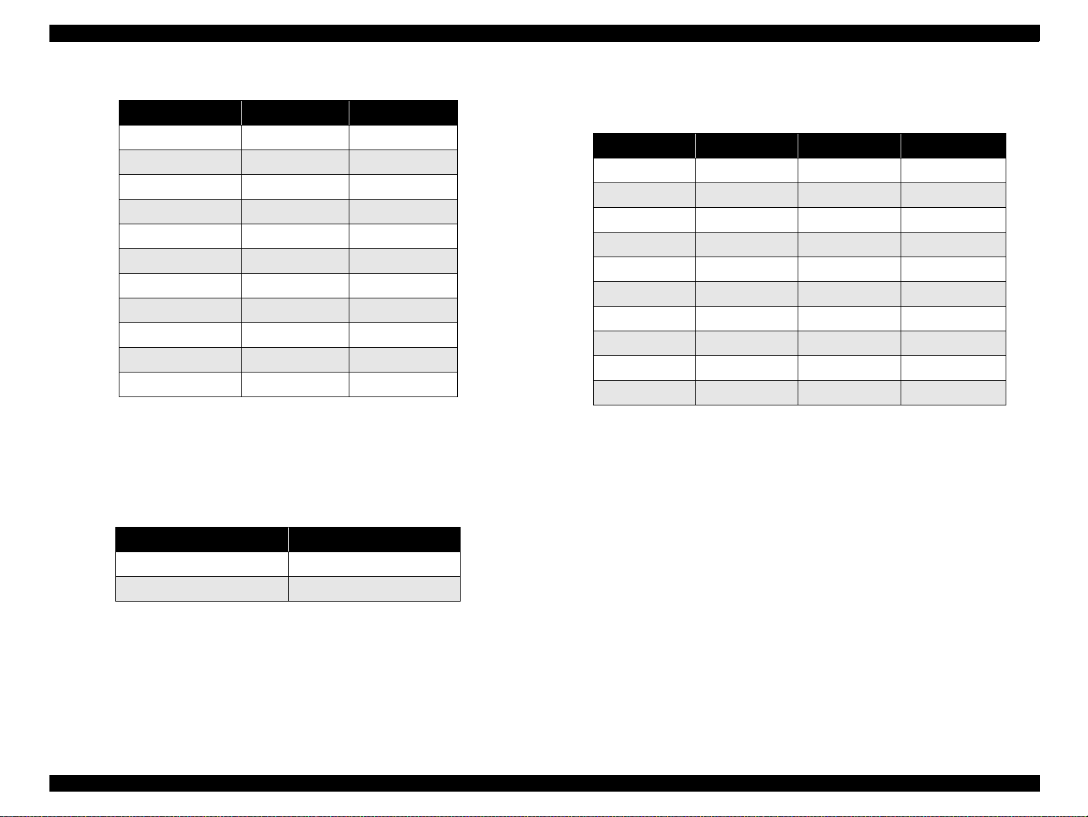
Number of sheets
Table 1-3. Hopper Capacity
Paper Type Size Sheets
2
Plain paper (65g/m
Envelope See “Pape r specifica ti on” on
Premium Semigloss Photo Paper A3+, A3, A4, Letter, US B 1 sheet
Glossy Paper-Photo Weight A3+, A3, A4, Letter, US B 1 sheet
Archival Matte Paper A4, Letter 1 sheet
Wat er color Paper-Radi ant Whit e A3+ 1 she et
Super Fine A3+, A3, A4 approx. 65 sheets
) A4, A3, Letter, Legal approx. 100 sheets
10 sheets
page -25
A3, A3+, US B 20 sheet
Stacker Capacity
NOTE: The figures in the table is measured in the normal room condition.
Table 1-4. Stacker Capacity
Paper Type Print Type Stacker Capacity
Plain paper Text 30 sheet or more
Graphics 20 sheet or more
Envelope Text 10 sheet or more
Archival Matte Paper Graphics 10 sheet or more
Super Fine Graphics 10 sheet or more
Other special paper Graphics 1 sheet o r m or e
1.2.3 Input data buffer
: 256KB
1.2.4 Electric specification
120 V version
Rated voltage: AC 120 V
Input voltage range: AC 99 - 132 V
Rated frequency range: 50 - 60 Hz
Input frequency range: 49.5 - 60.5 Hz
Rated current: 0.4A
Power consumption: Approx. 1815W (ISO10561 Letter Pattern)
Approx. 3.5W in standby mode
Energ y Star c o m pliant
Insulation Resistance: 10 M ohms min.
(between AC line and chassis, DC 500 V)
Product Descriptions Printing specification 12
Page 13
EPSON Stylus PHOTO 2000P Revision A
Dielectric strength: AC 1000 V rms. 1 minute or
AC 1200 V rms. 1 second
(between AC line and chassis)
220-240 V version
Rated voltage: AC 220 - 240 V
Input voltage range: AC 198 - 264 V
Rated frequency range: 50 - 60 Hz
Input frequency range: 49.5 - 60.5 Hz
Rated current: 0.2A
Power consumption: Approx. 1815W (ISO10561 Letter Pattern)
Approx. 3.5W in standby mode
Energy Star compliant
Insulation Resistan ce : 10 M ohms min.
(between AC line and chassis, DC 500 V)
Dielectric s trength : AC 1500 V rms. 1 minute
(between AC line and chassis)
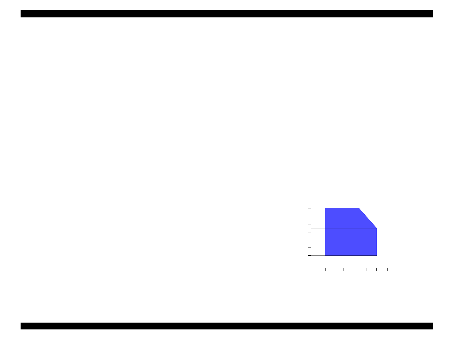
1.2.5 Environmental condition
Temperature : 10 to 35 °C (operating *3)
: -20 to 60
1 month at 40
120 hours at 60
Humidity : 20 to 80% RH (operating, *2,*3)
: 5 to 85% RH (non-operating, *1, *2)
Resistance to shock: 1 G, within 1 ms (operating)
: 2 G, within 2 ms (non-operating, *1)
Resistance to vibration: 0.15G (operating)
: 0.50G (non-operating, *1)
NOTE: *1: with shipment container
*2: without condensation
*3: Condition is as following figure.
C (non-operating, *1)
°
C
°
C
°
90
80
70
60
H u mid ity (% )
50
40
30
20
10
27
20
35
30
40
Temperature (°C)
Figure 1-1. Environmental Condition
Product Descriptions Printing specification 13
Page 14

EPSON Stylus PHOTO 2000P Revision A
1.2.6 Reliability
Total p r in t volume : 25,000 pages(Blac k) /10,000 pages(Color) (A4, Letter)
Print H ead Lif e : 3000 mil l ion dots/nozzle
1.2.7 Safety Approvals
120 V version:
Safety standards : UL1950
CSA22.2 No.950
EMI : FCC part15 subpart B class B
CSA C108.8 class B
220-240 V version:
Safety standards : EN 60950(VDE)
EMI : EN 55022(CISPR Pub.22) class B
: AS/NZS 3548 class B
1.2.8 Acoustic noise
Level : Approx. 42 dB(A) (According to ISO 7779)
1.2.9 CE Marking
220-240 V version
Low Voltage Di rective 73/23/EEC: EN60950
EMC Directive 89/336/EEC: EN55022 class B
EN61000-3-2
EN61000-3-3
EN50082-1
IEC801-2
IEC801-3
IEC801-4
Product Descriptions Printing specification 14
Page 15
EPSON Stylus PHOTO 2000P Revision A
1.3 Interface
1.3.1 Hardware interface
This printer provides USB and parallel in terface as standard.
1.3.1.1 Parallel interface
Transm ission mo de : 8 bit parallel, IEEE-1284 compat i bility m od e
Synchronization : By STROBE pulse
Handshaking : By BUSY and ACKNLG signal
Signal level : TTL compatible level
Adaptable connector : 57-30360(amphenol) or equivalent
BUSY sign al is set high before setting eit h er - E R R OR low or PE high and held high
until all these signals return to their inactive state.
BUSY signal is at hi gh level i n the follo wing cases.
-Duri ng data entry (s e e Data transmission timing)
-When input data buffer is full
-During -INIT signal is at low level or during hardware initialization
ERROR signal is at low level when the printer is in one of the following states.
-Printer hardware error (fatal error)
-Paper-out error
-Paper-jam error
-Ink-out error
PE signal is at high level during paper-out error.
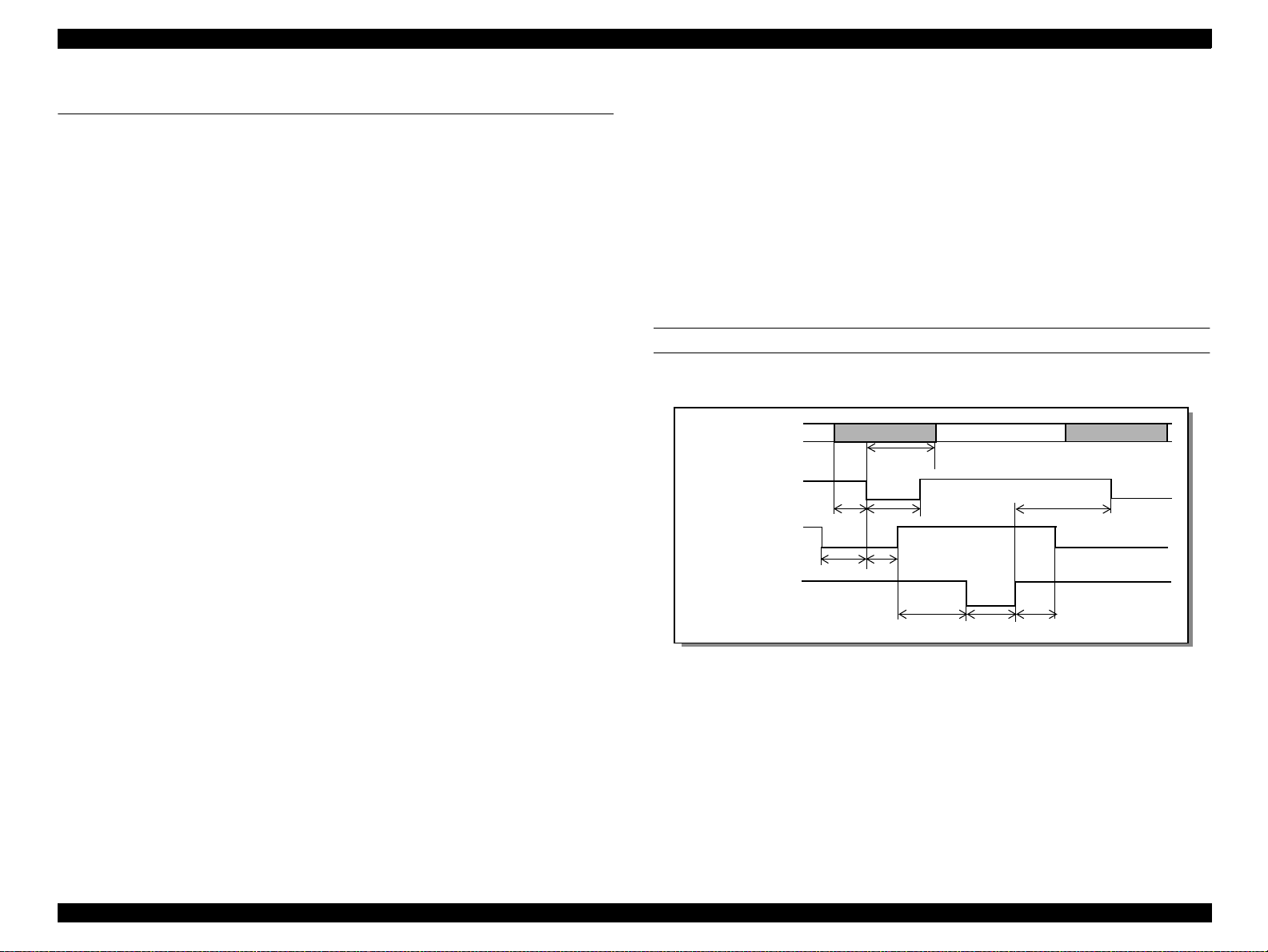
Data transmission timing
DATA
-STROBE
BUSY
-
tready
setup
t
data byte n
hold
t
t
busy
treply
stb
t
tack
data byte n+1
tnext
tnbusy
-During printer error (See -ERROR signal)
-When the parallel interface is not selected
Product Descriptions Interface 15
Page 16
EPSON Stylus PHOTO 2000P Revision A
Table 1-5. Parameters
Parameter Minimum Maximum
tsetup 500ns -
thold 500ns -
tstb 500ns -
tready 0 -
tbusy - 500ns
*1
tt-out
*2
tt-in
treply 0 -
tack 500ns 10us
tnbusy 0 -
tnext 0 -
- 120ns
- 200ns
*1:Rise and fall time of every output signal.
*2:Rise and fall time of every input signal.
T yp ica l timi ng f or t a ck is s hown belo w.
Signal Level: TTL Compatible (IEEE-1284 level 1 device)
Parameter Minimum Maximum Condition
VOH* - 5.5V
VOL* -0.5V -
IOH* - 0.32mA VOH = 2.4V
IOL* - 12mA VOL = 0.4V
CO - 50pF
VIH - 2.0V
VIL 0.8V -
IIH - 0.32mA VIH = 2.0V
IIL - 12 m A VIL = 0.8V
CI - 50pF
* A low logic level on the Logic H signal is 2.0V or less when the printer is p o w ere d off,
and this signal is equal to or exceeding 3.0V when the printer is powered on. The
receiver shall provide an impedance equivalent to 7.5K ohm to ground.
Table 1-7.
Table 1-6. Typical Time of Tack
Parallel I/F Mode Typical Time of tack
High Speed 0.5us
Normal Speed 2us
Product Descriptions Interface 16
Page 17
EPSON Stylus PHOTO 2000P Revision A
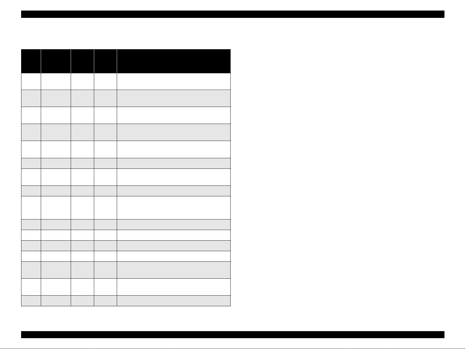
NOTE: In/Out ref ers to the direction of signal flow seen from the printer sid e.
Table 1-8. Connector Pin Assignment and Signals
Pin
No.
1 -STROBE 19 In The strobe pulse. Read-in of data is performed at
2 DATA0 20 In The DATA0 through DATA7 signals represent
3 -9 DATA1-7 21-27 In Each signal is at high lev e l w hen data is lo gical 1
10 -ACKNLG 28 Out This signal is a negative pulse indicating that the
11 BUSY 29 Out A high signal indicates that the printer cannot
12 PE 28 Out A high signal indicates paper-out error.
13 SLCT 28 Out Always at high level when the printer is powered
14 -AFXT 30 In Not used.
31 -INIT 30 In The falling edge of a negative pulse or a low signal
32 -ERROR 29 Out A low signal indicates printer error condition.
Signal
Name
Return
GND
pin
In/Out Functional description
the falling edge o f this pulse.
data bi ts 0 to 7 , re sp ectively.
and low le vel when data is log ical 0.
printe r can ag ai n accept da t a .
receive data .
on.
on this line causes t he p rinter to initialize.
Minimum 50 us pulse is necessary.
36 -SLIN 30 In Not used.
18 Logic H - Out Pulled up to +5 V via 3.9 K ohm resistor.
35 +5V - Out Pulled up to +5 V via 3.3 K ohm resistor.
17 Chassis
GND
16, 33
19-30
15, 34 NC - - Not connected.
GND - - Signal GND.
- - Chassis GND.
Product Descriptions Interface 17
Page 18
EPSON Stylus PHOTO 2000P Revision A
1.3.1.2 Parallel Interface (Reverse Channel)
Transmission mode : IEEE-1284 nibble mode
Adaptable connector : See forw ard channel
Synchronization : Refer to the IEEE-1284 specification
Handshaking : Refer to the IEEE-1284 specification
Data trans. timing : R efer to the IEEE-1284 specification
Signal level : IEEE-1284 level 1 device
Se e forward ch ann el
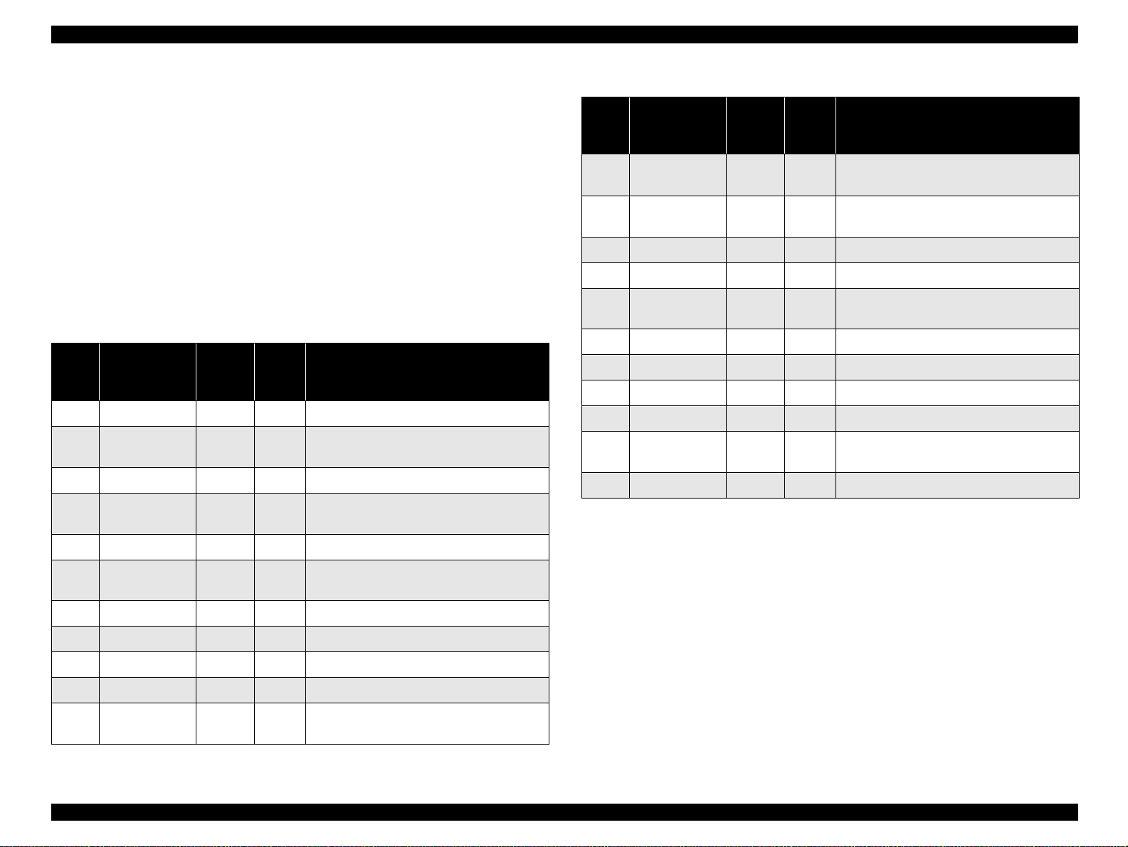
Table 1-9. Connector pin assignment and signals
Pin
No.
Signal Name
1 HostClk 19 In Host clock signal.
2 DATA0 20 In The DATA0 through DATA7 signals
3 DATA1 21 In respectively.
4 DATA2 22 In Each signal is at high level when data is
Return
GND
Pin
In/
Out*
Functional description
represent data bits 0 to 7,
logi ca l 1 an d lo w le ve l w h en
Table 1-9. Connector pin assignment and signals
Pin
No.
12 AckDataReq /
13 Xf lag / DataB it-
14 HostBusy 30 In Host busy signal.
31 -INIT 30 In Not used.
32 -DataAva il /
36 1284-Active 30 In 1284 active signal.
18 Logic-H - Out Pulled up to +5 V via 3.9 K ohm resistor.
35 +5V - Out Pulled up to +5 V via 3.3 K ohm resistor.
17 Chassis GND - - Chassis GND.
16, 33
19-30
15, 34 NC - - Not connected.
NOTE: In/Out ref ers to the direction of signal flow seen from the printer sid e.
Signal Name
DataBit-2,6
1,5
DataBit-0,4
GND - - Signal GND.
Return
GND
Pin
28 Out Acknowledge data req ues t sign al and revers e
28 Out X-flag signal and reverse channel transfer
29 Out Data available signal and reverse channel
In/
Out*
Functional description
channe l transfe r da ta bit 2 or 6 .
data bit 1 or 5.
transfer data bit 0 or 4.
5 DA T A 3 23 In da ta is logical 0.
6 DATA4 24 In These signals are used to transfer the 1284
extens ib ility reque st values
7 DATA5 25 In to the printer.
8 DATA6 26 In
9 DATA7 27 In
10 PtrClk 28 Out Printe r clock sig na l .
11 PtrBusy /
DataBit-3,7
29 Out Prin t e r busy sign al and re v erse channe l
trans fer data bit 3 or 7 .
Product Descriptions Interface 18
Page 19
EPSON Stylus PHOTO 2000P Revision A
Extensibility Request
The printer responds affirmatively when the extensibility request values are 00H or
04H,
00H : Request Nibble Mode Reverse Channel Transfer.
04H : Request Device ID;
Return Data Using Nibble Mode Rev Channel Transfer.
Device ID
World Standard Model
The printer sends following device ID string when it is requested.
When IEEE1284.4 is enabled,
[00H] [5CH]
MFG:EPSON;
CMD:ESCPL2,BDC,D4;
MDL:Stylus[[SP]Photo[SP]2000P;
CLS:PRINTER;
DES:EPSON[SP]Stylus[SP]Photo[SP]2000P;
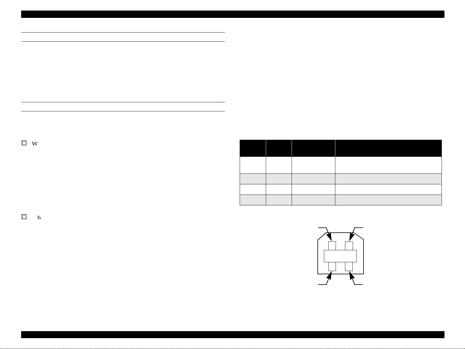
1.3.1.3 USB interface
Standard : based on
“Universal Serial Bus Specifications Revision 1.0”
“Universal Se rial Bus Device Class Definition for
Printing Devices Version 1.0”
Bit rate : 12Mbps (Full Speed Device)
Data encoding : NRZI
Adaptable connector : USB Series B
Recommended cable length: 2 meters
Table 1-10. Connector pin assignment and signals
Pin No.
1 VCC - Cab l e power. Ma xi m u m p o w er cons umptio n is
2 -Data bi-directional data
3 +Data bi-directional data, pull up to +3.3V via 1.5K ohm resistor
4 Ground - Cable ground
Signal
name
In/Out Function description
2mA
When IEEE1284.4 is disabled,
[00H] [59H]
MFG:EPSON;
CMD:ESCPL2,BDC;
MDL:Stylus[SP]Photo[SP]2000P;
CLS:PRINTER;
DES:EPSON[SP]Stylus[SP]Photo[SP]2000P;
Pin #2
Pin #3
Pin #1
Pin #4
Figure 1-2. USB Pin Assignment
Product Descriptions Interface 19
Page 20

EPSON Stylus PHOTO 2000P Revision A
1.3.1.4 Prevention Hosts from Data Transfer Time-out
Generall y, hosts a bandon data transfer to peripherals when a peripheral is in the busy
state for dozens of seconds continuously. To preve nt hosts from this kind of time-out ,
the printer receives data very s l owly, several by tes per minute , even if the printer is in
busy state. This slowdown is started when the rest of the input buffer becomes several
hundreds of bytes. Finally, the printer is in the busy state continuously when the input
buffer is full.
USB and IEEE1284.4 on the parallel interface do not require this function.
1.3.1.5 Interface Selection
The printer has 2 built-in interfaces; the USB and parallel interface.
These interfaces are selected automatically.
- Automatic selection
In this au to matic in ter fa ce se lec tio n mo d e , th e p r in ter is initia liz e d to th e idle sta te
scanning which interface receives data w hen it is po wered on. Then the interface that
receives data first is selected. When the host stops data tra n sfer and the printer is in th e
sta nd -b y sta te fo r the s ec o nd s , th e pr inte r is re tu rn ed to th e id le s ta te. As lo n g a s th e
h os t se nd s d ata o r th e p rin te r in ter fa ce is b u sy s tate , th e s ele c ted in te rfa ce is let a s it i s.
- Inte rface state and interface selection
Wh en the p arallel interface is not selected, the interface got in to th e b u sy state . W h en
th e p rin te r is initia lize d o r re tu rn ed to th e id le s ta te, th e p ara lle l inte rfa c e got into t he
ready state. Caution that the interrupt signal such as the -INIT signal on the parallel
interface is no t effective w hile that interface is not selected.
1.3.1.6 IEEE1284.4 protocol
The packet protocol described by IEEE1284.4 standard allows a device to carry on
multiple exchange s or conversations which contain data and/or control information
with another devic e at the same ti me across a singl e point-t o-point l in k. The protocol is
not, however, a device control language. It does provide basic transp ort-level flow
control and multip lexing s ervic es. The multipl exed log ic al cha nnels are inde penden t of
each other and blocking of one has no effect on the others. The protocol operate over
IEEE1284.
Automatic selection
A n initial sta te is c o m pa tib le inte rfac e a n d starts IEEE1284.4 comm unication when
m agic strings (1284.4 synchronous comm ands) are received.
On
An initial s ta te is IEE E1284.4 comm unication and data that received it by the time it is
able to take synchronization by m agic string (1284.4 synchronous com mands) is
discarded.
Off
A n initial sta te is c o m pa tible inte rfac e a n d ne ve r starts IE E E1 2 84 .4 co m m u n ica tion
even if m agic strings (1284.4 synchronous commands) are received.
Product Descriptions Interface 20
Page 21
EPSON Stylus PHOTO 2000P Revision A
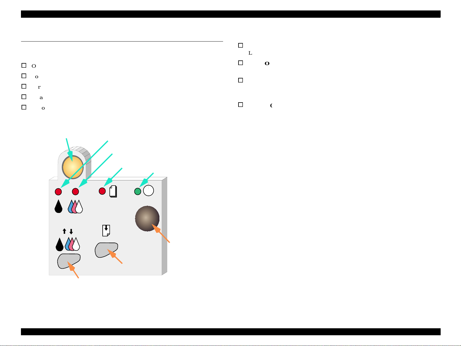
1.4 Operator Controls
1.4.1 Buttons
Oper a ting butto n
Load/Eject button
Cartridge repl acement button
Cleaning
Button
Ink Cartridge Replacement Button
Ink Out (Black) LED
Ink Out (Color)LED
Paper Out L ED
Power LED
1.4.2 LED Indicators
Power
Lights when the power switch is “ON” and AC power is supplied.
Paper Out
Lights during the pape r out condition, and blink s during the paper jam condition.
Ink Out (Black)
Lights during no black ink condition, and blinks during the black
ink low condition.
Ink Out (Color)
Lights during no color ink condition, and blinks during the color ink low
condition.
Power Button
Load/Eject Button
Cleaning Butt o n
Product Descriptions Operator Controls 21
Page 22
EPSON Stylus PHOTO 2000P Revision A
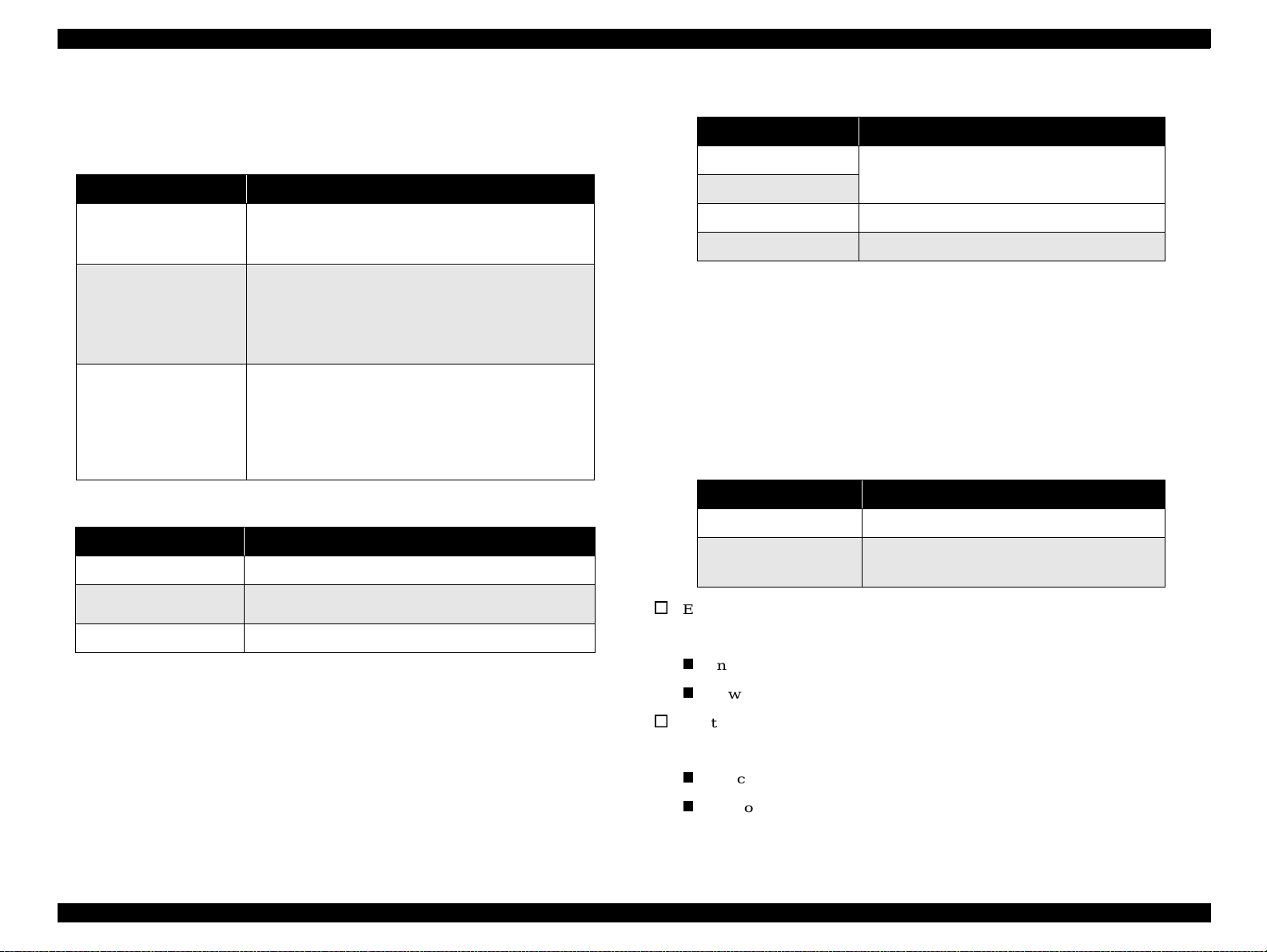
1.4.3 Panel Functions
Table 1-11. Panel Functions
Buttons Function
Load / Eject
Ink Cartridge
Replacement
Cleaning
(Push for 3 secon d s)
Table 1-12. Power-on Panel Functions
Switch Pressing with Power On Function
Load / Eject • Starts status printing.
Cleaning
Load/Eject + Cleaning • Enters the special settings mode. (Factory use only).
• Loads or ejects paper.
• Return s th e pr inthead f rom the ink c ar t r id ge
replacement position to the capping position.
• Starts the ink cartridge replacement sequence.
• Moves the carriage to the cartridge replacement
position.
• Returns the car ri age from the ink cart ri dge repl ace ment
position.
• Starts a head cleaning.
• In the condition of “Ink Low”, “Ink Out”, or “N o Ink
Cartridge”, start s t he ink ca rtridge replacement
sequence.
• Returns the car ri age from the ink cart ri dge repl ace ment
position.
*1
• Changes code pages / Selects IEEE1284.4 mode for
parallel I/F.
*2
Table 1-13. Content of 1BH of EEPROM
[bit7] [bit6] Actions
00
*1
11
01
10
Print firmware version, ink counter, selected code
page an d nozzle chec k pattern.
Hex-dump mode
Self test mode
*1:Factory default setting
1.4.4 Special Setting Mode
To enter the special setting mode, press Load/Eject button and Cleaning button while
turning on the printer. The Paper Out L ED starts blinking. While it is blinking (for
three seconds), press the s pecified butt on to activate the desirable set ting mode.
NOTE: Special setting modes are not intended for users.
Table 1-14. Special Setting Modes
Switch Function
Load / Eject • Resets EEPROM and timer IC.
Cleaning
(Push for 10 seconds)
EEPROM/Timer IC reset
*3
T he follo win g is r eset w ith this op era tio n:
• Resets the ink overflow counter in EEPROM.
Interface sele cti on (04H)
*1:One of the actio ns in Table 1-13 is carr ied out accord ing to the content of
1BH of EEPRO M.
Power off timer (6CH, 6DH)
*2:Not in ten ded for users.
Waste ink counter reset
*3:See Section 1.4.4. (Not intended for users.)
T he follo win g is r eset w ith this op era tio n:
Ink counter A0 (50H, 5DH)
Ink counter A80 (5EH, 5FH)
Product Descriptions Operator Controls 22
Page 23
EPSON Stylus PHOTO 2000P Revision A
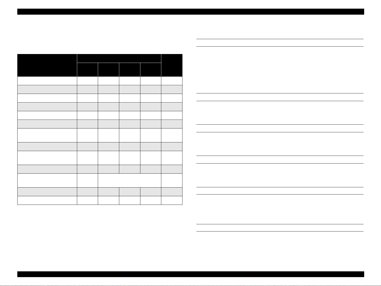
1.4.5 Printer Condition and Panel Status
Table 1-15 shows various errors and printer status.
Table 1-15. Printer Condition and Panel Status
Indicators
Printer Status
Power on condition On -- -- -- 9
Ink sequence Blinks -- -- -- 6
Ink cartridge replacement mode Blinks -- -- -- 5
Data proces sing Blinks -- -- -- 8
Paper out -- -- -- On 4
Paper jam condition -- Of f Off Blinks 3
No ink cartridge or ink end
(black)
Ink leve l low (b la ck ) -- Blinks -- -- 7
No ink cartridge or ink end
(color)
Power
-- On -- -- 7
-- -- On -- 7
Ink Out
(Black)
Ink Out
(Color)
Paper
Out
Priority
1.4.6 Errors
Ink out
When the printer runs out most of the ink of any co lor, it warns of an ink low condition
and keeps printing. When the ink cartridge is completely empty, t he printer stops
printing and generates I nk out error. In this condition , the ink cartridge must be
replaced with a new one. Not e an ink cartridge that is once taken out must not be used
again. Reinstalling of ink cartridges whose ink level is not full upsets the ink level
detection and may cause serious problems in the printheads.
Paper out
When the printer fails to load a sh eet of paper, it goes int o the Paper Out error
condition.
Paper jam
When the printer fails to eject a sheet of paper, it goes into the Paper Jam error
condition.
No ink cartridge
Ink le vel lo w ( c olor) -- -- Blinks -- 7
Enter EEPROM and Timer IC
reset
Maintenance request Blinks Blinks Blinks Blinks 2
Fatal error Blinks On On Blinks 1
-- On (for one second only) -
When the printer detects that an ink cartridge is missing, it goes into the No Ink
Cartridge error condition.
Maintenance request
When the total quantity of waste ink collected during cleanings and flushing reaches
the limit, printer indicates the Maintenance Request error and stops printing. The
NOTE: “--” means “no effect”.
absorber must be replaced by a service person.
Fatal errors
When the printer detects a carriage control error or CG access error, it goes into a fatal
error condition.
Product Descriptions Operator Controls 23
Page 24

EPSON Stylus PHOTO 2000P Revision A
1.4.7 Printer Initialization
There are three kinds of initialization methods as explained below:
1. Power on initialization
It perfor ms the foll ow ing wh en the printer is turned on or the pri nt er recogni zes
the cold res et command (re mote RS comman d):
(a) Initia liz es p rin ter m e c ha n ism .
(b) C lears inp u t d ata b uff er.
(c) C le ars prin t bu ffe r.
(d ) S ets de fau lt va lu es.
2. Panel initialization
Performed if the printer is turned off and back on within 10 seconds or /INIT
signal is input. It performs the following:
(a) C ap th e p rin te r h e ad .
(b) E jec t a p ap er.
(c) Clears input data buffer.
(d) C le ars print b uffe r.
(e) S ets de fa u lt v alu e s.
3. Software initia lization
The ESC@ command also initializes the printer. It performs the following:
(a) C le ars prin t bu ffe r.
(b ) S ets de fau lt va lu es.
Product Descriptions Operator Controls 24
Page 25

EPSON Stylus PHOTO 2000P Revision A
1.5 Paper
1.5.1 Paper handling
Do not perform reverse feed more than 9.5 mm(0.38”).
1.5.2 Paper specification
1.5.2.1 Cut Sheet
Size: A3 (297mm x 420mm)
A4 (210mm x 297mm)
A5 (148mm x 210mm)
A6 (105mm x 148mm)
B (2 79 mm x 432 mm)
B4 (257mm x 364mm)
B5 (182mm x 257mm)
Letter (216mm x 279mm)
1.5.2.2 Envelope
Size: #10 (241.3mm x 104.8mm)
DL (220mm x 110mm)
C6 (162mm x 114mm)
220x132 (220mm x 132mm)
Quality: Bond paper, PPC, Air mail
Weight: 45g/m
NOTE: Envelope printing is only available at normal temperature.
NOTE: Keep the longer side of the envelope horizontally at setting.
2
~ 75g/m2 (12 lb ~ 20 lb)
1.5.2.3 EPSON special media
Quality: EPSON specifically designed media for pigment
ink jet printers
(1) Glossy Paper - Photo Weight
Size: A3+ (329mm x 483mm)
A3 (297mm x 420m m)
Half letter (139.7mm x 215.9mm)
Legal (216mm x 356mm)
Executive (184.2mm x 266.7mm)
Quality: Plain paper, Bond paper
Thickness: 0.08mm ~ 0.11mm (0.003 ~ 0.004 inch)
2
Weight: 64g/m
~ 90g/m2 (17 lb ~ 24 lb, 55kg ~ 78kg)
(2) Premium Semigloss Photo
Size: A3+ (329mm x 483mm)
A4 (210mm x 297m m)
A3 (297mm x 420m m)
A4 (210mm x 297m m)
Letter (216mm x 279mm) (only for EAI)
B (only for EAI)
Roll paper
width: 89mm, 100mm, 210mm, 329mm
Product Descriptions Paper 25
Page 26

EPSON Stylus PHOTO 2000P Revision A
(3)Archival Matte Paper
Size: A3+ (329mm x 483mm)
A3 (297mm x 420mm)
A4 (210mm x 297mm)
Letter (216mm x 279mm)
B
Roll paper
width: 89mm, 100mm
(4)Water Paper - Radiant White
Size: A3+ (329mm x 483mm)
(5) Ink Jet Transparencies
Size: A4 (210mm x 297mm)
Letter (216mm x 279mm)
(6) Photo Quality Glossy Film
Size: A4 (210mm x 297mm)
Letter (216mm x 279mm)
Product Descriptions Paper 26
Page 27
EPSON Stylus PHOTO 2000P Revision A
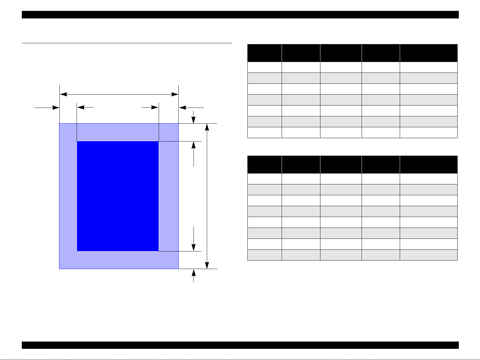
1.6 Printing area
1.6.1 Cut Sheet
LM RM
PW
Printable AreaPrintable Ar ea
TM
BM
PL
Table 1-16. Printi ng Area - Character Mode
Paper Size
A3
A4
Letter
B5
Legal
Statement
Executive
Left Margin
(minimum)
3 mm (0.12”) 3 mm (0.12”) 3 mm (0.12”) 14 mm (0.54”)
3 mm (0.12”) 3 mm (0.12”) 3 mm (0.12”) 14 mm (0.54”)
3 mm (0.12”) 9 mm (0.35”) 3 mm (0.12”) 14 mm (0.54”)
3 mm (0.12”) 3 mm (0.12”) 3 mm (0.12”) 14 mm (0.54”)
3 mm (0.12”) 9 mm (0.35”) 3 mm (0.12”) 14 mm (0.54”)
3 mm (0.12”) 3 mm (0.12”) 3 mm (0.12”) 14 mm (0.54”)
3 mm (0.12”) 3 mm (0.12”) 3 mm (0.12”) 14 mm (0.54”)
Right Margin
(minimum)
Top Margin
(minimum)
Bottom Margin
(minimum)
Table 1-17. Printing Area - Raster Graphics Mode
Paper Size
A3+
A3
A4
Letter
B5
Legal
Statement
Executive
Left Margin
(minimum)
3 mm (0.12”) 3 mm (0.12”) 3 mm (0.12”) 14 mm (0.54”)
3 mm (0.12”) 3 mm (0.12”) 3 mm (0.12”) 14 mm (0.54”)
3 mm (0.12”) 3 mm (0.12”) 3 mm (0.12”) 14 mm (0.54”)
3 mm (0.12”) 3 mm (0.12”) 3 mm (0.12”) 14 mm (0.54”)
3 mm (0.12”) 3 mm (0.12”) 3 mm (0.12”) 14 mm (0.54”)
3 mm (0.12”) 3 mm (0.12”) 3 mm (0.12”) 14 mm (0.54”)
3 mm (0.12”) 3 mm (0.12”) 3 mm (0.12”) 14 mm (0.54”)
3 mm (0.12”) 3 mm (0.12”) 3 mm (0.12”) 14 mm (0.54”)
*1:Bottom margin can be reduced to 3mm when paper dimension is defined by
using command, otherwise it remains 14mm. As for an area between 3mm
and 14mm margin, print quality may decline.
Right Margin
(minimum)
Top Margin
(minimum)
Bottom Margin
(minimum)
*1
Figure 1-3. Printable Area for Cut Sheet
Product Descriptions Printing area 27
Page 28
EPSON Stylus PHOTO 2000P Revision A
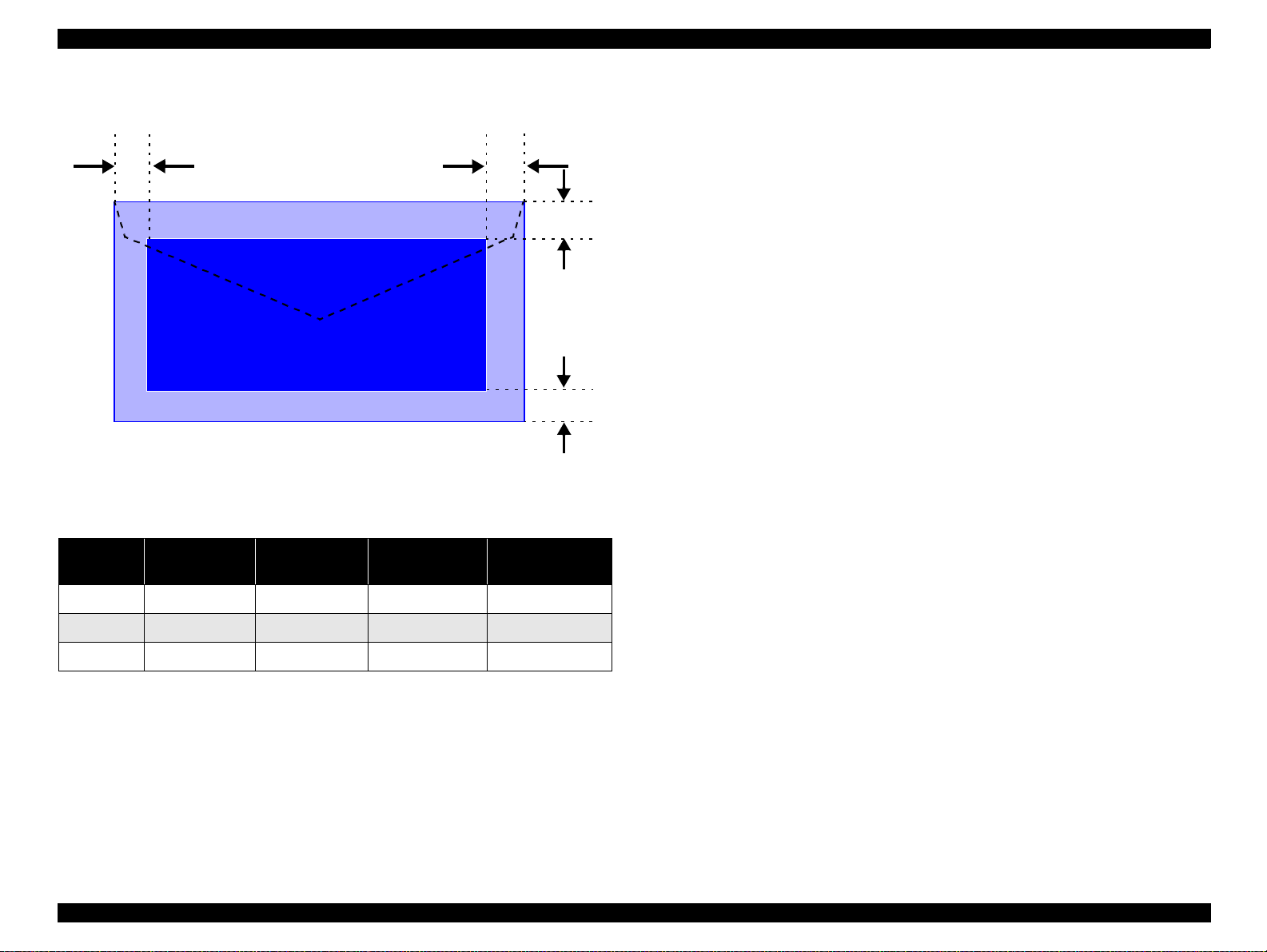
1.6.1.1 Envelopes
LM
RM
TM
Printable AreaPrintable Area
BM
Figure 1-4. Printable Area for Envelopes
Table 1-18. Envelope Margin
Left Margin
Size
#10 3 mm (0.12”) 28 mm (1.10”) 3 mm (0.12”) 14 mm (0.55”)
(minimum)
Right Margin
(minimum)
Top Margin
(minimum)
Bottom Margi n
(minimum)
DL 3 mm (0.12”) 7 mm (0.28”) 3 mm (0.12”) 14 mm (0.55”)
C6 3 mm (0.12”) 3 mm (0.12”) 3 mm (0.12”) 14 mm (0.55”)
Product Descriptions Printing area 28
Page 29

EPSON Stylus PHOTO 2000P Revision A
1.7 Ink cartridge
1.7.1 Black ink cartridge
Type : Exclusive cartridge
Color : Black
Print capac i ty : TBD
Ink life : 2 years from production date
Storage temperature
C - 40 °C (Storage, within a month at 40 °C)
: -20
°
: -30
C - 40 °C (Packing storage, within a month at 40 °C)
°
: -30
C - 60 °C (Transit, within 120 hours at 60 °C
°
and within a month at 40
Dimension : 20.1 mm(W) x 66.85 mm(D) x 38.5 mm(H)
1.7.2 Color ink cartridge
C)
°
Type : Exclusive cartridge
Color : Magenta, Cyan, Yellow, Light Cyan, Light Magenta
Print capac i ty : TBD
Ink life : 2 years from production date
Storage temperature
C - 40 °C (Storage, within a month at 40 °C)
: -20
°
: -30
C - 40 °C (Packing storage, within a month at 40 °C)
°
: -30
C - 60 °C (Transit, within 120 hours at 60 °C
°
and within a month at 40
Dimension : 49.1 mm(W) x 84.05 mm(D) x 41.8 mm(H)
NOTE: Do not refill the ink cartridge. The ink cartridge is a consumable item.
Do not use a cartridge whose ink life has expired.
Ink freezes below -4
than 3 hours at room temperature.
C; however it will be usable again after keeping it for more
°
C)
°
Product Descriptions Ink cartridge 29
Page 30
EPSON Stylus PHOTO 2000P Revision A
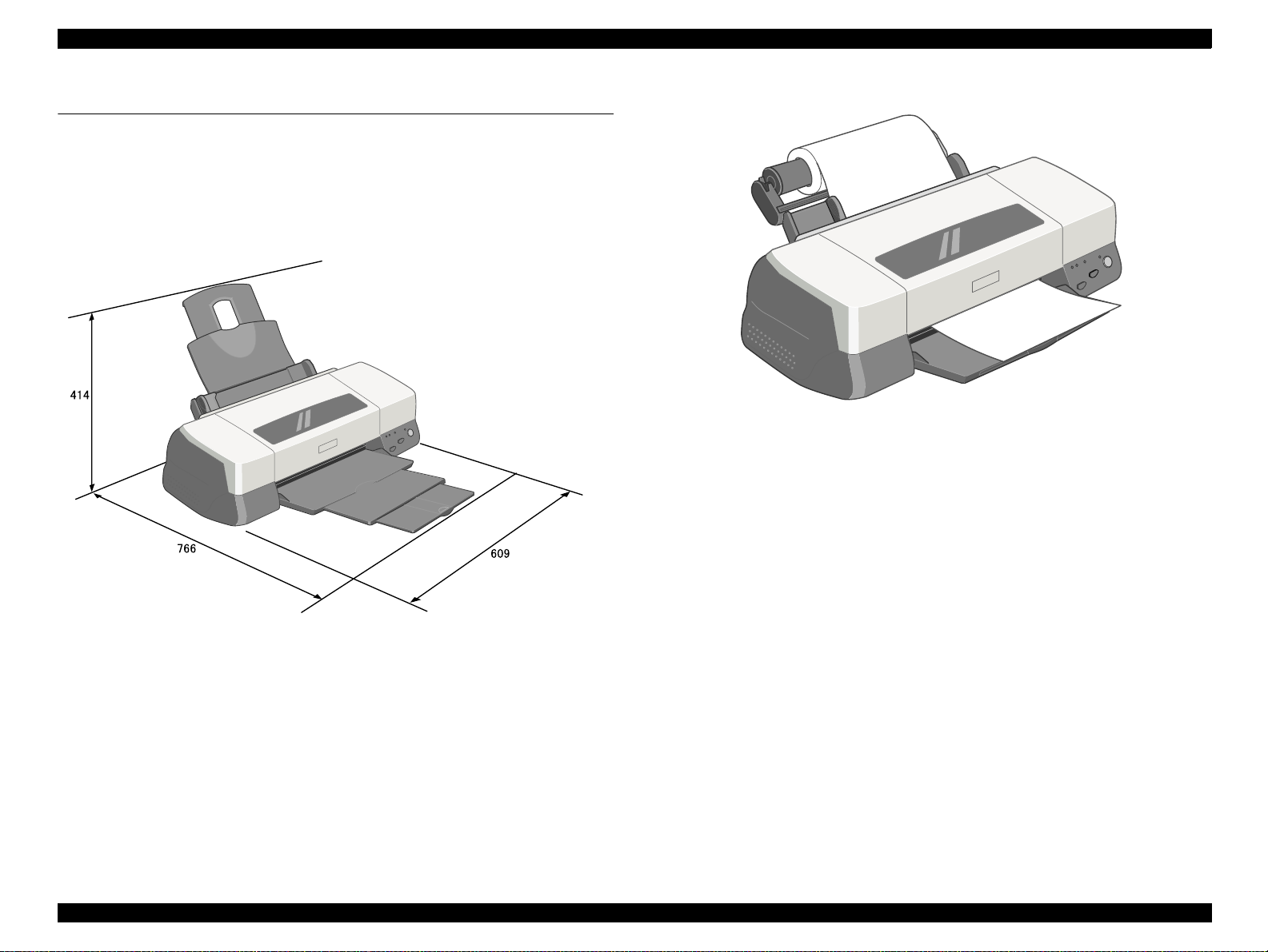
1.8 Physical specification
Weight : 8.4kg (without the ink cartridges)
Dimension : 609 mm(W) x 311 mm (D) x 175 mm (H) ( Stor age)
: 609 mm(W) x 766 mm (D) x 414 mm (H) (Printing)
Figure 1-6. With Roll Holder
Figure 1-5. Dimension -- Printing
Product Descriptions Physical specification 30
Page 31

OPERATING PRINCIPLES
CHAPTER
Page 32

EPSON Stylus PHOTO 2000P Revision A
2.1 Overview
This section describes the operating principles of the printer mechanism and electrical
circuit boards. The major components of the EPSON Stylus PHOTO 2000P are:
P rin ter mec ha n ism : M4 W 60
M ain board: C 304M A IN Board
Power supply board: C 298PSB/PSE B oard
2.1.1 Printer Mechanism
Unlike other EPSON ink jet printers, the
motor as power source. The DC motor enables the printer to lower noise during
printing. Table 2-1 shows variou s motor t ypes used in the pri nter and t heir applic ations.
Table 2-1. Motor Types and Correspondin g Applications
Motor Name Type Application / Feature
CR motor
PF motor
DC motor with
brush
DC motor with
brush
EPSO N S tylus PHO TO 2000P
uses a DC
Table 2-2.
Drives the carriage making little noise. Works with
a linear scale to monitor motor’s operating
condition.
Supplies power t o drive paper feeding roller s used to
send paper at specified speeds and load/eject paper.
To monitor paper feeding pitch, a loop scale is
attached beside the high-precision gear.
Figure 2-1 shows the printer mechanism block diagram for the Stylus PHOTO 2000P.
Rotary Encoder
Intermittent Gear
PF Motor Pinion
PF Motor
Flashing Window
Photo Interrupter (Encoder)
Notched Roller
Carriage Unit
Printhead
Timing Belt
Cap Unit
(without a valve)
Pump Unit
PF Drive Gear (high precision)
Photo Interrupter (Encoder)
Detector Wheel
ASF Sensor
LD Roller Shaft
Loading Rollers
PE Sensor
Pump/ASF Motor
Sends drive for pump operation and paper feeding
Pump/ASF
motor
4-Phase / 48-pole
stepping motor
from ASF. Since this is a stepping motor, it has no
scales or photo sensors that are used to monitor
motor’s operating condition.
The basic structure of the printer mechanism is most ly common to the Stylus COLOR
CR Guide Shaft
PF Roller
Liner Scale
CR Motor
PG Lever
Figure 2-1. Printer Mechanism Block Diagram
ASF/Pump Disengage
Gear Train
400, except that the Stylus PHOTO 2000P uses a Pump/ASF motor. With this motor
equipped, the paper loading mechanism and the pumping mechanisms are
independently driven, which allows the printer to offer higher throughput.
OPERATING PRINCIPLES Overview 32
Page 33

EPSON Stylus PHOTO 2000P Revision A
2.1.2 Ink
2.1.2.1 Comparison between Pigment Ink and Dye Ink
The main component of Stylus PHOTO 2000P is almost the same as of Stylus Photo
1270. The most signi ficant difference is its pigment ink use.
The difference between the pigment ink and dye ink is shown in the table below.
Table 2-3. Physical Differences
Dye Ink Pigment Ink
Single element that has a specific chemical
structure.
Element minimum unit: 1 ~ 2 nm Element minimum unit: 50 ~ 200nm
Ink is only composed of liquid phase (solvent
and elemen t).
Solvable to solvent (water, glycol, etc.) Not solvable. Only disperse.
Table 2-4. Features of Pigment Ink
Advantage Disadvantage
It can make h igh density color. Have to keep equally dispersed c o nditio n .
Better dura b ility against climate.
Not easy to blur.
No limit on its solubility.
Chem ic ally sta b le: Not e as y to chang e into
pois o n: High s afety.
Aggreg ate ma te rial of el em e nts.
Ink is composed of 2 phases: liquid phase
(solve nt) and solid ph ase (elemen t).
Long time storage may cause pigment
sediment.
Table 2-5. Features of Dye Ink -- Reference
Advantage Disadvantage
Solvable to solvent (water, glycol, etc.) Easy to blur.
Homogeneity is kept. When impurities are interfuse, chemical
High brightness.
change occurs and the element may be
deteriorated.
2.1.2.2 Drop of Pigment Ink and Dye Ink
The figure below shows how pigment ink and dye ink goes onto paper.
Figure 2-2. Pigment Ink an d Dye Ink
Dye ink infiltrates paper and the element disperses, then the thickness of color
decreases.
Table 2-5. Features of Dye Ink -- Reference
Advantage Disadvantage
Have been used for ink jet for long time. Restriction on its solubility.
Easy to express the gradation. Less durability against climate.
membranes. Thereby, it keeps the printing sharp and with high density.
OPERATING PRINCIPLES Overview 33
For pigment ink, the solvent infiltrates paper but the pigment goes onto paper and
Page 34

EPSON Stylus PHOTO 2000P Revision A
Ink Cartridge
2.1.3 Printhead Mechanism
The printhead mechanism operating principles of the Stylus PHOTO 2000P are
basically the same as for the previous EPSON ink jet printers. This printer, however,
employs a newly developed ink and improved printhead driving method to provide a
higher print quality and faster printing speed than ever. Also, an IC called CSIC that
stores ink-life data is attached to each ink cartridge. With this IC, ink life of each
cartridge can be individually monitored. Note, like for other models, a head voltage
must be written with a PC.
The printhead mechanism consists of ink cart ridges and printheads. Each printhead is
composed of PZT (Piezo Electric Element), nozzle surface, ink supply needle, nozzle
selection cir cuit board, cartri dge sensor, CSIC, and CSIC connection circuit. Figure 2-3
shows its component layout.
CSIC
Ink Cartridge
Nozzle Selector
Circuit Board
CSIC Connection
Circuit
Ink Supply Needle
An ink cartridge stores ink to be supplied to the printhead.
CSIC:
CSIC is a non-v ola tile memory E EPROM attache d t o eac h bl ack and c olo r in k
cartridge. It keeps the following information:
1) Ink remaini n g level
2) Number of cleanings performed
3) Number of installation of the ink cartridge
4) Accumulated installation time of the cartridge
5) Model name of the printer in use
6) Ink cartridge production information
7) Ink cartridge code
8) Number of times that the ink cartridge is recycled
Printhead
PZT
Driven by the print signal from the control circuit board, it ejects ink from the
nozzle plate.
Nozzle plate
Ink pressured by the PZT is ejected from this plate.
Ink supply needle
Connects the ink cartridge and printhead to run ink to the printhead.
CSIC connection circuit
Connects the control circuit board and CSIC attached on the ink cartridge.
One end of the harness is connected to the control board together with the
printhead cable.
Nozzle Plate
Figure 2-3. Printhead Mechanism
PZT
Nozzle se lection circuit boar d
This circuit, controlled by ASIC on the control circuit board, selects nozzles
to be driven for printi ng. On t he othe r hand, head drive volta ge is pr oduced on
the con t roller circuit side.
OPERATING PRINCIPLES Overview 34
Page 35

EPSON Stylus PHOTO 2000P Revision A
2.1.4 Carriage Mechanism
The carriage mechanism of the Stylus PHOTO 20 00P is composed of the carriage
motor (CR motor), carriage guide shaft, platen gap adjustment/parallelism adjustment
mechan i sm , c ar r i ag e loc k mechanis m , an d s o on.
2.1.4.1 Carriage Motor (CR Motor)
The carriage mechanism this printer is mostly the same as for other ink jet printers’
except it uses a DC motor as power source. See the table below for the carriage motor
specifications.
Table 2-6. Carriage Motor Specifications
Table 2-7.
Items Specifications
Type DC Motor with brush
Drive Voltage +42 V +/- 5% (Applied to the driver)
Coil resistance 29.2 ohms +/- 25%
Inductance 30.8 mH +/- 25%
Photo Coupler
Carriage Unit
Linear Encoder
Adjust Lever
Platen Surface
Eccentric Shaft
CR Motor
Parallelism Adjustment
Bushing
Carriage Guide
Shaft
Drive Method Constant Current Chopping
Driver IC LB1947
Op03
Figure 2-4. Carriage Mechanism (Top view)
In previous ink jet printers, since a stepping motor is used as a CR motor , the CR motor
controls the car ri age p o sition under the open loop system. This printer, however,
controls carriage speed and position with the closed loop system enabled by a DC
motor and encoder. This system, also used in the Stylus COLOR 900, is applied to
maintain a constant print quality. The CR motor also produces the print timing signal
(PTS signal) used for an accurate ink ejection timing. (Refer to Section 2.2.2.3 for
further information on the CR motor control circuit.)
For printing, the CR motor moves the carriage unit in the printing area along the CR
guide shaft.
OPERATING PRINCIPLES Overview 35
Page 36

EPSON Stylus PHOTO 2000P Revision A
2.1.4.2 Platen Gap (PG) /Parallelism Adjustment Mechanism
The PG adjust lever is attached to the left end of the carriage guid e sha ft . When the
carriag e g uide shaf t, which ha s an ecce ntr ici ty, r o tates as th e a dju stment le ver mov es, it
narrows or widens the distance (=PG: from 1.2 mm to 2.1 mm). This mecha ni sm
enables the user to print with a correct PG according to print result or other conditions
such as pap er curl.
Also, the parallelism adjustment bushings are attached to the right and left ends of the
carriag e g ui de shaf t . They a re us ed to set the ca rria ge g ui de shaf t pa ral lel with a pl aten .
Table 2-8.
Platen Gap Adjust Lever Setting
Table 2-9.
Lever Position PG adjustment value
Front (0) 0 mm (=PG is 1.2 mm)
Rear (+) + 0.9 mm (=PG is 2.1 mm)
2.1.4.3 Carriage Home Position (HP) Detection
Unlike previous Epson ink jet print ers, the carriage hom e pos ition is detected with the
drive cur rent from the CR motor and speed/po sition signal from the linear encoder.
2.1.5 Paper Feeding Mechanism
The paper feeding mechanism transports paper loaded from ASF usi ng the PF rollers
and paper eject rollers. A new type of DC motor is used as the PF motor. See the table
below for the PF motor specifications.
Table 2-10.
Item Description
Motor t yp e DC Moto r w ith B rush
Drive voltage +42V +/- 5% (Applied to the driver)
Coil Resistance 31.1 ohm +/- 25%
Inductance 26.6mH +/- 25%
Control method Constant current chopping drive
Stepping motor that is used in other printers as the PF motor controls paper feed by the
open loop system. On the other hand, this printer controls paper feeding mechanism
with the closed loop system by employing the DC motor and rotary encoder for more
accurate paper feeding. Therefore, a rotary encoder attached to the left end of the PR
roller shaft controls paper feed amount. For detailed information, see Section "PF
motor driver circui t".
PF Motor Specifications
Table 2-11.
Drive from th e PF motor is sent to the PF rollers and paper eject rollers as described
below.
Driv e transmis s io n to the PF rollers :
PF motor pinion gear
Driv e tran smission to th e eje ct rollers :
PF motor pinion gear
gear (28)
Paper ejec t r o ll er s
→
Spur gear (76) → PF rollers
→
Spur gear (76) → Combination gear (13.5, 308) → Spur
→
OPERATING PRINCIPLES Overview 36
Page 37

EPSON Stylus PHOTO 2000P Revision A
Figure 2-5 gives the paper feeding mechanism block diagram, showing the parts along
the PF motor drive transmissi on path s.
Combination Gear
(13.5, 308)
Spur Gear (76)
Paper Eject Roller
PF Roller
[Previous Models]
Notched Roller
Paper
Platen Surf ace
Printhead
Support Roller
Front Paper Guide
PF Motor Pinion Gear
PF Motor
Paper Eject Roller
Figure 2-5. Paper Feeding Mechanism
The printer loads paper at the ASF, which is detected by the PE sensor attached to the
right side of the top frame, and advances it to send the paper’s leading edge to the
halfway of the front paper guide . Then, to correct paper deflection, the printer feeds the
paper back specified steps toward ASF, and advances the paper again toward the front
paper guide and stops it at the specified TOF (Top Of Form) position. Once printing
starts, the paper is fed by the PF rollers and sub rollers. For printing or transporting the
tailing ed g e ar ea (14 mm), a notched roller and drive from the paper eject roller are
used. Like the Stylus Photo 750/1200, this printer also provides this extra printable
range of 14 mm from the bottom edge, excluding the bottom margin of 3mm, by
changing the position of the star wheel gear; it has been shifted by 5
the eject roller toward the front paper guide. Due to this change, the tailing edge of
paper is suppressed, and the printer can advance paper steadily. See Figure 2-6 next
page that shows how paper is t r ansported and parts involved.
from the top of
°
Paper Eject Rolle r
Bottom Margi n (3 mm)
PF Roller
[Stylus PHOTO 2000P]
°
Paper Eject Roller (round)
5
Steady Feeding
Figure 2-6. Paper Transportation
Notched roller is used for previous models as a paper eject roller. Stylus PHOTO
2000P adopts a round roller to prevent a paper from notched roller trace. When the
paper setting on the prin ter and the actu al paper ty pe differ s and i f the paper ejec t roller
is tainted with ink because the printer eject s pa per before the printed surface would b e
dried, you have to clean the roller by the roller cleaning function by the panel
operation. (See “Special Sett in g M o d e ” on pag e-22.)
OPERATING PRINCIPLES Overview 37
Page 38

EPSON Stylus PHOTO 2000P Revision A
2.1.5.1 CR Lock Mechanism
The carriage lock mechanism prevents th e carriage from being left unc apped for a long
time, which is usually caused by vibration during printer transportation, user’s
mishandling of the printer, and so on. If the carriage unit is left uncapped for a long
time, ink on the printhead surface dries gradually and, eventually, ink can not flow to
nozzles. In additi on to th at, ther e is a poss ib ili ty that the no zzles clogged wi t h drie d ink
can not be recovered by a head cleaning. To avoid this problem, the printer locks the
carriage unit under t he circumstance below:
After Power-Off
If th e p rin ter po w e r is tu rn ed of f in th e m id d le o f p rin ting o r o the r o p era tio ns , the
p rinte r c o mple tes th e initia liz atio n se q u en c e a n d th e n p e rfo rm s a c a rria g e loc k .
After Power-On
Wh en th e p rin te r is tu r n ed o n, th e p rin te r a u to ma tic ally b eg in s a po wer-o n c le an in g
and then p erform s a carriage lock .
[Power-on cleaning]
The printer runs a power-on cleaning automatically when its po wer is turned on. Since
th e tim er IC o n th e m a in co n tro l c irc uit b o ar d is p o we re d by a lithiu m b atte ry th a t is
als o moun ted o n the board , it kee p s co un ting the p r in ter’s power off time. According to
the power of time counted, the printer selects the cleaning level to perform.
Top view
Bushing 6
Paper Ejec t Roller
Figure 2-7. CR Lock Mechanism
CR Lock Lever
Middle Frame
Right side view
CR unit
CR unit
After paper ejection
If th e p rin ter do e s n o t re c eiv e a n y p rin t d ata a fter L o a d/Ejec t bu tto n is p re ss ed , it
p erf o r ms a carr ia ge lo c k a n d e nte rs a s ta nd b y s ta tus. But if pa p er is fe d into the printer,
th e p rin te r d o es no t p e rfo rm it.
OPERATING PRINCIPLES Overview 38
Page 39

EPSON Stylus PHOTO 2000P Revision A
2.1.6 Paper Loading Mechanism
The paper loading mechanism loads paper at the ASF unit and feeds paper to the PF
rollers. The ASF unit is the same as in previous models. A 4-phase 48-pole PM type
stepping motor is used as the ASF/Pump motor to drive ASF. Drive sent from this
motor is t r ansmitted to the ASF side and Pump side via the disengage m echanism (DE
mechanism). See Figure 2-12 for the ASF/Pump motor specifications.
Table 2-12. ASF/Pump Motor Specifications
Table 2-13.
Items Description
Motor type 4 Phase/ 48-pole /PM type pulse motor
Drive method Bipolar constant current drive
Drive voltage +42V +/- 5% (applied to the driver)
Coil Resistance 10.4 ohm +/- 10%
Inductance 15.0 ohm +/- 10%
Drive from the ASF/Pump motor is sent to the ASF unit by the switching operation of
the carriage unit and the DE mechanism described in the following section.
2.1.6.1 Drive Transmission to the ASF Unit
1) The CR unit moves to the right end of the CR shaft, which then pushe s the DE
lock lever to the right end.
2) The ASF/Pump motor rotates co unterclockwise specified steps (viewed from the
motor pinion gear side).
3) With the ASF-Pump motor’s rotation of step 2), the planetary gear set in the DE
unit shifts toward the combination gear (12, 22.4).
4) The carriage unit moves from the right end of the CR shaft specified steps, which
causes the DE lock lever to fix the planetary gear unit.
5) Torque from the ASF/Pump motor is transmitted as described below.
Motor pinion gear
Combination gear (14, 28)
Figure 2-8 shows the disengage mechani sm and its parts.
Combinat ion G e a r
14, 28
Planetary gear (15.2) → Combination gear (12, 22.4) →
→
Spur gear (32) in ASF
→
Comb ination G e ar 12, 22.4
Planetary Gear 15.2 Unit
DE Lock Lever
A
ASF-Pum p Moto r Pin io n Gear
Comb ination Gear 17.19, 25. 6
Figure 2-8. Disengage Mechanism
The ASF unit loads paper by the torque sent from the ASF/Pump motor v ia the DE
mechanism as described in the following section.
OPERATING PRINCIPLES Overview 39
Page 40

EPSON Stylus PHOTO 2000P Revision A
2.1.6.2 Paper Loading Operation
Multiple paper loading prevention mechanism is included in the ASF unit to ensure
steady paper loading. To prevent any paper from falli n g from the pap er se t posit io n
into the paper path, the paper return lever pushes paper that may have fallen off back
onto the hopper. Afte r this moti on is comple te d, the LD roller s tarts loadin g paper. The
paper loadi ng mecha nism , inc ludi ng the multi ple pape r lo ading p reve ntion mecha nism,
is described in the following steps.
1) When the printer power is turned on, the ASF/Pump motor rotates
countercloc kwise to det ect AS F home posi tio n. The n it rotates cl ockwis e spe cifie d
steps to set the LD roller and paper return lever in their standby status. (See
“Standby State” in Figure 2-1. )
2) When th e paper loading signal is sent from the PC and the Load/Eject butt on is
pressed, the AS F/Pump motor turns counterclockwise to let the LD roller st art
loading paper. (See “Paper Pick Up State” in Figure 2-1.)
3) When the paper is tr ans ported to the PF roller, the LD rol ler stops where it loses
friction. (See “PF Roller Pa per Feed State” in Figure 2-1.)
4) When the next print signal is sent and Load/Eject button is pressed*, the ASF/
Pump motor r otates clockwise specified steps to set the LD roller and the paper
return lever in standby status. (See “Standby State” in Figure 2-1.)
LD Roller
Paper Return
Lever
Hopper
Cam
Standby State
Hopper Spring
Pad Spri ng
Pad
2
Paper Load State
Pinch Roller
3
PF Roller Paper
Feeding State
* If t he print er do es not r ecei v e any print signal for TBD seconds in step 4, the LD
roller and the paper return leve r automatically return to the standby state.
Flowchart 2-1. Multip le Paper Loading Prevention Mechanism
OPERATING PRINCIPLES Overview 40
Page 41

EPSON Stylus PHOTO 2000P Revision A
Torque transmis sion to the pump unit
2.1.6.3 Pump Mechanism
The pump mechanism absorbs ink from the printhead and the cap assembly. The wiper
for head cleaning is included in the cap assembly.
The pump mechanism is driven by the ASF/Pump motor, a 4phase 48-pole PM type
stepping motor. See Table 2-12 for the ASF/Pump motor specifications. When the
torque from the ASF/Pump motor is switched to the pump unit side, the pump
mechanism act s di ffere ntly according to the directi ons of the ASF/Pump motor
rotation, as shown in the table below:
Table 2-14. ASF/Pump Motor Functions
Table 2-15.
Directions Corresponding Functions
Counterclockwise
Clockwise
• Absorbs ink.
• Sets the wiper.
• Releases tube.
• Resets the wiper.
T h e tor qu e fro m the ASF /Pu m p mo to r is tra n sm itted to th e pu m p m e c ha n is m a s
described below:
1) The CR unit moves to the right end of the CR shaft, which then pushes the DE
lock lever to the right end.
2) The ASF-Pump motor rotates clockwise (viewed from the motor pinion gear
side) specified steps.
3) With the rota tion of s tep 2), the planet ary gea r set in the DE unit moves toward
the combination gear (17.19, 25.6).
4) The CR unit moves specified steps from the right end of the CR shaft to the
left. With this motion, the DE lock lever fixes the planetary gear set.
5) Torque from the ASF/Pump motor is transmitted as described below.
Motor pinion gear
Tension belt → Pum p unit g e a r → Pump unit
→
Planetary gear (15.2) → Combination gear (17.19, 25.6)
→
Combination Gear 14, 28
Combination Gear 12, 22.4
Planetary Gear 15.2
A
DE Lock Lever
Tension Belt
ASF/Pump Motor Pinion Gear
Combination Gea r 17.19, 25.6
Pump Unit Gear
Figure 2-9. Torque to the Pump Mechanism
OPERATING PRINCIPLES Overview 41
Page 42

EPSON Stylus PHOTO 2000P Revision A
2.1.6.4 Capping Mechanism
The capping mechanism, which is driven by the pump unit, caps the printhead closely
to maintain air tightness inside the cap. This operation is required to vacuum ink from
the ink cartrid ges , printhead, and cap. Also, to moiste n t he inside of the cap while the
printer power is off, this mechanism works to keep the cap and the printhea d surface in
a tight contac t. This function prevents ink fr om clogging while the printer is not in use.
Previous Models
Negative
pressure is
released here.
Closed state
Ink Ejection
Hole
Valve
Released st at e
The capping mechanism of this printer is a newly designed valveless capping
mechanism. So, unlike previous printers, it does not integrates an air valve. The air
valve is usually equipped to remove bubbles created inside the cap by releasing the
negative pressure. However, due to change in the ink sequence, the new valveless
capping mechanism enables the printer to maintain the initial ink charge and cleaning
effects at the same level as before. Figure 2-10 outlines the valveless capping
mechanism.
Stylus PHOTO 2000P
Ink Ejection
Hole
There is no air valve
assembled.
Figure 2-10. Valveless Capping Mechanism
OPERATING PRINCIPLES Overview 42
Page 43

EPSON Stylus PHOTO 2000P Revision A
2.2 Electri ca l Circ u it Ope rat in g Prin c ipl es
The electric circuit of the Stylus PHOTO 2000P consists of the following:
Control circuit board: C 304M AIN
Power supply board: C 298PSB/PSE
Panel board: C304PN L
Refer to Figure 2-11 for the major connection of the boards and their roles.
C304PN L P anel Board
C304PNL Panel Board
Printer MechanismPrinter Mechanism
CR Motor
C304M A IN or C298MA IN-B
C304M A IN or C298MA IN-B
Control Board
Control Board
PF Motor
ASF/Pump Motor
3.3V Regulator3.3V Regulator
Head Driver Circuit
Sensors
Power OFF
+5VDC
+42VDC
2.2.1 C298PSB/PSE Board
The power supply boa rd for th e Stylus PHOTO 2000P is C298PSB/ PSE. It uses a RCC
switching regulator system, and supplies +42VDC and +5VDC to the printer
mechanism and control board.
2.2.1.1 Electrical Circuit
The table below shows the voltage s produced in this circuit and their applications.
Table 2-16. Application of the DC Voltages
Table 2-17.
Voltage Application
+42VDC ± 2VDC
Rated output current: 0.5 A
Maximum curr ent: 1.4 A
+5VDC ± 0.25VDC
Rated output current: 0.5 A
Maximum curr ent: 0.6 A
NOTE: The 5VDC is only applied to the parts and locations shown in the table above.
The C304MAIN use s 3.3V dri ve chips for mo st of the logi c-line chip s (CPU ,
ASIC, ROM, DRAM). For this reason, those chips are not driven by the +5VDC
produced by the but power supply board but the 3.3V DC that is reduced by the
3.3VDC regulator on the C298PSB/PSE.
• CR Motor
• ASF/Pump Motor
• PF Mot or
• Head driving power supply
• Logic sensor circuit
• Panel LED
• Nozzle selection circuit (on the printhead)
• I/F control circuit
• Slave CPU for DC motor control
C298PSB /PSE P ow er
C298PSB/PSE Power
Supply Board
Supply Board
Figure 2-11. Electric Circuit of Stylus PHOTO 2000P
OPERATING PRINCIPLES Electrical Circuit Operating Principles 43
Page 44

EPSON Stylus PHOTO 2000P Revision A
Figure 2-1 2 shows the block diagram for the C298 PSB/PSE board.
The C298PSB/PSE Board produces the +42VDC and +5VDC using AC power as
described below:
1. Regardless of the power swi tch’s on/off condi ti on, volt age is always app lie d to the
primary side of the power supply board from the moment or at the state that ACplug is plugged in. F 1, a fuse, prevents AC100V from flowing into the circuit. A
power thermistor TH1 also protects the circuit from rush current after power-on.
The filter circuit composed of L1, C1, and C2 prevents high harmonic wave noise
generated in the switching circuit from going out, and eliminates the noise from
outside.
2) The AC voltage is full-wave rectified by the diode bridge DB1 and smoothed by
C11.
3) Switching FET Q1 turns on via starting resistors R18 and R28 that are located on
the AC side to begi n switc hin g operat ion. By arran ging the startin g resis tors on the
AC side, half waves of the AC volta ge are only applied, and power used for this
operation is reduced compared with usual serial layout.
4) When the primary side is on, beca use the diode (D51) on the secondary side is
installed in the reverse direction, energy (current) led by the electromagnetic
induction through the trans (T1) does not flow to the secondary side.
5) When the energy charged in the transformer reaches a saturated state, the voltage
which keeps Q1 on becomes weak gradually. At the point this voltage drops to a
certain level, C13 absorbs the reverse current and Q1 quickly shuts off.
6) When the primary side is turned of f, th e energ y charged in T1 is opened according
to the diode(D51) direction on the secondary side. +42 V DC is output by these
circuit operations and the number of T1 spiral coil.
7) +5VDC is generated out of this +42VDC. Forming reference sawteeth waveforms
with an external RC integrating circuit, IC51 produces stable +5VDC with a
chopping circuit.
Figure 2-12. C298PSB/PSE Board Block Diagram
OPERATING PRINCIPLES Electrical Circuit Operating Principles 44
Page 45

EPSON Stylus PHOTO 2000P Revision A
2.2.1.2 Protection Circuits
The C298PSB/PSE board has the various protection circuits to stop voltage outputs if
an abnormal condition relating to the control circuit or the printer mechanism’s duty
occurs.
+42VDC Line Constant Voltage Control Circuit:
The output level of the +42V line is monitored by a detection circuit composed of
numbers of Zener diodes, and the information is fed back to the primary side via
photo coupler PC1. Along with the fed back signal, the switching FET on the
primary side v aries the level of the voltage output to the secondary side by
changing its frequency to keep the voltage up.
+42VDC line over current protection circuit:
If the +42 VDC line is over currented, the output volta ge level drops drastical ly.
When the voltage level is 36V or lower, zener diode ZD90 detects that condition
and sends information to the primary side via photo coupler PC1. In the primary
circui t, th en, switch ing operat io n st o p s to pro t ec t th e elect r ical circu its and pr i nt er
mechanism. To reset the circuit, turn the printer off and back on.
+42VDC line over voltage protection circuit:
If the voltage level of the +42VDC line exc ee ds 59V, zener dio des D52 and ZD87
detect it and feed back the information to the primary side via photo coupler PC1.
The switching op e ra tion in the primary side then stops to protect the electrical
circuits and printer mechanism.
+5V line constant voltage/constant current control circuit:
Both +5V line ou tput voltage and +5V line output curren t are monito r e d by
chopper IC (IC51). Detect ed information is input to the IC’s internal comparator
and stabilizing circuit. When the IC detects abnormally high current level, it stops
outputting voltage. The circuit recovers automatically.
2.2.1.3 Power Supply Control Function
Since this printer has the power switch in the secondary circuit, even if its power is
turned off through the operation panel, it can continue to supply voltage to the +5VDC
line and +42VDC line for about 30 seconds. This extr a time allows the printer to
complete the following ope rations:
If the printer is in a printing moti on and the CR uni t is out of its home position, the
printer stops printing, returns the CR unit to the home position, and performs CR
lock operation. Then the printer power shuts down.
If the printer is not printing but paper loaded at ASF remains in the printer, the
printer eject s the paper before the printer power shuts down.
2.2.1.4 Energy Save Mode
The power supply circuit enters the energy save mode by the sig nal ESAVE sent from
the control circuit. One the circuit is in this mode, it maintains the +42V line level in a
range from +20V to +23V.
+5V line over voltage protecti on circuit:
If the +5 V D C o ut put lev el exceed s 12 V , zen e r di o de ZD53 dete cts that condi tio n
and feeds back the information to the primary side via photo coupler PC1. The
switching operation in the primary side then stops to protect the electrical circuits
and printer mechanism.
OPERATING PRINCIPLES Electrical Circuit Operating Principles 45
Page 46

EPSON Stylus PHOTO 2000P Revision A
2.2.2 C304MAIN Board Circuit Operation Principles
The C304MAIN board in cludes the f o llowing:
Logic circuit (CPU, ASIC, DRAM, EEPROM, and so on)
Various motor control/driver circuits (CR motor, PF motor, and ASF/Pump
motor)
Head control/driver circuits
Interface circuit (parallel I/F, USB I/F)
Sensor circuit
Timer circuit
Reset circuit
The C304MAIN board is mainly differ ent fr om other main boards in the follow ing two
points.
1) Use of 3.3V drive logic chips
IC9, the 3.3 V regulator IC on the C304MAIN, produces 3.3 V by pressurin g
down the 5.5 VDC generated on the C298PSB/PSE board to drive several chips.
These chips are used to reduce power used to drive the logic circuit. See the table
below that separately shows the chips driven by the +5V and +3V.
Table 2-18. 3.3V Drive Chips & 5.5V Drive Chips
Table 2-19.
See Figure 2-13 for the C30 4MAIN bo ard block diagram.
CR Encoder senser
D-RAM 16M
(IC3)
CN8 HD FFC
Batt1
CN7
CN9 HD FFC
CR1
Timer &
Reset IC
(IC5)
EEPROM
(IC6)
C90A26CA
Slave CPU (IC15)
CN11
CN 6
CN5
PE Sensor
PF Encoder Sensor
Q3&Q4
Common
Driver
(IC10 or
IC11)
IC4
74VHC1612B4
C304PNL Board
Head
P-ROM 16M
(IC2)
C90A11CA
CPU (IC20)
CN3
USB
Address
Data
Address
Data
E0BA13KA
IC7
IC21
PDIUSBF11A
When it works as C298MAIN-B,
E01A13 (IC25)
E05B70CD
ASIC (IC8)
CN14
Motor
Driver
(IC18)
ASF Sensor
CR Motor
PF Motor
CN13
Motor
Driver
(IC19)
CN1 Parallel
ASF/Pump Motor
CN7
Motor
Driver
(IC12)
Figure 2-13. Block Diagram for the C304MAIN Board
Sensors
I/F Circuit
PNL Board
+5V 3.3V
CPU
ASIC
P-ROM
D-RAM
2) Use of slave CPU
Since the CR motor and PF motor o f this printer are DC motors, a slave CPU is
attached on the main board in addition to the CPU and ASIC. This slave CPU
exclusively controls the DC motors to remove the task from the CPU and ASIC.
So the CPU and ASIC can process data faster than before.
NOTE: The control board has C304Main board and C298MAIN board. C209MAIN
Board is named IC25, which is composed of IC20 and IC8.
OPERATING PRINCIPLES Electrical Circuit Operating Principles 46
Page 47

EPSON Stylus PHOTO 2000P Revision A
Table 2-20 shows the major ICs on the C304MAIN Board and their functions.
Table 2-20. Major Element on C304MAIN
IC Location Functions
A 128-pin SQFP package. Operates at 24.0MHz.
Power supply voltage is 3.3V.
CPU (C90A11CA) IC20
ASIC (E05B70**) IC8
• Sets the cu rrent v a lu e fo r th e A S F /Pump mo to r.
• Measu res the prin t he ad temperature .
• Several interrupting functions
• Outputs the system clock signal.
A 240-pin QFP package. Operates at 48.0MHz/
24.0MHz/28.0MHz. Power supply voltage is 3.3V.
• Controls interfaces.
• Contro ls specified motors.
• Controls the p rinthea d drive wav efor m circuit .
• Transfers serial data to the printhead.
• Controls the ASF/Pump motor
• Receives panel control signals and sensor signals
• EEPROM
• Controls detection of the signals output from the
encoder.
NOTE: C298MAIN Board i s IC25, which is co mposed of IC20 and IC8.
A 128-pin SQFP package. Operates at 24.0MHz.
Slave CPU
(C90A26CA)
PROM IC2
DRAM IC3
EEPROM
AT93C56
Reset IC
RTC9810SA
IC15
IC6
IC5
Power supply voltage is 3.3V.
• Contro ls the DC m otors. (Setting a n d controlling
the current value for the PF motor and CR motor)
8/16Mbit
• Stores the firm w a r e or firmware + C G
A 16Mbit DRAM. Power supply voltage is 3.3V.
• Serves as specified buffers and work area
2kbit
• Stores default setting values and specified
parameters.
• Resets the +5V /+24 VDC li ne circuit s.
• Serves as the ti m er powered by a li t hium battery.
OPERATING PRINCIPLES Electrical Circuit Operating Principles 47
Page 48

EPSON Stylus PHOTO 2000P Revision A
2.2.2.1 Printhead Driver Circuit
The printhead d r iver circuit includes:
Common driver IC IC10 (E09A14RA)/IC10 (E09A15KA) directly attached
to the C30 4MAIN boar d.
Nozzle selec tor IC (IR2C95F or SED6125T0A ) on the head board.
The common driver generates reference drive waveforms according to the output
signals from ASIC on the C304MAIN board. The reference drive waveforms are
amplified by the trans ist ors Q3 and Q4 and then t ran sferred to the nozzle sele ctor IC o n
the head board. Print data is converted to serial data by the ASIC and then also sent to
the nozzle selector IC on the head board. Based on the serial data, the nozzle selector
IC determines the nozzles to be actuated. The selected nozzles (PZT) are driven
according to the drive waveforms produ ced by the common driver. See Figure 2-14 for
the printhead dr iver circuit block diagram.
Head common driver circuit
The head common driver IC10 (E09A14RA)/IC10 (E09A15KA) generates
reference head drive waveforms according to the output of the following 9 signal
lines: A0-A4, CLK1, CLK2, RST, FLOOR, and DATA.
By the DATA signal output from the IC8 ASIC (E05B70**), the original data for
the head drive wave form is written in the memory in the IC10/IC11 . Addre sses for
the written data are det ermi ned by the A0 - A4 signals , and, of among, data used to
determine the waveform angles is selected. Then, setting the selected data,
producing trapezoid waveform value, and canceling the data are performed by the
rising edges of the CLK1 and CLK2 signals.
Head nozzle selector circuit
Print data is converted into serial data by the ASIC (E05B70**). Then the
converted data is allocated to the six rows, the number of the head nozzle rows, to
be transferred to the nozzle selector IR2C95F (Sharp) or SED6125T0A (EPSON)
through the six signal lines (HS01 to HS06). Data transmission from IC8 ASIC
(E05B70**) to the nozzle selector synchronizes with the LAT signal and SCK
clock signal. Referring to the transferred data, The nozzle selector IC selects the
nozzles to be activated, and the PZTs of the activated nozzles are driven by the
drive waveforms output from the head common driver.
HWA0
HWA1
HWA2
HWA3
HWA4
HWCLK1
HWCLK2
HWFLR
HWRST
HWSDATA
HWSCLK
HWSLAT
IC 8 ASIC
E05B70CD
HCH
HLAT
CRAI0
CRAI1
SWCO
SWC1
HS01
HS02
HS03
HS04
HS05
HS06
HSOCMD
HSOCLK
to CPU AN0 port
F1
AO
A1
A2
A3
A4
CLK1
CLK2
FLOOR
RST
DATA
DCLK
E
IC10
Commom
Driver IC
VCC
NPNB
FB
PNPB
CN8
CN9
CN9
COM
COM
COM
COM
VHV
VHV
CH
LAT
ENA
ENB
Nozzle Selecor IC
IR2C95F
COB
COA
SI1
SI2
SI3
SI4
SI5
SI6
SP
NCHGHNCHG
SCK
THM
Figure 2-14. Printhead Driver Circuit
Head Drive Pulse
OPERATING PRINCIPLES Electrical Circuit Operating Principles 48
Page 49

EPSON Stylus PHOTO 2000P Revision A
2.2.2.2 Reset Circuit
Reset circuits are attached on the C304MAIN board to monitor the two voltages: +5V
for the logic line and +42V for t he drive l ine. When each ci rcuit de te cts abnormal ity on
the corresponding line, it resets CPU and ASIC to prevent the printer from operating
abnormally. IC5 RTC- 9820SA, the reset circuit IC attac hed dire ctly on the main board,
monitors both + 5V an d +45 li nes bu t can re set them indepen dently . Se e Figure 2 -15 for
the block diagram for the reset circuits.
+3.3V
IC8
R27
E05B70CD
3.3K
VDT
FRST
RST
CE
SCLK
DATA
R26
3.3K
NMI
MRES
RESET
TCE
TCLK
TD ATA
+42V
+5V
VIN
VDD
D2
SB007-03CPTB
BAT1
CR2032
C18
0.1U
C19
0.1U
C21
0.1U
VBK
GND
Figure 2-15. Reset Circuit Block Diagram
+5V line reset circuit
The VDD port of IC5 reset IC monitors the +5V line. When the IC detects an
abnormal volta ge leve l (4 .3 V or lowe r), it output s a re set signal from t he RST port
to CPU and ASIC.
+42V line reset circuit
The VIN port of the IC5 reset IC monitors the +45V line. When the IC detects an
abnormal voltage level (35.5V or lower), it outputs a reset signal from the VDT
port to CPU and ASIC.
NOTE: IC5, also s erving as RIC (Real Time Clock), manages timer c ontrol w hen the
printer power is turned off. Power for this operation is supplied from the BAT1.
2.2.2.3 Motor Driver Circuit
The Stylus PHOTO 2000P is equipped with the CR motor and PF motor that are DC
motors and ASF/Pump motor, a stepping motor. To control the DC motors, a slave
CPU is mounted on the C304MAIN board beside the CPU and ASIC. Since the s lave
CPU is exclusively used to control DC motors, it reduces duty of CPU and ASIC to
offer faster data processing.
CR motor driver circuit
The i nternal equivalent circui t of the CR motor drive r IC (LB1947) is as shown below.
+42V
CN8
HEAD FFC
ENA
ENB
IC8
E05B70CD
CRAI0
CRAI1
NMI
RXD1
CRPHAB
CRAI2
CRBI2
CRBI3
CPU
P25
IC15
C90A13CA
NMI
P31
P33TXD1
P32CRBI3
P30
P64CRENBB
RES
MD2
P12
P11
P13
P27
P26
PE1
PE2
PE0
PE4
PA0
DA1
R138
4.4BK
R139
4.99BK
IC18
LB1947
VBB
IN1
IN2
ST
VI
MD
VREF
Figure 2-16. Internal Equivalent Circui t of t he CR Motor D river IC
The Slave CPU (C90A26CA) controls the CR position by referring to the pulses sent
from the linear encoder via ASIC (IC18). Based on the data sent from ASIC, the CPU
sets an appropriate drive current value used to determine the CR position and the
direction in which the CR moves. The slave CPU outputs specified control signals to
the motor driver. The motor driver IC18 then outputs CR motor drive current to the CR
motor.
OUTA
OUTB
CR
E
GND
IC24
M62552FP
+5V
R112
0.499
-
+
C117
1500p
C115
0.1U
CR-A
CR-B
R115
68BK
R114
12.7K
OPERATING PRINCIPLES Electrical Circuit Operating Principles 49
Page 50

EPSON Stylus PHOTO 2000P Revision A
+
-
+
-
U n lik e ste p p in g m o to rs, th e DC moto r th a t d riv e s th e c arr iag e
can not detect the current
carriage position by referring to the pulses given. For this reason, a linear scal e is
attached along the carr iage operat ion ran ge to detec t the carri ag e position. The linear
encoder sensor outputs two kinds of TTL level pulses: Phase A and Phase B.
1/180”
1/720”
Phase A
Phase B
Phase A
Phase B
Lens
LED
1/360”
Photo
Photo
Diodes
Diodes
Backward Rotation
(Counterclockwise)
Forward Rotation
(Clockwise)
Comparators
Comparators
A
A
Phase A
B
B
Phase B
Home position detection
Home position is detec ted based on the pulses o utput from the linear scale sens or
and DC motor control current value. The basic home position detection sequence
is as described below:
1) The linear encoder pulse counter in the IC15 Slave CPU (C90A26CA) is reset
by an initialization sequence at power-on.
2) The CR motor turns forward (clockwise) to move the carriage to the right.
Slave CPU (C90A26CA) assumes that the CR is in contact with the right
frame when the following conditions are satisfied:
The slave CPU detects the motor control current value is 720mA.
P1 (= number of pulses output during the above carriage movement) is
30* or less.
* Specified value that indicates CR is in the home position. (All edges in the
waveform are used in this condition.)
3) The CR motor rotates backward (counterclockwise) to move the carriage back
to the left, and the Slave CPU (C90A26CA) assumes that the carriage enters
the CR lock lever position when the following conditions are satisfied:
Slave CPU (C90A26CA) detects the motor control current value is 500
mA.
Difference between P1 and P2 (= number of pulses output while the CR
moves from the right frame) is 30 or less.
4) The CR motor rotates backward to move the carriage to the right again, and if
Slave CPU (C90A26CA) dete cts t he moto r control current v alu e is 720 mA, it
Figure 2-17. CR Linear Scale Encoder Pul se
assumes that the CR comes in back in contact with the right frame.
5) Difference between P1 and P3 (= number of pulses output for the CR’s
Direction for the CR’s curren t moveme nt is detected base d on the pulse wavef orms of
the shifted Phases A and B. Carriage posit ion i s, on the other hand, cont rolled ba sed on
a cycle of Phase A output waveform (1 cycle=1/ 180 inche s). Also, all ri sing an d falli ng
edges of the waveforms in the both phases (1 cycle=720) are used to control the
position of the CR that is i n its home position for ink sy stem.
movement from the CR lock lever position to the right frame) is 4 or less.
W hen all the conditions in the sequence are satisfie d, th e printer detects t he CR is in
the home position.
PTS (Print Timing Signal) production
The circuit produces PTS signal (cycle: 1/360 inches) by dividing waveform
cycles of Phase A. The print timing signal is used to eject ink at a correct timing.
OPERATING PRINCIPLES Electrical Circuit Operating Principles 50
Page 51

EPSON Stylus PHOTO 2000P Revision A
PF motor driv er circuit
1/180”
A DC motor is used as the PF moto r in this prin t er. In addition to the CPU and ASIC, a
slave CPU is mounted on the C304MAIN board. Since the slave CPU is exclusively
Phase A
Phase A
used t o co n t ro l D C m o to r s, it redu ces duty of C P U a nd AS I C t o o f fe r f a st e r data
processing. The block diagram for the PF motor driver circuit is as shown below:
Phase B
Phase B
1/360”
Figure 2-18. Print Timing Signal and Linear Encoder Phase A
CN12
PE Encorder
SCON
ENA
ENB
IC8
E05B70CD
CRPHAA
CRENBA
NMI
RXD1
CRBI3
CRPHAB
CRAI2
CRBI0
CRAI3
CPU
P25
IC15
C90A13CA
NMI
P31
P33TXD1
P32
P30
P64CRENBB
RES
MD2
P17
P15
P20
P21
PD3
PD1
PD0
PD4
PD6
PD5
PD7
DA0
IC19
A3958SB
MODE
PHASE
ENABLE
RANGE
REF
OSC
CLOCK
DATA
STOROBE
R138
4.4BK
R139
4.99BK
OUTA
OUTB
CP1
CP2
VREG
SENSE
GND
GND
GND
IC24
M62552FP
Figure 2-19. PF Motor Driver Circuit Block Diag ram
+42V
C119
0.22U
C120
022U
R113
0.24
-
+
C116
0.22U
PF-A
PF-B
C137
0.1U
Slave CPU (C90A26CA) controls paper feeding amount by referring to the encoder
pulses sent from ASIC (IC18). It sends a proper drive current value to the motor driver.
Based on the contro l signal from the slave CPU, the motor driver (IC19) outputs drive
current to th e PF mo to r .
Unlike a stepping motor, this DC motor can not detect paper feeding amount by
referring to the pulses given. For this reason, a loop scale is attached on the Gear 76 to
OPERATING PRINCIPLES Electrical Circuit Operating Principles 51
Page 52

EPSON Stylus PHOTO 2000P Revision A
detect paper feed amount.
The loop scale encoder sensor outputs two kinds of TTL level pulses Phase A and
Phase B to ASIC (IC8).
1/1440”
1/5760“
Phase A
Phase B
Phase A
Phase B
Forward Rotation
(Clockwise)
Backward Rotation
(Counterclockwise)
Lens
Photo
LED
Photo
Diodes
Diodes
Comparators
Comparators
A
+
A
-
Phase A
B
+
B
-
Phase B
2.2.2.4 ASF/Pump Motor Driver Circuit
ASF/Pump motor is a PM type st epping motor. The block diagram for the ASF/Pump
motor is as shown below:
+42V
IC8
E05B70CD
DATA Bus
PFPHAA
PFPHAB
PFENBA
PFENBB
IC15
C90A13CA
SWA2
Current control signals
PHASE1
PHASE2
ENABLE1
ENABLE2
VREF1
VREF2
DA0
IC12
LB11847
+
OUTA
OUTA
OUTB
OUTB
VBB
VCC
GND
IC22
SN104B00PSR
+42
C69
C75
0.1U
0.1U
CN6
ASF SENSOR
ASF-A
ASF-A
ASF-B
ASF-B
C79
100U
Figure 2-21. ASF/Pump Motor Circuit Block Diagram
op25
Figure 2-20. Loop Scale Encoder Pulse
OPERATING PRINCIPLES Electrical Circuit Operating Principles 52
Page 53

EPSON Stylus PHOTO 2000P Revision A
2.2.2.5 EEPROM Control Circuit
Since EEPROM is a nonvolatile memory, it keeps informati on written if the printer
power is turned off . It store s such i nformation as adjust ment va lues, f actory values, and
printer status values.
The EEPROM control circuit block diagram is as shown below:
+5V
206
205
204
203
EECK
E05B70CD
(IC8)
EECS
EECO
EECI
op17
93C56
(IC7)
8
6
5
Vcc
ORG
GND
CS
SK
DI
DO
1
2
3
4
Figure 2-22. EEPROM Circuit Bloc k Diagram
EEPROM is connected to ASIC with 4 lines and each line has the following function.
CS: Chip selection signal
CK: Data synchronism clock p ul se
DI: Data writing line (serial data) at power off.
DO: Data reading line (serial data) at power on.
2.2.2.6 Sensor Circuit
The Stylus PHOTO 2000P has the following five sensors to detect printe r’s status.
PE Sensor
ASF Sensor
BCO (Black head cartridge) sensor
CCO (Color head cartridge) sensor
Head Thermistor sensor
Liner sensor
The block diagram for the sensor circuit is as shown below:
CN5
PE Sensor
R57
200
PRV
C89
GND
C90
PE
CN6
ASF Sensor
R93
200
ASFV
C93
GND
C94
ASF
CN12
PF Motor Encoder Sensor
ENA
ENB
CN8
CR Motor Encolder Sensor
ENA
ENB
CN9
I/C Detection Sensor & Thermistor
COB
COC
THM
IC20 CPU
C90A11CA
AN0
DATA Bath
IC8 AISC
E05B70CD
CRPHAA
CRENBA
SWA1
SWA2
CRAI0
CRAI1
SWC0
SWC1
+5v
+5v
Figure 2-23. Sensor Circuit Block Diagram
OPERATING PRINCIPLES Electrical Circuit Operating Principles 53
Page 54

EPSON Stylus PHOTO 2000P Revision A
Each sensor’s functions and operating principles are as described below:
PE sensor
The PE sensor is located at the bottom right edge of the top frame in the printer
mechanism. It detects paper on the rear paper guide using a photo sensor and PE
sensor lever that are included in the sensor. When paper is present, the PE sen sor
lever does not cut in between the photo sensor terminals. So it outputs a LOW
signal to the AS IC. If there i s n o paper, on the ot her hand, t he le ver cut s in be tween
the photo sensor terminals. So it outputs a HIGH signal to the ASIC.
ASF sensor
The ASF sensor, located at the left edge of t he A SF, dete cts ASF home positi on.
This sensor consists of the ASF HP detector wheel an d a transmission photo
sensor. A small portion of the ASF HP sensor has a cutout, and when the cutout
comes into position between the photo diode terminals, that condition is detected
as ASF home position. In this status, since the photo diode terminal s ar e not
blocked by the wheel, a LOW signal is output to ASIC. Otherwise, a HIGH signal
is output. Referring to the ASF home position detected by this sensor, the printer
drives t he A SF/P um p moto r to s et th e LD roller and paper return lever ready to the
paper loading position.
Ink cartr idge sen sor (CSIC connector on the head board)
Ink cartridge sensor detects whether a black or color ink cartridge is installed.
Installation condition is determined depending on the CSIC’s connection. When a
cartridge is installed, i a LOW signal to ASIC is output. On the other hand, a
HIGH signal is output when a cartridge is out.
resolution of the sensor is 1/180 inch. It outputs HIGH signals for the black bands
and LOW signals for the transparent parts of the linear scale to the ASIC. The
printer controls the CR motor based on the signals output from this sensor. CR
home position is als o d etected based on the signals from this sensor.
Head thermistor
The h ead thermi s tor is dir ectly attac hed on the hea d driver board. It monitors th e
temperature around the printhead and feeds back the temperature to the CPU
analog port. The printer refers to this information to control head driver voltage
based on the ink viscosity.
PF motor encoder
The PF motor encoder includes the loop scale attached to the left end of the PF
roller shaft and the transmission photo sensor. The minimum resolution of the
sensor is 1/180 inches. The sensor outputs HIGH signals for the black lines and
LOW signal s for the transpare nt parts to the ASIC. The pri nter controls the PF
motor based on the signals output from this sensor.
CR motor enco d e r
CR motor encoder consists of the transmission photo sensor assembled in the CR
unit and the l inear scale attached along the CR scanni ng line. The minimum
OPERATING PRINCIPLES Electrical Circuit Operating Principles 54
Page 55

TROUBLESHOOTING
CHAPTER
Page 56

EPSON Stylus PHOTO 2000P Revision A
3.1 Overview
This chapter descri bes how to troubleshoot problems. It cons ists of the sections shown
in the flowchart below. When identifying and troubleshooting problems, be sure to
proceed to the correct section specified in the flowchart.
STARTSTART
Troubleshooting with
LED error indicators
Isolating the defective
parts on the power supply
board
Figure 3-1. Troubleshooting Flowchart
Isolating the problem
with exhibited
phenomenon
Table 3-1. Motor Resistance and Measurement Procedure
Motor
CR Motor CN14 Pins 1 & 2, 31.1
PF Motor CN13 Pins 1 & 2, 31.1 Ω +/- 25%
ASF/Pump Motor CN7
Connector
to check
Check pins Coil resistanc e
Ω
+/- 25%
Pins 1& 3 or
Pins 2 & 4
10.4
Ω
+/-10%
Table 3-2. Sensor Check and Measurement Procedure
Sensor Checkpoints Signal level
LOW Paper present
PE Sensor CN4, Pins 1 &2
HIGH Paper out
LOW In the ASF home
ASF Sensor CN6, Pins 1 &2
HIGH Out of the ASF home
Corresponding
condition
position
position
Following sections give detailed information on each step in the flowchart. Be sure to
perform troubleshooting by following the specified steps without omitting any
necessary operations.
Following tables show the checkpoin ts for each motor and sensor.
TROUBLESHOOTING Overview 56
Page 57

EPSON Stylus PHOTO 2000P Revision A
3.1.1 Self-Diagnostic Function
The EPSON Stylus PHOTO 2000P is equipped with the self-diagnostic function. With
this function, the printer can check its operations aft er power-on, and shows its various
conditions using LED indicators.
3.1.1.1 Troubleshooting with LED Error Indicators
Table 3-3. Error Indicat ion of Operation Panel
*1
Indicators
Priority
--9
Printer Status
Power On condition On Ink sequence proceeding Blink - - - 6
Ink cartridge replacement mode Blink - - - 5
Data Processing Blink - - - 8
Paper Out - - - On 4
Paper Jam - Off Off Blink 3
No Ink Cartridge / Ink End (black
ink cartridge)
Ink low (black ink cartridge) - Blink - - 7
No Ink Cartridge / Ink End (color
ink cartridge)
Ink low (color ink cartridge) - - Blink - 7
Reset, Timer IC reset, EE P RO M
reset
Maintenance Request (Waste ink
counter overflow)
Power Ink Out (Black) Ink Out (Color) Paper Out
-On - -7
--On-7
- On (for 1 second only) -
Blink Blink Blink Blink 2
Fatal Error Blink On On Blink 1
*1: “-” means “no effect”.
TROUBLESHOOTING Overview 57
Page 58

EPSON Stylus PHOTO 2000P Revision A
3.1.1.2 Error Conditions
This printer indicates an error when detecting the following conditions, and sets the
interface signal “/ERROR” to LOW and “BUSY” to HIGH to stop data input. In thi s
condition, the printer automatically enters non-printable status. Note if the printer is
establishing communication by IEEE1284.4 protocol, however, it remains in printable
status.
Each error condition is described below:
Ink End
Ink in black/color cartridge ends.
Remaining level of ink is low. In this case, the printer warns of the condition with
LED indicators. If ink runs out, on the other hand, the printer shows an ink end
condition and stops its operation. Note the error occurs if ink of any color in the
color ink cartridge runs out.
Paper Out
The printer attempts to load paper but fails.
Paper Jam
Maintenance Request
Total wasted ink amount reaches capacity. The printer stops operations.
C A U T I O N
Maintenance r e quest error is not cleared until the ink absorber is
replaced and waste ink counter in EEPROM is reset by the service
operation.
Fatal Error
An fatal error is indicated when such an error as carriage control error, or CG access
error occurs.
The printer fails to eject remaining paper with the specified number of paper
feeding steps at power-on.
The printer can not eject paper despite the FF command is sent or Load/Eject
button is pressed.
No Ink Cartridge / Ink Cartridge Problem
Ink car tr idge is n ot instal led or i n stalle d incorr ectly.
Information in CSIC of the ink cartridge is not read or written properly.
TROUBLESHOOTING Overview 58
Page 59

EPSON Stylus PHOTO 2000P Revision A
Table 3-4. Error Condition and Possible Causes
No. Error Possib le Causes Refer to:
1 Paper Out 1. Failure in paper loading
2. PE sensor connector is disconnected.
3. Sensor actuator is not acting properly or sensor bracket is not installed correctly.
4. PE sensor is defective.
5. ASF operates abnormally.
2 Paper Jam 1. Paper length is beyond the specifications.
2. The sensor is left on because paper dust or other foreign matter is lodged.
3. Sensor actuator is not acting properly or sensor bracket is not installed correctly.
4. PE sensor is defective.
5. Hop p e r release le ve r is not at ta ch ed properly.
3 Ink End / No Ink Cartridge 1. CSIC is not connected properly.
2. CSIC is defective.
3. Head FPC is defective.
4. Control bo ard is de fe ctive.
4 Maintenance Request Protect counter is showing limit. Tabl e 3- 8
5 Fatal Error 1. Linear encoder FFC is disconnected from the sensor or liner encoder is not attached
to the carriage.
2. Linear encoder is dislocated.
3. ASF sensor is dislocated or ASF sensor connector is disconnected.
4. AS F sensor is d e fective o r it fails to dete ct A SF h o m e position.
5. PF encoder FFC is disconnec ted from the encoder senso r or the encoder fails to read
the slit pattern on the loop scale.
6. CR motor coil is discontinued or burnt.
7. PF m o to r co il is dis c ontinue d or /burn t.
8. ASF/Pump motor coil is discontinued or burnt.
9. Improper engagement of ASF gear (32) and the combination gear (14, 28) in the DE
unit.
10.Torsion spring (0.618) has come off the DE lock lever or hook in the DE unit.
Tabl e 3- 5
Tabl e 3- 6
Tabl e 3- 7
Tabl e 3- 9
Paper is set in the ASF hopper but not fed.
3.1.1.3 Remedies for Paper Out Error
This section provides checkpoints and corres ponding actions to take when a Paper Out
error occurs for either of the following reasons:
Paper is loaded but not detected by the PE sensor actuator.
Be sure to follow the steps in the or der lis ted in the table.
TROUBLESHOOTING Overview 59
Page 60

EPSON Stylus PHOTO 2000P Revision A
NOTE: If the exhibited problem is s imilar to a problem listed under “Problem”, take the
actions in the right column. If not, proceed to the next step.
Table 3-5. Remedies for Paper Out Erro r
Step Problem Check & Actions
1 Load/Eject button is
pressed but paper is n ot
loaded even when the
ASF LD rollers turn,
and a Paper Out error is
displayed.
2 The Load/Eject button
is pressed and the ASF
LD ro llers turn. But
they turn again to send
paper beyond TOP
position. Then a Paper
Out erro r is displa ye d .
1. Set a cleaning sheet in the ASF up side down.
2. Hol d in g th e top edge , pres s the Lo ad/Eject bu tton to
remove micro pearl from the paper load roller.
To remove severe soiling, staple a cloth moistened with
alco h ol to a po stcard an d c le an the roll er in the same
manner.
CL Sheet
Non-adhesive Area
Non-adhesive Area
Adhesive Area
This side down
Check if the connector (yellow, 3-pin) for the PE sensor is
connected to PE sensor or CN5 on the Main Board.
PE Sensor
Connector
Base Sheet
Base Sheet
(Postcard)
(Postcard)
Staples
Cloth moistened
with alcohol
Torsio n Spring
<Printer Bottom>
Ditto Ditto
• Using your h an d, m ove the actu ator as if it were being
push ed by i ncoming pa per. Then release the actuator
and check if it automatically returns to its original
position with the tension of the torsion spring.
• Referring to th e illu stration above, check that the sensor
base is securely installed to the frame. If the sensor base
is loose or insta lle d in s ecurely, instal it s ec ur el y.
TROUBLESHOOTING Overview 60
Page 61

EPSON Stylus PHOTO 2000P Revision A
Table 3-5. Remedies for Paper Out Error (continued)
Step Problem Check & Actions
3 Ditto Check if the PE sensor is defective. Manually toggling the
actu at or, measur e th e volta ge at CN6/Pin 3. T h e correct
voltage levels are as follows:
4 The Load/Eject button
is pressed and the
hopper app ears to be
working OK. But paper
is not loaded. T h en a
Paper Out error is
displayed.
Paper present: LOW
Paper out: HIGH
Pin 3 (PE)
Pin 2 (GND)
M/C
CRH
PE ASF
RED
WHT
M/C
BLK
M/C
tr04
Hand-ro tate the shaft in the ASF in the p ap er fee d di rect ion
and check if the hopper springs back every time you rotate
the sh af t.
NOTE: Even though the ASF HP sensor is working
properly, the hopper does not load paper if it is not
operating at the correct timing. To solve that problem,
disassemble and reassemble the ASF or replace it. In case
the ASF HP sensor detects the ASF home position during
paper fe ed s equence , th e pr in te r enters a fatal error
condition.
TROUBLESHOOTING Overview 61
Page 62

EPSON Stylus PHOTO 2000P Revision A
3.1.1.4 Remedies for the Paper Jam Error
This section includes the checkpoints and actions the take to troubleshoot the Paper
Jam error when it occurs during paper feeding or after the printer is turned on.
The printer detects the Paper Jam Error in the following condition.
When the printer is turned on, the PE sensor detects paper and attempts to
eject it using the PF roller. But the paper detection signal does no change to
HIGH.
Be sure to follow the steps in the order described in the tables.
NOTE: If the exhibited problem is s imilar to a problem listed under “Problem”, take the
actions in the right column. If not, proceed to the next step.
Table 3-6. Remedies for Paper Jam Error
Step Problem Check & Actions
1 The PF roller turn to eject
paper but can not eject it
completely. Then a Paper
Jam error is d isplayed.
2 Printer is turned on, PF
roller turns continuously
for ten seconds, and then a
Paper Jam error is
displayed.
Explain to the user that a Paper Jam error occurs if the
paper whose length is beyond the specifications is
used.
Check if there is any paper de br is or dust lodge d on the
PE sensor. Also, viewing the PE sensor from the front,
check its lever is set in the correct position.
PE Sensor Lever
Step Problem Check & Actions
3 ditto Referring to Table 3-5 / Step 3, check if the sensor is
operating properly.
4 Paper is loaded at the ASF
and fed by the PF roller,
but its leading edge dose
not reach the front paper
guide.
The ASF repeats paper
feeding motion and the
Fatal E rror is displayed .
Check if the ASF hopper release lever is properly
installed to the LD roller shaft.
Right ASF Hopper
Left ASF Hopper
3.1.1.5 Remedies for No Ink Cartridge Error/Ink Cartridge Problem
This section includes the ch eckpoi nts an d correspon ding actio ns to t ake to t roubl esho ot
the No Ink Cartridge Error / Ink Cartridge Problem.
Be sure to follow the steps in the or der lis ted in the table.
NOTE: If the exhibited problem is similar to a problem listed under “Problem”, tak e the
actions in the right column. If not, proceed to the next step.
Table 3-7.
Remedies for No Ink Cartridge Error/Ink Cartridge Problem
Step Problem Check & Actions
• Check if any ink cartridges are instal l ed impr operl y. If
so, reinstall them.
• Try removing the ink cartridges and reinstalling them.
driver or progress meter.
• CSIC is defective.
Paper Guide Assy.
1 The printer is turned on
and then displays a No
Ink Cartridge error.
2 Ditto C h e ck th e le ve l of the ink re m aining us in g the printer
PF Roller
3 Ditto Replace the ink ca rtridge s w it h new ones.
TROUBLESHOOTING Overview 62
Page 63

EPSON Stylus PHOTO 2000P Revision A
Table 3-7.
Remedies for No Ink Cartridge Error/Ink Cartridge Problem
Step Problem Check & Actions
4 Ditto
• Check that the head FFC is correctly connected to the
head.
• Check that the head FFC is properly connected to the
connector on the main board.
• Check if the main board is defective.
3.1.1.6 Remedies for Maintenance Request Error
If th e printer is in this error condition, i t s tops all operations, i ncluding data tran sfer,
except for specified control panel functions.
Table 3-8. Remedies for Maintenance Request Error
Step Actions LED condition
1 Turn the printer on while pressing the Load/
Eject and the Cleaning button. The Paper Out
LED starts blinking.
2 While the Pape r Out L ED is bli nking, press the
Cleaning button.
NOTE: If you pres s t he L oad/Eject butto n in St ep 2, you a ctivate t he E E P R O M
initialization mode instead. This mode enables you to return the printer to its
normal condition if it is not accepting any data from the PC. This operation
clears the following:
1) P ower-off time: Len gth of time which the p rinter has been off since the last
power-off.
2) I/F selection: Selects an interface from “Auto”, “Parallel” or “USB”.
Factory default is “Auto”.
The Paper Out LED blinks for
three seconds.
The following three red LEDs
blink:
• Ink Out (Black)
• Ink Out (Color)
• Paper Out
TROUBLESHOOTING Overview 63
Page 64

EPSON Stylus PHOTO 2000P Revision A
3.1.1.7 Remedies for Fatal Error
A fatal error is basically caused by any of the following conditions:
The printer fails to detect the CR home position.
The printer fails to detect signals from the linear scale.
The ASF sensor fails to detect the ASF home position.
The following table shows various causes of the fatal error and corresponding
solutions. Be sure to follow the steps correctly to troubleshoot the fatal error.
NOTE: If the exhibited problem is s imilar to a problem listed under “Problem”, take the
actions in the right column. If not, proceed to the next step.
Table 3-9. Remedies for Fatal Error
Step Problem Check & Actions
1 The printer is powered
on and the CR unit
leaves its home
position and then
collides with the r ig ht/
left frame. After that, a
fatal error is displayed.
Check the linear encoder board visually for the following:
• Is the li near enco d er board prope rl y installe d to the
carri a ge ? If n o t, inst all it properly.
• Is the encoder FFC connected to the connector? If not,
connect it properly.
Linear Encoder Board
Table 3-9. Remedies for Fatal Error (continued)
Step Problem Check & Actions
3 When the Printer is
turned on, the CR
moves a little and you
hear the ASF Hopper
moving.
After that, a fatal error
is disp layed.
4 Ditto Turn the printer on and check for the correct voltages at
• Referring to the figure below, check that the ASF
sensor is attached to the correct position.
• Check that both connectors 1 and 2 are securely
connected.
ASF Frame (Left)
Connector 1
Connector 2
the pins shown in the figure below:
ASF Sensor
Control
Board
CN6
To Pin 3
(ASFV)
To Pin 2
2 Ditto
• Check that the linear encoder belt passes through the
slot in the sensor.
• Check that the sensor is free from dust and paper
debris.
• When the ASF HP detector wheel is in hom e
position, the v ol t ag e is 0.7 V or le ss .
• When th e ASF HP detector wheel is out of home
position, the v ol t ag e is 2.4 V or more.
(GND)
TROUBLESHOOTING Overview 64
Page 65

EPSON Stylus PHOTO 2000P Revision A
Table 3 -9. Remed ies for Fa tal Error (continued)
Step Problem Check & Actions
5 The printer i s turne d on
and the carria ge and the
PF motor mov e a little.
After th at, a fatal erro r
is displayed.
6 The printer is tu rned on
but the CR motor does
not operate at all. After
that, a fatal error is
displayed.
Check for the signal output from the PF encoder at eit her
pair of the following pins on the main control board:
• Pin 1 an P i n 4 of CN12
• Pin 1 and Pin 2 of CN12
Check for the signal output from the linear encode r at
either pair of the following pins on the main control board:
• Pin 1 an P i n 4 of CN12
• Pin 1 and Pin 2 of CN12
Encoder Output Waveform
Measure the coil resistance of the CR motor using a meter
as shown below:
Resistance: 31.1 Ω ± 25%
CR MotorCR Motor
Table 3-9. Remedies for Fatal Error (continued)
Step Problem Check & Actions
7 The printer is turned on
but the PF motor does
not operate at all. After
that, a fatal error is
displayed.
8 The printer is turned on
but the ASF hopper
does not make noises.
After that, a fatal error
is disp layed.
Measure the coil resistance of the PF motor using a meter
as shown below:
Resistance: 31. 1 Ω ± 25%
PF Motor PF Motor
Measure the coil resistance of the ASF/Pump motor.
Resistance: 10.4 Ω ± 10%
Step 1
To Pin 3
CR Motor
CR Motor
To Pin 1
To Pin 2
Step 2
To Pin 4
NOTE: Be sure t o measure the r esi stan ce a t e ach pa ir of
points shown above.
TROUBLESHOOTING Overview 65
Page 66

EPSON Stylus PHOTO 2000P Revision A
Table 3-9. Remedies for Fatal Error (continued)
Step Problem Check & Actions
9 The Printer is turned on
but:
• ASF makes no
noises.
• ASF does not move
but its gear is
making noises.
After th a t, a fatal error
is displayed.
10 The printer is turne d on
but the ASF dose not
move at all. After that,
a fatal error is
displayed.
Check that the ASF unit is properly installed by the correct
points as shown below:
Check that the torsion spring is securely attached to the
DE lock lever and DE unit.
Tensi on Spring (0.618 )
DE Lock Lever
TROUBLESHOOTING Overview 66
Page 67

EPSON Stylus PHOTO 2000P Revision A
3.1.2 Isolating the Faulty Part on the Power Supply Board
This sectio n explains how to troubleshoot the following problems:
The pr inter i s tu rned on but it d oes not perform initialization and no LED
indicators come on.
Problems occurs after the printer is turned on.
Be sure to troubleshoot in the order specified since the steps a re listed in the
disassembly order to facilitate the job.
NOTE: If you answer “Yes” to a qu estion listed under “Checkpoint”, take the action
described to the right under “Action”. If “No”, proceed to the next step.
Table 3-10. Isolati ng the Faulty Part on the Power Supply Board
Step Checkpoint Action
1 Is the Panel FFC
disconnected from the
connector on the panel
board?
2 Is the Panel FFC
disconnected from CN11
(black, 12-pin) on the
Main Board?
3 Has the Pin 3 of the panel
FFC br oken?
4 Has the fuse (F1) on the
power supply board
blown out?
The power switch for this printer is in the secondary
side. Therefore, if the FFC does not transmit signals, the
power supply board is not active despite the main board
operates properly.
The power switch for this printer is in the secondary
side. Therefore, if the FFC does not transmit signals, the
power supply board is not active despite the main board
operates properly.
Check fo r th e P in 3 using a ci rcuit te st er .
Check if the F1 loc at ed besi de CN1 on th e power supp ly
board has blown out.
Table 3-10. Isolating the Faulty Part on the Power Supply Board
Step Checkpoint Action
7 Is the choke coil L1
broken?
8 Is the transformer (T1)
broken?
Turn the power s upply board up side down and check fo r
the electrical continuity at the two poin ts below :
L1 (reverse side)
Referring to the figure below, check if the transformer is
disconnected from the pole. Try every combination.
L1 (reverse side)
tr16
5 Is CN1 on the power
supply board
disconnected?
6 Is CN10 on the main
board disconnected?
Check if CN1 is properly connected. CN1 supplies AC
power to the primary side of the power supply board.
Check i f CN10 on the m ai n board i s properly connected.
CN10 supplies DC voltage to the control circuit.
tr17
TROUBLESHOOTING Overview 67
Page 68

EPSON Stylus PHOTO 2000P Revision A
+
Table 3-10. Isolati ng the Faulty Part on the Power Supply Board
Step Checkpoint Action
9 Is the switching FET (Q1)
defective?
10 Is an NPN junction
transi st or defe ctive?
Check the electrical continuity of the switching FET by
trying t he four patterns b e lo w . If the m a in switch ing
FET is good, the results should be as shown under the
figure.
NOTE: Be sure to pay attention to the polarity.
S
+
Step 2 : On
+
G
+
G
Step 1: Off
G
-
D
Step 3: Off Step 4: Off
G
+
-
D
Check the electrical continuity of an NPN junction
transistor on the power supply board.
NOTE: Be sure to pay attention to the polarity.
Step 1: On Step 2: Off
NPN Tr
E
B
C
-
Step 3: Off
B
C
-
B
E
+
E
C
-
B
C
+
-
Step 4 : On
B
C
+
Table 3-10. Isolating the Faulty Part on the Power Supply Board
Step Checkpoint Action
11 Is a PNP junctio n
transistor defective?
S
D
-
tr18
D
12 Is the regulator IC (IC51)
defective?
E
E
tr19
Check the electrica l continuity of a PNP junction
transi stor on th e power supply boa rd in th e same manner
described in the previous step.
NOTE: Be sure to pay attention to the polarity.
E
C
Step 2: On
B
C
+
-
Step 4: On
B
-
C
E
E
Step 1: Off
B
C
-
Step 3: Off
B
+
C
-
PNP Tr
B
E
+
E
Using an os cill oscop e, check the output wavef orm a t Pin
8 of IC51. The output waveform should be as shown
below:
To Pin 8
To GND
IC5
Output Waveform
(Output)
TROUBLESHOOTING Overview 68
Page 69

EPSON Stylus PHOTO 2000P Revision A
3.1.3 Isolating the Faulty Part according to the Phenomenon
Refer to this section if you could not solve the problem in Section 3.1.1.1 or Section
3.1.2 or need more information to isolate the cause according t o the exhib i ted
phenomenon. This section mostly covers the problems relating to the main c ontrol
circuit and other parts.
Table 3-11. Phenomenons Exhibited
No. Phenomenon Exhibited Table to refer to
1 CR motor does not rotate. Table 3-12
2 PF mo t o r do e s not rota te. Table 3-13
3 Pum p/ASF moto r do e s no t ro ta te . Ta b le 3-14
4 Cleaning does not solve the print problem. Table 3-15
Table 3-12. CR Motor does not Work
Step Checkpoint Ac tion
1 Getting ready for
checking
waveforms.
2 Checking the
waveforms to
solve the
problem.
Using an oscilloscope, check the outputwaveform at CN14
(CR motor connector) on the main board. For checking, press
the Load/Eject button to drive the CR motor.
NOTE: Be sure to disconnect the CR motor cable.
NOTE: Ground one of the probes to the frame. The
Drive the CR mot or and che ck tha t the wave form shown b el ow
is output from each pin of CN14.
connector itself has no ground line since the CR
motor is a bi-polar motor.
µ
20
20V
• If the waveform appears as shown, replace the CR motor.
• If not, replace the main control board or the CR motor
driver IC (IC18).
TROUBLESHOOTING Overview 69
Page 70

EPSON Stylus PHOTO 2000P Revision A
Table 3-13. PF Motor does not Work
Step Checkpoint Action
1 Getting ready for
checking
waveforms.
2 Checking the
wavefo rm to
solve the
problem.
Using an oscill osc ope , chec k t he out put wave form at CN13 (PF
motor connector) on the main board. For checking, press the
Load /Eject button to drive the PF motor.
NOTE: Be sure to di sconnect the P F mo t or c abl e.
NOTE: Ground one of the probes to the frame. The
Drive the PF motor and check that the waveform shown below
is output from each pin of CN13.
conne c t o r i t self has no g round line since the PF
motor is a bi-polar motor.
µ
20
20V
Table 3-14. Pump/A SF Motor does not Work
Step Checkpoint Action
1 Getting ready for
checking
waveforms.
2 Checking the
waveform to solve
the problem.
Using an oscilloscope, check the outputwaveform at CN7
(Pump/ASF motor connector) on the main board. For
checkin g, p ress t he Load/ Ej ec t butt on t o dr ive t he Pu mp/A SF
motor.
NOTE: Be sure to disconnect th e Pump/ASF motor
NOTE: Ground one of the probes to the frame. The
Drive th e P um p / A SF motor
and che ck that the waveform
shown at ri ght is out put from
each pin of CN7.
• If the waveform appears
as shown, replace the
Pump/ASF motor.
• If not, replace the main
control board or the
Pump/ASF motor driver
IC (IC12 ).
cable.
connector itself has no ground line since the PF
moto r is a bi- polar motor.
µ
20
20V
µ
20
20V
• If the waveform appears as shown, replace the PF motor.
• If not, repl ac e the mai n co nt rol board or the PF mot or dr ive r
IC (IC19 ).
TROUBLESHOOTING Overview 70
Page 71

EPSON Stylus PHOTO 2000P Revision A
Table 3-15. Cleaning Does not Solve the Problem
Step Checkpoint Action
1 Run the head cleaning
7 or 8 times repeatedly.
2 Perform the initial ink
charge operation.
3 Printhead FFC is
disconnected.
Run the head cleaning by pressing the Cleaning button.
You can pe rform the initial ink c h arge operation in the
manner described below:
1. Using th e adjustme nt progra m, perfor m the initial
ink ch ar ge opera tio n ( = res ets the init ia l in k ch a rg e
flag in the EEP ROM).
2. Turn the printer off and back on.
Take out the main board and check if the head FFCs are
connected to CN8 and CN9. If they are connec ted aslant
as shown below, reconnect them, and then run a print
check.
Check that the connectors are not
connec t e d aslant.
Table 3-15. Cleaning Does not Solve the Problem (continued)
Step Checkpoint Action
5 Check if the
compressi on spring ha s
come off the cap unit.
6 Check if any ink tubes
are disconnected from
the cap uni t.
Check if the compression spring is correctly assembled
in the ca p u n it as show n be l ow .
Compression Spring
Note if the co m pression spri ng has co me off the cap
unit, the cap can not cover the head closely with enough
air tightness, and ink will not be absorbed as a result.
Referr ing to the fi gu re below, che ck th e fo ll ow i n g:
• Are all ink tubes securely connected to the cap unit?
• Are any ink tubes damaged?
Cap Unit In k Tube
Cap Unit
4 Check the cap for any
foreign matter, dirt, or
damage.
Remove the printer
mechanism an d
release the carriage
lock to mo ve the
carriage unit away
from home posit ion.
Then, ex amine the cap
rubber closely for any
problem in the figure
at right.
Dust
Damage
Rubber part
TROUBLESHOOTING Overview 71
Page 72

EPSON Stylus PHOTO 2000P Revision A
Table 3-15. Cleaning Does not Solve the Problem (continued)
Step Checkpoint Action
7 Check if the head FFCs
have come off the
printhead.
8 Check if the head
driver is defective.
Remove the head FFC holder from the CR unit, and
check that both FFCs are properly connected. Even if
they appear to be properly connected (not slant), try
disconnecting and then connecting them.
Head Board
Head FFCs
The common driver transistors Q3 and Q4 are attached
the heat sink on the main board. To check their
conditions, check the sawtooth wa ve form at th e em itter
terminals the transist ors usi ng an oscilloscope.
Q 4
Q 3
Table 3-15. Cleaning Does not Solve the Problem (continued)
Step Checkpoint Action
9 Check if the pre-driver
IC (IC10, IC11, or
IC13) is defective.
If the wavefo rm is not outp ut in th e previ ous step, check
for the waveform at the base of Q3 and Q4. Check for
the sawtooth waveform output from the pre-driver IC.
• If the correc t wave for m is outp ut, tran sis to r Q3/Q4 is
defective.
• If the correct waveform is not output, the pre-driver
IC is defective.
+
B
2 0 V
+
E
B
E
2
m
tr32
TROUBLESHOOTING Overview 72
Page 73

EPSON Stylus PHOTO 2000P Revision A
3.2 FAQ
The following table shows frequently asked questions and answers.
Table 3-16. FAQ (Ink / Ink Cartridge)
Questions Answers
Are the cartri dge o f S tylus
PHOTO1270 and Stylus
PHOTO 2000P compatible?
If I mistakenly install the
cartridge of Stylus
PHOTO1270 to S tyl us PHOTO
2000P or vise versa, is there
any affect on the printer?
What is the feature of the
pigme n t in k?
You can in s tall the cartridge of Stylus PHOTO127 0 to the
carriage of Stylus PHOTO 2000P or vise versa . The printer
does not print. In k end is dete cted by CIS C and there by not
displayed nor printed.
Even if the ink is attached on the ink supplying pin of the
head, t he r e is n o affect s uch as ink becomi ng adh es i ve.
1. Saturation is high because of microparticle structure.
2. Pigment ink is covered with resin. When it is dropped
onto the paper, it will be coated. Then the surface
becomes smooth and saturation becomes high. Also,
the bearing force against scratch becomes high and it
allows versatile media usage.
3. Strong against the light discomposure and has high
climate-resistance.
See “Ink” on page -33.
Tabl e 3-16. FAQ (Ink / Ink Cartridge)
Questions Answers
How long the ex pi ra tion d at e of
the ink cartridge for use?
Is there anything I should be
careful about the ink cartridge?
Dye ink requires 1 ~ 2 days for
color to be stabilized. How
about pigment ink?
Within half a year after the pack is opened.
Within 1.5 years after ink cartridge production.
If the ink is expired, the printing quality is not guaranteed.
• Keep the following items for ink cartridge storage.
- Keep the ink supplying port down.
- Be careful that no water or dust may attach on the ink
supplying port.
- Ink suppl ying por t has a v alve i nsi de: i nk do es n ot lea k
out. Still, be careful not to smear anything around the
ink.
• If you kept ink with its side d o wn for more than 3
months:
- Keep the ink with ink supplying port down for more
ato stable the printing quality, then use the ink.
• If you kept ink upsi de for mor e th an 1 .5 mo nth s:
- Keep the ink with ink supplying port down for long
time. Otherwise printing quality does not recove r.
It goes less than ∆E=1 within an hour.
How lo ng is the weatherresistance of the pigment ink?
What should I do when the
pigment ink is attached on the
hand.
About 100 years or more inside the house.
• Condition: Under fluor escent light 24°C, 60%, over
glass (cf. photographs: 60 years)
Do the same as you do for dye ink used for Stylus
PHOTO1270.
TROUBLESHOOTING FAQ 73
Page 74

EPSON Stylus PHOTO 2000P Revision A
Table 3-17. FAQ (Paper)
Questions Answers
Do we have to use the EPSON
exclusive paper?
Is the c l eaning sheet use d for
paper eject roller is as same as
of inkjet cleaning sheet (Ink Jet
Cleaning Sheets 100)?
What should we be careful
about on the special paper
usage.
What would happen if I
mistakenly print on the OHP
sheet when intended to print on
the special paper.
Table 3-18. FAQ (Printing)
Printer driver supports plain paper mode on the paper
setting. When printed on the plain paper, the printing
generally becomes faint.
For better quality printing, use the special paper
recommended by EPSON.
No.
• Stylus PHOTO 2000P Cleaning sheet is a half size of
A3+. Also can be replaced by plain paper.
•
Never use i nk je t cl eaning s h ee t for it aff ects on t h e
paper feed mechanism.
• Never use cleaning sheet included in the special
paper.
When prin ti ng 2000 ~ 3000 s heets on Archival Matte Paper
or Glossy Paper-Photo Weight, paper dust may attach on
the ASF roller and it may become difficult to feed paper.
• Use cleaning assem b ly of thi s printer and clean th e ASF
roller. (Re fe r to S e ct ion 6.1.2.3.)
Since i nk does not d ry out, it may s m ear t he p a per eject
roller.
• Clean the paper eject roller. (Refer to Section 6.1.2.2.)
Questions Answers
Does pigment ink have any
affect on hue compared with
dye ink?
Why does paper eject roller
changed fr om sawto oth ro ller to
round roller?
In normal use, what is the
cleaning interval of the paper
eject roller?
The exclusive paper for pigment ink is contrived for
pigment ink to develop good color. Due to this, pigment
ink produce the same i mage quality with dye ink does
when compared on their exclusive paper.
Pigment ink does not infiltrate paper and only pigmen t
attaches on the surface of paper. sawtooth roller may hurt
the printing surface.
Even for the normal printing, the ink will be gradually
attached on the paper eject roller. Cleaning should be done
about 1000 ~ 200 0 sheets each.
TROUBLESHOOTING FAQ 74
Page 75

DISASSEMBLY AND ASSEMBLY
CHAPTER
Page 76

EPSON Stylus PHOTO 2000P Revision B
4.1 Overview
This chapter describes procedures for disassembling the main components of the
EPSON Stylus PHOTO 2000P. Unless otherwise specified, disassembly units or
components can be reass embled by re vers ing the d isass embly proc edure. Therefore, n o
assembly procedures are included in this chapter. Precautions f or any disassembly or
assembly procedure are described under the heading “CAUTION” and “CHECK
POINT”. Any adjustments required after disassembling the units are described under
the heading “REQUIRED ADJUSTMENT”.
4.1.1 Precaution for Disassembling the Printer
See the precautions given under t he he ading “WARNING” and “CAUTION” in this
section when disassembling or assembling EPSON Stylus PHOTO 2000P.
Disconnect the power cable before disassembling or assembling
W A R N I N G
the printer.
Wear protecti ve goggles to protect your eyes from ink. If ink
gets in your eye, flush the eye w ith fresh water and se e a doctor
immediately.
If ink comes into contact with your skin, wash it off with soap
and water. If irritation occurs, contact a physician.
A lithium battery is installed on the main board of this printer.
Be sure to observe the following instructions when serving the
battery:
1. Keep the battery away from any metal or other batteries so
that electrodes of the opposite polarity do not come in
contact with each other.
2. Do not heat the battery or put it near fire.
3. Do not solder on any part of the battery. (Doing so may
result in leakage of electrolyte from the battery, burning or
explosion. The le ak age may affect other devices clos e to the
battery.)
4. Do not charge the battery. (An explos ion may be generated
inside the battery, and cause burning or explosion.)
5. Do not dismantle the battery. (The gas inside the battery
may hurt your throat. Leakage, burni n g or explosion may
also be resu l ted . )
6. Do not install the battery in the wrong direction. (This may
cause burning or explosion.)
Danger of explosion if the battery is incorrectly replaced.
Replace only with the same or equivalent type recommended by
the manufacture. Dispose the used batteries according to
government’s law and regulations.
DISASSEMBLY AND ASSEMBLY Overview 76
Page 77

EPSON Stylus PHOTO 2000P Revision B
4.1.2 Tools
C A U T I O N
C A U T I O N
Risque d’explosion si la pile est remplacée inco rrectmen t. Ne
remplacer que par une pile du même type ou d’un type
équivalent recommandé par le fabricant. Eliminer les piles
déchargées selon les lo is et les règl es de sécurité en vigueur.
Never remove the ink cartridge from the carriage unless this
manual specifies to do so.
When transporting the printer after installing the ink
cartridge, be sure to pack the printer for transportation
without removing the ink cartridge.
Use only recommended tools for disassembling, assembling or
adjusting the printer.
Apply lubricants and adhesives as specified. (See Chapter 6 for
details.)
Make the specified adjustments when you disassemble the
printer.
(See Chapter 4 for details.)
When assembling, if an ink cartridge is removed and needs to
be installed again, be sure to install a new ink cartridge because
of the following reasons;
1.Once the ink cart ri dge mou nt ed on the p rinte r is remov ed, air
comes into and creates bubbles in the cartridge. These
bubbles clog ink path and ca use printing malfunction.
2.If an ink cartridge in use is removed and is reinstalled, ink
quantity will not be detected correctly since the counter to
check ink consumption is cleared.
Because of the reasons above, make sure to return the printer
to the user with new ink cart ridges ins talled.
Table 4-1 lists the tools recommended for disassembling, assembling, or adjusting the
printer. Use only tools that meet these specifications.
Table 4-1. Tool List
Tools
(+) Driver No.2 O.K. B743800200
(+) Driver No.1 O.K. B743800100
Tweezers O.K. B741000100
Hexagon Box Driver
(Paired side: 5.5mm)
Scale PF unit Assembling tool EPSON exclusive 1050767
Mounting Plate Scale Attachment
tool
Cleaning Assembly EPSON exclusive 1056368
Black Empty Cartridge EPSON exclusive 1049785 (#F738)
Color Empty cartridge EPSON exclusive 1049787 (#F742)
C H E C K
P O I N T
Shipping liquid (S46) is the same as of the previous model.
Commercially
Available
O.K. B741700100
EPSON exclusive 1051765
Code
DISASSEMBLY AND ASSEMBLY Overview 77
Page 78

EPSON Stylus PHOTO 2000P Revision B
4.1.3 Specifications for Screws
Table 4-2 sho ws s cr ew specifications. During assembly and disassembly, make sure
that the specified types of screws are used at proper locations, referring to the table
below.
Table 4-2. Screw Specifications
Body Name Size
+Bind S-tite (CBS) M3x6
+Bind P-tite (CBP) M3x6
+Bind P-tite (CBP) M3x8
+Bind P-tite (CBP) M2.5x5
+Pan head (C.P.) M3x6
--- +Pan head B-tite Sems M3X8
+Bind S-tight Sems (CBS Sems) M3x6
+Bind S-tight (CBS) M3x10
--- +Pan head B-tite Sems 1.7 x 5
DISASSEMBLY AND ASSEMBLY Overview 78
Page 79

EPSON Stylus PHOTO 2000P Revision B
4.1.4 Service Checks After Repair
Before return ing the prin ter aft er servi ci ng, use the che ck lis t bel ow, whic h enabl es you
to keep record of servicing and shipping more efficiently.
Table 4-3. Inspection Checklist for Repaired Printer
Category Component Item to check Is Check Required?
Self-test Is the operation normal?
On-line test Was the on-line test successful?
Printhead Is ink ejected normally from all nozzles?
Does the carriage move smoothly?
Any a bnorm al noise during m o ve m ent?
Carr ia g e m e ch an ism
Printer units
Paper feeding mechanism
Adjustment Spe cified adjust m ent it ems Are adju sted conditions a ll right?
Lubricant Specified lubricated item
Function ROM version Newest version:
Ink ca rt ridges are the in k c ar tridges installe d c o rrectly?
Shipment package
Others Attached items Are all atta ched items from users included?
Protection conditions during
transport
Any dirt o r obstacles around the shaft of carriage
guide?
Is the CR motor at the correct temperature
(not over heating)?
Is paper fed smoothly?
Does paper get jammed?
Does paper get skew during paper feeding?
Are papers multi fed?
Does the PF motor get overheated?
Abnormal noise during paper feeding?
Is the paper path clear of all obstructions?
Is lubrication applied to the specified locations?
Is the quanti ty of lubrication adequate?
Is a ll th e p oi nted part s fi rm l y fixed?
Checked / Not necessary
Checked / Not necessary
Checked / Not necessary
Checked / Not necessary
Checked / Not necessary
Checked / Not necessary
Checked / Not necessary
Checked / Not necessary
Checked / Not necessary
Checked / Not necessary
Checked / Not necessary
Checked / Not necessary
Checked / Not necessary
Checked / Not necessary
Checked / Not necessary
Checked / Not necessary
Checked / Not necessary
Checked / Not necessary
Checked / Not necessary
Checked / Not necessary
Checked / Not necessary
DISASSEMBLY AND ASSEMBLY Overview 79
Page 80

EPSON Stylus PHOTO 2000P Revision B
4.2 Disassembly Procedures
The flowchart below shows procedures for disassembly.
START
START
HOUSING Removal
Circuit Board
Assembly Removal
MOTOR ASSEMBLY,
CR Removal
DE Unit Removal
PE Senso r Uni t
Removal
Printhead Unit
Removal
Panel Unit Removal
TRAY, ABSORBER
ASSE MBLY Removal
Ink Unit Removal
MOTOR ASSEMBLY,
ASF Removal
BOARD ASSEMBLY,
ENCODER Removal
ASF Unit Removal
SHAFT, ROLLER ,
LD Removal
ROLLER ASSEMBLY,
LD, RIGHT/LEFT
Figure 4-1. Flowchart of Disassembly
Carriage Unit
Removal
ROLLER, PF Removal
MOTOR ASSEMBLY,
PF Removal
DISASS EMBLY AND AS SEMBLY Disasse mb l y Pr oc ed ur es 80
Page 81

EPSON Stylus PHOTO 2000P Revision B
4.2.1 HOUSING Removal
Since the printer mechanism itsel f structures the bottom part, it appears jus t by
removing HOUSING.
1. Open the printer cover and set the PG adjustment lever to (+).
2. Remove the four sc rews (CBS, 3x10) securing HOUSING, and remove it.
C A U T I O N
C H E C K
P O I N T
When removing H OUSI NG, push it to the rear a little first, and
then lift it up.
When installing HOUSING, make sure the PG
adjustment lever is set to (+).
After assembling HOUSING, ensure the head FFC is
not caught in the back of HOUSING.
CBS (3x10)
CBS (3x10)
Figure 4-2. HOUSING Removal
DISASS EMBLY AND AS SEMBLY Disasse mb l y Pr oc ed ur es 81
Page 82

EPSON Stylus PHOTO 2000P Revision B
4.2.2 Circuit Board Assembly Removal
Since BOARD ASSEMBLY, MAIN and BOARD ASSEMBLY, POWER SUPPLY
are built in a bracket separated from the P rinter Mechanism, they can be removed as
one unit.
NOTE: The Main board and the Power Supply Board equipped with the and Stylus
PHOTO 1270 are the same, as listed below:
Main board: C304MAIN
Power Supply board: C298PSB/PSE
1. Remove HOUSING. (Refer to Section 4.2.1.)
2. Remove the screws* (CBS, 3x6) securing the M/B Unit to the printer mechanism.
Refer to Figure 4-3.
* Stylus PH OTO 870: Seven screws
Stylus PHOTO 1270: Eight screws
COVER, CABLE
CBS (3x6)
COVER,
CBS (3x6)
3. Lifting up SHIELD PLAT E, M/B Unit a little, remo ve COVER, CABLE and
COVER, CABLE; B together with the cables.
4. Disconnect all cables from the connectors on the main board and power supply
board.
CN1(AC Source connector on the power supply board)
CN5 (PE sensor)
CN6 (ASF HP sensor)
CN7 (ASF/Pump motor
CN8 (Head FFC1)
CN9 (Head FFC2)
CN10 (from the secondary side of the PS board)
CN11 (Panel Unit)
CN12 (PF Encoder Sensor)
5. Remove SHIELD PLATE, M/B Unit fr om the printer mechanism.
CBS (3x6)
CBS (3x6)
Figure 4-3. Removing the M/B Shield Plate
DISASS EMBLY AND AS SEMBLY Disasse mb l y Pr oc ed ur es 82
Page 83

EPSON Stylus PHOTO 2000P Revision B
C298PSB/PSE
Board
SHIELD PL ATE, M/
Earth Plate
CP (3x6)
CBS (3x6)
Earth Plate
C304MAIN Board
C A U T I O N
A D J U S T M E N T
R E Q U I R E D
Since the CN10 is a locking connector, be sure to unlock it
before disconnecting the cables.
Since the head FFCs have the same number of pins, be sure to
connect them to the right connectors.
When connecting the cables, connect them to the correct
connectors paying attention to the number of the pins.
Be sure to perform the following adjustments when you replace
the Main Board:
1. Initial ink charge
2. Head drive voltage input
3. Head angular adjustment
4. Bi-D adjustment
5. USB ID data input ( Refe r to Chapter 5.)
Be sure to replace the following parts when replace the Main
Board:
1. Waste ink absorbers
2. Ink cartridge (BK & Color)
Note th i s part rep la c em en t is req u ir e d si n ce severa l co u n te r s st o red
in the EEPROM are lost with a Main board replacement.
Figure 4-4. Circuit Board Removal
6. For re mov i n g e a ch c irc u it bo a rd a ssembly fr o m the M/B S hiel d Plate, remove the
screws s ecuring each unit and shield plate.
C304MAIN Board: Total 12 screws
9 screws: CBS (3x6)
3 screws: CP (3x6)
C298PSB/PSE Board: Total 4 screws (CBS, 3x6)
DISASS EMBLY AND AS SEMBLY Disasse mb l y Pr oc ed ur es 83
Page 84

EPSON Stylus PHOTO 2000P Revision B
C H E C K
P O I N T
When installing SHIELD PLATE, M/B to the printer
mechanism, set the cables, COVER CABLE, and COVER,
CABLE; B as shown in the figure below:
COVER,
Opening
COVER, CABLE; B
Opening
Figure 4-5. Setting th e Cables to the Cable Covers
DISASS EMBLY AND AS SEMBLY Disasse mb l y Pr oc ed ur es 84
Page 85

EPSON Stylus PHOTO 2000P Revision B
4.2.3 Panel Unit Removal
1. Remove HOUSING. (Refer to Section 4.2.1.)
2. Remove the harness for the Panel Unit from the frame in the printer mechanism.
C H E C K
P O I N T
When installing the harness to th e printer mechanism, be sure to
stick it along the marking line on the frame.
Marking Line
Harness
3. Remove the four screws (CBS, 3x6) securing the Panel Unit together with
HOUSING, REINFORCING, RIGHT to the printer mechanism.
4. Release th e h ook for th e fo r HOUSING, REINFORC ING, RI GHT from the squa re
cutout in the printer mechanism.
5. Release the pins fit in the printer mechanism, and then remove the Panel Unit
along with HOUSING, REINFORCING, RIGHT.
CBS (3x6)
CBS (3x6)
Pins
Panel Unit
HOUSING,
REINFORCING, RIGHT
Cutout
Figure 4-6. Panel Unit Removal
DISASS EMBLY AND AS SEMBLY Disasse mb l y Pr oc ed ur es 85
Page 86

EPSON Stylus PHOTO 2000P Revision B
6. Remove the two screws (CBP, 3x8) securing SHIELD PLAT, PANEL to the Panel
Unit, and then remove SHIELD PLATE, PANEL.
SHIELD PLATE, PANEL
CBP (3x8)
CBP (3x8)
BOARD ASSEMBLY, PANEL
Cup P-Tite (3 x6)
Harness
CBP (3x8)
Figure 4-7. BOARD ASSEMBLY , PANEL Removal
7. Remove the two screws (CBP, 3x8 / Cup P-Tite, 3x6) securing BOARD
ASSEMBLY PANEL to the Panel Unit.
8. Disconnect the harness from BOARD ASSEMBLY, PANEL.
C A U T I O N
When removing the Panel Unit, watch out for the stacker
assembly. Since the stacker assembly is attached to the Panel
Unit and HOUSING, PANEL, LEFT, if you remove the Panel
Unit, the stacker assembly will also come off .
DISASS EMBLY AND AS SEMBLY Disasse mb l y Pr oc ed ur es 86
Page 87

EPSON Stylus PHOTO 2000P Revision B
4.2.4 Printhead Unit Removal
1. Remove HOUSING. (Refer to Section 4.2.1.)
2. Set the PG lever to the rear.
3. Using tweezers, put the CR lock lever down to unlock the carriage.
4. Release the three hooks (A, B, C) fixing HOLDER, CABLE to the carri a ge, and
remove HOLDER, CABLE.
Head FFC
HOLDER, CABLE
C
B
A
Figure 4-8. Printhead Removal
5. Disconnect the head FFC from the connector on the printhead.
6. Remove the FFC from the BOARD ASSEMBLY, ENCODER.
7. Remove the TORS ION SPRING, 28.4 hung to the carriage and FASTENER,
HEAD.
TORSION SPRING,
28.4
FASTENER, HEAD
Figure 4-10. TORSION SPRING, 28.4 Removal
8. Remove the six screws (CBP, 3x6) securing FASTENER, HE AD t o the carriage,
and remove FASTENER, HEAD.
FASTENER, HEAD
BOARD ASSEMBLY,
ENCODER
FFC
CBP (3x6)
Figure 4-11. FASTENER, HEAD Removal
CBB Sems W2 (M2.5x6)
9. Move the carriage to the left end of the printer manually.
Figure 4-9. Encoder FFC Removal
10. Remove the one screw (CCB Sems W2, 2.5x6) (Refer to Figure 4-9) securing the
printhead to the carriage , and remove the printhead.
DISASS EMBLY AND AS SEMBLY Disasse mb l y Pr oc ed ur es 87
Page 88

EPSON Stylus PHOTO 2000P Revision B
A D J U S T M E N T
R E Q U I R E D
C H E C K
P O I N T
When you replace t he Prin th ead Unit, perform the fol lowing
adjustments:
1. Initial ink charge (Refer to Chapter 5/Section 5.1.1.)
2. Head Vol t age ID Input (Refer to Chapter 5/Section 5.1.2.)
3. Head Angular Adjustme n t (Refer to Chapter 5/Section 5.1.3. )
4. Bi-D Adjustment (Chapter 5 /Section 5.1.4.)
When installing FASTENER, HEAD, first fasten the two screws
(CBP, 3x6) securin g FASTENER, HEAD and the CBB Sems W2
(M2.5x6) temporarily, and then attach the torsion spring. After
that, fasten the screws tightly.
When installing FASTENER, HEAD to the Carriage Unit, fasten
the screws in the following order:
1) CBP (3x6) on the right
2) CBP (3x6) on the left
3) CBB Sems W2 (M2.5x6)
DISASS EMBLY AND AS SEMBLY Disasse mb l y Pr oc ed ur es 88
Page 89

EPSON Stylus PHOTO 2000P Revision B
4.2.5 TRAY, ABSORBER ASSEMBLY Removal
1. Remove HOUSING. (Refer to Section 4.2.1.)
2. Remove the Pane l Unit. (Refer to Section 4.2.3.)
3. Remove the two screws (CBS, 3x6) securing HOUSING, PANEL, LEFT to the
front left part of the printer mechanism.
Pin
CBP (3x8)
HOUSING, PANEL, LEFT
Figure 4-12. HOUSING, PANEL, LEFT Removal
4. Remove the one screw (CBP, 3x8) securing HOUSING, PANEL, LEFT to the
HOUSING, SUB, LEFT.
5. Release the pin fixing HOUSING, PANEL, LEFT to the printer mechanism, and
then remove HOUSING, PANEL, LEFT toward the front.
CBS (3x6)
6. Remove the two screws (CBS, 3x6) securing HOUSING, SUB, LEFT to the
printer mechanism.
7. Release the three hooks (two at the bott om and one in th e front) fix ing HOUSING,
SUB, LEFT to the printer mechanism, and remove HOUSING, SUB, LEFT.
8. Remove the on e screw (CBP, 3x6) securing PAPER GUIDE, LOWER to TRAY,
ABSORBER ASSEMBLY at the middle of the printer mechanism, and then
remove PAPER GUIDE, LOWER.
ABSORBER,
WASTE INK,
LARGE/SMALL
Hook in TRAY,
ABSORBER
CBP (3x8)
TRAY, ABSORBER
FRAME,
C A U T I O N
When removing HOUSING, PANEL, LEFT, watch out for the
CBP (3x8)
Stacker Assembly. Since the Stacker Assembly is fixed by the
Panel Unit and HOUSING, PANEL, LEFT, it will come off as
HOUSING, PANEL, LEFT is removed.
SPACER, TRAY
PAPER GUIDE,
LOWER
Figure 4-13. TRAY, ABSORBER ASSEMBLY Removal
DISASS EMBLY AND AS SEMBLY Disasse mb l y Pr oc ed ur es 89
Page 90

EPSON Stylus PHOTO 2000P Revision B
9. Removing the one screw (CBP, 3x8) securing TRAY, ABSORBER ASSEMBLY
to the right part of the printer mechanism.
10. Remove SPACER, TRAY securing TRAY, ABSORBER to the left side of the
printer mechanism, and then remove TRAY, ABSORBER by moving it
downward.
11. Remove ABSORBER, WASTE INK, LARGE/ SMALL from TRAY,
ABSORBER.
When installing TRAY, ABSORBER ASSEMBLY to the
C A U T I O N
A D J U S T M E N T
R E Q U I R E D
printer mechanism, make sure they are securely jointed with
SPACER, TRAY. Refer to Figure 4-14.
Be careful not to damage SCALE, PF, (loop scale) when
installing SPACER, TRAY.
Make sure the tip of the waste i nk tube is located at correct
position when reassembling the waste ink tube. Otherwise it
will cause ink leakage.
If you replace TRAY, ABSORBER ASSEMBLY, be sure to
perform the Wast e ink c ounter reset operation. (R efer to
Chapter.)
When installing TRAY, ABSORBER ASSEMBLY to the
printer mechanism, make sure it securely joins to FRAME,
RIGHT by its hook in the right.
DISASS EMBLY AND AS SEMBLY Disasse mb l y Pr oc ed ur es 90
Page 91

EPSON Stylus PHOTO 2000P Revision B
4.2.6 Ink Unit Removal
NOTE: Ink Unit consists of the Pump Unit, Cleaner Head, and Cap Assembly.
1. Remove HOUSING. (Refer to Section 4.2.1.)
2. Remove the Pane l Unit. (Refer to Section 4.2.3.)
3. Remove TRAY, ABSORBER ASSEMBLY. ( Refer to Section 4.2.5.)
4. Remove the three s crews (CBS, 3x6) securing the Ink Unit to the FRAME,
MIDDLE.
5. Remove the one screw (CBS, 3x6) securing the Ink Unit to FRAME, TOP. Then
remove the Ink System Assembly.
6. Release the hook fixing the Cap Assembly to the Ink Unit, and then remove the
Cap Assembly.
7. Disconnect the tube from the Cap Assembly.
FRAME, MIDDLE CBS (3x6)
CBS (3x6)
Ink Unit
FRAME, TOP
CBS (3x6)
Hook in the Cap Assemb ly
Figure 4-14. Ink Unit Removal
DISASS EMBLY AND AS SEMBLY Disasse mb l y Pr oc ed ur es 91
Page 92

EPSON Stylus PHOTO 2000P Revision B
C A U T I O N
C H E C K
P O I N T
1. When handling CLEANER, HEAD, note the points below:
Do not touch CLEANER, HEAD with your bare hands.
Ware gloves or use tweezers.
Do not smear CLEANER, HEAD with oil or grease.
When installing CLEANER, HEAD, set the rubber side
(black side) facing to the right.
2. When replacing the Cap Assembly, do not touch its sealing
rubber part.
1. When assembling the Cap Assembly to the Ink System
Assembly, make sure ABSORBER, SLIDER, CAP is assembled
in the cap assembly. ABSORBER, SLIDER, CAP should be set
as shown in Figure 4-15 in advance.
2. Check that the ink tube is securely connected to the connection
part of the Cap Assembly. (See Figure 4-16.) Also, make sure
the tube is not bent or crushed by the connection area. (See
Figure 4-17.)
3. Check that the ink tube is placed correctly in the Ink System.
(See to Figure 4-16.) Pay special att enti on in conne ctin g the tube
to the Pump Unit. Connect the tube by strictly following the
instruction given in Figure 4-18.
4. When assembling, be car eful not to crush or leave any stress on
the ink tube that connects the Pump Unit and Cap Assembly.
Also,
5. After installing the Pump Unit, ensure that CLEANER, HEAD
moves back and forth with rotation of the gear.
°
ABSORBER,
SLIDER, CAP
About 60-90
About 45
°
Figure 4-15. Setting the ABSORBER, SLIDER, CAP
Cap Assembly
Pump Unit
Ink Tube
Figure 4-16. Ink Tube Installation (1)
DISASS EMBLY AND AS SEMBLY Disasse mb l y Pr oc ed ur es 92
Page 93

EPSON Stylus PHOTO 2000P Revision B
Tube is not stretched out.
Figure 4-17. Ink Tube Installation (2)
Tube is not bent.
Marking line on the tube
2 mm
Pump Unit
Figure 4-18. Connedtign the Tube to the Pump Unit
DISASS EMBLY AND AS SEMBLY Disasse mb l y Pr oc ed ur es 93
Page 94

EPSON Stylus PHOTO 2000P Revision B
4.2.7 MOTOR ASSEMBLY, CR Removal
1. Remove HOUSING. (Refer to Section 4.2.1)
2. Using tweezers or a small screw driver, put the carriage lock lever down to the
front , and then sl ide the carriage to the middle of the printer mechanism.
3. Push the HOLDER, PULLEY, DRIVEN to loosen the CR Timing Belt, and then
disengage the timing belt from the pulley on the CR motor.
SCALE,
HOLDER, PULLEY,
DRIVEN
Timing Belt
Pulley in MOTOR
ASSEMBLY, CR
Figure 4-19. Timing Belt Removal
4. Disconnect the connector for MOT O R ASSEMBL Y, CR from the connector on
the main board. (Refer to Section 4.2.2.)
5. Remove the two screws (CP, 3x6) securing MOTOR ASSEMBLY, CR to
FRAME, TOP, and then remove MOTOR ASSEMBLY , CR.
C A U T I O N
FRAME, TOP
CP (3x6)
MOTOR ASSEMBLY, CR
Figure 4-20. MOTOR ASSEMBLY, CR Removal
When pushing HO LD ER , PULLEY , DRIVEN, be careful not
to damage SCALE, PF (loop scale).
When releasing the timing belt, be careful not to damage
SCALE, CR (linear encoder).
When removin g MOTOR ASSEMBL Y, CR, be sure not to hit
the edge of the installation hole with the motor’s pulley.
DISASS EMBLY AND AS SEMBLY Disasse mb l y Pr oc ed ur es 94
Page 95

EPSON Stylus PHOTO 2000P Revision B
4.2.8 MOTOR ASSEMBLY, ASF Removal
1. Remove HOUSING (Refer to Section 4.2.1.)
2. Remove the harness for MOTOR ASSEMBLY, ASF from the main board. (Refer
to Section 4.2.2.)
3. Lower LE VER , PLA N ETARY UNIT.
LEVER, PLANETARY
[Lever is held up.] [Lever is lowered.]
Figure 4-21. Setting LEVER, PLANETARY UNIT
4. Remove the two screws (CBP, 3x8) securing MOTOR ASSEMBLY, ASF to
BRACKET, MOTOR, ASF. Then push the motor assembly to the rear and then to
the right to remove it.
C H E C K
P O I N T
BRACKET, MOTOR, ASF
MOTOR ASSEMBLY, ASF
CBP (3x8)
Figure 4-22. MOTOR ASSEMBLY, ASF Removal
When installing MOTOR, ASSEMBLY, ASF5, make sure the
DE unit and LEVER, PLANETARY UNIT are set as shown
below:
DE Unit (BRACKET,
MOTOR, ASF)
LEVER,
PLANETARY UNIT
DISASS EMBLY AND AS SEMBLY Disasse mb l y Pr oc ed ur es 95
Page 96

EPSON Stylus PHOTO 2000P Revision B
4.2.9 DE Unit Removal
1. Remove HOUSING (Refer to Section 4.2.2.)
2. Remove MOTOR ASSEMBLY, CR. (See Section 4.2.7.)
3. Remove the Ink Unit. (Refer to Section 4.2.6.)
4. Remove the two screws (CBS , 3x6) securing SHEET, PROTECTION INK to
FRAME, BOTTOM, and then remove the sheet.
FRAME, TOP
SHEET, PROTECTION, INK
FRAME, BOTTOM
CBS (3x6)
5. Remove MOTOR, CR. (Refer to Section 4.2.7.)
6. Loosen the one screw (CBS, 3x6) securing the LEVER ASSEMBLY,
COMBINATION GEAR to FRAME, MIDDLE.
7. Remove the tension sprig (7.37) hung to FRAME MIDDLE and LEVER
ASSEMBLY, COMBINATION GEAR, and then remove TENSION BELT,
PUMP, TRANSMISSION from the combination gear (12, 22.92).
TENSION SPRING, 7.37
LEVER ASSEMBLY,
COMBINATION GEAR
FRAME, MIDDLE
CBS (3x6)
COMBINATION
GEAR, 12, 22.92
TENSION B ELT, PUMP,
TRANSMISSION
Figure 4-23. SHEET, PROTECTION, INK Removal
Figure 4-24. TENSI ON BELT, PUMP, TRANSMISSION Removal
DISASS EMBLY AND AS SEMBLY Disasse mb l y Pr oc ed ur es 96
Page 97

EPSON Stylus PHOTO 2000P Revision B
8. Remove the tension spring (0.618) attached to the LEVER, DE, LOCK and DE
Unit.
LEVER, DE,
TENSION SPRING, 0.618
Figure 4-25. TENSION SPRING, 0.618 Removal
9. Release the hook in the DE Unit (BRACKET, MOTOR, ASF) securing LEVER,
DE, LOCK. Then push the lever out to the right to release it from the installation
hole in the DE Unit and remove it.
LEVER, DE, LOCK
Locking position
LEVER, DE, LOCK
Figure 4-26. LEVER, DE, LOCK Removal
C A U T I O N
When removing LEVER, DE, LOCK, be careful not to break the
hook in the DE Unit.
DISASS EMBLY AND AS SEMBLY Disasse mb l y Pr oc ed ur es 97
Page 98

EPSON Stylus PHOTO 2000P Revision B
10. Remove the CBS screw (3x6) and CBP (3x8) screw securing the DE unit to
FRAME, MIDDLE and FRAME, TOP, respectively. Then remove DE uni t.
SCALE, CR
CBP (3x8)
C H E C K
P O I N T
Check that all gears are assembled in the DE unit correctly as
shown in the figure below:
Combination Gear,
12, 22.4
Combinatio n G e ar,
17.19, 25.6
LEVER, PLANETARY UNIT
Retaining Ring, D8.8
Felt, D3.6
Combination
Gear, 14, 28
BRACKET,
MOTOR, ASF
Figure 4-28. Parts Layout in DE Unit
Before assembling MOTOR ASSEMBLY, ASF to the DE Unit,
set LEVER, PLANETARY UNIT to the pump side. (See Figure
CBP (3x6)
4-28.)
Set TENSION BELT, PUMP, TRANSMISSION to the 17.19
gear of the Combination Gear (17.19, 25.6) before securing the
Figure 4-27. DE Unit Removal
11. Remove the harnesses from the harness clamp in the DE Unit.
C A U T I O N
Be sure to remove the screw (CBP, 3x8) carefully so you do not
DE unit to FRAME, MIDDLE.
DE Unit
Combination Gear,
17.19, 25.6
TENSION BELT, PUMP,
TRANSMISSION
damage the linear encoder (SCALE, CR).
DISASS EMBLY AND AS SEMBLY Disasse mb l y Pr oc ed ur es 98
Page 99

EPSON Stylus PHOTO 2000P Revision B
4.2.10 ASF Unit Removal
1. Remove HOUSING. (Refer to Section 4.2.1.)
2. Remove the foll owing cables from the cable clamp in the left side of the ASF
Assembly.
ASF HP sensor cable
MOTOR ASSEMBLY, PF cable
3. Disconnect the ASF HP sensor cable from the connector on the sensor.
4. Remove the head FFC from the ASF Unit.
5. Remove the one screw (CBS Sems, 3x6) and SHAFT, MOUNT, CR that are
securing the ASF Unit to FRAME, BOTTOM at the rear right and rear left,
respectively.
Paper Support Su b Unit
ASF viewed from the right
CBS Sems (3 x6 )
ASF viewed from the left
SHAFT, MOUNT, CR
Figure 4-29. ASF Unit Removal (1)
6. Tilting the paper support sub unit, release the hook fixing the ASF Unit to
FRAME, BOTTOM, and remove the ASF Unit toward the rear.
Figure 4-30. ASF Unit Removal (2)
Hook in the ASF Unit
Figure 4-31. ASF Unit Removal (3)
DISASS EMBLY AND AS SEMBLY Disasse mb l y Pr oc ed ur es 99
Page 100

EPSON Stylus PHOTO 2000P Revision B
C H E C K
P O I N T
When installi ng the ASF assem bly to FRAME, BOTTOM, make
sure the protrusion on the ASF fits in the installation hole in
FRAME, MIDDLE. (See F igure 4-32.)
When installing the AS F Unit, ensure the spur gear 32 in the
ASF Unit and the inner gear of the combination gear (14, 28) in
the DE Unit are meshed. (See Figure 4-32.)
When installing the ASF Unit, make sure the Hopper Assembly
is raised.
Combination Gear
14, 28
Installation Hole
Gear 32
Protrusion
C H E C K
P O I N T
When connecting the cables for ASF HP sensor and MOTOR
ASSEMBLY, PF, set them in the cable clamp in the rear left part
of the ASF Unit as shown in the figure below:
Cable Clamp
Figure 4-32. Check Points in ASF Assembly
DISASS EMBLY AND AS SEMBLY Disasse mb l y Pr oc ed ur es 100
 Loading...