

EPSON Stylus Photo 1400, Stylus Photo 1410, Stylus Photo 1430w, Stylus Photo 1500w Service Manual
Page 1
SERVICE MANUAL
Color Inkjet Printer
EPSON Stylus Photo 1400/1410/
Stylus Photo 1430W/1500W/
Artisan 1430
SEIJ06-009
Page 2

Notice:
All rights reserved. No part of this manual may be reproduced, stored in a retrieval system, or transmitted in any form or by any means, electronic, mechanical,
photocopying, recording, or otherwise, without the prior written permission of SEIKO EPSON CORPORATION.
The contents of this manual are subject to change without notice.
All effort have been made to ensure the accuracy of the contents of this manual. However, should any errors be detected, SEIKO EPSON would greatly appreciate being
informed of them.
The above not withstanding, SEIKO EPSON CORPORATION can assume no responsibility for any errors in this manual or the consequences thereof.
EPSON is a registered trademark of SEIKO EPSON CORPORATION.
General Notice: Other product names used herein are for identification purpose only and may be trademarks or registered trademarks of their
respective owners. EPSON disclaims any and all rights in those marks.
Copyright © 2011 SEIKO EPSON CORPORATION.
I&I CS Quality Assurance Department
Page 3

PRECAUTIONS
Precautionary notations throughout the text are categorized relative to 1) personal injury and 2) damage to equipment.
DANGER Signals a precaution which, if ignored, could result in serious or fatal personal injury.
Great caution should be exercised in performing procedures preceded by DANGER Headings.
WARNING Signals a precaution which, if ignored, could result in damage to equipment.
The precautionary measures itemized below should always be observed when performing repair/maintenance procedures.
DANGER
1. ALWAYS DISCONNECT THE PRODUCT FROM THE POWER SOURCE AND PERIPHERAL DEVICES BEFORE PERFORMING ANY MAINTENANCE OR REPAIR PROCEDURES.
2. NO WORK SHOULD BE PERFORMED ON THE UNIT BY PERSONS UNFAMILIAR WITH BASIC SAFETY MEASURES AS DICTATED FOR ALL ELECTRONICS TECHNICIANS IN
THEIR LINE OF WORK.
3. WHEN PERFORMING TESTING AS DICTATED WITHIN THIS MANUAL, DO NOT CONNECT THE UNIT TO A POWER SOURCE UNTIL INSTRUCTED TO DO SO. WHEN THE
POWER SUPPLY CABLE MUST BE CONNECTED, USE EXTREME CAUTION IN WORKING ON POWER SUPPLY AND OTHER ELECTRONIC COMPONENTS.
4. WHEN DISASSEMBLING OR ASSEMBLING A PRODUCT, MAKE SURE TO WEAR GLOVES TO AVOID INJURIES FROM METAL PARTS WITH SHARP EDGES.
WARNING
1. REPAIRS ON EPSON PRODUCT SHOULD BE PERFORMED ONLY BY AN EPSON CERTIFIED REPAIR TECHNICIAN.
2. MAKE CERTAIN THAT THE SOURCE VOLTAGE IS THE SAME AS THE RATED VOLTAGE, LISTED ON THE SERIAL NUMBER/RATING PLATE. IF THE EPSON PRODUCT HAS
A PRIMARY AC RATING DIFFERENT FROM AVAILABLE POWER SOURCE, DO NOT CONNECT IT TO THE POWER SOURCE.
3. ALWAYS VERIFY THAT THE EPSON PRODUCT HAS BEEN DISCONNECTED FROM THE POWER SOURCE BEFORE REMOVING OR REPLACING PRINTED CIRCUIT BOARDS
AND/OR INDIVIDUAL CHIPS.
4. IN ORDER TO PROTECT SENSITIVE MICROPROCESSORS AND CIRCUITRY, USE STATIC DISCHARGE EQUIPMENT, SUCH AS ANTI-STATIC WRIST STRAPS, WHEN
ACCESSING INTERNAL COMPONENTS.
5. DO NOT REPLACE IMPERFECTLY FUNCTIONING COMPONENTS WITH COMPONENTS WHICH ARE NOT MANUFACTURED BY EPSON. IF SECOND SOURCE IC OR OTHER
COMPONENTS WHICH HAVE NOT BEEN APPROVED ARE USED, THEY COULD CAUSE DAMAGE TO THE EPSON PRODUCT, OR COULD VOID THE WARRANTY OFFERED
BY EPSON.
6. WHEN USING COMPRESSED AIR PRODUCTS; SUCH AS AIR DUSTER, FOR CLEANING DURING REPAIR AND MAINTENANCE, THE USE OF SUCH PRODUCTS CONTAINING
FLAMMABLE GAS IS PROHIBITED.
Page 4
About This Manual
W A R N I N G
C A U T I O N
C H E C K
P O I N T
A D J U S T M E N T
R E Q U I R E D
This manual describes basic functions, theory of electrical and mechanical operations, maintenance, and repair procedures of the printer.
The instructions and procedures included herein are intended for the experienced repair technicians, and attention should be given to the precautions on the preceding page.
Manual Configuration
This manual consists of six chapters and Appendix.
CHAPTER 1. PRODUCT DESCRIPTIONS
Provides a general overview and specifications of the product.
CHAPTER 2. OPERATING PRINCIPLES
Describes the theory of electrical and mechanical operations of the
product.
CHAPTER 3. TROUBLESHOOTING
Describes the step-by-step procedures for the troubleshooting.
CHAPTER 4. DISASSEMBLY / ASSEMBLY
Describes the step-by-step procedures for disassembling and
assembling the product.
CHAPTER 5. ADJUSTMENT
Provides Epson-approved methods for adjustment.
CHAPTER 6. MAINTENANCE
Provides preventive maintenance procedures and the list of Epsonapproved lubricants and adhesives required for servicing the product.
CHAPTER 7. APENDIX
Provides the following additional information for reference:
• Connector summary
• Electric circuit diagrams
CHAPTER 8. Stylus Photo 1430W/1500W/Artisan 1430
Provides particular information on the EPSON Stylus Photo
1430W/1500W/Artisan 1430
Symbols Used in this Manual
Various symbols are used throughout this manual either to provide additional
information on a specific topic or to warn of possible danger present during a
procedure or an action. Be aware of all symbols when they are used, and always read
NOTE, CAUTION, and WARNING messages.
Indicates an operating or maintenance procedure, practice or condition
that, if not strictly observed, could result in injury.
Indicates an operating or maintenance procedure, practice, or condition
that, if not strictly observed, could result in damage to, or destruction of
equipment.
May indicate an operating or maintenance procedure, practice or
condition that is necessary to accomplish a task efficiently. It may also
provide additional information that is related to a specific subject, or
comment on the results achieved through a previous action.
Indicates a product reassembly procedure, practice or condition that
must be executed in accordance with the specified standards to maintain
the product’s quality.
Indicates an operating or maintenance procedure, practice or condition
that must be executed in accordance with the specified standards to
maintain the product’s quality.
Page 5

Revision Status
Revision Date of Issue Description
A October 20, 2006 First Release
Rev iced Contents
All Chapter
• Disciption about EPSON Stylus Photo 1430W/1500W/Artisan 1430 has been added.
Chapter 1
B October 24, 2011
• Check Point has been added in
• Made change for table in "Bottom edge
Chapter 2
• Check Point has been added in
Chapter 3
• Check Piont has been added in
Chapter 4
• Check Point has been added in
Chapter 5
• Check Point has been added in
• Made change in
Chapter 6
• Check Point has been added in
• Made change in "6.1.4 Lubrication (p148)".
Chapter 7
• Check Point has been added in
Chapter 8
• Information for EPSON Stylus Photo 1430W/1500W/Artisan 1430 has been added.
"5.1.3 Required Adjustment Tools (p134)".
"1.1 Overview (p9)".
(p14)".
"2.1 Overview (p22)".
"3.1 Overview (p41)".
"4.1 Overview (p73)".
"5.1 Adjustment Items and Overview (p129)".
"6.1 Overview (p146)".
"7.1 Connector Summary (p155)"
Page 6

EPSON Stylus Photo 1400/1410/1430W/1500W/Artisan 1430 Revision B
Contents
Chapter 1 PRODUCT DESCRIPTION
1.1 Overview ...................................................... 9
1.2 Printing Area ....................................................................................................... 10
1.2.1 Printing Area (Cut sheet, Envelope)........................................................... 11
1.3 PG Setting............................................................................................................ 16
1.4 Printer Function ................................................................................................... 17
1.4.1 Operator Controls ....................................................................................... 17
1.4.2 Buttons........................................................................................................ 17
1.4.3 LED Indicators............................................................................................ 17
1.4.4 Panel Functions........................................................................................... 17
1.4.5 Printer Condition and Panel LED Status .................................................... 18
1.4.6 Errors .......................................................................................................... 19
1.5 Size and Weight................................................................................................... 20
1.6 Accessories .......................................................................................................... 20
Chapter 2 OPERATING PRINCIPLES
2.1 Overview ............................................................................................................. 22
2.2 Printer Mechanism............................................................................................... 22
2.2.1 Carriage Mechanism................................................................................... 23
2.2.2 Printhead Specifications ............................................................................. 26
2.2.3 Paper Feeding Mechanism.......................................................................... 26
2.2.4 Paper Feeding Mechanism.......................................................................... 30
2.2.5 Ink System Mechanism............................................................................... 31
2.2.6 Ink Sequence............................................................................................... 33
2.2.7 Power-On Sequence.................................................................................... 34
2.3 Electrical Circuit Operating Principles................................................................ 35
2.3.1 Power Supply Circuit Operating Principle ................................................. 36
2.3.2 C655 MAIN Circuit Operating Principle ................................................... 37
Chapter 4 DISASSEMBLY AND ASSEMBLY
4.1 Overview ............................................................................................................. 73
4.1.1 Precautions.................................................................................................. 73
4.1.2 Tools ........................................................................................................... 74
4.1.3 Screws......................................................................................................... 74
4.1.4 Work Completion Checklist ....................................................................... 75
4.1.5 Sharp Metal Edges...................................................................................... 76
4.1.6 Method for making CSIC board removal tool............................................ 76
4.2 Disassembly/Assembly Procedures..................................................................... 77
4.2.1 Removing the Housings.............................................................................. 78
4.2.2 Waste Ink Pad............................................................................................. 84
4.2.3 Front Paper Guide Pad................................................................................ 85
4.2.4 ASF Assy.................................................................................................... 86
4.2.5 Removing the Boards ................................................................................. 90
4.2.6 Disassembling the Printer Mechanism ....................................................... 92
4.2.7 Removing the Motors ............................................................................... 122
4.2.8 Removing the Sensors .............................................................................. 124
Chapter 5 ADJUSTMENT
5.1 Adjustment Items and Overview....................................................................... 129
5.1.1 Servicing Adjustment Item List................................................................ 129
5.1.2 Replacement Part-Based Adjustment Priorities ....................................... 132
5.1.3 Required Adjustment Tools...................................................................... 134
5.2 Adjustment ........................................................................................................ 134
5.2.1 PF Belt Tension Adjustment..................................................................... 134
5.2.2 PG Adjustment ......................................................................................... 136
5.2.3 PF Roller Shaft Center Support Position Adjustment .............................. 141
Chapter 6 MAINTENANCE
Chapter 3 TROUBLESHOOTING
3.1 Overview ............................................................................................................. 41
3.1.1 Troubleshooting according to Panel Messages........................................... 41
3.1.2 Troubleshooting based on Observed Faults................................................ 63
6.1 Overview ........................................................................................................... 146
6.1.1 ROM Replacement ................................................................................... 146
6.1.2 Cleaning.................................................................................................... 146
6.1.3 Service Maintenance................................................................................. 147
6
Page 7

EPSON Stylus Photo 1400/1410/1430W/1500W/Artisan 1430 Revision B
6.1.4 Lubrication................................................................................................ 148
Chapter 7 APPENDIX
7.1 Connector Summary.......................................................................................... 155
7.1.1 Connectors and Pin Layouts ..................................................................... 155
7.2 Exploded Diagrams and Parts List .................................................................... 159
7.3 Electrical Circuit Diagrams ............................................................................... 159
Chapter 8 Stylus Photo 1430W/1500W/ Artisan 1430
8.1 Product Description ........................................................................................... 167
8.1.1 Product Specification................................................................................ 168
8.2 Troubleshooting................................................................................................. 172
8.3 Disassembly & Assembly.................................................................................. 173
8.3.1 Procedural Differences between the Models ............................................ 173
8.3.2 Disassembly procedures ........................................................................... 174
8.3.3 Locking/Releasing the Carriage ............................................................... 175
8.3.4 Removing the Housings............................................................................ 175
8.4 Adjustment ........................................................................................................ 187
8.4.1 Servicing Adjustment Item List............................... 187
8.4.2 Required Adjustments .............................................................................. 189
8.4.3 Mac Address setting ................................................................................. 191
8.5 Maintenance ...................................................................................................... 192
8.5.1 Lubrication of Carriage Shaft ................................................................... 196
8.6 Connecter Summary .......................................................................................... 198
7
Page 8

PRODUCT DESCRIPTION
CHAPTER
1
Page 9
EPSON Stylus Photo 1400/1410/1430W/1500W/Artisan 1430 Revision B
C H E C K
P O I N T
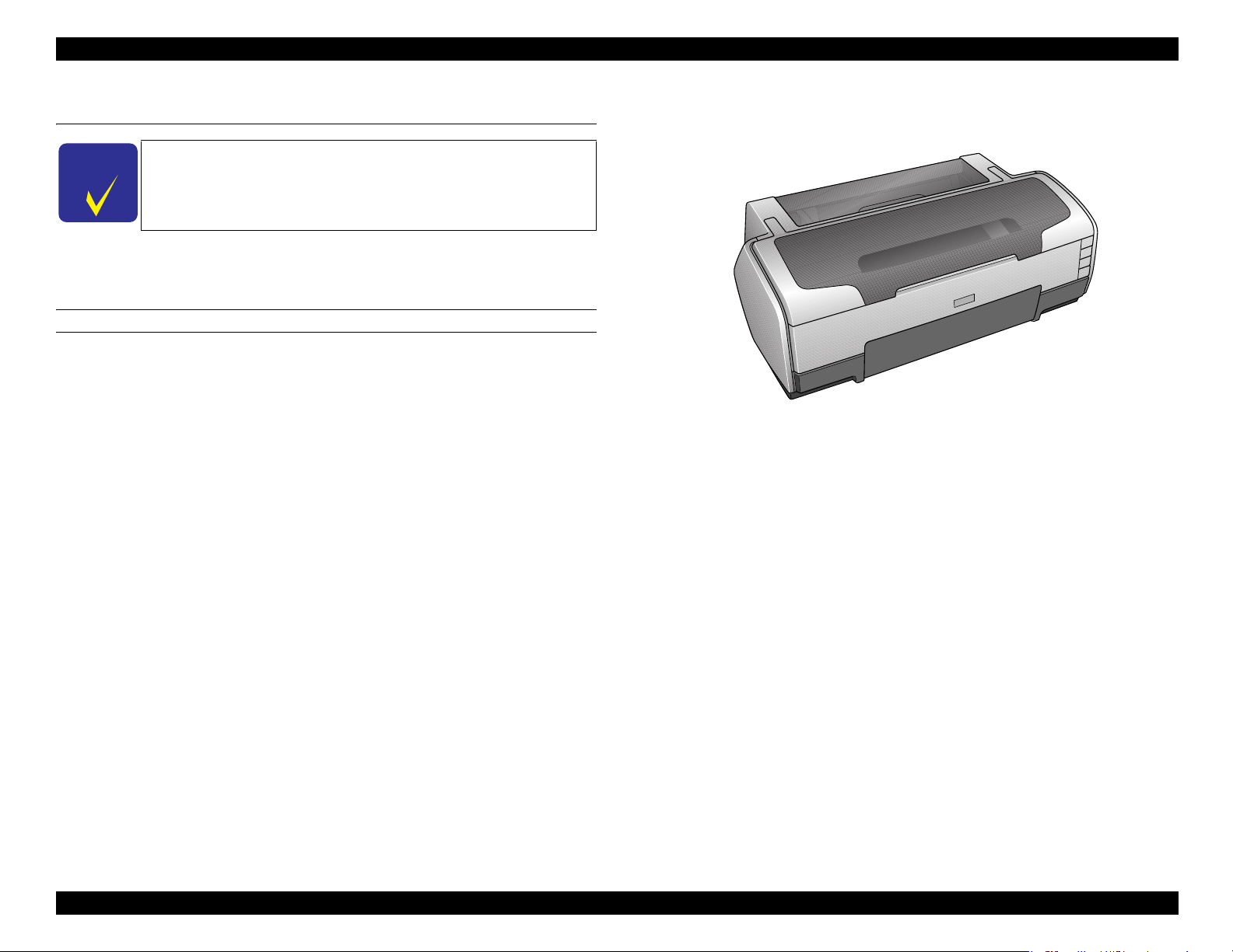
1.1 Overview
Description in this chapter is applied to EPSON Stylus Photo 1400/
1410. For information on Artisan 1430/ EPSON Stylus Photo
1430W/1500W, see "8.1 Product Description (p167)".
EPSON Stylus Photo 1400/1410 is a color inkjet printer designed for a wide range of
users, from home use to office use. The main features of this printer are:
Features
EPSON’s latest dye ink ensures high levels of lightfastness and gasfastness
Six individually replaceable ink cartridges let you print at up to
5760 x 1440 dpi (dots per inch).
Border-free printing up to A3+
High-quality and high-speed printing
CD-R direct printing capability using the CD/DVD tray fed into the front of the printer
ESC/P-R Level-1 command compatible
Prints RGB images transferred from the host devices
Directly prints from PictBridge and an USB Direct Print-enabled digital cameras
Clearly arranged three buttons and three LEDs offer quick, easy operation
Figure 1-1. Product’s External View
PRODUCT DESCRIPTION Overview 9
Page 10
EPSON Stylus Photo 1400/1410/1430W/1500W/Artisan 1430 Revision B
L
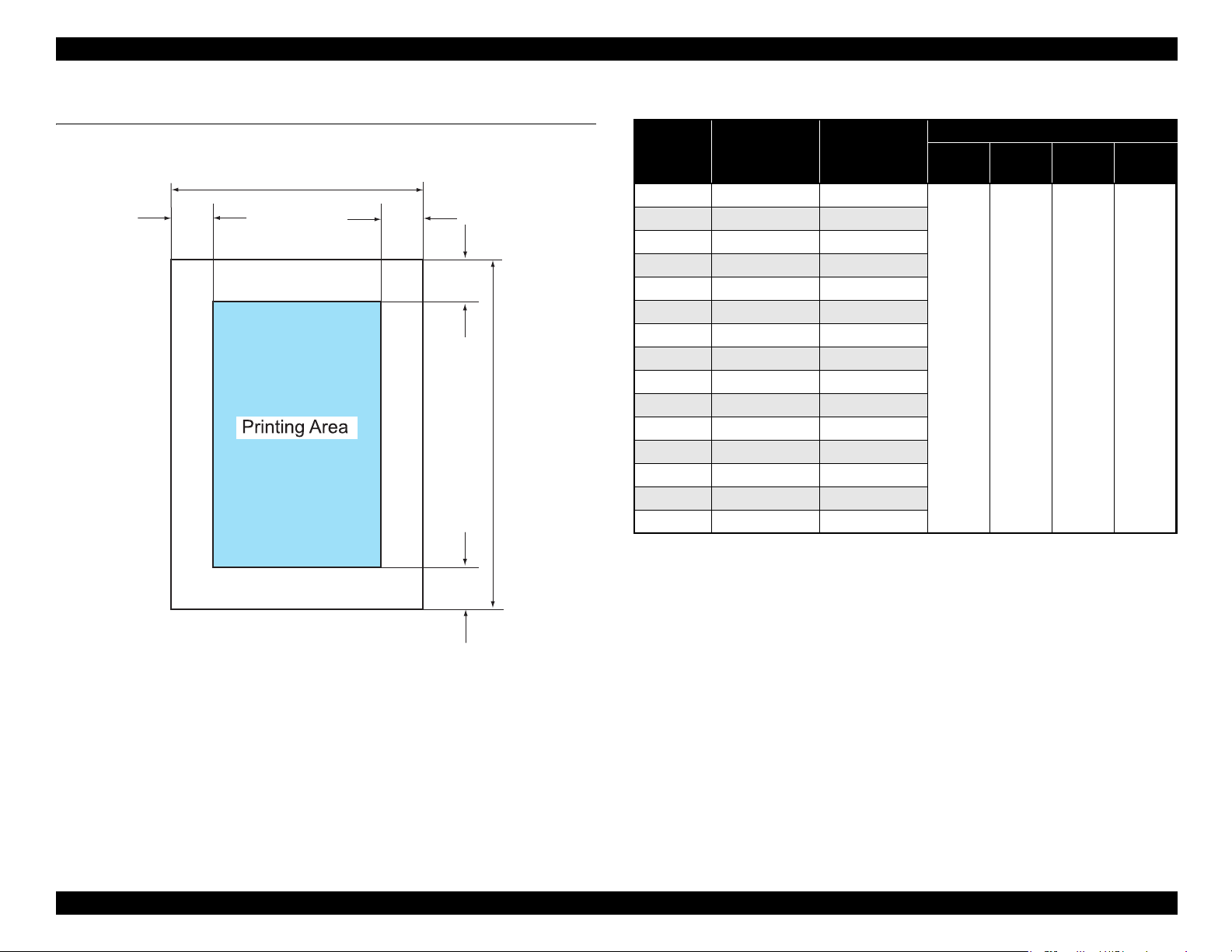
1.2 Printing Area
The printing area for this printer is shown below.
PW
LM RM
Figure 1-2. Printing Area
TM
BM
Table 1-1. Printing Area
Paper Size
Width
(PW)
Length
(PL)
Left
(LM)
Right
(RM)
Margin
Top
(TM)
Bottom
(BM)
*1
A3+ 329 mm (12.9 in.) 483 mm (19 in.)
A3 297 mm (11.7 in.) 420 mm (16.5 in.)
*2
US B
279.4 mm (11 in.) 431.8 mm (17 in.)
B4 257 mm (10.1 in.) 364 mm (14.3 in.)
US Legal 216 mm (8.5 in.) 356 mm (14 in.)
US Letter 216 mm (8.5 in.) 279 mm (10.9 in.)
A4 210 mm (8.3 in.) 297 mm (11.7 in.)
*3
B5
A5
182 mm (7.2 in.) 257 mm (10.1 in.)
*3
148 mm (5.8 in.) 210 mm (8.3 in.)
3 mm
(0.12 in.)
or more
3 mm
(0.12 in.)
or more
3 mm
(0.12 in.)
or more
3 mm
(0.12 in.)
or more
Half letter*2139.7 mm (5.5 in.) 215.9 mm (8.5 in.)
P
A6 105 mm (4.1 in.) 148 mm (5.8 in.)
*2
8x10
203.2 mm (8 in.) 254 mm (10 in.)
5x7 127 mm (5 in.) 262 mm (10.3 in.)
4x6 101.6 mm (4 in.) 152.4 mm (6 in.)
16:9 Wide 101.6 mm (4 in.)
180.6 mm (7.1 in.)
Note *1: Bottom margin can be reduced to 3 mm (minimum) by specifying the paper length
via ESC(S command, however, print quality may not be acceptable in the area 3 mm
to 43.3 mm (0.12 in. to 1.7 in.) from the bottom edge. When paper length is not
specified, the bottom margin will be 3 mm or more.
*2: EAI models only.
*3: Except for EAI models.
Note 1: Under the specific conditions, margins on all sides can be reduced to 0 mm.
2: Under the specific conditions, margins on both left and right sides can be reduced to
0 mm.
PRODUCT DESCRIPTION Printing Area 10
Page 11
EPSON Stylus Photo 1400/1410/1430W/1500W/Artisan 1430 Revision B
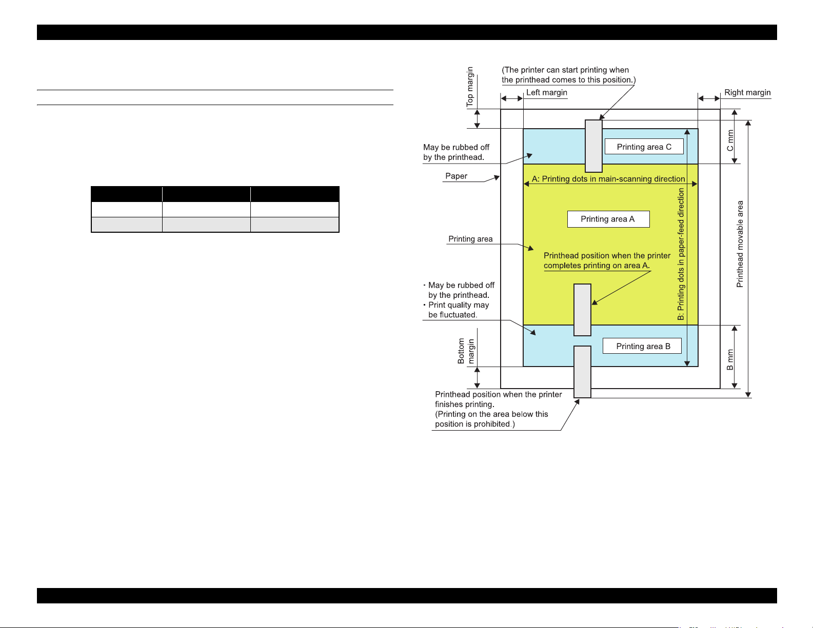
1.2.1 Printing Area (Cut sheet, Envelope)
Printing area (Print with borders)
Figure 1-3 shows the printing area (A, B, and C) for cut sheet and envelope.
Print quality may be fluctuated in printing area B, and both printing area B and C are
subject to being rubbed off by the Printhead. Margins on all sides are designed to
prevent the printed images from running off the paper.
Table 1-2. Printing Area
Paper Type Printing Area B Printing Area C
Cut sheet 43.3 mm (1.7 in.) 40.1 mm (1.58 in.)
Envelope 20 mm (0.79 in.) 40.1 mm (1.58 in.)
Figure 1-3. Printing Area (Print with Borders)
PRODUCT DESCRIPTION Printing Area 11
Page 12
EPSON Stylus Photo 1400/1410/1430W/1500W/Artisan 1430 Revision B
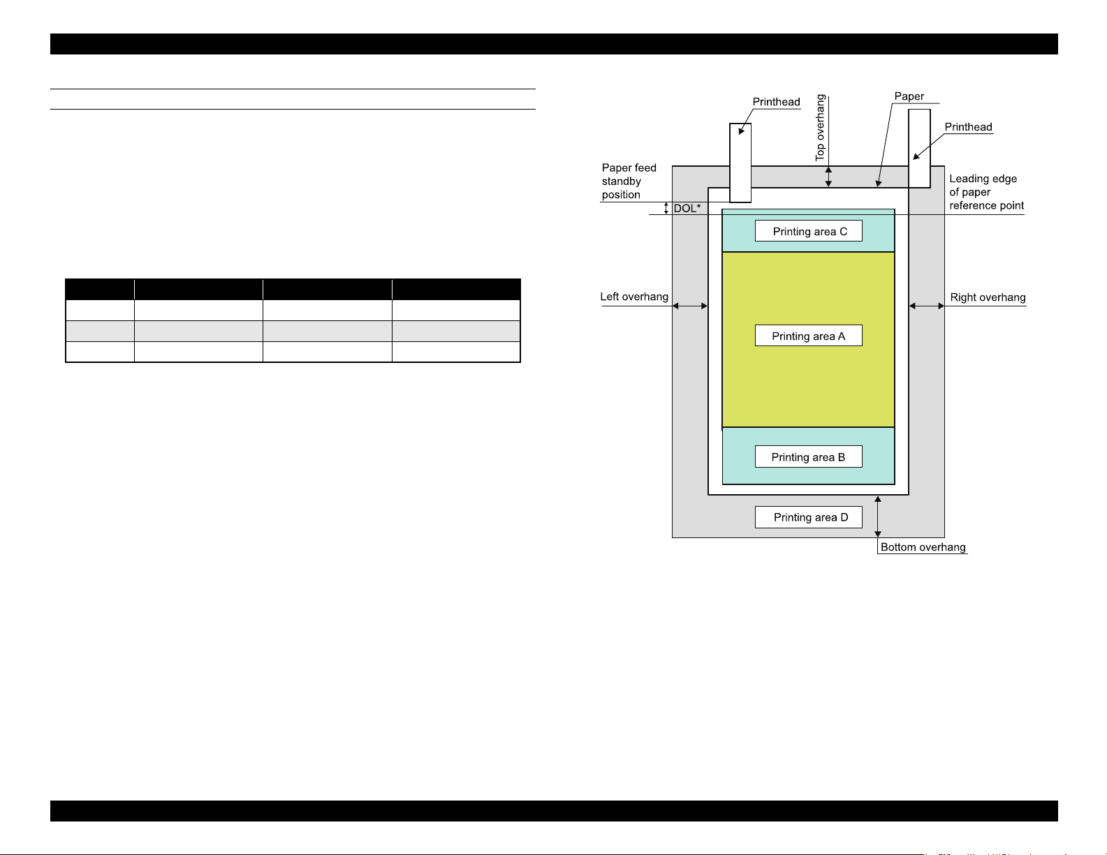
*: 2.96 mm (168/1440”)
Length from leading edge of paper reference point to paper feed standby position
Printing area (Border-free printing)
Figure 1-4 shows the printing area (A, B, C, and D) when border-free printing is
selected. Printing area D is supposed to be trimmed and may not be printed.
Border-free printing is available on the following media sizes:
Paper width
54, 55, 89, 100, 127, 210 mm
4, 5, 8, 8.5 inch
Table 1-3. Printing Area Off the Paper Edges
Margin 4x6 A4/Letter or smaller A3+ or smaller
Top 19/360” (1.34 mm) 42/360” (2.96 mm) 42/360” (2.96 mm)
Left/ Right 36/360” (2.54 mm) 36/360” (2.54 mm) 49/360” (3.46 mm)
Bottom 36/360” (2.54 mm.) 57/360” (4.02 mm) 64/360” (4.52 mm)
Figure 1-4. Printing Area (Border-free Printing)
PRODUCT DESCRIPTION Printing Area 12
Page 13
EPSON Stylus Photo 1400/1410/1430W/1500W/Artisan 1430 Revision B
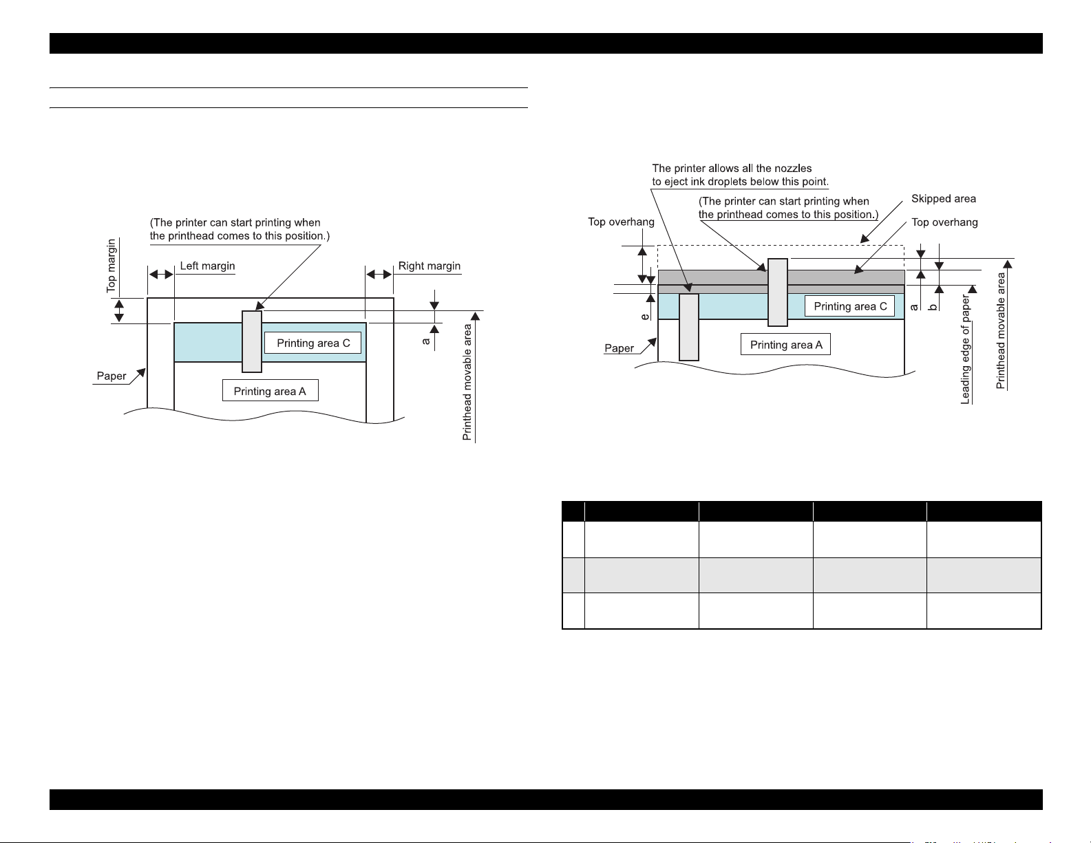
a = Not defined
Printhead movable area
Figure 1-5 to Figure 1-9 show movable area of the printhead in relation to the printing
area in sub-scanning (paper-feed) direction.
Top edge
(1) When top margin is set to 3 mm (0.12 in.)
Figure 1-5. Printhead Movable Area (3-mm Top Margin)
(2) When top margin is set to 0 mm
During printing the area indicated by the arrows a in the figure, some nozzles
are controlled not to eject ink droplets. When #1 nozzle passes through
printing area C, the control is cleared.
Figure 1-6. Printhead Movable Area (0-mm Top Margin)
Details on the length that the printhead moves off the paper edges (a), printing area off
the paper edges (b), and points where the nozzle control is cleared (e) are shown in the
table below.
4x6 (Hi-speed) 4x6
a
b
e
Note : As for e values, areas off the paper edges are indicated by negative values.
68/360”
(4.80 mm/0.19 in.)
13/360”
(0.92 mm/0.04 in.)
-55/360”
(-3.88 mm/-0.15 in.)
Nozzle positions for printing off the paper edge: #1 to #18 (18 nozzles in total)
Nozzle pitch for printing off the paper edge: 68/360 (4.80mm)
68/360”
(4.80 mm/0.19 in.)
9/360”
(0.64 mm/0.03 in.)
-50/360”
(-3.52 mm/-0.14 in.)
A4/Letter or smaller A3+ or smaller
68/360”
(4.80 mm/0.19 in.)
9/360”
(0.64 mm0.03 in.)
-46/360”
(-3.25 mm/-0.13 in.)
68/360”
(4.80 mm/0.19 in.)
9/360”
(0.64 mm0.03 in.)
-38/360”
(-2.68 mm/-0.1 in.)
PRODUCT DESCRIPTION Printing Area 13
Page 14
EPSON Stylus Photo 1400/1410/1430W/1500W/Artisan 1430 Revision B
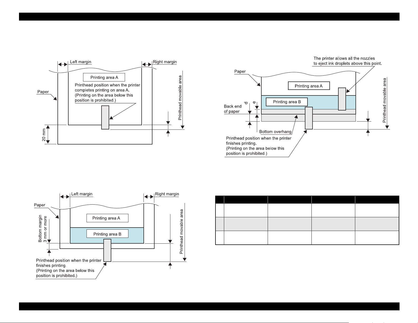
c = 33/360” (2.33 mm)
For reference: C= 20 mm - (length from upstream nozzle position to nip position + its
variations (simple addition) + variations in the bottom area accumulated from the top)
c
c = Not defined
Bottom edge
(1) When bottom margin is set to 20 mm (0.79 in.)
(For envelope/when bottom margin is set automatically)
Figure 1-7. Printhead Movable Area (20-mm Bottom Margin)
(2) When bottom margin is set to 3 to 20 mm (0.12 to 0.79 in.)
(3) When bottom margin is set to 0 mm
During printing the area indicated by the arrows c in the figure, some nozzles
are controlled not to eject ink droplets.
C
Figure 1-9. Printhead Movable Area (0-mm bottom margin)
c
Details on the length that the printhead moves off the paper edges (a), printing area off
the paper edges (b), and points where the nozzle control is cleared (e) are shown in the
table below.
4x6 (Hi-speed) 4x6
c
d
e
Note : As for e values, areas off the paper edges are indicated by negative values.
68/360”
(4.80 mm/0.19 in.)
27/360”
(1.91 mm/0.07 in.)
-41/360”
(-2.89 mm/-0.11 in.)
Nozzle positions for printing off the paper edge: #73 to #90 (18 nozzles in total)
Nozzle pitch for printing off the paper edge: 68/360 (4.80mm)
68/360”
(4.80 mm/0.19 in.)
30/360”
(2.12 mm/0.08 in.)
-44/360”
(-3.10 mm/-0.12 in.)
A4/Letter or smaller A3+ or smaller
68/360”
(4.80 mm/0.19 in.)
39/360”
(2.75 mm/0.10 in.)
-38/360”
(-2.68 mm/-0.1 in.)
68/360”
(4.80 mm/0.19 in.)
55/360”
(3.88 mm/0.16 in.)
-28/360”
(-1.98 mm/-0.08 in.)
Figure 1-8. Printhead Movable Area (3-mm Bottom Margin)
PRODUCT DESCRIPTION Printing Area 14
Page 15
EPSON Stylus Photo 1400/1410/1430W/1500W/Artisan 1430 Revision B
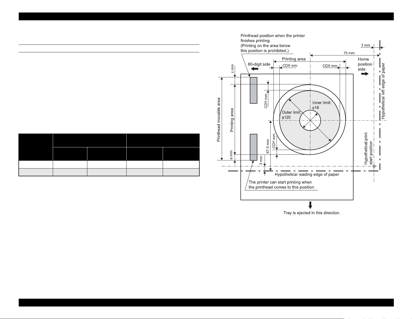
1.2.1.1 Printing Area (CD-R)
Printing Area
Figure 1-10 shows the printing area for CD-R. Outer and inner limit of printing area is
φ120 and φ18, respectively. The process of determining the reference point and
defining the printing area is described below.
(1) The reference point in main-scanning direction is 72 mm off from the center
of the CD-R (toward the home position side). The center of the CD-R is
detected automatically.
(2) The reference point in paper-feed direction is 67.5 mm off from the center of
the CD-R (toward the downstream side).
(3) User can change the center position of the CD-R in the range of ± CDX mm
(main-scanning direction) and ± CDY mm (paper-feed direction).
Amount of the Nozzles Off the
Unit
inch 358/360 359/360 ±14/180 ±28/360
mm 25.26 25.33 ±2 ±2
Paper Edges
a (Top) c (Bottom)
Adjustable Range of the CD-R
Center Position
CDX
(X direction)
CDY
(Y direction)
Figure 1-10. Printing Area (CD-R)
PRODUCT DESCRIPTION Printing Area 15
Page 16

EPSON Stylus Photo 1400/1410/1430W/1500W/Artisan 1430 Revision B
1.3 PG Setting
EPSON Stylus Photo 1400/1410/1430W/1500W/Artisan 1430 features an Auto Platen Gap (APG) adjuster that sets the platen gap to suit the type of paper being used, and this
prevents paper misalignment and jamming that can cause problems during operation.
Table 1-4 shows the relationship among PG positions, media, and sensors.
Table 1-4. PG Setting
PG Position
PG (– –) PG (–) PG (Typ) PG (+) PG (++) Release
• Plain paper
Printing
Not printing
PG value 1.05 mm (0.041 inch) 1.2 mm (0.047 inch) 1.7 mm (0.06 inch) 2.1 mm (0.08 inch) 4.5 mm (0.17 inch) ---
Sensor PG (– –) PG (–) PG (Typ) PG (+) PG (++) Release
APG sensor 1
APG sensor 2 L L L L H H
*
• Some special paper • Special paper
--- ---
HHHHHH
•PG (−) rubbing
prevention
• Standing-by after
power-on
(Output tray is lowered)
• At power-off
• Envelope
• PG (Typ) rubbing
prevention
---
•CD-R
• Initialization at poweron
• Cleaning (wiping)
• Replacing ink
cartridge(s)
---
• Waiting for CD-R to be
fed
• Removing jammed
paper
Note *: APG sensor 1 outputs L between each PG position.
PRODUCT DESCRIPTION PG Setting 16
Page 17
EPSON Stylus Photo 1400/1410/1430W/1500W/Artisan 1430 Revision B
Ink button
Paper button
Power button
Ink LED (red)
Paper LED (red)
Power LED (green)
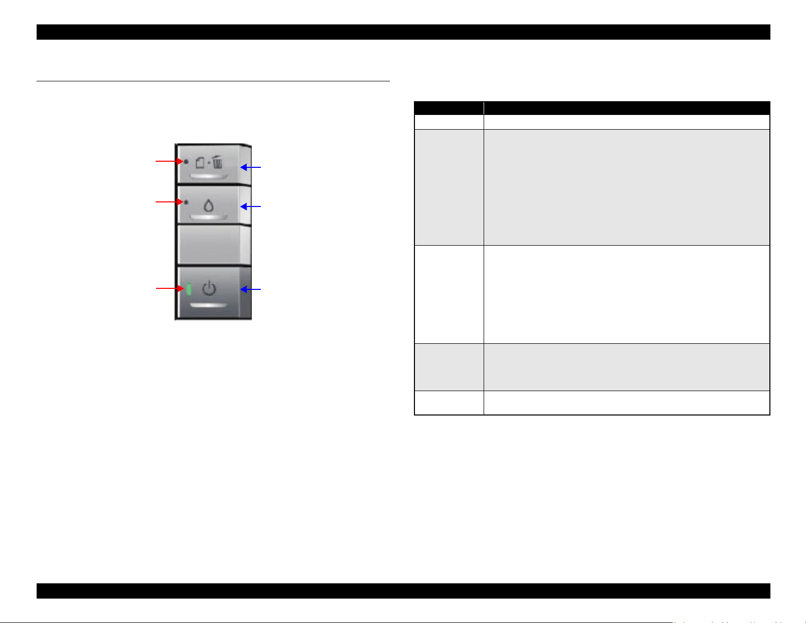
1.4 Printer Function
1.4.1 Operator Controls
The control panel is shown in the figure below.
Figure 1-11. Operator Controls
1.4.2 Buttons
Power button
Paper button
Ink button
1.4.3 LED Indicators
Power LED: Green
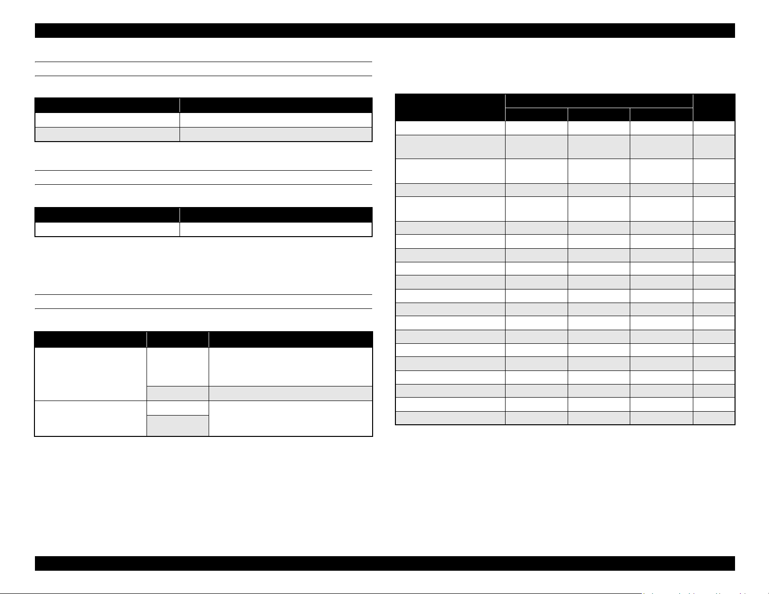
1.4.4 Panel Functions
Table 1-5. Normal Panel Functions
Button Function
Power
Paper
Ink
Ink
(When pushed
and held for 3
seconds)
CD-R guide
(When opened)
Note *: CD-R guide error occurs when the CD-R guide is opened during printing, or when
• Turns on/off the power.
• Loads or ejects the paper (Invalid when the CD-R guide is opened.)
• Clears double feed error and resumes printing.
• Cancels the current print job during printing.
• Clears paper out error and resumes printing.
• Clears paper jam error, ejects the paper, and resumes printing.
• When ink end (any cartridge) error occurs, the ink cartridge holder moves
to the ink replacement position.
• The ink cartridge holder returns to the home position from the ink
replacement position.
• The ink cartridge holder moves to the ink replacement position.
• When ink low, ink end, or no ink cartridge error occurs, the ink cartridge
holder moves to the ink check position.
• When the ink cartridge holder is in the ink check position, the holder
moves to check another cartridge of different color, or the holder moves to
the ink replacement position.
• The ink cartridge holder returns to the home position from the ink
replacement position.
• Starts printhead cleaning
• When ink low, ink end, or no ink cartridge error occurs, ink replacement
sequence starts.
• Clears CD-R guide error.
the printer receives a print job for cut-sheet with the CD-R guide opened.
*
Paper LED: Red
Ink LED: Red
PRODUCT DESCRIPTION Printer Function 17
Page 18
EPSON Stylus Photo 1400/1410/1430W/1500W/Artisan 1430 Revision B
Power-on functions
Table 1-6. Panel Function during Power-on
Button Held during Power-on Function
Paper
Ink
Starts status printings.
Starts in rubbing reduction mode.
Power-off function
Table 1-7. Panel Function during Power-off
Button Held during Power-off Function
Ink Forced power-off.
Note : Press the power button first. Making sure the power button is not pressed down, push
and hold the ink button for 7 seconds.
CD-R printing
Table 1-8. Panel Function during Printing on CD-R
Button CD/DVD Tray Function
• Clears CD/DVD tray error.
Paper
Ink
Inserted
Not inserted Clears CD/DVD tray error
Inserted Same as normal panel functions (including
Not inserted
• Cancels the current print job during
printing.
the functions when the button is pushed and
held for 3 seconds).
1.4.5 Printer Condition and Panel LED Status
Table 1-9. Panel Status
Printer Status
Power ON (Ready) condition On --- --- 12
Camera being connected
(No rubbing reduction)
Camera being connected
(Rubbing reduction)
Ink low --- --- Blink 11
Unsupported device
connection error
Data processing Blink --- --- 10
Loading/Ejecting paper Blink --- --- 10
No ink cartridge or Ink end --- --- On 9
CSIC error --- --- On 9
Processing ink sequence Blink --- --- 8
Ink cartridge change mode Blink --- --- 7
CD/DVD tray error --- On --- 6
Paper out --- On --- 6
Double feed --- On --- 6
Paper (CD-R) jam --- Blink --- 5
CD-R guide error
Maintenance request Off Alt Blink Alt Blink 3
Fatal error Off Hi-speed Blink Hi-speed Blink 2
Powering OFF Hi-speed Blink Off Off 1
Reset request
Note *: All the LEDs turn on for 0.2 seconds.
Note : ---: No change to LED.
*
Blink: 0.5 seconds on, 0.5 seconds off (repeat)
Blink2: 0.2 seconds on, 0.2 seconds off, 0.2 seconds on, 0.4 seconds off (repeat)
Blink3: 0.2 seconds off, 0.2 seconds on, 0.2 seconds off, 0.4 seconds on (repeat)
Blink4: 0.8 seconds on, 0.2 seconds off
Hi-speed Blink: 0.1 seconds on, 0.1 seconds off (repeat)
Alt Blink: Continuous alternating blink of Paper and Ink LEDs.
Power Paper Ink
Blink2 --- --- 12
Blink4 --- --- 12
--- Blink2 Blink3 10
--- Blink2 Hi-speed Blink 4
On On On ---
Button LEDs
Priority
PRODUCT DESCRIPTION Printer Function 18
Page 19

EPSON Stylus Photo 1400/1410/1430W/1500W/Artisan 1430 Revision B
1.4.6 Errors
Table 1-10. Errors
Error Status Occurrence Condition Remedy
Ink end
Paper out
Paper jam
Double feed error
No ink cartridge
Ink cartridge error
Maintenance
request
Fatal error
The printer has almost run out of
ink in any cartridge.
The printer fails to load a sheet of
paper.
1. The printer cannot eject the
remaining paper at power-on
within predetermined steps.
2. The printer cannot eject the
paper by FF command or
pressing the Paper button.
3. The printer cannot eject the CD/
DVD tray.
4. The printer prints on a 58 mm
(2.3 inch) or shorter length of
paper.
The printer detects that two sheets
have stuck together during paper
feed.
1. The printer detects at least one
ink cartridge is missing.
2. The printer cannot communicate
with the CSIC chip on one of the
cartridges.
When the total quantity of wasted
ink used for cleaning and flushing
reaches the calculated limit.
The printer cannot control error.
Carry out the ink cartridge
replacement operation. Remove the
CD/DVD tray before pressing the Ink
button.
Load a paper in the ASF, and press
the Paper button to feed the paper. Set
the CD-R guide lever to the ASF
position before pressing the button.
1. ASF mode
Remove the jammed paper and
press the Paper button. Set the CDR guide lever to the ASF position
before pressing the button.
2. CD-R mode
Remove the jammed CD/DVD tray
and press the Paper button.
Press the Paper button to eject the
paper. Set the CD-R guide lever to the
ASF position before pressing the
button.
Make sure genuine EPSON ink
cartridges are inserted and press the
Ink button. Remove the CD/DVD tray
before pressing the button.
Replace the waste ink pad and reset
the Waste Ink Counter.
Turn the power off and on again.
Table 1-10. Errors
Error Status Occurrence Condition Remedy
CD-R guide error
CD/DVD tray
error
Unsupported
device
connection error
1. The printer receives a print job
for cut-sheet when the CD-R
guide lever is set to the CD-R
position.
2. The CD-R guide lever is set to
the CD-R position during ASF
printing.
1. The printer receives a print job
for CD-R media when the CD-R
guide lever is set to the ASF
position.
CD/DVD tray is not inserted. Insert a CD/DVD tray and press the
Unsupported device is connected. Disconnect the device from the USB
Set the CD-R guide lever to the ASF
position.
Set the CD-R guide lever to the CD-R
position.
Paper button.
connector.
PRODUCT DESCRIPTION Printer Function 19
Page 20
EPSON Stylus Photo 1400/1410/1430W/1500W/Artisan 1430 Revision B
615
314
803
223
413
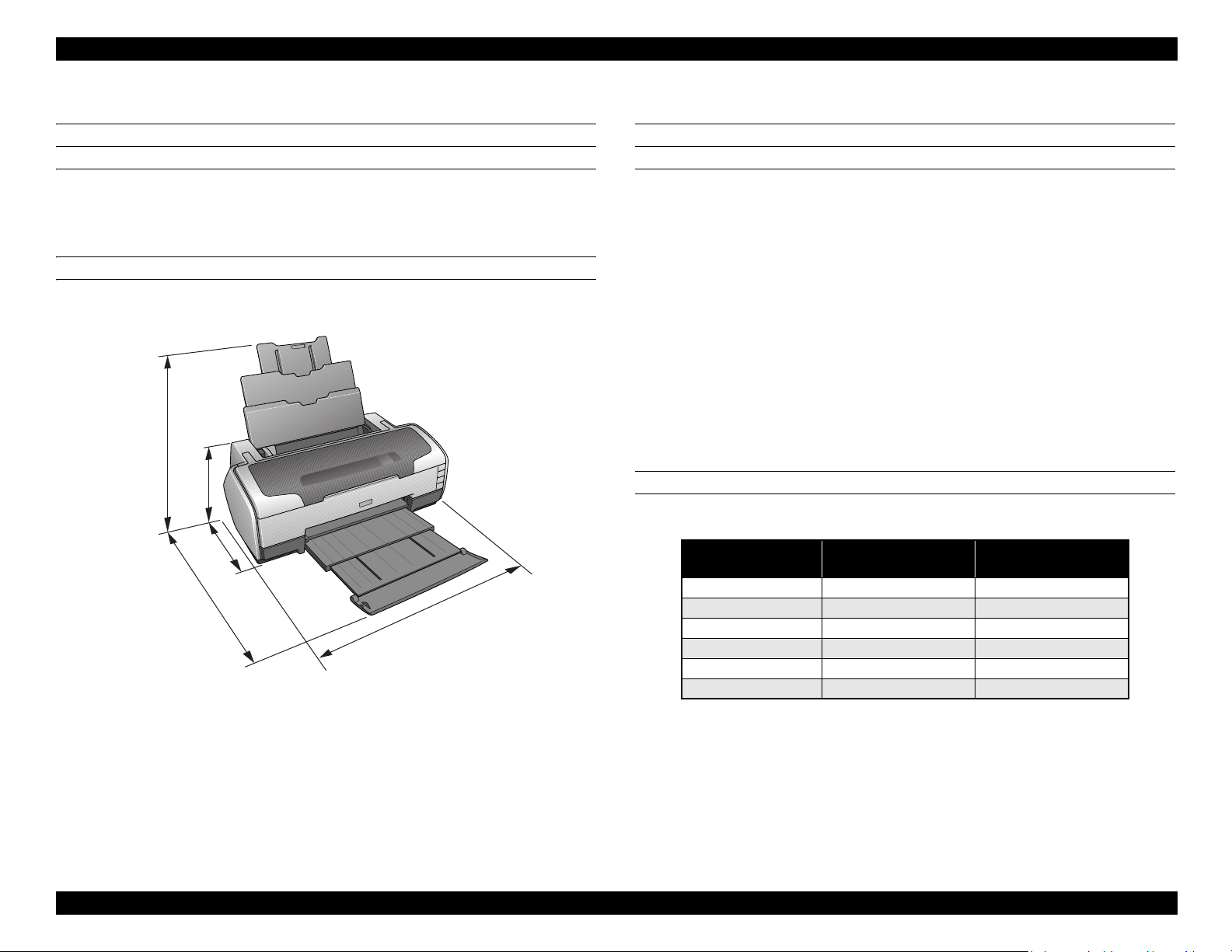
1.5 Size and Weight
Dimensions
Storage: 615 mm (24.2 in.) W x 314 mm (12.4 in.) D x 223 mm (8.8 in.) H
Printing: 615mm (24.2 in.) W x 803 mm (31.6 in.) D x 413 mm (16.3 in.) H
Weight
11.5 Kg (25.4 lbs.)
Figure 1-12. Physical Dimensions, in mm
1.6 Accessories
Standard accessories
User’s guide
Ink cartridge (one for each of the six colors)
Software CD-ROM
Setup sheet
On-line questionnaire sheet
Customer Satisfaction Card (information card)
Guarantee card
CD/DVD print kit
CD/DVD tray
Small CD insert
Consumable and optional supplies
Ink cartridge
Color EAI/EUR
Black T0791 T0811
Cyan T0792 T0812
Magenta T0793 T0813
Yellow T0794 T0814
Light Cyan T0795 T0815
Light Magenta T0796 T0816
Network Print Server
Latin / CIS / EAL
Middle East / Africa
PRODUCT DESCRIPTION Size and Weight 20
Page 21

OPERATING PRINCIPLES
CHAPTER
2
Page 22
EPSON Stylus Photo 1400/1410/1430W/1500W/Artisan 1430 Revision B
C H E C K
P O I N T
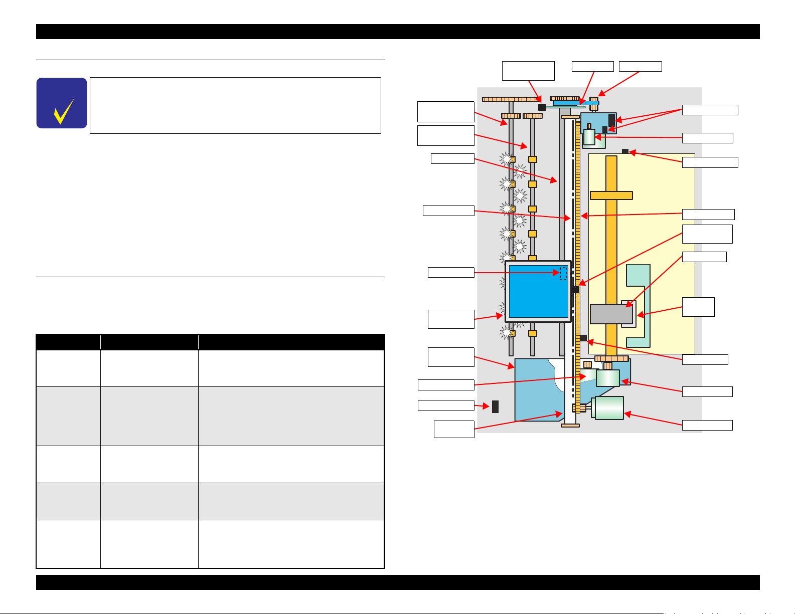
Rear Paper
Eject Roller
Front Paper
Eject Roller
PW Sensor
CR Scale
PF Roller
PF Encoder
Sensor
PF Scale
PF Motor
Carriage
Unit
Ink System
Unit
Pump Motor
CD-R Sensor
Carriage
Shaft
APG Sensors
APG Motor
APF Sensor
Timing Belt
CR Encoder
Sensor
LD Roller
Retard
Roller
PE Sensor
ASF Motor
CR Motor
2.1 Overview
Description in this chapter is applied to Stylus Photo 1400/1410,
but some of it can also he applied to Stylus Photo 1430W/1500W/
Artisan1430.
This chapter explains the operating principles of the mechanical sections and electrical
circuits in this product. The main components of this product are as follows.
Control Circuit Board : C655 MAIN
Power Supply Circuit Board : C589 PSB
Control Panel Board : C589 PNL
The basic mechanism is the same as the Stylus Photo R1800.
Head Circuit Board : C653 HEAD
2.2 Printer Mechanism
In common with previous model, this printer uses DC motors and stepping motors as
power source. The following table describes the motor types and their applications.
Table 2-1. Motors
Motor Name Type Applications/Functions
Drives the Carriage. Makes very little driving
CR Motor DC motor with brushes
noise. Controlled by the CR linear scale and CR
encoder sensor.
Drives the paper feed roller for the fixed-value
paper loading or the paper feed/eject operation. To
PF Motor DC motor with brushes
grasp the paper feed pitch, the precision gear
surface is fitted with the PF Scale and the PF
Encoder Sensor is used to control the motor.
Drives the Carriage Unit at the time of PG setting.
APG Motor DC motor with brushes
The two APG Sensors and Carriage Shaft are
driven vertically to control the motor.
ASF Motor
Pump Motor
OPERATING PRINCIPLES Overview 22
4-phase, 48-pole PM type
stepping motor
4-phase, 48-pole PM type
stepping motor
Drives the paper feed operation of the ASF. Since
this is a stepping motor, no scales or photo sensors
are required to grasp the driving conditions.
Drives the pump, wiper, etc. of the Ink System.
Since this is a stepping motor, no scales or photo
sensors are required to grasp the driving
conditions.
Figure 2-1. Printer Mechanism Outline
Page 23

EPSON Stylus Photo 1400/1410/1430W/1500W/Artisan 1430 Revision B
2.2.1 Carriage Mechanism
The Carriage mechanism consists of parts/units such as the Carriage Motor (CR
Motor), Carriage Shafts, Platen Gap Adjustment Mechanism and Carriage Lock
Mechanism.
2.2.1.1 Carriage Mechanism
The following indicates the specifications of the CR motor (DC motor) that drives the
Carriage.
Table 2-2. CR Motor Specifications
Item Specifications
Type DC motor with brushes
Drive voltage +42V ± 5% (voltage applied to driver)
Armature resistance 23.6Ω ± 10%
Inductance 17.5mH ± 25%
Drive method PWM, constant-current chopping
Drive IC A6628
Closed loop control based on the CR Motor (DC Motor) and CR Encoder Sensor has
advantages in stabilized print quality and silent operation.
Heat Generation Control
The printer has a mechanism to reduce the variations in the torque constant and
coil resistance of the DC motors, and variations in output voltage of the Power
Supply Board to obtain a designated heating value.
CR Measurement Sequence
To set the appropriate drive current value according to the CR mechanical load,
the mechanical load is measured in a CR measurement sequence and saved into
the EEPROM at power-on or after replacing the Ink Cartridge(s).
The above control and sequences correct the drive current value of the CR Motor
according to not only the mechanical load but also the variations of the motors. In
addition, the resultant CR drive current value is used to calculate a heating value, and
when the specified heating value is reached, wait time is provided per CR path for
printing.
CR Variation Measurement Sequence
The variations mentioned above are measured in a CR variation measurement
sequence when the CR mechanical load is in the initial status and saved into the
EEPROM. According to the saved information, the printer controls the drive
voltage to obtain a designated driving current. This minimizes the unit-to-unit
variation.
OPERATING PRINCIPLES Printer Mechanism 23
Page 24

EPSON Stylus Photo 1400/1410/1430W/1500W/Artisan 1430 Revision B
2.2.1.2 Carriage Home Position Detection
As in the previous model, the Carriage Home Position is detected using the drive
current of the CR Motor and the speed/position signal of the CR Linear Encoder.
The basic home position detection sequence is described below.
1. The CR linear encoder pulse counter in the CPU is reset by the initialization
operation performed at power-on.
2. When the CR Motor rotates counterclockwise, the Carriage Unit moves from left
to right. When the following conditions are satisfied, the CPU assumes that the
Carriage Unit made contact with the right frame.
The ASIC detects 935/1500 counts or more in the PWM output under CR
Motor load positioning control.
P1 (number of output pulses from when the power is switched on till the
Carriage Unit makes contact with the right frame) is 19 steps or less.
3. When the CR Motor rotates clockwise, the Carriage Unit moves from right to left.
When the following conditions are satisfied, the CPU assumes that the Carriage
Unit reached the CR lock confirmation position.
The ASIC detects 600/1500 counts or more in the PWM output under CR
Motor load positioning control.
A difference between P1 and P2 (number of output pulses from when the
Carriage Unit made contact with the right frame until it reaches the Carriage
lock confirmation position) is 19 steps or less.
4. When the CR Motor rotates counterclockwise to move the Carriage from left to
right and the CPU detects 935/1500 counts or more in the PWM output under CR
Motor load positioning control, the printer judges that the Carriage has moved to
the far right position (in contact with the right frame).
5. When a difference between P1 and P3 (number of output pulses from when the
Carriage Unit reached the Carriage lock confirmation position until it makes
contact with the right frame) is 4 steps or less, the printer judges that the Carriage
Unit is in the home position.
IC9 (CPU-ASIC) sets the drive current value adequate for the Carriage Unit motion
and outputs it to the motor driver.
2.2.1.3 Sequence Used for PW Detection
The PW (paper width) Sensor installed on the bottom of the Carriage Unit is used to
control the printer according to various sequences.
The following briefly describes the operating principle of the PW Sensor.
A dark voltage is measured by the PW Sensor in three places at the right flat area (area
without the absorber) on the Front Paper Guide every time the printer is turned on, and
the measurement values are saved into the EEPROM as threshold values.
Threshold value detection voltage: Paper present
Threshold value detection voltage: Paper absent
The following sequences are performed.
Detection of Left and Right Edges of Paper Control
Before Printing
The printer sets the print range according to the paper-size information from
the Driver and the actual paper-size detected by the PW sensor.
During Printing
When executing a borderless printing, the printer sets the off-range margins
by detecting the paper edges with the PW Sensor. When the resolution is 1440
x 1440 (VSD3) or 2880 x 1440 (VSD3) dpi, the printer performs the OffRange Thinning Out Control to make a further correction to the off-range
margins.
Detection of Top Edge of Paper Control
Before starting a print job, the printer detects the top edge of a loaded single sheet
of paper to set the off-range top margin. (Only when not detecting the top edge of
paper with the PW Sensor.)
Detection of Bottom Edge of Paper Control
After starting a borderless printing, the printer sets the off-range bottom margin.
Detection of Edges of CD-R Control
Before starting to print, the PW Sensor detects top, bottom, left and right edges of
the CD-R. See Section 2.2.3.3 CD-R Printing Mechanism on page 29.
Based on the signal output from IC9 (CPU-ASIC), IC11 (Motor Driver) outputs the CR
Motor drive current to the CR Motor.
OPERATING PRINCIPLES Printer Mechanism 24
Page 25
EPSON Stylus Photo 1400/1410/1430W/1500W/Artisan 1430 Revision B
Carriage Shaft
Carriage Unit
APG Motor
PG CamAPG Sensor
APG
Sensor
Detection of CD/DVD Tray Control
Before starting to print, determines the type of media.
PW sensor dark voltage (VH) measurement
PW sensor dark voltage (VH) measurement is performed at the following timings
and locations and used to calculate the threshold value of whether paper is present
or not.
CD/DVD Tray
When printing on a CD-R, the dark voltage is measured on the CD/DVD tray,
and the threshold value (VS) is then calculated and saved in the EEPROM
area as a PW detection level.
• Threshold value detection voltage: CD-R present
(tray home position detected)
The measurement voltage in the presence of the CD-R is saved into the
EEPROM as a white level. The white level value is used to check the sensor
deterioration condition on occasions such as servicing.
• If the measurement value of the white level is close to that of the PW
detection level, it means that the sensor is dirty or deteriorated.
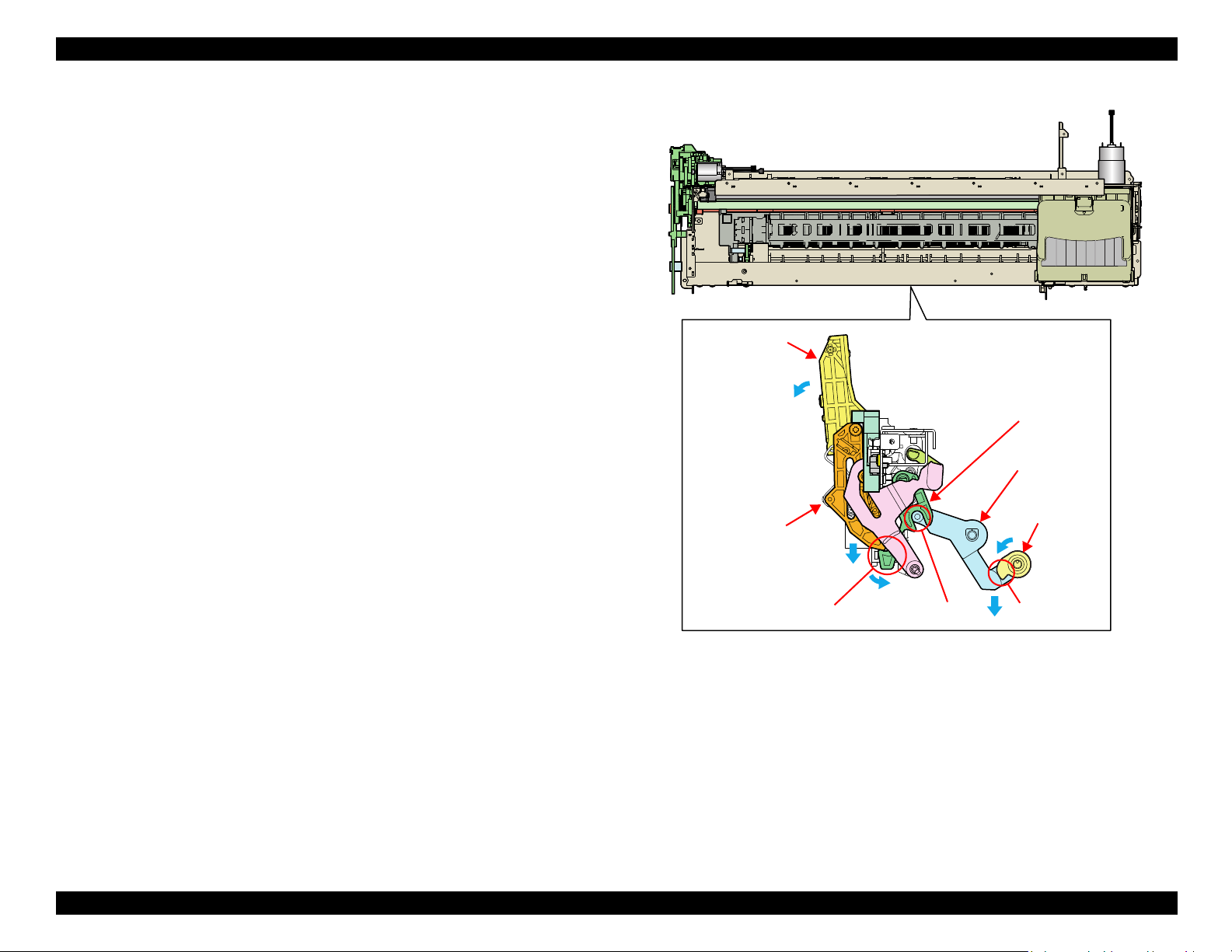
2.2.1.4 APG (Auto Platen Gap) Adjustment Mechanism
The following indicates the specification of the DC motor that drives the APG adjuster.
Table 2-3. APG Motor Specifications
Item Specifications
Type DC motor with brushes
Drive voltage +42V ± 5% (voltage applied to driver)
Armature resistance 64.7Ω ± 15%
Inductance 37.6mH ± 25%
Rotor Inertia 3.94gcm
Drive method PWM, constant-current chopping
Drive IC A6628
The APG Motor (DC Motor) and two APG Sensors drive the PG Cam to automatically
adjust the PG amount according to the paper.
2
Figure 2-2. APG Mechanism
OPERATING PRINCIPLES Printer Mechanism 25
Page 26
EPSON Stylus Photo 1400/1410/1430W/1500W/Artisan 1430 Revision B
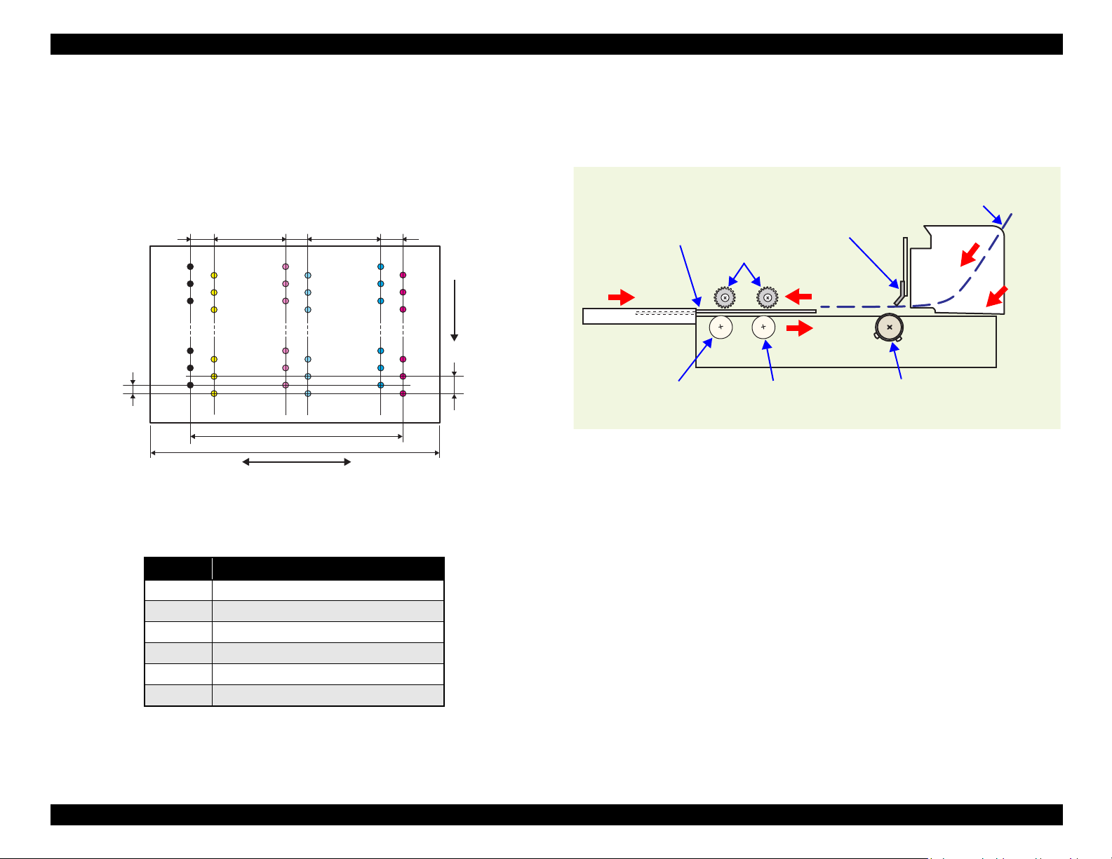
14.95mm
22.81mm
Carriage moving direction
Paper feeding
direction
0.141mm
(1/180inch)
0.282mm
(1/90inch)
Line A
Line B
6.209mm
(176/720inch)
0.846mm
(24/720inch)
0.846mm
(24/720inch)
6.209mm
(216/720inch)
Line C
Line D
Line E
Line F
0.846mm
(24/720inch)
CD/DVD Tray
Front Paper Eject Roller
Rear Paper Eject Roller
PF Roller
Star Wheel Rollers
PE Sensor
Cut sheet
2.2.2 Printhead Specifications
The Printhead of this product is a F3-Mach head.
The following shows the arrangement of the nozzles and the color arrangement of each
nozzle line when viewing the Printhead from behind.
2.2.3 Paper Feeding Mechanism
The paper feeding mechanism is a mechanism that feeds paper or CD/DVD tray to the
PF Roller Shaft.
Figure 2-4. Paper Feeding Mechanism
OPERATING PRINCIPLES Printer Mechanism 26
Figure 2-3. Nozzle Arrangement
Table 2-4. Nozzle Lines and the Corresponding Ink Color
Line Ink
ABlack
B Yellow
C Light-Magenta
D Light-Cyan
ECyan
F Magenta
Page 27
EPSON Stylus Photo 1400/1410/1430W/1500W/Artisan 1430 Revision B
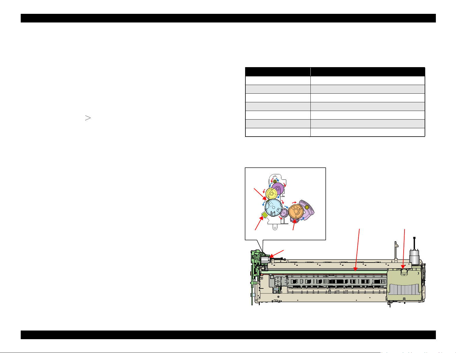
ASF Motor
Combination Gear 29, 11
LD Shaft Spur Gear
LD Roller
ASF Motor
ASF
Sensor
Combination
Gear 29.11
LD Shaft
Spur Gear
Relay Board
ASF Sensor
Wheel
Standby State
Feeding Paper
LD Roller
Hopper
Hopper
Compression
Spring
Retard
Roller
Paper
Paper Back Lever
LD
Roller
Cam
Paper Back Lever
Torsion Spring
2.2.3.1 ASF Paper Feeding Mechanism
The following shows the specifications of the stepping motor that drives the ASF Assy.
Table 2-5. ASF Motor Specifications
Item Specifications
Type
Drive voltage
Winding resistance
Inductance
Drive method
Drive IC
Driven by the ASF Motor, the ASF Assy performs the following feeding operation.
1. When a paper feeding command is issued from the PC or the Paper button of the
panel is pressed after power-on, the driving force of the ASF Motor begins to be
transmitted to the LD Roller following the route shown below.
4-phase, 48-pole PM type stepping motor
+42V ± 5% (voltage applied to driver)
7.0Ω ± 10% (per phase at 25°C)
10.2mH ± 20% (1kH, 1Vrms, at 25°C)
Bipolar drive/constant-current drive
A6628
4. When the next sheet of paper is fed by the LD Roller and the Retard Roller, the
Hopper is pressed against the Frame again by the Hopper Cams, and the Paper
Holder of the Paper Back Lever rises by the Cams on the left and right ends of the
LD Roller to prevent the next sheet from being fed with the previous sheet.
5. The LD Roller stops to rotate when it makes one revolution and the flag of the
ASF Sensor Wheel returns to the ASF Sensor.
2. When the LD Roller starts rotating, the flag of the ASF Sensor Wheel comes free
from the notch on the ASF Sensor. At the same time, the Paper Back Lever
becomes free from the Cams located at the left and right ends of the LD Roller,
then the Paper Holder on the Paper Back Lever inclines downward by tensile force
of the Paper Back Lever Torsion Spring.
3. By the LD Roller's rotation, the Hopper is released from the Hopper Cams located
on the left and right ends of the LD Roller, and the Hopper pops up by tensile force
of the Hopper Compression Spring.
OPERATING PRINCIPLES Printer Mechanism 27
Figure 2-5. ASF Paper Feeding Mechanism
Page 28
EPSON Stylus Photo 1400/1410/1430W/1500W/Artisan 1430 Revision B
CD/DVD Tray Base
Paper EJ Lock
Release Cam
Salient
Paper EJ
Transmission
Lock Lever
Paper EJ Lock
Lever
Jointed PositionTab
CD-R Release Lever
2.2.3.2 CD/DVD Tray Base Lock Mechanism
To prevent the Printhead from being damaged by mistake, the printer is designed to
lock the CD/DVD Tray Base when the Carriage Unit is out of its home position.
The following explains the lock mechanism of the CD/DVD Tray Base.
Lock Release Sequence
1. When the Carriage Unit returns to its home position, the Pump Motor drive is
transmitted to the Paper EJ Lock Release Cam.
2. The salient of the Cam presses down the Paper EJ Transmission Lock Lever
to release the tab of the Paper EJ Lock Lever from the Paper EJ Transmission
Lock Lever.
3. The CD-R Release Lever comes free from the Paper EJ Lock Lever and
comes down to enable the CD/DVD Tray Base to open.
When the Carriage Unit is out of its home position, the salient of the Paper EJ Lock
Release Cam does not press down the Paper EJ Transmission Lock Lever, and the tab
of the Paper EJ Lock Lever is not released. Therefore, the CD/DVD Tray Base cannot
be opened.
Figure 2-6. CD/DVD Tray Base Lock Mechanism
OPERATING PRINCIPLES Printer Mechanism 28
Page 29
EPSON Stylus Photo 1400/1410/1430W/1500W/Artisan 1430 Revision B
Carriage Unit
PW Sensor
CD-R Home Position
CD/DVD Tray
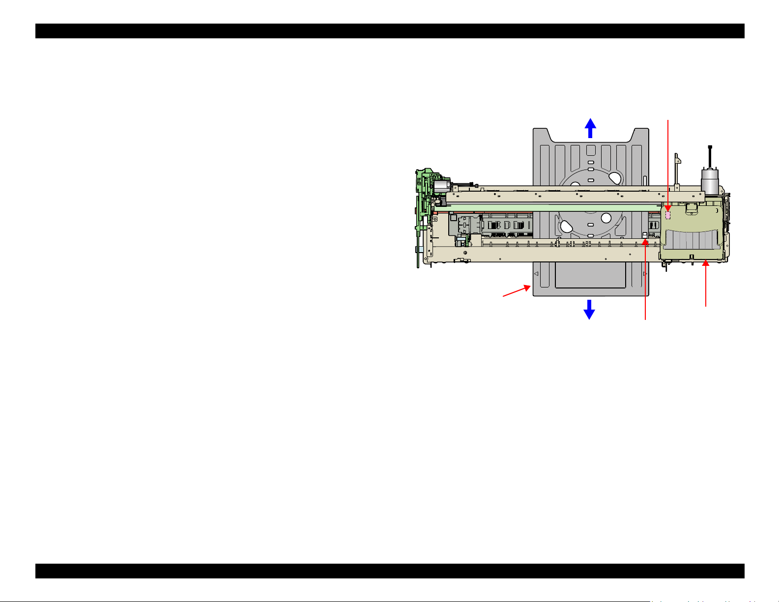
2.2.3.3 CD-R Printing Mechanism
CD/DVD Tray Home Position Detection Sequence
The following sequence is performed after opening the Front Cover (CD-R
Sensor: closed), inserting the CD/DVD Tray to the specified position, and pressing
the Paper button.
When the close signal of the CD-R Sensor is detected, no paper is fed from the
ASF even if the Paper button is pressed. In this case, pressing the Paper button
executes a CD/DVD Tray home position detection sequence.
1. When the APG Assy is driven, the PG position is set to “++” and the Driven
Roller of the Upper Paper Guide presses onto the CD/DVD Tray.
2. When the Carriage Unit moves to the left and the PW Sensor detects the CD-
R, the Carriage Unit returns to its home position (HP).
3. After waiting for about 5 seconds at the HP, the Carriage Unit moves to the
CD/DVD Tray HP detectable position (right end of the CD/DVD Tray).
4. The CD/DVD Tray is pulled towards the ASF, the PW Sensor detects the CD/
DVD Tray HP, and then the Carriage Unit moves to the center of the CD/
DVD Tray.
5. When the PW Sensor detects the white marking in the center of the CD/DVD
Tray, the CD/DVD Tray is fed in the paper ejection direction.
6. The Carriage Unit moves to the left, the PW Sensor detects the white marking
on the left, then the Carriage Unit moves to the right, and the PW Sensor
detects the white marking on the right.
7. The Carriage Unit moves to the center of the CD/DVD Tray, and the PW
Sensor starts detection of the front and back direction of the CD-R. After the
front end of the CD-R is detected, the CD/DVD Tray is fed towards the paper
ejection direction, and the back end of the CD-R is detected. After that, the
CD/DVD Tray is fed to the center of the CD-R in the paper ejection direction.
8. The Carriage Unit moves to the left, and the PW Sensor starts detection in the
horizontal direction of the CD-R. After the left end of the CD-R is detected,
the Carriage Unit moves to the right, and the right end of the CD-R is
detected.
9. The Carriage Unit stops after moving to the CD/DVD Tray HP detectable
position, then the CD/DVD Tray is fed towards the ASF.
10. When the CD/DVD Tray stops operating, the Carriage Unit moves to the
carriage HP and stands by.
If the CD/DVD Tray HP, the white marking, or the CD-R cannot be detected within the
steps predetermined for the CD/DVD Tray HP detection sequence, the CD/DVD Tray
is ejected and Paper Out Error is displayed.
Figure 2-7. CD-R Printing Mechanism
OPERATING PRINCIPLES Printer Mechanism 29
Page 30
EPSON Stylus Photo 1400/1410/1430W/1500W/Artisan 1430 Revision B
PF Motor
PF Timing Belt
PF Roller Spur Gear 31.5
Spur Gear 68
Front Paper Eject Roller
Spur Gear 16; B (front)
Spur Gear 15.5
Rear Paper Eject Roller
Combination Gear
36.294, 55
Spur Gear 16; B (rear)
Front Paper Guide
PF Roller
PF Motor
Front Paper Eject Roller
Rear Paper Eject Roller
PF Timing Belt
Combination Gear
36.294, 55
Spur Gear 31.5
Spur Gear 16;
B (front)
Spur Gear 68
Spur Gear 15.5
Spur Gear 16; B (rear)
2.2.4 Paper Feeding Mechanism
The Paper Feeding Mechanism is designed to transfer the paper fed from the ASF, or
the CD-R fed from the CD/DVD Tray according to the print data.
2.2.4.1 Paper Feeding Mechanism
The following shows the specifications of the DC motor that drives the Paper Feeding
Mechanism.
Table 2-6. PF Motor Specifications
Item Specifications
Type DC motor with brushes
Drive voltage +42V ± 5% (voltage applied to driver)
Armature resistance 21.2Ω ± 10%
Inductance 17.2mH (1kHz)
Rotor Inertia 18.8gcm2
Drive method PWM
Drive IC A6628
The following shows the part names and outline of the drive transmission path.
Like the CR Motor, a DC motor is used as the PF Motor in this product.
Closed loop control based on the DC Motor and Rotary Encoder has the following
advantages.
Improved paper feed accuracy
Paper feed amount control
The PF Motor drive is transmitted to the PF Roller and the Paper EJ Roller following
the route shown below.
OPERATING PRINCIPLES Printer Mechanism 30
Figure 2-8. Paper Feeding Mechanism
Page 31

EPSON Stylus Photo 1400/1410/1430W/1500W/Artisan 1430 Revision B
The fed paper is detected by the PE Sensor, and its front end is then transferred to the
front of the Front Paper Guide.
To eliminate the deflection of the paper, the paper is then returned toward the ASF
Assy by the specified number of steps according to the paper feeding mode.
The paper is re-transferred to the specified paper locating position of the Front Paper
Guide.
2.2.4.2 PF Measurement Sequence
The mechanical load in the paper feeding path is measured in the following cases
to perform control so that an adequate current value is set according to the
mechanical load.
When power is switched on
When the Ink Cartridge is replaced
When the mechanical load in the paper feeding path reaches the specified value,
Fatal Error is displayed.
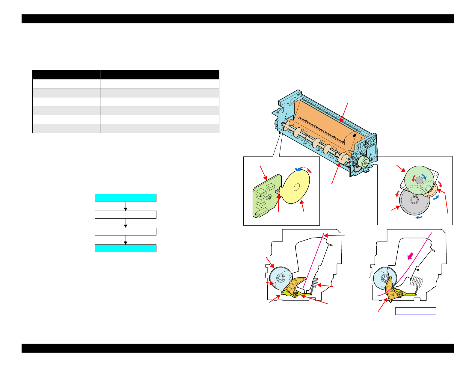
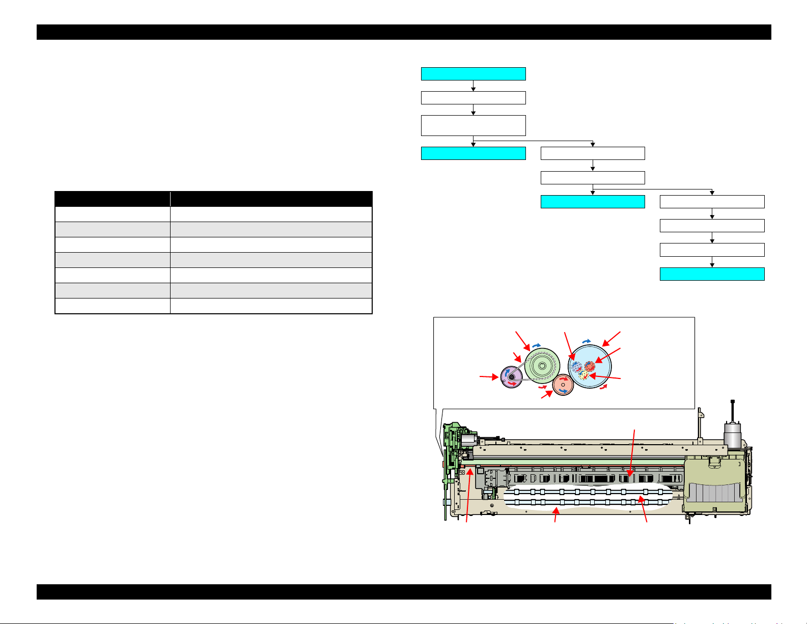
2.2.5 Ink System Mechanism
The Ink System Mechanism consists of the following units.
Pump Unit (including the CR Lock Lever)
Cap Unit
2.2.5.1 Pump Unit
The Pump Unit is designed to suck ink from the Printhead or Cap Unit. The Cap Unit
has a built-in Head Cleaning Wiper.
The following shows the specifications of the stepping motor that drives the Pump
Unit.
Table 2-7. Pump Motor Specifications
Item Specifications
Type 4-phase, 48-pole PM type stepping motor
Drive voltage +42V ± 5% (voltage applied to driver)
Winding resistance 10.3Ω ± 10% (per phase at 25°C)
Inductance 13.4mH ± 20% (1kH,1Vrms)
Drive method Bipolar drive/constant-current drive
Drive IC A6628
The following operations are performed when the drive of the Pump Motor is
transmitted to the Pump Unit.
Table 2-8. Pump Motor Rotation Directions and Functions
Pump Motor Rotation Direction* Functions
• Cap closing
CW direction
CCW direction
Note * : The direction (CW or CCW) was determined by viewing the motor from the output
shaft of the motor mounting plate.
• Ink suction
• Wiper resetting
• CR Lock setting
• Cap opening
• Pump release
• Wiper setting
• CR Lock resetting
OPERATING PRINCIPLES Printer Mechanism 31
Page 32

EPSON Stylus Photo 1400/1410/1430W/1500W/Artisan 1430 Revision B
Pump Motor
Combination Gear 10.2, 21.2 IS
Pump Unit
Spur Gear 20.4 IS
Pump Motor and Motor Pinion Gear
<Pump Unit inside>
Combination Gear 10.2, 21.2 IS
Spur Gear
20.4 IS
Cap Unit Side
To Waste ink pad
2.2.5.2 Drive Transmission Path to Pump Unit
The drive of the Pump Motor is transmitted to the Pump Unit in the following path.
The following shows the internal part names and operation outline of the Pump Unit.
The following shows the Pump Unit operating principle.
Figure 2-10. Pump Unit Operating Principle
Ink Suction
1. The Pinion Gear of the Pump Motor rotates in the CW direction.
2. The Roller turns and simultaneously presses the tube.
3. Ink is fed from the Cap Unit toward the Waste Ink Pad.
Pump Release
1. The Pinion Gear of the Pump Motor rotates in the CCW direction.
2. The Roller moves away from the tube and releases the tube.
3. Ink is not sucked.
Figure 2-9. Outline of Pump Unit Inside
OPERATING PRINCIPLES Printer Mechanism 32
Page 33

EPSON Stylus Photo 1400/1410/1430W/1500W/Artisan 1430 Revision B
Slider cap rises to perform
capping.
Printhead
Cap
Carriage Unit
2.2.5.3 Cap Unit
The Cap Unit is designed to keep inside of the Cap airtight by the Cap sticking to the
Printhead surface with the driving force of the Pump Motor when ink is sucked.
When the printer is in a standby status or its power is OFF, the Cap Unit prevents the
ink from thickening.
The following figures shows the Cap Unit operation.
Figure 2-11. Capping Mechanism
2.2.6 Ink Sequence
The following ink sequence is executed according to various timer, counter, flag and
other information saved on the EEPROM.
Initial Ink Filling
When the printer is powered on for the first time after purchase, the printer
executes the initial ink filling operation to fill the ink cavities of the Head with ink.
When the initial ink filling operation is performed properly, the printer clears the
flag in the EEPROM so that initial ink filling operation will not be performed
when it is powered on the next time. The Stylus Photo 1400/1410 requires about
170 seconds to perform the initial ink filling operation.
If the sequence does not end normally during initial filling, the initial filling flag is
not cleared and the CL operating flag is set. Because of these flags, when powered
on the next time, the printer assumes that it was powered off for some reason
during initial filling and executes CL3 instead of the initial filling sequence. (On
the previous model, initial filling was executed again. However, when this
operation was performed, ink was wasted and therefore CL3 is executed to cover
for the ink filling performance.)
When the initial filling flag is set and the CL operating flag is not set, the printer
judges that the initial filling was not executed at all (power was switched on but
the cartridges were not installed), and when the printer is powered on the next
time, it executes initial filling.
Replacement Cleaning
Replacement cleaning is executed when an Ink Cartridge(s) is replaced.
OPERATING PRINCIPLES Printer Mechanism 33
Page 34

EPSON Stylus Photo 1400/1410/1430W/1500W/Artisan 1430 Revision B
Manual Cleaning
This printer provides three different manual cleanings to remove ink coagulated by
air bubbles, viscous material, or foreign matter. Perform the following manual CL
operations by operating the panel or using the utility included in the printer driver.
Independently of the printing path after the previous CL, perform manual CL from
CL1 to CL3 in order if the cumulative printing timer counter is less than 9 minutes.
When the cumulative printing timer counter is more than 9 minutes, only CL1 is
executed.
Wiping Operation
Clean the nozzle surface, with the right-half of the rubber part on the wiper.
Flushing Operation
Prevent color mixture. Stabilize the ink surface inside the nozzles.
In addition, the printer determines which CL to perform according to the
remaining amount of ink in the Cartridge. When the printer detects the amount is
low, it automatically choose the CL that uses ink less than the other CLs. If the
remaining amount of ink is extremely low (Ink Low or Ink End status), the printer
disables the all the manual cleanings and indicates the status on the STM3.
2.2.7 Power-On Sequence
The following describes the printer operation after it is powered on.
When the Carriage Unit is in the Home Position with the CR Locked
1. After power-on, the drive of the APG Motor is transmitted to the Carriage Shaft,
and the PG position changes from PG Typ. to PG++.
2. The drive of the CR Motor is transmitted to the Carriage Unit, and the Carriage
Unit performs HP detection operation in the following path.
Home position ⇒ Right frame ⇒ CR Lock confirmation position
⇒ Right frame ⇒ Home position
3. The drive of the Pump Motor is transmitted to the Cap Unit, the Cap opens
(lowers), and the CR Lock is released.
4. After the Carriage Unit has moved to the left by the specified number of steps, the
Wiper, driven by the Pump Motor, performs the following.
Timer Cleaning
Ink is consumed depending on the combination of the cumulative printing timer,
cumulative cleaning count and cleaning timer.
Flushing
There are two types of flushing.
Flushing before printing
This is performed to reduce the viscosity of ink in the Printhead nozzles
before starting to print.
Scheduled Flushing
This is performed to prevent ink in the Printhead nozzles from increasing its
viscosity during printing.
Wiper setting ⇒ Wiper resetting
5. The Carriage Unit returns to the home position, and the PG position returns from
PG++ to PG Typ.
6. The drive of the PF Motor is transmitted to the PF Roller and Paper Eject Rollers
(front and rear) to rotate them for predetermined steps.
7. After moving between the left and right frames twice, the Carriage Unit moves to
the right end of the Front Paper Guide.
8. The PF Roller and Paper Eject Rollers (front and rear) rotates.
9. The Carriage Unit returns to the home position and is secured by the CR Lock.
OPERATING PRINCIPLES Printer Mechanism 34
Page 35

EPSON Stylus Photo 1400/1410/1430W/1500W/Artisan 1430 Revision B
PNL Board
MAIN Board
PSB/PSE Power
Supply Board
Power OFF +3.3VDC +42VDC
Printer
Mechanism
CR Motor
PF Motor
ASF Motor
Head drive circuit
Sensors
Pump Motor
APG Motor
When the Carriage Unit is Out of the Home Position
1. When the PG position is other than PG++ after power-on, the drive of the APG
Motor is transmitted to the Carriage Shaft, and the PG position changes to PG++.
2. The drive of the CR Motor is transmitted to the Carriage Unit, and the Carriage
Unit returns to the home position at slow speed.
3. The drive of the PF Motor is transmitted to the PF Roller and Paper Eject Rollers
(front and rear), which then rotate for about 2 seconds.
4. After the Carriage Unit has moved to the left by the specified number of steps, the
Wiper is set by the drive of the Pump.
5. After the Carriage Unit has returned to the home position, it moves to the left again
by the specified number of steps. Then driven by the Pump Motor, ink is sucked in
for about 4 seconds, then the Wiper is set, and the CR Lock is locked.
6. The Carriage Unit performs HP detection operation in the following path.
Home position ⇒ Right frame ⇒ CR Lock confirmation position
⇒ Right frame ⇒ Home position
7. The drive of the Pump Motor is transmitted to the Cap Unit, the Cap opens
(lowers), and the CR Lock is released.
8. The Carriage Unit returns to the home position, and the PG position returns from
PG++ to PG Typ.
9. The PF Motor drive is transmitted to the PF Roller and the Paper EJ Rollers (front
and rear) to rotate them for predetermined steps.
2.3 Electrical Circuit Operating Principles
The electrical circuit of Stylus Photo 1400/1410 consists of the following circuits.
Control circuit board: C655 MAIN
Power supply circuit board: C589 PSB
Control panel board: C589 PNL
Head circuit board: C653 HEAD
The following shows how the four circuit boards are connected.
10. Steps 7 to 9 of "When the Carriage Unit is in the Home Position with the CR
Locked (p34)" is carried out, and the Carriage Unit is locked.
OPERATING PRINCIPLES Electrical Circuit Operating Principles 35
Figure 2-12. Electrical Circuit Block Diagram
Page 36

EPSON Stylus Photo 1400/1410/1430W/1500W/Artisan 1430 Revision B
C51, C52
C11
D11, D12,
D13, D14
C1, FL1F1, TH1
AC Input
QF1
D51
ESAVE
PSC Signal
+5VDC
+3.3VDC
+42VDC
F51
IC51
Over Current
Protection
TRANS: T1
Smoothing
Circuit
Over Current Limitation
Over Voltage Limitation
Secondary Power
Supply SW function
Low Power mode
Separate-excited
Simulated Resonance
Flyback Converter
Filter Circuit
Full Wave
Rectifier
Circuit
Main Switching
Circuit
Smoothing
Circuit
+3.3V Chopper
Circuit
Fuse for LPS
2.3.1 Power Supply Circuit Operating Principle
The power supply circuit board of this product is the C589 PSB.
Basic circuit structure
Flyback switching system
+42VDC and +3.3VDC are supplied to the Printer Mechanism and Control
Board
The following indicates the applications of the voltages generated in this power supply
circuit.
+42VDC
Rated output current: 0.45A
Voltage Applications
+3.3VDC
Rated output current: 0.5A
Table 2-9. Supplied Power
• CR Motor
•PF Motor
•PG Motor
•ASF Motor
• Pump Motor
• Head drive voltage
• Logic sensor circuit
• Sensor circuit
• Nozzle selection circuit (on the Printhead)
• Interface control circuit
The following is a block diagram of the power supply circuit.
OPERATING PRINCIPLES Electrical Circuit Operating Principles 36
Figure 2-13. Power Supply Circuit Block Diagram
Page 37

EPSON Stylus Photo 1400/1410/1430W/1500W/Artisan 1430 Revision B
2.3.2 C655 MAIN Circuit Operating Principle
The C655 MAIN Board consists of the following circuits and sensors.
Logic Circuits (CPU-ASIC 2 in 1, PROM, SDRAM)
Circuits for controlling and driving Motors
(CR Motor, PF Motor, APG Motor, ASF Motor, Pump Motor)
Circuits for controlling and driving the Head
Interface Circuits (USB 2.0)
Sensor Circuits
RTC Circuit
DAC Converter Circuit
Regulator Circuit
Complex Circuit (IC8)
The Complex Circuit (IC8) that consists of EEPROM, RTC, and Reset circuit is
installed in the printer. Employing a large-capacity condenser for the Timer allows
to backup the time recorded at power-off for about a week after the power-off.
OPERATING PRINCIPLES Electrical Circuit Operating Principles 37
Page 38

EPSON Stylus Photo 1400/1410/1430W/1500W/Artisan 1430 Revision B
CPU-ASIC
2 in 1
(IC9)
Data
Address
PROM
(IC6)
SDRAM
(IC7)
USB2.0
CN1
Motor
Driver
(IC11)
Head
Driver
(IC10)
Q6, Q9,
Q10, Q11
CN6
PF Encoder Sensor
Printhead
CR Encoder Sensor
CR Motor
CN5
CN15
CN4
C653 Head Board
C589 PSB/PSE Board
RTC
(IC8)
CN14
PW Sensor
DAC
(IC4)
Motor
Driver
(IC12)
PF Motor
APG Motor
ASF Motor
Pump Motor
CN3
Relay Board
PE Sensor
ASF Sensor
APG Sensor 1
APG Sensor 2
CN10
CN11
CN12
CN7
CN8
CN9
CN13
C589 Panel Board
CD-R Sensor
USB Host
CN2
The following is the block diagram of the C655 MAIN control board.
Figure 2-14. C655 MAIN Control Board Block Diagram
OPERATING PRINCIPLES Electrical Circuit Operating Principles 38
Page 39

EPSON Stylus Photo 1400/1410/1430W/1500W/Artisan 1430 Revision B
OPERATING PRINCIPLES Electrical Circuit Operating Principles 39
Page 40

TROUBLESHOOTING
CHAPTER
3
Page 41

EPSON Stylus Photo 1400/1410/1430W/1500W/Artisan 1430 Revision B
C H E C K
P O I N T
3.1 Overview
Description in this chapter is applied to Stylus Photo 1400/1410, but
some of it can also be applied to Stylus Photo 1430W/1500W/
Artisan1430. Refer to the "8.2 Troubleshooting (p172)" for the
difference from Stylus Photo 1400/1410.
This chapter describes unit-level troubleshooting.
3.1.1 Troubleshooting according to Panel Messages
After checking the printer LED and STM3 error indications, you can grasp the fault location using the check list in this section. When you find the fault location, refer to Chapter 4
“Disassembly and Reassembly” and change the corresponding part and/or unit. The following table indicates the check point reference tables corresponding to the error states (LED
and STM3).
Table 3-1. Reference Tables of Error States
Error State Reference Table
Communication Error Refer to Table 3-2 "Troubleshooting of Communication Error" on page 42
Model Difference Refer to Table 3-2 "Troubleshooting of Communication Error" on page 42
Cover Open (Tray) Error Refer to Table 3-3 "Troubleshooting of Cover Error" on page 45
Paper Out Error Refer to Table 3-4 "Troubleshooting of Paper Out Error" on page 45
Paper Jam Error Refer to Table 3-5 "Troubleshooting of Paper Jam Error" on page 49
Paper Mismatch Error Refer to Table 3-6 "Troubleshooting of Paper Mismatch Error" on page 50
Ink Low Refer to Table 3-7 "Troubleshooting of Ink Low" on page 50
Ink End Error Refer to Table 3-8 "Troubleshooting of Ink End Error" on page 50
No Ink Cartridge/CSIC Error Refer to Table 3-9 "Troubleshooting of No Ink Cartridge/CSIC Error" on page 51
Maintenance Request Error Refer to Table 3-10 "Troubleshooting of Maintenance Request" on page 53
Fatal Error Refer to Table 3-11 "Troubleshooting of Fatal Error" on page 54
TROUBLESHOOTING Overview 41
Page 42

EPSON Stylus Photo 1400/1410/1430W/1500W/Artisan 1430 Revision B
Panel FFC
CN5
Panel FFC
Panel Board
connector
Table 3-2. Troubleshooting of Communication Error
Occurrence
Timing
Phenomenon Detail
At power-on The printer does not operate at
all.
Faulty Part/
Part Name
Panel FFC 1. Check that the Panel FFC is connected to the Panel Board
Connector and Main Board Connector CN5.
Check Point Remedy
1. Connect the Panel FFC to the Panel Board and
Main Board connector CN5.
2. Check the Panel FFC for damages. 2. Replace the Panel FFC with a new one.
Panel Board 1. Check the Panel Board for damages. 1. Replace the Panel Board with a new one.
TROUBLESHOOTING Overview 42
Page 43

EPSON Stylus Photo 1400/1410/1430W/1500W/Artisan 1430 Revision B
Power Supply Board
connector cable
Blue line
Pin 1 side
CN4
Fuse F1
Table 3-2. Troubleshooting of Communication Error
Occurrence
Timing
Phenomenon Detail
At power-on The printer does not operate at
all.
Faulty Part/
Part Name
Power Supply
Board
Check Point Remedy
1. Check that the Connector Cable of the Power Supply Board is
connected to the Main Board Connector CN4.
2. Make sure that the Power Supply Board connector cable is
inserted into the Main Board Connector CN4 with the blue line
on the cable facing the Pin 1 side of the connector as shown in
the picture above.
3. Check that the Fuse F1 on the Power Supply Board has not
blown.
1. Connect the Connector Cable of the Power
Supply Board to the Main Board Connector
CN4.
2. Reconnect the Power Supply Board Connector
cable so that the blue line is inserted into the
Pin 1.
3. Replace the Power Supply Board with a new
one.
4. Check the components on the Power Supply Board for damage. 4. Replace the Power Supply Board with a new
one.
TROUBLESHOOTING Overview 43
Page 44

EPSON Stylus Photo 1400/1410/1430W/1500W/Artisan 1430 Revision B
Relay Connector of
the Pump Motor
Relay Connector of
the ASF Motor
Table 3-2. Troubleshooting of Communication Error
Occurrence
Timing
At power-on After the power-on sequence has
At operation Operation at power-on is normal,
Phenomenon Detail
started, the LED turns off and the
printer does not operate.
but an error appears when the
print job is sent to the printer.
Faulty Part/
Part Name
Main Board 1. Check that the Relay connector of the ASF Motor and the Relay
connector of the Pump Motor are not connected to the wrong
connectors causing a short circuit.
Interface cable 1. Check that the Interface cable is connected between the PC and
the printer.
2. Check the Interface cable for breaking. 2. Replace the Interface cable with a new one.
EPSON
USB driver
USB 1. Check that the PC and printer are connected via the USB hub. 1. Enter the USB serial No. indicated on the
1. When using USB, check that the EPSON USB driver has been
installed on the PC.
Check Point Remedy
1. Connect the Relay Connector of the ASF
Motor and the Relay Connector of the Pump
Motor correctly, and replace the Main Board
with a new one.
1. Connect the Interface cable to the PC and the
printer.
1. Install the EPSON USB driver.
product nameplate.
Refer to Chapter 5 "ADJUSTMENT".
TROUBLESHOOTING Overview 44
Printer Driver 1. Check that the printer driver for Stylus Photo 1400/1410 has
already been installed.
2. Check that the connected printer is Stylus Photo 1400/1410. 2. Connect the Stylus Photo 1400/1410 printer.
Main Board 1. Check that a wrong model name has not been input to the
EEPROM address on the Main Board.
1. Install the printer driver for Stylus Photo 1400/
1410.
1. Using the Adjustment Program, enter the
correct model name.
Refer to Chapter 5"ADJUSTMENT".
Page 45

EPSON Stylus Photo 1400/1410/1430W/1500W/Artisan 1430 Revision B
Cleaning sheet Postcard used
as mount
Non-adhesive part
Adhesive part
This side down
Stapling
Cloth damped
with alcohol
Table 3-3. Troubleshooting of Cover Error
Occurrence
Timing
Phenomenon Detail
During printing A Cover Open (Tray) Error is
indicated during printing.
Occurrence
Timing
Phenomenon Detail
At operation When the Paper button is
pressed, the LD Roller attempt to
feed paper but the paper is not
fed.
Faulty Part/
Part Name
Check Point Remedy
Printer Cover 1. Check that the CD-R Unit is not open. 1. Close the CD-R Unit.
Table 3-4. Troubleshooting of Paper Out Error
Faulty Part/
Part Name
ASF Assy. 1. Check the LD Roller or Retard Roller of the ASF Assy for paper
dust and foreign matter.
Check Point Remedy
1. Using a cleaning sheet (part code:1262115),
clean the LD Roller and Retard Roller.
The procedure is as follows.
(1) Place the cleaning sheet upside down and
put it into the ASF Assy.
(2) Press the Paper button to start paper feed.
(3) Repeat the above steps several times.
* To remove persistent contamination,
staple an alcohol-dampened cloth to a
postcard and clean the rollers in the
following method.
(1) Place the alcohol-dampened cloth facing
to the LD Roller surface of the ASF Assy.
(2) Hold the mount top end securely and
press the Paper button.
(3) Repeat the paper feed sequence several
TROUBLESHOOTING Overview 45
times to clean the LD Roller surface of
the ASF Assy.
Page 46

EPSON Stylus Photo 1400/1410/1430W/1500W/Artisan 1430 Revision B
CN2
PW Sensor Connector
Sensor Holder
Detection Lever
Torsion Spring
Table 3-4. Troubleshooting of Paper Out Error
Occurrence
Timing
Phenomenon Detail
At operation Though paper is fed from the
ASF Assy, it stops near the PE
Sensor Lever.
Faulty Part/
Part Name
Check Point Remedy
PE Sensor 1. Check that the Connector cable of the PE Sensor is securely
connected to the PE Sensor and Relay Board Connector CN2.
2. Check that the Sensor Holder is mounted to the Mechanical
frame correctly.
1. Connect the Connector cable of the PE Sensor
to the PE Sensor and Relay Board Connector
CN2.
2. Install the Sensor Holder correctly.
3. Move the Detection Lever manually as when the paper passes,
and check that the Detection Lever returns to the original
3. Replace the PE Sensor Holder Unit with a new
one.
position automatically by the Torsion Spring when released.
Refer to the above photo.
4. Using a tester, check that the PE Sensor is normal.
⋅ Paper absent: 2.4V or more
4. Replace the PE Sensor Holder Unit with a new
one.
⋅ Paper present: 0.4V or less
TROUBLESHOOTING Overview 46
Page 47

EPSON Stylus Photo 1400/1410/1430W/1500W/Artisan 1430 Revision B
White Markings
HP detection
position
PW sensor
Carriage Unit Bottom
Table 3-4. Troubleshooting of Paper Out Error
Occurrence
Timing
The Paper button
was pressed at the
setting of the CD/
DVD Tray.
Phenomenon Detail
The CD/DVD Tray HP detection
sequence stops and the Tray is
ejected.
The CD/DVD Tray is fed toward
the ASF Assy, but is ejected
immediately.
Faulty Part/
Part Name
Check Point Remedy
CD/DVD Tray 1. Check the HP detection position or white markings of the CD/
DVD Tray for paper dust and foreign matter.
2. Check the Driven Roller surface for contamination such as paper
dust and CD-R coating material.
3. Check that the HP detection position or white markings of the
CD/DVD Tray are not chipped.
PW sensor 1. Check the PW Sensor for contamination such as paper dust,
ink, etc.
1. Remove paper dust and/or foreign matter from
the detection position.
2. Feed A4-size sheets of plain paper from the
ASF Assy several times to remove the
contamination.
3. Replace the CD/DVD Tray with a new one.
1. Clean the PW Sensor surface.
TROUBLESHOOTING Overview 47
2. Compare the EEPROM values in two places and check that they
are not approximated to each other.
2. Replace the PW Sensor with a new one.
Page 48

EPSON Stylus Photo 1400/1410/1430W/1500W/Artisan 1430 Revision B
PW Sensor
Connector
FFC
CR Encoder Board
Connector
Table 3-4. Troubleshooting of Paper Out Error
Occurrence
Timing
The Paper button
was pressed at the
setting of the CD/
DVD Tray.
Phenomenon Detail
The CD/DVD Tray moves
toward the ASF and the back end
of it reaches to the Driven Roller
on the Upper Paper Guide.Then
the CD/DVD Tray tries to go
farther, but it is ejected.
Faulty Part/
Part Name
Check Point Remedy
PW sensor 1. Check that the PW Sensor FFC is placed in the specified routing
positions and it does not make contact with any parts.
2. Check that the PW Sensor FFC is connected to the CR Encoder
Board and PW Sensor Connector. Refer to the above photo.
3. Check the PW Sensor or PW Sensor FFC for damages. 3. Replace the PW Sensor with a new one.
1. Place the PW Sensor FFC in the specified
routing positions.
2. Connect the FFC to the CR Encoder Board and
PW Sensor Connector.
TROUBLESHOOTING Overview 48
Page 49

EPSON Stylus Photo 1400/1410/1430W/1500W/Artisan 1430 Revision B
Paper EJ Frame Assy
Star Wheel Units
Spur Gear 16; B
Spur Gear 68
Table 3-5. Troubleshooting of Paper Jam Error
Occurrence
Timing
At operation At the time of paper ejection, the
Phenomenon Detail
PF Roller advances the paper but
cannot eject it completely.
Paper is not ejected completely
and causes a jam near the Paper
Eject Frame.
Faulty Part/
Part Name
1. Check that the size of the fed paper is not larger than that of the
–
ASF Assy. 1. Check that the paper is fed along the Right Edge Guide. 1. Feed the paper along the Right Edge Guide.
Paper EJ Frame
Assy.
Spur Gear 68
Spur Gear 16; B
Paper EJ Roller
Assy (front/rear)
paper specified by the driver.
1. Check that the Star Wheel Units have not come off the Paper EJ
Frame Assy.
2. Check the Paper EJ Frame Assy for deformation or damages. 2. Replace the Paper EJ Frame Assy with a new
1. Check the Spur Gear 68 or Spur Gear 16; B for damages. 1. Replace the Front (or Rear) Paper EJ Roller
Check Point Remedy
1. Tell the user that the paper size specified by the
driver is not available for the printer.
1. Securely install the Star Wheel Units to the
Paper EJ Frame Assy.
one.
Assy with a new one.
TROUBLESHOOTING Overview 49
Page 50

EPSON Stylus Photo 1400/1410/1430W/1500W/Artisan 1430 Revision B
Panel Board connector
Connector cable of
the CD-R Sensor
CD-R Sensor
Table 3-6. Troubleshooting of Paper Mismatch Error
Occurrence
Timing
At operation When feeding a CD-R (Board
Occurrence
Timing
At operation or
during printing
Phenomenon Detail
Paper), an error is displayed on
the LED and STM3.
Phenomenon Detail
A message is displayed on the
LED and STM3 during
printing.
Faulty Part/
Part Name
Paper EJ Frame
Assy
(CD/DVD Tray
Base)
CD-R Sensor 1. Check that the Connector cable of the CD-R Sensor is securely
1. Check if the CD/DVD Tray Base is closed or not. 1. Open the CD/DVD Tray Base.
connected to the connectors of the CD-R Sensor and Panel
Board.
2. Check the CD-R Sensor or Connector cable for damages. 2. Replace the CD-R Sensor with a new one.
Check Point Remedy
Table 3-7. Troubleshooting of Ink Low
Faulty Part/
Part Name
Ink Cartridge 1. Look at the remaining ink indication of the STM3 to check the
amount of the ink remaining in the Ink Cartridge.
Check Point Remedy
1. Connect the Connector cable of the CD-R
Sensor to the CD-R Sensor and Panel Board
Connectors.
1. Prepare a new Ink Cartridge.
Table 3-8. Troubleshooting of Ink End Error
Occurrence
Timing
During printing After the Carriage has detected
Phenomenon Detail
the HP, an error is displayed on
the LED and STM3.
Faulty Part/
Part Name
Ink Cartridge 1. Look at the remaining ink indication of the STM3 to check
whether the ink remains in the Ink Cartridge.
Check Point Remedy
1. Replace the Ink Cartridge with a new one.
TROUBLESHOOTING Overview 50
Page 51

EPSON Stylus Photo 1400/1410/1430W/1500W/Artisan 1430 Revision B
Tab
Memory Chip
Table 3-9. Troubleshooting of No Ink Cartridge/CSIC Error
Occurrence
Timing
At power-on After the Carriage has detected
Phenomenon Detail
the HP, an error is displayed on
the LED and STM3.
Faulty Part/
Part Name
Ink Cartridge 1. Check that the Ink Cartridge is installed correctly. 1. Install the Ink Cartridge correctly.
2. Check that the tab of the Ink Cartridge is not broken. 2. Replace the Ink Cartridge with a new one.
3. Check that the Memory Chip is not disconnected or not
damaged.
Check Point Remedy
3. Replace the Ink Cartridge with a new one.
TROUBLESHOOTING Overview 51
Page 52

EPSON Stylus Photo 1400/1410/1430W/1500W/Artisan 1430 Revision B
CN15
CSIC Board
Connector
CSIC FFC
CSIC Board
Electrode
Table 3-9. Troubleshooting of No Ink Cartridge/CSIC Error
Occurrence
Timing
Phenomenon Detail
At power-on After the Carriage has detected
the HP, an error is displayed on
the LED and STM3.
Faulty Part/
Part Name
CSIC FFC 1. Check that the CSIC FFC is connected to the CSIC Board
Connector and Main Board Connector CN15.
Check Point Remedy
1. Connect the CSIC FFC to the CSIC Board
Connector and Main Board Connector CN15.
2. Check the CSIC FFC for damage. 2. Replace the CSIC FFC with a new one.
CSIC Board 1. Check the CSIC Board for damage. 1. Replace the CSIC Board with a new one.
TROUBLESHOOTING Overview 52
Carriage Unit 1. Check that the electrodes on the CSIC Board, which make
contact with the Ink Cartridge are not bent.
1. Replace the Carriage Unit with a new one.
Page 53

EPSON Stylus Photo 1400/1410/1430W/1500W/Artisan 1430 Revision B
Table 3-10. Troubleshooting of Maintenance Request
Occurrence
Timing
At power-on At power-on, the printer does not
Phenomenon Detail
operate at all.
Faulty Part/
Part Name
Waste Ink Pads 1. Using the Adjustment Program, check if the Protection Counter
A+B value has exceeded 17455.
Check Point Remedy
1. Replace the Waste Ink Pads and reset the
Protection Counter A and B value in the
Adjustment Program.
TROUBLESHOOTING Overview 53
Page 54

EPSON Stylus Photo 1400/1410/1430W/1500W/Artisan 1430 Revision B
CR Motor
Relay Connector
CN6
Table 3-11. Troubleshooting of Fatal Error
Occurrence
Timing
At power-on At power-on, the CR Motor does
Phenomenon Detail
not operate at all.
Faulty Part/
Part Name
CR Motor 1. Check that the CR Motor connector cable is connected to the
Relay Connector.
2. Check the CR Motor connector cable for damages. 2. Replace the CR Motor with a new one.
3. Check if the CR Motor operates normally. 3. Replace the CR Motor with a new one.
Relay Connector
Cable
(for the CR
Motor)
1. Check that the Relay Connector Cable is connected to the Main
Board Connector CN6.
Check Point Remedy
1. Connect the CR Motor connector to the Relay
Connector.
1. Connect the Relay Connector Cable to the
Main Board Connector CN6.
2. Check the Relay Connector Cable for damages. 2. Replace the Relay Connector Cable with a new
one.
TROUBLESHOOTING Overview 54
Page 55

EPSON Stylus Photo 1400/1410/1430W/1500W/Artisan 1430 Revision B
Carriage Shaft
CN7 PF Motor
Table 3-11. Troubleshooting of Fatal Error
Occurrence
Timing
At power-on The power-on sequence is
Phenomenon Detail
executed but Fatal error is
displayed.
At power-on, the PF Motor does
not operate at all.
Faulty Part/
Part Name
CR drive
mechanism
PF Motor 1. Check that the Connector Cable of the PF Motor is connected to
1. Check that the Carriage Shaft is lubricated with grease. 1. Wipe the surface of the Carriage Shaft with a
the Main Board Connector CN7.
Check Point Remedy
dry, soft cloth, and lubricate the Carriage Shaft
with grease G-71.
Refer to Chapter 6 "MAINTENANCE".
1. Connect the PF Motor connector cable to the
Main Board Connector CN7.
TROUBLESHOOTING Overview 55
2. Check the PF Motor connector cable for damages. 2. Replace the PF Motor with a new one.
3. Check if the PF Motor operates normally. 3. Replace the PF Motor with a new one.
Page 56

EPSON Stylus Photo 1400/1410/1430W/1500W/Artisan 1430 Revision B
CN9
APG Motor
Relay Connector
Table 3-11. Troubleshooting of Fatal Error
Occurrence
Timing
At power-on At power-on, the APG Motor
Phenomenon Detail
does not operate at all.
At power-on, the Pump Motor
does not operate at all.
Faulty Part/
Part Name
APG Motor 1. Check that the Connector Cable of the APG Motor is connected
to the Main Board Connector CN9.
2. Check the APG Motor connector cable for damage. 2. Replace the APG Motor with a new one.
3. Check if the APG Motor operates normally. 3. Replace the APG Motor with a new one.
Pump Motor 1. Check that the Pump Motor connector cable is connected to the
Relay Connector.
Check Point Remedy
1. Connect the APG Motor connector cable to the
Main Board Connector CN9.
1. Connect the Pump Motor connector cable to
the Relay Connector.
2. Using a tester, check the resistance value of the Pump Motor.
Value of resistance: 10.3Ω ± 10%
3. Check the Pump Motor connector cable for damages. 3. Replace the Ink System Unit with a new one.
2. If the resistance value is abnormal, replace the
Ink System Unit with a new one.
TROUBLESHOOTING Overview 56
Page 57

EPSON Stylus Photo 1400/1410/1430W/1500W/Artisan 1430 Revision B
CN8
CN4
CN5
APG Sensors
Table 3-11. Troubleshooting of Fatal Error
Occurrence
Timing
At power-on At power-on, the Pump Motor
Phenomenon Detail
does not operate at all.
While the power-on sequence is
being executed, Fatal error is
displayed.
Faulty Part/
Part Name
Relay Connector
Cable
(for Pump
Motor)
APG Sensor 1. Check that the APG Sensor Connector cables are connected to
1. Check that the Relay Connector Cable is connected to the Main
Board Connector CN8.
2. Check the Relay Connector Cable for damages. 2. Replace the Relay Connector Cable with a new
the APG Sensors and Relay Board Connector CN4 and CN5.
Check Point Remedy
1. Connect the Relay Connector Cable to the
Main Board Connector CN8.
one.
1. Connect the APG Sensor Connector cables to
the APG Sensors and Relay Board Connector
CN4 and CN5.
2. Check the APG Sensors for damages. 2. Replace the APG Sensors with new ones.
TROUBLESHOOTING Overview 57
Page 58

EPSON Stylus Photo 1400/1410/1430W/1500W/Artisan 1430 Revision B
Relay Connector
ASF Motor
CN13
Table 3-11. Troubleshooting of Fatal Error
Occurrence
Timing
At power-on While the power-on sequence is
Phenomenon Detail
being executed, Fatal error is
displayed.
Faulty Part/
Part Name
ASF Motor 1. Check that the Connector cable of the ASF Motor is connected to
the Relay Connector.
2. Using a tester, check the resistance value of the ASF Motor.
Value of resistance: 7.0Ω ± 10%
3. Check the ASF Motor connector cable for damages. 3. Replace the ASF Motor with a new one.
Relay Connector
Cable
(for the ASF
Motor)
1. Check that the Relay Connector Cable is connected to the Main
Board Connector CN13.
Check Point Remedy
1. Connect the Connector cable of the ASF Motor
to the Relay Connector.
2. If the resistance value is abnormal, replace the
ASF Motor with a new one.
1. Connect the Relay Connector Cable to the
Main Board Connector CN13.
2. Check the Relay Connector Cable for damages. 2. Replace the Relay Connector Cable with a new
one.
TROUBLESHOOTING Overview 58
Page 59

EPSON Stylus Photo 1400/1410/1430W/1500W/Artisan 1430 Revision B
CN1
CN5
CR Scale
CR Encoder
Sensor Board
Table 3-11. Troubleshooting of Fatal Error
Occurrence
Timing
Phenomenon Detail
At power-on While the power-on sequence is
being executed, Fatal error is
displayed.
At power-on, the Carriage Unit
moves away from the home
position and bumps against the
right of the Frame, then hits the
left of the Frame.
Faulty Part/
Part Name
Check Point Remedy
Relay FFC 1. Check that the Relay FFC is connected to the Relay Board
Connector CN1 and Main Board Connector CN5.
2. Check the Relay FFC for damages. 2. Replace the Relay FFC Cable with a new one.
CR Scale 1. Check that the CR Scale is inserted in the slit of the CR Encoder
Sensor.
1. Connect the Relay FFC to the Relay Board
Connector CN1 and Main Board Connector
CN5.
1. Insert the CR Scale into the slit of the CR
Encoder Sensor.
2. Check the CR Scale for damages and dirt. 2. Wipe off the dirt completely or replace the CR
Scale with a new one.
CR Encoder
Sensor Board
1. Check the CR Encoder Sensor for paper dust, etc. 1. Remove the paper dust, etc. from the CR
Encoder Sensor.
2. Check the CR Encoder Sensor Board for damages. 2. Replace the CR Encoder Sensor Board with a
new one.
TROUBLESHOOTING Overview 59
Page 60

EPSON Stylus Photo 1400/1410/1430W/1500W/Artisan 1430 Revision B
CN14
CR Encoder Sensor
Board Connector
CN6
PF Encoder Sensor
Board Connector
Table 3-11. Troubleshooting of Fatal Error
Occurrence
Timing
Phenomenon Detail
At power-on At power-on, the Carriage Unit
moves away from the home
position and bumps against the
right of the Frame, then hits the
left of the Frame.
At power-on, the PF Roller
rotates fast about a half turn.
Faulty Part/
Part Name
Check Point Remedy
Sensor FFC 1. Check that the Sensor FFC is connected to the CR Encoder
Sensor Board Connector and Main Board Connector CN14.
2. Check the Sensor FFC for damages. 2. Replace the Sensor FFC with a new one.
PF Encoder
Sensor Holder
1. Check that the PF Encoder Sensor Holder is mounted correctly. 1. Install the PF Encoder Sensor Holder correctly.
2. Check that the FFC of the PF Encoder Sensor is securely
connected to the PF Encoder Sensor Board Connector and Relay
Board Connector CN6.
1. Connect the Sensor FFC to the CR Encoder
Sensor Board Connector and Main Board
Connector CN14.
2. Connect the PF Encoder Sensor FFC to the PF
Encoder Sensor Board and Relay Board
Connector CN6.
3. Check the PF Encoder Sensor for paper dust, etc. 3. Remove the paper dust, etc. from the PF
Encoder Sensor.
4. Check if the PF Encoder or the FFC is damaged. 4. Replace the PF Encoder with a new one.
TROUBLESHOOTING Overview 60
Page 61

EPSON Stylus Photo 1400/1410/1430W/1500W/Artisan 1430 Revision B
Slit
PF Scale
CN10, CN11, CN12, CN14 and CN15
Table 3-11. Troubleshooting of Fatal Error
Occurrence
Timing
At power-on At power-on, the PF Roller
During printing After receiving a print data, or
Phenomenon Detail
rotates fast about a half turn.
while performing the CD/DVD
Tray home position detection
sequence, an error is displayed
on the LED and STM3.
Faulty Part/
Part Name
PF Scale 1. Check that the PF Scale is inserted in the slit of the PF Encoder
Sensor.
2. Check the PF Scale for damages and dirt. 2. Replace the PF Scale with a new one.
CSIC FFC
Head FFC
Sensor FFC
1. Check that the CSIC FFC, Head FFC, and the Sensor FFC are
securely connected to the Main Board Connectors CN10, CN11,
CN12, CN14 and CN15.
Check Point Remedy
1. Install the PF Scale in the slit of the PF
Encoder Sensor correctly.
1. Connect the CSIC FFC, Head FFC, and the
Sensor FFC to the Main Board Connectors
CN10, CN11, CN12, CN14 and CN15.
TROUBLESHOOTING Overview 61
Page 62

EPSON Stylus Photo 1400/1410/1430W/1500W/Artisan 1430 Revision B
Print Head
Connector
Head FFC
CN10, 11, 12
Table 3-11. Troubleshooting of Fatal Error
Occurrence
Timing
During printing After starting to print, ink is not
Phenomenon Detail
ejected and paper stops midway.
Ink is not ejected from most
nozzles.
Faulty Part/
Part Name
Head FFC 1. Check that the Head FFC is securely connected to the Print Head
Connector and Main Board Connectors CN10, CN11 and CN12.
2. Check the Head FFC for damages. 2. Replace the Head FFC with a new one.
Print Head 1. Check for occurrence of Head Hot. 1. Replace the Print Head with a new one.
Check Point Remedy
1. Connect the Head FFC to the Print Head
Connector and Main Board Connectors CN10,
CN11 and CN12.
TROUBLESHOOTING Overview 62
Page 63

EPSON Stylus Photo 1400/1410/1430W/1500W/Artisan 1430 Revision B
Seal Rubbers
Extension Spring, 1.19 IS
Ink Tubes Pump Tube
Connection point
3.1.2 Troubleshooting based on Observed Faults
This section provides troubleshooting procedures based on observed faults such as
print quality troubles and abnormal noise.
Table 3-12. Print Quality Troubles
Observed Faults Details of the Fault
Dot missing and
mixed colors
Inks are not ejected from the
Print Head to the Cap.
Faulty Part/
Part Name
Ink System Unit
(Cap)
Check Point Remedy
1. Check for foreign matter around the Seal Rubber on the Cap Unit. 1. Remove the foreign matter around the Seal
Rubber completely.
2. Check that the Ink Tube is connected to the Pump Tube. 2. Connect the Ink Tube to the Pump Tube
securely.
3. Check that the Extension Spring 1.19 IS is correctly installed to
the Cap Unit.
3. Replace the Ink System Unit with a new one.
TROUBLESHOOTING Overview 63
Page 64

EPSON Stylus Photo 1400/1410/1430W/1500W/Artisan 1430 Revision B
Print Head
Connector
Head FFC
CN10, 11, 12
Cleaner Blade
Table 3-12. Print Quality Troubles
Observed Faults Details of the Fault
Dot missing and
mixed colors
Although inks are ejected from
the Print Head to the Cap, the
trouble still occurs after
executing a cleaning cycle or
replacing the Ink Cartridges.
Faulty Part/
Part Name
Check Point Remedy
Print Head 1. Run a Nozzle Check, and check the printed pattern if it has
broken lines or missing segments.
2. Check that the Head FFC is securely connected to the Print Head
Connector and Main Board Connectors CN10, CN11, and CN12.
3. Check the Head FFC for damages. 3. Replace the Head FFC with a new one.
Ink System Unit
1. Check if the Cleaner Blade is covered with paper dust or is bent. 1. Replace the Ink System Unit with a new one.
Cleaner Blade
1. After running a Head Cleaning, check the
Nozzle Check Pattern again.
2. Connect the Head FFC to the Print Head
Connector and Main Board Connectors CN10,
CN11, and CN12.
If the trouble still occurs after replacing it,
replace the Print Head with a new one.
TROUBLESHOOTING Overview 64
Main Board 1. Check the Main Board for damages. 1. Replace the Main Board with a new one.
Page 65

EPSON Stylus Photo 1400/1410/1430W/1500W/Artisan 1430 Revision B
Print Head
Connector
Head FFC
CN10, 11, 12
Table 3-12. Print Quality Troubles
Observed Faults Details of the Fault
Horizontal or vertical
banding / Getting
smeared
Although inks are ejected from
the Print Head to the Cap, almost
nothing is printed or the print
gets smeared with excessive ink
after executing a cleaning cycle
or replacing the Ink Cartridges.
Faulty Part/
Part Name
Head FFC 1. Check that the Head FFC is securely connected to the Print Head
Connector and Main Board Connectors CN10, CN11, and CN12.
Print Head 1. Check if the print quality recovers after running a cleaning or
replacing the Ink Cartridges.
Main Board 2. Check the Main Board for damages. 2. Replace the Main Board with a new one.
Check Point Remedy
1. Connect the Head FFC to the Print Head
Connector and Main Board Connectors CN10,
CN11, and CN12.
1. Run the cleaning and replace the Ink Cartridges
several times. If the trouble still occurs, replace
the Print Head with a new one.
TROUBLESHOOTING Overview 65
Page 66

EPSON Stylus Photo 1400/1410/1430W/1500W/Artisan 1430 Revision B
Direction of CR
movement
Direction of CR
movement
Table 3-12. Print Quality Troubles
Observed Faults Details of the Fault
Vertical or horizontal
banding / Color
shading
The printout has banding vertical
to the CR moving direction and
is not evenly colored.
* If the trouble still occurs after
doing all measures described
in the right-hand columns,
replace the CR Motor with a
new one.
Narrow stripes of the same width
appear horizontally to the CR
moving direction.
Faulty Part/
Part Name
Adjustment 1. For printing in the Bi-D mode, check that the Bi-D Adjustment
has been performed properly.
Print Head 1. Run a Nozzle Check, and check the printed pattern if it has
broken lines or missing segments.
Carriage Shaft 1. Check the surfaces of the Carriage Shaft for foreign matter. 1. Remove the foreign matter from the Carriage
2. Check that the Carriage Shaft is fully lubricated with grease. 2. Wipe the grease applied to the Carriage Shaft
3. Check that the Carriage Shaft is mounted horizontally. 3. Reassemble the Carriage Shaft correctly.
4. Check the Carriage Shaft for damages. 4. Replace the Carriage Shaft with a new one.
Printer Driver and
the Paper
Print Head 1. Run a Nozzle Check, and check the printed pattern if it has
PF Roller Shaft 1. Check the surface of the PF Roller Shaft for foreign matter. 1. Clean the PF Roller surface carefully.
1. Check if appropriate paper is used in accordance with the Printer
Driver settings.
broken lines or missing segments.
2. Check the PF Roller Shaft for damages. 2. Replace the PF Roller with a new one.
Check Point Remedy
1. Perform Bi-D Adjustment to eliminate
displacements between the upper and lower
lines.
Refer to Chapter 5 "ADJUSTMENT".
1. Perform the Head Cleaning, then check the
Nozzle Check Pattern.
Refer to Chapter 5
If the trouble still occurs, replace the Print Head
with a new one.
Shaft.
with a dry, soft cloth, and then apply G-71
grease.
Refer to Chapter 6 "MAINTENANCE".
1. Use the appropriate type of paper in accordance
with the Printer Driver.
1. Perform the Head Cleaning, then check the
Nozzle Check Pattern.
Refer to Chapter 5
If the trouble still occurs, replace the Print Head
with a new one.
"ADJUSTMENT"
"ADJUSTMENT"
.
.
* If the trouble still occurs after
doing all measures described
in the right-hand columns,
replace the PF Motor with a
new one.
TROUBLESHOOTING Overview 66
Page 67

EPSON Stylus Photo 1400/1410/1430W/1500W/Artisan 1430 Revision B
Star Wheel Rollers
Star Wheel Units
Table 3-12. Print Quality Troubles
Observed Faults Details of the Fault
Vertical or horizontal
banding / Color
shading
Paper EJ Roller
traces appear on the
printout.
When printing at 360 dpi,
horizontal banding and color
unevenness appears at a constant
frequency.
Star Wheel Rollers traces appear
in the CR moving direction.
Printout is faint or blurry.
The bottom of the printout is not
evenly colored.
Traces of the Paper EJ Roller
appear on the printed paper or
CD-R.
Faulty Part/
Part Name
Adjustment 1. Check that PF Adjustment has executed properly. 1. Perform PF Adjustment properly.
2. Check for Dot missing. 2. Replace the Ink System Unit with a new one.
Paper EJ Frame
Assy.
Printer Driver and
the Paper
Print Head 1. Using the Adjustment Program, check that the correct Head ID has
Adjustment 1. Check if the Positioning Adjustment of PF Roller Shaft Retainer
Printer Driver and
the Paper
Front and Rear
Paper EJ Roller
Assys.
1. Check that the Star Wheel Units have not come off or the Star
Wheel Rollers turns normally.
1. Check that adequate paper is used according to the setting of the
Printer Driver.
been written to the EEPROM.
has been performed properly.
1. Check if appropriate paper is used in accordance with the Printer
Driver settings.
1. Check if the Paper EJ Roller is clean or not. 1. Clean the Paper EJ Roller using the Roller
Check Point Remedy
Refer to Chapter 5 "ADJUSTMENT".
1. Install the Star Wheel Units to the Paper EJ
Frame Assy correctly.
1. Use the appropriate type of paper in accordance
with the Printer Driver.
1. Using the Adjustment Program, enter the 31digit code of the Head ID to the EEPROM.
Refer to Chapter 5 "ADJUSTMENT".
1. Make adjustments according to the specified
adjustment priority.
Refer to Chapter 5 "ADJUSTMENT".
1. Use the appropriate type of paper in accordance
with the Printer Driver.
Cleaning Mode.
TROUBLESHOOTING Overview 67
Page 68

EPSON Stylus Photo 1400/1410/1430W/1500W/Artisan 1430 Revision B
Front Paper Guide Pad Front Paper Guide
Table 3-12. Print Quality Troubles
Observed Faults Details of the Fault
The printout is
stained with ink.
The non-printed side or the
bottom of the printout is dirty
with ink.
When the paper size in the sent
print data is larger than the size
of the fed paper, data is printed
on the Front Paper Guide,
extending off the paper.
Ink smudges appear on the blank
area of the printout.
Faulty Part/
Part Name
Front Paper
Guide Pad
PW sensor 1. Check that the PW Sensor FFC is connected. 1. Connect the PW Sensor FFC.
Paper EJ Frame
Assy.
Front Paper
Guide
1. Check if the Front Paper Guide Pad is installed securely and
evenly in the setting position.
2. Check that the PW Sensor is not faulty. 2. Replace the PW Sensor with a new one.
1. Check the Star Wheel Rollers for ink stain. 1. Clean the Star Wheel Rollers with a soft cloth.
1. Check the Front Paper Guide for ink stain. 1. Clean the Front Paper Guide with a soft cloth.
Check Point Remedy
1. If the Ink pads are not securely installed,
reinstall the Front Paper Guide Pad correctly.
TROUBLESHOOTING Overview 68
Page 69

EPSON Stylus Photo 1400/1410/1430W/1500W/Artisan 1430 Revision B
Driven Roller Shaft
Rear Paper EJ Roller AssyFront Paper EJ Roller Assy
Cleaner Blade
Table 3-12. Print Quality Troubles
Observed Faults Details of the Fault
The printout is
stained with ink.
Ink smudges appear on the blank
area of the printout.
Faulty Part/
Part Name
Front and Rear
Paper EJ Roller
Assys
Driven Roller
Shaft
Ink System Unit 1. Check that wiping operation was performed properly. 1. Install the Cleaner blade correctly or replace it
1. Check the Front and Rear Paper EJ Roller Assys for ink stain. 1. Clean the Front and Rear Paper EJ Roller Assys
1. Check the Driven Roller Shaft for ink stain. 1. Clean the Driven Roller Shaft with a soft cloth.
Check Point Remedy
with a soft cloth.
with a new one.
TROUBLESHOOTING Overview 69
Page 70

EPSON Stylus Photo 1400/1410/1430W/1500W/Artisan 1430 Revision B
PF Roller Shaft
Table 3-12. Print Quality Troubles
Observed Faults Details of the Fault
The printout is
stained with ink.
The printout is
grainy.
Regarding hue of
images
Ink smudges appear on the blank
area of the printout.
Images are printed grainy in all
print modes. Or the image looks
rough.
When printed at 5760 dpi, the
printed images are poor or
grainy.
The whole image is reddish. Adjustment
Faulty Part/
Part Name
PF Roller Shaft 1. Check the PF Roller Shaft for ink stain. 1. Clean the PF Roller Shaft with a soft cloth.
Adjustment
Main Board
Print Head
Adjustment
Main Board
Print Head
Print Head
1. Check that PG, Bi-D and Head Angular Adjustments have been
made properly.
2. Print the adjustment check patterns and check if they are grainy. 2. If the images look still grainy after adjustment,
1. After making sure that PG, Bi-D and Head Angular Adjustments
have been made correctly, check whether PW Sensor has been
adjusted properly.
2. Print the adjustment check patterns and check if the printed
images are still poor or grainy.
1. Check if the PG has been adjusted properly. 1. Make the adjustment according to the specified
2. Check that Bi-D and Head Angular Adjustments have been made
properly.
3. Print the adjustment check patterns and check the image color. 3. If the image color does not change after
Check Point Remedy
1. Make the adjustments according to the specified
adjustment priority.
Refer to Chapter 5 "ADJUSTMENT".
replace the Main Board with a new one.
1. Make the adjustment according to the specified
adjustment priority.
Refer to Chapter 5 "ADJUSTMENT".
2. If the image quality does not improve after the
adjustment, replace the Print Head and Main
Board in this order, and check the image
graininess.
adjustment priority.
Refer to Chapter 5 "ADJUSTMENT".
2. Make the adjustments according to the specified
adjustment priority.
Refer to Chapter 5 "ADJUSTMENT".
adjustment, replace the Print Head with a new
one.
TROUBLESHOOTING Overview 70
Page 71

EPSON Stylus Photo 1400/1410/1430W/1500W/Artisan 1430 Revision B
Table 3-12. Print Quality Troubles
Observed Faults Details of the Fault
Borderless Printing Cannot make a borderless
printing (The printer prints with
margins despite the borderless
setting).
Occurrence Timing Details of the Fault
Printing operation is performed
normally but abnormal noise is
produced at power-on or during
–
operations.
Faulty Part/
Part Name
PW sensor 1. Check if the paper dust or scrap of the paper is attached to the
Front Paper Guide.
2. Check that the PW Sensor is operating normally.
Print the adjustment check patterns with the Adjustment Program,
and check that the clip function is executed normally.
(It is judged that the clip function is executed normally if an about
5mm margin is provided on the left of the first gray band pattern
in the patterns.)
Check Point Remedy
1. Remove the paper dust or scrap of the paper.
2. If it is judged that the clip function is not
executed normally, replace the PW sensor with a
new one.
Refer to Chapter 5 "ADJUSTMENT".
Table 3-13. Abnormal Noise
Faulty Part/
Part Name
Adjustment 1. Check that PF Belt Tension Adjustment has been executed
properly.
Carriage Shaft 1. Check that the Carriage Shaft is fully lubricated with grease. 1. Wipe the grease applied to the Carriage Shaft
Check Point Remedy
1. Make the adjustment according to the specified
adjustment priority.
Refer to Chapter 5 "ADJUSTMENT".
with a dry, soft cloth, and then apply grease (G-
71).
Refer to Chapter 6 "MAINTENANCE".
TROUBLESHOOTING Overview 71
Page 72

DISASSEMBLY AND ASSEMBLY
CHAPTER
4
Page 73

EPSON Stylus Photo 1400/1410/1430W/1500W/Artisan 1430 Revision B
C H E C K
P O I N T
W A R N I N G
C A U T I O N
4.1 Overview
Description in this chapter is applied to Stylus Photo 1400/1410, but
some of it can also be applied to Stylus Photo 1430W/1500W/
Artisan 1430. See below and "8.3 Disassembly & Assembly (p173)"
first for other than Stylus Photo 1400/1410.
This chapter describes procedures for disassembling and assembling EPSON Stylus
Photo 1400/1410/1430W/1500W/Artisan 1430. Unless otherwise specified,
disassembled units are reassembled by following the procedures in reverse order.
WARNING
Procedures that must be followed to avoid injury or loss of life.
CAUTION
Procedures that must be followed to avoid damaging the printer or test equipment.
CHECK POINT
Emphasize a particularly important process or procedure.
REASSEMBLY
Indicated when the assembling procedure differs to simple reverse-assembly.
ADJUSTMENT REQUIRED
Indicated if adjustments need to be carried out to complete the repair.
Refer to the exploded diagrams in the Appendix, when disassembling of any unit or
parts that are not described in this chapter.
Always read the precautions described in the next section before starting maintenance/
repair.
4.1.1 Precautions
Prior to disassembling/reassembling this product, always read the following
“WARNING” and “CAUTION” carefully.
Always disconnect the power cable. Working with the power
cable plugged in for cases such as voltage measurement, be
extremely careful not to get an electric shock, and strictly
follow the procedures in this manual.
Wear protective goggles to protect your eyes from ink. If ink
gets in your eyes, wash with clean water and see a doctor.
To prevent injury from sharp metal edges, always wear gloves
for disassembly and reassembly.
If ink gets on your skin, wash with soap and water. If skin
irritation occur, see a doctor.
To protect the microprocessors and circuitry, use static
discharge equipment, such as anti-static wrist straps when
accessing the internal components.
When transporting this printer, remove all cartridges. Remove
Cartridges especially for air transportation, due to reduction of
atmospheric pressure likely to cause ink leakage.
Use only the recommended tools for disassembly, reassembly
and adjustment.
Refer to Table 4-1 "List of Tools".
Tighten screws to the specified torques.
Carry out required adjustments.
Refer to "ADJUSTMENT" on page 128.
Use the specified lubricants and adhesives.
Refer to "MAINTENANCE" on page 145.
When using compressed air products; such as air duster, for
cleaning during repair and maintenance, the use of such
products containing flammable gas is prohibited.
DISASSEMBLY AND ASSEMBLY Overview 73
Page 74

EPSON Stylus Photo 1400/1410/1430W/1500W/Artisan 1430 Revision B
4.1.2 Tools
The following table indicates the tools recommended for disassembly/assembly.
All are commercially available, and should be ready beforehand.
Table 4-1. List of Tools
Tool Name Tool Code
Phillips Screw Driver, No.1 1080530
Phillips Screw Driver, No.2 1080532
Flat-blade Screwdriver 1080527
Tweezers 1080561
Needle nose pliers 1080564
Acetate Tape 1003963
PF Tension Measuring Tool 1231678
Penlight ---
4.1.3 Screws
The following table lists the screws used in this product. When disassembling and
reassembling the printer, refer to the following table and use the specified screws in the
specified positions.
Table 4-2. List of Screw Types
Image Description Image Description
1) C.B.P. 3x10 2) C.B.S. 3x6
3) C.B.S. (P2) 3x10 4) C.B.P. 3x8
5) C.B.S. 3x8 6) C.B.S. (P4) 3x8
7) C.B.P. 2.6x8 8) C.B.S. (P4) 3x6
9) C.B.P. 3x6 10) C.B.S. 3x4
11) C.C. 3x4 12) C.P.B. (P1) 1.7x5
13) C.B.P. 2.6x5 14) C.P.S. 3x10
15) C.B.P. 3x10
DISASSEMBLY AND ASSEMBLY Overview 74
Page 75

EPSON Stylus Photo 1400/1410/1430W/1500W/Artisan 1430 Revision B
4.1.4 Work Completion Checklist
Whenever the printer is serviced, use the checklist shown below to confirm all work is completed properly and the printer is ready to be returned to the user.
Classification Item Check Point Check Field
Main Unit Self-test Is the operation normal?
On-line Test Is the printing attempt successful? Checked / Not necessary
Print Head Is ink discharged normally from all the nozzles?
Carriage Mechanism Does it move smoothly? Checked / Not necessary
Any abnormal noise during the operation?
Are there any dirt or foreign objects on the CR Shaft? Checked / Not necessary
Is the CR Motor at the correct temperature? (Not too hot to touch?)
Paper Feeding
Mechanism
Adjustment Specified Adjustment Are all the adjustments correctly completed? Checked / Not necessary
Lubrication Specified Lubrication Has lubrication been applied at the specified points?
Function ROM Version Version: Checked / Not necessary
Packing Ink Cartridge Have the ink cartridges been removed?
Protective Materials Have all relevant protective materials been attached to the printer? Checked / Not necessary
Others CD/DVD Tray Is the operation normal?
Accessories Have all the accessories sent by the user been included in the package?
Is paper advanced smoothly? Checked / Not necessary
No paper jamming?
No paper skew? Checked / Not necessary
No multiple-sheet feeding?
Is the PF Motor at correct temperature? (Not too hot to touch?) Checked / Not necessary
Any abnormal noise?
Is the paper path free of obstructions? Checked / Not necessary
Is the amount of lubrication correct? Checked / Not necessary
Checked / Not necessary
Checked / Not necessary
Checked / Not necessary
Checked / Not necessary
Checked / Not necessary
Checked / Not necessary
Checked / Not necessary
Checked / Not necessary
Checked / Not necessary
Checked / Not necessary
Checked / Not necessary
DISASSEMBLY AND ASSEMBLY Overview 75
Page 76

EPSON Stylus Photo 1400/1410/1430W/1500W/Artisan 1430 Revision B
C A U T I O N
Main Frame
Main Frame
Main Frame
Main Frame
Main Frame
Board Shield Plate
USB Connector of
PictBridge Unit
Handle part
Clip
7mm
25mm
50mm
Special Tool
4.1.5 Sharp Metal Edges
During disassembly/reassembly of the Stylus Photo 1400/1410,
extra care must be taken to avoid injury from sharp metal edges,
especially from the edges shown below.
4.1.6 Method for making CSIC board removal tool
The CSIC board (refer to p94) can be easily removed by using a special tool. The
method for making the tool is described below.
1. Prepare a handle part of a clip, or a similar metal wire piece.
Figure 4-2. Method for making CSIC Board Removal Tool (1)
2. Bend the metal wire into dimensions described below.
DISASSEMBLY AND ASSEMBLY Overview 76
Figure 4-1. Parts with Sharp Metal Edges
Figure 4-3. Method for making CSIC Board Removal Tool (2)
Page 77

EPSON Stylus Photo 1400/1410/1430W/1500W/Artisan 1430 Revision B
The unit/parts within the broken line is not the shortest removal
procedure for that unit/parts, but is necessary for removing the
unit/parts underneath it.
"CSIC Assy"
4.2.6.2 page 94
4.2.8.4 page 126
"CR Motor"
4.2.7.1 page 122
"CR Scale"
4.2.6.1 page 92
"Paper EJ
Frame Assy"
4.2.6.7 page 106
"APG Assy"
4.2.6.4 page 96
Start
"Board Assy"
4.2.5.1 page 90
"Lower Housing and
Printer Mechanism"
4.2.1.5 page 82
"Upper Housing"
4.2.1.4 page 80
"APG Assy"
4.2.6.4 page 96
"Release Holder Assy"
4.2.6.10 page 113
"FLAG Release Assy"
4.2.6.11 page 114
"PE Sensor Holder"
4.2.8.1 page 124
"Upper Paper
Guide Assys"
4.2.6.12 page 115
"PE Sensor Holder"
4.2.8.1 page 124
"APG Assy"
4.2.6.4 page 96
"Printhead"
4.2.6.3 page 95
"Ink System Unit"
4.2.6.13 page 117
"Upper Paper
Guide Assys"
4.2.6.12 page 115
"PF Roller Shaft"
4.2.6.14 page 119
"Waste Ink Pad"
4.2.2 page 84
"Front Paper Guide
Pad"
4.2.3 page 85
"PF Motor"
4.2.7.2 page 123
"Carriage Shaft
and Carriage Unit"
4.2.6.5 page 98
"PictBridge Unit"
4.2.6.6 page 105
4.2.6.9 page 110
"Front Paper Guide and
Paper Eject Roller"
"PF Encoder
Sensor Holder"
"PF Encoder
Sensor Holder"
4.2.8.3 page 126
"CR Encoder
Sensor Board"
4.2.8.4 page 126
"PW Sensor"
4.2.8.2 page 125
"CD-R Release
Lever Sub Assy"
4.2.6.8 page 107
"Side Housing"
4.2.1.2 page 78
"ASF Assy"
4.2.4 page 86
"Rear Housing"
4.2.1.1 page 78
4.2 Disassembly/Assembly Procedures
The flowchart below lists the step-by-step disassembly procedures. When disassembling each unit, refer to the page number shown in the figure.
Figure 4-4. Disassembly Flowchart
DISASSEMBLY AND ASSEMBLY Disassembly/Assembly Procedures 77
Page 78

EPSON Stylus Photo 1400/1410/1430W/1500W/Artisan 1430 Revision B
IEEE Cover
1) C.B.P. 3x10
(6±1 kgf.cm)
1) C.B.P. 3x10
(6±1 kgf.cm)
2) C.B.S. 3x6
(6±1 kgf.cm)
Rear Housing
Rib
Side Housing
Positioning
Holes
Tabs
Guide Pins
Cutouts
4.2.1 Removing the Housings
4.2.1.1 Rear Housing
1. Remove the IEEE Cover like opening it from the left.
2. Remove the four C.B.P. 3x10 screws and the C.B.S. 3x6 screw that secure the
Rear Housing, and remove the Rear Housing.
4.2.1.2 Side Housing
1. Remove the Rear Housing. See Section 4.2.1.1 on page 78.
2. Insert a flat-blade screwdriver into the cutouts of the Lower Housing, and lift it in
the direction of the arrow to remove the Left Side Housing releasing the two tabs.
Remove the Right Side Housing in the same way.
Figure 4-7. Removing the Side Housing
Match the positioning holes of the Upper Housing with the guide
pins of the Side Housing.
Figure 4-5. Removing the Rear Housing
Install the IEEE Cover to the Rear Housing, facing the side of the
rib to the right.
Figure 4-8. Installing the Side Housing
DISASSEMBLY AND ASSEMBLY Disassembly/Assembly Procedures 78
Figure 4-6. Installing the IEEE Cover
Page 79

EPSON Stylus Photo 1400/1410/1430W/1500W/Artisan 1430 Revision B
CCW
CW
White Shaft
C A U T I O N
PG Cam (Right)
Interference
point
Paper EJ Frame
PG ++ position
Carriage
Unit
4.2.1.3 Locking/Releasing the Carriage and Opening/Closing
the CD-R Unit
Locking/releasing the Carriage and opening/closing the CD-R Unit are mutually
related. The CD-R Unit cannot be opened when the Carriage Lock is released.
1. Remove the Right Side Housing. See section 4.2.1.2 on page 78.
2. Insert the flat-blade screwdriver into the hole on the right side of the frame, and
rotate the white shaft of the Ink System Unit.
Table 4-3. Relation between Carriage Lock and CD-R Unit
Direction of Rotation Carriage CD-R Unit
Clockwise (CW) Locked Can be opened/closed.
Counterclockwise (CCW) Released Locked
When moving the Carriage Unit with the CD-R Unit opened, turn
the PG CAM (Right) beforehand so that PG ++ points downwards
to release the PG in order to prevent interference between the
Paper EJ Frame and Carriage Unit.
Figure 4-10. Interference between the Frame and Carriage Unit
Figure 4-9. Locking/Releasing the Carriage and Opening/Closing the CD-R Unit
DISASSEMBLY AND ASSEMBLY Disassembly/Assembly Procedures 79
Page 80

EPSON Stylus Photo 1400/1410/1430W/1500W/Artisan 1430 Revision B
Paper
Support
1
Guide Pin
3
Guide Pin
5
4
9
Tab
2
6
Tab
7
8
1) C.B.P. 3x10
(6±1 kgf.cm)
2) C.B.S. 3x6
(6±1 kgf.cm)
15) C.B.P. 3x10
(6±1 kgf.cm)
Upper
Housing
Printer Cover
CD-R Unit
Tabs
CN2
CN1
Panel FFC
Guide Pin
CD-R Sensor
Cable
4.2.1.4 Upper Housing
1. Remove the Side Housing. See Section 4.2.1.2 on page 78.
2. Open the Printer Cover and Paper Support.
3. Open the Front Cover. See section 4.2.1.3 on page 79.
4. Remove the four C.B.P. 3x10 screws, three C.B.S. 3x6 screws, and two C.B.P.
3x10 screws that secure the Upper Housing.
5. Disconnect the Panel FFC and CD-R Sensor Cable from connectors CN1 and CN2
on the Switch Board, and release the CD-R Sensor Cable from the tabs of the
Upper Housing.
Figure 4-12. Disconnecting the CD-R Sensor Cable and Panel FFC
6. Remove the Guide Pins from the two tabs shown in Figure 4-11, and remove the
Upper Housing upwards.
DISASSEMBLY AND ASSEMBLY Disassembly/Assembly Procedures 80
Figure 4-11. Screws that Secure the Upper Housing
Housing. See Figure 4-11.
When inserting the CD-R Sensor Cable into the Switch Board,
press the connector to make sure that it is firmly installed on
the Switch Board.
Referring to Figure 4-12, correctly route the Panel FFC and
CD-R Sensor Cable.
Tighten the screws in the order shown in Figure 4-11.
Align the Guide Pins with the positioning holes of the Upper
Page 81

EPSON Stylus Photo 1400/1410/1430W/1500W/Artisan 1430 Revision B
4) C.B.P. 3x8
(6±1 kgf.cm)
Right Printer Cover Holder
Left Printer Cover Holder
Guide Pin on the Upper Housing
Cutout on the Printer Cover
Upper Housing
Printer Cover
PRINTER COVER
1. Remove the two C.B.P. 3x8 screws that secure the Left Printer Cover Holder, and
draw it out in the direction of the arrow.
Remove the Right Printer Cover Holder in the same way.
Figure 4-13. Removing the Printer Cover Holder
2. Lift the Upper Housing in the direction of the arrows, pull the Guide Pin on the
Upper Housing away from the cutout on the Printer Cover, and remove the Printer
Cover.
Figure 4-14. Removing the Printer Cover
DISASSEMBLY AND ASSEMBLY Disassembly/Assembly Procedures 81
Page 82

EPSON Stylus Photo 1400/1410/1430W/1500W/Artisan 1430 Revision B
C A U T I O N
Handling Positions
1
3
4
Step 2
Ink Tubes
Waste Ink Tubes
Fastener
2
1) C.B.P. 3x10
(6±1 kgf.cm)
Printer Mechanism
1) C.B.P. 3x10
(6±1 kgf.cm)
6
Acetate Tape
5
3) C.B.S. (P2) 3x10
(6±1 kgf.cm)
Lower Housing
4.2.1.5 Lower Housing and Printer Mechanism
1. Remove the Upper Housing. See Section 4.2.1.4 on page 80.
2. Grip both ends of the Ink Tube Fastener with your fingers, slide it in the direction
of the arrows, and draw out the Waste Ink Tube from the Ink Tube.
3. Remove the acetate tape that secure the PictBridge Unit Connector Cable to the
Lower Housing.
4. Remove the four C.B.P. 3x10 screws and two C.B.S. (P2) 3x10 screws that secure
the Printer Mechanism.
See the page given below to check for sharp metal edges before
starting maintenance/repair.
• "Sharp Metal Edges" on page 76.
Always hold the positions indicated in the figure when handling
the Printer Mechanism to avoid deformation of the frames.
5. Hold the Printer Mechanism by its handling positions with both hands, and remove
DISASSEMBLY AND ASSEMBLY Disassembly/Assembly Procedures 82
Figure 4-15. Handling of the Printer Mechanism
it from the Lower Housing.
Figure 4-16. Screws that Secure the Printer Mechanism
Page 83

EPSON Stylus Photo 1400/1410/1430W/1500W/Artisan 1430 Revision B
Ink TubeWaste Ink Tube
Positioning Hole and
Dowel
Lower Housing
PictBridge Unit
3
A D J U S T M E N T
R E Q U I R E D
18mm
40mm
CN2
Acetate Tape position
Insert the Waste Ink Tube with the red line into the Ink Tube.
Figure 4-17. Installing the Ink Tubes
Make sure that the Waste Ink Tubes are not nipped by the
Printer Mechanism.
When installing the Printer Mechanism, match the positioning
hole of the PictBridge Unit to the dowel of the Lower Housing.
Figure 4-18. Installing the Printer Mechanism (1)
Tighten the screws in the order shown in Figure 4-16.
Secure the bracket of the PictBridge and the Printer
Mechanism together with screw .
When installing the Printer Mechanism, check that the
PictBridge Unit cable is secured to the Main Frame with
Acetate tape, and be careful not to pinch it. (For Acetate Tape
position of the PictBridge Unit cable, refer to "PictBridge Unit"
on page 105.)
Fix the PictBridge Unit cable to the Lower Housing with acetate
tape as shown below.
• Left edge: Align with the right edge of CN2
• Top edge: Do not cover the chips on the Main board.
Figure 4-19. Installing the Printer Mechanism (2)
After replacing the Printer Mechanism, be sure to make the
following adjustments.
1. Platen Gap (PG) Adjustment (p.129)
2. Head Angular Adjustment (p.130)
3. Auto Bi-D Adjustment (p.130)
4. First dot position (p.130)
5. PW Sensor Adjustment (p.130)
6. PF Deterioration Compensation Counter Reset (p.130)
7. PF Adjustment (p.130)
8. PF Adjustment (Bottom Margin) (p.130)
9. CR Motor Drive Dispersion Measurement Sequence (p.130)
Refer to Chapter 5 “Adjustment” for details on the adjustments.
DISASSEMBLY AND ASSEMBLY Disassembly/Assembly Procedures 83
Page 84

EPSON Stylus Photo 1400/1410/1430W/1500W/Artisan 1430 Revision B
4) C.B.P. 3x8
(6±1 kgf.cm)
Waste Ink Pads
A D J U S T M E N T
R E Q U I R E D
Waste Ink Tubes
1
2
1
2
3
4
Installation
Order
Installation
Order
4.2.2 Waste Ink Pad
1. Remove the Lower Housing. See section 4.2.1.5 on page 82.
2. Remove the C.B.P. 3x8 screw that secures the Waste Ink Tube.
3. Remove the 11 Waste Ink Pads from the Lower Housing.
Route the Waste Ink Tube as shown below.
Figure 4-21. Positions of Waste Ink Tubes
Referring to Figure 4-22, correctly install the Waste Ink Pads.
Figure 4-20. Removing the Waste Ink Pads
Figure 4-22. Installing the Waste Ink Pads
After replacing or removing the Waste ink Pads, be sure to make
the following adjustments.
Waste Ink Protection Counter Reset (p.131)
Refer to Chapter 5 “Adjustment” for details on the adjustment.
DISASSEMBLY AND ASSEMBLY Disassembly/Assembly Procedures 84
Page 85

EPSON Stylus Photo 1400/1410/1430W/1500W/Artisan 1430 Revision B
C A U T I O N
Front Paper Guide
Front Paper Guide Pads
Front Paper Guide Pad
Protection
Tabs
Tabs
OK
NG
4.2.3 Front Paper Guide Pad
1. Remove the Printer Mechanism. See section 4.2.1.5 on page 82.
2. Remove the Front Paper Guide Pads and Front Paper Guide Pad Protection from
the Front Paper Guide with tweezers.
After installing the Front Paper Guide Pads and Front Paper Guide
Pad Protection, lift the Printer Mechanism, and check the following
points.
1. Make sure that the tabs on the Pads are not cut midway.
2. Make sure that all tabs are in place on the Front Paper
Guide, and that they are facing down (toward the Waste Ink
Pads) without any folds.
3. Make sure that the turned edges of the tabs are protruding
completely from the Front Paper Guide.
Figure 4-24. Installing the Front Paper Guide Pad (1)
4. Make sure that the Pad is placed under a tab of the Front
Paper Guide.
DISASSEMBLY AND ASSEMBLY Disassembly/Assembly Procedures 85
Figure 4-23. Removing the Front Paper Guide Pads and
the Front Paper Guide Pad Protection
Make sure that the grease contained in the Front Paper Guide Pads
and the Front Paper Guide Pad Protection do not stick to other
parts.
Figure 4-25. Installing the Front Paper Guide Pad (2)
5. Make sure that all the tabs on the Pads are fitted into the
securing section under the Front Paper Guide.
Page 86

EPSON Stylus Photo 1400/1410/1430W/1500W/Artisan 1430 Revision B
5) C.B.S. 3x8
(8±1 kgf.cm)
Relay
Connector
Earth Cables
Relay
Connector
Cable
Ferrite Core
ASF Motor
ASF Assy
Two-sided
Tapes
CN5, CN10, CN11,
CN12, CN14, CN15
Main Board
Relay Board
PF Encoder Sensor FFC
Acetate Tape 1
Groove
APG Motor Cable
PE Sensor Cable
Acetate Tape 2
4.2.4 ASF Assy
1. Remove the Upper Housing. See Section 4.2.1.4 on page 80.
2. Remove the screw C.B.S. 3x8 that secures the Earth Cables positioned on the right
rear side of the printer, and remove the Earth Cables.
3. Disconnect the ASF Motor Connector from the Relay Connector.
4. Disconnect the Relay Connector Cable from the ASF Assy.
5. Disconnect all the Cables and the FFCs from the connectors on the Relay Board.
CN1 : Relay FFC
CN2 : PE Sensor Cable
CN4 : APG Sensor Cable (downside)
CN5 : APG Sensor Cable (the upper side)
CN6 : PF Encoder Sensor FFC
6. Disconnect the FFC bundled by the Acetate Tape 2 from the connectors (CN5,
CN10, CN11, CN12, CN14, CN15) on the Main Board, and release it from the
groove of the ASF Assy.
7. Remove the Acetate Tape 2, and disconnect the APG Motor Cable and PE Sensor
Cable from the ASF Assy.
8. Peel off the PF Encoder FFC secured by two pieces of double-sided adhesive tape
from the ASF Assy.
Figure 4-26. Releasing the Cables (1)
Secure the two Earth Cables together with the screw.
Referring to Figure 4-26, correctly route the Relay Connector
DISASSEMBLY AND ASSEMBLY Disassembly/Assembly Procedures 86
Cable.
Figure 4-27. Releasing the Cables (2)
Page 87

EPSON Stylus Photo 1400/1410/1430W/1500W/Artisan 1430 Revision B
5mm
Acetate Tape 2
APG Motor Cable
3mm
FFC
CN15
Acetate Tape
2) C.B.S. 3x6
(8±1 kgf.cm)
Front
Face
Guide Pin
Tab
LD Roller Shaft
Guide Roller LD
Guide Roller LD
9. Remove the two C.B.S. 3x6 screws that secure the two Guide Roller LDs.
Referring to Figure 4-27, route each of the Cables and FFCs.
After routing the APG Motor Cable to the rib of the ASF Assy,
secure it with the Acetate Tape 2 as shown below.
Figure 4-28. Installing the Acetate Tape 2
When installing the FFC to the connector (CN15), secure it with
acetate tape as shown below.
10. Gently pull the LD Roller Shaft to the rear of the printer, and remove the Guide
Roller LDs.
Figure 4-30. Removing the Guide Roller LD
Align the Guide Pins and tabs on the Guide Roller LDs with the
DISASSEMBLY AND ASSEMBLY Disassembly/Assembly Procedures 87
Figure 4-29. Installing the Acetate Tape
positioning holes on the Main Frame. See Figure 4-30.
Page 88

EPSON Stylus Photo 1400/1410/1430W/1500W/Artisan 1430 Revision B
2
1
6) C.B.S. (P4) 3x8
(8±1 kgf.cm)
ASF Assy
6) C.B.S. (P4) 3x8
(8±1 kgf.cm)
34
Tab
Guide Pin
Tab
Tab
Tab
11. Remove the three C.B.S. (P4) 3x8 screws that secure the ASF Assy, and remove
the ASF Assy from the Printer Mechanism.
Align the Guide Pin and four tabs on the ASF Assy with the
positioning holes on the Main Frame so that there is no gap
between the ASF Assy and the Main Frame.
Figure 4-31. Removing the ASF Assy
Figure 4-32. Installing the ASF Assy
Tighten the screws in the order shown in Figure 4-31.
DISASSEMBLY AND ASSEMBLY Disassembly/Assembly Procedures 88
Page 89

EPSON Stylus Photo 1400/1410/1430W/1500W/Artisan 1430 Revision B
Combination Gear 29.11
Hopper Pad
LD Roller
Gap of the ASF Assy
Retard Roller
Holder Tab
Reference
Tabs
Cutout
Reference Tabs Retard Roller Holder Tab
Lower Limit
Upper Limit
Adjusting the Position of the ASF Guide Roller LDs
In order to maintain the paper feed accuracy, when installing
the Guide Roller LDs, the position of the Guide Roller LDs
must be adjusted so that the positions of the LD Roller Shaft
and Retard Roller are optimized.
1. After installing the ASF Assy, loosen the two screws (2)
C.B.S. 3x6) that secure the Guide Roller LD. See Figure
4-30.
2. Turn Combination Gear 29.11 on the right side of the ASF
Assy CCW to raise the Hopper to the upper limit position
(until the Hopper Pad contacts the LD Roller).
3. With a penlight, light through the gap of the ASF Assy to check
that the tab on the Retard Roller Holder at the back of the two
Reference tabs on the ASF Assy can be seen. After making sure
that the two Reference tabs are aligned when viewed edge-on,
adjust the position of the Retard Roller Holder tab by
pressing the Guide Roller LD (0 digit side) so that it is placed
within the range as shown in the simplified diagram below.
DISASSEMBLY AND ASSEMBLY Disassembly/Assembly Procedures 89
Figure 4-33. Raising the Hopper
Figure 4-34. Aligning the Position of the Guide Roller LD
(0 Digit Side)
Page 90

EPSON Stylus Photo 1400/1410/1430W/1500W/Artisan 1430 Revision B
A D J U S T M E N T
R E Q U I R E D
Gap
Tab
Guide Pin
Table 4-4. Trouble Caused by Setting Mistakes
Tab Position Trouble
Over the upper
limit
• Paper feeding problems caused by non-feed
Under the
lower limit
• Multiple-sheet feeding
C A U T I O N
14) C.P.S. 3x10
(6±1 kgf.cm)
5
6
2) C.B.S. 3x6
(6±1 kgf.cm)
1
2
3
4
Board Assy
3) C.B.S. (P2) 3x10
(6±1 kgf.cm)
4. Align the Guide Pin and the tab on the 0 Digit Side Guide
Roller LD with the positioning holes on the Main Frame,
and tighten the Guide Roller LD (0 Digit Side) with the
screws. See Figure 4-35.
5. Check the position of the Retard Roller Holder tab again
through the gap. If it is not inside the range, remove the
screws on the Guide Roller LD (0 Digit Side), and repeat
steps 2 to 4 to set the tab within the range.
6. Check the clearance in both ends of the positioning hole that
the Guide Roller LD tab is inserted, and align Guide Roller
LD (130 Digit Side) to the same height, and tighten with the
screws.
Figure 4-35. Checking the Position of Tab on the Guide Roller LD
4.2.5 Removing the Boards
4.2.5.1 Board Assy
1. Remove the Rear Housing. See Section 4.2.1.1 on page 78.
2. Remove the four screws (2) C.B.S. 3x6), two screws (3) C.B.S. (P2) 3x10), and
the screw (14) C.P.S. 3x10) that secure the Board Assy.
After replacing or removing the ASF Assy, always make the
following adjustment.
First dot position (p.130)
Refer to Chapter 5 “Adjustment” for details on the adjustments.
DISASSEMBLY AND ASSEMBLY Disassembly/Assembly Procedures 90
Figure 4-36. Screws that Secure the Board Assy
Tighten the screws in the order shown in Figure 4-36.
See the page given below to check for sharp metal edges before
starting maintenance/repair.
• "Sharp Metal Edges" on page 76.
When performing the following procedure, prevent the FFC
and Connector Cables from being scratched.
Page 91

EPSON Stylus Photo 1400/1410/1430W/1500W/Artisan 1430 Revision B
FFCs and Connectors
Interference
point
Board Assy
Manual Paper
Guide
Radiation Plates
Grounding Plates
3mm
FFC
CN15
Acetate Tape
3. Disconnect all the FFCs and Connector Cables connected to the Board Assy in
order from the front, then draw out the Board Assy from the Printer taking care of
the interference between the Manual Paper Guide and the Radiation Plates on the
Board Assy.
CN2: USB Host (PictBridge)
CN3: Relay Board FFC
CN5: Operation Panel FFC
CN6: Relay Connector Cable (for CR Motor)
CN7: PF Motor Connector Cable
CN8: Relay Connector Cable (for Pump Motor)
CN9: APG Motor Connector Cable
CN10: Head FFC
CN11: Head FFC
CN12: Head FFC
CN13: Relay Connector Cable (for ASF Motor)
CN14: CR Encoder Sensor/PW Sensor FFC
CN15: CSIC FFC
Make sure that the FFCs are not crossing each other, and
connect the FFCs and Connector Cables to the Main Board
while paying attention to the edges of the Shield Plate.
Take care not to put the Board Assy onto the three Ground
Plates.
Figure 4-38. Installing the Board Assy (1)
When installing the FFC to the connector (CN15), secure it
with acetate tape as shown below.
DISASSEMBLY AND ASSEMBLY Disassembly/Assembly Procedures 91
Figure 4-37. Removing the Board Assy
Figure 4-39. Installing the Board Assy (2)
Page 92

EPSON Stylus Photo 1400/1410/1430W/1500W/Artisan 1430 Revision B
A D J U S T M E N T
R E Q U I R E D
C A U T I O N
Step 3
Step 4
Right CR Shaft
Mounting Plate
Tab
CR Scale
The following adjustment must be performed after replacing
the Main Board.
• When possible to read data from the old board
1. Main Board Data Read/Write (p.129)
• When impossible to read data from the old board
1. Market & Initial Settings (p.129)
2. USB ID Input (p.129)
3. Head ID Input (p.129)
4. Head Angular Adjustment (p.130)
5. Auto Bi-D Adjustment (p.130)
6. First dot position (p.130)
7. PW Sensor Adjustment (p.130)
8. Reset PF Deterioration counter
(write the maximum value) (p.130)
9. PF Adjustment (p.130)
10. PF Adjustment (Bottom Margin) (p.130)
11. CR Motor Drive Dispersion (p.130)
Refer to Chapter 5 “Adjustment” for details on the adjustments.
After replacing the Power Supply Board, the following
adjustment must be performed.
• CR Motor Drive Dispersion (p.130)
Refer to Chapter 5 “Adjustment” for details on the adjustments.
4.2.6 Disassembling the Printer Mechanism
4.2.6.1 CR Scale
1. Remove the Upper Housing. See Section 4.2.1.4 on page 80.
2. Release the Carriage lock, and move the Carriage Unit to the center.
See section 4.2.1.3 on page 79.
When performing the following procedure, take care not to damage
or break the ends of the CR Scale.
3. Pull the right end of the CR Scale in the direction of the arrow, and remove the CR
Scale from the tab on the Right CR Shaft Mounting Plate.
4. Draw out the right end of the CR Scale toward the left direction from the rear of
the Carriage Unit.
Figure 4-40. Drawing Out the CR Scale
DISASSEMBLY AND ASSEMBLY Disassembly/Assembly Procedures 92
Page 93

EPSON Stylus Photo 1400/1410/1430W/1500W/Artisan 1430 Revision B
Left CR Shaft
Mounting Plate
Torsion Spring 24.7
Tab
Step 6-1
Step 6-2
Step 6-3
Foot 1
Cutout
Tab
5. Release the coil section of Torsion Spring 24.7 from the tab on the Left CR Shaft
Mounting Plate with tweezers.
Figure 4-41. Removing the Torsion Spring 24.7 (1)
6. Remove Torsion Spring 24.7 from the CR Scale following the next steps:
6-1. Bring the coil section to an upright position.
6-2. Push downwards to release foot 1 from the cutout on the Left CR Shaft
Mounting Plate.
6-3. Turn the coil section counterclockwise.
6-4. Remove Torsion Spring 24.7 from the hole on the CR Scale.
7. Turn the CR Scale 90°, and remove it from the tab on the Left CR Shaft Mounting
Plate.
Figure 4-43. Removing the CR Scale
Figure 4-42. Removing the Torsion Spring 24.7 (2)
DISASSEMBLY AND ASSEMBLY Disassembly/Assembly Procedures 93
Page 94

EPSON Stylus Photo 1400/1410/1430W/1500W/Artisan 1430 Revision B
CR Encoder
CR Scale
CR Scale
Chipped edge
OK
NG
CR Scale
Hooked Portion
C A U T I O N
Head FFC Cover Hinge
Tab
Dowel
Ink Cartridge Cover Head FFC Cover
Tab A
Carriage Unit
Tab A
Pass the CR Scale through the slit of the CR Encoder.
Figure 4-44. Installing the CR Scale (1)
Set the CR Scale so that the chipped edge come to the top left
corner.
4.2.6.2 CSIC Assy
When removing the Head FFC Guide, do not use tools with
sharp ends as the FFC may get damaged.
Be careful not to break the Tabs of the FFC Guide.
1. Remove the CR Scale. See Section 4.2.6.1 on page 92.
2. Open the Cartridge Cover and remove all Ink Cartridges.
3. Disengage the two tabs of the Head FFC Cover, and while disengaging the dowel
with a flathead screw driver, slide it upward, and rotate it around the Hinge by 90°.
Place the right end of the CR Scale correctly so that it is not
hooked onto the hooked portion of the Right CR Shaft
Mounting Plate.
DISASSEMBLY AND ASSEMBLY Disassembly/Assembly Procedures 94
Figure 4-45. Installing the CR Scale (2)
Figure 4-46. Installing the CR Scale (3)
Figure 4-47. Removing the Head FFC Cover
4. Using the special tool (refer to p76), disengage tab A of the CSIC Assy on the right
rear side of the Carriage Unit.
Figure 4-48. Removing the CSIC Assy (1)
Page 95

EPSON Stylus Photo 1400/1410/1430W/1500W/Artisan 1430 Revision B
Tab B
Carriage Unit
Tab B
Removal Direction
CSIC Assy
CSIC FFC
Rear side of CSIC Assy
Connector
Hook
7) C.B.P. 2.6x8
(3±0.5 kgf.cm)
1
2
3
Head FFC
5. Using the special tool (refer to p76), disengage tab B of the CSIC Assy on the right
rear side of the Carriage Unit.
Figure 4-49. Removing the CSIC Assy (2)
6. Lift up the CSIC Assy from the Carriage Unit to disconnect the CSIC FFC, and
remove the CSIC Assy.
4.2.6.3 Printhead
1. Remove the CSIC Assy. See Section 4.2.6.2 on page 94.
2. Remove the three C.B.P. 2.6x8 screws that secure the Printhead using Phillips
Screw Driver, No.1, and remove the Printhead by lifting it up vertically.
Figure 4-51. Removing the Printhead (1)
3. Disconnect the two Head FFCs on the back side, and remove the Printhead.
Figure 4-50. Removing the CSIC Assy (3)
DISASSEMBLY AND ASSEMBLY Disassembly/Assembly Procedures 95
Figure 4-52. Removing the Printhead (2)
Page 96

EPSON Stylus Photo 1400/1410/1430W/1500W/Artisan 1430 Revision B
A D J U S T M E N T
R E Q U I R E D
CN9
APG Motor
APG Assy
APG Sensor Connectors
Acetate Tape
3
1
2
2) C.B.S. 3x6
(8±1 kgf.cm)
Tighten the screws in the order shown in Figure 4-51.
After replacing or removing the Printhead, the following
adjustment must be performed.
1. PG Adjustment (p.129)
2. Head ID Input (only after replacing) (p.129)
3. Head Angular Adjustment (p.130)
4. Auto Bi-D Adjustment (p.130)
5. First dot position (p.130)
6. PW Sensor Adjustment (p.130)
Refer to Chapter 5 “Adjustment” for details on the adjustments.
4.2.6.4 APG Assy
1. Remove the Upper Housing. See Section 4.2.1.4 on page 80.
2. Disconnect the APF Motor Cable from connector CN9 (red) on the Main Board
3. Remove the acetate tape, and remove the Cable from the ASF Assy.
4. Disconnect the Connector Cables from the two APG Sensor Connectors.
Figure 4-53. Disconnecting the Connector Cables
5. Remove the three C.B.S. 3x6 screws that secure the APG Assy and remove the
APG Assy from the Main Frame.
Figure 4-54. Removing the APG Assy
DISASSEMBLY AND ASSEMBLY Disassembly/Assembly Procedures 96
Page 97

EPSON Stylus Photo 1400/1410/1430W/1500W/Artisan 1430 Revision B
FLAG Release Assy
Released
Not Released
Upper Paper Guide
Delta Marks
Spur Gear 16
Combination Gear
22, 28.8, 32.4
Delta Marks
Tab
Spur Gear 16 PG Cam (Left)
When installing the APG Assy, make sure that the FLAG
Release Assy is NOT in a released state (with the Upper Paper
Guide down).
Figure 4-55. Installing the APG Assy
Refer to Figure 4-53, and route the APG Connector Cables
correctly.
Match the phase of the APG Assy following the next steps.
1. Match the delta marks of Spur Gear 16 and Combination
Gear 22, 28.8, 32.4.
2. At the position where the tab can be identified through the
cutout of the PG Frame, match the delta marks of Spur
Gear 16 and PG Cam (Left).
DISASSEMBLY AND ASSEMBLY Disassembly/Assembly Procedures 97
Figure 4-56. Phase Matching
Tighten the screws in the order shown in Figure 4-54.
Page 98

EPSON Stylus Photo 1400/1410/1430W/1500W/Artisan 1430 Revision B
PG Cam (Right)
1
2
2) C.B.S. 3x6
(8±1 kgf.cm)
Tab
Tabs
Left Frame Support Plate
Paper EJ Frame Assy
Cutout
Left PG Torsion Spring
Tab A
Tab B
4.2.6.5 Carriage Shaft and Carriage Unit
1. Remove the APG Assy. See Section 4.2.6.4 on page 96.
2. Turn the PG Cam (Right) around so that any mark other than PG++ comes to the
bottom.
Figure 4-57. Setting the PG Cam
3. Remove the two C.B.S. 3x6 screws that secure the Frame Support Plate (Left), and
remove it.
Insert the Left Frame Support Plate into the cutout of the Main
Frame. See Figure 4-58.
Align the two tabs on the Main Frame and the tab on the Paper
EJ Frame Assy with the three positioning holes on the Left
Frame Support Plate. See Figure 4-58.
Align the tab (rear side) of the Left Frame Support Plate with
the outside of the Left CR Shaft Mounting Plate. See Figure
4-58.
Tighten the screws in the order shown in Figure 4-58.
4. Remove the foot of Left PG Torsion Spring from Tab A, and release the coil
section from Tab B to remove Left PG Torsion Spring from the Main Frame.
Figure 4-59. Removing the Left PG Torsion Spring
DISASSEMBLY AND ASSEMBLY Disassembly/Assembly Procedures 98
Figure 4-58. Removing the Left Frame Support Plate
Page 99

EPSON Stylus Photo 1400/1410/1430W/1500W/Artisan 1430 Revision B
Right PG Torsion Spring
Tab A
Tab B
Foot
Left Side
Foot
Right Side
Cutout (rear side)
Tab
CR Shaft Mounting Plate Fixed Spring
Cutout
5. Remove the foot of Right PG Torsion Spring from Tab A, and release the coil
section from Tab B to remove the Right PG Torsion Spring from the Main Frame.
Figure 4-60. Removing the Right PG Torsion Spring
Place the feet of Left PG Torsion Spring and Right PG Torsion
Spring on the Carriage Shaft.
6. Remove CR Shaft Mounting Plate Fixed Spring from the tab and cutout on the
Main Frame, and draw out the spring in the direction of the arrow.
Figure 4-62. Removing the CR Shaft Mounting Plate Fixed Spring
Insert the foot of CR Shaft Mounting Plate Fixed Spring into the
cutout of the Main Frame (rear side). See Figure 4-62.
DISASSEMBLY AND ASSEMBLY Disassembly/Assembly Procedures 99
Figure 4-61. Installing the PG Torsion Springs
Page 100

EPSON Stylus Photo 1400/1410/1430W/1500W/Artisan 1430 Revision B
Tabs
Extension Spring for the
Driven Pulley Holder
Driven Pulley Holder
Driven Pulley Holder
CR Drive Belt
CR Motor Pinion Gear
4
3
2
1
8) C.B.S. (P4) 3x6
(8±1 kgf.cm)
8) C.B.S. (P4) 3x6
(8±1 kgf.cm)
CR Guide Plate
Tabs
7. Remove the Extension Spring for the Driven Pulley Holder from the Main Frame
and the tab on the Drive Pulley Holder with needle-nose pliers.
Figure 4-63. Removing the Extension Spring for the Driven Pulley Holder
8. Slide the Driven Pulley Holder to the right end of the cutout on the Main Frame,
then remove it toward you.
9. Remove the CR Drive Belt from the CR Motor Pinion Gear.
Figure 4-65. Removing the CR Drive Belt
10. Remove the four C.B.S. (P4) 3x6 screws that secure the CR Guide plate, and
remove it from the Main Frame.
Figure 4-66. Removing the CR Guide Plate
Figure 4-64. Removing the Driven Pulley Holder
Align the positioning holes of the CR Guide Plate with the seven
tabs on the Main Frame. See Figure 4-66.
Tighten the screws in the order shown in Figure 4-66.
DISASSEMBLY AND ASSEMBLY Disassembly/Assembly Procedures 100
 Loading...