

Page 1
SERVICE MANUAL
Large Format Color Inkjet Printer
SC-T7000 series SC-T5000 series SC-T3000 series
Confidential
SEIJ12008
Page 2

Notice:
All rights reserved. No part of this manual may be reproduced, stored in a retrieval system, or transmitted in any form or by any means, electronic,
mechanical, photocopying, recording, or otherwise, without the prior written permission of SEIKO EPSON CORPORATION.
The contents of this manual are subject to change without notice.
All efforts have been made to ensure the accuracy of the contents of this manual. However, should any errors be detected, SEIKO EPSON would greatly
appreciate being informed of them.
The above not withstanding SEIKO EPSON CORPORATION can assume no responsibility for any errors in this manual or the consequences thereof.
EPSON is a registered trademark of SEIKO EPSON CORPORATION.
General Notice: Other product names used herein are for identification purpose only and may be trademarks or registered trademarks of their
respective owners. EPSON disclaims any and all rights in those marks.
Copyright © 2012 SEIKO EPSON CORPORATION.
COMMERCIAL PRINTER CS QUALITY ASSURANCE DEPARTMENT
Confidential
Page 3

PRECAUTIONS
Precautionary notations throughout the text are categorized relative to 1) Personal injury and 2) Damage to equipment.
DANGER Signals a precaution which, if ignored, could result in serious or fatal personal injury. Great caution should be exercised in performing
procedures preceded by DANGER Headings.
WARNING Signals a precaution which, if ignored, could result in damage to equipment.
The precautionary measures itemized below should always be observed when performing repair/maintenance procedures.
DANGER
1. ALWAYS DISCONNECT THE PRODUCT FROM THE POWER SOURCE AND PERIPHERAL DEVICES PERFORMING ANY MAINTENANCE OR
REPAIR PROCEDURES.
2. NO WORK SHOULD BE PERFORMED ON THE UNIT BY PERSONS UNFAMILIAR WITH BASIC SAFETY MEASURES AS DICTATED FOR ALL
ELECTRONICS TECHNICIANS IN THEIR LINE OF WORK.
3. WHEN PERFORMING TESTING AS DICTATED WITHIN THIS MANUAL, DO NOT CONNECT THE UNIT TO A POWER SOURCE UNTIL
INSTRUCTED TO DO SO. WHEN THE POWER SUPPLY CABLE MUST BE CONNECTED, USE EXTREME CAUTION IN WORKING ON POWER
SUPPLY AND OTHER ELECTRONIC COMPONENTS.
4. WHEN DISASSEMBLING OR ASSEMBLING A PRODUCT, MAKE SURE TO WEAR GLOVES TO AVOID INJURY FROM METAL PARTS WITH
SHARP EDGES.
WARNING
1. REPAIRS ON EPSON PRODUCT SHOULD BE PERFORMED ONLY BY AN EPSON CERTIFIED REPAIR TECHNICIAN.
2. MAKE CERTAIN THAT THE SOURCE VOLTAGES IS THE SAME AS THE RATED VOLTAGE, LISTED ON THE SERIAL NUMBER/RATING
PLATE. IF THE EPSON PRODUCT HAS A PRIMARY AC RATING DIFFERENT FROM AVAILABLE POWER SOURCE, DO NOT CONNECT IT TO
THE POWER SOURCE.
3. ALWAYS VERIFY THAT THE EPSON PRODUCT HAS BEEN DISCONNECTED FROM THE POWER SOURCE BEFORE REMOVING OR
REPLACING PRINTED CIRCUIT BOARDS AND/OR INDIVIDUAL CHIPS.
4. IN ORDER TO PROTECT SENSITIVE MICROPROCESSORS AND CIRCUITRY, USE STATIC DISCHARGE EQUIPMENT, SUCH AS ANTI-STATIC
WRIST STRAPS, WHEN ACCESSING INTERNAL COMPONENTS.
5. REPLACE MALFUNCTIONING COMPONENTS ONLY WITH THOSE COMPONENTS BY THE MANUFACTURE; INTRODUCTION OF SECONDSOURCE ICs OR OTHER NON-APPROVED COMPONENTS MAY DAMAGE THE PRODUCT AND VOID ANY APPLICABLE EPSON WARRANTY.
6. WHEN AIR DUSTER IS USED ON THE REPAIR AND THE MAINTENANCE WORK, THE USE OF THE AIR DUSTER PRODUCTS CONTAINING
THE INFLAMMABLE GAS IS PROHIBITED.
7. MAKE SURE AN ANTIVIRUS SOFTWARE IS INSTALLED ON THE COMPUTER USED FOR SERVICE SUPPORT. BE SURE TO HAVE THE
LATEST VIRUS DEFINITION FILE FOR THE SOFTWARE.
Confidential
Page 4

About This Manual
This manual describes basic functions, theory of electrical and mechanical operations, maintenance and repair procedures of the printer. The instructions and procedures included
herein are intended for the experienced repair technicians, and attention should be given to the precautions on the preceding page.
Manual Configuration
This manual consists of six chapters and Appendix.
CHAPTER 1.PRODUCT DESCRIPTIONS
Provides a general overview and specifications of the product.
CHAPTER 2.TROUBLESHOOTING
Describes the step-by-step procedures for the troubleshooting.
CHAPTER 3.DISASSEMBLY / ASSEMBLY
Describes the step-by-step procedures for disassembling and assembling the product.
CHAPTER 4.ADJUSTMENT
Provides Epson-approved methods for adjustment.
CHAPTER 5.MAINTENANCE
Provides preventive maintenance procedures and the lists of Epson-approved lubricants and
adhesives required for servicing the product.
CHAPTER 6.APPENDIX
Provides the following additional information for reference:
• Connectors
• Panel Menu Maps
• ASP List
• Exploded Diagrams
Confidential
Page 5

Symbols Used in this Manual
Lubrication
Various symbols are used throughout this manual either to provide additional information on a specific topic or to warn of possible danger present during a procedure or an action.
Be aware of all symbols when they are used, and always read NOTE, CAUTION, or WARNING messages.
Indicates an operating or maintenance procedure, practice or condition that is necessary to keep the product’s quality.
Indicates an operating or maintenance procedure, practice, or condition that, if not strictly observed, could result in damage to, or destruction of, equipment.
May indicate an operating or maintenance procedure, practice or condition that is necessary to accomplish a task efficiently. It may also provide additional
information that is related to a specific subject, or comment on the results achieved through a previous action.
Indicates an operating or maintenance procedure, practice or condition that, if not strictly observed, could result in injury or loss of life.
Indicates that a particular task must be carried out according to a certain standard after disassembly and before re-assembly, otherwise the quality of the components
in question may be adversely affected.
Lubrication
Indicates that lubrication is needed for the parts after disassembly, when doing a maintenance or replacing a part with a new one.
Confidential
Page 6

Revision Status
Revision Date of Issue Description
A October 1, 2012 First release
Chapter 2
• 2.3Remedies for Service Call Error(p.43):partially deleted
B March 6, 2013
Chapter4
• 4.1.2Adjustment Items and the Order by Repaired Part(p.199):partially revised
• 4.14.1Main Board initial setting(p.270):was added
Confidential
Page 7

SC-T7000 series/SC-T5000 series/SC-T3000 series Revision B
Contents
Chapter 1 PRODUCT DESCRIPTION
1.1 Product Description ............................................................................................ 11
1.2 Basic Specifications ............................................................................................ 12
1.2.1 Basic Specifications ................................................................................... 12
1.2.2 Electric Specifications ............................................................................... 12
1.2.3 Ink Specifications ...................................................................................... 13
1.3 Printing Specifications ........................................................................................ 14
1.3.1 Paper Feed Specifications .......................................................................... 14
1.3.2 Supported Media ........................................................................................ 15
1.3.2.1 Epson Special Media Table ................................................................ 15
1.3.2.2 Usable Commercially Available Paper Size ...................................... 18
1.3.3 Printable area ............................................................................................. 20
1.3.4 Borderless Printing Specification .............................................................. 21
1.3.5 Stacker ....................................................................................................... 21
1.4 Hardware Specifications ..................................................................................... 22
1.4.1 Dimensions and Weight ............................................................................. 22
1.4.2 Installation Room Requirement ................................................................. 22
1.4.3 Part Names ................................................................................................. 23
1.5 Control Panel Specifications .............................................................................. 25
1.5.1 Control panel and LCD .............................................................................. 25
1.5.2 Menu Descriptions ..................................................................................... 27
1.5.3 Serviceman Mode ...................................................................................... 36
Chapter 2 TROUBLE SHOOTING
2.1 Overview ............................................................................................................ 40
2.1.1 Preliminary Check ..................................................................................... 40
2.1.1.1 Before performing troubleshooting .................................................... 40
2.1.1.2 Check for the usage environment ....................................................... 40
2.1.1.3 Recurrence check of the trouble ......................................................... 40
2.1.1.4 Check for the counter values/history .................................................. 40
2.1.1.5 Test print check .................................................................................. 40
2.1.2 Troubleshooting Procedure ........................................................................ 41
2.1.3 Procedure after troubleshooting ................................................................. 41
2.1.3.1 If the trouble has been successfully solved ........................................ 41
2.1.3.2 If necessary to escalate the trouble case ............................................. 41
2.2 Remedies for Maintenance Requests ................................................................. 42
2.3 Remedies for Service Call Error ........................................................................ 43
2.4 Remedies for Print Quality Troubles .................................................................. 58
2.5 Trouble on Paper Feeding .................................................................................. 62
2.6 Other Troubles .................................................................................................... 63
2.7 Trouble on Service Program ............................................................................... 64
2.8 Trouble on NVRAM Viewer .............................................................................. 65
Chapter 3 DISASSEMBLY & ASSEMBLY
3.1 Overview ............................................................................................................ 67
3.1.1 Precautions ................................................................................................. 67
3.1.2 Cautions after assembling .......................................................................... 69
3.1.3 Orientation Definition ................................................................................ 69
3.1.4 Recommended Tools ................................................................................. 70
3.2 Parts Diagram ..................................................................................................... 71
3.3 Disassembly Flowchart ...................................................................................... 78
3.4 Disassembly and Assembly Procedure ............................................................... 83
3.4.1 Preparation for servicing ........................................................................... 83
3.4.1.1 Unlocking the CR Unit ....................................................................... 83
3.4.2 Housing ...................................................................................................... 85
3.4.2.1 TOP COVER ...................................................................................... 85
3.4.2.2 FRONT COVER ................................................................................ 86
3.4.2.3 LOWER PAPER GUIDE ................................................................... 87
3.4.2.4 LOWER PAPER GUIDE B ............................................................... 88
3.4.2.5 IH COVER ......................................................................................... 89
3.4.2.6 WASTE INK TANK COVER ........................................................... 92
3.4.2.7 PRINTER COVER ............................................................................. 93
3.4.2.8 UPPER SUPPORT R COVER ........................................................... 94
3.4.2.9 RIGHT UPPER COVER & RIGHT ROLL COVER ........................ 95
3.4.2.10 RIGHT LOWER COVER ................................................................ 96
7
Confidential
Page 8

SC-T7000 series/SC-T5000 series/SC-T3000 series Revision B
3.4.2.11 RIGHT BASE COVER .................................................................... 97
3.4.2.12 LEFT LOWER COVER ................................................................... 98
3.4.2.13 REAR RIGHT LOWER COVER .................................................... 99
3.4.2.14 UPPER LEFT COVER .................................................................. 100
3.4.2.15 LEFT UPPER COVER & LEFT ROLL COVER .......................... 101
3.4.2.16 LEFT BASE COVER ..................................................................... 102
3.4.2.17 FRONT LEFT LOWER COVER ................................................... 103
3.4.2.18 REAR LEFT LOWER COVER ..................................................... 104
3.4.2.19 REAR ROLL COVER FRAME ..................................................... 105
3.4.2.20 CARTRIDGE COVER SENSOR .................................................. 106
3.4.2.21 R WASTE INK COVER SENSOR ................................................ 107
3.4.2.22 L WASTE INK COVER SENSOR ................................................ 108
3.4.2.23 INTERLOCK SWITCH ................................................................. 109
3.4.3 Electric Circuit Components .................................................................... 111
3.4.3.1 MAIN BOARD ................................................................................ 111
3.4.3.2 MAIN-B BOARD ............................................................................ 113
3.4.3.3 MAIN-C BOARD ............................................................................ 114
3.4.3.4 SUB BOARD ................................................................................... 115
3.4.3.5 SUB-B BOARD ............................................................................... 117
3.4.3.6 PSH BOARD .................................................................................... 118
3.4.3.7 PANEL BOARD .............................................................................. 120
3.4.4 Carriage Mechanism / Ink System Mechanism ....................................... 122
3.4.4.1 CR COVER ...................................................................................... 122
3.4.4.2 DAMPER KIT .................................................................................. 123
3.4.4.3 PRINT HEAD .................................................................................. 126
3.4.4.4 HEAD FFC ....................................................................................... 127
3.4.4.5 CR FFC ............................................................................................. 131
3.4.4.6 CR SCALE ....................................................................................... 135
3.4.4.7 CR ENCODER ................................................................................. 138
3.4.4.8 CR TIMMING BELT ....................................................................... 139
3.4.4.9 CR MOTOR ..................................................................................... 141
3.4.4.10 CR HP SENSOR ............................................................................ 143
3.4.4.11 APG UNIT ..................................................................................... 144
3.4.4.12 PG SENSOR ................................................................................... 146
3.4.4.13 PUMP CAP UNIT .......................................................................... 147
3.4.4.14 IC HOLDER ................................................................................... 148
3.4.4.15 INK TUBE ..................................................................................... 152
3.4.4.16 CR UNIT ........................................................................................ 156
3.4.4.17 IM SENSOR ................................................................................... 159
3.4.4.18 PW SENSOR .................................................................................. 161
3.4.5 Paper Feed Mechanism ............................................................................ 163
3.4.5.1 PF MOTOR ...................................................................................... 163
3.4.5.2 PF SCALE ........................................................................................ 165
3.4.5.3 PF ENCODER .................................................................................. 166
3.4.5.4 PF TIMING BELT ........................................................................... 168
3.4.5.5 PRESSURE ROLLER ...................................................................... 170
3.4.5.6 PRESSURE ROLLER MOTOR ...................................................... 171
3.4.5.7 PRESSURE ROLLER SENSOR ..................................................... 173
3.4.5.8 ATC MOTOR .................................................................................. 175
3.4.5.9 PE SENSOR (ROLL PAPER) ......................................................... 177
3.4.5.10 PE SENSOR (THICK PAPER) ...................................................... 178
3.4.5.11 PAPER THICKNESS SENSOR .................................................... 180
3.4.6 Cutter Mechanism .................................................................................... 181
3.4.6.1 CUTTER UNIT ................................................................................ 181
3.4.7 Fans .......................................................................................................... 183
3.4.7.1 BOARD BOX FAN ......................................................................... 183
3.4.7.2 SUCTION FAN ................................................................................ 184
3.4.8 Auto Take-up Reel ................................................................................... 185
3.4.8.1 TAKE-UP REEL COVER ............................................................... 185
3.4.8.2 TAKE-UP REEL SENSOR ............................................................. 186
3.4.8.3 TAKE-UP REEL LED ..................................................................... 187
3.4.8.4 TAKE-UP REEL SWITCH ............................................................. 188
3.4.8.5 TAKE-UP REEL PS BOARD ......................................................... 190
3.4.8.6 TAKE-UP REEL MOTOR .............................................................. 192
3.4.8.7 TAKE-UP REEL MAIN BOARD ................................................... 194
Chapter 4 ADJUSTMENT
4.1 Overview .......................................................................................................... 198
4.1.1 Precautions ............................................................................................... 198
4.1.2 Adjustment Items and the Order by Repaired Part .................................. 199
4.1.3 Adjustment Items ..................................................................................... 211
4.1.4 List of Tools/Software/Consumables for Adjustments ........................... 219
4.1.5 Service Program Basic Operations .......................................................... 220
4.2 NV-RAM BACKUP/NVRAM Viewer ............................................................ 221
4.2.1 NVRAM Read Procedure ........................................................................ 221
4.2.2 NVRAM Write Procedure ....................................................................... 221
4.2.3 NVRAM Viewer Basic Operation ........................................................... 222
4.3 ADJUSTMENTS (Individual) ......................................................................... 227
4.4 ADJUSTMENTS (Sequence) ........................................................................... 228
8
Confidential
Page 9

SC-T7000 series/SC-T5000 series/SC-T3000 series Revision B
4.5 Installing Firmware .......................................................................................... 229
4.6 Image Print ....................................................................................................... 230
4.7 Counter Reset ................................................................................................... 231
4.8 References ........................................................................................................ 232
4.9 Initial Ink Charge Flag ...................................................................................... 233
4.10 CR Related Adjustments ................................................................................ 234
4.10.1 CR Belt Tension Check ......................................................................... 234
4.10.2 APG Function Check ............................................................................. 237
4.10.3 Ink Mark Sensor Check & Auto Adjustment ........................................ 238
4.10.4 CR Scale Check ..................................................................................... 239
4.10.5 CR Active Damper Auto Adjustment .................................................... 240
4.10.6 Auto Uni-D Adjustment ........................................................................ 241
4.10.7 Auto Bi-D Adjustment, acceleration/deceleration print correction ....... 242
4.10.8 PW + T&B&S check and adjustment .................................................... 243
4.10.8.1 PW Adjustment .............................................................................. 243
4.10.8.2 T&B&S Adjustment ....................................................................... 243
4.10.9 PG Adjustment ....................................................................................... 245
4.11 Head Related Checks and Adjustments .......................................................... 248
4.11.1 Tube Inner Pressure Reduction .............................................................. 248
4.11.2 Head ID Input ........................................................................................ 249
4.11.3 Nozzle Check ......................................................................................... 251
4.11.4 Cleaning ................................................................................................. 252
4.11.5 Head Inclination Adjustment (CR direction) ......................................... 253
4.11.5.1 Head Inclination Auto Adjustment (CR direction) ........................ 253
4.11.5.2 Head Inclination Manual Adjustment (CR direction) .................... 254
4.11.5.3 Correcting Head Inclination (CR direction) ................................... 254
4.11.6 Head Slant Adjustment (PF direction) ................................................... 256
4.11.6.1 Head Slant Auto Adjustment (PF direction) .................................. 256
4.11.6.2 Head Slant Manual Adjustment (PF direction) .............................. 257
4.11.6.3 Correcting Head Slant (PF direction) ............................................. 258
4.12 Ink Supply Related Checks and Adjustments ................................................ 259
4.12.1 Ink eject ................................................................................................. 259
4.12.2 Cleaning (Tube Inner Cleaning) ............................................................ 260
4.12.3 Initial Ink Charge ................................................................................... 261
4.13 Media Feed Related Checks and Adjustments ............................................... 262
4.13.1 PF Belt Tension Check .......................................................................... 262
4.13.2 PC Scale Check ...................................................................................... 264
4.13.3 Media Feed Auto Adjustment ................................................................ 265
4.13.4 Cut Position Check & Adjustment ........................................................ 266
4.13.5 Paper Thickness Sensor Adjustment ..................................................... 267
4.13.6 Rear AD Adjustment ............................................................................. 269
4.14 Boards Related Checks and Adjustments ....................................................... 270
4.14.1 Main Board initial setting ...................................................................... 270
4.14.2 RTC & USB ID Input ............................................................................ 271
4.14.3 MAC Address Input ............................................................................... 272
4.14.4 Serial Number Input .............................................................................. 273
4.14.5 HDD S/N Information Writing .............................................................. 274
4.14.6 Board Replacement Date & Time Setting ............................................. 275
4.15 Other Printer Checks and Adjustments .......................................................... 276
4.15.1 Suction Fan Adjustment ........................................................................ 276
4.15.2 Panel Setting Reset & Job History Reset ............................................... 277
4.15.3 Operation Panel Check (LCD & Buttons) ............................................. 278
4.15.3.1 Panel LCD Operation Check .......................................................... 278
4.15.3.2 Panel Buttons Operation Check ..................................................... 278
4.15.4 Motor Measurement & Automatic Adjustment ..................................... 279
Chapter 5 MAINTENANCE
5.1 Overview .......................................................................................................... 281
5.2 Storing the Printer ............................................................................................ 282
5.3 Transportation .................................................................................................. 283
5.4 Exchange Parts ................................................................................................. 284
5.5 Cleaning ............................................................................................................ 285
5.6 Lubrication ....................................................................................................... 287
Chapter 6 APPENDIX
6.1 Block Wiring Diagram ..................................................................................... 291
6.1.1 Main Body ............................................................................................... 291
6.1.2 Auto Take-up Reel ................................................................................... 292
6.2 Connection Diagram ......................................................................................... 293
6.3 Panel Menu Map .............................................................................................. 309
6.4 Part names used in this manual ........................................................................ 312
6.5 Exploded Diagram/Parts List ........................................................................... 314
9
Confidential
Page 10

PRODUCT DESCRIPTION
CHAPTER
1
Confidential
Page 11

SC-T7000 series/SC-T5000 series/SC-T3000 series Revision B
1.1 Product Description
Models
SC-T7000 series: 1118 mm (44 inch); supports Super B0
SC-T5000 series: 914 mm (36 inch); supports Super A0
SC-T3000 series: 620 mm (24 inch); supports Super A1
Supported paper thickness
Up to 1.5 mm
Ink configuration
Brand-new water color pigment ink configuration with excellent black tone
important in quality CAD line drawing and highly vivid red essential for
commercial posters
Ink configuration: Cyan, Yellow, Magenta, Matte black, Photo black
High-speed throughput
Prints A1 plain paper in 28sec.
High print quality
For posters:
Excellent print quality in 4 colors, with resolution of up to 2800x1440
dpi, and in variable dot sizes (minimal 3.5 picoliter)
Space saving design
Front access design allows you to set the printer near a wall because you can
exchange the media, ink cartridges, maintenance box, and cutter from the front.
New driver and applications
Brand-new driver with simple UI
With the web UI OS-independent configuration and control of HDD through
the Web are available.
Provides the job monitoring and management functions using a job
monitoring tool.
Easy printing from Microsoft Office using dedicated plug-in software
Improved shorter occupancy time of the host PC
Occupancy time of the host PC has been significantly shortened with ESC/
Page and HP-GL2/RTL.
By adding the optional HDD unit, PC-less re-printing and more shortened
occupancy time become available.
Lower running cost
Independent ink cartridges for each color
high-capacity (700ml/350ml/150ml) ink cartridges
PC-less enlarged photocopy
For CAD:
High quality CAD line drawing achieved by optimizing the
combination of new inks and print modes
Media handling
Easier paper loading available thanks to the design for front-access and
spindle-less with optimal height based on ergonomics
Supports continuous printing of drawings or posters (in a standard size such as
A0, A1 or US-ANSI D/E)
Translucent printer cover allows you to check which roll paper is loaded
easily
Simply connecting a scanner enables PC-less enlarged photocopy.
Large sized LEDs
Equipped with large-sized LEDs for easier recognition of the printer’s error status
PRODUCT DESCRIPTION Product Description 11
Confidential
Page 12
SC-T7000 series/SC-T5000 series/SC-T3000 series Revision B
1.2 Basic Specifications
1.2.1 Basic Specifications
Item Specification
Print method On-demand inkjet
Configuratio
n of nozzles
Maximum resolution 2,880 x 1,440dpi
Control code
Paper feed method Friction
RAM
Interface
Temperature
Humidity
Black
Color
For Main 512 MB
For Network 128 MB
Main body operation environment 10°C to 35 °C
When storing (packed)
When storing (unpacked)
Main body operation environment 20% to 80% (Non condensing)
When storing (packed) 5% to 85% (Non condensing)
When storing (unpacked) 5% to 85% (Non condensing)
360 nozzles x 2 lines x 2 colors (Photo
Black, Matte Black)
360 nozzles x 2 lines x 3 colors
(Yellow, Magenta, Cyan)
ESC/P Raster (commands are
nondisclosure)
HP-GL/2, HP-RTL
High-Speed USB
Ethernet (10Base-T/100Base-TX/
1000Base-T)
-20 °C to 60 °C
(within 120 hours under 60 °C, and
within 1 month under 40 °C)
-20 °C to 40 °C
(within 1 month under 40 °C)
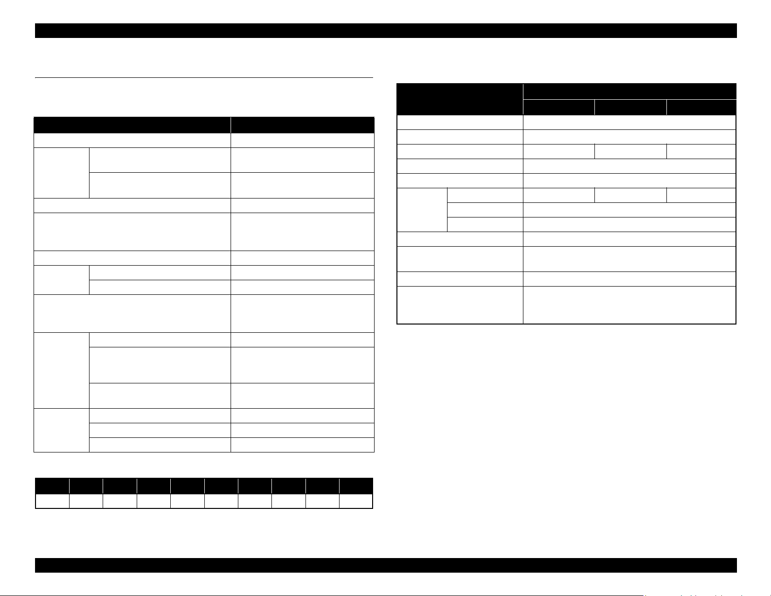
1.2.2 Electric Specifications
Item
Rated voltage 100 to 240 VAC
Input voltage range 90 to 264 VAC
Rated current 1.0 A to 0.5 A 0.9 A to 0.5 A 0.8 A to 0.4 A
Rated frequency 50 to 60 Hz
Input frequency range 49.5 to 60.5 Hz
Power
consumption
Insulation resistance 10 MΩ or more (between AC line and chassis at 500 VDC)
Dielectric strength
Leek current 0.25 mA or less
Compliance with regulations
Operating Approx. 72 W Approx. 65 W Approx. 54 W
Sleep mode 3.0 W or less
Power OFF 0.4 W or less
SC-T7000 series SC-T5000 series SC-T3000 series
1.0 kV rms AC for 1 min. or 1.2 kV rms AC for 1 sec.
Conforms to International Energy Star Program
(Category: the harmonic restraint measure guideline)
Conforms to VCCI Class B (with full options installed)
Specification
(between AC line and chassis)
*Nozzle set configuration is;
Row A Row B Row C Row D Row E Row F Row G Row H Row I Row J
C M Y PKMKMKPK Y M C
PRODUCT DESCRIPTION Basic Specifications 12
Confidential
Page 13

SC-T7000 series/SC-T5000 series/SC-T3000 series Revision B
1.2.3 Ink Specifications
Item Specification
Form Exclusive ink cartridge
Pigment ink
colors
Cartridge life See the date printed on the package (at normal temperature)
Guaranteed life
after
installation
Storage
Capacity 700 ml/350 ml/110ml
Dimensions
Black system: Photo Black, Matte Black
Color system: Yellow, Magenta, Cyan
1 year (after mounted in the printer)
Uninstalled (packed): -20 to 40 °C
(within 4 days under -20 °C, and within 1 month under 40 °C)
Installed: -20 to 40 °C
(within 4 days under -20 °C, and within 1 month under 40 °C)
Transporting (packed): -20 to 60 °C
(within 4 days under -20 °C, within 1 month under 40 °C, and within 72
hours under 60 °C)
700ml: W40 x L305 x H110 mm
350ml: W40 x L200 x H110 mm
110ml: W25 x L200 x H110 mm
PRODUCT DESCRIPTION Basic Specifications 13
Confidential
Page 14

SC-T7000 series/SC-T5000 series/SC-T3000 series Revision B
1.3 Printing Specifications
1.3.1 Paper Feed Specifications
Item Specification
Paper feed method Friction feed
Return pitch 2.2049
Paper feeder
Feed speed
μm (1/11,520 inch)
Roll paper manual feed
Cut sheet manual feed
300ms/ (1/6 inch)
PRODUCT DESCRIPTION Printing Specifications 14
Confidential
Page 15
SC-T7000 series/SC-T5000 series/SC-T3000 series Revision B
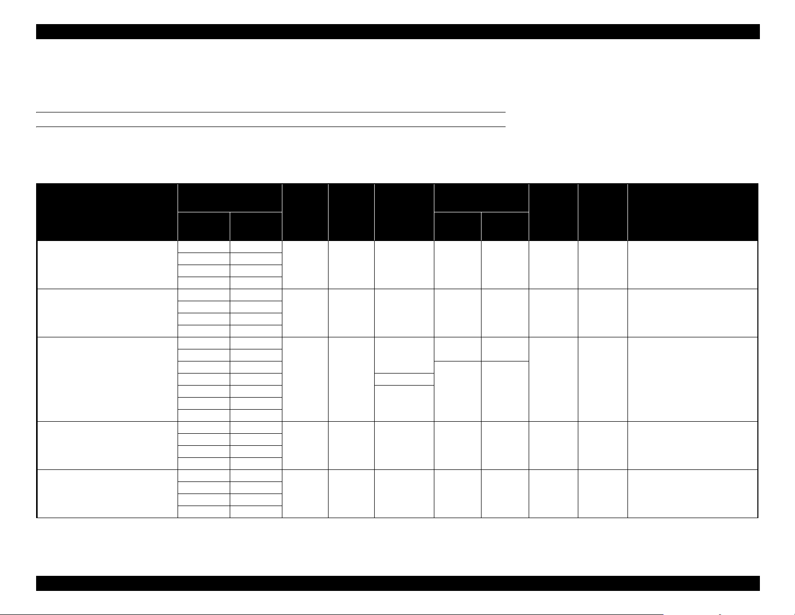
1.3.2 Supported Media
1.3.2.1 Epson Special Media Table
ROLL PAPER
Note "*1": SC-T3000 Series not supported
"*2": SC-T3000 Series/SC-T5000 Series not supported
"*3": When the optional auto take-up reel unit is used (SC-T7000 series)
"*4": Use the tensioner supplied with the auto take-up reel unit.
Size
Name
mm inch Forward Backward
406 16
Premium Glossy Photo Paper (250)
Premium Semigloss Photo Paper (250)
Premium Luster Photo Paper (260)
Premium Semimatte Photo Paper (260)
Photo Paper Gloss 250
610 24
*1
914
*2
1118
406 16
610 24
*1
914
*2
1118
254 10
300 11.8
406 16
508 20 -
610 24
*1
914
*2
1118
406 16
610 24
*1
914
*2
1118
432 17
610 24
*1
914
*2
1118
"*5": When a scanner is connected
"*6": U: Borderless printing available, but borders may appear or print quality decline due to paper
expanding or contracting.
*3
Head
Enlarged
*5
Alignment
ICC Profile
Thickness
(mm)
Core
Diameter
(inch)
Borderless
*6
Print
Take-up
EPSON SC-
*1
36
*2
44
0.27 3
√√√√√
T3000_5000_7000_Series Premium
Glossy Photo Paper 250.icc
EPSON SC-
*1
36
*2
44
0.27 3
√√√√√
√
--
T3000_5000_7000_Series Premium
Semigloss Photo Paper 250.icc
EPSON SC-
0.27 3
√√
√√
*1
36
*2
44
√
T3000_5000_7000_Series Premium
Luster Photo Paper 260.icc
EPSON SC-
*1
36
*2
44
0.27 3
√√√√√
T3000_5000_7000_Series Premium
Semimatte Photo Paper 260.icc
EPSON SC-
*1
36
*2
44
0.25 3
√√√√√
T3000_5000_7000_Series Photo
Paper Gloss 250.icc
PRODUCT DESCRIPTION Printing Specifications 15
Confidential
Page 16
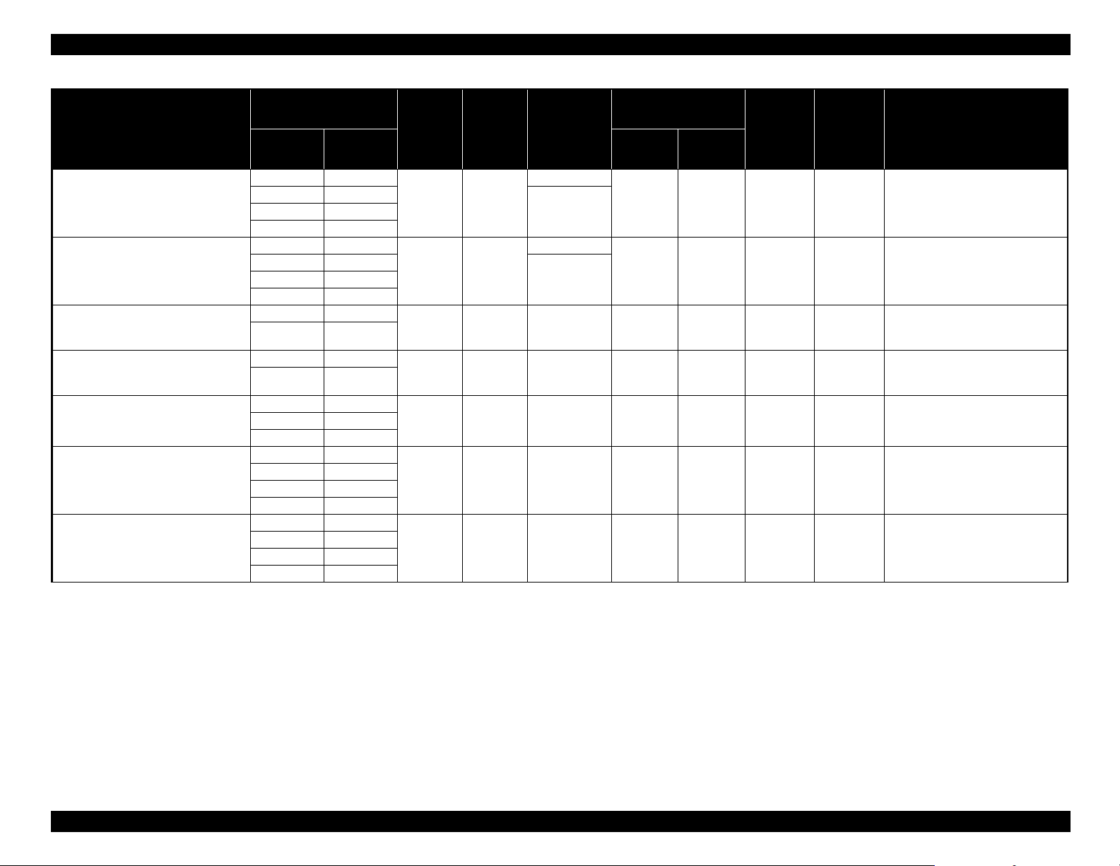
SC-T7000 series/SC-T5000 series/SC-T3000 series Revision B
Name
Premium Glossy Photo Paper (170)
Premium Semigloss Photo Paper (170)
Enhanced Synthetic Paper
Enhanced Adhesive Synthetic Paper
Doubleweight Matte Paper
Enhanced Matte Paper
Singleweight Matte Paper
Size
Thickness
(mm)
mm inch Forward Backward
420 (A2) ---
610 24
*1
914
1118
*2
36
44
420 (A2) ---
610 24
*1
914
1118
*2
36
44
*1
*2
*1
*2
0.18 2
0.18 2
Core
Diameter
(inch)
Borderless
*6
Print
-
√
-
√
Take-up
√√√ √
√√√ √
*3
610 24
1118
*2
*2
44
0.13 2
U
√√
610 24
1118
*2
*2
44
0.18 2
U
√√
610 24
914
1118
*1
*2
*1
36
*2
44
0.21 2
√√
*4
432 17
610 24
914 36
0.25 3
U
√
1118 44
432 17
610 24
*1
914
*2
1118
*1
36
*2
44
0.15 2
√√
*4
Enlarged
*5
Alignment
--
--
-
√√
--
-
√√
Head
√
ICC Profile
EPSON SCT3000_5000_7000_Series Premium
Glossy Photo Paper 170.icc
EPSON SCT3000_5000_7000_Series Premium
Semigloss Photo Paper 170.icc
EPSON SCT3000_5000_7000_Series Enhanced
Synthetic Paper.icc
EPSON SCT3000_5000_7000_Series Enhanced
Adhesive Synthetic Paper.icc
EPSON SCT3000_5000_7000_Series
Doubleweight Matte Paper.icc
EPSON SCT3000_5000_7000_Series Enhanced
and Archival Matte Paper.icc
EPSON SCT3000_5000_7000_Series
Singleweight Matte Paper.icc
PRODUCT DESCRIPTION Printing Specifications 16
Confidential
Page 17
SC-T7000 series/SC-T5000 series/SC-T3000 series Revision B
CUT SHEET
Note "*1": SC-T3000 Series not supported
"*2": When a scanner is connected
"*3": U: Borderless printing available, but borders may appear or print quality decline due to paper expanding or contracting.
Name Size
Premium Glossy Photo Paper
Premium Semigloss Photo Paper
Premium Luster Photo Paper
Archival Matte Paper/Enhanced Matte
Paper
Photo Quality Inkjet Paper
Enhanced Matte Posterboard
Thickness
(mm)
Super A3/B
0.27
US-C
Super A3/B
0.27
US-C
Super B
0.27
US-C
Super A3/B
A2 -
US-C
Super A3/B
US-C
610 x 762 mm
(24" x 30")
762 x 1016 mm
(30" x 40")
*1
0.26
0.12
1.30 - - - EPSON SC-T3000_5000_7000_Series Enhanced Matte Poster Board.icc
Borderless
U
U
U
U
U
U
U
U
U
U
*3
Enlarged
*2
Head Alignment ICC Profile
√√
√√
√√
-
-
√
√
EPSON SC-T3000_5000_7000_Series Premium Glossy Photo Paper.iccA2 -
EPSON SC-T3000_5000_7000_Series Premium Semigloss Photo Paper.iccA2 -
EPSON SC-T3000_5000_7000_Series Premium Luster Photo Paper.iccA2 -
EPSON SC-T3000_5000_7000_Series Enhanced and Archival Matte
Paper.icc
EPSON SC-T3000_5000_7000_Series Photo Quality Ink Jet Paper.iccA2 -
PRODUCT DESCRIPTION Printing Specifications 17
Confidential
Page 18
SC-T7000 series/SC-T5000 series/SC-T3000 series Revision B
1.3.2.2 Usable Commercially Available Paper Size
This printer supports the following paper specifications for non-Epson media.
C A U T I O N
Do not use paper that is wrinkled, scuffed, torn, or dirty.
Although plain paper and recycled paper manufactured by
other companies can be loaded and fed in the printer as long as
they meet the following specifications, Epson cannot guarantee
the print quality.
Although other paper types manufactured by other companies
can be loaded in the printer as long as they meet the following
specifications, Epson cannot guarantee the paper feeding and
print quality.
ROLL PAPER
Item Specification
Media types Plain paper and recycled paper
Paper core size 2 inch and 3 inch
Roll paper outer
diameter
Width
Paper thickness 0.08 to 0.5 mm
Basis weight 64 to 90g/m
Available width for
borderless printing
150 mm or less
SC-T7000 Series: 254 mm (10 inches) to 1,118 mm (44 inches)
SC-T5000 Series: 254 mm (10 inches) to 914 mm (36 inches)
SC-T3000 Series: 254 mm (10 inches) to 610 mm (24 inches)
2
254 mm/10 inch
300 mm/11.8 inch
Super A3/B/329 mm
406 mm/16 inch
17 inch
B2/515mm
A1/594mm
610 mm/24 inch
728 mm
A0/841 mm
914 mm/36 inch
1030 mm
1118 mm/44 inch
PRODUCT DESCRIPTION Printing Specifications 18
Confidential
Page 19

SC-T7000 series/SC-T5000 series/SC-T3000 series Revision B
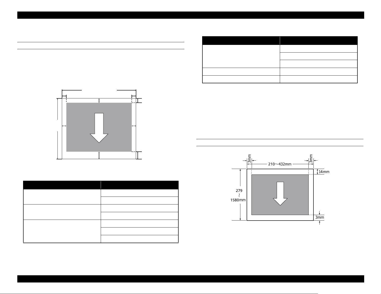
CUT SHEET
Item Specification
Media types Plain paper and recycled paper
SC-T7000 Series: 210 mm (A4) to 1,118 mm (44 inches)
Width
Length 279.4 to 1,580 mm
Paper thickness 0.08 to 0.8 mm
Available width for
borderless printing
SC-T5000 Series: 210 mm (A4) to 914 mm (36 inches)
SC-T3000 Series: 210 mm (A4) to 610 mm (24 inches)
254 mm/10 inch
300 mm/11.8 inch
Super A3/B/329 mm
406 mm/16 inch
17 inch
B2/515 mm
A1/594 mm
610 mm/24 inch
728 mm
A0/841 mm
914 mm/36 inch
1030 mm
1118 mm/44 inch
PRODUCT DESCRIPTION Printing Specifications 19
Confidential
Page 20
SC-T7000 series/SC-T5000 series/SC-T3000 series Revision B
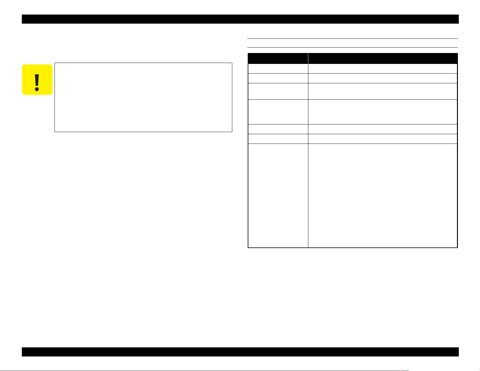
1.3.3 Printable area
ROLL PAPER
Note "*1": SC-T7000 Series
"*2": SC-T5000 Series
"*3": SC-T3000 Series
"*4": If “Banner” is selected for “Roll Paper Option” in the printer driver “Advanced” tab, the top
and bottom margins are 0 mm.
㪁㪈
㪁㪉
0mm/3mm
㪁㪊
㪁㪋
C
㪁㪋
A
3mm/15mm
D
3~45mm
127mm
15m
3mm/15mm
~
B
254mm~1118mm
254mm~914mm
254mm~620mm
Table 1-1. Roll Paper Margin
Roll Paper Margin Parameter Margin Values
A = 45mm
Top45mm/Bottom15mm
C =15mm
B, D = 3mm
3mm A, B, C, D = 3mm
15mm A, B, C, D = 15mm
When “Normal” is selected, the value for A is 20 mm for the following paper.
Premium Glossy Photo Paper (250) / Premium Semigloss Photo Paper (250) / Premium
Luster Photo Paper (260) / Premium Semimatte Photo Paper (260)
When the following media are used in the “CAD / Line Drawing” mode, the value for
A and C is 3 mm.
Singleweight Matte Paper
CUT SHEET
Table 1-1. Roll Paper Margin
Roll Paper Margin Parameter Margin Values
*
Normal
Top15mm/Bottom15mm
A, C = 15mm
B, D = 3mm
A, C = 15mm
B, D = 3mm
A = 35mm
Top35mm/Bottom15mm
C =15mm
B, D =3mm
PRODUCT DESCRIPTION Printing Specifications 20
Confidential
Page 21
SC-T7000 series/SC-T5000 series/SC-T3000 series Revision B
1.3.4 Borderless Printing Specification
AVAILABLE PAPER TYPE
For the paper types and sizes that support the borderless printing, see "1.3.2.1 Epson
Special Media Table" (p15).
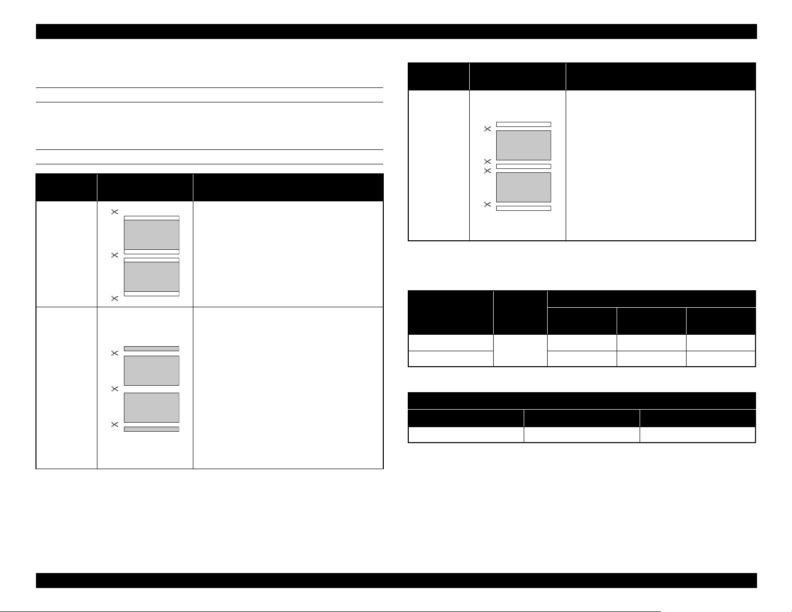
ROLL PAPER CUTTING OPERATION
Printer driver
settings
Borderless The default printer driver setting is “Borderless”.
Single Cut
Cutting Operation Explanation
A
B
The top area may become slightly uneven
depending on the image since the print
operation stops while cutting the top edge of
the roll paper.
If the cut position is misaligned slightly, small
A
B
parts of the image may be shown on the top or
bottom of the adjacent pages. If this occurs,
perform “Adjust Cut Position”.
When printing only one page the operation
performed is the same as that for “Double Cut”.
When continuously printing multiple sheets,
the printer cuts 1 mm inside on the top edge of
the first page and the bottom edge of the
subsequent pages to avoid showing margins.
Printer driver
settings
Double Cut
Cutting Operation Explanation
The top area may become slightly uneven
depending on the image since the print
operation stops while cutting the top edge of
the roll paper.
A
B
The printed paper is approximately 2 mm
shorter than the specified size since the printer
cuts the paper inside the image to avoid
showing top and bottom margins.
After cutting the bottom edge of the previous
page, the printer feeds the paper, and then cuts
the top edge of the following page. Although
this produces 60 to 127 mm cut-off pieces, the
cut is more accurate.
1.3.5 Stacker
Table 1-2. Continuous Stacker
Stackable Pages
Paper size Paper Type
A1 594 x 841mm
A0 841 x 1,189mm --- 20 pages 20 pages
Plain paper
Table 1-3. Single Sheet Stacker
SC-T3000 Series SC-T5000 Series SC-T7000 Series
Approx. 1,292 mm Approx. 1,292 mm Approx. 1,575 mm
SC-T3000
Series
20 pages 20 pages 20 pages
Maximum Length
SC-T5000
Series
SC-T7000
Series
PRODUCT DESCRIPTION Printing Specifications 21
Confidential
Page 22
SC-T7000 series/SC-T5000 series/SC-T3000 series Revision B
1.4 Hardware Specifications
This section provides the printer dimensions and shows the main components.
1.4.1 Dimensions and Weight
Model Width Depth
SC-T7000 Series 1,608 mm 813 mm 1,128 mm Approx. 82 kg
SC-T5000 Series 1,405 mm 813 mm 1,128 mm Approx. 75 kg
SC-T3000 Series
(w/o dedicated stand)
SC-T3000 Series
(w/ dedicated stand)
Note 1: When the paper basket is retracted
2: Excluding ink cartridges
1,050 mm 691 mm 613 mm Approx. 51 kg
1,050 mm 813 mm 1,128 mm Approx. 61 kg
*1
Height Weight
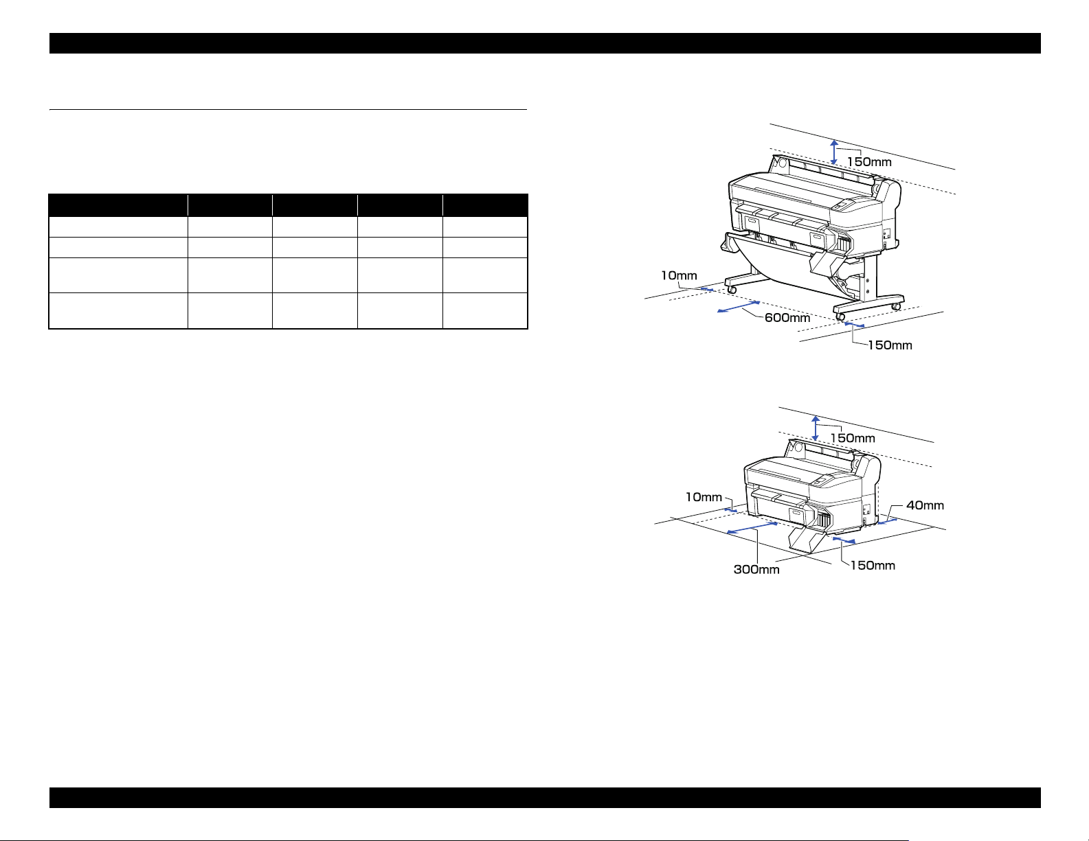
1.4.2 Installation Room Requirement
*2
Figure 1-1. SC-T7000 Series/SC-T5000 Series
Figure 1-2. SC-T3000 Series
PRODUCT DESCRIPTION Hardware Specifications 22
Confidential
Page 23
SC-T7000 series/SC-T5000 series/SC-T3000 series Revision B
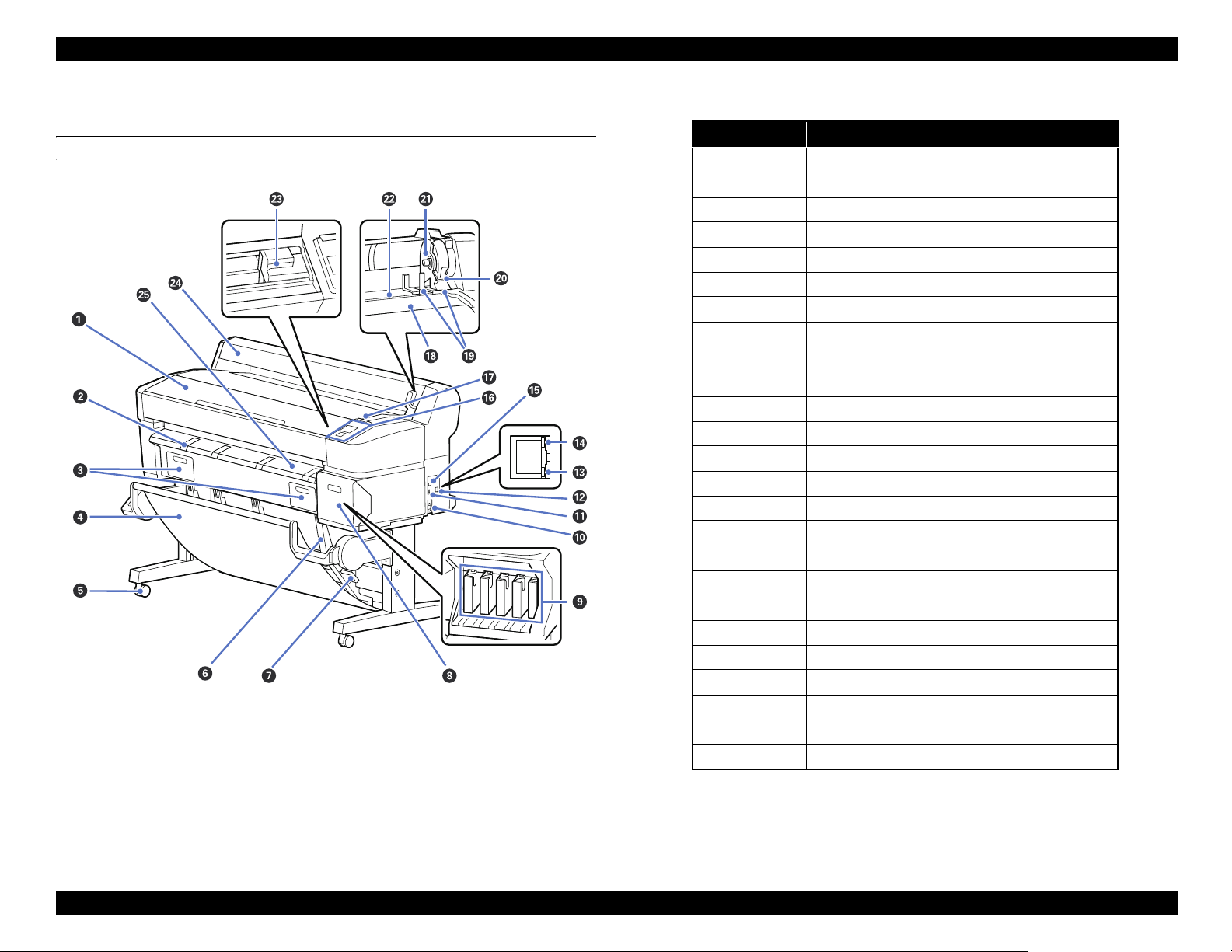
1.4.3 Part Names
FRONT SIDE
Figure 1-3. Front Side
Table 1-4. Front Side
No. Name
1 Printer cover
2 Poster board support
3 Maintenance box covers
4 Paper basket
5Casters
6Stack guides
7 Stack guide switch lever
8 Cartridge cover
9 Ink cartridges
10 AC inlet
11 Option port
12 LAN port
13 Data light
14 Status light
15 USB port
16 Control panel
17 Alert lamp
18 Roll rest
19 Adapter guides
20 Roll lock lever
21 Adapter holder
22 Paper slot
23 Print head
24 Roll paper cover
25 Paper eject guide
PRODUCT DESCRIPTION Hardware Specifications 23
Confidential
Page 24
SC-T7000 series/SC-T5000 series/SC-T3000 series Revision B
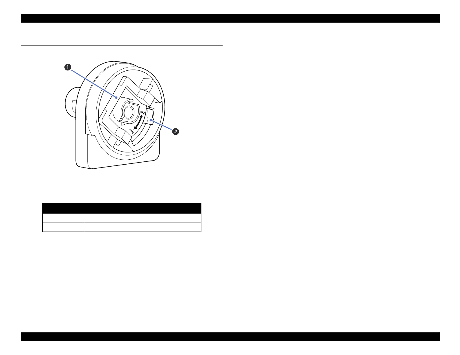
ROLL PAPER ADAPTER
Figure 1-4. Roll paper adapter
Table 1-5. Roll paper adapter
No. Name
1 Adapter lock lever
2 Size lever
PRODUCT DESCRIPTION Hardware Specifications 24
Confidential
Page 25
SC-T7000 series/SC-T5000 series/SC-T3000 series Revision B
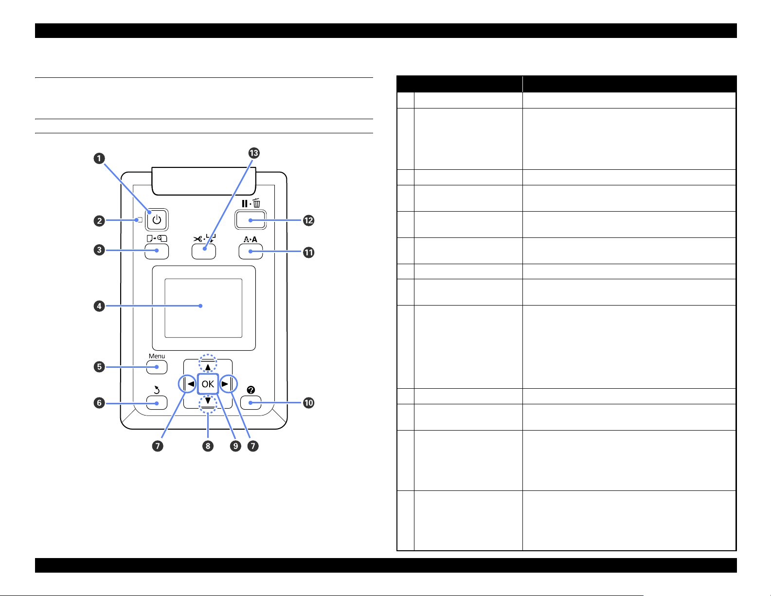
1.5 Control Panel Specifications
1.5.1 Control panel and LCD
CONTROL PANEL
Figure 1-5. Control panel
Table 1-6. Control panel
Name Function
1 Power button Turns the power on and off.
On: The power is on.
Flashing: The printer is receiving data or cleaning the
2 Power light
Off: The power is off.
3 Load/Remove Paper button Displays the Load/Remove Paper menu.
4 Screen
5 [Menu] button
6 Back button
7 Left/Right buttons Use these buttons to select tabs.
8 Up/Down buttons
9 OK button
10 Help button Displays the Help menu.
11 Maintenance button
12 Pause/Cancel button
13 Feed/Cut Media button
Displays the printer’s status, menus, error messages, and
so on.
Displays the menu for the tab currently selected in the
display.
If menus are displayed, pressing this button takes you up
one level in the menu hierarchy.
When menus are displayed, these buttons can be used to
highlight items or options.
Displays the menu for the tab currently selected in the
display.
When menus are displayed and an item is highlighted,
pressing this button displays the sub-menu for the
highlighted item.
If pressed while a parameter is selected from the Menu,
the parameter is set or executed.
Displays the Maintenance menu, which is used for nozzle
checks and head cleaning.
The printer enters pause status if this is pressed while
printing.
Pressing this button while a menu or help is displayed
closes the menu or help and returns the printer to ready
status.
It is used to manually cut roll paper using the built-in
cutter.
If printing is not currently in progress and the printer is
loaded with roll paper, you can feed paper ahead by
pressing first this button and then the [T] button.
print head or performing other operations in
the course of being shut down.
PRODUCT DESCRIPTION Control Panel Specifications 25
Confidential
Page 26
SC-T7000 series/SC-T5000 series/SC-T3000 series Revision B
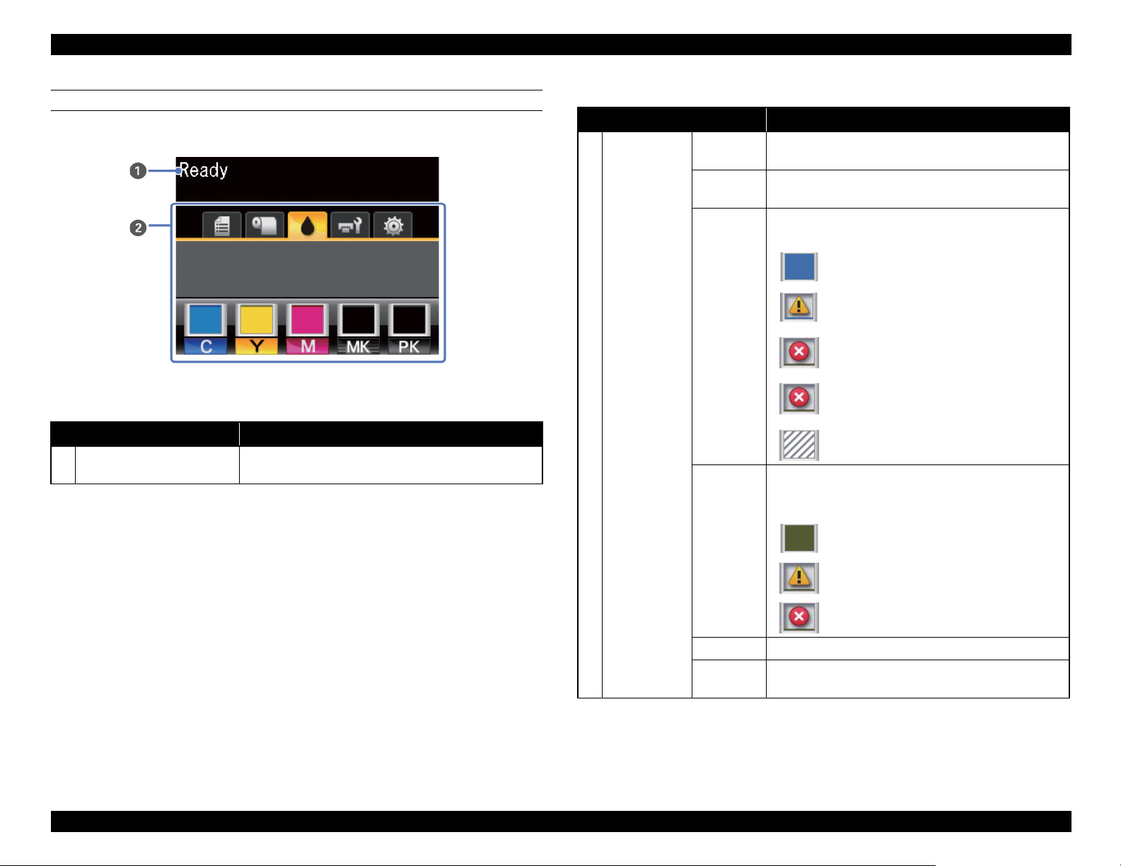
LCD
Screen View
Name Function
1 Message
Figure 1-6. LCD
Table 1-7. LCD
Displays the printer’s status, operation, and error
messages.
Tabs/Info
2
Display Area
Table 1-7. LCD
Name Function
Print
Queues Tab
Paper Tab
Ink Tab
Displays print job status and can be used to access the
Print Queues menu.
Shows the type of paper in the printer and can be used to
access the Paper menu.
Displays ink status.
The ink cartridge status is indicated as follows.
: No error.
: Ink is low.
: Ink cartridge is expended.
: An error occurred.
: Non-genuine cartridge is installed.
Shows the status of the Maintenance Box and is used to
display the Maintenance menu.
Maintenance Box status is shown as follows.
Maintenance
Tab
Setup Tab Displays the IP address and menus for various settings.
Enlarged
Copy Tab
Displayed only when a scanner is connected.
: No error.
: The Maintenance Box is nearing the end of
its service life.
: Maintenance Box is at the end of its service
life.
PRODUCT DESCRIPTION Control Panel Specifications 26
Confidential
Page 27

SC-T7000 series/SC-T5000 series/SC-T3000 series Revision B
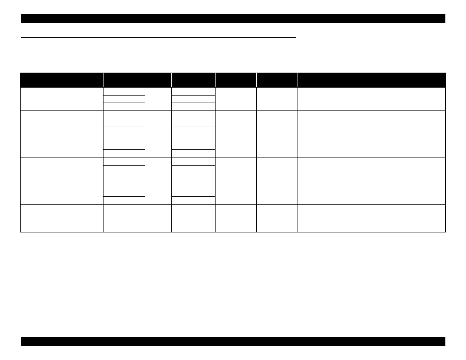
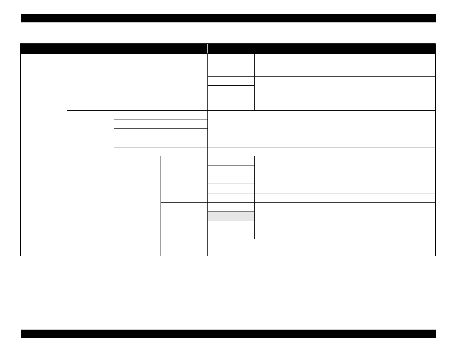
1.5.2 Menu Descriptions
Note "*1": Displayed only when optional hard disk unit is installed.
Table 1-8. Menu List
Menu Menu Item / Setting Value (Shaded one is the default) Explanation
Lists the estimated start time and time needed to print the selected job.
It also predicts whether the job can be completed without replacing paper, ink or the
Maintenance Box. Printing can proceed even if “Can Not Complete” is displayed.
However, the printer may run out of ink or paper during printing.
Remote Manager and the LFP HDD Utility display the reason for the “Can Not
Complete” message and allow you to hold or cancel the job.
The printer will only predict availability on the basis of the amount of paper
remaining if “On” is selected for “Roll Paper Remaining”.
The printer will not predict availability on the basis of the amount of ink remaining
when documents are printed using LFP Print Plug-In for Office or EPSON
CopyFactory5.
This option is available only if “On” is selected for “Store Held Job” in the Setup
menu.
Displays the print settings for held jobs and the reason the job is held.
Jobs that are held because the job print settings differ from those currently selected
for the printer can be printed as described below.
1. Replace the paper and take whatever other steps may be necessary to ready the
device for printing.
2. Select “Resume All Jobs”.
Shows the status of the selected stored job when it was last printed.
After viewing the job, press the [OK] button to enter the number of copies. Press the
[S]/[T] buttons to choose the number of copies and press the [OK] button to display
the estimated print time and print availability. Press the [OK] button to start printing.
Print Queues menu
Waiting Job Name
User
Estimated Start
Print Queue
Hold Queue
Saved Job Queue
Print Job Log Sheet Press the [OK] button to print the print job log.
*1
*1
XXXXXXXXXXX
(name of queued print job)
XXXXXXXXXXX
View Hold Queue
Resume All Jobs Press the [OK] button to resume all held jobs currently in the queue.
XXXXXXXXXXX (name of stored print
*1
job)
(name of held print
job)
Time
Estimated Print
Time
Printing
Availability
Paused Job Name
User
Paper Type
Source
Size
Reason For Hold
Stored Job Name
User
Length
Pages
Paper Type
Copies
Source
Size
Estimated Print
Time
PRODUCT DESCRIPTION Control Panel Specifications 27
Confidential
Page 28
SC-T7000 series/SC-T5000 series/SC-T3000 series Revision B
Table 1-8. Menu List
Menu Menu Item / Setting Value (Shaded one is the default) Explanation
Press the [OK] button to view instructions for removing the paper. Follow the onscreen instructions to remove the paper.
Instructions are not displayed if no paper is loaded.
Highlight the paper to be loaded and press the [OK] button. Follow the on-screen
instructions to load the paper.
If paper is already loaded in the printer, the instructions for removing the loaded
paper type will be displayed before loading instructions are shown.
You can select the media type that is the closest to the paper you are using.
Select the platen gap which is the distance between the print head and the paper.
Normally, select “Standard”. Select a wider setting if printed images are smeared. If,
upon performing head alignment you feel that it is still not completely aligned, select
“Narrow”.
Paper menu
Load/Remove Paper
Select Paper Type
Custom Paper
Setting
Remove Paper
Roll Paper
Cut Sheet (up to 0.8
mm thick)
Poster Board
Photo Paper
Matte Paper
Plain Paper
Others
Custom Paper Select the name of the custom paper loaded in the printer.
Select Reference
Paper
XXXXXXXXXXX
(name of custom
paper type)
Platen Gap
Detect Paper
Thickness
Select the type of paper loaded.
Photo Paper
Matte Paper
Plain Paper
Others
No Paper Selected Select this option if you do not wish to specify the paper type.
Narrow
Standard
Wide
Wider
Press the [OK] button to print a pattern to determine the thickness of the current paper.
Select the pattern number with the least misalignment from the print results.
PRODUCT DESCRIPTION Control Panel Specifications 28
Confidential
Page 29
SC-T7000 series/SC-T5000 series/SC-T3000 series Revision B
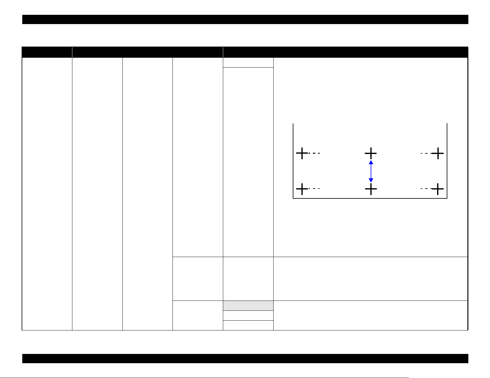
Table 1-8. Menu List
Menu Menu Item / Setting Value (Shaded one is the default) Explanation
Pattern Use this setting if you are unable to resolve banding issues (horizontal striped lines or
uneven colors) in the standard print area (for cut sheets, the area excluding the 1 to 2
cm strip at the bottom of the paper) even after head cleaning or head alignment.
When “Pattern” is selected;
Press the [OK] button to print an adjustment pattern. Measure the distances between
the “+” symbols in the printed adjustment pattern. Use only the distance between the
center symbols or the average of the distances between the left, center, and right
symbols.
Paper menu
Custom Paper
Setting
XXXXXXXXXXX
(name of custom
paper type)
Paper Feed Adjust
Value
Paper Suction -4 to 0
Normal
Roll Paper Tension
Extra High
After the adjustment pattern is printing, the length of the pattern will be displayed in
the control panel. Press the [S]/[T] buttons to enter the measured value and press
the [OK] button.
When “Value” is selected;
Choose an adjustment between -0.70 and +0.70%. Selecting too small a value causes
dark bands; adjust the amount upward. Similarly, choosing too large a value causes
white bands; adjust the amount downward.
It is important to choose the appropriate amount of suction for the paper used in order
to maintain the correct distance between the paper and the print head. Choosing too
high a value for thin or soft paper will increase the distance between the paper and the
print head, causing print quality to decline or preventing the paper feeding correctly.
If this happens, lower the paper suction. The suction power is weakened when the
parameter is lowered.
Select “High” or “Extra High” if the paper wrinkles during printing.High
PRODUCT DESCRIPTION Control Panel Specifications 29
Confidential
Page 30
SC-T7000 series/SC-T5000 series/SC-T3000 series Revision B
Table 1-8. Menu List
Menu Menu Item / Setting Value (Shaded one is the default) Explanation
Custom Paper
Paper menu
Maintenance menu
Setup menu Printer Setup Roll Paper Setup
Setting
Print Paper List Press the [OK] button to print a list of custom paper settings.
Nozzle Check
Head Cleaning
Head Alignment
Cutter Maintenance
XXXXXXXXXXX
(name of custom
paper type)
Auto(Uni-D)
Auto(Bi-D)
Manual(Uni-D)
Manual(Bi-D)
Adjust Cut Position -3 to 3 mm
Replace Cutter
Remove Skew
Setting Name
Restore Settings
Auto Cut
Refresh Margin
Page Line
On
Off
Enter a name of up to 22 characters for custom paper settings. Choose an easy-to-remember name for quick
selection.
Yes
No
Press the [OK] button to print a nozzle check pattern. Visually inspect the printed pattern and perform head
cleaning if you notice faint or missing areas.
Inspect the printed pattern and select the check boxes for patterns with faint or missing areas. To select all
nozzles, place a check in the box on the left.
If print results are grainy or out of focus, perform head alignment to realign the print head. If “Auto” is
selected, the printer will scan the printed pattern during printing and realign the head automatically.
If “Manual” is selected, a pattern will be printed; inspect the pattern visually and enter the value you think
appropriate.
Moves the cutter to the replacement position so it can be replaced. Press the [OK] button to move the cutter
to the replacement position. The paper must be removed before replacing the cutter.
On Choose “On” to automatically cut roll paper using the built-in cutter as each page is
Off
On If “On” is selected during borderless printing, the printer will automatically trim the
Off
On If “Auto Cut” is “Off”, you can choose to print (“On”) or not print (“Off”) cut lines
Off
Select whether to enable (“On”) or disable (“Off”) paper skew reduction.
Restore the selected custom paper settings to default values.
You can fine tune the cut position when printing to roll paper with no margins in all
directions. The cut position can be adjusted in increments of 0.2 mm.
printed, “Off” to disable auto paper cutting. The setting selected with the printer
driver takes priority when the printer driver is used.
leading edge to remove any ink stains that may have been left by the previous copy;
to disable this feature, choose “Off”.
on roll paper. Cut lines are not printed if “Auto Cut” is “On” or when cut sheets or
poster board is used.
Note, however, that if the roll width selected with the computer is narrower than the
paper loaded in the printer, cut lines will be printed regardless of the option selected
for “Auto Cut”.
The setting selected with the printer driver takes priority when the printer driver is
used.
PRODUCT DESCRIPTION Control Panel Specifications 30
Confidential
Page 31

SC-T7000 series/SC-T5000 series/SC-T3000 series Revision B
Table 1-8. Menu List
Menu Menu Item / Setting Value (Shaded one is the default) Explanation
Normal
Top 15 mm/
Bottom 15 mm
Setup menu Printer Setup
Roll Paper Setup
Advanced Settings
Roll Paper Margin
Roll Paper
Remaining
Remaining Alert
Roll Paper Tension
Less Head Scuffing
Top 35 mm/
Bottom 15 mm
Top 45 mm/
Bottom 15 mm
3 mm
15 mm
On Select whether to display/record (“On”) or not to display/record (“Off”) the amount
Off
1 to 15 m (4 to 50
ft)
Low Select “High” or “Extra High” if the paper wrinkles during printing.
Normal
High
Extra High
On If the paper is thick, the print head may scuff the print surface. Choose “On” to
Off
When set to “Normal”, the top and bottom margins are 15 mm, and the left and right
margins are 3 mm.
Except for “15 mm”, the left and right margins for all other settings are 3 mm.
of remaining roll paper. The following options can be made available by selecting
“On” and entering the length of the roll.
Amount of roll paper remaining
When the roll is removed, a barcode will automatically be printed on the roll
stating the length remaining, the value selected for the roll remaining alert, and the
paper type.
The barcode is automatically read and settings adjusted the next time the paper is
used, improving efficiency when multiple rolls of paper are used.
Printing Availability
The printer will estimate printing availability based on the length of the roll.
Displayed when “On” is selected for “Roll Paper Remaining”.
Set within a range from 1 to 15 m (4 to 50 ft) to display a warning when the amount
of remaining roll paper drops below that limit. You can set in 0.5 m (1 ft) increments.
“Roll Paper Tension” can be specified separately for each paper type using the
“Custom Paper Setting” option in the Paper menu.
When “Custom Paper” is chosen for “Select Paper Type”, the printer will use the
value selected for “Roll Paper Tension” in the “Custom Paper Setting”.
This setting takes effect if no custom roll paper tension is specified.
prevent scuffing. This option can be used to temporarily change the value selected for
“Custom Paper Setting” > “Platen Gap” in the Paper menu. Note, however, that “On”
has no effect when “Wider” is selected for “Platen Gap”.
PRODUCT DESCRIPTION Control Panel Specifications 31
Confidential
Page 32

SC-T7000 series/SC-T5000 series/SC-T3000 series Revision B
Table 1-8. Menu List
Menu Menu Item / Setting Value (Shaded one is the default) Explanation
Specify how long the printer pauses to allow the ink to dry after printing each page;
choose from values between 0 and 60 minutes. Depending on the ink density or paper
type, the ink may take a while to dry. If the ink blurs on the paper, set a longer time
for drying the ink.
The longer the drying time, the more time required for printing.
the paper width. Try choosing “Off” if a paper setting error is displayed when the
paper is correctly loaded. Note, however, that the printer may print outside the paper
when “Off” is selected. If it prints beyond the edges of the paper, the inside of the
printer becomes dirty with ink. We generally recommend to operate with this setting
set to “On”.
stop if the paper is skewed; select “Off” to disable this feature. “On” is recommended
in most circumstances as skewed paper may cause the printer to jam.
print jobs that require a paper type, source, or output paper size (width) that differs
from those currently selected with the printer will be saved as held jobs; select “Off”
to disable this feature.
If “Off” is selected, an error will be displayed and will printing will stop if the source
selected for the print job does not match that selected with the printer.
If “On” is selected, printing will not stop if an error occurs; instead, jobs with nonmatching settings will be saved to the hard disk unit as held jobs. Held jobs can be
printed from the Print Queues menu after the printer has been readied by, for
example, loading the correct type of paper.
Select “Yes” to restore all printer settings to default values.
2
View the total area printed (six-figure maximum).
Setup menu
Printer Setup
Printer Status
Drying Time Per
Page
Paper Size Check
Advanced Settings
Restore Settings
Firmware Version xxxxxxx,x.xx,xxxx You can see the firmware version.
Option Status Lists the optional accessories currently connected to the printer and available for use.
Show Total Prints
Print Status Sheet
Paper Skew Check
Store Held Job
0 to 60 minutes
On Choose whether the printer automatically detects (“On”) or does not detect (“Off”)
Off
On If “On” is selected, an error will be displayed in the control panel and printing will
Off
On This item is available when an optional hard disk unit is installed. If “On” is selected,
Off
Yes
No
XXXXXXX m
(XXXXXX ft2)
Press the [OK] button to print a list of current printer settings.
Choose this option to view settings at a glance.
PRODUCT DESCRIPTION Control Panel Specifications 32
Confidential
Page 33

SC-T7000 series/SC-T5000 series/SC-T3000 series Revision B
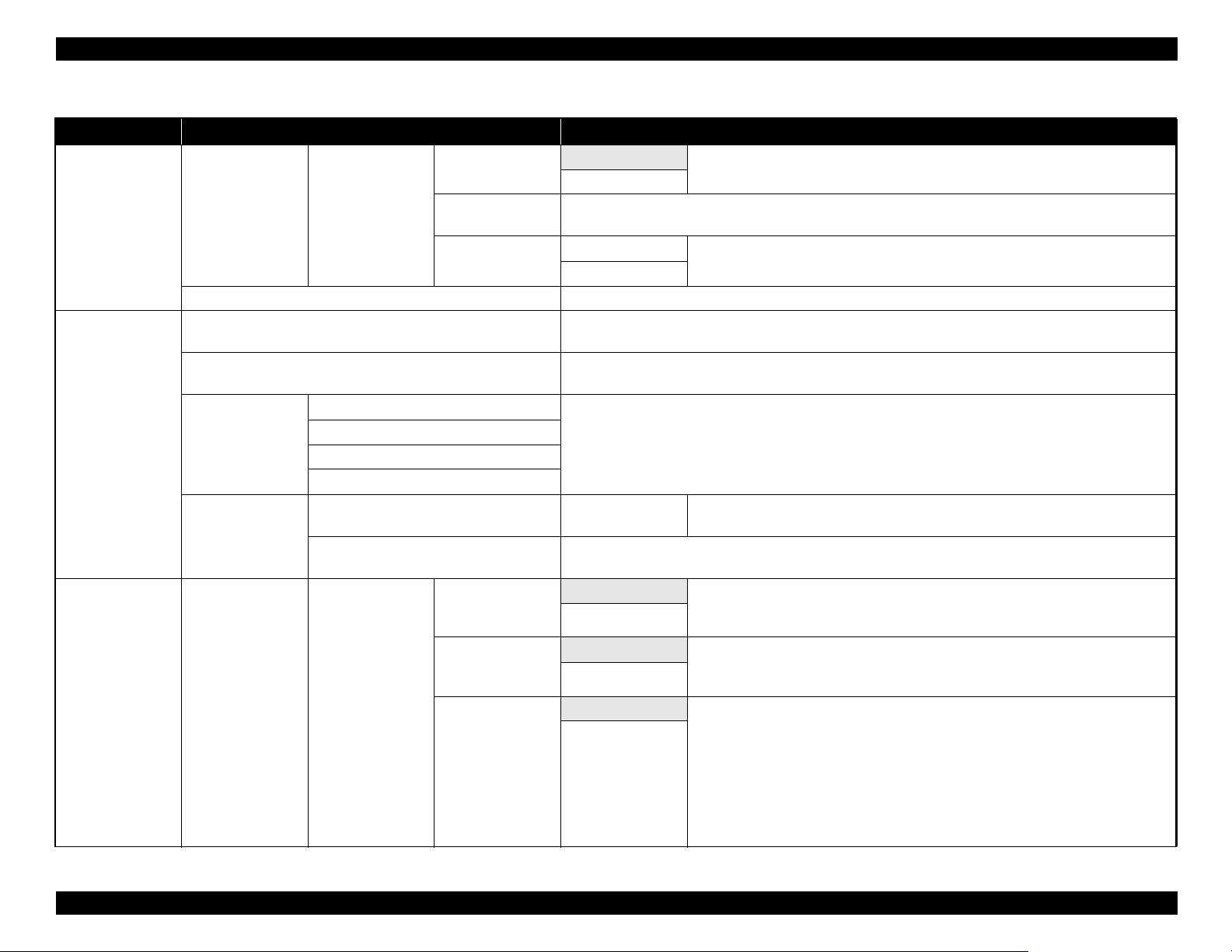
Table 1-8. Menu List
Menu Menu Item / Setting Value (Shaded one is the default) Explanation
Auto Select whether to use DHCP to set the IP address (“Auto”), or to set the address
manually (“Panel”). Choose “Panel” to enter the “IP address”, “Subnet Mask”, and
“Default Gateway”.
Select “Yes” to restore all network settings to default values.
received, and no control panel or other operations are performed for eight hours.
The delay before the printer turns off can be selected from values between 1 and 24
hours in increments of 1 hour.
Choose “Off” to prevent the printer turning off automatically.
Select “Yes” to restore all “Power Settings” to default values.
Select the language used on the control panel’s screen.
Select the unit of length which is displayed on the control panel’s screen or printed on
the patterns.
Choose whether the large alert lamp lights (“On”) or does not light (“Off”) when an
error occurs.
Setup menu
Network Setup
Power Settings
Preference
IP Address Setting
Print Status Sheet
Restore Settings
Sleep Mode 5 to 180 minutes Use this option to choose the period before the printer enters sleep mode.
Power Off Timer
Restore Settings
Language
Unit: Length
Alert Lamp Setting
Panel
Press the [OK] button to print a list of network settings. Choose this option to view network settings at a
glance.
Yes
No
Off The printer turns off automatically when there are no errors, no print jobs being
1 to 24 hours
Yes
No
Japanese
English
French
Italian
German
Portuguese
Spanish
Dutch
Russian
Korean
Chinese
m
ft/in
On
Off
PRODUCT DESCRIPTION Control Panel Specifications 33
Confidential
Page 34

SC-T7000 series/SC-T5000 series/SC-T3000 series Revision B
Table 1-8. Menu List
Menu Menu Item / Setting Value (Shaded one is the default) Explanation
Enter an administrator password of up to 20 characters.
Change Password
Operational Control Network Setup
Power Cleaning
Selecting Administrator Menu displays a password prompt. The Administrator Menu will only be displayed
if the correct password is entered, preventing non-administrators from accidentally changing settings.
Password Required
No Password
Required
Choose whether the administrator password is required to access “Network Setup”
from the control panel or Remote Manager.
Setup menu
Administrator
Menu
Manage HDD Format Hard Disk
Date And Time
Time Zone
Reset All Settings
Inspect the printed pattern and select the check boxes for patterns with faint or missing areas. To select all
nozzles, place a check in the box on the left.
Yes Select “Yes” to format the optional hard disk unit currently attached to the printer.
Formatting the hard disk unit deletes all stored print jobs.
No
MM/DD/YY
HH:MM
Enter the difference between the current time zone and GMT.
The selected time zone is used in e-mail notifications sent by Remote Manager when an error occurs.
Yes
No
Hard disk units that have been used with other printers must be formatted before they
can be used this printer.
Set the printer’s built-in clock. The printer clock provides the times that appear in
print outs of job information and printer status.
Select “Yes” to restore defaults for all settings except the “Date And Time”,
“Language”, and “Unit: Length” options in the Setup menu.
PRODUCT DESCRIPTION Control Panel Specifications 34
Confidential
Page 35

SC-T7000 series/SC-T5000 series/SC-T3000 series Revision B
Table 1-8. Menu List
Menu Menu Item / Setting Value (Shaded one is the default) Explanation
Color
B&W
With Border Document sizes are listed to the left of the arrows.
Borderless
A3, B4, A4, B5, A5,
LTR, 4x6
A0, US E, B1, A1,
USD, B2, US C,
A2, A0(2Sheets)
With Border
Borderless
Draft
Fine
Five options from
Light to Dark
Choose whether to copy in color or in black and white.
The copy is enlarged to fit the width of the roll currently loaded in the printer. The
maximum size is 914 mm (36 inches). If a roll wider than 36 inches is loaded in the
SC-T7000 Series, the maximum size is still 36 inches.
To print without borders, select “Borderless”.
The sizes available vary with the scanner.
Select the size of the original document when copying at other sizes.
The sizes available vary with the scanner.
Choose the output size when copying at other sizes.
“A0(2Sheets)” is available only with the SC-T3000 Series.
“A0” is available only with the SC-T5000 Series / SC-T7000 Series.
To print without borders, select “Borderless”.
Choose copy quality and print speed.
Choose copy density.
Enlarged Copy
menu
Color/B&W
Auto
Quality
Density
A3->Auto, B4->Auto, A4->Auto,
B5->Auto, A5->Auto, LTR->Auto,
4x6->Auto, A4/2->Banner (Auto)
Document Size
Other Size
Output Size
Border
PRODUCT DESCRIPTION Control Panel Specifications 35
Confidential
Page 36

SC-T7000 series/SC-T5000 series/SC-T3000 series Revision B
1.5.3 Serviceman Mode
The Serviceman Mode is intended to be used by a service person for servicing the printer.
HOW TO START & QUIT
1. Turn the printer on by pressing the [Menu], [Back], and [OK] buttons together.
2. Turn the printer off to quit the Serviceman Mode.
SERVICEMAN MODE MENU LIST
Menu
Class 1 2 3
Paper Adjusts the detection accuracy of the PAPER THICKNESS SENSOR.
Rear AD Adjusts the AD value of the PE Sensor.
CR Un Cap Unlocks or re-locks the carriage and uncaps/re-caps the Print Head.
Mecha Adjustment
LCD RGB Check
Panel Check Checks the operation of the buttons and the LEDs.
Sensor Check ILS Checks the operation of sensors.
Red
Blue
Explanation
Checks the operation of the LCD.Green
PRODUCT DESCRIPTION Control Panel Specifications 36
Confidential
Page 37

SC-T7000 series/SC-T5000 series/SC-T3000 series Revision B
Menu
Class 1 2 3
PG--
PG-
PG
H to F Speed
Life CR
F to H Speed
Page Size
Fan
Life Count
PGtyp
PG+
PG++
400 CPS
500 CPS
240 CPS
400 CPS
500 CPS
240 CPS
Explanation
Used only in manufacturing processes. Not used in service operations.
PRODUCT DESCRIPTION Control Panel Specifications 37
Confidential
Page 38

SC-T7000 series/SC-T5000 series/SC-T3000 series Revision B
Menu
Class 1 2 3
Feed Amount 1
PS1
PS2
PS3
PS4
PS1
PS2
PS3
PS4
PG--
PG-
PGtyp
PG+
PG++
Life
PF
RLS
APG
Cutter
Display Count
Feed Speed 1
Feed Amount 2
Feed Speed 2
Wait
Fan
Life Count
Wait1
Wait2
Life Count
PG
Wait
Life Count
Length
Return Length
Wait
Life Count
Explanation
Used only in manufacturing processes. Not used in service operations.
PRODUCT DESCRIPTION Control Panel Specifications 38
Confidential
Page 39

TROUBLE SHOOTING
CHAPTER
2
Confidential
Page 40

SC-T7000 series/SC-T5000 series/SC-T3000 series Revision B
2.1 Overview
This section explains the basic procedure for troubleshooting problems on the printer
quickly and efficiently.
When carrying out the troubleshooting procedures, take a flexible measure following
your sales company's policy and considering the troubling situation.
2.1.1 Preliminary Check
Make sure to verify or perform the following basic items whenever servicing the
printer.
2.1.1.1 Before performing troubleshooting
Before troubleshooting, perform basic checks such as connection check of the power
cable and installation check of the ink cartridges.
2.1.1.2 Check for the usage environment
Check the user's usage environment.
Temperature/humidity of the installation site
(For the guaranteed environment, see P.12.)
Drivers/RIP that the user uses
Genuine media or 3rd party's media?
2.1.1.3 Recurrence check of the trouble
Check if the trouble the user claims recurs with the returned printer.
If RIP was used, check if the trouble recurs when the driver is used.
If 3rd party's media were used, check if the trouble recurs when a genuine
medium is used.
If 3rd party's ink was used, perform the repair according to the policy of each
local sales subsidiary.
If the F/W was not the latest, gain agreement with the user on the update of F/
W, and check if the trouble recurs when the latest F/W is used.
2.1.1.4 Check for the counter values/history
Download NVRAM and check the following with NVRAM Viewer. (For the check
method, see P.222.)
Counter history of the periodic replacement parts. (if any part's life is near.)
Printer's operating history (if any cause for the trouble exists)
Error history (the frequency/history of errors related with the trouble)
2.1.1.5 Test print check
For the trouble related with print quality, carry out “Test Print” and check the current
adjustment status. (For the procedure of test print, see P.230.)
Genuine ink or 3rd party's ink?
F/W version (the latest?)
Check also the following if necessary.
Phenomenon Check Item
The installation site inclined?
Any vibrating equipment near the site?
Bad print quality
Missing dots/bad print quality Near a conditioner's ventilation duct?
The user's panel settings
Is the interior dirty?
Clean it if dirty.
TROUBLE SHOOTING Overview 40
Confidential
Page 41

SC-T7000 series/SC-T5000 series/SC-T3000 series Revision B
2.1.2 Troubleshooting Procedure
Refer to the following items according to the observed symptom, carry out the
corresponding troubleshooting following the procedures described in the next sections.
1. Trouble with a Maintenance Request or Service Call Error. (See P.42, P. 43)
2. Trouble on print quality (See P.58)
3. Trouble on paper feeding (See P.62)
4. Other troubles (See P.63)
5. Trouble on Service Program (See P.64)
6. Trouble on NVRAM Viewer (See P.65)
2.1.3 Procedure after troubleshooting
2.1.3.1 If the trouble has been successfully solved
Check if the movement of the covers is normal (without any damage, noises).
If any abnormality is found, lubricate or replace the faulty parts.
Carry out the cleaning after repair.
Prepare a report on the repair. (follow your company/local office's policy.)
2.1.3.2 If necessary to escalate the trouble case
Make a report with the following data.
Backed-up NVRAM data
For bad print quality: a print sample with the marked symptom and a printed
test pattern.
For faulty parts: the faulty parts themselves and a photos of the troubling
section.
Information on the user/the repair listed below
This is a format of the escalation report. At least check out the items on the
list and register the case in the escalation system.
• Model name
• Serial number
• With or without options
• Content of the claim from the user
• Date of occurrence
• Trouble occurrence conditions/recurrence method
• What the service person actually observed
(Check items before check, the content of troubleshooting and repair.)
• Date of escalation
• Purpose of escalation
(Measures which the user/service person)
• Degree of urgency (S/A/B/C)
S: High (those which may cause a death, ignition, etc.)
A: Problems, bugs
B: Strong request
C: Inquiry
• Deadline for the response
• Repair history
• Part-replacement history
TROUBLE SHOOTING Overview 41
Confidential
Page 42

SC-T7000 series/SC-T5000 series/SC-T3000 series Revision B
2.2 Remedies for Maintenance Requests
This section describes the remedies for maintenance requests. Maintenance requests do not effect the printer’s operation; therefore, you can continue the current printing. When a
maintenance request error occurs, the printer displays on the LCD a hexadecimal code of “NNNN” which correspond to the bit numbers assigned to error statuses as shown in the
table below.
Table 2-1. List of the Maintenance Requests
Bit assignment (Binary) NNNN
12 11 10 9 8 7 6 5 4 3 2 1 0
0000000000001 00000000 INK TUBE End of the life
00000000000
0000000000
000000000
00000000
0000000
000000
00000
0000
000
00
0
100000000000000001000IC HOLDER (Life of waste ink pad) Near the end of life
1000000000000000400DAMPER KIT Near the end of life
10000000000000000800IC HOLDER (Life of waste ink pad) End of the life
10000000000000100RTC Date/time not set
100000000000000200DAMPER KIT End of the life
100000000000040IC HOLDER End of the life
1000000000000080IC HOLDER Near the end of life
1000000000010 Reserved
10000000000020 Reserved
Note : Ex): When “Maintenance Request 00000108” is displayed.
As “00000108” in hexadecimal means “0000000000000000100001000” in binary, you can find out the code is assigned to Bit-3 and Bit-8 referring to the above table. In
this case, two errors are occurring simultaneously. (Bit-3:
(Hexa-
decimal)
1 0 00000002 PUMP CAP UNIT End of the life
1 0 0 00000004 PUMP CAP UNIT Near the end of life
1 0 0 0 00000008 RTC battery Out of battery
Out of battery/ Bit-8: the date/time not set.)
Parts corresponding to the request Status
TROUBLE SHOOTING Remedies for Maintenance Requests 42
Confidential
Page 43

SC-T7000 series/SC-T5000 series/SC-T3000 series Revision B
2.3 Remedies for Service Call Error
The following tables explains the Service Call error messages and remedies.
Table 2-2. Service Call Error
Code Category Error Name Cause Check Item Remedy
0001
0002
1101
1125
1138
1139
EMG NMI error CPU detects NMI.
EMG System error
CR scan pass counter has reached the specified
INK TUBE CR life error
CR CR HP detection error
CR Over current error
CR Oscillation error
value. (which means the INK TUBES have reached
the end of their service life.)
The CR HP SENSOR cannot detect the CR UNIT.
Or the CR UNIT cannot detect the touching surface
for the home position setting, so the home position
cannot be set.
CR HP SENSOR failure
False detection of the home due to paper jam or
any other obstacle
Misreading of CR SCALE
CR Lock is damaged.
Connection failure of the CR MOTOR or the CR
ENCODER.
The number of occurrences of overcurrent to the
CR MOTOR has reached a predetermined limit.
Irregular load
CR ENCODER failure
CR MOTOR failure
The control terminal (Vre terminal) of the CR
MOTOR driver has shorted out.
---
--- ---
---
1. Is the CR HP SENSOR out of order? Does the light
shielding plate react to the sensor?
2. Is there any paper jammed inside the printer?
3. Does the CR SCALE have any scratches or dirt?
4. Does the CR ENCODER work properly? Check it
using the Service Program.
5. Does the CR Lock function normally?
1. Is there any problems such as damaged cable in the
connections below?
CR ENCODER to SUB BOARD (CN102)
CR MOTOR to MAIN BOARD (CN19)
2. Does the CR ENCODER work properly? Check it
using the Service Program.
1. Is the CR MOTOR driver on the MAIN BOARD
damaged?
2. Is there any foreign materials around the CR
MOTOR driver?
Replace the MAIN BOARD. (See
P.111)
Replace the MAIN BOARD. (See
P.111)
Replace the INK TUBES (See
P.152) and reset the counter of the
INK TUBE (See P.231).
1. Replace the CR HP SENSOR.
(See P.143)
2. Re-install the CR ENCODER.
If it is faulty, replace it. (See
P.138)
3. Clean the CR SCALE using
ethanol.
4. Replace the CR SCALE. (See
P.135)
5. Replace the CR Lock (PUMP
CAP UNIT). (See P.147)
1. Replace the CR ENCODER.
(See P.138)
2. Replace the CR MOTOR. (See
P.141)
1. Remove the foreign material.
2. If the error still occurs, replace
the MAIN BOARD. (See
P.111)
TROUBLE SHOOTING Remedies for Service Call Error 43
Confidential
Page 44

SC-T7000 series/SC-T5000 series/SC-T3000 series Revision B
Table 2-2. Service Call Error
Code Category Error Name Cause Check Item Remedy
1. Check if the CR UNIT is attached correctly.
2. Is there any foreign materials on the CR UNIT
drive path?
3. Is there any problems such as damaged cable in the
connections below?
CR ENCODER to SUB BOARD (CN102)
CR MOTOR to MAIN BOARD (CN19)
4. Does the CR ENCODER work properly? Check it
using the Service Program.
Does the CR ENCODER work properly? Check it
using the Service Program.
1. Check the following connection and installation
direction.
CR ENCODER to SUB BOARD (CN102)
CR MOTOR to MAIN BOARD (CN19)
2. Check if the tension of the CR TIMING BELT is
proper.
3. Does the CR ENCODER work properly? Check it
using the Service Program.
---
Does the CR ENCODER work properly? Check it
using the Service Program.
1. Re-install the CR UNIT. (See
P.156)
2. Replace the CR ENCODER.
(See P.138)
3. Replace the CR MOTOR. (See
P.141)
1. Replace the CR ENCODER.
(See P.138)
2. Replace the SUB BOARD. (See
P.115)
3. Replace the MAIN BOARD.
(See P.111)
1. Adjust the tension of the CR
TIMING BELT. (See P.139)
2. Replace the CR ENCODER.
(See P.138)
Replace the MAIN BOARD. (See
P.111)
1. Replace the CR ENCODER.
(See P.138)
2. Replace the CR MOTOR. (See
P.141)
3. Replace the SUB BOARD. (See
P.115)
4. Replace the MAIN BOARD.
(See P.111)
113A
113B
113C
113D
113E
CR Overload error
CR Over speed error
CR Reversing error
CR Driving time-out error
CR Velocity deviation error
Overcurrent to the CR MOTOR was detected.
CR ENCODER cable is damaged.
CR MOTOR cable is damaged.
Irregular load
CR ENCODER failure
CR MOTOR failure
The CR MOTOR was driven at a speed faster than a
predetermined one during deceleration.
Irregular load
CR ENCODER failure
SUB BOARD is damaged.
CR MOTOR driver failure
The number of occurrences of reversing the CR
MOTOR has reached a predetermined limit.
The polarity of CR ENCODER cable is
opposite.
The polarity of CR MOTOR cable is opposite.
Slipping of the teeth of CR TIMING BELT
CR ENCODER failure
Abnormally-long driving duration of the CR
MOTOR was detected.
Irregular load
Firmware becomes out of control.
The CR MOTOR was driven at a speed abnormally
faster than a predetermined one during acceleration
or deceleration.
Irregular load
CR ENCODER failure
CR MOTOR failure
SUB BOARD is damaged.
CR MOTOR driver failure
TROUBLE SHOOTING Remedies for Service Call Error 44
Confidential
Page 45

SC-T7000 series/SC-T5000 series/SC-T3000 series Revision B
Table 2-2. Service Call Error
Code Category Error Name Cause Check Item Remedy
1. Is there any problems such as damaged cable in the
connections below?
CR ENCODER to SUB BOARD (CN102)
CR MOTOR to MAIN BOARD (CN19)
2. Check if the tension of the CR TIMING BELT is
proper.
3. Does the CR ENCODER work properly? Check it
using the Service Program.
1. Is the PF MOTOR driver on the MAIN BOARD
damaged?
2. Is there any foreign materials around the PF
MOTOR driver?
Does the PF ENCODER work properly? Check it
using the Service Program.
Does the PF ENCODER work properly? Check it
using the Service Program.
1. Check the following connection and installation
direction.
PF ENCODER to SUB-B BOARD (CN2)
PF MOTOR to SUB-B BOARD (CN1)
2. Check if the tension of the PF TIMING BELT is
proper.
3. Does the PF ENCODER work properly? Check it
using the Service Program.
---
1. Replace the CR ENCODER.
(See P.138)
2. Replace the CR MOTOR. (See
P.141)
1. Remove the foreign material.
2. If the error still occurs, replace
the MAIN BOARD. (See
P.111)
1. Replace the PF ENCODER.
(See P.166)
2. Replace the MAIN BOARD.
(See P.111)
1. Replace the PF ENCODER.
(See P.166)
2. Replace the SUB-B BOARD.
(See P.117)
3. Replace the MAIN BOARD.
(See P.111)
1. Adjust the tension of the PF
TIMING BELT. (See P.168)
2. Replace the PF ENCODER.
(See P.166)
Replace the MAIN BOARD. (See
P.111)
113F
1219
122A
122B
122C
122D
CR Lock error
PF Oscillation error
PF Overload error
PF Over speed error
PF Reversing error
PF Driving time-out error
The CR MOTOR was driven at a speed abnormally
slower than a predetermined one during operation.
CR ENCODER cable is damaged.
CR MOTOR cable is damaged.
Irregular load
CR ENCODER failure
CR MOTOR failure
The control terminal (Vre terminal) of the PF
MOTOR driver has shorted out.
Overcurrent to the PF MOTOR was detected.
PF ENCODER cable is damaged.
PF MOTOR cable is damaged.
Irregular load
PF ENCODER failure
PF MOTOR failure
The PF MOTOR was driven at a speed faster than a
predetermined one during deceleration.
PF irregular load
PF ENCODER failure
SUB-B BOARD is damaged.
PF MOTOR driver failure
The number of occurrences of reversing the PF
MOTOR has reached a predetermined limit.
The polarity of PF ENCODER cable is opposite.
The polarity of PF MOTOR cable is opposite.
Slipping of the teeth of PF TIMING BELT
PF ENCODER failure
Abnormally-long driving duration of the PF
MOTOR was detected.
Irregular load
Firmware becomes out of control.
TROUBLE SHOOTING Remedies for Service Call Error 45
Confidential
Page 46

SC-T7000 series/SC-T5000 series/SC-T3000 series Revision B
Table 2-2. Service Call Error
Code Category Error Name Cause Check Item Remedy
The PF MOTOR was driven at a speed abnormally
122E
122F
131B
1412
1416
1418
1419
PF Velocity deviation error
PF Lock error
Head driver
---
(transmission gate)
overheat error
PUMP Pump life error
PUMP
Undetermined position
error
PUMP Overcurrent error
PUMP Oscillation error
faster than a predetermined one during acceleration
or deceleration.
Irregular load
PF ENCODER failure
PF MOTOR failure
SUB BOARD is damaged.
PF MOTOR driver failure
The PF MOTOR was driven at a speed abnormally
slower than a predetermined one during operation.
PF ENCODER cable disconnection
PF MOTOR cable disconnection
Irregular load
PF ENCODER failure
PF MOTOR failure
Does the PF ENCODER work properly? Check it
using the Service Program.
1. Is there any problems such as damaged cable in the
connections below?
PF ENCODER to SUB-B BOARD (CN2)
PF MOTOR to SUB-B BOARD (CN1)
2. Does the PF ENCODER work properly? Check it
using the Service Program.
1. Turn the power off and then back on. Does the
The temperature of the Head driver rises, and has
reached a predetermined limit.
printer recover from the error?
2. Is the FFC connected to the connector properly
without being tilted?
The number of PUMP CAP UNIT operation has
reached the specified limit. (The rotation of the
---
pump motor has reached the specified limit.)
PUMP CAP UNIT failure Is the sensor cable connected properly?
Connection failure of the pump motor or the
pump motor encoder.
The number of occurrences of overcurrent to the
pump motor has reached a predetermined limit.
Irregular load
pump motor encoder failure
pump motor failure
1. Is there any problems such as damaged cable in the
connections below?
Pump motor (pump motor encoder) to MAIN
BOARD (CN14)
2. Does the pump motor encoder work properly?
Check it using the Service Program.
1. Is the pump motor driver on the MAIN BOARD
The control terminal (Vre terminal) of the pump
motor driver has shorted out.
damaged?
2. Is there any foreign materials around the pump
motor driver?
1. Replace the PF ENCODER.
(See P.166)
2. Replace the PF MOTOR. (See
P.163)
3. Replace the MAIN BOARD.
(See P.111)
1. Replace the PF ENCODER.
(See P.166)
2. Replace the PF MOTOR. (See
P.163)
1. Replace the HEAD FFC. (See
P.127)
2. Replace the PRINT HEAD.
(See P.126)
Replace the PUMP CAP UNIT
(See P.147), and reset its counter
(See P.231).
Replace the PUMP CAP UNIT
(See P.147).
Replace the pump motor encoder
and pump motor (PUMP CAP
UNIT). (See P.147)
1. Remove the foreign material.
2. If the error still occurs, replace
the MAIN BOARD. (See
P.111)
TROUBLE SHOOTING Remedies for Service Call Error 46
Confidential
Page 47

SC-T7000 series/SC-T5000 series/SC-T3000 series Revision B
Table 2-2. Service Call Error
Code Category Error Name Cause Check Item Remedy
141A
141B
141C
141D
141E
141F
14B0
PUMP Overload error
PUMP Over speed error
PUMP Reversing error
PUMP Driving time-out error
PUMP Velocity deviation error
PUMP Lock error
Pump in the ink
path
Life of the pump in the
ink path (IC HOLDER
life error)
Overcurrent to the pump motor was detected.
Pump motor encoder cable disconnection
Pump motor cable disconnection
Irregular load
Pump motor encoder failure
Pump motor failure
The pump motor was driven at a speed faster than a
predetermined one during deceleration.
Irregular load
Pump motor encoder failure
Pump motor driver failure
The number of occurrences of reversing the pump
motor has reached a predetermined limit.
The polarity of pump motor encoder cable is
opposite.
The polarity of pump motor cable is opposite.
Abnormally-long driving duration of the pump
motor was detected.
Irregular load
Firmware becomes out of control.
The pump motor was driven at a speed abnormally
faster than a predetermined one during acceleration
or deceleration.
Irregular load
Pump motor encoder failure
Pump motor failure
Pump motor driver failure
The pump motor was driven at a speed abnormally
slower than a predetermined one during operation.
Irregular load
Pump motor encoder failure
Pump motor failure
The IC HOLDER has reached its end of specified
life. (The number of detaching ink cartridges has
reached a predetermined limit.)
1. Is there any problems such as damaged cable in the
connections below?
Pump motor (pump motor encoder) to MAIN
BOARD (CN14)
2. Does the pump motor encoder work properly?
Check it using the Service Program.
Does the pump motor encoder work properly? Check
it using the Service Program.
1. Is there any problems such as damaged cable in the
connections below?
Pump motor (pump motor encoder) to MAIN
BOARD (CN14)
2. Does the pump motor encoder work properly?
Check it using the Service Program.
---
Does the pump motor encoder work properly? Check
it using the Service Program.
1. Is there any problems such as damaged cable in the
connections below?
Pump motor (pump motor encoder) to MAIN
BOARD (CN14)
2. Does the pump motor encoder work properly?
Check it using the Service Program.
---
Replace the pump motor encoder
and pump motor (PUMP CAP
UNIT). (See P.147)
1. Replace the pump motor
encoder (PUMP CAP UNIT).
(See P.147)
2. Replace the MAIN BOARD.
(See P.111)
Replace the pump motor encoder
(PUMP CAP UNIT). (See P.147)
Replace the MAIN BOARD. (See
P.111)
1. Replace the pump motor
encoder and pump motor
(PUMP CAP UNIT). (See
P.147)
2. Replace the MAIN BOARD.
(See P.111)
Replace the pump motor encoder
and pump motor (PUMP CAP
UNIT). (See P.147)
Replace the IC HOLDER. (See
P.148) and reset its counter (See
P.231).
TROUBLE SHOOTING Remedies for Service Call Error 47
Confidential
Page 48

SC-T7000 series/SC-T5000 series/SC-T3000 series Revision B
Table 2-2. Service Call Error
Code Category Error Name Cause Check Item Remedy
Replace the DAMPER KIT (See
P.123) and reset its counter (See
P.231).
1. Replace the PG SENSOR. (See
P.146)
2. Replace the APG UNIT. (See
P.144)
3. Remove any obstacles around
the CR UNIT home position.
The printer changes the PG with
the CR UNIT being at its home
position.
1. Remove the foreign material.
2. If the error still occurs, replace
the MAIN BOARD. (See
P.111)
Replace the APG UNIT. (See
P.144)
1. Replace APG UNIT. (See
P.144)
2. Replace the MAIN BOARD.
(See P.111)
Replace APG UNIT. (See P.144)
Replace the MAIN BOARD. (See
P.111)
14C0
150C
1519
151A
151B
151C
151D
DAMPER KIT DAMPER KIT error
PG
PG position
undetectable error
APG Oscillation error
APG Overload error
APG Over speed error
APG Reversing error
APG Driving time-out error
The DAMPER KIT has reached its end of specified
life.
When changing the PG, the PG SENSOR could not
detect the PG position.
The control terminal (Vre terminal) of the APG
motor driver has shorted out.
Connection failure of the APG motor.
Overcurrent to the APG motor was detected.
APG motor cable is damaged.
Irregular load
APG encoder failure
APG motor failure
The APG motor was driven at a speed faster than a
predetermined one during deceleration.
Irregular load
APG encoder failure
APG motor driver failure
The number of occurrences of reversing the APG
motor has reached a predetermined limit.
The polarity of APG motor cable is opposite.
APG motor failure
Detects that the driving period is irregularly long.
Irregular load
Firmware becomes out of control.
---
1. Is the PG SENSOR out of order? Does the light
shielding plate react to the sensor?
2. Do the planetary gearing work normally? (Do the
planet gears and outer gears properly engage with
each other?)
3. Is the CR UNIT out of its home position? (Do the
planet gears and outer gears properly engage with
each other?)
1. Is the APG motor driver on the MAIN BOARD
damaged?
2. Is there any foreign materials around the APG
motor driver?
Is there any problems such as damaged cable in the
connections below?
APG motor (APG encoder) to MAIN BOARD
(CN15)
---
Is there any problems such as damaged cable in the
connections below?
APG motor (APG encoder) to MAIN BOARD
(CN15)
---
TROUBLE SHOOTING Remedies for Service Call Error 48
Confidential
Page 49

SC-T7000 series/SC-T5000 series/SC-T3000 series Revision B
Table 2-2. Service Call Error
Code Category Error Name Cause Check Item Remedy
The APG motor was driven at a speed abnormally
151E
151F
1523
1530
1539
153A
153B
faster than a predetermined one during acceleration
or deceleration.
APG Velocity deviation error
APG Lock error
Irregular load
APG encoder failure
APG motor failure
APG motor driver failure
Connection failure of the APG motor.
The APG motor was driven at a speed
abnormally slower than a predetermined one
during operation.
Irregular load
APG encoder failure
APG motor failure
---
Is there any problems such as damaged cable in the
connections below?
APG motor (APG encoder) to MAIN BOARD
(CN15)
ROLL Roll sensor error TBD TBD TBD
Driven roller
Driven roller Oscillation error
Driven roller HP
detection error
TBD TBD TBD
The control terminal (Vre terminal) of the
PRESSURE ROLLER MOTOR driver has shorted
out.
1. Is the PRESSURE ROLLER MOTOR driver on the
MAIN BOARD damaged?
2. Is there any foreign materials around the
PRESSURE ROLLER MOTOR driver?
Overcurrent to the PRESSURE ROLLER MOTOR
Driven roller Overload error
was detected.
PRESSURE ROLLER SENSOR cable is
damaged.
PRESSURE ROLLER MOTOR cable is
damaged.
Irregular load
PRESSURE ROLLER MOTOR encoder failure
PRESSURE ROLLER MOTOR failure
1. Is there any problems such as damaged cable in the
connections below?
PRESSURE ROLLER MOTOR (PRESSURE
ROLLER SENSOR) to MAIN BOARD (CN14)
2. Does the PRESSURE ROLLER SENSOR work
properly? Check it using the Service Program.
The PRESSURE ROLLER MOTOR was driven at
a speed faster than a predetermined one during
Driven roller Over speed error
deceleration.
Irregular load
PRESSURE ROLLER SENSOR failure
PRESSURE ROLLER MOTOR driver failure
Does the PRESSURE ROLLER SENSOR work
properly? Check it using the Service Program.
1. Replace APG UNIT. (See
P.144)
2. Replace the MAIN BOARD.
(See P.111)
Replace APG UNIT. (See P.144)
1. Remove the foreign material.
2. If the error still occurs, replace
the MAIN BOARD. (See
P.111)
Replace the PRESSURE
ROLLER MOTOR. (See P.171)
1. Replace the PRESSURE
ROLLER SENSOR. (See
P.173)
2. Replace the MAIN BOARD.
(See P.111)
TROUBLE SHOOTING Remedies for Service Call Error 49
Confidential
Page 50

SC-T7000 series/SC-T5000 series/SC-T3000 series Revision B
Table 2-2. Service Call Error
Code Category Error Name Cause Check Item Remedy
1. Is there any problems such as damaged cable in the
connections below?
PRESSURE ROLLER MOTOR (PRESSURE
ROLLER MOTOR encoder cable) to SUB-B
BOARD (CN5)
2. Does the PRESSURE ROLLER SENSOR work
properly? Check it using the Service Program.
---
Does the PRESSURE ROLLER MOTOR encoder
work properly? Check it using the Service Program.
1. Is there any problems such as damaged cable in the
connections below?
PRESSURE ROLLER MOTOR (PRESSURE
ROLLER MOTOR encoder cable) to SUB-B
BOARD (CN5)
2. Does the PRESSURE ROLLER SENSOR work
properly? Check it using the Service Program.
1. Is the cutter motor driver on the MAIN BOARD
damaged?
2. Is there any foreign materials around the cutter
motor driver?
Replace the PRESSURE
ROLLER MOTOR encoder cable/
PRESSURE ROLLER MOTOR.
(See P.171)
Replace the MAIN BOARD. (See
P.111)
1. Replace the PRESSURE
ROLLER MOTOR encoder
cable/PRESSURE ROLLER
MOTOR. (See P.171)
2. Replace the MAIN BOARD.
(See P.111)
Replace the PRESSURE
ROLLER MOTOR encoder cable/
PRESSURE ROLLER MOTOR.
(See P.171)
1. Remove the foreign material.
2. If the error still occurs, replace
the MAIN BOARD. (See
P.111)
153C
153D
153E
153F
1540
1541
1548
1549
Driven roller Reversing error
Driven roller Driving time-out error
Driven roller Velocity deviation error
Driven roller Lock error
Cutter
Cutter
Cutter HP detection
error
Cutter
return error
Cutter Oscillation error
Cutter
Motor disconnection
error
The number of occurrences of reversing the
PRESSURE ROLLER MOTOR has reached a
predetermined limit.
The polarity of PRESSURE ROLLER MOTOR
encoder cable is opposite.
The polarity of PRESSURE ROLLER MOTOR
cable is opposite.
Abnormally-long driving duration of the
PRESSURE ROLLER MOTOR was detected.
Irregular load
Firmware becomes out of control.
The PRESSURE ROLLER MOTOR was driven at
a speed abnormally faster than a predetermined one
during acceleration or deceleration.
Irregular load
PRESSURE ROLLER MOTOR encoder failure
PRESSURE ROLLER MOTOR failure
PRESSURE ROLLER MOTOR driver failure
The PRESSURE ROLLER MOTOR was driven at
a speed abnormally slower than a predetermined
one during operation.
Irregular load
PRESSURE ROLLER MOTOR encoder failure
PRESSURE ROLLER MOTOR failure
TBD TBD TBD
TBD TBD TBD
The control terminal (Vre terminal) of the cutter
motor driver has shorted out.
TBD TBD TBD
TROUBLE SHOOTING Remedies for Service Call Error 50
Confidential
Page 51

SC-T7000 series/SC-T5000 series/SC-T3000 series Revision B
Table 2-2. Service Call Error
Code Category Error Name Cause Check Item Remedy
154A
154B
154C
154D
154E
154F
Cutter Overload error
Cutter Over speed error
Cutter Reversing error
Cutter Driving time-out error
Cutter Velocity deviation error
Cutter Lock error
Overcurrent to the cutter motor was detected.
Cutter motor encoder cable is damaged.
Cutter motor cable is damaged.
Irregular load
Cutter motor encoder failure
Cutter motor failure
The cutter motor was driven at a speed faster than a
predetermined one during deceleration.
Irregular load
Cutter motor encoder failure
Cutter motor driver failure
The number of occurrences of reversing the cutter
motor has reached a predetermined limit.
The polarity of cutter motor encoder cable is
opposite.
The polarity of cutter motor cable is opposite.
Abnormally-long driving duration of the cutter
motor was detected.
Irregular load
Firmware becomes out of control.
The cutter motor was driven at a speed abnormally
faster than a predetermined one during acceleration
or deceleration.
Irregular load
Cutter motor encoder failure
Cutter motor failure
Cutter motor driver failure
The cutter motor was driven at a speed abnormally
slower than a predetermined one during operation.
Irregular load
Cutter motor encoder failure
Cutter motor failure
1. Is there any problems such as damaged cable in the
connections below?
Cutter motor (cutter motor encoder) to SUB-B
BOARD (CN4)
2. Does the cutter motor encoder work properly?
Check it using the Service Program.
Does the cutter motor encoder work properly? Check
it using the Service Program.
1. Is there any problems such as damaged cable in the
connections below?
Cutter motor (cutter motor encoder) to SUB-B
BOARD (CN4)
2. Does the cutter motor encoder work properly?
Check it using the Service Program.
---
Does the cutter motor encoder work properly? Check
it using the Service Program.
1. Is there any problems such as damaged cable in the
connections below?
Cutter motor (cutter motor encoder) to SUB-B
BOARD (CN4)
2. Does the cutter motor encoder work properly?
Check it using the Service Program.
Replace the cutter motor/cutter
motor encoder (CUTTER UNIT).
(See P.181)
1. Replace the cutter motor
encoder (CUTTER UNIT). (See
P.181)
2. Replace the SUB-B BOARD.
(See P.117)
3. Replace the MAIN BOARD.
(See P.111)
Replace the cutter motor/cutter
motor encoder (CUTTER UNIT).
(See P.181)
Replace the MAIN BOARD. (See
P.111)
1. Replace the cutter motor
encoder (CUTTER UNIT). (See
P.181)
2. Replace the SUB-B BOARD.
(See P.117)
3. Replace the MAIN BOARD.
(See P.111)
Replace the cutter motor/cutter
motor encoder (CUTTER UNIT).
(See P.181)
TROUBLE SHOOTING Remedies for Service Call Error 51
Confidential
Page 52

SC-T7000 series/SC-T5000 series/SC-T3000 series Revision B
Table 2-2. Service Call Error
Code Category Error Name Cause Check Item Remedy
1551
1561
1599
159A
159B
159C
159D
159E
Sensor
---
ATC Oscillation error
ATC Overload error
ATC Over speed error
ATC Reversing error
ATC Driving time-out error
ATC Velocity deviation error
Paper Thickness
Sensor error
Paper thickness at
power-on error
TBD TBD TBD
TBD TBD TBD
The control terminal (Vre terminal) of the ATC
MOTOR driver has shorted out.
Overcurrent to the ATC MOTOR was detected.
ATC MOTOR cable disconnection.
Irregular load
ATC MOTOR encoder failure
ATC MOTOR failure
The ATC Motor was driven at a speed faster than a
predetermined one during deceleration.
Irregular load
ATC MOTOR encoder failure
APG MOTOR driver failure
The number of occurrences of reversing the ATC
Motor has reached a predetermined limit.
The polarity of ATC MOTOR cable is opposite.
ATC MOTOR failure
1. Is the ATC MOTOR driver on the MAIN BOARD
damaged?
2. Is there any foreign materials around the ATC
MOTOR driver?
1. Is there any problems such as damaged cable in the
connections below?
ATC MOTOR to MAIN BOARD (CN15)
2. Does the ATC MOTOR encoder work properly?
Check it using the Service Program.
Does the ATC MOTOR encoder work properly?
Check it using the Service Program.
1. Is there any problems such as damaged cable in the
connections below?
ATC MOTOR to MAIN BOARD (CN15)
2. Does the ATC MOTOR encoder work properly?
Check it using the Service Program.
1. Remove the foreign material.
2. If the error still occurs, replace
the MAIN BOARD. (See
P.111)
Replace the ATC MOTOR. (See
P.175)
1. Replace the ATC MOTOR.
(See P.175)
2. Replace the MAIN BOARD.
(See P.111)
Replace the ATC MOTOR. (See
P.175)
Abnormally-long driving duration of the ATC
MOTOR was detected.
Irregular load
Firmware becomes out of control.
---
Replace the MAIN BOARD. (See
P.111)
The ATC MOTOR was driven at a speed
abnormally faster than a predetermined one during
acceleration or deceleration.
Irregular load
ATC MOTOR encoder failure
ATC MOTOR failure
ATC MOTOR driver failure
Does the ATC MOTOR encoder work properly?
Check it using the Service Program.
1. Replace the ATC MOTOR.
(See P.175)
2. Replace the MAIN BOARD.
(See P.111)
TROUBLE SHOOTING Remedies for Service Call Error 52
Confidential
Page 53

SC-T7000 series/SC-T5000 series/SC-T3000 series Revision B
Table 2-2. Service Call Error
Code Category Error Name Cause Check Item Remedy
Connection failure of the ATC MOTOR.
1. Is there any problems such as damaged cable in the
connections below?
ATC MOTOR to MAIN BOARD (CN15)
2. Does the ATC MOTOR encoder work properly?
Check it using the Service Program.
Reset the date and time settings of the RTC using the
Service Program.
---
Is the HEAD FFC connected properly without being
connected at an angle and any abnormalities such as
peeled terminals?
---
Is the HEAD FFC connected properly without being
connected at an angle and any abnormalities such as
peeled terminals?
Replace the ATC MOTOR. (See
P.175)
If the error still occurs after
resetting the date and time,
perform the followings.
1. Replace the RTC backup
battery.
2. Replace the MAIN BOARD.
(See P.111)
1. Turn the power off and remove
the RTC backup battery.
2. After several seconds, re-attach
the battery and turn the power
back on.
3. Reset the date and time settings
of the RTC using the Service
Program.
1. Replace the HEAD FFC. (See
P.127)
2. Replace the PRINT HEAD.
(See P.126)
Replace the PRINT HEAD. (See
P.126)
1. Replace the HEAD FFC. (See
P.127)
2. Replace the PRINT HEAD.
(See P.126)
3. Replace the MAIN BOARD.
(See P.111)
159F
1900
1A23
1A26
1A37
1A38
1A39
The ATC MOTOR was driven at a speed
abnormally slower than a predetermined one
ATC Lock error
during operation.
Irregular load
ATC MOTOR encoder failure
ATC MOTOR failure
--- In-process life error TBD TBD TBD
RTC
Incorrect RTC data
error
RTC RTC Access T/O error
--- Thermistor error
Transistor
Hardware
environmental
temperature error
The various absolute time settings stored on the
NVRAM are abnormal.
The RTC circuit on the MAIN BOARD
malfunctions.
The HEAD FFC is not connected correctly.
A temperature out of a predetermined range was
detected by the Head thermistor.
Head thermistor failure
Transistor failure
A temperature out of a predetermined range was
detected by the Head thermistor.
Connection failure of the HEAD FFC.
Electric parts or components are damaged due to
improper HEAD FFC connection such as
Hardware Head error
connecting it at an angle.
The drive circuit in the PRINT HEAD is
damaged.
The fuse of the MAIN BOARD has blown.
TROUBLE SHOOTING Remedies for Service Call Error 53
Confidential
Page 54

SC-T7000 series/SC-T5000 series/SC-T3000 series Revision B
Table 2-2. Service Call Error
Code Category Error Name Cause Check Item Remedy
1A41
1A50
1A51
1A70
1A71
1A72
1F10
1F11
1F80
1F81
1F82
---
Hardware
Hardware
Hardware
Hardware
Hardware
Maintenance
Maintenance
CSIC control
CSIC control
CSIC control
Head rank ID
input error
I2C communication
error (Between
elements on ASIC and
MAIN)
I2C communication
error (Between
elements on ASIC and
SUB)
MAIN-to-MAIN-B
BOARD
communication error
MAIN-B BOARD
system error (Core0)
MAIN-B BOARD
system error (Core1)
Maintenance 1 (for
safety standard)
Maintenance 2 (for
safety standard)
CSIC error
CSIC error
CSIC error
An invalid Head rank ID was written to the
NVRAM.
An I2C communication error has occurred in the
MAIN BOARD.
An I2C communication error between the MAIN
BOARD and SUB BOARD has occurred.
TBD TBD TBD
TBD TBD TBD
TBD TBD TBD
TBD TBD TBD
TBD TBD TBD
CSIC control error
CSIC control error
CSIC control error
Check the Head rank ID using the Service Program.
---
Are the MAIN BOARD and SUB BOARD properly
connected to each other without any cable
disconnection, FFCs being connected at an angle, and
any abnormalities such as peeled terminals?
---
---
---
Rewrite the Head rank ID with a
correct one. (Page 249)
Replace the MAIN BOARD. (See
P.111)
1. Replace the FFC between the
MAIN BOARD and SUB
BOARD. (See P.131)
2. Replace the SUB BOARD. (See
P.115)
3. Replace the MAIN BOARD.
(See P.111)
1. Replace the IC HOLDER. (See
P.148)
2. Replace the MAIN BOARD.
(See P.111)
1. Replace the IC HOLDER. (See
P.148)
2. Replace the MAIN BOARD.
(See P.111)
1. Replace the IC HOLDER. (See
P.148)
2. Replace the MAIN BOARD.
(See P.111)
TROUBLE SHOOTING Remedies for Service Call Error 54
Confidential
Page 55

SC-T7000 series/SC-T5000 series/SC-T3000 series Revision B
Table 2-2. Service Call Error
Code Category Error Name Cause Check Item Remedy
1. Replace the IC HOLDER. (See
1F83
1F84
1F85
1FB8
1FB9
1FBE
1FBF
1FC0
1FC1
CSIC control
CSIC control
CSIC control
CSIC control
CSIC control
CSIC control
CSIC control
CSIC control
CSIC control
CSIC error
CSIC error
CSIC error
CSIC error
CSIC error
CSIC error
CSIC error
CSIC error
CSIC error
CSIC control error
CSIC control error
CSIC control error
CSIC control error
CSIC control error
CSIC control error
CSIC control error
CSIC control error
CSIC control error
---
---
---
---
---
---
---
---
---
P.148)
2. Replace the MAIN BOARD.
(See P.111)
1. Replace the IC HOLDER. (See
P.148)
2. Replace the MAIN BOARD.
(See P.111)
1. Replace the IC HOLDER. (See
P.148)
2. Replace the MAIN BOARD.
(See P.111)
1. Replace the IC HOLDER. (See
P.148)
2. Replace the MAIN BOARD.
(See P.111)
1. Replace the IC HOLDER. (See
P.148)
2. Replace the MAIN BOARD.
(See P.111)
1. Replace the IC HOLDER. (See
P.148)
2. Replace the MAIN BOARD.
(See P.111)
1. Replace the IC HOLDER. (See
P.148)
2. Replace the MAIN BOARD.
(See P.111)
1. Replace the IC HOLDER. (See
P.148)
2. Replace the MAIN BOARD.
(See P.111)
1. Replace the IC HOLDER. (See
P.148)
2. Replace the MAIN BOARD.
(See P.111)
TROUBLE SHOOTING Remedies for Service Call Error 55
Confidential
Page 56

SC-T7000 series/SC-T5000 series/SC-T3000 series Revision B
Table 2-2. Service Call Error
Code Category Error Name Cause Check Item Remedy
1. Replace the IC HOLDER. (See
1FC2
1FC3
1FE0
1FE1
1FE2
1FE3
2000
2002
2003
2008
200A
200D
3000
CSIC control
CSIC control
Storage control
Storage control Invalid lock TBD TBD TBD
Storage control Device access error TBD TBD TBD
Storage control Missing device TBD TBD TBD
Memory NVRAM error NVRAM erase or write error has occurred.
Memory SDRAM error
Memory
Memory
Memory F/W load error Reading/decompressing the firmware has failed.
System
AC shut-off AC shut-off
CSIC error
CSIC error
Controlled domain full
error
FLASH BOOT SUM
CHECK error
Wrong FLASH device
error
System interrupt
watchdog time-out error
CSIC control error
CSIC control error
TBD TBD TBD
Writing to the SDRAM was attempted, but nothing
could be written to it.
Installing the firmware has failed.
The Flash ROM is out of order.
TBD TBD TBD
A system failure such as CPU failure, or defective
cash has occurred.
The AC power has been shut off due to a power
failure, unplugged, PSH BOARD failure, or MAIN
BOARD failure or the like.
Check if the Power cable is correctly connected.
---
---
---
---
---
---
---
P.148)
2. Replace the MAIN BOARD.
(See P.111)
1. Replace the IC HOLDER. (See
P.148)
2. Replace the MAIN BOARD.
(See P.111)
Replace the MAIN BOARD. (See
P.111)
Replace the MAIN BOARD. (See
P.111)
1. Re-install the firmware. (Page
229)
2. Replace the MAIN BOARD.
(See P.111)
1. Re-install the firmware. (Page
229)
2. Replace the MAIN BOARD.
(See P.111)
Replace the MAIN BOARD. (See
P.111)
1. Replace the PSH BOARD. (See
P.118)
2. Replace the MAIN BOARD.
(See P.111)
TROUBLE SHOOTING Remedies for Service Call Error 56
Confidential
Page 57

SC-T7000 series/SC-T5000 series/SC-T3000 series Revision B
Table 2-2. Service Call Error
Code Category Error Name Cause Check Item Remedy
1. Re-install the firmware. (Page
229)
2. Replace the MAIN BOARD.
(See P.111)
1. Re-install the firmware. (Page
229)
2. Replace the MAIN BOARD.
(See P.111)
1. Replace the pressure unit (IC
HOLDER). (See P.148)
2. If the error still occurs, replace
the MAIN BOARD. (See
P.111)
1. Replace the pressure unit (IC
HOLDER). (See P.148)
2. If the error still occurs, replace
the MAIN BOARD. (See
P.111)
1. Replace the pressure unit (IC
HOLDER). (See P.148)
2. If the error still occurs, replace
the MAIN BOARD. (See
P.111)
1. Remove the foreign materials.
2. If the error still occurs, replace
the MAIN BOARD. (See
P.111)
Dxxy
Fxxx
1620
1621
1622
1623
This error is intended to be used in the product
Debugging
CPU CPU related service call There is something wrong with the firmware. Is the firmware installed correct one for the printer?
Pressure motor
Pressure motor
Pressure motor
Pressure motor
Service call for FW
debugging
Pressurizing
initialization error
Pressurizing/Suction
switching error
Operating time-out
error
Continuous revolution
error
development stage. It is supposed to not occur to
marketed products, but may occur due to an
unexpected cause such as external noises.
The initialization process did not complete within a
predetermined time period.
The pressurizing and suction processes did not
complete within a predetermined time period.
The switching operation did not complete within a
predetermined time period.
The control terminal (Vre terminal) of the pressure
motor driver has shorted out.
Turn the power off and then turn it back on. Does the
printer recover from the error? (No repair work is
needed unless the error occurs again.)
1. Is there any abnormal load applied to the pressure
unit?
2. Is there any disconnected connectors or damaged
cables?
1. Is there any abnormal load applied to the pressure
unit?
2. Is there any disconnected connectors or damaged
cables?
1. Is there any abnormal load applied to the pressure
unit?
2. Is there any disconnected connectors or damaged
cables?
1. Is the pressure motor driver on the MAIN BOARD
damaged?
2. Is there any foreign materials around the pressure
motor driver?
TROUBLE SHOOTING Remedies for Service Call Error 57
Confidential
Page 58

SC-T7000 series/SC-T5000 series/SC-T3000 series Revision B
2.4 Remedies for Print Quality Troubles
This section provides troubleshooting of print quality troubles classifying them by observed symptom. Before performing troubleshooting, refer to “Nozzle Check” (p251) and print
nozzle check pattern. Examine the printed pattern, and if any missing segment is found, perform the PRINT HEAD cleaning.
Table 2-3. Print Quality Troubles
Symptom Cause Check Item Remedy
The nozzles are still clogging after
cleaning.
The Wiper is contaminated and wiping
the PRINT HEAD cannot be performed
properly.
The Head Cap is contaminated. Is the Cap contaminated?
There is some foreign material on the
PRINT HEAD.
There is something wrong in the pump
tube and the cleaning (suctioning of
ink) cannot be performed properly.
The ink is leaking. Is there any ink leakage observed on the ink flow paths? If any leakage is found, correct it.
There is air inside the ink path. Is there any air bubbles observed in the ink flow paths? Run a head cleaning. (Page 252)
The HEAD FFC is not connected
correctly.
If any of the remedies above does not help, replace the following parts one by one.
PRINT HEAD (See P.126)
MAIN BOARD (The fuse may have blown) (See P.111)
1. Is the Wiper or Wiper Cleaner contaminated?
2. Is the Wiper or Wiper Cleaner damaged?
Is there any foreign materials on the PRINT HEAD? Clean the PRINT HEAD.
Is the pump tube being bent or getting caught between
surrounding parts or components?
Is the HEAD FFC connected properly without being
connected at an angle and any abnormalities such as peeled
terminals?
1. Clean the Wiper.
2. Replace the Wiper and Wiper Cleaner.
1. Clean the Cap.
2. Replace the Cap (PUMP CAP UNIT). (See
P.147)
Route the pump tube correctly.
1. Reconnect the HEAD FFC.
2. If the trouble still occurs, the cause may be
breaking of the HEAD FFC. Replace the HEAD
FFC. (See P.127)
TROUBLE SHOOTING Remedies for Print Quality Troubles 58
Confidential
Page 59

SC-T7000 series/SC-T5000 series/SC-T3000 series Revision B
Table 2-3. Print Quality Troubles
Symptom Cause Check Item Remedy
Carry out the following adjustments.
Auto Bi-D adjustment (Page 242)
Ink Mark Sensor check & Auto Adjustment
(Page 238)
Replace the IM SENSOR. (See P.159)
Carry out the adjustments correctly.
Head inclination adjustment (CR direction)
(Page 253)
Head slant adjustment (PF direction) (Page
256)
1. Correct the paper thickness setting.
2. Perform the PG adjustment. (Page 245)
Carry out the following adjustments.
Head inclination adjustment (CR direction)
(Page 253)
Head slant adjustment (PF direction) (Page
256)
Carry out the following adjustment.
Media Feed Auto Adjustment
Check the following settings.
Feed Adjustment
Media Tension
1. Clean the PF SCALE.
2. Reinstall the PF SCALE and PF ENCODER.
3. Replace the PF SCALE (See P.165) and PF
ENCODER (See P.166).
Correct the tension of the PF TIMING BELT.
(Page 262)
Replace the PF MOTOR. (See P.163)
Horizontal or vertical lines look
misaligned.
Bandings in the paper feeding direction.
Adjustment failure of the IM SENSOR
IM SENSOR is out of order.
The PRINT HEAD has not been
adjusted properly.
Improper PG adjustment
The PRINT HEAD has not been
adjusted properly.
The paper was not fed properly.
PF SCALE or PF ENCODER failure
The tension of the PF TIMING BELT is
not proper.
PF MOTOR failure
---
Does the IM SENSOR function normally? Check it using
the Service Program.
Have the following adjustments been made properly?
Head inclination auto adjustment (CR direction)
Head slant auto adjustment (PF direction)
1. Is the paper thickness setting correct?
2. Has the PG adjustment been made properly?
---
---
1. Is the PF SCALE damaged or contaminated?
2. Is the PF SCALE attached properly?
3. Is the PF ENCODER installed correctly?
---
---
TROUBLE SHOOTING Remedies for Print Quality Troubles 59
Confidential
Page 60

SC-T7000 series/SC-T5000 series/SC-T3000 series Revision B
Table 2-3. Print Quality Troubles
Symptom Cause Check Item Remedy
Carry out the following adjustments.
Auto Bi-D adjustment (Page 242)
Ink Mark Sensor check & Auto Adjustment
(Page 238)
1. Correct the paper thickness setting.
2. Perform the PG adjustment. (Page 245)
1. Clean the CR SCALE.
2. Reinstall the CR SCALE and CR ENCODER.
3. Replace the CR SCALE (See P.135) and CR
ENCODER (See P.138).
Correct the tension of the CR TIMING BELT.
(Page 234)
1. Make the suction setting properly.
2. Replace the SUCTION FAN. (See P.184)
1. Replace the paper with a new proper one.
2. Adjust the PG setting according to the paper
thickness.
1. Clean the platen.
2. Enable (select “ON”) the Paper Size Check
function.
Shake the ink cartridges so that ink droplets spread
evenly inside the cartridges.
Bandings in the carriage movement
direction.
Printed side is smudged or smeared with
ink.
The backside of paper is smudged or
smeared with ink.
Color or print density unevenness within a
page or across pages.
Adjustment failure of the IM SENSOR
Improper PG adjustment
CR SCALE or CR ENCODER failure
The tension of the CR TIMING BELT
is not proper.
Suction setting failure
SUCTION FAN failure
Lubrication on the CR moving parts is
insufficient.
There is a problem with the paper used.
Improper PG adjustment Has the PG adjustment been made properly? Perform the PG adjustment. (Page 245)
The PF (Paper Feed) Roller is
contaminated
The platen is contaminated.
Suction Fan is making the ink mists
drift to the back of the printing paper.
The ink in the ink cartridge is not
agitated enough.
Deterioration of ink quality Have the installed ink cartridges expired? Replace the expired ink cartridges with new ones.
Improper PG adjustment Has the PG adjustment been made properly? Perform the PG adjustment. (Page 245)
1. Is the paper thickness setting correct?
2. Has the PG adjustment been made properly?
1. Is the CR SCALE damaged or contaminated?
2. Is the CR SCALE attached properly?
3. Is the CR ENCODER installed correctly?
1. Is there any slack in the loaded paper?
2. Does the SUCTION FAN work normally? Check it
using the Service Program.
Has the oil pad of the CR UNIT dried out? If the pad is dry, lubricate it. (See P.287)
1. Is the paper wrinkled, bent, rippled, or warped?
2. Is the paper too thick and contacting with the head?
3. Is the paper too thin and loosening when being fed?
Is the PF roller smudged or smeared with ink or anything? Clean the roller. Print some blank pages to clean it.
1. Is the platen contaminated with ink?
2. Is the Paper Size Check function enabled?
Is the suction level of the fan proper? Change the suction level appropriately.
---
---
---
TROUBLE SHOOTING Remedies for Print Quality Troubles 60
Confidential
Page 61

SC-T7000 series/SC-T5000 series/SC-T3000 series Revision B
Table 2-3. Print Quality Troubles
Symptom Cause Check Item Remedy
Blurred print Too much ink discharge. Has the Head rank ID been written correctly?
Traces of Pressure Roller are caused
Paper dust is attached or the traces of the
rollers appear.
because the paper had been kept set in
the printer for a long time.
The paper dust attached on the PF
rollers transferred to the paper.
Is there any paper dust attached to the PF rollers?
---
Rewrite the Head rank ID with a correct one. (Page
249)
Remove the paper if the printer is left for a long
time.
Clean the rollers. Print some blank pages to clean
them.
TROUBLE SHOOTING Remedies for Print Quality Troubles 61
Confidential
Page 62

SC-T7000 series/SC-T5000 series/SC-T3000 series Revision B
2.5 Trouble on Paper Feeding
This section describes the possible troubles on paper feeding and their causes and remedies.
Table 2-4. Trouble on Paper Feeding
Symptom Cause Check Item Remedy
Paper is not fed into the printer properly.
Paper feeding or paper ejecting is
abnormal.
Paper is skewing.
Actual margins differ from the specified
margins.
Improper PE SENSOR adjustment
PE SENSOR failure
PF SCALE or PF ENCODER failure
The tension of the PF TIMING BELT is
not proper.
Suction setting failure
SUCTION FAN failure
PF rollers failure Are the PF rollers contaminated or damaged? Clean the rollers or replace them.
The Paper Skew Check function has
been disabled.
The Paper Size Check function has
been disabled.
The PW SENSOR is not working.
Roll paper edge is attached to the takeup reel at an angle.
The paper hold-down plate is pressing
paper too strong.
Paper feed amount is not configured
correctly.
The Paper Size Check function has
been disabled.
Does the PE SENSOR work normally? Check it using the
Service Program.
1. Is the PF SCALE damaged or contaminated?
2. Is the PF SCALE attached properly?
3. Is the PF ENCODER installed correctly?
1. Is the suction setting proper?
2. Does the SUCTION FAN work normally? Check it
using the Service Program.
Does the PW SENSOR work normally? Check it using the
Service Program.
---
---
---
---
---
---
---
---
Perform the Rear AD Adjustment. (Page 269)
Replace the PE SENSOR. (See P.177)
1. Clean the PF SCALE.
2. Reinstall the PF SCALE and PF ENCODER.
3. Replace the PF SCALE (See P.165) and PF
ENCODER (See P.166).
Correct the tension of the PF TIMING BELT.
(Page 262)
1. Make the suction setting properly.
2. Replace the SUCTION FAN.
Enable (select “ON”) the Paper Skew Check
function.
Enable (select “ON”) the Paper Size Check
function.
Replace the PW SENSOR. (See P.161)
Attach the paper to the take-up reel correctly.
Align the holes on the plate with the edges of
paper.
Perform the Media Feed Auto Adjustment. (Page
265)
Enable (select “ON”) the Paper Size Check
function. (The printer is not capable of precisely
correcting less than 2 mm differences.)
TROUBLE SHOOTING Trouble on Paper Feeding 62
Confidential
Page 63

SC-T7000 series/SC-T5000 series/SC-T3000 series Revision B
2.6 Other Troubles
Table 2-5. Other Troubles
Symptom Cause Check Item Remedy
The power cable is unplugged Is the power plug connected properly? Connect it properly.
The printer is not powered.
Cannot access to the network.
The printer makes a strange noise when the
CR is moving.
The power voltage is unstable.
Connection failure of the PSH BOARD
Connection failure of the PANEL
BOARD
If any of the remedies above does not help, replace the following parts one by one.
AC inlet
PSH BOARD (See P.118)
A wrong type of network cable is used. Is a crossing cable used as the network cable? Replace the cable with a straight cable.
Network cable failure
LAN connector failure Is the connector deformed or damaged? Replace the MAIN-C BOARD.
The MAC address is invalid.
Connection failure of the MAIN-C
BOARD
If any of the remedies above does not help, replace the MAIN-C BOARD. (See P.114)
The tension of the CR TIMING BELT
is not proper.
Lubrication of the CR UNIT and CR
shaft is insufficient.
CR SCALE or CR ENCODER failure
Unexpected tension was applied to the
tubes.
If any of the remedies above does not help, replace the CR MOTOR. (See P.141)
Is the electrical outlet overloaded sharing with any other
electric equipment?
Is there any problems in the connection between the PSH
BOARD and the MAIN BOARD?
Is there any problems in the connection between the
PANEL BOARD and the MAIN BOARD?
Is there any abnormalities observed on the cable?
Are the connectors firmly inserted?
Is the cable breaking?
Is the cable being bent or is there anything placed on the
cable?
---
Is there any problems in the connection between the
MAIN-C BOARD and the MAIN BOARD?
---
Does the CR UNIT move smoothly? Check it by pulling
the CR TIMING BELT.
1. Is the CR SCALE damaged or contaminated?
2. Is the CR SCALE attached properly?
3. Is the CR ENCODER installed correctly?
Is the resin film on the CR FFC attached properly? Attach the resin film properly.
Use one electrical outlet for the printer only if
possible.
Correct the problem.
Correct the problem.
Correct the problem.
Rewrite the address with a correct one. (Page 272)
Correct the problem.
Correct the tension of the CR TIMING BELT.
(Page 234)
If the unit does not move smoothly, lubricate it.
1. Clean the CR SCALE.
2. Reinstall the CR SCALE and CR ENCODER.
3. Replace the CR SCALE (See P.135) and CR
ENCODER (See P.138).
TROUBLE SHOOTING Other Troubles 63
Confidential
Page 64

SC-T7000 series/SC-T5000 series/SC-T3000 series Revision B
2.7 Trouble on Service Program
This section describes possible troubles on Service Program and their causes and remedies.
Table 2-6. Troubles on Service Program
Symptom Cause Check Item Remedy
Service Program does not start
The printer does not react to the program
command.
MAC address cannot be set.
“Remove paper” error
The operating system is not supported.
The printer is not connected to the
computer properly.
There is something wrong with the
program file.
Registration information of the program
is wrong.
More than one printers are connected to
the computer.
The printer is turned off.
The printer is in a status that cannot
accept the program command.
After the USB ID is changed, the
printer has not been reselected.
The printer is connected with a USB
cable.
The selected adjustment does not
require printing, but paper is loaded on
the printer.
Are you running the program on the following operating
systems?
Supported OS: Windows XP SP3, Windows 7
Is there any problem with the connection between the
printer and computer?
Try with another computer. Does the program start
normally?
Did you get the program through the official channel?
Check it with the license agreement displayed at the startup screen.
Is there any printer connected to the USB port on the
computer other than the one for adjustment?
1. Is the printer powered on?
2. Is there any error occurring on the printer?
1. Is the printer powered on?
2. Is there any error occurring on the printer?
--- Connect the printer with a network cable.
--- Remove the paper from the printer.
Run the program on the supported operating
systems.
Connect them properly.
If the program still does not start, the program files
may be broken. Download the set of program files
again.
Download the program file including security files
through the official channel.
Disconnect the printer which is not necessary for
the adjustment.
1. Turn the printer on.
2. Correct the printer errors.
Select the printer (USB port) correctly.
TROUBLE SHOOTING Trouble on Service Program 64
Confidential
Page 65

SC-T7000 series/SC-T5000 series/SC-T3000 series Revision B
2.8 Trouble on NVRAM Viewer
This section describes possible troubles on NVRAM Viewer and their causes and remedies.
Table 2-7. Trouble on NVRAM Viewer
Symptom Cause Check Item Remedy
The button to open the NVRAM Viewer is
not displayed.
The contents and the items displayed in the
NVRAM Viewer do not match with each
other.
History of the error and the counter reset
are not displayed on the NVRAM Viewer.
NVRAM Viewer function is set to
Hide.
The Service Program you are running is
different one.
History of the error and the counter
reset are shown only as a CSV file. It
will not be shown in the Viewer,
because they have too many items.
With a text editor, open the ini file (ServPrg.ini) in the
“Common” folder of the Service Program, and check the
setting status of the NVRAM Viewer. (0 = Hide, 1 = Show)
Are you running the Service Program for this product? Use the proper Service Program for this product.
---
Adjust the setting according to the policy of each
local sales subsidiary.
Click the “Send as CSV” button on the lower right
NVRAM Viewer screen to output the CSV file.
These histories are recorded in this file.
TROUBLE SHOOTING Trouble on NVRAM Viewer 65
Confidential
Page 66

DISASSEMBLY & ASSEMBLY
CHAPTER
3
Confidential
Page 67

SC-T7000 series/SC-T5000 series/SC-T3000 series Revision B
3.1 Overview
This chapter describes procedures for disassembling the main components of SCT7000 series/SC-T5000 series/SC-T3000 series.
Be sure to follow the steps when disassembling the unit.
Unless otherwise specified, disassembled units or components can be reassembled by
reversing the disassembly procedure.
WARNING
Procedures which, if not strictly observed, could result in personal injury are
described under the heading “WARNING”.
CAUTION
“CAUTION” signals a precaution which, if ignored, could result in damage to
equipment.
CHECK POINT
Important tips for procedures are described under the heading “CHECK POINT”.
REASSEMBLY
If the assembly procedure is different from the reversed disassembly procedure,
the correct procedure is described under the heading “REASSEMBLY”.
ADJUSTMENT
Any adjustments required after reassembly of components or parts are described
under the heading “ADJUSTMENT”. Be sure to perform the specified
adjustments with reference to Chapter 4 “ADJUSTMENT”.
LUBRICATION
“LUBRICATION” signals that the part needs to be lubricated when replacing or
maintaining it after disassembling.
C H E C K
P O I N T
The disassembly/assembly procedures are provided based on SCT7000 series. The procedures for SC-T5000 series/SC-T3000 series
are basically the same unless otherwise specified.
3.1.1 Precautions
Before starting the disassembly or reassembly of the product, read the following
precautions given under the headings “WARNING” and “CAUTION”.
W A R N I N G
When the PRINTR COVER is opened, a safety-interlock
mechanism causes the CR MOTOR and the PF MOTOR to
stop. When the interlock function is disabled, be sure to take
safety precautions and turn the function back to enabled after
the operation.
This printer is equipped with a lithium battery. When handling
the lithium battery, the following precautions should be
followed.
• When replacing the battery, replace it only with a specified
type of battery. Using a different type of battery may cause
excess heat or explosion.
Recommended battery: CR2032 (Sony)
• Dispose of used batteries according to manufacture’s
instructions and local regulations. Contact your local
government agency for information about battery disposal
and recycling.
• When disposing of the battery, be sure to securely cover its
(+) end with tape to prevent combustion or explosion.
• Do not recharge the battery.
• Do not use the battery if it is discolored or damaged, or if any
leakage of electrolyte is observed.
• Do not dismantle, solder or heat the battery. Doing so could
result in leakage of electrolyte, heat generation, or explosion.
• Do not heat the battery or dispose of it in fire.
• If the electrolyte leaked from the battery contacts with your
skin or gets into your eyes, rinse it off with clean water and
see a doctor immediately.
DISASSEMBLY & ASSEMBLY Overview 67
Confidential
Page 68

SC-T7000 series/SC-T5000 series/SC-T3000 series Revision B
The power switch for this printer is installed on the secondary
side of the power circuit; therefore, the power is always
supplied unless the AC Cable is unplugged. To prevent electric
shock and circuit damage during servicing, make sure to follow
the instructions below.
• Before removing a circuit board, make sure to unplug the
AC Cable from the AC outlet and confirm the LEDs are
turned off by pressing the Power button on the Operating
Panel. This operation discharges the residual charge in the
printer.
• Make sure not to place the removed circuit boards on the
metal and such directly.
Always wear gloves for disassembly and reassembly to avoid
injury from sharp metal edges.
Never touch the ink or wasted ink with bare hands. If ink comes
into contact with your skin, wash it off with soap and water
immediately. If irritation occurs, contact a physician.
If ink gets in your eye, flush the eye with fresh water and see a
doctor immediately.
When replacing the MAIN BOARD, PSH BOARD, or Power
harnesses and such, make sure to check visually if any harness
is caught in between or any wrong connection exists.
C A U T I O N
Locate the printer on a stable and flat surface.
Use only recommended tools for disassembly, assembly or
adjustment of the printer.
Apply lubricants and adhesives as specified.
Be careful not to soil the printer or the floor with the leaked ink
when removing the ink-path-related components or parts.
Spread a sheet of paper or cloth on the floor in advance.
Do not touch electrical circuit boards with bare hands as the
elements on the board are so sensitive that they can be easily
damaged by static electricity. If you have to handle the boards
with bare hands, use static electricity discharge equipment such
as anti-static wrist straps.
When the printer has to be operated with the covers removed,
take extra care not to get your fingers or clothes caught in
moving parts.
When you have to remove any parts or components that are
provided as after-service-parts but are not described in this
chapter, carefully observe how they are installed and make
sure to remember it before removing them.
Disassembling the frame and some components (platen, PF
shaft) of the printer is prohibited because they are assembled
with precise measurements in 1/100 mm unit at the factory.
DISASSEMBLY & ASSEMBLY Overview 68
Confidential
Page 69

SC-T7000 series/SC-T5000 series/SC-T3000 series Revision B
3.1.2 Cautions after assembling 3.1.3 Orientation Definition
C A U T I O N
The ink-path-related components or parts should be firmly and
securely reinstalled on the printer to prevent the ink from
leakage.
When reassembling the printer, make sure to connect the
connectors of the electric components or parts correctly and
securely. Use extreme care when connecting FFCs (flexible flat
cables). Improper connection of the FFCs, such as inserting
them diagonally into the connectors, could cause shortcircuiting and lead to breakdown of the electric elements on the
boards.
When reassembling the printer, make sure to route the FFCs
and other cables as specified in this chapter. Failure to do so
may cause an unexpected contact of the cables with sharp metal
edges, or lead to lower the noise immunity.
When you removed any parts (especially cables) that are
secured with acetate tape or two-sided tape, be sure to reinstall
and secure them with the tape as exactly the same as they were.
The terms used for indicating the orientation/direction throughout this chapter are as
follows.
Up
Left
Full side
Front
Rear
Right
Home side
Down
Figure 3-1. Orientation Definition
DISASSEMBLY & ASSEMBLY Overview 69
Confidential
Page 70

SC-T7000 series/SC-T5000 series/SC-T3000 series Revision B
3.1.4 Recommended Tools
To protect this product from damage, use the tools indicated in the following table. For
the tools required to perform the adjustment, refer to “Tools/Consumables for
Adjustments” in Chapter 4.
Table 3-1. Tools
Name Description Target Part
4 cm or longer shaft length (The
Phillips screwdriver, No. 1
Phillips screwdriver, No. 2
Tweezers Nothing in particular Parts in general
Acetate tape
Waste cloth
one with a magnet is
recommended)
25 cm or longer shaft length (The
one with a magnet is
recommended)
To secure the cable/harness, or for
the protection against the sharp
edge
To prevent staining the printer
with ink during operation
ٛ
PRINT HEAD
Some encoders/sensors
Parts in general
Parts in general (Use this tape
when it is removed or when
replacing the part)
INKTUBE
IC HOLDER
DUMPER KIT
PRINT HEAD
PUMP CAP UNIT
DISASSEMBLY & ASSEMBLY Overview 70
Confidential
Page 71

SC-T7000 series/SC-T5000 series/SC-T3000 series Revision B
3.2 Parts Diagram
REAR LEFT LOWER
UPPER LEFT COVER
(p. 100)
LEFT UPPER COVER & LEFT
ROLL COVER (p. 101)
LEFT LOWER COVER
(p. 98)
LEFT BASE COVER (p. 102)
FRONT LEFT LOWER COVER
(p. 103)
LOWER PAPER GUIDE
(p. 87)
WASTE INK TANK COVER
(p. 92)
PRINTER COVER (p. 93)
COVER (p. 104)
TOP COVER (p. 85)
REAR ROLL COVER FRAME (p. 105)
UPPER SUPPORT R COVER (p. 94)
RIGHT UPPER COVER
& RIGHT ROLL
COVER (p. 95)
REAR RIGHT LOWER
COVER (p. 99)
RIGHT LOWER COVER
(p. 96)
LOWER PAPER GUIDE B
(p. 88)
FRONT COVER
(p. 86)
LOWER PAPER GUIDE B
(p. 88)
WASTE INK TANK COVER
(p. 92)
RIGHT BASE COVER (p. 97)
LOWER PAPER GUIDE
(p. 87)
IH COVER (p. 89)
Figure 3-2. Housing
DISASSEMBLY & ASSEMBLY Parts Diagram 71
Confidential
Page 72

SC-T7000 series/SC-T5000 series/SC-T3000 series Revision B
L WASTE INK COVER SENSOR
(p. 108)
Detects the Open/Closed status of the
WASTE INK TANK COVER (L).
INTERLOCK SWITCH (p. 109)
Detects the Open/Closed status of the
PRINTER COVER.
R WASTE INK COVER SENSOR
(p. 107)
Detects the Open/Closed status of the
WASTE INK TANK COVER (R).
CARTRIDGE COVER SENSOR
(p. 106)
Detects the Open/Closed status of the
Cartridge Cover.
Figure 3-3. Cover sensors
DISASSEMBLY & ASSEMBLY Parts Diagram 72
Confidential
Page 73

SC-T7000 series/SC-T5000 series/SC-T3000 series Revision B
SUB-B BOARD (p. 117)
Relays the connection between the MAIN BOARD and electric parts
SUB BOARD (p. 115)
Relays the connection between the MAIN BOARD and
electric parts/components. See “6.2 Connection Diagram
(p293)” for specific connections to the concerning parts/
components.
PANEL BOARD (p. 120)
MAIN BOARD (p. 111)
• Communicates with the computer.
• Processes received data.
• Controls the printer mechanism.
• Stores the correction values and
various counters.
components. See “6.2 Connection Diagram (p293)” for specific connections
to the concerning parts/components.
BOARD BOX FAN (p. 183)
Cools the air inside the Board Box.
MAIN-C BOARD (p. 114)
Communicates across a network.
PSH BOARD (p. 118)
Generates the DC voltage for this printer
from the AC power supply.
MAIN-B BOARD (p. 113)
Relays the connection between the MAIN
BOARD and the HDD (option).
Figure 3-4. Electric Circuit Components
DISASSEMBLY & ASSEMBLY Parts Diagram 73
Confidential
Page 74

SC-T7000 series/SC-T5000 series/SC-T3000 series Revision B
DAMPER KIT (p. 123)
PG SENSOR (p. 146)
Detects the origin position of the
platen gap.
CR ENCODER (p. 138)
PRINT HEAD
(p. 126)
PW SENSOR (p. 161)
Detects the width of paper on the platen. This is a reflective photo
interrupter and detects the difference of the amount of reflection between
paper (white) and the platen (black).
IM SENSOR (p. 159)
Reads print patterns in the following adjustments.
•Auto Bi-D adjustment
•Auto Uni-D adjustment
•Roll paper remaining
amount detection
•Auto PF adjustment
•IMS sensitivity adjustment
Detects the pattern of the CR
SCALE to control the position of
the CR UNIT.
•IMS position adjustment
•IMS inspection
•Head inclination adjustment
•Head slant adjustment
HEAD FFC (p. 127) (x2)
CR SCALE (p. 135)
CR TIMMING BELT
(p. 139)
CR FFC (p. 131)
CR COVER (p. 122)
CR UNIT (p. 156)
APG UNIT (p. 144)
CR MOTOR (p. 141)
The motor to drive the CR UNIT.
CR HP SENSOR (p. 143)
Detects the home position of the CR UNIT.
Figure 3-5. Carriage Mechanism
DISASSEMBLY & ASSEMBLY Parts Diagram 74
Confidential
Page 75

SC-T7000 series/SC-T5000 series/SC-T3000 series Revision B
PUMP CAP UNIT (p. 147)
Includes the wiper section and the
sucking section, and maintains the
PRINT HEAD.
IC HOLDER (p. 148)
INK TUBE (p. 152)
Stores ink cartridges and includes the
following mechanism and parts.
•Pressure mechanism (Sensor/Motor)
•Ink Level Sensor
•CRCM Board
Figure 3-6. Ink System Mechanism
DISASSEMBLY & ASSEMBLY Parts Diagram 75
Confidential
Page 76
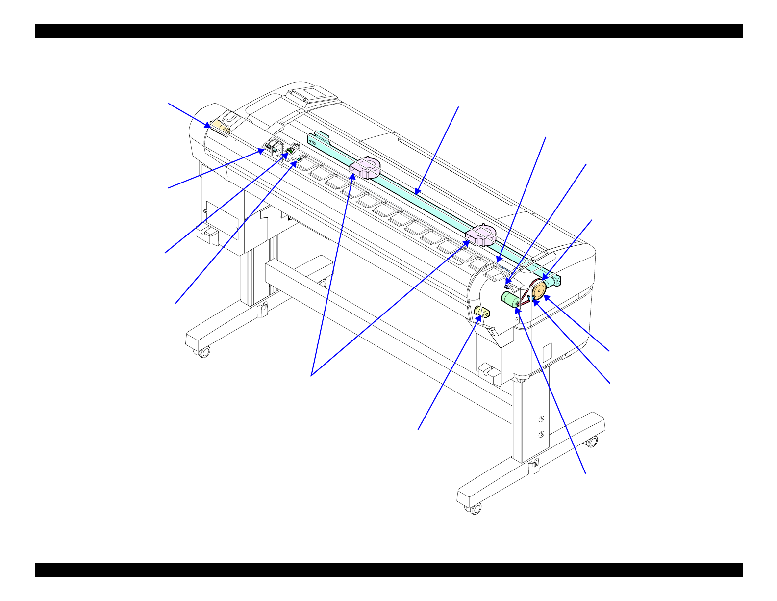
SC-T7000 series/SC-T5000 series/SC-T3000 series Revision B
f
ATC MOTOR (p. 175)
Feeds forward (normal rotation) and
rewinds (reverse rotation) the roll
paper to generate back tension.
* ATC: Auto Tension Control
PAPER THICKNESS SENSOR
(p. 180)
Detects the thickness of roll paper
being inserted into the printer.
PE SENSOR (ROLL PAPER)
(p. 177)
Detects the roll paper and cut
sheet.
PE SENSOR (THICK PAPER)
(p. 178)
Detects the thick paper.
CUTTER UNIT (p. 181)
PRESSURE ROLLER (p. 170)
PRESSURE ROLLER SENSOR
(p. 173)
Detects nipping/releasing status of
the PRESSURE ROLLER.
PF TIMING BELT (p. 168)
PF SCALE (p. 165)
SUCTION FAN (p. 184)
Sucks paper to the platen so as to stabilize the
position of paper when printing.
PRESSURE ROLLER MOTOR
(p. 171)
Makes the PRESSURE ROLLER
nip or release the media.
PF ENCODER (p. 166)
Detects the PF Scale patterns to
control the paper feeding (operation o
the PF MOTOR).
PF MOTOR (p. 163)
The motor to drive the Feed Roller.
Figure 3-7. Paper Feed Mechanism / Cutter
DISASSEMBLY & ASSEMBLY Parts Diagram 76
Confidential
Page 77

SC-T7000 series/SC-T5000 series/SC-T3000 series Revision B
TAKE-UP REEL COVER (p. 185)
TAKE-UP REEL
LED (p. 187)
TAKE-UP REEL
SWITCH (p. 188)
TAKE-UP REEL PS
TAKE-UP REEL
SENSOR (p. 186)
TAKE-UP REEL MAIN BOARD
(p. 194)
TAKE-UP REEL
MOTOR (p. 192)
BOARD (p. 190)
Figure 3-8. Auto Take-up Reel
DISASSEMBLY & ASSEMBLY Parts Diagram 77
Confidential
Page 78

SC-T7000 series/SC-T5000 series/SC-T3000 series Revision B
3.3 Disassembly Flowchart
HOUSING
Start
“3.4.2.14 UPPER LEFT COVER
“3.4.3.7 PANEL BOARD (p120)”
“3.4.2.9 RIGHT UPPER COVER &
“3.4.2.2 FRONT COVER (p86)”
“3.4.2.10 RIGHT LOWER COVER
(p100)”
“3.4.2.8 UPPER SUPPORT R
COVER (p94)”
“3.4.2.1 TOP COVER (p85)” “3.4.2.2 FRONT COVER (p86) ”
RIGHT ROLL COVER (p95)”
(p96)”
“3.4.2.5 IH COVER (p89)”
“3.4.2.20 CARTRIDGE COVER
SENSOR (p106)”
“3.4.2.4 LOWER PAPER GUIDE B
“3.4.2.3 LOWER PAPER GUIDE
“3.4.2.13 REAR RIGHT LOWER
“3.4.2.3 LOWER PAPER GUIDE
“3.4.2.4 LOWER PAPER GUIDE B
“3.4.2.10 RIGHT LOWER COVER
(p88)”
(p87)”
“3.4.2.6 WASTE INK TANK
COVER (p92)”
COVER (p99)”
(p87)”
(p88)”
(p96)”
“3.4.2.5 IH COVER (p89)”
“3.4.2.7 PRINTER COVER (p93)”
“3.4.2.10 RIGHT LOWER COVER
“3.4.2.2 FRONT COVER (p86)”
“3.4.2.23 INTERLOCK SWITCH
(p96)”
(p109)”
“3.4.2.8 UPPER SUPPORT R
COVER (p94)”
“3.4.2.10 RIGHT LOWER COVER
(p96)”
“3.4.2.11 RIGHT BASE COVER
(p97)”
“3.4.2.2 FRONT COVER (p86)”
“3.4.2.15 LEFT UPPER COVER &
LEFT ROLL COVER (p101)”
“3.4.2.18 REAR LEFT LOWER
COVER (p104)”
“3.4.2.12 LEFT LOWER COVER
(p98)”
“3.4.2.16 LEFT BASE COVER
(p102)”
“3.4.2.17 FRONT LEFT LOWER
COVER (p103)”
“3.4.2.3 LOWER PAPER GUIDE
“3.4.2.22 L WASTE INK COVER
(p87)”
SENSOR (p108)”
“3.4.2.21 R WASTE INK COVER
SENSOR (p107)”
DISASSEMBLY & ASSEMBLY Disassembly Flowchart 78
Confidential
Page 79

SC-T7000 series/SC-T5000 series/SC-T3000 series Revision B
ELECTRIC CIRCUIT COMPONENTS / FANS
Start
“3.4.2.14 UPPER LEFT COVER
“3.4.3.7 PANEL BOARD (p120)”
“3.4.2.9 RIGHT UPPER COVER &
“3.4.2.13 REAR RIGHT LOWER
“3.4.3.2 MAIN-B BOARD (p113)”
“3.4.3.3 MAIN-C BOARD (p114)”
(p100)”
“3.4.2.8 UPPER SUPPORT R
COVER (p94)”
“3.4.2.1 TOP COVER (p85)”
RIGHT ROLL COVER (p95)”
COVER (p99)”
“3.4.3.6 PSH BOARD (p118)”
“3.4.7.2 SUCTION FAN (p184)”
“3.4.2.2 FRONT COVER (p86)”
“3.4.2.15 LEFT UPPER COVER &
LEFT ROLL COVER (p101)”
“3.4.3.5 SUB-B BOARD (p117)”
“3.4.3.1 MAIN BOARD (p111)”
“3.4.7.1 BOARD BOX FAN
(p183)”
“3.4.2.8 UPPER SUPPORT R
COVER (p94)”
“3.4.3.7 PANEL BOARD (p120)”
“3.4.2.9 RIGHT UPPER COVER &
RIGHT ROLL COVER (p95)”
“3.4.1.1 Unlocking the CR Unit
(p83)”
“3.4.4.1 CR COVER (p122)”
“3.4.3.4 SUB BOARD (p115)”
DISASSEMBLY & ASSEMBLY Disassembly Flowchart 79
Confidential
Page 80

SC-T7000 series/SC-T5000 series/SC-T3000 series Revision B
CARRIAGE MECHANISM / INK SYSTEM MECHANISM
Start
“3.4.2.14 UPPER LEFT COVER
“3.4.3.7 PANEL BOARD (p120)”
“3.4.2.9 RIGHT UPPER COVER &
“3.4.2.2 FRONT COVER (p86)”
“3.4.2.10 RIGHT LOWER COVER
(p100)”
“3.4.2.8 UPPER SUPPORT R
COVER (p94)”
“3.4.2.1 TOP COVER (p85)”
RIGHT ROLL COVER (p95)”
(p96)”
“3.4.2.5 IH COVER (p89)”
“3.4.4.14 IC HOLDER (p148)”
“3.4.2.13 REAR RIGHT LOWER
COVER (p99)”
“3.4.2.10 RIGHT LOWER COVER
“3.4.1.1 Unlocking the CR Unit
(p96)”
(p83)”
“3.4.4.13 PUMP CAP UNIT
(p147)”
“3.4.1.1 Unlocking the CR Unit
“3.4.4.10 CR HP SENSOR (p143)”
“3.4.1.1 Unlocking the CR Unit
(p83)”
“3.4.4.11 APG UNIT (p144)”
(p83)”
“3.4.2.10 RIGHT LOWER COVER
(p96)”
“3.4.4.11 APG UNIT (p144)”
“3.4.2.2 FRONT COVER (p86)”
“3.4.2.15 LEFT UPPER COVER &
LEFT ROLL COVER (p101)”
“3.4.2.9 RIGHT UPPER COVER &
RIGHT ROLL COVER (p95)”
“3.4.1.1 Unlocking the CR Unit
“3.4.4.2 DAMPER KIT (p123)”
“3.4.4.3 PRINT HEAD (p126)”
“3.4.2.10 RIGHT LOWER COVER
(p83)”
“3.4.4.1 CR COVER (p122)”
(p96)”
“3.4.4.11 APG UNIT (p144)”
“3.4.4.9 CR MOTOR (p141)”
“3.4.4.6 CR SCALE (p135)”
“3.4.2.13 REAR RIGHT LOWER
COVER (p99)”
“3.4.4.4 HEAD FFC (p127)”
“3.4.2.10 RIGHT LOWER COVER
(p96)”
“3.4.2.5 IH COVER (p89)”
“3.4.4.15 INK TUBE (p152)”
“3.4.4.5 CR FFC (p131)”
“3.4.2.15 LEFT UPPER COVER &
LEFT ROLL COVER (p101)”
“3.4.4.9 CR MOTOR (p141)”
“3.4.4.6 CR SCALE (p135)”
“3.4.4.16 CR UNIT (p156)”
“3.4.4.7 CR ENCODER (p138)”
“3.4.4.12 PG SENSOR (p146)” “3.4.4.17 IM SENSOR (p159) ”
“3.4.4.8 CR TIMMING BELT
(p139)”
“3.4.4.18 PW SENSOR (p161)”
DISASSEMBLY & ASSEMBLY Disassembly Flowchart 80
Confidential
Page 81

SC-T7000 series/SC-T5000 series/SC-T3000 series Revision B
PAPER FEED MECHANISM / CUTTER
Start
“3.4.2.14 UPPER LEFT COVER
“3.4.3.7 PANEL BOARD (p120)”
“3.4.2.9 RIGHT UPPER COVER &
“3.4.2.2 FRONT COVER (p86)”
“3.4.2.15 LEFT UPPER COVER &
“3.4.2.12 LEFT LOWER COVER
“3.4.2.10 RIGHT LOWER COVER
“3.4.2.17 FRONT LEFT LOWER
(p100)”
“3.4.2.8 UPPER SUPPORT R
COVER (p94)”
“3.4.2.1 TOP COVER (p85)”
RIGHT ROLL COVER (p95)”
LEFT ROLL COVER (p101)”
(p98)”
(p96)”
COVER (p103)”
“3.4.2.19 REAR ROLL COVER
FRAME (p105)”
“3.4.5.9 PE SENSOR (ROLL
PAPER) (p177)”
“3.4.5.8 ATC MOTOR (p175)”
“3.4.5.11 PAPER THICKNESS
SENSOR (p180)”
“3.4.2.2 FRONT COVER (p86)”
“3.4.2.15 LEFT UPPER COVER &
LEFT ROLL COVER (p101)”
“3.4.2.18 REAR LEFT LOWER
COVER (p104)”
“3.4.2.12 LEFT LOWER COVER
“3.4.5.3 PF ENCODER (p166)”
(p98)”
“3.4.5.2 PF SCALE (p165)”
“3.4.2.19 REAR ROLL COVER
FRAME (p105)”
“3.4.5.10 PE SENSOR (THICK
PAPER) (p178)”
“3.4.5.6 PRESSURE ROLLER
MOTOR (p171)”
“3.4.5.4 PF TIMING BELT
(p168)”
“3.4.5.5 PRESSURE ROLLER
(p170)”
“3.4.5.1 PF MOTOR (p163)”
“3.4.5.7 PRESSURE ROLLER
SENSOR (p173)”
“3.4.2.5 IH COVER (p89)”
“3.4.2.4 LOWER PAPER GUIDE B
(p88)”
“3.4.2.3 LOWER PAPER GUIDE
“3.4.6.1 CUTTER UNIT (p181)”
(p87)”
DISASSEMBLY & ASSEMBLY Disassembly Flowchart 81
Confidential
Page 82

SC-T7000 series/SC-T5000 series/SC-T3000 series Revision B
AUTO TAKE-UP REEL (SC-T7050 SERIES ONLY)
Start
“3.4.8.1 TAKE-UP REEL
COVER (p185)”
“3.4.8.3 TAKE-UP REEL
LED (p187)”
“3.4.8.2 TAKE-UP REEL
SENSOR (p186)”
“3.4.8.4 TAKE-UP REEL
SWITCH (p188)”
“3.4.8.5 TAKE-UP REEL
PS BOARD (p190)”
“3.4.8.6 TAKE-UP REEL
MOTOR (p192)”
“3.4.8.7 TAKE-UP REEL
MAIN BOARD (p194)”
DISASSEMBLY & ASSEMBLY Disassembly Flowchart 82
Confidential
Page 83

SC-T7000 series/SC-T5000 series/SC-T3000 series Revision B
3.4 Disassembly and Assembly Procedure
This section describes procedures for disassembling the components allowed to be
disassembled. Unless otherwise specified, disassembled units or components can be
reassembled by reversing the disassembly procedure.
3.4.1 Preparation for servicing
3.4.1.1 Unlocking the CR Unit
Automatic
1. Turn the printer ON in the Serviceman Mode.
Turn the power ON while pressing [Menu], [Back] and [OK] buttons together.
2. Select Mecha Adjustment - CR Un Cap.
3. Press the [OK] button while [Enter] Un Cap is displayed.
The carriage unit is unlocked.
DISASSEMBLY & ASSEMBLY Disassembly and Assembly Procedure 83
Confidential
Page 84

SC-T7000 series/SC-T5000 series/SC-T3000 series Revision B
Manual
1. Remove the UPPER LEFT COVER. (p100)
2. Remove the UPPER SUPPORT R COVER. (p94)
3. Remove the PANEL BOARD. (p120)
4. Remove the TOP COVER. (p85)
5. Remove the RIGHT UPPER COVER & RIGHT ROLL COVER. (p95)
6. Insert a screwdriver into the cover through the hole as shown in the figure.
7. While viewing the CR Lock Lever status from the front of the printer, turn the
white shaft of the Pump Cap Unit counterclockwise with the driver.
8. The CR Lock Lever is lowered. Check that the lever reaches the CR unlock
position, and stop turning the white shaft.
C A U T I O N
C H E C K
P O I N T
Do not turn the white shaft clockwise with the driver.
When the CR is unlocked, it clicks.
Use a screwdriver with a 170 mm or longer shaft.
PUMP CAP
UNIT
Screwdrive
Insert driver here
Figure 3-9. Unlocking the CR Unit
CR Lock Lever
C A U T IO N
No clock
rotation!
CR unlocked
(The Lever is lowered)
Figure 3-10. Status of the CR Lock Lever
CR locked
(The lever is raised)
DISASSEMBLY & ASSEMBLY Disassembly and Assembly Procedure 84
Confidential
Page 85

SC-T7000 series/SC-T5000 series/SC-T3000 series Revision B
3.4.2 Housing
Positioning point
3.4.2.1 TOP COVER
1. Remove the UPPER LEFT COVER. (p100)
2. Remove the UPPER SUPPORT R COVER. (p94)
A
3. Remove the PANEL BOARD. (p120)
4. Remove the screw, and remove the TOP COVER.
A) Silver M3x8 S-tite screw with built-in washer: 1 pcs
5. Remove the PRINTER COVER. (p93)
Pay attention to the positioning points (See Figure 3-11).
Upper Support
Frame
TOP COVER
Figure 3-11. Removing the TOP COVER
DISASSEMBLY & ASSEMBLY Disassembly and Assembly Procedure 85
Confidential
Page 86

SC-T7000 series/SC-T5000 series/SC-T3000 series Revision B
3.4.2.2 FRONT COVER
1. Remove the UPPER LEFT COVER. (p100)
2. Remove the UPPER SUPPORT R COVER. (p94)
3. Remove the PANEL BOARD. (p120)
4. Open the PRINTER COVER.
5. Remove the seven screws, and remove the FRONT COVER.
A) Silver M3x8 S-tite screw with built-in washer: 7 pcs
To ensure the INTERLOCK SWITCH can detect the flag of
PRINTER COVE, tighten the screws which secure the FRONT
COVER while pulling the Front Frame toward you.
PRINTER COVER
A A A A A
FRONT COVER
Figure 3-12. Removing the FRONT COVER
INTERLOCK SWITCH
Front Frame
DISASSEMBLY & ASSEMBLY Disassembly and Assembly Procedure 86
Confidential
Page 87

SC-T7000 series/SC-T5000 series/SC-T3000 series Revision B
3.4.2.3 LOWER PAPER GUIDE
1. Remove the LOWER PAPER GUIDE B. (p88)
2. Open the WASTE INK TANK COVER.
3. Remove the three screws, and remove the LOWER PAPER GUIDE.
A) Silver M3x8 S-tite screw with built-in washer: 3 pcs
To ensure the tab of WASTE INK TANK COVER is inserted
in the groove of the Sensor Frame, install the LOWER PAPER
GUIDE with the WASTE INK TANK COVER opened.
When installing the LOWER PAPER GUIDE, take care not to
damage the L WASTE INK COVER SENSOR or R WASTE
INK COVER SENSOR.
Groove of the
Sensor Frame
L WASTE INK COVER
SENSOR
R WASTE INK COVER
SENSOR
LOWER PAPER GUIDE
A
WASTE INK TANK COVER
Figure 3-13. Removing the LOWER PAPER GUIDE
A
A
DISASSEMBLY & ASSEMBLY Disassembly and Assembly Procedure 87
Confidential
Page 88

SC-T7000 series/SC-T5000 series/SC-T3000 series Revision B
3.4.2.4 LOWER PAPER GUIDE B
1. Remove the two screws, and remove the LOWER PAPER GUIDE B.
A) Silver M3x8 S-tite screw with built-in washer: 2 pcs
A
A
LOWER PAPER GUIDE B
Figure 3-14. Removing the LOWER PAPER GUIDE B
A
A
DISASSEMBLY & ASSEMBLY Disassembly and Assembly Procedure 88
Confidential
Page 89

SC-T7000 series/SC-T5000 series/SC-T3000 series Revision B
3.4.2.5 IH COVER
1. Remove the UPPER LEFT COVER. (p100)
2. Remove the UPPER SUPPORT R COVER. (p94)
3. Remove the PANEL BOARD. (p120)
4. Remove the TOP COVER. (p85)
5. Remove the RIGHT UPPER COVER & RIGHT ROLL COVER. (p95)
6. Remove the FRONT COVER. (p86)
7. Remove the RIGHT LOWER COVER. (p96)
8. Release the cable from the four clamps.
9. Disconnect the cable from the relay connector (No.1), and release the cable of the
CARTRIDGE COVER SENSOR.
Clamps
10. Open the Cartridge Cover.
11. Remove the four screws that secure the IH COVER.
A) Silver M3x8 S-tite screw with built-in washer: 4 pcs
A
A
A
IH COVER
A
Cartridge Cover
Clamp
Figure 3-16. Removing the IH COVER
Cable of the
CARTRIDGE
COVER
SENSOR
Relay Connector (No.1)
Figure 3-15. Releasing the Cable
DISASSEMBLY & ASSEMBLY Disassembly and Assembly Procedure 89
Confidential
Page 90
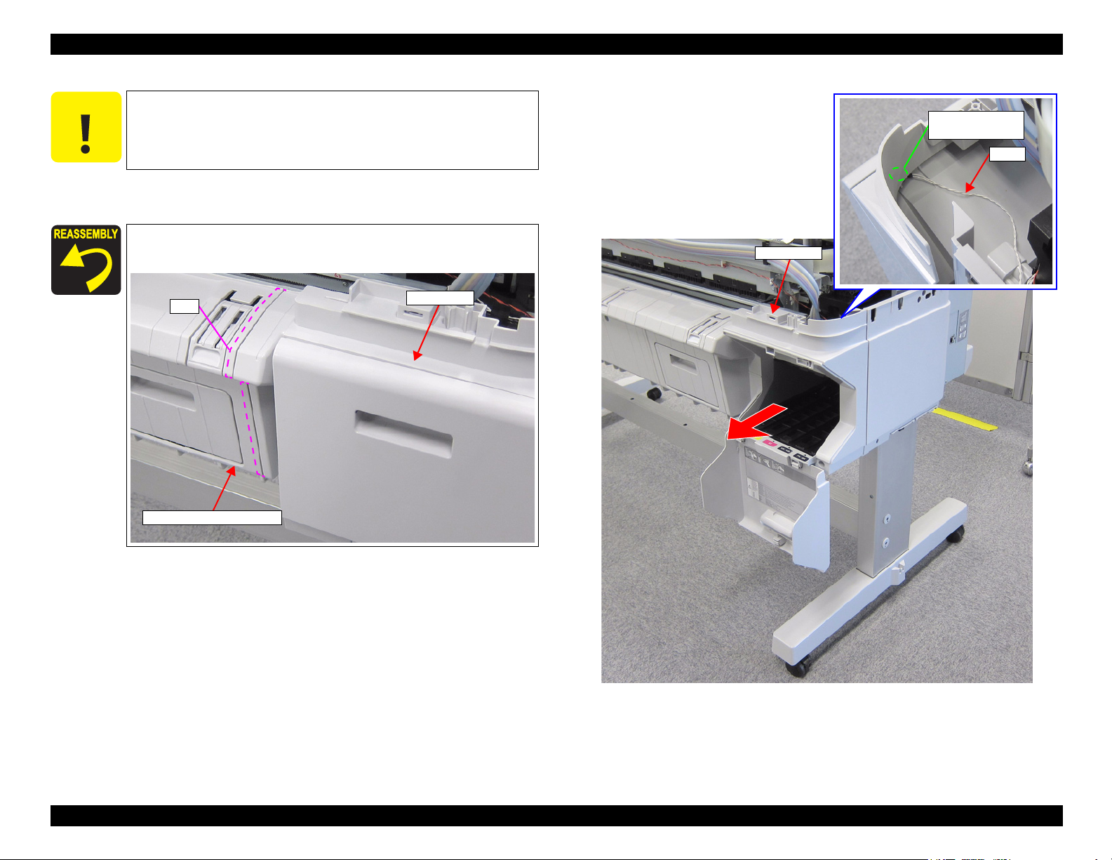
SC-T7000 series/SC-T5000 series/SC-T3000 series Revision B
C A U T I O N
Do not take off the IH COVER strongly too far in the following
steps because the CARTRIDGE COVER SENSOR is attached to
the IH COVER.
12. Pull out the IH COVER.
When installing the IH COVER, insert the rib under the LOWER
PAPER GUIDE.
Rib
CARTRIDGE
COVER SENSOR
Cable
IH COVER
IH COVER
LOWER PAPER GUIDE
Figure 3-17. Removing the IH COVER
DISASSEMBLY & ASSEMBLY Disassembly and Assembly Procedure 90
Confidential
Page 91

SC-T7000 series/SC-T5000 series/SC-T3000 series Revision B
13. Disengage the two hooks that secure the CARTRIDGE COVER SENSOR, and
remove the CARTRIDGE COVER SENSOR from the IH COVER.
Pay attention to the positioning points (See Figure 3-18).
Inside of IH COVER
Hole
CARTRIDGE
COVER SENSOR
Positioning point
Figure 3-18. Removing the CARTRIDGE COVER SENSOR
Positioning point
Hook
DISASSEMBLY & ASSEMBLY Disassembly and Assembly Procedure 91
Confidential
Page 92

SC-T7000 series/SC-T5000 series/SC-T3000 series Revision B
3.4.2.6 WASTE INK TANK COVER
1. Remove the LOWER PAPER GUIDE B. (p88)
2. Remove the LOWER PAPER GUIDE. (p87)
3. Disengage the two hooks on the WASTE INK TANK COVER from the two shafts
of the LOWER PAPER GUIDE using a tool such as a slotted-head screwdriver,
then remove the WASTE INK TANK COVER.
LOWER
PAPER GUIDE
WASTE INK TANK
COVER
Shafts
Back side
Hooks
Figure 3-19. Removing the WASTE INK TANK COVER
DISASSEMBLY & ASSEMBLY Disassembly and Assembly Procedure 92
Confidential
Page 93

SC-T7000 series/SC-T5000 series/SC-T3000 series Revision B
3.4.2.7 PRINTER COVER
1. Disengage the three hinges of the PRINTER COVER from the bearings, and
remove the PRINTER COVER.
Bearing
Hinge
PRINTER COVER
Figure 3-20. Removing the PRINTER COVER
DISASSEMBLY & ASSEMBLY Disassembly and Assembly Procedure 93
Confidential
Page 94

SC-T7000 series/SC-T5000 series/SC-T3000 series Revision B
3.4.2.8 UPPER SUPPORT R COVER
1. Remove the two screws, and remove the UPPER SUPPORT R COVER.
A) Silver M3x8 S-tite screw with built-in washer: 2 pcs
Pay attention to the positioning points. (See below figure)
UPPER SUPPORT R
COVER
A
Panel Housing
Positioning points
Positioning points
A
UPPER SUPPORT R
COVER
RIGHT LOWER
COVER
Figure 3-21. Removing the UPPER SUPPORT R COVER
TOP COVER
DISASSEMBLY & ASSEMBLY Disassembly and Assembly Procedure 94
Confidential
Page 95

SC-T7000 series/SC-T5000 series/SC-T3000 series Revision B
3.4.2.9 RIGHT UPPER COVER & RIGHT ROLL COVER
1. Remove the UPPER LEFT COVER. (p100)
2. Remove the UPPER SUPPORT R COVER. (p94)
3. Remove the PANEL BOARD. (p120)
4. Remove the TOP COVER. (p85)
5. Remove the six screws, and remove the RIGHT UPPER COVER & RIGHT
ROLL COVER.
A) Silver M4x12 P-tite screw with washer: 1 pcs
B) Silver M3x10 P-tite screw with washer: 2 pcs
C) Silver M3x8 S-tite screw with built-in washer: 3 pcs
Pay attention to the positioning points (See below figure, Figure
3-22).
Inside
Positioning points
RIGHT LOWER
COVER
B
Positioning point
A
RIGHT UPPER
COVER & RIGHT
ROLL COVER
C
B
IH COVER
C
C
Figure 3-22. Removing the RIGHT UPPER COVER & RIGHT ROLL COVER
DISASSEMBLY & ASSEMBLY Disassembly and Assembly Procedure 95
Confidential
Page 96

SC-T7000 series/SC-T5000 series/SC-T3000 series Revision B
3.4.2.10 RIGHT LOWER COVER
1. Remove the UPPER LEFT COVER. (p100)
2. Remove the UPPER SUPPORT R COVER. (p94)
3. Remove the PANEL BOARD. (p120)
4. Remove the TOP COVER. (p85)
5. Remove the RIGHT UPPER COVER & RIGHT ROLL COVER. (p95)
6. Remove the three screws, and remove the RIGHT LOWER COVER.
A) Silver M3x10 P-tite screw with washer: 1 pcs
B) Silver M3x8 S-tite screw with built-in washer: 2 pcs
Insert the two tabs of the IH COVER to the two holes on the
RIGHT LOWER COVER.
Pay attention to the positioning points (See below figure).
IH COVER
Tabs
RIGHT LOWER COVER
B
B
A
Figure 3-23. Removing the RIGHT LOWER COVER
RIGHT BASE COVER
Positioning points
RIGHT LOWER
COVER
DISASSEMBLY & ASSEMBLY Disassembly and Assembly Procedure 96
Confidential
Page 97

SC-T7000 series/SC-T5000 series/SC-T3000 series Revision B
3.4.2.11 RIGHT BASE COVER
1. Remove the UPPER LEFT COVER. (p100)
2. Remove the UPPER SUPPORT R COVER. (p94)
3. Remove the PANEL BOARD. (p120)
4. Remove the TOP COVER. (p85)
5. Remove the RIGHT UPPER COVER & RIGHT ROLL COVER. (p95)
6. Remove the RIGHT LOWER COVER. (p96)
RIGHT BASE COVER
7. Remove the two screws, and remove the RIGHT BASE COVER.
A) Silver M3x8 S-tite screw with built-in washer: 2 pcs
Pay attention to the positioning points (See below figure).
RIGHT BASE COVER
Positioning point
Positioning point
A
Figure 3-24. Removing the RIGHT BASE COVER
A
DISASSEMBLY & ASSEMBLY Disassembly and Assembly Procedure 97
Confidential
Page 98

SC-T7000 series/SC-T5000 series/SC-T3000 series Revision B
3.4.2.12 LEFT LOWER COVER
1. Remove the UPPER LEFT COVER. (p100)
2. Remove the UPPER SUPPORT R COVER. (p94)
3. Remove the PANEL BOARD. (p120)
4. Remove the TOP COVER. (p85)
5. Remove the FRONT COVER. (p86)
6. Remove the LEFT UPPER COVER & LEFT ROLL COVER. (p101)
7. Remove the REAR LEFT LOWER COVER. (p104)
8. Remove the two screws, and LEFT LOWER COVER.
A) Silver M3x10 P-tite screw with washer: 1 pcs
B) Silver M4x12 P-tite screw with washer: 1 pcs
Insert the two tabs of the FRONT LEFT LOWER COVER to
the two holes on the LEFT LOWER COVER.
Pay attention to the positioning points (See below figure).
FRONT LEFT
LOWER COVER
Tabs
Upper side
B
LEFT LOWER COVER
A
LEFT BASE COVER
Figure 3-25. Removing the LEFT LOWER COVER
Positioning points
LEFT LOWER
COVER
DISASSEMBLY & ASSEMBLY Disassembly and Assembly Procedure 98
Confidential
Page 99

SC-T7000 series/SC-T5000 series/SC-T3000 series Revision B
3.4.2.13 REAR RIGHT LOWER COVER
1. Remove the UPPER LEFT COVER. (p100)
2. Remove the UPPER SUPPORT R COVER. (p94)
3. Remove the PANEL BOARD. (p120)
4. Remove the TOP COVER. (p85)
5. Remove the RIGHT UPPER COVER & RIGHT ROLL COVER. (p95)
6. Remove the ten screws, and remove the REAR RIGHT LOWER COVER.
A) Silver M3x8 S-tite screw with built-in washer: 10 pcs
REAR RIGHT LOWER COVER
Inside
A
A
A
A
A
A
Figure 3-26. Removing the REAR RIGHT LOWER COVER
A
A
A
A
DISASSEMBLY & ASSEMBLY Disassembly and Assembly Procedure 99
Confidential
Page 100

SC-T7000 series/SC-T5000 series/SC-T3000 series Revision B
3.4.2.14 UPPER LEFT COVER
1. Open the PRINTER COVER.
2. Remove the five screws, and remove the UPPER LEFT COVER.
A) Silver M3x8 S-tite screw with built-in washer: 5 pcs
A
PRINTER COVER
UPPER LEFT COVER
A
A
A
A
Figure 3-27. Removing the UPPER LEFT COVER
DISASSEMBLY & ASSEMBLY Disassembly and Assembly Procedure 100
Confidential
 Loading...