

Page 1
SC-P800 series
Large Format Color Inkjet Printer
SERVICE MANUAL
SECP14-007
SE Group Confidential (Related Staff Only)
Page 2

SE Group Confidential (Related Staff Only)
Notice:
All rights reserved. No part of this manual may be reproduced, stored in a retrieval system, or transmitted in any form or by any means, electronic,
mechanical, photocopying, recording, or otherwise, without the prior written permission of SEIKO EPSON CORPORATION.
All effort have been made to ensure the accuracy of the contents of this manual. However, should any errors be detected, SEIKO EPSON would greatly
appreciate being informed of them.
The contents of this manual are subject to change without notice.
The above not withstanding SEIKO EPSON CORPORATION can assume no responsibility for any errors in this manual or the consequences thereof.
EPSON is a registered trademark of SEIKO EPSON CORPORATION.
Notice: Other product names used herein are for identification purpose only and may be trademarks or registered trademarks of their respective owners. EPSON
disclaims any and all rights in those marks.
Copyright © 2015 SEIKO EPSON CORPORATION.
352)(66,21$/35,17,1*23(5$7,216',9,6,21
Page 3

SE Group Confidential (Related Staff Only)
PRECAUTIONS
Precautionary notations throughout the text are categorized relative to 1) Personal injury and 2) Damage to equipment.
DANGER Signals a precaution which, if ignored, could result in serious or fatal personal injury. Great caution should be exercised in performing
procedures preceded by DANGER Headings.
WARNING Signals a precaution which, if ignored, could result in damage to equipment.
The precautionary measures itemized below should always be observed when performing repair/maintenance procedures.
DANGER
1. ALWAYS DISCONNECT THE PRODUCT FROM THE POWER SOURCE AND PERIPHERAL DEVICES PERFORMING ANY MAINTENANCE OR
REPAI
R PROCEDURES.
2. NO WORK SHOULD BE PERFORMED ON THE UNIT BY PERSONS UNFAMILIAR WITH BASI
C SAFETY MEASURES AS DICTATED FOR ALL
ELECTRONI
CS TECHNICIANS IN THEIR LINE OF WORK.
3. WHEN PERFORMING TESTING AS DICTATED WITHIN THIS MANUAL, DO NOT CONNECT THE UNIT TO A POWER SOURCE UNTI
L
INSTRUCTED TO DO SO. WHEN THE POWER SUPPLY CABLE MUST BE CONNECTED, USE EXTREME CAUTION IN WORKING ON POWER
SUPPLY AND OTHER ELECTRONI
C COMPONENTS.
4. WHEN DISASSEMBLING OR ASSEMBLING A PRODUCT, MAKE SURE TO WEAR GLOVES TO AVOID INJURY FROM
METAL PARTS WITH
SHARP EDGES.
WARNING
1. REPAIRS ON EPSON PRODUCT SHOULD BE PERFORMED ONLY BY AN EPSON CERTIFIED REPAIR TECHNICIAN.
2. MAKE CERTAIN THAT THE SOURCE VOLTAGES IS THE SAME AS THE RATED VOLTAGE, LISTED ON THE SERIAL NUMBER/RATI
NG
PLATE.
IF THE EPSON PRODUCT HAS A PRIMARY AC RATING DIFFERENT FROM AVAILABLE POWER SOURCE, DO NOT CONNECT
IT TO
THE POWER SOURCE.
3.
ALWAYS VERIFY THAT THE EPSON PRODUCT HAS BEEN DISCONNECTED FROM THE POWER SOURCE BEFORE REMOVI
NG OR
REPLACING PRINTED CIRCUIT BOARDS AND/OR INDIVIDUAL CHIPS.
4. IN ORDER TO PROTECT SENSITIVE MICROPROCESSORS AND CIRCUITRY, USE STATIC DISCHARGE EQUIPMENT, SUCH AS ANTI-STATIC
WRIST STRAPS, WHEN ACCESSING INTERNAL COMPONENTS.
5. REPLACE MALFUNCTIONING COMPONENTS ONLY WITH THOSE COMPONENTS BY THE MANUFACTURE; INTRODUCTION OF SECONDSOURCE ICs OR OTHER NON-APPROVED COMPONENTS MAY DAMAGE THE PRODUCT AND VOID ANY APPLICABLE EPSON WARRANTY.
6. WHEN AIR DUSTER IS USED ON THE REPAIR AND THE MAINTENANCE WORK, THE USE OF THE AIR DUSTER PRODUCTS CONTAI
NING
THE I
NFLAMMABLE GAS IS PROHIBITED.
7. MAKE SURE AN ANTIVIRUS SOFTWARE IS INSTALLED ON THE COMPUTER USED FOR SERVICE SUPPORT. BE SURE TO H
AVE THE
LATEST
VIRUS DEFINITION FILE FOR THE SOFTWARE.
Page 4

SE Group Confidential (Related Staff Only)
About This Manual
About This Manual: This manual is made for the sole purpose of providing necessary information in order that a serviceperson qualified by Epson performs his / her appropriate
repair / maintenance for the applicable Epson’s products. You shall not use this manual out of this purpose.
This manual is Epson’s confidential information. When you use this manual, you shall hold it in strict confidence and shall not disclose to any third party without prior consent of
Epson.
The instructions and procedures included herein are intended for the experienced repair technicians, and attention should be given to the precautions on the preceding page.
Manual Configuration
This manual consists of six chapters and Appendix.
CHAPTER 1.PRODUCT DESCRIPTIONS
Provides a general overview and specifications of the product.
CHAPTER 2.TROUBLESHOOTING
Describes the step-by-step procedures for the troubleshooting.
CHAPTER 3.DISASSEMBLY / ASSEMBLY
Describes the step-by-step procedures for disassembling and assembling the product.
CHAPTER 4.ADJUSTMENT
Provides Epson-approved methods for adjustment.
CHAPTER 5.MAINTENANCE
Provides preventive maintenance procedures and the lists of Epson-approved lubricants and
adhesives required for servicing the product.
CHAPTER 6.APPENDIX
Provides the following additional information for reference:
•
C
onnectors
• Panel Menu Maps
• ASP
List
•Exploded Diagrams
Page 5

SE Group Confidential (Related Staff Only)
Symbols Used in this Manual
Various symbols are used throughout this manual either to provide additional information on a specific topic or to warn of possible danger present during a procedure or an action.
Be aware of all symbols when they are used, and always read NOTE, CAUTION, or WARNING messages.
Indicates an operating or maintenance procedure, practice or condition that is necessary to keep the product’s quality.
Indicates an operating or maintenance procedure, practice, or condition that, if not strictly observed, could result in damage to, or destruction of, equipment.
May indicate an operating or maintenance procedure, practice or condition that is necessary to accomplish a task efficiently. It may also provide additional
information that is related to a specific subject, or comment on the results achieved through a previous action.
Indicates an operating or maintenance procedure, practice or condition that, if not strictly observed, could result in injury or loss of life.
Indicates that a particular task must be carried out according to a certain standard after disassembly and before re-assembly, otherwise the quality of the components
in question may be adversely affected.
Indicates that lubrication is needed for the parts after disassembly, when doing a maintenance or replacing a part with a new one.
Lubrication
Page 6

SE Group Confidential (Related Staff Only)
Revision Status
Revision Date of Issue Description
A March 27, 2015 First release
B
May 2,2015
• Chapter 4
Added of Figure 4-3,4 to page 211.
Changed of text to page 211.
Replacement of Figure 4-5,6,7,8 to page 212.
Page 7

SC-P800 series Revision B
7
SE Group Confidential (Related Staff Only)
Contents
Chapter 1 PRODUCT DESCRIPTION
1.1 Product Description ............................................................................................ 11
1.2 Basic Specifications ............................................................................................ 12
1.2.1 Basic Specifications ................................................................................... 12
1.2.2 Electric Specifications ............................................................................... 13
1.2.3 Ink Specifications ...................................................................................... 13
1.3 Printing Specifications ........................................................................................ 14
1.3.1 Paper Feed Specifications .......................................................................... 14
1.3.2 Paper Feeder Specifications ....................................................................... 14
1.3.3 Supported Media ........................................................................................ 15
1.3.3.1 Epson Special Media Table ................................................................ 15
1.3.3.2 Usable Commercially Available Paper Size ...................................... 17
1.3.4 Printable area ............................................................................................. 20
1.3.5 Borderless Printing Specification .............................................................. 21
1.4 Hardware Specifications ..................................................................................... 22
1.4.1 Dimensions and Weight ............................................................................. 22
1.4.2 Installation Room Requirement ................................................................. 22
1.4.3 Part Names ................................................................................................. 23
1.5 Control Panel Specifications .............................................................................. 25
1.5.1 Control panel ............................................................................................. 25
1.5.2 Menu Descriptions ..................................................................................... 28
1.5.3 Inspection Mode ........................................................................................ 32
Chapter 2 TROUBLE SHOOTING
2.1 Overview ............................................................................................................ 34
2.1.1 Preliminary Check ..................................................................................... 34
2.1.1.1 Before performing troubleshooting .................................................... 34
2.1.1.2 Check for the usage environment ....................................................... 34
2.1.1.3 Recurrence check of the trouble ......................................................... 34
2.1.1.4 Check for the counter values/history .................................................. 34
2.1.1.5 Test print check .................................................................................. 34
2.1.2 Troubleshooting Procedure ........................................................................ 35
2.1.3 Procedure after troubleshooting ................................................................. 35
2.1.3.1 If the trouble has been successfully solved ........................................ 35
2.1.3.2 If necessary to escalate the trouble case ............................................. 35
2.2 Remedies for Maintenance Requests ................................................................. 36
2.3 Remedies for Service Call Error ........................................................................ 37
2.4 Remedies for Print Quality Troubles .................................................................. 44
2.5 Trouble on Paper Feeding .................................................................................. 47
2.6 Other Troubles .................................................................................................... 48
2.7 Trouble on Service Program ............................................................................... 49
2.8 Trouble on NVRAM Viewer .............................................................................. 50
Chapter 3 DISASSEMBLY & ASSEMBLY
3.1 Overview ............................................................................................................ 52
3.1.1 Precautions ................................................................................................. 52
3.1.2 Cautions after assembling .......................................................................... 54
3.1.3 Orientation Definition ................................................................................ 54
3.1.4 Recommended Tools ................................................................................. 55
3.2 Parts Diagram ..................................................................................................... 56
3.3 Disassembly Flowchart ...................................................................................... 62
3.4 Disassembly and Assembly Procedure ............................................................... 68
3.4.1 Preparation for servicing ........................................................................... 68
3.4.1.1 Unlocking the CARRIAGE, ASSY. manually ................................... 68
3.4.2 Consumable ............................................................................................... 69
3.4.2.1 Ink Cartridge ...................................................................................... 69
3.4.2.2 Maintenance Cartridge ....................................................................... 70
3.4.3 Housing ...................................................................................................... 71
3.4.3.1 COVER, IH, ASSY. ........................................................................... 71
3.4.3.2 HOUSING, REAR, ASSY. ................................................................ 72
3.4.3.3 HOUSING, FRONT, LEFT ............................................................... 74
3.4.3.4 HOUSING, FRONT, RIGHT, UPPER .............................................. 75
3.4.3.5 COVER, WB ...................................................................................... 76
3.4.3.6 COVER, PRINTER ............................................................................ 77
3.4.3.7 PAPER, SUPPORT, ASSY. ............................................................... 78
3.4.3.8 Cover, Panel ....................................................................................... 79
3.4.3.9 HOUSING, LEFT .............................................................................. 80
Page 8

SC-P800 series Revision B
8
SE Group Confidential (Related Staff Only)
3.4.3.10 HOUSING, RIGHT .......................................................................... 81
3.4.3.11 Housing, Front, Support/Hinge, Cover, IC ...................................... 82
3.4.3.12 HOUSING, FRONT, UPPER .......................................................... 83
3.4.3.13 OPERATION, PANEL, ASSY. ....................................................... 84
3.4.3.14 HOUSING, UPPER .......................................................................... 85
3.4.3.15 COVER, HOUSING, LOWER ........................................................ 87
3.4.3.16 BASE, ENCLOSURE ...................................................................... 88
3.4.3.17 LOCK, COVER, ASSY. .................................................................. 90
3.4.3.18 MAINTENANCE CARTRIDGE SENSOR .................................... 93
3.4.4 Electric Circuit Components ...................................................................... 94
3.4.4.1 BOARD ASSY., MAIN ..................................................................... 94
3.4.4.2 BOARD ASSY., POWER SUPPLY .................................................. 97
3.4.4.3 AC INLET .......................................................................................... 99
3.4.4.4 BOARD ASSY., SUB ...................................................................... 100
3.4.4.5 WiFi, Assy ........................................................................................ 101
3.4.5 Carriage Mechanism / Ink System Mechanism ....................................... 102
3.4.5.1 COVER, CR ..................................................................................... 102
3.4.5.2 PRINT HEAD .................................................................................. 103
3.4.5.3 SCALE, CR ...................................................................................... 107
3.4.5.4 BOARD ASSY., ENCODER ........................................................... 110
3.4.5.5 BOARD ASSY., DETECTOR, PW; B ............................................ 111
3.4.5.6 BELT, CR ......................................................................................... 112
3.4.5.7 PULLEY, DRIVEN, ASSY. ............................................................ 113
3.4.5.8 MOTOR ASSY., APG ..................................................................... 114
3.4.5.9 MOTOR ASSY., CR ........................................................................ 116
3.4.5.10 APG SENSOR ................................................................................ 118
3.4.5.11 CARRIAGE, ASSY. ...................................................................... 119
3.4.5.12 PUMP, CAP ASSY. ....................................................................... 122
3.4.5.13 INK, SYSTEM, ASSY. .................................................................. 125
3.4.5.14 POROUS PAD, TRAY, INK EJECT ............................................. 132
3.4.5.15 POROUS PAD, INK WASTE BOX, RIGHT/
POROUS PAD, INK WASTE BOX, LEFT .................................... 133
3.4.5.16 PRESSURE, PUMP, ASSY. .......................................................... 135
3.4.5.17 CABLE ASSY., ASP ..................................................................... 137
3.4.6 Paper Feed Mechanism ............................................................................ 152
3.4.6.1 STACKER, ASSY. ........................................................................... 152
3.4.6.2 BOARD PAPER TRAY/FRAME, PAPER, EJECT, ASSY ............ 159
3.4.6.3 Rear Paper Guide Assy ..................................................................... 170
3.4.6.4 PAPER, GUIDE, LOWER, L / R ..................................................... 171
3.4.6.5 SCALE, PF, 180 ............................................................................... 172
3.4.6.6 ENCODER, PF, ASSY. ................................................................... 173
3.4.6.7 TIMING BELT, PF .......................................................................... 174
3.4.6.8 MOTOR, RELEASE, ASSY. ........................................................... 176
3.4.6.9 PAPER, DETECTOR, PE, ASF, ASSY .......................................... 179
3.4.6.10 ASF, ASSY. ................................................................................... 180
3.4.6.11 MOTOR ASSY., ASF .................................................................... 184
3.4.6.12 ASF SENSOR ................................................................................ 185
3.4.6.13 RELEASE SENSOR ...................................................................... 186
3.4.6.14 PAPER, DETECTOR, ASSY. ....................................................... 187
3.4.6.15 SHAFT, RELEASE, ASSY. .......................................................... 189
3.4.6.16 PAPER GUIDE, UPPER, ASSY. .................................................. 190
3.4.7 Printer Mechanism ................................................................................... 192
3.4.7.1 Replacing the PRINTER MECHANISM ......................................... 192
Chapter 4 ADJUSTMENT
4.1 Overview .......................................................................................................... 194
4.1.1 Precautions ............................................................................................... 194
4.1.2 Adjustment Items and the Order by Repaired Part .................................. 195
4.1.3 Adjustment Items ..................................................................................... 202
4.1.4 List of Tools/Software/Consumables for Adjustments ........................... 208
4.1.5 Service Program Basic Operations .......................................................... 209
4.2 NV-RAM BACKUP/NVRAM Viewer ............................................................ 210
4.2.1 NVRAM Read Procedure ........................................................................ 210
4.2.2 NVRAM Viewer Basic Operation ........................................................... 211
4.3 ADJUSTMENTS (Individual) ......................................................................... 216
4.4 ADJUSTMENTS (Sequence) ........................................................................... 217
4.5 Installing Firmware .......................................................................................... 218
4.6 Image Print ....................................................................................................... 219
4.7 Counter Reset ................................................................................................... 220
4.8 References ........................................................................................................ 221
4.9 Printer Setting Change ...................................................................................... 222
4.10 CR Related Adjustments ................................................................................ 223
4.10.1 PG Position Adjustment ........................................................................ 223
4.10.2 CR Timing Belt Tension Check ............................................................ 225
4.10.3 APG Function Check ............................................................................. 226
4.10.4 CR Scale Check ..................................................................................... 227
4.10.5 Bi-D Adjustment .................................................................................... 228
4.10.6 PW Adjustment ...................................................................................... 229
4.11 Head Related Checks and Adjustments .......................................................... 231
4.11.1 Head ID Input ........................................................................................ 231
4.11.2 Head Inclination Check & Adjustment (CR direction) ......................... 232
Page 9

SC-P800 series Revision B
9
SE Group Confidential (Related Staff Only)
4.11.3 Head Slant Check & Adjustment (PF direction) ................................... 236
4.11.4 Cleaning ................................................................................................. 238
4.11.5 Nozzle Check ......................................................................................... 239
4.11.6 Colorimetric Calibration ........................................................................ 240
4.11.6.1 Overview of the Colorimetric Calibration ...................................... 240
4.11.6.2 Adjusting Method of the Colorimetric Calibration ........................ 243
4.11.6.3 Maintenance menu ......................................................................... 253
4.12 Ink Supply Related Checks and Adjustments ................................................ 256
4.12.1 Initial ink charge .................................................................................... 256
4.12.2 Ink Selector Operation Check ................................................................ 257
4.13 Media Feed Related Checks and Adjustments ............................................... 259
4.13.1 PF Timing Belt Tension Check ............................................................. 259
4.13.2 LD Roller Position Adjustment ............................................................. 261
4.13.3 PF Scale Check ...................................................................................... 264
4.13.4 Media Feed Auto Adjustment ................................................................ 265
4.13.5 EJ Adjustment ........................................................................................ 267
4.14 Boards Related Checks and Adjustments ....................................................... 269
4.14.1 Main Board initial setting ...................................................................... 269
4.14.2 RTC Check & Input ............................................................................... 270
4.14.3 Serial Number & USB ID Input ............................................................ 271
4.14.4 MAC Address Input ............................................................................... 272
4.14.5 Initial Ink charge Flag off ...................................................................... 273
4.15 Other Printer Checks and Adjustments .......................................................... 274
4.15.1 CR Motor Measurement ........................................................................ 274
4.15.2 PF Motor Measurement & Automatic Adjustment ............................... 275
4.16 Inspection Mode ............................................................................................. 276
Chapter 5 MAINTENANCE
5.1 Overview .......................................................................................................... 279
5.2 Transportation ................................................................................................... 280
5.3 Exchange Parts ................................................................................................. 281
5.4 Cleaning ............................................................................................................ 282
5.5 Lubrication ....................................................................................................... 284
Chapter 6 APPENDIX
6.1 Block Wiring Diagram ..................................................................................... 294
6.2 Connection Diagram ......................................................................................... 295
6.3 Panel Menu Map ............................................................................................... 299
6.4 Part names used in this manual ........................................................................ 301
6.5 Exploded Diagram/Parts List ........................................................................... 303
Page 10

SE Group Confidential (Related Staff Only)
C H A P T E R
1
PRODUCT DESCRIPTION
Page 11
SC-P800 series Revision B
PRODUCT DESCRIPTION Product Description 11
SE Group Confidential (Related Staff Only)
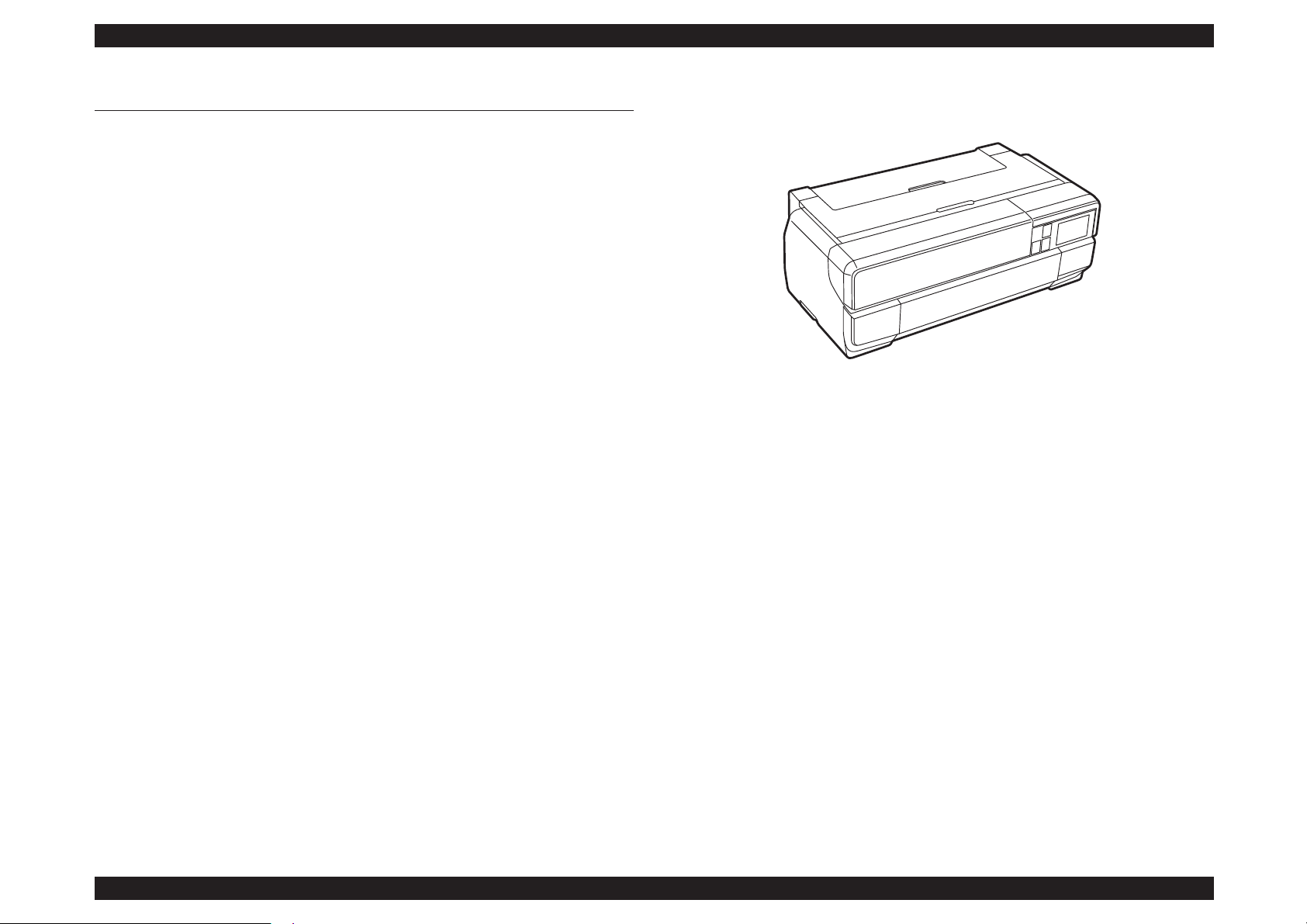
1.1 Product Description
SC-P800 series are large size color inkjet printers that support up to A2 (17”) sized cutsheet paper.
F-Mach (180N x 8-column) print head
Maximum print resolution (dpi): 2880 x 1440
Superior color and monochrome reproducibility with eight colors
UltrachromeK3 ink system, consisting of 4 basic colors (YMCK) with 2
complementary colors and 2 complementary blacks
Automatic switching between black ink modes; Photo black and Matte black.
Requires no user intervention, and ink used during the conversion is remarkably
reduced.
Two manual paper feeders are provided in addition to the ASF (Auto Sheet
Feeder)
Front manual feeder: Supports thick paper having a thickness of up to 1.5
mm.
Roll paper: Feeds paper using the roll paper unit (option).
High speed network and communication supported
100BASE-TX/10BASE-T Network Interface
USB2.0 High Speed Interface
Wireless LAN 802.11b/g/n Network Interface
Borderless printing supported
Equipped with a control panel having a 2.7-inch color touch panel, offering
excellent visibility and operability
Figure 1-1. External View
Page 12
SC-P800 series Revision B
PRODUCT DESCRIPTION Basic Specifications 12
SE Group Confidential (Related Staff Only)
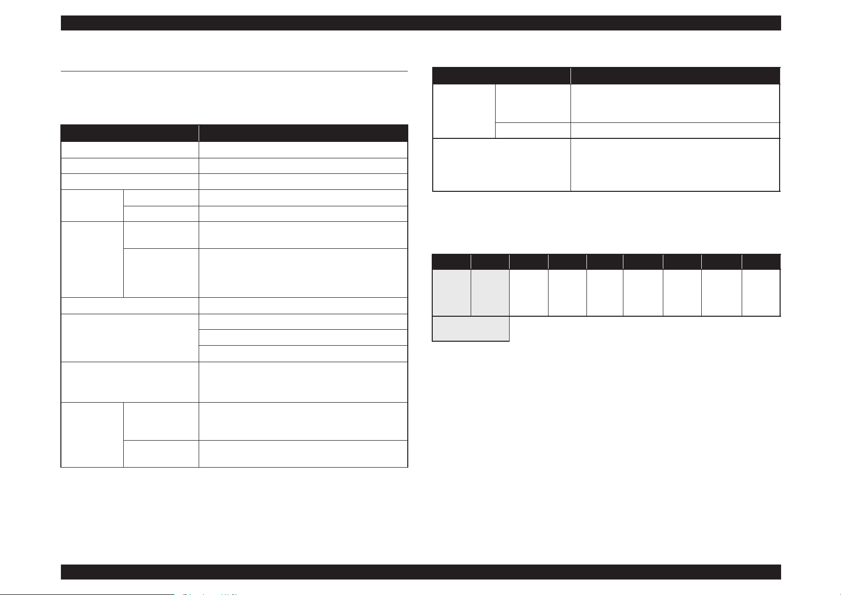
1.2 Basic Specifications
1.2.1 Basic Specifications
Note "*" : The all 9 ink cartridges can be installed simultaneously. The printer automatically switches
between Photo and Matte black depending on the driver selection while utilizing the same
physical ink channel.
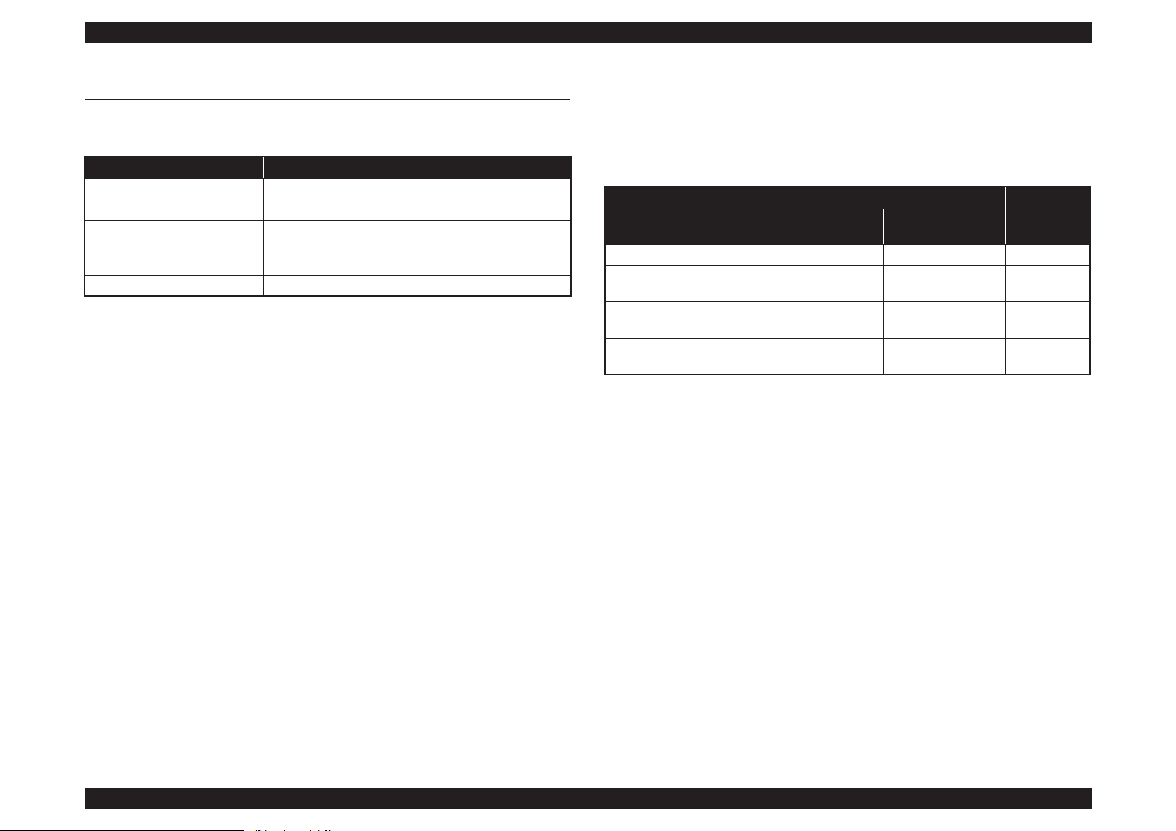
Table 1-1. Basic Specifications
Item Specifications
Maximum paper width 17 inch (43 cm)
Printing method On-demand ink jet method
Printing direction Two-way shortest distance printing with logical seeking
Print Head
Type F-Mach
Number of nozzles 180 Nozzles per color (180 Nozzles x 8 colors)*
Ink
Type
UltrachromeK3 ink system (9 independent ink
cartridges)*
Color of inks
Matte Black*, Photo Black*, Light Black, Light Light
Black, Cyan, Vivid Magenta, Yellow, Light Cyan, Vivid
Light Magenta (Refer to
table1-2 for the alignment
sequence of the cartridges)
Maximum print resolution 2880 dpi × 1440 dpi
Printing function
Borderless printing
Automatic bottom processing
L/4 x 6 Photo high-speed printing
Interface
Ethernet 100BASE-TX/10BASE-T
High-Speed USB
IEEE802.11b/g/n
Temperature
Main body
operation
environment
10 °C to 35 °C
When storing
-20 °C to 40 °C (within 120 hours under 60 °C, and
within 1 month under 40 °C)
Humidity
Main body
operation
environment
20% to 80% (Non condensing)
When storing 5% to 85% (Non condensing)
Operating life of the printer
Until any one of the following conditions is met.
12,000 pages (A2 plain paper fine mode)
1,600,000 paths (carriage movement)
5 years
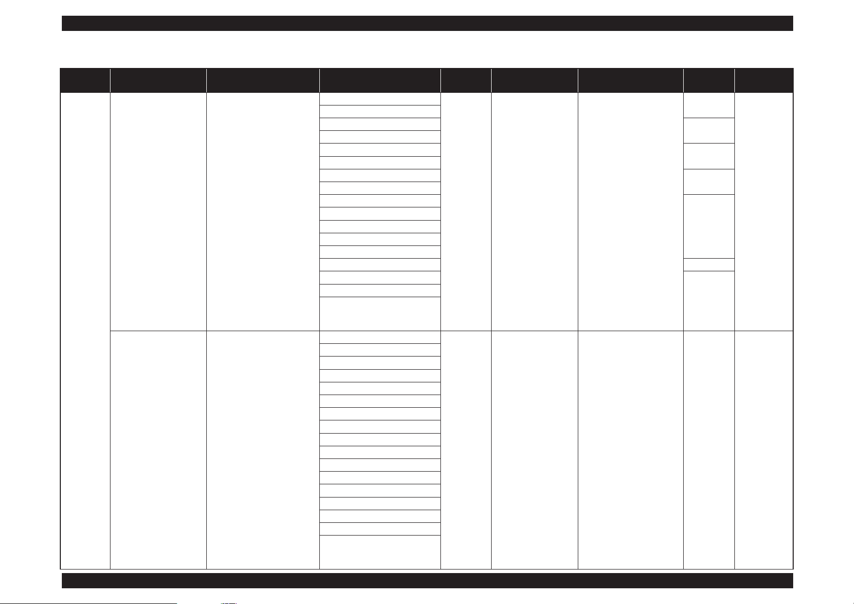
Table 1-2. Cartridge Alignment Sequence
Row 1 Row 2 Row 3 Row 4 Row 5 Row 6 Row 7 Row 8 Row 9
Matte
Black
(PK)
Photo
Black
(MK)
Light
Black
(LK)
Light
Light
Black
(LLK)
Cyan
(C)
Vivid
Magenta
(VM)
Light
Cyan
(Lc)
Vivid
Light
Magenta
(VLM)
Yellow
(Y)
Switched by an Ink
Selector
Table 1-1. Basic Specifications
Item Specifications
Page 13
SC-P800 series Revision B
PRODUCT DESCRIPTION Basic Specifications 13
SE Group Confidential (Related Staff Only)
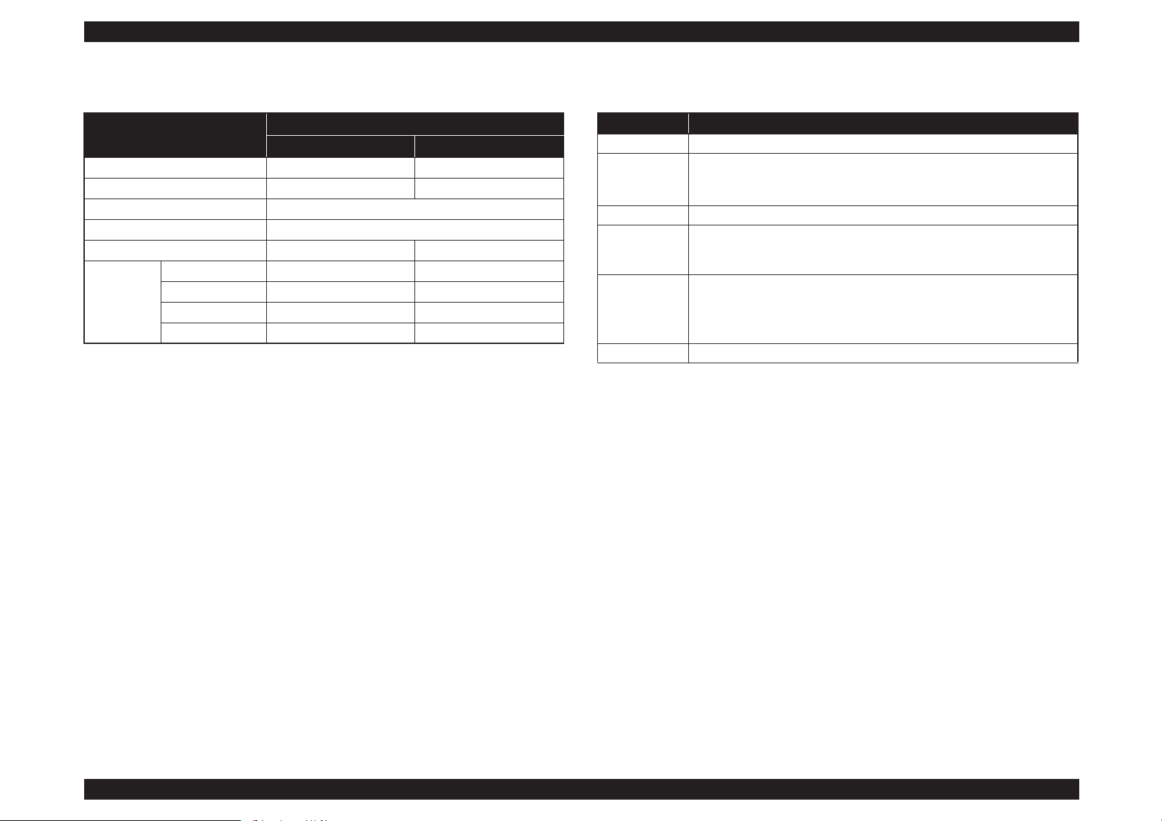
1.2.2 Electric Specifications
Note "* " : Pattern: ISO Bike, Media: plain paper, Mode:Default(720x360), Media size: A2, Printing size:
414 x 517.5mm
1.2.3 Ink Specifications
Table 1-3. Electric Specifications
Item
Specification
100/120V Model 220/240V Model
Rated voltage 120 VAC 220 to 240 VAC
Input voltage range 108 to 132 VAC 198 to 264 VAC
Rated frequency 50 to 60Hz
Input frequency range 49.5 to 60.5Hz
Rated current 0.6 A 0.3 A
Power
consumption
Operating* Approx. 21 W Approx. 21 W
Ready mode Approx. 5.8 W Approx. 5.8 W
Sleep mode Approx. 1.8 W Approx. 1.8 W
Power OFF Approx. 0.3 W Approx. 0.5 W
Table 1-4. Ink Specifications
Item Specification
Form Exclusive ink cartridge
Pigment ink
colors
Black system: Matte Black, Photo Black, Light Black, Light Light Black
Color system: Cyan, Vivid Magenta, Yellow, Light Cyan, Vivid Light
Magenta
Cartridge life See the date printed on the package (at normal temperature)
Guaranteed life
after
installation
6 month (after mounted in the printer)
Storage
Uninstalled (packed): -20 to 40 °C (within 1 month under 40 °C)
Installed: -20 to 40 °C (within 1 month under 40 °C)
Transporting (packed): -20 to 60 °C
(within 1 month under 40 °C, and within 72 hours under 60 °C)
Dimensions 700ml: W30 x L93 x H70 mm
Page 14
SC-P800 series Revision B
PRODUCT DESCRIPTION Printing Specifications 14
SE Group Confidential (Related Staff Only)
1.3 Printing Specifications
1.3.1 Paper Feed Specifications
1.3.2 Paper Feeder Specifications
SC-P800 series support three types of paper feeding methods; ASF, Front Manual
Feed, and Roll Paper Feed. The paper size and thickness for each of the methods are
shown in the table below. For paper type and feeder capacity, refer to
"1.3.3 Supported
Media" (p15).
Item Specification
Paper feed method Friction feed
Minimum pitch of paper feed 2.94 µm (1/8640 inch)
Paper feed
Rear ASF
Front manual feed
Rear roll paper
Paper feed speed 25.4 mm (1 inch) when line feed: 333 msec (3 inch/sec)
Paper Feed
Method
Paper Size
Thickness
(mm)
Width (mm) Length (mm)
Standard paper
(mm)
ASF 89 to 431.8 127 to 950 L/4”x6” to A2/USC 0.08 to 0.3
Front Manual Feed
(Fine art media)
203.2 to 431.8 254 to 950 A4/8”x10” to A2/USC 0.29 to 0.7
Front Manual Feed
(Board media)
203.2 to 431.8 254 to 594 A4/8”x10” to A2/USC 0.7 to 1.5
Roll paper 329 to 431.8 55 to 1117.6
A3+/8”x10” to A2/
USC
0.25 to 0.7
Page 15
SC-P800 series Revision B
PRODUCT DESCRIPTION Printing Specifications 15
SE Group Confidential (Related Staff Only)
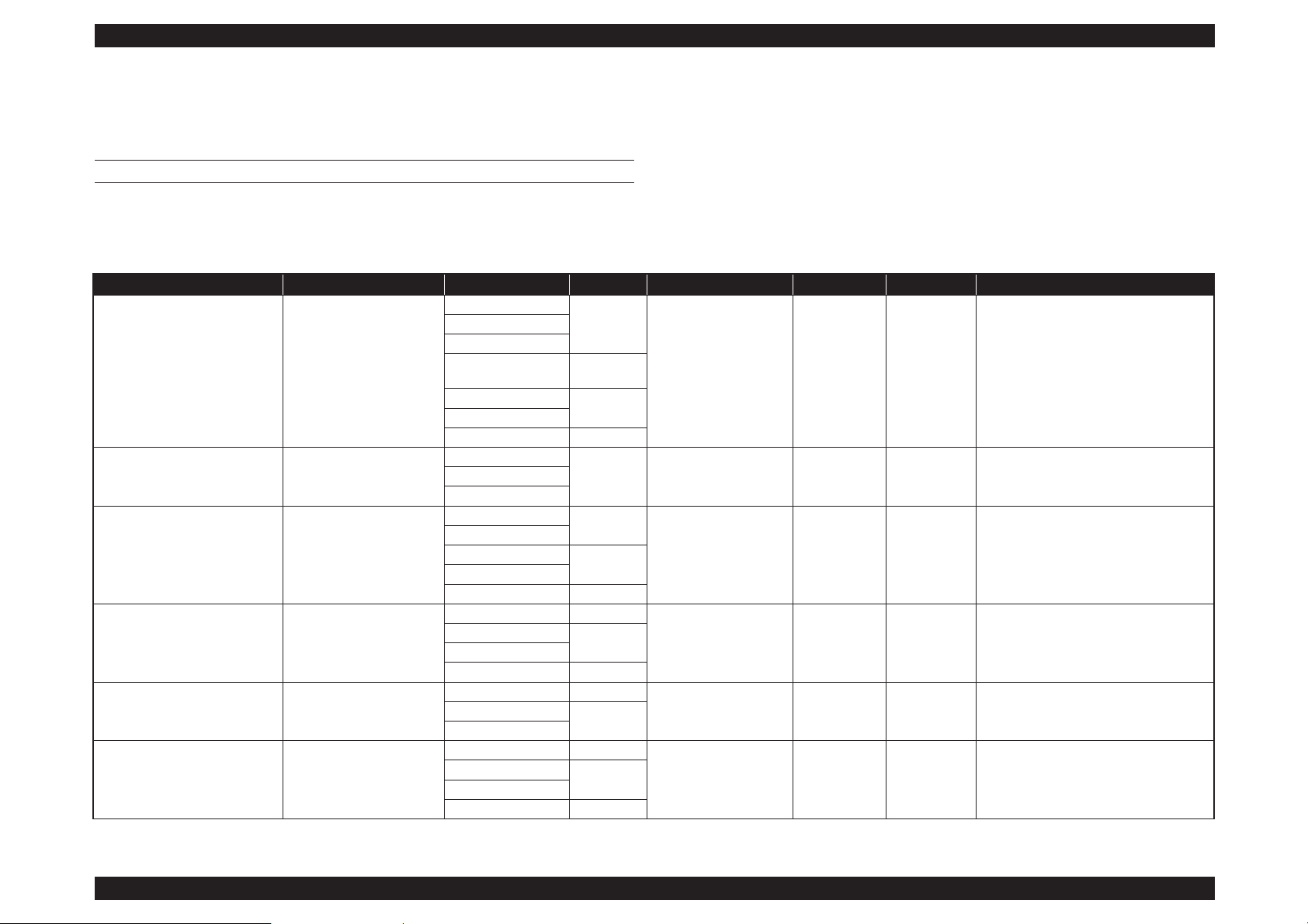
1.3.3 Supported Media
1.3.3.1 Epson Special Media Table
CUT SHEET
Note "*1": Borderless: Describes whether borderless printing is available.
"*2": Black ink: An abbreviation of the type of black ink supported by the media. PK: Photo Black/MK: Matte Black
"*3": May not be available depending on the area of purchase.
Table 1-5. Cut sheet Media Table
Paper Type Media Type (Printer Driver) Size Capacity Source Borderless
*1
Black ink
*2
ICC Profile
Premium Glossy Photo Paper Epson Premium Glossy
13 x 18 cm (5 x 7 in.)
30
Auto sheet feeder ✔ PK SC-P800 Series Epson Premium Glossy.icc
10 x 15 cm (4 x 6 in.)
A4
16:9 wide size
(102 x181 mm) *
3
20
A3
10
A3+
A2 1
Photo Paper Glossy Photo Paper Glossy
13 x 18 cm (5 x 7 in.)
30 Auto sheet feeder
✔ PK SC-P800 Series Photo Paper Glossy.icc10 x 15 cm (4 x 6 in.)
A4
Premium Semigloss Photo Paper Epson Premium Semigloss
10 x 15 cm (4 x 6 in.)
30
Auto sheet feeder
✔ PK
SC-P800 Series Epson Premium
Semigloss.icc
A4
A3
10
A3+
A2 1
Archival Matte Paper Epson Archival Matte
A4 30
Auto sheet feeder
✔ MK SC-P800 Series Epson Archival Matte.icc
A3
10
A3+
A2 1
Matte Paper Heavy-weight Epson Archival Matte
A4 30
Auto sheet feeder
✔ MK SC-P800 Series Epson Archival Matte.iccA3
10
A3+
Photo Quality Inkjet Paper Epson Photo Quality Ink Jet
A4 60
Auto sheet feeder --- MK SC-P800 Series Standard.icc
A3
50
A3+
A2 10
Page 16
SC-P800 series Revision B
PRODUCT DESCRIPTION Printing Specifications 16
SE Group Confidential (Related Staff Only)
ROLL PAPER
All paper loading methods are for roll paper.
Note "*1": Borderless: Describes whether borderless printing is available.
"*2": Black ink: An abbreviation of the type of black ink supported by the media. PK: Photo Black/
MK: Matte Black
Watercolor Paper - Radiant White
Watercolor Paper RadiantWhite
A3+ 1
Front manual feed
(fine art media)
✔ MK
SC-P800 Series Watercolor Paper-Radiant
White.icc
Velvet Fine Art Paper Velvet Fine Art Paper
A3
1
Front manual feed
(fine art media)
✔ MK SC-P800 Series VelvetFineArtPaper.iccA3+
A2
UltraSmooth Fine Art Paper UltraSmooth Fine Art Paper
A3+
1
Front manual feed
(fine art media)
✔
MK
SC-P800 Series UltraSmooth FineArt
Paper.icc
A2 ---
Epson Proofing Paper White
Semimatte
Epson Proofing Paper White
Semi-matte
A3+ 1 Auto sheet feeder ✔ PK
SC-P800 Series Epson Proofing Paper White
Semi-matte.icc
Premium Ink Jet Plain Paper plain papers A4 80 Auto sheet feeder ✔ PK/MK SC-P800 Series Standard.icc
Bright White Inkjet Paper plain papers A4 80 Auto sheet feeder ✔ PK/MK SC-P800 Series Standard.icc
Table 1-5. Cut sheet Media Table
Paper Type Media Type (Printer Driver) Size Capacity Source Borderless
*1
Black ink
*2
ICC Profile
Table 1-6. Roll Paper Media Table
Paper Type Media Type (Printer Driver) Size Core Borderless*1Black ink
*2
ICC Profile
Premium Glossy Photo Paper (250) Epson Premium Glossy 406 mm/16" 3 inch
✔ PK
SC-P800 Series Epson Premium
Glossy.icc
Premium Semigloss Photo Paper (250) Epson Premium Semigloss 406 mm/16" 3 inch
✔ PK
SC-P800 Series Epson Premium
Semigloss.icc
Premium Luster Photo Paper (260) Epson Premium Luster
329 mm (A3+)
3 inch
✔ PK
SC-P800 Series Epson Premium
Luster.icc
406 mm/16"
Premium Semimatte Photo Paper (260) Epson Premium Semigloss 406 mm/16" 3 inch
✔ PK
SC-P800 Series Epson Premium
Semigloss.icc
Enhanced Matte Paper Epson Archival Matte 432 mm/17" 3 inch
✔ MK SC-P800 Series Archival Matte.icc
Page 17
SC-P800 series Revision B
PRODUCT DESCRIPTION Printing Specifications 17
SE Group Confidential (Related Staff Only)
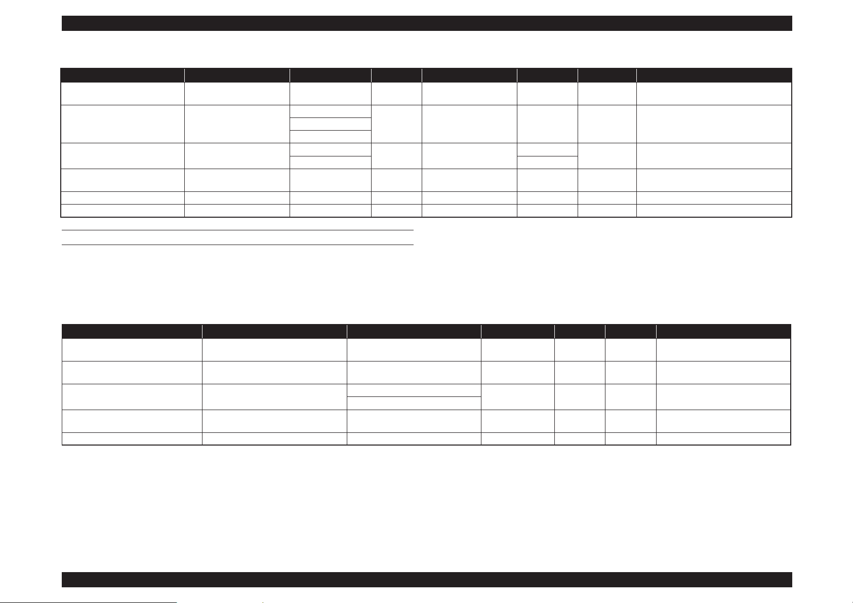
1.3.3.2 Usable Commercially Available Paper Size
This printer supports the following paper specifications for non-Epson media.
CUT SHEET
Note "*1": Borderless: Describes whether borderless printing is available.
"*2": Black ink: An abbreviation of the type of black ink supported by the media. PK: Photo Black/MK: Matte Black
"*3": The maximum length you can set in the printer driver is 15 m.
"*4": May not be available depending on the media being used. Contact the manufacturer of the media for more details.
C A U T I O N
Do not use paper that is wrinkled, scuffed, torn, or dirty.
Although plain paper and recycled paper manufactured by
other companies can be loaded and fed in the printer as long as
they meet the following specifications, Epson cannot guarantee
the print quality.
Although other paper types manufactured by other companies
can be loaded in the printer as long as they meet the following
specifications, Epson cannot guarantee the paper feeding and
print quality.
Table 1-7. Cut sheet Media Table
Item Paper Type Driver Media Types Size
Number of
Sheets
Paper thickness Loading Method Borderless
*1
Ink Type
*2
Plain Paper Cut sheets
See the manual supplied with the
paper and adjust settings as
appropriate.
A6
Up to 12 mm
total
thickness
0.08 mm to 0.11 mm
(64 to 90 g/m
2
)
Auto sheet feeder --- PK/MK
A5
B5
A4
Letter
Legal
Up to 5 mm
total
thickness
B4
A3
A2
Non-standard sizes
W: 89 mm to 431.8mm
L: 127 mm to 950mm*
3
Page 18
SC-P800 series Revision B
PRODUCT DESCRIPTION Printing Specifications 18
SE Group Confidential (Related Staff Only)
Thick paper
Cut sheets
See the manual supplied with the
paper and adjust settings as
appropriate.
A4
1 0.29 mm to 0.7 mm
Front manual feed tray (fine
art media
✔
*4
PK/MK
Letter
Legal
---
Half Letter
28 to 43 cm (11 to 17 in.)
✔
*4
43 to 56 cm (17 to 2 in.)
JIS B4
---
JIS B3
254 to 305 mm (10 to 12 in.)
✔
*4
A3
A3+
279 to 356 mm (11 to 14 in.)
30 to 30 cm (12 to 12 in.)
36 to 43 cm (14 to 17 in.) ---
41 to 51 cm (16 to 20 in.)
✔
*4
A2
Non-standard sizes
W: 89 mm to 431.8mm
L: 127 mm to 950mm*
3
Cut sheets
See the manual supplied with the
paper and adjust settings as
appropriate.
A4
1 1.2 mm to 1.5 mm
Front manual feed tray (poster
board)
--- PK/MK
Letter
Legal
Half Letter
28 to 43 cm (11 to 17 in.)
43 to 56 cm (17 to 22 in.)
JIS B4
JIS B3
254 to 305 mm (10 to 12 in.)
A3
A3+
279 to 356 mm (11 to 14 in.)
30 to 30 cm (12 to 12 in.)
36 to 43 cm (14 to 17 in.)
41 to 51 cm (16 to 20 in.)
A2
Non-standard sizes
W: 89 mm to 431.8mm
L: 127 mm to 950mm*
3
Table 1-7. Cut sheet Media Table
Item Paper Type Driver Media Types Size
Number of
Sheets
Paper thickness Loading Method Borderless
*1
Ink Type
*2
Page 19

SC-P800 series Revision B
PRODUCT DESCRIPTION Printing Specifications 19
SE Group Confidential (Related Staff Only)
ROLL PAPER
Note "*1": Borderless: Describes whether borderless printing is available.
"*2": Black ink: An abbreviation of the type of black ink supported by the media. PK: Photo Black/MK: Matte Black
"*3": You can specify and perform borderless printing; however, the print quality may decline or margins may appear due to the paper expanding or contracting.
"*4": The maximum length you can set in the printer driver is 15000 mm.
Table 1-8. Roll paper Media Table
Item Driver Media Types Size Paper thickness Roll Core Size Borderless*
1
Ink Type*
2
Roll paper
See the manual supplied with the paper
and adjust settings as appropriate.
13 to 17 inches wide
W: 329 to 431.8 mm
L: 55 to 1117.6 mm*
4
0.25 mm to 0.7 mm 2 inches/3 inches ✔*
3
PK/MK
Page 20
SC-P800 series Revision B
PRODUCT DESCRIPTION Printing Specifications 20
SE Group Confidential (Related Staff Only)
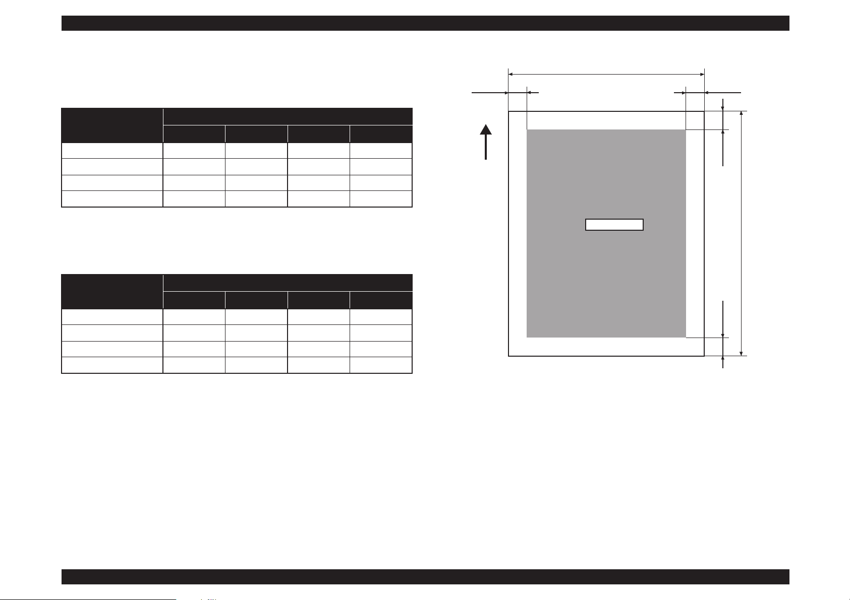
1.3.4 Printable area
Normal print
Note "*1": 0 mm for continuous print jobs.
"*2": 14 mm when Print Page Line on the control panel is set to On.
Borderless print
Note "* " : 0 mm for continuous print jobs.
Figure 1-2. Printable area
Table 1-9. Printable area (normal print)
Item
Dimension
Cut sheet Board paper Fine art paper Roll paper
TM (top margin) 3 mm 20 mm 3 mm 50 mm*
1
BM (bottom margin) 3 mm 20 mm 15 mm 19 mm*
2
LM (left margin) 3 mm 3 mm 3 mm 3 mm
RM (right margin) 3 mm 3 mm 3 mm 3 mm
Table 1-10. Printable area (borderless print)
Item
Dimension
Cut sheet Board paper Fine art paper Roll paper
TM (top margin) 0 mm 0 mm 0 mm 50 mm*
BM (bottom margin) 0 mm 0 mm 0 mm 14 mm
LM (left margin) 0 mm 0 mm 0 mm 0 mm
RM (right margin) 0 mm 0 mm 0 mm 0 mm
PW
LM RM
TM
BM
PL
Printable area
Paper feed direction
Page 21

SC-P800 series Revision B
PRODUCT DESCRIPTION Printing Specifications 21
SE Group Confidential (Related Staff Only)
1.3.5 Borderless Printing Specification
The following media sizes are supported for borderless printing. For paper type and
feeder capacity, refer to
"1.3.3 Supported Media" (p15).
Table 1-11. Borderless Printing Specification
Paper Type Size
A4 210 mm × 297 mm
A3 297 mm × 420 mm
A3+ 329 mm × 483 mm
A2 420 mm × 594 mm
Letter 8.5 inch × 11 inch
28 × 43 cm 11 inch × 17 inch
43 × 56 cm 17 inch × 22 inch
100 × 148 mm 100 mm × 148 mm
9 × 13 cm 3.5 inch × 5 inch
10 × 15 cm 4 inch × 6 inch
13 × 18 cm 5 inch × 7 inch
13 × 20 cm 5 inch × 8 inch
16:9 wide size 102 mm × 181 mm
20 × 25 cm 8 inch × 10 inch
254 × 305 mm 10 inch × 12 inch
279 × 356 mm 11 inch × 14 inch
30 × 30 cm 12 inch × 12 inch
41 × 51 cm 16 inch × 20 inch
13 inch (329 mm) roll paper 329 mm
16 inch roll paper 406 mm
16.5 inch (42 cm) roll paper 420 mm
17 inch roll paper 432 mm
Page 22
SC-P800 series Revision B
PRODUCT DESCRIPTION Hardware Specifications 22
SE Group Confidential (Related Staff Only)
1.4 Hardware Specifications
This section provides the printer dimensions and shows the main components.
1.4.1 Dimensions and Weight
Dimensions
Storage dimensions
(W) 684 mm × (D) 376 mm × (H) 250 mm
(W) 684 mm × (D) 586 mm × (H) 286 mm
*
Normal dimensions
(W) 684 mm × (D) 963 mm × (H) 550 mm
(W) 684 mm × (D) 769 mm × (H) 286 mm
*
Note"*":When optional items are attached
Weight
Approx. 19.5kg (without ink cartridges)
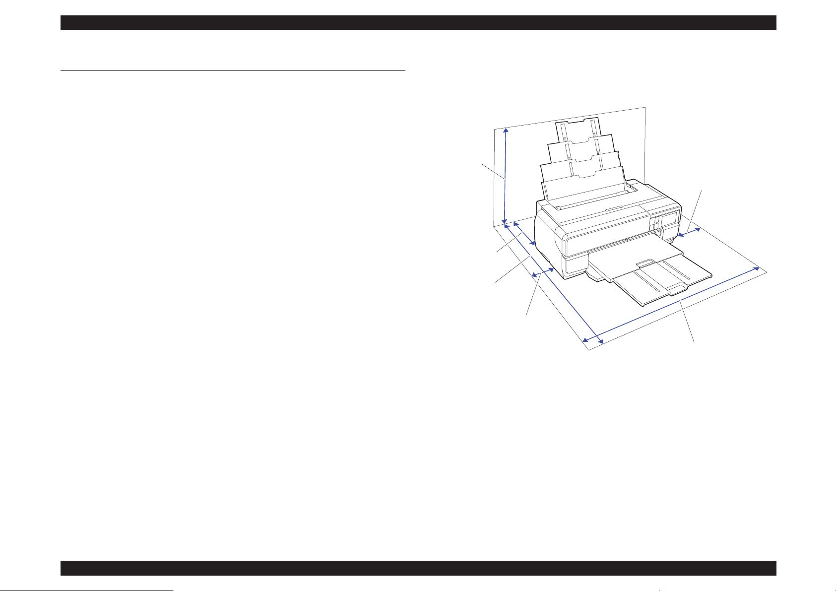
1.4.2 Installation Room Requirement
Figure 1-3. Installation space
NOTE: When printing on poster board, leave a space of at least 430 mm in behind
the printer.
100 mm
100 mm
1030 mm
550 mm
270 mm
884 mm
※
Page 23
SC-P800 series Revision B
PRODUCT DESCRIPTION Hardware Specifications 23
SE Group Confidential (Related Staff Only)
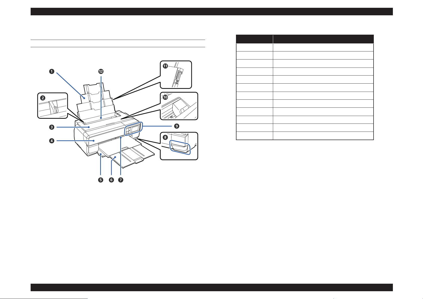
1.4.3 Part Names
FRONT SIDE
Figure 1-4. Front side
Table 1-12. Front side
No. Name
1 Paper support
2 Edge guide
3 Printer cover
4 Ink cartridge cover
5 Front cover
6 Output tray
7 Front manual feed tray
8 Maintenance cartridge cover
9 Control panel
10 Print head
11 Paper support edge guide
12 Auto sheet feeder
Page 24
SC-P800 series Revision B
PRODUCT DESCRIPTION Hardware Specifications 24
SE Group Confidential (Related Staff Only)
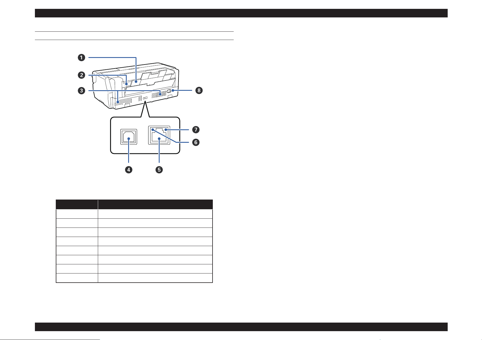
BACK SIDE
.
Figure 1-5. Back side
Table 1-13. Back side
No. Name
1 Rear support
2 Roll paper feeder
3 Airflow vents
4 USB port
5 LAN port
6 Status light
7 Data light
8 AC inlet
Page 25
SC-P800 series Revision B
PRODUCT DESCRIPTION Control Panel Specifications 25
SE Group Confidential (Related Staff Only)
1.5 Control Panel Specifications
1.5.1 Control panel
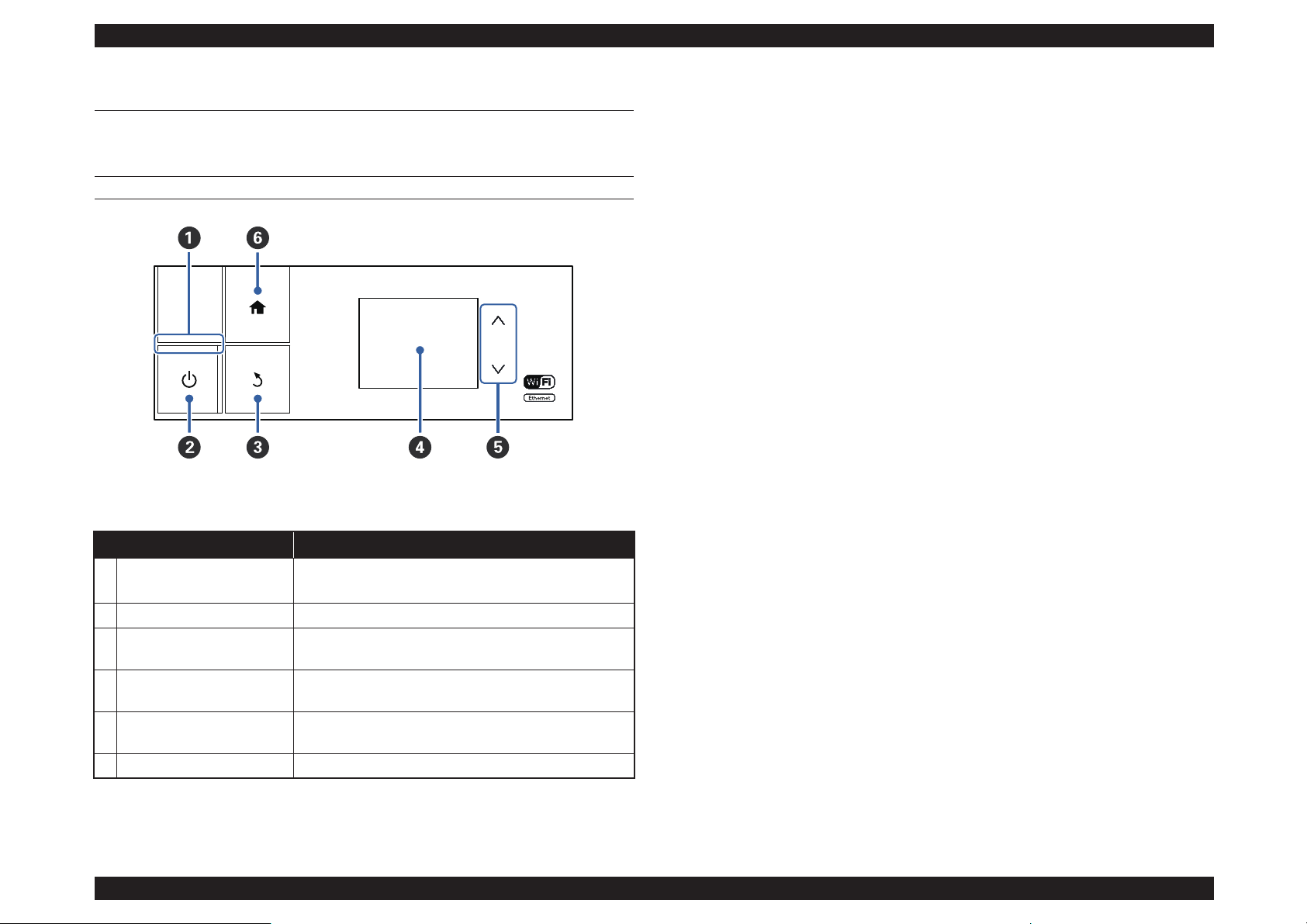
OPERATION PANEL
Figure 1-6. Operation panel
Table 1-14. Operation panel
Name Function
1 Power light
On: The power is on.
Off: The power is off.
2 Power button Turns the power on and off.
3 Back button
Press to return to the previous screen while the Menu is
displayed.
4 Screen
Displays the printer's status, menus, error messages, and so
on.
5 up and down buttons
Press to select menu items and setting values when a menu
is displayed.
6 Home button Display the home screen.
Page 26
SC-P800 series Revision B
PRODUCT DESCRIPTION Control Panel Specifications 26
SE Group Confidential (Related Staff Only)
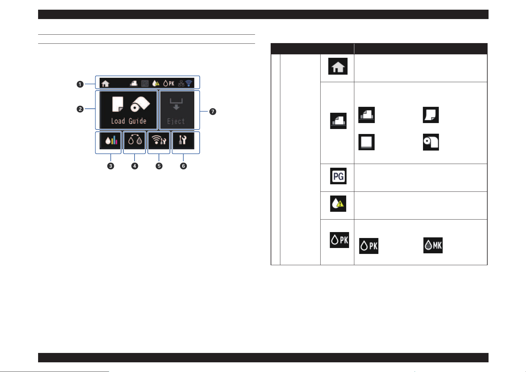
HOME SCREEN
Home Screen View
Figure 1-7. Home screen
Table 1-15. LCD
Name Function
1 Status icon
Indicates that the home screen is displayed.
Indicates the selected Load Guide using the following
icons.
Turns on when Thick Paper is set to On.
Indicates that the ink is running low or the maintenance
cartridge is running out of space. Prepare a new cartridge.
Indicates the selected black ink using the following icons.
Auto sheet
feeder
Fine art media
Poster board Roll paper
Photo black
ink
Matte black
ink
Page 27
SC-P800 series Revision B
PRODUCT DESCRIPTION Control Panel Specifications 27
SE Group Confidential (Related Staff Only)
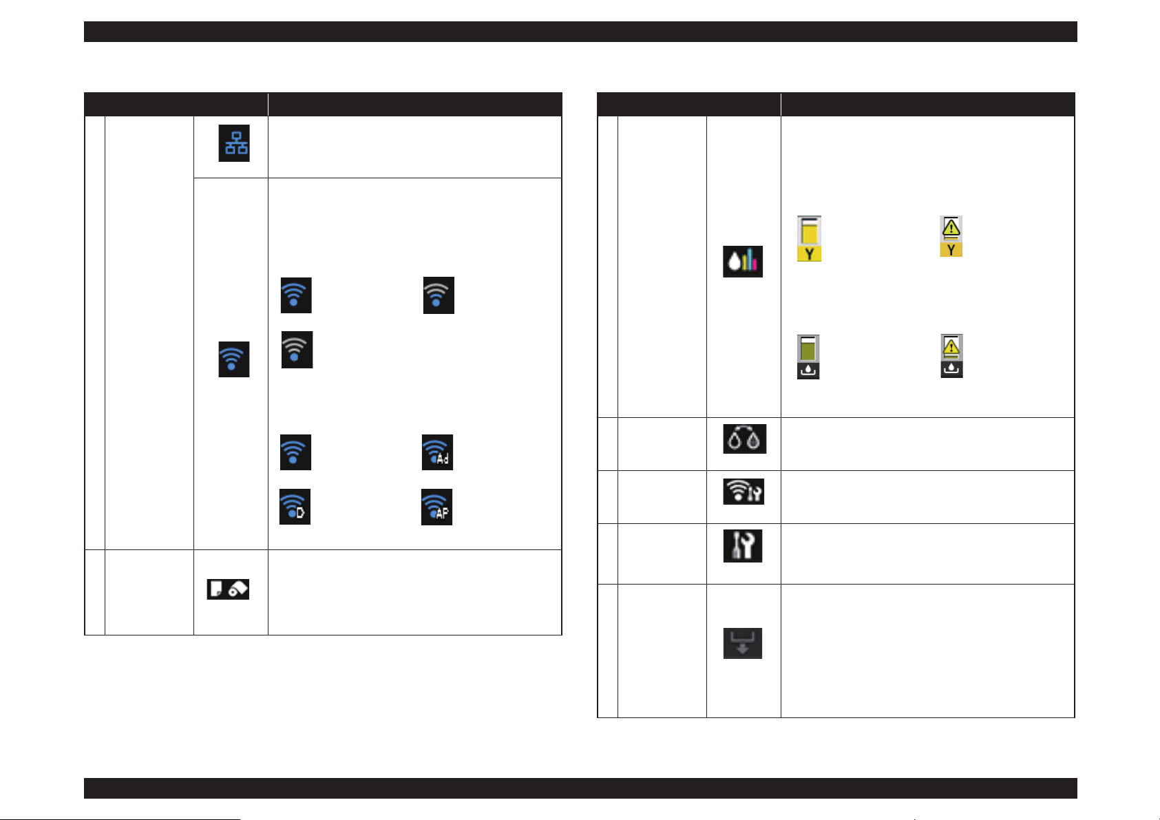
1 Status icon
Displayed when connected to a wired LAN.
Displays the operation mode, radio wave status, and
connection status for the wireless LAN.
The icon is not displayed when the wireless LAN is
disconnected.
The number of lines indicates the radio wave strength.
The icon changes as shown below depending on the
operation mode.
2
(Load Guide/
Media Setup)
button
Load Guide is displayed when paper is not loaded. You
can continue by checking the selected Load Guide
procedure on the screen.
Media Setup is displayed when paper is loaded. You can
set the Media Size and Media Type.
Table 1-15. LCD
Name Function
Strong Weak
Searching or
unavailable
Infrastructure
mode
Ad hoc mode
Wi-If Direct
mode
Simple AP mode
3
(Ink Remaining
Display) button
Displays the approximate amount of ink remaining and
free space in the maintenance cartridge.
Depending on the status of each cartridge, the icons
change as shown below.
Ink cartridge
Maintenance cartridge
4
(BK Ink
Change) button
You can change from one type of black ink to another.
5
(Network
Summary
Display) button
Displays the status of the printer's connection to the
computer. You can also display Wi-Fi/Network Settings
and so on directly from the Menu.
6 (Setup) button
You can perform printer maintenance and adjust printer
settings.
7
(Cut/Eject)
button
You can eject paper that has been loaded.
The following can be performed when roll paper is
loaded.
Move the end of the printed section to the cutting
position
Eject roll paper after moving the end of the printed
section to the cutting position
Eject roll paper
Table 1-15. LCD
Name Function
No error Ink low
No error The
Maintenance
Box is nearing
the end of its
service life.
Page 28
SC-P800 series Revision B
PRODUCT DESCRIPTION Control Panel Specifications 28
SE Group Confidential (Related Staff Only)
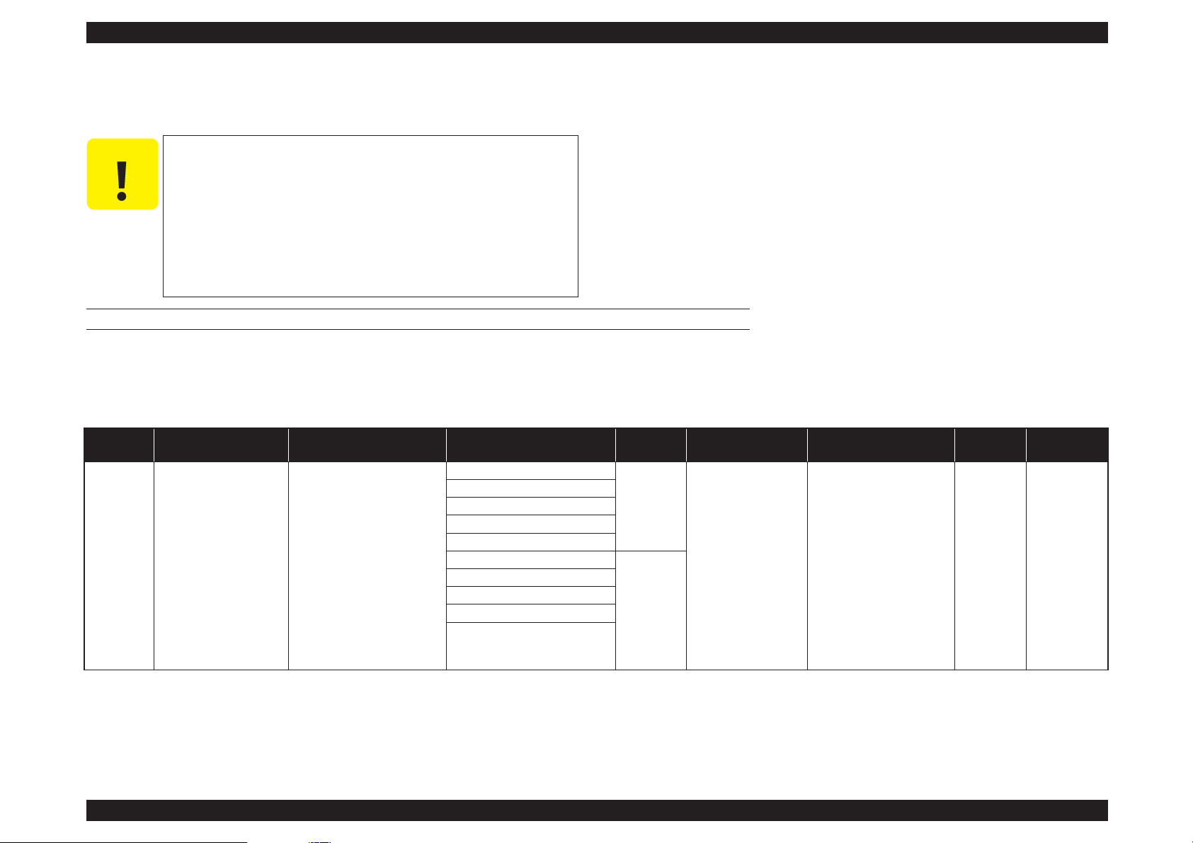
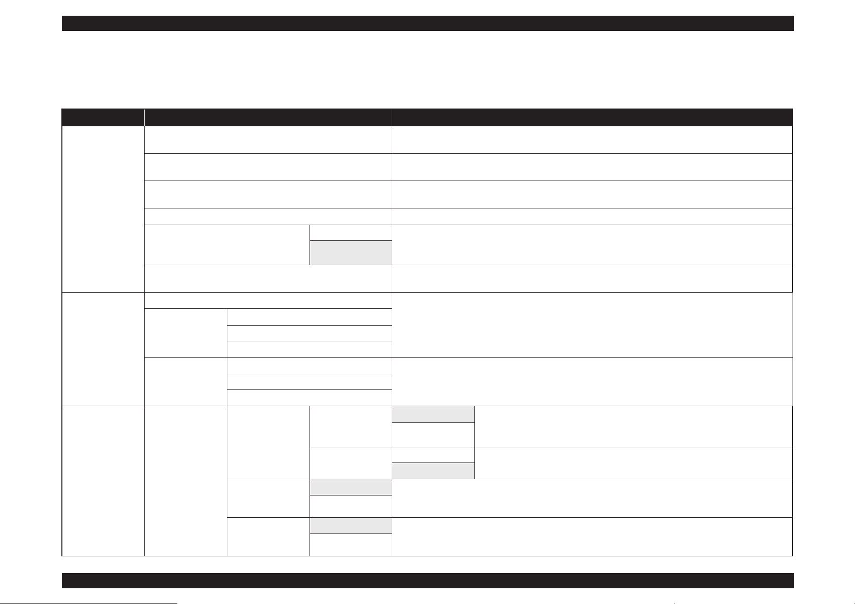
1.5.2 Menu Descriptions
Set up menu
Table 1-16. Set up menu
Menu Menu Item / Setting Value (Shaded one is the default) Explanation
Maintenance
Print Head Nozzle Check
Check whether the print head nozzles are clogged. Visually confirm the printed check pattern, and perform
head cleaning if there are any blurred or missing sections.
Print Head Cleaning
Perform head cleaning if you notice banding or gaps in the print results. Cleans the print head to improve the
print quality.
Heavy Head Cleaning
Use this if nozzles are clogged even after performing Print Head Cleaning several times. Note that this
consumes more ink than Print Head Cleaning.
Paper Guide Cleaning Select this option to pass (feed and eject) plain paper through the printer and clean the rollers.
Thick Paper
On This option is only available when printing from a smart device.
Set this if print results are scuffed or smeared. When this is set to On, print speed may slow down. Only use
this if scuffing occurs. When the printer is turned off, this setting returns to Off.
Off
Print Head Alignment
If print results appear grainy or out of focus, perform Print Head Alignment to correct the print
misalignment.
System
Administration
Check network information.
Network Status
Wi-Fi/Network Status
Wi-Fi Direct Status
Google Cloud Print Status
Print Status Sheet
Configuration Status Sheet
Prints an information sheet for the current status and settings.Supply Status Sheet
Usage History Sheet
System
Administration
Printer Settings
Paper Source
Settings
Paper Setup Display
On Automatically displays the media setup screen when paper is loaded.
When this is Off, AirPrint is unavailable. Also, Error Notice from Paper Source
Settings becomes Off.
Off
Error Notice
On
Set whether or not to display an error if the paper size or type differ from the printer
settings.
Off
Paper Skew Check
On This option only takes effect with fine art media and poster board. Select On to display an error in the control
panel’s screen when the paper is fed in at a slant. On is recommended, as feeding the paper at a slant can
cause the paper to jam.
Off
Horizontal Centered
On When this is set to On, even if the print position moves on the loaded paper due to a cutting error or paper
feed error, the printer detects the width of the paper and the image is adjusted and printed in the center. Even
if there is a paper cutting error or print position error, the margins are still set evenly on the left and right.
Off
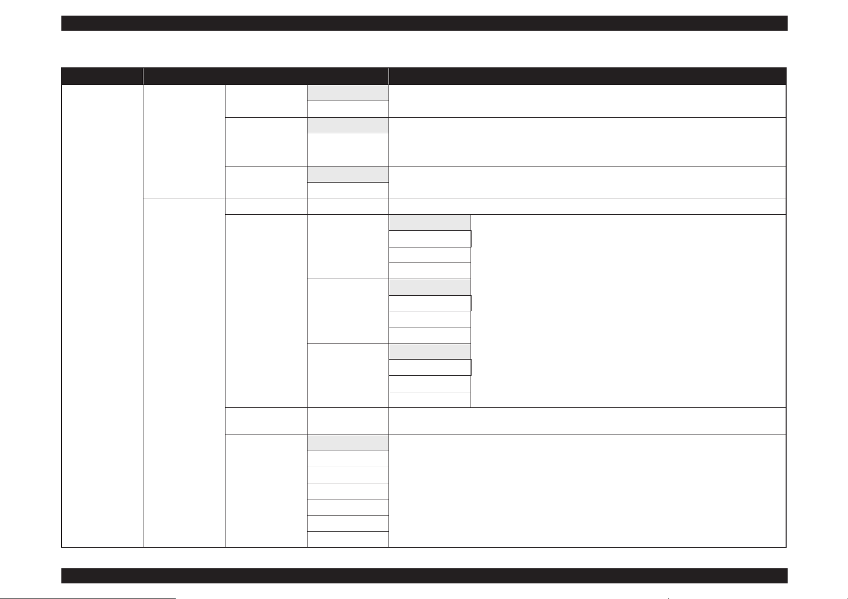
Page 29
SC-P800 series Revision B
PRODUCT DESCRIPTION Control Panel Specifications 29
SE Group Confidential (Related Staff Only)
System
Administration
Printer Settings
Print Page Line
On
When this is set to On, a dotted line is printed on the roll paper.
Off
Paper Size Check
On Select whether or not (On/Off) to detect the paper width. When this is set to Off, printing may be performed
beyond the edges of the paper. If printing is performed beyond the edges of the paper, the inside of the printer
will be soiled with ink. We recommend setting this to On. When selecting Off, borderless printing can not be
performed.
Off
BK Ink Auto Change
On
When this is set to On, the black ink is changed automatically using the Media Type selected in the printer
driver.
Off
Common Settings
LCD Brightness 1 to 9 You can adjust the brightness of the screen in nine stages.
Sound
Button Press
High
Set whether or not to play a sound and the volume for operation sounds, error sounds,
and done sounds.
Medium
Low
Off
Error Notice
High
Medium
Low
Off
CompletionNotice
High
Medium
Low
Off
Sleep Timer 1 to 240 mins.
Set the time to switch to sleep mode (energy saving mode) when the printer is not operated for a continuous
period.
Power Off Timer
Off
Set whether or not to turn off the printer automatically, as well as setting the time until the printer
automatically turns off when no printer operations are performed for a continuous period. The default setting
varies depending on the area of use.
30minutes
1h
2 h
4 h
8h
12h
Table 1-16. Set up menu
Menu Menu Item / Setting Value (Shaded one is the default) Explanation
Page 30
SC-P800 series Revision B
PRODUCT DESCRIPTION Control Panel Specifications 30
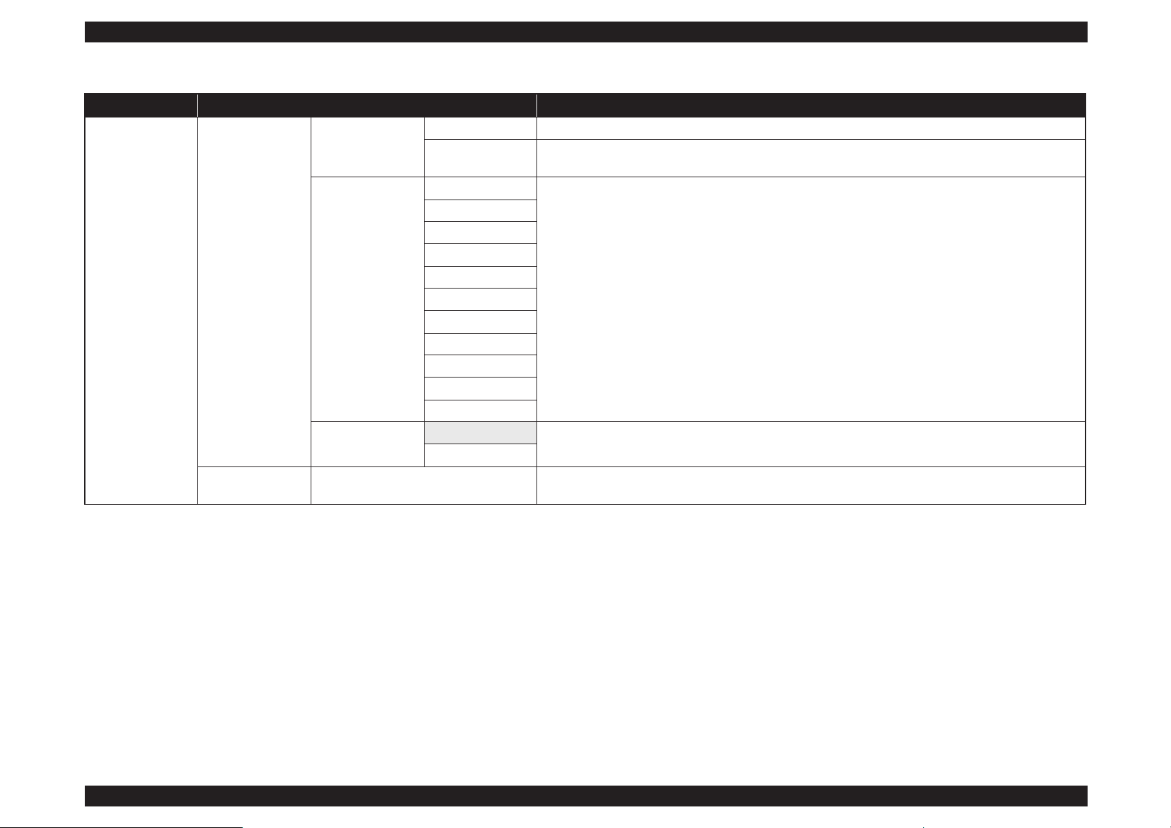
SE Group Confidential (Related Staff Only)
System
Administration
Common Settings
Date/Time Settings
Date/Time Set the date and time.
Time Difference
Set the time difference from Coordinated Universal Time (UTC). Default: Since this is set to ±0:00, it does
not normally need to be changed.
Language
English
Select the language for the screen display. The default setting varies depending on the area of use.
French
Italian
German
Spanish
Portuguese
Dutch
Russian
Simplified Chinese
Traditional Chinese
Korean
Operation Timer Out
On
You are returned to the Home screen if no operations are performed for three minutes on each menu.
Off
Wi-Fi/Network
Settings
Wi-Fi/Network Status Print a network status sheet. View network settings and connection status.
Table 1-16. Set up menu
Menu Menu Item / Setting Value (Shaded one is the default) Explanation
Page 31

SC-P800 series Revision B
PRODUCT DESCRIPTION Control Panel Specifications 31
SE Group Confidential (Related Staff Only)
Network Summary Display
System
Administration
Wi-Fi/Network
Settings
Wi-Fi Setup
Manual
---
Push Button Setup
(WPS)
PIN Code Setup
(WPS)
Wi-Fi Auto Connect
Disable Wi-Fi
Wi-Fi Direct Setup
Connection Check
Advanced Setup
Printer Name
TCP/IP Address
DNS Server
Proxy Server
Wi-Fi Direct
Google Cloud Print
Services
How to
Select How to display an explanation of the function. Visit the portal for more information on registering and
usage. You can stop/restart service usage and restore content to the default settings from Settings.
Settings
Restore Default
Settings
Wi-Fi/Network Settings Restore network settings to the default settings.
All except Network Settings Restore all control panel settings except network settings to the default settings.
All Settings Restore all settings to the default settings.
Table 1-16. Set up menu
Menu Menu Item / Setting Value (Shaded one is the default) Explanation
Table 1-17. Network Summary Display
Menu Menu Item Explanation
Menu
Wi-Fi/Network Settings
---
Wi-Fi Setup
Wi-Fi Direct Setup
Wi-Fi Setup
Page 32

SC-P800 series Revision B
PRODUCT DESCRIPTION Control Panel Specifications 32
SE Group Confidential (Related Staff Only)
1.5.3 Inspection Mode
The Inspection Mode is intended to be used by a service person for servicing the printer.
HOW TO START & QUIT
1. Press and hold the [Power] button, [Back] button, and [Home] button together for 10 seconds or longer.
2. To exit the Inspection Mode, press the [Power] button to power OFF the printer.
INSPECTION MODE MENU LIST
Table 1-18. Inspection Mode
Menu
Explanation
1 2 3
1. Printer Inspection Mode Printer Inspection Mode Flag check
Mode used for adjustment at factory shipment
Mode used for adjustment at factory shipment
2. Special Inspection
1. Inspection ALL Mode used for adjustment at factory shipment
2. CSIC Check Mode used for adjustment at factory shipment
3. Maintenance Box Check Mode used for adjustment at factory shipment
4. Panel Key Test To check the operation of buttons on the touch panel and operation of the touch panel
5. LCD/LED Test To check for the color and dot missing on the LCD and check the operation of the screen
6. Sensor Check To check the operation of each sensor
7. Rom Ver.check To check the current ROM version
3. Touch Screen Inspection
1. Touch Screen Calibration To adjust the input position of the touch panel
2. Touch PNL Measurement Mode To check the sensitivity of the touch panel
4. Development Mode 1. Electricity Test Mode Mode used for adjustment at factory shipment
5. Status Sheet Print Mode Mode used for adjustment at factory shipment
6. Normal Mode Mode used for adjustment at factory shipment
Page 33

SE Group Confidential (Related Staff Only)
C H A P T E R
2
TROUBLE SHOOTING
Page 34

SC-P800 series Revision B
TROUBLE SHOOTING Overview 34
SE Group Confidential (Related Staff Only)
2.1 Overview
This section explains the basic procedure for troubleshooting problems on the printer
quickly and efficiently.
When carrying out the troubleshooting procedures, take a flexible measure following
your sales company's policy and considering the troubling situation.
2.1.1 Preliminary Check
Make sure to verify or perform the following basic items whenever servicing the
printer.
2.1.1.1 Before performing troubleshooting
Before troubleshooting, perform basic checks such as connection check of the power
cable and installation check of the ink cartridges.
2.1.1.2 Check for the usage environment
Check the user's usage environment.
Temperature/humidity of the installation site
(For the guaranteed environment,
see P.12.)
Drivers/RIP that the user uses
Genuine media or 3rd party's media?
Genuine ink or 3rd party's ink?
F/W version (the latest?)
Check also the following if necessary.
2.1.1.3 Recurrence check of the trouble
Check if the trouble the user claims recurs with the returned printer.
If RIP was used, check if the trouble recurs when the driver is used.
If 3rd party's media were used, check if the trouble recurs when a genuine
medium is used.
If 3rd party's ink was used, perform the repair according to the policy of each
local sales subsidiary.
If the F/W was not the latest, gain agreement with the user on the update of F/
W, and check if the trouble recurs when the latest F/W is used.
2.1.1.4 Check for the counter values/history
Download NVRAM and check the following with NVRAM Viewer. (For the check
method,
see P.211.)
Counter history of the periodic replacement parts. (if any part's life is near.)
Printer's operating history (if any cause for the trouble exists)
Error history (the frequency/history of errors related with the trouble)
2.1.1.5 Test print check
For the trouble related with print quality, carry out “Test Print” and check the current
adjustment status. (For the procedure of test print,
see P.219.)
Phenomenon Check Item
Bad print quality
The installation site inclined?
Any vibrating equipment near the site?
The user's panel settings
Is the interior dirty?
Clean it if dirty.
Missing dots/bad print quality Near a conditioner's ventilation duct?
Page 35

SC-P800 series Revision B
TROUBLE SHOOTING Overview 35
SE Group Confidential (Related Staff Only)
2.1.2 Troubleshooting Procedure
Refer to the following items according to the observed symptom, carry out the
corresponding troubleshooting following the procedures described in the next sections.
1. Trouble with a Maintenance Request or Service Call Error.
(See P.36, P. 37)
2. Trouble on print quality (See P.44)
3. Trouble on Paper Feeding (See P.47)
4. Other troubles (See P.48)
5. Trouble on Service Program (See P.49)
6. Trouble on NVRAM viewer (See P.50)
2.1.3 Procedure after troubleshooting
2.1.3.1 If the trouble has been successfully solved
Check if the movement of the covers is normal (without any damage, noises).
If any abnormality is found, lubricate or replace the faulty parts.
Carry out the cleaning after repair.
Prepare a report on the repair. (follow your company/local office's policy.)
2.1.3.2 If necessary to escalate the trouble case
Make a report with the following data.
Backed-up NVRAM data
Firmware version
Service program version
For bad print quality: a print sample with the marked symptom and a printed
test pattern.
For faulty parts: the faulty parts themselves and a photos of the troubling
section.
Information on the user/the repair listed below
This is a format of the escalation report. At least check out the items on the
list and register the case in the escalation system.
• Model name
• Serial number
• With or without options
• Content of the claim from the user
• Date of occurrence
• Trouble occurrence conditions/recurrence method
• What the service person actually observed
(Check items before check, the content of troubleshooting and repair.)
• Date of escalation
• Purpose of escalation
(Measures which the user/service person)
• Degree of urgency (S/A/B/C)
S: High (those which may cause a death, ignition, etc.)
A: Problems, bugs
B: Strong request
C: Inquiry
• Deadline for the response
• Repair history
• Part-replacement history
Page 36

SC-P800 series Revision B
TROUBLE SHOOTING Remedies for Maintenance Requests 36
SE Group Confidential (Related Staff Only)
2.2 Remedies for Maintenance Requests
This section describes the remedies for maintenance requests. Maintenance requests do not effect the printer’s operation; therefore, you can continue the current printing. When a
maintenance request error occurs, the printer displays on the LCD a hexadecimal code of “NNNN” which correspond to the bit numbers assigned to error statuses as shown in the
table below.
Note : Ex): When “Maintenance Request 0000048” is displayed.
As “0000048” in hexadecimal means “100 1000” in binary, you can find out the code is assigned to Bit-3 and Bit-6 referring to the above table. In this case, two errors are
occurring simultaneously. (Bit-3: battery exhaustion/ Bit-6: pump counter near end.)
Table 2-1.
Maintenance Request Errors
Bit assignment (Binary)
XXXX
(Hexa-decimal)
Cause Remedy
12 11 10 9 8 7 6 5 4 3 2 1 0
0 0 0 0 0 0 0 0 0 0 0 0 1 00000001
The waste ink counter of the Absorbers for
Borderless Printing has reached the near end.
Replace the Absorbers for Borderless Printing (POROUS PAD,
INK WASTE BOX, RIGHT/POROUS PAD, INK WASTE BOX,
LEFT), and clear the usage counter with the Service Program.
0 0 0 0 0 0 0 0 0 0 0
1 0 00000002
The life of the ink supply tube has reached the
near end.
Replace the ink supply tube (INK, SYSTEM, ASSY), and clear the
usage counter with the Service Program.
0 0 0 0 0 0 0 0 0 0
1 0 0 00000004 Reserved
0 0 0 0 0 0 0 0 0
1 0 0 0 00000008 The RTC backup battery has run out.
Replace the battery, and initialize the RTC with the Service
Program.
0 0 0 0 0 0 0 0
1 0 0 0 0 00000010 Reserved
0 0 0 0 0 0 0
1 0 0 0 0 0 00000020 Reserved
0 0 0 0 0 0
1 0 0 0 0 0 0 00000040 The pump counter has reached the near end.
Replace the pump cap unit (PUMP, CAP, ASSY), and clear the
usage counter with the Service Program.
0 0 0 0 0
1 0 0 0 0 0 0 0 00000080 Reserved
0 0 0 0
1 0 0 0 0 0 0 0 0 00000100 Reserved
0 0 0
1 0 0 0 0 0 0 0 0 0 00000200 Reserved
0 0 1 0 0 0 0 0 0 0 0 0 0 00000400 Reserved
0
1 0 0 0 0 0 0 0 0 0 0 0 00000800
The Ink Cartridge removal counter has reached
the near end.
Replace the Cartridge Holder Waste Ink Pads (POROUS PAD,
TRAY, INK EJECT), and clear the usage counter with the Service
Program.
1 0 0 0 0 0 0 0 0 0 0 0 0 00001000
The ink selector driving frequency has reached the
near end.
Replace the ink selector (INK, SYSTEM, ASSY), and clear the
usage counter with the Service Program.
Page 37

SC-P800 series Revision B
TROUBLE SHOOTING Remedies for Service Call Error 37
SE Group Confidential (Related Staff Only)
2.3 Remedies for Service Call Error
The following tables explains the Service Call error messages and remedies.
Table 2-2. Service Call Error
Code Category Error Name Cause Check Item Remedy
1101 IS CR life error
The CR scan path counter has reached
a predetermined level. (The end of life
of the Ink Supply Tube)
---
Replace the Ink Supply Tube (INK,
SYSTEM, ASSY) and reset the counter
using the Adjustment Program. In
addition, check the statuses of the CR
motor (MOTOR ASSY., CR), the driven
pulley, the Carriage Unit, and the Head
FFC, if any abnormal noise or wear is
found, replace the corresponding part(s)
along with the Ink Supply Tube.
(See
P.125)
1121 CR CR reversing error
An abnormal operation (reversed
operation) of the CR unit was detected.
Contamination on CR scale
CR encoder failure (cable failure)
CR scale failure
Motor driver failure
CR belt failure
Driver pulley failure
CR motor failure (cable failure)
Check the reading status of the CR encoder with the Service
Program.
1. Replace the CR scale.
2. Replace the driven pulley.
3. Replace the CR motor.
4. Lubricate the OIL PAD of the CR
unit.
(See P.284)
5. Replace the CR timing belt.
6. Replace the FFC of the CR encoder.
7. Replace the CR unit.
8. Replace the MAIN board.
1123 CR CR Duty over error
The load on the CR motor has
exceeded the expected level.P
Paper jam (such as paper left on the
print path)
Increase of load (such as the
damaged CR shaft, damaged CR
shaft bearing, insufficient grease,
the deformed CR sub shaft)
CR motor failure (cable failure)
CR encoder failure (cable failure)
Visually check whether paper is left on the print path, and
remove it if left.
1. Replace the CR scale.
2. Replace the driven pulley.
3. Replace the CR motor.
4. Lubricate the OIL PAD of the CR
unit.
(See P.284)
5. Replace the CR timing belt.
6. Replace the FFC of the CR encoder.
7. Replace the CR unit.
8. Replace the MAIN board.
1124 CR CR reversing error
Drive time of the CR motor exceeding
the predetermined time was detected.
Firmware becomes out of control.
---
Replace the MAIN board.
Page 38

SC-P800 series Revision B
TROUBLE SHOOTING Remedies for Service Call Error 38
SE Group Confidential (Related Staff Only)
1125 CR
CR home position
detection error
When the power is ON, the pump cap
unit does not operate and the lock of
the CR unit cannot be released. Thus,
the CR home position cannot be
detected.
False detection of the home due to
paper jam or any other obstacle
Misreading of the CR scale
The CR lock is damaged.
1. Is there any paper jammed inside the printer?
2. Does the CR scale have any scratches or dirt?
3. Check the reading status of the CR encoder with the Service
Program.
4. Does the CR lock function normally? (Check manually
whether the pump unit functions or not.)
1. Replace the pump cap unit.
2. Replace the CR scale.
3. Replace the CR encoder.
1126 CR CR lock release error
The lock of the CR unit cannot be
released.
Pump unit failure
The CR lock is damaged.
1. Check manually whether the pump unit functions.
2. Is the CR unit stopped at the home position?
3. Are there any foreign materials around the pump unit?
1. Replace the pump cap unit.
2. Replace the CR scale.
1135 CR CR encoder test error
The output of the CR encoder does not
change even though the CR motor is
commanded to rotate.
CR encoder failure (cable failure)
CR motor failure (cable failure)
Large CR unit load
Are there any problems, such as the FFC is damaged or
disconnected, in the connection below?
CR encoder to SUB board (CN1)
1. Replace the CR motor.
2. Replace the driven pulley.
3. Replace the CR timing belt.
4. Replace the FFC of the CR encoder.
5. Replace the CR unit.
6. Replace the MAIN board.
1222 PF
PF drive timeover
error
Drive time of the PF motor exceeding
the predetermined value was detected.
Firmware becomes out of control.
---
Replace the MAIN board.
1223 PF PF encoder test error
The output of the PF encoder does not
change even though the PF motor is
commanded to rotate.
PF encoder failure (cable failure)
PF motor failure (cable failure)
Large paper feed load
Are there any problems, such as the FFC is damaged or
disconnected, in the connection below?
PF encoder to MAIN board (CN49)
1. Replace the PF motor.
2. Replace the FFC of the PF encoder.
3. Replace the PF encoder.
4. Replace the MAIN board.
5. Replace the printer mechanism unit.
122A PF PF overload error
The load on the PF motor has exceeded
the expected level.
Paper jam (paper left on the print
path)
Increase of load (such as the
damaged PF shaft, damaged PF
shaft bearing, or insufficient grease)
PF motor failure (cable failure)
PF encoder failure (cable failure)
Visually check whether paper is left on the print path, and
remove it if left.
1. Replace the PF motor.
2. Replace the FFC of the PF encoder.
3. Replace the PF encoder.
4. Replace the MAIN board.
5. Replace the printer mechanism unit.
Table 2-2. Service Call Error
Code Category Error Name Cause Check Item Remedy
Page 39

SC-P800 series Revision B
TROUBLE SHOOTING Remedies for Service Call Error 39
SE Group Confidential (Related Staff Only)
122C PF PF reversing error
An abnormal operation (reversing) of
the PF was detected.
Contamination on PF scale
PF encoder failure (cable failure)
PF scale failure
Motor driver failure
PF timing belt failure
PF motor failure (cable failure)
Check the reading status of the PF encoder with the Service
Program.
1. Replace the PF motor.
2. Replace the FFC of the PF encoder.
3. Replace the PF encoder.
4. Replace the PF scale.
5. Replace the MAIN board.
6. Replace the printer mechanism unit.
131B Head
Head driver
(transmission gate)
temp. error
The temperature of the head driver
rises, and has reached a
predetermined limit.
Head FFC insertion at an angle
Disconnection of the head FFC
SUB board failure
MAIN board failure
Check the connection of the head FFC for abnormalities, such
as whether it is inserted at an angle.
1. Replace the head FFC.
2. Replace the print head.
3. Replace the MAIN board.
1400 Pressure motor
Pressure motor drive
timeover
The pressure does not reach the
predetermined level despite
pressurization over a predetermined
time.
Pressure pump home sensor failure
Abnormal ink cartridge pack (air
leak)
Foreign materials are attached at the
I/C feed port. (Air leaks due to
incomplete seal.)
Check the connection part between the ink cartridge and ink
cartridge holder, and remove foreign materials if any.
1. Replace the ink cartridge.
2. Replace the pressure pump.
1403 Pressure motor
Pressure motor
pressure reducing
error
The pressure cannot be reduced.
Pressure pump failure
1. Are there any problems, such as the FFC is damaged or
disconnected, in the connection below?
Pressure motor to MAIN board (CN46)
Pressure sensor to MAIN board (CN52)
2. Is the pressure tube jammed?
Replace the pressure pump.
Table 2-2. Service Call Error
Code Category Error Name Cause Check Item Remedy
Page 40

SC-P800 series Revision B
TROUBLE SHOOTING Remedies for Service Call Error 40
SE Group Confidential (Related Staff Only)
1404 Pressure motor
Pump movement
cycle over error
The pressure does not reach the
predetermined level despite
pressurization over a predetermined
time.
• Pressure pump home sensor
failure
Air leaks.
• Abnormal ink cartridge pack
The seal of the I/C feed port is
incomplete, causing air to leak.
• Foreign materials are attached.
Check the connection part between the ink cartridge and ink
cartridge holder, and remove foreign materials if any.
1. Replace the ink cartridge.
2. Replace the pressure pump.
1410 PUMP
Drive time monitor
time-out (PUMP)
Drive time of the pump motor is longer
than the predetermined time.
Firmware becomes out of control.
---
Replace the MAIN board.
142D PUMP
Pump cap unit life
error
The pump counter has reached the
predetermined value.
---
Replace the pump cap unit.
1430 Waste ink Holder ink pad error
The ink cartridge replacement counter
has reached the predetermined value.
---
Replace the holder ink pad.
1431 Ink selector Ink selector error
The ink selector driving frequency has
reached the predetermined value.
---
Replace the ink selector (INK,
SYSTEM, ASSY).
1432 Ink selector
Ink selector drive
timeover
The ink selector does not finish
operating in the predetermined time.
Ink selector sensor failure
Ink selector motor failure
Perform the Ink Selector Operation Check using the Service
Program.
Replace the ink selector (INK,
SYSTEM, ASSY).
1434 Ink cover Ink cover unlock error
The cartridge cover does not open.
• Load is applied.
The open/closed status of the cover
cannot be detected.
• Ink cover open sensor failure
The lock cannot be released.
• Ink cover solenoid failure
Is an object put on the cartridge cover?
1. Replace the ink cover open sensor.
2. Replace the ink cover solenoid.
1498 Ink selector
ink selector switching
error
Switching the ink selector failed.
The non-existent position has been
specified.
---
Replace the ink selector
1501 Driven release
Release phase
detection error
The release roller position sensor
cannot detect the actuator after the
release motor has driven a
predetermined number of steps.
---
1. Replace the release sensor.
2. Replace the release motor.
Table 2-2. Service Call Error
Code Category Error Name Cause Check Item Remedy
Page 41

SC-P800 series Revision B
TROUBLE SHOOTING Remedies for Service Call Error 41
SE Group Confidential (Related Staff Only)
1502 Driven release
Drive time monitor
time-out
Drive time of the driven release motor
is longer than the predetermined time.
Firmware becomes out of control.
---
Replace the MAIN board.
150D ---
Mechanism unit
abnormal error
An abnormality was detected in the
mechanism unit.
Clean the inside of the printer. (See P.282) Replace the printer mechanism unit.
1511 APG
APG drive time
monitor time-out
Drive time of the APG motor is longer
than the predetermined time.
Firmware becomes out of control.
---
Replace the MAIN board.
1512 APG APG error
The APG home position cannot be
detected.
The APG motor cannot drive by the
predetermined amount.
• The CR lock cannot be released.
• APG sensor failure
• APG motor failure
Does turning OFF and ON the power remove the error?
1. Replace the APG sensor.
2. Replace the APG motor.
1513 APG APG reset error
The APG sensor cannot detect the
home position after the APG motor
has driven a predetermined number
of steps.
The APG motor cannot drive by the
predetermined amount.
• CR lock failure
• APG sensor failure
• APG motor failure
Does turning OFF and ON the power remove the error?
1. Replace the APG sensor.
2. Replace the APG motor.
1520 ASF
ASF drive time
monitor time-out
Drive time of the driven ASF motor is
longer than the predetermined time.
Firmware becomes out of control.
---
Replace the MAIN board.
1531 ASF
ASF phase detection
error
The detection status of the ASF sensor
does not change after the ASF motor
has driven a predetermined number of
steps.
ASF sensor failure
Connection failure
ASF motor failure
1. Check whether there are any foreign materials inside the
ASF.
2. Does turning OFF and ON the power remove the error?
1. Replace the APG sensor.
2. Replace the APG motor.
1535 Pressure pump
Pressure pump home
detection error
When the power is ON, the home
position of the pressure pump cannot
be detected.
Sticking of bellows
Pressure pump home sensor failure
Does turning OFF and ON the power remove the error?
pressure home sensor to Main board (CN52)
1. Replace the pressure pump.
2. Replace the MAIN board.
Table 2-2. Service Call Error
Code Category Error Name Cause Check Item Remedy
Page 42

SC-P800 series Revision B
TROUBLE SHOOTING Remedies for Service Call Error 42
SE Group Confidential (Related Staff Only)
1600 PW
Paper width sensor
obstruction error
When the power is ON, a foreign
material on the platen was detected.
An object reflecting light, such as
paper, is on the platen.
Check whether a foreign material is on the platen, and remove it
if any.
Replace the PW sensor.
1601 PW
Paper width sensor
malfunction
PW sensor failure
---
Replace the PW sensor.
1A23 RTC Invalid RTC data
The time information cannot be read
from the RTC.
Initialize the RTC with the Service Program, and set the date.
If the printer is not recovered even after
the date is reset, perform the following.
1. Replace the RTC backup battery.
2. Replace the MAIN board.
1A37 ---
Thermistor sensor
error
The head thermistor detected a
temperature of -20 degrees or lower
or 100 degrees or higher.
Head FFC insertion at an angle
Disconnection of the head FFC
SUB board failure
MAIN board failure
Check the connection of the head FFC for abnormalities.
1. Replace the head FFC.
2. Replace the print head.
3. Replace the MAIN board.
1A38 Hard
Transistor ambient
temp. error
The MAIN board detected a
temperature of -20 degrees or lower
or 100 degrees or higher.
MAIN board failure
---
Replace the MAIN board.
1F81 CSIC CSIC firmware CSIC-related firmware error Does turning OFF and ON the power remove the error?
1. Install the firmware again.
2. Replace the MAIN board.
1F82 CSIC
MAIN board
incorrect specification
error
The specifications of the MAIN board
are incorrect.
Set the Initial setting of the MAIN board with the Service
Program.
If setting the Initial setting has not
recovered the printer, replace the MAIN
board.
DXXX Debugging
Service call for FW
debugging
This error is intended to be used in the
product development stage. It is
supposed to not occur to marketed
products, but may occur due to an
unexpected cause such as external
noises.
Turn the power off and then turn it back on. Does the printer
recover from the error? (No repair work is needed unless the
error occurs again.)
1. Install the firmware again.
2. Replace the MAIN board.
FXXX CPU
CPU related service
call
There is something wrong with the
firmware.
Main board failure
Is the firmware installed correct one for the printer?
0102 RTC System fatal error RTC failure Does turning OFF and ON the power remove the error? Replace the RTC.
Table 2-2. Service Call Error
Code Category Error Name Cause Check Item Remedy
Page 43

SC-P800 series Revision B
TROUBLE SHOOTING Remedies for Service Call Error 43
SE Group Confidential (Related Staff Only)
0103 RTC System fatal error RTC failure Does turning OFF and ON the power remove the error? Replace the RTC.
0A30
Wi-Fi board/
MAIN board
System fatal error
Wi-Fi board or MAIN board failure
Does turning OFF and ON the power remove the error?
1. Replace the Wi-Fi board.
2. Replace the MAIN board.
0A39
Wi-Fi board/
MAIN board
System fatal error
Wi-Fi board or MAIN board failure
Does turning OFF and ON the power remove the error?
1. Replace the Wi-Fi board.
2. Replace the MAIN board.
Table 2-2. Service Call Error
Code Category Error Name Cause Check Item Remedy
Page 44

SC-P800 series Revision B
TROUBLE SHOOTING Remedies for Print Quality Troubles 44
SE Group Confidential (Related Staff Only)
2.4 Remedies for Print Quality Troubles
This section provides troubleshooting of print quality troubles classifying them by observed symptom. Before performing troubleshooting, refer to
"Nozzle Check" (p239)
and print
nozzle check pattern. Examine the printed pattern, and if any missing segment is found, perform the PRINT HEAD cleaning.
Table 2-3. Print Quality Troubles
Symptom Cause Check Item Remedy
The nozzles are still clogging after
cleaning.
The Wiper is contaminated and wiping
the PRINT HEAD cannot be performed
properly.
1. Is the Wiper or Wiper Cleaner contaminated?
2. Is the Wiper or Wiper Cleaner damaged?
1. Clean the Wiper.
2. Replace the Wiper and Wiper Cleaner.
The Head Cap is contaminated. Is the Cap contaminated?
1. Clean the Cap.
2. Replace the Cap (PUMP CAP UNIT).
(Page
122)
There is some foreign material on the
PRINT HEAD.
Is there any foreign materials on the PRINT HEAD? Clean the PRINT HEAD.
There is something wrong in the pump
tube and the cleaning (suctioning of
ink) cannot be performed properly.
Is the pump tube being bent or getting caught between
surrounding parts or components?
Route the pump tube correctly.
The ink is leaking. Is there any ink leakage observed on the ink flow paths? If any leakage is found, correct it.
There is air inside the ink path. Is there any air bubbles observed in the ink flow paths? Run a head cleaning.
(Page 238)
The HEAD FFC is not connected
correctly.
Is the HEAD FFC connected properly without being
connected at an angle and any abnormalities such as peeled
terminals?
1. Reconnect the HEAD FFC.
2. If the trouble still occurs, the cause may be
breaking of the HEAD FFC. Replace the
HEAD FFC.
(Page 137)
If any of the remedies above does not help, replace the following parts one by one.
PRINT HEAD (Page 103)
MAIN BOARD (The fuse may have blown) (Page 94)
Horizontal or vertical lines look
misaligned.
The PRINT HEAD has not been
adjusted properly.
Have the following adjustments been made properly?
Head inclination auto adjustment (CR direction)
Head slant auto adjustment (PF direction)
Carry out the adjustments correctly.
Head inclination adjustment (CR direction)
(Page 232)
Head slant adjustment (PF direction) (Page
236)
Improper PG adjustment
1. Is the paper thickness setting correct?
2. Has the PG adjustment been made properly?
1. Correct the paper thickness setting.
2. Perform the PG adjustment. (Page 223)
Page 45

SC-P800 series Revision B
TROUBLE SHOOTING Remedies for Print Quality Troubles 45
SE Group Confidential (Related Staff Only)
Bandings in the paper feeding direction.
The PRINT HEAD has not been
adjusted properly.
---
Carry out the following adjustments.
Head inclination adjustment (CR direction)
(Page 232)
Head slant adjustment (PF direction) (Page
236)
The paper was not fed properly.
---
Carry out the following adjustment.
Media Feed Auto Adjustment
Check the following settings.
Feed Adjustment
Media Tension
PF SCALE or PF ENCODER failure
1. Is the PF SCALE damaged or contaminated?
2. Is the PF SCALE attached properly?
3. Is the PF ENCODER installed correctly?
1. Clean the PF SCALE.
2. Reinstall the PF SCALE and PF ENCODER.
3. Replace the PF SCALE
(Page 172) and PF
ENCODER
(Page 173).
The tension of the PF TIMING BELT is
not proper.
---
Correct the tension of the PF TIMING BELT.
(Page 174)
PF MOTOR failure
---
Replace the PF MOTOR. (Page 176)
Bandings in the carriage movement
direction.
Improper PG adjustment
1. Is the paper thickness setting correct?
2. Has the PG adjustment been made properly?
1. Correct the paper thickness setting.
2. Perform the PG adjustment.
(Page 223)
CR SCALE or CR ENCODER failure
1. Is the CR SCALE damaged or contaminated?
2. Is the CR SCALE attached properly?
3. Is the CR ENCODER installed correctly?
1. Clean the CR SCALE.
2. Reinstall the CR SCALE and CR ENCODER.
3. Replace the CR SCALE
(Page 107) and CR
ENCODER
(Page 110).
The tension of the CR TIMING BELT
is not proper.
---
Correct the tension of the CR TIMING BELT.
(Page 225)
Lubrication on the CR moving parts is
insufficient.
Has the oil pad of the CR UNIT dried out? If the pad is dry, lubricate it.
(Page 284)
Printed side is smudged or smeared with
ink.
There is a problem with the paper used.
1. Is the paper wrinkled, bent, rippled, or warped?
2. Is the paper too thick and contacting with the head?
3. Is the paper too thin and loosening when being fed?
1. Replace the paper with a new proper one.
2. Adjust the PG setting according to the paper
thickness.
Improper PG adjustment Has the PG adjustment been made properly? Perform the PG adjustment.
(Page 223)
The PF (Paper Feed) Roller is
contaminated
Is the PF roller smudged or smeared with ink or anything? Clean the roller. Print some blank pages to clean it.
The backside of paper is smudged or
smeared with ink.
The platen is contaminated.
1. Is the platen contaminated with ink?
2. Is the Paper Size Check function enabled?
1. Clean the platen.
2. Enable (select “ON”) the Paper Size Check
function.
Table 2-3. Print Quality Troubles
Symptom Cause Check Item Remedy
Page 46

SC-P800 series Revision B
TROUBLE SHOOTING Remedies for Print Quality Troubles 46
SE Group Confidential (Related Staff Only)
Color or print density unevenness within a
page or across pages.
The ink in the ink cartridge is not
agitated enough.
---
Shake the ink cartridges so that ink droplets spread
evenly inside the cartridges.
Deterioration of ink quality Have the installed ink cartridges expired? Replace the expired ink cartridges with new ones.
Improper PG adjustment Has the PG adjustment been made properly? Perform the PG adjustment.
(Page 223)
Blurred print
Too much ink discharge. Has the Head rank ID been written correctly?
Rewrite the Head rank ID with a correct one.
(Page
231)
The ink droplet sizes are not proper. Are the RIP settings proper? Change the RIP settings accordingly.
Paper dust is attached or the traces of the
rollers appear.
Traces of Pressure Roller are caused
because the paper had been kept set in
the printer for a long time.
---
Remove the paper if the printer is left for a long
time.
The paper dust attached on the PF
rollers transferred to the paper.
Is there any paper dust attached to the PF rollers?
Clean the rollers. Print some blank pages to clean
them.
Table 2-3. Print Quality Troubles
Symptom Cause Check Item Remedy
Page 47

SC-P800 series Revision B
TROUBLE SHOOTING Trouble on Paper Feeding 47
SE Group Confidential (Related Staff Only)
2.5 Trouble on Paper Feeding
This section describes the possible troubles on paper feeding and their causes and remedies.
Table 2-4. Trouble on Paper Feeding
Symptom Cause Check Item Remedy
Paper is not fed into the printer properly. PE SENSOR failure
---
Replace the PE SENSOR. (See P.187)
Paper feeding or paper ejecting is
abnormal.
PF SCALE or PF ENCODER failure
1. Is the PF SCALE damaged or contaminated?
2. Is the PF SCALE attached properly?
3. Is the PF ENCODER installed correctly?
1. Clean the PF SCALE.
2. Reinstall the PF SCALE and PF ENCODER.
3. Replace the PF SCALE
(See P.172) and PF
ENCODER (See P.173).
The tension of the PF TIMING BELT is
not proper.
---
Correct the tension of the PF TIMING BELT.
(See
P.174)
PF rollers failure Are the PF rollers contaminated or damaged? Clean the rollers or replace them.
Paper is skewing.
The Paper Skew Check function has
been disabled.
---
Enable (select “ON”) the Paper Skew Check
function.
The Paper Size Check function has
been disabled.
---
Enable (select “ON”) the Paper Size Check
function.
The PW SENSOR is not working.
---
Replace the PW SENSOR.
(See P.111)
Actual margins differ from the specified
margins.
Paper feed amount is not configured
correctly.
---
Perform the Media Feed Auto Adjustment.
(Page
265)
The Paper Size Check function has
been disabled.
---
Enable (select “ON”) the Paper Size Check
function. (The printer is not capable of precisely
correcting less than 2 mm differences.)
Page 48

SC-P800 series Revision B
TROUBLE SHOOTING Other Troubles 48
SE Group Confidential (Related Staff Only)
2.6 Other Troubles
Table 2-5. Other Troubles
Symptom Cause Check Item Remedy
The printer is not powered.
The power cable is unplugged Is the power plug connected properly? Connect it properly.
The power voltage is unstable.
Is the electrical outlet overloaded sharing with any other
electric equipment?
Use one electrical outlet for the printer only if
possible.
Connection failure of the PSH BOARD
Is there any problems in the connection between the PSH
BOARD and the MAIN BOARD?
Correct the problem.
Connection failure of the PANEL
BOARD
Is there any problems in the connection between the
PANEL BOARD and the MAIN BOARD?
Correct the problem.
If any of the remedies above does not help, replace the following parts one by one.
AC inlet
Power Supply Board (See P.97)
Cannot access to the network.
A wrong type of network cable is used. Is a crossing cable used as the network cable? Replace the cable with a straight cable.
Network cable failure
Is there any abnormalities observed on the cable?
Are the connectors firmly inserted?
Is the cable breaking?
Is the cable being bent or is there anything placed on the
cable?
Correct the problem.
LAN connector failure Is the connector deformed or damaged? Replace the MAIN BOARD.
If any of the remedies above does not help, replace the Main Board.
(See P.94)
The printer makes a strange noise when the
CR is moving.
The tension of the CR TIMING BELT
is not proper.
---
Perform the CR Timing Belt Tension Check.
(Page
225)
Lubrication of the CR UNIT and CR
shaft is insufficient.
Does the CR UNIT move smoothly? Check it by pulling
the CR TIMING BELT.
If the unit does not move smoothly, lubricate it.
CR SCALE or CR ENCODER failure
1. Is the CR SCALE damaged or contaminated?
2. Is the CR SCALE attached properly?
3. Is the CR ENCODER installed correctly?
1. Clean the CR SCALE.
2. Reinstall the CR SCALE and CR ENCODER.
3. Replace the CR SCALE
(See P.107) and CR
ENCODER (See P.110).
If any of the remedies above does not help, replace the CR MOTOR.
(See P.116)
Page 49

SC-P800 series Revision B
TROUBLE SHOOTING Trouble on Service Program 49
SE Group Confidential (Related Staff Only)
2.7 Trouble on Service Program
This section describes possible troubles on Service Program and their causes and remedies.
Table 2-6. Troubles on Service Program
Symptom Cause Check Item Remedy
Service Program does not start
The operating system is not supported.
Are you running the program on the following operating
systems?
Supported OS: Windows Vista, Windows 7, Windows
8/8.1
Run the program on the supported operating
systems.
The printer is not connected to the
computer properly.
Is there any problem with the connection between the
printer and computer?
Connect them properly.
There is something wrong with the
program file.
Try with another computer. Does the program start
normally?
If the program still does not start, the program files
may be broken. Download the set of program files
again.
Registration information of the program
is wrong.
Did you get the program through the official channel?
Check it with the license agreement displayed at the startup screen.
Download the program file including security files
through the official channel.
More than one printers are connected to
the computer.
Is there any printer connected to the USB port on the
computer other than the one for adjustment?
Disconnect the printer which is not necessary for
the adjustment.
The printer does not react to the program
command.
The printer is turned off.
The printer is in a status that cannot
accept the program command.
1. Is the printer powered on?
2. Is there any error occurring on the printer?
1. Turn the printer on.
2. Correct the printer errors.
After the USB ID is changed, the
printer has not been reselected.
1. Is the printer powered on?
2. Is there any error occurring on the printer?
Select the printer (USB port) correctly.
“Remove paper” error
The selected adjustment does not
require printing, but paper is loaded on
the printer.
--- Remove the paper from the printer.
Page 50

SC-P800 series Revision B
TROUBLE SHOOTING Trouble on NVRAM Viewer 50
SE Group Confidential (Related Staff Only)
2.8 Trouble on NVRAM Viewer
This section describes possible troubles on NVRAM Viewer and their causes and remedies.
Table 2-7. Trouble on NVRAM Viewer
Symptom Cause Check Item Remedy
The button to open the NVRAM Viewer is
not displayed.
NVRAM Viewer function is set to
Hide.
With a text editor, open the ini file (ext_dlg.ini) in the
“Service” folder of the Service Program, and check the
setting status of the NVRAM Viewer. (0 = Hide, 1 = Show)
Adjust the setting according to the policy of each
local sales subsidiary.
The contents and the items displayed in the
NVRAM Viewer do not match with each
other.
The Service Program you are running is
different one.
Are you running the Service Program for this product? Use the proper Service Program for this product.
History of the error and the counter reset
are not displayed on the NVRAM Viewer.
History of the error and the counter
reset are shown only as a CSV file. It
will not be shown in the Viewer,
because they have too many items.
---
Click the “Send as CSV” button on the lower right
NVRAM Viewer screen to output the CSV file.
These histories are recorded in this file.
Page 51

SE Group Confidential (Related Staff Only)
C H A P T E R
3
DISASSEMBLY & ASSEMBLY
Page 52

SC-P800 series Revision B
DISASSEMBLY & ASSEMBLY Overview 52
SE Group Confidential (Related Staff Only)
3.1 Overview
This chapter describes procedures for disassembling the main components of SC-P800
series.
Be sure to follow the steps when disassembling the unit.
Unless otherwise specified, disassembled units or components can be reassembled by
reversing the disassembly procedure.
WARNING
Procedures which, if not strictly observed, could result in personal injury are
described under the heading “WARNING”.
CAUTION
“CAUTION” signals a precaution which, if ignored, could result in damage to
equipment.
CHECK POINT
Important tips for procedures are described under the heading “CHECK POINT”.
REASSEMBLY
If the assembly procedure is different from the reversed disassembly procedure,
the correct procedure is described under the heading “REASSEMBLY”.
ADJUSTMENT
Any adjustments required after reassembly of components or parts are described
under the heading “ADJUSTMENT”. Be sure to perform the specified
adjustments with reference to Chapter 4 “ADJUSTMENT”.
LUBRICATION
“LUBRICATION” signals that the part needs to be lubricated when replacing or
maintaining it after disassembling.
3.1.1 Precautions
Before starting the disassembly or reassembly of the product, read the following
precautions given under the headings “WARNING” and “CAUTION”.
W A R N I N G
When the PRINTR COVER is opened, a safety-interlock
mechanism causes the CR MOTOR and the PF MOTOR to
stop. When the interlock function is disabled, be sure to take
safety precautions and turn the function back to enabled after
the operation.
This printer is equipped with a lithium battery. When handling
the lithium battery, the following precautions should be
followed.
• When replacing the battery, replace it only with a specified
type of battery. Using a different type of battery may cause
excess heat or explosion.
Recommended battery: CR2032 (Sony)
• Dispose of used batteries according to manufacture’s
instructions and local regulations. Contact your local
government agency for information about battery disposal
and recycling.
• When disposing of the battery, be sure to securely cover its
(+) end with tape to prevent combustion or explosion.
• Do not recharge the battery.
• Do not use the battery if it is discolored or damaged, or if any
leakage of electrolyte is observed.
• Do not dismantle, solder or heat the battery. Doing so could
result in leakage of electrolyte, heat generation, or explosion.
• Do not heat the battery or dispose of it in fire.
• If the electrolyte leaked from the battery contacts with your
skin or gets into your eyes, rinse it off with clean water and
see a doctor immediately.
Page 53

SC-P800 series Revision B
DISASSEMBLY & ASSEMBLY Overview 53
SE Group Confidential (Related Staff Only)
W A R N I N G
The power switch for this printer is installed on the secondary
side of the power circuit; therefore, the power is always
supplied unless the AC Cable is unplugged. To prevent electric
shock and circuit damage during servicing, make sure to follow
the instructions below.
• Before removing a circuit board, make sure to unplug the
AC Cable from the AC outlet and confirm the LEDs are
turned off by pressing the Power button on the Operating
Panel. This operation discharges the residual charge in the
printer.
• Make sure not to place the removed circuit boards on the
metal and such directly.
Always wear gloves for disassembly and reassembly to avoid
injury from sharp metal edges.
Never touch the ink or wasted ink with bare hands. If ink comes
into contact with your skin, wash it off with soap and water
immediately. If irritation occurs, contact a physician.
If ink gets in your eye, flush the eye with fresh water and see a
doctor immediately.
When replacing the MAIN BOARD, PSH BOARD, or Power
harnesses and such, make sure to check visually if any harness
is caught in between or any wrong connection exists.
C A U T I O N
Locate the printer on a stable and flat surface.
Use only recommended or s for disassembly, assembly or
adjustment of the printer.
Apply lubricants and adhesives as specified.
Be careful not to soil the printer or the floor with the leaked ink
when removing the ink-path-related components or parts.
Spread a sheet of paper or cloth on the floor in advance.
Do not touch electrical circuit boards with bare hands as the
elements on the board are so sensitive that they can be easily
damaged by static electricity. If you have to handle the boards
with bare hands, use static electricity discharge equipment such
as anti-static wrist straps.
When the printer has to be operated with the covers removed,
take extra care not to get your fingers or clothes caught in
moving parts.
When you have to remove any parts or components that are
provided as after-service-parts but are not described in this
chapter, carefully observe how they are installed and make
sure to remember it before removing them.
Disassembling the frame and some components (platen, PF
shaft) of the printer is prohibited because they are assembled
with precise measurements in 1/100 mm unit at the factory.
Page 54

SC-P800 series Revision B
DISASSEMBLY & ASSEMBLY Overview 54
SE Group Confidential (Related Staff Only)
3.1.2 Cautions after assembling 3.1.3 Orientation Definition
The terms used for indicating the orientation/direction throughout this chapter are as
follows.
Figure 3-1. Orientation Definition
C A U T I O N
The ink-path-related components or parts should be firmly and
securely reinstalled on the printer to prevent the ink from
leakage.
When reassembling the printer, make sure to connect the
connectors of the electric components or parts correctly and
securely. Use extreme care when connecting FFCs (flexible flat
cables). Improper connection of the FFCs, such as inserting
them diagonally into the connectors, could cause shortcircuiting and lead to breakdown of the electric elements on the
boards.
When reassembling the printer, make sure to route the FFCs
and other cables as specified in this chapter. Failure to do so
may cause an unexpected contact of the cables with sharp metal
edges, or lead to lower the noise immunity.
When you removed any parts (especially cables) that are
secured with acetate tape or two-sided tape, be sure to reinstall
and secure them with the tape as exactly the same as they were.
Rear
Front
Up
Full side
Down
Left
Right
Home side
Page 55

SC-P800 series Revision B
DISASSEMBLY & ASSEMBLY Overview 55
SE Group Confidential (Related Staff Only)
3.1.4 Recommended Tools
To protect this product from damage, use the tools indicated in the following table. For
the tools required to perform the adjustment, refer to “Tools/Consumables for
Adjustments” in Chapter 4.
Table 3-1. Tools
Name Explanation Target parts
Phillips screwdriver, No. 1
40 mm or longer shaft length is
recommended. (The magnetized
one is preferable.)
---
Phillips screwdriver, No. 2
250 mm or longer shaft length is
recommended. (The magnetized one
is preferable.)
General
Phillips screwdriverBit Total length 100 mm or less ASF Assy
Flat-blade screwdriver For removing the housing ---
Tweezers --- ---
Acetate tape
For fixing the cable, harness or for
the sharp edge countermeasure
General (Use when tape is
peeled or for parts
replacement.)
Waste
For protecting the printer from
dirt
For preventing screws from
dropping into the printer
Ink system
Print head
Pump cap unit
Board paper tray
Page 56

SC-P800 series Revision B
DISASSEMBLY & ASSEMBLY Parts Diagram 56
SE Group Confidential (Related Staff Only)
3.2 Parts Diagram
Figure 3-2. Housing
COVER, IH, ASSY. (p. 71)
HOUSING, REAR, ASSY. (p. 72)
HOUSING, LEFT
(p. 80)
HOUSING, FRONT,
RIGHT, UPPER (p. 75)
COVER, PRINTER (p. 77)
PAPER, SUPPORT, ASSY. (p. 78)
HOUSING, LEFT (p. 80)
HOUSING, RIGHT (p. 81)
HOUSING, FRONT, UPPER
(p. 83)
Cover, Panel (p. 79)
HOUSING, UPPER (p. 85)
COVER, HOUSING,
LOWER (p. 87)
LOCK, COVER, ASSY.
(p. 90)
BASE, ENCLOSURE (p. 88)
MAINTENANCE CARTRIDGE
SENSOR (p. 93)
COVER, WB (p. 76)
Housing, Front, Support/
Hinge, Cover, IC (p. 82)
OPERATION, PANEL,
ASSY. (p. 84)
Page 57

SC-P800 series Revision B
DISASSEMBLY & ASSEMBLY Parts Diagram 57
SE Group Confidential (Related Staff Only)
Figure 3-3. Electric Circuit Components
BOARD ASSY., MAIN
(p. 94)
BOARD ASSY., POWER
SUPPLY (p. 97)
AC INLET (p. 99)
BOARD ASSY., SUB (p. 100)
WiFi, Assy (p. 101)
Page 58

SC-P800 series Revision B
DISASSEMBLY & ASSEMBLY Parts Diagram 58
SE Group Confidential (Related Staff Only)
Figure 3-4. Carriage Mechanism
COVER, CR (p. 102)
PRINT HEAD
(p. 103)
SCALE, CR (p. 107)
BOARD ASSY., ENCODER
(p. 110)
BOARD ASSY.,
DETECTOR, PW; B (p. 111)
BELT, CR (p. 112)
PULLEY, DRIVEN, ASSY.
(p. 113)
MOTOR ASSY., APG
(p. 114)
MOTOR ASSY., CR
(p. 116)
APG SENSOR
(p. 118)
CABLE ASSY., ASP
(p. 137)
CARRIAGE, ASSY. (p. 119)
Page 59

SC-P800 series Revision B
DISASSEMBLY & ASSEMBLY Parts Diagram 59
SE Group Confidential (Related Staff Only)
Figure 3-5. Ink System Mechanism
POROUS PAD, INK WASTE BOX,
RIGHT/ POROUS PAD, INK WASTE
BOX, LEFT (p. 133)
INK, SYSTEM, ASSY.
(p. 125)
PRESSURE, PUMP,
ASSY. (p. 135)
PUMP, CAP ASSY.
(p. 122)
POROUS PAD, TRAY,
INK EJECT (p. 132)
Page 60

SC-P800 series Revision B
DISASSEMBLY & ASSEMBLY Parts Diagram 60
SE Group Confidential (Related Staff Only)
Figure 3-6. Paper Feed Mechanism (1)
ASF, ASSY. (p. 180)
MOTOR ASSY., ASF
(p. 184)
BOARD PAPER TRAY/FRAME,
PAPER, EJECT, ASSY (p. 159)
STACKER, ASSY. (p. 152)
ASF SENSOR (p. 185)
Page 61

SC-P800 series Revision B
DISASSEMBLY & ASSEMBLY Parts Diagram 61
SE Group Confidential (Related Staff Only)
Figure 3-7. Paper Feed Mechanism (2)
PAPER, DETECTOR, PE,
ASF, ASSY (p. 179)
SHAFT, RELEASE, ASSY.
(p. 189)
Rear Paper Guide Assy
(p. 170)
PAPER, GUIDE,
LOWER, L / R (p. 171)
PAPER, DETECTOR,
ASSY. (p. 187)
PAPER GUIDE, UPPER,
ASSY. (p. 190)
MOTOR, RELEASE,
ASSY. (p. 176)
RELEASE SENSOR
(p. 186)
ENCODER, PF, ASSY.
(p. 173)
SCALE, PF, 180
(p. 172)
TIMING BELT, PF
(p. 174)
Page 62

SC-P800 series Revision B
DISASSEMBLY & ASSEMBLY Disassembly Flowchart 62
SE Group Confidential (Related Staff Only)
3.3 Disassembly Flowchart
HOUSING
"3.4.3.2 HOUSING, REAR, ASSY.
(p72)"
Start
"3.4.3.6 COVER, PRINTER (p77)"
"3.4.3.10 HOUSING, RIGHT
(p81)"
"3.4.3.1 COVER, IH, ASSY. (p71)"
"3.4.3.9 HOUSING, LEFT (p80)"
"3.4.3.4 HOUSING, FRONT,
RIGHT, UPPER (p75)"
"3.4.3.6 COVER, PRINTER (p77)"
"3.4.3.10 HOUSING, RIGHT
(p81)"
"3.4.3.12 HOUSING, FRONT,
UPPER (p83)"
"3.4.3.13 OPERATION, PANEL,
ASSY. (p84)"
"3.4.3.13 OPERATION, PANEL,
ASSY. (p84)"
"3.4.3.1 COVER, IH, ASSY. (p71)"
"3.4.3.11 Housing, Front, Support/
Hinge, Cover, IC (p82)"
"3.4.3.3 HOUSING, FRONT, LEFT
(p74)"
"3.4.3.8 Cover, Panel (p79)"
"3.4.3.4 HOUSING, FRONT,
RIGHT, UPPER (p75)"
"3.4.3.3 HOUSING, FRONT, LEFT
(p74)"
"3.4.3.8 Cover, Panel (p79)"
"3.4.3.7 PAPER, SUPPORT, ASSY.
(p78)"
"3.4.3.1 COVER, IH, ASSY. (p71)"
"3.4.3.11 Housing, Front, Support/
Hinge, Cover, IC (p82)"
"3.4.3.14 HOUSING, UPPER
(p85)"
"3.4.3.15 COVER, HOUSING,
LOWER (p87)"
"3.4.6.3 Rear Paper Guide Assy
(p170)"
"3.4.3.18 MAINTENANCE
CARTRIDGE SENSOR (p93)"
"3.4.3.16 BASE, ENCLOSURE
(p88)"
"3.4.3.7 PAPER, SUPPORT, ASSY.
(p78)"
"3.4.3.5 COVER, WB (p76)"
"3.4.3.17 LOCK, COVER, ASSY.
(p90)"
Page 63

SC-P800 series Revision B
DISASSEMBLY & ASSEMBLY Disassembly Flowchart 63
SE Group Confidential (Related Staff Only)
ELECTRIC CIRCUIT COMPONENTS / PRINTER MECHANISM
Start
"3.4.3.9 HOUSING, LEFT (p80)"
"3.4.3.4 HOUSING, FRONT,
RIGHT, UPPER (p75)"
"3.4.3.6 COVER, PRINTER (p77)"
"3.4.3.10 HOUSING, RIGHT
(p81)"
"3.4.3.12 HOUSING, FRONT,
UPPER (p83)"
"3.4.3.13 OPERATION, PANEL,
ASSY. (p84)"
"3.4.3.3 HOUSING, FRONT, LEFT
(p74)"
"3.4.3.8 Cover, Panel (p79)"
"3.4.3.7 PAPER, SUPPORT, ASSY.
(p78)"
"3.4.3.1 COVER, IH, ASSY. (p71)"
"3.4.3.11 Housing, Front, Support/
Hinge, Cover, IC (p82)"
"3.4.3.14 HOUSING, UPPER
(p85)"
"3.4.4.4 BOARD ASSY., SUB
(p100)"
"3.4.5.1 COVER, CR (p102)"
"3.4.4.1 BOARD ASSY., MAIN
(p94)"
"3.4.4.2 BOARD ASSY., POWER
SUPPLY (p97)"
"3.4.4.3 AC INLET (p99)"
"3.4.7.1 Replacing the PRINTER
MECHANISM (p192)"
"3.4.4.5 WiFi, Assy (p101)"
"3.4.3.2 HOUSING, REAR, ASSY.
(p72)"
Page 64

SC-P800 series Revision B
DISASSEMBLY & ASSEMBLY Disassembly Flowchart 64
SE Group Confidential (Related Staff Only)
CARRIAGE MECHANISM
Start
"3.4.5.12 PUMP, CAP ASSY.
(p122)"
"3.4.5.13 INK, SYSTEM, ASSY.
(p125)"
"3.4.5.11 CARRIAGE, ASSY.
(p119)"
"3.4.5.4 BOARD ASSY.,
ENCODER (p110)"
"3.4.5.15 POROUS PAD, INK
WASTE BOX, RIGHT/ POROUS
PAD, INK WASTE BOX, LEFT
(p133)"
"3.4.5.9 MOTOR ASSY., CR
(p116)"
"3.4.5.3 SCALE, CR (p107)"
"3.4.5.5 BOARD ASSY.,
DETECTOR, PW; B (p111)"
"3.4.5.6 BELT, CR (p112)"
"3.4.5.1 COVER, CR (p102)"
"3.4.5.2 PRINT HEAD (p103)"
"3.4.5.3 SCALE, CR (p107)"
"3.4.5.9 MOTOR ASSY., CR
(p116)"
"3.4.1.1 Unlocking the CARRIAGE,
ASSY. manually (p68)"
"3.4.5.7 PULLEY, DRIVEN, ASSY.
(p113)"
"3.4.5.10 APG SENSOR (p118)"
"3.4.5.8 MOTOR ASSY., APG
(p114)"
"3.4.6.10 ASF, ASSY. (p180)"
"3.4.3.2 HOUSING, REAR, ASSY.
(p72)"
"3.4.3.9 HOUSING, LEFT (p80)"
"3.4.3.4 HOUSING, FRONT,
RIGHT, UPPER (p75)"
"3.4.3.6 COVER, PRINTER (p77)"
"3.4.3.10 HOUSING, RIGHT
(p81)"
"3.4.3.12 HOUSING, FRONT,
UPPER (p83)"
"3.4.3.13 OPERATION, PANEL,
ASSY. (p84)"
"3.4.3.3 HOUSING, FRONT, LEFT
(p74)"
"3.4.3.8 Cover, Panel (p79)"
"3.4.3.7 PAPER, SUPPORT, ASSY.
(p78)"
"3.4.3.1 COVER, IH, ASSY. (p71)"
"3.4.3.11 Housing, Front, Support/
Hinge, Cover, IC (p82)"
"3.4.3.14 HOUSING, UPPER
(p85)"
"3.4.5.1 COVER, CR (p102)"
"3.4.5.2 PRINT HEAD (p103)"
"3.4.5.13 INK, SYSTEM, ASSY.
(p125)"
"3.4.5.17 CABLE ASSY., ASP
(p137)"
Page 65

SC-P800 series Revision B
DISASSEMBLY & ASSEMBLY Disassembly Flowchart 65
SE Group Confidential (Related Staff Only)
INK SYSTEM MECHANISM
Start
"3.4.5.15 POROUS PAD, INK
WASTE BOX, RIGHT/ POROUS
PAD, INK WASTE BOX, LEFT
(p133)"
"3.4.6.1 STACKER, ASSY. (p152)"
"3.4.5.12 PUMP, CAP ASSY.
(p122)"
"3.4.5.13 INK, SYSTEM, ASSY.
(p125)"
"3.4.5.14 POROUS PAD, TRAY,
INK EJECT (p132)"
"3.4.3.16 BASE, ENCLOSURE
(p88)"
"3.4.3.2 HOUSING, REAR, ASSY.
(p72)"
"3.4.3.9 HOUSING, LEFT (p80)"
"3.4.3.4 HOUSING, FRONT,
RIGHT, UPPER (p75)"
"3.4.3.6 COVER, PRINTER (p77)"
"3.4.3.10 HOUSING, RIGHT
(p81)"
"3.4.3.12 HOUSING, FRONT,
UPPER (p83)"
"3.4.3.13 OPERATION, PANEL,
ASSY. (p84)"
"3.4.3.3 HOUSING, FRONT, LEFT
(p74)"
"3.4.3.8 Cover, Panel (p79)"
"3.4.3.7 PAPER, SUPPORT, ASSY.
(p78)"
"3.4.3.1 COVER, IH, ASSY. (p71)"
"3.4.3.11 Housing, Front, Support/
Hinge, Cover, IC (p82)"
"3.4.3.14 HOUSING, UPPER
(p85)"
"3.4.5.1 COVER, CR (p102)"
Page 66

SC-P800 series Revision B
DISASSEMBLY & ASSEMBLY Disassembly Flowchart 66
SE Group Confidential (Related Staff Only)
PAPER FEED MECHANISM (1)
Start
"3.4.6.5 SCALE, PF, 180 (p172)"
"3.4.6.7 TIMING BELT, PF
(p174)"
"3.4.6.8 MOTOR, RELEASE, ASSY.
(p176)"
"3.4.6.14 PAPER, DETECTOR,
ASSY. (p187)"
"3.4.6.16 PAPER GUIDE, UPPER,
ASSY. (p190)"
"3.4.6.13 RELEASE SENSOR
(p186)"
"3.4.6.11 MOTOR ASSY., ASF
(p184)"
"3.4.6.2 BOARD PAPER TRAY/
FRAME, PAPER, EJECT, ASSY
(p159)"
"3.4.1.1 Unlocking the CARRIAGE,
ASSY. manually (p68)"
"3.4.6.6 ENCODER, PF, ASSY.
(p173)"
"3.4.5.16 PRESSURE, PUMP,
ASSY. (p135)"
"3.4.3.2 HOUSING, REAR, ASSY.
(p72)"
"3.4.3.9 HOUSING, LEFT (p80)"
"3.4.3.4 HOUSING, FRONT,
RIGHT, UPPER (p75)"
"3.4.3.6 COVER, PRINTER (p77)"
"3.4.3.10 HOUSING, RIGHT
(p81)"
"3.4.3.12 HOUSING, FRONT,
UPPER (p83)"
"3.4.3.13 OPERATION, PANEL,
ASSY. (p84)"
"3.4.3.3 HOUSING, FRONT, LEFT
(p74)"
"3.4.3.8 Cover, Panel (p79)"
"3.4.3.7 PAPER, SUPPORT, ASSY.
(p78)"
"3.4.3.1 COVER, IH, ASSY. (p71)"
"3.4.3.11 Housing, Front, Support/
Hinge, Cover, IC (p82)"
"3.4.3.14 HOUSING, UPPER
(p85)"
"3.4.6.1 STACKER, ASSY. (p152)"
"3.4.6.1 STACKER, ASSY. (p152)"
"3.4.6.15 SHAFT, RELEASE,
ASSY. (p189)"
Page 67

SC-P800 series Revision B
DISASSEMBLY & ASSEMBLY Disassembly Flowchart 67
SE Group Confidential (Related Staff Only)
PAPER FEED MECHANISM (2)
Start
"3.4.6.3 Rear Paper Guide Assy
(p170)"
"3.4.6.9 PAPER, DETECTOR, PE,
ASF, ASSY (p179)"
"3.4.6.12 ASF SENSOR (p185)"
"3.4.6.4 PAPER, GUIDE, LOWER,
L / R (p171)"
"3.4.6.8 MOTOR, RELEASE, ASSY.
(p176)"
"3.4.6.15 SHAFT, RELEASE,
ASSY. (p189)"
"3.4.6.10 ASF, ASSY. (p180)"
"3.4.3.2 HOUSING, REAR, ASSY.
(p72)"
"3.4.3.9 HOUSING, LEFT (p80)"
"3.4.3.4 HOUSING, FRONT,
RIGHT, UPPER (p75)"
"3.4.3.6 COVER, PRINTER (p77)"
"3.4.3.10 HOUSING, RIGHT
(p81)"
"3.4.3.12 HOUSING, FRONT,
UPPER (p83)"
"3.4.3.13 OPERATION, PANEL,
ASSY. (p84)"
"3.4.3.3 HOUSING, FRONT, LEFT
(p74)"
"3.4.3.8 Cover, Panel (p79)"
"3.4.3.7 PAPER, SUPPORT, ASSY.
(p78)"
"3.4.3.1 COVER, IH, ASSY. (p71)"
"3.4.3.11 Housing, Front, Support/
Hinge, Cover, IC (p82)"
"3.4.3.14 HOUSING, UPPER
(p85)"
"3.4.6.14 PAPER, DETECTOR,
ASSY. (p187)"
Page 68

SC-P800 series Revision B
DISASSEMBLY & ASSEMBLY Disassembly and Assembly Procedure 68
SE Group Confidential (Related Staff Only)
3.4 Disassembly and Assembly Procedure
This section describes procedures for disassembling the components allowed to be
disassembled. Unless otherwise specified, disassembled units or components can be
reassembled by reversing the disassembly procedure.
3.4.1 Preparation for servicing
3.4.1.1 Unlocking the CARRIAGE, ASSY. manually
1. Remove the HOUSING, RIGHT. (p81)
2. While pressing the carriage lock release gear in the direction of the arrow, turn it
counterclockwise until it stops to unlock the CARRIAGE, ASSY.
Figure 3-8. Unlocking the CARRIAGE, ASSY.
To lock the CARRIAGE, ASSY., put it back to the home position
and turn the release gear clockwise.
Carriage Lock
Release Gear
Page 69

SC-P800 series Revision B
DISASSEMBLY & ASSEMBLY Disassembly and Assembly Procedure 69
SE Group Confidential (Related Staff Only)
3.4.2 Consumable
3.4.2.1 Ink Cartridge
1. Turn the printer ON.
2. Press (Ink remaining display) button, and the COVER, IH, ASSY. rises
approximately 8 mm.
3. Open the COVER, IH, ASSY.
4. Press the Ink Lever of the each Ink Cartridge to release the lock.
5. Remove the Ink Cartridges.
Figure 3-9. Opening the COVER, IH, ASSY.
Figure 3-10. Removing the Ink Cartridges
C A U T I O N
Never touch the IC chips on the Ink Cartridges. Doing so may
cause a detection error of the Ink Cartridges or a malfunction
of the printer.
Never touch the ink supply port of the Ink Cartridges as ink
may leak from the port.
IC Chip
Ink Supply Port
COVER, IH, ASSY.
Home button
(Ink remaining display) button
Ink Cartridge
Ink Lever
Page 70

SC-P800 series Revision B
DISASSEMBLY & ASSEMBLY Disassembly and Assembly Procedure 70
SE Group Confidential (Related Staff Only)
3.4.2.2 Maintenance Cartridge
1. Open the COVER, WB.
2. Slightly lift the Maintenance Cartridge and pull it out from the main unit.
Figure 3-11. Opening the COVER, WB
Figure 3-12. Removing the Maintenance Cartridge
C A U T I O N
Never touch the IC chip on the Maintenance Cartridge. Doing so
may cause a detection error of the Maintenance Cartridge or a
malfunction of the printer.
IC Chip
COVER, WB.
Maintenance Cartridge
Page 71

SC-P800 series Revision B
DISASSEMBLY & ASSEMBLY Disassembly and Assembly Procedure 71
SE Group Confidential (Related Staff Only)
3.4.3 Housing
3.4.3.1 COVER, IH, ASSY.
1. Open the COVER, IH, ASSY.
2. Widen the parts shown in
Figure 3-13 to release the COVER, IH, ASSY. from the
two tabs (left and right), and remove the COVER, IH, ASSY.
Figure 3-13. Removing the COVER, IH, ASSY.
C A U T I O N
As the COVER, IH, ASSY is locked by the electric system, be sure
to open the COVER, IH, ASSY. with the power turned on. Never
force the COVER, IH, ASSY. open, or the lock system (LOCK,
COVER, ASSY.) may be broken. (Refer to
"3.4.2.1 Ink
Cartridge"(p69)
for releasing the lock.)
Tabs
Tabs
COVER, IH, ASSY.
Page 72

SC-P800 series Revision B
DISASSEMBLY & ASSEMBLY Disassembly and Assembly Procedure 72
SE Group Confidential (Related Staff Only)
3.4.3.2 HOUSING, REAR, ASSY.
1. Remove the five screws that secure the HOUSING, REAR, ASSY. and remove it.
Four C.B.P. 3 x 6 screws (6 ± 1 kgf.cm)
One C.B. 3 x 6 screw (4 ± 0.5 kgf.cm)
Figure 3-14. Removing the HOUSING, REAR, ASSY
C.B.P. 3x8
C.B. 3x6
HOUSING, REAR, ASSY.
Page 73

SC-P800 series Revision B
DISASSEMBLY & ASSEMBLY Disassembly and Assembly Procedure 73
SE Group Confidential (Related Staff Only)
Install the HOUSING, REAR, ASSY. so that all the points mentioned below are securely engaged.
Fig. Position of the points Main unit HOUSING, REAR, ASSY.
A Right side Two positioning holes Two positioning tabs
B Left side Two positioning holes Two positioning tabs
C Right side One positioning hook One positioning tab
D Left side One positioning hook One positioning tab
D
C
B
A
Page 74

SC-P800 series Revision B
DISASSEMBLY & ASSEMBLY Disassembly and Assembly Procedure 74
SE Group Confidential (Related Staff Only)
3.4.3.3 HOUSING, FRONT, LEFT
1. Remove the HOUSING, REAR, ASSY. (p72)
2. Remove the HOUSING, LEFT. (p80)
3. Open the STACKER, C.
4. Release the two hooks of the HOUSING, FRONT, LEFT, and remove the
HOUSING, FRONT, LEFT.
Figure 3-15. Removing the HOUSING, FRONT, LEFT
Be sure to insert the two positioning holes on the HOUSING,
FRONT, LEFT over the tabs on the HOUSING, LOWER.
STACKER, C
HOUSING, FRONT, LEFT
Tabs
Hooks
HOUSING, LOWER
Page 75

SC-P800 series Revision B
DISASSEMBLY & ASSEMBLY Disassembly and Assembly Procedure 75
SE Group Confidential (Related Staff Only)
3.4.3.4 HOUSING, FRONT, RIGHT, UPPER
1. Remove the HOUSING, REAR, ASSY. (p72)
2. Remove the HOUSING, RIGHT. (p81)
3. Open the STACKER, C.
4. Release the two hooks of the HOUSING, FRONT, RIGHT, UPPER, and remove
the HOUSING, FRONT, RIGHT, UPPER.
Figure 3-16. Removing the HOUSING, FRONT, RIGHT, UPPER
Be sure to insert the two positioning holes on the HOUSING,
FRONT, RIGHT, UPPER over the tabs on the HOUSING,
LOWER.
STACKER, C.
HOUSING, FRONT,
RIGHT, UPPER
Tabs
Hooks
HOUSING, LOWER
Page 76

SC-P800 series Revision B
DISASSEMBLY & ASSEMBLY Disassembly and Assembly Procedure 76
SE Group Confidential (Related Staff Only)
3.4.3.5 COVER, WB
1. Open the STACKER, C.
2. Remove the COVER, WB from the two tabs of the HOUSING, LOWER.
Figure 3-17. Removing the COVER, WB
STACKER, C
COVER, WB
Tab
Tab
HOUSING,
LOWER
Page 77

SC-P800 series Revision B
DISASSEMBLY & ASSEMBLY Disassembly and Assembly Procedure 77
SE Group Confidential (Related Staff Only)
3.4.3.6 COVER, PRINTER
1. Open the COVER, PRINTER.
2. Widen the parts shown in Figure 3-18 to release the COVER, PRINTER. from the
two tabs (left and right), and remove the COVER, PRINTER.
Figure 3-18. Removing the COVER, PRINTER
COVER, PRINTER
Tabs
Tabs
Page 78

SC-P800 series Revision B
DISASSEMBLY & ASSEMBLY Disassembly and Assembly Procedure 78
SE Group Confidential (Related Staff Only)
3.4.3.7 PAPER, SUPPORT, ASSY.
1. Open the PAPER, SUPPORT, ASSY.
2. Push on the circled points of the PAPER, SUPPORT, ASSY. inward to release its
both pivots, and remove the PAPER, SUPPORT, ASSY.
Figure 3-19. Removing the PAPER SUPPORT ASSY.
PAPER SUPPORT ASSY.
Page 79

SC-P800 series Revision B
DISASSEMBLY & ASSEMBLY Disassembly and Assembly Procedure 79
SE Group Confidential (Related Staff Only)
3.4.3.8 Cover, Panel
1. Remove the HOUSING, REAR, ASSY. (p72)
2. Remove the HOUSING, RIGHT. (p81)
3. Remove the two screws that secure the Cover, Panel, and remove the Cover,
Panel.
Two C.B.P. 3 x 8 screws (6 ± 1 kgf.cm)
Figure 3-20. Removing the Cover, Panel
Cover, Panel
C.B.P. 3x8 (Black)
C.B.P. 3x8 (Silver)
Page 80

SC-P800 series Revision B
DISASSEMBLY & ASSEMBLY Disassembly and Assembly Procedure 80
SE Group Confidential (Related Staff Only)
3.4.3.9 HOUSING, LEFT
1. Remove the HOUSING, REAR, ASSY. (p72)
2. Slightly lift the HOUSING, LEFT to release the three hooks.
3. Remove the HOUSING, LEFT from the two tabs of the HOUSING, LOWER.
Figure 3-21. Removing the HOUSING, LEFT
C A U T I O N
Do not remove or install the HOUSING, LEFT roughly, or the
positioning part on the HOUSING, LEFT may be damaged or
broken.
Be sure to insert the three positioning holes of the main unit over
the tabs on the HOUSING, LEFT.
HOUSING, LEFT
Hooks
Tab
Positioning
points
Positioning part
Tab
Positioning
part
Positioning
points
HOUSING, LOWER
Page 81

SC-P800 series Revision B
DISASSEMBLY & ASSEMBLY Disassembly and Assembly Procedure 81
SE Group Confidential (Related Staff Only)
3.4.3.10 HOUSING, RIGHT
1. Remove the HOUSING, REAR, ASSY. (p72)
2. Slightly lift the HOUSING, RIGHT to release the three hooks.
3. Remove the HOUSING, RIGHT from the two tabs of the HOUSING, LOWER.
Figure 3-22. Removing the HOUSING, RIGHT
C A U T I O N
Do not remove or install the HOUSING, RIGHT roughly, or the
positioning part on the HOUSING, RIGHT may be damaged or
broken.
Be sure to insert the three positioning holes of the main unit over
the tabs on the HOUSING, RIGHT.
Hooks
Positioning part
Tab
Positioning
points
Tab
Positioning
points
Positioning
part
HOUSING, LOWER
HOUSING, RIGHT
Page 82

SC-P800 series Revision B
DISASSEMBLY & ASSEMBLY Disassembly and Assembly Procedure 82
SE Group Confidential (Related Staff Only)
3.4.3.11 Housing, Front, Support/Hinge, Cover, IC
1. Remove the HOUSING, REAR, ASSY. (p72)
2. Remove the HOUSING,LEFT. (p80)
3. Remove the COVER, IH, ASSY. (p71)
4. Remove the screw that secures the Housing, Front, Support.
One C.B.P. 3 x 8 screw (6 ± 1 kgf.cm)
5.
Release the two hooks of the Housing, Front, Support
, and remove the
Housing,
Front, Support
.
6. Remove the Hinge, Cover, IC.
Figure 3-23. Removing the Housing, Front, Support/Hinge, Cover, IC
Place the Hinge, Cover, IC as shown below, and attach the
Housing, Front, Support.
Attach the tab of the Housing, Front, Support to the positioning
hole of the HOUSING, UPPER.
Insert the shaft of the Housing, Front, Support to the hole of the
HOUSING, UPPER.
Housing, Front, Support
Positioning
hole
Tab
Hinge, Cover, IC
Shaft and hole
HOUSING, UPPER
C.B.P. 3x8
Housing, Front, Support
Hinge, Cover, IC
Hooks
Page 83

SC-P800 series Revision B
DISASSEMBLY & ASSEMBLY Disassembly and Assembly Procedure 83
SE Group Confidential (Related Staff Only)
3.4.3.12 HOUSING, FRONT, UPPER
1. Remove the HOUSING, REAR, ASSY. (p72)
2. Remove the HOUSING, LEFT. (p80)
3. Remove the HOUSING, RIGHT. (p81)
4. Remove the HOUSING, FRONT, LEFT. (p74)
5. Remove the HOUSING, FRONT, RIGHT, UPPER. (p75)
6. Remove the Cover, Panel. (p79)
7. Remove the COVER, IH, ASSY. (p71)
8. Remove the Housing, Front, Support/Hinge, Cover, IC. (p82)
9. Lift the OPERATION, PANEL, ASSY.
10. Remove the six screws that secure the HOUSING, FRONT, UPPER and remove it.
Two C.B.P. 3 x 8 (P2) screws (6 ± 1 kgf.cm)
Two Shaft, Mount, Plates (9 ± 1 kgf.cm)
One C.B.S. 3 x 8 screw (9 ± 1 kgf.cm)
One C.B.P. 3 x 8 screw (6 ± 1 kgf.cm)
Figure 3-24. Removing the HOUSING, FRONT, UPPER
C.B.P(2). 3x8
C.B.S. 3x8
Shaft, Mount, Plate
HOUSING,
FRONT, UPPER
Operation,
Panel, Assy
C.B.P(2). 3x8
C.B.P. 3x8
Page 84

SC-P800 series Revision B
DISASSEMBLY & ASSEMBLY Disassembly and Assembly Procedure 84
SE Group Confidential (Related Staff Only)
3.4.3.13 OPERATION, PANEL, ASSY.
1. Remove the HOUSING, REAR, ASSY. (p72)
2. Remove the HOUSING, RIGHT. (p81)
3. Remove the Cover, Panel. (p79)
4. Disconnect the connectors CN1, CN2 on the Panel, Connection, Board. See Figure
3-25.
5. Remove the two screws that secure the Panel, Connection, Board, and remove the
Panel, Connection, Board.
See Figure 3-25.
Two C.B.P. 3 x 8 screws (6 ± 1 kgf.cm)
6. Remove the ferrite core.
See Figure 3-25.
7. Release the FFC from the tab on the HOUSING, UPPER. See Figure 3-25.
8. Remove the four screws that secure the OPERATION, PANEL, ASSY., and
remove the OPERATION, PANEL, ASSY.
See Figure 3-26.
Four C.B.P. 3 x 8 screws (6 ± 1 kgf.cm)
Figure 3-25. Removing the OPERATION, PANEL, ASSY. (1)
Figure 3-26. Removing the OPERATION, PANEL, ASSY. (2)
A D J U S T M E N T
R E Q U I R E D
When replacing/removing this part, refer to "4.1.2 Adjustment
Items and the Order by Repaired Part"(p195)
and make sure to
perform the specified operations including required adjustment.
Be sure to insert the four positioning holes of the OPERATION,
PANEL, ASSY. over the tabs on the main unit.
See Figure 3-26.
CN1
CN2
Panel, Connection,
Board
C.B.P. 3x8
C.B.P. 3x8
Ferrite core
FFC
Tab
HOUSING, UPPER
C.B.P. 3x8
C.B.P. 3x8
OPERATION, PANEL, ASSY.
Positioning
points
Positioning
points
Page 85

SC-P800 series Revision B
DISASSEMBLY & ASSEMBLY Disassembly and Assembly Procedure 85
SE Group Confidential (Related Staff Only)
3.4.3.14 HOUSING, UPPER
1. Remove the HOUSING, REAR, ASSY. (p72)
2. Remove the HOUSING, LEFT. (p80)
3. Remove the HOUSING, RIGHT. (p81)
4. Remove the HOUSING, FRONT, LEFT. (p74)
5. Remove the HOUSING, FRONT, RIGHT, UPPER. (p75)
6. Remove the Cover, Panel. (p79)
7. Remove the COVER, IH, ASSY. (p71)
8. Remove the Housing, Front, Support/Hinge, Cover, IC. (p82)
9. Remove the HOUSING, FRONT, UPPER. (p83)
10. Remove the OPERATION, PANEL, ASSY. (p84)
11. Remove the COVER, PRINTER. (p77)
12. Remove the PAPER SUPPORT ASSY. (p78)
13. Remove the screw that secures the grounding plate, and remove the grounding
plate. See Figure 3-27.
One C.P.S(P1). 3 x 6 screw (6 ±1 kgf.cm)
Figure 3-27. Removing the grounding plate
Grounding plate
C.P.S(P1). 3x6
Page 86

SC-P800 series Revision B
DISASSEMBLY & ASSEMBLY Disassembly and Assembly Procedure 86
SE Group Confidential (Related Staff Only)
14. Remove the four screws that secure the HOUSING, UPPER. See Figure 3-28.
Four C.B.P. 3 x 10 screws (6 ± 1 kgf.cm)
15. Remove the HOUSING, UPPER upward.
16. Remove the LOCK, COVER, ASSY. from the HOUSING, UPPER.
(p90)
Figure 3-28. Removing the HOUSING, UPPER
C A U T I O N
Note that the LOCK, COVER, ASSY. is attached to the HOUSING,
UPPER, and it is connected to the main unit with cables. When
removing the HOUSING, UPPER, be careful not to separate it too
much from the main unit to avoid damaging the cables.
C H E C K
P O I N T
When removing the HOUSING, UPPER, push outward on the left
and right sides of the HOUSING, UPPER to widen it in order not to
hit the drive gear.
Be sure to insert the four positioning holes of the HOUSING,
UPPER over the guide pins on the main unit as shown in
Figure
3-28
.
HOUSING, UPPER
C.B.P. 3x10
Positioning point
C.B.P. 3x10
Positioning point
C.B.P. 3x10
Positioning point
C.B.P. 3x10
Positioning point
Page 87

SC-P800 series Revision B
DISASSEMBLY & ASSEMBLY Disassembly and Assembly Procedure 87
SE Group Confidential (Related Staff Only)
3.4.3.15 COVER, HOUSING, LOWER
1. Remove the HOUSING, UPPER. (p85)
2. Pull the upper part of the COVER, HOUSING, LOWER rightward and remove the
COVER, HOUSING, LOWER upward while avoiding the FFCs on the main unit.
Figure 3-29. Removing the COVER, HOUSING, LOWER
FFC
COVER, HOUSING, LOWER
Right side of the printer
Page 88

SC-P800 series Revision B
DISASSEMBLY & ASSEMBLY Disassembly and Assembly Procedure 88
SE Group Confidential (Related Staff Only)
3.4.3.16 BASE, ENCLOSURE
1. Remove the HOUSING, UPPER. (p72)
2. Remove the Rear Paper Guide Assy. (p170)
3. Release the six hooks of the CLAMP, HARNESS, and remove the CLAMP,
HARNESS.
4. Release the harness.
5. Remove the four screws that secure the BASE, ENCLOSURE.
Four C.B.S. 3 x 6 screws (6 ± 1 kgf.cm)
Figure 3-30. Removing the BASE, ENCLOSURE (1)
CLAMP, HARNESS CLAMP, HARNESS
CLAMP, HARNESS
Hook
C.B.S. 3x6 C.B.S. 3x6BASE, ENCLOSURE
Page 89

SC-P800 series Revision B
DISASSEMBLY & ASSEMBLY Disassembly and Assembly Procedure 89
SE Group Confidential (Related Staff Only)
6. Release the harness from the wire saddle.
7. Remove the two screws that secure the AC INLET.
Two C.F.S. 3x6 screws (6 ± 1 kgf.cm)
8. Pull out the BASE, ENCLOSURE from the back of the printer.
9. Disconnect all the connector cables and the FFCs on the BOARD ASSY., MAIN,
and remove the BASE, ENCLOSURE. (Refer to
"3.4.4.1 BOARD ASSY.,
MAIN"(p94)
)
Figure 3-31. Removing the BASE, ENCLOSURE (2)
C A U T I O N
Note that the Main Board and the Power Supply Board are stored
in the BASE, ENCLOSURE, and they are connected to the main
unit with the cables. When removing the BASE, ENCLOSURE, be
careful not to separate it too much from the main unit to avoid
damaging the cables.
C A U T I O N
Do not disconnect/insert the FFCs from/into the connectors at an
angle. Doing so may damage, short, or break the terminals in the
connector resulting in a breakdown of the elements on the board.
BOARD ASSY., MAIN
C.F.S. 3x6
AC INLET
Wire saddle
BASE, ENCLOSURE
Page 90

SC-P800 series Revision B
DISASSEMBLY & ASSEMBLY Disassembly and Assembly Procedure 90
SE Group Confidential (Related Staff Only)
3.4.3.17 LOCK, COVER, ASSY.
1. Perform Step 1 to Step 15 in "3.4.3.14 HOUSING, UPPER"(p85), and remove the
HOUSING, UPPER from the main unit.
2. Remove the Rear Paper Guide Assy.
(p170)
3. Release the two hooks that secure the LOCK, COVER, ASSY. with a precision
screwdriver or similar tools to remove the LOCK, COVER, ASSY.
Figure 3-32. Removing the LOCK, COVER, ASSY.
Be sure to insert the two positioning holes of the LOCK, COVER,
ASSY. over the guide pins of the HOUSING, UPPER.
LOCK, COVER, ASSY
positioning points
HOUSING,
UPPER
Left side of the printer
LOCK, COVER, ASSY.
HOUSING, UPPER
Hooks
Page 91

SC-P800 series Revision B
DISASSEMBLY & ASSEMBLY Disassembly and Assembly Procedure 91
SE Group Confidential (Related Staff Only)
4. Release the LOCK, COVER, ASSY. cables from the hooked tabs on the HOUSING, UPPER.
Figure 3-33. Routing the LOCK, COVER, ASSY. Cables
Be sure to route the cables through the tabs as shown in Figure
3-33
.
HOUSING, UPPER
LOCK, COVER, ASSY
Cables of the LOCK, COVER, ASSY.
Page 92

SC-P800 series Revision B
DISASSEMBLY & ASSEMBLY Disassembly and Assembly Procedure 92
SE Group Confidential (Related Staff Only)
5. Release the cables of the LOCK, COVER, ASSY. from the two cable hooks.
See Figure 3-34.
6. Pull out the BASE, ENCLOSURE. (p88)
7. Release CN44 and CN51 connectors of the LOCK, COVER, ASSY. on the
BOARD ASSY., MAIN. See Figure 3-37.
8. Release the cables of the LOCK, COVER, ASSY., and remove the LOCK,
COVER, ASSY.
Figure 3-34. Releasing the LOCK, COVER, ASSY. Cables
Left back
Cable hook
Cables of the LOCK,
COVER, ASSY.
Page 93

SC-P800 series Revision B
DISASSEMBLY & ASSEMBLY Disassembly and Assembly Procedure 93
SE Group Confidential (Related Staff Only)
3.4.3.18 MAINTENANCE CARTRIDGE SENSOR
1. Remove the HOUSING, UPPER. (p85)
2. Disconnect the connector from the MAINTENANCE CARTRIDGE SENSOR.
See Figure 3-35.
3. Open the COVER, WB. See Figure 3-11.
4. Disengage the four tabs that secure the MOUNTING PLATE, DETECTOR,
LOWER with a precision screwdriver or similar tools accessing from the bottom
of the main unit, and remove the MOUNTING PLATE, DETECTOR, LOWER.
See Figure 3-35.
5. Disengage the two hooks that secure the MAINTENANCE CARTRIDGE
SENSOR to the MOUNTING PLATE, DETECTOR, LOWER, and remove the
MAINTENANCE CARTRIDGE SENSOR.
See Figure 3-36.
Figure 3-35. Removing the MOUNTING PLATE, DETECTOR, LOWER
Figure 3-36. Removing the MAINTENANCE CARTRIDGE SENSOR
- Bottom -
MOUNTING PLATE, DETECTOR, LOWER
MAINTENANCE
CARTRIDGE SENSOR
Connector
Releasing the tabs
Hooks
MOUNTING PLATE, DETECTOR, LOWER
MAINTENANCE CARTRIDGE SENSOR
Page 94

SC-P800 series Revision B
DISASSEMBLY & ASSEMBLY Disassembly and Assembly Procedure 94
SE Group Confidential (Related Staff Only)
3.4.4 Electric Circuit Components
3.4.4.1 BOARD ASSY., MAIN
1. Remove the HOUSING, UPPER. (p85)
2. Pull out the BASE, ENCLOSURE. (p88)
3. Disconnect the all connectors and FFCs from the BOARD ASSY., MAIN.
Note that CN13 connector is locking the Power Board Cable. Be sure to unlock
CN13 to disconnect the cable.
Figure 3-37. Connector Layout of the BOARD ASSY., MAIN
Figure 3-38. Disconnecting the Power Board Cable from CN13
A D J U S T M E N T
R E Q U I R E D
When replacing/removing this part, refer to "4.1.2 Adjustment
Items and the Order by Repaired Part"(p195)
and make sure to
perform the specified operations including required adjustment.
C A U T I O N
Do not disconnect/insert the FFCs from/into the connectors at an
angle. Doing so may damage, short, or break the terminals in the
connector resulting in a breakdown of the elements on the board.
Connect the FFCs to their correct positions matching the
numbers written on the FFCs with those printed on the board
as shown in
Figure 3-37
and Table 3-2.
CN44
CN61
CN47
CN46
CN40
CN13
CN53
CN50
CN51
CN71
CN70
CN69
CN72
CN49CN30
CN4
CN5
CN78
CN63
CN77
CN76
CN9
CN62
CN58 CN43
CN57
CN54
CN41
CN45
CN52CN48
Power Board Cable
CN13
BOARD ASSY., MAIN
Page 95

SC-P800 series Revision B
DISASSEMBLY & ASSEMBLY Disassembly and Assembly Procedure 95
SE Group Confidential (Related Staff Only)
Table 3-2. List of Connectors on the BOARD ASSY., MAIN
Connector No. Color Number of Pins Destination
CN4
(FFC)
12
Panel, Connection, Board
(OPERATION, PANEL, ASSY.)
CN5
(FFC)
12
CN9
White
5
WiFi, Assy
CN13
White
8
BOARD ASSY., POWER SUPPLY
CN30
(FFC)
7
CSIC, MAINTENANCE CARTRIDGE
CN40
White
3
MOTOR ASSY., CR
CN41
Black
3
MOTOR ASSY., PF
CN43
White
4
MOTOR ASSY., ASF
CN44
Black
2
INK COVER, SOLENOID
CN45
Black
4
MOTOR ASSY., PG
CN46
Red
2
MOTOR ASSY., PRESSURIZING
CN47
White
2
Rear Paper End Sensor
CN48
White
4
PAPER, DETECTOR, PE, ASF, ASSY
CN49
(FFC)
5
ENCODER, PF, ASSY.
CN50
Blue
2
BOARD PAPER TRAY OPEN SENSOR
CN51
Red
3
INK COVER SENSOR
CN52
White
6
PRESSURE SENSOR
PRESSURE PUMP HOME SENSOR
CN53
Blue
4
ASF PHASE SENSOR
CN54
Yellow
4
PE SENSOR
CN57
Yellow
2
MOTOR ASSY., RELEASE
CN58
Red
4
MOTOR ASSY., PUMP
CN61
Yellow
3
RELEASE ROLLER POSITION SENSOR
CN62
Blue
3
COVER, WB SENSOR
CN63
(FFC)
17
BOARD ASSY., SUB
CN69
(FFC)
17
PRINT HEAD
CN70
(FFC)
17
PRINT HEAD
CN71
(FFC)
17
PRINT HEAD
CN72
(FFC)
17
PRINT HEAD
CN76
(FFC)
23
CSIC RELAY BOARD
CN77
(FFC)
23
CSIC RELAY BOARD
CN78
(FFC)
23
CSIC RELAY BOARD
Table 3-2. List of Connectors on the BOARD ASSY., MAIN
Connector No. Color Number of Pins Destination
Page 96

SC-P800 series Revision B
DISASSEMBLY & ASSEMBLY Disassembly and Assembly Procedure 96
SE Group Confidential (Related Staff Only)
4. Remove the nine screws that secure the BOARD ASSY., MAIN to the BASE,
ENCLOSURE.
Nine C.B.S. 3 x 6 screws (6 ± 1 kgf.cm)
5. Remove the HEATSINK of the BOARD ASSY., MAIN to remove it from the
BASE, ENCLOSURE to remove the BOARD ASSY., MAIN.
6. Peel off the SHEET, HEATSHINK from the HEATSHINK of the BOARD
ASSY., MAIN.
Figure 3-39. Removing the BOARD ASSY., MAIN
C H E C K
P O I N T
The BOARD ASSY., MAIN and the BASE, ENCLOSURE are
adhered to each other with the SHEET, HEATSHINK.
C A U T I O N
Do not put the board directly on conductive surfaces with its
component side is facing down.
A lithium battery is pre installed on the boards provided as
service parts. Therefore, direct contact between the component
side of the board and conductive materials, or putting
conductive materials on the circuits must be avoided.
HEATSINK
BOARD ASSY.,
MAIN
C.B.S. 3x6
C.B.S. 3x6
BASE, ENCLOSURE
SHEET,
HEATSHINK
Page 97

SC-P800 series Revision B
DISASSEMBLY & ASSEMBLY Disassembly and Assembly Procedure 97
SE Group Confidential (Related Staff Only)
3.4.4.2 BOARD ASSY., POWER SUPPLY
1. Remove the HOUSING, UPPER. (p85)
2. Pull out the BASE, ENCLOSURE. (p88)
3. Disconnect the Power Board Cable from CN13 on the BOARD ASSY., MAIN.
Note that the connector is locking the cable. Be sure to unlock it to disconnect the
cable.
See Figure 3-41.
Figure 3-40. Connector Layout of the BOARD ASSY., POWER SUPPLY
Figure 3-41. Disconnecting the Power Board Cable from CN13
A D J U S T M E N T
R E Q U I R E D
When replacing/removing this part, refer to "4.1.2 Adjustment
Items and the Order by Repaired Part"(p195)
and make sure to
perform the specified operations including required adjustment.
C A U T I O N
When removing the BOARD ASSY., POWER SUPPLY, do not
start the work immediately after disconnecting the AC cable.
Wait for at least five minutes for the electrolytic capacitor to
finish discharging residual charges.
When performing
Step 3 to Step 4, be careful not to disconnect
the cable forcibly from CN2 on the board as the cable is
directly-mounted and it cannot be disconnected.
CN1
CN2
Power Board Cable
CN13
BOARD ASSY., MAIN
Page 98

SC-P800 series Revision B
DISASSEMBLY & ASSEMBLY Disassembly and Assembly Procedure 98
SE Group Confidential (Related Staff Only)
4. Disconnect the HARNESS, AC INLET from CN1 on the BOARD ASSY.,
POWER SUPPLY. See Figure 3-42.
5. Remove the four screws that secure the BOARD ASSY., POWER SUPPLY to the
BASE, ENCLOSURE, and remove the BOARD ASSY., POWER SUPPLY.
Two C.B.S. 3 x 6 screws (6
± 1 kgf.cm)
Two C.P. 3 x 6 screws (6
± 1 kgf.cm)
Figure 3-42. Removing the BOARD ASSY., POWER SUPPLY
BOARD ASSY.,
POWER
SUPPLY
C.B.S. 3x6
CN1
HARNESS, AC INLET
C.P. 3x6
Page 99

SC-P800 series Revision B
DISASSEMBLY & ASSEMBLY Disassembly and Assembly Procedure 99
SE Group Confidential (Related Staff Only)
3.4.4.3 AC INLET
1. Remove the HOUSING, UPPER. (p85)
2. Remove the BASE, ENCLOSURE. (p88)
3. Disconnect the HARNESS, AC INLET from CN1 on the BOARD ASSY.,
POWER SUPPLY.
4. Cut the cable tie that secures the HARNESS, AC INLET to the BASE,
ENCLOSURE.
5. Remove the screw that secures the grounding wire to the BASE, ENCLOSURE.
One C.B.(O). 4 x 8 screw (6 ± 1 kgf.cm)
6. Remove the two screws that secure the AC INLET to the BASE, ENCLOSURE.
Two C.F.S. 3 x 6 screws (6 ± 1 kgf.cm)
7. Remove the AC INLET from the notch of the BASE, ENCLOSURE.
Figure 3-43. Removing the AC INLET
C.F.S. 3x6
CN1
AC INLET
Grounding Wire
Cable tie
C.B.(O). 4x8
BASE, ENCLOSURE
HARNESS, AC INLET
Page 100

SC-P800 series Revision B
DISASSEMBLY & ASSEMBLY Disassembly and Assembly Procedure 100
SE Group Confidential (Related Staff Only)
3.4.4.4 BOARD ASSY., SUB
1. Remove the HOUSING, UPPER. (p85)
2. Remove the COVER, CR. (p102)
3. Disconnect the all connectors and FFCs from the BOARD ASSY., SUB.
4. Remove the two screws that secure the BOARD ASSY., SUB to the CARRIAGE,
ASSY., and remove the BOARD ASSY., SUB.
Two C.B.S. 3 x 6 screws (6 ± 1 kgf.cm)
Figure 3-44. Connector Layout of the BOARD ASSY., SUB
Figure 3-45. Removing the BOARD ASSY., SUB
C A U T I O N
Do not disconnect/insert the FFCs from/into the connectors at an
angle. Doing so may damage, short, or break the terminals in the
connector resulting in a breakdown of the elements on the board.
Connect the FFCs to their correct positions matching the
numbers written on the FFCs with those printed on the board
as shown in
Figure 3-37 and Table 3-2.
Route the cables of the APG SENSOR (CN4) keeping them
from contact with the spring as shown below.
Secure the grounding terminal of the MOTOR, INK SELECTOR
together with the BOARD ASSY., SUB with the C.B.S. 3 x 6 screw
on the right.
See Figure 3-45.
Cables
CN4
Spring
APG SENSOR
Table 3-3. List of Connectors on the BOARD ASSY., SUB
Connector No. Color Number of Pins Destination
CN1
(FFC)
17
BOARD ASSY., MAIN
CN2
White
2
MOTOR, INK SELECTOR
CN4
White
3
APG SENSOR
CN5
Black
3
SWITCH, INK SELECTOR
CN6
(FFC)
8
BOARD ASSY., DETECT, PW; B
CN5
CN1CN2
CN4 CN6
C.B.S. 3x6
BOARD ASSY., SUB
The Board and the grounding
terminal are secured together.
Grounding Wire
(MOTOR, INK SELECTOR)
 Loading...