

Page 1

SERVICE MANUAL
Color Inkjet Printer
SC- P600
SE GROUP CONFIDENTIAL (RELATED STAFF ONLY)
SEIJ 14-005
Page 2

Notice:
All rights reserved. No part of this manual may be reproduced, stored in a retrieval system, or transmitted in any form or
by any means, electronic, mechanical, photocopying, recording, or otherwise, without the prior written permission of
SEIKO EPSON CORPORATION.
All effort have been made to ensure the accuracy of the contents of this manual. However, should any errors be
detected, SEIKO EPSON would greatly appreciate being informed of them.
The contents of this manual are subject to change without notice.
The above not withstanding SEIKO EPSON CORPORATION can assume no responsibility for any errors in this
manual or the consequences thereof.
EPSON is a registered trademark of SEIKO EPSON CORPORATION.
Note :Other produc t names used herein are for identificati on pur pose only and may be trademarks or r egi st ered
trademarks of their respective owners. EPSON disclaims any and all rights in those marks.
Copyright
2014 SEIKO EPSON CORPORATION
COMMERCIAL PRINTER PRODUCT DEPT.
SE Group Confidential (Related Staff Only)
Page 3

Safety Precautions
All safety procedures described here shall be strictly adhered to by all parties servicing and maintaining this
product.
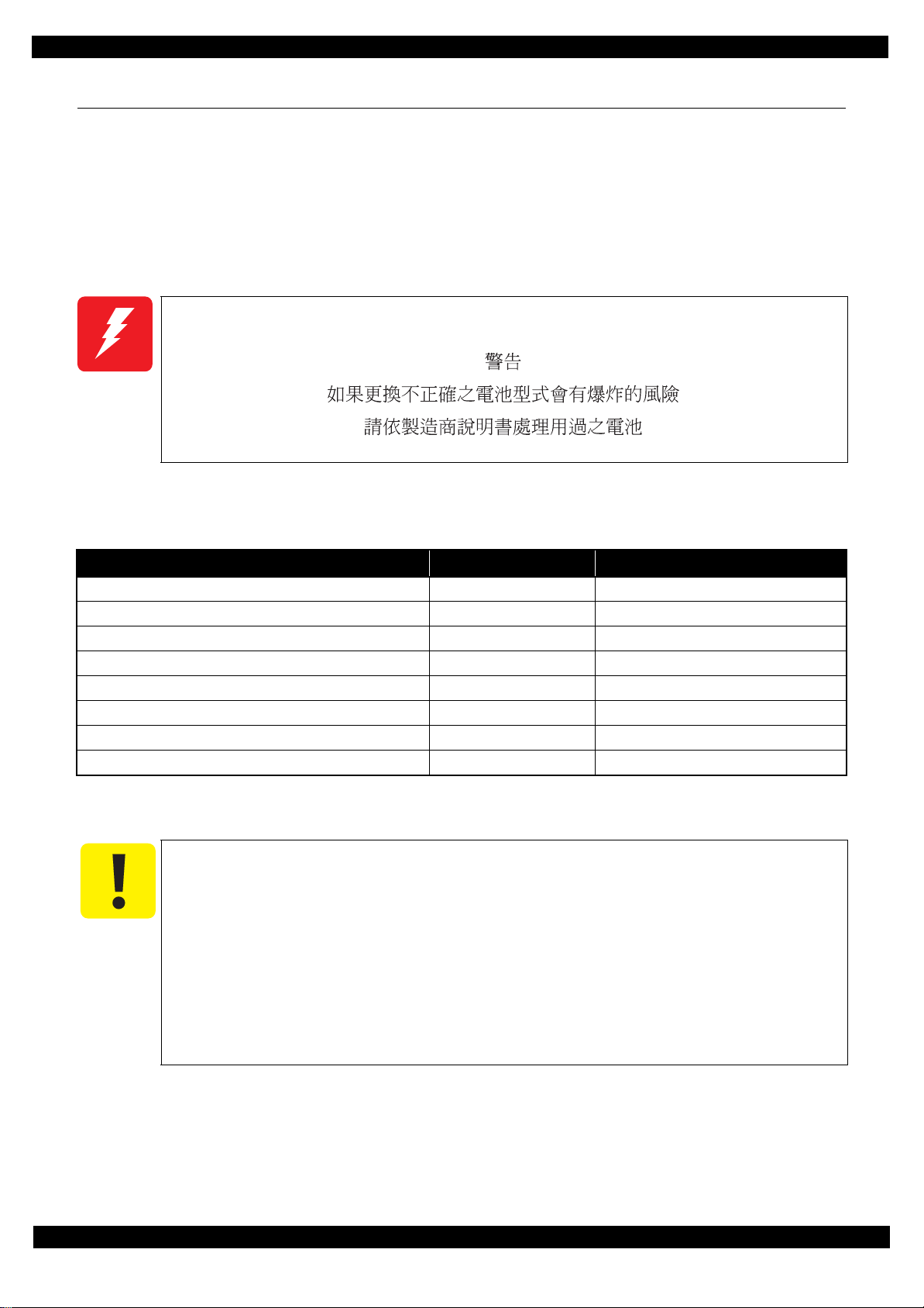
DANGER
Strictly observe the following cautions. Failure to comply could result in serious bodily injury or loss of life.
1. Always disconnect the product from the power source and peripheral devices when servicing the product or
performing maintenance.
2. When performing works de scr i bed in this manual, do not connect to a power sour ce until instructe d t o do so.
Connecting to a power source causes high voltage in the power supply unit and some electronic components
even if the product power swi tch is of f. If you need to perform the wor k wit h th e power cab le connected to a
power source, use extreme caution to avoid electrical shock.
WARNING
Strictly observe the following cautions. Failure to comply may lead to personal injury or loss of life.
1. Always wear protective goggles for disas sembly and reassembl y to prote ct your eye s from ink in wor king. If
any ink gets in your eyes, wash your eyes with clean water and consult a doctor immediately.
2. When using compressed air products; such as air duster, for cleaning during repair and maintenance, the use
of such products containing flammable gas is prohibited.
PRECAUTIONS
Strictly observe the following cautions. Failure to comply may lead to personal injury or damage of the product.
1. Repairs on Epson product should be performed only by an Epson certified repair technician.
2. No work should be per formed on this pr oduct by person s unfamil iar with basic s afety kn owledge re quired f or
electrician.
3. The power rating of this produc t is indicated on the seri al nu mb er/ ra ti ng pl at e. Never connect this product to
the power source whose voltages is different from the rated voltage.
4. Replace malfunctioning components only with those components provided or approved by Epson;
introduction of second- source ICs or other non-approv ed components may damage the product and void any
applicable Epson warranty.
5. In order to protect sensiti ve microp roc essor s and circu itry , use stati c disch arge equi pment, such as ant i-st atic
wrist straps, when accessing internal components.
6. Do not tilt this produc t immediate ly after ini tial in k charge, es peciall y after pe rforming the i nk charge s everal
times. Doing so may cause i nk to le ak f rom the product becaus e it may t ake so me ti me for t he was te ink pads
to completely absorb ink wasted due to the ink charge.
7. Never touch the ink or wasted ink with bare hands. If ink comes into c ont act with your skin, wash it off with
soap and water immediately. If you have a skin irritation, consult a doctor immediately.
SE Group Confidential (Related Staff Only)
Page 4

8. When disassembling or as sembl in g this product, make sure to we ar gloves to avoid injuries from metal parts
with sharp edges.
9. Use only recommended tools for disassembling, assembling or adjusting the printer.
10. Observe the specified torque when tightening screws.
11. Be extremely careful not to scratch or contaminate the following parts.
Nozzle plate of the printhead
Ink Supply Unit
CR Scale
PF Scale
Coated surface of the PF Roller
Gears
Rollers
LCD
Exterior parts
12. Never use oil or grease other than those specified in this manual. Use of different types of oil or grease may
damage the component or give bad influence on the printer function.
13. Apply the specified amount of grease described in this manual.
14. Make the specified adjustments when you disassemble the printer.
15. When cleaning this product, follow the procedure described in this manual.
16. When transporting this product after filling the ink in the printhead, pack the printer without removing the
ink cartridges in order to prevent the printhead from drying out.
17. Make sure to install antivirus software in the computers used for the service support activities.
18. Keep the virus pattern file of antivirus software up-to-date.
SE Group Confidential (Related Staff Only)
Page 5

About This Manual
About This Manual: This manual is made for t he sol e pur pose of pro v id ing neces sary information in order tha t a
serviceperson qualified by Epson performs his / her appropriate repair / maintenance for the applicable Epson’s
products. You shall not use this manual out of this purpose.
This manual is Epson’s c onfide ntial inf ormatio n. When yo u use this manua l, you shall hold it in stri ct co nfiden ce
and shall not disclose to any third party without prior consent of Epson.
This manual, consists of the foll owing cha pte rs, is inte nded for re pair s ervi ce pers onnel a nd incl udes i nfo rmatio n
necessary for properly performing maintenance and servicing the product.
CHAPTER 1. DISASSEMBLY / REASSEMBLY
Describes the disassembly/reassembly procedures for main parts/units of the product, and provides the
standard operation time for servicing the product.
CHAPTER 2. ADJUSTMENT
Describes the required adjustments for servicing the product.
CHAPTER 3. MAINTENANCE
Describes maintenance items and procedures for servicing the product.
CHAPTER 4. APPENDIX
Provides the following additional information for reference:
•
Power-On Sequence
•
Connector Diagram
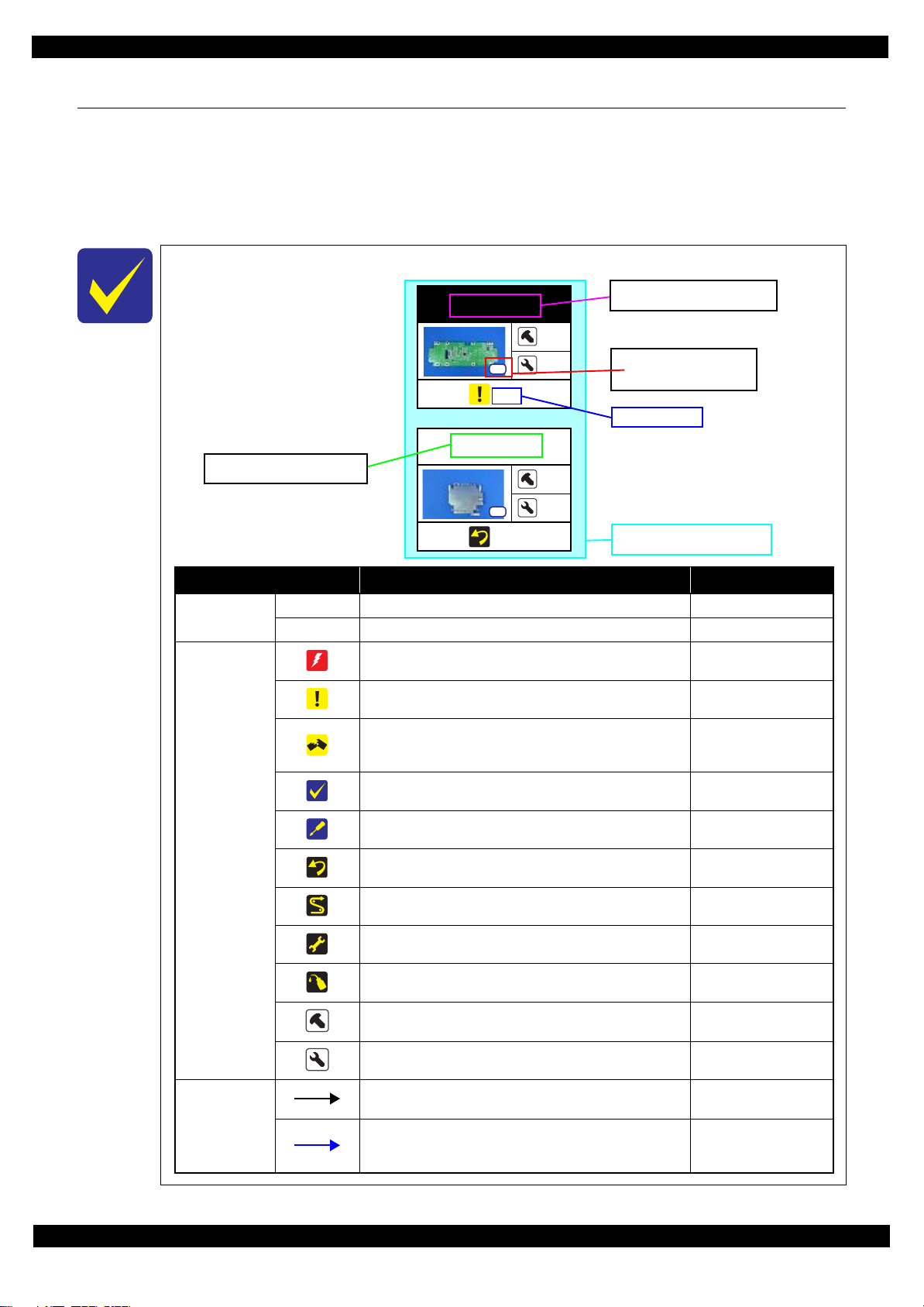
Symbols Used in this Manual
Various symbols are used throughout this manual either to provide additional information on a specific topic or
to warn of possible danger present during a procedure or an action. Pay attention to all symbols when they are
used, and always read explanation thoroughly and follow the instructions.
Indicates an operating or maintenance procedure, practice or condition that, if not strictly observed,
could resu lt in serious injury or loss of life.
Indicates an operat ing or main tenanc e proced ure, pract ice, or c onditi on that , if not st rict ly obse rved,
could result in bodily injury, damage or malfunction of equipment.
May indicate an operating or maintenance procedure, practice or condition that is necessary to
accomplish a task efficiently. It may also provide additional information that is related to a specific
subject, or comment on the results achieved through a previous action.
For Chapter 1 “Disassembly/Reassembly”, symbols other than indicated above are used to show additional
informati on for disassembly/rea ssembly. For the details on those symbols, see "1.2 Disassembly/Reassembly
Procedures (p14)".
SE Group Confidential (Related Staff Only)
Page 6

Revision Status
Revision Date of Issue Description
A September 30, 2014 First Release
B February 12, 2015 Chapter 1
- "1.1.2 Jigs (p10)": calibrator names were revised.
Chapter 2
- "2.1 Adjustment Items and the Order by Repaired Part (p32)": adjustment items when Print
Head was removed were revised.
- "2.2 Adjustment Items (p36)": description about Colorimetric calibration was revised.
- "2.3.7 Head Angular Adjustment CR/PF (p55)": partially revised.
- "2.3.8 Colorimetric Calibration (p57)": contents were added newly.
C March 31, 2015 Chapter 1
- "1.1 Overview (p9)": “WARNING” was added
- "1.1.1 Tools (p9) " : “CAUTION” was added
D November 24, 2015 Chapter 2
- "2.2 Adjustment Items (p36)": Note was added outside of Table2-3.
- "2.3.6 Initial setting (p54)": partially revised.
- "2.3.7 Head Angular Adjustment CR/PF (p55)": procedure was revised.
- "2.3.10 Touch screen adjustment (p70)": contents were added newly.
SE Group Confidential (Related Staff Only)
Page 7

SC-P600 Revision D
Contents
Chapter 1 Disassembly/Reassembly
1.1 Overview ................................................................................................................................................................... 9
1.1.1 Tools ................................................................................................................................................................. 9
1.1.2 Jigs .................................................................................................................................................................. 10
1.1.3 Precautions before Disassembling.................................................................................................................. 11
1.1.4 Preparation before Returning the Unit to the User......................................................................................... 12
1.2 Disassembly/Reassembly Procedures ..................................................................................................................... 14
1.2.1 Disassembly/Reassembly Flowchart.............................................................................................................. 15
1.2.1.1 Housing Part .......................................................................................................................................... 15
1.2.1.2 Printer Mechanism Part ......................................................................................................................... 16
1.3 Detail ed Disassembly/Reassembly Procedure for each Part/Unit........................................................................... 19
1.4 Routing FFCs/cables ............................................................................................................................................... 28
Chapter 2 Adjustment
2.1 Adjustment Items and the Order by Repaired Part.................................................................................................. 32
2.2 Adjustment Items .................................................................................................................................................... 36
2.3 Details of Adjustments ............................................................................................................................................ 39
2.3.1 PF Timing Belt Tension Adjustment.............................................................................................................. 39
2.3.2 PF Roller Shaft Center Support Position Adjustment .................................................................................... 40
2.3.3 ASF Guide Roller LDs position adjustment................................................................................................... 46
2.3.4 PG Adjustment ............................................................................................................................................... 49
2.3.5 Mist Recovery check ...................................................................................................................................... 53
2.3.6 Initial setting................................................................................................................................................... 54
2.3.7 Head Angular Adjustment CR/PF.................................................................................................................. 55
2.3.8 Colorimetric Calibration................................................................................................................................. 57
2.3.8.1 Overview of the Colorimetric Calibration............................................................................................. 57
2.3.8.2 Adjusting Method of the Colorimetric Calibration................................................................................ 60
2.3.8.3 Maintenance menu................................................................................................................................. 68
2.3.9 Ink Selector Check............................................................ ..... ...... ................................. .................................. 69
2.3.10 Touch screen adjustment .............................................................................................................................. 70
Chapter 3 Maintenance
3.1 Overview ................................................................................................................................................................. 72
3.1.1 Cleaning.......................................................................................................................................................... 72
3.1.2 Lubrication...................................................................................................................................................... 72
3.2 Lubrication Points and Instructions......................................................................................................................... 73
Chapter 4 Appendix
4.1 Power-On Sequence ................................................................................................................................................ 77
4.2 Connector Diagram ................................................................................................................................................. 80
4.3 Fatal Error Code ....................................................... ..... .......................................................................................... 81
SE Group Confidential (Related Staff Only)
7
Page 8

CHAPTER 1
DISASSEMBLY/REASSEMBLY
SE Group Confidential (Related Staff Only)
Page 9
SC-P600 Revision D
1.1 Overview
This chapter describes procedures for disassembling the main parts/units of Stylus Photo R3000. Unless
otherwise specified, disassembled parts/units can be reassembled by reversing the disassembly procedure. See
the cautions or tips for disassembly/reassembly described in "1.3 Detailed Disassembly/Reassembly Procedure
for each Part/Unit (p19 )".
Read the "Safety Precautions (p3)" before disassembling and reassembling.
When you have to remove units or parts that are not described in this chapter, see the exploded diagrams of SPI
(Service Parts Information).
This warning is for Taiw an.
1.1.1 Tools
Use only specified tools to avoid damaging the printer.
Name Availability
(+) Phillips screwdriver #1 O 1080530
(+) Phillips screwdriver #2 O --Flathead screwdriver O --Flathead Precision screwdriver #1 O --Tweezers O --Longnose pliers O --Acetate ta pe --- 1003963
Nippers O ---
Note *1: Some of the tools listed above are commercially available.
*2: EPSON provides the tools listed wi th EPS O N pa rt co de .
*1
EPSON Part Code
Bring back the followin g brought and used items, then dispo se of them based on the local
regulations in your country, please.
Ink cartridges
Cleaning cartridges
Draining cartridges
*2
Especially in case of ink cartridges in Europe, please refer to the following web site to
confirm the regulation in detail.
ECO Info: http://www.epson.eu/weee (available from July 2015)
Disassembly/Reassembly Overview 9
SE Group Confidential (Related Staff Only)
Page 10

SC-P600 Revision D
1.1.2 Jigs
*1
Name
Sonic tension gauge U-508 1 --- 1640645
PF Roller Adjustment Jig 1 --- 1553098
PF Roller Adjustment Jig Stand 1 --- 1553099
Level block 1 --- 1304994
Adjustment gauge for PG adjustment 1 --- 1276333
Oscilloscope or Tester + High-voltage probe 1 O
Calibrator (i1 Pro UV-Cut or i1Pro2) 1 O ---
Note *1: The jigs above are used for adjustment (See Chapter 2 " Adjustment (p31)".) No jigs are required for disassembling /
reassembling this printer.
*2: Some of the tools listed above are commercially available.
*3: Recommended maker and model number: (If the device which can measure resistance value of 100MΩ is not used, you may
not measure a value definite ly. As a result, there is the case that a parameter is not set w ithin a standard, the Mist Recovery
Function does not act, and dirt in the printer or printing back side dirt of the paper occur.)
Oscilloscope + High-voltage probe (A high vo ltage probe around 100MΩ made by Tektronix: P-5210A or THDP0100)
Tester (Ex. FLUKE True-rms Multimeter 110 Series, 3+1/2 columns of DMM: More than input 10MΩ) + High voltage probe
(around 75MΩ: FLUKE 80K-6 or 80K-40)
Q’ty Availability
*2
*3
EPSON Part Code
---
Disassembly/Reassembly Overview 10
SE Group Confidential (Related Staff Only)
Page 11
SC-P600 Revision D
Right
Hole
Phillips screw d river
CW
CCW
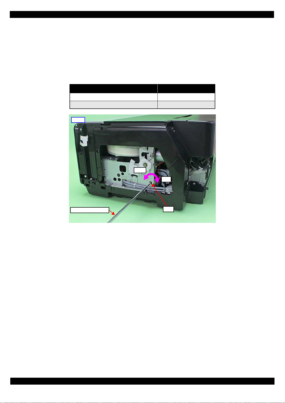
1.1.3 Precautions before Disassembling
Unlocking the carriage
Unlock the carriage by following the procedure below.
1. Remove the Rear Housing, Right Cover, and Right Decoration Plate.
2. Insert a phillips screwdriver into the hole of the frame on the rig ht side of the printer, and rotate the white
shaft of the Ink System.
Table 1-1. Carriage Lock/Unlock
Direction of Rotation Carriage
Clockwise (CW) Locked
Counterclockwise (CCW) Unlocked
Figure 1-1. Unlock t he Carriage
Handling the Ink Supply Unit
In order to prevent ink leakage, be careful of the following when handling the Ink Supply Unit.
(See "Ink Supply Unit (p22)" and "CR Contact Module (p22)" for details.)
Unless otherwise specified in this manual, do not disassemble the Ink Supply Unit any further than specified as an
ASP. Otherwise, replace the Ink Supply Unit with a new one.
Be careful not to damage the film of the ink path.
When disassembling/reassembling the printer, be careful not to apply extra force on the joint part of the ink tube
and I/C Holder Unit, and on that of the ink tube and Ink Selector.
Disassembly/Reassembly Overview 11
SE Group Confidential (Related Staff Only)
Page 12
SC-P600 Revision D
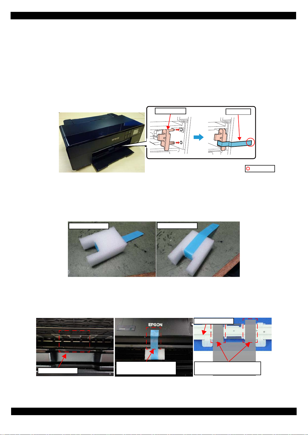
Front tray lock
Strong tape
Folded end
Upper of Pad
Lower of Pad
Attaching area
Attach the unfolded end of tape
to the front of the printer.
The location of the projections of
pad is between roller and claw.
Tray Suppot Assy
1.1.4 Preparation before Returning the Unit to the User
When returning the prin ter to the user, make sure to sec ur e the specified points with ta pes to avo id da maging the
printer during transport.
±
Attaching the front tray lock (tape length: 90
Attach the front tray lock (1535369) and secure it with strong tape as follows.
1. Attach the front tray lock on the position shown in Figure 1-2.
2. Attach the unfolded end of strong tape on the front tray lock as shown in Figure 1-2, and pull the tape and
apply it along the shapes of the Upper Housing Support Assy to secure the front tray lock.
2 mm, tape width: 18 mm, fold one end by 5 mm)
Figure 1-2. Attaching and Securing the Front Tray Lock
Attaching the front tray support pad (tape length: 190mm, tape width: 18 mm, fold one end by 5 mm)
Attach the front tray support pad (5125513) and secure it with strong tape as follows.
1. Attach the strong tape to the front tray support pad shown in Figure 1-3.
Figure 1-3. Attaching the strong tape to the front tray
2. Attach the front tray support pad to the front of the printer shown in Figure 1-4.
Figure 1-4. Attaching the front tray support pad
Disassembly/Reassembly Overview 12
SE Group Confidential (Related Staff Only)
Page 13
SC-P600 Revision D
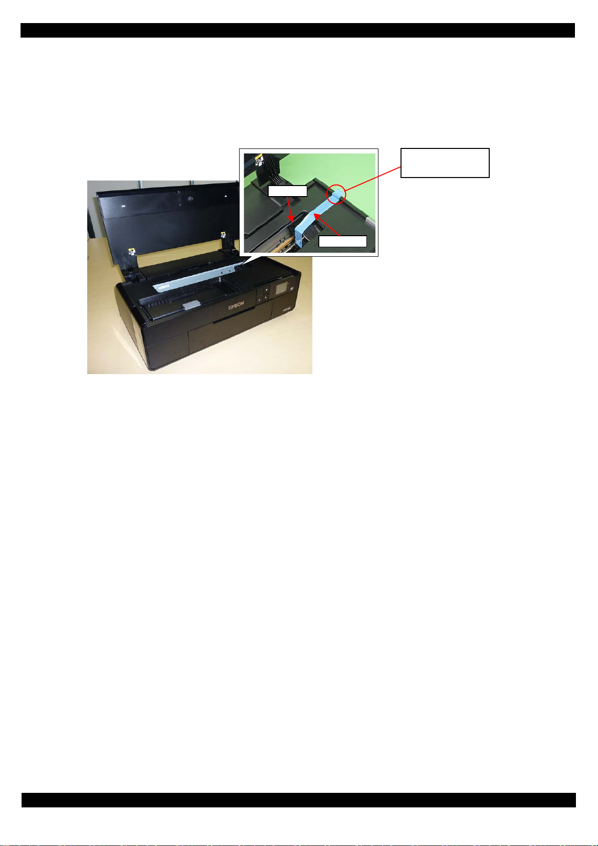
CR Unit
Strong tape
Attach strong tape with
its unfolded end sticking
out of the printer.
±
Securing the CR Unit (tape length: 220
2 mm, tape width: 18 mm, fold one end by 5 mm)
Secure the CR Unit with strong tape as follows.
1. Open the printer cover and move the CR Unit to its home position.
2. Attach the unfolded end of strong tape on the CR Unit, and pull the tape and apply it along the shapes of
the Upper Housing Assy to the right side of the print er to secure the CR Unit.
Figure 1-5. Securing the CR Unit
Disassembly/Reassembly Overview 13
SE Group Confidential (Related Staff Only)
Page 14
SC-P600 Revision D
LCD Shield
2
2
(p 15)
S4
Panel Board
2
4
(p 15)
Item Description Reference
Parts/unit name
White-letter
Part/unit supplied as an ASP ---
Black-letter
Part/unit not supplied as an ASP ---
Icon
Indicates a practice or condi ti on that could result in injury or
loss of life if n ot strictly observed.
Indicates the reference
page in blue-letter
Indicates a practice or condition that could result in damage to,
or destruction of equipment if not strictly observed.
Indicates the reference
page in blue-letter
Indicates the parts that are inevitably broken in the
disassembling procedure, and should be replaced with a new
one for reassembly.
---
Indicates necessary check items in the disassembling/
assembling procedure.
Indicates the reference
page in blue-letter
Indicates supplementary expla na ti on for disassembly is given.
Indicates the reference
page in blue-letter
Indicates particular tasks to keep qua li ty of the uni ts are
required.
Indicates the reference
page in blue-letter
Indicates particular routing of c ab le s is required.
Indicates the reference
page in blue-letter
Indicates particular adjustment(s) is/are required.
Chapter 2 " Adjustment
(p31)"
Indicates lubrication is require d.
Chapter 3 " Maintenance
(p71)"
Indicates the number of screws secu ring the parts/units. ---
Indicates the points secured w ith ot her than a screw such as a
hook, rib, dowel or the like
---
Arrowed line
Indicates a disassembling proc edure. ---
Indicates a removal procedure for a component of a part or
unit which is necessary to remo ve w hen proceeding to the
target part.
---
Shows removal/installation
as a unit/assy. is available.
Reference page
Black letters indicate a part/
unit not supplied as an ASP.
Shows the screw types and
the specified torque in the
“Screw type/torque list”.
White letters indicate a part/
unit supplied as an ASP.
1.2 Disassembly/Reassembly Procedures
This section describes procedures for disassembling the parts/units in a flowchart format. For some parts/units,
detailed procedures or precautions are provided (accordingly indicated by icons and cell’s color). Refer to the
explanations in the example chart below and perform an appropriate disassembling and assembling procedure.
(See "1.3 Detailed Disassembly/Reassembly Procedure for each Part/Unit (p19)".)
For routing cables, see "1.4 Routing FFCs/cables (p28)" .
The example below shows how to see the charts on the following pages.
S12
Disassembly/Reassembly Disassembly/Reassembly Procedures 14
SE Group Confidential (Related Staff Only)
Page 15
SC-P600 Revision D
S20
S5
S13
S6
S1
S2
S3
S4
S5
S6
S7
S8
S9
S10
S11
S12
S13
S14
S15
S16
S17
S18
S19
S20
S21
S22
S23
S24
S25
S26
S27
S28
S29
S30
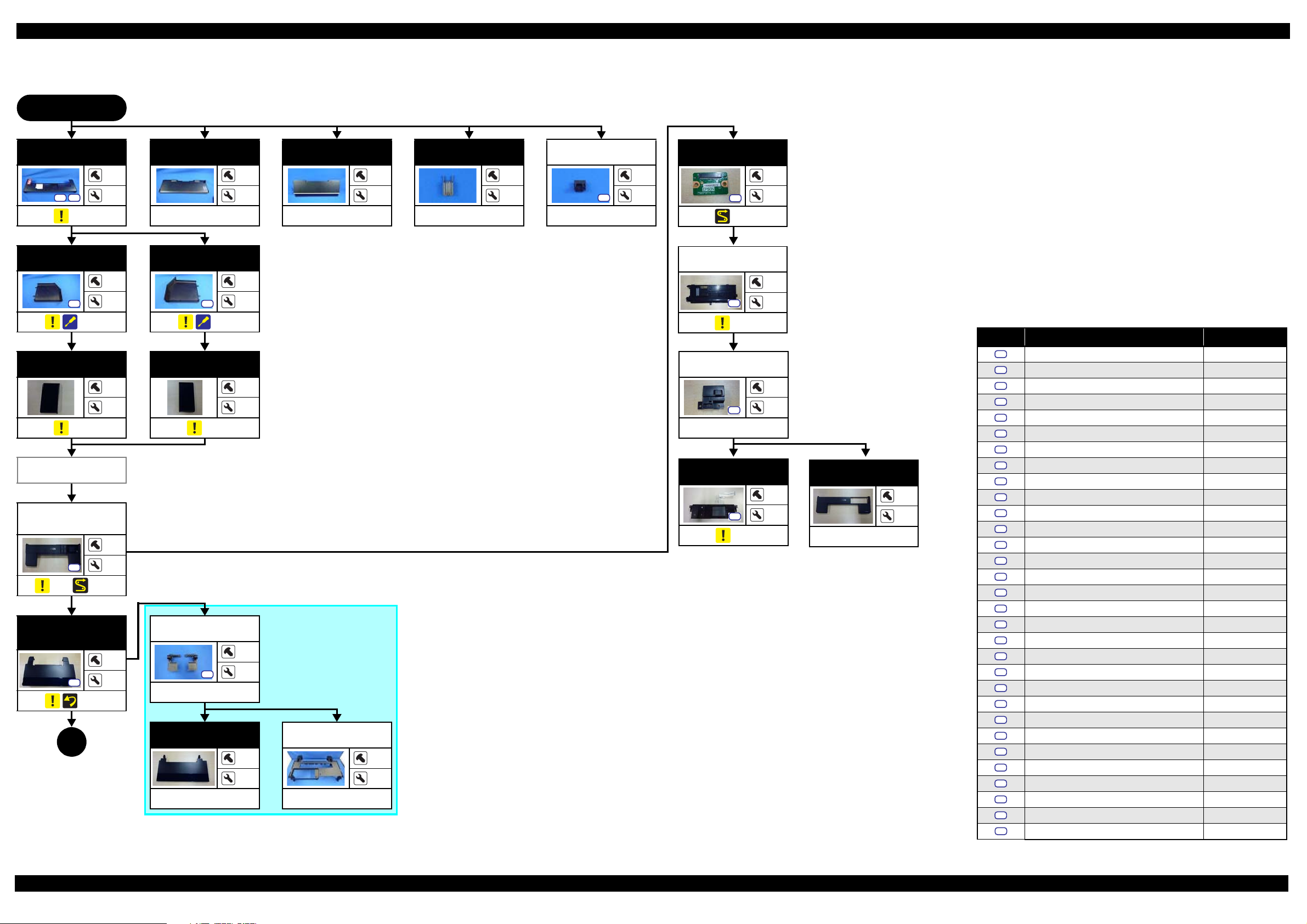
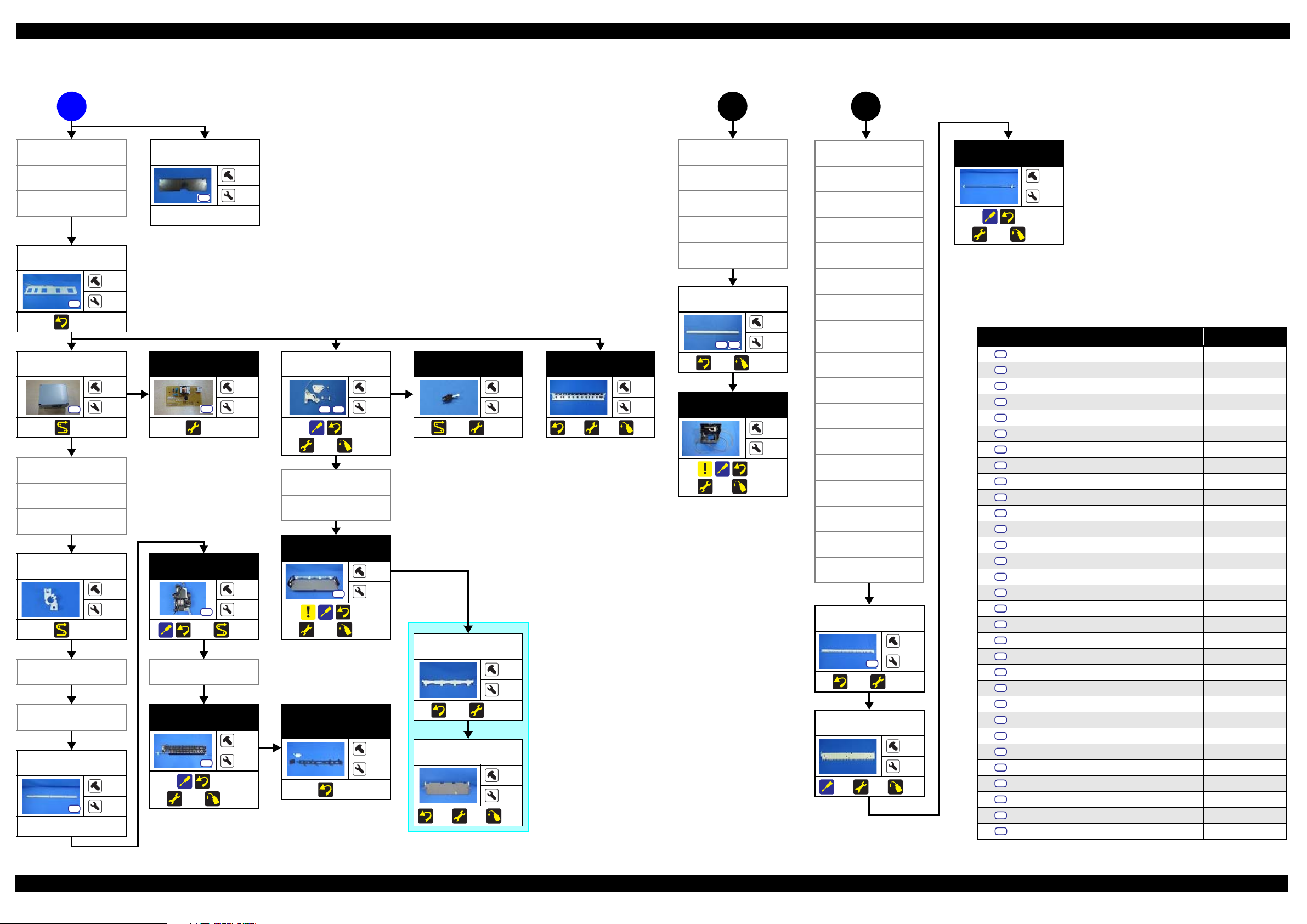
1.2.1 Disassembly/Reassembly Flowchart
1.2.1.1 Housing Part
START
Rear Housing
S9
(p 19)
Left Cover
(p 19)
Left
Decoration Plate
(p 19)
Adjust Printer
Cover
Upper Housing
Support Assy
(w/Panel Unit)
(p 19) (p 28)
Upper Housing
Assy (w/Upper
Printer Cover)
(p 19)
1
(p 16)
12
---
14
---
Paper Support
Assy
3
---
4
---
Stacker Cover
---
CSIC Terminal
---
2
---
---
2
Right Cover
1
4
S5
(p 19)
1
4
Adjust Printer
Cover
S5
---
---
Panel SUB
Board
1
S12
(p 28)
2
---
Panel Cover
Rear
3
S12
---
Screw type/torque list
(p 20)
Symbol Screw type Torque
Right
Decoration Plate
---
3
(p 19)
3
4
Upper Printer
Cover Holder
4
S12
---
Upper Printer
Cover
---
6
10
Upper Housing
---
---
---
---
---
Cover Open
Sensor Cover
S12
---
Panel Unit
S12
(p 20)
---
---
1
Upper Housing
Support Assy
4
---
---
---
S31
C.B.P-TITE SCREW,2.5X8,F/ZN-3C 2.5 ± 0.5 kgf·cm
C.B.P-TITE SCREW, 2.5X8,F/ZN-3C 3.5 ± 0.5 kgf·cm
C.B.P-TITE SCREW,2X6, F/ZN-3C 2.0
±
0.5 kgf·cm
C.B.P-TITE SCREW,2X6 ,F /ZN-3C 3.0 ± 1.0 kgf·cm
C.B.P-TITE SCREW,3X10,F/ZB-3C 6.0
±
1.0 kgf·cm
C.B.P-TITE SCREW,3X10,F/ZN-3C 6.0 ± 1.0 kgf·cm
±
C.B.P-TITE SCREW,3X18,F/ZN-3C 6.0
1.0 kgf·cm
C.B.P-TITE SCREW,3X6 ,F /ZN-3C 4.0 ± 0.5 kgf·cm
C.B.P-TITE SCREW,3X8 , F /ZB-3C 6.0
±
1.0 kgf·cm
C.B.P-TITE SCREW,3X8 ,F /ZN-3C 4.0 ± 0.5 kgf·cm
C.B.P-TITE SCREW,3X8, F/ZN-3C 5.0
±
1.0 kgf·cm
C.B.P-TITE SCREW,3X8 ,F /ZN-3C 6.0 ± 1.0 kgf·cm
±
C.B.P-TITE SCREW,4X8, F/ZN-3C 8.0
1.0 kgf·cm
C.B.SCREW,2.5X14,F/ZN-3C 3.0 ± 1.0 kgf·cm
C.B.SCREW,2.5X6,F/ZN-3C 3.5
±
0.5 kgf·cm
C.B.SCREW,3X4,F/ZN-3C 4.0 ± 0.5 kgf·cm
C.B.SCREW,3X6,F/ZN-3C 8.0
±
1.0 kgf·cm
C.B.S-TITE SCREW, 2.5X6,F/ZN-3C 4.0 ± 0.5 kgf·cm
C.B.S-TITE SCREW,3X4, F/ZN-3C 8.0
±
1.0 kgf·cm
C.B.S-TITE SCREW,3X6 ,F /ZN-3C 6.0 ± 1.0 kgf·cm
C.B.S-TITE SCREW,3X6, F/ZN-3C 8.0
±
1.0 kgf·cm
C.B.S-TITE SCREW,3X6 ,F /ZN-3C 9.0 ± 1.0 kgf·cm
C.B.S-TITE SCREW,3X8, F/ZN-3C 8.0
±
1.0 kgf·cm
C.B.S-TITE(P2)SCREW,3X10,F/ZN-3C 6.0 ± 1.0 kgf·cm
C.B.S-TITE(P4)SCREW,3X6,F/ZN-3C 8.0
±
1.0 kgf·cm
C.B.S-TITE(P4)SCREW,3X8,F/ZN-3C 5.0 ± 1.0 kgf·cm
C.B.S-TITE(P4)SCREW,3X8,F/ZN-3C 8.0
±
1.0 kgf·cm
C.C.SCREW,3X4,F/ZN-3C 4.0 ± 0.5 kgf·cm
C.P.SCREW,2.6X3,F/ZN-3C 3.0
±
0.5 kgf·cm
C.P.SCREW,3X10,F/ZN-3C 6.0 ± 1.0 kgf·cm
C.P.SCREW,3X4,F/ZN-3C 6.0
±
1.0 kgf·cm
Flowchart 1-1. Disassembly Flowchart of Housing Part
Disassembly/Reassembly Disassembly/Reassembly Flowchart 15
SE Group Confidential (Related Staff Only)
Page 16
SC-P600 Revision D
S12
S6
S20
S23
S31
S20
S24
S1
S2
S3
S4
S5
S6
S7
S8
S9
S10
S11
S12
S13
S14
S15
S16
S17
S18
S19
S20
S21
S22
S23
S24
S25
S26
S27
S28
S29
S30
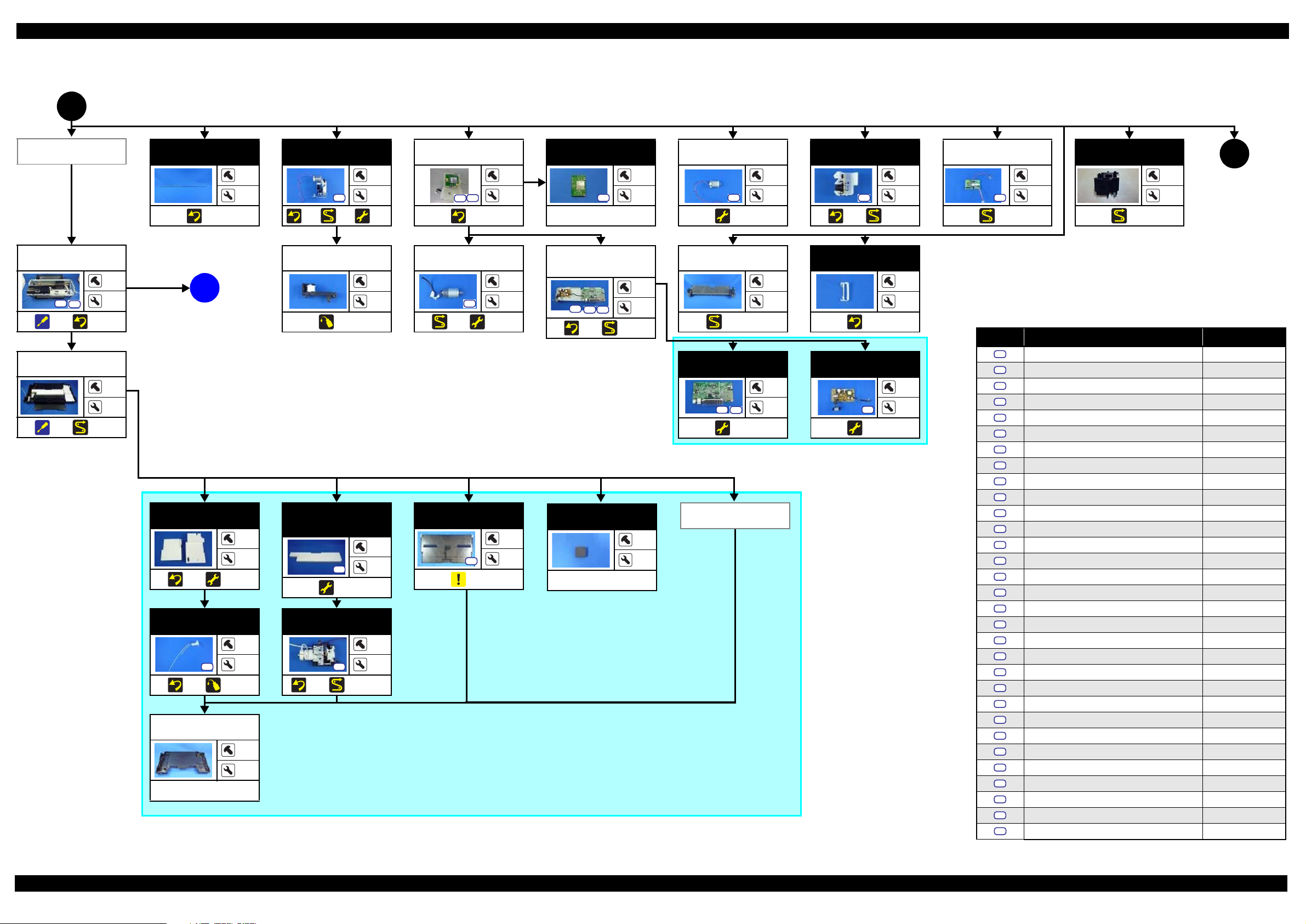
1.2.1.2 Printer Mechanism Part
(p 15)
1
Wireless LAN
Module Assy
Printer
Mechanism
S13
(p 21) (p 21)
*
Lower Housing
Assy
(p 21) (p 28)
---
---
CR Scale
---
3
(p 20)
(p 20)
APG Assy
S21
(p 29)
3
---
(p 31)
Driven Pulley
6
A
2
---
---
(p 18)
(p 73)
Wireless LAN
Module Assy
(p 20)
PF Motor
S28
(p 29) (p 31)
3
---
2
---
*: The Printer Mecha nism in this flowchart is not the one es tablished as an ASP . The Printer Me chanism as an ASP excludes the
following parts from th e Prin ter Mechanism i n thi s flowc har t. When r epla cing th e Prin ter Mechan ism spec ifi ed as an ASP, ad justments
are required. Se e Chapter 2 " Adjus t ment (p31)" for details.
• ASF Assy
• LD Roller Guide
• Board Assy (Main Board/Power Supply Board)
• Head FFC
• Printhead
• Printhead Mounting Plate
• CR Support Plate
• CR Cover
• Ink Supply Unit
•Ink Tube Holder
• Paper Guide (under ASF Assy)
• Shi el d Pla t e A ssy Upper Main Board
Wireless LAN
Module
S12
---
Board Assy (Main
Board/Power
Supply Board)
S24 S30
(p 27) (p 29)
---
APG Motor
3
2
S29
(p 31)
Roll Paper
Guide Assy
7
2
---
---
2
(p 28, p 29)
Main Board
4
S20
(p 31)
---
PF Encoder Assy
(p 27) (p 29)
Ink Tube Holder
(p 20)
Power Supply
Board
S20
(p 31)
1
4
---
6
4
---
ASF Relay
Board
1
---
(p 29)
ASF PE
Sensor Assy
(p 30)
---
(p 17)
4
Screw type/torque list
Symbol Screw type Torque
C.B.P-TITE SCREW,2.5X8,F/ZN-3C 2.5 ± 0.5 kgf·cm
C.B.P-TITE SCREW, 2.5X8,F/ZN-3C 3.5 ± 0.5 kgf·cm
C.B.P-TITE SCREW,2X6, F/ZN-3C 2.0
C.B.P-TITE SCREW,2X6 ,F /ZN-3C 3.0 ± 1.0 kgf·cm
C.B.P-TITE SCREW,3X10,F/ZB-3C 6.0
C.B.P-TITE SCREW,3X10,F/ZN-3C 6.0 ± 1.0 kgf·cm
C.B.P-TITE SCREW,3X18,F/ZN-3C 6.0
±
0.5 kgf·cm
±
1.0 kgf·cm
±
1.0 kgf·cm
2
C.B.P-TITE SCREW,3X6 ,F /ZN-3C 4.0 ± 0.5 kgf·cm
C.B.P-TITE SCREW,3X8 , F /ZB-3C 6.0
±
1.0 kgf·cm
C.B.P-TITE SCREW,3X8 ,F /ZN-3C 4.0 ± 0.5 kgf·cm
Waste Ink Pad
(p 20) (p 31)
Waste Ink Tube
Lower Paper
Guide Ink Pad
---
---
Tray
S12
(p 31)
1
---
Stacker Assy
S6
(p 19)
Foot
4
---
---
---
---
Stacker Cover
Decomp Pump
Assy
1
3
C.B.P-TITE SCREW,3X8, F/ZN-3C 5.0
±
1.0 kgf·cm
C.B.P-TITE SCREW,3X8 ,F /ZN-3C 6.0 ± 1.0 kgf·cm
±
C.B.P-TITE SCREW,4X8, F/ZN-3C 8.0
1.0 kgf·cm
C.B.SCREW,2.5X14,F/ZN-3C 3.0 ± 1.0 kgf·cm
C.B.SCREW,2.5X6,F/ZN-3C 3.5
±
0.5 kgf·cm
C.B.SCREW,3X4,F/ZN-3C 4.0 ± 0.5 kgf·cm
C.B.SCREW,3X6,F/ZN-3C 8.0
±
1.0 kgf·cm
C.B.S-TITE SCREW, 2.5X6,F/ZN-3C 4.0 ± 0.5 kgf·cm
C.B.S-TITE SCREW,3X4, F/ZN-3C 8.0
±
1.0 kgf·cm
C.B.S-TITE SCREW,3X6 ,F /ZN-3C 6.0 ± 1.0 kgf·cm
S12
(p 20) (p 73)
Lower Housing
---
S6
(p 20) (p 28, p 29)
---
---
--C.B.S-TITE SCREW,3X6, F/ZN-3C 8.0
±
1.0 kgf·cm
C.B.S-TITE SCREW,3X6 ,F /ZN-3C 9.0 ± 1.0 kgf·cm
C.B.S-TITE SCREW,3X8, F/ZN-3C 8.0
±
1.0 kgf·cm
C.B.S-TITE(P2)SCREW,3X10,F/ZN-3C 6.0 ± 1.0 kgf·cm
C.B.S-TITE(P4)SCREW,3X6,F/ZN-3C 8.0
±
1.0 kgf·cm
C.B.S-TITE(P4)SCREW,3X8,F/ZN-3C 5.0 ± 1.0 kgf·cm
C.B.S-TITE(P4)SCREW,3X8,F/ZN-3C 8.0
±
1.0 kgf·cm
C.C.SCREW,3X4,F/ZN-3C 4.0 ± 0.5 kgf·cm
---
C.P.SCREW,2.6X3,F/ZN-3C 3.0
±
0.5 kgf·cm
C.P.SCREW,3X10,F/ZN-3C 6.0 ± 1.0 kgf·cm
S31
C.P.SCREW,3X4,F/ZN-3C 6.0
±
1.0 kgf·cm
Flowchart 1-2. Disassembly Flowchart of Printer Mechanism Part (1)
Disassembly/Reassembly Disassembly/Reassembly Flowchart 16
SE Group Confidential (Related Staff Only)
Page 17
SC-P600 Revision D
S20
S12
S21
S1
S2
S3
S4
S5
S6
S7
S8
S9
S10
S11
S12
S13
S14
S15
S16
S17
S18
S19
S20
S21
S22
S23
S24
S25
S26
S27
S28
S29
S30
(p 16)
2
CR Cover
---
CR Support
Plate
(p 21) (p 28)
Wireless LAN
Module Assy
Ink Supply Unit
S1
S15 S21
S23
(p 22)
(
, p 29, p 29)
Printhead
Mounting Plate
Print head
Head FFC
CR Scale
LD Roller Guide
ASF Assy
Lower Housing
Assy
Lower Paper
Guide
4
(p 18)
(p 31)
(p 73)
---
LD Roller Guide
1
2
Ink Tube Guide
4
7
---
---
3
CR Relay Board
S20
(p 28)
2
---
(p 24)
S17
(p 31)
ASF Assy
S21
S27
(p 29)
2
4
4
2
(p 31)
ASF Motor
S12
(p 28, p 29)
2
---
CR Contact
Module
S7
S21
(p 22)
(p 29)
13
9
Screw type/torque list
Symbol Screw type Torque
PE Detector Assy
---
Ink Selector*
5
S15
S1
2
---
I/C Holder Unit*
S23
3
(p 28)
---
4
Release Holder
Assy
S21
(p 28) (p 31)
3
3
APG Assy
(p 11) (, p 28)
(p 11) (, p 29)
Paper Guide
(under ASF Assy)
---
APG Assy
---
2
Board Assy (Main
Board/Power
Supply Board)
Driven Pulley
Release Flag
Printhead
Mounting Plate
S2
(p 21)
Print head
S2
(p 21) (p 31)
1
---
3
---
Assy
(p 23) (p 31)
PE Detector Assy
Upper Paper
Guide Assy
---
4
CR Motor
S16
(p 23) (p 28, p 29)
(p 31)
2
---
Shield Plate Assy
Upper Main
Board
S21
(p 27)
3
2
---
2
Head FFC
(p 23) (p 31)
---
---
(p 26) (p 28, p 29)
*: The Ink Sele ctor and I /C Ho lder Unit ar e the pa r ts of the In k Sup ply Uni t. Howev er, if th e dis asse mbly is
3
(p 18)
not for replacement of the Ink Suppl y U ni t, it is faster that only either of the Ink Select or or I/ C H ol der
Unit is removed to proceed the next step. Therefore, they are listed in this flowchart separately.
Flowchart 1-3. Disassembly Flowchart of Printer Mechanism Part (2)
S31
C.B.P-TITE SCREW,2.5X8,F/ZN-3C 2.5 ± 0.5 kgf·cm
C.B.P-TITE SCREW, 2.5X8,F/ZN-3C 3.5 ± 0.5 kgf·cm
C.B.P-TITE SCREW,2X6, F/ZN-3C 2.0
±
0.5 kgf·cm
C.B.P-TITE SCREW,2X6 ,F /ZN-3C 3.0 ± 1.0 kgf·cm
C.B.P-TITE SCREW,3X10,F/ZB-3C 6.0
±
1.0 kgf·cm
C.B.P-TITE SCREW,3X10,F/ZN-3C 6.0 ± 1.0 kgf·cm
±
C.B.P-TITE SCREW,3X18,F/ZN-3C 6.0
1.0 kgf·cm
C.B.P-TITE SCREW,3X6 ,F /ZN-3C 4.0 ± 0.5 kgf·cm
C.B.P-TITE SCREW,3X8 , F /ZB-3C 6.0
±
1.0 kgf·cm
C.B.P-TITE SCREW,3X8 ,F /ZN-3C 4.0 ± 0.5 kgf·cm
C.B.P-TITE SCREW,3X8, F/ZN-3C 5.0
±
1.0 kgf·cm
C.B.P-TITE SCREW,3X8 ,F /ZN-3C 6.0 ± 1.0 kgf·cm
±
C.B.P-TITE SCREW,4X8, F/ZN-3C 8.0
1.0 kgf·cm
C.B.SCREW,2.5X14,F/ZN-3C 3.0 ± 1.0 kgf·cm
C.B.SCREW,2.5X6,F/ZN-3C 3.5
±
0.5 kgf·cm
C.B.SCREW,3X4,F/ZN-3C 4.0 ± 0.5 kgf·cm
C.B.SCREW,3X6,F/ZN-3C 8.0
±
1.0 kgf·cm
C.B.S-TITE SCREW, 2.5X6,F/ZN-3C 4.0 ± 0.5 kgf·cm
C.B.S-TITE SCREW,3X4, F/ZN-3C 8.0
±
1.0 kgf·cm
C.B.S-TITE SCREW,3X6 ,F /ZN-3C 6.0 ± 1.0 kgf·cm
C.B.S-TITE SCREW,3X6, F/ZN-3C 8.0
±
1.0 kgf·cm
C.B.S-TITE SCREW,3X6 ,F /ZN-3C 9.0 ± 1.0 kgf·cm
C.B.S-TITE SCREW,3X8, F/ZN-3C 8.0
±
1.0 kgf·cm
C.B.S-TITE(P2)SCREW,3X10,F/ZN-3C 6.0 ± 1.0 kgf·cm
C.B.S-TITE(P4)SCREW,3X6,F/ZN-3C 8.0
±
1.0 kgf·cm
C.B.S-TITE(P4)SCREW,3X8,F/ZN-3C 5.0 ± 1.0 kgf·cm
C.B.S-TITE(P4)SCREW,3X8,F/ZN-3C 8.0
±
1.0 kgf·cm
C.C.SCREW,3X4,F/ZN-3C 4.0 ± 0.5 kgf·cm
C.P.SCREW,2.6X3,F/ZN-3C 3.0
±
0.5 kgf·cm
C.P.SCREW,3X10,F/ZN-3C 6.0 ± 1.0 kgf·cm
C.P.SCREW,3X4,F/ZN-3C 6.0
±
1.0 kgf·cm
Disassembly/Reassembly Disassembly/Reassembly Flowchart 17
SE Group Confidential (Related Staff Only)
Page 18
SC-P600 Revision D
S27
S21
S21
S21
S1
S2
S3
S4
S5
S6
S7
S8
S9
S10
S11
S12
S13
S14
S15
S16
S17
S18
S19
S20
S21
S22
S23
S24
S25
S26
S27
S28
S29
S30
(p 16)
A
CR Cover
CR Support
Plate
Ink Supply Unit
Middle Frame
(p 23)
Mist Board Assy
(p 30)
LD Roller Guide
ASF Assy
Paper Guide
(under ASF Assy)
Mist Board
Cable Holder
(p 30)
Lower Paper
Guide
Stopper Tray
Unit
Lower Frame
---
10
---
(p 17)
3
Lower Paper
Guide
1
3
---
APG Assy
Driven Pulley
CR Scale
I/C Holder Unit
APG Assy
Driven Pu ll ey
Middle Frame
CR Guide Plate
Middle Frame
6
CR Guide Plate
5
S18
S25
Mist Board
1
1
S22
(p 31)
3
---
Stop p er Tray
Unit
S10 S21
(p 25)
(p 31) (p 73)
Tray Detector
2
---
(p 29) (p 31)
---
4
Star Wheel Assy
(p 26)
(p 31)
---
2
(p 73)
Star Wheel Assy
Lower Paper
Guide
(p 21) (p 74)
CR Unit
(p 24)
(p 31)
(p 74)
---
---
---
Front Tray Assy
Ink System
4
2
S21
(p 24) (p 29)
2
S8
(p 25)
(p 31) (p 74)
Star Wheel Assy
3
---
Tray Support
Assy
---
---
Front Paper
Guide Assy
1
S11
4
2
(p 26)
(p 31) (p 75)
---
Porous Pad
Front Paper
Guide
(p 26)
---
---
(p 25) (p 31)
Front Tray
(p 25)
(p 31)
---
---
(p 74)
Mist Board Assy
Mist Board
Cable Hold er
Paper Guide
(under ASF
Stopper Tray
Lower Frame
Ink System
Star Wheel Assy
Front Paper
Guide Assy
Release Hold er
Release Flag
PE Detector Assy
Upper Paper
Guide Assy
PF Frame
(p 23) (p 31)
Rear Paper
(p 23)
4
CR Unit
Assy)
Unit
Assy
Assy
S19
Guide
(p 31)
(p 17)
(p 73)
PF Roller
---
---
(p 27)
(p 31) (p 73)
Screw type/torque list
Symbol Screw type Torque
C.B.P-TITE SCREW,2.5X8,F/ZN-3C 2.5 ± 0.5 kgf·cm
C.B.P-TITE SCREW, 2.5X8,F/ZN-3C 3.5 ± 0.5 kgf·cm
C.B.P-TITE SCREW,2X6, F/ZN-3C 2.0
C.B.P-TITE SCREW,2X6 ,F /ZN-3C 3.0 ± 1.0 kgf·cm
C.B.P-TITE SCREW,3X10,F/ZB-3C 6.0
C.B.P-TITE SCREW,3X10,F/ZN-3C 6.0 ± 1.0 kgf·cm
C.B.P-TITE SCREW,3X18,F/ZN-3C 6.0
C.B.P-TITE SCREW,3X6 ,F /ZN-3C 4.0 ± 0.5 kgf·cm
C.B.P-TITE SCREW,3X8 , F /ZB-3C 6.0
C.B.P-TITE SCREW,3X8 ,F /ZN-3C 4.0 ± 0.5 kgf·cm
C.B.P-TITE SCREW,3X8, F/ZN-3C 5.0
C.B.P-TITE SCREW,3X8 ,F /ZN-3C 6.0 ± 1.0 kgf·cm
C.B.P-TITE SCREW,4X8, F/ZN-3C 8.0
C.B.SCREW,2.5X14,F/ZN-3C 3.0 ± 1.0 kgf·cm
C.B.SCREW,2.5X6,F/ZN-3C 3.5
C.B.SCREW,3X4,F/ZN-3C 4.0 ± 0.5 kgf·cm
C.B.SCREW,3X6,F/ZN-3C 8.0
C.B.S-TITE SCREW, 2.5X6,F/ZN-3C 4.0 ± 0.5 kgf·cm
6
---
C.B.S-TITE SCREW,3X4, F/ZN-3C 8.0
C.B.S-TITE SCREW,3X6 ,F /ZN-3C 6.0 ± 1.0 kgf·cm
C.B.S-TITE SCREW,3X6, F/ZN-3C 8.0
C.B.S-TITE SCREW,3X6 ,F /ZN-3C 9.0 ± 1.0 kgf·cm
C.B.S-TITE SCREW,3X8, F/ZN-3C 8.0
C.B.S-TITE(P2)SCREW,3X10,F/ZN-3C 6.0 ± 1.0 kgf·cm
C.B.S-TITE(P4)SCREW,3X6,F/ZN-3C 8.0
---
3
C.B.S-TITE(P4)SCREW,3X8,F/ZN-3C 5.0 ± 1.0 kgf·cm
C.B.S-TITE(P4)SCREW,3X8,F/ZN-3C 8.0
C.C.SCREW,3X4,F/ZN-3C 4.0 ± 0.5 kgf·cm
C.P.SCREW,2.6X3,F/ZN-3C 3.0
C.P.SCREW,3X10,F/ZN-3C 6.0 ± 1.0 kgf·cm
S31
C.P.SCREW,3X4,F/ZN-3C 6.0
±
0.5 kgf·cm
±
1.0 kgf·cm
±
1.0 kgf·cm
±
1.0 kgf·cm
±
1.0 kgf·cm
±
1.0 kgf·cm
±
0.5 kgf·cm
±
1.0 kgf·cm
±
1.0 kgf·cm
±
1.0 kgf·cm
±
1.0 kgf·cm
±
1.0 kgf·cm
±
1.0 kgf·cm
±
0.5 kgf·cm
±
1.0 kgf·cm
Flowchart 1-4. Disassembly Flowchart of Printer Mechanism Part (3)
Disassembly/Reassembly Disassembly/Reassembly Flowchart 18
SE Group Confidential (Related Staff Only)
Page 19
SC-P600 Revision D
Rear Housing
Left Right
Rear
C.B.S-TITE SCREW,3X6,F/ZN-3C (6 ± 1 kgf·cm)
C.B.P-TITE SCREW,3X8,F/ZB-3C (6 ± 1 kgf·cm)
Back of Rear Housing
Dowel
Rib
Hook
Rib
Hook
Section A
Left Cover
Right
Left
Right Cover
C.B.P-TITE SCREW,3X10,F/ZB-3C (6 ± 1 kgf·cm)
Left
Right
Left Decoratio n Pl ate
Right Decoration Pl a te
Hook
Rib
Lower Housing
C.B.P-TITE SCREW,3X10,F/ZN-3C (6 ± 1
Bottom
Stacker Assy
Lower Housing Assy
Hook
C.B.P-TITE SCREW,3X10,F/ZN-3C (6
±
1 kgf·cm)
Upper Housing Support Assy
Left
I/C Holder Unit
Cover Open Sensor
Cable
Back of Upper Housing Support Assy
Upper Housing
Support Assy
Panel FFCs
Panel SUBBoard
Right
2
3
4
Panel FFCs
Right
Hole
1
Left
Upper Housing Assy
C.B.P-TITE SCREW,4X8,F/ZN-3C (8 ± 1 kgf·cm)
Rear rightRear left
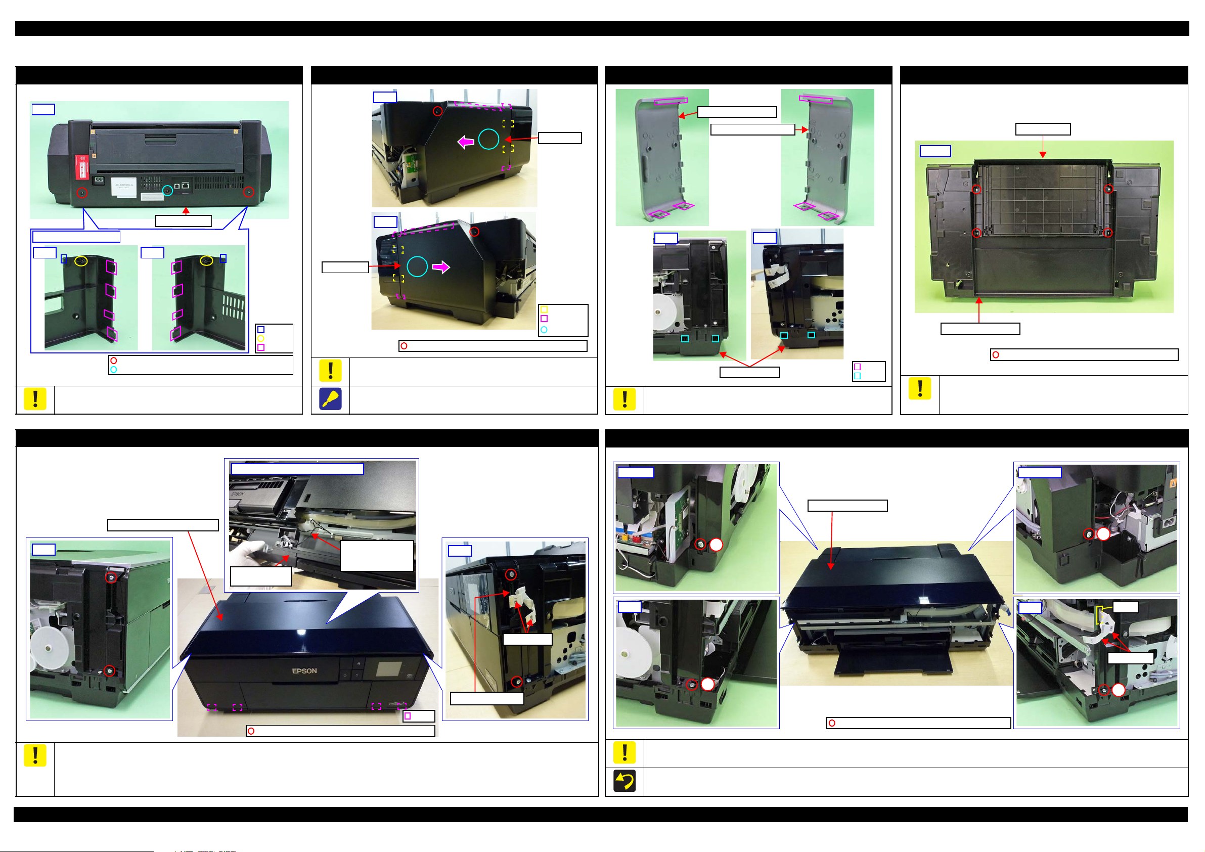
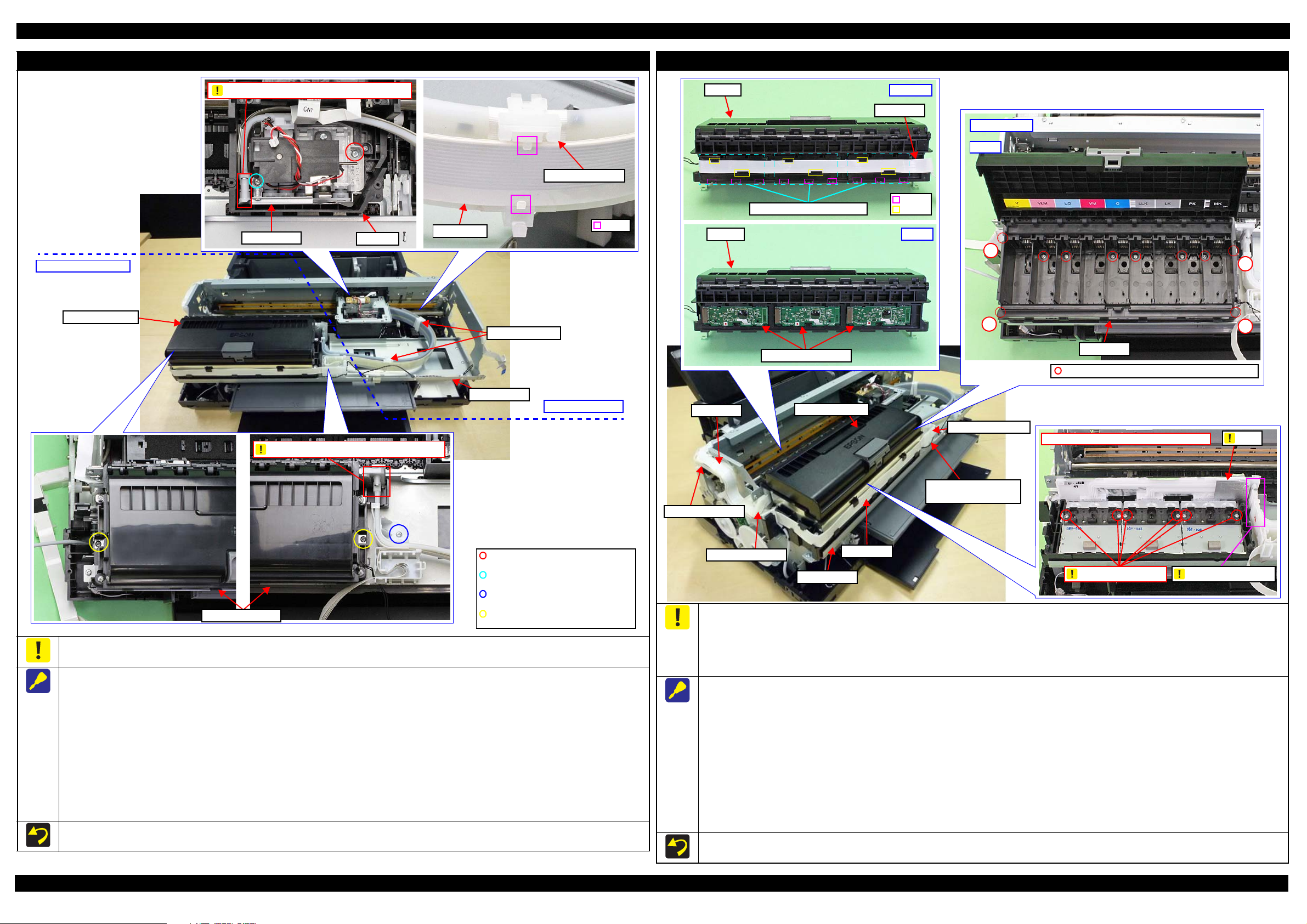
1.3 Detailed Disassembly/Reassembly Procedure for each Part/Unit
Rear Housing
Be careful not to dama ge the ho ok s (x2 ) , do w el s (x 2) and ribs (x8)
that secure the Rear Housing.
Left / Right Cover
Remove the Left/Right Cover carefully not to damage the hooks
(x2 each) and ribs (x3 each) that secure the Left /Right Cover.
When removing the Left/Right Co ver, slide it in the direction of the
arrow shown above while sli ghtly pushing the section A.
Left / Right Decoration Plate
Be careful not to damage the ribs (x3 each) that secure the Left/
Right Decoration Plate and hooks (x4) of the Lower Housing.
Stacker Assy
Be careful for ink to flow out then be cause if tilting is too soon afte r
the initial ink charge o r a similar situation, th e ink still on the Waste
Ink Pad which is not yet absorbed flows over out of the printer.
Upper Housing Support Assy (w/Panel Unit)
Disconnect the Pan el FFCs (x2) from the connectors on the Panel SUB Board before removing the Upper Housing Support Assy.
Be careful not to damage the hooks (x4) that secure the Upper Housing Support As sy.
Be careful to remove the Upper Housing Support Assy because the I/C Holder Unit Cover Open Sensor Cable is connected to the sensor on the
Disassembly/Reassembly Detailed Disassembly/Reassembly Procedure for each Part/Unit 19
back of the Upper Housing Support Assy.
Pull out the Panel F FCs (x2) from the hole of the Upper Housing Assy before removing the Upper Hou s ing Assy.
Tighten the screws in the order indicated in the figure above.
Upper Housing Assy (w/Printer Cover Upper)
SE Group Confidential (Related Staff Only)
Page 20
SC-P600 Revision D
Pane Cover Rear
Ferrite Core
Panel SUB Board
Housing Panel Rear
C.B.P-TITE SCREW, 3X8,F/ZN-3C (6 ± 1 kgf·cm)
Remove the Panel
Cover Rear
CR Scale
Torsion Spring, 0.39
CR Scale
Black triangle mark
Longer spring leg
Section B
Section A
Waste Ink Tube
/ Tube Holder
Waste Ink Pads
C.B.P-TITE SCREW,3X8,F/ZN-3C (6 ± 1 kgf·cm)
Waste Ink Tube
Installation
order
1 mm or less
Joint for Decomp Tube
Decomp Tube
Hook
Left inside of Lower Housing
Decomp Tube
I/C Holder Unit
Lower Housing
Decomp Tube
Groove
Left side
PG Cam LeftSpur Gear,14.4
Align tria n g l e m arks.
3
C.B.S-TITE SCREW,3X6,F/ZN-3C(8
±
1kgf·cm)
1
2
Ink Tube Holders
Ink Tube
Acetate Tape
C.B.P-TITE SCREW,3X10,F/ZN-3C (6±1 kgf·cm)
C.B.S-TITE SCREW,3X6,F/ZN-3C (6±1 kgf·cm)
Rear side
Right side
Hook
Panel Unit
Wireless LAN Module cable
Wireless LAN Module Assy
CR Scale
When disassembling the Panel Unit, take off the fixed screws (x4)
of the shafts that of Housing Panel Rear. Then r e move the unit
from the Housing Upp e r Support Assy by turni ng the whole unit
forward.
Waste Ink Tube / Waste Ink Pad
When installing the Wireless LAN Module Assy, put the following four cables through a hook of the part r ight side.
• Printer Cover Open Sensor cable
• I/C Holder Unit Cover Open Sensor cable
• Mist Board cable
• ASF PE Sensor Cable
Decomp Pump Assy
APG Assy
Attach the CR Scale to the spring leg with the black triangle
mark upward on the left side of the printer.
Attach the Torsion Sp ring, 0.39 as shown above.
Ink Tube Holder
When installing the Waste Ink Tube/Waste Ink Pads (x10),
confirm the shapes of them and inst all them in the orde r shown
above.
When installing the Waste Ink Tube, route it through the
groove of the Wast e Ink Pads, and insert the end of the shorter
tube to the section A and longer one to the section B.
Disassembly/Reassembly Detailed Disassembly/Reassembly Procedure for each Part/Unit 20
When connecting the Decomp Tube to the joint of the I/C
Holder Unit, make sure the gap between the end of the Decomp
Tube to the base of the joint is 1 mm or less, and then secure
the tube with the ho oks (x2).
Route the Decomp Tube through the groove of the Lower
Housing and secure the tube with the hook.
When installing the APG Assy, align the marks on the Spur
Gear,14.4 and PG Ca m Left to match their phases as shown
above.
Tighten the screws in the order indicate d i n t he fi gure above.
When installing the Ink Tube Holders (x2), install them on the
locations where the acetate tape (x2) is attached on the Ink Tube.
SE Group Confidential (Related Staff Only)
Page 21
SC-P600 Revision D
Front left
Connector of Stopper Tray
Sensor Relay Cable
Rear left
Stopper Tray Sensor Relay Cable
Decomp Pump Motor Cabl e
Left
Decomp Tube
I/C Holder
Unit
Right
Ink System Tube
Waste Ink Tube
Lower Housing Assy
Printer Mechanism
2
3
Right
6
Tube Clamp
C.B.S-TITE(P2)SCREW,3X10,F/ZN-3C
(6 ± 1kgf·c m)
C.B.P-TITE SCREW, 4X8, F /Z N -3C
(8 ± 1kgf·c m)
1 mm or less
5 ± 2 mm
Ink System Tubes
Tube Clamps
Tube Holder
Waste Ink Tubes
5
Rear left
4
Upper left
1
Front Left
Ink Tube Holder
Ink Tube Guide
Ink Tube Guide
Cable Holder Front
Positioning h ole
and Dowel
Rib
Hook
Cable Holder Front
CR Support Plate
Ink Selector Motor Cable
Ink Selector Sensor Cable
CR Encoder / PW Sensor FFC
Head FFC
Ink Tube Holders
Ink Tube Guide
C.B.P-TITE SCREW,3X8,F/ZN-3C (6 ± 1 kgf·cm)
CR Relay Board
C.B.S-TITE(P4)SCREW,3X6,F/ZN-3C(8
±
1kgf·cm)
C.B.S-TITE SCREW,2. 5X 6,F/ZN-3 C (4
±
CR Unit
CR Guid e Plate
1
23
45
6
2
1
3
CR Unit
Printhead
C.B.P-TITE SCREW,2.5X8,F/ZN-3C(3.5
±
0.5kgf·cm)
Printhead Mounting Plate
Printer Mechanism (1)
Disconnect the following cables/tubes when removing the Printer Mechanism from the Lower Housing Assy.
Disconnect the following cables from the connector on the Main Board.
• Stopper Tray Sensor Relay Cable (CN1)
• Decomp Pump Motor Cable (CN22)
Disconnect the Decomp Tube.
Disconnect the Ink System Tube from the Waste Ink Tube .
Disconnect the relay co nnector of the Stopper Tr ay Sensor Relay Cable.
Printer Mechanism (2)
Tighten the screws in the order indicate d i n t he fi gure above.
When connecting the Ink System Tube to the Waste Ink Tube, make sure the gap between the end of the Ink System Tube and the Tube Holder is
1 mm or less, and attach the Tube Clamp 5
±
2 mm from the end of the Ink System Tube.
CR Support Plate
When removing the CR Support Plat e, follow the procedure below.
1. Disconnect the follow i ng cables/FFCs from the connectors on the CR Rel ay Board.
• Ink Selector Motor Cable (CN2) • Ink Selector Sensor Cable (CN5)
• Head FFC (CN1) • CR Encoder / PW Sensor FFC (CN6)
2. Remove the screws (x4) that secure the CR Support Plate.
3. Release the hooks (x3 each) of the Ink Tu be Holders (x2) and remove the Ink Tube Guide from the Ink Tube Holders (x2).
4. Release the Ink Tube Guide from the ribs (x6) and dowel of the Cable Holder Front, and remove t he CR Support Plate.
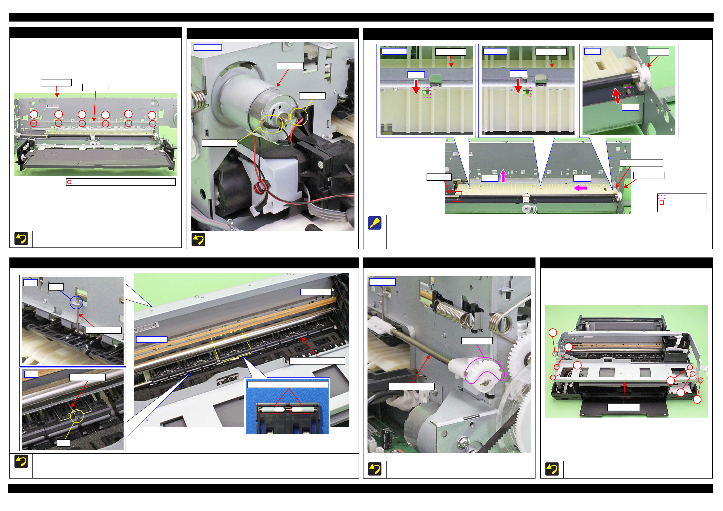
Disassembly/Reassembly Detailed Disassembly/Reassembly Procedure for each Part/Unit 21
Tighten the screws in the order indicated in the figure above.
CR Guide Plate
Printhead / Printhead Mounting Plate
Do not use the electric screwdriver when installing the Printhead
and/or the Printhead Mounting Plate. Doing so applies extra force
when tightening the scre w and affects the platen gap.
When installing the Printhead, follow the procedure below.
1. Temporarily tighten the screws (x3) and loosen them half turn.
2. Press the Printhead to the rear of the printer, and tighten the
screws (x3) in the order indicated in the figure above.
SE Group Confidential (Related Staff Only)
Page 22
SC-P600 Revision D
Ink tube connection part: Do not disassemble
I/C Holder Unit side
C.B.S-TITE SCREW,3X8,F/ZN-3C
(8 ± 1 kgf· cm)
C.B.S-TITE SCREW,3X6,F/ZN-3C
(8 ± 1 kgf· cm)
C.B.SCREW,2.5X6,F/ZN-3C
(3.5 ± 0.5 kgf· cm)
C.B.P-TITE SCREW,2.5X8,F/ZN -3C
(2.5 ± 0.5 kgf· cm)
Ink Tube Holders
I/C Holder Unit
I/C Holder Unit
Ink Selector side
Hook
Head FFC
Ink Tube Holder
CR Unit
Ink Selector
Ink tube connection part: Do not disassemble
Middle Frame
Head FFC
CSIC FFC
Cable Holder Left
Cable Hold er Rear
I/C Holder Unit
Cable Holder Front
I/C Holder Unit Cover
Open Sensor Cable
Middle Frame
C.B.P-TITE SCREW,3X18,F/ZN-3C (6
±
Inside Ink Box
1
4
2
3
Step 7
Ink Box
Ink Box
Step 9
CR Contact Modules
Ink Box
CSIC FFC
Hook
Rib
Step 8, 9
CR Contact Module Covers
Film
Bottom part of Ink Box: Do not dissemble
Ink Tube connection
Do not loosen screws
Ink Supply Unit
CR Contact Module
To prevent ink leakage, make sure not to separate the ink tubes from the I/C Holder Unit or the Ink Selector by removing the screws (x2). Loosening
the screws even just once will cause ink leakage, therefore, make sure to replace the Ink Supply Unit with a new one.
When removing the Ink Supply Unit, follow the procedure below.
1. Release the Head FFC from the hooks (x2 each) of the Ink Tube Holders (x2). Be carefu l not to damage the Head FFC then.
2. Remove the screws (x2) that secure the Ink Select or, and remove the Ink Selector from the CR Unit .
3. Disconnect the Decomp Tube from the I/C Holder Unit. (p 21)
4. After removing the Cable Holder Rear and Cable Holder Left from t he frame, disconnect the Head FFC and CSIC FFC from the connectors
on the Main Board, and then release the FFCs from the Cable Holder Rear and Cable Holder Left. (p 29)
5. Remove the screws (x3) that secure the I/C Ho lder Unit, and remove the I/C Holder Unit.
When removing the Ink Selector on th e way to the target part, perform only Step 1 and 2 above. Be careful not to contaminate the surroundings
with ink from the Ink Selector when taking subse quent steps.
When removing the I/C Holder Unit on the way to the target part, perform only Step 3 to 5 above. Place the removed I/C Holder Unit on the 0-
digit side of the Middl e Fr ame when taking subsequent steps.
Disassembly/Reassembly Detailed Disassembly/Reassembly Procedure for each Part/Unit 22
Do not use the electric screwdriver when installing the Printhead. Doi ng so applies extra force when tightening the screw and affects the platen gap.
To prevent ink leakage, make sure of the following when disassembling/reassembling the unit.
Do not remove the screws (x6 ) on the bo ttom of th e Ink B ox. Looseni ng the scre ws even ju st once will cause ink leakage, th erefo re, make sure to
replace the Ink Supply Unit with a new one.
Be careful not to damage the film of the ink path.
Be careful not to apply extra force o n the Ink Tube connection.
When removing the CR Contact Modules (x3), follow the procedure below.
1. Disconnect the Head FFC and CSIC FFC fro m t he connectors on the Main Board, and remove the Cable Holder Rear and Cable Holder Left
from the frame. (p 29)
2. Remove the Cable Holder Rear and Cabl e Holder Left from the CSIC FFC. (p 29)
3. Release the Head FFC from the ribs of the I/C Holder Uni t . (p 28)
4. Release the I/C Holder Unit Cover Open Sen sor Cable from the rib and hook of the Cable Holder Fron t. (p 28)
5. Remove the screws (x3) that secure the I/C Holder Unit. (p 22)
6. Remove the screws (x4) on the corners of the Ink Box and screws (x6) inside the Ink Box that secure the Ink Box.
7. Release the CSIC FFCs (x3) from the ribs (x6) of the Ink Box, and disconnect the CSIC FFCs (x3) from the connectors on the CR Contact
Modules (x3).
8. Release the hooks (x3 each) of the CR Cont act Module Covers, and r emove the CR Contact Module Covers and CR Contact Modules.
Tighten the screws in the order indicated in the figure above when securing the screws (x4) on th e corner of the Ink Box.
SE Group Confidential (Related Staff Only)
Page 23
SC-P600 Revision D
PF Frame
Main Frame
1
2
3
4
56
C.B.S-TITE SCREW,3X4,F /Z N -3C(8
±
1kgf·cm)
CR Motor
Red Cable
Black Cable
Rear right
Center
Step 1
Main Frame
Upper left
Step 1
Main Frame
Right
Bush, 8
Step 1
Rear Paper Guide
PF Roller
Step 2Step 3
Engagement point
with PF Roller
Positioning dowel
Main Frame
Upper Paper Guide Assy
The fourth roller of Upper Paper
Guide Assy from the 0-digit side
has shorter rubber parts.
Front
Torsion spring
Hook
Rear
Torsion spring
Hole
The rubber parts on roller are shorter.
0-digit side
130-digit s ide
Release Flag Assy
Gear Section
Rear left
1
2
3
4
5
6
Middle Frame
PF Frame
CR Motor
Rear Paper Guide
Tighten the screws in the order indicated in the figure above.
When installing the CR Motor, attach it with its red cable to the left
side of the printer.
Upper Paper Guide Assy
When removing the Rear Paper Guide, follow the pro cedure below.
1. Push the positioning dowels (x3) in the direction of the red arrow to release them.
2. Slide the Rear Paper Guide ap prox. 5 mm to the left to release the right side of the Rear Paper Guide from the Bush, 8.
3. Lift the rear side of the Rear Paper Guide and rel ease it from the PF Roller, and then remove the Rear paper Guide.
Release Flag Assy
Middle Frame
Make sure to install the Upper Paper Guide Assy whose roller has shorter rubber parts on the fourth position from 0-dig it side .
When attaching the torsion spring, insert the spring leg (straight side) into the hole of the Upper Paper Guide Assy, and engag e the other leg to
the hook of the frame.
When installing the Release Flag Assy, install it with its gear
section upward.
Tighten the screws in the order indicated in the figure above.
Disassembly/Reassembly Detailed Disassembly/Reassembly Procedure for each Part/Unit 23
SE Group Confidential (Related Staff Only)
Page 24
SC-P600 Revision D
Right
PG Torsion Spring Right
Step 8
PG Cam Right
Washer,
6.9X0.5X10.4
Step 3
Left
PG Torsion Spring Left
Step 3
C.B.S-TITE(P4) SCREW,3X10,F/ZN-3C
Step 4
Parallelism
Adjust Bushing
PG Cam Left
Step 8
Washer,
6.9X0.5X10.4
Left
CR Shaft Spacer
Step 5
Dent
Step 6
CR Shaft
Left CR Shaft
Mounting Plate
Step 7
Right
Dent
Step 6
CR Shaft
Step 9
Right CR Shaft Mounting Plate
Washer,
8.2X0.5X15
Leaf Spring,
8.2X0.25X15
CR Motor
Step 1
CR Shaft
CR Unit
C.B.SCREW,3X4,F/ZN-3C (4 ± 0.5 kgf·cm)
Timing Bel t
1
2
3
Grounding Wire
ASF Assy
Grounding
wire
Main Frame
C.B.S-TITE(P4)SCREW,3X8,F/ZN-3C(8
±
C.B.S-TITE SCREW,3X6,F/ZN-3C(8
±
1kgf·cm)
Cross-section
Ink System
Step 3
Ink System
Clamp A
Hole
Ink System Tube
Support Plate
C.B.S-TITE SCREW,3X6,F/ZN-3C (8 ± 1 kgf·cm)
Right
A hole to attach a clamp
to fix the Ink Tube
Connector
Step 1,3,4
Step 2,4
CR Unit
ASF Assy
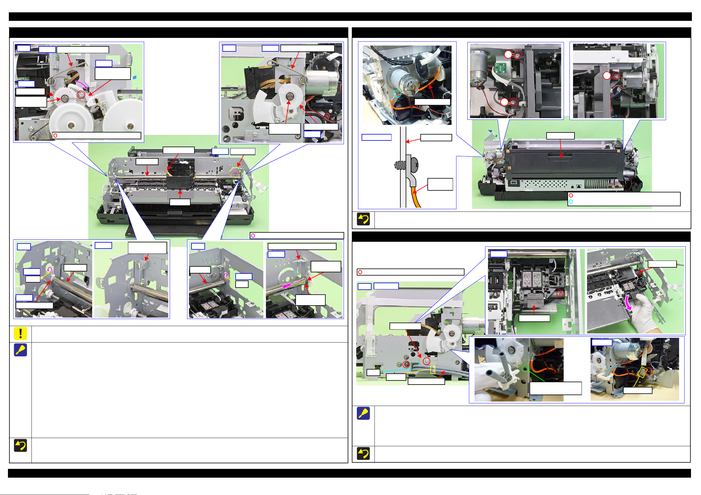
Tighten the screws in the order indicat ed in the figure above.
Attach the terminal of the grounding wire in the direction shown in the “Cross-section” figure.
Ink System
Be careful not to let the grease of the CR Sha ft adhere to the Timing Belt of the CR Unit.
When removing the CR Unit, follow the pro cedure below.
1. Remove the screws (x2) that secure the CR Motor, and remove the CR Motor from the frame.
2. Mark the contact point on the Parallelism Adjust Bushing with the frame. (p 50)
3. Remove the PG Torsion Spring Left / Right.
4. Loosen the screw that secure the Parallelism Adjust Bushing, and turn the Parallelism Adjust Bushing in the direction of the arrow shown above.
5. Remove the CR Shaft Spacer.
6. Lift the CR Shaft, and move both ends of it to the dent of the frame.
Disassembly/Reassembly Detailed Disassembly/Reassembly Procedure for each Part/Unit 24
7. Remove the Left CR Shaft Mounting Plate.
8. Remove the Washer, 6.9X0.5X10.4 (x1 each) that secure the PG Cam Left/Right, and remove the PG Cam Left/Right from the CR Shaft.
9. Slide the CR Shaft to the left to disengag e it fro m th e frame , an d from th e rig ht end of the CR Shaft, remove the Right CR Shaft Moun ting Plate,
Washer, 8.2X0.5X 15 , and Leaf Spring, 8.2X 0. 25X15 in order.
10. Remove the left end of the CR Shaft from the frame, and remove it together with the CR Unit.
11. Remove the CR Shaft from the CR Unit.
When installing the CR Motor, install it by referring to " CR Motor (p23)".
Be careful not to mistake the PG Torsion Spring Right and PG Torsion Spring Left when installing them because they look alike.
Make sure to install the Parallelism Adjust Bushing correctly to the location with the marking drawn when removing it.
When removing the Ink System, follow the procedure below.
1. Release the Ink System Tube from the clamp A and pull out from the hole of the frame.
2. Release the Pump Motor Cable from the connector.
3. Remove the screws (x2) that secure the Support Plate, and remove the Support Plate.
4. Remove the screws (x2) that secure the Ink System, and remove it downward while avoiding the frame.
When securing the Ink System Tubes (x2) with the clamp A, make sure to arrange the shorter one to the bottom as shown.
SE Group Confidential (Related Staff Only)
Page 25
SC-P600 Revision D
Step 5
Step 6
Right: Step 2-4
E-ring, 3
Spur Gear, 14.4
Torsion Spring, 187.9
Parallel Pin, 1.5
Front Tray Shaft
The location where
frame may interfere.
Front Right Tray Guide
Left: Step 4, 5
Front Left Tray Guide
The location where frame
may interfere.
The location wher e Front P aper
Guide Assy may interfere.
Front Right Tray Guide
Dowel
HookC.B.P-TITE SCREW,3X6,F/ZN-3C (4 ± 0.5 kgf·cm)
Front Tray
Front Tray Assy
The Front T ray is raised if
the gear is in this position.
Reassemble the Front Tray Assy with the Front Tray raised.
Stopper Tray Front Assy
Compression
Spring
This side is facing
to frame.
Attach Cover spring/
Compression spring
to shaft (longer side).
Cover Spring
Shaft
(shorter
side)
Link
Lever
Align shaft (shorter side)
of Link Lever to cam
groove of Stopper Tray.
Cam groove
E-ring, 3
Washer,
4.3X0.8X8
Stopper Tray
Torsion Spring, 187.9
C.B.P-TITE SCREW,3X8,F/ZN-3C(4 ± 0.5kgf·cm)
C.B.S-TITE SCREW,3X6,F/ZN-3C(8 ± 1kgf·cm)
EJ Link Left
Front Left Tray Guide
Washer,
26X0.5X4.7
Washer,
3.1X0.5X5.4
Extension Spring, 0.70
Tray Support Assy
EJ Link Right
Washer,
26X0.5X4.7
Front Right Tray Guide
Washer,
3.1X0.5X5.4
Extension Spring, 0.70
Tray Support Assy
Gear secti on of Fr on t T ra y
Washer,
3.1X0.5X5.4
Parallel Pin , 1.5Spur Gear, 14.4
Tray Support Assy
Back of Fron t Tray Assy
Front Tray
Front Tray Assy
Stopper Tray Unit
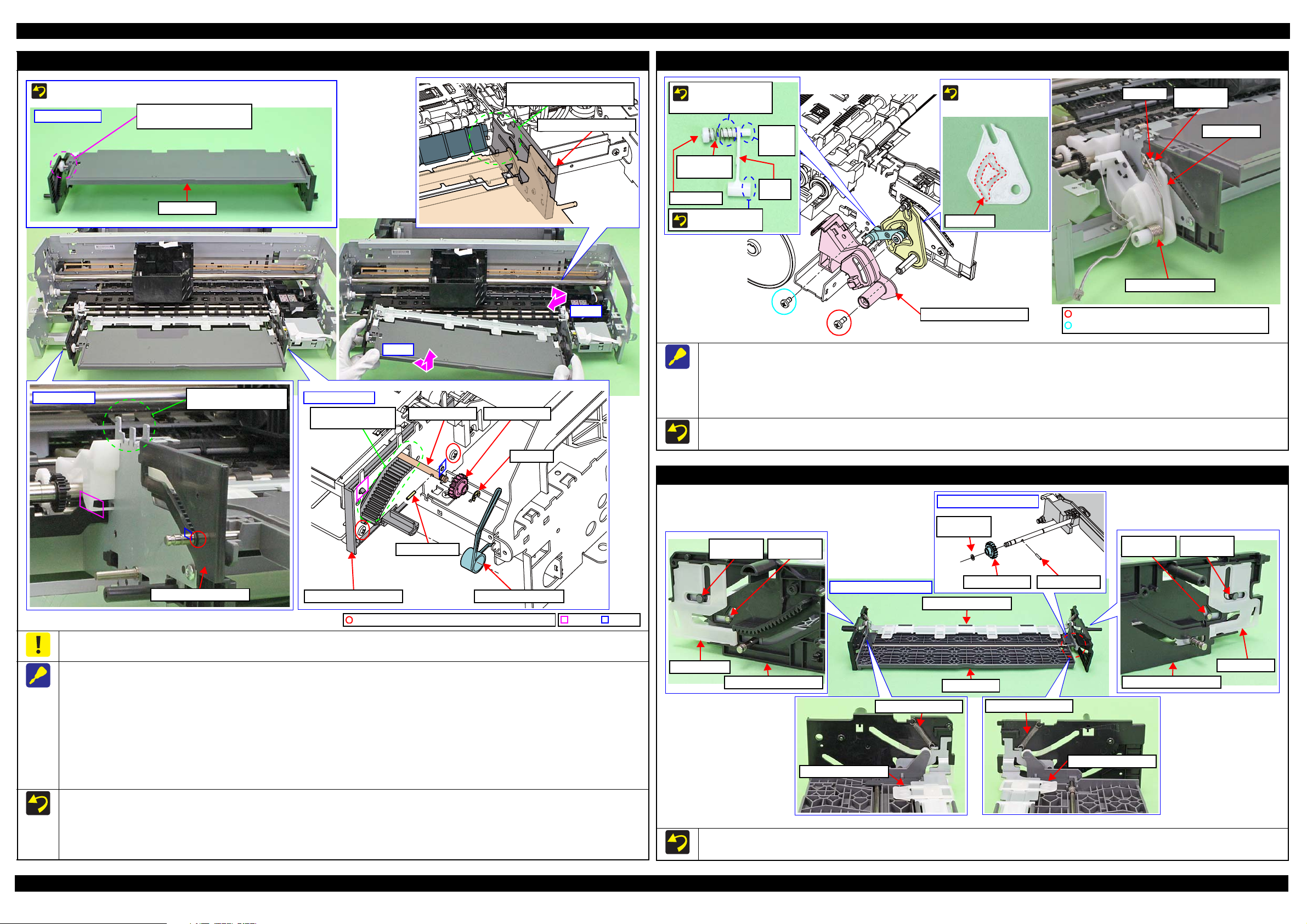
When removing the St opper Tray Unit, follow the procedure below .
1. Remove the To r s ion Spring, 187.9.
2. Remove the screws (x2) that secure the Stopper Tray Front Assy and remove the Stopper Tray Front Assy.
3. Remove the Lever Link with Cover Spring and Compress ion Spring.
4. Remove the E-ring, 3 and Washer, 4.3X0.8X8, and remove the Stopper Tray.
When attaching the Cover Spring to th e Link Lever, attach it as shown above.
After reassembling the Stopper Tray Unit, confirm the Torsion Spring, 187.9 is correctly attached.
Tray Support Assy / Front Tray
When disassembling/reassembling the Front Tray Assy, there are some locations where the frame and the Front Paper Guide Assy may interfere.
Therefore, be careful not to deform the frame when workin g.
When removing the Front Tray Assy, follow the procedure below.
1. Remove the screw that secure th e Mi st Board Assy.
2. Remove the Torsion Spring, 187.9 on the right sid e of the Front Tray Assy.
3. Remove the E -ring, 3, and remove the Spur Gear, 14.4 and Par allel Pin, 1.5.
4. Remove the screws (x3) that secure the Front Tray Assy.
5. Release the hook and dowel of the Front Left Tray Guide from the frame and slide it to the front of the printer, and then lift the left side of the
Front Tray Assy.
Disassembly/Reassembly Detailed Disassembly/Reassembly Procedure for each Part/Unit 25
6. Release the hook and dowels (x2) of the Front Right T ray G uide from the frame and slide it to the front of the printer while avoiding the Front Paper
Guide Assy, and then remove the Front Tray Assy by pulling out the Front Tray Shaft and Front Right Tray Guide from the hole of the frame.
Reassemble the Front Tray Assy with the Front Tray raised. After reassembly, make sure the Front Tray Assy is secured with the hooks and
dowels, and then secure it with the screws.
After reassembling the Front Tray Assy, confirm the Torsion Spring, 187.9 is correctly attached.
Before reassembling the Tray Support Assy/Front Tray, confirm the Washer,3.1X0.5X5.4 (x2) and Washer,26X0.5X4.7 (x2) are correctly
attached.
When reassembling the Front Tray Assy, install each part as shown above, and secure them with their dedicated washer, parallel pin, and extension spring.
Before reassem bling the Tray Supp or t A s sy/Front Tray, con firm the Washer,3.1X0.5X5.4 (x2) and W a sher,26X0.5X4.7 (x 2) are correctly attached.
SE Group Confidential (Related Staff Only)
Page 26

SC-P600 Revision D
Star Wheel Assy
Dowel
Rib
Dowel position
EJ Slider Right
EJ Slider Left
EJ Link Left
Front Left Tray Guide
Left
Front Right Tray Guide
EJ Link RIgh t
Right
Head FFC
Printhead connecting side
Double-sided tape
attachment position
Dowel
Rib
Hook
EJ Slider Left
Step 1, 2
EJ Slider Right
C.B.S-TITE SCREW,3X8,
F/ZN-3C (8 ± 1 kgf·cm)
EJ Roller Front
EJ Roller Rear
EJ Grounding Spring
C.B.S-TITE SCREW,3 X8, F/ ZN - 3C (5 ± 1
Right
Spring foot A
Spring foot B
Step 3, 4, 7
EJ Roller Rear
Washer
EJ Roller Front
Washer,
6.9X0.5X10.4
Left
Step 5
Bush, 8
Step 6
Front Paper Guide Assy
Step 8
Step 7
Front Paper Guide Assy
Bottom
Leg of Porous Pad Front Paper Gui de
Leg of EJ Ink Guide Left/Right
OK
Rib of Porous Pad Front
Paper Guide is hidden.
NG
Rib of Porous Pad Front
Paper Guide is sticking out.
Front Paper Gu ide
1: EJ Ink Guide Right
3: EJ Ink Guide Left
4: Porous Pad Left Paper Guide
2: Porous Pad Front Paper Guide
Porous Pad Front Paper Guide
Rib
Leg
Star Wheel Assy
Head FFC
Front Paper Guide Assy
Attach the dowels on the left/right of the Star Wheel Assy from
the left one first into their attachment positions shown above.
Insert the ribs on the left/right of the Star Wheel Assy to the
grooves on the EJ Frame S lider Left/Right.
When installing the EJ Ink Guide Left/Right, Porous Pad Front Paper Guide and Porous Pad Left Paper Guide, install them in the order shown
above.
After installing the Por ous Pad Front Paper Guide, make sure the legs (x10) of the Porous Pad Front Paper Guide and legs (x3) of the EJ Ink
Guide Left/Right are fully pulled out and they drop down straight from the hole of the Front Paper Guide Assy.
Make sure that all ribs (x47) of the Porous Pad Fr ont Paper Guide are fitte d into the grooves of the F r ont Paper Guide, and no p ad lifts off from
the platen.
To prevent degradation of print quality due to interference of the
Head FFC (x2) with the CR Unit movement, the Head FFC (x2) are
folded with the jig and bundled together with double-sided tape.
When handling the Head FFC, take care not to make an extra fold
on it other than original ones. Furthermore, do not peel the FFC
apart or change the attachment locations.
Porous Pad Front Paper Guide
When removing the Front Paper Guide Assy, follow the procedure below.
1. Release the hooks (x3) and dowels (x2) of the EJ Slider Left, and remove the EJ S l id er Left.
2. Remove the screw that secure the EJ Slider Right and release the dowels (x2) and rib, and then remo ve the EJ Slider Right.
3. Remove the EJ Grounding Spring on the right side of the Front Paper Guide Assy.
4. Remove the screw that secure the Front Paper Guide Assy.
5. Remove the Washer,6.9X0.5X10.4 from the EJ Roller Front.
6. Release the dowel of the Bush, 8 and rotate the Front Paper Guide Assy upward and align it with the cutout of the frame.
7. Slide the Front Paper Guide Assy to th e le ft, and release the dowels (x2) on the right side of it from the frame.
8. Lift the front side of the Front Paper Guide Assy and detach the EJ Roller Front from the cutout of the frame, and then remove the Front Paper
Guide Assy while avoiding the parts around it.
When installing the EJ Grounding Spring, follow the procedure below.
1. Engage the Spring Foot A to the groove of the EJ Roller Front.
2. Engage the bent section of the EJ Grounding Spring on the inner sid e of the washer outside the EJ Rol l e r R ear.
3. Engage the Spring Foot B to the hook of the frame.
Disassembly/Reassembly Detailed Disassembly/Reassembly Procedure for each Part/Unit 26
SE Group Confidential (Related Staff Only)
Page 27

SC-P600 Revision D
Bush, 8
Left
Step 4
PF Roller
Compression Spring, 4
E-ring, 7
Left
Step 3
PF Grounding Spring
PF Roller
Step 1
Groove
Cutout
Bush, 8
Right
Step 2
PF Roller
Step 5
PF Scale
PF Encoder Assy
PF Encoder
PF Scale
Rear
1
Shield Plate Assy Upper Main Board
Front
Screwdriver
150 mm or more
Lower Frame
2
3
C.B.S-TITE SCREW,3X6,F/ZN-3C (8 ± 1 kgf·cm)
Gap
Paper Guide (under ASF Assy)
Shield Plate Assy Upper Main Board
A
PF Roller
Sheild Plate Assy Upper Main Board
When tightening the screw that secures the Shield Plate Assy
Upper Main Board, use a screwdriver with the shaft length of
150 mm or more and tighten the screw straight. Otherwise, you
have to screw it obliquely and can not tighten it correctly
because the grip of the driver hits the lower frame.
Tighten the screws in th e or der indicated in the figure above.
Board Assy
After installing the Board Assy, confirm the gap shown above is
uniform. If not, the Shield Plate Assy Upper Main Board pushes up
the Paper Guide (under ASF Assy). In such a case, loosen the
screw (A) and adjust the Shield Plate Assy Upper Main Board
position until the gap become even, then tighten the screw (A).
When removing the PF Roller, follow the procedure below.
1. Remove the PF Grounding Spring.
2. Release the dowel of the Bush, 8 on the right side of the PF Roller, and rotate it upward and align it with the cutout of the frame.
3. Remove the E-ring, 7 and slide the Compre ssion Spring, 4 to the right .
4. Release the dowel of the Bush, 8 on the left side of the PF Roller, and rotate it upward and align it with the cutout of the frame.
5. Pull out the PF Roller to the left side from the hole of the frame and remove it from the frame.
When attaching the PF Grounding Spri ng, engage the longer bent leg to the groove of the PF Roller, and engage the other leg to the cutout of the
frame to secure the spring.
PF Scale / PF Encoder Assy
After installing the PF Encoder Assy, confirm the PF Encoder does not touch the PF Scale.
Disassembly/Reassembly Detailed Disassembly/Reassembly Procedure for each Part/Unit 27
SE Group Confidential (Related Staff Only)
Page 28

SC-P600 Revision D
Panel SUBBoard
Panel FFCs
Upper Housing
Hole
Groove
Rib
Hook
Upper Housing Support Assy
Ferrite Core
Hole
Grounding Wire
I/C Holder Unit Cover Open Sensor Cable:
make one turn around hook.
I/C Holder
Unit
Front
Cable Holder
Front
Rib
Hook
Head FFC
Upper
Cable Holder Front
I/C Holder Unit Head FFC
Rib
Cable Holder Front
I/C Holder Unit Cover
Open Sensor Cable
Decomp Pump Assy
Rib
Hook
Decomp Pump Motor Cable
Stopper Tray
Sensor Relay Cable
Decomp Pump Motor Cable
Make two turns
around hook.
Groove
Rib
CR Encoder / PW Sensor FFC
Head FFC
Route Ink Selector Mot o r Cab le
and Ink Selector Sensor Cable
through cutout of Ink Selector.
CR Relay Board
Ink Selector
CR Support Plate
Cable Hold er
Acetate Tape B: 18 x 30 mm
Right
Rib
Acetate Tape A
Double-si d ed tape Reference line
PE Detector
Assy
PE Sensor CableRelease Holder AssyPanel FFC
Cross-section
2
1
3
4
Pump Motor Cable
Roll Paper Guide
Open Sensor Cable
ASF Motor Relay Cable
CR Motor Cable1
2
3
4
5
Cable Hold er5
6
6
Shield Plate Assy Upper
Main Board
Cable Holder
Groove of Shield Plate
Assy Upper Main Board
Clamp
1.4 Routing FFCs/cables
Upper Housing Support Assy
Route the Panel FFCs though the hole of the Upper Housing, and connect it to
the connector on the Panel SUB Boar d.
Panel Unit
When routing a cable of the Panel Unit, follow the procedure below.
1. Route the Panel Unit FFC through the hole of th e Uppe r Housin g Sup port
Assy, and through the ferrite core. Fix a fold part of the FFC by the hook.
2. Connect the Panel Unit FFC to the connector on the Panel SUB Board.
3. Fix the grou nding wire on the Panel SUB Board with screws , and route
the wire t
hrough the rib and groove
as shown above.
Head FFC
Route the Head FFC through the I/C Holder Uni t and Cable Holder Front as shown above.
When routing the I/C Holder Unit Cover Open Sensor Cable, make one turn around the hook of the I/C Holder Unit and route through the ribs (x4) of the
Cable Holder Front, and then make one turn around the hook of the Cable Holder Front.
Decomp Pump Assy
When routing the Decomp Pump Motor Cable through the Decomp Pump
Assy, route the ca ble through the fo llowing ribs and hooks.
• Ribs (x3) and ho ok on the upper side of the Decomp Pump Assy
• Hooks (x4) and r ibs (x2) on the side of the Decomp Pump Assy
Route the following cables through the ribs and grooves of the Lower Housing.
• Decomp Pump Motor Cable
• Stopper Tray Sensor Relay Cable
Disassembly/Reassembly Routing FFCs/cables 28
Route the following cables/FFCs as shown above and connect them to the
connectors on the CR Relay Board.
Ink Selector Motor Cable (CN2)
Ink Selector Sensor Cable (CN5)
Head FFC (CN1)
CR Encoder / PW Sensor FFC (CN6)
CR Support Plate / Ink Selector
Upper side of the Board Assy
Route the Panel FFC throug h t he r ibs ( x2) al ong w ith th e ref eren ce l i ne a s sh ow n a bov e, and secure it with double-sided tape and two pieces of acetate tape A.
Route the PE Sensor Cable through the ribs (x6 ) of the Release Holder Assy, and secure it with the clamp.
Attach acetate tape B (18 x 30 mm) on the position shown above.
Route the cables through the groove on the S hiel d Plate Assy Upper Main Board arranging them in the order sh own in “cross-section” above, and secure
them with the Cable Holders (x2).
SE Group Confidential (Related Staff Only)
Page 29

SC-P600 Revision D
CN # Name CN # Name CN # Name
CN1
Stopper Tray
Open Sensor Relay Cab le
CN9 Head FFC CN19 CSIC FFC
CN10 Head FFC
CN20
Roll Paper Guide
Open Sensor Cable
CN2 CSIC FFC CN11 Head FFC
CN3 PictBridge Holder Cable CN12 CR Relay Board FFC CN22 Decomp Motor Cable
CN4 Panel FFC CN13 Mist Board Cable CN115 CR Motor Cable
CN5 Panel FFC CN15 CSIC FFC CN116 PF Motor Cable
CN6 ASF Relay Board FFC CN16
Printer Cover
Open Sensor Cable
CN117 Pump Motor Cable
CN7 Wireless L A N Module Cable
CN17
I/C Holder Unit Cover
Open Sensor Cable
CN118 APG Motor Cable
CN8 Head FFC CN119 ASF Motor Cable
Route Panel FFC
over ASF Assy.
Reference line
Double-sided tape
PF Encoder FFC
Panel FFC
Around ASF Relay Board
Route PE Sensor Cable
under rib of ASF Assy.
ASF Relay Board
APG HP Sensor Cable
APG Position
Sensor Cable
Double-sided tape
PF Encoder FFC
Secure PF Motor
Cable with clamp.
ASF PE
Sensor Cable
Pump Motor
Cable
CR Motor
Cable
Roll Paper Guide
Open Sensor Cable
APG Motor Cable
PF Motor Cable
ASF Motor
Cable
Mist Board
Cable
Printer Cove r
Sensor Cable
I/C Holder
Cover Sensor
Cable
Head FFC/CSIC FFC
Stopper Tray Open Sensor Relay Cable:
Pull out through hole of Lower Housing and make
one turn around hook, then connect to Main Board.
Decomp Motor Cable
CN2
CN15
CN11
CN9
CN8
CN10
CN12
CN4
CN5
CN19
CN1
CN7
CN20
CN6
CN118
CN115
CN119
CN117
CN116
CN22
CN16CN17
CN13
CN3
When routing the following FFCs,
route them through groove of A SF
Assy under Roll Paper Guide Assy.
Head FFC
CSIC FFC
Panel FFC
Hook
Refer below for t he connector layout on th e Main Board for the cables/FFCs . The connector numb ers are marked on each FFC, therefore, make sure of it when
connecting them .
ASF Relay Board FFC
CN #
Name
CN #
Name
CN #
Name
CN1
ASF Relay
Board FFC
CN2
PE Sensor
Cable
CN6
PF Encoder
FFC
ASF Assy
Hole
Route Head FFC through groove on left side of I/C
Holder Unit, and route it to Cable Holder Left.
Route CSIC FFC through groove of Cable Holder
Left, and route it to Cable Holder Rear.
Double-sided tape
Rib
Head FFC
CSIC FFC
Cable Hold er Rear
Double-sided tape
Cable Holder Left
Clamp A
ASF Motor Cable
ASF Motor Cable
Clamp B
Roll Paper Guide
Open Sensor
CR Motor Cable
Pump Motor Cable
Screw with
ASF Motor
ASF Motor
Relay Cable
Screw with
Ink System
Grounding wire
Rear left of printer (1)
Rear left of printer (2)
Fold the Head FFC / CSIC FFC along the fold line, and route them through the ribs (x6) of the Cable Holder Rear, Cable Holder Left, and the ribs (x3) on
the left side of the I/C Holder Unit.
Route the CSIC FFC over the Head FFC and secure the CSIC FFC with doubl e-si ded tape at the points shown in the figure above.
Rear right of printer
Disassembly/Reassembly Routing FFCs/cables 29
Fix the grounding wires with screws in two places of the ASF Motor and the Ink System.
Connect the ASF Motor Cable to the ASF Motor Relay Cable, and then secure it with the clamp A.
Be careful not to let the ASF Motor Relay Cable interfere with the Roll Paper Guide Open Sensor when routing it.
Connect the Pump Motor Cable to the Pump Motor Relay Cable, and then secure it with the clamp B.
SE Group Confidential (Related Staff Only)
Page 30

SC-P600 Revision D
Mist Board Cable Holder
Mist Board Cable Holder
Electrode cable
Cutout
Groove A
Groove B
Mist Board Assy
Mist Board Cable connector
Double-sided tape
Reference li n e
Rib
Main Frame
Section A
Hook
Step 5
Clamp
Mist Board Cable
Right side of Main Frame
Cable Holder R ight
Mist Board Cable
Groove
Panel FFC
Step 1 to 4
Main Frame
I/C Cover Sensor Cable
Printer Cover Sensor Cable
Right side of Main Frame
Upper side of Main Frame
Clamp
Rear side of Main Frame
ASF PE Sensor Holder
I/C Cover Sensor Cable
Printer Cover Sensor Cable
Mist Board Cable
Holes which fix hooks of the Holder
Mist Board Assy / Right side of the Main Frame
I/C Holder Unit Cover Open Sensor / Printer Cover Open Sensor
Route the I/C Holde r Un it Cover Open Sensor Cabl e and Printer Cover Open Sensor Cable through t he hole of the Main Frame as shown above.
Secure these two cables with clamps (x3) on the front part of the Main Frame.
ASF PE Sensor Holder
When routing the FFCs/cab le s on t he Mist Board Assy and the FFC on right side of the Main Frame, follow the procedure below.
1. Before installing the Cable Holder Right to the Main Frame, route the Mist Board Cable through the groove and ribs (x3) of the Cable Holder Right.
2. Route the Panel FFC along the reference line of the Main Frame, and secure it to the Main Frame with double-sided tape.
3. Route the Mist Board Cable through th e hole of the Main Frame.
4. Secure the I/C Holder Unit Cover Open Sensor Cable and Printer Cover Open Sensor Cable with the clamps (x2) and ribs (x2), and then route these
cables through the hole of the Main Frame.
5. Engage the section A of the Cable Holder Right to the Main Frame as shown above, and then secure the Cable Holder Right to the Main Frame with the
hooks (x2).
6. Connect the Mist Board Cable to the Mist Board Cable connector.
Pull out the electrode cable from t he cutout of the Main Frame and route the cabl e t hrough the groove A and B as shown above, and then connect it to the
Mist Board.
Disassembly/Reassembly Routing FFCs/cables 30
Secure hooks (x4) of t he ASF PE Sensor Holder to holes of the Main Frame as shown above.Route the I/C Holder Unit Cover Open Sensor Cable and
Printer Cover Open Sensor Cable through the hole of the Main Frame as shown above.
Route the followin g cables through a space between ASF PE Sensor Holder’s hooks and the Main Frame.
• I/C Holder Unit Cover Open Sensor Cable
• Printer Cover Ope n Se ns o r Cable
• Mist Board Cable
SE Group Confidential (Related Staff Only)
Page 31

CHAPTER 2
ADJUSTMENT
SE Group Confidential (Related Staff Only)
Page 32

SC-P600 Revision D
2.1 Adjustment Items and the Order by Repaired Part
The table from the following page lists the required adjustments depending upon the parts being repaired or
replaced. Find the part(s) you removed or replaced, and check which adjustment(s) must be carried out.
If the EEPROM data cannot be read out fro m the old Main Board usi ng the Adjust ment
Program when replacing the Main Board is required, the Waste Ink Pad and Lower
Paper Guide Ink Pad Tray must be replaced with the Main Board at the same time.
After all required adjustments are completed, use the “Final check pattern print”
function to print all adjustment patterns for final check. If you find a problem with the
printout patterns, carry out the adjustment again.
When replacing the Main Board and the Printer Mechanism at the same time, the
adjustmen t should be made after performing the initial setting .
The table items and marks used in the “Required Adjustment List” provided on the
following pages have the following meanings.
• “O” indicates that the adjustment must be carried out.
• “---” indicates that the adjustment is not required.
• The “Mechanism Adjustment” should be performed just after reinstalling or
reassembling the part or unit. (See " Table2-1 Adjustment items and the order by
repaired part (Mechanism Adjustment) (p33)")
• The “Adjustments using the Adjustment Program” need to be performed after
reassembl ing the printer completely. (See " Table2-2 Adjustment items and the order
by repaired part (Adjustment Program) (p34)")
If you have removed or replaced multiple parts, make sure to check the required
adjustmen t s for the all parts. And when multiple adjustments must be carried out, be
sure to carry out them in the order given in the “Priority” row.
Adjustment Adjustment Items and the Order by Repaired Part 32
SE Group Confidential (Related Staff Only)
Page 33

SC-P600 Revision D
Table 2-1. Adjustment items and the order by repaired part (Mechanism Adjustment)
Adjustment Type Mechanism adjustment
Priority 1 2 3 4
Adjustment Item
Purpose
Printer
Mechanism
PF Motor
Printhead
CR Unit
Part Name
LD Roller
Guide
Front Paper
Guide Assy
PF Roller
How to judge
Adjustment program
Tool
Replace
Remove
Replace
Remove
Replace
Remove
Replace
Remove
Replace
Remove
Replace
Remove
Replace
PF Belt Tension
Adjustment
To reduce the load on
the PF motor and to
ensure paper feed
accuracy.
PF Roller Shaft
Center Support
Position Adjustment
To compensate the
deflection amount on
the PF Roller Shaft
and to maintain the
appropriate paper feed
amount.
OOOO
O --- --- ---
O --- --- ---
--- --- --- O
--- --- --- O
--- --- --- O
--- --- --- O
--- --- O
--- --- O ---
--- --- --- O
--- --- --- O
O O --- --O O --- ---
See " 2.3.1 PF Timing
Belt Tension
Adjustment (p39)" for
the details.
See " 2.3.2 PF Roller
Shaft Center Support
Position Adjustment
(p40)" for the deta ils.
--- --- --- ---
(See p 39) (See p 40) (See p 46) (See p 49)
ASF Guide Roller
LDs position
adjustment
To correct the posi tion
of the LD Ro ller in
order to ma in tain the
paper feed accuracy.
*1
See " 2.3.3 ASF Guide
Roller LDs position
adjustment (p46)" for
the details.
PG Adjustm en t
To secure the
specified clearance
between the print
surface of the
Printhead and paper,
and adjust the
parallelism of the 0digit and 130-digit
sides in order to
maintain the print
quality.
---
See " 2.3.4 PG
Adjustment (p49)" for
the details.
Note 1: The adjustment is not necessary for the parts other than mentioned.
2: Make sure to perform the adjustment using the Adjustment Program after mechanism adjustment is complete.
(See " Table2-2 Adjustment items and the order by repaired part (Adjustment Program) (p34)" for the details.)
Note "*1": The adjustment is not necessary i f you m ark the installing positions of the LD Roller Gui de s befo re removing them, and alig n the markings
when installing the LD Roller Guides.
Adjustment Adjustment Items and the Order by Repaired Part 33
SE Group Confidential (Related Staff Only)
Page 34

SC-P600 Revision D
Table 2-2. Adjustment items and the order by repaired part (Adjustment Program)
Adjustment Type Adjustment using the Adjustment Program
Priority 1 2 3 4 5 6 7 8 9 10 11 12 13 14 15 16 17 18 19 20 21 22 23 24
Adjustment Item
Waste Ink
Pad
Lower Paper
Guide Ink
Pad Tray
Printer
Mechanism
APG Assy
APG Motor
Part Name
Board Assy*1
(Main Board/
Power Supply
Board)
Power
Supply
Board
PF Motor
Ink Supply
Unit
Printhead
CR Unit
PF Frame
Rear Paper
Guide
ASF Assy
Part Name
Release
Holder Assy
Release Flag
Assy
Upper Paper
Guide Assy
CR Motor
How to judge
Adjustment program
Tool
Note "*1": Only removing/replacing the Main Board is included.
"*2": The value about tw i ce of upper limit may enter.To reset the wa ste ink counter after replacing the Wa ste Ink Pa d
Remove
Replace
Remove
Replace
Replace
Remove
Replace
Remove
Replace
Remove
Replace
(Read OK)
Replace
(Read NG)
Remove
Replace
Remove
Replace
Remove
Replace
Remove
Replace
Remove
Replace
Remove
Replace
Remove
Replace
Remove
Replace
Remove
Replace
Remove
Replace
Remove
Replace
Remove
Replace
EEPROM
Data Copy
--- --- --- --- --- --- --- --- --- --- --- --- --- --- --- --- --- --- --- --- --- --- --- O
--- --- --- --- O --- --- --- --- --- --- --- --- --- --- --- --- --- --- --- --- --- --- O
--- --- --- --- --- --- --- --- --- --- --- --- --- --- --- --- --- --- --- --- --- --- --- O
--- --- --- --- O --- --- --- --- --- --- --- --- --- --- --- --- --- --- --- --- --- --- O
--- --- --- --- O --- O
--- --- --- --- --- --- --- --- --- O --- --- --- --- --- --- --- --- --- --- --- --- --- O
--- --- --- --- --- --- O --- --- O --- --- --- --- --- --- --- --- --- --- --- --- --- O
--- --- --- --- --- --- --- --- --- --- --- --- --- --- --- --- --- --- --- --- --- --- --- O
--- --- --- --- --- --- O --- --- --- --- --- --- --- --- --- --- --- --- --- --- --- --- O
--- --- --- --- --- --- --- --- --- --- --- --- --- --- --- --- --- --- --- --- --- --- --- O
O --- --- --- --- --- --- --- --- --- --- --- --- --- --- --- --- --- --- --- --- --- --- O
--- O O O --- --- ---OInput max.
--- --- --- --- --- --- --- --- --- --- --- --- --- --- --- --- --- --- --- --- --- --- --- O
------------------------------------------------------------OOOO
--- --- --- --- --- --- --- --- --- --- --- --- --- --- --- --- --- --- --- --- --- --- --- O
--- --- --- --- --- --- --- --- --- --- --- --- --- --- --- --- --- --- --- --- --- O --- O
--- --- --- --- --- --- --- --- --- --- --- --- --- --- --- --- --- --- --- --- --- --- --- O
--- --- --- --- --- O --- --- --- --- O --- --- --- --- --- --- --- --- --- --- --- --- O
---------------------------------------------OOOOO---------O
------O------O---------------------------OOOOO------OO
---------------------------------O---O---OOOOO---------O
---------------------------------O---O---OOOOO---------O
--- --- --- --- --- --- --- --- --- --- --- --- --- --- --- --- --- --- --- --- --- --- --- O
--- --- --- --- --- --- --- --- --- --- --- --- --- --- --- --- --- --- --- O --- --- --- O
--- --- --- --- --- --- --- --- --- --- --- --- --- --- --- --- --- --- --- --- --- --- --- O
--- --- --- --- --- --- --- --- --- --- --- --- --- --- --- --- --- --- --- O --- --- --- O
--- --- --- --- --- --- --- --- --- --- --- --- --- --- --- --- O --- --- --- --- --- --- O
--- --- --- --- --- --- --- --- --- --- --- --- --- --- --- --- O --- --- --- --- --- --- O
--- --- --- --- --- --- O --- --- --- --- --- --- --- --- --- --- --- --- --- --- --- --- O
--- --- --- --- --- --- O --- --- --- --- --- --- --- --- --- --- --- --- --- --- --- --- O
--- --- --- --- --- --- O --- --- --- --- --- --- --- --- --- --- --- --- --- --- --- --- O
--- --- --- --- --- --- O --- --- --- --- --- --- --- --- --- --- --- --- --- --- --- --- O
--- --- --- --- --- --- O --- --- --- --- --- --- --- --- --- --- --- --- --- --- --- --- O
--- --- --- --- --- --- O --- --- --- --- --- --- --- --- --- --- --- --- --- --- --- --- O
--- --- --- --- --- --- --- --- --- --- --- --- --- --- --- --- --- --- --- --- --- --- --- O
--- --- --- --- --- --- --- --- --- --- --- --- --- --- --- --- --- --- --- --- O --- --- O
--- --- --OOOOOOOOOOOOOOOOOOOOOO---O
--- --- --- --- --- --- --- --- --- --- --- ---
Initialize
Setting
Head ID
Input
MAC
address
Input
(p 54)
Waste Ink
Pad
Counter
Ink charge
--- --- --- --- --- ---
Release of
Driven
roller
check
Front Tray
print
counter
PF
deterioratio
n offset
O
Reset to 0OReset to 0
O
Input max.
value
value
APG
Function
Check
Ink
Selector
Check
CR Belt
check
Mist
Recovery
check
CR encode
check
PF encode
check
O---OOOOOOOOOOO---O
------------------OOOOOOOOO
(p 69) --- (p 53) --- --- (p 55) (p 36) (p 36) (p 36) (p 36)
(p 53) --- ---
Head
angular
adjustment
CR/PF
First Dot
adjustment
PW
adjustment
Bi-D
adjustment
PF / EJ
adjustment
CR motor
heat
protection
control
--- ---
--- Ruler Ruler --- --- --- ---
PF motor
heat
protection
control
Colori-
metric
calibration
(p 57)
(p 57)
Final check
pattern
print
---
---
Adjustment Required Adjustments 34
SE Group Confidential (Related Staff Only)
Page 35

SC-P600 Revision D
Table 2-2. Adjustment items and the order by repaired part (Adjustment Program)
Adjustment Type Adjustment using the Adjustment Program
Priority 1 2 3 4 5 6 7 8 9 10 11 12 13 14 15 16 17 18 19 20 21 22 23 24
Adjustment Item
Stopper Tray
Unit
Tray
Detector
Front Tray
Assy
Tray Support
Assy
Front Tray
Star Wheel
Assy
Front Paper
Guide Assy
Part Name
PF Roller
Mist Board
Assy
CR Scale
CR Belt /
CR encoder
PF Scale /
PF encoder
Assy
How to judge
Adjustment program
Tool
Note "*1": Only removing/replacing the Main Board is included.
"*2": The value about tw i ce of upper limit may enter.To reset the wa ste ink counter after replacing the Wa ste Ink Pa d
Remove
Replace
Remove
Replace
Remove
Replace
Remove
Replace
Remove
Replace
Remove
Replace
Remove
Replace
Remove
Replace
Remove
Replace
Remove
Replace
Remove
Replace
Remove
Replace
EEPROM
Data Copy
--- --- --- --- --- --- O --- --- --- --- --- --- --- --- --- --- --- --- --- --- --- --- O
--- --- --- --- --- --- O --- --- --- --- --- --- --- --- --- --- --- --- --- --- --- --- O
--- --- --- --- --- --- O --- --- --- --- --- --- --- --- --- --- --- --- --- --- --- --- O
--- --- --- --- --- --- O --- --- --- --- --- --- --- --- --- --- --- --- --- --- --- --- O
--- --- --- --- --- --- O --- --- --- --- --- --- --- --- --- --- --- --- --- --- --- --- O
--- --- --- --- --- --- O --- --- --- --- --- --- --- --- --- --- --- --- --- --- --- --- O
--- --- --- --- --- --- O --- --- --- --- --- --- --- --- --- --- --- --- --- --- --- --- O
--- --- --- --- --- --- O --- --- --- --- --- --- --- --- --- --- --- --- --- --- --- --- O
--- --- --- --- --- --- O --- --- --- --- --- --- --- --- --- --- --- --- --- --- --- --- O
--- --- --- --- --- --- O --- --- --- --- --- --- --- --- --- --- --- --- --- --- --- --- O
--- --- --- --- --- --- O --- --- --- --- --- --- --- --- --- --- O --- O --- --- --- O
--- --- --- --- --- --- O --- --- --- --- --- --- --- --- --- --- O --- O --- --- --- O
------------------------------------O---------OOOO---------O
------------------------------------O---------OOOO---------O
--- --- --- --- --- --- --- --- --- --- --- --- --- --- --- --- --- --- --- O --- --- --- O
--- --- --- --- --- --- ---
--- --- --- --- --- --- --- --- --- --- --- --- --- --- --- --- --- --- --- --- --- --- --- ---
--- --- --- --- --- --- --- --- --- --- --- --- O --- --- --- --- --- --- --- --- --- --- ---
--- --- --- --- --- --- --- --- --- --- --- --- --- O --- --- --- --- --- --- --- --- --- ---
--- --- --- --- --- --- --- --- --- --- --- --- --- O --- --- --- --- --- --- --- --- --- ---
--- --- --- --- --- --- --- --- --- --- --- O --- O --- --- --- --- --- --- --- --- --- ---
--- --- --- --- --- --- --- --- --- --- --- O --- O --- --- --- --- --- --- --- --- --- ---
--- --- --- --- --- --- --- --- --- --- --- --- --- --- O --- --- --- --- --- --- --- --- ---
--- --- --- --- --- --- --- --- --- --- --- --- --- --- O --- --- --- --- --- --- --- --- ---
--- --- --OOOOOOOOOOOOOOOOOOOOOO---O
--- --- --- --- --- --- --- --- --- --- --- ---
Initialize
Setting
Head ID
Input
MAC
address
Input
(p 54)
Waste Ink
Pad
Counter
Ink charge
--- --- --- --- --- ---
Release of
Driven
roller
check
Front Tray
print
counter
PF
deterioratio
n offset
O
Reset to 0OReset to 0
APG
Function
Check
Ink
Selector
Check
CR Belt
check
Mist
Recovery
check
CR encode
check
PF encode
check
--- --- --- --- --- --- --- --- --- --- O --- --- --- O
(p 69) --- (p 53) --- --- (p 55) (p 36) (p 36) (p 36) (p 36)
(p 53) --- ---
Head
angular
adjustment
CR/PF
First Dot
adjustment
PW
adjustment
Bi-D
adjustment
PF / EJ
adjustment
CR motor
heat
protection
control
--- ---
--- Ruler Ruler --- --- --- ---
PF motor
heat
protection
control
Colori-
metric
calibration
(p 57)
(p 57)
Final check
pattern
print
---
---
Adjustment Required Adjustments 35
SE Group Confidential (Related Staff Only)
Page 36

SC-P600 Revision D
2.2 Adjustment Items
The following table describes the general outline of the adjustment.
Table 2-3. Adjustment Items
Class Adjustment Items Purpose Printout pattern Hoe to judge Service Program Tool
PF Belt Tension Adjustment
PF Roller Shaft Center Support
Position Adjustment
To reduce the load on the PF motor and to ensure paper feed
accuracy.
To compensate the deflection amount on the PF Roller Shaft and
to maintain the appropriate paper feed amount.
---
---
See " 2.3.1 PF Timi ng Belt Tension Adjus tm e nt ( p 39)" for
the details.
See " 2.3.2 PF Roller Shaft Center Support Position
Adjustment (p40)" for the details.
---
---
Sonic tension gauge
Plastic tweezers
PF Roller Adjustment Jig
PF Roller Adjustment Jig
Stand
Level Block (When there
isn’t PF Roller Adjustment
Jig Stand)
Paper Feed related
ASF Guide Roller LDs position
adjustment
Release of Driven roller check To check the release operation of driven rollers. --- --- O --Front Tray print counter To initialize the Front Tray prin t counter according to th e replaced
PF deterioration offset To initialize the PF deterioration o ffs et counter according to the
To correct the position of the LD Roller in order to maintain the
paper feed accuracy.
parts.
replaced parts.
---
--- --- O ---
--- --- O ---
See " 2.3.3 ASF Guide Roller LDs position adjustment
(p46)" for the details.
--- Penlight
-2
First Dot adjustment
-1
0
1
Examine the lines on the left side of paper, and enter the
number beside the line that overlaps wi th the horizontal
line.
ORuler
2
To correct the print start position in the carriage moving direction
through software control.
PW adjustment
-2 -1 0 1 2
-2
-1
0
1
2
-2 -1 0 1 2
-2
-1
Examine the misaligned lines printed on top, bottom, left,
0
1
2
and right of the paper, and enter the number beside the line
that is exactly 5 mm away from the paper ed ge for each
side.
ORuler
OK
PF / EJ adjustment
PF motor heat protection control
PF encoder check
Note "*1": The value about twice of upper limit may enter.To reset th e w a ste ink c ounter after replacing the Waste Ink Pad.
To correct variation s in pa pe r f ee d accuracy to achieve hi gher print
quality.
To measure and correct the electrical variat ion of the motor and
the power supply board.
To check the PF Scale for any abnormality such as damage or dirt
and check if the scale can be prope r ly read by the encoder.
NG
OK NGNG
NG
--- --- O ---
--- --- O ---
Examine the printout patterns and enter the value for the
pattern with no overlap and gap between the two
rectangles.
O ---
Adjustment Required Adjustments 36
SE Group Confidential (Related Staff Only)
Page 37

SC-P600 Revision D
NG
OK
OK
NG
NG
Table 2-3. Adjustmen t Items
Class Adjustment Items Purpose Printout pattern Hoe to judge Service Program Tool
To secure the specified clearance b et ween the print surface of the
PG Adjustment
Head ID Input
Printhead and paper, and adjust the parallelism of the 0-digit and
130-digit sides in order to maintain the print quality.
To correct characteristic variation of t he replaced Printhead by
entering its Printhead ID (Head ID).
--- See " 2.3.4 PG Adjustment (p49)" for the details. --- Adjustment gauge
--- --- O ---
Print Head / CR related
Ink Supply relat ed
Head angular adjustment CR / PF
To correct the head angular (in CR/PF di rection) when installing
the Printhead.
See " 2.3.7 Hea d Angular Adjustmen t CR/PF (p5 5)" for the
details.
O---
NGOK
Bi-D adjustment
CR motor heat protection control
Colorimetric calibration
APG Function ch e ck
CR Belt check To move the CR Unit, and check if the movem ent is correctly. --- --- O ---
CR encoder check
Mist Recovery check
Waste Ink Pad Counter
Ink charge
To correct print start timing in bidirectional printing through
software control.
To measure and correct the electrical vari at i on of the motor and
the power supply board.
To register the Color ID to ensure consistent color quality.
To rotates the APG motor to change the PG, and see if the PG is
correctly set to its home position.
To check the CR Scale for any abnormality such as damage or dirt
and check if the scale can be properl y read by the encoder
To confirm the voltage applied to the plate under the Front Paper
Guide Assy is proper for ink mist recovery inside the printer.
To reset the waste ink counter after replacing the Waste Ink
Pad.*1
To fill ink inside the new Printhead to make it ready for print after
replacing the Printhead.*2
--- --- O ---
---
--- --- O ---
--- --- O ---
--- See " 2.3.5 Mist Recovery check (p53)" for the d etails. O ---
--- --- O ---
--- --- O ---
Examine the printout patterns, and enter the value for the
pattern with no gap and overlap.
See " 2.3.8 Colorimetric Calibration (p57)" for the details.
O---
---
See " 2.3.8 Colorimetric
Calibration (p57)" for the details.
Ink Selector Check To check the operation of the ink selector correctly. See " 2.3.9 Ink Selector Check (p69)" for the details. O ---
To copy adjustment values or the like stored on the old Main
Boards related
EEPROM Data Copy
Initialize Setting
MAC address Input
Board to the new board w hen the Main Board needs to be
replaced.
To write sales-destination-specific settings and the serial number
into the Main Board after replacing it.
To input the MAC address if the data in EEPROM cannot be read
out.
--- --- O ---
--- --- O ---
--- See " 2.3.6 Initial setting (p54)" for th e details. O ---
Adjustment Required Adjustments 37
SE Group Confidential (Related Staff Only)
Page 38

SC-P600 Revision D
Table 2-3. Adjustment Items
Class Adjustment Items Purpose Printout pattern Hoe to judge Service Program Tool
Others Final check pattern print To check if all the adj ustments have been prope rly made. --- --- O ---
Note "*1": The value about twice of upper limit may enter.To reset th e w a ste ink c ounter after replacing the Waste Ink Pad.
Note "*2": When completing Ink charge, Timer Cleaning Counter will be cleared.
Adjustment Required Adjustments 38
SE Group Confidential (Related Staff Only)
Page 39

SC-P600 Revision D
Left side
Microphone of sonic tension gauge
Adjuster part of the PF Motor attachment location
PF Timing Belt
2.3 Details of Adjustments
This section provides adjustment procedures for which explanation in details is necessary. See "2.1 Adjustment
Items and the Order by Repaired Part (p32)" for the adjustments not explained here.
2.3.1 PF Timing Belt Tension Adjustment
This section describes PF Timing Belt tension adjustment.
Tools
Sonic tension gauge
Plastic tweezers
Adjustment procedure
When performing the PF Timing Belt tension measurement, make sure of the following.
Bring the microphone of the sonic t ension gauge with in 5 mm from the Timing Belt but do
not let it touch the belt.
Flip the Timing Belt as weak as the sonic tension gauge can measure it.
Be careful not to damage the Timing belt when flipping it with the plastic tweezers.
1. Set the following parameters to the sonic tension gauge.
Weight: 001.2 g/m
Width: 005.0 mm
Span: 0048 mm
2. Bring the microphone of the sonic tension gauge close to the upper center of the PF Timing Belt.
3. Press the “MEASURE” button on the sonic tension gauge and flip the timing belt with plastic tweezers.
Figure 2-1. Microphone Position
The standard tension range of the PF Timing Belt Tension Adjustment is as follows:
Standard value: 10.5 - 12.5N
4. The adjustment is not necessary if the measured value falls within the standard value.
If not, loosen the screws that secure the PF Motor, and change the position of the PF Motor adjuster part of
the PF Motor attachment location little by little to adjust the belt tensi on. Repeat Step 3 until the measured
value falls within the standard value.
Adjustment Details of Adjustments 39
SE Group Confidential (Related Staff Only)
Page 40

SC-P600 Revision D
2.3.2 PF Roller Shaft Center Support Position Adjustment
This section describes PF Roller Shaft Center Support Position Adjustment.
This adjustment must be performed to compensate the deflection amount on the PF Roller Shaft and to maintain
an appropriate paper feed amount.
Tools
A substitute level block can be used if its surface accuracy is within 50 μ.
PF Roller Adjustment Jig
PF Roller Adjustment Jig Stand
Level Block (When there isn’t PF Roller Adjustment Jig S tand)
Figure 2-2. PF Roller Adjustment Jig and PF Roller Adjustment Jig Stand
Adjustment procedure
1. Install the PF Roller, and reassemble the unit up to the APG Assy.
(See "1-4 Disassembly Flowchart of Printer M echanism Part (3) (p18)" for details.)
Adjustment Details of Adjustments 40
SE Group Confidential (Related Staff Only)
Page 41

SC-P600 Revision D
0 position
2. Install the printer on a level workbench.
Place the printer on a le vel, warp-f ree tabl e. This adj ustment ca nnot be perfo rmed cor rectly if
it is performed on a warped table.
3. Set the PF Roller Adjustment Jig to the PF Roller Adjustment Jig Stand show in Figure 2-3.
Confirm the fixing with rubber of jig.
The length can be changed by adjusting the bolts.
Figure 2-3. Setting the PF Roller Adjustment Jig to the PF Roller Adjustment Jig Stand
4. Perfor m zero adjustment.
Long hand position: Turn the dial to adjust the “0” position on the scale to the long hand position with the jig set in
place on the PF Roller Adjustment Jig Stand.
Short hand position: Check it.
Figure 2-4. Perform zero adjustment
Adjustment Details of Adjustments 41
SE Group Confidential (Related Staff Only)
Page 42

SC-P600 Revision D
Center Support
Bushing Cam
5. Tilt th e Printer Mechanism at about 45 degrees, and loosen the screw that secures the Center Support
Bushing Cam.
Figure 2-5. Center Support Bushing Cam and the Screw
Adjustment Details of Adjustments 42
SE Group Confidential (Related Staff Only)
Page 43

SC-P600 Revision D
Check for any dirt on the PF Roller Shaft when performing the following procedure.
6. Set the jig in place on the PF Roller Shaft as shown in the figure below.
Left side of the Standard Position: Inside of PF Roller’s left end (E-ring)
Right side of the Standard Position: Clearance between PF Roller righ t end (Righ t Bushing 8) and lef t end of Upper
Paper Guide
Adjustment Position: Clearance between the 2nd Upper Paper Guide and 3rd one from the left
Figure 2-6. Setting the PF Roller Adjustment Jig (1)
Adjustment Details of Adjustments 43
SE Group Confidential (Related Staff Only)
Page 44

SC-P600 Revision D
down
up
Center Support
Bushing Cam
7. Press the standard positions to the direction of the back of the printer until hitting the printer.
Figure 2-7. Setting the PF Roller Adjustment Jig (2)
The standard range of the PF Roller Shaft Center Support Position Adjustment is as follows:
Standard value: -10 μm - 40 μm
8. Turn the Center Support Bushing Cam so that the long hand position is to between the standard value.
Make sure that the position of the short hand is the same as at “0” adjustment.
Figure 2-8. Positional Relationship between Center Support Bushing Cam and the Dial Gage
Adjustment Details of Adjustments 44
SE Group Confidential (Related Staff Only)
Page 45

SC-P600 Revision D
Unevenness
Outside the specified value range Inside the specified value range
9. Tighten the screw that secures the Center Support Bushing Cam.
Check the adjustment value again as it deviat es slightly when the scre w is tightene d.
The following shows print samples when adjustment of the PF Roller Shaft Center Support Positions are inside
and outside the specified value range.
Figure 2-9. Print Sample
Adjustment Details of Adjustments 45
SE Group Confidential (Related Staff Only)
Page 46

SC-P600 Revision D
Front
Dowel
Rib
LD Roller Shaft
LD Roller Guide
C.B.SCREW,3X6,F/ZN-3C (8 ± 1 kgf·cm)
LD Roller Guide
Combination Gear 29.11
Hopper Pad
LD Roller
Upper side of ASF
Right
2.3.3 ASF Guide Roller LDs position adjustment
This section describes ASF Guide Roller LDs position adjustment.
When installing the LD Roller Guides, the position of the LD Roller Guides must be adjusted so that the positions
of the LD Ro ller Shaft and Retard Roller are optimized in order to maintain the paper feed accuracy.
When only removing the ASF Assy, you do not need to perform thi s adj ust ment. In th at case,
mark the installing positions of the LD Roller Guides before removing them, and make sure to
align the markings when installing the LD Roller Guides.
Adjustment procedure
1. After installing the ASF Assy, loosen the scr ews (x2) that secure the L D Roller Guides.
Figure 2-10. LD Roller Guide
2. Turn Combination Gear 29.11 on the right side of the ASF Assy counterclockwise to raise the Hopper to the
upper limit position ( until the Hopper Pad cont acts the LD Roller).
Figure 2-11. Raising the Hopper
Adjustment Details of Adjustments 46
SE Group Confidential (Related Staff Only)
Page 47

SC-P600 Revision D
Aligning position for bottom of Retard
Roller Holder tab with reference tabs
Aligning position for top of Retard
Roller Holde r tab with referenc e tab s
Tab positions
When it is difficult to see the Retard Roller Holde r tab even if lightning inside with a penlight, remove the
Roll Paper Guide Assy.
Roll Paper G uide Assy
ASF Assy
Reference tabs
Retard Roller Holder tab
Lower Limit
Upper Limit
Back of Hopper
Reference
tabs
Retard Roller
Holder tab
Notch
Right
3. Light the printer’s inside throu gh a g ap betwe en the ASF Assy and t he Pape r Gui de (und er ASF Assy ) with a
penlight, and look the tab on the Ret ar d Roll er Hol der at th e bac k of the two reference tabs on the ASF Assy
through the notch. After makin g sure th at th e two r efe rence tabs are al ig ned when viewed e dge -on, ad jus t the
position o f the Retard Roller Holde r Tab by press i ng the LD Roller Guide (0-digit side) so that it is pl aced
within the range as shown in the simplified diagram in Figure 2-12.
Figure 2-12. Aligning the Position of the Guide Roller LD (0 Digit Side)
4. Align the guide pin and rib on the 0-digit side LD Roller Guide with the positioning holes on the Main
Frame, and tighten the LD Roller Gu ide (0-digit side) with the screws. (See Figure 2-13)
5. Check the position of the Retard Roller Holder tab again through the notch. If it is not inside the range,
remove the screws on the LD Roller Guide (0-digit side), and repeat Step 2 to Step 4 to set the ta b wit hi n the
range.
Adjustment Details of Adjustments 47
SE Group Confidential (Related Staff Only)
Page 48

SC-P600 Revision D
Gap
Rib of the LD Roller Guide
Guide pin
Tab Position Trouble
Above upper limit Paper feed mistakes caused by non-feed
Below lower limit Multiple-sheet feeding
6. Check the gap in both ends of the positioning hole that the rib of the LD Roller Guide is inserted. And align
LD Roller Guide (130-digit side) to the same height, and tight en with the screws.
Figure 2-13. Checking the Position of Rib of the LD Roller Guide
The following are the possible troubles for misadjustment.
Adjustment Details of Adjustments 48
SE Group Confidential (Related Staff Only)
Page 49

SC-P600 Revision D
Continuity measuring part
Adjustment gauge
plate (top face)
2.3.4 PG Adjustment
This section describes PG Adjustment.
This adjustment must be performed to secure the specified clearance between the print surface of th e Printhead
and paper.
To change the PG position, turn the cam each on the left and right side of the carriage shaft
simultaneously.
Tools
Adjustment gauge
In this adjustment, use the same adjustment gauge on the left and right sides.
Do not touch the surface of the adjustment gauge plate with bare hands.
Before performing this adjustment, clean the adjustment gauge with a soft cloth
moistened with Shipping Cleaning Liquid “CR06” (parts number: 6104713(1kg),
6104714(18kg)).
Adjustment procedure
Before starting PG Adjustment, completely wipe drops of ink around the Print Head.
Remaining drops of ink will stick t o the conti nui ty meas ure ment point of the adjustment
gauge, and cause continuity befor e the continui ty measurement po int makes contac t with
the metal frame around the Print Head, interrupting accurate PG Adjustment.
As the ink in the Print Head may stick fast and damage the Print Head during PG
Adjustment, make the continuity time detected with a tester as short as possible.
(Maximum three minutes.)
Move the CR Unit by moving the timing belt.
Place the printer on a level, warp-free table. PG Adjustment cannot be performed
normally on a warped table.
Make sure that the Ink Supply Unit and the CR Support Plate are secured when
performing the PG Adjustment.
Figure 2-14. Adjustment Gauge
1. With the following parts removed, install the printer on a level workbench and move the CR Unit to the
center of the printer.
Rear Housing
Left / Right Cover
Left / Right Decoration Plate
Adjust Printer Cover
Upper Housing Support Assy
Upper Housing Assy
CR Cover
Adjustment Details of Adjustments 49
SE Group Confidential (Related Staff Only)
Page 50
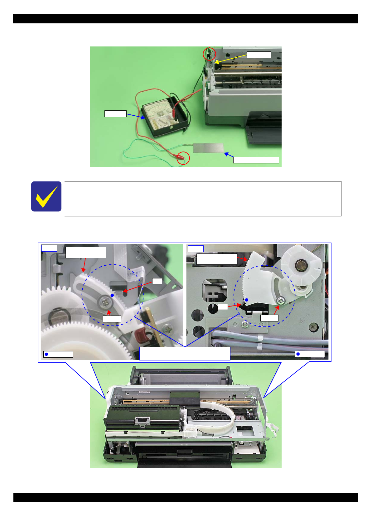
SC-P600 Revision D
Tester
Adjustment gauge
Frame
Right
Parallelism
Adjust Bushing
Screw
Marking
Rib
Screw
Rib
Left
Parallelism
Adjust Bushing
Marking
Align marking on Parallelism Adjust
Bushings with rib when disassembling.
2. Connect the tester to the upper section of the 130-side on the frame and adjustment gauge.
Figure 2-15. Connecting the Tester (Example)
Before disassembling the unit, mar k the contact points on the Parallelism A djust Bushin gs
(x2) with the rib of the frame, and align the markings with the rib when reassembling them.
(See Figure 2-16.)
3. Loosen the screws (x2) that secure the Parallelism Adjust Bushings (x2), and align the markings (marked
when disassembling) with the frame.
Figure 2-16. Setting the Parallelism Adjust Bushing
Adjustment Details of Adjustments 50
SE Group Confidential (Related Staff Only)
Page 51

SC-P600 Revision D
0
1
2
3
4
5
PG Cam
CR Unit
Adjustment gauge
130-digit side
4. To set the PG position to the “5” position, turn the PG Cam on the right end of the Carriage Shaft counter
clockwise (CCW) so that the point marked “5” faces down.
Figure 2-17. PG Cam Position
5. With the conductor connecti on portion of the adjustment gau ge up, set the gauge in the specified position (on
the left side of the Front Paper Guide Assy).
Setting Position
Rear direction: Align the rear end of the gauge with the Driven Roller Shaft of the Upper Paper Guide Assy.
Left direction: Align the left end of the gauge as shown in Figure 2-18.
6. Move the CR Unit onto the adjustment gauge.
Moving position
Align the left end of the gauge with the left end of the CR Unit.
Figure 2-18. Setting the Adjustment Gauge
7. To set the PG position to “0” , turn t he PG Cam on righ t end o f the Carri age Sh aft clock wis e (CW) so that th e
point marked “0” faces down. (See Figure 2-17.)
PG standard value
• PG position “0”: 1.05 mm - 1.25 mm
Adjustment Details of Adjustments 51
Adjustment resolu tion: 0.06 mm
SE Group Confidential (Related Staff Only)
Page 52

SC-P600 Revision D
Narrower PG
Wider PG
Parallelism Adjust
Bushing
0-digit side
CR Unit
Adjustment Gauge
8. Lower the gear of the Parallelism Adjust Bushing on the left side of the frame stepwise, and confirm
continuity. When con ti nui ty is confirmed, define t he posi t ion where the gear was r ai sed one step up from the
continuity position (where continuity is lost) as the left side PG position. Move the Parallelism Adjust
Bushing at least twice to confirm that the continuity position and the noncontinuity position are the same.
The following figure shows the states of the Adjust Parallel Bushing of the left side of the
frame and the PG.
(This also applies to the Adjust Parallel Bushing on the right side of the frame.)
Figure 2-19. Relationship between Parallelism Adjust Bushing and PG
9. To set the PG position to “5”, turn the PG Cam on right end of the Carriage Shaft counterclockwise (CCW)
so that the point marked “5” faces down. (See Figure 2-17.)
10. With its conductor connection portion down, set the adjustment gauge in the specified position (on the right
side of the Front Paper Gu ide Assy).
Setting Position
Rear direction: Align the rear end of the gauge with the Driven Roller Shaft of the Upper Paper Guide.
Right direction:Align the right end of the gauge with the position shown in Figure 2-20.
11. Move the CR Unit onto the adjustment gauge.
Moving position
Align the right end of the gauge with the right end of the CR Unit.
Figure 2-20. Setting the Adjustment Gauge
12. To set the PG position to “0 ”, turn t he PG Cam on righ t end of the Carri age Sh aft clock wis e (CW) so that th e
point marked “0” faces down. (See Figure 2-17.)
13. As in
Step 8
, move the Parallelism Adjust Bushing on the right side of the frame to set the right side PG position.
14. Set the PG position to “5”.
15. Set the adjustment gauge on the left side of the Front Paper Guide Assy.
16. Move the CR Unit onto the left side adjustment gauge.
17. Return the PG position to “0”.
18. Check continuity a gain a t the PG posi tion on the l eft s ide. I f the PG posi tion is no t out of pos itio n, t ighte n the
Parallelis m Adjust Bus hing with the screws to complete the adjustment. If it is out of position, repeat the
adjustment procedure from Step 8.
Adjustment Details of Adjustments 52
SE Group Confidential (Related Staff Only)
Page 53

SC-P600 Revision D
Plate under Front Paper Guide Assy
130-digit side frame
2.3.5 Mist Recovery check
This section describes Mist Recovery check.
Tools
Adjustment Program
Oscilloscope or Tester + High-voltage probe
(Refer to "1.1.2 Jigs (p10)" about the recommendation maker and model number)
Adjustment procedure
1. Start the Adjustment Program.
2. Select the Mist Recovery check and turn the high voltage module ON.
3. Using a
High-voltage probe,
Front Paper Guide Assy.
measure the voltage between the 130-digit side frame and the plate under the
Figure 2-21. Measuring the Voltage
The standard value of the Mist Recovery chec k is as follow s:
Standard value: 380
(If the device which can measure resistance value of 100MΩ is not used, you may not measure a value def initely. As a
result, there is the case that a parameter is not set within a standard, the Mist Recovery Function does not act, and dirt in
the printer or printing back side di rt of the paper occur.)
4. Confirm the voltage is within 380V
±
30 V
±
30V. (When you use the recommended tester and the High Voltage
Probe, the voltage is recorded with 1/1000. Please confirm with the value of thousandfold.)
5. Turn the high voltage module OFF.
Adjustment Details of Adjustments 53
SE Group Confidential (Related Staff Only)
Page 54

SC-P600 Revision D
MAC Address Label
Last six digits of MAC address
Shield Plate Lower
2.3.6 Initial setting
This setting is not necessary when the data in EEPROM on the Main Board can be read out.
To avoid a conflict of MAC address on a network, make sure to correctl y follow the MAC
address setting flowchart given on the following.
The user should be notified of the change of MAC address beca use of the following reasons.
• If the user has set the printer’s MAC address on a router, the repaired printer with a
new MAC address cannot be connected to the network.
• The default printer n ame on a network consists of “EPSON ” and the last six digits of the
MAC address. Therefore, the printer name becom es differ ent from the previous one.
You are required to enter the last six digits of the MAC address (xx:yy:zz) on the
Adjustment Program.
MAC address example: 00:00:48:xx:yy:zz
(“xx, yy, zz” represents a value unique to each printer)
Figure 2-22. MAC Address Label
Setting procedure
1. After replacing the Main Board, note down the MAC address written on a label on the Shield Plate Lower.
2. Connect the printer and the PC with the USB cable.
3. Start the Adjustment Program.
4. Select the “Initial S etting” from the menu. The initial setting screen app ears.
5. Click the check boxes you need to perform the initial setting.
6. Input the last 6 digit s on mac addres s int o the b lanks. (If y ou ne ed to input full mac a ddress , Click Full I nput.)
7. Press Perform button and make sure the configuration is proper by Pressing Check button.
Figure 2-23. Initial setting Screen
Adjustment Details of Adjustments 54
SE Group Confidential (Related Staff Only)
Page 55

SC-P600 Revision D
bigger gap
-> No good
How to judge Raster Offset pattern
gap
-> good
bigger gap
-> No good
2.3.7 Head Angular Adjustment CR/PF
This section describes Head Angular Adjustment CR/PF.
Basically, set the head angular adjustment lever on the CR Unit on the center position.
Tools
Adjustment Program
Adjustment procedure
1. Select the Head angular adjustment, and print the adjustment pattern.
−
2. Examine the printout patterns (
Make sure of the each direction. (0 >> 80 and 80 >> 0).
Case 1: the straight line is inside the range from -6 to +6.
Input the values of the most straight line and Press Input button.
Case 2: the straight line is NOT inside the range from -6 to +6.
Refer to Figure 2-25 and Adjust the head angular using Head angular adjustment lever.
Refer to Table 2-4 because the direction of the adjustment is depended on the direction of the printed patter
After adjustment, perform Step 2 again until the straight line is inside the range from -6 to +6.
6 to +6) in the Band pattern, and enter the values of the most straight lines.
3. Examine the printout patterns (+3 to −3) in the Raster Offset pattern, and select the value for the group of
which the gaps between the 2 color bars are the smallest, and then click the Input button.
Figure 2-24. Adjustment Pattern
Adjustment Details of Adjustments 55
SE Group Confidential (Related Staff Only)
Page 56

SC-P600 Revision D
CR Unit
Head angular
adjustment lever
#1
#6
#6
#1
Front side of CR
Unit moves down.
Front side of CR
Unit moves up.
Adjust the head angular adjustment lever position by
following the instruction in Adjustment Program.
Make sure to use tweezers when adjusting the head angular adjustment lever.
Table 2-4. Relation between adjustment pattern and Head angular adjustment lever
0 >> 80
Print from Home side to Full
side
Figure 2-25. Adjustment in the PF Directio
Adjustment direction of the Head angular adjustment lever
Rotate toward left from center
(Clockwise direction)
Rotate toward right from center
(Counter-Clockwise direction)
0 << 80
Print from Full side to Home
side
Adjustment Details of Adjustments 56
SE Group Confidential (Related Staff Only)
Page 57

SC-P600 Revision D
Calibrator
Scanning ruler
i1Pro calibrator / accessories
White
reference til e
Calibrator
Backing board
White reference tile
i1Pro2 calibrator / accessories
Scanning ruler
2.3.8 Colorimetric Calibration
2.3.8.1 Overview of the Colorimetric Calibration
Purpose
It can make revision values which adjust printing color of user’s printer and SEC standard unit equally.
The following parts have an influence on ink discharge, therefore revision is necessary after part exchange.
• Print Head
• Main Board
• Power Board
This revision values are applied to the EPSON genuine printer driver.
Tools
Table 2-5. Tools for Colorimetric Calibration
Tools Purpose / Specification
Plain paper (A4/Letter) For checking the nozzles.
Ultra Premium Presentation Paper Matte
Enhanced Matte Paper, Archival Matte Paper
(A4/Letter)
*1
Colorimetric Calibration application EPSON ColorBase2 (application for user)
PC
Calibrator
*3
White reference tile Accessory of calibrator
Scanning ruler Accessory of calibrator
Backing board Accessory of calibrator
Premium Glossy Photo Paper
Two USB cables For connecting printer and calibrator to PC with two USB cables.
For printing the calibration chart.
OS: refer to Table 2-6.
The following files must be installed on the PC:
-
Printer driver for the mod el to be adjusted
- Adobe AIR Runtime
*2
X-Rite i1Pro (with UV filter) or i1Pro2
For using as a background of the color chart during scanning (only
when a backing board is not attached to calibrator).
*1
) The Service Mode cannot select “Premium Photo P a per Glossy” and “Premium Glossy Photo Paper” which you can use for PK ink by
the User Mode.
*2
) It is downloaded automatically if connected to the network when a PC starts EPSON ColorBase2.
*3
) The Service Mode cannot select i1iO, i1iSis, ColorMunki which you can use by the User Mode.
Figure 2-26. Calibrator and accessories
Adjustment Details of Adjustments 57
SE Group Confidential (Related Staff Only)
Page 58

SC-P600 Revision D
Table 2-6. Support OS of EPSON ColorBase2
OS bit (reference) User Mode Service Mode
Windows XP SP3
Windows Vista 32/64 O ---
Windows 7 SP1 or later 32/64 O O
Windows 8 / 8.1 32/64 O O
Mac OS X (10.7.x, 10.8.x, 10.9.x) O ---
32 O O
64 O ---
Calibration principle
Measuring a color chart prin t resul t (i nk dis char ge amoun t) i n a ca libr ator.Created Color ID informat ion ba sed on
the obtained col or dif feren ce values (L*, a *, b*) is stored on the pr inter.When printing, the prin ter dri ver take s the
Color ID to correct the number of ink droplets (dot generation rate) for each of diff erent sized droplets of each
colors.
Correlation with Head ID adjustment
Head ID: In the pr int h ead manufacturing proc ess , i nk discharge amount of each head is actually measured to g et
individual characteristic information. The information is the Head ID that was set to revise a characteristic
difference betwee n the heads. The Head ID is shown with a la bel on the each pr int head, the refore you must inpu t
the Head ID to the printer after print h ead exchange.
Before performing Colorimetric Calibration, the conventional Head ID must be preregistered.
If you do not perform Colorimetric Calibration after performing Head ID adjustment,
the printer will be controlled only by the Head ID. In that case, the color precision is not
guaranteed.
Flow of the Colorimetric Calibration
The following steps show the Colorimetric Calibration:
1. Print a nozzle check pattern. If there is nozzle missing, run a head cleaning.
2. Print a color chart with the printer which you want to calibrate via ColorBase2.
3. Scan the printed colo r chart with a calibrator.
4. ColorBase2 calculates a Color ID from the sc anning result and calculation paramet er of the color i metric
calibration.
5. Write the Colo r ID to the printer. When printing, printer driver refers to the data of the Use r Color ID area.
Adjustment Details of Adjustments 58
SE Group Confidential (Related Staff Only)
Page 59

SC-P600 Revision D
Correlation with User adjustment and Service adjustment
The following table shows a correlation with user’s calibration.
Table 2-7.
Calibration timin g
ColorBase2 operation
mode
Correlation with User adjustment and Service adjustment
User adjustment Service adjustment
When the installation location changes.
When the printer has not been used for
an extended period of time.
When you are concerned about changes
in the color tones.
After the following parts exchange:
• Print Head
•Main Board
• Power Board
When reduce unit-to-unit variations in
color.
User Mode Service Mode
Same data is recorded to the following
Recording area of Color IDOnly recording to the “User Color ID
area”.
“Initializing *1the Color
ID”
operation contents
*1
) Menu title in the ColorBase2: “Maintenance” > “Restore Default Calibration” (refer to "2.3.8.3 Maintenance menu (p68) ")
“User Color ID area” is overwritten by the data recorded in the
area”
.
two areas:
• “User Color ID area”
• “Production Color ID area”
“Production Color ID
After changing Print Hea d / M ai n Boa rd / P ower Boar d, t he Color ID data which r ecor ded in
the “Production Color ID area” must be changed from Service Mode of the ColorBase2.
When a user carries out “Initial izing the Color ID” as the Pro duction Color ID is not chan ged,
a mismatch occurs between the Color ID and characteristic of changed part, then an
appropriate color calibration is not performed.
Adjustment Details of Adjustments 59
SE Group Confidential (Related Staff Only)
Page 60

SC-P600 Revision D
START
Print a nozzle check pattern
Select the media / calibrator,
and print the Color Chart.
Dry the Color Chart (5 min.)
Measure the Color Chart.
End
OK
NG
Head cleaning
Switch to Service Mode
Connect the printer and
calibrator to the PC,
and start the Co lorBase2
Convert the co lor me asur em ent
data to Color ID, then write
Color ID to the p rinter.
The ColorBase2 performs this
process automatically by clicking
[Active] button.
2.3.8.2 Adjusting Method of the Colorimetric Calibration
Adjusting workflow
The following illustrates the overall workflow.
Figure 2-27. Overall Workflow
To enhance the color accuracy, the ink churning is recommended before starting the
Colorimetric Calib rat ion . Remove the ink cartridges, and shake them four or five time s, t h en
reinstall them to the printer
Procedure
1. Connect the printer and the calibrator with the PC to which the ColorBase2 is installed using USB cables.
2. Turn the printer on.
3. Start up the ColorBase2.
4. Switch to Service Mode from the main menu screen: Click a point to show in “O” of the Figure 2-28 in the
pointer of the mouse in turn.
5. Input “7777” in the “enter password” cell, then click [OK] button (the password is fixed and cannot change).
Adjustment Details of Adjustments 60
SE Group Confidential (Related Staff Only)
Page 61

SC-P600 Revision D
1
2
3
4
No effect in Service Mode
Figure 2-28. Switching to Service Mode
6. Click [S tart Calibration] icon in the main menu screen.
Figure 2-29. Screen of the starting calibration
The list of “Applied Calibration Data” cannot be referred in the service mode.
7. Click Nozzle Check to execute the check.
8. Check the printed nozzle check pattern.
When there are broken lines or missing segments
Click Head Cleaning to execute the cleaning, then reprint a nozzle check pattern and check it.
When there are no broken lines or missing segments
Click Next to go to the Pri nt Color Chart screen.
The Next button becomes active after the Nozzle Check is executed.
If there are broken lines or missing segments, repeat the head cleaning until they are
eliminated.
x
Adjustment Details of Adjustments 61
SE Group Confidential (Related Staff Only)
Page 62

SC-P600 Revision D
Step 7
Step 8
Step 10
Figure 2-30. Nozzle Check screen
9. Select the following on the Print C olor Chart win dow.
Media Type: Ultra Premium Presentation Paper Matte / Enhanced Matte Paper, Archival Matter
Paper
Paper Size: A4 / Letter
Color Measurement Device: i1Pro (UV removal) / i1Pro2
Figure 2-31. Print Color Chart setting
10. Click the Print icon and load a sheet on the ASF, then print the chart.
Adjustment Details of Adjustments 62
SE Group Confidential (Related Staff Only)
Page 63

SC-P600 Revision D
Product name, serial no.,
selected black ink, print date
256 calibration patches
Nozzle Chec k Pattern
5 min. later
Active in 5 min.
Epson ColorBase2 Chart 1of1 Model:SC-P600 Serial:XXXXXXXXXX
SelectedInk:Photo Black PrintDay&Time:Oct. 06 2014 14:27
Figure 2-32. Illustration of Calibration Chart (Service Mode)
The recommended air temperature range for printing a Calibration Chart is 15 degrees
to 28 degrees.
The contents of the color chart differ between the User Mode and the Service Mode. (No
row or column numbers of the patches are printed in the Service Mode, but the nozzle
check pattern is printed instead.)
11. Confirm there is no d ot miss ing in t he nozz le che ck pat tern on the bot tom of the col or cha rt. If an y are found ,
run a cleaning from the panel menu on the printer, and then click “Print again”.
12. After drying is complete (after 5 minutes has passed), click Next to go to the measurement window.
Figure 2-33. Drying the Chart
Adjustment Details of Adjustments 63
SE Group Confidential (Related Staff Only)
Page 64

SC-P600 Revision D
Step 13
Step 14
Align the edge of scale with the first
row of the calibration patches.
Place the ch art w ith the no zzle
check pattern to the right.
Measurement start point
Measuring directi on
13. Confirm the calibrator is connected, click OK.
14. Place the calibrat or on the whit e reference tile (white plate) and click OK.
Figure 2-34. Prepari ng the Calibrator
The white reference tile (white plate) on the calibration plate should be clean. Clean off
any dirt with alcohol or other organic solvent. Use a soft cloth so as not to damage the
white reference tile (white plate).
The white reference tile (white plat e) and the calibrator are use d as a pair. Do not use any
other plate attached with other calibrators.
15.
Place the color chart on the backing b oard as sh own in Fi gure 2-35 and set the scanning ruler, and th en cl i ck OK.
(Use Premium Glossy Photo Paper instead if no backing board is available.) i1Pro2 is used for explanation in the
following figures.
Figure 2-35. Color chart setting
Adjustment Details of Adjustments 64
SE Group Confidential (Related Staff Only)
Page 65

SC-P600 Revision D
The chart for User Mode is used
on the tool window.
Step 15
Figure 2-36. Preparation for calibration
To avoid rubbing the color patches, set the color chart and perform the calibration with the
display on the tool window rotated in 90 degrees counterclockwise.
16.
Perform color measurement according t o the instructi on on the windo w. Press and hold the button on the cal ibrator
and wait for one to two seconds, and then keep holding it and slide the calibrator at a steady speed in the
measuring direction from the measurement start point shown in
i1Pro: Slide the calibrator on the calibration patches from left to right in approximately five seconds.
i1Pro2: Slide the calibrator on the calibration patches from left to right in approximately five seconds, and let go of
the button once. And then, press and hold the button on the calibrator again, and then keep holding it and
slide the calibrator on the calibration patches from right to left in approximately five seco nds.
When the color measurement is suc cessful ly comp let e, "O" appears, and then perform th e co lo r measuremen t on
Figure 2-35
.
the next row.
Adjustment Details of Adjustments 65
SE Group Confidential (Related Staff Only)
Page 66

SC-P600 Revision D
(1)
Color measurement
“complete” rows
Measured rows (starting from the left)
(2)
Color measurement
“not complete” rows
Rows to be measured (up to the right en d)
(3)
Cursor Automatically moves right when color measurement of a row is complete.
(4)
Measurement result “O” appears if the color valu e is within the normal range. Oth erwise or the number of pa tches is
not matched, “X” appears.
(5)
Stop button Discards the current measurement result and go back to the previous window before measurement.
Measurement start point
3
5
4
Orientation of the chart during measurement
1
2
Figure 2-37. Starting the Color Measurement
Table 2-8. Limitations of the calibrator
i1Pro i1Pro2
Measurement start
Upper left on the color chart Upper left on the color chart
point
Measuring direction
Times of measur ements
per row
When the
measurement fails
During color measurement, do not allow the calibrator to rub against unmeasured
In the direction of t he arrow in Figure 2-35
only. An error occurs if scanned in the reverse
direction.
Once Two times (one cycle)
Perform the measurement of the failed row.
Cannot go on to the next row until the
measurement is successfully comp le te.
Outward (tungsten light): In the direction of
the arrow in
Inward (UV light): In the reverse
Figure 2-35
only.
direction from the outward scanning
Perform the measurement of the failed row.
Cannot go on to the next row until the
measurement is successfully complete.
patches on the chart.
Prevent the ruler and calibrator from coming off the chart sheet during color
measurement. Doing so will cause incorrect color measurement.
Do not press the calibrator to the chart too strongly, otherwise the patch may be
damaged.
If “X” appears repeatedly and the measurement fails continuously, the measured color
value may be far out of the standard range. In that case, end the measurement and go to
the troubleshooting below.
Adjustment Details of Adjustments 66
x
SE Group Confidential (Related Staff Only)
Page 67

SC-P600 Revision D
Step 17
Table 2-9. Troubleshooting when the measurement fails
Presumable Cause Major Troubleshooting
The adjustment of the printer may be insufficient. After the adjustments that must be done after parts rep lacement are all
complete, perform the measuremen t ag ai n.
The media has deteriorated and discolored.
The media was stored in bad conditions and
damaged.
The color or contamination of the backing may be
interfering.
Wrong row/wrong m easuring directio n See Figure 2-35 and Table 2-8 and confirm the current row to be measured and
Measuring at an angle Align the scale with the ch art correctly again, and then slide the calib r ator in
Use new Ultra Premium Presentation Paper Matte Enhanced Matte Paper or
Archival Matte Paper.
When using the backing board: remove any contaminat ion on the backing
board, and then stack two col or charts over on each other and perform the
measurement.
Measurement without a ba cking board: Stack the color chart over on each
other on blank (white) Premium Glossy Photo Paper and perform t he
measurement.
the measuring direction are correct .
parallel to the ro w to be measured on the patches.
17. When the measurement of all the rows is complete, click the Completed button.
Figure 2-38. Color measurement completed
Adjustment Details of Adjustments 67
SE Group Confidential (Related Staff Only)
Page 68

SC-P600 Revision D
Step 18
Step 19
2
1
3
4
18. Click the Next button on the color measurement completed window.
19. On the apply calibration data window, click the Active button to write the calibration data to the printer.
Figure 2-39. Application of correction values
20. End the tool.
2.3.8.3 Maintenance menu
To display the maintenance menu, click the Maintenance button on the main screen.
Figure 2-40. Maintenance menu
Table 2-10. Details of the maintenance menu
Item Description
(1) Main screen button Goes back to the main screen.
(2) Nozzle check button Prints a nozzle check pattern.
Select a cleaning level among CL1, CL2, CL3, and CL4 and run it.
(3) Head cleaning button
Restore Default Calibration button Overwrite the data in the User Color ID area back to the saved data in
(4)
(Level selection available only in the Service Mode. Basically use
CL1, and if not improved much, raise the level and try again.)
the Production Color ID area.
x
Adjustment Details of Adjustments 68
SE Group Confidential (Related Staff Only)
Page 69

SC-P600 Revision D
Matte Black
Photo Black
Photo Black is lighter than M atte Black a little.
2.3.9 Ink Selector Check
This section describes Ink Selector Check.
Tools
Adjustment Program
Recommended printing paper: Plan Paper or Presentation Paper Matte
Adjustment procedure
1. Start the Adjustment Program.
2. Select the Ink Selector Check, and click [Check] for checking the current color
3. Select other color after confirming the color of Step 2, and click [Print] for printing the check pattern.
4. After printing, select other color with color of Step 3, and click [Print] again.
5. Compare the check patterns, and confirm the operation of the ink selector is correct by third color pattern of
the check patterns.
Figure 2-41. Confirming the check patterns
Adjustment Details of Adjustments 69
SE Group Confidential (Related Staff Only)
Page 70

SC-P600 Revision D
Power
Back
Home
2.3.10 Touch screen adjustment
This section describes calibration of Touch screen.
Purpose
To adjust the positions between LCD screen and detected position.
Tools
Stylus pen
(You can also use roundish plastic stick. It’s difficult to access by hand because the target is too small.)
Adjustment procedure
1. Call Inspection mode with pressing [Power] + [Home] + [Back] buttons for over 10 seconds.
Table 2-11. How to run Inspection mode
In inspection mode, Never to access the menu which is Not indicated as follows.
(To avoid mechanical troubles because of the incorrect data input.)
2. Select “3.Touch Screen Inspection” from Inspection menu using [Home] button, then Press [Back] button.
Moreover, Select “1.Touch Screen Calibration” using [Home] button, then Press [Back] button.
3. Display the adjustment screen by pressing “Push this Area. [OK].”
(When you need to cancel the adjus tment, Pre ss the ar ea where “Pus h [STOP] butt on [Cance l]” is display ed.)
4. Press “+” at 4 corners on the screen in order using stylus pen.
5. Press “Push this area. [Save]” using stylus pen.
6. Press red areas using stylus pen in order.
7. When completing the adjustme nt prope rl y, “Compl et e” is di spl ayed. Press [Back] button the n Pre ss [ P ower ]
button to shutdown the printer.
When not completing the adjustment properly, “Retry Check” is displayed. Press [Back] button then retry
adjustment from Step 3.
Adjustment Details of Adjustments 70
SE Group Confidential (Related Staff Only)
Page 71

CHAPTER 3
MAINTENANCE
SE Group Confidential (Related Staff Only)
Page 72

SC-P600 Revision D
3.1 Overview
This section provides information to maintain the p rinter in its op timum condition.
3.1.1 Cleaning
Except for the printhead, there are no other mechanical parts or units that require periodic cleaning. However, if
need arises, clean the component observing the following instructions.
Instructions for cleaning
Exterior parts such as housing
Wipe dirt off with a soft clean cloth moistened with water. For glossy or transparent parts, use of unwoven cloth is
recommended to avoid scratching those parts.
Inside of the printer
Remove paper dust with a vacuum cleaner.
Rubber or plastic rollers such as an LD roller used to feed paper
If paper dust adhered to the rollers decreases the frictional force of the rollers and the rollers cannot properly feed
paper, wipe off the paper dust with a soft cloth moistened with diluted alcohol.
Instructions for cleaning ink stains
Wipe the stains off with a cloth wrung out of diluted alcohol.
Do not use alcohol for cleaning the transparent parts. Doing so m ay cause them to get cloudy.
When wiping paper dust off the LD roller, be careful not to rub against the surface asperity.
To minimize the effect on the parts, use diluted alcohol such as 70% diluted ether.
After using alcohol for cleaning, make sure to wipe the part off with a soft dry dust-free
cloth to remove alcohol traces fully.
3.1.2 Lubrication
The type and amount of the grease used to lubricate the printer parts are determined based on the results of the
internal evaluations. Therefore, refer to " 3.2 Lubrication Points and Instructions (p73)" for the repairing
procedures below, and apply the specified type and amount of the grease to the specified part of the printer
mechanism.
Grease
Type Name EPSON Part Code Supplier
Grease G-26 1080614 EPSON
Grease G-45 1033657 EPSON
Grease G-71 1480655 EPSON
Grease G-74 1409257 EPSON
Shipping Liquid
Type Name EPSON Part Code Supplier
Shipping Liquid CR06 6104713 (1 kg)
6104714 (18 kg)
EPSON
Tools
Name Availability EPSON Part Code
Injector O * ---
Brush O * ---
Flux dispenser O * 1049533
Note *: Use tools whose specifications are specified in " 3.2 Lubrication Points and Instructions (p73)".
Maintenance Overview 72
SE Group Confidential (Related Staff Only)
Page 73

SC-P600 Revision D
Application Point
Waste Ink Tube
Application Point
CR Support Plate
Application Point
PF Grounding Spring
Rear Paper Guide
PF Roller
Application Point
Right
Star Wheel Assy
Torsion Spring, 47.45
Left
Star Wheel Assy
Torsion Spring, 47.45
Lever Link
2. Application Point
1. Application Point
3. Application Point
4. Application Point
5. Application Point
Cam Front Tray
Stopper Tray
Cam Front Tray
Driven Pu lley Holder
Driven Pulley
2. Application Point
1. Application Point
2. Application Point
1. Application Point
Washer, 8.2X0.5X14
PF Roller
10 mm
PF Roller
3.2 Lubrication Points and Instructions
<Lubrication Point>
Waste Ink Tube (x2)
<Type>
CR06
<Application Amount>
Adequate amount
<Remarks>
Apply with Flux Dispenser.
<Lubrication Point>
Contact poi nt of the Ink
Tube
<Type>
G-74
<Application Amount>
Adequate amount
<Remarks>
Apply with Flux Dispenser.
<Lubrication Point>
1. Rear Paper Guide
(Contact points of the PF
Roller)
2. PF Grounding Spring
(Contact points of the PF
Roller)
<Type>
G-45
<Application Amount>
1.
φ
1 mm x adequate
amount
2.
φ
1 mm x half of the
circumference
<Remarks>
Apply with injector.
<Lubrication Point>
Contact points of the
Torsion Spring, 47.45 (x2)
<Type>
G-26
<Application Amount>
φ
2 mm x 3 mm
<Remarks>
Spread it with brush after
application with injector.
Figure 3-1. Waste Ink Tube Figure 3-2. CR Support Plate
<Lubrication Point>
1. Stopper Tray
2. Bearing of the Lever Lin k
3. Shaft of the Lever Link
4. Cam Front Tray
5. Cam Front Tray (Contact
<Type>
G-26
<Application Amount>
1. φ 2 mm x adequate amount
2. φ 2 mm x 3 mm
3. φ 2 mm x half of the
4.
5.
<Remarks>
(Contact point of the
Compression Spring Cover)
(Protrusion x3)
point of the Lever Link )
circumference
φ
1 mm x 2 mm
φ
1 mm x adequate amount
1. 4. 5.
Apply with injector.
2. 3.
Spread it with brush after
application with injector.
Figure 3-3. Rear Paper Guide / PF Grounding Spring Figure 3-4. Star Wheel Assy
<Lubrication Point>
1. Contact poi nts (x4)
between the Driven
Pulley Holder and the
Frame
2. Shaft hole of the Driven
Pulley (x1 each)
<Type>
G-26
<Application Amount>
φ
1 mm x 2 mm
1.
2.
φ
1 mm x 1 mm (5 mg)
<Remarks>
Apply with injector.
<Lubrication Point>
1. Washer, 8.2X 0.5X14
(x2)
2. Shaft of the PF Roller
<Type>
G-45
<Application Amount>
1.
φ
2 mm x 1 mm
2.
φ
1 mm x 10 mm
<Remarks>
1. Apply with injector.
2. Spread it with brush
while rotating the PF
Roller after application
with injector.
Maintenance Lubricatio n Points and Instructions 73
Figure 3-5. Stopper Tray Unit
Figure 3-6. Driven Pulley Figure 3-7. PF Roller
SE Group Confidential (Related Staff Only)
Page 74

SC-P600 Revision D
2. Application Point
1. Application Point
3. Application Point
4. Application Point
5. 6. Application Point
PG Cam Right
PG Cam Left
Right CR Shaft Mounting Plate
40 mm
15 mm
Left CR Shaft Mounting P la te
Bottom of CR Unit
50 mm50 mm
CR Unit
CR Shaft
Application Point
CR Guide Plate
10 mm
1 mm
CR Guide Plate
Application Point
Left
Front Tray Assy
Right
Front Tray Assy
Front Tray Shaft
Front Tray Shaft
EJ Link Left
EJ Link Right
Front Tray
Front Tray
Guide Left
Front Tray
Guide Right
Application Point
<Lubrication Point>
1. PG Cam Left / Right
2. Left CR Shaf t Mo unt ing
Plate (x3)
3. Right CR Shaft
Mounting Plate (x3)
4. CR Shaft
(Contact po int s bet w een
the Torsion Spring,
13.14 and the PG
Torsion spring Left)
5. CR Unit
(Contact points of the
CR Shaft)
<Lubrication Point>
Contact point of the CR
Unit
<Type>
G-71
<Application Amount>
φ
2 mm x 70 mm
<Remarks>
On 1 mm from the end of
the frame, apply with
injector and spread it to 10
mm width with bru s h.
<Lubrication Point>
Contact points (x2)
between the Front Tray
Shaft and the Torsion
Spring, 187.9
<Type>
G-26
<Application Amount>
φ
2 mm x 1 mm
<Remarks>
Apply with injector.
6. CR Shaft
<Type>
1. 2. 3. 4. G-26
5. 6. G-71
<Application Amount>
1.
φ
1 mm
2. 13 mg (total amount)
3.
φ
2 mm x 40 mm
φ
2 mm x 15 mm
φ
1 mm x whole
circumference
φ
1 mm x 2 mm
4.
5. 6. 140
amount)
±
10 mg (total
Figure 3-9. CR Guide Plate Figure 3-10. Front Tray Assy
<Remarks>
1. Apply on the cam of
the PG Cam Left/Right
with injector.
2. 3. Apply with br ush.
4. 5. Apply with injector.
6. Apply with the
following.
1. Apply the center of the
CR Shaft (x4) with
brush.
2. Apply twice (50 mm
each) on the left side of
the CR Shaft and
spread it with brush.
3. Move the CR Unit
back and forth se ven
times slowly to spread
<Lubrication Point>
1. Front Tray
(Contact points (x5) of
the Front Tray Shaft)
2. EJ Link Left / Right
(x4 each)
3. Front Tray Guide Left /
Right (x10 each)
<Type>
G-74
<Application Amount>
Adequate amount
<Remarks>
---
the grease.
4. Apply twice (50 mm
each) on the right side
of the CR Shaft and
spread it with brush.
5. Move the CR Unit
back and forth se ven
times slowly to spread
the grease.
Maintenance Lubricatio n Points and Instructions 74
Figure 3-8. CR Unit
Figure 3-11. Front Tray
SE Group Confidential (Related Staff Only)
Page 75

SC-P600 Revision D
2. Application Point
1. Application Point
3. Application Point
4. Application Point
5. Application Point
EJ Slider Right
Front Paper Guide Assy
EJ Slider Left
Washer, 6.9X0.5X10.4
7 mm
EJ Roller Front
Right
EJ Roller Front
EJ Roller Rear
EJ Grounding Spring
Front left
Back left
Back right
Front right
Front Paper Guide
EJ Roller
Front
EJ Roller
Rear
<Lubrication Point>
1. Front Paper Guide (x9)
2. Contact point betw een
the Front Paper Guide
and the PF Roller
3. EJ Roller Front Shaft
4. Contact points (x2)
between the EJ Roller
Front / Rear and the EJ
Grounding Spr i ng
5. EJ Slider Left / Right
<Type>
1. 2. 3. 4. G-45
5. G-26
<Application Amount>
1. 3. Adequate amount
2.
φ
2 mm x 15 mm
4.
φ
1 mm x 3 mm
5. φ 2 mm x 1 mm
<Remarks>
1. 5.
Apply with injector.
3. Apply to 7 mm from
the Washer,
6.9X0.5X10.4, and
spread it with brush
while rotating the EJ
Roller Front.
4. Apply a f t e r installing
the EJ Grounding
Spring with br ush, and
spread it while rotating
the EJ Roller Front/EJ
Roller Rear.
Figure 3-12. Front Paper Guide Assy
Maintenance Lubricatio n Points and Instructions 75
SE Group Confidential (Related Staff Only)
Page 76

CHAPTER 4
APPENDIX
SE Group Confidential (Related Staff Only)
Page 77

SC-P600 Revision D
PG 2
PG 5
HP 0130
Digit number of CR
Carriage
PF Roller
LD Roller
The rotation di re ction of the PF Moto r
Clockwise:
Paper is fed normally
Counterclockwise:
Paper is fed backward
The above shows clockwise rotation .
The rotation direction of the ASF Motor.
CW: LD Roller rotates backward
CCW:LD Roller rotates normally
(Paper is fed)
The following shows clockw i s e rot ation.
The condition of the CR lock
Red: CR lock is set
White:CR loc k is released
The above shows the CR lock is set.
PG position
Shows “PG 2” position.
PG variation by APG Motor drive
PG becomes narrower (down-arrow ):
Clockwise rotation
PG becomes wider (up-arrow):
Counterclockwise rotation
The following shows when PG is narrow.
PG 2
PG 5
HP 0130
PG 2
PG 5
HP 0130
HP 0130
PG 2
PG 5
4.1 Power-On Sequence
This section describes the power-on sequences for this product. The conditions are as follows.
Conditions
Initial ink charge has finished.
The Front Tray Assy is set at the standard paper printing position without roll paper lo aded.
No paper on the paper path.
Turned off normally without any error.
The Printhead is capped with the Cap of the Ink System Assy.
The PG position is PG 2.
The Carriage is normally fixed by the CR Lock.
The ink cartridges with sufficient ink are installed, and no ink low or ink end error is occurring.
The following explains how to use the simplified diagrams in Table 4-1. The diagrams show
the movement of each component as seen from the front of the printer.
Figure 4-1. How to use the simplified diagrams
Table 4-1. Operation of the power-on sequence
Operation
Movement of each
component
1. Checking waste ink overflow
1-1.Reads out the pr ote c ti on counter value to check wa ste ink overflow.
2. APG initialization
Appendix Power-On Sequence 77
2-1.The APG Motor rotates counterclockwise until the PG position is set to PG:5 to
initialize the APG mecha n ism.
3. Seeking the home position
3-1.The carriage moves to the 0-digit side slowly and confirms it touc he s the Rig ht
Frame.
3-2.The carriage moves to the 130-digit side slowly and confirms it touches the CR lock.
HP 0130
SE Group Confidential (Related Staff Only)
Pump
*1
Motor
--- ---
--- ---
--- ---
PG 5
PG 2
--- ---
(Continue to the next page)
Decomp
Motor
*2
Page 78

SC-P600 Revision D
HP 0130
PG 2
PG 5
HP 0130
PG 2
PG 5
HP 0130
PG 2
PG 5
HP 0130
PG 2
PG 5
HP 0130
PG 2
PG 5
HP 0130
PG 2
PG 5
HP 0130
PG 2
PG 5
HP 0130
PG 2
PG 5
HP 0130
PG 2
PG 5
HP 0130
PG 2
PG 5
HP 0130
PG 2
PG 5
Table 4-1. Operation of the power-on sequence
Operation
3-3.The carriage moves to the 0-digit side slowly and confirms it touc he s the Rig ht
Frame, and the home position is fixed.
Afterward, the carriage position is monitored according to the signals from the CR
Encoder.
4. Releasing the CR lock
4-1.The Pump Motor rotates co unt erclockwise and r el eases the CR lock.
4-2.The carriage slow l y mo ve s to the 130-digit side to the CR lock check posit ion.
4-3.The carriage slightly moves to the 130-digit side.
4-4.The Pump Motor rota tes countercl o ckwise to set the Wiper of the In k S y s tem, and
then the Pump Motor rotates clockwise to retract the Wiper.
Movement of each
component
Pump
*1
Motor
--- ---
CCW ---
--- ---
--- ---
CCW
to CW
Decomp
Motor
---
*2
4-5.The carriage slowly returns to its home position.
5. Setting the APG to PG:2
5-1.The AP G M o tor rotates clockwise and sets the carr iage position to PG:2.
6. PF-ASF initialization
6-1.The PE Sensor detects no paper and th e A SF Sensor detects that the ASF is on its
home position, and then the PF Mot or rotates clockwise for approx. one se cond.
6-2.The AS F M o tor rotates co unterclockwise until the AS F Sensor detects that it gets
out of its home position.
6-3.The ASF Motor rotates clockwise unt il the AS F Sensor detec ts it is on its on ho me
position, and initializes the ASF mechanism.
7. Low temperature operation sequence
7-1.The carriage moves back and forth between 0-digit side and the 130-digit side for
two times.
*3
--- ---
HP 0130
--- ---
PG 5
PG 2
--- ---
--- ---
--- ---
--- ---
8. CR Motor measurement and PW Sensor initialization
8-1.The carriage slow ly moves to the 130-digit side.
8-2.The carriage performs a load measurement while moving to the VH Check position,
and records the detected vol ta ge of the P W Sensor at the specified three positions,
HP 0130
then stops.
PG 5
PG 2
Appendix Power-On Sequence 78
--- ---
--- ---
(Continue to the next page)
SE Group Confidential (Related Staff Only)
Page 79

SC-P600 Revision D
HP 0130
PG 2
PG 5
HP 0130
PG 2
PG 5
HP 0130
PG 2
PG 5
HP 0130
PG 2
PG 5
HP 0130
PG 2
PG 5
PG 2
PG 5
HP 0130
Table 4-1. Operation of the power-on sequence
Operation
8-3.The carriage de t ec ts th e voltage of the PW Sensor at the ca rri age stop position (the
black area at the Paper Guide Front).
8-4.The carriage pe rforms a load measurement whi le mo ving to the 0-digit side, and
stops.
9. PF Motor measurement
9-1.The PF Motor rotates clock wise for approx. one seconds, and perform s a load
measurement.
Movement of each
component
Pump
*1
Motor
--- ---
--- ---
--- ---
Decomp
Motor
*2
9-2.The carriage returns to its home position.
10.Detecting ink cartridge and initializing ink system
*4
10-1.The carriage move s to the 130-digit side to check the ink end sensor. The ink
remaining is detected after completing the chec k.
10-2.The carriage slowly returns to its home position.
11.CR lock setting
11-1.The Pump Motor rotat es c loc kwise, and sets the CR lock.
11-2.The carriage moves to the 130-digit side slowly and confirms it touche s the CR
lock.
11-3.The carriage returns to its home position.
HP 0130
--- ---
PG 5
PG 2
--- ---
--- ---
HP 0130
CW ---
PG 5
PG 2
HP 0130
--- ---
PG 5
PG 2
--- ---
Note *1: The rotation directions of the Pump Motor and their corresponding functions are as follows.
Clockwise: Cap closing/Pump suction/Wiper retracting/CR locking
Counterclockwise: Cap opening/Pump release/Wiper setting/CR unlocking
*2: T he rota tio n dir e ctions of the Decomp Motor an d the ir co r re s po nd ing functions are as fol low s.
Clockwise: Vented to atmosphere
Counterclockwise: Decompression
However, the Decomp Pump will not operate under the preconditions given in this section.
*3: Executes when the detected temperature is under 5°C (41°F) by the thermistor on the Printhead.
*4: The empty suction operation may occur depending on the situation.
Appendix Power-On Sequence 79
SE Group Confidential (Related Staff Only)
Page 80

SC-P600 Revision D
MK
PK
LKLLK
C
VMLC
VLM
Y
CN2
CN6
CN4
CN5
CN1
CN1
CN20
CN22
CN115
CN116
CN117
CN118
CN119
CN2
CN1
CN4
CN5
J1
CN7
CN3
CN30
CN35
CN13
CN2
CN60
CN19 CN15 CN2
CN1CN1CN1
CN9CN8 CN11 CN12CN10
CN1
CN1 CN2
CN1
CN2
CN2
CN5
CN6
CN6
CN3
CN1
CN2
CN1
CN2
CN3
PE Sensor
PF Encoder
APG/HP Sensor
APG/PH Sensor
ASF Relay Board
(CA58SUB-B)
Tray Detector
Roll Paper Guide Open Sensor
Decomp Pump Motor
CR Motor
PF Motor
Pump Motor
APG Motor
ASF Motor
LCD
Wireless LAN Module
Main Board
(CE21 MAIN)
USB
Ethernet
ASF Paper End Sensor
Printer Frame
Mist Board
(MPH1173)
CN1CN2
AC in
Power Supply Board
(CA86PSB/CA86PSE)
Printhead
CSIC
CR Contact
Module
CR Unit
I/C Holder Unit
CR Contact
Module
CR Contact
Module
CR Relay Board
(CA86SUB)
CR Encoder Board
PW Sensor
Ink Selector Sensor
Ink Selector Motor
Panel Sub Board
(CE21SUB-C)
Panel Board
(CE21PNL)
LCD Sub Board
(CD18SUB)
CN16
Cover Open Sensor
CN17
I/C Holder Cover Open Sensor
4.2 Connector Diagram
Cable connections of this printer are shown below.
Figure 4-2. Connector Diagram
Appendix Connector Diagram 80
SE Group Confidential (Related Staff Only)
Page 81

SC-P600 Revision D
4.3 Fatal Error Code
This secti on describes the fatal error code and the possible cau se for this product.
Table 4-2. Fatal Error List
Error
type
DC motor
error (CR)
DC motor
error (PF)
Error
code
01H P ID excess load error
03H PID reverse error
05H PID speed degradation error
F1H PID exce s s load error
F3H PID reverse error
F6H
Error name Possible cause Suspect Parts
Over current error
• CR Encoder failure
• Motor driver failu re
• Increase of CR load when printer is
printing (CR shaft is damaged, CR shaft
receiver is damaged, Grease is
consumed, DR laysha ft is de formed)
• Paper jam
• CR is collided to Front Tray Assy
• CR is collided to Upper Paper Guide
Assy
• CR Motor failur e
• CR Scale stain
• CR Encoder failure
• Motor driver failu re
• CR Belt failure
• CR Pully failure
• CR Encoder failure
• Motor driver
• PF Encoder failure
• Motor driver failu re
• Increase of PF load ( CR Bu sh is we ared,
CR grease is consumed, PF Roller
Center Support is deformed, CR is
collided to Front Tray Assy)
• Paper jam
• PF Motor failure
• PF Scale stain
• PF Encoder failure
• Motor driver failu re
• PF Belt failure
• Connection failure of the PF Motor or
the PF Encoder.
• PF irregular load
• PF Motor or PF Encoder failure.
• CR Encoder
• CR FFC
• Main Board
• CR Shaft, CR Unit, G uide CR
• CR grease
• Remove Paper Jam
• Front Tray Assy
• Front Tray Sensor
•APG Assy
• Upper Paper Guide Assy
• CR Motor
• CR Scale
• CR Encoder Assy
• CR FFC
• Main Board
• CR Belt
• CR Pully
• CR Encoder
• CR FFC
• Main Board
• CR Motor
• Paper Jam
• PF Encoder
• Main Board
• Check PF Belt tension
• CR Shaft grease
• Check PF Roller Shaft Center Support
Position Adjustment
• PF Roller
• PF Encoder
• Paper Jam
• PF Motor
• Front Tray Assy
• Rear Guide Assy
• PF Scale
• PF Encoder
• PF Encoder FFC
• Main Board
• PF Belt
• PF Encoder
• PF Motor
Appendix Fatal Error Code 81
SE Group Confidential (Related Staff Only)
Page 82

SC-P600 Revision D
Table 4-2. Fatal Error List
Error
type
Motor
drive time
error
Motor
drive time
error
Command
error
Printhead
system
error
Sequence
error
Sensor
error
APG error
Ink device
error
Circuit
error
Error
code
D1H CR (PID) driving time error
D3H PF (PID) driving time error
D5H ASF driving time error
D6H PUMP driving time error
D7H APG driving time error
D9H
30H
40H Transistor temperature error • Main Board fai lure • Main board
41H
42H
43H H ea d temperature error
50H CR Home position error
51H Deadlock avoidance error
52H
53H PF / ASF reset error
54H LD Roller reset error
55H Roll paper jam error
60H PW detector error • PW detector failure • PW detector
61H PW det ec to r confusion error
62H CD tray detection error
70H
71H APG reset e rror
B0H -
CFH
80H
Error name Possible cause Suspect Parts
Ink selector driving time
error
EEPROM verify error (by
command)
X-Hot detect error (pre
printing)
X-Hot detect error (after
flushing)
Impossible contact detection
error
APG assignment position
driving error
Ink device error
Circuit error
(include FFC disconnection
and fuse blowout)
• Firmware abnormal (sequence failure,
bug)
• Firmware abnormal (sequencefailure,
bug)
• Increase of rotation load of Pump unit
(deformation of gear, misarrangement
of phase)
• Firmware abnormal (sequence failure,
bug)
• Increase of changing load of ink selector
(deformation of gear)
*
---
• Printhead failure
• Main Board fai lure
• Paper jam
• Foreign object
• Deformat ion of the Main Frame
• CR lock operation fail ure
• detection operation of ASF phase failure
• Roll paper jam
• Use non-supported me di a (PW detector
cannot detect it)
• Mistake of the paper fe ed m e thod.
• PW detector failure
• Detection operation of PW f ai lure
(detection reflection rate)
(Printing to platen, ink mist attac h to
Front Paper Guide)
• Paper jam
• CD tray setting failu re
• CD tray failure
• CD is not put on the tr ay
• PW detector failure
• Detection ope rat ion of ASF phase
failure
• Deterioration of PF du rability
• PG Adjustment of right and left failure
• Ink Cartridge failure
• CSIC Terminal failure
• CR Contact Module failure
• Main Board fai lure
• Main Board fai lure
• FFC disconnection
• Firmware Update
• Firmware Update
• Ink System
• Firmware Update
• Ink Supply Unit
•Print Head
• Print Head FFC
• Main Board
• Ink System
• Waste Ink Tube
• ASF Assy
• ASF Motor
• PW detector
• Front Paper Guide Assy
• PW detector
• Remove Paper jam
•CD tray
• PW detector
•APG Assy
• Bushing Cam PG
• Bushing balancing adjustment part
• Ink Cartridge
•CSIC
• CRCM
• Main Board
• Main Board
• FFC
*
---
Note "*": Not o ccurs except in manufactu r ing process.
Appendix Fatal Error Code 82
SE Group Confidential (Related Staff Only)
 Loading...