

Page 1
SERVICE MANUAL
Large Format Color Inkjet Printer
SC-P5000 Series
Epson Stylus Pro 4900
Epson Stylus Pro 4910
SE Group Confidential (Related Staff Only)
SEIJ10007
Page 2

Notice:
All rights reserved. No part of this manual may be reproduced, stored in a retrieval system, or transmitted in any form or by any means, electronic,
mechanical, photocopying, recording, or otherwise, without the prior written permission of SEIKO EPSON CORPORATION.
The contents of this manual are subject to change without notice.
All efforts have been made to ensure the accuracy of the contents of this manual. However, should any errors be detected, SEIKO EPSON would greatly
appreciate being informed of them.
The above not withstanding SEIKO EPSON CORPORATION can assume no responsibility for any errors in this manual or the consequences thereof.
EPSON is a registered trademark of SEIKO EPSON CORPORATION.
General Notice: Other product names used herein are for identification purpose only and may be trademarks or registered trademarks of their
respective owners. EPSON disclaims any and all rights in those marks.
Copyright © 2016 SEIKO EPSON CORPORATION.
PS SALES & MARKETING (CS) DEPARTMENT
SE Group Confidential (Related Staff Only)
Page 3

PRECAUTIONS
Precautionary notations throughout the text are categorized relative to 1) Personal injury and 2) Damage to equipment.
DANGER Signals a precaution which, if ignored, could result in serious or fatal personal injury. Great caution should be exercised in performing
procedures preceded by DANGER Headings.
WARNING Signals a precaution which, if ignored, could result in damage to equipment.
The precautionary measures itemized below should always be observed when performing repair/maintenance procedures.
DANGER
1. ALWAYS DISCONNECT THE PRODUCT FROM THE POWER SOURCE AND PERIPHERAL DEVICES PERFORMING ANY MAINTENANCE OR
REPAIR PROCEDURES.
2. NO WORK SHOULD BE PERFORMED ON THE UNIT BY PERSONS UNFAMILIAR WITH BASIC SAFETY MEASURES AS DICTATED FOR ALL
ELECTRONICS TECHNICIANS IN THEIR LINE OF WORK.
3. WHEN PERFORMING TESTING AS DICTATED WITHIN THIS MANUAL, DO NOT CONNECT THE UNIT TO A POWER SOURCE UNTIL
INSTRUCTED TO DO SO. WHEN THE POWER SUPPLY CABLE MUST BE CONNECTED, USE EXTREME CAUTION IN WORKING ON POWER
SUPPLY AND OTHER ELECTRONIC COMPONENTS.
4. WHEN DISASSEMBLING OR ASSEMBLING A PRODUCT, MAKE SURE TO WEAR GLOVES TO AVOID INJURY FROM METAL PARTS WITH
SHARP EDGES.
WARNING
1. REPAIRS ON EPSON PRODUCT SHOULD BE PERFORMED ONLY BY AN EPSON CERTIFIED REPAIR TECHNICIAN.
2. MAKE CERTAIN THAT THE SOURCE VOLTAGES IS THE SAME AS THE RATED VOLTAGE, LISTED ON THE SERIAL NUMBER/RATING
PLATE. IF THE EPSON PRODUCT HAS A PRIMARY AC RATING DIFFERENT FROM AVAILABLE POWER SOURCE, DO NOT CONNECT IT TO
THE POWER SOURCE.
3. ALWAYS VERIFY THAT THE EPSON PRODUCT HAS BEEN DISCONNECTED FROM THE POWER SOURCE BEFORE REMOVING OR
REPLACING PRINTED CIRCUIT BOARDS AND/OR INDIVIDUAL CHIPS.
4. IN ORDER TO PROTECT SENSITIVE MICROPROCESSORS AND CIRCUITRY, USE STATIC DISCHARGE EQUIPMENT, SUCH AS ANTI-STATIC
WRIST STRAPS, WHEN ACCESSING INTERNAL COMPONENTS.
5. REPLACE MALFUNCTIONING COMPONENTS ONLY WITH THOSE COMPONENTS BY THE MANUFACTURE; INTRODUCTION OF SECONDSOURCE ICs OR OTHER NON-APPROVED COMPONENTS MAY DAMAGE THE PRODUCT AND VOID ANY APPLICABLE EPSON WARRANTY.
6. WHEN AIR DUSTER IS USED ON THE REPAIR AND THE MAINTENANCE WORK, THE USE OF THE AIR DUSTER PRODUCTS CONTAINING
THE INFLAMMABLE GAS IS PROHIBITED.
7. MAKE SURE AN ANTIVIRUS SOFTWARE IS INSTALLED ON THE COMPUTER USED FOR SERVICE SUPPORT. BE SURE TO HAVE THE
LATEST VIRUS DEFINITION FILE FOR THE SOFTWARE.
SE Group Confidential (Related Staff Only)
Page 4

About This Manual
This manual describes basic functions, theory of electrical and mechanical operations, maintenance and repair procedures of the printer. The instructions and procedures included
herein are intended for the experienced repair technicians, and attention should be given to the precautions on the preceding page.
Manual Configuration
This manual consists of six chapters and Appendix.
CHAPTER 1.PRODUCT DESCRIPTIONS
Provides a general overview and specifications of the product.
CHAPTER 2.TROUBLESHOOTING
Describes the step-by-step procedures for the troubleshooting.
CHAPTER 3.DISASSEMBLY / ASSEMBLY
Describes the step-by-step procedures for disassembling and assembling the product.
CHAPTER 4.ADJUSTMENT
Provides Epson-approved methods for adjustment.
CHAPTER 5.MAINTENANCE
Provides preventive maintenance procedures and the lists of Epson-approved lubricants and
adhesives required for servicing the product.
CHAPTER 6.APPENDIX
Provides the following additional information for reference:
• Connectors
• Panel Menu Maps
• ASP List
• Exploded Diagrams
SE Group Confidential (Related Staff Only)
Page 5

Symbols Used in this Manual
LubricationLubrication
Various symbols are used throughout this manual either to provide additional information on a specific topic or to warn of possible danger present during a procedure or an action.
Be aware of all symbols when they are used, and always read NOTE, CAUTION, or WARNING messages.
Indicates an operating or maintenance procedure, practice or condition that is necessary to keep the product’s quality.
Indicates an operating or maintenance procedure, practice, or condition that, if not strictly observed, could result in damage to, or destruction of, equipment.
May indicate an operating or maintenance procedure, practice or condition that is necessary to accomplish a task efficiently. It may also provide additional
information that is related to a specific subject, or comment on the results achieved through a previous action.
Indicates an operating or maintenance procedure, practice or condition that, if not strictly observed, could result in injury or loss of life.
Indicates that a particular task must be carried out according to a certain standard after disassembly and before re-assembly, otherwise the quality of the components
in question may be adversely affected.
Indicates that lubrication is needed for the parts after disassembly, when doing a maintenance or replacing a part with a new one.
SE Group Confidential (Related Staff Only)
Page 6

Revision Status
Revision Date of Issue Description
A October 8, 2010 First release
Revise:
Full-fledged revision. Refer to the revision bars in the manual. The following are the major revised items.
<Chapter 3>
• 3.4.3.9 AID Board Added reassembly caution.
• 3.4.6.3 Pickup Roller Added detailed description to the disassembly procedure.
• 3.4.6.5 Retard Roller Added disassembly caution and reassembly check items.
• 3.4.8.2 Cutter Motor Assy Revised the disassembly procedure.
• 3.4.12.9 EJ Planet Lever Newly added item.
<Chapter 4>
B March 31, 2011
C January 8, 2014
• 4.1.3 Description of Adjustments Deleted "Adjustment Value Reset".
• 4.2.3 NVRAM Viewer Basic Operation Added the list of information saved to CSV files.
• 4.10.8 Ink Mark Sensor Check & Adjustment Revised the UI and operation procedure of the service program.
• 4.12.3.2 Ink Charge Revised the operation procedure.
• 4.12.6.2 Ink Charge Revised the operation procedure.
• 4.14 Boards Related Checks and AdjustmentsDeleted "Adjustment Value Reset".
• 4.14.3 AID Function Check Revised the UI and operation procedure of the service program and added the
list of NG judgment.
• 4.15.3 Encoder Check Added steps.
• 4.16 SpectroProofer Related Adjustments Determined the pending items.
Revise:
<Chapter 3>
• 3.4.3.2 Network Board Added information of new board applied for ENERGY STAR Ver.2.0.
<Chapter 4>
• 4.1.2 Adjustment Items and the Order by Repaired PartAdded caution.
• 4.6 Image & Test Print Added caution.
• 4.11.6.2 Adjusting Method Revised tool list, added caution.
SE Group Confidential (Related Staff Only)
Page 7

Revision Date of Issue Description
Revise:
<Chapter 1>
• 1.4.2 Part Names Added "ILS30EP"
• 1.5.1.1 SC-P5000 Series Setup Menu Added "ILS30EP"
<Chapter 2>
• 2.9 Problems on SpectroProofer Partially added
D August 26,2014
E March 31, 2015
F
November 22,2016
<Chapter 3>
• 3.4.2.4 Control Panel Cover Added Check point
• 3.4.10.1 Color Measurement Device Added "ILS30EP"
<Chapter 4>
• 4.1.2 Adjustment Items and the Order by Repaired Part "Control Panel" adjustment Item was added
• 4.6 Image & Test Print "Adjustment pattern for CR direction head slant" Partially revised
• 4.11.4.1 CR Direction Head Slant Adjustment Added Check point
Revise:
<Chapter 3>
• 3.1.1 Precautions Partially added
• 4.1.4 Tools/Consumables for Adjustments Added "caution"
Revise:
<Chapter 1>
• 1.1 Product Description Information for SC-P5000 Series has been added.
• 1.2 Basic Specifications Information for SC-P5000 Series has been added.
• 1.3.2.2 Designated Paper Information for SC-P5000 Series has been added.
• 1.5 Control Panel Information for SC-P5000 Series has been added.
<Chapter 2>
• 2.2 Remedies for Maintenance Requests Changed
• 2.3 Remedies for Service Call Error Partially changed
• 2.5 Remedies for Print Quality Troubles Information for SC-P5000 Series has been added.
• 2.9 Problems on SpectroProofer Partially changed
<Chapter 3>
• 3.2 Parts Diagram Added “Antistatic Cloth Unit”
• 3.3 Disassembly Flowchart Added “Antistatic Cloth Unit”
• 3.4.2.18 Left Roll Cover/Right Roll Cover Procedure has been added
• 3.4.3.1 Main Board Changed “ADJUSTMENT REQUIRED”
• 3.4.4.3 CR Scale Added “CAUTION”
• 3.4.7.7 Antistatic Cloth Unit Newly added
SE Group Confidential (Related Staff Only)
Page 8

Revision Date of Issue Description
<Chapter 4>
• 4.1.2 Adjustment Items and the Order by Repaired Part Partially changed
• 4.1.3 Description of Adjustments Partially changed
• 4.1.4 Tools/Consumables for Adjustments Partially changed
• 4.1.5 Service Program Basic Operations Partially changed
• 4.2.1 NVRAM Read Procedure Partially changed
• 4.2.2 NVRAM Write Procedure Partially changed
• 4.5 Installing Firmware “CAUTION has been changed.
• 4.10.2 CR Belt Adjustment Partially changed
• 4.11.1 Head ID Check & Input Partially changed
• 4.11.5 Auto Bi-D Adjustment Partially changed
• 4.11.6 Colorimetric Calibration (Color ID) Procedure has been changed
• 4.12.2 Maintenance Box Remaining Space Check Partially changed
• 4.12.3.2 Ink Charge “CAUTION” had been added
• 4.12.8 LLK/V Ink Change (SC-P5000 Series) Newly added
F
November 22,2016
• 4.13.1 PF Belt Adjustment Partially changed
• 4.13.7.1 PW Adjustment Procedure has been changed
• 4.13.9 Cutter Belt Tension Check Partially changed
• 4.14.4 MAC Address Check & Input Procedure has been changed
• 4.14.6 Default Reset Procedure has been changed
• 4.14.7.1 Button Operation Check Partially changed
• 4.14.8 Color Mode Settings (SC-P5000 Series) Newly added
• 4.16.3 SpectroProofer Measurement Precision Check (Epson Stylus Pro 4900/4910 only)
Partially changed
• 4.17 SpectroProofer Checker (SC-P5000 Series) Newly added
<Chapter 5>
• 5.4 Cleaning Partially added
• 5.5 Lubrication Parts code of the grease (G-71) is changed.
<Chapter 6>
• 6.3 Panel Menu Map Information for SC-P5000 Series has been added.
• 6.4 Part names used in this manual Partially changed
SE Group Confidential (Related Staff Only)
Page 9

Revision Date of Issue Description
<Chapter 2>
• 2.2 Remedies for Maintenance Requests Partially changed
• 2.3 Remedies for Service Call Error Partially changed
G March 25, 2019
<Chapter 3>
• 3.4.4.3 CR Scale Partially changed
<Chapter 4>
• 4.5 Installing Firmware Partially changed
• 4.12.8 LLK/V Ink Change (SC-P5000 Series) Partially changed
SE Group Confidential (Related Staff Only)
Page 10

SC-P5000 Series/Epson Stylus Pro 4900/4910 Revision G
Contents
Chapter 1 PRODUCT DESCRIPTION
1.1 Product Description ............................................................................................ 16
1.2 Basic Specifications ............................................................................................ 19
1.2.1 Basic Specifications ................................................................................... 19
1.2.2 Electric Specifications ............................................................................... 19
1.2.3 Ink Specifications ...................................................................................... 20
1.2.4 General Specifications ............................................................................... 20
1.2.5 Reliability/Durability ................................................................................. 21
1.3 Printing Specifications ........................................................................................ 22
1.3.1 Paper Feed Specifications .......................................................................... 22
1.3.2 Paper Specification .................................................................................... 22
1.3.2.1 Supported Paper ................................................................................. 22
1.3.2.2 Designated Paper ................................................................................ 24
1.3.3 Printable Area ............................................................................................ 33
1.3.4 Borderless Printing Specification .............................................................. 34
1.3.5 Cutting of Roll Paper ................................................................................. 35
1.4 Hardware Specifications ..................................................................................... 36
1.4.1 Dimensions and Weight ............................................................................. 36
1.4.2 Part Names ................................................................................................. 37
1.5 Control Panel ...................................................................................................... 39
1.5.1 Setup Menu ................................................................................................ 46
1.5.1.1 SC-P5000 Series Setup Menu ............................................................ 46
1.5.1.2 Epson Stylus Pro 4900/4910 Setup Menu .......................................... 53
1.5.2 Maintenance Mode .................................................................................... 62
1.5.3 Serviceman Mode ...................................................................................... 64
Chapter 2 TROUBLE SHOOTING
2.1 Overview ............................................................................................................ 68
2.1.1 Preliminary Check ..................................................................................... 68
2.1.1.1 Check for the usage environment ....................................................... 68
2.1.1.2 Recurrence check of the trouble ......................................................... 68
2.1.1.3 Check for the counter values/history .................................................. 68
2.1.1.4 Test print check .................................................................................. 68
2.1.2 Troubleshooting Procedure ........................................................................ 69
2.1.3 Procedure after troubleshooting ................................................................. 69
2.1.3.1 If the trouble has been successfully solved ........................................ 69
2.1.3.2 If necessary to escalate the trouble case ............................................. 69
2.2 Remedies for Maintenance Requests ................................................................. 70
2.3 Remedies for Service Call Error ........................................................................ 73
2.4 Remedies for Error Messages related to SpectroProofer ................................... 97
2.5 Remedies for Print Quality Troubles .................................................................. 99
2.6 Trouble on Paper Feeding ................................................................................ 106
2.7 Printer does not Operate ................................................................................... 110
2.8 Abnormal Operations ....................................................................................... 112
2.9 Problems on SpectroProofer ............................................................................. 114
2.10 Trouble on Service Program ........................................................................... 118
2.11 Trouble on NVRAM Viewer .......................................................................... 121
2.12 Trouble on Colorimetric Calibration Adjustment program ............................ 122
Chapter 3 DISASSEMBLY & ASSEMBLY
3.1 Overview .......................................................................................................... 124
3.1.1 Precautions ............................................................................................... 124
3.1.2 Cautions after assembling ........................................................................ 126
3.1.3 Orientation Definition .............................................................................. 126
3.1.4 Recommended Tools ............................................................................... 127
3.2 Parts Diagram ................................................................................................... 128
3.3 Disassembly Flowchart .................................................................................... 139
3.4 Disassembly and Assembly Procedure ............................................................. 148
3.4.1 Preparation for servicing ......................................................................... 148
3.4.1.1 Unlocking the CR Unit ..................................................................... 148
3.4.1.2 Roll Unit ........................................................................................... 149
3.4.1.3 Paper Cassette .................................................................................. 150
3.4.1.4 Cutter Replacement .......................................................................... 151
3.4.1.5 Maintenance box 1 ........................................................................... 152
10
SE Group Confidential (Related Staff Only)
Page 11

SC-P5000 Series/Epson Stylus Pro 4900/4910 Revision G
3.4.1.6 Maintenance Box2 ............................................................................ 153
3.4.1.7 Ink Cartridge Replacement ............................................................... 154
3.4.1.8 Spindle .............................................................................................. 155
3.4.1.9 Mounter ............................................................................................ 156
3.4.2 Housing .................................................................................................... 157
3.4.2.1 Printer Cover .................................................................................... 157
3.4.2.2 Upper Front Cover ............................................................................ 158
3.4.2.3 Printer Cover Sensor ........................................................................ 160
3.4.2.4 Control Panel Cover ......................................................................... 161
3.4.2.5 Left Cover ......................................................................................... 163
3.4.2.6 Right Upper Cover ........................................................................... 164
3.4.2.7 Right Cover ...................................................................................... 165
3.4.2.8 Left IC Cover Frame/Right IC Cover Frame/
Left IC Sensor/Right IC Sensor ....................................................... 166
3.4.2.9 Front Cover ....................................................................................... 168
3.4.2.10 Front Cover Sensor ......................................................................... 169
3.4.2.11 Rear Cover ...................................................................................... 170
3.4.2.12 Rear Unit ........................................................................................ 171
3.4.2.13 Rear Unit Sensor ............................................................................ 172
3.4.2.14 Board Tray ...................................................................................... 173
3.4.2.15 Media Eject Cover .......................................................................... 174
3.4.2.16 CR Cover ........................................................................................ 175
3.4.2.17 Mid-Right Cover/Mid-Left Cover .................................................. 176
3.4.2.18 Left Roll Cover/Right Roll Cover .................................................. 177
3.4.3 Electric Circuit Components .................................................................... 179
3.4.3.1 Main Board ....................................................................................... 179
3.4.3.2 Network Board ................................................................................. 182
3.4.3.3 Power Supply Box ............................................................................ 184
3.4.3.4 Power Supply Board ......................................................................... 186
3.4.3.5 SUB Board ....................................................................................... 188
3.4.3.6 SUB-B Board ................................................................................... 189
3.4.3.7 SUB-C Board ................................................................................... 190
3.4.3.8 SUB-D Board ................................................................................... 191
3.4.3.9 AID Board ........................................................................................ 192
3.4.3.10 LED Board ..................................................................................... 193
3.4.3.11 Control Panel Board ....................................................................... 194
3.4.4 Carriage Mechanism ................................................................................ 195
3.4.4.1 CR Motor .......................................................................................... 195
3.4.4.2 CR Encoder ...................................................................................... 197
3.4.4.3 CR Scale ........................................................................................... 198
3.4.4.4 Ink Mark Sensor ............................................................................... 200
3.4.4.5 CR Unit/CR Belt .............................................................................. 202
3.4.4.6 APG Motor Assy .............................................................................. 206
3.4.4.7 APG Sensor ...................................................................................... 207
3.4.4.8 Oil pad holder ................................................................................... 209
3.4.5 Paper Feed Mechanism ............................................................................ 210
3.4.5.1 PF Motor .......................................................................................... 210
3.4.5.2 PF Encoder ....................................................................................... 211
3.4.5.3 PF Scale ..............................................
3.4.5.4 PF Belt .............................................................................................. 213
3.4.5.5 Suction Fan ....................................................................................... 214
3.4.5.6 PE Sensor ......................................................................................... 216
3.4.5.7 2nd PE Sensor .................................................................................. 220
3.4.5.8 PW Sensor ........................................................................................ 221
3.4.5.9 Paper Thickness Sensor1, 2 ............................................................. 223
3.4.5.10 Release Motor Assy ....................................................................... 225
3.4.5.11 Release Sensor ................................................................................ 226
3.4.5.12 Edge Release Assy ......................................................................... 227
3.4.5.13 Edge Sensor .................................................................................... 229
3.4.6 ASF Unit .................................................................................................. 230
3.4.6.1 ASF Motor Assy ............................................................................... 230
3.4.6.2 ASF Sub Motor Assy ....................................................................... 231
3.4.6.3 Pickup Roller .................................................................................... 232
3.4.6.4 Assist Roller Sensor/Retard Roller Sensor/
Pickup Unit Sensor .......................................................................... 236
3.4.6.5 Retard Roller .................................................................................... 239
3.4.6.6 Paper Empty Sensor ......................................................................... 242
3.4.6.7 Paper Cassette Sensor ....................................................................... 245
3.4.7 ROLL Unit ............................................................................................... 247
3.4.7.1 Roll Unit Sensor ............................................................................... 247
3.4.7.2 Roll Lock Sensor .............................................................................. 248
3.4.7.3 ATC Motor Assy .............................................................................. 250
3.4.7.4 Roll Feeding Motor Assy ................................................................. 251
3.4.7.5 Paper Guide Sensor .......................................................................... 252
3.4.7.6 Roll Feeding Sensor ......................................................................... 253
3.4.7.7 Antistatic Cloth Unit ........................................................................ 254
3.4.8 Cutter Unit ............................................................................................... 257
3.4.8.1 Cutter Cover ..................................................................................... 257
3.4.8.2 Cutter Motor Assy ............................................................................ 258
3.4.8.3 Cutter HP Sensor .............................................................................. 259
.............................................. 212
11
SE Group Confidential (Related Staff Only)
Page 12

SC-P5000 Series/Epson Stylus Pro 4900/4910 Revision G
3.4.8.4 Cutter Unit ........................................................................................ 261
3.4.9 Ink System Mechanism ............................................................................ 262
3.4.9.1 Ink Selector Assy .............................................................................. 262
3.4.9.2 Printhead ........................................................................................... 265
3.4.9.3 IS Unit .............................................................................................. 266
3.4.9.4 Wiper ................................................................................................ 269
3.4.9.5 Wiper Cleaner ................................................................................... 270
3.4.9.6 Head Cap .......................................................................................... 271
3.4.9.7 Home (Right) Side Cartridge Holder ............................................... 272
3.4.9.8 Full (Left) Side Cartridge Holder ..................................................... 275
3.4.9.9 Maintenance box 1 Holder ............................................................... 278
3.4.9.10 Ink Tubes ........................................................................................ 280
3.4.9.11 Head FFC ....................................................................................... 282
3.4.9.12 Right Holder FFC ........................................................................... 285
3.4.9.13 Left Holder FFC ............................................................................. 286
3.4.9.14 Decompression Pump ..................................................................... 287
3.4.10 Color Measurement Device and Backing Replacement ........................ 288
3.4.10.1 Color Measurement Device ............................................................ 288
3.4.10.2 Backing/White calibration tile holder ............................................ 289
3.4.11 Housing .................................................................................................. 290
3.4.11.1 Upper Cover ................................................................................... 290
3.4.11.2 I/F Cover ......................................................................................... 291
3.4.11.3 Right Cover .................................................................................... 292
3.4.11.4 Left Cover ....................................................................................... 293
3.4.11.5 Front Cover ..................................................................................... 294
3.4.11.6 Magnet Latch .................................................................................. 295
3.4.12 Color Measurement Device Parts .......................................................... 297
3.4.12.1 Main-C Board ................................................................................. 297
3.4.12.2 Encoder for paper pressing motor .................................................. 299
3.4.12.3 Thermistor ...................................................................................... 300
3.4.12.4 Drying Fan ...................................................................................... 301
3.4.12.5 Paper Pressing Motor ..................................................................... 302
3.4.12.6 CR HP Sensor ................................................................................. 304
3.4.12.7 Backing Sensor ............................................................................... 305
3.4.12.8 CR Motor ........................................................................................ 308
3.4.12.9 EJ Planet Lever ............................................................................... 310
Chapter 4 ADJUSTMENT
4.1 Overview .......................................................................................................... 313
4.1.1 Precautions ............................................................................................... 313
4.1.2 Adjustment Items and the Order by Repaired Part .................................. 314
4.1.3 Description of Adjustments ..................................................................... 326
4.1.4 Tools/Consumables for Adjustments ....................................................... 336
4.1.5 Service Program Basic Operations .......................................................... 338
4.2 NV-RAM BACKUP UTILITY/NVRAM Viewer ........................................... 339
4.2.1 NVRAM Read Procedure ........................................................................ 339
4.2.2 NVRAM Write Procedure ....................................................................... 339
4.2.3 NVRAM Viewer Basic Operation ........................................................... 340
4.3 ADJUSTMENTS (Individual) ......................................................................... 345
4.4 ADJUSTMENTS (Sequence) ........................................................................... 346
4.5 Installing Firmware .......................................................................................... 347
4.6 Image & Test Print ........................................................................................... 349
4.7 Counter Reset ................................................................................................... 352
4.8 References ........................................................................................................ 354
4.9 Initial Ink Charge Flag ..................................................................................... 355
4.10 CR Related Check & Adjustments ................................................................. 356
4.10.1 FFC Position Check ............................................................................... 356
4.10.1.1 FFC Position Check after replacing the Head FFC ........................ 356
4.10.1.2 FFC Position Check after replacing the tube ................................. 357
4.10.2 CR Belt Adjustment ............................................................................... 359
4.10.3 PG Height Check & Adjustment ........................................................... 361
4.10.4 APG Check ............................................................................................ 366
4.10.5 CR Encoder and Scale Check ................................................................ 367
4.10.6 CR Speed Initialize ................................................................................ 368
4.10.7 Active Damper Adjustment ................................................................... 369
4.10.8 Ink Mark Sensor Check & Adjustment ................................................. 370
4.11 Head Related Checks and Adjustments .......................................................... 372
4.11.1 Head ID Check & Input ......................................................................... 372
4.11.2 Nozzle Check ......................................................................................... 374
4.11.3 Cleaning ................................................................................................. 375
4.11.4 CR & PF Direction Head Slant Adjustment .......................................... 376
4.11.4.1 CR Direction Head Slant Adjustment ............................................ 376
4.11.4.2 PF Direction Head Slant Adjustment ............................................. 379
4.11.5 Auto Bi-D Adjustment ........................................................................... 381
4.11.6 Colorimetric Calibration (Color ID) ...................................................... 382
4.11.6.1 Adjustment Overview .................................................................... 382
4.11.6.2 Adjusting Method ........................................................................... 383
12
SE Group Confidential (Related Staff Only)
Page 13

SC-P5000 Series/Epson Stylus Pro 4900/4910 Revision G
4.12 Ink Supply Related Checks and Adjustments ................................................ 395
4.12.1 Wiper and Cap Cleaning & Exchange ................................................... 395
4.12.2 Maintenance Box Remaining Space Check ........................................... 396
4.12.3 Ink Eject and Initial Charge ................................................................... 397
4.12.3.1 Ink Eject ......................................................................................... 397
4.12.3.2 Ink Charge ...................................................................................... 398
4.12.4 Ink Selector Movement Check .............................................................. 399
4.12.5 ILS & CSIC Check ................................................................................ 400
4.12.5.1 ILS Check ....................................................................................... 400
4.12.5.2 CSIC Check .................................................................................... 401
4.12.6 Tubes Cleaning (and Ink Charge per Two Rows) ................................. 402
4.12.6.1 Tubes Cleaning ............................................................................... 402
4.12.6.2 Ink Charge ...................................................................................... 403
4.12.7 Leak Check (visually) ............................................................................ 404
4.12.8 LLK/V Ink Change (SC-P5000 Series) ................................................. 405
4.13 Media Feed Related Checks and Adjustments ............................................... 406
4.13.1 PF Belt Adjustment ................................................................................ 406
4.13.2 PF Encoder and Scale Check ................................................................. 408
4.13.3 Paper Thickness Sensor Position Adjustment ....................................... 409
4.13.4 Rear AD Adjustment ............................................................................. 412
4.13.5 Media Feed Correction Check & Adjustment ....................................... 413
4.13.6 Media Eject Correction Check & Adjustment ....................................... 416
4.13.7 PW + T&B&S Check & Adjustment ..................................................... 418
4.13.7.1 PW Adjustment .............................................................................. 418
4.13.7.2 T&B&S Adjustment ....................................................................... 418
4.13.8 Cut Position Check & Adjustment ........................................................ 420
4.13.9 Cutter Belt Tension Check ..................................................................... 421
4.13.10 Suction Check & Adjustment .............................................................. 423
4.14 Boards Related Checks and Adjustments ....................................................... 425
4.14.1 RTC&USB ID ....................................................................................... 425
4.14.2 Serial Number Check & Input ............................................................... 426
4.14.3 AID Function Check .............................................................................. 427
4.14.4 MAC Address Check & Input ............................................................... 429
4.14.5 USB Port and Network Communication Check .................................... 430
4.14.6 Default Reset ......................................................................................... 431
4.14.7 Operation Panel Check (Buttons & LCD) ............................................. 432
4.14.7.1 Button Operation Check ................................................................. 432
4.14.8 Color Mode Settings (SC-P5000 Series) ............................................... 433
4.15 Other Printer Checks and Adjustments .......................................................... 434
4.15.1 Motor Measurement Adjustment ........................................................... 434
4.15.2 Sensor Check ......................................................................................... 435
4.15.3 Encoder Check ..........................................
4.16 SpectroProofer Related Adjustments ............................................................. 442
4.16.1 SpectroProofer Sensor Check ................................................................ 442
4.16.1.1 Backing Sensor Check ................................................................... 442
4.16.1.2 Thermistor Check ........................................................................... 443
4.16.2 SpectroProofer Movement Check ......................................................... 444
4.16.2.1 Fan Function Check ....................................................................... 444
4.16.2.2 CR Function Check ........................................................................ 444
4.16.2.3 Paper Press Function Check ........................................................... 445
4.16.3 SpectroProofer Measurement Precision Check
(Epson Stylus Pro 4900/4910 only) ....................................................... 446
4.16.4 SpectroProofer Serial Number Check & Input ...................................... 448
4.17 SpectroProofer Checker (SC-P5000 Series) ................................................... 449
4.17.1 Inspection Outline .................................................................................. 449
4.17.2 Inspection Procedure ............................................................................. 449
............................................. 440
Chapter 5 MAINTENANCE
5.1 Overview .......................................................................................................... 452
5.2 Setting Up/Storing the Printer .......................................................................... 454
5.2.1 Setting Up ................................................................................................ 454
5.2.2 Storing the Printer and Cleaning the Ink Path ......................................... 454
5.3 Transportation .................................................................................................. 455
5.4 Cleaning ............................................................................................................ 456
5.4.1 Main Unit ................................................................................................. 456
5.4.2 Auto Color Measurement Device Mounter ............................................. 461
5.5 Lubrication ....................................................................................................... 464
Chapter 6 APPENDIX
6.1 Block Wiring Diagram ..................................................................................... 475
6.1.1 Main Body ............................................................................................... 475
6.1.2 SpectroProofer ......................................................................................... 476
6.2 Connection Diagram ......................................................................................... 477
6.2.1 Housing .................................................................................................... 477
6.2.2 Electric Circuit Components 1 ................................................................ 477
6.2.3 Electric Circuit Components 2 ................................................................ 478
13
SE Group Confidential (Related Staff Only)
Page 14

SC-P5000 Series/Epson Stylus Pro 4900/4910 Revision G
6.2.4 Carriage Mechanism ................................................................................ 478
6.2.5 Paper Feed Mechanism 1 ......................................................................... 479
6.2.6 Paper Feed Mechanism 2 ......................................................................... 479
6.2.7 ASF Unit .................................................................................................. 480
6.2.8 ROLL Unit ............................................................................................... 480
6.2.9 Cutter Unit ............................................................................................... 481
6.2.10 Ink System Mechanism 1 ....................................................................... 481
6.2.11 Ink System Mechanism 2 ....................................................................... 482
6.2.12 SpectroProofer ....................................................................................... 482
6.3 Panel Menu Map ............................................................................................... 483
6.4 Part names used in this manual ........................................................................ 487
6.5 Exploded Diagram/Parts List ........................................................................... 490
14
SE Group Confidential (Related Staff Only)
Page 15

PRODUCT DESCRIPTION
CHAPTER
1
SE Group Confidential (Related Staff Only)
Page 16
SC-P5000 Series/Epson Stylus Pro 4900/4910 Revision G
1.1 Product Description
SC-P5000 Series/Epson Stylus Pro 4900/4910 is a wide-format color inkjet printer that
supports up to 17 inch wide (A2) paper.
The main features are;
Supports very large-sized paper
Maximum available paper width: 432 mm
Maximum available paper size: 17 inch
Ink configuration
Installs the following 11 ink cartridges. The ink selector function is equipped, and
black ink can be switched between Photo Black and Matte Black depending on
media type.
SC-P5000 Series has the following two ink sets.
Epson Stylus Pro 4900/4910 supports K3 set only.
K3 set (EPSON UltraChrome HDX ink, 11 color ink set): Featuring accurate
tone representation
Color Abbreviation
Photo Black PK (Photo Black)
Matte Black MK (Matte Black)
Cyan C (Cyan)
Vivid Magenta VM (Vivid Magenta)
Yellow Y (Yellow)
Orange OR (Orange)
Green GR (Green)
Light Cyan LC (Light Cyan)
Vivid Light Magenta VLM (Vivid Light Magenta)
Light Black LK (Light Black)
Light Light Black LLK (Light Light Black)
Violet set (EPSON UltraChrome HDX ink, 11color ink set): Featuring a
broad color reproduction area
Color Abbreviation
Photo Black PK (Photo Black)
Matte Black MK (Matte Black)
Cyan C (Cyan)
Vivid Magenta VM (Vivid Magenta)
Yellow Y (Yellow)
Orange OR (Orange)
Green GR (Green)
Light Cyan LC (Light Cyan)
Vivid Light Magenta VLM (Vivid Light Magenta)
Light Black LK (Light Black)
Violet V (Violet)
Super high print quality
Achieves high quality printing with 11 colors of ink, resolution of up to 2880 x
1440 dpi, and variable dot sizes (minimal 3.5 picoliter)
Featuring accurate tone representation: K3 set (EPSON UltraChrome HDX
ink, 11 color ink set)
• Improved black OD value: glossy paper (PGPP) 2.5 or more, matte paper
(Photo Rag): 1.75 or more
• Improved light resistance: more resistant than traditional models (glossy
paper (PGPP) 45 years)
• Excellent PANTONE cover rate: 98%
Featuring a broad color reproduction area: Violet set (EPSON UltraChrome
HDX ink, 11color ink set)
• Improved black OD value: glossy paper (PGPP) 2.5 or more, matte paper
(Photo Rag): 1.75 or more
• Improved light resistance: more resistant than traditional models (glossy
paper (PGPP) 45 years)
•
Excellent PANTONE cover rate: 99% (Further improved the industryleading PANTONE cover rate. Reproduces exact colors that customers want.
PRODUCT DESCRIPTION Product Description 16
SE Group Confidential (Related Staff Only)
Page 17
SC-P5000 Series/Epson Stylus Pro 4900/4910 Revision G
Lower running cost
Employs 200 ml super high-capacity independent ink cartridges
Equips the on-demand cleaning function without excessive suction of ink
using the independent ink suction system for every two rows and the AID
function
Media handling
Supports a variety of media
Switches the roll paper and the ASF cassette automatically
Stores roll paper usage history and updates it automatically by reading a
barcode. This enables automatic detection of remaining amount of the paper.
Equips high speed auto cutter for roll paper
Borderless print is supported (for roll paper only)
The latest-type RIP
Supports various RIP made by 3rd parties
Options
SpectroProofer is available. Enables color measurement after printing.
Nozzle set configuration
K3 set (SC-P5000 Series/Epson Stylus Pro 4900/4910)
Ink configuration
K3 set (SC-P5000 Series/Epson Stylus Pro 4900/4910)
Left Side Right Side
1 2 3 4 5 6 7 8 9 10 11
GR LLK Y LC VLM OR MK VM LK C PK
Violet set (SC-P5000 Series)
Left Side Right Side
1 2 3 4 5 6 7 8 9 10 11
GR V Y LC VLM OR MK VM LK C PK
Note : 1-row starting from the left facing the front of the printer.
A-row B-row C-row D-row E-row F-row G-row H-row I-row J-row
C VM PK/MK LK OR GR LLK Y LM LC
Violet set (SC-P5000 Series)
A-row B-row C-row D-row E-row F-row G-row H-row I-row J-row
C VM PK/MK LK OR GR V Y LM LC
x
PRODUCT DESCRIPTION Product Description 17
SE Group Confidential (Related Staff Only)
Page 18
SC-P5000 Series/Epson Stylus Pro 4900/4910 Revision G
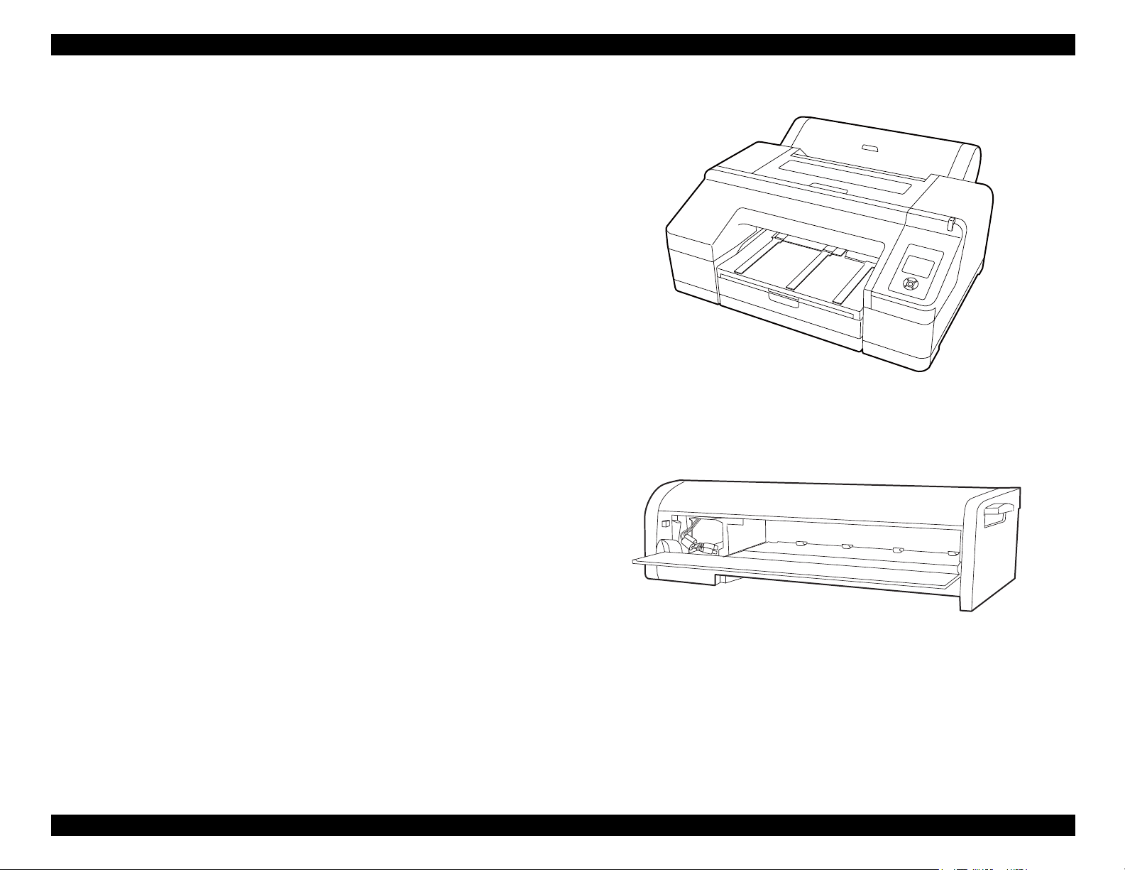
SpectroProofer (Option)
Full-fledged spectrophotometer realizes high precision color measurement.
Selectable from specifications with/without the UV filter, which enables the
users to configure colorimetric system adjusted with their workflow.
Drying Fans for drying ink stabilizes color in less than 2 minutes 30 seconds.
Paper pressing function prevents degrading precision of colorimetry caused
by floating of paper.
Selectable from the white backing or the black backing.
Figure 1-1. External View (Main body)
Figure 1-2. External View (SpectroProofer)
PRODUCT DESCRIPTION Product Description 18
SE Group Confidential (Related Staff Only)
Page 19
SC-P5000 Series/Epson Stylus Pro 4900/4910 Revision G
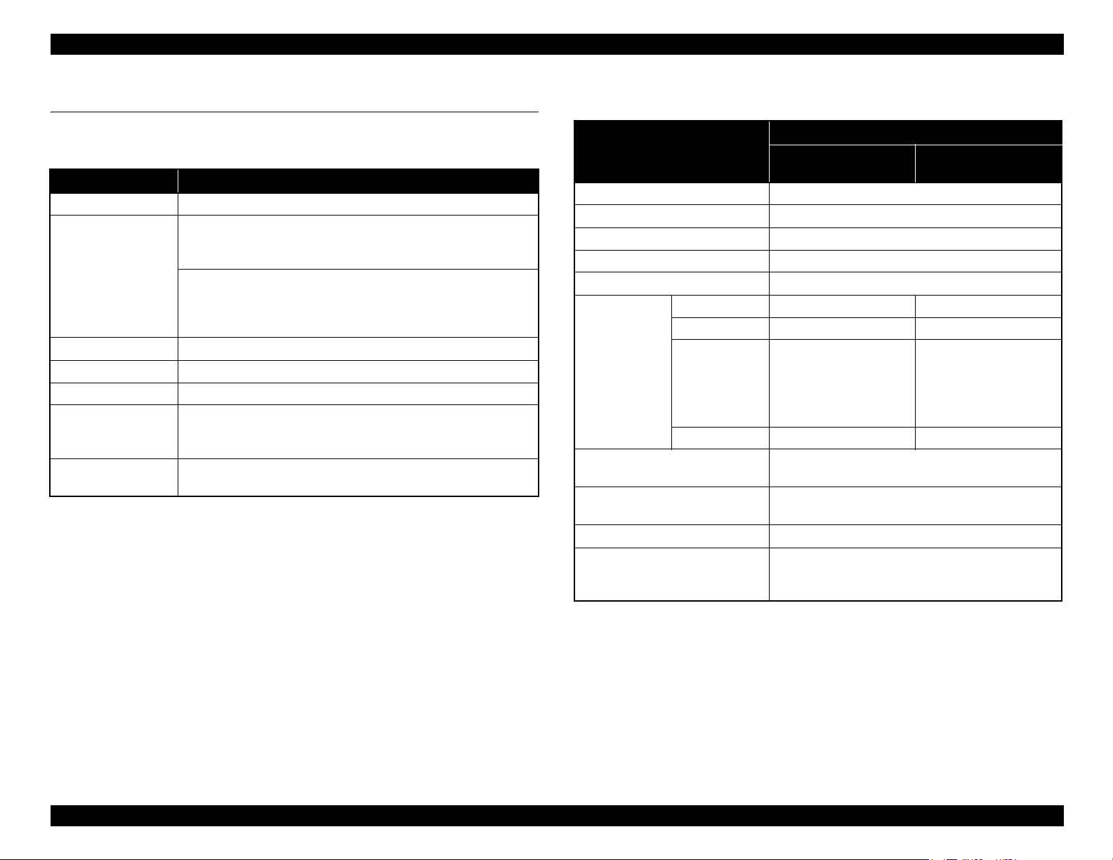
1.2 Basic Specifications
1.2.1 Basic Specifications
Item Specification
Print method On-demand inkjet
Black system:
360 nozzles x three colors
(Photo Black, Matte Black, Light Black, Light Light Black)
Nozzle configuration
Maximum resolution 2,880dpi x 1,440dpi
Control code ESC/P2 (command is nondisclosure)
Paper feed method Friction
RAM
Interface
Note "*": SC-P5000 Series only
Color system:
360 nozzles x seven colors
(Green, Yellow, Orange, Cyan, Light Cyan, Vivid Magenta, Vivid
Light Magenta, Violet*)
For Main: 256 MB
For Network: Epson Stylus Pro 4900/4910: 64 MB
SC-P5000 Series: 128 MB
USB 2.0 High Speed
Ethernet 10Base-T/100Base-TX/1000BASE-T*
1.2.2 Electric Specifications
Item
Rated voltage 100 to 240 VAC
Input voltage range 90 to 264 VAC
Rated current 0.4 A to 0.7 A
Rated frequency 50 to 60 Hz
Input frequency range 49.5 to 60.5 Hz
Operating Approx. 52 W Approx. 55 W
Standby 20 W 25 W
Power
consumption
Insulation resistance
Dielectric strength
Leek current 0.25 mA or less
Compliance with regulations
Sleep mode
Power off Approx. 0.5 W or less Approx. 0.5 W or less
Main body
SC-P5000 Series:
Approx. 5.0 W
Epson Stylus Pro 4900/
4910: Approx. 8.5 W or
less
10 M or more
(between AC line and chassis at 500 VDC)
1.0 kVrms AC for 1 min. or 1.2 kVrms AC for 1 sec.
(between AC line and chassis)
Conforms to International Energy Star Program
(Category: the harmonic restraint measure guideline)
Conforms to VCCI Class B (with full options installed)
Specification
SpectroProofer is
installed
SC-P5000 Series:
Approx. 5.0 W
Epson Stylus Pro 4900/
4910: Approx. 8.5 W or
less
PRODUCT DESCRIPTION Basic Specifications 19
SE Group Confidential (Related Staff Only)
Page 20
SC-P5000 Series/Epson Stylus Pro 4900/4910 Revision G
C A U T I O N
Temperature (°C)
Humidity (%)
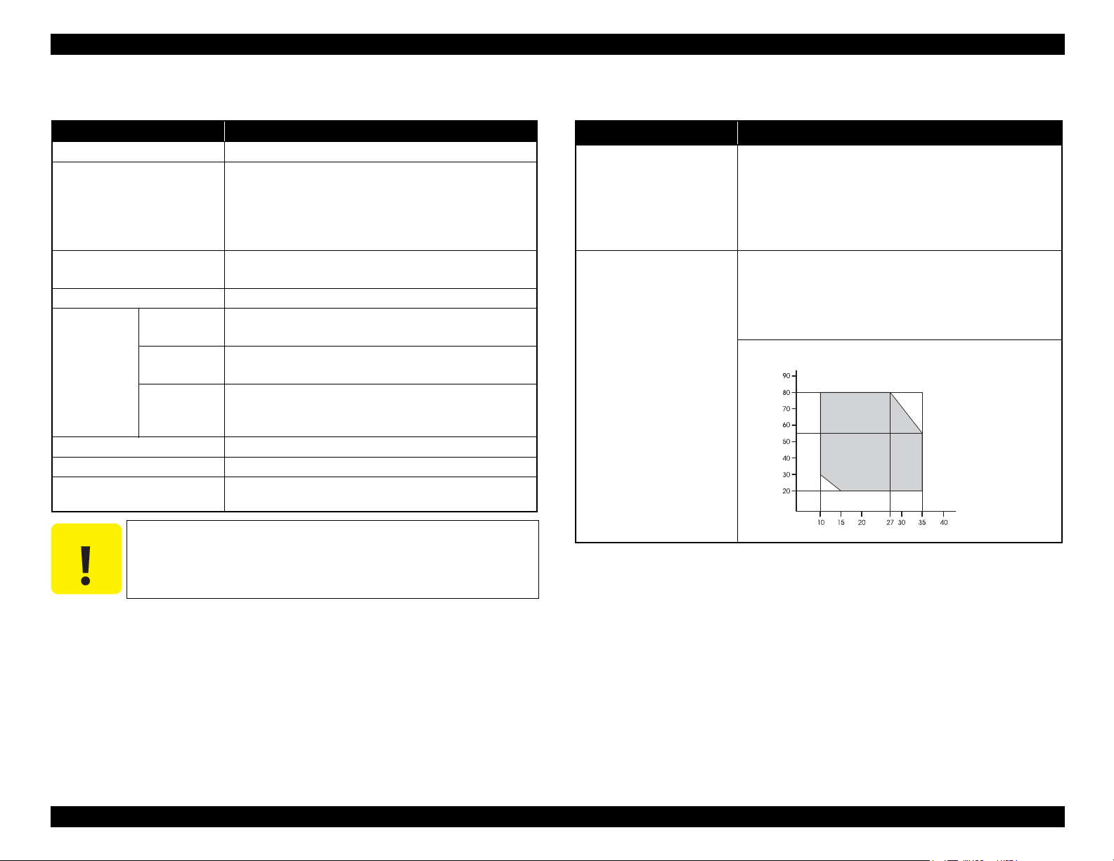
1.2.3 Ink Specifications
Item Specification
Form Exclusive ink cartridge
Black system:
Photo black, Matte black, Light black, Light light black
Pigment Ink colors
Cartridge life
Guaranteed life after installation Within 6 months after mounted in the printer
Uninstalled
(packed)
Storage
Capacity 200ml/80ml (bundled item)
Dimensions 25 (W) x 200 (L) x 100 (H)
Maintenance box/
Maintenance box 2
Installed
Transporting
(packed)
Color system:
Cyan, Light Cyan, Vivid magenta, Vivid light magenta,
Yellow, Orange, Green, Violet*
200ml: 3 years
80ml: 2 years
-20 to 40 °C
(within 1 month under 40 °C)
-20 to 40 °C
(within 1 month under 40 °C)
-20 to 60 °C
(within 72 hours under 60 °C, and within 1 month under
40 °C)
PXBMB1/PX17MB1
1.2.4 General Specifications
Item Specification
Operating: 10 to 35 °C
Storage (before unpacked): -20 to 60 °C
Temperature
Humidity
(within 120 hours under 60 °C, and within 1 month under
40 °C)
Storage (after unpacked): -20 to 40 °C
(within 1 month under 40°C)
Operating: 20 to 80% (no condensation)
Storage (before unpacked):
-20 to 85% (no condensation)
Storage (after unpacked):
5 to 85% (no condensation)
Note "*": SC-P5000 Series only
PRODUCT DESCRIPTION Basic Specifications 20
Never disassemble ink cartridges or refill ink in them.
SE Group Confidential (Related Staff Only)
Page 21

SC-P5000 Series/Epson Stylus Pro 4900/4910 Revision G
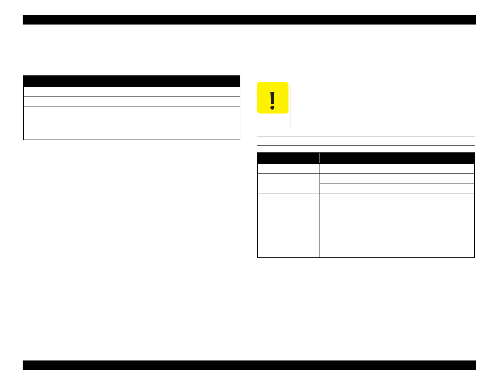
1.2.5 Reliability/Durability
Item Specification Remarks
Until any one of the following conditions is met.
5 years
Operating life of the printer
Cutter life (reference)
RTC backup battery 5 years or longer ---
CR Motor Approx. 6,000,000 paths
Head FFC Approx. 6,000,000 paths
Oil Pad Approx. 6,000,000 paths
Parts life
Ink Tube Approx. 6,000,000 paths
Ink Selector Assy 10,000 times 4 times/day x 250days x 5years x 2 (safety factor)
IS Unit 1,200,000 EP EP: revolutions (EP) of the motor for pump suction
Home (Right) Side Cartridge
Holder
Full (Left) Side Cartridge Holder 200,000 times 100,000 times (initial charge to product life) x 2 (safety factor)
Carriage life:
3,000,000 paths
Approx. 25,000 pages
(Super A2 size/Plain paper/Quality mode/720x720 dpi)
Standard paper: approx. 20,000 cuts
Hard cut paper: approx. 5,000 cuts
Approx. 25,000 pages
(Super A2 size/EPSON paper/Quality mode/Continuous printing/
720x720 dpi)
Approx. 25,000 pages
(Super A2 size/EPSON paper/Quality mode/Continuous printing/
720x720 dpi)
Approx. 25,000 pages
(Super A2 size/EPSON paper/Quality mode/Continuous printing/
720x720 dpi)
Approx. 25,000 pages
(Super A2 size/EPSON paper/Quality mode/Continuous printing/
720x720 dpi)
200,000 times 100,000 times (initial charge to product life) x 2 (safety factor)
---
---
PRODUCT DESCRIPTION Basic Specifications 21
SE Group Confidential (Related Staff Only)
Page 22
SC-P5000 Series/Epson Stylus Pro 4900/4910 Revision G
C A U T I O N
1.3 Printing Specifications
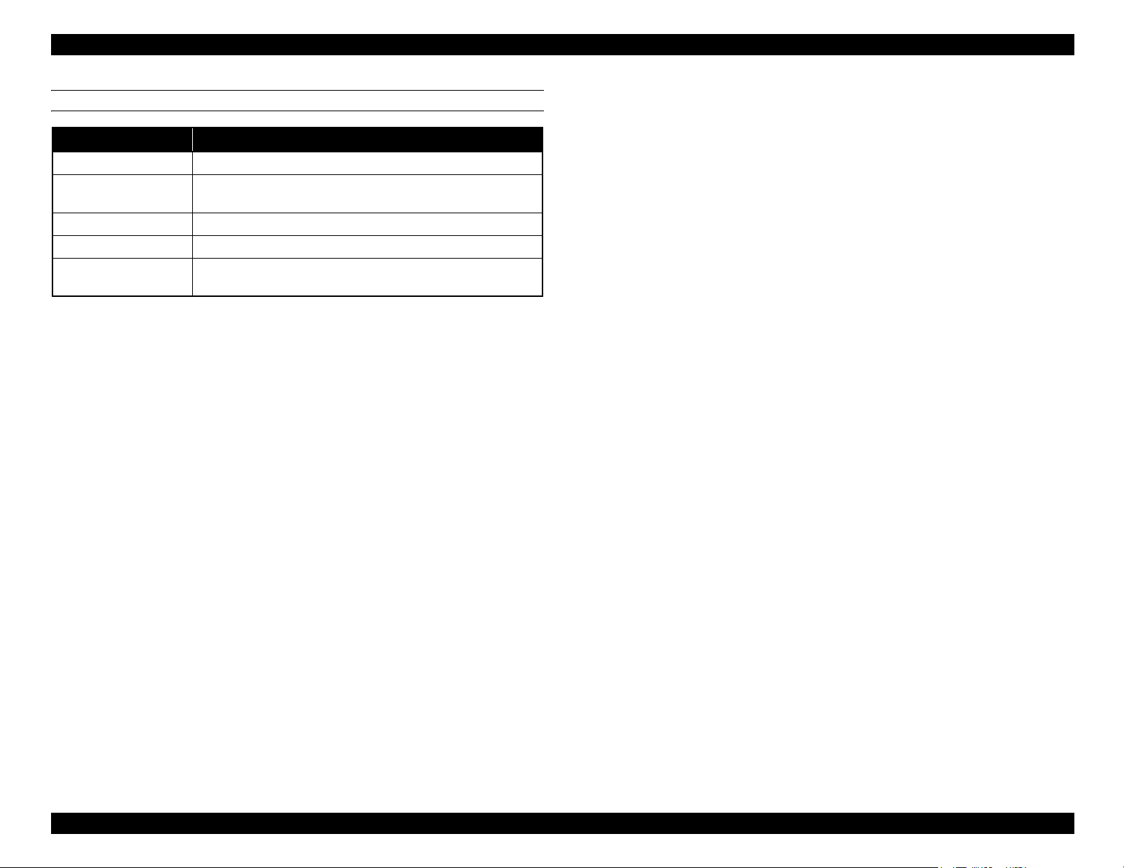
1.3.1 Paper Feed Specifications
Item Specification
Paper feed method Friction feed
Return pitch 2.2049 m (1/11,520 inch)
Roll paper manual feed
Paper feeder
Cut sheet manual feed
Cut sheet front manual feed
Cassette paper feed
1.3.2 Paper Specification
1.3.2.1 Supported Paper
The following explains the supported paper sizes and thickness.
Do not use wrinkled, scuffed, torn, or soiled paper.
Load paper just before printing. Do not leave paper loaded on
the printer when not printing. Store paper properly following
the instruction that comes with the paper.
When large quantities of paper need to be prepared in advance,
make a test print using the paper before purchase.
ROLL PAPER
Item Specification
Paper type Plain paper, recycled paper
Paper size
(within roll paper size)
Roll paper size
Paper thickness 0.08 to 0.11mm
Weight 64 to 90g/m
Available width for
borderless printing
2-inch core: 203 to 432 mm x to 45 m
3-inch core: 203 to 432 mm x to 30.5 m
2-inch core: Outer diameter 103 mm or less x 1 roll
3-inch core: Outer diameter 150 mm or less x 1 roll
2
A4/210 mm, A3/297 mm, Super A3/B/329 mm,
SuperW A3/329 mm, A2/420 mm*, 11 inch*, 17 inch, 8 inch*,
10 inch, 16 inch, 30 cm
Note "* " : Spacer for the borderless printing and 2-inch core are required.
PRODUCT DESCRIPTION Printing Specifications 22
SE Group Confidential (Related Staff Only)
Page 23
SC-P5000 Series/Epson Stylus Pro 4900/4910 Revision G
CUT SHEET
Item Specification
Paper type Plain paper, recycled paper
Paper size
Paper thickness 0.08 to 0.11mm
Weight 64 to 90g/m
Available width for
borderless printing
Width: 203 to 432 mm
Length: 254 to 610 mm
2
A4/210 mm, A3/297 mm, Super A3/B/329 mm, SuperW A3/329
mm, 17 inch, 10 inch, 16 inch, 30 cm
PRODUCT DESCRIPTION Printing Specifications 23
SE Group Confidential (Related Staff Only)
Page 24
SC-P5000 Series/Epson Stylus Pro 4900/4910 Revision G
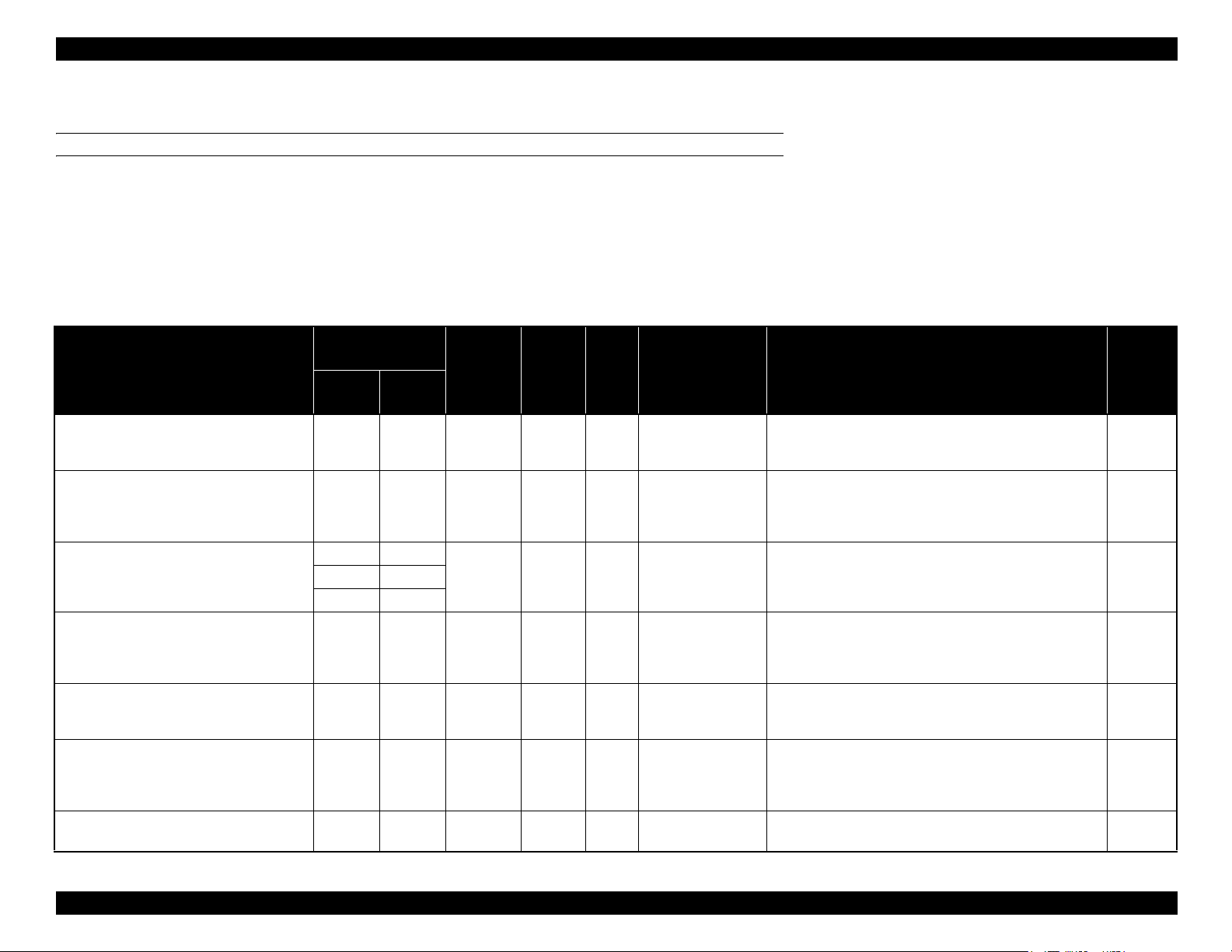
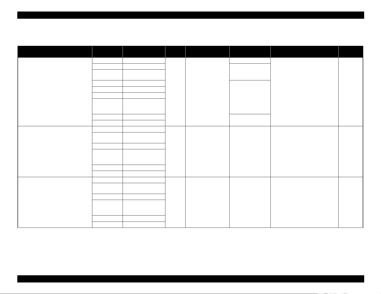
1.3.2.2 Designated Paper
ROLL PAPER
Note "*1": OK!: Recommended for borderless printing
OK: Borderless printing is available
NA: Borderless printing is NOT available
Borderless printing on the borderless printing available paper (OK) may result in drop in print quality or fail to produce complete borderless (white margins may appear) due to expanding of the paper. Borderless
printing can be made on commercially available paper, however, note that the availability is restricted by the paper size.
"*2": Spacer for the borderless printing is required.
SC-P5000 Series
Table 1-1. Designated Roll Paper List
Size
Name
mm inch
Premium Glossy Photo Paper (250) 406 16 OK 0.27 3" Normal
Premium Semigloss Photo Paper (250) 406 16 OK 0.27 3" Normal
254 10
Premium Luster Photo Paper (260)
406 16
Premium Semimatte Photo Paper (260) 406 16 OK 0.27 3" Normal
Premium Glossy Photo Paper (170) 420 (A2) --- OK*2 0.18 2" Normal
Premium Semigloss Photo Paper (170) 420 (A2) --- OK*2 0.18 2" Normal
Photo Paper Gloss 250 432 17 OK 0.25 3" Normal
Borderless
Print
OK 0.27 3" Normal
*1
Thickness
Core
Diameter
Roll Paper Tension ICC Profile Black Ink
LLK ink set: SC-P5000_Series_LLK
PremiumGlossyPhotoPaper250.icc
V ink set: SC-P5000_Series_V PremiumGlossyPhotoPaper250.icc
LLK ink set: SC-P5000_Series_LLK
PremiumSemiglossPhotoPaper250.icc
V ink set: SC-P5000_Series_V
PremiumSemiglossPhotoPaper250.icc
LLK ink set: SC-P5000_Series_LLK
PremiumLusterPhotoPaper260.icc
V ink set: SC-P5000_Series_V PremiumLusterPhotoPaper260.icc
LLK ink set: SC-P5000_Series_LLK
PremiumSemimattePhotoPaper260.icc
V ink set: SC-P5000_Series_V
PremiumSemimattePhotoPaper260.icc
LLK ink set: SC-P5000_Series_LLK
PremiumGlossyPhotoPaper170.icc
V ink set: SC-P5000_Series_V PremiumGlossyPhotoPaper170.icc
LLK ink set: SC-P5000_Series_LLK
PremiumSemiglossPhotoPaper170.icc
V ink set: SC-P5000_Series_V
PremiumSemiglossPhotoPaper170.icc
LLK ink set: SC-P5000_Series_LLK PhotoPaperGloss250.icc
V ink set: SC-P5000_Series_V PhotoPaperGloss250.icc
PK
PK
PK300 11.8
PK
PK
PK
PK
PRODUCT DESCRIPTION Printing Specifications 24
SE Group Confidential (Related Staff Only)
Page 25
SC-P5000 Series/Epson Stylus Pro 4900/4910 Revision G
Table 1-1. Designated Roll Paper List
Size
Name
mm inch
329 13
Epson Proofing Paper White Semimatte
Epson Proofing Paper Commercial
Singleweight Matte Paper 432 17 OK 0.15 2 Normal SC-P5000_Series Standard.icc MK
Enhanced Matte Paper 432 17 OK*2 0.25 3 Normal
UltraSmooth Fine Art Paper 432 17 OK*2 0.34 3 Normal
Singleweight Matte Paper 420 (A2) --- OK*2 0.15 2" Normal SC-P5000_Series Standard.icc MK
Enhanced Matte Paper 432 17 NA 0.25 3" Normal
Plain Paper (line drawing) 420 (A2) --- NA 0.08 2" Higher SC-P5000_Series Standard.icc MK
432 17
329 13
432 17
Borderless
Print
OK*2 0.25 3" Normal
OK*2 0.20 3 Normal
*1
Thickness
Core
Diameter
Roll Paper Tension ICC Profile Black Ink
LLK ink set: SC-P5000_Series_LLK
EpsonProofingPaperWhiteSemimatte.icc
V ink set: SC-P5000_Series_V
EpsonProofingPaperWhiteSemimatte.icc
LLK ink set: SC-P5000_Series_LLK
EpsonProofingPaperCommercial.icc
V ink set: SC-P5000_Series_V
EpsonProofingPaperCommercial.icc
LLK ink set: SC-P5000_Series_LLK
EnhancedMattePaper_MK.icc
V ink set: SC-P5000_Series_V EnhancedMattePaper_MK.icc
PK selected
LLK ink set: SC-P5000_Series_LLK
UltraSmoothFineArtPaper_PK.icc
V ink set: SC-P5000_Series_V UltraSmoothFineArtPaper_PK.icc
MK selected
LLK ink set: SC-P5000_Series_LLK
UltraSmoothFineArtPaper_MK.icc
V ink set: SC-P5000_Series_V UltraSmoothFineArtPaper_MK.icc
PK selected
(LLK ink set, when PK is selected)SC-P5000_Series_LLK
EnhancedMattePaper_PK.icc
V ink set: SC-P5000_Series_V EnhancedMattePaper_PK.icc
MK selected
LLK ink set: SC-P5000_Series_LLK
EnhancedMattePaper_MK.icc
V ink set: SC-P5000_Series_V EnhancedMattePaper_MK.icc
PK
PK
MK
PK/MK
MK
PRODUCT DESCRIPTION Printing Specifications 25
SE Group Confidential (Related Staff Only)
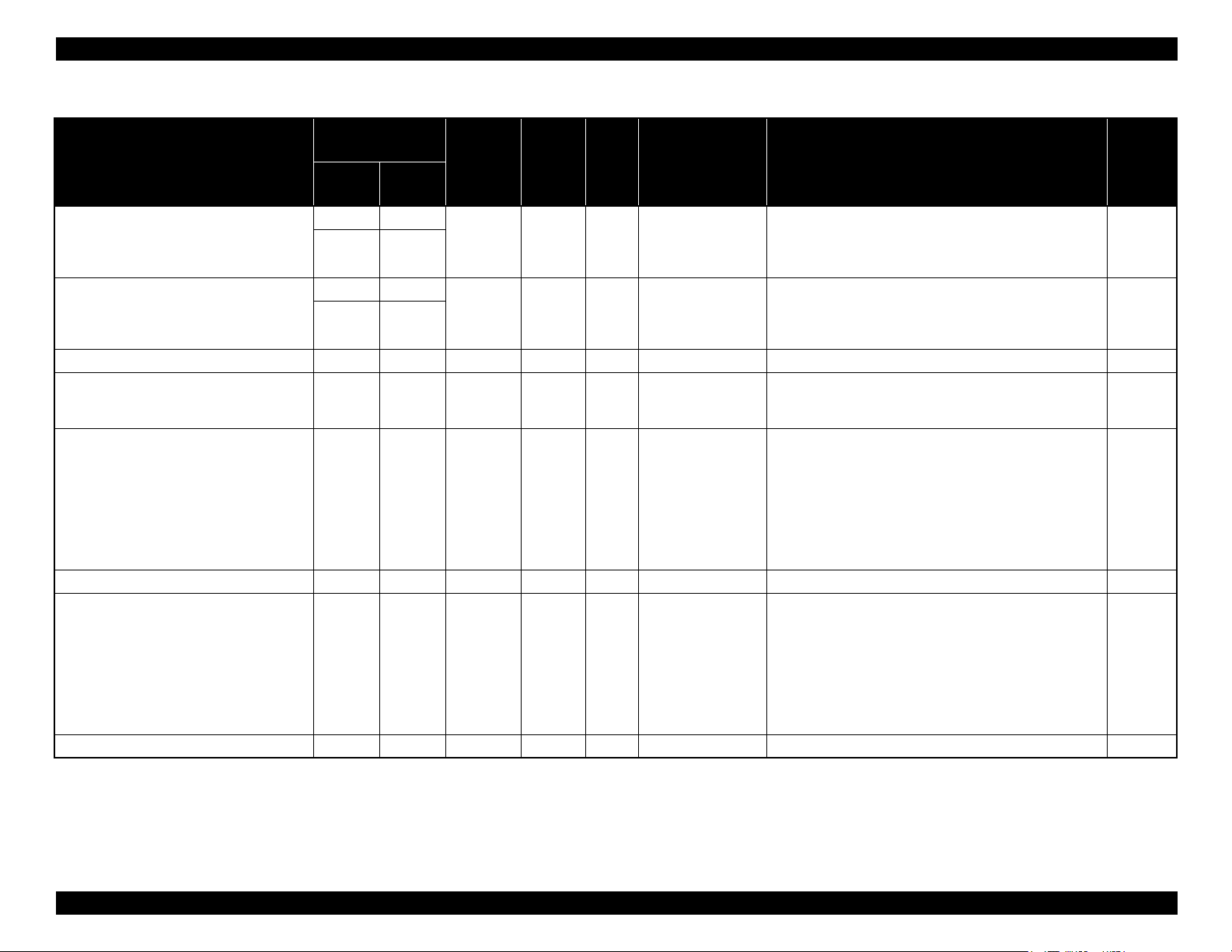
Page 26
SC-P5000 Series/Epson Stylus Pro 4900/4910 Revision G
Table 1-1. Designated Roll Paper List
Size
Name
mm inch
Plain Paper 420 (A2) --- NA 0.08 2" Higher SC-P5000_Series Standard.iccMK
Singleweight Matte Paper 420 (A2) --- OK*2 0.15 2" Normal SC-P5000_Series Standard.icc MK
Baryta 432 17 NA 0.356 3" Normal
Borderless
*1
Print
Thickness
Core
Diameter
Roll Paper Tension ICC Profile Black Ink
LLK ink set: SC-P5000_Series_LLK Baryta.icc
V ink set: SC-P5000_Series_V Baryta.icc
PK
Epson Stylus Pro 4900/4910
Table 1-2. Designated Roll Paper List
Size
Name
mm inch
Premium Glossy Photo Paper (250) 406 16 OK! 0.27 3" Normal
Premium Semigloss Photo Paper (250) 406 16 OK! 0.27 3" Normal
254 10
Premium Luster Photo Paper (260)
406 16
Premium Semimatte Photo Paper (260) 406 16 OK! 0.27 3" Normal
Photo Paper Gloss 250 432 17 OK! 0.25 3" Normal
Premium Glossy Photo Paper (170) 420 (A2) --- OK
Premium Semigloss Photo Paper (170) 420 (A2) --- OK
Enhanced (Archival) Matte Paper 432 17 OK 0.25 3" Normal
Singleweight Matte Paper 432 17 OK! 0.14 2" Normal
Epson Proofing Paper Commercial
329 13
432 17
Borderless
Print
OK! 0.27 3" Normal
OK 0.20 3" Normal
Thickness
*1
*2
*2
0.18 2" ---
0.18 2" ---
Core
Diameter
Roll Paper Tension ICC Profile Black Ink
Epson Stylus Pro 4900_4910
PremiumGlossyPhotoPaper250.icc
Epson Stylus Pro 4900_4910
PremiumSemiglossPhotoPaper250.icc
Epson Stylus Pro 4900_4910
PremiumLusterPhotoPaper260.icc
Epson Stylus Pro 4900_4910
PremiumSemimattePhotoPaper260.icc
Epson Stylus Pro 4900_4910
PhotoPaperGloss250.icc
Epson Stylus Pro 4900_4910
PremiumGlossyPhotoPaper170.icc
Epson Stylus Pro 4900_4910
PremiumSemiglossPhotoPaper170.icc
Epson Stylus Pro 4900_4910
EnhancedMattePaper_MK.icc
Epson Stylus Pro 4900_4910
SingleweightMattePaper.icc
Epson Stylus Pro 4900_4910
EpsonProofingPaperCommercial.icc
PK
PK
PK300 ---
PK
PK
PK
PK
MK
MK
PK
PRODUCT DESCRIPTION Printing Specifications 26
SE Group Confidential (Related Staff Only)
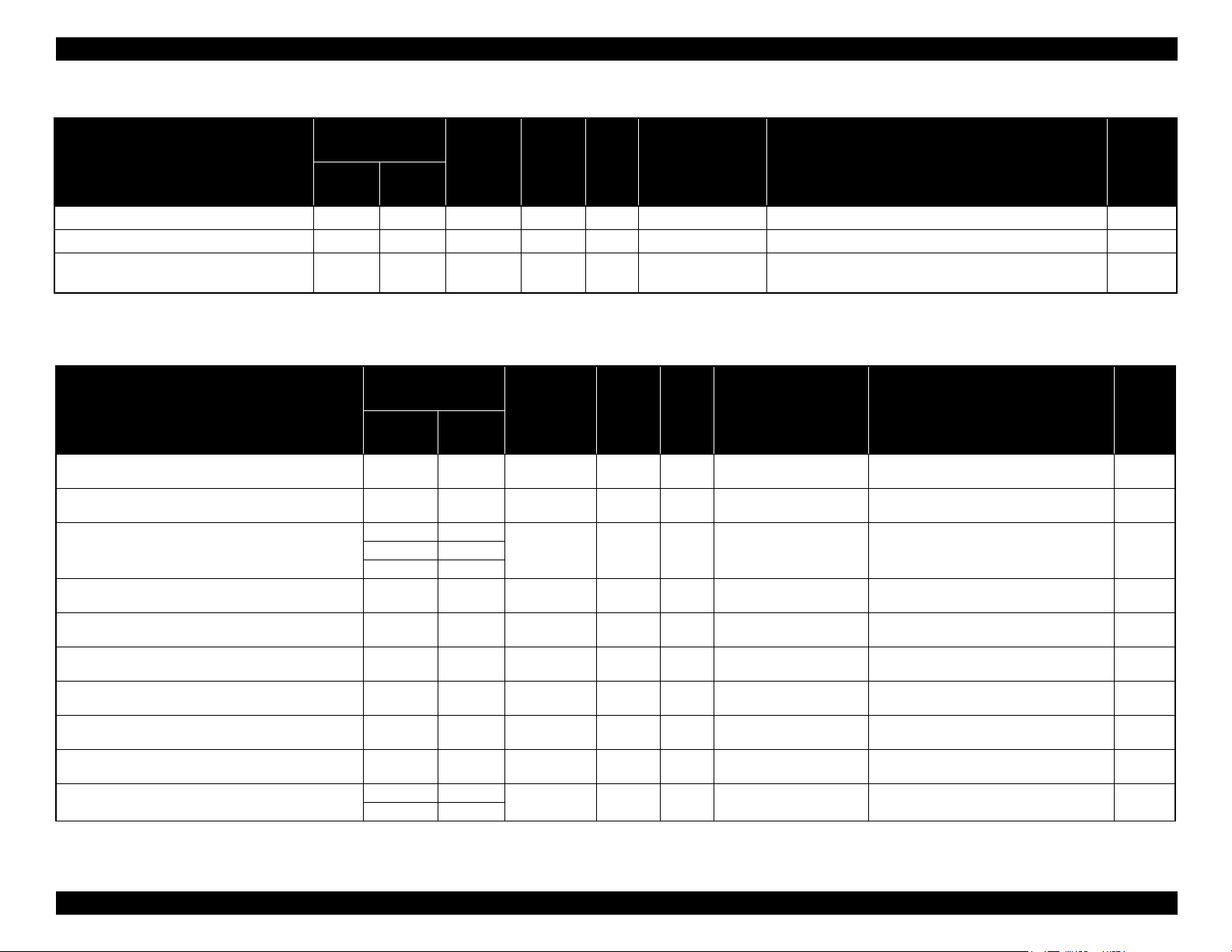
Page 27

SC-P5000 Series/Epson Stylus Pro 4900/4910 Revision G
Table 1-2. Designated Roll Paper List
Size
Name
mm inch
Epson Proofing Paper White Semimatte
Epson Proofing Paper Publication
UltraSmooth Fine Art Paper 432 17 OK 0.46 3” ---
Textured Fine Art Paper 432 17" OK 0.37 3" Normal
329 13
432 17
329 13
432 17
Borderless
Print
OK 0.25 3" Normal
OK 0.20 3" Normal
Thickness
*1
Core
Diameter
Roll Paper Tension ICC Profile Black Ink
Epson Stylus Pro 4900_4910
EpsonProofingPaperWhiteSemimatte.icc
Epson Stylus Pro 4900_4910
EpsonProofingPaperPublication.icc
Epson Stylus Pro 4900_4910
UltraSmoothFineArtPaper_PK.icc/
Epson Stylus Pro 4900_4910
UltraSmoothFineArtPaper_MK.icc
Epson Stylus Pro 4900_4910
TexturedFineArtPaper_PK.icc/
Epson Stylus Pro 4900_4910
TexturedFineArtPaper_MK.icc
PK
PK
PK/MK
PK/MK
PRODUCT DESCRIPTION Printing Specifications 27
SE Group Confidential (Related Staff Only)
Page 28
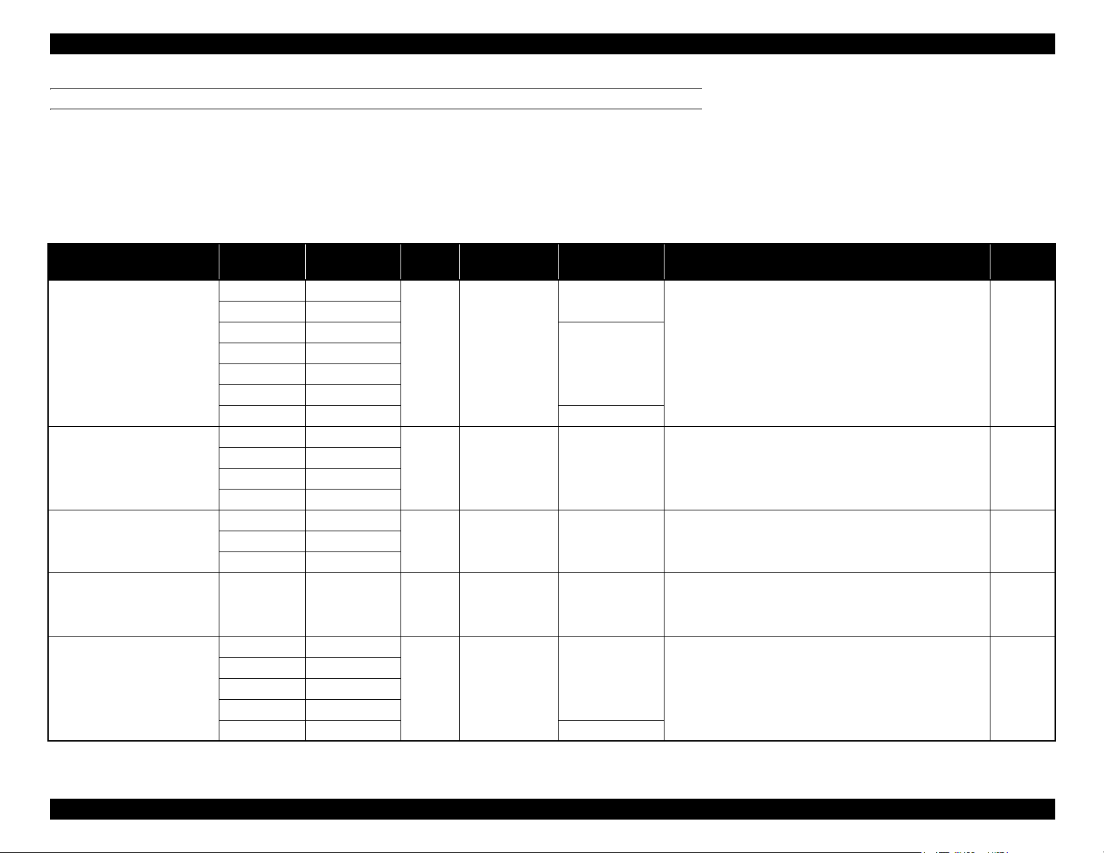
SC-P5000 Series/Epson Stylus Pro 4900/4910 Revision G
CUT SHEET
Note "*": OK!: Recommended for borderless printing
OK: Borderless printing is available
NA: Borderless printing is NOT available
Borderless printing on the borderless printing available paper (OK) may result in drop in print quality or fail to produce complete borderless (white margins may appear) due to expanding of the paper. Borderless
printing can be made on commercially available paper, however, note that the availability is restricted by the paper size.
SC-P5000 Series
Table 1-3. Designated Cut Sheet List
Name Size Borderless Print*Thickness
Premium Glossy Photo Paper
Premium Semigloss Photo Paper
Premium Luster Photo Paper
EPSON Proofing Paper White
Semimatte
Photo Quality Inkjet Paper
Print from Paper
Cassette
8" × 10" NA
A4 OK
11" × 14" NA
US B (11" x 17") NA
A3 OK
A3+ OK
A2 NA 25
A4 OK
A3 OK
A3+ OK
A2 NA
A3 OK
A2 NA
A3+ OK 0.25 OK 100
A4 OK
US-B NA
A3 OK
A3+ OK
A2 NA 30
0.27mm OK!
0.27mm OK! 100
0.27mm OK! 100
0.12mm OK
Sheets per Paper
Cassette (Max.)
100
20
100
ICC Profile Black Ink
LLK ink set: SC-P5000_Series_LLK PremiumGlossyPhotoPaper.icc
V ink set: SC-P5000_Series_V PremiumGlossyPhotoPaper.icc
LLK ink set: SC-P5000_Series_LLK
PremiumSemiglossPhotoPaper.icc
V ink set: SC-P5000_Series_V PremiumSemiglossPhotoPaper.icc
LLK ink set: SC-P5000_Series_LLK PremiumLusterPhotoPaper.icc
V ink set: SC-P5000_Series_V PremiumLusterPhotoPaper.icc
LLK ink set: SC-P5000_Series_LLK
EpsonProofingPaperWhiteSemimatte.icc
V ink set: SC-P5000_Series_V
EpsonProofingPaperWhiteSemimatte.icc
SC-P5000_Series Standard.icc MK
PK
PK
PKA3+ OK
PK
PRODUCT DESCRIPTION Printing Specifications 28
SE Group Confidential (Related Staff Only)
Page 29

SC-P5000 Series/Epson Stylus Pro 4900/4910 Revision G
Table 1-3. Designated Cut Sheet List
Name Size Borderless Print*Thickness
A4
Archival Matte Paper
Watercolor Paper - Radiant White A3+ OK 0.29mm --- ---
A3
A2
OK 0.25mm OK!
Print from Paper
Cassette
Sheets per Paper
Cassette (Max.)
100
50A3+
ICC Profile Black Ink
LLK ink set: SC-P5000_Series_LLK ArchivalMattePaper_MK.icc
V ink set: SC-P5000_Series_V ArchivalMattePaper_MK.icc
PK selected
LLK ink set: SC-P5000_Series_LLK WatercolorPaperRadiantWhite_PK.icc
V ink set: SC-P5000_Series_V WatercolorPaper-RadiantWhite_PK.icc
MK selected
LLK ink set: SC-P5000_Series_LLK WatercolorPaperRadiantWhite_MK.icc
V ink set: SC-P5000_Series_V WatercolorPaper-RadiantWhite_MK.icc
MK
PK/MK
Baryta A3 + NA 0.356mm × ---
A3+ OK
UltraSmooth Fine Art Paper
Velvet Fine Art Paper
A2 NA
A4
OK 0.48mm --- ---
A2
0.46mm --- ---
LLK ink set: SC-P5000_Series_LGY Baryta.icc
V ink set: SC-P5000_Series_V Baryta.icc
PK selected
LLK ink set: SC-P5000_Series_LLK UltraSmoothFineArtPaper_PK.icc
V ink set: SC-P5000_Series_V UltraSmoothFineArtPaper_PK.icc
MK selected
LLK ink set: SC-P5000_Series_LLK
UltraSmoothFineArtPaper_MK.icc
V ink set: SC-P5000_Series_V UltraSmoothFineArtPaper_MK.icc
PK selected
LLK ink set: SC-P5000_Series_LLK VelvetFineArtPaper_PK.icc
V ink set: SC-P5000_Series_V VelvetFineArtPaper_PK.icc
MK selected
LLK ink set: SC-P5000_Series_LLK VelvetFineArtPaper_MK.icc
V ink set: SC-P5000_Series_V VelvetFineArtPaper_MK.icc
PK
PK/MK
PK/MKA3+
PRODUCT DESCRIPTION Printing Specifications 29
SE Group Confidential (Related Staff Only)
Page 30
SC-P5000 Series/Epson Stylus Pro 4900/4910 Revision G
Epson Stylus Pro 4900/4910
Table 1-4. Designated Cut Sheet List
Name Size Borderless Print
Premium Glossy Photo Paper
Premium Semigloss Photo Paper
Premium Luster Photo Paper
8" x 10" NA
A4 OK!
Letter
(8.5" x 11")
11" x 14" NA
US B (11" x 17") NA
A3 OK!
Super A3 / B
(329mm x
483mm)
A2 NA
US C (17" x 22") OK!
A4 OK!
Letter
(8.5" x 11")
A3 OK!
Super A3 / B
(329mm x
483mm)
A2 NA
US C (17" x 22") OK!
A4 OK!
Letter
(8.5" x 11")
A3 OK!
Super A3 / B
(329mm x
483mm)
A2 NA
US C (17" x 22") OK!
NA
OK!
NA
OK!
NA
OK!
*
Thickness
0.27mm OK!
0.27mm OK! 100
0.27mm OK! 100
Print from Paper
Cassette
Sheets per Paper
Cassette (Max.)
100
50
20
25
ICC Profile Black Ink
Epson Stylus Pro 4900_4910
PremiumGlossyPhotoPaper.icc
Epson Stylus Pro 4900_4910
PremiumSemiglossPhotoPaper.icc
Epson Stylus Pro 4900_4910
PremiumLusterPhotoPaper.icc
PK
PK
PK
PRODUCT DESCRIPTION Printing Specifications 30
SE Group Confidential (Related Staff Only)
Page 31

SC-P5000 Series/Epson Stylus Pro 4900/4910 Revision G
Table 1-4. Designated Cut Sheet List
Name Size Borderless Print
Archival Matte Paper/
Enhanced Matte Paper
Photo Quality Inkjet Paper
EPSON Proofing Paper
White Semimatte
Watercolor Paper - Radiant White
UltraSmooth Fine Art Paper
Print from Paper
Cassette
A4 OK
Letter
(8.5" x 11")
NA
*
Thickness
*
A3
Super A3 / B
(329mm x
OK
*
0.26mm OK!
483mm)
A2 NA
US C (17" x 22") OK
A4 OK
*
*
Letter
(8.5" x 11")
NA
US B / 11"
A3
Super A3 / B
(329mm x
OK
*
0.12mm OK!
483mm)
A2 NA 30
US C (17" x 22") OK
*
Super A3 / B
(329mm x
483mm)
SuperW A3
OK
*
0.25mm OK! 100
(329mm x
559mm)
Super A3 / B
(329mm x
OK
*
0.29mm --- ---
483mm)
Super A3 / B
(329mm x
483mm)
OK
*
0.32mm --- ---
A2 NA
US C (17" x 22") OK
*
Sheets per Paper
Cassette (Max.)
100
50
100
100
ICC Profile Black Ink
Epson Stylus Pro 4900_4910
ArchivalMattePaper_MK.icc/
Epson Stylus Pro 4900_4910
EnhancedMattePaper_MK.icc
Epson Stylus Pro 4900_4910
PhotoQualityInkJetPaper.icc
Epson Stylus Pro 4900_4910
EpsonProofingPaperWhiteSemimatte.icc
Epson Stylus Pro 4900_4910
WatercolorPaperRadiantWhite_PK.icc/
Epson Stylus Pro 4900_4910
WatercolorPaperRadiantWhite_MK.icc
Epson Stylus Pro 4900_4910
UltraSmoothFineArtPaper_PK.icc/
Epson Stylus Pro 4900_4910
UltraSmoothFineArtPaper_MK.icc
MK
MK
PK
PK/MK
PK/MK
PRODUCT DESCRIPTION Printing Specifications 31
SE Group Confidential (Related Staff Only)
Page 32

SC-P5000 Series/Epson Stylus Pro 4900/4910 Revision G
Table 1-4. Designated Cut Sheet List
Velvet Fine Art Paper
Name Size Borderless Print
Letter
(8.5" x 11")
Super A3 / B
(329mm x
483mm)
A2 NA
US C (17" x 22") OK
NA
OK
*
*
*
Thickness
0.48mm --- ---
Print from Paper
Cassette
Sheets per Paper
Cassette (Max.)
ICC Profile Black Ink
Epson Stylus Pro 4900_4910
VelvetFineArtPaper_PK.icc/
Epson Stylus Pro 4900_4910
VelvetFineArtPaper_MK.icc
PK/MK
PRODUCT DESCRIPTION Printing Specifications 32
SE Group Confidential (Related Staff Only)
Page 33

SC-P5000 Series/Epson Stylus Pro 4900/4910 Revision G
3 to 15mm
*1
*1
15m
127mm
to
3 to 15mm
254 to 432mm
3 to 15mm
3 to 35mm
1.3.3 Printable Area
ROLL PAPER
Margins for roll paper depends on the Roll Paper Margin settings in the Printer Setup
menu.
Note "*1": When the “Roll Paper (Banner)” is selected for the “Source” in the “Paper Settings” of the
printer driver, the top and bottom margins become 0 mm.
"*2": When the Default is selected, “a” becomes 20mm for the following paper types; Premium
Glossy Photo Paper(250), Premium Semigloss Photo Paper(250), and Premium Luster Photo
Paper(260).
CUT SHEET
3mm3mm
203 to 432 mm
3mm
254
to
610mm
3 to 17mm*
Note "*": The default for printing with border is 14mm. The default for borderless printing is 17mm.
Roll Paper Margin settings Explanation
Default
Top/Bottom 15mm
Top 35/Bottom 15mm
3mm a, b, c, d = 3mm
15mm a, b, c, d = 15mm
a = c = 15mm *2
b = d = 3mm
a = c = 15mm
b = d = 3mm
a = 35mm
c = 15mm
b = d = 3mm
PRODUCT DESCRIPTION Printing Specifications 33
SE Group Confidential (Related Staff Only)
Page 34

SC-P5000 Series/Epson Stylus Pro 4900/4910 Revision G
1.3.4 Borderless Printing Specification
AVAILABLE PAPER TYPE
For the paper types and sizes that support the borderless printing, see
"1.3.2.2 Designated Paper" (p24).
BORDERLESS PRINTING MODE
The following types of borderless printing are available with the printer driver.
Table 1-5. Borderless Printing Mode
Driver Setting Printer Operation Remarks
Default
Printing is interrupted
for cutting off the top
margin of the first
page. This may cause
color inconsistencies
depending on the print
data.
The cut line between
pages may be slightly
off the border.
Normal Cut*
Single Cut
1*2
*
Prints an image bleeding it off
the left and right edges of
paper. The top and bottom
margins are determined by
2
Roll Paper Margin setting.
Prints an image bleeding it off
all the edges of paper.
The cutting methods is as
follows.
The minimum width
required for cutting is
applied as the top margin of
the first page, then the top
margin is cut off during
printing.
No margin is provided between pages, and the
cutting is made on the border between the pages.
When the job is finished, the bottom side of the last
page is cut off without margin.
The minimum width required for cutting is applied
as margins between pages.
Table 1-5. Borderless Printing Mode
Driver Setting Printer Operation Remarks
Prints an image bleeding it off
all the edges of paper.
The cutting methods is as
follows.
The auto refresh margin is
applied as the top margin of
the first page, then the top
Double Cut
1*2
*
margin is cut off during
printing.
The bottom side of each
page is cut off without margin.
The minimum width required for cutting is applied
as margins between pages.
Note "*1": The cut pages vertical length becomes about 2mm shorter than the specified size.
"*2": Color inconsistencies or ink smudges due to the interruption of printing for cutting off top
margins are likely to occur on the following papers.
• Glossy media such as PGPP250
• Single Weight Matte Paper
Printing is interrupted
for cutting off the top
margin of the first
page. This may cause
color inconsistencies
depending on the print
data.
The top and bottom
sides of each page are
cut off at the position
slightly inward the
image edges so that no
white margin appears
on the edges of the cut
pages. This causes the
vertical length of the
cut page about 2mm
shorter than the
specified length.
PRODUCT DESCRIPTION Printing Specifications 34
SE Group Confidential (Related Staff Only)
Page 35
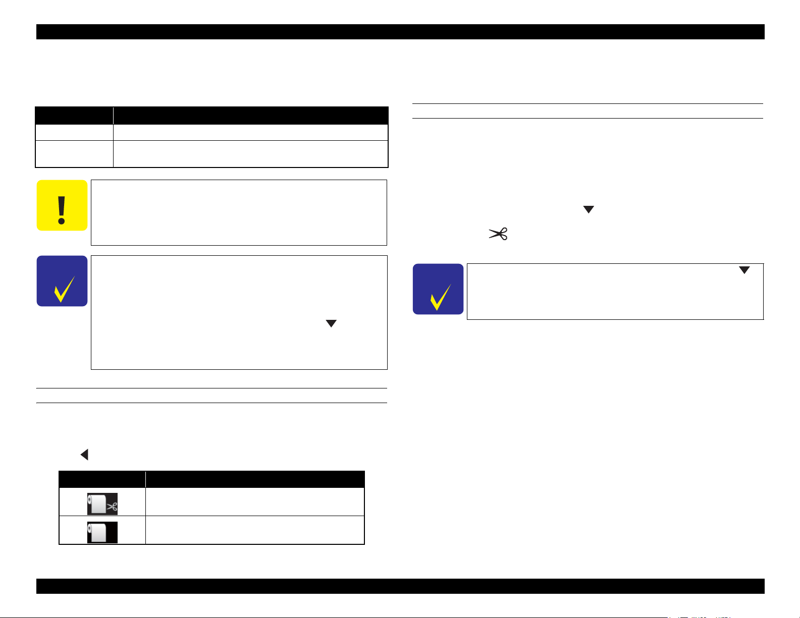
SC-P5000 Series/Epson Stylus Pro 4900/4910 Revision G
C A U T I O N
C H E C K
P O I N T
C H E C K
P O I N T
1.3.5 Cutting of Roll Paper
The printer offers two ways of cutting for roll paper.
Cut Method Description
Auto cut The printer automatically cuts paper with the built-in cutter.
Manual cut
The user can manually move the built-in cutter to cut paper, or use a
commercially available cutter.
Some types of roll paper cannot be cut with the built-in cutter.
In such cases, cut it manually with a commercially available
cutter or the like.
When cutting Clear Film, please hold it by hands so that it does
not fall on the floor in order to prevent scratches.
It may take time for the cutting operation.
The minimum length of paper you can cut with the built-in
cutter is fixed to 80 or 127 mm and cannot be changed. The
length is 210 mm when the optional SpectroProofer is installed.
When cutting the roll paper of the length which cannot be
automatically cut by the built-in cutter, press the button to
feed paper up to a position where the paper can be cut
manually, and then cut the paper with a commercially-available
cutter or a similar tool.
Setting from the printer
Select “Auto Cut” in the “Paper Setting” window of the printer driver.
HOW TO CUT
Auto cut
The printer automatically cuts paper with the built-in cutter each time a page is
printed.
Manual cut
Follow the procedure below to cut paper at the desired position.
1. After a page is printed, press the button to advance the paper to the cut
position.
2. Press the button. Select [Cut] from the selection screen on the display,
and press [OK] button. The built-in cutter moves and cuts the paper.
If the roll paper cannot be cut by the built-in cutter, press the
button to feed the paper to a position where you can cut it
manually.
SETTING BEFORE PRINTING
The cut method setting can be made by the control panel or the printer driver.
Setting on the computer
Press button to select the cut method.
Icon Description
Roll Auto Cut On
Roll Auto Cut Off
PRODUCT DESCRIPTION Printing Specifications 35
SE Group Confidential (Related Staff Only)
Page 36

SC-P5000 Series/Epson Stylus Pro 4900/4910 Revision G
Height
Depth
Width
267 mm
199 mm
787 mm
1.4 Hardware Specifications
This section provides the printer dimensions and shows the main components.
1.4.1 Dimensions and Weight
MAIN UNIT
Figure 1-3. Dimensions
SPECTROPROOFER MOUNTER
Figure 1-4. Dimensions
External Dimensions
Weight*
Width Depth Height
787 mm 199 mm 267 mm Approx. 9.0 kg
Note * : Excluding the accessories and color measurement device.
構成
Body (with Paper Eject Support retracted) 863 mm 766 mm 405 mm Approx. 52 kg
Body (with Paper Eject Support extracted) 863 mm 1134 mm 405 mm Approx. 52 kg
Body & Color Measurement Device 877 mm 1299 mm 405 mm Approx. 60.7 kg
Note *: Excluding the ink cartridges and paper
PRODUCT DESCRIPTION Hardware Specifications 36
Width Depth Height Weight*
SE Group Confidential (Related Staff Only)
Page 37

SC-P5000 Series/Epson Stylus Pro 4900/4910 Revision G
Front cover
Cartridge
cover (left)
Paper cassette
Output tray
Maintenance Box 2
Paper eject
support
Front paper
feed slot
Cartridge
cover (right)
Maintenance Box 1
Ink cartridges
CR Unit
Control panel
Large alert light
Printer cover
Rear paper feed slot
Paper guide
Edge guide
Roll paper feed slot
Roll paper cover
Spindle holders
Rear unit
Roll paper holder
unit connector
USB interface
connector
Airflow
vent
LAN connector
AC inlet
Status light (green, red)
Movable flange (black)
Spindle
Attachment
Spacer
1.4.2 Part Names
FRONT SIDE OF MAIN UNIT
BACK SIDE OF MAIN UNIT/SPINDLE
PRODUCT DESCRIPTION Hardware Specifications 37
Figure 1-5. Front side of Main Unit
Figure 1-6. Back side of Main Unit/Spindle
SE Group Confidential (Related Staff Only)
Page 38

SC-P5000 Series/Epson Stylus Pro 4900/4910 Revision G
Handles
Front Cover
Paper Presser
ILS communication cable
ILS DC cable
Color Measurement Device carriage
Side Cover
Printer connection cable
White calibration tile
holder insert slot
Backing insert
slot
Lens
DC connector
Communication connector
White calibration tile
ILS20EP
ILS30EP
Communication connector
DC connector
DC connector cable
White calibration tile
Lens
SPECTROPROOFER MOUNTER
Figure 1-7. SpectroProofer Mounter
PRODUCT DESCRIPTION Hardware Specifications 38
SE Group Confidential (Related Staff Only)
Page 39
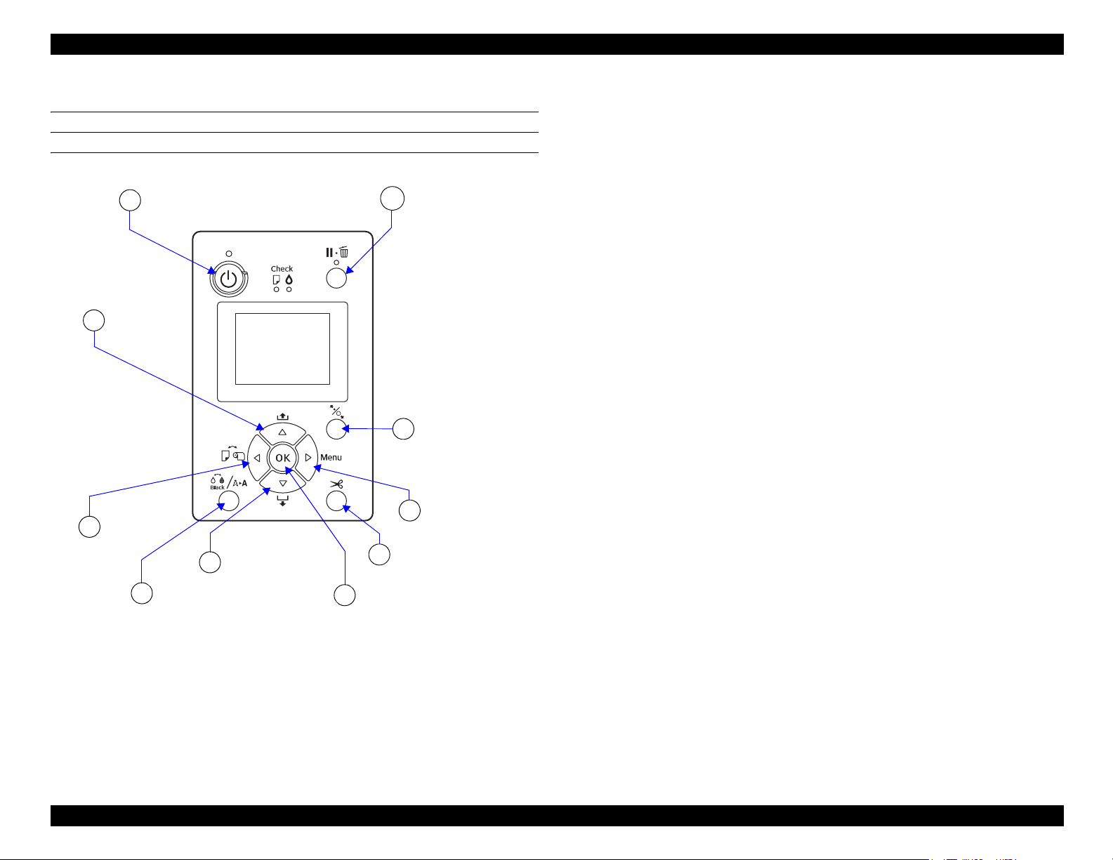
SC-P5000 Series/Epson Stylus Pro 4900/4910 Revision G
[Power] button
[Pause/Cancel] button
1
8
[Ink menu] button
[Paper Cut] button
[Paper Set] button
3
4
[Menu] button
[OK] button
6
[Paper Feed] buttons
7
9
[Paper Source]
button
10
[Paper Feed]
buttons
2
5
1.5 Control Panel
BUTTONS
Figure 1-8. BUTTONS
PRODUCT DESCRIPTION Control Panel 39
SE Group Confidential (Related Staff Only)
Page 40

SC-P5000 Series/Epson Stylus Pro 4900/4910 Revision G
Function
Button Name
When pressed normally
1 [Power] button Turns the printer On or Off. Power-off
2 [Pause/Cancel] button When printing: Pauses the operation --- Cancels the panel settings.
• Locks/unlocks the paper presser.
3 [Paper Set] button
4 [Menu] button
5 [Paper Cut] button Cuts the roll paper. --- ---
6 [OK] button During ink drying: Stops the operation. --- Sets/Executes the selected item.
7 [Paper Feed (forward)] buttons
8 [Ink menu] button
9 [Paper Source] button Changes the paper type. --- Goes to the upper tier.
10 [Paper Feed (backward)] buttons
• After printing the roll paper: Releases the paper pressure and rolls the roll paper for removal.
When Remaining Paper Setup is On: Rolls the paper while printing the barcode on the front edge.
• Goes to the setting menu.
• When printing: Displays the Printer Status menu.
• Feeds the roll paper forward.
• While the paper presser is released: Changes the setting of the suction fan.
• Feeds the cut sheet.
• SC-P5000 Series
Goes to the Maintenance Menu.
• Epson Stylus Pro 4900/4910
Goes to the Ink Menu.
• Feeds the roll paper backward.
• While the paper presser is released: Changes the setting of the suction fan.
When pressed down
for 2 sec.
--- ---
--- Goes to the lower tier.
Feeds the paper at high
speed
--- ---
Feeds the paper at high
speed
For panel setting
• Goes to the next item.
• Decreases the set value.
• Goes back to the previous item.
• Increases the set value.
PRODUCT DESCRIPTION Control Panel 40
SE Group Confidential (Related Staff Only)
Page 41
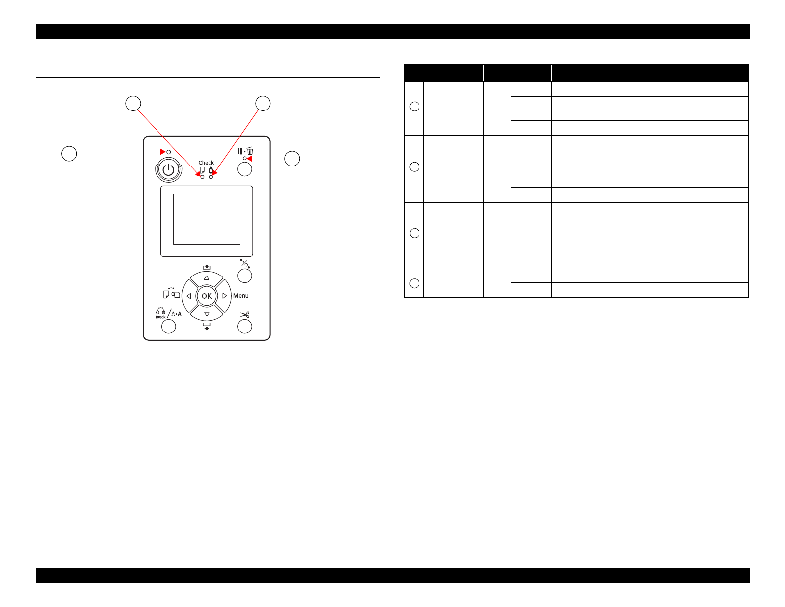
SC-P5000 Series/Epson Stylus Pro 4900/4910 Revision G
Power light
A
Ink Check light
Pause light
D
C
Paper Check light
B
A
B
C
D
LIGHTS (LED)
Figure 1-9. LED
Name Color Status Description
ON The printer power is on.
The printer is receiving a data or performing the power-off
Power Green
Paper Check Orange
Ink Check Orange
Pause Green
Note "*1": Repeats turning On and Off every 500 ms. When a maintenance error is occurring, the LED
repeats ON for 100 ms and OFF for 5 seconds.
Note : All the LEDs flash when a service call error is occurring.
*1
Flashing
OFF The printer power is off.
Flashing
OFF The printer is ready to print data.
Flashing
OFF The printer is ready to print data.
OFF The printer is ready to print data.
sequence.
ON
ON
ON Pausing/Canceling a job.
• No paper is loaded in the paper source.
• The paper setting is not correct.
• Paper is jammed.
*1
• Paper is not loaded straight.
• The installed ink cartridge is expended.
• The ink cartridge is not installed.
• The wrong ink cartridge is installed.
*1
The installed ink cartridge is nearly expended.
PRODUCT DESCRIPTION Control Panel 41
SE Group Confidential (Related Staff Only)
Page 42

SC-P5000 Series/Epson Stylus Pro 4900/4910 Revision G
4
5
7
3
8
6
1
2
9
LCD
Normal indication
SC-P5000 Series
No. Item Description
Message Printer status, operating status, or an error message is displayed.
1
Displays the setting of “Platen Gap”.
: “Narrow” is selected.
: “Standard” is selected.
Platen Gap
2
Paper Source Selected paper type and roll paper cut settings are displayed.
3
SpectroProofer status SpectroProofer available to use is displayed as an icon.
4
Ink cartridge status The current ink level in each of the nine cartridges is indicated.
x
5
Black Ink selection The selected black ink is indicated.
6
Waste ink level in the
7
maintenance boxes
Paper Counter The remaining amount of the paper is displayed.
8
Roll Paper Margin
9
: “Wide” is selected.
: “Wider” is selected.
: “Widest” is selected.
The approximate amount of space in the Maintenance Box is
indicated.
The setting made by the Roll Paper Margin menu is indicated
beside the [ ].
• Auto: “Default” is selected.
• 15mm: “Top/Bottom 15 mm” is selected.
• 35/15mm: “Top 35/Bottom 15 mm” is selected.
• 3mm: “3mm” is selected.
• 15mm: “15mm” is selected.
x
PRODUCT DESCRIPTION Control Panel 42
SE Group Confidential (Related Staff Only)
Page 43

SC-P5000 Series/Epson Stylus Pro 4900/4910 Revision G
4
5
7
3
8
6
1
2
9
Epson Stylus Pro 4900/4910
Figure 1-10. LCD (Normal indication)
No. Item Description
Message Printer status, operating status, or an error message is displayed.
1
Displays the setting of “Platen Gap”.
: “Narrow” is selected.
: “Wide” is selected.
Platen Gap
2
Paper Source Selected paper type and roll paper cut settings are displayed.
3
SpectroProofer status SpectroProofer available to use is displayed as an icon.
4
Ink cartridge status The current ink level in each of the nine cartridges is indicated.
5
Black Ink selection The selected black ink is indicated.
6
Waste ink level in the
7
maintenance boxes
Paper Counter The remaining amount of the paper is displayed.
8
Roll Paper Margin
9
: “Wider” is selected.
: “Widest” is selected.
When the selected registered number in “Paper Number” is
displayed, “Platen Gap” is not displayed.
The approximate amount of space in the Maintenance Box is
indicated.
The setting made by the Roll Paper Margin menu is indicated
beside the [ ].
• Auto: “Default” is selected.
• 15mm: “Top/Bottom 15 mm” is selected.
• 35/15mm: “Top 35/Bottom 15 mm” is selected.
• 3mm: “3mm” is selected.
• 15mm: “15mm” is selected.
PRODUCT DESCRIPTION Control Panel 43
SE Group Confidential (Related Staff Only)
Page 44

SC-P5000 Series/Epson Stylus Pro 4900/4910 Revision G
ICONS ON THE LCD
Remaining ink level of each color
Ink cartridge
No. Ink Color
1
2
3
4
5
6
7
8
9
10
11
Note : “1” on the above table is the left end, and “11” is the right end.
Note "*": SC-P5000 Series only
Green (GR)
Light Light Black (LLK) / Violet (V)*
Yellow (Y)
Light Cyan (LC)
Vivid Light Magenta (VLM)
Orange (OR)
Matte Black (MK)
Vivid Magenta (VM)
Light Black (LK)
Cyan (C)
Photo Black (PK)
Ink remaining
<SC-P5000 Series>
Icon
There is enough ink remaining. The height of the
indicator changes with the level of ink remaining.
Prepare a new ink cartridge.
The ink is expended so you cannot print.
Replace the ink cartridge with a new one.
Cartridge error or no cartridge error has occurred.
<Epson Stylus Pro 4900/Epson Stylus Pro 4910>
Icon Ink Cartridge
There is enough ink remaining.
Ink Cartridge
Prepare a new ink cartridge.
The ink is expended so you cannot print.
Replace the ink cartridge with a new one.
Cartridge error or no cartridge error has occurred.
PRODUCT DESCRIPTION Control Panel 44
SE Group Confidential (Related Staff Only)
Page 45

SC-P5000 Series/Epson Stylus Pro 4900/4910 Revision G
Free space of the maintenance box
<SC-P5000 Series>
Icon
here is enough free space in the maintenance box. The
height of the indicator corresponds to the amount of
space.
Prepare a new maintenance box. (flashing)
The maintenance box becomes full. Replace the box
with a new one. (flashing)
<Epson Stylus Pro 4900/Epson Stylus Pro 4910>
Icon Free space of maintenance box
There is enough free space in the maintenance box.
Prepare a new maintenance box. (flashing)
The maintenance box becomes full. Replace the box
with a new one. (flashing)
PRODUCT DESCRIPTION Control Panel 45
SE Group Confidential (Related Staff Only)
Page 46

SC-P5000 Series/Epson Stylus Pro 4900/4910 Revision G
1.5.1 Setup Menu
1.5.1.1 SC-P5000 Series Setup Menu
Table 1-6. Menu Mode Settings List
Menu Menu Item
Nozzle Check
Head Cleaning
Maintenance
Head Alignment
Adjust Cut Position -3 to 3mm
Change Black Ink You can switch the type of black ink you want to use.
(shaded one is the default)
Printless Nozzle Check
Print Check Pattern
Check And Clean Nozzle When you press the OK button, you can check the status of the nozzles and automatically clean only the nozzle arrays that are clogged.
All Nozzles Normal, Heavy
C/VM
PK(MK)/
Select
Nozzles
Paper
Thickness
Alignment
GY
OR/GR
LLK(V)/
Y
VLM/LC
Paper Type
Paper Thickness
Auto
Manual
Normal,
Heavy
Uni-D
Bi-D 5-Color
Bi-D All
Uni-D
Bi-D 2-Color
Bi-D All
When you press the OK button, you can check the status of the nozzles, and the results of clogging detection are displayed on the
control panel. When clogged nozzles are detected, if you press the [Ink menu] button, then cleaning starts automatically.
Press the OK button to print a nozzle check pattern. Inspect the pattern visually and perform head cleaning if you detect faint or missing
colors.
Select both the ink colors for head cleaning and the strength of the cleaning. Only use this menu when nozzles are clogged.
Ink colors to be cleaned
Check the ink colors with faint or missing segments in the check pattern, and then specify which nozzles to clean. The displayed items
differ depending on the ink sets.
• If there are faint or missing segments in all colors: Select All Nozzles.
• If there are faint or missing segments in only a few colors: Select Nozzles, and then select the specific ink colors you want to clean.
Cleaning strength
Normally, select Normal. If nozzles are clogged even after performing Normal head cleaning several times, perform Heavy cleaning.
Perform print head alignment when the print results look grainy or out-of-focus. First, do Paper Thickness, and then do Alignment.
You can fine tune the cut position when printing to roll paper with no margins in all directions. The cut position can be adjusted in
increments of 0.2 mm.
Settings
PRODUCT DESCRIPTION Control Panel 46
SE Group Confidential (Related Staff Only)
Page 47

SC-P5000 Series/Epson Stylus Pro 4900/4910 Revision G
Table 1-6. Menu Mode Settings List
Menu Menu Item
Paper Type
Custom Paper
Paper
Print Paper List Press the OK button to print a list of custom paper settings.
Roll Paper Remaining
Cut Sheet Remaining
Paper
Number
(1 to 10)
Remaining
Paper Setup
Roll Paper
Length
Roll Length
Alert
Sheet
Number
Sheet
Number
Alert
Photo Paper
Proofing Paper
Fine Art Paper
Matte Paper
Plain Paper
Others
Custom Paper
No Paper Selected
Select Reference Paper
Platen Gap
Thickness Pattern
Paper Feed Adjust A
Paper Feed Adjust B
Drying Time
Paper Suction
Set Roll Paper Tension
Remove Skew
ON
OFF
5.0 to 99.5m
1 to 15m
10 to 990 sheets
1 to 50 sheets
(shaded one is the default)
Select the type of paper loaded. When loading commercially available paper, or when using customized paper settings, Proofing Paper
select the Custom Paper settings name.
Register paper information when using commercially available paper or when using customized paper settings for genuine Epson
paper.
You can register up to 10 by assigning them to Paper No. 1 to Paper No. 10. After registering, you can print using the saved settings
simply by specifying the Paper No. Even when the printer is turned off, the saved settings are retained.
Select whether to display/record (On) or not to display/record (Off) the amount of remaining roll paper. If On is selected, you will be
prompted to enter the length of the roll. When a length has been entered for the loaded roll paper, a barcode will automatically be
printed on the roll stating the length remaining, the value selected for the roll remaining alert, and the paper type when the roll is
removed. The barcode is automatically read and settings adjusted the next time the paper is used, improving efficiency when multiple
rolls of paper are used.
Displayed when On is selected for Remaining Paper Setup. Set the length for the loaded roll paper to 5.0 to 99.5 m. You can set in 0.5m
increments.
Displayed when On is selected for Remaining Paper Setup. Set within a range from 1 to 15 m to display a warning when the amount of
remaining roll paper drops below that limit. You can set in 1 m increments.
Set the number of sheets loaded in the paper cassette in a range from 10 to 990 sheets in increments of 10 sheets. The number of cut
sheets remaining is displayed on the control panel's screen based on the settings you choose for Sheet Number and Sheet Number Alert.
You can set the number of sheets left in the paper cassette at which a warning is displayed by entering a number between 1 and 50
sheets in increments of 1 sheet. The number of cut sheets remaining is displayed on the control panel's screen based on the settings you
choose for Sheet Number and Sheet Number Alert.
Settings
PRODUCT DESCRIPTION Control Panel 47
SE Group Confidential (Related Staff Only)
Page 48

SC-P5000 Series/Epson Stylus Pro 4900/4910 Revision G
Table 1-6. Menu Mode Settings List
Menu Menu Item
Roll Paper Setup
Paper
Refresh Margin
Platen Gap
Printer Setup
Paper Size Check
Paper Skew Check
Print Page
Line
Roll Paper
Margin
Auto Roll
Feeding
(shaded one is the default)
ON
OFF
Standard
Top 15 mm/
Bottom 15 mm
Top35 mm/
Bottom15 mm
3mm
15mm
ON
OFF
ON This setting is effective for roll paper only. After printing borderless on all edges, select whether to cut automatically (On) or not to cut
OFF
Narrow
Standard
Wide
Wider
Widest
ON
OFF
ON
OFF
Select whether to print (On) or not to print (Off) a page line (line along which to cut) on the roll paper.
This is not printed on cut sheets. However, a vertical line is printed when the roll paper width that is specified on the computer is
smaller than the width of the roll paper that is loaded in the printer.
The setting selected with the printer driver takes priority when the printer driver is used.
When set to Standard, the top and bottom margins are 15 mm, and the left and right margins are 3 mm. Except for 15mm, the left and
right margins for all other settings are 3 mm.
When using the Epson special media UltraSmooth Fine Art Paper you must set this to Off before loading the paper. If set
to On for UltraSmooth Fine Art Paper, the roller of the pressure roller may leave a mark on the surface of the paper.
When using paper other than UltraSmooth Fine Art Paper, set it to On.
When this is set to On, the following operations are available. When Off is selected, an error occurs and the following operations
cannot be performed.
• When a paper cassette is specified for printing from the printer driver and a print job is executed, roll paper is automatically set to
saved mode and printing is performed by feeding from the paper cassette, even if roll paper is being fed to the printer.
• Roll paper is automatically set to saved mode and cut paper can be fed when Cut Sheet is also selected from the Paper Type menu.
After printing the cut sheets, and Roll Paper/Cut or Roll Paper/No Cut is selected from the Paper Type menu, roll paper is
automatically fed from saved mode.
(Off) the leading edge of the paper to remove any marks which may have been left in preparation for the next job when printing with
margins.
Select the platen gap, which is the distance between the print head and the paper. Normally, select Standard. Select a wider setting if
print results are scratched or smudged. If, upon performing head alignment, you feel that it is still not completely aligned, select
Narrow.
This setting is cleared when the printer is turned off. When the printer is turned back on, this setting operates at the factory default
setting.
Choose whether the printer automatically detects (On), or does not automatically detect (Off), the width of the media. We
generally recommend to operate with this setting set to On. Try choosing Off if a paper setting error is displayed when the
paper is correctly loaded. Note, however, that the printer may print outside the paper when Off is selected. If it prints beyond the edges
of the paper, the inside of the printer becomes dirty with ink.
If On is selected, an error will be displayed in the control panel and printing will stop if the paper is skewed; select Off to
disable this feature. On is recommended in most circumstances as skewed paper may cause the printer to jam.
Settings
PRODUCT DESCRIPTION Control Panel 48
SE Group Confidential (Related Staff Only)
Page 49

SC-P5000 Series/Epson Stylus Pro 4900/4910 Revision G
Table 1-6. Menu Mode Settings List
Menu Menu Item
Auto Nozzle Check
Timer Cleaning
Printer Setup
Printer Status
Print Nozzle Pattern
Auto Black Ink Change
BK Ink Change Setting
Calibration Setting
Initialize Settings
Firmware Version You can see the firmware version.
Print Status Sheet Press the OK button to print a list of current printer settings. Choose this option to view settings at a glance.
Calibration Date
Total Prints You can see the total number of pages you have printed (up to 6 figures).
Print Job Information You can print the job information saved in the printer (up to 10 jobs).
Auto
Cleaning
Setting
Auto
Cleaning
Times
(shaded one is the default)
On: Periodically
On: Every Job
OFF
1 to 3 When set to On in Auto Cleaning Setting, sets the number of times to automatically repeat cleaning if clogged nozzles are detected.
6 to 60 hours
OFF
Every 10 pages This setting is effective for roll paper only.
Every Page
OFF
Auto
Manual
Normal
Quick
ON
OFF
Yes
No
Set the timing for performing an Auto Nozzle Check that will run before printing starts.
On:Periodically: Checks at fixed intervals at a timing determined by the printer.
On:Every Job: Checks at each job.
Off: Checks only under specific conditions.
Auto Nozzle Check sets the timing that you want the printer to check the status of the nozzles, and if clogged nozzles are
detected, sets the number of times to perform auto cleaning. If the nozzles are not clogged, cleaning is not performed.
When the following operations are done after the set time has passed from the time the last print was completed, the status of the
nozzles is checked. If clogged nozzles are detected, cleaning is done automatically.
• The printer is turned on.
• The printer returns from sleep mode.
Prints a nozzle check pattern at the top of the page after printing every page or every 10 pages.
You can check by viewing the pattern after printing, and determine if there are any problems in the print results before and after
printing.
If the black ink type setting in the printer and the printer driver differ, it can be changed automatically to the selected type by
the printer driver.
Auto: The black ink type is changed automatically, and printing is performed.
Manual: An error message is displayed on the control panel's screen, and printing is paused.
When you select Quick, you can reduce the time necessary for changing the black ink type. However, when using the black ink
immediately after changing, glossy sections may be uneven.
Select Normal to maintain print quality immediately after changing the blank ink type.
You can make settings whether to enable the calibration data for Epson Color Calibration Utility.
For details on the calibration procedure and so on, see the software manual.
If Yes is selected, the Printer Setup is restored to default values.
Displays the latest Epson Color Calibration Utility execution log. You can check details on operations and so on in Epson Color
Calibration Utility.
Settings
PRODUCT DESCRIPTION Control Panel 49
SE Group Confidential (Related Staff Only)
Page 50

SC-P5000 Series/Epson Stylus Pro 4900/4910 Revision G
Table 1-6. Menu Mode Settings List
Menu Menu Item
SpectroProofer SProofer Status
Network Settings
Network Setup
Preferences Language
IP Address Setting
IP, SM, DG Setting You can set the IP address, Subnet Mask, and Default Gateway. Contact your system administrator for detailed information.
Print Status Sheet Press the OK button to print a list of the Network Setup. Use this information for a complete overview of network settings.
Init Network Setting Press the OK button to restore all Network Setup content to default values.
(shaded one is the default)
Device Version:ILS Displays the version of the ILS installed on the mounter.
Calibration Tile S/N Displays the calibration tile serial number of the ILS installed on the mounter.
Firmware Version Displays the version of the mounter.
Device Temperature Displays the temperature of the ILS installed on the mounter.
Air Temperature Displays the air temperature around the mounter.
Backing Color
Calibration Status The status of the ILS calibration appears as Successful or Failed.
Show
Hide
Auto
Panel
Japanese
English
French
Italian
German
Portuguese
Spanish
Dutch
Russian
Korean
Chinese
Displays the backing colors installed in the mounter. If the color differs from the actual color, check the status of the backing and make
sure it is installed correctly. For details on installing the SpectroProofer Mounter 17, see the Setup Guide (booklet).
The following items only appear when Show is selected.
Select whether to use DHCP to set the IP address (Auto), or to set the address manually (Panel). When you select Panel, the IP, SM,
DG Setting Panel below is displayed.
Select the language used on the control panel's screen.
Settings
PRODUCT DESCRIPTION Control Panel 50
SE Group Confidential (Related Staff Only)
Page 51
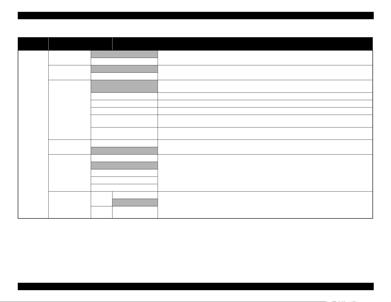
SC-P5000 Series/Epson Stylus Pro 4900/4910 Revision G
Table 1-6. Menu Mode Settings List
Menu Menu Item
Length Units
Temperature Units
Maintenance Alert
Preferences
Cut Sheet Remaining
Sleep Mode
Power Management
Power Off
Timer
Time To
Off
(shaded one is the default)
Metric
Feet/Inch
°C
°F
Disable
Ink The alert lamp flashes when running low on ink.
Maintenance Box The alert lamp flashes when Maintenance Box 1/2 does not have enough empty space.
Ink Or Maint Box The alert lamp flashes when running low on ink or when Maintenance Box 1/2 does not have enough empty space.
Paper
All
ON
OFF
5 minutes
15 minutes
60 minutes
120 minutes
210 minutes
Enable
Disable
1 to 24 hours
Select the unit of length which is displayed on the control panel's screen or printed on the patterns.
Select the temperature units used in the control panel display.
Sets the type of running low warnings to be displayed by the alert lamp.
If set to Disable, the alert lamp does not display any running low warnings.
If either Roll Paper Remaining or Cut Sheet Remaining is set, the alert lamp flashes when either of these reaches their respective
warning levels.
The alert lamp flashes when running low on ink, when Maintenance Box 1/2 does not have enough empty space, or when running low
on paper.
Choose whether or not to show (On/Off) Cut Sheet Remaining in the Menu. When set to On, you can set the number of pages to trigger
a running low warning and the number of pages loaded in the paper cassette.
The printer will enter sleep mode if no errors have occurred, no print jobs have been received, and no actions are performed on the
control panel for an extended period of time. This setting selects the amount of time until the printer enters sleep mode.
The printer turns off automatically when there are no errors, no print jobs being received, and no control panel or other
operations are performed for eight hours. The delay before the printer turns off can be selected from values between 1 and 24 hours in
increments of 1 hour. If you do not want the printer to automatically turn itself off, set Power Off Timer to Disable.
Settings
PRODUCT DESCRIPTION Control Panel 51
SE Group Confidential (Related Staff Only)
Page 52
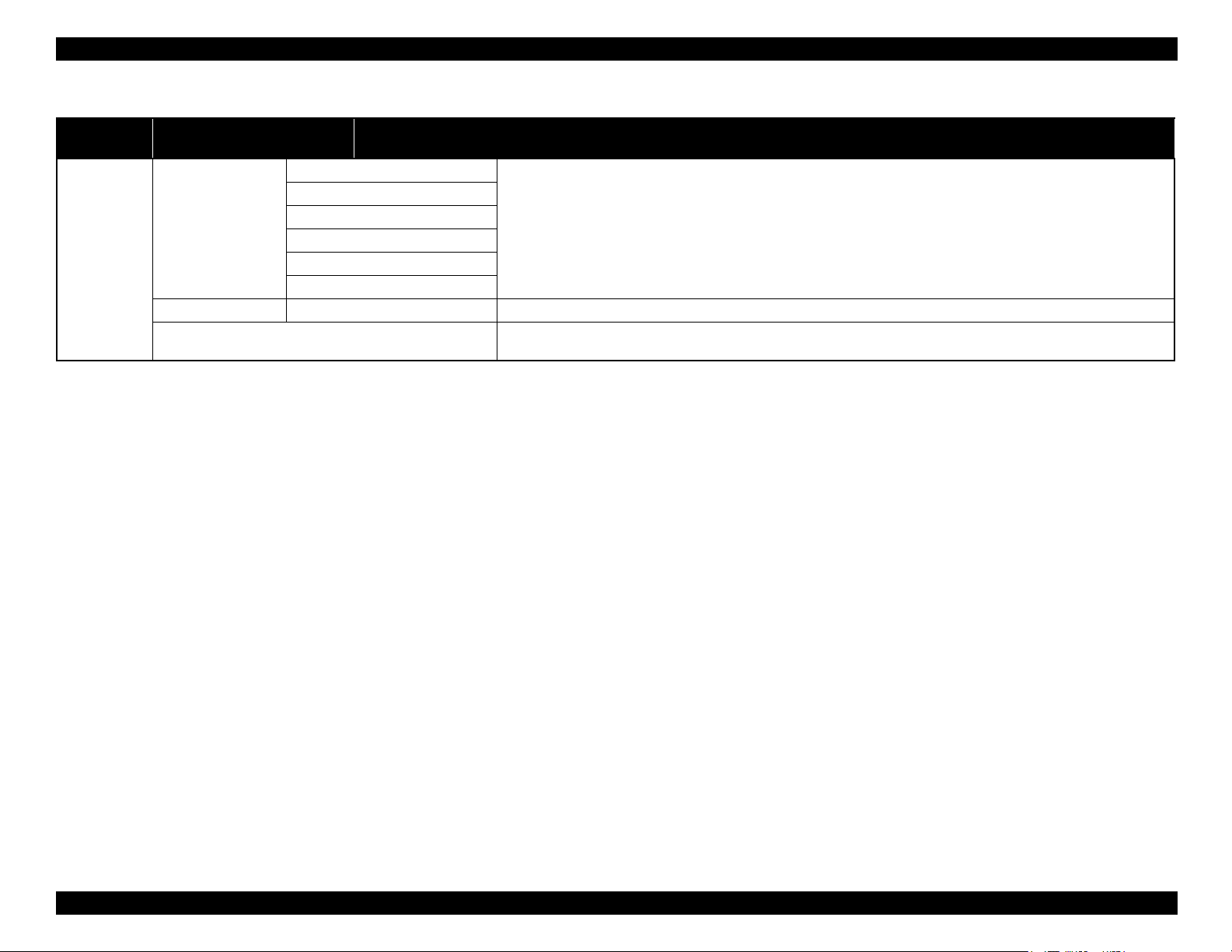
SC-P5000 Series/Epson Stylus Pro 4900/4910 Revision G
Table 1-6. Menu Mode Settings List
Menu Menu Item
Powerful Cleaning
Administrator
Menu
Clock Setting MM/DD/YY HH:MM Set the printer’s built-in clock. The time provided by the clock is used when printing logs and status sheets.
Reset All Settings
All Nozzles
C/VM
PK(MK)/GY
OR/GR
LLK(V)/Y
VLM/LC
(shaded one is the default)
Performs more powerful cleaning than Head Cleaning from the Maintenance menu. Check the ink colors with faint or missing
segments in the check pattern, and then specify which nozzles to clean.
• If there are faint or missing segments in all colors: Select All Nozzles.
• If there are faint or missing segments in only a few colors: Select the specific ink colors you want to clean.
Pressing the OK button restores all settings, such as settings in the menus on the control panel and paper settings, to their factory
settings.
Settings
PRODUCT DESCRIPTION Control Panel 52
SE Group Confidential (Related Staff Only)
Page 53

SC-P5000 Series/Epson Stylus Pro 4900/4910 Revision G
1.5.1.2 Epson Stylus Pro 4900/4910 Setup Menu
Table 1-7. Menu Mode Settings List
Menu Menu Item
Printer Setup
(shaded one is the default)
Platen Gap
Page Line
Roll Paper Margin
Paper Size Check
Paper Skew Check
Refresh Margin
Auto Nozzle Check
Print Nozzle Pattern
Change Black Ink
Settings
Narrow
Standard
Wide
Wider
Widest
On Sets whether to print a page line (line for manual cutting) on roll paper or not. The page line is printed when On is selected.
Off
Default
Top/Bottom 15mm
Top 35/Bottom 15mm
3mm
15mm
On Sets whether to detect the paper width and the top or not.
Off
On This setting is effective for roll paper only.
Off
On
Off
On: Periodically
On: Every Job
Off
Off
On: Every Page
On: Every 10 Pages
Off
On
Explanation
Sets the platen gap (gap between the printhead and the platen).
When the “Others” is selected in the Paper Type of the Paper Setup menu, the platen gap designated at the Custom Paper menu has a
priority over the setting made here. ("PG Settings List" on page 59)
The vertical line may be printed when the roll paper width that is set in the printer driver is smaller than the width of the roll paper that
is loaded in the printer. This setting is available for roll paper only.
Sets the margins for roll paper.
When the Default is selected, the top and the bottom margins become 15mm and the right and the left margins become 3mm.
Setting to Off deactivates the sensor that detects the paper width when paper is loaded on the printer. This allows the user to use paper
whose width is out of the sensor’s detectable range. It means that the user can print an image larger than the paper size. The user should
know that doing so soils the platen and may cause a print quality or any other trouble.
Sets whether to detect the paper skew or not.
Setting to Off does not carry out the detection and printing is continued even if the paper is skewed. When this setting is set to Off, the
user should have known the risk.
This setting is not available for cut sheet because the skew detection function after printing is not provided for cut sheet.
This setting is available only when roll paper is used.
When this is set to On, the top edge area of paper soiled by the previous borderless printing is automatically cut off.
Sets the execution timing for the auto nozzle check. When the nozzle clogging is detected, the cleaning starts automatically. You can
set the number of executions for cleaning from "1.5.2 Maintenance Mode (p62) ".
The printer prints a nozzle check pattern automatically at the specified timing. This setting is available only when roll paper is used.
When the set number of pages is reached, the nozzle check pattern is printed on the top of the page. The counter for counting the pages
is not reset even by power-off. When this setting is changed, the counter is cleared.
When this is set to ON and the type of the black ink differs between the printer and the printer driver, the black ink of the printer is
changed automatically in printing.
PRODUCT DESCRIPTION Control Panel 53
SE Group Confidential (Related Staff Only)
Page 54

SC-P5000 Series/Epson Stylus Pro 4900/4910 Revision G
Table 1-7. Menu Mode Settings List
Menu Menu Item
Printer Setup
Test Print
Maintenance
Printer Status
(shaded one is the default)
Auto Roll Feeding
Initialize Settings Print All the settings made using the control panel are returned to their default.
Status Sheet Print Prints information on the printer status.
Network Status Sheet Print Prints information on the network status.
Job Information Print Prints a print job history report (up to 10 jobs) that is stored in the printer.
Custom Paper Print Prints the settings made in the Custom Paper menu.
Cutter Adjustment -3.0mm to +3.0mm Fine tune the cut position when printing to roll paper with no margins in all directions. In increments of 8 mil (0.2 mm) in all directions.
Clock Setting MM/DD/YY HH:MM Sets the date and time for the internal clock.
Version
Ink Level
Maintenance Box
Job History
Total Prints nnnnnn Pages Displays the total printed pages using 6-digit decimal number.
myEpsonPrinter Status
"Firmware version information"
Not Started, Enabled, Disabled
MM/DD/YY HH:MM GMT
Settings
On
Off
on page 61
(Ink color)
[E**********F]
1
[E**********F]
2
[E**********F]
No.0 to No.9
Ink xx.x ml
Paper xxxxxx cm
Last Uploaded:
(Not Uploaded)
When this is set to ON, the paper is fed on the platen from the roll paper standby position.
Displays the firmware version. Refer to "Firmware version information" on page 61.
Displays the ink level in the installed ink cartridges.
Displays the waste ink level in the installed maintenance boxes.
Job No.
Displays the job number that is stored in the printer. The latest job number is 0 (zero).
The amount of ink consumed
Displays the amount of ink consumed for each job.
The amount of paper consumed
2
Displays the total area of paper used for each job.
This function is not supported in some areas or some countries.
Explanation
PRODUCT DESCRIPTION Control Panel 54
SE Group Confidential (Related Staff Only)
Page 55

SC-P5000 Series/Epson Stylus Pro 4900/4910 Revision G
Table 1-7. Menu Mode Settings List
Menu Menu Item
Paper Setup
Head Alignment
(shaded one is the default)
Roll Paper Remaining
Cut Sheet Remaining
Paper Type
Custom Paper
(1-10)
Paper Thickness
Alignment
Settings
Make settings for the remaining roll paper.
[Off] (default)
Disables the roll paper remaining amount count function.
Remaining Paper Setup
Roll Paper Length You can make these settings only when Remaining Paper Setup above is set to On.
Roll Length Alert
Sheet Number You can make these settings only when Cut Sheet Remaining is set to On.
Sheet Number Alert
Photo Paper
Proofing Paper
Fine Art Paper
Matte Paper
Plain Paper
Others
Custom Paper
No Paper Selected
Paper No. No.1 to 10
Paper Type Sets thickness of paper to be used.
Paper Thickness
Auto Sets whether to carry out the head alignment adjustment automatically or manually.
Manual
[On]
Displays the roll paper remaining amount on the LCD. When you press the [Paper Set] button, a barcode that includes information on
the amount of remaining roll paper, the Roll Length Alert, and the Paper Type is printed.
When roll paper is replaced with a new one, the printer reads the barcode and automatically applies the read settings for the new roll
paper.
The printer sets roll paper length, and the remaining length of roll paper to be alerted when the set amount is reached.
The printer displays the roll paper remaining amount and the alert for shortage of the remaining on the LCD.
The printer sets the number of remaining cut sheets, and the number of remaining cut sheets to be alerted when the set number is
reached.
The printer displays the number of remaining cut sheets and the alert for shortage of the remaining on the LCD.
Sets the paper type loaded on the printer.
You can select a number (between 1 to 10) to register the settings (such as Paper Type, Platen Gap, Thickness Pattern, Paper Feed
Adjust, Drying Time, Paper Suction) or to recall these settings you have made. The number you select here is displayed on the LCD
panel. For the menu item, see Table 1-8 "Custom Paper Menu List" (p57).
• When Epson paper is used, select the paper type.
• When not Epson paper is selected, enter the thickness of the selected paper.
[Auto]
The adjustment is carried out automatically after the adjustment pattern is printed.
[Manual]
Select this to carry out the adjustment manually (visually check the patterns and enter selected values) after printing the adjustment
pattern.
Explanation
PRODUCT DESCRIPTION Control Panel 55
SE Group Confidential (Related Staff Only)
Page 56

SC-P5000 Series/Epson Stylus Pro 4900/4910 Revision G
Table 1-7. Menu Mode Settings List
Default
Settings
Hide
Show
Auto
Panel
000.000.000.000
to
255.255.255.255
000.000.000.000
to
255.255.255.255
000.000.000.000
to
255.255.255.255
On
Off
Off
On
Explanation
The Network Setup menu items appear on the LCD only when this is set to Show.
Sets whether to set the IP address automatically or manually.
When the Panel is selected, the IP, SM, DG Setting menu is enabled to enter the address manually.
Sets the IP address manually.
Sets the subnet mask manually.
Sets the default gateway manually.
Enables or disables the Bonjour.
Enables or disables the WSD.
Displays the status of each item of SpectroProofer, such as the version of SpectroProofer, the product numbers of the white calibration
tiles, the temperature of Color Measurement Device (ILS20EP/ILS30EP), ambient air temperature, and the color of the backing, and
ILS Calibration Status.
Menu Menu Item
Network Settings
IP Address Setting
Network Setup
SpectroProofer SpectroProofer Status Information
IP,SM,DG Setting
Bonjour
WSD
Init Network Setting Execute Returns the network settings to their default.
(shaded one is the default)
IP Address
Subnet Mask
Gateway
PRODUCT DESCRIPTION Control Panel 56
SE Group Confidential (Related Staff Only)
Page 57

SC-P5000 Series/Epson Stylus Pro 4900/4910 Revision G
Custom Paper Menu
Table 1-8. Custom Paper Menu List
Menu Item
Paper Type
Platen Gap
Thickness Pattern Print Prints a pattern for checking the thickness of the loaded paper.
Paper Feed Adjust A
Paper Feed Adjust B
Drying Time
Paper Suction
Set Roll Paper Tension
Remove Skew
(shaded one is the default)
Settings
Photo Paper
Proofing Paper
Fine Art Paper
Matte Paper
Plain Paper
Others
Narrow
Standard
Wide
Wider
Widest
0.00% Adjusts the paper feed line pitch when banding occurs in the area 1 to 2 cm from the end of paper.
-0.70% to +0.70%
0.00%
-0.70% to +0.70%
0.0 sec
0.0 to 10.0 sec
Standard
-1 to -4
Normal
Extra High
On
Off
Sets the paper type loaded on the printer.
Adjusts the platen gap (gap between the printhead and paper surface) according to the paper thickness.
Standard: use this setting under normal conditions
Narrow: select this when using thin paper.
Wide, Wider, Widest: select this when smudges or blurring appear due to an excess pressure on the paper.
The larger the value is, the more the possibility to cause white bands on printout image.
The smaller the value is, the more the possibility to cause black bands on printout image.
Adjusts the paper feed line pitch when banding occurs in the area 1 to 2 cm from the end of paper.
Sets a time period to pause the carriage movement for drying the printed surface. Depending on paper type and density, drying ink may take
longer. Check the result and set longer time period in such case.
Sets the power level of the suction fan.
When using a cloth or thin paper or when winkles appear in the paper during printing, select “High” or “Extra High”.High
Sets whether to perform this operation to reduce the paper skew or not.
Explanation
PRODUCT DESCRIPTION Control Panel 57
SE Group Confidential (Related Staff Only)
Page 58

SC-P5000 Series/Epson Stylus Pro 4900/4910 Revision G
Ink Menu
Table 1-9. Ink Menu List
Menu Item Settings Explanation
Auto Cleaning
C/VM, PK (MK)/LK, O/
Manual Cleaning
Nozzle Check
Change Black Ink --- Changes the type of the black ink.
G, LLK(V)/Y, VLM/LC,
No
Yes
All Colors, All Colors
(Powerful)
Auto Nozzle Check
Print Check Pattern Prints the nozzle check pattern.
Selects Yes to execute Auto Nozzle Check and
head cleaning.
Selects the color lines to be cleaned and the
power of cleaning.
Executes Auto Nozzle Check. Displays the result
on the control panel.
PRODUCT DESCRIPTION Control Panel 58
SE Group Confidential (Related Staff Only)
Page 59

SC-P5000 Series/Epson Stylus Pro 4900/4910 Revision G
PG Settings List
The table below shows the actual platen gap amount specified by the printer driver
or the control panel.
<SC-P5000 Series>
Table 1-10. PG Settings List
Paper Thickness Sensor Panel mm
1.2
1.2
1.2
1.6
1.2
1.2
1.6
2.1
1.2
1.6
2.1
2.6
1.6
2.1
2.6
2.6
2.1
2.6
2.6
2.6
0.4mm or less
Narrow
Standard
Wide
Wider
Widest
--- 2.6
Table 1-10. PG Settings List
Paper Thickness Sensor Panel mm
1.2
Narrow
Standard
0.5mm to 0.8mm
0.9mm to 2.1mm --- 2.6
Wide
Wider
Widest
--- 2.6
1.2
1.2
1.6
1.2
1.2
1.6
2.1
1.2
1.6
2.1
2.6
1.6
2.1
2.6
2.6
2.1
2.6
2.6
2.6
PRODUCT DESCRIPTION Control Panel 59
SE Group Confidential (Related Staff Only)
Page 60

SC-P5000 Series/Epson Stylus Pro 4900/4910 Revision G
<Epson Stylus Pro 4900/4910>
Table 1-11. PG Settings List
Paper
Thickness
Sensor
Less than
0.4mm
Paper Thickness
Setting by Driver
No setting
0.0 to 0.8mm
0.9mm to 1.5mm -- -- 2.6
Menu Setting
Narrow
Standard
Wide
Wider
Widest
Media Table or Printer
Driver PG Setting
Narrow 0.8
Standard 0.8
Wide 1.2
Wider 1.6
Narrow 0.8
Standard 1.2
Wide 1.6
Wider 2.1
Narrow 1.2
Standard 1.6
Wide 2.1
Wider 2.6
Narrow 1.6
Standard 2.1
Wide 2.6
Wider 2.6
Narrow 2.1
Standard 2.6
Wide 2.6
Wider 2.6
PG Value (mm)
Paper
Thickness
Sensor
0.5mm to
0.8mm
0.9mm to
2.1mm
Table 1-11. PG Settings List
Paper Thickness
Setting by Driver
No setting
0.0 to 0.8mm
0.9mm to 1.5mm -- -- 2.6
-- -- -- 2.6
Menu Setting
Narrow
Standard
Wide
Wider
Widest
Media Table or Printer
Driver PG Setting
Narrow 1.2
Standard 1.2
Wide 1.2
Wider 1.6
Narrow 1.2
Standard 1.2
Wide 1.6
Wider 2.1
Narrow 1.2
Standard 1.6
Wide 2.1
Wider 2.6
Narrow 1.6
Standard 2.1
Wide 2.6
Wider 2.6
Narrow 2.1
Standard 2.6
Wide 2.6
Wider 2.6
PG Value (mm)
PRODUCT DESCRIPTION Control Panel 60
SE Group Confidential (Related Staff Only)
Page 61

SC-P5000 Series/Epson Stylus Pro 4900/4910 Revision G
Firmware version information
The table below explains the firmware version information printed by selecting the
Version in the Printer Status menu.
<Format>
M0XXXX,xx.xx,IBCC
Table 1-12. Firmware Version Information
Item Explanation
**0
XXXX Indicates the firmware version installed on the printer.
xx.xx Indicates the network firmware version.
I “A” is indicated for this printer.
B “0” is indicated for this printer.
C
The code assigned to this printer: M0
“0” (zero) is assigned to a special version of printer.
A hexadecimal number (00H-FFH) appears to indicate the specified custom
number that registers a special operation setting. When no custom operation
is specified, “00” appears.
PRODUCT DESCRIPTION Control Panel 61
SE Group Confidential (Related Staff Only)
Page 62

SC-P5000 Series/Epson Stylus Pro 4900/4910 Revision G
1.5.2 Maintenance Mode
The maintenance mode allows you to change the environmental settings such as
language and unit settings to be displayed, or to return all the settings to their default.
The user can also access this mode.
HOW TO START & QUIT
1. While holding down the [Pause/Cancel] button, turn the printer on.
2. Turn the printer off to quit the maintenance mode.
MAINTENANCE MODE MENU LIST
SC-P5000 Series
Menu Item Settings Explanation
CUSTOM 0 to 255 Save the custom setting.
Epson Stylus Pro 4900/4910
Menu Item
Language
Length Units
Settings
(shaded one is the
default)
Japanese
English
French
Italian
German
Portuguese
Spanish
Dutch
Korean
Chinese
Metric
Feet/Inch
Explanation
Selects the language used for the control panel
display.
Selects the unit of length to be used for various
length information.
Menu Item
Temperature Units
Auto Cleaning Times
Maintenance Alert
Cut Sheet Remaining
Time To Low Power
Settings
(shaded one is the
default)
°C
F
1
2
3
Disable
Ink
Maintenance Box
Ink Or Maint Box
Papers
All
Off
On
5 minutes
15 minutes
60 minutes
120 minutes
180 minutes
Explanation
Selects the unit of temperature displayed on
the LCD panel.
Sets the number of cleanings when nozzle
clogging is detected at auto nozzle check.
Selects the type whose remaining amount is
displayed with the large alert lamp.
Displays Cut Sheet Remaining in Setting menu
when setting to On.
Sets the time to turn to the sleep mode
automatically.
PRODUCT DESCRIPTION Control Panel 62
SE Group Confidential (Related Staff Only)
Page 63

SC-P5000 Series/Epson Stylus Pro 4900/4910 Revision G
Settings
Menu Item
Power Management
Default Panel Execute
Custom 0 to 255 Stores custom settings.
(shaded one is the
default)
Sets whether to enable or disable the Power
Power Off Timer
Time To Off Sets per hour in a range from 1 to 24 hours.
Off Timer after turning to the sleep mode. The
default is disabled.
Returns all the settings made by the control
panel to their default.
Explanation
PRODUCT DESCRIPTION Control Panel 63
SE Group Confidential (Related Staff Only)
Page 64

SC-P5000 Series/Epson Stylus Pro 4900/4910 Revision G
1.5.3 Serviceman Mode
The Serviceman Mode is intended to be used by a service personnel for servicing the
printer.
HOW TO START & QUIT
1. Turn the printer on by pressing the [OK], [Paper Feed/Down], and [Menu/Right] buttons together.
2. Turn the printer off to quit the Serviceman Mode.
SERVICEMAN MODE MENU LIST
Menu Explanation
Paper Displays the Paper Thickness Sensor response for adjustment.
Rear AD Adjusts the AD value of the Rear Sensor (PE Sensor).
CR Un Cap Unlocks or re-locks the carriage and uncaps/re-caps the Printhead.
Red
Mecha Adjustment
LCD RGB Check
Blue
Panel Check Checks the operation of the Buttons and the LEDs.
Roll Unit
Roll Support
Sensor Check
ASF Cassette
ASF Paper
Front Cover
Checks the operation of the LCD.Green
Checks the operation of sensors.
PRODUCT DESCRIPTION Control Panel 64
SE Group Confidential (Related Staff Only)
Page 65

SC-P5000 Series/Epson Stylus Pro 4900/4910 Revision G
Menu Explanation
PG
H to F Speed
CR
PF
Life
RLS
APG
Cutter
F to H Speed
Page Size
Fan
Life Count
Feed Amount 1
Feed Speed 1
Feed Amount 2
Feed Speed 2
Wait
Fan
GS Change Position 1
GS Change Position 2
Life Count
Wait1
Wait2
Life Count
PG
Wait
Life Count
Length
Return Length
GS Change Position 1
GS Change Position 2
Wait
Life Count
Used only in manufacturing processes. Not used in service operations.
PRODUCT DESCRIPTION Control Panel 65
SE Group Confidential (Related Staff Only)
Page 66

SC-P5000 Series/Epson Stylus Pro 4900/4910 Revision G
Menu Explanation
Wait1
Wait2
Wait3
Life Count
Used only in manufacturing processes. Not used in service operations.
Life
GS
Display Count Display Count
PRODUCT DESCRIPTION Control Panel 66
SE Group Confidential (Related Staff Only)
Page 67

TROUBLE SHOOTING
CHAPTER
2
SE Group Confidential (Related Staff Only)
Page 68

SC-P5000 Series/Epson Stylus Pro 4900/4910 Revision G
2.1 Overview
This section explains the basic procedure for troubleshooting problems on the printer
quickly and efficiently.
When carrying out the troubleshooting procedures, take a flexible measure following
your sales company's policy and considering the troubling situation.
2.1.1 Preliminary Check
Make sure to verify or perform the following basic items whenever servicing the
printer.
2.1.1.1 Check for the usage environment
Check the user's usage environment.
Temperature/humidity of the installation site
(For the guaranteed environment, see P.20.)
Drivers/RIP that the user uses
Genuine media or 3rd party's media?
Genuine ink or 3rd party's ink?
F/W version (the latest?)
Check also the following if necessary.
2.1.1.2 Recurrence check of the trouble
Check if the trouble the user claims recurs with the returned printer.
If RIP was used, check if the trouble recurs when the driver is used.
If 3rd party's media were used, check if the trouble recurs when the genuine
media is used.
If 3rd party's ink was used, check if the trouble recurs when the genuine ink is
used.
If the F/W was not the latest, check if the trouble recurs when the latest F/W is
used.
2.1.1.3 Check for the counter values/history
Download NVRAM and check the following with NVRAM Viewer. (For the check
method, see P.340.)
Counter history of the periodic replacement parts. (if any part's life is near.)
Printer's operating history (if any cause for the trouble exists)
Error history (the frequency/history of errors related with the trouble)
2.1.1.4 Test print check
For the trouble related with print quality, carry out “Test Print” and check the current
adjustment status. (For the procedure of test print, see P.349.)
Phenomenon Check Item
The installation site inclined?
Any vibrating equipment near the site?
Bad print quality
Missing dots/bad print quality Near a conditioner's ventilation duct?
The user's panel settings
Is the interior dirty?
Clean it if dirty.
TROUBLE SHOOTING Overview 68
SE Group Confidential (Related Staff Only)
Page 69

SC-P5000 Series/Epson Stylus Pro 4900/4910 Revision G
2.1.2 Troubleshooting Procedure
Refer to the following items according to the observed symptom, carry out the
corresponding troubleshooting following the procedures described in the next sections.
1. Trouble with a Maintenance Request or Service Call Error. (See P.70, P. 73)
2. Trouble on print quality (See P.99)
3. Trouble on paper feeding (See P.106)
4. When the printer does not operate (See P.110)
5. Trouble on printer operations (See P.112)
6. Trouble on SpectroProofer (See P.114)
7. Trouble on Service Program (See P.118)
2.1.3 Procedure after troubleshooting
2.1.3.1 If the trouble has been successfully solved
Check if the movement of the covers is normal (without any damage, noises).
If any abnormality is found, lubricate or replace the faulty parts.
Carry out the cleaning after repair.
Prepare a report on the repair. (follow your company/local office's policy.)
2.1.3.2 If necessary to escalate the trouble case
Make a report with the following data.
Backed-up NVRAM data
For bad print quality: a print sample with the marked symptom and a printed
test pattern.
For faulty parts: the faulty parts themselves and a photos of the troubling
section.
Information on the user/the repair listed below
This is a format of the escalation report. At least check out the items on the
list and register the case in the escalation system.
Model name
Serial number
With or without options
Content of the claim from the user
Date of occurrence
Trouble occurrence conditions/recurrence method
What the service person actually observed
(Check items before check, the content of troubleshooting and repair.)
Date of escalation
Purpose of escalation
(Measures which the user/service person)
Degree of urgency (S/A/B/C)
S: High (those which may cause a death, ignition, etc.)
A: Problems, bugs
B: Strong request
C: Inquiry
Deadline for the response
Repair history
Part-replacement history
TROUBLE SHOOTING Overview 69
SE Group Confidential (Related Staff Only)
Page 70

SC-P5000 Series/Epson Stylus Pro 4900/4910 Revision G
2.2 Remedies for Maintenance Requests
This section describes the remedies for maintenance requests. Maintenance requests do not effect the printer’s operation; therefore, you can continue the current printing. When a
maintenance request error occurs, the printer displays on the LCD a hexadecimal code of “NNNN” which correspond to the bit numbers assigned to error statuses as shown in the
table below.
Table 2-1. About the Maintenance Request NNNN (Bit assignment)
Bit assignment (Binary)
31 30 29 28 27 26 25 24 23 22 21 20 19 18 17 16 15 14 13 12 11 10 9 8 7 6 5 4 3 2 1 0
00000000000000000000000000000010
0000000000000000000000000000
000000000000000000000000000
0000000000000000000000000
000000000000000000000000
000000000000000000000
0000000000000000000
00000000000000000
00000000000000
000000000
00000
000
000000000000000000000000
10000000000000000000000000000
100000000000000000000000000
10000000000000000000000
100000000000000000
100000000000000
1000000000000
10000000000
1000000
10000000
10001000
1000
10000
NNNN
(Hexadecimal)
0000002
00000008
00000010
00000040
00000080
00000400
00001000
00004000
00020000
00400000
04000000
10000000
(e.g.) 0088
(Reserved)
(Reserved)
(Reserved)
Ink selector life
(Reserved)
(Reserved)
(Reserved)
(Reserved)
Cartridge holder life
(Reserved)
(Reserved)
(Reserved)
(Reserved)
Suction pump life
(Reserved)
CR life (tube life)
(Reserved)
AID error
(Reserved)
Near the end of
Ink selector life
(Reserved)
(Reserved)
(Reserved)
Date not set
Near the end of
Cartridge Holder like
Ink System life
Near the end of
(Reserved)
AID error
RTC backup
exhaustion
(Reserved)
(Reserved)
Description
RTC backup battery
Near the end of CR life
Note "*1":Ex): When “Maintenance Request 0088” is displayed.
As “0088” in hexadecimal means “1000 1000” in binary, you can find out the code is assigned to Bit-3 and Bit-7 referring to the above table. In this case, two errors are
occurring simultaneously. (Bit-3: battery exhaustion/ Bit-7: the date and time has not been set.)
"*2":Do not reset the counter without replacing the part. Doing so will result in increasing chance of ink leakage and failure rate. It is not only a quality assurance issue, but
also causes the customer so much trouble.
TROUBLE SHOOTING Remedies for Maintenance Requests 70
SE Group Confidential (Related Staff Only)
Page 71

SC-P5000 Series/Epson Stylus Pro 4900/4910 Revision G
Table 2-2. About the Maintenance Request NNNN (Bit assignment)
NNNN
(Hexadecimal)
0000002
00000008
00000010
00000040
00000080
00000400
00001000
00004000
00020000
00400000
04000000
10000000
(e.g.) 0088
The CR scan pass counter has come near the specified life. (Six million passes = the end of life of the
Ink Supply Tube.)
The RTC backup battery on the Main Board reached the end of its life. Replace the battery and set date and time.
(Non-recoverable AID error due to breakdown) See "Remedy for No. 0010/4000 (p. 72)".
The pump counter has come near the specified life. (The end of the IS Unit’s life.) Replace the IS Unit and reset the counter.
The date has not been set. Set date and time.
Operations of the diaphragm in the Cartridge Holder comes near the specified life (The end of the
Cartridge Holder's life).
The number of operation counter of the Ink Selector has come near the specified life. Replace the Ink Selector and reset the counter.
(All nozzle clogging error) See "Remedy for No. 0010/4000 (p. 72)".
The Ink Tube has reached the end of its life. Replace the Ink Tube and reset the counter.
The Suction Pump has reached the end of its life. Replace the IS Unit and reset the counter.
The Cartridge Holder has reached the end of its life. Replace the Cartridge Holder and reset the counter.
The Ink Selector has reached the end of its life. Replace the Ink Selector and reset the counter.
The RTC backup battery becomes exhausted and the date has not been set. Carry out the remedy for 0008 and 0080.
Cause Remedy
Replace the following parts and reset the counter of the CR Motor and the FFC, Ink Tubes and CR
Pads Counter.
Ink Tubes
CR Motor
Head FFC
Oil Pad
Check which Cartridge Holder (the left one or the right one) has trouble with the NVRAM Viewer.
Replace the Cartridge Holder and reset the counter.
x
TROUBLE SHOOTING Remedies for Maintenance Requests 71
SE Group Confidential (Related Staff Only)
Page 72

SC-P5000 Series/Epson Stylus Pro 4900/4910 Revision G
REMEDY FOR NO. 0010/4000
If the Maintenance Request No. 0010 or No. 4000 occurs, take the following measure according to the procedure below.
NOTE : There is a priority for occurrence of No. 0010 and No. 4000. Because No. 0010 has the priority, when both No. 0010 and No. 4000 occur at the same time, No. 4000 is not displayed,
but No. 0010 is displayed only. When the cause of No. 0010 is removed, No. 4000 is displayed then.
Table 2-3. Remedy for Maintenance Request No. 0010/4000
Request No. Description Cause Remedy/Check Point
Check the connection to the AID Board, and correct it if
1
any failure found.
Check around the Flushing Box, and remove accumulated
ink or dust if any. (Through accumulated ink or dust, the
2
electric current may leak.)
Replace the IS Unit. (See P.266)
3
Replace the AID Board. (See P.192)
4
Print the nozzle check pattern to check this. If all the
colors have nozzle clogging, replace the Printhead. (See
1
P.265)
Check the connection to the AID Board, and correct it if
2
any failure found.
Replace the IS Unit. (See P.266)
3
0010
4000
Communication with the AID Board is not established. Connection failure of FFC or FFC is broken.
The voltage applied to the Flushing Box does not reach
the specified level.
It detects twice in a row that all the nozzles are clogging.
Due to accumulated ink and such around the Flushing
Box, the electric current is leaking.
High voltage power module in the AID Board is broken.
Printhead is broken.
Connection failure of AID cable or AID cable is broken.
TROUBLE SHOOTING Remedies for Maintenance Requests 72
SE Group Confidential (Related Staff Only)
Page 73

SC-P5000 Series/Epson Stylus Pro 4900/4910 Revision G
2.3 Remedies for Service Call Error
The following tables explains the Service Call error messages and remedies.
11XX Series CR error code
Code Error Name Cause Check Item Remedy
Replace the following parts and
reset the counter of the CR Motor
and the FFC, Ink Tubes and CR
Pads Counter.
Ink Tubes
CR Motor
Head FFC
Oil pad
1. Re-install the CR Encoder. (See
P.197)
2. Clean the CR Scale with
ethanol.
3. Replace the CR Scale. (See
P.198)
4. Replace the IS Unit. (See
P.266)
1. Replace the CR Encoder. (See
P.197)
2. Replace the CR Motor. (See
P.195)
3. If the printer does not recover
from the error, it may be caused
by irregular load of the CR
Mechanism. Replace the Printer
Mechanism.
1101
1125
1138
CR life error
CR HP detection error
CR Motor
over current error
The maintenance counter for the Ink Supply Tube exceeded
the threshold value. (CR scan pass counter has reached the
specified value (six million passes)).
The CR Unit cannot track the Home position to set the CR
origin.
False origin detection due to paper jam or the like
Misreading of CR Scale
CR Lock is damaged.
1. Connection failure of the CR Motor or the CR Encoder.
2. Detects accumulatively more than the specified number of
times that the electric current which flows when driving the
motor is irregularly large.
Irregular load
CR Encoder failure
CR Motor failure
---
1. Check if the paper is jammed.
2. Check if the CR Scale is read out properly (See P.198).
Check if the CR Scale is damaged or contaminated.
3. Check if the CR Lock functions normally. (See P.148)
1. Check the following connection for disconnection and
damage.
CR Encoder to SUB Board (CN102)
CR Motor to SUB-B Board (CN204)
2. Carry out “Encoder Check” to check if the CR Encoder
functions normally. (See P.440)
3. Carry out “Motor Measurement Adjustment (CR Motor)” to
check if CR Motor functions normally. (See P.434)
TROUBLE SHOOTING Remedies for Service Call Error 73
SE Group Confidential (Related Staff Only)
Page 74

SC-P5000 Series/Epson Stylus Pro 4900/4910 Revision G
Code Error Name Cause Check Item Remedy
1. Check if the CR Unit is attached correctly.
2. Check if any foreign material exists in CR Unit’s drive
section.
3. Check the following connection for disconnection and
damage.
CR Encoder to SUB Board (CN102)
CR Motor to SUB-B Board (CN204)
4. Carry out “Encoder Check” to check if the CR Encoder
functions normally. (See P.440)
5. Carry out “Motor Measurement Adjustment (CR Motor)” to
check if the CR Motor functions normally. (See P.434)
Carry out “Encoder Check” to check if the CR Encoder
functions normally. (See P.440)
1. Check the following connection and installation direction.
CR Encoder to SUB Board (CN102)
CR Motor to SUB-B Board (CN204)
2. Check if the tension of the CR Timing Belt is proper. (See
P.359)
3. Carry out “Encoder Check” to check if the CR Encoder
functions normally. (See P.440)
---
1. Carry out “Encoder Check” to check if the CR Encoder
functions normally. (See P.440)
2. Carry out “Motor Measurement Adjustment (CR Motor)” to
check if the CR Motor functions normally. (See P.434)
1. Re-install the CR Unit. (See
P.195)
2. Replace the CR Encoder. (See
P.197)
3. Replace the CR Motor. (See
P.195)
1. Replace the CR Encoder. (See
P.197)
2. Replace the SUB-B Board. (See
P.189)
3. Replace the Main Board. (See
P.179)
1. Adjust the tension of the CR
Timing Belt. (See P.359)
2. Replace the CR Encoder. (See
P.197)
Replace the Main Board. (See
P.179)
1. Replace the CR Encoder. (See
P.197)
2. Replace the CR Motor. (See
P.195)
3. Replace the SUB-B Board. (See
P.189)
4. Replace the Main Board. (See
P.179)
113A
113B
113C
113D
113E
CR Motor
overload error
CR Motor
over speed error
CR Motor
reversing error
CR Motor
driving time-out error
CR Motor
velocity deviation error
The electric current flowing when driving the motor is
irregularly large.
CR Encoder cable is damaged.
CR Motor cable is damaged.
Irregular load
CR Encoder failure
CR Motor failure
Detects that it is being driven at an irregularly faster speed
than the specified value just before stopping.
Irregular load
CR Encoder failure
SUB Board is damaged.
CR Motor driver failure
Detects accumulatively more than the specified number of
times that it is being driven in the opposite direction to the
specified driving direction.
The polarity of CR Encoder cable is opposite.
The polarity of CR Motor cable is opposite.
Slipping of the teeth of CR Timing Belt
CR Encoder failure
Detects that the driving period is irregularly long.
Irregular load
Firmware becomes out of control.
Detects, when accelerating/decelerating the motor, that it is
being driven at an irregularly faster speed than the specified
value.
Irregular load
CR Encoder failure
CR Motor failure
SUB Board is damaged.
CR Motor driver failure
TROUBLE SHOOTING Remedies for Service Call Error 74
SE Group Confidential (Related Staff Only)
Page 75

SC-P5000 Series/Epson Stylus Pro 4900/4910 Revision G
Code Error Name Cause Check Item Remedy
Detects that it is being driven at an irregularly slower speed
than the specified value.
CR Encoder cable is damaged.
CR Motor cable is damaged.
Irregular load
CR Encoder failure
CR Motor failure
113F
CR Motor
lock error
12XX Series paper feed error code
Code Error Name Cause Check Item Remedy
The electric current flowing when driving the motor is
irregularly large.
PF Encoder cable is damaged.
PF Motor cable is damaged.
Irregular load
PF Encoder failure
PF Motor failure
Detects that it is being driven at an irregularly faster speed
than the specified value just before stopping.
PF irregular load
PF Encoder failure
SUB Board is damaged.
PF Motor driver failure
Detects accumulatively more than the specified number of
times that it is being driven in the opposite direction to the
specified driving direction.
The polarity of PF Encoder cable is opposite.
The polarity of PF Motor cable is opposite.
Slipping of the teeth of PF Timing Belt
PF Encoder failure
122A
122B
122C
PF Motor
overload error
PF Motor
over speed error
PF Motor
reversing error
1. Check the following connection for disconnection and
damage.
CR Encoder to SUB Board (CN102)
CR Motor to SUB-B Board (CN204)
2. Carry out “Encoder Check” to check if the CR Encoder
functions normally. (See P.440)
3. Carry out “Motor Measurement Adjustment (CR Motor)” to
check if the CR Motor functions normally. (See P.434)
1. Check the following connection for disconnection and
damage.
PF Encoder to SUB-C Board (CN303)
PF Motor to SUB-C Board (CN302)
2. Carry out “Encoder Check” to check if the PF Encoder
functions normally. (See P.440)
3. Carry out “Motor Measurement Adjustment (PF Motor)” to
check if the PF Motor functions normally. (See P.434)
Carry out “Encoder Check” to check if the PF Encoder
functions normally. (See P.440)
1. Check the following connection for disconnection and
installation direction.
PF Encoder to SUB-C Board (CN303)
PF Motor to SUB-C Board (CN302)
2. Check if the tension of the PF Timing Belt is proper. (See
P.406)
3. Carry out “Encoder Check” to check if the PF Encoder
functions normally. (See P.440)
1. Replace the CR Encoder. (See
P.197)
2. Replace the CR Motor. (See
P.195)
1. Replace the PF Encoder. (See
P.211)
2. Replace the PF Motor. (See
P.210)
3. If the printer does not recover
from the error, it may be caused
by irregular load of the PF
Mechanism. Replace the Printer
Mechanism.
1. Replace the PF Encoder. (See
P.211)
2. Replace the SUB-C Board. (See
P.190)
3. Replace the Main Board. (See
P.179)
1. Adjust the tension of the PF
Timing Belt. (See P.406)
2. Replace the PF Encoder. (See
P.211)
TROUBLE SHOOTING Remedies for Service Call Error 75
SE Group Confidential (Related Staff Only)
Page 76

SC-P5000 Series/Epson Stylus Pro 4900/4910 Revision G
Code Error Name Cause Check Item Remedy
122D
122E
122F
PF Motor
driving time-out error
PF Motor
velocity deviation error
PF Motor
lock error
Detects that the driving period is irregularly long.
Irregular load
Firmware becomes out of control.
Detects, when accelerating/decelerating the motor, that it is
being driven at an irregularly faster speed than the specified
value.
Irregular load
PF Encoder failure
PF Motor failure
SUB Board is damaged.
PF Motor driver failure
1. The PF Motor or the PF Encoder is not connected correctly.
2. Detects that it is being driven at an irregularly slower speed
than the specified value.
Irregular load
PF Encoder failure
PF Motor failure
---
1. Carry out “Encoder Check” to check if the PF Encoder
functions normally. (See P.440)
2. Carry out “Motor Measurement Adjustment (PF Motor)” to
check if the PF Motor functions normally. (See P.434)
1. Check the following connection for disconnection and
damage.
PF Encoder to SUB-C Board (CN303)
PF Motor to SUB-C Board (CN302)
2. Carry out “Encoder Check” to check if the PF Encoder
functions normally. (See P.440)
3. Carry out “Motor Measurement Adjustment (PF Motor)” to
check if the PF Motor functions normally. (See P.434)
Replace the Main Board. (See
P.179)
1. Replace the PF Encoder. (See
P.211)
2. Replace the PF Motor. (See
P.210)
3. Replace the SUB-C Board. (See
P.190)
4. Replace the Main Board. (See
P.179)
1. Replace the PF Encoder. (See
P.211)
2. Replace the PF Motor. (See
P.210)
13XX Series head driver error code
Code Error Name Cause Check Item Remedy
131B
Head driver
(transmission gate)
overheat error
The temperature of the Head driver rises, and reaches the
specified level.
1. Turn the power off and then on again to check if the printer
recovers from the error.
2. Check the connection of the Head FFC.
Any slant connection or a similar abnormality?
1. Replace the Head FFC. (See
P.282)
2. Replace the Printhead. (See
P.265)
TROUBLE SHOOTING Remedies for Service Call Error 76
SE Group Confidential (Related Staff Only)
Page 77

SC-P5000 Series/Epson Stylus Pro 4900/4910 Revision G
14XX Series IS unit error code
Code Error Name Cause Check Item Remedy
1412
141A
141B
141C
141D
141E
IS Motor
life error
IS Motor
overload error
IS Motor
over speed error
IS Motor
reversing error
IS Motor
driving time-out error
IS Motor
velocity deviation error
The number of pump operation counter of the IS Unit reached
the specified upper limit.
The electric current flowing when driving the motor is
irregularly large.
IS Motor Assy cable is damaged.
Irregular load
IS Motor Assy encoder failure
IS Motor failure
Detects that it is being driven at an irregularly faster speed
than the specified value just before stopping.
Irregular load
IS Motor Assy encoder failure
SUB Board is damaged.
IS Motor driver failure
Detects accumulatively more than the specified number of
times that it is being driven in the opposite direction to the
specified driving direction.
The polarity of IS Motor Assy cable is opposite.
IS Motor Assy encoder failure
Detects that the driving period is irregularly long.
Irregular load
Firmware becomes out of control.
Detects, when accelerating/decelerating the motor, that it is
being driven at an irregularly faster speed than the specified
value.
Irregular load
IS Motor Assy encoder failure
IS Motor failure
SUB Board is damaged.
IS Motor driver failure
---
1. Check the following connection for disconnection and
damage.
IS Motor Assy to SUB-B Board (CN228, CN229)
2. Carry out “Encoder Check” to check if the IS Motor Assy
encoder functions normally. (See P.440)
3. Carry out “Motor Measurement Adjustment (IS Motor
Assy)” to check if the IS Motor functions normally. (See
P.434)
Carry out “Encoder Check” to check if the IS Motor Assy
encoder functions normally. (See P.440)
1. Check the following connection and installation direction.
IS Motor Assy to SUB-B Board (CN228, CN229)
2. Carry out “Encoder Check” to check if the IS Motor Assy
encoder functions normally. (See P.440)
---
1. Carry out “Encoder Check” to check if the IS Motor Assy
encoder functions normally. (See P.440)
2. Carry out “Motor Measurement Adjustment (IS Motor)” to
check if the IS Motor functions normally. (See P.434)
Replace the IS Unit. (See P.266)
Replace the IS Unit. (See P.266)
1. Replace the IS Unit. (See
P.266)
2. Replace the SUB-B Board. (See
P.189)
3. Replace the Main Board. (See
P.179)
Replace the IS Unit. (See P.266)
Replace the Main Board. (See
P.179)
1. Replace the IS Unit. (See
P.266)
2. Replace the SUB-B Board. (See
P.189)
3. Replace the Main Board. (See
P.179)
TROUBLE SHOOTING Remedies for Service Call Error 77
SE Group Confidential (Related Staff Only)
Page 78

SC-P5000 Series/Epson Stylus Pro 4900/4910 Revision G
Code Error Name Cause Check Item Remedy
1. Check the following connection for disconnection and
damage.
IS Motor Assy to SUB-B Board (CN228, CN229)
2. Carry out “Encoder Check” to check if the IS Motor Assy
encoder functions normally. (See P.440)
3. Carry out “Motor Measurement Adjustment (IS Motor)” to
check if the IS Motor functions normally. (See P.434)
---
Using NVRAM Viewer, check which Cartridge Holder (the
left one or the right one) has reached the end of the specified
life. (See P.340)
1. Check the connection between the Wiper and the Cap
Sensor (CN231), and conduct “Sensor Check” for function
check (See P.435).
2. Check the connection of IS Unit HP Sensor (CN230), and
conduct “Sensor Check” for function check (See P.435).
Discharge ink, and carry out “Ink Selector Movement Check”
for function check (See P.370).
---
1. Check the following connection for disconnection and
damage.
Ink Selector Motor to SUB Board (CN105)
Ink Selector Sensor to SUB Board (CN106)
SUB Board to Main Board (CN100)
2. Discharge ink, and carry out “Ink Selector Movement
Check” for function check (See P.399).
---
Replace the IS Unit. (See P.266)
Replace the Ink Selector Assy.
(See P.262)
Replace the Cartridge Holder.
(See P.272) (See P.275)
1. Replace the Wiper and Cap
Sensor.
2. Replace the IS Unit HP Sensor.
3. Replace the IS Unit. (See
P.266)
Replace the Ink Selector Assy.
(See P.262)
Replace the Ink Selector Assy.
(See P.262)
Replace the Ink Selector Assy.
(See P.262)
Replace the Main Board. (See
P.179)
141F
1431
1432
1433
1494
1496
1497
149D
IS Motor
lock error
Ink Selector
life error
Cartridge Holder
life error
IS Unit position
sensor error
Ink Selector error
Ink Selector Sensor
error detection
Ink Selector
Switching time-out
error
Ink Selector
driving time-out error
1. Connection failure of the IS Motor Assy.
2. Detects that it is being driven at an irregularly slower speed
than the specified value.
Irregular load
IS Motor Assy encoder failure
IS Motor failure
The number of operation counter of the Ink Selector has
reached the specified life. (10,000 times)
Operations of the diaphragm in the Cartridge Holder exceeded
the specified value.
Positions of the ink system components do not match with the
sensor condition.
Connection failure of the sensor
Sensor failure
IS Unit failure
Ink select operation failed.
Ink Selector’s load is abnormal.
Ink Selector Sensor failure
Ink Selector Motor failure
Ink select operation failed.
Ink Selector Sensor failure
1. The Ink Selector Motor or the Ink Selector Sensor is not
connected correctly.
2. Connection between the SUB Board and the Main Board
has an abnormality.
3. Ink selection is not completed after the specified time has
passed.
Ink Selector Motor failure
Ink Selector Sensor failure
Detects that the driving period is irregularly long.
Ink Selector irregular load
Firmware becomes out of control.
TROUBLE SHOOTING Remedies for Service Call Error 78
SE Group Confidential (Related Staff Only)
Page 79

SC-P5000 Series/Epson Stylus Pro 4900/4910 Revision G
150X Series PG unit error code
Code Error Name Cause Check Item Remedy
1. Connection failure of the APG Sensor.
2. When PG is being adjusted, the APG Sensor cannot detect
its origin.
150C
PG origin detection
error
APG Sensor failure
APG Motor failure
3. Carriage is not moved to the PG adjustment position.
FFC connection failure
151X Series APG unit error code
Code Error Name Cause Check Item Remedy
1. Connection failure of the APG Motor.
2. The electric current flowing when driving the motor is
irregularly large.
APG Motor Assy cable is damaged.
Irregular load
APG Motor Assy encoder failure
APG Motor failure
Detects that it is being driven at an irregularly faster speed
than the specified value just before stopping.
Irregular load
APG Motor Assy encoder failure
SUB Board is damaged.
APG Motor driver failure
Detects accumulatively more than the specified number of
times that it is being driven in the opposite direction to the
specified driving direction.
The polarity of APG Motor Assy cable is opposite.
APG Motor Assy encoder failure
Detects that the driving period is irregularly long.
Irregular load
Firmware becomes out of control.
151A
151B
151C
151D
APG Motor
overload error
APG Motor
over speed error
APG Motor
reversing error
APG Motor
driving time-out error
1. Check the connection of the APG Sensor (CN104) for
disconnection and damage.
2. Run “FFC Position Check” to check the attachment status of
FFC, tubes, and clamps.(See P.356)
Check the connection of the APG Motor Assy (CN207,
CN206) for disconnection and damage.
---
Check the connection of the APG Motor Assy (CN207,
CN206) for disconnection and damage.
---
1. Replace the APG Sensor. (See
P.207)
2. Replace the APG Motor Assy.
(See P.206)
Replace the APG Motor Assy.
(See P.206)
1. Replace the APG Motor Assy.
(See P.206)
2. Replace the SUB-B Board. (See
P.189)
3. Replace the Main Board. (See
P.179)
Replace the APG Motor Assy.
(See P.206)
Replace the Main Board. (See
P.179)
TROUBLE SHOOTING Remedies for Service Call Error 79
SE Group Confidential (Related Staff Only)
Page 80

SC-P5000 Series/Epson Stylus Pro 4900/4910 Revision G
Code Error Name Cause Check Item Remedy
Detects, when accelerating/decelerating the motor, that it is
being driven at an irregularly faster speed than the specified
value.
151E
APG Motor
velocity deviation error
Irregular load
APG Motor Assy encoder failure
APG Motor failure
SUB Board is damaged.
APG Motor driver failure
---
1. Connection failure of the APG Motor Assy.
2. Detects that it is being driven at an irregularly slower speed
151F
APG Motor
lock error
than the specified value.
Irregular load
APG Motor Assy encoder failure
APG Motor failure
Check the connection of the APG Motor Assy (CN207,
CN206) for disconnection and damage.
152X Series ROLL unit error code
Code Error Name Cause Check Item Remedy
1. Detects an irregular load of the Roll Feeding Motor.
Roll Lock Sensor failure
1520
1521
1522
1523
Roll Feeding Motor
lock retry error
Roll Lock Sensor
detection error
Roll Feeding Sensor
detection error
Roll Sensor
error
Roll Feeding Motor failure
2. Detects the velocity deviation error of the Roll Feeding
Motor.
Roll Feeding Motor Assy encoder failure
SUB Board is damaged.
Roll Feeding Motor driver failure
1. Connection failure of the Roll Lock Sensor.
2. Cannot detect Roll lock operation.
Roll Lock Sensor failure
Roll Feeding Motor failure
1. Connection failure of the Roll Feeding Sensor.
2. Roll Feeding Sensor does not detect the end of paper.
Roll Feeding Sensor failure
Roll Feeding Motor failure
Cannot detect the end of the roll paper if it is fed.
Connection failure of the Roll Sensor.
Roll Sensor failure
1. Check if the Spindle is correctly attached to the printer.
2. Carry out “Sensor Check” to check if the Roll Lock Sensor
functions normally. (See P.435)
1. Check the connection of the Roll Lock Sensor (CN607) for
disconnection and damage.
2. Carry out “Sensor Check” to check if the Roll Lock Sensor
functions normally. (See P.435)
1. Check the connection of the Roll Feeding Sensor (CN606)
for disconnection and damage.
2. Carry out “Sensor Check” to check if the Roll Feeding
Sensor functions normally. (See P.435)
1. Check the connection of the Roll Sensor (CN605) for
disconnection and damage.
2. Carry out “Sensor Check” to check if the Roll Sensor
functions normally. (See P.435)
1. Replace the APG Motor Assy.
(See P.206)
2. Replace the SUB-B Board. (See
P.189)
3. Replace the Main Board. (See
P.179)
Replace the APG Motor Assy.
(See P.206)
1. Replace the Roll Lock Sensor.
(See P.248)
2. Replace the Roll Feeding Motor
Assy. (See P.251)
3. Replace the SUB-D Board. (See
P.191)
4. Replace the Main Board. (See
P.179)
1. Replace the Roll Lock Sensor.
(See P.248)
2. Replace the Roll Feeding Motor
Assy. (See P.251)
1. Replace the Roll Feeding
Sensor. (See P.253)
2. Replace the Roll Feeding Motor
Assy. (See P.251)
Replace the Roll Sensor.
TROUBLE SHOOTING Remedies for Service Call Error 80
SE Group Confidential (Related Staff Only)
Page 81

SC-P5000 Series/Epson Stylus Pro 4900/4910 Revision G
Code Error Name Cause Check Item Remedy
152A
152B
152C
152D
152E
152F
Roll Feeding Motor
overload error
Roll Feeding Motor
over speed error
Roll Feeding Motor
reversing error
Roll Feeding Motor
driving time-out error
Roll Feeding Motor
velocity deviation error
Roll Feeding Motor
lock error
The electric current flowing when driving the motor is
irregularly large.
Roll Feeding Motor Assy cable is damaged.
Irregular load
Roll Feeding Motor Assy encoder failure
Roll Feeding Motor failure
Detects that it is being driven at an irregularly faster speed
than the specified value just before stopping.
Irregular load
Roll Feeding Motor Assy encoder failure
SUB Board is damaged.
Roll Feeding Motor driver failure
Detects accumulatively more than the specified number of
times that it is being driven in the opposite direction to the
specified driving direction.
The polarity of Roll Feeding Motor Assy cable is opposite.
Roll Feeding Motor Assy encoder failure
Detects that the driving period is irregularly long.
Irregular load
Firmware becomes out of control.
Detects, when accelerating/decelerating the motor, that it is
being driven at an irregularly faster speed than the specified
value.
Irregular load
Roll Feeding Motor Assy encoder failure
Roll Feeding Motor failure
SUB Board is damaged.
Roll Feeding Motor driver failure
1. Connection failure of the Roll Feeding Motor Assy.
2. Detects that it is being driven at an irregularly slower speed
than the specified value.
Irregular load
Roll Feeding Motor Assy encoder failure
Roll Feeding Motor failure
1. Check if the Spindle is correctly attached to the printer.
2. Check the connection of the Roll Feeding Motor Assy
(CN601, CN602) for disconnection and damage.
3. Carry out “Encoder Check” to check if the Roll Feeding
Motor Assy encoder functions normally. (See P.440)
1. Check if the Spindle is correctly attached to the printer.
2. Carry out “Encoder Check” to check if the Roll Feeding
Motor Assy encoder functions normally. (See P.440)
1. Check if the Spindle is correctly attached to the printer.
2. Check the connection of the Roll Feeding Motor Assy
(CN601, CN602) for disconnection and wrong installation.
3. Carry out “Encoder Check” to check if the Roll Feeding
Motor Assy encoder functions normally. (See P.440)
Check if the Spindle is correctly attached to the printer.
1. Check if the Spindle is correctly attached to the printer.
2. Carry out “Encoder Check” to check if the Roll Feeding
Motor Assy encoder functions normally. (See P.440)
1. Check if the Spindle is correctly attached to the printer.
2. Check the connection of the Roll Feeding Motor Assy
(CN601, CN602) for disconnection and damage.
3. Carry out “Encoder check” to check if the Roll Feeding
Motor Assy encoder functions normally. (See P.440)
1. Replace the Roll Feeding Motor
Assy. (See P.251)
2. Replace the Roll Lock
Sensor.(See P.248)
1. Replace the Roll Feeding Motor
Assy. (See P.251)
2. Replace the SUB-D Board. (See
P.191)
3. Replace the Main Board. (See
P.179)
4. Replace the Roll Lock
Sensor.(See P.248)
1. Replace the Roll Feeding Motor
Assy. (See P.251)
2. Replace the Roll Lock
Sensor.(See P.248)
1. Replace the Main Board. (See
P.179)
2. Replace the Roll Lock
Sensor.(See P.248)
1. Replace the Roll Feeding Motor
Assy. (See P.251)
2. Replace the SUB-D Board. (See
P.191)
3. Replace the Main Board. (See
P.179)
4. Replace the Roll Lock
Sensor.(See P.248)
1. Replace the Roll Feeding Motor
Assy. (See P.251)
2. Replace the Roll Lock
Sensor.(See P.248)
TROUBLE SHOOTING Remedies for Service Call Error 81
SE Group Confidential (Related Staff Only)
Page 82

SC-P5000 Series/Epson Stylus Pro 4900/4910 Revision G
153X Series release motor error code
Code Error Name Cause Check Item Remedy
1530
1531
153A
153B
153C
153D
Release sensor
HP detection error
Release Sensor
error
Release Motor
overload error
Release Motor
over speed error
Release Motor
reversing error
Release Motor
driving time-out error
When detecting the origin of the driven roller (to reset the
driven roller), the status of the Release Sensor and the current
roller position do not match.
Release Sensor failure
Release Motor failure
1. Connection failure of the Release Sensor.
2. Cannot detect the switching operation status of the driven
roller.
Release Sensor failure
Release Motor failure
The electric current flowing when driving the motor is
irregularly large.
Release Motor Assy cable is damaged.
Irregular load
Release Motor Assy encoder failure
Release Motor failure
Detects that it is being driven at an irregularly faster speed
than the specified value just before stopping.
Irregular load
Release Motor Assy encoder failure
SUB Board is damaged.
Release Motor driver failure
Detects accumulatively more than the specified number of
times that it is being driven in the opposite direction to the
specified driving direction.
The polarity of Release Motor Assy cable is opposite.
Release Motor Assy encoder failure
Detects that the driving period is irregularly long.
Irregular load
Firmware becomes out of control.
1. Check the connection of the Release Sensor (CN307) for
disconnection and damage.
2. Carry out “Sensor Check” to check if the Release Sensor
functions normally. (See P.435)
1. Check the connection of the Release Sensor (CN307) for
disconnection and damage.
2. Carry out “Sensor Check” to check if the Release Sensor
functions normally. (See P.435)
1. Check the connection of the Release Motor Assy (CN305,
CN306) for disconnection and damage.
2. Carry out “Encoder Check” to check if the Release Motor
Assy encoder functions normally. (See P.440)
Carry out “Encoder Check” to check if the Release Motor
Assy encoder functions normally. (See P.440)
1. Check the connection of Release Motor Assy (CN305,
CN306) for disconnection and wrong installation.
2. Carry out “Encoder Check” to check if the Release Motor
Assy encoder functions normally. (See P.440)
---
1. Replace the Release Sensor.
(See P.226)
2. Replace the Release Motor
Assy. (See P.225)
1. Replace the Release Sensor.
(See P.226)
2. Replace the Release Motor
Assy. (See P.225)
Replace the Release Motor Assy.
(See P.225)
1. Replace the Release Motor
Assy. (See P.225)
2. Replace the SUB-C Board. (See
P.190)
3. Replace the Main Board. (See
P.179)
Replace the Release Motor Assy.
(See P.225)
Replace the Main Board. (See
P.179)
TROUBLE SHOOTING Remedies for Service Call Error 82
SE Group Confidential (Related Staff Only)
Page 83

SC-P5000 Series/Epson Stylus Pro 4900/4910 Revision G
Code Error Name Cause Check Item Remedy
1. Connection failure of the Release Sensor.
2. Detects, when accelerating/decelerating the motor, that it is
being driven at an irregularly faster speed than the specified
value.
153E
Release Motor
velocity deviation error
Irregular load
Release Motor Assy encoder failure
Release Motor failure
SUB Board is damaged.
Release Motor driver failure
1. Connection failure of the Release Motor.
2. Connection failure of the Release Encoder.
3. Connection between the SUB-C Board and the Main Board
has an abnormality.
4. Detects that it is being driven at an irregularly slower speed
than the specified value.
Irregular load
Release Encoder failure
Release Motor failure
153F
Release Motor
lock error
154X Series cutter unit error code
1. Check the connection of the Release Sensor (CN307) for
disconnection and damage.
2. Carry out “Encoder Check” to check if the Release Motor
Assy encoder functions normally. (See P.440)
1. Check the connection of the Release Motor (CN305) for
disconnection and damage.
2. Check the connection of the Release Encoder (CN306) for
disconnection and damage.
3. Check the connection between the SUB-C Board and Main
Board for disconnection and damage (CN301).
4. Carry out “Encoder Check” to check if the Release Motor
Assy encoder functions normally. (See P.440)
1. Replace the Release Motor
Assy. (See P.225)
2. Replace the SUB-B Board. (See
P.189)
3. Replace the Main Board. (See
P.179)
Replace the Release Motor Assy.
(See P.225)
Code Error Name Cause Check Item Remedy
1. Check if the paper is jammed around the Cutter Unit.
2. Check the connection of the Cutter HP Sensor (CN315) for
disconnection and damage.
3. Carry out “Sensor Check” to check if the Cutter HP Sensor
functions normally. (See P.435)
1. Check if the tension of the Cutter Timing Belt is proper.
(See P.421)
2. Carry out “Sensor Check” to check if Cutter HP Sensor
functions normally. (See P.435)
1. Replace the Cutter HP Sensor.
(See P.304)
2. Replace the Cutter Motor Assy.
(See P.258)
Replace the Cutter HP Sensor.
(See P.304)
1540
1541
Cutter HP Sensor
detection error
Cutter
return error
The home position of the Cutter is not detected.
Operation failure due to paper jam
Cutter HP Sensor failure
Cutter Motor Assy failure
The Cutter cannot return to its home position.
Slipping of the teeth of the Cutter Timing Belt.
Cutter HP Sensor failure
1. Connection between the SUB-B Board and the Main Board
1. Check the connection between the SUB-B Board and Main
Board for disconnection and damage (CN201).
2. Check the connection of the Cutter Motor Assy (CN222,
CN223) for disconnection and damage.
3. Carry out “Encoder Check” to check if the Cutter Motor
Assy encoder functions normally. (See P.440)
Replace the Cutter Motor Assy.
(See P.258)
1549
Cutter Motor
disconnection error
has an abnormality.
2. The Cutter Unit operation is not detected.
Irregular load
Cutter Motor Assy cable is damaged.
Cutter Motor Assy encoder failure
Cutter Motor Assy failure
TROUBLE SHOOTING Remedies for Service Call Error 83
SE Group Confidential (Related Staff Only)
Page 84

SC-P5000 Series/Epson Stylus Pro 4900/4910 Revision G
Code Error Name Cause Check Item Remedy
154A
154B
154C
154D
154E
154F
Cutter Motor
overload error
Cutter Motor
over speed error
Cutter Motor
reversing error
Cutter Motor
driving time-out error
Cutter Motor
velocity deviation error
Cutter Motor
lock error
1. Connection failure of the Cutter HP Sensor.
2. The electric current flowing when driving the motor is
irregularly large.
Irregular load
Cutter Motor Assy cable is damaged.
Cutter Motor Assy encoder failure
Cutter Motor Assy failure
Detects that it is being driven at an irregularly faster speed
than the specified value just before stopping.
Irregular load
Slipping of the teeth of the Cutter Timing Belt.
Cutter Motor Assy encoder failure
SUB Board is damaged.
Cutter Motor Assy driver failure
Detects accumulatively more than the specified number of
times that it is being driven in the opposite direction to the
specified driving direction.
The polarity of Cutter Motor Assy cable is opposite.
Cutter Motor Assy encoder failure
Detects that the driving period is irregularly long.
Irregular load
Firmware becomes out of control.
Detects that it is being driven at an irregularly faster speed
than the specified value.
Irregular load
Slipping of the teeth of the Cutter Timing Belt.
Cutter Motor Assy encoder failure
SUB Board is damaged.
Cutter Motor Assy driver failure
1. Connection failure of the Cutter Motor Assy.
2. Detects that it is being driven at an irregularly slower speed
than the specified value.
Irregular load
Cutter Motor Assy encoder failure
Cutter Motor Assy failure
1. Check the connection of the Cutter HP Sensor (CN315) for
disconnection and damage.
2. Check if any abnormal load is applied to the cutter
mechanism.
3. Carry out “Encoder Check” to check if the Cutter Motor
Assy encoder functions normally. (See P.440)
1. Check if the tension of the Cutter Timing Belt is proper.
(See P.421)
2. Carry out “Encoder Check” to check if the Cutter Motor
Assy encoder functions normally. (See P.440)
1. Check the connection of the Cutter Motor Assy (CN222,
CN223) for disconnection and damage.
2. Carry out “Encoder Check” to check if the Cutter Motor
Assy encoder functions normally. (See P.440)
---
1. Check if the tension of the Cutter Timing Belt is proper.
(See P.421)
2. Carry out “Encoder Check” to check if the Cutter Motor
Assy encoder functions normally. (See P.440)
1. Check the connection of the Cutter Motor Assy (CN222,
CN223) for disconnection and damage.
2. Carry out “Encoder Check” to check if the Cutter Motor
Assy encoder functions normally. (See P.440)
Replace the Cutter Motor Assy.
(See P.258)
1. Replace the Cutter Motor Assy.
(See P.258)
2. Replace the SUB-B Board. (See
P.189)
3. Replace the Main Board. (See
P.179)
Replace the Cutter Motor Assy.
(See P.258)
Replace the Main Board. (See
P.179)
1. Replace the Cutter Motor Assy.
(See P.258)
2. Replace the SUB-B Board. (See
P.189)
3. Replace the Main Board. (See
P.179)
Replace the Cutter Motor Assy.
(See P.258)
TROUBLE SHOOTING Remedies for Service Call Error 84
SE Group Confidential (Related Staff Only)
Page 85

SC-P5000 Series/Epson Stylus Pro 4900/4910 Revision G
155X Series paper thickness sensor/DCP motor error code
Code Error Name Cause Check Item Remedy
1. Check if the Paper Thickness Sensor is secured firmly.(See
P.223)
2. Check if the cable of the Paper Thickness Sensor is routed
correctly and secured with hooks. (See P.223)
3. Carry out “Sensor Check” to check if the Paper Thickness
Sensor functions normally. (See P.435)
1. Check the connection of the Decompression Pump (CN232,
CN233) for disconnection and damage.
2. Carry out “Encoder Check” to check if the Decompression
Pump encoder functions normally. (See P.440)
Carry out “Encoder Check” to check if the Decompression
Pump encoder functions normally. (See P.440)
1. Check the connection of the Decompression Pump Assy
(CN232, CN233) for disconnection and wrong installation.
2. Carry out “Encoder Check” to check if the Decompression
Pump encoder functions normally. (See P.440)
---
Carry out “Encoder Check” to check if the Decompression
Pump encoder functions normally. (See P.440)
Replace the Paper Thickness
Sensor. (See P.223)
Replace the Decompression
Pump. (See P.287)
1. Replace the Decompression
Pump. (See P.287)
2. Replace the SUB-B Board. (See
P.189)
3. Replace the Main Board. (See
P.179)
Replace the Decompression
Pump. (See P.287)
Replace the Main Board. (See
P.179)
1. Replace the Decompression
Pump. (See P.287)
2. Replace the SUB-B Board. (See
P.189)
3. Replace the Main Board. (See
P.179)
1551
155A
155B
155C
155D
155E
Paper Thickness
Sensor error
DCP Motor
overload error
DCP Motor
over speed error
DCP Motor
reversing error
DCP Motor
driving time-out error
DCP Motor
velocity deviation error
1. During detection of paper thickness, the thickness cannot be
determined because the sensor is not stable due to vibration
or the like.
2. The Paper Thickness Sensor is damaged and cannot detect
the paper thickness correctly.
The electric current flowing when driving the motor is
irregularly large.
Decompression Pump cable is damaged.
Irregular load
Decompression Pump encoder failure
Decompression Pump failure
Detects that it is being driven at an irregularly faster speed
than the specified value just before stopping.
Irregular load
Decompression Pump encoder failure
SUB Board is damaged.
Decompression Pump driver failure
Detects accumulatively more than the specified number of
times that it is being driven in the opposite direction to the
specified driving direction.
The polarity of Decompression Pump Assy cable is
opposite.
Decompression Pump Assy encoder failure
Detects that the driving period is irregularly long.
Irregular load
Firmware becomes out of control.
Detects, when accelerating/decelerating the motor, that it is
being driven at an irregularly faster speed than the specified
value.
Irregular load
Decompression Pump Assy encoder failure
Decompression Pump failure
SUB Board is damaged.
Decompression Pump driver failure
TROUBLE SHOOTING Remedies for Service Call Error 85
SE Group Confidential (Related Staff Only)
Page 86

SC-P5000 Series/Epson Stylus Pro 4900/4910 Revision G
Code Error Name Cause Check Item Remedy
1. Connection failure of the Decompression Pump Assy.
2. Detects that it is being driven at an irregularly slower speed
155F
DCP Motor
lock error
than the specified value.
Irregular load
Decompression Pump Assy encoder failure
Decompression Pump failure
156X Series ASF motor error code
Code Error Name Cause Check Item Remedy
1561
1562
156A
156B
Paper thickness at
power-on error
ASF Motor
abnormal load
detection error
ASF Motor
overload error
ASF Motor
over speed error
At power-on, the paper thickness sensor detects more than 2.2
mm paper thickness.
When driving the ASF motor, the electric current to drive the
motor exceeded the threshold value continuously more than
specified times.
Paper feed error at the ASF
Connection between the ASF Motor and the SUB-C Board
has an abnormality.
ASF Motor Assy encoder failure
ASF Motor failure
The electric current flowing when driving the motor is
irregularly large.
Irregular load
ASF Motor Assy cable is damaged.
ASF Motor Assy encoder failure
ASF Motor failure
Detects that it is being driven at an irregularly faster speed
than the specified value just before stopping.
Irregular load
ASF Motor Assy encoder failure
SUB Board is damaged.
ASF Motor driver failure
1. Check the connection of the Decompression Pump (CN232,
CN233) for disconnection and damage.
2. Carry out “Encoder Check” to check if the Decompression
Pump encoder functions normally. (See P.440)
1. Check if the paper with the thickness more than 2.2 mm is
loaded.
2. Carry out “Sensor Check” to check if the Paper Thickness
Sensor functions normally. (See P.435)
3. Check and adjust the position of Paper Thickness Sensor
(See P.409).
1. Check if the paper is correctly loaded into the ASF Cassette.
2. Check the connection of the ASF Motor Assy (CN311,
CN312) for disconnection and damage.
3. Carry out “Encoder Check” to check if the ASF Motor Assy
encoder functions normally. (See P.440)
1. Check the connection of the ASF Motor Assy (CN311,
CN312) for disconnection and damage.
2. Carry out “Encoder Check” to check if the ASF Motor Assy
encoder functions normally. (See P.440)
Carry out “Encoder Check” to check if the ASF Motor Assy
encoder functions normally. (See P.440)
Replace the Decompression
Pump. (See P.287)
Replace the Paper Thickness
Sensor. (See P.223)
Replace the ASF Motor Assy.
(See P.230)
Replace the ASF Motor Assy.
(See P.230)
1. Replace the ASF Motor Assy.
(See P.230)
2. Replace the SUB-C Board. (See
P.190)
3. Replace the Main Board. (See
P.179)
TROUBLE SHOOTING Remedies for Service Call Error 86
SE Group Confidential (Related Staff Only)
Page 87

SC-P5000 Series/Epson Stylus Pro 4900/4910 Revision G
Code Error Name Cause Check Item Remedy
156C
156D
156E
156F
ASF Motor
reversing error
ASF Motor
driving time-out error
ASF Motor
velocity deviation error
ASF Motor
lock error
Detects accumulatively more than the specified number of
times that it is being driven in the opposite direction to the
specified driving direction.
The polarity of ASF Motor Assy cable is opposite.
ASF Motor Assy encoder failure
Detects that the driving period is irregularly long.
Irregular load
Firmware becomes out of control.
Detects, when accelerating/decelerating the motor, that it is
being driven at an irregularly faster speed than the specified
value.
Irregular load
ASF Motor Assy encoder failure
ASF Motor failure
SUB Board is damaged.
ASF Motor driver failure
Detects that it is being driven at an irregularly slower speed
than the specified value.
Irregular load
ASF Motor Assy encoder failure
ASF Motor failure
1. Check the connection of the ASF Motor Assy (CN311,
CN312) for disconnection and wrong installation.
2. Carry out “Encoder Check” to check if the ASF Motor Assy
encoder functions normally. (See P.440)
---
Carry out “Encoder Check” to check if the ASF Motor Assy
encoder functions normally. (See P.440)
Carry out “Encoder Check” to check if the ASF Motor Assy
encoder functions normally. (See P.440)
Replace the ASF Motor Assy.
(See P.230)
Replace the Main Board. (See
P.179)
1. Replace the ASF Motor Assy.
(See P.230)
2. Replace the SUB-C Board. (See
P.190)
3. Replace the Main Board. (See
P.179)
Replace the ASF Motor Assy.
(See P.230)
157X Series ASF unit error code
Code Error Name Cause Check Item Remedy
1571
1572
1573
ASF Retard Roller
Sensor operation error
ASF Pickup Roller
operation error
ASF Assist Roller
operation error
ASF Retard Roller is not operating.
Connection failure of the Retard Roller Sensor.
Retard Roller Sensor failure
ASF Sub Motor failure
ASF Pickup Roller is not operating.
Connection failure of the Pickup Unit Sensor.
Pickup Unit Sensor failure
ASF Sub Motor failure
ASF Assist Roller is not operating.
Connection failure of the Assist Roller Sensor.
Assist Roller Sensor failure
ASF Sub Motor failure
1. Check the connection of the Retard Roller Sensor (CN216)
for disconnection and damage.
2. Carry out “Sensor Check” to check if the Retard Roller
Sensor functions normally. (See P.435)
1. Check the connection of the Pickup Unit Sensor (CN215)
for disconnection and damage.
2. Carry out “Sensor Check” to check if the Pickup Unit
Sensor functions normally. (See P.435)
1. Check the connection of the Assist Roller Sensor (CN217)
for disconnection and damage.
2. Carry out “Sensor Check” to check if the Assist Roller
Sensor functions normally. (See P.435)
1. Replace the Retard Roller
Sensor. (See P.236)
2. Replace the ASF Sub Motor
Assy. (See P.231)
1. Replace the Pickup Unit
Sensor. (See P.236)
2. Replace the ASF Sub Motor
Assy. (See P.231).
1. Replace the Assist Roller
Sensor. (See P.236)
2. Replace the ASF Sub Motor
Assy. (See P.231)
TROUBLE SHOOTING Remedies for Service Call Error 87
SE Group Confidential (Related Staff Only)
Page 88

SC-P5000 Series/Epson Stylus Pro 4900/4910 Revision G
Code Error Name Cause Check Item Remedy
The electric current flowing when driving the motor is
157A
157B
157C
157D
157E
157F
ASF Sub Motor
overload error
ASF Sub Motor over
speed error
ASF Sub Motor
reversing error
ASF Sub Motor driving
time-out error
ASF Sub Motor
velocity deviation error
ASF Sub Motor lock
error
irregularly large.
Irregular load
ASF Sub Motor Assy cable is damaged.
ASF Sub Motor Assy encoder failure
ASF Sub Motor failure
Detects, when accelerating/decelerating the motor, that it is
being driven at an irregularly faster speed than the specified
value.
Irregular load
ASF Sub Motor Assy encoder failure
ASF Sub Motor failure
SUB Board is damaged.
ASF Sub Motor driver failure
Detects accumulatively more than the specified number of
times that it is being driven in the opposite direction to the
specified driving direction.
The polarity of ASF Sub Motor Assy cable is opposite.
ASF Sub Motor Assy encoder failure
Detects that the driving period is irregularly long.
Irregular load
Firmware becomes out of control.
Detects, when accelerating/decelerating the motor, that it is
being driven at an irregularly faster speed than the specified
value.
Irregular load
ASF Sub Motor Assy encoder failure
ASF Sub Motor failure
SUB Board is damaged.
ASF Sub Motor driver failure
1. Connection failure of the ASF Sub Motor Assy.
2. Detects that it is being driven at an irregularly slower speed
than the specified value.
Irregular load
ASF Sub Motor Assy encoder failure
ASF Sub Motor failure
1. Check the connection of the ASF Sub Motor Assy (CN213,
CN214) for disconnection and damage.
2. Carry out “Encoder Check” to check if the ASF Sub Motor
Assy encoder functions normally. (See P.440)
Carry out “Encoder Check” to check if the ASF Sub Motor
Assy encoder functions normally. (See P.440)
1. Check the connection of the ASF Sub Motor Assy (CN213,
CN214) for disconnection and wrong installation.
2. Carry out “Encoder Check” to check if the ASF Sub Motor
Assy encoder functions normally. (See P.440)
---
Carry out “Encoder Check” to check if the ASF Sub Motor
Assy encoder functions normally. (See P.440)
1. Check the connection of the ASF Sub Motor Assy (CN213,
CN214) for disconnection and damage.
2. Carry out “Encoder Check” to check if the ASF Sub Motor
Assy encoder functions normally. (See P.440)
Replace the ASF Sub Motor Assy.
(See P.231)
1. Replace the ASF Sub Motor
Assy. (See P.231)
2. Replace the SUB-B Board. (See
P.189)
3. Replace the Main Board. (See
P.179)
Replace the ASF Sub Motor Assy.
(See P.231)
Replace the Main Board. (See
P.179)
1. Replace the ASF Sub Motor
Assy. (See P.231)
2. Replace the SUB-B Board. (See
P.189)
3. Replace the Main Board. (See
P.179)
Replace the ASF Sub Motor Assy.
(See P.231)
TROUBLE SHOOTING Remedies for Service Call Error 88
SE Group Confidential (Related Staff Only)
Page 89

SC-P5000 Series/Epson Stylus Pro 4900/4910 Revision G
158X Series edge release assy error code
Code Error Name Cause Check Item Remedy
1581
1582
158A
158B
158C
Paper eject position
error
ASF Edge Guide
open/close error
EG Motor
overload error
EG Motor
over speed error
EG Motor
reversing error
When paper eject position is shifting, it cannot be shifted
properly or this operation itself cannot be detected (Release =>
low load star wheels => high load star wheels).
Foreign object is stuck.
Connection error of the Eject Star Wheels Position Sensor
Eject Star Wheels Position Sensor failure
Edge Release Assy encoder failure
Edge Release Assy failure
ASF Edge Guide is not operating. The operation of the ASF
Edge Guide is not detected.
Connection failure of the EG Sensor.
EG Sensor failure
Edge Release Assy encoder failure
Edge Release Assy failure
The electric current flowing when driving the motor is
irregularly large.
Irregular load
Edge Release Assy cable is damaged.
Edge Release Assy encoder failure
Edge Release Assy failure
Detects, when accelerating/decelerating the motor, that it is
being driven at an irregularly faster speed than the specified
value.
Irregular load
Edge Release Assy encoder failure
Edge Release Assy failure
SUB Board is damaged.
Edge Release Assy driver failure
Detects accumulatively more than the specified number of
times that it is being driven in the opposite direction to the
specified driving direction.
The polarity of Edge Release Assy cable is opposite.
Edge Release Assy encoder failure
1. Check if any foreign object is stuck in the paper eject
mechanism.
2. Check the connection of the Eject Star Wheels Position
Sensor (CN235) for disconnection and damage.
3. Carry out “Sensor Check” to check if the Eject Star Wheels
Position Sensor functions normally. (See P.435)
4. Carry out “Encoder Check” to check if the Edge Release
Assy encoder functions normally. (See P.440)
1. Check the connection of the EG Sensor (CN220) for
disconnection and damage.
2. Check the connection of the Edge Release Assy (CN218,
CN219) for disconnection and damage.
3. Carry out “Sensor Check” to check if the Edge Sensor
functions normally. (See P.435)
4. Carry out “Encoder Check” to check if the Edge Release
Assy encoder functions normally. (See P.440)
1. Check the connection of the Edge Release Assy (CN218,
CN219) for disconnection and damage.
2. Carry out “Encoder Check” to check if the Edge Release
Assy encoder functions normally. (See P.440)
Carry out “Encoder Check” to check if the Edge Release Assy
encoder functions normally. (See P.440)
1. Check the connection of the Edge Release Assy (CN218,
CN219) for disconnection and wrong installation.
2. Carry out “Encoder Check” to check if the Edge Release
Assy encoder functions normally. (See P.440)
1. Replace the Eject Star Wheels
Position Sensor.
2. Replace the Edge Release Assy.
(See P.227)
1. Replace the Edge Sensor. (See
P.229)
2. Replace the Edge Release Assy.
(See P.227)
Replace the Edge Release Assy.
(See P.227)
1. Replace the Edge Release Assy.
(See P.227)
2. Replace the SUB-B Board. (See
P.189)
3. Replace the Main Board. (See
P.179)
Replace the Edge Release Assy.
(See P.227)
TROUBLE SHOOTING Remedies for Service Call Error 89
SE Group Confidential (Related Staff Only)
Page 90

SC-P5000 Series/Epson Stylus Pro 4900/4910 Revision G
Code Error Name Cause Check Item Remedy
Detects that the driving period is irregularly long.
Irregular load
Firmware becomes out of control.
158D
EG Motor
driving time-out error
Detects, when accelerating/decelerating the motor, that it is
being driven at an irregularly faster speed than the specified
value.
158E
EG Motor
velocity deviation error
Irregular load
Edge Release Assy encoder failure
Edge Release Assy failure
SUB Board is damaged.
Edge Release Assy driver failure
1. Connection failure of the Edge Release Assy.
2. Detects that it is being driven at an irregularly slower speed
158F
EG Motor
lock error
than the specified value.
Irregular load
Edge Release Assy encoder failure
Edge Release Assy failure
159X Series ATC motor error code
---
Carry out “Encoder Check” to check if the Edge Release Assy
encoder functions normally. (See P.440)
1. Check the connection of the Edge Release Assy (CN218,
CN219) for disconnection and damage.
2. Carry out “Encoder Check” to check if the Edge Release
Assy encoder functions normally. (See P.440)
Replace the Main Board. (See
P.179)
1. Replace the Edge Release Assy.
(See P.227)
2. Replace the SUB-B Board. (See
P.189)
3. Replace the Main Board. (See
P.179)
Replace the Edge Release Assy.
(See P.227)
Code Error Name Cause Check Item Remedy
159A
159B
159C
ATC Motor
overload error
ATC Motor
over speed error
ATC Motor
reversing error
The electric current flowing when driving the motor is
irregularly large.
Irregular load
ATC Motor Assy cable is damaged.
ATC Motor Assy encoder failure
ATC Motor failure
Detects, when accelerating/decelerating the motor, that it is
being driven at an irregularly faster speed than the specified
value.
Irregular load
ATC Motor Assy encoder failure
ATC Motor failure
SUB Board is damaged.
ATC Motor driver failure
Detects accumulatively more than the specified number of
times that it is being driven in the opposite direction to the
specified driving direction.
The polarity of ATC Motor Assy cable is opposite.
ATC Motor Assy encoder failure
1. Check if the Spindle is correctly attached to the printer.
2. Check the connection of the ATC Motor Assy (CN603,
CN604) for disconnection and damage.
3. Carry out “Encoder Check” to check if the ATC Motor Assy
encoder functions normally. (See P.440)
1. Check if the Spindle is correctly attached to the printer.
2. Carry out “Encoder Check” to check if the ATC Motor Assy
encoder functions normally. (See P.440)
1. Check if the Spindle is correctly attached to the printer.
2. Check the connection of the ATC Motor Assy (CN603,
CN604) for disconnection and wrong installation.
3. Carry out “Encoder Check” to check if the ATC Motor Assy
encoder functions normally. (See P.440)
1. Replace the ATC Motor Assy.
(See P.250)
2. Replace the Roll Lock
Sensor.(See P.248)
1. Replace the ATC Motor Assy.
(See P.250)
2. Replace the SUB-D Board. (See
P.191)
3. Replace the Main Board. (See
P.179)
4. Replace the Roll Lock
Sensor.(See P.248)
1. Replace the ATC Motor Assy.
(See P.250)
2. Replace the Roll Lock
Sensor.(See P.248)
TROUBLE SHOOTING Remedies for Service Call Error 90
SE Group Confidential (Related Staff Only)
Page 91

SC-P5000 Series/Epson Stylus Pro 4900/4910 Revision G
Code Error Name Cause Check Item Remedy
1. Replace the Main Board. (See
P.179)
2. Replace the Roll Lock
Sensor.(See P.248)
1. Replace the ATC Motor Assy.
(See P.250)
2. Replace the SUB-D Board. (See
P.191)
3. Replace the Main Board. (See
P.179)
4. Replace the Roll Lock
Sensor.(See P.248)
1. Replace the Roll Lock Sensor.
(See P.248)
2. Replace the ATC Motor Assy.
(See P.250)
3. Replace the Roll Lock
Sensor.(See P.248)
159D
159E
159F
ATC Motor
driving time-out error
ATC Motor
velocity deviation error
ATC Motor
lock error
Detects that the driving period is irregularly long.
Irregular load
Firmware becomes out of control.
Detects, when accelerating/decelerating the motor, that it is
being driven at an irregularly faster speed than the specified
value.
Irregular load
ATC Motor Assy encoder failure
ATC Motor failure
SUB Board is damaged.
ATC Motor driver failure
1. There is an error on the Roll Unit.
2. Connection failure of the Roll Lock Sensor.
3. Connection between the SUB-D Board and the Main Board
has an abnormality.
4. Detects that it is being driven at an irregularly slower speed
than the specified value.
Irregular load
ATC Motor Assy encoder failure
ATC Motor failure
Check if the Spindle is correctly attached to the printer.
1. Check if the Spindle is correctly attached to the printer.
2. Carry out “Encoder Check” to check if the ATC Motor Assy
encoder functions normally. (See P.440)
1. Check if the Spindle is correctly attached to the printer.
2. Check if the Roll Unit and the printer are correctly
connected with the cable.
3. Check the connection of the Roll Lock Sensor (CN607) for
disconnection and damage.
4. Check the connection between the SUB-D Board and Main
Board (CN600) for disconnection and damage.
5. Carry out “Sensor Check” to check if the Roll Lock Sensor
functions normally. (See P.435)
6. Carry out “Encoder Check” to check if the ATC Motor Assy
encoder functions normally. (See P.440)
18XX Series AID error code
Code Error Name Cause Check Item Remedy
1. Turn the power off and then on again to check if the printer
recovers from the error.
1801
AID
communication error
An error occurs during AID communication check.
Connection failure of the AID Board.
AID Board failure
2. Check the connection between the AID Board and Main
Board for disconnection and damage (Main Board side:
CN8, AID Board side: CN1).
Replace the AID Board. (See
P.192)
3. Carry out “AID Function Check” to check if the AID Board
functions normally. (See P.427)
TROUBLE SHOOTING Remedies for Service Call Error 91
SE Group Confidential (Related Staff Only)
Page 92

SC-P5000 Series/Epson Stylus Pro 4900/4910 Revision G
1AXX/1FXX/200X/3000/4000/DXXy/FXXX Series main board/other error code
Code Error Name Cause Check Item Remedy
1. Replace the RTC backup
1A23
1A26
1A37
1A38
1A39
1A41
1A50
Incorrect RTC data
error
RTC Access
T/O error
Thermistor error
Transistor
environmental
temperature error
Head error
Head rank ID
input error
I2C communication
error (Between
elements on ASIC and
MAIN)
The value information on various absolute time stored on
NVRAM is abnormal.
The RTC circuit on the Main Board malfunctions.
1. The Head FFC is not connected correctly.
2. The thermistor detects a temperature out of the
specification.
3. Head thermistor failure
1. Transistor failure
2. The thermistor detects a temperature out of the
specification.
1. Connection failure of the Head FFC.
2. The head is damaged due to a slant connection of the Head
FFC or the like.
The drive circuit in the Printhead is damaged.
The fuse of the Main Board has blown.
The information of the Head rank ID is wrong.
The I2C communication error has occurred in the Main Board.
Check and adjust the RTC status from “RTC&USB ID Check
and Adjustment” (See P.425).
---
Check the connecting part of Head FFC if there is any loose or
slant connection, or ripped terminals or the breaking of the
FFC (CN101, 102).
---
Check the connecting part of Head FFC if there is any loose or
slant connection, or ripped terminals or the breaking of the
FFC (CN101, 102).
Carry out “Head ID Check & Input” to check the current ID.
(See P.372)
---
battery.
2. Replace the Main Board. (See
P.179)
1. Turn the power off and remove
the RTC backup battery.
2. After several seconds, re-attach
the battery and turn the power
back on.
3. If the printer recovers from the
error, set date and time using
“RTC&USB ID check and
adjustment”. (See P.425)
1. Replace the Head FFC. (See
P.282)
2. Replace the Printhead. (See
P.265)
Replace the Printhead. (See
P.265)
1. Replace the Head FFC. (See
P.282)
2. Replace the Printhead. (See
P.265)
3. If the printer does not recover
from the error after trying 1 and
2, replace the Main Board. (See
P.179)
Configure the Head rank ID again.
Replace the Main Board. (See
P.179)
TROUBLE SHOOTING Remedies for Service Call Error 92
SE Group Confidential (Related Staff Only)
Page 93

SC-P5000 Series/Epson Stylus Pro 4900/4910 Revision G
Code Error Name Cause Check Item Remedy
1. Replace the FFC (CN100)
between the Main Board and
SUB Board.
2. Replace the SUB Board. (See
P.188)
3. Replace the Main Board. (See
P.179)
Replace the Main Board. (See
*
P.179)
Replace the Main Board. (See
*
P.179)
Replace the Main Board. (See
*
P.179)
Replace the Main Board. (See
*
P.179)
Replace the Main Board. (See
*
P.179)
Replace the Main Board. (See
*
P.179)
Replace the Main Board. (See
*
P.179)
Replace the Main Board. (See
*
P.179)
Replace the Main Board. (See
*
P.179)
1. Replace the Cartridge Holder.
(Check both right/left ones
respectively.) (See P.272)(See
P.275)
2. Replace the Main Board. (See
*
P.179)
1A51
1AB0
1AB1
1AB2
1AB3
1AB4
1AB5
1AB6
1AB7
1F80
1FB8
I2C communication
error (Between
elements on ASIC and
SUB)
Main Board
communication error
(0)
Main Board
communication error
(1)
Main Board
communication error
(2)
Main Board
communication error
(3)
Main Board
communication error
(4)
Main Board
communication error
(5)
Main Board
communication error
(6)
Main Board
communication error
(7)
ILS error (1)
ILS error (2)
The I2C communication error between the Main Board and
SUB Board has occurred.
IC failure has occurred on the Main Board.
IC failure has occurred on the Main Board.
IC failure has occurred on the Main Board.
IC failure has occurred on the Main Board.
IC failure has occurred on the Main Board.
IC failure has occurred on the Main Board.
IC failure has occurred on the Main Board.
IC failure has occurred on the Main Board.
ILS (Cartridge Ink Level Sensor) control error has occurred.
The fuse of the Main Board has blown.
ILS (Cartridge Ink Level Sensor) control error has occurred.
Cartridge Holder Board failure
Main Board failure
Check the connection between the Main Board and the SUB
Board if there is any loose or slant connection, or ripped
terminals or the breaking of the FFC (CN100).
Turn the power off and then on again to check if the printer
recovers from the error.
Turn the power off and then on again to check if the printer
recovers from the error.
Turn the power off and then on again to check if the printer
recovers from the error.
Turn the power off and then on again to check if the printer
recovers from the error.
Turn the power off and then on again to check if the printer
recovers from the error.
Turn the power off and then on again to check if the printer
recovers from the error.
Turn the power off and then on again to check if the printer
recovers from the error.
Turn the power off and then on again to check if the printer
recovers from the error.
---
---
TROUBLE SHOOTING Remedies for Service Call Error 93
SE Group Confidential (Related Staff Only)
Page 94

SC-P5000 Series/Epson Stylus Pro 4900/4910 Revision G
Code Error Name Cause Check Item Remedy
1FB9
1FBE
1FBF
1FC0
1FC1
1FC2
1FC3
CSIC error (1)
CSIC error (2)
CSIC error (3)
CSIC error (4)
CSIC error (5)
CSIC error (6)
CSIC error (7)
CSIC control error has occurred.
Main Board failure
CSIC control error has occurred.
Cartridge Holder Board failure
Main Board failure
CSIC control error has occurred.
Cartridge Holder Board failure
Main Board failure
Communication failure between the Cartridge Holder and
Main Board.
Connection failure of the FFC.
Cartridge Holder Board failure
Main Board failure
CSIC control error has occurred.
Cartridge Holder Board failure
Main Board failure
CSIC control error has occurred.
Cartridge Holder Board failure
Main Board failure
CSIC control error has occurred.
Main Board failure
---
---
---
Check the following connections if there is any loose or slant
connection, or ripped terminals or the breaking of cables.
Cartridge Holder (left) to Main Board (Main Board side:
CN500, IH side: CN1)
Cartridge Holder (right) to Main Board (Main Board side:
CN400, IH side: CN1)
---
---
---
Replace the Main Board. (See
*
P.179)
1. Replace the Cartridge Holder.
(Check both right/left ones
respectively.) (See P.272)(See
P.275)
2. Replace the Main Board. (See
*
P.179)
1. Replace the Cartridge Holder.
(Check both right/left ones
respectively.) (See P.272)(See
P.275)
2. Replace the Main Board. (See
*
P.179)
1. Replace the FFC between the
Cartridge Holder and Main
Board. (Check both right/left
ones respectively.)
2. Replace the Cartridge Holder.
(Check both right/left ones
respectively.) (See P.272)(See
P.275)
3. Replace the Main Board. (See
*
P.179)
1. Replace the Cartridge Holder.
(Check both right/left ones
respectively.) (See P.272)(See
P.275)
2. Replace the Main Board. (See
*
P.179)
1. Replace the Cartridge Holder.
(Check both right/left ones
respectively.) (See P.272)(See
P.275)
2. Replace the Main Board. (See
*
P.179)
Replace the Main Board. (See
*
P.179)
TROUBLE SHOOTING Remedies for Service Call Error 94
SE Group Confidential (Related Staff Only)
Page 95

SC-P5000 Series/Epson Stylus Pro 4900/4910 Revision G
Code Error Name Cause Check Item Remedy
1FC4
1FC5
1FC6
1FC7
1FC8
1FC9
1FCA
ILS error (3)
ILS error (4)
ILS error (5)
ILS error (6)
ILS error (7)
ILS error (8)
ILS error (9)
ILS control error has occurred.
The fuse of the Main Board has blown.
ILS control error has occurred.
The fuse of the Main Board has blown.
ILS control error has occurred.
Cartridge Holder Board failure
Main Board failure
ILS control error has occurred.
Cartridge Holder Board failure
Main Board failure
ILS control error has occurred.
Cartridge Holder Board failure
Main Board failure
ILS control error has occurred.
Cartridge Holder Board failure
Main Board failure
ILS control error has occurred.
Cartridge Holder Board failure
Main Board failure
---
---
---
---
---
---
---
Replace the Main Board. (See
*
P.179)
Replace the Main Board. (See
*
P.179)
1. Replace the Cartridge Holder.
(Check both right/left ones
respectively.) (See P.272)(See
P.275)
2. Replace the Main Board. (See
*
P.179)
1. Replace the Cartridge Holder.
(Check both right/left ones
respectively.) (See P.272)(See
P.275)
2. Replace the Main Board. (See
*
P.179)
1. Replace the Cartridge Holder.
(Check both right/left ones
respectively.) (See P.272)(See
P.275)
2. Replace the Main Board. (See
*
P.179)
1. Replace the Cartridge Holder.
(Check both right/left ones
respectively.) (See P.272)(See
P.275)
2. Replace the Main Board. (See
*
P.179)
1. Replace the Cartridge Holder.
(Check both right/left ones
respectively.) (See P.272)(See
P.275)
2. Replace the Main Board. (See
*
P.179)
TROUBLE SHOOTING Remedies for Service Call Error 95
SE Group Confidential (Related Staff Only)
Page 96

SC-P5000 Series/Epson Stylus Pro 4900/4910 Revision G
Code Error Name Cause Check Item Remedy
1. Replace the Cartridge Holder.
(Check both right/left ones
respectively.) (See P.272)(See
P.275)
2. Replace the Main Board. (See
*
P.179)
Replace the Main Board. (See
*
P.179)
Replace the Main Board. (See
P.179)
1. Re-install the firmware. (See
P.347)
2. Replace the Main Board. (See
P.179)
1. Re-install the firmware. (See
P.347)
2. Replace the Main Board. (See
P.179)
Replace the Main Board. (See
P.179)
1. Replace the Power Supply
Board. (See P.186)
2. Replace the Main Board. (See
P.179)
1. Check the exchange part using
NVRAM viewer.
2. Replace the parts which have
already reached the End of Life.
1. Re-install the firmware. (See
P.347)
2. Replace the Main Board. (See
P.179)
1. Re-install the firmware. (See
P.347)
2. Replace the Main Board. (See
P.179)
1FCB
2000
2002
2003
200A
200D
3000
4000
Dxxy
Fxxx
ILS control error has occurred.
ILS error (10)
Cartridge Holder Board failure
Main Board failure
NVRAM error NVRAM erase or write error has occurred.
SDRAM error
FLASH BOOT SUM
CHECK error
Any value cannot be input when accessing SDRAM to write
the value.
1. Installation of the firmware has been failed.
2. The Flash ROM is damaged.
F/W load error Reading/decompressing the firmware has been failed.
System interrupt
watchdog time-out
error
A system f ailure such as CPU failur e, defec tive cash or the l ike
has occurred.
The AC power has been shut off due to a power failure,
AC shut-off
unplugged, Power Supply Board failure, or Main Board failure
or the like.
Replace Parts Exchange parts is reached the end of life.
Service call for FW
debugging
CPU related service
call
This is an error for debugging in the design stage. However, it
may occur due to unexpected reasons such as external noises.
The firmware has a defect.
The Main Board is broken.
---
---
---
---
---
---
Check if the Power cable is correctly connected.
Make sure which parts have already reached the End of Life
using NVRAM viewer.
Turn the power off once and turn it back on to check if the
printer recovers from the error. (Ignore it if the error does not
occur again).
Check if the installed firmware supports this printer.
Note * : When replacing these parts, collect and send them to SEIKO EPSON CORPORATION to request error analysis (See P.69).
TROUBLE SHOOTING Remedies for Service Call Error 96
SE Group Confidential (Related Staff Only)
Page 97

SC-P5000 Series/Epson Stylus Pro 4900/4910 Revision G
2.4 Remedies for Error Messages related to SpectroProofer
The Error messages and their corresponding remedies are explained below.
Code Details Cause Check Item Remedy
1. Turn the power off and re-install the SpectroProofer.
SpectroProofer
01
uninstallation error
Paper Eject Support
02
uninstallation error
Foreign material
detection error in paper
13
pressing
Paper pressing origin
position detection
14
failure error
CR HP Sensor no
15
detection error
Paper pressing system
abnormal measurement
16
value error
The SpectroProofer or the Backing is not installed
correctly.
The Paper Eject Support is not installed correctly.
The Paper Pressing Plate does not work correctly.
Backing is not installed correctly.
Paper that does not meet the specifications is used.
Connection failure of the Paper Pressing Motor
Paper Pressing Motor failure
Origin position detection was not successfully made.
Paper Pressing Unit failure
1. CR HP Sensor failure
2. The Paper Pressing Plate does not work correctly.
There is some foreign material within the carriage
movement range.
Backing is not installed correctly.
White calibration tile holder is not installed
correctly.
Paper that does not meet the specifications is used.
Paper Pressing Unit failure
3. Carriage mechanism failure
Detects a load over the specified range when measuring it.
Paper Pressing Motor failure
Paper Pressing Unit failure
2. Check the connection between the SpectroProofer and
Main Board for disconnection and damage (Main
Board side: CN2, CN7).
Turn the power off and re-install the SpectroProofer and
Paper Eject Support.
1. Check the Backing Sensor from “SpectroProofer
Sensor Check”. (See P.442)
2. Check if paper which meets the specifications is used,
and the printer is used in the specified usage
environment.
3. Check the connection of the Paper Pressing Motor for
disconnection and damage.
4. Carry out “Paper Press Function Check” from
“SpectroProofer Movement Check”. (See P.444)
---
1. Check the Backing Sensor from “SpectroProofer
Sensor Check”. (See P.442)
2. Check if paper which meets the specifications is used,
and the printer is used in the specified usage
environment.
3. Check if the White calibration tile holder is installed
correctly.
4. Carry out “CR Function Check” from “SpectroProofer
Movement Check”. (See P.444)
Carry out “Paper Press Function Check” from
“SpectroProofer Movement Check”. (See P.444)
---
---
Replace the Paper Pressing Motor. (See
P.302)
If the printer does not recover from the
error, the paper pressing mechanism may
have a phase shifting. Replace the
SpectroProofer.
Replace the SpectroProofer.
1. Replace the CR HP Sensor. (See P.304)
2. Replace the Paper Pressing Motor. (See
P.302)
3. Replace the SpectroProofer.
1. Replace the Paper Pressing Motor. (See
P.302)
2. Replace the SpectroProofer.
TROUBLE SHOOTING Remedies for Error Messages related to SpectroProofer 97
SE Group Confidential (Related Staff Only)
Page 98

SC-P5000 Series/Epson Stylus Pro 4900/4910 Revision G
Code Details Cause Check Item Remedy
1. Check if there is any foreign material on the fan, and
Drying Fan lock
65
detection error
ILS calibration error
80
CR related drive error
D5
Paper pressing related
D6
operating error
The Drying Fan is not rotating.
There is a foreign object stuck in the fan.
Connection failure of the Drying Fan
Drying Fan failure
Color measurement is not properly conducted.
White calibration tile holder failure
SpectroProofer failure
Detects that the driving period of the CR Motor is
irregularly long.
Irregular load
Firmware becomes out of control.
Fatal error related to the Paper Pressing Motor control
occurred.
the fan can rotate manually.
2. Check the connection of the Drying Fan for
disconnection and damage.
3. Carry out “Fan Function Check” from “SpectroProofer
Movement Check”. (See P.444)
1. Check if the White calibration tile holder is installed,
and the tile is not contaminated.
2. Check if there is any dirt on the lens of the
SpectroProofer.
3. Check if the SpectroProofer lamp burned out.
---
1. Check the following connection for disconnection and
damage, and cable installation is correct.
Encoder for paper pressing motor to Main-C Board
Paper Pressing Motor to Main-C Board
2. Carry out “Paper Press Function Check” from
“SpectroProofer Movement Check”. (See P.444)
Replace the Drying Fan. (See P.301)
Replace the SpectroProofer and White
calibration tile
Replace the Main Board. (See P.179)
1. Replace the encoder for Paper Pressing
Motor. (See P.299)
2. Replace the Paper Pressing Motor. (See
P.302)
3. Replace the Main-C Board. (See P.297)
4. Replace the Main Board. (See P.179)
TROUBLE SHOOTING Remedies for Error Messages related to SpectroProofer 98
SE Group Confidential (Related Staff Only)
Page 99

SC-P5000 Series/Epson Stylus Pro 4900/4910 Revision G
2.5 Remedies for Print Quality Troubles
This section provides troubleshooting of print quality troubles classifying them by observed symptom. Before performing troubleshooting, refer to "Nozzle Check" (p374) and print
nozzle check pattern. Confirm the printed result of the nozzle check pattern, and if any dot missing is found, perform the cleaning. Carry out “CL1” if nine nozzles or less are found,
and “CL2” if 10 nozzles or more are found.
Table 2-4. Print Quality Troubles
Symptom Cause Check Item Remedy
Clean the Wiper. (See P.457)
If the printer does not recover from the error after
cleaning, replace the following parts at a time.
Wiper (See P.269)
Wiper Cleaner (See P.270)
Clean the Head Cap. (See P.271)
If the printer does not recover from the error after
cleaning, replace the Head Cap. (See P.271)
Remove the foreign material if any. (See P.456)
If the tube is caught, re-install the IS Unit. (See
P.266)
Eject ink, and re-attach the connected parts with a
torque driver. Be sure to attach the O ring correctly
when reattaching them.
Connect the Head FFC again.
If the printer does not recover from the error, the
cause may be the breaking of the Head FFC.
Replace the Head FFC (See P.282).
Replace the following parts in the order below.
Printhead (See P.265)
Main Board (See P.179) (The fuse may have
blown)
Clean the Antistatic Cloth using a cleaning sheet
(See P.458).
Replace it if not improved after cleaned, or it is
dirty or damaged (ripped or becomes fluffy) (See
P.254).
The nozzles are still clogging after
cleaning.
The Wiper is contaminated. Check if the Wiper or the Wiper Cleaner is contaminated.
The Head Cap is contaminated. Check if the Head Cap is contaminated.
There is some foreign material on the
Printhead.
There is something wrong in the pump
tube.
The ink is leaking.
There is air in the Ink Tubes. Check if there is air in the Ink Tubes. Perform a cleaning (CL3).
The Head FFC is not connected
correctly.
---
Dust and such accumulate on the
Antistatic Cloth (SC-P5000 Series
only)
Check if there is some foreign material on the Printhead.
(See P.456)
Check if the pump tube of the IS Unit is caught.
Check if the Cartridge Holder, Ink Tubes and Ink Selector
are connected correctly.
Check the connection of the Head FFC.
Check if the Head FFC is connected at a slant.
Check if the Head FFC is damaged.
Check if the terminal is peeled off.
If any of the remedies above does not help, conduct the
remedy in the column on the right.
Check if any dust accumulates on the Antistatic Cloth.
TROUBLE SHOOTING Remedies for Print Quality Troubles 99
SE Group Confidential (Related Staff Only)
Page 100

SC-P5000 Series/Epson Stylus Pro 4900/4910 Revision G
Table 2-4. Print Quality Troubles
Symptom Cause Check Item Remedy
If it is not correctly adjusted, carry out the
following adjustments.
Auto Bi-D Adjustment (See P.381)
Ink Mark Sensor check & adjustment (See
P.370)
Replace the Ink Mark Sensor if the function check
shows trouble (See P.200).
If it is not correctly adjusted, carry out the
following adjustments.
CR Direction Head Slant Adjustment (See
P.376)
PF Direction Head Slant Adjustment (See
P.379)
1. Correct the paper type setting.
2. Adjust the values of check items in the left
column, if any of them is out of the specified
range.
Gaps can be seen in the borders.
Adjustment failure of the Ink Mark
Sensor
Ink Mark Sensor is damaged.
The printhead has not been adjusted
properly.
Adjustment failure of the height of PG
Carry out “Test Pattern Print” from the Service Program.
(See P.349)
Check if “Auto Bi-D Adjustment” is carried out
properly.
Carry out the function check of the Ink Mark Sensor. (See
P.370)
Check if it functions normally.
Print the following adjustment patterns to check if the
adjustment is correctly made.
CR Direction Head Slant Adjustment (See P.376)
PF Direction Head Slant Adjustment (See P.379)
1. Check if the paper type setting is proper.
2. Check the height of the Printhead. (See P.361) Check if
it is within the specified range.
3. Check the position of the Paper Thickness Sensor. (See
P.409) Check if it is within the specified range.
TROUBLE SHOOTING Remedies for Print Quality Troubles 100
SE Group Confidential (Related Staff Only)
 Loading...