

Page 1
English
OI-X03
User’s Manual
410082300
Page 2
English
A
14
13
12
11
15
1
16
10
2
3
4
5
6
9
8
7
ii
Page 3
English
B
19
20
21
22
18
17
C
23
40
37
36
35
39
38
34
33 32
31
30
24
25
26
27
28
29
iii
Page 4

English
D
E
iv
F
41
Page 5

G
H
English
I
v
Page 6

English
J
K
42
43
vi
L
Page 7

English
English
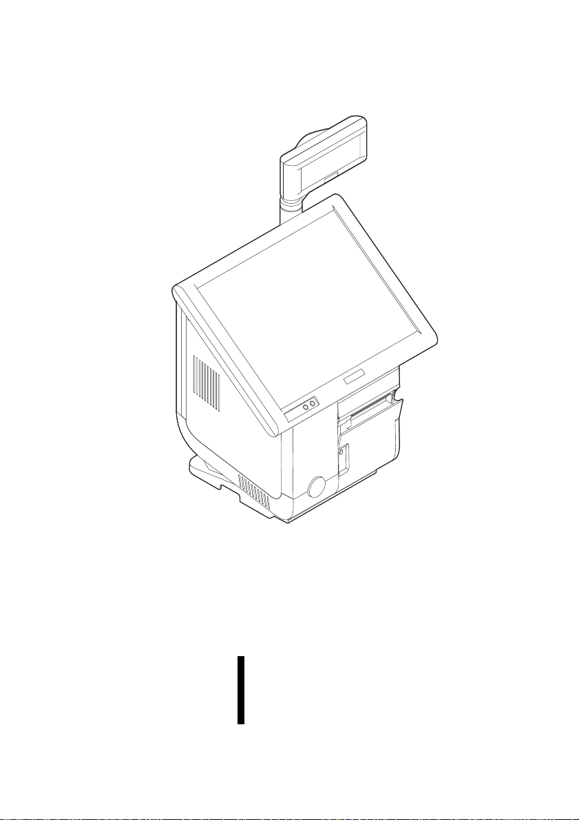
OI-X03
User’s Manual
This manual explains how to use the IR-700 when the OI-X03 is installed. See the IR-700 user’s manual for
information not included in this manual.
Illustrations
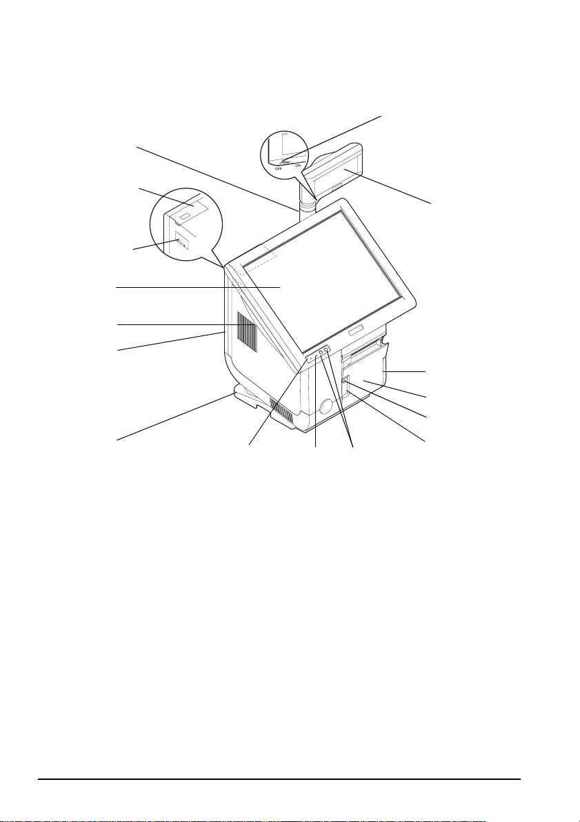
All of the illustrations are at the beginning of this manual. They are identified by letters (A, B, C . . .). Some
of the illustrations have numbers in them. See the list below for the meaning of the numbers. The text has
references to the letters and the numbers. For example: “See Illustration A” or “See A 16.” (“A 16” means
number 16 on Illustration A.)
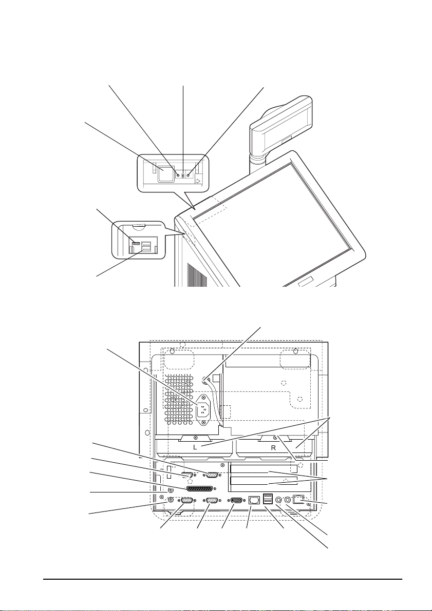
Illustration A: Illustration B: 29. MIC
1. Pole Inside the front cover and side
2. Customer display power switch 31. DM-D
3. Customer display (option) 17. System reset switch 32. Display
4. Printer Unit 18. Disable switch for power switch 33. COM2
5. Printer cover 19. TM printer reset switch 34. COM1
6. Feed button 20. Power switch 35. Keyboard
7. Paper Out LED 21. Speaker volume control knob 36. Mouse
8. LCD brightness adjust button 22. USB 37. Parallel
9. HDD LED Illustration C: 38. COM5
10. Power LED lower side of the IR-700 39. COM6
11. Stand cover 23. TM power 40. AC inlet
12. Back cover 24. HDD Illustration F:
13. LCD lock lever 25. Drawer-kick 41. Printer cover
14. LCD unit 26. PCI slot Illustration J:
15. Side cover 27. Ethernet 42. Feed button
16. Front cover 28. Line-out llustration K:
cover
30. USB
43. Bottom plate
OI-X03 User’s Manual 1
Page 8

English
Part Names
See Illustrations A through C.
Opening the Front Cover
Open the front cover before operating the power switch, the reset switch, or the
disable switch for the power switch. See Illustrations D and B.
Controlling the Speaker Volume
Press the lever of the side cover down and open the side cover. See Illustration E
Control the volume of the speaker with the speaker volume control. Turn the
volume control forward to turn up the volume. Turn it backward to turn down the
volume. See Illustration B
Replacing the Paper
Note:
When the roll paper is used up, the Paper Out LED comes on. Replace the roll paper.
See A 7
The Power Out LED does not come on if the roll paper is near the end. However, if the roll
paper has a color to indicate that the roll is near the end, replace the roll then; do not wait
for the Paper Out LED to come on.
Replace the roll paper by following these steps:
1. Open the printer cover in the direction indicated by the arrow. See
Illustration F
2. Remove the used roll paper core if there is one, and insert the new roll paper.
See Illustration G.
Note:
Be sure that the paper comes off the roll in the correct direction. See Illustration H
3. After pulling out the roll paper a little, close the printer cover.
After closing the printer cover, cut off the end of the roll paper that was pulled
out.
Paper Feed
Press the Feed button to feed paper. See Illustration J
Removing the Stand Cover
Remove the stand cover so that you can connect the AC cable as described in the
next section of this manual. Follow these steps:
1. Lay the IR-700 on its rear cover is on a soft cloth.
Note:
Be careful not to get the IR-700 dirty and not to damage the back cover.
2 OI-X03 User’s Manual
Page 9

2. Loosen one screw and remove the under plate. See illustration K. When
attaching the bottom plate, place the cables of the peripheral devices and the
AC cables in the spaces on both sides.
Note:
Be careful not to pinch the cables with the bottom plate.
3. Loosen four screws and remove the stand cover. See Illustration L
Connecting the AC Cable
After removing the stand cover, connect the AC cable through into the hole to the
AC inlet.
Connecting USB Devices
USB devices can be connected to the USB connectors on the side and back.
Note:
When booting the main unit with USB devices, connect them to the USB connectors on
the side. The USB connectors on the rear are not guaranteed.
English
OI-X03 User’s Manual 3
 Loading...