

Page 1

Display Attached Controller
@E.Terminal for MC
USER'S MANUAL
Hardware
FEH300b
Page 2

Preface
This hardware edition of the user’s manual describes system composition, specifications, and handling of the @E.Terminal.
In order to operate the hardware properly, please read this user’s manual carefully. When using modules or peripheral
devices, be sure to read the corresponding user’s manuals listed below.
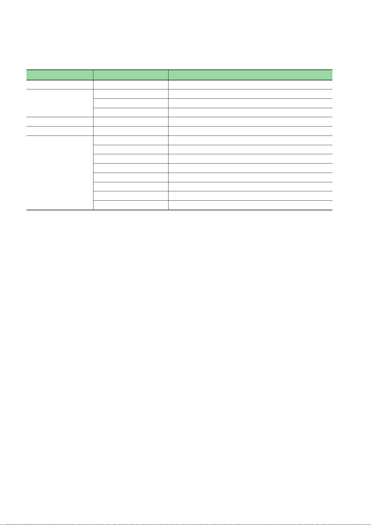
Title Manual No. Contents
@E.Terminal for MC
User's Manual <Function>
V8 series Hardware Specifications 2016NEx Hardware specifications and handling procedures of the
V8 series Reference Manual 1055NEx Describes functions and the usage of the MONITOUCH
V series Macro Reference 1056NEx Describes overview of the macro of the V-SFT version 5,
V8 series Introductory Manual 1057NEx Describes basic operation of the MONITOUCH V8 series.
V8 series Connection Manual 2201NEx The connection and communication parameters for the V8
User's Manual Hardware, MICREX-SX series
SPH
User's Manual Instruction (Standard Loader),
MICREX-SX series
User's Manual SX-Programmer Standard
<Reference>, MICREX-SX series
User's Manual Instruction (D300win),
MICREX-SX series
User's Manual D300win <Reference>,
MICREX-SX series
FALDIC α series User's Manual, RYS-V Type MHT258 (Eng) Describes the specifications and operations of FALDIC α
ALPHA 5 series User's Manual,
RYT-V Type
FEH301 Describes functions and the usage of motion control
content for @E.Terminal for MC.
MONITOUCH V8 series are explained.
V8 series.
the usage of the macro editor and contents of the macro
commands.
series and controllers are explained in detail.
FEH201 Describes the system configuration, the specifications and
operations of modules in the MICREX-SX series.
FEH588 Describes the memory, language and system definitions of
the MICREX-SX series.
FEH590 Describes the menu and icon of the SX-Programmer
Standard all of the operations of the SX-Programmer
Standard.
FEH200 Describes the memory, language and system definitions of
the MICREX-SX series.
FEH257 Describes the menu and icon of D300winV3 and all of the
operations of D300winV3.
series.
MEHT300 Describes the specifications and operations of ALPHA 5
series.
In addition to the above manuals, the following Fuji Electric Systems Co., Ltd. site offers var ious manuals and technical
documents associated with the @E.Terminal for MC.
URL http://www.fesys.co.jp/eng/
Notes
1. This manual may not be reproduced in whole or part in any form without prior written approval by the manufacturer.
2. The contents of this manual (including specifications) are subject to change without prior notice.
3. If you find any ambiguous or incorrect descriptions in this manual, please write them down (along with the manual
No. shown on the cover) and contact FUJI.
Page 3
Be sure to read the “Safety Precautions” thoroughly before using the module.
Warning
◊ Never use the output signal of @E.Terminal for operations that may threaten human life or damage the system, such
as signals used in case of emergency. Please design the system so that it can cope with the malfunctions of a touch
switch. A malfunction of a touch switch will result in machine accident or damage.
◊ Turn off the power supply when you set up the unit, connect new cables or perform maintenance or inspections.
Otherwise, electrical shock or damage may occur.
◊ Never touch any terminals while the power is on. Otherwise, electric shock may occur.
◊ You must put a cover on the terminals on the unit when you turn the power on and operate the unit. Otherwise,
electric shock may occur.
◊ The liquid crystal in the LCD panel is a hazardous substance. If the LCD panel is damaged, do not ingest the leaked
liquid crystal. If the liquid crystal spills on skin or clothing, use soap and wash off thoroughly.
◊ Never disassemble, recharge, deform by pressure, short-circuit, reverse the polarity of the lithium battery, nor dispose
of the lithium battery in fire. Failure to follow these conditions will lead to explosion or ignition.
◊ Never use a lithium battery that is deformed, leaks, or shows any other signs of abnormality. Failure to follow these
conditions will lead to explosion or ignition.
◊ The power lamp flashes when the backlight is at the end of life or is faulty. However, the switches on the screen are
operable at this time. Do not touch the screen when the screen becomes dark and the power lamp flashes.
Otherwise, a malfunction may occur and result in machine accident or damage.
Here, the safety precaution items are classified into “Warning” and “Caution.”
Safety Precautions
Warning
Caution
Even some items indicated by “Caution” may also result in a serious accident.
Both safety instruction categories provide important information. Be sure to strictly observe these instructions.
: Incorrect handling of the device may result in death or serious injury.
: Incorrect handling of the device may result in minor injury or physical damage.
Page 4

Safety Precautions
Caution
◊ Check the appearance of the unit when it is unpacked. Do not use the unit if any damage or deformation is found.
Failure to do so may lead to fire, damage or malfunction.
◊ For use in a facility or for a system related to nuclear energy, aerospace, medical, traffic equipment, or mobile
installations, please consult your local distributor.
◊ Operate (or store) @E.Terminal under the conditions indicated in this manual and related manuals. Failure to do so
could cause fire, malfunction, physical damage or deterioration.
◊ Understand the following environmental limits for use and storage of @E.Terminal. Otherwise, fire or damage to the
unit may result.
- Avoid locations where there is a possibility that water, corrosive gas, flammable gas, solvents, grinding fluids or
cutting oil can come into contact with the unit.
- Avoid high temperature, high humidity, and outside weather conditions, such as wind, rain or direct sunlight.
- Avoid locations where excessive dust, salt, and metallic particles are present.
- Avoid installing the unit in a location where vibration or physical shock may be transmitted.
◊ Equipment must be correctly mounted so that the main terminal of @E.Terminal will not be touched inadvertently.
Otherwise, an accident or electric shock may occur.
◊ Check periodically that terminal screws on the power supply terminal block and fixtures are firmly tightened. Loosened
screws may result in fire or malfunction.
◊ Tighten terminal screws on the power supply terminal block of display part equally to a torque of 0.8 N·m for the
NP5M0101-5H4/4H4, NP5N0011-5H4/4H4, or 1.2 N·m for the NP5M0101-3H4/NP5N-0011-3H4. And tighten terminal
screws on the power supply terminal block of the controller unit equally to a torque of 0.5 to 0.6 N·m. Improper
tightening of screws may result in fire, malfunction, or trouble.
◊ Tighten mounting screws on the unit equally to a torque of 0.5 to 0.7 N·m. Excessive tightening may distort the panel
surface. Loose tightening may cause @E.Terminal to come off, malfunction or be short-circuited.
◊ @E.Terminal has a glass screen. Do not drop or give physical shock to the unit. Otherwise, the screen may be
damaged.
◊ Connect the cables correctly to the terminals of @E.Terminal in accordance with the specified voltage and wattage.
Over-voltage, over-wattage, or incorrect cable connection could cause fire, malfunction or damage to the unit.
◊ Be sure to establish a ground of @E.Terminal. The FG terminal must be used exclusively for the unit with the level of
grounding resistance less than 100Ω. Otherwise, electric shock or a fire may occur.
◊ Prevent any conductive particles from entering into @E.Terminal. Failure to do so may lead to fire, damage, or
malfunction.
◊ After wiring is finished, remove the paper used as a dust cover before starting to operate @E.Terminal. Operation with
the cover attached may result in accident, fire, malfunction, or trouble.
◊ Do not attempt to repair @E.Terminal at your site. Ask us or the designated contractor for repair.
◊ Do not repair, disassemble or modify @E.Terminal. We are not responsible for any damages resulting from repair,
disassembly or modification of @E.Terminal that was performed by an unauthorized person.
◊ Do not use a sharp-pointed tool when pressing a touch switch. Doing so may damage the screen. Doing so may
damage the screen.
◊ Only experts are authorized to set up the unit, connect the cables or perform maintenance and inspection.
◊ Lithium batteries contain combustible material such as lithium or organic solvent. Mishandling may cause heat,
explosion or ignition resulting in fire or injury. Read related manuals carefully and handle the lithium battery correctly
as instructed.
◊ When using @E.Terminal that has analog switch resolution with resistance film, do not press two or more points on the
screen at the same time. If two or more positions are pressed at the same time, the switch located between the
pressed positions activates.
◊ Take safety precautions during such operations as setting change during running, forced output, start, and stop.
Any misoperation may cause unexpected machine motions, resulting in machine accident or damage.
◊ In facilities where a failure of @E.Terminal could lead to accident threatening human life or other serious damage, be
sure that the facilities are equipped with adequate safeguards.
◊ At the time of disposal, @E.Terminal must be treated as industrial waste.
◊ Before touching @E.Terminal, discharge static electricity from your body by touching grounded metal. Excessive static
electricity may cause malfunction or trouble.
◊ The LED lamp on the CF card interface cover illuminates in red when the power is supplied to the CF card.
Never remove the CF card or turn off the power of @E.Terminal while the LED lamp is lit. Doing so may destroy the
data on the CF card. Check that the LED lamp has gone off before removing the CF card or turning off the power of
@E.Terminal.
Page 5

Safety Precautions
[General Notes]
• Never bundle control cables nor input/output cables with high-voltage and large-current carrying cables such as
power supply cables. Keep these cables at least 200 mm away from the high-voltage and large-current carrying
cables. Otherwise, malfunction may occur due to noise.
• When using @E.Terminal in an environment where a source of high-frequency noise is present, it is recommended
that the FG shielded cable (communication cable) be grounded at its ends. However, the cable may be grounded
only at one end if this is necessary due to unstable communication conditions or for any other reason.
• Plug connectors or sockets of @E.Terminal in the correct or ientation. Failure to do so may lead to damage or
malfunction.
• If a LAN cable is inserted into the MJ1 or MJ2 connector on @E.Terminal, the counterpart device may be
damaged. Check the indication on the unit and insert a cable into the correct position.
• Do not use thinners for cleaning because they may discolor @E.Terminal surface. Use alcohol or benzine
commercially available.
• If a data receive error occurs when @E.Ter minal and the counterpart (PLC, temperature controller, etc.) are
started at the same time, read the manual for the counterpart unit and remove the error correctly.
• Avoid discharging static electricity on the mounting panel of @E.Terminal. Static charges can damage the unit and
cause malfunctions. Otherwise, malfunction may occur due to noise.
• Avoid prolonged display of any fixed pattern. Due to the characteristics of the liquid crystal display, an afterimage
may occur. If a prolonged display of a fixed pattern is expected, use the auto OFF function of the backlight.
[Notes on LCD]
Note that the following conditions may occur under normal circumstances.
• The response time, brightness and colors of @E.Terminal may be affected by the ambient temperature.
• Tiny spots (dark or luminescent) may appear on the display due to the liquid crystal characteristics.
• There are variations in brightness and colors on each unit.
• Cold cathode tubes are incorporated into the LCD display for backlights. Optical properties (brightness, irregular
colors, etc.) may change in a low-temperature environment or over time of operation.
Page 6

*Manual No. is shown on the cover.
Printed on *Manual No. Revision contents
Aug. 2008 FEH300 First edition
Nov. 2008 FEH300a • Display part is changed from UG40 series to V8 series.
• Accessory "Noise filter" is eliminated from controller hardware version "03" or later.
Dec. 2008 FEH300b @E.Terminal (No contents installed) was added.
Revisions
Page 7

Contents
Preface
Safety Precautions
Revisions
Contents
Page
Section 1 General ..........................................................................................1-1
1-1 Overview of @E.Terminal for MC.................................................................................................. 1-1
1-2 Appearance ..................................................................................................................................... 1-2
1-3 Types................................................................................................................................................ 1-3
1-4 System Composition...................................................................................................................... 1-5
Section 2 Specifications ...............................................................................2-1
2-1 Specifications ................................................................................................................................. 2-1
2-1-1 General specifications ........................................................................................................................... 2-1
2-1-2 Display unit specifications ..................................................................................................................... 2-2
2-1-3 Controller unit specifications ................................................................................................................. 2-6
2-2 Dimensions and Panel Cut-out ..................................................................................................... 2-8
2-2-1 External dimensions and panel cut-out dimensions for the NP5M0101-5H4/NP5N0011-5H4............ 2-8
2-2-2 External dimensions and panel cut-out dimensions for the NP5M0101-4H4/NP5N0011-4H4............ 2-9
2-2-3 External dimensions and panel cut-out dimensions for the NP5M0101-3H4/NP5N0011-3H4.......... 2-10
2-3 Names and Functions .................................................................................................................. 2-11
2-3-1 Display unit .......................................................................................................................................... 2-11
2-3-2 Controller unit ...................................................................................................................................... 2-14
2-4 Serial Connector........................................................................................................................... 2-16
2-5 Modular Jack (MJ1 / MJ2)............................................................................................................ 2-17
2-6 Dip Switches ................................................................................................................................. 2-18
Section 3 Installation ....................................................................................3-1
3-1 Mounting Procedure ...................................................................................................................... 3-1
3-2 Power Supply Cable Wiring ........................................................................................................... 3-2
Section 4 Inspection and Maintenance .......................................................4-1
4-1 Inspection and Maintenance ......................................................................................................... 4-1
4-1-1 Daily inspection ..................................................................................................................................... 4-1
4-1-2 Periodical inspection ............................................................................................................................. 4-1
4-2 Battery Replacement ..................................................................................................................... 4-2
4-3 Maintenance Services.................................................................................................................... 4-4
4-3-1 Ordering notes....................................................................................................................................... 4-4
4-3-2 Free-of-charge warranty period and scope of warranty........................................................................ 4-4
4-3-3 Service costs ......................................................................................................................................... 4-4
Appendix 1
About Project for @E.Terminal (No contents installed)
...
App.
1-1
Page 8

Section 1 General
Page
1-1 Overview of @E.Terminal for MC...............................................................................1-1
1-2 Appearance ................................................................................................................. 1-2
1-3 Types ............................................................................................................................1-3
1-4 System Composition ..................................................................................................1-5
Page 9
Section 1 General
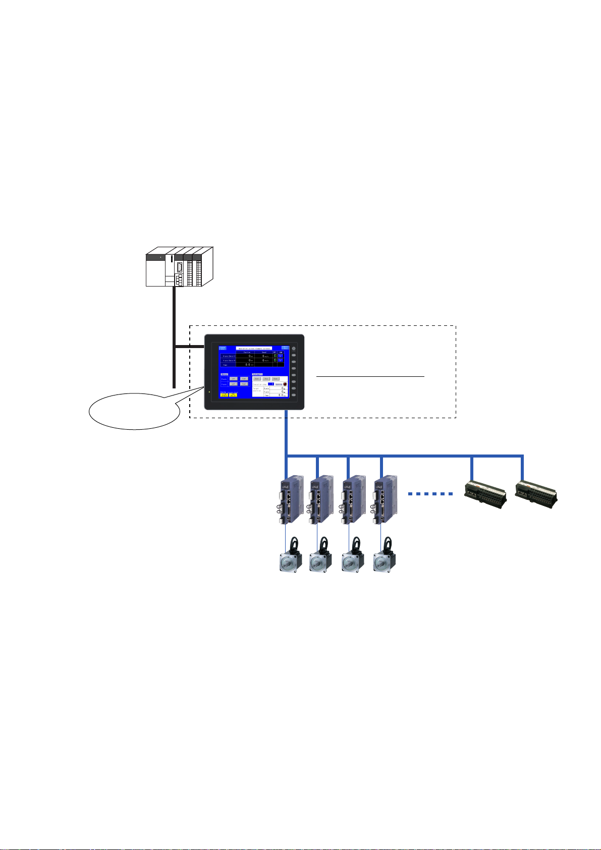
1-1 Overview of @E.Terminal for MC
The @E.Terminal for MC Display Attached Controller is an all-in-one programmable operation displa y and motion controller.
Features:
1) The guidance function of the display screen allows you to easily set up parameters and positioning data
previously set up by a dedicated machine.
Also, it enables easy equipment maintenance.
2) The SX bus allows one-touch connection of up to eight servo amplifiers (axes) (FALDIC-α and APLHA5 VS
type), minimizing the need for wires.
3) The upper level controller can be connected by Ethernet and the like.
4) The lineup includes three different display screen sizes. 8 inch, 10 inch and 12 inch models are available.
5) The content corresponding to motion is supplied in the standard package.
Content for PTP control and synchronous control (ratio synchronization, cycle synchronization, flying shear, and
rotary shear) are provided.
Ethernet, ctc.
@E.Terminal for MC
Contents for motion control
• Screen data
• Controller built-in software
Motion functions
(Setting/Display)
SX bus Note)
Note: The SX bus is a MICREX-SX series dedicated high-speed serial bus.
1-1
Page 10
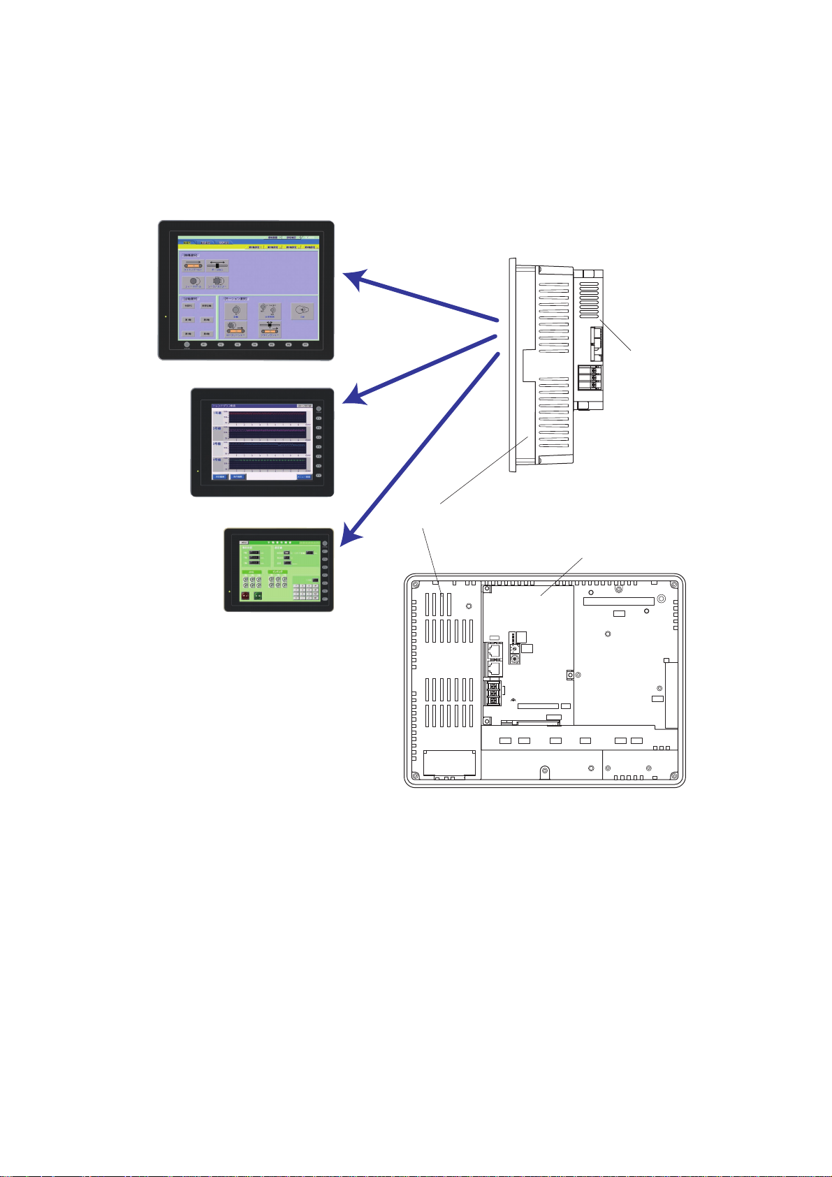
1-2 Appearance
@E.Terminal for MC is composed of a programmable operation display (the display unit) and a controller unit attached to
the back of the display unit.
The controller unit is attached with screws to the connector area of the communication unit at the back of the display unit,
similar to the way in which the communication unit is attached.
Type 12
Controller unit
Type 10
Type 8
Front
Display unit
SX-BUS
Side
Controller unit
CN5
ONL
ERR
UROM
RUN
IN
ALM
BAT
4:RUN
3:U-TERM
2:TERM
1:STOP
CPU
No.
OUT
+
24V DC
FG
MJ2
MJ1
USER ROM CARD
USB
LOADER
CN1
CN7
CF
LAN
U-AU-B
Back
1-2
Page 11
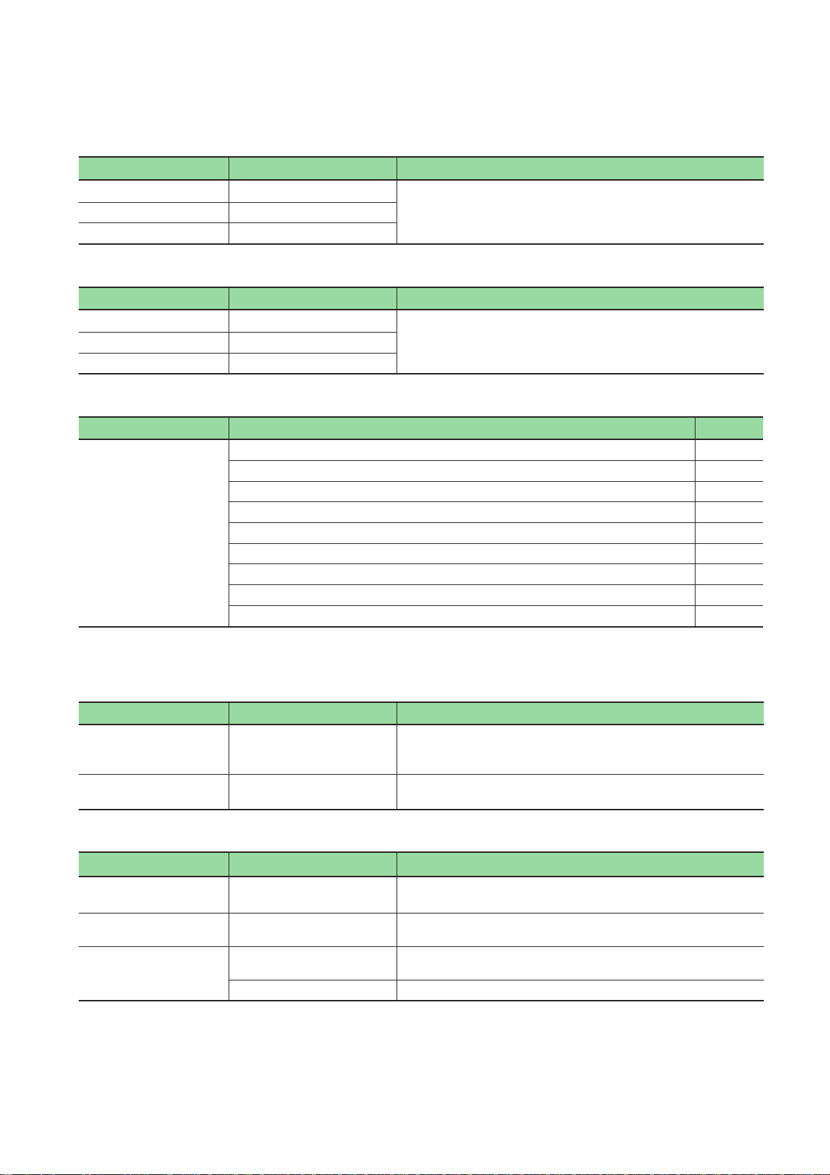
1-3 Types
• @E.Terminal for MC
Product types Display size Specifications
NP5M0101-5H4 12.1 inches
NP5M0101-4H4 10.4 inches
NP5M0101-3H4 8.4 inches
• @E.Terminal (No contents installed)
Product types Display size Specifications
NP5N0011-5H4 12.1 inches
NP5N0011-4H4 10.4 inches
NP5N0011-3H4 8.4 inches
• Accessories
Product types Names Quantity
NP5M0101-5H4
NP5M0101-4H4
NP5M0101-3H4
NP5N0011-5H4
NP5N0011-4H4
NP5N0011-3H4
Instruction Manual 1
Backup CD of the @E.Terminal for MC Note1) 1
SX bus terminating plug 2
Screw driver 1
Fixture 4
Binder for USB cable (Only NP5M0101-3H4/NP5N0011-3H4) 1
USB cable cramp for port A/B (Only NP5M0101-5H4/4H4, NP5N0011-5H4/4H4) 2
M3 x 8 screw for USB cable cramp (Only NP5M0101-5H4/4H4, NP5N0011-5H4/4H4) 2
Noise filter Note2) 1
• TFT color, 800 x 600 dots, DC power supply
• Controller unit
• Contents of the motion control
(Screen data, built in software in the controller)
• TFT color, 800 x 600 dots, DC power supply
• Controller unit
• No contents installed
Note 1: Backup CD is not attached to NP5N0011-5H4/4H4/3H4.
Note 2: Noise filter is not attached from controller unit hardware version “03” or later.
• Screen drawing tools
Names Types Specifications
Configuration software:
English version
Screen data transfer cable V-CP 3m, Used for connection between the V8 series and a personal
V-SFT-5 Screen editor:
Windows98SE/NT4.0/Me/2000/XP/XP64Edition/Vista32-bit
compatible
computer.
• Programming support tool for controller
Names Types Specifications
SX-Programmer Standard NP4H-SWN Programming support tool SX-Programmer Standard,
SX-Programmer Expert
(D300win)
Support tool cable NW0H-CNV RS-232C/RS-485 converter for the programming support tool for AT
NP4H-SEDBV3 IEC61131-3 based on Programming support tool D300winV3,
NW0H-CA3 Support tool connection cable (Used to combined the NW0H-CNV)
Standard expansion FB, Windows95/98/ME/2000/XP/NT4.0
Standard expansion FB, Windows2000/XP/NT4.0
compatible personal computer
1-3
Page 12
1-3 Types
• Auxiliaries and others
Names Types Specifications
Battery for display unit V7-BT Replacement lithium primary battery for the V8 series
Replacement backlight for
TFT
Battery for controller NP8P-BT Primary lithium battery for memory data backup for controller unit
SX bus terminating plug NP8B-BP For SX bus loop terminating (1 piece)
SX bus expansion cabl NP1C-P3 Cable length: 300mm
V812-FL Replacement backlight for V812 TFT
V810-FL Replacement backlight for V810S TFT
V808S-FL Replacement backlight for V808S TFT
NP1C-P6 Cable length: 600mm
NP1C-P8 Cable length: 800mm
NP1C-02 Cable length: 2000mm
NP1C-05 Cable length: 5000mm
NP1C-10 Cable length: 10000mm
NP1C-15 Cable length: 15000mm
NP1C-25 Cable length: 25000mm
* For information about peripheral accessories of the display unit not documented in this manual, please refer to “V8
series Hardware Specifications (2016NEx)”.
1-4
Page 13
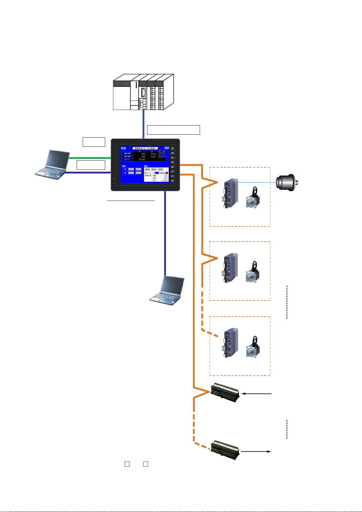
1-4 System Composition
@E.Terminal for MC
Screen editor
"V-SFT-5"
(V5.3.0.0 or later)
SX bus
Ethernet/RS-232C or RS-485
LAN/CN1/MJ1/MJ2
USB-B
MJ1/MJ2
External PG
(only No. 1 axis)
[No. 1 axis]
SX bus station No.: "201"
[No. 2 axis]
SX bus station No.: "202"
[No. 8 axis]
SX bus station No.: "208"
FALDIC ALPHA5
FALDIC - α
FALDIC ALPHA5
FALDIC - α
FALDIC ALPHA5
FALDIC - α
"V-CP"
Up to 8 servos and I/O terminals each
can be connected.
SX bus station No.: "221"
SX bus station No.: "228"
I/O terminal
Input 8 points/
Output 8 points
(NR1SW-16T65DT)
I/O terminal
Input 8 points/
Output 8 points
(NR1SW-16T65DT)
Starting up signal etc.
RDY etc.
Programming support tool
SX-Programmer Standard
"NP4H-SWN" (V2.3.5.1 or later)
SX-Programmer Expert (D300win)
"NP4H-SEDBV3" (V3.4.4.0 or later)
"NW0H-CNV + NW0H-CA3"
or
commercially available USB cable
PLC/general purpose
computer
The following illustration shows the system composition of @E.Terminal for MC.
Note) Connectable servo amplifier
FALDIC- α (RYS***S3-VSS, RYS***M3-VSK)
FALDIC ALPHA5 (RYT*** 5-VS )
1-5
Page 14

Section 2 Specifications
Page
2-1 Specifications.............................................................................................................. 2-1
2-1-1 General specifications........................................................................................................... 2-1
2-1-2 Display unit specifications..................................................................................................... 2-2
(1) Display unit specifications....................................................................................................................... 2-2
(2) Touch switch specifications .....................................................................................................................2-2
(3) Function switch specifications.................................................................................................................2-2
(4) Interface specifications ...........................................................................................................................2-3
(5) Clock and backup memory specifications............................................................................................... 2-3
(6) Drawing environment ..............................................................................................................................2-4
(7) Display function specifications ................................................................................................................2-4
(8) Function performance specifications ......................................................................................................2-5
2-1-3 Controller unit specifications ................................................................................................. 2-6
(1) Application performance specifications...................................................................................................2-6
(2) Specific system memory .........................................................................................................................2-7
2-2 Dimensions and Panel Cut-out..................................................................................2-8
2-2-1 External dimensions and panel cut-out dimensions for the
NP5M0101-5H4/NP5N0011-5H4.......................................................................................... 2-8
2-2-2 External dimensions and panel cut-out dimensions for the
NP5M0101-4H4/NP5N0011-4H4 .......................................................................................... 2-9
2-2-3 External dimensions and panel cut-out dimensions for the
NP5M0101-3H4/NP5N0011-3H4 ........................................................................................ 2-10
2-3 Names and Functions............................................................................................... 2-11
2-3-1 Display unit.......................................................................................................................... 2-11
(1) NP5M0101-5H4/NP5N0011-5H4.......................................................................................................... 2-11
(2) NP5M0101-4H4/NP5N0011-4H4.......................................................................................................... 2-11
(3) NP5M0101-3H4/NP5N0011-3H4.......................................................................................................... 2-12
2-3-2 Controller unit...................................................................................................................... 2-14
2-4 Serial Connector .......................................................................................................2-16
2-5 Modular Jack (MJ1 / MJ2)......................................................................................... 2-17
2-6 Dip Switches.............................................................................................................. 2-18
Page 15

Section 2 Specifications
2-1 Specifications
2-1-1 General specifications
Items
Physical
environmental
conditions
Mechanical
working
conditions
Electrical
working
conditions
Power supply Rated input voltage 24V DC (Note2)
Isolation resistance 500 V DC, 5 MΩ or more
Dimensions WxHxD(mm) 326.4 x 259.6 x 99.0 303.8 x 231.0 x 99.0 233.0 x 178.0 x 96.0
Mass Approx. 3.5 kg Approx. 3.1 kg Approx. 2.1 kg
Note 1) Pollution degree 2: This pollution does not conduct usually, but under certain circumstances temporary
Note 2) Use 24V DC power supply which comply to UL standard Class2 insulation.
Operational ambient
temperature
Storage ambient
temperature
Operational ambient
humidity
Operational altitude 2000 m or less above sea level (Transport condition: 70 kPa or more)
Operational atmosphere No corrosive gas, no excessive dust, no conductive dust contamination, and
Pollution degree 2 (Note1)
Vibration resistance Half-amplitude: 0.075 mm, acceleration: 9.8 m/s
Shock resistance Peak acceleration: 147 m/s
Noise resistance Rising time: 1 ns, pulse width: 1 µs, Noise voltage: 1.5 kVp-p
Static electricity
discharge resistance
Rated voltage (tolerance) 24V DC ±10%
Permissible momentary
power failure
power supply consumption
(Max. rated)
Rush current 170 A or less
Input terminal block
Display unit Terminal block screw: M3.5 - (Connection to the
Controller unit Terminal block screw: M3
Dielectric strength 500 V AC 1 minute (Between external terminals and frame ground)
conductivity occurs due to condensation.
Specifications
NP5M0101-5H4
NP5N0011-5H4
0to+50°C
-10 to +60 °C
85 % RH or less
(Without dew condensation, max. wet-bulb temperature: 39 °C or less)
not stained with organic solvents.
X, Y, Z: 3 directions for one hour
(Measured by using a noise simulator.)
Contact: ±4 kV, air: ±8 kV
1 ms or less
42 W or less 37 W or less 35 W or less
Tightening torque: 0.8 N·m
Tightening torque: 0.5 to 0.6 N·m
NP5M0101-4H4
NP5N0011-4H4
2
, X, Y, Z: 3 directions three times each
NP5M0101-3H4
NP5N0011-3H4
2
,
controller unit)
• Installation specifications
Item Specifications
Grounding Less than 100Ω, FG/SG separated
Protection structure Front panel (Note 1) Compliant with IP65 (When using waterproof gasket) (Note 2)
Cooling system Cooling naturally
Structure Inserted in a mounting panel
Appropriate mounting panel thickness 1.5 to 5 mm
Note: 1) Protection structure for the front when the @E.Terminal is mounted on the mounting panel.
Note: 2) It is recommended to use the mounting panel whose thickness (steel, stainless) is 3.0 mm or more to keep the
unit compliant with IP65. The strength differs depending on the material of the mounting panel. Check the
environment where the @E.Terminal is used.
2-1
Page 16

2-1 Specifications
2-1-2 Display unit specifications
(1) Display unit specifications
Item
Display device TFT color
Display size 12.1-inch 10.4-inch 8.4-inch
Colors 65,536 colors (without blinks) / 32,768 colors (with blinks)
Display resolution (W x H) 800 x 600 dots
Dot pitch (W x H) 0.3075 x 0.3075 mm 0.264 x 0.264 mm 0.2135 x 0.213 mm
Backlight Cold cathode tube
Backlight life
(average life of backlight only)
Backlight auto OFF function Always ON, random setting
Brightness adjustment Function switch: 3 levels / Macro: 128 levels
Surface sheet material Polycarbonate, 0.3 mm thick
POWER lamp ON: Normal (green)
NP5M0101-5H4
NP5N0011-5H4
Approx. 50,000 hours (at the normal temperature of 25° C)
Blink: Backlight error
NP5M0101-4H4
NP5N0011-4H4
NP5M0101-3H4
NP5N0011-3H4
(2) Touch switch specifications
Item Specifications
Method Analog resistance film type
Number of switches 1024 x 1024
Mechanical life One million activations or more
Surface treatment Hard-coated, anti-glare treatment 5 %
(3) Function switch specifications
Item Specifications
Number of function switches 8 pcs.
Method Matrix resistance film type
Mechanical life One million activations or more
2-2
Page 17

2-1 Specifications
(4) Interface specifications
Item Specifications
D-sub 9-pin (CN1) Applicable
Modular jack 8-pin
(MJ1/MJ2)
USB connector
(USB-A/B)
Ethernet port
100BASE-TX/
10BASE-T
(LAN)
CF card interface Compliant with CompactFlash
Extensional communication port
(CN5)
Optional unit port (CN7) RGB input/output, video, sound
Note) For details, refer to the User’s Manual <V8 Series Connection Manual> (2201NEx).
(5) Clock and backup memory specifications
Item Specifications
Battery specification Coin-type lithium primary cell
Backup memory SRAM 512 kbytes
Backup period Approx. 5 years (Ambient temperature at 25 °C)
Battery voltage drop detection Provided (Internal memory of $s167 allocated)
Calendar accuracy Monthly deviation ±90 s (Ambient temperature at 25 °C) (Note)
Note) Time loss is approximately 90 seconds a month in an ambient temperature of 25 °C in the non-energized state
(backup with battery). Depending on the ambient temperature, the calendar may lose 356 seconds or advance
189 seconds in a month at the maximum. Correct the clock periodically.
standards
Synchronization Asynchronous type
Data length 7- or 8-bit
Parity None, odd, even
Stop bit 1- or 2-bit
Baud rate 4800, 9600, 19200, 38400, 57600, 76800, 115.2kbps
Applications PLC, temperature controller, barcode reader, etc.
Applicable
standards
Applications Screen data transfer (MJ1), PLC, temperature controller, CREC, barcode reader,
Applicable
standards
Baud rate Low speed: 1.5 Mbps, full speed: 12 Mbps
USB-AUSB-B
Applications Printer (EPSON PM series), CF card reader/writer
Applicable
standards
Baud rate Low speed: 1.5 Mbps, full speed: 12 Mbps
Applications Screen data transfer, PictBridge-compatible printer
Applicable
standards
Baud rate 100 Mbps, 10 Mbps
Recommended
cable
Applications PLC connection, etc.
RS-232C, RS-422/485
(187500 bps for MPI connection (Note))
RS-232C, RS-485 (2-wire connection)
V-I/O, Multi-link 2, V-Link, etc.
Compliant with USB version 1.1
Compliant with USB version 1.1
Compliant with IEEE802.3u (100BASE-TX), IEEE802.3 (10BASE-T)
100 Ω UTP (unshielded twist-pair cable), category 5, max. 100 m long
TM
Controller unit connection
(The communication unit is not connectable.)
(The optional unit "GU-xx" is necessary.)
2-3
Page 18

2-1 Specifications
(6) Drawing environment
Item Specifications
Drawing method Exclusive configuration software
Drawing tool Name of exclusive configuration software: V-SFT-5
(7) Display function specifications
Item Specifications
Interface language (Note: 1) Japanese English/
Characters 1/4-size, 1-byte ANK code Latin 1 ASCII code ASCII code ASCII code
2-byte 16-dot JIS #1, 2 levels - Chinese
2-byte 32-dot JIS #1 level - - - -
Font Windows font
Character size 1/4-size 8 x 8 dots
1-byte 8 x 16 dots
2-byte 16 x 16 dots or 32 x 32 dots
Enlargement
factor
Number of
displayable
characters
Character properties Display properties: Normal, reverse, blink, bold, shadow, transparent
Graphics Lines: Line, continuous line, box, parallelogram, polygon
Graphic properties Line types: 6 (thin, thick, dot, chain, broken, two-dot chain)
Note: 1) In addition, the following fonts are available.
Gothic, English/Western Europe HK Gothic, English/Western Europe HK Times, Central Europe, Cyrillic, Greek,
Turkish. For more information, refer to the “V8 series Reference Manual.”
Note: 2) Applicable when Gothic font, Windows font or stroke font is used.
Display
resolution
1/4-size 100 characters x 75 lines
1-byte 100 characters x 37 lines
2-byte 57 characters x 37 lines
Personal computer: Pentium III 800 MHz or above
OS: Windows98SE/NT4.0/Me/2000/XP/XP64 Edition/Vista 32-bit
Capacity of hard disk required:
Display: Resolution 1024 x 800 or above
Stroke font (under development)
X: 1 to 8 times, Y: 1 to 8 times
Point (Note: 2) : 8, 9, 10, 11, 12, 14, 16, 18, 20, 22, 24, 26, 28, 36, 48, 72
800 x 600
Colors: 65,536 colors (without blinks) / 32,768 colors (with blinks)
Circles: Circle, arc, sector, ellipse, elliptical arc
Others: Tile patterns
Tile patterns: 16 (incl. user-definable 8 patterns)
Display properties: Normal, reverse, blink
Colors: 65,536 colors (without blinks) 32,768 colors (with blinks)
Color selection: Foreground, background, boundary (line)
(Pentium IV 2.0 GHz or above recommended)
Free space of approx. 850 Mbytes or more
Screen color: 16 bits or more
Western Europe
Chinese
(Traditional)
(traditional)
Chinese
(Simplified)
Chinese
(simplified)
Korean
Hangul
(without Kanji)
2-4
Page 19

2-1 Specifications
(8) Function performance specifications
Item Specifications
Screens Max. 1024
Screen memory Flash memory: Approx. 12.5 Mbytes (Varies depending on the font)
Switch 1024 per screen
Switch actions Set, reset, momentary, alternate, to light
Lamp Reverse, blink, exchange of graphics
Graph Pie, bar, panel meter and closed area graph:No limitation
Data
setting
Sampling Sampling display of buffer data
Graphic library Max. 2560
Overlap library Max. 1024
Data blocks Max. 1024
Messages Max. 32768 lines
Patterns Max. 1024
Macro blocks Max. 1024
Page blocks Max. 1024
Direct blocks Max. 1024
Screen blocks Max. 1024
Data sheets Max. 1024
Screen library Max. 1024
Comments Max. 32768
Device memory map Max. 32 x 8 (PLC1 to PLC8)
Time display Provided
Hard copy Provided
Buzzer Provided, 2 sounds (short beep, long beep)
Auto OFF function Always ON, random setting
Self-diagnostic function Switch self-test function
Note: 1) The number of setting memor y locations is limited to 1024 per screen.
Note: 2) Layer: 4 per screen (base + 3 overlap displays)
Numerical data display No limitation
Character display No limitation
Message display Display resolution: 800 x 600: Max. 100 characters (1-byte)
(Possible to press a function switch and a switch on the display at the same time)
1024 per screen
Statistics and trend graphs: Max. 256 per layer (Note: 2)
No limitation
(Constant sampling, bit synchronization, alarm logging, time order alarming, alarm
function)
Communication parameter setting check function
Communication check function
2-5
Page 20

2-1 Specifications
2-1-3 Controller unit specifications
(1) Application performance specifications
Item Specifications
Type NP5M0101-5H4/4H4/3H4 NP5N0011-5H4/4H4/3H4
Control system Stored program,
Input / Output connection method Direct input / output (SX bus)
I/O control system Via SX bus: Synchronous refresh with takt
CPU 32-bit RISC processor
Memory types Program memory, data memory, temporary memory
Programming language <When used the D300win> <When used the Standard Loader>
Program memory capacity 49152 steps
Memory I/O memory 512 words
General memory 65536 words
Retain memory 22528 words 8192 words
User FB instance memory 4096 words 8192 words
Memory for
System FB
System memory 512 words
No. of tasks Default tasks (Cyclic scanning): 1
No. of programs Max. 256 (Max. 128 for one task)
Diagnosis function Self diagnosis (memory checking, ROM sum checking), system configuration
Secret preserving function By password (set with the support tool)
Calendar Available up to 12/31/2069 23:59:59
Backup of application program Flash ROM built in CPU module
User ROM function Application programs, system definitions, zipped files and compressed projects
Backup of data
memory
Note: The application specifications of the controller unit are equivalent to those of the NP1PM-48R MICREX-SX series
CPU module. For more information on memory, language, and system definition, please refer to “User’s Manual
Instruction Edition, MICREX-SX series” as appropriate for your programming support tool.
• SX-Programmer Standard FEH588
• SX-Programmer Expert (D300win) FEH200
Timer
Integrating timer 64 points 128 points
Counter 128 points 256 points
Edge detection 512 points 1024 points
Others 2048 words 8192 words
Backup area Retain memory, retain attributed memory (e.g. current value of counter),
Battery Lithium primary cell, replacement time: 5 minutes or less (at 25 °C)
Backup period Approx. 5 years (at 25 °C)
Cyclic scanning system (default task), periodic task, event task
IL language (Instruction List) LD language
ST language (Structured Text) ST language
LD language (Ladder Diagram)
FBD language (Function Block Diagram)
SFC elements (Sequential Function Chart)
(Up to 256 words, useable I/O memory on the @E.Termina for MC.)
6144 words 16384 words
256 points 512 points
Periodic tasks: 4
Event tasks : 4 (Total of 4 tasks when periodic task is used)
monitoring, module fault monitoring
Precision: ± 27 s/month (at 25 °C, when active)
Backup area: Application program, system definition, ZIP file
can be stored in user ROM cards.
calendar IC memory, RAS area
2-6
Page 21

2-1 Specifications
(2) Specific system memory
The table below lists system memory specific to @E.Terminal controller unit.
[Expansion annunciator relay area]
Address Names Descriptions
SM1240
(%MX10.124.0)
[Cause of memory error]
Address Names Descriptions Level
SM84
(%MX10.8.4)
Display unit connection status
flag
Display unit DPRAM error Turns ON when an error occurs in DPRAM for
Represents whether a display unit is connected
(ON/OFF of display unit power supply).
1: Connected 0: None
Fatal fault
display unit I/F in controller unit.
2-7
Page 22

2-2 Dimensions and Panel Cut-out
2-2-1 External dimensions and panel cut-out dimensions for the NP5M0101-5H4/NP5N0011-5H4
(Unit: mm)
• Front view
259.6
• Rear view
245.2
+0.5
326.4
+0.5
-0
313.0
-0
Panel cut-out dimensions
246.2
F 2
F 1
SYSTEM
F 7F 6F 5F 4F 3
• Side view
312.0
CN5
ONL
SX-BUS
ERR
UROM
RUN
IN
ALM
BAT
4:RUN
3:U-TERM
2:TERM
1:STOP
CPU
No.
OUT
+
24V DC
FG
USER ROM CARD
LOADER
CN1
MJ1
MJ2
CN7
USB
LAN
CF
U-B U-A
(66)
Note)
99.0
7.0
• Bottom view
99.0
312.0
Note: Arrange SX bus expansion cable so that
radius of bend in the cable is at least 50mm.
Plug/unplug the SX bus expansion cable in
the perpendicular direction.
2-8
Page 23

2-2 Dimensions and Panel Cut-out
2-2-2 External dimensions and panel cut-out dimensions for the NP5M0101-4H4/NP5N0011-4H4
(Unit: mm)
• Front view
231.0
303.8
SYSTEM
F 1
F 2
F 3
F 4
F 5
F 6
F 7
-0
+0.5
216.2
Panel cut-out dimensions
289.0
+0.5
-0
• Rear view
215.2
• Bottom view
99.0
• Side view
288.0
CN5
ONL
SX-BUS
ERR
UROM
RUN
IN
ALM
BAT
4:RUN
3:U-TERM
2:TERM
1:STOP
CPU
No.
OUT
+
24V DC
FG
USER ROM CARD
LOADER
MJ2
CN1
MJ1
CN7
USB
LAN
CF
U-AU-B
(66)
Note)
288.0
99.0
7.0
Note: Arrange SX bus expansion cable so that
radius of bend in the cable is at least 50mm.
Plug/unplug the SX bus expansion cable in
the perpendicular direction.
2-9
Page 24

2-2 Dimensions and Panel Cut-out
2-2-3 External dimensions and panel cut-out dimensions for the NP5M0101-3H4/NP5N0011-3H4
(Unit: mm)
• Front view
178.0
233.0
-0
+0.5
Panel cut-out dimensions
165.5
220.5
+0.5
-0
• Rear view
SX-BUS
IN
CN5
165.0
OUT
+
FG
• Bottom view
96.0
• Side view
220.0
(66)
96.0
6.9
ONL
ERR
UROM
RUN
ALM
BAT
4:RUN
3:U-TERM
2:TERM
1:STOP
CPU
No.
24V DC
24VDC
FG
USB
USER ROM CARD
CN1
LOADER
CN7
LAN
MJ1
CF
Note)
U-B
U-A
MJ2
220.0
Note: Arrange SX bus expansion cable so that
radius of bend in the cable is at least 50mm.
Plug/unplug the SX bus expansion cable in
the perpendicular direction.
2-10
Page 25

2-3-1 Display unit
(1) NP5M0101-5H4/NP5N0011-5H4
1)
2-3 Names and Functions
4)
6)
8)
5)
2)
F 2
F 1
SYSTEM
3)
(2) NP5M0101-4H4/NP5N0011-4H4
1)
CN5
CN1
MJ1
MJ2
F 7F 6F 5F 4F 3
CN7
7)
CF
U-B U-A
LAN
16)
15)14)13)12)11)10)9)
17)
4) 5)
6)
8)
2)
SYSTEM
F 1
F 2
F 3
F 4
F 5
F 6
F 7
3)
9) 10)
CN5
MJ2
CN1
MJ1
11) 12) 13) 14) 15)
CN7
CF
7)
LAN
U-AU-B
16)
17)
2-11
Page 26

2-3 Names and Functions
(3) NP5M0101-3H4/NP5N0011-3H4
1)
4)
6)
5)
CF
7)
3)
CN7
CN5
2)
24VDC
9)
FG
12)
LAN
U-B
MJ2
MJ1
14) 15)
U-A
CN1
13)
16)
8)
10) 11)
17)
1) Display
This is the display unit.
2) Power lamp (POWER)
Illuminates in green when the display unit is powered on, and is operating normally. Flashes when an error occurs to the
backlight (burned-out backlight, etc.).
3) Function keys
Used for RUN/STOP selection, brightness adjustment and backlight ON/OFF (setting on the V-SFT-5 editor required).
These switches can be used as user-defined switches in the RUN mode.
4) Communication interface unit connector (CN5)
Connects with the controller unit.
* Hidden by the controller unit.
5) Optional unit connector (CN7)
Used for mounting the optional unit “GU-xx” for video input, sound output, RGB input or RGB output.
6) Battery holder
Contains a backup battery for SRAM and clock.
When the battery voltage drops, replace the battery with a new one (V7-BT).
* Hidden by the controller unit. Replace battery by detaching the controller unit.
7) CF card connector (CF)
This is the connector where the CF card is inserted. Access to the CF card is enabled when the cover is closed.
8) Dip switch
8-bit Dip switch used for setting terminating resistance of the CN1 signal line and the MJ1/MJ2 RS-485 signal line.
* In NP5M0101-5H4/4H4, NP5N0011-5H4/4H4, the dip switch is hidden by the controller unit. Operate dip switch by
detaching the controller unit.
2-12
Page 27

2-3 Names and Functions
9) Power supply terminal block (display unit)
Supplies the power to the display unit (24 V DC).
10) Modular jack 1 (MJ1)
Used for screen data transfer and connection with PLCs or other peripheral devices.
11) Modular jack 2 (MJ2)
Used for connection with PLCs or other peripheral devices.
12) PLC communication connector (CN1)
Used for connection with a controller (PLC, temperature controller, inverter, etc.).
13) 100BASE-TX/10BASE-T connector (LAN)
Used for Ethernet connection.
14) USB-B (slave port)
Used for screen data transfer or connection with a PictBridge-compatible printer.
15) USB-A (master port)
This is the connector where a printer or a CF card reader/writer is connected.
16) USB cable clamp mounting hole
For NP5M0101-5H4/4H4, NP5N0011-5H4/4H4, this hole is used for attaching a USB cable clamp.
For NP5M0101-3H4/NP5N0011-3H4, this hole is used for attaching a USB cable binder.
17) Mounting holes
Used for inserting fixtures when securing the @E.Terminal to the mounting panel.
2-13
Page 28

2-3 Names and Functions
2-3-2 Controller unit
1) Status indication
LED
5) SX bus
connector
6) Power supply
terminal block
(3 poles)
Version No.
SX-BUS
IN
OUT
Name plate
+
24V DC
FG
ONL
ERR
UROM
RUN
ALM
BAT
4:RUN
3:U-TERM
2:TERM
1:STOP
CPU
No.
USER ROM CARD
Seal of the occasion of next
battery replacement
2) Key switch
3) CPU No. selection key switch
USB
LOADER
4) Data backup
battery
9) USB-miniB connector
card (CF card)
8) Loader connector 7) Connector for user ROM
2-14
Page 29

2-3 Names and Functions
1) Status indication LED (Controller unit)
Symbol Color Descriptions
ONL
ERR
UROM Green Lights on continuously when the CPU recognizes a user ROM card.
RUN
ALM
Green
Red
Green
Red
Status of the controller unit.
<Lights on pattern>
ONL ERR Status of controller unit
OFF OFF Power OFF, system resetting or initializing
Blinks - SX bus standing on
ON OFF Normally running
ON ON Nonfatal fault, at a running
OFF ON Fatal fault at a stop
Lights on continuously when a user ROM card (compact flash card) is correctly installed in the CPU
module and the key switch is set to "3" or "4".
Status of system of the conntroller unit.
(Note)
<Lights on pattern>
RUN ALM Status of system
OFF OFF Power OFF or application program at a stop
ON OFF Normally running
ON ON Nonfatal fault, at a running
OFF ON Fatal fault, at a stop
Blinks - While the CPU is accessing the user ROM
BAT Orange Turned on when data backup battery dropped or disconnected.
Note: The system includes the own CPU.
2) Key switch (Controller unit)
Selects the running mode of the controller unit.
1: STOP 2: TERM 3: U-TERM 4: RUN
* The shipment default is 3 (U-TERM).
3) CPU No. selection key switch
Sets the CPU number of the controller unit. Set the number to “0”.
4) Data backup battery (Controller unit)
The battery backs up the retain memory of the contoller uint.
5) SX bus connector (IN, OUT)
Be sure to connect cable from OUT to IN.
For the connection cable, use a dedicated SX bus extension cable.
6) Power supply terminal block (Controller unit)
Supplies the power to the display unit (24 V DC).
7) Connector for user ROM card (CF card) (Controller unit)
This is the connector where the User ROM card (CF card) is inserted.
8) Loader connector
For the personal computer loader, use a RS-232C port.
9) USB-miniB connector (Controller unit)
Connects to the USB port of a personal computer loader.
Please use a commercially sold USB cable (male A connector _ male miniB connector).
2-15
Page 30

2-4 Serial Connector
Communication (RS-232C, RS-422/485) with a controller is enabled via the serial connector (CN1).
• For NP5M0101-5H4/4H4
NP5N0011-5H4/4H4
Bottom view Bottom view
The serial connector pins correspond to signals as given below.
CN1 (D-sub 9-pin, female)
15
69
RS-232C (Note: 1) RS-422 / RS-485 (Note: 1)
Pin No.
Signal Contents Signal Contents
1
2
3
4
5
6
7
8
9
NC
RD
SD
NC
SG
NC
RTS
CTS
NC
Not used +RD Receive data (+)
Receive data -RD Receive data (-)
Send data -SD Send data (-)
Not used +SD Send data (+)
Signal ground SG Signal ground
Not used +RTS Request to send (+)
Request to send -RTS Request to send (-)
Clear to send NC Not used
Not used +5V Use prohibited (Note: 2)
• For NP5M0101-3H4
NP5N0011-3H4
Note: 1) The signal level can be changed between RS-232C and RS-422/485 on the configuration software.
When RS-232C is selected, set the dip switches 5 and 7 to the OFF position.
(For more information on the dip switch, refer to “Chapter 2-6”.)
Note: 2) When RS-422/485 is selected, +5V is output from pin No. 9.
+5V is used as the power supply for the external terminating resistance for RS-422/485 communication.
It cannot be used as an external power supply.
Recommended connector
The following connector is recommended for a self-made cable.
Recommended
connector
DDK's 17JE-23090-02 (D8C) -CG D-sub 9-pin / male / inch screw thread (#4-40UNC) type /
with hood / lead- and cadmium-free
2-16
Page 31

2-5 Modular Jack (MJ1 / MJ2)
A screen data transfer cable (MJ1 only), temperature controller, barcode reader, CREC, or V-I/O can be connected to the
modular jack (MJ1 or MJ2).
• For NP5M0101-5H4/4H4
NP5N0011-5H4/4H4
Bottom view Bottom view
Pins of MJ1 and MJ2 correspond to signals as given below.
MJ1/2 Pin No. Signal Contents
1 +SD/RD RS-485 + data
2 -SD/RD RS-485 - data
3 +5V
4 +5V
5 SG Signal ground
12345678
Note: 1) Allowable current for the external power supply +5V at MJ1/MJ2/USB-A of the @E.Terminal.
• For MJ1 and MJ2, the maximum allowable current is 150 mA in total.
• When connecting an optional unit or communication unit, be careful not to exceed the total allowable current
(650 mA) for USB-A, MJ1 and MJ2.
6SG
7 RD RS-232C receive data
8 SD RS-232C send data
• For NP5M0101-3H4
NP5N0011-3H4
Externally supplied +5 V
(Note: 1)
2-17
Page 32

2-6 Dip Switches
In NP5M0101-5H4/4H4, NP5N0011-5H4/4H4, the dip switch is hidden by the controller unit.
Operate the dip switch by detaching the controller unit.
The @E.Terminal is equipped with eight (1 to 8) dip switches. When setting the dip switch, turn the power off.
Upon delivery, all the dip switches are set to OFF.
• For NP5M0101-5H4/4H4
NP5N0011-5H4/4H4
• For NP5M0101-3H4
NP5N0011-3H4
Rear view Rear view
CN5
MJ2
CN1
MJ1
CN7
CN5
CF
LAN
U-AU-B
24VDC
FG
Dip switch
ON
12345678
CF auto-uploading
CF card interface cover
access control
Not used
CN1 +SD/-SD terminating resistor at pins 3 and 4
MJ2 (modular jack 2) terminating resistor
CN1 +RD/-RD terminating resistor at pins 1 and 2
MJ1 (modular jack 1) terminating resistor
CN7
LAN
CN1
U-B
MJ1
CF
U-A
MJ2
Dip switch number 1 (Note: ) (CF Auto-uploading)
Set the dip switch number 1 to the ON position when auto-uploading a screen data file saved on a CF card.
Procedure
1. Have a CF card
Have a CF card to which the screen data is loaded using the V-SFT-5 editor. (For the loading procedure, refer to
the “V8 series Reference Manual.” )
2. Insert a CF card
Turn the power of the display unit off, and set the dip switch number 1 to the ON position. Open the CF card
interface cover, and insert a CF card.
3. Auto-uploading starts
Turn the power of the display unit on. The screen data is automatically loaded into the FLASH memory of the unit.
Note: Be sure to set the dip switch number 1 to the OFF position if you do not use CF auto-uploading function.
2-18
Page 33

Dip switch number 2 (CF Card interface cover access control)
When the dip switch number 2 is set to the ON position, access to the CF card is possible
Caution
whether the cover is opened or not. In case access to the CF card is disabled because of
damage of the CF card interface cover, set the dip switch number 2 to the ON position.
Normally keep it in the OFF position.
With the dip switch number 2, the LED status when the CF card interface cover is opened can be set.
Dip switch number 2 LED Contents
Access to the CF card is not performed.
CF card can be removed.
Accessing the CF card.
After the access is finished, the LED goes off.
OFF
ON
Not lit
Lights up in red
Lights up in red Access to the CF card is possible at all times.
Dip switch number 3, 4 (Not used)
Set the dip switch number 3 and 4 to OFF.
Dip switch number 5, 6, 7, 8 (Terminating resistor setting)
2-6 Dip Switches
Caution
When connecting a controller at CN1 via RS-232C, set the dip switch number 5 and 7 to the
OFF position.
• When connecting a controller at CN1 via RS-422/485 (2-wire connection), set the dip switch number 7 to the ON
position.
• When connecting a controller at CN1 via RS-422/485 (4-wire connection), set the dip switch number 5 and 7 to the
ON position.
• For the following connections at modular jack 1 or 2, set the dip switch number 6 or 8 to the ON position.
• Master station for multi-link 2 connection
• Connection with a controller (PLC, temperature controller, etc.) via RS-485
• Connection with the card recorder “CREC” (optional)
• Connection with the serial extension I/O “V-I/O” (optional)
• Connection to the @E.Ter minal at the termination of V-Link connection via RS-485
* Detaching controller unit
To operate the dip switch in NP5M0101-5H4/4H4, NP5N0011-5H4/4H4, remove the controller unit.
Remove mounting screws at three places to remove the controller unit from the display unit.
Be careful not to drop or lose the mounting screws.
CN7
CF
LAN
U-AU-B
Mounting screws at three places
M3 screws thread,
Tightening torque:
0.5 to 0.7N·m
SX-BUS
CN5
ONL
ERR
UROM
RUN
IN
ALM
BAT
4:RUN
3:U-TERM
2:TERM
1:STOP
CPU
No.
OUT
+
24V DC
-
FG
MJ2
MJ1
USER ROM CARD
USB
LOADER
CN1
2-19
Page 34

Section 3 Installation
Page
3-1 Mounting Procedure ................................................................................................... 3-1
(1) Mounting procedure ................................................................................................................................3-1
(2) Mounting angle .......................................................................................................................................3-1
3-2 Power Supply Cable Wiring ........................................................................................ 3-2
(1) Power supply cable wiring....................................................................................................................... 3-2
(2) Grounding ............................................................................................................................................... 3-4
Page 35

(1) Mounting procedure
1) Insert the @E.Terminal unit into the mounting panel (max. thick: 5 mm).
Section 3 Installation
3-1 Mounting Procedure
Panel cut-out dimensions
X
Y
Types
NP5M0101-5H4/NP5N0011-5H4
NP5M0101-4H4/NP5N0011-4H4
NP5M0101-3H4/NP5N0011-3H4
X
Unit: mm
X
313.0
289.0
220.5
+0.5
-0
+0.5
-0
+0.5
-0
246.2
216.2
165.5
+0.5
-0
+0.5
-0
+0.5
-0
Y
Y
2) Insert four fixtures attached to the @E.Terminal unit into the mounting holes, and tighten them with the
tightening screws.
Tightening torque: 0.5 to 0.7 N·m
Fixture dimensions
(Unit: mm)
7
N
C
F
B
S
U
D
R
A
C
M
O
R
R
E
R
E
D
A
O
L
1
N
C
C
T
E
S
E
R
A
-
U
B
-
U
N
A
L
18.0
17.8
10.5
5
N
C
L
N
O
R
R
E
M
O
R
U
S
U
B
-
N
X
U
R
S
M
L
A
T
A
B
N
I
N
U
R
:
4
M
R
E
T
-
U
:
3
M
R
E
T
:
2
P
O
T
S
:
1
U
P
C
.
o
N
T
U
O
V
4
2
C
D
V
0
G
F
S
U
2
J
M
1
J
M
* When the @E.Terminal unit is attached to the mounting panel, the fixtures and frame grounds (FG) are connected.
To prevent static electricity, be sure to connect the mounting panel to the frame ground.
3) Mount the gasket so that it will be sandwiched securely between the @E.Terminal unit and the mounting panel.
(2) Mounting angle
Install the unit within the angle of 15° to 135° as shown on the right.
90°
135°
Display
3-1
Display
15°
0°
Page 36

3-2 P ower Supply Cable Wiring
Warning
Electric shock hazard.
Shut the power off before wiring the power supply cable.
(1) Power supply cable wiring
Power supply terminal blocks of the display unit and the controller unit are connected with each other with a cable by
default. Use one power supply terminal block to connect the power supply cable.
• For NP5M0101-5H4/4H4
NP5N0011-5H4/4H4
Connect the power supply cable to the power
supply terminal block of the display unit.
CN5
ONL
SX-BUS
ERR
UROM
RUN
IN
ALM
BAT
4:RUN
3:U-TERM
2:TERM
1:STOP
CPU
No.
OUT
+
24V DC
-
FG
USER ROM CARD
LOADER
MJ2
CN1
MJ1
CN7
USB
LAN
CF
U-AU-B
• For NP5M0101-3H4
NP5N0011-3H4
Connect the power supply cable to the power
supply terminal block of the controller unit.
ONL
SX-BUS
ERR
UROM
RUN
IN
ALM
BAT
4:RUN
3:U-TERM
2:TERM
1:STOP
CN5
CPU
No.
OUT
+
24V DC
-
24VDC
FG
FG
USER ROM CARD
LOADER
USB
CN1
CN7
LAN
MJ1
CF
U-B
U-A
MJ2
+
24V DC
FG
24V DC
+
Power
supply
FG
Grounding
Power supply
Grounding
• Attaching noise filter
Attach accompanying noise filter to the power supply cable between the DC power supply and the power supply terminal
block.
Keep the distance between the DC power supply
and the power supply module as short as possible,
and the cable must be twisted densely.
@E.terminal side
DC power
supply
Noise filter
(accessory)
+
24V DC
-
FG
Do not bundle up and do not close.
* Noise filter is not required for controller unit hardware version “03” or later.
Noise filter is not attached as accessory with above version.
3-2
Page 37

3-2 P o wer Supply Cable Wiring
φ 3.7mm
8mm
or less
3.7mm
8mm
or less
3.7mm
7.1mm
or less
φ 3.7mm
7.1mm
or less
• Tighten terminal screws on the power supply terminal block of the display unit with the following torque.
Use a power supply cable within the range shown below.
Tterminal screw
Types
NP5M0101-5H4
NP5M0101-4H4
NP5N0011-5H4
NP5N0011-4H4
Screw
size
Tightening
torque
Crimp-style terminal
M3.5 0.8N·m AWG18 - 16
Power
Cable
NP5M0101-3H4
NP5N0011-3H4
M3.5 1.2N·m AWG16 - 14
• The power supply terminal block of the controller unit uses M3 terminal screws. Their tightening torque should be
0.5 to 0.6 N·m.
Select the appropriate cable, and crimp terminals to be used. Applicable cable sizes and crimp terminals are as
follows:
Maker Form Types
Cable size
AWG mm
2
36467
AMP
Round
terminals
34104
22 to 18 0.3 to 0.8 mm
2
34105
Nichifu
Round
terminals
0.3-3
0.3-3N
24 to 20 0.2 to 0.5 mm
1.25-3
1.25-3N
1.25-3S
22 to 16 0.3 to 1.3 mm
1.25-3.5N
1.25-3.5S
2-3N 16 to 14 1.3 to 2.0 mm
0.3Y-3 24 to 20 0.2 to 0.5 mm
2
2
2
2
6
Terminal dimensions
7.6
1.25Y-3
JST
NTK
Angle edge
terminals
Round
terminals
Round
terminals
Angle edge
terminals
1.25Y-3N
1.25Y-3S
22 to 16 0.3 to 1.3 mm
1.25Y-3.5
2Y-3
2Y-3.5S
16 to 14 1.3 to 2.0 mm
AT1-10 22 to 16 0.3 to 1.3 mm
AT2-10 16 to 14 1.3 to 2.0 mm
SRA-20-3.2
SRA-20T-3.2
22 to 18 0.3 to 0.8 mm
0.4-3 26 to 22 0.2 to 0.3 mm
1.25-3
VR1.25-3
22 to 16 0.3 to 1.3 mm
VD1.25-3
VD2-3S 16 to 14 1.3 to 2.0 mm
2
2
2
2
2
2
2
2
3-3
Page 38

3-2 P ower Supply Cable Wiring
(2) Grounding
Caution
Be sure to establish a ground of the @E.Terminal.
(The level of grounding resistance should be less than 100Ω.)
• An independent earth pole must be used for the @E.Terminal.
• Use a cable which has a nominal cross section of more than 2 mm2 for grounding.
• Set the grounding point near the @E.Terminal to shorten the distance of grounding cables.
@E.Terminal
equipment
@E.TerminalOther
equipment
@E.TerminalOther
Other
equipment
* When the @E.Terminal unit is attached to the mounting panel, the fixtures and frame grounds (FG) are connected.
To detach the FG terminal from the ground, attach the insulating sheet to the fixtures and the mounting panel for
insulation.
3-4
Page 39

Section 4 Inspection and Maintenance
Page
4-1 Inspection and Maintenance......................................................................................4-1
4-1-1 Daily inspection..................................................................................................................... 4-1
4-1-2 Periodical inspection ............................................................................................................. 4-1
4-2 Battery Replacement .................................................................................................. 4-2
(1) Battery specification................................................................................................................................ 4-2
(2) Precautions .............................................................................................................................................4-2
(3) How to replacement battery ....................................................................................................................4-2
4-3 Maintenance Services ................................................................................................ 4-4
4-3-1 Ordering notes ...................................................................................................................... 4-4
4-3-2 Free-of-charge warranty period and scope of warranty ........................................................ 4-4
4-3-3 Service costs......................................................................................................................... 4-4
Page 40

Section 4 Inspection and Maintenance
4-1 Inspection and Maintenance
Warning
Be sure to turn off the power before conducting inspection or maintenance.
Failure to do so could cause an electric shock or damage to the unit.
4-1-1 Daily inspection
• Check that the screws on the @E.Terminal are tightened firmly.
• Check that the connectors and terminal screws used for connection with other devices are tightened firmly.
• If the display surface or frame is dirty, wipe it with a soft cloth soaked in alcohol (commercially available).
• Conduct periodical inspection once or twice a year. The number of inspections may be increased as necessary if
facilities are relocated or modified, or the environment is hot, humid, or dusty.
4-1-2 Periodical inspection
Inspect the following points periodically.
• Are the ambient temperature and humidity appropriate?
0 to +50 °C, 85 % RH or less
• Are the environmental conditions appropriate?
No excessive dust, no conductive dust contamination, and not stained with organic solvents.
• Does the atmosphere contain no corrosive gas?
• Is the source voltage in the allowable range?
With DC power supply: 24 V DC ± 10 %
• Are the @E.Terminal mounting screws tightened firmly?
• Are the connectors and terminal screws used for connection with other devices tightened firmly?
• Is the lithium primary battery within the expiry date?
About 5 years from the date of your purchase
4-1
Page 41

4-2 Battery Replacement
When the time comes to replacement the battery, replace it for a new one even if battery error is not displayed.
Also, when low battery voltage of the display unit and the controller unit is discovered, replace the battery for a new one
immediately.
Replacement the batteries of the display unit and the controller unit at the same time.
(1) Battery specification
• Controller unit
Items Specifications
Battery specification Lithium primary cell
Backup time Approx. 5 years (Ambient temperature at 25 °C)
Battery boltage drop
detection funnction
Battery for replacement Type: NP8P-BT
Required time in the
battery replacement
• Display unit
Items Specifications
Battery specification Coin-type lithium primary cell
Backup time Approx. 5 years (Ambient temperature at 25 °C)
Battery boltage drop
detection funnction
Battery for replacement Type: V7-BT
Required time in the
battery replacement
Provided (Status indication LED: BAT)
5 minutes or less
Provided (Internal memory of $s167 allocated)
3 minutes or less
Battery replacement
(2) Precautions
• Do not short across the batter y.
• Do not discard in a fire.
• Do not attempt to recharge the battery.
• Do not disassemble the battery.
• Observe local and governmental regulations when disposing of waste batteries.
(3) How to replacement battery
• Battery replacement of controller unit
1) Turn off power supply of the @E.Terminal.
2) Remove battery holder cover at top of controller unit. Remove battery connector and then remove battery from
battery holder.
3) Attach a new battery connector, mount battery into the battery holder, and attach the cover.
Perform the exchange quickly (within five minutes). When battery is detached for a long time, the data retained
during power outage may become erased.
4) Enter the battery guarantee period on a seal to be used on the occasion of the next battery replacement, and
affix seal to the controller unit.
4-2
Page 42

Battery replacement
4-2 Battery Replacement
• Battery replacement of display unit
1) Remove the controller unit from @E.Terminal.
Remove mounting screws at three places to remove the controller unit from the display unit.
Be careful not to drop or lose the mounting screws.
CN7
CF
LAN
U-AU-B
Mounting screws at three places
M3 screws thread,
Tightening torque:
0.5 to 0.7N·m
SX-BUS
CN5
ONL
ERR
UROM
RUN
IN
ALM
BAT
4:RUN
3:U-TERM
2:TERM
1:STOP
CPU
No.
OUT
+
24V DC
-
FG
MJ2
MJ1
USER ROM CARD
USB
LOADER
CN1
2) Open the battery holder cover of the display unit in the direction of the arrow as shown in the left illustration below.
CN5
MJ2
MJ1
CN1
CN7
CF
LAN
RESET
U-AU-B
3) Remove battery connector, and slide battery to remove it from its socket, as shown in
the right figure.
4) Insert a new battery into the socket so that the red cable side of the new battery faces
the board and the cable is on the left side. Next, slide battery from the arrow key
direction shown in the right figure.
5) Connect the battery connector, and close the battery holder cover.
6) Attach the controller unit to the display unit and fix it with mounting screws at
three places.
Socket
Note: Replace the display unit battery “UG30P-BT” within three minutes after
the unit is turned off. If it is not possible to replace within three minutes,
make a backup copy of data in the SRAM.
4-3
Battery holder
Printed
circuit
board
Battery
connector
Page 43

4-3 Maintenance Services
Maintenance services
4-3-1 Ordering notes
When ordering electrical and control equipment (or requesting price estimates), the following general notes are to be
observed, unless otherwise specified in the estimation paper, contract paper, catalogs, or specifications.
When the product is delivered, check the contents of the package as soon as possible. Even before inspection, use
caution on storing and using the product safely.
4-3-2 Free-of-charge warranty period and scope of warranty
[Free-of-charge warranty period]
(1) This product is covered by a warranty for a period of one year from the date of purchase or 18 months from the date of
manufacture described in the nameplate, whichever comes earlier.
(2) This warranty period may not be applied if the operating environment, operating condition, operating frequency, or
number of operations affects the operating life of the product.
(3) The warranty period for the product section repaired by Fuji Electric service sector is six (6) months from the date of
completion of repair.
[Warranty period]
(1) If a failure judged to be the responsibility of Fuji Electric occurs during the warranty period, the failed section of the
product is replaced or repaired on a free-of-charge basis at the site of purchase or delivery of the product. However, the
following failures are not covered by this warranty.
• Breakage of or damage to the appearance (case or surface sheet), touch switches, LCD, or other components
due to dropping, impact, or mishandling
• LCD or backlight at the end of life
• Fusion of a printed circuit board pattern associated with connection to external devices, or fusion of a pattern in
the terminal block or connector section of a printed circuit board caused by short-circuiting of external load
circuit
• Overvoltage or different voltage applied due to wiring mistake (power supply terminal, external communication
terminal, or other terminal blocks)
• Failure caused by lightning surge
• Failure due to the entry of conductive substances, water, solvent, particles, etc. under inappropriate
environmental conditions
• Failure due to inappropriate environmental conditions (e.g. corrosive gas or high humidity)
• Failure due to vibration or impact exceeding the specified level
• Disassembly and modification by the customer or failure obviously resulting from improper handling by the
customer
(2) The warranty is limited only to a single purchased product and a single delivered product.
(3) The upper limit of the warranty period is (1). Any damages caused by failures of the purchased product and delivered
product (damages to or loss of machinery and equipment, or passive damages) are not covered by this warranty.
[Repair period after production stoppage and supply period of spare parts (maintenance period)]
As for retired models (products), Fuji Electric performs repair work within seven (7) years from the date of retirement. As
for major spare parts for repair, Fuji Electric also performs repair work within seven (7) years from the date of retirement.
With electronic parts, however, difficulty in procurement or production may be anticipated because of short life cycles and
therefore repair or spare parts supply may be difficult even during the warranty period. For details, please contact Fuji
Electric sales office or service sector.
4-3-3 Service costs
The price of the product does not include maintenance and servicing costs, such as the cost of dispatching an engineer to
the customer. The customer will be charged for actual expenses in the following cases.
(1) Guidance for installation and adjustment, and attendance at a test operation
(2) Maintenance, inspection, adjustment, and repair
(3) Technical guidance and technical education
4-4
Page 44

Appendix 1 About Project f or @E.Terminal
(No contents installed)
Page
Appendix 1 About Project for @E.Terminal (No contents installed) .................... App. 1-1
Page 45

Appendix 1 About Project f or @E.Terminal
(No contents installed)
When you make new project for controller of @E.Terminal (No contents installed) by personal computer loader (SXprogrammer Expert/ Standard), download template for new project from our homepage.
The project for controller of @E. Terminal for MC is stored in backup CD.
(1) Download template
Access to our homepage, download from [Software libraries] of [Programmable controllers].
(Address: http://www.fesys.co.jp/eng/)
(2) Template file
• The file for SX-programmer Expert (SPH2000-48CR.zwt)
The file is compressed project type. Uncompress the project before use.
• The file for SX-programmer Standard (SPH2000-48CR.Sxt)
The file is template type. Register template in the loader before use.
(3) Order to register template to SX-Programmer Standard.
When you click [File]-[New], [Template selection] screen is displayed. Right click mouse under description area, and select
[import]. Select template file at [import] dialog, and click open.
Template of <SPH2000-48CR> is registered at [Template selection] screen.
(4) Notes
In [Execution band ratio setting] of [CPU running definition],
proportion of [Built-in] must be set as “0.”
App. 1-1
Page 46

Gate City Ohsaki, East Tower, 11-2, Osaki 1-chome, Shinagawa-ku, Tokyo, 141-0032,Japan
Phone: +81-3-5435-7280
Fax: +81-3-5435-7425
URL http://www.fesys.co.jp/eng/
Printed on recycled paper.
Printed in Japan 2008-12 FIS
 Loading...