

Page 1

Epson® SureColor® F7170
User’s Guide
Page 2

Copyrights and Trademarks
All rights reserved. No part of this publication may be reproduced, stored in a retrieval system, or transmitted in any
form or by any means, electronic, mechanical, photocopying, recording, or otherwise, without the prior written
permission of Seiko Epson Corporation. The information contained herein is designed only for use with this Epson
printer. Epson is not responsible for any use of this information as applied to other printers.
Neither Seiko Epson Corporation nor its affiliates shall be liable to the purchaser of this product or third parties for
damages, losses, costs, or expenses incurred by the purchaser or third parties as a result of accident, misuse, or
abuse of this product or unauthorized modifications, repairs, or alterations to this product, or (excluding the U.S.)
failure to strictly comply with Seiko Epson Corporation’s operating and maintenance instructions.
Seiko Epson Corporation shall not be liable for any damages or problems arising from the use of any options or
any consumable products other than those designated as Original Epson Products or Epson Approved Products
by Seiko Epson Corporation.
Seiko Epson Corporation shall not be held liable for any damage resulting from electromagnetic interference that
occurs from the use of any interface cables other than those designated as Epson Approved Products by Seiko
Epson Corporation.
EPSON and SureColor are registered trademarks and EPSON Exceed Your Vision is a registered logomark of
Seiko Epson Corporation.
General Notice: Other product names used herein are for identification purposes only and may be trademarks of
their respective owners. Epson disclaims any and all rights in those marks.
This information is subject to change without notice.
© 2014 Epson America, Inc., 3/14
CPD-40250
Copyrights and Trademarks 2
Page 3

Contents
Chapter 1 Introduction
Important Safety Instructions. . . . . . . . . . . . . . . . . . . . . . . . . . . . . . . . . . . . . . . . . . . . . . . . . . 6
When choosing a location for this product . . . . . . . . . . . . . . . . . . . . . . . . . . . . . . . . . . . . 6
When setting up this product . . . . . . . . . . . . . . . . . . . . . . . . . . . . . . . . . . . . . . . . . . . . . . 6
When using this product . . . . . . . . . . . . . . . . . . . . . . . . . . . . . . . . . . . . . . . . . . . . . . . . . 7
When handling the ink packs. . . . . . . . . . . . . . . . . . . . . . . . . . . . . . . . . . . . . . . . . . . . . . 7
Warnings, Cautions, Important and Notes . . . . . . . . . . . . . . . . . . . . . . . . . . . . . . . . . . . . 8
Printer Parts. . . . . . . . . . . . . . . . . . . . . . . . . . . . . . . . . . . . . . . . . . . . . . . . . . . . . . . . . . . . . . . 9
Front. . . . . . . . . . . . . . . . . . . . . . . . . . . . . . . . . . . . . . . . . . . . . . . . . . . . . . . . . . . . . . . . . 9
Slider (chip holder). . . . . . . . . . . . . . . . . . . . . . . . . . . . . . . . . . . . . . . . . . . . . . . . . . . . . 12
LAN port. . . . . . . . . . . . . . . . . . . . . . . . . . . . . . . . . . . . . . . . . . . . . . . . . . . . . . . . . . . . . 13
Interior . . . . . . . . . . . . . . . . . . . . . . . . . . . . . . . . . . . . . . . . . . . . . . . . . . . . . . . . . . . . . . 14
Back . . . . . . . . . . . . . . . . . . . . . . . . . . . . . . . . . . . . . . . . . . . . . . . . . . . . . . . . . . . . . . . . 15
Control Panel . . . . . . . . . . . . . . . . . . . . . . . . . . . . . . . . . . . . . . . . . . . . . . . . . . . . . . . . . 16
Understanding the Display. . . . . . . . . . . . . . . . . . . . . . . . . . . . . . . . . . . . . . . . . . . . . . . 18
Features. . . . . . . . . . . . . . . . . . . . . . . . . . . . . . . . . . . . . . . . . . . . . . . . . . . . . . . . . . . . . . . . . 21
Realizing High Productivity . . . . . . . . . . . . . . . . . . . . . . . . . . . . . . . . . . . . . . . . . . . . . . 21
Superior Ease of Use. . . . . . . . . . . . . . . . . . . . . . . . . . . . . . . . . . . . . . . . . . . . . . . . . . . 21
Notes on Usage and Storage . . . . . . . . . . . . . . . . . . . . . . . . . . . . . . . . . . . . . . . . . . . . . . . . 23
Installation Space. . . . . . . . . . . . . . . . . . . . . . . . . . . . . . . . . . . . . . . . . . . . . . . . . . . . . . 23
Notes When Using the Printer . . . . . . . . . . . . . . . . . . . . . . . . . . . . . . . . . . . . . . . . . . . . 23
Notes When Not Using the Printer. . . . . . . . . . . . . . . . . . . . . . . . . . . . . . . . . . . . . . . . . 24
Notes on Handling Ink Packs and Ink Tanks . . . . . . . . . . . . . . . . . . . . . . . . . . . . . . . . . 26
Handling Media . . . . . . . . . . . . . . . . . . . . . . . . . . . . . . . . . . . . . . . . . . . . . . . . . . . . . . . 26
Using the Supplied Software . . . . . . . . . . . . . . . . . . . . . . . . . . . . . . . . . . . . . . . . . . . . . . . . . 27
Contents of the Software CD . . . . . . . . . . . . . . . . . . . . . . . . . . . . . . . . . . . . . . . . . . . . . 27
Starting EPSON LFP Remote Panel 2. . . . . . . . . . . . . . . . . . . . . . . . . . . . . . . . . . . . . . 28
Exiting EPSON LFP Remote Panel 2 . . . . . . . . . . . . . . . . . . . . . . . . . . . . . . . . . . . . . . 28
Uninstalling Software. . . . . . . . . . . . . . . . . . . . . . . . . . . . . . . . . . . . . . . . . . . . . . . . . . . . . . . 29
Chapter 2 Basic Operations
Loading and Exchanging Media . . . . . . . . . . . . . . . . . . . . . . . . . . . . . . . . . . . . . . . . . . . . . . 30
Loading Media . . . . . . . . . . . . . . . . . . . . . . . . . . . . . . . . . . . . . . . . . . . . . . . . . . . . . . . . 31
Viewing and Changing Media Settings . . . . . . . . . . . . . . . . . . . . . . . . . . . . . . . . . . . . . 43
Exchanging Media . . . . . . . . . . . . . . . . . . . . . . . . . . . . . . . . . . . . . . . . . . . . . . . . . . . . . 45
Using the Auto Take-up Reel Unit . . . . . . . . . . . . . . . . . . . . . . . . . . . . . . . . . . . . . . . . . . . . . 48
Media Loading and Take-Up . . . . . . . . . . . . . . . . . . . . . . . . . . . . . . . . . . . . . . . . . . . . . 48
Removing the Take-up Roll . . . . . . . . . . . . . . . . . . . . . . . . . . . . . . . . . . . . . . . . . . . . . . 62
Contents 3
Page 4

Before Printing. . . . . . . . . . . . . . . . . . . . . . . . . . . . . . . . . . . . . . . . . . . . . . . . . . . . . . . . . . . . 64
Saving Optimal Settings for the Current Media (Print Media Settings) . . . . . . . . . . . . . . . . . 64
Parameters Stored in Media Setting Banks. . . . . . . . . . . . . . . . . . . . . . . . . . . . . . . . . . 65
Saving Settings . . . . . . . . . . . . . . . . . . . . . . . . . . . . . . . . . . . . . . . . . . . . . . . . . . . . . . . 66
Changing Heater Settings . . . . . . . . . . . . . . . . . . . . . . . . . . . . . . . . . . . . . . . . . . . . . . . . . . . 72
Correcting Print Misalignment (Head Alignment). . . . . . . . . . . . . . . . . . . . . . . . . . . . . . . . . . 73
Feed Adjustment . . . . . . . . . . . . . . . . . . . . . . . . . . . . . . . . . . . . . . . . . . . . . . . . . . . . . . . . . . 76
Using a Test Pattern . . . . . . . . . . . . . . . . . . . . . . . . . . . . . . . . . . . . . . . . . . . . . . . . . . . 77
Performing Feed Adjustment During Printing . . . . . . . . . . . . . . . . . . . . . . . . . . . . . . . . 79
Printable area . . . . . . . . . . . . . . . . . . . . . . . . . . . . . . . . . . . . . . . . . . . . . . . . . . . . . . . . . . . . 80
Chapter 3 Maintenance
Daily Maintenance . . . . . . . . . . . . . . . . . . . . . . . . . . . . . . . . . . . . . . . . . . . . . . . . . . . . . . . . . 82
Cleaning the Platen, Pressure Rollers, and Media Holding Plates . . . . . . . . . . . . . . . . 82
Checking for Clogged Nozzles. . . . . . . . . . . . . . . . . . . . . . . . . . . . . . . . . . . . . . . . . . . . 84
Head Cleaning . . . . . . . . . . . . . . . . . . . . . . . . . . . . . . . . . . . . . . . . . . . . . . . . . . . . . . . . 86
Maintenance Around the Print Head . . . . . . . . . . . . . . . . . . . . . . . . . . . . . . . . . . . . . . . . . . . 88
Cleaning: Preparation and Notes. . . . . . . . . . . . . . . . . . . . . . . . . . . . . . . . . . . . . . . . . . 88
Part Cleaning . . . . . . . . . . . . . . . . . . . . . . . . . . . . . . . . . . . . . . . . . . . . . . . . . . . . . . . . . 89
Cleaning the Wiper Rail . . . . . . . . . . . . . . . . . . . . . . . . . . . . . . . . . . . . . . . . . . . . . . . . . 95
Disposing of Waste Ink . . . . . . . . . . . . . . . . . . . . . . . . . . . . . . . . . . . . . . . . . . . . . . . . . 97
Replacing the Wiper and Wiper Cleaner . . . . . . . . . . . . . . . . . . . . . . . . . . . . . . . . . . . 101
Chip Unit Replacement and Ink Refills . . . . . . . . . . . . . . . . . . . . . . . . . . . . . . . . . . . . . . . . 104
Time Period for Chip Unit Replacements and Ink Refills. . . . . . . . . . . . . . . . . . . . . . . 104
Procedure for Chip Unit Replacement and Ink Refills . . . . . . . . . . . . . . . . . . . . . . . . . 105
Disposal of Used Consumables. . . . . . . . . . . . . . . . . . . . . . . . . . . . . . . . . . . . . . . . . . 112
Parts That Are Periodically Replaced . . . . . . . . . . . . . . . . . . . . . . . . . . . . . . . . . . . . . 113
Chapter 4 Using the Control Panel Menu
Menu Operations . . . . . . . . . . . . . . . . . . . . . . . . . . . . . . . . . . . . . . . . . . . . . . . . . . . . . . . . . 114
Menu List . . . . . . . . . . . . . . . . . . . . . . . . . . . . . . . . . . . . . . . . . . . . . . . . . . . . . . . . . . . . . . . 115
Details of the Menu . . . . . . . . . . . . . . . . . . . . . . . . . . . . . . . . . . . . . . . . . . . . . . . . . . . . . . . 119
The Media Setup Menu . . . . . . . . . . . . . . . . . . . . . . . . . . . . . . . . . . . . . . . . . . . . . . . . 119
The Printer Setup Menu. . . . . . . . . . . . . . . . . . . . . . . . . . . . . . . . . . . . . . . . . . . . . . . . 124
The Maintenance Menu . . . . . . . . . . . . . . . . . . . . . . . . . . . . . . . . . . . . . . . . . . . . . . . . 126
The Print Logs Menu . . . . . . . . . . . . . . . . . . . . . . . . . . . . . . . . . . . . . . . . . . . . . . . . . . 127
The Printer Status Menu . . . . . . . . . . . . . . . . . . . . . . . . . . . . . . . . . . . . . . . . . . . . . . . 127
The Network Setup Menu . . . . . . . . . . . . . . . . . . . . . . . . . . . . . . . . . . . . . . . . . . . . . . 128
The Preference Menu . . . . . . . . . . . . . . . . . . . . . . . . . . . . . . . . . . . . . . . . . . . . . . . . . 128
The Reset All Settings Menu . . . . . . . . . . . . . . . . . . . . . . . . . . . . . . . . . . . . . . . . . . . . 129
Contents 4
Page 5

Chapter 5 Problem Solver
When a Message Is Displayed . . . . . . . . . . . . . . . . . . . . . . . . . . . . . . . . . . . . . . . . . . . . . . 130
When a Maintenance Call/Service Call Occurs. . . . . . . . . . . . . . . . . . . . . . . . . . . . . . . . . . 131
Troubleshooting. . . . . . . . . . . . . . . . . . . . . . . . . . . . . . . . . . . . . . . . . . . . . . . . . . . . . . . . . . 131
You cannot print (because the printer does not work) . . . . . . . . . . . . . . . . . . . . . . . . . 131
The printer sounds like it is printing, but nothing prints . . . . . . . . . . . . . . . . . . . . . . . . 132
The prints are not what you expected . . . . . . . . . . . . . . . . . . . . . . . . . . . . . . . . . . . . . 133
Media Problems. . . . . . . . . . . . . . . . . . . . . . . . . . . . . . . . . . . . . . . . . . . . . . . . . . . . . . 137
Other Problems . . . . . . . . . . . . . . . . . . . . . . . . . . . . . . . . . . . . . . . . . . . . . . . . . . . . . . 160
Chapter 6 Appendix
Options and Consumable Products. . . . . . . . . . . . . . . . . . . . . . . . . . . . . . . . . . . . . . . . . . . 162
Supported Media . . . . . . . . . . . . . . . . . . . . . . . . . . . . . . . . . . . . . . . . . . . . . . . . . . . . . . . . . 163
Moving and Transporting the Printer . . . . . . . . . . . . . . . . . . . . . . . . . . . . . . . . . . . . . . . . . . 164
Moving the Printer . . . . . . . . . . . . . . . . . . . . . . . . . . . . . . . . . . . . . . . . . . . . . . . . . . . . 164
Removing and Attaching the Media Guide Bar . . . . . . . . . . . . . . . . . . . . . . . . . . . . . . . . . . 165
Removing the Media Guide Bar. . . . . . . . . . . . . . . . . . . . . . . . . . . . . . . . . . . . . . . . . . 165
Attaching the Media Guide Bar . . . . . . . . . . . . . . . . . . . . . . . . . . . . . . . . . . . . . . . . . . 170
Transport . . . . . . . . . . . . . . . . . . . . . . . . . . . . . . . . . . . . . . . . . . . . . . . . . . . . . . . . . . . 174
System Requirements . . . . . . . . . . . . . . . . . . . . . . . . . . . . . . . . . . . . . . . . . . . . . . . . . . . . . 174
Specifications Table. . . . . . . . . . . . . . . . . . . . . . . . . . . . . . . . . . . . . . . . . . . . . . . . . . . . . . . 175
Standards and Approvals. . . . . . . . . . . . . . . . . . . . . . . . . . . . . . . . . . . . . . . . . . . . . . . 177
FCC Compliance Statement . . . . . . . . . . . . . . . . . . . . . . . . . . . . . . . . . . . . . . . . . . . . . . . . 178
Appendix A Where To Get Help
Contacting Epson Support. . . . . . . . . . . . . . . . . . . . . . . . . . . . . . . . . . . . . . . . . . . . . . . . . . 179
Appendix B Software License Terms
Open Source Software Licenses . . . . . . . . . . . . . . . . . . . . . . . . . . . . . . . . . . . . . . . . . . . . . 180
Bonjour. . . . . . . . . . . . . . . . . . . . . . . . . . . . . . . . . . . . . . . . . . . . . . . . . . . . . . . . . . . . . 180
Other Software Licenses . . . . . . . . . . . . . . . . . . . . . . . . . . . . . . . . . . . . . . . . . . . . . . . . . . . 187
Info-ZIP copyright and license . . . . . . . . . . . . . . . . . . . . . . . . . . . . . . . . . . . . . . . . . . . 187
Contents 5
Page 6

Chapter 1
Introduction
Important Safety Instructions
Read all of these instructions before using the printer. Also be sure to follow all warnings
and instructions marked on the printer.
When choosing a location for this product
❏ Place this product on a flat, stable surface that is larger than this product. This product
will not operate properly if it is tilted or at an angle.
❏ Avoid places subject to rapid changes in temperature and humidity. Also keep it away
from direct sunlight, strong light, or heat sources.
❏ Avoid places subject to shocks and vibrations.
❏ Keep this product away from dusty areas.
❏ Place this product near a wall outlet where the plug can be easily unplugged.
When setting up this product
❏ This product’s power cord is for use with this product only. Use with other equipment
may result in fire or electric shock.
❏ Connect all equipment to properly grounded power outlets. Avoid using outlets on the
same circuit as copiers or air control systems that regularly switch on and off.
❏ Avoid electrical outlets controlled by wall switches or automatic timers.
❏ Keep the entire computer system away from potential sources of electromagnetic
interference, such as loudspeakers or the base units of cordless telephones.
❏ Use only the type of power source indicated on the product’s label.
❏ Use only the power cord that comes with this product. Use of another cord may result
in fire or electric shock.
❏ Do not use a damaged or frayed power cord.
Introduction 6
Page 7

❏ If you use an extension cord with this product, make sure the total ampere rating of the
devices plugged into the extension cord does not exceed the cord’s ampere rating.
Also, make sure the total ampere rating of all devices plugged into the wall outlet does
not exceed the wall outlet’s ampere rating.
❏ If damage occurs to the plug, replace the cord set or consult a qualified electrician. If
there are fuses in the plug, make sure you replace them with fuses of the correct size
and rating.
When using this product
❏ Do not block or cover the openings in this product’s case
❏ Do not insert objects through the slots. Take care not to spill liquid on this product.
❏ Do not attempt to service this product yourself.
❏ Unplug this product and refer servicing to qualified service personnel under the
following conditions: The power cord or plug is damaged; liquid has entered the
product; the product has been dropped or the cabinet damaged; the product does not
operate normally or exhibits a distinct change in performance.
❏ Do not move the print head by hand; otherwise you may damage this product.
❏ Always turn the product off using the P power button on the control panel. When this
button is pressed, the P power light flashes briefly then goes off. Do not unplug the
power cord or turn off the product until the P power light stops flashing.
❏ This device has two power systems. There is a risk of electric shock unless the two
power cables are unplugged during maintenance.
When handling the ink packs
❏ Keep ink packs out of the reach of children and do not drink the ink.
❏ Wear protective eyewear and gloves when refilling ink tanks or replacing the waste ink
bottle.
Should ink contact your skin or enter your eyes or mouth, immediately take the
following actions:
❏ If fluid adheres to your skin, immediately wash it off using large volumes of soapy
water. Consult a physician if the skin appears irritated or is discolored.
Introduction 7
Page 8

❏ If fluid enters your eyes, rinse immediately with water. Failure to observe this
precaution could result in bloodshot eyes or mild inflammation.
❏ If fluid enters your mouth, consult a physician immediately.
❏ If fluid is swallowed, do not force the person to vomit, and consult with a physician
immediately. If the person is forced to vomit, fluid may get caught in the trachea,
which can be dangerous.
The lithium batteries in this product contain Perchlorate Material - special handling may
apply. See www.dtsc.ca.gov/hazardouswaste/perchlorate.
Warnings, Cautions, Important and Notes
Warning:
w
Caution:
c
Important:
Note:
Warnings must be followed to avoid serious bodily injury.
Cautions must be followed to avoid bodily injury.
Important must be followed to avoid damage to this product.
Notes contain useful or additional information on the operation of this
product.
Introduction 8
Page 9
Printer Parts
Your product may look different from the illustrations in this guide, but the instructions are
the same.
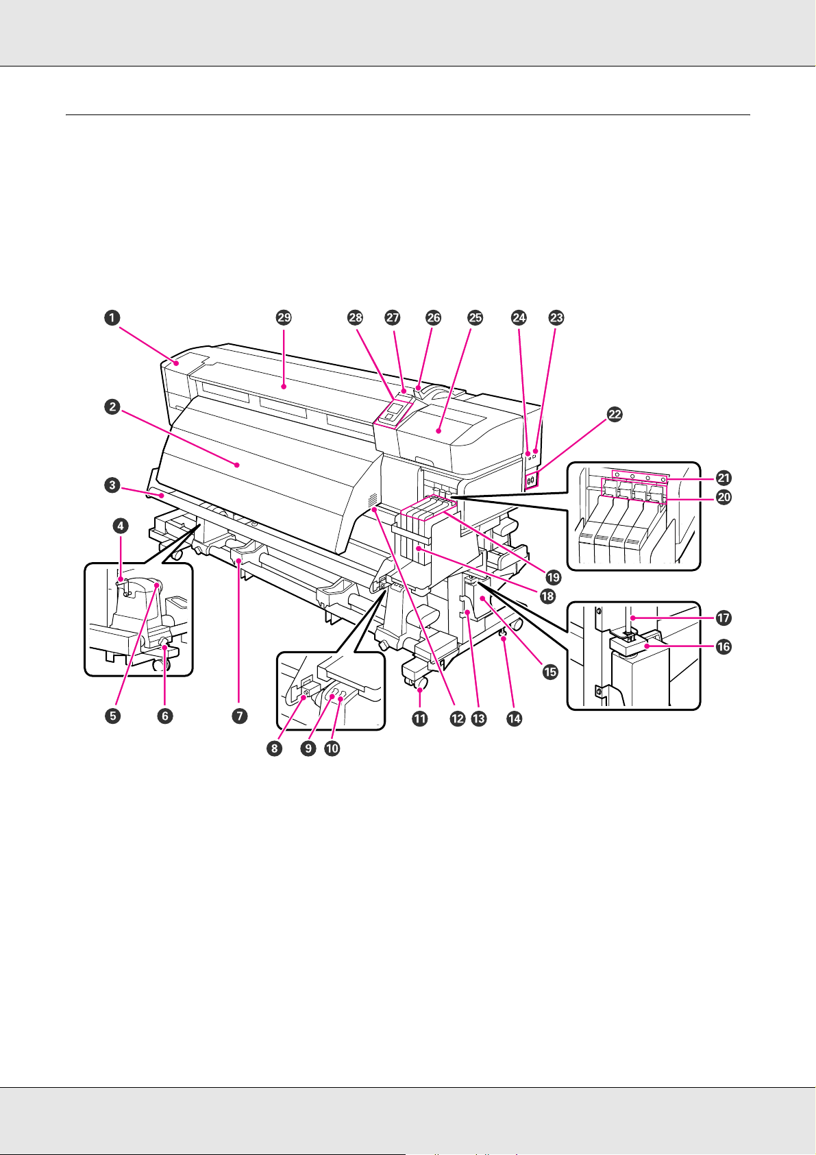
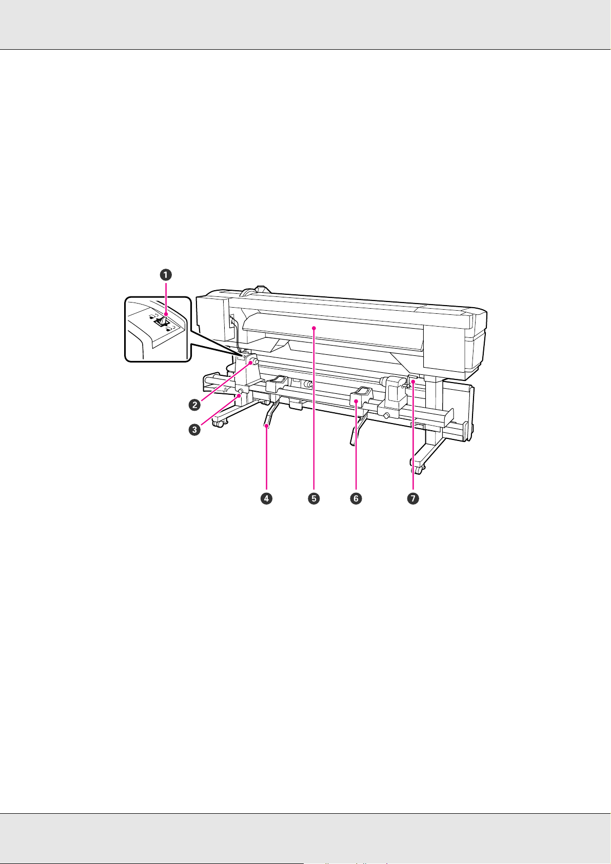
Front
1 Maintenance cover (left)
Open this cover to clean the area around the print head. It is normally closed when the printer is in use.
See “Cleaning Around the Print Head” on page 91.
2 After heater
The after heater can be used to rapidly dry ink after printing.
See “Heating & Drying” on page 68.
3 Media guide bar
The media guide bar maintains tension to prevent the media from sagging as it is taken up.
4Handle
After placing media on the left roll holder, rotate the handle to press the holder and apply pressure to the roll core.
Introduction 9
Page 10

5 Roll core holder
Place an empty roll core for media take-up on these holders. There are two holders: one on the left and one on the right.
See“Media Loading and Take-Up” on page 48.
6 Roll core holder locking screw
The locking screws keep the roll core holders in place once they have been attached to the roll core. There are two locking
screws: one on the left and one on the right.
7 Roll support
Rest media temporarily on these supports when removing the take-up roll. There are two supports: one on the left and one
on the right.
8 Adjustment screw
Use the adjustment screw when performing parallel adjustment.
9Auto switch
Use this switch to select the auto take-up direction. Choose Off to disable auto take-up.
10 Manual switch
Use this switch to select the manual take-up direction. The selected option takes effect when the Auto switch is in the Off
position.
11 Casters
There are two casters on each leg. Once installation is complete, the front casters should be kept locked while the printer is in
use. If the stand fixing screw is lowered too much, the caster rises off the floor. Do not use the printer if a caster is off the floor.
12 Airflow vents
These vents release air from inside the printer. Do not obstruct the airflow vents.
13 Waste ink bottle (tank) holder
Place the waste ink bottle in this holder.
14 Stand fixing screw
In addition to locking the casters, the stand fixing screws also keep the printer securely in place. The stand fixing screws
cannot be used for horizontal adjustment of the printer. After installation, keep the printer securely in place during use.
15 Waste ink bottle (tank)
Waste ink collects in this bottle.
Replace with a new waste ink bottle when the level approaches the line.
16 Stopper
The stopper prevents splatter when waste ink is ejected. Fit the stopper onto the mouth of the waste ink bottle.
17 Waste ink tube
Waste ink is discharged from this tube. Be sure the end of this tube is in the waste ink bottle while the printer is in use.
18 Ink tank
Holds ink used for printing.
19 Slider (chip holder)
See “Slider (chip holder)” on page 12.
20 Lock lever
Raise the levers to unlock the slider for removal when replacing the chip unit. Always lower the lock lever after inserting the
slider.
Introduction 10
Page 11

21 Chip unit check lamp
This lamp turns on when a message related to the chip unit is displayed.
On: An error occurred. Check the message on the control panel’s screen.
Off: No error.
22 AC inlets #1 and #2
Connect the power cables. Make sure you connect both cables.
23 LAN port
See “LAN port” on page 13.
24 USB port
Connects the USB cable.
25 Maintenance cover (right)
Open this cover to perform maintenance around the print head. Normally closed when using the printer.
See “Maintenance Around the Print Head” on page 88.
26 Media loading lever
After loading media, lower the media loading lever to keep the media in place. Raise the lever to release the media prior to
removal.
27 Alert lamp
This lamp lights or flashes when an error occurs.
On/flashing: An error has occurred; the type of error is indicated by how the lamp lights or flashes. Check the message on
the control panel’s screen.
Off: No error.
28 Control panel
See “Control Panel” on page 16.
29 Front cover
Open when loading media, cleaning the inside of the printer, or removing jammed media. Normally closed when using the
printer.
Introduction 11
Page 12
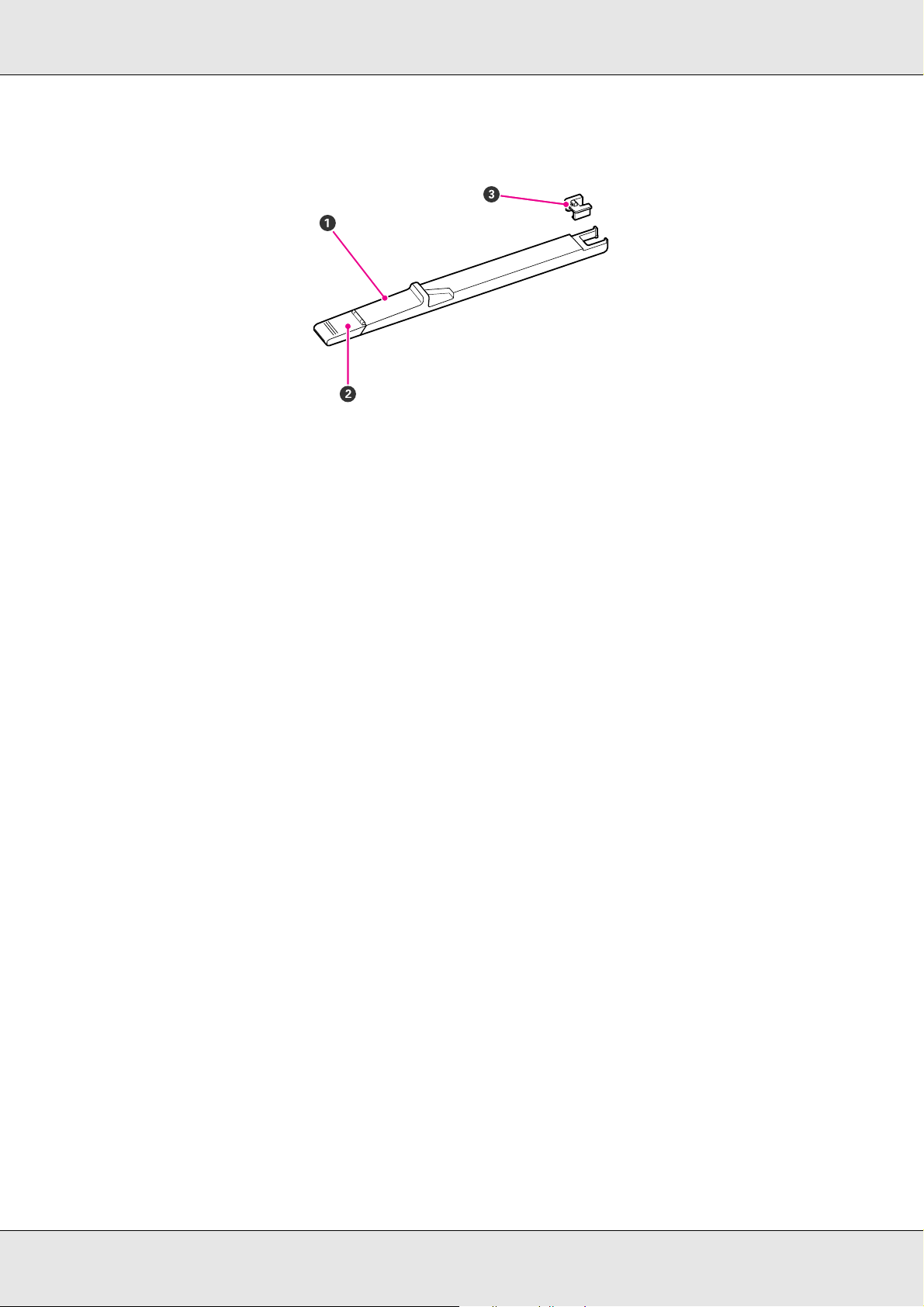
Slider (chip holder)
1Slider
Attach the chip unit included with the ink pack before refilling the ink.
See “Chip Unit Replacement and Ink Refills” on page 104.
2Ink inlet cover
Open this cover to refill the ink tank with ink.
3Chip unit
A unit that includes an IC chip.
This is included with the ink pack.
Introduction 12
Page 13
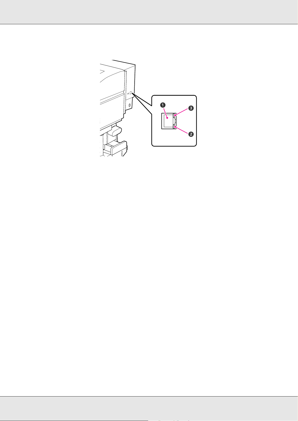
LAN port
1RJ-45 connector
Connects the LAN cable. Use a shielded twisted pair cable (category 5 or higher).
2 Data lamp (orange)
Indicates the network connection status and whether the printer is receiving data.
On: Connected
Flashing: Receiving data
3 Status lamp (green/red)
The color indicates network connection speed.
Red: 100Base-TX
Green: 1000Base-T
Introduction 13
Page 14
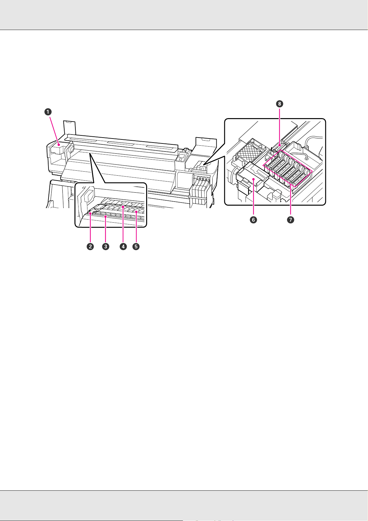
Interior
Dirt on any of the following parts may reduce print quality. Regularly clean or replace these
parts as described in the chapters listed in the reference sections below.
1 Print head
The print head prints by moving left and right while emitting ink. Cleaning may be required.
See “Cleaning Around the Print Head” on page 91.
2 Media holding plate
The media holding plates prevent the media from riding up and keep fuzz on the cut edge of the media from touching the
print head. Position the plates at either side of the media before printing.
See “Loading Media” on page 31.
3Cutter groove
Pass the blade of a cutter (not included) down this groove to cut media.
4 Pressure rollers
These rollers press down on the media during printing.
See “Cleaning the Platen, Pressure Rollers, and Media Holding Plates” on page 82.
5 Platen
The platen suctions the media for printing.
See “Cleaning the Platen, Pressure Rollers, and Media Holding Plates” on page 82.
6 Wiper cleaner
The wiper cleaner removes ink from the wiper. Replacement may be required.
See “Replacing the Wiper and Wiper Cleaner” on page 101.
Introduction 14
Page 15
7Caps
8Wiper
Back
Except during printing, these caps cover the print head nozzles to prevent them from drying out. Cleaning may be required.
See “Part Cleaning” on page 89.
The wiper removes ink from the print head nozzles. Cleaning or replacement may be required.
See “Part Cleaning” on page 89
See “Replacing the Wiper and Wiper Cleaner” on page 101.
1Drive switch
The drive switch is used to feed the media during loading and to rewind the media for replacement.
2 Roll holder
Place media on these holders. There are two holders: one on the left and one on the right.
3 Roll holder fixing screw
These screws fix the roll holders in place once the media has been installed. There are two screws: one on the left and one on
the right.
4 Roll holder lever
If the media to be mounted on the roll holders seems heavy, use these levers to raise the media effortlessly to the level of the
roll holders. There are two levers: one on the left and one on the right.
5Loading guide
Media is loaded along this guide.
6 Roll support
Rest media on these supports before placing it on the roll holders. There are two supports: one on the left and one on the right.
Introduction 15
Page 16
7Handle
After placing media on the right roll holder, rotate the handle to apply pressure to the roll core.
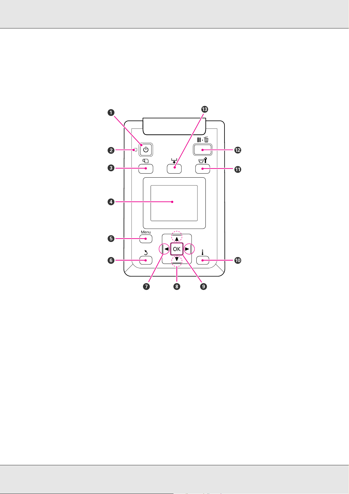
Control Panel
1 P button (power button)
Turns the power on and off.
2 P light (power light)
The printer's operational status is indicated by a lit or flashing light.
On: The power is on.
Flashing: The printer is receiving data or performing head cleaning or other operations during shut-down.
Off: The power is off.
Introduction 16
Page 17

3 M button (media setup button)
Press this button to display the Media Setup menu, which contains such items as Media Remaining, Select Media,
Customize Settings, and Print Media List. This button is disabled during printing.
See “The Media Setup Menu” on page 119.
4 Display
Displays the printer's status, menus, error messages, and so on. See “Understanding the Display” on page 18.
5 Menu button
Press this button to display menus. See “Using the Control Panel Menu” on page 114.
6 y button (back button)
Press this button to exit to the previous menu when options are displayed. See “Menu Operations” on page 114.
7 l/r buttons (left and right arrow buttons)
Use to position the cursor when performing such tasks as entering a Setting Name or IP Address in the setup menu.
8 u/d buttons (media feed buttons)
When media is loaded, you can press the d button to feed the media and the u button to rewind. Keep the d button pressed
to feed the media up to 103 cm (40.6 inches). Keep the u button pressed to rewind the media up to 25 cm (9.8 inches).
Note that when the u button is used to rewind, the media will stop when its edge reaches the starting print position. Rewind
can be resumed by releasing the button and then pressing it again.
When the menus are displayed, these buttons can be used to select menu items and options. See “Menu Operations” on
page 114.
9OK button
Pressing this button when a menu item is highlighted displays options for the selected item.
Pressing this button when an option is highlighted selects the highlighted item or performs the selected operation.
When a warning alarm is sounding, press this button to stop the sound.
10 button
Pressing this button displays the Heating & Drying menu, where you can adjust the Heater Temperature.
11 # button (maintenance button)
Pressing this button displays the Maintenance menu, which contains such items as Nozzle Check, Cleaning, Head Washing,
Head Maintenance, and Waste Ink Counter. This button is disabled during printing.
See “The Maintenance Menu” on page 126.
Introduction 17
Page 18
12 W button (pause/cancel button)
The printer enters pause status if this is pressed while printing. To release the pause status, press the W button again, or
select Pause Cancel on the screen and then press the Z button. To cancel print jobs being processed, select Job Cancel on
the screen and then press the Z button.
Pressing this button when menus are displayed closes the menus and returns the printer to ready status.
13 button (media feed button)
When the printer is in the ready state, you can feed the media to the cut position by pressing this button and then Z.
See “Cutting Media” on page 46.
When printing is in progress, you can use this button to adjust media feed.
See “Feed Adjustment” on page 76.
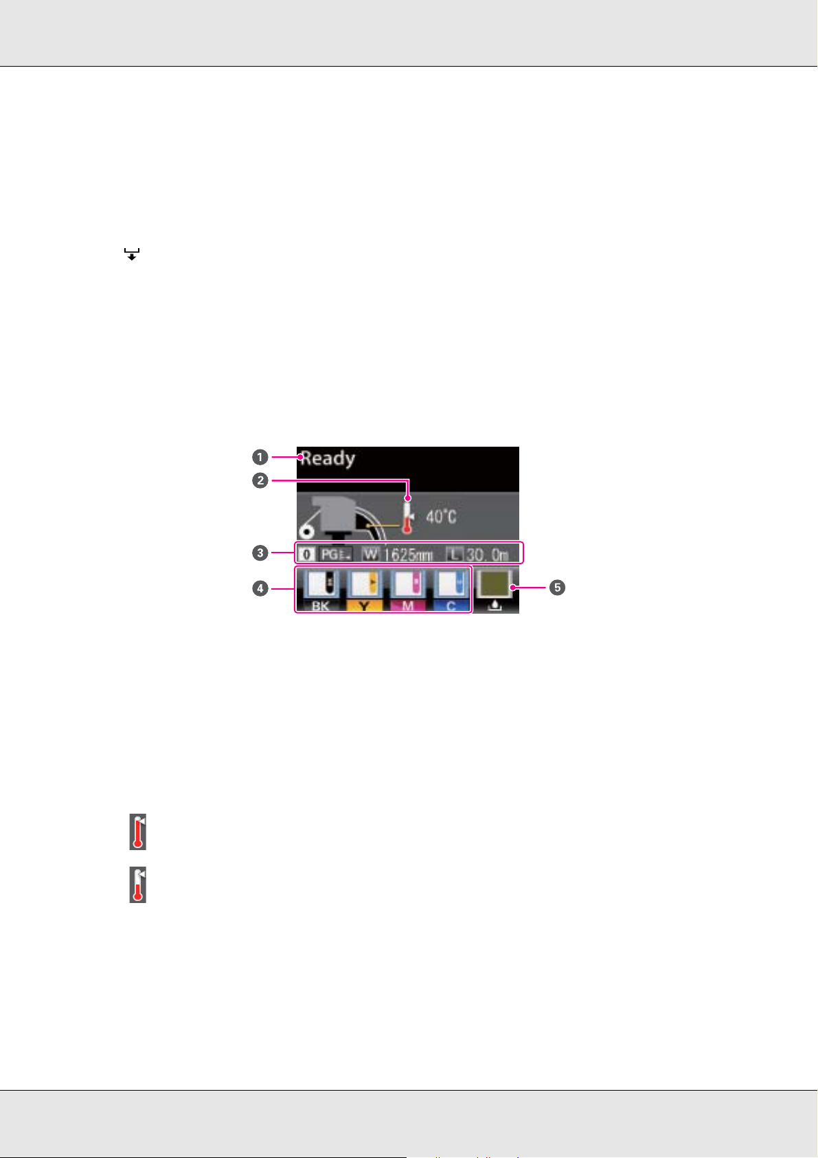
Understanding the Display
1Messages
Displays the printer's status, operation, and error messages.
See “When a Message Is Displayed” on page 130.
2 Heater temperature
This display shows the temperature settings for the after heater. The thermometer icons give a rough indication of the
current temperatures of the heaters.
The heater has reached the selected temperature.
The heater has not reached the selected temperature.
3Media info
From left to right, this display shows the selected media, platen gap, media width, and media remaining.
Introduction 18
Page 19
3Media info
If a media setting bank number created with this printer is selected as the print media, the number (from 1 to 30) will be
displayed. When RIP Settings is selected, 0 will be displayed.
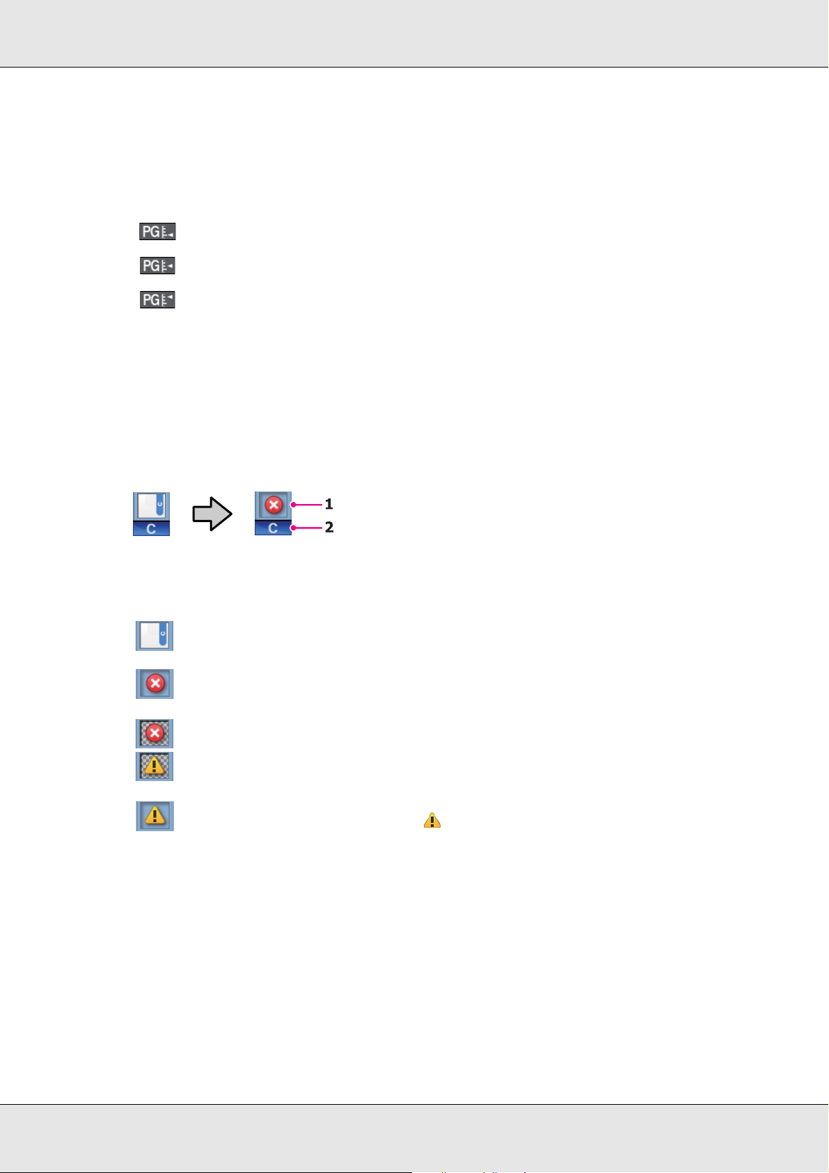
The selected platen gap is shown as follows.
1.5
2.0
2.5
The media remaining is not displayed if Off is selected for Remaining Setup in the Media Remaining menu.
See “The Media Setup Menu” on page 119.
4 Chip unit status
The display changes as shown below when an error is detected in the installed chip unit.
Normal Warning or error
1 Status indicators
The chip unit status is indicated as follows.
No error. Ready to print.
An error occurred. Check the message on the screen, and clear the error
The chip unit could not be recognized or it is not compatible with the printer. Or, the slider is not
locked. Check the on-screen message.
The chip unit requires replacement. Replace the chip unit with one from a new ink pack. As it gets
closer to time to replace the chip unit, will begin to flash.
2 Ink color codes
BK: Black
Y: Yellow
M: Magenta
C: Cyan
Introduction 19
Page 20

5 Waste ink bottle status
Displays the approximate amount of space available in the waste ink bottle. The display changes as shown below
when the waste ink bottle is nearly full or an error occurs .
Normal Warning or error
1
1 Status indicators
The status of the waste ink bottle is shown as follows.
No error. The indicator changes to show the amount of space available.
The waste ink bottle is almost full. Ready a new waste ink bottle.
The waste ink bottle is full. Replace with a new waste ink bottle.
Introduction 20
Page 21

Features
This wide-format color ink jet printer supports roll media up to 1626 mm (64 inches) in
width. The main features of this printer are described below.
Realizing High Productivity
Improved Drying Characteristics
The printer is equipped with an after heater that can be used to rapidly dry ink after printing.
Media Feeding Unit Accommodates High-Capacity Rolls
The standard media feeding unit can handle high-capacity rolls with external diameters of
up to 250 mm (9.8 inches) and weights of up to 40 kg (88.2 lb), ensuring that media require
less frequent replacement.
Auto Take-up Reel Unit Comes Standard
The auto take-up reel unit automatically takes up printed media cleanly, with no wrinkles.
This is useful for large print jobs or continuous overnight printing, and supports the
high-precision take-up necessary for continuous-type sublimation transfer printers.
High-Capacity Ink Tanks Included
The printer includes high-capacity ink tanks for high productivity. We also offer 1000 ml
high-capacity ink packs for refill. This eliminates the need for frequent ink replacement.
Superior Ease of Use
Easy Media Installation and Take-up
The roll and roll core holders require no spindles, eliminating the need to attach spindles
before installing media. Just bring the media to the printer and install it directly. Never
having to juggle long spindles makes installing media a snap even where space is limited.
In addition to roll supports that give you a place to rest media during installation, the printer
offers lift levers that allow heavy media to be effortlessly raised to the level of the roll
holders.
Introduction 21
Page 22

Ease of Maintenance
Print quality can only be ensured through daily maintenance, and the printer is constructed
with this in mind.
Lamp and Alarm Error Alerts
When an error occurs, an alarm will sound and the alert lamp will light. The large alert lamp
is highly visible, even at a distance.
An alarm sounds simultaneously to prevent time wasted while stoppages due to errors go
unnoticed.
High-Speed USB/Gigabit Ethernet
The printer comes equipped with high-speed USB and 100 Base-TX/1000 Base-T network
interfaces.
Introduction 22
Page 23
Notes on Usage and Storage
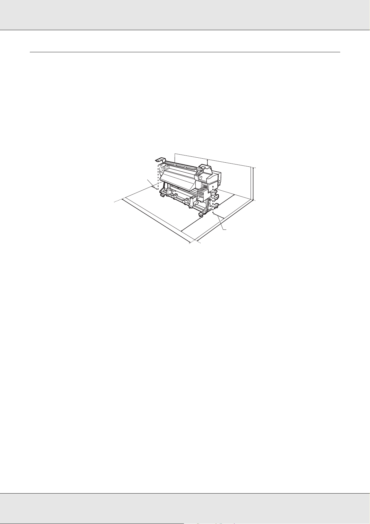
Installation Space
Make sure that you secure the following space, clear of any other objects, so that paper
ejection and consumable replacement are not obstructed.
For the external dimensions of the printer, see “Specifications Table” on page 175.
100 mm (3.9 in.)
500 mm (19.7 in.)
3620 mm (142.5 in.)
1000 mm
(39.4 in.)
m
m
)
.
0
n
0
i
0
4
1
.
9
3
(
2903 mm
(114.3 in.)
500 mm (19.7 in.)
1750 mm
(68.9 in.)
Notes When Using the Printer
Note the following points when using this printer to avoid breakdowns, malfunctions, and
print quality decline.
❏ When using the printer, observe the operating temperature and humidity range
described in the “Specifications Table” on page 175.
Note, however, that the desired results may not be achieved if the temperature and
humidity are within the limits for the printer but not within those for the media. Be sure
the operating conditions suit the media. For more information, see the documentation
supplied with the media.
Also, when operating in dry areas, air-conditioned environment, or under direct
sunlight, maintain the appropriate humidity.
❏ Avoid using the printer in locations with heat sources or locations that are exposed to
direct drafts from ventilators or air conditioners. The print head nozzles could dry out
and clog.
❏ Do not bend or tug the waste ink tube. Ink could spill inside or around the printer.
Introduction 23
Page 24

❏ We recommend performing maintenance on the following components as required.
Failure to perform appropriate maintenance will shorten print head life.
See “Maintenance Around the Print Head” on page 88.
Component to be cleaned Frequency
Print head When colors in the printout are faint or missing even after head has been
Wiper
Caps
Wiper rail
cleaned.
When the printout is smudged or not clear.
Component requiring
replacement
Wiper cleaner If the printout is faint or smudged, or segments are missing even after cleaning
Wiper
Frequency
❏ The print head may not be capped (the print head may not return to the right side) if the
printer is turned off when the media is jammed or an error has occurred. Capping is a
function for automatically covering the print head with a cap (lid) to prevent the print
head from drying out. In this case, turn on the power and wait until capping is performed
automatically.
❏ When the power is on, do not remove the power plug or cut the power at the breaker.
The print head may not be capped properly. In this case, turn on the power and wait
until capping is performed automatically.
❏ The print head is automatically cleaned at a fixed interval after printing to keep the
nozzles from clogging.
Be sure that the waste ink bottle is installed whenever the printer is on.
❏ As well as being expended during printing, ink is used during head cleaning and other
maintenance required to keep the print head in working order.
Notes When Not Using the Printer
If you are not using it, note the following points when storing the printer. If it is not stored
correctly, you may not be able to print properly the next time it is used.
❏ If you do not print for a long time, the print head nozzles may become clogged. Turn the
printer on at least once a week to prevent the print head clogging.
Introduction 24
Page 25

Head cleaning will be performed automatically after the printer is turned on. Head
cleaning helps maintain print quality. Do not turn the printer off until cleaning is
complete.
Leaving the printer for too long without turning it on may result in a malfunction. Repair
work for such malfunction will be charged.
❏ If you will not be using the printer for more than 2 weeks, maintenance must be
performed by a service engineer before and after this period. This maintenance work
will be charged.
Note that even if proper maintenance has been done before a long period of non-use,
repair may be necessary when doing maintenance for reusing the printer, depending on
the period and conditions of storage. In such a case, the repair work will also be
charged.
Contact your dealer or Epson Support.
❏ The pressure rollers may crease media left in the printer. The media may also become
wavy or curled, causing jams or resulting in the media coming into contact with the print
head. Remove the media before storing the printer.
❏ Store the printer after confirming that the print head has been capped (the print head is
positioned at the far right). If the print head is left uncapped for a long time, the print
quality may decline.
Note:
If the print head is not capped, turn the printer on, wait until capping is performed automatically,
and then turn it off.
❏ Close all covers before placing the printer in storage. If you are not using the printer for
a long time, put an anti-static cloth or cover on the printer to prevent dust build-up. The
print head nozzles are very small, and they can become clogged easily if fine dust gets
on the print head, and you may not be able to print properly.
❏ If you have not used the printer for a long time, check the print head for clogging before
you start printing. Perform head cleaning if the print head is clogged.
See “Checking for Clogged Nozzles” on page 84.
❏ When storing the printer, be sure that it is level: do not store it on an angle, on end, or
upside down.
Introduction 25
Page 26

Notes on Handling Ink Packs and Ink Tanks
Note the following points when handling ink packs and ink tanks.
❏ Do not remove the ink tanks
Ink tanks are calibrated when installed. Removing them can harm quality and
functionality.
❏ Store ink packs at room temperature out of direct sunlight.
❏ To ensure print quality, use all the ink in the ink pack before one of the following
(whichever comes first):
❏ The date printed on the ink pack
❏ 25 days from the day the ink tank was refilled from the ink pack
❏ If the ink pack has been stored in a cold location for a long period of time, keep at room
temperature for at least 4 hours before using.
❏ Be sure not to leave any ink in the ink pack when you refill an ink tank.
❏ Refill the ink tank as soon as possible after opening the ink pack.
❏ Do not place any objects on the ink tank or subject the tank to strong impacts.
Otherwise, the tank could be detached.
Handling Media
Note the following when handling or storing media. Media that is in poor condition will not
produce good quality prints.
Be sure to read the documentation provided with each type of media.
Notes on Handling
❏ Do not fold the media or damage the printable surface.
❏ Do not touch the printable surface. Moisture and oils from your hands can affect print
quality.
❏ When handling media, hold it by both edges. We recommend wearing cotton gloves.
❏ Keep the media dry.
Introduction 26
Page 27

❏ Packaging materials can be used to store media and should not be thrown away.
❏ Avoid locations that are subject to direct sunlight, excessive heat, or humidity.
❏ When not in use, media should be removed from the printer, rewound, and inserted in
its original packaging for storage. Leaving media in the printer for extended periods
may cause it to deteriorate.
Handling Media After Printing
To maintain long lasting, high quality print results, note the following points.
❏ Do not rub or scratch the printed surface. If it is rubbed or scratched, the ink may peel
off.
❏ Do not touch the printed surface, as this may remove the ink.
❏ Make sure printouts are completely dry before folding or stacking, as otherwise
discoloration or other marks may appear where the prints touch. These marks will
disappear if the prints are immediately separated and dried but will become permanent
if the surfaces are not separated.
❏ Avoid direct sunlight.
❏ To prevent discoloration, display and store prints as instructed in the documentation
supplied with the media.
Using the Supplied Software
Contents of the Software CD
The following applications are available on the supplied software CD. Install as required.
For information about these applications, see the on-line help for the application in
question.
Note:
❏ The supplied disk does not contain printer drivers. A software RIP is required for printing.
❏ The latest software utilities can be downloaded from the Epson website.
Introduction 27
Page 28

Software Name Summary
EPSON LFP Remote Panel 2 EPSON LFP Remote Panel 2 is used to update firmware from a computer and copy the media
settings bank created in the printer’s setup menu to a computer.
See “Starting EPSON LFP Remote Panel 2” on page 28 and “Exiting EPSON LFP Remote Panel 2”
on page 28.
Epson Drivers and utilities Install the Epson communications driver (EPSON SC-F7100 Series Comm Driver).
The Epson communications driver is required if the EPSON LFP Remote Panel 2 is to be used to
copy media settings. It is not a printer driver. In addition, the software RIP may not display
printer status if the Epson communications driver is not installed when the printer is connected
to a computer via USB. See the software RIP documentation for more information on the status
display.
EPSONNet Config With this software, you can configure various network settings for the printer from your
computer. This is useful as it allows you to enter addresses and names using the keyboard. The
manual is also installed along with the software.
Starting EPSON LFP Remote Panel 2
Launch EPSON LFP Remote Panel 2 after confirming that the printer displays Ready.
1. The application can be launched using either of the following two methods.
❏ Double-click the EPSON LFP Remote Panel 2 icon on the desktop. The EPSON LFP Remote
Panel 2 icon is created when the application is installed.
❏ Click Start > All Programs (or Programs) > EPSON LFP Remote Panel 2 > EPSON LFP Remote
Panel 2.
2. Click the desired item in the EPSON LFP Remote Panel 2 main window.
See EPSON LFP Remote Panel 2 help for more information.
Exiting EPSON LFP Remote Panel 2
Click Finish in the EPSON LFP Remote Panel 2 main window.
Introduction 28
Page 29
Uninstalling Software
Important:
❏ Log in as an administrator.
❏ Enter the administrator password when prompted and then proceed with the remainder of the
operation.
❏ Exit any other applications that may be running.
This section describes how to uninstall EPSON LFP Remote Panel 2 and the Epson
communications driver.
1. Turn off the printer, and unplug the interface cable.
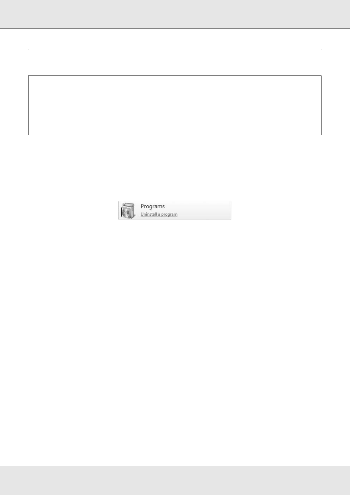
2. Go to the Control Panel and click Uninstall a program from the Programs category.
3. Select the software you want to remove and then click Uninstall/Change (or
Change/Remove).
To uninstall the EPSON communications driver, select EPSON SC-F7000 Series
Comm Driver Printer Uninstall.
To uninstall EPSON LFP Remote Panel 2, select EPSON LFP Remote Panel 2.
4. Select the target printer icon, and then click OK.
5. Follow the on-screen instructions to continue.
When the delete confirmation message appears, click Yes.
If you are reinstalling the Epson communications driver, restart the computer.
Introduction 29
Page 30

Chapter 2
Basic Operations
Loading and Exchanging Media
Caution:
❏ Be careful not to trap your hands or fingers when opening or closing the front cover.
c
Failure to observe this precaution could result in injury.
❏ Secure the media in place by the following procedure. Injury may occur if the media
falls.
❏ Do not rub your hands along the edges of the media. The edges are sharp and can
cause injury.
Note:
For information on the media that can be used in the printer, see “Supported Media” on
page 163.
Basic Operations 30
Page 31

Important:
❏ Load media immediately before printing. The pressure rollers may crease media left in the
printer. The media may also become wavy or curled, causing jams or resulting in the media
coming into contact with the print head.
❏ If the following points are not observed when handling media, small amounts of dust and lint
may stick to the media surface and cause in ink drops in the prints.
❏ Do not place exposed media directly on the floor. Media should be rewound and inserted
in its original packaging for storage.
❏ Do not carry media with the media surface pressed against clothing. Handle media in its
individual packaging until just before loading the media in the printer.
❏ If media is loaded and the right and left edges of the roll are uneven, media feeding
problems may cause the media to move around during printing. Either rewind to align the
edges or use a roll without any issues.
Loading Media
This section describes how to load media when the standard media feeding unit is
installed. We recommend that you perform a parallel adjustment of the media feeding unit
to ensure that media is fed straight and to avoid printing or take-up problems. For more
information, see “Parallel adjustment of the media feeding unit” on page 141.
Basic Operations 31
Page 32

Caution:
❏ The after heater may be hot; observe all necessary precautions. Failure to observe the
c
necessary precautions could result in burns.
❏ Because the media is heavy, it should not be carried by one person. When loading or
removing the media, use at least two persons.
1. Remove the media holding plates, if installed.
2. Turn on the printer by pressing the P button.
3. Loosen the roll holder fixing screws and adjust the roll holders so that the gap between
the two is wider than the media.
Center the roll supports between the roll holders.
Basic Operations 32
Page 33

Important:
If the right holder handle shaft is not visible, rotate the handle forward until it stops. The
media can not be properly loaded if the handle shaft is not visible.
4. Place media on the roll support oriented according to how it is rolled (see below) and
position it as indicated by the mark on the label.
Printable side out
Printable side in
Basic Operations 33
Page 34

If the label does not have a loading position, mark it on the label as instructed in the
Setup Guide.
Note:
Be sure the option selected for Roll Type in the Customize Settings menu matches how
the media is rolled. Roll Type defaults to Printable Side Out. Be sure to select Printable
Side In after loading media rolled printable side in.
For more information see “Roll Type” on page 70.
5. Raise the roll holder lever on the left side of the printer to lift the media into position,
then firmly insert the roll holder.
If the roll of media has an outer diameter which is less than 140 mm (5.5 inches), lift it
up by your hands, and place it on the roll holder. The roll core will not reach the holder
when raised using the roll holder lever.
6. Tighten the roll holder screw to fix the roll holder in place.
Basic Operations 34
Page 35

7. Raise the roll holder lever on the right side of the printer to lift the media into position,
then firmly insert the roll holder.
If the roll of media has an outer diameter which is less than 140 mm (5.5 inches), lift it
up by your hands, and place it on the roll holder as described in step 5.
8. To ensure that the roll holder is inserted into the roll core sufficiently, push the center
section on the side of the roll holder toward the roll end.
Important:
If the roll holder is not inserted far enough into the roll core, media will not be fed correctly
because of slippage between the roll holder and roll core.
This may cause banding in the prints.
Basic Operations 35
Page 36

9. Tighten the roll holder screw to fix the roll holder in place.
Important:
If the roll holder fixing screw is loose, the roll holder may move during printing. This could
cause stripes and unevenness in the prints.
10.Rotate the handle until part A in the illustration below is fully inserted.
Important:
Once part A is hidden, do not turn the handle any further. Failure to observe this precaution
could damage the roll holder.
If part A is still visible even after the handle has been turned fully, rewind the handle.
Loosen the roll holder fixing screw on the right side, and then restart from Step 8.
Basic Operations 36
Page 37

11.Confirm that the right and left edges of the attached roll are aligned, and realign them if
necessary.
12.Raise the media loading lever.
13.Pull out the edge of the media and insert it into the printer.
Basic Operations 37
Page 38

Note:
Media that is heavy and difficult to unroll can be fed by pressing the drive switch on the left
roll holder.
Printable side out
Printable side in
14.Insert the media past the pressure rollers and lower the media loading lever to hold it in
place.
Confirm that the left edge of the media passes over the center of the square in the label
on the loading guide.
Important
Perform steps 14 to 4 in reverse order and repeat the loading process if the left edge of the
media is not within the guides. Do not attempt to reposition the roll holders while they are
inserted in the media.
Basic Operations 38
Page 39

15.Go to the front of the printer and open the front cover.
16.Hold the center of the media and raise the media loading lever.
17.Pull the media straight forward to the leading edge of the after heater.
18.Close the front cover.
19.Rewind the leading edge of the media to the front cover.
For media with the printable side out, press the u button. For media with the printable
side in, press the d button.
Basic Operations 39
Page 40

Confirm that the paper was fed straight with the media straight and taut.
Note:
We recommend using the r button on the control panel to set Media Suction to 2, which
helps to ensure that the media is rewound straight.
20.Open the front cover.
21.Lower the media loading lever to hold the media in place.
22.Attach the media holding plates.
Basic Operations 40
Page 41

First, position the plates so that the edges of the media are in the centers of the round
holes.
Important:
Always position the plates so that the edges of the media are at the centers of the round
holes. Incorrect positioning causes banding (horizontal banding, lines, or strips of uneven
color) during printing.
Basic Operations 41
Page 42

23.Align the white lines of the plates with the white lines of the platen and push the plates
down to lock them in place and keep them from lifting.
Important:
❏ Do not use the media holding plates with media that is more than 0.4 mm (0.02 inch)
thick. The media holding plates could touch and damage the print head.
❏ Move the media holding plates to the left and right edges of the platen when they are
not in use.
❏ Do not use the media holding plates if the sides of the printed media are smudged or
torn.
24.Close the front cover.
Basic Operations 42
Page 43

Viewing and Changing Media Settings
The control panel displays the following information once the media is loaded.
This display can be used to view or change the following two options:
❏ Remaining Setup
On: The printer displays the amount of media remaining.
Off: The printer does not display the amount of media remaining.
When Remaining Setup is On, the printer will calculate the approximate amount of
media remaining based on the length of the roll and the amount used for printing and
display this information in the control panel. The display gives a rough idea of the
amount of media available before printing, making it easier to know when media
requires replacement.
In addition, a warning will be displayed when the amount of media remaining reaches a
specified level.
❏ Selected Media
Displays the parameters on which media settings are based as shown below.
RIP Settings: Media settings are based on those in the RIP.
XXXXXXXXXXXXXXXXXX: Media settings are based on those stored in the printer
in media settings bank No. 1.
Media settings banks can store a variety of settings for different media based on the
options selected in the Media Suction, Head Alignment, and other menus. Up to 30
combinations of settings can be stored by assigning them to banks No. 1 to 30. Using
the printer’s media settings is recommended.
Basic Operations 43
Page 44

See “Saving Settings” on page 66.
1. Select an option.
To print with current settings:
Use the d/u buttons to select Keep Settings Above and press the Z button.
Proceed to step 6.
To change settings:
Use the d/u buttons to select Change Settings and press the Z button.
2. Select the items you want to change and press the Z button.
3. Select the desired option and press the Z button.
4. Press the y button to display the dialog shown in step 2 and then press the y button
again.
5. After confirming that the settings are correct, use the d/u buttons to select Keep
Settings Above and press the Z button.
6. The roll type selection screen appears.
Use the d/u buttons to select the roll type that matches the loaded roll and press the
Z button.
7. If On is selected for Remaining Setup, you will be prompted to enter the length of the
current media. Use the d/u buttons to choose a length between 5.0 and 999.5 m (15
and 3000 feet) and press the Z button. You can set in 0.5 m increments. If the display
is in feet, lengths are given in increments of 1 foot.
The printer will display Ready after a brief pause, showing that it is ready to print. Transmit
the data to be printed from the computer.
Basic Operations 44
Page 45

Exchanging Media
To replace the media after printing, print the amount of media remaining, cut the media,
and remove the roll.
Printing the Amount of Media Remaining
The printer displays the amount of media remaining and any media low warnings in the
control panel. This makes it possible to determine whether the media requires replacement
before printing.
The amount of media remaining can only be displayed if the correct length is entered when
the media is loaded.
You can print the amount of media remaining on the leading edge of the roll before it is
removed from the printer and then enter this number the next time the media is loaded for
accurate information on the amount remaining.
Note:
The printer does not calculate or display the amount of media remaining when Off is selected for
Remaining Setup in the setup menu. See “Viewing and Changing Media Settings” on page 43.
The following section describes how to print the amount of media remaining.
1. Confirm that the printer is ready to print.
2. Press the M button, select Media Remaining in the menu, and press the Z button.
3. Select Print Remaining Length and press the Z button.
Basic Operations 45
Page 46

4. Press the Z button to print the amount of media remaining.
Cutting Media
Use a cutter (not included) to cut the media when printing is complete. This section
described how to use a cutter to cut the media.
Caution:
❏ The after heater may be hot; observe all necessary precautions. Failure to observe the
c
necessary precautions could result in burns.
❏ When cutting media, be careful not to cut your fingers or hands with the cutter or other
blades.
1. Confirm that the printer is ready to print.
2. Press the button and the Z button. The printer will feed the trailing edge of the
printed media to a position over the cutter groove.
Basic Operations 46
Page 47

If you have printed the amount of media remaining, press the u button to rewind the
media so that this information will remain on the roll after the media is cut.
3. Remove the media holding plates.
4. Cut the media with the cutter.
Pass the blade of the cutter down the cutting groove.
Basic Operations 47
Page 48

Important:
To continue printing after cutting, do not rewind the media past the cutter groove (on the
pressure roller side).
If the leading edge of the media is curled, stop rewinding before the media reaches the inner
side of the front cover.
Note:
If you are using the auto take-up reel unit, set the Auto switch on the auto take-up reel unit to Off
before using the Manual switch to position the media over the cutting groove.
Removing Media
You can now remove the media from the roll holders. To remove the media, reverse the
steps you followed to load it. See the section beginning with “Loading Media” on page 31.
Using the Auto Take-up Reel Unit
Media Loading and Take-Up
The auto take-up reel unit automatically takes up media as it is printed, improving the
efficiency of unmanned operation.
The auto take-up reel unit for this printer can take-up media in either of the following
directions.
Printed side out Printed side in
Take-up with the printed side out places the printed surface on the outside of the roll.
Take-up with the printed side in places the printed surface on the inside of the roll.
Basic Operations 48
Page 49

Caution:
❏ Be sure that your hands or hair do not get caught in the auto take-up reel unit while it
c
is in operation. Failure to observe this precaution could result in injury.
❏ Perform the following procedure to correctly secure the roll core for the auto take-up
reel unit into place. Injury may occur if the take-up roll falls.
Important:
❏ We recommend using a take-up roll core with the same width as the media. If a take-up roll
core of a different width is used, the take-up roll core may bend, and the media will be taken
up incorrectly.
❏ Do not use a roll core with a deformed interior. If the roll core holder slips, the media may be
taken up incorrectly.
Attaching the Roll Core
1. Set the Auto switch to Off.
Basic Operations 49
Page 50

2. After confirming that the media is loaded correctly, press the d button to feed the media
as far as the auto take-up reel unit roll core holder.
Important:
Always press the d button to feed the media as far as the roll core holder. If the media is
pulled by hand, the media may twist during take-up.
3. Loosen the roll core holder locking screws and adjust the roll core holders so that the
gap between the two is wider than the media.
Center the roll supports between the roll holders.
Important:
If the left roll core handle shaft is not visible, rotate the handle until it stops. The media can
not be properly loaded if the handle shaft is not visible.
Basic Operations 50
Page 51

4. Align the right roll core holder with the right edge of the media and tighten the locking
screw.
5. Insert the roll core onto the right holder.
6. Confirm the following: the left roll core holder is fully inserted into the roll core, and the
roll core and edges of the media are not misaligned.
Important:
If the edges of the media are misaligned, the media cannot be taken up correctly. To
correct misalignment, loosen the right roll core holder locking screw, and then restart from
Step 4.
7. To ensure that the roll core holder is inserted sufficiently, push the center section on the
side of the roll core holder towards the roll end.
Basic Operations 51
Page 52

Confirm that the roll core and edges of the media are not misaligned.
Important:
Stop when part A is no longer visible. The take-up reel unit may not function as expected
if the holder is inserted too far.
8. Tighten the roll core holder locking screw to fix the roll core holder in place.
Basic Operations 52
Page 53

9. Rotate the handle until part A in the illustration below is fully inserted.
Important:
Once part A is hidden, do not turn the handle any further. Failure to observe this precaution
could damage the roll core holder.
If part A is not hidden even after turning the handle until it can no longer be turned, the roll
core holder may not be fully inserted. Return to step 6.
For information on take-up with the printed side out, see the following section.
For information on take-up with the printed side in, see “Take-Up With the Printed Side
Facing In” on page 58.
Take-Up With the Printed Side Facing Out
1. Pass the media under the media guide bar, and then attach the media to the take-up
roll core.
Basic Operations 53
Page 54

In the order shown in the illustration, tape the media to the take-up roll core. When
attaching in the center, tape while pulling the center of the media straight. When
attaching on the left and right, tape while pulling the media sideways.
Important:
If the media is lifted up between the attached pieces of tape, the media will not be taken up
correctly. We recommend either adding tape and attaching it uniformly or fixing creases at
the leading edge of the media.
2. Press the d button in the control panel to feed enough media for a single wrap around
the roll core.
Basic Operations 54
Page 55

3. Flip the Manual switch to to wrap the media once around the roll core.
4. Confirm that the media is not loose.
Basic Operations 55
Page 56

Confirm differences in tension on the right and left by lightly tapping on both edges of
the media.
Important:
As shown in the identified sections in the illustration below, if the tension of the left and
right edges of the media are different, the media that follows cannot be taken up correctly.
If there is slack on one side, flip the Manual switch to to rewind the media, remove the
tape, and then restart from Step 1.
Basic Operations 56
Page 57

5. Confirm that the edges of media taken up on the roll core are not misaligned.
Important:
If the edges of media taken up on the roll core are misaligned, the media that follows
cannot be taken up correctly. When misaligned, rewind the media, remove the tape, and
then restart from Step 1.
6. Flip the Auto switch to .
Basic Operations 57
Page 58

Take-Up With the Printed Side Facing In
1. Pass the media under the media guide bar, and then attach the media to the take-up
roll core.
In the order shown in the illustration, tape the media to the take-up roll core. When
attaching in the center, tape while pulling the center of the media straight. When
attaching on the left and right, tape while pulling the media sideways.
Important:
If the media is lifted up between the attached pieces of tape, the media will not be taken up
correctly. We recommend either adding tape and attaching it uniformly or fixing creases at
the leading edge of the media.
2. Press the d button in the control panel to feed enough media for a single wrap around
the roll core.
Basic Operations 58
Page 59

3. Flip the Manual switch to to wrap the media once around the roll core.
4. Confirm that the media is not loose.
Basic Operations 59
Page 60

Confirm differences in tension on the right and left by lightly tapping on both edges of
the media.
Important:
As shown in the identified sections in the illustration below, if the tensions of the left and
right edges of the media are different, the media that follows cannot be taken up correctly.
If there is slack on one side, flip the Manual switch to to rewind the media, remove the
tape, and then restart from Step 1.
Basic Operations 60
Page 61

5. Confirm that the edges of media taken up on the roll core are not misaligned.
Important:
If the edges of media taken up on the roll core are misaligned, the media that follows
cannot be taken up correctly. When misaligned, rewind the media, remove the tape, and
then restart from Step 1.
6. Flip the Auto switch to .
Basic Operations 61
Page 62

Removing the Take-up Roll
Caution:
❏ Because the media is heavy, it should not be carried by one person. When loading or
c
removing the media, use at least two persons.
❏ Perform the following procedure to properly remove the take-up roll. Injury may occur
if the take-up roll falls.
1. Set the Auto switch to Off.
2. Cut the media and roll the cut end onto the take-up reel. See “Cutting Media” on
page 46.
3. Rotate the handle of the left roll core holder.
Basic Operations 62
Page 63

4. To prevent the media from sliding off the roll, support the roll at its left end.
5. Loosen the left roll core holder locking screw and remove the roll core holder from the
roll.
6. Lower the roll onto the roll support.
7. To prevent the media from sliding off the roll, support the roll at its right end.
8. Loosen the right roll core holder locking screw and remove the roll core holder from the
roll.
Basic Operations 63
Page 64

9. Lower the roll onto the roll support.
Before Printing
To maintain print quality, perform the following inspection before starting work each day.
❏ Print a check pattern to check for clogged nozzles.
❏ Perform head cleaning if parts of the pattern are faint or missing.
See “Checking for Clogged Nozzles” on page 84.
See “Head Cleaning” on page 86.
Saving Optimal Settings for the Current Media (Print Media Settings)
A variety of media settings can be optimized for the current media and stored in the printer.
Once frequently used settings have been stored in a media setting bank, they can be
recalled to instantly optimize multiple parameters.
The printer offers a total of 30 media setting banks.
This section describes how to create media setting banks and the settings that can be
stored.
Basic Operations 64
Page 65

Parameters Stored in Media Setting Banks
Media setting banks store the following:
❏ Setting Name
❏ Feed Adjustment
❏ Platen Gap
❏ Head Alignment
❏ Heating & Drying
❏ Media Suction
❏ Head Movement
❏ Multi-Strike Printing
❏ Roll Type
❏ Tension Measurement
❏ Feeding Tension
❏ Take-up Tension
❏ Feed Speed
For more information on these items, see “The Media Setup Menu” on page 119.
Basic Operations 65
Page 66

Saving Settings
Follow the steps below to save media settings.
Choosing a Media Setting Bank
1. After confirming that the printer is ready to print, press the Menu button.
The settings menu will be displayed.
2. Select Media Setup and press the Z button.
3. Use the d/u buttons to select Customize Settings and press the Z button.
4. Use the d/u buttons to select a media setting bank number between 1 and 30 and then
press the Z button.
Note that any settings already saved to the printer will be overwritten.
Setting Name
Name the media setting bank. Using distinctive names makes it easier to select banks for
use.
1. Select Setting Name and press the Z button.
2. Use the d/u buttons to display letters and symbols. When the desired character is
displayed, press the r button to select the next entry position.
Mistakes can be erased by pressing the l button to delete the previous character and
move the cursor back one spot.
Basic Operations 66
Page 67

3. After entering the name, press the Z button.
Feed Adjustment (manual)
Feed Adjustment is used to correct banding (horizontal banding, lines, or strips of uneven
color).
You need to visually inspect prints and enter a correction by hand.
For more information on feed adjustment, see “Feed Adjustment” on page 76.
Platen Gap
Adjust the platen gap (the gap between the print head and the media) if prints are
smudged.
1. Use the d/u buttons to select Platen Gap and press the Z button.
2. Use the d/u buttons to select the desired setting and press the Z button.
3. Press the y button to return to the customize settings menu.
Important:
Select 2.5 only if prints are still smudged when 2.0 is selected. Choosing a larger gap than
required may result in ink stains inside the printer, reduced print quality, or shorter product life.
Head Alignment (manual)
Select Head Alignment to correct print head misalignment when prints seem grainy or out
of focus.
You need to check the pattern and enter the optimum adjustment value for alignment.
For more information on manual head alignment, see “Correcting Print Misalignment
(Head Alignment)” on page 73.
Basic Operations 67
Page 68

Heating & Drying
Set the temperature of the after heater.
Note:
Adjust Heater Temperature as follows:
❏ Set the heater to the temperatures recommended in the documentation provided with the
media, if available.
❏ Raise the temperature if the prints are blurred or smudged or the ink clots. Note, however,
that raising the temperature too high can cause the media to shrink, wrinkle, or deteriorate.
1. Use the d/u buttons to select Heating & Drying and press the Z button.
2. Use the d/u buttons to select the item you want to change.
Heater Temperature
(1) Select Heater Temperature and press the Z button.
(2) Use the d/u buttons to set the after heater temperature.
Drying Time Per Pass
(1) Use the d/u buttons to select Drying Time Per Pass and press the Z button.
(2) Use the d/u buttons to set the drying time.
When you want to maintain a constant drying time even when the print width changes, set the following value in accordance
with the media width.
A: Drying time (seconds)
Drying Time Guidelines by Media Width
64 52 44 42 36 24
Drying time in seconds 2.3 2 1.8 1.7 1.6 1.3
Blank Area Feed
(1) Use the d/u buttons to select Blank Area Feed and press the Z button.
(2) Use the d/u buttons to select the desired setting.
The following section shows the recommended setting values for Blank Area Feed according to the number of passes.
Basic Operations 68
Page 69

Recommended setting values for Blank Area Feed
Number of passes Blank Area Feed
1Mode 1
2 to 4 Mode 2
5 to 8 Mode 3
After Heater Feed
(1) Use the d/u buttons to select After Heater Feed and press the Z button.
(2) Use the d/u buttons to select whether to feed media to the after heater after printing (On/Off).
3. After finishing the configuration, press the Z button.
4. Press the y button twice to return to the customize settings menu.
Media Suction
While printing, the printer uses suction to provide the pressure needed to maintain the
correct distance between the media and the print head; the amount of pressure required
varies with the type of media. Less suction is used for thin media that would not print or
feed correctly at high levels of suction.
1. Use the d/u buttons to select Media Suction and press the Z button.
2. Use the d/ u buttons to choose a value.
3. Select the desired option and press the Z button.
4. Press the y button to return to the customize settings menu.
Head Movement
Choose the range in which the print head moves during printing.
1. Use the d/u buttons to select Head Movement and press the Z button.
2. Use the d/u buttons to select the desired setting and press the Z button.
For faster printing, select Data Width.
For even, high-quality printing, select Printer Full Width.
Multi-Strike Printing
Choose the number of times each line is printed.
Basic Operations 69
Page 70

1. Use the d/u buttons to select Multi-Strike Printing and press the Z button.
2. Use the d/u buttons to choose a value.
3. Select the desired option and press the Z button.
4. Press the y button to return to the customize settings menu.
Roll Type
Choose Printable Side Out or Printable Side In according to how the media is rolled.
1. Use the d/u buttons to select Roll Type and press the Z button.
2. Use the d/u buttons to select the desired setting and press the Z button.
3. Select the desired option and press the Z button.
Tension Measurement
Periodically is recommended in most circumstances. Choose Off if slack develops in the
media or other printing problems occur.
1. Use the d/u buttons to select Tension Measurement and press the Z button.
2. Use the d/u buttons to select the desired setting and press the Z button.
3. Select the desired option and press the Z button.
Feeding Tension
Feeding Tension has 2 settings: Auto and Manual.
The default setting of Auto is recommended in most situations. If creases appear during
printing or black bands (dark stripes) appear in the prints, set Feeding Tension to Manual.
We recommend setting Feeding Tension to the value below that complies the width of the
loaded media.
If other values are used, banding (horizontal banding, lines, or strips of uneven color) or
wrinkles may appear in the prints.
Recommended values for Feeding Tension by media width
Value of Feeding Tension (when Tension Measurement is
Periodically/Every Page)
64 52 44 42 36 24
Lv28 Lv23 Lv19 Lv19 Lv16 Lv11
Basic Operations 70
Page 71

If you have previously performed Feed Adjustment, you will need to perform it again after
adjusting Media Tension. See “Feed Adjustment (manual)” on page 67.
1. Use the d/u buttons to select Feeding Tension and press the Z button.
2. Use the d/u buttons to select the item you want to change.
Selecting Auto
(1) Select Auto and press the Z button.
(2) Confirm that the checkbox has been selected and press the Z button.
(3) Press the y button to return to the customize settings menu.
Selecting Manual
(1) Select Manual and press the Z button.
(2) Use the d/u buttons to set the recommended value.
(3) After finishing the configuration, press the Z button.
(4) Press the y button twice to return to the customize settings menu.
Take-up Tension
Take-up Tension has 2 settings: Auto and Manual.
The default setting of Auto is recommended in most situations. If creases appear during
printing or black bands (dark stripes) appear in the prints, set Take-up Tension to Manual.
When Manual is set, we recommend setting Take-up Tension to Lv3.
If you have previously performed Feed Adjustment, you will need to perform it again after
adjusting Take-up Tension. See “Feed Adjustment (manual)” on page 67.
1. Use the d/u buttons to select Take-up Tension and press the Z button.
2. Use the d/u buttons to select the item you want to change.
Selecting Auto
(1) Select Auto and press the Z button.
(2) Confirm that the checkbox has been selected and press the Z button.
(3) Press the y button to return to the customize settings menu.
Selecting Manual
(1) Select Manual and press the Z button.
(2) Use the d/u buttons to set the recommended value.
Basic Operations 71
Page 72

(3) After finishing the configuration, press the Z button.
(4) Press the y button twice to return to the customize settings menu.
Feed Speed
Choose a slower feed speed if media is creased or torn or sticks together during printing.
The lower the value, the slower the speed.
1. Use the d/u buttons to select Feed Speed and press the Z button.
2. Use the d/u buttons to choose a value.
3. Select the desired option and press the Z button.
4. Press the y button to return to the customize settings menu.
Exiting the Menus
Press W to exit the menus.
Changing Heater Settings
Adjust the temperature of the after heater during printing.
The default Heater Temperature is 55 °C (131 °F).
Heater status can be viewed on the control panel. See “Understanding the Display” on
page 18.
Basic Operations 72
Page 73

Use the following procedure.
Note:
❏ Temperature settings can be stored separately for each media type. See “Saving Optimal
Settings for the Current Media (Print Media Settings)” on page 64.
❏ The time needed for the heaters to reach the specified temperatures varies with the ambient
temperature.
1. After checking that the printer is ready, press the button to display the Heating &
Drying menu.
2. Use the d/u buttons to select the desired option and press the Z button.
3. Choose a value.
Heater Temperature
(1) Set the after heater temperature.
(2) Use the d/u buttons to choose a temperature.
(3) After finishing the configuration, press the Z button.
Correcting Print Misalignment (Head Alignment)
Given that there is a slight gap between the print head and the media, the landing sites for
the different colors of ink may be affected by humidity, temperature, inertial forces imparted
by the print head, or the direction of the print head as it moves from right to left or left to
right. As a result, prints may appear grainy or out of focus. When this happens, perform
Head Alignment to correct the print misalignment.
The thickness of the media determines the distance between the media and the print head.
Head Alignment values can be stored separately for each type of media. Stored values
can be recalled instantly the next time the media is used.
Basic Operations 73
Page 74

In Head Alignment, you can select the following adjustment methods.
❏ Manual(Uni-D)
Select for unidirectional printing.
❏ Manual(Bi-D)
Select for bidirectional printing.
For Head Alignment, you need to check the pattern and enter the optimum adjustment
value for alignment.
Notes on correct adjustment:
The condition of media is important for correct head alignment.
Observe the following points when loading media.
❏ Head Alignment varies with the media being used. Load and adjust the media that will
be used in the actual print job.
❏ Pull the media to the prescribed position before performing Head Alignment. Correct
adjustment may not be possible if the media is not pulled sufficiently because the
condition of the leading edge of the media may worsen due to waves or other issues.
See “Loading and Exchanging Media” on page 30.
1. Confirm that the media has been pulled to the prescribed position.
Correct adjustment may not be possible if the media is not pulled sufficiently. See
“Loading and Exchanging Media” on page 30.
2. After confirming that the printer is ready to print, press the Menu button.
The settings menu will be displayed.
3. Select Media Setup and press the Z button.
4. Use the d/u buttons to select Customize Settings and press the Z button.
Basic Operations 74
Page 75

5. Use the d/u buttons to select a media setting bank number between 1 and 30 and then
press the Z button.
Note that any settings already saved in the printer will be overwritten.
6. Use the d/u buttons to select Head Alignment and press the Z button.
7. Use the d/u buttons to select Manual(Uni-D) or Manual(Bi-D) and press the Z
button.
8. An alignment pattern will be printed.
When printing is complete, the media will automatically be fed to a position where the
pattern is clearly visible.
Cut the media if necessary. See “Cutting Media” on page 46.
Note:
To rewind the media, press the u button. Stop rewinding before the media is past the cutter
groove (on the pressure roller side).
If the leading edge of the media is curled, stop rewinding before the media reaches the
inner side of the front cover.
9. Check the pattern and select the pattern number that has the least gaps.
In the following example, this would be pattern number 2.
C1
1
23
10.When C1 is displayed in the control panel, use the l/r buttons to select the number
recorded in step 9 and press the Z button.
11.Select the numbers for all colors and press the Z button.
Basic Operations 75
Page 76

Note:
To rewind the media, press the u button. Stop rewinding before the media is past the cutter
groove (on the pressure roller side).
If the leading edge of the media is curled, stop rewinding before the media reaches the
inner side of the front cover.
12.When the final color has been configured, the printer returns to a ready state.
Feed Adjustment
Feed Adjustment is used to correct banding (horizontal banding, lines, or strips of uneven
color).
Two methods are available:
❏ Visually inspect prints and enter a correction by hand.
❏ Enter a correction during printing and inspect the results.
Notes on correct adjustment:
The condition of media is important for correct Feed Adjustment.
Observe the following points when loading media.
❏ Feed Adjustment varies with the media used. Load the media for which feed
adjustment is required under the same conditions as the actual print job. For example,
if you are using the Auto Take-up Reel Unit for printing, the Auto Take-up Reel Unit
should also be used for feed adjustment.
❏ We recommend performing adjustment again in the following cases, even if the media
has been adjusted.
❏ When the media type is the same but the width is different.
❏ When the Feeding Tension and Take-up Tension have been changed.
❏ When Media Suction has been changed.
❏ Pull the media to the prescribed position before performing Feed Adjustment. Correct
adjustment may not be possible if the media is not pulled sufficiently because the
condition of the leading edge of the media may worsen due to waves or other issues.
See “Loading and Exchanging Media” on page 30.
Basic Operations 76
Page 77

Using a Test Pattern
1. Confirm that the media has been pulled to the prescribed position.
Correct adjustment may not be possible if the media is not pulled sufficiently. See
“Loading and Exchanging Media” on page 30.
2. After confirming that the printer is ready to print, press the Menu button.
The settings menu will be displayed.
3. Select Media Setup and press the Z button.
4. Use the d/u buttons to select Customize Settings and press the Z button.
5. Use the d/u buttons to select a media setting bank number between 1 and 30 and then
press the Z button.
Note that any settings already saved in the printer will be overwritten.
6. Use the d/u buttons to select Feed Adjustment and press the Z button.
7. Select Manual and press the Z button.
8. Use the d/u buttons to select a test pattern and press the Z button twice.
The longer the pattern, the more accurate the adjustment.
9. The printer will print a test pattern.
When printing is complete, the media will automatically be fed to a position where the
pattern is clearly visible.
Basic Operations 77
Page 78

10.Using a ruler that shows millimeters, measure the distance between the “+” symbols.
Use values measured at #1 and #2.
11.Pattern length is displayed on the control panel. Select the values measured in Step 10.
Use the l/r buttons to select the number of #1 and press the Z button. Use the l/r
buttons to select the number of #2 and press the Z button.
12.If configuration is finished, the printer returns to a ready state.
Basic Operations 78
Page 79

Performing Feed Adjustment During Printing
Feed adjustment during printing is recommended for minor banding issues.
1. Press the button during printing.
2. An adjustment value will be displayed. Use the d/u buttons to select a value.
If the feed amount is too small, black bands (dark stripes) will appear; adjust the feed
amount upwards.
If, in contrast, the feed amount is too large, white bands (pale stripes) will appear; adjust
the feed amount downwards.
3. If you are not satisfied with the results, use the d/u buttons to enter an adjustment
value.
The Feed Adjustment value of the currently selected media setting is overwritten.
4. Press the Z button when settings are complete.
Basic Operations 79
Page 80

Printable area
The gray area in the illustration below shows the printable area. The arrow indicates the
feed direction.
The positions of items 1 to 2 are as follows:
(right edge of media)
1
On selected for Media Size Check: The right edge of the media.
Off selected for Media Size Check: Right edge reference position
(left edge of media)
2
On selected for Media Size Check: The left edge of the media.
Off selected for Media Size Check: 1626 mm (64 inches) to the left from the right edge reference position
On selected for Media Size Check Off selected for Media Size Check
(11.8–64 in.)
*1
(64 in.)
(0.1–1 in.)
(0.2 in.)
(0.2 in.)
(0.1–32.5 in.)
(0.1–1 in.)
(0.2 in.)
(0.2 in.)
(0.1–32.5 in.)
*1 The guide for the right edge reference position is the after heater or the longest mark of the label on the eject guide.
Basic Operations 80
Page 81

*2 When media holding plates are attached, within 5 mm (0.2 inch) of the left and right edges of the media is recognized
as the media edge.
For example, if the Side Margin is set to 5 mm (0.2 inch), the actual margin is 10 mm (0.4 inch). Note that if the media
holding plates are attached incorrectly, this value fluctuates. See “Loading Media” on page 31.
*3 The value when jobs are printed continuously. Differs by the length the media was pulled when the media is loaded.
*4 The value selected for Side Margin(Left) in the setup menu. The default value is 5 mm (0.2 inch).
*5 The total of the values selected for Print Start Position and Side Margin(Right) in the setup menu. The default
settings for Print Start Position and Side Margin(Right) are 0 mm and 5 mm (0.2 inch).
*6 Leave left and right margins of 10 mm (0.4 inch) or more when using media holding plates. Narrower margins could
result in printing over the plates.
Note:
❏ When side margins are configured on both the printer and RIP, this becomes the combined
value.
❏ If the total of the print data width and side margin exceeds the printable area, a portion of the
data will not be printed.
❏ If the following points are not observed when Media Size Check is Off, printing may occur
outside the left and right edges of the media. Ink used outside the edges of the media will
stain the inside of the printer.
❏ Ensure that the print data width does not exceed the loaded media width.
❏ When media is loaded to the left of the right side reference position, align the Print Start
Position setting with the position where the media set. See “The Printer Setup Menu” on
page 124.
Basic Operations 81
Page 82

Chapter 3
Maintenance
Daily Maintenance
To maintain print quality, perform the following inspection and cleaning before starting work
each day.
Cleaning the Platen, Pressure Rollers, and Media Holding Plates
Caution:
❏ The after heater may be hot; observe all necessary precautions. Failure to observe the
c
necessary precautions could result in burns.
❏ Be careful not to trap your hands or fingers when opening or closing the front cover.
Failure to observe this precaution could result in injury.
Ink and particles of paper and lint from the media accumulate on the platen, pressure
rollers, and media holding plates. Ink on these surfaces may be transferred to the media.
Clean them thoroughly.
Important:
Continued use with lint, dust, or ink adhering to these surfaces could damage the print head or
clog the nozzles.
1. Make sure the printer is turned off and the screen has turned off, and then unplug the
power cable from the outlet.
2. Wait one minute.
3. Open the front cover.
4. Raise the media loading lever.
5. Clean the pressure rollers.
Maintenance 82
Page 83

Remove particles of paper and dust from the pressure rollers using a soft-bristled
brush.
6. Clean the media holding plates and platen.
Dampen a soft cloth in water, wring it out thoroughly, and use it to remove lint and dust
from the media holding plates on both the left and right sides and from the platen.
Maintenance 83
Page 84

Checking for Clogged Nozzles
We recommend that you check the nozzles for clogs each time you print to ensure quality
results.
Ways to Check for Clogs
There are two ways to check for clogs.
❏ Print Nozzle Pattern
At specified intervals, the printer prints a test pattern at the start of normal printing.
When printing is complete, you can visually inspect the pattern to determine whether
there may be faint or missing colors in the preceding or following printout.
See “The Printer Setup Menu” on page 124.
❏ On-Demand Nozzle Pattern
Nozzle patterns can be printed as required and inspected visually to determine whether
the nozzles are clogged.
Depending on the width of the loaded media, you can conserve the amount of media used
by printing patterns side by side in the margins of a printed pattern.
❏ From 51 inches to less than 64 inches: it is possible to print side by side up to 3 times
at the right side, center, and left side.
❏ From 34 inches to less than 51 inches: it is possible to print side by side up to 2 times
at the right side and left side.
Note that when the media width is less than 34 inches and Media Size Check is set to Off,
it is not possible to print side by side.
Maintenance 84
Page 85

This section explains how to print and inspect a check pattern.
1. After confirming that the printer is ready, press the # button.
The Maintenance menu will be displayed.
2. Select Nozzle Check, select a print position, and press the Z button.
3. A nozzle pattern will be printed.
4. Inspect the nozzle pattern.
Example of clean nozzles:
The pattern contains no gaps.
Example of clogged nozzles:
Perform head cleaning if any segments are missing from the pattern. See “Head
Cleaning” on page 86.
Maintenance 85
Page 86

Always remove clogs from the nozzles of all colors before resuming use. If clogged
nozzles (including clogged nozzles for colors that are not used) remain after resuming
use, the clogs can no longer be removed.
5. The menus close when printing is complete.
If you will use the margin of media on which a check pattern has been printed, use the
u button to rewind the media until the Print Start Position reaches the position of the
pressure roller.
Head Cleaning
Should the nozzle pattern contain faint or missing segments, you may be able to unclog the
nozzles by cleaning the print head as described below.
There is no need to clean the head if the print result does not contain faint areas or other
color problems.
You can also clean the head while printing is paused. Note, however, that hues in the
printout may change when printing is resumed.
Head Cleaning Level
Choose from three levels of head cleaning.
Select Execute (Light) first. If the pattern still contains faint or missing segments after
head cleaning has been performed once, try again using Execute (Medium) or Execute
(Heavy).
Note:
If colors are faint or missing even after head cleaning, perform regular part cleaning. See “Part
Cleaning” on page 89.
Auto Maintenance Options
The printer features handy auto maintenance options for performing regular head cleaning
at an interval selected as described below.
❏ Periodical Cleaning
Head cleaning is performed automatically at selected intervals of 1 to 240 hours. See
“The Printer Setup Menu” on page 124.
Maintenance 86
Page 87

❏ Cleaning Cycle
Head cleaning is performed automatically at selected intervals of 1 to 10 pages. See
“The Printer Setup Menu” on page 124.
This section explains how to clean the head if you find that the nozzles are clogged on
printing a test pattern.
1. Pressing the # button when the printer is ready to print displays the Maintenance
menu.
Pressing the # button when printing is paused takes you to step 3.
2. Use the d/u buttons to select Cleaning and press the Z button.
3. Choose the nozzles to be cleaned.
All Nozzles
Choose this option if all patterns in the printed nozzle check results contain faint or
missing segments. If you select All Nozzles, proceed to step 5.
Selected Nozzles
Choose this option if only some of the numbered patterns (nozzle arrays) in the printed
nozzle check results contained faint or missing segments. You can select multiple
nozzle arrays.
4. Choose the nozzle arrays to be cleaned.
Maintenance 87
Page 88

❏ Use the d/u buttons to choose the nozzle arrays with faint or missing segments in the nozzle
check pattern and press the Z button.
❏ After selecting the arrays you wish to clean, select Proceed and press the Z button.
5. Select a cleaning level and press the Z button.
Select Execute (Light) first.
The menu will close when cleaning is complete. Print a nozzle pattern and inspect the
results to determine whether the problem has been resolved. See “Checking for
Clogged Nozzles” on page 84.
If you paused the printer in step 1, printing will resume when head cleaning is complete;
check the printout to confirm whether the problem has been resolved.
Maintenance Around the Print Head
The printer requires cleaning and part replacement around the print head to maintain print
quality; the maintenance schedule depends on the frequency with which the printer is
used.
Failure to perform appropriate maintenance will shorten product life.
Cleaning: Preparation and Notes
What You’ll Need
Ready the following items before beginning part cleaning.
❏ Protective eyeware (not included)
Protects your eyes from ink.
❏ A maintenance kit (supplied with printer)
Contains gloves, cleaning sticks, a wiper, and a wiper cleaner.
Order new maintenance kits once the contents of the supplied maintenance kit are
exhausted. See “Options and Consumable Products” on page 162.
❏ A clean room wipe (not included)
A lint-free (non-woven) cleaning cloth. Use to clean around the print head.
Maintenance 88
Page 89

❏ A metal or plastic tray made from polypropylene (PP) or polyethylene (PE) (not
included)
Used cleaning sticks, wipers, and wiper cleaners taken from the printer can be placed
here.
Notes on Cleaning
❏ Remove the media from the printer before proceeding.
❏ Complete the task within 10 minutes to prevent the print head drying out.
An alarm will sound after 10 minutes.
❏ Never touch the belts, circuit boards, or any parts that do not require cleaning.
Failure to observe this precaution could result in malfunction or reduced print quality.
❏ Do not use anything other than a consumable cleaning stick from Epson. Other types
of sticks that produce lint will damage the print head.
❏ Always use fresh cleaning sticks. Re-using sticks can make stains even harder to
remove.
❏ Do not touch the ends of the sticks. Oil from your hands could damage the print head.
❏ Do not use any liquid. Do not add any cleaning solution, water, or alcohol to the
cleaning stick. If water, alcohol, or cleaning solution gets on the nozzle surface, cap, or
wiper, this can damage the printer.
❏ Touch a metallic object before starting work to discharge any static electricity.
Part Cleaning
To preserve print quality and ensure good results, clean around the print head as
suggested below.
❏ When colors in the printout are faint or missing even after the head has been cleaned.
❏ When the printout is smudged.
Clean the parts in the following order:
(1) Print head
(2) Wiper
Maintenance 89
Page 90

(3) Caps
(4) Wiper rail
Moving the Print Head
This section describes how to position the print head for part cleaning.
Important:
Be sure to follow the steps below when positioning the print head. Moving the print head
manually could cause malfunction.
1. Confirm that the printer is on and press #.
The Maintenance menu will be displayed.
2. Use the d/u buttons to select Head Maintenance and press the Z button.
3. Press the Z button to move the print head to the part cleaning position.
4. Open the maintenance covers at each end.
Maintenance 90
Page 91

Cleaning Around the Print Head
Inspect the area around the print head and remove any ink stains as described below.
1. Use a cleaning stick to wipe areas 1 and 2.
Important:
Be sure to use a narrow cleaning stick to clean between the nozzles (the areas shown
in the illustration). Do not touch the nozzle surface. Touching the nozzle surface with
the cleaning stick could damage the print head.
Nozzle area:
1
Clean as shown in the illustration.
Other areas:
2
Wipe adhered ink, lint, and dust. When lint or dust is caught, hook it with the tip of a cleaning stick.
Maintenance 91
Page 92

2. Ink spatters on the base of the print head can be removed using a clean room wipe (not
included).
Important:
❏ Be sure not to touch the nozzle surface during cleaning. Failure to observe this
precaution could damage the print head.
❏ The parts shown below are sensors. Be careful not to touch this area with your hands
or clean room wipes. Failure to observe this precaution could affect print quality.
Cleaning the Wiper and Caps
1. Clean the front and back of the wiper with a cleaning stick.
If the attachment points do not require cleaning, clean the wiper as shown below and
proceed to step 7.
Maintenance 92
Page 93

If there is ink on the attachment points, remove the wiper for cleaning. Proceed to step
2.
2. Remove the wiper.
Holding the wiper by the attachment point, tilt it to the left and lift it out.
Maintenance 93
Page 94

3. Clean the front and back of the wiper with a cleaning stick.
4. Clean the bottom of the wiper with a cleaning stick.
5. Clean the attachment points with a cleaning stick.
6. Return the wiper when cleaning is complete.
Maintenance 94
Page 95

Place the wiper on the attachment point and press it down until it clicks into place.
7. Clean the area around the outside of the caps with a cleaning stick.
Important:
Do not touch the insides of the caps. Failure to observe this precaution could deform the
affected parts.
Cleaning the Wiper Rail
Important:
Neglecting to clean the wiper rail can impair the performance of the wiper, causing product
malfunction.
1. When Press OK after cleaning is displayed on the control panel, press the Z button
to move the wiper to the back.
Maintenance 95
Page 96

2. Remove the wiper cleaner.
Grasp the cleaner as shown and lift it from the printer.
3. Clean the area shown in the illustration.
4. Return the wiper cleaner that was removed in Step 2 to its original position.
Maintenance 96
Page 97

Place it on the attachment point and press down until you hear a click.
5. Close both maintenance covers and press the Z button.
The menus will close when the print head returns to its normal position.
Disposing of Waste Ink
When to Dispose of Waste Ink
Be sure to replace the waste ink bottle when the following message is displayed on the
control panel.
❏ Prepare empty waste ink bottle.
❏ Replace waste ink bottle and press Z.
Leave the waste ink in the waste ink bottle for disposal; do not transfer it to another
container.
Be sure to read the Safety Data Sheet before a replacement procedure. You can download
it from your local Epson Web site.
Maintenance 97
Page 98

Caution:
❏ Store waste ink in a location out of reach of children.
c
❏ Wear protective eyewear and gloves when replacing waste ink bottle.
❏ Should waste ink contact your skin or enter your eyes or mouth, immediately take
the following actions:
❏ If fluid adheres to your skin, immediately wash it off using large volumes of soapy
water. Consult a physician if the skin appears irritated or is discolored.
❏ If fluid enters your eyes, rinse immediately with water. Failure to observe this
precaution could result in bloodshot eyes or mild inflammation. If problems persist,
consult with a physician.
❏ If fluid enters your mouth, consult with a physician as soon as possible.
❏ If swallowed, do not induce vomiting. Consult with a physician as soon as possible.
If vomiting is induced, vomited material may enter the windpipe, which is
dangerous.
Important:
❏ Never remove the waste ink bottle while the head is being cleaned or a head cleaning
operation is in progress. Failure to observe this precaution could cause ink to leak.
❏ The waste ink from the printer is industrial waste. Proper waste ink disposal in compliance
with the industrial waste disposal laws and ordinances of your local government is required.
Consign disposal of waste inks to an industrial waste disposer. At this point, please provide
the Material Safety Data Sheet (MSDS) to the industrial waste disposer. You can download
it from your local Epson website.
The Waste Ink counter
The printer tracks waste ink and displays a message when the counter reaches the
warning level. If you follow the message instructions and replace the waste ink bottle, the
waste ink counter is cleared automatically.
If you replace the waste ink bottle before being prompted by a message, run the Waste Ink
Counter option in the Maintenance menu after replacement.
See “The Maintenance Menu” on page 126.
Important:
If you replace the waste ink bottle before being prompted by a message, always clear the waste
ink counter. Otherwise, the printer will not be able to accurately track the waste ink level.
Maintenance 98
Page 99

Replacing the Waste Ink Bottle
1. Raise the stopper.
2. Remove the waste ink bottle from the waste ink bottle holder.
Maintenance 99
Page 100

Note:
If the underside of the stopper is stained, wipe it.
3. Insert the waste ink tube into the mouth of the new waste ink bottle and place the waste
ink bottle in the holder.
Tightly seal the lid on the used waste ink bottle.
Important:
❏ Be sure to confirm that the waste ink tube is inserted in the mouth of the waste ink
bottle. Ink will spill onto the surrounding area if the tube is not inserted in the bottle.
❏ You will need the lid for the waste ink bottle when disposing of waste ink. Keep the lid
in a safe place; do not throw it out.
4. Lower the stopper.
Important:
Confirm that the stopper adheres closely to the mouth of the bottle. If there is a gap, waste
ink may splatter and stain the surrounding area.
5. Press the Z button.
6. Check again to confirm that a fresh waste ink bottle is correctly placed and then press
the Z button to reset the waste ink counter.
Maintenance 100
 Loading...