

Page 1
SERVICE MANUAL
Large Format Color Inkjet Printer
SC-F6000 series SC-B6000 series
Confidential
SEIJ12011
Page 2

Notice:
All rights reserved. No part of this manual may be reproduced, stored in a retrieval system, or transmitted in any form or by any means, electronic,
mechanical, photocopying, recording, or otherwise, without the prior written permission of SEIKO EPSON CORPORATION.
The contents of this manual are subject to change without notice.
All efforts have been made to ensure the accuracy of the contents of this manual. However, should any errors be detected, SEIKO EPSON would greatly
appreciate being informed of them.
The above not withstanding SEIKO EPSON CORPORATION can assume no responsibility for any errors in this manual or the consequences thereof.
EPSON is a registered trademark of SEIKO EPSON CORPORATION.
General Notice: Other product names used herein are for identification purpose only and may be trademarks or registered trademarks of their
respective owners. EPSON disclaims any and all rights in those marks.
Copyright © 2013 SEIKO EPSON CORPORATION.
COMMERCIAL PRINTER CS QUALITY ASSURANCE DEPARTMENT
Confidential
Page 3

PRECAUTIONS
Precautionary notations throughout the text are categorized relative to 1) Personal injury and 2) Damage to equipment.
DANGER Signals a precaution which, if ignored, could result in serious or fatal personal injury. Great caution should be exercised in performing
procedures preceded by DANGER Headings.
WARNING Signals a precaution which, if ignored, could result in damage to equipment.
The precautionary measures itemized below should always be observed when performing repair/maintenance procedures.
DANGER
1. ALWAYS DISCONNECT THE PRODUCT FROM THE POWER SOURCE AND PERIPHERAL DEVICES PERFORMING ANY MAINTENANCE OR
REPAIR PROCEDURES.
2. NO WORK SHOULD BE PERFORMED ON THE UNIT BY PERSONS UNFAMILIAR WITH BASIC SAFETY MEASURES AS DICTATED FOR ALL
ELECTRONICS TECHNICIANS IN THEIR LINE OF WORK.
3. WHEN PERFORMING TESTING AS DICTATED WITHIN THIS MANUAL, DO NOT CONNECT THE UNIT TO A POWER SOURCE UNTIL
INSTRUCTED TO DO SO. WHEN THE POWER SUPPLY CABLE MUST BE CONNECTED, USE EXTREME CAUTION IN WORKING ON POWER
SUPPLY AND OTHER ELECTRONIC COMPONENTS.
4. WHEN DISASSEMBLING OR ASSEMBLING A PRODUCT, MAKE SURE TO WEAR GLOVES TO AVOID INJURY FROM METAL PARTS WITH
SHARP EDGES.
WARNING
1. REPAIRS ON EPSON PRODUCT SHOULD BE PERFORMED ONLY BY AN EPSON CERTIFIED REPAIR TECHNICIAN.
2. MAKE CERTAIN THAT THE SOURCE VOLTAGES IS THE SAME AS THE RATED VOLTAGE, LISTED ON THE SERIAL NUMBER/RATING
PLATE. IF THE EPSON PRODUCT HAS A PRIMARY AC RATING DIFFERENT FROM AVAILABLE POWER SOURCE, DO NOT CONNECT IT TO
THE POWER SOURCE.
3. ALWAYS VERIFY THAT THE EPSON PRODUCT HAS BEEN DISCONNECTED FROM THE POWER SOURCE BEFORE REMOVING OR
REPLACING PRINTED CIRCUIT BOARDS AND/OR INDIVIDUAL CHIPS.
4. IN ORDER TO PROTECT SENSITIVE MICROPROCESSORS AND CIRCUITRY, USE STATIC DISCHARGE EQUIPMENT, SUCH AS ANTI-STATIC
WRIST STRAPS, WHEN ACCESSING INTERNAL COMPONENTS.
5. REPLACE MALFUNCTIONING COMPONENTS ONLY WITH THOSE COMPONENTS BY THE MANUFACTURE; INTRODUCTION OF SECONDSOURCE ICs OR OTHER NON-APPROVED COMPONENTS MAY DAMAGE THE PRODUCT AND VOID ANY APPLICABLE EPSON WARRANTY.
6. WHEN AIR DUSTER IS USED ON THE REPAIR AND THE MAINTENANCE WORK, THE USE OF THE AIR DUSTER PRODUCTS CONTAINING
THE INFLAMMABLE GAS IS PROHIBITED.
7. MAKE SURE AN ANTIVIRUS SOFTWARE IS INSTALLED ON THE COMPUTER USED FOR SERVICE SUPPORT. BE SURE TO HAVE THE
LATEST VIRUS DEFINITION FILE FOR THE SOFTWARE.
Confidential
Page 4

About This Manual
C H E C K
P O I N T
This manual describes basic functions, theory of electrical and mechanical operations, maintenance and repair procedures of the printer. The instructions and procedures included
herein are intended for the experienced repair technicians, and attention should be given to the precautions on the preceding page.
SC-F6000 series/SC-B6000 series were designed based on SC-T7000 series. The most of the
mechanical structures and functions are the same as those of SC-T7000 series. This manual
provides only the differences from SC-T7000 series and omits descriptions common to SC-T7000
series.
Manual Configuration
This manual consists of six chapters and Appendix.
CHAPTER 1.PRODUCT DESCRIPTIONS
Provides a general overview and specifications of the product.
CHAPTER 2.TROUBLESHOOTING
Describes the step-by-step procedures for the troubleshooting.
CHAPTER 3.DISASSEMBLY / ASSEMBLY
Describes the step-by-step procedures for disassembling and assembling the product.
CHAPTER 4.ADJUSTMENT
Provides Epson-approved methods for adjustment.
CHAPTER 5.MAINTENANCE
Provides preventive maintenance procedures and the lists of Epson-approved lubricants and
adhesives required for servicing the product.
CHAPTER 6.APPENDIX
Provides the following additional information for reference:
• Connectors
• Panel Menu Maps
• ASP List
• Exploded Diagrams
Confidential
Page 5

Symbols Used in this Manual
LubricationLubrication
Various symbols are used throughout this manual either to provide additional information on a specific topic or to warn of possible danger present during a procedure or an action.
Be aware of all symbols when they are used, and always read NOTE, CAUTION, or WARNING messages.
Indicates an operating or maintenance procedure, practice or condition that is necessary to keep the product’s quality.
Indicates an operating or maintenance procedure, practice, or condition that, if not strictly observed, could result in damage to, or destruction of, equipment.
May indicate an operating or maintenance procedure, practice or condition that is necessary to accomplish a task efficiently. It may also provide additional
information that is related to a specific subject, or comment on the results achieved through a previous action.
Indicates an operating or maintenance procedure, practice or condition that, if not strictly observed, could result in injury or loss of life.
Indicates that a particular task must be carried out according to a certain standard after disassembly and before re-assembly, otherwise the quality of the components
in question may be adversely affected.
Indicates that lubrication is needed for the parts after disassembly, when doing a maintenance or replacing a part with a new one.
Confidential
Page 6

Revision Status
Revision Date of Issue Description
A February 22, 2013 First release
Chapter 2
• 2.3Remedies for Service Call Error(p.35):partially deleted
B March 15, 2013
Chapter 4
• 4.1.2Adjustment Items and the Order by Repaired Part(p.88):partially revised
• 4.14.1Main Board initial setting(p.123):was added
Confidential
Page 7

SC-F6000 series/SC-B6000 series Revision B
Contents
Chapter 1 PRODUCT DESCRIPTION
1.1 Product Description ............................................................................................ 11
1.2 Basic Specifications ............................................................................................ 12
1.2.1 Basic Specifications ................................................................................... 12
1.2.2 Electric Specifications ............................................................................... 12
1.2.3 Ink Specifications ...................................................................................... 13
1.3 Printing Specifications ........................................................................................ 14
1.3.1 Supported media ........................................................................................ 14
1.3.2 Printable area ............................................................................................. 15
1.4 Hardware Specifications ..................................................................................... 16
1.4.1 Dimensions and Weight ............................................................................. 16
1.4.2 Installation Space ....................................................................................... 16
1.4.3 Part Names ................................................................................................. 17
1.5 Control Panel Specifications .............................................................................. 19
1.5.1 Control panel and LCD .............................................................................. 19
1.5.2 Menu Descriptions ..................................................................................... 21
1.5.3 Serviceman Mode ...................................................................................... 28
Chapter 2 TROUBLE SHOOTING
2.1 Overview ............................................................................................................ 32
2.1.1 Preliminary Check ..................................................................................... 32
2.1.1.1 Before performing troubleshooting .................................................... 32
2.1.1.2 Check for the usage environment ....................................................... 32
2.1.1.3 Recurrence check of the trouble ......................................................... 32
2.1.1.4 Check for the counter values/history .................................................. 32
2.1.1.5 Test print check .................................................................................. 32
2.1.2 Troubleshooting Procedure ........................................................................ 33
2.1.3 Procedure after troubleshooting ................................................................. 33
2.1.3.1 If the trouble has been successfully solved ........................................ 33
2.1.3.2 If necessary to escalate the trouble case ............................................. 33
2.2 Remedies for Maintenance Requests .................................................................. 34
2.3 Remedies for Service Call Error ......................................................................... 35
2.4 Remedies for Print Quality Troubles .................................................................. 39
2.4.1 Ink Clogging .............................................................................................. 39
2.5 Trouble on Paper Feeding .................................................................................. 40
2.6 Other Troubles .................................................................................................... 41
2.6.1 Ink End Error ............................................................................................. 41
2.6.2 Wrong ink mixture error ............................................................................ 41
2.7 Trouble on Service Program ............................................................................... 43
2.8 Trouble on NVRAM Viewer .............................................................................. 43
Chapter 3 DISASSEMBLY & ASSEMBLY
3.1 Overview ............................................................................................................ 45
3.1.1 Precautions ................................................................................................. 45
3.1.2 Cautions after assembling .......................................................................... 47
3.1.3 Orientation Definition ................................................................................ 47
3.1.4 Recommended Tools ................................................................................. 48
3.2 Parts Diagram ..................................................................................................... 49
3.3 Disassembly Flowchart ...................................................................................... 55
3.4 Disassembly and Assembly Procedure ............................................................... 56
3.4.1 Preparation for servicing ........................................................................... 56
3.4.1.1 Unlocking the CR Unit ....................................................................... 56
3.4.2 Housing ...................................................................................................... 57
3.4.2.1 TOP COVER ...................................................................................... 57
3.4.2.2 FRONT COVER ................................................................................ 57
3.4.2.3 LOWER PAPER GUIDE ................................................................... 57
3.4.2.4 LOWER PAPER GUIDE B ............................................................... 57
3.4.2.5 IH COVER ......................................................................................... 58
3.4.2.6 WASTE INK TANK COVER ........................................................... 61
3.4.2.7 PRINTER COVER ............................................................................. 61
3.4.2.8 UPPER SUPPORT R COVER ........................................................... 61
3.4.2.9 RIGHT UPPER COVER & RIGHT ROLL COVER ........................ 61
3.4.2.10 RIGHT LOWER COVER ................................................................ 61
3.4.2.11 RIGHT BASE COVER .................................................................... 61
3.4.2.12 LEFT LOWER COVER ................................................................... 61
7
Confidential
Page 8

SC-F6000 series/SC-B6000 series Revision B
3.4.2.13 REAR RIGHT LOWER COVER .................................................... 61
3.4.2.14 UPPER LEFT COVER .................................................................... 61
3.4.2.15 LEFT UPPER COVER & LEFT ROLL COVER ............................ 61
3.4.2.16 LEFT BASE COVER ....................................................................... 61
3.4.2.17 FRONT LEFT LOWER COVER ..................................................... 61
3.4.2.18 REAR LEFT LOWER COVER ....................................................... 61
3.4.2.19 REAR ROLL COVER FRAME ....................................................... 61
3.4.2.20 SIDE COVER SENSOR .................................................................. 62
3.4.2.21 R WASTE INK COVER SENSOR .................................................. 64
3.4.2.22 L WASTE INK COVER SENSOR .................................................. 64
3.4.2.23 INTERLOCK SWITCH ................................................................... 64
3.4.3 Electric Circuit Components ...................................................................... 65
3.4.3.1 MAIN BOARD .................................................................................. 65
3.4.3.2 MAIN-B BOARD .............................................................................. 65
3.4.3.3 MAIN-C BOARD .............................................................................. 65
3.4.3.4 SUB BOARD ..................................................................................... 65
3.4.3.5 SUB-B BOARD ................................................................................. 65
3.4.3.6 PSH BOARD ...................................................................................... 65
3.4.3.7 PANEL BOARD ................................................................................ 65
3.4.4 Carriage Mechanism / Ink System Mechanism ......................................... 66
3.4.4.1 CR COVER ........................................................................................ 66
3.4.4.2 DAMPER KIT .................................................................................... 67
3.4.4.3 PRINT HEAD .................................................................................... 71
3.4.4.4 HEAD FFC ......................................................................................... 75
3.4.4.5 CR FFC ............................................................................................... 75
3.4.4.6 CR SCALE ......................................................................................... 75
3.4.4.7 CR ENCODER ................................................................................... 75
3.4.4.8 CR TIMMING BELT ......................................................................... 75
3.4.4.9 CR MOTOR ....................................................................................... 75
3.4.4.10 CR HP SENSOR .............................................................................. 75
3.4.4.11 APG UNIT ....................................................................................... 75
3.4.4.12 PG SENSOR ..................................................................................... 75
3.4.4.13 PUMP CAP UNIT ............................................................................ 75
3.4.4.14 INK HOLDER .................................................................................. 76
3.4.4.15 INK TUBE ....................................................................................... 80
3.4.4.16 CR UNIT .......................................................................................... 80
3.4.4.17 PW SENSOR .................................................................................... 80
3.4.4.18 INK TANK/CARTRIDGE ............................................................... 81
3.4.5 Paper Feed Mechanism .............................................................................. 83
3.4.5.1 PF MOTOR ........................................................................................ 83
3.4.5.2 PF SCALE .......................................................................................... 83
3.4.5.3 PF ENCODER .................................................................................... 83
3.4.5.4 PF TIMING BELT ............................................................................. 83
3.4.5.5 PRESSURE ROLLER ........................................................................ 83
3.4.5.6 PRESSURE ROLLER MOTOR ........................................................ 83
3.4.5.7 PRESSURE ROLLER SENSOR ....................................................... 83
3.4.5.8 ATC MOTOR .................................................................................... 83
3.4.5.9 PE SENSOR (ROLL PAPER) ........................................................... 83
3.4.5.10 PE SENSOR (THICK PAPER) ........................................................ 83
3.4.5.11 PAPER THICKNESS SENSOR ...................................................... 83
3.4.6 Cutter Mechanism ...................................................................................... 84
3.4.6.1 CUTTER UNIT .................................................................................. 84
3.4.7 Fans ............................................................................................................ 85
3.4.7.1 BOARD BOX FAN ........................................................................... 85
3.4.7.2 SUCTION FAN .................................................................................. 85
Chapter 4 ADJUSTMENT
4.1 Overview ............................................................................................................ 87
4.1.1 Precautions ................................................................................................. 87
4.1.2 Adjustment Items and the Order by Repaired Part .................................... 88
4.1.3 Adjustment Items ....................................................................................... 98
4.1.4 List of Tools/Software/Consumables for Adjustments ............................. 99
4.1.5 Service Program Basic Operations .......................................................... 100
4.2 NV-RAM BACKUP/NVRAM Viewer ............................................................ 101
4.2.1 NVRAM Read Procedure ........................................................................ 101
4.2.2 NVRAM Write Procedure ....................................................................... 101
4.2.3 NVRAM Viewer Basic Operation ........................................................... 101
4.3 ADJUSTMENTS (Individual) ......................................................................... 102
4.4 ADJUSTMENTS (Sequence) ........................................................................... 103
4.5 Installing Firmware .......................................................................................... 104
4.6 Image Print ....................................................................................................... 104
4.7 Counter Reset ................................................................................................... 104
4.8 References ........................................................................................................ 104
4.9 Initial Ink Charge Flag ..................................................................................... 104
4.10 CR Related Adjustments ................................................................................ 105
4.10.1 CR Belt Tension Check ......................................................................... 105
4.10.2 APG Function Check ............................................................................. 105
8
Confidential
Page 9

SC-F6000 series/SC-B6000 series Revision B
4.10.3 CR Scale Check ..................................................................................... 105
4.10.4 CR Active Damper Auto Adjustment .................................................... 105
4.10.5 Manual Uni-D Adjustment .................................................................... 106
4.10.6 Manual Bi-D Adjustment ...................................................................... 107
4.10.7 PW + T&B&S check and adjustment .................................................... 109
4.10.7.1 PW Adjustment .............................................................................. 109
4.10.8 PG Adjustment ....................................................................................... 109
4.11 Head Related Checks and Adjustments .......................................................... 110
4.11.1 Tube Inner Pressure Reduction .............................................................. 110
4.11.2 Head ID Input ........................................................................................ 110
4.11.3 Nozzle Check ......................................................................................... 110
4.11.4 Cleaning ................................................................................................. 110
4.11.5 Head Inclination Manual Adjustment (CR direction) ........................... 111
4.11.6 Head Slant Manual Adjustment (PF direction) ..................................... 113
4.12 Ink Supply Related Checks and Adjustments ................................................ 115
4.12.1 Switch between Ink Cartridges and Ink Tanks ...................................... 115
4.12.2 Activation of Cleaning Cartridge ........................................................... 116
4.12.3 Ink eject ................................................................................................. 117
4.12.4 Cleaning (Tube Inner Cleaning) ............................................................ 118
4.12.5 Initial Ink Charge ................................................................................... 119
4.13 Media Feed Related Checks and Adjustments ............................................... 120
4.13.1 PF Belt Tension Check .......................................................................... 120
4.13.2 PF Scale Check ...................................................................................... 120
4.13.3 Media Feed Manual Adjustment ........................................................... 121
4.13.4 Cut Position Check & Adjustment ........................................................ 122
4.13.5 Paper Thickness Sensor Adjustment ..................................................... 122
4.13.6 Rear AD Adjustment ............................................................................. 122
4.14 Boards Related Checks and Adjustments ....................................................... 123
4.14.1 Main Board initial setting ...................................................................... 123
4.14.2 RTC & USB ID Input ............................................................................ 123
4.14.3 MAC Address Input ............................................................................... 123
4.14.4 Serial Number Input .............................................................................. 123
4.14.5 Board Replacement Date & Time Setting ............................................. 123
4.15 Other Printer Checks and Adjustments .......................................................... 124
4.15.1 Suction Fan Adjustment ........................................................................ 124
4.15.2 Panel Setting Reset & Job History Reset ............................................... 124
4.15.3 Operation Panel Check (LCD & Buttons) ............................................. 124
4.15.4 Motor Measurement & Automatic Adjustment ..................................... 124
Chapter 5 MAINTENANCE
5.1 Overview .......................................................................................................... 126
5.2 When left unused/transportation ...................................................................... 127
5.2.1 When left unused ..................................................................................... 127
5.2.1.1 Preparation before leaving printer unused ....................................... 127
5.2.1.2 Preparation for installation (after transport) ..................................... 128
5.2.2 Transportation .......................................................................................... 129
5.2.2.1 Preparation before transportation ..................................................... 129
5.2.2.2 Preparation after transportation ........................................................ 130
5.3 Exchange Parts ................................................................................................. 131
5.4 Cleaning ............................................................................................................ 132
5.5 Lubrication ....................................................................................................... 132
Chapter 6 APPENDIX
6.1 Block Wiring Diagram ..................................................................................... 134
6.2 Connection Diagram ......................................................................................... 135
6.3 Panel Menu Map .............................................................................................. 136
6.4 Part names used in this manual ........................................................................ 139
6.5 Exploded Diagram/Parts List ........................................................................... 140
9
Confidential
Page 10

PRODUCT DESCRIPTION
CHAPTER
1
Confidential
Page 11
SC-F6000 series/SC-B6000 series Revision B
C A U T I O N
1.1 Product Description
Product configuration
SC-F6000 Series: Sublimation transfer printer
SC-B6000 Series: Watercolor ink printer
Available paper type
Available media width: Max. 1118 mm (44 inch) (supports B0+)
Paper thickness: Up to 1.5 mm
Ink configuration
SC-F6000 Series: Sublimation transfer ink
SC-B6000 Series: Watercolor dye ink
Wear protective eyewear, gloves and mask when refilling ink
tanks or replacing the waste ink bottle.
If ink adheres to your skin, immediately wash it off with plenty
of soap water. Consult a physician if any problem such as
irritation appears.
If ink gets into your eyes, wash immediately with clean water.
Otherwise your eyes could be seriously injured. If you have any
medical condition, consult a physician.
If ink gets into your mouth, wash it well and immediately
consult a physician.
Do not touch the printed media with your hands.
Do not mix the ink with other type ink.
If it is hard to breath when using the printer, ventilate the room
and let in fresh air.
Dispose of the waste ink and printed media according to local
regulations.
CISS
The printer includes a 1.5-liter ink tank. Supplied ink packs allow you to refill the ink
even during printing.
High speed throughput
Table 1-1. SC-F6000 series
Media Mode Printing Mode
Draft 360x720 dpi 1 63.4 m
High Speed 720x720 dpi 2 30.2 m
Sublimation
transfer media
Production 2 720x720 dpi 3 22.7 m
Production 1 720x720 dpi 4 15.8 m2/h
High Quality 720x1440 dpi 6 11.2 m
High Quality 720x1440 dpi 8 8.3 m
Number of
passes
Throughput
Table 1-2. SC-B6000 series
Media Mode Printing Mode
Glossy paper
Glossy film
Heavy matte
paper
Thin matte paper
Normal paper High Speed 360x720 dpi 1 TBD m
Fine 720x1440 dpi 5 8.1 m
High Quality 720x1440 dpi 7 3.6 m2/h
Fine 720x1440 dpi 5 8.1 m
High Quality 720x1440 dpi 7 3.6 m
High Speed 720x720 dpi 3 21.4 m2/h
Fine 720x720 dpi 4 15.8 m
High Speed 720x720 dpi 2 42.9 m
Fine 720x720 dpi 4 15.8 m2/h
Number of
passes
Throughput
Media handling
Easier paper loading available thanks to the design for front-access and spindleless with optimal height based on ergonomics
Space saving design
Front access design allows you to set the printer near a wall because you can
exchange the media, ink cartridges, maintenance box, and cutter from the front.
Supports RIP made by 3rd parties
EPSON driver is not provided for Windows nor for Mac.
2
/h
2
/h
2
/h
2
/h
2
/h
2
/h
2
/h
2
/h
2
/h
2
/h
2
/h
Large sized LEDs
Equipped with large-sized LEDs for easier recognition of the printer’s error status.
PRODUCT DESCRIPTION Product Description 11
Confidential
Page 12
SC-F6000 series/SC-B6000 series Revision B
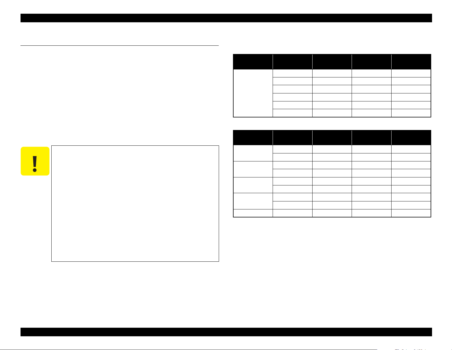
1.2 Basic Specifications
1.2.1 Basic Specifications
Table 1-3. Basic Specifications
Item Specification
Print method On-demand inkjet
Configuration of nozzles*
Maximum resolution 720 x 1440dpi
Control code ESC/P Raster (undisclosed command)
Paper feed method Friction feed
RAM
Interface
Temperature
Humidity
For Main 512 MB
For Network 128 MB
Main body operation environment 15°C to 35 °C
When storing (packed)
When storing (unpacked)
Main body operation environment 20% to 80% (Non condensing)
When storing (packed) 5% to 85% (Non condensing)
When storing (unpacked) 5% to 85% (Non condensing)
360 nozzles x 2 rows x 4 colors
(Black, Cyan, Magenta, Yellow)
High-Speed USB 2.0
Ethernet (100Base-TX/1000Base-
T)
-20 °C to 60 °C
(within 120 hours at 60 °C, within 1
month at 40 °C)
-20 °C to 40 °C
(within 1 month at 40 °C)
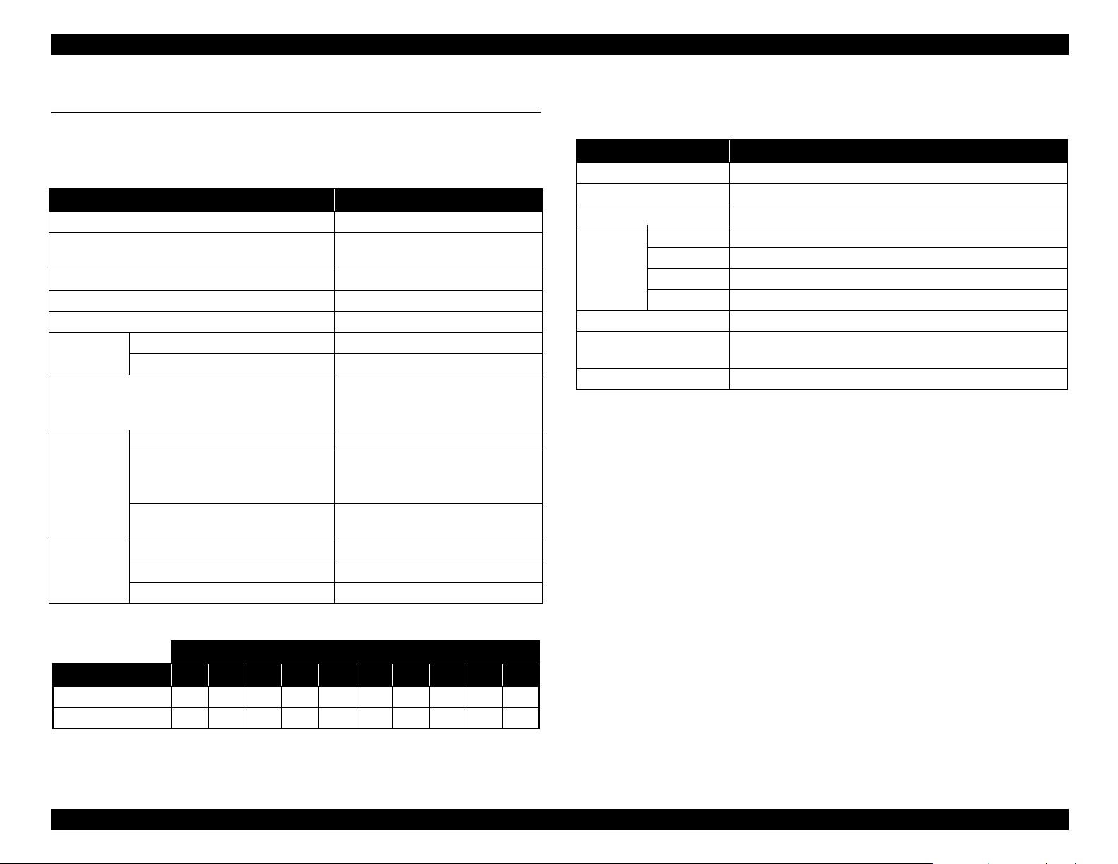
1.2.2 Electric Specifications
Table 1-4. Electric Specifications
Item Specification
Rated voltage AC 100 to 240 V
Rated frequency 50 to 60 Hz
Rated current 1.0A to 0.5A
In use Approx. 65 W
Power
consumption
Insulation resistance 10 MΩ or more (between AC line and chassis at 500 VDC)
Dielectric strength
Leek current 0.25 mA or less
Ready mode Approx. 20 W
Sleep mode Approx. 3.0 W or less
Power off 0.4 W or less
1.0 kV rms AC for 1 min. or 1.2 kV rms AC for 1 sec.
(between AC line and chassis)
*Nozzle set configuration is;
Row
Product A B C D E F G H I J
SC-F6000 Series C Y M BK - - BK M Y C
SC-B6000 Series C M Y BK - - BK Y M C
PRODUCT DESCRIPTION Basic Specifications 12
Confidential
Page 13

SC-F6000 series/SC-B6000 series Revision B
1.2.3 Ink Specifications
Ink Pack
Table 1-5. Ink Pack
Item Specification
Form Dedicated ink pack (standing pouch)
Ink colors
Use by day See the date printed on the package (at normal temperature)
Storage
temperature
Capacity 1000 ml
Dimensions 170 (W) x 272 (L) mm
Cleaning liquid
Cleaning is for servicing only. Packages of the cleaning liquid are only provided as an
ASP.
Black system: Black
Color system: Yellow, Magenta, Cyan
Uninstalled: -20 to 40°C (within a month at 40 °C)
Installed: -20 to 35 °C (within a month at 40 °C)
Transporting: -20 to 60 °C (within a month at 40 °C, within 72 hours at
60 °C)
PRODUCT DESCRIPTION Basic Specifications 13
Confidential
Page 14

SC-F6000 series/SC-B6000 series Revision B
C A U T I O N
1.3 Printing Specifications
1.3.1 Supported media
This printer supports the following paper specifications for non-Epson media.
Do not use paper that is wrinkled, scuffed, torn, or dirty.
Although plain paper and recycled paper manufactured by
other companies can be loaded and fed in the printer as long as
they meet the following specifications, Epson cannot guarantee
the print quality.
Although other paper types manufactured by other companies
can be loaded in the printer as long as they meet the following
specifications, Epson cannot guarantee the paper feeding and
print quality.
ROLL PAPER
Table 1-6. Roll Paper
Item Specification
Roll core size 2 inch and 3 inch
Roll paper outer diameter 150 mm or less
Width 254 mm (10 inches) to 1118 mm (44 inches)
Paper thickness 0.08 to 0.5 mm
Basis weight 64 to 260 g/m
2
PRODUCT DESCRIPTION Printing Specifications 14
Confidential
Page 15
SC-F6000 series/SC-B6000 series Revision B
3mm/15mm/45mm
3mm/15mm/150mm
254mm~1118mm
127mm
~
15m
3mm/15mm 3mm/15mm
A
C
D
B
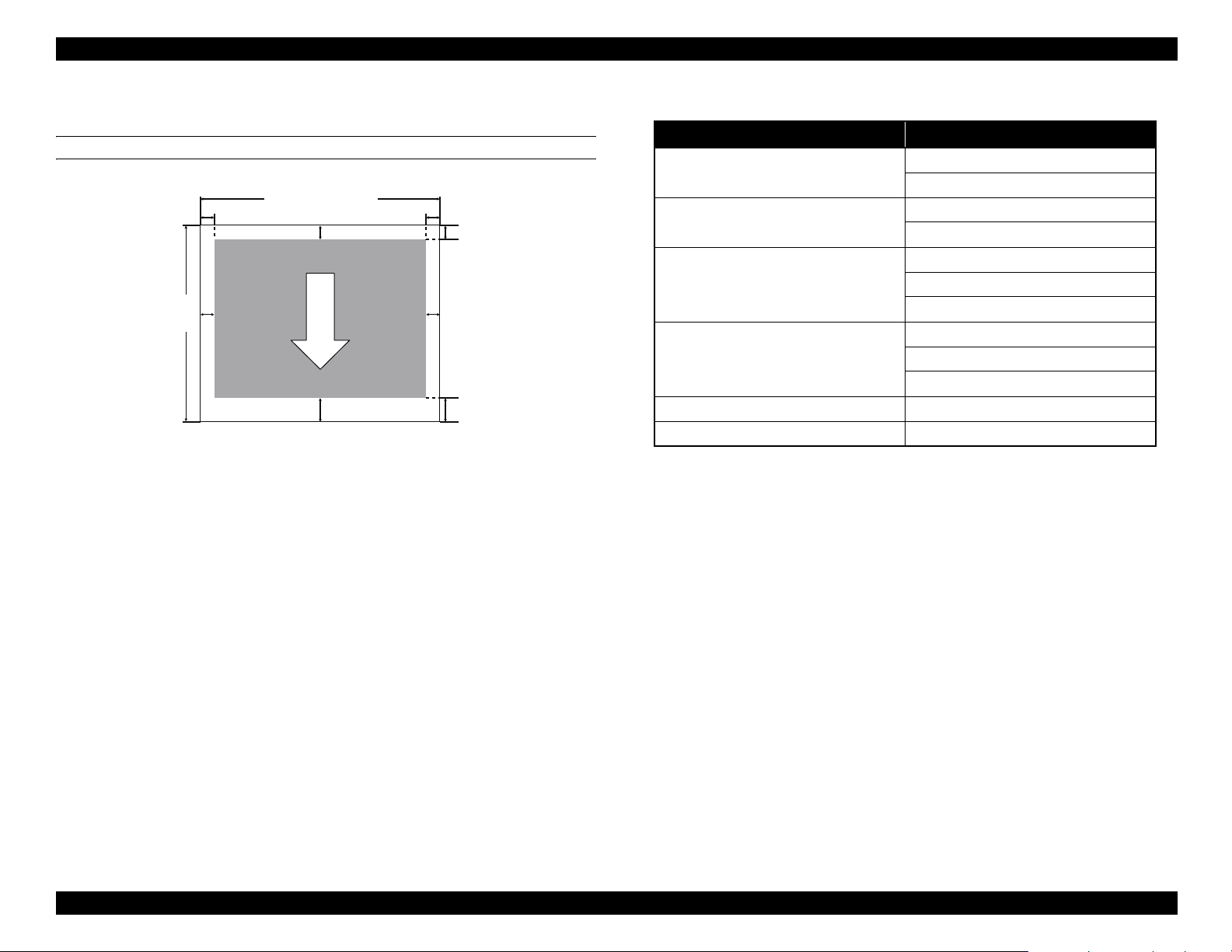
1.3.2 Printable area
ROLL PAPER
Table 1-7. Roll Paper Margin
Roll Paper Margin Parameter Margin Values
Normal
A, C = 15mm
B, D = 3mm
A, C = 15mm
Top15mm/Bottom15mm
B, D = 3mm
A = 45mm
Top35mm/Bottom15mm
C = 15mm
B, D = 3mm
A = 15mm
Top15mm/Bottom150mm
C = 150mm
B, D = 3mm
3mm A, B, C, D = 3mm
15mm A, B, C, D = 15mm
Note *1 : If Normal is selected along with any of the following paper types under Select
Paper Type in the Paper menu, the value of A is 20 mm.
Premium Glossy 250/Premium Semigloss 250/Premium Luster 260/Premium
Semimatte 260
*2: If Normal is selected, and Auto Cut is turned Off in the Setup menu, the value of C
is 150 mm.
*1*2
PRODUCT DESCRIPTION Printing Specifications 15
Confidential
Page 16
SC-F6000 series/SC-B6000 series Revision B
1.4 Hardware Specifications
This section provides the printer dimensions and shows the main components.
1.4.1 Dimensions and Weight
Table 1-8. Dimensions and Weight
Width Depth Height Weight
1608 mm 917 mm 1128 mm Approx. 90 kg
Note "*": Ink not included.
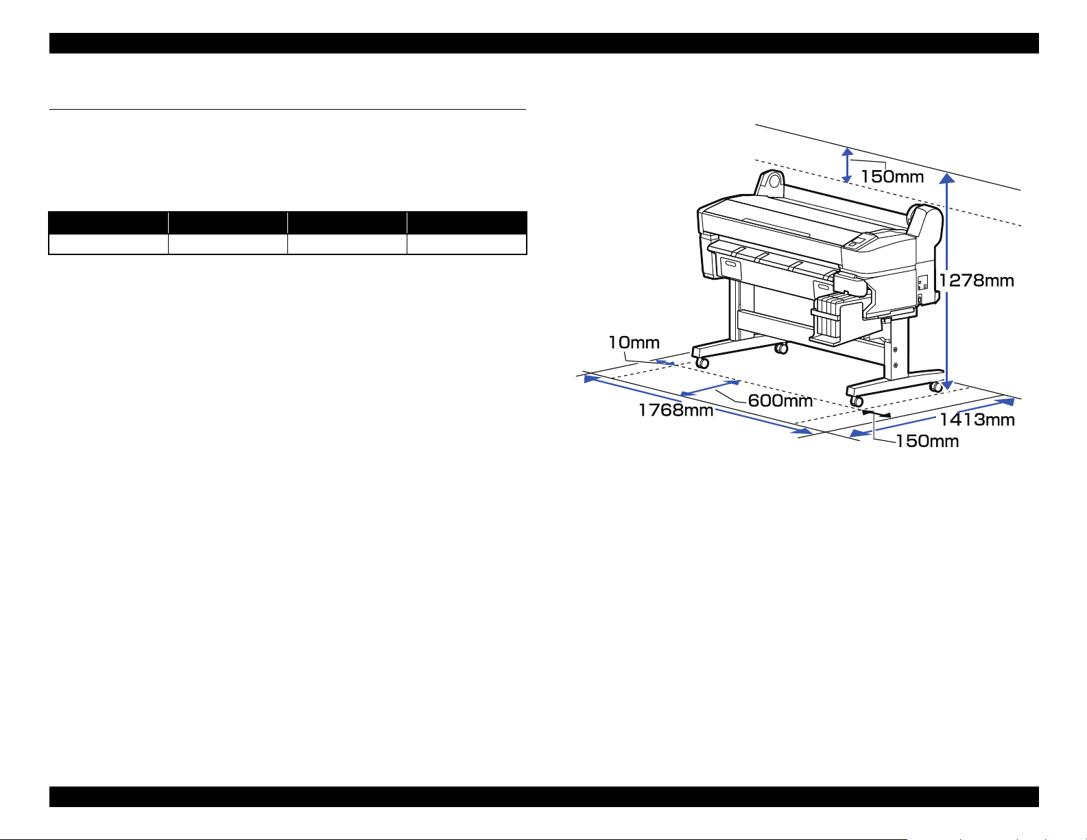
1.4.2 Installation Space
*
Figure 1-1. Installation Space
PRODUCT DESCRIPTION Hardware Specifications 16
Confidential
Page 17
SC-F6000 series/SC-B6000 series Revision B
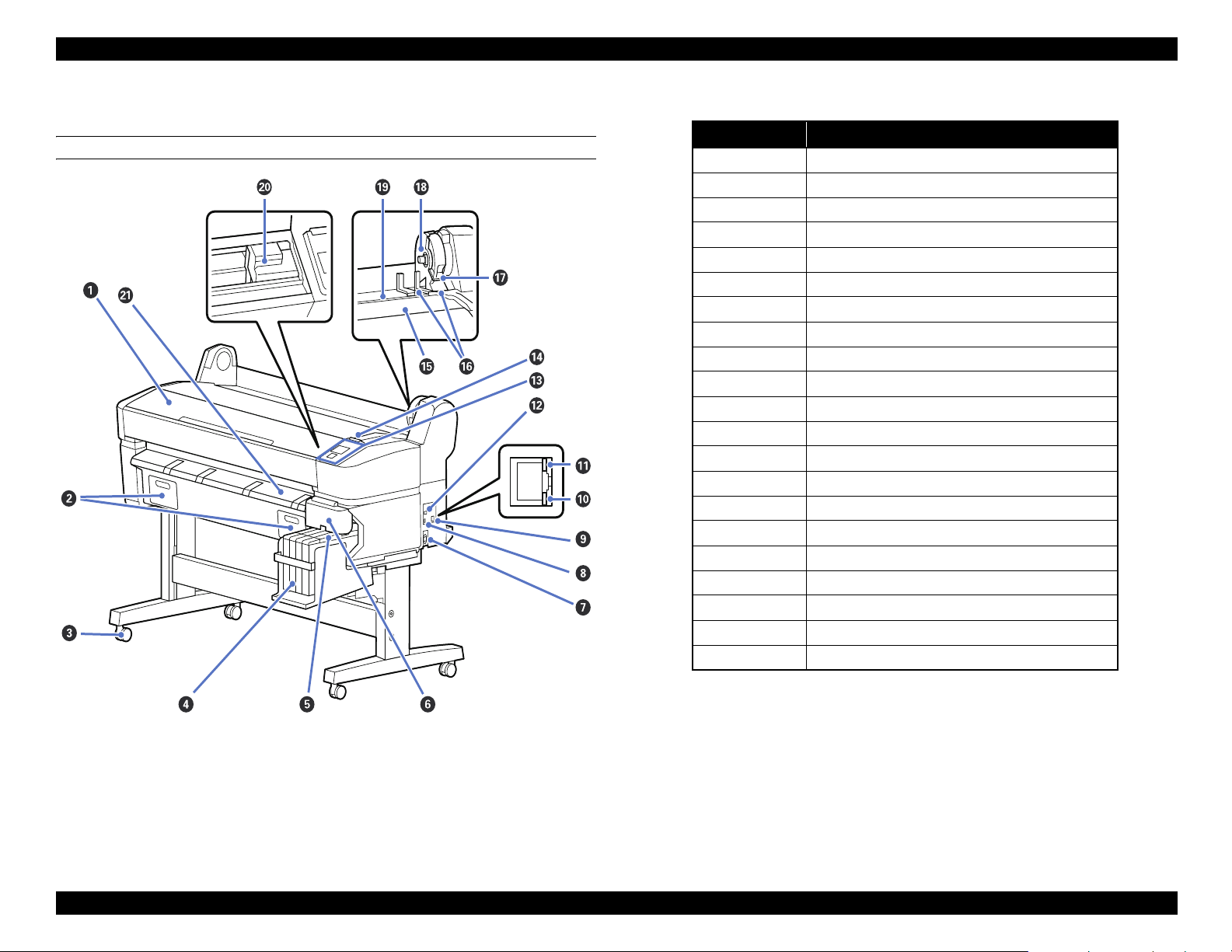
1.4.3 Part Names
FRONT SIDE
Table 1-9. Front Side
No. Name
1 Printer cover
2 Maintenance box covers
3Casters
4 Ink tank
5 Slider
6 Side cover
7 AC inlet
8 Option port
9 LAN port
10 Data light
11 Status light
12 USB port
13 Control panel
14 Alert lamp
15 Roll rest
16 Adapter guides
17 Roll lock lever
18 Adapter holder
19 Paper slot
20 Print head
21 Paper eject guide
Figure 1-2. Front Side
PRODUCT DESCRIPTION Hardware Specifications 17
Confidential
Page 18

SC-F6000 series/SC-B6000 series Revision B
SLIDER
Figure 1-3. Slider
Table 1-10. Slider
No. Name
1 Slider
2 Ink inlet cover
3 Chip unit
ROLL PAPER ADAPTER
Figure 1-4. Roll paper adapter
Table 1-11. Roll paper adapter
No. Name
1 Adapter lock lever
2 Size lever
PRODUCT DESCRIPTION Hardware Specifications 18
Confidential
Page 19
SC-F6000 series/SC-B6000 series Revision B
1.5 Control Panel Specifications
1.5.1 Control panel and LCD
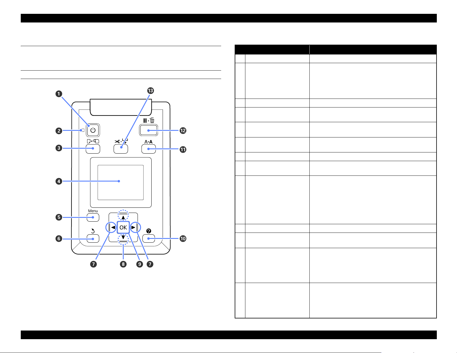
CONTROL PANEL
Figure 1-5. Control panel
Table 1-12. Control panel
Name Function
1 Power button Turns the power on and off.
On: The power is on.
Flashing: The printer is receiving data or cleaning the
2 Power light
Off: The power is off.
3 Load/Remove Paper button Displays the Load/Remove Paper menu.
4Screen
5 [Menu] button
6 Back button
7 Left/Right buttons Use these buttons to select tabs.
8 Up/Down buttons
9 OK button
10 Help button Displays the Help menu.
11 Maintenance button
12 Pause/Cancel button
13 Feed/Cut Media button
Displays the printer’s status, menus, error messages, and so
on.
Displays the menu for the tab currently selected in the
display.
If menus are displayed, pressing this button takes you up
one level in the menu hierarchy.
When menus are displayed, these buttons can be used to
highlight items or options.
Displays the menu for the tab currently selected in the
display.
When menus are displayed and an item is highlighted,
pressing this button displays the sub-menu for the
highlighted item.
If pressed while a parameter is selected from the Menu,
the parameter is set or executed.
Displays the Maintenance menu, which is used for nozzle
checks and head cleaning.
The printer enters pause status if this is pressed while
printing.
Pressing this button while a menu or help is displayed
closes the menu or help and returns the printer to ready
status.
It is used to manually cut roll paper using the built-in
cutter.
If printing is not currently in progress and the printer is
loaded with roll paper, you can feed paper ahead by
pressing first this button and then the [T] button.
print head or performing other operations in
the course of being shut down.
PRODUCT DESCRIPTION Control Panel Specifications 19
Confidential
Page 20
SC-F6000 series/SC-B6000 series Revision B
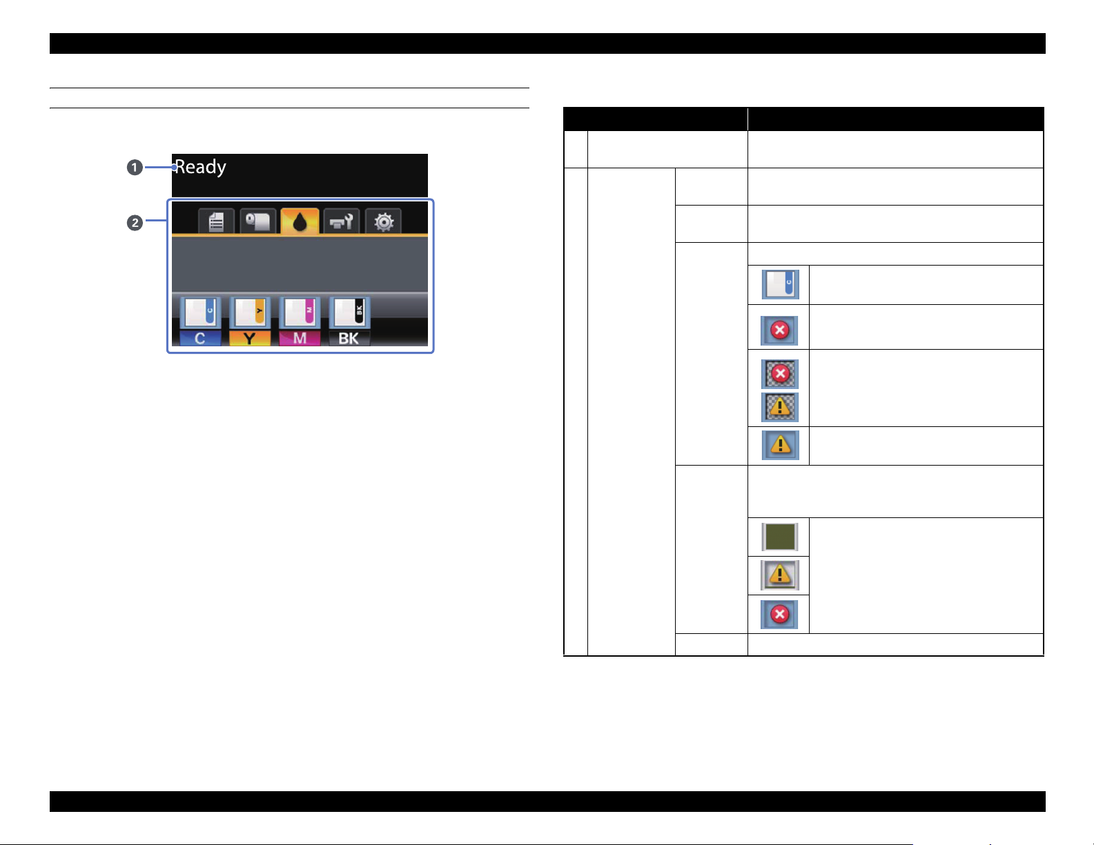
LCD
Screen View
Figure 1-6. LCD
1 Message
Tabs/Info
2
Display Area
Table 1-13. LCD
Name Function
Displays the printer’s status, operation, and error
messages.
Print
Queues Tab
Paper Tab
Ink Tab
Displays print job status and can be used to access the
Print Queues menu.
Shows the type of paper in the printer and can be used to
access the Paper menu.
Displays the ink status of the chip unit.
: No error.
: An error occurred.
: The chip unit could not be recognized or it
is not compatible with the printer. Or the
slider is not locked.
: Ink is low.
Shows the status of the Maintenance Box and is used to
display the Maintenance menu.
Maintenance Box status is shown as follows.
Maintenance
Tab
Setup Tab Displays the IP address and menus for various settings.
: No error.
: The Maintenance Box is nearing the end of
its service life.
: Maintenance Box is at the end of its service
life.
PRODUCT DESCRIPTION Control Panel Specifications 20
Confidential
Page 21
SC-F6000 series/SC-B6000 series Revision B
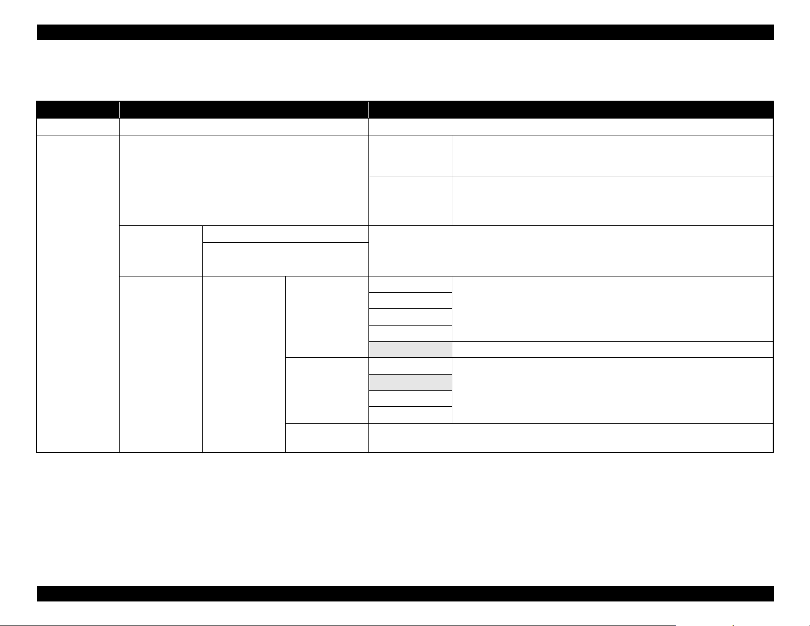
1.5.2 Menu Descriptions
Table 1-14. Menu List
Menu Menu Item / Setting Value (Shaded one is the default) Explanation
Print Queues menu Print Job Log Sheet Press the [OK] button to print the print job log.
Press the [OK] button to view instructions for removing the paper. Follow the onscreen instructions to remove the paper.
Instructions are not displayed if no paper is loaded.
After you make your selection, press the [OK] button. Follow the on-screen
instructions to load the paper.
If the roll paper is already loaded, the instructions for removing the loaded paper will
be displayed before loading instructions are shown.
You can select the media type that is the closest to the paper you are using.
Select the platen gap which is the distance between the print head and the paper.
Normally, select “Standard”. Select a wider setting if printed images are smeared. If,
upon performing head alignment you feel that it is still not completely aligned, select
“Narrow”.
Paper menu
Load/Remove Paper
Select Paper Type
Custom Paper
Setting
Remove Paper
Roll Paper
RIP Settings Select the paper settings to use for printing.
If RIP Settings is selected, the paper settings set in the software RIP are used.
1 to 10 (Paper Settings Number)
Select Reference
Paper
XXXXXXXXXXX
(name of custom
paper type)
Platen Gap
Detect Paper
Thickness
Set to a number between 1 and 10 to use the paper settings set in that slot for printing. To save a group of
paper settings in this way, use Custom Paper Setting.
Photo Paper
Matte Paper
Plain Paper
Others
No Paper Selected Select this option if you do not wish to specify the paper type.
Narrow
Standard
Wide
Wider
Press the [OK] button to print a pattern to determine the thickness of the current paper.
Select the pattern number with the least misalignment from the print results.
PRODUCT DESCRIPTION Control Panel Specifications 21
Confidential
Page 22
SC-F6000 series/SC-B6000 series Revision B
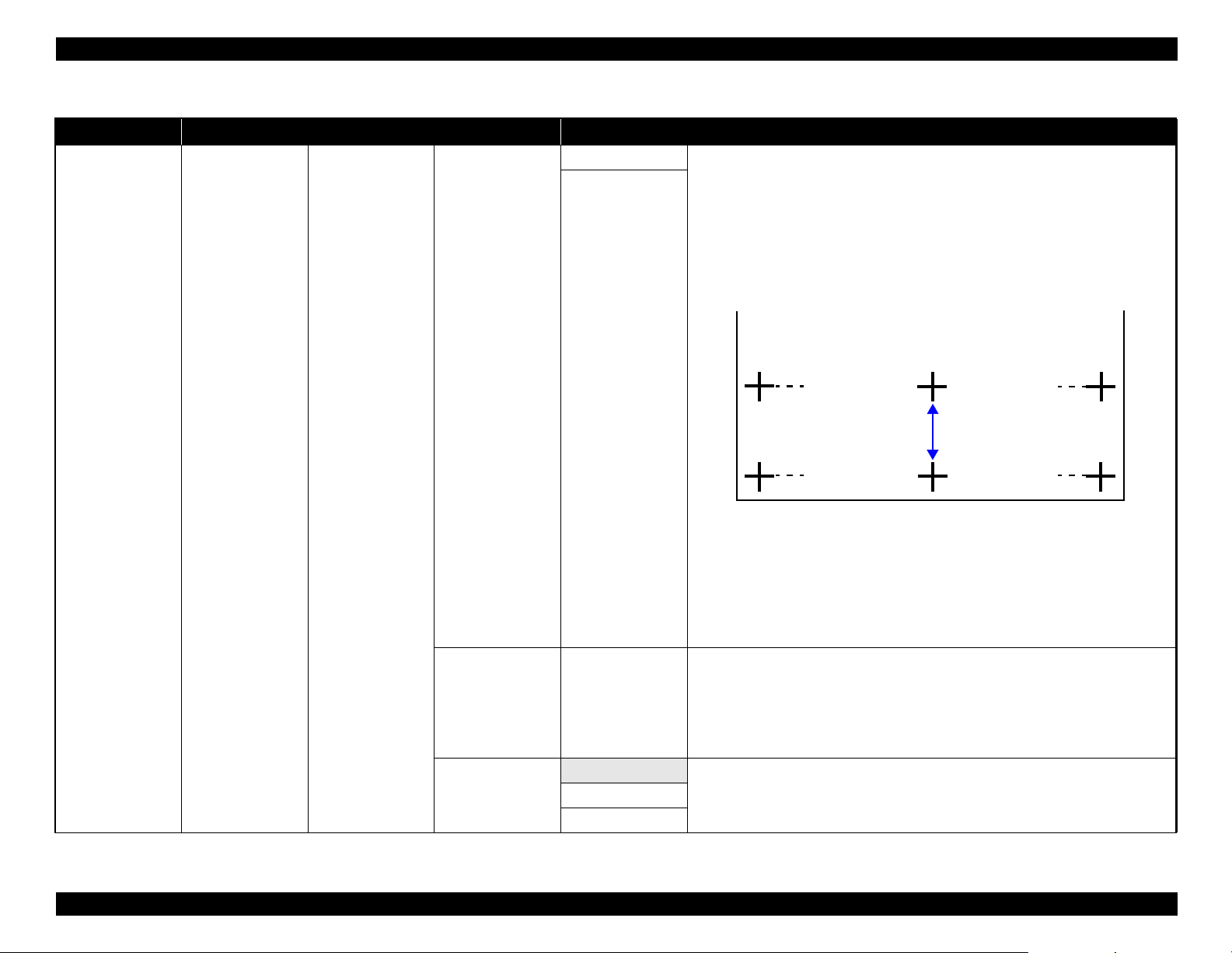
Table 1-14. Menu List
Menu Menu Item / Setting Value (Shaded one is the default) Explanation
Pattern Use this setting if you are unable to resolve banding issues (horizontal striped lines or
uneven colors) in the standard print area (for cut sheets, the area excluding the 1 to 2
cm strip at the bottom of the paper) even after head cleaning or head alignment.
When “Pattern” is selected;
Press the [OK] button to print an adjustment pattern. Measure the distances between
the “+” symbols in the printed adjustment pattern. Use only the distance between the
center symbols or the average of the distances between the left, center, and right
symbols.
Paper menu
Custom Paper
Setting
XXXXXXXXXXX
(name of custom
paper type)
Paper Feed Adjust
Value
Paper Suction -4 to 0
Normal
Roll Paper Tension
Extra High
After the adjustment pattern is printing, the length of the pattern will be displayed in
the control panel. Press the [S]/[T] buttons to enter the measured value and press
the [OK] button.
When “Value” is selected;
Choose an adjustment between -0.70 and +0.70%. Selecting too small a value causes
dark bands; adjust the amount upward. Similarly, choosing too large a value causes
white bands; adjust the amount downward.
It is important to choose the appropriate amount of suction for the paper used in order
to maintain the correct distance between the paper and the print head. Choosing too
high a value for thin or soft paper will increase the distance between the paper and the
print head, causing print quality to decline or preventing the paper feeding correctly.
If this happens, lower the paper suction. The suction power is weakened when the
parameter is lowered.
Select “High” or “Extra High” if the paper wrinkles during printing.High
PRODUCT DESCRIPTION Control Panel Specifications 22
Confidential
Page 23
SC-F6000 series/SC-B6000 series Revision B
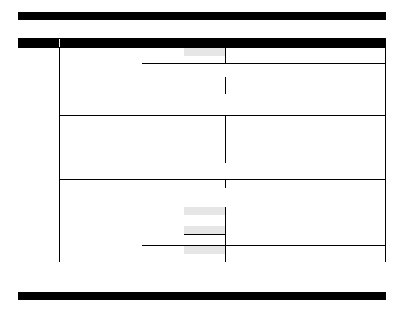
Table 1-14. Menu List
Menu Menu Item / Setting Value (Shaded one is the default) Explanation
Custom Paper
Paper menu
Maintenance menu
Setup menu Printer Setup Roll Paper Setup
Setting
Print Paper List Press the [OK] button to print a list of custom paper settings.
Nozzle Check
Head Cleaning
Head Alignment
Cutter Maintenance
XXXXXXXXXXX
(name of custom
paper type)
All Nozzles
Selected Nozzles
Manual(Uni-D)
Manual(Bi-D)
Adjust Cut Position -3 to 3 mm The cut position can be adjusted in increments of 0.1 mm.
Replace Cutter
Remove Skew
Setting Name
Restore Settings
Auto Cut
Refresh Margin
Page Line
On
Off
Enter a name of up to 22 characters for custom paper settings. Choose an easy-to-remember name for quick
selection.
Yes
No
Press the [OK] button to print a nozzle check pattern. Visually inspect the printed pattern and perform head
cleaning if you notice faint or missing areas.
Execute (Light),
Execute (Medium),
Execute (Heavy)
Execute (Light),
Execute (Medium),
Execute (Heavy)
If print results are grainy or out of focus, perform head alignment to realign the print head.
Moves the cutter to the replacement position so it can be replaced. Press the [OK] button to move the cutter
to the replacement position. The paper must be removed before the cutter can be replaced. Remove the paper
before proceeding.
On Choose “On” to automatically cut roll paper using the built-in cutter as each page is
Off
On If “On” is selected during borderless printing, the printer will automatically trim the
Off
On
Off
Select whether to enable (“On”) or disable (“Off”) paper skew reduction.
Restore the selected custom paper settings to default values.
Check the number of any patterns with faint or missing segments and specify whether
you want to perform cleaning for all nozzles or only for the rows containing those
numbers. “All Nozzles” performs head cleaning for all nozzles. “Selected Nozzles”
allows you to specify a row or rows of nozzles to perform head cleaning for.
You can choose between the following levels for head cleaning: “Execute (Light),
Execute (Medium)”, or “Execute (Heavy)”. At first, use “Execute (Light)”. If you
still notice any faint or missing areas, then use “Execute (Medium)”. If you still
notice any faint or missing areas, then use “Execute (Heavy)”.
printed, “Off” to disable auto paper cutting. However, borderless printing is not
guaranteed on this printer.
leading edge to remove any ink stains that may have been left by the previous copy;
to disable this feature, choose “Off”.
If “Auto Cut” is “Off”, you can choose to print (“On”) or not print (“Off”) cut lines
on roll paper. Cut lines are not printed if “Auto Cut” is “On”.
PRODUCT DESCRIPTION Control Panel Specifications 23
Confidential
Page 24

SC-F6000 series/SC-B6000 series Revision B
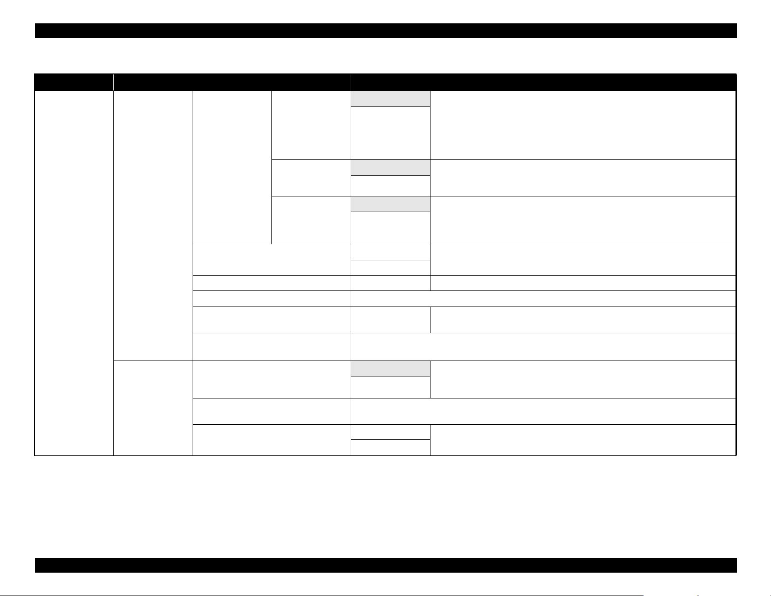
Table 1-14. Menu List
Menu Menu Item / Setting Value (Shaded one is the default) Explanation
Normal
Top 15 mm/
Bottom 15 mm
Setup menu Printer Setup
Roll Paper Setup
Advanced Settings
Roll Paper Margin
Roll Paper
Remaining
Remaining Alert
Roll Paper Tension
Less Head Scuffing
Drying Time Per
Page
Top 45 mm/
Bottom 15 mm
Top 15 mm/
Bottom 150 mm
3 mm
15 mm
On Select whether to display/record (On) or not to display/record (Off) the amount of
Off
1 to 15 m (4 to 50
ft)
Low Select “High” or “Extra High” if the paper wrinkles during printing.
Normal
High
Extra High
On If the paper is thick, the print head may scuff the print surface. Choose “On” to
Off
Off, 0.1 to 60
minutes
When set to “Normal”, the top and bottom margins are 15 mm, and the left and right
margins are 3 mm.
Except for “15 mm”, the left and right margins for all other settings are 3 mm.
remaining roll paper. “Roll Paper Remaining” can be enabled by selecting “On” and
entering the length of the roll.
Displayed when “On” is selected for “Roll Paper Remaining”.
Set within a range from 1 to 15 m (4 to 50 ft) to display a warning when the amount
of remaining roll paper drops below that limit. You can set in 1 m (4 ft) increments.
“Roll Paper Tension” can be specified separately for each paper type using the
“Custom Paper Setting” option in the Paper menu.
When “Custom Paper” is chosen for “Select Paper Type”, the printer will use the
value selected for “Roll Paper Tension” in the “Custom Paper Setting”.
This setting takes effect if no custom roll paper tension is specified.
prevent scuffing. This option can be used to temporarily change the value selected for
“Custom Paper Setting” > “Platen Gap” in the Paper menu. Note, however, that “On”
has no effect when “Wider” is selected for “Platen Gap”.
Specify how long the printer pauses to allow the ink to dry after printing each page;
select Off or choose from values between 0.1 and 60 minutes. Depending on the ink
density or paper type, the ink may take a while to dry. If the ink blurs on the paper, set
a longer time for drying the ink.
The longer the drying time, the more time required for printing.
PRODUCT DESCRIPTION Control Panel Specifications 24
Confidential
Page 25
SC-F6000 series/SC-B6000 series Revision B
Table 1-14. Menu List
Menu Menu Item / Setting Value (Shaded one is the default) Explanation
On Choose whether the printer automatically detects (“On”) or does not detect (“Off”)
the paper width. Try choosing “Off” if a paper setting error is displayed when the
paper is correctly loaded. Note, however, that the printer may print outside the paper
when “Off” is selected. If it prints beyond the edges of the paper, the inside of the
printer becomes dirty with ink. We generally recommend to operate with this setting
set to “On”.
stop if the paper is skewed; select “Off” to disable this feature. “On” is recommended
in most circumstances as skewed paper may cause the printer to jam.
every 1 to 10 pages. If “Off” is selected, no Cleaning Cycle is used. If you choose a
number between 1 and 10 pages, head cleaning will be performed automatically
before printing occurs after the set number of pages is printed.
Select “Yes” to restore all printer settings to default values.
View the total area printed (six-figure maximum).
manually (“Panel”). Choose “Panel” to enter the “IP address”, “Subnet Mask”, and
“Default Gateway”.
Select “Yes” to restore all network settings to default values.
Setup menu
Printer Setup
Network Setup
Paper Size Check
Advanced Settings
Paper Skew Check
Cleaning Cycle
Restore Settings
Firmware Version xxxxxxx,x.xx,xxxx You can see the firmware version.
Option Status Lists the optional accessories currently connected to the printer and available for use.
Show Total Prints
Print Status Sheet
IP Address Setting
Print Status Sheet
Restore Settings
Off
On If “On” is selected, an error will be displayed in the control panel and printing will
Off
Off Select when to perform scheduled head cleaning; you can select from “Off” or after
Every 1 to 10 pages
Yes
No
XXXXXXX m2
(XXXXXX ft2)
Press the [OK] button to print a list of current printer settings.
Choose this option to view settings at a glance.
Auto Select whether to use DHCP to set the IP address (“Auto”), or to set the address
Panel
Press the [OK] button to print a list of network settings. Choose this option to view network settings at a
glance.
Yes
No
PRODUCT DESCRIPTION Control Panel Specifications 25
Confidential
Page 26
SC-F6000 series/SC-B6000 series Revision B
Table 1-14. Menu List
Menu Menu Item / Setting Value (Shaded one is the default) Explanation
The printer enters sleep mode automatically when there are no errors, no print jobs
being received, and no control panel or other operations are performed for the
selected period. Use this option to choose the period before the printer enters sleep
mode.
received, and no control panel or other operations are performed for eight hours.
The delay before the printer turns off can be selected from values between 1 and 24
hours in increments of 1 hour.
Choose “Off” to prevent the printer turning off automatically.
Select “Yes” to restore all “Power Settings” to default values.
Select the language used on the control panel’s screen.
Select the unit of length which is displayed on the control panel’s screen or printed on
the patterns.
Choose whether the large alert lamp lights (“On”) or does not light (“Off”) when an
error occurs.
Setup menu
Power Settings
Preference
Sleep Mode 5 to 240 minutes
Off The printer turns off automatically when there are no errors, no print jobs being
Power Off Timer
Restore Settings
Language
Unit: Length
Alert Lamp Setting
1 to 24 hours
Yes
No
Japanese
English
French
Italian
German
Portuguese
Spanish
Dutch
Russian
Korean
Chinese
m
ft/in
On
Off
PRODUCT DESCRIPTION Control Panel Specifications 26
Confidential
Page 27

SC-F6000 series/SC-B6000 series Revision B
Table 1-14. Menu List
Menu Menu Item / Setting Value (Shaded one is the default) Explanation
Setup menu
Administrator
Menu
Date And Time
Time Zone
Reset All Settings
MM/DD/YY
HH:MM
Enter the difference between the current time zone and GMT.
The selected time zone is used in e-mail notifications sent by Remote Manager when an error occurs.
Yes
No
Set the printer’s built-in clock. The printer clock provides the times that appear in
print outs of job information and printer status.
Select “Yes” to restore defaults for all settings except the “Date And Time”,
“Language”, and “Unit: Length” options in the Setup menu.
PRODUCT DESCRIPTION Control Panel Specifications 27
Confidential
Page 28
SC-F6000 series/SC-B6000 series Revision B
1.5.3 Serviceman Mode
The Serviceman Mode is intended to be used by a service person for servicing the
printer.
HOW TO START & QUIT
1. Turn the printer on by pressing the [Menu], [Back], and [OK] buttons together.
2. Turn the printer off to quit the Serviceman Mode.
SERVICEMAN MODE MENU LIST
Menu
Class 1 2 3
Paper Adjusts the detection accuracy of the PAPER THICKNESS SENSOR.
Rear AD Adjusts the AD value of the PE Sensor.
CR Un Cap Unlocks or re-locks the carriage and uncaps/re-caps the Print Head.
Mecha Adjustment
LCD RGB Check
Panel Check Checks the operation of the buttons and the LEDs.
Sensor Check ILS Checks the operation of sensors.
Red
Blue
Explanation
Checks the operation of the LCD.Green
PRODUCT DESCRIPTION Control Panel Specifications 28
Confidential
Page 29

SC-F6000 series/SC-B6000 series Revision B
Menu
Class 1 2 3
PG--
PG-
PG
H to F Speed
Life CR
F to H Speed
Page Size
Fan
Life Count
PGtyp
PG+
PG++
400 CPS
500 CPS
240 CPS
400 CPS
500 CPS
240 CPS
Explanation
Used only in manufacturing processes. Not used in service operations.
PRODUCT DESCRIPTION Control Panel Specifications 29
Confidential
Page 30
SC-F6000 series/SC-B6000 series Revision B
Menu
Class 1 2 3
Feed Amount 1
PS1
PS2
PS3
PS4
PS1
PS2
PS3
PS4
PG--
PG-
PGtyp
PG+
PG++
Life
PF
RLS
APG
Cutter
Display Count
Feed Speed 1
Feed Amount 2
Feed Speed 2
Wait
Fan
Life Count
Wait1
Wait2
Life Count
PG
Wait
Life Count
Length
Return Length
Wait
Life Count
Explanation
Used only in manufacturing processes. Not used in service operations.
PRODUCT DESCRIPTION Control Panel Specifications 30
Confidential
Page 31

TROUBLE SHOOTING
CHAPTER
2
Confidential
Page 32

SC-F6000 series/SC-B6000 series Revision B
2.1 Overview
This section explains the basic procedure for troubleshooting problems on the printer
quickly and efficiently.
When carrying out the troubleshooting procedures, take a flexible measure following
your sales company's policy and considering the troubling situation.
2.1.1 Preliminary Check
Make sure to verify or perform the following basic items whenever servicing the
printer.
2.1.1.1 Before performing troubleshooting
Before troubleshooting, perform basic checks such as connection check of the power
cable and installation check of the ink cartridges.
2.1.1.2 Check for the usage environment
Check the user's usage environment.
Temperature/humidity of the installation site
(For the guaranteed environment, see P.12.)
Drivers/RIP that the user uses
2.1.1.3 Recurrence check of the trouble
Check if the trouble the user claims recurs with the returned printer.
If 3rd party's ink was used, perform the repair according to the policy of each
local sales subsidiary.
If the F/W was not the latest, gain agreement with the user on the update of F/
W, and check if the trouble recurs when the latest F/W is used.
2.1.1.4 Check for the counter values/history
Download NVRAM and check the following with NVRAM Viewer. (For the check
method, see P.101.)
Counter history of the periodic replacement parts. (if any part's life is near.)
Printer's operating history (if any cause for the trouble exists)
Error history (the frequency/history of errors related with the trouble)
2.1.1.5 Test print check
For the trouble related with print quality, carry out “Test Print” and check the current
adjustment status. (For the procedure of test print, see P.104.)
What type of media is used?
Genuine ink or 3rd party's ink?
F/W version (the latest?)
Check also the following if necessary.
Phenomenon Check Item
The installation site inclined?
Any vibrating equipment near the site?
Bad print quality
Missing dots/bad print quality Near a conditioner's ventilation duct?
The user's panel settings
Is the interior dirty?
Clean it if dirty.
TROUBLE SHOOTING Overview 32
Confidential
Page 33

SC-F6000 series/SC-B6000 series Revision B
2.1.2 Troubleshooting Procedure
Refer to the following items according to the observed symptom, carry out the
corresponding troubleshooting following the procedures described in the next sections.
1. Trouble with a Maintenance Request or Service Call Error. (See P.34, P. 35)
2. Trouble on print quality (See P.39)
3. Trouble on paper feeding (See P.40)
4. Other troubles (See P.41)
5. Trouble on Service Program (See P.43)
6. Trouble on NVRAM Viewer (See P.43)
2.1.3 Procedure after troubleshooting
2.1.3.1 If the trouble has been successfully solved
Check if the movement of the covers is normal (without any damage, noises).
If any abnormality is found, lubricate or replace the faulty parts.
Carry out the cleaning after repair.
Prepare a report on the repair. (follow your company/local office's policy.)
2.1.3.2 If necessary to escalate the trouble case
Make a report with the following data.
Backed-up NVRAM data
For bad print quality: a print sample with the marked symptom and a printed
test pattern.
For faulty parts: the faulty parts themselves and a photos of the troubling
section.
Information on the user/the repair listed below
This is a format of the escalation report. At least check out the items on the
list and register the case in the escalation system.
• Model name
• Serial number
• With or without options
• Content of the claim from the user
• Date of occurrence
• Trouble occurrence conditions/recurrence method
• What the service person actually observed
(Check items before check, the content of troubleshooting and repair.)
• Date of escalation
• Purpose of escalation
(Measures which the user/service person)
• Degree of urgency (S/A/B/C)
S: High (those which may cause a death, ignition, etc.)
A: Problems, bugs
B: Strong request
C: Inquiry
• Deadline for the response
• Repair history
• Part-replacement history
TROUBLE SHOOTING Overview 33
Confidential
Page 34

SC-F6000 series/SC-B6000 series Revision B
2.2 Remedies for Maintenance Requests
This section describes the remedies for maintenance requests. Maintenance requests do not effect the printer’s operation; therefore, you can continue the current printing. When a
maintenance request error occurs, the printer displays on the LCD a hexadecimal code of “NNNN” which correspond to the bit numbers assigned to error statuses as shown in the
table below.
Table 2-1. List of the Maintenance Requests
Bit assignment (Binary)
12 11 10 9 8 7 6 5 4 3 2 1 0
000000000000
000000000001 0 00000002
0000000000
0000000001000 00000008
0000000010000 00000010
0000000
000000
0000010000000 00000080
0000
0001000000000 00000200
0010000000000 00000400
100000000000 00000800
0
1000000000000 00001000
100000000 00000100
100000 00000020
1000000 00000040
Note : Ex): When “Maintenance Request 00000108” is displayed.
As “00000108” in hexadecimal means “0000000000000000100001000” in binary, you can find out the code is assigned to Bit-3 and Bit-8 referring to the above table. In
this case, two errors are occurring simultaneously. (Bit-3:
1 00000000
1 0 0 00000004
Out of battery/ Bit-8: the date/time not set.)
NNNN
(Hexa-decimal)
Parts corresponding to the request Status
INK TUBE End of the life
PUMP CAP UNIT End of the life
PUMP CAP UNIT Near the end of life
RTC battery Out of battery
Reserved
Reserved
INK HOLDER End of the life
INK HOLDER Near the end of life
RTC Date/time not set
DAMPER KIT End of the life
DAMPER KIT Near the end of life
Reserved
Reserved
TROUBLE SHOOTING Remedies for Maintenance Requests 34
Confidential
Page 35

SC-F6000 series/SC-B6000 series Revision B
2.3 Remedies for Service Call Error
The following tables explains the Service Call error messages and remedies.
Table 2-2. Service Call Error
Code Category Error Name Cause Check Item Remedy
0001
0002
1101
1125
1138
1139
113A
113B
113C
113D
113E
113F
1219
122A
122B
122C
122D
122E
122F
131B
1412
1416
1417
1418
1419
EMG NMI error Refer to the service manual for SC-T7000 series/SC-T5000 series/SC-T3000 series.
EMG System error Refer to the service manual for SC-T7000 series/SC-T5000 series/SC-T3000 series.
INK TUBE CR life error Refer to the service manual for SC-T7000 series/SC-T5000 series/SC-T3000 series.
CR CR HP detection error Refer to the service manual for SC-T7000 series/SC-T5000 series/SC-T3000 series.
CR Over current error Refer to the service manual for SC-T7000 series/SC-T5000 series/SC-T3000 series.
CR Oscillation error Refer to the service manual for SC-T7000 series/SC-T5000 series/SC-T3000 series.
CR Overload error Refer to the service manual for SC-T7000 series/SC-T5000 series/SC-T3000 series.
CR Over speed error Refer to the service manual for SC-T7000 series/SC-T5000 series/SC-T3000 series.
CR Reversing error Refer to the service manual for SC-T7000 series/SC-T5000 series/SC-T3000 series.
CR Driving time-out error Refer to the service manual for SC-T7000 series/SC-T5000 series/SC-T3000 series.
CR Velocity deviation error Refer to the service manual for SC-T7000 series/SC-T5000 series/SC-T3000 series.
CR Lock error Refer to the service manual for SC-T7000 series/SC-T5000 series/SC-T3000 series.
PF Oscillation error Refer to the service manual for SC-T7000 series/SC-T5000 series/SC-T3000 series.
PF Overload error Refer to the service manual for SC-T7000 series/SC-T5000 series/SC-T3000 series.
PF Over speed error Refer to the service manual for SC-T7000 series/SC-T5000 series/SC-T3000 series.
PF Reversing error Refer to the service manual for SC-T7000 series/SC-T5000 series/SC-T3000 series.
PF Driving time-out error Refer to the service manual for SC-T7000 series/SC-T5000 series/SC-T3000 series.
PF Velocity deviation error Refer to the service manual for SC-T7000 series/SC-T5000 series/SC-T3000 series.
PF Lock error Refer to the service manual for SC-T7000 series/SC-T5000 series/SC-T3000 series.
--- Head driver (transmission gate) overheat error Refer to the service manual for SC-T7000 series/SC-T5000 series/SC-T3000 series.
PUMP Pump life error Refer to the service manual for SC-T7000 series/SC-T5000 series/SC-T3000 series.
PUMP Undetermined position error Refer to the service manual for SC-T7000 series/SC-T5000 series/SC-T3000 series.
Discard the current ink
Wrong color ink was filled in the
CSIC Wrong ink mixture
PUMP Overcurrent error Refer to the service manual for SC-T7000 series/SC-T5000 series/SC-T3000 series.
PUMP Oscillation error Refer to the service manual for SC-T7000 series/SC-T5000 series/SC-T3000 series.
ink tank. This error occurs if the
combination of the ink holder and
the chip unit is not correct.
Check if wrong color ink is filled
(check if the combination of the ink
holder and the chip unit is correct.)
tank, and clean the ink
path using cleaning
liquid, then install a
new ink tank. (Page
41)
TROUBLE SHOOTING Remedies for Service Call Error 35
Confidential
Page 36

SC-F6000 series/SC-B6000 series Revision B
Table 2-2. Service Call Error
Code Category Error Name Cause Check Item Remedy
141A
141B
141C
141D
141E
141F
14B0
14C0
150C
1519
151A
151B
151C
151D
151E
151F
1523
1530
1539
153A
153B
153C
153D
153E
153F
1540
1541
1548
1549
154A
154B
154C
PUMP Overload error Refer to the service manual for SC-T7000 series/SC-T5000 series/SC-T3000 series.
PUMP Over speed error Refer to the service manual for SC-T7000 series/SC-T5000 series/SC-T3000 series.
PUMP Reversing error Refer to the service manual for SC-T7000 series/SC-T5000 series/SC-T3000 series.
PUMP Driving time-out error Refer to the service manual for SC-T7000 series/SC-T5000 series/SC-T3000 series.
PUMP Velocity deviation error Refer to the service manual for SC-T7000 series/SC-T5000 series/SC-T3000 series.
PUMP Lock error Refer to the service manual for SC-T7000 series/SC-T5000 series/SC-T3000 series.
Pump in the ink path Life of the pump in the ink path (INK HOLDER life error) Refer to the service manual for SC-T7000 series/SC-T5000 series/SC-T3000 series.
DAMPER KIT DAMPER KIT error Refer to the service manual for SC-T7000 series/SC-T5000 series/SC-T3000 series.
PG PG position undetectable error Refer to the service manual for SC-T7000 series/SC-T5000 series/SC-T3000 series.
APG Oscillation error Refer to the service manual for SC-T7000 series/SC-T5000 series/SC-T3000 series.
APG Overload error Refer to the service manual for SC-T7000 series/SC-T5000 series/SC-T3000 series.
APG Over speed error Refer to the service manual for SC-T7000 series/SC-T5000 series/SC-T3000 series.
APG Reversing error Refer to the service manual for SC-T7000 series/SC-T5000 series/SC-T3000 series.
APG Driving time-out error Refer to the service manual for SC-T7000 series/SC-T5000 series/SC-T3000 series.
APG Velocity deviation error Refer to the service manual for SC-T7000 series/SC-T5000 series/SC-T3000 series.
APG Lock error Refer to the service manual for SC-T7000 series/SC-T5000 series/SC-T3000 series.
ROLL Roll sensor error Refer to the service manual for SC-T7000 series/SC-T5000 series/SC-T3000 series.
Driven roller Driven roller HP detection error Refer to the service manual for SC-T7000 series/SC-T5000 series/SC-T3000 series.
Driven roller Oscillation error Refer to the service manual for SC-T7000 series/SC-T5000 series/SC-T3000 series.
Driven roller Overload error Refer to the service manual for SC-T7000 series/SC-T5000 series/SC-T3000 series.
Driven roller Over speed error Refer to the service manual for SC-T7000 series/SC-T5000 series/SC-T3000 series.
Driven roller Reversing error Refer to the service manual for SC-T7000 series/SC-T5000 series/SC-T3000 series.
Driven roller Driving time-out error Refer to the service manual for SC-T7000 series/SC-T5000 series/SC-T3000 series.
Driven roller Velocity deviation error Refer to the service manual for SC-T7000 series/SC-T5000 series/SC-T3000 series.
Driven roller Lock error Refer to the service manual for SC-T7000 series/SC-T5000 series/SC-T3000 series.
Cutter Cutter HP detection error Refer to the service manual for SC-T7000 series/SC-T5000 series/SC-T3000 series.
Cutter Cutter return error Refer to the service manual for SC-T7000 series/SC-T5000 series/SC-T3000 series.
Cutter Oscillation error Refer to the service manual for SC-T7000 series/SC-T5000 series/SC-T3000 series.
Cutter Motor disconnection error Refer to the service manual for SC-T7000 series/SC-T5000 series/SC-T3000 series.
Cutter Overload error Refer to the service manual for SC-T7000 series/SC-T5000 series/SC-T3000 series.
Cutter Over speed error Refer to the service manual for SC-T7000 series/SC-T5000 series/SC-T3000 series.
Cutter Reversing error Refer to the service manual for SC-T7000 series/SC-T5000 series/SC-T3000 series.
TROUBLE SHOOTING Remedies for Service Call Error 36
Confidential
Page 37

SC-F6000 series/SC-B6000 series Revision B
Table 2-2. Service Call Error
Code Category Error Name Cause Check Item Remedy
154D
154E
154F
1551
1561
1599
159A
159B
159C
159D
159E
159F
1900
1A23
1A26
1A37
1A38
1A39
1A41
1A50
1A51
1A70
1A71
1A72
1F10
1F11
1F80
1F81
1F82
1F83
1F84
1F85
Cutter Driving time-out error Refer to the service manual for SC-T7000 series/SC-T5000 series/SC-T3000 series.
Cutter Velocity deviation error Refer to the service manual for SC-T7000 series/SC-T5000 series/SC-T3000 series.
Cutter Lock error Refer to the service manual for SC-T7000 series/SC-T5000 series/SC-T3000 series.
Sensor Paper Thickness Sensor error Refer to the service manual for SC-T7000 series/SC-T5000 series/SC-T3000 series.
--- Paper thickness at power-on error Refer to the service manual for SC-T7000 series/SC-T5000 series/SC-T3000 series.
ATC Oscillation error Refer to the service manual for SC-T7000 series/SC-T5000 series/SC-T3000 series.
ATC Overload error Refer to the service manual for SC-T7000 series/SC-T5000 series/SC-T3000 series.
ATC Over speed error Refer to the service manual for SC-T7000 series/SC-T5000 series/SC-T3000 series.
ATC Reversing error Refer to the service manual for SC-T7000 series/SC-T5000 series/SC-T3000 series.
ATC Driving time-out error Refer to the service manual for SC-T7000 series/SC-T5000 series/SC-T3000 series.
ATC Velocity deviation error Refer to the service manual for SC-T7000 series/SC-T5000 series/SC-T3000 series.
ATC Lock error Refer to the service manual for SC-T7000 series/SC-T5000 series/SC-T3000 series.
--- In-process life error Refer to the service manual for SC-T7000 series/SC-T5000 series/SC-T3000 series.
RTC Incorrect RTC data error Refer to the service manual for SC-T7000 series/SC-T5000 series/SC-T3000 series.
RTC RTC Access T/O error Refer to the service manual for SC-T7000 series/SC-T5000 series/SC-T3000 series.
--- Thermistor error Refer to the service manual for SC-T7000 series/SC-T5000 series/SC-T3000 series.
Hardware Transistor environmental temperature error Refer to the service manual for SC-T7000 series/SC-T5000 series/SC-T3000 series.
Hardware Head error Refer to the service manual for SC-T7000 series/SC-T5000 series/SC-T3000 series.
--- Head rank ID input error Refer to the service manual for SC-T7000 series/SC-T5000 series/SC-T3000 series.
Hardware I2C communication error (Between elements on ASIC and MAIN) Refer to the service manual for SC-T7000 series/SC-T5000 series/SC-T3000 series.
Hardware I2C communication error (Between elements on ASIC and SUB) Refer to the service manual for SC-T7000 series/SC-T5000 series/SC-T3000 series.
Hardware MAIN-to-MAIN-B BOARD communication error Refer to the service manual for SC-T7000 series/SC-T5000 series/SC-T3000 series.
Hardware MAIN-B BOARD system error (Core0) Refer to the service manual for SC-T7000 series/SC-T5000 series/SC-T3000 series.
Hardware MAIN-B BOARD system error (Core1) Refer to the service manual for SC-T7000 series/SC-T5000 series/SC-T3000 series.
Maintenance Maintenance 1 (for safety standard) Refer to the service manual for SC-T7000 series/SC-T5000 series/SC-T3000 series.
Maintenance Maintenance 2 (for safety standard) Refer to the service manual for SC-T7000 series/SC-T5000 series/SC-T3000 series.
CSIC control CSIC error Refer to the service manual for SC-T7000 series/SC-T5000 series/SC-T3000 series.
CSIC control CSIC error Refer to the service manual for SC-T7000 series/SC-T5000 series/SC-T3000 series.
CSIC control CSIC error Refer to the service manual for SC-T7000 series/SC-T5000 series/SC-T3000 series.
CSIC control CSIC error Refer to the service manual for SC-T7000 series/SC-T5000 series/SC-T3000 series.
CSIC control CSIC error Refer to the service manual for SC-T7000 series/SC-T5000 series/SC-T3000 series.
CSIC control CSIC error Refer to the service manual for SC-T7000 series/SC-T5000 series/SC-T3000 series.
TROUBLE SHOOTING Remedies for Service Call Error 37
Confidential
Page 38

SC-F6000 series/SC-B6000 series Revision B
Table 2-2. Service Call Error
Code Category Error Name Cause Check Item Remedy
1FB8
1FB9
1FBE
1FBF
1FC0
1FC1
1FC2
1FC3
1FE0
1FE1
1FE2
1FE3
2000
2002
2003
2008
200A
200D
3000
Dxxy
Fxxx
1620
1621
1622
1623
CSIC control CSIC error Refer to the service manual for SC-T7000 series/SC-T5000 series/SC-T3000 series.
CSIC control CSIC error Refer to the service manual for SC-T7000 series/SC-T5000 series/SC-T3000 series.
CSIC control CSIC error Refer to the service manual for SC-T7000 series/SC-T5000 series/SC-T3000 series.
CSIC control CSIC error Refer to the service manual for SC-T7000 series/SC-T5000 series/SC-T3000 series.
CSIC control CSIC error Refer to the service manual for SC-T7000 series/SC-T5000 series/SC-T3000 series.
CSIC control CSIC error Refer to the service manual for SC-T7000 series/SC-T5000 series/SC-T3000 series.
CSIC control CSIC error Refer to the service manual for SC-T7000 series/SC-T5000 series/SC-T3000 series.
CSIC control CSIC error Refer to the service manual for SC-T7000 series/SC-T5000 series/SC-T3000 series.
Storage control Controlled domain full error Refer to the service manual for SC-T7000 series/SC-T5000 series/SC-T3000 series.
Storage control Invalid lock Refer to the service manual for SC-T7000 series/SC-T5000 series/SC-T3000 series.
Storage control Device access error Refer to the service manual for SC-T7000 series/SC-T5000 series/SC-T3000 series.
Storage control Missing device Refer to the service manual for SC-T7000 series/SC-T5000 series/SC-T3000 series.
Memory NVRAM error Refer to the service manual for SC-T7000 series/SC-T5000 series/SC-T3000 series.
Memory SDRAM error Refer to the service manual for SC-T7000 series/SC-T5000 series/SC-T3000 series.
Memory FLASH BOOT SUM CHECK error Refer to the service manual for SC-T7000 series/SC-T5000 series/SC-T3000 series.
Memory Wrong FLASH device error Refer to the service manual for SC-T7000 series/SC-T5000 series/SC-T3000 series.
Memory F/W load error Refer to the service manual for SC-T7000 series/SC-T5000 series/SC-T3000 series.
System System interrupt watchdog time-out error Refer to the service manual for SC-T7000 series/SC-T5000 series/SC-T3000 series.
AC shut-off AC shut-off Refer to the service manual for SC-T7000 series/SC-T5000 series/SC-T3000 series.
Debugging Service call for FW debugging Refer to the service manual for SC-T7000 series/SC-T5000 series/SC-T3000 series.
CPU CPU related service call Refer to the service manual for SC-T7000 series/SC-T5000 series/SC-T3000 series.
Pressure motor Pressurizing initialization error Refer to the service manual for SC-T7000 series/SC-T5000 series/SC-T3000 series.
Pressure motor Pressurizing/Suction switching error Refer to the service manual for SC-T7000 series/SC-T5000 series/SC-T3000 series.
Pressure motor Operating time-out error Refer to the service manual for SC-T7000 series/SC-T5000 series/SC-T3000 series.
Pressure motor Continuous revolution error Refer to the service manual for SC-T7000 series/SC-T5000 series/SC-T3000 series.
TROUBLE SHOOTING Remedies for Service Call Error 38
Confidential
Page 39

SC-F6000 series/SC-B6000 series Revision B
C H E C K
P O I N T
C H E C K
P O I N T
2.4 Remedies for Print Quality Troubles
Refer to the service manual for SC-T7000 series/SC-T5000 series/SC-T3000 series.
2.4.1 Ink Clogging
If the ink clogging persists even though you clean the surrounding area of the ink
system and perform a cleaning, carry out the following procedure.
REQUIRED TOOL
Cleaning cartridges (2 to 4 pcs)
New ink tanks (2 to 4 pcs)
Maintenance boxes (2 to 4 pcs)
New chip unit (for 2 to 4 colors. See below for which colors should be prepared.)
Due to the structure of this printer, you cannot replace only one
tank. Therefore, replacement of the tanks should be made
according to the combinations below.
For SC-F6000 Series
• BK and M
• Y and C
For SC-B6000 Series
• BK and Y
• M and C
REMEDY
4. Clean the areas where ink is attached such as the area around the print head, cap,
wiper or wiper rail. (Page 132)
5. Remove the ink tank of the clogging ink color and the other ink tank of the
corresponding color combination given below. (Page 81)
Due to the structure of this printer, you cannot replace only one
tank. Therefore, replacement of the tanks should be made
according to the combinations below.
For SC-F6000 Series
• BK and M
• Y and C
For SC-B6000 Series
• BK and Y
• M and C
6. Start the printer in the Serviceman Mode.
Turn on the printer while pressing [Menu] + [Back] + [OK].
7. Select Ink Eject.
Select the corresponding color rows, and press the [Run] button to run the ink
eject. (Page 117)
8. Select Activation of Cleaning Cartridge.
Select the corresponding color rows, and press the [Run] button to validate the
cleaning cartridge. (Page 116)
9. Turn off the printer.
10. Install the cleaning cartridges. (Page 81)
11. Turn on the printer.
1. Turn on the printer.
2. Start the service program and select Countermeasure of ink clogging (When no
using printer) from ADJUSTMENT (Sequence).
3. Select Auto CR unlock & move CR to full column side.
Press the [Run] button.
The CR lock is released and the CR Unit moves to the full side, then the printer
turns off automatically. (Page 56)
TROUBLE SHOOTING Remedies for Print Quality Troubles 39
12. Select Tube inner cleaning.
Select the corresponding color rows, and press the [Run] button to fill the cleaning
liquid. (Page 118)
13. When performing cleaning for the other rows continuously, replace the
maintenance box in the home side with a new one.
14. Turn off the printer.
15. Remove the cleaning cartridges.
Confidential
Page 40

SC-F6000 series/SC-B6000 series Revision B
16. Start the printer in the Serviceman Mode.
Turn on the printer while pressing [Menu] + [Back] + [OK].
17. Replace the maintenance box at the home side with a new one.
18. Select Ink Eject.
Select the corresponding color rows, and press the [Run] button to eject the
cleaning liquid. (Page 117)
19. Select Switch between Ink cartridges and Ink tanks.
Select the corresponding color rows and Ink tank, and press the [Run] button to
validate the ink tanks. (Page 115)
20. Turn off the printer.
21. Install the new ink tanks. (Page 81)
22. Install the chip units, and then pour ink into the ink tanks.
23. Turn on the printer.
24. Select Initial ink charge.
Select the corresponding color rows, and press the [Run] button to perform the
initial ink charge. (Page 119)
25. Select Nozzle Check.
Select Nozzle Check Pattern Print, and press the [Run] button to perform the
nozzle check. (Page 110)
2.5 Trouble on Paper Feeding
Refer to the service manual for SC-T7000 series/SC-T5000 series/SC-T3000 series.
26. Perform cleaning if necessary. (Page 110)
27. If the error persists, replace the Print Head.
TROUBLE SHOOTING Trouble on Paper Feeding 40
Confidential
Page 41

SC-F6000 series/SC-B6000 series Revision B
C H E C K
P O I N T
C H E C K
P O I N T
2.6 Other Troubles
Refer to the service manual for SC-T7000 series/SC-T5000 series/SC-T3000 series.
2.6.1 Ink End Error
Ink End Error (“Chip unit expended.”) occurs even sufficient ink remains in the ink
tank.
Table 2-3. Ink End Error
Cause Remedy
Foreign material came in from the spout of the
ink tank, and it caused filter clogging inside
the printer and blocked ink flow, then Ink End
Error occurred.
Installation of the ink tank is not appropriate,
so ILS cannot be detected correctly.
2.6.2 Wrong ink mixture error
If wrong color ink is filled in an ink tank during filling ink, carry out the procedure
below.
REQUIRED TOOL
Cleaning cartridges (2 to 4 pcs)
New ink tanks (2 to 4 pcs)
Maintenance boxes (2 to 4 pcs)
New chip unit (for 2 to 4 colors. See below for which colors should be prepared.)
Replace the ink tank with a new one. Discard
the old tank and the ink inside the tank.
Check the detection condition of ILS from
Sensor Check in the Serviceman Mode.
OFF: ILS is detected.
ON: ILS is not detected correctly.
If ON is displayed, re-install the corresponding
ink tank.
Due to the structure of this printer, you cannot replace only one
tank. Therefore, replacement of the tanks should be made
according to the combinations below.
For SC-F6000 Series
• BK and M
• Y and C
For SC-B6000 Series
• BK and Y
• M and C
REMEDY
1. Start the printer in the Serviceman Mode.
Turn on the printer while pressing [Menu] + [Back] + [OK].
2. Remove the ink tank in which wrong ink was filled and the other ink tank of the
corresponding color combination given below. (Page 81)
Due to the structure of this printer, you cannot replace only one
tank. Therefore, replacement of the tanks should be made
according to the combinations below.
For SC-F6000 Series
• BK and M
• Y and C
For SC-B6000 Series
• BK and Y
• M and C
3. Start the service program and select Resolution of mixing ink error from
ADJUSTMENT (Sequence).
4. Select Ink Eject.
Select the corresponding color rows, and press the [Run] button to carry out the
ink eject. (Page 117)
5. Select Activation of Cleaning Cartridge.
Select the corresponding color rows, and press the [Run] button to validate the
cleaning cartridge. (Page 116)
6. Turn off the printer.
TROUBLE SHOOTING Other Troubles 41
Confidential
Page 42

SC-F6000 series/SC-B6000 series Revision B
7. Install the cleaning cartridges. (Page 81)
8. Turn on the printer.
9. Select Tube inner cleaning.
Select the corresponding color rows, and press the [Run] button to fill the cleaning
liquid. (Page 118)
10. When performing cleaning for the other rows continuously, replace the
maintenance box in the home side with a new one.
11. Remove the cleaning cartridges.
12. Turn off the printer.
13. Start the printer in the Serviceman Mode.
Turn on the printer while pressing [Menu] + [Back] + [OK].
14. Replace the maintenance box at the home side with a new one.
15. Select Ink Eject.
Select the corresponding color rows, and press the [Run] button to eject the
cleaning liquid. (Page 117)
16. Select Switch between Ink cartridges and Ink tanks.
Select the corresponding color rows and Ink tank, and press the [Run] button to
validate the ink tanks. (Page 115)
17. Turn off the printer.
25. Select Time stamp of the resolution date (Mixing ink error).
Click [Run] button.
18. Install the new ink tanks. (Page 81)
19. Replace the maintenance box at the home side with a new one.
20. Install the chip units, and then pour ink into the ink tanks.
21. Turn on the printer.
22. Select Initial ink charge.
Select the corresponding color rows, and press the [Run] button to perform the
initial ink charge. (Page 119)
23. Select Nozzle Check.
Select Nozzle Check Pattern Print, and press the [Run] button to perform the
nozzle check. (Page 110)
24. Perform cleaning if necessary. (Page 110)
TROUBLE SHOOTING Other Troubles 42
Confidential
Page 43

SC-F6000 series/SC-B6000 series Revision B
2.7 Trouble on Service Program
Refer to the service manual for SC-T7000 series/SC-T5000 series/SC-T3000 series.
2.8 Trouble on NVRAM Viewer
Refer to the service manual for SC-T7000 series/SC-T5000 series/SC-T3000 series.
TROUBLE SHOOTING Trouble on Service Program 43
Confidential
Page 44

DISASSEMBLY & ASSEMBLY
CHAPTER
3
Confidential
Page 45

SC-F6000 series/SC-B6000 series Revision B
W A R N I N G
3.1 Overview
This chapter describes procedures for disassembling the main components of SCF6000 series/SC-B6000 series.
Be sure to follow the steps when disassembling the unit.
Unless otherwise specified, disassembled units or components can be reassembled by
reversing the disassembly procedure.
WARNING
Procedures which, if not strictly observed, could result in personal injury are
described under the heading “WARNING”.
CAUTION
“CAUTION” signals a precaution which, if ignored, could result in damage to
equipment.
CHECK POINT
Important tips for procedures are described under the heading “CHECK POINT”.
REASSEMBLY
If the assembly procedure is different from the reversed disassembly procedure,
the correct procedure is described under the heading “REASSEMBLY”.
ADJUSTMENT
Any adjustments required after reassembly of components or parts are described
under the heading “ADJUSTMENT”. Be sure to perform the specified
adjustments with reference to Chapter 4 “ADJUSTMENT”.
LUBRICATION
“LUBRICATION” signals that the part needs to be lubricated when replacing or
maintaining it after disassembling.
3.1.1 Precautions
Before starting the disassembly or reassembly of the product, read the following
precautions given under the headings “WARNING” and “CAUTION”.
When the PRINTR COVER is opened, a safety-interlock
mechanism causes the CR MOTOR and the PF MOTOR to
stop. When the interlock function is disabled, be sure to take
safety precautions and turn the function back to enabled after
the operation.
This printer is equipped with a lithium battery. When handling
the lithium battery, the following precautions should be
followed.
• When replacing the battery, replace it only with a specified
type of battery. Using a different type of battery may cause
excess heat or explosion.
Recommended battery: CR2032 (Sony)
• Dispose of used batteries according to manufacture’s
instructions and local regulations. Contact your local
government agency for information about battery disposal
and recycling.
• When disposing of the battery, be sure to securely cover its
(+) end with tape to prevent combustion or explosion.
• Do not recharge the battery.
• Do not use the battery if it is discolored or damaged, or if any
leakage of electrolyte is observed.
• Do not dismantle, solder or heat the battery. Doing so could
result in leakage of electrolyte, heat generation, or explosion.
• Do not heat the battery or dispose of it in fire.
• If the electrolyte leaked from the battery contacts with your
skin or gets into your eyes, rinse it off with clean water and
see a doctor immediately.
DISASSEMBLY & ASSEMBLY Overview 45
Confidential
Page 46

SC-F6000 series/SC-B6000 series Revision B
W A R N I N G
C A U T I O N
The power switch for this printer is installed on the secondary
side of the power circuit; therefore, the power is always
supplied unless the AC Cable is unplugged. To prevent electric
shock and circuit damage during servicing, make sure to follow
the instructions below.
• Before removing a circuit board, make sure to unplug the
AC Cable from the AC outlet and confirm the LEDs are
turned off by pressing the Power button on the Operating
Panel. This operation discharges the residual charge in the
printer.
• Make sure not to place the removed circuit boards on the
metal and such directly.
Always wear gloves for disassembly and reassembly to avoid
injury from sharp metal edges.
Never touch the ink or wasted ink with bare hands. If ink comes
into contact with your skin, wash it off with soap and water
immediately. If irritation occurs, contact a physician.
If ink gets in your eye, flush the eye with fresh water and see a
doctor immediately.
When replacing the MAIN BOARD, PSH BOARD, or Power
harnesses and such, make sure to check visually if any harness
is caught in between or any wrong connection exists.
Locate the printer on a stable and flat surface.
Use only recommended tools for disassembly, assembly or
adjustment of the printer.
Apply lubricants and adhesives as specified.
Be careful not to soil the printer or the floor with the leaked ink
when removing the ink-path-related components or parts.
Spread a sheet of paper or cloth on the floor in advance.
Do not touch electrical circuit boards with bare hands as the
elements on the board are so sensitive that they can be easily
damaged by static electricity. If you have to handle the boards
with bare hands, use static electricity discharge equipment such
as anti-static wrist straps.
When the printer has to be operated with the covers removed,
take extra care not to get your fingers or clothes caught in
moving parts.
When you have to remove any parts or components that are
provided as after-service-parts but are not described in this
chapter, carefully observe how they are installed and make
sure to remember it before removing them.
Disassembling the frame and some components (platen, PF
shaft) of the printer is prohibited because they are assembled
with precise measurements in 1/100 mm unit at the factory.
DISASSEMBLY & ASSEMBLY Overview 46
Confidential
Page 47

SC-F6000 series/SC-B6000 series Revision B
C A U T I O N
Rear
Front
Up
Full side
Down
Left
Right
Home side
3.1.2 Cautions after assembling 3.1.3 Orientation Definition
The ink-path-related components or parts should be firmly and
securely reinstalled on the printer to prevent the ink from
leakage.
When reassembling the printer, make sure to connect the
connectors of the electric components or parts correctly and
securely. Use extreme care when connecting FFCs (flexible flat
cables). Improper connection of the FFCs, such as inserting
them diagonally into the connectors, could cause shortcircuiting and lead to breakdown of the electric elements on the
boards.
When reassembling the printer, make sure to route the FFCs
and other cables as specified in this chapter. Failure to do so
may cause an unexpected contact of the cables with sharp metal
edges, or lead to lower the noise immunity.
When you removed any parts (especially cables) that are
secured with acetate tape or two-sided tape, be sure to reinstall
and secure them with the tape as exactly the same as they were.
The terms used for indicating the orientation/direction throughout this chapter are as
follows.
Figure 3-1. Orientation Definition
DISASSEMBLY & ASSEMBLY Overview 47
Confidential
Page 48

SC-F6000 series/SC-B6000 series Revision B
3.1.4 Recommended Tools
To protect this product from damage, use the tools indicated in the following table. For
the tools required to perform the adjustment, refer to “Tools/Consumables for
Adjustments” in Chapter 4.
Table 3-1. Tools
Name Description Target Part
4 cm or longer shaft length (The
Phillips screwdriver, No. 1
Phillips screwdriver, No. 2
Tweezers Nothing in particular Parts in general
Acetate tape
Waste cloth
one with a magnet is
recommended)
25 cm or longer shaft length (The
one with a magnet is
recommended)
To secure the cable/harness, or for
the protection against the sharp
edge
To prevent staining the printer
with ink during operation
ٛ
PRINT HEAD
Some encoders/sensors
Parts in general
Parts in general (Use this tape
when it is removed or when
replacing the part)
INKTUBE
INK HOLDER
DUMPER KIT
PRINT HEAD
PUMP CAP UNIT
DISASSEMBLY & ASSEMBLY Overview 48
Confidential
Page 49

SC-F6000 series/SC-B6000 series Revision B
RIGHT UPPER COVER
& RIGHT ROLL
COVER (p. 61)
REAR ROLL COVER FRAME (p. 61)
REAR RIGHT LOWER
COVER (p. 61)
RIGHT LOWER COVER (p. 61)
RIGHT BASE COVER (p. 61)
IH COVER (p. 58)
LOWER PAPER
GUIDE (p. 57)
LOWER PAPER GUIDE (p. 57)
LOWER PAPER GUIDE B (p. 57)
LOWER PAPER GUIDE B (p. 57)
FRONT LEFT LOWER COVER (p. 61)
LEFT LOWER COVER (p. 61)
REAR LEFT LOWER
COVER (p. 61)
LEFT BASE COVER (p. 61)
FRONT COVER
(p. 57)
UPPER LEFT COVER (p. 61)
LEFT UPPER COVER & LEFT
ROLL COVER (p. 61)
UPPER SUPPORT R COVER (p. 61)
TOP COVER (p. 57)
PRINTER COVER (p. 61)
WASTE INK TANK COVER (p. 61)
WASTE INK TANK COVER (p. 61)
3.2 Parts Diagram
Figure 3-2. Housing
DISASSEMBLY & ASSEMBLY Parts Diagram 49
Confidential
Page 50

SC-F6000 series/SC-B6000 series Revision B
SIDE COVER SENSOR (p. 62)
Detects the Open/Closed status of the Side Cover.
INTERLOCK SWITCH (p. 64)
Detects the Open/Closed status of the
PRINTER COVER.
R WASTE INK COVER SENSOR (p. 64)
Detects the Open/Closed status of the WASTE
INK TANK COVER (R).
L WASTE INK COVER SENSOR (p. 64)
Detects the Open/Closed status of the
WASTE INK TANK COVER (L).
Figure 3-3. Cover sensors
DISASSEMBLY & ASSEMBLY Parts Diagram 50
Confidential
Page 51

SC-F6000 series/SC-B6000 series Revision B
MAIN BOARD (p. 65)
• Communicates with the computer.
• Processes received data.
• Controls the printer mechanism.
• Stores the correction values and
various counters.
MAIN-C BOARD (p. 65)
Communicates across a network.
PSH BOARD (p. 65)
Generates the DC voltage for this printer
from the AC power supply.
BOARD BOX FAN (p. 85)
Cools the air inside the Board Box.
SUB BOARD (p. 65)
Relays the connection between the MAIN BOARD and
electric parts/components. See “6.2 Connection Diagram
(p135)” for specific connections to the concerning parts/
components.
MAIN-B BOARD (p. 65)
SUB-B BOARD (p. 65)
Relays the connection between the MAIN BOARD and electric parts
components. See “6.2 Connection Diagram (p135)” for specific connections
to the concerning parts/components.
PANEL BOARD (p. 65)
DISASSEMBLY & ASSEMBLY Parts Diagram 51
Figure 3-4. Electric Circuit Components
Confidential
Page 52

SC-F6000 series/SC-B6000 series Revision B
CR COVER (p. 66)
DAMPER KIT (p. 67)
PRINT HEAD
(p. 71)
CR SCALE (p. 75)
CR FFC (p. 75)
CR TIMMING BELT
(p. 75)
CR MOTOR (p. 75)
The motor to drive the CR UNIT.
CR HP SENSOR (p. 75)
Detects the home position of the CR UNIT.
APG UNIT (p. 75)
PG SENSOR (p. 75)
Detects the origin position of the
platen gap.
CR UNIT (p. 80)
HEAD FFC (p. 75) (x2)
PW SENSOR (p. 80)
Detects the width of paper on the platen. This
is a reflective photo interrupter and detects
the difference of the amount of reflection
between paper (white) and the platen (black).
CR ENCODER (p. 75)
Detects the pattern of the CR
SCALE to control the position of
the CR UNIT.
Figure 3-5. Carriage Mechanism
DISASSEMBLY & ASSEMBLY Parts Diagram 52
Confidential
Page 53

SC-F6000 series/SC-B6000 series Revision B
PUMP CAP UNIT (p. 75)
Includes the wiper section and the
sucking section, and maintains the
PRINT HEAD.
INK HOLDER (p. 76)
Stores INK TANKs and includes the
following mechanism and parts.
•Pressure mechanism (Sensor/Motor)
•Ink Level Sensor
•CRCM Board
INK TUBE (p. 80)
Figure 3-6. Ink System Mechanism
DISASSEMBLY & ASSEMBLY Parts Diagram 53
Confidential
Page 54

SC-F6000 series/SC-B6000 series Revision B
PF MOTOR (p. 83)
The motor to drive the Feed Roller.
PF SCALE (p. 83)
PF ENCODER (p. 83)
Detects the PF Scale patterns to
control the paper feeding (operation of
the PF MOTOR).
PRESSURE ROLLER (p. 83)
SUCTION FAN (p. 85)
Sucks paper to the platen so as to stabilize the
position of paper when printing.
PAPER THICKNESS SENSOR
(p. 83)
Detects the thickness of roll paper
being inserted into the printer.
PF TIMING BELT (p. 83)
PRESSURE ROLLER MOTOR (p. 83)
Makes the PRESSURE ROLLER nip or
release the media.
PRESSURE ROLLER SENSOR
(p. 83)
Detects nipping/releasing status of
the PRESSURE ROLLER.
CUTTER UNIT (p. 84)
ATC MOTOR (p. 83)
Feeds forward (normal rotation) and
rewinds (reverse rotation) the roll
paper to generate back tension.
* ATC: Auto Tension Control
PE SENSOR (THICK PAPER) (p. 83)
Detects the thick paper.
PE SENSOR (ROLL PAPER) (p. 83)
Detects the roll paper and cut sheet.
Figure 3-7. Paper Feed Mechanism / Cutter
DISASSEMBLY & ASSEMBLY Parts Diagram 54
Confidential
Page 55

SC-F6000 series/SC-B6000 series Revision B
3.3 Disassembly Flowchart
Refer to the service manual for SC-T7000 series/SC-T5000 series/SC-T3000 series.
DISASSEMBLY & ASSEMBLY Disassembly Flowchart 55
Confidential
Page 56

SC-F6000 series/SC-B6000 series Revision B
3.4 Disassembly and Assembly Procedure
This section describes procedures for disassembling the components allowed to be
disassembled. Unless otherwise specified, disassembled units or components can be
reassembled by reversing the disassembly procedure.
3.4.1 Preparation for servicing
3.4.1.1 Unlocking the CR Unit
Refer to the service manual for SC-T7000 series/SC-T5000 series/SC-T3000 series.
DISASSEMBLY & ASSEMBLY Disassembly and Assembly Procedure 56
Confidential
Page 57

SC-F6000 series/SC-B6000 series Revision B
3.4.2 Housing
3.4.2.1 TOP COVER
Refer to the service manual for SC-T7000 series/SC-T5000 series/SC-T3000 series.
3.4.2.2 FRONT COVER
Refer to the service manual for SC-T7000 series/SC-T5000 series/SC-T3000 series.
3.4.2.3 LOWER PAPER GUIDE
Refer to the service manual for SC-T7000 series/SC-T5000 series/SC-T3000 series.
3.4.2.4 LOWER PAPER GUIDE B
Refer to the service manual for SC-T7000 series/SC-T5000 series/SC-T3000 series.
DISASSEMBLY & ASSEMBLY Disassembly and Assembly Procedure 57
Confidential
Page 58

SC-F6000 series/SC-B6000 series Revision B
Relay Connector (No.1)
Clamps
Clamp
Cable of the
CARTRIDGE
COVER
SENSOR
C A U T I O N
IH Cover
Hole
Side Cover
A
A
A
Cable of the SIDE
COVER SENSOR
A
3.4.2.5 IH COVER
1. Remove the UPPER LEFT COVER. (p61)
2. Remove the UPPER SUPPORT R COVER. (p61)
3. Remove the PANEL BOARD. (p65)
4. Remove the TOP COVER. (p57)
5. Remove the RIGHT UPPER COVER & RIGHT ROLL COVER. (p61)
6. Remove the FRONT COVER. (p57)
7. Remove the RIGHT LOWER COVER. (p61)
8. Remove the INK TANK. (p81)
9. Release the cable from the four clamps.
10. Disconnect the cable from the relay connector (No.1), and release the cable of the
CARTRIDGE COVER SENSOR.
11. Pull out the cable of the SIDE COVER SENSOR into the hole of the IH COVER.
12. Open the Side Cover.
Do not take off the Side Cover strongly too far in the following steps
because the SIDE COVER SENSOR is attached to the Side Cover.
13. Remove the four screws, and remove the Side Cover.
A) Silver M3x8 P-tite screw with built-in washer: 4 pcs
DISASSEMBLY & ASSEMBLY Disassembly and Assembly Procedure 58
Figure 3-8. Releasing the Cable
Figure 3-9. Removing the Side Cover
Confidential
Page 59

SC-F6000 series/SC-B6000 series Revision B
SIDE COVER
SENSOR
Hook
Inside of Side Cover
Positioning point
Hook
Ink Supply Cover
B
B
B
B
Bottom side
14. Disengage the two hooks that secure the SIDE COVER SENSOR, and remove the
SIDE COVER SENSOR from the Side Cover.
Pay attention to the positioning point (See Figure 3-10).
15. Remove the four screws, and remove the Ink Supply Cover.
B) Silver M3x8 S-tite screw with built-in washer: 4 pcs
DISASSEMBLY & ASSEMBLY Disassembly and Assembly Procedure 59
Figure 3-10. Removing the SIDE COVER SENSOR
Figure 3-11. Removing the Ink Supply Cover
Confidential
Page 60

SC-F6000 series/SC-B6000 series Revision B
IH COVER
C
C
C
C
IH COVER
LOWER PAPER GUIDE
Rib
16. Remove the four screws that secure the IH COVER.
C) Silver M3x8 S-tite screw with built-in washer: 4 pcs
Figure 3-12. Removing the IH COVER
When installing the IH COVER, insert the rib under the LOWER
PAPER GUIDE.
17. Pull out the IH COVER.
DISASSEMBLY & ASSEMBLY Disassembly and Assembly Procedure 60
Confidential
Page 61

SC-F6000 series/SC-B6000 series Revision B
3.4.2.6 WASTE INK TANK COVER
Refer to the service manual for SC-T7000 series/SC-T5000 series/SC-T3000 series.
3.4.2.7 PRINTER COVER
Refer to the service manual for SC-T7000 series/SC-T5000 series/SC-T3000 series.
3.4.2.8 UPPER SUPPORT R COVER
Refer to the service manual for SC-T7000 series/SC-T5000 series/SC-T3000 series.
3.4.2.9 RIGHT UPPER COVER & RIGHT ROLL COVER
Refer to the service manual for SC-T7000 series/SC-T5000 series/SC-T3000 series.
3.4.2.10 RIGHT LOWER COVER
Refer to the service manual for SC-T7000 series/SC-T5000 series/SC-T3000 series.
3.4.2.11 RIGHT BASE COVER
Refer to the service manual for SC-T7000 series/SC-T5000 series/SC-T3000 series.
3.4.2.12 LEFT LOWER COVER
Refer to the service manual for SC-T7000 series/SC-T5000 series/SC-T3000 series.
3.4.2.17 FRONT LEFT LOWER COVER
Refer to the service manual for SC-T7000 series/SC-T5000 series/SC-T3000 series.
3.4.2.18 REAR LEFT LOWER COVER
Refer to the service manual for SC-T7000 series/SC-T5000 series/SC-T3000 series.
3.4.2.19 REAR ROLL COVER FRAME
Refer to the service manual for SC-T7000 series/SC-T5000 series/SC-T3000 series.
3.4.2.13 REAR RIGHT LOWER COVER
Refer to the service manual for SC-T7000 series/SC-T5000 series/SC-T3000 series.
3.4.2.14 UPPER LEFT COVER
Refer to the service manual for SC-T7000 series/SC-T5000 series/SC-T3000 series.
3.4.2.15 LEFT UPPER COVER & LEFT ROLL COVER
Refer to the service manual for SC-T7000 series/SC-T5000 series/SC-T3000 series.
3.4.2.16 LEFT BASE COVER
Refer to the service manual for SC-T7000 series/SC-T5000 series/SC-T3000 series.
DISASSEMBLY & ASSEMBLY Disassembly and Assembly Procedure 61
Confidential
Page 62

SC-F6000 series/SC-B6000 series Revision B
Relay Connector (No.1)
Clamps
Clamp
Cable of the
CARTRIDGE
COVER
SENSOR
C A U T I O N
IH Cover
Hole
Side Cover
A
A
A
Cable of the SIDE
COVER SENSOR
A
3.4.2.20 SIDE COVER SENSOR
1. Remove the UPPER LEFT COVER. (p61)
2. Remove the UPPER SUPPORT R COVER. (p61)
3. Remove the PANEL BOARD. (p65)
4. Remove the TOP COVER. (p57)
5. Remove the RIGHT UPPER COVER & RIGHT ROLL COVER. (p61)
6. Remove the FRONT COVER. (p57)
7. Remove the RIGHT LOWER COVER. (p61)
8. Release the cable from the four clamps.
9. Disconnect the cable from the relay connector (No.1), and release the cable of the
CARTRIDGE COVER SENSOR.
10. Pull out the cable of the SIDE COVER SENSOR into the hole of the IH COVER.
11. Open the Side Cover.
Do not take off the Side Cover strongly too far in the following steps
because the SIDE COVER SENSOR is attached to the Side Cover.
12. Remove the four screws, and remove the Side Cover.
A) Silver M3x8 P-tite screw with built-in washer: 4 pcs
DISASSEMBLY & ASSEMBLY Disassembly and Assembly Procedure 62
Figure 3-13. Releasing the Cable
Figure 3-14. Removing the Side Cover
Confidential
Page 63

SC-F6000 series/SC-B6000 series Revision B
SIDE COVER
SENSOR
Hook
Inside of Side Cover
Positioning point
Hook
13. Disengage the two hooks that secure the SIDE COVER SENSOR, and remove the
SIDE COVER SENSOR from the Side Cover.
Pay attention to the positioning point (See Figure 3-15).
Figure 3-15. Removing the SIDE COVER SENSOR
DISASSEMBLY & ASSEMBLY Disassembly and Assembly Procedure 63
Confidential
Page 64

SC-F6000 series/SC-B6000 series Revision B
3.4.2.21 R WASTE INK COVER SENSOR
Refer to the service manual for SC-T7000 series/SC-T5000 series/SC-T3000 series.
3.4.2.22 L WASTE INK COVER SENSOR
Refer to the service manual for SC-T7000 series/SC-T5000 series/SC-T3000 series.
3.4.2.23 INTERLOCK SWITCH
Refer to the service manual for SC-T7000 series/SC-T5000 series/SC-T3000 series.
DISASSEMBLY & ASSEMBLY Disassembly and Assembly Procedure 64
Confidential
Page 65

SC-F6000 series/SC-B6000 series Revision B
3.4.3 Electric Circuit Components
3.4.3.1 MAIN BOARD
Refer to the service manual for SC-T7000 series/SC-T5000 series/SC-T3000 series.
3.4.3.2 MAIN-B BOARD
Refer to the service manual for SC-T7000 series/SC-T5000 series/SC-T3000 series.
3.4.3.3 MAIN-C BOARD
Refer to the service manual for SC-T7000 series/SC-T5000 series/SC-T3000 series.
3.4.3.4 SUB BOARD
Refer to the service manual for SC-T7000 series/SC-T5000 series/SC-T3000 series.
3.4.3.5 SUB-B BOARD
Refer to the service manual for SC-T7000 series/SC-T5000 series/SC-T3000 series.
3.4.3.6 PSH BOARD
Refer to the service manual for SC-T7000 series/SC-T5000 series/SC-T3000 series.
3.4.3.7 PANEL BOARD
Refer to the service manual for SC-T7000 series/SC-T5000 series/SC-T3000 series.
DISASSEMBLY & ASSEMBLY Disassembly and Assembly Procedure 65
Confidential
Page 66

SC-F6000 series/SC-B6000 series Revision B
3.4.4 Carriage Mechanism / Ink System Mechanism
3.4.4.1 CR COVER
Refer to the service manual for SC-T7000 series/SC-T5000 series/SC-T3000 series.
DISASSEMBLY & ASSEMBLY Disassembly and Assembly Procedure 66
Confidential
Page 67

SC-F6000 series/SC-B6000 series Revision B
A D J U S T M E N T
R E Q U I R E D
3.4.4.2 DAMPER KIT
When replacing/removing this part, refer to “4.1.2 Adjustment
Items and the Order by Repaired Part” (p88) and make sure to
perform the specified operations including required adjustment.
REQUIRED TOOL
Ink Cartridges for service (4 pcs)
USB cable
Service program
Communication driver
PREPARATION BEFORE REPLACEMENT
1. Start the printer in the Serviceman Mode.
Turn on the printer while pressing [Menu] + [Back] + [OK].
2. Start the service program and select When replace Damper kit from
ADJUSTMENT (Sequence).
3. Select Damper Kit Counter.
Press the [Run] button to reset the counter. (p104)
REPLACEMENT
1. Remove the UPPER LEFT COVER. (p61)
2. Remove the UPPER SUPPORT R COVER. (p61)
3. Remove the PANEL BOARD. (p65)
4. Remove the TOP COVER. (p57)
5. Remove the FRONT COVER. (p57)
6. Remove the LEFT UPPER COVER & LEFT ROLL COVER. (p61)
7. Remove the RIGHT UPPER COVER & RIGHT ROLL COVER. (p61)
8. Unlock the CR UNIT. (p56)
9. Remove the CR COVER. (p66)
4. Turn off the printer.
5. Start the printer in the Serviceman Mode.
Turn on the printer while pressing [Menu] + [Back] + [OK].
6. Select Tube inner pressure reduction.
Press the [Run] button to reduce the pressure in the tube. (p110)
7. Select Switch between Ink cartridges and Ink tanks.
Select All channels and Ink Cartridge for service, and press the [Run] button to
validate the ink cartridges for service. (p115)
8. Select Auto CR unlock & move CR to full column side.
Press the [Run] button.
The CR lock is released and the CR UNIT moves to the full side, then the printer
turns off automatically. (p56)
DISASSEMBLY & ASSEMBLY Disassembly and Assembly Procedure 67
Confidential
Page 68

SC-F6000 series/SC-B6000 series Revision B
A
CR Rear Frame
A
Rear Tube Guide
Positioning point
Positioning point
Positioning point
Positioning point
B
B
B
CR Sub Fixing Plate
B
C
C
Grounding wire
CR Sub Tube Frame
DAMPER KIT
CR UNIT
Screw
together
Positioning points
10. Remove the two screws, and remove the CR Rear Frame.
A) Silver M3x6 S-tite screw with built-in washer: 2 pcs
Pay attention to the positioning points (See below figure, Figure
3-16).
11. Move the CR UNIT on the Platen.
12. Remove the six screws, and remove the CR Sub Fixing Plate.
B) Silver M3x10 Machine screw: 4 pcs
C) Silver M3x8 S-tite screw with built-in washer: 2 pcs
Secure the Grounding wire and the plate with the same screw
shown in the below figure.
Pay attention to the positioning points (See Figure 3-17).
Figure 3-16. Removing the CR Rear Frame
Figure 3-17. Removing the CR Sub Fixing Plate
DISASSEMBLY & ASSEMBLY Disassembly and Assembly Procedure 68
Confidential
Page 69

SC-F6000 series/SC-B6000 series Revision B
CR FFC
SUB BOARD
CN100
Ferrite Core Holder
Hooks
C A U T I O N
DAMPER KIT
D
D
CR FFC
INK TUBE
13. Disconnect the CR FFC from the connector (CN100) of the SUB BOARD.
14. Release the CR FFC from the two hooks of the Ferrite Core Holder, and place the
CR FFC over the rear of the printer temporarily.
When the INK TUBE is removed at the following step, ink may
drip off from the tube. Prepare a waste cloth or the like in advance
and be careful not to contaminate the surroundings.
15. Remove the two screws, and remove the INK TUBE from the DAMPER KIT.
D) Silver M2.5x16 screw: 2 pcs
Figure 3-18. Releasing the CR FFC
DISASSEMBLY & ASSEMBLY Disassembly and Assembly Procedure 69
Figure 3-19. Removing the INK TUBE
Confidential
Page 70

SC-F6000 series/SC-B6000 series Revision B
Joint Rubber
E
E
E
Upper side
DAMPER KIT
16. Remove the three screws, and remove the DAMPER KIT.
E) Silver M3x10 Machine screw: 3 pcs
Before installing the joint, make sure the Joint Rubbers are
attached to it.
Before attaching the Joint Rubber, let it get wet with cleaning
liquid.
AFTER REPLACEMENT
1. Install the four ink cartridges for service. (p81)
2. Turn the printer on.
3. Select Cleaning.
Select CL3 and all channels and press the [Run] button to perform CL3.
4. Select Nozzle Check.
Select Nozzle Check Pattern Print, and press the [Run] button to perform the
nozzle check. (p110)
5. Select Switch between Ink cartridges and Ink tanks.
Select All channels and Ink Cartridge for service, and press the [Run] button to
validate the INK TANKs. (p115)
6. Turn off the printer.
7. Turn on the printer.
8. Confirm that there are no errors.
Figure 3-20. Removing the DAMPER KIT
DISASSEMBLY & ASSEMBLY Disassembly and Assembly Procedure 70
Confidential
Page 71

SC-F6000 series/SC-B6000 series Revision B
A D J U S T M E N T
R E Q U I R E D
C A U T I O N
C H E C K
P O I N T
Ink tank guard
Side Cover
3.4.4.3 PRINT HEAD
When replacing/removing this part, refer to “4.1.2 Adjustment
Items and the Order by Repaired Part” (p88) and make sure to
perform the specified operations including required adjustment.
Be careful not to touch the nozzle surface of the PRINT HEAD.
REQUIRED TOOL
Ink Cartridges for service (4 pcs)
Premium Glossy Photo Paper (250) 24 inches or longer
(used in adjustment)
Thickness gauge (used in adjustment)
PREPARATION BEFORE REPLACEMENT
1. Start the service program and select When replace print head from
ADJUSTMENT (Sequence).
3. Turn off the printer.
4. Remove the four screws (one each) that secure the INK TANK.
Figure 3-21. Screws that secure the INK TANK
5. Open the Side Cover.
6. Remove the two screws and remove the ink tank guard.
2. Select Switch between Ink cartridges and Ink tanks. Select All channels and
Ink Cartridge for service and press the [Run] button to make Ink Cartridge for
service available.
This operation should be carried out after replacing the PRINT
HEAD so as not to use the user's ink.
Figure 3-22. Removing Ink tank guard
DISASSEMBLY & ASSEMBLY Disassembly and Assembly Procedure 71
Confidential
Page 72
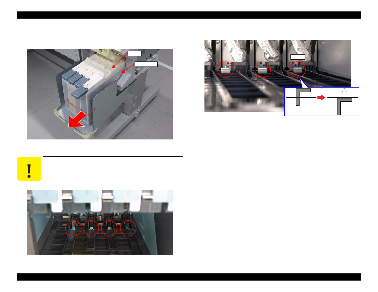
SC-F6000 series/SC-B6000 series Revision B
C A U T I O N
INK TANK
Slider
Hook
7. Pull the Sliders slightly toward you.
8. Remove all the INK TANKs.
Figure 3-23. Removing the INK TANKs
9. Loosen the four screws inside the ink holder.
Just loosen the screws, but do not remove them.
10. Confirm the hooks (plates) shown below are evenly lowered.
Figure 3-25. Plates
11. Install the four ink cartridges for service.
12. Start the printer in the Serviceman Mode.
Turn on the printer while pressing [Menu] + [Back] + [OK].
13. Select Tube inner pressure reduction.
Press the [Run] button to reduce the pressure in the tube. (p110)
Figure 3-24. Screw position
DISASSEMBLY & ASSEMBLY Disassembly and Assembly Procedure 72
Confidential
Page 73

SC-F6000 series/SC-B6000 series Revision B
PRINT HEAD
HEAD FFC
Connector
Connector
PRINT HEAD
A
A
A
Upper side
REPLACEMENT
1. Select Auto CR unlock & move CR to full column side.
Press the [Run] button.
The CR lock is released and the CR UNIT moves to the full side, then the printer
turns off automatically. (p56)
2. Remove the UPPER LEFT COVER. (p61)
3. Remove the UPPER SUPPORT R COVER. (p61)
4. Remove the PANEL BOARD. (p65)
5. Remove the TOP COVER. (p57)
6. Remove the FRONT COVER. (p57)
7. Remove the LEFT UPPER COVER & LEFT ROLL COVER. (p61)
8. Remove the RIGHT UPPER COVER & RIGHT ROLL COVER. (p61)
9. Remove the CR COVER. (p66)
10. Remove the DAMPER KIT. (p67)
11. Disconnect the HEAD FFCs from the four connectors of the PRINT HEAD.
12. Remove the three screws, and remove the PRINT HEAD.
A) Silver M2.6x8 Machine screw: 3 pcs
Figure 3-27. Removing the PRINT HEAD
Figure 3-26. Removing the HEAD FFC
DISASSEMBLY & ASSEMBLY Disassembly and Assembly Procedure 73
Confidential
Page 74

SC-F6000 series/SC-B6000 series Revision B
AFTER REPLACEMENT
1. Start the printer in the Serviceman Mode.
Turn on the printer while pressing [Menu] + [Back] + [OK].
2. Select Printer Head Counter.
Press the [Run] button to reset the counter. (p104)
3. Select Head ID Input.
Input the head rank ID and press the [Write] button. (p110)
4. Turn off the printer. (Make sure to turn off the printer to enable the head ID
setting.)
5. Start the printer in the Serviceman Mode.
Turn on the printer while pressing [Menu] + [Back] + [OK].
6. Load a media for adjustment (Premium Glossy Photo Paper (250) 24 inches or
longer).
7. Select Cleaning.
Select CL3 and all channels and press the [Run] button to perform CL3. (p110)
8. Run the nozzle check from the control panel or from the service program (p110).
9. Perform the Head Inclination Manual Adjustment (CR direction). (p111)
10. Perform the Head Slant Manual Adjustment (PF direction). (p113)
20. Confirm that the hooks shown in Figure 3-25 are set up.
21. Install the INK TANKs.
22. Secure the INK TANKs with the four screws (one each). (p71)
23. Confirm that all the INK TANKs are installed properly.
24. Secure the ink tank guard with the two screws. (p71)
25. Turn on the printer and confirm that there are no errors.
11. Turn off the printer.
12. Perform the PG adjustment. (p109)
13. Turn on the printer.
14. Perform the Manual Uni-D Adjustment. (p106)
15. Perform the Manual Bi-D Adjustment. (p107)
16. Select Switch between Ink cartridges and Ink tanks.
Select All channels and Ink Tank and press the [Run] button to validate the INK
TANKs. (p115)
17. Turn off the printer.
18. Remove the ink cartridges.
19. Tighten the four screws loosened in Step 9.
DISASSEMBLY & ASSEMBLY Disassembly and Assembly Procedure 74
Confidential
Page 75

SC-F6000 series/SC-B6000 series Revision B
3.4.4.4 HEAD FFC
Refer to the service manual for SC-T7000 series/SC-T5000 series/SC-T3000 series.
3.4.4.5 CR FFC
Refer to the service manual for SC-T7000 series/SC-T5000 series/SC-T3000 series.
3.4.4.6 CR SCALE
Refer to the service manual for SC-T7000 series/SC-T5000 series/SC-T3000 series.
3.4.4.7 CR ENCODER
Refer to the service manual for SC-T7000 series/SC-T5000 series/SC-T3000 series.
3.4.4.8 CR TIMMING BELT
Refer to the service manual for SC-T7000 series/SC-T5000 series/SC-T3000 series.
3.4.4.9 CR MOTOR
Refer to the service manual for SC-T7000 series/SC-T5000 series/SC-T3000 series.
3.4.4.10 CR HP SENSOR
Refer to the service manual for SC-T7000 series/SC-T5000 series/SC-T3000 series.
3.4.4.11 APG UNIT
Refer to the service manual for SC-T7000 series/SC-T5000 series/SC-T3000 series.
3.4.4.12 PG SENSOR
Refer to the service manual for SC-T7000 series/SC-T5000 series/SC-T3000 series.
3.4.4.13 PUMP CAP UNIT
Refer to the service manual for SC-T7000 series/SC-T5000 series/SC-T3000 series.
DISASSEMBLY & ASSEMBLY Disassembly and Assembly Procedure 75
Confidential
Page 76
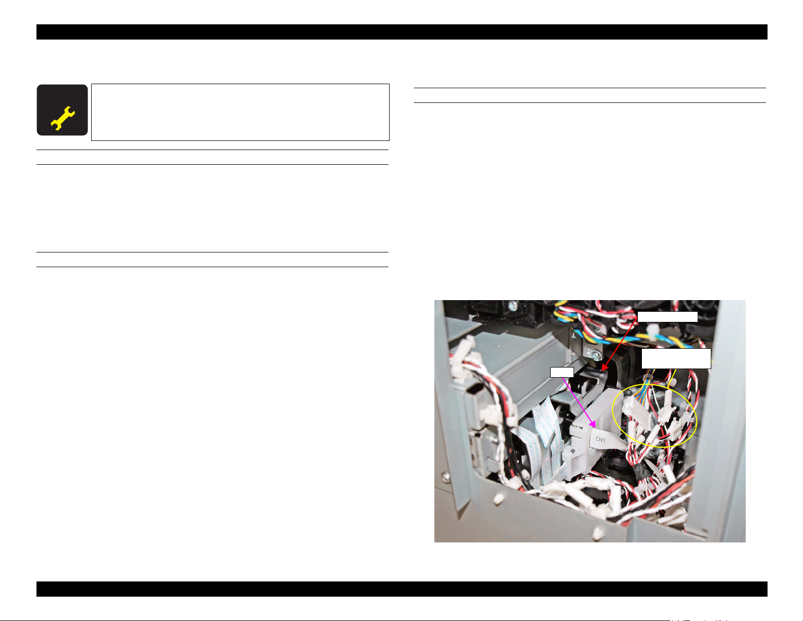
SC-F6000 series/SC-B6000 series Revision B
A D J U S T M E N T
R E Q U I R E D
Relay Connector
(No.2, No.8, No.10)
FFC
INK HOLDER
3.4.4.14 INK HOLDER
When replacing/removing this part, refer to “4.1.2 Adjustment
Items and the Order by Repaired Part” (p88) and make sure to
perform the specified operations including required adjustment.
REQUIRED TOOL
Ink Cartridges for service (4 pcs)
USB cable
Service program
Communication driver
PREPARATION BEFORE REPLACEMENT
1. Start the printer in the Serviceman Mode.
Turn on the printer while pressing [Menu] + [Back] + [OK].
2. Start the service program and select When replace ink holder from
ADJUSTMENT (Sequence).
3. Select Ink Holder Counter.
Press the [Run] button to reset the counter. (p104)
11. Turn off the printer.
REPLACEMENT
1. Remove the UPPER LEFT COVER. (p61)
2. Remove the UPPER SUPPORT R COVER. (p61)
3. Remove the PANEL BOARD. (p65)
4. Remove the TOP COVER. (p57)
5. Remove the RIGHT UPPER COVER & RIGHT ROLL COVER. (p61)
6. Remove the FRONT COVER. (p57)
7. Remove the RIGHT LOWER COVER. (p61)
8. Remove the IH COVER. (p58)
9. Disconnect the cable from the Relay Connector (No.2, No.8, No.10).
10. Remove the FFC from the back side of the INK HOLDER.
4. Turn off the printer.
5. Turn on the printer.
6. Select Switch between Ink cartridges and Ink tanks.
Select All channels and Ink Cartridge for service, and press the [Run] button to
validate the ink cartridges for service. (p115)
7. Turn off the printer.
8. Remove all the INK TANKs. (p81)
9. Start the printer in the Serviceman Mode.
Turn on the printer while pressing [Menu] + [Back] + [OK].
10. Select Ink Eject.
Select All channels, and press the [Run] button to run the ink eject. (p117)
Figure 3-28. Disconnecting the Relay connectors and FFC
DISASSEMBLY & ASSEMBLY Disassembly and Assembly Procedure 76
Confidential
Page 77

SC-F6000 series/SC-B6000 series Revision B
Boss
Rear Cover
A
Back side
Maintenance Box Holder
FFC
Edging saddle
Connector
Back side
Double-sided tape
Double-sided tape
11. Remove the screw that secures the Rear Cover.
A) Silver M3x8 S-tite screw with built-in washer: 1 pcs
12. Disengage the boss of the Rear Cover, and remove the Rear Cover.
13. Disconnect the FFC from the connector of the Maintenance Box Holder.
14. Peel of the FFC from the frame and insert it into the edging saddle.
Figure 3-30. Releasing the FFC
Figure 3-29. Removing the Rear Cover
DISASSEMBLY & ASSEMBLY Disassembly and Assembly Procedure 77
Confidential
Page 78

SC-F6000 series/SC-B6000 series Revision B
B
B
B
B
INK HOLDER
Front side
C A U T I O N
INK HOLDER
INK TUBE
C
C
15. Remove the four screws that secure the INK HOLDER.
B) Silver M3x6 S-tite screw with built-in washer: 4 pcs
16. Pull the INK HOLDER slightly toward you.
When the INK TUBE is removed at the following step, ink may
drip off from the tube. Prepare a waste cloth or the like in advance
and be careful not to contaminate the surroundings.
17. Remove the two screws, and remove the INK TUBE from the INK HOLDER.
C) Silver M2.5x16 Machine screw: 2 pcs
18. Remove the INK HOLDER while pulling out the FFC.
Figure 3-31. Removing the INK HOLDER (1)
Figure 3-32. Removing the INK HOLDER (2)
DISASSEMBLY & ASSEMBLY Disassembly and Assembly Procedure 78
Confidential
Page 79

SC-F6000 series/SC-B6000 series Revision B
Joint Rubber
Before installing the joint, make sure the Joint Rubber are
attached to it.
Before attaching the Joint Rubber, let it get wet with cleaning
liquid.
AFTER REPLACEMENT
1. Install the four ink cartridges for service. (p81)
2. Turn on the printer.
3. Select Initial ink charge.
Select All channels, and press the [Run] button to perform the initial ink charge.
(p119)
4. Select Nozzle Check.
Select Nozzle Check Pattern Print, and press the [Run] button to perform the
nozzle check. (p110)
5. Perform cleaning if necessary. (p110)
6. Select Switch between Ink cartridges and Ink tanks.
Select All channels and Ink Tank, and press the [Run] button to validate the INK
TANKs. (p115)
7. Turn off the printer.
8. Remove the four ink cartridges for service. (p81)
9. Install the INK TANKs. (p81)
10. Turn on the printer.
11. Confirm that there are no errors.
DISASSEMBLY & ASSEMBLY Disassembly and Assembly Procedure 79
Confidential
Page 80

SC-F6000 series/SC-B6000 series Revision B
3.4.4.15 INK TUBE
Refer to the service manual for SC-T7000 series/SC-T5000 series/SC-T3000 series.
3.4.4.16 CR UNIT
Refer to the service manual for SC-T7000 series/SC-T5000 series/SC-T3000 series.
3.4.4.17 PW SENSOR
Refer to the service manual for SC-T7000 series/SC-T5000 series/SC-T3000 series.
DISASSEMBLY & ASSEMBLY Disassembly and Assembly Procedure 80
Confidential
Page 81

SC-F6000 series/SC-B6000 series Revision B
C A U T I O N
Ink tank guard
Side Cover
3.4.4.18 INK TANK/CARTRIDGE
This section describes the removing procedure for the INK TANK and the installation
procedure for cartridges. There are two types of cartridges; cleaning cartridges and ink
cartridges for service.
When using the INK TANKs, cleaning cartridges, and ink
cartridges for service, they should be validated by using software
(Service Program). (See
REMOVING THE INK TANK
1. Remove the four screws (one each) that secure the INK TANK.
P. 115 or P. 116.)
Figure 3-33. Screws that secure the INK TANK
2. Open the Side Cover.
3. Remove the two screws and remove the ink tank guard.
DISASSEMBLY & ASSEMBLY Disassembly and Assembly Procedure 81
Figure 3-34. Ink tank guard
Confidential
Page 82

SC-F6000 series/SC-B6000 series Revision B
C A U T I O N
Slider
INK TANK
Hook
4. Pull the Slider slightly toward you.
5. Remove the INK TANK.
Figure 3-36. Screw position
2. Confirm the hooks (plates) shown below are evenly lowered.
Figure 3-35. Removing the INK TANK
INSTALLING THE CARTRIDGES
1. Loosen the four screws inside the ink holder.
Just loosen the screws, but do not remove them.
DISASSEMBLY & ASSEMBLY Disassembly and Assembly Procedure 82
Figure 3-37. Plates
3. Install the CARTRIDGEs.
Confidential
Page 83

SC-F6000 series/SC-B6000 series Revision B
3.4.5 Paper Feed Mechanism
3.4.5.1 PF MOTOR
Refer to the service manual for SC-T7000 series/SC-T5000 series/SC-T3000 series.
3.4.5.2 PF SCALE
Refer to the service manual for SC-T7000 series/SC-T5000 series/SC-T3000 series.
3.4.5.3 PF ENCODER
Refer to the service manual for SC-T7000 series/SC-T5000 series/SC-T3000 series.
3.4.5.4 PF TIMING BELT
Refer to the service manual for SC-T7000 series/SC-T5000 series/SC-T3000 series.
3.4.5.5 PRESSURE ROLLER
Refer to the service manual for SC-T7000 series/SC-T5000 series/SC-T3000 series.
3.4.5.6 PRESSURE ROLLER MOTOR
Refer to the service manual for SC-T7000 series/SC-T5000 series/SC-T3000 series.
3.4.5.11 PAPER THICKNESS SENSOR
Refer to the service manual for SC-T7000 series/SC-T5000 series/SC-T3000 series.
3.4.5.7 PRESSURE ROLLER SENSOR
Refer to the service manual for SC-T7000 series/SC-T5000 series/SC-T3000 series.
3.4.5.8 ATC MOTOR
Refer to the service manual for SC-T7000 series/SC-T5000 series/SC-T3000 series.
3.4.5.9 PE SENSOR (ROLL PAPER)
Refer to the service manual for SC-T7000 series/SC-T5000 series/SC-T3000 series.
3.4.5.10 PE SENSOR (THICK PAPER)
Refer to the service manual for SC-T7000 series/SC-T5000 series/SC-T3000 series.
DISASSEMBLY & ASSEMBLY Disassembly and Assembly Procedure 83
Confidential
Page 84

SC-F6000 series/SC-B6000 series Revision B
3.4.6 Cutter Mechanism
3.4.6.1 CUTTER UNIT
Refer to the service manual for SC-T7000 series/SC-T5000 series/SC-T3000 series.
DISASSEMBLY & ASSEMBLY Disassembly and Assembly Procedure 84
Confidential
Page 85

SC-F6000 series/SC-B6000 series Revision B
3.4.7 Fans
3.4.7.1 BOARD BOX FAN
Refer to the service manual for SC-T7000 series/SC-T5000 series/SC-T3000 series.
3.4.7.2 SUCTION FAN
Refer to the service manual for SC-T7000 series/SC-T5000 series/SC-T3000 series.
DISASSEMBLY & ASSEMBLY Disassembly and Assembly Procedure 85
Confidential
Page 86

ADJUSTMENT
CHAPTER
4
Confidential
Page 87

SC-F6000 series/SC-B6000 series Revision B
C A U T I O N
4.1 Overview
This chapter describes the Service Program software utility and the adjustment
procedures required after repairing or replacing certain parts.
4.1.1 Precautions
Always observe the following cautions whenever making an adjustment on the printer.
Always refer to 4.1.2 Adjustment Items and the Order by
Repaired Part (p88) and make sure to perform all the
adjustments listed in the table in the given order.
Always read and follow the precautions given in each section
that explains each adjustment. Ignoring the precautions can
result in malfunction of the printer.
ADJUSTMENT Overview 87
Confidential
Page 88

SC-F6000 series/SC-B6000 series Revision B
4.1.2 Adjustment Items and the Order by Repaired Part
The following table shows the required adjustments by repaired or replaced part and the order in which the adjustments must be performed.
Note "*1" : The adjustments required for the MAIN BOARD differs depending on whether the NVRAM on the old board can be backed up or not.
"*2": When the firmware update is required, first check the version of firmware currently installed on the printer, then update the firmware if necessary.
"*3": PGPP: Premium Glossy Photo Paper (250)
Matte Paper: Archival Matte Paper/Enhanced Matte Paper
Table 4-1. Adjustment items and the order by repaired part
Class
CR related
parts/units
Replaced or Repaired (Reattached)
Part/Unit
CR MOTOR
CR SCALE
CR TIMING BELT
Required Operations
Replacement 1 Replacement --- √ √
2 Turn the power on in normal mode.
3 CR Belt Tension Check √
CR Motor Measurement & Automatic
4
Adjustment
After
replacement
Replacement 1 Replacement --- √ √
After
replacement
Replacement 1 Replacement
After
replacement
5 CR Active Damper Adjustment (Automatic) √√---
6 Manual Uni-d adjustment √ PGPP √√
7 Manual Bi-D adjustment √ PGPP √√
8 PW + T&B&S check and adjustment √ Matte paper √ --9 Reset the motor counter. √√---
10 Housing Assembly --- √√
2 Turn the power on in normal mode. --- √√
3 CR Scale Check √√√
4 Housing Assembly --- √√
2 Turn the power on in normal mode. --- √√
3 CR Belt Tension Check √
4 APG function check √√---
5 CR Scale Check √√---
6 CR Active Damper Adjustment (Automatic) √√---
7 Manual Uni-d adjustment √ PGPP √√
Service
Program
---
√√---
---
Jig Media Replaced Reattached Page
√√
Tensimeter U507
Tensimeter
U-507
√√
√ √
√√
p. 75
p. 105
p. 124
p. 105
p. 106
p. 107
p. 109
p. 104
p. 75
p. 105
p. 75
p. 105
p. 105
p. 105
p. 105
p. 106
ADJUSTMENT Overview 88
Confidential
Page 89

SC-F6000 series/SC-B6000 series Revision B
Table 4-1. Adjustment items and the order by repaired part
Class
CR related
parts/units
Replaced or Repaired (Reattached)
Part/Unit
CR TIMING BELT
CR UNIT (CR Assy)
APG UNIT (APG Motor)
PW SENSOR
Required Operations
8 Manual Bi-D adjustment √ PGPP √√
After
replacement
9 PW + T&B&S check and adjustment √ Matte paper √ ---
10 Housing Assembly --- √√
Replacement 1 Replacement
2 CR Belt Tension Check √
3 APG function check √√√
4 CR Scale Check √√√
CR Motor Measurement & Automatic
5
Adjustment
6 CR Active Damper Adjustment (Automatic) √√---
Head inclination manual adjustment (CR
7
After
replacement
direction)
8 Head slant manual adjustment (PF direction) √√√
9PG Adjustment √ Thickness gauge √ ---
10 Manual Uni-d adjustment √ PGPP √√
11 Manual Bi-D adjustment √ PGPP √√
12 PW + T&B&S check and adjustment √ Matte paper √ --13 Cut Position check & adjustment √√---
14 Reset the motor counter. √√---
15 Housing Assembly --- √√
Replacement 1 Replacement
After
replacement
2 APG function check √√---
3 Reset the motor counter. √√---
Replacement 1 Replacement
After
replacement
2 PW + T&B&S check and adjustment √ Matte paper √ ---
3 Cut Position Check & Adjustment √√---
Service
Program
Jig Media Replaced Reattached Page
p. 107
p. 109
---
Tensimeter
U-507
√ √
√√
p. 80
p. 105
p. 105
p. 105
√√---
p. 124
p. 105
√√√
p. 111
p. 113
p. 109
p. 106
p. 107
p. 109
p. 122
p. 104
---
√ √
p. 75
p. 105
p. 104
---
√ √
p. 80
p. 109
p. 122
ADJUSTMENT Overview 89
Confidential
Page 90

SC-F6000 series/SC-B6000 series Revision B
Table 4-1. Adjustment items and the order by repaired part
Class
CR related
parts/units
Head
related
Replaced or Repaired (Reattached)
Part/Unit
CR ENCODER
PRINT HEAD
Required Operations
Replacement 1 Replacement
2 CR Belt Tension Adjustment √
3 APG function check √√---
4 CR Scale Check √√---
CR Motor Measurement & Automatic
5
After
replacement
Adjustment
6 CR Active Damper Adjustment (Automatic) √√---
Head inclination manual adjustment (CR
7
direction)
8 Head slant manual adjustment (PF direction) √√√
9 PW + T&B&S check and adjustment √ Matte paper √ --10 Housing Assembly --- √√
Before
replacement
Replacement
1 Turn the power on in Serviceman mode.
2 Tube inner pressure reduction √√√
Auto CR unlock & move CR to full column
3
side
4 Replacement
5 Turn the power on in Serviceman mode.
6 Reset the print head counter. √√---
7 Head ID Input √√---
8 Turn the power on in Serviceman mode.
9 Set paper. --- PGPP √√
After
replacement
10 Activate the ink cartridges for service. √√√
11 Cleaning √√√
12 Nozzle Check √ PGPP √√
Head inclination manual adjustment (CR
13
direction)
14 Head slant manual adjustment (PF direction) √√√
15 PG Adjustment --- Thickness gauge √ ---
Service
Program
---
Jig Media Replaced Reattached Page
√ √
Tensimeter U507
√√
p. 75
p. 105
p. 105
p. 105
√√---
p. 124
p. 105
√√√
p. 111
p. 113
p. 109
---
√√
p. 110
√ √ √
---
---
√ √
√ ---
p. 71
p. 104
p. 110
---
√√
p. 115
p. 110
p. 110
√√√
p. 111
p. 113
p. 109
ADJUSTMENT Overview 90
Confidential
Page 91

SC-F6000 series/SC-B6000 series Revision B
Table 4-1. Adjustment items and the order by repaired part
Class
Head
related
Ink supply
related
parts/units
Replaced or Repaired (Reattached)
Part/Unit
PRINT HEAD
PUMP CAP UNIT
INK HOLDER
Required Operations
16 Manual Uni-d adjustment √ PGPP √√
After
replacement
17 Manual Bi-D adjustment √ PGPP √√
18 Activate the ink tanks. √√√
Replacement 1 Replacement
2 Turn the power on in normal mode. --- √ ---
After
replacement
Pump Cap Unit Measurement & Automatic
3
Adjustment
4 Reset the unit counter. √√---
1 Turn the power on in Serviceman mode.
2 Reset the Ink Holder counter. √√---
3 Turn the power off.
4 Turn the power on in normal mode. --- √√
Before
replacement
5 Activate the ink cartridges for service. √√√
6 Turn the power off.
7 Remove the ink tanks.
8 Turn the power on in normal mode. --- √√
9 Ink eject √√√
10 Turn the power off.
Replacement 11 Replacement
12 Install the ink cartridges for service. --- √√
13 Turn the power on in normal mode. --- √√
14 Initial ink charge √√√
15 Nozzle Check √ PGPP √√
16 Cleaning √√√
After
replacement
17 Activate the ink tanks. √√√
18 Turn the power off.
19 Remove the ink cartridges for service.
20 Install the ink tanks.
21 Turn the power on in normal mode.
22 Make sure the error never recurs.
Service
Program
---
Jig Media Replaced Reattached Page
√ √
√√---
---
---
---
---
---
---
---
---
---
---
---
√√
√ ---
√√
√√
√√
√ √
√√
√√
√√
√√
√√
p. 106
p. 107
p. 115
p. 75
p. 124
p. 104
p. 104
p. 115
p. 81
p. 117
p. 76
p. 81
p. 119
p. 110
p. 110
p. 115
p. 81
p. 81
ADJUSTMENT Overview 91
Confidential
Page 92

SC-F6000 series/SC-B6000 series Revision B
Table 4-1. Adjustment items and the order by repaired part
Class
Ink supply
related
parts/units
Replaced or Repaired (Reattached)
Part/Unit
INK TUBE
Before
replacement
Replacement
After
replacement
Required Operations
1 Turn the power on in Serviceman mode.
2 Reset the tube counter. √√---
3 Turn the power off.
4 Turn the power on in normal mode. --- √√
5 Activate the ink cartridges for service. √√√
6 Turn the power off.
7 Remove the ink tanks.
8 Turn the power on in Serviceman mode.
9 Ink eject √√√
Auto CR unlock & move CR to full column
10
side
Auto CR unlock & move CR to full column
11
side
12 Replacement
13 Install the ink cartridges for service. --- √√
14 Turn the power on in normal mode. --- √√
15 Initial ink charge √√√
16 Nozzle Check √ PGPP √√
17 Cleaning √√√
18 Activate the ink tanks. √√√
19 Turn the power off.
20 Remove the ink cartridges for service.
21 Install the ink tanks.
22 Turn the power on in normal mode.
23 Make sure the error never recurs.
Service
Program
---
Jig Media Replaced Reattached Page
√√
p. 104
---
√ ---
p. 115
---
---
---
√√
√√
p. 81
√√
p. 117
√√√
√ √ √
---
√ √
p. 80
p. 81
p. 119
p. 110
p. 110
p. 115
---
---
---
---
---
√√
√√
√√
p. 81
p. 81
√√
√√
ADJUSTMENT Overview 92
Confidential
Page 93

SC-F6000 series/SC-B6000 series Revision B
Table 4-1. Adjustment items and the order by repaired part
Class
Ink supply
related
parts/units
Paper feed
related
parts/units
Replaced or Repaired (Reattached)
Part/Unit
DAMPER KIT
PF TIMING BELT
Required Operations
1 Turn the power on in Serviceman mode.
2 Reset the damper kit counter. √√---
Before
replacement
3 Turn the power off.
4 Turn the power on in Serviceman mode.
5 Tube inner pressure reduction √√√
6 Activate the ink cartridges for service. √√√
Auto CR unlock & move CR to full column
7
Replacement
side
8 Replacement
9 Install the ink cartridges for service. --- √√
10 Turn the power on in normal mode. --- √√
11 Cleaning √√√
12 Nozzle Check √ PGPP √√
After
replacement
13 Activate the ink tanks. √√√
14 Turn the power off.
15 Remove the ink cartridges for service.
16 Install the ink tanks.
17 Turn the power on in normal mode.
18 Make sure the error never recurs.
Replacement 1 Replacement
2 Turn the power on in normal mode. --- √√
3 PF Belt Tension check √
After
replacement
PF Motor Measurement & Automatic
4
Adjustment
5 Media Feed Manual Adjustment √√---
6 PW + T&B&S check and adjustment √ Matte paper √ ---
7 Cut Position Check & Adjustment √√---
Service
Program
---
---
---
Jig Media Replaced Reattached Page
√√
√ --√√
√ √ √
---
---
---
---
---
---
---
Tensimeter U507
√ √
√√
√√
√√
√√
√√
√ √
√√
√√---
p. 104
p. 110
p. 115
p. 67
p. 81
p. 110
p. 110
p. 115
p. 81
p. 81
p. 83
p. 120
p. 124
p. 121
p. 109
p. 122
ADJUSTMENT Overview 93
Confidential
Page 94

SC-F6000 series/SC-B6000 series Revision B
Table 4-1. Adjustment items and the order by repaired part
Class
Paper feed
related
parts/units
Board
related
parts/units
Replaced or Repaired (Reattached)
Part/Unit
PF MOTOR
PF ENCODER
CUTTER UNIT (cutter motor)
ATC MOTOR
PAPER THICKNESS SENSOR
Main Board
(NVRAM backup OK)
*1
Required Operations
Replacement 1 Replacement
2 Turn the power on in normal mode. --- √ ---
3 PF Belt Tension check √
PF Motor Measurement & Automatic
After
replacement
4
Adjustment
5 Media Feed Manual Adjustment √√---
6 PW + T&B&S check and adjustment √ Matte paper √ ---
7 Cut Position Check & Adjustment √√---
8 Reset the motor counter. √√---
Replacement 1 Replacement
After
replacement
2 Turn the power on in normal mode. --- √√
3 PF Scale Check √√√
Replacement 1 Replacement
2 Turn the power on in normal mode. √√---
After
replacement
3 Cutter motor measurement √√---
4 Cut Position Check & Adjustment √√---
5 Reset the motor counter. √√---
Replacement 1 Replacement
2 Turn the power on in normal mode. --- √ ---
After
replacement
3 ATC Motor Measurement √√---
4 Reset the motor counter. √√---
Replacement 1 Replacement
After
replacement
2 Paper thickness sensor adjustment ---
1 Print Cover Open --- √ ---
Before
replacement
2 Remove Slider --- √ ---
3 Turn the power on in Serviceman mode. --- √ ---
4 NVRAM Backup tool (Read) √√---
Replacement 5 Replacement
Service
Program
---
Jig Media Replaced Reattached Page
√ √
Tensimeter U507
√√
√√---
---
---
---
---
√ √
√ √
√ √
√ √
Adjustment jig
for paper
√√
thickness sensor
---
√ √
p. 83
p. 120
p. 124
p. 121
p. 109
p. 122
p. 104
p. 83
p. 120
p. 84
p. 124
p. 122
p. 104
p. 83
p. 124
p. 104
p. 83
p. 122
p. 101
p. 65
ADJUSTMENT Overview 94
Confidential
Page 95

SC-F6000 series/SC-B6000 series Revision B
Table 4-1. Adjustment items and the order by repaired part
Class
Board
related
parts/units
Replaced or Repaired (Reattached)
Part/Unit
Main Board
(NVRAM backup OK)
*1
Main Board
(NVRAM backup NG)
*1
Required Operations
6 Turn the power on in Firmware update mode. --- √ ---
7 Model Selection (at service program) √√---
Update the firmware.
8
off)
9 Turn the power on in Serviceman mode. --- √ ---
10 NVRAM Clear OK --- √ ---
Main Board initial setting (automatically
11
power off)
After
replacement
12 Firmware update mode ON --- √ ---
13 NVRAM Backup tool (Write) √√---
14 Turn the power off. --- √ ---
15 Print Cover Close --- √ ---
16 Turn the power on in normal mode --- √ ---
17 Install Slider --- √ ---
18 Model Selection (at service program) √√---
19 RTC & USB ID Input √√---
20 Reset the Main Board exchange counter. √√---
21 Housing Assembly --- √√
Before
replacement
1 Print Cover Open --- √ ---
2 Remove Slider --- √ ---
Replacement 3 Replacement
4 Turn the power on in Firmware update mode. --- √ ---
5 Model Selection (at service program) √√---
Update the firmware.
6
off)
After
replacement
7 Turn the power on in Serviceman mode. --- √ ---
8 NVRAM Clear OK --- √ ---
Main Board initial setting (automatically
9
power off)
10 Serviceman Mode ON --- √ ---
11 Initial Ink Charge Flag √√---
*2
(automatically power
*2
(automatically power
Service
Program
Jig Media Replaced Reattached Page
√√---
√√---
---
√ √
√√---
√√---
p. 104
p. 123
p. 101
p. 123
p. 123
p. 65
p. 104
p. 123
p. 104
ADJUSTMENT Overview 95
Confidential
Page 96

SC-F6000 series/SC-B6000 series Revision B
Table 4-1. Adjustment items and the order by repaired part
Class
Board
related
parts/units
Replaced or Repaired (Reattached)
Part/Unit
Main Board
(NVRAM backup NG)
*1
After
replacement
Required Operations
12 Rear AD Adjustment --- √ ---
13 Head ID Input √√---
14 Turn the power on in Serviceman mode. --- √ ---
15 RTC & USB ID Input √√---
16 Model Selection (at service program) √√---
17 MAC Address Input √√---
18 Serial Number Input √√---
19 Slider Installation --- √ ---
Check the firmware version on the cotrol
20
panel
21 Suction Fan Adjustment √√---
22 APG function check √√---
PF Motor Measurement & Automatic
23
Adjustment
CR Motor Measurement & Automatic
24
Adjustment
25 CR Active Damper Adjustment (Automatic) √√---
Pump Cap Unit Measurement & Automatic
26
Adjustment
27 ATC Motor Measurement √√---
28 Paper thickness sensor adjustment √√---
29 Nozzle Check √ PGPP √ ---
30 Cleaning √√---
31 Media Feed Manual Adjustment √√---
32 Manual Uni-d adjustment √ PGPP √√
33 Manual Bi-D adjustment √ PGPP √√
34 PW + T&B&S check and adjustment √ Matte paper
35 CUT Motor Measurement √√---
36 Cut Position Check & Adjustment √√---
37 Reset the Main Board exchange counter. √√---
Service
Program
Jig Media Replaced Reattached Page
--- √ ---
√√---
√√---
√√---
√ ---
p. 122
p. 110
p. 123
p. 123
p. 123
p. 124
p. 105
p. 124
p. 124
p. 124
p. 124
p. 122
p. 110
p. 110
p. 121
p. 106
p. 107
p. 109
p. 124
p. 122
p. 123
ADJUSTMENT Overview 96
Confidential
Page 97

SC-F6000 series/SC-B6000 series Revision B
Table 4-1. Adjustment items and the order by repaired part
Class
Replaced or Repaired (Reattached)
Part/Unit
MAIN-C BOARD (Network
Board)
Board
related
parts/units
PSH BOARD (Power Supply
Board)
PSH BOARD (Power Supply
Board)
Others SUCTION FAN
Required Operations
Replacement 1 Replacement
2 Turn the power on in Firmware update mode. --- √ ---
3 Update the firmware.
After
replacement
4 Turn the power on in Serviceman mode. --- √ ---
5 MAC Address Input √√---
6 Housing Assembly --- √√
Replacement 1 Replacement
2 Turn the power on in normal mode. --- √ ---
CR Motor Measurement & Automatic
3
Adjustment
PF Motor Measurement & Automatic
After
replacement
4
Adjustment
Pump Cap Unit Measurement & Automatic
5
Adjustment
6 CUT Motor Measurement √√---
7 Make the replacement date & time setting. √√---
After
replacement
8 ATC Motor Measurement √√---
9 Housing Assembly --- √√
Replacement 1 Replacement
After
replacement
2 Suction Fan Adjustment √√---
*2
Service
Program
---
Jig Media Replaced Reattached Page
√ √
√√---
---
√ √
√√---
√√---
√√---
---
√ √
p. 65
p. 104
p. 123
p. 65
p. 124
p. 124
p. 124
p. 124
p. 123
p. 124
p. 85
p. 124
ADJUSTMENT Overview 97
Confidential
Page 98

SC-F6000 series/SC-B6000 series Revision B
4.1.3 Adjustment Items
This section describes the adjustment items different from those for SC-T7000 series only. For the adjustments other than listed below, see the service manual for SC-T7000 series/
SC-T5000 series/SC-T3000.
Table 4-2. Adjustment Items
Class Adjustment Items Overview Symptoms that the Adjustment is Needed Printer Mode
If this adjustment is not made, print quality
problems such as misaligned lines, grainy image,
banding may occur.
If this adjustment is not made, print quality
problems such as misaligned lines, grainy image,
banding may occur.
When cartridges or tanks are not recognized
If paper feeding accuracy lowers, print quality
problems such as banding may occur.
Normal
mode
Normal
mode
Normal
mode
Normal
mode
Normal
mode
CR related
Ink Supply
related
Media
Feed
related
Manual Uni-d adjustment
Manual Bi-D Adjustment
Switch between Ink
cartridges and Ink tanks
Activation of Cleaning
cartridges
Media Feed Manual
Adjustment
Reduce misalignment of ink droplets fired to
paper during unidirectional printing.
Reduce misalignment of ink droplets fired to
paper during bidirectional printing.
Activates the ink cartridges for service or ink
tanks.
Activates the cleaning cartridges. When the cleaning cartridges are not recognized
Adjusts the amount of media feeding which
usually varies between the printers.
Service
Program
√ PGPP p.106
√ PGPP p.107
√ p.115
√ p.116
√ PGPP p.121
Jig Media Page
ADJUSTMENT Overview 98
Confidential
Page 99

SC-F6000 series/SC-B6000 series Revision B
4.1.4 List of Tools/Software/Consumables for Adjustments
The tables below show the tools required for adjusting this printer.
Hardware Tools
Table 4-3. Hardware tools
Tool Name Code Target Adjustment
Sonic tensimeter U-507
Adjustment jig for paper
thickness sensor (0.5/0.6/
0.8/1.0)
Standard Sheet (JETRAS
JP-D300S)
Thickness Gauge (2.5/2.8)
Calibrated Loupe
Ruler
Software Tools
1294120
---
1476228
Commercially
available
Commercially
available
Commercially
available
CR Belt Tension Adjustment
PF Belt Tension Adjustment
Paper thickness sensor adjustment
Rear AD Adjustment
PG Adjustment
CR & PF Direction Head Slant Adjustment
Cut Position Check & Adjustment
PW + T&B&S Check & Adjustment
Cut Position Check & Adjustment
Consumables
Table 4-5. Consumables
Consumable Name Code Target Adjustment
Premium Glossy Photo
Paper (250)
Ink cartridge for service
(for SC-F6000 Series)
Ink cartridge for service
(for SC-B6000 Series)
Cleaning Cartridge
---
BK: 1598657
C: 1598658
M: 1598659
Y: 1598660
BK: 1598662
C: 1598663
M: 1598664
Y: 1598665
1582821
Most of the adjustments
Most of the adjustments
Most of the adjustments
Most of the adjustments
Table 4-4. Software tools
Software Name Explanation
Service Program Used for almost all of the required adjustments.
Communication Driver To connect with the printer.
Latest version of firmware
---
ADJUSTMENT Overview 99
Confidential
Page 100

SC-F6000 series/SC-B6000 series Revision B
4.1.5 Service Program Basic Operations
Refer to the service manual for SC-T7000 series/SC-T5000 series/SC-T3000 series.
ADJUSTMENT Overview 100
Confidential
 Loading...