

Page 1

Stylus Pro 4800 Field Repair Guide 6/9/05
Table of Contents
Table of Contents - - - - - - - - - - - - - - - - - - - - - - - - - - - - - - - - - - - 1
Control Panel Map - - - - - - - - - - - - - - - - - - - - - - - - - - - - - - - - - - - 5
Component Replacement - - - - - - - - - - - - - - - - - - - - - - - - - - - - - - - - 11
Carriage Removal Procedure - - - - - - - - - - - - - - - - - - - - - 12
Cartridge Release Lever Repair - - - - - - - - - - - - - - - - - - - - 15
Cartridge Release Sensor Repair - - - - - - - - - - - - - - - - - - - 16
Damper Removal - - - - - - - - - - - - - - - - - - - - - - - - - - - 17
Ink Bay Removal (Left) - - - - - - - - - - - - - - - - - - - - - - - - 25
Ink Bay Removal (Right) - - - - - - - - - - - - - - - - - - - - - - - 30
Input Roller Assembly, Disassembly - - - - - - - - - - - - - - - - - - 35
Input Roller Assembly, Re-assembly - - - - - - - - - - - - - - - - - 40
Input Roller Assembly Removal - - - - - - - - - - - - - - - - - - - - 45
Main Board Replacement - - - - - - - - - - - - - - - - - - - - - - - 50
Paper Exit Roller Removal - - - - - - - - - - - - - - - - - - - - - - 57
Plastic Roller Upgrade - - - - - - - - - - - - - - - - - - - - - - - - 60
Print Head Replacement Procedure - - - - - - - - - - - - - - - - - - 79
Pump and Cap Installation - - - - - - - - - - - - - - - - - - - - - - 86
Pump and Cap Removal - - - - - - - - - - - - - - - - - - - - - - - 92
Side Cover Removal (Left) - - - - - - - - - - - - - - - - - - - - - - 97
Side Cover Removal (Right) - - - - - - - - - - - - - - - - - - - - - - 98
Top Cover Removal - - - - - - - - - - - - - - - - - - - - - - - - - 100
Troubleshooting - - - - - - - - - - - - - - - - - - - - - - - - - - - - - - - - - - - 101
Error Codes (Maintenance) - - - - - - - - - - - - - - - - - - - - - 102
Error Codes (Service) - - - - - - - - - - - - - - - - - - - - - - - - 103
00000088 - - - - - - - - - - - - - - - - - - - - - - - - - - - - - - 106
00000101 - - - - - - - - - - - - - - - - - - - - - - - - - - - - - - 107
00000103 - - - - - - - - - - - - - - - - - - - - - - - - - - - - - - 108
00000105 - - - - - - - - - - - - - - - - - - - - - - - - - - - - - - 109
Printer Component, Software Item, LCD Display, Printer Button Page 1.
Page 2

Stylus Pro 4800 Field Repair Guide 6/9/05
00010000 - 00010003 - - - - - - - - - - - - - - - - - - - - - - - - 110
Color Shift - - - - - - - - - - - - - - - - - - - - - - - - - - - - - 111
Command Error - - - - - - - - - - - - - - - - - - - - - - - - - - - 112
Communication Errors PC - - - - - - - - - - - - - - - - - - - - - - 113
Cover Open - - - - - - - - - - - - - - - - - - - - - - - - - - - - - 115
Drop of Ink - - - - - - - - - - - - - - - - - - - - - - - - - - - - - 116
Grainy or Ghosting - - - - - - - - - - - - - - - - - - - - - - - - - 117
Horizontal Banding - - - - - - - - - - - - - - - - - - - - - - - - - 118
Missing Nozzle Diagnosis and Repair - - - - - - - - - - - - - - - - 120
Paper Jam Errors - - - - - - - - - - - - - - - - - - - - - - - - - - 123
Paper Not Cut - - - - - - - - - - - - - - - - - - - - - - - - - - - 124
Reload Paper - - - - - - - - - - - - - - - - - - - - - - - - - - - - 125
Random Nozzles - - - - - - - - - - - - - - - - - - - - - - - - - - 127
Scratch - - - - - - - - - - - - - - - - - - - - - - - - - - - - - - - 128
Set Ink Cartridges - - - - - - - - - - - - - - - - - - - - - - - - - - 129
Set Ink Lever - - - - - - - - - - - - - - - - - - - - - - - - - - - - 130
Smudge - - - - - - - - - - - - - - - - - - - - - - - - - - - - - - 131
Smear - - - - - - - - - - - - - - - - - - - - - - - - - - - - - - - 132
Vertical Banding - - - - - - - - - - - - - - - - - - - - - - - - - - 133
Wrong Ink Cartridge - - - - - - - - - - - - - - - - - - - - - - - - - 134
Adjustments - - - - - - - - - - - - - - - - - - - - - - - - - - - - - - - - - - - - - 135
1000mm Feed Adjustment - - - - - - - - - - - - - - - - - - - - - 136
Auto Bi-D Adjustment - - - - - - - - - - - - - - - - - - - - - - - - 137
Auto Uni-D Adjustment - - - - - - - - - - - - - - - - - - - - - - - 138
Carriage Timing Belt Tension Adjustment - - - - - - - - - - - - - - 139
Change Model Name - - - - - - - - - - - - - - - - - - - - - - - - 140
Check Nozzle - - - - - - - - - - - - - - - - - - - - - - - - - - - - 142
Check Platen Gap - - - - - - - - - - - - - - - - - - - - - - - - - 143
Cleaning / Charging (Priming) - - - - - - - - - - - - - - - - - - - - 144
Clear PF Micro Feed Adjustment [Bi-D] - - - - - - - - - - - - - - - 145
Printer Component, Software Item, LCD Display, Printer Button Page 2.
Page 3

Stylus Pro 4800 Field Repair Guide 6/9/05
Copy Bi-D Variables - - - - - - - - - - - - - - - - - - - - - - - - 146
Copy Uni-D Variables - - - - - - - - - - - - - - - - - - - - - - - - 147
CR Encoder Sensor Position Adjustment - - - - - - - - - - - - - - 148
Head Rank ID - - - - - - - - - - - - - - - - - - - - - - - - - - - - 149
Ink Discharge. - - - - - - - - - - - - - - - - - - - - - - - - - - - 150
Multi Sensor Adjustment for Auto Nozzle Check - - - - - - - - - - - 151
Multi Sensor Auto PF Adjustment - - - - - - - - - - - - - - - - - - 152
Multi Sensor Level Adjustment - - - - - - - - - - - - - - - - - - - 153
Multi Sensor Position Adjustment - - - - - - - - - - - - - - - - - - 154
Nozzle Bi-D Adjustment - - - - - - - - - - - - - - - - - - - - - - - 156
Paper Feed Timing Belt Adjustment - - - - - - - - - - - - - - - - - 157
Paper Thickness Sensor Adjustment - - - - - - - - - - - - - - - - 159
Platen Gap Adjustment - - - - - - - - - - - - - - - - - - - - - - - 162
Platen Position Adjustment - - - - - - - - - - - - - - - - - - - - - 165
Print Head Slant Adjustment (CR) - - - - - - - - - - - - - - - - - - 167
Print Head Slant Adjustment (PF) - - - - - - - - - - - - - - - - - - 171
RearAD Sensor Calibration - - - - - - - - - - - - - - - - - - - - - 174
Reset ASF Counter - - - - - - - - - - - - - - - - - - - - - - - - - 175
Reset Paper Ejection Switching - - - - - - - - - - - - - - - - - - - 176
Reset PF Motor Counter - - - - - - - - - - - - - - - - - - - - - - 177
Reset When Cleaning Unit Change - - - - - - - - - - - - - - - - - 178
Reset When CR Unit Change - - - - - - - - - - - - - - - - - - - - 179
Reset When Cutter Change - - - - - - - - - - - - - - - - - - - - - 180
Reset When Print Head Change - - - - - - - - - - - - - - - - - - - 181
RTC & USB & IEEE1394ID Adjustment - - - - - - - - - - - - - - - 182
Skew Check - - - - - - - - - - - - - - - - - - - - - - - - - - - - 186
T&B&S [Cut Sheet] Adjustment - - - - - - - - - - - - - - - - - - - 187
T&B&S [Roll Paper] Adjustment - - - - - - - - - - - - - - - - - - - 188
Reference - - - - - - - - - - - - - - - - - - - - - - - - - - - - - - - - - - - - - - 189
Accessories List - - - - - - - - - - - - - - - - - - - - - - - - - - 190
Printer Component, Software Item, LCD Display, Printer Button Page 3.
Page 4

Stylus Pro 4800 Field Repair Guide 6/9/05
Cleaning Fluid - - - - - - - - - - - - - - - - - - - - - - - - - - - 191
Color Order - - - - - - - - - - - - - - - - - - - - - - - - - - - - - 192
Connector Diagram - - - - - - - - - - - - - - - - - - - - - - - - - 193
Consumable/Service Parts List - - - - - - - - - - - - - - - - - - - 194
Firmware History - - - - - - - - - - - - - - - - - - - - - - - - - - 196
Firmware Update Procedure - - - - - - - - - - - - - - - - - - - - 197
Glossary - - - - - - - - - - - - - - - - - - - - - - - - - - - - - - 198
Ink Draining Procedure - - - - - - - - - - - - - - - - - - - - - - - 204
Ink Tube Order - - - - - - - - - - - - - - - - - - - - - - - - - - - 205
Prime, On or Off - - - - - - - - - - - - - - - - - - - - - - - - - - 206
Revision History - - - - - - - - - - - - - - - - - - - - - - - - - - 207
Sensors, Motors, Solenoids, and Fans - - - - - - - - - - - - - - - - 208
Service Procedure - - - - - - - - - - - - - - - - - - - - - - - - - 210
Service Tools - - - - - - - - - - - - - - - - - - - - - - - - - - - - 212
Stress Test (Test Image) - - - - - - - - - - - - - - - - - - - - - - 213
User Nozzle Check Order - - - - - - - - - - - - - - - - - - - - - - 214
Utilities - - - - - - - - - - - - - - - - - - - - - - - - - - - - - - - - - - - - - - - - 215
Adjustment Wizard2 - - - - - - - - - - - - - - - - - - - - - - - - - 216
Colorimetric Calibration Procedure - - - - - - - - - - - - - - - - - 219
Epson Paper Feed Adjuster - - - - - - - - - - - - - - - - - - - - - 237
NVRAM.EXE - - - - - - - - - - - - - - - - - - - - - - - - - - - - 240
PRNprint.exe - - - - - - - - - - - - - - - - - - - - - - - - - - - - 243
Printer Component, Software Item, LCD Display, Printer Button Page 4.
Page 5

Stylus Pro 4800 Field Repair Guide 6/9/05
Control Panel Map
Roll Auto Cut
Roll Auto Cut Off
Ink Out
Paused
Pause
Power
Roll / SheetSheet
Status
Ink Quantity
Media Feed
Maintenance Tank Level
Paper
Out
Hold for 3 seconds to reset/clear
Printer
Printer Component, Software Item, LCD Display, Printer Button Page 5.
Hold for 3 seconds to cut
roll media
Hold the 4 Arrow Buttons and Power on for F/W Down-
load Mode.
Hold for 3 seconds to clean
Page 6

Stylus Pro 4800 Field Repair Guide 6/9/05
User Menu: Press the Menu button when
the printer displays Ready
1. PRINTER SETUP.
PLATEN GAP: *STANDARD, NARROW, WIDEST, WIDER,
WIDE
PAGE LINE: *ON, OFF
INTERFACE: *AUTO, USB, IEEE1394, OPTION
CODE PAGE: *PC437, PC850,
PAPER MARGIN: *DEFAULT, T/B15mm, T/B25mm,15mm,
3mm
PPR SIZE CHK: *ON, OFF
PPR ALIGN CHK: *ON, OFF
TIME OUT: *OFF, 30SEC, 60SEC, 180SEC, 300SEC
CUTTER ADJ: EXEC
REFRESH MRGN: *ON, OFF
SHEET SIZE CHK: *ON, OFF
AUTO NZL CK: *ON, OFF
AUTO CLEANING: *ON, OFF
QUIET CUT: *OFF, ON
INIT SETTINGS: EXEC
4. CUSTOM PAPER.
3. PRINTER STATUS.
VERSION: (CURRENT FIRMWARE)
PRINTABLE PG: (FOR EACH COLOR)MK
(nnnnnn)PG
INK LEFT: (FOR EACH COLOR)MK E*****F
MAINT TANK: E*****F
USAGE COUNT: INK (nnnn.n)ML, PPR
(nnnn.n)CM
USE COUNT CLR: EXEC
JOB HISTORY: N0.(N) I:(nnn)ML, P:(nnn)CM
JOB HISTORY CLR: EXEC
TOTAL PRINTS: (nnnn)
SERVICE LIFE: CUTTER, CR MOTOR, PF
MOTOR, HEAD UNIT,CLEANING UNIT,
(E*****F)
PAPER NUMBER: *STANDARD, NO. (1-10)
Platen Gap: Standard, Narrow, Wide, Wider
Thickness Pat: Print
Cut Method: *Standard, Thick (Fast, Slow), Thin
Paper
2. TEST PRINT.
NOZZLE CHECK: PRINT
STATUS CHECK: PRINT
JOB INFO: PRINT
CUSTOM PAPER: PRINT
Printer Component, Software Item, LCD Display, Printer Button Page 6.
PPR Feed Adj: (n.nn)%
Eject Roller: *Auto, Sheet, Roll Curled, Roll Normal
Drying Time: (n.n)sec
Suction: *Standard, -4, -3, -2, -1
M/W ADJ: *Standard,1 , 2
Page 7

Stylus Pro 4800 Field Repair Guide 6/9/05
5. MAINTENANCE
CUTTER REPL: EXEC
BK Ink Change: EXEC (For Changing between Matte
and Photo Black)
PWR CLEANING: N CLEANING Y
CLOCK SETTING: (mm/dd/yy hh:mm)
6. Head Alignment.
PAPER THKNS: *STD, (n.n)MM
ALIGNMENT: AUTO (UNI-D, #3, #2, #1, BI-
MANUAL (UNI-D, BI-D All, BI-
Maintenance Mode 1: Press and hold the Pause button and turn on the Printers
HEX DUMP: PRINT EXEC (In this mode, the printer prints hexadecimal values received)
LANGUAGE: *ENGLISH, PORTUGUE, SPANISH, GERMAN, ITALIAN, FRENCH (Control panel language)
Paper Counter: *Off, ON (On causes the printer to count down from 250 (full tray))
UNIT: *METER, FEET/INCH (Set’s the unit of measure that the printer displays)
4CMW72: *OFF, ON (?)
CUT PRESSURE: *100% (0%-150%) (Adjusts the Paper Cutter pressure)
SSCL: EXEC (Super Strong Cleaning)
ROLL PPR FEED: *OFF, ON (On saves leading edge paper)
DEFAULT PANEL: EXEC (Returns Maintenance Mode 1 settings to Factory Default)
D All, BI-D 2-COLOR)
D 2-COLOR)
CRTG INFO MENU: MANUFACTURER,COLOR, INK TYPE, INK CAPACITY, INK LEFT, PRODUCTION
DATE, EXPIRATION DATE, INK LIFE, INK AGE (CSIC
information, for each ink cartridge)
Maintenance Mode 2: Press and hold the Left, Down, and Up buttons and turn on the Printer
SELF TESTING:
Test:
Version: (Displays the current firmware version)
Panel: (Button tests for the control panel)
Sensor: (Sensor tests for all sensors)
Encoder: (Encoder tests for both encoders)
Fan: (Fan tests for all fans)
Elec.: Record: Maintenance: (Usage Counters for the following devices) WasteInk, Wiper, Rubbing,
Printer Component, Software Item, LCD Display, Printer Button Page 7.
Page 8

Stylus Pro 4800 Field Repair Guide 6/9/05
Lever, Cover, Ink Lever, Cr Motor, PF Motor, PrintNumber, Cleaning, Fire A, Fire B, Fire C, Fire
D, Fire E, Fire F, Fire G, Fire H, Cut, Cute Sole, LockSolen
Record: Error: Error (0 - 6) (Displays the last 7 errors)
D/A Revision: Measure Va: (nn.nnn)v (?)
CSIC: Slot (1 - 8), Maintenance Tank (?)
Actuator: Cutter: [Enter], Start (Tests the cutter assembly)
Actuator2: Cutter Sol, Pump Motor (Tests the following devices)
Adjustment:
Cut Adj.: Pressure: *73% (Adjusts voltage used for the cutter solenoid)
PG ADJ: [Enter], Start: PG Offset *(nn) (Used for adjusting the platen gap)
Rear AD: [Enter], Start: Exc.: RearAD: (nnn nnn nnn) (For adjusting the rear paper sensor)
Edge Sns Lvl: [Enter], Start: (For adjusting the sensitivity of the edge sensor)
Check Nozzle: [Enter] Print: (Service level nozzle check)
Check Skew: Check Skew: (n.n)mm (Default 1.0) (Used for setting the amount of allowable skew)
Print:
Check Ptn.: [Enter] Print (Prints all alignment patterns)
Adj. Variable: [Enter] Print (Prints the numeric adjustment variables currently set)
View Counters (Displays the usage/life counter information for the following devices/operations)
Cutter, Cutter Total, Total Pages, Maint Tank, CR Motor, CR Total, PF Motor, Nozzle A, Nozzle B,
Nozzle C, Nozzle D, Nozzle E, Nozzle F, Nozzle G, FL Box, Cleaner, Sponge, ASF, Feed Roller, PG
Maintenance Mode 3: Press and hold the Pause, Down, and Right buttons and turn on the Printer
SELF TESTING2:
TEST: Sensor: (Sensor tests for all sensors)
Adjustment:
Clean Head: Exec (Evacuates the ink in the Ink Tubes)
Clean Head2: Exec (?)
Counter Clear: Reset Counter? (?)
Ink Drain:
Printer Component, Software Item, LCD Display, Printer Button Page 8.
Page 9

Stylus Pro 4800 Field Repair Guide 6/9/05
Cleaning:
Std. KK0 (Weakest cleaning cycle (uses less ink))
Std. KK1 (Medium strength cleaning cycle)
Std. KK2 (Stronger cleaning cycle)
Std. KK3 (Strongest cleaning cycle)
Init. Fill (Forces a initial fill (prime))
Parameter:
Initialize:
All: Initialize OK? (Resets all of the following counters at once)
PF Resolution: Initialize OK? (Resets this counter only)
Head Record: Initialize OK? (Resets this counter only)
Wiping Record: Initialize OK? (Resets this counter only)
Rab. Record: Initialize OK? (Resets this counter only)
Waste Record: Initialize OK? (Resets this counter only)
CRmot Record: Initialize OK? (Resets this counter only)
PFmot Record: Initialize OK? (Resets this counter only)
Lever Record: Initialize OK? (Resets this counter only)
Cover Record: Initialize OK? (Resets this counter only)
Ink Lever Record: Initialize OK? (Resets this counter only)
Update: InkParameter: Init. Fill: (Set, Reset) (Reset, turns off the initial fill)
HeadWashFLG (?)
Mask Type: Dispersion, Regular (?)
PF BiD Adjust: (+/- n) (?)
Uni-D Trap: (On, Off) (?)
Display: Address: (Used for displaying data at specific RAM addresses)
Custom: (?)
Life: CR Motor, PF Motor, CR+PF Motor, Roller, Roller Rel, D/E Chg, Hopper, ASFLoad, Cutter, Head U/D,
Head Lock, Cleaning, Print, Total Life, CR+PF+Fire, TotalLife2, TotalLife3, Check (Used for design testing
of these devices and assemblies)
Printer Component, Software Item, LCD Display, Printer Button Page 9.
Page 10

Stylus Pro 4800 Field Repair Guide 6/9/05
Service Config
Chg DEVICE-ID: *Sty Pro 4800, PX-6500 (Used for choosing the Plug and Play printer name)
MD TBL: ID = (1-7D Hex) (“Modifying parameter of media table is available”)
Clear Counters (Clears the usage/life counter information for the following devices/operations)
Cutter REPL, Init All (Initializes all counters in this menu), NVRAM, RTC: (YY/MM/DD/HH), Cutter, CR
Motor, CR Total, PF Motor, Head, Cleaner, Total Pages, SPONGE, ASF,FEED ROLLER, PG, CR UNIT
MAINT, CL UNIT MAINT, HEAD MAINT, CUT UNIT MAINT (Sponge = Boarderless Pads)
MAINT INFO: (Page 88 - 98 in the Service Manual)
Menu E: (E1 - E17), Menu R: (R1 - R9), Menu S: (S1 - S25), Menu A: (A1 - A32), Menu B: (B1 - B48),
Menu P: (P1 - P42), Menu M: (M1 - M26), Menu O: (O1 - O28), Menu F: (F1 - F28), Menu N: (N1 - N22)
INIT INFO (Resets MAINT INFO menu data)
INIT. MENU E:, INIT. MENU R:, INIT. MENU S:, INIT. MENU A:, INIT. MENU B:, INIT. MENU P:, INIT.
MENU M:, INIT. MENU O:, INIT. MENU F:, INIT. MENU N:
Parameter Backup Mode: (Allows Parameter backup without the Printer being online)
1. Enter Maintenance Mode 2
2. Lift both (2) Ink Levers
3. Remove the Maintenance Tank
4. Move the Paper Release Lever to the released position.
: Press and hold the Left, Down, and Up buttons and turn on the Printer
Firmware Download Mode:
Hold the 4 Arrow Buttons and Power on for F/W Download Mode
Printer Component, Software Item, LCD Display, Printer Button Page 10.
Page 11

Stylus Pro 4800 Field Repair Guide 6/9/05
Component
Replacement
Printer Component, Software Item, LCD Display, Printer Button Page 11.
Page 12
Stylus Pro 4800 Field Repair Guide 6/9/05
Carriage Removal Procedure
1. Unplug the Printer.
2. Raise both Ink Levers, closing the Ink Valves.
3. Remove the Left Side Cover.
4. Release the Carriage Lock, and move the Carriage Mechanism away from the capped position.
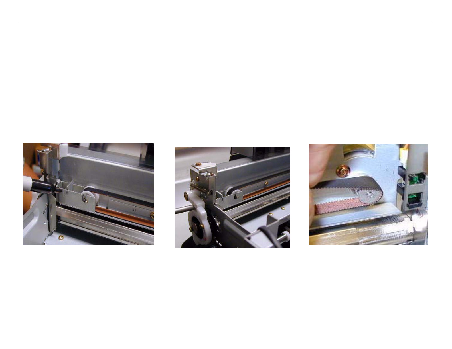
5. Mark the Carriage Belt Tension Gauge, loosen, and remove the Belt.
Mark Belt Tension Gauge
Carriage Removal Procedure Printer Component, Software Item, LCD Display, Printer Button Page 12.
Loosen Belt tension
Remove Belt from
the Carriage Motor
Page 13
Stylus Pro 4800 Field Repair Guide 6/9/05
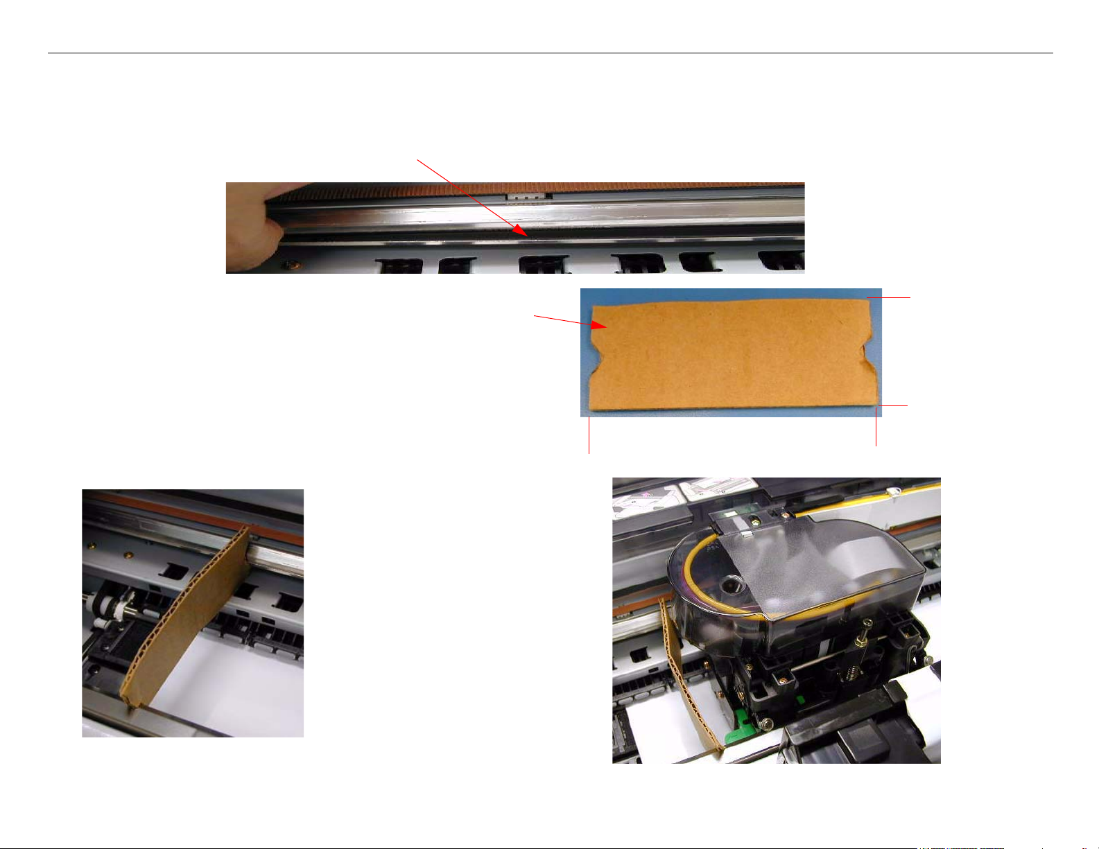
6. Carriage Rail Cover (Wheel Track) protection steps.
The Carriage Rail Covers will separate and bend when removing the Print Head if not protected.
1. Make a double wall cardboard jig as shown.
1.75” wide
.5” wide, and1/4” deep V slot
5” long
2. Place the jig so that the
V slots support the Car-
riage Rail Covers
Note:The jig should be placed
so that it supports the
Carriage Rail Covers
beside to the Print
Head, when it is in the
removal position (see
step 8).
Carriage Removal Procedure Printer Component, Software Item, LCD Display, Printer Button Page 13.
Page 14
Stylus Pro 4800 Field Repair Guide 6/9/05
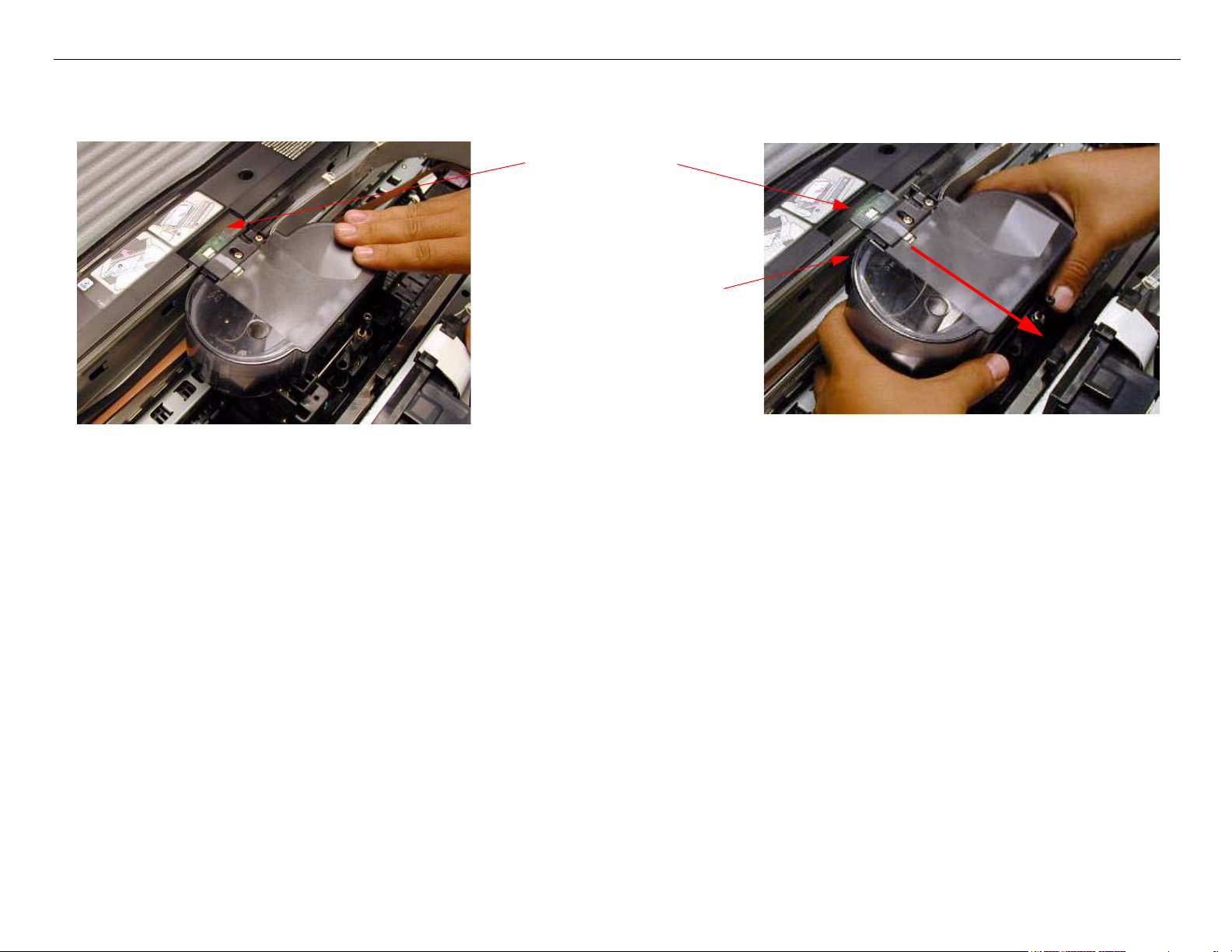
7. Move the Carriage Mechanism at the removal slot as shown. Compress the Tension Springs
against the Front Carriage Rail, and lift out the Carriage.
Removal Slot
Be careful to free the
Carriage Timing
Strip
Carriage Removal Procedure Printer Component, Software Item, LCD Display, Printer Button Page 14.
Page 15
Stylus Pro 4800 Field Repair Guide 6/9/05
Cartridge Release Lever Repair
1. Remove the Ink Bay.
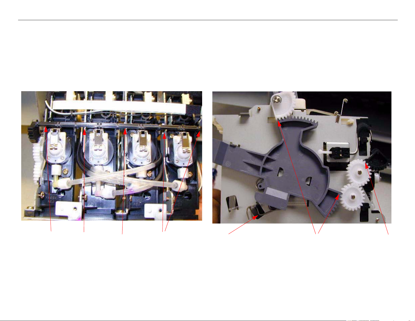
2. Ensure that the Gears and Spring are in the positions shown. (This is the Cartridge released, and
the Valves closed position)
Ensure that the Valve Open/Close
Cam is fully seated in the Interlocks.
Cartridge Release Lever Repair Printer Component, Software Item, LCD Display, Printer Button Page 15.
Spring position
3 Gear positions to check.
Page 16
Stylus Pro 4800 Field Repair Guide 6/9/05
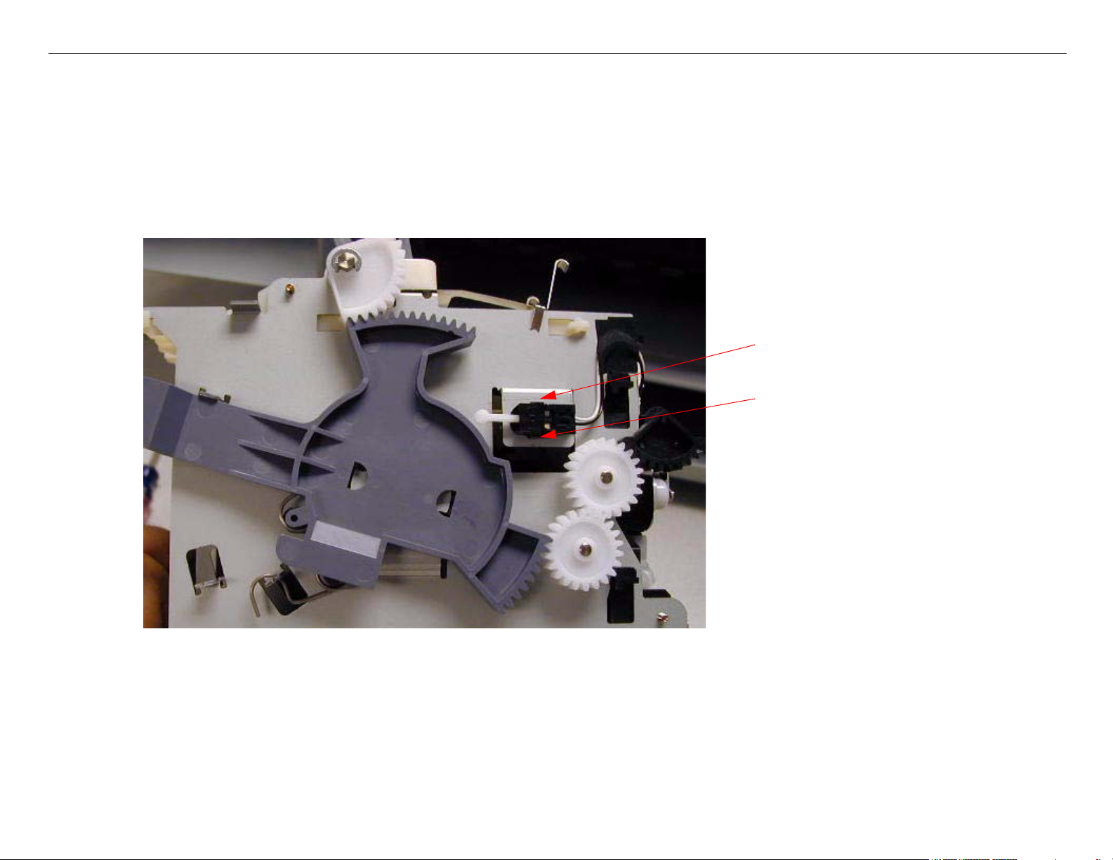
Cartridge Release Sensor Repair
1. Remove the Ink Bay Assembly.
2. Remove the Cartridge Release Sensor, and replace.
The Sensor is fastened
by 2 Interlocks.
Cartridge Release Sensor Repair Printer Component, Software Item, LCD Display, Printer Button Page 16.
Page 17
Stylus Pro 4800 Field Repair Guide 6/9/05
Damper Removal
1. Raise both Ink Levers, closing the Ink Valves.
2. Remove the Left Side Cover.
3. Move the Carriage Mechanism to the left as shown, remove 3 Screws, and remove the Carriage
Cover.
Slot
3 Screws
Lift off
Damper Removal Printer Component, Software Item, LCD Display, Printer Button Page 17.
Page 18
Stylus Pro 4800 Field Repair Guide 6/9/05
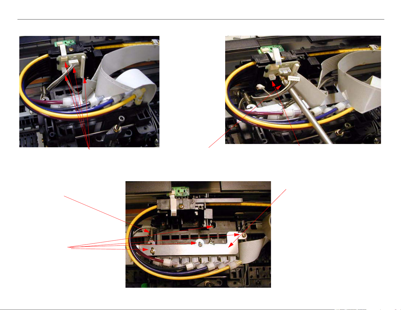
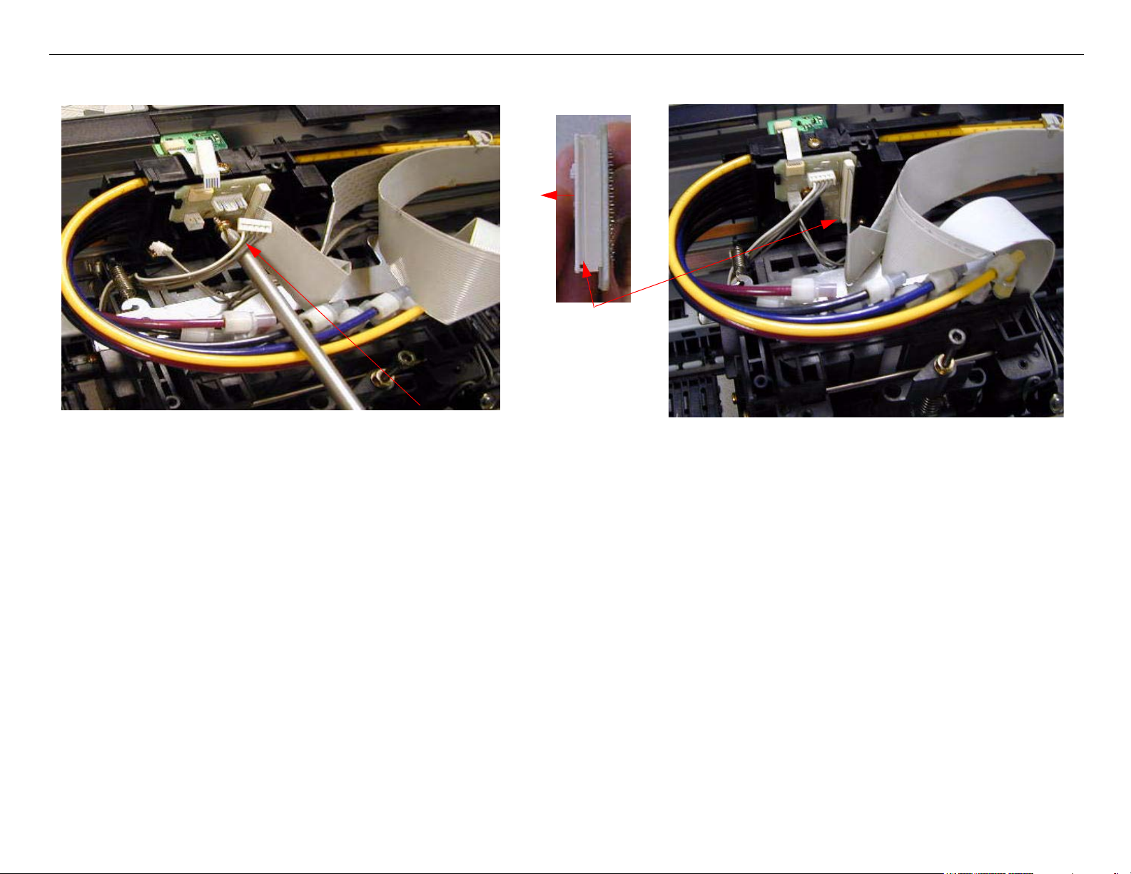
4. Disconnect 4 Cables, remove 1 Screw, and remove the Junction Board
1. Disconnect 4 Cables.
2. Remove 1 Screw.
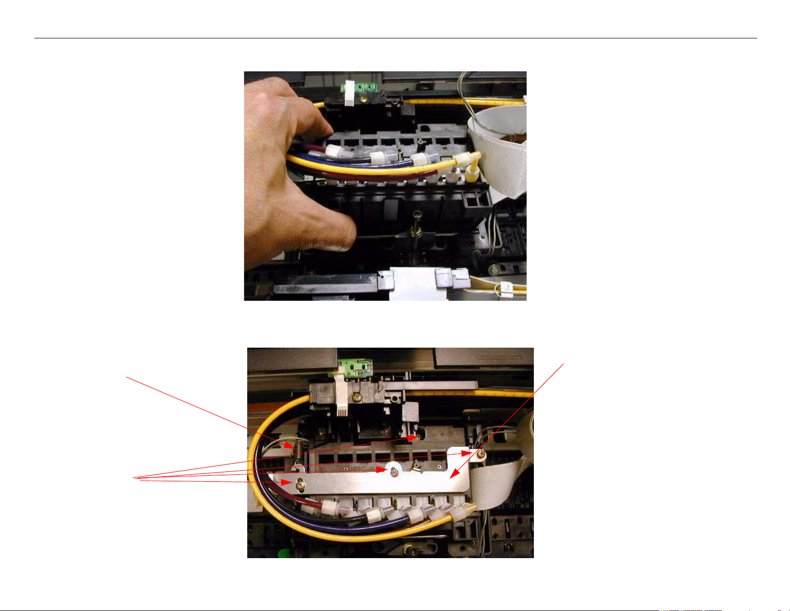
5. Remove 4 Screws, 1 Stay Bar, and 1 Spring.
1 Spring
4 Screws
3. Remove the Junction Board.
1 Stay Bar
Damper Removal Printer Component, Software Item, LCD Display, Printer Button Page 18.
Page 19
Stylus Pro 4800 Field Repair Guide 6/9/05
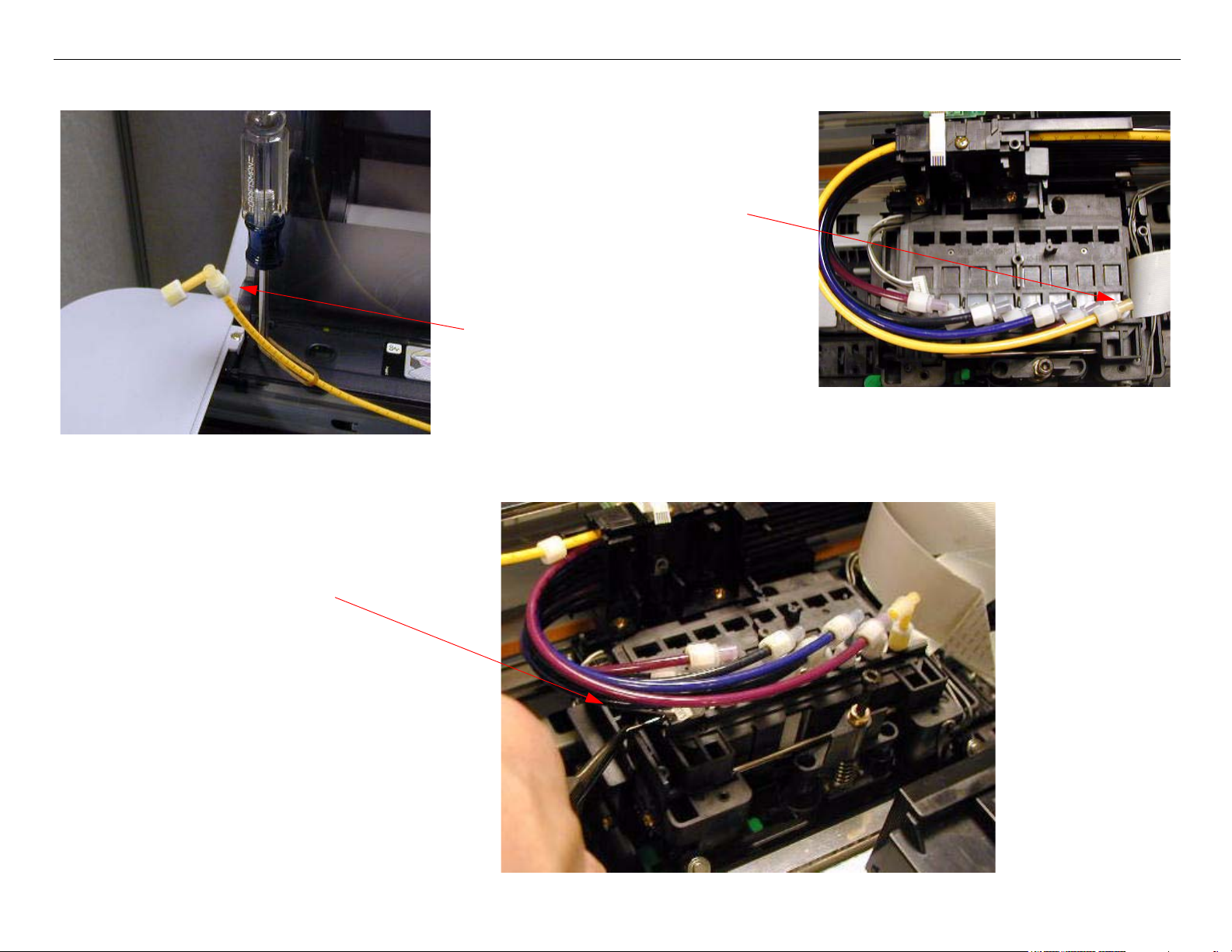
6. Disconnect the Ink Lines, from the Dampers to be replaced.
Disconnect the Lines at the
Damper (bottom of the Elbow
Joint).
Move the Lines to the side, and
fasten out of the way.
7. Remove the Stay Bar that fastens the Dampers to the Assembly.
Remove the Stay Bar.
Damper Removal Printer Component, Software Item, LCD Display, Printer Button Page 19.
Page 20
Stylus Pro 4800 Field Repair Guide 6/9/05
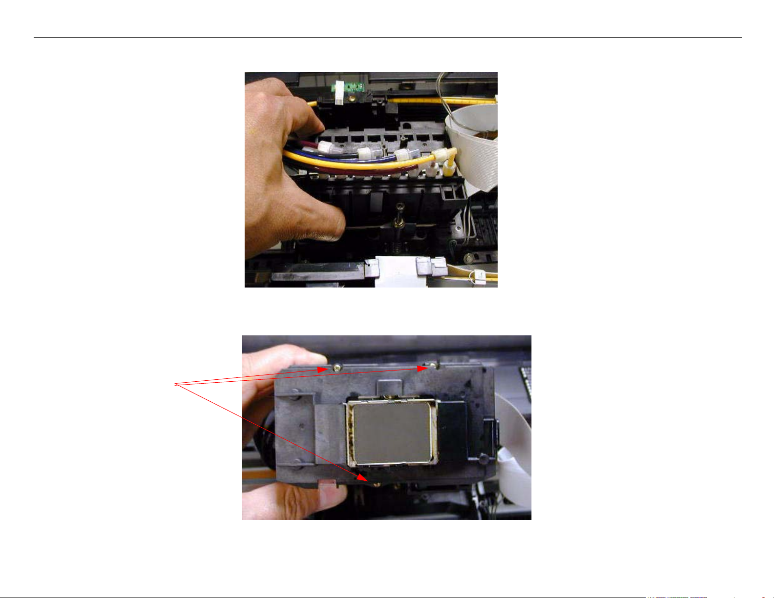
8. Lift out the Print Head / Damper Assembly.
9. .Turn over the Print Head / Damper Assembly and remove 3 Screws.
Remove 3 Screws.
Damper Removal Printer Component, Software Item, LCD Display, Printer Button Page 20.
Page 21
Stylus Pro 4800 Field Repair Guide 6/9/05
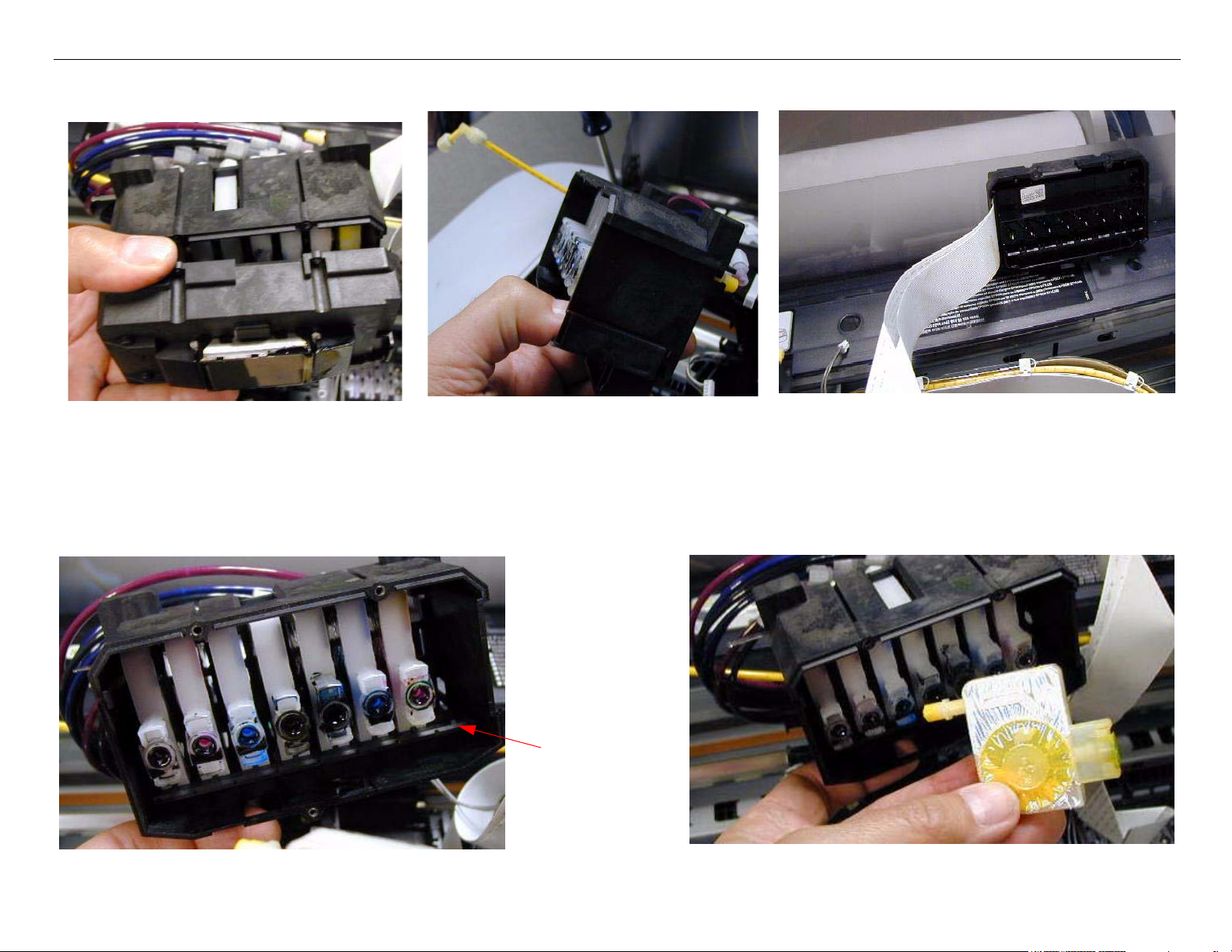
10. Disconnect the Print Head from the Damper Assembly.
1. Disconnect the Print Head from
the Damper Assembly.
2. Hold the Damper Assembly like
this so that ink does not leak.
3. Place the Print Head off to the side
as shown.
11. Release the Interlock that corresponds to the Damper(s) to be replaced, and lift out the
Damper(s)
Damper Interlock
Damper Removal Printer Component, Software Item, LCD Display, Printer Button Page 21.
Page 22

Stylus Pro 4800 Field Repair Guide 6/9/05
12. Install the new Damper(s).
13. Re-connect the Ink Tubes to the new Dampers, and manually prime all the Dampers.
With the Damper openings facing
up, draw the air out of the each
Damper.
14. Reconnect the Print Head to the Damper Assembly.
Connect the Print Head and
fasten with 3 Screws.
Damper Removal Printer Component, Software Item, LCD Display, Printer Button Page 22.
Page 23
Stylus Pro 4800 Field Repair Guide 6/9/05
15. Place the Print Head / Damper Assembly back into the Carriage Mechanism.
16. Replace 4 Screws, 1 Stay Bar, and 1 Spring.
1 Spring
4 Screws
Damper Removal Printer Component, Software Item, LCD Display, Printer Button Page 23.
1 Stay Bar
Page 24
Stylus Pro 4800 Field Repair Guide 6/9/05
17. Re-install the Junction Board, fasten with 1 Screw, and reconnect 4 Cables.
This Connector
has a latch.
Install the Junction Board and fasten with 1 Screw.
Reconnect 4 Cables.
18. Perform cleaning cycles and nozzle checks until the nozzles are working.
19. Perform the Print Head mechanical adjustments.
19.1 Perform the Print Head Slant Adjustment (CR)
19.2 Perform the Print Head Slant Adjustment (PF)
Damper Removal Printer Component, Software Item, LCD Display, Printer Button Page 24.
Page 25

Stylus Pro 4800 Field Repair Guide 6/9/05
Ink Bay Removal (Left)
1. Remove the Left and Right Side Covers.
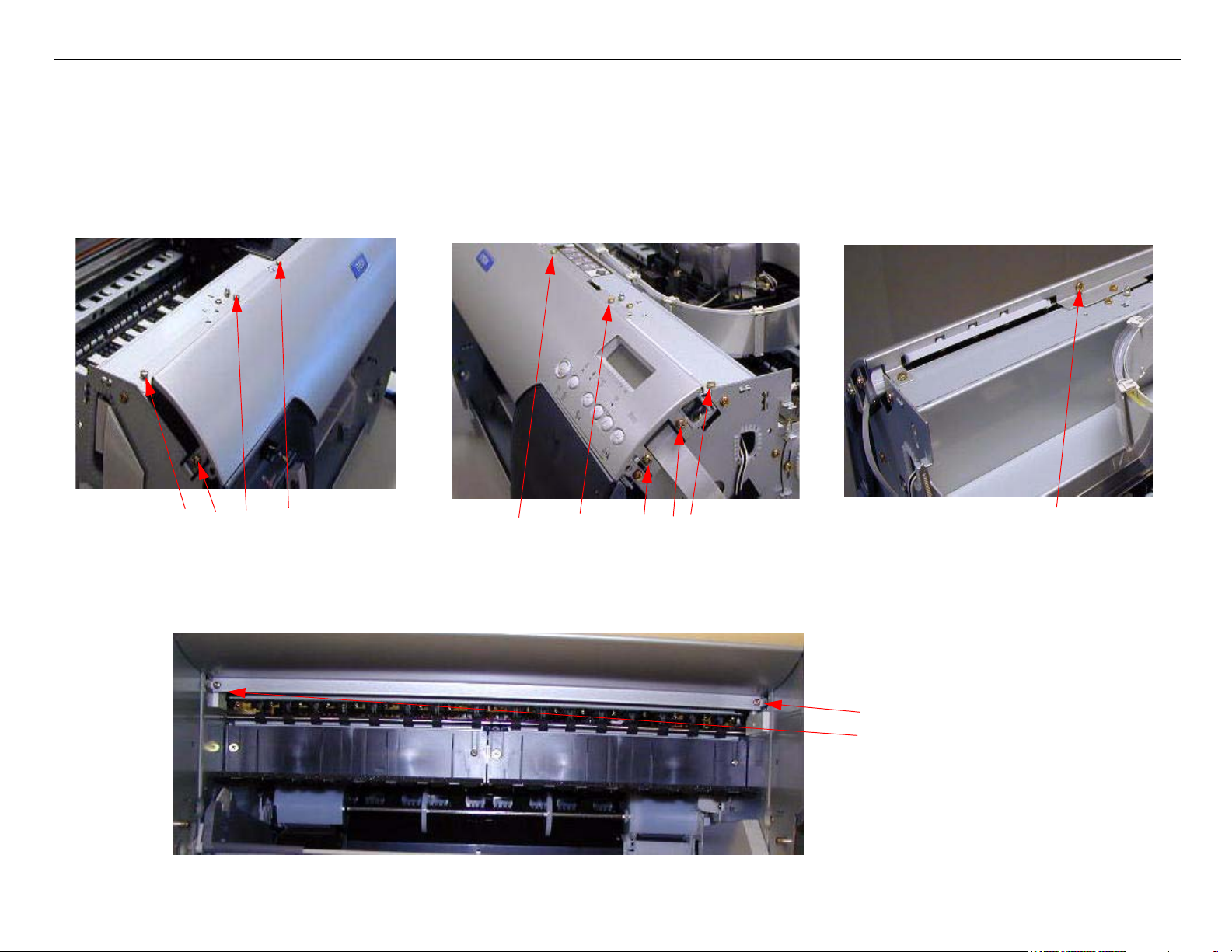
2. Remove the 10 Screws fastening the Front Panel.
Remove 4 Screws
Remove 5 Screws
(View from the back)
Remove 1 Screw
3. Remove 2 Screws fastening the Front Panel.
Remove 2 Screws
Ink Bay Removal (Left) Printer Component, Software Item, LCD Display, Printer Button Page 25.
Page 26
Stylus Pro 4800 Field Repair Guide 6/9/05
4. Remove the Front Panel.
5. Remove 4 Screws that fasten the Ink Bay Cover, and 1 Screw that fastens the Cartridge
Release Handle, and lift off the Cover.
Remove 1 Screw
This hole in the Cover
allows easy access to the
Remove 4 Screws
Cartridge Release Handle
Lift off the Cover.
Screw
Ink Bay Removal (Left) Printer Component, Software Item, LCD Display, Printer Button Page 26.
Page 27
Stylus Pro 4800 Field Repair Guide 6/9/05
6. Remove 2 Screws and 2 Brackets
1 Screw and Bracket
on the Right Side
1 Screw and Bracket
on the Left Side
7. Remove 2 Screws from the front.
2 Screws from the front
Ink Bay Removal (Left) Printer Component, Software Item, LCD Display, Printer Button Page 27.
Page 28
Stylus Pro 4800 Field Repair Guide 6/9/05
8. Remove 2 Screws from the back of the Ink Bay Assembly.
Blow up of
this area
Look through this area,
Remove 2 Screws
on the back of the
Printer, to find 2 Screws
9. Disconnect the 4 Foil CSIC Cables and the Cartridge Release Sensor Cable.
Cartridge Release Sensor Cable
4 CSIC Cables
Re-assembly Note: Cable Order
Yellow-Magenta-Cyan-Matte Black
Ink Bay Removal (Left) Printer Component, Software Item, LCD Display, Printer Button Page 28.
Page 29
Stylus Pro 4800 Field Repair Guide 6/9/05
10. Maneuver the Ink Tubes from the Slot.
11. Slide out the Ink Bay Assembly, while assisting the Cables through the Frame.
Ink Bay Removal (Left) Printer Component, Software Item, LCD Display, Printer Button Page 29.
Page 30
Stylus Pro 4800 Field Repair Guide 6/9/05
Ink Bay Removal (Right)
1. Remove the Left and Right Side Covers.
2. Remove the 10 Screws fastening the Front Panel.
Remove 4 Screws
Remove 5 Screws
(View from the back)
Remove 1 Screw
3. Remove 2 Screws fastening the Front Panel.
Remove 2 Screws
Ink Bay Removal (Right) Printer Component, Software Item, LCD Display, Printer Button Page 30.
Page 31

Stylus Pro 4800 Field Repair Guide 6/9/05
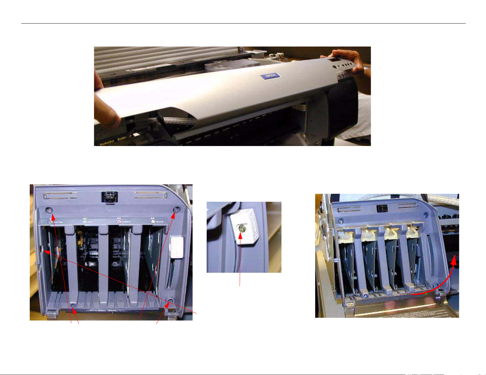
4. Remove the Front Panel.
5. Remove 4 Screws that fasten the Ink Bay Cover, and 1 Screw that fastens the Cartridge
Release Handle, and lift off the Cover.
Remove 4 Screws
Ink Bay Removal (Right) Printer Component, Software Item, LCD Display, Printer Button Page 31.
Remove 1 Screw
Lift off the Cover.
Page 32

Stylus Pro 4800 Field Repair Guide 6/9/05
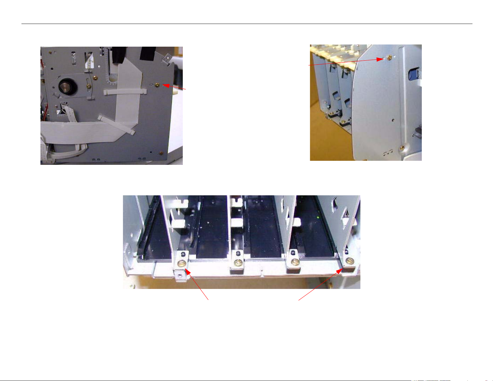
6. Remove 4 Screws and 2 Brackets
1 Screw and Bracket
on the right side
1 Screw and Bracket
on the left side
1 Screw on the
left Side
7. Remove 2 Screws from the front.
1 Screw on
the right Side.
2 Screws from the front
Ink Bay Removal (Right) Printer Component, Software Item, LCD Display, Printer Button Page 32.
Page 33

Stylus Pro 4800 Field Repair Guide 6/9/05
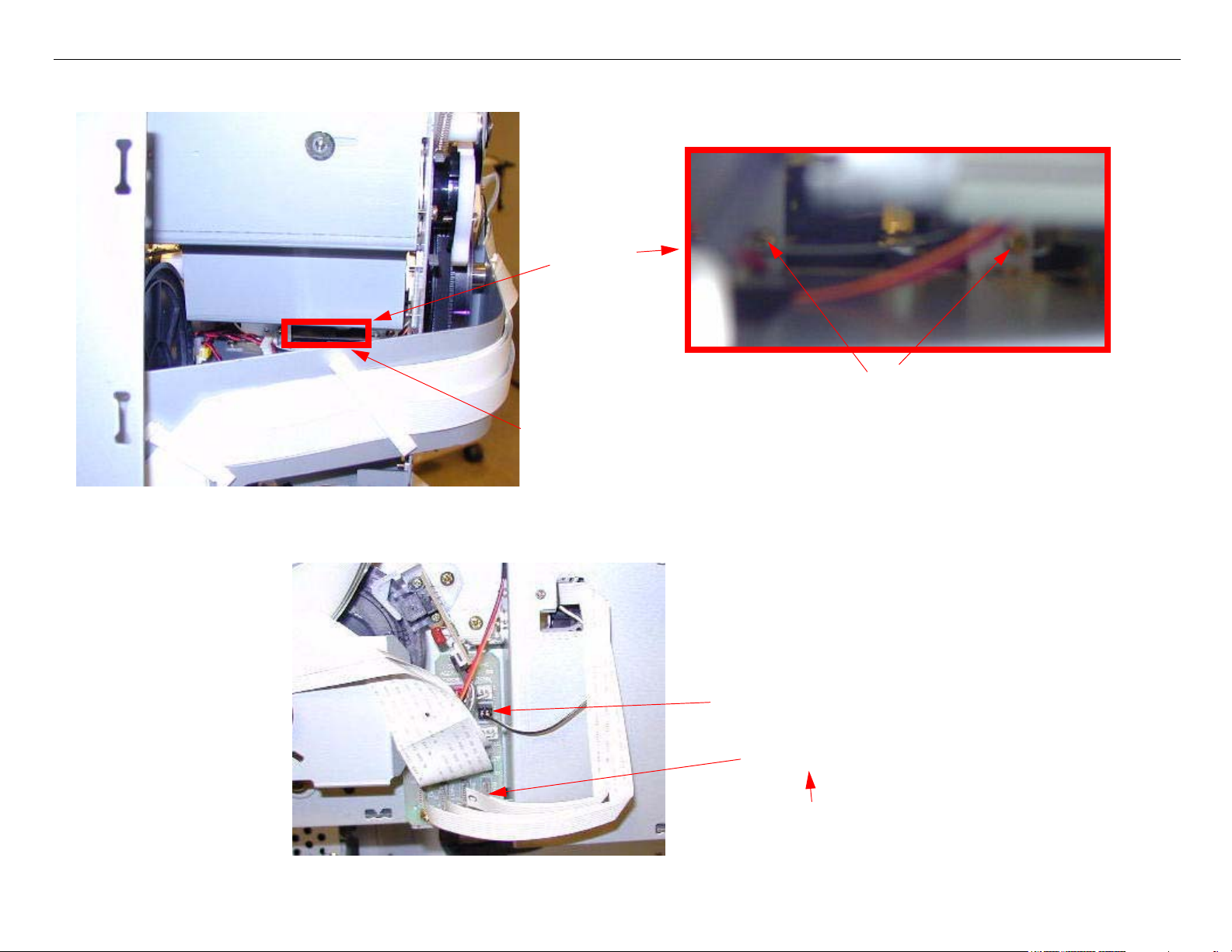
8. Remove 2 Screws from the back of the Ink Bay Assembly.
View is from the
back of the Printer
Pump Assembly
Remove 2 Screws
9. Disconnect the 4 Foil CSIC Cables and the Cartridge Release Sensor Cable.
Cartridge
Release Sensor
Cable
Ink Bay Removal (Right) Printer Component, Software Item, LCD Display, Printer Button Page 33.
4 CSIC Cables
Re-assembly Note: Cable Order
Top to Bottom
Black, Light Cyan, Light
Magenta, Light Black
Page 34

Stylus Pro 4800 Field Repair Guide 6/9/05
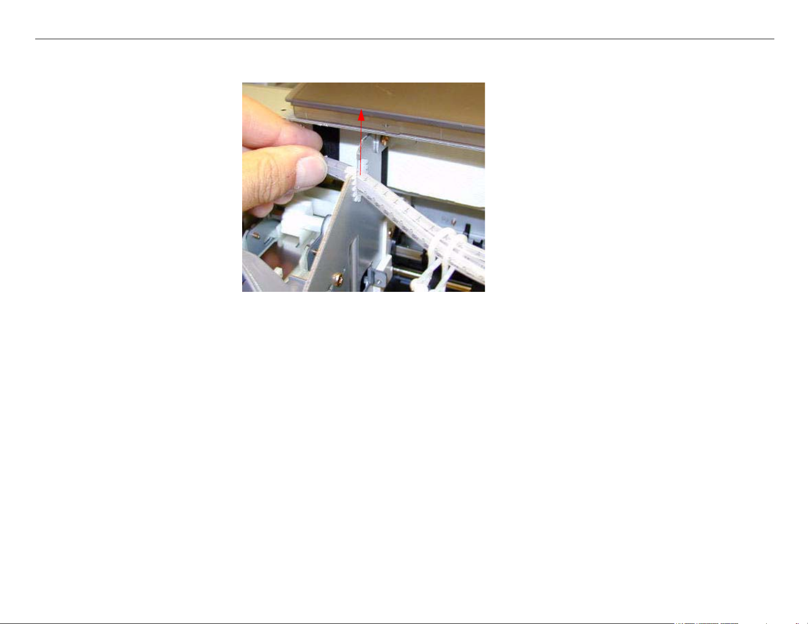
10. Maneuver the Ink Tubes from the slot.
11. Slide out the Ink Bay Assembly, while assisting the Cables through the Frame.
Ink Bay Removal (Right) Printer Component, Software Item, LCD Display, Printer Button Page 34.
Page 35

Stylus Pro 4800 Field Repair Guide 6/9/05
Input Roller Assembly, Disassembly
1. Remove the E-Ring, Gear, and Paddle shown below.
Input Roller Assembly, Disassembly Printer Component, Software Item, LCD Display, Printer Button Page 35.
Page 36

Stylus Pro 4800 Field Repair Guide 6/9/05
2. Detach the 3 Interlocks that fasten the Input Roller Cover, and slide the Cover off the Roller.
Detach 3 Interlocks
3. Remove the 2 E-Rings shown below
Remove the E-Ring
Slide off the Cover
Remove the E-Ring
Input Roller Assembly, Disassembly Printer Component, Software Item, LCD Display, Printer Button Page 36.
Page 37

Stylus Pro 4800 Field Repair Guide 6/9/05
4. Detach the 3 Interlocks holding the remaining Roller Cover, and slide it off.
3 Interlocks
5. Slide the remaining components off the Shaft.
Input Roller Assembly, Disassembly Printer Component, Software Item, LCD Display, Printer Button Page 37.
Page 38

Stylus Pro 4800 Field Repair Guide 6/9/05
6. Release the Interlocks, as shown below.
7. Lift up the Paper Tray Base, and remove the Separation Pad Assembly as shown below.
Input Roller Assembly, Disassembly Printer Component, Software Item, LCD Display, Printer Button Page 38.
Page 39

Stylus Pro 4800 Field Repair Guide 6/9/05
8. Maneuver the remaining side of the Paper Tray Base as shown below to free the last Separation
Pad Assembly.
Input Roller Assembly, Disassembly Printer Component, Software Item, LCD Display, Printer Button Page 39.
Page 40

Stylus Pro 4800 Field Repair Guide 6/9/05
Input Roller Assembly, Re-assembly
1. Assemble the Base Unit until it looks this.
2. Maneuver the Separation Pad Assembly into the slot as shown.
Input Roller Assembly, Re-assembly Printer Component, Software Item, LCD Display, Printer Button Page 40.
Page 41

Stylus Pro 4800 Field Repair Guide 6/9/05
3. Re-hook the Interlock / Pivot Points that connect the Separation Pad Assembly to the Base.
4. Press down on the Separation Pad Assembly until the Black Levers lock it in the down position.
These two pieces must be pressed tightly together to allow
the Paper Separation Assembly too fully compress the
Springs.
Input Roller Assembly, Re-assembly Printer Component, Software Item, LCD Display, Printer Button Page 41.
Page 42

Stylus Pro 4800 Field Repair Guide 6/9/05
5. Study the polarity, and order of the parts below.
Paddles positioned, so that the
arrow on the side faces up
The Disks have depressions, that fit
the Springs.
Home Position Window faces the opposite direction from the flat side of the
Roller.
The Right and Left Rollers are different. Pay
attention to the position of the Slots.
6. Install the Roller Assembly components into the Base Assembly, following the directions above.
Paddle on the outside of the Frame.
Paddle on the inside
of the Frame.
Cover marked with R
Input Roller Assembly, Re-assembly Printer Component, Software Item, LCD Display, Printer Button Page 42.
Cover marked with L
Page 43

Stylus Pro 4800 Field Repair Guide 6/9/05
7. Rotate the Input Rollers so that the flat side is down to allow the Roller to interlock with the Roller
Frame.
Flat side down
This part of both Rollers must fit through the Roller Side Frame.
8. Re-attach the Roller Covers, 3 E-rings, and Gear.
1 E-Ring between the
Roller Assembly and the
Frame.
1 E-Ring fastening
this Gear.
Gear
2 Roller Covers E-Ring
Input Roller Assembly, Re-assembly Printer Component, Software Item, LCD Display, Printer Button Page 43.
Page 44

Stylus Pro 4800 Field Repair Guide 6/9/05
9. Test the Roller Assembly before installation
Place a piece of paper in the Tray.
Input Roller Assembly, Re-assembly Printer Component, Software Item, LCD Display, Printer Button Page 44.
Rotate the Gear and check for proper operation
Page 45

Stylus Pro 4800 Field Repair Guide 6/9/05
Input Roller Assembly Removal
1. Remove the Left Side Cover.
2. Remove the Right Side Cover.
3. Remove the Ink Cartridges, and leave the Levers up (closing the Valves).
Lever up, closing
Lever up, closing
the Valves
the Valves
4. Remove the Rear Paper Guide Support and the Paper Jam Cover.
Rear Paper Guide Support (directions at step 5)
Remove the Paper Jam
Cover (shown removed)
Input Roller Assembly Removal Printer Component, Software Item, LCD Display, Printer Button Page 45.
Page 46

Stylus Pro 4800 Field Repair Guide 6/9/05
5.
1. Remove this Screw
on the left.
2. Remove this Screw
on the right.
3. Free the Rear Paper
Guide Support from
the Printer.
4. Remove the Screw
that holds the Manual
Feed Sensor to the
Support.
5. Remove the Sensor from
the Rear Paper Guide Sup-
port
Input Roller Assembly Removal Printer Component, Software Item, LCD Display, Printer Button Page 46.
Page 47

Stylus Pro 4800 Field Repair Guide 6/9/05
6. Rotate the Printer onto it’s back.
7. Remove the 2 screws fastening the Right Side Air Duct to the Frame.
2 Screws
Input Roller Assembly Removal Printer Component, Software Item, LCD Display, Printer Button Page 47.
Page 48

Stylus Pro 4800 Field Repair Guide 6/9/05
8. Lift the Right Side Air Duct exposing the 2 Screws noted in step 9.
This is 1 of the 2 Screws
shown is the picture on the
left in step 9.
9. Remove the 3 Screws that fasten the Input Roller Assembly to the Right Side Frame.
Back side of the
Waste Ink Tank Slot
3 Screws
Loosen this Screw.
Input Roller Assembly Removal Printer Component, Software Item, LCD Display, Printer Button Page 48.
Page 49

Stylus Pro 4800 Field Repair Guide 6/9/05
10. Remove the 3 Screws that fasten the Input Roller Assembly to the Left Side Frame.
3 Screws
11. Slide the Input Roller Assembly out about 2 inches, disconnect the Input Roller HP Sensor, and
fully remove the Assembly.
Left side of the Printer
Input Roller Home
Position Sensor
Input Roller Assembly Removal Printer Component, Software Item, LCD Display, Printer Button Page 49.
Page 50

Stylus Pro 4800 Field Repair Guide 6/9/05
Main Board Replacement
1. Back up the Printer’s parameters using the Parameter Backup / Restore Utility (Nvram.exe)
2. Turn off the Printer and UNPLUG from AC.
3. Remove the Rear Paper Guide Assembly.
Push the 2 Grey Tabs and pull
out the Cover
4. Remove the 6 Screws fastening the Main Board Housing.
3 Screws
Main Board Replacement Printer Component, Software Item, LCD Display, Printer Button Page 50.
3 Screws
Page 51

Stylus Pro 4800 Field Repair Guide 6/9/05
5. Slide out the Main Board Housing until the Cable Connectors are visable.
6. Un-fasten the Cables
The number on the Foil Cable
corresponds to the Connector
number
Main Board Replacement Printer Component, Software Item, LCD Display, Printer Button Page 51.
Page 52

Stylus Pro 4800 Field Repair Guide 6/9/05
7. Remove the 5 Screws and Hardware fastening the Ports to the Main Board Housing.
5 Screws
8. Remove the 7 Screws fastening the Board to the Housing.
4 Screws
3 Screws
Main Board Replacement Printer Component, Software Item, LCD Display, Printer Button Page 52.
Page 53

Stylus Pro 4800 Field Repair Guide 6/9/05
9. Fasten the new Board to the Housing with 7 Screws (see above) Do not fully tighten.
10. Install the Port Covers and 5 Screws
5 Screws
11. Full tighten the 7 Main Board Screws.
12. Connect the Cables to the Board. Ensure that the Cables are fully seated (straight).
Main Board Replacement Printer Component, Software Item, LCD Display, Printer Button Page 53.
Page 54

Stylus Pro 4800 Field Repair Guide 6/9/05
13. Write down the IEEE (Firewire) ID, if the Printer’s Parameters are not available.
The IEEE ID is located in the
Main Board Cavity
14. Attach the Board Housing to the Printer and fasten with 6 Screws.
Tilt the Board Assembly, while inserting, so
that the leading edge drops on to the Printer
Mechanism’s Board Support Ledge.
Main Board Replacement Printer Component, Software Item, LCD Display, Printer Button Page 54.
Fasten with 6 Screws
Page 55

Stylus Pro 4800 Field Repair Guide 6/9/05
15. Down load the current firmware version.
15.1 Open the PRNPRINT application, and prepare to send the current firmware version to the Printer.
15.2 Turn on the Printer while depressing the Left, Up, Down, and Right arrow buttons, The Printer will display
UPDATE F/W.
15.3 Send the current firmware to the Printer.
16. Re-Install the Printer’s parameters using the Parameter Backup / Restore Utility (Nvram.exe)
16.1 Perform the RTC&USBID&IEEE1394ID Adjustment.
16.2 Perform the Colormetric Calibration.
If the Printer’s Parameters are not available skip step 16, and follow step 17.
17. Perform the following operations in the order listed.
17.1 Stop the Printer from priming (See The Prime ON / Off chapter).
17.1.1 Note: Init.Fill: Reset = The Printer ‘s prime function is turned off.
17.2 Perform the Rear Sensor AD Adjustment.
17.3 Perform the Cutter Pressure adjustment.
17.4 Perform the Platen Gap adjustment.
17.5 Enter the Head Rank ID (Print Head calibration values).
17.6 Perform the Multi Sensor Level Adjustment.
17.7 Perform the Print Head Slant (CR) Adjustment.
17.8 Perform the Print Head Slant (PF) Adjustment.
17.9 Perform the Multi Sensor Adjustment for Auto Nozzle Check.
17.10Perform the Nozzle Bi-D Adjustment.
17.11Perform the Auto Bi-D Adjustment.
17.11.1Copy Bi-D variables
Main Board Replacement Printer Component, Software Item, LCD Display, Printer Button Page 55.
Page 56

Stylus Pro 4800 Field Repair Guide 6/9/05
17.12Perform the Auto Uni-D Adjustment.
17.12.1Copy Uni-D variables.
17.13Perform the Platen Position Adjustment
17.14Perform the Clear Micro Feed PF Adjustment (Bi-D)
17.15Perform the 1000 mm Feed Adjustment, or Multi Sensor Auto PF Adjustment.
17.16Perform the T&B&S (Roll Paper) Adjustment.
17.17Perform the T&B&S (Cut Sheet) Adjustment.
17.18Perform the RTC&USBID&IEEE1394ID Adjustment.
17.19Perform the Colormetric Calibration.
Main Board Replacement Printer Component, Software Item, LCD Display, Printer Button Page 56.
Page 57

Stylus Pro 4800 Field Repair Guide 6/9/05
Paper Exit Roller Removal
1. Remove the Left and Right Side Covers.
2. Remove the 10 Screws fastening the Front Panel.
Remove 4 Screws
Remove 5 Screws
(View from the back)
Remove 1 Screw
3. Remove 2 Screws fastening the Front Panel.
Remove 2 Screws
Paper Exit Roller Removal Printer Component, Software Item, LCD Display, Printer Button Page 57.
Page 58

Stylus Pro 4800 Field Repair Guide 6/9/05
4. Remove the Front Panel.
5. Remove the2 Screws that fasten the Exit Roller.
Remove 2 Screws
Paper Exit Roller Removal Printer Component, Software Item, LCD Display, Printer Button Page 58.
Page 59

Stylus Pro 4800 Field Repair Guide 6/9/05
6. Remove the Exit Roller.
7. The Exit Roller must be re-installed using the correct polarity.j
Long end
Gold Spring side, on the top
Short end
Silver Spring side, on the bottom
Paper Exit Roller Removal Printer Component, Software Item, LCD Display, Printer Button Page 59.
Page 60

Stylus Pro 4800 Field Repair Guide 6/9/05
Plastic Roller Upgrade
Note: This procedure documents the replacement of 9 Plastic Rollers with 9 Rubber Coated Plastic
Rollers. These Rollers make contact with the printable side of the media. The old Roller design
could scuff the surface of Fine Art Media.
1. Remove the Left Side Cover.
2. Remove the Right Side Cover.
3. Remove the Paper Release Lever Assembly Cover.
1. Remove 1 Screw.
2. Remove the Cover.
Plastic Roller Upgrade Printer Component, Software Item, LCD Display, Printer Button Page 60.
Page 61

Stylus Pro 4800 Field Repair Guide 6/9/05
4. Remove the Top Cover as shown.
Lever up both sides of the
Top Cover at the Hinges.
5. Remove the Top Cover Component shown below.
Remove 1 Screw
Remove 1 Screw
Lift of the Top Cover
Component.
Plastic Roller Upgrade Printer Component, Software Item, LCD Display, Printer Button Page 61.
Page 62

Stylus Pro 4800 Field Repair Guide 6/9/05
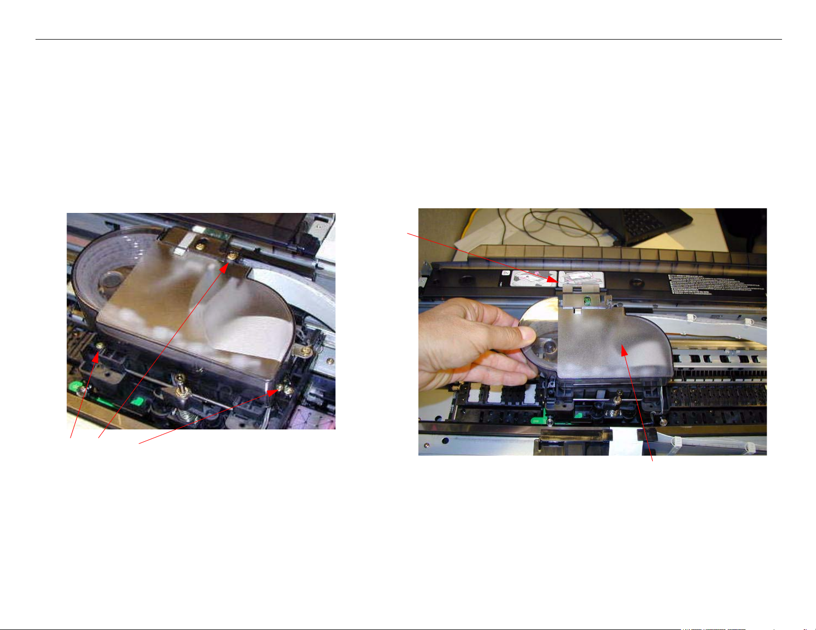
6. Remove the Paper Thickness Sensor Assembly.
Remove these 2 Screws. Remove the 2 Screws accessed
through these holes.
Lift off the Paper Thickness
Sensor Assembly.
Do not loosen these 2 Screws.
7. Remove the Rear Paper Guide Support and the Paper Jam Cover.
Rear Paper Guide Support (directions at step 8)
Remove the Paper Jam
Cover (shown removed)
Plastic Roller Upgrade Printer Component, Software Item, LCD Display, Printer Button Page 62.
Page 63

Stylus Pro 4800 Field Repair Guide 6/9/05
8. Paper Guide Support removal
1. Remove this Screw
on the left.
2. Remove this Screw
on the right.
3. Free the Rear Paper
Guide Support from
the Printer.
4. Remove the Screw
that holds the Manual
Feed Sensor to the
Support.
5. Remove the Sensor from
the Rear Paper Guide Sup-
port
Plastic Roller Upgrade Printer Component, Software Item, LCD Display, Printer Button Page 63.
Page 64

Stylus Pro 4800 Field Repair Guide 6/9/05
9. Remove the Paper Release Lever Assembly.
Remove 2 Screws.
Remove the Assembly.
10. Remove the Paper Release Transmission Gear.
1. Note the position of the Gear in rela-
tion to this Rubber Stopper.
2. Remove the Gear.
Plastic Roller Upgrade Printer Component, Software Item, LCD Display, Printer Button Page 64.
Page 65

Stylus Pro 4800 Field Repair Guide 6/9/05
11. Remove the Gear shown below.
To r e m o v e th i s Gear, follow the
4 steps listed below.
1. Note the Gears’ orientation
to this Rubber Stopper.
2. Note the Interlock on
the back side of the
Gear.
Plastic Roller Upgrade Printer Component, Software Item, LCD Display, Printer Button Page 65.
3. Rotate the Gear so that the Interlock
is in this position.
4. Remove the Gear.
Page 66

Stylus Pro 4800 Field Repair Guide 6/9/05
12. Remove the Roller Assembly.
Remove the Roller Assembly by
finessing the right side of the
Assembly out, followed by the
left.
13. Place the Roller Assembly on a flat surface.
Ensure that the Assembly is in this position
Plastic Roller Upgrade Printer Component, Software Item, LCD Display, Printer Button Page 66.
Page 67

Stylus Pro 4800 Field Repair Guide 6/9/05
14. Remove 4 Screws that fasten the Release Roller to the Assembly, and remove the Roller.
15. Flip up the white Paper Guides so that the Assembly is in this position.l
Plastic Roller Upgrade Printer Component, Software Item, LCD Display, Printer Button Page 67.
Page 68

Stylus Pro 4800 Field Repair Guide 6/9/05
16. Inspect 1 of the 3 Paper Guides and note the items listed below.
The Shaft ends here,
and goes next to this
Support.
Note the way that the Shaft
is behind some Supports,
and under others.
These are the Rollers to be replaced.
17. Remove the 3 Paper Guide Assemblies, and install the new Rollers.
The Shaft ends
here, and goes next
to this Support.
The Hook on the
Springs goes to the
right.
Old Rollers
Plastic Roller Upgrade Printer Component, Software Item, LCD Display, Printer Button Page 68.
New Rollers.
Page 69

Stylus Pro 4800 Field Repair Guide 6/9/05
18. Lay out the Assembly Components like this.
19. Attach the Guides to the Frame starting on the right.
1. Under here.
4. Under here.
2. Over here.
5. Over here.
3. Spring in the
Notch.
6. Spring in the
Notch.
Plastic Roller Upgrade Printer Component, Software Item, LCD Display, Printer Button Page 69.
Page 70

Stylus Pro 4800 Field Repair Guide 6/9/05
20. It should look like this when installed correctly.
21. Use the same method to replace the second and third Guide Assemblies.
Plastic Roller Upgrade Printer Component, Software Item, LCD Display, Printer Button Page 70.
Page 71

Stylus Pro 4800 Field Repair Guide 6/9/05
22. The Assembly should look like this when the 3 Guides are installed.
23. Lay out the remaining Components like this.
Square opening on this
end.
Plastic Roller Upgrade Printer Component, Software Item, LCD Display, Printer Button Page 71.
Page 72

Stylus Pro 4800 Field Repair Guide 6/9/05
24. Note these aspects of the Release Roller.
Square Hole on the left side.
These Notches make contact with the White Guides.
25. Place the Release Roller against the White Guides.j
Square Hole on this side.
Notches against the White Guides.
Plastic Roller Upgrade Printer Component, Software Item, LCD Display, Printer Button Page 72.
Page 73

Stylus Pro 4800 Field Repair Guide 6/9/05
26. Fasten the Release Roller with 1 Bracket in the middle, and then install the remaining Brackets.
27. Spin the Release Roller and verify that the Guides and Notches line up properly.
Guides and Notches
should look like this.
Plastic Roller Upgrade Printer Component, Software Item, LCD Display, Printer Button Page 73.
Page 74

Stylus Pro 4800 Field Repair Guide 6/9/05
28. Install the Roller Assembly.
1. Insert the Left Side first.
3. Install 2 Screws.
2. Insert the Right Side second.
Plastic Roller Upgrade Printer Component, Software Item, LCD Display, Printer Button Page 74.
Page 75

Stylus Pro 4800 Field Repair Guide 6/9/05
29. Install the Paper Thickness Sensor Assembly.
Fasten with 2 Screws.
30. Install the Gear pictured below.
Insert this Gear. It is “keyed’
and will only insert 1 way.
Plastic Roller Upgrade Printer Component, Software Item, LCD Display, Printer Button Page 75.
Page 76

Stylus Pro 4800 Field Repair Guide 6/9/05
31. Attach the Release Transmission Gear and the Release Lever Assembly.
2. Install this
Assembly so
that the Gear is
held in place.
3. Fasten with 2
1. Insert this Gear.
Screws.
32. Attach the Manual Feed Sensor to the Paper Guide.
1. Hold in place on
the back side of
the Guide.
2. Route the Wire
through the Fas-
teners.
3. Fasten with 1
Screw.
Plastic Roller Upgrade Printer Component, Software Item, LCD Display, Printer Button Page 76.
Page 77

Stylus Pro 4800 Field Repair Guide 6/9/05
33. Install the Paper Guide Assembly and fasten with 2 Screws.
1 Screw
1 Screw
34. Perform the Paper Thickness Sensor Adjustment.
35. Install the Plastic Cover pictured below, and fasten with 3 Screws.
1 Small Head
Screw.
2 Big Head
Screws.
Plastic Roller Upgrade Printer Component, Software Item, LCD Display, Printer Button Page 77.
Page 78

Stylus Pro 4800 Field Repair Guide 6/9/05
36. Install the Top Cover.
Lever the Pivot into the
Hinges.
37. Install the Paper Release Lever Assembly Cover.
1. Install the Cover.
2. Fasten with 1 Screw.
38. Replace the Left and Right Side Covers.
Plastic Roller Upgrade Printer Component, Software Item, LCD Display, Printer Button Page 78.
Page 79

Stylus Pro 4800 Field Repair Guide 6/9/05
Print Head Replacement Procedure
1. Run the Adjustment Wizard and input the new Print Head’s calibration value.
2. Unplug the Printer.
3. Raise both Ink Levers, closing the Ink Valves.
4. Remove the Left Side Cover.
5. Release the Carriage Lock, and move the Carriage Mechanism away from the capped position.
6. Mark the Carriage Belt Tension Gauge, loosen, and remove the Belt.
Mark Belt Tension Gauge
Print Head Replacement Procedure Printer Component, Software Item, LCD Display, Printer Button Page 79.
Loosen Belt Tension
Remove Belt from
the Carriage Motor
Page 80

Stylus Pro 4800 Field Repair Guide 6/9/05
7. Carriage Rail Cover (Wheel Track) protection steps.
The Carriage Rail Covers will separate and bend when removing the Print Head if not protected.
1. Make a double wall cardboard jig as shown.
1.75” wide
.5” wide, and1/4” deep V slot
5” long
2. Place the jig so that the
V slots support the Car-
riage Rail Covers
Note:The jig should be placed
so that it supports the
Carriage Rail Covers
beside to the Print
Head, when it is in the
removal position (see
step 8).
Print Head Replacement Procedure Printer Component, Software Item, LCD Display, Printer Button Page 80.
Page 81

Stylus Pro 4800 Field Repair Guide 6/9/05
8. Move the Carriage Mechanism at the removal slot as shown. Compress the Tension Springs
against the Front Carriage Rail, and lift out the Carriage.
Removal Slot
Be careful to free the
Carriage Timing
Strip
9. Turn over the Carriage Mechanism, and support it with one hand (ensure that the Nozzles and
the Carriage Encoder are not damaged).
Remove 3 Screws
Print Head Replacement Procedure Printer Component, Software Item, LCD Display, Printer Button Page 81.
Page 82

Stylus Pro 4800 Field Repair Guide 6/9/05
10. Remove the Print Head by rotating the top of the Head away from the Carriage.
11. Remove 3 Screws fastening the Head to the Head Case.
Remove 3 Screws
Separate the Print Head
from the Print Head
Case.
Print Head Replacement Procedure Printer Component, Software Item, LCD Display, Printer Button Page 82.
Page 83

Stylus Pro 4800 Field Repair Guide 6/9/05
12. Disconnect the Print Head Cables
Gently remove the
Cables.
The Top Cable is the 0
Cable.
13. Connect the new Print Head to the Cables. Ensure that the 0 Cable is on top (Nozzle Plate side).
14. Attach the Print Head to the Head Case.
15. Attach the Head Case to the Carriage Mechanism.
16. Re-install the Carriage Mechanism.
16.1 Ensure that the Timing Strip is routed through the Sensor.
16.2 Use the Carriage Rail Cover protection jig.
17. Place the Carriage Belt on the Carriage Motor Pulley.
18. Tighten the Carriage Belt until the Gauge reaches the mark that represents the proper tension.
Print Head Replacement Procedure Printer Component, Software Item, LCD Display, Printer Button Page 83.
Page 84

Stylus Pro 4800 Field Repair Guide 6/9/05
19. Verify that the Carriage Rail Covers, Carriage Bearings, Carriage Belt and Timing Strip are
properly in place.
20. Move the Carriage Mechanism to the capped position.
21. Plug in the Printer, and lower both Ink Cartridge Levers to open the Ink Valves.
22. Defeat the Cover Sensor, and turn on the Printer.
23. Turn on the Printer, and let it come Ready.
24. Press the Menu button and navigate to Maintenance.
25. Press the Menu button and navigate to PWR CLEANING.
26. Press the Menu button to execute.
27. Print a Nozzle Check Pattern (Perform standard cleanings if necessary).
28. Perform the following adjustments in sequence.
Print Head Replacement Procedure Printer Component, Software Item, LCD Display, Printer Button Page 84.
Page 85

Stylus Pro 4800 Field Repair Guide 6/9/05
28.1 Perform Reset When Print Head Change
28.2 Perform the Print Head Slant Adjustment (CR)
28.3 Perform the Print Head Slant Adjustment (PF)
28.4 Reset (initialize) the user settings using the Epson Paper Feed Adjuster utility.
28.5 Perform the Nozzle Bi-D Adjustment
28.6 Perform the Auto Bi-D Adjustment
28.7 Perform Copy Bi-D variables
28.8 Perform the Auto Uni-D Adjustment
28.9 Perform Copy Uni-D variables
28.10Perform the Colormetric Calibration.
Print Head Replacement Procedure Printer Component, Software Item, LCD Display, Printer Button Page 85.
Page 86

Stylus Pro 4800 Field Repair Guide 6/9/05
Pump and Cap Installation
1. Before installing the Pump and Cap Assembly identify the Tube Receptacles where the Pump
Tubes must be inserted.
Blow up view
Tubes go here
2. Before installing the Pump and Cap Assembly, note this detail.
The Plastic Tray that sits under
the Pump, and that the Tubes
are inserted into, has one corner
that sits on top of the Pump /
Cap Assembly Frame.
View from the bottom. Note the
Plastic Tray is on top of the
Frame Mount.
View from the back of the Printer.
The Plastic is on top of the
Frame.
Pump and Cap Installation Printer Component, Software Item, LCD Display, Printer Button Page 86.
Page 87

Stylus Pro 4800 Field Repair Guide 6/9/05
3. Insert the Cap Assembly part of the way, through the back of the Printer.
If the Ink Tubes
are not fully
inserted, the
Ink may bubble
back through
the cap.
Slide the Cap and Pump
Assembly, part of the way in
Feed the Tubes into the receptacle
Assist the Tubes fully into the receptacle,
while sliding in the Assembly.
4. Install the 4 Screws securing the Cap and Pump Assembly. Ensure that the Assembly is
correctly seated to avoid carriage errors.
2 Screws
Ensure that the Flushing
Box Screw Hole is correctly
aligned before tightening the
Assembly screws.
2 Screws
Pump and Cap Installation Printer Component, Software Item, LCD Display, Printer Button Page 87.
Page 88

Stylus Pro 4800 Field Repair Guide 6/9/05
5. Install the Flushing Box and fasten with 1 Screw
Tube into the hole leading to
the Waste InkTank
1 Screw
6. Plug in the Pump Home Position Sensor.
Plug in
Pump and Cap Installation Printer Component, Software Item, LCD Display, Printer Button Page 88.
Page 89

Stylus Pro 4800 Field Repair Guide 6/9/05
7. Install the Gear and Shaft Assembly, and fasten it with 2 Screws.
Install Gear and
Shaft Assembly.
2 Screws
8. Install the Platen Gap Motor, and fasten with 2 Screws.
Install the Motor
2 Screws
Pump and Cap Installation Printer Component, Software Item, LCD Display, Printer Button Page 89.
Page 90

Stylus Pro 4800 Field Repair Guide 6/9/05
9. Install the Trigger Shaft.
Insert Trigger Shaft into the
Right Side Frame
Flex the Trigger Shaft from the back side of the
Printer, until the end of the Shaft can be inserted
into the Socket
Insert Into
Socket here
Pump and Cap Installation Printer Component, Software Item, LCD Display, Printer Button Page 90.
Page 91

Stylus Pro 4800 Field Repair Guide 6/9/05
10. Replace the Trigger Spring.
Spring goes here.
Ensure that the Splash
Guard is routed as shown.
11. Replace the Trigger Assembly End Piece.
Trigger Assembly End Piece here
12. Perform Reset When Cleaning Unit Change (if the Cap/Pump Assembly was changed).
Pump and Cap Installation Printer Component, Software Item, LCD Display, Printer Button Page 91.
Page 92

Stylus Pro 4800 Field Repair Guide 6/9/05
Pump and Cap Removal
1. Remove the Right Side Cover.
2. Remove the Flushing Box.
Remove Screw.
Lift out the Flushing Box.
3. Remove the Trigger Assembly End Piece and Spring.
Trigger Assembly End Piece
Trigger Spring
Pump and Cap Removal Printer Component, Software Item, LCD Display, Printer Button Page 92.
Page 93

Stylus Pro 4800 Field Repair Guide 6/9/05
4. Flex the Trigger Shaft until the end farthest from the Side Frame clears it’s Socket, then remove
the Shaft.
Flex the Shaft from
behind
Free the end of the
Shaft from it’s
Socket
Slide out the Trigger
Shaft
5. Remove 4 Screws securing the Cap and Pump Assembly.
2 Screws
2 Screws
Pump and Cap Removal Printer Component, Software Item, LCD Display, Printer Button Page 93.
Page 94

Stylus Pro 4800 Field Repair Guide 6/9/05
6. Remove 2 Screws fastening the Platen Gap Motor, and remove.
2 Screws
Remove the Motor
7. Remove 2 Screws fastening the Gear and Shaft Assembly, and remove.
Remove Gear
and Shaft
Assembly.
2 Screws
8. Slide the Cap and Pump Assembly to the right, to separate the Assembly from the Gear.
Separate the Assembly
from the Gear
Slide the Cap and Pump
Assembly this way.
Pump and Cap Removal Printer Component, Software Item, LCD Display, Printer Button Page 94.
Page 95

Stylus Pro 4800 Field Repair Guide 6/9/05
9. Unplug the Pump Home Position Sensor.
Re-assembly note:
The Plastic Tray that the Pump /
Cap Assembly covers, sits on top
of the Pump / Cap Assembly
Frame at this corner.
Unplug
10. Slide the Cap and Pump Assembly out the back of the Printer.
Remove from the back of the Printer
Slide the Assembly to the back
Pump and Cap Removal Printer Component, Software Item, LCD Display, Printer Button Page 95.
Page 96

Stylus Pro 4800 Field Repair Guide 6/9/05
Cap and Pump Assembly Components.
Cap
Wiper Blade
Pump
Pump and Cap Removal Printer Component, Software Item, LCD Display, Printer Button Page 96.
Page 97

Stylus Pro 4800 Field Repair Guide 6/9/05
Side Cover Removal (Left)
Remove Screw
Remove 2 Screws
Side Cover Removal (Left) Printer Component, Software Item, LCD Display, Printer Button Page 97.
Remove Screw
The Left Side Cover will slide off
Page 98

Stylus Pro 4800 Field Repair Guide 6/9/05
Side Cover Removal (Right)
Remove the Rear Paper Guide Assembly
Remove Screw
Side Cover Removal (Right) Printer Component, Software Item, LCD Display, Printer Button Page 98.
Page 99

Stylus Pro 4800 Field Repair Guide 6/9/05
Remove Waste Ink Tank
Remove 2
Screws
The Right Side Cover will slide off.
Remove Screw
Remove
2 Screws
and slide
off Lever
Side Cover Removal (Right) Printer Component, Software Item, LCD Display, Printer Button Page 99.
Page 100

Stylus Pro 4800 Field Repair Guide 6/9/05
Top Cover Removal
1. Using a small flat head screw driver, lever the right Top Cover Hinge pivot point out of the Hinge
Frame.
2. Using a small flat head screw driver, lever the left Top Cover Hinge pivot point out of the Hinge
Frame.
3. Lift off the Top Cover.
Top Cover Removal Printer Component, Software Item, LCD Display, Printer Button Page 100.
 Loading...