

Page 1

Developer’s Guide
*Includes information on OT-BU30.
00139800 EN
M
Rev.A
Page 2

Cautions
No part of this document may be reproduced, stored in a retrieval system, or transmitted in any form or by any
means, electronic, mechanical, photocopying, recording, or otherwise, without the prior written permission of
Seiko Epson Corporation.
The contents of this document are subject to change without notice. Please contact us for the latest
information.
While every precaution has been taken in the preparation of this document, Seiko Epson Corporation assumes
no responsibility for errors or omissions.
Neither is any liability assumed for damages resulting from the use of the information contained herein.
Neither Seiko Epson Corporation nor its affiliates shall be liable to the purchaser of this product or third parties
for damages, losses, costs, or expenses incurred by the purchaser or third parties as a result of:
accident, misuse, or abuse of this product or unauthorized modifications, repairs, or alterations to this product,
or (excluding the U.S.) failure to strictly comply with Seiko Epson Corporation’s operating and maintenance
instructions.
Seiko Epson Corporation shall not be liable against any damages or problems arising from the use of any options
or any consumable products other than those designated as Original Epson Products or Epson Approved
Products by Seiko Epson Corporation.
Trademarks
EPSON is a registered trademark of Seiko Epson Corporation.
Exceed Your Vision and ESC/POS are registered trademarks or trademarks of Seiko Epson Corporation.
Microsoft and Windows are registered trademarks of Microsoft Corporation in the United States and/or other
countries.
Android TM is a trademark of Google LLC.
All other trademarks are the property of their respective owners and used for identification purpose only.
ESC/POS® Command System
Epson ESC/POS is a proprietary POS printer command system that includes patented or patent-pending
commands. ESC/POS is compatible with most Epson POS printers and displays.
ESC/POS is designed to reduce the processing load on the host computer in POS environments. It comprises a set
of highly functional and efficient commands and also offers the flexibility to easily make future upgrades.
©Seiko Epson Corporation 2021.
(1)
Page 3

Important Safety Information
This document presents important information intended to ensure safe and effective use of this product. Read
this section carefully and store it in an accessible location.
Safety Precautions
WA R NI N G : Handling the product improperly by ignoring this symbol can lead to death or serious injury.
In the following cases, immediately turn off the power and contact qualified service personnel.
Continued use may lead to fire or electric shock.
If the product emits smoke, a strange odor, or unusual noise.
If water or other liquid spills into the product.
If the product is too hot to touch or the case is deformed.
Note the following points to avoid accidents such as fire, electric shock, or burn.
Do not use this product where flammable fumes from gasoline, benzine, thinner, or other flammable liquids
may be in the air.
Do not use aerosol sprayers containing flammable gas inside or around the product.
Do not cover the product with cloth, or place the product in locations subject to high levels of humidity or dust.
Do not allow foreign objects or flammable objects to fall into the equipment.
Do not touch the inside of the product except where mentioned in the manual.
Do not use the product with any voltage and current other than the ones specified.
Do not connect cables in ways other than those mentioned in the manual.
Never disassemble or modify the product.
CAU T ION: Handling the product improperly by ignoring this symbol can lead to injury and property
damage.
Note the following points to avoid injury or malfunction.
Setup the product on a firm, stable, horizontal surface.
Do not place heavy objects on top of the product. Never stand or lean on the product.
Do not press your hands or fingers against the cutter when removing printed paper or loading/replacing roll
paper.
Do not put your hands between the cover and the body of the product when opening/closing the cover.
Never attempt to repair the product yourself.
Do not connect a telephone line to the drawer kick connector (Model for specified customer only).
For safety, turn off the power if the product will not be used for a long period.
(2)
Page 4

Caution Labels
The caution labels on the product indicate the following precautions.
CAU T ION: Do not touch the thermal head and the frame on its side because it can be very hot after
printing.
CAU T ION: The sharp edge can cut your fingers.
Restriction of Use
When this product is used for applications requiring high reliability/safety, such as transportation devices related to
aviation, rail, marine, automotive, etc.; disaster prevention devices; various safety devices, etc.; or
functional/precision devices, etc., you should use this product only after giving consideration to including failsafes
and redundancies into your design to maintain safety and total system reliability. Because this product was not
intended for use in applications requiring extremely high reliability/safety, such as aerospace equipment, main
communication equipment, nuclear power control equipment, or medical equipment related to direct medical care,
etc., please make your own judgment on this product's suitability after a full evaluation.
(3)
Page 5

Product Overview
This chapter describes features of the product.
Features
This product (printer unit) is intended to be integrated into a self-service terminal.
For details on how to integrate it into a self-service terminal, refer to the following:
Appendix M PRINTER INSTALLATION DESIGN GUIDE
Appendix N INSTALLING THE POWER SWITCH AND POWER/FEED SWITCH COVER
Appendix O REPLACEMENT FOR SMALL COVER OPEN LEVER
Appendix P BEZEL OPTION (OT-BU30)
Appendix Q RECOMMENDED POWER SUPPLY
Appendix R PRINTER UNIT HANDLING
(4)
Page 6

Product Configurations
Models
Standard model
Models for specified customers
Accessories
Included
Main unit
Roll paper (φ 35 mm)
Switch cover
For power switch
For power/feed switch
Small cover open lever, including 1 spare screw
Roll paper guides for 58 mm {2.28"} paper: 2
Equipment mounting brackets: 2
Product fixing brackets, including 2 screws + 1 spare (total of 3 screws)
Options
Bezel option (Model: OT-BU30)
AC Adapter (Model: PS-180)
Optional external buzzer (Model: OT-BZ20) (Model for specified customer only)
(5)
Page 7

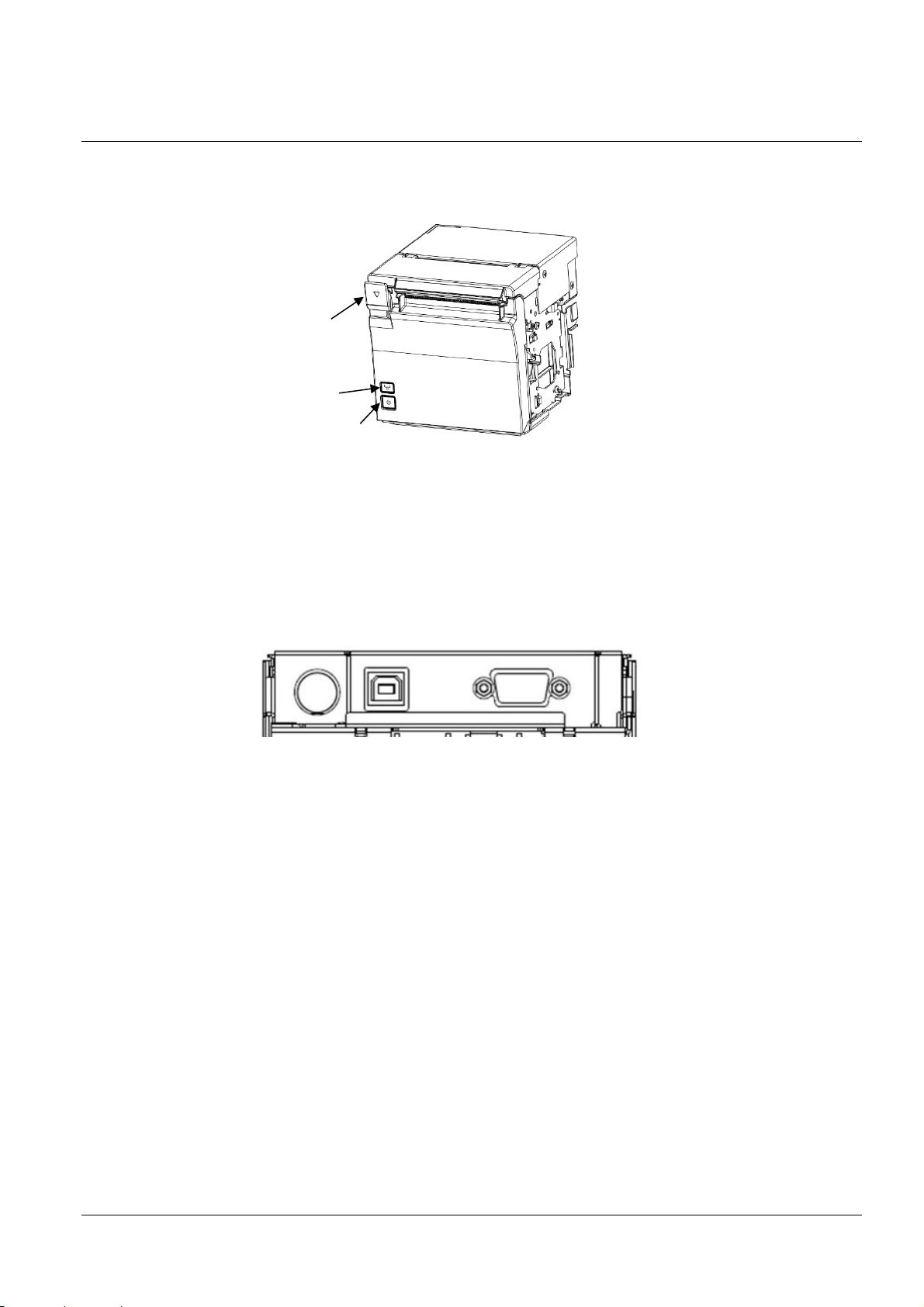
Part Names and Function
1
2
3
1 2 3
4
5
Front
1 Cover open lever Operate this lever to open the roll paper cover.
2 Feed button
3 Power switch Turns the printer on or off.
4 Roll paper cover Open this cover when loading or replacing roll paper.
5 Panel LED For details on LED, see "Panel LED" on page 16.
NOTE
When turning off the printer without using the power switch, it is recommended to send a power-
off command to the printer. If you use the power-off sequence, the latest maintenance counter
values are saved. (Maintenance counter values are usually saved every two minutes.)
For information about ESC/POS commands, see the ESC/POS Command Reference.
Pressing this button once feeds roll paper for one line. Hold down this
button to continue feeding roll paper.
Connectors
4
1 Power supply connector Connect the AC adapter.
2 USB connector (Type-B) Connects the USB cable for connecting to a computer.
3 Serial connecter Connects the serial cable for connecting to a computer.
4 Drawer kick connector
(Model for specified customer only)
Connects the cash drawer or the optional external buzzer.
(6)
Page 8

Storage humidity
(1) Scope of this document
This document applies to the EU-m30 and bezel option OT-BU30.
(2) Product safety precautions
1) Do not allow a voltage that exceeds the absolute maximum rating to be applied to the power connector.
If the applied voltage exceeds the absolute maximum rating, excess current may flow, causing thermal damage
to components.
OUTLINE
Absolute maximum rating
Circuit input power supply voltage 26.4 V
Storage temperature See 1.13 Environmental Conditions (2)
2) Use the product within the range of operating conditions shown in the table below.
Operating conditions
Articles Min. Typ. Max. Units
Printer power supply voltage 22.3 24.0 25.7 V
Operating temperature See 1.13 Environmental Conditions (1) Guaranteed
Operating humidity
3) Do not create short circuits between connector terminals in the printer unit.
Do not create short circuits between power connector terminals.
A short circuit to a low-impedance power supply can create excess current, causing thermal damage to
components.
4) During transport and storage, properly protect printer unit exterior (exposed) circuit boards and electronic
components with conductive sponges, aluminum foil, and such.
5) Do not drop clips and other conductive materials onto the printer unit's circuit board.
Short circuits between component connectors (terminals) can create excess current, causing thermal damage
to components.
6) Use only the cables indicated in this document. Also, use only the wiring indicated in this document.
Wiring done incorrectly can lead to a failure, fire, explosion, or other accident.
7) Do not disassemble or modify. Such actions can lead to injury or electric shock.
8) During operation, do not directly touch gears or other moving parts. You can get cut or otherwise injured.
9) Do not install in an unstable location (such as on an unsteady pedestal or sloping area). The product can
fall and you can get injured.
10) Do not install in a damp or dusty location. Also, ensure that the product is not exposed to water droplets.
Failure to do so may result in product failure, fire, or electric shock.
11) If the product will not be used for a long period, be sure to turn off the power to the printer unit for safety.
12) The symbols shown below are used in order to ensure safety and proper use of this product.
Read and thoroughly understand the meaning of each symbol before using the product.
Articles Rating Units
Storage environment.
operating environment.
1
Page 9

Caution
Caution: Hot Surface (See Appendix B.)
Caution: Sharp Edges (See Appendix P.)
2
Page 10

TABLE OF CONTENTS
OUTLINE .............................................................................................................................................................................. 1
(1) Scope of this document ............................................................................................................................................ 1
(2) Product safety precautions ...................................................................................................................................... 1
TABLE OF CONTENTS ........................................................................................................................................................... 3
1 GENERAL SPECIFICATIONS ....................................................................................................................... 6
1.1 Print Specifications ................................................................................................................................................... 6
1.2 Character Specifications ........................................................................................................................................... 6
1.3 Autocutter .................................................................................................................................................................. 6
1.4 Paper Sensor .............................................................................................................................................................. 7
1.5 Roll Paper Supply Device ......................................................................................................................................... 7
1.6 Paper Specifications .................................................................................................................................................. 7
1.7 Print Area ................................................................................................................................................................... 8
1.8 Printing and Cutting Positions ............................................................................................................................... 8
1.9 Internal Memory ..................................................................................................................................................... 10
1.10 Electrical Characteristics ........................................................................................................................................ 10
1.11 EMI and Safety Standards Applied ....................................................................................................................... 12
1.12 Reliability ................................................................................................................................................................. 13
1.13 Environmental Conditions .................................................................................................................................... 13
1.14 Installation ............................................................................................................................................................... 15
1.15 Interface .................................................................................................................................................................... 15
1.15.1 Interfaces equipped ........................................................................................................................................ 15
1.15.2 USB interface .................................................................................................................................................. 16
1.15.3 RS-232 serial interface ................................................................................................................................... 18
1.16 Connectors ............................................................................................................................................................... 21
1.16.1 Interface connector ........................................................................................................................................ 21
1.16.2 Power supply connector ................................................................................................................................ 21
1.16.3 Drawer kick connector (modular connector) *For specified customer only ........................................ 22
1.16.4 Allowable interface/power supply cable dimensions ................................................................................ 24
2 Structure ............................................................................................................................................................ 25
2.1 EU-m30, Standard model ...................................................................................................................................... 25
2.2 For specified customer ........................................................................................................................................... 26
3 Function ............................................................................................................................................................ 27
3.1 Control Commands ................................................................................................................................................ 27
3.2 Character Code Tables ........................................................................................................................................... 27
3.3 Switches .................................................................................................................................................................... 27
3.3.1 Power switch ................................................................................................................................................... 27
3.3.2 Feed button ..................................................................................................................................................... 27
3.4 Indicators ................................................................................................................................................................. 28
3.4.1 Displayed color and icon ............................................................................................................................... 28
3.4.2 Displayed patterns .......................................................................................................................................... 28
3.5 Printer Setting .......................................................................................................................................................... 29
3.5.1 DIP switch settings ......................................................................................................................................... 29
3.5.2 Software setting .............................................................................................................................................. 29
3.6 Self-test ..................................................................................................................................................................... 34
3.6.1 Self-test function ............................................................................................................................................ 34
3.6.2 Running self-test ............................................................................................................................................ 34
3.7 Hexadecimal Dumping .......................................................................................................................................... 34
3.7.1 Hexadecimal dumping function .................................................................................................................. 34
3.7.2 Running hexadecimal dumping ................................................................................................................... 34
3.8 Information Print Modes and Setting Modes ..................................................................................................... 35
3
Page 11

3.8.1 NV graphics information print mode ......................................................................................................... 35
3.8.2 R/E (receipt enhancement) information print mode ................................................................................ 36
3.8.3 Software setting mode ................................................................................................................................... 36
3.8.4 Initial setting restoration mode .................................................................................................................... 37
3.9 Error Processing ...................................................................................................................................................... 37
3.9.1 Errors that recover automatically ................................................................................................................ 37
3.9.2 Recoverable errors .......................................................................................................................................... 38
3.9.3 Unrecoverable errors ..................................................................................................................................... 38
3.10 Open Cover .............................................................................................................................................................. 38
3.11 Print Buffer-full Printing ....................................................................................................................................... 39
3.12 Optional external buzzer *For specified customer only .................................................................................... 39
3.13 Printing Using Multiple Interfaces ....................................................................................................................... 40
3.14 Updating Firmware ................................................................................................................................................ 40
4 Case Specifications .......................................................................................................................................... 42
4.1 External Dimensions and Mass ............................................................................................................................ 42
4.1.1 Bezel Option Not Equipped .......................................................................................................................... 42
4.1.2 Bezel Option Equipped.................................................................................................................................. 42
4.2 Color ......................................................................................................................................................................... 42
4.3 External Dimensions .............................................................................................................................................. 43
4.3.1 Bezel Option Not Equipped .......................................................................................................................... 43
4.3.2 Bezel option equipped ................................................................................................................................. 44
4.4 Dimensions for Installing to Customer Device .................................................................................................. 45
Appendix A RECOVERY FROM AN AUTOCUTTER ERROR .................................................................................... 46
A.1 If You Can Open the Roll Paper Cover................................................................................................................ 46
A.2 If You Cannot Open the Roll Paper Cover .......................................................................................................... 46
Appendix B PRINT HEAD AND PLATEN ROLLER CLEANING ............................................................................... 47
B.1 Thermal Head .......................................................................................................................................................... 47
B.2 Platen Roller............................................................................................................................................................. 47
Appendix C NOTES ON USING THE DRAWER KICK CONNECTOR *For specified customer only ................. 48
C.1 Conditions for Using the Drawer Kick Connector ............................................................................................ 48
C.2 Notes on the pulse generating command (ESC p) ............................................................................................. 48
C.3 Using a drawer that does not meet the conditions in C.2 (ESC p, DLE DC4) ............................................... 49
Appendix D NOTES ON UPDATING THE MAINTENANCE COUNTER AND TURNING THE PRINTER'S
POWER OFF ............................................................................................................................................................................ 51
D.1 About Updating the Maintenance Counter ........................................................................................................ 51
D.2 Printer Power-off Procedures ............................................................................................................................... 51
Appendix E NOTES ON PRINTING BAR CODES AND 2-DIMENSIONAL SYMBOLS ........................................ 52
Appendix F NOTES ON SCANNING THE PRINT RESULT ON THE RECEIPT .................................................... 53
Appendix G NOTES ON USING THE ASB STATUS ..................................................................................................... 54
Appendix H NOTES ON ARP (AUTOMATIC REDUCTION OF PAPER) AND AUTOMATIC LOGO
PRINTING FUNCTION ......................................................................................................................................................... 55
H.1 ARP: Reduction of Excessive Top Margin, Reduction of Excessive Bottom Margin, Reduction of Line
Spacing, and Reduction of Line Spacing Where Extra Line Feeds Are Included ....................................................... 55
H.2 ARP: Reduction of Bar Code Height .................................................................................................................... 55
H.3 Automatic Logo Printing Function ...................................................................................................................... 55
Appendix I SETTING PAPER WIDTH ............................................................................................................................ 56
I.1 Notes ......................................................................................................................................................................... 56
I.2 Method for Installing 58 mm {2.28"} Roll Paper Guides ................................................................................... 56
Appendix J NOTES ON PRINTING AND BACKFEED ................................................................................................ 58
Appendix K THAI CHARACTER PRINTING ................................................................................................................. 59
K.1 Character Size for Printing Thai Characters ....................................................................................................... 59
K.2 Character Structure for Thai Character 1-pass Print Mode ............................................................................. 60
4
Page 12

K.3 Character Structure for Thai Character 3-pass Print Mode ............................................................................. 61
Appendix L USING A POWER SUPPLY OTHER THAN THE PS-180 ...................................................................... 62
Appendix M PRINTER INSTALLATION DESIGN GUIDE ........................................................................................... 63
M.1 Notes on Printer Installation ................................................................................................................................. 63
M.2 Bezel Option Not Equipped .................................................................................................................................. 65
M.3 Bezel Option Equipped .......................................................................................................................................... 67
Appendix N INSTALLING THE POWER SWITCH AND POWER/FEED SWITCH COVER ............................... 69
N.1 Installing the Switch Cover .................................................................................................................................... 69
Appendix O REPLACEMENT FOR SMALL COVER OPEN LEVER ........................................................................... 70
O.1 Replacement for Small Cover Open Lever .......................................................................................................... 70
Appendix P BEZEL OPTION (OT-BU30) ........................................................................................................................ 71
P.1 Notes on Using the Bezel Option (OT-BU30) .................................................................................................... 71
P.2 Installing the Bezel Option (OT-BU30) ............................................................................................................... 71
Appendix Q RECOMMENDED POWER SUPPLY ......................................................................................................... 73
Appendix R PRINTER UNIT HANDLING ...................................................................................................................... 74
R.1 When purchasing this product ............................................................................................................................. 74
R.2 Notes on use ............................................................................................................................................................. 74
R.3 Prohibitions ............................................................................................................................................................. 74
R.4 When not using for a long period ........................................................................................................................ 74
R.5 When using at low temperature ............................................................................................................................ 74
R.6 When using at high temperature .......................................................................................................................... 74
Appendix S Application Development Information ........................................................................................................ 75
S.1 Controlling the Printer ........................................................................................................................................... 75
S.1.1 ESC/POS .......................................................................................................................................................... 75
S.2 Controlling the Cash Drawer (Model for specified customer only) ................................................................ 75
S.2.1 ESC/POS Commands .................................................................................................................................... 75
S.2.2 For Windows Printer Drivers (APD) .......................................................................................................... 75
S.2.3 OPOS (OCX Driver) ...................................................................................................................................... 75
S.2.4 OPOS for .NET ............................................................................................................................................... 75
S.2.5 Epson ePOS SDK for Android ..................................................................................................................... 76
S.3 Controlling the Optional External Buzzer (Model for specified customer only) .......................................... 76
S.3.1 ESC/POS Command ...................................................................................................................................... 76
S.3.2 For Windows Printer Drivers (APD) .......................................................................................................... 76
S.3.3 OPOS (OCX Driver) ...................................................................................................................................... 76
S.3.4 OPOS for .NET ............................................................................................................................................... 76
S.3.5 Epson ePOS SDK for Android ..................................................................................................................... 76
S.4 Software .................................................................................................................................................................... 77
S.4.1 Development Kit ............................................................................................................................................ 77
S.4.2 Drivers ............................................................................................................................................................. 77
S.4.3 Utilities............................................................................................................................................................. 78
S.4.4 Download ........................................................................................................................................................ 78
5
Page 13

1 GENERAL SPECIFICATIONS
1.1 Print Specifications
(1) Print speed
The maximum is 100 mm/s {3.94"/s} when printing ladder bar codes, 2-dimensional symbols, or multi-tone
graphics.
The print speed changes automatically depending on the voltage applied to the printer and the condition of the
head temperature.
Maximum print speed may not be achieved depending on the data transmission conditions and the combination
of commands.
If the print speed fluctuates or intermittent printing occurs due to the data transmission conditions, printing
may be shaded or white lines may occur.
(2) Multi-tone graphics printing and limitations
Multi-tone graphics printing is possible (up to 16 tones when using our specified paper).
Multi-tone printing is not supported in Page mode.
Voids (white spaces) may appear depending on the paper type (uneven application of chromogenic coating).
It may not be possible to recreate an original image because a certain density level cannot be achieved due to th
following causes:
Environmental temperature, power supply and voltage
Paper type (chromogenic characteristics)
Paper variations, such as variations among manufacturing lots
Printing pattern (effect of heat accumulation of the print head or of voltage drop/speed change due to high
duty)
For multi-tone printing, the preservative quality of materials printed using multi-tone printing decreases in
direct relationship with the lighter the printing. Accordingly, do not use multi-tone printing when preservative
quality is required.
Reading quality of bar codes/2-dimensional symbols in multi-tone graphics printing is not guaranteed.
e
1.2 Character Specifications
Can be changed via the software settings.
For details, see 3.8.3 Software setting mode.
1.3 Autocutter
The cut paper may be pulled at the cut edge when it is removed, causing reduced printing pitch for the first line
o
f the next receipt.
To prevent dot displacement, after cutting, feed the paper approximately 1 mm {16/406"} or more before the firs
l
ine of printing. This operation can be enabled by enabling the pre-feed before next print, or by setting the top
margin specification via backfeed to 8.5 to 2 mm.
For the setting method, see 3.5.2. Software setting.
When issuing paper whose vertical length is short, ensure at least 20 mm.
t
6
Page 14

1.4 Paper Sensor
(1) Function
Detects whether paper is present in the paper path.
(2) Method
Microswitch
1.5 Roll Paper Supply Device
Use roll paper that is not deformed, and ensure there is no slack when setting.
(1) Function
Supplies paper with a width of 80 mm {3.15"} or 58 mm {2.28"}
(2) Method
Drop-in roll paper
1.6 Paper Specifications
(1) Paper specifications
Paper types Specified thermal paper
Form Roll paper, Chromogenic side: Outside
Size Roll paper diameter 83 mm {3.27"} maximum
Roll paper core
Roll width when taken up 58 + 0.5/-1.0 mm
Paper width 57.5 ± 0.5 mm {2.26 ± 0.02"} 79.5 ± 0.5 mm {3.13 ± 0.02"}
Paper thickness Maximum of 80 μm, minimum of 48 μm
Table 1.6.1 Paper Specifications
Paper width 58 mm Paper width 80 mm
Outside diameter: 18 + 0.5/-0.1 mm {0.71 + 0.02/-0.004"}
Inner diameter: 12 + 0.5/-0.1 mm {0.47 + 0.02/-0.004"}
Width: Same as the roll paper width, or smaller than the
paper width by 1 mm {0.04"} or less.
*Paper must not be pasted to the roll paper core
80 + 0.5/-1.0 mm
{2.28 + 0.02/-0.04"}
{3.15 + 0.02/-0.04"}
) Specified original paper
(2
Use the following specified original papers to ensure print quality and reliability.
Table 1.6.2 Specified Original Paper
Specified original paper Manufacturer
TF50KS-EY, TF60KS-E NIPPON Paper Industries Co., Ltd.
PD160R, PD190R Oji Imaging Media Co., Ltd.
P220AGB-1 Mitsubishi Paper Mills Limited.
AP45KS-ND, AP50KS-ND Jujo Thermal Oy
F5047(55), F5047(48) Mitsubishi HiTec Paper Europe GmbH
KT55FA, KT48FA, KT55PF, KT48PF Papierfabrik August Koehler SE
7
Page 15

(3) Print density adjustment depending on the specified original paper
In order to ensure optimal print quality and reliability, we recommend using the print density settings in the
table below.
The initial setting is 100% print density.
The print density can be changed using customized values.
When the print density setting is too dark, the print speed tends to drop.
When the print density setting is too dark, paper dust sticks to the print head surface, often resulting in faded
print.
Table 1.6.3 Specified Original Paper and Recommended Print Density Setting
Specified original paper Print density Print speed
TF50KS-EY, TF60KS-E, PD160R,
PD190R, P220AGB-1, AP45KS-ND,
AP50KS-ND, KT55PF
KT48FA, KT55FA, KT48PF, P5047(55) 110% 250 mm/s {9.84"/s}
(4) Notes on preprinting
Preprinted thermal paper may cause faulty printing and decreased print density due to the thermal head sticking
to the recording surface. Therefore, it is preferable to avoid using preprinted thermal paper.
If using preprinted thermal paper, make sure in advance that the conditions recommended by the original paper
manufacturing company (type of ink, print conditions, etc.) are met, and that there is no faulty printing or
decreased print density in the actual usage environment.
100% 250 mm/s {9.84"/s}
1.7 Print Area
(1) When paper width is set to 80 mm {3.15"}
(a) Maximum print area
72 ± 0.2 mm {2.84 ± 0.0079"} (576 dots)
(b) Left margin
Approx. 3.75mm {0.15"} for a paper width of 79.5 ± 0.5 mm {3.13 ± 0.02"}
(c) Right margin
Approx. 3.75 mm {0.15"} for a paper width of 79.5 ± 0.5 mm {3.13 ± 0.02"}
(2) When paper width is set to 58 mm {2.28"}
(a) Maximum print area
52.5 ± 0.2 mm {2 ± 0.00787"} (420 dots)
(b) Left margin
Approx. 2.5 mm {0.098"} for a paper width of 57.5 ± 0.5 mm {2.26 ± 0.02"}
(c) Right margin
Approx. 2.5 mm {0.098"} for a paper width of 57.5 ± 0.5 mm {2.26 ± 0.02"}
1.8 Printing and Cutting Positions
(1) Autocut
Approx. 9.5 mm {0.37"} from the print position
(2) Emergency cutting
Approx. 19.5 mm {0.77"} from the print position
8
Page 16

Approx. 9.5 mm
Paper feed direction
Approx. 19.5 mm
{0.77"}
Emergency cutting position
Autocut position
Print position
{0.37"}
Figure 1.8.1 Printing and Cutting Positions
These values are the design center values for the position of the structures, and vary from the top margin values.
When setting the cut position, take into account that values may vary as a result of paper slack or variations in
the paper.
9
Page 17

1.9 Internal Memory
(1) Receive buffer
4 KB or 45 bytes (Select using software settings)
(2) Downloaded character area
12 KB (Shared with the downloaded bit image area)
(3) Macro area
2 KB
(4) NV graphics area
384 KB
(5) Downloaded graphics area
208 KB
(6) NV user memory area
1 KB
1.10 Electrical Characteristics
(1) Supply voltage
+24 VDC ± 7%
*Safety Information
Be sure to use a safety-standards-applied power source that meets the following specifications.
Rated output: 24V/2.1A - 10.0A, Maximum output: 240VA or less
(2) DC current consumption (at 24 VDC, 25°C {77°F}, normal print density)
Operating: See Table 1.10.1 to 1.10.2.
Standby: Average current 0.1 A
10
Page 18

(a) When paper width is set to 80mm {3.15"}
52.5 mm {2.07"}
72 mm {2.84"}
EU-m30: 35 columns
EU-m30: 48 columns
52.5 mm {2.07"}
ABCDE
6789
67890
BCDE
ABCDE
6789
67890
BCDE
Table 1.10.1 Current Consumption (Operating) (when paper width is set to 80 mm {3.15"})
Print ratio Approximately 18% (with
the print pattern below)
Font A, ANK rolling
pattern for 30 lines + paper
feeing of 5 lines +
autocutting
(Repeats 20h to 7Fh)
Print
example
50%
(Printing length: 20 mm
{0.79"})
100%
(Printing length: 20 mm
{0.79"})
72 mm {2.84"}
EU-m30 Mean: Approximately 1.5 A Mean: Approximately 3.5 A Mean: Approximately 4.6 A
(b) When paper width is set to 58 mm {2.28"}
Table 1.10.2 Current Consumption (Operating)
Print ratio Approximately 18% (with
the print pattern below)
Font A, ANK rolling pattern
50%
(Printing length: 20 mm
{0.79"})
100%
(Printing length: 20 mm
{0.79"})
for 30 lines + paper feeing of
5 lines + autocutting
(Repeats 20h to 7Fh)
Print
example
EU-m30 Mean: Approximately 1.5 A Mean: Approximately 3.1 A Mean: Approximately 4.0 A
11
Page 19

Front
Rear
Figure 1.11.1 Scope of Static Electricity Evaluation
Note:
Printing with this product is assumed to be receipts or the equivalent. If printing is continuously performed
with a high print ratio, the overcurrent limitation may be operated. Therefore, the printing length must not
exceed 20mm {0.79"} when printing with 100% print ratio.
(3) AC power consumption (AC100 to 230 V / 50 to 60 Hz)
EU-m30
Operating: Approx. 24.2 W
Standby: Approx. 0.8 W
*Average power under operating conditions. Depends on use conditions and model.
1.11 EMI and Safety Standards Applied
(1) Safety standards
Certified as part (component) installed and used in product: Recognized component product
*Not certified as final product: Not final product
CB (IEC60950-1/IEC62368-1)
TUV Bauart (EN62368-1)
UL cULus UL62368-1/CAN/CSA No62368-1
(2) EMC
Europe EMC Directive (EN55032/24) EMC Class A
Oceania RCM AS/NZS CISPR32 Class A
North America FCC Class A, ICES-003 Class A
Scope of static electricity evaluation is shown below.
(3) Model for specified customer
In addition to aforementioned (1) safety standards and (2) EMC, acquire the following:
CQC GB4943/GB9254 Class A
*Product has no CQC mark displayed.
12
Page 20

1.12 Reliability
Relative
humidity
Ambient temperature
[%RH]
[°C]
10
20
40
60
80
90
0
0
10
20
30
40
50
Guaranteed operating
environment
40°C {104°F} 65%
34°C {93°F} 90%
45°C {113°F} 50%
5°C {41°F} 90%
5°C {41°F} 10%
45°C {
113°F} 10%
(1) Life
Printer mechanism: 17 million lines (Repeating 10 line-printing + 5 line-paper feeding)
Print head 150 km
Autocutter 1,500,000 cuts
(At room temperature and normal humidity with specified original paper type no. being TF50KS-EY,
PD160R, KT55FA)
Note: End of life is defined as the point at which the component reaches the beginning of the wearout period.
(2) MTBF
360,000 hours
Note: Failure is defined as a random failure occurring at the time of the random failure period.
(3) MCBF
65,000,000 lines printed
Note: This is an average failure interval based on failures relating to wear-out and random failures
up to the service life.
1.13 Environmental Conditions
(1) Guaranteed operating environment (Temperature and humidity)
Figure 1.13.1 Guaranteed Operating Environment (Temperature and Humidity)
(2) Storage environment
-20 to 60°C {-4 to 140°F}, 10 to 90% RH
13
Page 21

(3) Vibration resistance
(a) When packed
Vibration conditions
Frequency: 5 to 55 Hz
Acceleration: Approximately 19.6 m/s² {2 G}
Sweep: 10 minutes (half cycle)
Duration: 1 hour
Directions: x, y, and z
Test method
After applying vibration under the above conditions, visually inspect the interior and exterior and check
operation.
Test result
No visible exterior or interior damage, and no abnormal operation.
(4) Impact resistance
(a) When packed
Drop conditions
Packing method: Epson standard package
Height: 60 cm {23.62"}
Directions: 1 corner, 3 edges, and 6 surfaces
Test method
After dropping under the above conditions, visually inspect the interior and exterior and check
operation.
Test result
No visible exterior or interior damage, and no abnormal operation.
(b) When unpacked
Drop conditions
Height: 5 cm {1.97"}
Directions: Lift one edge and release it (for all 4 edges)
Test method
After dropping under the above conditions, visually inspect the interior and exterior and check
operation.
Test result
No visible exterior or interior damage, and no abnormal operation.
14
Page 22

(c) When using included mounting brackets (impact resistance test specifications)
Z direction
Y direction
X direction
Impact acceleration: Approximately 147 m/s² {15 G}
Operation time: 11 ms
Direction, count: 1 time each in Y, Z directions
Point of impact: Unit installation point
Note: See Appendix M if impact may possibly be applied in X direction.
Figure 1.13.2 Direction of Impact
(5) Acoustic noise
(a) Operation noise
Test conditions: Epson standard
Test method: Epson standard
Measuring result: Approx. 60 dB (Bystander position)
Note: Measured value fluctuates depending on the paper used and the print conditions (print pattern, print
speed, print density, etc.).
(6) Altitude
3000m or less
1.14 Installation
Install in a level place.
See Appendix M for details.
1.15 Interface
1.15.1 Interfaces equipped
Note: For details about printing on models equipped with multiple interfaces, see 3.13 Printing Using Multiple
Interfaces.
Standard, for specified customer
USB interface
RS-232 serial interface
15
Page 23

1.15.2 USB interface
Pin number
Signal name
1
VBUS
2
D-
3
D+ 4 GND
Shell
Shield
Bit
Field
Description
Reserved
Reserved
0: Paper Not Empty
1: Paper Empty
4
Select
1: Select (Fixed)
0: Error
1: Not Error
2, 1, 0
Reserved
Reserved
2 1 4 3 2 1 4
3
(1) USB connector
Type USB upstream port connector (USB type-B connector)
Pin assignments
(2) USB communication specifications
(a) USB functions
Overall specifications: Complies with USB 2.0
Communication speed: Full-Speed (12 Mbps)
Communication method: USB bulk transmission method
Power supply specifications: USB self power supply function
Current consumed by USB bus: 2 mA (provided entirely from the main unit)
USB packet size
With full-speed connection
USB bulk OUT: 64 bytes
USB bulk IN: 64 bytes
USB device class
USB vendor-defined class and USB printer class
Switching of the class can be set by the software settings on startup.
(For the setting method, see 3.5.2.)
(b) Receiving the status from the printer
The status of the printer is sent to the host computer via the USB bulk transmission method.
The USB bulk transmission method is a host-controlled transmission method. Unlike RS-232 transmission,
it cannot spontaneously interrupt data transmission to the host computer.
The printer has a 128-byte status data buffer. Statuses that exceed the buffer capacity are canceled. In
order to avoid lack of status data, it is necessary to periodically retrieve status data at the host computer.
(c) USB Device Requests of USB printer class
GET PORT STATUS
If this USB device request is requested, the printer returns the following statuses.
5 Paper Empty
3 Not Error
16
Page 24

GET DEVICE ID
If this USB Device Request is requested, the printer returns the following character string.
[00H][XXH] *1
MFG:EPSON;
CMD:ESC/POS;
MDL:EU-m30; *2
CLS:PRINTER;
DES:EPSON[SP]EU-m30; *2
CID:EpsonTM00001021; *2
*1: DeviceID character string size
*2: The character string depends on the language model and mode.
SOFT RESET
The host computer uses this USB Device Request when initializing the printer input buffer.
(3) Notes
Use a cable that complies with the USB 2.0 standard.
17
Page 25

1.15.3 RS-232 serial interface
Pin number
Function
1 – 2
RXD
3
TXD
4
DTR
5
SG 6 DSR
7
RTS
8
–
9 – Shell
Shield
(1) Connectors
Type D-SUB9 (Male)
Pin assignments
(2) Specifications (Complies with RS-232)
Data transmission method: Serial
Synchronization: Asynchronous
Handshaking: DTR/DSR or XON/XOFF control
Signal levels: MARK = -3 to -15 V: Logic "1"/ OFF
SPACE = +3 to +15 V: Logic "0"/ ON
Transmission speeds: 2400, 4800, 9600, 19200, 38400, 57600, 115200 bps
[bps: bits per second]
Bit length: 7 and 8-bit
Parity settings: None, even, odd
Stop bits: 1 or more
Connector: D-SUB9 (Male)
Notes:
Handshaking, bit length, transmission speed and parity settings are the same as the setting of the
communication conditions of the serial interface (3.5.2).
The stop bit for data transfer from the printer is fixed at 1 bit.
(3) Online/Offline switching
This printer does not have an online/offline switch. This printer goes offline under the following conditions:
During the period from when the power is turned on until the printer is ready to receive data after
mechanism initialization
During a self-test
When the cover is open
Feeding paper via Feed switch
When the printer stops printing due to a paper-end (when a paper-end is detected by the roll paper-end
sensor)
When waiting for a switch to be pressed during macro execution
When an error has occurred
18
Page 26

Offline
(4) Interface connector terminal assignments and signal functions
Table 1.15.1 Signal Layout and Functions
Pin
number
Signal
name
Signal
direction
Function
2 RXD Input Data reception
3 TXD Output Data transmission
4 DTR Output When DTR/DSR control is selected:
This signal indicates whether the printer is busy.
SPACE indicates that the printer is ready to receive data, and MARK
indicates that the printer is busy.
The printer becomes busy (MARK) under the following conditions:
Printer status
(1) During the period from when the
power is turned on until the printer
is ready to receive data after
mechanism initialization
(2) During a self-test
(3) When the cover is open
(4) Feeding paper via Feed switch
(5) When the printer stops printing
due to a paper-end
(6) When waiting for a switch to be
pressed during macro execution
(7) When an error has occurred
(8) When the receive buffer is full (*1) BUSY BUSY
When XON/XOFF control is selected:
The signal indicates whether the printer is correctly connected and is
ready to receive data from the host computer.
SPACE indicates that the printer is correctly connected and is ready to
receive data from the host computer. The signal is always SPACE
except in the following cases:
• During the period from when the power is turned on until the
printer is ready to receive data after mechanism initialization
• During a self-test
5 SG – Signal ground
6 DSR Input This signal indicates whether the host computer can receive data.
SPACE indicates that the host computer can receive data, and MARK
indicates that the host computer cannot receive data. When DTR/DSR
control is selected, the printer transmits data after confirming this signal
(except when transmitting data by DLE EOT or GS a).
When XON/XOFF control is selected, the printer does not check this
signal.
7 RTS Output Same as DTR
Memory switch
1-3 status
ON OFF
BUSY
BUSY
----
----
----
----
----
BUSY
BUSY
BUSY
BUSY
BUSY
BUSY
BUSY
*1: Definition of “receive buffer full”
1) When the receive buffer capacity is specified as 4 KB (Memory switch 1-2 is off ):
19
Page 27

(1) If Memory switch 5-2 is OFF:
The printer status becomes "buffer full" from when the remaining space in the receive buffer drops to 128
bytes until such time that the remaining space in the receive buffer increases to 256 bytes.
(2) If Memory switch 5-2 is ON:
The printer status becomes "buffer full" from when the remaining space in the receive buffer drops to 128
bytes until such time that the remaining space in the receive buffer increases to 138 bytes.
2) When the receive buffer capacity is specified as 45 bytes (Memory switch 1-2 is ON):
The printer status becomes "buffer full" from when the remaining space in the receive buffer drops to 16 bytes
until such time that the remaining space in the receive buffer increases to 26 bytes regardless of the Memory
switch 5-2 status.
The printer ignores the data received when the remaining space in the receive buffer is 0 byte.
(5) XON/XOFF transmission timing
When XON/XOFF control is selected, the printer transmits an XON or XOFF signal at the timing shown below.
The transmission timing differs depending on the Memory switch 1-3 setting.
Printer status
Memory switch 1-3
status
ON OFF
XON
transmission
(9) First time the printer goes online after turning the power on
(10) When the receive buffer full status is cleared
(11) When the printer status changes from offline to online
(12) When the printer recovers from a recoverable error by use of
Tran smit
Tran smit
––
––
Tran smit
Tran smit
Tran smit
Tran smit
a command
XOFF
transmission
(13) When the receive buffer becomes full
(14) When the printer status changes from online to offline
Tran smit
––
Tran smit
Tran smit
Notes:
The XON code is <11>H and the XOFF code is <13>H.
XON is not transmitted when the receive buffer is full even in case (3) above.
XOFF is not transmitted when the receive buffer is full even in case (6) above.
(6) RS-232 connection example
Host computer side Printer side
TXD ------------------------------------ RXD
DSR ------------------------------------ DTR
CTS ------------------------------------ RTS
RXD ------------------------------------ TXD
DTR ------------------------------------ DSR
F.G. ------------------------------------ F.G.
S.G. ------------------------------------ S.G.
Notes:
Be careful that the status is not handshaking if connected to a DCE (data is discharged). (DCE: Data Circuit
Terminating Equipment)
Transmit data to this printer after turning on the power and initializing the printer.
(7) Notes on setting Memory switch 1-3 to ON
1) Print operation stops but the status does not become busy when an error has occurred, the cover is open,
printing stops due to a paper-end, or paper is fed by using the Feed switch.
20
Page 28

2) When setting Memory switch 1-3 to ON to enable handshaking with the printer, be sure to check the printer
1 2 3
status using the GS a command and the automatic status back function of the data dependent on that
command.
In this setting, the default value of n for GS a is 2. The printer automatically transmits the printer status
when the online/offline status changes.
3) Be sure that the receive buffer does not become full when using DLE EOT, DLE ENQ, or DLE DC4.
Notes on using a host computer that cannot transmit data when the printer is busy:
DLE EOT, DLE ENQ, and DLE DC4 cannot be used if an error occurs when the printer is busy due to a
receive buffer-full status.
Notes on using a host computer that can transmit data when the printer is busy:
A DLE EOT, DLE ENQ, or DLE DC4 command used while transmitting bit-image data is processed as
bit-image data if the receive buffer becomes full while transmitting bit-image data.
Data transmitted when the receive buffer is full may be lost.
Example:
Check the printer status using GS r after transmitting each line of data with a 4-KB receive buffer. The
amount of data for one line must not make the receive buffer become full.
(8) Notes on setting Memory switch 1-7 to ON
1) When using #6 pin (DSR) to reset, turn memory switch 1-7 ON.
2) When memory switch 1-7 is turned ON, the printer enters reset status when MARK level is input to #6 pin
(DSR) or connector (terminal) is open.
1.16 Connectors
1.16.1 Interface connector
(1) See Section 1.15. Interfaces.
1.16.2 Power supply connector
(1) Function
This is the connector for the external power supply.
Using PS connector, it is possible to connect optional power supply PS-180, etc.
(2) Pin assignments
Pin number Function
1 +24 V
2 GND
3 N.C
SHELL F. G
(3) Model
Printer side: Hosiden TCS7960-532010 or equivalent
User side: Hosiden TCP8927-631167 or equivalent
21
Page 29

1.16.3 Drawer kick connector (modular connector) *For specified customer only
Frame GND
Drawer kick drive signal 1
Drawer kick open/close signal
+24 V
Drawer kick drive signal 2
Signal GND
ON
OFF
t1×2 ms
t2×2 ms
6 1 6
1
(1) Function
Connect to the drawer or the optional external buzzer.
The pulse specified by the ESC p or DLE DC4 command is output to this connector.
The host computer can confirm the status of the input signal by using the DLE EOT, GS a, or GS r command.
(2) Pin assignments
Pin number Signal name Direction
1
2
3
4
5
6
Note: +24 V is output through pin 4 when the power is turned on. However, pin 4 must be used only for the
drawer or the optional external buzzer.
(3) Connector model
Printer side: MOLEX 52065-6615 or the equivalent
User side: 6-position 6-contact (RJ12 telephone jack)
–
Output
Input
–
Output
–
(4) Drawer kick drive signal
Output voltage: Approximately 24 V
Output current: 1 A or less
The drawer kick solenoid must have a resistance value of 24 Ω or higher.
Do not use one that is less than 24 Ω, as it will result in an overcurrent.
Figure 1.17.1 shows the ON/OFF signal of the drawer kick solenoid.
t1 (ON time) and t2 (OFF time) are specified by ESC p or DLE DC4.
Figure 1.16.1 Drawer Kick Drive Signal
22
Page 30

(5) Drawer open/close signal
A
B
F. G
P-GND +24V
1
2
3
4
5
6
P-GND
Control device
Drawer-kick connector
Shielded
Drawer-kick solenoid
Drawer open/close switch
User side (Drawer side)
Printer side
Figure 1.16.2 Drawer Kick Connection Diagram
Use a shielded cable for the drawer connector cable.
Two driver transistors cannot be energized simultaneously.
The drawer drive duty should be designed by the user so as to use the following ratio.
ON time
(ON time + OFF time)
≤ 0.2
Be sure to use the printer power supply (connector pin 4) for the drawer power source.
The resistance of the drawer kick solenoid must not be less than specified. Otherwise, an overcurrent could
damage the solenoid.
Do not connect a telecommunication network to the drawer kick connector.
Do not insert the USB connector ("B" Plugs of the series B connectors) into the drawer kick connector. Doing
so may damage the connector, printer, or the host computer system.
(6) Connection of the optional external buzzer
The optional external buzzer can be connected to the drawer kick connector.
When the optional external buzzer is connected, be sure to set the optional external buzzer to Enable with the
software setting. (See 3.5.2 for how to change the setting.)
When the optional external buzzer is used, a drawer cannot be used. It is prohibited that both the optional
external buzzer and the drawer are connected at the same time by using a branched connector.
23
Page 31

1.16.4 Allowable interface/power supply cable dimensions
12
11
13
13
Note: User must confirm that the connector plug and cable fit in the storage space.
<USB cabel>
(Type-B Plug)
<Power supply cable>
<Serial cable>
24
Page 32
2 Structure
1
3
2
1
2
3
2.1 EU-m30, Standard model
(1) Exterior
1: Cover open lever 2: Feed button 3: Power switch
(2) Interfaces equipped
USB and serial (RS-232, D-Sub 9 pin)
(3) Connector layout
1: Power supply connector 2: USB connector (Type-B) 3: Serial connector
(4) Accessories
Roll paper (φ 35 mm)
Switch cover
For power switch
For power/feed switch
Small cover open lever, including 1 spare screw
Roll paper guides for 58 mm {2.28"} paper: 2
Equipment mounting brackets: 2
Product fixing brackets, including 2 screws + 1 spare (total of 3 screws)
(5) Options
Bezel option: Model: OT-BU30
Power supply adapter: Model: PS-180
25
Page 33
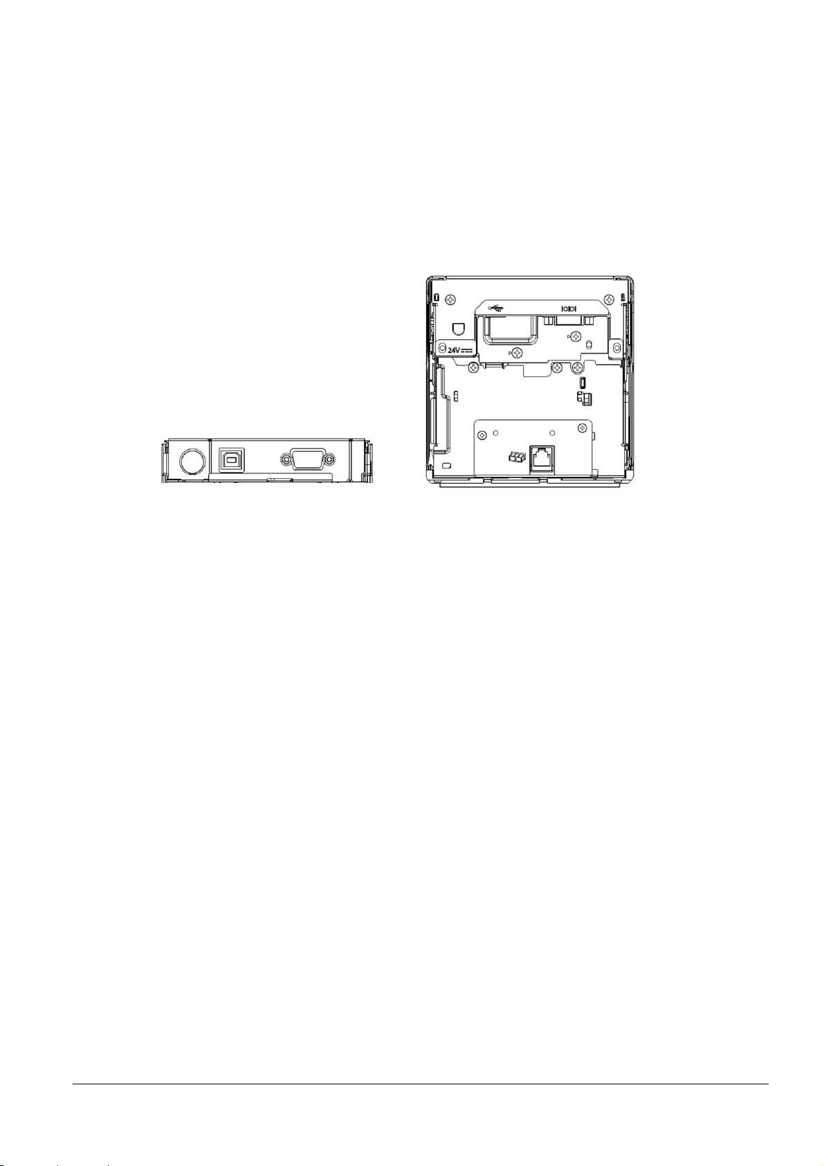
2.2 For specified customer
1 2 3
4
(1) Exterior
Same as EU-m30 (See 2.1.(1).)
(2) Interfaces equipped
USB and serial (RS-232, D-Sub 9 pin)
(3) Connector layout
1: Power supply connector 2: USB connector (Type-B) 3: Serial connector 4: DK connector
(4) Accessories
Roll paper (φ 35 mm)
Switch cover
For power switch
For power/feed switch
Small cover open lever, including 1 spare screw
Roll paper guides for 58 mm {2.28"} paper: 2
Equipment mounting brackets: 2
Product fixing brackets, including 2 screws + 1 spare (total of 3 screws)
(5) Options
Bezel option: Model: OT-BU30
Power supply adapter: Model: PS-180
Optional external buzzer: Model: OT-BZ20
26
Page 34

3 Function
3.1 Control Commands
See "ESC/POS Command Reference" (www.epson-biz.com/pos/reference/).
3.2 Character Code Tables
See "Character Code Tables for TM Printers"(www.epson-biz.com/pos/reference/).
3.3 Switches
3.3.1 Power switch
(1) Type
Locking push switch
(2) Function
(a) Turn the power on or off.
Notes:
Operate the power switch with the power connector connected.
If turning on the power after turning the power off, first check that the panel LED has turned off before doing
so.
If turning off the power without using the power switch, or if you do not execute the DLE DC4 (fn = 2)
command, the maintenance counter value may not be updated properly. For the proper usage of the
maintenance counter, see Appendix D.
3.3.2 Feed button
(1) Type
Non-locking push switch
(2) Function
1) Executes paper feeding. Press once to feed paper based on the line spacing set by the ESC 2 and ESC 3
commands, or press and hold to continue feeding paper.
Note: Paper feeding cannot be performed under the following conditions.
When the paper is at the end
When the roll paper cover is open
While printing is in progress
When set to disabled by ESC c 5.
2) If you push this button when the printer is in the macro execution standby state, the defined macro is
executed.
3) When executing a self-test, use the button to temporarily stop or restart the test.
4) Starts printing/setting mode for each type of information, selects the menu, and executes it.
27
Page 35

3.4 Indicators
3 3 2
1
3.4.1 Displayed color and icon
1: POWER LED (Blue) 2: ERROR LED (Orange) 3: Flashing LED (Blue)
3.4.2 Displayed patterns
(1) Printer status icon
POWER
Normal status On Off On or [Off]*3
Initializing after power-on On On On
Executing self-test On *1 Off
Continued self-test standby On Flashing - (1) Off
Paper is being fed by the Feed button On *1 Off
Macro execution standby On Flashing - (1) Off
Roll paper cover open when not
printing
Paper-end On On Off
Near-end On Flashing - (3)
Errors that recover automatically On On Off
Recoverable errors On On Off
Unrecoverable errors On Flashing - (4) Off
Updating firmware Flashing - (1) Off Off
In firmware forced update mode On On On
Power OFF in process Flashing - (1) On Off
Power OFF standby *2 Flashing - (2) Off Off
Printing completed flashing
(Attention flashing)
ERROR
LED
On On Off
On *1 [Flashing - (5) *4 *5]
LED
*5
Flashing
LED
According to normal
status above
or Off *3
Flashing - (1): Repeats between on for 320 ms then off for 320 ms.
Flashing - (2): Repeats between on for 160 ms then off for 2,400 ms.
Flashing - (3): Repeats between on for 320 ms then off for 2240 ms.
Flashing - (4): Repeats between on for 480 ms then off for 160 ms.
Flashing - (5): Repeats between on for 640 ms then off for 640 ms.
*1 Depends on the paper sensor status. It is Off if there is paper, and On if there is no paper. Furthermore,
when a near-end is detected (if equipped with near-end sensor), the light is Flashing - (4), and when a nearend is not detected, it depends on the paper sensor status.
*2 See Appendix D.2.
*3 Can select with the EU-m30 Utility. [ ]: Set when shipped.
*4 Flashing starts when print job is completed. Can select the flashing duration with the EU-m30 Utility.
When the flashing duration ends, the light turns Off.
If, however, a new print job is received during the preset duration and printing starts, the flashing stops at
28
Page 36
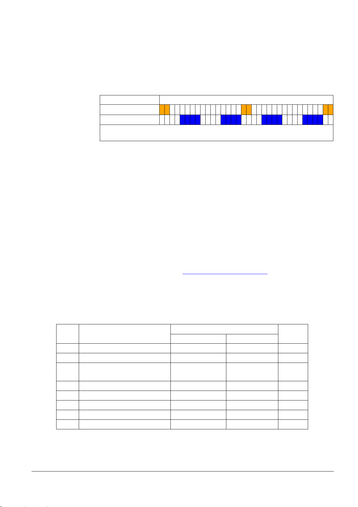
that time.
ERROR LED
Also, if the time from the completion of a print job (end of operation) to the start of the next print job is less
than 640 ms, the next print job will start without flashing.
For details, see 3.5.2 Software setting.
*5 A Near-End Error (orange) LED and Printing Completed (blue/attention) LED will not flash at the same
time.
3.5 Printer Setting
3.5.1 DIP switch settings
This printer is not equipped with DIP switches.
3.5.2 Software setting
(1) Memory switches
Can be changed using one of the following methods.
1 segment: 160 ms Elapsed time
Flashing LED
640 ms
640 ms
(a) User setup commands: GS ( E
Step 1: Moves to the user setting mode with GS ( E <Function 1>
Step 2: Change settings with GS ( E <Function 3>.
Step 3: End the user setting mode with GS ( E <Function 2>.
For details, see "ESC/POS Command Reference" (www.epson-biz.com/pos/reference/
(b) Software setting mode (except some functions)
For details, see 3.8.3 Software setting mode.
(c) EU-m30 Utility
Table 3.5.1 Memory Switch 1 (Msw1)
Msw Function Setting value Factory
1-1 (Reserved) - - 48 (OFF)
1-2 Receive buffer capacity 4 KB 45 bytes 48 (OFF)
1-3 Condition for BUSY Receive buffer full
1-4 Data processing with reception error Replace with "?" Ignored 48 (OFF)
1-5 Automatic line feed Always disabled Always enabled 48 (OFF)
1-6 (Reserved) - - 48 (OFF)
1-7 Pin 6: Reset signal selection Not used Used 48 (OFF)
1-8 (Reserved) - - 48 (OFF)
48 (OFF) 49 (ON)
Receive buffer full 48 (OFF)
and offline
).
setting
29
Page 37
Table 3.5.2 Memory Switch 5 (Msw5)
48 (OFF)
49 (ON)
5-2
(Reserved)
– – 48 (OFF)
Msw Function Setting value Factory
setting
5-1 USB power-saving function *1 Enabled Disabled 48 (OFF)
5-3 Paper sensors to output paper end
signal
Roll paper end, nearend sensor enabled
Disabled 48 (OFF)
5-4 Error signal output Enabled Disabled 48 (OFF)
5-5 Pre-feed before next print
*2
Disabled Enabled 48 (OFF)
*3
5-6 Roll paper near-end sensor Disabled Enabled 49 (ON)
5-7 (Reserved) – – 48 (OFF)
5-8 (Undefined) – – 48 (OFF)
*1: Valid only when the USB interface communication condition is set to the vendor-defined class and the
system configuration is set so that the USB driver can support the USB power-saving function.
*2: When a customized value (specification for the top margin by backfeed) is set and back feed occurs, this
setting is disabled.
*3: Japanese model only, default setting 49 (ON).
(2
) Customized value setting
Can be changed using one of the following methods.
(a) User setup commands: GS ( E
Step 1: Moves to the user setting mode with GS ( E <Function 1>
Step 2: Change the setting with GS ( E <Function 5>.
Step 3: End the user setting mode with GS ( E <Function 2>.
For details, see "ESC/POS Command Reference" (www.epson-biz.com/pos/reference/
).
(b) Software setting mode (except some functions)
For details, see 3.8.3 Software setting mode.
(c) EU-m30 Utility (except some functions)
Table 3.5.3 Types of Customized Values
Function Selectable values Factory setting
NV user memory capacity 1 KB, 64 KB, 128 KB, 192 KB 1 KB
NV graphics memory capacity None, 64 KB, 128 KB, 192 KB, 256 KB,
384 KB
320 KB, 384KB
Roll paper width *2 80 mm {3.15"}, 58 mm {2.28"} 80 mm {3.15"}
Print density 70 to 130% (In 5% units) 100%
Print speed Level 1 to 13 (Low speed to high
Level 13
speed)
Thai character print mode Thai 1 pass / Thai 3 pass Thai 1 pass
Default character code table 43 pages selectable with ESC t 0
Default international character 18 types selectable with ESC R 0
30
Page 38

Function Selectable values Factory setting
Selection of the interface Fixed to serial interface
Fixed to built-in USB
All interfaces
enabled
Serial/USB automatic switching
All interfaces enabled
Command execution (offline) Enabled/Disabled Enabled
Specification for the top margin by backfeed *3 9.5 to 2 mm (in 0.5 mm units) 9.5 mm {0.37"}
Switchover time for a valid interface 1 to 10 seconds (1 second units) 1 second
Selection of primary connection interface Auto (Interface where data was first
Auto
received)/Serial/USB/No primary
connection
Power supply capacity *5 Power supply capacity level 1 to 3 Capacity: High
Autocutting of roll paper when the roll paper
Does not cut/cuts Cuts
cover is closed
(ARP) Reduction of excessive top margin Does not reduce/reduces Does not reduce
(ARP) Reduction of excessive bottom margin Does not reduce/reduces Does not reduce
(ARP) Reduction ratio of line spacing Does not reduce/reduces 25%/
Does not reduce
reduces 50%/reduces 75%
(ARP) Reduction ratio of line spacing where extra
line feeds are included
(ARP) Reduction ratio of bar code height Does not reduce/reduces 25%/
Does not reduce/reduces 25%/
reduces 50%/reduces 75%
Does not reduce
Does not reduce
reduces 50%/reduces 75%
(ARP) Reduction ratio of character height Does not reduce/reduces 25%/reduces
Does not reduce
50%/reduces 75%/reduces 75% and
shortens character height
Font A auto replacement Does not replace/Font B/Font C Does not replace
Font B auto replacement Does not replace/Font A/Font C Does not replace
Font C auto replacement Does not replace/Font A/Font B Does not replace
Print density during multi-tone printing 70 to 130% (In 5% units) 100%
Buzzer function: Optional external buzzer
Enabled/Disabled Disabled
enabled/disabled
*For specified customer only
Buzzer function: Buzzer frequency (Error) *1 Does not sound/sounds 1 time/
Sounds continuously
Sounds
continuously
Buzzer function: Sound pattern (Autocut) *1 Patterns A to E Pattern A
Buzzer function: Buzzer frequency (Autocut) *1 Does not sound/sounds 1 time Sounds 1 time
Buzzer function: Sound pattern (Pulse 1) *1 Patterns A to E Pattern A
Buzzer function: Buzzer frequency (Pulse 1) *1 Does not sound/sounds 1 time Sounds 1 time
Buzzer function: Sound pattern (Pulse 2) *1 Patterns A to E Pattern B
Buzzer function: Buzzer frequency (Pulse 2) *1 Does not sound/sounds 1 time Sounds 1 time
Command-compatible mode EU-m30/TM-m30/TM-m30II EU-m30
Selection of batch print enabled/disabled and
print direction
Disabled/enabled (forward)/enabled
(reverse)
Disabled
*1: The functions are enabled for the optional external buzzer. *For specified customer only
*2: For the method for changing the paper width, see Appendix I.
*3: For notes on using the backfeed, see Appendix J.
31
Page 39

(3) Set the customized values of model-specific
Can be changed using one of the following methods.
(a) User setup commands: GS ( E
Step 1: Moves to the user setting mode with GS ( E <Function 1>
Step 2: Change settings with GS ( E <Function 97>.
Step 3: End the user setting mode with GS ( E <Function 2>.
For details, see "ESC/POS Command Reference" (www.epson-biz.com/pos/reference/
).
(b) Software setting mode (except some functions)
For details, see 3.8.3 Software setting mode.
Table 3.5.4 Model-specific Customized Values
Function Selectable values Factory setting
Selection of built-in character types South Asia languages / Simplified Chinese South Asia languages
(4) USB interface communication condition setting
Can be changed using one of the following methods.
(a) User setup commands: GS ( E
Step 1: Moves to the user setting mode with GS ( E <Function 1>
Step 2: Change settings with GS ( E <Function 15>.
Step 3: End the user setting mode with GS ( E <Function 2>.
For details, see "ESC/POS Command Reference" (www.epson-biz.com/pos/reference/
).
(b) Software setting mode (except some functions)
For details, see 3.8.3 Software setting mode.
(c) EU-m30 Utility (except some functions)
Table 3.5.5 USB Interface Communication Condition
Function Selectable values Factory setting
Class Vend o r-defined class/Printer class Printer class
(5) Serial interface communication condition setting
The settings for the serial interface communication condition can be changed using one of the following methods.
User setup commands: GS ( E
(1) Moves to the user setting mode with GS ( E <Function 1> command.
(2) Change settings with GS ( E <Function 11>.
(3) End the user setting mode with GS ( E <Function 2> command.
* For details, see "ESC/POS Command Reference" (www.epson-biz.com/pos/reference/
Software setting mode
See 3.8.3. Software setting mode.
EU-m30 Utility
).
32
Page 40
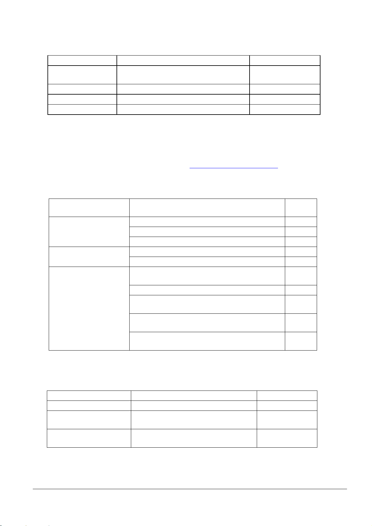
Table 3.5.6 Serial Interface Communication Condition
Function Selectable values Factory setting
Transmission speeds 2400 bps/4800 bps/9600 bps/19200 bps/38400
115200 bps
bps/57600 bps/115200 bps
Parity settings No parity/odd parity/even parity No parity
Handshaking DTR/DSR control/XON/XOFF control DTR/DSR control
Bit length 7-bit length/8-bit length 8-bit length
(6) Receipt enhancement setting
Can be changed using one of the following methods.
(a) Group of commands for receipt enhancement control: FS ( E
For details, see "ESC/POS Command Reference" (www.epson-biz.com/pos/reference/
).
(b) EU-m30 Utility (except some functions)
Table 3.5.7 Receipt Enhancement
Function Selectable values Factory
Auto top logo print setting Key code Undefined
Justification (left/center/right) Undefined
Number of lines to be deleted below top logo Undefined
Auto bottom logo print setting Key code Undefined
Justification (left/center/right) Undefined
Extended settings for auto top
logo/bottom logo printing
Prints the top logo while paper feeding to the cutting
position: Enabled/disabled
Enabled
Prints the top logo at power-on: Enabled/disabled Disabled
Prints the top logo when the roll paper cover is closed:
Enabled
Enabled/disabled
Prints the top logo while clearing the buffer to recover from
Enabled
a recoverable error: Enabled/disabled
Prints the top logo after paper feeding with the Feed button
Disabled
has finished: Enabled/disabled
setting
(7) Flashing LED setting
The following settings can be changed using the EU-m30 Utility.
Table 3.5.8 Flashing LED Setting
Function Selectable values Factory setting
Light on in normal status Enabled (On)/Disabled (Off) Disabled (Off)
Printing completed flashing
Enabled/Disabled Enabled
(Attention flashing)
Printing completed flashing
Flashing duration
5, 6, 7, 8, 9, 10, 11,12, 13, 14, or 15 (sec) from
end of print job
8 (sec)
33
Page 41

3.6 Self-test
3.6.1 Self-test function
Executes printer status printing and rolling pattern printing.
(a) Printer status printing
Product name
Firmware version
Product serial number
Interface information
Built-in character fonts
Maintenance information (Head running length, number of times of autocutting)
(b) Rolling pattern printing
A rolling pattern using the built-in character set
3.6.2 Running self-test
Can be executed using one of the following methods.
(a) Execution using Feed button
Step 1: With the roll paper cover closed, turn the printer power on while pressing the Feed button.
Step 2: Execute printing of the printer status.
Step 3: After printing the current printer status, the printer prints the following message:
Select Modes by pressing Feed Button.
Continue SELF-TEST: Less than 1 second
Mode Selection : 1 second or more
The ERROR LED indicator flashes and the printer enters the Rolling pattern printing standby state.
Step 4: Briefly press the Feed button to start rolling pattern printing.
Step 5: When a certain number of lines of rolling pattern printing is completed,
*** completed ***
is printed, and the software reset is automatically executed.
(b) Executing using a command
Step 1: Transmit the GS ( A command (printer status print).
Step 2: Transmit the GS ( A command (rolling pattern print).
Step 3: When a certain number of lines of "test printing" is completed,
*** completed ***
is printed, and the software reset is automatically executed.
3.7 Hexadecimal Dumping
3.7.1 Hexadecimal dumping function
Prints the data sent from the host in a hexadecimal and corresponding text.
3.7.2 Running hexadecimal dumping
Can be executed using one of the following methods.
(a) Execution using Feed button
Step 1: Open the roll paper cover.
Step 2: Holding the Feed button, turn on the power then close the roll paper cover.
Step 3: Turn off the power, or press the Feed button three times to complete this procedure.
34
Page 42

(b) Executing using a command
Hexadecimal Dump
Step 1: Transmit the GS ( A command (Hexadecimal dump print).
Step 2: Turn off the power, or press the Feed button three times to complete this procedure.
Notes:
If no characters correspond to the data received, the printer prints ".".
During hexadecimal dumping, any commands other than DLE EOT do not function.
Print data that is less than one line can be printed by pressing down the Feed button
<Printing example>
To terminate hexadecimal dump,
press Feed button three times.
1B 21 00 1B 26 02 40 40 1B 69 .!..&.@@.i
1B 25 01 1B 63 34 00 1B 30 31 .%..c4..01
41 42 43 44 45 46 47 48 49 4A ABCDEFGHIJ
*** completed ***
3.8 Information Print Modes and Setting Modes
3.8.1 NV graphics information print mode
(1) NV graphics information printing function
Prints the NV graphics information registered in the printer.
The following information is printed.
Capacity of the NV graphics
Occupied capacity of the NV graphics
Unused capacity of the NV graphics
Number of NV graphics that are registered
Key code, number of dots in X direction, and number of dots in Y direction for each piece of data
NV graphics data
(2) Starting the mode
Step 1: With the roll paper cover closed, turn the printer power on while pressing the Feed button until printing
Step 2: After the printer status is printed, press the Feed button until printing of the instructions for operation
Step 3: After the instructions for operation are printed, press the Feed button once.
Step 4: Then, press and hold the Feed button until printing of the NV graphics information starts.
of the printer status starts.
method starts.
(3) Ending the mode
Turn the power off.
35
Page 43

3.8.2 R/E (receipt enhancement) information print mode
(1) R/E (receipt enhancement) information printing function
Prints the following R/E information presently registered in the printer.
The following information is printed.
Auto top logo print setting
Auto bottom logo print setting
Extended settings for auto top logo/bottom logo printing
(2) Starting the mode
Step 1: With the roll paper cover closed, turn the printer power on while pressing the Feed button until printing
of the printer status starts.
Step 2: After the printer status is printed, press the Feed button until printing of the instructions for operation
method starts.
Step 3: After the instructions for operation are printed, press the Feed button twice.
Step 4: Then, press and hold the Feed button until printing of the R/E information starts.
(3) Ending the mode
Turn the power off.
3.8.3 Software setting mode
(1) Software setting function
Executes software settings using the buttons on the printer.
The software setting values that can be set are as follows:
Print density
Auto reduction of amount of paper to use
Enabling/disabling paper autocutting at cover close
Paper width setting *1
Thai character print control method
Selection of built-in character types
Auto replacement of font
Communication conditions using a USB interface
Print speed
NV user memory capacity
Command execution (offline)
Specification for the top margin by backfeed
Optional external buzzer control *For specified customer only
Power supply capacity
Interface setting
Switchover time for a valid interface
Selection of primary connection interface
Enabling/disabling Display when interface is activating
Enabling/disabling the pre-feed before next print function
Enabling/disabling the roll paper near-end sensor
Command-compatible mode (model name setting)
*1: Regarding the paper width setting, see Appendix I.
36
Page 44

(2) Starting the mode
Step 1: With the roll paper cover closed, turn the printer power on while pressing the Feed button until printing
of the printer status starts.
Step 2: After the printer status is printed, press the Feed button until printing of the instructions for operation
method starts.
Step 3: After the instructions for operation are printed, press the Feed button three times.
Step 4: Then, press and hold the Feed button until printing of the software setting mode starts.
Step 5: The instructions for the setting method are printed. Perform settings in accordance with the
instructions.
(3) Ending the mode
After completing the setting, the set content is stored, and the printer is initialized.
When printer initialization ends, the printer is ready for normal printing.
3.8.4 Initial setting restoration mode
(1) Initial setting restoration function
Restores current settings to the saved settings (if settings have been saved for restoration).
(2) Starting the mode
Step 1: With the roll paper cover closed, turn the printer power on while pressing the Feed button until printing
of the printer status starts.
Step 2: After the printer status is printed, press the Feed button until printing of the instructions for operation
method starts.
Step 3: After the instructions for operation are printed, press the Feed button four times.
Step 4: Then, press and hold the Feed button until printing of the initial setting restoration mode starts.
Step 5: After the instructions are printed, press the Feed button once.
Step 6: Press and hold the Feed button until the restoration complete message is printed.
(3) Ending the mode
Turn the power off.
3.9 Error Processing
3.9.1 Errors that recover automatically
(1) Head temperature error
Error contents:
LED display pattern:
Recovery method:
(2) Roll paper cover open error
Error contents:
LED display pattern:
Recovery method:
Detected a (hot) head temperature in excess of the appropriate range.
See 3.4.2.
Automatically stops printing and automatically recovers when the head
temperature drops.
Detected the roll paper cover was open during printing.
See 3.4.2.
Automatically recovers when the roll paper cover is closed.
37
Page 45

3.9.2 Recoverable errors
Unable to recover
See 3.4.2.
LED display pattern:
Error contents:
Recovery method:
LED display pattern:
Note:
When any error shown above occurs, turn off the power as soon as possible.
(1) Autocutter error
Error contents:
LED display pattern:
Recovery method:
3.9.3 Unrecoverable errors
(1) R/W error in memory
Error contents:
LED display pattern:
Recovery method:
(2) High voltage error
Error contents:
LED display pattern:
Recovery method:
Detected an error in the autocutter operation.
See 3.4.2.
Execute DLE ENQ 1 and DLE ENQ 2.
Remove any paper jams or foreign objects and close the roll paper cover.
Note: See Appendix A if this does not solve the error.
Detected an error during memory R/W.
See 3.4.2.
Detected abnormal voltage (high) in the power source.
Unable to recover
(3) Low voltage error
Error contents:
Recovery method:
(4) CPU execution error
LED display pattern:
(5) Internal circuit connection error
Error contents:
Recovery method:
3.10 Open Cover
Operate the cover open lever to open the roll paper cover.
Opening the roll paper cover during printing will cause an error to occur and printing to stop. Close the roll
paper cover to rec over.
Opening the roll paper cover during standby will send the printer offline. Close the roll paper cover to recover.
The status just before the cover was opened is maintained while the cover is open.
Notes:
When opening the roll paper cover, be sure to use the cover open lever.
Do not open the roll paper cover during printing.
Never open the cover while the autocutter is operating. Doing so may cause mechanical damage.
Detected abnormal voltage (low) in the power source.
See 3.4.2.
Unable to recover
The CPU executes an incorrect address.
See 3.4.2.
Unable to recover
Detected an error in the internal circuit connection.
See 3.4.2.
Unable to recover
38
Page 46

3.11 Print Buffer-full Printing
(1) When in Standard mode
When subsequent data is received after the printer processes one line of data in the print buffer, the printer
automatically prints the processed line and feeds the paper by one line.
(2) When in Page mode
When subsequent data is received after the printer processes one line of data in the print buffer, the printer
automatically moves the printing position to one line below the processed line.
3.12 Optional external buzzer *For specified customer only
(1) Optional external buzzer settings
The optional external buzzer (OT-BZ20) can be used by connecting it to the drawer kick connector and, under
software settings, setting the "Optional external buzzer enabled/disabled" item to "Enabled".
(a) Sounding/stopping by the buzzer commands
It is possible to sound the buzzer by setting a sound pattern and a buzzer frequency with ESC ( A.
It is possible to stop sounding the buzzer with DLE DC4 <Function 3>.
(b) Cooperative sounding by using commands other than the buzzer commands
Buzzer sounding is possible by autocutting commands/operations (GS V 0, GS V 65, ESC i, ESC m,
autocutting for automatic top logo printing, automatic cutting at cover close).
Buzzer sounding is possible by the commands that generate the specified pulse (drawer kick) (ESC p, DLE
DC4 <fn = 1>).
The sound pattern and buzzer frequency can be set with the software setting. (See 3.5.2 for how to change
the setting.)
(c) Autonomic sound
Buzzer sounding is possible when a paper-end is detected.
Buzzer sounding is possible when an error occurs.
The buzzer frequency can be set with the software setting. (See 3.5.2 for how to change the setting.)
(d) Stopping the buzzer sounding
It is possible to stop sounding the buzzer with DLE DC4 <Function 3>.
It is possible to stop sounding the buzzer by opening the cover. (However, if the cause for sounding remains
when the cover is closed, the buzzer will begin sounding again.)
(2) Notes for when connecting, installing, and using
1) When, in the software settings, the "Optional external buzzer enabled/disabled" item is set to "Enabled", a
pulse is not output to the drawer kick connector pin, and therefore, the drawer cannot be driven.
2) When the optional external buzzer is used, it is prohibited that both the optional external buzzer and the
drawer are connected at the same time by using a branched connector.
3) The optional external buzzer does not sound when the optional external buzzer is connected after the printer
power is on or if the optional external buzzer is disconnected and reconnected while the printer power is on;
therefore, be sure to turn on the printer with the optional external buzzer connected and do not disconnect
the optional external buzzer when the printer power is on.
4) Be sure to fix the buzzer to the printer unit with the affixing tape (bundled with the optional external buzzer).
5) Do not install the optional external buzzer on the roll paper eject surface, as doing so will block paper eject.
6) Be sure to clean and dry the surface of the printer and the optional external buzzer where the affixing tape is
attached before attaching the affixing tape to the printer and the optional external buzzer.
7) To prevent liquid from entering, it is recommended to install the optional external buzzer so that the volume
adjustment knob is positioned sideways or downward.
39
Page 47

8) Do not purposely put any water, oil, chemicals, or any other water-based material on the buzzer. Doing so
may cause a malfunction.
3.13 Printing Using Multiple Interfaces
Models with multiple interfaces do not fix the interface to be used, but can use all the interfaces (*1).
You can select just one interface as the primary connection interface (*1). There are no limitations on
command functions for the primary connection interface, and priority is given to processing received data.
Other interfaces are set as secondary connection interfaces. There are limitations on command functions for
the secondary connection interface (*2), and priority is not given to processing received data.
The following table describes the differences between the primary connection interface and the secondary
connection interfaces.
Connection I/F Connection
priority
Primary High None None Maintained
Secondary Low None Ye s Initialized
Set the interface you want to constantly use as the primary connection interface. Be aware that if you set
primary connection interface selection to "Auto" (the interface where data is first received), the primary
connection interface may not be determined uniquely based on the order of data received from each interface.
When the primary connection interface selection is "Auto" and the primary connection interface is not
determined because data is not being received, the interface to be printed is determined as the primary
connection interface.
The printer has an independent receive buffer for each interface, data can always be received on each interface.
If using multiple interfaces, set the receive buffer capacity to 4 KB (initial setting) (*4).
The printer switches the active interface in accordance with the priority, and processes the data in each receive
buffer sequentially.
The active interface can be switched when all the following conditions are met.
The receive buffer for the active interface has been empty (there is no unprocessed data) for the set time (*5)
or longer.
Printing has stopped.
(*1) For interface types and how to select the primary connection interface, see "3.5.2 Software setting (2)
Customized value setting."
(*2) The following ESC/POS commands are disabled for the secondary connection interface.
DLE DC4 (fn = 2), ESC &, ESC ?, GS ( D, GS ( L <Functions 81,82,83>, GS *, GS :, GS D <Function 83>, GS
^, FS 2
(*3) If you are using ePOS-Print SDK or Epson ePOS SDK, the maintaining or initializing of print settings when
closing the connection does not affect the operations of the application.
(*4) For the method to set the receive buffer capacity, see Section 3.5.2 Software setting, (1) Memory switches.
(*5) For the method to set the set time (Switchover wait time for a valid interface), see Section 3.5.2 Software
setting, (2) Customized value setting.
Function limitation
when using Epson
ePOS SDK
Function limitation on
ESC/POS commands
(*2)
Print settings when
connection is closed
(*3)
3.14 Updating Firmware
(1) Method for updating firmware
You can update the firmware on this printer using the following method.
Step 1: With the printer's power on, execute the firmware update tool.
Step 2: When the printer begins the firmware update processing, the Power LED flashes.
40
Page 48

Note: Do not to turn off the printer's power while the firmware update tool is performing the update.
(2) Recovery method for when updating the firmware fails
If updating the firmware fails, and the Power and Error LEDs flash at the same time when the power is turned on,
try updating the firmware again by using the firmware update tool. However, in such cases you can only use the
USB interface.
41
Page 49

4 Case Specifications
4.1 External Dimensions and Mass
4.1.1 Bezel Option Not Equipped
Width: Approximately 127 mm {5"}
Depth: Approximately 131.2 mm {5.17"}
Height: Approximately 127 mm {5"}
Approximately 129 mm {5.1"} (including protrusions)
Mass: Approximately 1.3 kg {2.87 lb} (roll paper excluded)
4.1.2 Bezel Option Equipped
Width: Approximately 127 mm {5"}
Depth: Approximately 155.9 mm {6.14"}
Height: Approximately 127 mm {5"}
Approximately 129 mm {5.1"} (including protrusions)
Mass: Approximately 1.3 kg {2.87 lb} (roll paper excluded)
4.2 Color
EPSON standard color: ENB9, EBCK
42
Page 50
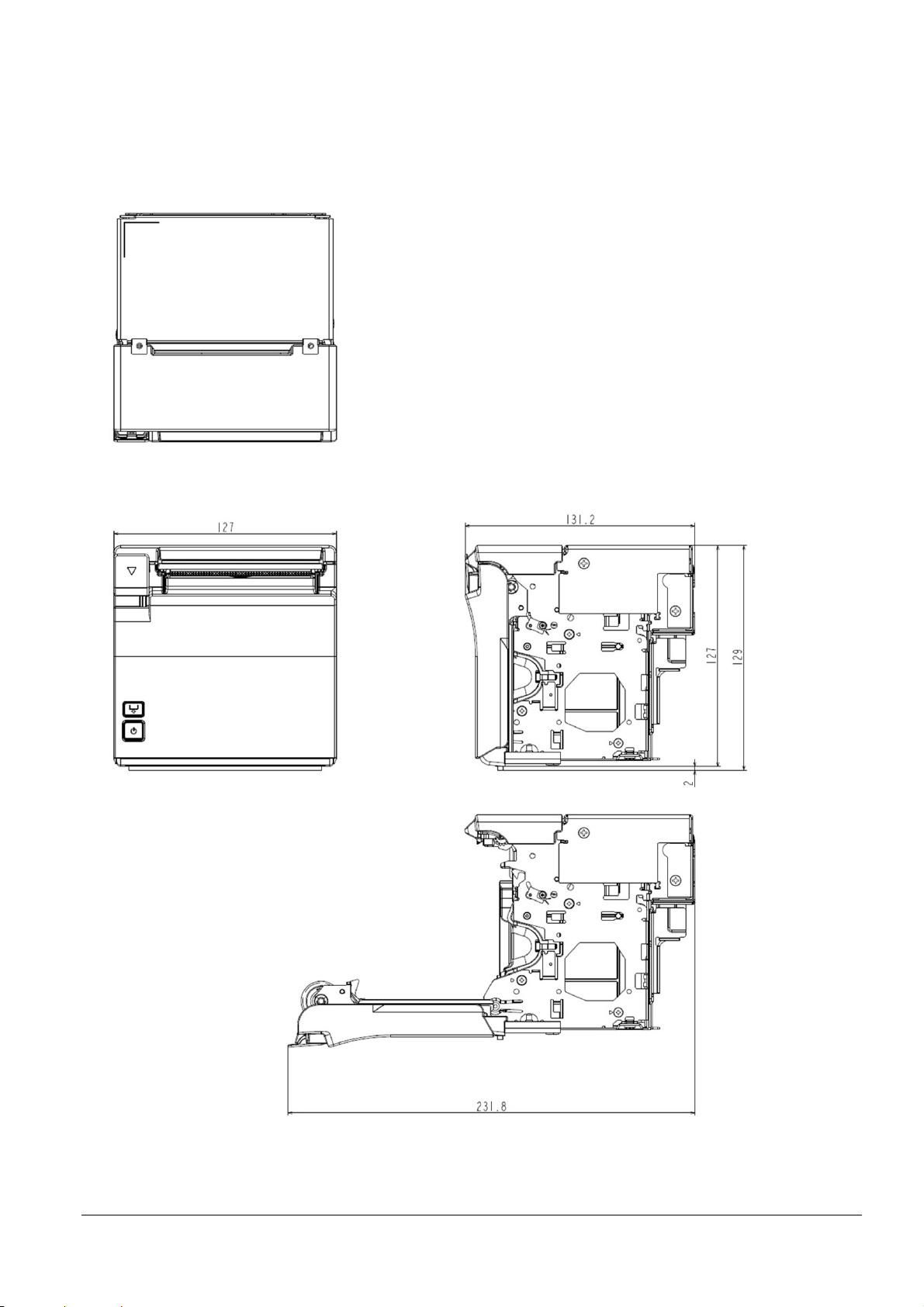
4.3 External Dimensions
4.3.1 Bezel Option Not Equipped
[Units: mm]
Figure 4.3.1 External Dimensions (Bezel Option Not Equipped)
43
Page 51
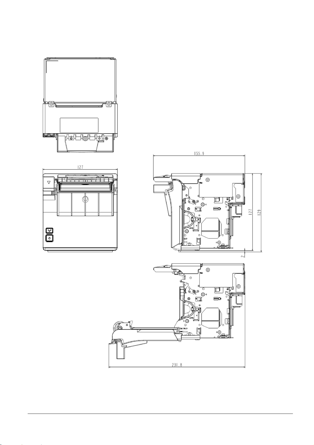
4.3.2 Bezel option equipped
[Units: mm]
Figure 4.3.2 External Dimensions (Bezel Option Equipped)
44
Page 52

4.4 Dimensions for Installing to Customer Device
See Appendix M.
45
Page 53

Appendix A RECOVERY FROM AN AUTOCUTTER ERROR
A.1 If You Can Open the Roll Paper Cover
If a foreign object such as a push pin or paper clip drops in the autocutter and causes the autocutter to lock up,
the printer enters an error state and begins the recovery operation automatically.
If the problem is not serious, the autocutter recovers and returns to its normal position.
If the error cannot be resolved even after recovery operations, open the roll paper cover, remove any foreign
objects or paper jams, set the roll paper, then close the roll paper cover.
A.2 If You Cannot Open the Roll Paper Cover
Turn the printer off then on again.
46
Page 54

Appendix B PRINT HEAD AND PLATEN ROLLER CLEANING
Print head
Thermal element
Heat sink
B.1 Thermal Head
Paper dust or other foreign objects on the thermal elements may lower the print quality. In this case, clean the
print head as follows:
Step 1: Open the roll paper cover.
Step 2: Clean the thermal elements of the print head using a cotton swab moistened with alcohol solvent
(ethanol or IPA).
Notes:
Do not touch the print head thermal elements.
Be careful not to scratch the print head during cleaning.
Step 3: Insert roll paper, pull out some paper, and close the roll paper cover.
Notes:
The print head becomes very hot immediately after printing. Be sure to allow the print head to cool down
(after printing) before cleaning it.
Also, be sure to turn off the printer power before cleaning the print head.
Turn on the printer power only after alcohol has completely dried.
B.2 Platen Roller
Figure B.1.1 Print Head Thermal Element
Depending on the roll paper used, paper dust may stick to the platen roller and the paper may not be fed correctly.
To remove the paper dust, clean the platen roller with a cotton swab moistened with water as described in the
thermal head section above. Turn on the printer power only after the water has completely dried.
47
Page 55

Appendix C NOTES ON USING THE DRAWER KICK CONNECTOR *For specified
OFF time
customer only
C.1 Conditions for Using the Drawer Kick Connector
Drawer specifications differ significantly depending on the manufacturer and the model. Make sure that the
specifications of the drawer used meet the following conditions when connected to the drawer kick connector.
These conditions also apply to any other devices to be connected to the drawer kick connector.
Never use a drawer (or other devices) that does not meet all of the following conditions:
[Conditions]
The load, such as a drawer kick solenoid, must be connected between pins 4 and 2 or pins 4 and 5 of the drawer
kick connector. (*1)
When the drawer open/close signal that indicates the state of the drawer is used, a switch must be provided
between drawer kick connector pins 3 and 6. (*2)
The resistance of the load, such as a drawer kick solenoid, must be 24 Ω or more or the input current must be 1
A or less. (*3)
Make sure to use the drawer kick connector 4 pin (24 V power supply) for driving the drawer. Never connect
any other power supply to the drawer kick connector. (*4)
The peak current is 1 A. See item (2) below for power status.
*1: Proper operation is not guaranteed with different connections.
*2: Proper operation is not guaranteed with different connections or connection to a component other than a
switch.
*3: Connection to equipment whose resistance is less than 24 Ω or whose input current is more than 1 A may
cause an overcurrent and damage the connected equipment as well as the printer.
*4: Operation is not guaranteed with other power supplies.
C.2 Notes on the pulse generating command (ESC p)
When using ESC p to drive the drawer connected to the drawer kick connector, set the command parameters to
meet the following conditions:
ESC p m t1 t2
Or, OFF time ≥ ON time × 4 ······ Formula C-2
ON time + OFF time
ON time
ON time
≤ 0.2 ······ Formula C-1
48
Page 56

Figure C.1.1 shows the drive signal waveform generated when the drawer is driven according to the above
PRINT#1, CHR$(&H1B); "p"; CHR$(0); CHR$(100); CHR$(250);
GOSUB *WAIT300MS
*WAIT300MS
RETURN
conditions.
ON
OFF
t1 × 2 ms t2 ≥ (t1 × 4) × 2 ms
Figure C.1.1 Drawer Drive Signal Waveform
The ON time depends on the specifications of the drawer used. Be sure to check the drawer specifications and set
a suitable time. To use a drawer that does not meet the conditions of Formulas C-1 and C-2, see C.3.
C.3 Using a drawer that does not meet the conditions in C.2 (ESC p, DLE DC4)
For ESC p
Setting the values of t1 and t2 according to the conditions in C.2 results in a maximum ON time of 126 ms (0 ≤
t1 ≤ 63), since the setting ranges of t1 and t2 are 0 to 255.
To use a drawer that requires an ON time exceeding 126 ms, the following conditions must be met:
ON time
ON time + (OFF time + α)
α: processing time of other sequence
α is the period from the OFF time until the next ON time when the drawer-driving is prohibited.
For DLE DC4
Since DLE DC4 sets ON time equal to OFF time, use α so that Formula C-3 is met.
An example program in which the drawer connected to drive signal 1 is driven with an ON time of 200 ms is
shown below.
≤ 0.2 ······ Formula C-3
:
:
300 [ms] wait routine
*1: Corresponds to α of Formula C-3. Set the value so that it satisfies Formula C-3
(or include an internal processing time that is equal to or longer than this wait routine).
ON time 200 ms OFF time 500 ms
(*1)
49
Page 57

The drive signal waveform generated when the drawer is driven according to the above conditions is shown in
Figure C.1.2.
ON
OFF
200 ms 500 ms α = 300 ms
Figure C.1.2 Drawer Drive Signal Waveform
50
Page 58

Appendix D NOTES ON UPDATING THE MAINTENANCE COUNTER AND TURNING
THE PRINTER'S POWER OFF
D.1 About Updating the Maintenance Counter
This printer has a maintenance counter with functions as described in the command description for GS g 0 and
GS g 2.
The values of the maintenance counter are automatically stored in the NV memory every 2 minutes (or 4
minutes maximum) when the printer is operating, except in the power save mode.
However, if the power off is performed as described in Section D.2, the printer stores the latest values of the
maintenance counter and executes the power off control, regardless of the updating interval described above.
If the printer is not sending/receiving data or is not operating while the power is turned on, the printer enters
the power-saving mode.
D.2 Printer Power-off Procedures
If turning the power off without using the power switch, we recommend doing so after executing the power-off
sequence command DLE DC4 (fn = 2).
The following is an example of the printer power off process when the printer is turned off using the DLE DC4
(fn = 2) command.
Step 1: The host computer transmits the following continuous procedure before the system is turned off:
(1) Executes GS ( D pL pH m a b (pL=3, pH =0, m =20, a =2, b =1)
(2) Executes GS r n (n =1)
Step 2: The host computer waits for the paper sensor status sent from the printer in response to the GS r n
command.
Step 3: The host computer transmits DLE DC4 fn a b (fn = 2, a = 1, b = 8).
Step 4: The host computer waits for the power-off notice.
Step 5: After receiving the power-off notice, wait one second or longer, then turn off the power.
Notes:
The power-off sequence is performed within approximately 5 seconds after DLE DC4 fn a b is sent, and then the
power-off notice is sent. After that, the printer enters power-off standby.
If the power-off notice is not confirmed, wait for at least 5 seconds after transmitting DLE DC4 fn a b. At this
time, the printer has only performed software processing, and the power is not turned off.
Do not reset the printer until you have confirmed the power-off notice after transmitting DLE DC4 (fn = 2).
51
Page 59

Appendix E NOTES ON PRINTING BAR CODES AND 2-DIMENSIONAL SYMBOLS
User must set the quiet zone, depending on the bar code standards.
When printing PDF417 (2-dimensional symbols), it is recommended to set the height of one step of the symbol
to three to five times the width of one module. The total height of code should be approximately 5 mm {0.20"}
or more.
The recognition rate of ladder bar codes and 2-dimensional symbols may vary depending on widths of the
modules, print density, environmental temperature, type of roll paper (thermal paper), and characteristics of the
reader. Therefore, user must check the recognition rate before setting the use conditions so that the restrictions
of the reader are satisfied.
Reading quality of bar codes/2-dimensional symbols in multi-tone graphics printing is not guaranteed.
When printing ladder bar codes/2-dimensional symbols with graphics printing, instead of using the bar
codes/2-dimensional symbols print commands, set the print speed to speed level 5.
The print speed level can be set with GS ( K.
52
Page 60

Appendix F NOTES ON SCANNING THE PRINT RESULT ON THE RECEIPT
To determine whether the ability of the reader (scanner) can be satisfied by using bar codes, 2-dimensional
symbols, or characters printed on receipt (roll paper), take the following points into consideration.
1) Print density
The print density may vary depending on the type of roll paper or the environmental conditions.
2) Slant of the Print
The printed bar code or characters may not be horizontal to the paper as shown in the figure below.
They may slant in the range of ± 1.6° and the slanting direction or the angle varies during printing or each
time a receipt is issued.
Figure F.1 Slant of the Print
Note: If paper other than the ones described in Section 1.6, Paper Specifications, is used or if the paper is used out
of the range described in Section 1.13, Environmental Conditions, the print density may vary or the slant of
print result may become wider.
53
Page 61

Appendix G NOTES ON USING THE ASB STATUS
Combined ASB (1 + 2 + 3 + 4)
0011 1100
0000 0000
0000 0000
0000 1111
The latest ASB (4)
0001 1100
0000 0000
0000 1111
0000 1111
Any accumulated ASB status signals left for transmission from the last to the newest ASB status transmission shall
be transmitted together at a time as one ASB status showing the presence of change, followed by the latest ASB
status.
Example: In the normal (standby) state, the ASB status is configured as follows.
First byte Second byte Third byte Fourth byte
0001 0100 0000 0000 0000 0000 0000 1111
The following pieces of data are accumulated when the following printer status changes occur: 1) the cover is
opened, 2) the paper is removed and the cover is closed, 3) the cover is opened, and 4) the cover is closed.
(1) 0011 1100 0000 0000 0000 0000 0000 1111
(2) 0001 1100 0000 0000 0000 1111 0000 1111
(3) 0011 1100 0000 0000 0000 1111 0000 1111
(4) 0001 1100 0000 0000 0000 1111 0000 1111
When the ASB status is received following this, the actual ASB that is sent is a total of eight (8) bytes, consisting of
the combined ASB (1 + 2 + 3 + 4) and the latest ASB (4).
+
Note: When the primary connection interface selection is set to "Auto", set ASB with the secondary connection
interface if you wish to obtain ASB with said interface.
54
Page 62

Appendix H NOTES ON ARP (AUTOMATIC REDUCTION OF PAPER) AND
AUTOMATIC LOGO PRINTING FUNCTION
H.1 ARP: Reduction of Excessive Top Margin, Reduction of Excessive Bottom Margin, Reduction
of Line Spacing, and Reduction of Line Spacing Where Extra Line Feeds Are Included
Paper reduction is not performed for space dot lines of graphics printing data.
H.2 ARP: Reduction of Bar Code Height
When reducing bar code height, reading of the bar code is not guaranteed. Be sure to check reading a bar code
with a user’s bar code reader in advance.
H.3 Automatic Logo Printing Function
The automatic bottom logo printing is a function of logo printing that works with an autocutting command and
produces good printing quality when using the GS V m n (paper feeding + paper cutting) command. When
using cutting-only commands (GS V m, ESC i, or ESC m), extra line spacing above a bottom logo occurs,
depending on the paper feeding command before the cutting command.
When printing a top logo during paper feeding to the cutting position, the GS V m n (paper feeding + paper
cutting) command will produce good printing quality. When using cutting only commands, printing a logo
before cutting is not performed.
55
Page 63

Figure I.1
Figure I.2
Appendix I SETTING PAPER WIDTH
I.1 Notes
If changing the paper width from 80 mm {3.15"} to 58 mm {2.28"}, install the included roll paper guides for 58
mm {2.28"} paper width.
Be sure to set the paper width using software settings to align the print area. (For the setting method, see 3.5.2
(2).)
Note: After changing the paper width from 80 mm {3.15"} to 58 mm {2.28"}, while using 58 mm {2.28"}, you are
prohibited from changing the paper width again back to 80 mm {3.15"}.
(If using paper with a 58 mm {2.28"} width, part of the head will rub directly against the platen without any
paper, so the part of the head that rubbed against the platen may be damaged. Also, the section of the
cutter blade without paper may be dulled. Therefore, printing and auto-cutting cannot be done for the
expanded section of the paper width.)
I.2 Method for Installing 58 mm {2.28"} Roll Paper Guides
Step 1: Check that the printer's power is off, then open the roll paper cover.
Step 2: Align the three protrusions of the 58 mm {2.28"} width roll paper guide (marked as L SIDE) with the slits
on the Power button side of the printer, and insert them.
56
Page 64
Figure I.3
Step 3: Align the three protrusions of the other 58 mm {2.28"} width roll paper guide (not marked as L SIDE)
with the slits on the opposite side of the printer, and insert them.
Step 4: Set the roll paper.
Step 5: Close the roll paper cover, then turn the printer power on.
57
Page 65

Appendix J NOTES ON PRINTING AND BACKFEED
1) If top margin specification via backfeed (3.5.2 (2)) is enabled, the backfeed operation is performed before
starting printing directly after the autocut. If top eject, this backfeed operation is performed after the paper
in the eject port is removed.
2) If enabling the top margin specification via backfeed (3.5.2 (2)), we recommend disabling the auto top logo
printing (3.5.2 (6)). Backfeeding a paper that uses top logo printing can often cause paper jams.
3) Even if top margin specification via backfeed (3.5.2 (2)) is enabled, the backfeed is not performed in the
following cases.
Backfeeding directly after autocutting of roll paper when the roll paper cover is closed
Backfeeding during the self-test
4) When backfeeding is performed, slack in paper can cause wrinkles and friction marks. Check with the user
before using. If you wish to prevent friction marks, use thermal paper that has high resistance to abrasion.
5) Perform autocutter operation after feeding paper a minimum of 20 mm.
(This is to prevent small pieces of cut paper from dropping into the autocutter and causing paper jams.)
58
Page 66
Appendix K THAI CHARACTER PRINTING
64
64
32
32
46
46
23
23
To print using Thai characters, you can use the Thai character 1-pass print mode or Thai character 3-pass print
mode. Select the Thai character print mode in the software settings. (See Section 3.5.2 for how to change the
setting.)
K.1 Character Size for Printing Thai Characters
Table K.1.1 Thai Character Sizes (Thai Character 1-pass Print Mode)
Font
(Structure of Thai
characters)
Font A
(12 × 46)
Font B
(10 × 46)
Font C
(9 × 35)
Special font A
(12 × 24)
Standard Double-height Double-width
W × H (mm) cpl W × H (mm) cpl W × H (mm) cpl W × H (mm) cpl
1.25 × 5.75
1.13 × 5.75
0.88 × 4.38
1.25 × 3.00
48
1.25 × 11.50
35 35 17 17
57
1.13 × 11.50
42 42 21 21
64
0.88 × 8.75
46 46 23 23
48
1.25 × 6.00
35 35 17 17
48
57
64
48
2.50 × 5.75
2.26 × 5.75
1.75 × 4.38
2.50 × 3.00
width/double height
24
2.50 × 11.50
28
2.26 × 11.50
32
1.75 × 8.75
24
2.50 × 6.00
Double
24
28
32
24
Special font B
(9 × 24)
(Space between characters is not included.)
(Characters can be scaled up to 64 times as large as the standard sizes.)
The upper columns of Table O.1.1 are for 80-mm paper width, and the lower columns are for 58-mm paper width.
Font
(Structure of Thai
characters)
Font A
(12 × 72)
Font B
(10 × 72)
Font C
(9 × 51)
Special font A
(12 × 72)
Special font B
(9 × 72)
0.88 × 3.00
Table K.1.2 Thai Character Sizes (Thai Character 3-pass Print Mode)
Standard Double-height Double-width
W × H (mm) cpl W × H (mm) cpl W × H (mm) cpl W × H (mm) cpl
1.25 × 9.00
1.13 × 9.00
0.88 × 6.38
1.25 × 9.00
0.88 × 9.00
0.88 × 6.00
48
1.25 × 18.00
35 35 17 17
57
1.13 × 18.00
42 42 21 21
64
0.88 × 12.75
46 46 23 23
48
1.25 × 18.00
35 35 17 17
64
0.88 × 18.00
46 46 23 23
48
57
64
48
64
1.75 × 3.00
2.50 × 9.00
2.26 × 9.00
1.75 × 6.38
2.50 × 9.00
1.75 × 9.00
1.75 × 6.00
width/double height
24
2.50 × 18.00
28
2.26 × 18.00
32
1.75 × 12.75
24
2.50 × 18.00
32
1.75 × 18.00
Double
24
28
32
24
32
(Space between characters is not included.)
(Characters can be scaled up to 64 times as large as the standard sizes.)
The upper columns of Table O.1.2 are for 80-mm paper width, and the lower columns are for 58-mm paper width.
59
Page 67
K.2 Character Structure for Thai Character 1-pass Print Mode
12dot
12dot
15dot24dot7dot
46dot
17dot6dot
35dot
1line
1 2 3
4
5
6
7
8
9
10
9dot
1line
1 2 3
4
567
8910
Font A Font B
12dot
24dot
1line
9dot
24dot
1line
Special Font A Special Font B
1 2 3
4
5
6
7
8
9
10
1 2 3
4
6 8910
5 7
Figure K.2.1 Thai Character 1-pass Print Mode Fonts A and B
The numbers in the figure indicate the order in which character code data is transmitted.
Figure K.2.2 Thai Character 1-pass Print Mode Special Fonts A and B
The numbers in the figure indicate the order in which character code data is transmitted.
60
Page 68
K.3 Character Structure for Thai Character 3-pass Print Mode
12dot
17dot
24dot24dot24dot
72dot
17dot17dot
51dot
1line 1line1line
1
2
3 4 5 6
7
8
9 10 11 12
13
14
15 16 17 18
9dot
1line1line1line
1 2 3
4 5 6
7 8 9 10 11 12
13 14 15
16 17 18
Font A Font B
12dot
24dot
24dot
24dot
72dot
1line 1line1line
1 2 3 4
5
6
7 8 9 10 11 12
13 14 15 16 17 18
9dot
1 2 3
4 5 6
7 8 9 10 11 12
13 14 15 16 17 18
24dot24dot24dot
72dot
1line 1line1line
Special Font A Special Font B
Figure K.3.1 Thai Character 3-pass Print Mode Fonts A and B
The numbers in the figure indicate the order in which character code data is transmitted.
Figure K.3.2 Thai Character 3-pass Print Mode Special Fonts A and B
The numbers in the figure indicate the order in which character code data is transmitted.
Note: Special fonts A and B are recommended when using Thai character 1-pass print mode.
61
Page 69
Appendix L USING A POWER SUPPLY OTHER THAN THE PS-180
If the power supply has low performance or the print duty is high, the power supply might become cut off. In
such a cause, you may be able to avoid power supply cut-offs through the combination of the power supply
capacity setting, print speed setting, and number of energized head divisions setting below.
Note: However, operation with a power supply other than the PS-180 is not guaranteed.
If the power supply capacity is set low and you perform printing with a high print duty, the print speed can be
automatically lowered to reduce the current consumed per unit hour.
You can use the customized values (memory switches) to change the setting from "Power supply capacity level 3
(Default, Capacity: High; PS-180 equivalent)" to "Power supply capacity level 2" or "Power supply capacity level 1
(Capacity: Low; Adapter C equivalent)."
"Power supply capacity level 3 (Default, Capacity: High)" setting
Consumed current
"Power supply capacity level 2" setting
"Power supply capacity level 1 (Capacity: Low)" setting
Print duty
Figure L.1 Relationship between Power Supply Capacity Setting and Consumed Current (Illustration)
Even if the print speed is set slow and you perform printing with a low print duty, you can reduce the current
consumed per unit hour.
You can use the customized values (memory switches) to change the print speed setting.
By changing the number of energized head divisions setting from 1 division (default) to 2 or 4 divisions, you can
reduce the peak current during printing. If you set the division printing to a setting other than 1 division
(default), the print speed will automatically be limited.
You can use the customized values (memory switches) to change the number of energized head divisions setting.
* Refer to section 3.5.2 for how to change the customized values (memory switches).
62
Page 70
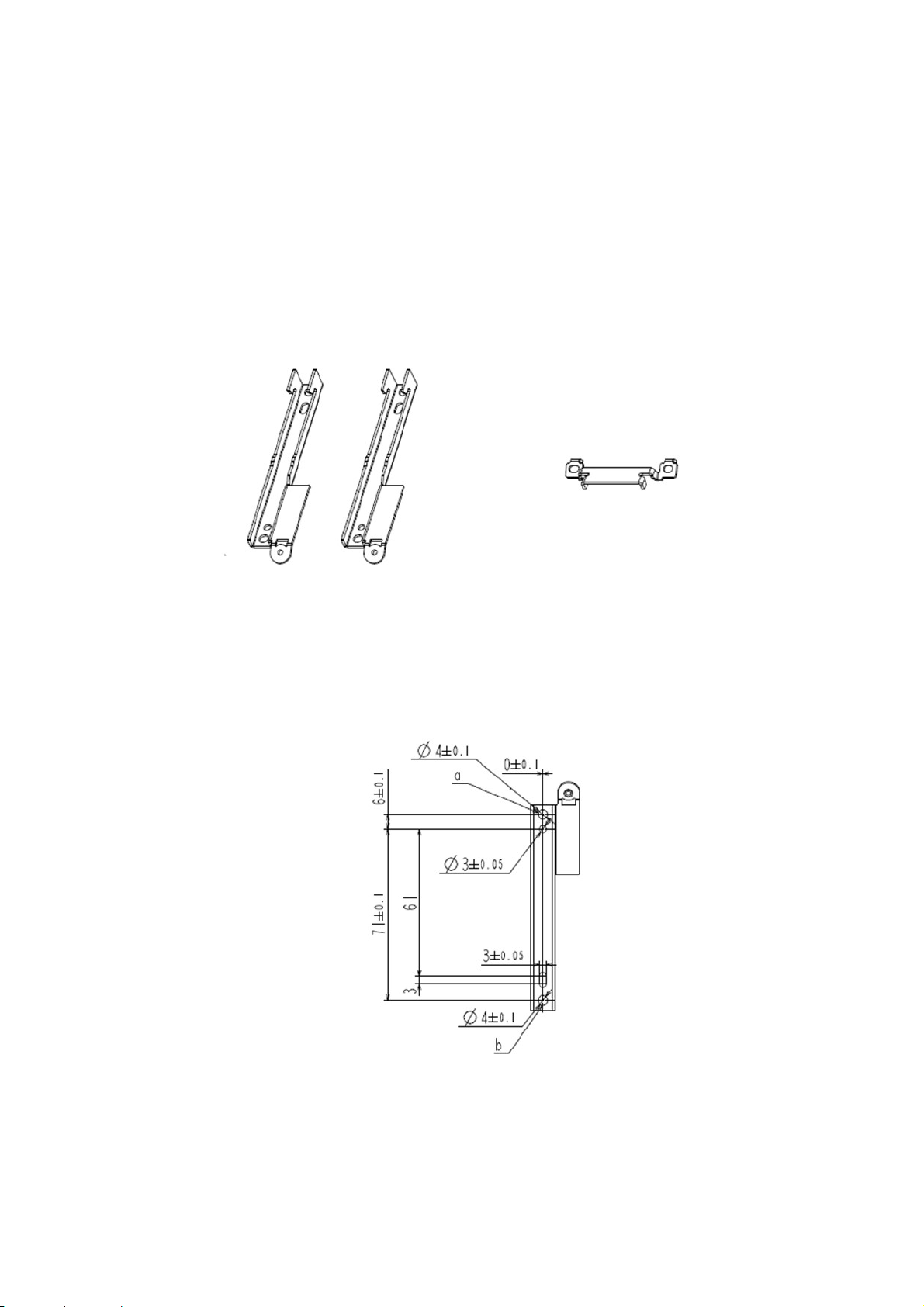
Appendix M PRINTER INSTALLATION DESIGN GUIDE
M.1 Notes on Printer Installation
Take into consideration paper ejection and dropping performance when designing the printer's paper discharge
port.
Because plated steel is used in this product, edges may be subject to rust.
Shape details may differ slightly from the actual parts.
When installing the printer, use brackets that come with the product.
Brackets include two equipment mounting brackets and one product fixing bracket for fastening the brackets to
the EU-m30.
Figure M.1 Equipment Mounting Brackets Figure M.2 Product Fixing Bracket
The two equipment mounting brackets are fastened to the equipment with two screws (a, b).
For the mounting position, see the drawings in M.2 Bezel Option Not Equipped and M.3 Bezel Option
Equipped.
Figure M.3 Equipment Mounting Bracket: Installation Point Dimensions
63
Page 71
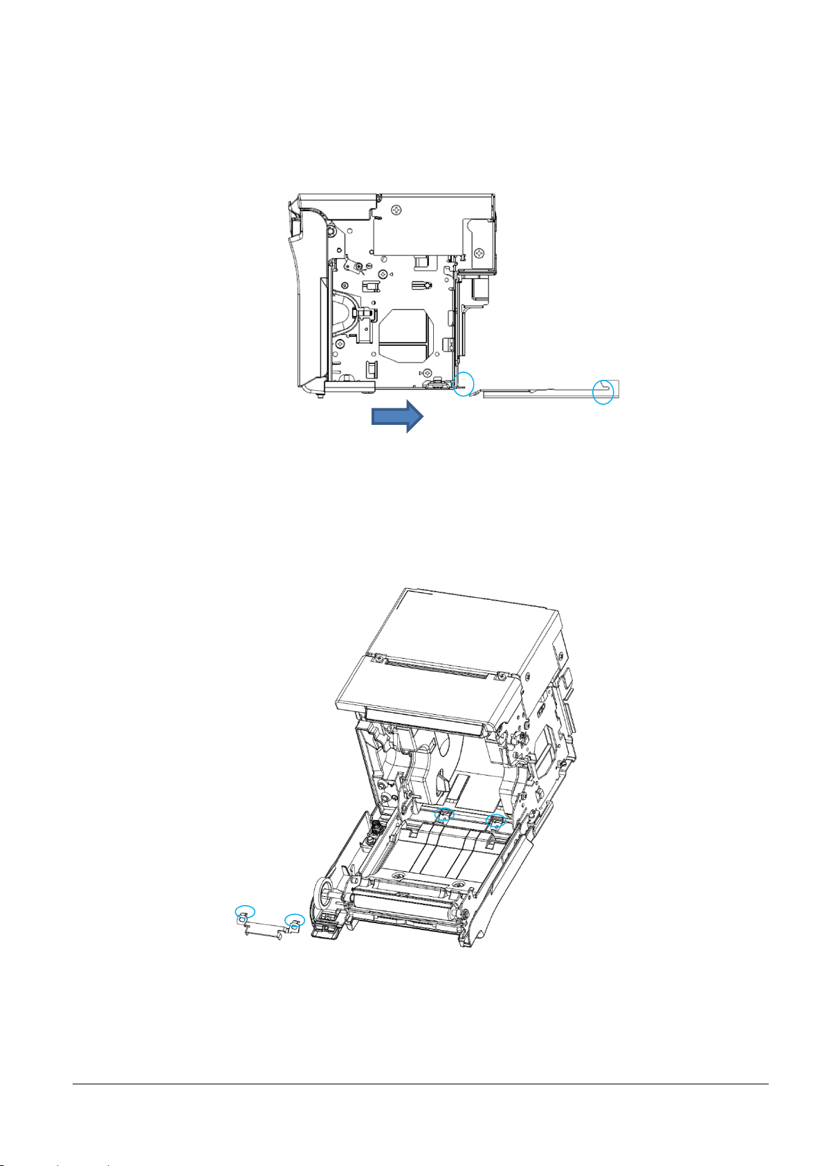
Fasten the two equipment mounting brackets, insert the printer from the interface side, and align the position
such that the printer and bracket engagement points.
Figure M.4 Positioning the Printer
Insert the protrusions of the product fixing bracket into the equipment mounting bracket holes, and fasten with
screws.
Figure M.5 Installation of Product Fixing Bracket
64
Page 72
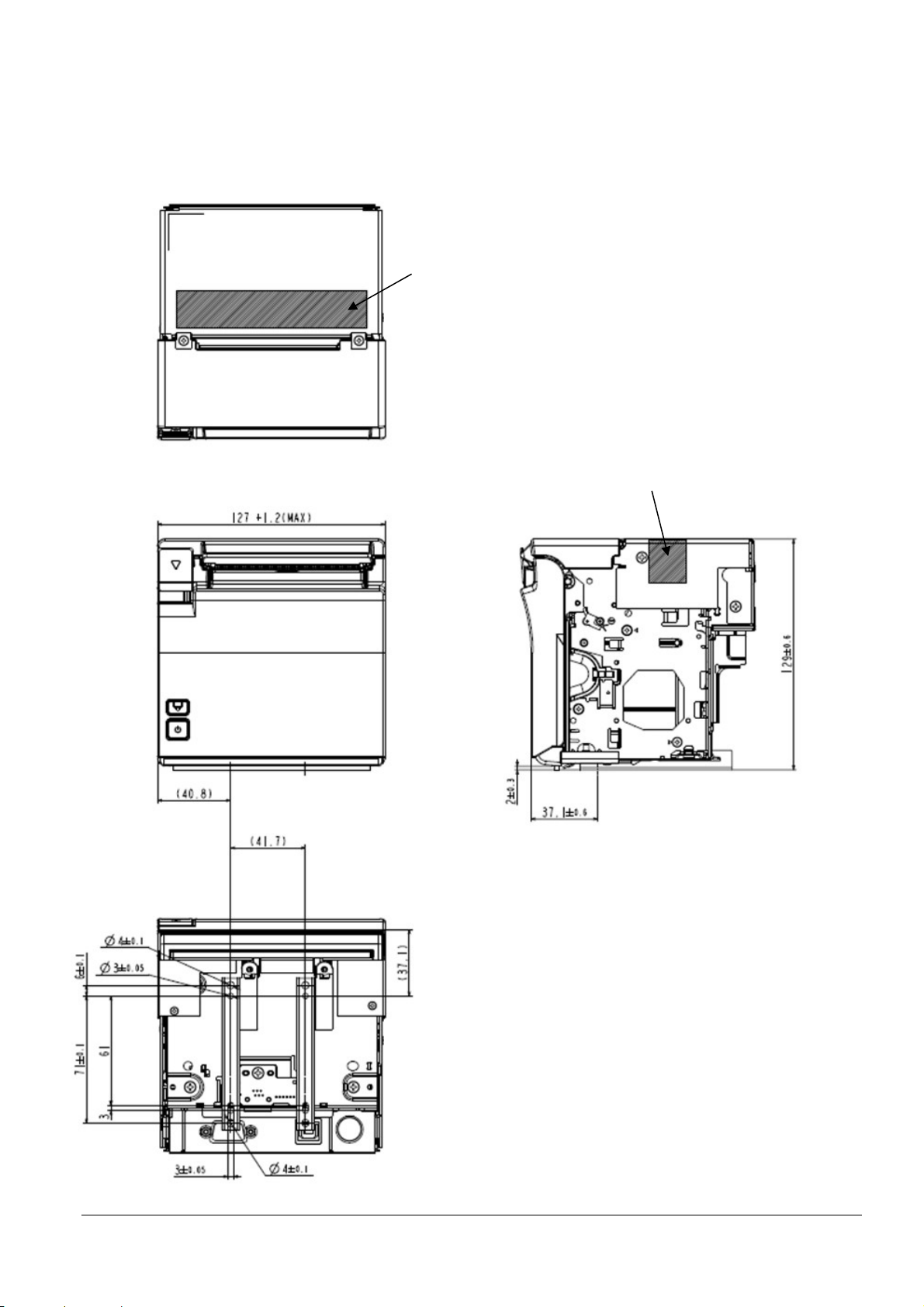
M.2 Bezel Option Not Equipped
X direction: Printer support
Z direction: Printer support
X direction: Printer support
If impact may possibly be applied, provide support for the printer on the equipment side.
65
Page 73

Y direction: Printer support
X direction: Printer support
66
Page 74

M.3 Bezel Option Equipped
Z direction: Printer support
X direction: Printer support
If impact may possibly be applied, provide support for the printer on the equipment side.
67
Page 75

Y direction: Printer support
X direction: Printer support
68
Page 76

Appendix N INSTALLING THE POWER SWITCH AND POWER/FEED SWITCH COVER
Figure N.1
N.1 Installing the Switch Cover
Step 1: Clean the area around the switch.
Step 2: Peel off the switch cover's double-sided adhesive tape, and affix such that the switch cover's rear
protrusions enter the power switch's recesses.
Figure N.2
69
Page 77

Appendix O REPLACEMENT FOR SMALL COVER OPEN LEVER
To prevent malfunction, the cover open lever can be replaced with the included small cover open lever.
O.1 Replacement for Small Cover Open Lever
Step 1: Check that the printer's power is off, then open the roll paper cover.
Step 2: Press down on the cover open lever and remove the cover open lever screw.
Step 3: Pull the cover open lever out from the metal sheet part.
Figure O.1
Step 4: Insert the small cover open lever into the metal sheet part.
Step 5: Fasten the small cover open lever with the screw removed in step 2.
Figure O.2
Step 6: Set the roll paper.
Step 7: Close the roll paper cover, then turn the printer power on.
70
Page 78

Appendix P BEZEL OPTION (OT-BU30)
Sharp edge
Figure P.1
Figure P.2
P.1 Notes on Using the Bezel Option (OT-BU30)
1) A bezel option (OT-BU30) can be used with this printer.
2) If using the bezel option (OT-BU30), the printer's paper can only be ejected in the front direction.
3) Confirm that there is enough space even when the printer's roll paper cover is open.
P.2 Installing the Bezel Option (OT-BU30)
Step 1: Check that the printer's power is off, then open the roll paper cover.
Step 2: zRemove the screws that fasten the case containing the indicators.
Step 3: Remove the case containing the indicators.
Step 4: Install the case containing the indicators on top of the bezel option.
Note:
The sharp edge can cut your fingers.
Install the case without touching the sharp edge.
Step 5: Close the roll paper cover.
Step 6: Clean the roll paper cover.
Step 7: Peel off the backing from the tape attached to the part at the bottom of the bezel option. Then attach it
such that the side of the bezel option fits in the ribs of the roll paper cover's paper discharge port.
71
Page 79

Figure P.3
72
Page 80

Appendix Q RECOMMENDED POWER SUPPLY
A power supply with a rating of 24 V/2.1 A or higher (50.6 W or higher) is recommended.
If a power supply less than 24 V/2.1 A (less than 50.6 W) is used, printing may temporarily stop and uneven
print density may occur.
Incidentally, by using customized value settings GS ( E (fn = 5) and lowering the power supply capacity
setting, you can reduce temporary printing stoppages and uneven print density occurrences. See
Appendix L for details.
73
Page 81

Appendix R PRINTER UNIT HANDLING
R.1 When purchasing this product
To prevent static electricity damage to thermal head elements and IC sensors, take steps to prevent static
electricity and ensure that your body is grounded before handling the product.
To prevent malfunction and static electricity damage to thermal head elements and IC sensors, ensure that the
frame (casing) is properly grounded before installing the product.
R.2 Notes on use
This printer uses a line thermal head. For longer head life, avoid using in areas that are noticeably dirty and
dusty.
Since a thermal head is used with this printer, do not expose it to condensation.
If condensation is on the product, do not turn on the power until the condensation is gone.
R.3 Prohibitions
Do not touch thermal head elements, driver ICs, and connectors directly with your fingers, a screwdriver,
tweezers, etc.
Protect the thermal head surface from mechanical stress and impacts (including friction from particles).
During operation and right after the end of operation, do not directly touch areas near the thermal head and
motor.
Keep contaminants from adhering to the thermal paper and platen.
Do not apply excessive force to the connectors.
R.4 When not using for a long period
If roll paper is left set for a long period, it may discolor or fade, and may stick to the platen. Also, deformation
of the platen rubber may cause some printing to lighten.
R.5 When using at low temperature
When printing starts (particularly at low temperature), the initial printing may be somewhat light due to the
head being cold.
R.6 When using at high temperature
When printing at high temperature, print bleeding or other print quality problems may occur.
74
Page 82

Appendix S Application Development Information
This chapter describes how to control the printer and gives information useful for printer application development.
S.1 Controlling the Printer
The printer supports the following command systems:
ESC/POS
Users can control the printer by using the aforementioned commands, or the following development kits or drivers.
Epson ePOS SDK for Android
OPOS ADK
OPOS ADK for .NET
JavaPOS ADK (Windows)
EPSON Advanced Printer Driver (APD)
EPSON TM Virtual Port Driver
S.1.1 ESC/POS
ESC/POS is the Epson original printer command system for POS printers and customer display. With ESC/POS
commands, you can directly control all the printer functions, but detailed knowledge of printer specifications or
combination of commands is required, compared to using drivers and applications.
For detailed information about ESC/POS commands, see the ESC/POS Command Reference that can be accessed
from the following URL.
www.epson-biz.com/pos/reference/
S.2 Controlling the Cash Drawer (Model for specified customer only)
A pulse output is sent to drawer kick connector pin 2 or pin 5, and you can open the drawer.
You can also check the open/close status of the drawer by checking the signal level of the drawer kick connector pin
3.
These controls are executed by a driver or by commands.
Note: Whether or not pin 2 or pin 5 operates the drawer kick connector depends on the connected cash drawer.
S.2.1 ESC/POS Commands
Prepare the output command for the specified pulse and the status transmission command. For details, see the
ESC/POS Command Reference.
S.2.2 For Windows Printer Drivers (APD)
You can set the drawer to open when printing is started. For details, see the manual for drivers. For details on
control, see the manual for Status API of the driver.
S.2.3 OPOS (OCX Driver)
Register a cash drawer using the SetupPOS Utility, and control using the OpenDrawer method or the DirectIO
function.
For details, see the "EPSON OPOS ADK MANUAL APPLICATION DEVELOPMENT GUIDE Cash Drawer" and
the "UnifiedPOS Specification". You can acquire documents regarding the UnifiedPOS from the following link.
https://www.omg.org/retail/unified-pos.htm
S.2.4 OPOS for .NET
Register a cash drawer using the SetupPOS Utility, and control using the OpenDrawer method or the DirectIO
function.
75
Page 83

For details, see the "EPSON OPOS ADK for .NET MANUAL Application Development Guide Cash Drawer
(EPSON Standard)" and the "UnifiedPOS Specification". You can acquire documents regarding the UnifiedPOS
from the following link.
https://www.omg.org/retail/unified-pos.htm
S.2.5 Epson ePOS SDK for Android
The output command for the drawer kick pulse and the status transmission command are provided in each SDK
library. For details, see the user's manuals provided with each SDK.
S.3 Controlling the Optional External Buzzer (Model for specified customer only)
You can set the optional external buzzer to buzz when an error occurs and when an automatic cut off occurs. By
using the driver or the command, you can specify when to sound the buzzer.
In addition, the beep pattern and how many times to sound the buzzer can be changed.
S.3.1 ESC/POS Command
Use the buzzer control command or the output command for the specified pulse. For details, see the ESC/POS
Command Reference.
S.3.2 For Windows Printer Drivers (APD)
Use the DirectIO function or the API for opening the drawer. For details, see the manual for Status API of the
drivers.
S.3.3 OPOS (OCX Driver)
Register a POS printer using the SetupPOS Utility and control using the DirectIO function.
For details, see the "EPSON OPOS ADK MANUAL APPLICATION DEVELOPMENT GUIDE POSPrinter
(TM Series)".
S.3.4 OPOS for .NET
Register a POS printer using the SetupPOS Utility and control using the DirectIO function.
For details, see the "EPSON OPOS ADK for .NET MANUAL Application Development Guide POSPrinter".
S.3.5 Epson ePOS SDK for Android
The command for the buzzer function is provided in each SDK library. For details, see the user's manuals provided with each SDK.
76
Page 84

S.4 Software
Software
Description
TM printers from native applications of
The following software is provided for application development.
S.4.1 Development Kit
Epson ePOS SDK for Android This is a development kit for controlling
smart devices. This includes libraries, manuals, and sample programs.
EPSON OPOS ADK This OCX driver can control POS peripherals using OLE technology. *1
Because controlling POS peripherals with original commands is not required on
the application side, efficient system development is possible.
EPSON OPOS ADK for .NET The OPOS ADK for .NET is a POS industry standard printer driver compatible
with Microsoft POS for .NET. It allows you to develop applications that are
compatible
with the UPOS (Unified POS) specification. When developing applications,
use a separate development environment such as Microsoft Visual Studio .NET.
EPSON JavaPOS ADK
(Windows)
JavaPOS is the standard specification which defines an architecture and device
interface (API) to access various POS devices from a Java based system. Using
JavaPOS standard API allows control with Java based applications of functions
inherent to each device. A flexible design with Java language and JavaPOS
enables many different types of computer systems, such as stand alone or
network configuration, to use a same application. You can use JavaPOS to
build applications and drivers independently of platforms. This allows flexible
configurations using thin clients to meet the system requirements.
*1: OLE technology developed by Microsoft divides software into part blocks. The OPOS driver is presupposed
to be used with a development environment, such as Visual Basic, unlike ordinary Windows printer drivers.
It is not a driver to be used for printing from commercial applications. You can acquire documents regarding
the UnifiedPOS from the following link.
https://www.omg.org/retail/unified-pos.htm
S.4.2 Drivers
Software Description Operating
EPSON Advanced
Printer Driver
(APD)
EPSON TM Virtual
Port Driver
In addition to ordinary Windows printer driver functions, this driver
has controls specific to POS. The Status API (Epson original DLL) that
monitors printer status and sends ESC/POS commands is also
attached to this driver.
This is a serial/parallel-USB/LAN conversion driver to make an Epson
TM/BA/EU printer connected via USB or LAN accessible from a POS
application through a virtual serial or parallel port. It allows you to
directly control devices connected via USB or LAN with ESC/POS
commands without making changes in the POS application that
controls devices connected via a serial or parallel interface.
environment
Windows
Windows
77
Page 85

S.4.3 Utilities
EU-m30 Utility
A utility for checking and changing various printer settings. Use this
Windows
Software Description Operating
Epson TM Utility A utility that is available on the App Store or Google Play. Use this to
perform wireless connection setup and change settings on the printer
from iOS and Android devices.
In addition, the utility has the following functions.
Sample receipt printing
Printer status display
Quick pairing by QR code
Firmware update
utility to:
Check the current settings
Test operation
Store logos
Set paper saving
Set printing control
Set communication interfaces
Configure the network settings
Configure the TM-Intelligent function settings
Save/restore settings
Deployment Tool Use to make network and printer settings simultaneously. Allows
you to make settings efficiently at the time of introducing TM printers
for the first time, or when configuring multiple TM printers at the
same time.
Monitoring Tool Use to check a list of status for the Epson printers connected to the
network. You can also update certificates for multiple printers used
for WPA-Enterprise in a batch.
EU-m30
Firmware Updater
Use this tool to update the printer's firmware.
An executable file and the firmware are packaged together.
environment
Android
Windows
Windows
Windows
S.4.4 Download
You can obtain software and manuals from one of the following URLs. For customers in North America, go to the
following web site:
→ www.epson.com/support/
For customers in other countries, go to the following web site:
→ www.epson-biz.com/
78
 Loading...