

Page 1

ESC/VP Level 6 Serial Communication Manual (Abridged Edition)
ESC/VP Level 6 Serial Communicat ion Manual (Abridged Edit ion) Ver.3
Table of Contents
REVISION STATUS.................................................................................................................................................... 2
1. OUTLINE ................................................................................................................................................................ 2
2. APPLICATION........................................................................................................................................................ 2
3. SERIAL COMMUNICATION SPECIFICATIONS ................................................................................................... 3
[Communication Conditions]
[Connectors]
[Serial cable connection diagram]
4. COMMAND TYPES ................................................................................................................................................ 4
5. COMMAND STRUCTURE...................................................................................................................................... 5
6. CONTROL CODE................................................................................................................................................... 9
00 SPECIAL CONTROL...............................................9
03 : Power
06 : Communication rate
09 : Lamp Hour
12 : Error information
16 : Key codes
01 SCREEN CONTROL.............................................11
00 : Input Source
01 : Input mode
02 : Freeze
03 : A/V Mute
02 AUDIO CONTROL.................................................12
00 : Volume
06 : Bass
07 : Treble
08 : SRS SPACE
09 : SRS CENTER
03 PC CONTROL.......................................................13
00 : Brightness
01 : Contrast
02 : Sync.
03 : Tracking
0D : Sharpness
0E : Input Resolution
12 : Automatic setup
04 VIDEO CONTROL.................................................15
00 : Brightness
01 : Contrast
02 : Sharpness
03 : Saturation
04 : Tint
05 : Video Mode
06 : Smooth Motion
05 DISPLAY CONTROL.............................................17
02 : Rear Proj.
03 : Ceiling
06 OPTION.................................................................18
03 : Source Prompt
04 : Blank
09 : BNC Input Source Type
0F : Keystone
10 : Start up Screen
11 : Message
14 : V Keystone
15 : DelayON
16 : Comp1/DV1 selection
19 : Computer2 input format
07 CUSTOM...............................................................20
08 : PinP
09 : PinP audio selection setting
1 of 20
Page 2

ESC/VP Level 6 Serial Communication Manual (Abridged Edition)
REVISION STATUS
Revision Issued Date Description
1 2001.1.15 First Release
2 2001.4.27 Clerical error correction. The power on command of EMP-7600/5600.
3 2001.8.10 Addition audio control commands
1. OUTLINE
This manual describes the ESC/VP Level 6 protocol for communication with projectors manufactured by Seiko Epson.
The manual is an abridged edition which summarizes the most commonly-used functions.
If further details ar e required, please refer to the full edition of the manual.
2. APPLICATION
This manual applies to the following models.
[Applicable models]
• EMP-8100/9100
• EMP-8150
• EMP-7700/7600/5600
2 of 20
Page 3

ESC/VP Level 6 Serial Communication Manual (Abridged Edition)
3. SERIAL COMMUNICATION SPECIFICATIONS
The projectors can be controlled by connecting a serial cable to the projector (Mouse/Com port) and a computer so that ESC/VP
commands can be sent from the computer to the projector.
[Communication Conditions]
• Communication Speed Standard speed: 9600 bps (EMP-8100/9100/8150/7700: 9600 to 57600 bps)
(EMP-7600/5600: 9600 to 38400 bps)
• Bit length 8 bit
• Parity None
• Stop bit 1 bit
• Flow control Hardware (DTR/DSR)
[Connectors]
Connector type: D-sub 9pin
(The pins which are a ctu all y use d are the fiv e p ins fro m 2 to 6 . Th es e pi ns are use d to send and receive data, for flow control and
for grounding.)
Projector PC
8
9
12
13
(RS-232C D- sub 9pin)
[Serial cable connection diagram]
<EMP-8100/8150/9100>
(Projector) (Main cable) (Computer serial cable) (PC)
GND 13 5 5 5 GND
RD 9 2 2 3 TD
TD 8 3 3 2 RD
DTR 10 4 4 6 DSR
DSR 11 6 6 4 DTR
<EMP-7700/7600/5600>
(Projector) (Main cable) (PC) Signal Function
GND 5 5 GND GND
RD 2 3 TD TD
TD 3 2 RD RD
DTR 4 6 DSR DSR
DSR 6 4 DTR DTR
List of Signal Function
Ground
Data trans m i ssion
Data reception
Data set ready
Data terminal ready
3 of 20
Page 4

ESC/VP Level 6 Serial Communication Manual (Abridged Edition)
4. COMMAND TYPES
The types of commands used can be divided into apply commands and reply commands. Both of these command types can be
further divided into setting commands, acquisition commands and initialization commands. Apply commands are used to make
settings, acquire information and carry out initialization, and reply commands provide responses to apply commands.
Sending Receiving
Apply command
Reply command
Figure 4-1. Apply/Reply Command
The table below gives details on each command.
Table 4-1. Details on each command
Command Types Caption
Apply command Set/Report/Indicate/Request Sets, reports, indicates and requests values
Get Gets the current value.
Initialize Initializes a value.
Package Command which combines the attributes of setting, reporting, indicating and requesting
Reply command Set/Report/Indicate/Request Response to an apply command for setting, reporting, indicating or requesting
Get Return Packet for getting
Initialize Return Packet for initializing
Package Response to a package apply command
Alert Alert response to apply commands
4 of 20
Page 5
ESC/VP Level 6 Serial Communication Manual (Abridged Edition)
5. COMMAND STRUCTURE
• ECommands are expressed as hexadecimal codes.
• All commands start with an ID code and end with a checksum.
When an ESC/VP command which is sent from the computer is received by the projector, a reply is returned.
However, the replies w hich a r e ret urne d by the proj ec tor o nly in dic ate w het her th e in iti al c om m and was re ce iv ed by the projector,
and do not indicate whether the command was executed or not.
Acquisition commands are sent in order to check the execution of a command.
In addition, if the next command is sent before the reply to a previous command has been received from the projector, it may
result in a communication error.
The command structure is shown below.
bytes.
* Command layout is BigEndian.
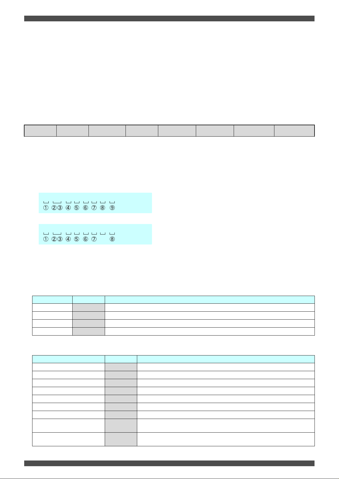
(1) STX
(2) Size (3) Attribute (4) FromTo (5) Group (6) Item (7) Parameter (8) Check Sum
* The maximum length for a command is 1024
(1) STX
: 0x1D (1 byte)
(2) Size
: Size of a command packet (Specifies a number of the data from 1D to CS) (2 bytes)
Example) To turn the power on over a serial connection
1D 000x 01 01 00 03 01 CS
---> 0x0009
Example) To check the power status over a serial connection
1D 000x 02 01 00 03 01 CS
---> 0x0008
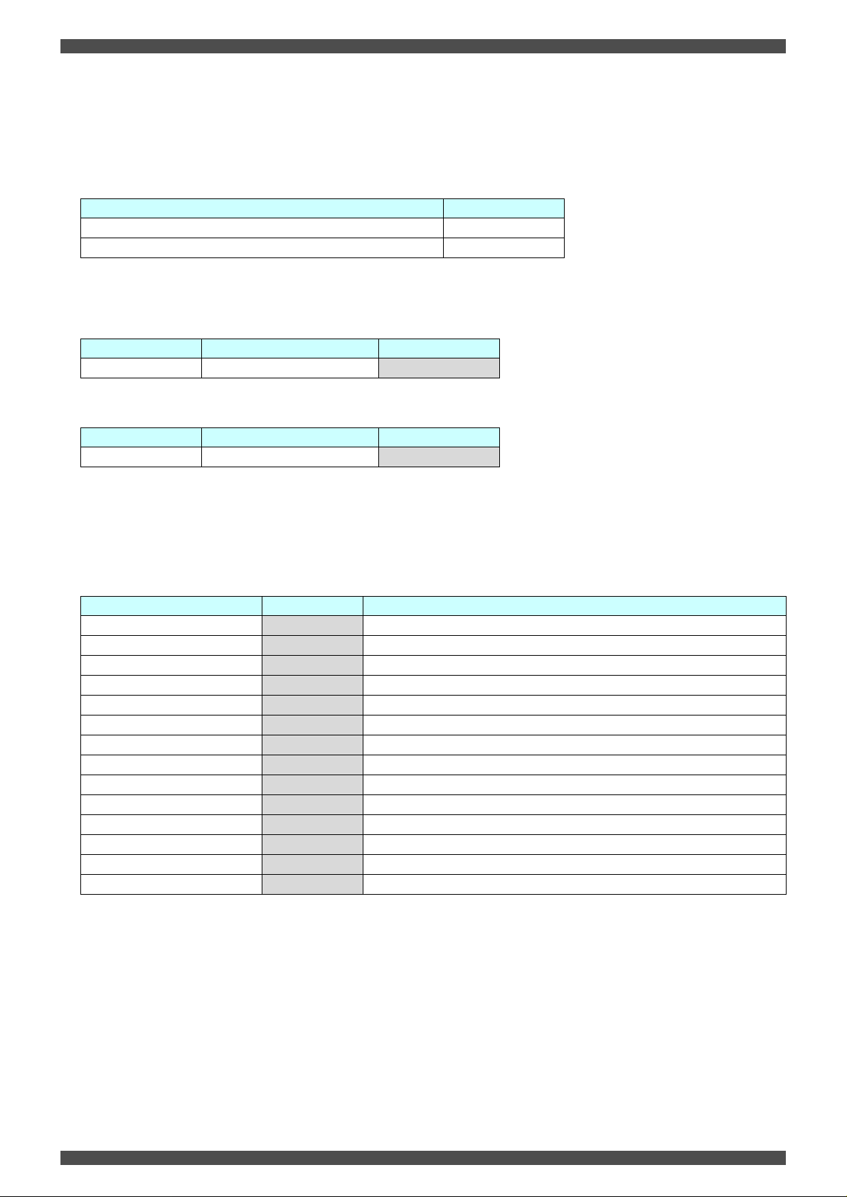
(3) Attribute
: Indicates attributes such as apply command/reply command, OK/Not OK, etc. (1 byte)
The attribute codes are shown below.
Table 5-1. Attribute of the Apply command
Attribute Attribute code Caption
Set 0x01 Sets, reports and indicates values.
Get
Initialize
Package
0x02 Gets the current value.
0x03 Initializes a value.
0x05 Command which combines the attributes of setting, reporting, indicating and requesting.
Table 5-2. Attribute of the Reply command
Attribute Attribute code Caption
Return Packet for setting (OK) 0x81 Indicates that the set command received was analyzed correctly.
Return Packet for setting (NG)
Return Packet for getting (OK)
Return Packet for getting (NG)
Return Packet for initializing (OK)
Return Packet for initializing (NG)
Response to package (OK)
Response to package (not OK)
Alert response to commands
0xC1 Indicates that the set command received was not analyzed correctly.
0x82 Indicates that the get command received was analyzed correctly.
0xC2 Indicates that the get command received was not analyzed correctly.
0x83 Indicates that the initialize command received was analyzed correctly.
0xC3 Indicates that the initialize command received was not analyzed correctly.
0x85 Indicates that the combined attribute command received has been parsed correctly.
0xC5
0x8F
Indicates that the combined attribute command received has not been parsed correctly.
Indicates that the command received contained an error and could not be parsed correctly.
5 of 20
Page 6
ESC/VP Level 6 Serial Communication Manual (Abridged Edition)
(4) FromTo
: Specifies the sending and receiving ends of the FromTo command. (1 byte)
Indicates sending end between 7th and 4th bit and receiving end between 3rd to 0th bit.
The basic FromTo combination is shown below.
Table 5-3. List of FromTo codes (bit)
Machines Code (bit)
PC (RS-232C communication) 0x00
Master projector or stand-alone projector 0x01
The apply/reply codes using FromTo combinations are shown below.
Table 5-4. List of FromTo codes for apply commands
From To Apply
PC (Serial) Projector (Master) 0x01
Table 5-5. List of FromTo codes for reply commands
From To Reply
PC (Serial) Projector (Master) 0x10
(5) Functional Classification (Group)
: Represents the functional classification as classification codes. (1 byte)
Table 5-6. List of Functional Classification
Functional classifi cation Group Code Caption
Special control (Special) 0x00 Performs switching and resetting the operating mode.
Screen control (Screen)
Audio control (Audio)
PC control (PC)
VIDEO control (Video)
Display control (Display)
Option (Option)
Custom (Custom)
Reserved
Reserved
Reserved
Reserved
Stack control (Stack)
Reserved
* Refer to the full manual if using stack control.
0x01 Controls the display screen.
0x02 Controls the audio.
0x03 Controls PC's image quality.
0x04 Controls Video's image quality.
0x05 Controls the display.
0x06 Sets the additional functions for the whole projector.
0x07 Sets the additional functions that user can program.
0x08
0x09
0x0E
0x0F
0x10 Performs various kinds of controls of Stack.
0x20
6 of 20
Page 7

ESC/VP Level 6 Serial Communication Manual (Abridged Edition)
(6) Function (Item)
: ESC/VP functions and the classification code for those are as follows. (1 byte)
Table 5-7. List of Function
Functional
classification
Special Control
(Special)
Screen Control
(Screen)
Audio Control
(Audio)
PC Control (PC)
Grou
p
Code
0x00
0x01
0x02
0x03
Function
Power
Communication rate
Initialize all
Lamp on
Cursor Speed
Password
Error Information
Administrator Log on
Administrator Log off
Key code
Serial command
Max/Min
Alert
Product ID
Software version
Protocol version
Input source
Input mode
Freeze
A/V Mute
Volume
Bass
Treble
SRS SPACE
SRS CENTER
Brightness
Contrast
Sync.
Tracking
Get tracking base
Get PC Frequency
Get Resolution
Sharpness
Resolution
Preset
Automatic setup
Automatic black level adjustment
Automatic white level adjustment
Item
Code
0x03
0x06
0x07
0x09
0x10
0x11
0x12
0x13
0x14
0x16
0x17
0x18
0x19
0x20
0x21
0xFF
0x00
0x01
0x02
0x03
0x00
0x06
0x07
0x08
0x09
0x00
0x01
0x02
0x03
0x04
0x0A
0x0B
0x0D
0x0E
0x0F
0x12
0x13
0x14
Functional
classification
Video Control
(Video)
Display Control
(Display)
Option (Option)
Custom (Custom)
Stack Control
(Stack)
Grou
p
Code
0x04
0x05
0x06
0x07
0x10
Function
Brightness
Contrast
Sharpness
Color
Tint
Video mode
Smooth motion
Horizontal Position
Vertical Position
Rear Proj.
Ceiling
Color Temperature
Black Level
White Level
Auto color temperature
Select color temperature
Color temperature Red
Color temperature Green
Color temperature Blue
Language
Source Prompt
Blank
Set user gamma
BNC
Keystone
Startup screen
Message
Comp2 Sync termination
V keystone
DelayON
Comp1/DVI
Sleep Mode
Computer2 input format
PinP
PinP audio selection setting
Check Stack state
Check Stack
Lock/Unlock
Source changing
Item
Code
0x00
0x01
0x02
0x03
0x04
0x05
0x06
0x00
0x01
0x02
0x03
0x04
0x08
0x09
0x0A
0x0B
0x0C
0x0D
0x0E
0x00
0x03
0x04
0x08
0x09
0x0F
0x10
0x11
0x13
0x14
0x15
0x16
0x17
0x19
0x08
0x09
0x00
0x01
0x04
0x06
: Valid for Master projector or Stand-alone projector only
: Valid for Master projector only
: Commands listed in the abridged manual
7 of 20
Page 8

ESC/VP Level 6 Serial Communication Manual (Abridged Edition)
(7) Parameters
: Parameters differ for each command, so refer the separate descriptions for each command.
* In the case of items for which the setting range can be adjusted, the parameter values are the values in the table below
which have been converted to hexadecimal format.
-30 0 30
- +
E2 00 1E
Table 5-8. Hexadecimal conversion list
Decimal 1 2 3 4 5 6 7 8 9 101112131415161718192021222324252627282930
Hexadeci-
Decimal -1 -2 -3 -4 -5 -6 -7 -8 -9 -10 -11 -12 -13 -14 -15 -16 -17 -18 -19 -20 -21 -22 -23 -24 -25 -26 -27 -28 -29 - 30
Hexadeci-
* If a reply command contains an error attribute, the following parameter (2 bytes) is set.
Table 5-9. List of error parameters
01 02 03 04 05 06 07 08 09 0A 0B 0C 0D 0E 0F 10 11 12 13 14 15 16 17 18 19 1A 1B 1C 1D 1E
mal
FF FE FD FC FB FA F9 F8 F7 F6 F5 F4 F3 F2 F1 F0 EF EE ED EC EB EA E9 E8 E7 E6 E5 E4 E3 E2
mal
Parameters Error type Error condition
0x0001
0x0002
0x0003 Resource error Insufficient EasyMP.net resources.
0x0004 Download in progress Projector is in download mode.
0x0005 Setting not currently possible The apply command received cannot be processed.
0x0006 Lamp off Projector lamp is switched off.
0x0007
0x0008 EasyMP.net rebooting EasyMP.net is at end sequence.
0x0009 Status mismatch A command which was different from the expected command was received.
0x000A
0x000B
0x000C Locked An item which has been locked by the administrator (installer) was specified.
0x000D Not available for stack A command which cannot be used for a stack configuration was specified.
Network in use An attempt was made to communicate with the projector via a network connection, but
No applicable setting Parameter is outside the setting range and FromTo is incorrect.
Error between projector and
EasyMP.net
Projector error When too many retries or timeouts occur between master and slave projectors when
Network not connected An attempt at communication with the computer (network) was made, but no computer
another computer was already communicating with the projector.
Command is not supported, or unknown command.
When the command was sent via EasyMP.net and too many retries or timeouts occur
between EasyMP.net and the projector, it indicates an error upstream from EasyMP.net.
connected in a stack, it indicates an error upstream from the master projector.
(network) exists.
(8) Checksum
: Represent checksum (1 byte)
Checksum calculation method
All bytes of data from th e s ize to th e pa ram ete rs i s ad ded tog eth er, an d th e tw os co mp lem en t of t he result in hexadecima l fo rmat is subtracted from 0x0100 to obtain the checksum.
Example) For the command "1D 0007 01 10 00 02 0A CS"
0x00 + 0x07 + 0x01 + 0x10 + 0x00 + 0x02 + 0x0A = 0x24 ---> 0x0100 - 0x24 = 0xDC
8 of 20
Page 9

ESC/VP Level 6 Serial Communication Manual (Abridged Edition)
6. CONTROL CODE
00 SPECIAL CONTROL
Command
structure
Type
03 : Power
Controls the projector power and gets the present power state.
<In the case of a power on setup of EMP-7600/5600>
Set 1B 07 01 -- 00 03 01 F4 1B 06
<In cases other than a power on setup of EMP-7600/5600, and the case of EMP-8100/9100/8150/7700>
[Parameter]
Set 1D 0009 01 01 00 03
Get 1D 0008 02 01 00 03 -- CS 1D
06 : Communication rate
Controls the communication rate.
[Parameter]
Set
Get
Initialize 1D 0008 03 01 00 06 -- CS 1D
09 : Lamp Hour
Gets the present lamp hour.
[Parameter]
Get
12 : Error information
Gets and reports projector error information.
[Parameter]
Set
Get
STX Size
Data relating to the power states.
0x00: PowerOFF
0x01: PowerON
0x02: Suspend
0x10: During Startup
0x11: Cool down
0x20: System fault
Data relating to communication rate.
<For EMP-8100/9100/8150/7700>
0x00: 9600bps
0x01: 19200bps
0x02: 38400bps
0x03: 57600bps
1D 0009 01 01 00 06 PAR A CS 1D
1D 0008 02 01 00 06 -- CS 1D
Returns the present lamp hour (in hours) (2 bytes)
1D 0008 02 01 00 09 -- CS 1D
Projector error information
The following data is set with an OR:
0x00: No error or error is cancelled.
0x01: Fan problem
0x04: Internal temperature is abnormally high.
0x08: Lamp life expectancy is closed to end.
0x20: Lamp problem
0x40: Other failures
0x80: Stack failure (EMP-8100/8150/9100 only)
1D 0009 01 01 00 12 -- CS 1D
1D 0008 02 01 00 12 -- CS 1D
AttributeFrom
Apply Reply
Param
Group Item
To
* Although setting 0x02 and later in parameter and sending command to the projector, returns NG
in replay. 0x02 and later are available just for informing from the projector.
}
Check-
eter
00
01
<For EMP-7600/5600>
0x00: 9600bps
0x01: 19200bps
0x02: 38400bps
STX Size
sum
CS 1D
AttributeFrom
81
C1
0008
000A81C1
0009
000A82C2
0008
000A81C1
0009
000A82C2
0009
000A83C3
000A
000A82C2
0008
000A81C1
0009
000A82C2
Param
Group Item
To
-- 00 03 -- CS
10 00 03
10 00 03 PARA CS
10 00 06
10 00 06 PARA CS
10 00 06 PARA CS
10 00 09 PARA CS
10 00 12
10 00 12 PARA CS
eter
--
PARA
--
PARA
--
PARA
Check-
sum
CS
CS
CS
9 of 20
Page 10

00 SPECIAL CONTROL
Command
structure
Type
16 : Key codes
Controls the key codes.
[Parameter]
STX Size
Key attribute length, key attribute, key code length, key code and reserved space are returned in order (12 bytes).
ESC/VP Level 6 Serial Communication Manual (Abridged Edition)
Apply Reply
AttributeFrom
To
Group Item
Param
eter
Check-
sum
STX Size
AttributeFrom
To
Group Item
Param
eter
Check-
sum
Set
Key attribute length
Key attribute
: Size of the key attribute (2 bytes)
: Indicates whether following bits are ON or OFF (2 bytes)
Bit 0: 0 = key OFF, 1 = key ON
Bit 1: 0 = shift key OFF, 1 = shift key ON
Key code length
Key code
0x0001: Power
0x0002: reserved
0x0100: Source
0x0101: Computer
0x0102: Computer-P
0x0103: DVI
0x0104: Computer2
0x0110: Video
0x0111: S-Video
0x0112: Video-P
0x0113: BNC
0x0120: EasyMP.net
0x0200: Menu
: Size of key code (2 bytes)
: (2 bytes)
0x0201: HEMP
0x0202: Enter
0x0203: ESC
0x0300: Auto
0x0301: Tracking+
0x0302: Tracking0x0303: Sync+
0x0304: Sync0x0500: F1
0x0501: F2
0x0502: F3
0x0503: F4
0x0504: F5
Reserved: 0x00000000 (4 bytes)
1D 0014 01 01 00 16 PARA CS 1D
0x0600: Left mouse button click
0x0601: Right mouse button click
0x0700: Volume+
0x0701: Volume0x0702: A/V Mute
0x0703: Zoom+
0x0704: Zoom0x0705: Resize
0x0706: Freeze
0x0707: PinP
0x0708: Preset
0x0709: Keystone+
0x070A: Keystone-
0008
000A81C1
10 00 16
--
PARA
CS
10 of 20
Page 11

ESC/VP Level 6 Serial Communication Manual (Abridged Edition)
01 SCREEN CONTROL
Command
structure
Type
STX Size
AttributeFrom
00 : Input Source
Controls the input source
[Parameter]
Data relating to input source.
<For EMP-8100/8150/9100/7700>
0x10: PC1
0x20: Reserved
0x21: Video (Composite)
0x22: Video (S)
0x30: BNC (RGB)
0x40: BNC (YCrCb)
0x50: DVI
0xE1: Reserved
0xE2: EasyMP.net
Set
Get
Initialize
1D 0009 01 01 01 00 PARA CS 1D
1D 0008 02 01 01 00 -- CS 1D
1D 0008 03 01 01 00 -- CS 1D
01 : Input mode
Controls the input mode.
[Parameter]
Data relating to input mode
0x00: No mode (NoSignal)
0x01: PC
0xE0: NTSC
0xE1: NTSC4.43
0xE2: PAL
0xE3: PALN
Set
Get
1D 0009 01 01 01 01 PARA CS 1D
1D 0008 02 01 01 01 -- CS 1D
02 : Freeze (* Only valid for Standalone/Master projector)
Controls the Freeze.
Freeze ON: Freezes the image.
[Parameter]
Data relating to Freeze
0x00: Freeze OFF
0x01: Freeze ON
0x02: Toggle switch
Set
Get
Initialize
1D 0009 01 01 01 02 PARA CS 1D
1D 0008 02 01 01 02 -- CS 1D
1D 0008 03 01 01 02 -- CS 1D
03 : A/V Mute (* Only valid for Standalone/Master projector)
Controls the A/V Mute.
A/V Mute ON: Temporarily mutes the umage and sound.
[Parameter]
Data relating to A/V Mute
0x00: A/V Mute OFF
0x01: A/V Mute ON
Set 1D 0009 01 01 01 03 PARA CS 1D
Get
Initialize
1D 0008 02 01 01 03 -- CS 1D
1D 0008 03 01 01 03 -- CS 1D
Apply Reply
Param
To
Group Item
eter
Check-
sum
STX Size
<For EMP-7600/5600>
0x10: PC1
0x11: PC2 (RGB)
0x12: Component Video (YCbCr)
0x13: Component Video (YPbPr)
0x21: Video (Composite)
0x22: Video (S)
0x50: DVI
0008
000A81C1
0009
000A82C2
0009
000A83C3
0xE4: PALM
0xE5: PAL60
0xE6: SECAM
0xE7: NTSC50
0xE8: YCrCb(50Hz)
0xEA: 480P
0xEB: 720P
0xEC: 1080I
0xED: 1080P
0xD0: Not Supported
0xE9: YCrCb(60Hz)
0008
000A81C1
0009
000A82C2
0008
000A81C1
0009
000A82C2
0009
000A83C3
0008
000A81C1
0009
000A82C2
0009
000A83C3
AttributeFrom
To
10 01 00
10 01 00 PARA CS
10 01 00 PARA CS
10 01 01
10 01 01 PARA CS
10 01 02
10 01 02 PARA CS
10 01 02 PARA CS
10 01 03
10 01 03 PARA CS
10 01 03 PARA CS
Group Item
Param
eter
--
PARA
--
PARA
--
PARA
--
PARA
Check-
sum
CS
CS
CS
CS
11 of 20
Page 12

ESC/VP Level 6 Serial Communication Manual (Abridged Edition)
02 AUDIO CONTROL
Command
structure
Type
STX Size
AttributeFromT
00 : Volume
Controls the volume for the currently-selected audio input.
[Parameter]
Volume Value (1 byte)
Setting range: 00 to 1F
Set
Get
Initialize
1D 0009 01 FT 02 00 PARA CS 1D
1D 0008 02 FT 02 00 -- CS 1D
1D 0008 03 FT 02 00 -- CS 1D
06 : Bass
Controls the bass for the currently-selected audio input.
[Parameter]
Bass Value (1 byte)
Setting range: FA to FF, 00 to 06
Set
Get 1D 0008 02 FT 02 06 -- CS 1D
Initialize 1D 0008 03 FT 02 06 -- CS 1D
1D 0009 01 FT 02 06 PARA CS 1D
07 : Treble
Controls the treble for the currently-selected audio input.
[Parameter]
Treble Value (1 byte)
Setting range: FA to FF, 00 to 06
Set
Get
Initialize
1D 0009 01 FT 02 07 PARA CS 1D
1D 0008 02 FT 02 07 -- CS 1D
1D 0008 03 FT 02 07 -- CS 1D
08 : SRS SPACE (Applicable models: EMP-8100/8150/9100)
Controls the SRS Space level for the currently-selected audio input.
Adjusts the width of hte sound.
[Parameter]
SRS SPACE Value (1 byte)
Setting range: 00 to 06
Set
Get 1D 0008 02 FT 02 08 -- CS 1D
Initialize 1D 0008 03 FT 02 08 -- CS 1D
1D 0009 01 FT 02 08 PARA CS 1D
09 : SRS CENTER (Applicable models: EMP-8100/8150/9100)
Controls the SRS Center level for the currently-selected audio input.
Adjusts the depth of the sound.
[Parameter]
SRS CENTER Value (1 byte)
Setting range: 00 to 06
Set 1D 0009 01 FT 02 09 PARA CS 1D
Get
Initialize
1D 0008 02 FT 02 09 -- CS 1D
1D 0008 03 FT 02 09 -- CS 1D
Apply Reply
Param
Group Item
o
eter
check-
sum
STX Size
AttributeFromT
0008
000A81C1
0009
000A82C2
0009
000A83C3
0008
000A81C1
0009
000A82C2
0009
000A83C3
0008
000A81C1
0009
000A82C2
0009
000A83C3
0008
000A81C1
0009
000A82C2
0009
000A83C3
0008
000A81C1
0009
000882C2
0009
000883C3
Param
Group Item
o
FT 02 00
eter
--
PARA
check-
sum
CS
FT 02 00 PARA CS
FT 02 00 PARA CS
FT 02 06
--
PARA
CS
FT 02 06 PARA CS
FT 02 06 PARA CS
FT 02 07
--
PARA
CS
FT 02 07 PARA CS
FT 02 07 PARA CS
FT 02 08
--
PARA
CS
FT 02 08 PARA CS
FT 02 08 PARA CS
FT 02 09
--
PARA
CS
FT 02 09 PARA CS
FT 02 09 PARA CS
12 of 20
Page 13

ESC/VP Level 6 Serial Communication Manual (Abridged Edition)
03 PC CONTROL
Command
structure
Type
STX Size
AttributeFrom
00 : Brightness
Controls the screen brightness for the currently-selected PC input source.
[Parameter]
Brightness Value (1 byte)
Setting range: E2 to FF, 00 to 1E
Set
Get
Initialize
1D 0009 01 01 03 00 PARA CS 1D
1D 0008 02 01 03 00 -- CS 1D
1D 0008 03 01 03 00 -- CS 1D
01 : Contrast
Controls the screen contrast for the currently-selected PC input source.
[Parameter]
Contrast Value (1 byte)
Setting range: E2 to FF, 00 to 1E
Set
Get 1D 0008 02 01 03 01 -- CS 1D
Initialize 1D 0008 03 01 03 01 -- CS 1D
1D 0009 01 01 03 01 PARA CS 1D
02 : Sync.
Controls the screen synchronization for the currently-selected PC input source.
Adjusts disturbance, blurring and vertical noise that appears on the Computer image.
[Parameter]
Sync. Value (1 byte)
Setting range: 00 to 3F
Set
Get
Initialize 1D 0008 03 01 03 02 -- CS 1D
1D 0009 01 01 03 02 PARA CS 1D
1D 0008 02 01 03 02 -- CS 1D
03 : Tracking
Controls the screen tracking for the currently-selected PC input source.
Adjusts vertical stripes that appear on the Computer image.
[Parameter]
Tracking Value (2 bytes)
Setting range: 80 to FF, 00 to 7F
Set
Get
Initialize 1D 0008 03 01 03 03 -- CS 1D
1D 000A 01 01 03 03 PARA CS 1D
1D 0008 02 01 03 03 -- CS 1D
0D : Sharpness
Controls the screen sharpness for the currently-selected PC input source.
[Parameter]
Sharpness Value (1 byte)
Setting range: FA to FF, 00 to 05
Set 1D 0009 01 01 03 0D PARA CS 1D
Get
Initialize
1D 0008 02 01 03 0D -- CS 1D
1D 0008 03 01 03 0D -- CS 1D
Apply Reply
Param
To
Group Item
eter
Check-
sum
STX Size
AttributeFrom
0008
000A81C1
0009
000A82C2
0009
000A83C3
0008
000A81C1
0009
000A82C2
0009
000A83C3
0008
000A81C1
0009
000A82C2
0009
000A83C3
0008
000A81C1
000A
000A82C2
000A
000A83C3
0008
000881C1
0009
000A82C2
0009
000A83C3
Param
Group Item
To
10 03 00
eter
--
PARA
Check-
sum
CS
10 03 00 PARA CS
10 03 00 PARA CS
10 03 01
--
PARA
CS
10 03 01 PARA CS
10 03 01 PARA CS
10 03 02
--
PARA
CS
10 03 02 PARA CS
10 03 02 PARA CS
10 03 03
--
PARA
CS
10 03 03 PARA CS
10 03 03 PARA CS
10 03 0D -- CS
10 03 0D PARA CS
10 03 0D PARA CS
13 of 20
Page 14

ESC/VP Level 6 Serial Communication Manual (Abridged Edition)
03 PC CONTROL
Command
structure
Type
STX Size
AttributeFrom
0E : Input Resolution
Controls the screen input resolution for the currently-selected PC input source.
[Parameter]
Input Resolution (1 byte)
0x00: AUTO
0x01: NTSC(I)
0x02: PAL(I)
0x03: 1024x768(I)
0x04: 1120X750(I)
0x05: 1280X1024(I)
0x06: 1600X1200(I)
0x07: 1920X1034(I)
0x08: 1920x1080(I)
0x09: 640x350
0x0A: 640x400
0x0B: 640x480/MAC13
0x0C: 480P
Set
Get
Initialize 1D 0008 03 01 03 0E -- CS 1D
1D 0009 01 01 03 0E PARA CS 1D
1D 0008 02 01 03 0E -- CS 1D
12 : Automatic setup (* Only valid for Standalone/Master projector)
Reports the start and end of automatic setup.
[Parameter]
Data relating to automatic setup status, horizontal resolution and vertical resolution are returned in that order.
Apply Reply
Param
Group Item
To
0x0D: 720x350
0x0E: 720x400
0x0F: 800x600
0x10: MAC16
0x11: 960x720
0x12: 720P
0x13: 1024x480
0x14: 1024x600
0x15: 1024x768
0x16: MAC19
0x17: 1024x1024
0x18: 1152x864
0x19: MAC21
0x1A: 152x900(1A)
eter
Check-
sum
STX Size
0x1B: 1280x960(1B)
0x1C: 1280x1024(1C)
0x1D: 1600x1024(1D)
0x1E: 1600x1200(1E)
0x1F: 1600x1280(1F)
0x20: 1920x1080
0x21: 1400x1050
0x80: Preset 1
0x81: Preset 2
0x82: Preset 3
0x83: Preset 4
0x84: Preset 5
0xA0: Custom 1
0xA1: Custom 2
0008
000A81C1
0009
000A82C2
0009
000A83C3
AttributeFrom
To
10 03 0E
10 03 0E PARA CS
10 03 0E PARA CS
Group Item
Param
eter
--
PARA
Check-
sum
CS
(1) Data relating to automatic setup status: (1 byte)
0x00: Start
0x01: Normal completion
0x02: Abnormal completion
(2) Horizontal resolution: (2 bytes)
Only valid at start. NULL is embedded at end.
(3) Vertical resolution: (2 bytes)
Only valid at start. NULL is embedded at end.
Set 1D 000D 01 01 03 12 PARA CS 1D
0008
000D81C1
10 03 12
--
PARA
CS
14 of 20
Page 15

ESC/VP Level 6 Serial Communication Manual (Abridged Edition)
04 VIDEO CONTROL
Command
structure
Type
STX Size
AttributeFrom
00 : Brightness
Controls the screen brightness for the currently-selected video input source.
[Parameter]
Brightness Value (1 byte)
Setting range: F1 to FF, 00 to 0F
Set
Get
Initialize
1D 0009 01 01 04 00 PARA CS 1D
1D 0008 02 01 04 00 -- CS 1D
1D 0008 03 01 04 00 -- CS 1D
01 : Contrast
Controls the screen contrast for the currently-selected video input source.
[Parameter]
Contrast Value (1 byte)
Setting range: F1 to FF, 00 to 0F
Set
Get 1D 0008 02 01 04 01 -- CS 1D
Initialize 1D 0008 03 01 04 01 -- CS 1D
1D 0009 01 01 04 01 PARA CS 1D
02 : Sharpness
Controls the screen sharpness for the currently-selected video input source.
[Parameter]
Sharpness Value (1 byte)
Setting range: FB to FF, 00 to 06
Set
Get
Initialize
1D 0009 01 01 04 02 PARA CS 1D
1D 0008 02 01 04 02 -- CS 1D
1D 0008 03 01 04 02 -- CS 1D
03 : Satura tion
Controls the screen saturation for the currently-selected video input source.
[Parameter]
Saturation Value (1 byte)
Setting range: F1 to FF, 00 to 0F
Set
Get 1D 0008 02 01 04 03 -- CS 1D
Initialize
1D 0009 01 01 04 03 PARA CS 1D
1D 0008 03 01 04 03 -- CS 1D
04 : Tint
Controls the screen tint for the currently-selected video input source.
[Parameter]
Tint Value (1 byte)
Setting range: F1 to FF, 00 to 0F
Set
Get
Initialize
1D 0009 01 01 04 04 PARA CS 1D
1D 0008 02 01 04 04 -- CS 1D
1D 0008 03 01 04 04 -- CS 1D
Apply Reply
Param
To
Group Item
eter
Check-
sum
STX Size
0008
000A81C1
0009
000A82C2
0009
000A83C3
0008
000A81C1
0009
000A82C2
0009
000A83C3
0008
000A81C1
0009
000A82C2
0009
000A83C3
0008
000A81C1
0009
000A82C2
0009
000A83C3
0008
000A81C1
0009
000A82C2
0009
000A83C3
AttributeFrom
To
10 04 00
10 04 00 PARA CS
10 04 00 PARA CS
10 04 01
10 04 01 PARA CS
10 04 01 PARA CS
10 04 02
10 04 02 PARA CS
10 04 02 PARA CS
10 04 03
10 04 03 PARA CS
10 04 03 PARA CS
10 04 04
10 04 04 PARA CS
10 04 04 PARA CS
Group Item
Param
eter
--
PARA
--
PARA
--
PARA
--
PARA
--
PARA
Check-
sum
CS
CS
CS
CS
CS
15 of 20
Page 16

ESC/VP Level 6 Serial Communication Manual (Abridged Edition)
04 VIDEO CONTROL
Command
structure
Type
STX Size
AttributeFrom
05 : Video Mode
Controls the video mode for the currently-selected video input source.
[Parameter]
Data relating to video mode
* The video signal method will be automatically set up in the [Auto] mode, but do not use the [Auto] mode for the PAL system
(60Hz).
0x00: AUTO
0x01: NTSC
0x02: NTSC4.43
Set 1D 0009 01 01 04 05 PARA CS 1D
Get
Initialize
1D 0008 02 01 04 05 -- CS 1D
1D 0008 03 01 04 05 -- CS 1D
06 : Smooth Motion (Applicable mode ls: EMP- 8100/8150/9100)
Controls whether smooth motion is on or off.
Images, etc., will move smoothly when seen after this has been set at [ON].
[Parameter]
Data relating to whether smooth motion is on or off (1 byte)
0x00: OFF
0x01: ON
Set
Get 1D 0008 02 01 04 06 -- CS 1D
Initialize 1D 0008 03 01 04 06 -- CS 1D
1D 0009 01 01 04 06 PARA CS 1D
Apply Reply
Param
To
Group Item
0x03: PAL
0x04: PAL N
0x05: PAL M
eter
Check-
sum
STX Size
0x06: PAL60
0x07: SECAM
0x08: NTSC50
AttributeFrom
0008
000A81C1
0009
000A82C2
0009
000A83C3
0008
000A81C1
0009
000A82C2
0009
000A83C3
Param
Group Item
To
10 04 05
eter
--
PARA
Check-
sum
CS
10 04 05 PARA CS
10 04 05 PARA CS
10 04 06
--
PARA
CS
10 04 06 PARA CS
10 04 06 PARA CS
16 of 20
Page 17

ESC/VP Level 6 Serial Communication Manual (Abridged Edition)
05 DISPLAY CONTROL
Command
structure
Type
STX Size
AttributeFrom
02 : Rear Proj.
Controls rear projection for the images being projected.
[Parameter]
Data relating to whether rear projection is on or off
0x00: OFF 0x01: ON
Set
Get
Initialize
1D 0009 01 01 05 02 PARA CS 1D
1D 0008 02 01 05 02 -- CS 1D
1D 0008 03 01 05 02 -- CS 1D
03 : Ceiling
Controls ceiling for the images being projected.
[Parameter]
Data relating to whether ceiling is on or off
0x00: OFF 0x01: ON
Set
Get 1D 0008 02 01 05 03 -- CS 1D
Initialize 1D 0008 03 01 05 03 -- CS 1D
1D 0009 01 01 05 03 PARA CS 1D
Apply Reply
Param
To
Group Item
eter
Check-
sum
STX Size
0008
000A81C1
0009
000A82C2
0009
000A83C3
0008
000A81C1
0009
000A82C2
0009
000A83C3
AttributeFrom
To
10 05 02
10 05 02 PARA CS
10 05 02 PARA CS
10 05 03
10 05 03 PARA CS
10 05 03 PARA CS
Group Item
Param
eter
--
PARA
--
PARA
Check-
sum
CS
CS
17 of 20
Page 18

ESC/VP Level 6 Serial Communication Manual (Abridged Edition)
06 OPTION
Command
structure
Type
STX Size
AttributeFrom
03 : Source Prompt
Controls whether input source name is displayed or not displayed.
[Parameter]
Data relating to whether input source name is displayed or not.
0x00: OFF
0x01: ON
Set
Get
Initialize 1D 0008 03 01 06 03 -- CS 1D
1D 0009 01 01 06 03 PARA CS 1D
1D 0008 02 01 06 03 -- CS 1D
04 : Blank
Controls the screen color when the screen is blank.
[Parameter]
Data relating to Blank color
0x00: Black
0x01: Blue
0x02: User Logo
Set
Get 1D 0008 02 01 06 04 -- CS 1D
Initialize 1D 0008 03 01 06 04 -- CS 1D
1D 0009 01 01 06 04 PARA CS 1D
09 : BNC Input Source Type (Applicable models: EMP-8100/8150/9100/7700)
Controls the input format for the BNC connector.
[Parameter]
Data relating to input format for the BNC connector
0x00: RGB
0x01: YCrCb
0x02: YPbPr
Set
Get
Initialize
1D 0008 01 01 06 09 PARA CS 1D
1D 0008 02 01 06 09 -- CS 1D
1D 0008 03 01 06 09 -- CS 1D
0F : Keystone
Controls the keystone correction for the projected images.
Adjusts trapezoid distortion.
[Parameter]
Keystone Value (1 byte)
Setting range: 80 to FF, 00 to 7F
Set
Get
Initialize
1D 0009 01 01 06 0F PARA CS 1D
1D 0008 02 01 06 0F -- CS 1D
1D 0008 03 01 06 0F -- CS 1D
10 : Start up Screen
Controls whether the startup screen is displayed or no displayed.
Displays the user logo during warm-up after the power has been switched on.
[Parameter]
Data relating to whether the startup screen is displayed or no displayed
0x00: Non-display
0x01: Display
Set
Get
Initialize 1D 0008 03 01 06 10 -- CS 1D
1D 0009 01 01 06 10 PARA CS 1D
1D 0008 02 01 06 10 -- CS 1D
Apply Reply
Param
To
Group Item
eter
Check-
sum
STX Size
0008
000A81C1
0009
000A82C2
0009
000A83C3
0008
000A81C1
0009
000A82C2
0009
000A83C3
0008
000A81C1
0009
000A82C2
0009
000A83C3
0008
000A81C1
0009
000A82C2
0009
000A83C3
0008
000A81C1
0009
000A82C2
0009
000A83C3
AttributeFrom
To
10 06 03
10 06 03 PARA CS
10 06 03 PARA CS
10 06 04
10 06 04 PARA CS
10 06 04 PARA CS
10 06 09
10 06 09 PARA CS
10 06 09 PARA CS
10 06 0F
10 06 0F PARA CS
10 06 0F PARA CS
10 06 10
10 06 10 PARA CS
10 06 10 PARA CS
Group Item
Param
eter
--
PARA
--
PARA
--
PARA
--
PARA
--
PARA
Check-
sum
CS
CS
CS
CS
CS
18 of 20
Page 19

ESC/VP Level 6 Serial Communication Manual (Abridged Edition)
06 OPTION
Command
structure
Type
STX Size
AttributeFrom
11 : Message
Controls the screen state when no signal is input.
[Parameter]
Data relating to screen state when no signal is input
0x00: Non-display
0x01: Black
0x02: Blue
0x03: Logo
Set
Get
Initialize
1D 0009 01 01 06 11 PARA CS 1D
1D 0008 02 01 06 11 -- CS 1D
1D 0008 03 01 06 11 -- CS 1D
14 : V Keystone
Adjusts the projected image in the vertical direction during keystone correction.
[Parameter]
Vertical Keystone Value (1 byte)
Setting range: 80 to FF, 00 to 7F
Set
Get 1D 0008 02 01 06 14 -- CS 1D
Initialize 1D 0008 03 01 06 14 -- CS 1D
1D 0009 01 01 06 14 PARA CS 1D
15 : DelayON (Applicable models: EMP-8100/8150/9100/7700)
Controls the DelayOn ON/OFF setting.
When set to ON, the lamp is on when power is being supplied through the power cable. When set to OFF, this function is disabled.
[Parameter]
Data relating to DelayON ON/OFF setting (1 byte)
0x00: OFF
0x01: ON
Set
Get
Initialize
1D 0009 01 01 06 15 PARA CS 1D
1D 0008 02 01 06 15 -- CS 1D
1D 0008 03 01 06 15 -- CS 1D
16 : Comp1/DV1 selection
Sets the Computer1 or DVI image bus independent of he I/F panel slide switch setting.
Gets the current image bus setting (Computer or DVI).
[Parameter]
Data relating to image bus setting (1 byte)
0x00: Computer1
0x01: DVI
Set
Get 1D 0008 02 01 06 16 -- CS 1D
1D 0009 01 01 06 16 PARA CS 1D
19 : Computer2 input format (Applicable models: EMP-7600/5600)
Controls the input format for the Computer2 terminal.
[Parameter]
Data relating to Computer2 terminal input format
0x00: RGB
0x01: YCbCr
0x02: YPbCr
Set
Get
Initialize
1D 0008 01 01 06 19 PARA CS 1D
1D 0008 02 01 06 19 -- CS 1D
1D 0008 03 01 06 19 -- CS 1D
Apply Reply
Param
To
Group Item
eter
Check-
sum
STX Size
AttributeFrom
0008
000A81C1
0009
000A82C2
0009
000A83C3
0008
000A81C1
0009
000A82C2
0009
000A83C3
0008
000A81C1
0009
000A82C2
0009
000A83C3
0008
000A81C1
0009
000A82C2
0008
000A81C1
0009
000A82C2
0009
000A83C3
To
10 06 11
10 06 11 PARA CS
10 06 11 PARA CS
10 06 14
10 06 14 PARA CS
10 06 14 PARA CS
10 06 15
10 06 15 PARA CS
10 06 15 PARA CS
10 06 16
10 06 16 PARA CS
10 06 19
10 06 19 PARA CS
10 06 19 PARA CS
Group Item
Param
eter
--
PARA
--
PARA
--
PARA
--
PARA
--
PARA
Check-
sum
CS
CS
CS
CS
CS
19 of 20
Page 20

ESC/VP Level 6 Serial Communication Manual (Abridged Edition)
07 CUSTOM
Command
structure
Type
STX Size
AttributeFrom
08 : PinP
Controls the input source which is input by PinP.
PinP: Adds a sub-screen to the image.
[Parameter]
Data relating to input source which is input by PinP
0x00: Composite video
0x01: S-Video
Set 1D 0009 01 01 07 08 PARA CS 1D
Get 1D 0009 02 01 07 08 -- CS 1D
Initialize
1D 0008 03 01 07 08 -- CS 1D
09 : PinP audio selection setting (Applicable models: EMP-7600/5600)
Controls the audio selections which are enabled for PinP.
[Parameter]
Audio enabled for PinP
0x00: Main screen
0x01: Sub screen
Set
Get
Initialize
1D 0009 01 01 07 09 PARA CS 1D
1D 0009 02 01 07 09 -- CS 1D
1D 0008 03 01 07 09 -- CS 1D
Apply Reply
Param
To
Group Item
eter
Check-
sum
STX Size
AttributeFrom
0008
000A81C1
0009
000A82C2
0009
000A83C3
0008
000A81C1
0009
000A82C2
0009
000A83C3
Param
Group Item
To
10 07 08
eter
--
PARA
Check-
sum
CS
10 07 08 PARA CS
10 07 08 PARA CS
10 07 09
--
PARA
CS
10 07 09 PARA CS
10 07 09 PARA CS
20 of 20
 Loading...