

Epson L60IIP - TM B/W Direct Thermal Printer, ESC/POS TM-L60II, ESC/POS TM-L60IIP Information Manual
Page 1
TM-L60II/L60II P
Using this online information guid e
The words on the left side of this screen are bookmark s for all the
topics in this guide .
Use the scroll ba r next to the bookmarks to find any topic you
want. Click a bookmark to instantly jump to its topic. (If you wish,
you can increase the size of the bookmark area by dragging the
dividing bar to the right. )
Use the zoo m tools to magnify or reduce the page display .
Click the Fin d button if you want to search for a particular term.
(However, using the bookmarks is usually quicker. )
Complete online documentation for Acrobat Reader is located in the Help directory for Acrobat Reader .
Page 2
EPSON
®
Guide to
TM-L60II/L60IIP
SEIKO EPSON CORPORATION
400617700
Page 3

The programming examples in this manual are provided for the sole purpose of illustrating the
functions of the products. Seiko Epson Corporation makes no warranty, either expressed or implied,
as to their reliability and appropriateness for other uses.
All rights reserved. No part of this publication may be reproduced, stored in a retrieval system, or
transmitted in any form or by any means, electronic, mechanical, photocopying, recording, or
otherwise, without the prior written permission of Seiko Epson Corporation. No patent liability is
assumed with respect to the use of the information contained herein. While every precaution has been
taken in the preparation of this book, Seiko Epson Corporation assumes no responsibility for errors or
omissions. Neither is any liability assumed for damages resulting from the use of the information
contained herein.
Neither Seiko Epson Corporation nor its affiliates shall be liable to the purchaser of this product or
third parties for damages, losses, costs, or expenses incurred by purchaser or third parties as a result
of: accident, misuse, or abuse of this product or unauthorized modifications, repairs, or alterations to
this product, or (excluding the U.S.) failure to strictly comply with Seiko Epson Corporation’s
operating and maintenance instructions.
Seiko Epson Corporation shall not be liable against any damages or problems arising from the use of
any options or any consumable products other than those designated as Original Epson Products or
Epson Approved Products by Seiko Epson Corporation.
EPSON is a registered trademark of Seiko Epson Corporation.
ESC/POS is a trademark of Seiko Epson Corporation.
NOTI CE: The contents of this manual are subject to change without notice.
Copyright© 1996 by Seiko Epson Corporation, Nagano, Japan.
ESC/POS™ Information Manual
Guide to TM–L60II/L60IIP
9604-00
SEIKO EPSON CORPORATION
SYSTEM DEVICE D IVISION
2070 Kotobuki Koaka, Matsumoto-shi, Nagano-ken 399, Japan
Page 4

Introduction
ESC/POS™
The market for store automation equipment is changing rapidly with the widespread
introduction of POS (point of sale) terminals. These terminals are now appearing even in small
retail stores and specialty shops. They occupy a secure position in the range of applications
available for personal computers.
As more personal computers come to be used as POS terminals, the demand for matching
standardized peripheral devices is expected to rise. At present, however, many of the competing
POS terminal printer displays on the market employ mutually incompatible command sets. This
imposes limits on the expandability and range of applications possible with PC-based systems.
There is a need for a new command set designed to provide the expandability and universal
applicability demanded by the market.
To meet this need, Seiko Epson Corporation proposes the adoption of a newly developed
command set to standardize POS terminal peripheral devices: ESC/POS (Epson Standard Code
for Point of Sale).
The aim when developing ESC/POS was to create a set of control codes that could be used to
operate any output device connected to a POS terminal. These new codes are intended to replace
the mutually incompatible command sets previously in use.
TM/DM series models already support ESC/POS, and they have been evaluated highly in the
marketplace.
Seiko Epson Corporation plans to produce new models in the TM/DM series offering ESC/POS
support and to continue to work for the standardization of the entire POS environment to
promote the dissemination of ESC/POS.
About This Manual
❏ Chapter 1 contains a table of supported commands, descriptions of all the commands
arranged by function with program examples and print samples, and character code tables.
❏ Chapter 2 contains an example showing several commands used in a program for issuing a
coupon containing bar codes.
❏ Chapter 3 contains a table of the commands listed by function type and a table showing
which commands are supported by various EPSON printers.
Rev. A i
Page 5

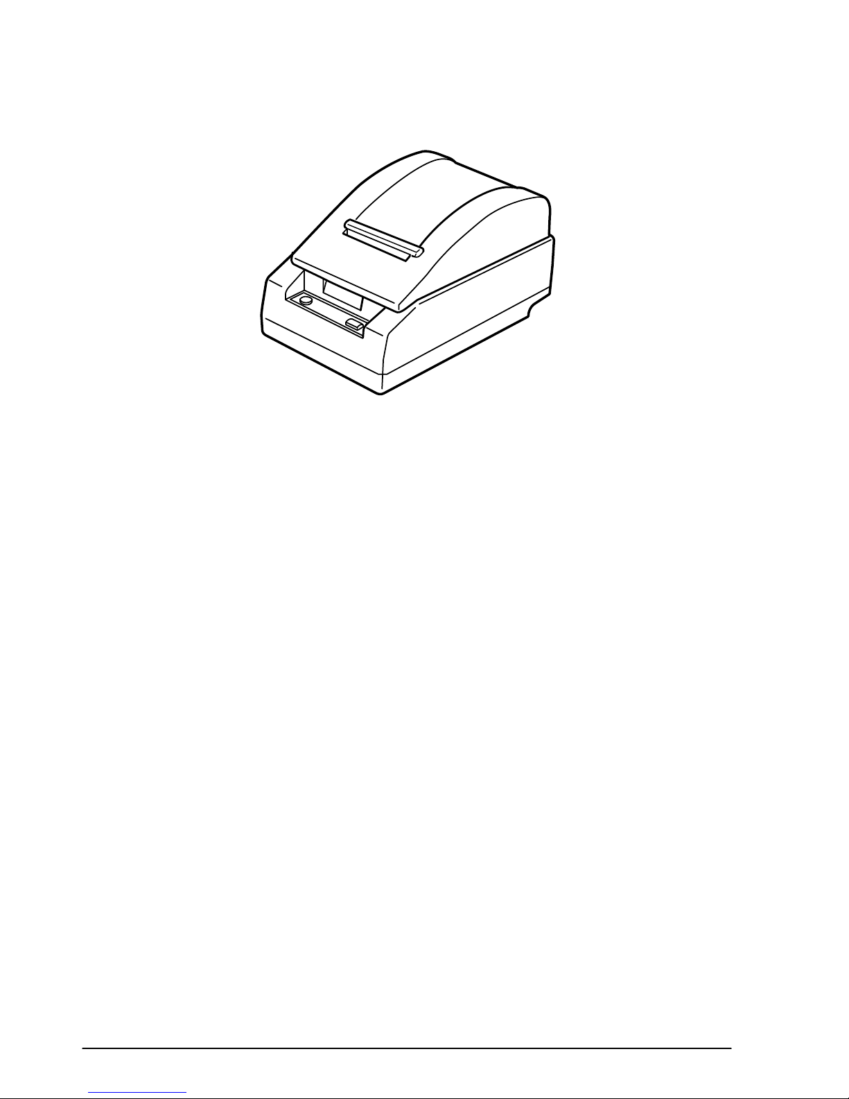
Features
The TM-L60II (RS-232 serial interface) and TM-L60IIP (parallel interface) are line thermal
printers that can print on roll paper and thermal labels. The printers have the following features:
❏ Light weight and ultra-compact size.
❏ High speed printing: 12 lines per second.
❏ Low-noise thermal printing.
❏ High reliability due to few moving parts.
❏ Easy maintenance for tasks such as head cleaning.
❏ Easy paper insertion with semi-auto loading for both roll paper and labels.
❏ Label ejection commands prevent extraneous label feeding.
❏ Serial numbers can be printed on labels.
❏ Command protocol based on the ESC/POS standard.
❏ Various layouts possible using page mode.
❏ Font selection (12 × 24 or 9 × 24) possible using a command.
❏ Character extension (up to 64 times the standard size) and character smoothing.
❏ Four different print densities selectable via DIP switch settings.
❏ Four-way routing of the interface, drawer control, and power cables: on either side,
underneath, or from the back of the case.
❏ Controls on the front of the printer for easy operation, without requiring access to the sides
and back.
❏ Water-resistant operation panel.
❏ Bar code printing possible both in the vertical direction (fence bar code) and horizontal
direction (ladder bar code in page mode) using a command.
❏ Repeated operation and copy printing possible using macro definitions.
❏ Control capability for two drawers via the built-in interface.
❏ Bidirectional parallel interface based on the IEEE 1284 Nibble/Byte Modes standard.
❏ Thermal paper or thermal label can be selected via DIP switch settings.
ii Rev. A
Page 6

The TM-L60II can also be used as the following:
❏ A one-station printer for ECR and POS.
❏ A ticket-issuing device.
❏ An output device for weighing and other types of measurement.
❏ A small scale label-marker for stores.
Option
❏ EPSON power supply unit, PS-150.
Specifications
❏ Printing specifications
Printing method: Thermal line printing
Printing speed: Approximately 12 lines/second (1/6-inch feed)
Dot density: 180 dpi × 180 dpi
Printing width: Thermal paper: 54.19 mm (2.13”), 384 dot positions
Thermal label : 51.93 mm (2.04”), 368 dot positions
❏ Character specifications
Character fonts: 12 × 24/9 × 24
Characters per line: Thermal paper : 32/42
Thermal label : 30/40
Character size: 1.41(W) × 3.39(H) mm/.99(W) × 3.39(H) mm
Character sets: ASCII: 95 characters
International: 32 characters
Extended graphics: 128 characters × 6 pages
❏ Paper size: Thermal paper : 59.0-60.5(W) mm × 83.0 mm diameter
Thermal label : 59.5-61.0(W) mm × 83.0 mm diameter
❏ Interface: RS-232 (serial interface)
or
IEEE 1284 (parallel interface)
❏ Receive buffer: 4K or 45 bytes (selectable by DIP switch)
Rev. A iii
Page 7
iv Rev. A
Page 8

TM–L60II/L60IIP Information Manual
Chapter 1
Command Descriptions
Following this table are all the commands organized by function and described with program
examples and print samples.
Supported Commands
Command Name Function type
HT Horizontal tab Print position 1-31
LF Print and line feed Print 1-5
➀ Print and return to standard mode
FF
CR Print and carriage return Print 1-6
CAN Cancel print data in page mode Character 1-24
DLE E OT Real-time status transmission Status 1-44
ESC FF Print data in page mode Print 1-8
ESC SP Set right-side character spacing Character 1-12
ESC ! Se lect print mode(s) Character 1-17
ESC $ Set absolute print position Print position 1-29
ESC % Se lect/cancel user-defined character set Character 1-13
ESC & Define user-defined characters Character 1-13
✻ Select bit-image mode Bit image 1-37
ESC
ESC – Turn underline mode on/off Character 1-18
ESC 2 Select de fault line s pacing Line spacing 1-10
ESC 3 Set line spacing Line spacing 1-10
ESC = Se lect peripheral device Miscellaneous function 1-60
ESC ? Cancel user-defined characte rs Character 1-13
ESC @ Initialize printer Miscellaneous function 1-57
ESC D Set horizontal tab positions Print position 1-31
ESC E Turn emphasized mode on/off Character 1-18
ESC G Turn double-strike mode on/off Character 1-19
ESC J Print and feed paper Print 1-6
ESC L Select page mode Miscellaneous function 1-61
ESC R Select an international character set Character 1-15
ESC S Select standard mode Miscellaneous function 1-61
ESC T Se lect print direction in page mode Print position 1-34
(in page mode)
➁ Print and feed label to print starting position
(on label)
Print 1-8
Print 1-9
Page
number
Rev. A Command Descriptions 1-1
Page 9

Command Name Function type
ESC V Turn 90° clockwise rotation mode on/off Character 1-21
ESC W Set printing area in page mode Print position 1-33
ESC \ Set relative print position Print position 1-29
ESC a Select justification Print position 1-30
ESC c 3
ESC c 4 Se lect paper sensor(s) to stop printing Paper sensor 1-26
ESC c 5 Enable/disable panel buttons Panel button 1-25
ESC d Print and feed
ESC p Generate pulse Miscellaneous function 1-60
ESC t Select character code table Character 1-16
ESC u Transmit peripheral device status Status 1-47
ESC v Transmit paper sensor status Status 1-48
ESC { Turn upside-down printing mode on/off Character 1-20
GS FF Print and eject label Print 1-9
GS ! Set character size Character 1-22
GS $ Set absolute vertical print position in page mode Print position 1-36
✻ Define downloaded bit image Bit image 1-39
GS
GS / Print downloaded bit image Bit image 1-39
GS : Start/end macro definition Macro function 1-55
GS < Initialize printer mechanism Miscellaneous function 1-62
GS A Adjust label print starting position Miscellaneous function 1-62
GS B Turn white/black reverse printing mode on/off Character 1-23
GS C 0 Select counter print mode Miscellaneous function 1-63
GS C 1 Select count mode (A) Miscellaneous function 1-64
GS C 2 Set counter Miscellaneous function 1-64
GS C ; Select count mode (B) Miscellaneous function 1-66
GS H Select printing position of HRI characters Bar code 1-53
GS I Transmit printer ID Miscellaneous function 1-59
GS L Set left margin Print position 1-32
GS P Set horizontal and vertical motion units Miscellaneous function 1-58
GS W Set printing area width Print position 1-32
GS \ Set relative vertical print position in page mode Print position 1-36
GS ^ Execute macro Macro function 1-55
GS a Enable/disable Automatic Status Back (ASB) Status 1-41
GS b Turn smoothing mode on/off Character 1-23
Se lect paper sensor(s) to output paper-end
signals
n
lines Print 1-7
Paper sensor 1-27
Page
number
1-2 Command Descriptions Rev. A
Page 10
TM–L60II/L60IIP Information Manual
Command Name Function type
GS c Print c ounter Miscellaneous function 1-63
GS f Set font for HRI characters Bar code 1-53
GS h Select bar code height Bar code 1-49
GS k Print bar code Bar code 1-51
GS r Transmit status Status 1-43
GS w Set bar code width Bar code 1-50
Page
number
Rev. A Command Descriptions 1-3
Page 11
Using Bit Value Tables
For each command that has a complex method of determining the variable n, there is a table showing
how to calculate the variable in three numbering systems: binary, hexadecimal, and decimal.
When you look at the table, first find the value of each component of the variable. Then add the
values of the components together to determine the value of the variable n.
For example, here is how you would use the table below, which sets the print mode, to combine
double height, double width, and underline. In the table, you see that bit 4 on (or hex 10 or decimal
16) turns on double height, bit 5 on (or hex 20 or decimal 32) turns on double width, and bit 7 on (or
hex 80 or decimal 128) turns on underline mode.
To combine all three, turn on bits 4, 5, and 7, which is 10110000 in binary. Or you can add the hex
values 10, 20, and 80 for the hex sum of B0, or you can add the decimal values 16, 32, and 128 for the
decimal value of 176.
Therefore, you send the following to turn on double height, double width, and underline, depending
on the numbering system used:
ASCII ESC ! n
Hex 1B 21 B0
Decimal 28 33 176
Bit Off/On Hex Decimal Function
Off 00 0 Character font-A selected.
1
On 01 1 Character font-B selected.
2 — — — Undefined.
Off 00 0 Emphasized mode not selected.
3
On 08 8 Emphasized mode selected.
Off 00 0 Double-height mode not selected.
4
On 10 16 Double-height mode selected.
Off 00 0 Double-width mode not selected.
5
On 20 32 Double-width mode selected.
6 — — — Undefined.
Off 00 0 Underline mode not selected.
7
On 80 128 Underline mode selected.
Note that the program examples throughout this chapter use decimal numbers, but binary, decimal,
and hexadecimal numbers all have the same printing results.
1-4 Command Descriptions Rev. A
Page 12

TM–L60II/L60IIP Information Manual
Print Commands
The TM-L60II/L60IIP printers support the following commands for printing characters and
advancing paper:
Command Name
LF Print and line feed
CR Print and carriage return
ESC J Print and feed paper
ESC d Print and feed n lines
ESC FF Print data in page mode
FF ➀ Print and return to standard mode (in page mode)
➁ Print and feed label to print starting position (on label)
GS FF Print and eject label
LF
[Name] Print and line feed
[Format] ASCII LF
Hex 0A
Decimal 10
LF prints the data in the print buffer and feeds one line. The amount of paper fed per line is based on
the value set using the line spacing command. The default setting is 1/6 inch.
Program Example Print Sample
PRINT #1, "AAAAA"; CHR$(&HA); AAAAA
PRINT #1, "BBBBB"; CHR$(&HA); BBBBB
Rev. A Command Descriptions 1-5
Page 13
CR
[Name] Print and carriage return
[Format] ASCII CR
Hex 0D
Decimal 13
When auto line feed is enabled, the CR command functions in the same way as the LF command.
When auto line feed is disabled, CR is ignored. The DIP switch setting enables or disables auto line
feed. When using the serial interface, CR is ignored.
Program Example Print Sample
PRINT #1, "AAAAA"; CHR$(&HD); AAAAA ←Auto line feed enabled
PRINT #1, " BBBBB"; CHR$(&HA); BBBBB
AAAAA BBBBB ←Auto line feed disabled
ESC J n
[Name] Print and feed paper
[Format] ASCII ESC J n
Hex 1B 4A n
Decimal 27 74 n
[Range] 0 ≤ n ≤ 255
ESC J n prints the data in the print buffer and feeds the paper [n × (vertical or horizontal motion unit)]
inches. This command is used to temporarily feed a specific length without changing the line spacing
set by other commands. The maximum paper feed amount is 40 inches. When standard mode is
selected, the vertical motion unit set by GS P is used. When page mode is selected, the vertical or
horizontal motion unit set by GS P is used for the print direction set by ESC T.
Program E xample P rint Sample
PRINT #1, CHR$(&H1D);"P";CHR$(180);CHR$(180);
PRINT #1, "AAAAA"; CHR$(&HA);
PRINT #1, "BBBBB"; CHR$(&H1B);"J";CHR$(100);
PRINT #1, "CCCCC"; CHR$(&HA);
PRINT #1, "DDDDD"; CHR$(&HA);
AAAAA
BBBBB
CCCCC
DDDDD
ESC J used to pr int one line and the n adv ance
the paper b y 100 /180 inch
1-6 Command Descriptions Rev. A
Page 14
TM–L60II/L60IIP Information Manual
ESC d n
[Name] Print and feed n lines
[Format] ASCII ESC d n
Hex 1B 64 n
Decimal 27 100 n
[Range] 0 ≤ n ≤ 255
ESC d n prints the data in the print buffer and feeds n lines. The amount of paper fed per line is based
on the value set using the line spacing command. The maximum paper feed amount is 40 inches. The
default setting of the paper feed amount is 1/6 inch.
Program Ex ample Print Sample
PRINT #1, "AAAAA "; CHR$(&HA);
PRINT #1, "BBBBB "; CHR$(&H1B);"d";CHR$(6);
PRINT #1, "CCCCC "; CHR$(&HA);
AAAAA
BBBBB
CCCCC
ESC d us ed to print one line and
advance the paper by six lines
Rev. A Command Descriptions 1-7
Page 15

ESC FF
[Name] Print data in page mode
[Format] ASCII ESC FF
Hex 1B 0C
Decimal 27 12
FF
[Name] ➀ Print and return to standard mode (in page mode)
[Format] ASCII FF
Hex 0C
Decimal 12
ESC FF prints all buffered data in the printable area collectively, in page mode. This command is
enabled only in page mode. After printing, the printer does not clear the buffered data or values set
by other commands. When the printer returns to standard mode, FF or ESC S should be executed.
FF prints the data in the print buffer collectively and returns to standard mode. The buffer data is
deleted after being printed. This command returns the values set by the ESC W command to the
default values. The value set by ESC T command is maintained. This command is enabled only in
page mode.
Program Example Print Sample
PRINT #1, CHR$(&H1B);"L"; ← Select pa ge mode AAAAA
PRINT #1, CHR$(&H1B);"W";CHR$(0);CHR$(0);CHR$(0);
CHR$(0);CHR$(120);CHR$(0);CHR$(240);CHR$(0);
PRINT #1, CHR$(&H1B);"T";CHR$(0);
PRINT #1, "AAAAA"; CHR$(&HA); AAAAA
PRINT #1, "BBBBB"; CHR$(&HA); BBBBB
PRINT #1, CHR$(&H1B);CHR$(&HC); CCCCC
PRINT #1, "CCCCC"; CHR$(&HC);
BBBBB
1-8 Command Descriptions Rev. A
Page 16

TM–L60II/L60IIP Information Manual
FF
[Name] ➁ Print and feed label to print starting position (on label)
[Format] ASCII FF
Hex 0C
Decimal 12
GS FF
[Name] Print and eject label
[Format] ASCII GS FF
Hex 1D 0C
Decimal 29 12
FF prints the data and feeds the next label to the print starting position when thermal label is selected
in standard mode.
GS FF prints the data in the print buffer and ejects the label. This command is effective only when
thermal label is selected with the paper selection DIP switch. When the printer label is advanced so
that the label can be peeled off, the PAPER LED blinks as it waits for the PAPER FEED switch to be
pressed. When the PAPER FEED switch is pressed, the next label is fed to the print start position. After
advancing the label, the line moves to the print start position.
This command is only effective when thermal label is selected with the paper selection DIP switch,
and is enabled only in standard mode.
Program Example Print Sample
PRINT #1, "AAAAA"; CHR$(&HA); AAAAA
PR IN T #1, "BBBBB"; CH R$(&H1D);CHR$(&HC); BB BBB
PR IN T #1, "CCCCC"; CH R$(&HA) ;
CC CCC
Rev. A Command Descriptions 1-9
Page 17
Line Spacing Commands
The TM-L60II/L60IIP printers support the following commands for setting line spacing. These
commands only set the line spacing; they do not actually advance the paper. The line spacing set
using these commands affects the results of the LF and ESC d commands. The paper is advanced
using the paper feed button (PAPER FEED).
Command Name
ESC 2 Select default line spacing
ESC 3 Set line spacing
ESC 2
[Name] Select default line spacing
[Format] ASCII ESC 2
Hex 1B 32
Decimal 27 50
ESC 3 n
[Name] Set line spacing
[Format] ASCII ESC 3 n
Hex 1B 33 n
Decimal 27 51 n
[Range] 0 ≤ n ≤ 255
ESC 2 sets the line spacing to 1/6 inch. This is equivalent to 30 dots.
ESC 3 n sets the line spacing to [n × (vertical or horizontal motion unit)] inches. The default setting of
the paper feed amount is 1/6 inch (n=60). The maximum line spacing amount is 40 inches. When
standard mode is selected, the vertical motion unit set by GS P is used. When page mode is selected,
the vertical or horizontal motion unit set by GS P is used for the print direction set by ESC T.
Program Ex ample Print Sample
PRINT #1, CHR$(&H1D);"P";CHR$(180);CHR$(180);
FOR n=25 TO 50 STEP 5
PRINT #1, CHR$(&H1B);"3";CHR$(n); ← S et line spacing
PR INT #1, "AAAAA"; CHR $(&HA);
NEXT n
PRINT #1, CHR$(&H1B);"2"; ← Set defa ult line spacing
PRINT #1, "BBBBB"; CHR$(&HA);
PRINT #1, "CCCCC"; CHR$(&HA);
AAAAA
AAAAA
AAAAA
AAAAA
AAAAA
AAAAA
BBBBB
CCCCC
25/180-i nch ( 25-dot) line spacing
30/180-i nch ( 30-dot) line spacing
35/180-i nch ( 35-dot) line spacing
40/180-i nch ( 40-dot) line spacing
45/180-i nch ( 45-dot) line spacing
50/180-i nch ( 50-dot) line spacing
1/6-inch (30- dot) line spacing
1-10 Command Descriptions Rev. A
Page 18

TM–L60II/L60IIP Information Manual
Character Commands
The TM-L60II/L60IIP supports the following commands for setting character font and size.
Command Name
ESC SP Set right-side character spacing
ESC % Select/cancel user-defined character set
ESC & Define user-defined characters
ESC ? Cancel user-defined characters
ESC R Select an international character set
ESC t Select character code table
ESC ! Select print mode(s)
ESC – Turn underline mode on/off
ESC E Turn emphasized mode on/off
ESC G Turn double-strike mode on/off
ESC { Turn upside-down printing mode on/off
ESC V Turn 90° clockwise rotation mode on/off
GS ! Set character size
GS B Turn white/black reverse printing mode on/off
GS b Turn smoothing mode on/off
CAN Cancel print data in page mode
Rev. A Command Descriptions 1-11
Page 19

ESC SP n
[Name] Set right-side character spacing
[Format] ASCII ESC SP n
Hex 1B 20 n
Decimal 27 32 n
[Range] 0 ≤ n ≤ 255
ESC SP n sets the right-side character spacing in [n × (vertical or horizontal motion unit)] inches. It is
used to change the spacing between characters. The default setting is n=0. When standard mode is
selected, the horizontal motion unit set by GS P is used. When page mode is selected, the vertical or
horizontal motion unit set by GS P is used for the print direction set by ESC T.
Program Example Print Sample
PRINT #1, CHR$(&H1D);"P";CHR$(180);CHR$(180);
PRINT #1, CHR$(&H1B);" ";CHR$(0);← Character spacing set to 0
PRINT #1, "AAAAA "; CHR$(&HA);
PRINT #1, CHR$(&H1B);" ";CHR$ (6);← Character spacing s et to 6
PRINT #1, "BBBBB "; CHR$(&HA);
PRINT #1, CHR$(&H1B);" ";CHR$ (12);← Charac ter spacing set to 12
PRINT #1, "CCCCC "; CHR$(&HA);
AAAAA ← 0-inch right- side chara cter spaci ng
BB BB B ← 6/180-inch r ight- side character spacing
CCCCC ← 12/180-i nch right- side chara cter spaci ng
1-12 Command Descriptions Rev. A
Page 20

TM–L60II/L60IIP Information Manual
ESC % n
[Name] Select/cancel user-defined character set
[Format] ASCII ESC % n
Hex 1B 25 n
Decimal 27 37 n
[Range] 0 ≤ n ≤ 255 (Only the least significant bit of n is enabled.)
ESC & y c1 c2 [x1 d1 ... d(y × x1)] ... [xk d1 ... d(y × xk)]
[Name] Define user-defined characters
[Format] ASCII ESC & y c1 c2 [x1 d1 ... d(y × x1)] ... [xk d1 ... d(y × xk)]
Hex 1B 26 y c1 c2 [x1 d1 ... d(y × x1)] ... [xk d1 ... d(y × xk)]
Decimal 27 38 y c1 c2 [x1 d1 ... d(y × x1)] ... [xk d1 ... d(y × xk)]
[Range] y = 3
32 ≤ c1 ≤ c2 ≤ 126
0 ≤ x ≤ 12 (12 × 24 font)
0 ≤ x ≤ 9 (9 × 24 font)
0 ≤ d1...d (y × x) ≤ 255
k = c2 - c1 + 1
ESC ? n
[Name] Cancel user-defined characters
[Format] ASCII ESC ? n
Hex 1B 3F n
Decimal 27 63 n
[Range] 32 ≤ n ≤ 126
ESC % n selects or cancels the user-defined character set. When the LSB (least significant bit) of n is 1,
the user-defined character set is selected. When it is 0, the internal character set is selected; this is the
default setting.
ESC & y c1 c2 [x1 d1 ... d(y × x1)] ... [xk d1 ... d(y × xk)] defines user-defined characters from character
code c1 to c2. y and x are the configuration of a user-defined character. y specifies the number of
bytes in the vertical direction. x specifies the number of dots in the horizontal direction. Character
code range from ASCII code 20H (32) to 7EH (126) can be defined by c1 and c2. Data (d) specifies a bit
printed to 1 and not printed to 0. At the default, user-defined characters are not defined and the
internal character set is printed. Once the user-defined characters have been defined, they are
available until ESC @, ESC ?, or GS
✻ is executed; the user-defined characters are redefined; the
power is turned off; or the printer is reset. The downloaded bit image is canceled.
Rev. A Command Descriptions 1-13
Page 21
ESC ? n cancels the user-defined characters defined for the character code n. After the user-defined
characters are canceled, the internal character set is printed.
P rogra m Ex ample
y=3
PRINT #1, CHR$(&H1B);"&";CHR$(y);"AC";
x=9: PRINT #1, CHR$(x );
FOR i=1 TO y*x
READ d: PRINT #1, CHR$(d );
NEX T i
x=11: PRINT #1, CHR$(x);
FOR i=1 TO y*x
READ d: PRINT #1, CHR$(d );
NEX T i
x=12: PRINT #1, CHR$(x);
FOR i=1 TO y*x
READ d: PRINT #1, CHR$(d);
NEX T i
PRINT #1, CHR$(&H1B);"%";CHR$(0); ← Select the internal chara cter set
PRINT #1, "A B C D E"; CHR$(&HA);
PRINT #1, CHR$(&H1B);"%";CHR$(1); ←Sele ct the user-defined charac ter s et
PRINT #1, "A B C D E"; CHR$(&HA):
PRINT #1, CHR$(&H1B);"?";"A"; ← Canc el the user-defined chara cter set
PRINT #1, "A B C D E"; CHR$(&HA);
Defines the
user-de fined
charact ers as
"A", "B ", and "C"
DAT A &H0 0,&H20,&H00, &H00,&H20,&H00,&H 00,&H7 0
DAT A &H0 0,&H00,&HF8, &H00,&H07,&HFF,&H 00,&H0 0
DAT A &HF 8,&H00,&H00, &H70,&H00,&H00,&H 20,&H0 0
DAT A &H0 0,&H20,&H00
DAT A &H0 0,&H20,&H00, &H00,$HF8,&H00,&H 03,&H8 E
DAT A &H0 0,&H0E,&H03, &H80,&H38,&H00,&H E0,&HE 0
DAT A &H0 0,&H38,&H38, &H00,&HE0,&H0E,&H 03,&H8 0
DAT A &H0 3,&H8E,&H00, &H00,&HF8,&H00,&H 00,&H2 0
DAT A &H0 0
DAT A &H0 0,&H30,&H00, &H00,&HF0,&H00,&H 03,&HF 0
DAT A &H0 0,&H0F,&H3F, &HF8,&H3C,&H3F,&H F8,&HF 0
DAT A &H0 0,&H18,&HF0, &H00,&H18,&H3C,&H 3F,&HF 8
DAT A &H0 F,&H3F,&HF8, &H03,&HF0,&H00,&H 00,&HF 0
DAT A &H0 0,&H00,&H30, &H00
Print Samp le
ABCDE ← Characters from internal cha racte r set
♦ ◊ ↑ DE ← Charac ters from user-def ined character set
A ◊ ↑ DE ← Character s from user-defined chara cter set (1 character ca nceled)
1-14 Command Descriptions Rev. A
Page 22

TM–L60II/L60IIP Information Manual
ESC R n
[Name] Select an international character set
[Format] ASCII ESC R n
Hex 1B 52 n
Decimal 27 82 n
[Range] 0 ≤ n ≤ 10
ESC R n selects an international character set n as follows. The default value is U.S.A. (n=0).
n Country
0 U.S.A.
1 France
2Germany
3U.K.
4 Denmark I
5 Sweden
6Italy
7 Spain
8 Japan
9Norway
10 Denmark II
P rog ram Example P rint Sa mpl e
FO R n=0 TO 10 # $ @ [ \ ] ^ ` { ¦ }
PRINT #1, CHR$(&H1B);"R";CHR$(n); # $à°ç§^`éùè¨←
PRINT #1, "# $ @ (\) ^ ` {¦} ~ ";CHR$ (& HA); # $§ÄÖÜ ^ `äöüß←
NEXT n £
# $ @ÆØÅ^` æø å~←
# ¤ÉÄÖ ÅÜé äöåü←
# $@°\й^щатим←
Pt $@¡Ñ ¿^` ¨с}~←
# $@[¥]^`{¦}~←
# ¤ЙЖШЕЬйжшеь←
# $ÉÆØ ÅÜé æøåü←
$@
[\]
^`
{ ¦ }
~
←
n
~
←
n
n
n
=0 (Defa ult settin g)
n
=1
=2
n
=3
=4
n
=5
n
=6
=7
n
=8
n
=9
n
=10
Rev. A Command Descriptions 1-15
Page 23
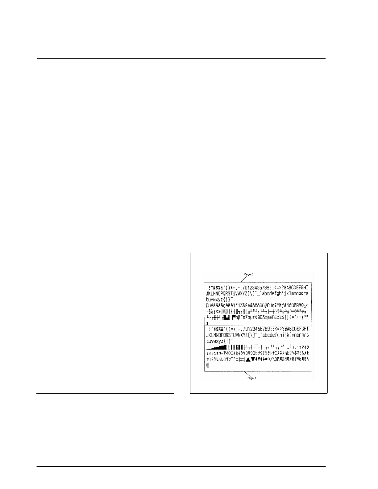
ESC t n
[Name] Select character code table
[Format] ASCII ESC t n
Hex 1B 74 n
Decimal 27 116 n
[Range] 0 ≤ n ≤ 5, n = 255
ESC t n selects a page n from the character code table as follows. The alphanumeric characters [20H
(decimal 32) to 7FH (decimal 127)] are the same for each page. The graphic characters [80H (decimal
128) to FFH (decimal 255)] are different for each page. The default setting is page 0.
n Character code table
0 Page 0 [PC437 (U.S.A., Standard Europe)]
1 Page 1 [Katakana]
2 Page 2 [PC850 (Multilingual)]
3 Page 3 [PC860 (Portuguese)]
4 Page 4 [PC863 (Canadian-French)]
5 Page 5 [PC865 (Nordic)]
255 Page 255 [Space page]
Program Example Print Sample
PRINT #1, CHR$(&H1B);"t";CHR$(0);← Select p age 0
GOSUB printing
PRINT #1, CHR$(&H1B);"t";CHR$(1);← Select p age 1
GOSUB printing
END
printing:
FOR i=&H20 TO &H7F
PRINT #1, CHR$(i);
NEXT i
PRINT #1, CHR$(&HA);
FOR i=&H80 TO &HFF
PRINT #1, CHR$(i);
NEXT i
PRINT #1, CHR$(&HA);
RETURN
1-16 Command Descriptions Rev. A
Page 24
TM–L60II/L60IIP Information Manual
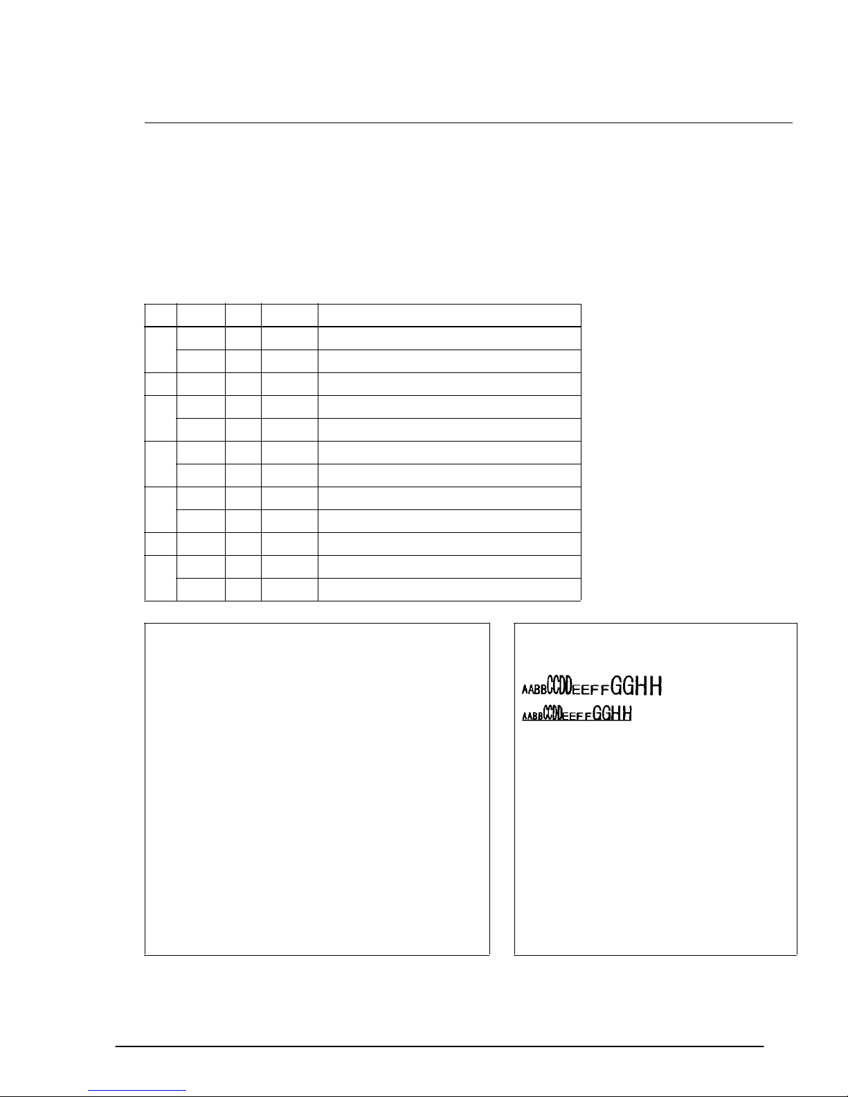
ESC ! n
[Name] Select print mode(s)
[Format] ASCII ESC ! n
Hex 1B 21 n
Decimal 27 33 n
[Range] 0 ≤ n ≤ 255
ESC ! n selects print modes using n as follows. The default setting is n=0.
Bit Off/On Hex Decimal Function
Off 00 0 Character font 12 x 24 selected.
0
On 01 1 Character font 9 x 24 select ed.
1, 2 — — — Undefined.
Off 00 0 Emphasized mode not selected.
3
On 08 8 Emphasized mode selected.
Off 00 0 Double-height mode not selected.
4
On 10 16 Double-height mode selected.
Off 00 0 Double-width mode not selected.
5
On 20 32 Double-width mode selected.
6 – – – Undefined.
Off 00 0 Underline mode not selected.
7
On 80 128 Underline mode selected.
Program E xample Print Samp le
PRINT #1, CHR$(&H1B);"!";CHR$(0); "AA";
PRINT #1, CHR$(&H1B);"!";CHR$(8); "BB";
PRINT #1, CHR$(&H1B);"!";CHR$(16); "CC";
PRINT #1, CHR$(&H1B);"!";CHR$(24); "DD";
PRINT #1, CHR$(&H1B);"!";CHR$(32); "EE";
PRINT #1, CHR$(&H1B);"!";CHR$(40); "FF";
PRINT #1, CHR$(&H1B);"!";CHR$(48); "GG";
PRINT #1, CHR$(&H1B);"!";CHR$(56); "HH";CHR$(&HA);
PRINT #1, CHR$(&H1B);"!";CHR$(129); "AA";
PRINT #1, CHR$(&H1B);"!";CHR$(137); "BB";
PRINT #1, CHR$(&H1B);"!";CHR$(145); "CC";
PRINT #1, CHR$(&H1B);"!";CHR$(153); "DD";
PRINT #1, CHR$(&H1B);"!";CHR$(161); "EE";
PRINT #1, CHR$(&H1B);"!";CHR$(169); "FF";
PRINT #1, CHR$(&H1B);"!";CHR$(177); "GG";
PRINT #1, CHR$(&H1B);"!";CHR$(185); "HH";CHR$(&HA);
← 12 x 24 font
← 9 x 24 fo nt
with under line
AA: N ormal
BB: E mphasized
CC: D ouble-height
DD: E mphasized + Double-height
EE: D ouble-width
FF: E mphasized + Double-width
GG: D ouble-height + Double-wid th
HH: E mphasized + Double-height + Do uble-width
Rev. A Command Descriptions 1-17
Page 25

ESC – n
[Name] Turn underline mode on/off
[Format] ASCII ESC – n
Hex 1B 2D n
Decimal 27 45 n
[Range] 0 ≤ n ≤ 2, 48 ≤ n ≤ 50
ESC – n turns underline mode on or off. When n=1 or 49, underline mode (one-dot width) is turned
on; when n=2 or 50, underline mode (two-dot width) is turned on; and when n=0 or 48, underline
mode is turned off. The underline mode is on, 90° clockwise rotated characters and white/black
inverted characters cannot be underlined. The default setting is n=0.
Program E xample P rint Sample
PRINT #1, CHR$(&H1B);"-";CHR$(1); ← Select AAAAA ← Underline ( one-d ot width) turned on
PRINT #1, "AAAAA"; CHR$(&HA); BBBBB ← Underline turn ed off
PRINT #1, CHR$(&H1B);"-";CHR$(0); ← Cancel
PRINT #1, "BBBBB"; CHR$(&HA);
ESC E n
[Name] Turn emphasized mode on/off
[Format] ASCII ESC E n
Hex 1B 45 n
Decimal 27 69 n
[Range] 0 ≤ n ≤ 255 (Only the least significant bit of n is enabled.)
ESC E n turns emphasized mode on or off. When the LSB (least significant bit) of n is 1, emphasized
mode is turned on; when it is 0, emphasized mode is turned off. The default setting is n=0.
Emphasized and double-strike printing appear the same.
Program E xample P rint Sample
PRINT #1, CHR$(&H1B);"E";CHR$(1);← Select AAAAA ← Emphasized
PRINT #1, "AAAAA"; CHR$(&HA); BBBBB ← Normal
PRINT #1, CHR$(&H1B);"E";CHR$(0);← Cancel
PRINT #1, "BBBBB"; CHR$(&HA);
1-18 Command Descriptions Rev. A
Page 26

TM–L60II/L60IIP Information Manual
ESC G n
[Name] Turn double-strike mode on/off
[Format] ASCII ESC G n
Hex 1B 47 n
Decimal 27 71 n
[Range] 0 ≤ n ≤ 255 (Only the least significant bit of n is enabled.)
ESC G n turns double-strike mode on or off. When the LSB (least significant bit) of n is 1, double-
strike mode is turned on; when it is 0, double-strike mode is turned off. The default setting is n=0.
Double-strike and emphasized printing appear the same.
Program E xample P rint Sample
PRINT #1, CHR$(&H1B);"G";CHR$(1); ← Select AAAAA ← Dou ble-strike
PRINT #1, "AAAAA"; CHR$(&HA); BBBBB ← Normal
PRINT #1, CHR$(&H1B);"G";CHR$(0); ← Cancel
PRINT #1, "BBBBB"; CHR$(&HA);
Rev. A Command Descriptions 1-19
Page 27

ESC { n
[Name] Turn upside-down printing mode on/off
[Format] ASCII ESC { n
Hex 1B 7B n
Decimal 27 123 n
[Range] 0 ≤ n ≤ 255 (Only the least significant bit of n is enabled.)
ESC { n turns upside-down printing mode on or off. When the LSB (least significant bit) of n is 1,
upside-down printing mode is turned on; when it is 0, upside-down printing mode is turned off. The
default setting is n=0. When upside-down mode is turned on, the printer prints 180°-rotated
characters from right to left. The line printing order is not reversed; therefore be careful of the order of
the data transmitted. In standard mode, this command is enabled only when input at the beginning of
a line. In page mode, an internal flag is activated and this command is enabled when the printer
returns to standard mode.
Program E xample P rint Sample
PRINT #1, CHR$(&H1B);"{";CHR$(0); ← Cancel
GOSUB printing
PRINT #1, CHR$(&H1B);"{";CHR$(1); ← Select
GOSUB printing
END
printing:
PRINT #1, "ABCDE"; CHR$(&HA);
PRINT #1, "BCDEF"; CHR$(&HA);
RETURN
Normal printing
ABCDE
BCDEF
ABCDE
BCDEF
Upside-do wn
printing
1-20 Command Descriptions Rev. A
Page 28
TM–L60II/L60IIP Information Manual
ESC V n
[Name] Turn 90° clockwise rotation mode on/off
[Format] ASCII ESC V n
Hex 1B 56 n
Decimal 27 86 n
[Range] 0 ≤ n ≤ 1, 48 ≤ n 49
ESC V n turns the 90° clockwise rotation mode on or off. When n=1 or 49, 90° clockwise rotation
mode is turned on; when n=0 or 48, this mode is turned off. This command is enabled only in
standard mode. If this command is entered in page mode, an internal flag is activated and the
command is enabled when the printer returns to standard mode.
Program Example Pr int Sample
PRINT #1, CHR$(&H1D);"P";CHR$(180);CHR$(180);
PRINT #1, CHR$(&H1B);" ";CHR$(20);← Set right-s ide spacing
PRINT #1, CHR$(&H1B);"3";CHR$ (15);← Set line spacin g
PRINT #1, CHR$(&H1B);"V";CHR$ (1);← Turn on
GOSUB printing
PRINT #1, CHR$(&H1B);"2";← Set line spacing
PRINT #1, CHR$(&H1B);"V";CHR$ (0);← Turn off
GOSUB printing
END
printing:
PRINT #1, "AAAAA"; CHR$(&HA);
PRINT #1, "BBBBB"; CHR$(&HA);
PRINT #1, "CCCCC"; CHR$(&HA);
RETURN
Right-s ide spacing
ABC
ABC
ABC
AAAAA
A
BBBBB
B
C
CCCCC
Right-s ide spacing
ABC
ABC
ABC
Line
spacing ESC V 1
Li ne
spacing
ESC V 0
Rev. A Command Descriptions 1-21
Page 29
GS ! n
[Name] Select character size
[Format] ASCII GS ! n
Hex 1D 21 n
Decimal 29 33 n
[Range] 0≤ n ≤ 255
GS ! n selects the character height using bits 0 to 3, and selects the character width using bits 4 to 7.
Character width selection is as follows:
Hex Decimal Width
00 0 1 (normal)
10 16 2 (double-width)
20 32 3
30 48 4
40 64 5
50 80 6
60 96 7
70 112 8
Character height selection is as follows:
Hex Decimal Width
00 0 1 (normal)
01 1 2 (double-widt h)
02 2 3
03 3 4
04 4 5
05 5 6
06 6 7
07 7 8
Program E xample P rint Sample
PRINT #1, CHR$(&H1D);"!";CHR$(68);
PRINT #1, "BBBBB"; CHR$(&HA);
PRINT #1, CHR$(&H1D);"!";CHR$(0)
PRINT #1, "AAAAA"; CHR$(&HA);
BBBBB
AAAAA ←
Normal
← Select five-times
normal font height
and fi ve-times
normal font width
1-22 Command Descriptions Rev. A
Page 30
TM–L60II/L60IIP Information Manual
GS B n
[Name] Turn white/black reverse printing mode on/off
[Format] ASCII GS B n
Hex 1D 42 n
Decimal 29 66 n
[Range] 0≤ n ≤ 255 (Only the least significant bit of n is enabled.)
GS B n turns the white/black reverse printing mode on or off. When the LSB (least significant bit) of
n is 1, white/black reverse printing mode is turned on. When it is 0, white/black reverse printing
mode is turned off. The default setting is n=0. In white/black reverse printing mode, characters are
printed in white on a black background.
Program Example Print Sample
AAAAA
PRINT #1, CHR$(&H1D);"B";CHR$(1);
PRINT #1, "AAAAA"; CHR$(&HA); BBBBB ← N ormal
PRINT #1, CHR$(&H1D);"B";CHR$(0);
PRINT #1, "BBBBB";CHR$(&HA);
← Reverse
GS b n
[Name] Turn smoothing mode on/off
[Format] ASCII GS b n
Hex 1D 62 n
Decimal 29 98 n
[Range] 0≤ n ≤ 255 (Only the least significant bit of n is enabled.)
GS b n turns the smoothing mode on or off. When the LSB (least significant bit) of n is 1, smoothing
mode is turned on. When it is 1, smoothing mode is turned off. The default setting is n=0. Smoothing
is available for quadruple-size or larger characters.
Program Example Print Sample
PRINT #1, CHR$(&H1D);"!";CHR$(68); ←
PRINT #1, CHR$(&H1D);"b";CHR$(1); ←
PRINT #1, "AAAAA"; CHR$(&HA);
Select font size
Turn on
AAAAA
Rev. A Command Descriptions 1-23
Page 31

CAN
[Name] Cancel print data in page mode
[Format] ASCII CAN
Hex 18
Decimal 24
CAN deletes all the print data in the current printable area when the printer is in page mode. If data
that existed in the previously specified printable area also exists in the currently specified printable
area, it will also be deleted.
Program Ex ample P rin t Sample
PRINT #1, CHR$(&H1D);"P";CHR$(180);CHR$(180); AAAAAAAAAAAAAAAAAAAA
PRINT #1, CHR$(&H1B);"L"; ← Sele ct page mode AAAAAAAAAAAAAAAAAAAA
PRINT #1, CHR$(&H1B);"W";CHR$(0);CHR$(0);CHR$(0);
CHR$(0);CHR$(240);CHR$(0);CHR$(44);CHR$(1);
PRINT #1, CHR$(&H1B);"T";CHR$(0); ← Select print direction AAAAA AAAAAAAAAA
FOR i=1 to 200 : PRINT #1, "A"; : NEXT i AAAAA AAAAAAAAAA
PRINT #1,CHR$(&H1B);"W";CHR$(60);CHR$(0);CHR$(90);
CHR$(0);CHR$(60);CHR$(0);CHR$(120);CHR$(0);
PRINT #1, CHR$(&H18);← Cancel print data AAAAAAAAAAAAAAAAAAAA
PRINT #1, CHR$(&HC);← Batch print and return standard mode AAAAAAAAAAAAAAAAAAAA
AAAAAAAAAAAAAAAAAAAA
AAAAA AAAAAAAAAA
AAAAA AAAAAAAAAA
AAAAAAAAAAAAAAAAAAAA
1-24 Command Descriptions Rev. A
Page 32

TM–L60II/L60IIP Information Manual
Panel Button Command
The TM-L60II/L60IIP printers support the following command for enabling and disabling the panel
button (PAPER FEED):
Command Name
ESC c 5 Enable/disable panel buttons
ESC c 5 n
[Name] Enable/disable panel buttons
[Format] ASCII ESC c 5 n
Hex 1B 63 35 n
Decimal 27 99 53 n
[Range] 0 ≤ n ≤ 255 (Only the least significant bit of n is enabled.)
ESC c 5 n enables or disables the PAPER FEED button. When the LSB (least significant bit) of n is 1,
this button is disabled; when it is 0, this button is enabled. To prevent problems caused by
accidentally pressing the PAPER FEED button, use this command to disable the button. When the
printer cover is open, the button is enabled regardless of the setting of this command. When using the
GS FF command or when the printer is in macro execution standby, the PAPER FEED button is
enabled regardless of the setting of this command.
Program Exam pl e
PRINT #1, CHR$(&H1B);"c5";CHR$(1); ← Disable panel bu ttons
Rev. A Command Descriptions 1-25
Page 33

Paper Sensor Commands
The TM-L60II/L60IIP printers support the following commands for controlling the paper sensor(s)
that stop printing and output paper-end signals:
Command Name
ESC c 4 Select paper sensor(s) to stop printing
ESC c 3 Select paper sensor(s) to output paper-end signals
ESC c 4 n
[Name] Select paper sensor(s) to stop printing
[Format] ASCII ESC c 4 n
Hex 1B 63 34 n
Decimal 27 99 52 n
[Range] 0 ≤ n ≤ 255
ESC c 4 n selects the paper sensor that stops printing when the paper runs out. The default setting is
when all paper sensors are disabled (n=0). Bits 0 and 1 indicate the same sensor. If one of the bits is
enabled, the paper roll near-end sensor is selected to stop printing. The paper roll sensor is always
enabled, and when a paper-end is detected, the printer stops printing.
When the paper roll near-end sensor is enabled, and if the sensor detects a near-end condition during
printing, the printer stops printing and goes off-line automatically after the current printing.
Replacing a new paper roll starts the printing again.
When the paper roll near-end sensor is disabled, and if a paper near-end condition is detected during
printing, the PAPER OUT LED comes on, but the printer does not stop printing and does not go offline.
The paper sensor(s) used to stop printing are selected by using n as follows:
Bit Off/On Hex Decimal Function
Off 00 0 Paper roll near-end sensor disabled.
0
On 01 1 Paper roll near-end sensor enabled.
Off 00 0 Paper roll near-end sensor disabled.
1
On 02 2 Paper roll near-end sensor enabled.
2-7 - - - Undefined.
Program Exam pl e
PRINT #1, CHR$(&H1B);"c4";CHR$(1); ←
Paper roll near- end sensor enabl ed
1-26 Command Descriptions Rev. A
Page 34

TM–L60II/L60IIP Information Manual
ESC c 3 n
[Name] Select paper sensor(s) to output paper-end signals
[Format] ASCII ESC c 3 n
Hex 1B 63 33 n
Decimal 27 99 51 n
[Range] 0 ≤ n ≤ 255
ESC c 3 n selects the paper sensor that outputs a paper-end signal to the parallel interface when a
paper-end is detected. The default setting is when all sensors are enabled (n= 15).
It is possible to select multiple sensors to output signals. Then, if any of the sensors detects a paper
end, the paper end signal is output. This command is available only with a parallel interface and is
ignored with a serial interface.
The paper sensor(s) used to output paper-end signals are selected by using n as follows:
Bit Off/On Hex Decimal Function
Off 00 0 Paper roll near-end sensor disabled.
0
On 01 1 Paper roll near-end sensor enabled.
Off 00 0 Paper roll near-end sensor disabled.
1
On 02 2 Paper roll near-end sensor enabled.
Off 00 0 Paper roll end sensor disabled.
2
On 02 4 Paper roll end sensor enabled.
Off 00 0 Paper roll end sensor disabled.
3
On 08 8 Paper roll end sensor enabled.
4-7 - - - Undefined.
P ro gram Examp l e
PRINT #1, CHR$(&H1B);"c3";CHR$(15); ← All sensors enabled
Rev. A Command Descriptions 1-27
Page 35

Print Position Commands
The TM-L60II/L60IIP printers support the following commands for setting the print position:
Command Name
ESC $ Set absolute print position
ESC \ Set relative print position
ESC a Select justification
HT Horizontal tab
ESC D Set horizontal tab positions
GS L Set left margin
GS W Set printing area width
ESC W Set printing area in page mode
ESC T Set print direction in page mode
GS $ Set absolute vertical print position in page mode
GS \ Set relative vertical print position in page mode
1-28 Command Descriptions Rev. A
Page 36

ESC $ nL nH
[Name] Set absolute print position
TM–L60II/L60IIP Information Manual
[Format] ASCII ESC $ n
L nH
Hex 1B 24 nL nH
Decimal 27 36 nL nH
[Range] 0 ≤ nL ≤ 255
H ≤ 255
0 ≤ n
ESC \ nL nH
[Name] Set relative print position
[Format} ASCII ESC \ n
L nH
Hex 1B 5C nL nH
Decimal 27 92 nL nH
[Range] 0 ≤ nL ≤ 255
H ≤ 255
0 ≤ n
ESC $ n
L nH sets the print starting position to [(nL + nH × 256) × (horizontal or vertical motion unit)]
inches from the beginning of the line.
ESC \ n
L nH moves the print starting position to [(nL + nH × 256) × (horizontal or vertical motion
unit)] inches from the current position. Use the complement of N for setting N pitch movement to the
left: –N pitch = 65536 – N, where N=(n
L + nH × 256).
When standard mode is selected, the horizontal motion unit set by GS P is used. When page mode is
selected, the horizontal or vertical motion unit set by GS P is used for the print direction set by ESC T.
Program Example Print Sample
PRINT #1, CHR$(&H1D);"P";CHR$(180);CHR$(180);
PRINT #1, "ABCD";
PRINT #1, CHR$(&H1B);"$";CHR$(90);CHR$(0);
PRINT #1, "EFGH"; CHR$(&HA);
PRINT #1, "ABCD";
PRINT #1, CHR$(&H1B);"\";CHR$(90);CHR$(0);
PRINT #1, "EFGH"; CHR$(&HA);
90/180 inch
ABCD EFGH
ABCD EFGH
90/180 inc h
Rev. A Command Descriptions 1-29
Page 37

ESC a n
[Name] Select justification
[Format] ASCII ESC a n
Hex 1B 61 n
Decimal 27 97 n
[Range] 0 ≤ n ≤ 2
48 ≤ n ≤ 50
ESC a n aligns all the data in one line to a specified position. Left justification is selected when n=0 or
48, centering is selected when n=1 or 49, and right justification is selected when n=2 or 50. The default
setting is left justification (n=0). This command is enabled only at the beginning of a line in standard
mode. If this command is entered in page mode, an internal flag is activated and the command is
enabled when the printer returns to standard mode.
Program E xample P rint Sample
FOR n=0 T O 2
PRINT #1, CHR$(&H1B);"a";CHR$(n);
PRINT #1, "ABC"; CHR$(&HA);
PRINT #1, "ABCD"; CHR$(&HA);
PRINT #1, "ABCDE"; CHR$(&HA);
NEX T n
AB C
AB CD
AB CDE
ESC a 0
ABC
ABC D
AB CDE
ESC a 1
ESC a 2
ABC
ABC D
ABC DE
1-30 Command Descriptions Rev. A
Page 38

TM–L60II/L60IIP Information Manual
HT
[Name] Horizontal tab
[Format] ASCII HT
Hex 09
Decimal 10
ESC D n1...nk NUL
[Name] Set horizontal tab positions
[Format] ASCII ESC D n1...nk NUL
Hex 1B 44 n1...nk 00
Decimal 27 68 n1...nk 0
[Range] 1 ≤ n ≤ 255
0 ≤ k ≤ 32
HT moves the print position to the next horizontal tab position. This command is used to align the
character columns. The command is ignored unless the next horizontal tab position has been set.
ESC D n1...nk NUL sets the horizontal tab positions. n specifies the column number (counted from
the left margin or the beginning of the line) for setting a horizontal tab position. This command
deletes any previously set horizontal tab positions. Up to 32 tab positions can be set. The default tab
positions are at intervals of 8 characters (columns 9, 17, 25, etc.) for the 12 × 24 font.
Program Example Print Sample
PRINT #1, "0123456789012345678901234567890123456";
PRINT #1, CHR$(&HA);
GOSUB ht
PRINT #1, CHR$(&H1B);"D";CHR$(10);CHR$(20);
PRINT #1, CHR$(30);CHR$(0);
GOSUB ht
END
ht:
FOR i=1 TO 4
PRINT #1, CHR$ (& H9); "H" ;
NEXT i
PRINT #1, CHR $(& HA);
RETURN
012 34 567890123456 78901234567890123456
HHHH
HHHH
↑↑↑
Defaul t →
Tab
position
10
8162432
Tab
position
20
Tab
positio n
30
Rev. A Command Descriptions 1-31
Page 39

GS L nL nH
[Name] Set left margin
[Format] ASCII GS L n
L nH
Hex 1D 4C nL nH
Decimal 29 76 nL nH
[Range] 0 ≤ nL ≤ 255
H ≤ 255
0 ≤ n
GS W nL nH
[Name] Set printing area width
[Format] ASCII GS W n
L nH
Hex 1D 57 nL nH
Decimal 29 87 nL nH
[Range] 0 ≤ nL ≤ 255
H ≤ 255
0 ≤ n
GS L n
beginning of a line. The default setting is n
L nH sets the left margin to [(nL + nH × 256) × (horizontal motion unit)] inches from the
L=0, nH=0. This command is enabled only at the beginning
of a line in standard mode. If this command is entered in page mode, an internal flag is activated and
the command is enabled when the printer returns to standard mode.
GS W n
left margin. The default setting is n
L nH sets the printing area width to [(nL + nH × 256) × (horizontal motion unit)] inches from the
L=0, nH=2. This command is enabled only at the beginning of a line
in standard mode. If this command is entered in page mode, an internal flag is activated and the
command is enabled when the printer returns to standard mode.
If the above commands set the printing area width to less than the width of one character, the
printing area width is extended to accommodate one character for the line.
The horizontal motion units use the horizontal value set by the GS P command. The default setting of
the horizontal motion unit is 1/180 inches.
Program E xample P rint Sample
PRINT #1, CHR$(&H1D);"P";CHR$(180);CHR$(180);
PRINT #1, "01234567890123456789"; CHR$(&HA);
PRINT #1, CHR$(&H1D);"L";CHR$(60);CHR$(0);
PRINT #1, CHR$(&H1D);"W";CHR$(120);CHR$(0);
PRINT #1, "01234567890123456789"; CHR$(&HA);
01234567890123456789
0123456789
0123456789
Left Printing area
margin width
1-32 Command Descriptions Rev. A
Page 40

ESC W xL xH yL yH dxL dxH dyL dyH
[Name] Set printing area in page mode
TM–L60II/L60IIP Information Manual
[Format] ASCII ESC W x
L xH yL yH dxL dxH dyL dyH
Hex 1B 57 xL xH yL yH dxL dxH dyL dyH
Decimal 27 87 xL xH yL yH dxL dxH dyL dyH
[Range] 0 ≤ xL, xH, yL, yH, dxL, dxH, dyL, dyH ≤ 255
L = dxH = 0 or dyL= dyH = 0)
ESC W x
(except for dx
L xH yL yH dxL dxH dyL dyH sets the size and position of the printing area in page mode as
follows:
Horizontal starting position = [(x
Vertical starting position = [(y
Printing area width = [(dx
Printing area height = [(dy
L + dxH × 256) × (horizontal motion unit)] inches
L + dyH × 256) × (vertical motion unit)] inches
L+ xH × 256) × (horizontal motion unit)] inches
L + yH × 256) × (vertical motion unit)] inches
The default settings are as follows:
xL = xH = yL = yH = 0
dx
L = 0, dxH = 2, dyL = 126, dyH = 6
This command is enabled only in page mode. If this command is entered in standard mode, an
internal flag is activated and the command is enabled when the printer selects page mode.
The horizontal and vertical motion units use the horizontal and vertical values set by the GS P
command. The default settings of the horizontal and vertical motion units are 1/180 and 1/360
inches, respectively.
Program Example Print Sample
PRINT #1, CHR$(&H1B);"L";← Select page mode
PRINT #1, CHR$(&H1B);"W";CHR$ (0);CHR$(0);CHR$(0);CHR$(0);CHR$(180);
CHR$(0);CHR$(132);CHR$(3);
PRINT #1, CHR$(&H1B);"T";CHR$ (0);← Select print direct ion
PRINT #1, "AAAAA "; CHR$(&HA);← S tore chara cters for printing
PRINT #1, "BBBBB "; CHR$(&HA);← S tore chara cters for printing
PRINT #1, CHR$(&H1B);"T";CHR$ (2);← Select print direct ion
PRINT #1, "CCCCC "; CHR$(&HA);← S tore chara cters for printing
PRINT #1, "DDDDD "; CHR$(&HC);← B atch print and return to standard mode
AAAAA
BBBBB
←
DDDDD
CCCCC
Printing
area se t
by ESC W
Rev. A Command Descriptions 1-33
Page 41

ESC T n
[Name] Set print direction in page mode
[Format] ASCII ESC T n
Hex 1B 54 n
Decimal 27 84 n
[Range] 0 ≤ n ≤ 3
48 ≤ n ≤ 51
ESC T n sets the print direction and starting position in page mode specified by n as shown below.
The default setting is n=0. This command is enabled only in page mode. If this command is entered in
standard mode, an internal flag is activated and the command is enabled when the printer returns to
page mode.
n
Print Direction Starting Position
0, 48 Left to right Upper left (A in the figure)
1, 49 Bottom to t op Lower left (B in the figure)
2, 50 Right to left Lower right (C in the figure)
3, 51 Top to bottom Upper right (D in the figure)
A
Pr intin g area
B
Paper feed direction
D
C
The parameters for the horizontal or vertical motion units (x or y) differ depending on the starting
position of the printing area as follows:
If the starting position is the upper left or lower right of the printing area (n=0, 2, 48, or 50):
❏ These commands use horizontal motion units: ESC SP, ESC $, ESC \
❏ These commands use vertical motion units: ESC 3, ESC J, GS $, GS \
If the starting position is the upper right or lower left of the printing area (n=1, 3, 49, or 51):
❏ These commands use horizontal motion units: ESC 3, ESC J, GS $, GS \
❏ These commands use vertical motion units: ESC SP, ESC $, ESC \
1-34 Command Descriptions Rev. A
Page 42

TM–L60II/L60IIP Information Manual
Program Example Pr int Sample
PRINT #1, CHR$(&H1B);"L";← Select page mode
PRINT #1, CHR$(&H1B);"W";CHR$ (0);CHR$(0);CHR$(0);CHR$(0);
CHR$(240);CHR$(0);CHR$(224);CHR$(1);
PRINT #1, CHR$(&H1B);"T";CHR$ (0);← Select print direct ion
PRINT #1, "AAAAA "; CHR$(&HA);← S tore chara cters for printing
PRINT #1, "BBBBB "; CHR$(&HA);← S tore chara cters for printing
PRINT #1, CHR$(&H1B);"T";CHR$ (1);← Select print direct ion
PRINT #1, "CCCCC "; CHR$(&HA);← S tore chara cters for printing
PRINT #1, "DDDDD "; CHR$(&HA);← S tore chara cters for printing
PRINT #1, CHR$(&H1B);"T";CHR$ (2);← Select print direct ion
PRINT #1, "EEEEE "; CHR$(&HC);← B atch print and return to standard mode
AAAAA
BBBBB
CCCCC
DDDDD
←
EEEEE
Printing
area set
by ESC W
Rev. A Command Descriptions 1-35
Page 43

GS $ nL nH
[Name] Set absolute vertical print position in page mode
[Format] ASCII GS $ n
L nH
Hex 1D 24 nL nH
Decimal 29 36 nL nH
[Range] 0 ≤ nL ≤ 255
H ≤ 255
0 ≤ n
GS \ nL nH
[Name] Set relative vertical print position in page mode
[Format] ASCII GS \ n
L nH
Hex 1D 5C nL nH
Decimal 29 92 nL nH
[Range] 0 ≤ nL ≤ 255
H ≤ 255
0 ≤ n
GS $ n
[(n
L nH sets the absolute vertical print starting position for buffer character data in page mode to
L + nH × 256) × (vertical or horizontal motion unit)] inches. This command is effective only in page
mode.
GS \ n
L nH moves the vertical print starting position in page mode to [(nL + nH × 256) × (vertical or
horizontal motion unit)] inches from the current position. This command is ignored in standard
mode. Use the complement of N for setting pitch movement upward: − N pitch = 65536 − N, where
N=(n
L + nH × 256).
The horizontal and vertical motion units set by GS P are used for the print direction set by ESC T.
Pro gr am Example Print Samp l e
PRINT #1, CHR$(&H1D);"P";CHR$(180);CHR$(180);
PRINT #1, CHR$(&H1B);"L";← Select page mode
PRINT #1, CHR$(&H1B);"W";CHR$ (0);CHR$(0);CHR$(0);CHR$(0);
CHR$(180);CHR$(0);CHR$(132);CHR$(3);
PRINT #1, CHR$(&H1B);"T";CHR$ (0);← Select print direct ion
PRINT #1, "AAAAA "; CHR$(&HA);← S tore chara cters for printing
PRINT #1, "BBBBB ";
PRINT #1, CHR$(&H1D);"$";CHR$ (90);CHR$(0);
PRINT #1, "CCCCC "; CHR$(&HA);← S tore chara cters for printing
PRINT #1, "DDDDD "; CHR$(&HA);← S tore chara cters for printing
PRINT #1, "EEEEE ";
PRINT #1, CHR$(&H1D);"\";CHR$ (90);CHR$(0);
PRINT #1, "FFFFF "; CHR$(&HC);← B atch print and return to standard mode
AAAAA
BBBBB
DDDDD
EEEEE
CCCCC
FFFFF
90/180 i nch
← Print ing
area set
by ESC W
90/180 i nch
1-36 Command Descriptions Rev. A
Page 44
TM–L60II/L60IIP Information Manual
Bit-Image Commands
The TM-L60II/L60IIP printers support the following bit-image commands:
Command Name
ESC ✻ Select bit-image mode
✻ Define downloaded bit image
GS
GS / Print downloaded bit image
ESC ✻ m nL nH d1...dk
[Name] Select bit-image mode
[Format] ASCII ESC ✻ mn
Hex 1B 2A mn
Decimal 27 42 mn
LnHd1...dk
LnHd1...dk
LnHd1...dk
[Range] m = 0, 1, 32, 33
L ≤ 255
0 ≤ n
H ≤ 3
0 ≤ n
0 ≤ d ≤ 25 5
ESC ✻ m n
(n
L + nH × 256). d indicates the bit image data. Set a bit to 1 to print a dot. This command is used to
L nH d1...dk selects a bit-image mode using m for the number of dots specified by
print a predefined picture or logo.
The modes selectable by m are as follows:
m
0 8-dot single density 60 DPI 8 90 DPI n
1 8-dot double density 60 DPI 8 180 DPI n
32 24-dot single density 180 DPI 24 90 DPI (n
33 24-dot double density 180 DPI 24 180 DPI (n
Mode
Vertical Direction Horizontal Direction
Dot Density Number of Dots Dot Density Amount of Data (k)
L + nH × 256
L + nH × 256
L + nH × 256) × 3
L + nH × 256) × 3
Rev. A Command Descriptions 1-37
Page 45

Program E xample P rint sample
m=0: GOSUB bitimage8
m=1: GOSUB bitimage8
m=32: GOSUB bitimage24
m=33: GOSUB bitimage24
END
bitimage8:
PRINT #1,
CHR$(&H1B);"*";CHR$(m);CHR$(18 0);CHR$(0);
FOR i=1 TO 180
PRINT #1, CHR$(i);
NE XT i
PRINT #1, CHR$(&HA);
RETURN
bitimage24:
PRINT #1,
CHR$(&H1B);"*";CHR$(m);CHR$(18 0);CHR$(0);
FOR i=1 TO 180
PRINT #1, CHR$(i);CHR$(i);CHR$(i);
NE XT i
PRINT #1, CHR$(&HA);
RETURN
m=0
m=1
m=32
m=33
1-38 Command Descriptions Rev. A
Page 46

GS ✻ x y d1...d(x × y × 8)
[Name] Define downloaded bit image
TM–L60II/L60IIP Information Manual
[Format] ASCII GS
✻ x y d1...d(x × y × 8)
Hex 1D 2A x y d1...d(x × y × 8)
Decimal 29 42 x y d1...d(x × y × 8)
[Range] 1 ≤ x ≤ 255
1 ≤ y ≤ 48
x × y ≤ 1536
0 ≤ d ≤ 255
GS / m
[Name] Print downloaded bit image
[Format] ASCII GS / m
Hex 1D 2F m
Decimal 29 47 m
[Range] 0 ≤ m ≤ 3
48 ≤ m ≤ 51
✻ x y d1...d(x × y × 8) defines a downloaded bit image using x × 8 dots in the horizontal direction
GS
and y × 8 dots in the vertical direction. Once a downloaded bit image has been defined, it is available
until another definition is made, ESC @ or ESC & is executed, the printer is reset, or the power is
turned off. When this command is executed, the user-defined characters are cleared. The default
setting is no downloaded bit image defined.
GS / m prints a downloaded bit image using the mode specified by m, as follows. In standard mode,
this command is effective only when there is no data in the print buffer. This command is ignored if a
downloaded bit image has not been defined.
m
0, 48 Normal 180 DPI 180 DPI
1, 49 Double-width 180 DPI 90 DPI
2, 50 Double-height 90 DPI 180 DPI
3, 51 Quadruple 90 DPI 90 DPI
Mode Vertical Dot Density Horizontal Dot Density
Rev. A Command Descriptions 1-39
Page 47
Program Example Program Example (continued)
x=16: y=5
PRINT #1, CHR$(&H1D);"*";CHR$(x);CHR$(y);
FOR i=1 TO x*y*8
READ a$: d=VAL("&H"+a$)
Define
downloade d
bit image
PRINT #1, CHR$(d);
NEXT i
FOR m=0 TO 3
PRINT #1, CHR$(&H1D);"/";CHR$(m)
PRINT #1, CHR$(&HA);
←
Print d ownloaded
bit ima ge
NEXT m
END
DATA FF,FF,FF,FF,FF,FF,FF,FF,FF,FF,C0,00,00,00,03,C0
DATA 00,00,00,03,CF,FF,FF,FF,F3,CF,FF,FF,FF,F3,CF,FF
DATA FF,FF,F3,CF,FF,FF,FF,F3,CF,FF,FF,FF,F3,CF,C0,FC
DATA 03,F3,CF,C0,FC,03,F3,CF,C0,FC,03,F3,CF,C0,FC,03
DATA F3,CF,C0,FC,03,F3,CF,C0,FC,03,F3,CF,C0,FC,03,F3
DATA CF,C0,FC,03,F3,CF,C0,FC,03,F3,CF,C0,00,03,F3,C0
DATA 00,00,00,03,C0,FF,00,03,F3,C3,FF,C0,03,F3,C7,FF
DATA E0,03,F3,C7,FF,F0,03,F3,CF,FF,F8,03,F3,CF,FF,FC
DATA 03,F3,CF,E3,FE,03,F3,CF,C1,FF,03,F3,CF,C0,FF,83
DATA F3,CF,C0,7F,C7,F3,CF,C0,3F,FF,F3,CF,C0,1F,FF,F3
DATA CF,C0,0F,FF,E3,CF,C0,07,FF,E3,CF,C0,03,FF,C3,C0
DATA 00,00,FF,03,C0,00,00,00,03,C0,3F,FF,FC,03,C0,FF
DATA FF,FF,03,C3,FF,FF,FF,C3,C7,FF,FF,FF,E3,C7,FF,FF
DATA FF,E3,CF,FF,FF,FF,F3,CF,F0,00,0F,F3,CF,C0,00,03
DATA F3,CF,C0,00,03,F3,CF,C0,00,03,F3,CF,C0,00,03,F3
DATA CF,C0,00,03,F3,CF,C0,00,03,F3,CF,C0,00,03,F3,CF
DATA C0,00,03,F3,CF,C0,00,03,F3,C0,00,00,00,03,C0,00
DATA 00,00,73,C0,00,00,03,C3,C0,00,00,1E,03,C0,00,00
DATA 70,03,C0,00,03,C0,03,C0,00,1E,00,03,C0,00,78,00
DATA 03,C0,03,C0,00,03,C0,0E,00,00,03,C0,78,00,00,03
DATA C3,C0,00,00,03,CE,00,00,00,03,C0,00,00,00,03,CF
DATA FF,FF,FF,F3,CF,FF,FF,FF,F3,CF,FF,FF,FF,F3,CF,FF
DATA FF,FF,F3,CF,FF,FF,FF,F3,CF,FF,FF,FF,F3,CF,C0,0F
DATA C0,03,CF,C0,0F,C0,03,CF,C0,0F,C0,03,CF,C0,0F,C0
DATA 03,CF,C0,0F,C0,03,CF,E0,1F,C0,03,CF,FF,FF,C0,03
DATA CF,FF,FF,CO,03,C7,FF,FF,80,03,C7,FF,FF,80,03,C1
DATA FF,FE,00,03,C0,3F,F0,00,03,C0,00,00,00,03,C0,0F
DATA FF,F0,03,C0,FF,FF,FF,03,C3,FF,FF,FF,C3,C7,FF,FF
DATA FF,E3,C7,FF,FF,FF,E3,CF,FF,FF,FF,F3,CF,F0,00,0F
DATA F3,CF,C0,00,03,F3,CF,C0,00,03,F3,CF,C0,00,03,F3
DATA CF,C0,00,03,F3,CF,C0,00,03,F3,CF,C0,00,03,F3,CF
DATA C0,00,03,F3,CF,F0,00,0F,F3,CF,FF,FF,FF,F3,C7,FF
DATA FF,FF,E3,C7,FF,FF,FF,E3,C3,FF,FF,FF,C3,C0,FF,FF
DATA FF,03,C0,0F,FF,F0,03,C0,00,00,00,03,C0,FF,00,03
DATA F3,C3,FF,C0,03,F3,C7,FF,E0,03,F3,C7,FF,F0,03,F3
DATA CF,FF,F8,03,F3,CF,FF,FC,03,F3,CF,E3,FE,03,F3,CF
DATA C1,FF,03,F3,CF,C0,FF,83,F3,CF,C0,7F,C7,F3,CF,C0
DATA 3F,FF,F3,CF,C0,1F,FF,F3,CF,C0,0F,FF,E3,CF,C0,07
DATA FF,E3,CF,C0,03,FF,C3,C0,00,00,FF,C3,C0,00,00,00
DATA 03,C0,00,00,00,03,FF,FF,FF,FF,FF,FF,FF,FF,FF,FF
Print Sample
← GS/0
← GS/1
← GS/2
← GS/3
1-40 Command Descriptions Rev. A
Page 48

TM–L60II/L60IIP Information Manual
Status Commands
The TM-L60II/L60IP printers support the following status transmission commands. These
commands can be used to determine the status of the printer, paper sensors, and peripheral devices
connected to the printer.
Command Name
GS a Enable/disable Automatic Status Back (ASB)
GS r Transmit status
DLE EOT Real-time status transmission
ESC u Transmit peripheral device status
ESC v Transmit paper sensor status
GS a n
[Name] Enable/disable Automatic Status Back (ASB)
[Format] ASCII GS a n
Hex 1D 61 n
Decimal 29 97 n
[Range] 0 ≤ n ≤ 255
GS a n selects a status for ASB transmission. ASB is enabled if any status item is selected. The printer
automatically transmits a 4-byte status message whenever the status changes. Multiple status items
can be selected. When n=0, ASB is disabled. The default (n=0 or n=2) depends on the DIP switch
settings. If ASB is enabled when the printer is disabled by the ESC = command, the printer transmits
a 4-byte status message whenever the status changes. The status items are selected using n as follows:
Bit Off/On Hex Decimal Status for ASB
Off 00 0 Drawer kick-out connector pin 3 status disabled.
0
On 01 1 Drawer kick-out connector pin 3 status enabled.
Off 00 0 On-line/off-line status disabled.
1
On 02 2 On-line/off-line status enabled.
Off 00 0 Error status disabled.
2
On 04 4 Error status enabled.
Off 00 0 Paper roll sensor status disabled.
3
On 08 8 Paper roll sensor status enabled.
4-7 — — — Undefined.
Program Exam pl e
PRINT #1, CHR$(&H1D);"a";CHR$(4);← Enable "Err or" status
Rev. A Command Descriptions 1-41
Page 49

First byte (printer information)
Bit Off/On Hex Decimal Statu s for ASB
0 Off 00 0 Not used. Fixed to Off.
1 Off 00 0 Not used. Fixed to Off.
Off 00 0 Drawer kick-out connector pin 3 is LOW.
2
On 04 4 Drawer kick-out connector pin 3 is HIGH.
Off 00 0 On-line.
3
On 08 8 Off-line.
4 On 10 16 Not used. Fixed to On.
Off 00 0 Cover is closed.
5
On 20 32 Cover is opened.
Off 00 0
6
On 40 64 Paper is being fed by the paper feed button.
7 Off 00 0 Not used. Fixed to Off.
Paper is not being fed by the paper feed
button.
Second byte (error information)
Bit Off/On Hex Decimal Status for ASB
0,1 — — — Undefined.
Off 00 0 No label detection error.
2
On 04 4 Label detection error occurred.
3 — — — Undefined.
4 Off 00 0 Not used. Fixed to Off.
Off 00 0 No unrecoverable error.
5
On 20 32 Unrecoverable error occurred.
Off 00 0 No automatically recoverable error.
6
On 40 64 Automatically recoverable error occurred.
7 Off 00 0 Not used. Fixed to Off.
1-42 Command Descriptions Rev. A
Page 50

Third byte (paper sensor information)
Bit Off/On Hex Decimal Status for ASB
Off 00 0 Paper roll near-end sensor: paper adequate.
0,1
On 03 3 Paper roll near-end sensor: paper near end.
Off 00 0 Paper roll end sensor: paper present.
2,3
On 0C 12 Paper roll end sensor: paper not present.
4 Off 00 0 Not used. Fixed to Off.
5,6 — — — Undefined.
7 Off 00 0 Not used. Fixed to Off.
Fourth byte (paper sensor information)
Bit Off/On Hex Decimal Status for ASB
0-3 — — — Undefined.
4 Off 00 0 Not used. Fixed to Off.
5,6 — — — Undefined.
7 Off 00 0 Not used. Fixed to Off.
TM–L60II/L60IIP Information Manual
GS r n
[Name] Transmit status
[Format] ASCII GS r n
Hex 1D 72 n
Decimal 29 114 n
[Range] n = 1, 2, 49, 50
GS r n transmits 1 byte status data specified by n as follows: paper sensor status when n=1 or 49 and
drawer kick-out connector status when n=2 or 50. When the paper roll end sensor detects a paper-end, the
printer goes off-line and does not execute this command. Therefore, bit 2 and 3 do not transmit paper-end
status.
Program E xample
PRINT #1, CHR$(&H1D);"r";CHR$(1)
; ← Transm its p aper sensor status
Rev. A Command Descriptions 1-43
Page 51

Paper sensor status (n=1, 49)
Bit Off/On Hex Decimal Status
Off 00 0 Paper roll near-end sensor: paper adequate.
0,1
On 03 3 Paper roll near-end sensor: paper near end.
Off 00 0 Paper roll end sensor: paper present.
2,3
On (0C) (12) Paper roll end sensor: paper not present.
4 Off 00 0 Not used. Fixed to Off.
5,6 — — — Undefined.
7 Off 00 0 Not used. Fixed to Off.
Drawer kick-out connector status (n=2, 50)
Bit Off/On Hex Decimal Status
Off 00 0 Drawer kick-out connector pin 3 is LOW.
0
On 01 1 Drawer kick-out connector pin 3 is HIGH.
1-3 — — — Undefined.
4 Off 00 0 Not used. Fixed to Off.
5,6 — — — Undefined.
7 Off 00 0 Not used. Fixed to Off.
DLE EOT n
[Name] Real-time status transmission
[Format] ASCII DLE EOT n
Hex 10 04 n
Decimal 16 4 n
[Range] 1 ≤ n ≤ 4
DLE EOT n transmits the specified status in real time. This command is executed if the printer is offline, the print buffer is full, or an error occurs.
n indicates the status function as follows:
n
1 Transmit printer status
2 Transmit off-line status
3 Transmit error status
4 Transmit paper roll sensor status
Function
1-44 Command Descriptions Rev. A
Page 52

Program E xample
PRINT #1, CHR$(&H10);CHR$(&H4);CHR$(2); ← T ransmits off-line status
Printer status (n=1)
Bit Off/On Hex Decimal Function
0 Off 00 0 Not used. Fixed to Off.
1 On 02 2 Not used. Fixed to On.
Off 00 0 Drawer kick-out connector pin 3 is LOW.
2
On 04 0 Drawer kick-out connector pin 3 is HIGH.
Off 00 0 On-line.
3
On 08 8 Off-line.
4 On 10 16 Not used. Fixed to On.
5,6 — — — Undefined.
7 Off 00 0 Not used. Fixed to Off.
TM–L60II/L60IIP Information Manual
Off-line status (n=2)
Bit Off/On Hex Decimal Function
0 Off 00 0 Not used. Fixed to Off.
1 On 02 2 Not used. Fixed to On.
Off 00 0 Cover is closed.
2
On 04 4 Cover is opened.
Off 00 0
3
On 08 8 Paper i s being fed by the paper feed button.
4 On 10 16 Not used. Fixed to On.
Off 00 0 No paper-end stop.
5
On 20 32 Printing stops due to paper-end.
Off 00 0 No error.
6
On 40 64 Error occurred.
7 Off 00 0 Not used. Fixed to Off.
Paper is not being fed by the paper feed
button.
Rev. A Command Descriptions 1-45
Page 53

Error status (n=3)
Bit Off/On Hex Decimal Function
0 Off 00 0 Not used. Fixed to Off.
1 On 02 2 Not used. Fixed to On.
Off 00 0 No label detection error.
2
On 04 4 Label detection error occurred.
3 — — — Undefined.
4 On 10 16 Not used. Fixed to On.
Off 00 0 Unrecoverable error occurred.
5
On 20 32 Recoverable error occurred.
Off 00 0 No automatic ally recoverable error.
6
On 40 64 Automatically recoverable error occurred.
7 Off 00 0 Not used. Fixed to Off.
Paper roll sensor status (n=4)
Bit Off/On Hex Decimal Function
0 Off 00 0 Not used. Fixed to Off.
1 On 02 2 Not used. Fixed to On.
Off 00 0 Paper roll near-end sensor: paper adequate.
2,3
On 0C 12 Paper roll near-end sensor: paper near end.
4 On 10 16 Not used. Fixed to On.
Off 00 0 Paper roll end sensor: paper adequate.
5,6
On 60 96 Paper roll end sensor: paper not present.
7 Off 00 0 Not used. Fixed to Off.
1-46 Command Descriptions Rev. A
Page 54

TM–L60II/L60IIP Information Manual
ESC u n
[Name] Transmit peripheral device status
[Format] ASCII ESC u n
Hex 1B 75 n
Decimal 27 117 n
[Range] n = 0, 48
ESC u n transmits the status of drawer kick-out connector pin 3 as 1 byte of data when n=0 or 48. This
command allows the host to determine the status of a peripheral device. GS r is preferred for
checking the status because ESC u is not a recommended command.
Program Ex ample
PRINT #1, CHR$(&H1B);"p";CHR$(0);CHR$(25);CHR$(250); ←Generates a puls e
PRINT #1, CHR$(&H1B);"u";CHR$(0);
Peripheral device status
Bit Off/On Hex Decimal Status
Off 00 0 Drawer kick-out connector pin 3 is LOW.
0
On 01 1 Drawer kick-out connector pin 3 is HIGH.
1–3 — — — Undefined.
4 Off 00 0 Not used. Fixed to Off.
5, 6 — — — Undefined.
7 Off 00 0 Not used. Fixed to Off.
Rev. A Command Descriptions 1-47
Page 55

ESC v
[Name] Transmit paper sensor status
[Format] ASCII ESC v
Hex 1B 76
Decimal 27 118
ESC v transmits the status of a paper sensor as 1 byte of data. When the paper roll end sensor detects
a paper-end, the printer goes off-line and does not execute this command. Therefore, bit 2 and 3 do
not transmit paper-end status. GS r is preferred for checking the status because ESC v is not a
recommended command.
Program Ex ample
PRINT #1, CHR$(&H1B);"v";
Paper sensor status
Bit Off/On Hex Decimal Statu s
Off 00 0 Paper roll near-end sensor: paper adequate.
0,1
On 03 3 Paper roll near-end sensor: paper near end.
Off 00 0 Paper roll end sensor: paper present.
2,3
On (0C) (12) Paper roll end sensor: paper not present.
4 Off 00 0 Not used. Fixed to Off.
5,6 — — — Undefined.
7 Off 00 0 Not used. Fixed to Off.
1-48 Command Descriptions Rev. A
Page 56

TM–L60II/L60IIP Information Manual
Bar Code Commands
The TM-L60II/L60IIP printers support the following bar code commands:
Command Name
GS h Set bar code height
GS w Set bar code width
GS k Print bar code
GS H Select printing position of Human Readable Interpretation (HRI) characters
GS f Select font for HRI characters
GS h n
[Name] Set bar code height
[Format] ASCI GS h n
Hex 1D 68 n
Decimal 29 104 n
[Range] 1 ≤ n ≤ 255
GS h n sets the height of the bar code. n specifies the number of dots in the vertical direction. One dot
corresponds to 1/180 inch. The default setting is n=162.
Program Ex ample Prin t Sam ple
PRINT #1, CHR$(&H1D);"h";CHR$(50);← Set height to 50
P RI N T #1, CHR $ (&H1D );"k"; C HR$( 2) ; ← Print bar code
P RI N T #1, "49 6 59570 7379"; C HR$( 0) ;
PRINT #1, CHR $(& HA);
PRINT #1, CHR$(&H1D);"h";CHR$(100);← Set heig ht to 100
P RI N T #1, CHR $ (&H1D );"k"; C HR$( 2) ; ← Print bar code
P RI N T #1, "49 6 59570 7379"; C HR$( 0) ;
PRINT #1, CHR $(& HA);
← Height: 50 dots
← Height: 100 dots
Rev. A Command Descriptions 1-49
Page 57

GS w n
[Name] Set bar code width
[Format] ASCII GS w n
Hex 1D 77 n
Decimal 29 119 n
[Range] 2 ≤ n ≤6
GS w n sets the horizontal size of a bar code. n specifies the bar code width as shown below. The
multilevel bar codes are UPC-A, UPC-E, JAN13, JAN8, CODE93, and CODE128. The binary level bar
codes are CODE39, ITF, and CODABAR. The default setting is n=3.
Module Width (mm) for
n
2 0.282 0.282 0.706
3 0.423 0.423 1.129
4 0.564 0.564 1.411
5 0.706 0.706 1.834
6 0.847 0.847 2.258
PRINT #1, CHR$(&H1D);"w";CHR$(3);← Set width size to 3
PRINT #1, CHR$(&H1D);"k";CHR$ (2);← Print bar code
PRINT #1, "496595707379";CHR$ (0);
PRINT #1, CHR$(&HA);
PRINT #1, CHR$(&H1D);"w";CHR$ (4);← Set width size to 4
PRINT #1, CHR$(&H1D);"k";CHR$ (2);← Print bar code
PRINT #1, "496595707379";CHR$ (0);
PRINT #1, CHR$(&HA);
Multilevel Bar Code
Program Example Print Sample
Thin Element Width (mm) Thick Element Width (mm)
Binary Level Bar Code
← Width size 3
← Width size 4
PRINT #1, CHR$(&H1D);"w";CHR$ (5);← Set width size to 5
PRINT #1, CHR$(&H1D);"k";CHR$ (2);← Print bar code
PRINT #1, "496595707379";CHR$ (0);
PRINT #1, CHR$(&HA);
1-50 Command Descriptions Rev. A
← Width size 5
Page 58

TM–L60II/L60IIP Information Manual
➀ GS k m d1...dk NUL ➁ GS k m n d1...dn
[Name] Print bar code
[Format] ➀ ASCII GS k m d1...dk NUL
Hex 1D 6B m d1...dk 00
Decimal 29 107 m d1...dk 0
➁ ASCII GS k m n d1...dn
Hex 1D 6B m n d1...dn
Decimal 29 107 m n d1...dn
[Range] ➀ 0 ≤ m ≤ 6 (k and d depend on the bar code system used)
➁ 65 ≤ m ≤ 73 (n and d depend on the bar code system used)
➀ GS k m d1...dk NUL and ➁ GS k m n d1...dn select a bar code system and print the bar code. m
specifies a bar code system as follows:
➀
m
0
1
2
3
4
5
6
65
66
67
68
69
Bar Code System Number of Characters Remarks
UPC-A
UPC-E
JAN13 (EAN13)
JAN8 (EAN8)
CODE39
ITF
CODABAR
UPC-A
UPC-E
JAN13 (EAN13)
JAN8 (EAN8)
CODE39
11 ≤ k ≤ 12
11 ≤ k ≤ 12
12 ≤ k ≤ 13
7 ≤ k ≤ 8
1 ≤
k
1 ≤
k
(even number)
1 ≤
k
11 ≤ n ≤ 12
11 ≤ n ≤ 12
12 ≤ n ≤ 13
7 ≤ n ≤ 8
1 ≤
n
≤ 255
48 ≤
48 ≤
48 ≤
48 ≤
48 ≤
d
=32, 36, 37, 43, 45, 46, 47
48 ≤
48 ≤
d
=36, 43, 45, 46, 47, 58
48 ≤
48 ≤
48 ≤
48 ≤
48 ≤
d
=32, 36, 37, 43, 45, 46, 47
d
≤ 57
d
≤ 57
d
≤ 57
d
≤ 57
d
≤ 57, 65 ≤ d ≤ 90
d
≤ 57
d
≤ 57, 65 ≤ d ≤ 68
d
≤ 57
d
≤ 57
d
≤ 57
d
≤ 57
d
≤ 57, 65 ≤ d ≤ 90
➁
70
71
72
73
ITF
CODABAR
CODE93
CODE128
1 ≤
n
≤ 255 (even number)
1 ≤
n
≤ 255
1 ≤
n
≤ 255
2 ≤
n
≤ 255
48 ≤
d
≤ 57
48 ≤
d
≤ 57, 65 ≤ d ≤ 68
d
=36, 43, 45, 46, 47, 58
0 ≤
d
≤ 127
0 ≤
d
≤ 127
In GS k m d1...dk NUL, d indicates the character code to be printed and k indicates the number of
characters to be printed. In GS k m n d1...dn, n indicates the number of bar code data; the printer
processes n bytes from the next character data as bar code data. d indicates the character code to be
printed. If n is outside of the specified range, the printer stops command processing and processes the
following data as normal data.
Rev. A Command Descriptions 1-51
Page 59

The following apply to GS k m d1...dk NUL and GS k m n d1...dn in standard mode:
❏ If d is outside of the specified range, the printer only feeds paper and processes the following
data as normal data.
❏ If the horizontal size exceeds the printing area, the printer only feeds the paper.
❏ These commands feed as much paper as is required to print the bar code, regardless of the line
spacing specified by other commands.
❏ These commands are enabled only when no data exists in the print buffer. When data exists in
the print buffer, the printer processes the data following m as normal data.
❏ After printing a bar code, these commands set the print position to the beginning of the line.
❏ These commands are not affected by print modes (emphasized, double-strike, underline, or
character size etc.), except for upside-down mode.
The following apply to GS k m d1...dk NUL and GS k m n d1...dn in page mode:
❏ These commands develop bar code data in the print buffer, but do not print it. After processing
bar code data, these commands move the print position to the right-side dot of the bar code.
❏ If d is out of the specified range, the printer stops command processing and processes the
following data as normal data. In this case, the data buffer position does not change.
Program Example P rint Sample
PRINT #1, CHR$(&H1D);"k";CHR$(2);← Print bar code
PRINT #1, "496595707379";CHR$ (0);
PRINT #1, CHR$(&HA);
PRINT #1, CHR$(&H1D);"k";CHR$ (67);CHR$(12);
PRINT #1, "496595707379";← Print bar code
1-52 Command Descriptions Rev. A
Page 60

GS H n
[Name] Select printing position of HRI characters
[Format] ASCII GS H n
Hex 1D 48 n
Decimal 29 72 n
[Range] 0 ≤ n ≤ 3
48 ≤ n ≤ 51
GS f n
[Name] Select font for HRI characters
[Format] ASCII GS f n
Hex 1D 66 n
Decimal 29 102 n
[Range] 0 ≤ n ≤ 1
TM–L60II/L60IIP Information Manual
48 ≤ n ≤49
GS H n selects the printing position of HRI characters when printing a bar code. n selects the printing
position as follows:
n
0, 48 Not printed
1, 49 Above the bar code
2, 50 Below the bar code
3, 51 Both above and below the bar code
Printing Position
The default setting is n=0. HRI characters are printed using the font specified by GS f.
GS f n selects a font for the HRI characters used when printing a bar code. When n=0 or 48, the
12 × 24 font is selected. When n=1 or 49, the 9 × 24 font is selected. The default setting is n=0. HRI
characters are printed at the position specified by GS H.
Rev. A Command Descriptions 1-53
Page 61

Program Example Print Sample
PRINT #1, CHR$(&H1D);"h";CHR$(80);← Set height to 80 dots
PRINT #1, CHR$(&H1D);"f";CHR$ (0);← Select font
FOR n=0 t o 3
P RI N T #1, CHR $ (&H1D) ;"H"; C HR$( n) ; ← Select print position
P RI N T #1, CHR $ (&H1D) ;"k"; C HR$( 2) ; ← Print bar code
PRINT #1, "49 659 5707379 ";CHR$(0);
PRINT #1, CHR $(& HA);
NEX T n
PRINT #1, CHR$(&H1D);"f";CHR$(1);← Select font
PRINT #1, CHR$(&H1D);"H";CHR$ (2);← Select print positi on
PRINT #1, CHR$(&H1D);"k";CHR$ (2);← Print bar code
PRINT #1, "496595707379";CHR$ (0);
PRINT #1, CHR$(&HA);
← GS H 0
← GS H 1
← GS H 2
← GS H 3
← GS H 2
12 x 24
font
9 x 24
font
1-54 Command Descriptions Rev. A
Page 62

TM–L60II/L60IIP Information Manual
Macro Function Commands
The TM-L60II/L60IIP printers support the following macro function commands:
Command Name
GS : Start/end macro definition
GS ^ Execute macro
GS :
[Name] Start/end macro definition
[Format] ASCII GS :
Hex 1D 3A
Decimal 29 58
GS ^ r t m
[Name] Execute macro
[Format] ASCII GS ^ rtm
Hex 1D 5E rtm
Decimal 29 94 rtm
[Range] 0 ≤ r ≤ 255
0 ≤ t ≤ 255
0 ≤ m ≤ 1
GS : starts or ends macro definition. Macro definition starts when this command is received during
normal operation and ends when it is received during macro definition. Normal printing is
performed while the macro is being defined. If the printer receives this command again immediately
after previously receiving it, the printer remains in the macro undefined state. A macro is not defined
when the power is turned on.
The macro definition can contain up to 2048 bytes. If the macro definition exceeds this value, the
excess data is not stored.
GS ^ r t m executes a macro r times while waiting t × 100 msec for each macro execution. When m=0,
the macro executes r times continuously at the interval specified by t. When m=1, the printer waits for
the period specified by t, blinks the LED indicator, and then waits for the PAPER FEED button to be
pressed. After this button is pressed, the printer executes the macro once. The printer repeats this
operation r times.
Rev. A Command Descriptions 1-55
Page 63

If this command is received while a macro is being defined, the printer ends macro definition mode
and clears the definition. If a macro is not defined or if r is 0, nothing is executed. When the macro is
executed by pressing the PAPER FEED button (m=1), paper cannot be fed with this button.
Program Example Print Sample
PRINT #1, CHR$(&H1D);":";
PRINT #1, CHR$(&H1B);"a";CHR$(1);
PRINT #1, "***Hello";
PRINT #1, CHR$(&H1B);"!";CHR$(48);
PRINT #1, "EPSON ";
PRINT #1, CHR$(&H1B);"!";CHR$(0);
PRINT #1, "World!***";
PRINT #1, CHR$(&HA); CHR$(&HA);
PRINT #1, CHR$(&H1B);"a";CHR$(0);
PRINT #1, CHR$(&H1B);"!";CHR$(128);
PRINT #1, "No. "; CHR$(&HA);
PRINT #1, "Name "; CHR$(&HA);
PRINT #1, "Addre ss ";
PRINT #1, CHR$(&H1B);"!";CHR$(0);
PRINT #1, CHR$(&H1D);CHR$(&HC);
PRINT #1, CHR$(&H1D);":";
PRINT #1, CHR$(&H1D);"^";CHR$(2);CHR$(0);CHR$(0);
Define s
macro
1-56 Command Descriptions Rev. A
Page 64

TM–L60II/L60IIP Information Manual
Miscellaneous Function Commands
The TM-L60II/L60IIP supports the following miscellaneous function commands.
Command Name
ESC @ Initialize printer
GS P Set horizontal and vertical motion units
GS I Transmit printer ID
ESC p Generate pulse
ESC = Select peripheral device
ESC L Select page mode
ESC S Select standard mode
GS < Initialize printer mechanism
GS A Adjust label print starting position
GS c Print counter
GSC 0 Select counter print mode
GS C 1 Select count mode (A)
GS C 2 Set counter
GS C ; Select count mode (B)
ESC @
[Name] Initialize printer
[Format] ASCII ESC @
Hex 1B 40
Decimal 27 64
ESC @ initializes the printer. All settings, including character font and line spacing settings, are
canceled.
Program E xample P rint Sample
PRINT #1, CHR$(&H1B);"!";CHR$(56);
PRINT #1, "AAAAA"; CHR$(&HA);
PRINT #1, CHR$(&H1B);"@";
PRINT #1, "BBBBB"; CHR$(&HA);
AAAAA
BBBBB ←All settings are canceled afte r ESC @ is executed
Rev. A Command Descriptions 1-57
Page 65

GS P x y
[Name] Set horizontal and vertical motion units
[Format] ASCII GS P xy
Hex 1D 50 xy
Decimal 29 80 xy
[Range] 0 ≤ x ≤ 255
0 ≤ y ≤ 255
GS P x y sets the horizontal and vertical motion units to 1/x and 1/y inches, respectively. The
horizontal and vertical motion units indicate the minimum pitch used for calculating the values of
related commands (shown below). The default values are x=180 and y=360. The calculated result
when using this command with other commands is truncated to the minimum value of the
mechanical pitch (1/180 inch horizontal and 1/360 inch vertical) or an exact multiple of that
minimum value. When x and y are set to 0, the default setting of each value is used.
Commands used with the horizontal motion unit (1/x) in standard mode: ESC SP, ESC $, ESC \,
GS L, and GS W.
Commands used with the vertical motion unit (1/y ) in standard mode: ESC 3, ESC J, and GS A.
Commands used with the horizontal and vertical motion units (1/x and 1/y) in page mode (either x
or y can be used, depending on the print direction set with ESC T): ESC SP, ESC $, ESC \, ESC 3,
ESC J, ESC W, GS $, and GS \.
Program Example Print Sample
PRINT #1, CHR$(&H1D);"P";CHR$(180);CHR$(180); AAAAA
PRINT #1, CHR$(&H1B);"3";CHR$(30); ←
PRINT #1, "AAAAA "; CHR$(&HA); CCCCC
PRINT #1, "BBBBB "; CHR$(&HA);
PRINT #1, CHR$(&H1D);"P";CHR$ (180);CHR$(90); DDDDD
PRINT #1, CHR$(&H1B);"3";CHR$ (30); ←
PRINT #1, "CCCCC "; CHR$(&HA); EEEEE
PRINT #1, "DDDDD "; CHR$(&HA);
PRINT #1, "EEEEE "; CHR$(&HA);
Set line spacing BBBBB
Set line s pacin g
30/180- inch line spaci ng
30/90-i nch line spacing
1-58 Command Descriptions Rev. A
Page 66

TM–L60II/L60IIP Information Manual
GS I n
[Name] Transmit printer ID
[Format] ASCII GS I n
Hex 1D 49 n
Decimal 29 73 n
[Range] 1 ≤ n ≤ 3
49 ≤ n ≤ 51
GS I n transmits the printer ID specified by n as follows. Each printer ID consists of 1 byte of data.
n
1, 49 Printer model ID TM-L60II/L60IIP 0BH
2, 50 Type ID See table below.
3, 51 ROM version ID Depends on ROM version.
Printer ID Specification ID (hexadecimal)
Type ID (n=2 or 50)
Bit Off/On Hex Decimal Function
0 Off 00 0 Two-byte character code not supported.
1 Off 00 0 Auto-cutter not equipped.
Off 00 0 Non-label thermal paper.
2
On 04 4 Label thermal paper.
3 — — — Undefined.
4 Off 00 0 Not used. Fixed to Off.
5, 6 — — — Undefined.
7 Off 00 0 Not used. Fixed to Off.
Program E xample
PRINT #1, CHR$(&H1D);"I";CHR$(1);←
Rev. A Command Descriptions 1-59
Transmits printer ID
Page 67

ESC p m t1 t2
[Name] Generate pulse
[Format] ASCII ESC p mt1t2
Hex 1B 70 mt1t2
Decimal 27 112 mt1t2
[Range] m = 0, 1, 48, 49
0 ≤ t1 ≤ 255
0 ≤ t2 ≤ 25 5
ESC p m t1 t2 sends a pulse (on time= t1 × 2 msec / off time= t2 × 2 msec) to the specified connector
pin. When m=0 or 48, the pulse is sent to drawer-kick-out connector pin 2; when m=1 or 49, the pulse
is sent to drawer-kick-out connector pin 5.
Program Example
PRINT #1, CHR$(&H1B);"p";CHR$(0);CHR$(25);CHR$(250);
ESC = n
[Name] Select peripheral device
[Format] ASCII ESC = n
Hex 1B 3D n
Decimal 27 61 n
[Range] 0 ≤ n ≤ 255 (Only the least significant bit of n is enabled.)
ESC = n selects the device to which the host computer sends data. When the LSB (least significant bit)
of n is 1, the printer is enabled; When it is 0, the printer is disabled. The default setting is n=1. If ASB
is enabled when the printer is disabled by the ESC =, the printer transmits a 4-byte status message
whenever the status changes.
Program Ex ample Print Sample
A AAAA CC CC C
PRINT #1, CHR$(&H1B);"=";CHR$(1);←
PRINT #1, "AAAAA ";
PRINT #1, CHR$(&H1B);"=";CHR$ (0);← Printer disabled
PRINT #1, " BBBBB";
PRINT #1, CHR$(&H1B);"=";CHR$ (1);← Printer enabled
PRINT #1, " CCCCC"; CHR$(&HA);
Printer enabled
1-60 Command Descriptions Rev. A
Page 68

TM–L60II/L60IIP Information Manual
ESC L
[Name] Select page mode
[Format] ASCII ESC L
Hex 1B 4C
Decimal 27 76
ESC S
[Name] Select standard mode
[Format] ASCII ESC S
Hex 1B 53
Decimal 27 83
ESC L switches from standard mode to page mode. This command is enabled only when input at the
beginning of a line in standard mode; it has no effect in page mode. The following commands are not
effective in page mode: ESC V, ESC a, ESC {, GS L, and GS W. If these commands are processed in
page mode, an internal flag is activated.
ESC S switches from page mode to standard mode. This command is effective only in page mode.
Data buffered in page mode is cleared. This command returns the values set by ESC W to the default
values. The value set by the ESC T is maintained. The printer returns to standard mode with the FF,
ESC @, and ESC S. This command sets the print position to the beginning of the line.
Standard mode is selected as the default.
Program Example Print Sample
PRINT #1, CHR$(&H1B);"L";← Select page mode AAAAA
PRINT #1, CHR$(&H1B);"W";CHR$ (0);CHR$(0);CHR$(0);
CHR$(0);CHR$(60);CHR$(0);CHR$(180);CHR$(0);
PRINT #1, CHR$(&H1B);"T";CHR$ (0);← Select print direction
PRINT #1, "AAAAA "; CHR$(&HA);← S tore chara cters for printing
PRINT #1, "BBBBB "; CHR$(&HA);← S tore chara cters for printing
PRINT #1, "CCCCC ";
PRINT #1, CHR$(&H1B);CHR$(&HC );← Batch print
PRINT #1, CHR$(&H1B);"S";← Select standard mode
BBBBB
CCCCC
Rev. A Command Descriptions 1-61
Page 69

GS <
[Name] Initialize printer mechanism
[Format] ASCII GS <
Hex 1D 3C
Decimal 29 60
GS < feeds label paper to the printing start position. This command is only effective when thermal
label is selected with the paper selection DIP switch, and does not initialize the values set by other
commands.
Program Ex ample
PRINT #1, CHR$(&H1D);"<";
GS A m n
[Name] Adjust print starting position
[Format] ASCII GS A mn
Hex 1D 41 mn
Decimal 29 65 mn
[Range] 0 ≤ m ≤ 255 (Only the least significant bit of m is enabled.)
0 ≤ n ≤ 255
GS A m n adjusts the label print starting position in a selected direction, and by a specified amount
from the default position. This command is effective only when Thermal Label is selected with the
paper selection DIP switch. This command will be ignored unless it is received just after feeding a
label to the print starting position, using the FF, GS FF, or GS < commands, or by pressing the PAPER
FEED button, or at the time of power-on. The default setting is m=0, n=0. When executing the
commands, the paper is fed to adjust the print starting position of the current label, as follows.
m specifies the adjusting direction. When the LSB of m = 0, the label position is adjusted in the normal
direction. When the LSB of m = 1, the label position is adjusted in the reverse direction.
n specifies the adjustment amount. The adjustment amount formula is [n × (vertical motion unit)]
inches. The vertical motion units use the vertical value set by the GS P. The default setting of the
vertical motion unit is 1/360 inch.
Program Ex ample
PRINT #1, CHR$(&H1D);"A";CHR$(0);CHR$(18);
1-62 Command Descriptions Rev. A
Page 70

TM–L60II/L60IIP Information Manual
GS c
[Name] Print counter
[Format] ASCII GS c
Hex 1D 63
Decimal 29 99
GS c sets the serial counter value in the print buffer and increments or decrements the counter value.
The counter print mode is set by the GS C 0 command, and the counter mode is set by the GS C 1 or
GS C ; command.
After setting the current counter value in the print buffer as print data (a character string), the printer
counts up or down based on the count mode set. The counter value in the print buffer is printed when
the printer receives a print command or is in the buffer-full state.
In count-up mode, if the counter value set by this command goes out of the counter operation range
set by the GS C 1 or GS C ; commands, it is forced to convert to the minimum value.
In count-down mode, if the counter value set by this command goes out of the counter operation
range set by the GS C 1 or GS C ; commands, it is forced to convert to the maximum value.
Program Example Print Sample
PRINT #1, CHR$(&H1D);"C0";CHR$(3);CHR$(0);
PRINT #1, "AAAAA"; CHR$(&H1D);"c";CHR$(&HA); AAAAA 1
PRINT #1, "BBB BB"; CHR$(&H1D);"c";CHR$(&HA); BBBBB 2
GS C 0 n m
[Name] Select counter print mode
[Format] ASCII GS C 0 nm
Hex 1D 43 30 nm
Decimal 29 67 48 nm
[Range] 0 ≤ n ≤ 5
0 ≤ m ≤ 2, 48 ≤ m ≤ 50
GS C 0 n m selects a print mode for the serial number counter. n specifies the number of digits to be
printed. When n = 0, the printer prints the actual digits indicated by the number value. When n= 1 to
5, this command sets the number of digits to be printed. If n or m is out of the defined range, the
previously set print mode is not changed. The default setting is n=0, m=0.
Rev. A Command Descriptions 1-63
Page 71

m specifies the printing position within the entire range of printed digits, as follows:
m
0,48 Align right Adds spaces to the left
1,49 Align right Adds "0" to the left
2,50 Align left Adds spaces to the right
PRINT #1, CHR$(&H1D);"C0";CHR$(3);CHR$(0); AAAAA 1 ←
PRINT #1, "AAAAA"; CHR$(&H1D);"c";CHR$(&HA); BBBBB0002 ←
PRINT #1, CHR$(&H1D);"C0";CHR$(4);CHR$(1);
PRINT #1, "BBBBB"; CHR$(&H1D);"c";CHR$(&HA);
Printing Position Processing of Digits Less Than Those Specified
Program Example Print Sample
GS C 1 aL aH bL bH n r
[Name] Select count mode (A)
[Format] ASCII GS C 1 a
L aH bL bH nr
Align rig ht an d adds spaces to the left
Align right and adds "0" to the left
Hex 1D 43 31 a
Decimal 29 67 49 a
0 ≤ a
0 ≤ b
0 ≤ b
L ≤ 255
H ≤ 255
L ≤ 255
H ≤ 255
[Range] 0 ≤ a
0 ≤ n ≤ 255
0 ≤ r ≤ 255
GS C 2 nL nH
[Name] Set counter
[Format] ASCII GS C 2 n
Hex 1D 43 32 nL nH
Decimal 29 67 50 nL nH
[Range] 0 ≤ nL ≤ 255
H ≤ 255
0 ≤ n
L aH bL bH nr
L aH bL bH nr
L nH
1-64 Command Descriptions Rev. A
Page 72

TM–L60II/L60IIP Information Manual
GS C 1 aL aH bL bH n r selects a count mode for the serial number counter. aL, aH, bL, or bH specify the
counter range. n indicates the stepping amount when counting up or down. r indicates the repetition
number when the counter value is fixed. The default settings are as follows: a
b
H=255, n=1, r=1.
L=1, aH=0, bL=255,
Count-up mode is specified when [a
equal to 0. In setting count-up mode, the minimum value of the counter is [a
maximum value is [b
L + bH × 256]. If counting up reaches a value exceeding the maximum, it is
L + aH × 256] < [bL + bH × 256] and n is not equal to 0 and r is not
L + aH × 256] and the
resumed with the minimum value.
Count-down mode is specified when [a
not equal to 0. In setting count-down mode, the maximum value of the counter is [a
the minimum value is [b
L + bH × 256]. If counting down reaches a value less than the minimum, it is
L + aH × 256] > [bL + bH × 256] and n is not equal to 0 and r is
L + aH × 256] and
resumed with the maximum value.
Counting stops when [a
GS C 2 n
counter set by [n
L nH sets the serial number counter value. nL and nH determine the value of the serial number
L + nH × 256]. The default setting is nL=1, nH=0.
L + aH × 256] = [bL + bH × 256] or n= 0 or r = 0.
In count-up mode, if the counter value specified by this command goes out of the counter operation
range specified by the GS C 1 or GS C ; commands, it is forced to convert to the minimum value set
by the GS c command.
In count-down mode, if the counter value specified by this command goes out of the counter
operation range specified by the GS C 1 or GS C ; commands, it is forced to convert to the maximum
value set by the GS c command.
Program E xample Print Sample
PRINT #1, CHR$(&H1D);"C1";CHR$(1);CHR$(0);
CHR$(44);CHR$(1);CHR$(1);CHR$(1);
PRINT #1, CHR$(&H1D);"C2";CHR$(10);CHR$(0);
PRINT #1, CHR$(&H1D);"C0";CHR$(3);CHR$(1);
PRINT #1, "Line ";CHR$(&H1D);"c";CHR$(&HA);
PRINT #1, "Line ";CHR$(&H1D);"c";CHR$(&HA);
Line 010
Line 011
Rev. A Command Descriptions 1-65
Page 73

GS C ; sa; sb; sn; sr; sc;
[Name] Select count mode (B)
[Format] ASCII GS C ; sa ; sb ; sn ; sr ; sc ;
Hex 1D 43 3B sa 3B sb 3B sn 3B sr 3B sc 3B
Decimal 29 67 59 sa 59 sb 59 sn 59 sr 59 sc 59
[Range] "0" ≤ sa ≤ "65535"
"0" ≤ sb ≤ "65535"
"0" ≤ sn ≤ "255"
"0" ≤ sr ≤ "255"
"0" ≤ sc ≤ "65535"
GS C ; sa ; sb ; sn ; sr ; sc ; selects a count mode for the serial number counter, and specifies the value
of the counter.
sa, sb, sn and sr are all displayed in ASCII characters using the codes for "0" to "9". sa and sb specify
the counter range. sn indicates the stepping amount for counting up or down. sr indicates the
repetition number with the counter value fixed. sc indicates the counter value. The default settings
are as follows: sa="1", sb="65535", sn="1", sr="1", and sc="1".
Count-up mode is specified when sa < sb and sn is not equal to 0 and sr is not equal to 0. When count-
up mode is specified, sa is the minimum counter value and sb is the maximum counter value. If
counting up reaches a value exceeding the maximum, it is resumed with the minimum value. If the
counter value set by sc is outside the counter operation range, the counter value is forced to convert to
the minimum value by executing the GS c command.
Count-down mode is specified when sa > sb and sn is not equal to 0 and sr is not equal to 0. When
count-down mode is specified, sa is the maximum counter value and sb is the minimum counter
value. If counting down reaches a value less than the minimum, it is resumed with the minimum
value. If the counter value set by sc is outside the counter operation range, the counter value is forced
to convert to the maximum value by executing the GS c command.
Counting stops when sa = sb or sn = 0 or sr =0.
Program Example Print Sample
PRINT #1, CHR$(&H1D);"C;300;1;1;2;100;"; 0100
PRINT #1, CHR$(&H1D);"C0";CHR$(4);CHR$(1); 0100
PRINT #1, CHR$(&H1D);"c";CHR$(&HA); 0099
PRINT #1, CHR$(&H1D);"c";CHR$(&HA); 0099
PRINT #1, CHR$(&H1D);"c";CHR$(&HA); 0098
PRINT #1, CHR$(&H1D);"c";CHR$(&HA);
PRINT #1, CHR$(&H1D);"c";CHR$(&HA);
1-66 Command Descriptions Rev. A
Page 74
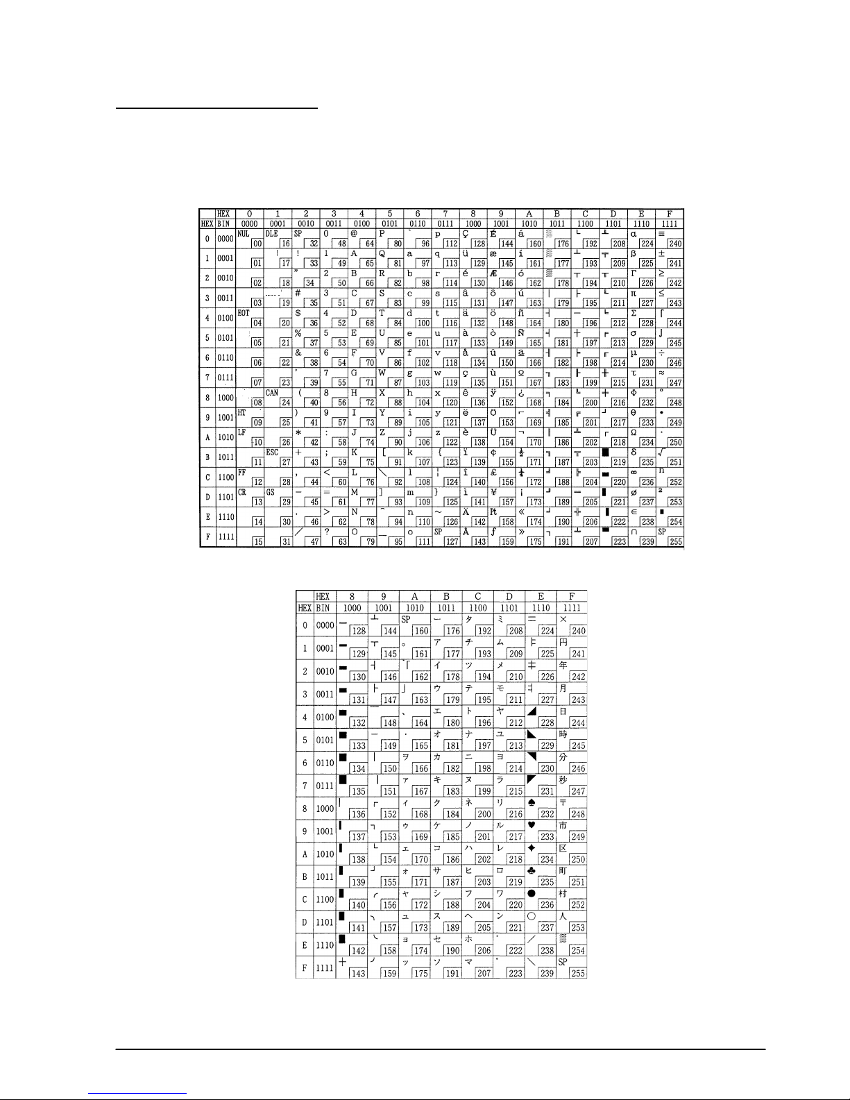
TM–L60II/L60IIP Information Manual
Character Code Tables
SP in a table represents space.
Page 0 (PC437: U.S.A., Standard Europe) (International character set: U.S.A)
Page 1 (Katakana)
Rev. A Command Descriptions 1-67
Page 75

Page 2 (PC850: Multilingual)
Page 3 (PC860: Portuguese)
1-68 Command Descriptions Rev. A
Page 76
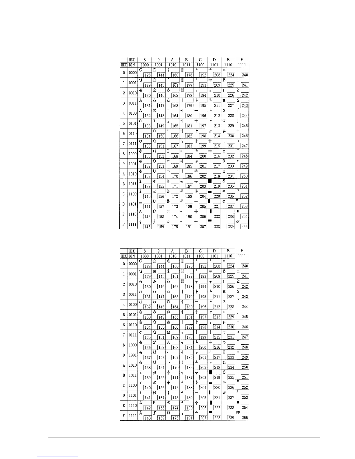
Page 4 (PC863: Canadian-French)
TM–L60II/L60IIP Information Manual
Page 5 (PC865: Nordic)
Rev. A Command Descriptions 1-69
Page 77

International character set
ASCII code (hexadecimal)
Country
U.S. A. # $ @ [ \] ^` { ¦}
France # $ à ° ç § ^ ` é ù è ¨
Germany # $ § Ä Ö Ü ^ ` ä ö ü ß
U.K. £
Denmark I # $ @ Æ Ø Å ^ ` æ ø å
S w e d e n # ¤ É Ä Ö Å Ü é ä ö å ü
I t a l y # $ @ ° \ é ^ ù à ò è ì
Spain Pt $ @ ¡ Ñ ¿ ^ ` ¨ ñ }
Japan # $ @ [ ¥ ] ^` { ¦}
N o r w a y # ¤ É Æ Ø Å Ü é æ ø å ü
Hex 2324405B5C5D5E607B7C7D 7E
Dec 3536649192939496123124125126
$@
[ \ ] ^`
{ ¦ }
~
~
~
~
~
D e n m a r k I I # $ É Æ Ø Å Ü é æ ø å ü
1-70 Command Descriptions Rev. A
Page 78

TM–L60II/L60IIP Information Manual
Using Character Code Tables
The example below uses Page 0 (PC437) (see page 1-67) to illustrate the use of the character code
tables.
You can find the character "A" in Page 0 as follows:
The decimal value for the character "A" is 65.
Follow its column straight up to find the digits.
Hexadecimal . . .4
Binary. . . . . . . . .0100
These numbers are the most significant bits of the ASCII code.
Follow its row to the left to find the digits.
Hexadecimal . . .1
Binary. . . . . . . . .0001
These numbers are the least significant bits of the ASCII code.
The combination of the numbers above is the ASCII code for character "A".
Decimal . . . . . . .<65>
10
Hexadecimal . . .<41>H
Binary. . . . . . . . .<01000001>B
Rev. A Command Descriptions 1-71
Page 79
TM–L60II/L60IIP Information Manual
Chapter 2
Application
This chapter presents an example illustrating ESC/POS command functions and printing results. The
example shows how to issue a label containing bar codes. Set the paper selection function of the DIP
switch to thermal label before turning on the printer.
Bar Codes Label Issuing
Procedure Commands Used Description
1. P ri nt message A ESC a, ESC !, LF Sets the print position to the center with ESC a and prints
message A with LF.
2. Print bar code GS H, GS f, GS h, GS k, ESC J Prints bar co de after selecting the height o f the bar code
with GS h and the printing position of the HRI characters
with GS H.
3. P ri nt message B ESC a, ESC J Prints message B using ESC J.
4. Print date ESC a, ESC !, GS FF Sets the print positio n to t he right using ESC a, selects font B
(9 x 24) with ESC !, and prints the date with GS FF.
*The paper LED blinks when the label is ejected from the
position where the label can be peeled off. Press the
PAPER FEED switch and peel off the label. The next label
feeds to the starting positi on.
Print Sample
1996.4.10
1996.4.10
Rev. A Application 2- 1
Page 80

Program Example
PRINT #1, CHR$(&H1B);"@";←
Initialize s the printer
NO$="00001" : GOSUB start
NO$="00002" : GOSUB start
END
start:
PRINT #1, CHR$(&H1B);"a";C HR$(1);←
PRINT #1, CHR$(&H1B);"!";C HR$(40);←
Selects center print position
Selects c haract er print mode
(emphasize d + d ouble-height + double-wid th)
PRINT #1, "EPSON";
PRINT #1, CHR$(&H1B);"!";C HR$(8);←
Cancels double-width
PRINT #1, "Rental Video"; CHR$(&HA);
PRINT #1, CHR$(&H1B);"!";C HR$(0);←
PRINT #1, CHR$(&H1D);"H";C HR$(2);←
PRINT #1, CHR$(&H1D);"f";C HR$(1);←
Cancels emphasized
Selects printing position for HRI char acters
Selects HRI characters
PRINT #1, CHR$(&H1D);"h";C HR$(35);←Sets bar cod e hei ght
PRINT #1, CHR$(&H1D);"k";C HR$(4);"∗";NO$;"*";CHR$(0);
PRINT #1, CHR$(&H1B);"J";C HR$(5);
PRINT #1, CHR$(&H1B);"-";C HR$(2);←
Sets un derline width to 2 dots
P RINT #1, " NAME ";
PRINT #1, CHR$(&H1B);"J";C HR$(70);
PRINT #1, CHR$(&H1B);"-";C HR$(0);←
Cancels previous character print mode
Prints messa ge A
Prints bar code
Prints message B
PRINT #1, CHR$(&H1B);"a";C HR$(2);←
PRINT #1, CHR$(&H1B);"!";C HR$(1);←
PRINT #1, "1996.4.10";
PRINT #1, CHR$(&H1D);CHR$( HC);←
V$=INPUT$(1)←
Ready to input (waiting to input )
Prints and feeds the label print starting posit ion
RETURN
Selects right print position
Selects font B (9 x 24)
Prints the date and
feeds th e lab el to
the pri nt starting
positio n
2-2 Application Rev. A
Page 81

TM–L60II/L60IIP Information Manual
Chapter 3
Command Reference
Command Classification
ESC/POS printer commands in this chapter are classified by function and by sheet and grade. The
sheet and grade classification is called matrix classification.
The sheet classification is divided into single sheet commands and multiple sheet commands. The grade
classification is separated into basic commands and extension commands.
Basic commands are defined as fundamental printer controls, including print commands and character
type selection commands. Extension commands are defined as control codes for functions specific to
individual printers. These commands are further divided into mechanical extension commands that
relate to additional mechanical functions such as stamp and auto-cutter units, hardware extension
commands that relate to additional hardware functions such as panel button control, and software
extension commands that relate to additional software functions such as user-defined and Bar code
control.
The commands can also be classified by function, which is how they are presented in Chapter 1 and
the Function Type table in this chapter. The function types, such as Print Commands and Line
Spacing Commands, are briefly explained in the corresponding sections of Chapter 1.
The illustration below shows the ESC/POS command overview diagram for printers.
Multiple sheet
Sheet
Single sheet
Multiple sheet
commands
Single sheet commands
Basic commands
Grade
Mechanical extension commands
Extension commands
Hardware extension commands
Software extension commands
Rev. A Command Reference 3-1
Page 82

Function Type
Function Type Command Name Matrix Category
Print commands
Line spacing
commands
LF
FF
CR
ESC FF
ESC J
ESC K
ESC d
ESC e
GS FF
ESC 2
ESC 3
ESC C
Print and line feed Basic single
1. Print and eject cut sheet (in
standard mode)
2. Print and return to standard
mode (in page mode)
3. Print and feed label to print
starting position (on label)
Print and carriage return Mechanical extension
Print data in page mode Software extension
Print and feed paper Mechanical extension
Print and reverse feed Mechanical extension
n
Print and feed
Print and reverse feed
Print and eject label Hardware extension
Select default line spacing Mechanical extension
Set line spacing Mechanical extension
Set cut sheet eject length Mechanical extension
lines Basic single
n
lines Mechanical extension
Mechanical extension
Mechanical extension
Mechanical extension
Supported
Command
●
●
●
●
●
●
●
●
●
●
Character commands
The TM-L60II/L60IIP supports the commands marked with a ● in the “Supported Command” column.
CAN
ESC SP
ESC !
ESC %
ESC &
ESC –
ESC ?
ESC E
ESC G
ESC R
ESC V
ESC r
ESC t
ESC z
Cancel print data in page mode Software extension
Set right-side character spacing Basic single
Select print mode(s) Basic single
Select/cancel user-defined
character set
Define user-defined characters Software extension
Turn underline mode on/off Software extension
Cancel user-defined characters Software extension
Turn emphasized mode on/off Software extension
Turn double-strike mode on/off Software extension
Select an international
character set
Turn 90° clockwise rotation mode
on/off
Select print color Mechanical extension
Select character code table Basic single
Turn parallel printing mode on/
off for receipt and journal
Software extension
Basic single
Software extension
Mechanical extension
●
●
●
●
●
●
●
●
●
●
●
●
3-2 Command Reference Rev. A
Page 83

TM–L60II/L60IIP Information Manual
Function Type Command Name Matrix Category
Character commands
(continued)
Printing paper
commands
Paper sensor
commands
Print position
commands
Status commands
ESC {
GS !
GS B
GS b
ESC c 0
ESC c 1
ESC f
ESC c 3
ESC c 4
HT
RS
ESC $
ESC D
ESC T
ESC W
ESC \
ESC a
GS $
GS L
GS W
GS \
DLE EOT
DLE EOT BS
Turn upside-down printing mode
on/off
Select character size Software extension
Turn white/black reverse printing
mode on/off
Turn smoothing mode on/off Software extension
Select paper type(s) for printing Basic multiple
Select paper type(s) for
command settings
Set cut sheet wait time Mechanical extension
Select paper sensor(s) to output
paper-end signals
Select paper sensor(s) to stop
printing
Horizontal tab Software extension
Journal tab Mechanical extension
Set absolute print position Software extension
Set horizontal tab positions Software extension
Select print direction in page
mode
Set printing area in page mode Software extension
Set relative print position Software extension
Select justification Software extension
Set absolute vertical print
position in page mode
Set left margin Software extension
Set printing area width Software extension
Set relative vertical print position
in page mode
Real-time status transmission Hardware extension
Transmit real-time MICR status Hardware extension
Basic single
Software extension
Mechanical extension
Mechanical extension
Mechanical extension
Software extension
Software extension
Software extension
Supported
Command
●
●
●
●
●
●
●
●
●
●
●
●
●
●
●
●
●
●
ESC u
ESC v
GS ENQ
GS a
GS r
The TM-L60II/L60IIP supports the commands marked with a ● in the “Supported Command” column.
Rev. A Command Reference 3-3
Transmit peripheral device status Hardware extension
Transmit paper sensor status Hardware extension
Transmit real-time printer status Hardware extension
Enable/disable Automatic
Status Back (ASB)
Transmit status Hardware extension
Hardware extension
●
●
●
●
Page 84

Function Type Command Name Matrix Category
ESC
Bit-image commands
Bar code commands
Macro function
commands
Kanji control
commands
Mechanism control
commands
Panel button
commands
The TM-L60II/L60IIP supports the commands marked with a ● in the “Supported Command” column.
✻
✻
GS
GS /
GS H
GS f
GS h
GS k
GS w
GS :
GS ^
FS !
FS &
FS –
FS .
FS 2
FS C
FS S
FS W
ESC <
ESC F
ESC U
ESC i
ESC m
ESC o
ESC q
GS V
ESC c 5
ESC c 6
Select bit-image mode Basic single
Define downloaded bit image Software extension
Print downloaded bit image Software extension
Select printing position of HRI
characters
Select font for HRI characters Software extension
Set bar code height Software extension
Print bar code Software extension
Set bar code width Software extension
Start/end macro definition Software extension
Execute macro Software extension
Select print mode(s) for Kanji
characters
Select Kanji character mode Software extension
Turn underline mode on/off for
Kanji characters
Cancel Kanji character mode Software extension
Define user-defined Kanji
characters
Select Kanji character code
system
Set left- and right-side Kanji
character spacing
Turn quadruple-size mode on/
off for Kanji characters
Return home Mechanical extension
Set/cancel cut sheet reverse
eject
Turn unidirectional printing mode
on/off
Partial cut (one point left uncut) Mechanical extension
Partial cut (three points left
uncut)
Stamp Mechanical extension
Paper release Mechanical extension
Select cut mode and cut paper Mechanical extension
Enable/disable panel buttons Hardware extension
Enable/disable on-line button Hardware extension
Software extension
Software extension
Software extension
Software extension
Software extension
Software extension
Software extension
Mechanical extension
Mechanical extension
Mechanical extension
Supported
Command
●
●
●
●
●
●
●
●
●
●
●
3-4 Command Reference Rev. A
Page 85

TM–L60II/L60IIP Information Manual
Function Type Command Name Matrix Category
MICR commands
Miscellaneous function
commands
The TM-L60II/L60IIP supports the commands marked with a ● in the “Supported Command” column.
FS a 0
FS a 1
FS a 2
FS b
FS c
DLE ENQ
ESC =
ESC @
ESC L
ESC S
ESC p
FS L
GS <
GS A
GS C 0
GS C 1
GS C 2
GS C ;
GS E
GS I
GS P
GS c
GS z 0
Read check paper Mechanical extension
Load check paper to print
starting position
Eject check paper Mechanical extension
Request retransmission of check
paper reading result
MICR mechanism cleaning Mechanical extension
Real-time request to printer Software extension
Select peripheral device Software extension
Initialize printer Basic single
Select page mode Software extension
Select standard mode Software extension
Generate pulse Hardware extension
Select double density page
mode
Initialize printer mechanism Mechanical extension
Adjust label print starting position Hardware extension
Select counter print mode Software extension
Select count mode (A) Software extension
Set counter Software extension
Select count mode (B) Software extension
Select head control method Hardware extension
Transmit printer ID Hardware extension
Set horizontal and vertical
motion units
Print counter Software extension
Set on-line recovery wait time Software extension
Mechanical extension
Mechanical extension
Software extension
Software extension
Supported
Command
●
●
●
●
●
●
●
●
●
●
●
●
●
●
Rev. A Command Reference 3-5
Page 86

3-6
Reference Table
Command Name Function
Supported Command
TM-
267II
TM-T Series TM-L Series TM-U200 TM-300/300M
TM270
TM-U375
TM-U375M
TM-
U925
TM-U950
TM-U950M
TM-
215S
TM295
T60 T80 T80M T85 L60 L60II B D A B C D
HT
Horizontal tab Moves the printing
position to the next
horizontal tab
position.
●●●●●●●●●●●●●● ● ● ●
LF
Print and line
feed
Prints the data in the
print buffer and
feeds one line
based on the current
line spacing.
●●●●●●●●●●●●●● ● ● ● ● ●
FF
1. Print and
eject cut
sheet (in
standard
mode)
Prints the data in the
print buffer and
ejects the cut sheet.
●● ● ● ●
2. Print and
return to
standard
mode (in
page
mode)
Prints the data in the
print buffer and
returns to standard
mode.
●● ● ●
3. Print and
feed label
to print
starting
position (on
label)
Prints the data in the
print buffer and
feeds the next label
to the print starting
position.
●●
The commands supported by each printer are marked by a ● or a O. The functions of the commands marked by a O may differ, depending on the printer model.
Page 87

3-7
TM–L60II/L60IIP Information Manual
CR
Print and
carriage
return
When auto line feed
is enabled, this
command functions
in the same way as
LF
. When auto line
feed is disabled, this
command prints the
data in the print
buffer and does not
feed the paper.
OOOO
● ● ●●●●
O
●●●●
O
CAN
Cancel print
data in page
mode
Clears all the print
data in the printing
area in page mode.
●● ● ●
RS
Journal tab Moves the print
position to the
beginning of the
journal paper.
●
DLE EOT
Real-time
status
transmission
Transmits a specified
status in real time.
●●●● ●●● ●
DLE EOT BS
Real-time
MICR status
transmission
Transmits MICR
status in real time. OO
DLE ENQ
Real-time
request to
printer
Responds to a
request from the host
computer upon
receiving this
command.
●●●
●
●●
ESC FF
Print data in
page mode
Prints the data in the
print buffer in page
mode.
●●
ESC SP
Set right-side
character
spacing
Sets the right-side
character spacing.
●●●●●●●●●●●●●● ● ● ● ● ●
Command Name Function
Supported Command
TM-
267II
TM-T Series TM-L Series TM-U200 TM-300/300M
TM270
TM-U375
TM-U375M
TM-
U925
TM-U950
TM-U950M
TM-
215S
TM295
T60 T80 T80M T85 L60 L60II B D A B C D
The commands supported by each printer are marked by a
●
or a O. The functions of the commands marked by a O may differ, depending on the printer model.
Page 88

3-8
ESC !
Select print
mode(s)
Selects a print
mode(s).
●●●●●●●●●●●●●● ● ● ● ● ●
ESC $
Set absolute
print position
Sets the print starting
position from the
beginning of the line.
●●●●●● ● ● ●
ESC %
Select/
cancel userdefined
character set
Selects or cancels
the user-defined
character set.
●●●●●●●●●●●●●● ● ● ● ●
●
ESC &
Define userdefined
characters
Defines user-defined
characters for a
specified character
code.
●●●●●●●●●●●●●● ● ● ● ●
●
ESC
✻ Select bit-
image mode
Selects a bit-image
mode for a specified
number of dots.
●●●●●●●●●●●●●● ● ● ● ●
●
ESC –
Turn underline
mode on/off
Turns underline mode
on or off.
●●●●●●
OOOO
●●●
ESC 2
Select default
line spacing
Sets the line spacing
to 1/6 inch.
●●●●●●●●●●●●●● ● ● ● ●
●
ESC 3
Set line
spacing
Sets the line spacing
to a specified value.
●●●●●●●●●●●●●● ● ● ● ●
●
ESC <
Return home Moves the print head
to the home position.
● ● ●●●● ● ● ●
ESC =
Select
peripheral
device
Selects the device
to which the host
computer sends
data.
●●●●●●●● ● ● ● ●
ESC ?
Cancel userdefined
characters
Cancels the userdefined characters
for a specified
character code.
●●●● ●●●
Command Name Function
Supported Command
TM-
267II
TM-T Series TM-L Series TM-U200 TM-300/300M
TM270
TM-U375
TM-U375M
TM-
U925
TM-U950
TM-U950M
TM-
215S
TM295
T60 T80 T80M T85 L60 L60II B D A B C D
The commands supported by each printer are marked by a
●
or a O. The functions of the commands marked by a O may differ, depending on the printer model.
Page 89

3-9
TM–L60II/L60IIP Information Manual
ESC @
Initialize
printer
Clears the data in the
print buffer and resets
the printer mode to
the mode that was in
effect when the
power was turned on.
●●●●●●●●●●●●●● ● ● ● ● ●
ESC C
Set cut sheet
eject length
Sets the eject length
for cut sheet to a
specified number of
lines.
●● ● ● ●
ESC D
Set horizontal
tab positions
Sets the horizontal
tab positions.
●●●●●●●●●●●●●● ● ● ●
ESC E
Turn
emphasized
mode on/off
Turns emphasized
mode on or off.
●●●●●●
OOOO
●●●
ESC F
Set/cancel
cut sheet
reverse eject
Sets or cancels the
cut sheet reverse
eject specified by FF.
●
ESC G
Turn doublestrike mode
on/off
Turns double-strike
mode on or off.
●●●●●●
OOOO
●●●
ESC J
Print and
feed paper
Prints the data in the
print buffer and
feeds the paper a
specified distance.
●●●●●●●●●●●●●● ● ● ● ● ●
ESC K
Print and
reverse feed
Prints the data in the
print buffer and
feeds the paper a
specified distance in
the reverse direction.
●●
●●
●
ESC L
Select page
mode
Switches from
standard mode to
page mode.
●●
●●
Command Name Function
Supported Command
TM-
267II
TM-T Series TM-L Series TM-U200 TM-300/300M
TM270
TM-U375
TM-U375M
TM-
U925
TM-U950
TM-U950M
TM-
215S
TM295
T60 T80 T80M T85 L60 L60II B D A B C D
The commands supported by each printer are marked by a
●
or a O. The functions of the commands marked by a O may differ, depending on the printer model.
Page 90
3-10
ESC R
Select an
international
character set
Selects a country’s
character set.
●●●●●●●●●●●●●● ● ● ● ● ●
ESC S
Select
standard
mode
Switches from page
mode to standard
mode.
●●
ESC T
Select print
direction in
page mode
Selects the print
direction and starting
position in page
mode.
●●
●●
ESC U
Turn
unidirectional
printing
mode on/off
Turns unidirectional
printing mode on or
off.
● ● ●●●● ● ● ● ●
ESC V
Turn 90°
clockwise
rotation mode
on/off
Turns 90° clockwise
rotation mode on or
off.
●●●●●●
●●
ESC W
Set printing
area in page
mode
Sets the position and
the size of the
printing area in page
mode.
●● ● ●
ESC \
Set relative
print position
Sets the print starting
position based on
the current position.
●●●●●● ● ● ●
ESC a
Select
justification
Aligns all the data in
one line to a
specified position.
●●●●●●●● ● ● ●
ESC c 0
Select print
paper(s)
Selects paper type(s)
for printing.
●●● ● ● ●
ESC c 1
Select paper
type(s) for
command
settings
Selects paper type(s)
for use with various
command settings.
●● ● ●
Command Name Function
Supported Command
TM-
267II
TM-T Series TM-L Series TM-U200 TM-300/300M
TM270
TM-U375
TM-U375M
TM-
U925
TM-U950
TM-U950M
TM-
215S
TM295
T60 T80 T80M T85 L60 L60II B D A B C D
The commands supported by each printer are marked by a
●
or a O. The functions of the commands marked by a O may differ, depending on the printer model.
Page 91

3-11
TM–L60II/L60IIP Information Manual
ESC c 3
Select paper
sensor(s) to
output paperend signals
Selects paper
sensor(s) to output
paper-end signals.
O O O O O O OOOO O O O O
ESC c 4
Select paper
sensor(s) to
stop printing
Selects the paper
sensor(s) that stops
printing when the
paper runs out.
●●●●●●●●●●●●●● ● ● ● ●
ESC c 5
Enable/
disable panel
buttons
Enables or disables
the panel buttons.
●●●●●●●●●●●●●● ● ● ● ● ●
ESC c 6
Enable/
disable on-line
button
Enables or disables
the ON-LINE switch.
●
●
ESC d
Print and
feed
n
lines
Prints the data in the
print buffer and
feeds
n
lines.
●●●●●●●●●●●●●● ● ● ● ● ●
ESC e
Print and
reverse feed
n
lines
Prints the data in the
print buffer and
feeds
n
lines in the
reverse direction.
●●
●● ●
ESC f
Set cut sheet
wait time
Sets the time that the
printer waits for cut
sheet to be inserted
and the time from
insertion of the sheet
to the start of
printing.
●●
●● ● ● ●
ESC i
Partial cut
(one point
left uncut)
Executes a partial
cut of the paper with
one point left uncut.
● ●●●
●● ● ●
Command Name Function
Supported Command
TM-
267II
TM-T Series TM-L Series TM-U200 TM-300/300M
TM270
TM-U375
TM-U375M
TM-
U925
TM-U950
TM-U950M
TM-
215S
TM295
T60 T80 T80M T85 L60 L60II B D A B C D
The commands supported by each printer are marked by a
●
or a O. The functions of the commands marked by a O may differ, depending on the printer model.
Page 92

3-12
ESC m
Partial cut
(three points
left uncut)
Executes a partial
cut of the paper with
three points left
uncut.
●●●
●● ● ●
ESC o
Stamp Executes stamp
printing.
●●
ESC p
Generate
pulse
Sends a specified
pulse to a specified
connector pin.
●●●●●●●●●●●●● ● ● ● ● ●
ESC q
Paper release Releases the paper.
●● ●
ESC r
Select print
color
Selects the print
color.
● ●●●
O
●
ESC t
Select
character
code table
Selects a page from
the character code
table.
●●●●●●●●●●●●●● ● ● ● ● ●
ESC u
Transmit
peripheral
device status
Transmits the status
of a specified
connector pin.
OO
●●●●
OOOO O
●●●●●
ESC v
Transmit
paper sensor
status
Transmits the status
of a paper sensor.
●
OO
●●
●●
OOOO O
●
●
●●●
ESC z
Turn parallel
printing
mode on/off
for receipt
and journal
Turns parallel printing
mode on or off for
receipt and journal
paper.
●
ESC {
Turn upsidedown printing
mode on/off
Turns upside-down
printing mode on or
off.
●●●●●●●●●●●●●● ● ● ● ● ●
FS !
Select print
mode(s) for
Kanji
characters
Selects print mode(s)
for Kanji characters.
●
OOOO O O
Command Name Function
Supported Command
TM-
267II
TM-T Series TM-L Series TM-U200 TM-300/300M
TM270
TM-U375
TM-U375M
TM-
U925
TM-U950
TM-U950M
TM-
215S
TM295
T60 T80 T80M T85 L60 L60II B D A B C D
The commands supported by each printer are marked by a
●
or a O. The functions of the commands marked by a O may differ, depending on the printer model.
Page 93

3-13
TM–L60II/L60IIP Information Manual
FS &
Select Kanji
character
mode
Selects Kanji
character mode.
●
OOOO O O
FS –
Turn underline
mode on/off
for Kanji
characters
Turns underline mode
on or off for Kanji
characters.
●
OOOO O O
FS .
Cancel Kanji
character
mode
Cancels Kanji
character mode.
●
OOOO O O
FS 2
Define userdefined Kanji
characters
Defines user-defined
Kanji characters for
specified character
codes.
●
OOOO O O
FS C
Select Kanji
character
code system
Selects the Kanji
character code
system.
●
OOOO O O
FS L
Select double
density page
mode
Switches from
standard mode to
double-density
page mode.
O
FS S
Set left- and
right-side
Kanji
character
spacing
Selects the right- and
left-side Kanji
character spacing.
●
OOOO O O
FS W
Turn
quadruplesize mode on/
off for Kanji
characters
Turns quadruple-size
mode on or off for
Kanji characters.
●
OOOO O O
FS a 0
Read check
paper
Selects the MICR
function and reads
the check paper.
OO
Command Name Function
Supported Command
TM-
267II
TM-T Series TM-L Series TM-U200 TM-300/300M
TM270
TM-U375
TM-U375M
TM-
U925
TM-U950
TM-U950M
TM-
215S
TM295
T60 T80 T80M T85 L60 L60II B D A B C D
The commands supported by each printer are marked by a
●
or a O. The functions of the commands marked by a O may differ, depending on the printer model.
Page 94

3-14
FS a 1
Load check
paper to print
starting
position
Loads check paper
to the print starting
position.
OO
FS a 2
Eject check
paper
Ejects the check
paper.
OO
FS b
Request
retransmission
of check
paper
reading result
Retransmits the
previous check
paper (MICR
character) reading
results.
OO
FS c
MICR
mechanism
cleaning
Cleans the MICR
mechanism. OO
GS ENQ
Transmit realtime printer
status
Transmits the status
of the printer upon
receiving this
command.
●●
GS FF
Print and
eject label
Prints the data in the
print buffer and
ejects the label.
●●
GS !
Select
character size
Selects the
character width and
height.
●●
GS $
Set absolute
vertical print
position in
page mode
Sets the absolute
vertical print starting
position for
characters in page
mode.
●●
GS
✻ Define
downloaded
bit image
Defines a
downloaded bit
image using a
specified number of
dots.
●●●●●● ●
●
●
Command Name Function
Supported Command
TM-
267II
TM-T Series TM-L Series TM-U200 TM-300/300M
TM270
TM-U375
TM-U375M
TM-
U925
TM-U950
TM-U950M
TM-
215S
TM295
T60 T80 T80M T85 L60 L60II B D A B C D
The commands supported by each printer are marked by a
●
or a O. The functions of the commands marked by a O may differ, depending on the printer model.
Page 95
3-15
TM–L60II/L60IIP Information Manual
GS /
Print
downloaded
bit image
Prints a downloaded
bit image using a
specified mode.
●●●●●● ●
●
●
GS :
Start/end
macro
definition
Starts or ends a
macro definition.
●●●●●●
GS <
Initialize
printer
mechanism
Feeds a label to the
print starting position.
●●
GS A
Adjust label
print starting
position
Sets the label
position relative to
the default position.
●●
GS B
Turn white/
black reverse
printing
mode on/off
Turns white/black
reverse printing
mode on or off.
●●
GS C 0
Set counter
print mode
Selects a print mode
for the serial counter.
●●
GS C 1
Select count
mode (A)
Selects a count
mode for the serial
counter.
●●
GS C 2
Set counter Sets the counter
value.
●●
GS C ;
Select count
mode (B)
Selects a count
mode for the serial
counter and
specifies the counter
value.
●●
GS E
Select head
control
method
Selects the print
speed and head
energizing time.
●●●● ●
●
●
Command Name Function
Supported Command
TM-
267II
TM-T Series TM-L Series TM-U200 TM-300/300M
TM270
TM-U375
TM-U375M
TM-
U925
TM-U950
TM-U950M
TM-
215S
TM295
T60 T80 T80M T85 L60 L60II B D A B C D
The commands supported by each printer are marked by a
●
or a O. The functions of the commands marked by a O may differ, depending on the printer model.
Page 96

3-16
GS H
Select
printing
position of HRI
characters
Selects the printing
position of HRI
characters when
printing a bar code.
●●●●●●
GS I
Transmit
printer ID
Transmits a specified
printer ID.
●●●●
●
●
●
●
GS L
Set left margin Sets the left margin
using specified
values in standard
mode.
●● ●
GS P
Set horizontal
and vertical
motion units
Sets the horizontal
and vertical motion
units.
●●
●
●
●
GS V
Select cut
mode and cut
paper
Cuts the specified
paper.
●●
GS V
Select cut
mode and cut
paper
Advances the
specified paper to
the cut position and
performs the cut.
●●●
GS W
Set printing
area width
Sets the printing area
width to a defined
area in standard
mode.
●● ●
GS \
Set relative
vertical print
position in
page mode
Moves the vertical
print starting position
in page mode to a
specified distance
from the current
position.
●●
GS ^
Execute
macro
Executes a macro.
●●●●●●
Command Name Function
Supported Command
TM-
267II
TM-T Series TM-L Series TM-U200 TM-300/300M
TM270
TM-U375
TM-U375M
TM-
U925
TM-U950
TM-U950M
TM-
215S
TM295
T60 T80 T80M T85 L60 L60II B D A B C D
The commands supported by each printer are marked by a
●
or a O. The functions of the commands marked by a O may differ, depending on the printer model.
Page 97

3-17
TM–L60II/L60IIP Information Manual
GS a
Enable/
disable
Automatic
Status Back
(ASB)
Selects a status for
ASB transmission.
●●●● ●●●
●
GS b
Turn
smoothing
mode on/off
Selects or cancels
smoothing.
●●
GS c
Print counter Selects a serial
counter value in the
print buffer and
increments or
decrements the
counter value.
●●
GS f
Select font
for HRI
characters
Selects a font for the
HRI characters used
when printing a bar
code.
●●●●●●
GS h
Set bar code
height
Selects the height of
a bar code.
●●●●●●
GS k
Print bar
code ➀
Selects a bar code
system and prints
the bar code.
●●●●●●
GS k
Print bar
code ➁
Selects a bar code
system and prints
the bar code.
●●
GS r
Transmit status Transmits a specified
status.
●●●●
●
●
●
●
GS w
Set bar code
width
Selects the
horizontal size of the
bar code.
●●●●●●
GS z 0
Set on-line
recovery wait
time
Sets the on-line
recovery wait time.
●●
Command Name Function
Supported Command
TM-
267II
TM-T Series TM-L Series TM-U200 TM-300/300M
TM270
TM-U375
TM-U375M
TM-
U925
TM-U950
TM-U950M
TM-
215S
TM295
T60 T80 T80M T85 L60 L60II B D A B C D
The commands supported by each printer are marked by a
●
or a O. The functions of the commands marked by a O may differ, depending on the printer model.
Page 98

SEIKO EPSON CORPORATION
2070 Kotobuki Koaka, Matsumoto-shi, Nagano-ken 399, Japan
SYSTEM DEVICE DIVISION
 Loading...