

Epson EPL-C8200 Service manual
EPSON
EPSON
EPSON France S.A.
EPL-C8200
SERVICE MANUAL
®
SERVICE MANUAL
Color Laser Printer
EPSON ColorPage EPL-C8200
SEPG99-003

EPSON ColorPage EPL-C8200 Revision B
Notice
o
All rights reserved. No p art of t his manual may be reprod uced, stored i n a ret rieval syste m, or trans mit ted in any form or by any means electronic,
mechanical, photocopying, or otherwise, without the prior written permission of SEIKO EPSON CORPORATION.
o
All effort have been made to ensure the accuracy of the contents of this manual. However, should any errors be detected, SEIKO EPSON would
greatly appreciate being informed of them.
o
The contents of this manual are subject to change without notice.
o
All effort have been made to ensure the accuracy of the contents of this manual. However, should any errors be detected, SEIKO EPSON would
greatly appreciate being informed of them.
o
The above not withstanding SEIKO EPSON CORPORATION can assume no responsibility for any errors in this manual or the consequences
thereof.
EPSON is a registered trademark of SEIKO EPSON CORPORATION.
General Notice: Other product names used herein are for identification purpose only and may be trademarks or registered trademarks of their
respective owners. EPSON disclaims any and all rights in those marks.
Copyright © 1999 SEIKO EPSON CORPORA TION. Printed in Japan.

EPSON ColorPage EPL-C8200 Revision B
PRECAUTIONS
Precautionary notations throughout the text are categorized relative to 1)Personal injury and 2) damage to equipment.
DANGER
WARNING
The precautionary measures itemized below should always be observed when performing repair/maintenance procedures.
Signals a precaution which, if ignored, could result in serious or fatal personal injury. Great caution should be exercised in
performing procedures preceded by DANGER Headings.
Signals a precaution which, if ignored, could result in damage to equipment.
DANGER
1. ALWAYS DISCONNECT THE PRODUCT FROM THE POWER SOURCE AND PERIPHERAL DEVICES PERFORMING ANY
MAINTENANCE OR REPAIR PROCEDURES.
2. NO WORK SHOULD BE PERFORMED ON THE UNIT BY PERSONS UNFAMILIAR WITH BASIC SAFETY MEASURES AS DICTATED
FOR ALL ELECTRONICS TECHNICIANS IN THEIR LINE OF WORK.
3. WHEN PERFORMING TESTING AS DICTATED WITHIN THIS MANUAL, DO NOT CONNECT THE UNIT TO A POWER SOURCE UNTIL
INSTRUCTED TO DO SO. WHEN THE POWER SUPPLY CABLE MUST BE CONNECTED, USE EXTREME CAUTION IN WORKING ON
POWER SUPPLY AND OTHER ELECTRONIC COMPONENTS.
WARNING
1. REPAIRS ON EPSON PRODUCT SHOULD BE PERFORMED ONLY BY AN EPSON CERTIFIED REPAIR TECHNICIAN.
2. MAKE CERTAIN THAT THE SOURCE VOLTAGES IS THE SAME AS THE RATED VOLTAGE, LISTED ON THE SERIAL NUMBER/
RATING PLATE. IF THE EPSON PRODUCT HAS A PRIMARY AC RATING DIFFERENT FROM AVAILABLE POWER SOURCE, DO NOT
CONNECT IT TO THE POWER SOURCE.
3. ALWAYS VERIFY THAT THE EPSON PRODUCT HAS BEEN DISCONNECTED FROM THE POWER SOURCE BEFORE REMOVING OR
REPLACING PRINTED CIRCUIT BOARDS AND/OR INDIVIDUAL CHIPS.
4. IN ORDER TO PROTECT SENSITIVE MICROPROCESSORS AND CIRCUITRY, USE STATIC DISCHARGE EQUIPMENT, SUCH AS
ANTI-STATIC WRIST STRAPS, WHEN ACCESSING INTERNAL COMPONENTS.
5. REPLACE MALFUNCTIONING COMPONENTS ONLY WITH THOSE COMPONENTS BY THE MANUFACTURE; INTRODUCTION OF
SECOND-SOURCE ICs OR OTHER NONAPPROVED COMPONENTS MAY DAMAGE THE PRODUCT AND VOID ANY APPLICABLE
EPSON WARRANTY.
EPSON ColorPage EPL-C8200 Revision B
W ARNING
CAUTIO N
NOTE
About this manual
This manual describes basic functions, theory of electrical and mechanical operations, maintenance and repair procedures of the EPSON EPLC8200. The instructions and procedures included herein are intended for the experienced repair technici ans, and attention should be given to the
precautions on the preceding page.
Manual Configuration
This manual consists of six chapters and Appendix.
CHAPTER 1. PRODUCT DESCRIPTIONS
Provides a general overview and specifications of the
product.
CHAPTER 2. OPERATING PRINCIPLES
Describes the theory of electrical and mechanical
operations of the product.
CHAPTER 3. DISASSEMBLY / ASSEMBLY AND ADJUSTMENT
Describes the step-by-step procedur es for
disassembling/assembling and adjusting the product.
CHAPTER 4. DIAGNOSTICS
Provides Epson-approved methods for diagnostics.
CHAPTER 5. TROUBLESHOOTING
Provides the step-by-step procedure s for
troubleshooting.
CHAPTER 6. MAINTENANCE
Provides preventive maintenance procedures and the
lists of Epson-approved lubricants and adhesives
required for servicing the product.
APPENDIX
Provides the following additional information for
reference:
• Connector pin assignments
• Electric circuit boards components layout
• Exploded diagram
• Electrical circuit boards schematics
Symbols Used in this Manual
Various symbols are used throughout this manual either to provide
additional information on a specif ic topic or to warn of possible danger
present during a procedure or an action. Be aware of all symbols when
they are used, and always read NOTE, CAUTION, or WARNING
messages.
Indicates an operating or maintenance procedure, practice
or condition that, if not strictly observed, could result in
injury or loss of life.
Indicates an operating or maintenan ce pr ocedure, practi ce,
or condition that, if not strictly observed, could result in
damage to, or destruction of, equipment.
CHECK
PO INT
May indicate an operating or maintenance procedure,
practice or condition that is necessary to accomplish a task
efficiently. It may also provid e add itional information that is
related to a specific subject, or comment on the results
achieved through a previous action.

EPSON ColorPage EPL-C8200 Revision B
Abbreviation
ADC = Automatic Density Control
AG = Analog Ground
ASSY = Assembly
AUX. = Auxiliary
B/W = Black and White
BCR = Bias Charge Roll
Bk = Black
BK = Black
BTR = Bias Transfer Roll
BUR = Back Up Roll
C = Cyan
CART. = Cartridge
CCW = Counterclockwise
CL. = Clutch
CLN = Cleaning (or Cleaner)
CLK = Clock
CONT. = Controller
CR = Charge Roll
CRU = Customer Replaceable Unit
CRUM = CRU Monitor
CW = Clockwise
DB = Developing Bias
DEVE. = Developer
DIAG. = Diagnostic
dpi = dots per inch
DTS = Detach Saw
ELEC. = Electric
EP = Electrophotography
FDR = Feeder
FG = Frame Ground
FRU = Field Replaceable Unit
GND = Ground
H/R = Heat Roll
Hex = Hexadecimal
HVPS = High Voltage Power Supply
I/F = Interface
IBT = Intermediate Belt Transfer
ID = Image Density (or Identificati on)
L = Left
L/H = Left Hand
L/P = Low Paper
LD = Laser Diode
LEF = Long Edge Feed
LVPS = Low Voltage Power Supply
M = Magenta
MAG. = Magnetic
MCU = Machine Control Unit
MECH. = Mechanical
MOT. = Motor
MSI = Multi Sheet Inserter
N/F = Normal Force
N/P = No Paper
NVM = Non Volatile Memory
O/H = Option Hinge
OHP = Overhead Projector
(In this manual, OHP means OHP film)
OPC = Organic Photo Conductor
P/H = Paper Handling
P/R = Pressure Roll
PCDC = Pixel Count Dispense Control
Pixel = Picture Cell
PPM = Prints Per Minute
PV = Print Volume
PWB = Printed Wiring Board
R = Right
R/H = Right Hand
REGI. = Registration
ROS = Raster Output Scanner
RTN = Ret urn
SEF = Short Edge Feed
SG = Signal Ground
SNR = Sensor
SOL. = Solenoid
SOS = Start Of Scan
SPI = Scans Per Inch
SYNC. = Synchronous
TC = Toner Concentration
TEMP. = Temperature
TR = Transfer
TRANS. = Transport
WDD = Wide Range Dynamic Damper
XERO. = Xerographic
Y = Yellow
YMCBk = Yellow, Magenta, Cyan, Black
EPSON ColorPage EPL-C8200 Revision B
Safety Information
To prevent accidents during a maintenance procedure, strictly observe
the Warnings and Cautions. Do not do anything that is dang erous or not
within the scope of this document.
Do not do anything that is dangerous even if not specifically described
in this manual. In addition to the descriptions below and those given in
this manual, there are many situations and circumstances that are
dangerous. Be aware of these when you are working with the printer.
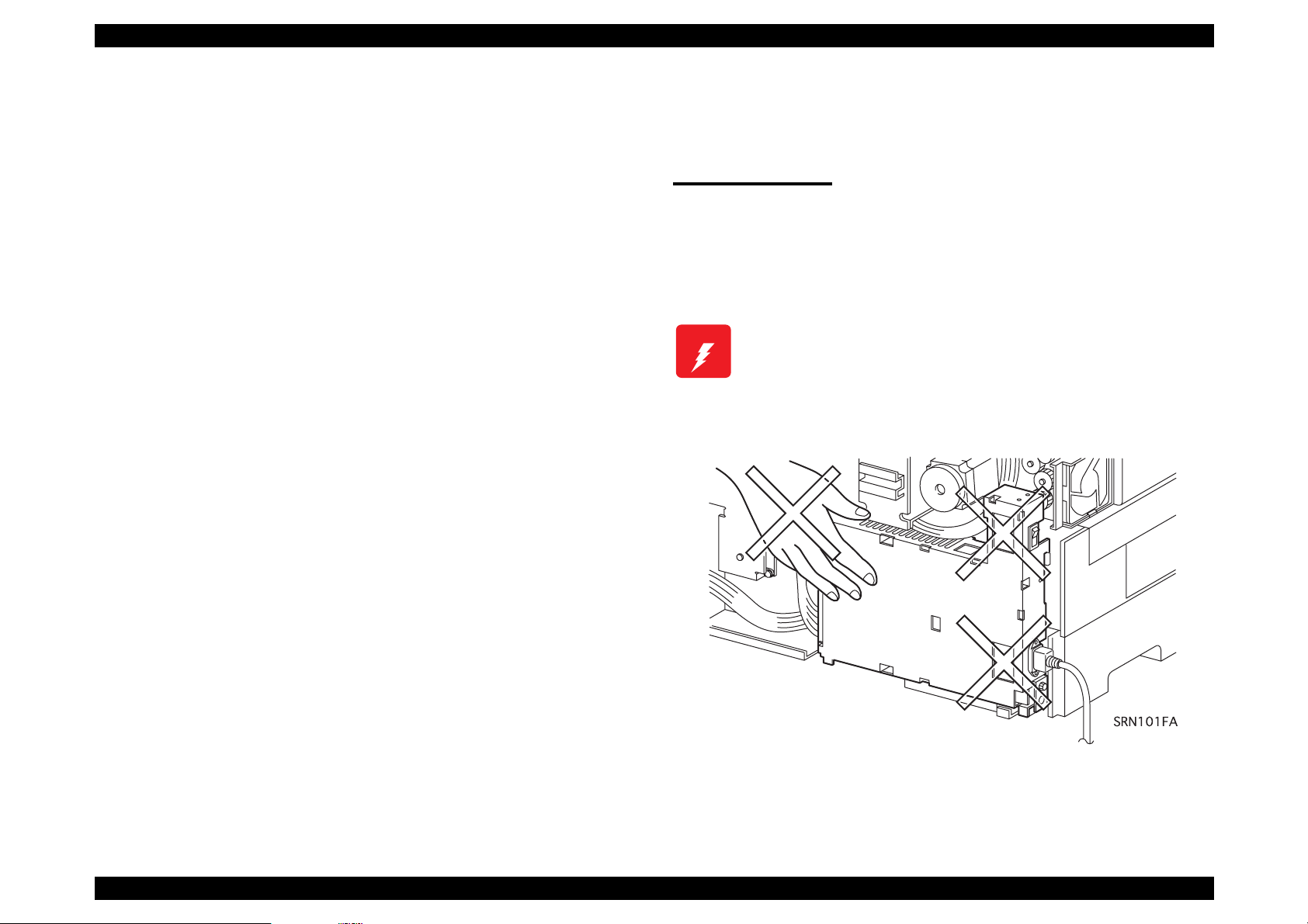
Power Supply
Before starting any service procedure, switch off the printer power and
unplug the power cord from the wall outlet. If you must service the
printer when the power is applied, be aware of the pot ential for elect rical
shock and do all tasks by following the procedures in this manual.
W ARNING
Do not touch any live part unless you are instructed to
do so by a service procedure. The LVPS power supply
switch/inlet part is li ve even when the power switch has
been turned off. Do not touch any live part.
EPSON ColorPage EPL-C8200 Revision B
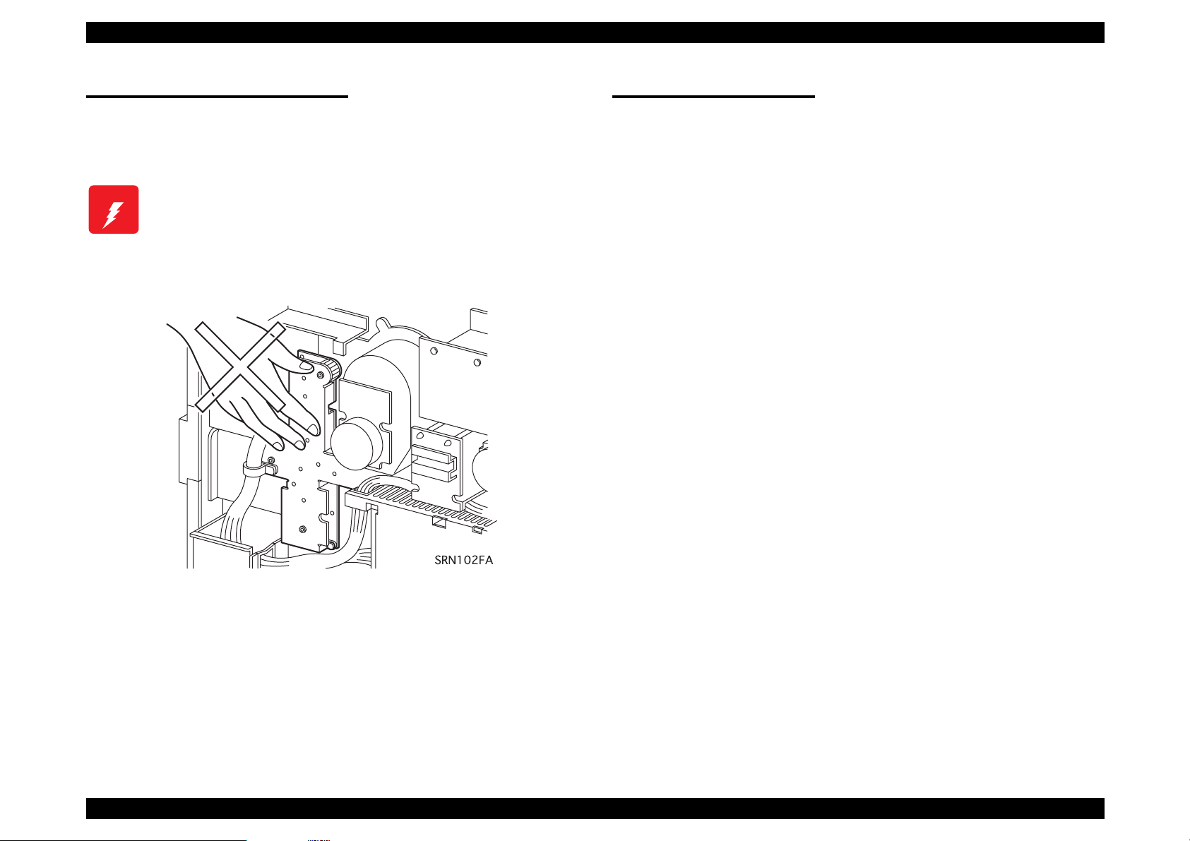
Mechanical Components
If you service a driving assembly (e.g., gears), first turn off the power
and unplug the power cord. Then manually rotate the assembly.
W ARNING
Do not touch the driving part (e.g., gears) while the
assembly (printer) is being driven.
Safety Components
The printer is equipped with safety components (e.g., interlock
switches, fuses, thermostat) and safety switches for protecting users
and service personnel from injury and the equipment from damage.
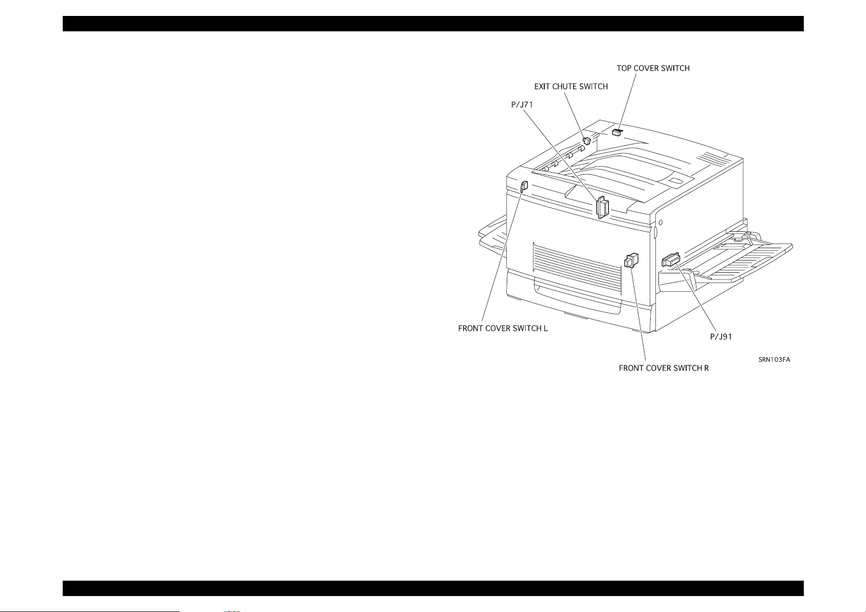
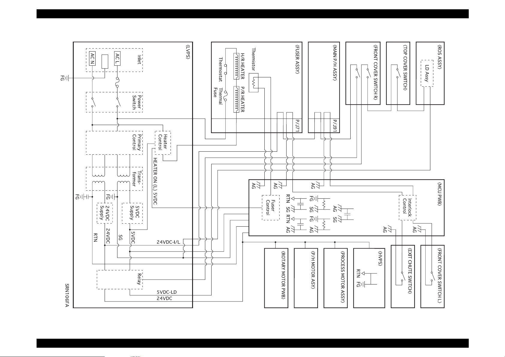
The printer has two interlock switches, two saf ety switches and two
interlock connectors that serve as the main safety mechanism.
o
Front Cover Switch R
This switch is turned off when the Front Cover Assembly is opened.
It cuts off the power supply (24VDC, 5VDC-LD) from the power
supply unit to stop all operat ions and di sconnec ts the out put (5VDCLD) circuit from the power supply and stops the laser beam
emission.
This switch consists of the following two swit ches:
n
A switch that cuts off the power supply (24VDC, 5VDC-LD) to
the control circuits and related parts.
n
A switch that directly cuts off the power supply circuit (5VDC-LD)
to the laser beam output circuit.
o
Front Cover Switch L
This is a safety switch. This switch is turned off when the Front
Cover Assembly is opened, causing the printer without control units
to stop operating.
o
Top Cover Switch
This is an interlock switch that directly cuts off the power supply
(5VDC-LD) circuit to the laser beam output circuit. This switch is
turned off when the Top Cover Assembly is removed, cutting off the
output (5VDC-LD) circuit from the power supply unit and stopping
the laser beam emission.
EPSON ColorPage EPL-C8200 Revision B
o
Exit Chute Switch
This switch is a safety switch. Thi s switch i s turned off when t he Exit
Upper Assembly (the cover on the upper left side of the printer) is
opened.
o
P/J91 (Connector that connects the Main Harness Assembly and
Registration Harness Assembly)
This is an interlock connector that cuts off the power supply
(24VDC, 5VDC-LD) to the control circuit and related parts.
This connector is disconnected when the Main P/H Assembly (pullout type unit on the right side of the printer) is pulled out, cutting off
the output (24VDC, 5VDC-LD) from the power supply and stopping
the printer operation without control units.
o
P/J71 (Connector that connects the Fuser Connector and Fuser
Harness Assembly)
This is an interlock connector that cuts off the power supply
(24VDC, 5VDC-LD) to the control circuit and related parts.
This connector is disconnected when the Fuser Assembly (pull-out
type unit on the left side of the printer) is pulled out, cutting off the
output (24VDC, 5VDC-LD) from the power supply and stopping the
printer operation without control units.
EPSON ColorPage EPL-C8200 Revision B
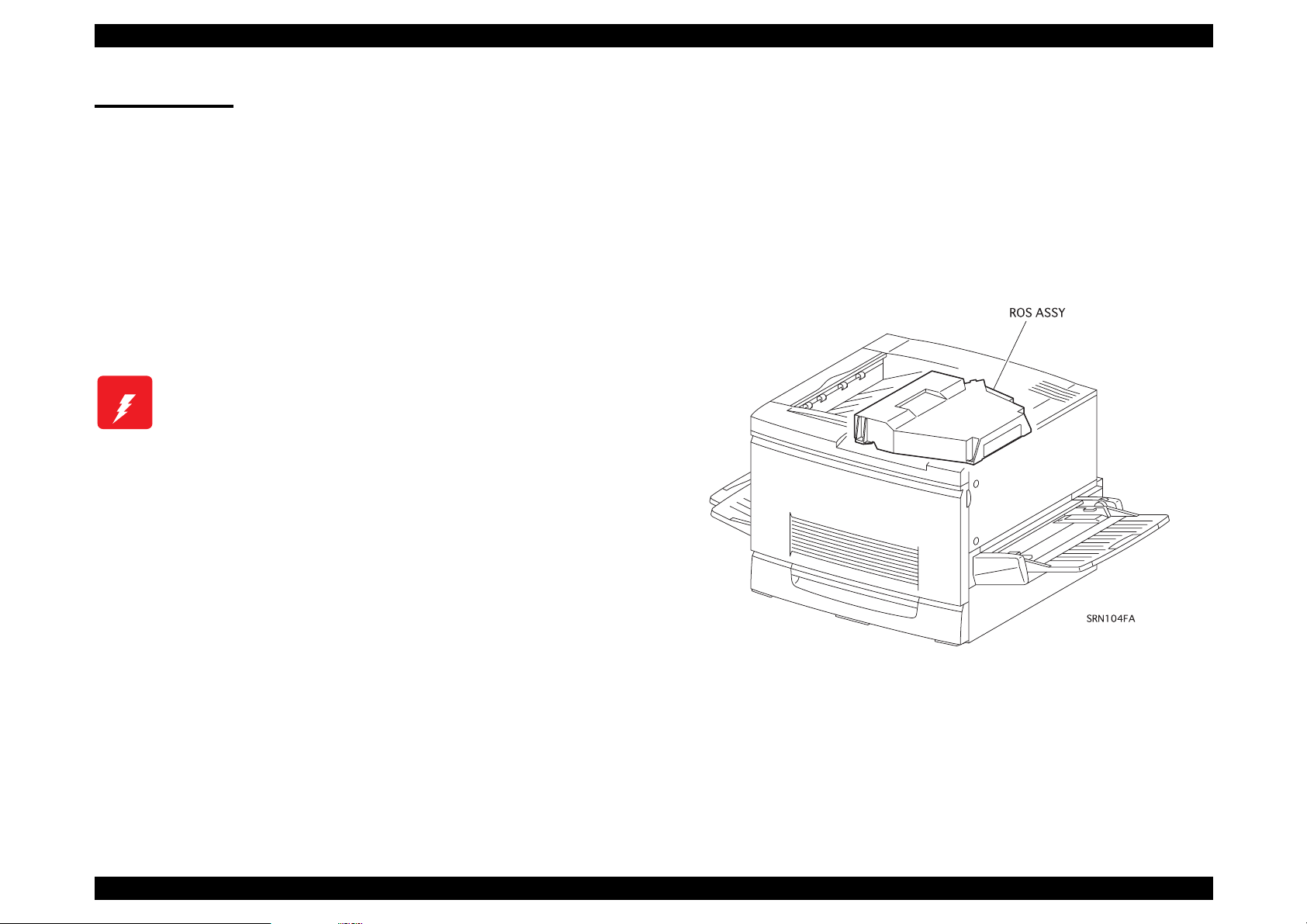
Laser Beam
The printer has two interlock switches: the Front Cover Switch R and
the Top Cover Switch. The purpose of these switches is to turn off the
laser beam emission if any of t he pri nter cover s h ave been op ened; th is
protects the user or servi ce personnel from exposure to the laser beam
from the ROS Assembly.
A laser beam may be emitted during a maintenance operation. Do not
turn on these interlock switches simult aneously under any
circumstances except in a normal operation.
n
W ARNING
Do not expose yourself to the laser beam to prevent
injury (blindness).
n
Do not open the cover that has the laser beam
warning label.
n
If you disassemble or assemble the printer, turn off
the power.
n
If you need to work on the printer with power applied,
strictly follow the instructions in thi s manual.
n
If you have to activate the printer while pressing the
Front Cover Switch R by hand or with a tool, remove
the Top Cover. (Do not turn on these interlock
switches simultaneously under any circumstances
except in a normal operation.)
n
Understand how the laser beam functions and take
maximum precautions not to injure yourself or anyone
around you.
NOTE:The laser beam has a narrower frequency band and more
coherent phases than any ot her light (sunlight , electr ic light ).
It has excellent monochromaticity and convergence. A thin
laser beam reaches long distances. Because of its
convergence characteristic, the laser beam converges into
one point, causing high density and high temperature. A
laser beam is harmful to the human body.
NOTE:The laser beam in this printer is invisibl e.
EPSON ColorPage EPL-C8200 Revision B
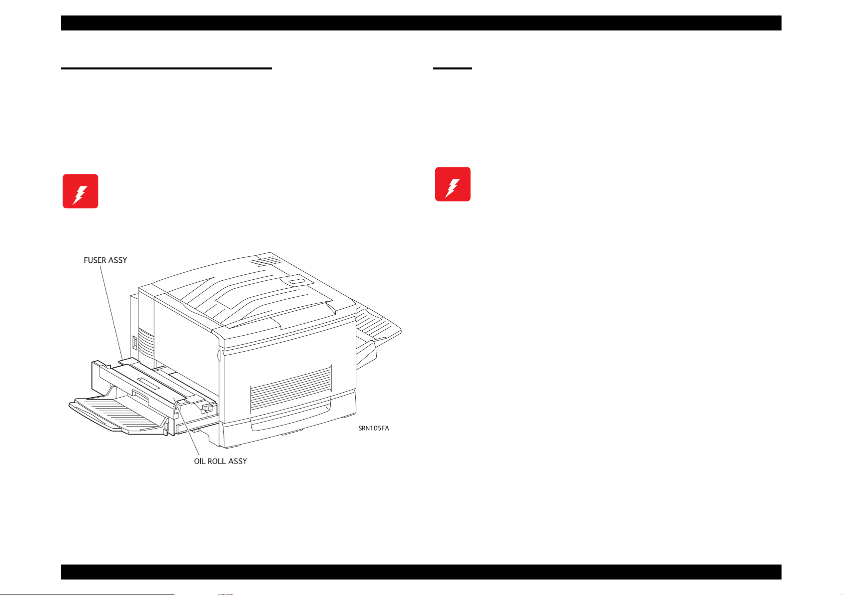
High Temperature Assembly
To prevent you from becoming injured or burned, do the following:
Before working with a high temperature Assembly (e.g., Fuser
Assembly), turn off the power, unplug the power cord and wait until it
cools down.
W ARNING
The high temperature Assembly is very hot
immediately after any printer operations. Wait at least
40 minutes before you start working on the printer.
Parts
To prevent you from becoming injured, keep the following in mind:
o
When handling heavy parts (including the printer it self), use good
posture to protect your back whenever you lift, move or place parts.
W ARNING
o
Be careful not to injure yourself with the sharp edg es of the par ts.
o
Do not work with wet or oily hands-you may drop a part or injure
yourself. Dry your hands first.
o
When pulling out a part (including a harness), do not use too much
force. Pull out the part carefull y and slowly step by step.
Do not lift, move or place heavy parts in a body posture
that is likely to cause injury to yourself or cause the
part to drop.

EPSON ColorPage EPL-C8200 Revision B
Consumables
Some parts may cause a particulate explosion or fire if handled
improperly. Do not handle these parts near fire or throw into a fire.
Some materials (e.g., Developer or Fuser Oil) may cause bodily inj ury.
Do not swallow or inhale these materials or allow them to come in
contact with the eyes.
Help to protect those around you and follow the prohibiti ons against
swallowing or inhalin g those materials. Be careful t o protect the eyes at
all times.
Place a sheet inside or under the printer so that the floor or workbench
is protected.
If the Developer or Fuser Oi l gets on your clothing, dry it with a cloth a nd
wash with clean water.
NOTE:The printer has the following consumable parts:
•
Drum Cartridge
•
Oil Roll Assembly
•
Toner Cartridge M
•
Toner Cartridge Bk
•
Waste Toner Box
•
Toner Cartridge Y
•
Toner Cartridge C
Improper Printer Use
Modifying, revising, tampering with the printer, especially to the safety
mechanism, is strictly prohibited in all circumstances.
EPSON ColorPage EPL-C8200 Revision B

EPSON ColorPage EPL-C8200 Revision B
Manual Contents
Chapter 1 Product Descriptions
Chapter 2 Operating Principles
Chapter 3 Disassembly and Assembly / Adjustment
Chapter 4 Diagnostics
Chapter 5 Troubleshooting
Chapter 6 Maintenance
Appendix
EPSON ColorPage EPL-C8200 Revision B
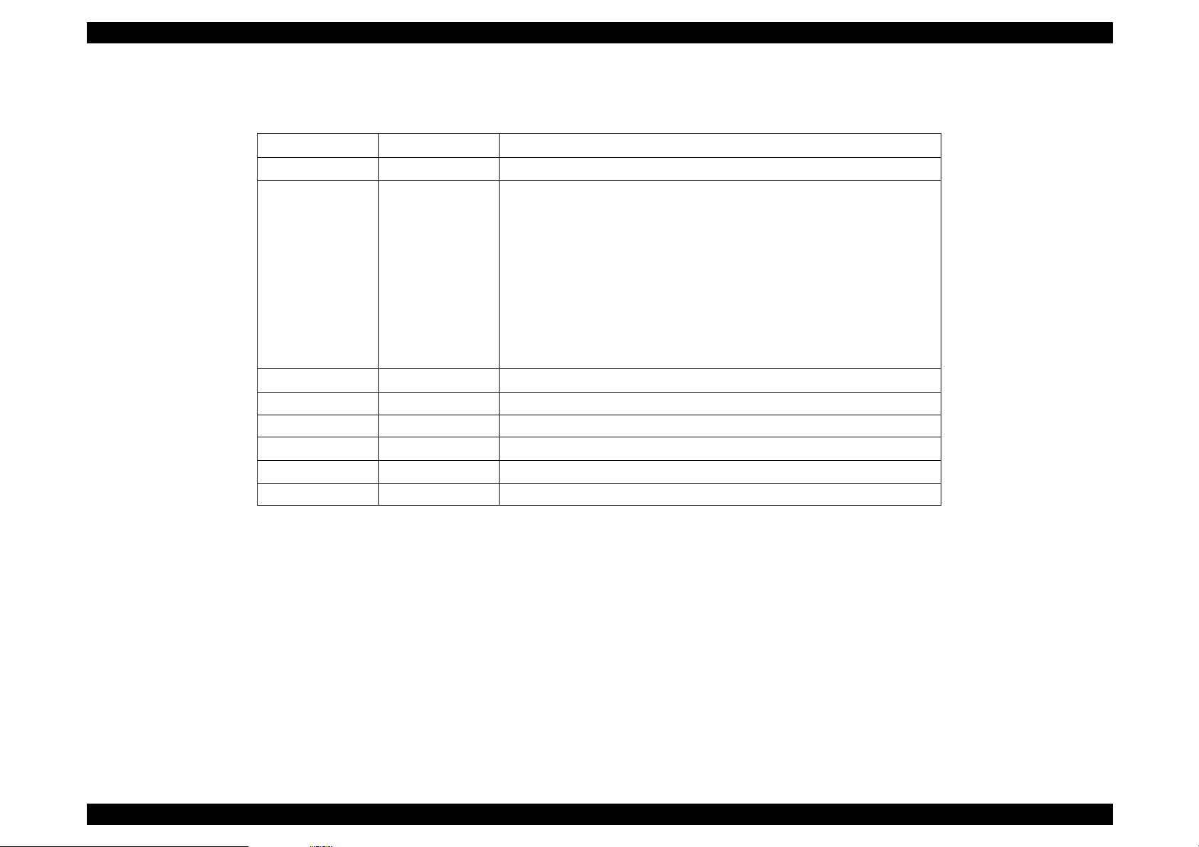
Revision Status
Revision Issued Date Description
Revision A Jul y 7th, 1999 Firs t issue
Revision B August 31, 1999 Second release
The manual has been mainly revised on the following points:
[Chapter 1]
• Unknown code ”xxxx” for EPSON Rip Station is replaced with “5200”.
[Chapter 3]
• Section 3.2.12.21 “FUSER IN SENSOR Removal” is added.
• Section 3.2.12.22 “FUSER CHUTE FAN Removal” is added.
• New adjustment item “DEVE. SPACER Selection” is added.
[Chapter 4]
• Page 4-13: Change in Table 4-6 with additional data file names.

PRODUCT DESCRIPTIONS
CHAPTER
1

EPSON ColorPage EPL-C8200 Revision B
Tabl e of Co nt en t s
Features.................................................................................................. 1
Specifications........................................................................................ 3
Basic Specifications.......................................................................... 3
Paper Specification.......................................... ..... ....... ....... ....... ..... .. 8
Reliability and Durability.................................................................. 11
Operating Environment................................................................... 13
Environmental Conditions for Storage and Transportation............. 14
Electrical Specifications.................................................................. 14
Process Specifications.................................................................... 15
Applicable Standards ...................................................................... 16
Options and Consumable Products ................................................ 16
Toner cartridge ................................................................... ..... 17
Drum Cartridge .................... .. ..... ..... .. ..... .. ..... .. ..... ..... .. ..... .. ..... 18
Fuser Oil Roll ........................................................................... 18
Waste Toner Box ..................................................................... 19
Regularly Replaced Parts ............................................................... 19
Exterior Dimensions........................................................................ 19
Controller Specifications................................................................. 20
Controller Board Jumper Settings................................................... 21
Interface Specifications ...................................................................... 21
Parallel Interface Specification........................................................ 22
Ethernet Interface........................................................................... 24
Type B Interface.............................................................................. 25
Control Panel....................................................................................... 26
Appearance and Descriptions......................................................... 26
LED Description ....................................................................... 27
Button Functions............................................................................. 28
Service Functions................................................................................ 30
Hex Dump Mode............................................................................. 30
Support Mode ................................................................................. 30
EEPROM Initialization ..................................................................... 30
Formatting the Flash ROM Module................................................. 31
Updating the Program ROM ........................................................... 31
ROM Module Copy ......................................................................... 31
Panel Setting Initialization............................................................... 31
Maintenance Mode ......................................................................... 31
Error Recovery Operation............................................................... 32
Panel Setting........................................................................................ 33
Setting Methods.............................................................................. 33
OneTouch mode ...................................................................... 33
SelecType mode ..................................................................... 33
SelecType Setting Menu List.......................................................... 35
Details of Menus and Settings........................................................ 39
RAM Expansion.............................................................................. 45

EPSON ColorPage EPL-C8200 Revision B
1.1 Features
The EPSON ColorPage EPL-C8200 is a non-impact color page printer
that is desi gned based on t he EPL-C8000. This pr int er is mainly
improve d on a controller basis. The m ain features of th e printer are a s
follows:
Engine features (Same as for EPL-C8000)
1. Designed for performance in t rue business environme nt s . S upports
sizes from A5 to A3W. Printing speed (on A4/Lett er) is 4ppm for
color print ing, 16ppm f or m onochrom e printing.
2. Support s high-resol ut ion full color (T rue 600dpi).
3. Can gen erate high- quality print s on s pecial (ded ic at ed) paper.
4. Support s th ic k sh eets and OH P (dedicated OHP shee t s).
5. Easy to maintain for a c olor laser p rint er.
6. The prin te r is equipped w it h t he 2 standard paper feed bins; Paper
tray (150 sheets; A3W) and standard universal cassette (250
sheets: A3).
7. Installin g an optiona l 500-Sheet Paper Casset t e U nit provides 4
bins with a maximum capacity of 900 sheets.
With a Larg e C apacity Pa per Unit instal led, the print er has 5 bins
holding u p to 1150 sheets .
n 64-bit high speed memory: SDRAM DIMM
(Same as EPL-C80 00)
n 64MB R AM s t andard: expandable up to 256MB (2 expansion
slots) (Sam e as EPL-C8000)
2. Color management technology
Enhanced ASIC supported
n Color m anagemen t technology inc luded in hardware for fa s te r
image m anipulatio n
n AcuLaser Color Halftoning and CRIT (Color RIT) supported
n New com pression t ec hnology enables furth er reduction in RAM
use compared to EPL-C8000.
3. Mo nochrome print techn ology
n AcuLas er Color Half t oning (for Colo r C opy Station 8200) and
RIT supported
4. Two standard interfaces
n Bi-dire ctional parallel I/F: IEEE1284 compliance, EC P
n Ethernet interface (100Base -T X/10Base-T)
5. ins t allation of ex pansion RAM (DIMMs) improves the following:
n AcuLas er Color Half t oning drawing area
n Print data processing speed
n Resolution
6. To ner save mo de for both blac k and monochrome print s enabled.
8. Standa rd paper ejec t ion is face down (up to 250 sh eets). Face -up
ejection is al s o av ailable (up t o 150 sheets).
Controller features (Specific to EPL-C8200)
1. Newly d ev eloped high-speed co nt roller
n New 64-bit RISC CPU: R5000- 200MHz
7. ROM update function with a flash DIMM installed (for RCC)
8. HDD (Hard Disk Drive) can be installed.
Chapter 1 Product Descriptions 1-1
EPSON ColorPage EPL-C8200 Revision B
Software features
1. ESC/Page-Color increases AcuLaser Color Halftoning speed.
2. Bidirectional EJL and MIB can retri eve printer status and mo nitor the
printer environment.
3. Remote panel function using the Web browser (for JAVA JSSK1.1)
4. Electrical sort system with an optional HDD
Expanded I/F data buffer size (for Ethernet I/ F only)
Font registration in the PostScript3 mode
5. Full compatibility with the EPL-N2700:
LJ4, GL2, 1239X, ESC/Page (monochrome)
6. Supports PostScript3 when used with an optional EPSON RIP
Station 5200 or Adobe PostScrip 3 Module.
7. Used with SC6000 (optional), color copy (EPSON Color Copy
Station) is enabled.
8. Font Management function by the EPSON FONT Manager
Supports 96 screen fonts, including 31 fonts suppor ted by the
printer.
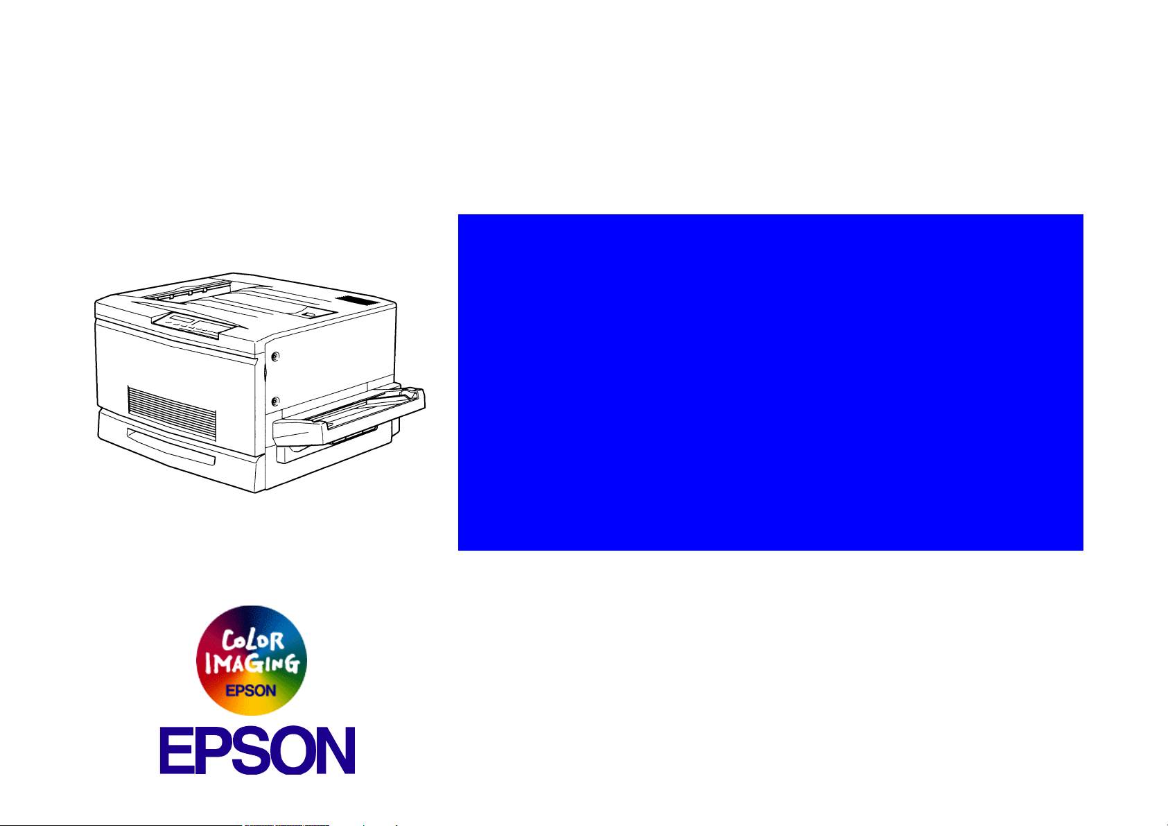
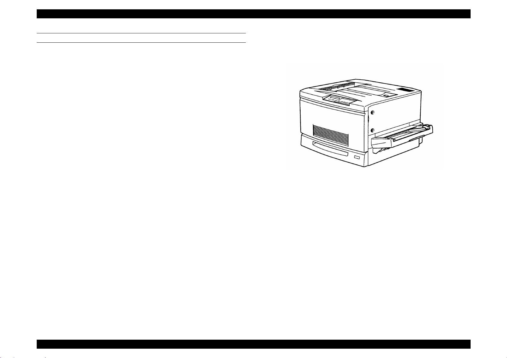
Figure 1-1. Exterior View of the EPL-C8200
Chapter 1 Product Descriptions 1-2
EPSON ColorPage EPL-C8200 Revision B
1.2 Specifications
This section describes specificat ions for this printer.
1.2.1 Basic Specifications
o Method: Semi-co nductive laser beam scanning and
dry electrophotogr aphic process
o Resolution: 600 DPI
o Print mode:
n B/W mode: Standard monochrome print mode that
supports the fastest speed.
n Color mod e: Color mod e w hich uses the co lor toner of Y,
M, C, and BK .
o Speed mode:
n Standard mode: Transports paper at the highest speed
supporte d by the print er.
n Half speed mode: Low speed mode that enables better fusing
for thick paper (over 105g/m
OHP shee t .
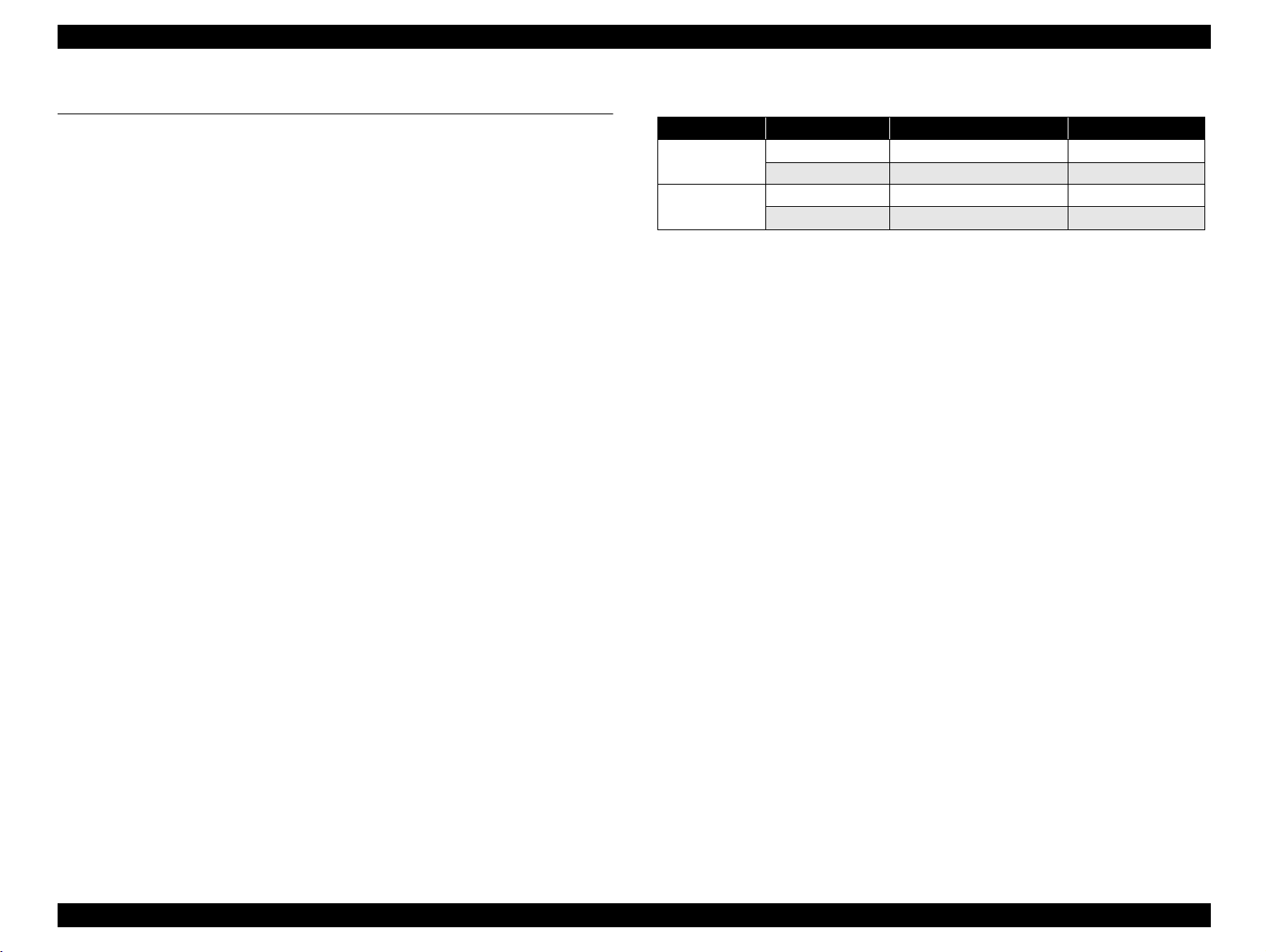
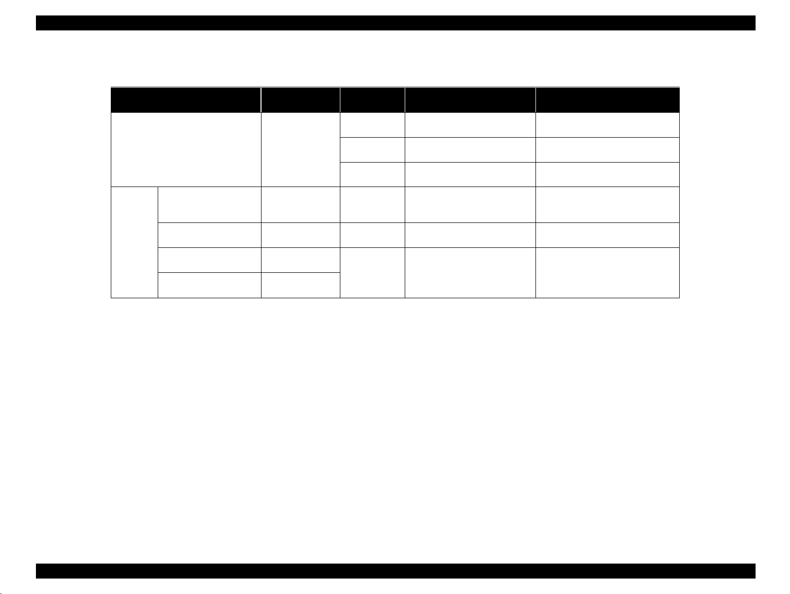
o Print speed: See Table 1-1.
2
) envelopes, and
Table 1-1. Speed Mode
Print mode Speed mode LT/A4 LEF*1 2UP
B/W Standard mode 16 PPM or more 8PPM or more
Half speed mode 2.7 PPM or more 1.3PPM or more
Color Standard mode 4 PPM or more 2PPM or more
half speed mode 1.8 PPM or more 0.9PPM or more
*1: [LEF, or Long Edge Feed]
The longer edge of the paper is the top toward the paper feed direction.
[SEF, or Short Edge Feed]
The shorter edge of the paper is the top toward the paper fe ed dir ection.
*2: I n t his mode , the print er prints t wo pr int im ages on t he IBT belt and t he im ages
are transf erred in sequence onto two sheets of paper. It is avail able for LT/A4
(LEF) or smaller.
*2
B(LD)/A3 SEF
o First print*:
n Face-up: B/W: 20 seconds or less (LT/A4 LEF)
Color: 42.6 seconds or less (LT/A4 LEF)
n Face-down: B/W: 24.9 seconds or less (LT/A4 LEF)
Color: 47.6 seconds or less (LT/A4 LEF)
NOTE: First print is defined as the duration taken after receiving the
start command un ti l out putting the fi rs t p rint . It is applicable
when a fe eder is selec t ed in the stand ard mode. (Not
applied during the pr oc es s c ontrol oper at ion.)
o Warm-up time: Withi n 300 secon ds
(at 22
°C, 55% Rh, rated vol ta ge)
*1
Chapter 1 Product Descriptions 1-3
EPSON ColorPage EPL-C8200 Revision B
o Paper handling : See Table 1-2.
Table 1-2. Paper Feeding
Paper source Available feeder
Standard Tray (MS I)
Cassette
Unit*
Standard universal
2 *7
cassette
Optional A3W cassette Standard feeder 250 sheets
Optional Large
Capacity Paper Unit *
Optional 500-Shee t
Paper Cassette Unit *
*1 *6
Standard feeder 250 sheets
250 x 3 feeder
3
(option)
250 x 2 feeder
4
(option)
Capacity
(Thickness)
150 sheets
90 x 139.7 - 330.2 x 457.2 mm 60 - 105g/m2, 16 - 20 lb (Normal
Paper size Available paper thic kness
(16mm)
75 sheets 90 x 139.7 - 330.2 x 457.2 mm
OHP sheet/Labels/Thick paper
20 sheets Envelopes
*5
Monarch, C10, DL, C6
B5 LEF, Letter LEF, A4 LEF,
(28mm)
B4, A3, Legal, Executive LEF,
Ledger (B)
A3W (304.8 x 420 - 328 x 453
(28mm)
250 sheets
(28mm)
mm)
Letter LEF, A4LEF, B4, A3,
Legal LEF, Executive LEF,
Ledger (B)
paper, Recommend ed paper)
105 - 220g/m
2
(Thick paper, Special paper)
60 - 105g/m
2
(Normal paper,
Recommended paper)
60 - 105g/m
2
(Normal paper,
Recommended paper)
60 - 105g/m
2
(Normal paper,
Recommended paper)
*1: C hange the side guide position in the MSI tray for paper whose width is more than 304.8mm (12”)
*2: E ach cassset tes is equi pped with th e side guide an d end guide that also serve to detect paper s ize. They ar e set by the user . With an opt ional
Large Capacity Paper Unit installed, 4 cassettes (maximum) can be used and, including a standard tr ay, up to 1150 sheets can be set.
*3: C om posed of 3 paper cassetts (each holds 250 sheets). Each paper cassette unit is compat ibl e with a standard universal cass ette and can
be set in any slot.
*4: C om posed of 2 paper cassetts (each holds 250 sheets). Each paper cassette unit is compat ibl e with a standard universal cass ette and can
be inserted in any slot.
*5: N ote the following point s when setting envelopes :
- Open flaps and set them facing to the tailing side.
- Set envelopes with the longer edges fi rst. Length (excluding flap) must be shorter tha n width.
- The minimum length with a flap open must be 143mm.
- The minimum width must be 90mm.
*6: Paper out condition is detected.
*7: P aper out and paper near empty condi tions are detected for each cassette.
Paper near empty condition: 40 sheets ± 30 sheets (condition: Fuj i Xerox L paper, 64g/m
2
)
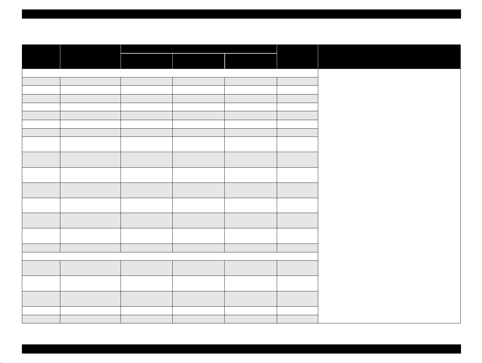
o Paper size: See Table 1 -3 .
Chapter 1 Product Descriptions 1-4
EPSON ColorPage EPL-C8200 Revision B
Table 1-3. Paper Size / 2-UP Mode Availability
Paper setting ori entation
Paper Size
Standard tray
(MSI)
Standard cassette A3W cassette
Normal paper
A3W 328 x 453mm SEF SEF Unavailable
A3 297 x 420mm SEF SEF Unavailable
A4 210 x 297mm LEF LEF Available
A5 148 x 210mm LEF Available
B4 257 x 364mm SEF SEF Unavailable
B5 182 x 257mm LEF Available
I-B5 176 x 250 LEF Available
LT
HLT
LG
EXE
GLG
GLT
B (LD)
F4 210 x 330 SEF Unavailable
8.5 x 11”
(215.9 x 279.4mm)
5.5 x 8.5”
(139.7X215.9mm)
8.5 x l4”
(215.9X355.6mm)
7.25 x 10.5”
(184.15X266.7mm)
8.5 x 13”
(215.9X330.2mm)
8 x 10.5”
(203.2 x 266.7mm)
11 x 17”
(279.4 x 431.8mm)
LEF LEF Available
LEF Available
SEF SEF Unavailable
LEF LEF Available
SEF Unava ilable
LEF Available
SEF SEF Unavailable
Special paper
OHP Sheet
MON
C10
DL 110 x 220mm LEF* Available
C6 114 x 162 LEF* Available
8.5 x 11”
(210 x 297mm)
3 7/8” x 71/2”
(98.43 x 190.5mm)
41/8 x 91/2
(104.78 x 241.3mm)
LEF Available
LEF* Available
LEF* Available
2UP mode
availability
Notes
• LEF: Long edge is loaded first.
• SEF: Short edge is lo aded first.
• 2UP is availabl e only for paper size of LT(LEF) or
smaller. For custom size paper, paper length along
the loading direction must be 8.5 inch or shorter. As
for envelopes, the total length including the opened
flap part must be 8.5 in ch or shorter.
• The minimum size of paper set in the standard
universal paper cassette is EXE (LEF).
• The maximum size of paper set in the MSI tray is
330.2 x 457.2 mm (13” x 18”).
• When setting envelopes (LEF*), open their flaps and
set the rear ends of the flaps toward paper feeding
direction.
• A3W cassette hav e capability for only A3W paper.
Chapter 1 Product Descriptions 1-5
EPSON ColorPage EPL-C8200 Revision B
o Paper aligning: Single side aligning (front si de) for all sizes
(both standard tray (MSI) and each cassette)
o Consumables:
n TONER CARTRIDGE (Black, Cyan, Magenta, Yellow)
n DRUM CARTRIDGE (including one WASTE TONER BOX)
n WASTE TONER BOX
n OIL ROLL
o Regularly repla ce d parts:
n MAIN FUSER ASSEMBLY
n Air filter (replaced with the MAIN FUSER ASSEMBLY
n BELT CLE ANER ASSEMBLY
n 2ND BTR ASSEMBLY
o Paper output:
n Face-down (FD):
2
250 sheet s (B5/EXE or la rger, up to 105 g/ m
or 28lb
n Face-up (FU):
150 sheet s (s m aller than A4 )
50 sheets (A4 or larger)
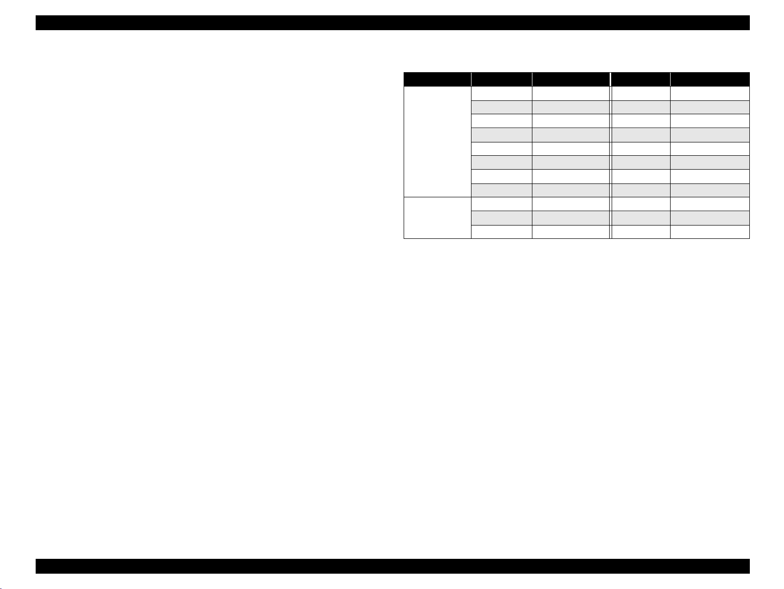
See Table 1-4 FD ava ilability for eac h paper size.
Table 1-4. Face-Down Output Availability
Paper Size FD Availability Paper Size FD Availability
Normal paper A3W Available HLT Unavailable
A3 Available LG Available
A4 Available EXE Available
A5 U navailable GLG Available
B4 Available GLT Available
B5 Available B(LD) Available
LT Available F4 Available
I-B5 Unavailable
Special paper OHP sheet FU* C10 FU*
Postcard FU* DL FU*
MON FU* C6 FU*
NOTE
1. The minimum paper size available for FD ejection is 182 mm in the pap er feeding
direction x 210 mm vert ical to the paper feeding direction.
2. “FU*” in the FD availabi li ty columns means face-up ejection for OHP, thick paper ,
and envelope.
o Dimensions (without option):
728 (W)* m m x 641 (D)* mm x 49 0 (H ) mm (toler ances: ± 1%)
* When the standard tray (MSI) and Outpu t tra y (F U ) are stored.)
o Weight: 68.4 kg ± 1% (without option)
o Voltage: 110V/120V
220V/240V
± 10%, 50 / 60Hz ± 3Hz
± 10%, 50/ 60Hz ± 3Hz
o Power con su m ption, Rated current:Se e T able 1-5.
Chapter 1 Product Descriptions 1-6
EPSON ColorPage EPL-C8200 Revision B
Table 1-5. Power Consumption Specifications
Operating (color)
Operating (B/W)
Power
consumption
Rated current
*1:
Saves more energy than in standby mode. Time required for warning up
Standby mode
Energy save mode 1
Energy save mode 2
• 100 V: 11A or less (at rated voltage)
• 115V: 10A or less (at rated volt age)
• 240V: 5A or less (at rated volt age)
is shorter.
*2:
Completely non-operating condition. Complies with the Energy Star.
• Average: 400Wh or less
• Maximum: 1100W or less (Fuser: On)
• Average: 500Wh or less
• Maximum: 1100W or less (Fuser: On)
• Average: 250Wh or less
• Maximum: 1000W or less (Fuser: On)
100W or less (Fuser: Off)
• Average: 200Wh or less
*1
• Maximum: 1000W or less (Fuser: On)
100W or less (Fuser: Off)
• Average: 45Wh or less
*2
• Maximum: 1000W or less (Fuser: On)
100W or less (Fuser: Off)
o Product life
n Printer: Approx imately 18 0, 000 printe d pages on A4 LEF
(450,000 images) or five years, whichever comes first.
n Standard tray (MSI): 72,000 she et s
n 250 sheets x 3 feeders:135,000 sheets (45,000 sheets x 3)
o Acoustic noise: Operating = 54 . 8dB (A) or less
Stand-by = 3 8. 3dB (A) or les s
Energy Save mode 1 = 38. 3dB (A) or les s
Energy Save mode 2 = 35. 0dB (A) or les s
o Ozone emission: 0.02 ppm (time waited average value) or less.
o Toxicity: Ph ot o c onductor, to ner, carrier, plastic
material have no effect on human body.
Chapter 1 Product Descriptions 1-7
EPSON ColorPage EPL-C8200 Revision B
1.2.2 Paper Specification
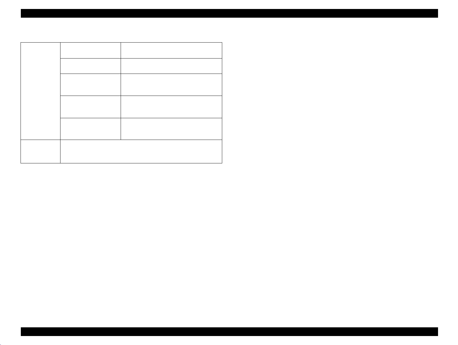
o Paper specifica ti ons : See Table 1 -6.
Table 1-6. Paper Specifications
Paper Type
Recommended paper 4024 paper (B/W), X-pressi on paper (color)
Normal Paper Normal copier paper, Recycled paper,
Special Paper OHP film, Card stock, Labels, Color pap er, Thick
NOTE: lb: Ream Weight = lb/500sheets/17” x 22”
2
g/m
1
= 0.2659763 lb
NOTE: Before purchasing a large amo unt of paper, try it out and
check tha t it is properly fed.
NOTE: Avoid usin g t he types of paper listed below to prevent
abnormal printing, paper jam, and printer m alf unction.
- Carbon paper, non-carbon paper, therm al paper, impact paper,
acidic paper
- Pape r th at has gone thro ugh a thermal or an ink-je t p rint er.
- Pape r th at is to o t hic k or t hin.
- Wet (d am p) paper
- Pape r to w hic h a special coat ing has bee n applied, o r co lored
paper that has gone through surfac e process.
- Pape r th at has been lubric ated (too smooth or slippery).
- Paper whose texture is different on the front and back.
- Pape r w it h holes for bind ers and perfor at ions.
- Pape r w it h irregular shape or not cut wi th right angles.
- Paper with labels that come off and stick easily.
- Paper with glue, staples, or paper clips attached.
- Special ink-jet pap er (Super Fin e Paper, glo s s y film , and so on.)
- OHP s heets for othe r co lor laser prin te rs , m onochrome printers,
and photoc opiers.
2
60g/m
- 105g/m2 (16lb - 28lb)
paper (105g/m
2
- 220g/m2), DTP paper, Envelopes
- Pap er t hat has gone th rough other co lor laser prin te rs ,
monochrome printers, and photocopiers.
- Past ed paper
Chapter 1 Product Descriptions 1-8
EPSON ColorPage EPL-C8200 Revision B
o Paper source classification:See Table 1-7.
Table 1-7. Paper Usability for Each Paper Source
Paper source
Standard (MSI) tray RF P P P P P P
Standard universal cassette RF P N N N N N
A3W cassette*
Large Capacity Paper Unit
500-Sheet Paper Cassette Uni t
3
*3
Recommended
paper
RF P NNNNN
RF P N N N N N
Normal
paper
OHP
sheet
Postcard Labels
Special paper
Thick
paper*
1
Envelope
2
*
NOTE: RF: Reliable feedi ng and good image quality, P: Possible, but limited to paper generally avai lable, N: Not supported
*1:
105 - 220g/m
*2:
MON, C10, DL, C6
*3:
Option
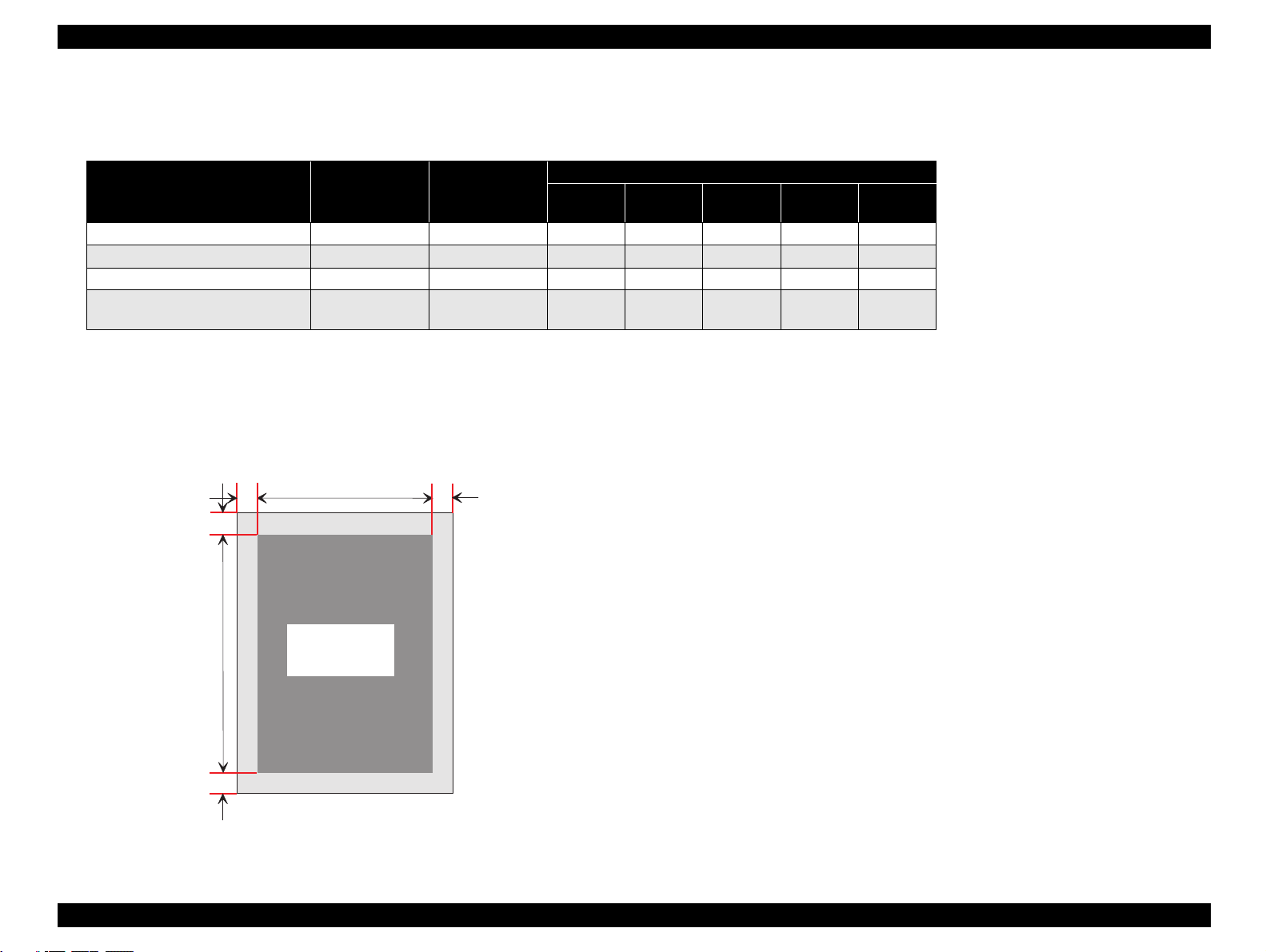
o Guaranteed print area: See F igure 1-2.
2
4m m 4m m
o Maximum guaranteed print area:
Area wit h a m argin of 4 mm fr om each side
Applie d to a paper size up to 297mm (11.7”) width x 431 .8 m m (17”)
length.
4m m
o Maximum printable are a:
320mm (12.6”) widt h x 449.2mm (17. 7”) length
G uaranteed
print area
4m m
Figure 1-2. Guaranteed Print Area
Chapter 1 Product Descriptions 1-9
EPSON ColorPage EPL-C8200 Revision B
r
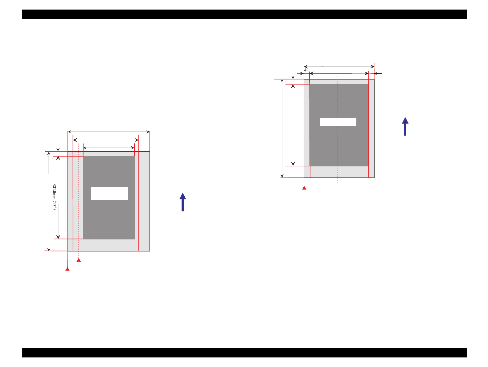
o Printable area:
Paper whose width is 304.8mm (12”) or shorter: From the edge
Paper whose width is longer than 304.8mm (12”)*: From th e point
with a margin of 5mm
* When loading paper whose width is more than 30 4. 8 m m (12”),
the standard cassette (MSI) is shifted and print position starts with
a margin of 5 mm from the paper edge (a). This change is applied
to paper loaded from the A3W cassette.
n When th e s t andard tray (MSI) or A3W cass et te is used.
330.2m m (13")
4m m
457.2m m (18")
(a )
320m m (12,6")
297m m (11.7")
Printable
area
Paper feeding direction
n When th e s t andard univ ers al cassette, Large Capacit y Paper
Unit, or 500-Sheet Pa per Cassette U nit is us ed.
4m m
4m m
457.2m m (18")
431.8m m (17")
M axim um size of paper: 304.8 m m (11.2") w idth x 457.2 m m (18") length
Printable area: 296.8 m m (11.7") w idth x 449.2 m m (17.7") length
G uaranteed print area: 296.8 m m (11.7") w idth x 431.8 m m (17") length
304.8m m (12,6")
296.8m m (11.7")
Printable area
Side guide position for paper w hose w idth is 304.8 m m (12") or less
4m m
Paper feeding direction
Figure 1-4. Printable Area 2
Side guide position for paper w hose w idth is 304.8 m m or shorte
Side guide position for paper w hose w idth is m ore than 304.8 m m
Length betw een the guides is 12.6m m
M axim um size of paper: 330.2 m m (13") w idth x 457.2 m m (18") length
Printable area: 320.0 m m (12.6") w idth x 449.2 m m (17.7") length
G uaranteed print area: 297 m m (11.7") w idth x 431.8 m m (17") length
Figure 1-3. Printable Area 1
Chapter 1 Product Descriptions 1-10
EPSON ColorPage EPL-C8200 Revision B
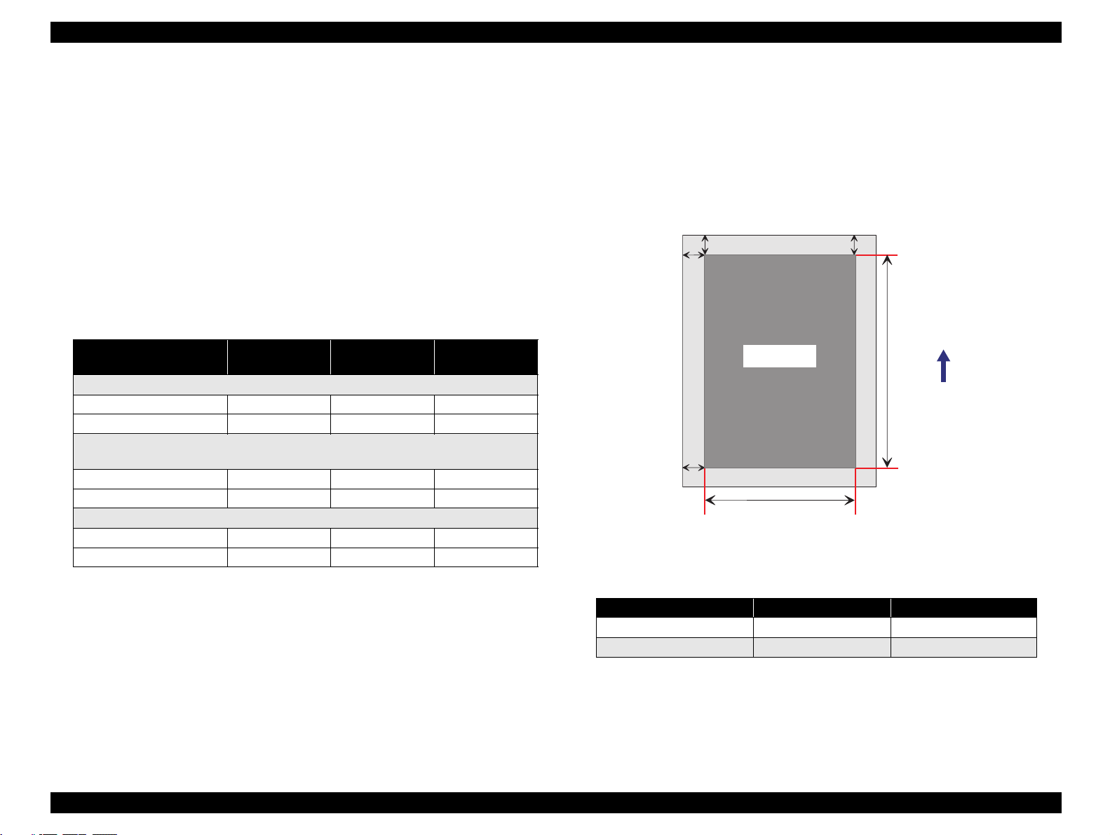
a
b
c
d
e
f
Print area
Paper feeding direction
1.2.3 Reliability and Durability
o MPBF:
n Printer inc luding standard tray (MSI ):
38,000 pages or more (95,000 im ages or more* )
o Print position accuracy:
n Main scan direction:Referenc e position (c )
n Sub sca n direction:Ref erence position (a)
See Figure 1-5.
± 2.5 mm
± 2.0 mm
n Printer inc luding optio nal 250 sheet x 3 fee ders:
32,000 pages or more (80,000 im ages or more* )
o Paper skew: See F igure 1-5 and Ta ble 1-9.
NOTE: Figured out based on t he MPBF in c ondition that th e job
ratio of the c olor and mon oc hrome pri nt s is 1 : 1, s inc e 1
page of co lor print is formed with 4 ima ges.
o Paper feed reliability: See Table 1-8.
Table 1-8. Paper Feed Reliability
Recommended
paper
Standard paper tray
Paper jam rate 1/500 or less 1/100 or less 1/100
Multiple feeding rate 1/80 or less 1/50 or less 1/50
Standard universal cassette / Large Capacity Paper Unit / 500-Sheet Paper
Cassette Unit(option)
Paper jam rate 1/3,000 or les s 1/2,000 or less
Multiple feeding rate 1/800 or less 1/500 or less
A3W cassette (option)
Paper jam rate 1/2,000 or less
Multiple feeding rate 1/500 or less
* Do not feed envelopes at high temperature to avoid adhering.
* Statistics for envel opes only appl y to f ront f ace feedin g under nor mal temper-
ature. (back side feeding is not included.)
NOTE: Paper jam or multiple feeding occurred to the t op sheet of
Normal paper Special paper *
Figure 1-5. Paper Skew
Table 1-9. Paper Skew
Direction A4 (landscape) A3
Main scan direction (|c-d|)
Sub scan directi on (|a-b|)±2.0mm(e=271mm)
1.5mm(f=196mm)
±
3.0mm(f=406mm)
±
2.0mm(f=271mm)
±
an added stac k of paper is igno red.
Chapter 1 Product Descriptions 1-11

EPSON ColorPage EPL-C8200 Revision B
o Durability:
n Printer:
180,000 sheets* (450,000 images) A4 LEF or 5 years,
whichever comes first. Parts r egu larly replaced by the service is
ignored.
* 450,000 sheets if the printer is used for monochrome print only. In
color printing, one page is formed with 4 images, and the value
“180,000” sheets is figured out in the condition that the job ratio of
monochrome and color printings is 1:1.
n Standard tray (MSI): 72,000 she et s
n 250sheet s x 3 fe eders: 1 35,000 sheets (45,00 0 s heets x 3)
o MTTR: Within 30 minutes (average)
o Curl height at ejec ti on: Less than
image rat io of 5% in non- aligned condit ion,
which varies depen ding on the ima ge rate
and align ing pattern. )
± 15mm (Color print ing with the
Chapter 1 Product Descriptions 1-12
EPSON ColorPage EPL-C8200 Revision B
1.2.4 Operating Environment
o Temper atur e: 10 to 32°C
o Humidity: 15% to 85% RH (without condensation)
o Air pressure (altit ude):760 h Pa or more (25 00 meters o r les s )
o Levelness:
Front - rear direction on t he t able:5mm or less (within 641mm)
Right - left d irec t ion on the table:10 mm or les s (w it hin 560mm)
o Luminosity: 3000 lux or le ss (not to expos ed to direct
sunlight )
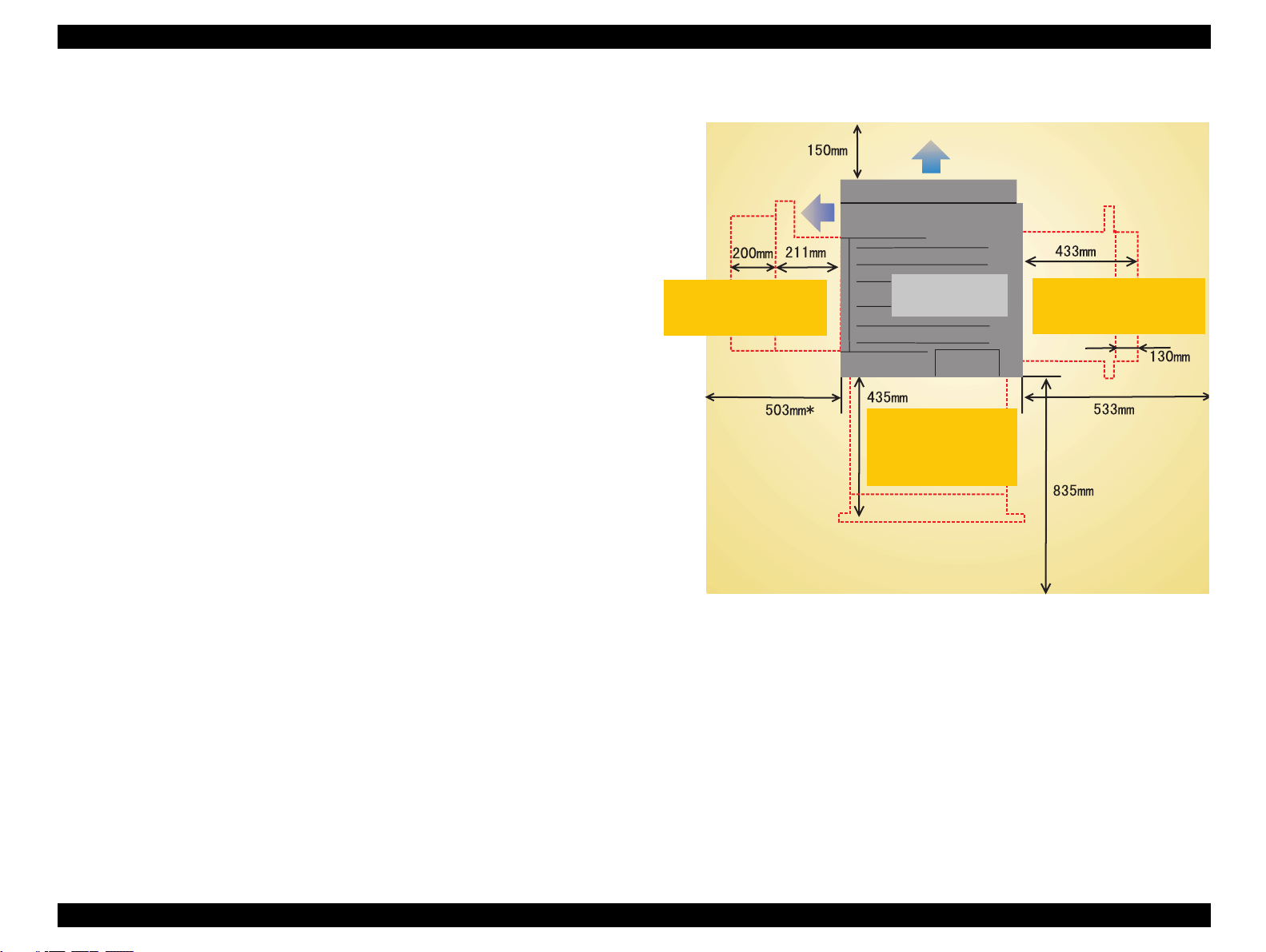
o Surrounding en v ironment: See Figu re 1-6.
Ventilation
R equired w hen pullin g
out the FUSER UNIT
to remove jammed paper.
* 511 m m w ith a face-up tray installed.
Ventilation
R equired w hen pulling out
the paper path unit to
rem ove jam m ed paper.
R equired w hen pullin g
out the standard paper
c a s s e tte u n it to lo a d
paper.
Figure 1-6. Space Requirement
Chapter 1 Product Descriptions 1-13
 Loading...