

Epson EPL-5700 Service Manual

6(59,&(0$18$/
3DJH3ULQWHU
EPSON EPL-5700
®
4009173

NOTICE
All rights reserved. No part of this manual may be reproduced, stored in a retrieval system, or transmitted in any form or by any means, electronic,
mechanical, photocopying, recording, or otherwise, without the prior written permission of SEIKO EPSON CORPORATION.
The contents of this manual are subject to change without notice.
All effort have been made to ensure the accuracy of the contents of this manual. However, should any errors be detected, SEIKO EPSON would greatly
appreciate being informed of them.
The above not withstanding SEIKO EPSON CORPORATION can assume no responsibility for any errors in this manual or the consequences thereof.
EPSON is a registered trademark of SEIKO EPSON CORPORATION.
General Notice: Other product names used herein are for identification purpose only and may be trademarks or registered trademarks of their respective
owners. EPSON disclaims any and all rights in those marks.
Copyright © 1996 SEIKO EPSON CORPORATION. Printed in Japan.

PRECAUTIONS
Precautionary notations throughout the text are categorized relative to 1)Personal injury and 2) damage to equipment.
DANGER
WARNING
The precautionary measures itemized below should always be observed when performing repair/maintenance procedures.
Signals a precaution which, if ignored, could result in serious or fatal personal injury. Great caution should be exercised in performing
procedures preceded by DANGER Headings.
Signals a precaution which, if ignored, could result in damage to equipment.
DANGER
1. ALWAYS DISCONNECT THE PRODUCT FROM THE POWER SOURCE AND PERIPHERAL DEVICES PERFORMING ANY MAINTENANCE OR
REPAIR PROCEDURES.
2. NOWORK SHOULD BE PERFORMED ON THE UNIT BY PERSONS UNFAMILIER WITH BASIC SAFETY MEASURES AS DICTATED FOR ALL
ELECTRONICS TECHNICIANS IN THEIR LINE OF WORK.
3. WHEN PERFORMING TESTING AS DICTATED WITHIN THIS MANUAL, DO NOT CONNECT THE UNIT TO A POWER SOURCE UNTIL
INSTRUCTED TO DO SO. W HEN THE POWER SUPPLY CABLE MUST BE CONNECTED, USE EXTREME CAUTION IN WORKING ON POW ER
SUPPLY AND OTHER ELECTRONIC COMPONENTS.
WARNING
1. REPAIRS ON EPSON PRODUCT SHOULD BE PERFORMED ONLY BY AN EPSON CERTIFIED REPAIR TECHNICIAN.
2. MAKE CERTAIN THAT THE SOURCE VOLTAGES IS THE SAME AS THE RATED VOLTAGE, LI STED ON T HE SERIAL NUMBER/RATING PLAT E. IF
THE EPSON PRODUCT HAS A PRIMARY AC RATING DIFFERENT FROM AVAILABLE POW ER SOURCE, DO NOT CONNECT IT TO THE POW ER
SOURCE.
3. ALWAYS VERIFY THAT T HE EPSO N PRODUCT HAS BEEN DI SCONNECT ED FRO M THE POWER SOURCE BEFORE REMOVING OR REPLACING
PRINTED CIRCUIT BOARDS AND/OR INDIVIDUAL CHIPS.
4. IN ORDER TO PROTECT SENSITIVE MICROPROCESSORS AND CIRCUITRY, USE STATIC DISCHARGE EQUIPMENT, SUCH AS ANTI-STATIC
WRIST STRAPS, WHEN ACCESSING INTERNAL COMPONENTS.
5. REPLACE MALFUNCTIONING COMPONENTS ONLY WITH THOSE COMPONENTS BY THE MANUFACTURE; INTRODUCTION OF SECONDSOURCE ICs OR OTHER NONAPPROVED COMPONENTS MAY DAMAGE THE PRODUCT AND VOID ANY APPLICABLE EPSON WARRANTY.

PREFACE
This manual describes basic functions, theory of electrical and mechanical operations, maint enance and repair procedures of EPL - 5700. T he instr uctions and
procedures included herein are intended for t he experienced repair technicians, and at tention should be g iven to the precaution s on the preceding page. T he
chapters are organized as follows:
CHAPTER 1. PRODUCT DESCRIPTIONS
Provides a general overview and specifications of the product.
CHAPTER 2. OPERATING PRINCIPLES
Describes the theory of electrical and mechanical operations of the product.
CHAPTER 3. TROUBLESHOOTING
Provides the step-by-step procedures for troubleshooting.
CHAPTER 4. DISASSEMBLY AND ASSEMBLY
Describes the step-by-step procedures for disassembling and assembling the
product.
CHAPTER 5. ADJUSTMENTS
Provides Epson-approved methods for adjustment.
CHAPTER 6. MAINTENANCE
Provides preventive maintenance procedures and the lists of Epson-approved
lubricants and adhesives required for servicing the product.
APPENDIX
Provides the following additional information for reference:
• Connector pin assignments
• Electric circuit boards components layout
• Exploded diagram
• Electrical circuit boards schematics

REVISION STATUS
Rev. Date Page(s) Contents
A 1998/05/06 All First release

TABLE OF CONTENTS
PRODUCT DESCRIPTION
1.1 FEATURES.................................................................................................................................................................1-1
1.2 PAPER SPECIFICATION ...........................................................................................................................................1-6
1.3 PANEL OPERATION..................................................................................................................................................1-8
1.3.1 Power Switch .................................................................................................................................................................................. 1-8
1.3.2 Control Panel .................................................................................................................................................................................. 1-8
1.3.2.1 Switches................................................................................................................................................................................ 1-8
1.3.2.2 Lights..................................................................................................................................................................................... 1-8
1.3.3 List of Panel Setting ....................................................................................................................................................................... 1-9
1.3.4 Special(alternative) Operation..................................................................................................................................................... 1-13
1.3.4.1 Operation at Power On........................................................................................................................................................ 1-13
1.3.4.2 Up-dating ROM Program..................................................................................................................................................... 1-14
1.4 OPTIONS AND CONSUMABLE...............................................................................................................................1-15

OPERATING PRINCIPLES
2.1 OPERATING PRINCIPLES OF MECHANISM............................................................................................................2-1
2.1.1 Overview.......................................................................................................................................................................................... 2-1
2.1.2 Paper Path....................................................................................................................................................................................... 2-2
2.1.3 Paper Feed Mechanism.................................................................................................................................................................. 2-3
2.1.3.1 Paper Feed Operation........................................................................................................................................................... 2-3
2.1.3.2 Paper Empty Sensor................................................................................................................................................................2-4
2.1.4 Second Paper Feed Unit(Option)......................................................................................................................................................2-4
2.1.4.1 Mechanism...............................................................................................................................................................................2-4
2.1.4.2 Paper Empty Sensor................................................................................................................................................................2-5
2.1.4.3 Cassette Type Sensor..............................................................................................................................................................2-5
2.1.5 Laser Exposure..................................................................................................................................................................................2-6
2.1.5.1 Sub Scanning Direction(Vertical scanning direction)................................................................................................................2-6
2.1.5.2 Main Scanning Direction(Horizontal scanning direction)..........................................................................................................2-7
2.1.5.3 Printable Area ..........................................................................................................................................................................2-7
2.1.6 Charging Process..............................................................................................................................................................................2-7
2.1.6.1 Overview (Refer to Figure2-9 on the next page)......................................................................................................................2-7
2.1.6.2 Cleaning OPC drum.................................................................................................................................................................2-8
2.1.7 Developing .........................................................................................................................................................................................2-9
2.1.7.1 Overview ..................................................................................................................................................................................2-9
2.1.7.2 Function of each parts in the development part.......................................................................................................................2-9
2.1.8 Transfer Process .............................................................................................................................................................................2-10
2.1.8.1 Overview ................................................................................................................................................................................2-10

2.1.9 Fusing Process................................................................................................................................................................................2-11
2.1.9.1 Overview ................................................................................................................................................................................2-11
2.1.9.2 Fusing Temperature Control Circuit.......................................................................................................................................2-11
2.1.9.3 Prevention of paper bent from the fusing...............................................................................................................................2-12
2.1.10 Paper Eject.....................................................................................................................................................................................2-13
2.1.10.1 Face up/Face down disengage mechanism.........................................................................................................................2-13
2.2 ELECTRIC CIRCUIT...................................................................................................................................................2-14
2.3 CONTROLLER OPERATING PRINCIPLES...............................................................................................................2-16
TROUBLESHOOTING
3.1 OVERVIEW...................................................................................................................................................................3-1
3.2 ELECTRIC CHECK POINT...........................................................................................................................................3-1
3.2.1 Rating of Power Fuse F1...................................................................................................................................................................3-1
3.2.2 Coil Resistance of Main Motor..........................................................................................................................................................3-1
3.2.3 Checking Sensors .............................................................................................................................................................................3-2
3.3 PRINTER CONDITION .................................................................................................................................................3-3
3.3.1 Indication............................................................................................................................................................................................3-3
3.3.1.1 “Status” Conditions...................................................................................................................................................................3-3
3.3.1.2 “Error” Conditions.....................................................................................................................................................................3-4
3.3.1.3 “Warning” Conditions ...............................................................................................................................................................3-6
3.3.1.4 Service Req. Error....................................................................................................................................................................3-7
3.3.2 Paper Jam Sensor .............................................................................................................................................................................3-9
3.3.2.1 Overview ..................................................................................................................................................................................3-9
3.3.2.2 Paper Jam Sensor Conditions..................................................................................................................................................3-9
3.3.2.3 Resetting the Paper Jam..........................................................................................................................................................3-9

3.4 TROUBLESHOOTING................................................................................................................................................3-10
3.4.1 Handling Paper Jam ........................................................................................................................................................................3-10
3.4.1.1 Paper Jam at power on..........................................................................................................................................................3-10
3.4.1.2 Paper Jam at Paper Feed and Transporting..........................................................................................................................3-10
3.4.2 Troubleshooting for Abnormal Operations ...................................................................................................................................3-11
3.4.2.1 Abnormal Laser......................................................................................................................................................................3-11
3.4.2.2 Abnormal Polygon Motor........................................................................................................................................................3-11
3.4.2.3 Abnormal Fusing....................................................................................................................................................................3-11
3.4.2.4 Power can not be turned on...................................................................................................................................................3-11
3.4.3 Troubleshooting Print Quality Problems.......................................................................................................................................3-12
3.4.4 Horizontal Lines...............................................................................................................................................................................3-14
DISASSEMBLY AND ASSEMBLY
4.1 OVERVIEW...................................................................................................................................................................4-1
4.1.1 Precaution for Disassembly and Assembly.....................................................................................................................................4-1
4.1.2 Recommended Tools ........................................................................................................................................................................4-2
4.1.3 Specification for Screws...................................................................................................................................................................4-2
4.1.4 Work Completion Check ...................................................................................................................................................................4-2
4.2 DISASSEMBLY PROCEDURE.....................................................................................................................................4-3
4.2.1 Preparation Before Disassembly......................................................................................................................................................4-4
4.2.2 Right Cover Removal.........................................................................................................................................................................4-5
4.2.3 Paper Feed Roller Removal ..............................................................................................................................................................4-6
4.2.4 Paper Empty Sensor Removal(PE1).................................................................................................................................................4-6
4.2.5 ROM(C215PROG-B) Exchange.........................................................................................................................................................4-7
4.2.6 Control Panel Removal......................................................................................................................................................................4-8
4.2.7 Front Cover Removal.........................................................................................................................................................................4-9

4.2.8 Interlock Switch Removal ...............................................................................................................................................................4-10
4.2.9 Main Control Board Removal..........................................................................................................................................................4-11
4.2.10 Left Cover Removal.......................................................................................................................................................................4-12
4.2.11 Print Head Unit Removal...............................................................................................................................................................4-13
4.2.12 Paper Feed Roller Unit Removal ..................................................................................................................................................4-14
4.2.13 Paper Feed Solenoid Removal .....................................................................................................................................................4-15
4.2.14 Top Cover Removal.......................................................................................................................................................................4-16
4.2.15 Rear Cover Removal......................................................................................................................................................................4-17
4.2.16 Fusing Unit Removal.....................................................................................................................................................................4-18
4.2.17 Disassembling the Fusing Unit ....................................................................................................................................................4-19
4.2.17.1 Heater Lamp Removal ......................................................................................................................................................... 4-19
4.2.17.2 Thermister, Thermostat Removal.........................................................................................................................................4-21
4.2.17.3 Paper Eject Sensor(PS3).....................................................................................................................................................4-22
4.2.18 Transfer Roller Exchange .............................................................................................................................................................4-23
4.2.19 Power Board Removal................................................................................................................................................................... 4-24
4.2.20 High Voltage Board Removal........................................................................................................................................................4-26
4.2.21 Paper Sensor(PS1) Removal.........................................................................................................................................................4-27
4.2.22 Main Motor Removal......................................................................................................................................................................4-27
4.2.23 Driving Unit Removal.....................................................................................................................................................................4-28
4.3 DISASSEMBLY AND ASSEMBLY FOR OPTIONAL SECOND PAPER FEED UNIT.................................................4-29
4.3.1 Second Paper Feed Roller Exchange ............................................................................................................................................4-29

ADJUSTMENT
5.1 ADJUSTMENT..............................................................................................................................................................5-1
5.1.1 Interlock Switch Position Adjustment..............................................................................................................................................5-1
MAINTENANCE
6.1 MINTENANCE..............................................................................................................................................................6-1
6.1.1 User Maintenance..............................................................................................................................................................................6-1
6.1.2 Service Maintenance .........................................................................................................................................................................6-1
APPENDIX
7.1 CONECTOR PIN ASSIGMENTS ..................................................................................................................................7-1
7.2 CIRCUIT BOARD COMPONENT LAYOUT..................................................................................................................7-6
7.3 EXPLODED DIAGRAM.................................................................................................................................................7-7
7.4 CIRCUIT DIAGRAM....................................................................................................................................................7-17


PRODUCT DESCRIPTION
&+$37(5

EPL-5700 Chapter1 Product Description
1.1 FEATURES
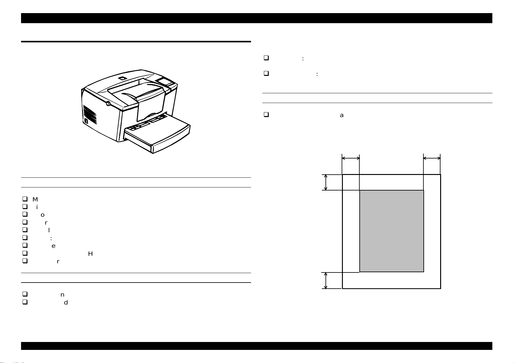
EPL-5700 is a small and compact A4 size page printer that semiconductor
laser beam scanning is applied for. Following shows features.
Figure 1-1. Exterior View
PROCESS SPECIFICATION
Method: Dry mono-component xerographic method
Light source: Semiconductor laser
Photoelectric unit: OPC drum(organic photoconductor)
Charge: Rotating brush charging type
Developer: Exposed section developer system
Toner: Mono-component nonmagnetic toner
Transfer method: Roller transfer
Fixing: Heat roller system
Density regulator: Developer bias variation system(user can regulate)
*2:Regarding printing with custom size(non-standard
size)paper, the printing speed will become faster
because cleaning takes place automatically.
First print: 19 seconds(A4/LTR), 18.2 seconds(B5)
17.3 seconds(A5), 20.2 seconds(legal)
Warm-up time: 20 seconds or less (at 23 degree Celsius, standard
voltage)
PRINTABLE AREA
Print area Area within margins of 4mm from each side.
(Refer to Figure 1-2)
Note)
The printable area may change depending on
the print mode.
4mm
4mm
4mm
Printable Area
PRINT SPEED
Resolution: 600 dpi
Print Speed: 8ppm(A4/LTR/B5/A5),
6.9ppm(legal)
*1:Same with optional cassette
Rev. A
4mm
Figure 1-2. Printable Area
1-1

EPL-5700 Chapter1 Product Description
2
PAPER HANDLING
Paper supply
method
Multipurpose tray 150
Note)
*1 For 20lb(75g/m2) paper.
*2 When printing on the back file of the paper using manual printing,
since the paper may curl, a maximum of 20 pages can be set.
Table 1-1. Paper Handling
Capacity Supplied paper size Permissible
paper thickness
sheets*1
Standard paper types
are those that fall
within the range of
Normal paper 60
to 90g/m2 (16 to
24lb)
those usable sizes
given below.
76.2 x 127∼ 215.9
x355.6 mm
(A4, JIS-B5,A5,
Letter, Government
letter, Executive,
Legal, Government
Legal, F4, Half
Letter) or Custom
size (optional size
that falls within the
range of standard
paper sizes)
50sheets
20sheets
Japanese official
post card*2
Japanese official
Special paper
190g/m
2
post card*2
(when printing on
back)
10
sheets
Envelopes
Monarch, C10, DL,
C5,C6
International-B5
Labels/OHP/thick
pages
Normal paper 60
to 90g/m2(16 to
24lb)
Thick paper 90 to
157 g/m
2
Special paper
(labels, OHP)
Table 1-2. Paper Handling (Cont.)
Paper supply
method
Manual Feed slot*4 1 sheet Standard or
Capacity Supplied paper
size
Custom paper
sizes that fall
within the range of
usable sizes given
below.
Permissible
paper thickness
Normal paper 60 to
90g/m2(16 to 24lb)
Thick paper 90 to
157g/m
2
Special paper
(labels, OHP)
100x148∼215.9x
355.6 mm
Lower cassette
*1,*5
500
sheets*1
A4, LG, LT Normal paper
60 to 90g/m
2
(16 to 24lb)
Note)
*1: For 20lb(75g/m2) paper.
*4: Manually fed papers are inserted one page at a time above the
cover of the paper tray.
*5: Cassette trays can be used for each of the standard paper sizes.
The maximum size of the paper supply including the paper tray is
650 sheets.
CONSUMABLES
Name: Developer and Toner cartridge
Organic Photoconductor Unit
Life1* Developer equipment
(Black colored mono component nonmagnetic toner:
Average 6000 sheets.)
OPC drum(organic photo conductor unit):20000
sheets.
Note 1*)
These number represent the number of printed pages that can be
printed assuming continuous printing on an A4 page with print duty of 5%.
The life will change based on the print duty and method of printing
(continuous printing, intermittent printing, printing density, toner
economizing)
Rev. A
1-
EPL-5700 Chapter1 Product Description
3
CONTROLLER SPECIFICATION
CPU RISC VR4300 100MHz
RAM Standard 4MB(EDO type)
SIMM option: 1
32MB, 16MB, 8MB, 4MB (EDO type, 1 slot)
Maximum 36MB(4MB(standard) + 32MB(expansion
SIMM slot)
ROM Font: 2Mbytes(mounted on main board)
Program: 4Mbytes (mounted on ROM DIMM board)
Host interface Standard, Centronics, Bi-direnctional parallel
IEEE-1284 nibble
ECP
RS232C Serial
Type-B I/F: 1 slot
SOFT SPECIFICATION
Control Code Bi-direction EJL
Emulation ESC/Page mode
PCL5E mode
GL/2 mode
FX mode
ESC/P2 mode
I239x
Post Script level 2(Option)
ENVIRONMENTAL CONDITION
[Usage conditions including expendable parts]
Temperature: 10 to 35 °C
Humidity: 15% to 85% without condensation
Air pressure(altitude): 760hPa or more(2500 meters or less)
Surface angle: 1 degree incline or less (for both front
to rear and side to side)
Luminosity: 3000 lux or less(not exposed to direct
sunlight)
[Environmental conditions for storage and transportation]
Normal
Temperature Extremes
(1/3 of total
holding period) Low
Normal 30 to 85%
Humidity Extremes
(1/3 of total
holding period) Low 10 to 30%
Holding Period 18 months after
Shipping Air Pressure: 460 to 760 hPa
Resistance to shock: For JIS Z0200 1987 Level 1 with no
abnormalities.
Dropping direction: 1 corner, 6 sides, 3 edges
High
High 85 to 95%
0 to 35 °C
35 to 40 °C
-20 to 0 °C
manufacture
Rev. A
1-

EPL-5700 Chapter1 Product Description
4
ELECTRICAL SPECIFICATION
Power supply:
120 model
120V +/- 10%, 50-60Hz +/-3Hz
200V model
220 to 240V +/- 10%, 50-60Hz +/- 3Hz
Electrical characteristic
1) AC line noise:
Pulse width: 50 to 1000 ns
Pulse polarity: ±
Repeat: non-simultaneous
Modes: common/normal
Voltage: 1kv
However, the parts can withstand up to 2kv without damage.
2) Instant cutoff: DIP 100%(for standard voltage-10%) for one
cycle with normal print quality.
3) Electrostatic durability:
up to ± 10kv: no hardware errors
no unrecoverable software errors for the operator
up to ± 15kv: without damage to components
4) Rush current: 1/2 cycle, 50A or less
5) Insulation resistance: 10 M Ω or less
6) Dielectric strength: Assuming the following voltages are input for
one minute with no breakdowns.
120V model: AC 1000V(duration of one
surge)
200V model: AC1500V(duration of one
surge)
7) Leakage current: 3.5mA or less (120V model)
3.5mA or less (200V model)
DIMENSIONS
Dimensions: Main unit 397(W)mm x 463(L)mm x251(H) mm
Weight: Approximately 7.5Kg(not including expendable or
optional parts)
RELIABILITY AND DURABILITY
Product life Approximately 180000 printed pages or five years,
whichever comes first.
MPBF: 25000 sheets or more
Note)
This is the average number of sheets before a breakdown will
occur that either requires the change of parts or for which the user is
unable to resolve.
MTBF: 3000 hrs(10 months) or more
Paper Feed Reliability(for recommended paper or normal paper)
Jam rate: 1/2000 or less(not including multiple pages)
Misfeed: 1/2000 or less
Multiple page feed rate: 1/500 or less
Paper wrinkling: 1/1000 or less
Paper leading edge folds: 1C or more, 1/1000 or less
Instances of only 1C excluded*1
Note)
*1: 1C signifies a corner folded
1mm.
Rev. A
1-
EPL-5700 Chapter1 Product Description
5
APPLICABLE CERTIFICATION STANDARDS AND REGULATIONS
The specification of this engine meet the certification standards and
regulations below. There are cases in which the standards and regulations
that apply differently to products, including the controller, depending on their
destination.
[Safety Standards]
Table 1-3. Safety Standards
Model Name Applicable certification
120V model UL 1950
CSA 22.2 No.950
200V model TÜV-GS(EN60950)
NEMKO(EN60950)
[Safety Regulations]
Table 1-4. Safety Regulations
Model Name Applicable certification
120V model FDA(NCDRH) Class 1
200V model TÜV-GS(EN60825)
NEMKO(EN60825)
[EMC]
Table 1-5. EMC
Model Name Applicable certification
100V model CNS 13438
CISPR22(Taiwan)
FCC Part15 Subpart B Class B/CSA
C108.8 Class B
200V model EC EMC Directive 89/336/PEC
EN55022 Class B
EN61000-3-2
EN61000-3-3
EN50082-1
AS 3548(Australia)
Power consumption: In compliance with international Energy
Star standards.
Others:
Toner: Do not effect on human body(in
accordance with OSHA, TSCA,
EINECS and CSCL)
OPC: Does not effect human body(in
accordance with OSHA)
Ozone emissions: Conforms to UL 478, 5th version.
Materials: Conforms to Swiss environmental
protection laws(does not include CdS)
Ozone: 0.02 ppm or less.
Potential toxicity: OPC, toner, and plastic parts are
nontoxic.
Noise: Stand-by 30 dB(A) or less.
In operation, 47.0 dB(A) or less.
Rev. A
1-
EPL-5700 Chapter1 Product Description
6
POWER CONSUMPTION
Power consumption
120V model 220-240V model
Standard Maximum current 5.3A 3.0A
Power
consumption
Average during continuous printing Less than
Standby mode
(average)
Note)
*1 Energy star compliment.
Resistance to vibration: Vibration frequency, 5 to 100Hz, 100 to 5 Hz.
Maximum(during
warming up)
heater on Less than
heater off*1 Less than
580W 580W
Less than
200W
210W
Less than
40W
40W
Less than
15W
15W
Acceleration:1G
Cleaning time:10 minutes(one way)
Added vibration direction: 3 directions
Added vibration time: 60 minutes in each
direction X,Y, and Z, for 180 minutes total.
Output paper: Face-down-maximum 100 sheets (for 20lb. (75g/
2
m
)paper)
Face up-maximum 20 sheets(for 20lb. (75g/m
when using the optional face up tray)
Use the lever on the right side of the printer to switch
the front and rear sides of the paper when changing
the face up orientation.
2
) paper,
1.2 PAPER SPECIFICATION
Useable paper types are mentioned below.
PAPER TYPES
Normal Paper 60g/m
Copy, bond, and recycled paper in general use.
Special Paper Labels, Japanese official post cards, OHP film, Color
paper, thick paper(90 to 157 g/ m
paper, letterhead.
Note)
Ibs:ream weight= ib./500 pages/17x22 g/m2:1g/m2=0.2659763 lbs.
CAUTION
The paper type listed below can not be used with
• • Carbon paper, non-carbon paper, thermal
• • Paper that has gone through a thermal transfer
• • Paper that is too thick or too thin.
• • Wet(damp) paper.
• • Paper to which a special coating has been
• • Paper that has been lubricated(too smooth or
• • Paper with holes for binders or perforations.
• • Folder, curled, or damaged paper.
• • Paper of irregular shape or not cut with right
• • Paper with labels that come off and stick easily.
• • Paper with glue, staples, or paper clips attached.
2
to 90g/ m2 (16 lbs. to 24 lbs.)
2
), special DTP
this printer. They will result in bad printouts,
paper jams, and can damage the printer.
transfer paper, impact paper, acidic paper.
or ink-jet printer.
applied, or colored paper that has gone through
surface process.
slippery), too rough, or whose texture is
different on the front and back.
angles.
Rev. A
1-

EPL-5700 Chapter1 Product Description
7
CAUTION
• • Special ink-jet paper(surface fine paper, glossy
paper, glossy film, etc).
PAPER CLASSIFICATIONS
Table 1-6.Paper Classification
Paper
supply
Paper
Tray
Lower
Cassette**
Note)
1* OHP
2* Government postcards.
3* Labels.
4*Thick paper(90 to 157g/m2)
5* Envelopes(MON, C10, DL, C5, C6, International-B5)
O: Can guarantee paper feed reliability and image quality.
♦: Can guarantee paper feed reliability and image quality. However,
this is limited to those paper types used generally.
♠: Can print characters. However, this is limited to those paper types
used generally.
X: Can not feed.
**:Option.
Standard
paper
O
O
Normal
Paper
(60 to 90
g/m2)
1* 2* 3* 4* 5*
♦ ♠ ♠ ♠ ♠ ♠
♦
X X X X X
Special Paper
PAPER SIZE
Table 1-7.Paper Size and Paper Feeding
Paper
Type
Normal Half Letter (5.5)x(8.5) O O
Paper Legal (8.5)x(14) O O O*
Note)
Special Monarch(MO) 98.43x190.5 O O
Paper C10 104.78x241.3 O O
O: O.K
*: Depends on destinations.
Paper
Type
Paper Size Paper
Tray
A4 210x297 O O O*
A5 148x210 O O
JIS-B5 182x257 O O
Letter (8.5)x(11) O O O*
EXE (7.25)x(10.5) O O
Government
Legal
Government
Legal
F4 210x330 O O
3x5” 3x5”
Table 1-8. Paper Size and Paper Feeding(Cont.)
Paper Paper Size
Post Card 100x148 O O
DL 110x220 O O
C5 162x229 O O
C6 114x162 O O
International-
B5
16MO 198x275 O O
(8.5)x(13) O O
(8)x(10.5) O O
O
(76.2x127)
Paper Tray Manual Feed
(mm/inch)
176x250 O O
Manual
Feed
Slot
Optional
Lower
Cassette
Slot
Rev. A
1-
EPL-5700 Chapter1 Product Description
8
1.3 PANEL OPERATION
1.3.1 Power Switch
Power switch is located left rear side of the printer. It controls power On/Off.
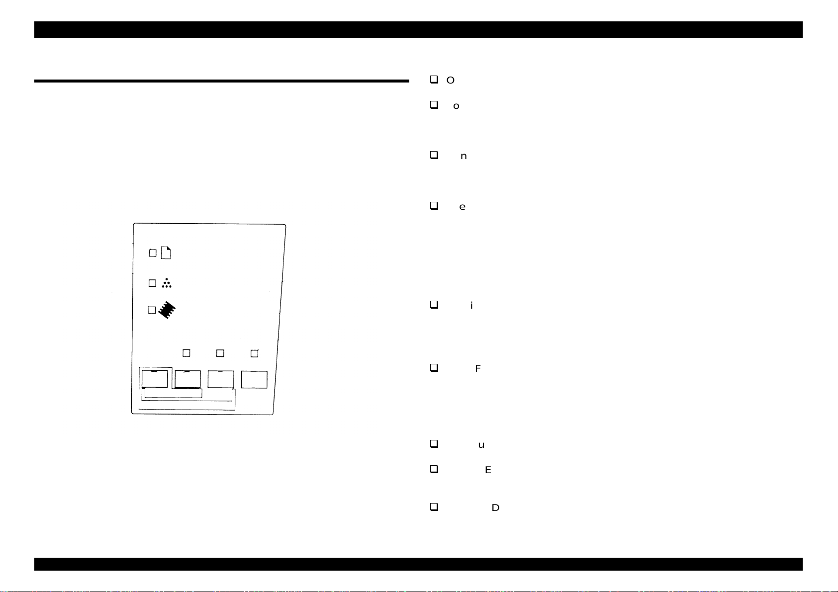
1.3.2 Control Panel
The control panel of EPL-5700 is located right edge of the front printer.
There are six LED lights and four non lock type switches.
Paper
Toner
Memory
Alt
Continue
Reset
Status Sheet
Figure 1-3. Control Panel
Form Feed On Line
1.3.2.1 Switches
On line switch: Switches the printer between on line and off line
status.
Form feed switch: When the printer is off line and data remains in the
printer’s memory, prints out the data and clears the
buffer. If used in combination with the Alt button, a
status sheet is printed.
Continuous switch:Enables the printer to resume printing after certain
maintenance-required conditions or errors have been
cleared. If used in combination with the Alt button, the
printer is reset.
Alternate switch: Use this button in combination with the Continue
button in order to stop printing and reset (Warm boot).
In the reset condition, if both Alt switch and Continue
switch are pressed more than 5 seconds, the printer
goes to “Reset All” condition.
1.3.2.2 Lights
On Line LED(green): Displays a non-flashing light when the printer
is on line, indicating the printer can receive
print data. When the printer is off line, this light
is off. The light flashes as the system switches
between on-line and off-line status.
Form Feed LED(yellow): Comes on when data is received and stored in
the printer’s buffer prior to printing. Flashing
indicates the printer is processing data. When
no data remains in the printer buffer(the
section of memory reserved for receiving
data), this light is off.
Continue LED(red): Flashes when an error is detected or a
maintenance procedure must be performed.
Paper LED(yellow): Displays a non-flashing light when a general
paper error, or “Printer Open” error has
occurred.
Toner LED(yellow): Displays a non-flashing light when it is time to
change the developer cartridge (toner).
Flashes to indicate the toner is low.
Rev. A
1-

EPL-5700 Chapter1 Product Description
9
Memory LED(yellow): Displays a non-flashing light when either a
Print Overrun or Mem Overflow error has
1.3.3 List of Panel Setting
occurred. Flashes when the resolution is
reduced from 600 to 300 dpi, because of lack
of memory size.
This printer has no LCD display in the control panel, so it is not possible to
make function settings from the control panel, excluding toner left quantity
reset and OPC drum life reset by the special operation and status sheet.
Refer to Chapter 3 for error conditions.
Function settings can be performed using “RCP”(remote control panel).
In the Table below, note that the bold and italic value in the “Value” column
CAUTION
This printer has EEPROM to maintain the function
setting. Data-writing to EEPROM can not be
guaranteed, if the power is turned off during
writing. Therefore, sometimes service error call
occurs or the panel setting returns to the initial
setting by all reset or at the next power on. In
order to prevent this, do not turn off the printer at
the following conditions, since data-writing to
EEPROM is performed.
•• From the power is turned on until the On Line
light stays on.
••When On-line light is flashing.
indicates the factory default setting.
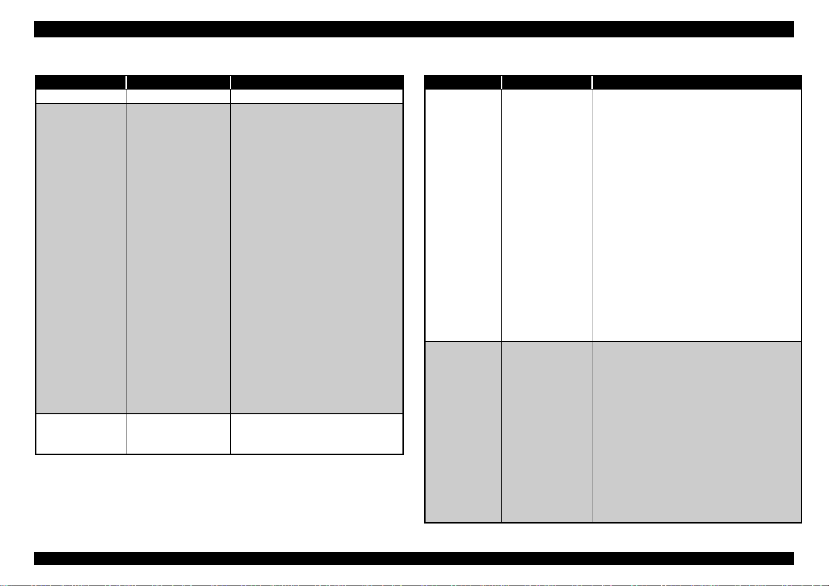
Table 1-9. Function Setting for Control Panel
Menu Item Value
Test Menu
• Status sheet
• ESC/Page Font
Sample.
• LJ4 Font Sample.
• ESCP2 Font
Sample.
• FX Front Sample
• 1239X Front
Emulation
Menu
Printing
Menu
Sample.
• PS Status Sheet
• PS Font Sample
• PS Fact Sheet
• Parallel
• Serial
• AUX
*2
• Paper Source
• Page Size
• Wide A4
• Orientation
• Copies
• Manual Feed
• Resolution
• Skip Blank Page
*1
*1
*1
LJ4
, ESCP2, I239X, PS*1, GL2,
AUTO
•
Auto
*10
•
A4
LGL, GLT, GLG, EXE, F4,
MON, C10, DL, C5, C6, IB5,
CTM.
Off,
Port
-999
1
Off,
600,
Off
ON
On
, On
•
•
•
•
•
•
, MP, LC1*3.
, A5, B5,
, Land
300
*14
LT
*17
, HLT,
Rev. A
1-

EPL-5700 Chapter1 Product Description
0
Table 1-10. Function Setting for the Control Panel(Cont.)
Menu Item Value
Tray Size
Menu
• MP Tray Size
*16
•
A4
HLT, LGL, GLT, GLG,
EXE, F4, MON, C10,
DL, C5, C6, IB5.
, LT, LGL.
•
A4
•
On
•
Off
4, 5, 1, 2
•
3,
• -9.0, -
Config Menu
• LC1 Size
*3
• RITech
• Toner Save
• Density
• Top Offset, Left Offset
0.5mm.
• Size Ignore
• Auto Cont
• Page Protect
• Image Optimum
• Paper Type
*5
•
Off,
•
Off,
•
Auto
•
Auto
•
Normal
Transprnc.
Setup Menu
• Interface
• Time Out
• Standby
• Language
•
Auto
AUX*2.
• 0, 5-
•
Enable
•
English
Deutsch, ITALIANO,
ESPANOL, SVENSKA,
Dansk, Dederl., SUOMI,
Portugues.
• Toner
• Page Count
• 0∼100
• 0∼999999999
• SelecType Init
Parallel Menu
• Speed
• Bi-D
• Buffer Size
•
Fast,
•
Nibble
•
Normal
Minimum.
, A5, B5,
LT
, Off.
, On.
, -99.0 mm step
0.0
On
On
, On
, Off, On
, Thin*5, Thick,
, Parallel, Serial,
-300
60
, Disable
, Francais,
Normal
, ECP, Off
, Maximum,
*17
Table 1-11. Function Setting for the Control Panel(Cont.)
Menu Item Value
,
Serial Menu
• Word Length
• Baud Rate
•
•
, 7
8
, 19200, 38400, 57600, 300,
9600
600, 1200, 2400, 4800
Even, odd
, 2
, Off
Off, Robust
, Maximum, Minimum.
Maximum, Minimum.
, Off
Off
CR+LF
LF
, FF
Space
, On
DIMM, Download.
∼ available(Max 65535)
∼99.99 cpi step 0.01
10.00
∼999.75pt step 0.25 pt
12.00
, Roman-8, ECM94-1,
AUX Menu
ESC/Page
*4
Menu
LJ4 Menu
• Parity
• Stop Bit
• DTR
• Xon/Xoff
• Buffer Size
*2
• Buffer Size
• Auto CR
• Auto FF
• CR Function
• LF Function
• FF Function
• Error Code
• Avoid Error
• Font Source
• Font Number
•
Pitch
•
Height
• SymSet
*15
*15
•
None,
•
1
•
On
•
On,
•
Normal
Normal,
•
On
•
On,
•
CR,
•
LF+CR,
•
FF+CR
•
Ignore,
•
Off
•
Resident,
•
0
• 0.44∼
cpi
• 4.00∼
•
*7
IBM-US
8859-2 ISO, 8859-9 ISO, IBM-DN,
PcMuktiling, PcE. Europe,
PcTk437, WiAnsi, WiE.Europe,
WiTurkish, DeskTop, PsText,
VeInternati, VeUS, MsPublishin,
Math-8, PsMath, PiFont, Legal,
UK, ANSI ASCII, Swedis2,
Intalian, Spanish,
German,Norweg1, Fench2,
Windows.
*17
• Form
• Source SymSet
*7
• 5∼
• 0∼
60
277
*16
∼
64
∼3199
∼128 Lines.
Rev. A
1-1
EPL-5700 Chapter1 Product Description
Table 1-12. Function Setting for the Control Panel(Cont.)
Menu Item Value
LJ4 Menu Dest Symset
GL2 Menu
• GL-Mode
• Scale
• Origin
• Pen
• End
• Join
• Pen0
• Pen1
• Pen2
• Pen3
• Pen4
• Pen5
• Pen6
*6
*6
*6
*6
*6
PS Menu
• Error Sheet
• Protect Level
• MicroGray
0∼
277
∼3199
• GLlike,
•
•
•
, A0, A1, A2, A3
Off
Corner,
Pen0
Pen4*6, Pen5*6, Pen6
•
Butt,
Round.
•
Mitered
Triangular, Round, Beveled,
None.
• 0.05∼
0.05mm.
• 0.05∼
0.05mm.
• 0.05∼
0.05mm.
• 0.05∼
0.05mm.
• 0.05∼
0.05mm.
• 0.05∼
0.05mm.
• 0.05∼
0.05mm.
Off
, On
•
• 1∼5
, Off
•
On
LJ4GL2
Center
, Pen1, Pen2*6, Pen3*6,
*6
Square, Triangular,
, Miteredbeveled.
∼5.00mm step
0.35
∼5.00mm step
0.35
∼5.00mm step
0.35
∼5.00mm step
0.35
∼5.00mm step
0.35
∼5.00mm step
0.35
∼5.00mm step
0.35
Table 1-13. Function Setting for the Control Panel(Cont.)
Menu Item Value
ESCP2 Menu
FX Menu
• Font
• Pitch
• Condensed
• T. Margin
• Text
• CGTable
*7
• Country
• Auto CR
• Auto LF
• Bit Image
• ZeroChar
• Font
• Pitch
• Condensed
• T.Margin
• Text
• CGTable
• Country
•
Courier,
serif, Roman T, Orator S, Sans H,
Script, OCR A, OCR B.
•
10cpi
•
Off,
• 0.40∼
• 1∼
62
•
PcUSA
PcCanFrenc, PcNordic, PcTurkish2,
PcE. Europe, BpBRASCII,
BpAbicomp
•
USA,
Denmark, Sweden, Italy, Spain1,
Japan, Norway, Denmark2, Spain2,
LatinAmeric, Korea, Legal.
•
On,
•
Off,
•
Dark
, φ
•
0
•
Courier
Script, Orator S, OCR A, OCR B
•
10cpi
•
Off,
• 0.40∼
• 1∼
62
•
PcUSA
PcCanFrenc, PcNordic, PcTurkish2,
PcE. Europe, BpBRASCII,
BpAbicomp
•
USA,
Denmark, Sweden, Italy, Spain1,
Prestige, Roman, Sans,
, 12cpi, 15cpi, Prop.
On
∼1.50 inch step 0.05 inch
0.50
*17
*16
66
, Italic, PcMultiln, PcPortugue,
France, Germany, UK,
Off
On
, Light, BarCode
, Prestige, Roman, Sans serif,
, 12cpi, 15cpi, Prop.
On
∼1.50 inch step 0.05 inch
0.50
*17
*16
66
, Italic, PcMultiln, PcPortugue,
France, Germany, UK,
Japan, Norway, Denmark2, Spain2,
LatinAmeric
∼available (Max 81) Lines
∼available (Max 81) Lines
Rev. A
1-11

EPL-5700 Chapter1 Product Description
2
Table 1-14. Function Setting for the Control Panel(Cont.)
Menu Item Value
FX Menu
1239X Menu
• Auto CR
• Auto LF
• Bit Image
• ZeroChar
• Font
• Pitch
• Code Page
• Text
• Auto CR
• Auto LF
• Alt.Graphic
• Bit Image
• ZeroChar
• CharacterSet
•
On,
•
Off,
•
Dark
, φ
•
0
•
Courier
Roman, Sans serif,
Script, Orator S, OCR A,
OCR B
•
10cpi
17cpi, 20cpi, 24cpi,Prop.
•
437,
• 0.30∼
step 0.05 inch
• 1∼
63
(Max111)Lines
•
Off,
•
Off,
•
Off,
•
Dark
, φ
•
0
• 1,
Off
On
, Light, BarCode
, Prestige,
, 12cpi, 15cpi,
850, 860, 863, 865
∼1.50 inch
0.40
*17
*16
∼
∼available
67
On
On
On
, Light, BarCode
2
Note)
*1: Can only be selected when Parrot-V option.
*2: Can only be selected when Type-BI/F option is installed.
*3: Can only be selected when optional lower cassette is installed.
*4: These item will not be displayed on the panel and can not select or
change from the RCP etc. And these items will not be printed on
status sheet. Also these items will be hidden to the users.
*5: Normal Select when using normal paper.
Thin Invalid for EPL-5700. This setting is only possible to
change by EJL command, but if printer receive this
command, internal setting will force to set to Normal
setting.
Thick Select when using narrow media such as envelopes,
postcards, etc.
*6 Can only be selected in GLlike mode.
*7 When the NLSP font DIMM is added, the selectable SymSet and
CGTable for RCP for DOS are added. Following symbol set will be
added.
For LJ4 mode:
Pclcelandic*
PcEt850*
PcNordic*
WiEstonian*
BpBRASCII*
PcGk869*
PcCy855*
WiCyrillic*
8859-8ISO*
PcAr864*
For ESCP2 mode:
PcSI437*
Mazowia*
8859-7ISO*
PcUkr866*
*8 Indicated only when NLSP Bitmap3 Font ROM for Turkey*
*9 Indicated only when NLSP EDG OEM Scalable Font ROM for
Turkey*
13
.
8
, PCLt774*8, PcTurk1*8*9, PcPortugues*8,
8
, PcTurk2*8*9, PcCanFrench*8, PcSI437*8,
8
, 8859-3ISO*8, 8859-4ISO*8,WiBaltic*8,
8
, WiLantvian*8 Mazowia*8*12, CodeMJK*8*12,
8
, BPAbicomp*8, PcGk437*
8*10
, 8859-7ISO*8*10, WiGreek*8, Europe3*8,
8*11
, PcCy866*8*11, PcLt866*8, 8859-5ISO*8,
8
, Bulgarian*8*11, PcUkr866*8, Hebrew7*8,
8
, Bebrew8*8, PcHe862*8, Arabic8*8,
8
,8859-6ISO*8, OCR A*8, OCR B*
8
, PCTurkish1*8, Pclceiandic*8, 8859-ISO*8,
8
,CodeMJK*8, PcGk437*8, PcGk851*8, PcGk869*8,
8
,PcCy855*8, PcCy866*8, Bulgarian*8,
8
, Hebrew7*8,Hebrew8*8, PcAr864*8, PcHe862*8.
8*10
, PcGk851*8,
8
13
.
Rev. A
1-1

EPL-5700 Chapter1 Product Description
3
*10 Indicated only when NLSP EDG OEM Scalable Font ROM for
Greek*
*11 Indicated only when NLSP EDG OEM Scalable Font ROM for
Cyrillic*
*12 Indicated only when NLSP EDG OEM Scalable Font ROM for
Latin*
13
.
13
.
13
.
*13 When changing the “SymSet” to this value, “Font Source” and “Front
Number” is set to “Resident” and “0”. So it is necessary to change
“Font Source” and “Front Number” to the font which supports this
symbol set.
*14 Only applied to LJ4 and ESC/Page mode.
*15 Either pitch or height will be displayed.(decided by selected font)
*16 Factory setting for Europe and Pacific.
*17 Factory setting for North America.
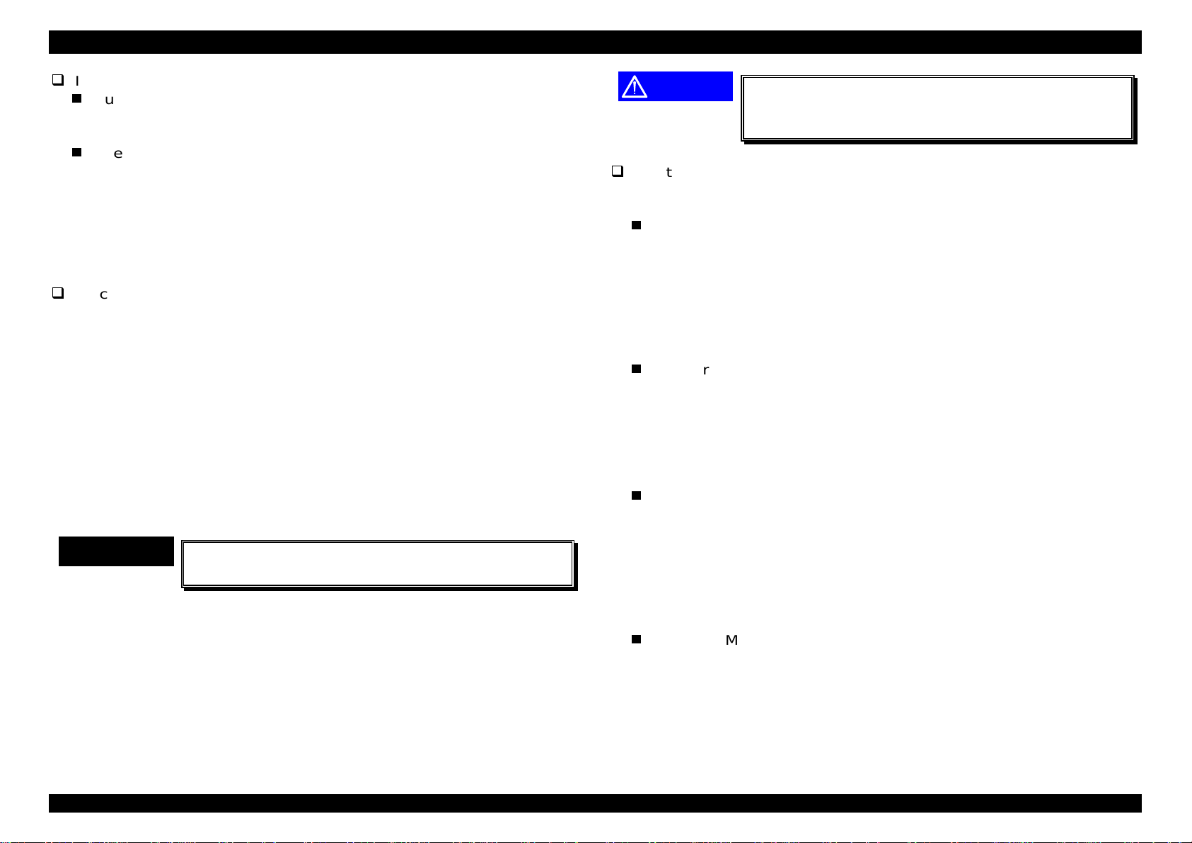
1.3.4 Special(alternative) Operation
1.3.4.1 Operation at Power On
After turning the power on while pressing a particular button, and keep
pressing the switch until the paper feed lamp, toner lamp and memory lamp
are turned on, following function will start.
Hexadecimal Damp
Turn on the power while pressing the Form Feed switch, then the
printer will enter damp mode. The received data is converted by
hexadecimal ASCII and printed out.
This function is canceled by Warm Boot(see page 1-8) or turning
power again.
Toner Reset
Turn on the power while pressing On Line switch and Form Feed
switch, the left toner quantity is reset and becomes toner full
condition. (E
Then, printer returns to the normal condition.
OPC Drum life reset
Turn on the power while pressing On-line switch and Continue switch.
The printer sets OPC drum life 100%.
Then, printer returns to the normal condition.
F)
Rev. A
Following is not opened to the users.
Initialization of EEPROM
Turn on the power while pressing On-line switch, Continue Switch and
Alt switch. Then, EEPROM setting returns to the original settings,
which were set at the factory. All setting including the total print count
is cleared.
Then, printer goes to Warm Boot and returns to the normal condition.
1-1
EPL-5700 Chapter1 Product Description
4
Initialization of Panel Setting Values
Turn on the power while pressing Continue switch, then the printer
resets panel setting values to the original setting which were set at the
factory.
Then, printer goes to Warm Boot and returns to the normal condition.
1.3.4.2 Up-dating ROM Program
Since the ROM programs, which were produced during the initial massproduction, are using Flash-ROM, they can be up-dated through the parallel
interface from the host computer, when it becomes necessary to up-date.
Procedure for up-dating
1. Connect the printer and host computer by parallel interface cable.
2. Turn the power of the printer on, while pressing On-line, Form Feed and
Continue switches.
3. Stop pressing switches after Paper, Toner and Memory lights turn on.
Continue light and From Feed light turns off 3 seconds after other lights turn
on with flashing On-line light. The printer is ready to receive the program
data from the host computer.
4. Transfer the program data by COPY command of DOS from the host
computer, as it is shown below.
>COPY_/B_File Name_LPT1 press Return key.
Note)
”_” above means to take one space.
CHECK POINT
9
The printer indicates that old program is being erased, turning the Toner,
Memory and Form Feed lights on and blinking the on-line light.
Then, the printer indicates that new program is being written, turning the
Memory and Form Feed lights on and blinking On-line light.
5. On-line light blinks and other lights turns off after up-date process is
completed normally.
6. Press On-line switch and re-boot the printer.
Printer should be receiving condition before the
data is sent from the host computer.
CAUTION
If you fail to up-date the program ROM correctly,
Service Req. Error appears and the printer will not
be able to start.
Solution when error occurs.
If up-dating RON fails, error is indicated and goes to Check SUM error
(service req. error) without appropriate operations.
Write Error
Because of defective device of Flash-ROM or defective confection
with DIMM slot, Paper, Continue and Form Feed lights turn on while
writing or erasing program , then On-line light blinks and light error is
indicated. Operation is canceled by pressing Alt switch. In this case,
old program still remains and transferred data is red but abandoned.
Up-date is proceeded by pressing On-line switch, but the printer does
not operate well.
Data Error
Data error is indicated by turning Toner, Continue and Form Feed
lights on and blinking On-line light.
Operation is canceled by pressing Alt switch. In this case, old
program still remains and transferred data is red but abandoned.
Up-date is proceeded by pressing On-line switch, but the printer does
not operate well.
Address Error
This error occurs when writing address to program ROM is done out
of range. Address error is indicated by turning Toner, Continue and
Form Feed lights on and blinking On-line light. Operation is canceled
by pressing Alt switch. In this case, old program still remains and
transferred data is red but abandoned. Up-date is proceeded by
pressing On-line switch, but the printer does not operate well.
Check SUM Error of Program ROM
When up-dating ROM fails, Check SUM error appears. Memory and
Continue lights turn on and On-line light blinks to indicate Check SUM
error. Press On-line switch and re-boot the printer.
Rev. A
1-1

EPL-5700 Chapter1 Product Description
5
1.4 OPTIONS AND CONSUMABLE
Following shows options and consumable for EPL-5700.
Table 1-15. Printer Options
Name Code
500 Sheet Lower Paper Cassette C81287*
Face Up Tray C81286*
Operational memory module Refer to Reference
Guide
EPSON Script Level 2 module C83229*
Optional Interface Cards;
• Optional Ethernet Card
• 32KB Serial Interface Card
• 32KB Parallel Interface Card
• Coax Interface Card
• Twinax Interface Card
• AppleTalk Interface Card
• GPIB Interface Card
Note)*
The asterisk(*) is a substitute for the last digit of the product number,
which varies by country.
• C82357*/C82362*
• C82307*
• C82310*
• C82314*
• C82315*
• C82312*
• C82313*
Rev. A
1-1

 Loading...