

Page 1
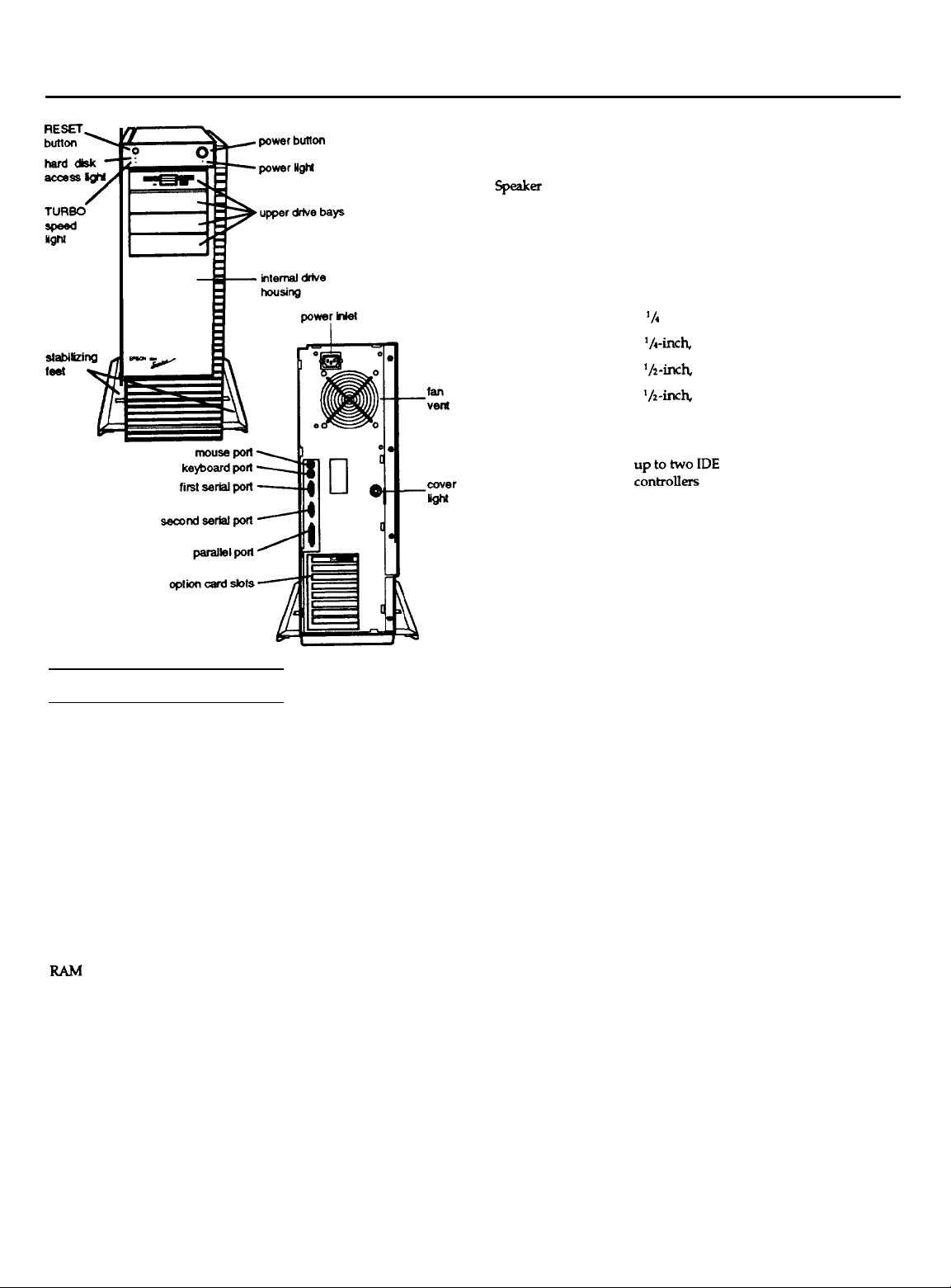
EISA Series Tower
Computer Specifications
Main System Board
System memory
BIOS
Shadow RAM
EISA configuration
Clock/calendar
Interfaces
Serial
Parallel
Mouse
Keyboard
4MB RAM standard on SIMMs; expandable
using 1MB, 2MB, 4MB, or 8MB SIMMs up to
64MB (maximum); SIMMs must be 70ns, 36bit, R-pin, gold-leaded, fast-page mode type
Two-part system BIOS; one 64KB permanent
BIOS on an EPROM; one 64KB CPUdependent BIOS in a ROM device
Automatically copies the system BIOS from
ROM into RAM; shadow RAM for video
BIOS and external BIOS is software selectable
8KB SRAM; battery-backup
Real-time clock, calendar, and CMOS RAM
for
configuration;
Two RS-232-C ISA compatible,
asynchronous; 9-pin D-shell connectors
ISA compatible, 25-pin, D-shell connector
Mini DIN, 6-pin connector for PS/2
compatible mouse or other device
Mini DIN, 6-pin connector for PS/2
compatible keyboard
battery backup
Option slots
Controllers
Diskette
and
tape drive
Hard disk
Processor Board
CPU
Cache memory
Math coprocessor
Mass Storage Bays
Power Supply
Type
Input ranges
Maximum current
Eight 32-bit EISA expansion slots (16-bit and
8-bit ISA compatible); bus-mastering option
cards allowable in slots 1 through 5 and slot 8
Internal; operation and
volume
controllable
by software
Controller on the main
system board
supprts up to two diskette drives in any of
these formats:
5
‘/d
-inch, high-density, 1.2MB
5
‘/,-inch,
double-density, 360KB
3
‘/2-inch,
high-density, 1.44MB
3
‘/2-inch,
double-density, 720KB
Also supports one optional tape drive
Interface on the main system board supports
rInt;o;iDE
486SX/25
drives with embedded
board: Intel 80486SX, 25 MHz
microprocessor
486DX/33 board: Intel 80486DX, 33 MHz
microprocessor
Both boards:
simulated 8 MHz and other
processor simulation speeds selectable
through software or keyboard command
486SX/25 board: 8KB internal cache in the
80486SX microprocessor
486DX/33 board: 8KB internal cache in the
80486DX microprocessor; 64KB Intel
82485MA-33 Turbocache module with write
through, two-way set associative cache
memory and controller
486SX/25 board two sockets available for
optional Weitek WTL4167 and Intel 80487SX
math coprocessors
486DX/33 board: internal coprocessor in the
80486DX and one socket for an optional
Weitek WTL4167 coprocessor
Up to six half-height devices; two half-height
or one full-height internal bays; four halfheight or one full-height and two half-height
externally-accessible bays
300W, fan-cooled, automatic input voltage
sensing, thermally protected
98
to 132 VAC and 196 to 264 VAC,
47 to 63Hz
At 110 Volts, 6 Amps; at 240 Volts, 3.3 Amps
EISA Series Computers
1/92
Tower-l
Page 2
EISA Series Tower
Maximum outputs
* The +12 V peak current is limited to 30 seconds maximum
Output cables
Four main
system
board cables; six mass
storage cables
Option slot power limits
Maximum current +5 Volts
For each slot
For all eight slots120 Amps
/
7 Amps
I l 12volts
1
1.5 Amps 0.75 Amps
1
2 Amps
-5 Volts
0.75 Amps
Keyboard
Detachable two position, 101 or 102
sculpted keys
Layout
Country-dependent main typewriter
keyboard; numeric/cursor control keypad;
four-key cursor control keypad; 12 function
keys
-12 Volts
0.75
Amps
0.75
Amps
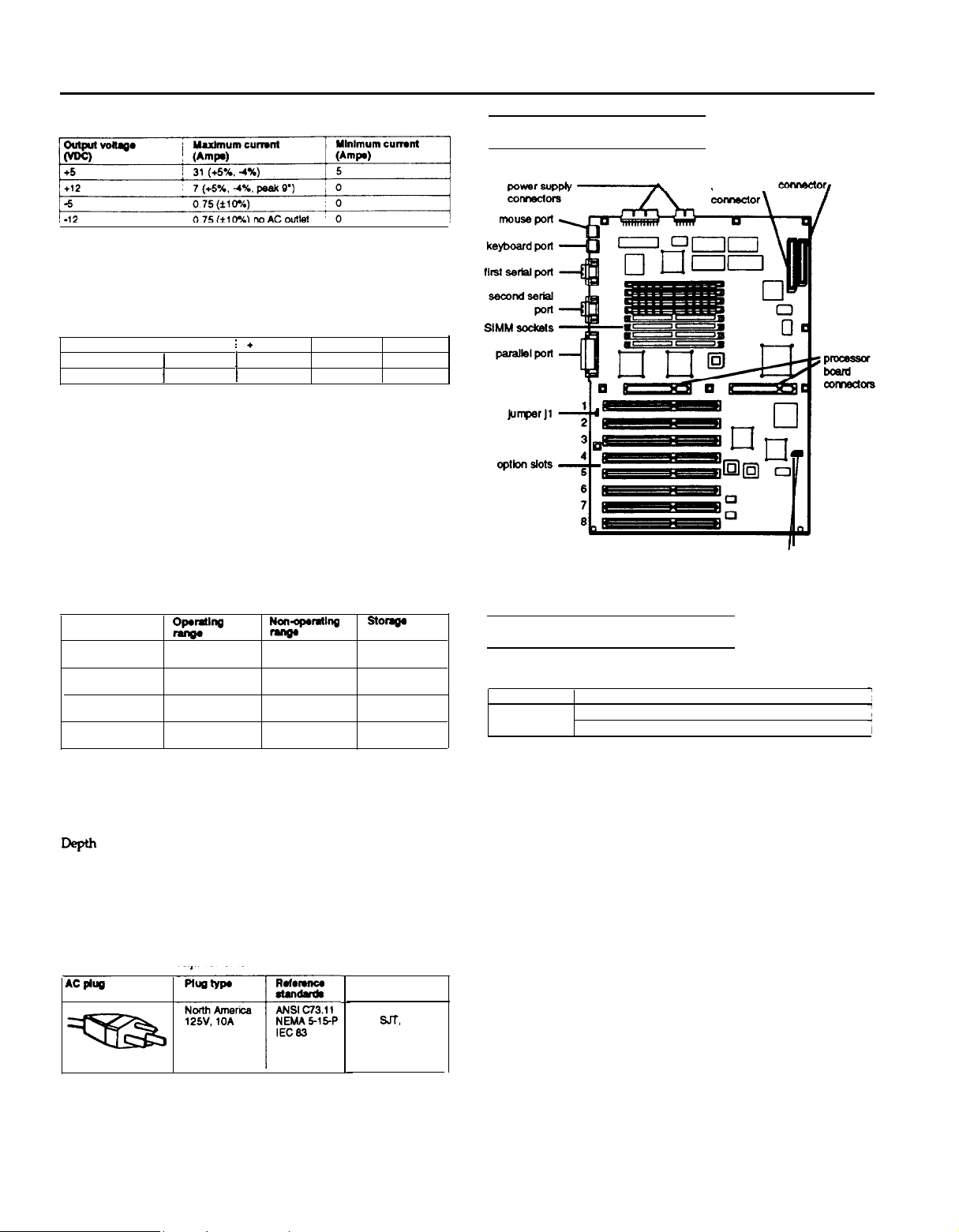
Main System Board Map
hard disk
drive \
alternate hard disk
drive LED connector
diskette drive
Environmental Requirements
Condition
Temperature
Humidity
(non-condensing)
Altitude
Maximum wet bulb 68°F
wyP-&wl
41° to 95°F
5° to 35°C
20% to 80%
-330 to 9900 ft
-100 lo 3000 m
20°C
~*~‘%I
-
-4° to 140°F
-20° to 60°C
10% to 90%
-330 to 11880 ft -330 to 39600 ft
-100 to 3600 m
104°F
40°C
Physical Characteristics
Width
Height
weight
8.5 inches (213 mm)
19.75 inches (494 mm)
25.5 inches (638 mm)
Single diskette drive model
(without keyboard): 61 Ib (27.5 kg)
Power Source Requirements
120 Volt power source requirement
North America
125V, 10A
ANSI C73.11
NEMA 5-15-P
IEC 83
7
SOW@
range
-4° to 140°F
-20° to 60°C
10% to 90%
-100 to 12000 m
134°F
57°C
Power cold
UL/CSA Listed
Type
SJ-f,
no. 18/3AWG
of no. 16/3AWG,
or <HAR> 300V.
10A or 13A
Main System Board Jumper
System board jumper J1 settings
Setting
Pins 1 & 2 Disable password check
Pins 2 & 3
Function
Enable password check
Tower-2
1/92
EISA Series Computers
Page 3

EISA Series Tower
Processor Board Maps
486DX/33 processor
Weitek WTL4167 math
coprocessor socket
486SX/25
processor board
Weitek WTL4167 math
coprocessor socket
board
Intel 80486DX 33 MH
microprocessor
(with heat sink)
\
\
.
processor board
interface connectors
Intel 80487SX
coprocessor
cache module
Z
\
Intel 80487SX
microprocessor
Serial Port Connector (CN3, CN4)
Serial port connector pin assignments
Pin Signal
1
Data Carrier Detect
Receive
2
3
4
5
Data
Transmit Data
Data Terminal Ready
not used
Pin Signal
6 Data Set Ready
7
Request To sand
8 Clear To Send
Ring Indicator
9
Keyboard and Mouse Connectors (CN1, CN2)
/
,
/
processor board
interface connectors
Main System Board Connectors
Parallel Port Connector (CN5)
Pin 13
Pin 25
Parallel port connector pin assignments
Pin 14
Keyboard connector pin assignments
Mouse connector pin assignments
Pin Signal
1
Mouse Data
2
Resewed
3
Ground
Pin Signal
4
+5 VDC (fused)
5
Mouse Clock
6 Resewed
Note: Although the keyboard and mouse connectors are physically
identical, they cannot be used interchangeably.
EISA Series Computers
1/92
Tower-3
Page 4

EISA Series Tower
Power Supply Connector (CN7)
System board power supply connector (CN7) pin assignments
Power Supply Connector (CN17)
Pin 1
Pin 6
System board power supply connector (CN17) pin assignments
Power Supply Connection
P9, Pin 1
P9, Pin 2
P9, Pin 3
P9. Pin 4
P9, Pin 5
P9. Pin 6
2
3
4
5
6
Pin
1
Signal
+5 VDC
+5 VDC
GND
GND
GND
+12 VDC
Pin 1
Tower-4
1/92
EISA Series Computers
Page 5

EISA Series Tower
DMA Controller
System Memory Map
Direct memory access (DMA) improves system performance by
allowing devices to access the system memory directly. This ability is
provided by two 82C37-compatible direct memory access controllers
(DMACs) contained in the 82357. The seven independent 32-bit DMA
channels are listed in the table below along with their associated
DMA controller and their device assignments.
DMA request level
1
Level
DRQ 0 (CTRL1)
DRQ 1 (CTRL1)
DRQ 2 (CTRL1)
DRQ 3 (CTRL1)
DRQ 4 (CTRL2)
DRQ 5 (CTRL2)
DRQ 6 (CTRL2)
DRQ 7 (CTRL2)
Assigned Device
Spare
,
,
SDLC
Diskette drive controller
Spare
(Cascade for CTRL1)
Spare
Spare
Spare
Hardware interrupt (IRQ) map
/
Interrupt
IRQ0
IRQ1
IRQ2
IRQ3
IRQ4
Function
System timer
Keyboard
Cascade interrupt
Serial port 2
Serial port 1
lRQ11
IRQ12
IRQ13
IRQ14
lRQ15
1
Unused
I
Mouse
/
Numeric coprocessor
1
Hard disk drive controller
1
Unused
l
Use of the memory areas for video memory and the video BIOS
depends upon the type of video adapter card installed.
EISA Series Computers
1/92
Tower-5
Page 6

EISA Series Tower
Hard Disk Drives
The following table lists the types of hard disk drives you can use in
your computer. Check this table and the manual that came with your
hard disk to find the correct type for the hard disk drive(s) installed
in your computer. Then select that type at the hard disk drive Type
prompt. If you do not find your drive type in the table, select User
defined and enter your drive’s parameters.
Hard disk drive types
(1) Miniscribe 8425F, Seagate ST125
(2) for Seagate (formerly CDC Imprimis) default setting (34 sectors per track)
(3) Micropolis 1325. Atasi 3085. Lanstor Lan64 Maxtor XT1085, Newbury NDR1085
(4) Micropolis 1323A Miniscribe 3035, Microscience HH1050. Seagate ST4053
(5) Epson IDE drives: 40MB (type 59), 100MB (type 60). 200MB (type 64)
(6) The BIOS translates the actual parameters for Cylinders. Heads,
values. The parameters listed in your drive's documentation may be the following:
Cylinders (1366), Heads (8),
Hard disk drive jumper settings
Jumper
HSP
C/D
DSP
ACT
X = jumper installed
- = no jumper installed
One Hard Disk
drive
X
X
and
Landing zone (1355).
Two Hard disk
I
drives: master
(primary)
-
X
X
X
and
Landing zone to these
Two hard disk
drives: slave
;
(secondary)
ii-
!1X
Note: If you install two 200MB hard disk drives, install one jumper
from each drive in the two jumper positions on the master drive. Do
not instaIl any jumpers on the slave drive.
The folIowing illustration shows the location of the jumpers on the
optimal Epson 200MB IDE hard disk drive.
Tower-6
1/92
EISA Series Computers
Page 7

EISA Series Tower
SIMM Installation
Error Codes and Messages
The following table lists all the error codes and messages that may
appear during System diagnostic testing.
system diagnostic error codes and messages
0103
0104
0105
0105 ! DMA controller register error
0106
0107
0108
0108
0108
0109
0110
The table below describes the type of SIMMs you can install in these
sockets.
SIMM description
0111
0112
0113
0114
0115
Memory
0201
0201
Diskette drive(s)
0601
The table below gives examples of valid SIMM configurations you
can use in your computer.
Example SIMM configurations
Bank 0
U12 U13
1 1
1 1
2 2
2 2
4 4
8 8
* = Factory configuration
U14 U15
1
1
2 2
2
4 4
8 8
Bank 1
U16 U17
1
- ---
1
1 1 1 1
_---
2
1 1 1 1
2 2 2 2
8 8 8 8
U18 U19
Total memory
4MB
8MB
8MB
12MB
24MB
64MB
kzi
0605
0606
0607
Coprocessor
0701
0702
0703
0704
0705
0706
0707
0708
0709
0710
Parallel port(s)
0901
Serial ports (s)
1101
1101
1102
1103
Hard disk drive(s)
1701
1702
1703
/
CPU
error
I ROM checksum error
1
Timer counter register error
/
Timer counter error
j
Refresh error
DMA page register error
Refresh error
Keyboard controller timeout error
Keyboard controller self diegnostic error
Keyboard controller mite command error
CMOS checksum error
CMOS shutdown byte error
CPU instruction error
CMOS battery error
lnterrup controller error
Protect mode error
Protect mode error 2
I
1
Memory error
I Parity error
Diskette drive controller error
(
Sequential seek error
I Random seek error
1
Write error
1
Read error
j
Remove error
’ Insert error
Coprocessor not installed
Coprocessor initialize error
Coprocessor invalid operation mask error
Coprocessor st field error
Coprocessor comparison error
Coprocessor zero divide mask error
Coprocessor addition error
Coprocessor subtraction error
Coprocessor multiplication error
Coprocessor precision error
Error
control signal always low
control signal always high
Timeout error
Verity error
Seek error
Write error
Read error
1
I
i
EISA Series Computers
1/92
Tower-7
Page 8

EISA Series Tower
The tables below list the possible error messages and tone codes.
Power-on diagnostic error messages
!
Message
No timer tick interrupt
Shut down failure
I
Gate A20 failure
’
Unexpected interrupt in protected mode
1
Decreasing available memory
9
I
Timer chip counter 2 failed
j
Time-of-day clock slopped
Power-on diagnostic error tone codes
’
Error tone code / Description
1-1-3
1-14
I 1-3-2
1-3-3
1-34
1-4-1
14-2
1-4-3
1-4-4
2-1-1
2-1-2
2-1-3
2-14
2-2-1
2-2-2
2-2-3
2-24
2-3-1
2-3-2
2-3-3
12-34
124-l
24-2
2-4-3
2-4-4
3-1-1
3-1-2
3-1-3
3-1-4
3-24
3-3-4
34-1
34-2
4-2-1
4-2-2
4-2-3
4-24
4-3-1
8KB and real-time clocks CMOS write/read failure
1
BIOS ROM Checksum failure
I Wrong memory installation
First 64KB RAM chip or data line failure (multi-bit)
First 64KB RAM odd/even logic failure
First 64KB RAM address line failure
First 64KB RAM parity test failure
Fail-safe timer test failure
Software NMI port teat failure
First 64KB RAM or data line failure bit 0
First 64KB RAM or data line failure bit 1
First 64KB RAM or data line failure bit 2
First 64KB RAM or data line failure bit 3
/
First 64KB RAM or data line failure bit 4
’
First 64KB RAM of data line failure bit 5
First 64KB RAM or data line failure bit 6
First 64KB RAM or data line failure bit 7
First 64KB RAM or data line failure bit 8
First 64KB RAM or data line failure bit 9
1
First 64KB RAM or data line failure bit A
I
First 64KB RAM or data line failure bit B
1
First 64KB RAM or data line failure bit C
j
First 64KB RAM or data line failure bit D
/
First 64KB RAM or data line failure bit E
First 64KB RAM or data line failure bit F
Slave DMA register lest failure
Master DMA register test failure
Master interrupt mask register test failure
Slave interrupt mask register leaf failure
Keyboard controller test failure
Video memory test failure
Display initialization test failure
Display retrace test failure
Timer tick interrupt test failure
j
Shutdown teat failure
Gate A20 failure
/
Unexpected Interrupt in protected mode
1
RAM teat failure above address 0FFFFh
Description
:
Timer tick failure
’
Shutdown failure
Gate A20 failure
Unexpected Interrupt in protected mode
RAM failure above address 0FFFFh
interval timer channel 2 failure
Power-on diagnostic error tone codes
Error
4-3-3
CM
!44-1
44-2
L
44-3
Description
lnterval timer channel 2 test failure
Time-of-day clock test failure
I Serial port test failure
/
Parallel port test failure
1
Coprocessor test failure
Information Reference List
Engineering Change Notices
None.
Technical Information Bulletins
None.
Product Support Bulletins
None.
Related Documentation
Epson EISA Series Tower
TM-TOWERT
TM-TOWERC
PL-TOWER ElSA Series Tower, Park Price List
SPKTOWER
Y739991001
I
1
I
I
1
EISA Series Tower, Service Manual Text
EISA Series Tower,
Cover/Spine/Divider
EISA Series Tower, Self Paced Kit
EISA Series Tower User’s Guide
,
Tower-8
1/92
EISA Series Computers
 Loading...