

Page 1

Page 2

FCC COMPLIANCE STATEMENT
FOR AMERICAN USERS
This equipment has been tested and found to comply with the limits for a class B digital
device, pursuant to Part 15 of the FCC Rules. These limits are designed to provide
reasonable protection against harmful interference in a residential installation. This
equipment generates, uses, and can radiate radio frequency energy and, if not installed
and used in accordance with the instructions, may cause harmful interference to radio and
television reception. However, there is no guarantee that interference will not occur in a
particular installation. If this equipment does cause interference to radio and television
reception, which can be determined by turning the equipment off and on, the user is
encouraged to try to correct the interference by one or more of the following measures:
Cl
Reorient or relocate the receiving antenna
0
Increase the separation between the equipment and receiver
0
Connect the equipment into an outlet on a circuit different from that to which the
receiver is connected
Cl
Consult the dealer or an experienced radio/TV technician for help.
WARNING
The connection of a non-shielded equipment interface cable to this equipment will
invalidate the FCC Certification of this device and may cause interference levels that
exceed the limits established by the FCC for this equipment. It is the responsibility of the
user to obtain and use a shielded equipment interface cable with this device. If this
equipment has more than one interface connector, do not leave cables connected to unused
interfaces.
Changes or modifications not expressly approved by the manufacturer could void the
user’s authority to operate the equipment.
FOR CANADIAN USERS
This digital apparatus does not exceed the Class B limits for radio noise emissions from
digital apparatus as set out in the radio interference regulations of the Canadian
Department of Communications.
Le présent appareil numérique n’émet pas de bruits radioélectriques dépassant les limites
applicables aux appareils numériques de Classe B prescrites dans le règlement sur le
brouillage radioélectrique édicté par le Ministère des Communications du Canada.
Page 3

EPSON EISA
User’s Guide
Page 4

IMPORTANT NOTICE
Epson America, Inc., makes no representations or warranties, either express or implied,
by or with respect to anything in this manual, and shall not be liable for any implied
warranties of merchantability and fitness for a particular purpose or for any indirect,
special, or consequential damages. Some states
do
not allow the exclusion of incidental or
consequential damages, so this exclusion may not apply to you.
COPYRIGHT NOTICE
All rights reserved. No part of this publication may be reproduced, stored in a retrieval
system, or transmitted, in any form or by
any
means, electronic, mechanical,
photocopying, recording, or otherwise, without the prior written permission of Epson
America, Inc. No patent liability is assumed with respect to the use of information
contained herein. Nor is any liability assumed for damages resulting from the use of the
information contained herein. Further, this publication and features described herein are
subject to change without notice.
The power-on diagnostic error messages and error tone codes in Appendix C are copyright
1985-1989, Phoenix Technologies Ltd.
TRADEMARKS
Epson is a registered trademark and the EISA Series design is a trademark of Seiko Epson
Corporation.
General notice: Other product names used herein are for identification purposes only and
may be trademarks of their respective companies.
Copyright © 1991 by Epson America, Inc.
Torrance, California
ii
Y735991001
Page 5

Important Safety Instructions
1.
Read all of these instructions and save them for later reference.
2.
Follow all warnings and instructions marked on the computer.
3.
Unplug the computer from the wall outlet before cleaning. Use a
damp cloth for cleaning; do not use liquid or aerosol cleaners.
4.
Do not spill liquid of any kind on the computer.
5.
Do not place the computer on an unstable cart, stand, or table.
6.
Slots and openings in the cabinet and the back or bottom are
provided for ventilation; do not block or cover these openings.
Do not place the computer near or over a radiator or heat
register.
7.
Operate the computer using the type of power source indicated on
its label. If you are not sure of the type of power available,
consult your dealer or local power company.
8.
If you plan to operate the computer in Germany, observe the
following safety precaution:
To provide adequate short-circuit protection and over-current
protection for this computer, the building installation must be
protected by a 16 Amp circuit breaker.
Beim Anschulß des Computers an die Netzversorgung muß
sichergestellt werden daß die Gebäudeinstallation mit einem
16 A Überstromschutzschalter abgesichert ist.
9.
Connect all equipment to properly grounded (earthed) power
outlets. If you are unable to insert the plug into an outlet, contact
your electrician to replace your outlet. Avoid using outlets on
the same circuit as photocopiers or air control systems that
regularly switch on and off.
iii
Page 6

10. Do not allow the computer’s cord to become damaged or frayed.
11. If you use an extension cord with the computer, make sure the
total of the ampere ratings of the devices plugged into the
extension cord does not exceed the ampere rating for the
extension cord. Also, make sure the total of all products plugged
into the wall outlet does not exceed 15 amperes.
12. Do not insert objects of any kind into this product through the
cabinet slots.
13. Except as specifically explained in this User’s Guide, do not
attempt to service the computer yourself. Refer all servicing to
qualified service personnel.
14. Unplug the computer from the wall outlet and refer servicing to
qualified service personnel under the following conditions:
A.
When the power cord or plug is damaged.
B.
If liquid has entered the computer.
C.
If the computer does not operate normally when the operating
instructions are followed. Adjust only those controls that are
covered by the operating instructions. Improper adjustment
of other controls may result in damage and often requires
extensive work by a qualified technician to restore the
computer to normal operation.
iv
D.
If the computer has been dropped or the cabinet has been
damaged.
E.
If the computer exhibits a distinct change in performance.
Page 7

Instructions Importantes de Sécurité
1.
Lire complètement les instructions qui suivant et les conserver
pour references futures.
2.
Bien suivre tous les avertissements et les instructions indiqués sur
l’ordinateur.
3.
Debrancher l’ordinateur de toute sortie murale avant le nettoyage.
Utiliser un chiffon humide; ne jamais utiliser un nettoyeur
liquide ou une bonbonne aérosol.
4.
Ne jamais renverser un liquide d’aucune sorte sur l’ordinateur.
5.
Ne pas placer l’ordinateur sur un chariot, un support, ou une table
instable.
6.
Les évents dans le meubles, à l’arrière et en dessous sont conçus
pour l’aération; on ne doit jamais les bloquer. Ne pas placer
l’ordinateur près d’une source de chaleur directe.
7.
Le fonctionnement de l’ordinateur doit s’effectuer conformément
au type de source d’alimentation indiquée sur l’étiquette. Dans le
cas d’un doute de la source disponible, on doit communiquer
avec le concessionaire ou la compagnie d’électricité.
8.
Lorsqu’ on désire utiliser l’ordinateur en Allemagne, on doit
observer les normes sécuritaires qui suivent:
l
Afin d’assurer une protection adequate à l’ordinateur contre
les court-circuits et le survoltage, l'installation de l’édifice
doit comprendre un disjoncteur de 16 amp.
9.
On doit brancher tout l’equipement dans une sortie reliée à la
masse. Lorsqu’il est impossible d’insérer la fiche dans la prise, on
doit retenir les services d’un électricien ou remplacer la prise. Ne
jamais utiliser une prise sur le même circuit qu’un appareil à
photocopie ou un système de contrôle d’aération avec
commutation marche-arrêt.
V
Page 8

10.
S’assurer que le cordon d’alimentation de l’ordinateur n’est pas
effrité.
11. Dans le cas où on utilise un cordon de rallonge avec l’ordinateur,
on doit s’assurer que la valeur totale d'ampères branches dans le
cordon n’excède en aucun temps les amperes du cordon de
rallonge. La quantité totale des appareils branches dans la prise
murale ne doit jamais excéder 15 amperes.
12. Ne jamais insérer un objet de quelque sorte que ce soit dans les
cavités de cet appareil.
13. Sauf tel que spécifié dans la notice d’utilisation, on ne doit jamais
tenter d’effectuer une réparation de l’ordinateur. On doit référer
le service de cet appareil à un technicien qualifié.
14. Débrancher l’ordinateur de la prise murale et confier le service au
personnel de service qualifié selon les conditions qui suivent:
Lorsque le cordon d’alimentation ou la prise sont endommagés.
A.
Lorsqu’un liquide s’est infiltré dans l’ordinateur.
B.
Lorsque l’ordinateur refuse de fonctionner normalement
C.
même en suivant les instructions. N’ajuster que les
commandes qui sont énumérées dans les instructions de
fonctionnement. Tout ajustement inadéquat de tout autre
contrôle peut provoquer un dommage et souvent nécessiter
des réparations élaborées par un technicien qualifié afin de
remettre l’appareil en service.
vi
Lorsqu’on a échappé l’ordinateur ou que l’on a endommagé le
D.
boîtier.
Lorsque l’ordinateur démontre un changement noté au niveau
E.
de sa performance.
Page 9

Contents
Introduction
Optional Equipment
Software
How to Use This Manual
Where to Get Help
Chapter 1
Preparing to Set Up the System
Installation Overview
Installing Optional Equipment
Connecting Peripheral Devices
Turning On the Computer
Running the Change Country Code Utility
Chapter 2
How to Use This Chapter . . . . ............
The Configuration Process . . . ............
...............................
Setting Up Your System
Setting the Country Code for the First Time
Changing the Country Code
Running System Configuration
Using Configuration Files . . . . . . . . .............
Using the Keyboard . . . . ............
Using a Mouse . . . . . . ............
Using On-line Help . . . . ............
........................
......................
.........................
..................
........................
..................
..................
.....................
...........
........
.................
3
3
4
5
l-l
l-3
l-4
l-5
l-6
l-7
l-8
l-10
2-2
2-3
2-3
2-4
2-4
2-5
vii
Page 10

Configuring Your System
Starting the Program
Setting the Date and Time
Performing the Configuration Steps
Adding or Removing a Board
Defining the Configuration Settings
......................
......................
...................
.............
.................
.............
Using Advanced Configuration Options
Using Alternate Configuration Files
Creating an Alternate SCI File
Loading an Alternate SCI File
Using Special Modes
Using the SD Command
Using the CF Command
.........................
....................
....................
................
.................
.................
Copying the Configuration Files to a Hard Disk
...........
......
2-6
2-6
2-8
2-9
2-10
2-10
2-17
2-19
2-19
2-20
2-21
2-21
2-22
2-24
Chapter 3
Locking the Computer’s Cover
Using a Power-on Password
Using Your Computer
...................
....................
Changing or Deleting a Password
Using a Password in Network Server Mode
Changing the Processor Speed
Entering Keyboard Commands
Using the ESPEED Program
Parking the Hard Disk Drive Heads
Chapter 4
Special Precautions
Removing the Cover
Accessing lnternal Components
..................
.................
Removing the Front Panel
Removing the Subassembly
Replacing the Subassembly
Replacing the Front Panel
Replacing the Cover
.................
Post-installation Setup Procedures
...................
................
..................
................
..............
.............
.............
..............
.........
..............
.........
3-1
3-2
3-3
3-3
3-5
3-6
3-7
3-8
4-l
4-2
4-4
4-6
4-8
4-10
4-11
4-12
viii
Page 11

Chapter 5
Installing and Removing Options
Main System Board Map
Processor Board Maps
Option Cards
Installing Option Cards
Removing Option Cards
Processor Boards
Removing the Processor Board
Installing the Processor Board
Math Coprocessor
Installing a Math Coprocessor
Removing a Math Coprocessor
Memory Modules
Installing Memory Modules
Removing Memory Modules
Chapter 6
Using the Correct Drive Bay
Setting the IDE Hard Disk Drive Jumpers
Changing the Jumper Settings
Installing or Removing a Drive in the External Bay
Installing a Drive
Removing a Drive
Installing or Removing a Drive in the Internal Bay
Removing a Drive
Installing a Drive
Connecting the Cables
.............................
...........................
..........................
..........................
Installing and Removing Drives
......................
.......................
....................
...................
................
................
................
...............
.................
................
....................
............
................
.......................
.......................
.......................
........................
.....................
.......
.......
5-2
5-3
5-4
5-5
5-6
5-7
5-7
5-8
5-9
5-9
5-10
5-11
5-13
5-15
6-2
6-3
6-4
6-5
6-6
6-12
6-14
6-15
6-16
6-18
Appendix A Running System Diagnostics
Starting the Program
Deleting Tests
Adding Tests
........................
.........................
..........................
A-2
A-3
A-4
ix
Page 12

Running Tests
Resuming From an Error
System Diagnostic Tests
Error Messages
.............................
............................
....................
.......................
A-5
A-6
A-7
A-8
Appendix B
Starting the Program
Formatting a New Disk
Reformatting a Used Disk
Selecting an Option
Starting the Formatting Process
Option 1, Format
Modifying the Defective Track Table
Formatting the Disk
Option 2, Destructive Surface Analysis
Option 3, Non-destructive Surface Analysis
Exiting the Program
Appendix C Troubleshooting
Identifying Your System
Error Messages
Power or Lock-up Problems
Password Problems
Keyboard Problems
Monitor Problems
Diskette Problems
Diskette Drive Problems
Hard Disk Problems
Software Problems
Printer Problems
Option Card Problems
Memory Module Problems
Mouse Problems
Math Coprocessor Problems
Formatting a Hard Disk
.........................
....................
...................
.......................
................
...........................
......................
..............
.........................
.......................
............................
.....................
..........................
..........................
...........................
..........................
.......................
.........................
..........................
...........................
........................
.....................
...........................
....................
............
...........
B-2
B-3
B-4
B-4
B-4
B-5
B-7
B-8
B-9
B-11
B-12
C-l
C-2
C-5
C-9
C-11
C-11
C-12
C-13
C-14
C-15
C-16
C-16
C-17
C-17
C-18
x
Page 13

Appendix D Specifications
Main System Board
Interfaces
Controllers
Processor Board
Mass Storage Bays
Power Supply.
Keyboard
Environmental Requirements
Physical Characteristics
Power Source Requirements
System Memory Map
Glossary
Index
........................
.......................
........................
..................
....................
...................
.....................
................
.................
............
.............
D-l
D-l
D-2
D-3
D-3
D-4
D-5
D-5
D-5
D-6
D-7
xi
Page 14

Tables
Key commands
System board options
Default non-cache address blocks
Hard disk drive types
Advanced configuration options
SD command parameters
CF command parameters
Keyboard speed setting commands
ESPEED program parameters
Option slot power limits
Coprocessors
SIMM descriptions
Example SIMM configurations
Hard disk drive number settings
System diagnostic tests
System diagnostic error messages
Power-on diagnostic error messages
Power-on diagnostic error tone codes
Power supply maximum outputs
Option slot power limits
Environmental requirements
120 Volt power source requirements
240 Volt power source requirements
........................
......................
......................
....................
...........................
.......................
.....................
....................
...............
...............
...................
...................
..............
.................
................
................
...............
.............
............
...............
.................
.............
.............
2-4
2-11
2-14
2-15
2-18
2-22
2-23
3-6
3-8
5-4
5-9
5-12
5-13
6-5
A-7
A-8
C-2
C-3
D-4
D-4
D-5
D-6
D-6
xii
Page 15

Introduction
The Epson® EISA Series computer is a powerful, versatile
system ideally suited for use as either a network server or a
high-performance personal workstation. It incorporates the
latest EISA (Extended Industry Standard Architecture)
technology into a convenient desktop design. Its exceptional
features and flexibility enable you to use the most advanced
peripheral devices and software while maintaining full
compatibility with ISA technology.
Your system includes the following features:
Ll
4MB of RAM on single inline memory modules (SIMMs)
cl
SIMM sockets for installing up to 64MB of memory using
lMB, 2MB, 4MB, or 8MB SIMMs
cl
8KB of extended CMOS RAM for EISA configuration
information
cl
Upgradable processor board providing high speed cache
memory and math coprocessor support
cl
One built-in parallel and two built-in serial interfaces
tl
IBM® PS/2® compatible mouse port and keyboard port
Ll
Five EISA expansion slots compatible with 32-bit EISA bus
master cards and 8- or 16-bit ISA cards
cl
IDE hard disk drive interface for up to two hard disk drives
CJ
Diskette drive controller for up to two diskette drives and
one tape drive
Ll
Mass storage bays for up to five drives.
Introduction 1
Page 16

The built-in interfaces let you connect basic peripheral devices
(such as a printer and mouse) directly to the computer, leaving
the expansion slots for optional devices such as a SCSI adapter
or a networking card.
Your computer’s EISA technology allows the 32-bit processor
to access EISA-compatible I/O expansion boards 32 bits at a
time optimizing system throughput. In addition, the EISA burst
mode
capability enables data transfers of up to 33MB of data per
second through the EISA bus.
The powerful EISA configuration program automatically
configures any EISA boards you install and provides all the
necessary information for configuring most ISA boards. The
result is a configuration that manages your system resources in
the most efficient manner possible.
The EISA Series computer offers several other features to
enhance system performance:
Automatic shadow RAM support. This speeds up access to
tl
the system and video BIOS.
Processor speed simulation support. You can set the
0
processor to emulate a variety of system speeds from
8 MHz up to your processor’s highest speed to provide
compatibility with a wide variety of software.
2
Introduction
Password security. You can set a password in either regular
0
or network server mode.
Page 17

Optional Equipment
By adding SIMMs to the main system board, you can expand
the computer’s memory up to 64MB.
On the upgradeable processor board, you can install a math
coprocessor or another processor, depending on the board you
have.
You can also install a variety of other options, such as diskette
drives, hard disk drives, a tape drive, or a SCSI subsystem.
Check with your authorized Epson dealer to see which options
are available.
Software
Your system comes with three diskettes (Reference 1,2, and 3)
containing the following software:
EISA System Configuration program
ISA configuration files for popular ISA boards
System diagnostics program
Hard disk drive low-level formatting utility
HDDPARK program to park the hard disk drive
read/write heads
ESPEED program to change the processor simulation speed
CHGCTR program to set country-dependent keyboard and
configuration information.
Introduction 3
Page 18

How to Use This Manual
This manual explains how to set up, configure, and operate
your computer, as well as how to install options and run
diagnostic tests. It does not cover your operating system; see
your operating system manual for instructions on installing
and using it.
Although you should be sure to follow the steps in Chapter 1
and Chapter 2 to set up and configure your system, you may
not need to read everything in this book. See the following
chapter summaries to find the sections you need.
Chapter 1 provides instructions for setting up your system.
Chapter 2 describes how to run the System Configuration
program to configure your computer.
Chapter 3 provides instructions for certain operating
procedures, such as locking the computer’s cover, using a
password, and changing the operating speed.
Chapter 4 describes how to remove and replace the cover and
front panel to access the internal components.
Chapter 5 gives instructions for installing and removing options.
Chapter 6 explains how to install and remove disk drives.
Appendix A outlines the system diagnostic tests.
Appendix B describes how to perform a hardware-level format
on a hard disk.
Appendix C contains troubleshooting tips.
Appendix D gives the technical specifications for the computer.
At the end of the manual, you’ll find a glossary and an index.
4
Introduction
Page 19

Where to Get Help
If you purchased your computer outside of the United States,
please contact your dealer or the marketing location nearest
you for customer support and service. International marketing
locations are listed on the inside of this manual’s back cover.
If you purchased your Epson product in the United States,
Epson America provides local customer support and service
through a nationwide network of authorized Epson dealers and
Service Centers.
Epson also provides the following support services through the
Epson Customer Resource Center at (800) 922-8911:
Technical assistance with the installation, configuration,
and operation of Epson products
Assistance in locating your nearest Authorized Epson
Reseller or Service Center
Sales of ribbons, supplies, parts, documentation, and
accessories for your Epson product
Customer Relations
Epson technical information library fax service
Product literature with technical specifications on our
current and new products.
Introduction 5
Page 20

Chapter 1
Setting Up Your System
This chapter describes the steps you perform to set up your
system for the first time. It defines the system requirements and
gives a general outline of the steps you need to follow to start
using your computer. It also describes how to set the
appropriate country code for the system’s keyboard and
configuration information.
Preparing to Set Up the System
Before you set up your system, be sure to read “Important
Safety Instructions” at the beginning of this manual (before the
table of contents). These instructions provide information about
properly caring for your computer and operating it correctly.
Setting Up Your System
1-1
Page 21

It is important to choose a safe, convenient location for your
system. Make sure your location provides the following:
A flat, hard surface. Surfaces like carpeted floors and beds
attract static electricity, which can erase data on your disks,
damage the computer’s circuitry, and prevent proper
ventilation.
Good air circulation. Leave several inches of space around
the computer so air can move freely.
Moderate environmental conditions. Select a cool, dry area
and protect your computer from extremes in temperature,
humidity, dust, and smoke. Avoid direct sunlight or any
other source of heat.
No electromagnetic interference. Do not place your system
too close to any electrical device, such as a telephone, that
generates an electromagnetic field.
Appropriate power sources. Connect all your equipment to
the appropriate power source. See “Power Source
Requirements” in Appendix D for more information.
1-2
Remove the protector card. If you have a 5¼-inch diskette
drive, be sure to remove the protector card from the
diskette slot. This card is inserted at the factory to protect
the read/write heads in the drive.
Setting Up Your System
Page 22

Installation Oveview
This section lists the general steps you follow to install options,
connect peripheral devices, and configure your system. For
detailed instructions on performing these steps, see the
appropriate sections specified below.
1.
Install any optional equipment you want to add to your
computer, such as disk drives, a math coprocessor, memory
modules, or EISA option cards. Do not install any ISA
option cards yet (unless you will be using an ISA card to
control your monitor). See “Installing Optional Equipment”
below.
2.
Connect a monitor, a printer, and the keyboard. See
“Connecting Peripheral Devices” below.
3.
Then see “Turning On Your Computer,” below, before you
turn on the system.
4.
Run the Change Country Code utility (CHGCTR) to install
the correct keyboard driver and configuration information
for your system. See “Running the Change Country Code
Utility,” below, for instructions.
5.
Read “The Configuration Process” in Chapter 2 to familiarize
yourself with the use of the System Configuration program.
6.
Run the System Configuration program, as described in
Chapter 2, to configure your system.
7.
If you have other ISA option cards to install, turn off the
system, unplug all the power cords, and disconnect any
peripheral devices from the computer.
8.
Set any switches or jumpers on your ISA cards, if necessary,
and install them in the computer. See Chapter 5 for
instructions on installing option cards.
Setting Up Your System
1-3
Page 23

9.
Connect all of your peripheral devices.
10. Install your operating system and any other application
programs. See the manuals that came with your software
for installation instructions.
Installing Optional Equipment
The first time you set up your computer, you should install any
disk drives, math coprocessor, memory modules, or EISA
option cards you plan to use. Do not install any ISA option
cards yet, unless you will be installing an ISA video adapter
card to control your monitor.
You can install the rest of your ISA cards after you run the
System Configuration program. This program provides
information about the jumper and switch settings for the ISA
option cards you will install.
Follow the instructions in Chapters 5 and 6 to install optional
equipment in your computer. Be sure to check your computer’s
option slot power limits on page 5-4 before you install any
option cards.
You may need to unlock the computer’s cover to access the
internal components. See Chapter 3 for instructions.
When you are finished installing optional equipment, return to
this chapter for guidelines on connecting the peripheral devices
necessary to run the System Configuration program.
1-4 Setting Up Your System
Page 24
Connecting Peripheral Devices
You may not want to connect all your peripheral devices before
you run the System Configuration program for the first time. If
you’ll be installing ISA cards after running the program, you
may want to connect only those devices necessary to perform
the program’s functions. If you connect other devices, you will
need to disconnect them to install the ISA cards.
You must connect a monitor and a keyboard to run the System
Configuration program. You may also want to connect a
printer.
As you set up your computer, leave this manual’s back cover
foldout open so you can refer to the illustrations identifying the
different parts of the computer.
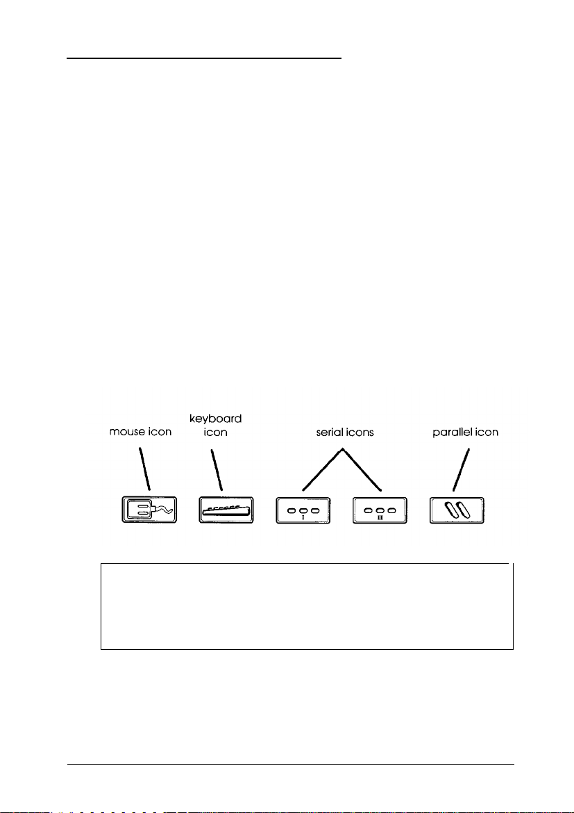
The following icons mark the built-in interfaces on the back of
the computer:
Caution
Although the keyboard and mouse ports are physically
identical, you cannot use them interchangeably. Be sure to
plug the keyboard and the mouse into the correct ports.
Before connecting your peripheral devices, make sure the
power buttons or switches on the computer and all the
peripheral devices are turned off.
Setting Up Your System
1-5
Page 25

Then connect the devices in the following order:
1.
Connect your peripheral device cables to the computer.
2.
Connect the power cords to the computer and other devices,
if necessary.
3.
Plug the power cords into their electrical outlets.
Be sure to read the next section before you turn on your
computer.
Turning On the Computer
After you set up your system, you’re ready to turn on the
power. But first, read the following safety rules to avoid
accidentally damaging your computer or injuring yourself:
Lt
Do not connect or disconnect any power or peripheral
device cables when the computer’s power is on.
Cl
Never turn on the computer with a protector card in the
diskette drive.
1-6
tl
Never turn on the computer when its cover is off.
Ll
Never turn off or reset your computer while a disk drive
light is on. This can destroy data stored on disk.
Ci
Always wait at least five seconds after you turn off the
power before you turn it on again. This allows the
computer to clear and reset its memory.
Ci
Do not leave a beverage near your system or any of its
components. Spilled liquid can damage the circuitry of
your equipment.
Setting Up Your System
Page 26

Cl
Always turn off the power, disconnect the computer’s
power cord, and wait 30 seconds before you remove the
cover. Only remove the cover to access internal devices.
Now you can run the Change Country Code utility.
Running the Change Country Code Utility
Before you configure your computer or perform any other
operations, you need to create new AUTOEXEC.BAT and
CONFIG.SYS files for your country on the Reference 1 diskette.
You do this by running the Change Country Code utility.
This utility creates files that contain the appropriate keyboard
driver and configuration information for the country you select.
The program runs automatically the first time you boot your
computer from the Reference 1 diskette.
Country codes are available for the following countries:
tl United States
tl United Kingdom
Q
France
0
Germany
CI
Italy
Cl
Spain.
The default country code is United States. See the instructions
in the next section to set the appropriate country code and
create the correct AUTOEXEC.BAT and CONFIG.SYS files.
Later, if you need to change the country code and create new
files, see the “Changing the Country Code” section.
Setting Up Your System
1-7
Page 27

Setting the Country Code for the first Time
To run the Change Country Code utility the first time you boot
your computer from the Reference 1 diskette, follow these steps:
1.
Insert the Reference 1 diskette in drive A.
2.
Turn on your computer or press the
3.
After a moment, you see a screen describing the Change
Country Code utility. The screen includes the following
message and prompt:
Current country code is United States.
Change country code? (Y/N)
If you want to select the default country code, United States,
press m. You see a message telling you that the program
still must update your files. Then the program copies the
files. Go to step 4.
If you want to select another country code, press m. You see
the following:
RESET
button.
1-8
Press Fl - US Version (United States)
Press F2 - UK Version (United Kingdom)
Press F3 - FR Version (French)
Press F4
Press F5 - IT Version (Italian)
Press F6 - SP Version (Spanish)
- GR Version (German)
Press any other key to accept the
current country code.
Press the appropriate function key for your country. The
program copies the files and displays a message confirming
the change.
Setting Up Your System
Page 28

4.
When you see the following message, press any key to reboot
the system and run the System Configuration program:
Now you should reboot the system to run
the appropriate AUTOEXEC.BAT and
CONFIG.SYS files and start the System
Configuration program.
Press any key to reboot . . .
After a moment, you see the System Configuration program
title screen. If you want to run the program now, see the
information in Chapter 2 before you begin.
If you do not want to configure your computer now, remove
the diskette from drive A and turn off your computer.
The AUTOEXEC.BAT and CONFIG.SYS files on your
Reference 1 diskette are now customized for your country’s
keyboard and configuration information. Whenever you boot
your system from the Reference 1 diskette, the computer runs
the appropriate files for your country.
The System Configuration program also sets the format of the
date and time in your computer’s real-time clock to the
appropriate format for your country.
Setting Up Your System
l-9
Page 29

Changing the Country Code
If you need to change the country code for your system’s
keyboard driver and configuration information, you can run
the CHGCTR utility. Follow these steps:
1.
Insert the Reference 1 diskette in drive A and log onto
drive A.
2.
At the
information screen for the Change Country Code utility
followed by this prompt:
3.
If you want to keep the current country code, press IN).
You see a message telling you that the program still must
update your files. Then the program copies the files. Go to
step 4.
If you want to select another country code, press [VI. You see
a list of the function keys to press to select a different code.
Press the appropriate function key for the country code you
want. The program copies the files and displays a message
confirming the change.
A>
prompt, type
Change country code? (Y/N)
CHGCTR
and press [Enter. You see the
l-10
4.
When you see the following message, press any key to reboot
the system and run the System Configuration program:
Now you should reboot the system to run
the appropriate AUTOEXEC.BAT and
CONFIG.SYS files and start the System
Configuration program.
Press any key to reboot . . .
After a moment, you see the System Configuration title
screen. If you want to run that program now, see Chapter 2
for instructions.
Setting Up Your System
Page 30

If you do not want to run System Configuration, remove the
Reference 1 diskette from drive A and turn off your
computer.
The AUTOEXEC.BAT and CONFIG.SYS files on your
Reference 1 diskette are now customized for the country you
selected.
The System Configuration program also sets the format of the
date and time in your computer’s real-time clock to the
appropriate format for the country you selected.
Setting Up Your System
1-11
Page 31

Chapter 2
Running System Configuration
The System Configuration program, provided with your
system on the Reference 1 diskette, allows you to configure
your computer. Use the program to do the following:
Learn about the configuration process
Set the date and time
Copy the configuration (CFG) files for any option cards you
install
Configure the system board and any option cards
Create one or more System Configuration Information
(SCI) files
Access other system utilities, such as System diagnostics
and hard disk utilities.
You must run the System Configuration program to configure
your system before you can use your computer for any other
purpose. You may need to run it again later if you add or
remove options, such as memory, disk drives, or option cards.
After running the program, you save your current
configuration in the computer’s CMOS and in a file called
SYSTEM.SCI. Your computer checks this information each time
you turn it on and assigns your system resources based on the
configuration options you selected.
If you want to create an alternate configuration file for your
computer or another computer, you can create an alternate SCI
file. See page 2-19 for more information.
Running System Configuration
2-1
Page 32

Note
The first time you configure your computer, you must run
the program from the Reference 1 diskette and it is best to
always run it from there.
How to Use This Chapter
This chapter is divided into the following four sections:
CI
The Configuration
configuring your computer using the System Configuration
program. It also tells you how to use the keyboard or a
mouse with the program and how to use on-line help.
Process describes the various aspects of
tl Configuring Your System
instructions for running the System Configuration program
and is organized in the order in which you should perform
the operations.
CI
Using Alternate Configuration Files
create and use alternate configuration files, should you find
it necessary to do so.
Ll
Using Special Modes
computer by running it in special operating modes, such as
non-target modeling mode.
Read “The Configuration Process” first to familiarize yourself
with all aspects of the configuration process. Then perform the
configuration operations in the order they are described under
“Configuring Your System.”
If you need to create alternate configuration files or run the
program in special modes, see pages 2-19 or 2-21, respectively.
provides step-by-step
tells you how to
tells you how to configure your
2-2
Running System Configuration
Page 33

The Configuration Process
This section describes the following configuration operations:
Ci
Using the configuration files
Ll
Using the keyboard or a mouse with the program
Li
Using on-line help.
Using Configuration Files
Configuration (or CFG) files provide information to the system
about a card’s functions and resource requirements so your
computer can allocate its resources efficiently. They also
provide instructions for setting any switches and jumpers on
ISA cards.
You copy to your Reference 1 diskette a configuration file for
each card you install using the System Configuration program.
EISA cards come with the necessary CFG file to allow the
program to configure the card automatically. See your EISA
card documentation for more information.
ISA option cards may come with the necessary CFG file for this
program. If not, Epson provides many ISA configuration files
on the Reference 3 diskette. You can also write to the
manufacturer of your option card and request a CFG file for it.
Use the file provided by your ISA card manufacturer, if
possible, and do not copy more than one file for a card.
If you do not have a configuration file for your ISA card, you
can still install the card in your system. However, you should
configure the rest of your system and then follow the
instructions that came with the card to set any of its switches or
jumpers.
Running System Configuration 2-3
Page 34

Using the Keyboard
If you use a keyboard when you run the System Configuration
program, refer to the table below for a description of the keys
you can use to move the cursor and select items. If you’ll be
using a mouse with the program, see “Using a Mouse” below.
Most of the screens show which keys you can press to perform
various operations. Follow the instructions on each screen.
Whenever the
<OK>. To select the <Cancel> icon, you can either press the
m
key or highlight <cancel> and press
Key commands
<OK>
icon is highlighted, press
IEnter
w
Using a Mouse
to select
The first time you run System Configuration, you must use the
keyboard. After configuring your system, load your operating
system and then install your mouse driver. Then you can run
System Configuration using your mouse.
2-4
Running System Configuration
Page 35

To select most options, place the cursor on the option and click
the left button once to highlight it and again to select it.
When you see
m
or
m
on the screen, you can scroll the
text. Place the cursor on the arrow indicating the scroll
direction and hold down the left button. Release it to stop.
Keep in mind that this chapter gives keyboard instructions
when describing how to use the System Configuration
program. You should substitute the appropriate mouse
equivalents when performing the same operations.
Using On-line Help
The System Configuration program provides extensive on-line
help information. You can obtain help in the following ways:
Q
Highlight a menu option to see a description of its function.
tl Select Step 1: Important EPSON EISA
configuration information for detailed information
about each step in the configuration process.
Q
Press the
following menu appears:
m
key whenever
you see Help=Fl.
EPSON EISA Configuration Help
The
Current screen
Selected item or board
All boards
Keys
Using help
EPSON EISA configuration
Press
D
to select the help information you need; then press
IEnter
Running System Configuration
2-5
Page 36

Configuring Your System
Follow the instructions in this section and on your screen to
configure your computer using the System Configuration
program. You configure your system in the following order:
Set the date and time
Add or remove boards; when you add an option card, the
program copies the necessary configuration files
View or edit the details of your configuration; use this
selection to define your configuration options
View your jumper and switch settings
Save the configuration as you exit the program.
Starting the
Follow these steps to start the System Configuration program
from the Reference 1 diskette:
1.
2.
2-6 Running System Configuration
Program
Insert the Reference 1 diskette in drive A and turn on or reset
the computer.
Note
If you installed any EISA option cards in your system,
you see a message telling you to run the configuration
program. Press
After a moment, you see the title screen for the System
Configuration program. Press any key to continue. You see
the Welcome screen.
I
to continue.
Page 37

3.
Press IEnter You see the Main Menu:
Main Menu
Learn about configuring your computer
Configure computer
Set date
Set time
Access to other utilities
Maintain system configuration diskette
Exit from this utility
Note
If you installed any EISA option cards in your system,
the program first asks you to insert a diskette containing
a CFG file for the EISA card. Remove the Reference 1
diskette, insert the appropriate configuration diskette,
and press IEnter Follow the instructions on the screen to
complete the installation process and then go to step 4.
4.
For an overview of the configuration process, highlight
Learn about configuring your computerand
press IEnter When you have finished reading the three
Help screens, press
(You can press
m
to return to the Main
m
to return to the Main Menu at any
Menu.
time.)
Now set the date and time of your computer’s real-time clock,
as described below.
Running System Configuration 2-7
Page 38

Setting the Date and Time
The real-time clock in your computer continuously tracks the
date and time-even when the computer is turned off. The first
time you run the configuration program, set the date and time
for your computer. You can set them again later to adjust your
clock for seasonal time adjustments, such as daylight savings
time. The computer automatically changes the date for leap
years.
Follow these steps to set the date and time:
1.
At the Main Menu, select Set date. You see a prompt such
as the following:
Set Date
Date 06-08-1992 (mm-dd-yyyy)
Note
The format for the date and time may look different from
the prompts shown here, depending on the country code
you chose when you ran the Change Country Code
utility. (See Chapter 1 for more information.)
2.
The current setting for
necessary. You
and overtype the date. Then press (Enter.
3.
At the Main Menu, select Set time. You see a prompt
similar to the Set Date prompt.
4.
Type the current time and press IEnter You see the Main
Menu.
Now you can configure your computer, as described below.
2-8
Running System Configuration
can
Date
use the arrow keys to move the cursor
is highlighted. Correct it as
Page 39

Performing the Configuration Steps
Follow these steps to configure your computer:
1.
At the Main Menu, select Configure computer. You see
this menu:
Steps in configuring your computer
Step 1:
Step 2:
Step 3:
Step 4: Examine required switches
Step 5:
2.
Select Step 1 and read the information displayed on your
screen about configuring your system. If you want to print
any of the screens, press the
3.
Select Step 2 and follow the instructions on the screen to
add, remove, or move option cards in your configuration
and copy any necessary CFG files to your Reference 1
diskette. See the next section for more information.
4.
Select Step 3 and follow the instructions on the screen to
view or edit the details of your option cards and your
system board. See “Defining the Configuration Settings”
below for more information.
5.
Select Step 4 if you want to view the switch or jumper
settings you may need to change on any ISA cards you will
install. Follow the instructions on the screen.
Important EPSON EISA
configuration information
Add
or remove boards
View or edit details
Save and exit
[K]
key.
6.
When you are finished configuring your system, select
Step
CMOS and reboot the system. You can also exit the
program without saving the configuration, if necessary.
Follow the instructions on the screen.
5 to save the configuration in your computer’s
Running
System Configuration
2-9
Page 40

Adding or Removing a Board
Select
Step 2:
add or remove an option card. The program displays a list of
the computer’s slots with a description of any boards or cards
that it detects. The computer automatically detects EISA cards,
but you must add the necessary ISA card information. Follow
the instructions on the screen to add, move, or remove an
option card.
When you add an option card, you need the configuration
diskette that came with the card. Follow the instructions on the
screen to copy the appropriate CFG files to your Reference 1
diskette.
Add or
remove
boards
when you need to
Defining the Configuration Settings
Select
Step 3:
configuration menu to view your system configuration options.
Follow the instructions on the screen to edit the functions of
these options or to change their resource assignments. You can
also perform various advanced configuration operations by
accessing the Advanced menu. See “Using the Advanced
Configuration Options,”
information.
View or edit details
later in the chapter, for more
from the
You cannot change the settings for certain options because they
are detected and set automatically by the program. Some
options or settings may not be available, depending on the
processor board you have installed.
If you add any EISA option cards to your system, various
configuration options for the card(s) appear on the screen
beneath the system board options. See your EISA option card
documentation for information about configuring your card(s).
2-10
Running System Configuration
Page 41
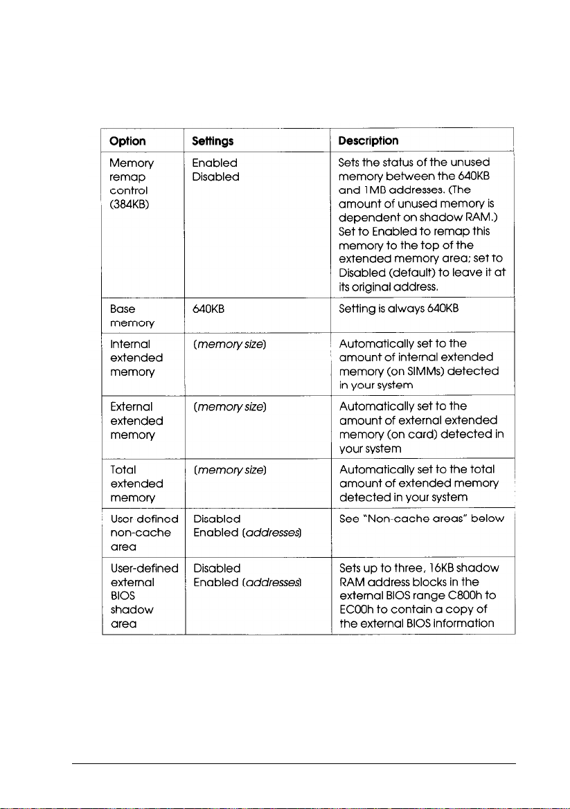
The table below describes the settings available for each of the
system board options.
System board options
Running System Configuration
2-11
Page 42

System board options (continued)
2-12 Running System Configuration
Page 43

System board options (continued)
Running System Configuration
2-13
Page 44
System board options (continued)
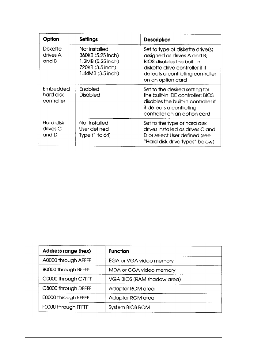
Non-cache areas
Your computer automatically caches all of your memory except
for the six non-cache memory blocks listed in the table below.
You can define up to three additional, 16KB, non-cache
memory blocks by selecting the User defined non-cache area(s)
option and entering the block addresses. For example, if you
install a network or bus-mastering option card, such as a SCSI
controller, you should set the address blocks used by these
boards as non-cache blocks to avoid any memory conflicts.
Default non-cache address blocks
2-14
Running System Configuration
Page 45
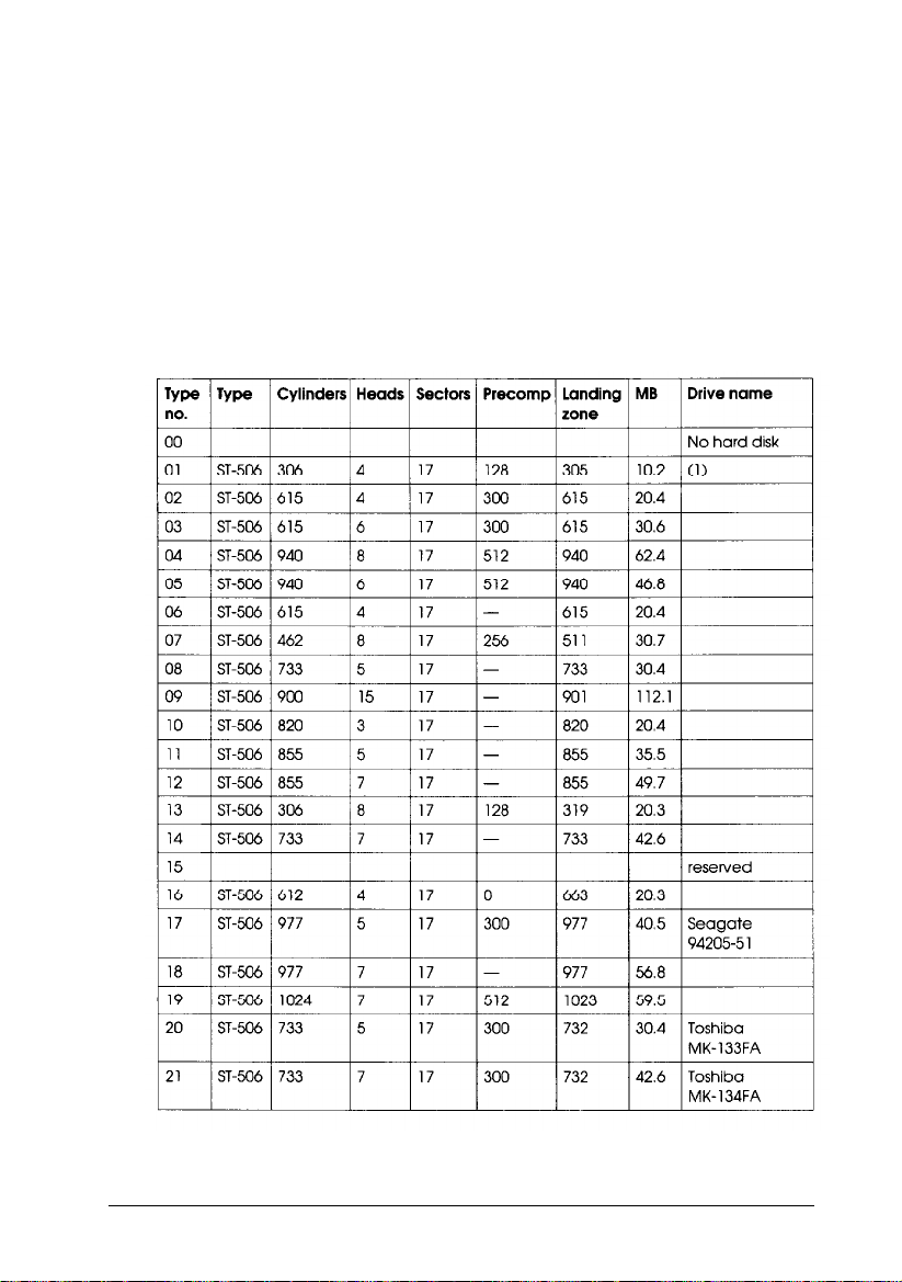
Hard disk drive types
The following table lists the types of hard disk drives you
can use in your computer. Check this table and the manual that
came with your hard disk to find the correct type for the hard
disk drive(s) installed in your computer. Then select that type
at the hard disk drive
drive type in the table, select User
drive’s parameters.
Hard disk drive types
Type
prompt. If you do not find your
defined and enter your
Running System Configuration 2-15
Page 46

2-16
Running System Configuration
Page 47

Hard disk drive types (continued)
(1) Miniscribe 8425F. Seagate ST125
(2) For Seagate (formerly CDC Imprimis) default setting (34 sectors per track)
(3) Micropolis 1325, Atasi 3085, Lanstor Lan64, Maxtor XT1085, Newbury
NDR1085
(4) Micropolis 1323A. Miniscribe 3035, Microscience HH1050. Seagate ST4053
(5) Epson IDE drives: 40MB (type 59). 1 OOMB (type 60). 200MB (type 64)
(6) The BIOS translates the actual parameters for Cylinders, Heads, and
Landing zone to these values, The parameters listed in your drive’s
documentation may be the following: Cylinders (1366), Heads (8), and
Landing zone (1365).
Using Advanced Configuration Options
To perform advanced configuration operations, press In] at
the View
menu:
or edit details
screen. You see the Advanced
Lock/unlock boards
View additional system information menu
Set verification mode menu
Maintain SC1 files menu
Running System Configuration
2-17
Page 48

The table below describes the operations you can select from
the Advanced menu and its submenus.
Advanced configuration options
2-18 Running System Configuration
Page 49

Using Alternate Configuration Files
When you save your configuration in your computer’s CMOS,
the computer also creates or updates the System Configuration
file called
with a different name for your own computer or for another
Epson EISA computer.
You may want to create an alternate configuration for your
own computer that includes a different set of option cards.
Then, whenever you need to use that configuration, you can
load the alternate SCI file and save it in your computer’s CMOS.
If you run System Configuration on a non-target computer
(an IBM AT compatible computer or another Epson EISA
computer), you can create an file for the target computer. Then
you can transport the alternate SCI file to the target computer,
load it, and save it in that computer’s CMOS.
To create an alternate SCI file, follow the guidelines in the next
section. To load an alternate SCI file when you need to use one,
see “Loading an Alternate SCI File” below.
SYSTEM.SCI.
You can also create an alternate SCI file
Creating an Alternate SCI File
You can create an alternate SCI file using the following
methods:
U
Select
Q
CI
Create backup SCI file
system configuration diskettemenu.
Select the Save as option from the Maintain SCI
files menu when you are using the advanced
configuration options.
Run the System Configuration program in non-target
modeling mode and save the configuration you create to a
backup SCI file when you exit.
Running System Configuration
from the
Maintain
2-19
Page 50

The program asks you to name the alternate SCI file you create.
Do not name the file SYSTEM.SCI; this is the name of your
current configuration file.
Use the third method only when you are running the
configuration program on a non-target computer. This method
protects you from accidentally saving the configuration you
create in that computer’s CMOS. See “Using Special Modes” for
instructions on using non-target modeling mode.
Loading an Alternate SCI File
To load an alternate SCI file and store it in the target
computer’s CMOS, follow these steps:
1.
Run the System Configuration program and select
Maintain system configuration diskettefrom
the Main Menu.
2.
Select Load a backup SCI file.
3.
Select the alternate SCI file you want to load from the list of
SCI files displayed on the screen,
4.
Exit and save the SCI file in the computer’s CMOS.
Note
You can also load an alternate SCI file by selecting Open
from the Maintain SCI files menu when you are using the
advanced configuration options. (See page 2-18.) This
method allows you to load the file while you are looking at
the View or edit details screen for another configuration.
However, the Open option erases the currently loaded
configuration before loading the new file.
Now the computer is configured according to the information
in the alternate SCI file.
2-20
Running System Configuration
Page 51

Using Special Modes
You can run the System Configuration program in various
special modes, including non-target modeling mode, by
starting the program with one of the two commands described
in this section. You can also use these commands to run the
program from a hard disk that runs MS-DOS if you copy the
necessary files to the disk first.
The SD command starts the System Configuration program
and allows you to run that program or any of the other utilities
available on the Access to other utilities menu. The CF
command also starts the System Configuration program, but
you cannot run any other utilities.
You can run the program(s) in different modes by including
one or more parameters on the SD or CF command line, as
described in the next sections.
Using the SD Command
If you want to run the program from your hard disk, first
follow the instructions under “Copying the Configuration Files
to a Hard Disk” below. Then follow these steps to use the SD
command:
1.
To run the program from a diskette, insert the Reference 1
diskette in drive A and log onto drive A.
To run the program from a hard disk, log onto the drive and
directory where you copied the configuration files.
2.
Type the following and press m to start the program:
SD
[parameters1
Running System Configuration
2-21
Page 52

The table below describes the parameters you can use to
modify the way the program runs on your computer.
Note
To run the System Configuration program in non-target
modeling mode, add the /N parameter to the command line.
Modeling mode only affects the way the configuration
program operates; it does not affect any of the other utilities
you can run using the SD command.
SD command parameters
Using the CF Command
If you want to run the System Configuration program from
your hard disk, first follow the instructions under “Copying the
Configuration Files to a Hard Disk” below.
2-22
Running System Configuration
Page 53

Then follow these steps to use the CF command:
1.
To run the program from a diskette, insert the Reference 1
diskette in drive A and log onto drive A. To run the
program from a hard disk, log onto the drive and directory
where you copied the configuration files.
2.
Then type the following and press B to start the program:
CF [parameters]
The table below describes the parameters you can use to
modify the way the program runs on your computer.
CF
command parameters
Running System Configuration
2-23
Page 54

Copying the Configuration Files to a Hard Disk
To run the System Configuration program from your hard disk,
you must be running the MS-DOS operating system from that
disk.
To copy all the configuration files from the Reference 1 diskette
to the hard disk, insert the diskette in drive A, type the
following command, and press
COPY A:*.* [d:] [path]
I:
where
d:
and
path
are the drive and directory to which you
want to copy the files.
2-24 Running System Configuration
Page 55

Chapter 3
Using Your Computer
This chapter briefly describes the following operations:
II
Locking the computer’s cover
Ll
Using a power-on password
Ll
Changing the processor speed
Cl
Parking the hard disk drive heads.
Locking the Computer’s Cover
You can lock the cover onto the computer to prevent
unauthorized users from accessing its internal components.
To lock the cover, insert the key as shown on the left and turn it
clockwise. To unlock the cover, insert the key as shown on the
right and turn it counterclockwise.
Using Your Computer
3-1
Page 56

Using
a Power-on Password
If you set a power-on password when you ran the System
Configuration program, you must enter it every time you turn
on the computer. Follow these steps to enter your password:
1.
When you turn on the computer, you see the following
prompt:
Enter password:
2.
Type your password. The screen does not display the
characters you type. Then press [Enter.
After you enter the correct password, you see Password
Then the computer loads your operating system.
Note
If you turned on network server mode and booted your
computer from a hard disk, you use a different procedure to
enter your password. See “Using a Password in Network
Server Mode,” below.
OK
.
If you do not enter the correct password, you see the message
Password is incorrect and another prompt to enter the
password. You have two more chances to enter the correct
password; try typing it again.
If you do not enter the correct password at the third prompt,
the screen displays the following message:
System halted! Reset your system.
The system locks the keyboard and you cannot use your
computer. Press
again.
3-2
Using Your Computer
RESET
and try to enter the correct password
Page 57

Changing or Deleting a Password
You can change or delete a password when you see the Enter
password prompt. Follow these steps:
Turn on the computer. You see the prompt to enter a
1.
password.
2.
To change the password, type the current password followed
by a forward slash (/). After the slash, enter the new
password you want to use. For example, if your current
password is 123 and you want to change it to ABC, type:
123/ABC
To delete the password, type the current password followed
only by a forward slash (/), for example:
123/
The screen does not display what you type.
3.
Press IEnter You see a message confirming the change or
deletion and then the computer loads your operating
system.
Using
a Password
in Network Server Mode
If you are using your system as a network server, you may
want to prevent unauthorized users from entering commands
at the keyboard. To provide this security, you can enable a
power-on password in network server mode using the System
Configuration program.
Using Your Computer
3-3
Page 58

If you set a password but do not turn on network server mode,
you must enter the password before the computer loads the
operating system or the network software. Once you load it,
anyone can access your system by typing commands on the
keyboard. However, if you set a password and turn on network
server mode, you can load the operating system and network
software
before
you enter the password. This allows other
computers in the network to access the system, but prevents
unauthorized users from entering commands at your keyboard
and using any network server access privileges.
When you boot the computer from the hard disk in network
server mode, you do not see the Enter
password prompt
(as you would if network server mode was turned off). The
password prompt is hidden to prevent unauthorized users
from knowing that a password is required. If you boot the
computer from a diskette, you still see the prompt.
See Chapter 2 for instructions on using System Configuration
to set a password and turn on network server mode. Then
follow these steps to enter your password:
1.
Turn on your computer. If you boot from the hard disk, you
do not see the password prompt.
2.
Type your password and press IEnter The screen does not
display what you type.
Now you should be able to use your computer. Press a key
such as
m
to see if the keyboard accepts your command.
If you entered an incorrect password, the computer does not
respond. Type the correct password, press (Enter, and try using
the computer again. You can try as many times as you want.
3-4
Using Your Computer
Page 59

Note
If you boot from a diskette, you see the Enter
prompt. Enter your password as described under “Using a
Power-on Password” above.
You cannot change or delete a password when you boot from
the hard disk in network server mode. First insert a bootable
diskette in drive A and turn on the computer. Then change or
delete the password, as described in the previous section. If you
delete the password, the computer automatically turns off
network server mode.
password
Changing the Processor Speed
Your computer’s processor can operate at high speed, low
speed, and automatic speed, as well as other processor
simulation speeds. When it is at high speed, the
light is on.
You set the default (or power-on simulation) speed in the
System Configuration program, described in Chapter 2. If
necessary, you can temporarily change the processor speed
using keyboard commands or the ESPEED program.
TURBO
speed
High speed is the highest speed available on your processor
board and low speed simulates an 8 MHz processor speed.
Automatic speed switches from high to low speed whenever
the computer accesses a diskette. You can set simulation speeds
for various other processors using the System Configuration
program. See Chapter 2 for more information.
Certain application programs may have specific timing
requirements for diskette access and can run only at low speed.
See the manual for your program to determine if this is the case.
Using Your Computer
3-5
Page 60

If you often use a copy-protected program diskette, you may
want to set your processor speed to change automatically to
low speed when accessing the diskette and return to high speed
when it is finished.
There are three ways to change the processor speed:
LI
Run the System Configuration program (power-on
simulation speed setting)
U
Enter a keyboard command (temporary speed setting)
Q
Run the ESPEED program (temporary speed setting).
If you use programs that require the processor to operate at low
or automatic speed only occasionally, you should use the
keyboard commands or the ESPEED program, described
below, to change the processor speed.
Entering Keyboard Commands
To change the processor speed, enter one of the keyboard
commands in the table below.
Keyboard speed setting commands
You must use the a, a, or m key located on the numeric
keypad.
The speed setting remains in effect until you press
turn off the computer, or until you change it again.
3-6
Using Your Computer
RESET
or
Page 61

Note
You can use the commands listed above while you are
running a program. However, if that program uses one of
these commands for another function, you cannot use it to
change the processor speed. For example, if the program
uses the
cannot enter
to low. Another alternative is to use the ESPEED program,
described below.
(F] [AltIlT]
[xl IAltll~]
command to move the cursor, you
to change the processor speed
Using the ESPEED Program
ESPEED allows you to change the processor speed to high or
low, or set the speed to change automatically. This method is
convenient if your application program does not recognize the
m
key commands or if you want to include the command
in a batch file.
The ESPEED program is provided with your system on the
Reference 1 diskette. If you do not have a hard disk, insert your
Reference 1 diskette in drive A and log onto drive A before you
enter the command to start the program.
If you have a hard disk from which you are running MS-DOS,
copy the file ESPEED.EXE from your Reference 1 diskette onto
your hard disk and run the program from there.
To run the ESPEED program, type the following at the
command prompt and press
ESPEED [parameter]
(Enterl:
Using Your Computer
3-7
Page 62

You can use one of these parameters:
ESPEED
program parameters
If you do not include the parameter when you type the ESPEED
command, the program displays the command syntax and
parameter options.
The processor speed you set remains in effect until you press
RESET
or turn off the computer, or until you change it to a
different setting.
Parking the Hard Disk Drive Heads
If you need to move your computer to a new location, you may
want to park the hard disk drive heads to protect the disk
during the move. You do this by running the HDDPARK
program. HDDPARK
region on the disk surface that does not contain data, and locks
them securely in place so you cannot damage the disk.
moves
the drive’s read/write heads to a
Many hard disk drives, including all the Epson drives,
automatically park their heads when you turn off the
computer. If your drive does not do this, or if you are not
sure that it does, be sure to run the HDDPARK program.
3-8 Using Your Computer
Page 63

Follow these steps to run HDDPARK:
Insert the Reference 2 diskette in drive A and log onto that
1.
drive.
Type HDDPARK and press
2.
IEnter
The computer locks the
heads and disables the keyboard.
Remove any diskettes and turn off the computer.
3.
Note
You can also run HDDPARK by selecting Access
other
utilities from the Main Menu of the System
to
Configuration program. Then select Park hard disk.
You can also copy the files HDDPARK.COM and
HDDPARK.VER to your hard disk and run the program
from there.
Using Your Computer
3-9
Page 64

Chapter 4
Accessing lnternal Components
To access your computer’s internal components, you need to
remove the cover. You may also need to remove the front panel
and the subassembly (the metal case that holds the drive bays).
The instructions in this chapter explain how to do these tasks:
tl
Remove and replace the cover
Ll
Remove and replace the front panel
0
Remove and replace the subassembly
0
Perform post-installation setup procedures.
Read the following safety precautions before you begin.
Special Precautions
As you perform the procedures described in this chapter and in
Chapters 5 and 6, observe the following precautions to avoid
damaging your equipment or injuring yourself:
0
While this manual provides detailed instructions for
installing a variety of optional equipment, do not attempt a
procedure if you have any reservations about performing it;
ask your dealer for assistance.
tl
Always turn off the computer, disconnect all cables to the
computer and any peripheral devices, and then wait at least
30 seconds before you remove the cover. First disconnect
the power cord from the electrical outlet and then from the
computer’s back panel. Then disconnect all peripheral
devices from the computer, including the monitor and
keyboard.
Accessing
Internal
Components
4-1
Page 65

0
Every time you remove the cover, be sure to ground
yourself by touching the inside of the computer’s back
panel before you touch any components inside. If you are
not properly grounded, you could conduct static electricity
and damage your components. Also, do not touch any
components except those that this manual instructs you to
touch.
Ll
When disconnecting cables from sockets on the computer’s
main system board or any devices (such as disk drives),
avoid pulling on the cable; grasp the plastic connector to
remove it from a socket.
CI
When plugging a connector or a component into a socket,
be sure to position it correctly. Carefully align any
connector pins with the corresponding holes in the socket
before you push in the connector. Otherwise, you can
severely damage the equipment.
LI
Always replace the computer’s cover before you turn on
the power, or the computer may overheat.
Removing the Cover
Remove the computer’s cover to do any of the following:
Ct
Install or remove option cards
Ll
Install or remove single inline memory modules (SIMMs)
Ll
Remove the processor board to access its components
Lt
Install or remove disk drives or other storage devices.
4-2 Accessing Internal Components
Page 66

Follow these steps to remove the cover:
1.
Turn off the computer and any peripheral devices connected
to it. Then disconnect the computer’s power cord from the
electrical outlet and from the back panel. Also disconnect
any peripheral device cables that are connected to the
computer, including the keyboard cable.
2.
Turn the computer around so you are facing the back panel.
3.
If necessary, unlock the computer’s cover. (See Chapter 3 for
instructions.)
4.
Loosen the three thumbscrews on the computer’s back panel
by turning them counterclockwise, as shown below. (The
screws will disengage, but they do not come all the way off.)
Accessing Infernal Components
4-3
Page 67

Grasp the sides of the cover (toward the front of the
5.
computer) and pull it firmly back toward you, as shown
below. Then lift it up and off the computer.
Removing the Front Panel
You must remove the computer’s front panel to install or
remove a disk drive from the external drive bay or to remove
the subassembly from the computer.
Follow these steps:
Turn the computer so you are facing the front panel.
1.
4-4
Accessing Internal Components
Page 68

2.
Release the six tabs securing the front panel to the computer
case, as shown below. You may want to use a flat-blade
screwdriver to release the tabs.
3.
Once these tabs are free, grasp the sides of the front panel
and pull it straight toward you, as shown below. Be careful
not to pull the panel off at an angle; this may bend or pop
off the power and
RESET
buttons. If a button pops off,
carefully place it back onto its post.
Accessing Infernal Components 4-5
Page 69

Removing the Subassembly
You need to remove the subassembly if you are installing your
first hard disk drive, removing your only hard disk drive, or
installing or removing a hard disk drive that is mounted next to
the power supply.
Follow these steps:
Turn the computer so you are facing its front side.
1.
Disconnect the power supply and drive cables from the backs
2.
of all the drives installed in your computer. Note which
cables are connected to which drives so you can easily
reconnect them later.
Open the clasps holding the power supply and drive cables
3.
to the side of the subassembly, as shown in the following
illustration. Then remove all the cables from the clasps.
4-6 Accessing Infernal Components
Page 70

Grasp the back of the subassembly by the edge on its upper
4.
left side, as shown below, and lift up the back end.
Pull the subassembly forward slightly to release it from the
5.
two pins beneath the front panel opening.
Accessing Infernal Components
4-7
Page 71
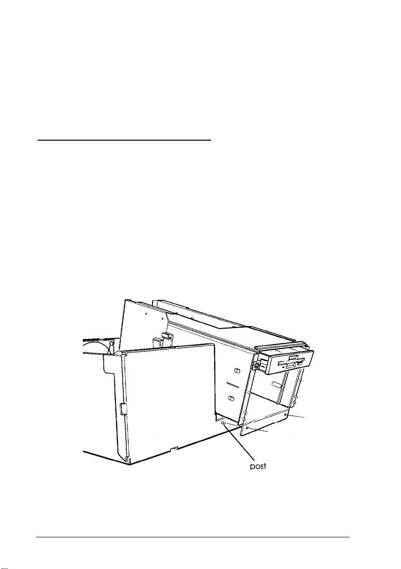
6.
Holding the subassembly up, disconnect the diskette and
hard disk drive cable connectors from their sockets on the
main system board.
7.
Now lift the subassembly out of the computer and place it on
your work surface.
Replacing the Subassembly
Follow these steps to replace the subassembly:
1.
Turn the computer so you are facing its front side.
2.
Make sure the diskette drive cable connector and the hard
disk drive cable connector (if necessary) are connected to
the appropriate sockets on the main system board.
3.
Hold the subassembly at a slight angle and guide the front of
it down through the opening in the front of the computer.
4.
Fit the two holes in the lower front of the subassembly over
the two posts on the front of the computer case.
4-8 Accessing Internal Components
Page 72

5.
Lower the back end of the subassembly into the computer.
If necessary, align the post beneath the back right edge of
the subassembly with the hole on the top of the power
supply. Then lower the subassembly all the way down.
6.
Gather the power supply and drive cables and place them in
the clasps on the side of the subassembly, as shown below.
Snap the clasps shut.
Accessing Internal Components
4-9
Page 73

7.
Connect the necessary power supply and drive cables to the
backs of all your drives, as described in Chapter 6.
Replacing the Front Panel
Follow these steps to replace the computer’s front panel:
1.
Turn
the
computer so you are facing its front side.
2.
Align the openings in the front panel with the power button,
RESET
your computer case. Also align the front panel tabs with
their corresponding notches in the case. Then guide
front panel straight onto the computer case, as shown
below.
button, and drives that extend out from
the
front of
the
3.
Press the front panel onto the computer to fully insert all the
tabs into the notches on the computer case. If all the front
panel tabs do not snap into position, remove the front panel
and try again.
4-10 Accessing Internal Components
Page 74

Replacing the Cover
Follow these steps to replace the computer’s cover:
1.2.Turn the computer so you are facing the back panel.
Hold the cover at a slight angle, as shown below, and lower
the front part onto the computer. Then lower the back of
the cover.
3.
Slide the cover forward until the front edge overlaps the top
edge of the front panel.
4.
Tighten the three thumbscrews on the back panel to secure
the cover to the computer.
Lock the cover onto the computer, if desired.
5.
6.
Reconnect the monitor, printer, keyboard, and any other
peripheral devices you have. Then reconnect the power
cord to the back of the computer and to an electrical outlet.
Accessing Infernal Components
4-11
Page 75

Post-installation Setup Procedures
After you install or remove options, you need to run the System
Configuration program on your Reference 1 diskette so you can
update your system’s configuration information. The program
will automatically update the information about some optional
equipment, such as additional memory or a math coprocessor.
See Chapter 2 for instructions.
If you installed a hard disk drive that has never received a
low-level format, you need to format the disk. Check the
manual that came with your drive, and then, if necessary,
follow the instructions in Appendix B to format your new hard
disk.
You may also want to test a newly-installed option. Some
options come with their own diagnostic test programs. You can
test the following options with the System diagnostics program
on your Reference 2 diskette:
Q
System memory
0
Numeric coprocessor
Serial and parallel ports
Q
Ll
Disk drives
Cl
Dot matrix printers.
See Appendix A for instructions.
4-12
Accessing Internal Components
Page 76

Chapter 5
Installing and Removing Options
This chapter provides instructions for installing and removing
the following optional equipment:
Q
Option cards
Ll
Math coprocessor
Q
Memory modules (SIMMs).
It also includes instructions for removing and installing the
processor board to replace it or to add a math coprocessor.
At the beginning of this chapter, you’ll find maps of your main
system board and the available processor boards. Refer to these
illustrations to locate the different components on the boards.
Before you perform any of the procedures given here, read the
“Special Precautions” on page 4-1 and then remove the
computer’s cover, as described in Chapter 4.
When you have finished installing or removing options, replace
the computer’s cover as described in Chapter 4; then follow the
“Post-installation Setup Procedures” on page 4-12 to update
your configuration.
Installing and Removing Options
5-1
Page 77

Main System Board Map
Use the following illustration to locate components on your
main system board.
5-2 Installing and Removing Options
Page 78

Processor Board Maps
Refer
to
the appropriate illustration below to locate
components on your processor board.
486DX/33 processor board
486SX/25 processor board
Installing and Removing Options
5-3
Page 79

Option Cards
Your computer has five option slots, each of which
can
accommodate one card of the following types:
0
32-bit EISA bus master option card
tl
16-bit ISA compatible option card
Ll
8-bit ISA compatible option card.
Before you install an option card, check all the power
requirements given in the documentation that came with the
card. Make sure that the power required by the card does not
exceed the power limit for its slot, and that the total power for
all the cards does not exceed the power limit for all five slots.
The table below lists the power limits.
Option slot power limits
Maximum current
For each slot 7 Amps
For all five slots
+5 Volts
16 Amps
+ 12 Volts
1.5 Amps
3 Amps
-5 Volts
0.5 Amps 0.5 Amps
0.5 Amps
-12 volts
0.5 Amps
Caution
Although your power supply is protected against excessive
power loads, you could still damage the main system board
if you install an option card that draws more power than the
limits shown in this table.
5-4
Installing and Removing Options
Page 80

Installing
Follow these steps to install an option card:
1.
2.
Option Cards
Unpack the option card and adjust any switches or jumpers
on it, if necessary. Check the option card instructions and
any of the jumper and switch settings you viewed when
you ran the System Configuration program. See Chapter 2
for more information.
Remove the retaining screw from the top of the metal option
slot cover and lift out the slot cover, as shown below.
Keep the screw to secure the option card to the computer. Store
the slot cover in a safe place in case you remove the option
card later.
Installing and Removing Options 5-5
Page 81

Insert the card into the slot with the connector pins pointing
3.
down, as shown below. If you are installing a full-length
card, insert the other end of the card into the appropriate
card guide near the front of the computer.
Push the card downward firmly to insert it as far as it will go.
Secure the end of the card to the back of the computer with
4.
the retaining screw.
Removing Option Cards
If you need to remove an option card, reverse the steps outlined
above. Be sure to replace the option slot cover over the empty
slot to ensure proper airflow inside the computer.
5-6 Installing and Removing Options
Page 82

Processor Boards
Your computer comes with an upgradeable processor board.
To upgrade the board, you can:
Ll
Install a math coprocessor
Ll
Install a new coprocessor (486SX/25 only)
Q
Replace the processor board with a different board.
Removing the Processor Board
You need to remove the processor board to install or remove a
math coprocessor on the board, or if you want to install a
different processor board. Follow these steps:
1.
Disconnect any cables connected to the processor board and
any cables connected to other devices that lay over the
processor board.
2.
Remove the retaining screws securing the processor board
brackets to the inside of the computer case.
Installing and Removing Options
5-7
Page 83

Pull the board straight up and out of the system board
3.
interface sockets; do not rock it back and forth.
If you are installing a math coprocessor, place the board on a
4.
static-free surface with the component side facing up and
see the “Math Coprocessor” section in this chapter.
If you are replacing the processor board, store it in an anti-static
bag in a safe location. See the next section for instructions
on installing the new processor board.
Installing the Processor Board
Follow these steps to install the processor board:
Insert the connectors on the bottom of the processor board
1.
into the processor board connectors on the main system
board. Guide the board straight into the connectors; do not
insert it at an angle or rock it back and forth.
5-8
Secure each end of the board with the retaining screws.
2.
If you disconnected any cables to remove the processor board,
3.
reconnect them.
Installing and Removing Options
Page 84
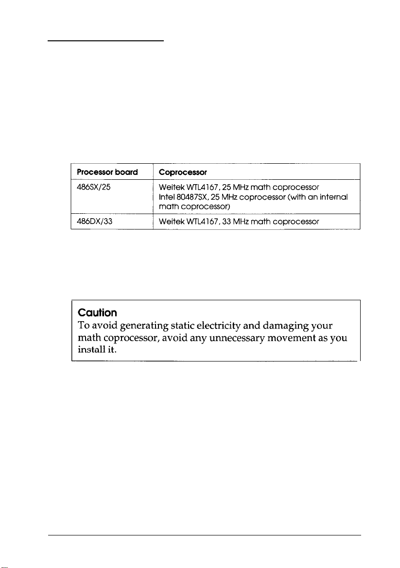
Math
Coprocessor
A math coprocessor speeds up the numeric calculations your
computer performs when using some applications. It also
increases the speed at which graphic images are displayed on
your monitor when you use graphics-oriented software.
You can install the following coprocessors:
Coprocessors
Installing a Math Coprocessor
Carefully follow the steps below to install a math coprocessor.
1.
Remove the processor board from the computer. See page 5-7
for instructions.
2.
Place the processor board on your work surface so that the
board’s connectors are closest to you and the top edge of
the board is away from you. Locate the math coprocessor
socket(s). (See the illustration on page 5-3 if necessary.)
Installing and Removing Options 5-9
Page 85

3.
Turn the coprocessor so that the orientation dot in one corner
is in the position shown below. Align the coprocessor pins
with the holes in the socket and gently push the
coprocessor into the socket, pressing evenly on all sides.
Caution
If you insert the math coprocessor in the wrong position,
you could permanently damage it.
Examine the coprocessor to be sure it is inserted all the way
into the socket.
4.
Reinstall the processor board. See page 5-8.
Removing a Math Coprocessor
If you need to remove the math coprocessor from your
processor board, contact your dealer for assistance. The
procedure requires a special extracting tool, and if you try to
remove it without this tool you can easily damage it.
5-10
Installing and Removing Options
Page 86

Memory Modules
Your computer comes with 4MB of memory provided by
SIMMs (single inline memory modules) which are installed on
the main system board. You can install additional SIMMs to
increase your computer’s memory to 64MB.
There are eight SIMM sockets on the main system board. Each
socket can contain either a single-sided or double-sided SIMM.
The SIMMs must all be 70ns (nanosecond), 36-bit, 72-pin,
gold-leaded, fast-page mode SIMMs.
The SIMM sockets are organized in two banks, as shown below.
Facing the computer’s back panel, the four left-hand sockets
(U12, U13, U14, and U15) are in Bank 0 and the four right-hand
sockets (U16, U17, U18, and U19) are in Bank 1, as shown
below.
Installing and Removing Options 5-11
Page 87

The table below describes the type of SIMMs you can install in
these sockets.
SIMM description
The SIMMs for your computer are usually described first by
their number of logical
sides
(single or double) and then by the
number of bits they contain multiplied by the width of the data
bus (256Kbx36). Check with your dealer to make sure you
install the correct type of SIMMs.
You can install these SIMMs in many different ways. For best
performance, however, follow these guidelines:
Fill each bank with four SIMMs of the same size
0
Install SIMMs in Bank 0 first and then use Bank 1
tl
5-12
Install the highest capacity SIMMs in Bank 0 and the same
Ll
or lower capacity SIMMs in Bank 1.
Installing and Removing Options
Page 88

The table below gives examples of valid SIMM configurations
you can use in your computer.
Example SIMM configurations
l Factory configuration
Once you have determined where to add SIMMs, follow the
instructions below to install them. If you need to remove the
four 1MB SIMMs that came with your system, see “Removing
Memory Modules” on page 5-15.
Installing Memory Modules
Follow these steps to install SIMMs:
1.
If necessary, see the main system board illustration
on
5-2 to locate the SIMM sockets.
2.
It is easiest to install the SIMMs in the sockets farthest from
the processor board first. Then work your way toward the
sockets closest to the processor board.
Installing and Removing Options 5-13
page
Page 89

Position each SIMM so its notched edge is toward the back of
the computer; then insert it in the socket at an angle as
shown below.
3.
Gently press down on the SIMM and, at the same time, press
the top to the left until it is vertical and clicks into place
between the metal tabs and the retaining posts.
5-14
Installing and Removing Options
Page 90

Make sure the SIMM is fully inserted into the socket and that
the retaining posts pins fit into the holes at both ends.
4.
Repeat steps 2 and 3 for each SIMM you want to install.
Removing Memory Modules
If you need to remove memory modules from your computer,
follow the steps below. Check the information on page 5-11 to
be sure you remove SIMMs from the correct sockets.
1.
It is easiest to remove the SIMMs from the sockets closest to
the processor board first. Then work your way toward the
sockets farthest from them.
Use your fingers or two small screwdrivers to pull away the
metal tabs securing the SIMM at each end. Be careful not to
pull the tabs too far, or they may break.
As you pull away the tabs, the SIMM falls to the right at an
angle. Carefully remove the SIMM.
2.
Repeat step 1 for each SIMM you need to remove.
Installing and Removing Options
5-15
Page 91

Chapter 6
Installing and Removing Drives
The instructions in this chapter describe how to install and
remove optional Epson drives in your computer. You can use
these instructions to install a variety of devices, including
diskette drives, hard disk drives, and tape drives. Even if your
drive looks a bit different from the one illustrated here, you
install it the same way.
If you are installing or removing a non-Epson drive, you can
follow these instructions, although some of the steps in this
chapter may not apply. See the manual that came with your
drive for more information.
This chapter describes how to do the following:
Use the correct drive bay
Li
Set the IDE (Integrated Drive Electronics) jumpers on a
Ll
hard disk drive
Install or remove a drive in the external drive bay
Cl
Install or remove an internal drive.
Li
Before you perform any of the procedures described below,
remove the computer’s cover as described in Chapter 4. You
may also need to remove the front panel and subassembly; the
instructions in this chapter tell you when this is necessary.
Installing and Removing Drives
6-1
Page 92
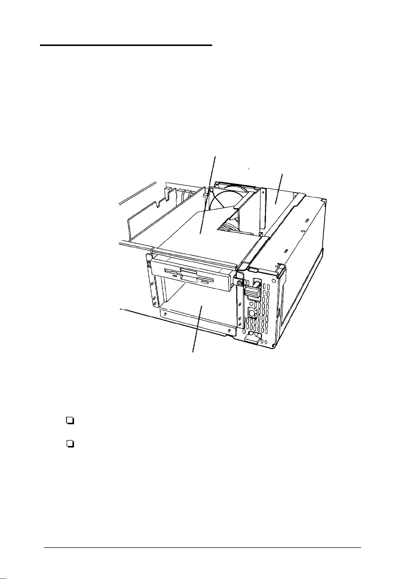
Using the Correct Drive Bay
Your system can hold up to five half-height drives or a
combination of third-, half-, and full-height drives.
As shown below, there are two drive bays: the external drive
bay and the internal drive bay.
subassembly
internal drive bay
external drive bay
The external bay can accommodate up to three drives in the
following configurations:
One third-height drive and two half-height drives
Ll
One third-height drive and one full-height drive.
tl
You can install either two half-height drives or one full-height
drive in the internal bay.
6-2
Installing and Removing Drives
Page 93

If you are installing a hard disk, it is best to install it in the
internal bay. This reserves the external bay for any accessible
drives you may want to add later. If you prefer, however, you
can install a hard disk in the external bay; just leave the drive
slot cover installed in the front panel.
You can install 3½-inch drives in the internal bay. In the
external bay, you can install 5¼-inch drives or 3½-inch drives
with 5¼-inch mounting frames attached.
You also need to attach metal drive brackets to each drive you
install in the external bay. Two sets of these brackets (and their
retaining screws) came in the box with your computer. The
instructions in this chapter tell you how to install them.
Setting the IDE Hard Disk Drive Jumpers
You may need to change the hard disk drive jumper settings if
you install or remove an IDE hard disk drive. The jumpers tell
the computer whether you are using one hard disk drive or two.
Note
You do not need to set any jumpers if you are removing
your only hard disk drive.
If you are installing only one hard disk drive, see “Changing
the Jumper Settings” below to check your drive’s jumpers.
If you are removing one hard disk drive and leaving another in
your computer, you need to change the jumper settings on the
remaining drive to indicate that it is the only hard disk drive
installed.
Installing and Removing Drives
6-3
Page 94
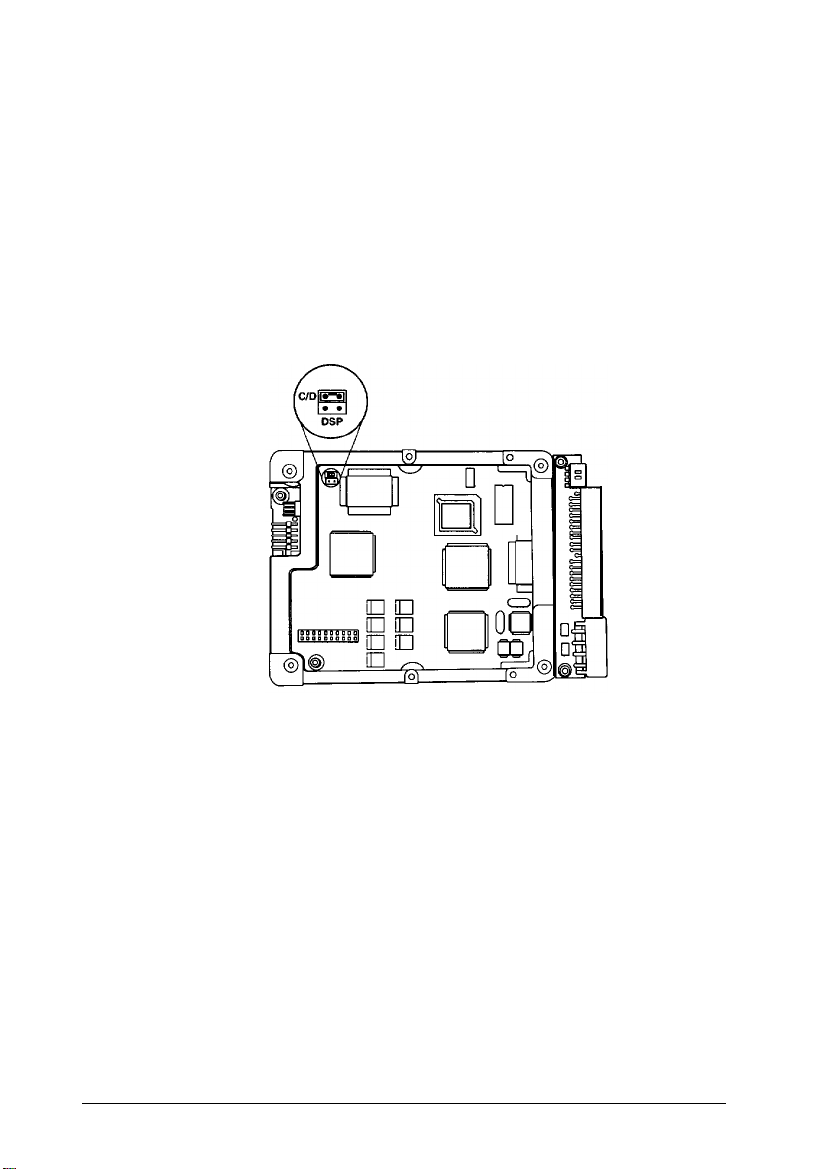
If you install two hard disk drives, you must change the jumper
settings on each drive to indicate which is the master (primary)
and which is the slave (secondary). The primary drive is the
one from which you boot your computer.
Changing the Jumper Settings
The following illustration shows the location of the jumpers on
the optional Epson 200MB IDE hard disk drive.
If you are installing another type of Epson hard disk drive, the
jumpers may be in a different location, and there may be four
jumper positions instead of two. The 200MB drive has only two
jumper positions: C/D and DSP. Your drive may have four
positions: HSP, C/D, DSP, and ACT.
6-4 Installing and Removing Drives
Page 95

Set the jumpers according to the table below.
Hard disk drive jumper settings
X = jumper installed
— = no jumper installed
Note
If you install two 200MB hard disk drives, install one jumper
from each drive in the two jumper positions on the master
drive. Do not install any jumpers on the slave drive.
To install or remove a drive in the internal bay, see page 6-14.
To install or remove a drive in the external bay, see the next
section.
Installing or Removing a Drive in the External Bay
This section describes how to install or remove an Epson
diskette drive. You can also use these instructions to install or
remove another type of storage device; see the manual that
came with it for additional installation instructions.
Installing and Removing Drives
6-5
Page 96

Installing
a Drive
On each interior side of the external drive bay, there is a plastic
guide with four support grooves, as shown below. You need to
select the appropriate grooves for your drive depending on the
size of the drive and where you want to locate it.
The third-height diskette drive that came with your computer
is installed in the grooves at the top of the bay.
instructions that came with the drive to install the frame.
6-6 Installing and Removing Drives
Page 97

Follow the steps below to install a drive in the external bay.
1.
Locate the following parts that came with your computer for
each drive you will install:
Ct
two metal drive brackets
Ct
four retaining screws (with attached flat washers)
Ll
two nuts (with attached star washers)
Q
small wrench.
2.
Attach one bracket to each side of the drive, as shown below.
Loosely secure each bracket with two retaining screws.
Installing and Removing Drives
6-7
Page 98

Slide the drive into the bay as shown below, aligning the
3.
bracket screws on each side with the appropriate grooves in
the drive bay guide.
Guide the holes in the front of the brackets over the threaded
4.
posts on the front of the subassembly. Then push the drive
all the way into the drive bay.
6-8
Secure the drive to the drive bay with the two nuts.
5.
You may need to adjust the drive’s position in the drive bay
6.
by sliding it along the drive brackets. A diskette drive (or
other externally-accessible device) should extend out of the
bay and its faceplate should be flush with the front panel.
A hard disk drive should fit all the way into the bay. If
necessary, replace the front panel (as described in Chapter
4) to check the drive’s position.
When the drive position is correct, remove the two nuts
7.
securing it to the drive bay and slide it out of the bay. Then
tighten the four drive bracket screws, slide the drive back
into the bay, and replace the two nuts.
Installing and Removing Drives
Page 99

8.
Locate one of the power supply cables (labelled Pl through
P5) in the clasps on the left side of the subassembly. (You
can use any one that is available.) Align the notched corners
on the cable connector and the socket on the back of the
drive, as shown below. Then push in the connector.
9.
Locate the appropriate drive cable for the drive. If you
installed a diskette or tape drive, go to step 10. If you
installed a hard disk drive, go to step 12.
Note
If you are installing a non-Epson drive, see the manual
that came with it for instructions on connecting the drive
cable.
10. If you are connecting diskette drive A, use the connector
labelled FDDl on the end of the diskette drive cable. If you
are connecting diskette drive B, use the middle cable
connector labelled FDD2. If you are connecting a tape drive,
use the cable connector labelled TAPE DRIVE ONLY.
Installing and Removing Drives
6-9
Page 100

Align the cable connector with the drive interface so that the
divider in the connector lines up with the gap in the
interface, as shown below. Then push in the connector.
11. To remove the slot cover for the drive you just installed, turn
the front panel so you are looking at the inside of the panel.
Press outward on the slot cover tabs, as shown below, and
pop out the slot cover.
6-10 Installing and Removing Drives
 Loading...