

Page 1
User's Guide
Page 2
Safety Instructions
Safety indications
The documentation and the projector use graphical symbols to show how to use the projector safely.
The indications and their meaning are as follows. Make sure you understand them properly before reading the guide.
Warning
Caution
General information indications
Attention
This symbol indicates information that, if ignored, could result in personal injury or even death due to incorrect handling.
This symbol indicates information that, if ignored, could result in personal injury or physical damage due to incorrect handling.
Indicates contents that could cause damage or malfunction to the projector.
Indicates additional information and points which may be useful to know regarding a topic.
a
s Indicates a page where detailed information regarding a topic can be found.
g
[Name] Indicates the name of the buttons on the remote control or the control panel.
Menu Name Indicates the Configuration menu items.
Indicates that an explanation of the underlined word or words in front of this symbol appears in the glossary of terms. See the "Glossary" section of the
"Appendix".
s "Glossary" p.226
Example: [Esc] button
Example:
Select Brightness from Image.
Image - Brightness
Page 3
Safety Warning and Cautions
3
Make sure you read the following before you use the projector.
s
Safety Instructions
Warning and Cautions on Installation
An optional ceiling mount is required when suspending the projector from
a ceiling.
s
"Optional Accessories" p.198
Warning
• Do not use or install the projector where it may be subject to water or rain,
or high humidity, such as outdoors, in a bathroom, or shower room, and so
on. Otherwise, it could cause a fire or electric shock.
• A special method of installation is required when suspending the projector
from a ceiling (ceiling mount). If installation work is not carried out
correctly, the projector could fall down. This may result in injury or
accidents. Contact your local dealer or the nearest address provided in the
Epson Projector Contact List.
s Epson Projector Contact List
• When installing the projector on the ceiling, make sure you take measures to
prevent it from falling such as passing a wire through the handles.
• If you use adhesives on the ceiling mount fixing points to prevent the screws
from loosening, or if you use things such as lubricants or oils on the
projector, the projector case may crack causing it to fall from its ceiling
mount. This could cause an accident or injury to anyone under the ceiling
mount.
When installing or adjusting the ceiling mount, do not use adhesives to
prevent the screws from loosening and do not use oils or lubricants and so
on.
• Do not cover the projector's air intake vent or air exhaust vent. If either of
the vents is covered, the internal temperature could rise and cause a fire.
• Do not place flammable objects in front of the lens. If you set the schedule to
turn on the projector automatically, any flammable objects placed in front of
the lens could cause a fire.
• Do not tie the power cord and other connection cables together. Otherwise, it
could cause a fire.
• Only use the specified power-supply voltage. Otherwise, it could cause a fire
or electric shock.
Page 4
Safety Warning and Cautions
4
Warning
• Be careful when handling the power cord. Otherwise, it could cause a fire or
electric shock. Note the following when handling the power cord.
- Do not plug multiple power cords in a single electric outlet.
- Do not plug in the power cord if there are any foreign substances, such
as dust, stuck to it.
- Make sure you insert the power cord all the way in.
- Do not plug in or unplug the power cord with wet hands.
- Do not pull the cord when unplugging the power cord. Make sure you
hold it by the plug.
• Do not use a damaged power cord. Otherwise, it could cause a fire or electric
shock. Note the following when handling the power cord.
- Do not alter the power cord.
- Do not place any heavy objects on the power cord.
- Do not bend, twist, or pull the power cord forcibly.
- Do not layout the power cord near a heating device.
• When using the power cord in an area where the power-supply voltage is less
than 120 V, make sure that the power is supplied from an outlet with more
than 15 A.
• Do not share the outlet that you are using for the projector with other
devices.
Attention
• Do not install the projector in a location that is subject to vibration or
shock.
• Do not install the projector near a high-voltage line or object that generates
magnetism. Otherwise the projector may not work correctly.
• Do not use or store the projector in a location that is subject to extreme
temperatures. Also, avoid sudden temperature changes.
Make sure you use or store the projector in a place that is within the
following operating or storage temperature ranges.
- Operating temperature range: 0 to +50˚C
- Storage temperature range: -10 to +60˚C (No condensation)
* At an altitude of 0 to 1,499 m, the operating temperature is 0 to
+50˚C when Power Consumption is set to ECO or Temp
Interlock, and 0 to +45˚C when it is set to Normal.
At an altitude of 0 to 1,500 m, the operating temperature is 0 to
+45˚C when Power Consumption is set to ECO or Temp
Interlock, and 0 to +40˚C when it is set to Normal.
• When using at an altitude of 1,500 m or more, set High Altitude Mode to
On.
s Extended - Operation - High Altitude Mode p.122
*
(No condensation)
Caution
Do not place the projector on an unstable surface, such as on an unstable table
or tilted surface. When projecting vertically, install the projector appropriately
to prevent the projector from falling.
Otherwise it may cause an injury.
Page 5
Safety Warning and Cautions
5
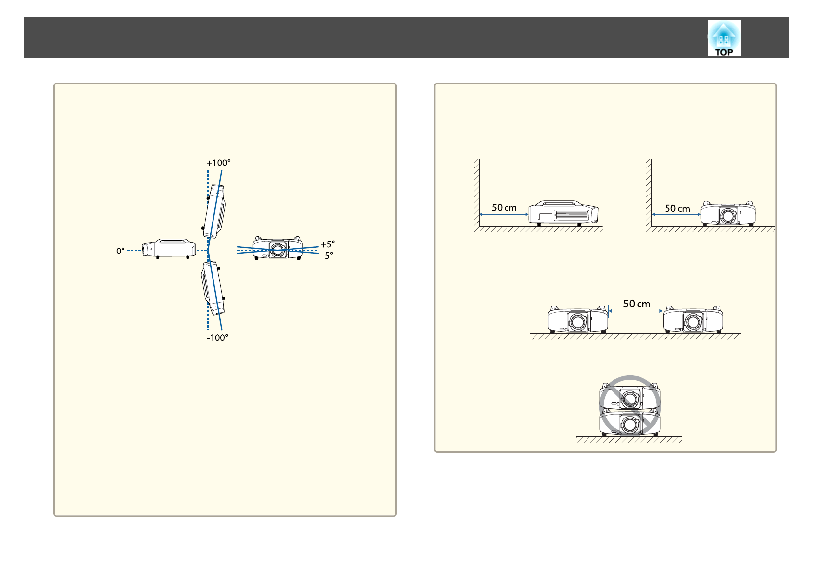
Attention
• When projecting with the projector tilted, do not tilt it at more than the
specified angle. This may cause malfunctions or accidents to occur.
Angle of tilt (when a standard lamp is attached)
Do not use the projector upside down.
Using the projector at angles not shown in the illustrations above may
damage it or cause an accident.
For the operating conditions when attaching the lamp unit (for portrait use),
see the following.
s "Notes on portrait projection" p.6
• Once installation is complete, make sure you set the Direction. Otherwise the
lamp's operating life may be reduced significantly.
s "Setting the direction" p.30
• Using the projector at an improper angle or setting the Configuration menu
incorrectly causes malfunctions and shortens the operating life of optical
parts.
Attention
• Make sure there is a gap at least as wide as shown in the following
illustration between the wall and the air exhaust vent and the air intake
vent.
Air exhaust vent Air intake vent
• When setting up multiple projectors, make sure there is a gap at least as wide
as shown in the following illustration between the projectors. Also, make sure
that the heat from the air exhaust vent does not go into the air intake
vent.
• Do not place the projector directly on top of another projector.
Page 6
Safety Warning and Cautions
6
Attention
• When installing the projector on a surface other than the floor, use the four
ceiling mount fixing points to secure the projector. Never detach the handles.
If you use the projector without handles, it may cause a malfunction.
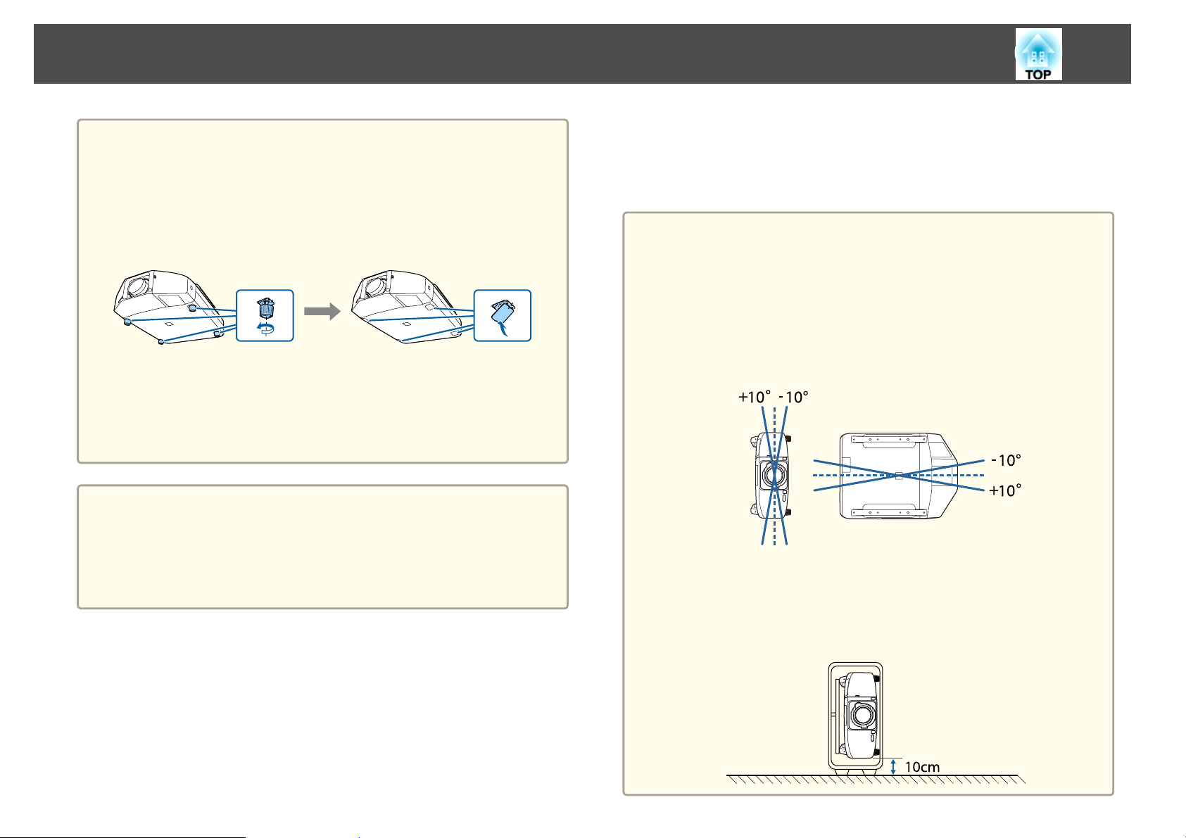
• When installing the projector on the ceiling, remove the feet and attach the
supplied foot covers.
• The feet can be attached and removed. Note that the feet will detach if they
are extended more than 10 mm.
After removing the feet, make sure you attach the supplied foot covers.
• Do not use the screw holes for the feet to secure the projector or attach other
screws, and so on. Otherwise malfunctions may occur.
• We recommend setting the focus, zoom, and lens shift at least 20
a
minutes after you start the projection, because images are not stable
right after turning on the projector.
• When adjusting the vertical lens shift, adjust by moving the image
from the bottom to the top. If it is adjusted from the top to the
bottom, the image position may move down slightly after adjusting.
Notes on portrait projection
An optional frame is required for portrait projection.
s
"Optional Accessories" p.198
Attention
• When performing portrait projection, attach lamp units (for portrait use) on
both Lamp 1 and Lamp 2. If dedicated lamps are not used, the projector does
not cool down correctly, and it may cause a malfunction.
s "Optional Accessories" p.198
• Make sure you install the projector with the air intake vent facing down. If
the air intake vent is facing up, the projector does not cool down correctly,
and it may cause a malfunction.
Angle of tilt
Using the projector at angles not shown in the illustrations above may
damage it or cause an accident.
• Make sure that you install the projector with the air intake vent facing down
and that there is a gap at least as wide as shown in the following illustration
between the projector and the floor and so on.
Page 7
Safety Warning and Cautions
7
a
• You cannot rotate the display direction for the menu, message, and
so on.
• When performing portrait projection, you do not need to set the
Direction.
• Power Consumption is disabled.
s Settings - Power Consumption p.121
Warning and Cautions on Usage
Warning
• Do not cover the projector's air intake vent or air exhaust vent. If either of
the vents is covered, the internal temperature could rise and cause a fire.
• Do not look into the lens while projecting.
Caution
Do not place objects that may become warped or otherwise affected by heat
near the air exhaust vent and do not put your face or hands near the vent
while projection is in progress.
Attention
• Do not repeatedly turn off the power and immediately back on. Turning the
power on and off frequently may shorten the lamp's operating life.
• Only remove the lens unit when necessary. If dust or dirt enters the
projector, projection quality deteriorates or it could cause a malfunction.
• Try not to touch the lens section with your hand or fingers. If fingerprints or
oils are left on the surface of the lens, projection quality deteriorates.
• Store the projector with the lens unit attached.
If the projector is stored without the lens unit, dust and dirt may get inside
the projector and cause malfunctions or lower the quality of projection.
• Do not store the projector with the front side facing up.
• When storing, make sure you remove the batteries from the remote control.
If the batteries are left in the remote control for an extended period of time,
they may leak.
Page 8
Safety Warning and Cautions
Notes on Transporting
There are many glass parts and precision components inside the projector.
To prevent damage due to impacts when transporting, handle the projector
as follows.
Caution
The projector should not be carried by one person. Two people are needed to
unpack or carry the projector.
Attention
• When Moving Nearby
- Turn off the power to the projector and disconnect all cables.
- Attach the cover to the lens.
• When Transporting
After checking the points in "When Moving Nearby", prepare the following
and then pack up the projector.
- Retract the feet for storing.
- Remove the lens unit if an optional lens, other than the standard zoom
lens, is attached.
Attach the standard zoom lens if the projector has a built-in lens. If the
projector does not have a lens, attach the cover that was on the lens
mount when you purchased the projector.
- The vertical and horizontal lens shifts are positioned in the center.
- Enclose the projector securely in packaging material to protect it from
shock, and place it into a strong cardboard container. Be sure to notify
the carrier company that it is precision equipment.
8
Page 9

Contents
9
Safety Instructions ..................................... 2
Introduction
Part Names and Functions .................................. 14
Front/Top...................................................14
Rear .......................................................15
Base ...................................................... 16
Interface ................................................... 16
Control panel................................................18
Remote Control...............................................20
Replacing the remote control batteries .............................23
Remote control operating range................................. 24
Preparing the Projector
Installing the Projector ..................................... 26
Attaching the Projector Lens Unit.................................. 26
Attaching................................................. 26
Removing .................................................27
Attaching and Removing the Interface Cover...........................28
Removing .................................................28
Attaching................................................. 29
Installation Settings ............................................30
Setting the direction......................................... 30
Changing the direction of the image (Projection)...................... 31
Selecting the lamp ...........................................31
Screen Settings ...............................................32
Adjusting the position of the image on the projected screen.............. 33
Displaying a Test Pattern ........................................34
Adjusting the Position of the Projected Image (Lens shift).................. 35
Adjusting the tilt of the projected image (for normal installment)...........36
Adjusting the Zoom ............................................37
Adjusting the Focus............................................ 37
When using a short throw zoom lens ELPLU02........................ 38
ID Settings..................................................39
Setting the projector ID....................................... 39
Checking the projector ID ......................................39
Setting the remote control ID ................................... 40
Connecting Equipment ..................................... 41
Connecting a Computer......................................... 41
Connecting Image Sources .......................................42
Connecting to an External Monitor..................................44
Connecting a LAN Cable......................................... 45
Connecting an HDBaseT Transmitter ................................ 46
Installing the Wireless LAN Unit (ELPAP07) ............................47
Using the Quick Wireless Connection USB Key........................ 48
Batch Setup ............................................... 49
Setup Using a USB flash drive.....................................49
Saving settings to the USB flash drive..............................49
Reflecting saved settings to other projectors .........................51
Setup by Connecting the Computer and Projector with a USB Cable........... 53
Saving settings to a computer................................... 53
Reflecting saved settings to other projectors .........................54
When Setup Fails ..............................................56
Basic Usage
Projecting Images ......................................... 58
Automatically Detect Input Signals and Change the Projected Image (Search) . . . . 58
Switching to the Target Image.....................................59
Adjusting Projected Images ................................ 60
Correcting Distortion in the Projected Image...........................60
H/V-Keystone..............................................61
Quick Corner...............................................62
Curved Surface .............................................63
Point Correction ............................................ 65
Corner Wall................................................ 67
Selecting the Projection Quality (Selecting Color Mode)...................70
Page 10

Contents
10
Setting Auto Iris .............................................. 71
Changing the Aspect Ratio of the Projected Image....................... 72
Changing methods ..........................................72
Adjusting the Image ...........................................76
Adjusting the Hue, Saturation, and Brightness ........................76
Gamma adjustment.......................................... 76
Frame Interpolation (EB-Z10005U/EB-Z10000U/EB-Z9875U/EB-Z9870U/EB-
Z9750U only) . . ............................................ 78
Projecting 3D Images ...........................................78
Useful Functions
Multi-Projection Function . ................................. 80
Preparation ................................................. 80
Edge Blending............................................... 81
Adjust the overlapping area of the images (Edge Blending) ...............81
Correcting the brightness......................................83
Fine-tuning the color balance................................... 85
Combining Scaled Images....................................... 89
Projection Functions ....................................... 91
Projecting Two Images Simultaneously (Split Screen) .....................91
Operating procedures........................................91
Restrictions during split screen projection........................... 93
Hiding the Image Temporarily (Shutter)..............................94
Freezing the Image (Freeze)......................................95
Enlarging Part of the Image (E-Zoom)................................95
Saving a User's Logo...........................................96
Memory Function .......................................... 98
Saving/Loading/Erasing the Memory ................................98
Scheduling Function ...................................... 100
Setting the Time ............................................. 100
Saving a Schedule............................................ 101
Setting a schedule .......................................... 101
Lamp Relay Mode .......................................... 102
Checking a schedule........................................ 104
Editing a schedule .......................................... 105
Security Functions ........................................ 107
Managing Users (Password Protection).............................. 107
Kinds of Password Protection .................................. 107
Setting Password Protection................................... 108
Entering the Password....................................... 109
Restricting Operation .......................................... 110
Control Panel Lock ..........................................110
Lens Operation Lock........................................ 111
Remote Control Button Lock................................... 111
Anti-Theft Lock .............................................. 112
Installing the wire lock....................................... 112
Configuration Menu
Using the Configuration Menu ............................. 114
List of Functions .......................................... 115
Configuration Menu Table ...................................... 115
Network Menu ............................................ 116
Image Menu................................................ 117
Signal Menu ................................................ 119
Settings Menu ...............................................121
Extended Menu ..............................................122
Network Menu .............................................. 127
Notes on operating the Network menu............................128
Soft keyboard operations ..................................... 128
Basic menu............................................... 129
Wireless LAN Menu ......................................... 130
Search access point screen.................................... 131
Security menu .............................................132
Wired LAN menu ........................................... 133
Mail menu............................................... 134
Others menu ..............................................135
Reset Menu...............................................136
Page 11

Contents
11
Info Menu (Display Only)........................................136
Reset Menu.................................................138
Troubleshooting
Using the Help ........................................... 140
Reading the Indicators . . . . . . .............................. 141
Reading Status Monitor ................................... 150
Checking the Status........................................... 150
Understanding the screen .....................................151
Setting the screen display (LCD) .................................152
Explanations of the Display Content ................................153
Problem Solving .......................................... 160
Problems Relating to Images ..................................... 160
No images appear .......................................... 160
Moving images are not displayed................................160
Projection stops automatically ..................................161
Not supported. is displayed ....................................161
No Signal. is displayed ....................................... 161
Images are fuzzy, out of focus, or distorted ......................... 162
Interference or distortion appear in images ......................... 162
The image is truncated (large) or small, the aspect is not suitable, or the image has
been reversed .............................................163
Image colors are not correct................................... 164
Images appear dark ......................................... 165
Problems when Projection Starts .................................. 166
The projector does not turn on ................................. 166
Other Problems.............................................. 167
The remote control does not turn on............................. 167
Nothing appears on the external monitor.......................... 168
I want to change the language for messages and menus................ 168
Email is not received even if a problem occurs in the projector............ 168
The battery that saves your clock settings is running low. is displayed ....... 169
Cannot change settings using a Web browser ....................... 169
Event ID ................................................. 170
Maintenance
Cleaning ................................................. 172
Cleaning the Projector's Surface...................................172
Cleaning the Lens............................................ 172
Cleaning the Air Filter ..........................................172
Replacing Consumables ................................... 175
Replacing the Lamp ........................................... 175
Lamp replacement period..................................... 175
How to replace the lamp......................................176
Resetting the lamp hours..................................... 179
Replacing the Air Filter......................................... 179
Air filter replacement period ................................... 179
How to replace the air filter.................................... 179
Image Maintenance ....................................... 181
Panel Alignment ............................................. 181
Color Uniformity............................................. 183
Appendix
Monitoring and Controlling ............................... 186
About EasyMP Monitor .........................................186
About Message Broadcasting.................................. 186
Changing Settings Using a Web Browser (Web Control)................... 186
Setting the projector........................................ 186
Displaying the Web Control Screen.............................. 187
Using the Using Mail Notification to Report Problems.................... 187
Reading error notification emails ................................ 188
Management Using SNMP...................................... 189
Displaying the Web Remote Screen................................ 189
Operating the lens ..........................................190
ESC/VP21 Commands ..........................................191
Page 12

Contents
12
Command list............................................. 191
Cable layouts............................................. 191
About PJLink................................................192
About Crestron RoomView
Operating the projector from the computer .........................194
..................................... 193
®
Optional Accessories and Consumables .................... 198
Optional Accessories.......................................... 198
Consumables............................................... 199
Screen Size and Projection Distance ........................ 200
for EB-Z10005U/EB-Z10000U/EB-Z9875U/EB-Z9870U/EB-Z9750U/EB-Z11000W/EB-
Z9900W/EB-Z9800W . . . ....................................... 200
Standard zoom lens ELPLS04................................... 200
Short throw zoom lens ELPLU02 ................................. 201
Rear projection wide lens ELPLR04............................... 202
Wide zoom lens ELPLW04..................................... 203
Middle throw zoom lens ELPLM06............................... 205
Middle throw zoom lens ELPLM07............................... 206
Long throw zoom lens ELPLL07 ................................. 207
Projection Distances for EB-Z11005/EB-Z11000/EB-Z9870 . . . . . . . . . . . . . . . . . 208
Standard zoom lens ELPLS04................................... 209
Short throw zoom lens ELPLU02 ................................. 210
Rear projection wide lens ELPLR04............................... 211
Wide zoom lens ELPLW04..................................... 212
Middle throw zoom lens ELPLM06............................... 213
Middle throw zoom lens ELPLM07............................... 214
Long throw zoom lens ELPLL07 ................................. 216
Specifications ............................................ 220
Projector General Specifications ...................................220
Appearance .............................................. 225
Glossary ................................................. 226
General Notes ............................................ 228
About Notations ............................................. 228
Trademarks and Copyrights......................................229
Index .................................................... 230
Supported Monitor Displays ............................... 218
Supported Resolutions ......................................... 218
Computer signals (analog RGB) ................................. 218
Component video .......................................... 218
Composite video ........................................... 218
Input Signals from the DVI-D input port, HDMI input port, and HDBaseT port*
........................................................219
Input Signals from SDI Input Port(For EB-Z10005U/EB-Z10000U/EB-Z9875U/EB-
Z9870U only) . ............................................ 219
1
.
Page 13

Introduction
This chapter explains the names for each part.
Page 14
Part Names and Functions
The illustrations in this guide are for projectors with the standard zoom
lens ELPLS04.
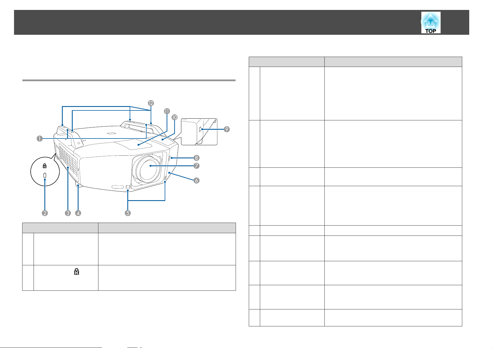
Front/Top
Air intake vent
C
(Air filter)
14
Name Function
Takes in air to cool the projector internally. If dust collects
here it can cause the internal temperature to rise, and this
can lead to problems with operation and shorten the
optical engine's service life. Be sure to clean the air filter
regularly.
s "Cleaning the Air Filter" p.172
s "Replacing the Air Filter" p.179
Name Function
Handles
A
B
Security slot ( )
Use these handles when carrying the projector. Also, you
can pass an anti-theft wire lock through the handle to
secure the projector.
s "Installing the wire lock" p.112
The security slot is compatible with the Microsaver
Security System manufactured by Kensington.
s "Installing the wire lock" p.112
Front feet
D
Remote receiver
E
Interface cover
F
Projection lens
G
Interface cover
H
removal switch
Interface cover
I
removal button
Cable wiring slot (top)
J
When setting up on a desk, turn to extend and retract to
adjust the horizontal tilt.
The front feet can be removed when the projector is
installed on a ceiling.
s "Adjusting the tilt of the projected image (for normal
installment)" p.36
Receives signals from the remote control.
s "Remote control operating range" p.24
Remove this cover to connect cables to the ports inside
when connecting the projector to video equipment.
s "Interface" p.16
s "Attaching and Removing the Interface Cover"
p.28
Images are projected through here.
Operate this when removing the interface cover.
s "Attaching and Removing the Interface Cover"
p.28
Operate this when removing the interface cover.
s "Attaching and Removing the Interface Cover"
p.28
Remove the cover, and pass the cable up through here.
s "Attaching and Removing the Interface Cover"
p.28
Lens replacement
K
cover
Remove when attaching or removing the lens.
s "Attaching the Projector Lens Unit" p.26
Page 15
Part Names and Functions
15
Name Function
Ceiling mount fixing
L
points
(4 points)
Attach the optional ceiling mount here when suspending
the projector from a ceiling.
s "Optional Accessories" p.198
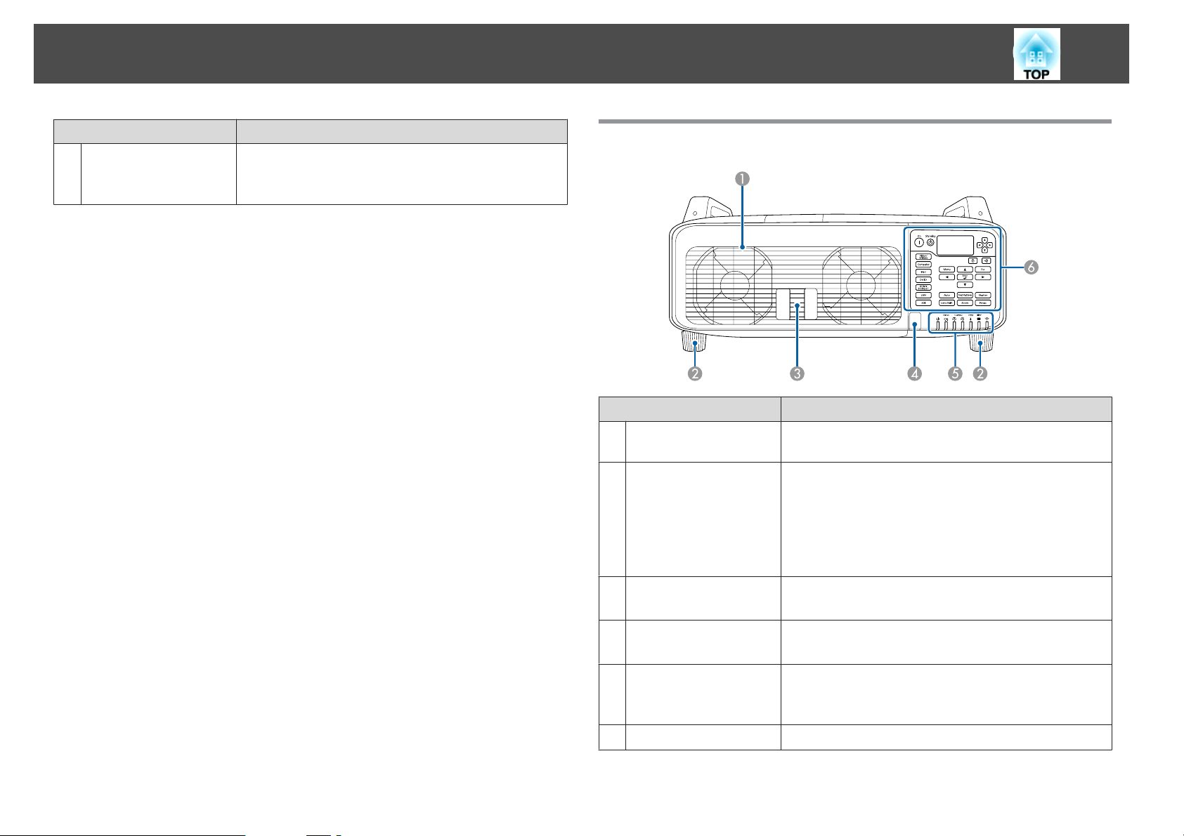
Rear
Air exhaust vent
A
(Lamp cover)
Rear feet
B
Name Function
Exhaust vent for air used to cool the projector internally.
Open this cover to replace the projector's lamps.
When setting up on a desk, turn to extend and retract to
adjust the horizontal tilt.
The front feet can be removed when the projector is
installed on a ceiling.
s "Adjusting the tilt of the projected image (for normal
installment)" p.36
Lamp cover open lever
C
Remote receiver
D
Status indicators
E
Control panel
F
Use this lever to open the lamp cover.
s "Replacing the Lamp" p.175
Receives signals from the remote control.
s "Remote control operating range" p.24
The color of the indicators and whether they are flashing
or lit indicate the status of the projector.
s "Reading the Indicators" p.141
s "Control panel" p.18
Page 16
Part Names and Functions
16
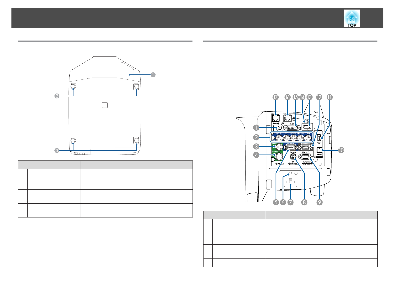
Base
Cable wiring slot
A
(bottom)
Name Function
Remove the cover, and pass the cable down through here.
s "Attaching and Removing the Interface Cover"
p.28
Interface
You can access the following ports by removing the interface cover. For
information on how to remove the interface cover and connect video
equipment, see the following.
s
"Attaching and Removing the Interface Cover" p.28
s
"Connecting Equipment" p.41
B
C
Front feet
Rear feet
s "Adjusting the tilt of the projected image (for normal
installment)" p.36
s "Adjusting the tilt of the projected image (for normal
installment)" p.36
Name Function
SDI input port
A
(For EB-Z10005U/EBZ10000U/EB-Z9875U/
EB-Z9870U only)
BNC input port
B
Video input port
C
Inputs SDI signals from video equipment.
For analog RGB signals from a computer and component
video signals from other video sources.
For composite video signals from video sources.
Page 17
Part Names and Functions
17
Name Function
S-Video input port
D
Computer input port
E
Cable holder
F
Power inlet
G
Remote port
H
For S-video signals from video sources.
For analog RGB signals from a computer and component
video signals from other video sources.
Insert the supplied cord clamp here to prevent the cord
from falling out.
Connects the power cord to the projector.
The shape may differ depending on your projector model.
Connects the optional remote control cable set and inputs
signals from the remote control. When the remote control
cable is plugged into this port, the remote receiver on the
projector is disabled.
s "Optional Accessories" p.198
Name Function
Wireless LAN unit port
K
Monitor out port
L
HDMI input port
M
Cable holder
N
• Connects the optional wireless LAN unit.
s "Installing the Wireless LAN Unit (ELPAP07)"
p.47
• Connects the optional Quick Wireless Connection USB
Key.
"Using the Quick Wireless Connection USB Key"
s
p.48
• This is used for batch settings.
"Batch Setup" p.49
s
Outputs analog RGB signals input from the Computer
input port or the BNC input port to an external monitor.
This is not available for component video signals or other
signals being input from any port other than the
Computer input port or the BNC input port.
s "Cable layouts" p.191
Inputs image signals from HDMI compatible video
equipment and computers. This projector is compatible
with
HDCPg.
Insert the supplied HDMI cable clamp here to prevent the
HDMI cable from falling out.
RS-232C port
I
Service port
J
When controlling the projector from a computer, connect
it to the computer with an RS-232C cable.
s "Serial connection" p.191
This port is used by maintenance personnel to control the
projector. This is used for batch settings.
s "Batch Setup" p.49
DVI-D input port
O
Inputs the computer DVI-D signals.
Page 18
Part Names and Functions
18
LAN port
P
HDBaseT port
Q
Name Function
Connects a LAN cable to connect to a network.
s "Connecting a LAN Cable" p.45
Connects a LAN cable to the optional HDBaseT
Transmitter.
s "Connecting an HDBaseT Transmitter" p.46
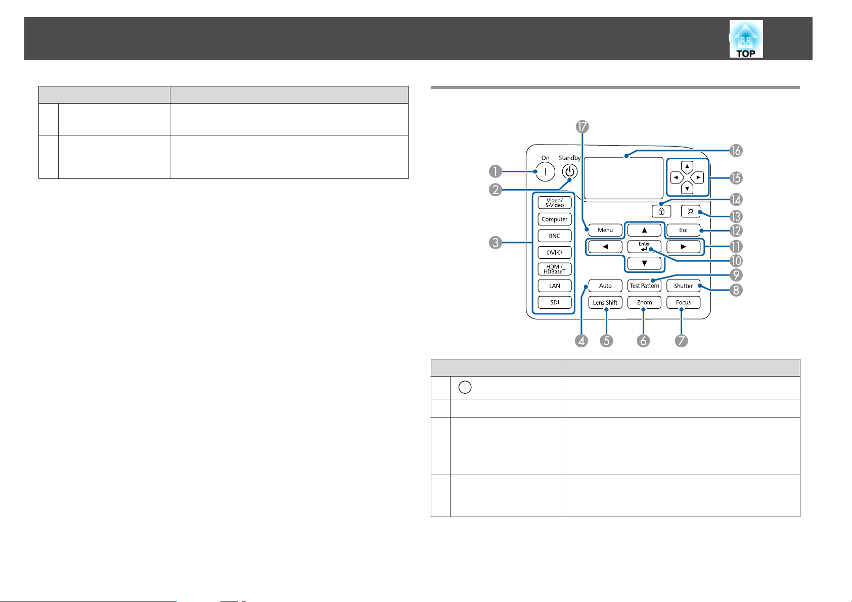
Control panel
Name Function
A
[ ] button
Press to turn on the projector.
[t] button
B
Change input buttons
C
[Auto] button
D
Press to turn off the projector.
Press to change to signals from each input port.
s "Switching to the Target Image" p.59
The [SDI] button is only available for EB-Z10005U/EB-
Z10000U/EB-Z9875U/EB-Z9870U.
If pressed while projecting analog RGB signals from the
Computer input port or the BNC input port, you can
automatically optimize Tracking, Sync., and Position.
Page 19
Part Names and Functions
19
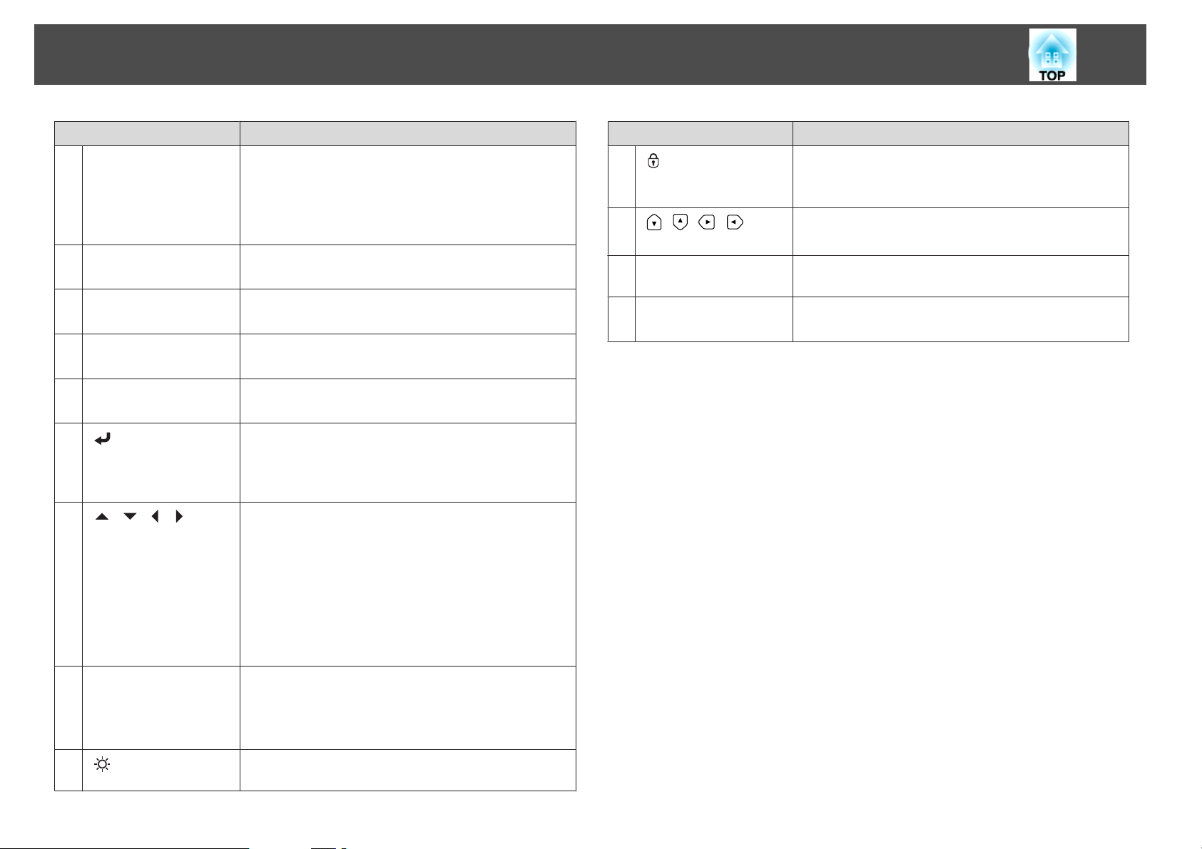
Name Function
[Lens Shift] button
E
[Zoom] button
F
[Focus] button
G
[Shutter] button
H
[Test Pattern] button
I
J
[ ] button
K
[ ][ ][ ][ ]
buttons
Press to adjust the lens shift.
s "Adjusting the Position of the Projected Image (Lens
shift)" p.35
If pressed for more than five seconds, the lens position
returns to the center.
Press to adjust the zoom.
s "Adjusting the Zoom" p.37
Press to adjust the focus.
s "Adjusting the Focus" p.37
Press to turn the signals on or off temporarily.
s "Hiding the Image Temporarily (Shutter)" p.94
Displays a test pattern.
s "Displaying a Test Pattern" p.34
If pressed while the Configuration menu or the Help
screen is displayed, it determines an item or moves to the
next level.
s "Using the Configuration Menu" p.114
• Press to adjust focus, zoom, and lens shift.
s "Adjusting the Position of the Projected Image
(Lens shift)" p.35
s "Adjusting the Zoom" p.37
s "Adjusting the Focus" p.37
• If pressed when the Configuration menu or the Help
screen is displayed, menu items and setting values are
selected.
s "Using the Configuration Menu" p.114
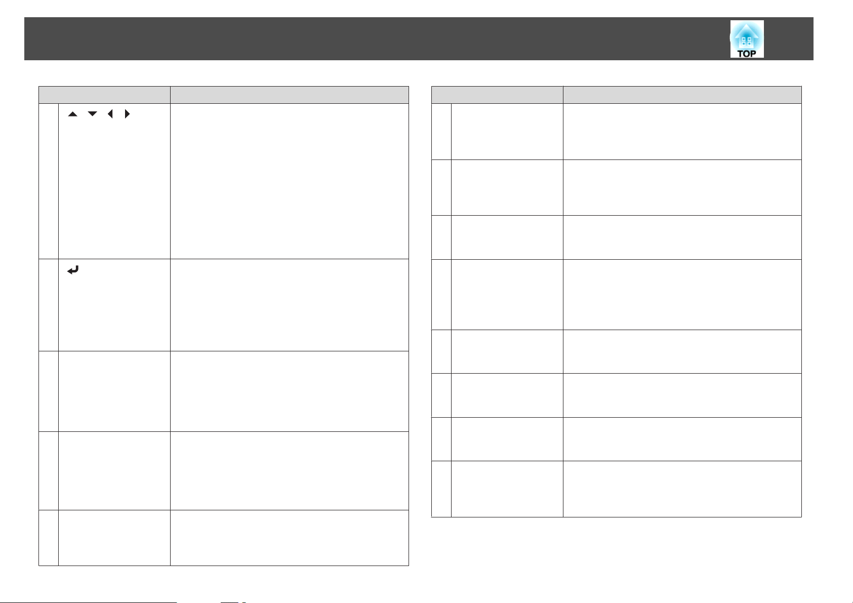
Name Function
N
[ ] button
O
[ ][ ][ ][ ]
buttons
Status monitor
P
[Menu] button
Q
Press to display the Control Panel Lock screen allowing
you to make settings to lock the control panel buttons.
s "Restricting Operation" p.110
Press to select the menu items and setting values for status
monitor to monitor the projector's status.
Displays the projector's status by character information.
s "Reading Status Monitor" p.150
Press to display and close the Configuration menu.
s "Using the Configuration Menu" p.114
[Esc] button
L
M
[ ] button
• Press to stop the current function.
• If pressed when the Configuration menu is displayed, it
returns to the previous menu level.
s "Using the Configuration Menu" p.114
Press to turn on or off the buttons on the control panel and
the status monitor.
Page 20

Part Names and Functions
20
Remote Control
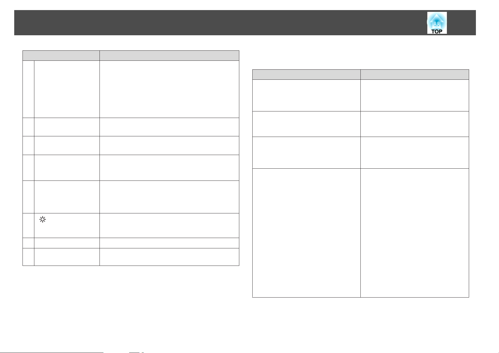
Name Function
A
[ ] button
[t] button
B
Change input buttons
C
[Aspect] button
D
[Auto] button
E
[Freeze] button
F
[Test Pattern] button
G
[Lens Shift] button
H
Press to turn the projector on.
Press to turn the projector off.
Press to change to signals from each input port.
s "Switching to the Target Image" p.59
The [SDI] button is only available for EB-Z10005U/EB-
Z10000U/EB-Z9875U/EB-Z9870U.
Each time the button is pressed, the aspect mode changes.
s "Changing the Aspect Ratio of the Projected Image"
p.72
If pressed while projecting analog RGB signals from the
Computer input port or the BNC input port, you can
automatically optimize Tracking, Sync., and Position.
Press to pause or unpause the images.
s "Freezing the Image (Freeze)" p.95
Displays a test pattern.
s "Displaying a Test Pattern" p.34
Press to adjust the lens shift.
s "Adjusting the Position of the Projected Image (Lens
shift)" p.35
If pressed for more than five seconds, the lens position
returns to the center.
[Zoom] button
I
[Menu] button
J
Press to adjust the zoom.
s "Adjusting the Zoom" p.37
Press to display and close the Configuration menu.
s "Using the Configuration Menu" p.114
Page 21
Part Names and Functions
21
K
[ ][ ][ ][ ]
buttons
L
[ ] button
[Split] button
M
[Page] buttons
N
[[][]]
[User 1] button
O
[User 2] button
[User 3] button
Name Function
• Press to adjust focus, zoom, and lens shift.
s "Adjusting the Position of the Projected Image
(Lens shift)" p.35
s "Adjusting the Zoom" p.37
s "Adjusting the Focus" p.37
• When the Configuration menu or the Help screen is
displayed, pressing these buttons selects menu items
and setting values.
s "Using the Configuration Menu" p.114
• When using the optional wireless mouse receiver,
pressing these buttons moves the pointer.
s "Optional Accessories" p.198
• If pressed while the Configuration menu or the Help
screen is displayed, it determines an item or moves to
the next level.
s "Using the Configuration Menu" p.114
• Acts as a mouse's left button when using the optional
wireless mouse receiver.
s "Optional Accessories" p.198
Each time you press the button, the image changes
between projecting two images simultaneously by
splitting the projected screen, or projecting one image as
normal.
s "Projecting Two Images Simultaneously (Split
Screen)" p.91
• Moves to the previous or next image file when
projecting images from a computer connected via a
network.
• When using the optional wireless mouse receiver, you
can change the PowerPoint file page during projection
by pressing the page up/page down buttons.
Select any frequently used item from the nine available
Configuration menu items, and assign it to one of these
buttons.
s "Settings Menu" p.121
Name Function
Numeric buttons
P
[ID] button
Q
[ID] switch
R
Remote port
S
[Help] button
T
[Num] button
U
[E-Zoom] buttons
V
[z][x]
[Default] button
W
• Enter the password.
s "Setting Password Protection" p.108
• Use this button to enter numbers in Network settings in
the Configuration menu.
Hold down this button and press the numeric buttons to
select the ID for the projector you want to operate using
the remote control.
s "ID Settings" p.39
Press this switch to enable (On)/disable (Off) ID settings
for the remote control.
s "ID Settings" p.39
Connects the optional remote control cable set and
outputs signals from the remote control.
s "Optional Accessories" p.198
When the remote control cable is plugged into this remote
port, the remote control light-emitting area is disabled.
Press to display and closes the Help screen which shows
you how to deal with problems if they occur.
s "Using the Help" p.140
Hold down this button and press the numeric buttons to
enter passwords and numbers.
s "Setting Password Protection" p.108
Press to enlarge or reduce the image without changing the
projection size.
s "Enlarging Part of the Image (E-Zoom)" p.95
Enabled when "[Default]: Reset" is displayed on the
Configuration menu guide. The settings being adjusted
are returned to their default values.
s "Using the Configuration Menu" p.114
Page 22
Part Names and Functions
22
Name Function
[Esc] button
X
[Focus] button
Y
[Shutter] button
Z
[Color Mode] button
a
[Search] button
b
c
[ ] button
Indicator
d
Remote control light-
e
emitting area
• Press to stop the current function.
• If pressed when the Configuration menu is displayed, it
moves to the previous level.
s "Using the Configuration Menu" p.114
• Acts as a mouse's right button when using the optional
wireless mouse receiver.
s "Optional Accessories" p.198
Press to adjust the focus.
s "Adjusting the Focus" p.37
Press to turn the image on or off temporarily.
s "Hiding the Image Temporarily (Shutter)" p.94
Each time the button is pressed, the color mode changes.
s "Selecting the Projection Quality (Selecting Color
Mode)" p.70
Press to change to the next input source that is sending an
image.
s "Automatically Detect Input Signals and Change the
Projected Image (Search)" p.58
Press to illuminate the buttons on the remote control for
approximately 15 seconds. This is useful when using the
remote control in the dark.
A light is emitted when outputting remote control signals.
Outputs remote control signals.
You can perform the following operations by simply pressing one of the
buttons on the remote control.
Operation Set
Selecting the password security settings.
s "Managing Users (Password
Protection)" p.107
Locking or unlocking some of the operation
of the buttons on the remote control.
s "Restricting Operation" p.110
Initializing the settings for the remote
receiver in the Configuration menu.
(Enables all Remote receiver for this
projector.)
Displaying frequently used Configuration
menu items.
Hold down the [Freeze] button for more
than five seconds. The Password Protection
screen is displayed, and you can select
various settings.
Hold down the [Help] button for more than
five seconds.
Hold down the [Menu] button for more than
15 seconds.
Press the [User1], [User2], or [User3]
button. You can set the menu item you want
to assign to each button in User Button.
s Settings - User Button p.121
The following items can be assigned.
Power Consumption, Info, Progressive,
Geometric Correction, Multi-Projection,
Resolution, Memory, Image Processing, or
On-Screen Display
When you press the button for which OnScreen Display is assigned, menu or
messages are not displayed on the screen.
When the same button is pressed, they are
displayed again. If On-Screen Display is
enabled, you cannot operate the
Configuration menu (except switching the
Color Mode and input source).
Page 23
Part Names and Functions
23
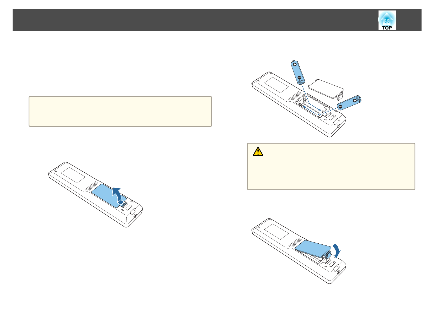
Replacing the remote control batteries
If delays in the responsiveness of the remote control occur or if it does not
operate after it has been used for some time, it could mean that the
batteries are running low. When this happens, replace them with new
batteries. Have two AA size alkaline or manganese batteries ready. You
cannot use other batteries except for the AA size alkaline or manganese.
Attention
Make sure you read the following manual before handling the batteries.
s Safety Instructions
a
Remove the battery cover.
Release the battery compartment cover catch, and then lift up the
cover.
b
Replace the old batteries with new batteries.
Caution
Check the positions of the (+) and (-) marks inside the battery holder to
ensure the batteries are inserted the correct way.
If the batteries are not used correctly, they could explode or leak causing
a fire, injury, or damage to the product.
c
Reattach the battery cover.
Press the battery compartment cover until it clicks into place.
Page 24
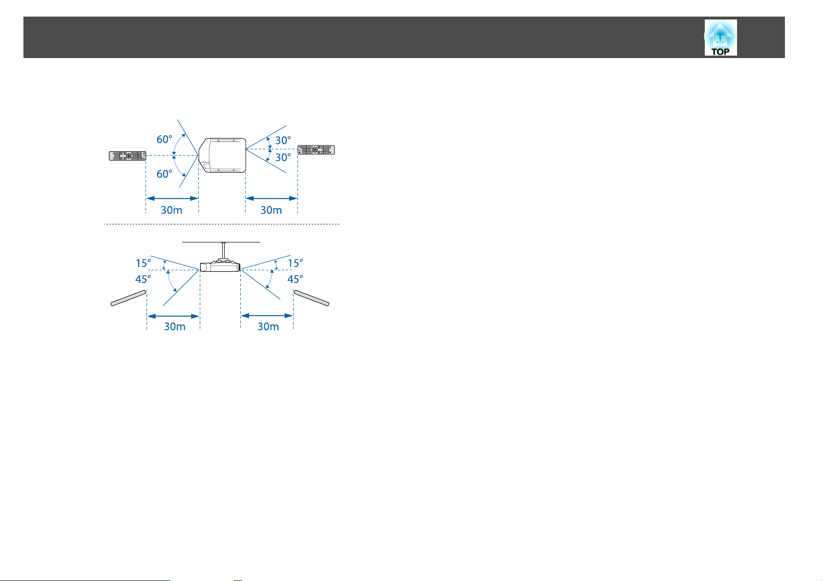
Part Names and Functions
Remote control operating range
24
Page 25

Preparing the Projector
This chapter explains how to install the projector and connect projection sources.
Page 26
Installing the Projector
26
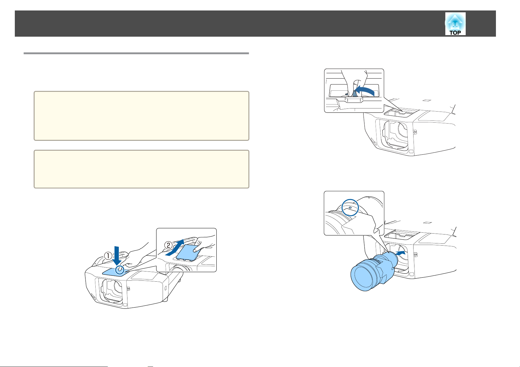
Attaching the Projector Lens Unit
Attaching
Attention
• Do not attach the lens unit when the projector's lens insertion section is
facing up. Dust or dirt could enter the projector.
• Try not to touch the lens section with your hand or fingers. If fingerprints or
oils are left on the surface of the lens, projection quality deteriorates.
To make sure that keystone correction is performed correctly, set the
a
Lens Type in the Configuration menu according to the lens you are
using.
s Extended - Operation - Advanced - Lens Type p.122
Remove the lens replacement cover.
a
Lightly press the lens replacement cover. When the rear part rises,
remove the lens replacement cover.
b
c
Turn the lock lever counterclockwise.
Insert the lens unit straight into the lens insertion section with the
white circle on the lens on top.
Page 27
Installing the Projector
27
d
e
While holding the lens unit firmly, turn the lock lever clockwise
until it is locked.
Check that the lens cannot be detached.
Attach the lens replacement cover.
Removing
Attention
When replacing the lens unit, turn off the power first. If lens shift has been
performed, set the lens shift to the center before replacing the lens unit.
s "Adjusting the Position of the Projected Image (Lens shift)" p.35
a
Remove the lens replacement cover.
Lightly press the lens replacement cover. When the rear part rises,
remove the lens replacement cover.
Page 28
Installing the Projector
28
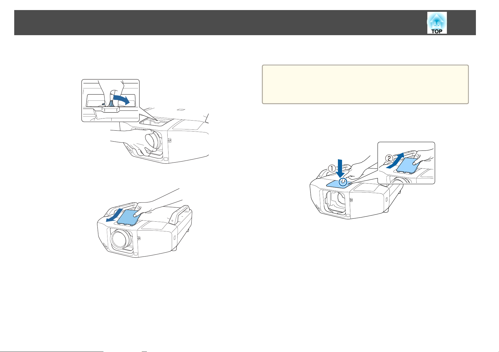
b
While holding the lens unit firmly, turn the lock lever
counterclockwise until it is unlocked.
Pull the lens unit straight out as it is released.
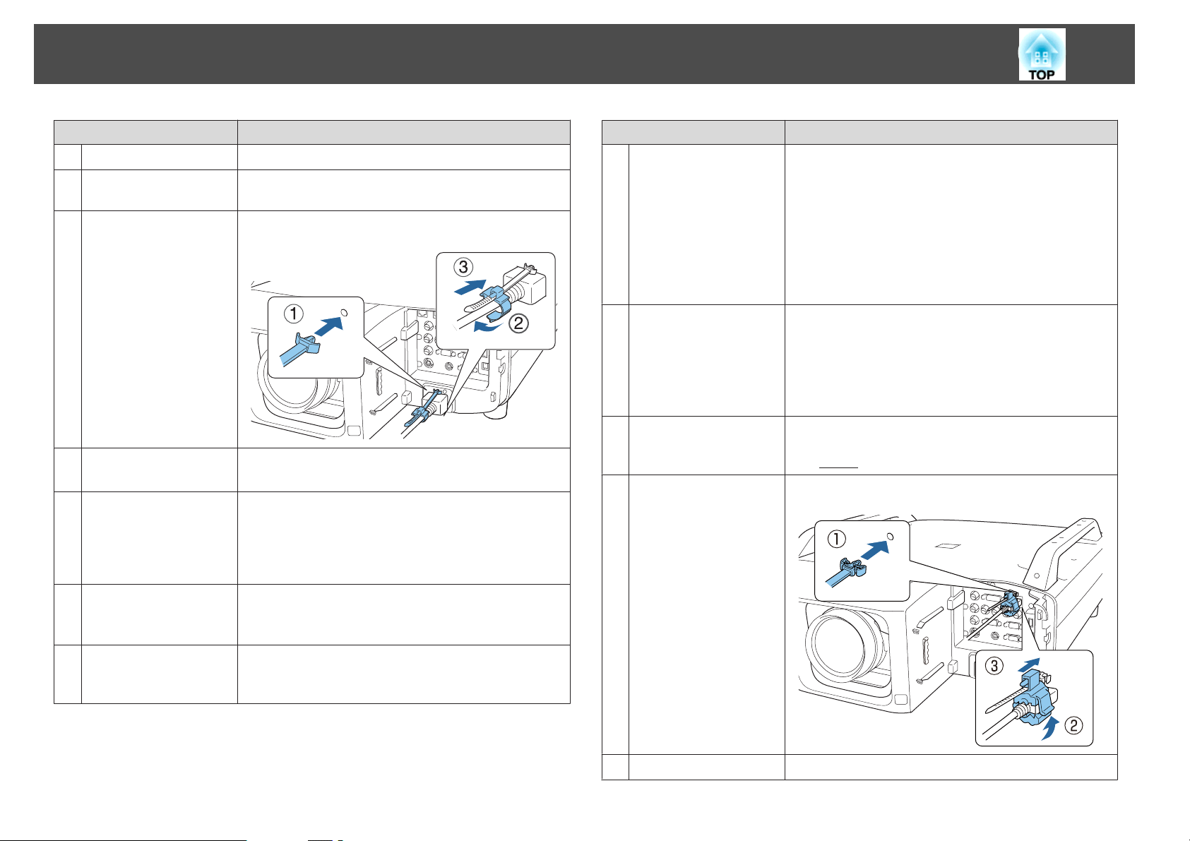
Attaching and Removing the Interface Cover
Remove the interface cover before installing the projector so that it is easier
to connect the cable after installation.
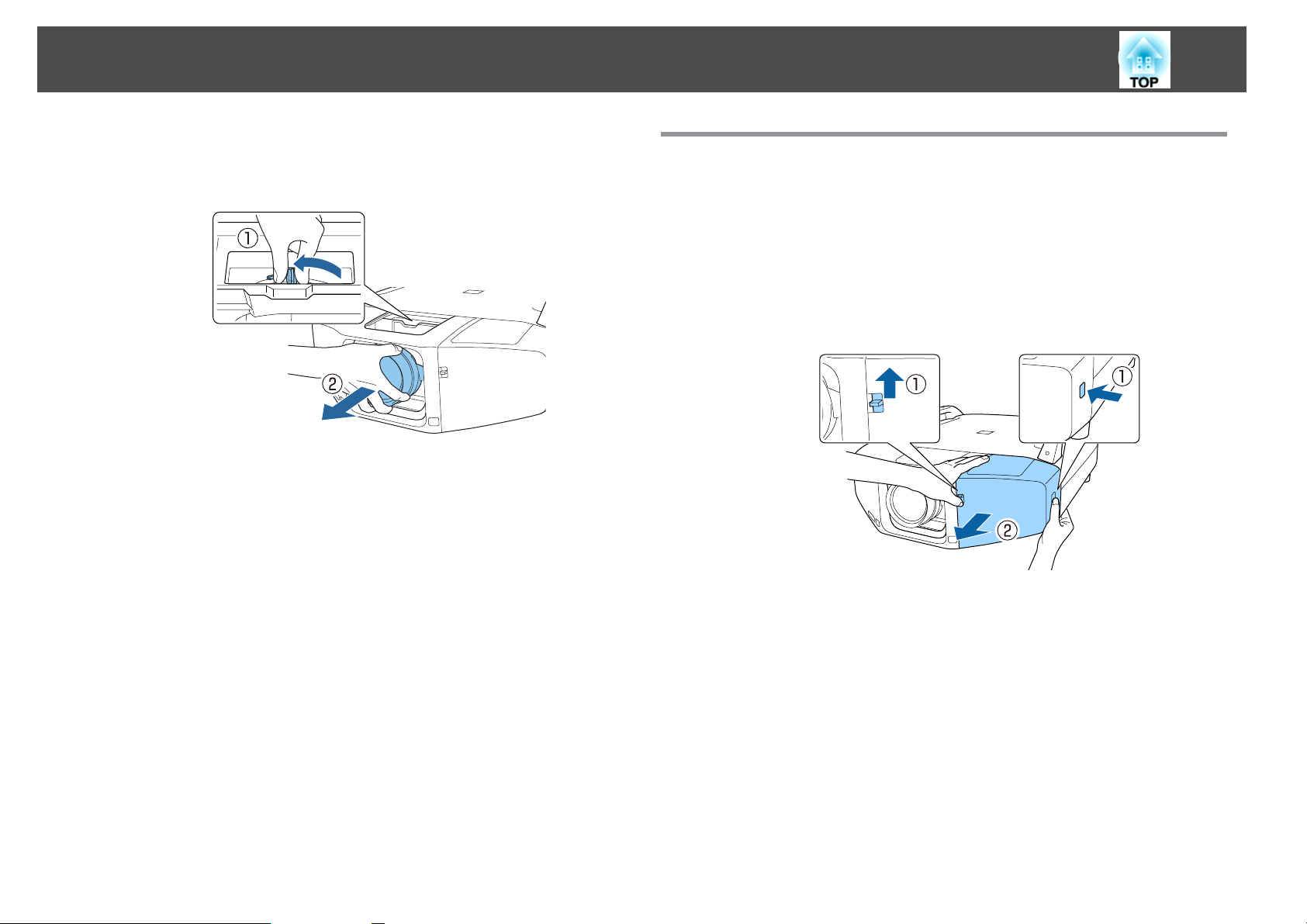
Removing
While pushing up the switch, press the button on the side and pull
the interface cover straight out.
Page 29
Installing the Projector
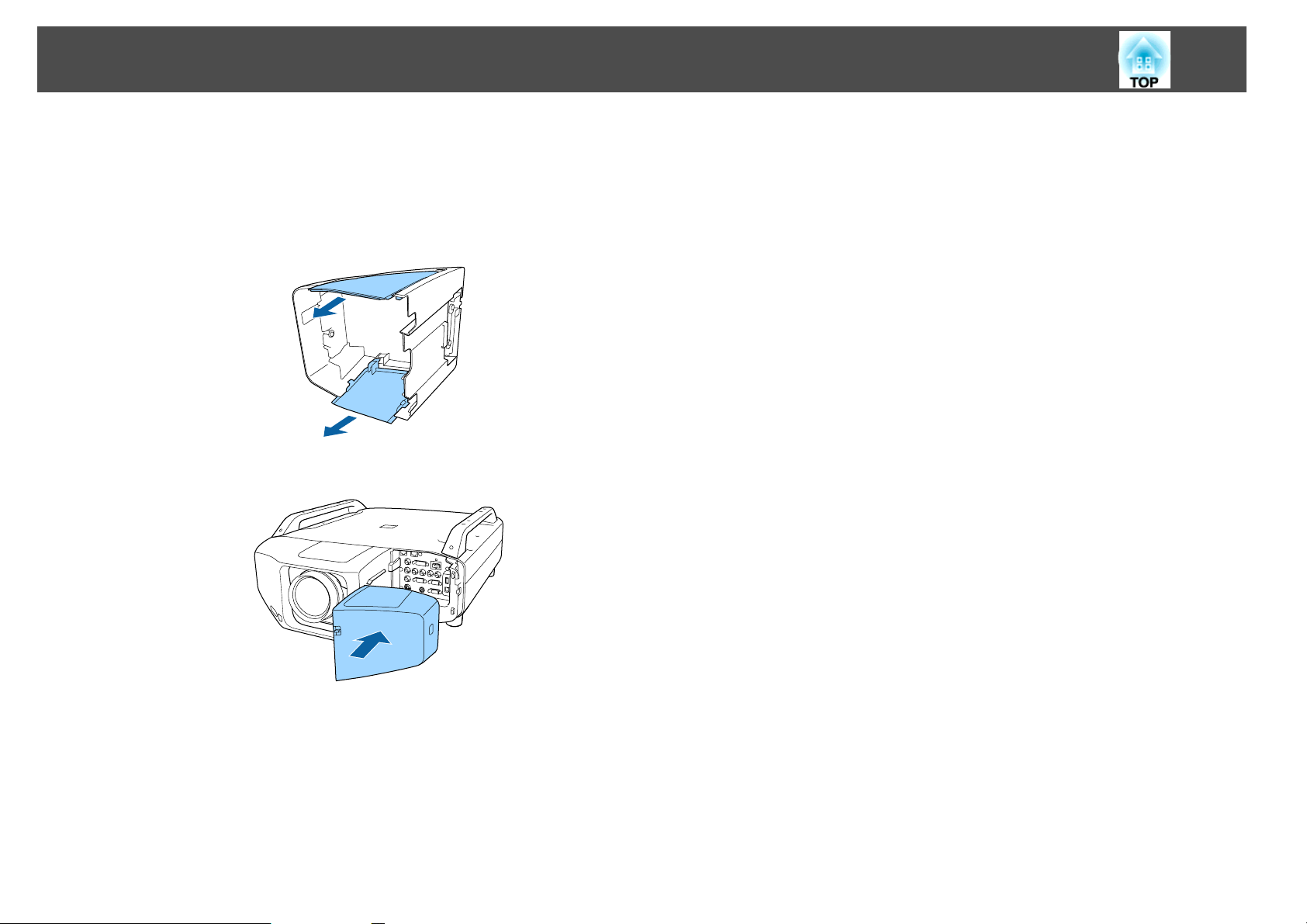
Attaching
29
a
b
Remove the top cover when passing the connected cables from
the top. Remove the bottom cover when passing the connected
cables from the bottom.
Press the interface cover along the guide until it clicks into place.
Page 30
Installing the Projector
30
Installation Settings
Setting the direction
When installation is complete, set the Direction in the Configuration menu
according to the vertical installation angle.
Attention
Make sure you set the Direction correctly. Otherwise the lamp's operating life
may be reduced significantly.
When performing portrait projection, you do not need to set the
a
Direction.
Press the [ ] button to turn on the projector.
a
If the images are out of focus, press the [Focus] button to adjust.
s
"Adjusting the Focus" p.37
Press the [Menu] button.
b
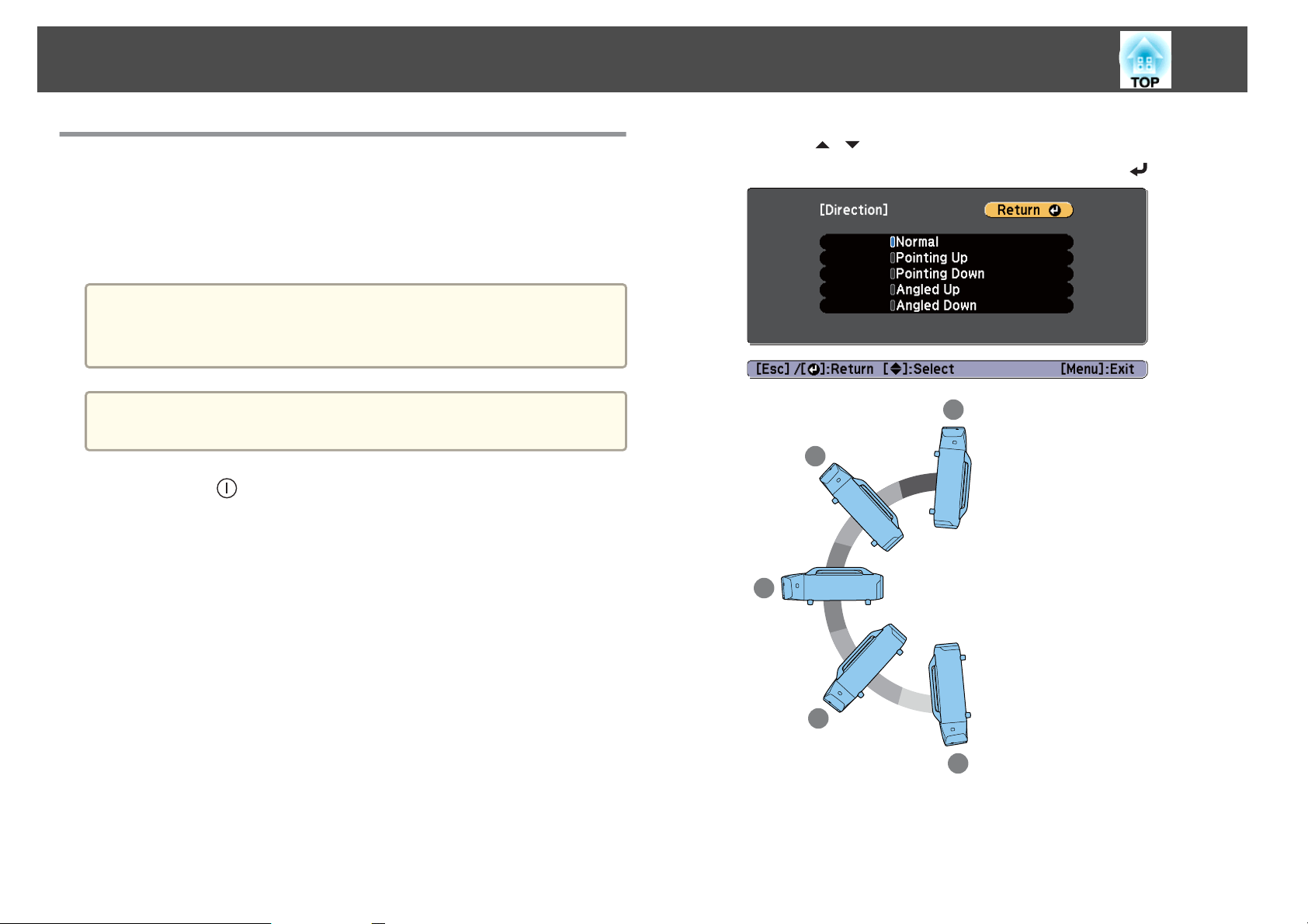
d
Press the [ ][ ] buttons to select the installation angle based on
the direction of the projector, and then press the [
1
Pointing Up
A
Angled Up
2
3
B
Normal
C
Angled Down
D
Pointing Down
E
] button.
c
Select Direction from Extended.
4
5
When the settings are complete, press the [Menu] button.
e
Page 31

Installing the Projector
31
Changing the direction of the image (Projection)
You can change the direction of the image using Projection mode in the
Configuration menu.
s
Extended - Projection p.122
When Front is used, the image directions for each projection mode are as
follows.
Front (default) Front/Upside Down
Rear Rear/Upside Down
Selecting the lamp
When the installation is complete, select the lamps you want to turn based
on the usage or condition.
Press the [Menu] button while projecting.
a
b
Select Lamp Select from Extended.
c
Select the lamp to be turned on, and then press the [ ] button.
The lamp turns on according to the selection.
Dual
(default)
Single
Both Lamp 1 and Lamp 2 turn on. When one of the lamps
dies, the other lamp remains on.
When the projector is turned on, the lamp with less total
operation time turns on. When one of the lamps dies, the
other lamp turns on.
d
Lamp 1
Lamp 2
Press the [Menu] button to finish making settings.
Lamp 1 turns on. When Lamp 1 dies, Lamp 2 turns on.
Lamp 2 turns on. When Lamp 2 dies, Lamp 1 turns on.
Page 32
Installing the Projector
32
a
• You can specify the date and time and automatically switch the
lamps.
"Scheduling Function" p.100
s
• Approximately 120 seconds after changing the Lamp Select settings,
you cannot change Lamp Select or turn off the projector.
• Note that switching the settings for Lamp Select in a short time may
deteriorate the lamps or cause a malfunction.
• When performing Multi-Projection, set it to Dual.
• When a problem or warning occurs in the projector, you may not be
able to set Lamp Select.
• When the brightness of the lamps is reduced due to Temp Interlock,
you cannot set Lamp Select.
s Settings - Power Consumption p.121
Screen Settings
Set the Screen Type according to the aspect ratio of the screen being used.
The area where the image is displayed matches the shape of the screen.
The settings for the Screen Type at the time of purchase are as
a
a
follows:
• WUXGA/WXGA projector: 16:10
• XGA projector: 4:3
Press the [Menu] button while projecting.
s
"Using the Configuration Menu" p.114
Select Display from Extended.
b
c
Select Screen Type from Screen.
d
Select the screen's aspect ratio from 4:3, 16:9, and 16:10.
The shape of the background test pattern changes depending on the
setting.
Page 33
Installing the Projector
33
e
Press the [Menu] button to finish making settings.
• When you change the Screen Type, adjust the aspect ratio for the
a
Adjusting the position of the image on the projected screen
You can adjust the position of the image if there are margins between the
edge of the image and the projected screen frame due to the Screen Type
setting.
a
projected image as well.
"Changing the Aspect Ratio of the Projected Image" p.72
s
• This function does not support Message Broadcasting (an EasyMP
Monitor plugin).
The Screen Position cannot be adjusted in the following situations.
• If you are using a WUXGA/WXGA projector and the Screen Type
is set to 16:10
• If you are using an XGA projector and the Screen Type is set to
4:3
You can move the image to the left and right.
a
Press the [Menu] button while projecting.
s
"Using the Configuration Menu" p.114
Select Display from Extended.
b
c
Select Screen Position from Screen.
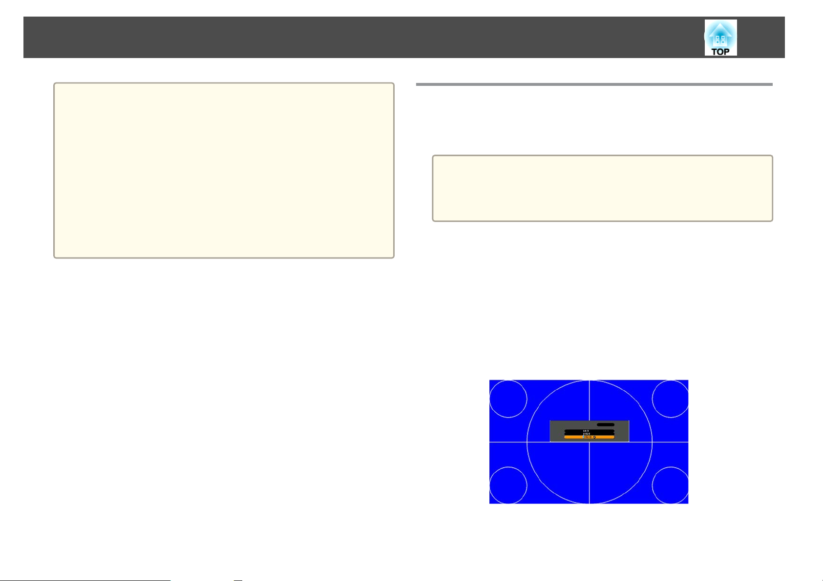
d
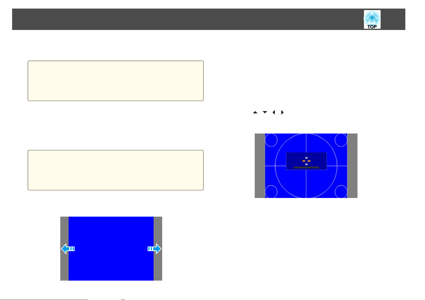
Use [ ][ ][ ][ ] buttons to adjust the position of the image.
You can check the current display position by using the background
test pattern.
Example: If you are using a WUXGA/WXGA projector and the Screen
Type is set to 4:3
e
Press the [Menu] button to finish making settings.
Page 34

Installing the Projector
34
Displaying a Test Pattern
A test pattern can be displayed to adjust the projection status without
connecting video equipment.
The shape of a test pattern depends on the setting in Screen Type. Set the
Screen Type first.
s
"Screen Settings" p.32
Press the [Test Pattern] button while projecting.
a
b
Press the [ ][ ] buttons on the remote control or the [ ] button
on the control panel to change the test pattern.
Using the remote control Using the control panel
The following image adjustments can be made while the test pattern
is being displayed.
Top Menu Name Sub Menu/Items
Image
Signal
Settings
Extended
*1 Except for Customized
Except for Black Level
*2
To set menu items that cannot be set while the test pattern is
a
being displayed or to fine-tune the projected image, project an
image from the connected device.
Color Mode s p.70
Color Temp.
Advanced
*1
- Gamma
- RGB
- RGBCMY s p.76
Reset
Auto Setup
Geometric Correction s p.60
Multi-Projection
s p.76
*2
s p.80
c
Press the [Esc] button to close the test pattern.
Page 35
Installing the Projector
35
Adjusting the Position of the Projected Image (Lens shift)
The lens can be shifted to adjust the position of the projected image, for
example, when the projector cannot be installed directly in front of the
screen.
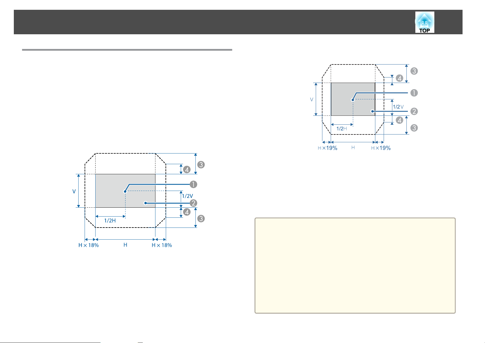
The ranges within which the image can be moved are shown below. The
position of the projected image cannot be moved to both the horizontal and
vertical maximum values.
EB-Z10005U/EB-Z10000U/EB-Z9875U/EB-Z9870U/EB-Z9750U/EBZ11000W/EB-Z9900W/EB-Z9800W
EB-Z11005/EB-Z11000/EB-Z9870
Center of lens
A
Projected image when lens shift is set in the center
B
Maximum motion range: V×56% (When using a short throw zoom
C
lens ELPLU02, if you move it more than 50%, part of the screen
cannot be displayed correctly.)
When the horizontal direction is at the maximum value: V×32%
D
Center of lens
A
Projected image when lens shift is set in the center
B
Maximum motion range: V×60%
C
When the horizontal direction is at the maximum value: V×31%
D
a
• When adjusting the vertical lens shift, adjust by moving the image
from the bottom to the top. If it is adjusted from the top to the
bottom, the image position may move down slightly after adjusting.
• We recommend setting the focus, zoom, and lens shift at least 20
minutes after you start the projection, because images are not stable
right after turning on the projector.
• The image will be clearest when both the vertical and horizontal lens
shift are set in the center.
• Hold down the [Lens Shift] button for approximately five seconds,
the position of the lens returns to the center.
• The rear short throw zoom lens ELPLR04 does not support lens
shift.
Page 36
Installing the Projector
36
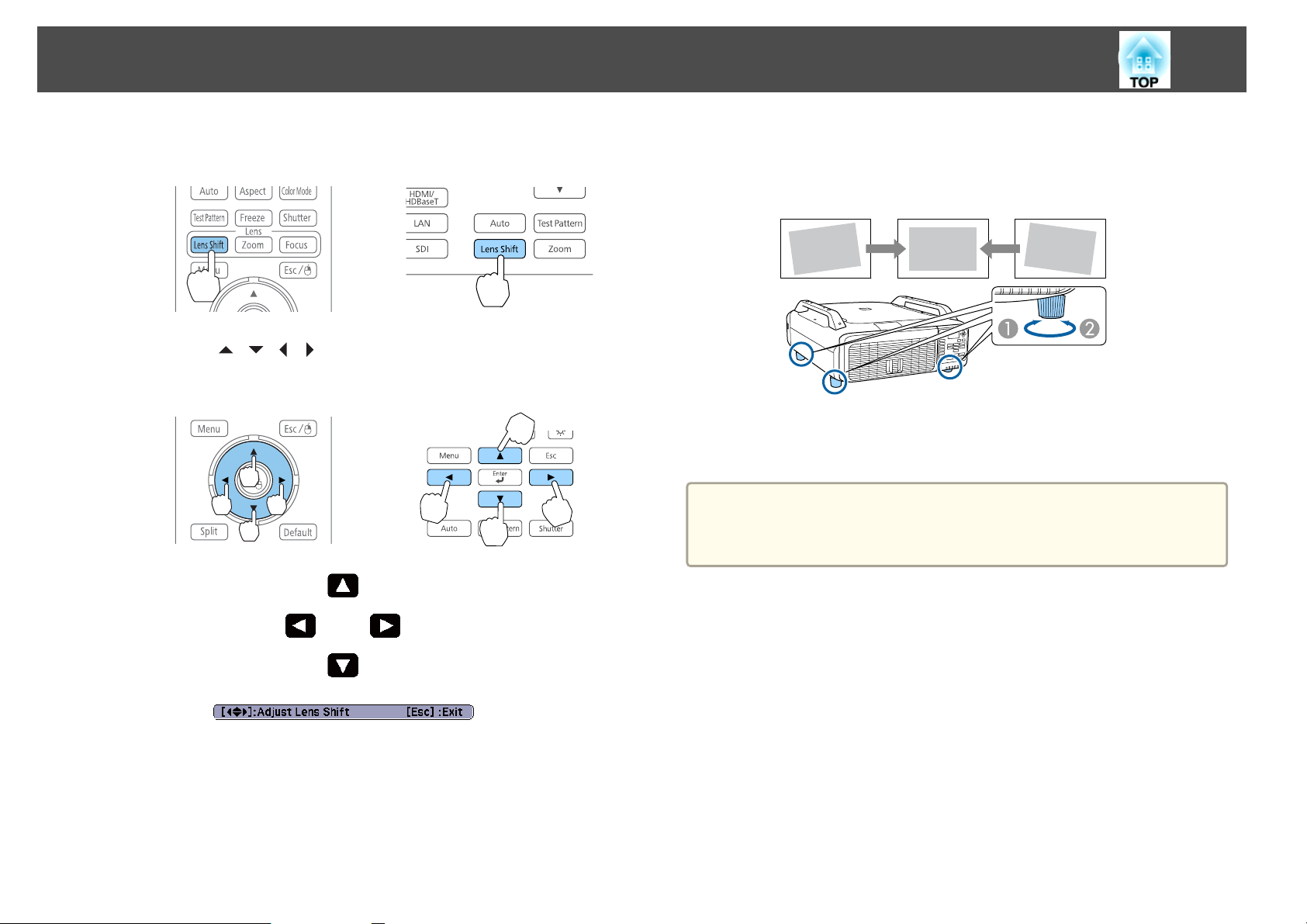
a
b
Press the [Lens Shift] button.
Using the remote control Using the control panel
Press the [ ][ ][ ][ ] buttons to adjust the position of the
projected image.
Using the remote control Using the control panel
Adjusting the tilt of the projected image (for normal installment)
Extend and retract the front feet and rear feet to adjust the projector's
horizontal and vertical tilt. You can adjust within a range of ±3.5°.
Extend the front feet and rear feet.
A
Retract the front feet and rear feet.
B
Attention
The front feet and rear feet can be attached and removed. Note that the feet
will detach if they are extended more than 10 mm.
c
Press the [Esc] button to finish the adjustment.
Page 37
Installing the Projector
37
Adjusting the Zoom
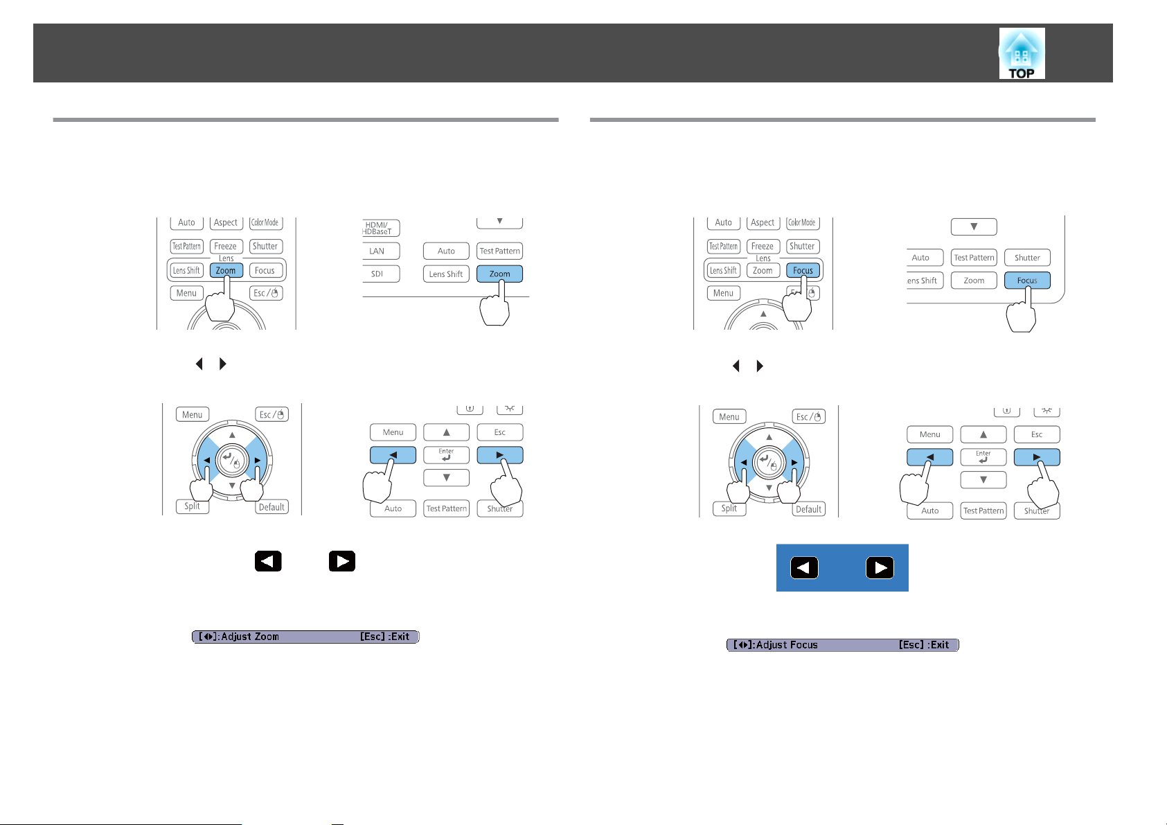
Press the [Zoom] button.
a
Using the remote control Using the control panel
Press the [ ][ ] buttons to adjust.
b
Using the remote control Using the control panel
Adjusting the Focus
Press the [Focus] button.
a
Using the remote control Using the control panel
Press the [ ][ ] buttons to adjust.
b
Using the remote control Using the control panel
c
Press the [Esc] button to finish the adjustment.
c
Press the [Esc] button to finish the adjustment.
Page 38
Installing the Projector
38
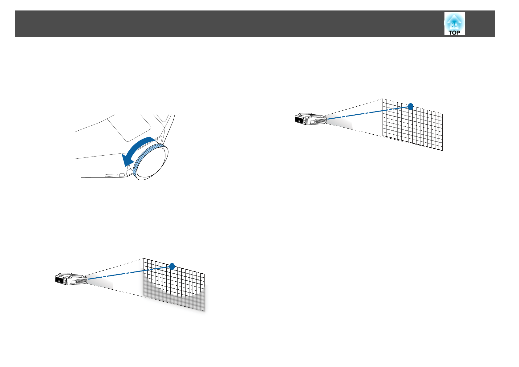
When using a short throw zoom lens ELPLU02
Follow the steps below to adjust the focus when the lens is shifted up,
down, left, or right using the lens shift function.
a
b
Turn the distortion ring counterclockwise until it cannot go any
further.
Focus the image around the center of the lens.
s
"Adjusting the Focus" p.37
Example: When the lens shift is turned all the way down.
c
d
Correct screen distortion using the distortion ring.
When correcting distortion, the area around the edges of the image
is also focused.
Focus the entire screen.
If the area around the lens axis is out of focus, fine-tune by turning
the distortion ring.
Page 39

Installing the Projector
39
ID Settings
When an ID is set for the projector and the remote control, you can use
the remote control to operate only the projector with a matching ID. This
is useful when you use multiple projectors together.
• Operation using the remote control is possible only for projectors
a
Setting the projector ID
that are within the operating range of the remote control.
s "Remote control operating range" p.24
• When Remote Control Type is set to Simple from Operation Advanced in the Configuration menu, you cannot set the remote
control ID.
s "Extended Menu" p.122
• IDs are ignored when the projector ID is set to Off or the remote
control ID is set to 0.
Press the [Menu] button while projecting.
a
b
Select Multi-Projection from Extended.
d
Select the ID you want to set, and then press the [ ] button.
Press the [Menu] button to close the Configuration menu.
e
Checking the projector ID
During projection, press the [Help] button while holding down the [ID]
button.
Remote control
c
Select Projector ID, and then press the [ ] button.
When you press the buttons, the current projector ID is displayed on the
projection screen. It closes after about three seconds.
Page 40
Installing the Projector
40
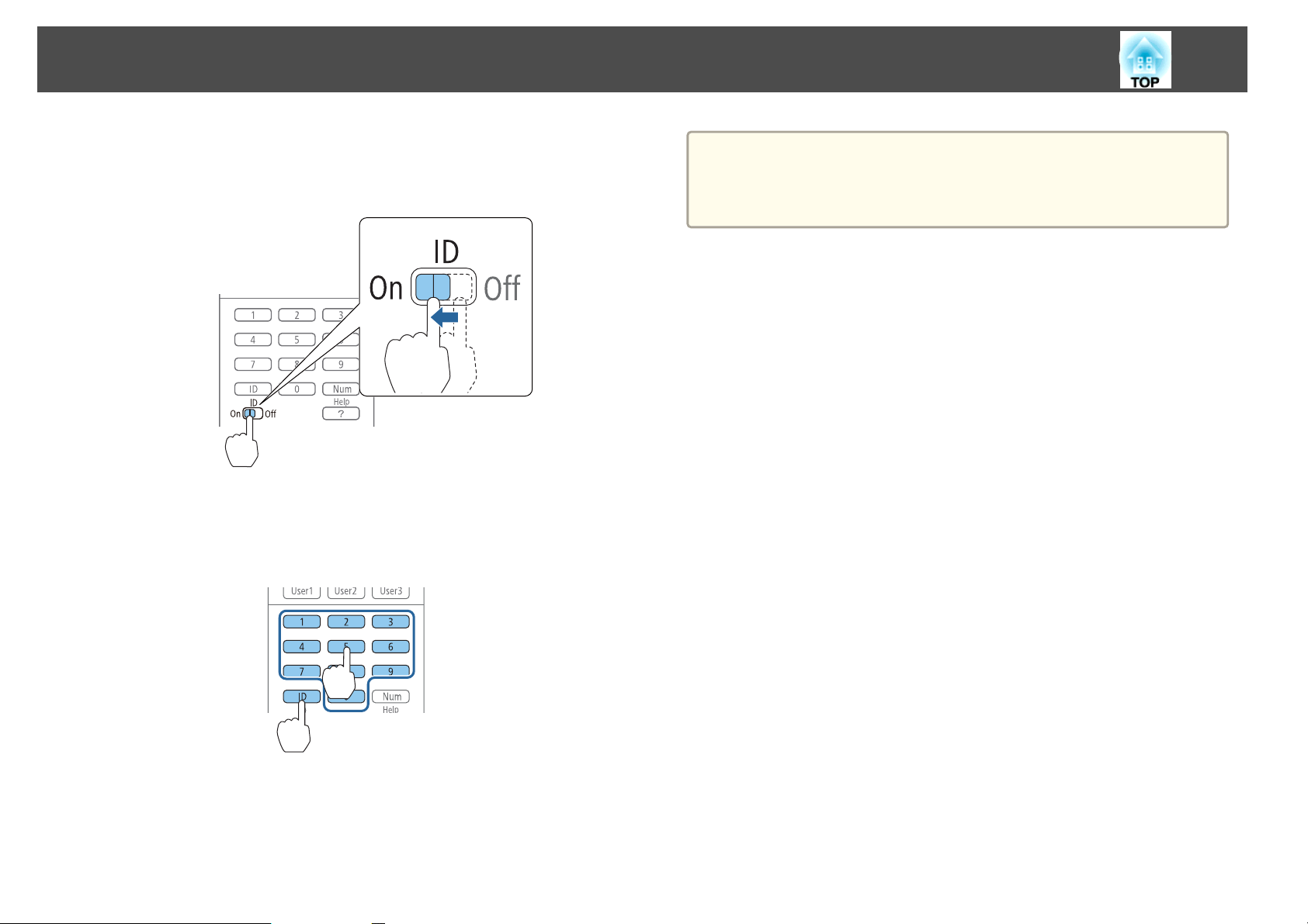
Setting the remote control ID
Set the remote control [ID] switch to On.
a
b
While holding down the [ID] button, press the number of the ID
for the ID of the projector you want to operate.
s
"Checking the projector ID" p.39
Remote control
a
The remote control ID setting is saved in the remote control. Even if
the remote control batteries are removed to replace them and so on,
the stored ID setting is retained. However, if the batteries are left out
for a long time, it is reset to the default value (ID0).
Once this setting has been made, the projector that can be operated by the
remote control is limited.
Page 41
Connecting Equipment
The port name, location, and connector orientation differ depending on the source being connected.
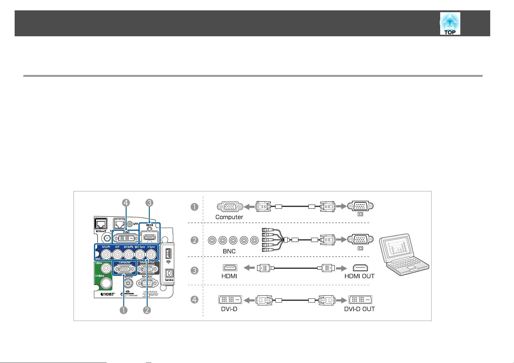
Connecting a Computer
To project images from a computer, connect the computer using one of the following methods.
When using the supplied computer cable
A
Connect the computer's display output port to the projector's Computer input port.
When using a commercially available 5BNC cable
B
Connect the computer's display output port to the projector's BNC input port.
When using a commercially available HDMI cable
C
Connect the HDMI port on the computer to the projector's HDMI input port.
When using a commercially available DVI-D cable
D
Connect the DVI-D port on the computer to the projector's DVI-D input port.
41
Page 42

Connecting Equipment
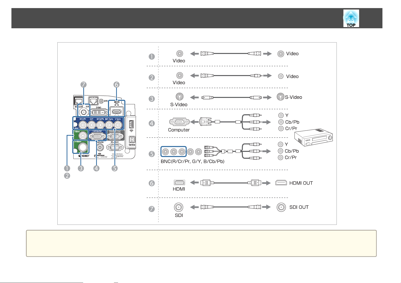
Connecting Image Sources
To project video images, connect the computer using one of the following methods.
When using a commercially available BNC video cable (composite input)
A
Connect the video output port on the image source to the projector's Video input port.
When using a commercially available RCA video cable
B
Use a commercially available BNC/RCA adapter and connect the video output port on the image source to the projector's Video input port.
When using a commercially available S-video cable
C
Connect the S-video output port on the image source to the projector's S-Video input port.
When using an optional component video cable (D-sub/component converter)
D
s "Optional Accessories" p.198
Connect the component output port on the image source to the projector's Computer input port.
When using a commercially available component video cable (RCA) and BNC/RCA adapters
E
Connect the component output port on the video equipment to the projector's BNC input port (R/Cr/Pr, G/Y, B/Cb/Pb).
When using a commercially available HDMI cable
F
Connect the HDMI port on the image source to the projector's HDMI input port.
When using a commercially available BNC video cable (SDI input, EB-Z10005U/EB-Z10000U/EB-Z9875U/EB-Z9870U only)
G
Connect the SDI port on the image source to the projector's SDI input port.
42
Page 43
Connecting Equipment
43
Attention
• If you connect it to the projector when the input source is on, it could cause a malfunction.
• If the orientation or shape of the plug differs, do not try to force it in. The device could be damaged or could malfunction.
Page 44

Connecting Equipment
If the source you want to connect to has an unusually shaped port, use the cable supplied with the device or an optional cable to connect to the projector.
a
Connecting to an External Monitor
Connect the external monitor to the projector's Monitor Out port using the cable supplied with the external monitor.
44
a
• Make the following settings to output image even when the projector is in standby mode.
Set Standby Mode to Communication On.
Extended - Standby Mode p.122
s
Set A/V Output to Always On.
Extended - A/V Settings - A/V Output p.122
s
• Only analog RGB signals from the Computer input port or BNC input port can be output to an external monitor. You can set which signals to output in
Monitor Out.
s Extended - A/V Output - Monitor Out p.122
Page 45

Connecting Equipment
Connecting a LAN Cable
Connect a LAN port on network hubs or other equipment to the projector's LAN port with a commercially available 100BASE-TX or 10BASE-T LAN
cable.
By connecting a computer to the projector over a network, you can project images and check the status of the projector.
45
a
To prevent malfunctions, use a category 5 or higher shielded LAN cable.
Page 46

Connecting Equipment
Connecting an HDBaseT Transmitter
Connect the optional HDBaseT transmitter with a commercially available 100BASE-TX LAN cable.
s
"Optional Accessories" p.198
46
a
• Make sure you read the User's Guide supplied with the HDBaseT transmitter carefully before use.
• Use a category 5e or category 6 shielded LAN cable.
• When connecting or disconnecting the LAN cable, make sure you turn off the power for the projector and the HDBaseT transmitter.
• When performing Ethernet communication or serial communication, or when using the wired remote control via HDBaseT port, set Control Communications
to On in the Configuration menu.
s Extended - HDBaseT - Control Communications p.122
Note that when Control Communications is set to On, the projector's LAN port, RS-232C port, and Remote port are disabled.
• When using the Extron XTP transmitter or switcher, connect to the projector's HDBaseT port. Set Extron XTP to On (Standby Mode and Control
Communications are automatically set to On).
s Extended - HDBaseT - Extron XTP p.122
Page 47

Connecting Equipment
47
Installing the Wireless LAN Unit (ELPAP07)
a
Remove the interface cover.
s
"Attaching and Removing the Interface Cover" p.28
Install the wireless LAN unit.
b
a
When connecting a projector to which the wireless LAN unit is
attached to a computer using a wireless LAN, set the Wireless LAN
Power setting in the wireless LAN menu to On. (The default setting is
On.)
s "Wireless LAN Menu" p.130
Page 48
Connecting Equipment
48
Using the Quick Wireless Connection USB Key
Connect the optional Quick Wireless Connection USB Key to the wireless
LAN unit installation section. Check the following points when connecting
a computer to the projector using wireless LAN.
• The wireless LAN unit (ELPAP07) is connected to the projector.
• The projector is setup to connect to the network using wireless LAN.
s
"Wireless LAN Menu" p.130
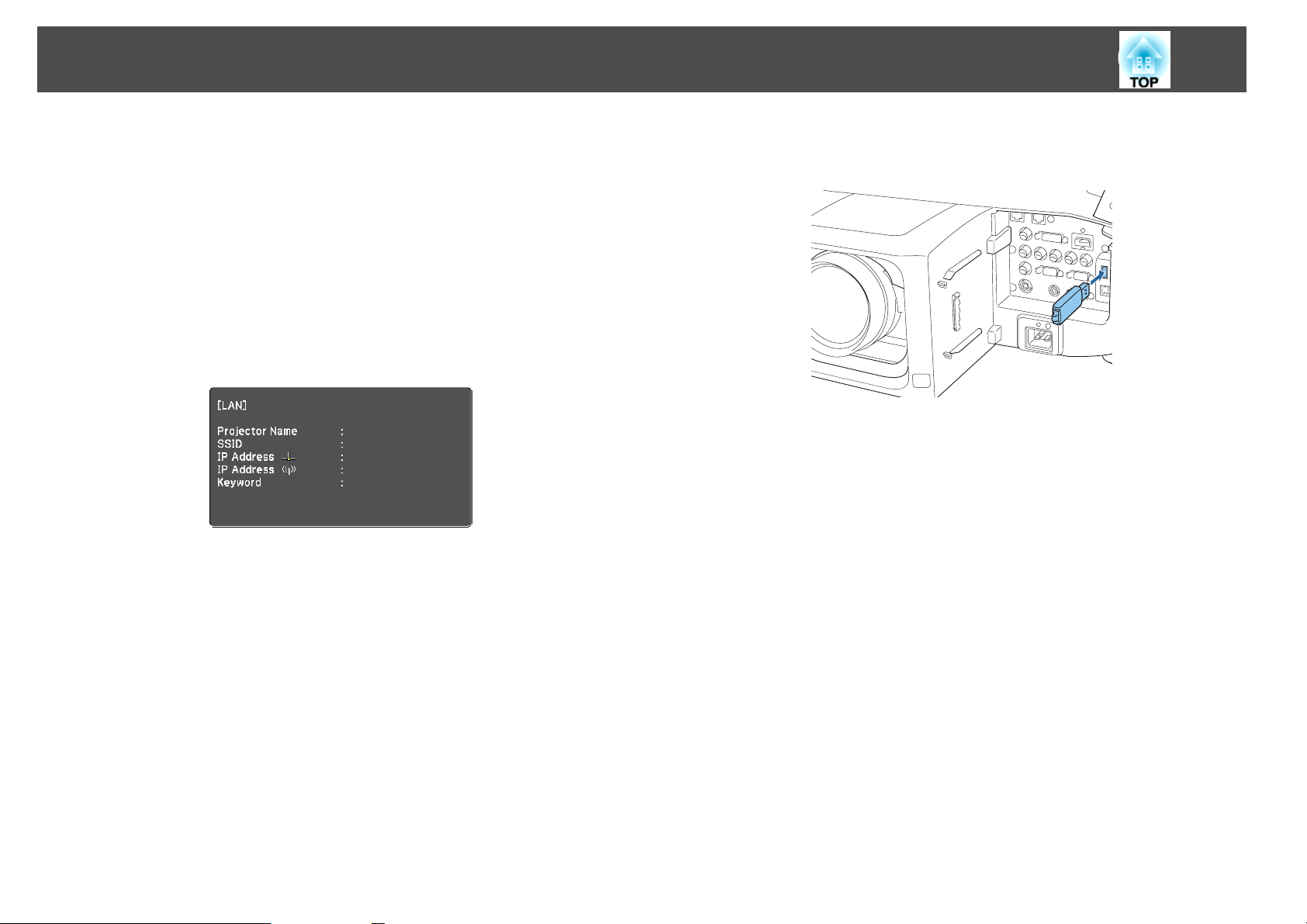
a
b
Turn on the projector, and then press the [LAN] button.
The following screen is displayed.
Check that the SSID and IP address information are displayed, and
then remove the wireless LAN unit.
s
"Installing the Wireless LAN Unit (ELPAP07)" p.47
c
d
e
Insert the Quick Wireless Connection USB Key in the wireless LAN
unit installation section.
When the message "Network information update complete.
Remove the Quick Wireless Connection USB Key Adapter." is
displayed, remove the Quick Wireless Connection USB Key.
After removing the Quick Wireless Connection USB Key, reattach
the wireless LAN unit.
Connect the Quick Wireless Connection USB Key to the computer.
From this point on, see the user's guide supplied with the Quick
Wireless Connection USB Key.
Page 49

Batch Setup
49
Once the Configuration menu content has been set for one projector, you
can use it to perform batch setup for multiple projectors (batch setup
function). The batch setup function is only for projectors with the same
model number.
Use one of the following methods.
• Setup using a USB flash drive.
• Setup by connecting the computer and projector with a USB cable.
• Setup using EasyMP Network Updater.
This manual explains the USB flash drive and the USB cable methods.
• The following content is not reflected by the batch setup function.
a
- The Network menu settings (except for the Mail menu and the
Others menu)
- Lamp Hours and Status in the Info menu
• Perform batch setup before adjusting the projected image.
Adjustment values for the projected image, such as Geometric
Correction are reflected by the batch setup function. If batch setup is
performed after adjusting the projected image, the adjustments you
made may change.
• By using the batch setup function, the registered User's Logo is set
for the other projectors. Do not register confidential information and
so on as the User's Logo.
Setup Using a USB flash drive
This section explains how to perform batch setup using a USB flash drive.
• Use a FAT format USB flash drive.
a
Saving settings to the USB flash drive
a
b
• The batch setup function cannot be used by USB flash drives that
incorporate security functions. Use a USB flash drive that does not
incorporate security functions.
• The batch setup function cannot be used by USB card readers or
USB hard disks.
Disconnect the power cord from the projector, and check that all
of the projector's indicators have turned off.
Connect the USB flash drive to the projector's wireless LAN unit
port.
Caution
Performing batch setup is the customers responsibility. If batch setup fails due
to a power failure, communication error, and so on, the customer is responsible
for any repair costs incurred.
Page 50
Batch Setup
50
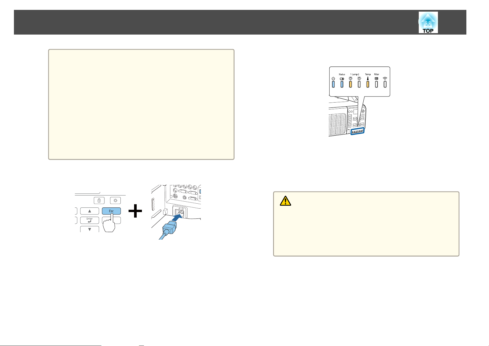
c
• Connect the USB flash drive directly to the projector. If the
a
While holding down the [Esc] button on the remote control or the
control panel, connect the power cord to the projector.
USB flash drive is connected to the projector through a USB
hub, the settings may not be saved correctly.
• Connect an empty USB flash drive. If the USB flash drive
contains data other than the batch setup file, the settings may
not be saved correctly.
• If you have saved a batch setup file from another projector to
the USB flash drive, delete the file or change the file name.
The batch setup function cannot overwrite a batch setup file.
• The file name for the batch setup file is PJCONFDATA.bin. If
you need to change the file name, add text after
PJCONFDATA. If you change the file name in any other way,
the projector may not be able to recognize the file correctly.
• You can only use single-byte characters for the file name.
When the projector's indicators turn on as follows, release the [Esc]
button.
Power Status Lamp1 Temp
Blue - On Blue - On Orange - On Orange - On
When all of the indicators start flashing, the batch setup file is being
written.
Caution
• Do not disconnect the power cord from the projector while the file is
being written. If the power cord is disconnected, the projector may not
start correctly.
• Do not disconnect the USB flash drive from the projector while the
file is being written. If the USB flash drive is disconnected, the
projector may not start correctly.
Page 51

Batch Setup
When writing completes normally, the projector enters standby
status.
Reflecting saved settings to other projectors
a
Disconnect the power cord from the projector, and check that all
of the projector's indicators have turned off.
51
Power
Blue - On
When the projector is in standby status, remove the USB flash
drive.
b
Connect the USB flash drive containing the saved batch setup file
to the projector's wireless LAN unit port.
• When the USB flash drive contains 1 to 3 types of batch
a
setup files, the file is reflected to the projector with the same
model number. If there are multiple files for a projector with
the same model number, the settings may not be reflected
correctly.
• When there are four or more types of batch setup files on the
USB flash drive, the settings may not be reflected correctly.
• Do not store any data except for the batch setup file on the
USB flash drive. If the USB flash drive contains data other
than the batch setup file, the settings may not be reflected
correctly.
Page 52
Batch Setup
52
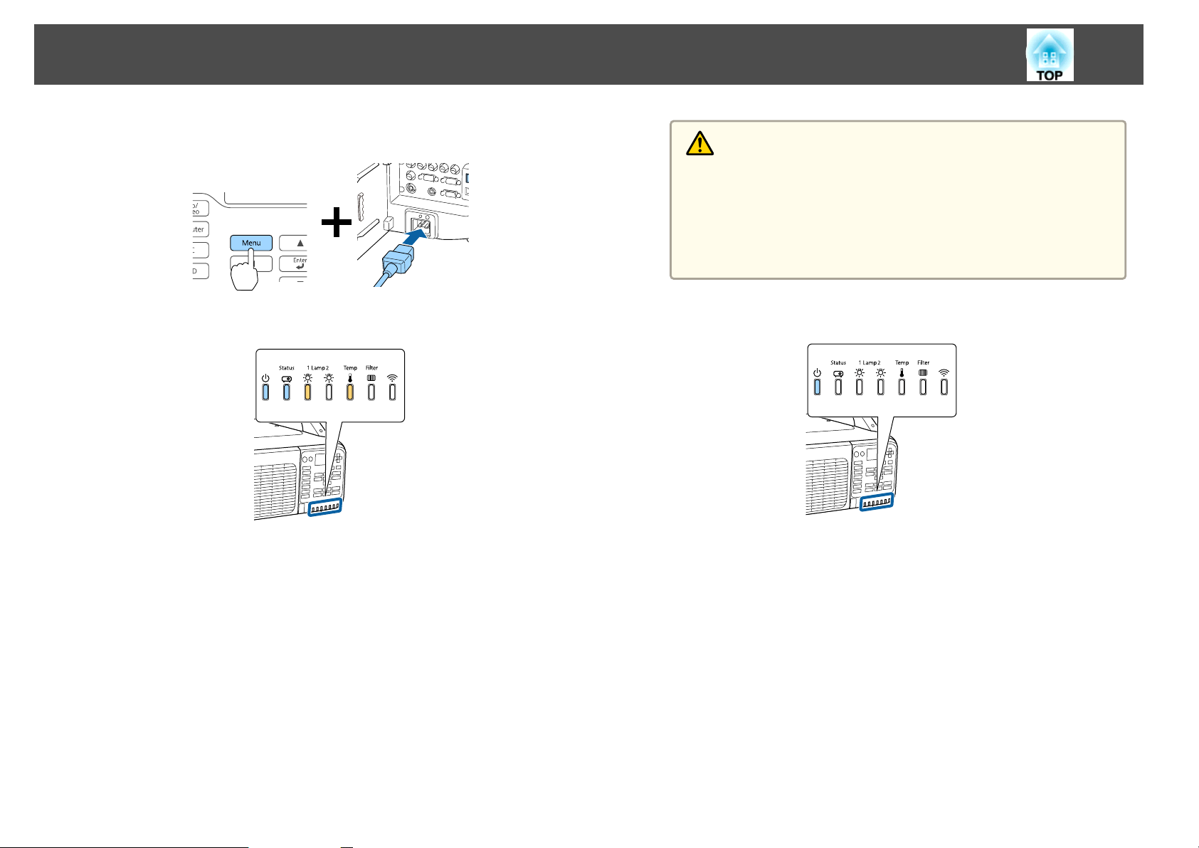
c
While holding down the [Menu] on the remote control or the
control panel, connect the power cord to the projector.
When the projector's indicators turn on as follows, release
the [Menu] button.
d
Caution
• Do not disconnect the power cord from the projector while the
settings are being written. If the power cord is disconnected, the
projector may not start correctly.
• Do not disconnect the USB flash drive from the projector while the
settings are being written. If the USB flash drive is disconnected, the
projector may not start correctly.
When writing completes normally, the projector enters standby
status.
Power Status Lamp1 Temp
Blue - On Blue - On Orange - On Orange - On
The indicators remain on for about 75 seconds.
When all of the indicators start flashing, the settings are being
written.
Power
Blue - On
When the projector is in standby status, remove the USB flash
drive.
Page 53

Batch Setup
53
Setup by Connecting the Computer and Projector with a USB Cable
The following operating systems support the batch setup function.
a
Saving settings to a computer
a
b
• Windows Vista and later
• Mac OS X 10.5.3 and later
Disconnect the power cord from the projector, and check that all
of the projector's indicators have turned off.
Connect the computer's USB port to the projector's Service port
with a USB cable.
c
While holding down the [Esc] button on the remote control or the
control panel, connect the power cord to the projector.
When all of the projector's indicators turn on, release the [Esc]
button.
Power Status Lamp1 Temp
Blue - On Blue - On Orange - On Orange - On
The projector is recognized as a removable disk by the computer.
Page 54
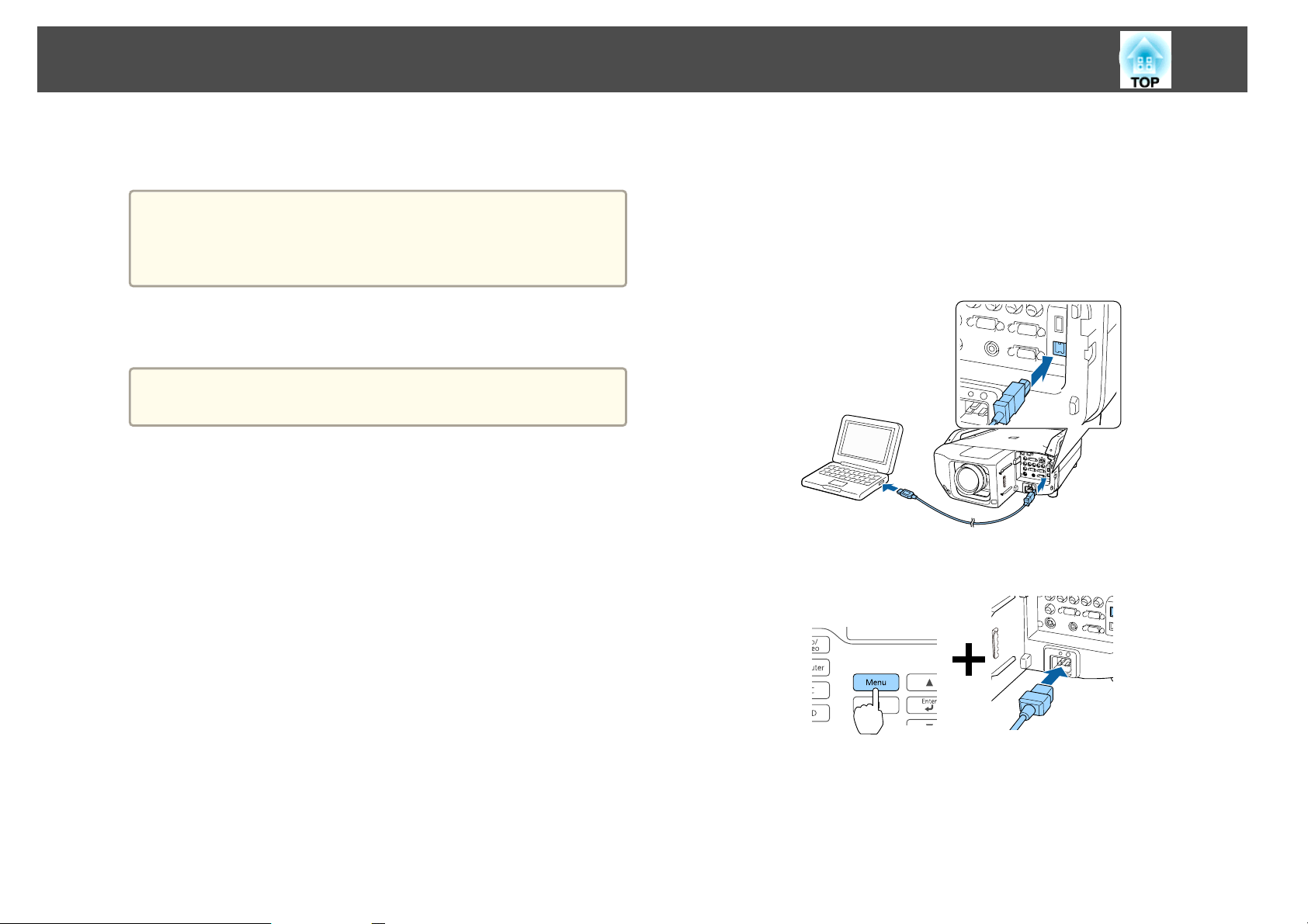
Batch Setup
54
d
e
Open the removable disk, and save the batch setup file
(PJCONFDATA.bin) to the computer.
If you need to change the name of the batch setup file, add text
a
Perform "Remove USB device" on your computer, and then
disconnect the USB cable.
after PJCONFDATA. If you change the PJCONFDATA section
of the file name, the projector may not be able to recognize the
file correctly.
When using OS X, perform "Remove EPSON_PJ".
a
The projector enters standby status.
Reflecting saved settings to other projectors
a
b
c
Disconnect the power cord from the projector, and check that all
of the projector's indicators have turned off.
Connect the computer's USB port to the projector's Service port
with a USB cable.
While holding down the [Menu] on the remote control or the
control panel, connect the power cord to the projector.
Page 55

Batch Setup
55
When the projector's indicators turn on as follows, release
the [Menu] button.
Power Status Lamp1 Temp
Blue - On Blue - On Orange - On Orange - On
The projector is recognized as a removable disk by the computer.
d
e
Copy the batch setup file (PJCONFDATA.bin) that you saved to
your computer to the top level folder of the removable disk.
Do not copy any files or folders other than the batch setup file
a
Perform "Remove USB device" on your computer, and then
disconnect the USB cable.
to the removable disk.
When using OS X, perform "Remove EPSON_PJ".
a
When all of the indicators start flashing, the settings are being
written.
Caution
Do not disconnect the power cord from the projector while the settings
are being written. If the power cord is disconnected, the projector may
not start correctly.
When writing completes normally, the projector enters standby
status.
Page 56
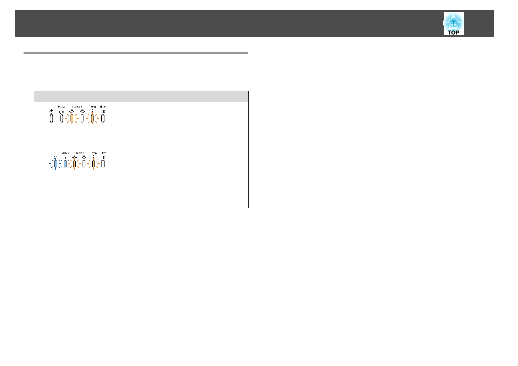
Batch Setup
When Setup Fails
The indicators notify you if an error occurs. Check the status of the
indicators.
Status of the Indicators Remedy
The batch setup file may be corrupt, or the USB
flash drive or USB cable may not be connected
correctly. Disconnect the USB flash drive or the
USB cable, unplug and then plug in the projector's
Lamp1: Orange - flashing fast
Temp: Orange - flashing fast
Power: Blue - flashing fast
Status: Blue - flashing fast
Lamp1: Orange - flashing fast
Temp: Orange - flashing fast
power cord, and then try again.
Writing the settings may have failed and an error
may have occurred in the projector's firmware.
Stop using the projector, remove the power cord
from the electrical outlet, and contact your local
dealer or the nearest address provided in the Epson
Projector Contact List.
s Epson Projector Contact List
56
Page 57

Basic Usage
This chapter explains how to project and adjust images.
Page 58

Projecting Images
58
Automatically Detect Input Signals and Change the Projected Image (Search)
Press the [Search] button on the remote control to project images from the
port currently receiving an image.
Remote control
a
• You can make settings so that images are projected from the same
input port the next time the projector is turned on.
s Extended - Operation - Startup Source Search p.122
• The following screen is displayed while no image signals are input.
* For EB-Z10005U/EB-Z10000U/EB-Z9875U/EB-Z9870U only
When multiple devices are connected, press the [Search] button on the
remote control until the target image is projected.
When video equipment is connected, make sure that the equipment is ready
to play, and then start this operation.
Page 59

Projecting Images
59
Switching to the Target Image
You can change directly to the target image from the remote control or by
pressing the following buttons on the control panel.
The following shows the input ports for each button.
Remote control
Control panel
Input ports
Changes to images from a computer connected over the network.
E
For EB-Z10005U/EB-Z10000U/EB-Z9875U/EB-Z9870U only
H
Page 60

Adjusting Projected Images
60
Correcting Distortion in the Projected Image
You can correct keystone distortion in projected images using one of the
following methods.
• H/V-Keystone
Manually correct keystone distortion in the horizontal and vertical
directions independently.
s
"H/V-Keystone" p.61
• Quick Corner
Manually correct the four corners independently.
s
"Quick Corner" p.62
• Curved Surface
Manually correct distortion that occurs when projecting on a curved
surface, and adjust the amount of expansion and contraction.
s
"Curved Surface" p.63
• Point Correction
Corrects slight distortion which occurs partially, or adjusts the image
position in an overlapping area when projecting from multiple projectors.
s
"Point Correction" p.65
• Corner Wall
Manually correct distortion that occurs when projecting on a surface with
right angles, such as a square pillar or the corner of a room, and adjust
the amount of expansion and contraction.
s
"Corner Wall" p.67
Page 61

Adjusting Projected Images
61
• You cannot combine multiple adjustment methods. However, you
a
H/V-Keystone
Manually correct keystone distortion in the horizontal and vertical
directions independently. The angle of vertical and horizontal tilt for the
projector can be corrected up to 30 degrees against the screen. (The
specifications are when a standard zoom lens ELPLS04 is attached).
can use Point Correction after performing Curved Surface or Corner
Wall.
• When you want to re-adjust the projection position and so on, if
you want to release the correction status temporarily, set the
Geometric Correction to Off. Even when it is set to Off, the
correction values are saved.
Settings - Geometric Correction p.121
s
Press the [Menu] button while projecting.
a
b
Select Geometric Correction from Settings.
c
Select H/V-Keystone, and then press the [ ] button.
When the message "If this setting is changed, the image may be
distorted." is displayed, press the [
] button.
d
Press the [ ][ ] buttons to select the correction method, and
then use the [
V-Keystone
H-Keystone
][ ] buttons to make the corrections.
e
When you correct keystone distortion, the projected image may
a
To complete the corrections, press the [Menu] button.
be reduced.
Page 62

Adjusting Projected Images
62
Quick Corner
This allows you to manually correct each of the four corners of the
projected image separately.
Press the [Menu] button while projecting.
a
b
Select Geometric Correction from Settings.
c
Select Quick Corner, and then press the [ ] button.
When the message "If this setting is changed, the image may be
] button again.
] button.
d
distorted." is displayed, press the [
Press the [ ][ ][ ][ ] buttons to select the corner you want to
adjust, and then press the [
e
If the [Esc] button is pressed for approximately two seconds,
a
Press the [ ][ ][ ][ ] buttons to correct the position of the
corner.
When you press the [
allows you to select the area to be corrected is displayed.
If the message "Cannot adjust any further." is displayed while
adjusting, you cannot adjust the shape any further in the direction
indicated by the gray triangle.
the confirm default reset screen is displayed.
Select Yes to reset the result of Quick Corner corrections.
] button, the screen shown in step 4 that
f
g
Repeat steps 4 and 5 as needed to adjust any remaining corners.
When the corrections are complete, press the [Menu] button.
Page 63

Adjusting Projected Images
63
Curved Surface
Manually correct distortion that occurs when projecting on a curved
surface, and adjust the amount of expansion and contraction.
Project from the front with the horizontal lens shift in the center.
s
"Adjusting the Position of the Projected Image (Lens shift)" p.35
• Project onto an arc surface with the same radius.
a
Correction method
• If a large amount of adjustment is performed, the focus may not be
uniform even after making adjustments.
Press the [Menu] button while projecting.
a
b
Select Geometric Correction from Settings.
c
Select Curved Surface, and then press the [ ] button.
When the message "If this setting is changed, the image may be
distorted." is displayed, press the [
] button.
e
Press the [ ][ ][ ][ ] buttons to select the area you want to
adjust, and then press the [
When selecting a corner, you can adjust the two sides next to the
corner.
] button.
d
Select Correct Shape, and then press the [ ] button.
a
If the [Esc] button is pressed for approximately two seconds,
the confirm default reset screen is displayed.
Select Yes to reset the result of Curved Surface.
Page 64
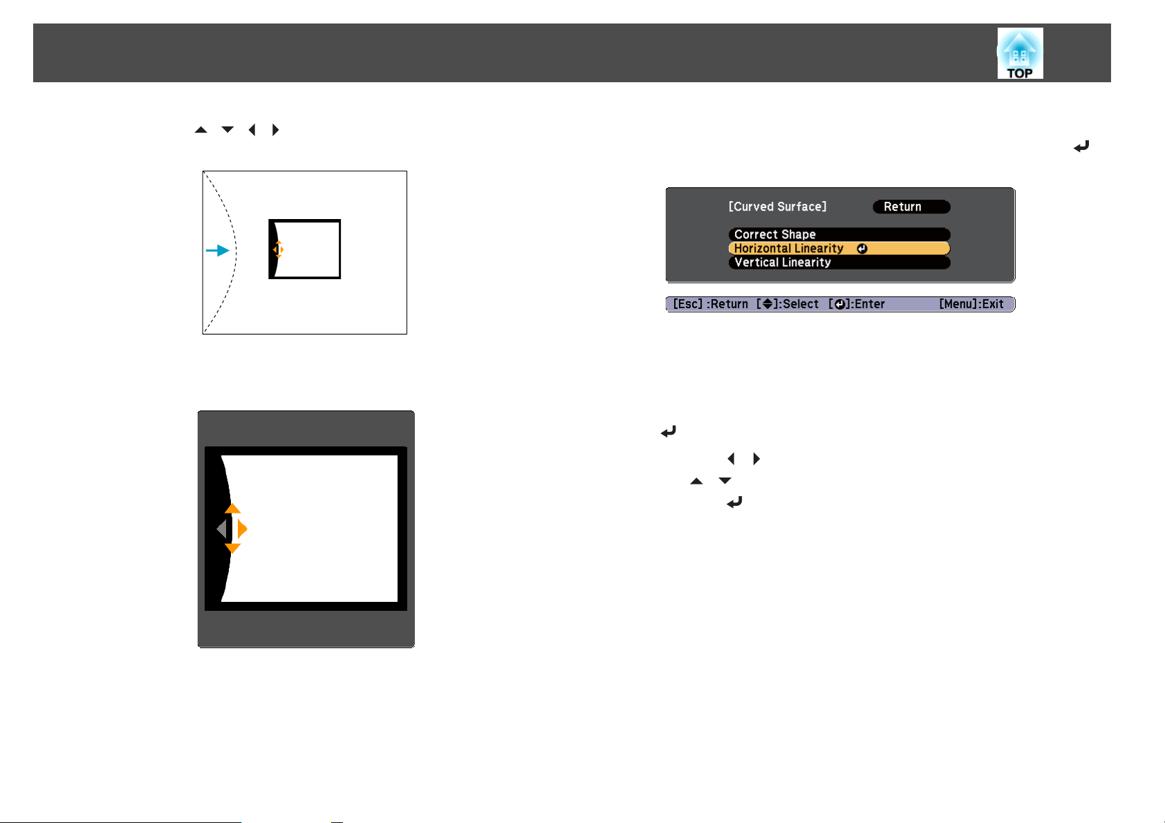
Adjusting Projected Images
64
f
Press the [ ][ ][ ][ ] buttons to adjust the position of the
sides.
If the triangle in the direction you are adjusting the shape turns gray,
as shown in the screen shot below, you cannot adjust the shape any
further in that direction.
i
j
Press the [Esc] button to return to the screen in step 4. Select
Horizontal Linearity or Vertical Linearity, and then press the [
button.
Select Horizontal Linearity to adjust the horizontal expansion or
contraction, and select Vertical Linearity to adjust the vertical
expansion or contraction.
Select the standard line for the adjustments, and then press the
[
] button.
Press the [
the [
press the [
The selected standard line is displayed in flashing orange and white.
][ ] buttons when selecting Horizontal Linearity, and
][ ] buttons when selecting Vertical Linearity, and then
] button.
]
g
h
Press the [Esc] button to return to the previous screen.
Repeat steps 5 to 7 as needed to adjust any remaining parts.
If the image expands and contracts, go to the next step and adjust
the linearity.
Page 65

Adjusting Projected Images
65
k
Adjust the linearity.
Correct it so that the distance between lines is equal.
When the [
Selecting Horizontal Linearity Selecting Vertical Linearity
When the [ ] button is pressed
Selecting Horizontal Linearity Selecting Vertical Linearity
] button is pressed
Point Correction
Divides the projected image by the grid and corrects the distortion by
moving the point of intersection from side to side and up and down.
• You can make corrections by 0.5 pixel in each direction in the
a
following ranges.
EB-Z10005U/EB-Z10000U/EB-Z9875U/EB-Z9870U/EB-Z9750U:
Maximum of 48 pixels in vertical and horizontal directions
EB-Z11000W/EB-Z9900W/EB-Z9800W/EB-Z11005/EB-Z11000/EB-
Z9870:
Maximum of 32 pixels in vertical and horizontal directions
• When fine-tuning the result of corrections you made in Curved
Surface and Corner Wall, you can adjust in a maximum range of 10
pixels in vertical and horizontal directions.
Press the [Menu] button while projecting.
a
b
Select Geometric Correction from Settings.
c
Select Point Correction, and then press the [ ] button.
When the message "If this setting is changed, the image may be
distorted." is displayed, press the [
] button again.
l
a
To complete the corrections, press the [Menu] button.
You can fine tune the results of Curved Surface using Point
Correction. Change Geometric Correction to Point Correction, and
then make adjustments after selecting Keep the current geometric
correction settings.
s "Point Correction" p.65
a
When changing from Curved Surface or Corner Wall to Point
Correction, the screen displaying the adjustment method is
displayed.
Keep the current geometric correction settings: Use Point
Correction to fine tune images adjusted using Curved Surface or
Corner Wall.
Reset the geometric correction settings: Reset adjustments
made to images using Curved Surface or Corner Wall, and then
perform adjustment using Point Correction.
Page 66

Adjusting Projected Images
66
d
e
Select Point Correction, and then press the [ ] button.
Point Correction
Pattern Color
Reset
Select the point number (3x3, 5x5, or 9x9), and then press the
[
] button.
Select the point number (3x3, 5x5, 9x9), and then
make the Point Correction setting.
Select the color of the grid when performing
corrections.
Resets all corrections for Point Correction to their
default values.
f
g
Press the [ ][ ][ ][ ] buttons to move to the point you want
to correct, and then press the [
Press the [ ][ ][ ][ ] buttons to correct distortion.
] button.
h
To continue to correct another point, press the [Esc] button to
return to the previous screen, then repeat the step 6 and 7.
Each time you press the [ ] button, you can show or hide the
a
To complete the corrections, press the [Menu] button.
image and the grid.
Page 67
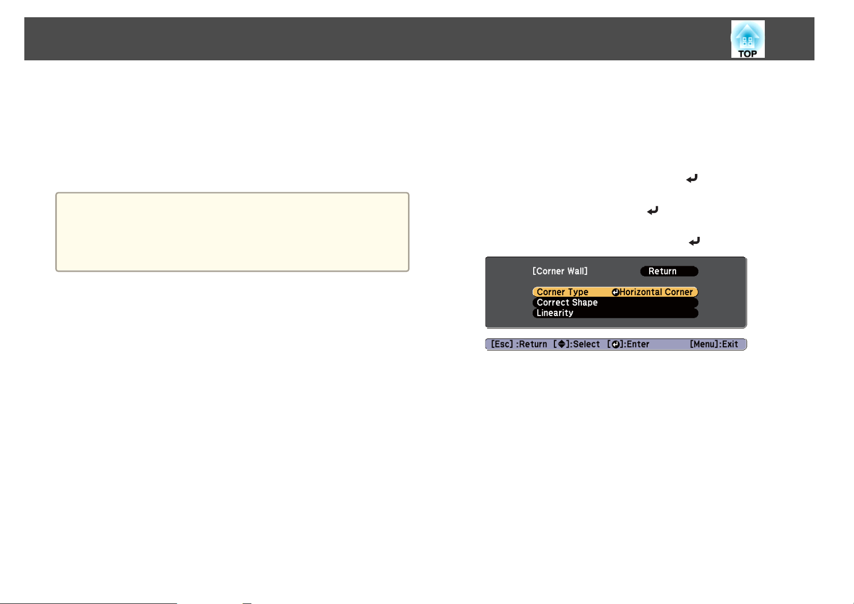
Adjusting Projected Images
67
Corner Wall
Manually correct distortion that occurs when projecting on a surface with
right angles, such as a square pillar or the corner of a room, and adjust the
amount of expansion and contraction.
Project from the front with the horizontal lens shift in the center.
s
"Adjusting the Position of the Projected Image (Lens shift)" p.35
• Project onto a surface with a right angle.
a
• If a large amount of adjustment is performed, the focus may not be
uniform even after making adjustments.
• You may not be able to adjust Corner Wall correctly when using the
short throw zoom lens ELPLU02.
Correction method
Press the [Menu] button while projecting.
a
Select Geometric Correction from Settings.
b
Select Corner Wall, and then press the [ ] button.
c
When the message "If this setting is changed, the image may be
distorted." is displayed, press the [
Select Corner Type, and then press the [ ] button.
d
] button again.
Page 68
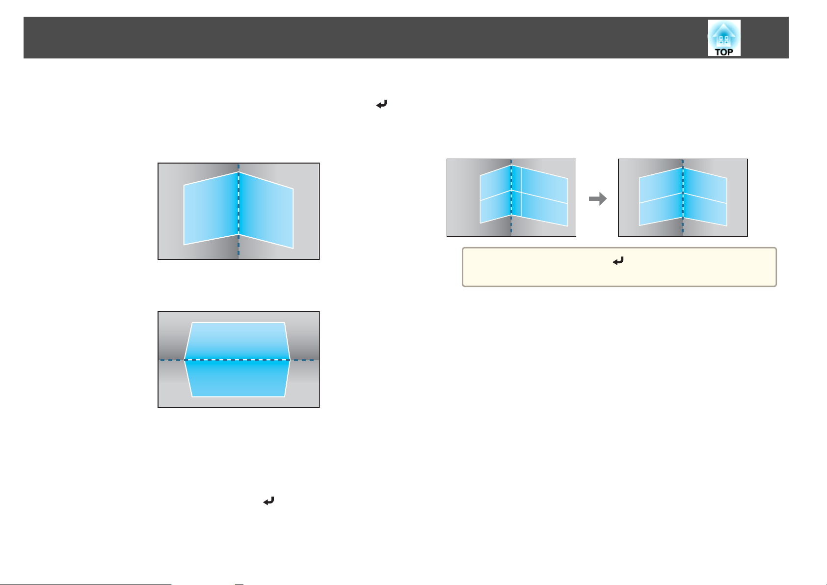
Adjusting Projected Images
68
e
To fit the projected image to the projection position, select
Horizontal Corner or Vertical Corner, and then press the [
button.
When the surfaces line up horizontally:
Select Horizontal Corner.
When the surfaces line up vertically:
Select Vertical Corner.
]
g
Adjust the position of the projector and the lens shift so that the
line in the center of the screen matches the corner (the point
where the two surfaces meet).
s
"Adjusting the Position of the Projected Image (Lens shift)"
p.35
Each time you press the [ ] button, you can show or hide the
a
image and the grid.
f
From here on, steps are explained using Horizontal Corner as an
example.
Press the [Esc] button to display the screen from step 4. Select
Correct Shape, and then press the [
] button.
Page 69
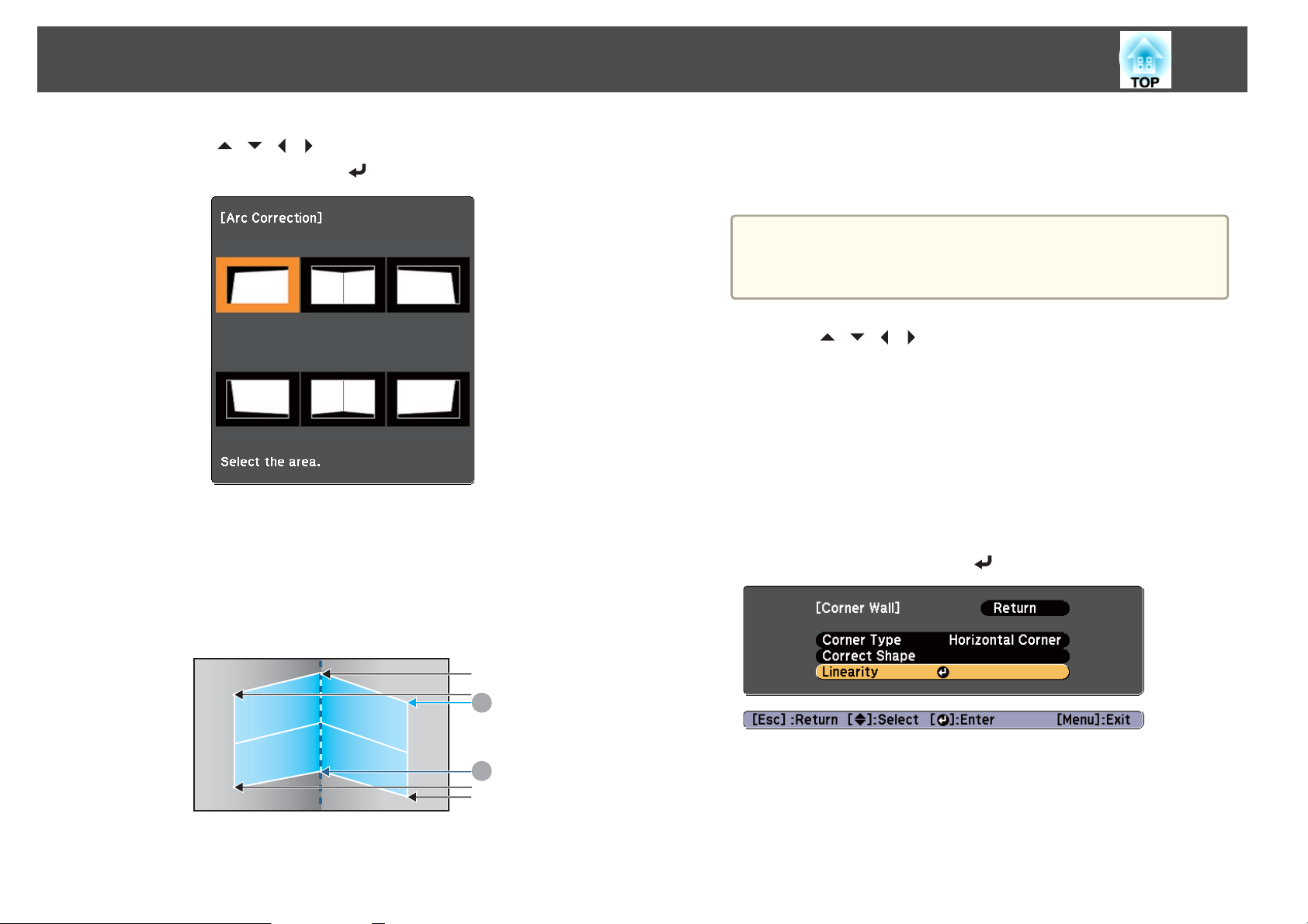
Adjusting Projected Images
69
h
Press the [ ][ ][ ][ ] buttons to select the area you want to
adjust, and then press the [
Adjustment tips
When selecting Horizontal Corner:
Adjust the upper area based on the lowest point (indicated by the
arrow).
Adjust the lower area based on the highest point (indicated by the
arrow).
] button.
U
V
i
j
k
When selecting Vertical Corner:
Adjust the left and right based on the point nearest to the vertical
line in the center of the screen.
If the [Esc] button is pressed for approximately two seconds,
a
Press the [ ][ ][ ][ ] buttons to adjust the shape.
If the message "Cannot adjust any further." is displayed while
adjusting, you cannot adjust the shape any further in the direction
indicated by the gray triangle.
Repeat steps 8 and 9 as needed to adjust any remaining parts.
If the image expands and contracts, go to the next step and adjust
the linearity.
Press the [Esc] button to display the screen from step 4. Select
Linearity, and then press the [
the confirm default reset screen is displayed.
Select Yes to reset the result of Corner Wall.
] button.
A
B
Page 70
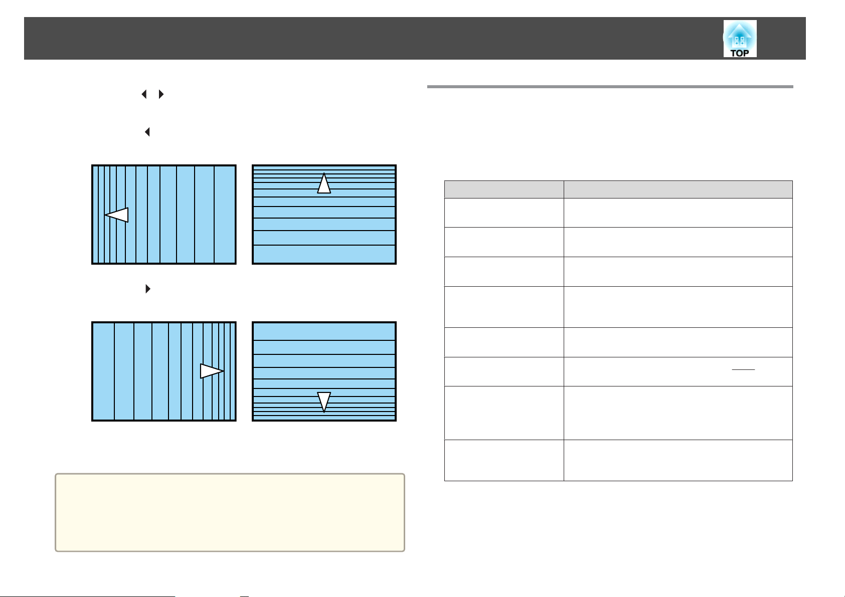
Adjusting Projected Images
70
l
m
a
Press the [ ][ ] buttons to adjust the linearity.
Correct it so that the distance between lines is equal.
When the [
When selecting Horizontal Corner When selecting Vertical Corner
When the [ ] button is pressed
When selecting Horizontal Corner When selecting Vertical Corner
To complete the corrections, press the [Menu] button.
You can fine tune the results of Corner Wall using Point Correction.
Change Geometric Correction to Point Correction, and then make
adjustments after selecting Keep the current geometric correction
settings.
s "Point Correction" p.65
] button is pressed
Selecting the Projection Quality (Selecting Color Mode)
You can easily obtain the optimum image quality simply by selecting the
setting that best corresponds to your surroundings when projecting. The
brightness of the image varies depending on the mode selected.
Mode Application
Dynamic
Presentation
Theatre
*1
Photo
*2
Sports
sRGB
DICOM SIM
Multi-Projection
*1 This can only be selected when inputting RGB signals.
*2 This selection is only available when the input signal is component video, or
when the input source is Video or S-Video.
*1
Ideal for use in a bright room. This is the brightest
mode.
Ideal for making presentations using color materials
in a bright room.
Ideal for watching films in a dark room. Gives
images a natural tone.
Ideal for projecting still pictures, such as photos, in
a bright room. The images are vivid and brought
into contrast.
Ideal for watching TV programs in a bright room.
The images are vivid and brought to life.
Ideal for images that conform to the
standard.
Ideal for projecting X-ray photographs and other
medical images. This produces images with clear
shadows. The projector is not a medical device and
cannot be used for medical diagnosis.
Ideal for projecting from multiple projectors.
Minimize the color tone difference between each
projected image.
sRGBg color
Page 71
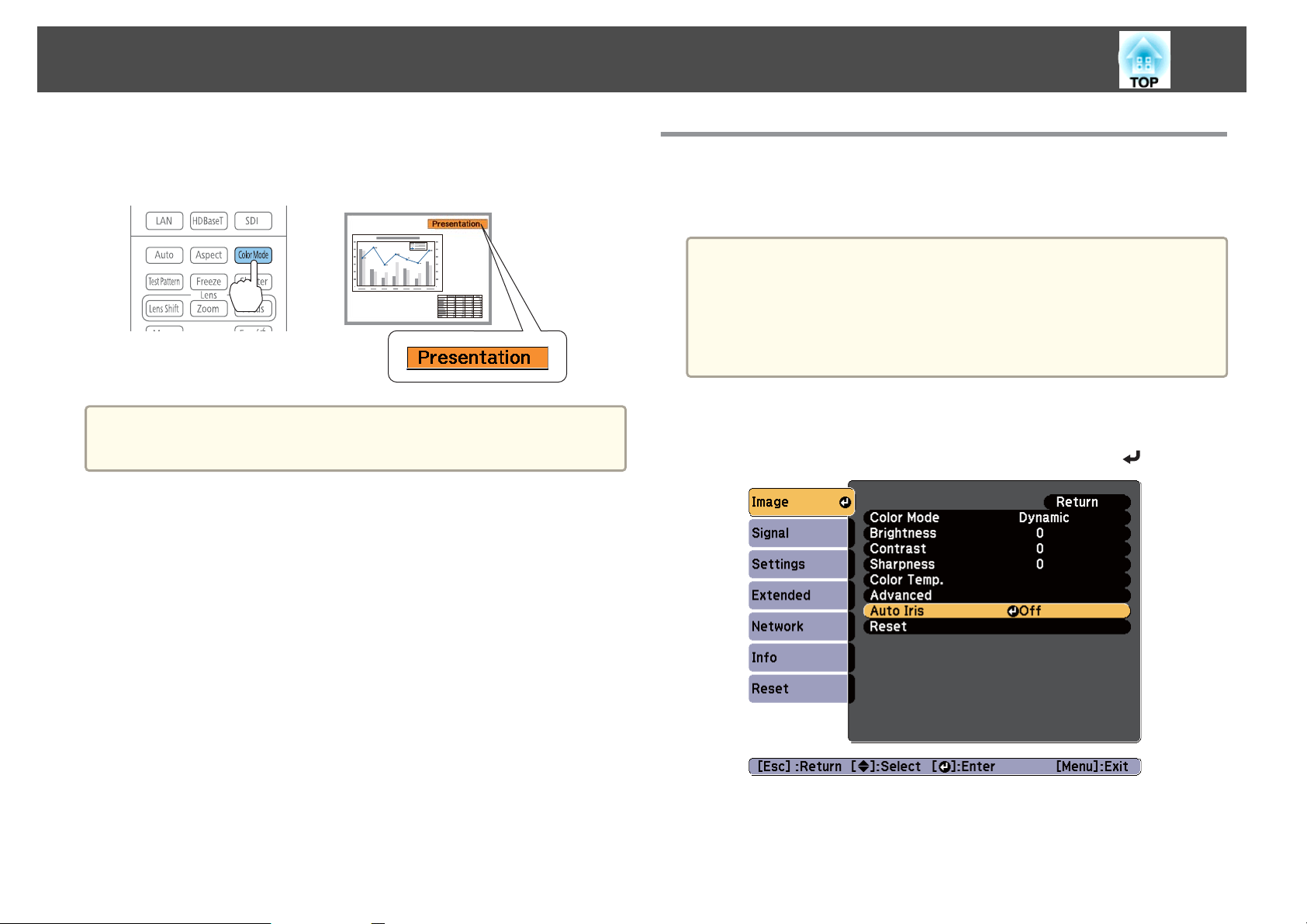
Adjusting Projected Images
71
Each time you press the [Color Mode] button, the Color Mode name is
displayed on the screen and the Color Mode changes.
Remote control
You can set Color Mode in the Configuration menu.
a
s Image - Color Mode p.117
Setting Auto Iris
By automatically setting the luminance according to the brightness of the
displayed image, it lets you enjoy deep and rich images.
• If you keep projecting extremely dark images, Auto Iris may stop for
a
approximately ten minutes. When you are using multiple projectors,
black levels may differ depending on the projected images.
• Auto Iris can only be set when the Color Mode is set to Dynamic
(3D Dynamic) or Theatre (3D Theatre).
• When Edge Blending is set to On, Auto Iris is disabled.
Press the [Menu] button while projecting.
a
b
Select Auto Iris from Image, and then press the [ ] button.
Page 72
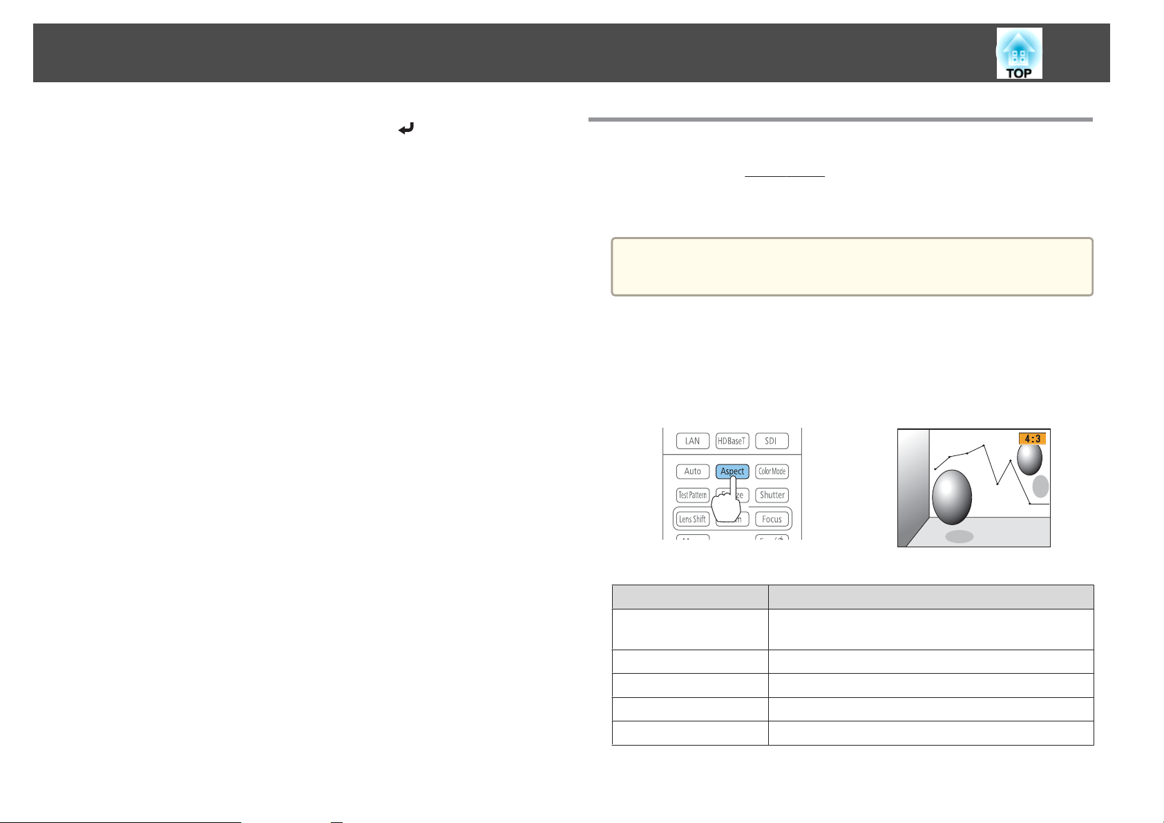
Adjusting Projected Images
72
c
d
Select High Speed, and then press the [ ] button.
If you are concerned about the operation noise of Auto Iris, set it to
Normal.
The setting is stored for each color mode.
Press the [Menu] button to finish making settings.
Changing the Aspect Ratio of the Projected Image
You can change the Aspect Ratiog of the projected image to suit the type,
the ratio of height and width, and the resolution of the input signals.
Available aspect modes vary depending on the Screen Type currently set.
Set the Screen Type before changing the aspect ratio.
a
Changing methods
Each time you press the [Aspect] button on the remote control, the aspect
mode name is displayed on the screen and the aspect ratio changes.
s "Screen Settings" p.32
Remote control
Aspect Mode Explanation
Auto
Normal
4:3
16:9
Full
Projects in an appropriate aspect ratio based on
information from the signal being input.
Projects while retaining the aspect ratio of the input image.
Projects at an aspect ratio of 4:3.
Projects at an aspect ratio of 16:9.
Projects at the full size of the projected screen.
Page 73

Adjusting Projected Images
73
Aspect Mode Explanation
Zoom
Native
a
• You can also set the aspect ratio in the Configuration menu.
s Signal - Aspect p.119
• If parts of the computer image are missing, set the Resolution
setting to Wide or Normal in the Configuration menu, according to
the resolution of the computer.
s Signal - Resolution p.119
Projects by enlarging the input image to the full width of
the projected screen while retaining the aspect ratio. Areas
that exceed the edges of the projected screen are not
projected.
Projects to the center of the projected screen at the
resolution of the input image. Areas that exceed the edges
of the projected screen are not projected.
The aspect mode changes as shown in the tables below.
The following colors in screen images in the tables indicate areas that are
not displayed.
: The area where the image is not displayed depending on the screen
type setting.
: The area where the image is not displayed depending on the aspect
mode setting.
EB-Z10005U/EB-Z10000U/EB-Z9875U/EB-Z9870U/EB-Z9750U/EB-Z11000W/EB-Z9900W/
EB-Z9800W
Screen type setting: 16:10
Aspect Ratio of Input Signal
16:10 16:9 4:3
Auto or Normal
16:9
Full
Zoom
*
Native
The image may differ depending on the resolution of the input signal.
*
Page 74

Adjusting Projected Images
74
Screen type setting: 16:9
Aspect Ratio of Input Signal
16:10 16:9 4:3
Auto or Normal
Full
Zoom
*
Native
The image may differ depending on the resolution of the input signal.
*
Screen type setting: 4:3
Aspect Ratio of Input Signal
16:10 16:9 4:3
Auto or Normal
4:3
16:9
*
Native
* Only computer images and images from the HDMI input port/HDBaseT port.
The image may differ depending on the resolution of the input signal.
EB-Z11005/EB-Z11000/EB-Z9870
Screen type setting: 4:3
16:10 16:9 4:3
Auto or Normal
4:3
Aspect Ratio of Input Signal
Page 75

Adjusting Projected Images
75
Aspect Ratio of Input Signal
16:10 16:9 4:3
16:9
*
Native
* Only computer images and images from the HDMI input port/HDBaseT port.
The image may differ depending on the resolution of the input signal.
Screen type setting: 16:9
Aspect Ratio of Input Signal
16:10 16:9 4:3
Auto or Normal
Full
Aspect Ratio of Input Signal
16:10 16:9 4:3
Auto or Normal
16:9
Full
Zoom
*
Native
* The image may differ depending on the resolution of the input signal.
Zoom
*
Native
* The image may differ depending on the resolution of the input signal.
Screen type setting: 16:10
Page 76

Adjusting Projected Images
76
Adjusting the Image
Adjusting the Hue, Saturation, and Brightness
You can adjust the Hue, Saturation, and Brightness for R (red), G (green),
B (blue), C (cyan), M (magenta), and Y (yellow) color components.
Make settings in the Configuration menu.
s
Image - Advanced - RGBCMY p.117
You can also make adjustments from Multi-Projection in the
a
Configuration menu.
s Extended - Multi-Projection - RGBCMY p.122
Gamma adjustment
Adjusts differences in the coloring for the projected image that occurs
depending on the connected device.
Make settings in the Configuration menu.
s
Image - Advanced - Gamma p.117
Select and adjust the correction value
Image - Advanced - Gamma p.117
s
When a larger value is selected, the dark areas of images become brighter,
but the color saturation for lighter areas may become weaker.
When a smaller value is selected, you can reduce the overall brightness of
the image to make the image sharper.
If you select DICOM SIM from Color Mode on the Image menu, select the
adjustment value according to the projection size.
• If the projection size is 150 inches or less, select a small value.
• If the projection size is 150 inches or more, select a large value.
Medical images may not be reproduced correctly according to your
a
settings and screen specifications.
Page 77

Adjusting Projected Images
77
Adjust while viewing the image
Image - Advanced - Gamma - Customized - Adjust it from the image
s
p.117
Move the cursor on the projected image to the part where you want to
change the brightness, and then press the [
buttons to adjust the value.
] button. Press the [ ][ ]
Adjust using the gamma adjustment graph
Image - Advanced - Gamma - Customized - Adjust it from the graph
s
p.117
Adjust while looking at the gamma adjustment graph.
Page 78

Adjusting Projected Images
78
Frame Interpolation (EB-Z10005U/EB-Z10000U/EB-Z9875U/EBZ9870U/EB-Z9750U only)
The current and previous frames are used to create intermediate frames,
interpolating to produce smooth-moving images. You can resolve clumsymoving images, such as frame skipping when projecting a fast moving
image.
Make settings in the Configuration menu.
s
Signal - Frame Interpolation p.119
You can select the level of interpolation from Low, Normal or High. Set to
Off if noise occurs when setting an interpolation level.
Projecting 3D Images
By using two projectors, you can project passive 3D images. You need the
following optional items to project and view 3D images. Make sure you
read the notes in the user's guides supplied with the optional items.
• Polarizer (ELPPL01)
This is only available for standard zoom lens ELPLS04, middle throw
zoom lens ELPLM06, and long throw zoom lens ELPLL07.
• Passive 3D Glasses (ELPGS02A/ELPGS02B)
• Frame (ELPMB44)
s
"Optional Accessories" p.198
When projecting 3D images, set 3D Images to On in the Configuration
menu.
s
Signal - 3D Setup - 3D Images p.119
The following color modes are available when projecting 3D images. When
projecting using the optional 3D polarizers (ELPPL01), you can view images
at their optimal color tint.
• 3D Dynamic
• 3D Presentation
• 3D Theatre
• 3D Multi-Projection
s
"Selecting the Projection Quality (Selecting Color Mode)" p.70
a
This projector arranges the polarizing direction of projection for R
(red), G (green), and B (blue). It is not necessary to inverse left and
right eye G (green) image signals.
Page 79

Useful Functions
This section describes the Multi-Projection, Split Screen, Memory, Schedule, and Security functions.
Page 80

Multi-Projection Function
80
When projecting to a wide screen from multiple projectors, you can adjust
the difference of brightness and color tone between each projected image to
create a seamless screen.
There are two general methods of projecting from multiple projectors.
U Projecting different images from each projector, and creating a seamless screen
V Projecting the same image from each projector, using the Scale function to
project a large image
• We recommend setting the focus, zoom, and lens shift at least 20
a
minutes after you start the projection, because images are not stable
right after turning on the projector.
• Set Lamp Select to Dual.
Extended - Lamp Select p.122
s
• If the values for Geometric Correction are large, the image position
adjustment for overlapping images becomes difficult.
• The Test Pattern can be displayed to adjust the projection status
without connecting video equipment.
s "Displaying a Test Pattern" p.34
• If you project a dot by dot image that can be projected without
being enlarged or reduced, you can make adjustments precisely.
Preparation
Follow the steps below to adjust the projected images for the multiprojection function.
a
Set an ID for the projector and the remote control.
s
"Setting the projector ID" p.39
The basic setting method is the same, but you have to use the scale
V
function to adjust the projection position for
s
"Combining Scaled Images" p.89
Here we will take
U
as an example.
.
Page 81

Multi-Projection Function
81
b
c
d
Adjust the position of the projected image in the following order
(starting from the adjustments that have larger corrections).
(1) Projector's position (angle)
s "Installation Settings" p.30
(2) Lens shift/Zoom
s "Adjusting the Position of the Projected Image (Lens shift)" p.35
s "Adjusting the Zoom" p.37
(3) Correct the four image corners
s "Quick Corner" p.62
(4) Correct the slight position misalignment that occurs when matching the
projected images.
s "Point Correction" p.65
Set the Color Mode to Multi-Projection with the [Color Mode]
button.
• You can also set from Color Mode in Multi-Projection.
a
Adjusts the color tone for the whole screen as necessary.
s
"Color Uniformity" p.183
s Extended - Multi-Projection - Color Mode p.122
• When projecting 3D images, set it to 3D Multi-Projection.
Edge Blending
Follow the steps below to adjust the overlapping areas of the images.
(1) Fine tune the overlapping areas to make seamless screen.
s "Adjust the overlapping area of the images (Edge Blending)" p.81
(2) Adjust the brightness difference for each projector lamp.
s "Correcting the brightness" p.83
(3) Adjust the color balance of the projected images.
s "Fine-tuning the color balance" p.85
Adjust the overlapping area of the images (Edge Blending)
You can fine tune the overlapping areas to make seamless screen.
a
Press the [Menu] button while projecting.
s
"Using the Configuration Menu" p.114
b
Select Multi-Projection from Extended.
Page 82

Multi-Projection Function
82
c
Select Edge Blending, and then press the [ ] button.
The following screen is displayed.
Submenu Function
Edge Blending
Set to On to activate Edge Blending. Set to Off
when not projecting from multiple projectors.
d
e
f
Turn on Edge Blending.
(1)
Select Edge Blending, and then press the [
(2)
Select On, and then press the [
(3) Press the [Esc] button.
Set Guide Display to On.
(1)
Select Guide Display, and then press the [
(2)
Select On, and then press the [
(3) Press the [Esc] button.
If the guide is not clear, you can change the color of the guide
a
Set Pattern Guide to On.
(1)
(2)
(3) Press the [Esc] button.
on Guide Colors.
Select Pattern Guide, and then press the [
Select On, and then press the [
] button.
] button.
] button.
] button.
] button.
] button.
Top Edge/Bottom
Edge/Left Edge/Right
Edge
Guide Display
Pattern Guide
Guide Colors
Blending: Set to On to activate Edge Blending
towards your settings, and the blend range will be
shaded.
Blend Range: Adjusts the range to be shaded.
Adjustment is possible at a level of one pixel. The
maximum range is 45% of the resolution.
Set to On to display a guide on the Edge Blending
setting range.
Set to On to display a guide to match the position of
the Edge Blending setting range.
Select a combination of guide colors from the three
provided.
Page 83
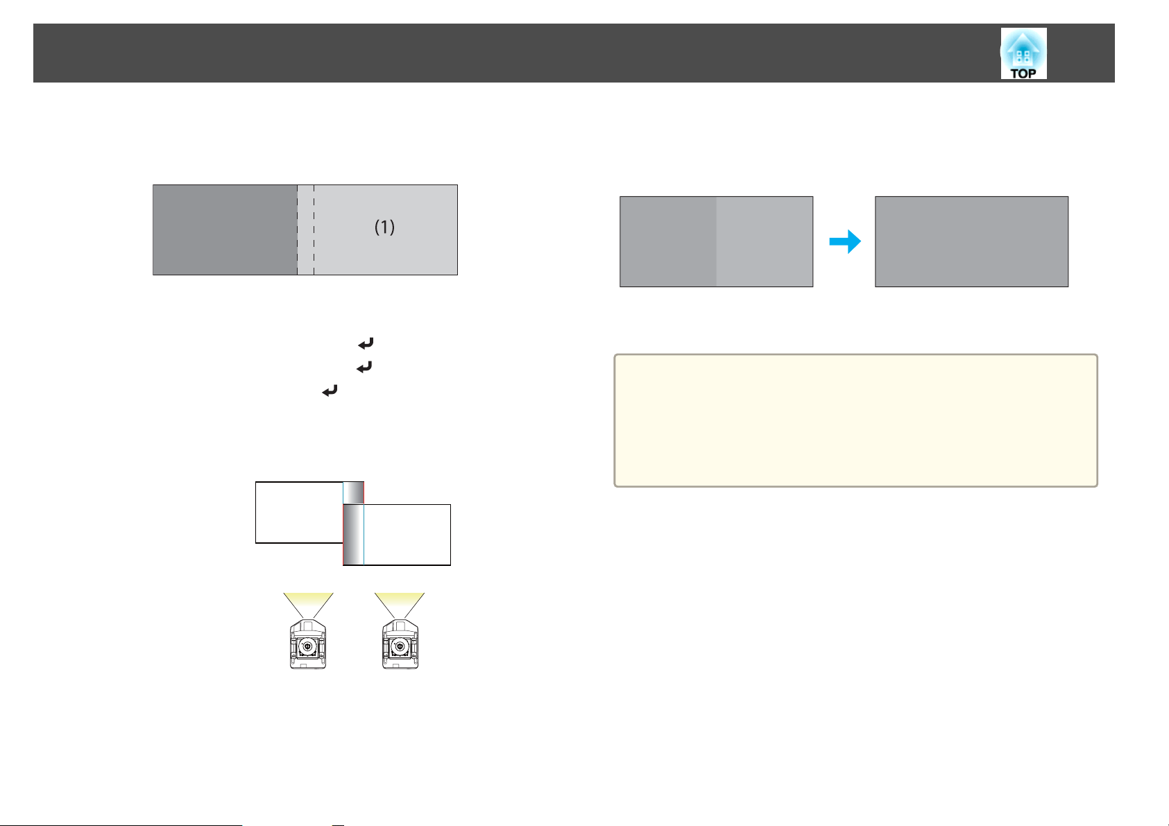
Multi-Projection Function
83
g
Set Top Edge, Bottom Edge, Left Edge, or Right Edge according
to the parts of the image that are overlapped.
The following shows how to set screen (1) as an example.
In the example above, you need to adjust the Left Edge because you
can see the overlapping areas on the left side of the image (1).
(1)
Select Left Edge, and then press the [
(2)
Select Blending, and then press the [
(3)
Select On, and then press the [
(4) Press the [Esc] button.
(5) In Blend Range, adjust the range to be shaded.
When a guide appears on the same position as the overlapping area, you
can set the blend range with the selected value.
] button.
] button.
] button.
Correcting the brightness
Adjust the Brightness Level so that the lamp brightness is the same for
each projector.
Adjust so that all projectors are the same brightness as the darkest lamp.
You can adjust the brightness in five levels.
• Set Power Consumption to Normal.
a
s Settings - Power Consumption p.121
• You cannot adjust the Brightness Level during the portrait
projection.
• Even if you adjust the Brightness Level, the brightness of each lamp
may not match exactly.
h
(6) Press the [Esc] button.
After the settings are complete, set Guide Display and Pattern
Guide to Off to finish.
Page 84

Multi-Projection Function
84
a
b
Select Brightness Level from Multi-Projection, and then press the
[
] button.
Select 1 to 5 as the brightness.
c
Press the [Esc] button to return to the previous screen.
a
You can switch the projected image between the input image
and the white image using the [
][ ] buttons.
Page 85

Multi-Projection Function
85
Fine-tuning the color balance
Adjust the brightness of the projected image and the color balance that was
adjusted by Edge Blending.
The brightness and color may not be uniform even after making
a
Color Matching
You can fine tune the color balance and brightness from black to white for
each color tone.
a
adjustments.
Select Color Matching from Multi-Projection, and then press the
[
] button.
The following screen is displayed.
Half of the overlapped area is displayed in black so that it is easy to
check the edge of the image.
Adjustment Level: There are six levels from white through gray, and
up to black. You can adjust each level individually.
Red, Green, Blue: Adjusts the tone for each color.
Brightness: Adjusts the image brightness.
b
c
d
Whenever the [ ] button is pressed, the screen changes
a
Select Adjustment Level, and then use the [ ][ ] buttons to set
the adjustment level.
Select Red, Green, or Blue, and then press the [ ][ ] buttons to
adjust the color tone.
Select Brightness, and then use the [ ][ ] buttons to adjust the
brightness.
between the projected image and the adjustment screen.
Page 86

Multi-Projection Function
86
e
Return to step 2 and adjust each level.
f
Press the [Esc] button to return to the previous screen.
Adjusting RGBCMY
You can adjust the Hue, Saturation, and Brightness for R (red), G (green),
B (blue), C (cyan), M (magenta), and Y (yellow) color components.
s
"Adjusting the Hue, Saturation, and Brightness" p.76
Black Level
When a black image is displayed, only areas where the images overlap
stands out. The black level function allows you to match the brightness and
tone for areas where the images do not overlap with areas where the images
overlap, to make the difference less noticeable.
• Black Level can only be adjusted correctly in images where two
a
images overlap.
• You cannot adjust the black level when a test pattern is displayed.
• If the Geometric Correction value is large, you may not be able to
adjust correctly.
• The brightness and tone may differ in areas where the images
overlap as well as in other areas even after performing black level
adjustment.
• If you change the Top Edge/Bottom Edge/Right Edge/Left Edge
setting, the Black Level is returned to its default value.
s "Adjust the overlapping area of the images (Edge Blending)"
p.81
Page 87

Multi-Projection Function
87
a
b
Select Black Level from Multi-Projection, and then press the [ ]
button.
Select Color Adjustment, and then press the [ ] button.
c
d
Adjust the black tone and brightness for the areas that do not
overlap to match the areas that overlap.
After this, if the tone for some areas do not match, adjust them by
Area Correction.
Press the [Esc] button, to return to the screen displayed in step
2.
Page 88

Multi-Projection Function
88
e
Select Area Correction, and then press the [ ] button.
The points where you want to set the range for adjustment are
displayed.
The points are displayed based on the settings for Top Edge/Bottom
Edge/Right Edge/Left Edge.
The number of points displayed on one side differs depending on the
adjustment method selected in geometric correction.
Example: When Left Edge is On and Point Correction (5x5) is
selected
f
g
Press the [ ][ ][ ][ ] buttons to select the point you want to
move, and then press the [
The selected point is displayed in orange.
Press the [ ][ ][ ][ ] buttons to move the point.
To continue to move another point, press the [Esc] button to return
to step 6, and then repeat steps 6 and 7.
To return Black Level to its default value, press the [Esc]
a
button to return to the screen from step 5, select [Reset], and
then press the [
] button.
] button.
h
To complete the adjustment, press the [Menu] button.
Page 89

Multi-Projection Function
89
Combining Scaled Images
A section of the image is cropped and displayed. This allows you to create
one large image by combining images projected from multiple projectors.
a
Project the image, and then press the [Menu] button.
s
"Using the Configuration Menu" p.114
Select Multi-Projection from Extended.
b
You can also perform the same operation from Scale in
a
Select Scale, and then press the [ ] button.
Signal.
c
d
Set Scale to On.
(1)
Select Scale, and then press the [
(2)
Select On, and then press the [
(3) Press the [Esc] button to return to the previous screen.
] button.
] button.
(2)
Select Zoom Display or Full Display, and then press the [
Zoom Display: Adjusts according to the image currently displayed.
(2) Full Display: Adjusts according to the projector's panel size (the
maximum area in which an image can be displayed).
] button.
e
Set Scale Mode.
(1)
Select Scale Mode, and then press the [
] button.
(3) Press the [Esc] button to return to the previous screen.
Page 90

Multi-Projection Function
90
f
g
Adjust the scale.
Select the adjustment method with the [
using the [
- +: Enlarges or reduces an image vertically and horizontally at the
same time.
Scale Vertically: Enlarges or reduces an image vertically.
Scale Horizontally: Enlarges or reduces an image horizontally.
Adjust the Image Display Range.
(1)
Select Image Display Range, and then press the [
(2)
Press the [
Adjust the coordinates and size of each image while viewing the screen.
(3) Press the [Menu] button to finish making settings.
][ ] buttons.
][ ][ ][ ] buttons to scroll the image.
][ ] buttons, then adjust
] button.
Page 91
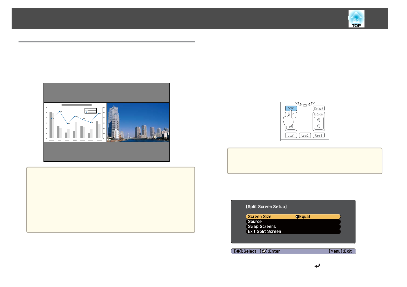
Projection Functions
91
Projecting Two Images Simultaneously (Split Screen)
You can simultaneously project images from two sources on the right and
left of the screen.
• The following input source combinations cannot be projected using
a
the split screen function.
Computer and BNC
S-Video and Video
HDMI and HDBaseT
DVI-D and HDMI
DVI-D and HDBaseT
• You cannot project the same input source on both sides (left and
right) of the screen.
Operating procedures
Projecting on a split screen
a
b
Press the [Split] button on the remote control while projecting.
The currently selected input source is projected on the left of the
screen.
You can also perform the same operations in the Configuration
a
Press the [Menu] button.
The Split Screen Setup screen is displayed.
menu.
s Settings - Split Screen p.121
Remote control
c
Select Source, and then press the [ ] button.
Page 92

Projection Functions
92
d
e
Select each input source for Left and Right.
You can perform the same operations using the following
a
Select Execute, and then press the [ ] button.
To switch the source during split screen projection, start the
procedure from step 2.
procedure.
s "Automatically Detect Input Signals and Change the
Projected Image (Search)" p.58
s "Switching to the Target Image" p.59
Switching the left and right screens
Use the following procedure to switch the projected images displayed on
the left and right screens.
Press the [Menu] button during split screen projection.
a
b
Select Swap Screens, and then press the [ ] button.
The projected images on the left and right are swapped.
Switching the left and right image sizes
Press the [Menu] button during split screen projection.
a
b
Select Screen Size, and then press the [ ] button.
c
Select the screen size you want to display, and then press the [ ]
button.
Page 93

Projection Functions
93
The projected images appear as shown below after setting the screen size.
Equal Larger Left
Larger Right
• You cannot enlarge both the left screen and right screen images at
a
the same time.
• When one image is enlarged, the other image is reduced.
• Depending on the image signals that are being input, the images on
the left and right may not appear to be the same size even if Equal
is set.
• Select Exit Split Screen on the Split Screen Setup screen.
s
p.91
Restrictions during split screen projection
Operating restrictions
The following operations cannot be performed during split screen
projection.
• Setting the Configuration menu
• E-Zoom
• Changing the aspect mode
• Using the [User1], [User2], or [User3] button on the remote control
• Help can be displayed only when image signals are not being input or
when an error or warning notification is displayed.
• The user's logo is not displayed.
Restrictions relating to images
• The default values for the Image menu are applied to the image on the
right screen. However, the settings for the image projected on the left
screen are applied to the image on the right screen for Color Mode,
Color Temp., and Advanced.
• The Frame Interpolation and Super-resolution settings in the Signal
menu are applied to the image projected on the left screen.
• Auto Iris is not available.
s
Image - Auto Iris p.117
Ending split screen
Press the [Esc] button to end split screen.
The following steps can also be used to end split screen.
• Press the [Split] button on the remote control.
Page 94

Projection Functions
94
Hiding the Image Temporarily (Shutter)
You can switch off the image on the screen when you want to focus the
audience's attention on what you are saying, or when you do not want to
display operations such as changing files.
Each time you press the [Shutter] button, the shutter function turns on or
off.
Remote control
a
• When the shutter function is activated and no operations are
performed for about 120 minutes, the projector turns off
automatically. If you do not want to turn off the power, set Shutter
Timer to Off.
s Extended - Operation - Shutter Timer p.122
• If you press the [t] button while the shutter is closed, the shutter is
automatically released and a message requesting confirmation to turn
off the power is displayed on the screen.
• The Lamp1 and Lamp2 indicators flash while the shutter function is
activated.
• When an event that is set in the schedule function is executed, the
shutter function is released.
• When Shutter Release is set to Shutter in the Extended menu, the
following operations can be performed while the shutter function is
still being activated.
- Change the source with the change input buttons on the remote
control.
- Control the projector from a computer using communication
commands.
s Extended - Operation - Advanced - Shutter Release p.122
The shutter function is only released by pressing the [Shutter]
button, or by sending a command to release the shutter function.
• When projecting moving images, the images continue to be played
back while the shutter function is activated. It is not possible to
resume projection from the point where the shutter function was
activated.
• The lamp is still lit while the shutter function is activated, so the
lamp hours continue to accumulate.
Page 95

Projection Functions
95
Freezing the Image (Freeze)
When Freeze is activated on moving images, the frozen image continues to
project on the screen, so you can project a moving image one frame at a
time like a still photo. Also, you can perform operations such as changing
between files during presentations from a computer without projecting any
images if the Freeze function is activated beforehand.
Each time you press the [Freeze] button, the Freeze function turns on or
off.
Remote control
• When projecting moving images, the images continue to be played
a
back while the screen is frozen. It is not possible to resume
projection from the point where the screen was frozen.
• If the [Freeze] button is pressed while the Configuration menu or
the Help screen is displayed, the menu or the Help screen that is
displayed is closed.
• Freeze still works while E-Zoom is being used.
Enlarging Part of the Image (E-Zoom)
This is useful when you want to expand images to see them in greater
detail, such as graphs and tables.
Start E-Zoom.
a
z
Press the [
] button to display the target scope ( ).
Remote control
Page 96

Projection Functions
96
b
c
Move the target scope ( ) to the area of the image that you
want to enlarge.
Remote control
Enlarge.
Remote control
[z] button: Expands the area each time
it is pressed. You can expand quickly by
holding the button down.
[x] button: Reduces images that have
been enlarged.
[Esc] button: Cancels E-Zoom.
• During enlarged projection, press the [ ][ ][ ][ ]
a
buttons to scroll the image.
• E-Zoom is unavailable when Scale is set to On.
s Signal - Scale p.119
Saving a User's Logo
You can save the image that is currently being projected as a User's Logo.
Once a User's Logo has been saved, the logo cannot be returned to the
a
a
factory default.
Project the image you want to save as the User's Logo, and then
press the [Menu] button.
s
"Using the Configuration Menu" p.114
Select User's Logo from Extended.
b
• When User's Logo Protection from Password Protection is
set to On, a message is displayed and the User's Logo cannot
be changed. You can make changes after setting User's Logo
Protection to Off.
s "Managing Users (Password Protection)" p.107
• If User's Logo is selected when Geometric Correction, E-
Zoom or Aspect are being performed, the function currently
being performed is temporarily canceled.
c
a
When the message "Choose this image as the User's Logo?" is
displayed, select Yes.
a
When you press the [ ] button, the screen size may change
depending on the signal to match the actual resolution of the
image signal.
Page 97

Projection Functions
97
d
e
f
Move the box to select the part of the image to use as the User's
Logo.
You can perform the same operations from the projector's control
panel.
Remote control
You can save at 400x300 dots in size.
a
When you press the [ ] button and the message "Select this
image?" is displayed, select Yes.
Select the zoom factor from the zoom setting screen.
g
When the message "Save this image as the User's Logo?" is
displayed, select Yes.
The image is saved. After the image has been saved, the message
"Completed." is displayed.
When a User's Logo is saved, the previous User's Logo is
a
erased.
Page 98
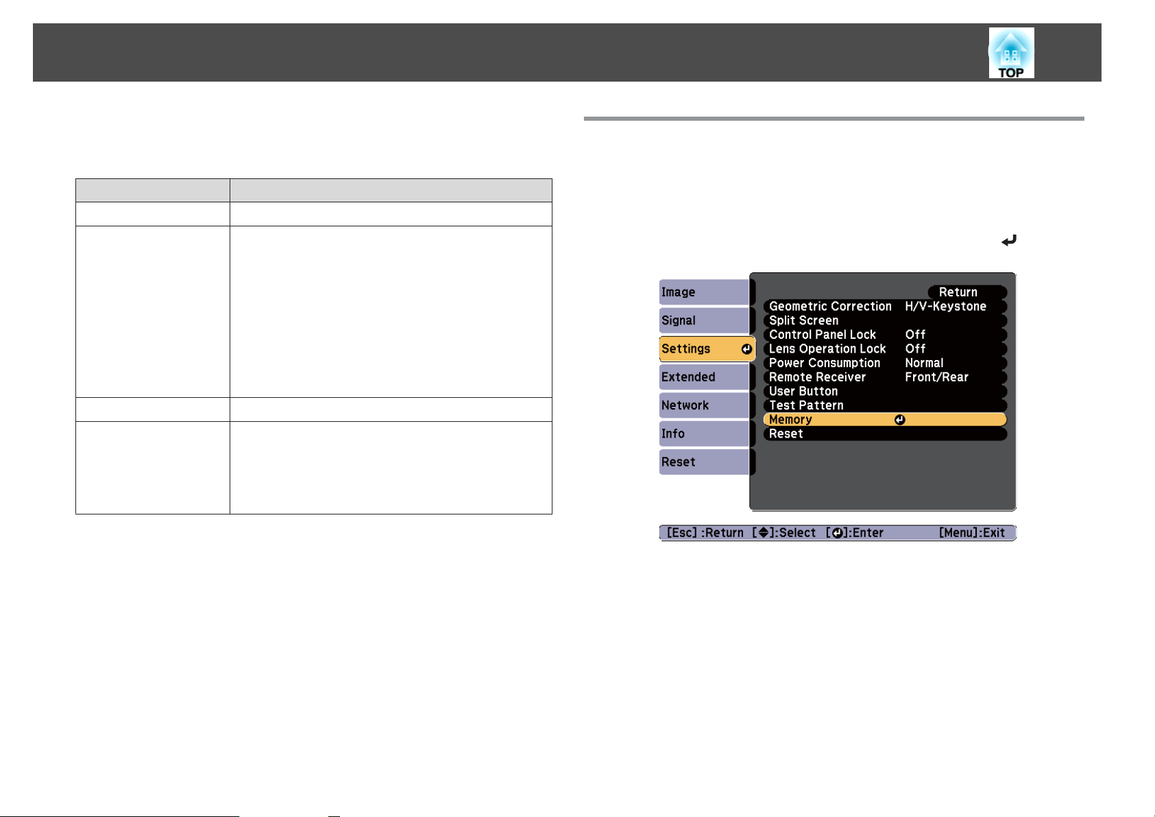
Memory Function
98
The settings for the image currently displayed are saved as a memory,
allowing you to load them when necessary. Settings for the following menu
items are saved in the memory.
Top Menu Submenu
Image
Signal
Settings
Extended
All setting items
Progressive
Frame Interpolation
Noise Reduction
Mosquito NR
Video Range
Scale
Overscan
Image Processing
3D Images
Super-resolution
Power Consumption
Multi-Projection
- Brightness Level
- Edge Blending
- Color Matching
- Black Level
Saving/Loading/Erasing the Memory
a
Press the [Menu] button while an image is being displayed.
s
"Using the Configuration Menu" p.114
Select Memory from Settings, and then press the [ ] button.
b
Page 99
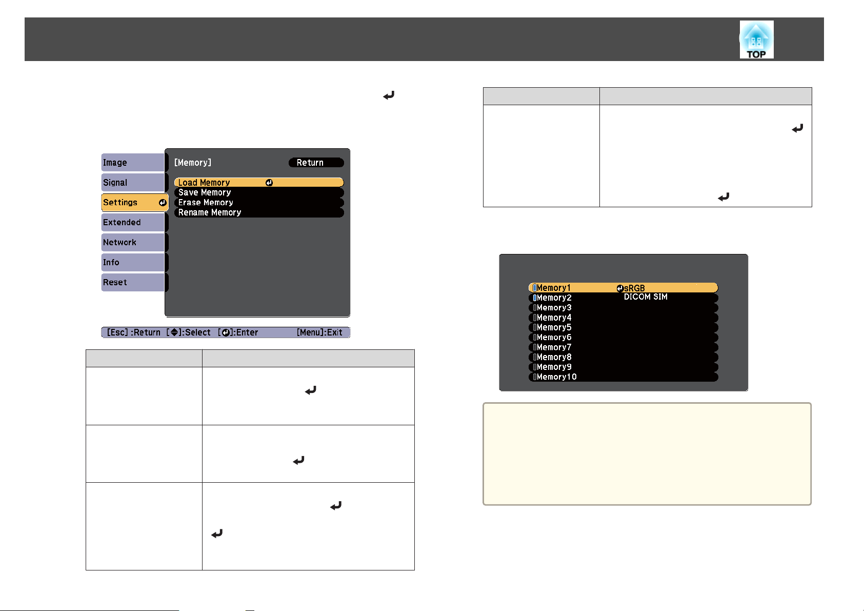
Memory Function
99
c
Select the function you want to perform, then press the [ ]
button.
You can only perform Load Memory and Save Memory when an
image is displayed.
Function Explanation
Load Memory
Save Memory
Erase Memory
Loads the saved memory. When you select a
memory and press the [
applied to the current image are replaced with the
settings from the memory.
The settings for the image currently displayed are
saved as a memory. When you select a memory
name and press the [
saved.
Erases the registered memory. When you select a
memory name and press the [
message is displayed. Select Yes, and then press the
[
] button to erase the selected memory. You can
erase all memories from Reset Memory.
s Reset - Reset Memory p.138
] button, the settings
] button, the settings are
] button, a
Function Explanation
Rename Memory
Changes the memory name. Select the memory
name you want to change, and then press the [
button. Enter the memory name using the soft
keyboard.
s "Soft keyboard operations" p.128
When you have finished, move the cursor over
Finish, and then press the [
] button.
When a memory has already been saved, the memory name and its
color mode are displayed.
• You can register up to ten types of memory.
a
• If the mark on the left of the memory name is turned blue, it
means the memory has already been registered. When you
select a registered memory, a message is displayed asking you
to confirm if you want to overwrite the memory. If you select
Yes, the previous settings are deleted and the current settings
are registered.
]
Page 100
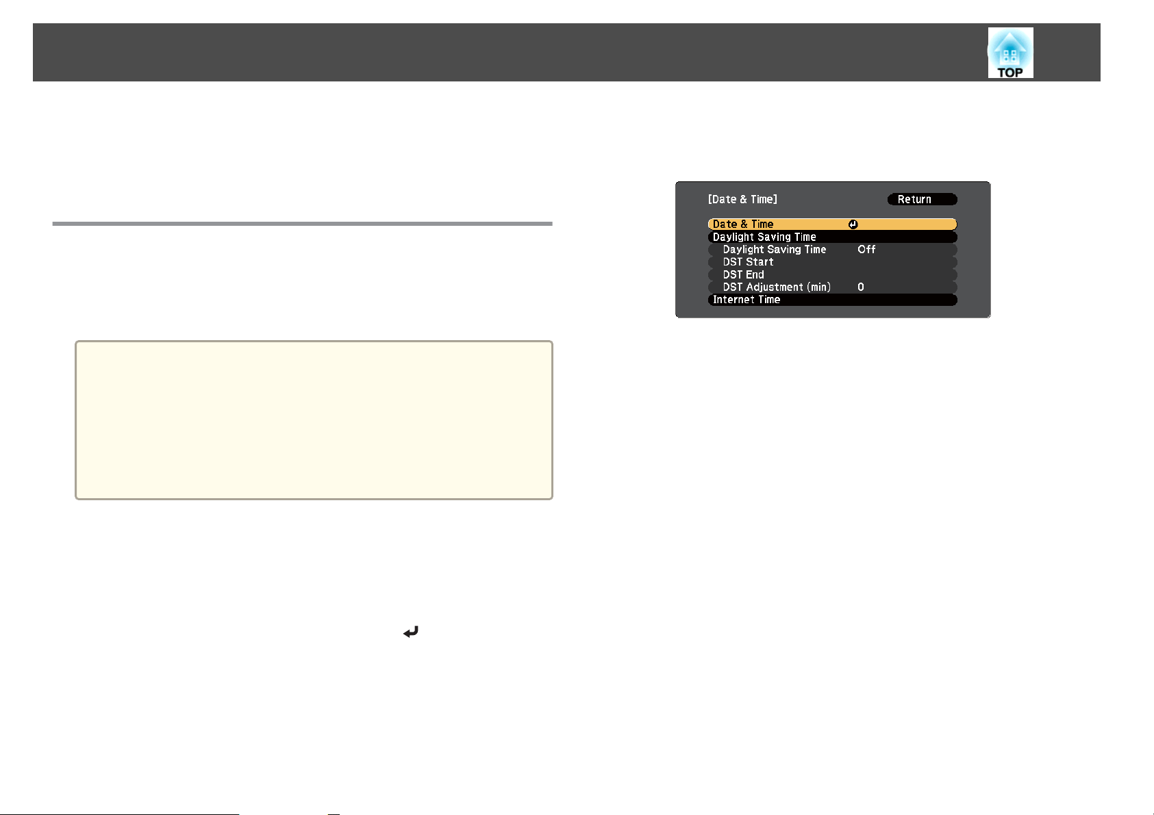
Scheduling Function
100
You can schedule turning the projector power on/off and switching the
input source, as events in the schedule. Registered events are executed
automatically at the specified time on the specified dates or weekly. You can
register up to 30 events.
Setting the Time
You can set the time for the projector. The set time is used for the schedule
function.
s
"Saving a Schedule" p.101
• When you turn on the projector for the first time, the message "Do
a
you want to set the time?" is displayed. When you select Yes, the
screen from step 4 is displayed.
• When Time/Schedule Protection is set to On in Password
Protection, settings related to the date and time cannot be changed.
You can make changes after setting Time/Schedule Protection to
Off.
s "Managing Users (Password Protection)" p.107
d
Make settings for the date and time.
Use the soft keyboard to enter the date and time.
s
"Soft keyboard operations" p.128
a
b
c
Press the [Menu] button while projecting.
s
"Using the Configuration Menu" p.114
Select Operation from Extended.
Select Date & Time, and then press the [ ] button.
 Loading...