

Installation Guide

About This Installation Guide
Warning
Caution
Warning
This guide describes how to mount the ultra-short-throw projectors listed below to a wall using the Epson®
ELPMB62 wall mount.
The following projectors are covered by this guide:
• BrightLink® 1480Fi/1480Fi+
• BrightLink® 1485Fi/1485Fi+
• BrightLink® EB-725Wi/EB-735Fi
• PowerLite® EB-720/EB-725W
• PowerLite® EB-750F/EB-755F
• PowerLite® EB-800F/EB-805F
The BrightLink 1480Fi/1480Fi+/1485Fi/1485Fi+ is shown in most illustrations in this guide, but the steps are
the same for all models unless otherwise noted.
Safety Instructions
For your safety, read all the instructions in this guide before using the wall mount. Incorrect handling that
ignores instructions in this guide could damage the wall mount or could result in personal injury or property
damage. Keep this installation guide on hand for future reference.
Read the safety instructions in the online User's Guide for your projector and follow the instructions in this
document.
Explanation of Symbols
The warning marks shown below are used throughout this installation guide to prevent personal injury or
property damage. Make sure you understand these warnings when reading this installation guide.
This symbol indicates information that, if ignored, could possibly result in personal injury or even death
due to incorrect handling.
This symbol indicates information that, if ignored, could possibly result in personal injury or physical
damage due to incorrect handling.
This symbol indicates related or useful information.
Symbol indicating an action that must not be done
Symbol indicating an action that should be done
Safety Precautions for Installation
The wall mount is designed specifically for mounting a projector to a wall. If anything other than a
projector is mounted, the weight may result in damage.
If the wall mount falls, it could cause personal injury or property damage.
The installation work (wall mounting) should be performed by specialists who have technical knowledge
and ability. Incomplete or incorrect installation could cause the wall mount to fall and cause personal
injury or property damage.
2
Follow the steps in this guide to install the wall mount, and be sure to use the bolts and screws specified in
Warning
this guide
If the instructions are not followed, this product may fall, resulting in personal injury or an accident.
Handle the power cord carefully.
Incorrect handling may cause fire or electric shock. Observe the following precautions when handling:
• Do not handle the power plug with wet hands.
• Do not use a power cord that is damaged or modified.
• Do not pull the power cord with too much force when routing the cable through the wall mount.
Do not install the wall mount in a place where it might be subjected to vibration or shock.
Vibration or shock could cause damage to the projector or mounting surface. It could also cause the wall mount or
projector to fall and cause personal injury or property damage.
The installation work should be performed by at least two qualified service personnel. If you need to
loosen any screws during installation, be careful not to drop the wall mount.
If the wall mount or projector falls, it could cause personal injury or property damage.
Make sure you use the included safety wire kit when mounting your projector.
Install the wall mount so that it can sufficiently support the weight of the projector and wall mount, and
resist any horizontal vibration. Use M10 or 3/8 inch nuts and bolts and make sure to use appropriate wall
anchors for your wall type.
Nuts and bolts smaller than M10 or 3/8 inch could cause the wall mount to fall. Epson accepts no responsibility for
any damage or injury caused by lack of wall strength or inadequate installation.
When you mount the projector on the wall with the wall mount, the wa ll must be strong enough to hold the
projector and the wall mount.
The maximum combined weight of the projector and wall mount is approximately 41.7 lb (18.9 kg). If the
wall is not strong enough, reinforce the wall before installation.
The installation work should be performed by at least two qualified service personnel. If you need to
loosen any screws during installation, be careful not to drop this product.
If this product falls, it could cause damage or injury.
Inspect the wall mount on a regular basis to ensure there are no broken parts or loose screws.
If there are any broken parts, stop using the wall mount immediately. If the wall mount or projector falls, it could
cause personal injury or property damage.
Never modify the wall mount.
English
Do not hang on the wall mount or hang a heavy object on the wall mount.
If the projector or wall mount falls, it could cause personal injury or property damage.
Do not use adhesives, lubricants, or oils to install or adjust the wall mount.
If you use adhesives to prevent the screws from loosening or things such as lubricants or oils on the part of the
projector attached to the slide plate, the case may crack and cause the projector to fall, resulting in personal injury
or property damage.
Tighten all screws firmly after adjustment.
Otherwise, the projector or wall mount may fall and cause personal injury or property damage.
Never loosen the bolts and nuts after installation.
Confirm that the screws have not become loose on a regular basis. If you find any loose screws, tighten them
firmly. Otherwise, the projector or wall mount may fall and cause personal injury or property damage.
When performing wiring, make sure the cable does not come into contact with any screws or bolts.
Handling the cable incorrectly may cause fire or electric shock.
Do not install in a location subject to oily smoke or smoke for events.
If oils stick to the slide plate fixing part of the projector, the case may crack and cause the projector to fall, resulting
in personal injury or property damage.
3
Follow the instructions in this guide to install and operate the touch unit.
Warning
Caution
If the touch unit is not installed and operated properly, the light emitted from the laser could cause injury to
eyesight.
Never modify the control pad or touch unit.
When performing wiring, make sure the cable does not come into contact with any screws or bolts.
Handling the cable incorrectly may cause fire or electric shock.
Do not apply optical devices such as a magnifying glass or telescope to the laser light diffused from the
touch unit.
If such optical devices are applied, it could cause personal injury or fire.
Do not look into the touch unit’s laser diffusion ports.
This could cause injury to eyesight. Extra care should be taken when children are present.
Do not view the laser light using optical devices such as a magnifying glass within a range of 2.75 inches
(70 mm).
Viewing at close range could cause injury to eyesight.
Connect the touch unit to BrightLink 1480Fi/1480Fi+/1485Fi/1485Fi+/EB-725Wi/EB-735Fi models only. Do
not connect it to any other projectors or devices.
Do not use the touch unit if you are using or are near medical equipment such as a pacemaker.
The magnet within the touch unit generates electromagnetic interference which could cause medical equipment
to malfunction.
Do not install the wall mount in a location where the operating temperature for your projector model may
be exceeded. Such an environment may damage the projector.
Install the wall mount in a place free from excessive dust and humidity to prevent the lens or optical
components from becoming dirty.
Do not use excessive force when adjusting the wall mount.
The wall mount may break, resulting in personal injury.
Keep magnetic storage media (for example, magnetic cards or electronic devices such as computers,
digital watches, or cell phones) away from the touch unit.
The magnet within the touch unit generates electromagnetic interference which could corrupt data or cause the
media or device to malfunction.
4
Installation Location
47.2 inches (120 cm)
15.7 inches (400 mm)
7.9 inches (200 mm)
• Before installing the projector, verify the power supply wiring for the installation location.
• If you want to hide the projector power plug under the wall plate cover, make sure the power outlet is
located in the empty space to the left or right of the wall plate.
• Install the projector away from other electric devices such as fluorescent lights or air conditioners. Some
kinds of fluorescent lights could interfere with the remote control of the projector.
• Install the projector away from direct sunlight and other bright light sources.
• Make sure there is at least 20 inches (50 cm) of space between the wall and the projector’s air exhaust and
intake vents on the left and right.
• It is recommended to keep VGA computer cable length less than 65 feet (20 meters) to reduce external
noise.
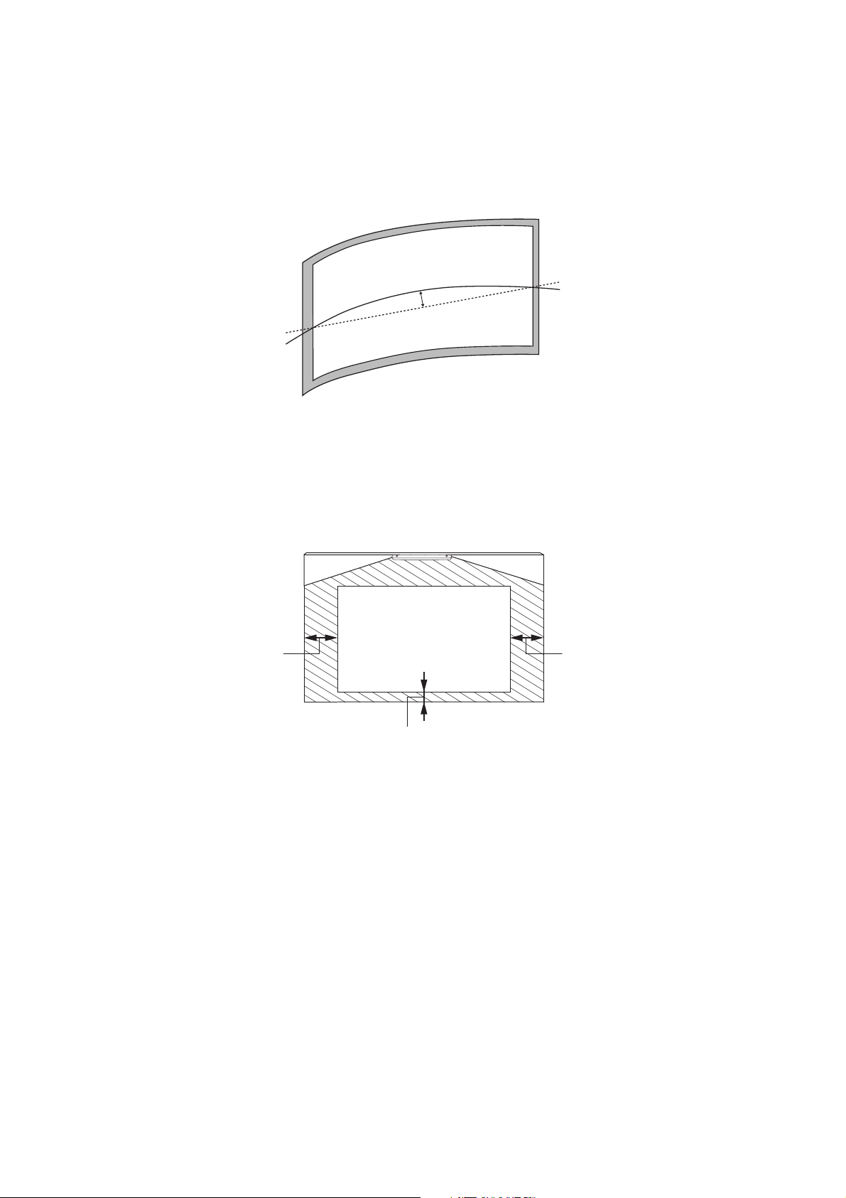
• Install the projector at an angle of no more than 3° horizontally or vertically in relation to the projection
surface.
• Install the projector in a location where the projected image is within reach.
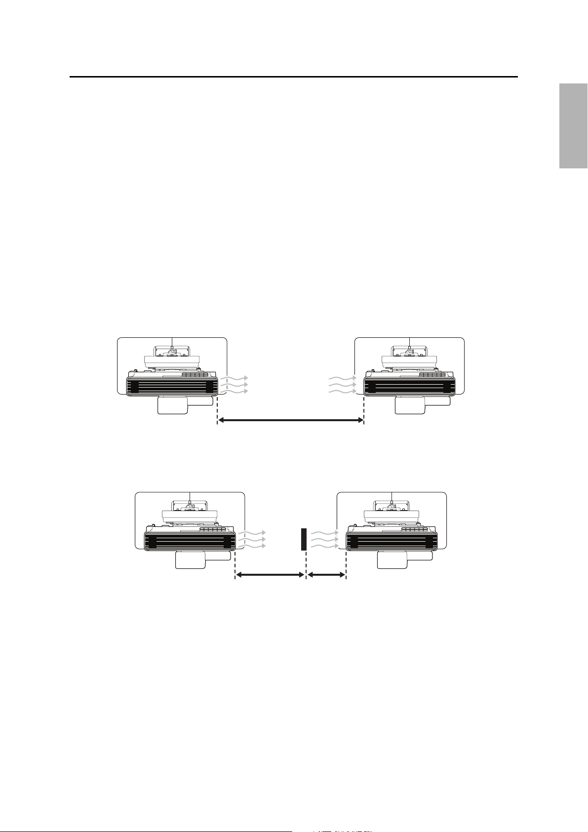
• When installing two or more projectors, check the following:
• Make sure the temperature of the surrounding environment is less than 95°F (35°C). If the
environment is too hot, the projectors may overheat and the power may turn off without warning.
• Make sure you leave a gap of at least 47.2 inches (120 cm) between the projectors.
English
If the projectors are installed closer than 47.2 inches (120 cm) apart, install a partition to block the
heat from the projector’s exhaust vent. The partitions should be larger than the exhaust vent and
installed approximately 15.7 inches (400 mm) from the exhaust vent and 7.9 inches (200 mm) from
the intake vents.
5
• Before installing the touch unit (included with the BrightLink 1485Fi/1485Fi+; available as an optional
0.2 in. (5 mm)
0.8 in. (20 mm)
4.0 in. (100 mm)4.0 in. (100 mm)
accessory for the BrightLink 1480Fi/1480Fi+/EB-725Wi/EB-735Fi), verify that the installation location
meets the following conditions:
• The touch unit can be secured to the surface with magnets or screws, or the optional touch unit
bracket.
• The surface is flat, smooth, and unwarped with no more than 0.2 inch (5 mm) of unevenness in any
direction on the screen surface.
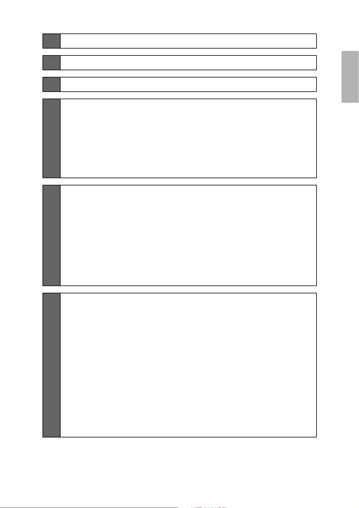
• When installing the touch unit (included with the BrightLink 1485Fi/1485Fi+; available as an optional
accessory for the BrightLink 1480Fi/1480Fi+/EB-725Wi/EB-735Fi) within the frame of the whiteboard,
secure the touch unit with magnets or screws. Make sure there are no obstacles, such as cables, or
protruding objects such as whiteboard trays, pen holders, or thick frames in the shaded areas in the
following figure. The touch unit will not operate correctly if anything is obstructing the infrared signal. If
there is an obstacle that cannot be removed, you can use the supplied infrared deflectors to prevent laser
detection issues.
• When installing the touch unit (included with the BrightLink 1485Fi/1485Fi+; available as an optional
accessory for the BrightLink 1480Fi/1480Fi+/EB-725Wi/EB-735Fi) above the frame of a whiteboard, use the
optional touch unit bracket.
• If the distance from the wall to the surface of the whiteboard is greater than 2 inches (51 mm), you
must install the touch unit on the whiteboard.
• If the frame of the whiteboard extends more than 0.1 inch (3 mm) away from the board surface, you
must install the touch unit on the whiteboard or screen.
6
1 Package Contents
9
2 Specifications
3 Connecting Devices
4 Positioning the Projector
Installation worksheet for projecting on a pre-installed wall-mounted board
Installation worksheet for projecting on a plain wall
Projection distance worksheets
Diagonal image size and mounting position
Distance from top of projected image to wall plate
Installation measurement tables
5 Installing the Projector
Assemble the parts
Install the wall plate on the wall
Determine the projection distance and pull out the mount arm slider
Route the cables through the wall mount arm
Attach the mount arm to the wall plate
Adjust the vertical slide position of the arm
Attach the projector to the wall mount
Connect the power cord and other cables to the projector
13
19
21
22
24
25
26
27
27
43
43
45
48
49
49
51
52
53
English
6 Adjusting the Image
Turn on the projector
Select the screen type
Adjust the focus
Display the test pattern
Use adjustment dial 1 on the left side to adjust the horizontal roll
Use adjustment dial 2 on the top to adjust the horizontal rotation
Use adjustment dial 3 on the front to adjust the vertical tilt
Adjust the horizontal slide
Adjust the forward/backward slide
Adjust the vertical slide
Re-adjust the focus
Turn off the display of the test pattern
56
56
57
56
58
59
60
60
61
61
62
63
63
7
7 Attaching the Covers
Attach the wall plate cover and end cap
Attach the cable cover to the projector (BrightLink 1480Fi/1480Fi+/1485Fi/
1485Fi+ and PowerLite EB-800F/EB-805F only)
64
64
65
8 Installing the Touch Unit
Installing the touch unit on a whiteboard
Install infrared deflectors along any obstacles
Display the installation pattern
Determine the installation position for the touch unit
Install the touch unit
Turn on the touch unit
Adjust the angle
Installing the touch unit above a whiteboard
Install infrared deflectors along any obstacles
Turn on the projector
Display the installation pattern
Determine the installation position for the bracket
Drill holes for the bracket
Install the bracket
Turn on the touch unit
Adjust the angle
67
68
68
69
70
72
74
76
80
80
81
81
82
83
83
85
87
9 Installing the HDBaseT Control Pad and Pen Stand
Check the installation location
Installing the HDBaseT Control Pad
Remove the front cover
Connect the power cable
Attach the control pad
Secure the AC adapter
Connect the projector cables to the control pad
Attach the front cover
Installing the pen stand
10 Appendix
Using the Easy Interactive Function
Using Auto Screen Adjustment
Making Additional Screen Adjustments
Attaching a Security Cable
92
92
92
93
94
93
94
94
95
95
97
97
97
100
105
8
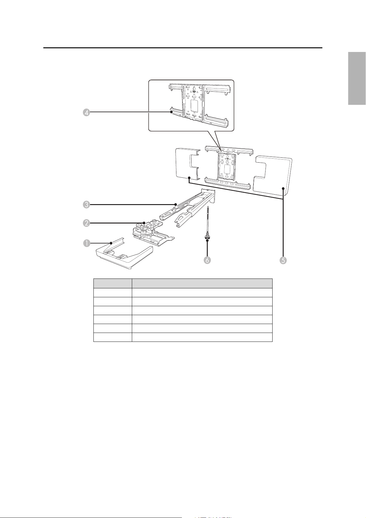
1 Package Contents
Wall Mount
English
# Part name
1End cap
2 3-axis adjustment unit and slide plate (attached when shipped)
3 Wall mount
4 Wall plate
5 Wall plate cover
6 Hexagonal shaft
9
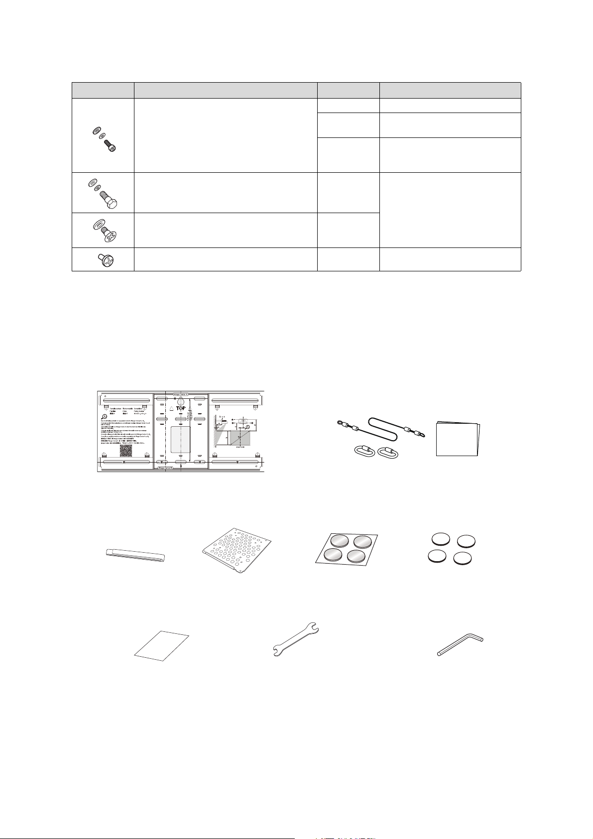
Hardware
Hexagon wrench (for M4)
Template sheet
(for installing the wall plate)
Open-ended wrench
13 mm (for M8 and M6) × 6 mm
(for hexagonal shaft)
Masking sticker
Mini PC plate
Mini PC band
Safety wire installation kit (for
securing the projector)
Corner markers*
Magnets for corner markers*
Shape Name Quantity Application
M4 × 12 mm hexagon socket head cap bolt with
washer/spring washer
5 For wall plate assembly
4 For 3-axis adjustment unit/wall mount
installation
4 For slide plate/projector installation
M6 × 20 mm hexagon shoulder head bolt with
washer/spring washer
M6 × 20 mm cross recessed head shoulder screw
with plastic washer
M3 × 6 mm cross recessed head shoulder screws 4
1 For wall mount/wall plate installation
3
For Mini PC plate installation
• Use the bolts or screws supplied with the wall mount to install it as directed in this guide. Do not
substitute these bolts with any other types.
• You need to use commercially available M10 × 60 mm or 3/8 inch anchors (at least 4) and one M10 screw
to attach the wall plate to the wall.
• Gather the tools and parts you need before you begin installation, including a #3 cross-head screwdriver.
Accessories
*Included with the BrightLink 1480Fi/1480Fi+/1485Fi/1485Fi+/EB-725Wi/EB-735Fi projectors.
10
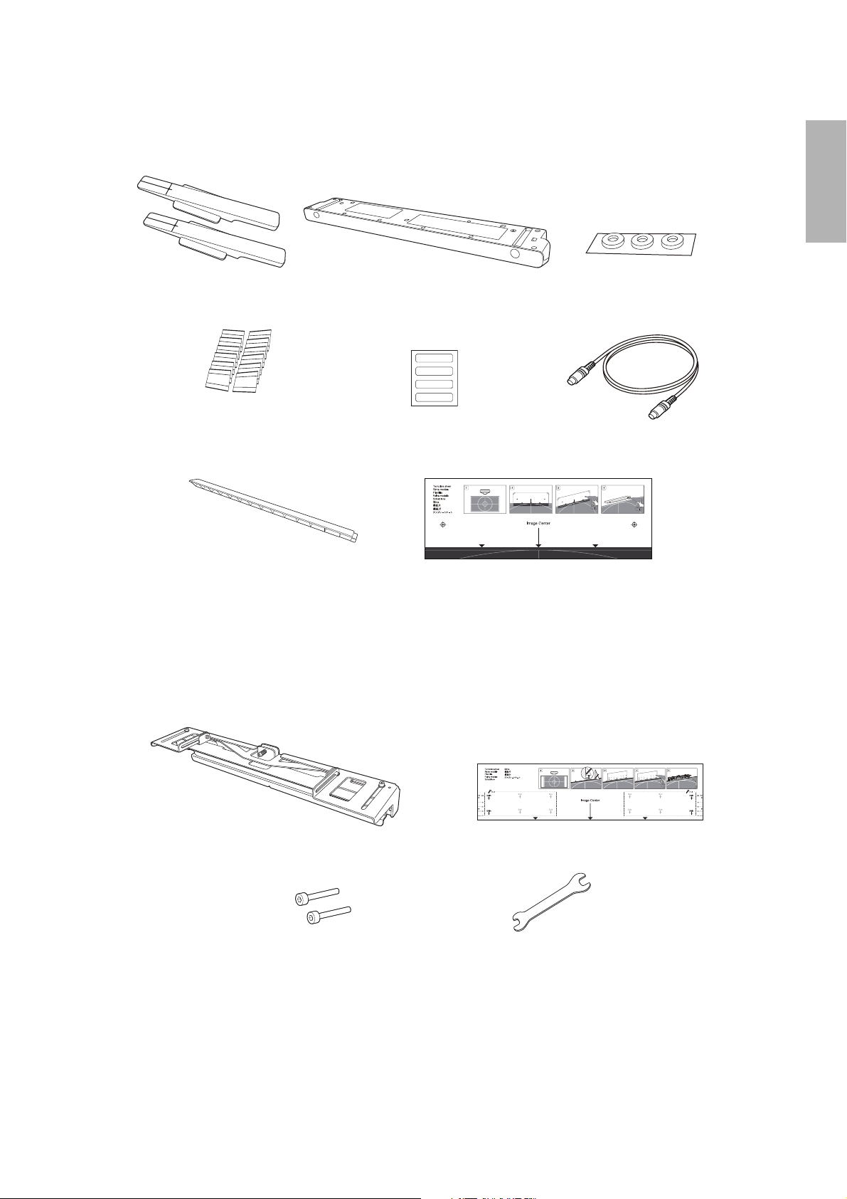
Touch unit (included with BrightLink 1485Fi/1485Fi+)
Tap e (a ppr ox. 2. 4 in che s
[6 cm]) for securing the
markers (×12)
Label (×4)
Touch unit
Touch unit connection cable
Infrared deflector (approx.
11.2 inches [28.5 cm]) (×12)
Spacer for screw holes (×3)
Marker (x2)
Touch unit template sheet
Touch unit bracket
M4 × 25 mm hexagon
socket head cap bolt (×2)
Bracket template sheet
Hexagon wrench (for
M4 bolts)
The following parts are packaged with the BrightLink 1485Fi/1485Fi+ (available as an optional accessory for
the BrightLink 1480Fi/1480Fi+/EB-725Wi/EB-735Fi) and are necessary when attaching the touch unit. When
installing the touch unit on a non-magnetic screen or whiteboard, you will also need three M4 screws.
English
Optional touch unit bracket
The following parts are packaged with the optional touch unit bracket (available as an optional accessory for
BrightLink models listed in this guide) and are necessary when attaching the touch unit above the frame of a
whiteboard. When installing the bracket, you will also need four (4) M4 wood screws or M4 anchor bolts (not
included).
11
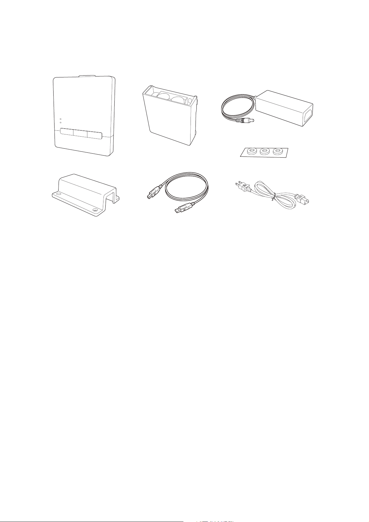
Control pad (included with BrightLink 1485Fi/1485Fi+)
Control pad
Pen stand and cover
AC adapter
AC adapter holder
USB cable
Power cable
Spacer for screw holes (×3)
The following parts are packaged with your projector (BrightLink 1485Fi/1485Fi+ only; available as an
optional accessory for the PowerLite EB-800F/EB-805F) and are necessary when attaching the control pad.
When installing the control pad on a wall, you will also need four commercially available M4 × 20 mm screws.
12
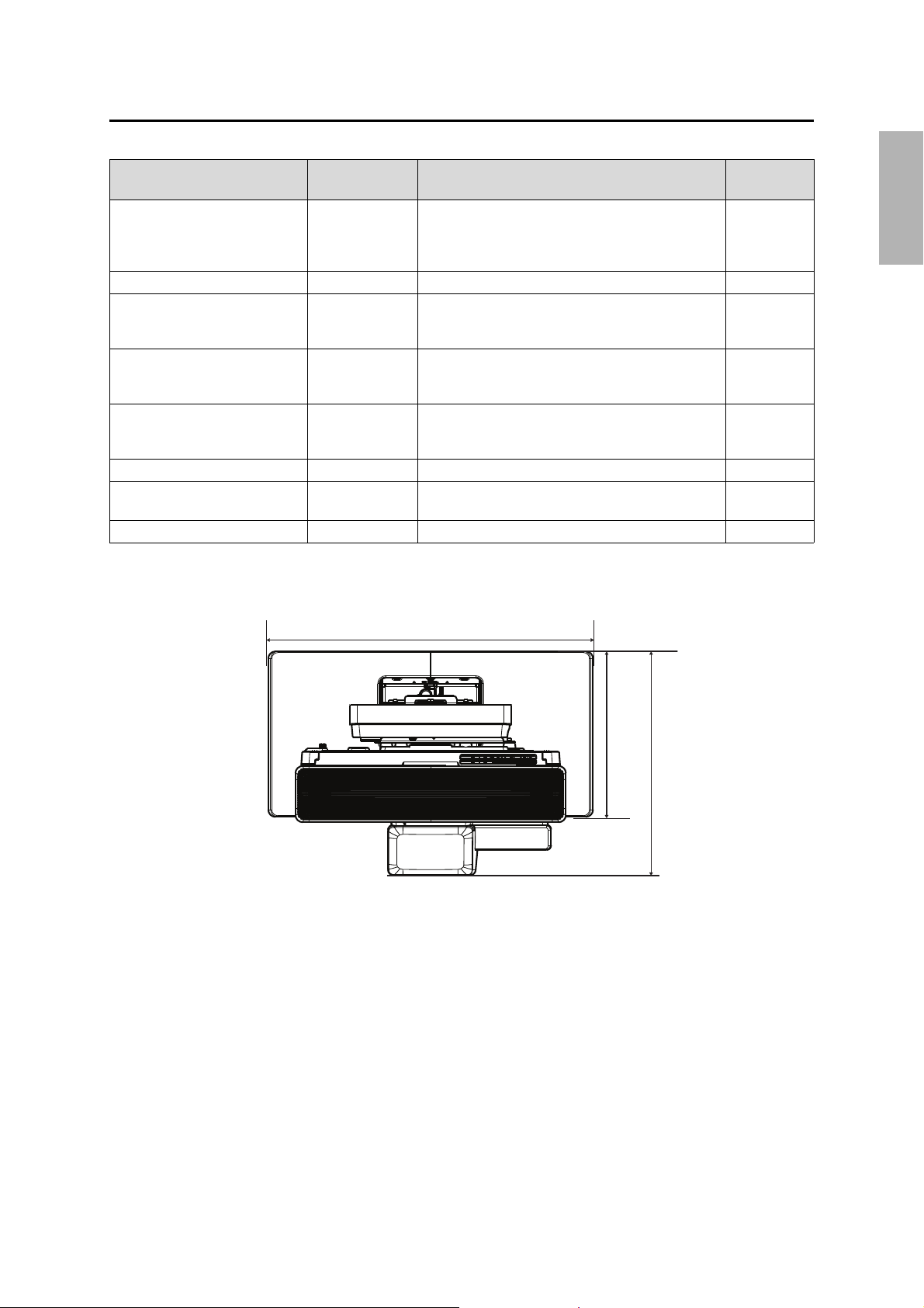
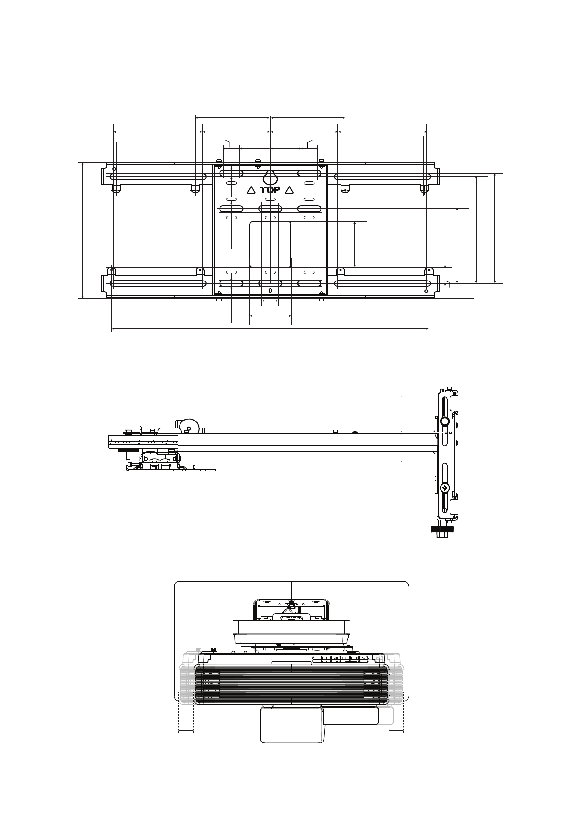
2 Specifications
11.0 in. (280 mm)
21.7 in. (550 mm)
13.3 to 16.5 in. (338.5 to 418.5 mm)
Reference
Item Specification Additional information
Wall mount weight (including the
3-axis adjustment unit, slide plate,
wall plate, wall plate cover, and
end cap)
Maximum load capacity 33.1 lb (15.0 kg) — —
Vertical slide adjustment range ±1.6 in. (40 mm) — Refer to the
Horizontal slide adjustment range ±1.8 in. (45 mm) — Refer to the
Forward/backward slide
adjustment range
Horizontal roll adjustment range ±3° Fine adjustments possible with adjustment dial
Horizontal rotation adjustment
range
Vertical tilt adjustment range ±3° Fine adjustments possible with adjustment dial
Approx. 20.3 lb
(9.2 kg)
0 to 15.1 in.
(0 to 383 mm)
±8° Fine adjustments possible with adjustment knob
——
Determine adjustment unit installation position based
on screen size
page
illustration on
page 14
illustration on
page 14
Refer to the
illustration on
page 15
s p. 59
s p. 60
s p. 60
English
Wall plate cover
13
Wall plate
19.5 in. (496 mm)
5.2 in. (131 mm)
1.1 in. (28.3 mm)
5.1 in. (130.2 mm)
7.3 in. (186.4 mm)
7.6 in. (192.2 mm)
1.8 in.
(45 mm)
1.8 in.
(45 mm)
3.9 in. (99 mm) 3.9 in. (99 mm)
5.2 in. (131 mm)
3.1 in.
(79 mm)
0.9 in. (24 mm)
2.4 in. (60 mm)
9.2 in. (234.8 mm)
0.9 in. (24 mm)
0.9 in. (24 mm)
1.6 in. (40 mm)
1.6 in. (40 mm)
1.8 in. (45 mm) 1.8 in. (45 mm)
The wall plate is in three pieces when shipped. Use the included M4 × 12 mm bolts (×5) to attach the separate
pieces together before mounting the projector. See page 43 for instructions.
Vertical slide adjustment range
Horizontal slide adjustment range
14
Forward/backward slide adjustment range
15.1 in. (383 mm)
Arm slide adjustment range
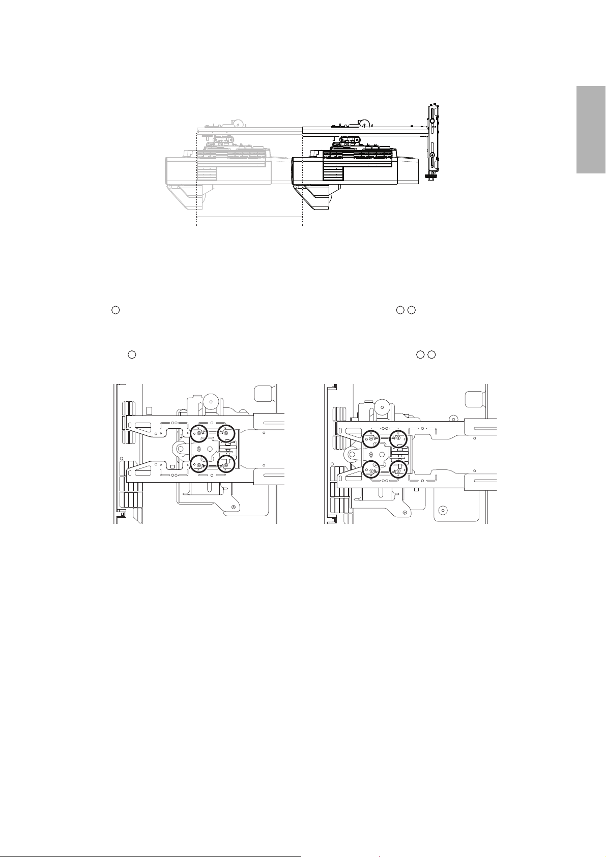
Adjustment from 3-axis adjustment unit installation position
By changing the installation position of the 3-axis adjustment unit to the front or back, you can adjust the
installation position of the projector.
• BrightLink 1480Fi/1480Fi+/1485Fi/1485Fi+ and PowerLite EB-800F/EB-805F: Mount it at the
stamp when the image is less than 80 inches diagonally, or at the stamp when the projected
image is 80 inches or more diagonally.
• BrightLink EB-725Wi/EB-735Fi and PowerLite EB-720/EB-725W/EB-750F/EB-755F: Mount it at
the stamp when the image is less than 90 inches diagonally, or at the stamp when the
projected image is 90 inches or more diagonally.
English
To see these stamps, you need to remove the two top bolts and slide out the arm extension.
15
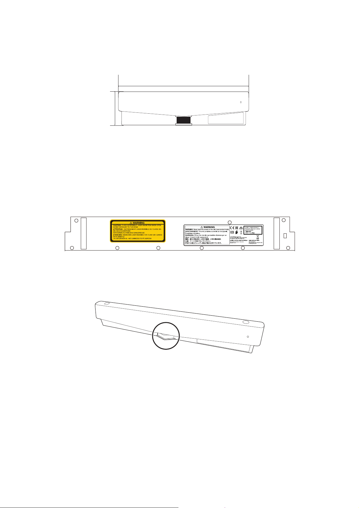
Touch unit (included with BrightLink 1485Fi/1485Fi+)
16.6 in. (422 mm)
2.6 in. (64.8 mm)
External dimensions and weight
The touch unit weighs approximately 21.2 ounces (600 g).
Attached labels
The touch unit is a Class 1 laser product that conforms to the IEC/EN60825-1:2014 standard. There are warning
labels affixed to the touch unit to indicate that it is a Class 1 laser product. The labels contain the following
information:
• Class 1 laser product
• Warning: Never open any covers on this unit. Laser product inside.
• Warning:
• Caution: Class 3B invisible laser radiation when open.
• Avoid exposure to the beam.
Laser diffusion port
The laser beam is diffused from the laser diffusion ports on the bottom of the touch unit.
• Light source output: Max. 285 W
• Wavelength: 932 to 952 nm
16
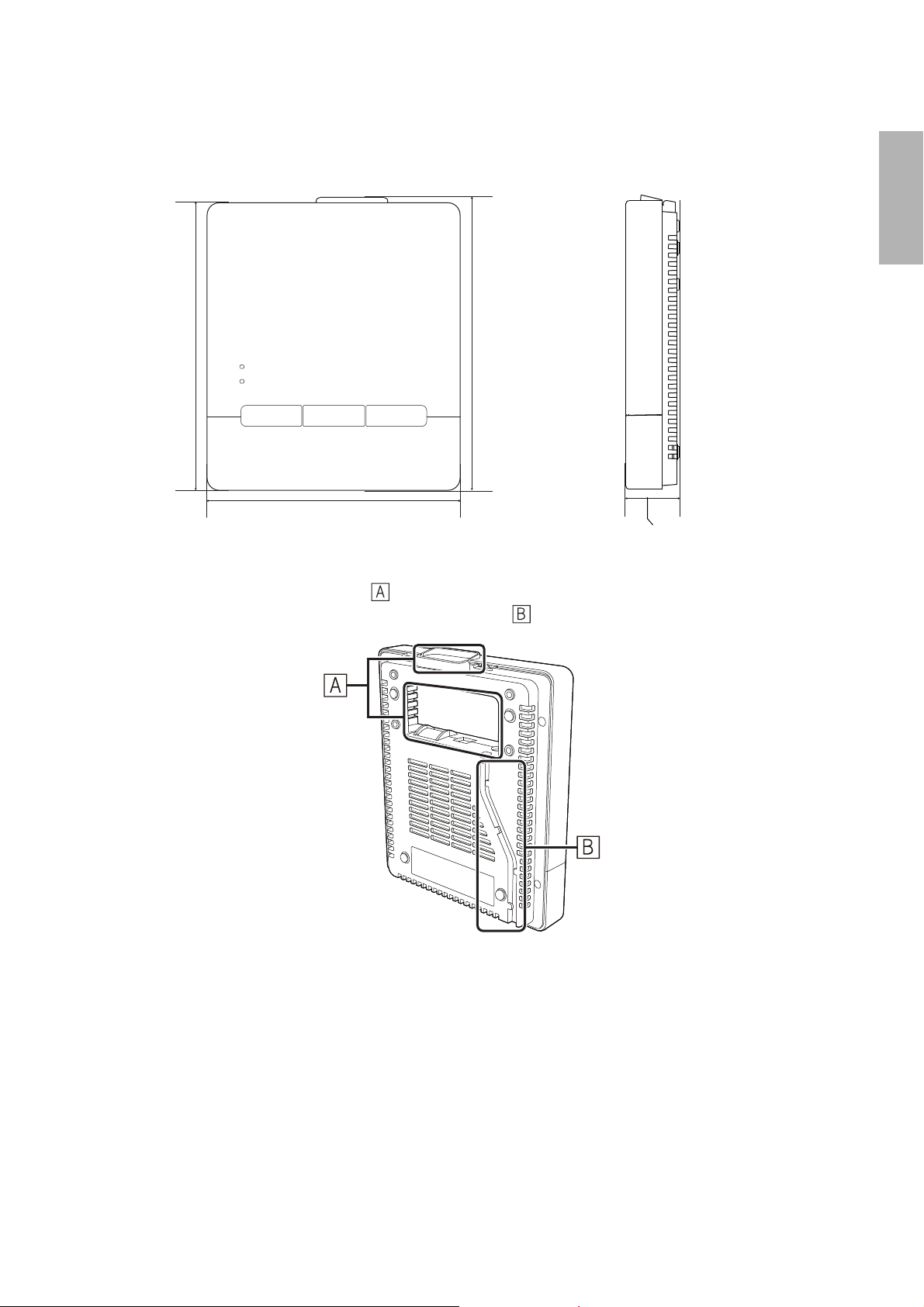
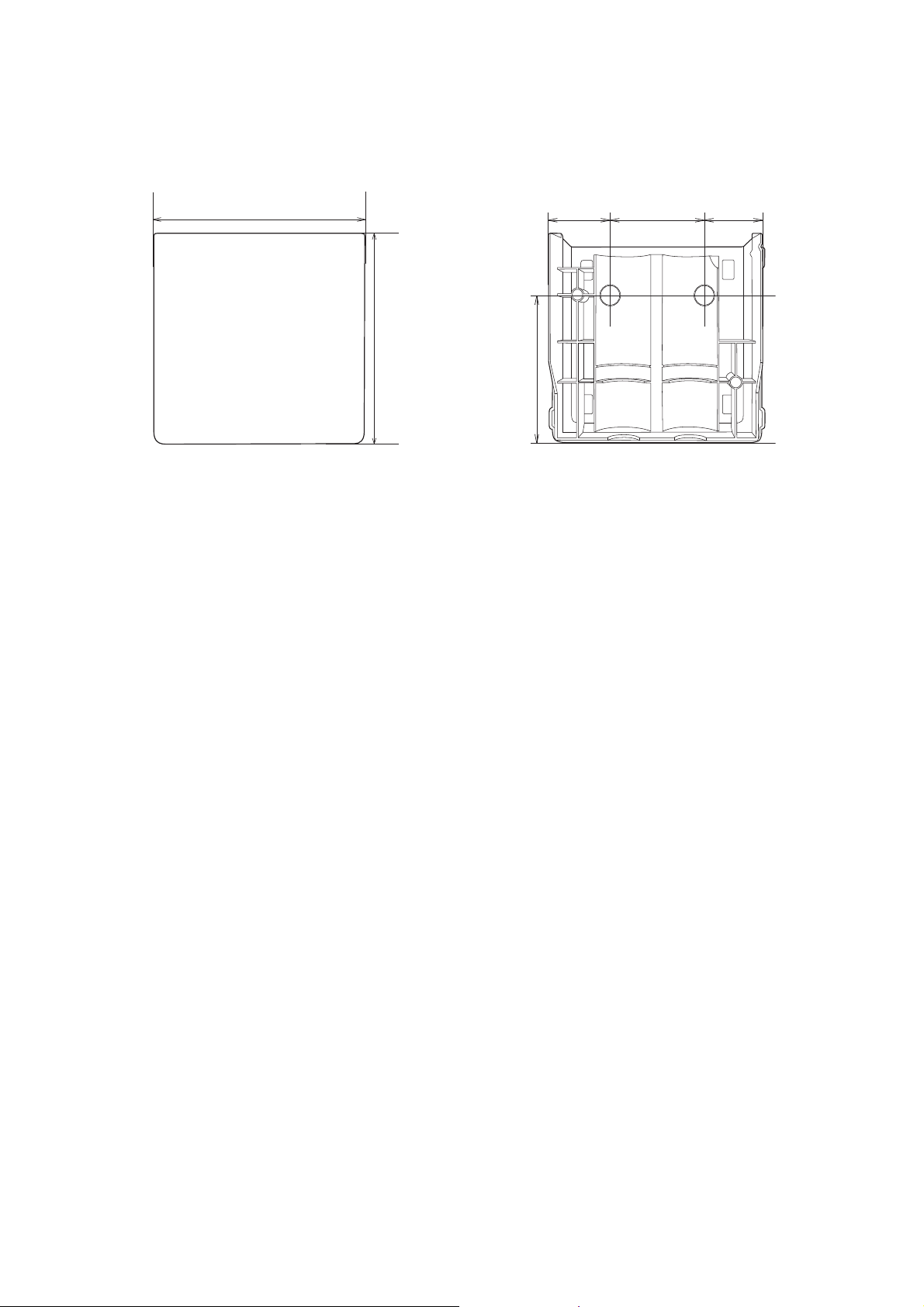
Control pad (included with BrightLink 1485Fi/1485Fi+)
6.9 in (174 mm)
7.8 in (198 mm)
7.9 in (201.8 mm)
1.4 in (36.5 mm)
External dimensions and weight
The control pad weighs approximately 22.2 ounces (630 g).
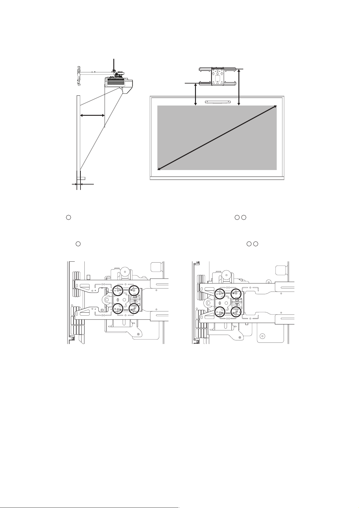
English
Cable routing holes
When routing cables, use the positions ( ) in the following figure as the cable routing holes. Route the
power cable along the groove on the back of the control pad ( ).
17
Pen stand (included with BrightLink 1485Fi/1485Fi+/EB-725Wi/EB-735Fi)
4.0 in (101.9 mm)
1.7 in
(44.4 mm)
2.8 in (70 mm)
3.9 in (99.9 mm)
1.1 in
(28.8 mm)
1.1 in
(28.8 mm)
External dimensions and weight
The pen stand weighs approximately 3.3 ounces (93 g).
18
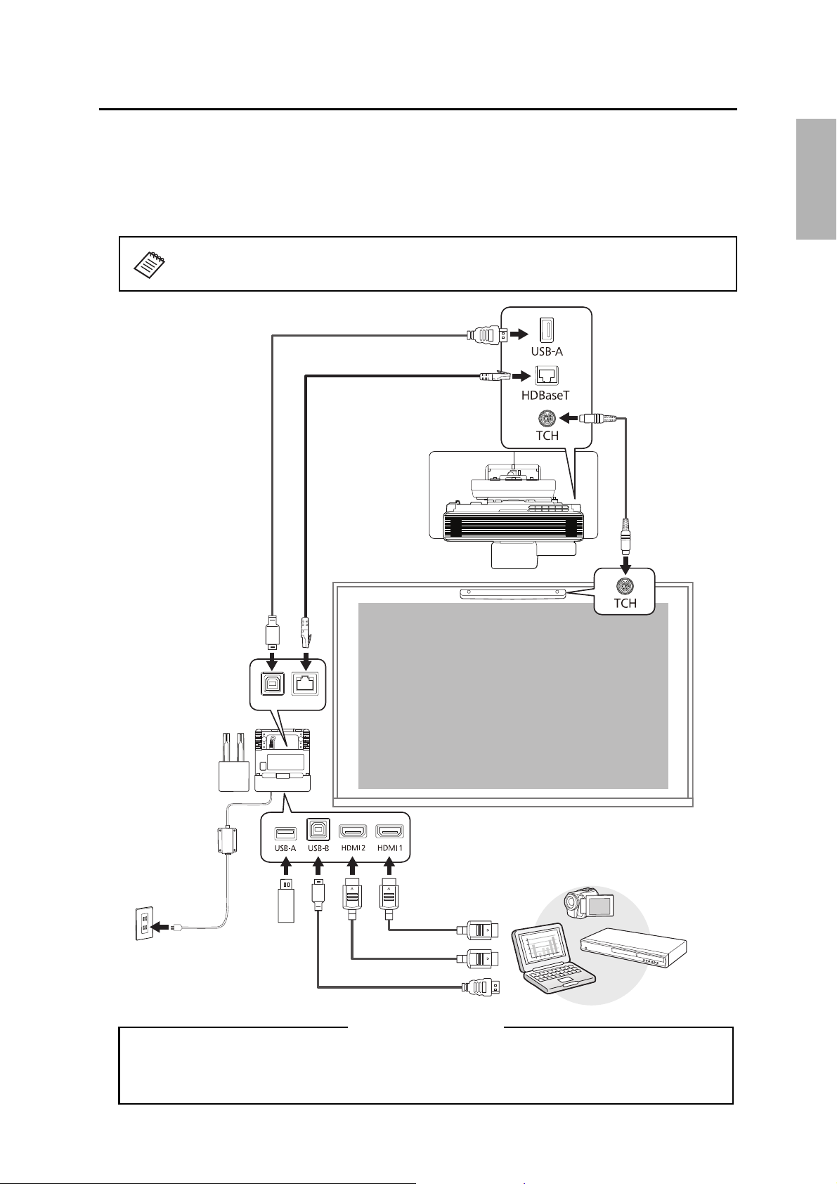
3Connecting Devices
Connection Example
(4K30p: Max 131 feet [40 m], CAT6a/CAT7)
(1080p60p: Max 230 feet [70 m], CAT6a/CAT7)
(For saving or importing content via USB drive)
When interacting with a computer, you also need a USB cable that runs from the computer to
the projector. However, when using the projector’s built-in toolbar, you do not need this USB
cable.
For Interactive Use
Make sure you have the power cord, computer cable, and other parts at the location where the wall mount is
to be installed. Make sure you also have all necessary cables for the Touch Unit (if applicable) and other
devices, such as a document camera or microphone, that you will connect to the projector. Your projector’s
connection panel may differ slightly from the model in the illustrations. For details, refer to the online User’s
Guide for your projector.
English
The connection example below shows the control pad (included with the BrightLink
1485 Fi/Fi+ only).
19

Connecting the Control Pad
The Control Pad is included with the BrightLink 1485Fi/Fi+. It provides a convenient alternative for turning on
and controlling your projector.
You must install the projector before installing the control pad. See page 92 for instructions.
20
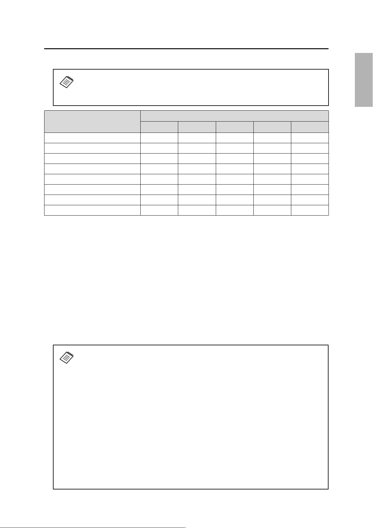
4 Positioning the Projector
Your Epson projector can project images up to the following sizes:
This guide covers select image sizes. For other image sizes, use the Throw Distance
Calculator at
www.epson.com/support (U.S.), www.epson.ca/support (Canada), or
www.latin.epson.com/support (Latin America).
English
Projector
16:10 16:9 4:3 16:6 21:9
BrightLink 1480Fi/1480Fi+ 90 inches 100 inches 80 inches Not supported 120 inches
BrightLink 1485Fi/1485Fi+ 90 inches 100 inches 80 inches 120 inches 120 inches
BrightLink EB-725Wi 100 inches 100 inches 100 inches Not supported Not supported
BrightLink EB-735Fi 100 inches 100 inches 98 inches 110 inches Not supported
PowerLite EB-720 103 inches 101 inches 110 inches Not supported Not supported
PowerLite EB-725W 120 inches 116 inches 106 inches Not supported Not supported
PowerLite EB-750F/EB-755F 110 inches 120 inches 98 inches 110 inches Not supported
PowerLite EB-800F/EB-805F 90 inches 130 inches 80 inches 120 inches 120 inches
You can project onto a pre-installed whiteboard or directly onto a plain wall.
The height of the included wall mount determines the maximum image size and how high the image appears
on the wall or whiteboard. The distance of the projector from the wall (once it is mounted on the adjustable
arm of the wall mount) also affects image size and position.
If you want to install the Touch Unit outside of the frame of a whiteboard, use the optional Touch Unit Bracket.
If the distance from the wall to the surface of the whiteboard is greater than 2 inches (51 mm) or the frame of
the whiteboard extends more than 0.1 inch (3 mm) away from the board surface, you must install the Touch
Unit on the whiteboard or screen.
Maximum projected image size (diagonally)
If you are planning to project on a whiteboard, the image may not fill the entire board, depending on the
aspect ratio. If you match the image height to the board’s height, gaps may appear on the sides of the board.
Use the following worksheets to determine the proper location of the wall plate on the wall. If you are
projecting onto a pre-installed whiteboard, use the worksheet on page 22. If you are projecting on a plain
wall, use the worksheet on page 24.
When installing the Touch Unit on a whiteboard (if applicable), make sure there are no
cables, whiteboard trays, pen holders, or thick frames in the following areas around
the edge of the board:
❏ From the top of the projected image to the bottom of the Touch Unit:
• BrightLink 1480Fi/1480Fi+/1485Fi/1485Fi+: 0.79 to 2 inches (20 to 50 mm) for
16:6 (BrightLink 1485Fi/1485Fi+ only) and 21:9 aspect ratios; 0.22 to 2 inches
(5.7 to 50 mm) for all other aspect ratios
• BrightLink EB-735Fi: 1.61 to 2 inches (41 to 50 mm) for 16:6 aspect ratio; 0.70
to 2 inches (17.7 to 50 mm) for all other aspect ratios
• BrightLink EB-725Wi: 0.54 to 2 inches (13.7 to 50 mm) for all aspect ratios
❏ From the edges of the projected image to the edges of the board: at least 4 inches
(100 mm) left and right
❏ From the bottom of the projected image to the bottom of the board: 0.8 inch
(20 mm)
If there are obstacles such as within the areas listed above, the Touch Unit will not
operate properly.
21
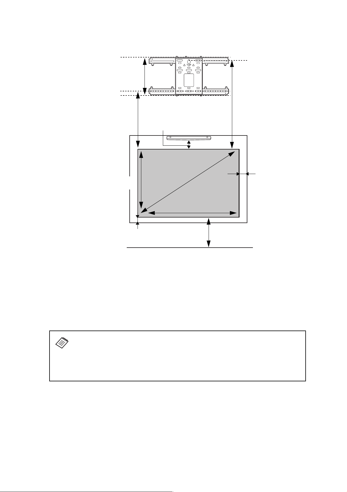
Installation worksheet for projecting on a pre-installed wall-mounted
11 in. (280 mm)—height of
wall plate plus cover
Required distance from top
of image area to bottom
holes of wall plate (c)
Diagonal size of
image area (S)
Height of
image area (h)
Width of image area (w)
Distance from floor to
bottom of image area (f)
4.0 in. (100 mm)—
gap between
projected image and
frame (only required if
your whiteboard has a
thick bezel or frame)
0.8 in. (20 mm)—
minimum distance
from bottom of image
area to bottom of
board
Distance from top of
image area to
temporary wall plate
hole (d)
Distance from top of image area to
bottom of Touch Unit (if applicable)—
see below
board
Distance from top of image area to bottom of Touch Unit (if applicable):
BrightLink 1480Fi/1480Fi+/1485Fi/
1485Fi+
BrightLink EB-735Fi 1.61 to 2 inches (41 to 50 mm) for 16:6
BrightLink EB-725Wi — 0.54 to 2 inches (13.7 to 50 mm) for all
If you want to install the Touch Unit (BrightLink models only) outside of the frame of a
whiteboard, use the optional Touch Unit Bracket. If the distance from the wall to the
surface of the whiteboard is greater than 2 inches (51 mm) or the frame of the
whiteboard extends more than 0.1 inch (3 mm) away from the board surface, you must
0.79 to 2 inches (20 to 50 mm) for 16:6
(BrightLink 1485Fi/1485Fi+ only) and
21:9 aspect ratios
aspect ratio
0.22 to 2 inches (5.7 to 50 mm) for all
other aspect ratios
0.70 to 2 inches (17.7 to 50 mm) for all
other aspect ratios
aspect ratios
install the Touch Unit on the whiteboard or screen.
See page 67 for details on mounting the Touch Unit.
1. Measure the ceiling height (distance from the floor to the ceiling). _____
2. Measure the height of the board’s image area (h). _____ (h)
3. Measure the width of the board’s image area (w). _____ (w)
4. Measure the distance from the floor to the bottom of the board’s image area (f). _____ (f)
5. Measure the thickness of the board (distance from the projection surface to the wall)
(x).
_____ (x)
22

6. Determine the aspect ratio of the board or of the images that will be projected. You
may need to consult your IT department for this information.
___ 4:3 XGA ___ 16:10 WXGA/WUXGA ___ 16:9 Widescreen ___ 16:6* ___ 21:9**
*BrightLink 1485Fi/1485Fi+/EB-735Fi and PowerLite EB-750F/EB-755F/EB-800F/EB-805F
only.
**BrightLink 1480Fi/1480Fi+/1485Fi/1485Fi+ and PowerLite EB-800F/EB-805F only.
If your desired aspect ratio does not match the native aspect ratio of your product,
use the Throw Distance Calculator at www.epson.com/support (U.S.),
www.epson.ca/support (Canada), or www.latin.epson.com/support (Latin America) to
determine the correct measurements.
7. Using the tables on pages 30 to 32 and your desired image height (h), find the required
distance between the top of the image area and the bottom holes of the wall plate (c). _____ (c)
8. Using the tables on pages 30 to 32 and your desired image height (h), find the required
distance between the top of the image area and the temporary wall plate hole (d). _____ (d)
English
9. Determine the position for your projector installation by adding the values for (f), (h),
and (c), plus an additional 11 inches (280 mm) for the height of the wall plate plus the
cover.
If the ceiling height of your room (as noted in step 1) does not meet the minimum
ceiling height required for your board, you may need to select a smaller image size or
move the board to a lower position on the wall.
10. After confirming your image size, use tape or a pencil to mark the distance (c) from the
top of the image area on the board to the bottom holes of the wall plate.
11. Align the line (horizontal) on the template sheet with the (c) mark, then align the
center line on the template sheet with the center of the image area. Follow the
instructions on page 43 to install the projector.
_____ (f )
_____ (h)
_____ (c)
+ 11
inches
(280 mm)
_____ total
23
Installation worksheet for projecting on a plain wall
11 in. (280 mm)—height of
wall plate plus cover
Required distance from top of
image area to bottom holes of
wall plate (c)
Diagonal size of
image area (S)
Height of
image area (h)
Distance from top of
image area to
temporary wall plate
hole (d)
Width of image area (w)
Distance from floor to
bottom of image area (f)
Ceiling height
Distance from top of image area to
bottom of Touch Unit (if applicable)—
see below
Distance from top of image area to bottom of Touch Unit (if applicable):
BrightLink 1480Fi/1480Fi+/1485Fi/
1485Fi+
BrightLink EB-735Fi 1.61 to 2 inches (41 to 50 mm) for 16:6
BrightLink EB-725Wi — 0.54 to 2 inches (13.7 to 50 mm) for all
0.79 to 2 inches (20 to 50 mm) for 16:6
(BrightLink 1485Fi/1485Fi+ only) and
21:9 aspect ratios
aspect ratio
0.22 to 2 inches (5.7 to 50 mm) for all
other aspect ratios
0.70 to 2 inches (17.7 to 50 mm) for all
other aspect ratios
aspect ratios
1. Measure the ceiling height (distance from the floor to the ceiling). _____
2. Determine the aspect ratio of the board or of the images that will be projected. You
may need to consult your IT department for this information.
___ 4:3 XGA ___ 16:10 WXGA/WUXGA ___ 16:9 Widescreen ___ 16:6* ___ 21:9**
*BrightLink 1485Fi/1485Fi+/EB-735Fi and PowerLite EB-750F/EB-755F/EB-800F/EB-805F
only.
**BrightLink 1480Fi/1480Fi+/1485Fi/1485Fi+ and PowerLite EB-800F/EB-805F only.
If your desired aspect ratio does not match the native resolution of your product, use
the Throw Distance Calculator at www.epson.com/support (U.S.),
www.epson.ca/support (Canada), or www.latin.epson.com/support (Latin America) to
determine the correct measurements.
3. Using the tables on pages 30 to 32, select the largest image size available for your
ceiling height.
Image height (h)
Image width (w)
4. Determine the desired distance from the floor to the bottom of the image area (f).
The recommended minimum distance is 30 inches (762 mm). Images appearing less
_____ (h)
_____ (w)
_____ (f )
than 28 inches (711 mm) from the floor may be obstructed for some viewers.
24

5. Find the top of the projected image area by adding distances (f) and (h). _____
6. Use the tables on pages 30 to 32 to determine the required distance from the top of the
image area to the bottom holes of the wall plate (c). _____ (c)
7. Use the tables on pages 30 to 32 to determine the required distance between the top
of the image area and the temporary wall plate hole (d). _____ (d)
8. Add:
Required distance from top of image area to bottom holes of wall plate (c)
Height of image area (h)
Distance from floor to bottom of image area (f)
Height of wall plate plus cover
If the total exceeds the ceiling height, you will need to reduce the image size or reduce
the distance from the floor to the bottom of the image area.
9. After confirming your image size, use tape or a pencil to mark the distance (c) from the
top of the image area on the board to the bottom holes of the wall plate.
10. Align the line (horizontal) on the template sheet with the (c) mark, then align the
center line on the template sheet with the center of the image area. Follow the
instructions on page 43 to install the projector.
_____ (c)
_____ (h)
_____ (f )
+ 11
inches
(280 mm)
_____ total
Projection distance worksheets
The tables on the following pages provide installation information for select image sizes. The minimum ceiling
height is based on an image 30 inches (762 mm) from the floor; if the image is lower, the minimum ceiling
height is reduced by the corresponding measurement.
Use the worksheets, the illustrations, and the information in the tables on the following pages to determine
the projection distance and placement of the wall plate.
English
25
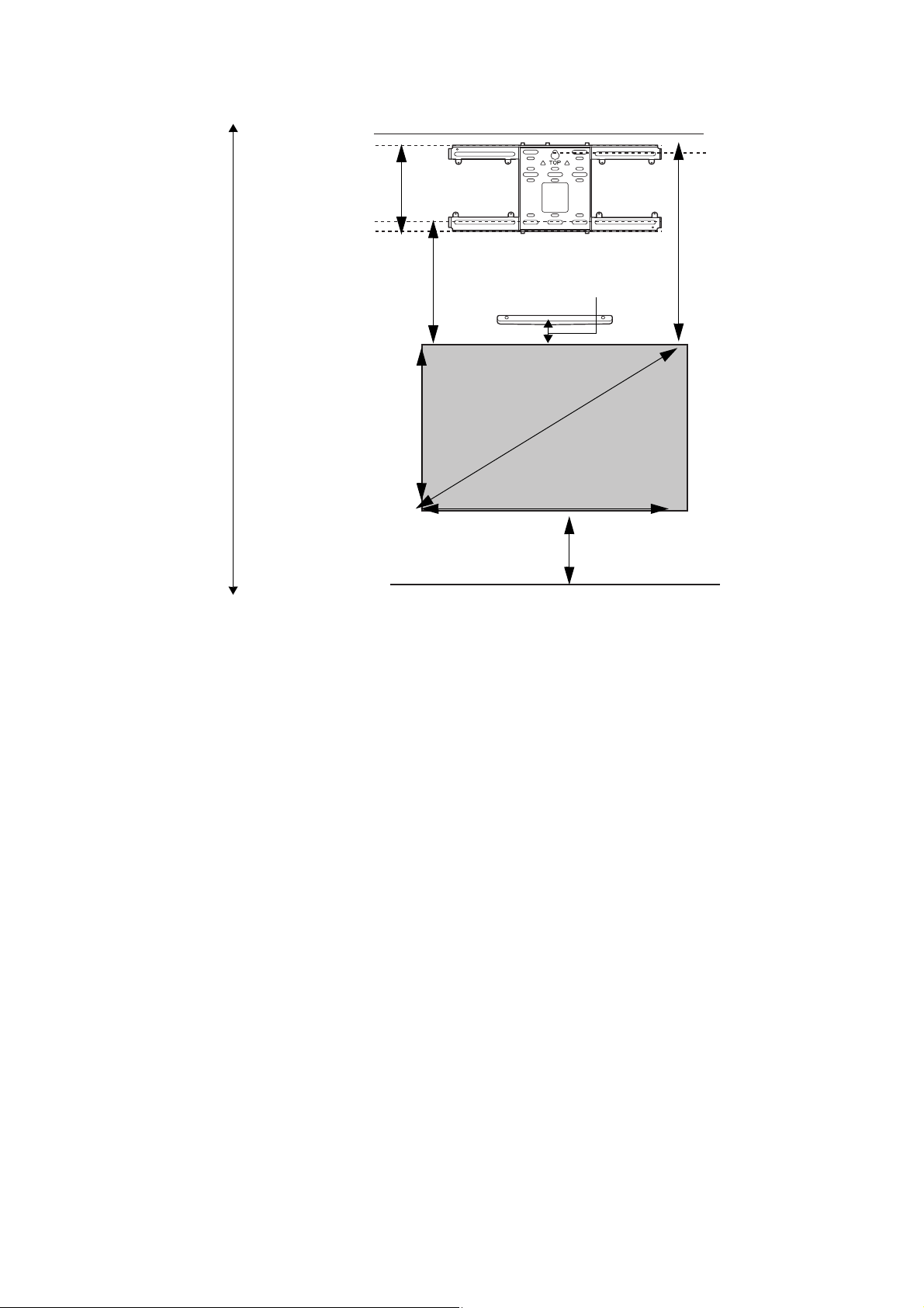
Diagonal image size and mounting position
S
a
c
d
b + x
x
In order to see the stamp and the numbers on the slider scale (b), you need to slide out the arm extension.
• BrightLink 1480Fi/1480Fi+/1485Fi/1485Fi+ and PowerLite EB-800F/EB-805F: Mount it at the
stamp when the image is less than 80 inches diagonally, or at the stamp when the projected
image is 80 inches or more diagonally.
• BrightLink EB-725Wi/EB-735Fi and PowerLite EB-720/EB-725W/EB-750F/EB-755F: Mount it at
the stamp when the image is less than 90 inches diagonally, or at the stamp when the
projected image is 90 inches or more diagonally.
26
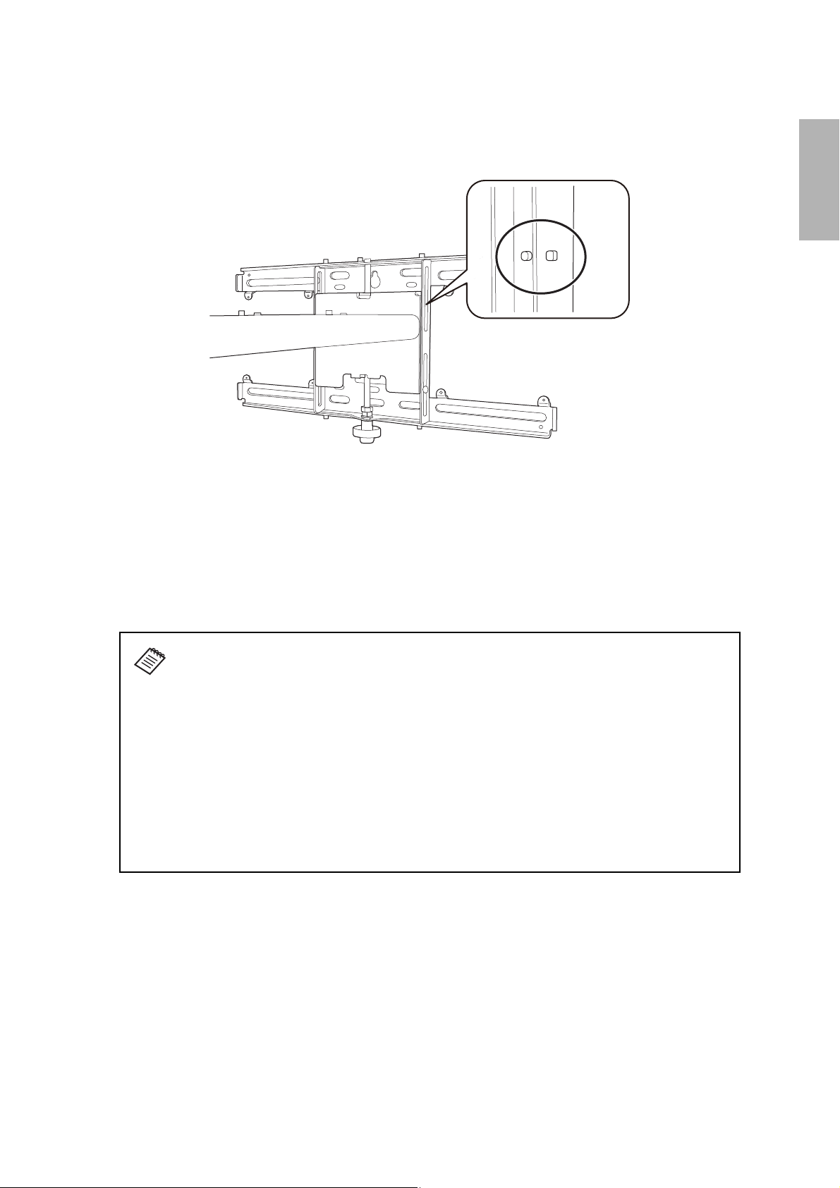
Distance from top of projected image to wall plate
The distance (c) from the top of the projected image to the bottom mounting holes on the wall plate is the
number given when the vertical slide is set to the base position, as shown below.
Match the notch on the wall mount to the position of the stamp on the wall plate.
Installation measurement tables
English
See the following pages for your projector’s installation measurement tables:
• BrightLink 1480Fi/1480Fi+/1485Fi/1485Fi+ and PowerLite EB-800F/EB-805F on page 28.
• BrightLink EB-735Fi and PowerLite EB-750F/EB-755F on page 33.
• BrightLink EB-725Wi and PowerLite EB-725W on page 37.
• PowerLite EB-720 on page 41.
The measurements may differ depending on the location where you place the
projector. When projecting in Tele mode, the quality of the projected images may
decrease.
When projecting in the 16:6 (BrightLink 1485Fi/1485Fi+/EB-735Fi and PowerLite EB750F/EB-755F/EB-800F/EB-805F) or 21:9 (BrightLink 1480Fi/1480Fi+/1485Fi/1485Fi+
and PowerLite EB-800F/EB-805F) aspect ratio, the projected image has black bars
above and below it by default. You can use the Screen Position setting to move the
projected image to the top of the screen and the black bars below the image. Note that
the distance from the top of the image to the bottom wall plate holes (c) or temporary
wall plate hole (d) will vary if you change the Screen Position setting. The distance
tables for the 16:6 and 21:9 aspect ratios include measurements for both the default
Screen Position setting and measurements for an image that has been adjusted to sit
at the top of the projection screen.
27
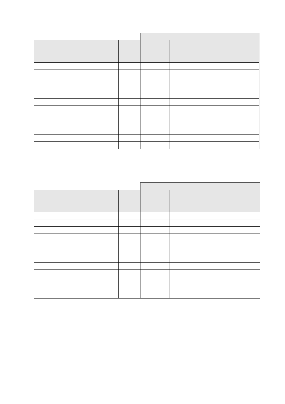
BrightLink 1480Fi/1480Fi+/1485Fi/1485Fi+ and PowerLite EB-800F/EB-805F
Measurements in Inches for 16:9
Diagonal
image size (S)
65”
70"
75"
80"
85"
90"
95”
100”
105”**
110”**
115”**
120”**
125”**
130”**
Distance from top
of image to
Min. ceiling
height*
80.8 56.7 31.9 6.2 5.8 7.9 15.5
83.6 61.0 34.3 7.5 7.1 8.2 15.8
86.3 65.4 36.8 8.7 8.3 8.5 16.1
89.1 69.7 39.2 10.0 6.1 8.9 16.4
91.8 74.1 41.7 11.2 7.4 9.2 16.7
94.6 78.4 44.1 12.4 8.6 9.5 17.0
97.4 82.8 46.6 13.7 9.9 9.8 17.4
100.1 87.2 49.0 15.0 11.1 10.1 17.7
103.0 91.5 51.5 16.2 12.4 10.5 18.0
105.7 95.9 53.9 17.4 13.6 10.8 18.3
108.5 100.2 56.4 18.7 14.9 11.1 18.7
111.2 104.6 58.8 19.9 16.1 11.4 19.0
114.0 108.9 61.3 21.2 17.4 11.7 19.3
116.8 113.3 63.7 22.4 18.6 12.0 19.6
Image
width (w)
Image
height (h)
Min. projection
distance (a)
Sliderscale
mark (b)
bottom wall plate
holes (c)
Distance from top
temporary wall
plate hole (d)
of image to
* Based on an image 30 inches from the floor; if the image is lower, the minimum ceiling height is reduced by the corresponding
measurement.
**Interactive features not supported for images larger than 100”.
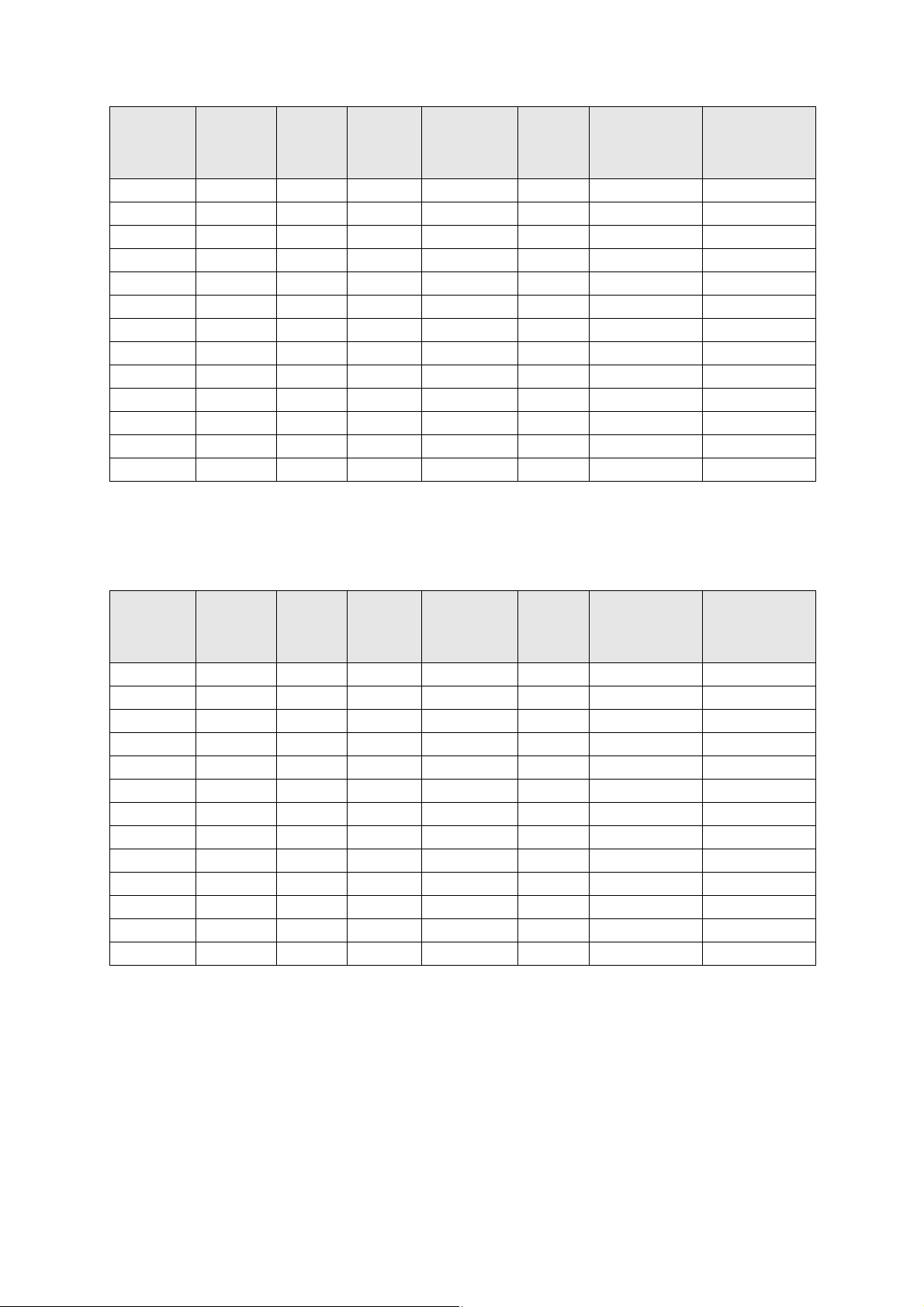
Measurements in Centimeters for 16:9
Diagonal
image size (S)
65”
70"
75"
80"
85"
90"
95”
100”
105”**
110”**
115”**
120”**
125”**
130”**
Distance from top
of image to
Min. ceiling
height*
205.2 143.9 80.9 15.8 14.8 20.1 39.3
212.3 155.0 87.2 19.0 18.0 20.9 40.1
219.3 166.0 93.4 22.1 21.1 21.7 40.9
226.3 177.1 99.6 25.3 15.6 22.5 41.7
233.3 188.2 105.8 28.5 18.8 23.3 42.5
240.4 199.2 112.1 31.6 21.9 24.1 43.3
247.4 210.3 118.3 34.8 25.1 24.9 44.1
254.4 221.4 124.5 38.0 28.3 25.7 44.9
261.6 232.4 130.8 41.1 31.4 26.6 45.8
268.6 243.5 137.0 44.3 34.6 27.4 46.6
275.6 254.6 143.2 47.5 37.8 28.2 47.4
282.6 265.7 149.4 50.6 40.9 29.0 48.2
289.7 276.7 155.7 53.8 44.1 29.8 49.0
296.7 287.8 161.9 57.0 47.3 30.6 49.8
Image
width (w)
Image
height (h)
Min. projection
distance (a)
Sliderscale
mark (b)
bottom wall plate
holes (c)
Distance from top
of image to
temporary wall
plate hole (d)
* Based on an image 76.2 cm from the floor; if the image is lower, the minimum ceiling height is reduced by the corresponding
measurement.
**Interactive features not supported for images larger than 100”.
28
BrightLink 1480Fi/1480Fi+/1485Fi/1485Fi+ and PowerLite EB-800F/EB-805F
Measurements in Inches for 16:6 (BL 1485Fi/1485Fi+ and PL EB-800F/EB-805F)
Default Screen Position Screen Position max. (top)
Distance from
Diagonal
image
size (S)
65”
70"
75"
80"
85"
90"
95”
100”
105”
110”
115”
120”
* Based on an image 30 inches from the floor; if the image is lower, the minimum ceiling height is reduced by the corresponding
measurement.
Min.
Image
Image
ceiling
height*
77.7 60.9 22.8 7.4 7.0 13.9 21.5 8.2 15.7
80.3 65.6 24.6 8.8 8.4 14.7 22.2 8.5 16.1
82.8 70.2 26.3 10.1 9.7 15.5 23.0 8.9 16.5
85.3 74.9 28.1 11.5 7.6 16.3 23.8 9.2 16.8
87.9 79.6 29.8 12.8 9.0 17.0 24.6 9.6 17.2
90.4 84.3 31.6 14.1 10.3 17.8 25.4 9.9 17.5
93.0 88.9 33.3 15.5 11.7 18.6 26.2 10.3 17.8
95.5 93.6 35.1 16.8 13.0 19.4 26.9 10.6 18.1
98.0 98.3 36.9 18.1 14.3 20.2 27.7 10.9 18.5
100.6 103.0 38.6 19.5 15.7 20.9 28.5 11.3 18.9
103.1 107.7 40.4 20.8 17.0 21.7 29.3 11.6 19.2
105.6 112.4 42.1 22.2 18.3 22.5 30.1 12.0 19.6
width
(w)
height
(h)
Min. proj.
distance
(a)
Sliderscale
mark (b)
top of image
to bottom wall
plate holes (c)
Distance from
top of image to
temporary wall
plate hole (d)
Distance from
top of image
to bottom wall
plate holes (c)
Distance from
top of image to
temporary wall
plate hole (d)
Measurements in Centimeters for 16:6 (BL 1485Fi/1485Fi+ and PL EB-800/EB-805F)
Default Screen Position Screen Position max. (top)
Distance from
Diagonal
image
size (S)
65”
70"
75"
80"
85"
90"
95”
100”
105”
110”
115”
120”
* Based on an image 76.2 cm from the floor; if the image is lower, the minimum ceiling height is reduced by the corresponding
measurement.
Min.
Image
Image
ceiling
height*
197.5 154.6 58.0 18.9 17.9 35.3 54.5 20.8 40.0
203.9 166.5 62.4 22.3 21.3 37.3 56.5 21.7 40.9
210.4 178.4 66.9 25.7 24.7 39.3 58.5 22.6 41.8
216.8 190.3 71.3 29.1 19.4 41.3 60.5 23.5 42.7
223.3 202.2 75.8 32.5 22.8 43.3 62.5 24.4 43.6
229.8 214.0 80.3 35.9 26.2 45.3 64.5 25.2 44.4
236.2 225.9 84.7 39.3 29.6 47.3 66.5 26.1 45.3
242.6 237.8 89.2 42.7 33.0 49.2 68.4 26.9 46.1
249.0 249.7 93.6 46.1 36.4 51.2 70.4 27.8 47.0
255.5 261.6 98.1 49.5 39.8 53.2 72.4 28.7 47.9
262.0 273.5 102.6 52.9 43.2 55.2 74.4 29.6 48.8
268.4 285.4 107.0 56.3 46.6 57.2 76.4 30.5 49.7
width
(w)
height
(h)
Min. proj.
distance
(a)
Sliderscale
mark (b)
top of image
to bottom wall
plate holes (c)
Distance from
top of image to
temporary wall
plate hole (d)
Distance from
top of image
to bottom wall
plate holes (c)
Distance from
top of image to
temporary wall
plate hole (d)
29
BrightLink 1480Fi/1480Fi+/1485Fi/1485Fi+ and PowerLite EB-800F/EB-805F
Measurements in Inches for 16:10
Distance from top
of image to
Diagonal
image size (S)
61”
65”
70"
75"
80"
85"
90"
95”
100”
105”**
110”**
115”**
120”**
* Based on an image 30 inches from the floor; if the image is lower, the minimum ceiling height is reduced by the corresponding
measurement.
**Interactive features not supported for images larger than 100”.
Min. ceiling
height*
81.3 51.7 32.3 6.5 6.1 8.0 15.5
83.7 55.1 344.4 7.5 7.1 8.2 15.8
86.7 59.4 37.1 8.9 8.5 8.6 16.1
89.7 63.6 39.8 10.2 9.8 8.9 16.5
92.7 67.8 42.4 11.6 7.8 9.3 16.9
95.6 72.1 45.0 12.9 9.1 9.6 17.2
98.7 76.3 47.7 14.3 10.5 10.0 17.5
101.7 80.6 50.4 15.6 11.8 10.3 17.9
104.7 84.8 53.0 17.0 13.1 10.7 18.2
107.7 89.1 55.7 18.3 14.5 11.0 18.5
110.6 93.3 58.3 19.6 15.8 11.3 18.9
113.6 97.5 60.9 21.0 17.2 11.7 19.3
116.6 101.8 63.6 22.4 18.5 12.0 19.6
Image
width (w)
Image
height (h)
Min. projection
distance (a)
Sliderscale
mark (b)
bottom wall plate
holes (c)
Distance from top
of image to
temporary wall
plate hole (d)
Measurements in Centimeters for 16:10
Distance from top
of image to
Diagonal
image size (S)
61”
65”
70"
75"
80"
85"
90"
95”
100”
105”**
110”**
115”**
120”**
* Based on an image 76.2 cm from the floor; if the image is lower, the minimum ceiling height is reduced by the corresponding
measurement.
**Interactive features not supported for images larger than 100”.
Min. ceiling
height*
206.5 131.4 82.1 16.4 15.4 20.2 39.4
212.6 140.0 87.5 19.1 18.1 20.9 40.1
220.2 150.8 94.2 22.6 21.6 21.8 41.0
227.9 161.5 101.0 26.0 25.0 22.7 41.9
235.5 172.3 107.7 29.4 19.7 23.6 42.8
243.0 183.1 114.4 32.8 23.1 24.4 43.6
250.7 193.9 121.2 36.3 26.6 25.3 44.5
258.3 204.7 127.9 39.7 30.0 26.2 45.4
265.9 215.4 134.6 43.1 33.4 27.1 46.3
273.5 226.2 141.4 46.5 36.8 27.9 47.1
281.1 236.9 148.1 49.9 40.2 28.8 48.0
288.7 247.7 154.8 53.4 43.7 29.7 48.9
296.3 258.5 161.5 56.8 47.1 30.6 49.8
Image
width (w)
Image
height (h)
Min. projection
distance (a)
Sliderscale
mark (b)
bottom wall plate
holes (c)
Distance from top
of image to
temporary wall
plate hole (d)
30

BrightLink 1480Fi/1480Fi+/1485Fi/1485Fi+ and PowerLite EB-800F/EB-805F
Measurements in Inches for 4:3
Distance from top
of image to
Diagonal
image size (S)
65”
70"
75"
80"
85”
90”
95”
100”
105”**
* Based on an image 30 inches from the floor; if the image is lower, the minimum ceiling height is reduced by the corresponding
measurement.
**Interactive features not supported for images larger than 100”.
Min. ceiling
height*
88.8 52.0 39.0 9.8 9.4 8.8 16.4
92.2 56.0 42.0 11.4 11.0 9.2 16.8
95.6 60.0 45.0 12.9 12.5 9.6 17.2
99.0 64.0 48.0 14.4 10.6 10.0 17.6
102.4 68.0 51.0 15.9 12.1 10.4 18.0
105.8 72.0 54.0 17.5 13.7 10.8 18.3
109.2 76.0 57.0 19.0 15.2 11.2 18.7
112.6 80.0 60.0 20.5 16.7 11.6 19.1
116.0 84.0 63.0 22.0 18.2 12.0 19.5
Image
width (w)
Image
height (h)
Min. projection
distance (a)
Sliderscale
mark (b)
bottom wall plate
holes (c)
Distance from top
of image to
temporary wall
plate hole (d)
Measurements in Centimeters for 4:3
Diagonal
image size (S)
65”
70"
75"
80"
85”
90”
95”
100”
105”**
Distance from top
of image to
Min. ceiling
height**
225.7 132.1 99.1 25.0 24.0 22.4 41.6
234.3 142.2 106.7 28.9 27.9 23.4 42.6
242.9 152.4 114.3 32.8 31.8 24.4 43.6
251.5 162.6 121.9 36.6 26.9 25.4 44.6
260.1 172.7 129.5 40.5 30.8 26.4 45.6
268.8 182.9 137.2 44.4 34.7 27.4 46.6
259.4 193.0 144.8 48.3 38.6 28.4 47.6
268.0 203.2 152.4 52.1 42.4 29.4 48.6
276.6 213.4 160.0 56.0 46.3 30.4 49.6
Image
width (w)
Image
height (h)
Min. projection
distance (a)
Sliderscale
mark (b)
bottom wall plate
holes (c)
Distance from top
of image to
temporary wall
plate hole (d)
* Based on an image 76.2 cm from the floor; if the image is lower, the minimum ceiling height is reduced by the corresponding
measurement.
**Interactive features not supported for images larger than 100”.
31

BrightLink 1480Fi/1480Fi+/1485Fi/1485Fi+ and PowerLite EB-800F/EB-805F
Measurements in Inches for 21:9
Default Screen Position Screen Position max. (top)
Min.
Diagonal
image
size (S)
65”
70"
75"
80"
85"
90"
95”
100”
105”**
110”**
115”**
120”**
* Based on an image 30 inches from the floor; if the image is lower, the minimum ceiling height is reduced by the corresponding
measurement.
**Interactive features not supported for images larger than 100”.
Min.
Image
ceiling
height*
78.7 59.8 25.6 7.1 6.7 12.1 19.7 8.1 15.7
81.3 64.3 27.6 8.4 8.0 12.8 20.3 8.5 16.0
84.0 68.9 29.5 9.7 9.3 13.4 21.0 8.8 16.4
86.6 73.5 31.5 11.1 7.2 14.1 21.6 9.1 16.7
89.2 78.1 33.5 12.4 8.5 14.7 22.3 9.5 17.0
91.8 82.7 35.4 13.7 9.8 15.4 22.9 9.8 17.4
94.4 87.3 37.4 15.0 11.2 16.0 23.5 10.1 17.7
97.1 91.9 39.4 16.3 12.5 16.7 24.2 10.5 18.1
99.7 96.5 41.4 17.6 13.8 17.3 24.8 10.8 18.4
102.3 101.1 43.3 18.9 15.1 17.9 25.5 11.1 18.7
104.9 105.7 45.3 20.2 16.4 18.6 26.1 11.5 19.1
107.5 110.3 47.3 21.6 17.8 19.2 26.8 11.8 19.4
width
(w)
Image
height
(h)
projection
distance
(a)
Sliderscale
mark (b)
Distance from
top of image
to bottom wall
plate holes (c)
Distance from
top of image to
temporary wall
plate hole (d)
Distance from
top of image
to bottom wall
plate holes (c)
Distance from
top of image to
temporary wall
plate hole (d)
Measurements in Centimeters for 21:9
Default Screen Position Screen Position max. (top)
Min.
Diagonal
image
size (S)
65”
70"
75"
80"
85"
90"
95”
100”
105”**
110”**
115”**
120”**
* Based on an image 76.2 cm from the floor; if the image is lower, the minimum ceiling height is reduced by the corresponding
measurement.
**Interactive features not supported for images larger than 100”.
Min.
Image
ceiling
height*
200.0 151.8 65.0 18.1 17.1 30.8 50.0 20.6 39.8
206.6 163.4 70.0 21.4 20.4 32.4 51.6 21.5 40.7
213.3 175.1 75.0 24.7 23.7 34.1 53.3 22.4 41.6
219.9 186.8 80.0 28.1 18.4 35.7 54.9 23.2 42.4
226.6 198.4 85.0 31.4 21.7 37.4 56.5 24.1 43.3
233.2 210.1 90.0 34.7 25.0 39.0 58.2 24.9 44.1
239.9 221.8 95.1 38.1 28.4 40.6 59.8 25.7 44.9
246.6 233.5 100.1 41.4 31.7 42.3 61.5 26.7 45.9
253.2 245.1 105.1 44.8 35.1 43.9 63.1 27.5 46.7
259.8 256.8 110.1 48.1 38.4 45.5 64.7 28.3 47.5
266.5 268.5 115.1 51.4 41.7 47.2 66.4 29.2 48.4
273.1 280.2 120.1 54.8 45.1 48.8 68.0 30.0 49.2
width
(w)
Image
height
(h)
projection
distance
(a)
Sliderscale
mark (b)
Distance from
top of image
to bottom wall
plate holes (c)
Distance from
top of image to
temporary wall
plate hole (d)
Distance from
top of image
to bottom wall
plate holes (c)
Distance from
top of image to
temporary wall
plate hole (d)
32

BrightLink EB-735Fi and PowerLite EB-750F/EB-755F
Measurements in Inches for 16:9
Distance from top
of image to
Diagonal
image size (S)
70"
75"
80"
85"
90"
95”
100”
105”**
110”**
115”**
120”**
125”**
130”**
* Based on an image 30 inches from the floor; if the image is lower, the minimum ceiling height is reduced by the corresponding
measurement.
**Interactive features not supported for images larger than 100”.
Min. ceiling
height*
84.3 61.0 34.3 3.4 5.7 8.9 16.5
87.3 65.4 36.8 4.6 6.9 9.6 17.1
90.4 69.7 39.2 5.8 8.1 10.2 17.7
93.4 74.1 41.7 7.0 9.3 10.8 18.3
96.5 78.4 44.1 8.1 7.0 11.4 19.0
99.6 82.8 46.6 9.3 8.2 12.0 19.6
102.6 87.2 49.0 10.5 9.4 12.6 20.2
105.7 91.5 51.5 11.7 10.6 13.2 20.8
108.8 95.9 53.9 12.9 11.8 13.9 21.4
111.8 100.2 56.4 14.1 13.0 14.4 22.0
114.9 104.6 58.8 15.2 14.1 15.1 22.6
118.0 109.0 61.3 16.4 15.3 15.7 23.2
121.0 113.3 63.7 17.6 16.5 16.3 23.9
Image
width (w)
Image
height (h)
Min. projection
distance (a)
Sliderscale
mark (b)
bottom wall plate
holes (c)
Distance from top
of image to
temporary wall
plate hole (d)
Measurements in Centimeters for 16:9
Distance from top
of image to
Diagonal
image size (S)
70"
75"
80"
85"
90"
95”
100”
105”**
110”**
115”**
120”**
125”**
130”**
* Based on an image 76.2 cm from the floor; if the image is lower, the minimum ceiling height is reduced by the corresponding
measurement.
**Interactive features not supported for images larger than 100”.
Min. ceiling
height*
214.1 155.0 87.2 8.7 14.5 22.7 41.9
221.9 166.0 93.4 11.7 17.5 24.3 43.5
229.6 177.1 99.6 14.7 20.6 25.8 45.0
237.4 188.2 105.8 17.7 23.6 27.4 46.6
245.2 199.2 112.1 20.7 17.9 28.9 48.2
253.0 210.3 118.3 23.7 20.9 30.5 49.7
260.7 221.4 124.5 26.7 23.9 32.0 51.3
268.6 232.5 130.8 29.7 26.9 33.6 52.8
276.4 243.6 137.0 32.7 29.9 35.2 54.4
284.1 254.6 143.2 35.7 32.9 36.7 55.9
291.9 265.6 149.4 38.7 35.9 38.3 57.5
299.7 276.8 155.7 41.7 38.9 39.8 59.0
307.5 287.8 161.9 44.7 41.9 41.4 60.6
Image
width (w)
Image
height (h)
Min. projection
distance (a)
Sliderscale
mark (b)
bottom wall plate
holes (c)
Distance from top
of image to
temporary wall
plate hole (d)
33

BrightLink EB-735Fi and PowerLite EB-750F/EB-755F
Measurements in Inches for 16:6
Default Screen Position Screen Position max. (top)
Distance from
Diagonal
image
size (S)
65”
70"
75"
80"
85"
90"
95”
100”
105”
110”
* Based on an image 30 inches from the floor; if the image is lower, the minimum ceiling height is reduced by the corresponding
measurement.
Min.
Image
Image
ceiling
height*
78.5 60.9 22.8 3.4 5.7 14.6 22.2 8.9 16.5
81.3 65.6 24.6 4.6 7.0 15.7 23.3 9.6 17.2
84.1 70.2 26.3 5.9 8.2 16.8 24.4 10.2 17.8
87.0 74.9 28.1 7.2 9.5 17.9 25.5 10.9 18.5
89.9 79.6 29.8 8.5 10.8 19.0 26.6 11.5 19.1
92.7 84.3 31.6 9.7 8.6 20.1 27.7 12.2 19.8
95.6 88.9 33.3 11.0 9.9 21.2 28.8 12.9 20.4
98.4 93.6 35.1 12.2 11.1 22.3 29.9 13.5 21.1
101.2 98.3 36.9 13.5 12.4 23.4 31.0 14.2 21.7
104.1 103.0 38.6 14.8 13.7 24.5 32.0 14.8 22.4
width
(w)
height
(h)
Min. proj.
distance
(a)
Sliderscale
mark (b)
top of image
to bottom wall
plate holes (c)
Distance from
top of image to
temporary wall
plate hole (d)
Distance from
top of image
to bottom wall
plate holes (c)
Distance from
top of image to
temporary wall
plate hole (d)
Measurements in Centimeters for 16:6
Default Screen Position Screen Position max. (top)
Distance from
Diagonal
image
size (S)
65”
70"
75"
80"
85"
90"
95”
100”
105”
110”
* Based on an image 76.2 cm from the floor; if the image is lower, the minimum ceiling height is reduced by the corresponding
measurement.
Min.
Image
Image
ceiling
height*
199.4 154.6 58.0 8.6 14.4 37.2 56.4 22.7 41.9
206.5 166.5 62.4 11.8 17.7 39.9 59.2 24.3 43.6
213.8 178.4 66.9 15.0 20.9 42.7 61.9 26.0 45.2
221.0 190.3 71.3 18.2 24.1 45.5 64.7 27.7 46.9
228.3 202.2 75.8 21.5 27.4 48.3 67.5 29.3 48.6
235.6 214.0 80.3 24.7 21.9 51.1 70.3 31.0 50.2
242.8 225.9 84.7 27.9 25.1 53.9 73.1 32.7 51.9
250.1 237.8 89.2 31.1 28.3 56.7 75.9 34.4 53.6
257.2 249.7 93.6 34.4 31.6 59.4 78.7 36.0 55.2
264.5 261.6 98.1 37.5 34.8 62.2 81.4 37.7 56.9
width
(w)
height
(h)
Min. proj.
distance
(a)
Sliderscale
mark (b)
top of image
to bottom wall
plate holes (c)
Distance from
top of image to
temporary wall
plate hole (d)
Distance from
top of image
to bottom wall
plate holes (c)
Distance from
top of image to
temporary wall
plate hole (d)
34

BrightLink EB-735Fi and PowerLite EB-750F/EB-755F
Measurements in Inches for 16:10
Distance from top
of image to
Diagonal
image size (S)
65”
70"
75"
80"
85"
90"
95”
100”
105”
110”
* Based on an image 30 inches from the floor; if the image is lower, the minimum ceiling height is reduced by the corresponding
measurement.
Min. ceiling
height*
84.4 55.1 34.4 3.5 5.8 9.0 16.5
87.7 59.3 37.1 4.8 7.1 9.6 17.2
91.1 63.6 39.8 6.0 8.3 10.3 17.9
94.3 67.8 42.4 7.3 9.6 10.9 18.5
97.7 72.1 45.0 8.6 10.9 11.6 19.2
101.0 76.3 47.7 9.9 8.7 12.3 19.8
104.3 80.6 50.4 11.1 10.0 13.0 20.5
107.6 84.8 53.0 12.4 11.3 13.6 21.2
110.9 89.1 55.7 13.7 12.6 14.3 21.9
114.2 93.3 58.3 15.0 13.9 14.9 22.5
Image
width (w)
Image
height (h)
Min. projection
distance (a)
Sliderscale
mark (b)
bottom wall plate
holes (c)
Distance from top
of image to
temporary wall
plate hole (d)
Measurements in Centimeters for 16:10
Diagonal
image size (S)
65”
70"
75"
80"
85"
90"
95”
100”
105”
110”
Distance from top
of image to
Min. ceiling
height*
214.5 140.0 87.5 8.8 14.7 22.8 42.0
222.9 150.7 94.2 12.1 18.0 24.5 43.7
231.4 161.6 101.0 15.3 21.2 26.2 45.4
239.7 172.3 107.7 18.6 24.4 27.8 47.1
248.1 183.0 114.4 21.8 27.7 29.5 48.7
256.6 193.9 121.2 25.1 22.2 31.2 50.4
265.0 204.6 127.9 28.3 25.5 32.9 52.1
273.4 215.4 134.6 31.6 28.7 34.6 53.8
281.8 226.2 141.4 34.8 32.0 36.2 55.5
290.2 237.0 148.1 38.1 35.2 37.9 57.1
Image
width (w)
Image
height (h)
Min. projection
distance (a)
Sliderscale
mark (b)
bottom wall plate
holes (c)
Distance from top
of image to
temporary wall
plate hole (d)
* Based on an image 76.2 cm from the floor; if the image is lower, the minimum ceiling height is reduced by the corresponding
measurement.
35

BrightLink EB-735Fi and PowerLite EB-750F/EB-755F
Measurements in Inches for 4:3
Distance from top
of image to
Diagonal
image size (S)
55”
60”
65”
70"
75"
80"
85”
90”
95”
* Based on an image 30 inches from the floor; if the image is lower, the minimum ceiling height is reduced by the corresponding
measurement.
Min. ceiling
height*
82.6 44.0 33.0 2.8 5.1 8.6 16.2
86.4 48.0 36.0 4.2 6.5 9.4 16.9
88.8 52.0 39.0 5.7 8.0 10.1 17.7
93.9 56.0 42.0 7.1 9.4 10.9 18.4
97.6 60.0 45.0 8.6 10.9 11.6 19.2
101.4 64.0 48.0 10.0 12.3 12.4 19.9
105.1 68.0 51.0 11.5 13.8 13.1 20.7
108.9 72.0 54.0 12.9 11.8 13.9 21.4
112.6 76.0 57.0 14.4 13.2 14.6 22.2
Image
width (w)
Image
height (h)
Min. projection
distance (a)
Sliderscale
mark (b)
bottom wall plate
holes (c)
Distance from top
of image to
temporary wall
plate hole (d)
Measurements in Centimeters for 4:3
Diagonal
image size (S)
55”
60”
65”
70"
75"
80"
85”
90”
95”
Distance from top
of image to
Min. ceiling
height**
209.9 111.7 83.8 7.0 12.9 21.9 41.1
219.4 121.9 91.4 10.7 16.6 23.8 43.0
229.0 132.1 99.1 14.4 20.3 25.7 44.9
238.5 142.2 106.7 18.1 24.0 27.6 46.8
248.0 152.4 114.3 21.8 27.6 29.5 48.7
257.5 162.6 121.9 25.4 31.3 31.4 50.6
267.0 172.7 129.5 29.1 35.0 33.3 52.5
276.6 182.9 137.2 32.8 30.0 35.2 54.4
286.1 193.1 144.8 36.5 33.6 37.1 56.3
Image
width (w)
Image
height (h)
Min. projection
distance (a)
Sliderscale
mark (b)
bottom wall plate
holes (c)
Distance from top
of image to
temporary wall
plate hole (d)
* Based on an image 76.2 cm from the floor; if the image is lower, the minimum ceiling height is reduced by the corresponding
measurement.
36

BrightLink EB-725Wi and PowerLite EB-725W
Measurements in Inches for 16:10
Distance from top
of image to
Diagonal
image size (S)
65”
70"
75"
80"
85"
90"
95”
100”
105”**
110”**
115”**
120”**
* Based on an image 30 inches from the floor; if the image is lower, the minimum ceiling height is reduced by the corresponding
measurement.
**Interactive features not supported for images larger than 100”.
Min. ceiling
height*
83.0 55.1 34.4 2.7 5.0 7.6 15.1
95.4 59.3 37.1 3.9 6.3 17.3 15.7
89.4 63.6 39.8 5.2 7.5 8.7 16.2
92.6 67.8 42.4 6.4 8.7 9.2 16.8
95.8 72.1 45.0 7.6 9.9 9.8 17.3
99.0 76.3 47.7 8.8 7.7 10.3 17.9
102.2 80.6 50.4 10.0 8.9 10.9 18.4
105.4 84.8 53.0 11.2 10.1 11.4 19.0
108.6 89.1 55.7 12.4 11.3 12.0 19.5
111.8 93.3 58.3 13.7 12.6 12.5 20.1
115.0 97.5 60.9 14.9 13.8 13.1 20.6
118.2 101.7 63.6 16.1 15.0 13.6 21.2
Image
width (w)
Image
height (h)
Min. projection
distance (a)
Sliderscale
mark (b)
bottom wall plate
holes (c)
Distance from top
of image to
temporary wall
plate hole (d)
Measurements in Centimeters for 16:10
Distance from top
of image to
Diagonal
image size (S)
65”
70"
75"
80"
85"
90"
95”
100”
105”**
110”**
115”**
120”**
* Based on an image 76.2 cm from the floor; if the image is lower, the minimum ceiling height is reduced by the corresponding
measurement.
**Interactive features not supported for images larger than 100”.
Min. ceiling
height*
210.9 140.0 87.5 6.9 12.8 19.2 38.4
219.0 150.8 94.2 10.0 15.9 20.6 39.8
227.2 161.6 101.0 13.1 19.0 22.0 41.2
235.3 172.3 107.7 16.2 22.0 23.4 42.6
243.4 183.0 114.4 19.2 25.1 24.8 44.0
251.6 193.9 121.2 22.3 19.5 26.2 45.4
259.7 204.6 127.9 25.4 22.6 27.6 46.8
267.8 215.4 134.6 28.5 25.7 29.0 48.2
276.0 226.2 141.4 31.6 28.8 30.4 49.6
284.1 237.0 148.1 34.7 31.9 31.8 51.0
292.2 247.7 154.8 37.8 35.0 33.2 52.4
300.3 258.4 161.5 40.9 38.1 34.6 53.8
Image
width (w)
Image
height (h)
Min. projection
distance (a)
Sliderscale
mark (b)
bottom wall plate
holes (c)
Distance from top
of image to
temporary wall
plate hole (d)
37

BrightLink EB-725Wi and PowerLite EB-725W
Measurements in Inches for 16:9
Distance from top
of image to
Diagonal
image size (S)
65”
70"
75"
80"
85"
90"
95”
100”
105”**
110”**
115”**
* Based on an image 30 inches from the floor; if the image is lower, the minimum ceiling height is reduced by the corresponding
measurement.
**Interactive features not supported for images larger than 100”.
Min. ceiling
height*
82.4 56.6 31.9 3.1 5.5 9.5 17.1
85.6 61.0 34.3 4.4 6.7 10.2 17.8
88.7 65.4 36.8 5.7 8.0 10.9 18.5
91.9 69.7 39.2 6.9 9.2 11.7 19.2
95.0 74.1 41.7 8.1 10.5 12.4 19.9
98.2 78.4 44.1 9.4 8.3 13.0 20.6
101.3 82.8 46.6 10.7 9.5 13.7 21.3
104.5 87.2 49.0 11.9 10.8 14.4 22.0
107.7 91.5 51.5 13.1 12.0 15.2 22.7
110.8 95.9 53.9 14.4 13.3 15.9 23.4
114.0 100.2 56.4 15.7 14.5 16.6 24.1
Image
width (w)
Image
height (h)
Min. projection
distance (a)
Sliderscale
mark (b)
bottom wall plate
holes (c)
Distance from top
of image to
temporary wall
plate hole (d)
Measurements in Centimeters for 16:9
Distance from top
of image to
Diagonal
image size (S)
65”
70"
75"
80"
85"
90"
95”
100”
105”**
110”**
115”**
* Based on an image 76.2 cm from the floor; if the image is lower, the minimum ceiling height is reduced by the corresponding
measurement.
**Interactive features not supported for images larger than 100”.
Min. ceiling
height*
209.3 143.9 80.9 8.0 13.9 24.2 43.4
217.4 155.0 87.2 11.2 17.1 26.0 45.2
225.4 166.0 93.4 14.4 20.2 27.8 47.0
233.4 177.1 99.6 17.5 23.4 29.6 48.8
241.4 188.2 105.8 20.7 26.6 31.4 50.6
249.4 199.2 112.1 23.9 21.1 33.1 52.4
257.4 210.3 118.3 27.1 24.2 34.9 54.1
265.4 221.4 124.5 30.2 27.4 36.7 55.9
273.5 232.5 130.8 33.4 30.6 38.5 57.7
281.5 243.6 137.0 36.6 33.8 40.3 59.5
289.5 254.6 143.2 39.8 36.9 42.1 61.3
Image
width (w)
Image
height (h)
Min. projection
distance (a)
Sliderscale
mark (b)
bottom wall plate
holes (c)
Distance from top
of image to
temporary wall
plate hole (d)
38

BrightLink EB-725Wi and PowerLite EB-725W
Measurements in Inches for 4:3
Distance from top
of image to
Diagonal
image size (S)
60”
65”
70"
75"
80"
85”
90”
95”
100”
105”
* Based on an image 30 inches from the floor; if the image is lower, the minimum ceiling height is reduced by the corresponding
measurement.
Min. ceiling
height*
84.9 48.0 36.0 3.4 5.7 7.9 15.4
88.5 52.0 39.0 4.8 7.1 8.5 16.1
92.1 56.0 42.0 6.2 8.5 9.1 16.7
95.8 60.0 45.0 7.6 9.9 9.8 17.3
99.4 64.0 48.0 8.9 11.3 10.4 18.0
103.0 68.0 51.0 10.3 12.6 11.0 18.6
106.6 72.0 54.0 11.7 10.6 11.6 19.2
110.3 76.0 57.0 13.1 12.0 12.2 19.8
113.9 80.0 60.0 14.4 13.3 12.9 20.4
117.5 84.0 63.0 15.8 14.7 13.5 21.1
Image
width (w)
Image
height (h)
Min. projection
distance (a)
Sliderscale
mark (b)
bottom wall plate
holes (c)
Distance from top
of image to
temporary wall
plate hole (d)
Measurements in Centimeters for 4:3
Diagonal
image size (S)
60”
65”
70"
75"
80"
85”
90”
95”
100”
105”
Distance from top
of image to
Min. ceiling
height**
215.6 121.9 91.4 8.7 14.6 20.0 39.2
224.9 132.1 99.1 12.2 18.1 21.6 40.8
234.1 142.2 106.7 15.7 21.6 23.2 42.4
243.3 152.4 114.3 19.2 25.1 24.8 44.0
252.5 162.6 121.9 22.7 28.6 26.4 45.6
261.7 172.7 129.5 26.2 32.1 28.0 47.2
270.9 182.9 137.2 29.7 26.9 29.5 48.8
280.1 193.1 144.8 33.2 30.4 31.1 50.4
289.3 203.2 152.4 36.7 33.9 32.7 51.9
298.5 213.3 160.0 40.2 37.4 34.3 53.5
Image
width (w)
Image
height (h)
Min. projection
distance (a)
Sliderscale
mark (b)
bottom wall plate
holes (c)
Distance from top
of image to
temporary wall
plate hole (d)
* Based on an image 76.2 cm from the floor; if the image is lower, the minimum ceiling height is reduced by the corresponding
measurement.
39

PowerLite EB-720
Measurements in Inches for 4:3
Distance from top
of image to
Diagonal
image size (S)
65”
70"
75"
80"
85”
90”
95”
100”
105”
110”
* Based on an image 30 inches from the floor; if the image is lower, the minimum ceiling height is reduced by the corresponding
measurement.
Min. ceiling
height*
87.1 52.0 39.0 4.0 5.9 7.0 14.6
90.6 56.0 42.0 5.3 7.6 7.6 15.1
94.1 60.0 45.0 6.6 8.9 8.1 15.6
97.6 64.0 48.0 7.9 10.2 8.6 16.1
101.1 68.0 51.0 9.2 11.5 9.1 16.7
104.6 72.0 54.0 10.5 9.4 9.6 17.2
108.1 76.0 57.0 11.8 10.7 10.1 17.7
111.6 80.0 60.0 13.1 12.0 10.6 18.2
115.1 84.0 63.0 14.4 13.3 11.1 18.7
118.6 88.0 66.0 15.7 14.6 11.7 19.2
Image
width (w)
Image
height (h)
Min. projection
distance (a)
Sliderscale
mark (b)
bottom wall plate
holes (c)
Distance from top
of image to
temporary wall
plate hole (d)
Measurements in Centimeters for 4:3
Distance from top
of image to
Diagonal
image size (S)
65”
70"
75"
80"
85”
90”
95”
100”
105”
110”
* Based on an image 76.2 cm from the floor; if the image is lower, the minimum ceiling height is reduced by the corresponding
measurement.
Min. ceiling
height**
221.2 132.1 99.1 10.1 15.0 17.9 37.1
230.1 142.2 106.7 13.4 19.3 19.2 38.4
239.0 152.4 114.3 16.7 22.6 20.5 39.7
247.9 162.6 121.9 20.0 25.9 21.8 41.0
256.8 172.7 129.5 23.3 29.2 23.1 42.3
265.8 182.9 137.2 26.7 23.8 24.4 43.6
274.7 193.1 144.8 30.0 27.2 25.7 44.9
283.6 203.2 152.4 33.3 30.5 27.0 46.2
292.5 213.3 160.0 36.6 33.8 28.3 47.5
301.4 223.5 167.6 39.9 37.1 29.6 48.8
Image
width (w)
Image
height (h)
Min. projection
distance (a)
Sliderscale
mark (b)
bottom wall plate
holes (c)
Distance from top
of image to
temporary wall
plate hole (d)
40

PowerLite EB-720
Measurements in Inches for 16:9
Distance from top
of image to
Diagonal
image size (S)
60”
65”
70"
75"
80"
85"
90"
95”
100”
* Based on an image 30 inches from the floor; if the image is lower, the minimum ceiling height is reduced by the corresponding
measurement.
Min. ceiling
height*
82.4 52.3 29.4 4.1 6.4 12.0 19.6
85.8 56.6 21.9 5.5 7.8 13.0 20.5
89.2 61.0 34.3 6.9 9.2 13.9 21.5
92.7 65.4 36.8 8.3 10.6 14.9 22.4
96.1 69.7 39.2 9.8 12.1 15.9 23.4
99.5 74.1 41.7 11.2 13.5 16.8 24.4
102.9 78.4 44.1 12.6 11.5 17.8 25.4
106.3 82.8 46.6 14.0 12.9 18.7 26.3
109.7 87.2 49.0 15.4 14.3 19.7 27.3
Image
width (w)
Image
height (h)
Min. projection
distance (a)
Sliderscale
mark (b)
bottom wall plate
holes (c)
Distance from top
of image to
temporary wall
plate hole (d)
Measurements in Centimeters for 16:9
Diagonal
image size (S)
60”
65”
70"
75"
80"
85"
90"
95”
100”
Distance from top
of image to
Min. ceiling
height*
209.3 132.8 74.7 10.3 16.2 30.4 49.7
218.0 143.8 80.9 13.9 19.8 32.9 52.1
226.7 155.0 87.2 17.6 23.4 35.3 54.6
235.4 166.0 93.4 21.2 27.0 37.8 57.0
244.1 177.1 99.6 24.8 30.7 40.3 59.5
252.7 188.2 105.8 28.4 34.3 42.7 61.9
261.5 199.2 112.1 32.0 29.2 45.2 64.4
270.1 210.3 118.3 35.6 32.8 47.6 66.8
278.8 221.4 124.5 39.2 36.4 50.1 69.3
Image
width (w)
Image
height (h)
Min. projection
distance (a)
Sliderscale
mark (b)
bottom wall plate
holes (c)
Distance from top
of image to
temporary wall
plate hole (d)
* Based on an image 76.2 cm from the floor; if the image is lower, the minimum ceiling height is reduced by the corresponding measurement.
41

PowerLite EB-720
Measurements in Inches for 16:10
Distance from top
of image to
Diagonal
image size (S)
60”
65”
70"
75"
80"
85"
90"
95”
100”
* Based on an image 30 inches from the floor; if the image is lower, the minimum ceiling height is reduced by the corresponding
measurement.
Min. ceiling
height*
82.9 50.8 31.8 3.6 5.9 10.1 17.6
86.3 55.1 34.4 5.0 7.3 10.9 18.5
89.8 59.3 37.1 6.4 8.7 11.7 19.3
93.3 63.6 39.8 7.8 10.1 12.5 20.1
96.7 67.8 42.4 9.1 11.5 13.3 20.9
100.2 72.1 45.0 10.5 12.8 14.1 21.7
103.6 76.3 47.7 11.9 10.8 14.9 22.5
107.1 80.6 50.4 13.3 12.2 15.7 23.3
110.5 84.8 53.0 14.7 13.5 16.5 24.1
Image
width (w)
Image
height (h)
Min. projection
distance (a)
Sliderscale
mark (b)
bottom wall plate
holes (c)
Distance from top
of image to
temporary wall
plate hole (d)
Measurements in Centimeters for 16:10
Diagonal
image size (S)
60”
65”
70"
75"
80"
85"
90"
95”
100”
Distance from top
of image to
Min. ceiling
height*
210.6 129.3 80.8 9.2 15.0 25.6 44.8
219.3 140.0 87.5 12.7 18.6 27.6 46.9
228.1 150.7 94.2 16.2 22.1 29.7 48.9
237.0 161.6 101.0 19.7 25.6 31.8 51.0
245.7 172.3 107.7 23.2 29.1 33.8 53.0
254.5 183.0 114.4 26.7 32.6 35.9 55.1
263.3 193.9 121.2 30.2 27.4 37.9 57.1
272.1 204.6 127.9 33.7 30.9 40.0 59.2
280.8 215.4 134.6 37.3 34.4 42.0 61.2
Image
width (w)
Image
height (h)
Min. projection
distance (a)
Sliderscale
mark (b)
bottom wall plate
holes (c)
Distance from top
of image to
temporary wall
plate hole (d)
* Based on an image 76.2 cm from the floor; if the image is lower, the minimum ceiling height is reduced by the corresponding
measurement.
42

5 Installing the Projector
❏ When you mount the projector on the wall with the wall mount, the wall requires enough
strength to hold the projector and the wall mount, as well as the Control Pad and the
Touch Unit, if applicable.
This wall mount should be installed on a concrete wall. Confirm the weight of the projector
and the wall mount before installation, and maintain the strength of the wall. If the wall is
not strong enough, reinforce the wall before installation.
❏ The maximum combined weight of the projector and the wall mount is about 41.7 lb
(18.9 kg).
❏ Do not hang cables over the wall mount.
❏ Install the wall mount so that it can sufficiently support the weight of the projector and
wall mount, and resist any horizontal vibration. Use M10 or 3/8 inch nuts and bolts and
make sure to use appropriate wall anchors for your wall type. Nuts and bolts smaller than
M10 or 3/8 inch could cause the wall mount to fall.
❏ Epson accepts no responsibility for any damage or injury caused by lack of wall strength or
inadequate installation.
Warning
Make sure to follow the steps below to install the wall mount. If you ignore these steps, the wall mount could
fall and cause personal injury or property damage.
English
A Assemble the parts
1. Assemble the wall plate.
Assemble the wall plate and two frames into one unit, and secure them with the M4 × 12 mm hexagon
socket head cap bolts (×5) supplied.
43

2. BrightLink 1480Fi/1480Fi+/1485Fi/1485Fi+ and PowerLite EB-800F/EB-805F only: Loosen the two
screws with a cross-head screwdriver and remove the cable cover from the projector.
3. Align the 3-axis adjustment unit with the slide plate’s alignment mark.
If the 3-axis adjustment unit is not aligned, loosen the M4 × 12 mm hexagon socket head cap bolt ( )
and correct the alignment ( ). Then, tighten the M4 × 12 mm hexagon socket head cap bolt.
4. Attach the 3-axis adjustment unit and slide plate to the projector.
Attach the 3-axis adjustment unit and slide plate to the projector using the M4 × 12 mm hexagon
socket head cap bolts (×4) supplied.
44

B Install the wall plate on the wall
Center line of
projection surface
line of template
sheet
line of template
sheet
1. Determine the template sheet position and attach it to the wall.
• Confirm where the beams or studs are within the wall that can support the projector and wall mount.
• From the projection distance table, confirm the screen size (S), the distance between the projection
image and wall plate bottom holes (c), and the distance between the projection image and
temporary wall plate hole (d).
• BrightLink 1480Fi/1480Fi+/1485Fi/1485Fi+ and PowerLite EB-800F/EB-805F: Align the center of
the projection surface (vertical) with Image Center A (vertical) on the template sheet.
BrightLink EB-725Wi/EB-735Fi and PowerLite EB-720/EB-725W/EB-750F/EB-755F: Align the
center of the projection surface (vertical) with Image Center B (vertical) on the template sheet.
• Align the lines (horizontal) on the template with the height of (c) and (d).
English
If you want to hide the projector power plug under the wall plate cover, make sure the
power outlet is located in the empty space to the left or the right of the wall plate.
45

2. Drive an M10 screw (not included) into the temporary wall plate hole.
Leave at least 0.2 inch (6 mm) between the screw head and the wall.
3. Determine the position of the wall plate’s mounting holes.
Use at least four mounting holes for proper balance.
4. Drill holes of the following diameters and depths.
Drill diameter
Pilot hole depth 1.8 in. (45 mm)
Anchor hole depth 1.6 in. (40 mm)
5. Remove the template sheet.
6. If necessary, use a device such as a dust pump to clean out concrete dust from the hole.
3/8 inch anchor bolts: 0.39 in. (10 mm)
M10 anchor bolts: 0.41 in. (10.5 mm)
46

7. Position the wall plate on the temporary wall plate screw.
8. Insert commercially available M10 × 60 mm or 3/8 inch anchors into the holes and secure them in
place.
English
9. Remove the temporary wall plate screw.
47

C Determine the projection distance and pull out the mount arm slider
1. Using the tables on pages 30 to 32, check the number for the slider measure (b).
2. Loosen the M4 × 12 mm hexagon socket head cap bolts (×2), and then pull out the slider on the wall
mount.
Align the slider with the measure (b+x) that is equal to the slider measure (b) plus the thickness of the
projection screen (x).
For an illustration of how to measure the thickness of the projection screen (x), see page 26.
48

D Route the cables through the wall mount arm
English
For BrightLink projectors with a Touch Unit: Make sure to route the Touch Unit
connection cable through the wall mount arm. Route the Touch Unit connection cable
so that the end that connects to the Touch Unit appears from the lower part of the wall
mount as shown above.
E Attach the mount arm to the wall plate
1. Insert the hexagonal shaft into the wall mount ( ).
2. Insert and turn the hexagonal shaft at the top of the mount arm into the slot on the wall plate ( ).
49

3. Insert the hexagonal shaft into the slot at the top of the wall plate ( ).
❏ Make sure the Touch Unit connection cable is not wired into the wall with the other cables.
❏ Take care not to trap the cables between the mount arm and wall plate.
Caution
4. Insert the hexagonal shaft into the slot at the bottom of the wall plate ( ).
5. Secure the mount arm to the wall plate by tightening the supplied M6 × 20 mm cross recessed head
shoulder screws (×3) with the #3 cross-head screwdriver.
Make sure you use the included plastic washers. If you don’t use the plastic washers,
you may damage the M8 hexagon bolt as you adjust the vertical slide position.
50

F Adjust the vertical slide position of the arm
1. Adjust the vertical slide with the M8 hexagon bolt at the bottom of the wall mount ( ), or the
hexagonal shaft at the top of the wall mount ( ). Start by aligning the notch on the arm with the
alignment mark on the wall plate as shown below ( ).
Tightening the M8 hexagon bolt lowers the wall mount, and loosening the bolt raises it ( ).
Tightening the hexagonal shaft raises the wall mount, and loosening the shaft lowers it ( ).
2. Secure the wall mount with the M6 × 20 mm hexagon shoulder bolt.
English
51

G Attach the projector to the wall mount
When installing or adjusting the wall mount, do not use adhesives to prevent the screws from
loosening and do not use lubricants or oils on the projector slide plate. This may cause the case
to crack and the projector to fall, resulting in personal injury or property damage.
Warning
Attach the 3-axis adjustment unit with the projector to the wall mount arm.
Decide which position you want to use for installing the 3-axis adjustment unit:
• BrightLink 1480Fi/1480Fi+/1485Fi/1485Fi+ and PowerLite EB-800F/EB-805F: Mount it at the
stamp when the image is less than 80 inches diagonally, or at the stamp when the projected
image is 80 inches or more diagonally.
• BrightLink EB-725Wi/EB-735Fi and PowerLite EB-720/EB-725W/EB-750F/EB-755F: Mount it at
the stamp when the image is less than 90 inches diagonally, or at the stamp when the
projected image is 90 inches or more diagonally.
• Tighten the M4 × 12 mm hexagon socket head cap bolts (×4) supplied to install the 3-axis
adjustment unit.
52

H Connect the power cord and other cables to the projector
Connect any necessary cables such as the computer cable, HDMI cable, USB cable, Touch Unit
connection cable (if applicable), Control Pad cables (if applicable), and power cord to the projector. See
your projector’s online User Guide for detailed connection information.
Use M4 screws (not included) to secure any additional devices or accessories, such as external tuners, to
the mounting point on the wall mount.
If you are planning to run the cables inside the wall, make sure you follow all local electrical codes. If
you are running the cables outside the wall, use a cable management system to keep the cables from
obstructing the image. An optional cable management system is available from Epson (part number
ELPCK01).
English
53

I Attach a Mini PC or Stick PC if necessary
You can secure a Mini PC or Stick PC to the left or the right side of the wall plate.
Attach the Mini PC so that the air exhaust vents of the PC are not blocked. Install the PC
so that the air exhaust vents are at the top and the air intake vents are at the bottom.
If your Mini PC has screw holes that line up with the holes in the Mini PC plate, you can secure it with
the M3 × 6 mm screws (×4) supplied.
If your Mini PC does not have screw holes or they do not line up with the holes on the Mini PC plate, you
can secure it with the included Mini PC band.
1. Wrap the band around the Mini PC plate.
2. Secure the Mini PC plate to the wall plate using the M3 × 6 mm screws (×4) supplied.
54

3. Rest the PC on the lip of the Mini PC plate and secure it with the band.
English
55

6 Adjusting the Image
To ensure the best image quality, follow the steps below to adjust the projected image. You can also use the
Auto Screen Adjustment feature to automatically adjust the image. See page 97 for more information.
If possible, avoid adjustments with the Auto Screen Adjustment, Quick Corner, or
Keystone functions of the projector. Doing so may result in a reduction in image
quality and pen or finger touch calibration.
Follow these guidelines for setting up the projector:
• Make sure the image is evenly rectangular, without distortion.
• Make sure the projector is tilted no more than 3° vertically and horizontally in relation to the projected
image.
Your remote control or projector control panel may look different from the
illustrations in this section, but the instructions are the same except where noted.
A Turn on the projector
Press the power button on the remote control or the projector.
B Adjust the focus
1. Open the cover ( ).
2. Use the focus lever to adjust the focus ( ).
BrightLink 1480Fi/1480Fi+/1485Fi/1485Fi+ and PowerLite EB-800F/EB-805F:
BrightLink EB-725Wi/EB-735Fi and PowerLite EB-720/EB-725W/EB-750F/EB-755F:
3. After you finish making the adjustment, close the cover.
56

C Select the screen type
1. Press the [Menu] button on the remote control or control panel.
BrightLink 1480Fi/1480Fi+/1485Fi/1485Fi+ and PowerLite EB-800F/EB-805F:
Remote Control Control Panel
BrightLink EB-725Wi/EB-735Fi and PowerLite EB-720/EB-725W/EB-750F/EB-755F:
Remote Control Control Panel
2. Select Installation.
3. Select Screen Type.
English
57

4. Select the setting that matches the aspect ratio of your projection surface.
Normal
Aspect Ratio
If necessary, you can press the [Aspect] button on the remote control to temporarily change the aspect
ratio as necessary to match the input signal.
You will need to project content from a connected device in order to change the aspect
ratio.
Remote Control
The following is a list of available aspect settings:
• Auto: Automatically sets the aspect ratio according to the input signal and the Resolution setting.
• Full: Displays images using the full width of the projection area, but does not retain the aspect ratio.
4:3 ratio images are elongated horizontally.
• Zoom: Displays images using the full width of the projection area and maintains the aspect ratio of
the image. The image may be cut off on the top and bottom depending on its aspect ratio.
• Native: Displays images as is (aspect ratio and resolution are maintained). Black bands may appear or
images may be cut off, depending on the resolution.
5. If you selected the 16:6 (BrightLink 1485Fi/1485Fi+/EB-735Fi and PowerLite EB-750F/EB-755F/EB-800F/
EB-805F only) or 21:9 (BrightLink 1480Fi/14840Fi+/1485Fi/1485Fi+ and PowerLite EB-800F/EB-805F)
Screen Type setting and want to eliminate the black bar at the top of the screen, select the
Installation > Screen Position setting and then press and hold the up arrow button on the remote
until the image rests at the top of the screen.
D Display the test pattern
1. Press the [Menu] button on the remote control or control panel.
BrightLink 1480Fi/1480Fi+/1485Fi/1485Fi+ and PowerLite EB-800F/EB-805F:
Remote Control Control Panel
BrightLink EB-725Wi/EB-735Fi and PowerLite EB-720/EB-725W/EB-750F/EB-755F:
Remote Control Control Panel
2. Select Installation.
3. Select Setting Plate Installation Guide.
58

4. The installation guide and test pattern are displayed. Use these to monitor the image as you make the
adjustments in steps
E to J.
E Use adjustment dial 1 on the left side to adjust the horizontal roll
Repeat steps
1. Loosen the lower adjustment dial ( ).
E to J as necessary.
English
2. Turn the upper adjustment dial to adjust the horizontal roll ( ).
3. After you finish making all of the adjustments in steps
you loosened in .
E to J, tighten the lower adjustment dial
59

F Use adjustment dial 2 on the top to adjust the horizontal rotation
1. Loosen the screw to unlock the adjustment dials ( ).
2. Turn the adjustment dials to adjust the horizontal rotation ( ).
3. After you finish making all of the adjustments in steps
.
E to J, tighten the screw you loosened in
G Use adjustment dial 3 on the front to adjust the vertical tilt
1. Loosen the lower adjustment dial ( ).
2. Turn the upper adjustment dial to adjust the vertical tilt ( ).
3. After you finish making all of the adjustments in steps
you loosened in .
E to J, tighten the lower adjustment dial
60

H Adjust the horizontal slide
1. Loosen the M4 × 12 mm hexagon socket head cap bolt ( ).
2. Adjust the slider for the slide plate ( ).
English
3. After you finish making all of the adjustments in steps
socket head cap bolt you loosened in .
E to J, tighten the M4 × 12 mm hexagon
I Adjust the forward/backward slide
1. Loosen the M4 × 12 mm hexagon socket head cap bolts (×2) ( ).
2. Adjust the slider for the wall mount ( ).
3. After you finish making all of the adjustments in steps
socket head cap bolts (×2) you loosened in .
61
E to J, tighten the M4 × 12 mm hexagon

J Adjust the vertical slide
1. Loosen the M6 × 20 mm hexagon shoulder bolt ( ).
2. Adjust the vertical slide with the M8 hexagon bolt at the bottom of the wall mount, or the hexagonal
shaft at the top of the wall mount ( ).
Tightening the M8 hexagon bolt lowers the wall mount, and loosening the bolt raises it.
Tightening the hexagonal shaft raises the wall mount, and loosening the shaft lowers it.
3. After you finish making your adjustments, tighten the M6 × 20 mm hexagon shoulder bolt you
loosened in .
62

K Re-adjust the focus
Tighten all screws firmly. Otherwise, the projector or wall mount may fall and cause personal
injury or property damage.
Warning
1. Open the front cover ( ).
2. Use the focus lever to adjust the focus ( ).
BrightLink 1480Fi/1480Fi+/1485Fi/1485Fi+ and PowerLite EB-800F/EB-805F:
BrightLink EB-725Wi/EB-735Fi and PowerLite EB-720/EB-725W/EB-750F/EB-755F:
English
3. After you finish making the adjustment, close the cover.
L Turn off the display of the test pattern
Press the [Esc] button on the remote control or control panel to turn off the test pattern.
63

7 Attaching the Covers
A Attach the wall plate cover and end cap
If you need to use a security cable, make sure you attach it before installing the wall plate cover. See
page 105 for instructions.
1. Attach the left wall plate cover.
2. Attach the right wall plater cover.
64

3. Attach the end cap to the mount arm.
4. If you want to cover the groove in the mount arm, attach the masking sticker as shown.
English
B Attach the cable cover to the projector (BrightLink 1480Fi/1480Fi+/
1485Fi/1485Fi+ and PowerLite EB-800F/EB-805F only)
Attach the cable cover ( ) and use a cross-head screwdriver to tighten the screws (x2) and secure the
cable cover ( ).
65

Only a specialist should remove or reinstall the projector, including for maintenance and
repairs. Refer to your online User’s Guide for your projector for instructions on maintenance and
repairs.
Caution
❏ Never loosen the bolts and nuts after installation. If you find any loose screws, tighten
them firmly. Otherwise, the projector or wall mount may fall and cause personal injury or
property damage.
❏ Do not hang on the wall mount or hang a heavy object on the wall mount. If the projector
or wall mount falls, it could cause personal injury or property damage.
Warning
66

8 Installing the Touch Unit
0.1 inch (3 mm)
2 inches (51 mm)
The touch unit should only be connected to the BrightLink 1480Fi/1480Fi+/1485Fi/1485Fi+/
EB-725Wi/EB-735Fi models. Do not connect the touch unit to any other projectors or devices.
Caution
Before installing the touch unit, make sure you install the projector and adjust the projected image (see page
43). You also need to calibrate the interactive pen(s) before you install the touch unit (see the online User’s
Guide for more information).
The touch unit is included with the BrightLink 1485Fi/1485Fi+. You can purchase it as
an optional accessory for the BrightLink 1480Fi/1480Fi+/EB-725Wi/EB-735Fi.
The steps for installing the touch unit vary depending on where you are installing the touch unit:
• If you are installing the touch unit on a whiteboard, see ”Installing the touch unit on a whiteboard” on
page 68.
• If you are installing the touch unit above the frame of a whiteboard (requires the optional touch unit
bracket), see ”Installing the touch unit above a whiteboard” on page 80. To achieve the best touch
performance it is highly recommended that you install the touch unit directly on the whiteboard.
❏ If the distance from the wall to the surface of the whiteboard is greater than
2 inches (51 mm), you must install the touch unit on the whiteboard.
❏ If the frame of the whiteboard extends more than 0.1 inch (3 mm) away from the
board surface, you must install the touch unit on the whiteboard.
English
67

Installing the touch unit on a whiteboard
Follow the steps below to install the touch unit on a whiteboard. Some menus may differ slightly from the
illustrations, but the installation instructions are the same.
❏ There are magnets built in to the back of the touch unit. Typically, the touch unit
should be installed by attaching the magnets to the screen or whiteboard.
❏ If the touch unit cannot be attached with the magnets, use commercially available
M4 screws (×2).
❏ Install the touch unit on a flat, smooth, unwarped surface. If there is unevenness
on the screen surface of more than 0.2 inch (5 mm) in any direction, your fingers
may not be detected and finger touch operations may not be performed correctly.
A Install infrared deflectors along any obstacles
If there is an obstacle that cannot be removed, such as a whiteboard tray or thick frame, remove the
tape from the back of the supplied infrared deflectors and stick them to the screen so that the laser is
not reflected by the obstacle.
Make sure to use as many deflectors as necessary to match the full width of the obstacle.
❏ Do not remove an infrared deflector once it has been stuck in place.
❏ Do not stick tape on or place anything on the infrared deflectors. The deflectors
will not function properly if anything is placed on them.
68

B Turn on the projector
Press the power button on the remote control or the projector.
C Display the installation pattern
1. Press the [Menu] button on the remote control or control panel.
BrightLink 1480Fi/1480Fi+/1485Fi/1485Fi+:
Remote Control Control Panel
BrightLink EB-725Wi/EB-735Fi:
Remote Control Control Panel
2. Select Installation.
3. Select Touch Unit.
English
4. Select Installation Pattern.
69

The Installation pattern is displayed on the projected image.
D Determine the installation position for the touch unit
1. Mark the following installation positions:
• ( ): The center line of the installation pattern.
• ( ): 0.79 to 1.97 inches (20 to 50 mm) from the top edge of the projected image for 16:6/21:9
aspect ratio images or 0.22 to 1.97 inches (5.7 to 50 mm) from the top edge of the projected image
for all others; align with the bottom edge of the touch unit.
The touch unit must be installed above the image area.
70

2. For non-magnetic boards or screens, attach the template sheet to the board.
Line up the pattern on the bottom of the sheet with the top of the projected pattern.
Drill two holes where indicated and remove the template sheet.
English
71

E Install the touch unit
When installing the touch unit on a magnetic surface, be careful not to trap your fingers or any
other part of your body between the magnets and the installation surface.
Caution
• For magnetic boards, place the back of the touch unit on the screen surface to secure it.
• For non-magnetic boards or screens, attach the spacers to the screw holes on the back of the touch
unit.
Remove the rubber caps from the front of the touch unit.
72

Secure the touch unit with two (2) M4 screws (not included).
0.8 in. (20 mm)
English
Re-attach the rubber caps.
73

F Turn on the touch unit
1. Connect the touch unit connection cable from the projector to the port on the touch unit. Make sure
the arrows on the port and cable are lined up.
Make sure you use the supplied touch unit connection cable. Operations are not
possible with a commercially available cable.
2. Press the [Menu] button on the remote control or control panel.
BrightLink 1480Fi/1480Fi+/1485Fi/1485Fi+:
Remote Control Control Panel
BrightLink EB-725Wi/EB-735Fi:
3. Select Installation.
Remote Control Control Panel
74

4. Select Touch Unit.
Do not look into the projector’s projection window or the touch unit’s laser diffusion ports
(located on the bottom of the touch unit); this could cause injury to eyesight.
Warning
5. Set Power to On.
English
The touch unit power turns on and the power light turns blue.
When Power is set to On, the touch unit automatically powers up when the projector is
turned on.
75

G Adjust the angle
Adjust the angle of the laser light coming from the touch unit so that the touch unit can detect the
position of your fingers.
Make sure to calibrate the interactive pen(s) before running touch unit setup. Press the
User button on the remote control and select Yes to perform an auto-calibration. Refer
to the online User’s Guide for your projector for detailed instructions on calibrating the
pen(s).
1. Press the [Menu] button on the remote control or control panel.
BrightLink 1480Fi/1480Fi+/1485Fi/1485Fi+:
Remote Control Control Panel
BrightLink EB-725Wi/EB-735Fi:
Remote Control Control Panel
2. Select Installation.
3. Select Touch Unit.
76

4. Select Touch Unit Setup.
If you’re using multiple projectors and the HDMI Out Setting option in the MultiProjection menu is set to Process Out, follow the on-screen instructions to turn off the
Power setting for the touch unit on the next projector you set up.
5. Select Installing the Touch Unit without the bracket.
English
77

6. Attach the two markers to the positions shown on the projected screen.
Match the positions so that the crosses ( ) overlap with the points ( ) on the marker positions.
Move the marker over the projected cross until the lines of the cross align with the lines on the marker.
Attach the markers to the projection screen as follows:
• For magnetic screens: Place the bottom of the markers onto the screen with the thinner end of the
marker facing the touch unit.
• For non-magnetic screens: Use the supplied tape to secure the markers with the thinner side of the
marker facing the touch unit.
Do not place anything other than the markers near the projected image during angle
adjustment. If other objects are on the projected image, angle adjustment may not be
performed correctly.
7. Press the [Enter] button on the remote control or control panel to begin the auto adjustment.
8. When adjustments are complete, remove the markers.
If auto adjustment fails, follow the instructions on the screen to manually adjust the
angle of the laser and run auto adjustment again.
78

9. Touch each of the four yellow circles on the screen and verify that the gray touch indicators appear in
the correct position.
Finger touch operations may not function correctly if you are wearing bandages,
artificial nails, nail polish, or anything else that may obstruct your fingers.
If the gray indicators do not appear where you touched the screen, you need to manually adjust the
touch unit alignment.
English
Select Up using the control panel or remote control and press [Enter]. Try touching the four dots again
and repeat this process until the touch indicators appear in the correct position.
10. Perform touch calibration by pressing Menu on the remote control. On the Installation menu, select
Touch Unit, then Touch Calibration. Follow the instructions on the screen.
See the online User’s Guide for more details on the touch calibration.
H Attach labels
Attach the labels to the tabs on either side of the touch unit.
If the touch unit moves out of position, use the labels to determine where to reposition
the touch unit.
79

Installing the touch unit above a whiteboard
Follow the steps below to use the optional touch unit bracket to install the touch unit above the frame of a
whiteboard. Some menus may differ slightly from the illustrations, but the installation instructions are the
same.
Install the touch unit bracket on a flat, smooth, unwarped surface. If there is
unevenness on the screen surface of more than 0.2 inch (5 mm) in any direction, your
fingers may not be detected and finger touch operations may not be performed
correctly.
A Install infrared deflectors along any obstacles
If there is an obstacle that cannot be removed, such as a whiteboard tray or thick frame, remove the
tape from the back of the supplied infrared deflectors and stick them to the screen so that the laser is
not reflected by the obstacle.
Make sure to use as many deflectors as necessary to match the full width of the obstacle.
❏ Do not remove an infrared deflector once it has been stuck in place.
❏ Do not stick tape on or place anything on the infrared deflectors. The deflectors
will not function properly if anything is placed on them.
80

B Turn on the projector
Press the power button on the remote control or the projector.
C Display the installation pattern
1. Press the [Menu] button on the remote control or control panel.
BrightLink 1480Fi/1480Fi+/1485Fi/1485Fi+:
Remote Control Control Panel
BrightLink EB-725Wi/EB-735Fi:
Remote Control Control Panel
2. Select Installation.
3. Select Touch Unit.
English
4. Select Installation Pattern.
81

The Installation pattern is displayed on the projected image.
D Determine the installation position for the bracket
Align the bottom of the bracket template sheet with the top of the projection surface and attach the
sheet to the wall.
The touch unit must be installed above the image area.
82

E Drill holes for the bracket
If possible, drill holes at the four points labeled Main on the template sheet.
If you’re unable to use the points labeled Main, you can secure the bracket at the points labeled Sub.
Make sure you secure the bracket at four points (two on the left and two on the right)
for proper balance.
English
F Install the bracket
1. Loosen the screws (×2) at the top of the bracket.
2. Slide the front of the bracket forward until it is fully extended.
To prevent the front of the bracket from slipping during installation, loosely tighten the top screws.
3. Secure the bracket on the wall using four (×4) 3.8 mm wood screws that are 46 mm long or four (×4) M4
anchor bolts (not included).
83

4. Slide the front of the bracket until the lower edge touches the projection surface.
0.1 inch (3 mm)
2 inches (51 mm)
❏ If the distance from the wall to the surface of the whiteboard is greater than
2 inches (51 mm), you must install the touch unit on the whiteboard.
❏ If the frame of the whiteboard extends more than 0.1 inch (3 mm) away from the
board surface, you must install the touch unit on the whiteboard.
5. Tighten the screws (×2) at the top of the bracket that you loosened in step 1.
6. Remove the rubber caps (×2) from the front of the touch unit.
84

7. Secure the touch unit to the bracket with the M4 × 25 mm bolts (×2) supplied.
When attaching the touch unit to the bracket, be careful not to trap your fingers or any other
part of your body between the magnets and the bracket.
Caution
8. Re-attach the rubber caps.
English
G Turn on the touch unit
1. Connect the touch unit connection cable that is connected to the projector to the port on the
Touc h U ni t.
Make sure you use the supplied touch unit connection cable. Operations are not
possible with a commercially available cable.
85

2. Press the [Menu] button on the remote control or control panel.
BrightLink 1480Fi/1480Fi+/1485Fi/1485Fi+:
Remote Control Control Panel
BrightLink EB-725Wi/EB-735Fi:
Remote Control Control Panel
3. Select Installation.
4. Select Touch Unit.
86

5. Set Power to On.
Do not look into the projector’s projection window or the touch unit’s laser diffusion ports
(located on the bottom of the touch unit); this could cause injury to eyesight.
Warning
The touch unit power turns on and the indicator light turns blue.
When Power is set to On, the touch unit automatically powers up the next time the
projector is turned on.
H Adjust the angle
Adjust the angle of the laser light coming from the touch unit so that the touch unit can detect the
position of your fingers.
English
Make sure to calibrate the interactive pen(s) before running touch unit setup. Press the
User button on the remote control and select Yes to perform an auto-calibration. Refer
to the online User’s Guide for your projector for detailed instructions on calibrating the
pen(s).
1. Press the [Menu] button on the remote control or control panel.
BrightLink 1480Fi/1480Fi+/1485Fi/1485Fi+:
Remote Control Control Panel
BrightLink EB-725Wi/EB-735Fi:
Remote Control Control Panel
87

2. Select Installation.
3. Select Touch Unit.
4. Select Touch Unit Setup.
If you’re using multiple projectors and the HDMI Out Setting option in the MultiProjection menu is set to Process Out, follow the on-screen instructions to turn off the
Power setting for the touch unit on the next projector you set up.
5. Select Installing the Touch Unit with the bracket.
88

6. Loosen the adjustment screw at the top of the bracket until it stops turning.
Make sure you stop loosening the screw as soon as it stops turning. Continuing to turn
the screw may remove it from the bracket.
English
89

7. Attach the two markers to the positions shown on the projected screen.
Match the positions so that the crosses ( ) overlap with the points ( ) on the marker positions.
Move the marker over the projected cross until the lines of the cross align with the lines on the marker.
Attach the markers to the projection screen as follows:
• For magnetic screens: Place the bottom of the markers onto the screen.
• For non-magnetic screens: Use the supplied tape to secure the markers.
Do not place anything other than the markers near the projected image during angle
adjustment. If other objects are on the projected image, angle adjustment may not be
performed correctly.
8. Press the [Enter] button on the remote control or control panel to begin the auto adjustment.
9. When adjustments are complete, remove the markers.
If auto adjustment fails, follow the instructions on the screen to manually adjust the
bracket position and run auto adjustment again.
90

10. Touch each of the four yellow circles on the screen and verify that the gray touch indicators appear in
the correct position.
Finger touch operations may not function correctly if you are wearing bandages,
artificial nails, nail polish, or anything else that may obstruct your fingers.
If the gray indicators do not appear where you touched the screen, you need to manually adjust the
touch unit alignment.
English
Select Up using the control panel or remote control and press [Enter]. Try touching the four dots again
and repeat this process until the touch indicators appear in the correct position.
11. Perform touch calibration by pressing Menu on the remote control. On the Installation menu, select
Touch Unit, then Touch Calibration. Follow the instructions on the screen.
See the online User’s Guide for more details on the touch calibration.
91

9 Installing the HDBaseT Control Pad and Pen Stand
The control pad should only be connected to the BrightLink 1485Fi/1485Fi+ and
PowerLite EB-800F/EB-805F. Do not connect the control pad to any other projectors. Previous
Epson control pad models do not support HDBaseT.
Caution
0.8 in. (20 mm)
4.0 in. (100 mm)4.0 in. (100 mm)
You must install the projector before installing the control pad and pen stand.
Check the installation location
Make sure there is enough space surrounding the control pad to easily connect or disconnect cables.
If you are using the touch unit, make sure that you do not install the control pad or pen stand in the shaded
areas of the following figure. The touch unit will not operate correctly if anything is obstructing the infrared
signal.
Installing the HDBaseT Control Pad
The Control Pad is included with the BrightLink 1485Fi/1485Fi+ and is an optional accessory for the
PowerLite EB-800F/EB-805F.
A Remove the front cover
Grip the hole in the top of the cover and remove it.
92

B Connect the power cable
❏ Make sure the screws are not angled.
❏ Make sure the control pad is firmly attached.
❏ Do not attach the control pad with double-side tape or magnets.
Warning
Connect the power cable and route it down the groove on the back of the control pad.
C Attach the control pad
English
Attach the control pad with commercially available M4 × 20 mm screws (×4).
Check that the control pad is operating correctly before attaching it with the screws.
93

D Secure the AC adapter
Secure the AC adapter holder to the wall using M4 screws (×4)
Slide the AC adapter into the holder and connect the power cable.
E Connect the projector cables to the control pad
See the connection example on page 19 for details.
94

F Attach the front cover
Installing the pen stand
The pen stand is included with the BrightLink 1485Fi/1485Fi+/EB-725Wi/EB-735Fi. You can secure the
pen stand with commercially-available M4 screws (not included) or the attached magnets.
English
A Secure the pen stand:
• If your whiteboard is magnetic, you can use the magnets on the back of the pen stand to secure it.
You need to leave a gap of at least 3.9 inches (100 mm) between the pen stand and the
left or right side of the projected image or the touch feature may not function
properly. If you are unable to leave this gap, install the pen stand on the wall next to
the whiteboard.
• If you don’t have a magnetic whiteboard or are unable to fit the pen stand on the whiteboard with the
proper gap around the projected image, use commercially-available M4 screws (not included) to
secure it to the wall.
95

B Attach the pen stand cover.
96

10 Appendix
Using the Easy Interactive Function
After you install your BrightLink projector (and the Touch Unit, if applicable), you need to perform calibration
to align the positions of the cursor and your interactive pen(s) (and finger, if the Touch Unit is installed). See
the projector’s online User’s Guide or Start Here folder for detailed instructions.
In order to use the Easy Interactive Tools software, you must first install the software on your computer. Mac
users also need to install a driver that enables pen or finger touch interactivity to work. Both software
programs are available for download.
For details, see the online User’s Guide or visit the following site and search for your product:
U.S.: www.epson.com/support/brightlinkdownloads
Canada: www.epson.ca/support/brightlinkdownloads
Latin America: www.latin.epson.com/support
Using Auto Screen Adjustment
If possible, avoid adjustments with the Auto Screen Adjustment, Quick Corner, or
Keystone functions of the projector. Doing so may result in a reduction in image
quality and pen or finger touch calibration.
English
The Auto Screen Adjustment feature automatically corrects the position and shape of any image that is 110
inches or smaller diagonally. This feature is only available on the BrightLink 1480Fi/1480Fi+/1485Fi/1485Fi+/
EB-725Wi/EB-735Fi.
Make sure you select the correct Screen Type setting before performing the Auto
Screen Adjustment. Changing the Screen Type will reset any screen adjustments. See
page 57 for more information.
The Auto Screen Adjustment may not work properly if:
❏ The projection surface is not flat.
❏ There are patterns, obstructions, or dirt/debris on the projection surface.
1. Place one corner marker in each corner of the intended image location.
The corner marker stickers can only be placed once. If you want to re-use the markers,
attach them to the included magnets.
97

2. Press the [Menu] button on the remote control or control panel.
BrightLink 1480Fi/1480Fi+/1485Fi/1485Fi+:
Remote Control Control Panel
BrightLink EB-725Wi/EB-735Fi:
Remote Control Control Panel
3. Select Installation.
4. Select Auto Screen Adjustment.
5. Loosen all of the adjustment dials and screws.
98

6. Adjust the projector position so that the corner markers are completely within the highlighted areas in
Tighten all screws firmly. Otherwise, the projector or wall mount may fall and cause personal
injury or property damage.
Warning
the corners of the image.
7. Tighten any adjustment dials and screws that you previously loosened.
English
8. Open the front cover ( ).
9. Use the focus lever to adjust the focus ( ).
BrightLink 1480Fi/1480Fi+/1485Fi/1485Fi+:
BrightLink EB-725Wi/EB-735Fi:
10. After you finish making the adjustment, close the front cover.
99

11. Press the [Enter] button on the remote control or control panel to begin the adjustment.
Once the adjustment is complete, you can use the Quick Corner setting to make further adjustments.
Using the Arc Correction or Point Correction options will reset your previous adjustments.
Making Additional Screen Adjustments
If possible, avoid adjustments with the Auto Screen Adjustment, Quick Corner, or
Keystone functions of the projector. Doing so may result in a reduction in image
quality and pen or finger touch calibration.
Correcting the Image Shape on a Curved Screen
If you are projecting on a curved screen, adjust the Arc Correction setting to correct the image shape.
Touch unit installation requires a projection surface that is flat, smooth, and unwarped
with no more than 0.2 inch (5 mm) of unevenness in any direction on the screen
surface.
1. Press the [Menu] button on the remote control or control panel.
BrightLink 1480Fi/1480Fi+/1485Fi/1485Fi+ and PowerLite EB-800F/EB-805F:
Remote Control Control Panel
BrightLink EB-725Wi/EB-735Fi and PowerLite EB-720/EB-725W/EB-750F/EB-755F:
Remote Control Control Panel
2. Select Installation.
3. Select Geometry Correction.
100
 Loading...