

Page 1
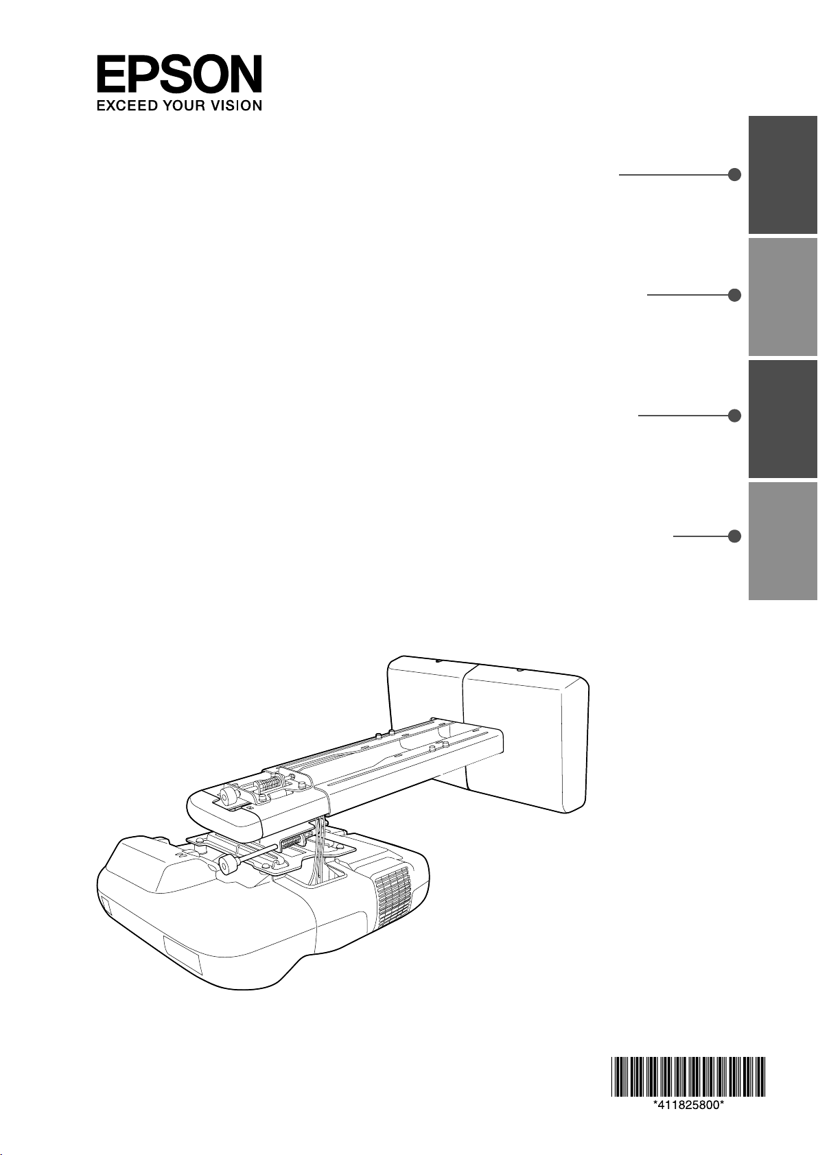
Installation Guide
EnglishFrançaisEspañolPortuguês
Guide d’installation
Guía de instalación
Manual de instalação
Page 2

Page 3

Installation Guide
English
English
Page 4
Safety Instructions
For your safety, read all the instructions in this guide before using the setting plate. Incorrect handling that
ignores instructions in this guide could damage the setting plate or could result in personal injury or property
damage. Keep this installation guide at hand for future reference.
Read the User's Guide and Safety Instructions for your projector and follow the instructions in these
documents.
Explanation of Symbols
The warning marks shown below are used throughout this installation guide to prevent personal injury or
property damage. Make sure you understand these warnings when reading this installation guide.
Warning
Caution
This symbol indicates information that, if ignored, could possibly result in personal injury or even death
due to incorrect handling.
This symbol indicates information that, if ignored, could possibly result in personal injury or physical
damage due to incorrect handling.
Symbol indicating an action that must not be done
Symbol indicating an action that should be done
Safety Precautions for Installation
Warning
The setting plate is designed specifically for mounting a projector to a wall. If anything other than a
projector is mounted, the weight may result in damage.
If the setting plate falls, it could cause personal injury or property damage.
The installation work (wall mounting) should be performed by specialists who have technical knowledge
and ability. Incomplete or incorrect installation could cause the setting plate to fall and cause personal
injury or property damage. Contact the customer support office listed on the Epson Projector Contact List
in the User's Guide for your projector when installing the setting plate.
Follow the instructions in this guide when installing the setting plate.
If the instructions are not followed, the setting plate may fall, resulting in personal injury or an accident.
Handle the power cable carefully.
Incorrect handling may cause fire or electric shock. Observe the following precautions when handling:
• Do not handle the power plug with wet hands.
• Do not use a power cable that is damaged or modified.
• Do not pull the power cable with too much force when routing the cable through the setting plate.
When you mount the projector on the wall with the setting plate, the wall requires enough strength to hold
the projector and the setting plate. Confirm the mass of the projector and the setting plate before
installation, and maintain the strength of the wall. If the wall is not strong enough, reinforce the wall
before installation.
Do not install the setting plate in a place where it might be subjected to vibration or shock.
Vibration or shock could cause damage to the projector or mounting surface. It could also cause the setting plate or
projector to fall and cause personal injury or property damage.
Install the setting plate so that it can sufficiently support the mass of the projector and setting plate, and
resist any horizontal vibration. Use M8 nuts and bolts.
Nuts and bolts smaller than M8 could cause the setting plate to fall. Epson takes no responsibility for any damage or
injury caused by incorrect installation.
4
Page 5
Warning
The installation work should be performed by at least two qualified service personnel. If you need to
loosen any screws during installation, be careful not to drop the setting plate.
If the setting plate or projector falls, it could cause personal injury or property damage.
Inspect the setting plate on a regular basis to ensure there are no broken parts or loose screws.
If there are any broken parts, stop using the setting plate immediately. If the setting plate or projector falls, it could cause
personal injury or property damage.
Never modify the setting plate.
Do not hang on the setting plate or hang a heavy object on the setting plate.
If the projector or setting plate falls, it could cause personal injury or property damage.
If you use adhesives to prevent the screws from loosening or things such as lubricants or oils on the slide
plate fixing part of the projector, the case may crack and cause the projector to fall, resulting in personal
injury or property damage. Do not use adhesives, lubricants, or oils to install or adjust the setting plate.
Tighten all screws firmly after adjustment.
If the screws are not tightened firmly, the projector or setting plate may fall and cause personal injury or property
damage.
Never loosen the bolts and nuts after installation.
Confirm that the screws have not become loose on a regular basis. If you find any loose screws, tighten them firmly. If the
screws are not tightened firmly, the projector or setting plate may fall and cause personal injury or property damage.
English
Caution
Do not install the setting plate in a location where the operating temperature for your projector model
may be exceeded.
Such an environment may damage the projector.
Install the setting plate in a place free from excessive dust and humidity to prevent the lens or optical
components from becoming dirty.
Do not use excessive force when adjusting the setting plate.
The setting plate may break, resulting in personal injury.
Place to Install the Setting Plate
Carry out the power supply wiring work for the installation location of the setting plate in advance.
Install the projector away from other electric devices such as fluorescent lights or air conditioners. Some
kinds of fluorescent lights could interfere with the remote control of the projector.
It is recommended to keep connection cable length less than 20 meters to reduce external noise.
Install the setting plate in a place free from excessive dust and humidity to prevent the lens or optical
components from becoming dirty.
About This Installation Guide
This guide describes how to mount the short-throw projector EB-460i/460/450Wi/450W/440W to a wall using
the exclusive setting plate.
5
Page 6

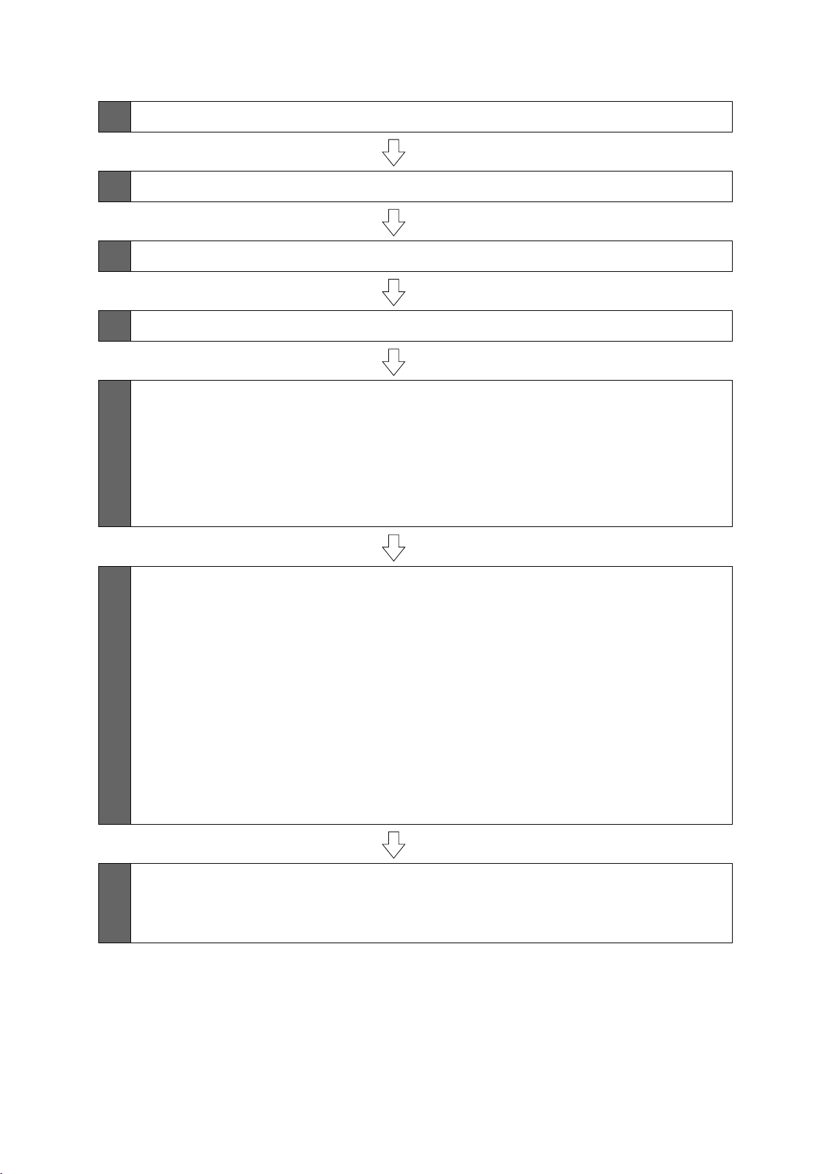
1 Package Contents
s Page 7
2 Specifications
3 Connecting Devices
4 Projection Distance Table
5 Installation Procedure
(1) Install the wall plate on the wall
(2) Determine the projection distance and pull out the slider
(3) Attach the setting plate to the wall plate
(4) Secure the projector to the setting plate
(5) Connect the power cable and other cables to the projector
6 Adjusting the Projection Screen
s Page 8
s Page 9
s Page 10
s Page 13
s Page 17
(1) Turn on the projector
(2) Change the aspect ratio
(3) Display the test pattern
(4) Adjust the focus
(5) Use the top adjustment dial to adjust the vertical tilt
(6) Use the right adjustment dial to adjust the horizontal rotation
(7) Use the left adjustment dial to adjust the horizontal roll
(8) Adjust the vertical slide
(9) Adjust the forward/backward slide
(10) Turn off the display of the test pattern
7 Attaching the Covers
(1) Attach the wall plate cover and end cap
(2) Attach the cable cover to the projector
s Page 21
6
Page 7
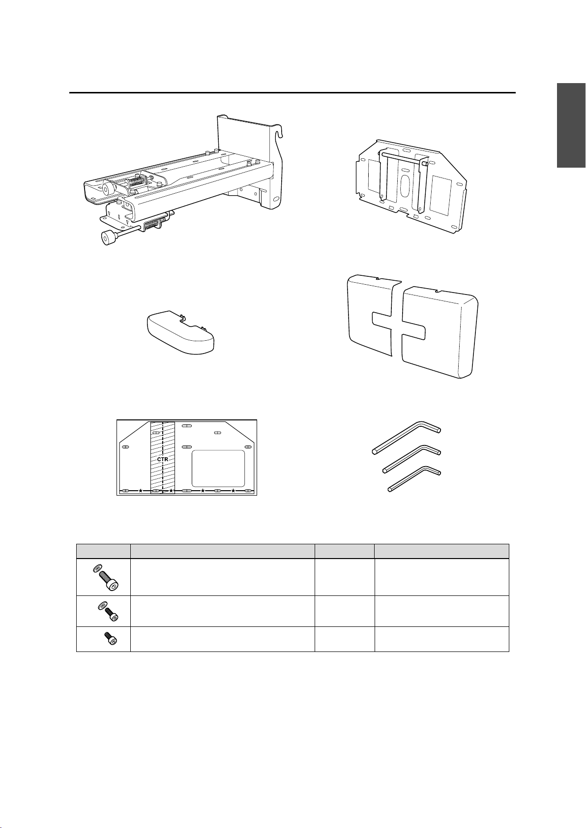
1. Package Contents
English
Setting plate
End cap
Template sheet
(for installing the wall plate)
Wall plate
Wall plate cover
Hexagon wrenches (for M4, M5, and M8)
Shape Name Quantity Application
M8 x 15 mm hexagon socket head cap bolt with
washer
M5 x 12 mm hexagon socket head cap bolt with
washer
M4 x 12 mm hexagon socket head cap bolt without
washer
Use the bolts supplied with the setting plate to install it, as directed in this guide. Do not substitute these
2 For installing setting plate
2 For securing projector
2 For installing wall plate cover
bolts with any other types.
Use commercially available M8 x 50 mm anchors (at least 3) or 8 x 80 mm lag bolts (at least 3) to attach the
wall plate to the wall.
Gather the tools and parts you need before you begin installation.
7
Page 8
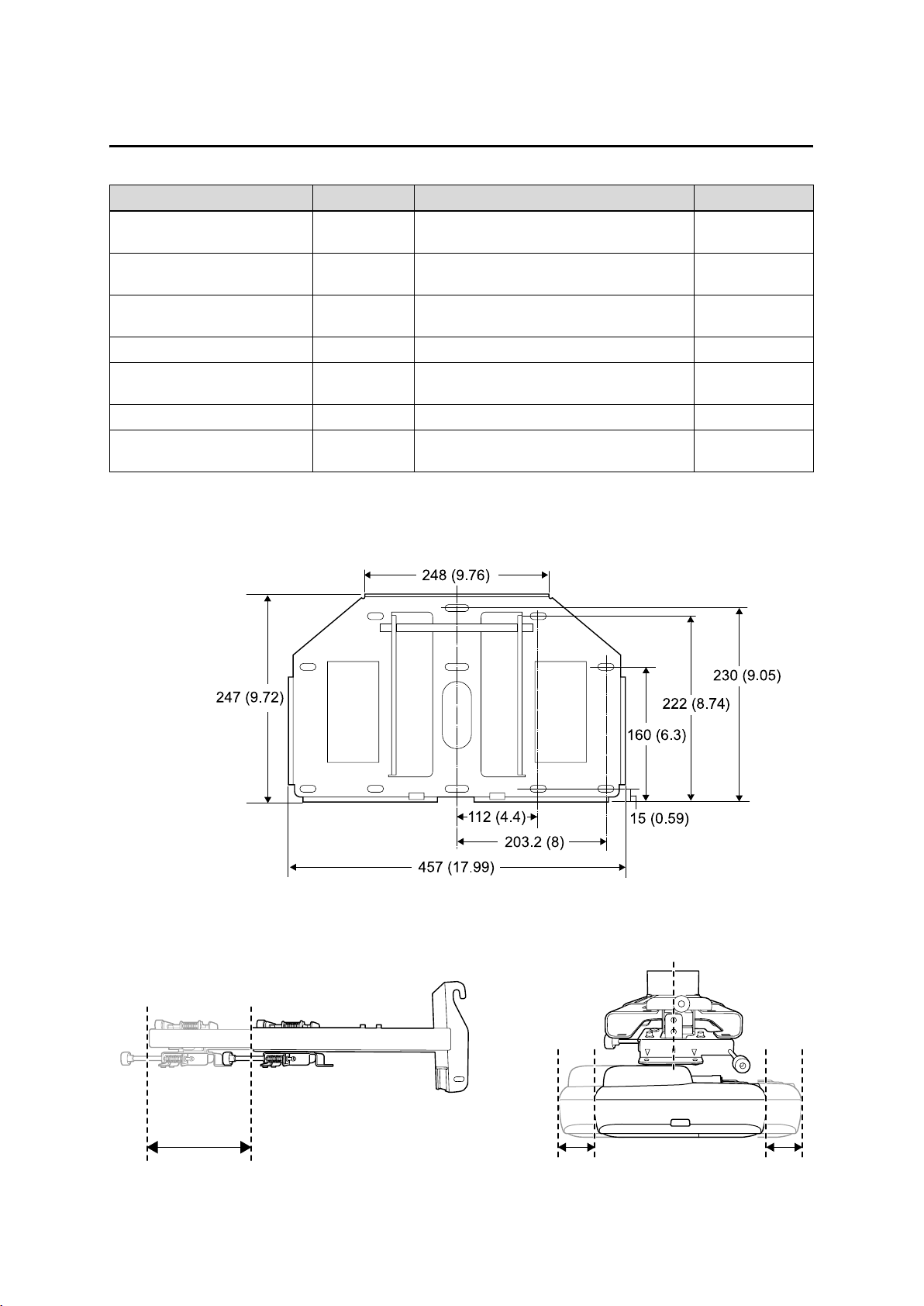
2. Specifications
Item Specification Remark Reference Page
Setting plate mass Approx. 6.3 kg
(13.89 lb.)
Forward/backward slide
adjustment range
Vertical slide adjustment range ± 4
Vertical tilt adjustment range ± 5
Horizontal rotation adjustment
range
Horizontal roll adjustment range ± 3
Horizontal slide adjustment range ± 45 mm
Wall plate
0 to 300 mm
(11.81 in.)
°
°
°
± 5
°
(1.77 in.)
Wall plate (2.2 kg [4.85 lb.])
Covers and cap (0.47 kg [1.04 lb.])
Minimum: 28 mm (1.10 in.)
Maximum: 42.5 mm (1.67 in.)
Fine adjustments possible with adjustment dial
Fine adjustments possible with adjustment dial
Fine adjustments possible with adjustment dial
Refer to the figure
below
s p. 20
s p. 18
s p. 19
s p. 19
Refer to the figure
below
[Unit: mm (in.)]
Setting plate adjustment range
Forward/backward slide adjustment range:
0 to 300 mm (11.81 in.)
Horizontal slide adjustment range:
± 45 mm (1.77 in.)
8
Page 9
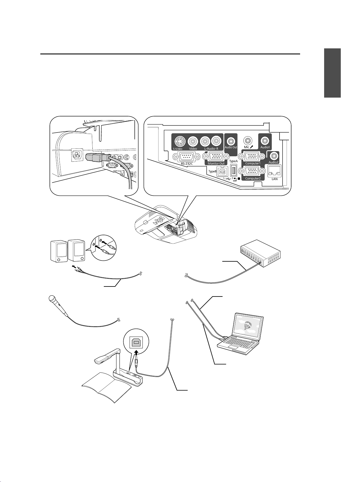
3.Connecting Devices
Prepare a power cable, computer cable, USB cable, and so on at the location where the setting plate is to be
installed.
Prepare all necessary cables for devices, such as a document camera or microphone, that you will connect to
the projector.
Connection Example
English
External speakers
Audio cable
(commercially available product)
Microphone
Document camera
LAN device
LAN cable
Computer cable
(for computer video output)
Computer
USB cable
(for Easy Interactive Function)
Dedicated USB cable
(supplied with document camera)
9
Page 10
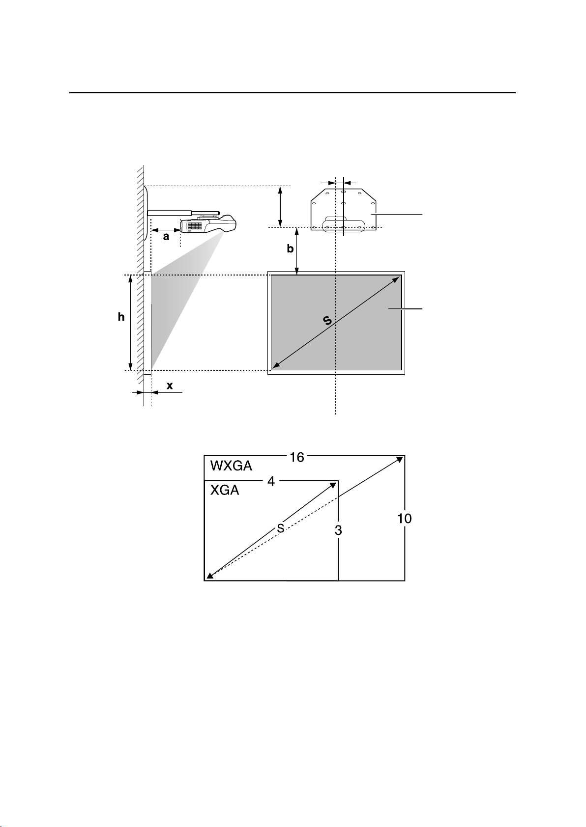
4. Projection Distance Table
Refer to the table below and install the setting plate and projector to project images at an appropriate size on
the projection surface. The values are only rough estimates.
The recommended range for the projection distance (a) is 7 to 37 cm (2.76 to 14.57 in.).
240 mm (9.44 in.)
Distance from wall of
projection surface
65 mm (2.55 in.)
Offset value for the position of
the center of the screen and the
center of the wall plate
Wall plate
Projection surface
10
Page 11
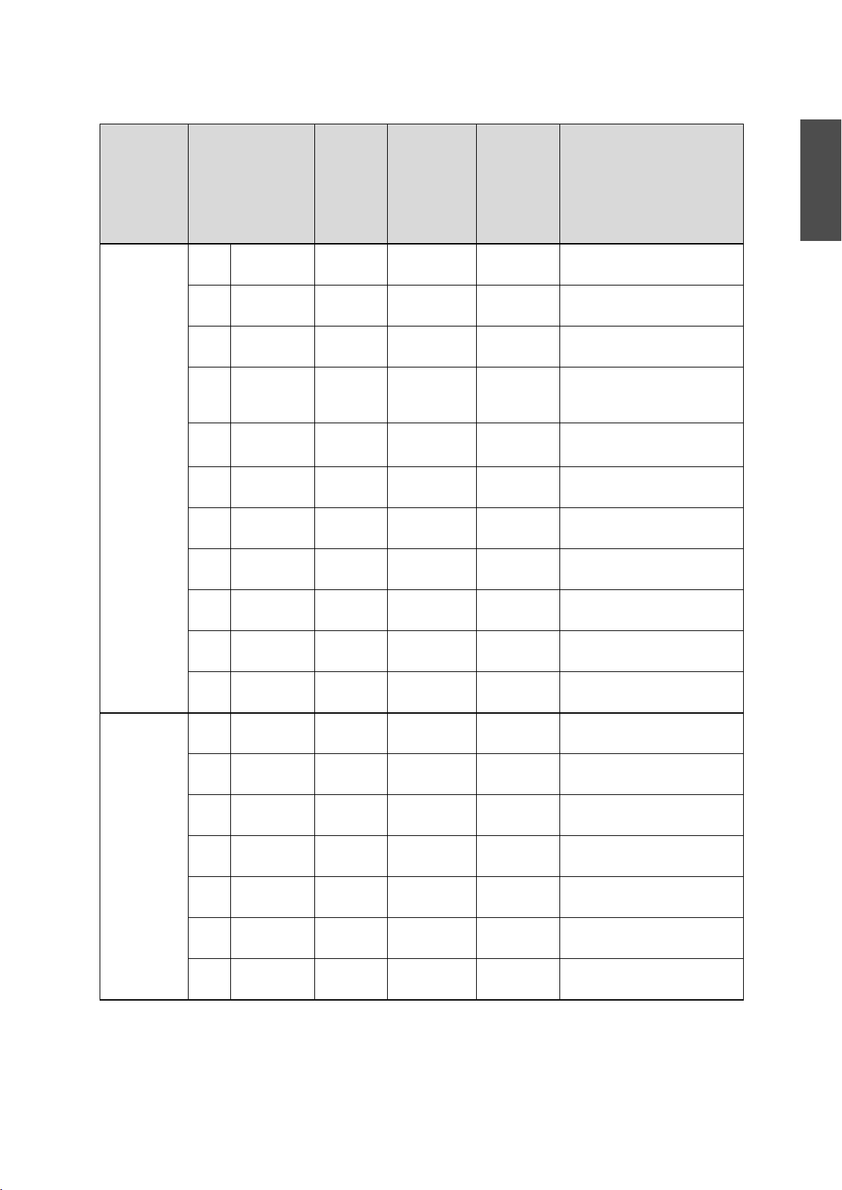
S a b h
Unit: mm (in.)
Screen
Aspect Ratio
4:3 63" 1280x960
64" 1300x970
70" 1420x1070
77" 1560x1170
77.5" 1570x1180
78" 1580x1190
80" 1630x1220
87" 1770x1330
Size
(50.39x37.79)
(51.18x38.18)
(55.90x42.12)
(61.41x46.06)
(61.81x46.45)
(62.20x46.85)
(64.17x48.03)
(69.68x52.36)
Projection
Distance
Minimum
(Wide)
Distance
Between
Projection
Surface and
Height of
Projection
Surface
Interactive
Whiteboard
Wall Plate
71 (2.80) 175 (6.89) 960 (37.80) Hitachi StarBoard FX-63
79 (3.11) 177 (6.97) 975 (38.39) SMART Board 660
Promethean ActivBoard 164
125 (4.92) 191 (7.52) 1067 (42.01)
178 (7.00) 207 (8.15) 1173 (46.18) Hitachi Cambridge Board 77
Hitachi StarBoard FX-77
SMART Board 680
182 (7.16) 208 (8.19) 1181 (46.50) RM ClassBoard2 77.5
INTERWRITE
186 (7.32) 209 (8.23) 1189 (46.81) PolyVision TS610
Promethean ActivBoard 178 / 378
201 (7.91) 213 (8.39) 1219 (47.99)
255 (10.03) 229 (9.02) 1326 (52.20)
®
BOARD 1077
English
90" 1830x1370
(72.04x53.93)
100" 2030x1520
(79.92x59.84)
102" 2070x1550
(81.49x61.02)
16:10 60" 1290x810
(50.78x31.88)
70" 1510x940
(59.44x37.00)
78" 1680x1050
(66.14x41.33)
80" 1720x1080
(67.71x42.51)
87" 1870x1170
(73.62x46.06)
90" 1940x1210
(76.37x47.63)
96" 2070x1290
(81.49x50.78)
277 (10.90) 236 (9.29) 1372 (54.02)
354 (13.93) 259 (10.20) 1524 (60.00)
369 (14.52) 264 (10.39) 1554 (61.18)
76 (2.99) 257 (10.12) 808 (31.81)
157 (6.18) 294 (11.57) 942 (37.09)
222 (8.74) 325 (12.79) 1050 (41.34) PolyVision TS 600
/ TS610 / TSL610
238 (9.37) 332 (13.07) 1077 (42.40)
294 (11.57) 358 (14.09) 1171 (46.10) SMART Board 685 / Promethean
ActivBoard 387
319 (12.55) 370 (14.57) 1212 (47.72)
367 (14.44) 392 (15.43) 1292 (50.87)
11
Page 12
S a b h
Screen
Aspect Ratio
16:9 58" 1280x720
60" 1330x750
65" 1440x810
70" 1550x870
71" 1570x880
80" 1770x1000
82" 1820x1020
85" 1880x1060
Size
(50.39x28.34)
(52.36x29.52)
(56.69x31.88)
(61.02x34.25)
(61.81x34.64)
(69.68x39.37)
(71.65x40.15)
(74.01x41.73)
Projection
Distance
Minimum
(Wide)
Distance
Between
Projection
Surface and
Height of
Projection
Surface
Interactive
Whiteboard
Wall Plate
73 (2.87) 295 (11.61) 722 (28.43)
90 (3.54) 304 (11.97) 747 (29.41) RM ClassBoard2 60
131 (5.15) 327 (12.87) 809 (31.85)
173 (6.81) 350 (13.78) 872 (34.33)
181 (7.12) 355 (13.98) 884 (34.80)
256 (10.07) 396 (15.59) 996 (39.21)
272 (10.70) 405 (15.94) 1021 (40.20) Hitachi StarBoard FX-82W
297 (11.69) 419 (16.50) 1058 (41.65)
INTERWRITE
INTERWRITE
®
BOARD 1071
®
BOARD 1085
90" 1990x1120
(78.34x44.09)
93" 2060x1160
(81.10x45.66)
339 (13.34) 441 (17.36) 1121 (44.13)
364 (14.33) 455 (17.91) 1158 (45.59)
12
Page 13
5. Installation Procedure
Make sure to follow the steps below to install the setting plate. If you ignore these steps, the setting plate
could fall and cause personal injury or property damage.
The maximum combined mass of the setting plate and the projector is approximately 15.2 kg
(33.5 lb). When you install the setting plate, calculate the permissible weight, carefully check
the construction, material, and strength of the wall, and perform the installation properly using
the most appropriate method.
A Install the wall plate on the wall
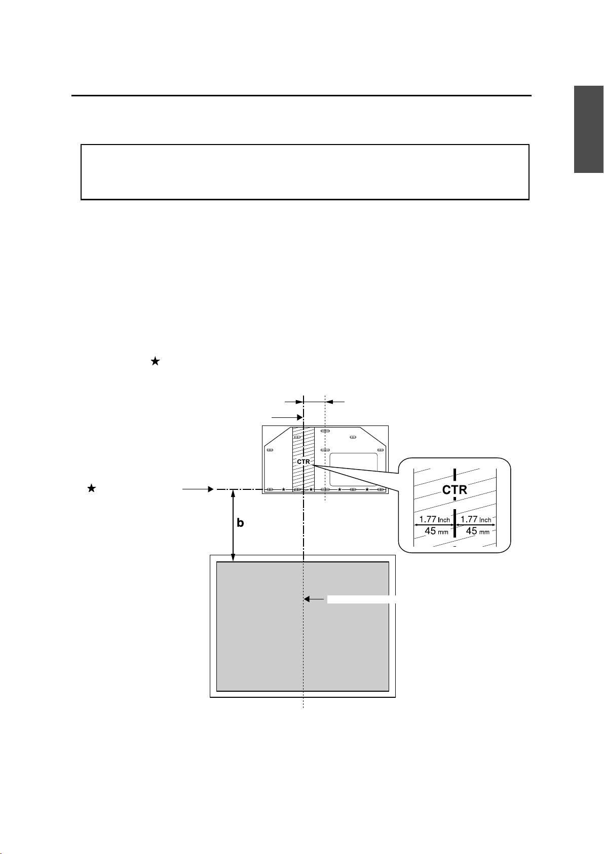
(1) Determine the template sheet position.
• From the projection distance table, confirm the screen size (S) and the distance between the
projection surface and wall plate (b).
• Align the CTR line (vertical) of the template sheet with the center line (vertical) of the projection
surface.
Confirm where the beams are within the wall, and shift the position left or right as necessary.
(The position can be shifted horizontally left or right from the center line of the projection surface by
up to 45 mm [1.77 in.].)
Align the line (horizontal) of the template with the height of (b).
English
CTR line of template sheet
line of template sheet
65 mm (2.55 in.)
Center line of projection surface
(2) Attach the template sheet to the wall.
13
Page 14
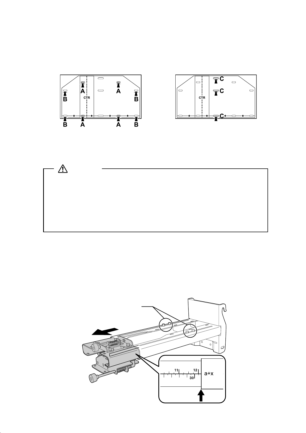
(3) Make mounting holes in the wall in the required locations.
The wall plate needs to be secured by commercially available anchors or lag bolts in the following
places. It is recommended that the wall plate be secured in at least three places.
• If securing the wall plate in four places, make the holes indicated by A or B in the figure.
• If securing the wall plate in three places, make the holes indicated by C in the figure.
Four mounting holes
Three mounting holes
(4) Remove the template sheet.
(5) Mount the wall plate on the wall.
Warning
❏ When you mount the projector on the wall with the setting plate, the wall needs to be
strong enough to hold the projector and the setting plate. Confirm the mass of the
projector and the setting plate before installation, and maintain the strength of the wall. If
the wall is not strong enough, reinforce the wall before installation.
❏ Install the setting plate so that it can sufficiently support the mass of the projector and
setting plate, and resist any horizontal vibration. Use M8 nuts and bolts. Nuts and bolts
smaller than M8 could cause the setting plate to fall.
❏ Epson takes no responsibility for any damage or injury caused by incorrect installation.
B Determine the projection distance and pull out the slider
(1) From the projection distance table, calculate the distance (a) from the projection surface to
the front of the projector.
(2) Loosen the four screws and pull out the slider on the setting plate.
Align the slider with the mark slider measure that is a distance (a+x) equivalent to the distance (a) plus
the thickness of the projection screen (x).
Screws (4 )
Slider measure
14
Page 15
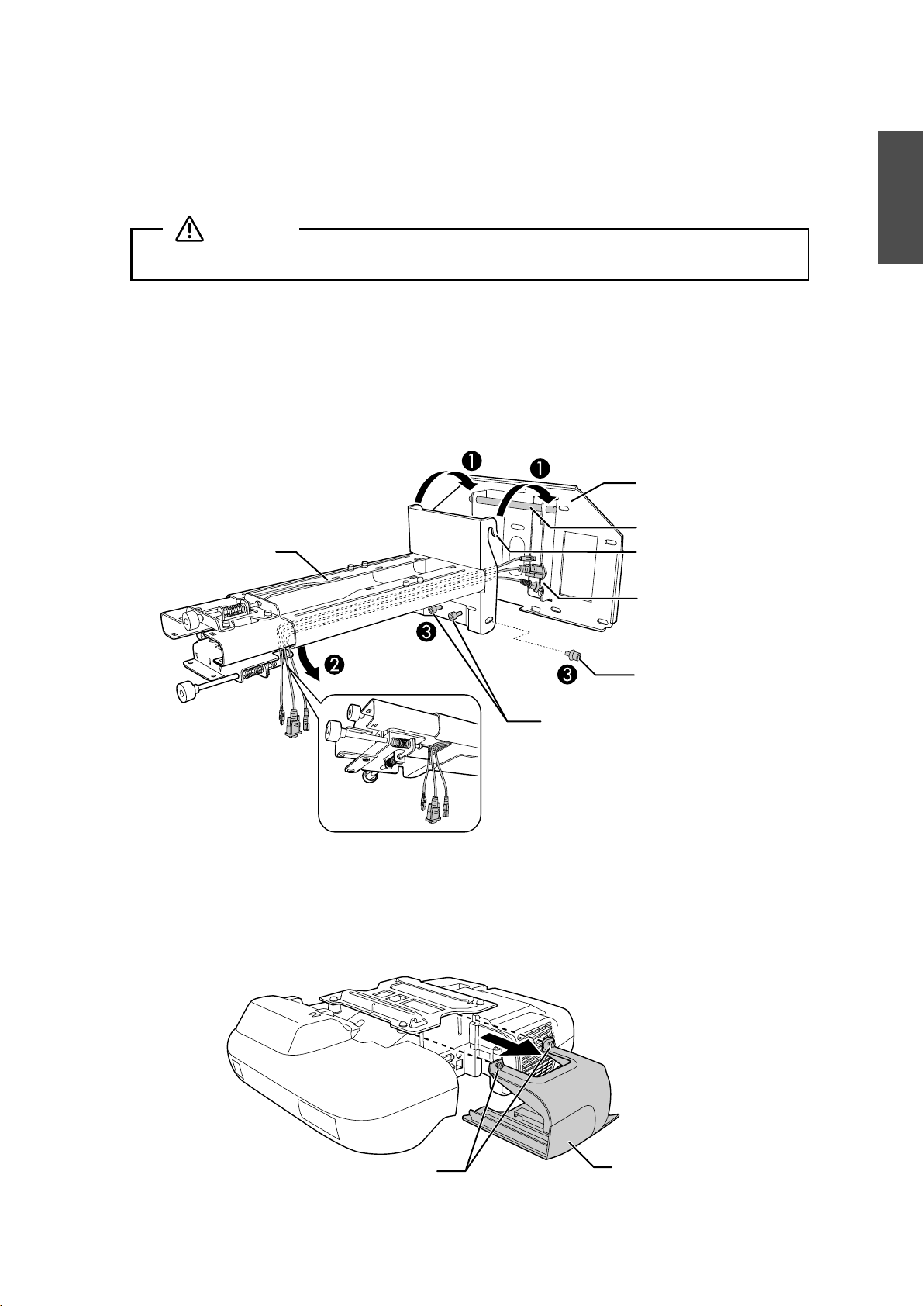
C Attach the setting plate to the wall plate
(1) Hang the setting plate hook onto the wall plate bar (A).
(2) Lift up the setting plate and pass the cables through it (
B).
Caution
Take care not to trap the cables between the setting plate and wall plate.
(3) Tighten the two M8 x 15 mm hexagon socket head cap bolts and two M8 x 35 mm hexagon
socket head cap bolts supplied with the setting plate so that the setting plate becomes
vertical against the wall (
Use the two M8 x 35 mm hexagon socket head cap bolts to adjust the vertical slide.
s p. 20
Setting plate
C).
Wall plate
Wall plate bar
Setting plate hook
Cables
English
M8 x 35 mm hexagon
socket head cap bolts (2)
D Secure the projector to the setting plate
(1) Loosen the two screws and remove the cable cover from the projector.
M8 x 15 mm hexagon socket
head cap bolts (one on left
and one on right)
Screws (2)
Cable cover
15
Page 16
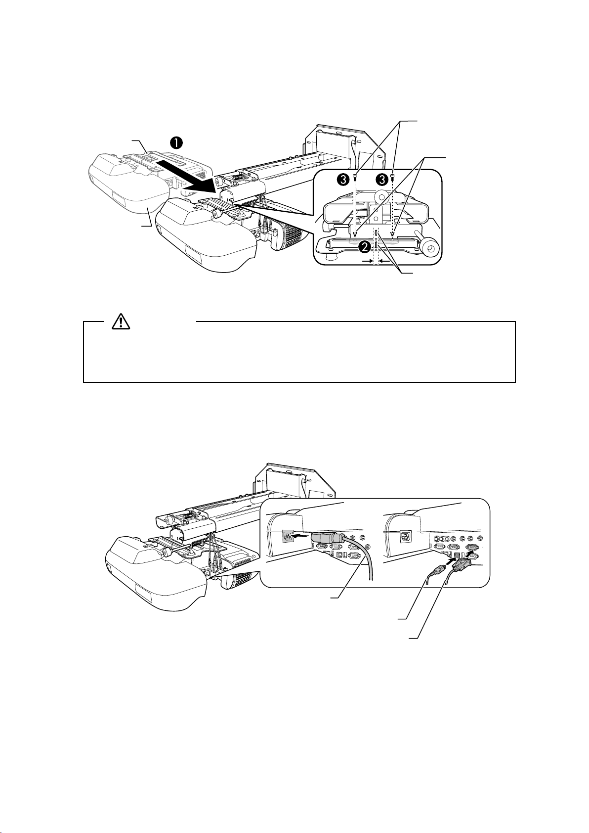
(2) Insert the slide plate into the setting plate from the interface side of the projector (A).
Align the marks on the projector and the setting plate (
Slide plate
Projector
interface side
B).
M5 x 12 mm hexagon
socket head cap bolts (2)
Bolt positions
Marks
(3) Tighten the two M5 x 12 mm hexagon socket head cap bolts (
C).
Warning
If you use adhesives to prevent the screws from loosening or things such as lubricants or oils
on the slide plate fixing part of the projector, the case may crack and cause the projector to fall,
resulting in personal injury or property damage. Do not use adhesives, lubricants, or oils to
install or adjust the setting plate.
E Connect the power cable and other cables to the projector
Connect any necessary cables such as the power cable, computer cable, and USB cable to the projector.
Power cable
16
USB cable
Computer cable
Page 17
6. Adjusting the Projection Screen
i
To ensure maximum projection screen quality, follow the steps below to adjust the projection screen.
Do not make adjustments with the Keystone function of the projector. Doing so may
result in a reduction in image quality.
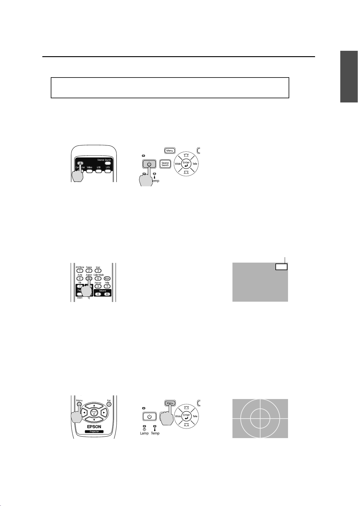
A Turn on the projector
Using Remote Control Using Control Panel
B Change the aspect ratio
Each time you press the [Aspect] button on the remote control, the aspect name is displayed on the
screen and the aspect ratio changes.
Change the setting according to the signal for the connected equipment.
Remote Control
Aspect Rat
English
o
Alternatively, set the aspect ratio from the [Signal] menu - [Aspect] from the Configuration menu.
s User’s Guide for the projector: [Configuration] menu - [Signal] menu
C Display the test pattern
Press the [Menu] button and select the [Settings] menu - [Pattern] - [Test Pattern] from the
Configuration menu.
s User’s Guide for the projector: [Configuration] menu - [Settings] menu
Using Remote Control Using Control Panel
4:3
17
Page 18
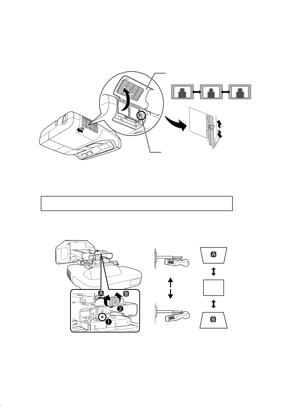
D Adjust the focus
(1) Move the air filter cover lever to open the air filter cover.
(2) Use the focus lever to adjust the focus.
Air filter cover
Focus lever
(3) After you finish making the adjustment, close the air filter cover.
E Use the top adjustment dial to adjust the vertical tilt
Repeat steps E to I as necessary.
(1) Loosen the screw that corresponds to the top adjustment dial (A).
(2) Turn the adjustment dial to adjust the vertical tilt (
B).
(3) After you finish making all of the adjustments in steps
loosened in
A.
18
E to I, tighten the screw you
Page 19
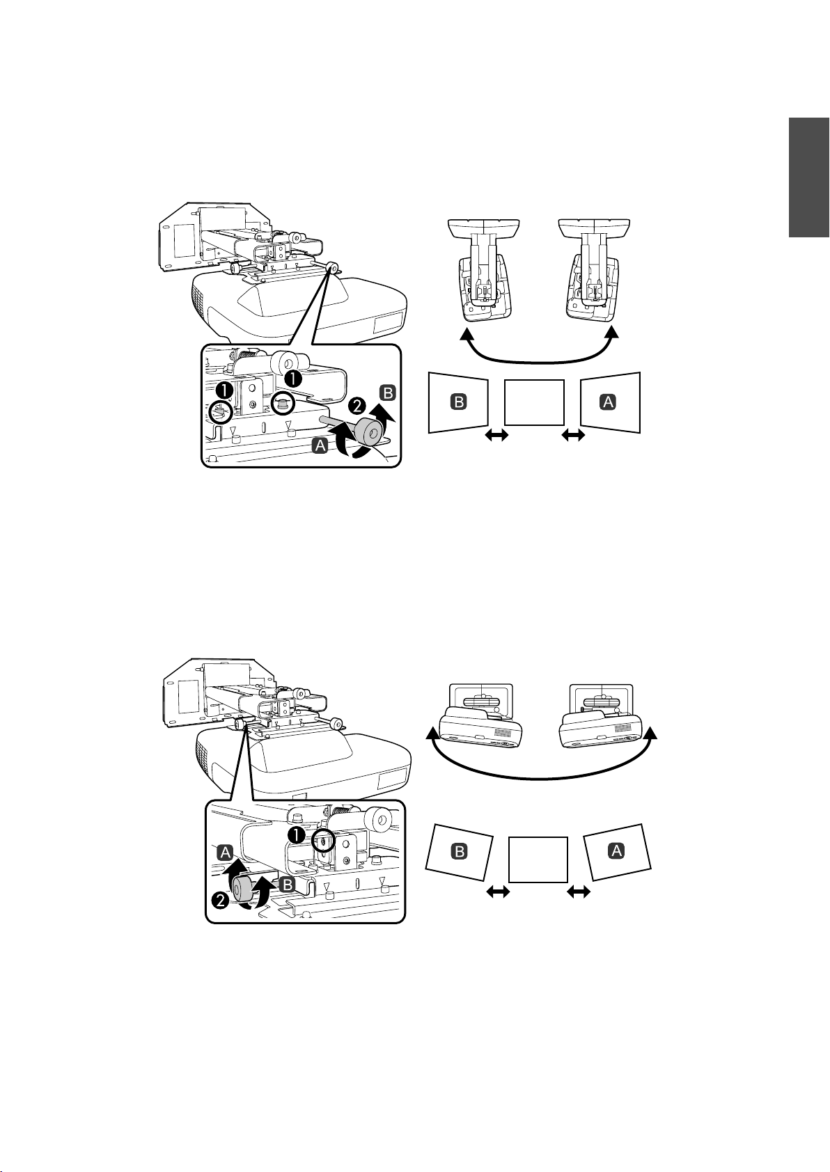
F Use the right adjustment dial to adjust the horizontal rotation
(1) Loosen the two screws that correspond to the right adjustment dial (A).
(2) Turn the adjustment dial to adjust the horizontal rotation (
(3) After you finish making all of the adjustments in steps
loosened in
A.
B).
E to I, tighten the two screws you
G Use the left adjustment dial to adjust the horizontal roll
English
(1) Loosen the screw that corresponds to the left adjustment dial (A).
(2) Turn the adjustment dial to adjust the horizontal roll (
(3) After you finish making all of the adjustments in steps
loosened in
A.
B).
E to I, tighten the screw you
19
Page 20
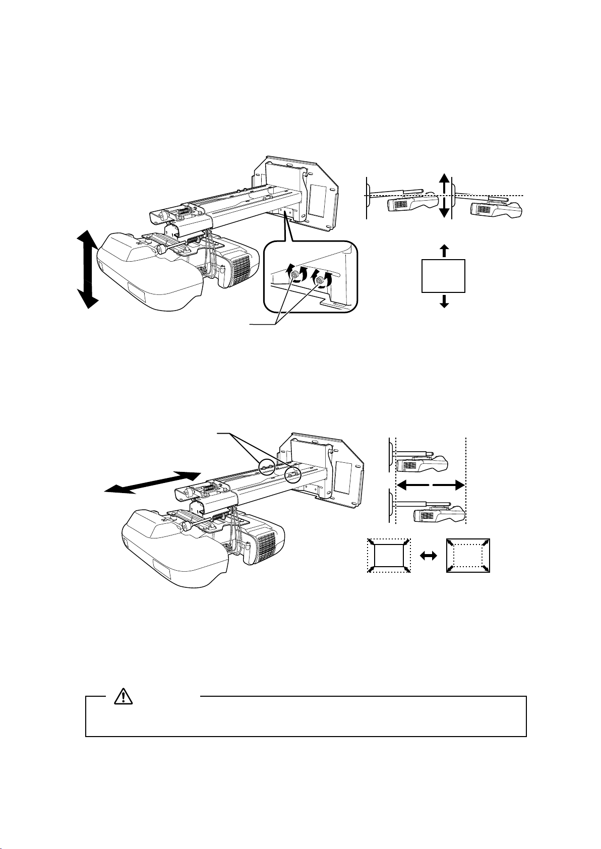
H Adjust the vertical slide
Adjust the vertical slide with the two M8 x 35 mm hexagon socket head cap bolts at the bottom of the
setting plate. Tightening the bolts raises the setting plate, and loosening them lowers it.
The projection screen is raised or lowered accordingly.
M8 x 35 mm
hexagon socket
head cap bolts (2)
I Adjust the forward/backward slide
Loosen the four screws and adjust the slider of the setting plate.
Screws (4)
After you finish making all of the adjustments in steps
E to I, tighten the screws.
J Turn off the display of the test pattern
Press the [Esc] button on the remote control or control panel to turn off the test pattern.
Warning
Tighten all screws firmly. If the screws are not tightened firmly, the projector or setting plate
may fall and cause personal injury or property damage.
20
Page 21
7. Attaching the Covers
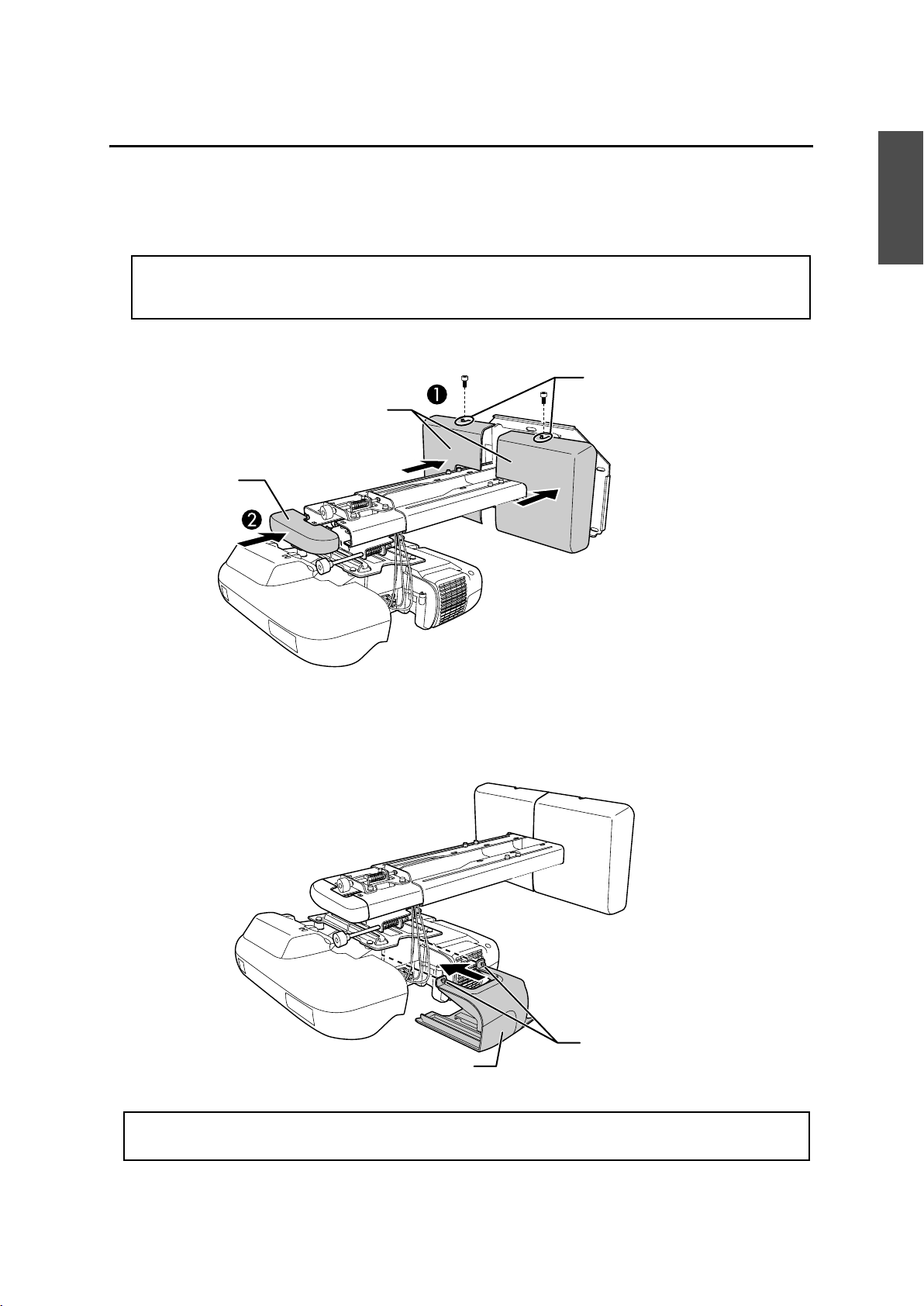
A Attach the wall plate cover and end cap
(1) Secure the wall plate cover with the two M4 x 12 mm hexagon socket head cap bolts (A).
Depending on how the cables are wired, you may need to cut out parts of the wall
q
(2) Place the end cap with the concave portion facing up (
plate cover to allow the cables to be passed through it.
Wall plate cover
End cap
B).
M4 x 12 mm
hexagon socket head
cap bolts (2)
English
B Attach the cable cover to the projector
Attach the cable cover and tighten the two screws to secure the cable cover.
Screws (2)
Cable cover
Only a specialist should remove or reinstall the projector, including for maintenance and
repairs. Refer to the User’s Guide of your projector for instructions on maintenance and repairs.
21
Page 22
Warning
❏ Never loosen the bolts and nuts after installation. Confirm that the screws have not
become loose on a regular basis. If you find any loose screws, tighten them firmly. If the
screws are not tightened firmly, the projector or setting plate may fall and cause personal
injury or property damage.
❏ Do not hang on the setting plate or hang a heavy object on the setting plate. If the
projector or setting plate falls, it could cause personal injury or property damage.
8. Appendix
Using the Easy Interactive Function
After you install an Easy Interactive Function compatible model (EB-460i/450Wi), you need to install the Easy
Interactive Driver and perform calibration (to align the positions of the cursor and Easy Interactive Pen).
For details, refer to the supplied Quick Start Guide or the User’s Guide on the Document CD-ROM.
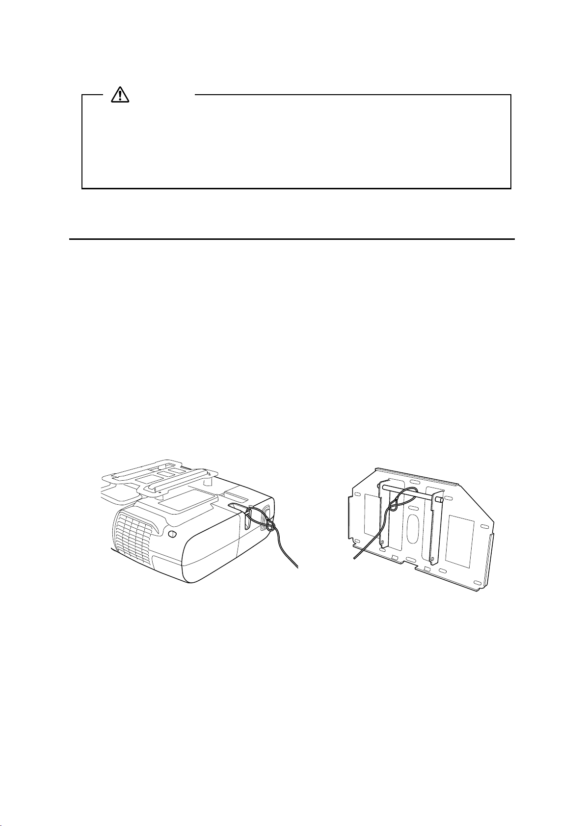
Attaching a Security Cable
If the projector is to be installed in a room where it will be left unattended, you can use a commercially
available theft-prevention wire lock to secure the projector to a post or other object to prevent someone from
taking it.
Pass the wire of the theft-prevention wire lock through the security cable installation point.
For details on how to lock the wire lock, refer to the User’s Guide supplied with the wire lock.
22
Page 23
Guide d’installation
Français
Français
Page 24
Consignes de sécurité
Pour votre sécurité, veuillez lire toutes les consignes contenues dans ce guide avant d’utiliser le support de
montage. Une manipulation incorrecte ne respectant pas ces consignes pourrait endommager le support de
montage ou provoquer des blessures corporelles ou des dommages matériels. Conservez ce guide
d’installation à portée de main pour pouvoir vous y reporter ultérieurement.
Lisez le Guide de l’utilisateur et les Consignes de sécurité de votre projecteur et suivez les instructions figurant
dans ces documents.
Explication des symboles
Les symboles d’avertissement ci-dessous sont utilisés dans ce guide d’installation afin de vous éviter de vous
blesser ou de provoquer des dommages matériels. Assurez-vous de bien avoir compris la signification de ces
avertissements lorsque vous lisez ce guide.
Avertissement
Attention
Ce symbole signale des informations qui, si elles sont ignorées, peuvent provoquer des
blessures, voire la mort, en raison d’une manipulation incorrecte.
Ce symbole indique des informations qui, si elles sont ignorées, peuvent provoquer des
blessures ou des dommages physiques, en raison d’une manipulation incorrecte.
Symbole indiquant une action à ne pas faire
Symbole indiquant une action à faire
Consignes de sécurité pour l’installation
Avertissement
Le support de montage est conçu exclusivement pour fixer un projecteur à un mur. Si un équipement autre
qu’un projecteur est installé, son poids peut endommager le support.
En cas de chute du support de montage, il peut provoquer des blessures corporelles ou des dommages matériels.
Les travaux d’installation (fixation murale) doivent être effectués par des spécialistes disposant des
compétences techniques et du savoir-faire appropriés. Une installation incomplète ou incorrecte peut
entraîner la chute du support de montage et provoquer des blessures corporelles ou des dommages
matériels. Contactez le bureau du service d’assistance à la clientèle répertorié dans la Liste des contacts
pour projecteurs Epson du Guide de l’utilisateur de votre projecteur pour installer le support de montage.
Suivez les instructions du présent guide pour installer le support de montage.
En cas de non-respect des instructions, le support de montage peut tomber et provoquer des blessures corporelles ou un
accident.
Manipulez le cordon secteur avec précaution.
Une manipulation incorrecte peut provoquer un incendie ou une électrocution. Prenez les précautions suivantes en le
manipulant :
• Ne saisissez pas la fiche secteur avec des mains humides.
• N’utilisez pas un cordon secteur endommagé ou modifié.
• Ne tirez pas exagérément sur le cordon lorsque vous le faites passer à travers le support de montage.
La fixation du projecteur sur un mur à l’aide du support de montage doit être effectuée sur un mur
suffisamment solide pour maintenir le support de montage et le projecteur. Vérifiez donc le poids du
projecteur et du support de montage avant l’installation et veillez à la bonne solidité du mur. Si la solidité
du mur est insuffisante, renforcez le mur avant de procéder à l’installation.
N’installez pas le support de montage à un endroit où il peut être soumis à des vibrations ou des chocs.
Des vibrations ou des chocs pourraient endommager le projecteur ou la surface de montage. Vous risqueriez également de
provoquer la chute du support de montage ou du projecteur et donc des blessures corporelles ou des dommages matériels.
Installez le support de montage de sorte qu’il puisse supporter son poids ainsi que celui du projecteur et
résister à toute vibration horizontale. Utilisez des écrous et des boulons M8.
Si vous utilisez des écrous et des boulons de taille inférieure à M8, le support de montage risque de tomber. Epson décline
toute responsabilité en cas de dommage ou de blessure dû à une mauvaise installation.
24
Page 25
Avertissement
L’installation doit être exécutée par au moins deux techniciens qualifiés. Si vous devez desserrer des vis
pendant l’installation, veillez à ne pas provoquer la chute du support de montage.
En cas de chute du support de montage ou du projecteur, il peut provoquer des blessures corporelles ou des dommages
matériels.
Contrôlez régulièrement le support de montage pour vérifier qu’aucune de ses pièces n’est endommagée
ou que des vis ne sont pas desserrées.
Si des pièces sont endommagées, cessez immédiatement d’utiliser le support de montage. En cas de chute du support de
montage ou du projecteur, il peut provoquer des blessures corporelles ou des dommages matériels.
Ne modifiez jamais le support de montage.
Ne suspendez aucun objet au support de montage ni ne posez d’objet lourd sur celui-ci.
En cas de chute du projecteur ou du support de montage, il peut provoquer des blessures corporelles ou des dommages
matériels.
Si vous utilisez des adhésifs pour empêcher les vis de se desserrer ou si vous utilisez des lubrifiants ou des
huiles sur la plaque coulissante de fixation du projecteur, le boîtier risque de se détériorer, au risque de
provoquer la chute du projecteur et des blessures corporelles ou des dommages matériels. N’utilisez pas
d’adhésifs, ni d’huiles ou lubrifiants pour installer ou régler le support de montage.
Serrez fermement toutes les vis après tout réglage.
Des vis insuffisamment serrées peuvent entraîner la chute du projecteur ou du support de montage et provoquer des
blessures corporelles ou des dommages matériels.
Ne desserrez jamais les écrous et les boulons après l’installation.
Vérifiez régulièrement que les vis ne se sont pas desserrées. Si vous constatez le moindre jeu, resserrez fermement les vis
concernées. Des vis insuffisamment serrées peuvent entraîner la chute du projecteur ou du support de montage et
provoquer des blessures corporelles ou des dommages matériels.
Français
Attention
N’installez pas le support de montage dans un endroit qui excède la plage de température de
fonctionnement du modèle de projecteur.
Un tel environnement peut endommager le projecteur.
Installez le support de montage dans un endroit à l’abri de la poussière et de l’humidité pour que l’objectif
et les éléments optiques internes ne se salissent pas.
Ne forcez pas de manière excessive lorsque vous réglez le support de montage.
Le support de montage peut être endommagé et provoquer des blessures corporelles.
Emplacement où installer le support de montage
Préparez à l’avance le câblage de l’alimentation électrique de l’emplacement d’installation du support de
montage.
Éloignez le projecteur des autres appareils électriques, notamment des éclairages fluorescents ou des
climatiseurs. Certains types d’éclairages fluorescents risquent d’interférer avec la télécommande du projecteur.
Nous vous recommandons d’utiliser un câble de connexion d’une longueur inférieure à 20 mètres afin de
réduire l’effet de parasites.
Installez le support de montage dans un endroit à l’abri de la poussière et de l’humidité pour que l’objectif
et les éléments optiques internes ne se salissent pas.
À propos de ce guide d’installation
Le présent guide décrit comment installer le projecteur à courte distance de projection EB-460i/460/450Wi/
450W/440W sur un mur à l’aide du support de montage prévu exclusivement à cet effet.
25
Page 26
1 Contenu de l’emballage
s Page 27
2 Spécifications
3 Connexion des appareils
4 Tableau de distance de projection
5 Procédure d’installation
(1) Installez la plaque murale sur le mur
(2) Déterminez la distance de projection et retirez la glissière
(3) Fixez le support de montage à la plaque murale
(4) Fixez le projecteur au support de montage
(5) Connectez le cordon secteur et les autres câbles au projecteur
6 Réglage de l’écran de projection
s Page 28
s Page 29
s Page 30
s Page 32
s Page 36
(1) Mettez le projecteur sous tension
(2) Changez le rapport largeur/hauteur
(3) Affichez la mire
(4) Réglez la mise au point
(5) Utilisez la molette de réglage supérieure pour régler l’inclinaison verticale
(6) Utilisez la molette de réglage droite pour régler la rotation horizontale
(7) Utilisez la molette de réglage gauche pour régler le roulis horizontal
(8) Réglez le coulissement vertical
(9) Réglez le coulissement vers l’avant/l’arrière
(10) Supprimez l’affichage de la mire
7 Fixation des caches
(1) Fixez le cache de la plaque murale et le capuchon de protection
(2) Fixez le cache du câble au projecteur
s Page 40
26
Page 27

1. Contenu de l’emballage
Français
Support de montage
Capuchon de
protection
Fiche modèle
(pour l’installation de la plaque murale)
Plaque murale
Cache de la plaque murale
Clés à six pans (pour M4, M5 et M8)
Forme Nom Quantité Application
Boulon à tête cylindrique à six pans M8 x 15 mm
avec rondelle
Boulon à tête cylindrique à six pans M5 x 12 mm
avec rondelle
Boulon à tête cylindrique à six pans M4 x 12 mm
sans rondelle
Utilisez les boulons fournis avec le support de montage pour installer ce dernier, comme décrit dans le
2 Pour installer le support de montage
2Pour fixer le projecteur
2 Pour installer le cache de la plaque
murale
présent guide. Ne leur substituez pas un autre type de boulons.
Utilisez des pattes de fixation M8 x 50 mm (3 minimum) ou des tire-fonds 8 x 80 mm (3 minimum),
disponibles dans le commerce, pour fixer la plaque murale au mur.
Rassemblez les outils et les éléments nécessaires avant de commencer l’installation.
27
Page 28

2. Spécifications
Élément Spécification Remarque Page de référence
Poids du support de montage Environ 6,3 kg
(13,89 livres)
Plage de réglage du coulissement
vers l’avant/l’arrière
Plage de réglage du coulissement
vertical
Plage de réglage de l’inclinaison
verticale
Plage de réglage de la rotation
horizontale
Plage de réglage du roulis
horizontal
Plage de réglage du coulissement
horizontal
Plaque murale
0 à 300 mm
(11,81 pouces)
°
± 4
°
± 5
°
± 5
°
± 3
± 45 mm
(1,77 pouce)
Plaque murale (2,2 kg [4,85 livres])
Caches et capuchon (0,47 kg [1,04 livre])
Minimum : 28 mm (1,10 pouce)
Maximum : 42,5 mm (1,67 pouce)
Réglages précis possibles avec la molette de
réglage
Réglages précis possibles avec la molette de
réglage
Réglages précis possibles avec la molette de
réglage
Voir l’illustration
ci-dessous
s p. 39
s p. 37
s p. 38
s p. 38
Voir l’illustration
ci-dessous
Plage de réglage du support de montage
[Unité : mm (pouce)]
Plage de réglage du coulissement vers l’avant/l’arrière :
0 à 300 mm (11,81 pouces)
Plage de réglage du coulissement horizontal :
± 45 mm (1,77 pouce)
28
Page 29

3. Connexion des appareils
Préparez le cordon secteur, le câble d’ordinateur, le câble USB, etc., à l’emplacement d’installation du support
de montage.
Préparez tous les câbles nécessaires aux appareils, une caméra document ou un microphone par exemple,
que vous envisagez de connecter au projecteur.
Exemple de connexion
Français
Haut-parleurs externes
Câble audio
(disponible dans le commerce)
Microphone
Caméra document
Appareil réseau local
Câble réseau local
Câble d’ordinateur
(pour la sortie vidéo
de l’ordinateur)
Ordinateur
Câble USB
(pour Easy Interactive
Func tion)
Câble USB dédié
(fourni avec la caméra document)
29
Page 30

4. Tableau de distance de projection
Reportez-vous au tableau ci-dessous et installez le support de montage et le projecteur de manière à projeter
des images d’une taille appropriée sur la surface de projection. Les valeurs indiquées sont approximatives.
La plage recommandée de distance de projection (a) est de 7 à 37 cm (2,76 à 14,57 pouces).
Décalage pour la position du
65 mm (2,55 pouces)
240 mm (9,44 pouces)
centre de l’écran et du centre de
la plaque murale
Plaque murale
Surface de projection
Distance du mur de la
surface de projection
30
Page 31

S a b h
Unité : mm (pouce)
Rapport
largeur/
hauteur
Taille de
l’écran
Distance de
projection
minimum
(Large)
Distance entre
la surface de
projection et
la plaque
Hauteur de la
surface de
projection
Tableau blanc
interactif
murale
4:3 63" 71 (2,80) 175 (6,89) 960 (37,80) Hitachi StarBoard FX-63
64" 79 (3,11) 177 (6,97) 975 (38,39) SMART Board 660
Promethean ActivBoard 164
70" 125 (4,92) 191 (7,52) 1067 (42,01)
77" 178 (7,00) 207 (8,15) 1173 (46,18) Hitachi Cambridge Board 77
Hitachi StarBoard FX-77
SMART Board 680
77,5" 182 (7,16) 208 (8,19) 1181 (46,50) RM ClassBoard2 77.5
INTERWRITE
78" 186 (7,32) 209 (8,23) 1189 (46.81) PolyVision TS610
Promethean ActivBoard 178 / 378
80" 201 (7,91) 213 (8,39) 1219 (47,99)
87" 255 (10,03) 229 (9,02) 1326 (52,20)
90" 277 (10,90) 236 (9,29) 1372 (54,02)
100" 354 (13,93) 259 (10,20) 1524 (60,00)
®
BOARD 1077
Français
102" 369 (14,52) 264 (10,39) 1554 (61,18)
16:10 60" 76 (2,99) 257 (10,12) 808 (31,81)
70" 157 (6,18) 294 (11,57) 942 (37,09)
78" 222 (8,74) 325 (12,79) 1050 (41,34) PolyVision TS 600
80" 238 (9,37) 332 (13,07) 1077 (42,40)
87" 294 (11,57) 358 (14,09) 1171 (46,10) SMART Board 685 / Promethean
90" 319 (12,55) 370 (14,57) 1212 (47,72)
96" 367 (14,44) 392 (15,43) 1292 (50,87)
16:9 58" 73 (2,87) 295 (11,61) 722 (28,43)
60" 90 (3,54) 304 (11,97) 747 (29,41) RM ClassBoard2 60
65" 131 (5,15) 327 (12,87) 809 (31,85)
70" 173 (6,81) 350 (13,78) 872 (34,33)
71" 181 (7,12) 355 (13,98) 884 (34,80)
80" 256 (10,07) 396 (15,59) 996 (39,21)
82" 272 (10,70) 405 (15,94) 1021 (40,20) Hitachi StarBoard FX-82W
/ TS610 / TSL610
ActivBoard 387
INTERWRITE
®
BOARD 1071
85" 297 (11,69) 419 (16,50) 1058 (41,65)
90" 339 (13,34) 441 (17,36) 1121 (44,13)
93" 364 (14,33) 455 (17,91) 1158 (45,59)
31
INTERWRITE
®
BOARD 1085
Page 32

5. Procédure d’installation
Veillez à bien respecter les étapes ci-dessous lorsque vous installez le support de montage. Si vous les ignorez,
le support de montage pourrait tomber et provoquer des blessures corporelles et des dommages matériels.
Le poids combiné maximum du support de montage et du projecteur peut atteindre environ
15,2 kg (33,5 livres). Lorsque vous installez le support de montage, calculez le poids autorisé,
vérifiez avec le plus grand soin la construction, le matériau et la solidité du mur et procédez à
l’installation selon la méthode qui convient le mieux.
A Installez la plaque murale sur le mur
(1) Déterminez la position de la fiche modèle.
• En vous aidant du tableau de distance de projection, vérifiez la taille de l’écran (S) et la distance entre
la surface de projection et la plaque murale (b).
• Alignez la ligne CTR (verticale) de la fiche modèle avec la ligne centrale (verticale) de la surface de
projection.
Vérifiez l’emplacement des poutres à l’intérieur du mur et déplacez vers la gauche ou la droite si
nécessaire.
(La position peut être décalée horizontalement vers la gauche ou la droite de la ligne centrale de la
surface de projection de 45 mm [1,77 pouce] au maximum.)
Alignez la ligne (horizontale) du modèle avec la hauteur de (b).
Ligne CTR de la fiche modèle
Ligne de la fiche
modèle
65 mm (2,55 pouces)
Ligne centrale de la surface de projection
(2) Fixez la fiche modèle au mur.
32
Page 33

(3) Percez les trous de montage dans le mur aux emplacements nécessaires.
La plaque murale doit être fixée à l’aide de pattes de fixation ou de tire-fonds disponibles dans le
commerce aux emplacements suivants. Nous vous recommandons de fixer la plaque murale à trois
emplacements minimum.
• Si vous fixez la plaque murale à quatre emplacements, percez les trous indiqués par A ou B sur
l’illustration.
• Si vous fixez la plaque murale à trois emplacements, percez les trous indiqués par C sur l’illustration.
Français
Quatre trous de montage
Trois trous de montage
(4) Retirez la fiche modèle.
(5) Installez la plaque murale sur le mur.
Avertissement
❏ La fixation du projecteur sur un mur à l’aide du support de montage doit être effectuée sur
un mur suffisamment solide pour maintenir le support de montage et le projecteur. Vérifiez
donc le poids du projecteur et du support de montage avant l’installation et veillez à la
bonne solidité du mur. Si la solidité du mur est insuffisante, renforcez le mur avant de
procéder à l’installation.
❏ Installez le support de montage de sorte qu’il puisse supporter son poids ainsi que celui du
projecteur et résister à toute vibration horizontale. Utilisez des écrous et des boulons M8. Si
vous utilisez des écrous et des boulons de taille inférieure à M8, le support de montage
risque de tomber.
❏ Epson décline toute responsabilité en cas de dommage ou de blessure dû à une mauvaise
installation.
B Déterminez la distance de projection et retirez la glissière
(1) En vous aidant du tableau de distance de projection, calculez la distance (a) entre la surface
de projection et l’avant du projecteur.
(2) Desserrez les quatre vis et retirez la glissière du support de montage.
Alignez la glissière avec le repère de mesure de la glissière qui représente une distance (a+x)
équivalente à la distance (a) plus l’épaisseur de l’écran de projection (x).
Vis (4 )
Mesure de
glissière
33
Page 34

C Fixez le support de montage à la plaque murale
(1) Suspendez le crochet du support de montage à la barre de la plaque murale (A).
(2) Relevez le support de montage et faites passer les câbles à travers (
B).
Attention
Veillez à ne pas bloquer les câbles entre le support de montage et la plaque murale.
(3) Serrez les deux boulons à tête cylindrique à six pans M8 x 15 mm et les deux boulons à tête
cylindrique à six pans M8 x 35 mm fournis avec le support de montage afin que ce dernier
soit à la verticale (
Utilisez les deux boulons à tête cylindrique à six pans M8 x 35 mm pour régler le coulissement vertical.
s p. 39
Support de montage
C).
Plaque murale
Barre de la plaque murale
Crochet du support de
montage
Câbles
Boulons à tête cylindrique
à six pans M8 x 35 mm (2)
D Fixez le projecteur au support de montage
(1) Desserrez les deux vis et retirez le cache du câble du projecteur.
Boulons à tête cylindrique à
six pans M8 x 15 mm (un à
gauche et un à droite)
Vis (2 )
Cache du câble
34
Page 35

(2) Insérez la plaque coulissante dans le support de montage à partir du côté d’interface du
projecteur (
Alignez les repères sur le projecteur et le support de montage (
Plaque coulissante
A).
B).
Boulons à tête
cylindrique à six pans
M5 x 12 mm (2)
Positions des
boulons
Côté d’interface
du projecteur
Repères
(3) Serrez les deux boulons à tête cylindrique à six pans M5 x 12 mm (
C).
Avertissement
Si vous utilisez des adhésifs pour empêcher les vis de se desserrer ou si vous utilisez des
lubrifiants ou des huiles sur la plaque coulissante de fixation du projecteur, le boîtier risque de
se détériorer, au risque de provoquer la chute du projecteur et des blessures corporelles ou des
dommages matériels. N’utilisez pas d’adhésifs, ni d’huiles ou lubrifiants pour installer ou
régler le support de montage.
E Connectez le cordon secteur et les autres câbles au projecteur
Connectez tous les câbles nécessaires, le cordon secteur, le câble d’ordinateur et le câble USB par
exemple, au projecteur.
Français
Cordon secteur
35
Câble USB
Câble d’ordinateur
Page 36

6. Réglage de l’écran de projection
Pour garantir une qualité d’écran de projection optimale, procédez comme décrit ci-dessous pour régler
l’écran de projection.
Ne procédez à aucun réglage avec la fonction Keystone du projecteur. Vous risqueriez
de détériorer la qualité de l’image.
A Mettez le projecteur sous tension
Avec la télécommande Avec le panneau de
commande
B Changez le rapport largeur/hauteur
Chaque fois que vous appuyez sur le bouton [Aspect] de la télécommande, le nom de l’aspect s’affiche
à l’écran et le rapport largeur/hauteur change.
Changez le réglage en fonction du signal de l’équipement connecté.
Té lé co m ma n de
Vous pouvez également définir le rapport largeur/hauteur dans le menu [Signal] - [Aspect] du menu
Configuration.
s Guide de l’utilisateur du projecteur : menu [Configuration] - menu [Signal]
Rapport largeur/hauteur
C Affichez la mire
Appuyez sur le bouton [Menu] et sélectionnez le menu [Réglage] - [Motif ] - [Mire] dans le menu
Configuration.
s Guide de l’utilisateur du projecteur : menu [Configuration] - menu [Réglage]
4:3
Avec la télécommande Avec le panneau de
commande
36
Page 37

D Réglez la mise au point
(1) Déplacez le levier du capot du filtre à air pour ouvrir le capot du filtre à air.
(2) Utilisez le levier de mise au point pour régler la mise au point.
Capot du filtre à air
Levier de mise au point
(3) Une fois le réglage terminé, fermez le capot du filtre à air.
Français
E Utilisez la molette de réglage supérieure pour régler l’inclinaison
verticale
Répétez les étapes E à I si nécessaire.
(1) Desserrez la vis correspondant à la molette de réglage supérieure (A).
(2) Tournez la molette de réglage pour régler l’inclinaison verticale (
B).
(3) Une fois tous les réglages des étapes
desserrée à l’étape
A.
E à I terminés, serrez la vis que vous avez
37
Page 38

F Utilisez la molette de réglage droite pour régler la rotation
horizontale
(1) Desserrez les deux vis correspondant à la molette de réglage droite (A).
(2) Tournez la molette de réglage pour régler la rotation horizontale (
B).
(3) Une fois tous les réglages des étapes
desserrées à l’étape
A.
E à I terminés, serrez les deux vis que vous avez
G Utilisez la molette de réglage gauche pour régler le roulis horizontal
(1) Desserrez la vis correspondant à la molette de réglage gauche (A).
(2) Tournez la molette de réglage pour régler le roulis horizontal (
B).
(3) Une fois tous les réglages des étapes
desserrée à l’étape
A.
E à I terminés, serrez la vis que vous avez
38
Page 39

H Réglez le coulissement vertical
Réglez le coulissement vertical à l’aide des deux boulons à tête cylindrique à six pans M8 x 35 mm
qui se trouvent sur la partie inférieure du support de montage. Serrez les boulons pour relever le
support de montage et desserrez-les pour l’abaisser.
L’écran projection est relevé ou abaissé en conséquence.
Boulons à tête cylindrique
à six pans M8 x 35 mm (2)
Français
I Réglez le coulissement vers l’avant/l’arrière
Desserrez les quatre vis et réglez la glissière du support de montage.
Vis (4 )
Une fois tous les réglages des étapes
E à I terminés, serrez les vis.
J Supprimez l’affichage de la mire
Appuyez sur le bouton [Esc] de la télécommande ou du panneau de commande pour supprimer la
mire.
Avertissement
Serrez fermement toutes les vis. Des vis insuffisamment serrées peuvent entraîner la chute du
projecteur ou du support de montage et provoquer des blessures corporelles ou des
dommages matériels.
39
Page 40

7. Fixation des caches
A Fixez le cache de la plaque murale et le capuchon de protection
(1) Fixez le cache de la plaque murale à l’aide des deux boulons à tête cylindrique à six pans
M4 x 12 mm (
q
A).
En fonction du câblage, vous devrez peut-être découper une partie du cache de la
plaque murale pour pouvoir passer les câbles à travers celui-ci.
(2) Placez le capuchon de protection, partie concave orientée vers le haut (
Boulons à tête cylindrique
à six pans M4 x 12 mm (2)
Cache de la plaque murale
Capuchon de
protection
B Fixez le cache du câble au projecteur
Fixez le cache du câble et serrez les deux vis pour le bloquer en place.
B).
Vis (2 )
Cache du câble
Seul un spécialiste est autorisé à désinstaller ou réinstaller le projecteur, même pour l’entretien
et les réparations. Reportez-vous au Guide de l’utilisateur de votre projecteur pour plus
d’informations sur l’entretien et les réparations.
40
Page 41

Avertissement
❏ Ne desserrez jamais les écrous et les boulons après l’installation. Vérifiez régulièrement
que les vis ne se sont pas desserrées. Si vous constatez le moindre jeu, resserrez fermement
les vis concernées. Des vis insuffisamment serrées peuvent entraîner la chute du projecteur
ou du support de montage et provoquer des blessures corporelles ou des dommages
matériels.
❏ Ne suspendez aucun objet au support de montage ni ne posez d’objet lourd sur celui-ci. En
cas de chute du projecteur ou du support de montage, il peut provoquer des blessures
corporelles ou des dommages matériels.
8. Annexe
Utilisation de Easy Interactive Function
Après avoir installé un modèle compatible avec Easy Interactive Function (EB-460i/450Wi), vous devez installer
Easy Interactive Driver et procéder à un calibrage (pour aligner les positions du curseur et de Easy Interactive
Pen).
Pour plus d’informations, reportez-vous au Guide de démarrage rapide ou au Guide de l’utilisateur fourni sur
le disque Document CD-ROM.
Français
Fixation d’un câble de sécurité
Si le projecteur doit être installé dans une pièce qui ne sera pas surveillée, vous pouvez utiliser un verrou de
câble antivol disponible dans le commerce pour fixer le projecteur à un pilier ou autre objet pour éviter qu’il
soit volé.
Faites passer le câble du verrou antivol dans le point d’installation du câble de sécurité.
Pour plus d’informations sur le verrouillage du verrou de câble, reportez-vous au Guide de l’utilisateur fourni
avec le verrou.
41
Page 42

Page 43

Guía de instalación
Español
Español
Page 44

Instrucciones de seguridad
Para su seguridad, lea todas las instrucciones de esta guía antes de usar el soporte de montaje. Un manejo
incorrecto sin seguir las instrucciones de esta guía podría dañar el soporte o causar daños personales o
materiales. Guarde a mano esta guía de instalación para futuras consultas.
Lea el manual de usuario y las instrucciones de seguridad del proyector y siga las instrucciones de estos
documentos.
Explicación de los símbolos
Las señales de advertencia que se muestran a continuación aparecen en esta guía de instalación para evitar
daños personales o materiales. Asegúrese de que entiende estas advertencias al leer la guía de instalación.
Advertencia
Precaución
Este símbolo hace referencia a información que, si se ignora, podría causar daños personales e incluso la
muerte debido a un manejo incorrecto.
Este símbolo hace referencia a información que, si se ignora, podría causar daños personales y materiales
debido a un manejo incorrecto.
Este símbolo indica una acción que no se debe realizar
Este símbolo indica una acción que sí se debe realizar
Precauciones de seguridad para la instalación
Advertencia
El soporte ha sido diseñado específicamente para montar un proyector en la pared. Si se monta cualquier
otro objeto que no sea un proyector, la diferencia de peso podría provocar daños.
Si el soporte cae, podría provocar daños personales o materiales.
La instalación (en la pared) la deben realizar personas especializadas con conocimientos y destrezas
técnicas. Si la instalación se realiza de forma incompleta o incorrecta, el soporte podría caer y provocar
daños personales o materiales. Póngase en contacto con el centro de atención al cliente que aparece en la
Lista de contactos de proyectores Epson del manual de usuario de su proyector al instalar el soporte.
Siga las instrucciones de esta guía para instalar el soporte de montaje.
Si no sigue las instrucciones, el soporte puede caer y provocar daños personales o accidentes.
Maneje el cable de alimentación con cuidado.
Un uso indebido puede provocar un incendio o una descarga eléctrica. Al manejarlo, tome las siguientes precauciones:
• No maneje el enchufe con las manos mojadas.
• No use un cable de alimentación dañado o modificado.
• No tire demasiado fuerte del cable de alimentación cuando lo dirija a través del soporte.
Al montar el proyector en la pared con el soporte de montaje, la pared deberá ser lo suficientemente
resistente para aguantar el proyector y el soporte. Verifique el peso del proyector y del soporte antes de su
instalación y asegúrese de la resistencia de la pared. Si la pared no fuese lo suficientemente resistente,
refuércela antes de la instalación.
No instale el soporte en un lugar donde pueda sufrir vibraciones o golpes.
Las vibraciones o golpes podrían dañar el proyector o la superficie de montaje. También podrían hacer que el soporte de
montaje o el proyector caigan, causando daños personales o materiales.
Instale el soporte de manera que aguante bien el peso del proyector y resista cualquier vibración
horizontal. Utilice tuercas y tornillos M8.
Si utiliza tuercas y tornillos más pequeños de M8, el soporte podría caerse. Epson no se hace responsable de cualquier
daño o lesión provocado por una instalación incorrecta.
44
Page 45

Advertencia
La instalación la deberían llevar a cabo al menos dos técnicos cualificados. Si tiene que aflojar los tornillos
durante la instalación, tenga cuidado de que no se caiga el soporte.
Si el soporte o el proyector se caen, podrían provocar daños personales o materiales.
Compruebe regularmente el soporte para garantizar que no haya piezas rotas o tornillos flojos.
Si hay piezas rotas, deje de utilizar el soporte de manera inmediata. Si el soporte o el proyector se caen, podrían provocar
daños personales o materiales.
Nunca modifique el soporte de montaje.
No se cuelgue del soporte ni cuelgue de él ningún objeto pesado.
Si el soporte o el proyector se caen, podrían provocar daños personales o materiales.
Si usa adhesivos para evitar que los tornillos se aflojen, o lubricantes o aceites en la placa deslizante de la
parte de fijación del proyector, la caja se podría romper, haciendo que caiga el proyector y causando daños
personales o materiales. No use adhesivos, lubricantes o aceites para instalar o ajustar el soporte.
Apriete firmemente todos los tornillos.
Si los tornillos no están lo suficientemente apretados, el proyector o el soporte pueden caer y causar daños personales o
materiales.
No afloje nunca las tuercas y tornillos después de la instalación.
Compruebe regularmente que los tornillos no se han aflojado. Si encuentra algún tornillo flojo, apriételo firmemente. Si
los tornillos no están lo suficientemente apretados, el proyector o el soporte pueden caer y causar daños personales o
materiales.
Español
Precaución
No instale el soporte en un lugar donde la temperatura de funcionamiento del proyector pueda ser
excesiva.
El proyector podría dañarse en tal situación.
Instale el soporte en un lugar sin excesivo polvo y humedad, para evitar que la lente y los componentes
ópticos se ensucien.
No emplee una fuerza excesiva a la hora de ajustar el soporte.
Éste podría romperse, causando daños personales.
Lugar de instalación del soporte de montaje
Antes de instalar el soporte, realice primero el trabajo eléctrico en el lugar de la instalación.
Instale el proyector en un sitio lejos de dispositivos eléctricos como luces fluorescentes o sistemas de aire
acondicionado. Algunos fluorescentes pueden interferir con el mando a distancia del proyector.
Se recomienda que el cable de conexión sea inferior a 20 metros, para minimizar el ruido externo.
Instale el soporte en un lugar sin excesivo polvo y humedad, para evitar que la lente y los componentes
ópticos se ensucien.
Acerca de esta guía de instalación
Esta guía describe cómo montar el proyector de tiro corto EB-460i/460/450Wi/450W/440W en una pared
usando el soporte de montaje exclusivo.
45
Page 46

1 Contenidos del paquete
s Página 47
2 Especificaciones
3 Dispositivos de conexión
4 Tabla de distancias de proyección
5 Procedimiento de instalación
(1) Instale la placa de la pared en la pared
(2) Determine la distancia de proyección y saque el dispositivo deslizante
(3) Fije el soporte de montaje a la placa de la pared
(4) Fije el proyector al soporte de montaje
(5) Conecte el cable de alimentación y los otros cables al proyector
6 Ajuste de la pantalla de proyección
s Página 48
s Página 49
s Página 50
s Página 52
s Página 56
(1) Encienda el proyector
(2) Cambie el tamaño
(3) Despliegue el patrón de prueba
(4) Ajuste el enfoque
(5) Use la rosca de ajuste superior para ajustar la inclinación vertical
(6) Use la rosca de ajuste derecha para ajustar la rotación horizontal
(7) Use la rosca de ajuste izquierda para ajustar el giro horizontal
(8) Ajuste el deslizamiento vertical
(9) Ajuste el deslizamiento hacia adelante/atrás
(10) Apague el patrón de prueba
7 Acople de las cubiertas
(1) Acople la cubierta de la placa de la pared y la tapa
(2) Acople la cubierta del cable al proyector
s Página 60
46
Page 47

1. Contenidos del paquete
Soporte de montaje
Tap a
Plantilla
(para instalar la placa de la pared)
Placa de la pared
Español
Cubierta de la placa de la pared
Llaves allen hexagonales (M4, M5 y M8)
Forma Nombre Cantidad Uso
Tornillo de cabeza allen M8 x 15 mm con arandela 2 Para instalar el soporte de montaje
Tornillo de cabeza allen M5 x 12 mm con arandela 2 Para asegurar el proyector
Tornillo de cabeza allen M4 x 12 mm sin arandela 2 Para instalar la cubierta de la placa
de la pared
Utilice los tornillos que se entregan con el soporte de montaje para instalarlo, tal y como se indica en esta
guía. No sustituya estos tornillos por otros.
Utilice tornillos de anclaje M8 x 50 mm disponibles en el mercado (al menos 3) o tornillos de rosca de 8 x
80 mm (al menos 3) para fijar la placa a la pared.
Antes de comenzar la instalación, asegúrese de tener todas las piezas y herramientas.
47
Page 48

2. Especificaciones
Elemento Especificación Observación Página de
Peso del soporte de montaje Aprox. 6,3 kg
(13,89 libras)
Márgenes de ajuste de
deslizamiento hacia adelante/atrás
Márgenes de ajuste de
deslizamiento vertical
Márgenes de ajuste al inclinar
verticalmente
Márgenes de ajuste de rotación
horizontal
Márgenes de ajuste de giro
horizontal
Márgenes de ajuste de
deslizamiento horizontal
Placa de la pared
De 0 a 300 mm
(11,81 pulgadas)
°
± 4
°
± 5
°
± 5
°
± 3
± 45 mm
(1,77 pulgadas)
Placa de la pared (2,2 kg [4,85 libras])
Cubiertas y tapa (0,47 kg [1,04 libras])
Mínimo: 28 mm (1,10 pulgadas)
Máximo: 42,5 mm (1,67 pulgadas)
Con la rosca de ajuste podrá realizar ajustes
precisos
Con la rosca de ajuste podrá realizar ajustes
precisos
Con la rosca de ajuste podrá realizar ajustes
precisos
referencia
Consulte el dibujo
más abajo
s pág. 59
s pág. 57
s pág. 58
s pág. 58
Consulte el dibujo
más abajo
Márgenes de ajuste del soporte de montaje
[Unidad: mm (pulgadas)]
Márgenes de ajuste de deslizamiento hacia adelante/atrás:
De 0 a 300 mm (11,81 pulgadas)
48
Márgenes de ajuste de deslizamiento horizontal:
± 45 mm (1,77 pulgadas)
Page 49

3. Dispositivos de conexión
Prepare un cable de alimentación, un cable para ordenador, un cable USB, etc. en el lugar donde instalará el
soporte de montaje.
Prepare todos los cables necesarios para dispositivos como un cámara de documentos o un micrófono, que
conectará al proyector.
Ejemplo de conexión
Español
Altavoces externos
Cable de audio
(producto disponible en el
mercado)
Micrófono
Cámara de documentos
Dispositivo LAN
Cable LAN
Cable para ordenador
(para salida de vídeo del
ordenador)
Ordenador
Cable USB
(para Easy Interactive
Function)
Cable USB especial
(suministrado con la cámara de documentos)
49
Page 50

4. Tabla de distancias de proyección
Consulte la siguiente tabla e instale el soporte de montaje y el proyector de manera que pueda proyectar
imágenes de un tamaño adecuado en la superficie de proyección. Estos valores son sólo cálculos
aproximativos.
Se recomienda una distancia de proyección (a) de entre 7 y 37 cm (2,76 y 14,57 pulgadas).
Valor de ajuste de la posición
65 mm (2,55 pulgadas)
240 mm (9,44 pulgadas)
del centro de la pantalla y el
centro de la placa de la pared
Placa de la pared
Superficie de proyección
Distancia desde la pared de
la superficie de proyección
50
Page 51

S a b h
Unidad: mm (pulgadas)
Tam añ o
Tamaño de
pantalla
Distancia de
proyección
mínimo
(ancho)
Distancia entre
la superficie de
proyección
y la placa de la
Altura de la
superficie de
proyección
Pizarra
interactiva
pared
4:3 63" 71 (2,80) 175 (6,89) 960 (37,80) Hitachi StarBoard FX-63
64" 79 (3,11) 177 (6,97) 975 (38,39) SMART Board 660
Promethean ActivBoard 164
70" 125 (4,92) 191 (7,52) 1067 (42,01)
77" 178 (7,00) 207 (8,15) 1173 (46,18) Hitachi Cambridge Board 77
Hitachi StarBoard FX-77
SMART Board 680
77,5" 182 (7,16) 208 (8,19) 1181 (46,50) RM ClassBoard2 77,5
INTERWRITE
78" 186 (7,32) 209 (8,23) 1189 (46,81) PolyVision TS610
Promethean ActivBoard 178 / 378
80" 201 (7,91) 213 (8,39) 1219 (47,99)
87" 255 (10,03) 229 (9,02) 1326 (52,20)
90" 277 (10,90) 236 (9,29) 1372 (54,02)
100" 354 (13,93) 259 (10,20) 1524 (60,00)
®
BOARD 1077
Español
102" 369 (14,52) 264 (10,39) 1554 (61,18)
16:10 60" 76 (2,99) 257 (10,12) 808 (31,81)
70" 157 (6,18) 294 (11,57) 942 (37,09)
78" 222 (8,74) 325 (12,79) 1050 (41,34) PolyVision TS 600
80" 238 (9,37) 332 (13,07) 1077 (42,40)
87" 294 (11,57) 358 (14,09) 1171 (46,10) SMART Board 685 / Promethean
90" 319 (12,55) 370 (14,57) 1212 (47,72)
96" 367 (14,44) 392 (15,43) 1292 (50,87)
16:9 58" 73 (2,87) 295 (11,61) 722 (28,43)
60" 90 (3,54) 304 (11,97) 747 (29,41) RM ClassBoard2 60
65" 131 (5,15) 327 (12,87) 809 (31,85)
70" 173 (6,81) 350 (13,78) 872 (34,33)
71" 181 (7,12) 355 (13,98) 884 (34,80)
80" 256 (10,07) 396 (15,59) 996 (39,21)
82" 272 (10,70) 405 (15,94) 1021 (40,20) Hitachi StarBoard FX-82W
/ TS610 / TSL610
ActivBoard 387
INTERWRITE
®
BOARD 1071
85" 297 (11,69) 419 (16,50) 1058 (41,65)
90" 339 (13,34) 441 (17,36) 1121 (44,13)
93" 364 (14,33) 455 (17,91) 1158 (45,59)
51
INTERWRITE
®
BOARD 1085
Page 52

5. Procedimiento de instalación
Asegúrese de seguir estos pasos para instalar el soporte de montaje. Si los ignora, el soporte de montaje
podría caer y provocar daños personales o materiales.
El peso máximo del soporte de montaje y el proyector es de unos 15,2 kg (33,5 libras).
Al instalar el soporte de montaje, calcule el peso permitido, compruebe con cuidado la pared
(estructura, materiales y resistencia) y lleve a cabo la instalación utilizando el método más
apropiado.
A Instale la placa de la pared en la pared
(1) Determine la posición de la plantilla.
• A partir de la tabla de distancias de proyección, confirme el tamaño de la pantalla (S) y la distancia
entre la superficie de proyección y la placa de la pared (b).
• Ajuste la línea CTR (vertical) de la plantilla con la línea central (vertical) de la superficie de proyección.
Verifique dónde están las vigas de la pared y cambie la posición a la izquierda o la derecha, según sea
necesario.
(La posición se puede mover horizontalmente hacia la izquierda o la derecha desde la lína central de
la superficie de proyección, hasta 45 mm [1,77 pulgadas]).
Ajuste la línea (horizontal) de la plantilla con la altura de (b).
Línea de la plantilla
65 mm (2,55 pulgadas)
Línea CTR de la plantilla
Línea central de la superficie de proyección
(2) Fije la plantilla a la pared.
52
Page 53

(3) Realice los agujeros de montaje en la pared en los lugares indicados.
La placa de la pared ha de estar sujetada con tornillos de anclaje o tornillos de rosca disponibles en el
mercado en los siguientes puntos. Se recomienda que la placa de la pared quede fijada en al menos
tres puntos.
• Si se sujeta la placa de la pared por cuatro puntos, haga los agujeros señalados con A o B en el dibujo.
• Si se sujeta la placa de la pared por tres puntos, haga los agujeros señalados con una C en el dibujo.
Cuatro agujeros de sujeción Tres agujeros de sujeción
(4) Quite la plantilla.
(5) Instale la placa de la pared en la pared.
Advertencia
❏
Al montar el proyector en la pared con el soporte de montaje, la pared deberá ser lo
suficientemente resistente para aguantar el proyector y el soporte de montaje. Verifique el
peso del proyector y del soporte antes de su instalación y compruebe la resistencia de la pared.
Si la pared no fuese lo suficientemente resistente, refuércela antes de la instalación.
❏ Instale el soporte de manera que aguante bien el peso del proyector y resistir cualquier
vibración horizontal. Utilice tuercas y tornillos M8. Si utiliza tuercas y tornillos más
pequeños de M8, el soporte podría caerse.
❏ Epson no se hace responsable de cualquier daño o lesión provocado por una instalación
incorrecta.
B Determine la distancia de proyección y saque el dispositivo
deslizante
(1) Con ayuda de la tabla de distancias de proyección calcule la distancia (a) desde la superficie
de proyección hasta la parte delantera del proyector.
(2) Afloje los cuatro tornillos y tire del dispositivo deslizante en el soporte de montaje.
Alinee el dispositivo deslizante sobre la regla a una distancia (a+x) equivalente a la distancia (a) más el
grosor de la pantalla de proyección (x).
Tornillos (4)
Español
53
Regla
Page 54

C Fije el soporte de montaje a la placa de la pared
(1) Cuelgue el soporte de montaje por el enganche a la barra de la placa de la pared (A).
(2) Levante el soporte de montaje y pase los cables a través de él (
B).
Precaución
Tenga cuidado de no atrapar los cables entre el soporte de montaje y la placa de la pared.
(3) Apriete los dos tornillos de cabeza allen M8 x 15 mm y los dos tornillos de cabeza allen M8 x
35 mm que se entregan con el soporte de montaje, hasta que éste esté en posición vertical
contra la pared (
Use los dos tornillos de cabeza allen M8 x 35 mm para ajustar la placa vertical.
s pág. 59
Soporte de montaje
C).
Placa de la pared
Barra de la placa de la pared
Enganche del soporte de
montaje
Cables
Tornillos de cabeza allen
M8 x 35 mm (2)
D Fije el proyector al soporte de montaje
(1) Afloje los dos tornillos y quite la cubierta del cable del proyector.
Tornillos de cabeza allen
M8 x 15 mm (uno a la
izquierda y uno a la derecha)
Tornillos (2)
Cubierta del cable
54
Page 55

(2) Introduzca la placa deslizante en el soporte de montaje por el lado de contacto del proyector
(
A). Alinee las marcas del proyector y del soporte de montaje (B).
Tornillos de cabeza
Placa deslizante
Lado de
contacto del
proyector
allen M5 x 12 mm (2)
Agujeros para
los tornillos
Marcas
(3) Apriete los dos tornillos de cabeza allen M5 x 12 mm (
C).
Advertencia
Si usa adhesivos para evitar que los tornillos se aflojen, o lubricantes o aceites en la placa
deslizante de la parte de fijación del proyector, la caja se podría romper, haciendo que caiga el
proyector y causando daños personales o materiales. No use adhesivos, lubricantes o aceites
para instalar o ajustar el soporte.
E Conecte el cable de alimentación y los otros cables al proyector
Conecte cualquier cable que sea necesario, como el de alimentación, el del ordenador y el cable USB,
al proyector.
Español
Cable de alimentación
55
Cable USB
Cable para ordenador
Page 56

6. Ajuste de la pantalla de proyección
Para garantizar la máxima calidad en la pantalla de proyección, siga estos pasos para ajustarla.
No realice ajustes con la función Keystone del proyector. Si lo hace, la calidad de la
imagen podría verse mermada.
A Encienda el proyector
Con el mando a distancia Con el panel de control
B Cambie el tamaño
Cada vez que pulse el botón [Aspect] del mando a distancia, aparecerá en la pantalla el tamaño de la
proyección y cambiará.
Cambie los ajustes según la señal del equipo conectado.
Mando a distancia
Si no, también puede ajustar el tamaño en el menú [Señal] - [Aspecto] en el menú Configuración.
s Manual de usuario del proyector: menú [Configuración] - menú [Señal]
C Despliegue el patrón de prueba
Pulse el botón [Menu] y seleccione el menú [Ajustes] - [Patrón] - [Patrón de prueba] del menú
Configuración.
s Manual de usuario del proyector: menú [Configuración] - menú [Ajustes]
Con el mando a distancia Con el panel de control
Tam añ o
4:3
56
Page 57

D Ajuste el enfoque
(1) Mueva la palanca de la cubierta del filtro de aire para abrirla.
(2) Use la palanca de enfoque para ajustarlo.
Cubierta del filtro de aire
Palanca de enfoque
(3) Cuando haya finalizado el ajuste, cierre la cubierta del filtro de aire.
E Use la rosca de ajuste superior para ajustar la inclinación vertical
Repita los pasos E - I según sea necesario.
(1) Afloje el tornillo que corresponde con la rosca de ajuste superior (A).
(2) Gire la rosca de ajuste para ajustar la inclinación vertical (
B).
Español
(3) Una vez realizados los ajustes de los pasos
E - I, apriete el tornillo que aflojó en A.
57
Page 58

F Use la rosca de ajuste derecha para ajustar la rotación horizontal
(1) Afloje los dos tornillos que corresponden con la rosca de ajuste derecha (A).
(2) Gire la rosca de ajuste para ajustar la rotación horizontal (
(3) Una vez realizados los ajustes de los pasos
E
-
I
B).
, apriete los dos tornillos que aflojó en A.
G Use la rosca de ajuste izquierda para ajustar el giro horizontal
(1) Afloje el tornillo que corresponde con la rosca de ajuste izquierda (A).
(2) Gire la rosca de ajuste para ajustar el giro horizontal (
(3) Una vez realizados los ajustes de los pasos
E - I, apriete el tornillo que aflojó en A.
B).
58
Page 59

H Ajuste el deslizamiento vertical
Ajuste el deslizamiento vertical con los dos tornillos allen M8 x 35 mm en la parte inferior del soporte
de montaje. Al apretar los tornillos el soporte de montaje se alza, y al aflojarlos, se baja.
La pantalla de proyección se alza o baja de manera correspondiente.
Tornillos de
cabeza allen M8 x 35 mm (2)
I Ajuste el deslizamiento hacia adelante/atrás
Afloje los cuatro tornillos y ajuste el dispositivo deslizante en el soporte de montaje.
Tornillos (4)
Una vez realizados los ajustes de los pasos
E - I, apriete los tornillos.
Español
J Apague el patrón de prueba
Pulse el botón [Esc] del mando a distancia o del panel de control para apagar el patrón de prueba.
Advertencia
Apriete firmemente todos los tornillos. Si los tornillos no están lo suficientemente apretados, el
proyector o el soporte pueden caer y causar daños personales o materiales.
59
Page 60

7. Acople de las cubiertas
A Acople la cubierta de la placa de la pared y la tapa
(1) Fije la cubierta de la placa de la pared con los dos tornillos allen M4 x 12 mm (A).
Según las características de los cables, tal vez tenga que cortar partes de la cubierta de
q
la placa de la pared para que los cables pasen por ella.
(2) Coloque la tapa con la parte cóncava hacia arriba (
Cubierta de la placa
de la pared
Tap a
B).
B Acople la cubierta del cable al proyector
Acople la cubierta del cable y apriete los dos tornillos para fijarla.
Tornillos de
cabeza allen M4 x 12 mm (2)
Tornillos (2)
Cubierta del cable
Sólo un especialista debería quitar o reinstalar el proyector, también para labores de
mantenimiento y reparación. Consulte el manual de usuario del proyector para más información
sobre tareas de mantenimiento y reparación.
60
Page 61

Advertencia
❏ No afloje nunca las tuercas y tornillos después de la instalación. Compruebe regularmente
que los tornillos no se han aflojado. Si encuentra algún tornillo flojo, apriételo firmemente.
Si los tornillos no están lo suficientemente apretados, el proyector o el soporte pueden
caer y causar daños personales o materiales.
❏ No se cuelgue del soporte ni cuelgue de él ningún objeto pesado. Si el soporte o el
proyector se caen, podrían provocar daños personales o materiales.
8. Apéndice
Uso de la Easy Interactive Function
Una vez instalado un modelo compatible con Easy Interactive Function (EB-460i/450Wi), deberá instalar el
Easy Interactive Driver y realizar la calibración (para alinear las posiciones del cursor y el Easy Interactive Pen).
Para más información, consulte la Guía de inicio rápido o el Manual de usuario del CD-ROM de documentos.
Acople del cable de seguridad
Español
Si el proyector se va a instalar en una sala donde quedará sin vigilancia, puede usar un candado antirrobo
disponible en el mercado, con el fin de sujetar el proyector y evitar que alguien lo pueda robar.
Pase un extremo del candado por el punto de instalación del cable de seguridad.
Para más información sobre cómo bloquear el candado, consulte el manual de usuario que se entrega con el
mismo.
61
Page 62

Page 63

Manual de instalação
Português
Português
Page 64

Instruções de Segurança
Para sua segurança leia todas as instruções presentes neste manual antes de utilizar o suporte. Um
manuseamento incorrecto que ignore as instruções contidas neste manual poderá danificar o suporte ou
poderá resultar em lesões pessoais ou danos de propriedade. Mantenha este manual de instalação disponível
para futura referência.
Leia o Manual do Utilizador e Instruções de Segurança do seu videoprojector e siga as instruções
apresentadas nestes documentos.
Explicação dos Símbolos
Os sinais de alerta apresentados em seguida são utilizados ao longo deste manual de instalação para evitar
lesões pessoais ou danos de propriedade. Assegure-se de que compreende estes sinais quando ler este
manual de instalação.
Alerta
Atenção
Este símbolo indica a informação que, se for ignorada, poderá resultar em lesões pessoais ou mesmo
morte devido ao manuseamento incorrecto.
Este símbolo indica a informação que, se for ignorada, poderá resultar em lesões pessoais ou danos físicos
devido ao manuseamento incorrecto.
Símbolo que indica uma acção que não deve ser efectuada
Símbolo que indica uma acção que deve ser efectuada
Precauções de Segurança para Instalação
Alerta
O suporte foi concebido especificamente para montar um videoprojector na parede. Se for montado outro
elemento que não um videoprojector, o peso poderá resultar em danos.
Se o suporte cair, poderá resultar em lesões pessoais ou danos de propriedade.
O trabalho de instalação (montagem na parede) deverá ser efecuado por especialistas que têm
conhecimento técnico e habilidade. Uma instalação incompleta ou incorrecta poderá dar origem à queda
do suporte e causar lesões pessoais e danos de propriedade. Entre em contacto com o gabinete de apoio ao
cliente presente na Lista de Contactos para Videoprojectores Epson no Manual do Utilizador para o seu
videoprojector quando instalar o suporte.
Siga as instruções deste manual quando instalar o suporte.
Se não seguir as instruções, o suporte poderá cair, resultando em lesões pessoais ou num acidente.
Manuseie o cabo de corrente com cuidado.
Um manuseamento incorrecto poderá causar um incêndio ou choque eléctrico. Observe as precauções apresentadas em
seguida durante o manuseamento:
• Não manuseie a tomada de corrente com as mãos molhadas.
• Não utilize um cabo de corrente danificado ou alterado.
• Não puxe o cabo de corrente com demasiada força quando direccionar o cabo através do suporte.
Quando montar o videoprojector na parede com o suporte, esta deverá possuir força suficiente para fixar o
videoprojector e o suporte. Confirme o peso do videoprojector e o suporte antes da instalação e mantenha
a força da parede. Se a parede não for suficientemente forte, reforce-a antes da instalação.
Não instale o suporte num local que esteja sujeito a vibrações ou choques.
Vibrações ou choques poderão resultar em danos no videoprojector ou superfície de montagem. Poderão, igualmente,
resultar na queda do suporte ou do videoprojector e dar origem a lesões pessoais ou danos de propriedade.
Instale o suporte para que este consiga suportar de forma suficiente o peso do videoprojector e suporte e
resistir a qualquer vibração horizontal. Utilize porcas e parafusos M8.
Porcas e parafusos inferiores a M8 poderão resultar na queda do suporte. A Epson não assume qualquer responsabilidade
por danos ou lesões causadas por uma instalação incorrecta.
64
Page 65

Alerta
O trabalho de instalação deverá ser efectuado por, pelo menos, dois funcionários qualificados. Se for
necessário desapertar parafusos durante a instalação, tenha atenção para não deixar cair o suporte.
Se o suporte ou o projector caírem, poderão dar origem a lesões pessoais ou danos de propriedade.
Verifique o suporte regularmente para se assegurar que não existem peças partidas ou parafusos soltos.
Se existirem peças partidas, deixe de utilizar o suporte imediatamente. Se o suporte ou o projector caírem, poderão dar
origem a lesões pessoais ou danos de propriedade.
Nunca altere o suporte.
Não se pendure no suporte, nem pendure um objecto pesado no mesmo.
Se o videoprojector ou suporte caírem, poderão dar origem a lesões pessoais ou danos de propriedade.
Se utilizar adesivos para evitar que os parafusos se desapertem ou a presença de lubrificantes ou óleos na
parte fixa da placa deslizante do videoprojector, o compartimento poderá danificar-se e causar a queda do
projector, resultando em lesões pessoais ou danos de propriedade. Não utilize adesivos, lubrificantes ou
óleos para instalar ou ajustar o suporte.
Aperte todos os parafusos com força após o ajuste.
Se os parafusos não forem apertados com força, o videoprojector ou suporte poderão cair resultando em lesões pessoais
ou danos de propriedade.
Nunca desaperte os parafusos e porcas após a instalação.
Confirme regularmente que os parafusos não ficam desapertados. Se encontrar parafusos desapertados, aperte-os com
força. Se os parafusos não forem apertados com força, o videoprojector ou suporte poderão cair resultando em lesões
pessoais ou danos de propriedade.
Atenção
Não instale o suporte num local onde a temperatura de funcionamento do modelo do seu videoprojector
possa ser excedida.
Esse tipo de ambiente poderá danificar o videoprojector.
Instale o suporte num local sem pó em excesso e humidade para evitar que as lentes ou componentes
ópticos fiquem sujos.
Não utilize força excessiva ao ajustar o suporte.
O suporte poderá partir-se, resultando em lesões pessoais.
Local para Instalar o Suporte
Efectue o trabalho de ligação de alimentação para o local da instalação no suporte previamente.
Instale o videoprojector longe de outros dispositivos eléctricos como luzes fluorescentes ou aparelhos de
ar condicionado. Alguns tipos de luzes fluorescentes poderão interferir com controlo remoto do
videoprojector.
Recomendamos que mantenha o comprimento do cabo de ligação inferior a 20 metros para reduzir o
ruído externo.
Instale o suporte num local sem pó em excesso e humidade para evitar que as lentes ou componentes
ópticos fiquem sujos.
Português
Sobre o Manual de Instalação
Este manual descreve a forma de montar um videoprojector EB-460i/460/450Wi/450W/440W numa parede
através de um suporte exclusivo.
65
Page 66

1 Conteúdos da Embalagem
s Página67
2 Especificações
3 Dispositivos de Ligação
4 Tabela de Distância de Projecção
5 Procedimento de Instalação
(1) Instale a plataforma de placa na parede
(2) Determine a distância de projecção e puxe a parte móvel
(3) Fixe o suporte à placa de parede
(4) Fixe o videoprojector ao suporte
(5) Ligue o cabo de corrente e os outros cabos ao videoprojector
6 Ajustar o Ecrã de Projecção
s Página68
s Página69
s Página70
s Página72
s Página76
(1) Ligue o videoprojector
(2) Altere a relação do aspecto
(3) Apresentar o padrão de teste
(4) Ajuste a focagem
(5) Utilize o indicador de ajuste do topo para ajustar a inclinação vertical
(6) Utilize o indicador de ajuste do lado direito para ajustar a rotação horizontal
(7) Utilize o indicador de ajuste do lado esquerdo para ajustar a oscilação horizontal
(8) Ajuste a parte móvel vertical
(9) Ajuste a parte móvel para a frente/para trás
(10) Desligue o ecrã do teste do modelo
7 Fixar as Tampas
(1) Fixe a tampa da placa de parede e protecção da extremidade
(2) Fixar a protecção dos cabos no videoprojector
s Página80
66
Page 67

1. Conteúdos da Embalagem
Suporte
Tampa da extremidade
Folha modelo
(para instalar na placa de parede)
Placa de parede
Tampa da placa de parede
Português
Chaves sextavadas (para M4, M5 e M8)
Forma Nome Quantidade Aplicação
Parafuso de cabeça cilíndrica sextavado M8 x 15
mm com anilha
Parafuso de cabeça cilíndrica sextavado M5 x 12
mm com anilha
Parafuso de cabeça cilíndrica sextavado M4 x 12
mm sem anilha
Utilize os parafusos fornecidos com o suporte para o instalar, conforme indicado no presente manual. Não
2 Para instalação do suporte
2 Para fixar o videoprojector
2 Para instalar a tampa da placa de
parede
substitua estes parafusos por outros tipos.
Utilize âncoras M8 x 50 mm disponíveis comercialmente (pelo menos 3) ou parafusos 8 x 80 mm (pelo
menos 3) para fixar a plataforma à parede.
Reúna as ferramentas e peças necessárias antes de iniciar a instalação.
67
Page 68

2. Especificações
Item Especificação Observação Página de Referência
Peso do suporte Aprox. 6,3 kg
(13,89 lb.)
Intervalo de ajuste de
deslizamento para a frente/trás
Intervalo de ajuste de
deslizamento vertical
Intervalo de ajuste de inclinação
vertical
Intervalo e ajuste de rotação
horizontal
Intervalo de ajuste de balanço
horizontal
Intervalo de ajuste de
deslizamento horizontal
Placa de parede
0 a 300 mm
(11,81 pol.)
°
± 4
°
± 5
°
± 5
°
± 3
± 45 mm
(1,77 pol.)
Placa de parede (2,2 kg [4,85 lb.])
Tampas e protecções (0,47 kg [1,04 lb.])
Mínimo: 28 mm (1,10 pol.)
Máximo: 42,5 mm (1,67 pol.)
Ajustes ideais possíveis com indicador de
ajuste
Ajustes ideais possíveis com indicador de
ajuste
Ajustes ideais possíveis com indicador de
ajuste
Consulte a figura
apresentada em seguida
s p. 79
s p. 77
s p. 78
s p. 78
Consulte a figura
apresentada em seguida
[Unidade: mm (pol.)]
Intervalo de ajuste do suporte
Intervalo de ajuste de deslizamento para a frente/trás:
0 a 300 mm (11,81 pol.)
Intervalo de ajuste de deslizamento horizontal:
± 45 mm (1,77 pol.)
68
Page 69

3. Dispositivos de Ligação
Prepare um cabo de corrente, cabo de computador, cabo USB etc. no local onde o suporte for instalado.
Prepare todos os cabos necessários para os dispositivos, como uma câmara ou microfone que pretender ligar
ao videoprojector.
Exemplo de Ligação
Altifalantes externos
Cabo de áudio
(produto disponível à venda)
Microfone
Câmara para documentos
Dispositivo LAN
Português
Cabo LAN
Cabo de computador
(para saída de vídeo do
computador)
Computador
Cabo USB
(para Easy Interactive
Func tion)
Cabo USB dedicado
(fornecido com câmara para documentos)
69
Page 70

4. Tabela de Distância de Projecção
Consulte a tabela apresentada em seguida e instale o suporte e videoprojector para projectar imagens numa
dimensão adequada para a superfície de projecção. Os valores são apenas estimativas.
A distância recomendada para projecção (a) é 7 a 37 cm (2,76 a 14,57 pol.).
O valor para a posição do centro
65 mm (2,55 pol.)
240 mm (9,44 pol.)
do ecrã e o centro da placa de
parede
Placa de parede
Superfície de projecção
Distância entre a parede e a
superfície de projecção
70
Page 71

S a b h
Unidade: mm (pol.)
Relação
Aspecto
Ecrã
Tamanho
Distância de
Projecção
Mínimo
(Largo)
Distância Entre
a Superfície de
Projecção e
a Placa de
Altura da
Superfície de
Projecção
Interactivo
Quadro Branco
Parede
4:3 63" 71 (2,80) 175 (6,89) 960 (37,80) Hitachi StarBoard FX-63
64" 79 (3,11) 177 (6,97) 975 (38,39) SMART Board 660
Promethean ActivBoard 164
70" 125 (4,92) 191 (7,52) 1067 (42,01)
77" 178 (7,00) 207 (8,15) 1173 (46,18) Hitachi Cambridge Board 77
Hitachi StarBoard FX-77
SMART Board 680
77,5" 182 (7,16) 208 (8,19) 1181 (46,50) RM ClassBoard2 77.5
INTERWRITE
78" 186 (7,32) 209 (8,23) 1189 (46,81) PolyVision TS610
Promethean ActivBoard 178 / 378
80" 201 (7,91) 213 (8,39) 1219 (47,99)
87" 255 (10,03) 229 (9,02) 1326 (52,20)
90" 277 (10,90) 236 (9,29) 1372 (54,02)
100" 354 (13,93) 259 (10,20) 1524 (60,00)
102" 369 (14,52) 264 (10,39) 1554 (61,18)
®
BOARD 1077
Português
16:10 60" 76 (2,99) 257 (10,12) 808 (31,81)
70" 157 (6,18) 294 (11,57) 942 (37,09)
78" 222 (8,74) 325 (12,79) 1050 (41,34) PolyVision TS 600
80" 238 (9,37) 332 (13,07) 1077 (42,40)
87" 294 (11,57) 358 (14,09) 1171 (46,10) SMART Board 685 / Promethean
90" 319 (12,55) 370 (14,57) 1212 (47,72)
96" 367 (14,44) 392 (15,43) 1292 (50,87)
16:9 58" 73 (2,87) 295 (11,61) 722 (28,43)
60" 90 (3,54) 304 (11,97) 747 (29,41) RM ClassBoard2 60
65" 131 (5,15) 327 (12,87) 809 (31,85)
70" 173 (6,81) 350 (13,78) 872 (34,33)
71" 181 (7,12) 355 (13,98) 884 (34,80)
80" 256 (10,07) 396 (15,59) 996 (39,21)
82" 272 (10,70) 405 (15,94) 1021 (40,20) Hitachi StarBoard FX-82W
85" 297 (11,69) 419 (16,50) 1058 (41,65)
/ TS610 / TSL610
ActivBoard 387
INTERWRITE
INTERWRITE
®
BOARD 1071
®
BOARD 1085
90" 339 (13,34) 441 (17,36) 1121 (44,13)
93" 364 (14,33) 455 (17,91) 1158 (45,59)
71
Page 72

5. Procedimento de Instalação
Siga as etapas apresentadas em seguida para montar o suporte. Se ignorar estas etapas, o suporte poderá cair
e causar lesões pessoais ou danos de propriedade.
O peso máximo combinado para o suporte e videoprojector é aproximadamente 15,2 kg
(33,5 lb). Quando instalar o suporte, calcule o peso permissível, verifique com atenção a
construção, material e força da parede e proceda à instalação correctamente recorrendo ao
método mais adequado.
A Instale a plataforma de placa na parede
(1) Determine a posição da folha modelo.
• A partir da tabela de distância de projecção, confirme o tamanho do ecrã (S) e a distância entre a
superfície de projecção e a placa de parede (b).
• Alinhe a linha CTR (vertical) da folha modelo com a linha central (vertical) da superfície de projecção.
Confirme onde se encontra a estrutura na parede e desloque a posição para a esquerda ou direita
conforme for necessário.
(A posição pode ser alterada horizontalmente para a esquerda ou direita a partir da linha central da
superfície de projecção até 45 mm [1,77 pol.].)
Alinhe a linha (horizontal) do modelo com a altura de (b).
Linha CTR da folha modelo
Linha da folha modelo
65 mm (2,55 pol.)
Linha central da superfície de projecção
(2) Fixe a folha modelo à parede.
72
Page 73

(3) Efectue os orifícios de montagem na parede nos locais necessários.
A placa de parede deverá ser fixa por âncoras disponíveis à venda ou parafusos nos locais indicados
em seguida. Recomendamos que a placa de parede seja fixa em, pelo menos, três pontos.
• Se fixar a placa de parede em quatro pontos, efectue os orifícios indicados por A ou B na figura.
• Se fixar a placa de parede em três pontos, efectue os orifícios indicados por C na figura.
Quatro orifícios de montagem
Três orifícios de montagem
(4) Remova a folha modelo.
(5) Instale a placa de parede na parede.
Alerta
❏ Quando montar o videoprojector na parede com o suporte, esta deverá ter força suficiente
para fixar o videoprojector e o suporte. Confirme o peso do videoprojector e o suporte
antes da instalação e mantenha a força da parede. Se a parede não for suficientemente
forte, reforce-a antes da instalação.
❏ Instale o suporte para que este consiga suportar de forma suficiente o peso do
videoprojector e suporte e resistir a qualquer vibração horizontal. Utilize porcas e
parafusos M8. Porcas e parafusos inferiores a M8 poderão resultar na queda do suporte.
❏ A Epson não assume qualquer responsabilidade por danos ou lesões causadas por uma
instalação incorrecta.
B Determine a distância de projecção e puxe a parte móvel
(1) A partir da tabela de distância de projecção, calcule a distância (a) da superfície de projecção
para a parte da frente do projector.
(2) Solte os quatro parafusos e puxe a parte móvel no suporte.
Alinhe a parte móvel com a marca da medida da parte móvel que é uma distância (a+x) equivalente à
distância (a) mais a espessura do ecrã de projecção (x).
Português
Parafusos (4)
Medida da parte
móvel
73
Page 74

C Fixe o suporte à placa de parede
(1) Fixe o gancho do suporte na barra da placa de parede (A).
(2) Eleve o suporte e passe os cabos através do mesmo (
B).
Atenção
Tenha atenção para não entalar os cabos entre o suporte e a placa de parede.
(3) Aperte os dois parafusos de cabeça cilíndrica sextavada de M8 x 15 mm e os dois parafusos
de cabeça cilíndrica sextavada M8 x 35 mm fornecidos com o suporte para que o suporte
fique na vertical quando colocado na parede (
Utilize os dois parafusos de cabeça cilíndrica sextavada M8 x 35 mm para ajustar a parte móvel vertical.
s p. 79
Suporte
C).
Placa de parede
Barra da placa de parede
Gancho do suporte
Cabos
Parafusos de cabeça cilíndrica
sextavados M8 x 35 mm (2)
D Fixe o videoprojector ao suporte
(1) Desaperte os dois parafusos e remova a tampa do cabo do videoprojector.
Parafusos de cabeça cilíndrica
sextavada M8 x 15 mm (um do
lado esquerdo e outro no lado
direito)
Parafusos (2)
Tam pa d o ca bo
74
Page 75

(2) Insira a plataforma móvel no suporte a partir do lado da interface o videoprojector (A).
Alinhe as marcas no videoprojector e suporte (
Placa deslizante
Videoprojector
interface lateral
B).
Parafusos de cabeça
cilíndrica sextavados
M5 x 12 mm (2)
Posições dos
parafusos
Marcas
(3) Aperte os dois parafusos de cabeça cilíndrica sextavados M5 x 12 mm (
C).
Alerta
Se utilizar adesivos para evitar que os parafusos se desapertem ou a presença de lubrificantes
ou óleos na parte fixa da placa deslizante do videoprojector, o compartimento poderá
danificar-se e causar a queda do projector, resultando em lesões pessoais ou danos de
propriedade. Não utilize adesivos, lubrificantes ou óleos para instalar ou ajustar o suporte.
E Ligue o cabo de corrente e os outros cabos ao videoprojector
Ligue todos os cabos necessários como o cabo de corrente, cabo de computador e cabo USB ao
projector.
Português
Cabo de corrente
75
Cabo USB
Cabo de computador
Page 76

6. Ajuste do Ecrã de Projecção
Para garantir uma qualidade máxima do ecrã de projecção, siga as etapas apresentadas em seguida para
ajustar o ecrã de projecção.
Não efectue qualquer ajuste com a função Keystone do videoprojector. Esta operação
poderá resultar numa redução da qualidade de imagem.
A Ligue o videoprojector
Utilize o Controlo Remoto Utilize o Painel de Controlo
B Altere a relação do aspecto
Em cada vez que pressionar no botão [Aspect] no controlo remoto, o nome do aspecto é apresentado
no ecrã e a relação de aspecto é alterada.
Altere as definições de acordo com o sinal para o equipamento ligado.
Controlo Remoto
Em alternativa, defina a relação de aspecto a partir do menu [Sinal] - [Aspecto] no menu de
Configuração.
s Manual do Utilizador para o videoprojector: Menu [Configuração] - menu [Sinal]
Relação Aspecto
C Apresentar o padrão de teste
Pressione o botão [Menu] e seleccione o menu [Definição] - [Modelo] - [Testar Modelo] a partir do
menu Configuração.
s Manual do Utilizador para o videoprojector: Menu [Configuração] - menu [Definição]
4:3
Utilize o Controlo Remoto Utilize o Painel de Controlo
76
Page 77

D Ajuste a focagem
(1) Desloque a alavanca da tampa do filtro de ar para abrir a tampa do filtro de ar.
(2) Utilize a alavanca de focagem para ajustar a focagem.
Tampa do filtro de ar
Alavanca de focagem
(3) Após terminar o ajuste, feche a tampa do filtro de ar.
E Utilize o indicador de ajuste do topo para ajustar a inclinação vertical
Repita as etapas E a I consoante o necessário.
(1) Desaperte o parafuso correspondente ao indicador de ajuste de topo (A).
(2) Rode o indicador de ajuste para ajustar a inclinação vertical (
B).
Português
(3) Após terminar os ajustes nas etapas
E a I, aperte o parafuso que desapertou em A.
77
Page 78

F Utilize o indicador de ajuste do lado direito para ajustar a rotação
horizontal
(1) Desaperte os dois parafusos correspondentes ao indicador de ajuste do lado direito (A).
(2) Rode o indicador de ajuste para ajustar a rotação horizontal (
B).
(3) Após terminar os ajustes nas etapas
E
a
I
, aperte os dois parafusos que desapertou em A.
G Utilize o indicador de ajuste do lado esquerdo para ajustar a
oscilação horizontal
(1) Desaperte o parafuso correspondente ao indicador de ajuste do lado esquerdo (A).
(2) Rode o indicador de ajuste para ajustar a oscilação horizontal (
B).
(3) Após terminar os ajustes nas etapas
E a I, aperte o parafuso que desapertou em A.
78
Page 79

H Ajuste a parte móvel vertical
Ajuste a parte móvel vertical com os dois parafusos de cabeça cilíndrica sextavados M8 x 35 mm no
fundo do suporte. Apertar os parafusos eleva o suporte e desapertá-los baixa-o.
O ecrã de projecção é subido ou descido de acordo com a necessidade.
M8 x 35 mm
parafusos de cabeça cilíndrica
sextavados (2)
I Ajuste a parte móvel para a frente/para trás
Solte os quatro parafusos e ajuste a parte móvel do suporte.
Parafusos (4 )
Após terminar os ajustes nas etapas
E a I, aperte os parafusos.
J Desligue o ecrã do teste do modelo
Pressione o botão [Esc] no controlo remoto ou painel de controlo para desligar o teste do modelo.
Português
Warning
Aperte todos os parafusos com força. Se os parafusos não forem apertados com força,
o videoprojector ou suporte poderão cair resultando em lesões pessoais ou danos de
propriedade.
79
Page 80

7. Fixar as Tampas
A Fixe a tampa da placa de parede e protecção da extremidade
(1) Fixe a tampa da placa de parede com dois parafusos de cabeça cilíndrica sextavados M4 x 12 mm
(
A
).
Consoante a forma como os cabos se encontrarem ligados poderá ser necessário
q
(2) Coloque a protecção da extremidade com a parte côncava para a frente (B).
cortar partes da tampa da placa de parede para permitir que os cabos passem através
da mesma.
M4 x 12 mm
parafusos de cabeça cilíndrica
Tampa da placa de parede
Tampa da
extremidade
sextavados (2)
B Fixar a protecção dos cabos no videoprojector
Fixe a protecção dos cabos e aperte os dois parafusos para a segurar.
Parafusos (2)
Tam pa d o ca bo
Apenas um especialista deverá remover ou instalar novamente o videoprojector, mesmo para
manutenção e reparações. Consulte o Manual do Utilizador do seu videoprojector para verificar
as instruções sobre manutenção e reparações.
80
Page 81

Alerta
❏ Nunca desaperte os parafusos e porcas após a instalação. Confirme regularmente que os
parafusos não ficam desapertados. Se encontrar parafusos desapertados, aperte-os com
força. Se os parafusos não forem apertados com força, o videoprojector ou suporte
poderão cair resultando em lesões pessoais ou danos de propriedade.
❏ Não se pendure no suporte, nem pendure um objecto pesado no mesmo. Se o
videoprojector ou suporte caírem, poderão dar origem a lesões pessoais ou danos de
propriedade.
8. Anexos
Utilizar a Easy Interactive Function
Após instalar uma modelo compatível com a Easy Interactive Function (EB-460i/450Wi), será necessário instalar
o Easy Interactive Driver e efectuar a calibração (para alinhar as posições do cursor e Easy Interactive Pen).
Para mais informações, consulte o Guia de Referência Rápida fornecido ou o Manual do Utilizador no CD-ROM
de Documentação.
Fixar um Cabo de Segurança
Se o videoprojector for instalado numa divisão onde permanecer sem vigilância, poderá utilizar um bloqueio
de cabo de prevenção e roubos disponível à venda para garantir que o videoprojector fica fixo a um poste ou
outro objecto para evitar roubos.
Passe o cabo do bloqueio de prevenção de roubos através do ponto de instalação do cabo de segurança.
Para mais informações sobre como bloquear o bloqueio do cabo, consulte o Manual do Utilizador fornecido
com o bloqueio do cabo.
Português
81
Page 82

Page 83

Page 84

Printed in China
 Loading...