

Page 1
Installation Guide
Page 2
Using the Product Safely
Safety Instructions
For your safety, read all the instructions in this guide before using this product. Incorrect handling that ignores
instructions in this guide could damage this product or could result in personal injury or property damage.
Keep this installation guide at hand for future reference.
Read the User's Guide and Safety Instructions for your projector and follow the instructions in these documents.
Safety indications
The documentation and this product use graphical symbols to show how to use this product safely.
The indications and their meaning are as follows. Make sure you understand them properly before reading
the guide.
Symbol Explanation
Warning
Caution
This symbol indicates information that, if ignored, could possibly result in personal injury or
even death due to incorrect handling.
This symbol indicates information that, if ignored, could possibly result in personal injury or
physical damage due to incorrect handling.
Explanation of Symbols
Symbols Explanation
Symbol indicating an action that must not be done
Symbol indicating an action that should be done
Symbol indicating related or useful information
c
Safety Precautions for Installation
Warning
The setting plate is exclusively for mounting the projector on a wall. If anything other than
a projector is mounted, the weight may result in damage.
If this product falls, it could cause death or personal injury.
The installation work (wall mounting) should be performed by specialists who have technical knowledge and ability. Incomplete or incorrect installation could cause the product
to fall and cause personal injury or property damage.
Follow the instructions in this guide when installing this product.
If the instructions are not followed, this product may fall, resulting in personal injury or an accident.
1
Page 3
Using the Product Safely
Warning
Handle the power cord carefully.
Incorrect handling may cause fire or electric shock. Observe the following precautions when handling:
•
Do not handle the power plug with wet hands.
•
Do not use a power cord that is damaged or modified.
•
Do not pull the power cord with too much force when routing the cable through the setting plate.
Do not install the setting plate in a place where it might be subjected to vibration or shock.
This could cause damage to the projector or mounting surface. If this product falls, it could cause
death or personal injury.
Install the setting plate so that it can sufficiently support the mass of the projector and
setting plate, and resist any horizontal vibration. Use M10 nuts and bolts.
Nuts and bolts smaller than M10 could cause the setting plate to fall. Epson accepts no responsibility
for any damage or injury caused by lack of wall strength or inadequate installation.
The installation work should be performed by at least two qualified service personnel. If
you need to loosen any screws during installation, be careful not to drop this product.
If this product falls, it could cause death or personal injury.
When mounting this product on a wall, the wall requires enough strength to hold the
projector and the setting plate.
This product should be installed on a concrete wall. The maximum combined weight of the projector and the setting plate is approximately 16 kg (not including cables). Ensure the strength of
the wall before mounting this product on the wall. If the wall is not strong enough, reinforce the
wall before installation.
Inspect the setting plate on a regular basis to ensure there are no broken parts or loose
screws.
If any parts are damaged, stop using the setting plate immediately. If this product falls, it could
cause death or personal injury.
Do not disassemble or remodel this product.
There are numerous high-voltage sections inside the product that could cause a fire, electric shock,
or an accident.
Do not hang on this product or hang a heavy object on this product.
If this product falls, it could cause death or personal injury.
Do not use adhesives, lubricants, or oils to install or adjust the setting plate.
If you use adhesives to prevent the screws from loosening or things such as lubricants or oils on
the slide plate fixing part of the projector, the case may crack and cause the projector to fall,
resulting in personal injury or property damage.
Tighten all screws firmly after adjustment.
Otherwise, the product may fall and cause personal injury or property damage.
Never loosen the bolts and nuts after installation.
Confirm that the screws have not become loose on a regular basis. If you find any loose screws,
tighten them firmly. Otherwise, the product may fall an d c au se pe rs on al in ju ry or pr op er ty da ma ge .
Route the cables so that they are not interfered with the nuts and bolts.
Incorrect handling of the cables may cause fire or electric shock.
2
Page 4
Using the Product Safely
Warning
When turning on the projector, do not look into the projection window.
This could cause damage to eyesight due to the powerful light emitted. Take particular care when
there are children present. When turning on the projector at a distance using the remote control,
make sure there is no one looking into the projection window.
When using the projector, do not place any objects or put your hand near the projection
window.
This area is dangerous as it reaches a high temperature due to the concentrated projection light.
Do not cover the projector's air intake vent or air exhaust vent. If either of the vents are
covered, the internal temperature could rise and cause a fire.
Avoid locations subject to high temperatures, such as close to heaters, and leave a gap of at least
50 cm between the wall and the air exhaust vent.
Do not use the projector in a location subject to combustible or explosive gas.
The projector may catch fire because of the high temperature of the lamp inside the projector.
If any abnormalities occur with this product, immediately disconnect the cables from the
product, and then contact your local dealer or the nearest Epson service call center.
Continuing to use the product in an abnormal condition could cause a fire, electric shock, or visual
impairment.
Caution
Do not install this product in a location where the operating temperature for your projector
model may be exceeded.
Such an environment may damage the projector.
Install this product in a place free from excessive dust and humidity to prevent the lens or
optical components from becoming dirty.
Do not use excessive force when adjusting this product.
This product may break, resulting in personal injury.
Notes on handling the Touch Unit (EB-1460Ui/EB-1450Ui only)
Warning
Do not disassemble or remodel the Touch Unit.
The Touch Unit contains a high power laser product that could cause a fire, electric shock, or an
accident.
Only connect the Touch Unit to the EB-1460Ui/EB-1450Ui. Do not connect it to any other
projectors or devices.
The device could malfunction, or laser light that is higher than normal intensity could be emitted.
Do not go near the Touch Unit if you are using medical equipment such as a pace maker.
Furthermore, when using the Touch Unit, make sure there is no one using medical equipment such as a pace maker, in the surrounding area.
A powerful magnet within the unit generates electromagnetic interference which may cause medical equipment to malfunction.
3
Page 5

Using the Product Safely
Caution
Do not go near the Touch Unit with magnetic storage media such as magnetic cards, or
precision electronic devices such as computers, digital watches, or mobile phones.
A powerful magnet within the unit could corrupt data or cause a malfunction.
About This Installation Guide
This guide describes how to mount the ultra short-throw projector EB-1460Ui/EB-1450Ui/EB-1440Ui on a wall.
It also describes how to install the Touch Unit (EB-1460Ui/EB-1450Ui only), Control Pad, and Pen Stand after
mounting on a wall.
4
Page 6
Using the Product Safely
Choosing an Installation Location
Projector installation location
•
Carry out power supply wiring work for the installation location of the setting plate in advance.
•
Install the projector away from other electric devices such as fluorescent lights or air conditioners. Some kinds of
fluorescent lights could interfere with the remote control of the projector.
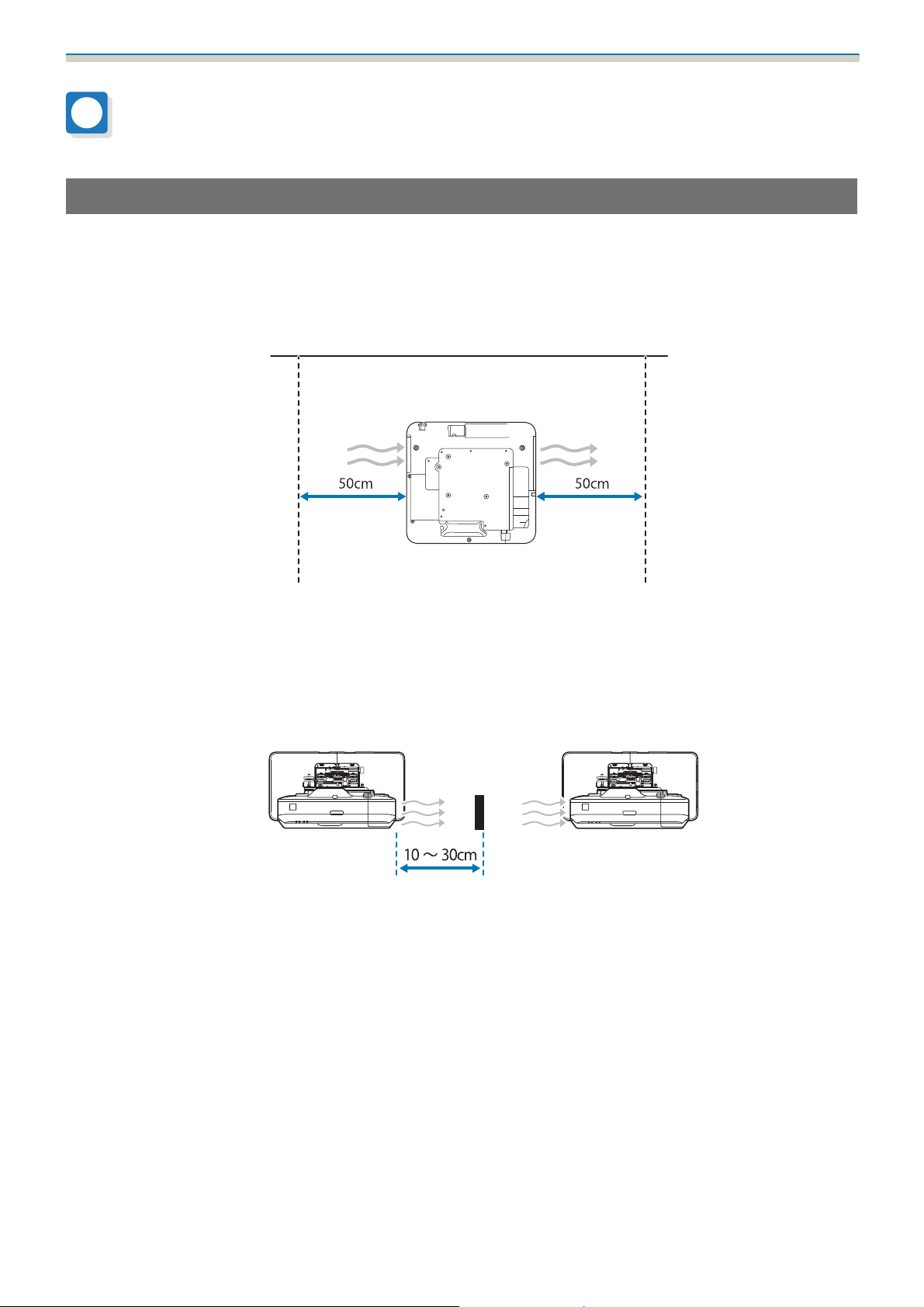
•
When installing the projector, make sure there is a gap of at least 50 cm from the wall to the projector's air exhaust
and intake vents on the left and right.
•
When installing two or more projectors in parallel, make sure the temperature of the surrounding environment is
less than 35°C.
If the environment is too hot, the projector may overheat and the power may turn off without warning. When using
the projector in an environment of 35°C or more, install a partition to block the heat vented from the projector's air
exhaust vent. Make sure the partition is slightly larger than the exhaust vent (approx. 2 cm wider and taller), and then
install the partition 10 to 30 cm from the exhaust vent.
•
It is recommended to keep connection cable length less than 20 meters to reduce external noise.
•
We recommend using stick-on screens or board screens.
•
Install the projector so that it is tilted at an angle of no more than ±3° vertically and horizontally in relation to the screen.
•
When using the interactive function (Easy Interactive Function), install so that the projected image is within reach.
•
Do not install the projector or the screen in a location subject to direct sunlight. If the projector or the screen are
subject to direct sunlight, the interactive function may not operate correctly.
5
Page 7
Using the Product Safely
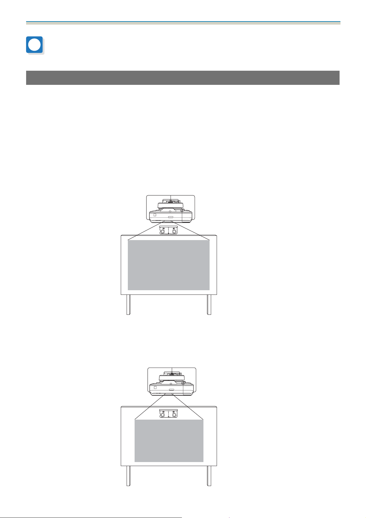
Touch Unit installation location (EB-1460Ui/EB-1450Ui only)
•
When using the Touch Unit, install the projector using one of the following methods. The Touch Unit cannot be used
if another installation method is used.
•
Mount the projector on a wall or suspend it from a ceiling and project images from in front of the screen.
•
Install vertically on a table and project from the front of the desk. (When installing vertically on a table, you need
the optional Interactive Table Mount (ELPMB29).)
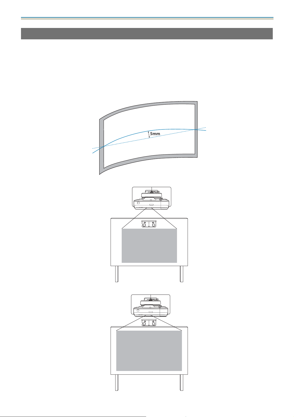
•
Before installing the Touch Unit, make sure that the installation surface is not warped or distorted, and that any
unevenness on the screen surface is less than 5 mm.
•
When installing the Touch Unit on a whiteboard, secure the Touch Unit with magnets or screws.
•
When installing the Touch Unit outside the whiteboard, you need the supplied Touch Unit Bracket.
6
Page 8
Using the Product Safely
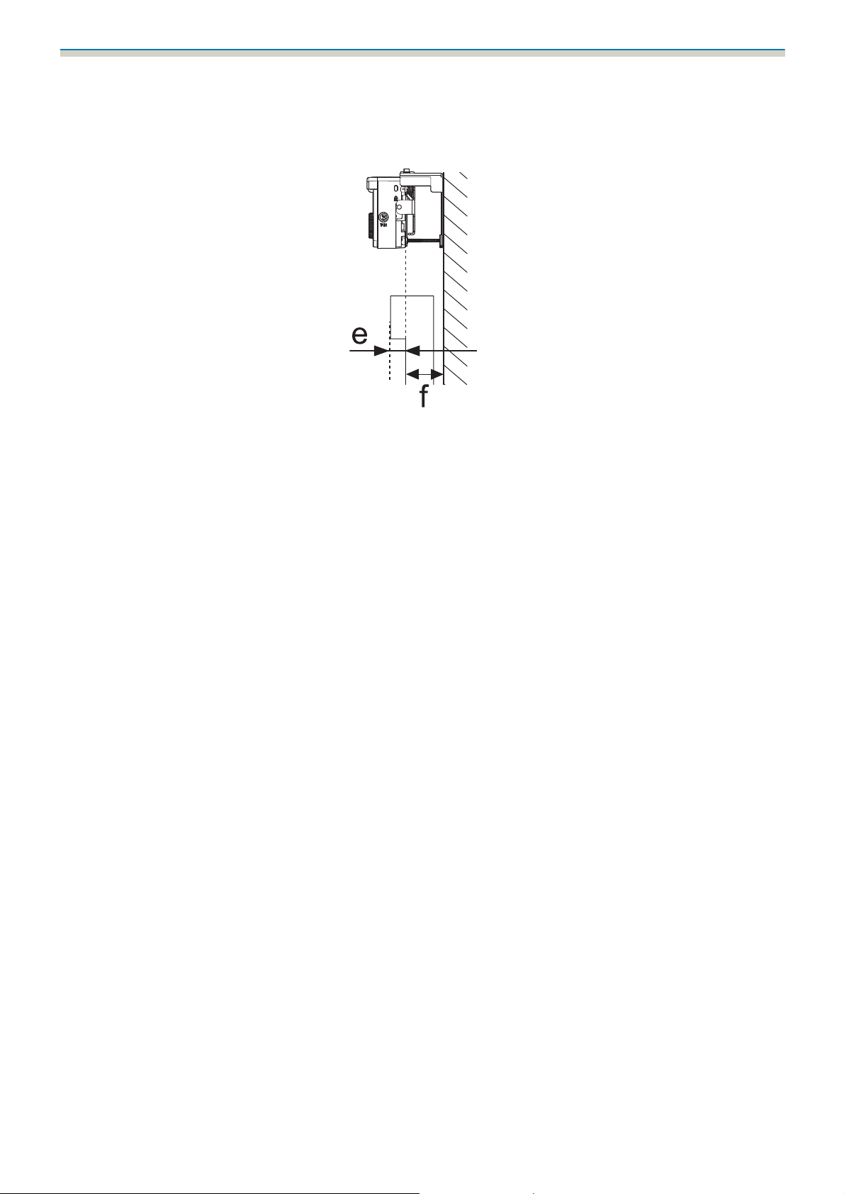
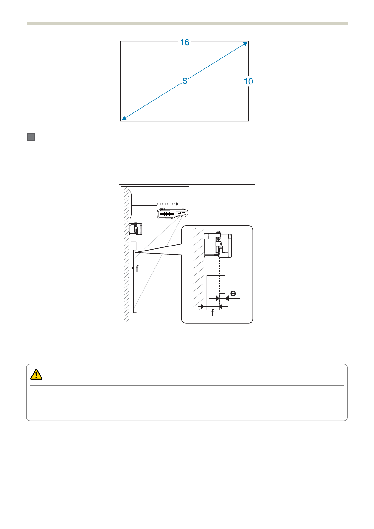
•
If the distance from the wall to the surface of the screen (f) is more than 51 mm, you cannot install the Touch Unit
outside the whiteboard.
•
If there is a frame around the screen, make sure that the thickness of the top of the frame (e) is less than 3 mm. If
the thickness of the top of the screen exceeds 3 mm, the Touch Unit will not operate correctly.
7
Page 9

Contents
Using the Product Safely
Safety Instructions .................... 1
Safety indications .......................1
Explanation of Symbols ................... 1
Safety Precautions for Installation............ 1
Notes on handling the Touch Unit (EB-1460Ui/
EB-1450Ui only) .........................3
About This Installation Guide ...............4
Choosing an Installation Location ...... 5
Projector installation location ............... 5
Touch Unit installation location (EB-1460Ui/
EB-1450Ui only) .........................6
Installation Guide
Installation Work Flow ............... 10
Installing one projector ..................10
When two or more projectors are installed in
parallel.............................. 11
Package Contents .................... 12
Setting plate ..........................12
Control Pad...........................13
Touch Unit (EB-1460Ui/EB-1450Ui only) . . . . . . . 13
Touch Unit Bracket ....................14
Laser diffusion port ...................21
Projection Distance Table ............ 23
Figures of Installation Dimensions ........... 23
When installing the Touch Unit (EB-1460Ui/
EB-1450Ui only) ...................... 24
When installing the Control Pad and the Pen
Stand ............................. 27
When Projected Image is Smaller than 85 Inches 28
16:10 projected image.................29
When Projected Image is 85 inches or more . . . . 30
16:10 projected image.................31
Installing the Setting Plate ........... 32
Connecting Devices ..................... 32
Necessary cables .....................32
Installation Procedure ...................36
Assemble the parts ...................36
Install the wall plate on the wall..........38
Determine the projection distance, and then
pass the cables through the setting plate . . . . 40
Attaching the setting plate to the wall plate . . 42
Securing the projector to the setting plate . . . 44
Adjusting the Position of the Projector.......46
Sticking the infrared deflectors (EB-1460Ui/
EB-1450Ui only) ...................... 52
Specifications ....................... 15
Setting plate ..........................15
Wall plate cover ......................15
Wall plate .......................... 16
Vertical slide adjustment range ...........16
Horizontal slide adjustment range......... 17
Forward/backward slide adjustment range . . 17
Position for installing accessories.........18
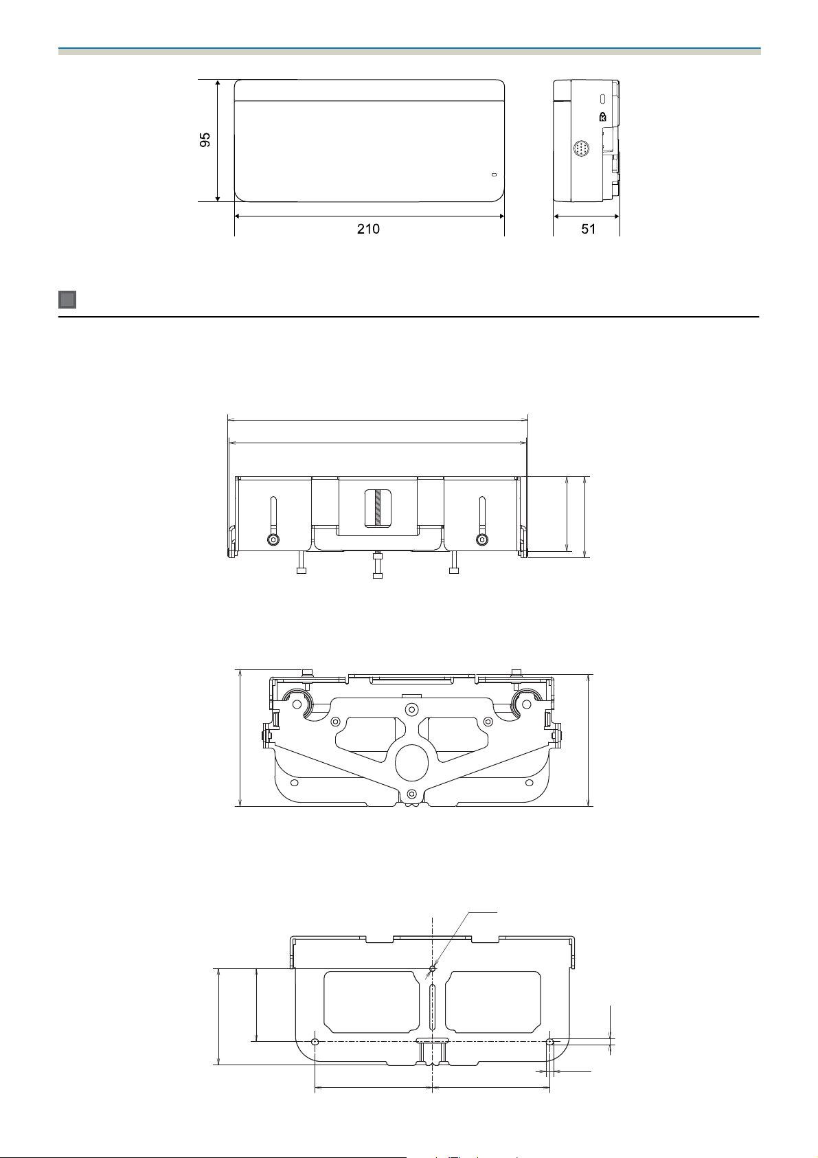
Control Pad/Pen Stand................... 18
Control Pad (external dimensions/weight) . . . 18
Cable routing holes ...................19
Pen Stand (external dimensions/weight)....19
Touch Unit (EB-1460Ui/EB-1450Ui only) . . . . . . . 19
Touch Unit (external dimensions/weight) . . . 19
Touch Unit Bracket (external dimensions/
adjustment range/weight) ..............20
Attached labels ...................... 21
Arc Correction....................... 53
Calibrating the pen .....................54
Attaching the Covers .................... 58
Installing the Control Pad and the Pen
Stand ............................... 61
Installing the Control Pad ................. 61
Installing the Pen Stand ..................62
Installing the Touch Unit (EB-1460Ui/
EB-1450Ui only) ..................... 64
When installing the Touch Unit outside the
whiteboard (using the Touch Unit Bracket) . . . . 64
Installation Procedure .................64
Angle Adjustment ....................69
Touch Calibration ....................84
When installing the Touch Unit on the
whiteboard (without using the Touch Unit
Bracket) .............................. 87
Installation Procedure .................87
8
Page 10

Contents
Angle Adjustment ....................91
Appendix
Installing Multiple Projectors in
Parallel (Multi-Projection) ............ 95
Multi-Projection settings .................95
Setting the Projector ID ................95
Adjusting the Image in Multi-Projection . . . . . 98
When two projectors are installed in parallel
and you are using the interactive function . . . . . 99
Setting the projectors in sync ........... 100
Setting Multi-Projection Interactive ....... 101
Batch Setup Function ............... 108
Setup Using a USB flash drive ............. 109
Saving settings to the USB flash drive..... 109
Copying saved settings to other projectors . 111
When Setup Fails ...................... 112
Attaching a Security Cable ........... 113
General Notice ..................... 114
9
Page 11
Installation Guide
Installation Work Flow
Installing one projector
Follow the procedures below to mount the projector on a wall.
Installing the Setting Plate and the Projector (s p.32)
a
Adjusting the Position of the Projector (s p.46)
b
Calibrating the Interactive Pen (s p.54)
c
Installing the Control Pad and the Pen Stand (s p.61)
d
When installing the Touch Unit, finish installing the projector first, and then follow the procedures below.
(EB-1460Ui/EB-1450Ui only)
The procedure differs depending on where the Touch Unit is to be installed.
When installing the Touch Unit outside the whiteboard (using the Touch Unit Bracket)
Installing the Touch Unit (s p.64)
a
Adjusting the Angle of Laser Diffusion (s p.69)
b
Performing Touch Calibration (s p.84)
c
When installing the Touch Unit on the whiteboard (without using the Touch Unit Bracket)
10
Page 12

Installation Guide
Installing the Touch Unit (s p.87)
a
Adjusting the Angle of Laser Diffusion (s p.91)
b
Performing Touch Calibration (s p.84)
c
When two or more projectors are installed in parallel
When using the multi-projection function (when multiple projectors are installed in parallel to project one,
large screen), follow the steps below.
Installing the Setting Plate and the Projector (s p.32)
a
Adjusting the Position of the Projector (s p.46)
b
Setting the Projector ID (s p.95)
c
Adjusting the Image in Multi-Projection (s p.98)
d
When two projectors are installed in parallel and you want to use the interactive function, make the following
settings. Make the settings for each projector.
Setting Projector Synchronization (s p.100)
a
Setting Multi-Projection Interactive (s p.101)
b
11
Page 13
Installation Guide
Package Contents
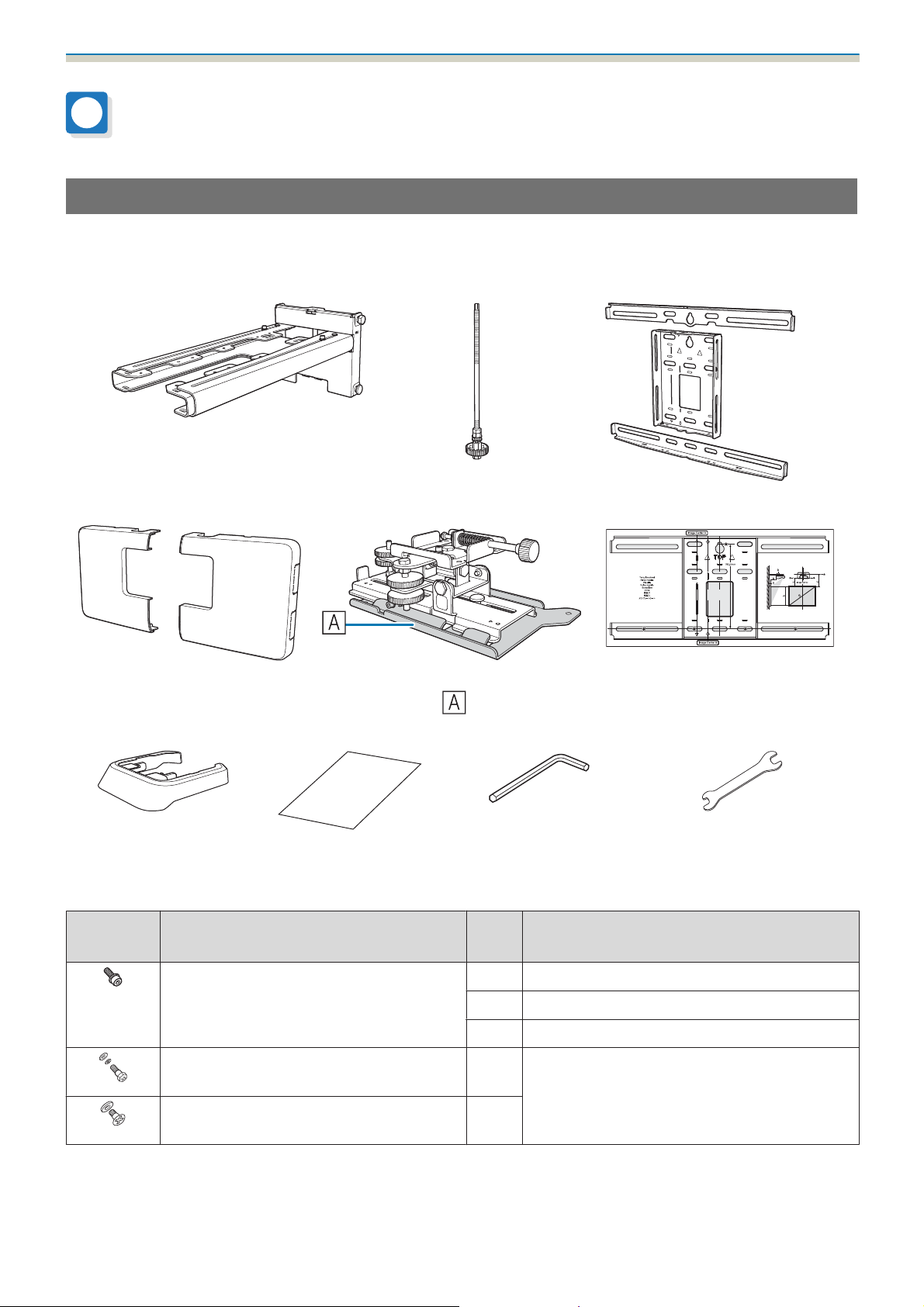
Setting plate
The following supplied items are necessary to mount the projector on a wall. Confirm that you have all items
before beginning. Depending on the area in which you purchased the product, the Setting Plate is not
supplied. In this situation, purchase the optional Setting Plate (ELPMB46).
Setting plate Hexagonal axis Wall plate
Wall plate cover 3-axis adjustment unit
*The slide plate (
ing shipping.
End cap Masking sticker Hexagon wrench (for M4) Open-ended spanner
Shape Name
) is secured dur-
Quan-
Template sheet
(for installing the wall plate)
13 mm (for M8 and M6),
6 mm (for hexagonal axis)
Application
tity
M4 x 12 mm hexagon socket head cap bolt
with washer/spring washer
M6 x 20 mm hexagon shoulder head bolt
with washer/spring washer
M6 x 20 mm cross recessed head shoulder
screws with plastic washers
•
Use the bolts or screws supplied with this product to install it as directed in this guide. Do not substitute these bolts
with any other types.
•
You need to use commercially available M10 x 60 mm anchors (at least 4) and one M10 screw to attach the wall plate
to the wall.
5For wall plate assembly
4 For 3-axis adjustment unit/arm installation
4 For slide plate/projector installation
1 For setting plate/wall plate installation
3
12
Page 14
Installation Guide
•
Gather the tools and parts you need before you begin installation.
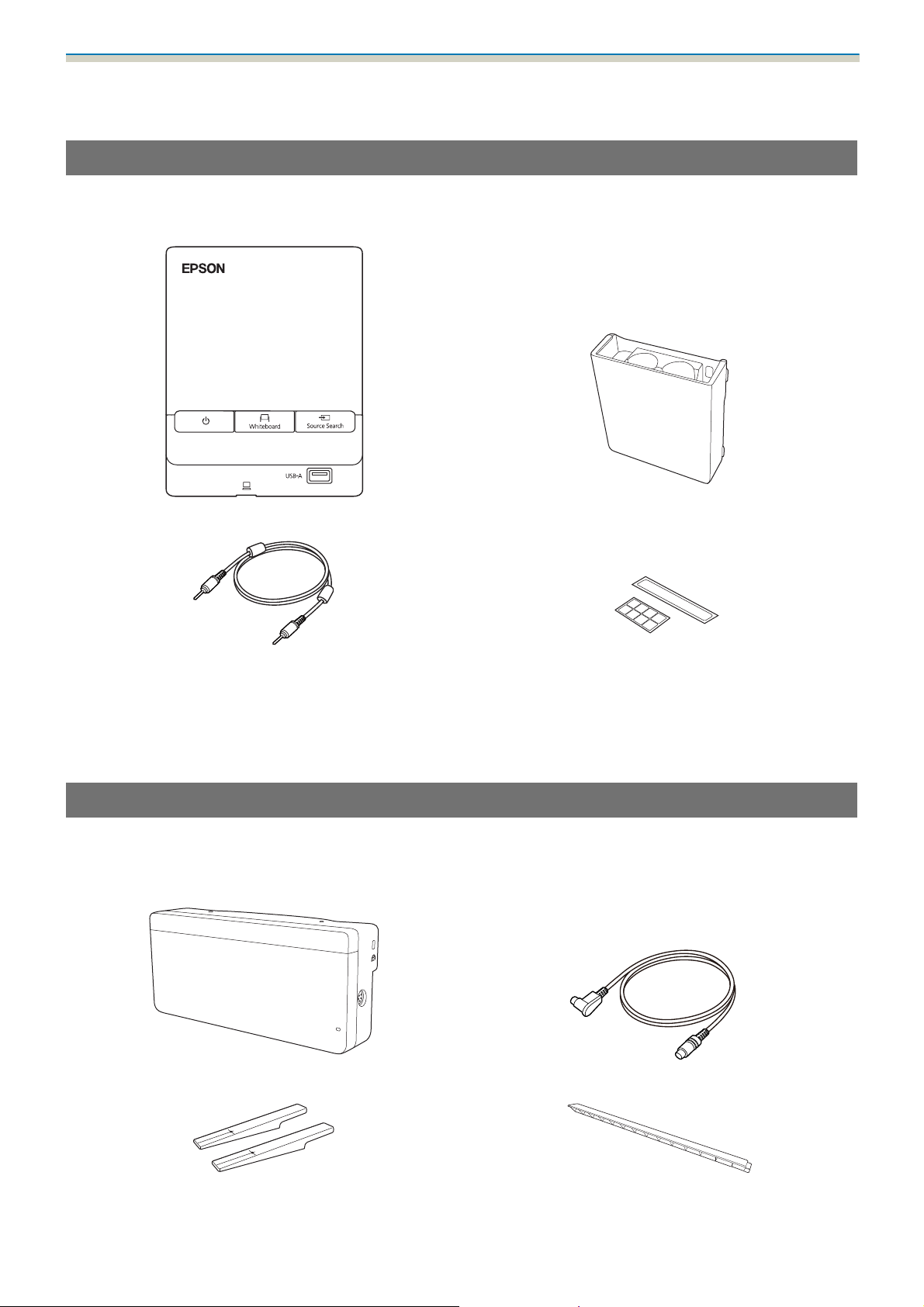
Control Pad
The following supplied products are necessary when attaching the Control Pad. Confirm that you have all
items before beginning.
Control Pad Pen Stand
Stereo mini cable
(for connecting the Control Pad (approx. 5m))
Port protection stickers
When installing the Control Pad on a wall and so on, prepare commercially available M4 screws (20 mm x4).
When installing the Pen Stand on a wall and so on, prepare commercially available M4 screws (20 mm x2).
Touch Unit (EB-1460Ui/EB-1450Ui only)
The following supplied products are necessary when attaching the Touch Unit. Confirm that you have all
items before beginning. When installing the Touch Unit outside the whiteboard, use the supplied Touch Unit
Bracket.
Touch Unit Touch Unit connection cable (approx. 2.8 m)
Markers x2 Infrared deflectors
(approx. 28.5 cm) x8
13
Page 15
Installation Guide
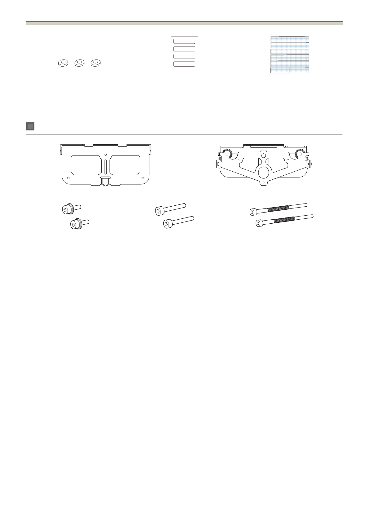
Spacer for screw hole x3 Label x4 Tape for securing the markers
(approx. 6 cm) x12
When installing the Touch Unit on a non-magnetic whiteboard, prepare three commercially available M4
screws.
Touch Unit Bracket
Installation plate Securing plate
M4 x 12 mm hexagon socket head
cap bolts x2
M4 x 25 mm hexagon socket head
cap bolts x2
M4 x 55 mm hexagon socket head cap
bolt x1
M4 x 70 mm hexagon socket head cap
bolt x1
For the installation plate, you also need three commercially available 4 mm diameter wood screws, or three
M4 anchor bolts.
14
Page 16
Installation Guide
Specifications
Setting plate
Item Specification Remark Reference
Setting plate weight Approx. 7.2 kg Setting plate (2.9 kg), 3-axis adjustment
unit (1.0 kg), slide plate (0.6 kg), wall plate
(2.0 kg), wall plate cover and end cap (0.7
kg)
Maximum load capacity 9.5 kg
Page
Forward/backward slide adjustment range
Vertical slide adjustment range ±38 mm See the fig-
Horizontal roll adjustment
range
Horizontal rotation adjustment
range
Vertical tilt adjustment range ±3° Fine adjustments possible with adjust-
Horizontal slide adjustment
range
13 to 350 mm Arm slide adjustment range: 0 to 263 mm
Adjustment for 3-axis adjustment unit installation position: 87 mm
±3° Fine adjustments possible with adjust-
ment dial
±8° Fine adjustments possible with adjust-
ment dial
ment dial
±45 mm See the fig-
See the figure below
ure below
s
p.46
s
p.46
s
p.46
ure below
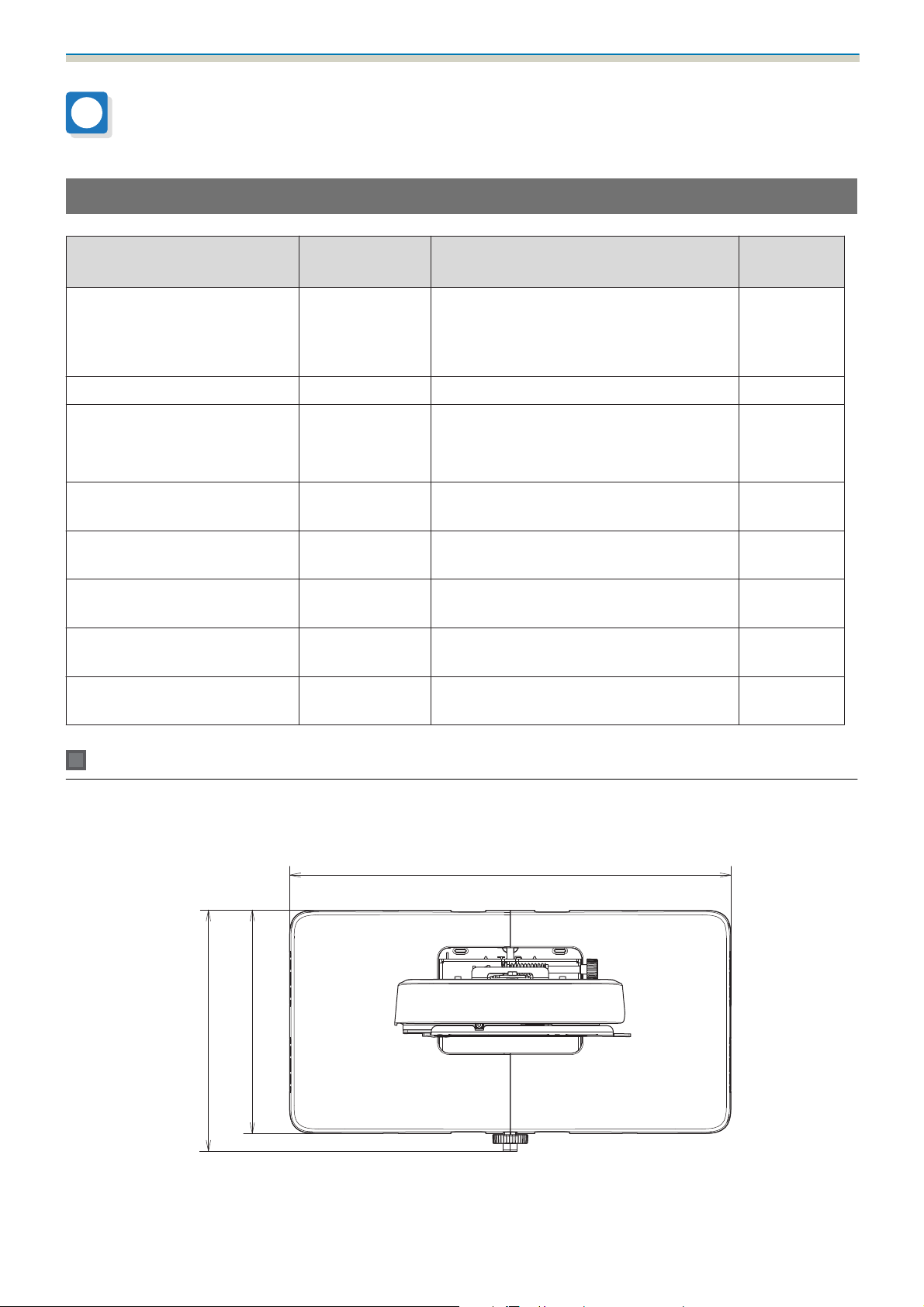
Wall plate cover
The following dimensions apply when attaching the wall plate cover.
[Unit: mm]
505.7
255.7
277.1
When installing the wall plate cover, you need a space of approximately 263 mm from the center of the wall
plate to the left side, and approximately 253 mm to the right side.
15
Page 17
Installation Guide
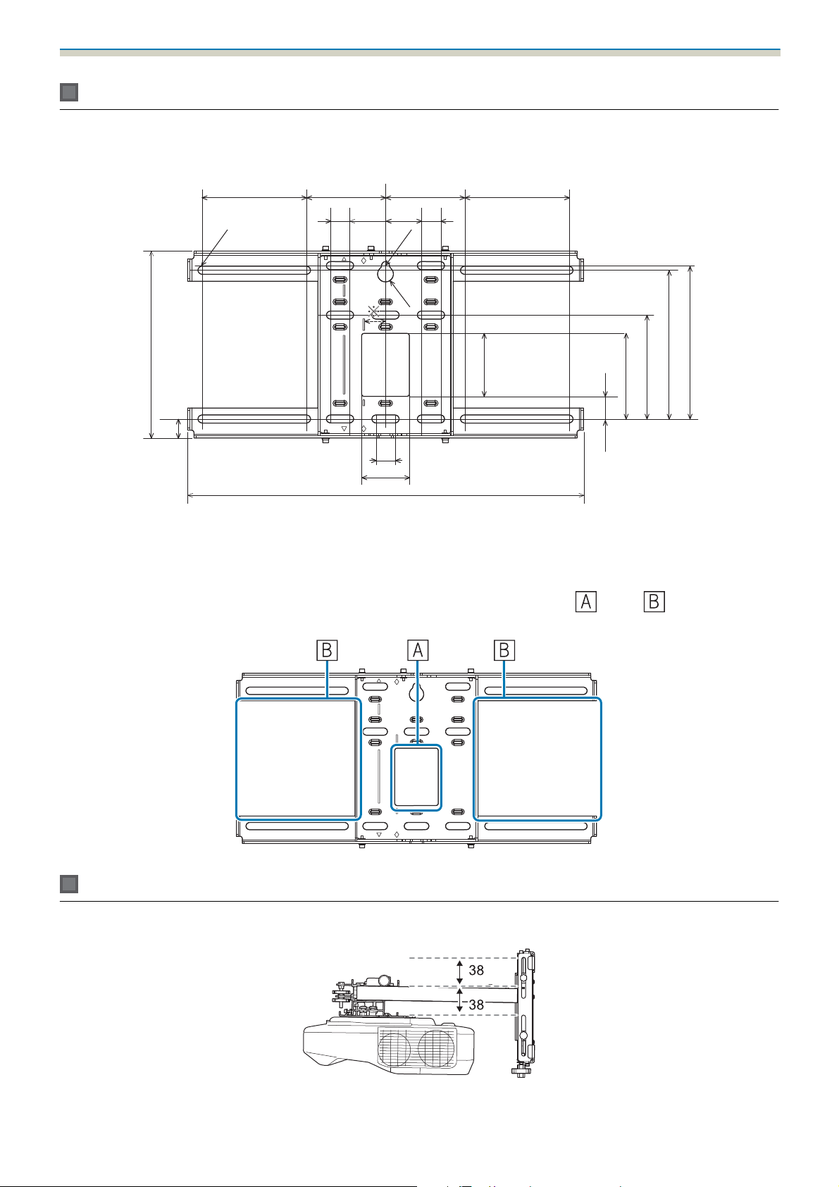
Wall plate
The following figure shows two frames connected to one plate (separate when shipped).
131131 99 99
24
24
4545
[Unit: mm]
24
60
496
5.1
R10
79
28.3
107.3
130.2
186.4
192.3
5.1
234.4
24
*
The offset value for the position of the center of the projected image and the center of the wall plate is 27 mm.
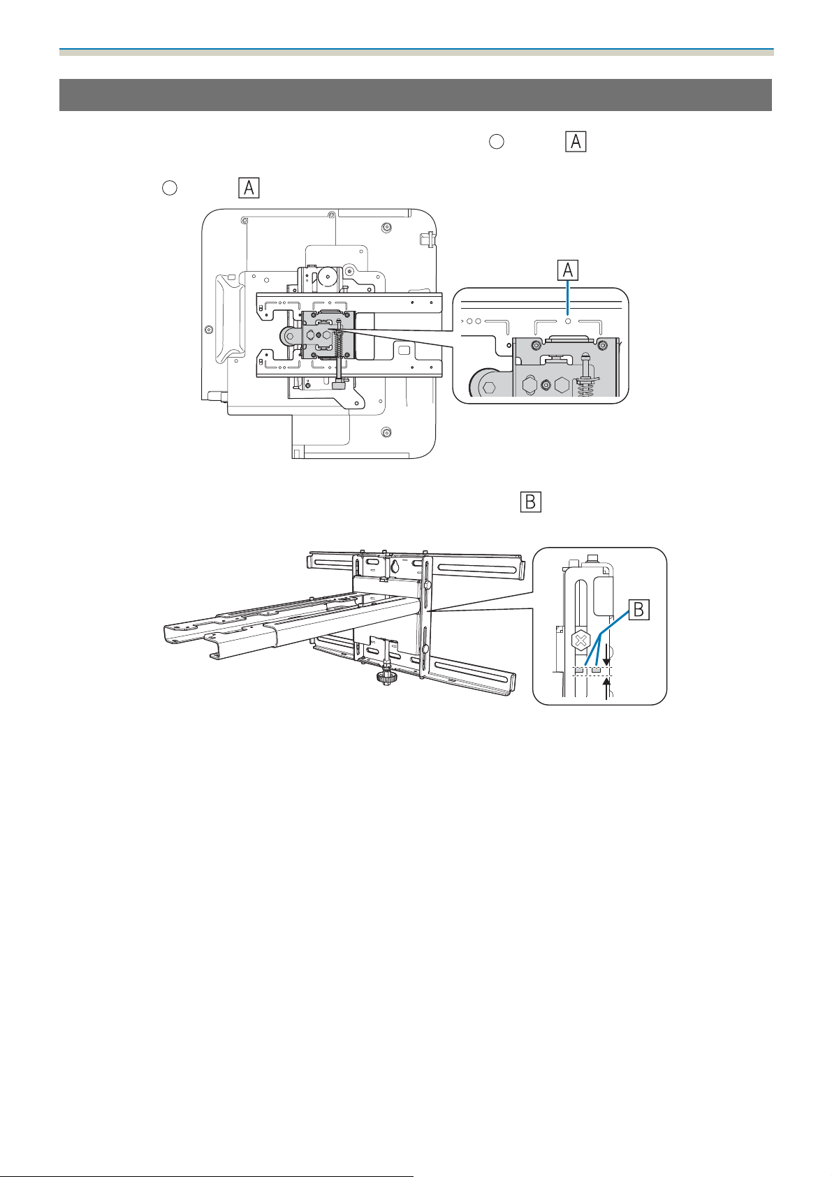
Cable routing holes
When routing cables to connect to the projector through a wall, use positions ( ) and ( ) in the following
figure as the cable routing holes.
Vertical slide adjustment range
[Unit: mm]
16
Page 18
Installation Guide
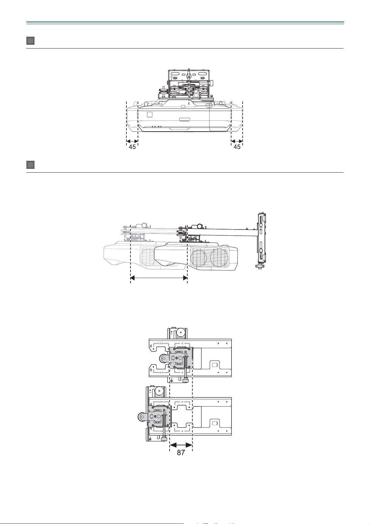
Horizontal slide adjustment range
Forward/backward slide adjustment range
Arm slide adjustment range
[Unit: mm]
263
Adjustment range for 3-axis adjustment unit installation position
[Unit: mm]
[Unit: mm]
17
Page 19
Installation Guide
Position for installing accessories
These screw holes allow you to secure peripheral devices and accessories such as external tuners. Use
commercially available M4 screws.
[Unit: mm]
35
2 x M4
49.7
30.5
60.8
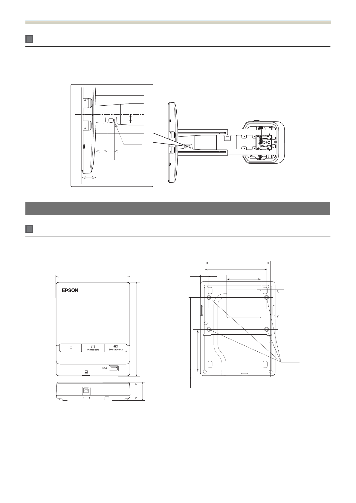
Control Pad/Pen Stand
Control Pad (external dimensions/weight)
135.9
[Unit: mm]
111
109.5
3.511.5
63.3
51.5
153.5
29
30.9
•
Weight: approx. 262 g
•
Operating temperature: 0 to +50°C (no condensation)
•
Operating temperature: -20 to +60°C (no condensation)
10715.47
47
4 x M4
18
Page 20
Installation Guide
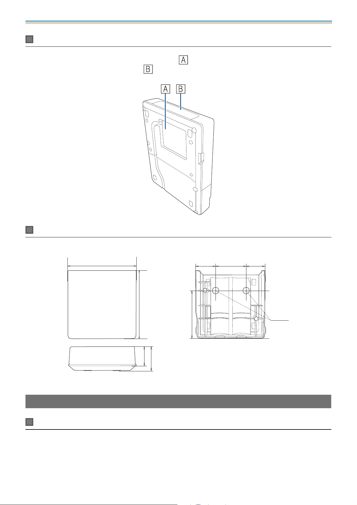
Cable routing holes
When routing cables through a wall, use the position ( ) shown in the followingfigure as the cable routing
hole. Otherwise, remove the cable cover (
the groove at the back of the Control Pad.
) and route the cables from there. Route the printer cable along
Pen Stand (external dimensions/weight)
101.9
99.9
35.5
36.0
The Pen Stand weighs approximately 93 g.
Touch Unit (EB-1460Ui/EB-1450Ui only)
70.0
28.8
44.4
[Unit: mm]
28.8
2 x M4
Touch Unit (external dimensions/weight)
[Unit: mm]
19
Page 21
Installation Guide
The Touch Unit weighs approximately 450 g.
Touch Unit Bracket (external dimensions/adjustment range/weight)
Top
229.8
228
[Unit: mm]
Front
Installation plate (front)
104.8
Ø4.2
57
62
[Unit: mm]
101
[Unit: mm]
74
56
90
2-4.5
2-5.7
90
20
Page 22
Installation Guide
When the Touch Unit is installed (side)
Touch Unit Bracket weights approximately 750 g.
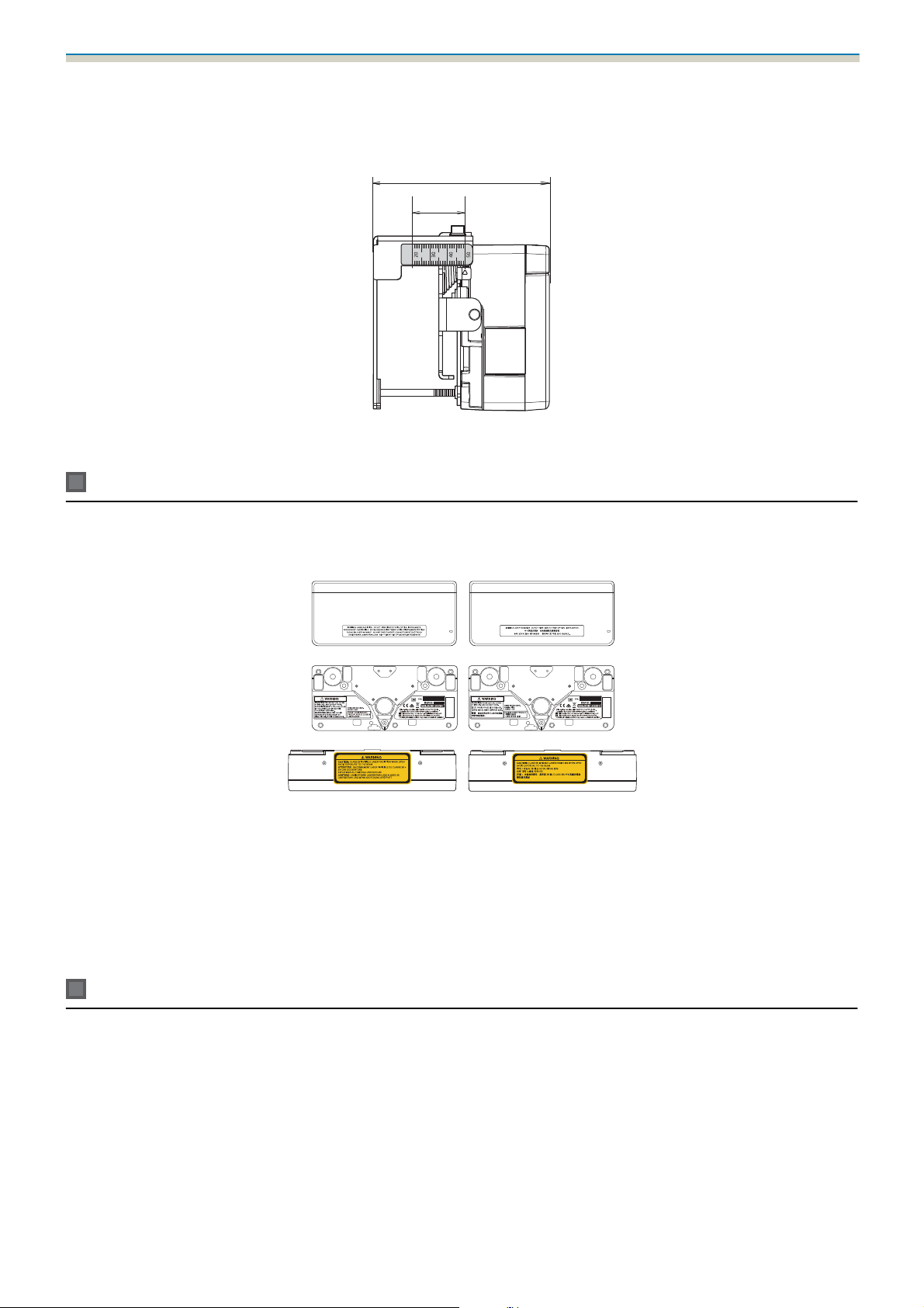
Attached labels
[Unit: mm]
100.8
30
The Touch Unit is a Class 1 laser product that conforms to the IEC/EN60825-1:2007 standard.
There are warning labels affixed to the Touch Unit to indicate that it is a Class 1 laser product.
The labels contain the following information.
•
Class 1 laser product
•
Warning: Do not open the case. The device contains a high power laser product.
•
Warning:
•
Caution: If this section is opened, class 3B invisible laser radiation will be emitted.
•
Avoid exposure to the radiation beams.
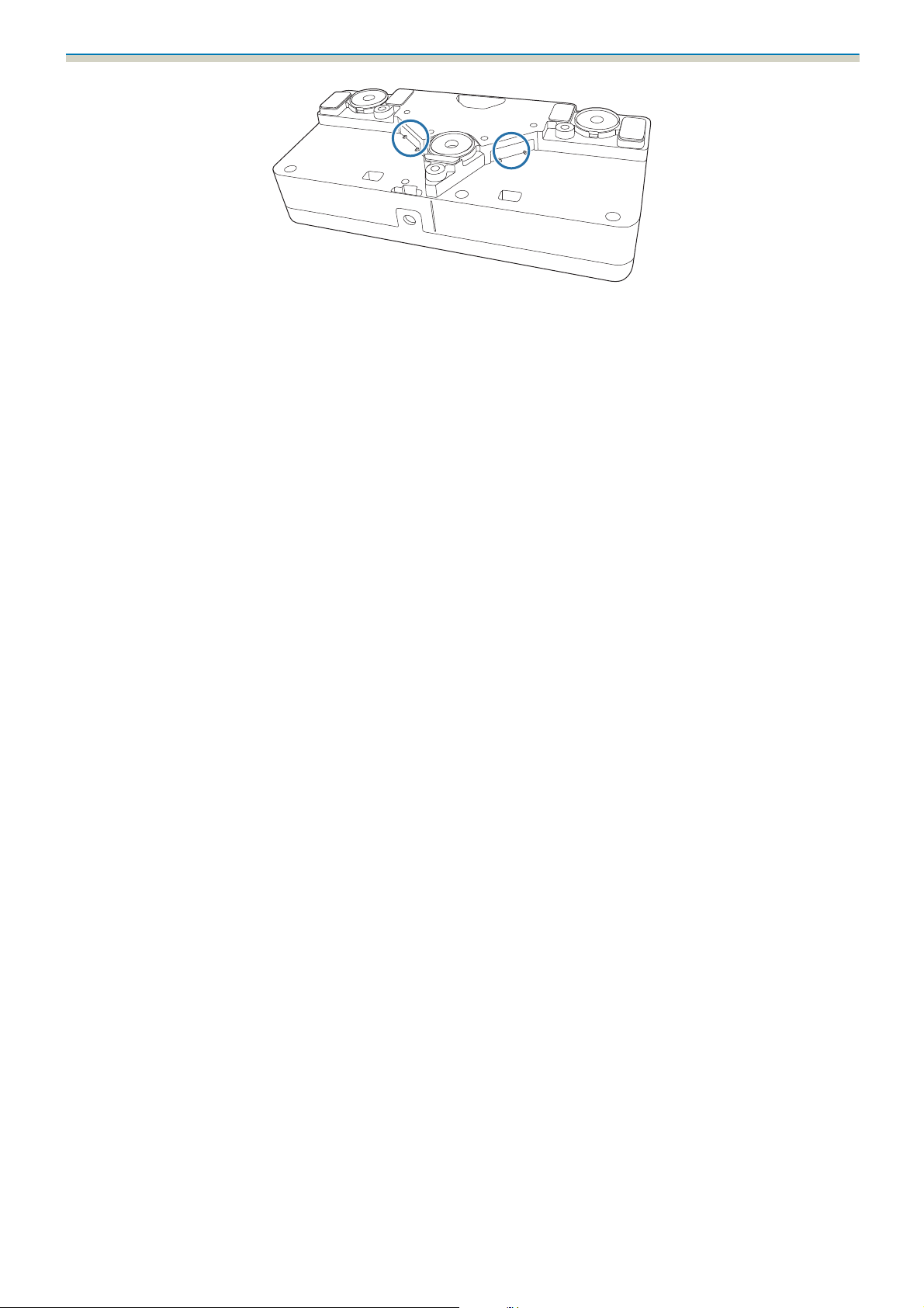
Laser diffusion port
The laser beam is diffused from the laser diffusion ports at the back of the Touch Unit.
21
Page 23
Installation Guide
22
Page 24
Installation Guide
Projection Distance Table
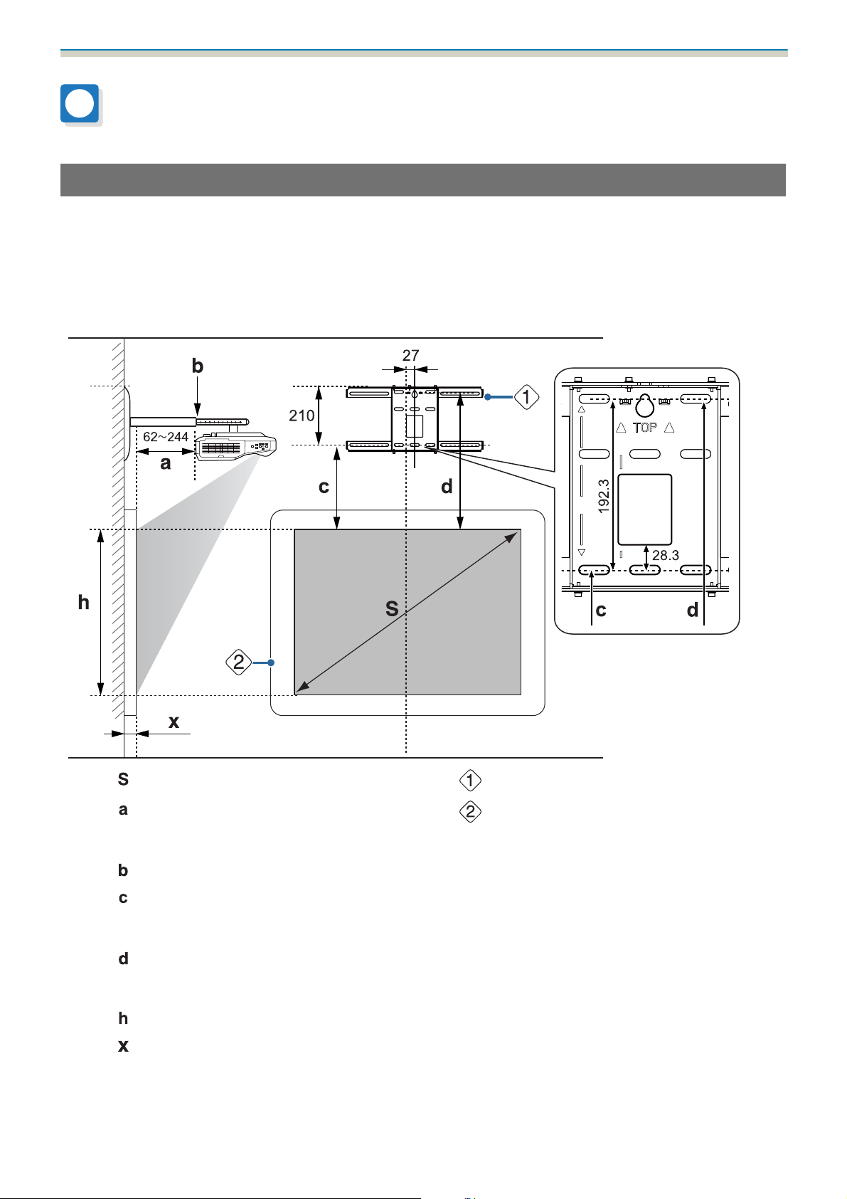
Figures of Installation Dimensions
To find the appropriate projection distance, see the following figures when installing. The values are only
rough estimates.
The recommended range for the projection distance (a) is 62 to 244 mm.
The offset value for the position of the center of the projected image and the center of the wall plate is 27 mm.
[Unit: mm]
Projected image size
:
Minimum projection distance (Wide: maxi-
:
mum zoom)
to maximum (Tele: minimum zoom)
Numbers on the arm slide scale
:
Distance from the top of the projected image
:
to the bottom wall plate installation screw
hole
Distance from the top of the projected image
:
to the wall plate temporary securing screw
hole
Height of projected image
:
Distance from surface of screen to wall (100
:
mm or less)
Aspect ratio for standard projected image
23
Wall plate
:
Screen
:
Page 25
Installation Guide
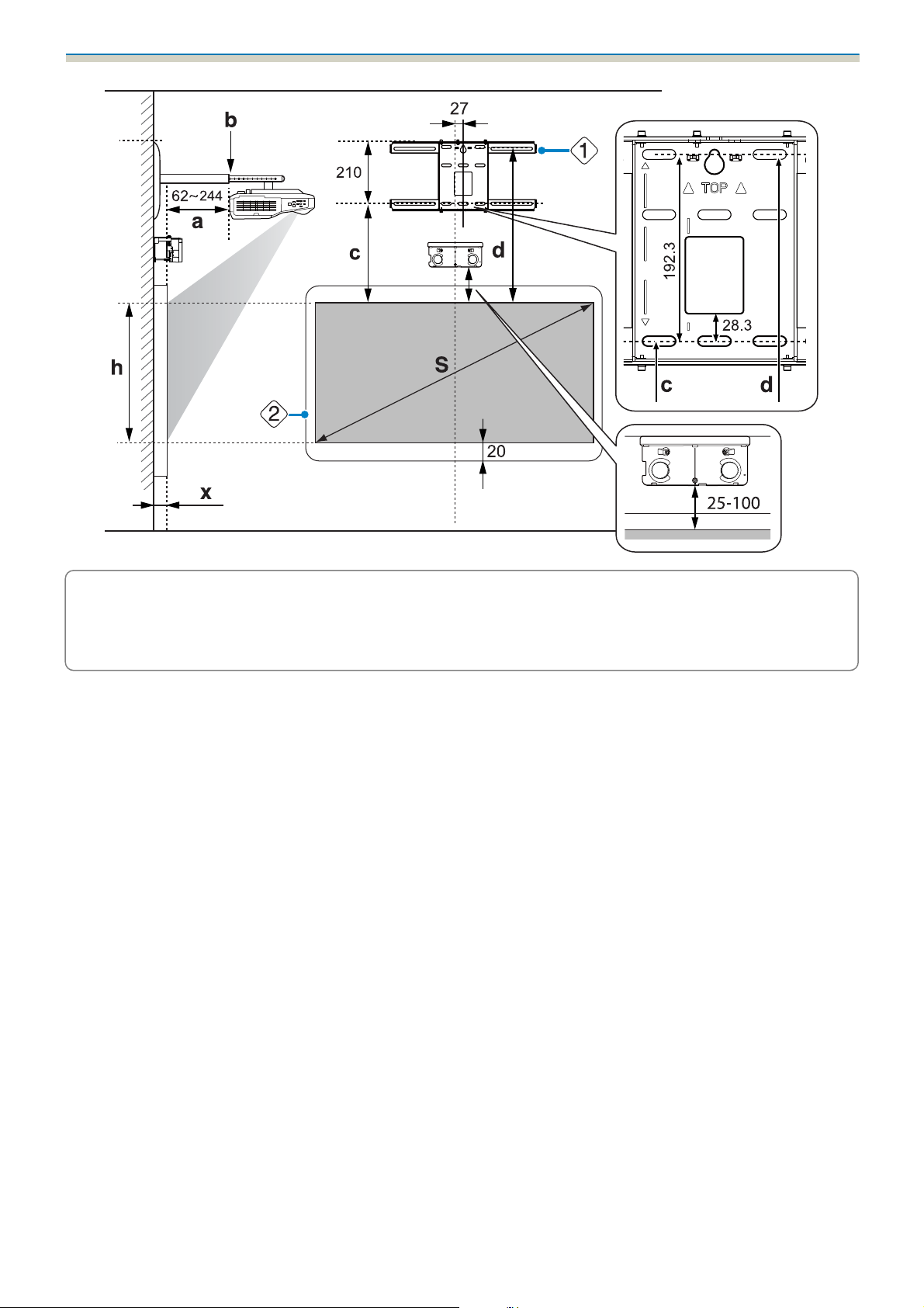
When installing the Touch Unit (EB-1460Ui/EB-1450Ui only)
By using the supplied Touch Unit Bracket, you can install the Touch Unit outside the whiteboard.
When installing the Touch Unit outside the whiteboard, measure the length from the surface where the Touch
Unit is installed to the whiteboard surface ((f) in the following figure).
•
When (f) is 20 to 50 mm, you can install the Touch Unit outside the whiteboard using the bracket.
•
When (f) is less than 20 mm or more than 50 mm install the Touch Unit on the whiteboard.
•
When the thickness of the top of the frame (e) is 3 mm or more, install the Touch Unit on the whiteboard.
Caution
Install the bottom edge of the Touch Unit so that it is 25 to 100 mm from the top edge of the projected image.
If there are obstacles between the projected image and the Touch Unit such as cables, whiteboard trays,
or holders, the Touch Unit will not operate correctly.
When the Touch Unit is installed outside the whiteboard (using the Touch Unit Bracket)
[Unit: mm]
24
Page 26
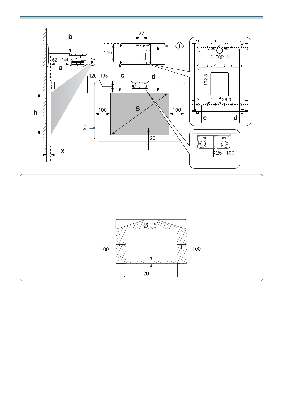
Installation Guide
If there are any obstacles such as a frame or tray at the bottom of the screen, touch operations will
not operate correctly. Stick the supplied infrared deflectors along the locations of the obstacles
c
(
s
p.52). Make sure there is a space of approximately 20 mm between the place where the infrared
deflector is stuck and the bottom of the projected image.
When installing the Touch Unit on the whiteboard (without using the Touch Unit Bracket)
You need to leave at least 120 mm distance between the top edge of the projected image and the top edge
of the actual screen.
[Unit: mm]
25
Page 27
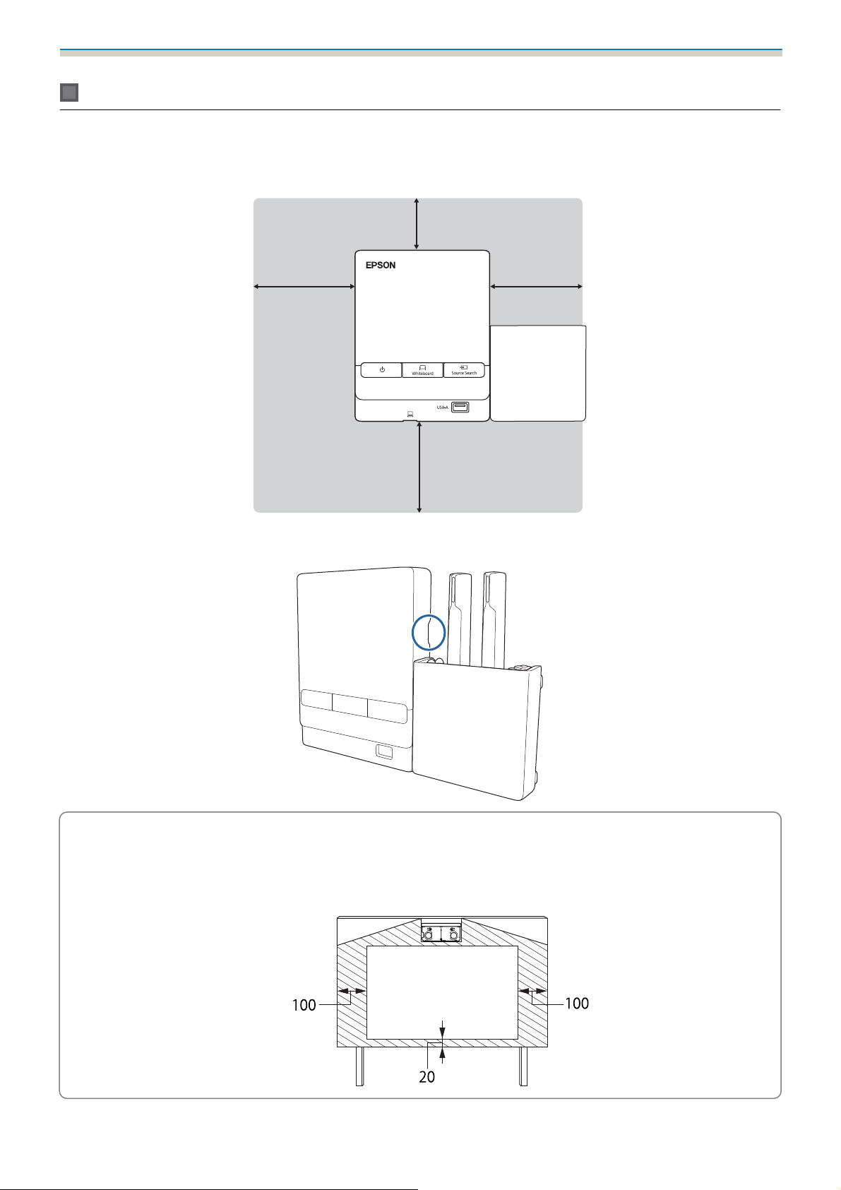
Installation Guide
c
•
If there are any obstacles such as a frame or tray at the bottom of the screen, touch operations will not
operate correctly. Stick the supplied infrared deflectors over the locations of the obstacles (
Make sure there is a space of at least 20 mm between the place where the infrared deflector is stuck
and the bottom of the projected image.
•
If there are obstacles in the shaded areas in the following figure, such as cables, whiteboard trays,
holders, or a thick frame, touch operations will not operate correctly.
s
p.52).
26
Page 28
Installation Guide
㻝㻜㻜
㻡㻜
When installing the Control Pad and the Pen Stand
When installing the Control Pad, leave enough space around it to install/remove the cover or to connect/
disconnect cables easily as shown in the following figure.
[Unit: mm]
㻝㻜㻜
When installing the Pen Stand next to the Control Pad, do not install it so that it covers the groove in the front
cover as shown in the following figure.
㻝㻜㻜
c
When installing the Touch Unit, do not install the Control Pad on the projection screen and the
surrouding area (shaded area in the following figure). Otherwise The Touch Unit will not operate
correctly.
[Unit: mm]
27
Page 29
Installation Guide
When Projected Image is Smaller than 85 Inches
Mount the 3-axis adjustment unit at the position marked with a stamp ( ).
The projection distance table provides the figures when mounting the 3-axis adjustment unit at the position
marked with a
stamp ( ).
The distance from the top of the projected image to the bottom wall plate installation screw hole (c) is the
number given when the vertical slide is set to the standard position (
Match the notch on the setting plate to the position of the stamp on the wall plate.
).
28
Page 30
Installation Guide
16:10 projected image
[Unit: cm]
S
Projected image sizeaProjection Dis-
tance
Minimum
(Wide) to Maxi-
mum (Tele)
70" 150.8x94.2 6.2 to 20.8 17.1 to 31.7 21.4 40.6 94.3
71" 152.9x95.6 6.6 to 21.6 17.5 to 32.5 21.7 40.9 95.6
72" 155.1x96.9 7.2 to 22.4 18.1 to 33.3 22.0 41.2 96.9
73" 157.2x98.3 7.8 to 23.2 18.7 to 34.1 22.3 41.5 98.3
74" 159.4x99.6 8.4 to 24.1 19.3 to 35.0 22.6 41.8 99.6
75" 161.5x101.0 9.0 to 24.9 19.9 to 35.8 22.8 42.0 101.0
76" 163.7x102.3 9.6 to 25.7 20.5 to 36.6 23.1 42.3 102.3
77" 165.9x103.7 10.2 to 26.5 21.1 to 37.4 23.4 42.6 103.7
78" 168.0x105.0 10.8 to 27.3 21.7 to 38.2 23.7 42.9 105.0
79" 170.2x106.3 11.4 to 28.1 22.3 to 39.0 24.0 43.2 106.3
b
Numbers on
the arm slide
scale
c
Distance to
the bottom
wall plate in-
stallation
screw hole
d
Distance from
the top of the
projected image to the wall
plate tempora-
ry securing
screw hole
h
Height of
projected
image
80" 172.3x107.7 12.0 to 29.0 22.9 to 39.9 24.2 43.4 107.7
81" 174.5x109.0 12.6 to 29.8 23.5 to 40.7 24.5 43.7 109.1
82" 176.6x110.4 13.2 to 30.6 24.1 to 41.5 24.8 44.0 110.4
83" 178.8x111.7 13.8 to 31.0 24.7 to 41.9 25.1 44.3 111.7
84" 180.9x113.1 14.4 to 31.0 25.3 to 41.9 25.4 44.6 113.0
Images smaller than 70 inches are not projected correctly.
•
The values are only rough estimates. The value may differ depending on the location where you place
c
the projector.
•
When projecting in Tele, the quality of the projected images may decrease.
29
Page 31

Installation Guide
When Projected Image is 85 inches or more
Mount the 3-axis adjustment unit at the position marked with a stamp ( ).
The projection distance table provides the figures when mounting the 3-axis adjustment unit at the position
marked with a
stamp ( ).
The distance from the top of the projected image to the bottom wall plate installation screw hole (c) is the
number given when the vertical slide is set to the standard position (
Match the notch on the setting plate to the position of the stamp on the wall plate.
).
30
Page 32

Installation Guide
16:10 projected image
[Unit: cm]
S
Projected image size
85" 183.1x114.4 15.0 to 33.7 17.2 to 35.9 25.6 44.8 114.5
86" 185.2x115.8 15.6 to 34.5 17.8 to 36.7 25.9 45.1 115.8
87" 187.4x117.1 16.2 to 35.3 18.4 to 37.5 26.2 45.4 117.1
88" 189.5x118.5 16.9 to 36.2 19.1 to 38.4 26.5 45.7 118.5
89" 191.7x119.8 17.5 to 37.0 19.7 to 39.2 26.8 46.0 119.8
90" 193.9x121.2 18.1 to 37.9 20.3 to 40.1 27.1 46.3 121.1
91" 196.0x122.5 18.7 to 38.7 20.9 to 40.9 27.3 46.5 122.5
92" 198.2x123.9 19.4 to 39.6 21.6 to 41.8 27.6 46.8 123.9
93" 200.3x125.2 20.0 to 39.7 22.2 to 41.9 27.9 47.1 125.2
94" 202.5x126.5 20.6 to 39.7 22.8 to 41.9 28.2 47.4 126.5
a
Projection
Distance
Minimum
(Wide) to
Maximum
(Tele)
b
Numbers on
the arm slide
scale
c
Distance to the
bottom wall
plate installa-
tion screw hole
d
Distance from
the top of the
projected im-
age to the wall
plate tempora-
ry securing
screw hole
h
Height of
projected im-
age
95" 204.6x127.9 21.3 to 39.7 23.5 to 41.9 28.5 47.7 127.8
96" 206.8x129.2 21.9 to 39.7 24.1 to 41.9 28.7 47.9 129.3
97" 208.9x130.6 22.5 to 39.7 24.7 to 41.9 29.0 48.2 130.6
98" 211.1x131.9 23.1 to 39.7 25.3 to 41.9 29.3 48.5 131.9
99" 213.2x133.3 23.8 to 39.7 26.0 to 41.9 29.6 48.8 133.2
100" 215.4x134.6 24.4 to 39.7 26.6 to 41.9 29.9 49.1 134.6
Images larger than 100 inches are not projected correctly.
•
The values are only rough estimates. The value may differ depending on the location where you place
c
the projector.
•
When projecting in Tele, the quality of the projected images may decrease.
31
Page 33

Installation Guide
Installing the Setting Plate
Connecting Devices
Necessary cables
Be sure to prepare the power cord supplied.
Additionally, prepare the necessary cables according to the devices being used.
•
USB cable supplied
•
Touch Unit connection cable supplied (EB-1460Ui/EB-1450Ui only)
•
Stereo mini cable supplied
•
Optional computer cables and other cables (prepare according to the connected devices)
For details, see the projector's User's Guide (on the Document CD-ROM).
Necessary cables when using the Easy Interactive Function
When performing mouse operations using the Easy Interactive Function, you need a USB cable. Even when
projecting using a computer cable, a USB cable is necessary to perform mouse operations.
Necessary cables when installing two projectors in parallel and using the Easy Interactive Function
When using the interactive function with two projectors installed in parallel, you need the optional remote
control cable set (ELPKC28).
32
Page 34

Installation Guide
In
When connecting one computer to two projectors and using the interactive function, connect a USB cable
from the computer to each projector. You need a computer with two USB-A ports.
Out
Necessary cables when installing the Touch Unit (EB-1460Ui/EB-1450Ui only)
You need the supplied Touch Unit connection cable when installing the Touch Unit and connecting it to the
projector. Operations are not performed correctly with a commercially available cable.
The shape of the plug that connects to the projector and the plug that connects to the Touch Unit differ. See
the following figure to connect to the correct ports.
33
Page 35

Installation Guide
Necessary cables when installing the Control Pad
When installing the Control Pad, you need the supplied stereo mini cable that connects the Control Pad to
the projector to supply power to it (
being used.
•
When projecting computer images (USB Display), or performing mouse operations u s n g t h e E a s y I n teractive Function,
). Additionally, prepare the necessary cables according to the devices
you need the USB cable supplied (
•
When projecting images from a USB storage device, or when saving data to the USB storage device, you need the
USB cable supplied and a commercially available USB storage device (
•
When printing the projected image, you need the USB cable supplied ( ) and the USB cable supplied with your
printer (
•
When inputing characters with a USB keyboard using the Remote Desktop function, you need the USB cable supplied
(
) and a commercially available USB keyboard ( ).
).
).
).
c
The following Epson projectors can be connected to the Control Pad. Check the rating label on the
projector.
•
H727x (where x is any from A to Z)
•
H771x (where x is any from A to Z)
If you want to connect a different projector or if you have any queries, check the Epson Projector
Contact List provided on the Document CD-ROM and contact your local dealer.
34
Page 36

Installation Guide
Prepare cables for the connected devices (example)
Document camera
Dedicated USB cable (supplied with document cam-
era)
External speakers
Audio cable (commercially available)
External monitor
DVI-D cable (commercially
available)
Computer
Computer cable (optional accessory)
LAN device
LAN cable (commercially
available)
35
Page 37

Installation Guide
Installation Procedure
Make sure to follow the steps below to install the setting plate. If these steps are not followed, the product
could fall and cause personal injury or property damage.
Warning
Do not use adhesives, lubricants, or oils to install or adjust the setting plate. If you use adhesives to prevent
the screws from loosening or things such as lubricants or oils on the slide plate fixing part of the projector,
the case may crack and cause the projector to fall, resulting in personal injury or property damage.
Assemble the parts
Connect the plate and frames (x2) and secure with the M4 x 12 mm bolts (x5) supplied
a
36
Page 38

Installation Guide
Check that the 3-axis adjustment unit is aligned with the slide plate's standard position
).
b
(
c
If the standard position ( ) is not correct, loosen the M4 bolt and adjust the position of the slide
plate. When you have finished making adjustments, tighten the bolt.
Secure the 3-axis adjustment unit and the slide plate to the base of the projector with the
M4 x 12 mm bolts (x4) supplied
Bolt installation positions
37
Page 39

Installation Guide
Install the wall plate on the wall
Determine the projection position based on the projected image size
a
See the projection distance table to check the following values.
•
Projected image size (S)
•
Distance from the top of the projected image to the bottom wall plate installation screw hole (c)
•
Distance from the top of the projected image to the wall plate temporary securing screw hole (d)
s
"Projection Distance Table" p.23
Use the screw hole in the following figure as the temporary screw hole for the wall plate. The
distance from the bottom wall plate installation screw hole to the temporary screw hole is
c
192.3 mm.
We recommend marking the following positions. These will be the basis for determining the mounting
position of the wall plate.
•
Position of the temporary screw hole ( )
•
Position of the bottom wall plate installation screw hole ( )
•
Center line ( ) of the projected image
38
Page 40

Installation Guide
Attach the template sheet to the wall
b
•
Match the center line ( ) checked in step 1 to the Image Center B line on the template sheet.
Confirm where the beams are within the wall, and shift the position left or right as necessary.
(The position can be shifted horizontally left or right from the center line of the projection surface up to a
maximum of 45 mm.)
•
Match the height ( ) and ( ) checked in step 1 to the lines on the template sheet.
[Unit: mm]
c
d
Drive a commercially available M10 screw into the position of the temporary screw hole
for the wall plate
Leave a gap of 6 mm or more between the wall and the screw head.
Determine the positions for the mounting holes for the wall plate
From the screw holes shown in the figure below, secure at least four points for optimum balance.
39
Page 41

Installation Guide
Drill the holes in the wall
e
f
g
Drill diameter: 10.5 mm
Pilot hole depth: 45 mm
Anchor hole depth: 40 mm
Remove the template sheet, and clean the concrete dust from the holes with a dust pump
Position the wall plate on the wall and insert M10 x 60 mm commercially available anchors
into the holes
Attach the nut and tap it with a hammer
until the core touches the top of the anchor.
Tighten the nut with a commercially available spanner to secure the wall plate to the wall
h
Determine the projection distance, and then pass the cables through the setting plate
Check the following values in the projection distance table
a
•
Numbers on the arm slide scale (b)
•
Distance from surface of screen to wall (x)
s
"Projection Distance Table" p.23
40
Page 42

Installation Guide
Loosen the M4 x 12 mm bolts (x2) and extend the arm slide on the setting plate
b
c
Align the slider with the combined distances of (b) and (x) that you checked in step 1.
Route the necessary cables through the setting plate
See the following figure to route the cables so that the ends of the cables that connect to the projector
are on the projector's interface side.
Warning
Do not hang the rest of the cable over the setting plate. They could fall and cause an accident.
•
Route the Touch Unit connection cable through the setting plate (EB-1460Ui/EB-1450Ui only).
c
Route the cable so that the end that connects to the Touch Unit appears from the lower part of
the setting plate.
•
Route the Control Pad connection cable through the setting plate (EB-1460Ui/EB-1450Ui only).
41
Page 43

Installation Guide
Attaching the setting plate to the wall plate
Insert the hexagonal axis into the setting plate
a
b
Mount the setting plate to the wall plate
Insert the top of the hexagonal axis into the wall plate, and then insert it into the slot at the bottom.
Caution
•
Do not wire the Touch Unit connection cable into the wall (EB-1460Ui/EB-1450Ui only). If it is wired
into the wall, it cannot be connected to the Touch Unit.
•
Take care not to trap the cables between the setting plate and wall plate.
42
Page 44

Installation Guide
Secure the setting plate and the wall plate
c
Secure the supplied M6 screws (x3) with a commercially available No.3 cross-head screwdriver, and
then lightly tighten the supplied M6 bolt (x1) with the spanner.
Adjust the vertical slide with the open-ended spanner, and align it with the standard
d
position (
•
Tightening the hexagonal axis at the top ( ) raises the setting plate, and loosening the axis lowers it.
•
Tightening the M8 bolt at the bottom ( ) lowers the setting plate, and loosening the bolt raises it. (You can
also use a 17 mm socket wrench.)
)
43
Page 45

Installation Guide
Tighten the M6 bolt (x1) to fix the setting plate in position
e
Securing the projector to the setting plate
Loosen the screws (x2) and remove the cable cover from the projector
a
44
Page 46

Installation Guide
Attach the 3-axis adjustment unit to the setting plate with the M4 x 12 mm bolts (x4)
b
supplied
•
When a projected image is smaller than 85 inches: Mount the unit at the stamp ( ).
•
When a projected image is 85 inches or more: Mount the unit at the stamp ( ).
: Smaller than 85 inches : 85 inches or more
45
Page 47

Installation Guide
Connect the cables to the projector
c
s
"Connecting Devices" p.32
Connect the power cord last.
Use commercially available M4 screws to secure peripheral devices and accessories such as external
tuners to the screw holes in the following figure.
Install the wireless LAN module supplied in the wireless LAN unit module slot.
Adjusting the Position of the Projector
•
Do not make adjustments using the projector's Keystone function. Doing so may result in a reduction in image quality.
•
When setting up multiple projectors using the batch setup function, perform the batch setup before adjusting the
projected image.
s "Batch Setup Function" p.108
46
Page 48

Installation Guide
When installing the Touch Unit (EB-1460Ui/EB-1450Ui only), if there are any obstacles at the bottom
of the whiteboard such as a frame or trays, stick the infrared deflectors along the bottom edge of
c
the whiteboard before adjusting the projector.
s
"Sticking the infrared deflectors (EB-1460Ui/EB-1450Ui only)" p.52
Press the [Power] button on the remote control or the control panel to turn on the projector
a
b
Using the Remote Control Using the Control Panel
Caution
While projecting, do not put your face or hands near the air exhaust vent, and do not place objects
that may become warped or damaged by heat near the vent. Hot air from the air exhaust vent could
cause burns, warping, or accidents to occur.
Open the air filter cover, and then adjust the focus using the focus lever
Fine-tune the focus later.
After you finish making adjustments, close the air filter cover.
•
You can change the display language from Language on the Extended menu.
c
s
Projector's User's Guide - Projector menu
•
When you turn on the projector for the first time, the message "Do you want to set the
time?" is displayed. If you set it later, select No.
47
Page 49

Installation Guide
Change the aspect ratio of the projected image (only when necessary)
c
d
Project images from a connected device, and then press the [Aspect] button on the remote control.
Each time you press the button, the aspect name is displayed on the screen and the aspect ratio
changes.
Using the Remote Control
•
For details on connecting to devices and projecting images, see the Quick Start Guide.
•
c
Press the projector's [Menu] button.
Using the Remote Control Using the Control Panel
The aspect ratio does not change when no images are being projected from the connected
device.
•
You can also change the aspect ratio from Aspect from the Signal menu.
s
Projector's User's Guide - Projector menu
e
Select Installation Guide from Settings
The guidance screen is displayed.
48
Page 50

Installation Guide
After loosening the adjustment dial at the bottom, adjust the horizontal roll using the
f
adjustment dial at the top.
Repeat steps 6 to 11 as necessary.
c
g
After you finish making adjustments, tighten the adjustment dial at the bottom.
Loosen the M4 screw (x1) with the hexagon wrench, and then adjust the horizontal rotation
with the adjustment dial
After you finish making adjustments, tighten the M4 screws that you loosened.
49
Page 51

Installation Guide
After loosening the adjustment dial at the bottom, adjust the vertical tilt using the
h
adjustment dial at the top.
i
After you finish making adjustments, tighten the adjustment dial at the bottom.
Loosen the M4 bolt with the hexagon wrench, and then adjust the horizontal slide
After you finish making adjustments, tighten the M4 bolt that you loosened.
50
Page 52

Installation Guide
Loosen the M4 bolts (x2) with the hexagon wrench, and then adjust the forward/backward
j
slide
k
After you finish making adjustments, tighten the M4 bolts that you loosened.
Loosen the M6 bolt (x1) with the open-ended spanner, and then adjust the vertical slide
Adjust the vertical slide with the hexagonal axis at the top or the bottom.
•
Tightening the hexagonal axis at the top raises the setting plate, and loosening the axis lowers it.
•
Tightening the M8 bolt at the bottom lowers the setting plate, and loosening the bolt raises it. (You can also
use a 17 mm socket wrench.)
After you finish making adjustments, tighten the M6 bolt that you loosened.
51
Page 53

Installation Guide
Make sure that all of the bolts that you loosened in steps 6 to 11 are securely tightened
l
Warning
Tighten all bolts and screws firmly. Otherwise, the product may fall and cause personal injury or
property damage.
Adjust the focus to match the focus in the following figure ( )
m
Open the air filter cover, and then adjust the focus.
When (
until the (
After you finish making adjustments, close the air filter cover.
) is in focus, check the ( ) areas. If any of the ( ) areas are out of focus, adjust the focus
) areas are uniform.
Press the [Esc] button on the remote control or the control panel to remove the guidance
n
When installing the Touch Unit, if there are any obstacles at the bottom of the whiteboard such as a frame
or trays, touch operations will not operate correctly. If there are any obstacles , stick the infrared deflectors
along the bottom edge of the whiteboard before adjusting the position of the projector.
screen
Sticking the infrared deflectors (EB-1460Ui/EB-1450Ui only)
52
Page 54

Installation Guide
•
Do not remove an infrared deflector once it has been stuck in place. This can weaken the adhesive
c
strength of the tape.
•
Do not stick tape or place anything on the infrared deflectors. The infrared deflector will not function
correctly.
Arc Correction
When fine-tuning the shape of the projected image, perform Arc Correction.
Turn on the projector, and then press the [Menu] button
a
Using the Remote Control Using the Control Panel
Select Geometry Correction from Settings
b
53
Page 55

Installation Guide
Select Arc Correction
c
Select Arc Correction
d
Select the side you want to correct
e
f
Correct the selected side
If the message "Cannot adjust any further."is displayed while adjusting, you cannot adjust the shape
any further in the direction indicated by the gray triangle.
Repeat steps 5 and 6 as needed to adjust any remaining sides
g
Calibrating the pen
Check that adjusting the position of the projector is complete before you start calibrating the interactive pen.
s
"Adjusting the Position of the Projector" p.46
54
Page 56

Installation Guide
There are two methods available for calibrating the pen; Auto Calibration and Manual Calibration. When
calibrating the pen for the first time after installing the projector, perform Manual Calibration for optimum
calibration.
For the Auto Calibration method, see the projector's User's Guide (on the Document CD-ROM).
When two projectors are installed in parallel and you are using the interactive function, set the multiprojection interactive features before adjusting the pen.
c
s
"When two projectors are installed in parallel and you are using the interactive function" p.99
Turn on the projector, and then press the [Menu] button
a
b
Using the Remote Control Using the Control Panel
Select Easy Interactive Function from Extended
c
Select Manual Calibration
55
Page 57

Installation Guide
Check that the screen is in focus, and then select Yes
d
A green dot is displayed at the top left of the projection screen.
Touch the center of the dot with the pen tip of the interactive pen
e
The dot disappears and moves to the next position.
Make sure you touch the center of the dot. Otherwise, it may not be positioned correctly.
c
56
Page 58

Installation Guide
Repeat step 5 until all of the dots disappear
f
The dot appears at the top left first and then moves towards the bottom right.
When all of the dots disappear, calibration is complete.
•
Check that there are no obstacles between the interactive pen and the Interactive pen
c
receiver (
).
•
If you touch the wrong position, press the [Esc] button on the remote control to return to the
previous dot.
•
To cancel calibration, hold down the [Esc] button for two seconds.
57
Page 59

Installation Guide
Attaching the Covers
Attach the wall plate covers
a
Install the right cover first.
•
Depending on the cable configurations, you may need to cut notches ( ) in the wall plate
c
covers to route the cables. Perform deburring on the cut sides to smooth off any sharp edges.
Make sure you do not damage the cables when routing them through the cut holes.
Also, make sure you operate the cutter safely.
•
When removing the wall plate cover, press the tabs at the top and bottom of the rear of the wall
plate cover with a hexagonal wrench, and pull it forward.
58
Page 60

Installation Guide
Fit the end cap to the setting plate
b
If you are concerned about the groove in the arm, stick the supplied masking sticker.
c
c
Attach the cable cover to the projector, and then secure it with the screws (x2)
59
Page 61

Installation Guide
Caution
Only a specialist should remove or reinstall the projector, including for maintenance and repairs. See the
projector's User's Guide for instructions on maintenance and repairs.
Warning
•
Never loosen the bolts and nuts after installation. Confirm that the screws have not become loose on a regular
basis. If you find any loose screws, tighten them firmly. Otherwise, the product may fall and cause personal
injury or property damage.
•
Do not hang on this product or hang a heavy object on this product. If this product falls, it could cause death
or personal injury.
60
Page 62

Installation Guide
Installing the Control Pad and the Pen Stand
Installing the Control Pad
See the following for the installation location of the Control Pad.
s
"When installing the Control Pad and the Pen Stand" p.27
Remove the front cover
a
b
Check the installation position and secure with commercially available M4 screws (20 mm
x4)
Warning
•
Be careful not to tilt the screws to the installation surface when securing.
•
Make sure that the Control Pad is secured properly.
•
Do not use double-sided tape or magnets to secure the Control Pad.
We recommend checking the operation of the Control Pad before securing with screws.
c
61
Page 63

Installation Guide
Connect the cable that is connected to the projector to the Control Pad
c
d
e
For details on connecting cables, see the following.
s
"Necessary cables when installing the Control Pad" p.34
Paste the port protection stickers supplied to the plugs on the Control Pad that are not
being used
s
"Control Pad" p.13
Attach the front cover
Installing the Pen Stand
See the following for the installation location of the Pen Stand.
s
"When installing the Control Pad and the Pen Stand" p.27
Remove the front cover
a
62
Page 64

Installation Guide
Check the installation position and secure with commercially available M4 screws (20 mm
b
x2)
Warning
•
Be careful not to tilt the screw to the installation surface when securing.
•
Make sure that the Pen Stand is secured properly.
•
Do not use double-stick tapes or magnets to secure the Pen Stand.
c
Attach the cover
63
Page 65

Installation Guide
Installing the Touch Unit (EB-1460Ui/ EB-1450Ui only)
Check that the following procedures have been completed before installing the Touch Unit.
•
Installing the Projector (s p.32)
•
Adjusting the Position of the Projector (s p.46)
•
Calibrating the Interactive Pen (s p.54)
The procedure differs depending on where the Touch Unit is to be installed.
•
When installing the Touch Unit outside the whiteboard (using the Touch Unit Bracket) (s p.64)
•
When installing the Touch Unit on the whiteboard (without using the Touch Unit Bracket) (s p.87)
When installing the Touch Unit outside the whiteboard (using the Touch Unit Bracket)
Installation Procedure
Install the Touch Unit outside the whiteboard using the Touch Unit Bracket and connect it to the projector.
Check that the screen is parallel to the surface on which the Touch Unit is installed.
Caution
Only connect the Touch Unit to the EB-1460Ui/EB-1450Ui. Do not connect it to any other projectors or
devices.
Turn on the projector, and then press the [Menu] button
a
Using the Remote Control Using the Control Panel
b
Select Easy Interactive Function from Extended
64
Page 66

Installation Guide
Select Touch Unit Setup
c
Select Installation Pattern
d
e
The installation pattern is displayed on the projected image.
Loosen the screw at the bottom of the dial cover using a commercially available No.2 crosshead screwdriver
65
Page 67

Installation Guide
Slide the dial cover down to remove it
f
Determine the installation position for the Touch Unit Bracket
g
We recommend marking the following installation positions (positions of the screw holes) to make
installation easier.
(
): Center line of installation pattern. Align with the center line ( ) of the installation plate.
): 25 to 100 mm from the top edge (white line) of the projected image. Align with the bottom line
(
of the installation plate.
[Unit: mm]
25-100mm
66
Page 68

Installation Guide
Install the installation plate using three M4 commercially available 4 mm wood screws, or
h
three M4 anchor bolts.
i
Attach the securing plate to the rear of the Touch Unit with the two M4 x 25 mm bolts
supplied
Adjust the position so that the two screw holes of the Touch Unit and the two screw holes of the
securing plate are aligned. Tighten the bolts to the securing plate using the supplied hexagon wrench.
Caution
There is a powerful magnet on the rear of the Touch Unit. Do not trap your hand between the Touch
Unit and the securing plate.
67
Page 69

Installation Guide
Use the supplied M4 x 12 mm bolts (x2) to install the securing plate on the installation plate
j
k
Tighten the bolts to the securing plate using the supplied hexagon wrench.
Measure the distance from the wall to the surface of the screen (f)
l
Adjust the height of the left and right according to the value (f) measured in step 11
Loosen the two screws and move the Touch Unit back and forth to adjust the left and right so that the
arrow aligns with the value on the scale the same as (f). When you have finished adjusting, tighten the
two screws.
68
Page 70

Installation Guide
Secure the Touch Unit and the installation plate with the hexagon socket head cap bolt
m
The bolt used varies according to the distance (f) from the wall to the surface of the screen measured
in step 11. Tighten the bolt to the installation plate using the supplied hexagon wrench.
When (f) = 20 to 35 mm: M4 x 55 mm bolt
When (f) = 35 to 50 mm: M4 x 70 mm bolt
Connect the Touch Unit connection cable that is connected to the projector to the TCH
n
An infrared laser in the shape of a curtain is emitted from the Touch Unit. The infrared laser reflects off your
finger when touched to the whiteboard thereby detecting the finger position allowing the projector's infrared
camera to recognize the position being reflected.
port on the Touch Unit
Angle Adjustment
69
Page 71

Installation Guide
Adjust the angle of the laser light coming from the Touch Unit so that the projector can correctly detect the
position of your finger.
B
A
C
B
A: Infrared laser emission unit
B: Fulcrum
C: Vertical movable point
If the laser is not emitted parallel to the screen, the projector will not detect touch operations or the position
of your finger correctly.
70
Page 72

Installation Guide
When the laser is not parallel to the screen
•
The position of your finger may not be detected
even if you touch the projected image.
•
Even if you do not touch the projected image,
touch operations may be incorrectly detected and
unintended operations may be performed.
•
The position of your finger detected by the projector and your actual finger position may not
align, and an unintended operation may be performed.
•
The projector enters a state in which a touch is
still being detected, and a click operation is not
recognized.
If there are any obstacles at the bottom of the whiteboard such as a frame or trays, the laser will be reflected
and the location of your finger will not be detected correctly. Stick infrared deflectors on the frame and the
trays to prevent them from reflecting the laser.
s
"Sticking the infrared deflectors (EB-1460Ui/EB-1450Ui only)" p.52
c
•
When two projectors are installed in parallel and you want to use the interactive function, set the multiprojection interactive features in advance.
s
"When two projectors are installed in parallel and you are using the interactive function" p.99
•
Before adjusting the angle, make sure that interactive pen calibration is complete.
s
"Calibrating the pen" p.54
71
Page 73

Installation Guide
Select Easy Interactive Function from the projector's Extended menu
a
Select Touch Unit Setup
b
c
Set Power to On
The Touch Unit power turns on and the indicator is lit blue.
When Power is set to On, the next time the projector is turned on, the Touch Unit automatically
turns on.
c
72
Page 74

Installation Guide
Select Angle Adjustment
d
Select Installing the Touch Unit with the bracket
e
The following screen is displayed.
73
Page 75

Installation Guide
Turn the adjustment screw for the Touch Unit fully clockwise using the hexagon wrench
f
g
supplied with the setting plate
Turn the adjustment dials on the Touch Unit counterclockwise until you hear a clicking
sound
When you hear a clicking sound coming from the adjustment dial, stop turning, and then press the
[
] button on the remote control. The following screen is displayed.
74
Page 76

Installation Guide
Attach the supplied two markers to the marker positions ( ) ( ) on the projection
h
screen
Match the positions so that the crosses ( ) for the markers overlap with the points ( ) for the
) ( ).
(
•
Magnetic screens: Place the bottom of the markers onto the screen.
•
Non-magnetic screens: Use the supplied tape to secure the markers. Attach the tape so that the either end of
marker does not come loose off the screen.
Correct Incorrect
Do not place anything other than the markers near the projected image during angle
adjustment. If other objects are on the projected image, angle adjustment may not be
c
performed correctly.
75
Page 77

Installation Guide
Turn the adjustment screw on the Touch Unit counterclockwise to display the pointers
i
(
) ( )
Adjusting the angle of the Touch Unit using the adjustment screw
Before adjustment After adjustment
When the pointers overlap in the correct position, the colors become solid ( ) ( ).
76
Page 78

Installation Guide
Turn the adjustment screw clockwise to move the pointer down as needed.
j
•
When turning the adjustment screw, make sure shadows from your arm or body do not overlap
c
When the pointers on the left and right become solid colors ( ) ( ), press the [ ]
button on the remote control
The following screen is displayed.
with the markers.
•
If the pointers are not solid colors ( ) ( ), check if the Touch Unit and screen are parallel.
Adjust the Touch Unit Bracket so that the Touch Unit and screen are parallel.
77
Page 79

Installation Guide
Turn the adjustment dials on the Touch Unit to move the pointers ( ) ( ) so that they
k
overlap with the target (
When you turn the adjustment dial clockwise, the pointer moves diagonally up towards the center of
the projected image.
) ( ) of the same color on either side
When you turn the adjustment dial counterclockwise, the pointer moves diagonally down away from
the center of the projected image.
When the pointers overlap in the correct position, the colors become solid ( ) ( ).
•
If you hear a clicking sound from the dial, the pointer does not move any further.
•
c
When turning the dials, make sure shadows from your arm or body do not overlap with the
markers.
78
Page 80

Installation Guide
When the pointers on the left and right become solid colors ( ) ( ), press the [ ]
l
button on the remote control
The following screen is displayed.
m
Place the markers at the top marker positions [1] ( ) ( )
When angle adjustment is performed correctly, the upper pointers become solid colors ( ) ( ).
If the upper pointers do not become solid colors ( ) ( ), start again from step 1.
79
Page 81

Installation Guide
Place the markers at the bottom marker positions [2] ( ) ( )
n
When angle adjustment is performed correctly, the bottom pointers become solid colors ( ) ( ).
o
If the bottom pointers do not become solid colors ( ) ( ), start again from step 4.
When you have finished checking, remove the markers, and then press the [ ] button on
the remote control
The following screen is displayed.
80
Page 82

Installation Guide
Trace the dots ( ) with your finger
p
When angle adjustment is performed correctly, the dots you have traced disappear.
Touch operations may not perform correctly if you are wearing artificial nails or nail polish, or
if your fingers are obstructed by bandages and so on.
c
When all of the dots have disappeared, select Complete and press the [ ] button on the remote
control. Then, go to step 17.
If some dots remain as shown in the following figure, check the following points.
If the dots on the left and right do not disappear: Remove any obstacles that are on the left and right
of the projection screen. After removing any obstacles, press the [
control, and then perform step 16 again. Perform additional adjustment if dots still remain even after
performing this step, or if there are obstacles that cannot be removed such as whiteboard trays or
frames.
] or [ ] button on the remote
s
"Additional adjustments" p.82
81
Page 83

Installation Guide
Attach the dial cover, and then tighten the screw at the bottom of the dial cover
q
When you have finished making adjustments, perform a touch calibration.
s
"Touch Calibration" p.84
Make sure you store the markers in a safe place.
c
Additional adjustments
Perform additional adjustments if the dots on the left and right remain after adjusting the angle.
If the laser crosses the frame of the screen, it reflects within the screen and touch operations cannot be
performed correctly. Additional adjustments adjust the height of the laser beam so that it does not cross the
frame on the left and right.
82
Page 84

Installation Guide
Select Additional Adjustment
a
The following screen is displayed.
After this, adjust using the same procedure for angle adjustment from step 11. Follow the on-screen
instructions to make adjustments.
s
"Angle Adjustment" p.69
When you have finished making adjustments, perform a touch calibration.
s
"Touch Calibration" p.84
Make sure you store the markers in a safe place.
c
83
Page 85

Installation Guide
Touch Calibration
Perform touch calibration so that the projector can recognize touch operations precisely.
When two projectors are installed in parallel and you are using the interactive function, check the
following before performing touch calibration.
c
•
The multi-projection interactive features are set
s
"When two projectors are installed in parallel and you are using the interactive function" p.99
•
Both projectors and the Touch Unit are turned on
Press the projector's [Menu] button
a
b
Using the Remote Control Using the Control Panel
Select Easy Interactive Function from Extended
c
Select Touch Unit Setup
84
Page 86

Installation Guide
Select Touch Calibration
d
The focus adjustment message is displayed.
Check that the screen is in focus, and then select Yes
e
A dot is displayed at the top left of the projection screen.
85
Page 87

Installation Guide
Touch the center of the dot with your finger
f
When the dot disappears and moves to the next position, remove your finger.
•
Make sure you touch the center of the dot. Otherwise, it may not be positioned correctly.
c
g
•
Do not touch with anything else except the tip of your finger.
Repeat step 6 until all of the dots disappear
When all of the dots disappear, touch calibration is complete.
•
If you touch the wrong position, press the [Esc] button on the remote control or control panel.
c
This returns you to the previous dot. You cannot go back by two dots.
•
To cancel touch calibration, hold down the [Esc] button for two seconds.
•
It may take several seconds after all of the dots have disappeared until touch calibration is
complete.
86
Page 88

Installation Guide
When installing the Touch Unit on the whiteboard (without using the Touch Unit Bracket)
About installation
•
There are magnets built into the back of the Touch Unit. Normally, the Touch Unit should be installed by attaching
the magnets to the screen.
•
If the magnets cannot be attached to a screen, use commercially available M4 screws (x3).
•
Attach the Touch Unit to the same level surface as the screen surface.
Installation Procedure
Install the Touch Unit, and then connect to the projector.
Caution
Only connect the Touch Unit to the EB-1460Ui/EB-1450Ui. Do not connect it to any other projectors or
devices.
a
b
Turn on the projector, and then press the [Menu] button
Using the Remote Control Using the Control Panel
Select Easy Interactive Function from Extended
87
Page 89

Installation Guide
Select Touch Unit Setup
c
Select Installation Pattern
d
e
The installation pattern is displayed on the projected image.
Loosen the screw at the bottom of the dial cover using a commercially available No.2 crosshead screwdriver
88
Page 90

Installation Guide
Slide the dial cover down to remove it
f
Determine the installation position for the Touch Unit
g
We recommend marking the following installation positions to make installation easier.
(
): Center line of installation pattern. Align with the center line of the Touch Unit ( ).
): 25 to 100 mm from the top edge of the projected image. Align with the bottom edge of the
(
Touch Unit.
[Unit: mm]
89
Page 91

Installation Guide
Secure the Touch Unit
h
•
Magnetic screens: Place the back of the Touch Unit on the screen surface, and then secure.
Caution
When installing the Touch Unit on a magnetic surface, be careful not to trap your fingers or any
other part of your body between the magnets and the installation surface. Powerful magnets are
used which can cause injury if you trap your fingers.
•
Non-magnetic screens: Attach spacers and secure with M4 screws (x3).
90
Page 92

Installation Guide
Connect the Touch Unit connection cable that is connected to the projector to the TCH
[Unit: mm]
Screw hole cross-section
i
This section explains how to adjust the angle of the Touch Unit. For details on angle adjustment, see p.69.
port on the Touch Unit
Angle Adjustment
•
When two projectors are installed in parallel and you want to use the interactive function, set the multi-
c
projection interactive features in advance.
s
"Multi-Projection settings" p.95
•
Before adjusting the angle, make sure that interactive pen calibration is complete.
s
"Calibrating the pen" p.54
91
Page 93

Installation Guide
Select Easy Interactive Function from the projector's Extended menu
a
Select Touch Unit Setup
b
c
Set Power to On
The Touch Unit power turns on and the indicator is lit blue.
When Power is set to On, the next time the projector is turned on, the Touch Unit automatically
turns on.
c
92
Page 94

Installation Guide
Select Angle Adjustment
d
93
Page 95

Installation Guide
Select Installing the Touch Unit without the bracket
e
The following screen is displayed.
The next procedures are the same as for adjusting the angle (after step 11) when installing outside the
whiteboard using the bracket.
s
"Angle Adjustment" p.69
•
When installing the Touch Unit using magnets, stick labels on the tabs on the sides of the Touch
c
When you have finished making adjustments, perform a touch calibration.
s
"Touch Calibration" p.84
Unit. Match the center of the labels with the tabs.
•
If the Touch Unit moves out of position, use the labels to reinstall it at the correct position.
94
Page 96

Appendix
Installing Multiple Projectors in Parallel (MultiProjection)
By installing multiple projectors in parallel, you can project one, large image (Multi-Projection).
Check the following when installing multiple projectors in parallel.(s"Installation Work Flow" p.10)
When projecting the screen from one computer, you need to make the following preparations. See
the documentation provided with your computer to check how to make settings.
c
•
Connect a cable from one computer to each projector (the computer needs two image output ports)
•
Set to output images to multiple screens from one computer
Multi-Projection settings
Follow the steps below when using the Multi-Projection function.
Setting the Projector ID (s p.95)
a
Adjusting the Image in Multi-Projection (s p.98)
b
Setting the Projector ID
Turn on the projector, and then press the [Menu] button
a
Using the Remote Control Using the Control Panel
95
Page 97

Appendix
Select Multi-Projection from Extended
b
Select Projector ID
c
d
e
Select the ID number for the target projector
Press the [Menu] button to close the menu
Repeat steps 1 to 5 for the remaining projectors.
96
Page 98

Appendix
Point the remote control at the projector you want to operate, and then press the [ID]
f
button
The ID set for the projector is displayed on the projected screen. The display turns off after
approximately three seconds.
g
While holding down the [ID] button, press the button with the same number as the
projector ID for the projector you want to operate
Remote control operations for the projector with the selected ID are enabled.
97
Page 99

Appendix
Press the [ID] button and check the ID setting
h
The following is displayed.
•
•
c
Remote Control: On is displayed: You can operate the projector currently being operated.
Remote Control: Off is displayed: You cannot operate the projector with the remote control. Repeat the
procedure above to enable remote control operations.
•
Each time the projector is turned on, you need to select the projector ID for the projector you
want to operate. When the projector is turned on, the ID set for the remote control is 0.
•
When Projector ID is set to Off, you can operate the projector using the remote control
regardless of the ID setting selected using the remote control.
•
When the remote control ID is set to 0, you can operate all of the projectors regardless of the
projector ID setting.
Adjusting the Image in Multi-Projection
•
Check that projector position adjustment is complete
s"Adjusting the Position of the Projector" p.46
•
If you are concerned about the alignment between images being projected in multi-projection, try performing Arc
Correction.
s"Arc Correction" p.53
Turn on the projector, and then press the [Menu] button
a
Using the Remote Control Using the Control Panel
98
Page 100

Appendix
Select Multi-Projection from Extended
b
Set Multi-Projection to On
c
Press the [Esc] button to return to the previous screen.
Make each setting
d
Color Mode
Color Uniformity
Brightness Level
Color Matching
Set the same item for each projector.
Adjust the color balance for the entire screen (only when necessary).
If the brightness for each lamp is different, adjust the lamp brightness
from level 1 to 5. Adjust the darkest lamp as the standard. This is only
available when Power Consumption is set to Normal from the ECO
menu.
Adjust the color and brightness in gradations from all white to all black.
When two projectors are installed in parallel and you are using the interactive function
When two projectors are installed in parallel and you want to use the interactive function, after adjusting the
image for multi-projection, make the following settings. Make the settings for each projector in turn. You
cannot set the two projectors at the same time.
Setting Projector Synchronization (s p.100)
a
Setting Multi-Projection Interactive (s p.101)
b
c
When two images overlap, the interactive function does not work correctly.
99
 Loading...