

Page 1

DEWALT Industrial Tool Co., 701 East Joppa Road, Baltimore, MD 21286 Printed in U.S.A. (JUN00-CD-1) Form No. 390268-00
DW746 Copyright © 2000
Page 2

INSTRUCTION MANUAL
GUIDE D'UTILISATION
MANUAL DE INSTRUCCIONES
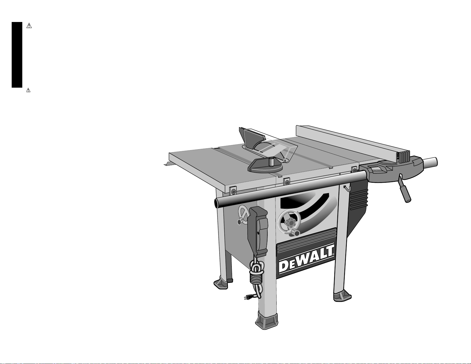
DW746
Woodworker’s Table Saw
Scies circulaires à table d’entrepreneur
Sierra de banco para madera
INSTRUCTIVO DE OPERACIÓN, CENTROS DE SERVICIO Y PÓLIZA
DE GARANTIA. ADVERTENCIA: LEASE ESTE INSTRUCTIVO ANTES
DE USAR EL PRODUCTO. SI TIENE DUDAS, POR FAVOR LLAME.
Before returning this
product call
1-800-4-DEWAL T
IF YOU SHOULD EXPERIENCE A PROBLEM WITH YOUR DEWALT PURCHASE,
CALL 1-800-4 DEW AL T.
IN MOST CASES, A DEW AL T REPRESENTA TIVE CAN RESOLVE
YOUR PROBLEM OVER THE PHONE.
IF YOU HA VE A SUGGESTION OR COMMENT, GIVE US A CALL.
YOUR FEEDBACK IS VIT AL TO THE SUCCESS OF DEW ALT'S
QUALITY IMPROVEMENT PROGRAM.
See our catalog on the World Wide Web. www.dewalt.com
Page 3
English
DEW ALT…GUARANTEED TOUGH
DEWALT high performance industrial tools are made for America’s
toughest industrial and construction applications. The design of
every tool in the line – from drills to sanders to table saws – is the
result of rigorous use on job sites and throughout industry. Each
tool is produced with painstaking precision using advanced
manufacturing systems and intense quality control. Every tool is
checked before it leaves the factory to make sure that it meets your
standards for durability, reliability and power.
D
EWALT Built Job site Tough…WE GUARANTEE IT.
WARNING: FOR YOUR OWN SAFETY, READ INSTRUCTION MANUAL BEFORE OPERATING SAW • ALWAYS WEAR EYE PROTECTION • DO NOT WEAR
GLOVES, NECKTIES, JEWELRY OR LOOSE CLOTHING • CONTAIN LONG HAIR • KEEP HANDS AND FINGERS OUT OF THE SAW BLADE PATH — USE
EXTRA CAUTION WHEN BEVELING • ALWAYS USE BLADE GUARD AND SPREADER FOR EVERY OPERATION FOR WHICH IT CAN BE USED, INCLUDING
THROUGH SAWING • USE A “PUSH STICK” WHEN REQUIRED • KNOW HOW TO AVOID KICKBACKS — SEE MANUAL • ALWAYS SUPPORT WORK WITH
TABLE AND FENCE OR MITER GAUGE • NEVER USE FENCE AND MITER GAUGE TOGETHER • NEVER REACH AROUND OR OVER SAW BLADE • SECURELY
MOUNT SAW BLADE BEFORE OPERATING • NEVER REMOVE JAMMED OR CUT-OFF PIECES UNTIL POWER IS OFF AND BLADE HAS STOPPED • DO NOT
EXPOSE TO RAIN OR USE IN DAMP LOCATIONS • DO NOT OPERATE THIS MACHINE WHILE UNDER THE INFLUENCE OF ALCOHOL OR DRUGS • FAILURE
TO COMPLY WITH THESE WARNINGS MAY RESULT IN SERIOUS PERSONAL INJURY.
WARNING: USE OF THIS TOOL CAN GENERATE DUST CONTAINING CHEMICALS
KNOWN TO CAUSE CANCER, BIRTH DEFECTS OR OTHER REPRODUCTIVE HARM.
USE APPROPRIATE RESPIRATORY PROTECTION.
Page 4
WARNING: FOR YOUR OWN SAFETY READ INSTRUCTION MANUAL BEFORE
OPERATING SAW.
WARNING: When using electric tools, basic safety precautions should always
be followed to reduce risk of fire, electric shock, and personal injury, including the
following:
Grounding Instructions
In the event of a malfunction or breakdown, grounding provides a path of least resistance for
electric current to reduce the risk of electric shock. This tool is equipped with an electric cord
having an equipment-grounding conductor and grounding plug. The plug must be plugged
into a matching outlet that is properly installed and grounded in accordance with all local
codes and ordinances. Do not modify plug provided — if it will not fit the outlet, have the
proper outlet installed by a qualified electrician.
Improper connection of the equipment-grounding conductor can result in a risk of electric
shock. The conductor with insulation having an outer surface that is green with or without
yellow stripes is the equipment-grounding conductor. If repair or replacement of the electric
cord or plug is necessary, do not connect the equipment-grounding conductor to a live
terminal.
Check with a qualified electrician or service personnel if the grounding instructions are not
completely understood, or if in doubt as to whether the tool is properly grounded.
Use only 3-wire extension cords that have 3-prong grounding plugs and 3-pole receptacles
that accept the tool’s plug.
REPAIR OR REPLACE DAMAGED OR WORN CORDS IMMEDIATELY.
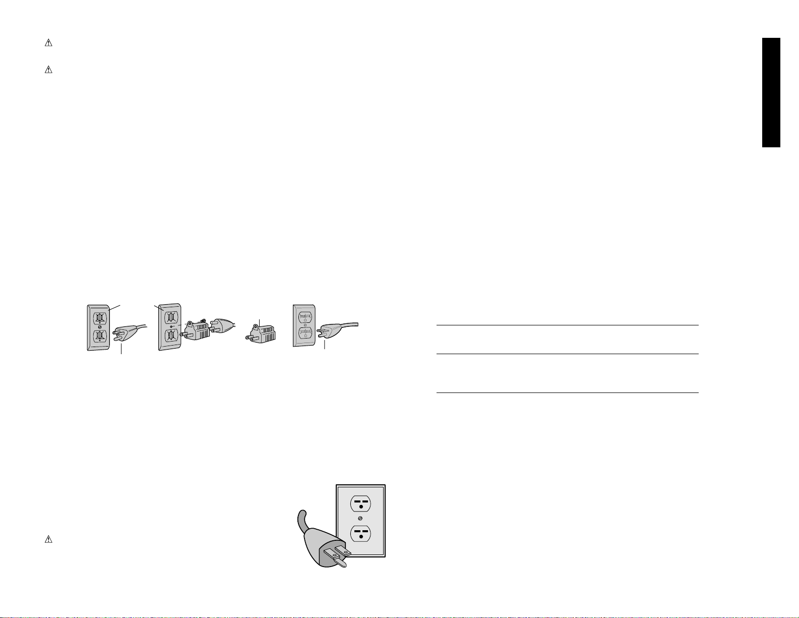
Grounded tools intended for use on a supply circuit having a nominal rating less than 150
volts: This tool is intended for use on a circuit that has an outlet that looks like the one
illustrated in Figure A. The tool has a grounding plug that looks like the plug illustrated in
Figure A. A temporary adapter, which looks like the adapter illustrated in Figures B and C,
may be used to connect this plug to a 2-pole receptacle as shown in Figure B if a properly
grounded outlet is not available. The temporary adapter should be used only until a
properly grounded outlet can be installed by a qualified electrician. The green-colored rigid
ear, lug, and the like, extending from the adapter must be connected to a permanent
ground such as a properly grounded outlet box.
The adapter (C) is not for use in Canada.
240 Volt Operation
The motor supplied with your saw is a dual voltage, 120, 240 volt
motor. If it is desired to operate your saw at 240 volts, single
phase, it is necessary to reconnect the motor leads in the motor
junction box by following the instructions given on the motor
nameplate.
WARNING: Make sure motor is disconnected from power
source before reconnecting motor leads.
It is also necessary to replace the 120 volt plug, supplied with the
motor, with a UL/CSA listed plug suitable for 240 volts and the
rated current of the saw as shown. Contact your local DEWALT Service Center or qualified
electrician for proper procedures to install the plug. The saw must comply with all local and
national electrical codes after the 240 volt plug is installed.
The saw with the 240 volt plug should only be connected to an outlet having the same
configuration as the plug illustrated. No adapter is available or should be used with the 240
volt plug.
Important Safety Instructions
• KEEP GUARDS IN PLACE and in working order.
• REMOVE ADJUSTING KEYS AND WRENCHES. Form habit of checking to see that keys
and adjusting wrenches are removed from tool before turning it on.
• KEEP WORK AREA CLEAN. Cluttered areas and benches invite injuries.
• DON’T USE IN DANGEROUS ENVIRONMENT. Don’t use power tools in damp or wet
locations, or expose them to rain. Keep work area well lighted.
• KEEP CHILDREN AWAY. All visitors should be kept safe distance from work area.
• MAKE WORKSHOP CHILD PROOF with padlocks, master switches, or by removing starter
keys.
• DON’T FORCE TOOL. It will do the job better and safer at the rate for which it was designed.
• USE RIGHT TOOL. Don’t force tool or attachment to do a job for which it was not designed.
• USE PROPER EXTENSION CORD. Make sure your extension cord is in good condition. When
using an extension cord, be sure to use one heavy enough to carry the current your product will
draw. An undersized cord will cause a drop in line voltage resulting in loss of power and
overheating. The following table shows the correct size to use depending on cord length and
nameplate ampere rating. If in doubt, use the next heavier gage. The smaller the gage number,
the heavier the cord.
Minimum Gage for Cord Sets
Volts Total Length of Cord in Feet
120V 0-25 26-50 51-100 101-150
240V 0-50 51-100 101-200 201-300
Ampere Rating
More Not more AWG
Than Than
0-6 18 16 16 14
6 - 10 18 16 14 12
10 - 12 16 16 14 12
12 - 16 14 12 Not Recommended
• WEAR PROPER APPAREL. Do not wear loose clothing, gloves, neckties, rings, bracelets, or
other jewelry which may get caught in moving parts. Nonslip footwear is recommended. Wear
protective hair covering to contain long hair.
• ALWAYS USE SAFETY GLASSES. Also use face or dust mask if cutting operation is dusty.
Everyday eyeglasses only have impact resistant lenses, they are not safety glasses.
• SECURE WORK. Use clamps or a vise to hold work when practical.
• DON’T OVERREACH. Keep proper footing and balance at all times.
• MAINTAIN TOOLS WITH CARE. Keep tools sharp and clean for best and safest performance.
Follow instructions for lubricating and changing accessories.
• DISCONNECT TOOLS before servicing; when changing accessories, such as blades, bits,
cutters, and the like.
• REDUCE THE RISK OF UNINTENTIONAL STARTING. Make sure switch is in off position
before plugging in.
• USE RECOMMENDED ACCESSORIES. Consult the instruction manual for recommended
accessories. The use of improper accessories may cause risk of injury to persons.
• NEVER STAND ON TOOL. Serious injury could occur if the tool is tipped over or if the cutting
tool is unintentionally contacted.
• CHECK DAMAGED PARTS. Before further use of the tool, a guard or other part that is damaged
should be carefully checked to determine that it will operate properly and perform its intended
1
English
AB CD
GROUNDING PIN
GROUNDED
OUTLET
BOX
GROUNDING
MEANS
GROUNDING PIN
ADAPTER
Page 5

• No special wood is needed to make a push-stick as long
as it’s sturdy and long enough. A length of 12 inches is
recommended with a notch that fits against the edge of
the workpiece to prevent slipping. It’s a good idea to
have several push sticks of the same length (12 inches)
with different size notches for different workpiece
thicknesses.
• See the inside back cover for a picture of a push stick.
The shape can vary to suit your own needs as long as it
performs its intended function of keeping your hands
away from the blade.
SAVE THESE INSTRUCTIONS
FOR FUTURE USE
Specifications
Horsepower 1-3/4
Table Size 27" x 40 3/4"
Miter Angle 60° L&R
Bevel Angle -2° to 47° Left
Blade Size 10" (254mm)
Max. Cut Depth 0° Bevel ..............3 1/8" (79mm)
Max. Cut Depth 45° Bevel ............2-1/8" (54mm)
RPM, no load 3000
DW746 Basic Unit
Assembling custom accessories to this unit is covered in the
instructions packed with them. Assemble any accessories
first. Operating instructions and adjustments are covered in
this manual starting with step 16, on page 4.
Tools Included
To aid you with assembly of your new saw, we have
included the following tools.
• T50 torx wrench
• 5mm hex wrench
• Combination wrench with 16mm, 13mm 10mm
and 22mm openings
• Blade wrench with 15/16” and 10mm box ends.
Tools You Will Need to Supply
• Flat blade screwdrivers
• 16mm or 5/8” open end wrench or pliers
• Ruler
• Square
• Soft hammer, or regular hammer and block of wood
To speed assembly, the following would be helpful:
• 16mm or 5/8” socket wrench, with 6” extension
• 13mm or 1/2” socket wrench
2
function–check for alignment of moving parts, binding of
moving parts, breakage of parts, mounting, and any other
conditions that may affect its operation. A guard or other part
that is damaged should be properly repaired or replaced.
• DIRECTION OF FEED. Feed work into a blade or cutter
against the direction of rotation of the blade or cutter only.
• NEVER LEAVE TOOL RUNNING UNATTENDED. TURN
POWER OFF. Don’t leave tool until it comes to a complete
stop.
Additional Safety Rules for Table
Saws
• Wear eye protection.
• Use saw-blade guard and spreader for every operation for
which it can be used, including all through sawing.
• Keep hands out of line of saw blade.
• Use a push-stick when required.
• Know how to reduce risk of kickback.
• Do not perform any operation freehand.
• Never reach in back of or over saw blade.
CAUTION: Some wood contains preservatives such as
copper chromium arsenate (CCA) which can be toxic. When
cutting these materials extra care should be taken to avoid
inhalation and minimize skin contact.
• USE A DUST MASK and safety glasses when sawing. This
saw is capable of generating large amounts of sawdust.
WARNING: Some dust created by power sanding,
sawing, grinding, drilling, and other construction activities
contains chemicals known to cause cancer, birth defects or
other reproductive harm. Some examples of these chemicals
are:
• lead from lead-based paints,
• crystalline silica from bricks and cement and other
masonry products, and
• arsenic and chromium from chemically-treated lumber
(CCA).
Your risk from these exposures varies, depending on how
often you do this type of work. To reduce your exposure to
these chemicals: work in a well ventilated area, and work
with approved safety equipment, such as those dust masks
that are specially designed to filter out microscopic particles.
Kickbacks
HOW TO AVOID THEM AND PROTECT YOURSELF
FROM POSSIBLE INJURY:
a) Be certain that the rip fence is parallel to the saw blade.
b) Do not rip by applying the feed force to the section of the
workpiece that will become the cut-off (free) piece. Feed
force when ripping should always be applied between
the saw blade and the fence; use a push stick for short
work, 6” (152mm) wide or less. For less than 2" (51mm)
wide, you must use a special fixture.
c) Keep saw blade guard, splitter and anti-kickback pawls
in place and operating properly. Keep pawls sharp. If
pawls are not operational, return your unit to the nearest
D
EWALT Service Center for repair. The splitter must be
in alignment with the saw blade and the pawls must stop
a kickback once it has started. Check their action before
ripping.
d) Plastic and composition (like hardboard) materials may
be cut on your saw. However, since these are usually
quite hard and slippery, the anti-kickback pawls may not
stop a kickback. Therefore, be especially attentive to
following proper set up and cutting procedures for
ripping.
e) Use saw blade guard and splitter for every operation for
which it can be used, including all through sawing.
Saw Blade Guard and Spreader
Your table saw is equipped with a blade guard and
spreader assembly that covers the blade and prevents
accidental contact. The spreader is a flat plate that fits into
the cut made by the saw blade and effectively fights
kickback by lessening the tendency of the blade to bind in
the cut. The spreader can only be used when making
through cuts that sever the wood. When making dadoes,
rabbits and other cuts that make less than through cuts, the
blade guard and spreader assembly must be removed from
the saw.
Two anti-kickback pawls are located on the sides of the
spreader that allow the wood to pass through the blade in
the cutting direction but lock it if it tries to move backwards
toward the operator.
TERMS:
The following terms will be used throughout the
manual and you should become familiar with them.
• Through-Sawing refers to any cut that completely severs
the workpiece.
• Push-Stick refers to a wooden stick, usually home-made,
that is used to push small workpieces through the saw and
keeps the operator’s hands clear of the blade.
• Kickback occurs when the saw blade binds in the cut and
violently thrusts the workpiece back toward the operator.
• Freehand refers to cutting without the use of a miter gauge
or rip fence or any other means of guiding or holding the
workpiece other than the operator’s hand.
Making a Push Stick (Back Page)
• In order to operate your table saw safely you must use
a push-stick whenever the size or shape of the
workpiece would cause your hands to be within 6 inches
of the saw blade or other cutter.
English
Page 6
• 10 mm open end wrench
• T20 and T25 Torx drivers
• T40 Torx wrench.
Your will also need:
• Mild solvent cleaner such as mineral spirits, paint
thinner or denatured alcohol.
• High quality paste wax
Necessary Hardware
Your hardware bag, located in the parts box, contains all
the necessary nuts, bolts and washers to assemble the
components included with the DW746 Woodworker’s Table
Saw.
To make assembly of your saw easier, match the nuts,
bolts and washers with the chart on the next page.
Separate them by size so that you can easily locate the
item you need. Before each step, check your hardware
against the chart and identify the pieces you need.
Assembly for DW746
PLEASE READ ENTIRE ASSEMBLY
SECTION
BEFORE PROCEEDING.
STEP 1. Remove parts box, motor cover,
fence beam and side tables from saw.
STEP 2. Turn the saw right side up. You will
need help. The combined weight of the
table top and motor assembly is
approximately 200 lbs.
STEP 3. Cut and remove plastic strap holding the motor.
STEP 4. Using front hand crank, lower the motor some
and remove the foam packing material between the
motor and the mechanism.
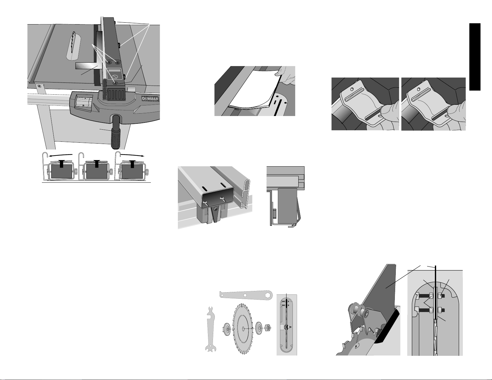
STEP 5. Install bevel crank. (Fig. 1) To do this, first install
the crank handle (A) over the shaft (B), rotate it slightly
to fully engage the shaft pin. Screw the lock knob (C)
3
English
FIG. 2
A
B
C
FIG. 1
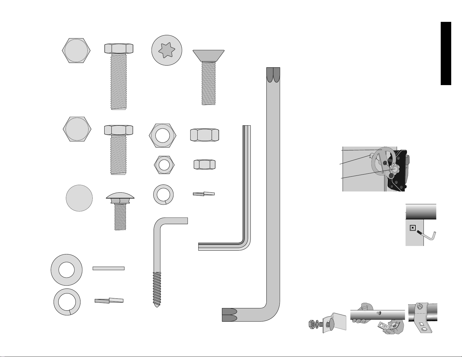
Hardware Included with the DW746 Woodworker’s Table Saw
Bolt
10 mm x 35 mm
(2 pieces)
Bolt
10 mm x 25 mm
(8 pieces)
Carriage Bolt
8 mm x 20 mm
(4 pieces)
T50 Torx
Flat Head Screw
10 mm x 30 mm
(4 pieces)
FLAT WASHER
(14 PIECES)
10 MM LOCK WASHER
(14 PIECES)
8 MM LOCK WASHER
(4 PIECES)
5 MM
HEX
WRENCH
( 1 )
T50
TORX
WRENCH
(1)
M 10 NUT 16 MM HEX
(8 PIECES)
M 8 NUT 13 MM HEX
(4 PIECES)
WRENCH
HOOK
(1)
PARTS SHOWN ARE FULL SIZE - EXTRA FASTENERS MAY HAVE BEEN INCLUDED
Page 7
English
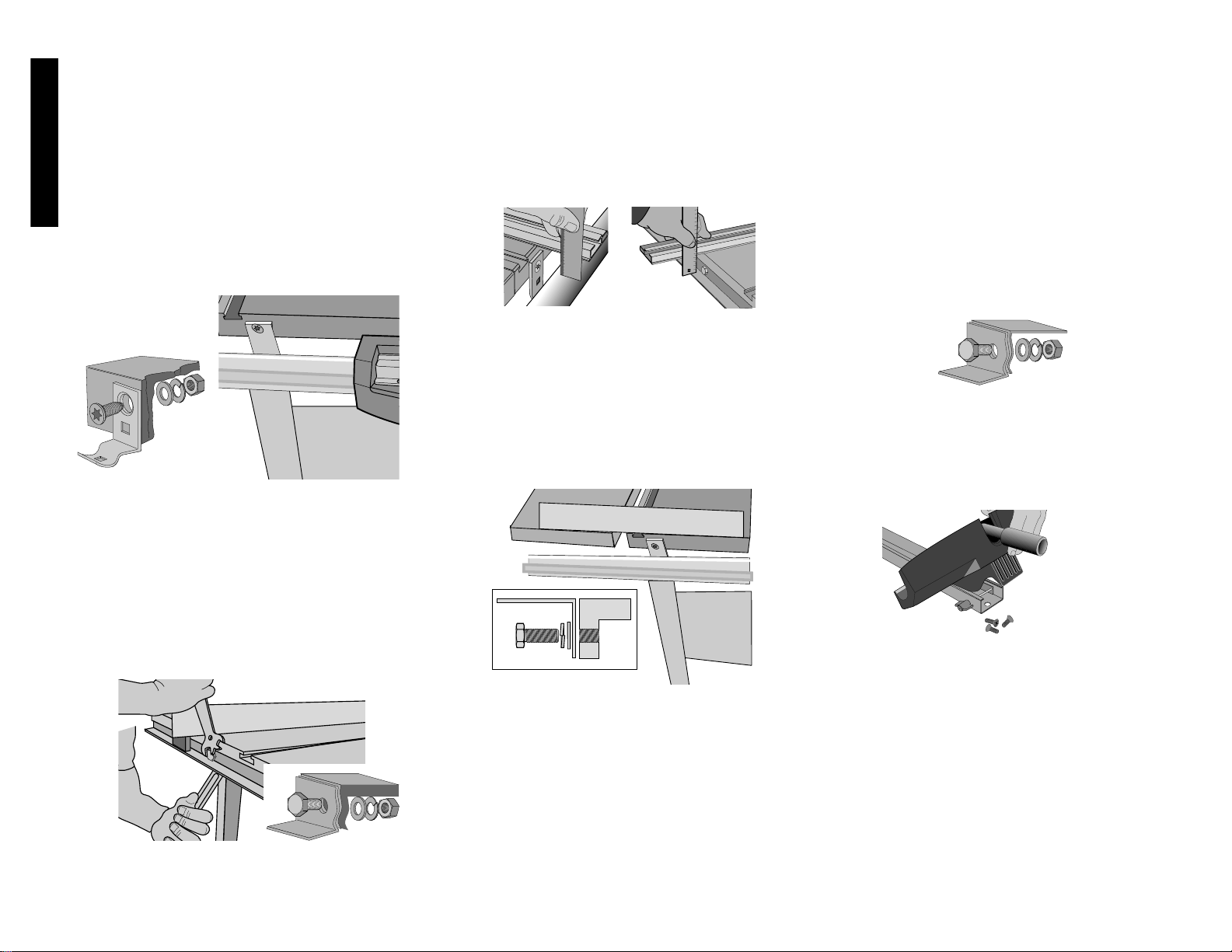
STEP 13. Attach the left & right Support Tables. (Fig. 6)
You will need: 6 - 10 x 25 mm Hex Head Bolts
6 - 10 mm Flat Washers
6 - 10 mm Lock Washers
Without support table in place, install the 3 bolts per side
with washers as shown keeping 1/4” gap. Rest a side
table on the bolts, fitting into the notches. Using the
extruded fence face as a guide, flush the support table
to the main table edge and snug the front bolt. Repeat
this process for the rear bolt. Tighten the center bolt.
Repeat on the other side.
STEP 14. Attach front rail brackets to Support Tables.
You will need: 2 - 10 x 30 mm Flat Head Screws
2 - 10 mm Flat Washers
2 - 10 mm Lock Washers
2 - 10 mm Nuts
Align front brackets with the support table and tighten
bracket nuts to the rail. Attach the wing tables to the
outer front rail support brackets, keeping the washers
and nut on the inside of the table. Using the fence face
as a straight edge, make sure the front outer corner of
the wing table is level with the inner edge and main table
surface. Repeat this procedure for the other support
table.
STEP 15. Attach rear rail to support tables.
You will need: 2 - 10 x 25 mm Hex Head Bolts
2 - 10 mm Flat Washers
2 - 10 mm Lock Washers
2 - 10 mm Nuts
Attach the wing tables to the outer rear rail support
brackets, again, keeping the washers and nut on the
inside. Using the fence face as a straight edge, make
sure the rear outer corner of the wing table is level with
the inner edge and the main table surface. Repeat this
procedure for the other side table.
STEP 16. Assemble the fence beam to the fence head
mm Lock Washers
2 - 10 mm Nuts
Secure each screw through the upper hole in the center
brackets keeping the flat washer, lock washer and nut
on the inside of the table. Tighten snug but not very
tight.Tighten center rail bracket nuts, leaving the outer
ones finger tight.
STEP 11. Attach rear rail. (Fig. 4)
You will need: 2 - 10 x 35 mm Hex Head Bolts
2
-
10 mm Flat Washers
2 - 10 mm Lock Washers
2 - 10 mm Nuts
Secure rear rail to main table top using hex head bolts,
washers, lock washers and nuts. Keeping the washers
and nuts on the inside of the table. The flat side should
be down unless you are also mounting an accessory
(consult accessory instructions for rail mounting
details.). Make sure ends of the rear rail line up with
the ends of the front rail. Tighten snug but not very tight.
STEP 12. Parallel the rails to the table top (Fig. 5). Using
your fence face or a straightedge to extend the table
surface over the rail, make sure the distance from the
table top to the rail top is the same at both the left and
right side of the table. If the rails are not lined up
correctly, loosen the mounting screws slightly and tap
on the rail brackets with a soft hammer or regular
hammer and a block of wood until the distances are the
same. Tighten fasteners securely. Repeat for the rear
rail.
into place until it is fully seated, then back it off 1/4 to 1/2
turn.
STEP 6. Using height crank, raise mechanism up as high
as it will go.
STEP 7. Install wrench hook. On the front right leg, near
the top is a plastic threaded insert. Thread the “L”
shaped wrench hook in until only a few threads are
visible.
STEP 8. Unpack rail carton. (contains front & rear rail)
STEP 9.Assemble front rail and brackets (Fig. 2).
You will Need: 4 - 8 mm Carriage Bolts
4 - 8 mm Lock Washers
4 - 8 mm Nuts
Assemble carriage bolts, lock washers and nuts to front
rail brackets (just a few threads). Put the head of the
carriage bolt into keyhole slots in the front rail and slide
to engage the square part of the bolt. Run nut in until it
is finger tight. Repeat for other 3 brackets. When
attaching brackets to the rail, the rail must be positioned
correctly so that the rip scale is right side-up. Also all 4
brackets should face the same direction.
STEP 10. Attach front rail with brackets to the table top.
(Fig. 3) You will need:
2 - 10 x 30 mm Flat Head Screws
2 - 10 mm Flat Washers
2 10
FIG. 4
FIG. 7
FIG. 6
FIG. 3
4
FIG. 5
Page 8
A
C
B
D
PIVOTING
SCREW
DETAIL A
beam, allow the face to rest on the table top, and
retighten the wing nuts.
3. Slide the fence so the face is in line with the edge of the
miter slot.
4. Adjust the beam angle to the miter slot as follows;
a. Loosen the farthest two torx screws (A) so the beam
will pivot on the third. Don’t over loosen the screws,
slightly loose works best.
b. Loosen the pivot screw (A) just enough to pivot
beam, but snug enough not to prevent beam from
moving side to side.
c. Lock fence head to front rail.
d. Parallel the fence face to the miter slot.
e. Tighten all three screws (A) which hold the fence
beam to the head, starting with the rearmost two.
Now the beam is square to the table.
STEP 18. Adjust the fence face height and position
(Fig. 9). Loosen the wing nuts that retain the fence face
to the beam. Lift the fence face and slide 16 pages of the
instruction manual or other paper between the face and
(Fig. 7). Remove the three flat head screws which
secure the cover plate to the fence head with the
T50 Torx wrench. Turn the beam upside down.
Slide the fence head into the beam as shown. Flip
the beam over and install the cover plate and three
screws snug but not tight.
STEP 17. Adjusting Fence to Table Top (Fig. 8)
Check alignment of beam and fence face before each
cutting session.
SQUARE FENCE FACE TO TABLE TOP
1. Make sure all surfaces are clean of sawdust.
2. Make sure the lock knobs (B) are secure.
3. Lock the beam in place with handle (C).
4. Using a square (D), check the fence face angle to the
table top.
5. If an adjustment is necessary, loosen the three torx
screws (A) just slightly and slide the beam to re-align the
face (See Detail A).
6. Tighten the three torx screws (A).
7. Recheck alignment to the table.
PARALLEL FENCE TO BLADE
1. Place fence on rails, near the right-hand miter slot.
Ensure that the rear glide is located correctly. See step
19.
2. Loosen the wing nuts (B) retaining the face to the fence
English
5
FIG.9
the table. This will set the height of the face
approximately 1/16” off of the table top. The face can
also be adjusted forward and back to suit your
preference. Tighten the wing nuts to secure the face.
When cutting very thin material, the fence face can be
adjusted so that it rests on the table top. Be sure to readjust the face to about 1/16” before sliding the fence.
STEP 19. Adjust the rear fence glide (Fig. 10). If
necessary, adjust the rear glide to locate it correctly
against the rear rail by loosening the two screws which
secure it to the fence beam. The plastic retaining clip
should be deflected somewhat when the glide is
positioned correctly. This adjustment should only be
necessary if the rear rail has been relocated by the
addition of an optional accessory.
STEP 20. To install the saw blade (Fig.11), remove the
arbor nut (A) and outer clamp washer(B), then slip the
blade over the spindle and re-install the washer and nut.
Use the spindle lock wrench to hold the shaft while
tightening the nut with the blade wrench. Make sure the
blade is installed correctly for the rotation of your saw.
The cutting teeth should face the front of the saw.
STEP 21. Adjust the fence scale indicator (Fig. 12).
Slide the fence until it just touches the blade. Loosen the
fence indicator screw and slide it until the hairline aligns
with the “0” line on the scale. Tighten the screw. If the
FIG.10
FIG. 8
SPINDLE
LOCK
WRENCH
BLADE WRENCH
FIG. 11
FIG. 13
A
B
B
C
D
A
B
FIG. 12
Page 9
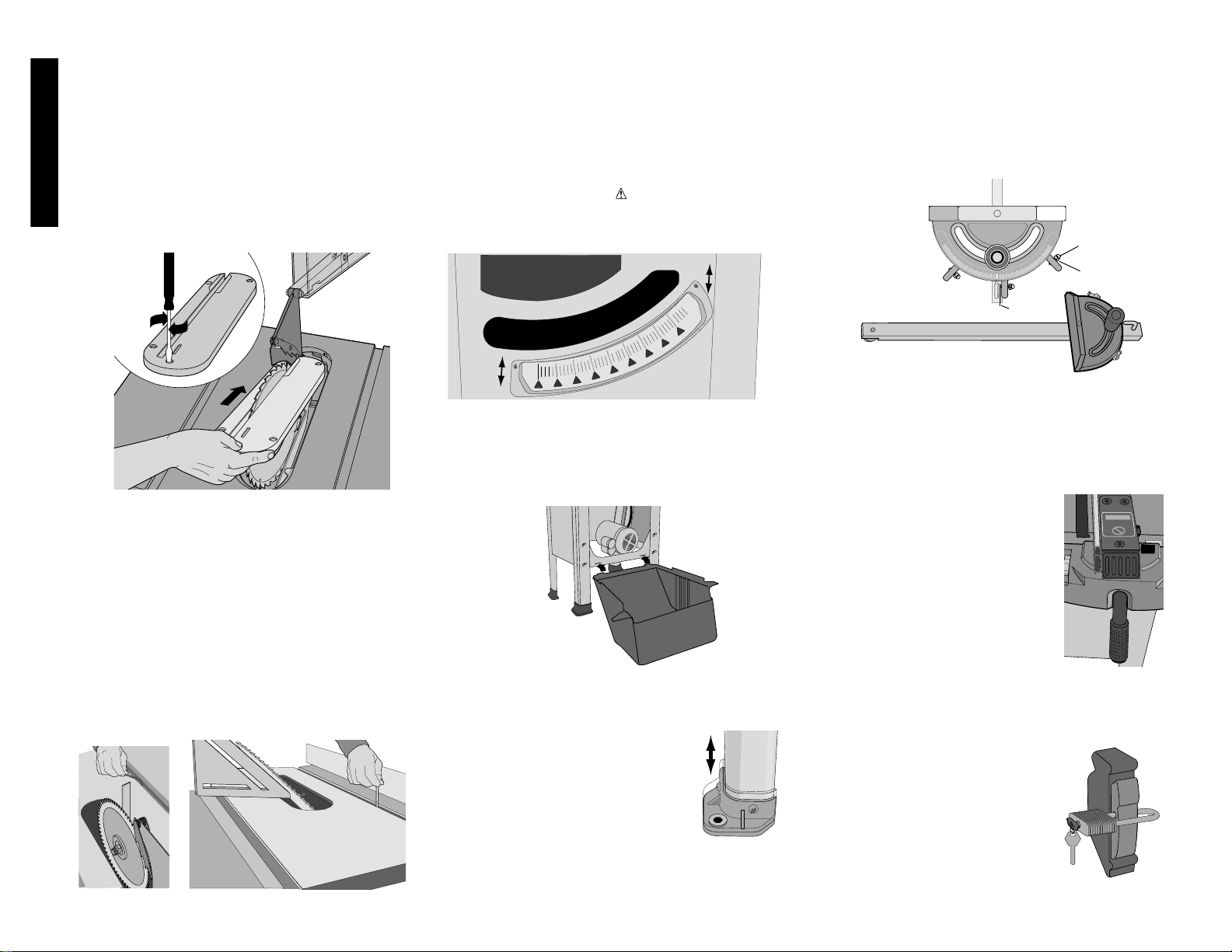
the table and lower the plate into its opening. The throat
plate includes four adjustment screws which raise or
lower it. When properly adjusted, the front of the throat
plate should be flush or slightly below the surface of the
table top, and the rear of the throat plate should be
flush or slightly above the table top. The center front
screw, when turned clockwise, will engage a cam under
the front lip of the table, locking the throat plate in
place. Rotate the screw counterclockwise 1/2 turn to
remove the throat plate. CAUTION: THE THROAT
PLATE MUST BE IN PLACE AT ALL TIMES.
STEP 24. Adjust the bevel stops (Fig. 15). Using a
square, set the blade to exactly “0” degrees. If the
blade stops beveling before it gets to 0, back the stop
set screw up with the 5 mm allen wrench and then
proceed to “0” degrees. The set screw is located in the
left miter guide slot. With the blade set at 0, slowly turn
the zero stop screw in until you feel resistance. Bevel
the blade away from 0 a little then back to the stop. Remeasure the angle and repeat the stop adjustment as
necessary until the blade stops at 0 degrees. Set the 45
stop the same way. The set
screw for the 45˚ stop is located
in the right hand miter guide slot.
NOTE: For some special cuts,
the stops can be backed out and
the saw will bevel from -2
degrees to 47 degrees.
STEP 25. Adjust the bevel scale
(Fig. 16). Bevel the saw until it hits the zero bevel stop.
low profile fence face accessory or a wider homemade
fence face is used which is out of the adjustment range
of the pointer, the pointer can be removed completely,
turned 180 degrees, re-installed, and aligned with the “0”
line.
STEP 22. Install the guard and splitter assembly (Fig.
13). Raise the blade to its highest point. Loosen the
outer guard retaining nuts (A) enough so that the splitter
will fit between the two guard retaining plates (B). Install
the splitter (C) and ensure that it is aligned with the
blade. If not, the position is adjusted by moving the inner
guard clamp nuts (D) which changes the location where
the splitter mounts. Make sure the splitter is centered
and parallel to the blade by lining up the parts with a
straightedge. Also make sure there is some clearance
between the splitter and the blade and that the blade
spins freely. If the splitter is tilted relative to the blade,
the splitter plate can be bent until it lines up correctly.
IMPORTANT: THE GUARD SHOULD BE IN PLACE
FOR ALL POSSIBLE CUTS. When making non-through
cuts, the guard can be easily removed by slightly
loosening the outer guard nuts (A). The guard can easily
be replaced without having to readjust the inner nuts.
STEP 23. Install and adjust the throat plate (Fig. 14).
Align the throat plate as shown and insert the tabs on
the back of the throat plate into the holes at the back of
English
6
Remove the height crank lock knob and height crank.
Adjust the red pointer by loosening the screw where it
attaches to its shaft, move the pointer until it lines up
with the 0 line on the scale, and re-tighten the screw.
The pointer should be positioned just barely off of the
scale surface. Bevel the saw to the 45 degrees stop. If
the pointer doesn’t point to 45 degrees, loosen the two
screws which hold the scale to the saw front panel and
slide the scale up or down until the pointer lines up with
the 45 line. Re-tighten the scale screws. Replace the
height crank and lock knob.
STEP 26. Install the motor cover (Fig. 17). Remove the
two cover screws and washers from the top of the two
side legs with a small flat blade screwdriver. Snap the
two bottom tabs of the cover into the slots in the right
lower crossmember. Place the cover
in position and re-install the screws
and washers.
STEP 27. Level the saw (Fig. 18). Move
the saw to the location you want to
keep it. If the saw rocks on the floor,
the foot not touching the floor can be
lowered to compensate for the uneven
floor. Loosen the two screws that hold
the foot to the leg. Let the foot fall to
the floor surface. Re-tighten the
screws holding the foot to the leg.
If your saw will have a permanent location, we
recommend that the feet be bolted to the floor using the
holes provided.
STEP 28. Adjustment and use of miter gage (Fig. 19).
Your miter gauge features adjustable
stops at 90° and 45° left and right. To
adjust these stops, loosen the lock
nuts (A) and tighten or loosen the
three adjusting screws (B). Check the
gauge with a square against the
blade and tighten the three adjusting
screws. To set the miter gauge past
the 45 degree stops, flip up the stop
plate (C) and continue to the required
FIG. 17
FIG. 18
FIG. 16
30
30
45
60
75
75
90
60
45
FIG. 19
A
B
C
FIG. 15
FIG. 14
Page 10

English
angle.
STEP 29. Clean the table top. Your saw was shipped with
a rust preventive coating which should be removed. Clean
the top with mineral spirits or denatured alcohol and apply
paste wax. Apply and remove soon afterward to prevent a
sticky build-up.
Rip Fence Operation
FENCE LOCK LEVER
The fence lock lever locks the rip fence in place, preventing
movement. To lock the fence, push down. To unlock the
lever, pull it up. NOTE: When ripping, always lock the fence
to the rail.
RIP SCALE POINTER
NOTE: The rip scale pointer will need to be readjusted
whenever a thicker or thinner blade is installed. Should
you decide to use a thicker face, or the D
EWALT low fence
face accessory, the scale pointer may be removed and
turned 180˚ to line up with the scale. (Fig. 12)
RIP FENCE CAPACITY
The fence will slide beyond the end of the rails in either
direction without falling off. Stops are provided to keep the
fence attached.
On-Off Switch
Pull out the switch paddle to turn your saw ON and push it
in to turn your saw OFF. A hole is provided in the switch
for insertion of a padlock to lock the saw off.
WARNING: Be sure switch is in the OFF position before
plugging machine in.
Saw Blades
THIS SAW IS INTENDED FOR THE USE WITH SAW
BLADES 10” IN DIAMETER OR SMALLER.
1. The saw blade furnished with your new saw is a 10"
(254mm) fine ripping blade, used for ripping (with the
grain) through the material, and occasional cross cuts.
The center hole to fit on the arbor is 5/8" (16mm)
diameter (.625"). This blade will produce a good quality
cut for many applications.
2. There are many types of blades available to do specific
and special jobs such as cross cut only, rip only, hollow
ground, thin plywood, paneling, etc.
3. Use only saw blades designed for maximum safe
operating speeds of 5,000 RPM or greater.
4. Saw blades should always be kept sharp. It is
recommended that you locate a reputable sharpening
service to sharpen your blades when needed.
5. Never stack blades on top of one another to store. Place
material such as cardboard between them to keep the
blades from coming in contact with one another.
CAUTION: Abrasive wheels should not be used on this
saw.
Operation
Plain sawing includes ripping and cross cutting, plus a few
other standard operations of fundamental nature. With all
power tools, respecting the tool, using caution and following
safe practices will considerably lessen the possibility of
personal injury. However, if normal safety precautions are
overlooked or completely ignored, personal injury to the
operator can result. Read and follow all warnings indicated
on the saw. Familiarize yourself with all the components
and features before attempting any cuts. Know how to
make adjustments before turning the saw on. Observe the
safety rules included in this manual.
THIS SAW IS NOT INTENDED FOR CUTTING METAL.
Operating Instructions
There are two basic types of cuts: ripping and crosscutting.
In general, cutting with the grain is ripping and across the
grain is crosscutting. However, with man made materials
this distinction is somewhat difficult to make. Therefore,
cutting a piece of wood to a different width is ripping and
cutting across the short dimension is crosscutting. Neither
ripping or crosscutting may be done safely freehand!
Ripping requires the use of the rip fence and crosscutting
uses the miter gauge.
CAUTION: Before using the saw each and every time
verify the following:
1. Blade is tight.
2. Bevel angle and height lock knobs are tight.
3. If ripping, ensure fence lock lever is tight and fence is
parallel to the blade.
4. If crosscutting, miter gauge knob is tight.
5. Safety glasses are being worn.
6. The blade guard is properly attached and the
anti-kickback teeth are functioning.
Failure to adhere to these common safety rules can greatly
increase the likelihood of injury.
Ripping
1. Lock the rip fence by pressing the fence lock lever
down. Remove the miter gauge.
2. Raise the blade so it is about 1/8"(3.2mm) higher than
the top of the workpiece.
3. Hold the workpiece flat on the table and against the
fence. Keep the workpiece about 1" (25.4mm) away
from the blade.
CAUTION: The workpiece must have a straight edge
against the fence and must not be warped, twisted or
bowed. Keep both hands away from the blade and away
from the path of the blade.
4. Turn the saw on and allow the blade to come up to
speed. Both hands can be used in starting the cut.
When there is approximately twelve (12) inches
(305mm) left to be
ripped, use only one hand, with your thumb pushing the
material, your index and second finger holding the
material down and your other fingers hooked over the
fence. Always keep your thumb along side your first two
fingers and near the fence.
5. Keeping the workpiece against the table and fence,
slowly feed the workpiece rearward all the way through
the saw blade. Continue pushing the workpiece until it is
clear of the guard and it falls off the rear of the table. Do
not overload the motor.
6. NEVER try to pull the workpiece back with the blade
turning. Turn the switch off, allow the blade to stop, raise
the anti-kickback teeth on each side of the splitter if
necessary and slide the workpiece out.
7. When sawing a long piece of material or a panel, always
use a work support. A sawhorse, rollers, or out feed
assembly provides adequate support for this purpose. The
work support must be at the same height as the saw
table.
CAUTION: Never push or hold onto the “free” or “cut
off” side of the workpiece.
Bevel Ripping
This operation is the same as ripping except the bevel
angle is set to an angle other than zero degrees.
WARNING: Before connecting the table saw to the
power source or operating the saw, always inspect the
guard and splitter for proper alignment and clearance with
saw blade. Check alignment after each change of bevel
angle.
Ripping Small Pieces
It is unsafe to rip small pieces. It is not safe to put your hands
close to the blade. Instead, rip a larger piece to obtain the
desired piece. When a small width is to be ripped and the hand
cannot be safely put between the blade and the rip fence, use
one or more push sticks. A pattern is
included on the back cover to make
push sticks. Use them to hold the
workpiece against the table and
fence, and push the workpiece fully
past the blade
Crosscutting
1. Remove the rip fence and place
the miter gauge in the desired
slot.
2. Adjust the blade height so that
the blade is about 1/8" (3.2mm)
higher than the top of the
workpiece.
3. Hold the workpiece firmly
against the miter gauge with the path of the blade in line
with the desired cut location. Keep the workpiece an inch
7
Page 11
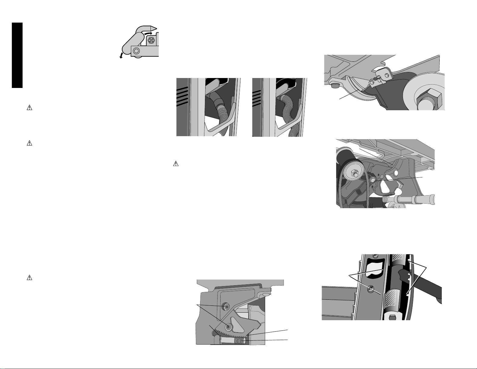
narrow cut-offs or when cutting with a dado blade, clean the
dust collection port each time. If you find you are clogging
the port often, the dust port elbow may be removed by
loosening the two screws where it attaches to the dust
shroud. A dust collection hose can then be attached directly
to the shroud as long as the saw is not beveled past 35˚.
Maintenance, Cleaning
Care of the table top
Protect your investment. Keep your table saw clean. If you
notice signs of rust, steel wool the areas, clean with mineral
spirits or denatured alcohol and apply paste wax.
8
English
or so in front of the blade. KEEP
BOTH HANDS ON THE MITER
GAUGE, AWAY FROM THE
BLADE AND THE PATH OF THE
BLADE.
4. Start the saw motor and allow the
blade to come up to speed.
5. While using both hands to keep the workpiece against the
face of the miter gauge, and holding the workpiece flat
against the table, slowly push the workpiece through the
blade.
6. NEVER try to pull the workpiece back with the blade
turning. Turn the switch off, allow the blade to stop, and
carefully slide the workpiece out.
CAUTION: Never touch or hold onto the “free” or “cut
off” end of the workpiece.
Bevel Crosscutting
This operation is the same as crosscutting except that the
bevel angle is set to an angle other than 0 degrees.
WARNING: Before connecting the table saw to the
power source or operating the saw, always inspect the guard
and splitter for proper alignment and clearance with saw
blade. Check alignment after each change of bevel angle.
Mitering
This operation is the same as crosscutting except the
miter gauge is locked at an angle other than 0°. Hold the
workpiece FIRMLY against the miter gauge and feed the
workpiece slowly into the blade (to prevent the workpiece
from moving).
MITER GAUGE OPERATION
To set your miter gauge, loosen the lock handle and move
the miter gauge to the desired angle. The miter gauge has
set stops and 90° and 45° left and right. To rotate the miter
gauge beyond these stops, flip the stop plate up, as shown.
Compound Mitering
This is a combination of bevel crosscutting and mitering.
Follow the instruction for both, bevel crosscutting and
mitering.
Dado Cutting
CAUTION: Do not attempt to stack dado blades thicker
than 13/16" (20mm). Do not use dado blades larger than
8" (200mm) diameter. Since dado cuts are not through
cuts, the cuts must be performed with the blade guard
removed. To remove the blade guard, loosen the two bolts
(A) shown in Figure 13 and remove the guard assembly.
Anytime a cut is required that is considerably wider than the
saw kerf, a dado is used. When using the dado, the special
dado insert (also sold as an accessory) must be used.
When installing the dado blade set, it may be necessary to
eliminate the outer clamp washer from the assembly in
order to capture sufficient thread to safely hold the dado
blade set.
A dado cut is commonly used to add support and line up a
shelf for a cabinet, bookcase or some such project. When
using the dado, the guard must be removed. Use EXTREME
care when using the dado without the guard. If a deep cut is
required, use several successive passes rather than
attempting to make it with one pass. Maximum dado width
on this saw is 13/16" (20mm). DO NOT USE WIDER
COMBINATIONS.
When cutting with a dado blade use dust collection to prevent
heavy dust loads from piling up under the saw and on the fan
intake on the motor. Clean these areas often.
CAUTION: Always check dado blade clearance before
plugging in the saw.
Be sure to place the guard and standard throat plate back in
position and check adjustments when the dado cuts are
complete.
Dust Collection
Your table saw is equipped with a dust shroud and dust
collection port. For best results, connect a vacuum to the
port at the rear of the saw.
If the saw is operated without a vacuum attached, most of the
dust will be blown out the dust collection port. After extended
use, the saw’s dust collection system may become clogged.
To clear the dust collection system:
a) Unplug the saw.
b) Use a paint stick or long screwdriver to loosen debris
and cut-offs and pass it out through the port.
When cutting wet wood without a vacuum, making long
A
B
D
E
F
FIG. 22
A
B
E
FIG. 21
C
Page 12
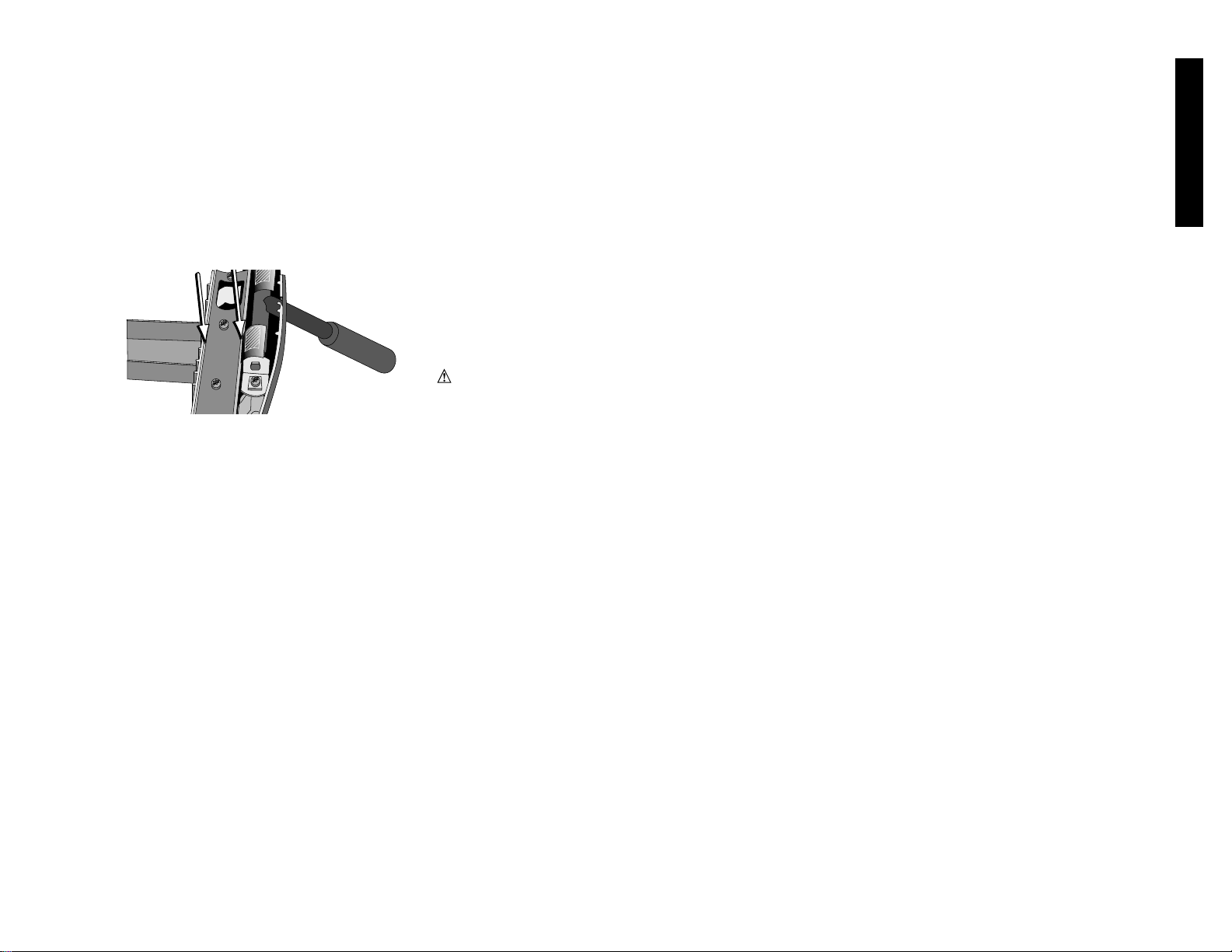
If the fence head glide strips (arrows below) become worn
or damaged, it can easily be replaced. Consult your local
D
EWALT Service Center for parts and assistance.
Accessories
Recommended accessories for use with your tool are
available at extra cost from your distributor or local service
center.
D
EWALT manufactures the following accessories for your
saw:
DW7460 - Mobile base
DW7461 - Sliding Table and Premium Gauge
DW7462 - Iron Wing
DW7463 - Outfeed Table
DW7464 - 52” Rail System with Legs and Table Board
DW7466 - Dado Throat Plate
DW7467 - Steel Wing
DW7468 - 30” Rail System with Legs and Table Board
DW7469 - Low Profile Fence Face
DW7471 - Enhanced Miter Gauge
CAUTION: The use of any non-recommended
accessory may be hazardous.
If you need assistance in locating any accessory, please
contact D
EWALT Industrial Tool Co., 701 East Joppa
Road, Baltimore, MD 21286 or call
1-800-4-D
EWALT (1-800-433-9258).
Important
To assure product SAFETY and RELIABILITY, repairs,
maintenance and adjustment should be performed by
authorized service centers or other qualified service
organizations, always using identical replacement parts.
Full Warranty
This saw warranted for two years from date of purchase.
We will repair, without charge, any defects due to faulty
materials or workmanship. For warranty repair information,
call 1-800-4-D
EWALT. This warranty does not apply to
accessories or damage caused where repairs have been
made or attempted by others. This warranty gives you
specific legal rights and you may have other rights which
vary in certain states or provinces.
In addition to the warranty, D
EWALT tools are covered by
our:
30 DAY NO RISK SATISFACTION GUARANTEE
If you are not completely satisfied with the performance of
9
English
Over time, the lubricants used in the mechanism of
your tablesaw may need to be replenished.
HEIGHT AND BEVEL GEAR (FIG. 22):
First clean off any accumulated sawdust from the gears
and the worms with a stiff brush. Next, remove any pitch or
resin which has built up. You may need to use a solvent
such as mineral spirits to remove it. Next, re-apply grease
to the worms (A) to the gears (B) and the washer/pin
assembly(C). You can also apply paste wax to the gears if
you find that the grease is attracting too much sawdust. If
any backlash has occurred in the bevel system, you can readjust the bevel gear clearance by loosening the two
screws (D) which hold the gear to the cradle, letting the
gear fall into tighter mesh, lightly tightening the screws,
rotating the worm one full turn to set the gear height, then
fully tightening the gear retaining screws. This adjustment
must be made at 0˚ bevel.
BEVEL PIVOT:
The bevel pivot trunnions, both front and back should also
be maintained. First clean them like the gears were
cleaned. Then apply grease into the curved slots (E) and
bevel the saw back and forth to distribute the grease.
ARBOR PIVOT:
You may also need to lubricate the arbor pivot pin (F). This
can be done by applying a light oil at both the base and
top of the pivot pin.
Lubricating Fence Head
The moving parts of your fence head should be periodically
greased. This includes the area between the cams and
locking levers (A), and between the cams and the fence
head casting (B).
Maintaining Fence System
Your fence should always slide freely. If it seems to require
excessive force to slide or if it feels rough, wipe the rails
and fence head gliding surface with a cloth or paper towel.
Check the movement again. If it still feels rough, clean the
fence head with a mild solvent such as denatured alcohol
or mineral spirits. Re-coat the rail with a heavy coat of
paste wax or a light oil. Slide the fence head back and
forth several times to coat the rail and fence. Wipe off any
excess wax or oil from the rail.
your DEWALTheavy duty industrial tool, simply return it to the
participating seller within 30 days for a full refund. Please
return the complete unit, transportation prepaid. Proof of
purchase may be required.
Page 13

10
English
Troubleshooting
SAW WILL NOT START WHAT TO DO:
1. Saw not plugged in. 1. Plug in saw.
2. Fuse blown or circuit breaker tripped. 2. Replace fuse or reset circuit breaker.
3. Cord damaged. 3. Have cord replaced by authorized service
center.
SAW MAKES UNSATISFACTORY CUTS WHAT TO DO:
1. Dull blade. 1. Replace blade. Page 5.
2. Blade mounted backwards 2. Turn blade around. Page 5.
3. Gum or pitch on blade. 3. Remove blade and clean with turpentine
and coarse steel wool or household oven
cleaner.
4. Incorrect blade for work being done. 4. Change blade type. Page 6.
BLADE DOES NOT COME UP TO SPEED WHAT TO DO:
1. Extension cord too light or too long. 1. Replace with adequate size cord. Page 1.
2. Low house current 2. Contact your electric power company.
3. Belt worn or broken. 3. Replace belt. See D
EWALT service center
MACHINE VIBRATES EXCESSIVELY WHAT TO DO:
1. Saw on uneven floor 1. Reposition on flat surface. Adjust feet to
stabilize. See page 6.
2. Damaged saw blade. 2. Replace blade. Page 5.
3. Saw not secured to floor. 3. Fasten saw to floor.
4. Damaged belt. 4. Replace belt.
INACCURATE MITER CUTS WHAT TO DO:
1. Miter gauge not adjusted correctly 1. Check and adjust. Page 6.
2. Miter gauge not square to blade. 2. Check and adjust. Page 6.
3. Blade not perpendicular to table. 3. Check and adjust bevel stops. Page 6.
4. Workpiece moving. 4. Clamp workpiece to miter head face.
Glue 120 grit sandpaper to miter head
face.
MATERIAL BINDING DURING CUT WHAT TO DO:
1. Cutting bowed material. 1. Material should be laid flat at the point of
cut and supported with scrap and/or miter
gauge.
2. Fence not aligned parallel to blade. 2. Align fence. Page 4.
3. Splitter not aligned with blade. 3. Align splitter. Page 5.
INACCURATE RIP CUTS WHAT TO DO:
1. Rip scale pointer not aligned. 1. Adjust pointer. Page 5.
INACCURATE BEVEL CUTS WHAT TO DO:
1. Bevel scale not adjusted. 1. Adjust scale. Page 6.
2. Bevel stops not adjusted. 2. Adjust bevel stops. 6.
REAR OF FENCE POPS UP
WHEN FENCE LOCKS WHAT TO DO:
1. Rear clip not engaged with rear rail. 1. Re-attach fence. Be sure clip is engaged.
Page 5.
2. Rear cap/clip not positioned correctly 2. Adjust rear cap position. Page 5.
FENCE DOES NOT SLIDE FREELY WHAT TO DO:
1. Fence drags or hops as it is moved. 1. Clean front and rear rails. Reapply wax. Pg. 8
2. Rear cap/clip interferes rear of saw. 2. Adjust rear cap position. Page 5.
FENCE HITS TABLE TOP OR GAP CHANGES
AS IT IS SLID ALONG THE RAILS WHAT TO DO:
1. Front and/or rear rail not parallel to table. 1. Adjust rails so that they are parallel. Page 4.
2. Support tables not aligned with table top 2. Adjust support tables to align with top.
Page 4.
3. Fence face drags along table surface. 3. Adjust fence face. Page 5.
HEIGHT OR BEVEL CRANKS
HARD TO TURN WHAT TO DO:
1. Crank locks engaged. 1. Loosen lock knob 1/4 to 1/2 turn.
2. Sawdust, pitch on height or bevel gears
making operation difficult. 2. See Maintenance, page 8.
DUST PORT CLOGS WHAT TO DO:
1. Vacuum not attached 1. Attach vacuum. Page 8
2. Cutting small slivers or chunks 2. Remove dust port. Use paint stick or
screwdriver to dislodge debris or leave
port off. Page 8
Page 14

11
Français
DEW ALT… CONÇU POUR LE CHANTIER
Les outils industriels è rendement élevé D
EWALT répondent aux pires exigences de
l’industrie et de la construction en Amérique du Nord. La conception de chacun des outils
de la gamme (des perceuses aux ponceuses, en passant par les rectifieuses) résulte de
leur utilisation rigoureuse sur le chantier et dans l’industrie. Chaque outil est construit
avec une précision laborieuse à l’aide de systèmes de fabrication de pointe et un intense
contrôle de la qualité. Chacun d’eux est soigneusement vérifié avant de quitter l’usine afin
de s’assurer que l’outil répond aux normes de durabilité, de fiabilité et de puissance des
utilisateurs.
D
EWALT:
Conçu pour le chantier … NOUS LE ARANTISSONS.
POUR TOUT RENSEIGNEMENT SUPPLÉMENTAIRE SUR CET OUTIL OU TOUT AUTRE
OUTIL D
EWALT, COMPOSER SANS FRAIS LE NUMÉRO:
1 800 4-DEWALT (1 800 433-9258)
AVERTISSEMENT : PAR MESURE DE SÉCURITÉ PERSONNELLE, LIRE LE GUIDE D’UTILISATION AVANT D’UTILISER LA SCIE. TOUJOURS PORTER DES LUNETTES DE
SÉCURITÉ. NE PAS PORTER DE GANTS, DE CRAVATE, DE BIJOUX NI DE VETEMENTS AMPLES. PROTÉGER LA CHEVELURE LORSQU’ELLE EST LONGUE. ÉLOIGNER LES
DOIGTS ET LES MAINS DE LA TRAJECTOIRE DE LA LAME; PRENDRE PARTICULIEREMENT SOIN LORS DES COUPES EN BISEAU. TOUJOURS UTILISER LE PROTECTEUR ET
LE RÉPARTITEUR POUR TOUTES LES COUPES, Y COMPRIS LES COUPES COMPLETES. UTILISER UN BATON POUR POUSSER LE MATÉRIAU LE CAS ÉCHÉANT. SAVOIR
COMMENT ÉVITER LES REBONDS; CONSULTER LE GUIDE. TOUJOURS SOUTENIR LA PIECE À DÉCOUPER À L’AIDE DE LA TABLE ET DU GUIDE, OU DE L’INDICATEUR
D’ONGLETS. NE JAMAIS UTILISER SIMULTANÉMENT LE GUIDE ET L’INDICATEUR D’ONGLETS. NE JAMAIS S’ÉTIRER AU-DESSUS NI AUTOUR DE LA LAME. BIEN FIXER LA
LAME AVANT D’UTILISER L’OUTIL. NE JAMAIS RETIRER DES PIECES COINCÉES NI COUPÉES AVANT D’AVOIR MIS L’OUTIL HORS TENSION ET DE S’ETRE ASSURÉ DE
L’IMMOBILISATION DE LA LAME. PROTÉGER DE LA PLUIE ET NE PAS UTILISER DANS DES ENDROITS HUMIDES. BIEN FIXER L’OUTIL AFIN D’EN ÉVITER DES MOUVEMENTS
IMPRÉVUS. NE PAS SE SERVIR DE L’OUTIL APRES AVOIR CONSOMMÉ DE L’ALCOOL OU DES DROGUES. LE NON-RESPECT DU PRÉSENT AVERTISSEMENT COMPORTE DES
RISQUES DE BLESSURES GRAVES.
AVERTISSEMENT : PAR MESURE DE SÉCURITÉ, NE PAS UTILISER LA SCIE AVANT LE MONTAGE FINAL CONFORME AUX INSTRUCTIONS NI AVANT D’AVOIR LU ET
COMPRIS LES POINTS SUIVANTS.
Page 15

12
AVERTISSEMENT : Par mesure de sécurité personnelle, lire le guide d'utilisation avant d'utiliser la
scie.
AVERTISSEMENT : Afin de réduire les risques d'incendie, de secousses électriques ou de
blessures lorsqu'on utilise des outils électriques, il faut toujours respecter les mesures de sécurité
suivantes.
Mise à la terre
En cas de défaillance ou de bris, la mise à la terre procure un chemin de moindre résistance au
courant électrique afin de réduire le risque de secousses électriques. L'outil est muni d'un cordon
comportant un conducteur de terre et d'une fiche de terre. Il faut brancher la fiche dans une prise
correspondante bien installée et mise à la terre selon les lois et règlements de la région. Il ne faut pas
modifier la fiche de l’outil; lorsque la fiche ne s’insère pas dans la prise, faire installer une prise
appropriée par un électricien certifié.
Une mauvaise connexion du fil de terre présente des risques de secousses électriques. Le conducteur
vert (ou vert et jaune) du cordon constitue la mise à la terre. Si la réparation ou le remplacement d’un
cordon d’électrique ou d’une fiche s’avèrent nécessaires, ne pas brancher la mise à la terre dans une
borne sous tension.
Consulter un électricien certifié ou un représentant du service à la clientèle si les instructions de mise
à la terre ne sont pas parfaitement assimilées ou si un doute réside quant à la mise à la terre. Utiliser
seulement des cordons de rallonge trifilaires ayant une fiche à 3 broches ainsi qu'une prise à 3 trous
acceptant la fiche de l'outil.
Réparer ou remplacer immédiatement tout cordon endommagé ou usé.
Outils mis à la terre conçus pour être alimentés à une tension maximale de 150 volts : Cet outil est
conçu pour être alimenté par un circuit dont la fiche ressemble à celle illustrée à la figure A. L’outil
comporte une fiche de mise à la terre qui ressemble à celle illustrée à la figure A. On peut utiliser un
adaptateur temporaire (figures B et C) pour brancher ce type de fiche dans des prises à deux trous
(figure B). Utiliser l’adaptateur temporaire uniquement en attendant l’installation d’une prise mise à la
terre par un électricien certifié. L'oreille ou la cosse rigide et verte de l’adaptateur doit être reliée à une
mise à la terre permanente, comme une prise bien mise à la terre. L’adaptateur (C) ne peut être utilisé
au Canada.
Fonctionnement à 240 volts
Le moteur de la scie est à double voltage, 120 ou 240 volts. Pour un
fonctionnement monophasé de la scie à 240 volts, reconnecter les fils du
moteur dans la boîte de dérivation conformément aux instructions énoncées
sur la plaque signalétique du moteur.
AVERTISSEMENT : Débrancher le moteur de sa source d’alimentation
avant d’en connecter les fils.
Il faut également remplacer la fiche 120 volts fournie avec le moteur par
une fiche approuvée par UL/CSA convenant à une tension de 240 volts et au
courant requis. Communiquer avec le centre de service DEWALT de la
région ou avec un électricien certifié pour connaître la méthode d’installation de la fiche. La scie doit
être conforme aux codes électriques local et national une fois la prise de 240 volts installée.
Brancher la scie munie d’une fiche de 240 volts uniquement à une prise semblable à celle de
l’illustration. Aucun adaptateur n’existe ou ne doit être utilisé avec la fiche de 240 volts.
Importantes mesures de sécurité
• S’ASSURER QUE LES PROTECTEURS sont en place et en bon état.
• ENLEVER LES CLÉS DE RÉGLAGE. Prendre l'habitude de vérifier si les clés de réglage ont
été retirées avant de faire démarrer l'outil.
• BIEN DÉGAGER LA SURFACE DE TRAVAIL. Des surfaces et des établis encombrés
peuvent être la cause de blessures.
• TENIR COMPTE DU MILIEU DE TRAVAIL. Ne pas se servir des outils électriques dans des
endroits humides ou mouillés. Les protéger de la pluie. Bien éclairer la surface de travail.
• ÉLOIGNER LES ENFANTS. Tous les visiteurs doivent être tenus à l'écart de l'aire de travail.
• GARDER L’ATELIER À L’ÉPREUVE DES ENFANTS en y installant des cadenas, des
interrupteurs généraux ou en retirant les clés des démarreurs.
• NE JAMAIS FORCER L'OUTIL. Afin d'obtenir un rendement sûr et efficace, utiliser l'outil à son
rendement nominal.
• UTILISER L'OUTIL APPROPRIÉ. Ne jamais exiger d'un petit outil ou d'un accessoire le
rendement d'un outil de fabrication plus robuste.
• CORDONS DE RALLONGE. S'assurer que le cordon de rallonge est en bon état. Lorsqu'on
se sert d'un cordon de rallonge, s'assurer qu'il est de calibre approprié pour la tension
nécessaire au fonctionnement de l'outil. L'utilisation d'un cordon de calibre inférieur occasionne
une baisse de tension entraînant une perte de puissance et la surchauffe. Le tableau suivant
indique le calibre approprié selon la longueur du cordon et les mentions de la plaque
signalétique de l'outil. En cas de doute, utiliser un cordon de calibre supérieur. Le chiffre
indiquant le calibre est inversement proportionnel au calibre du cordon.
Calibre minimal des cordons de rallonge
Tension Longueur totale du cordon en pieds
120 V 0-25 26-50 51-100 101-150
240 V 0-50 51-100 101-200 201-300
Courant
Au moins Au plus AWG
0- 6 18 16 16 14
6 - 10 18 16 14 12
10 - 12 1 16 14 12
12 - 16 14 12 Non recommandé
PORTER DES VÊTEMENTS APPROPRIÉS. Éviter de porter des vêtements amples, des
gants, des cravates, des bracelets ou tout autre bijou qui peuvent être happés par les pièces
en mouvement. Il est conseillé de porter des chaussures à semelle antidérapante. Protéger
la chevelure si elle est longue.
• TOUJOURS PORTER DES LUNETTES DE SÉCURITÉ. Porter également un masque
respiratoire si le travail de coupe produit de la poussière. Les lentilles des verres correcteurs
résistent seulement aux chocs; ce NE sont PAS des lunettes de sécurité.
• ASSUJETTIR LA PIÈCE. Immobiliser la pièce à l'aide de brides ou d'un étau.
• NE PAS DÉPASSER SA PORTÉE. Toujours demeurer dans une position stable et garder son
équilibre.
• PRENDRE SOIN DES OUTILS. Conserver les outils propres et affûtés pour qu'ils donnent un
rendement supérieur et sûr. Suivre les directives concernant la lubrification et le remplacement
des accessoires.
• DÉBRANCHER LES OUTILS avant de les réparer ou d’en changer un accessoire (comme une
lame, un foret ou un couteau).
• ÉVITER LES DÉMARRAGES ACCIDENTELS. S'assurer que l'interrupteur est à la position
hors circuit lorsqu'on branche l'outil.
• UTILISER LES ACCESSOIRES RECOMMANDÉS. Consulter le guide d’utilisation pour
connaître la liste des accessoires recommandés. L’utilisation d’accessoires inappropriés peut
présenter des risques de blessures.
• NE JAMAIS SE TENIR SUR L’OUTIL. Cela présente des risques de blessures graves si l’outil
bascule ou si on touche à la lame par inadvertance.
• VÉRIFIER LES PIÈCES ENDOMMAGÉES. Avant de continuer à utiliser l'outil, il faut vérifier
Français
AB CD
BROCHE DE PRISE
MISE À LA TERRE
BROCHE DE PRISE
MISE À LA TERRE
PRISE MISE
À LA TERRE
DISPOSITIF DE
MISE À LA TERRE
ADAPTATEUR
Page 16

si le protecteur ou toute autre pièce endommagée remplit
bien la fonction pour laquelle il a été prévu. Vérifier
l'alignement et les attaches des pièces mobiles, le degré
d'usure des pièces et leur montage, ainsi que tout autre
facteur susceptible de nuire au bon fonctionnement de
l'outil. Faire réparer ou remplacer tout protecteur ou toute
autre pièce endommagée dans un centre de service
autorisé.
• DIRECTION D’ALIMENTATION. Appliquer le matériau
sur la lame uniquement dans la direction opposée à la
rotation de la lame.
• TOUJOURS SURVEILLER L’OUTIL. LE METTRE HORS
TENSION. Laisser l’outil seulement lorsqu’il est
complètement immobilisé.
Mesures de sécurité propres aux
scies circulaires à table
• Porter des lunettes de sécurité.
• Utiliser le protecteur et le répartiteur à chaque coupe
lorsque c'est possible, y compris les coupes complètes du
matériau.
• Éloigner les mains de la trajectoire de la lame.
• Utiliser un bâtonnet pour pousser le cas échéant.
• Savoir comment minimiser les risques de rebonds.
• Ne pas effectuer de tâches à main levée.
• Ne jamais s'étirer derrière ni au-dessus de la lame.
AVERTISSEMENT : Certains outils, tels que les
sableuses électriques, les scies, les meules, les perceuses
ou certains autres outils de construction, peuvent soulever
de la poussière contenant des produits chimiques
susceptibles d’entraîner le cancer, des malformations
congénitales ou pouvant être nocifs pour le système
reproductif. Parmi ces produits chimiques, on retrouve :
• le plomb dans les peintures à base de plomb;
• la silice cristalline dans les briques et le ciment et autres
produits de maçonnerie;
• l’arsenic et le chrome dans le bois de sciage ayant subi
un traitement chimique (CCA).
Le risque associé à de telles expositions peut varier selon
la fréquence avec laquelle on effectue ces travaux. Pour
réduire l’exposition à de tels produits, il faut travailler dans
un endroit bien ventilé et utiliser l’équipement de sécurité
approprié tel un masque anti-poussières spécialement
conçu pour filtrer les particules microscopiques.
• PORTER UN MASQUE RESPIRATOIRE et des lunettes
de sécurité. Le travail de coupe peut produire d'importantes
quantités de sciure.
Rebonds
COMMENT LES ÉVITER ET SE PROTÉGER DES RISQUES
DE BLESSURES QU'ILS PRÉSENTENT.
a) S'assurer que la lame est parallèle au guide de refente.
b) Ne pas couper en refente en exerçant la pression
d'alimentation à la section de la pièce qui est inutile. Il
faut toujours exercer la poussée d'alimentation entre
la lame et le guide pendant les coupes de refente, en
utilisant un bâtonnet pour les petits travaux (largeur
d'au plus 152 mm (6 po). Lorsque la largeur est
inférieure à 51 mm (2 po), il faut se servir d'un dispositif
spécial.
c) Laisser le protecteur, le répartiteur et les cliquets
d'arrêt en place et en bon état de fonctionnement.
S'assurer que les cliquets sont tranchants. Lorsque les
cliquets ne sont pas fonctionnels, confier la réparation
de l'outil au personnel du centre de service DeWalt de
la région. Le répartiteur doit être aligné sur la lame et
les cliquets doivent arrêter un rebond dès qu'il
commence. Vérifier leur fonctionnement avant
d'effectuer des coupes en refente.
d) La scie peut découper des plastiques et des
agglomérés (comme des panneaux rigides). Toutefois,
comme ces matériaux sont très rigides et glissants, il
arrive que les cliquets n'arrêtent pas les rebonds. Il
faut donc accorder une attention particulière au
montage et aux directives de coupe en refente.
e) Utiliser le protecteur et le répartiteur à chaque coupe
lorsque c'est possible, y compris les coupes complètes
du matériau.
Protecteur et répartiteur
La scie à table est munie d’un ensemble de protecteur et de
répartiteur qui couvre la lame et en empêche le contact
accidentel. Le répartiteur est une plaque plane qui s’insère dans
la fente creusée par la lame de la scie et prévient efficacement les
rebonds en atténuant la tendance qu’a la lame à se coincer dans
la coupe. Le répartiteur peut seulement servir lors de coupes
complètes qui séparent le bois. Lorsqu’on fait des
embrèvements, des feuillures ou d’autres coupes qui ne
traversent pas le bois, retirer l’ensemble de protecteur et
répartiteur de la scie. Deux cliquets d’arrêt se trouvent sur les
côtés du répartiteur et permettent au bois de se déplacer dans la
direction de coupe mais le bloquent s’il se dirige en direction de
l’utilisateur.
TERMES
Il faut se familiariser avec les termes suivants, qui sont utilisés
tout au long du présent guide.
• La coupe complète consiste en une coupe divisant le
matériau en deux.
• Le bâtonnet désigne un bâton de bois, généralement
fait main, dont on se sert pour pousser les petites
pièces à ouvrer vers la scie tout en éloignant les mains
de l'utilisateur de la lame.
• Les rebonds se produisent lorsque la lame bloque dans
la coupe et repousse violemment la pièce à ouvrer vers
l’utilisateur.
• On dit qu’une coupe est faite à main levée lorsqu’on
n’utilise ni guide d’onglet, ni guide de refente, ni tout
autre moyen pour guider ou assujettir la pièce à ouvrer.
13
Français
Fabrication d’un bâtonnet (page
arrière)
• Pour se servir de la scie à table de façon sûre, il faut
utiliser un bâtonnet pour pousser toute pièce dont les
dimensions ou la forme exigeraient que les mains de
l’utilisateur se rapprochent à moins de 6 pouces de la
lame.
• La fabrication d’un bâtonnet ne demande aucun type
de bois particulier. Il doit cependant être solide et
suffisamment long. Le bâtonnet mesure idéalement 12
po et comporte une encoche qui s’appuie sur l’arête
de la pièce à ouvrer pour l’empêcher de glisser. Il est
pratique d’avoir plusieurs bâtonnets de la même
longueur (12 pouces) comportant des encoches de
dimensions différentes pouvant convenir aux pièces
d’épaisseurs différentes.
• Un bâtonnet est illustré sur la couverture intérieure
arrière. La forme peut varier en fonction des besoins
de l’utilisateur, tant qu’il permet d’éloigner efficacement
les mains de la lame.
CONSERVER CES MESURES
À TITRE DE RÉFÉRENCE.
Fiche technique
Puissance (HP) 1 3/4
Dimensions de la table 27 po sur 40 3/4 po
Angle des onglets 60°à gauche et à droite
Angle des biseaux De -2°à 47°à gauche
Dimension de la lame 254 mm (10 po)
Prof. de coupe max. 0° en biseau..........79 mm (3 1/8 po)
Prof. de coupe max. 45° en biseau........54 mm (2 1/8 po)
Régime sous vide (tr/min) 3 000
Unité de base DW746
L’assemblage des accessoires complémentaires à cet outil est
expliqué dans les instructions qui les accompagnent. Les
instructions d’utilisation et de réglage sont énoncées dans ce
guide à partir de l’étape 16 de la page 21.
Outils compris
Nous avons joint les outils suivants à la nouvelle scie pour en
faciliter l’assemblage.
• Clé Torx T50
• Clé hexagonale de 5 mm
• Clé mixte à ouvertures de 16 mm, 13 mm, 10 mm et
22 mm
• Clé polygonale à embouts de 15/16 po et 10 mm.
Outils requis
• Tournevis à lame plate
• Clé à fourches de 16 mm ou 5/8 po ou pinces
• Règle
Page 17

14
•Équerre
•Massette ou marteau et bloc de bois
Les outils suivants accéléreront le montage
•Clé à douille de 16 mm ou 5/8 po avec rallonge de 6 po
•Clé à douille de 13 mm ou 1/2 po
•Clé à fourches de 10 mm
• Tournevis Torx T20 et T25
• Clé Torx T40
Autres articles requis
• Solvant doux, comme du white-spirit, du décapant ou
de l’alcool dénaturé.
• Cire en pâte de haute qualité
Ferrures requises
Le sac de ferrures qui se trouve dans la boîte de pièces contient
tous les écrous, boulons et rondelles nécessaires à l’assemblage
des composants de la scie circulaire à table d’entrepreneur
DW746.
Pour faciliter l’assemblage de la scie, identifier les écrous,
boulons et rondelles sur le tableau de la page suivante. Les
séparer par dimensions pour pouvoir les identifier plus
rapidement. Avant chaque étape, identifier les pièces requises.
Montage du DW746
LIRE TOUTE LA SECTION SUR LE MONTAGE AVANT DE
COMMENCER.
ÉTAPE 1. Retirer la boîte de pièces, le couvercle du
moteur, la poutrelle du guide de refente et les tables
latérales de la scie.
ÉTAPE 2. Tourner la scie à l’envers avec de l’aide. Le
poids combiné de la table et du moteur totalise environ
200 lb.
ÉTAPE 3. Couper la courroie de
plastique qui tient le moteur et la
retirer.
ÉTAPE 4. À l’aide de la manivelle qui
se trouve à l’avant, abaisser le
moteur et retirer la mousse
d’emballage qui le sépare du
Français
BOULONS
HEXAGONAUX
10 MM X 35 MM (2)
Tornillera incluida con la sierra de banco para madera DW746
VIS Á TÊTE PLATE
(4)
BOULONS
HEXAGONAUX
10 MM X 25 MM
(8)
CLÉ HEXAGONAL
5 MM (1)
ÉCROUS 10 MM (8)
ÉCROUS DE 8 MM
(4 PIEZAS)
CLÉ TORX
T50 (1)
BOULONS Á TÊTE
BOMBÉE
8 MM (4)
RONDELLES DE
BLOCAGE 10 MM
(14)
RONDELLES
PLATES (14)
CROCHET Á
CLÉ (1)
RONDELLES DE
BLOCAGE DE
8 MM (4)
Å
B
C
FIG. 1
Page 18

mécanisme.
ÉTAPE 5. Installer la manivelle de biseau (figure 1).
Pour ce faire, installer d’abord la poignée de la
manivelle (A) sur l’arbre (B) et la tourner légèrement
pour engager la goupille de l’arbre. Visser la poignée
de verrouillage (C) en place jusqu’au bout, puis la
dévisser de 1/4 à 1/2 tour.
ÉTAPE 6. À l’aide de la manivelle de réglage en hauteur,
soulever le mécanisme au maximum.
ÉTAPE 7. Installer le crochet à clé. Sur la patte avant
droite, presque en haut, se trouve un orifice fileté en
plastique. Y visser le crochet à clé en forme de L
jusqu’à ce que seuls quelques filets soient visibles.
ÉTAPE 8. Ouvrir la boîte des rails (qui contient les rails
avant et arrière).
ÉTAPE 9. Assembler le rail avant et les supports
(fig.2). Ferrures requises :
4 boulons à tête bombée de 8 mm
4 rondelles de blocage de 8 mm
4 écrous de 8 mm
Assembler les supports de rail avant (en ne vissant que
quelques filets). Placer la tête du boulon à tête bombée
dans les trous en poire du rail avant et faire glisser les
boulons pour en insérer la partie carrée. Visser l’écrou à
la main. Répéter pour les trois autres supports. Placer les
supports sur le rail en s’assurant que l’échelle de refente
est orientée vers le dessus de la table. Les quatre
supports doivent être orientés dans la même direction.
ÉTAPE 10. Fixer le rail avant et les supports sur la
table (figure 3). Ferrures requises :
4 vis à tête plate de 10 x 30 mm
4 rondelles plates
4 rondelles de blocage de 10 mm
4 écrous de 10 mm
Fixer chaque vis dans le trou supérieur du support. En
laissant les rondelles et écrous à l’intérieur de la table,
installer une rondelle plate, une rondelle de blocage et un
écrou. Serrer les écrous du support de rail central et
serrer les autres à la main.
ÉTAPE 11. Fixer le rail arrière (figure 4). Ferrures
requises :
2 boulons hexagonaux de 10 x 35 mm
2 rondelles plates
2 rondelles de blocage de 10 mm
2 écrous de 16 mm
Fixer le rail arrière à la table à l’aide de boulons
hexagonaux, de rondelles, de rondelles de blocage et
d’écrous, en gardant les rondelles et les écrous à
l’intérieur de la table. Le côté plat devrait être orienté
15
Français
vers le bas, à moins de monter également un accessoire
(consulter les détails des instructions des accessoires
relatifs au montage des rails). S’assurer que les
extrémités du rail arrière s’alignent sur celles du rail avant.
Bien serrer, mais sans forcer.
ÉTAPE 12. Installer les rails parallèlement sur la
table (figure 5). En utilisant la face du guide ou une
règle à niveler pour prolonger la surface de la table
au-delà du rail, s’assurer que la distance entre la table
et le rail est la même des deux côtés de la table. Si
les rails ne sont pas bien alignés, desserrer les vis de
montage légèrement et tapoter les supports des rails à
l’aide d’une massette ou d’un marteau et d’un bloc de
bois jusqu’à ce que les distances soient égales. Bien
serrer les vis. Répéter pour le rail arrière.
ÉTAPE 13. Fixer les tables de soutien de gauche et de
droite (figure 6). Ferrures requises :
6 boulons hexagonaux de 10 x 25 mm
6 rondelles plates
6 rondelles de blocage de 10 mm
6 écrous de 10 mm
Avant d’installer la table de soutien, installer 3 boulons et
rondelles par côté, comme le montre l’illustration, en
conservant un jeu de 1/4 po. Déposer une table latérale
sur les boulons en les insérant dans les encoches. En se
guidant sur la face de guide extrudé, placer la table de
FIG. 2
FIG. 3
FIG. 4
FIG. 5
FIG. 6
Page 19

l’onglet.
e. Serrer les trois vis (A) qui retiennent le longeron du
guide à la tête, en commençant avec les deux vis
arrière. Le longeron est maintenant monté en parallèle
au plateau.
ÉTAPE 18. Régler la hauteur et la position de la face
du guide (figure 9). Desserrer les écrous à oreilles qui
fixent la face du guide à la poutrelle. Soulever la face
du guide et glisser 16 pages de ce guide d’utilisation ou
d’autres papiers entre la face
et la table. La hauteur de la face sera ainsi réglée à
environ 1/16 po de la table. L’utilisateur peut choisir
d’avancer ou de reculer la face du guide. Serrer les
écrous à oreilles pour fixer la face. On peut régler la
face du guide pour qu’elle repose sur la surface de la
table lors de la coupe de matériaux très minces.
S’assurer de régler la face à environ 1/16 po avant de
la faire glisser.
16
Français
soutien à égalité avec le bord de la table principale et
serrer le boulon avant. Répéter pour le boulon arrière.
Serrer le boulon du centre. Répéter de l’autre côté.
ÉTAPE 14. Fixer les supports du rail avant aux tables
de soutien. Ferrures requises :
2 vis à tête plate de 10 x 30 mm
2 rondelles de blocage de 10 mm
2 écrous de 10 mm
Aligner les supports avant sur la table de soutien et serrer les
écrous des supports sur le rail. Fixer les tables latérales aux
supports extérieurs du rail avant en gardant les rondelles et
écrous à l’intérieur de la table. En utilisant la face du guide
comme règle à niveler, s’assurer que le coin extérieur avant de
la table latérale est de niveau avec le côté intérieur et la surface
de la table principale. Répéter pour l’autre table de soutien.
ÉTAPE 15. Fixer le rail arrière aux tables de soutien.
Ferrures requises :
2 boulons hexagonaux de 10 x 25 mm
2
rondelles de blocage de 10 mm
2 écrous de 10 mm
Fixer les tables latérales aux supports extérieurs du rail arrière en
gardant une fois de plus les rondelles et écrous à l’intérieur de la
table. En utilisant la face du guide comme règle à niveler,
s’assurer que le coin extérieur arrière de la table d’extrémité est
de niveau avec le côté intérieur et la surface de la table principale.
Répéter pour l’autre table de soutien.
ÉTAPE 16. Assembler la poutrelle du guide de refente
sur le talon du guide (figure 7). Retirer les trois vis à
tête plate qui fixent la plaque d’extrémité au talon du
guide à l’aide de la clé Torx T50. Retourner la
poutrelle. Glisser le talon du guide sur la poutrelle,
comme le montre l’illustration. Retourner la poutrelle,
installer la plaque d’extrémité et serrer les trois vis sans
forcer.
ÉTAPE 17. Réglage du guide à la surface du plateau
(Fig. 8)
Vérifier si le longeron et la face du guide sont bien alignés
avant d’amorcer une coupe.
ÉQUERRAGE DE LA FACE DU GUIDE À LA SURFACE
DU PLATEAU
1. S’assurer que les surfaces soient propres et exemptes
de sciures de bois.
2. Vérifier si les boutons de verrouillage (B) sont bien
serrés.
3. Verrouiller le longeron au moyen de la poignée (C ).
4. À l’aide de l’équerre, (D) vérifier l’angle de la face du
guide par rapport à la surface du plateau.
5. Si un réglage s’avère nécessaire, desserrer les trois vis
à tête étoilée (A) juste assez pour pouvoir faire glisser
le longeron et réaligner la face (voir les détails A).
6. Serrer légèrement les trois vis à tête étoilée (A).
7. Revérifier l’alignement du plateau.
MONTAGE EN PARALLÈLE DU GUIDE À LA LAME
1. Mettre le guide sur les montants, près de la fente de
l’onglet du côté droit, en s’assurant que la partie arrière
soit correctement orientée. Voir l’étape 19.
2. Desserrer les écrous à oreilles (B) qui retiennent la
face au longeron du guide. S’assurer que cette
dernière soit bien appuyée sur la surface du plateau
avant de resserrer les écrous.
3. Glisser le guide de manière à en aligner la face avec
le bord de la fente de l’onglet.
4. Régler l’angle du longeron par rapport à la fente,
comme suit :
a. Desserrer les deux vis à tête étoilée les plus
éloignées (A) pour faire pivoter le longeron sur la
troisième vis seulement; ce pivotement sera plus facile
si les vis ne sont pas trop desserrées.
b. Desserrer la vis de pivot (A) juste assez pour faire
pivoter le longeron, mais pas trop pour empêcher le
longeron de se déplacer d’un côté à l’autre.
c. Verrouiller la tête du guide sur le montant avant.
d. Mettre la face du guide en parallèle avec la fente de
FIG. 7
FIG. 8
FIG. 9
FIG. 11
A
B
A
C
B
D
PIVOTING
SCREW
DETAIL A
FIG. 10
Page 20

ÉTAPE 19. Régler la bande de glissement arrière du
guide (figure 10). Au besoin, régler la bande de
glissement arrière pour l’appuyer correctement sur le
rail arrière en desserrant les deux vis qui le fixent à la
poutrelle du guide. L’étrier en plastique est légèrement
dérivé quand la bande de glissement est bien placée.
Ce réglage est nécessaire uniquement si le rail arrière
est replacé après l’ajout d’un accessoire optionnel.
ÉTAPE 20. Pour installer la lame de la scie (figure
11), retirer l’écrou de l’axe (A) et la rondelle externe (B),
puis glisser la lame sur l’arbre et réinstaller la rondelle
et l’écrou. Immobiliser l’arbre avec la clé de
verrouillage de l’arbre tout en serrant l’écrou à l’aide de
la clé polygonale. S’assurer que la lame est installée
correctement en fonction de la rotation de la scie. Les
dents de coupe doivent être orientées vers l’avant de la
scie.
ÉTAPE 21. Régler l’indicateur de l’échelle de refente
(figure 12). Glisser le guide jusqu’à ce qu’il touche la
lame. Desserrer la vis de l’indicateur et le glisser
jusqu’à ce que la fine ligne soit alignée à la ligne du “ 0
” sur l’échelle. Serrer la vis. Si on utilise la face de
guide basse ou une face de guide maison qui excède
l’échelle de réglage de l’indicateur, retirer celui-ci, le
tourner de 180 degrés, le réinstaller et l’aligner sur la
ligne du “ 0 ”.
ÉTAPE 22. Installer le protecteur et le répartiteur
(figure 13). Soulever la lame au maximum. Desserrer
les écrous de retenue du protecteur externe (A) pour
que le répartiteur passe entre les deux plaques de
17
Français
retenue du protecteur (B). Installer le répartiteur (C)
et s’assurer qu’il est aligné sur la lame. Sinon, en
régler la position en déplaçant les écrous internes du
protecteur (D), ce qui déplace l’emplacement de
montage du répartiteur. S’assurer que le répartiteur
est centré et parallèle à la lame en alignant les pièces
à l’aide d’une règle à niveler. S’assurer également que
l’espace est suffisant entre le répartiteur et la lame
pour que celle-ci tourne librement. Si le répartiteur est
incliné par rapport à la lame, on peut plier la plaque du
répartiteur jusqu’à ce qu’elle soit alignée correctement.
IMPORTANT : LE PROTECTEUR DOIT ÊTRE EN
PLACE POUR TOUS LES TYPES DE COUPE. Pour
les coupes qui ne traversent pas le matériau, on peut
facilement retirer le protecteur en desserrant
légèrement les écrous externes du protecteur (A). On
peut alors le replacer facilement sans devoir régler les
écrous internes de nouveau.
ÉTAPE 23. Installer et régler la plaque de lumière
(fig. 14). Aligner la plaque de lumière de la manière
illustrée et insérer les ergots à l'arrière de la plaque de
lumière dans les trous à l'arrière de la table puis
abaisser l'avant de la plaque de lumière dans
l’ouverture. La plaque de lumière comporte quatre vis
de réglage permettant de la soulever ou de l'abaisser.
Lorsque la plaque est bien réglée, l'avant de celle-ci
devrait affleurer la surface de la table ou se trouver
légèrement sous le niveau de la table et l'arrière de la
plaque de lumière devrait affleurer la surface de la
table ou se trouver légèrement au-dessus du niveau
de la table. Lorsqu’on tourne la vis centrale avant
dans le sens horaire, une came s’insère sous la lèvre
avant de la table, ce qui immobilise la plaque de
lumière. Tourner la vis de 1/2 tour dans le sens
antihoraire pour retirer la plaque de lumière.
MISE EN GARDE : La plaque de lumière devrait être
en place en tout temps.
ÉTAPE 24. Régler les butées de biseau (figure 15). À
l’aide d’une équerre, régler la lame à exactement 0
degré. Si la lame arrête de s’incliner avant d’atteindre
0, immobiliser la vis de réglage de la butée à l’aide
d’une clé à six pans de 5 mm, puis continuer jusqu’à 0
degré. La vis de réglage se trouve dans la fente de
gauche du guide d’onglets. Une fois la lame réglée à
0, tourner lentement la vis de réglage jusqu’à sentir une
résistance. Écarter légèrement la lame de 0, puis la
ramener sur la butée. Mesurer l’angle de nouveau et
régler la butée au besoin, jusqu’à ce que la lame
s’arrête à 0 degré. Régler la butée de 45 degrés de la
même façon. La vis de réglage de la butée de 45
degrés se trouve dans la fente de droite du guide
d’onglets. NOTE : Pour certaines coupes particulières,
on peut reculer les butées et incliner la lame entre -2
et 47 degrés.
ÉTAPE 25. Régler l’échelle de biseau (figure 16).
Incliner la lame jusqu’à ce qu’elle atteigne la butée de
0. Retirer le bouton de verrouillage de la manivelle de
réglage en hauteur et la manivelle. Régler l’indicateur
FIG. 13
A
B
C
B
FIG. 14
FIG. 15
FIG. 16
FIG. 12
FIG. 17
Page 21

Français
18
rouge en desserrant la vis qui la fixe à l’arbre, puis
déplacer l’indicateur jusqu’à ce
qu’il s’aligne sur la ligne de 0 de
l’échelle. Resserrer la vis.
L’indicateur doit effleurer la
surface de l’échelle. Incliner la
scie à la butée de 45 degrés. Si
l’indicateur ne pointe pas la
marque de 45 degrés, desserrer
les deux vis qui fixent l’échelle au
panneau avant de la scie (au-dessus) et glisser
l’échelle vers le haut ou le bas jusqu’à ce que
l’indicateur pointe la ligne de 45 degrés. Resserrer les
vis de l’échelle. Replacer la manivelle de réglage en
hauteur et le bouton de verrouillage.
ÉTAPE 26. Installer le couvercle du moteur (figure 17).
Retirer les deux vis du couvercle et les rondelles du
dessus des pattes de chaque côté à l’aide d’un petit
tournevis à lame plate. Insérer les deux ergots
inférieurs du couvercle dans les fentes de la traverse
inférieure droite. Placer le couvercle et réinstaller les
vis et les rondelles.
ÉTAPE 27. Mettre la scie de niveau (figure 18).
Transporter la scie là où elle sera utilisée. Si la scie
bascule sur le plancher, abaisser la patte qui ne touche
pas au sol pour compenser l’inégalité du plancher.
Desserrer les deux vis qui joignent le pied à la patte.
Laisser le pied tomber sur la surface du sol. Resserrer
les vis qui fixent le pied à la patte. Si l’emplacement de
la scie est permanent, nous recommandons de
boulonner les pieds au sol par les trous déjà percés.
ÉTAPE 28. Réglage et utilisation du
guide d’onglet (figure 19). Le
guide d’onglet comporte des butées
réglées à 90° et à 45°à gauche et à
droite. Pour régler les butées,
desserrer les contre-écrous (A) et
serrer ou desserrer les trois vis de
réglage (B). Vérifier le guide en
plaçant une équerre contre la lame
et serrer les trois vis de réglage.
Pour déplacer le guide d’onglet audelà de la butée de 45°, soulever la
plaque de butée (C) et continuer
jusqu’à l’angle désiré.
ÉTAPE 29. Nettoyer le dessus de la table. La scie est
couverte d’un enduit qui la protège contre la rouille et
qu’il faut enlever. Nettoyer la surface à l’aide de whitespirit ou d’alcool dénaturé et appliquer de la cire en
pâte. La retirer peu de temps après l’application pour
éviter la formation d’un dépôt collant.
Fonctionnement du guide de
refente
LEVIER DE VERROUILLAGE DU
GUIDE
Le levier de verrouillage du guide sert à
bloquer le guide de refente en place afin d'en
empêcher le mouvement. Pour bloquer le
guide, l'abaisser. Pour débloquer le levier, le
soulever (fig. 8). NOTE : Toujours bloquer le
guide sur le rail pour effectuer des coupes de
refente.
INDICATEUR DE L'ÉCHELLE DE REFENTE
NOTE : Il faut régler l'indicateur de l'échelle de refente lorsqu'on
installe une lame d'une épaisseur différente. Lorsqu’on utilise
une face plus épaisse ou la face de guide basse DeWALT,
retirer l’indicateur d’échelle et le tourner de 180° pour l’aligner
sur l’échelle (figure 12).
CAPACITÉ DU GUIDE DE REFENTE
Le guide peut glisser au-delà des rails, dans l’une ou l’autre des
directions, sans tomber. Les butées empêchent le guide de
tomber.
Interrupteur
Tirer la palette de l'interrupteur pour mettre la scie en marche et
la pousser pour arrêter la scie. L'interrupteur comporte un trou
afin de pouvoir y insérer un cadenas pour verrouiller la scie en
position hors tension.
AVERTISSEMENT : S'assurer que l'interrupteur est en
position hors tension avant de brancher la scie.
Lames
LA SCIE EST CONÇUE POUR UTILISER DES LAMES D'UN
DIAMÈTRE MAXIMAL DE 254 mm (10 po).
1. La lame fournie avec la scie est une lame universelle
de 254 mm (10 po) qui sert pour effectuer des coupes
de refente (dans le sens du grain) à travers le matériau
ainsi qu’à l’occasion, des coupes transversales. Le
trou qui s'adapte sur l'arbre est de 16 mm (5/8 po ou
0,625 po). La lame produit une coupe de bonne qualité
pour la plupart des utilisations.
2. Il existe de nombreux types de lames permettant
d'effectuer des tâches spécifiques et particulières
(comme les lames pour coupes en travers seulement,
pour refente seulement, à dents évidées, minces pour
contreplaqué, à revêtement, etc.).
3. Utiliser seulement des lames conçues pour fonctionner
à une vitesse de fonctionnement maximale d'au moins
5 000 tr/min.
4. Les lames de scie doivent toujours être affûtées. Il est
conseillé de trouver un service d'affûtage reconnu afin
de faire affûter ses lames au besoin.
5. Ne jamais empiler les lames lorsqu'on les range.
Placer un matériau comme du carton entre elles pour
éviter qu'elles ne se touchent.
MISE EN GARDE : Il ne faut pas utiliser de lames abrasives
avec la scie.
Fonctionnement
Les coupes ordinaires comprennent les coupes en refente et les
coupes transversales, ainsi que d'autres opérations standard de
nature fondamentale. Comme pour tous les outils électriques, on
peut grandement minimiser les risques de blessures en travaillant
avec soin et en respectant les consignes suivantes. Toutefois, si
l'utilisateur ignore ou ne prend pas toutes les précautions
normales, il y a risque de blessures. Lire et respecter tous les
avertissements des étiquettes de la scie. Se familiariser avec
les divers composants et caractéristiques avant de procéder à
une coupe. Apprendre à effectuer les réglages avant de mettre la
scie en marche. Se conformer aux directives du présent guide.
LA SCIE N'EST PAS CONÇUE POUR COUPER LES MÉTAUX.
Directives relatives au
fonctionnement
Il y a deux types de coupes de base : en refente et en travers. En
règle générale, les refentes se font dans le sens du grain et les
coupes transversales se font à travers le sens du grain. Il est
toutefois difficile de faire cette distinction dans le cas des
matériaux synthétiques. C'est pourquoi, il est entendu qu'une
coupe de bois pour obtenir une largeur différente de la largeur
initiale constitue une refente tandis qu'une coupe dans la
dimension la plus courte est une coupe en travers. Il n'est pas sûr
d'effectuer l'une ou l'autre de ces coupes à main levée. Il faut
utiliser le guide pour les coupes en refente et le guide d'onglet
pour les coupes en travers.
MISE EN GARDE : Il faut toujours vérifier les points suivants
avant chaque utilisation de la scie.
1. La lame est serrée.
2. Les boutons de verrouillage du biseau et de la hauteur
sont serrés.
3. En cas de refente, le levier de verrouillage du guide
est serré et le guide est parallèle à la lame.
4. En cas de coupes transversales, le bouton du guide
d'onglet est serré.
5. L'utilisateur porte des lunettes de sécurité.
6. Le protecteur est bien fixé et les cliquets d'arrêt
fonctionnent bien.
Le non-respect de ces mesures fondamentales augmente
grandement le risque de blessures.
Refente
1. Fixer le guide de refente en abaissant le levier de
verrouillage du guide. Retirer le guide d'onglet.
2. Soulever la lame de sorte qu'elle dépasse le dessus de
la pièce à ouvrer de 3,2 mm (1/8 po).
30
30
45
60
75
75
90
60
45
A
B
FIG. 19
FIG. 18
Page 22

2. Régler la hauteur de la lame de sorte qu'elle dépasse
le dessus du matériau de 3,2
mm (1/8 po).
3. Retenir la pièce fermement
contre le guide d'onglet en
alignant la trajectoire de la
lame sur l'emplacement voulu
de la coupe. Laisser la pièce
à environ 25,4 mm (1 po) du
devant de la lame. GARDER LES DEUX MAINS SUR
LE GUIDE D’ONGLET, À DISTANCE DE LA LAME
ET DE SA TRAJECTOIRE.
4. Démarrer la scie et attendre
que la lame atteigne son plein
régime.
5. Tout en se servant des deux
mains pour maintenir la pièce
contre le devant du guide
d'onglet et à plat contre la
table, pousser lentement la
pièce à travers la lame.
6. NE JAMAIS tenter de retirer la
pièce lorsque la lame tourne.
Mettre l'interrupteur en position
hors tension, attendre
l'immobilisation de la lame et
retirer soigneusement la pièce
hors de la scie.
MISE EN GARDE : Ne jamais toucher ni retenir la partie inutile
du matériau découpé.
Coupes transversales en biseau
Ce genre de coupe se fait comme une coupe transversale sauf
qu'on règle le biseau à un angle autre que 0°.
AVERTISSEMENT : Avant de brancher la scie circulaire à
table ou de la mettre en marche, toujours vérifier l'alignement et
le jeu du protecteur et du répartiteur. Vérifier l'alignement après
chaque modification apportée à l'angle de coupe.
Onglets
Ce genre de coupe se fait comme une coupe transversale sauf
qu'on règle le guide d'onglet à un angle autre que 0°. Maintenir la
pièce FERMEMENT contre le guide d'onglet et alimenter la
pièce lentement à travers la lame pour l'empêcher de bouger.
FONCTIONNEMENT DU GUIDE D'ONGLET
Pour régler le guide d'onglet, il faut desserrer la poignée de
verrouillage et déplacer le guide d'onglet vers l'angle voulu. Le
guide d'onglet comporte des butées réglées à 90° et à 45°à
gauche et à droite. Pour déplacer le guide d'onglet au-delà de
ces butées, soulever la plaque de butée.
Onglets mixtes
Il s'agit d'un mélange de coupe transversale en biseau et d'une
coupe en onglets. Suivre les consignes pour les coupes
transversales en biseau et pour les coupes en onglets.
19
Français
Embrèvements
MISE EN GARDE : Ne pas tenter d'empiler des lames
d'embrèvement d'une épaisseur de plus de 20 mm (13/16 po).
Ne pas utiliser des lames d'embrèvement d'un diamètre de plus
de 200 mm (8 po).
Puisque les embrèvements ne traversent pas le matériau, il faut
faire ce genre de coupe après avoir retiré le protecteur. Pour
retirer ce dernier, desserrer les deux boulons (A) montrés à la
figure 13 et retirer le protecteur. Chaque fois qu'il faut couper une
rainure plus large que celle de la scie, il faut faire un
embrèvement. Lorsqu'on se sert d'une lame d'embrèvement, il
faut utiliser la pièce rapportée spéciale pour les embrèvements
(vendue séparément). Pour installer la lame d’embrèvement, il
peut être nécessaire de retirer la rondelle extérieure pour libérer
suffisamment de filets pour fixer la lame d’embrèvement de façon
sûre.
Ce genre de coupe sert surtout pour donner du soutien et aligner
une tablette pour une étagère, une bibliothèque ou tout autre
projet semblable. Lorsqu'on fait un embrèvement, il faut retirer
le protecteur. Faire TRÈS attention lorsqu'on fait un
embrèvement sans le protecteur. Lorsqu'il faut effectuer une
coupe profonde, faire plusieurs passes successives au lieu de
faire la coupe en une seule passe. La largeur maximale de
l'embrèvement sur la scie est de 20 mm (13/16 po). NE PAS
UTILISER DES COMBINAISONS PLUS LARGES.
Utiliser le dispositif de dépoussiérage lorsqu’on fait un
embrèvement pour prévenir l’accumulation de grandes quantités
de poussière sous la scie et dans l’admission du ventilateur du
moteur. Nettoyer ces endroits fréquemment.
MISE EN GARDE : Toujours vérifier le jeu des lames
d'embrèvement avant d'utiliser la scie.
Remettre le protecteur et la plaque de lumière en place et vérifier
les réglages à la fin des embrèvements.
Dépoussiérage
La scie circulaire à table comporte un couvercle et un orifice de
dépoussiérage. Afin d'optimiser les résultats, brancher un boyau
d'aspirateur sur l'orifice situé à l'arrière de la scie.
Lorsqu'on se sert de la scie sans aspirateur, la plupart de la
poussière générée sera soufflée hors de l'orifice de
dépoussiérage.
Le système de dépoussiérage peut se bloquer à la longue. Pour
le nettoyer, faire ce qui suit.
a) Débrancher la scie.
b) Utiliser un bâton à peinture ou un long tournevis pour
enlever les débris et les retailles et le passer à travers
3. Retenir la pièce à plat contre la table et le guide.
Garder la pièce à environ 25,4 mm (1 po) de la lame.
MISE EN GARDE : Il faut placer un rebord droit de la
pièce à ouvrer contre le guide et ce rebord ne doit pas
être gauchi, tordu ni recourbé. Éloigner les mains de la
lame et de sa trajectoire.
4. Mettre la scie en marche et attendre que la lame
atteigne son plein régime. On peut utiliser les deux
mains pour partir la coupe. N'utiliser qu'une seule main
lorsqu'il reste environ 305 mm (12 po) de matériau à
refendre en se servant du pouce pour pousser le
matériau, de l'index et du majeur pour retenir le
matériau contre la table ainsi que de l'annuaire et de
l'auriculaire pour le retenir contre le guide. Toujours
laisser le pouce près de l'index et du majeur, près du
guide.
5. Tout en retenant la pièce contre la table et le guide,
alimenter lentement la pièce vers l'arrière à travers la
lame. Continuer de pousser la pièce jusqu'à ce qu'elle
soit sortie du protecteur et qu'elle tombe à l'arrière de la
table. Ne pas surcharger le moteur.
6. Ne jamais tenter de retirer la pièce lorsque la lame
tourne. Mettre l'interrupteur en position hors tension,
attendre l'immobilisation de la lame, soulever les
cliquets d'arrêt de chaque côté du répartiteur au besoin
et faire glisser la pièce hors de la scie.
7. Lorsqu'on scie une longue pièce de matériau ou un
panneau, toujours se servir d'un soutien. Un chevalet,
des rouleaux ou un dispositif d'alimentation externe
feront l'affaire. Le soutien doit être à la même hauteur
que la table de la scie.
MISE EN GARDE : Ne jamais pousser ni retenir la partie
inutile du matériau découpé.
Refente en biseau
Ce genre de coupe se fait comme une refente sauf qu'on règle le
biseau à un angle autre que 0°.
AVERTISSEMENT : Avant de brancher la scie circulaire à
table ou de la mettre en marche, toujours vérifier l'alignement et
le jeu du protecteur et du répartiteur. Vérifier l'alignement après
chaque modification apportée à l'angle de coupe.
Refente de petites pièces
Il n'est pas sûr de couper en refente de petites pièces. Il n'est pas
sûr de placer les mains près de la lame. Il vaut mieux, dans ce
cas, de couper en refente une grande pièce pour obtenir la pièce
voulue, Lorsqu'il faut refendre une pièce de petite largeur et
qu'on ne peut placer la main entre la lame et le guide, se servir
d'un ou de plusieurs bâtonnets. Le présent guide comporte un
modèle sur la couverture arrière permettant de se fabriquer un
tel bâtonnet. S'en servir pour retenir la pièce contre la table et le
guide, ainsi que pour pousser la pièce à travers la lame.
Coupes transversales
1. Retirer le guide de refente et placer le guide d'onglet
dans la fente voulue.
FIG. 21
Page 23

20
Français
l’orifice.
Chaque fois qu'on coupe du bois vert sans aspirateur, qu’on fait
de longues coupes étroites ou qu'on fait des embrèvements,
nettoyer l’orifice de dépoussiérage. Si l’orifice se bloque souvent,
retirer le coude de l’orifice de dépoussiérage en desserrant les
deux vis qui retiennent le couvercle. Un boyau de dépoussiérage
peut être fixé directement au couvercle, tant que la scie n’est pas
inclinée à plus de 35°.
Entretien et nettoyage
Entretien de la surface de la table
Protéger son investissement en gardant la scie à table propre.
Si de la rouille apparaît, frotter les régions avec de la laine d’acier,
nettoyer avec du white-spirit ou de l’alcool dénaturé et applique
de la cire
en pâte.
À la longue, il peut s’avérer nécessaire de renouveler les
lubrifiants utilisés dans les mécanismes de la scie à table.
ENGRENAGES DE RÉGLAGE EN HAUTEUR ET DE
BISEAU
Éliminer d’abord toute sciure accumulée dans les engrenages et
les vis sans fin à l’aide d’une brosse à soies rigides. Retirer
ensuite la poix et la résine accumulées. Il peut être nécessaire
d’utiliser un solvant, comme du white-spirit. Appliquer de la
graisse sur les vis sans fin (A) sur les engrenages (B) et le
rondelle (C). On peut remplacer la graisse par de la cire en pâte
si la graisse attire trop de sciure. Si le système de biseau s’est
déplacé, on peut régler le dégagement de l’engrenage de biseau
en desserrant les deux vis (D) qui fixent l’engrenage au berceau,
le laissant tomber dans un engrènement plus serré. Serrer les
vis légèrement, faire tourner la vis sans fin d’un tour complet
pour régler la hauteur de l’engrenage, puis serrer les vis de
retenue de l’engrenage. L’angle de biseau doit alors être de 0
degré.
PIVOT DE L’ARBRE
Il faudra peut-être lubrifier le pivot de l’arbre en appliquent de
l’huile légère à ses deux extrémités.
PIVOT DE BISEAU
Il faut également entretenir les pivots de biseau avant et arrière.
Les nettoyer de la même façon que les engrenages. Appliquer
ensuite de la graisse sur les fentes incurvées (A) et pivoter la
lame d’avant en arrière pour répartir la graisse.
Lubrification du talon du guide
Les parties mobiles du talon du guide requièrent un graissage
régulier. Ces parties comprennent la région entre les cames et
les leviers de verrouillage (A) et celle entre les cames et la partie
coulée du talon du guide.
Entretien du système de guidage
Le guide doit toujours glisser librement. Si le glissement est
difficile ou inégal, essuyer les rails et la surface de glissement du
E
F
talon du guide à l’aide d’un chiffon ou d’une serviette de papier
et vérifier le mouvement. Si le glissement demeure inégal,
nettoyer le talon du guide à l’aide d’un solvant doux, comme de
l’alcool dénaturé ou du white-spirit. Appliquer une couche
généreuse de cire en pâte ou d’une huile légère. Glisser le talon
du guide d’avant en arrière plusieurs fois pour bien enduire le rail
et le guide. Essuyer tout excès de cire ou d’huile sur le rail.
On peut facilement remplacer une bande de glissement de talon
de guide usée ou endommagée.
Consulter le centre de service DEWALT de la région pour obtenir
des pièces ou de l’assistance.
Accessoires
Les accessoires recommandés pour l'outil sont vendus
séparément chez les détaillants et au centre de service de la
région.
La société DEWALT offre les accessoires suivants pour la scie.
DW7460 - Base mobile
DW7461 - Table coulissante et guide
DW7462 - Table latérale en fer
DW7463 - Table d’alimentation
DW7464 - Système de rails de 52 po avec pattes et panneau de
table
DW7465 - Plaque de lumière pour embrèvement
DW7467 - Face de guide basse
MISE EN GARDE : L’utilisation de tout accessoire non
recommandé pour l’outil peut être dangereuse.
Pour trouver un accessoire, prière de communiquer avec
D
EWALT Industrial Tool Co., 701 East Joppa Road,
Baltimore, MD 21286, É.-U. ou composer sans frais le 1
(800) 4-DeWALT (1 (800) 433-9258).
Important!
Pour assurer la SÉCURITÉ D’EMPLOI et la FIABILITÉ de l’outil,
n’en confier la réparation, l’entretien et les rajustements qu’à un
centre de service DEWALT ou à un atelier d’entretien autorisé
n’utilisant que les seules pièces de rechange D
EWALT.
Garantie complète
La scie est garantie pendant deux ans à partir de la date d’achat.
Toute pièce d’un outil qui s’avérait défectueuse en raison d’un
vice de matière ou de fabrication sera réparée sans frais. Pour
obtenir de plus amples renseignements relatifs à la garantie,
composer le 1 (800) 4-DEWALT (1 (800) 433-9258). La présente
garantie ne couvre pas les accessoires ni les avaries dues aux
réparations tentées ou effectuées par des tiers. Les modalités de
la présente garantie donnent des droits légaux spécifiques.
L’utilisateur peut également se prévaloir d’autres droits selon
l’état ou la province qu’il habite.
En outre, la garantie suivante couvre les outils DEWALT.
GARANTIE DE SATISFACTION DE 30 JOURS OU
ARGENT REMIS
Si, pour quelque raison que ce soit, l’outil industriel de service
intensif DEWALT ne donne pas entière satisfaction, il suffit de le
retourner chez le marchand participant dans les 30 jours suivant
la date d’achat afin d’obtenir un remboursement complet. Il faut
retourner, port payé, l’outil complet. On peut exiger une preuve
d’achat.
A
B
A
B
D
C
E
Page 24

21
Français
Guide de dépannage
LA SCIE NE DÉMARRE PAS
VÉRIFIER SI SOLUTION
1.La scie est branchée. 1.Brancher la scie.
2.Le fusible a sauté ou le disjoncteur est enclenché. 2.Remplacer le fusible ou enclencher le disjoncteur.
3.Le cordon est endommagé. 3.Faire remplacer le cordon au centre de service autorisé.
LA SCIE NE COUPE PAS BIEN
VÉRIFIER SI SOLUTION
1.La lame est émoussée. 1.Remplacer la lame (page 16).
2.La lame est installée à l’envers. 2.La replacer à l’endroit (page 16).
3.Il y a de la gomme ou de la poix sur la lame. 3.La lame ne convient pas à la coupe.
4.Enlever la lame, la nettoyer avec de la térébenthine et une laine d’acier de gros
calibre ou à l’aide d’un nettoyant à fours. 4.Remplacer la lame (page 16).
LA SCIE N’ATTEINT PAS SON PLEIN RÉGIME
VÉRIFIER SI SOLUTION
1.Le cordon de rallonge est de trop faible calibre ou il est trop long. 1.Utiliser un cordon de dimensions appropriées (page 12).
2.Le courant domestique est trop faible. 2.Appeler la compagnie d’électricité.
3.La courroie est usée ou brisée. 3.Remplacer la courroie (centre de service D
EWALT).
LA SCIE VIBRE DÉMESURÉMENT
VÉRIFIER SI SOLUTION
1.La scie se trouve sur un plancher inégal. 1.Replacer la scie sur une surface plane.
2.La lame est endommagée. 2.Régler les pieds pour stabiliser (page 17).
3.La scie n’est pas fixée au sol.
4.La courroie est endommagée. 4.Remplacer la courroie.
LES COUPES EN ONGLET MANQUENT DE PRÉCISION
VÉRIFIER SI SOLUTION
1.Le guide d’onglet est mal réglé. 1.Vérifier et régler (page 17.)
2.Le qui d’onglet n’est pas perpendiculaire à la lame. 2.Vérifier et régler (page 17).
3.La lame n’est pas perpendiculaire à la table. 3.Vérifier et régler (page 16).
4.Le matériau se déplace. 4.Immobiliser le matériau sur la face du guide d’onglet. Coller du papier abrasif de grain 120 sur la face du guide d’onglet.
LE MATÉRIAU SE COINCE PENDANT LA COUPE
VÉRIFIER SI SOLUTION
1.On coupe un matériau arqué. 1.Placer le matériau à plat au point de coupe et le soutenir avec du bois de rebut ou le guide d’onglet.
2.Le guide n’est pas parallèle à la lame. 2.Aligner le guide (page 15).
3.Le répartiteur n’est pas aligné sur la lame. 3.Aligner le répartiteur (page 16).
LES COUPES DE REFENTE MANQUENT DE PRÉCISION
VÉRIFIER SI SOLUTION
1.L’indicateur de l’échelle de refente n’est pas aligné. 1.Régler l’indicateur (page 16).
LES COUPES EN BISEAU MANQUENT DE PRÉCISION
VÉRIFIER SI SOLUTION
1.L’échelle de biseau n’est pas réglée. 1.Régler l’échelle (page 16).
2.Les butées de biseaux ne sont pas réglées. 2.Régler les butées de biseaux (page 16).
L’ARRIÈRE DU GUIDE SE SOULÈVE QUAND LE GUIDE BLOQUE
VÉRIFIER SI SOLUTION
1.L’étrier arrière ne retient pas le rail arrière. 1.Refixer le guide. S’assurer que l’étrier fixe le rail (page 15).
2.Le bouchon ou l’étrier arrière est mal placé. 2.Régler la position du bouchon arrière (page 15).
LE GUIDE NE GLISSE PAS LIBREMENT
VÉRIFIER SI SOLUTION
1.Le guide traîne ou saute pendant le glissement. 1.Nettoyer les rails avant et arrière. Appliquer de la cire (page 15).
2.Le bouchon ou l’étrier arrière entrave l’arrière de la scie. 2.Régler la position du bouchon arrière (page 15).
LE GUIDE ATTEINT LA SURFACE DE LA TABLE OU LE JEU CHANGE
AU FIL DU GLISSEMENT LE LONG DES RAILS
VÉRIFIER SI SOLUTION
1.Le rail avant ou arrière n’est pas parallèle à la table. 1.Régler les rails pour les rendre parallèles (page 15).
2.Les tables de soutien ne sont pas alignées sur la surface de la table. 2.Régler les tables de soutien pour les aligner sur la surface de la table (page 14).
3.La face du guide traîne sur la surface de la table. 3.Régler la face du guide (page 15).
LA MANIVELLE DE BISEAU OU DE RÉGLAGE DE LA HAUTEUR
EST DIFFICILE À TOURNER
VÉRIFIER SI SOLUTION
1.Le verrou de la manivelle est engagé. 1.Dévisser le bouton de verrouillage de 1/4 à 1/2 tour.
2.De la sciure ou de la poix rend le fonctionnement des engrenages de
hauteur ou de biseau difficile. 2.Voir la section sur l’entretien (page 18).
L’ORIFICE DE DÉPOUSSIÉRAGE SE BLOQUE
VÉRIFIER SI SOLUTION
1.L’aspirateur n’est pas branché à l’orifice. 1.Brancher l’aspirateur (page 18).
2.On coupe de petits fragments ou morceaux. 2.Retirer l’orifice de dépoussiérage. Utiliser un bâton à peinture ou un tournevis pour déloger les débris ou ne pas remettre l’orifice en place.
Page 25

ADVERTENCIA: POR SU PROPIA SEGURIDAD, LEA EL MANUAL DE INSTRUCCIONES ANTES DE OPERAR LA SIERRA UTILICE SIEMPRE PROTECCION PARA LOS OJOS
NO USE GUANTES, CORBATA, ARTICULOS DE JOYERIA NI PRENDAS DE VESTIR FLOJAS CUBRASE EL CABELLO SI LO TIENE LARGO CONSERVE LAS MANOS Y LOS DEDOS
FUERA DEL CAMINO DEL DISCO DE LA SIERRATENGA MUCHO CUIDADO CUANDO CORTE A BISEL UTILICE SIEMPRE LA GUARDA DEL DISCO Y EL SEPARADOR EN TODAS
LAS OPERACIONES EN QUE SE PUEDA USAR, INCLUSIVE EL CORTE COMPLETO UTILICE UNA VARA PARA EMPUJAR CUANDO SE REQUIERA SEPA COMO EVITAR EL
CONTRAGOLPECONSULTE EL MANUAL APOYE SIEMPRE LA PIEZA DE TRABAJO CON LA MESA Y LA GUIA O LA ESCALA ANGULAR NUNCA UTILICE LA GUIA Y LA ESCALA
ANGULAR AL MISMO TIEMPO NUNCA SE COLOQUE POR ARRIBA O ALREDEDOR DEL DISCO ASEGURE BIEN EL DISCO ANTES DE OPERAR LA SIERRA NUNCA RETIRE
PIEZAS ATORADAS O DESPRENDIDAS HASTA HABER APAGADO LA MAQUINA Y DESPUES DE QUE EL DISCO SE HAYA DETENIDO NO EXPONGA LA UNIDAD A LA LLUVIA NI
LA USE EN LUGARES MOJADO
S NO OPERE ESTA MAQUINA BAJO LA INFLUENCIA DE ALCOHOL O DROGAS NO SEGUIR ESTAS ADVERTENCIAS PUEDE RESULTAR EN LESIONES PERSONALES SEVERAS.
ADVERTENCIA: EL USO DE ESTA HERRAMIENTA PUEDE GENERAR POLVO CON CONTENIDO DE
PRODUCTOS QUIMICOS QUE SE SABE PUEDEN CAUSAR CANCER, DEFECTOS CONGNITOS Y OTROS
DAOS REPRODUCTIVOS. UTILICE LA PROTECCION RESPIRATORIA ADECUADA.
DEWALT...PARA TRABAJOS PESADOS
Las herramientas industriales DEWALT de alto rendimiento se han fabricado para las más
duras condiciones industriales y de construcción. El diseño de cada una de las
herramientas de esta línea desde taladros hasta lijadoras y esmeriladoras es resultado
de su empleo bajo rigurosas condiciones en centros de trabajo e instalaciones
industriales. Cada instrumento se ha fabricado con precisión extrema bajo sistemas
avanzados de manufactura y rígido control de calidad. Cada herramienta se verifica
concienzudamente antes de dejar la fábrica, para asegurarse de que satisface sus
estándares de durabilidad, confiabilidad y potencia.
DEWALT Para trabajos pesados_LO GARANTIZAMOS.
Page 26

ADVERTENCIA: POR SU PROPIA SEGURIDAD LEA EL MANUAL ANTES DE
OPERAR LA SIERRA.
ADVERTENCIA: Siempre que utilice herramientas elctricas, debe seguir ciertas
precauciones básicas de seguridad para reducir el riesgo de incendio, choque elctrico y
lesiones personales, entre las que se encuentran las siguientes.
Instrucciones de conexión a tierra
En caso de mal funcionamiento o ruptura, la tierra proporciona un camino de menor
resistencia para la corriente elctrica para reducir los riesgos de un choque elctrico. Esta
herramienta está equipada con un cable eléctrico equipado con un conductor a tierra y una
pata en la clavija para conexión atierra. La clavija debe conectarse a una toma que
concuerde y que est instalada y aterrizada apropiadamente de acuerdo con todos los
cádigos y regulaciones locales. No modifique la clavija si no se acopla a la toma de
corriente, haga que un electricista calificado le instale una toa de corriente apropiada.
La conexión impropia del equipo/conductor a tierra puede originar riesgos de choque
elctrico. El conductor con aislamiento verde con o sin franjas amarillas es el de conexóin a
tierra. Si se requiere reparar o reemplazar el cable, no conecte el conductor de conexión a
tierra a una terminal viva.
Verifique con un electricista calificado si no comprende bien las instrucciones de aterrizaje,
o si tiene dudas acerca del correcto aterrizaje de la herramienta.
Utilice únicamente extensiones de tres hilos que tengan clavijas con 3 patas y tomas de
corriente de tres polos que acepten la clavija de la herramienta.
REPARE O REEMPLACE LOS CABLES DAADOS O DESGASTADOS INMEDIATAMENTE.
Herramientas aterrizadas diseñadas para usarse en un circuito de alimentación con tensión
nominal menor a 150 volts: Esta herramienta está diseñada para usarse en un circuito con
una toma que se mira como la ilustrada en la figura A. La herramienta tiene una clavija
para conexión a tierra como la que se muestra en la figura A. Se puede usar un adaptador
temporal, que se ve como el que se ilustra en las figuras B y C, para conectar esta clavija
a una toma de corriente de 2 polos, como la ilustrada en la figura B, si no se cuenta con una
toma de corriente aterrizada. El adaptador temporal debe usarse nicamente hasta que se
instale una toma de corriente aterrizada. La lengeta rígida de color verde, que se extiende
del adaptador debe conectarse a tierra permanente, como a la caja de una toma de
corriente aterrizada apropiadamente.
El adaptador (C) no debe usarse en Canadá.
Operacin a 240 volts
El motor de su sierra se puede utilizar con dos tipos de voltaje, 120 o 240 volts. Si desea
operar su sierra a 240 volts, con una fase, es necesario reconectar los cables del motor en
la caja de conexiones siguiendo las instrucciones de la placa de identificacin del motor.
ADVERTENCIA: Asegúrese que el motor esát desconectado de la toma de corriente
antes de reconectar los cables.
Puede ser necesario cambiar la clavija de 120 volts, que viene con el motor, por una
clavija adecuada para 240 volts. Consulte al centro de servicio D
EWALT de su localidad o
con un electricista calificado para conocer los procedimientos de instalacin de la clavija
adecuados. La sierra debe cumplir con todos los códigos elctricos locales y nacionales
después de haber instalado la clavija para 240 volts.
La sierra con la clavija de 240 volts debe conectarse nicamente a una toma de corriente que
tenga la misma configuracin que la clavija ilustrada. No hay adaptadores para este tipo de
clavijas de 240 volts.
Instrucciones importantes de seguridad
• CONSERVE LAS GUARDAS EN SU SITIO y listas para trabajar.
• RETIRE LAS LLAVES DE AJUSTE Y DEMAS HERRAMIENTA. Hágase el hábito de revisar
que las herramientas y llaves de ajuste se hayan retirado de la máquina antes de encenderla.
• CONSERVE LIMPIA EL AREA DE TRABAJO. Los bancos y las áreas con objetos
acumulados propician accidentes.
• NO SE USE EN AMBIENTES PELIGROSOS. No utilice herramientas eléctricas en lugares
inundados o mojados, no las exponga a la lluvia. Conserve bien iluminada el área de trabajo.
• CONSERVE APARTADOS A LOS NIÑOS. Todos los visitantes deben permanecer a distancia
segura del área de trabajo.
• HAGA SU TALLER A PRUEBA DE NIÑOS con candados, interruptores maestros o retirando
las llaves de arranque.
• NO FUERCE LA HERRAMIENTA. Esta hará su trabajo mejor y de manera más segura bajo
las especificaciones para las que se diseño.
• UTILICE LA HERRAMIENTA ADECUADA. No fuerce una herramienta o un dispositivo para
hacer un trabajo para el que no fueron diseñados.
• UTILICE EL CABLE DE EXTENSION APROPIADO. Asegúrese que su cable de extensin est
é en buenas condiciones. Cuando emplee una extensión, asegrese de que tenga el calibre
suficiente para soportar la corriente necesaria para su herramienta. Un cable con calibre menor
causará una caída de voltaje en la línea resultando en pérdida de potencia y
sobrecalentamiento. La tabla siguiente muestra el calibre correcto para usarse de acuerdo
con la longitud de la extensión y el amperaje señalado en la placa de identificacin de la
herramienta. Si tiene dudas, utilice el calibre siguiente. Mientras menor sea el número del
calibre, mayor ser su capacidad.
Calibre mínimo requerido (AWG) para cables de extensin
Volts Longitud total de la extensin (metros)
120 V 0 - 7.5 7.6 - 15.2 15. 3 - 30.4 30.5 - 45.7
240 V 0 - 15.2 15.3 - 30.4 30.5 - 60.8 60.9 - 121.2
Amperaje en la placa de identificacin
Ms No más Calibre promedio del alambrede de
0- 6 18 16 16 14
6 - 10 18 16 14 12
10 - 12 16 16 14 12
12 - 16 14 12 No se recomienda
• UTILICE LAS ROPAS ADECUADAS. No utilice prendas flojas, guantes corbatas, anillos
brazaletes ni otros artículos de joyera que pudiesen quedar atrapados por las piezas en
movimiento. Se recomienda el uso de calzado antiderrapante. Cúbrase el cabello si lo tiene
largo.
• SIEMPRE UTILICE ANTEOJOS DE SEGURIDAD. También utilice una máscara contra polvo
si la operación que efectuará lo produce. Los anteojos de diario solamente tienen lentes
resistentes al impacto, no son anteojos de seguridad.
• ASEGURE LAS PIEZAS DE TRABAJO. Utilice prensas para sujetar su trabajo cuando le sea
práctico.
• NO SE SOBREEXTIENDA. Conserve los pies bien apoyados, lo mismo que el equilibrio.
• CUIDE SUS HERRAMIENTAS. Consérvelas afiladas y limpias para un rendimiento más
seguro y más eficaz. Siga las instrucciones para la lubricación y el cambio de accesorios.
• DESCONECTE LAS HERRAMIENTAS antes de darles servicio y cuando cambie de
accesorios, tales como discos, brocas, cuchillas, y otros similares.
23
Español
AB CD
PATA DE CONEXION A TIERRA
TOMA DE
CORRIENTE
ATERRIZADA
MEDIO DE
ATERRIZAJE
PATA DE
CONEXION A TIERRA
ADAPTADOR
Page 27

• Corte a través se refiere a cualquier corte que separe
dos piezas de madera.
• Vara para empujar se refiere a una varita de madera,
normalmente hecha en casa, que se emplea para
empujar piezas pequeñas a través de la sierra y
conserva las manos del operador fuera del rea del
disco.
• El contragolpe ocurre cuando el disco se atora en el
corte y empuja violentamente la pieza de trabajo hacia
el operador.
• Manos libres se refiere a cortar sin el uso de la escala
angular o la guía para corte de tiras u otros medios que
no sean las manos del operador guen o sujeten la
pieza de trabajo.
Para hacer una vara para empujar
• Con el objeto de utilizar su sierra de manera segura,
debe usar una vara para empujar siempre que el
tamaño o la forma de la pieza de trabajo ocasione que
sus manos queden a menos de 15 cm del disco.
• No se necesita madera especial para hacer la vara
para empujar, con tal que sea suficientemente
resistente. Se recomienda una longitud de 30 cm con
una muesca que se acople al borde de la tabla para
evitar que se deslice. Es una buena idea tener varias
varas para empujar de la misma longitud (30 cm) con
muscas de diferentes tamaños, para materiales de
diferentes espesores.
• Vea la figura de la vara para empujar en el interior de
la portada. la forma puede variar para adaptarse a sus
necesidades mientras que cumpla con su función de
dejar sus manos fuera de la zona del disco.
CONSERVE ESTAS
INSTRUCCIONES PARA
REFERENCIAS FUTURAS
Especificaciones
Caballos de fuerza 1-3/4
Tamaño de la mesa 685 mm x 1035 mm
Angulo de inglete 60 I y D
Angulo de bisel -2 a 47 a la izquierda
Tamao del disco 254 mm (10")
Prof. máx. de corte Bisel 0..............79 mm (3 1/8")
Prof. máx. de corte Bisel 45............54 mm (2-1/8")
POTENCIA
Motor de 120 Volts
2 160 watts
Motor de 15 amperes
3000 rpm
Unidad básica DW746
El ensamblaje de accesorios opcionales para esta unidad está
24
• REDUZCA EL RIESGO DE ENCENDIDO ACCIDENTAL.
Asegúrese que el interruptor esté en posición de apagado
antes de conectar la herramienta.
UTILICE LOS ACCESORIOS RECOMENDADOS.
Consulte el manual de instrucciones para conocer los
accesorios recomendados. El empleo de accesorios no
apropiados puede ocasionar riesgos de lesiones a las
personas.
• NUNCA SE PARE EN LA HERRAMIENTA. Se puede
lesionar gravemente si la herramienta se vuelca o hace
contacto accidental con la pieza de corte.
• REVISE LAS PARTES DAÑADAS. Antes de seguir
utilizando la herramienta, una guarda u otra pieza que esté
dañada debe ser examinada cuidadosamente para
determinar si funcionará apropiadamente y cumplirá con su
función. Revise la alineacin de las piezas móviles, su
montaje, la ruptura de las piezas, montajes y cualesquiera
otras condiciones que pudiesen afectar su operación. Una
guarda u otra parte dañada debe ser reparada
correctamente o reemplazada.
• SENTIDO DE ALIMENTACION. Alimente la pieza de
trabajo hacia el disco únicamente en contra de su sentido
de rotación.
• NUNCA DEJE LA HERRAMIENTA EN OPERACION
DESATENDIDA. APAGUELA. No deje la herramienta
hasta que se haya detenido completamente.
Reglas adicionales de seguridad
para sierras de banco
• Utilice protección para los ojos.
• Utilice la guarda del disco y el separador para cada
operación en la que puedan usarse, inclusive el corte a
todo lo largo.
• Conserve las manos fuera de la línea del disco.
• Utilice una vara cuando se requiera.
• Sepa cómo reducir el peligro de contragolpe.
• No efectúe ninguna operación a manos libres.
• Nunca se coloque por detrs o por encima del disco.
ADVERTENCIA : Parte del polvo creado al lijar,
aserruchar, moler o perforar con máquina, así como al
realizar otras actividades de la construcción, contiene
substancias químicas que se sabe producen cáncer,
defectos congénitos u otras afecciones reproductivas.
Algunos ejemplos de esas substancias químicas son:
• plomo de pinturas a base de plomo,
• sílice cristalizado de ladrillos y cemento y otros
productos de albañilería, y
• arsénico y cromo de la madera químicamente tratada
(CCA).
El riesgo al contacto con estas substancias varía, según la
frecuencia en que se haga este tipo de trabajo. Para reducir
la exposición a esas substancias químicas: trabaje en un
área bien ventilada, y trabaje con equipos de seguridad
aprobados, tales como máscaras contra el polvo
especialmente diseñadas para filtrar las partículas
microscópicas.
• UTILICE UNA MASCARILLA y gafas de seguridad
cuando corte. Esta sierra es capaz de generar grandes
cantidades de serrn.
Contragolpes
COMO EVITARLOS Y PROTEGERSE DE POSIBLES
LESIONES:
a) Asegúrese de que la guía para corte de tiras esté
paralela al disco.
b) No corte tiras aplicando la fuerza de alimentación a la
parte de la pieza que se desprender. La fuerza de
alimentación al cortar tiras debe aplicarse siempre
entre la guía y el disco; utilice una vara para empujar
piezas pequeñas, 15 cm (6”) de ancho o menos. Para
cortar piezas menores a 5 cm (2”) debe utilizar un
dispositivo especial.
c) Conserve en su sitio la guarda, el separador y los
trinquetes anti-contragolpe en su sitio y funcionando
correctamente. Conserve los trinquetes afilados. Si no
funcionan, lleve su unidad al centro de servicio
D
EWALT más cercano para reparacin. El separador
debe estar alineado con el disco y los trinquetes debe
detener el contragolpe una vez que se haya iniciado.
Revise su accionamiento antes de cortar tiras.
d) Puede cortar en su sierra materiales plásticos y
aglomerados. Sin embargo, ya que normalmente estos
materiales son muy duros y resbaladizos, los
trinquetes pueden no detener un contragolpe. Por lo
tanto, esté especialmente atento al modo apropiado de
ajuste y a los procedimientos de corte para cortar tiras.
e) Utilice la guarda del disco y el separador para todas las
operaciones en que se puedan usar, inclusive el corte
a todo lo largo.
Guarda del disco y separador
Su sierra de banco está equipada con un montaje que
consta de la guarda para el disco y un separador que
cubre el disco y evita el contacto accidental. El separador
es una placa plana que entra en el corte hecho por el
disco y lucha de manera efectiva contra el contragolpe
disminuyendo la tendencia del disco a atorarse en el
corte. El separador puede usarse únicamente para hacer
cortes que atraviesen la pieza. Cuando haga canales,
cortes a media madera y otro tipo de cortes que no
atraviesen la pieza, deben retirase la guarda y el
separador de la sierra.
Los dos trinquetes anti-contragolpes se encuentran a los
lados del separador y permiten que la madera pase a
través del disco en la direccin del corte, pero evitan que
se mueva hacia el operador.
TERMINOS:
Los siguientes términos se usarán en el manual y por lo
tanto debe familiarizarse con ellos.
Español
Page 28

25
Español
Tornillería incluida con la sierra de banco para madera DW746
TORNILLO10
MM X 35 MM(2
PIEZAS)
TORNILLO TORX
T50CABEZA
PLANA10 MM X 30
MM(4 PIEZAS)
LLAVE
HEXAGONAL
5 MM(1)
TORNILLO10 MM X
25 MM(8 PIEZAS)
TUERCA HEXAGONAL
M10 16 MM (8 PIEZAS)
TUERCA HEXAGONAL
M8 13 MM(4 PIEZAS)
ROLDANA DE SEGURIDAD
8 MM(4 PIEZAS)
TORNILLO DE CARRO8
MM X 20 MM (4 PIEZAS)
GANCHOPARA
LLAVES(1)
ROLDANA PLANA(14
PIEZAS)
ROLDANA DE
SEGURIDAD 10
MM(14 PIEZAS)
LLAVETORXT
50(1)
cubierto en las instrucciones que vienen empacadas con ellos.
Las instrucciones de operación y los ajustes estn cubiertos en
este manual empezando en el paso 14, pagina 26.
Herramientas incluidas
Para ayudarle a ensamblar su nueva sierra, hemos incluido las
siguientes herramientas.
• Llave Torx T50
• Llave hexagonal de 5 mm
• Llave combinada con aberturas para 10, 13, 16 y 22 mm
• Llave para el disco con aberturas de 10 mm y 15/16"
Herramientas que usted necesitar
• Destornilladores planos
• Llave espaola de 16 mm o 5/8" o pinzas
• Regla
• Escuadra
• Marro suave o un martillo y un bloque de madera
Para acelerar el ensamblaje, lo siguiente le sera de
utilidad:
• Dado de 16 mm o 5/8" con extensin de 15 cm
• Dado de 13 mm o 1/2"
• Llave española de 10 mm
• Destornilladores Torx T20 y T25
• Llave Torx T40
También necesitará:
• Limpiador suave a base de solvente como adelgazador
de pintura, alcohol desnaturalizado, etc.
• Cera en pasta de alta calidad
Herrajes necesarios
Su bolsa con herrajes, que viene en la caja de piezas,
contiene todas las tuercas, tornillos y roldanas necesarios
para ensamblar los componentes incluidos con la sierra
de banco para madera DW746.
Para facilitar el ensamblaje de su sierra, compare las
tuercas, tornillos y roldanas con los de la tabla que viene
a continuación. Sepárelos por tamao de manera que
localice fácilmente la pieza que necesita. Ates de cada
paso, revise sus herrajes contra la tabla e identifique las
piezas que necesite.
A
B
C
FIG. 1
Page 29

26
Ensamblaje para DW746
LEA POR FAVOR LA SECCION COMPLETA DE
ENSAMBLAJE ANTES DE PROCEDER.
PASO 1. Saque de la sierra la caja con las piezas, la tapa
del motor, la viga de la guía y las
mesas laterales.
PASO 2. Coloque la sierra con el lado
derecho hacia arriba. Necesitar
ayuda. El peso combinado de la
cubierta y el montaje del motor es
de aproximadamente 90 kg.
PASO 3. Corte y retire la tira de
plástico que sujeta al motor.
PASO 4. Con la ayuda de la manivela frontal, baje el
motor un poco y saque el material de empaque que se
encuentra entre el motor y el mecanismo.
PASO 5. Instale la manivela de bisel (Fig. 1). Para hacer
esto, instale primero el mango de la manivela (A) en la
flecha (B), y gírela ligeramente para que enganche con
el perno de la flecha. Enrosque la perilla en su lugar
hasta que asiente por completo, despus sáquela de 1/4
a 1/2 vuelta.
PASO 6. Con la ayuda de la manivela de altura, suba el
mecanismo tanto como sea posible.
PASO 7. Instale el gancho para las llaves. En la pata
frontal derecha, cerca de la parte superior, hay un
inserto roscado. Inserte allí el gancho para las llaves
con forma de “L” hasta que solo queden visibles
algunas vueltas de la cuerda.
PASO 8. Desempaque la caja con el riel (contiene los
rieles trasero y delantero).
PASO 9. Ensamble el riel frontal y los soportes (Fig.
2).Usted necesitará:
4 tornillos de carro de 8 mm
4 roldanas de seguridad de 8 mm
4 tercas de 8 mm
Ensamble los soportes del riel frontal (sólo algunos
hilos). Ponga la cabeza del tornillo de carro en los
orificios del riel frontal y deslcelo para asegurar la parte
cuadrada del tornillo. Enrosque la cuerda hasta quedar
apretada. Repita con los otros 3 soportes. Cuando
coloque los soportes en el riel, éste debe quedar
correctamente colocado de manera que la escala de
corte de tiras quede del lado derecho y hacia arriba.
Tambin, los 4 soportes debern quedar apuntando
hacia la misma dirección.
PASO 10. Instale el riel frontal con los soportes en la
cubierta (Fig. 3). Usted necesitará:
4 tornillos de 10 x 30 mm con cabeza plana
4 roldanas planas
4 roldanas de seguridad de 10 mm
4 tuercas de 10 mm
Asegure cada tornillo a travs de los orificios superiores
de cada soporte. Deje las tuercas y las roldanas hacia
el interior de la mesa, instale una roldana plana, una
roldana de seguridad y la tuerca. Apriete las tuercas
centrales del riel, dejando las laterales apretadas a
mano.
PASO 11. Coloque el riel trasero (Fig. 4).
Usted necesitar:
2 tornillos de 10 x 35 mm con cabeza
hexagonal
2 roldanas planas
2 roldanas de seguridad de 10 mm
2 tuercas de 16 mm
Español
Asegure el riel trasero a la cubierta de la mesa con los
tornillos con cabeza hexagonal, las roldanas, las
roldanas de seguridad y la tuercas. Deje las roldanas
y las tuercas hacia el interior de la mesa. El lado plano
debe quedar hacia abajo a menos que usted est
montando tambin un accesorio (consulte las
instrucciones relacionadas con los accesorios para
conocer los detalles de montaje del riel). Asegrese que
los extremos del riel trasero queden alineados con los
del riel frontal. Apriete, pero no con demasiada fuerza.
PASO 12. Deje los rieles paralelos a la cubierta de la
mesa (Fig. 5). Utilizando la cara de su guía o una regla
para extender la superficie de la mesa sobre el riel,
asegúrese que la distancia de la cubierta de la mesa a
la parte superior del riel sea igual en ambos lados
(derecha e izquierda) de la mesa. Si los rieles no
están correctamente alineados, afloje ligeramente los
tornillos de montaje y dé unos golpecitos a los soportes
del riel con un marro suave o un bloque de madera
hasta que las distancias sean iguales. Apriete los
tornillos con firmeza. Repita con el riel trasero.
PASO 13. Instale las mesas izquierda y derecha (Fig.
6)Usted necesitará:
6 tornillos 10 x 25 mm con cabeza hexagonal
FIG. 2
FIG. 3
FIG. 4
FIG. 5
FIG. 6
Page 30

MONTAJE DE LA GUÕA A LA CUCHILLA EN FORMA
PARALELA
1. Coloque la guÌa sobre los rieles, cerca del lado
derecho de la ranura del inglete, y aseg˙rese de que la
parte trasera se encuentre correctamente orientada.
Ver paso 19.
2. Afloje las tuercas de mariposa (B) que sujetan la cara
a la guÌa de la viga. Aseg˙rese de que Èsta ˙ltima
permanezca en la superficie de la mesa antes de
apretar nuevamente las tuercas de mariposa.
3. Deslice la guÌa de manera que su cara y el borde de la
ranura del inglete queden alineados.
4. Ajuste al ·ngulo de la viga con relaciÛn a la ranura de
la siguiente manera:
a. Afloje los dos tornillos con cabeza de estrella que se
encuentran m·s alejados (A), de manera que la viga
pivote sobre el tercer tornillo. No afloje demasiado los
tornillos, dado que la viga pivotar· de manera m·s f·cil
al aflojarlos tan sÛlo ligeramente.
b. Afloje el tornillo del pivote (A) apenas lo necesario para
hacer pivotar la viga, pero no demasiado para impedir
que la viga se desplace de un lado al otro.
c. Asegure la cabeza de la guÌa al riel delantero.
Coloque la cara de la guÌa paralelamente a la ranura del
inglete.
d. Apriete los tres tornillos (A) que sujetan la viga de la
guÌa a la cabeza, comenzando por los dos tornillos
traseros.
e. De esta manera la viga se encuentra ahora a escuadra
procedimiento con la mesa del otro lado.
PASO 16. Ensamble la viga de la gua con cabeza de
la gua (Fig. 7). Retire los tres tornillos de cabeza plana
que aseguran la placa de la cubierta a la cabeza de la
gua con la llave Torx T50. Gire la viga de cabeza.
Deslice la cabeza de la gua en la viga como se
muestra. Pase la viga por arriba e instale la placa de
la cubierta y los tres tornillos sin apretar demasiado.
PASO 17. Cómo ajustar la guía a la parte superior de
la mesa (Fig. 8)
Verifique que la barra esté alineada respecto a la cara de
la guía antes de iniciar cualquier sesión de corte.
ENCUADRE LA CARA DE LA GUÍA CON LA PARTE
SUPERIOR DE LA MESA
1. Asegure que todas las superficies estén libres de
aserrín.
2. Asegure que los botones de cierre (B) estén bien
ajustados.
3. Fije la barra en su sitio con la manivela (C).
4. Uitlizando una escuadra, verifique que la cara de la
guía esté bien alineada con la parte superior de la
mesa.
5. Si se necesita un ajuste, (D) afloje ligeramente los tres
tornillos troquelados (A). La barra se deslizará para
realinearse con la cara (ver detalle A).
6. Ajuste los tres tornillos troquelados (A).
7. Verifique nuevamente el alineamiento respecto a la
mesa.
27
Español
6 roldanas planas
6 roldanas de seguridad de 10 mm
6 tuercas de 10 mm
Sin las mesas de apoyo en su lugar, instale los 3
tornillos por lado con las roldanas como se muestra
dejando una separación de 1/4". Apoye una mesa
lateral en los tornillos, acomodándola en las muescas.
Utilizando el lado extruído de la guía, acomode la mesa
lateral al ras de la mesa principal y apriete el tornillo
frontal. Repita el procedimiento para el tornillo trasero.
Apriete el tornillo central. Repita después del otro
lado.
PASO 14. Una los soportes del riel frontal a las mesas
de apoyo.Usted necesitar:
2 tornillos de 10 x 30 mm de cabeza plana
2 roldanas de seguridad de 10 mm
2 tuercas de 10 mm
Alinee los soportes frontales a la mesa de apoyo y
apriete las tuercas de los soportes al riel. Una las
mesas laterales a los soportes exteriores del riel
frontal, dejando las tuercas y las roldanas hacia el
interior de la mesa. Utilice la cara de la guía como
regla, asegúrese que la esquina frontal exterior de la
mesa auxiliar esté a nivel con el borde interior y la
superficie de la mesa principal. Repita este
procedimiento para la otra mesa de apoyo.
PASO 15. Una el riel trasero a las mesas de apoyo.
Usted necesitar:
2 tornillos 10 x 25 mm con cabeza hexagonal
2 roldanas de seguridad de 10 mm
2 tuercas de 10 mm
Una las mesas laterales a los soportes del riel trasero,
dejando de nuevo las tuercas y las roldanas hacia el
interior de la mesa. Utilizando la cara de la gua como
regla, asegrese que la esquina exterior trasera de la
mesa auxiliar est nivelado con el borde interior y la
superficie de la mesa principal. Repita este
FIG. 7
FIG. 9
A
C
B
D
PIVOTING
SCREW
DETALLE A
FIG. 8
Page 31

DEBE QUEDAR SIEMPRE QUE SEA POSIBLE EN
SU SITIO. Cuando haga cortes que no atraviesen la
pieza, la guarda puede desmontarse con facilidad
aflojando las tuercas de fijacin exteriores(A). La guarda
puede colocarse de nuevo sin tener que ajustar las
tuercas internas.
PASO 23. Instale y ajuste la placa de garganta (Fig.
14). Coloque la placa de garganta como se muestra e
inserte las lengetas en la parte posterior de la placa de
garganta en los orificios de la parte posterior de la
mesa y baje la placa en su abertura. La placa de
garganta incluye cuatro tornillos de ajuste que la suben
o la bajan. Cuando se ajusta apropiadamente, el frente
de la placa de garganta debe quedar al ras o
ligeramente por debajo de la superficie de la cubierta, y
la parte posterior debe estar al ras o ligeramente por
arriba de la cubierta. El tornillo central del frente, al
girar en el sentido de las manecillas del reloj, se
enganchar con una leva que se encuentra bajo el labio
de la mesa, asegurando la placa en su sitio. Gire el
tornillo en sentido opuesto a las manecillas del reloj 1/2
vuelta para retirar la placa de garganta.
PRECAUCION: la placa de garganta siempre debe
estar en su sitio.
PASO 24. Ajuste los topes de bisel (Fig. 15). Con la
con la llave del disco. Asegrese de que el disco est
correctamente instalado para la rotacin de su sierra.
Los dientes de corte deben apuntar hacia el frente de
la sierra.
PASO 21. Ajuste el indicador de la escala de la gua
(Fig. 12). Deslice la gua hasta que toque apenas el
disco. Afloje el tornillo del indicador de la gua y
deslcela hasta que la lnea quede alineada con el 0 de
la gua. Apriete el tornillo. Si el accesorio bajo de la cara
de la gua o una cara hecha en casa se usa y queda
fuera del nivel de ajuste del indicador, se puede retirar
el indicador por completo y girarlo 180 grados, a
continuacin reinstlelo y alinelo con la lnea de 0.
PASO 22. Instale la guarda y el accesorio separador
(Fig. 13). Suba el disco a su punto ms alto. Afloje las
tuercas exteriores de retencin de la guarda (A) los
suficiente para que el separador se acomode entre las
dos placas de retencin de la guarda (B). Instale el
separador y asegrese que quede alineado con el
disco. Si no es as, la posicin se ajusta moviendo las
tuercas de fijacin interiores de la guarda (D) lo que
cambia la posicin en que se monta el separador.
Asegrese de que el separador est centrado y paralelo
al disco alineando las piezas con una regla. Asegrese
tambin de que haya un poco de espacio entre el
separador y el disco y de que el disco gire libremente.
Si el separador est inclinado en relacin con el disco, la
placa de ste puede doblarse hasta quedar
correctamente alineado. IMPORTANTE: LA GUARDA
con la mesa.
PASO 18. Ajuste la altura y la posicin de la cara de la
gua (Fig. 9). Afloje las mariposas que retienen la cara
de la gua contra la viga. Levante la cara de la viga y
deslice 16 pginas del manual de instrucciones u otro
papel entre la cara y la mesa. Esto ajustar la altura de
la cara a aproximadamente 1/16 de la cubierta de la
mesa. La cara puede ajustarse tambin hacia adelante o
hacia atrs de acuerdo a su gusto. Apriete las mariposas
para asegurar la cara. Cuando corte materiales muy
delgados, puede ajustar la gua de manera que se apoye
en la cubierta. Asegrese de reajustarla a 1/16 antes de
deslizar la gua.
PASO 19. Ajuste el deslizador de la gua trasera (Fig.
10). En caso necesario, ajuste el deslizador trasero para
colocarlo correctamente contra el riel trasero aflojando
los dos tornillos que lo fijan a la viga de la gua.
La pinza de retencin de plstico debe inclinarse cuando el
deslizador queda correctamente colocado. Este ajuste
solamente es necesario si el riel trasero se ha movido
por la adicin de un accesorio opcional.
PASO 20. Para instalar el disco de la sierra (Fig. 11).
retire la tuerca de la flecha (A) y la roldana de sujecin
exterior (B), a continuacin deslice el disco sobre la
flecha y reinstale la roldana y la tuerca. Use la llave de
la flecha para sujetar el eje mientras aprieta la tuerca
28
Español
FIG. 13
A
B
B
C
D
FIG. 14
FIG. 15
FIG. 12
LLAVE DE
SEGURO DE
LA FLECHA
FIG. 11
LLAVE DEL DISCO
A
B
FIG. 10
Page 32

Operacin de la gua para corte al
hilo
PALANCA DE SEGURIDAD DE LA GUIA
La palanca de seguridad de la gua fija la gua en su sitio, evitando
movimientos. Para asegurar la gua, empuje hacia abajo. Para
liberar la palanca tire de ella hacia arriba (observe la Fig. 8)
NOTA: cuando corte al hilo, asegure siempre la gua contra el riel.
INDICADOR DE LA ESCALA DE CORTE AL HILO
NOTA: El indicador de la escala de corte al hilo puede requerir
ajustes cuando se cambia de disco por uno ms grueso o ms
delgado. Si decide utilizar una cara ms gruesa, o el accesorio
DeWALT de gua baja, puede quitar el indicador de la escala y
girarlo 180 para alinearlo con la escala (Fig. 12).
CAPACIDAD DE CORTE AL HILO
La gua se desliza ms all del fin de los rieles en cualquier direccin
sin caer. Se ha provisto de topes para conservar unida la gua.
Interruptor de encendido y
apagado
Tire de la paleta del interruptor para ENCENDER su sierra y
empjela para apagarla.
El interruptor cuenta con un orificio para insertar un candado para
asegurar la sierra.
ADVERTENCIA: Asegrese que el interruptor est en posicin de
apagado antes de conectar la mquina.
Discos de sierra
LA SIERRA EST DISEADA PARA EMPLEARSE CON DISCOS
DE 10" (254 mm) DE DIAMETRO O MENORES.
1. El disco que acompaa a su nueva sierra es un disco
fino para corte al hilo de 254 mm (10"), que se usa para
cortes al hilo a travs del material, y para cortes
ocasionales de travs. El orificio central para el eje tiene
16 mm (5/8") de dimetro (0.625"). Este disco producir
un corte de buena calidad en muchas aplicaciones.
2. Existen muchos tipos de discos para trabajos
especficos y especiales como corte de travs, corte al
hilos, dientes gruesos, para madera contraplacada
delgada, panelera, etc.
3. Utilice nicamente discos de sierra diseados para
velocidades mximas de operacin segura de 5,000 RPM
o ms.
4. Conserve afilados los discos para su sierra. Es
recomendable que encuentre un servicio de afilado
confiable para que afile sus discos cuando sea
necesario.
5. Nunca apile discos uno sobre para guardarlos.
Coloque materiales como hojas de cartn entre ellos
para evitar que los discos hagan contacto entre s.
PRECAUCION: No deben utilizarse discos
abrasivos con esta sierra.
Operacin
El corte simple incluye corte al hilo y el corte de travs y algunas
PASO 26. Instale la tapa del motor (Fig. 17). Retire los
dos tornillos de la tapa y las roldanas de la parte
superior de las dos patas laterales con un
destornillador de punta plana. Ajuste las dos lengetas
inferiores de la tapa en las ranuras de la cruz inferior
derecha. Coloque la tapa en su posicin y reinstale los
tornillos y las roldanas.
PASO 27. Nivele la sierra (Fig. 18). Mueva la sierra al
lugar en que la va a dejar. Si la sierra se balancea, el
pie que no hace contacto con el piso puede bajarse
para compensar el piso disparejo. Afloje los dos
tornillos que sujetan el pie a la pata. Deje que el pie
caiga a la superficie del piso. Reapriete los tornillos
sujetando el pie a la pata.
Si su sierra estar permanentemente en un lugar, le
recomendamos atornillar los pies al piso usando los
orificios provistos para ello.
PASO 28. Ajuste y uso de la escala
de inglete (Fig. 19). La escala de
inglete cuanta con topes
preestablecidos a 90 y a 45 hacia la
derecha y la izquierda. Para ajustar
estos topes, afloje las tuercas de
seguridad (A) y apriete o afloje los
tres tornillos de ajuste (B). Verifique
la escala con una escuadra contra el
disco y apriete los tres tornillos de
ajuste. Para ajustar la escala ms all
de los topes de 45 grados, levante la
placa del tope (C) y contine hasta el ngulo que
requiera.
PASO 29. Limpie la cubierta de la mesa.
Su sierra viene con un recubrimiento
preventivo contra el xido que debe
eliminar. Limpie la mesa con un
solvente mineral o con alcohol
desnaturalizado y aplique cera en
pasta. Aplique y retire pronto para
evitar la formacin de sarro.
ayuda de una escuadra, ajuste el disco exactamente a
0 grados. Si el disco deja de inclinarse antes de llegar
a 0, haga retroceder el prisionero con la llave allen de
5 mm y proceda a colocar el disco a 0 grados. El
prisionero se encuentra en la ranura de la gua de
inglete del lado izquierdo. Con el disco dispuesto a 0
grados, gire lentamente el prisionero hasta que
empiece a sentir cierta resistencia. Mida de nuevo el
ngulo y repita el ajuste del tope hasta que el disco se
pare en 0 grados. Ajuste el tope de 45 grados de la
misma manera. El prisionero para el tope de 45 grados
se encuentra en la ranura para corte de inglete del lado
derecho. NOTA: Para algunos cortes especiales, los
topes pueden sacarse y la sierra se inclinar desde -2
grados hasta 47 grados.
PASO 25. Ajuste de la escala de bisel (Fig. 16). Incline
la sierra hasta que haga contacto con el tope cero.
Retire la perilla del seguro de la manivela de altura y
la manivela. Ajuste el indicador rojo aflojando el tornillo
con el que se monta a su flecha, mueva el indicador
hasta que quede alineado con la lnea del 0 de la escala
y reapriete el tornillo. El indicador deber quedar
colocado justo fuera de la superficie de la escala.
Incline la sierra hasta el tope de 45
grados. Si el indicador no apunta a
45 grados, afloje los dos tornillos
que sujetan la escala al panel
frontal de la sierra (arriba) y
deslice la escala hacia arriba o
hacia abajo hasta que el indicador
apunte a la lnea de 45 grados.
Reapriete los tornillos de la
escala. Coloque de nuevo la
manivela de altura y la perilla del seguro.
29
Español
30
30
45
60
75
75
90
60
45
A
B
C
FIG. 19
FIG. 16
FIG. 17
FIG. 18
Page 33

30
Español
otras operaciones estndar de naturaleza fundamental. Respete
todas las herramientas elctricas y tenga cuidado de seguir las
prcticas de seguridad para disminuir considerablemente la
posibilidad de lesiones personales. Sin embargo, si se ignoran
las precauciones de seguridad, el operador puede resultar
lesionado. Lea y siga todas las advertencias indicadas en la
sierra. Familiarcese con todos los componentes y dispositivos
antes de intentar cualquier corte. Sepa cmo hacer ajustes antes
de encender la sierra. Observe las reglas de seguridad incluidas
en este manual.
ESTA SIERRA NO ESTA DISEADA PARA CORTAR METAL.
Instrucciones de operacin
Existen dos tipos bsicos de corte: el corte al hilo y el corte de
travs. En general, el corte de tiras es cortar al hilo y el corte de
travs es cortar a travs del hilo. Sin embargo, esta distincin es difcil
de lograr con los materiales sintticos. Por lo tanto, cortar una
pieza de madera a un ancho diferente es cortar al hilo, y cortar a
travs de la dimensin ms pequea es cortar de travs. Ni el corte al
hilo ni el corte de travs pueden hacerse de manera segura a
manos libres! El corte al hilo requiere de la gua para corte al hilo
y el corte de travs emplea la escala de inglete.
PRECAUCION: Antes de usar la sierra cada vez verifique los
siguiente:
1. Que el disco est apretado.
2. Que las perillas de los seguros de inclinacin y altura
estn apretadas.
3. Si corta al hilo, asegrese de que la palanca de
seguridad de la gua est apretada y que la gua est
paralela al disco.
4. Si corta de travs, que la perilla de la escala de inglete
est apretada.
5. Que tenga gafas de seguridad puestas.
6. Que la guarda del disco est correctamente instalada y
que los dientes anti-contragolpes funcionen.
No seguir estas reglas de seguridad puede aumentar en
gran medida la posibilidad de una accidente.
Corte al hilo
1. Asegure la gua para corte al hilo oprimiendo la
palanca. Retire la escala de inglete.
2. Suba el disco para que quede aproximadamente 3 mm
(1/8") ms alto que la parte superior de la pieza de
trabajo.
3. Sujete la pieza de trabajo plana sobre la mesa y contra
la gua. Conserve la pieza de trabajo a 25 mm (1") del
disco.
PRECAUCION: La pieza de trabajo debe tener un
borde recto contra la gua y no debe estar pandeada,
torcida o arqueada. Conserve ambas manos lejos del
disco y lejos del camino del disco.
4. Encienda la sierra y permita que el disco alcance su
velocidad mxima. Se pueden usar ambas manos para
iniciar el corte. Cuando queden aproximadamente 30
cm (12") por cortar, use una sola mano y empuje el
material con su pulgar y sujtelo con los dedos ndice y
medio, y los otros dos dedos deben estar sobre la gua.
Conserve siempre el pulgar al lado de los dos primeros
dedos y cerca de la gua.
5. Alimente lentamente la pieza conservndola contra la
mesa y contra la gua. Contine empujando la pieza
hasta que haya pasado la guarda y caiga por la parte
trasera de la sierra. No sobrecargue el motor.
6. NUNCA trate de tirar de la pieza hacia atrs con el disco
en movimiento. Apague el interruptor, permita que el
disco se pare, levante los dientes anti-contragolpes
de cada lado del separador en caso necesario y
deslice la pieza hacia fuera.
7. Cuando corte una pieza larga o un panel, use siempre
una superficie de apoyo. Un caballete, rodillos, o un
montaje de salida proporcionan un soporte adecuado
para este fin. El soporte auxiliar debe tener la misma
altura que la mesa de la sierra.
Corte de tiras a bisel
Este operacin es un corte al hilo pero con un ngulo de bisel
diferente a cero grados.
ADVERTENCIA: Antes de conectar la sierra a la toma de
corriente, verifique que la guarda y el separador estn
correctamente alineados y tengan una distancia adecuada al
disco. Verifique la alineacin despus de cada cambio de ngulo de
bisel.
Corte de tiras pequeñas
Es inseguro cortar tiras pequeñas. No es seguro colocar sus
manos cerca del disco. En lugar, corte tiras más largas y
después corte una más pequeña de ahí. Cuando se desea cortar
una tira demasiado angosta y no se puede colocar la mano de
manera segura entre el disco y la gua de corte de tiras, utilice
una o varias varitas para empujar. Se incluye un patrón en la
segunda de forros para hacer estas varas. Uselas para sujetar
la pieza contra la mesa y la guía, y empuje la pieza para que
pase completamente el disco.
Corte de través
1. Retire la guía para corte al hilo y coloque la escala de
inglete en la ranura que desee.
2. Ajuste la altura del disco de manera que éste quede
aproximadamente 3 mm (1/8") por arriba del material a
cortar.
3. Sujete la pieza con firmeza
contra la escala de inglete con el
lugar deseado para el corte
alineado con el disco. Conserve
la pieza de corte a una o dos
pulgadas del disco. CONSERVE
AMBAS MANOS EN LA
ESCALA DE INGLETE, LEJOS
DEL DISCO Y DE SU CAMINO.
4. Encienda el motor y permita que el disco alcance la
velocidad máxima.
5. Empuje lentamente la pieza a
través del disco, sujetando con
ambas manos contra la escala
de inglete y oprimiendo contra la
mesa de trabajo.
6. NUNCA trate de tirar de la pieza
hacia atrás con el disco en
movimiento. Apague el
interruptor, permita que el disco
se pare y deslice con cuidado la pieza hacia fuera.
PRECAUCION: Nunca toque ni sujete el extremo que
se desprende de la pieza de trabajo.
Corte de través a bisel
Esta operación es la misma que el corte
de través pero con el ángulo de bisel
diferente a 0 grados.
ADVERTENCIA: Antes de conectar la
sierra a la toma de corriente, verifique que
la guarda y el separador estén
correctamente alineados y tengan una
distancia adecuada al disco. Verifique la alineación después de
cada cambio de ángulo de bisel.
Inglete
Esta operación es la misma que el corte de través excepto que
la escala de inglete está asegurada a un ángulo diferente a 0.
Sujete la pieza con FIRMEZA contra la escala de inglete y
alimntela lentamente hacia el disco (para evitar que la pieza se
mueva).
OPERACION DE LA ESCALA DE INGLETE
Para ajustar la escala de inglete, afloje el mango del seguro y
mueva la escala hasta el ngulo que desee. La escala angular
tiene topes preestablecidos a 90 y a 45 a izquierda y derecha.
Para girar la escala de inglete más all de estos topes, levante la
placa tope como se muestra.
Inglete compuesto
Esta es una combinacin de corte de través a bisel e inglete. Siga
las instrucciones para ambos, el corte de través a bisel y el
inglete.
Corte de canales
PRECAUCION: No intente apilar discos para corte de canales
a más de 20 mm (13/16”) de espesor. No utilice discos para
cortar canales más grandes de 200 mm (8) de diámetro. Ya que
los cortes de canales no traspasan la pieza, deben realizarse sin
la guarda. Para quitar la guarda afloje los dos tornillos (A)
ilustrados en la figura 13 y quite el montaje de la guarda.
Siempre que se requiera hacer un corte considerablemente más
ancho que el que se logra con un disco normal, se emplea un
Page 34

disco para canales. Cuando utilice el disco para canales, debe
emplear el inserto especial para canales (también se vende como
accesorio).Cuando instale el juego de discos para canales, puede
ser necesario eliminar la roldana de sujeción externa del montaje
para lograr tener cuerda suficiente para sujetar con seguridad el
juego de cuchillas para canales.
Un corte de canal se utiliza siempre que se desea añadir soporte.
Cuando se utilice este tipo de disco, debe removerse la guarda.
Tenga EXTREMA precaución cuando utilice este disco sin la
guarda. Si se requiere un corte profundo haga varias pasadas
sucesivas en vez de intentar hacerlo de una sola vez. El ancho
máximo para este tipo de discos es de 20 mm (13/16). NO
EMPLEE COMBINACIONES MÁS ANCHAS.
Cuando corte con discos para canales utilice un recolector para
polvo para evitar que se acumule bajo la sierra y en la entrada del
ventilador del motor. Limpie con frecuencia estas zonas.
PRECAUCION: Siempre revise el espacio del disco antes de
conectar la sierra.
Asegúrese de regresar la guarda y la placa de respaldo estándar
a su posición y revisar los ajustes cuando termine de hacer cortes
de canal.
Recolección de polvo
Su sierra está equipada con una coraza para polvo y un puerto de
recolección de polvo. Para obtener mejores resultados, conecte
una aspiradora al puerto en la parte trasera de la sierra
Si se opera la sierra sin tener conectada una aspiradora,
la mayor parte del polvo será expulsada por el puerto de
recolección de polvo. Después de uso prolongado, el
sistema de recolección de polvo se puede bloquear. Para
limpiar el sistema de recolección de polvo:
a) Desconecte la sierra.
b) Utilice un palo para remover pintura o un destornillador
largo para aflojar los residuos acumulados y páselo a
través del puerto.
Cuando corte madera húmeda sin aspiradora, cuando haga
cortes angostos o cuando trabaje con un juego para corte de
canales, limpie el puerto de recolección de polvo cada vez. Si
encuentra que el puerto se bloquea a menudo, puede retirar el
codo del puerto de recolección aflojando los dos tornillos con
que se une a la coraza para polvo. Se puede instalar
directamente una manguera para la recolección del polvo
mientras la sierra no se incline más de 35.
Mantenimiento, limpieza
Cuidado de la cubierta
Siempre que vea que se empieza a acumular óxido en la
cubierta, elimínelo con fibra de alambrey encere de nuevo.
Proteja su inversin. Conserve limpia su sierra de banco. Si ve
signos de óxido, limpie las áreas oxidadas con fibra de alambre
y con solventes minerales o alcohol desnaturalizado y aplique
después cera en pasta.
Debe encerar con frecuencia la guia y los rieles. La guía
debe deslizarse libremente siempre. Si parece requiere de fuerza
excesiva para deslizarla o se siente áspero, debe limpiarsey
encerarse. Primero, limpie los rieles verifique el movimiento de
nuevo. Si la guía no se desliza libremente, limpie los montantes
de los rieles en la cabeza y en el riel con un solvente suave
como alcohol desnaturalizado. Aplique cera en pasta.
Encere los carros de los rieles que se encuentran dentro de
la cabeza de la guía.
Limpie los carros que se encuentran dentro de la cabeza de la
guía (las flechas abajo), aplique una buena capa de cera en
basta y pula.
Con el tiempo, los lubricantes empleados en el mecanismo
de su sierra de banco pueden requerir ser sustituidos.
ENGRANE DE ALTURA Y BISEL:
Limpie primero el polvo acumulado de los engranes y gusanos
con un cepillo de cerdas rígidas. A continuación, elimine
31
Español
C
A
B
E
F
cualquier formación de resina acumulada. Puede necesitar
usar un solvente para eliminar estos residuos. Después,
aplique grasa a los gusanos (A) a los engranes (B) y los
roldana (C). Puede aplicar también cera en pasta a los
engranes si piensa que la grasa está atrayendo demasiado
polvo. si hay juego entre los dientes del mecanismo de bisel,
puede reajustar el espacio del engrane de bisel aflojando los
dos tornillos (D) que sujetan el engrane a la cuna, dejando
que el engrane se apriete y apretando ligeramente los
tornillos, girando el gusano una vuelta completa para ajustar
la altura del engrane, y posteriormente apretando
completamente los tornillos de retención del engrane. Este
ajuste debe hacerse a bisel de 0.
CENTRO DE GIRO DEL EJE:
Puede necesitar lubricar el perno de giro del eje. Esto se
puede hacer aplicando una capa fina de aceite en la base y en
la punta del perno de giro.
CENTRO DE GIRO DE BISEL:
Ambos muñones del centro de giro de bisel, el delantero y el
trasero, deben recibir mantenimiento. Lmpielos primero igual
que los engranes. Después aplique grasa en las ranuras
C
E
A
B
Page 35

32
curvas (A) e incline la sierra hacia atrás y hacia adelante para
distribuir la grasa.
Lubricación de la cabeza de la
gua
Las partes móviles de la cabeza de la guía deben engrasarse
periódicamente. Esto incluye el área entre las levas y las
palancas de seguridad (A), y entre las levas y la pieza colada
de la cabeza de la guía (B).
Mantenimiento del sistema de la
guía
La guía debe deslizarse siempre libremente. Si requiere
demasiada fuerza para deslizarla o se siente áspero, limpie los
rieles y la cabeza de la guía con un trapo o una toalla de papel.
Revise de nuevo el movimiento. Si se siente forzado, limpie la
cabeza de la guía con un solvente suave como alcohol
desnaturalizado u otro solvente mineral. Recubra el riel con
una buena capa de cera en pasta o aceite ligero. Deslice la
cabeza de la guía hacia adelante y hacia atrás varias veces
para cubrir el riel y la guía. Elimine cualquier exceso de cera o
de aceite del riel.
Si el patín de la cabeza de la guía se desgasta o se daña, se
puede reemplazar con facilidad. Consulte al centro de servicio
D
EWALT de su localidad.
Accesorios
Los accesorios recomendados para emplearse con su
herramienta estn a su disposicin con costo adicional con el
distribuidor o centro de servicio de su localidad.
DeWALT fabrica los siguientes accesorios para su sierra:
DW7460 - Base móvil
DW7461 - Mesa deslizable y escala Premium
DW7462 - Ala de hierro
DW7463 - Mesa de salida
DW7464 - Sistema de rieles de 132 mm (52") con patas y
cubierta
DW7465 - Placa de respaldo para corte de canales
DW7467 - Cara de gua de bajo perfil
PRECAUCION: El uso de cualquier accesorio puede ser
peligroso.
Si necesita ayuda para localizar algn accesorio,
comunquese por favor con DEWALT Industrial Tool
Co., 701 East Joppa Road, Baltimore, MD 21286
o llame al (5) 326-7100
Importante
Para garantizar la SEGURIDAD y la CONFIABILIDAD, debern
hacerse reparaciones, mantenimiento y ajustes de esta
herramienta en los centros certificados de servicio autorizado
u otras organizaciones calificadas que empleen siempre
refacciones idnticas.
PARA REPARACION Y SERVICIO DE SUS
HERRAMIENTAS ELECTRICAS FAVOR DE DIRIGIRSE AL
CENTRO DE SERVICIO MAS CERCANO
CULIACAN
Av. Nicolas Bravo #1063 Sur (91 671) 242 10
GAUDALAJARA
Av. La Paz #1779 (91 3) 826 69 78.
MEXICO
Eje Lázaro Cárdenas No. 18 Local D, 588-9377
Col. Obrera
MERIDA
Calle 63 #459-A (91 99) 23 54 90
MONTERREY
Av. Francisco I. Madero Pte. 1820-A (91 83) 72 11 25
PUEBLA
17 Norte #205 (91 22) 46 37 14
QUERETARO
Av. Madero 139 Pte. (91 42) 14 16 60
SAN LOUIS POTOSI
Pedro Moreno #100 Centro (91 48) 14 25 67
TORREON
Blvd. Independencia, 96 pte. (91 17) 16 52 65
VERACRUZ
Prolongación Diaz Miron #4280 (91 29) 21 70 16
VILLAHERMOSA
Constitucion 516-A (91 93) 12 53 17
PARA OTRAS LOCALIDADES LLAME AL: 326 7100
Garanta Completa
Las herramientas industriales DEWALT están garantizadas
durante un año a partir de la fecha de compra. Repararemos,
sin cargos, cualquier falla debida a material o mano de obra
defectuosos. Por favor regrese la unidad completa, con el
transporte pagado, a cualquier Centro de Servicio para
Herramientas Industriales de DEWALT o a las estaciones de
servicio autorizado enlistadas bajo Herramientas Eléctricas
en la Sección Amarilla. Esta garanta no se aplica a los
accesorios ni a daños causados por reparaciones efectuadas
por terceras personas. Esta garanta le otorga derechos legales
específicos, y usted puede tener otros derechos que pueden
variar en algunos estados o provincias.
En adición a la garanta, las herramientas DEWALT están
amparadas por nuestra:
GARANTIA DE SATISFACCIN SIN RIESGO
POR 30 DIAS
Si usted no se encuentra completamente satisfecho con el
desempeño de su herramienta industrial DEWALT,
sencillamente devuélvala a los vendedores participantes
durante los primeros 30 días después de la fecha de compra
para que le efectúen un reembolso completo. Por favor
regrese la unidad completa, con el porte pagado. Se puede
requerir prueba de compra.
Español
Page 36

33
Español
Solución a problemas frecuentes
LA SIERRA NO ENCIENDE QUÉ HACER
1. La sierra no est conectada. 1. Conecte la sierra
2. Se quem un fusible o se bot el interruptor de circuito. 2. Cambie el fusible o restablezca el interruptor.
3. El cable est daado. 3. Haga cambiar el cable en un centro de servicio autorizado.
LA SIERRA HACE CORTES INSATISFACTORIOS QUÉ HACER
1. Disco sin filo. 1. Cambie el disco. Pagina 27.
2. Disco montado al revs. 2. Voltee el disco. Pagina 27.
3. Disco con resina o savia. 3. Quite el disco y lmpielo con aguarrs y una fibra de acero o con limpia hornos.
4. Disco incorrecto para el trabajo que se hace 4. Cambie el tipo de disco. Pagina 27.
EL DISCO NO ALCANZA LA VELOCIDAD DE TRABAJO QUÉ HACER
1. La extensin es muy delgada o muy larga. 1. Cmbiela por una extensin adecuada. Pagina 23.
2. Voltaje bajo. 2. Comunquese a la compaa de luz.
3. Banda rota o desgastada. 3. Cambie la banda. Vaya a un centro de servicio D
EWALT.
LA MAQUINA VIBRA EXCESIVAMENTE QUÉ HACER
1. Est sobre una superficie irregular. 1. Colquela sobre una superficie plana. Ajuste las patas para estabilizarla. Vase pagina 6.
2. Disco daado 2. Cambie el disco. Pagina 27.
3. La sierra no est anclada. 3. Ancle la sierra
4. Banda daada. 4. Cambie la banda.
INGLETES IMPRECISOS QUÉ HACER
1. La escala de inglete no est ajustada correctamente. 1. Verifique y ajuste. Pagina 28.
2. La escala de inglete no est a escuadra con el disco. 2. Verifique y ajuste. Pagina 28.
3. El disco no est perpendicular a la mesa. 3. Verifique y ajuste los topes de bisel. Pagina 27.
4. Pieza en movimiento. 4. Fije la pieza a la escala de inglete. Adhiera lija grano 120 a la cara de la cabeza de inglete.
EL MATERIAL SE ATORA DURANTE EL CORTE QUÉ HACER
1. Corte de material pandeado. 1. El material debe yacer plano en el punto de corte y debe apoyarse con madera de desperdicio o en la escala de inglete.
2. La gua no est alineada en paralelo al disco. 2. Alinee la gua. Pagina 26.
3. El separador no est alineado con el disco.. 3. Alinee el separador. Pagina 27.
CORTES DE TIRAS IMPRECISOS QUÉ HACER
1. El indicador de la escala de corte de tiras no est alineado. 1. Ajuste el indicador. Pagina 27.
CORTES A BISEL IMPRECISOS QUÉ HACER
1. La escala de bisel no est ajustada. 1. Ajuste la escala. Pagina 27.
2. Los topes de bisel no estn ajustados. 2. Ajuste los topes de bisel. Pagina 27.
LA PARTE TRASERA DE LA GUIA SE LEVANTA AL ASEGURARLA QUÉ HACER
1. La pinza trasera no se enganch con el riel trasero. 1. Coloque de nuevo la gua. Asegrese de que la pinza se enganche. Pagina 26.
2. La tapa/pinza trasera no est colocada correctamente. 2. Ajuste la posicin de la tapa trasera. Pagina 26.
LA GUIA NO SE DESLIZA LIBREMENTE QUÉ HACER
1. La gua se atora o brinca al moverla. 1. Limpie los rieles delantero y trasero. Aplique cera. Pagina. 26.
2. La tapa/pinza trasera interfiere en la parte trasera de la sierra. 2. Ajuste la posicin de la tapa trasera. Pagina 26.
LA GUIA GOLPEA LA CUBIERTA DE LA MESA O LA SEPARACION
CAMBIA AL DESLIZARLA EN LOS RIELES QUÉ HACER
1. Algu no de los rieles no est paralelo a la mesa. 1. Ajuste los rieles para que queden paralelos. Pagina 26.
2. Las mesas de apoyo no estn alineadas con la cubierta. 2. Ajuste las mesas de apoyo para alinearlas con la cubierta. Pagina 25.
3. La gua se atora a los largo de la cubierta. 3. Ajuste la cara de la gua. Pagina 26.
CUESTA TRABAJO GIRAR LAS MANIVELAS DE ALTURA O DE BISEL QUÉ HACER
1. Los seguros de las manivelas estn accionados. 1. Afloje la perilla de seguridad 1/4 a 1/2 vuelta.
2. Polvo, resina o engranes de bisel dificultan la operacin. 2. Consulte Mantenimiento, pagina 30.
PUERTO PARA POLVO BLOQUEADO QUÉ HACER
1. No se instal aspiradora. 1. Instale una aspiradora. Pagina 30.
2. Cortando hojas pequeas o cuas. 2. Retire el puerto para polvo. Utilice un palo para remover pintura o un destornillador para desalojar los desechos, o deje desconectado el puerto.
Page 37

CUT OFF HERE TO PUSH 1/4" (6.3mm) WOOD
D COUPER ICI POUR POUSSER DU BOIS D’UNE PAISSEUR DE 6,3 mm (1/4 po)
CORTE AQUI PARA EMPUJAR MADERA DE 6,3 mm (1/4")
CUT OFF HERE TO PUSH 1/2" (12.7mm) WOOD
D COUPER ICI POUR POUSSER DU BOIS D’UNE PAISSEUR DE 12,7 mm (1/2 po)
CORTE AQUI PARA EMPUJAR MADERA DE 12,7 mm (1/2")
NOTCH TO HELP PREVENT HAND FROM SLIPPING
ENCOCHE PR VENANT LE GLISSEMENT DE LA MAIN
CURVA PARA AYUDAR A EVITAR QUE LA MANO SE DESLICE
OPTIONAL HANGING HOLE
TROU DE SUSPENSION FACULTATIF
ORIFICIO OPCIONAL PARA COLGAR
Adjust length of push stick so hand
will clear blade guard and rip fence.
R gler la longueur du b ton pour pousser de sorte
que la main reste loin du protecteur
et du guide de refente.
Ajuste la longitud de la vara para
que la mano pase libre por la guarda
del disco y la gu a.
CAUTION
Make push stick from plywood or hardwood
equal to or less than the width of the material
to be cut.
MISE EN GARDE
Fabriquer le b ton avec du contreplaqu ou du bois
franc, d’une largeur au plus gale celle du
mat riau d couper.
PRECAUCION
Haga una palanca para empujar con madera o madera
contraplacada igual o menor al espesor del material
que va a cortar.
Push Stick Pattern
Modèle de bâton pour pousser
Patrón de palanca para empujar
 Loading...