

Page 1

DW076
Rotary Laser
Laser rotatif
Láser rotativo
INSTRUCTION MANUAL
GUIDE D'UTILISATION
MANUAL DE INSTRUCCIONES
INSTRUCTIVO DE OPERACIÓN, CENTROS DE SERVICIO Y PÓLIZA
DE GARANTÍA. ADVERTENCIA: LÉASE ESTE INSTRUCTIVO
ANTES DE USAR EL PRODUCTO.
If you have questions or comments, contact us.
Pour toute question ou tout commentaire, nous contacter.
Si tiene dudas o comentarios, contáctenos.
1-800-4-DEWALT • www.dewalt.com
Page 2

Page 3

English
1
IF YOU HAVE ANY QUESTIONS OR COMMENTS ABOUT THIS
OR ANY D
EWALT TOOL, CALL US TOLL FREE AT:
1-800-4-D
EWALT (1-800-433-9258)
WARNING! Read and understand all instructions.
Failure to follow all instructions listed below may result
in electric shock, fire and/or serious personal injury.
SAVE THESE INSTRUCTIONS
Safety Instructions for Lasers
• Do not operate the laser in explosive atmospheres, such as
in the presence of flammable liquids, gases, or dust. Power
tools create sparks which may ignite the dust or fumes.
• Use the laser only with the specifically designated batteries.
Use of any other batteries may create a risk of fire.
• Store idle laser out of reach of children and other untrained
persons. Lasers are dangerous in the hands of untrained users.
• Use only accessories that are recommended by the manufacturer for your model. Accessories that may be suitable for
one laser, may create a risk of injury when used on another laser.
• Tool service must be performed only by qualified repair
personnel. Service or maintenance performed by unqualified personnel may result in injury. To locate your nearest
D
E
WALT service center call 1-800-4-DEWALT (1-800-433-9258)
or go to http://www.dewalt.com on the Internet.
• Do not use optical tools such as a telescope or transit to
view the laser beam. Serious eye injury could result.
• Do not place the laser in a position which may cause anyone to intentionally or unintentionally stare into the laser
beam. Serious eye injury could result
• Turn the laser off when it is not in use. Leaving the laser on
increases the risk of staring into the laser beam.
• Repairs and servicing MUST be performed by a qualified
repair facility. Repairs performed by unqualified personnel
could result in serious injury.
• Do not disassemble the laser tool. There are no user serviceable parts inside.
• Do not operate the laser around children or allow children
to operate the laser. Serious eye injury may result.
• Do not remove or deface warning labels. If labels are
removed user or others may inadvertently expose themselves to
radiation.
• Position the laser securely on a level surface. Damage to the
laser or serious injury could result if the laser falls.
• Dress properly. Do not wear loose clothing or jewelry.
Contain long hair. Keep your hair, clothing, and gloves
away from moving parts. Loose clothing, jewelry, or long hair
can be caught in moving parts. Air vents often cover moving
parts and should also be avoided.
CAUTION - Use of controls or adjustments or performance
of procedures other than those specified herein may result in
hazardous radiation exposure.
WARNING! DO NOT DISASSEMBLE THE ROTARY LASER.
There are no user serviceable parts inside. Disassembling the
rotary laser will void all warranties on the product. Do not
modify the product in any way. Modifying the tool may result in
hazardous laser radiation exposure.
• The label on your tool may include the following symbols.
V......................volts
mW ................milliwatts
..............laser warning symbol
nm ..................wavelength in nanometers
IIIa ..................Class IIIa Laser
Page 4
English
2
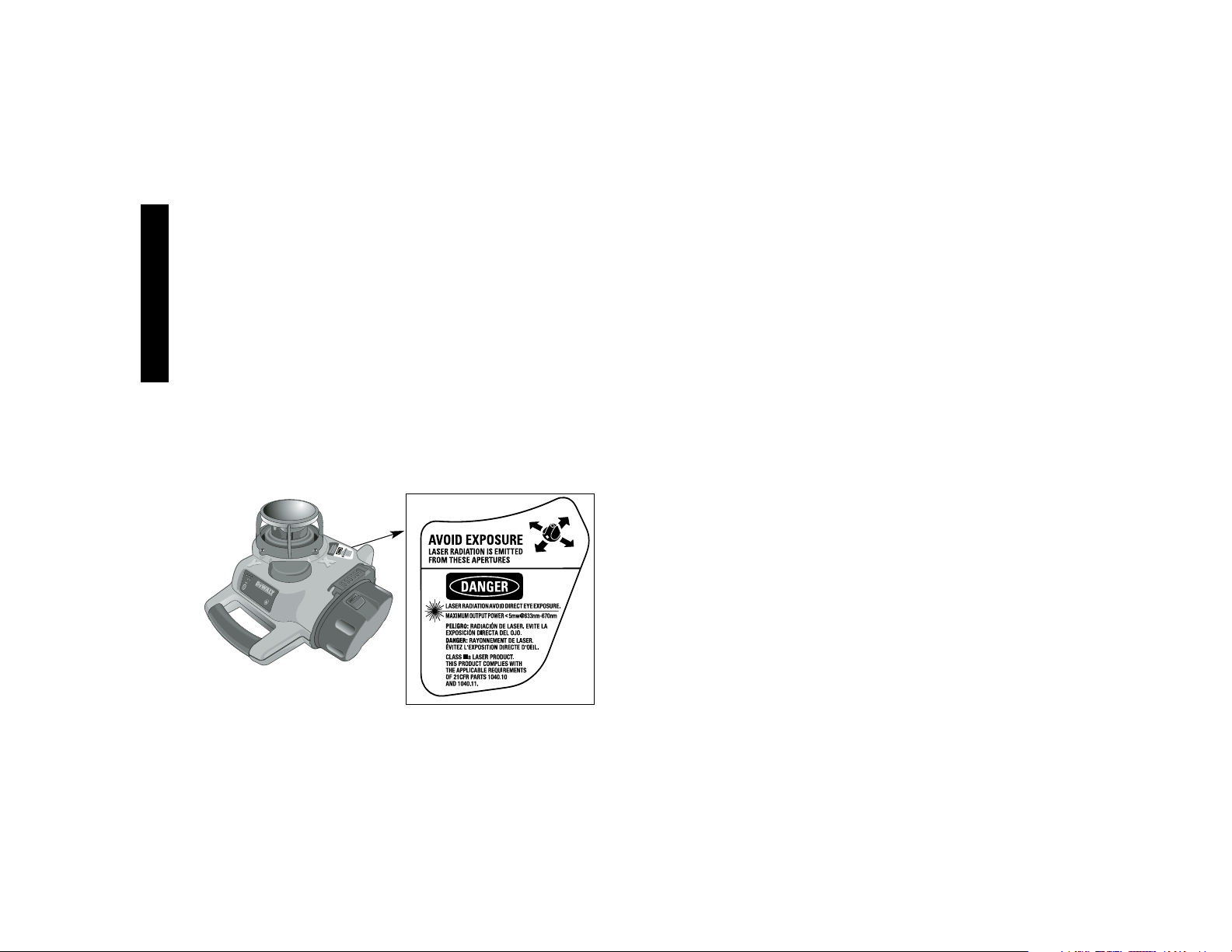
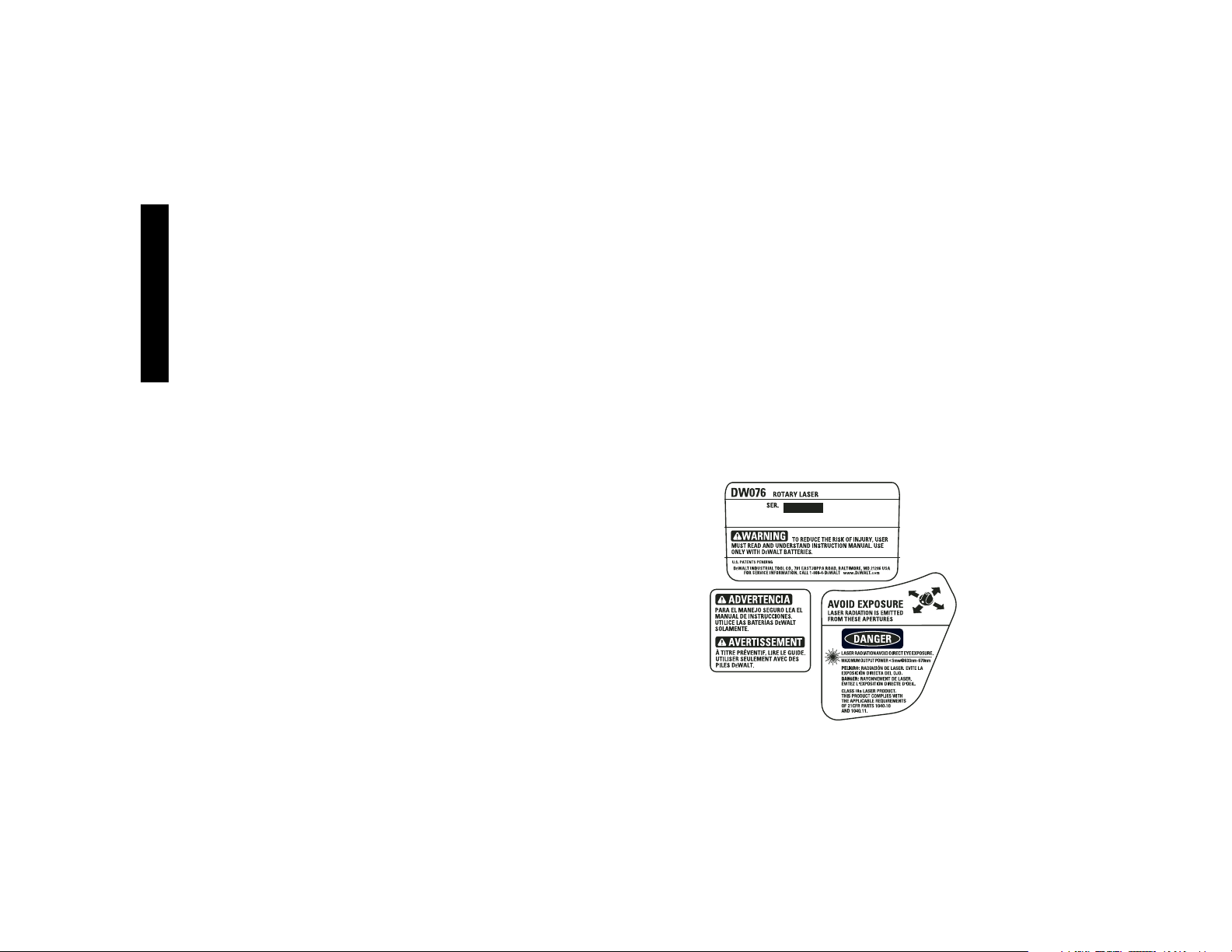
• For your convenience and safety, the following labels are on
your laser.
AVOID EXPOSURE: LASER RADIATION IS EMITTED FROM
THIS APERTURES.
DANGER: LASER RADIATION. AVOID DIRECT EYE
EXPOSURE.
Laser Information
The DW076 Cordless Rotary Laser is listed as a CLASS IIIA
LASER PRODUCT and complies with the applicable requirement
of title 21 of the Code of Federal Regulations set forth by: the
Department of Health, Education, and Welfare; the Food and Drug
Administration; the Center for Devices and Radiological Health.
These devices comply with Part 15 of the FCC Rules. Operation is
subject to the following two conditions: (1) this device may not
cause harmful interference, and (2) this device must accept any
interference received, including interference that may cause undesired operation.
NOTE: This equipment has been tested and found to comply with
the limits for a Class B digital device, pursuant to Part 15 of the FCC
Rules. These limits are designed to provide reasonable protection
against harmful interference in a residential installation. This equipment generates, uses and can radiate radio frequency energy and,
if not installed and used in accordance with the instructions, may
cause harmful interference to radio communications. However,
there is no guarantee that interference will not occur in a particular
installation. If this equipment does cause harmful interference to
radio and television reception, which can be determined by turning
the equipment off and on, the user is encouraged to try to correct the
interference by one or more of the following measures:
• Reorient or relocate the receiving antenna.
• Increase the separation between the equipment and receiver.
• Connect the equipment into an outlet on a circuit differentfrom
that which the receiver is connected.
• Consult the dealer or an experienced radio/TV technician for
help.
These Class B digital devices comply with Canadian ICES-003.
Important Safety Instructions for
Battery Packs
Your tool uses a 9.6, 12.0, 14.4 or an 18 Volt DEWALT battery pack.
When ordering replacement battery packs, be sure to include catalog number and voltage. Extended Run-Time battery packs deliver
more run-time than standard battery packs. Consult the chart at the
end of this manual for compatibility of chargers and battery packs.
NOTE: Your tool will accept either standard or Extended Run Time
battery packs. However, be sure to select proper voltage. Batteries
slowly lose their charge when they are not on the charger, the best
place to keep your battery is on the charger at all times.
The battery pack is not fully charged out of the carton. Before using
the battery pack and charger, read the safety instructions below.
Then follow charging procedures outlined.
Page 5
English
3
READ ALL INSTRUCTIONS
• Do not incinerate the battery pack even if it is severely damaged or is completely worn out. The battery pack can explode
in a fire.
• A small leakage of liquid from the battery pack cells may
occur under extreme usage or temperature conditions. This
does not indicate a failure. However, if the outer seal is broken
and this leakage gets on your skin:
a. Wash quickly with soap and water.
b. Neutralize with a mild acid such as lemon juice or vinegar.
c. If battery liquid gets into your eyes, flush them with clean
water for a minimum of 10 minutes and seek immediate
medical attention. (MEDICAL NOTE: The liquid is 25-35%
solution of potassium hydroxide.)
• Charge the battery packs only in D
E
WALT chargers.
• DO NOT splash or immerse in water or other liquids.
• Do not store or use the tool and battery pack in locations
where the temperature may reach or exceed 105°F (40˚)
(such as outside sheds or metal buildings in summer).
DANGER: Electrocution hazard. Never attempt to open the bat-
tery pack for any reason. If battery pack case is cracked or damaged, do not insert into charger. Electric shock or electrocution may
result. Damaged battery packs should be returned to service center for recycling.
NOTE: Battery storage and carrying caps are provided
for use whenever the battery is out of the tool or charger. Remove cap before placing battery in charger or tool.
WARNING: Fire hazard. Do not store or carry
battery so that metal objects can contact exposed
battery terminals. For example, do not place battery
in aprons, pockets, tool boxes, product kit boxes, drawers, etc., with
loose nails, screws, keys, etc. without battery cap. Transporting
batteries can possibly cause fires if the battery terminals
inadvertently come in contact with conductive materials such
as keys, coins, hand tools and the like.
The US Department of
Transportation Hazardous Material Regulations (HMR) actually
prohibit transporting batteries in commerce or on airplanes (i.e.,
packed in suitcases and carry-on luggage) UNLESS they are
properly protected from short circuits. So when transporting individual batteries, make sure that the battery terminals are protected
and well insulated from materials that could contact them and
cause a short circuit.
The RBRC™ Seal
The RBRC™ (Rechargeable Battery Recycling
Corporation) Seal on the nickel-cadmium battery (or
battery pack) indicates that the costs to recycle the battery (or battery pack) at the end of its useful life have
already been paid by D
EWALT. In some areas, it is ille-
gal to place spent nickel-cadmium batteries in the trash or municipal
solid waste stream and the RBRC program provides an environmentally conscious alternative.
RBRC in cooperation with D
EWALT and other battery users, has
established programs in the United States to facilitate the collection
of spent nickel-cadmium batteries. Help protect our environment
and conserve natural resources by returning the spent nickelcadmium battery to an authorized D
EWALT service center or to your
local retailer for recycling. You may also contact your local recycling
center for information on where to drop off the spent battery.
RBRC™ is a registered trademark of the
Rechargeable Battery
Recycling Corporation.
Important Safety Instructions for
Battery Chargers
SAVE THESE INSTRUCTIONS: This manual contains important
safety instructions for battery chargers.
• Before using charger, read all instructions and cautionary mark-
ings on charger, battery pack, and product using battery pack.
Page 6

English
4
DANGER: Electrocution hazard. 120 volts are present at charg-
ing terminals. Do not probe with conductive objects. Electric shock
or electrocution may result.
WARNING: Shock hazard. Do not allow any liquid to get inside
charger. Electric shock may result.
CAUTION: Burn hazard. To reduce the risk of injury, charge only
D
E
WALT nickel cadmium rechargeable batteries. Other types of
batteries may burst causing personal injury and damage.
CAUTION: Under certain conditions, with the charger plugged in
to the power supply, the exposed charging contacts inside the
charger can be shorted by foreign material. Foreign materials of a
conductive nature such as, but not limited to, steel wool, aluminum
foil, or any buildup of metallic particles should be kept away from
charger cavities. Always unplug the charger from the power supply
when there is no battery pack in the cavity. Unplug charger before
attempting to clean.
• DO NOT attempt to charge the battery pack with any charg-
ers other than the ones in this manual. The charger and battery pack are specifically designed to work together.
• These chargers are not intended for any uses other than
charging D
E
WALT rechargeable batteries. Any other uses
may result in risk of fire, electric shock or electrocution.
• Do not expose charger to rain or snow.
• Pull by plug rather than cord when disconnecting charger.
This will reduce risk of damage to electric plug and cord.
• Make sure that cord is located so that it will not be stepped
on, tripped over, or otherwise subjected to damage or
stress.
• Do not use an extension cord unless it is absolutely necessary. Use of improper extension cord could result in risk of fire,
electric shock, or electrocution.
• An extension cord must have adequate wire size (AWG or
American Wire Gauge) for safety. The smaller the gauge
number of the wire, the greater the capacity of the cable, that is
16 gauge has more capacity than 18 gauge. When using more
than one extension to make up the total length, be sure each
individual extension contains at least the minimum wire size.
Recommended Minimum Wire Size for Extension Cords
Total Length of Cord
25 ft. 50 ft. 75 ft. 100 ft. 125 ft. 150 ft. 175 ft.
7.6 m 15.2 m 22.9 m 30.5 m 38.1 m 45.7 m 53.3 m
Wire Size AWG
18 18 16 16 14 14 12
• Do not place any object on top of charger or place the
charger on a soft surface that might block the ventilation
slots and result in excessive internal heat. Place the charg-
er in a position away from any heat source. The charger is ventilated through slots in the top and the bottom of the housing.
• Do not operate charger with damaged cord or plug — have
them replaced immediately.
• Do not operate charger if it has received a sharp blow, been
dropped, or otherwise damaged in any way. Take it to an
authorized service center.
• Do not disassemble charger; take it to an authorized service
center when service or repair is required. Incorrect reassembly may result in a risk of electric shock, electrocution or fire.
• Disconnect the charger from the outlet before attempting
any cleaning. This will reduce the risk of electric shock.
Removing the battery pack will not reduce this risk.
• NEVER attempt to connect 2 chargers together.
• The charger is designed to operate on standard household
electrical power (120 Volts). Do not attempt to use it on any
other voltage. This does not apply to the vehicular charger.
Page 7
English
5
Using Automatic Tune-Up™ Mode
The Automatic Tune-Up™ Mode equalizes or balances the individual cells in the battery pack allowing it to function at peak capacity.
Battery packs should be tuned up weekly or after 10 charge/discharge cycles or whenever the pack no longer delivers the same
amount of work. To use the Automatic Tune-Up™, place the battery
pack in the charger and leave it for at least 8 hours. The charger
will cycle through the following modes.
1. The red light will blink continuously indicating that the 1-hour
charge cycle has started.
2. When the 1-hour charge cycle is complete, the light will stay on
continuously and will no longer blink. This indicates that the
pack is fully charged and can be used at this time.
3. If the pack is left in the charger after the initial 1-hour charge,
the charger will begin the Automatic Tune-Up mode. This mode
continues up to 8 hours or until the individual cells in the battery
pack are equalized. The battery pack is ready for use and can
be removed at any time during the Tune-Up mode.
4. Once the Automatic Tune Up mode is complete, the charger will
begin a maintenance charge; the red indicator will remain lit.
SAVE THESE INSTRUCTIONS FOR
FUTURE USE
Chargers
Your tool uses a DEWALT charger. Your battery can be charged in
D
EWALT 1 Hour Chargers, 15 Minute Chargers or Vehicular 12 Volt
Charger. Be sure to read all safety instructions before using
your charger. Consult the chart at the end of this manual for
compatibility of chargers and battery packs.
Charging Procedure
DANGER: Electrocution hazard. 120 volts present at charging
terminals. Do not probe with conductive objects. Danger of electric
shock or electrocution.
1. Plug the charger into an appropriate outlet before inserting
battery pack.
2. Insert the battery pack into the charger, making sure the pack
is fully seated. The red (charging) light will blink continuously
indicating that the charging process has started.
3. The completion of charge will be indicated by the red light
remaining ON continuously. The pack is fully charged and may
be used at this time or left in the charger.
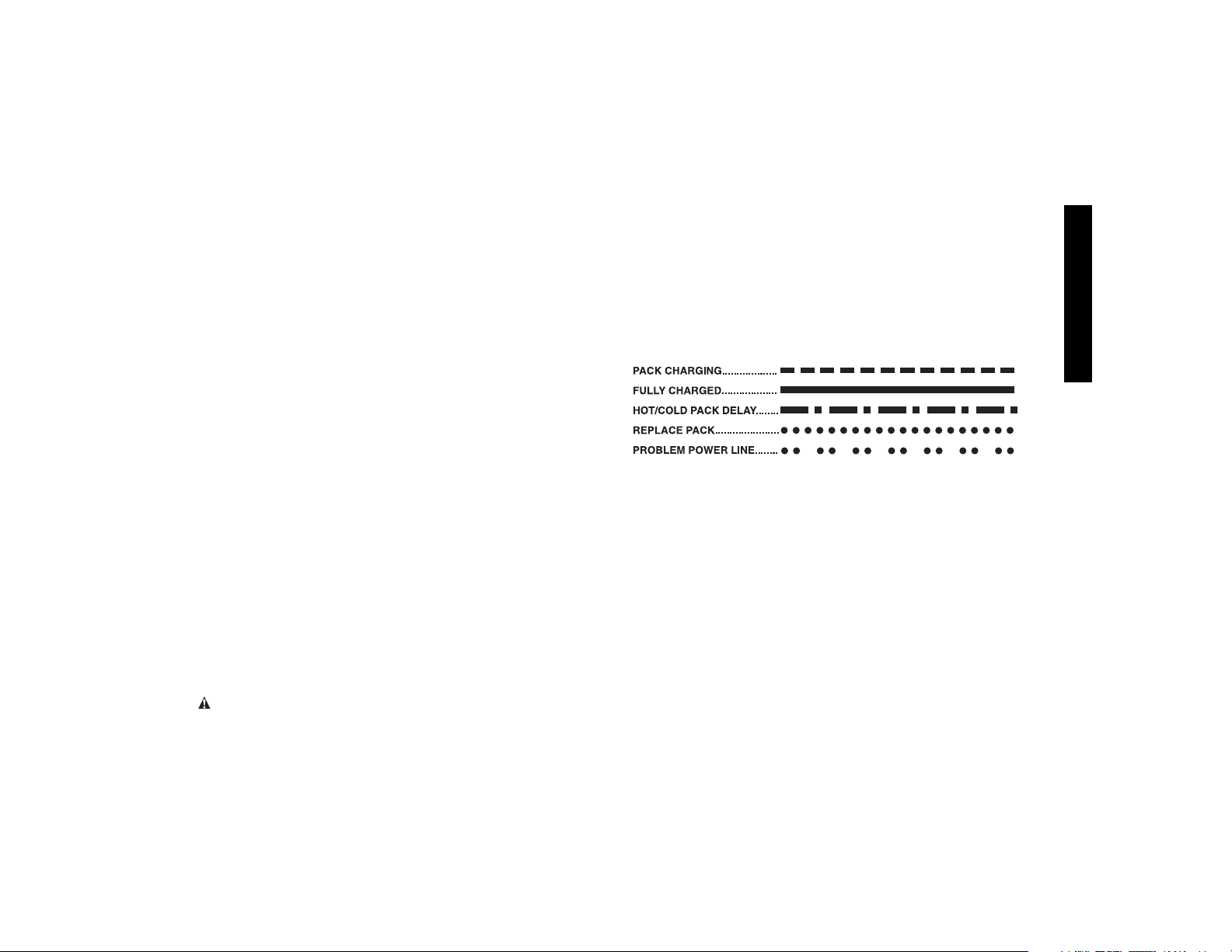
Indicator Light Operation
Charge Indicators
Some chargers are designed to detect certain problems that can
arise with battery packs. Problems are indicated by the red light
flashing at a fast rate. If this occurs, re-insert battery pack into the
charger. If the problem persists, try a different battery pack to determine if the charger is OK. If the new pack charges correctly, then the
original pack is defective and should be returned to a service center
or other collection site for recycling. If the new battery pack elicits the
same trouble indication as the original, have the charger tested at
an authorized service center.
HOT/COLD PACK DELAY
Some chargers have a Hot/Cold Pack Delay feature: when the
charger detects a battery that is hot, it automatically starts a Hot
Pack Delay, suspending charging until the battery has cooled.
After the battery has cooled, the charger automatically switches
to the Pack Charging mode. This feature ensures maximum
Page 8

English
6
battery life. The red light flashes long, then short while in the Hot
Pack Delay mode.
PROBLEM POWER LINE
Some chargers have a Problem Power Line indicator. When the
charger is used with some portable power sources such as generators or sources that convert DC to AC, the charger may temporarily
suspend operation, flashing the red light with two fast blinks fol-
lowed by a pause. This indicates the power source is out of limits.
LEAVING THE BATTERY PACK IN THE CHARGER
The charger and battery pack can be left connected with the red
light glowing indefinitely. The charger will keep the battery pack
fresh and fully charged.
NOTE: A battery pack will slowly lose its charge when kept out of
the charger. If the battery pack has not been kept on maintenance
charge, it may need to be recharged before use. A battery pack
may also slowly lose its charge if left in a charger that is not plugged
into an appropriate AC source.
WEAK BATTERY PACKS: Chargers can also detect a weak battery. Such batteries are still usable but should not be expected to
perform as much work. In such cases, about 10 seconds after battery insertion, the charger will beep rapidly 8 times to indicate a
weak battery condition. The charger will then go on to charge the
battery to the highest capacity possible.
Important Charging Notes
1. Longest life and best performance can be obtained if the battery pack is charged when the air temperature is between 65°F
and 75°F (18°- 24°C). DO NOT charge the battery pack in an
air temperature below +40°F (+4.5°C), or above +105°F
(+40.5°C). This is important and will prevent serious damage to
the battery pack.
2. The charger and battery pack may become warm to touch
while charging. This is a normal condition, and does not
indicate a problem. To facilitate the cooling of the battery pack
after use, avoid placing the charger or battery pack in a warm
environment such as in a metal shed, or an uninsulated trailer.
3. If the battery pack does not charge properly:
a. Check current at receptacle by plugging in a lamp or other
appliance
b. Check to see if receptacle is connected to a light switch
which turns power off when you turn out the lights.
c. Move charger and battery pack to a location where the
surrounding air temperature is approximately 65°F - 75°F
(18°- 24°C).
d. If charging problems persist, take the tool, battery pack and
charger to your local service center.
4. The battery pack should be recharged when it fails to produce
sufficient power on jobs which were easily done previously. DO
NOT CONTINUE to use under these conditions. Follow the
charging procedure. You may also charge a partially used pack
whenever you desire with no adverse affect on the battery pack.
5. Under certain conditions, with the charger plugged into the
power supply, the exposed charging contacts inside the charger can be shorted by foreign material. Foreign materials of a
conductive nature such as, but not limited to, steel wool, aluminum foil, or any buildup of metallic particles should be kept
away from charger cavities. Always unplug the charger from the
power supply when there is no battery pack in the cavity.
Unplug charger before attempting to clean.
6. Do not freeze or immerse charger in water or any other liquid.
WARNING: Shock hazard. Don’t allow any liquid to get inside
charger. Electric shock may result.
Page 9
English
7
CAUTION: Never attempt to open the battery pack for any rea-
son. If the plastic housing of the battery pack breaks or cracks,
return to a service center for recycling.
LASER OPERATION
• Ensure that the battery is properly charged. If the “Power” LED
light is flashing, the battery needs to be charged.
• To extend battery life per charge, turn the laser off when it is not
in use.
• To ensure the accuracy of your work, check the laser calibration
often. See the Field Calibration Check section of this manual.
• Before attempting to use the laser, make sure the tool is positioned on a relatively smooth,secure surface.
• Always mark the center of the laser line or dot. If you mark different parts of the beam at different times you will introduce
error into your measurements.
• To increase working distance and accuracy, set up the laser in
the middle of your working area.
• When attaching to a tripod or wall, mount the laser securely.
• When working indoors, a slow rotary head speed will produce
a visibly brighter line, a faster rotary head speed will produce a
visibly solid line.
• To increase beam visibility, wear a Laser Enhancement
Glasses (not included) and/or use a Laser Target Card (not
included) to help find the beam.
• Extreme temperature changes can cause movement or shifting
of building structures, metal tripods, equipment, etc., which can
effect accuracy. Check your accuracy often while working.
• If the laser is dropped or has suffers a sharp blow, have the
calibration system checked by a qualified service center before
using the laser.
NOTE: The DW076 rotary laser has no remote control capability.
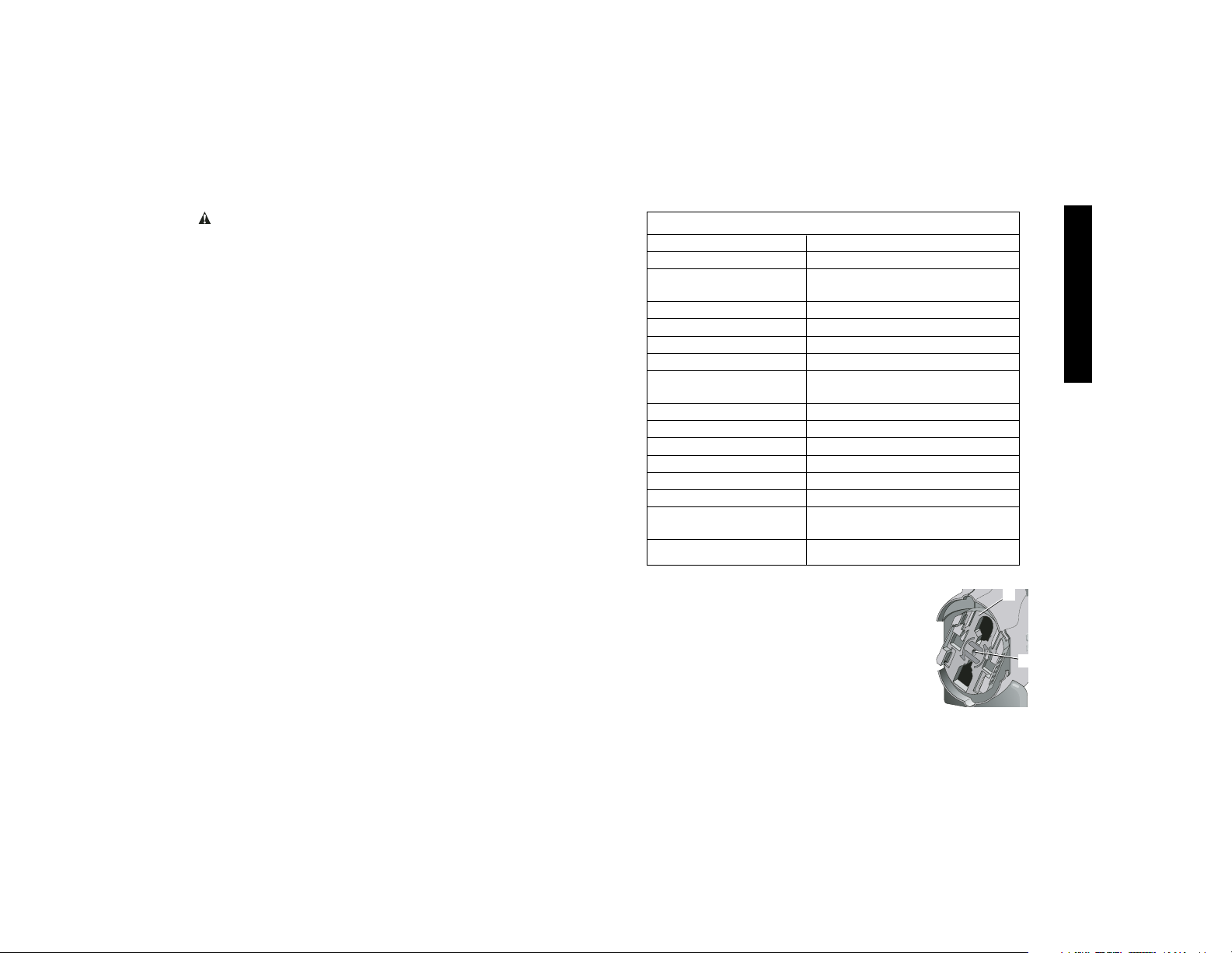
Installing and Removing the
Battery Pack
NOTE: Make sure your battery pack is fully
charged before you install it.
INSTALLING THE BATTERY PACK
1. Rotate the battery adapter plate (A) so that the
applicable cut out for 9.6, 12, 14.4 volt pack
or the 18 volt pack is aligned with the battery
contacts facing the inside of the cut out.
B
A
SPECIFICATIONS
Light Source Semiconductor laser diode
Laser Wavelength 630 – 680nm Visible
Laser Power <5mw, CLASS IIIa LASER
PRODUCT
Rotation Speed approx. 600 rpm
Self-Leveling Range ± 5°
Indoor Visible Range 200' (61m) diameter
Range with Detector 1500' (450m) diameter
Level Accuracy ± 1/8" per 100'
(± 3mm per 31m)
Power Source 9.6V–18V DEWALT batteries
Operating Temperature 23°F to 122°F (-5°C to 50°C)
Storage Temperature -4°F to 158°F (-20°C to 70°C)
Water Resistant IPX4
Usage Indoor and Outdoor
Altitude Up to 6560' (2000m)
Maximum Relative 95%
Humidity
Rated Pollution Degree 2
Page 10
English
8
2. Slide the battery pack in firmly until you hear the battery pack
lock in place.
REMOVING THE BATTERY PACK
1. Push the battery in slightly, press the release buttons, and firmly pull the battery pack out of the receptacle.
2. The battery ejector pin (B) will aid in removing the pack.
3. To recharge the battery pack, insert it into the charger as
described in the charger section of this manual.
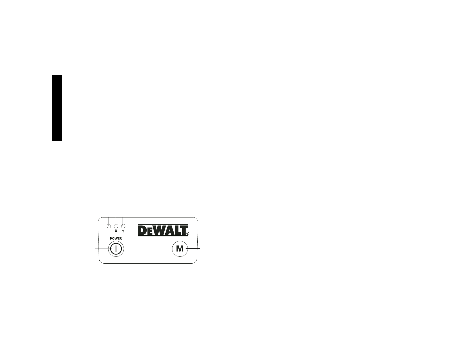
Control Panel
The laser is controlled by the ON/OFF button (C) and the manual
rotation button (D). Three indicator lights are on the control panel,
power LED light (E), X-axis leveling (F), and Y-axis leveling (G).
TURNING THE LASER ON
1. Insert the fully charged battery pack through the proper cut out
in battery adapter plate. Be sure that the battery is firmly
engaged.
2. Gently press the ON/OFF button (C) to power the laser on.
The laser diode will turn on and the power LED light (E) will
illuminate. The X-axis and Y-axis leveling lights (F, G) will
flash indicating that the laser is automatically leveling.
NOTE: The head will only rotate momentarily if the laser is leveling.
The head will begin or resume rotation once the laser is level.
C
D
EFG
TURNING THE LASER OFF
Gently press the ON/OFF button to turn the laser off. The power
LED Light will no longer be illuminated.
Using the Laser on a Tripod
1. Position the tripod securely and set it to the desired height.
2. Make sure that the top of the tripod is roughly level. the laser
will self-level only if the top of the tripod is within ± 5˚ of level.
If the laser is set up too far out of level, it will beep when it
reaches the limit of its leveling range. No damage will be done
to the laser, but it will not operate in an “out of level” condition.
3. Secure the laser to the tripod by screwing the threaded knob on
the tripod into the female thread on the bottom of the laser.
NOTE: Be sure that the tripod you are working with has a 5/8"–11
threaded screw to ensure secure mounting.
4. Turn the laser on by pressing the ON/OFF button (C). The
rotary head starts to spin after the unit levels itself.
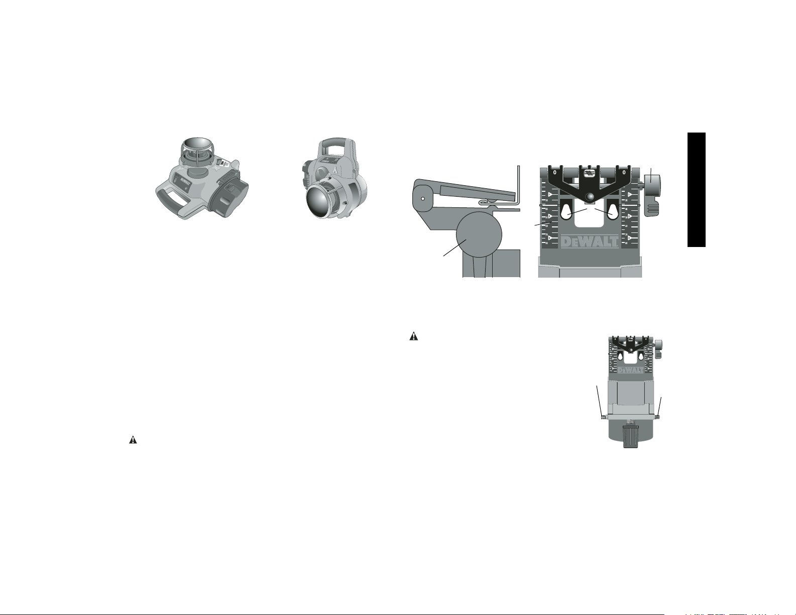
Using the Laser in Level Mode
The laser can be positioned directly on the floor or on a tripod
(described above) for applications such as carpentry.
1. Place the laser on a smooth surface where it will not be
disturbed.
2. Position the laser for level setting as shown.
3. Turn the laser on by pressing the ON/OFF button (C).
4. The level indicator lights (F, G) blink on and off until the rotary
head is level.
5. The rotary head starts spinning after leveling and the indicator lights remain on continuously.
NOTE: When the laser is out of leveling range. The rotary head
stops spinning, the laser turns off, the transmitter beeps and
the level indicator lights (F, G) blink.
Page 11
English
9
Using the Laser in Manual Mode
To activate manual mode, press the manual button (D) for at least
two seconds. The laser will not self level and the level indicator
lights (F, G) do not light while in manual mode. Manual mode may
be used in either level or vertical orientation.
Using the Laser in Vertical Mode
The laser can be positioned to be used in the vertical orientation.
The laser will not self level in vertical mode.
1. Place the laser on a smooth surface where it will not be
disturbed.
2. Position the laser vertically as shown.
3. The laser must be put in manual mode when used in vertical
orientation.
4. Turn the laser on by pressing the ON/OFF button (C).
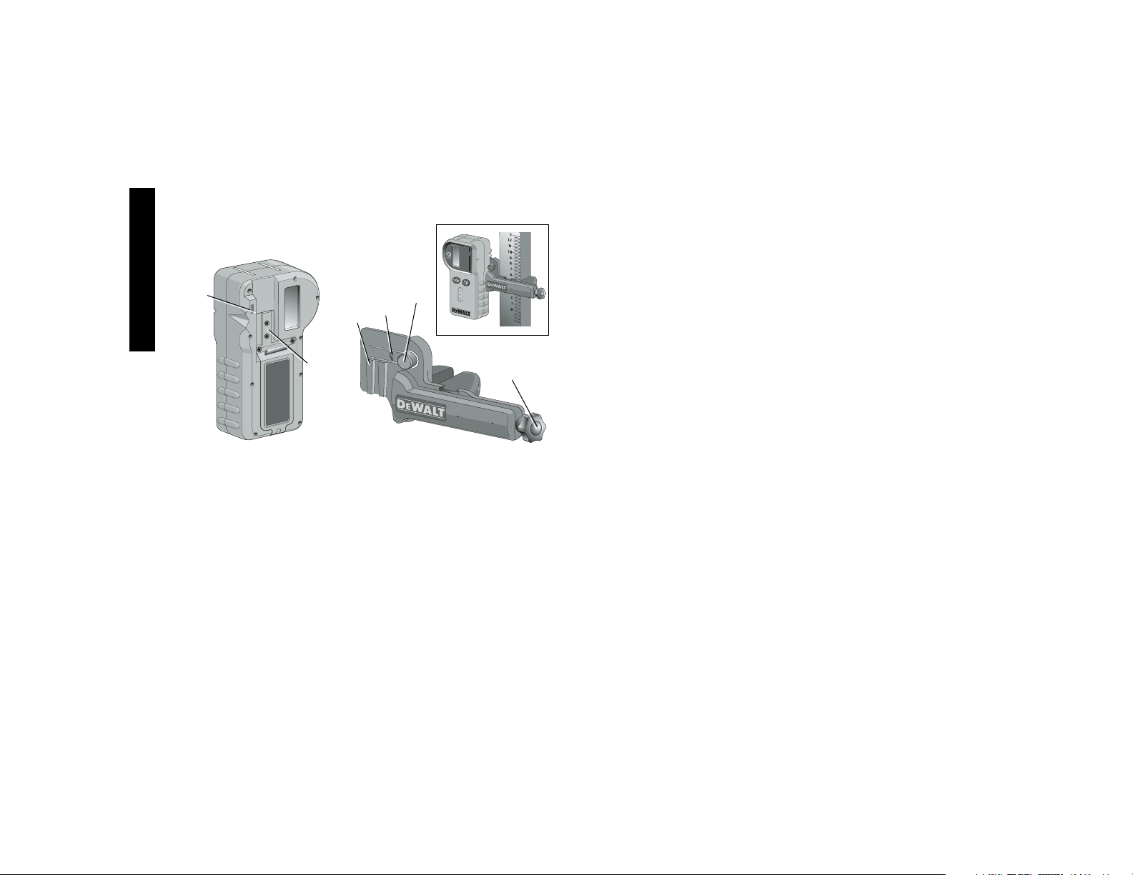
Using the Laser with a Wall Mount
The DW076 Rotary Laser has been designed to work with an
accessory Wall Mount (DW0770). It can be used for attaching the
tool to track or celing angle (mould) and to aid in acoustical ceiling
installation. Follow the directions below for using the wall mount.
CAUTION: Before attaching the laser level to wall track or
ceiling angle, be sure that the track or angle is properly secured.
1. Attach the Laser to the accessory wall mount.
LEVEL
MODE
VERTICAL
MODE
2. With the wall mount measuring scale (H) facing you, rotate the
wall mount clamp locking knob (I) towards you to open the
clamp jaws.
3. Position the clamp jaws around the wall track or ceiling angle
and as shown rotate the wall mount clamp locking knob away
from you to close the clamp jaws shut on the track. Be sure that
the wall mount clamp locking knob is securely locked before
proceding.
CAUTION: Always use a ceiling wire
hanger or equivalent material, in addition to
the wall mount clamp, to help secure the laser
level while mounting it to a wall. Thread the
wire through the handle of the laser level. DO
NOT thread the wire through the protective
metal cage. Additionally, screws may be used
to fasten the wall mount directly to the wall as
a back up. Screw holes (J) are located in the
wall mount next to the measuring scales.
4. The tool can be adjusted up and down to
the desired offset height for working. To
change the height, loosen the Rack ‘N
Pinion locking knob (K) located on the left
of the wall mount.
K
L
I
J
H
I
Page 12
English
10
5. Turn the Rack ‘N Pinion adjustment knob (L) located to the right
of the wall mount to move the laser level up and down to set
your height. Use the wall mount measuring scale to pinpoint
your mark.
NOTE: It may be helpful to turn the power on and turn the rotary
head so that it puts a dot on one of the laser scales. The
D
EWALT target card is marked at 1-1/2" (38mm), therefore, it
may be easiest to set the offset of the laser to 1-1/2" (38mm)
below the wall angle.
6. Once you have positioned the
laser at the desired offset height,
tighten the Rack ‘N Pinion
locking knob to maintain the
offset.
7. Using the base leveling knob
(M), approximate a level position
from the wall.
Laser Accessories
Recommended accessories for use with your tool are available for
purchase at your factory-owned local service center.
CAUTION: The use of any non-recommended accessory may
be hazardous. Use only D
E
WALT accessories designed for use
with this product.
If you need any assistance in locating any accessory, please contact D
EWALT Industrial Tool Co., 701 East Joppa Road, Baltimore,
MD 21286 or call 1-800-4-D
EWALT (1-800-433-9258). See our
catalog on the World Wide Web at www.dewalt.com.
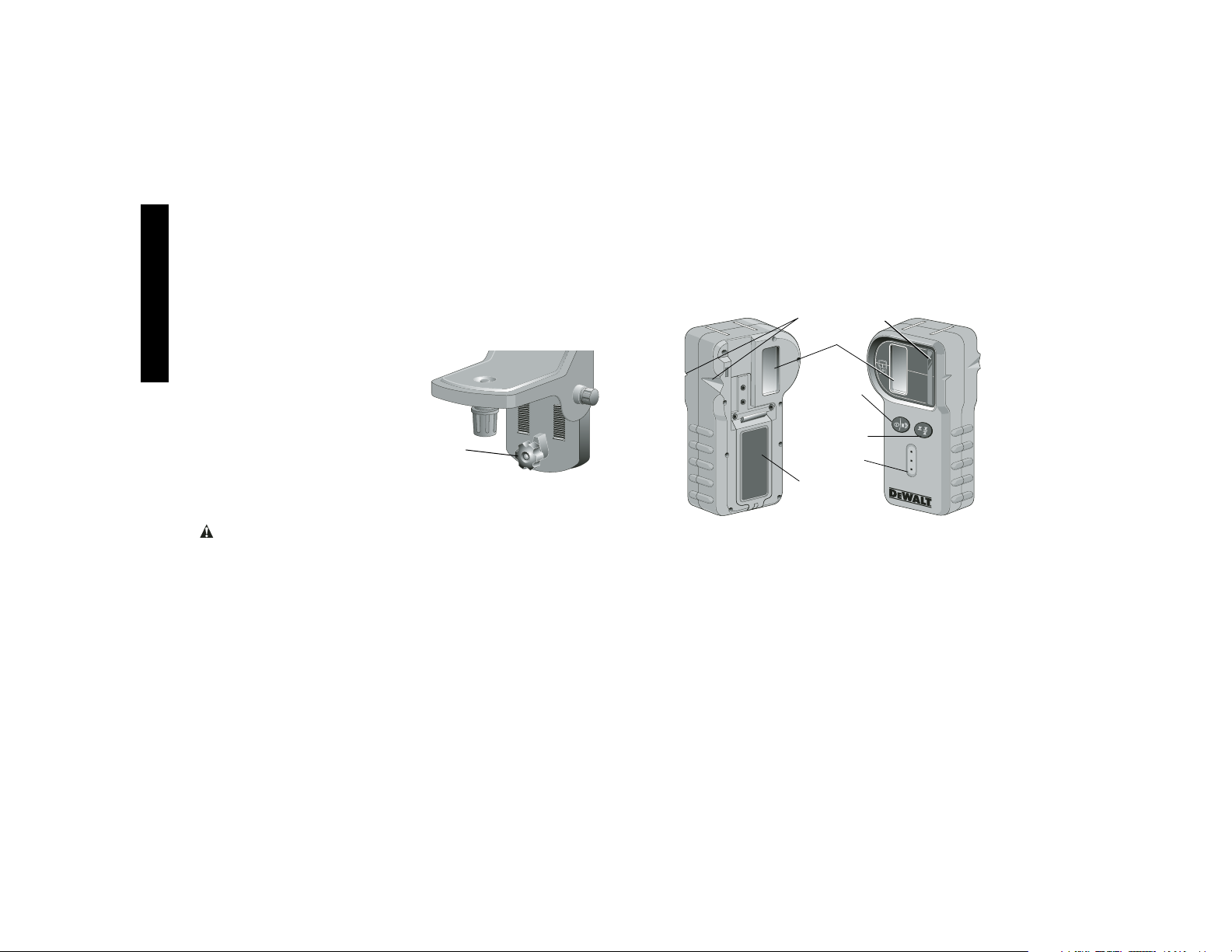
Digital Laser Detector: DW0772
Some laser kits include a DEWALT digital laser detector. The
D
EWALT digital laser detector allows you to locate a laser beam
emitted by a rotary laser in bright light conditions or over long distances. The detector can be used in both indoor and outdoor situations where it is difficult to see the laser beam. The detector is not
M
for use with non-rotating lasers but is compatible with most rotary
red-beam or infra-red (invisible) beam lasers on the market. It can
be set to indicate the location of the beam to either the nearest 1/8"
or the nearest 1/25". The detector gives both visual signals through
the display window (N) and audio signals through the speaker (O)
to indicate the location of the laser beam.
The D
EWALT digital laser detector can be used with or without the
detector clamp. When used with the clamp, the detector can be
positioned on a grade rod, leveling pole, stud or post.
BATTERIES
The digital laser detector is powered by a 9 volt battery. To install
the battery provided, lift up on the battery compartment cover (P).
Place the 9 volt battery in the compartment, aligning the battery
as shown on the embossed icon (Q).
DETECTOR CONTROLS
The detector is controlled by the power/volume button (R) and the
accuracy mode button (S). When the power/volume button is
pushed once, the detector is turned on. The top of the display win-
X
N
R
S
O
P
Y
Page 13
English
11
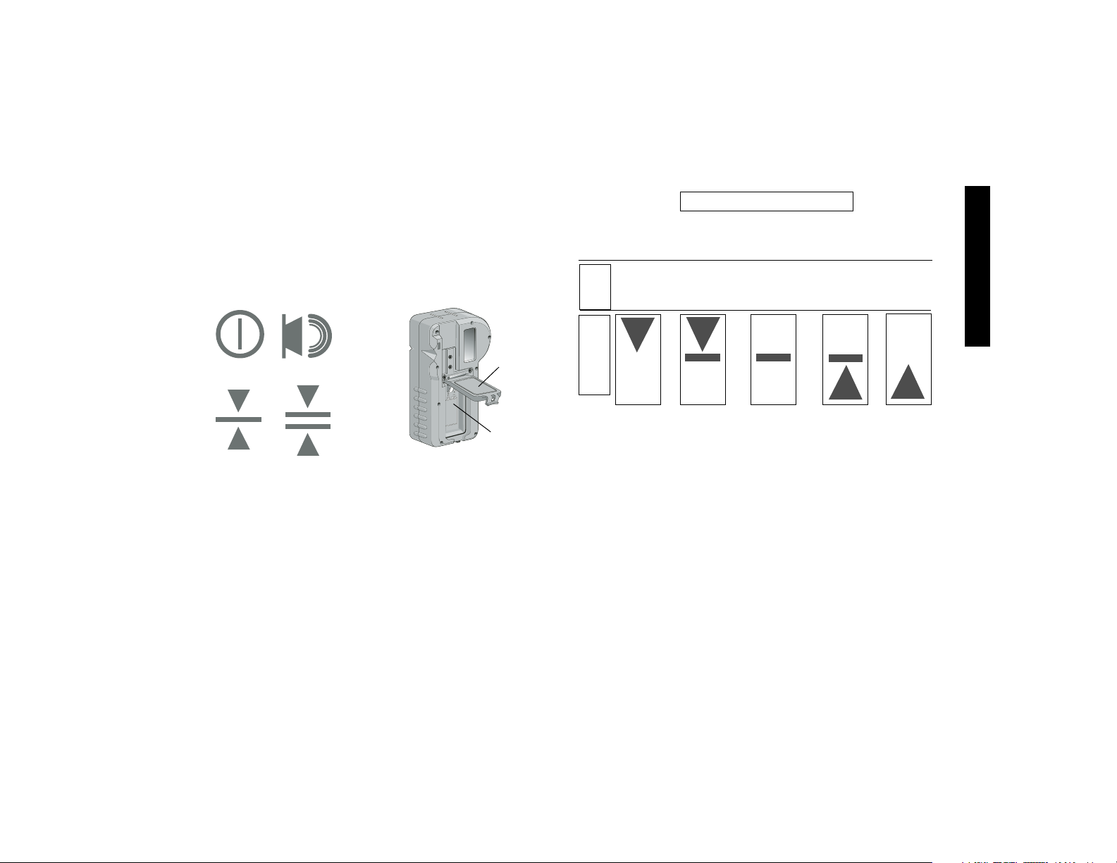
dow shows the ON icon (T), and the volume icon (U). To decrease
the volume of the audible signal that the detector emits when it senses a laser beam, push the button again; one of the half circles next
to the horn icon will dissappear. To turn off the audible signal push
the button a third time; the volume icon will dissapear. The D
EWALT
digital laser detector also has an auto shut-off feature. If a rotary
laser beam does not strike the beam detection window, or, if no buttons are pressed, the detector will shut itself off in about 30 minutes.
When the detector is on, the bottom of the window shows an accuracy mode icon. Either the ±1/25" accuracy mode icon (V) will
appear, or the ±1/8" accuracy mode icon (W) will appear. When
the ±1/25" accuracy mode icon appears, it indicates that the detector will give an “on grade” reading only when the laser beam is on
grade or no more than 1/25" above or below it. When the 1/8"
accuracy mode icon appears, it indicates that the detector will give
an “on grade” reading when the laser beam is on grade or approximately 1/8" above or below it. Push the accuracy mode button (S)
once to change the accuracy mode.
P
T
U
V
W
Q
Detector Operation
1. Set up and position the rotary laser that you will be using
according to the manufacturer’s directions. Turn the laser on
and make sure that the laser is rotating and emitting a laser
beam.
NOTE: This detector has been designed to be used only with a
rotating laser. The detector will not work with a stationary beam
laser level.
2. Turn the detector on by pressing the power/volume button (R).
3. Adjust the volume as desired as described in the Detector
Controls above.
4. Position the detector so that the detector window (X) is facing
the laser beam produced by the rotary laser. Move the detector
up or down within the approximate area of the beam, until you
have centered the detector. For information about the display
window indicators and the audible signal indicators, see the
table titled Indicators.
Slightly Slightly
Above Above On Below Below
Grade Grade Grade Grade Grade
fast fast steady slow slow
beep beep tone beep beep
audible
signals
INDICATORS
display icons
Page 14
English
12
5. Use the marking notches (Y) to accurately mark the position of
the laser beam.
MOUNTING ON A GRADE ROD
1. To secure your detector to a grade rod, first attach the detector
to the clamp by pushing in on the clamp latch (Z). Slide the
tracks on the clamp (AA) around the rail on the detector (BB)
until the latch (CC) on the clamp pops into the latch hole (DD)
on the detector.
2. Open the jaws of the clamp by turning the clamp knob (EE)
counterclockwise.
3. Position the detector at the height needed and turn the clamp
knob clockwise to secure the clamp on the rod.
4. To make adjustments in height, slightly loosen the clamp,
reposition and retighten.
Detector Cleaning and Storage
• Dirt and grease may be removed from the exterior of the
detector using a cloth or soft, non-metallic brush.
Z
AA
BB
CC
EE
DD
• The DEWALT digital laser detector is waterproof. If you should
drop the detector in mud, wet concrete, or a similar substance,
simply hose the detector off. Do not use high pressure water,
(e.g., from a pressure washer).
• The best storage place is one that is cool and dry—away from
direct sunlight and excess heat or cold.
Detector Service
Except for batteries, there are no user serviceable parts in the
Digital Laser Detector. Do not disassemble the unit. Unauthorized
tampering with the laser detector will void all warranties.
Detector Troubleshooting
THE DETECTOR WILL NOT TURN ON
• Press and release the power/volume button.
• Check to see that the battery is in place and in the proper
position.
• If the detector is very cold, allow it to warm up in a heated area.
• Replace the 9 volt battery. Turn the unit on.
• If the detector still does not turn on, take the detector to a
D
EWALT service center.
THE DETECTOR’S SPEAKER MAKES NO SOUND
• Ensure that the detector is on.
• Press the power/volume button. It will toggle from high, to low,
to mute.
• Ensure that the rotary laser is spinning and that it is emitting a
laser beam.
• If the detector is still not making any sound, take it to a D
EWALT
service center.
THE DETECTOR IS NOT RESPONDING TO MY STATIONARY
LASER LEVEL
• The D
EWALT Digital Laser Detector has been designed to work
only with rotary lasers.
Page 15
English
13
THE DETECTOR IS GIVING OFF A TONE BUT THE
LCD DISPLAY WINDOW IS NOT FUNCTIONING.
• If the detector is very cold, allow it to warm up in a heated area.
• If the LCD display window is still not functioning, take the detector to a D
EWALT service center.
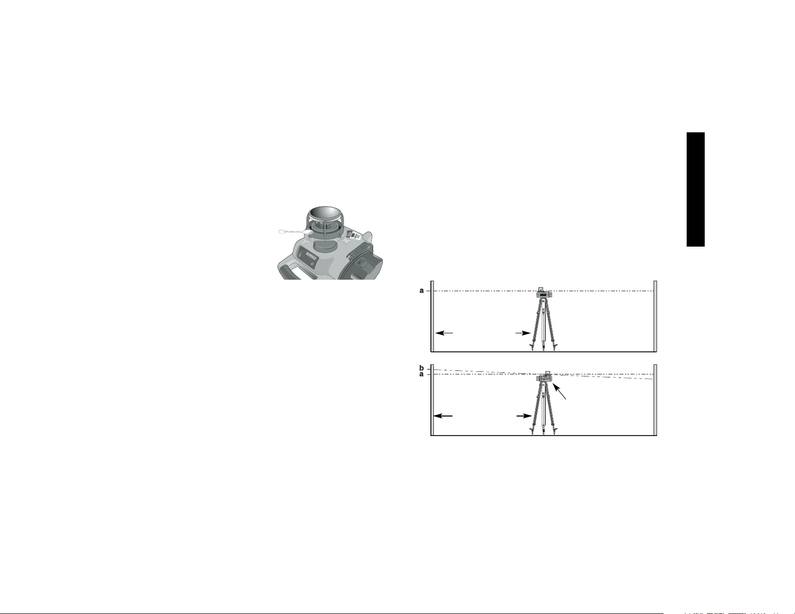
LASER MAINTENANCE
1. Under some conditions, the
glass lens inside the rotary
head may collect some dirt or
debris. This will affect beam
quality and operating range.
The lens should be cleaned
with a cotton swab moistened
with water as shown.
2. The flexible rubber shield can be cleaned with a wet lint-free
cloth such as a cotton cloth. USE WATER ONLY — DO NOT
use cleansers or solvents. Allow the unit to air dry before
storing.
3. To maintain the accuracy of your work, check the calibration of
the laser often. See the Field Calibration Check section of this
manual.
4. Calibration checks and other maintenance repairs can be
performed by D
EWALT service centers. Two free calibration
checks are included under the D
EWALT One Year Free
Service Contract.
5. When the laser is not in use, store it in the kit box provided.
6. Do not store your laser in the kit box if the laser is wet. Dry
exterior parts with a soft, dry cloth and allow the laser to air dry.
7. Do not store your laser at temperatures below 0˚F (-18˚C) or
above 105˚F (41˚C).
CLEANING
Exterior plastic parts may be cleaned with a damp cloth and mild
detergent. Although these parts are highly solvent resistant,
NEVER use solvents. Never use compressed air to clean the laser.
Field Calibration Check
Field calibration checks should be done frequently. This section
provides instructions for performing simple field calibration checks
of your D
EWALT Rotary Laser. Field calibration checks do not
calibrate the laser. That is, these checks do not correct errors in the
leveling or plumbing capability of the laser. Instead, the checks
indicate whether or not the laser is providing a correct level and
plumb line. These checks cannot take the place of professional
calibration performed by a D
EWALT service center.
LEVEL MODE CALIBRATION CHECK
1. Set up a tripod 50' (15m) from a vertical wall as shown. Make
sure that the head of the tripod is level using a bubble vial.
APPROX. 50 ft.
(15m)
APPROX. 50 ft.
(15m)
BEAM
BEAM
LASER UNIT
ROTATED 180˚
Page 16
English
14
2. Mount the rotary laser on the tripod so that the X-axis points
away from the wall as shown.
3. Turn the laser on by pressing the ON/OFF button.
4. Mark the center of the beam elevation on the wall (a).
5. Turn the entire laser unit 180° so that the X-axis points towards
the wall and mark the center of the beam elevation (b).
6. If the distance between the two marks (a, b) is no more than
1/8" (3 mm), the laser is properly calibrated.
7. Repeat the above steps for the Y-axis by first pointing the Y-axis
away from the wall then turning the entire laser unit 180° again.
Repairs
To assure product SAFETY and RELIABILITY, repairs, maintenance
and adjustments should be performed by a D
EWALT factory service
center, a D
EWALT authorized service center or other qualified
service personnel. Always use identical replacement parts.
Three Year Limited Warranty
DEWALT will repair, without charge, any defects due to faulty materials or workmanship for three years from the date of purchase.
This warranty does not cover part failure due to normal wear or tool
abuse. For further detail of warranty coverage and warranty repair
information, visit www.dewalt.com or call 1-800-4-D
EWALT (1-800-
433-9258). This warranty does not apply to accessories or damage
caused where repairs have been made or attempted by others.
This warranty gives you specific legal rights and you may have
other rights which vary in certain states or provinces.
In addition to the warranty, D
EWALT tools are covered by our:
1 YEAR FREE SERVICE
D
EWALT will maintain the tool and replace worn parts caused by
normal use, for free, any time during the first year after purchase.
90 DAY MONEY BACK GUARANTEE
If you are not completely satisfied with the performance of your
D
EWALT Power Tool, Laser, or Nailer for any reason, you can
return it within 90 days from the date of purchase with a receipt for
a full refund – no questions asked.
LATIN AMERICA: This warranty does not apply to products sold in
Latin America. For products sold in Latin America, see country
specific warranty information contained either in the packaging, call
the local company or see website for warranty information.
RECONDITIONED PRODUCT: Reconditioned product is covered
under the 1 Year Free Service Warranty. The 90 Day Money Back
Guarantee and the Three Year Limited Warranty do not apply to
reconditioned product.
FREE WARNING LABEL REPLACEMENT: If your warning labels
become illegible or are missing, call 1-800-4-D
EWALT for a free
replacement.
Page 17

Français
15
SI VOUS AVEZ DES QUESTIONS OU VOULEZ NOUS FAIRE
PART DE VOS COMMENTAIRES CONCERNANT CET OUTIL OU
TOUT AUTRE OUTIL D
EWALT, COMPOSEZ SANS FRAIS LE :
1 800 433-9258
AVERTISSEMENT : Lire, comprendre et suivre
toutes les directives précisées ci-dessous, y com-
pris les consignes de sécurité, afin d’éviter les risques de
choc électrique, d’incendie ou de blessure grave.
CONSERVER CES DIRECTIVES
Consignes de sécurité concernant les
lasers
• Ne pas utiliser le laser dans une atmosphère explosive,
comme à proximité de liquides, de gaz ou de poussières
inflammables; le moteur peut créer des étincelles et enflammer
les vapeurs ou les poussières environnantes.
• N’utiliser le laser qu’avec les piles désignées, car l’utilisation
d’un autre type de piles pourrait entraîner un risque d’incendie.
• Lorsqu’on n’utilise pas le laser, le ranger hors de la portée
des enfants ou des personnes non qualifiées; les outils sont
dangereux entre les mains de personnes inexpérimentées.
• N’utiliser que les accessoires recommandés par le fabricant
pour le modèle concerné; un accessoire destiné à un laser par-
ticulier peut devenir dangereux lorsqu’il est utilisé avec un autre.
• L’outil doit être entretenu ou réparé par le personnel qualifié seulement; toute maintenance effectuée par une person-
ne non qualifiée pourrait entraîner des risques de blessure.
Pour obtenir le numéro du centre de service D
E
WALT le plus
près, composer le 1 800 433-9258 ou consulter le site Internet
http://www.dewalt.com.
• Ne pas utiliser un dispositif optique, tel qu’un téléscope ou
une lunette de passage, pour examiner le faisceau laser afin
d’éviter de blesser grièvement les yeux.
• Ne pas mettre le laser dans une position qui pourrait
encourager une personne à regarder directement le faisceau laser, volontairement ou involontairement, car cela pour-
rait blesser grièvement les yeux.
• Mettre le laser hors tension après chaque utilisation, car un
laser laissé sous tension encourage une personne à regarder
directement le faisceau laser.
• La réparation et l’entretien DOIVENT être effectués dans un
centre de service autorisé ou par du personnel qualifié;
toute opération d’entretien ou de réparation effectuée par une
personne non qualifiée pourrait entraîner des blessures graves.
• Ne pas démonter l’outil laser; ce dernier ne comprend aucune
pièce interne destinée à être entretenue par l’utilisateur.
• Ne pas utiliser le laser en présence d’un enfant, ni autoriser
les enfants à utiliser le laser afin d’éviter les blessures graves
aux yeux.
• Ne pas retirer ni abîmer les étiquettes d’avertissement; le
fait de retirer les étiquettes augmentera les risques d’exposition
aux rayonnements laser.
• S’assurer de bien déposer le laser sur une surface de
niveau afin de l’empêcher de tomber et de s’endommager ou
de blesser l’utilisateur.
• Porter des vêtements appropriés; ne pas porter de vêtements amples ni de bijoux. Couvrir ou attacher les cheveux
longs. Garder les cheveux, les vêtements, les bijoux et les
gants éloignés des pièces mobiles, car ceux-ci peuvent s’y
coincer. Se tenir éloigné des évents puisque ces derniers pourraient camoufler des pièces mobiles.
MISE EN GARDE : L’utilisation de procédures, de commandes
ou de réglages autres que ceux précisés aux présentes pourrait
entraîner des risques d’exposition aux rayonnements laser.
AVERTISSEMENT! NE PAS DÉMONTER LE LASER
ROTATIF. L’outil ne comprend aucune pièce interne destinée à
Page 18

Français
16
être entretenue par l’utilisateur. Le fait de démonter le laser
rotatif annulera toute garantie appuyant ce produit; on ne doit
jamais modifier ce dernier de quelque manière que ce soit afin
d’éviter d’entraîner des risques d’exposition aux rayonnements.
• L’étiquette apposée sur l’outil peut afficher les symboles suivants :
V ........................volts
MW ....................milliwatts
................symbole d’avertissement du laser
nm......................longueur d’onde exprimée en nanomètres
IIIa......................laser de classe IIIa
• Pour des fins pratiques et de sécurité, la scie à onglets comprend les étiquettes d’avertissement suivantes
ÉVITER L’EXPOSITION AUX RAYONNEMENTS LASER
ÉMIS PAR CES OUVERTURES.
DANGER. RAYONNEMENTS LASER. ÉVITER LES
RISQUES D’EXPOSITION OCULAIRE.
Information sur les lasers
Le laser rotatif sans fil DW076 est répertorié en tant que PRODUIT
À LASER DE CLASSE IIIa; il est conforme aux exigences pertinentes contenues au chapitre 21 du Code of Federal Regulations
(ou CFR) des États-Unis établies par les organismes américains
suivants : le Department of Health, Education and Welfare, le Food
and Drug Administration et le Center for Devices and Radiological
Health.
Ces dispositifs sont conformes aux dispositions de la partie 15 des
règlements de la FCC. Le fonctionnement doit respecter les deux
conditions suivantes : (1) ce dispositif ne doit pas causer de brouillage nuisible, et (2) ce dispositif doit accepter tout brouillage qu’il
reçoit, y compris celui qui cause un fonctionnement indésirable.
REMARQUE : Les essais ont démontré que cet appareil respecte
les limites régissant un dispositif numérique de classe B, conformément aux dispositions de la partie 15 des règlements de la
FCC. Le but de ces limites est de fournir une protection
raisonnable contre le brouillage nuisible dans une installation
résidentielle. Cet appareil génère, utilise et peut produire une
énergie radiofréquence rayonnée et, lorsqu’il n’est pas installé et
utilisé conformément aux directives, peut causer le brouillage
nuisible des communications radio. Cependant, il n’existe aucune
garantie que le brouillage ne se produira pas dans une installation particulière. Si cet appareil entraîne le brouillage nuisible de
la réception radio ainsi que celle des programmes de télévision,
ce qui peut être déterminé en allumant et en éteignant l’appareil,
on invite l’utilisateur à tenter de corriger le problème relié au
brouillage au moyen de l’une des deux méthodes suivantes :
• en réorientant ou en déplaçant l’antenne de réception,
• en augmentant l’espace entre l’appareil et le récepteur ou
• en raccordant l’appareil à une prise murale reliée à un
circuit autre que celui dans lequel le récepteur est branché.
Page 19

Français
17
• Communiquer avec le distributeur ou un technicien de
radio ou de téléviseur qualifié pour obtenir de l’aide.
Cet appareil numérique de la classe B est conforme à la norme
NMB-003 du Canada.
Consignes de sécurité importantes
concernant les bloc-piles
L’outil fonctionne sur un bloc-pile DEWALT de 9,6, de 12,0 de 14,4
ou de 18 volts. Au moment de commander un bloc-pile de
rechange, s’assurer d’inclure le numéro de catalogue et la tension
appropriée. Les bloc-piles à durée prolongée durent plus
longtemps que les bloc-piles standard. Consulter le diagramme à
la fin du présent manuel afin de vérifier la compatibilité du chargeur
avec le bloc-pile.
REMARQUE : Bien que l’outil puisse fonctionner au moyen de l’un
ou l’autre de ces bloc-piles, on doit s’assurer d’en choisir un de tension appropriée. Un bloc-pile perd graduellement sa charge s’il
n’est pas laissé dans le chargeur; il est donc recommandé de le
laisser dans le chargeur en tout temps.
Le bloc-pile n’est pas complètement chargé au moment de sa
livraison. Avant d’utiliser le bloc-pile et le chargeur, lire attentivement toutes les consignes de sécurité énumérées ci-dessous et
suivre les méthodes de chargement précisées ci-dessous.
LIRE TOUTES LES DIRECTIVES
• NE PAS incinérer le bloc-pile même s’il est gravement
endommagé ou complètement usé, car il pourrait exploser en
présence de flammes.
• Les cellules peuvent subir une fuite légère par suite d’un
usage extrême ou d’une exposition à certaines températures; cela n’indique pas un problème. Cependant, si le scellant
externe est percé et le liquide entre en contact avec la peau, on
doit:
a. se laver rapidement la partie du corps touchée avec de l’eau
savonneuse;
b. neutraliser l’effet au moyen d’un acide doux tel que du jus de
citron ou du vinaigre;
c. si les yeux sont touchés, les rincer à fond avec de l’eau
propre pendant au moins 10 minutes et consulter
immédiatement un médecin. (REMARQUE AUX FINS
MÉDICALES : ce liquide contient une solution composée
de 25 à 35 % d’hydroxyde de potassium).
• Ne recharger les blocs-piles que dans des chargeurs D
E
WALT.
• NE PAS immerger le chargeur ou le bloc-pile dans l’eau ou tout
autre liquide quelconque, ni l’éclabousser.
• Ne pas ranger ou utiliser l’outil et le bloc-pile là où la température ambiante peut excéder 40 °C (105 °F) (comme des
hangars ou des bâtiments métalliques en été).
DANGER : Risques d’électrocution. Ne jamais tenter d’ouvrir le
bloc-pile pour quelque raison que ce soit. Si le compartiment se
rupture ou subit des dommages, ne pas l’insérer dans le chargeur
afin d’éviter les risques.de choc électrique ou d’électrocution. On
doit retourner les bloc-piles endommagés à un centre de service
afin qu’ils puissent être recyclés.
REMARQUE : Un capuchon est fourni avec la
pile en vue d’être utilisé chaque fois qu’on retire cette
dernière de l’outil ou du chargeur en vue de la ranger
ou de la transporter; enlever le capuchon avant de
remettre la pile dans le chargeur ou dans l’outil.
AVERTISSEMENT : Risques d’incendie. S’assurer, au
moment de ranger ou de transporter un bloc-pile ou une pile,
qu’aucun objet métallique n’entre en contact avec leurs
bornes à découvert de celui-ci. Par exemple, il faut éviter de
placer un bloc-pile ou une pile sans capuchon dans un tablier, une
poche, une boîte à outils ou un tiroir (etc.) contenant des objets tels
que des clous, des vis ou des clés, car tout contact entre les
bornes à découvert et un objet métallique comme une clé, une
pièce de monnaie, un outil à main. etc. pourrait causer un
incendie. En effet, les règlements américains Hazardous Material
Page 20

Français
18
Regulations (HMR) du US Department of Transportation interdisent
le transport d’un bloc-pile ou d’une pile dans tout moyen de transport commercial ou aéronef (que ce soit dans une valise ou le
bagage de cabine) SAUF s’ils sont bien protégés contre les courtscircuits. On doit donc s’assurer, lorsqu’on transporte un bloc-pile ou
une pile séparément, de bien protéger et isoler les bornes contre
tout matériau qui risque d’entrer en contact avec eux et de causer
un court-circuit.
Sceau RBRC
MC
Le sceau RBRCMCde la Rechargeable Battery
Recycling Corporation apposé sur la pile au nickelcadmium (ou le bloc-pile) indique que les coûts de
recyclage de ce dernier à la fin de sa vie utile ont déjà
été payés par D
EWALT. En certains endroits, la mise
au rebut ou aux ordures municipales des piles au nickel-cadmium
est illégale; le programme de «RBRC» constitue donc une solution
des plus pratiques et écologiques.
La «RBRC», en collaboration avec D
EWALT et d’autres utilisateurs
de piles, a mis sur pied des programmes aux États-Unis dans le but
de faciliter la collecte des piles déchargées. D
EWALT encourage
ses utilisateurs à participer à son programme de protection de l’environnement et de conservation des ressources naturelles en
retournant les piles usagées à un centre de service D
EWALT ou
chez un dépositaire local afin qu’elles puissent être recyclées. On
peut en outre se renseigner auprès d’un centre de recyclage local
pour connaître d’autres sites les acceptant.
RBRC
MC
est une marque déposée de la
Rechargeable Battery
Recycling Corporation.
Consignes de sécurité importantes
concernant les chargeurs de piles
CONSERVER CES DIRECTIVES : Le présent manuel comprend
d’importantes directives et consignes de sécurité concernant les
chargeurs de piles.
• Avant d’utiliser le chargeur, lire toute directive et étiquettes de
mise en garde apposées sur le chargeur, le bloc-pile et le produit utilisant le bloc-pile.
DANGER : Risques d’électrocution. Les bornes du chargeur
conduisent une tension de 120 volts. Ne pas toucher le chargeur ou
la borne avec des objets conducteurs, chocs électriques ou électrocution peuvent en résulter.
AVERTISSEMENT : Risques de choc électrique. Ne jamais laiss-
er de liquide s’infiltrer à l’intérieur du chargeur afin d éviter les
risques de choc électrique.
MISE EN GARDE : Risques de brûlure. Afin de réduire les
risques de blessure, ne charger que des piles rechargeables au
nickel-cadmium D
E
WALT. Car les autres peuvent éclater et entraîn-
er des blessures ou des dommages matériels.
MISE EN GARDE : Sous certaines conditions, lorsque le
chargeur est enfiché au bloc d’alimentation, les contacts de charge
exposés à l’intérieur du chargeur peuvent être court-circuités par
des corps étrangers. Les corps étrangers de nature conductrice
telle que, mais pas limité à, la paille de fer, les feuilles d’aluminium,
ou tout accumulation de particules métalliques doivent être tenus
éloignés des cavités du chargeur. Toujours débrancher le chargeur
du bloc d’alimentation lorsque le bloc-pile n’y est pas inséré ou
avant de le nettoyer.
• NE PAS tenter de charger le bloc-piles avec des chargeurs
autres que ceux décrits dans ce manuel. Le chargeur et le
bloc-pile sont conçus spécialement pour être utilisés ensemble.
• Ces chargeurs n’ont pas été conçus pour une utilisation
autre que recharger les piles rechargeables D
E
WALT. Toute
autre utilisation pose des risques d’incendie, de choc électrique
ou d’électrocution.
• Ne pas exposer le chargeur à la pluie ou à la neige.
• Débrancher le chargeur en saisissant la fiche, non le
cordon, afin de réduire les risques d’endommager la fiche ou le
cordon électrique.
Page 21

Français
19
• S’assurer que le cordon est placé de manière à éviter qu’il
ne subisse des dommages ou des abus ou que des personnes s’y prennent les pieds et trébuchent.
• Ne pas utiliser de rallonge à moins que cela ne soit absolument nécessaire, car l’usage d’une rallonge ayant une puis-
sance inadéquate augmente les risques d’incendie, de choc
électrique ou d’électrocution.
• Afin d’assurer la sécurité de l’utilisateur, utiliser une ral-
longe du calibre AWG approprié. Plus le calibre est petit,
plus la capacité est grande; autrement dit, une rallonge de calibre 16 est plus puissante qu’une rallonge de calibre 18.
Lorsqu’on utilise plusieurs rallonges pour obtenir la longueur
voulue, s’assurer que chacune d’elles présente les valeurs
minimales requises.
Calibre minimal recommandé pour les rallonges
Longueur totale de la rallonge
25 pi 50 pi 75 pi 100 pi 125 pi 150 pi 175 pi
7,6 m 15,2 m 22,9 m 30,5 m 38,1 m 45,7 m 53,3 m
Calibre AWG
18 18 16 16 14 14 12
• Ne poser aucun objet sur le dessus du chargeur. Ne pas
mettre le chargeur sur une surface molle qui pourrait bloquer les évents et provoquer une chaleur interne excessive. Mettre le chargeur à l’abri de toute source de chaleur. Le
chargeur dispose d’orifices d’aération situés sur le dessus et le
dessous du boîtier.
• Ne pas utiliser le chargeur avec un cordon ou une fiche
endommagé; les faire changer immédiatement.
• Ne pas utiliser le chargeur s’il a reçu un coup, fait une chute
ou a été endommagé de quelque façon que ce soit. Si cela
se produit, l’apporter à un centre de service autorisé.
• Ne pas démonter le chargeur ; l’apporter à un centre de
service autorisé pour tout service ou réparation. Le fait de le
réassembler de façon incorrecte augmente les risques de choc
électrique, d’électrocution et d’incendie.
• Débrancher le chargeur de la prise murale avant de
procéder au nettoyage afin de réduire les risques de chocs
électriques. Le fait de retirer le bloc-pile ne réduit pas ce risque.
• NE JAMAIS tenter de connecter 2 chargeurs ensemble.
• Le chargeur est conçu pour être utilisé sur une prise
résidentielle standard de 120 volts. Ne pas tenter de le
brancher sur une prise autre que celle pour laquelle il a
été conçu. Cette directive ne s’applique pas aux chargeurs
pour véhicules.
Utilisation du mode Tune-up
MC
Automatique
Le mode de Tune-UpMCAutomatique égalise ou équilibre chaque
cellule du bloc-piles pour lui permettre de fonctionner à son rendement optimum. Les blocs-piles doivent être réglés chaque semaine
ou après une dizaine de cycles de charges/décharges ou chaque
fois que la durée de fonctionnement du bloc-piles diminue. Pour
utiliser le Tune-Up
MC
Automatique, mettre le bloc-piles dans le
chargeur et l’y laisser pendant au moins 8 heures. Le chargeur
passera par les modes suivants :
1. Le voyant rouge clignotera de façon continue indiquant que le
cycle de chargement d’une heure a commencé.
2. Lorsque ce dernier est terminé, le voyant restera allumé sans
clignoter. Cela indique que le bloc-piles est chargé à plein et
peut être alors utilisé.
3. Si le bloc-piles est laissé dans le chargeur après la charge initiale de 1 heure, le chargeur entrera en mode automatique de
mise au point. Ce mode dure jusqu'à 8 heures ou jusqu'à ce
que les cellules du bloc-piles soient corrigées. Le bloc-piles est
prêt à être utilisé et peut être enlevé en tout temps durant le
mode de mise au point.
Page 22

Français
20
4. Lorsque le mode automatique de mise au point est terminé, le
chargeur débute une charge d'entretien; le témoin rouge
demeurera allumé.
CONSERVER LES PRÉSENTES
DIRECTIVES À TITRE DE RÉFÉRENCE
Chargeurs
L’outil utilise un chargeur DEWALT. La pile peut être chargée au
moyen d’un chargeur D
EWALT d’une heure ou de 15 minutes, ou
d’un chargeur pour véhicules de 12 volts. S’assurer de lire toutes
les consignes de sécurité avant d’utiliser le chargeur. Consulter le
diagramme apparaissant à la fin du présent manuel afin de vérifier
la compatibilité du chargeur avec le bloc-pile.
Méthode de Chargement
DANGER : Risques d’électrocution. Les bornes du chargeur
conduisent une tension de 120 volts. Ne pas toucher le chargeur
ou la borne avec des objets conducteurs. Il y a danger de chocs
électriques ou électrocution.
1. Enficher le chargeur dans une prise appropriée avant d’y insérer le bloc-pile.
2. Insérer le bloc-pile dans le chargeur, en s’assurant qu’il est bien
enfoncé. Le voyant (de charge) rouge clignotera continuellement, indiquant que le cycle de charge est amorcé.
3. Le bloc-pile est complètement chargé lorsque le voyant rouge
restera ALLUMÉ. On peut alors le réutiliser ou le laisser dans
le chargeur.
Fonctionnement des voyants
Voyants de charge
Certains chargeurs sont conçus pour détecter certains problèmes
pouvant être reliés aux blocs-piles. Tout problème est indiqué par
le voyant clignotant rapidement. Dans cette éventualité, réinsérer le
bloc-pile dans le chargeur. Si le problème persiste, essayer un
autre bloc-pile pour déterminer si le chargeur fonctionne. Si le nouveau bloc-pile se recharge correctement, le bloc-pile initial est
endommagé et doit être retourné à un centre de service ou tout
autre site de récupération pour y être recyclé. Si le nouveau blocpile provoque le même problème que le premier, faire vérifier le
chargeur à un centre de service autorisé.
DISPOSITIF DE DÉTECTION DE PILES CHAUDES
OU FROIDES
Certains chargeurs sont munis d’un dispositif de détection de piles
chaudes ou froides. Lorsque le chargeur détecte une pile chaude,
il démarre automatiquement le dispositif de détection de piles
chaudes, suspendant le chargement jusqu’à ce que la pile
refroidisse. Une fois la pile refroidie, le chargeur se met automatiquement en mode de chargement. Cette caractéristique assure
aux piles une durée de vie maximale. Le voyant rouge clignote
longuement, puis brièvement, en mode de détection de piles
chaudes ou froides.
Page 23

Français
21
PROBLÈMES RELIÉS À LA SOURCE DE COURANT
Certains chargeurs ont un voyant indiquant qu’il existe un problème
relié à la source de courant. Lorsque le chargeur est utilisé avec
certaines sources de courant, telles que les générateurs ou un
convertisseur de courant continu en courant alternatif, le chargeur
peut alors suspendre temporairement le chargement. En présence
d’un tel problème, le chargeur émet deux clignotements rapides,
suivis d’une pause, indiquant que le problème se situe au niveau
de la source de puissance.
BLOC-PILES LAISSÉ DANS LE CHARGEUR
Le chargeur et son bloc-piles peuvent rester connectés avec le
voyant rouge allumé indéfiniment. Le chargeur maintiendra la pile
pleinement chargé.
REMARQUE : Un bloc-pile perdra graduellement sa charge s’il est
laissé hors du chargeur. Si le bloc-pile n’a pas été maintenu en
mode de maintenance de charge, il peut être nécessaire de le
recharger avant chaque utilisation. Un bloc-pile peut aussi perdre sa
charge graduellement s’il est laissé dans un chargeur qui n’est pas
branché à une source de courant alternatif appropriée.
BLOC-PILE FAIBLE : Les chargeurs peuvent aussi détecter les
piles faibles. Ces piles sont encore utilisables mais leur durée
d’utilisation sera courte. Dans ce cas, 10 secondes après l’insertion
de la pile, le chargeur émettra rapidement huit signaux sonores
pour indiquer que la pile est faible. Le chargeur se mettra ensuite à
recharger la pile à sa capacité maximale.
Notes importants concernant le
chargement
1. Pour une durée de vie prolongée et des performances
optimales, recharger le bloc-piles à une température ambiante
de 18° à 24 °C (65 °F à 75 °F ). NE PAS recharger le bloc-piles
dans un lieu où la température ambiante est inférieure à
+4.5 °C (+40 °F), ou supérieure à +40.5 °C (+105 °F). C’est
important pour prévenir tout dommage sérieux au bloc-piles.
2. Le chargeur et son bloc-piles peuvent devenir chaud au
toucher pendant le rechargement. C’est normal et ne
représente en aucun cas une défaillance du produit. Pour
faciliter le refroidissement du bloc-piles après usage, éviter de
laisser le chargeur ou le bloc-piles là où la température
ambiante est élevée comme dans un hangar métallique ou une
caravane non isolée.
3. Si le bloc-piles ne se recharge pas correctement :
a. Vérifier le courant à la prise en y branchant une lampe ou
tout autre appareil.
b. Vérifier que la prise n’est pas commandée par un interrup-
teur qui coupe le courant en éteignant les lumières.
c. Déplacer le chargeur et le bloc-piles dans un lieu où la
température ambiante est entre environ 18° et 24 °C (65 °F
et 75 °F).
d. Si le problème persiste, ramener l’appareil, le bloc-piles et le
chargeur à un centre de service local.
4. Recharger le bloc-piles lorsqu’il ne produit plus assez de
puissance pour effectuer un travail qu’il faisait facilement
auparavant. NE PAS CONTINUER à utiliser dans ces
conditions. Suivre la méthode de rechargement. Il est aussi
possible de recharger partiellement un bloc-piles vide si
nécessaire sans effet adverse pour le bloc-piles.
5. Sous certaines conditions, lorsque le chargeur est enfiché au
bloc d’alimentation, les contacts de charge exposés à l’intérieur
du chargeur peuvent être court-circuités par des corps
étrangers. Les corps étrangers de nature conductrice telle que,
mais pas limité à, la paille de fer, les feuilles d’aluminium, ou
tout accumulation de particules métalliques doivent être tenus
éloignés des cavités du chargeur. Toujours débrancher le
chargeur du bloc d’alimentation lorsque le bloc-pile n’y est pas
inséré ou avant de le nettoyer.
6. Ne pas congeler ou immerger le chargeur de pile dans l’eau ou
tout autre liquide.
Page 24

Français
22
AVERTISSEMENT : Risques de choc électrique. Ne jamais
laisser de liquide s’infiltrer à l’intérieur du chargeur afin d éviter les
risques de choc électrique.
MISE EN GARDE : Ne jamais tenter d’ouvrir le bloc-piles pour
quelque raison que ce soit. Si le boîtier plastique du bloc-piles
casse ou se fend, le retourner à un centre de service pour y être
recyclé.
UTILISATION DU LASER
• Assurez-vous que la pile est correctement chargée. Si le
voyant d'alimentation DEL clignote, cela signifie que la pile doit
être chargée.
• Pour prolonger la durée de vie de la pile, par la charge,
éteignez le laser lorsqu'il n'est pas utilisé.
• Pour assurer l'exactitude de votre travail, vérifiez souvent
l'étalonnage du laser. Reportez-vous à la section Vérifier
l'étalonnage sur place de ce manuel.
• Avant d'utiliser le laser, assurez-vous que l'outil est positionné
sur une surface fixe et relativement lisse.
• Marquez toujours le centre du trait ou du point du laser. Si vous
marquez différentes parties du faisceau, à différents moments,
vous commettrez une erreur dans vos mesures.
• Pour augmenter la distance de travail et l'exactitude, installez
le laser au centre de votre lieu de travail.
• Si vous montez le laser sur un trépied ou un mur, fixez-le
solidement.
• Si le travail se fait à l'intérieur, une vitesse faible de la tête
rotative produira un trait vif visible alors qu'une vitesse élevée
de la tête rotative produira un trait plein visible.
• Pour accroître la visibilité du faisceau, portez des lunettes
d'accentuation du laser (non incluses) ou utilisez une carte de
guidage du laser (non incluse) pour aider à trouver le faisceau.
• Les changements de température extrêmes peuvent causer le
déplacement des structures de l'immeuble, des trépieds
métalliques, de l'équipement, etc., ce qui risque de nuire à
l'exactitude. Vérifiez souvent l'exactitude durant votre travail.
• En cas de chute du laser ou s'il reçoit un violent coup, faites
vérifier le système d'étalonnage par un centre de réparation
professionnel avant d'utiliser le laser.
REMARQUE : Le laser rotatif DW076 n'a aucune capacité pour
télécommande.
SPÉCIFICATIONS
Source de lumière Diode laser à semi-conducteur
Longueur d’onde Visibilité de 630 – 680 nm
du laser
Puissance du laser <5 mw, PRODUIT LASER
CLASSE IIIa
Vitesse de rotation environ 600 tr/min
Plage d’autonivellement ± 5 °
Plage visible à l’intérieur diamètre de 61 m (200 pi)
Plage avec détecteur diamètre de 450 m (1500 pi)
Précision du niveau ± 3 mm par 31 mm
(± 1/8 po par 100 pi)
Source d’alimentation batteries DEWALT 9,6 V–18 V
Température de -5 °C à 50 °C
fonctionnement (23 °F à 122 °F)
Température -20 °C à 70 °C
d'entreposage (-4 °F à 158 °F)
Résistant à l’eau IPX4
Utilisation Intérieure et extérieure
Altitude Jusqu’à 2000 m (6560 pi)
Humidité relative 95%
maximum
Niveau de pollution
nominale 2
Page 25

Français
23
Installation et retrait du bloc-pile
REMARQUE : S’assurer que le bloc-pile est complètement chargé
avant de l’installer.
INSTALLATION DU BLOC-PILE
1. Faire pivoter la plaque d’adaptation de la pile
(A) dotée du logement prévu pour un bloc-pile
de 9,6, de 12 ou de 14,4 volts ou pour un blocpile de 18 volts; aligner le logement avec les
éléments de contact des piles (ces derniers
doivent être orientés vers l’intérieur).
2. Glisser le bloc-pile fermement dans le laser
rotatif jusqu’à ce qu’on entende un déclic indiquant qu’il est bien enclenché.
RETRAIT DU BLOC-PILE
1. Appuyer légèrement sur le bloc-pile, puis sur les boutons de
dégagement et tirer fermement le bloc-pile hors de son compartiment
2. Utiliser la tige d’éjection (B) pour retirer le bloc-pile.
3. Pour recharger le bloc-pile, l’insérer dans le chargeur selon les
directives appropriées du présent guide.
Panneau de commande
Le laser est commandé par le bouton marche/arrêt (C) et le bouton
rotatif manuel (D). Le panneau de commande comprend trois
voyants : voyant d'alimentation DEL (E), mise à niveau de l'axe X
(F) et la mise à niveau de l'axe Y (G).
ALLUMER LE LASER
1. Insérez le bloc-piles complètement chargé dans la découpe
appropriée de la plaque de l'adaptateur piles. Assurez-vous
que le bloc-piles est bien engagé.
2. Enfoncez doucement le bouton marche/arrêt (C) afin d'allumer
le laser. La diode du laser s'allumera ainsi que le voyant
d'alimentation DEL (E). Les voyants de mise à niveau des axes
B
A
X et Y (F, G) clignoteront indiquant ainsi que le laser effectue
une mise à niveau automatique.
REMARQUE : La tête n'effectuera qu'une rotation momentanée si
le laser effectue une mise à niveau. La tête commencera ou
reprendra la rotation après la mise à niveau du laser.
ÉTEINDRE LE LASER
Enfoncez doucement le bouton marche/arrêt pour éteindre le laser.
Le voyant d'alimentation DEL ne sera plus allumé.
Utilisation du laser sur un trépied
1. Positionnez bien le trépied et réglez-le à la hauteur désirée.
2. Assurez-vous que le sommet du trépied se trouve approximativement au niveau. Le laser effectuera une mise à niveau
automatique uniquement si le sommet du trépied se trouve à
± 5˚ du niveau. Si le laser est configuré à une valeur trop
éloignée du niveau, il émettra un bip au moment d'atteindre la
limite de sa plage de mise à niveau. Le laser ne sera pas
endommagé, mais il ne fonctionnera pas en conditon de « mise
à niveau incorrecte ».
3. Fixez le laser au trépied en vissant le bouton fileté du trépied
dans filet femelle logé dans la partie inférieure du laser.
REMARQUE : Assurez-vous que le trépied que vous utilisez est
pourvu d'une vis filetée de 5/8 po–11 afin de garantir une fixation
sûre.
C
D
E
F
G
Page 26

Français
24
4. Allumez le laser en enfonçant le bouton marche/arrêt (C). La
tête rotative se met à tourner après la mise à niveau automatique du laser.
Utilisation du laser en mode de mise
à niveau
Le laser peut être positionné directement sur le plancher ou sur un
trépied (précédemment décrit) pour des applications comme la
charpenterie.
1. Placez le laser sur une surface lisse, à un endroit où il ne sera
pas perturbé.
2. Positionnez le laser pour le réglage du niveau comme il est
indiqué.
3. Allumez le laser en enfonçant le bouton MARCHE/ARRÊT (C).
4. Les voyants de mise à niveau (F, G) clignotent jusqu'à ce que
la tête rotative soit au niveau.
5. La tête rotative se met à tourner après la mise à niveau et les
voyants demeurent allumés.
REMARQUE : Lorsque le laser n'est pas compris dans la plage de
mise à niveau, la tête rotative cesse de tourner, le laser s'éteint, le
tranmetteur émet un bip et les voyants de mise à niveau (F, G)
clignotent.
MODE
DE MISE
À
NIVEAU
MODE
VERTICAL
Utilisation du laser en mode manuel
Pour activer le mode manuel, enfoncer le bouton manuel (D)
pendant aux moins deux secondes. Le laser n'effectuera pas de
mise à niveau et les voyants de mise à niveau (F, G) ne
s'allumeront pas en mode manuel. le mode manuel peut être
utilisé soit pour une orientation horizontale ou verticale.
Utilisation du laser en mode vertical
Le laser peut être positionné selon une orientation verticale. Le
laser n'effectuera pas de mise à niveau en mode vertical.
1. Placez le laser sur une surface lisse, à un endroit où il ne sera
pas perturbé.
2. Positionnez le laser à la verticale comme il est indiqué.
3. Le laser doit être en mode manuel lorsqu'il est utilisé selon une
oritentation verticale.
4. Allumez le laser en enfonçant le bouton MARCHE/ARRÊT (C).
Installation au mur
Le laser rotatif DW076 est muni d’un support mural (DW0770)
permettant de fixer l’outil à un rail ou à une moulure de plafond en
vue d’installer un plafond insonorisant. Pour installer l’outil au mur,
on doit suivre les directives suivantes :
MISE EN GARDE : Avant de fixer le niveau laser à un rail mural
ou à une moulure de plafond, on doit s’assurer que ce dernier est
solidement assujetti au mur.
1. Fixer le laser au support mural.
2. Placer l’échelle de mesure du support mural (H) devant soi,
puis tourner le bouton de verrouillage du support mural (I) vers
soi afin d’en ouvrir les mâchoires.
3. Fixer ces dernières autour du rail ou de la moulure (voir
l’illustration), puis replacer le bouton de verrouillage afin de
refermer les mâchoires sur le rail. S’assurer que le bouton de
verrouillage est fermement verrouillé avant de continuer.
Page 27

Français
25
MISE EN GARDE : Lorsqu’on utilise un support mural, toujours
accrocher le niveau laser au plafond au moyen du crochet prévu à
cette fin ou d’un dispositif semblable afin de s’assurer qu’il est bien
retenu au mur. Passer un fil à travers la poignée/cage métallique
de protection. On peut aussi utiliser des vis pour assujettir l’outil
directement au mur. Les trous (J) prévus à cette fin sont situés sur
le support mural, près des échelles de mesure.
4. On peut régler l’outil verticalement jusqu’à la hauteur de
décalage appropriée. Pour modifier la hauteur, desserrer le
bouton de réglage à pignon et crémaillère (K) situé à gauche
du support mural.
5. Tourner le bouton de réglage à pignon et crémaillère (L) situé à
droite du support mural afin de déplacer le niveau vers le haut
ou vers le bas, à la hauteur appropriée; effectuer le réglage de
précision au moyen de l’échelle de mesure du support mural.
REMARQUE : Il pourrait s’avérer utile de mettre le laser en marche
et de faire pivoter la tête rotative de manière à faire paraître un
point sur l’une des échelles du laser. Puisque le point marqué à
l’aide de la carte indicatrice de cibles D
EWALT se projette à
38,1 mm (1-1/2 po), il est plus facile de régler la hauteur de
décalage à cette distance, sous l’angle du mur.
I
J
H
I
6. Une fois le laser positionné à la hauteur voulue, serrer le
bouton de verrouillage à pignon et crémaillère afin de maintenir
le réglage.
7. Au moyen du bouton de nivellement (M), choisir une position
horizontale approximative par rapport au mur.
ACCESSOIRES DU LASER
Les accessoires recommandés pour cet outil sont vendus séparément dans le centre de service de votre région.
MISE EN GARDE : L’usage d’un accessoire non recommandé
peut présenter un danger. N’utiliser que des accessoires D
E
WALT
conçus pour être utilisés avec ce produit.
Pour obtenir plus d’information sur les accessoires, communiquer
avec D
EWALT Industrial Tool Company, 701 East Joppa Road,
Baltimore, MD 21286 aux États-Unis, ou composer le 1 800
433-9258. Visiter notre site Web au www.dewalt.com pour
consulter notre catalogue.
Détecteur laser numérique : DW0772
Certaines trousses de laser comprennent un détecteur laser
numérique D
EWALT. Le détecteur laser numérique DEWALT vous
permet de repérer le faisceau laser émis par un laser rotatif dans
un milieu soumis à lumière vive ou pour une portée étendue. Le
K
L
M
Page 28

Français
26
détecteur peut être utilisé tant à l'intérieur qu'à l'extérieur, là où il est
difficle de voir le faisceau du laser. Le détecteur ne doit pas être utilisé avec les lasers non rotatifs, il est toutefois compatible avec la
plupart des lasers à faisceau rouge ou à faisceau à infrarouge
(invisible) rotatif vendus sur le marché. Il peut être réglé de manière
à indiquer l'emplacement du faisceau au 1/8 po près ou au 1/25 po
près. Le détecteur émet des signaux visuels, dans la fenêtre
d'affichage (N), et des signaux sonores, par le haut-parleur (O),
pour indiquer l'emplacement du faisceau laser.
Le détecteur laser numérique D
EWALT peut être utilisé avec ou
sans la pince. Lorsqu'il est utilsé avec la pince, le détecteur peut
être positionné sur une barre graduée, une mire de nivellement, un
montant ou un poteau.
PILES
Le détecteur laser numérique est alimenté par une pile de 9 V. Pour
poser la pile incluse, soulevez le couvercle du logement de la pile
(P). Placez la pile de 9 V dans son logement, et alignez la pile,
comme il est indiqué sur l'icône estampée (Q).
X
N
R
S
O
P
Y
COMMANDES DU DÉTECTEUR
Le détecteur est commandé par le bouton d'alimentation/volume
(R) et le bouton de mode d'exactitude (S). Lorsque le bouton
d'alimentation/volume est enfoncé une fois, le détecteur s'allume.
La partie supérieure de la fenêtre d'affichage montre l'icône ON (T)
et l'icône de volume (U). Pour réduire le volume du signal sonore
émis par le détecteur lorsqu'il détecte un faisceau laser, enfoncez
de nouveau le bouton; un des demi-cercles, situés à côté de l'icône
de klaxon, disparaît. Pour interrompre le signal sonore, enfoncer le
bouton une troisième fois; l'icône de volume disparaît. Le détecteur
laser numérique D
EWALT est aussi doté d'une fonction d'arrêt
automatique.Si un faisceau laser rotatif n'entre pas en contact avec
la fenêtre de détection du faisceau ou si aucun bouton n'est
enfoncé, le détecteur s'arrêtera de lui-même au bout de 30 minutes.
Lorsque le détecteur est allumé, la partie inférieure de la fenêtre
montre une icône du mode d'exactitude. Soit l'icône du mode
d'exactitude de ± 1/25 po (V) ou de ± 1/8 po (W) apparaîtra.
Lorsque l'icône du mode d'exactitude de ± 1/25 po apparaît, cela
indique que le détecteur donne une lecture « au niveau du sol »
uniquement si le faisceau laser se trouve au niveau du sol ou à un
maximum de 1/25 po au-dessus ou sous le niveau du sol. Lorsque
l'icône du mode d'exactitude de 1/8 po apparaît, cela signfie que le
P
T
U
V
W
Q
Page 29

Français
27
détecteur donnera une lecture « au niveau du sol » si le faisceau
laser se trouve au niveau du sol ou à environ 1/8 po au-dessus ou
sous le niveau du sol. Enfoncez le bouton du mode d'exactitude (S)
une fois pour changer le mode d'exactitude.
Utilisation du détecteur
1. Configurez et positionnez le laser rotatif que vous utiliserez
selon les directives du fabricant. Allumez le laser, puis assurezvous qu'il tourne et qu'il émet un faisceau laser.
REMARQUE : Ce détecteur a été conçu pour être utilisé uniquement avec un laser rotatif. Le détecteur ne fonctionnera pas avec
un niveau laser au faisceau stationnaire.
2. Allumez le détecteur en enfonçant le bouton d'alimentation/
volume (R).
3. Réglez le volume comme vous le voulez, selon les indications
données à la section précédente Commandes du détecteur.
4. Positionnez le détecteur de manière à ce que sa fenêtre (X) soit
vis-à-vis le faisceau laser produit par le laser rotatif. Déplacez
Légèrement Légèrement
Au-dessus Au-dessus du Au sous le sous le
du niveau du niveau niveau niveau niveau
du sol du sol du sol du sol du sol
bip bip bip bip bip
rapide rapide régulier lent lent
Signaux
signals
INDICATORS
icônes
affichées
le détecteur vers le haut ou le bas, dans la zone approximative
du faisceau, jusqu'à ce que le détecteur soit centré. Pour
obtenir de l'information sur les témoins de la fenêtre d'affichage
et les voyants du signal sonore, reportez-vous au tableau
intitulé Indicateurs.
5. Utilisez les repères de marquage (Y) pour marquer avec exactitude la position du faisceau laser.
MONTAGE SUR UNE BARRE GRADUÉE
1. Pour fixer votre détecteur à une barre graduée, fixez d'abord le
détecteur à la pince en le poussant sur le loquet de serrage (Z).
Glissez les rails sur la pince (AA), autour du rail du détecteur
(BB), de manière à ce que le loquet (CC) de la pince s'encastre dans le trou du loquet (DD) du détecteur.
2. Ouvrez les mâchoires de la pince. Pour ce faire, tournez le
bouton (EE) de la pince dans le sens antihoraire.
3. Positionnez le détecteur à la hauteur désirée, puis tournez le
bouton de la pince dans le sens horaire pour la fixer sur la
barre.
Z
AA
BB
CC
EE
DD
Page 30

Français
28
4. Pour effectuer des réglages de hauteur, desserrez légèrement
la pince, repositionnez, puis resserrez.
Nettoyage et rangement du détecteur
• La saleté et la graisse peuvent être enlevées de la surface
extérieure du détecteur au moyen d'un chiffon ou d'une brosse
douce non métallique.
• Le détecteur laser numérique D
EWALT est étanche. Si vous
échappez le détecteur dans la boue, le béton fluide ou une
substance semblable, arrosez simplement le détecteur pour
le nettoyer. N'utilisez pas d'eau sous pression provenant par
exemple d'un nettoyeur à pression.
• Le meilleur endroit de rangement est celui qui est frais et sec,
loin de toute lumière directe et de température excessive
(chaleur ou froid).
Réparation du détecteur
À l'exception des piles, aucune pièce du détecteur laser numérique
ne peut être réparée par l'utilisateur. Ne démontez pas l'appareil.
Toute altération non autorisée du détecteur laser annulera les
garanties.
Dépannage du détecteur
LE DÉTECTEUR NE S'ALLUME PAS
• Enfoncez et relâchez le bouton d'alimentation/volume.
• Vérifiez si la pile est en place et au bon endroit.
• Si le détecteur est très froid, laissez-le se réchauffer dans un
endroit chauffé.
• Remplacez la pile de 9 V. Allumez le détecteur.
• Si le détecteur ne s'allume toujours pas, apportez-le à un
centre de réparation D
EWALT.
LE HAUT-PARLEUR DU DÉTECTEUR N'ÉMET AUCUN SON
• Assurez-vous que le détecteur est allumé.
• Enfoncez le bouton d'alimentation/volume. Il passera d'élevé à
bas, puis à sourdine.
• Assurez-vous que le laser rotatif tourne et qu'il émet un faisceau laser.
• Si le détecteur n'émet toujours pas de son, apportez-le à un
centre de réparation D
EWALT.
LE DÉTECTEUR NE RÉPOND PAS À MON NIVEAU LASER
STATIONNAIRE
• Le détecteur laser numérique D
EWALT a été conçu pour
fonctionner uniquement avec les lasers rotatifs.
LE DÉTECTEUR ÉMET UN SON, MAIS LA FENÊTRE
D'AFFICHAGE À CRISTAUX LIQUIDES NE FONCTIONNE PAS.
• Si le détecteur est très froid, laissez-le se réchauffer dans un
endroit chauffé.
• Si la fenêtre d'affichage à cristaux liquides ne fonctionne toujours pas, apportez le détecteur à un centre de réparation
D
EWALT.
ENTRETIEN DU LASER
1. Dans certaines conditions, la
lentille de verre, logée à l'intérieur de la tête rotative, peut
accumuler de la saleté ou des
débris. Cela nuira à la qualité
du faisceau et à la plage de
fonctionnement. La lentille
doit être nettoyée avec un
coton-tige humecté d'eau comme il est indiqué.
2 Le protecteur de caoutchouc flexible peut être nettoyé avec un
chiffon non pelucheux comme un chiffon de coton. UTILISEZ
UNIQUEMENT DE L'EAU — N'UTILISEZ PAS de nettoyants
ou de solvants. Laissez sécher l'appareil avant de le ranger.
Page 31

Français
29
3. Afin de maintenir l'exactitude de votre travail, vérifiez souvent
l'étalonnage du laser. Reportez-vous à la section Vérification
de l'étalonnage sur place du présent manuel.
4. Les vérifications d'étalonnage et les travaux de réparation peuvent être effectués par les centres de réparation D
EWALT. En
vertu du contrat d'entretien gratuit d'un an D
EWALT, vous avez
droit à deux vérifications d'étalonnage gratuites.
5. Lorsque le laser n'est pas utilisé, rangez-le dans la boîte de
rangement incluse.
6. Ne rangez pas votre laser dans la boîte s'il est mouillé.
Asséchez les pièces extérieures avec un chiffon propre et sec,
puis laissez-le sécher à l'air libre.
7. Ne rangez pas votre laser à une température inférieure à
-18 ˚C (0 ˚F) ou supérieure à 41 ˚C (105 ˚F).
NETTOYAGE
Les pièces extérieures en plastique peuvent être nettoyées avec
un chiffon humecté et un détergent doux. Bien que ces pièces
soient hautement résistantes aux solvants, n'utilisez JAMAIS de
solvants. N'utilisez jamais d'air comprimé pour nettoyer le laser.
Vérification de l'étalonnage sur place
Les vérification d'étalonnage sur place dovient être réalisées
fréquemment. Cette section donne des directives permettant de
réaliser des vérifications d'étalonnage simples sur place de votre
laser rotatif D
EWALT. Les vérifications d'étalonnage sur place
ne permettent pas d'étalonner le laser. C'est-à-dire que ces
vérifications ne corrigent pas les erreurs de mise à niveau ou la
capacité d'aplomb du laser. Les vérifications indiquent plutôt si le
laser procure ou non une mise à niveau correcte et un aplomb. Ces
vérifications ne peuvent remplacer l'étalonnage professionnel
réalisé par un centre de réparation D
EWALT.
VÉRIFICATION D'ÉTALONNAGE DU MODE DE
MISE À NIVEAU
1. Installez un trépied à 15 m (50 pi) d'un mur comme il est
illustré. Assurez-vous que la tête du trépied est au niveau au
moyen d'une fiole à bulles.
2. Fixez le laser rotatif sur un trépied, de manière à ce que l'axe
X soit dirigé loin du mur comme il est illustré.
3. Allumez le laser en enfonçant le bouton marche/arrêt.
4. Marquez le centre de la hauteur du faisceau sur le mur (a).
5. Tournez le laser de 180° de manière à ce que l'axe X soit
dirigé vers le mur, puis marquez le centre de la hauteur du
faisceau (b).
6. Si la distance séparant les deux repères (a, b) est inférieure à
3 mm (1/8 po), cela signifie que le laser est bien étalonné.
7. Refaites les étapes précédentes pour l'axe Y de manière à
diriger d'abord l'axe Y loin du mur, puis tournez de nouveau le
laser de 180 °.
ENVIRON
15 m (50 pi)
ENVIRON
15 m (50 pi)
FAISCEAU
FAISCEAU
ROTATION DU
LASER À 180˚
Page 32

Français
30
Réparations
Pour assurer la SÉCURITÉ et la FIABILITÉ du produit, les
réparations, l’entretien et les réglages doivent être réalisés par un
centre de réparation en usine D
EWALT, un centre de réparation
autorisé D
EWALT ou par un personnel de réparation professionnel.
Toujours utiliser des pièces de rechange identiques.
Garantie limitée de trois ans
DEWALT réparera, sans frais, tout produit défectueux causé par un
défaut de matériel ou de fabrication pour une période de trois ans
à compter de la date d’achat. La présente garantie ne couvre pas
les pièces dont la défectuosité a été causée par une usure normale
ou l’usage abusif de l’outil. Pour obtenir de plus amples renseignements sur les pièces ou les réparations couvertes par la présente
garantie, visiter le site www.dewalt.com ou composer le 1 800 4339258 (1 800 4-D
EWALT). Cette garantie ne s’applique pas aux
accessoires et ne vise pas les dommages causés par des réparations effectuées par un tiers. Cette garantie confère des droits
légaux particuliers à l’acheteur, mais celui-ci pourrait aussi bénéficier d’autres droits variant d’un état ou d’une province à l’autre.
En plus de la présente garantie, les outils D
EWALT sont couverts
par notre :
CONTRAT D’ENTRETIEN GRATUIT D’UN AN
D
EWALT entretiendra l’outil et remplacera les pièces usées au
cours d’une utilisation normale et ce, gratuitement, pendant une
période d’un an à compter de la date d’achat, et la
GARANTIE DE REMBOURSEMENT DE 90 JOURS
Si l’acheteur n’est pas entièrement satisfait, pour quelque raison
que ce soit, du rendement de l’outil électrique, du laser ou de la
cloueuse D
EWALT, celui-ci peut le retourner, accompagné d’un
reçu, dans les 90 jours à compter de la date d’achat, pour obtenir
un remboursement intégral, sans aucun problème.
AMÉRIQUE LATINE: Cette garantie ne s'applique aux produits
vendus en Amérique latine. Pour ceux-ci, veuillez consulter les
informations relatives à la garantie spécifique présente dans l'emballage, appeler l'entreprise locale ou consulter le site Web pour les
informations relatives à cette garantie.
PRODUIT RÉNOVÉ : Tout produit rénové est couvert par une
garantie gratuite d’entretien d’un an. Les garantie de remboursement sous 90 jours et garantie limitée de trois ans ne s’appliquent
pas aux produits rénovés.
REMPLACEMENT GRATUIT DES ÉTIQUETTES D’AVERTISSEMENT : Si les étiquettes d’avertissement deviennent illisibles ou
sont perdues, composer le 1 800 4-D
EWALT pour en obtenir le
remplacement gratuit.
Page 33

Español
31
¡ADVERTENCIA! Por favor lea detenidamente el
manual de instrucciones antes de utilizar el pro-
ducto; el no cumplir con las instrucciones puede resultar en
choque eléctrico, incendio y (o) serias lesiones personales.
CONSERVE ESTAS INSTRUCCIONES
Instrucciones de seguridad de los
sistemas láser
• No opere el láser en atmósferas explosivas como en la
presencia de polvo, gases o de líquidos inflamables; las
herramientas eléctricas producen chispas que pueden incendiar las partículas ambientales o los gases.
• Utilice el láser únicamente con las baterías señaladas; el
uso de cualquier otro tipo de batería puede ocasionar el riesgo
de incendio.
• Mantenga toda herramienta que no esté en uso fuera del
alcance de los niños y de las personas no entrenadas; las
herramientas son peligrosas en manos de personas inexpertas.
• Utilice únicamente los accesorios que el fabricante
recomienda según el modelo del láser; algunos accesorios
apropiados para un tipo de láser pueden resultar peligrosos al
utilizarse con otro.
• El mantenimiento de la herramienta deberá ser efectuado
únicamente por personal de servicio calificado. El servicio o
mantenimiento realizado por personal inexperto puede resultar
en el riesgo de lesiones serias. A fin de localizar el centro de
servicio D
E
WALT más cercano, llame gratis al 1-800-
4-D
E
WALT (1-800-433-9258) o visite nuestro sitio Web:
http://www.dewalt.com.
• No utilice telescopios ni dispositivos de aumento para
divisar el rayo láser; el uso de tales accesorios puede resultar
en serias lesiones de los ojos.
• No coloque el láser de manera que alguien pueda fijar la
vista en el rayo láser intencional o involuntariamente; el
hacerlo puede resultar en serias lesiones de la vista.
• Apague la herramienta cuando no esté en uso, a fin de evitar el riesgo de fijar la vista en el rayo láser.
• El mantenimiento de la herramienta DEBE ser efectuado
únicamente en un centro de servicio calificado. El servicio o
mantenimiento realizado por personal inexperto puede resultar
en el riesgo de lesiones de gravedad.
• No desarme el sistema láser; el interior de la herramienta no
contiene partes de utilidad para el consumidor.
• No opere el láser cerca de los niños ni permita que los
niños utilicen el láser. Esto podría resultar en serias lesiones
de la vista.
• No retire ni mutile las etiquetas de advertencia. Si las etique-
tas no permanecen en la herramienta, el usuario o demás personas pueden ser expuestas a la radiación del láser inadvertidamente.
• Apoye el láser firmemente sobre una superficie plana. El
láser se puede dañar u ocasionar serias lesiones personales si
se llegase a caer.
• Vístase apropiadamente. No lleve ropa holgada ni joyería.
Cubra o sujete el cabello largo hacia atrás. Mantenga la ropa,
guantes, joyería o el cabello largo alejado de las partes móviles
de la herramienta. Los escapes de aire a veces cubren las partes
móviles de la herramienta y éstos también deben ser evitados.
PRECAUCIÓN: El uso de cualquier control o ajuste, o la
ejecución de procedimientos no señalados en este manual
puede resultar en la exposición peligrosa a la radiación
emitida por el láser.
¡ADVERTENCIA! NO DESARME EL LÁSER ROTATIVO. El
interior de esta herramienta no contiene partes de utilidad
para el consumidor. El desarmar el láser rotativo anulará de
inmediato las garantías del producto. A fin de evitar cualquier
Page 34

Español
32
exposición peligrosa a la radiación del láser, no altere ni modifique
este producto de ninguna manera.
• La etiqueta de su herramienta puede incluir los siguientes
símbolos.
V..........................voltios
mW ....................mili vatio
................símbolo de advertencia del láser
nm ......................longitud de honda en nanómetros
IIIa ......................láser clase IIIa
• Para mayor conveniencia y seguridad, esta herramienta incluye
las siguientes etiquetas de seguridad:
EVITE TODA EXPOSICIÓN: EMISIÓN DE RADIACIÓN
LÁSER A TRAVÉS DE ESTAS ABERTURAS
PELIGRO: RADIACIÓN LÁSER. EVITE LA EXPOSICIÓN
DIRECTA DE LA VISTA.
Información sobre el sistema láser
El láser rotativo inalámbrico modelo DW076 está catalogado como
un PRODUCTO LÁSER CLASE IIIA y cumple con el requisito
apropiado del título 21 del código de regulaciones federales asignado por el departamento de salud, educación y asistencia social;
por la administración de drogas y alimentos y por el centro de control de dispositivos y salud radiológica.
Estos aparatos cumplen con las normas de seguridad de la sección
quince de la comisión federal de comunicaciones FCC y el uso de
los mismos estará sujeto a las siguientes condiciones: (1) estos
aparatos no deberán ocasionar ningún tipo de interferencia dañina,
(2) estos aparatos deberán aceptar cualquier interferencia recibida
aunque ésta ocasione un funcionamiento indeseable.
NOTA: Este equipo ha sido sometido a prueba y cumple con los
requisitos de los aparatos digitales clase B, conforme a las normas
de la sección quince de la comisión federal de comunicaciones
FCC. Estos requisitos han sido trazados a fin de brindar protección
contra cualquier interferencia dañina en las instalaciones residenciales. Este equipo genera, utiliza y puede emitir frecuencia
radioeléctrica. Si el equipo no se instala ni se utiliza según las
instrucciones, podría ocasionar interferencia dañina a las radiocomunicaciones.
No existe ninguna garantía que no habrá interferencia en determinada instalación. Si este equipo llegase a ocasionar interferencia
en la recepción de la radio o la televisión (esto se puede verificar
encendiendo y apagando los aparatos), se recomienda considerar
los siguientes pasos:
• Oriente o reubique la antena receptora.
• Aumente la distancia entre el equipo y el receptor.
• Asegúrese que el equipo y el receptor no estén conectados a
la misma toma de corriente ni al mismo circuito.
• Para mayor asistencia, por favor consulte con el distribuidor del
producto o con un técnico de radios y televisores.
Los aparatos digitales clase B cumplen con las normas canadienses ICES-003.
Page 35

Español
33
Instrucciones de seguridad
importantes para las unidades
de alimentación
Esta herramienta funciona con baterías DEWALT de 9,6, 12, 14,4
o 18 voltios. Cuando solicite unidades de alimentación de
repuesto, no olvide indicar el número de catálogo y el voltaje. Las
unidades de alimentación con tiempo de operación extendido
duran más que las unidades de alimentación tradicionales.
Consulte el cuadro al final de este manual para ver la compatibilidad entre cargadores y unidades de alimentación.
NOTA: Su herramienta puede utilizar unidades de alimentación
tradicionales o de tiempo de operación extendido. Sin embargo,
asegúrese de seleccionar el voltaje apropiado. Las baterías pierden su carga lentamente cuando no se encuentran en el cargador.
El mejor lugar para almacenar la batería es en el cargador, en todo
momento.
La unidad de alimentación no viene completamente cargada de
fábrica. Antes de usar la unidad de alimentación y el cargador, lea
las siguientes instrucciones de seguridad. A continuación, siga los
procedimientos de carga indicados.
LEA TODAS LAS INSTRUCCIONES
• No incinere la unidad de alimentación, aunque esté completamente dañada o gastada. Las unidades de alimentación
pueden explotar si se queman.
• Las celdas de la unidad de alimentación pueden tener fugas
pequeñas de líquido bajo condiciones extremas de uso o
temperatura. Esto no indica una falla. Sin embargo, si el sello
externo ha sido roto y su piel entra en contacto con el líquido:
a. Lave rápidamente con jabón y agua.
b. Neutralice con un ácido suave como jugo de limón o vinagre.
c. Si el líquido de la batería le entra a los ojos, lávelos con agua
limpia por al menos 10 minutos y hágase ver por un médico
de inmediato. (NOTA MÉDICA: El líquido es una solución de
25–35% de hidróxido de potasio).
• Cargue las unidades de alimentación sólo en cargadores
D
E
WALT.
• NO salpique con ni sumerja en agua u otros líquidos.
• No guarde ni use la herramienta y unidad de alimentación
en lugares donde la temperatura podría alcanzar o superar
los 40ºC (105ºF), tales como cobertizos o construcciones de
metal en verano.
PELIGRO: Peligro de electrocución. Nunca intente abrir la
unidad de alimentación por ningún motivo. Si la caja plástica de la
unidad de alimentación se triza o daña, no introduzca la batería en
el cargador. Podría producir choque eléctrico o electrocución.
Lleve las unidades de alimentación dañadas a un centro de
servicio para su reciclaje.
NOTA: Los capuchones para transporte y almacenaje de las
baterías se proporcionan para usarse siempre que la batería esté
fuera de la herramienta o del cargador. Retire
el capuchón antes de colocar la batería en la herramienta o en el cargador.
ADVERTENCIA: Peligro de incendio. No guarde
ni lleve baterías, unidades de alimentación o pilas
en un lugar donde sus terminales pudieran entrar
en contacto con algún objeto metálico. Por ejemplo, no ponga
baterías, unidades de alimentación o pilas dentro de un delantal o
bolsillo, una caja de herramientas o de almacenamiento del producto, un cajón, etc., junto con clavos sueltos, tornillos, llaves, etc.
si no están debidamente protegidas. El transporte de baterías,
unidades de alimentación o pilas puede causar un incendio si
sus terminales entran en contacto sin querer con materiales
conductores como llaves, monedas, herramientas de mano
y otros por el estilo. De hecho, el reglamento sobre materiales
peligrosos (HMR) del Ministerio de Transporte de los Estados
Unidos prohibe el transporte de baterías, unidades de alimentación o pilas en cualquier tipo de transporte terrestre o aéreo
Page 36

Español
34
(es decir, embaladas en maletas y maletines de mano) A NO SER
que estén debidamente protegidas de hacer cortocircuito. Por lo
tanto, cuando transporte baterías, unidades de alimentación o
pilas individuales, asegúrese que sus terminales estén protegidos
y debidamente aislados de materiales que pudieran entrar en
contacto con ellos y causar un cortocircuito.
El sello RBRC™
El sello RBRCTM(corporación de reciclaje de baterías
recargables) que aparece en la batería de níquel-cadmio o en (el paquete) indica que los costos de reciclar
la batería o (el paquete) una vez inservible han sido ya
cubiertos por D
EWALT. En algunas áreas, se prohíbe
desechar las baterías de níquel-cadmio inservibles en la basura o
en los desperdicios de la municipalidad y es por ello que el programa RBRC brinda una alternativa a fin de ayudar a preservar el
medio ambiente.
La RBRC en colaboración con D
EWALT y otros usuarios de
baterías, ha establecido programas en los Estados Unidos de
América a fin de facilitar la recolección de las baterías de níquelcadmio una vez gastadas. Ayude a proteger el medio ambiente y a
preservar los recursos naturales; devuelva las baterías inservibles
de níquel-cadmio a los establecimientos o centros de servicio
autorizado D
EWALT que participan en el programa de reciclaje.
Puede también ponerse en contacto con el centro de reciclaje de
su localidad para que le indiquen cómo y dónde desechar las
baterías gastadas.
RBRC
MC
es una marca registrada de
Rechargeable Battery
Recycling Corporation.
Instrucciones importantes de
seguridad para cargadores de batería
CONSERVE ESTAS INSTRUCCIONES: Este manual contiene
instrucciones de seguridad para los cargadores de batería.
• Antes de usar el cargador, lea todas las instrucciones y adver-
tencias que se encuentren en el cargador, la unidad de alimentación y el producto que usa la unidad de alimentación.
PELIGRO: Peligro de electrocución. Hay 120 voltios en los
terminales de carga. No tocar con objetos conductores. Podría
producir choque eléctrico o electrocución.
ADVERTENCIA: Peligro de descarga eléctrica. No permita que
ningún líquido se introduzca en el cargador. Podría producir
choque eléctrico.
PRECAUCIÓN: Peligro de quemadura. Para reducir el riesgo de
lesión, sólo cargue baterías recargables de níquel cadmio
D
E
WALT. Otros tipos de baterías podrían reventarse y causar
lesiones corporales y otros daños.
PRECAUCIÓN: Bajo ciertas condiciones, cuando el cargador
está enchufado, los contactos de carga expuestos dentro del cargador pueden hacer cortocircuito si entran en contacto con algún
material ajeno. Los materiales ajenos de naturaleza conductora,
como la lana de acero, el papel de aluminio o cualquier acumulación de partículas metálicas, deben conservarse alejados de las
cavidades del cargador. Desenchufe siempre el cargador cuando
no haya una unidad de alimentación en su cavidad. Desenchufe el
cargador antes de intentar limpiarlo.
• NO intente cargar la unidad de alimentación con otros
cargadores que no sean los descritos en este manual. El
cargador y la unidad de alimentación fueron específicamente
diseñados para trabajar en conjunto.
• Estos cargadores no fueron diseñados para ser utilizados
para más que cargar las baterías recargables D
E
WALT.
Cualquier otro uso puede ocasionar incendios, choque eléctrico
o electrocución.
• No exponga el cargador a lluvia o nieve.
• Jale del enchufe y no del cable cuando desconecte el
cargador. De esta forma se reduce el riesgo de daño al enchufe
y cable.
Page 37

Español
35
• Asegúrese que el cable no sea ubicado de manera que
podría ser pisado, causar que alguien tropiece con él o ser
expuesto a otro tipo de daños.
• No se debería usar un alargador a no ser que sea absolutamente necesario. El uso de un alargador incorrecto
podría resultar en riesgo de incendio, descarga eléctrica o
electrocución.
• Los hilos del alargador deben ser de un calibre apropiado
(AWG o American Wire Gauge) para su seguridad. Mientras
menor sea el calibre del hilo, mayor la capacidad del cable. Es
decir, un hilo calibre 16 tiene mayor capacidad que uno de 18.
Cuando se utilice más de un alargador para completar el largo
total, asegúrese que los hilos de cada alargador tengan el calibre mínimo.
Calibres mínimos recomendados para alargadores
Longitud total del cable
25 pies 50 pies 75 pies 100 pies 125 pies 150 pies 175 pies
7,6 m 15,2 m 22,9 m 30,5 m 38,1 m 45,7 m 53,3 m
Calibre AWG
18 18 16 16 14 14 12
• No coloque ningún objeto sobre el cargador ni coloque éste
sobre una superficie blanda que pueda bloquear las ranuras
de ventilación y resultar en un calor interno excesivo.
Coloque el cargador en un lugar alejado de cualquier fuente de
calor. El cargador se ventila a través de las ranuras que se
encuentran en la parte superior e inferior de la caja protectora.
• No opere el cargador con un cable o enchufe dañado - cám-
bielos de inmediato.
• No utilice el cargador si ha recibido algún golpe agudo, si
se ha caído o si presenta cualquier otro daño. Llévelo a un
centro de servicio autorizado.
• No desarme el cargador; llévelo a un centro de servicio
autorizado cuando deba ser reparado. Si es reensamblado
incorrectamente, puede causar choque eléctrico, electrocución
o incendios.
• Desenchufe el cargador antes de intentar limpiarlo. Esto
reducirá el riesgo de choque eléctrico. Retirar la batería no
reducirá este riesgo.
• NUNCA intente conectar 2 cargadores entre sí.
• El cargador fue diseñado para operar con corriente domés-
tica estándar (120 voltios). No intente usarlo con ningún
otro voltaje. Esto no aplica al cargador vehicular.
Utilización de la modalidad Tune Up
MC
Automática
La modalidad Tune-upMCAutomática iguala o equilibra los elementos individuales de la unidad de alimentación permitiendo que funcione al máximo de su capacidad. Las unidades de alimentación
deberían ser ajustadas semanalmente o después de 10 ciclos de
carga y descarga o siempre que la unidad deje de rendir como de
costumbre. Para usar el Tune-Up
MC
Automático, ponga la unidad de
alimentación en el cargador y déjela allí por lo menos durante 8
horas. El cargador pasará por las modalidades siguientes.
1. La luz roja parpadeará continuamente para indicar que se ha
iniciado el ciclo de carga de 1 hora.
2. Cuando el ciclo de carga de 1 hora haya finalizado, la luz permanecerá encendida de manera continua y dejará de
parpadear. Esto indica que la unidad está totalmente cargada
y lista para ser usada.
3. Si se deja la unidad de alimentación en el cargador después
del ciclo de carga inicial de 1 hora, el cargador iniciará el modo
Tune-Up automático. Este modo continúa hasta 8 horas o
hasta que los elementos individuales de la unidad de alimentación estén igualados. Entonces la unidad de alimentación está lista para usar y se la puede retirar en cualquier
momento durante el modo Tune-up.
Page 38

Español
36
4. Una vez que está completo el modo Tune-up, el cargador
iniciará una carga de mantenimiento; el indicador rojo quedará
encendido.
GUARDE ESTAS INISTRUCCIONES
PARA FUTURAS CONSULTAS
Cargadores
Su herramienta usa un cargador DEWALT. Su batería puede ser
cargada en cargadores D
EWALT de 1 hora, de 15 minutos o
vehiculares de 12 voltios. Asegúrese de leer todas las normas de
seguridad antes de usar el cargador. Consulte el cuadro al final de
este manual para ver la compatibilidad entre cargadores y
unidades de alimentación.
Procedimiento de carga
PELIGRO: Peligro de electrocución. Hay 120 voltios en los
terminales de carga. No tocar con objetos conductores. Peligro
de choque eléctrico o electrocución.
1. Enchufe el cargador a una toma de corriente apropiada antes
de insertar la unidad de alimentación.
2. Inserte la unidad de alimentación en el cargador comprobando
que la unidad quede bien puesta en el cargador. La luz roja (de
carga) parpadeará continuamente para indicar que se ha iniciado el proceso de carga.
3. La luz roja se quedará continuamente ENCENDIDA cuando se
haya completado el proceso de carga. La unidad estará
entonces completamente cargada y podrá ser utilizada en ese
momento o dejarse en el cargador.
Operación de la luz indicadora
Indicadores de carga
Algunos cargadores fueron diseñados para detectar ciertos problemas que pueden surgir con las unidades de alimentación. Estos
problemas se indican mediante una luz roja intermitente rápida. Si
esto ocurre, vuelva a colocar la unidad de alimentación en el cargador. Si el problema persiste, pruebe con otra unidad de alimentación para determinar si el cargador está en buen estado. Si
la segunda unidad de alimentación carga correctamente, significa
que la primera está fallada y debería ser llevada a un centro de servicio u otro lugar de colección para su reciclaje. Si la segunda
unidad de alimentación hace que el cargador indique el mismo
problema que la primera, lleve el cargador a un centro de servicio
autorizado para su examinación.
RETRASO POR UNIDAD CALIENTE/FRÍA
Algunos cargadores tienen una función de retraso por unidad
caliente/fría: cuando el cargador detecta una batería caliente,
inmediatamente empieza un retraso por unidad caliente y suspende
la carga hasta que la batería se haya enfriado. Una vez enfriada la
batería, el cargador pasará automáticamente a la modalidad de
carga de la unidad. Esta función asegura la máxima duración de su
batería. La luz roja parpadeará a intervalos largos, luego cortos
cuando esté en modalidad de retraso por unidad caliente.
LÍNEA DE ALIMENTACIÓN PROBLEMÁTICA
Algunos cargadores tienen un indicador de problemas en la línea.
Cuando el cargador se utiliza con algunas fuentes portátiles de cor-
Page 39

Español
37
riente, tales como generadores o fuentes que convierten corriente
continua a corriente alterna, el cargador puede temporalmente
suspender su operación, haciendo destellar la luz roja con dos
destellos rápidos seguidos por una pausa. Esto indica que la
fuente de corriente se ha salido de su límite.
PERMANENCIA DE LA UNIDAD DE ALIMENTACIÓN EN EL
CARGADOR
El cargador y la unidad de alimentación pueden dejarse conectados con la luz roja encendida indefinidamente. El cargador mantendrá la unidad de alimentación fresca y completamente cargada.
NOTA: La unidad de alimentación perderá su carga lentamente si
se retira del cargador. Si no se ha dejado la unidad de alimentación
en carga de mantenimiento, puede que sea necesario recargarla
antes de usarla nuevamente. La unidad de alimentación también
puede perder lentamente su carga si se deja en un cargador que
no está enchufado en una toma de corriente alterna adecuada.
UNIDADES DE ALIMENTACIÓN DÉBILES: Los cargadores
también pueden detectar una batería débil. Estas baterías aún son
utilizables, pero no se puede esperar de ellas el mismo
rendimiento. En tales casos, aproximadamente 10 segundos
después de introducir la batería, el cargador emitirá 8 ‘bip’ rápidos
para indicar el estado débil de la batería. Acontinuación el cargador
procederá a cargar la batería hasta su máxima capacidad posible.
Notas importantes sobre la carga
1. Se puede obtener una mayor duración y un mejor rendimiento
si la unidad de alimentación se carga a una temperatura ambiental de 18 - 24°C (65 - 75°F). NO cargue la unidad de alimentación a una temperatura ambiental inferior a +4,5ºC
(+40°F) o superior a +40,5ºC (+105°F). Esto es muy importante
y se evitarán graves daños en la unidad de alimentación.
2. Puede que el cargador y la unidad de alimentación se calienten ligeramente durante el proceso de carga. Esto es normal y
no representa ningún problema. Para facilitar el enfriamiento
de la unidad de alimentación después del uso, evite colocar el
cargador o la unidad de alimentación en un lugar cálido, como
un cobertizo metálico o un remolque sin aislamiento térmico.
3. Si la unidad de alimentación no se carga correctamente:
a. -Pruebe la corriente del receptáculo, enchufando una
lámpara u otro dispositivo.
b. Compruebe que el receptáculo no esté conectado a un
interruptor de luz que corte la corriente al apagar la luz.
c. Mueva el cargador y la unidad de alimentación a un lugar
donde la temperatura ambiental sea aproximadamente
18 - 24ºC (65 - 75°F).
d. Si el problema de carga continúa, lleve la herramienta,
unidad de alimentación y el cargador a su centro de servicio
local.
4. Se deberá recargar la unidad de alimentación cuando deje de
producir suficiente energía para tareas que se ejecutaban con
facilidad anteriormente. NO CONTINÚE usándola bajo estas
circunstancias. Siga el procedimiento de carga. También puede
cargar una unidad de alimentación que haya sido usada parcialmente cuando lo desee, sin dañarla.
5. Bajo ciertas condiciones, cuando el cargador está enchufado,
los contactos de carga expuestos dentro del cargador pueden
hacer cortocircuito si entran en contacto con algún material
ajeno. Los materiales ajenos de naturaleza conductora, como
la lana de acero, el papel de aluminio o cualquier acumulación
de partículas metálicas, deben conservarse alejados de las
cavidades del cargador. Desenchufe siempre el cargador
cuando no haya una unidad de alimentación en su cavidad.
Desenchufe el cargador antes de intentar limpiarlo.
6. No congele ni sumerja el cargador en agua o cualquier otro
líquido.
ADVERTENCIA: Peligro de descarga eléctrica. No permita que
ningún líquido se introduzca en el cargador. Podría producir
choque eléctrico.
Page 40

Español
38
PRECAUCIÓN: Nunca intente abrir la unidad de alimentación
por ningún motivo. Si la caja plástica de la unidad de alimentación
se triza o rompe, llévela a un centro de servicio para su reciclaje.
OPERACIÓN DEL LÁSER
• Asegúrese de que la batería está cargada correctamente. Si el
diodo emisor de luz (LED, por su sigla en inglés) de “Energía”
(“Power”) está titilando, se debe cargar la batería.
• Para aumentar la duración de cada carga de la batería, apague
el láser cuando no se usa.
• Para asegurar la precisión de su trabajo, controle a menudo
la calibración del láser. Consulte la sección Control de
calibración de campo de este manual.
• Antes de intentar utilizar el láser, asegúrese de que la
herramienta está colocada sobre una superficie firme y
relativamente lisa.
• Marque siempre el centro de la línea o punto láser. Si marca
diferentes partes del rayo en momentos diferentes, introducirá
un factor de error en sus mediciones.
• Para aumentar la distancia y la precisión operativas, ubique el
láser en el medio de su área de trabajo.
• Cuando lo conecta a un trípode o una pared, monte el láser
firmemente.
• Cuando trabaja en el interior, una velocidad lenta del cabezal
rotatorio producirá una línea visiblemente más brillante, una
velocidad más rápida del cabezal rotatorio producirá una línea
visiblemente sólida.
• Para aumentar la visibilidad del rayo, utilice anteojos para
realce de láser (no se incluyen) o utilice una Tarjeta de blanco
para láser (no se incluye) para ayudar a ubicar el rayo.
• Los cambios extremos de temperatura pueden provocar
movimientos o cambios en las estructuras de construcción,
trípodes metálicos, equipos, etc. que pueden afectar la precisión. Controle su precisión con frecuencia mientras trabaja.
• Si se deja caer el láser o ha sufrido un golpe severo, haga
controlar el sistema de calibración por un centro de servicio
calificado antes de utilizarlo.
NOTA: El láser rotativo modelo DW076 no tiene ninguna
capacidad para control remoto.
ESPECIFICACIONES
Fuente de luz Diodo láser semiconductor
Longitud de ondas 630 – 680 nm visible
del láser
Potencia del láser <5mW, PRODUCTO LÁSER
DE CLASE IIIa
Velocidad de rotación aprox. 600 rpm
Escala de ± 5°
autonivelación
Alcance de visibilidad 61 metros (200 pies)
en interiores de diámetro
Alcance con detector 450 metros (1500 pies)
de diámetro
Precisión de nivel ± 3 mm por 31 metros
(± 1/8 pulgadas por 100 pies)
Fuente de alimentación Baterías DEWALT de 9,6V–18V
Temperatura de -5°C a 50°C
funcionamiento (23°F a 122°F)
Temperatura de -20°C a 70°C
almacenamiento (-4°F a 158°F)
Resistente al agua IPX4
Uso En espacios interiores y al
aire libre
Altitud Hasta 2000 metros (6560 pies)
Humedad relativa 95%
máxima
Grado de
contaminación 2
Page 41

Español
39
Instalación y remoción del paquete de
baterías
NOTA: Asegúrese que las baterías estén
completamente cargadas antes de instalarlas.
INSTALACIÓN DE LAS BATERÍAS
1. Gire la placa del adaptador de las baterías (A)
de manera que la guía apropiada de 9,6, 12, o
14,4 voltios o la de 18 voltios coincida con los
contactos, orientados hacia adentro de la guía.
2. Deslice las baterías firmemente hasta encajar
en el compartimiento.
REMOCIÓN DE LAS BATERÍAS
1. Presione la batería despacio hacia adentro, presione los
botones de liberación y retire las baterías del compartimiento.
2. El pasador eyector (B) facilita la remoción de las baterías.
3. Para cargar las baterías, introduzca el paquete en el cargador
y siga los mismos pasos de instalación señalados en este
manual.
Panel de control
El láser es controlado por el botón de encendido/apagado
(ON/OFF) (C) y el botón de rotación manual (D). En el panel de
control hay tres luces indicadoras, diodos emisores de luz (LED,
por su sigla en inglés) de energía (E), nivelador del eje X (F) y
nivelador del eje Y (G).
ENCENDIDO DEL LÁSER
1. Inserta la fuente de alimentación totalmente cargada en la
ranura correcta en la placa del adaptador de batería.
Asegúrese de que la batería queda colocada firmemente.
2. Presione suavemente el botón de encendido/apagado
(ON/OFF) para encender (ON) el láser. Se encenderá el diodo
láser y se iluminará el diodo emisor de luz (LED, por su sigla
B
A
en inglés) de energía (E). Las luces de nivelación de los ejes X
e Y (F, G) titilarán indicando que el láser se está nivelando
automáticamente.
NOTA: El cabezal sólo rotará momentáneamente si el láser se está
nivelando. El cabezal comenzará o reanudará la rotación una vez
que el láser esté nivelado.
APAGADO DEL LÁSER
Presione suavemente el botón de encendido/apagado (ON/OFF)
para apagar (OFF) el láser. Ya no estará iluminado el diodo emisor
de luz (LED, por su sigla en inglés) de energía.
Uso del láser sobre un trípode
1. Ubique el trípode firmemente y fíjelo a la altura deseada.
2. Asegúrese de que la parte superior del trípode esté aproximadamente nivelada, el láser sólo se autonivela si la parte
superior del trípode está a ±5° del nivel. Si el láser está fijado
muy fuera de nivel, emitirá un sonido cuando alcance el límite
de su escala de nivelación. El láser no sufrirá ningún daño,
pero no funcionará en una condición de “fuera de nivel”.
3. Asegure el láser al trípode atornillando el vástago roscado del
trípode en la rosca hembra de la parte inferior del láser.
NOTA: Asegúrese de que está utilizando un trípode con tornillo
roscado 5/8 –11 para lograr un montaje firme.
C
D
E
F
G
Page 42

Español
40
4. Encienda el láser oprimiendo el botón de encendido/apagado
(on/off) (C). El cabezal rotatorio comienza a girar después que
la unidad de autonivela.
Uso del láser en modo nivel horizontal
El láser se puede colocar directamente sobre el piso o sobre un
trípode (según se describe previamente), por ejemplo para usar en
carpintería.
1. Ubique el láser sobre una superficie lisa donde no se lo perturbe.
2. Ubique el láser para fijar nivel según se muestra.
3. Encienda el láser oprimiendo el botón de encendido/apagado
(on/off) (C).
4. Las luces indicadoras de nivel (F, G) titilarán hasta que el
cabezal rotatorio esté nivelado.
5. Luego de nivelarse, el cabezal rotatorio comienza a girar y las
luces indicadoras quedan encendidas permanentemente.
NOTA: Cuando el láser está fuera de la escala de nivelación. El
cabezal rotatorio deja de girar, el láser se apaga, y el transmisor
emite sonidos y las luces indicadoras de nivel (F, G) titilan.
MODO NIVEL
HORIZONTAL
MODO
VERTICAL
Uso del láser en modo manual
Para activar el modo manual, oprima el botón manual (D) al menos
durante dos segundos. El láser no se autonivelará y las luces indicadores de nivel (F, G) no se encenderán mientras esté en modo
manual. El modo manual se puede utilizar para orientación
horizontal o vertical.
Uso del láser en modo vertical
El láser se puede ubicar para utilizarlo para orientación vertical. El
láser no se autonivelará en modo vertical.
1. Ubique el láser sobre una superficie lisa donde no se lo
perturbe.
2. Ubique el láser verticalmente como se muestra.
3. El láser se debe poner en modo manual cuando se lo utiliza
para orientación vertical.
4. Encienda el láser oprimiendo el botón de encendido/apagado
(ON/OFF) (C).
Montaje de pared
El láser rotativo modelo DW076 ha sido diseñado para funcionar
con el montaje de pared modelo DW0770. El montaje de pared es
apropiado para fijar la herramienta a los carriles y molduras y
facilitar la instalación de techos acústicos y otras aplicaciones de
nivelación.
PRECAUCIÓN: Antes de fijar la herramienta a los carriles del
cielo raso, verifique que los carriles estén bien asegurados.
1. Instale el láser en el montaje de pared.
2. Oriente la escala de medición hacia usted (H), gire la perilla de
sujeción de la mordaza del montaje (I) hacia usted y abra la
mordaza.
3. Coloque la mordaza alrededor del carril tal como aparece en la
ilustración, gire la perilla de fijación de la mordaza y asegúrese
que la mordaza esté bien afianzada en el carril antes de
proceder.
Page 43

Español
41
PRECAUCIÓN: Siempre utilice un gancho de suspensión de
alambre o de material semejante, además de la mordaza del montaje, para asegurar el nivel láser. Pase el alambre por el mango del
nivel láser pero NUNCA a través del marco de metal que protege
la unidad. Como medida de refuerzo, se puede utilizar tornillos
para fijar el montaje directamente a la pared. Los tornillos (J) se
encuentran en el montaje de pared junto a las escalas de medición.
4. La herramienta se puede orientar hacia arriba y hacia abajo
hasta alcanzar la altura deseada para trabajar. Para regular la
altura, afloje la perilla de fijación de piñón y cremallera (K) al
costado izquierdo del montaje de pared.
5. Gire la perilla de ajuste (L) del costado derecho del montaje
para orientar el láser hacia arriba o hacia abajo a fin de fijar la
altura. Utilice la escala de medición del montaje de pared para
establecer una marca precisa.
NOTA: Puede resultar ventajoso encender y apagar el cabezal
rotativo a fin de lograr que éste señale una marca en una de las
escalas del láser. El blanco de tarjeta D
EWALT está marcado a
1-1/2", de manera que resulta más fácil ajustar el desplazamiento
del láser a 1-1/2" menor que el ángulo de la pared.
I
J
H
I
6. Una vez que ajuste el láser a la altura de desplazamiento
deseada, apriete la perilla de fijación de piñón y cremallera
para no perder el desplazamiento.
7. Utilice la perilla de nivelación de la base (M) para establecer
una posición de nivel desde la pared.
ACCESORIOS LÁSER
Los accesorios recomendados para esta herramienta se
encuentran a la venta por separado en los centros de servicio
D
EWALT en su localidad.
PRECAUCIÓN: El uso de cualquier accesorio no recomendado
por el fabricante puede ser peligroso. Utilice únicamente los accesorios D
E
WALT diseñados para esta herramienta.
Para localizar cualquiera de los accesorios, por favor escriba a
D
EWALT Industrial Tool Co., 701 East Joppa Road, Baltimore, MD
21286 o llame gratis al 1-800-4-D
EWALT (433-9258). Visítenos en
Internet: www.dewalt.com para consultar nuestro catálogo.
Detector digital de láser: DW0772
Algunos equipos láser incluyen un detector digital de láser
D
EWALT. El detector digital de láser DEWALT le encontrará un rayo
láser emitido por un láser rotatorio cuando la luz ambiente es muy
brillante o las distancias son largas. El detector se puede utilizar en
K
L
M
Page 44
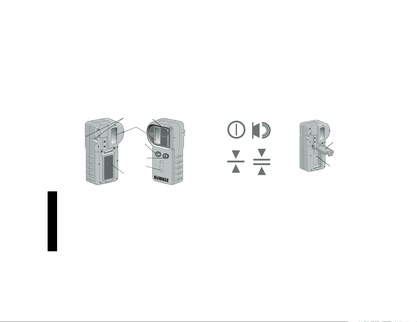
Español
42
el interior o al aire libre, cuando es difícil ver el rayo láser. El detector no está diseñado para utilizarlo con láseres no rotatorios, pero
es compatible con la mayoría de los rayos láser rotatorios de rayo
rojo o infrarrojo (invisible) que existen en el mercado. Se lo puede
fijar para indicar la ubicación del rayo en el 1/8" más cercano o en
1/25" más cercano. El detector da señales visuales mediante un
visor (N) y señales de sonido mediante el altavoz (O) para indicar
la ubicación del rayo láser.
BATERÍAS
El detector digital de láser está alimentado por una batería de
9 voltios. Para instalar la batería provista, levante la tapa del
compartimiento de la batería (P). Ubique la batería de 9 voltios en
el compartimiento, alinee la batería como se muestra en el icono
grabado (Q).
CONTROLES DEL DETECTOR
El detector se controla mediante el botón de energía/volumen (R)
y el botón de modo precisión (S). Cuando se oprime una vez el
botón de energía/volumen, se enciende el detector. La parte
superior del visor muestra el icono encendido (ON) (T) y el icono
X
N
R
S
O
P
Y
de volumen (U). Para disminuir el volumen de la señal sonora
que emite el detector cuando detecta una rayo láser, oprima el
botón nuevamente; uno de los semicírculos al lado del icono de
la bocina desaparecerá. Para apagar la señal sonora oprima el
botón una tercera vez; el icono de volumen desaparecerá. El
detector digital de láser D
EWALT también tiene una función de
apagado automático. Si un rayo láser rotatorio no coincide con el
visor de detección del rayo, o si no se oprime ningún botón, el
detector se apagará solo en unos 30 minutos.
Cuando el detector está encendido, la parte inferior del visor
muestra un icono de modo precisión. Aparecerá el icono de modo
precisión ±1/25" (V), o aparecerá el icono de modo precisión ±1/8"
(W). Cuando aparece el icono de modo precisión ±1/25", indica
que el detector va a dar una lectura de “a nivel” sólo cuando el
rayo láser esté a nivel o no más que 1/25" por encima o por
debajo del mismo. Cuando aparece el icono de modo precisión
±1/8", indica que el detector va a dar una lectura de “a nivel”
cuando el rayo láser esté a nivel o aproximadamente 1/8" por
encima o por debajo del mismo. Oprima el botón de modo
precisión (S) una vez para cambiar el modo precisión.
P
T
U
V
W
Q
Page 45

Español
43
Operación del detector
1. Fije y ubique el láser rotatorio que utilizará de acuerdo con las
instrucciones del fabricante. Encienda el láser y asegúrese de
que el láser está rotando y emitiendo un rayo láser.
NOTA: Este detector ha sido diseñado para utilizarlo únicamente
con un láser rotatorio. El detector no funcionará con un nivel de
rayo láser fijo.
2. Encienda el detector oprimiendo el botón energía/volumen (R).
3. Ajuste el volumen según desee como se describe previamente
en la sección Controles del detector.
4. Ubique el detector para que el visor del detector (X) enfrente al
rayo láser producido por el láser rotatorio. Mueva el detector
hacia arriba o hacia abajo dentro del área aproximada del rayo,
hasta que haya centrado el detector. Por información sobre los
indicadores visuales del visor y los indicadores de señal
sonora, vea la tabla titulada Indicadores.
Ligeramente Ligeramente
Sobre Sobre A Bajo Bajo
Nivel Nivel Nivel Nivel Nivel
sonido sonido tono sonido sonido
rápido rápido constante lento lento
señales
sonoras
INDICADORES
iconos del
visor
5. Utilice las muescas marcadoras (Y) para marcar con precisión
la posición del rayo láser.
MONTAJE SOBRE UNA BARRA NIVELADORA
1. Para afirmar su detector sobre una barra niveladora, primero
conecte el detector a la abrazadera empujándolo en el cerrojo
de la abrazadera (Z). Deslice las correderas de la abrazadera
(AA) alrededor del riel del detector (BB) hasta que el cerrojo
(CC) de la abrazadera encaje en el agujero del cerrojo (DD)
del detector.
2. Abra las mordazas de la abrazadera girando la perilla de la
abrazadera (EE) en el sentido inverso a las agujas del reloj.
3. Ubique el detector a la altura requerida y gire la perilla de la
abrazadera en el sentido de las agujas del reloj para afirmar la
agarradera a la barra.
4. Para hacer ajustes en altura, afloje ligeramente la abrazadera,
vuelva a ubicar y vuelva a ajustar.
Z
AA
BB
CC
EE
DD
Page 46

Español
44
Limpieza y almacenaje del detector
• Se puede quitar la suciedad y la grasa de la parte externa del
detector utilizando una tela o un cepillo suave, que no sea
metálico.
• El detector digital de láser D
EWALT es impermeable. Si
llegara a dejar caer el detector en barro, concreto húmedo o
una sustancia similar, simplemente lávelo con una
manguera. No utilice agua a alta presión, por ejemplo de una
lavadora a presión.
• El mejor lugar de almacenamiento es uno que sea fresco y seco
(fuera de la luz solar directa y de un exceso de calor o frío).
Mantenimiento del detector
Excepto por las baterías, en el detector digital de láser no hay
piezas a las que el usuario les pueda realizar mantenimiento. No
desarme la unidad. Manipular el detector de láser sin autorización
cancelará todas las garantías.
Detección de problemas del detector
EL DETECTOR NO ENCIENDE
• Oprima y suelte el botón de energía/volumen.
• Controle si la batería está bien colocada y en la posición
correcta.
• Si el detector está muy frío, déjelo calentar en un área calefaccionada.
• Reemplace la batería de 9 voltios. Encienda la unidad.
• Si el detector aún no enciende, lleve el detector a un centro de
servicio D
EWALT.
EL ALTAVOZ DEL DETECTOR NO EMITE SONIDOS
• Asegúrese de que el detector está encendido.
• Oprima el botón de energía/volumen. Alternará desde alto a
bajo a mudo.
• Asegúrese de que el láser rotatorio está girando y que está
emitiendo un rayo láser.
• Si el detector continúa sin emitir ningún sonido, llévelo a un
centro de servicio D
EWALT.
EL DETECTOR NO RESPONDE A MI NIVEL LÁSER FIJO
• El detector digital de láser D
EWALT ha sido diseñado para
operar únicamente con láseres rotatorios.
EL DETECTOR EMITE TONO PERO EL VISOR DE CRISTAL
LÍQUIDO (LCD, POR SU SIGLA EN INGLÉS) NO FUNCIONA.
• Si el detector está muy frío, déjelo calentar en un área calefaccionada.
• Si el visor de cristal líquido (LCD, por su sigla en inglés) continúa sin funcionar, lleve el detector a un centro de servicio
D
EWALT.
MANTENIMIENTO DEL LÁSER
1. En ciertas condiciones, se
puede acumular un poco de
suciedad o partículas en las
lentes de cristal que están
dentro del cabezal rotatorio.
Esto afectará la calidad y la
escala de operación del rayo.
Se deben limpiar las lentes
con un hisopo de algodón
humedecido con agua, según se muestra.
2. El protector de goma flexible se puede limpiar con una tela
húmeda que no deje pelusa, como una tela de algodón.
UTILICE SÓLO AGUA – NO utilice limpiadores ni solventes.
Deje que la unidad se seque al aire antes de almacenarla.
3. Para mantener la precisión de su trabajo, controle a menudo la
calibración del láser. Consulte la sección Control de
calibración de campo de este manual.
Page 47

Español
45
4. Los controles de calibración y otras reparaciones de mantenimiento se pueden realizar en los centros de servicio D
EWALT.
En el contrato de servicio gratuito de un año de D
EWALT se
incluyen dos calibraciones gratuitas.
5. Cuando el láser no está en uso, guárdelo en el estuche que se
provee.
6. No guarde su láser en el estuche si está húmedo. Seque las
partes externas con una tela suave y limpia y permita que el
láser se seque al aire.
7. No lo guarde a temperaturas inferiores a –18°C (0°F) o superiores a 41°C (105°F).
LIMPIEZA
Las partes externas plásticas se pueden limpiar con una tela
húmeda y detergente suave. Aunque estas partes son muy
resistentes a los solventes, NUNCA utilice solventes. Nunca use
aire comprimido para limpiar el láser.
Control de calibración de campo
Los controles de calibración de campo se deben realizar con frecuencia. Esta sección provee instrucciones para realizar controles
de calibración de campo simples de su láser rotatorio D
EWALT. Los
controles de calibración de campo no calibran el láser. Es decir,
estos controles no corrigen errores en la capacidad de nivelación
horizontal o a plomo del láser. En cambio, estos controles indican
si el láser provee o no niveles horizontales o a plomo correctos.
Estos controles no pueden reemplazar la calibración profesional
realizada por un centro de servicio D
EWALT.
CONTROL DE CALIBRACIÓN DE MODO NIVEL HORIZONTAL
1. Coloque un trípode a 15 m (50 pies) de una pared vertical
como se muestra. Asegúrese de que la cabeza del trípode está
a nivel usando un nivel de burbuja.
2. Monte el láser rotatorio sobre el trípode de manera que el eje X
apunte en la dirección contraria a la pared según se muestra.
3. Encienda el láser oprimiendo el botón de encendido/apagado
(ON/OFF).
4. Marque el centro de la elevación del rayo sobre la pared (a).
5. Gire toda la unidad láser 180° para que el eje X apunte hacia
la pared y marque el centro de la elevación del rayo (b).
6. Si la distancia entre las dos marcas (a, b) es menor que 3 mm
(1/8"), el láser está calibrado correctamente.
7. Repita los pasos anteriores para el eje Y apuntando primero el
eje Y en el sentido contrario a la pared, luego gire nuevamente
toda la unidad láser 180°.
Reparaciones
Para garantizar la SEGURIDAD y la CONFIABILIDAD, deberán
hacerse reparaciones, mantenimiento y ajustes de esta herramienta en los centros autorizados de servicio D
EWALT u otras organi-
zaciones autorizadas. Estas organizaciones prestan servicio a las
herramientas D
EWALT y emplean siempre refacciones legitimas
D
EWALT.
APROXIMADAMENTE
15 m (50 pies)
RAYO
RAYO
LA UNIDAD LÁSER
ROTÓ 180°
APROXIMADAMENTE
15 m (50 pies)
Page 48

Español
46
Póliza de Garantía
IDENTIFICACIÓN DEL PRODUCTO:
Sello o firma del Distribuidor.
Nombre del producto: __________ Mod./Cat.: ______________
Marca: _____________________ Núm. de serie:___________
(Datos para ser llenados por el distribuidor)
Fecha de compra y/o entrega del producto: _________________
Nombre y domicilio del distribuidor donde se adquirió el producto:
____________________________________________________
Este producto está garantizado por un año a partir de la fecha de
entrega, contra cualquier defecto en su funcionamiento, así como
en materiales y mano de obra empleados para su fabricación.
Nuestra garantía incluye la reparación o reposición del producto
y/o componentes sin cargo alguno para el cliente, incluyendo mano
de obra, así como los gastos de transportación razonablemente
erogados derivados del cumplimiento de este certificado.
Para hacer efectiva esta garantía deberá presentar su
herramienta y esta póliza sellada por el establecimiento comercial
donde se adquirió el producto, de no contar con ésta, bastará la
factura de compra.
EXCEPCIONES.
Esta garantía no será válida en los siguientes casos:
• Cuando el producto se hubiese utilizado en condiciones
distintas a las normales;
• Cuando el producto no hubiese sido operado de acuerdo con
el instructivo de uso que se acompaña;
• Cuando el producto hubiese sido alterado o reparado por personas distintas a las enlistadas al final de este certificado.
Anexo encontrará una relación de sucursales de servicio de fábrica, centros de servicio autorizados y franquiciados en la República
Mexicana, donde podrá hacer efectiva su garantía y adquirir
partes, refacciones y accesorios originales.
Garantía limitada por tres años
DEWALT reparará, sin cargo, cualquier falla que surja de defectos en el material o la fabricación del producto, por hasta tres
años a contar de la fecha de compra. Esta garantía no cubre fallas de las piezas causadas por su desgaste normal o abuso a la
herramienta. Para mayores detalles sobre la cobertura de la
garantía e información acerca de reparaciones realizadas bajo
garantía, visítenos en www.dewalt.com o dirígase al centro de
servicio más cercano. Esta garantía no aplica a accesorios o a
daños causados por reparaciones realizadas o intentadas por
terceros. Esta garantía le otorga derechos legales específicos,
además de los cuales puede tener otros dependiendo del estado
o provincia en que se encuentre.
Además de la garantía, las herramientas D
EWALT están cubiertas
por:
1 AÑO DE SERVICIO GRATUITO
D
EWALT mantendrá la herramienta y reemplazará las piezas gas-
tadas por su uso normal, sin cobro, en cualquier momento durante
un año a contar de la fecha de compra.
GARANTÍA DE REEMBOLSO DE SU DINERO POR 90 DÍAS
Si no está completamente satisfecho con el desempeño de su
máquina herramienta, láser o clavadora D
EWALT, cualquiera sea
el motivo, podrá devolverlo hasta 90 días de la fecha de compra
con su recibo y obtener el reembolso completo de su dinero – sin
necesidad de responder a ninguna pregunta.
AMÉRICA LATINA: Esta garantía no se aplica a los productos que
se venden en América Latina. Para los productos que se venden
en América Latina, debe consultar la información de la garantía
específica del país que viene en el empaque, llamar a la compañía
local o visitar el sitio Web a fin de obtener esa información.
PRODUCTO REACONDICIONADO: Los productos reacondicionados están cubiertos bajo la Garantía de 1 Año de Servicio Gratuito.
Page 49

Español
47
La Garantía de 90 Días de Reembolso de su Dinero y la Garantía
Limitada de Tres Años no aplican a productos reacondicionados.
REEMPLAZO GRATUITO DE LAS ETIQUETAS DE ADVERTENCIA: Si las etiquetas de advertencia se tornan eligibles o se pierden,
llame al 1-800-4-D
EWALT para reemplazarlas sin costo alguno.
PARA REPARACIÓN Y SERVICIO DE SUS HERRAMIENTAS
ELÉCTRICAS, FAVOR DE DIRIGIRSE AL CENTRO DE
SERVICIO MÁS CERCANO
CULIACAN, SIN
Av. Nicolás Bravo #1063 Sur - Col. Industrial Bravo (667) 7 12 42 11
GUADALAJARA, JAL
Av. La Paz #1779 - Col. Americana Sector Juárez (33) 3825 6978
MEXICO, D.F.
Eje Central Lázaro Cárdenas No. 18
Local D, Col. Obrera (55) 5588 9377
MERIDA, YUC
Calle 63 #459-A - Col. Centro (999) 928 5038
MONTERREY, N.L.
Av. Francisco I. Madero No.831 - Col. Centro (81) 8375 2313
PUEBLA, PUE
17 Norte #205 - Col. Centro (222) 246 3714
QUERETARO, QRO
Av. Madero 139 Pte. - Col. Centro (442) 214 1660
SAN LUIS POTOSI, SLP
Av. Universidad 1525 - Col. San Luis (444) 814 2383
TORREON, COAH
Blvd. Independencia, 96 Pte. - Col. Centro (871) 716 5265
VERACRUZ, VER
Prolongación Díaz Mirón #4280 - Col. Remes (229) 921 7016
VILLAHERMOSA, TAB
Constitución 516-A - Col. Centro (993) 312 5111
PARA OTRAS LOCALIDADES LLAME AL: (55) 5326 7100
IMPORTADOR: DEWALT S.A. DE C.V.
BOSQUES DE CIDROS ACCESO RADIATAS NO. 42
COL. BOSQUES DE LAS LOMAS, 3A. SECCIÓN, CP 05120
DELEGACIÓN CUAJIMALPA, MÉXICO, D.F
TEL. 5 326 7100
R.F.C.: BDE810626-1W7
Para servicio y ventas consulte
“HERRAMIENTAS ELECTRICAS”
en la sección amarilla.
Especificatións
DW076 9.6–18V DC ( )
Page 50

Page 51

Page 52

Battery Output Chargers/Charge Time – Chargeurs/Durée de charge (Minutes) – Cargadores de baterías/Tiempo de carga (Minutos)
DEWALT Industrial Tool Co., 701 East Joppa Road, Baltimore, MD 21286 (SEP05) Form No. 637226-00 DW076
Copyright © 2005 D
EWALT
The following are trademarks for one or more DEWALT power tools: the yellow and black color scheme; the “D” shaped air intake grill; the
array of pyramids on the handgrip; the kit box configuration; and the array of lozenge-shaped humps on the surface of the tool.
Cat Number Voltage DW9106 DW9118 DW9107 DW9108 DW9116 DW9216 DW9117 DW911 DC011 DW0249 DW0246 DW9109
DW0242 24 X X X X X X X X X 60 60 X
DC9096 18 X X X 60 60 60 20 60 60 X X 60
DW9096 18 X X X 60 60 60 20 60 60 X X 60
DW9098 18 X X X 30 30 30 12 30 30 X X 30
DW9099 18 X X X 45 45 45 15 45 45 X X 45
DC9091 14.4 90 115 60 60 60 60 20 60 60 X X 60
DW9091 14.4 45 90 45 45 45 45 15 45 45 X X 45
DW9094 14.4 60 60 30 30 30 30 12 30 30 X X 30
DC9071 12 90 115 60 60 60 60 20 60 60 X X 60
DW9071 12 60 90 45 45 45 45 15 45 45 X X 45
DW9072 12 45 60 30 30 30 30 12 30 30 X X 30
DW9050 12 40 X X X X X X X X X X X
DW9061 9.6 60 90 45 45 45 45 15 45 45 X X 45
DW9062 9.6 45 60 30 30 30 30 12 30 30 X X 30
DW9048 9.6 40 X X X X X X X X X X X
DW9057 7.2 45 60 30 30 30 30 12 30 30 X X 30
120 Volts 12 Volts
X Indicates that the battery pack is not compatible with that specific charger.
X indique que le bloc-piles n’est pas compatible avec ce chargeur.
Una “X” indica que el paquete de baterías no es compatible con ese determinado cargador.
All charge times are approximate. Actual charge time may vary.
Read the instruction manual for more specific information.
Les durées de charge sont approximatives; la durée de charge rélle peut varier.
Lire le manuel d’utilisation pour obtenir des renseignements plus précis.
El tiempo de duración de carga es aproximado; la duración de carga real puede variar.
Lea el manual de instrucciones para obtener información más precisa.
DEWALT Battery and Charger Systems
 Loading...