

Page 1
DM-D Pole Unit for TM 1 Station Printers
DP-505
Installation Manual
Copyright© 2000 by Seiko Epson Corporation
Safety Precautions
This document presents important information intended to ensure safe and effective use
of this product. Please read this document carefully and store it in an accessible location
near your installation.
Precaution Headings
This document uses the two headings shown below to call attention to potential hazards.
Failure to observe the warnings or cautions provided under these headings may lead to
injury or property damage. Be sure that you understand the meaning of each heading
before you proceed.
WARNING:
Indicates a potentially lethal hazard. Failure to observe a
WARNING may result in severe injury or death.
401322700
CAUTION:
Cautions must be observed to avoid minor injury to yourself or
damage to your equipment.
Safety Precautions
CAUTION:
❏
Do not connect cables other than those specified in this manual.
Doing so may result in fire or improper operation.
❏
Be sure to set this product on a firm, stable, horizontal surface. The
product may be damaged or cause injury if it falls.
❏
Do not place heavy objects on top of this product. The product may
be damaged and cause injury if it falls.
1
Page 2

❏
Do not attach more than one extension support. The product may
be damaged or cause injury if it falls.
Meaning of Symbol
The following symbol is used in this document. Please bear in mind the meaning of the
symbol when handling the product.
Note:
Notes have important information and useful tips on the operation of your display.
EPSON is registered trademark of Seiko Epson Corporation.
Contents
Unpacking . . . . . . . . . . . . . . . . . . . . . . . . . . . . . . . . . . . . . . . . . . . . . . . . . . . . . . . . . . . . . . . 3
Cautions on Handling . . . . . . . . . . . . . . . . . . . . . . . . . . . . . . . . . . . . . . . . . . . . . . . . . . . . . 3
Assembling . . . . . . . . . . . . . . . . . . . . . . . . . . . . . . . . . . . . . . . . . . . . . . . . . . . . . . . . . . . . . . 4
Assembling using Velcro tapes . . . . . . . . . . . . . . . . . . . . . . . . . . . . . . . . . . . . . . . . . 4
Assembling using screws . . . . . . . . . . . . . . . . . . . . . . . . . . . . . . . . . . . . . . . . . . . . . . 8
Specification . . . . . . . . . . . . . . . . . . . . . . . . . . . . . . . . . . . . . . . . . . . . . . . . . . . . . . . . . . . . . 8
2
Page 3
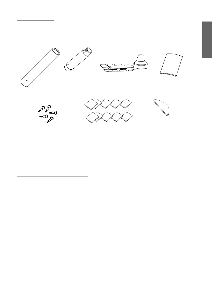
Unpacking
t
installation manual
The following items are in the box.
extension suppor
fixing plate
support
Velcro tape
fixing screws for
wooden position
Velcro tapes
(square type)
Make sure that you have all the items shown above, and that none has
been damaged. If you find anything missing or damaged, please
contact your DP-505 dealer.
(round type)
English
Cautions on Handling
When you use the DP-505, be sure to note the following points:
❏
❏
Avoid locations that are unstable or are subject to high levels of
vibration.
When connecting or disconnecting cables, make sure that the
power switches of the DM-D customer display (EPSON
DM-D
series) and the TM printer connected to the display are turned off.
3
Page 4

Assembling
When using an
extension support
Before assembling this product, you must install the UB-S09 in the TM
printer. See the UB-S09 installation manual for installation steps.
Assembling steps using Velcro tapes
1. Make sure both the printer and the host computer are turned off.
2. Disconnect the DC cable from the printer.
CAUTION:
• You must disconnect the power supply because electrical
current is flowing in some parts of the printer circuit even
when the power switch is turned off; otherwise you may
damage the UB-S09 and the printer.
• When disconnecting the DC cable, hold the plug firmly.
Do not tug on the cord itself.
3. Pass the cable for the customer display through the support, and
attach the support to the display.
When using the extension support, insert the tab on the extension
support into the hole on the support until you feel it click.
4
Page 5

4. Pass the cable for the display through the hole on the fixing plate
10
and attach the support to the fixing plate as shown below.
5. Peel the backing off of one side of the Velcro tapes and attach the
tapes to both faces of the fixing plate. See the table below to find the
attaching position for Velcro tapes and the display for your
particular printer. (The positioning numbers of Velcro tapes are on
the fixing plate.)
English
Printer type
TM-T88II
TM-U210/
U230
3
4
Positioning number of
Velcro tape attachment
1 to 9 and 11 Right side
1 to 11 Left side
1 to 11 Both sides
1
5
2
Attaching position for display
(seen from the front of the
printer)
8
11
9
6
7
5
Page 6

6. Peel off the backing on the other side of the Velcro tapes, and stick
the fixing plate where you want it to be.
7. Connect the cable for the display to the DC connector on the TM
printer (UB-S09) until you feel it click. Store any excess cable in the
TM printer, if necessary.
Note: The illustration above shows the TM-T88II printer with the UB-S09 installed.
CAUTION:
Do not connect this connector to an ordinary telephone
line.
6
Page 7

8. Place the TM printer on the fixing plate. Since the forms of the rear
side of the printer are different, see the table below for the
mounting position for each TM printer.)
Printer type Mounting positions for TM printers
TM-T88II Set the printer so that no rubber foot on the rear side of
the printer is placed on the Velcro tape.
TM-U210/U230
Set the printer so that no rubber foot on the rear
•
side of the printer is placed on the Velcro tape.
Set the printer so that the iron plate on the rear side of
•
the printer is placed on the Velcro tapes.
Note:
Place the TM-U230 printer as shown below. (Do not place it vertically.)
English
9. Connect the power supply to the TM printer.
7
Page 8

Assembling steps using screws
130 mm
{5.1 in}.
260 mm
{10.2 in.}
1. Follow steps 1 to 4 in “Assembling steps using Velcro tapes.”
2. Secure the fixing plate where you want it with the fixing
screws.
3. Follow steps 7 to 9 in “Assembling steps using Velcro tapes.”
General Specifications
214 mm
{8.4 in.}
❏
Height: 260 mm {10.2 in.}
(When using the extension support: 385 mm {15.2 in.})
❏
Width: 130 mm {5.1 in.}
❏
Depth: 214 mm {8.4 in.}
❏
Mass: 421 g (When using the extension support: 495 g)
8
 Loading...