

Page 1

ARM720T Revision 4
(AMBA AHB Bus Interface Version)
CORE CPU MANUAL
Page 2

NOTICE
No part of this material may be reproduced or duplicated in any form or by any means without the written permission of Seiko Epson. Seiko Epson reserves the right to make changes to this material without notice. Seiko
Epson does not assume any liability of any kind arising out of any inaccuracies contained in this material or due
to its application or use in any product or circuit and, further, there is no representation that this material is applicable to products requiring high level reliability, such as medical products. Moreover, no license to any intellectual property rights is granted by implication or otherwise, and there is no representation or warranty that
anything made in accordance with this material will be free from any patent or copyright infringement of a third
party. This material or portions thereof may contain technology or the subject relating to strategic products under
the control of the Foreign Exchange and Foreign Trade Law of Japan and may require an export license from the
Ministry of International Trade and Industry or other approval from another government agency.
* is the registered trademark of ARM Limited.
* CompactFlash is a registered trademark of Sandisk Corporation.
Names mentioned herein are trademarks and/or registered trademarks of their respective companies.
Copyright ©2001, 2003 ARM Limited. All rights reserved.
Page 3

Preface
1 Introduction
2 Programmer’s Model
3 Configuration
4 Instruction and Data Cache
5Write Buffer
6 The Bus Interface
7 Memory Management Unit
8 Coprocessor Interface
9 Debugging Your System
10 ETM Interface
11 Test Support
A Signal Descriptions
Glossary
Index
Page 4

Page 5

Preface
About this document................................................................................................xi
1 Introduction
1.1 About the ARM720T processor.................................................................1-1
1.2 Coprocessors ............................................................................................1-5
1.3 About the instruction set............................................................................1-5
1.4 Silicon revisions.......................................................................................1-18
2 Programmer’s Model
2.1 Processor operating states........................................................................2-1
2.2 Memory formats.........................................................................................2-2
2.3 Instruction length.......................................................................................2-3
2.4 Data types .................................................................................................2-3
2.5 Operating modes.......................................................................................2-4
2.6 Registers ...................................................................................................2-4
2.7 Program status registers ...........................................................................2-8
2.8 Exceptions...............................................................................................2-10
2.9 Relocation of low virtual addresses by the FCSE PID.............................2-15
2.10 Reset.......................................................................................................2-16
2.11 Implementation-defined behavior of instructions.....................................2-17
CONTENTS
Contents
3 Configuration
3.1 About configuration....................................................................................3-1
3.2 Internal coprocessor instructions...............................................................3-2
3.3 Registers ...................................................................................................3-3
4 Instruction and Data Cache
4.1 About the instruction and data cache ........................................................4-1
4.2 IDC validity ................................................................................................4-2
4.3 IDC enable, disable, and reset ..................................................................4-2
5 Write Buffer
5.1 About the write buffer ................................................................................5-1
5.2 Write buffer operation................................................................................5-2
6 The Bus Interface
6.1 About the bus interface..............................................................................6-1
6.2 Bus interface signals .................................................................................6-3
6.3 Transfer types............................................................................................6-5
6.4 Address and control signals ......................................................................6-7
6.5 Slave transfer response signals ................................................................6-9
6.6 Data buses ..............................................................................................6-10
6.7 Arbitration................................................................................................6-12
6.8 Bus clocking ............................................................................................6-13
ARM720T CORE CPU MANUAL EPSON i
Page 6

CONTENTS
6.9 Reset .......................................................................................................6-13
7 Memory Management Unit
7.1 About the MMU..........................................................................................7-1
7.2 MMU program-accessible registers...........................................................7-3
7.3 Address translation....................................................................................7-4
7.4 MMU faults and CPU aborts....................................................................7-15
7.5 Fault address and fault status registers...................................................7-16
7.6 Domain access control ............................................................................7-17
7.7 Fault checking sequence.........................................................................7-19
7.8 External aborts.........................................................................................7-21
7.9 Interaction of the MMU and cache...........................................................7-21
8 Coprocessor Interface
8.1 About coprocessors...................................................................................8-1
8.2 Coprocessor interface signals ...................................................................8-3
8.3 Pipeline-following signals...........................................................................8-4
8.4 Coprocessor interface handshaking..........................................................8-5
8.5 Connecting coprocessors..........................................................................8-9
8.6 Not using an external coprocessor..........................................................8-10
8.7 STC operations........................................................................................8-10
8.8 Undefined instructions.............................................................................8-10
8.9 Privileged instructions..............................................................................8-10
9 Debugging Your System
9.1 About debugging your system...................................................................9-2
9.2 Controlling debugging................................................................................9-3
9.3 Entry into debug state................................................................................9-5
9.4 Debug interface .........................................................................................9-9
9.5 ARM720T core clock domains...................................................................9-9
9.6 The EmbeddedICE-RT macrocell............................................................9-10
9.7 Disabling EmbeddedICE-RT....................................................................9-11
9.8 EmbeddedICE-RT register map ..............................................................9-12
9.9 Monitor mode debugging.........................................................................9-12
9.10 The debug communications channel.......................................................9-14
9.11 Scan chains and the JTAG interface.......................................................9-17
9.12 The TAP controller...................................................................................9-19
9.13 Public JTAG instructions..........................................................................9-20
9.14 Test data registers...................................................................................9-22
9.15 Scan timing..............................................................................................9-25
9.16 Examining the core and the system in debug state.................................9-26
9.17 Exit from debug state...............................................................................9-29
9.18 The program counter during debug.........................................................9-30
9.19 Priorities and exceptions..........................................................................9-32
9.20 Watchpoint unit registers.........................................................................9-33
9.21 Programming breakpoints........................................................................9-36
9.22 Programming watchpoints.......................................................................9-38
9.23 Abort status register.................................................................................9-38
9.24 Debug control register .............................................................................9-39
9.25 Debug status register...............................................................................9-41
9.26 Coupling breakpoints and watchpoints....................................................9-43
9.27 EmbeddedICE-RT timing.........................................................................9-44
ii EPSON ARM720T CORE CPU MANUAL
Page 7

10 ETM Interface
10.1 About the ETM interface..........................................................................10-1
10.2 Enabling and disabling the ETM7 interface.............................................10-1
10.3 Connections between the ETM7 macrocell and the
ARM720T processor................................................................................10-2
10.4 Clocks and resets....................................................................................10-3
10.5 Debug request wiring...............................................................................10-3
10.6 TAP interface wiring ................................................................................10-3
11 Test Support
11.1 About the ARM720T test registers ..........................................................11-1
11.2 Automatic Test Pattern Generation (ATPG)............................................11-2
11.3 Test State Register..................................................................................11-3
11.4 Cache test registers and operations........................................................11-3
11.5 MMU test registers and operations..........................................................11-8
A Signal Descriptions
A.1 AMBA interface signals .............................................................................A-1
A.2 Coprocessor interface signals ...................................................................A-2
A.3 JTAG and test signals ...............................................................................A-3
A.4 Debugger signals.......................................................................................A-4
A.5 Embedded trace macrocell interface signals.............................................A-5
A.6 ATPG test signals......................................................................................A-7
A.7 Miscellaneous signals................................................................................A-7
CONTENTS
Glossary
Index
ARM720T CORE CPU MANUAL EPSON iii
Page 8

CONTENTS
List of Figures
Figure 1-1 720T Block diagram....................................................................................1-2
Figure 1-2 ARM720T processor functional signals.......................................................1-3
Figure 1-3 ARM instruction set formats........................................................................1-7
Figure 1-4 Thumb instruction set formats...................................................................1-14
Figure 2-1 Big-endian addresses of bytes with words..................................................2-2
Figure 2-2 Little-endian addresses of bytes with words ...............................................2-3
Figure 2-3 Register organization in ARM state.............................................................2-5
Figure 2-4 Register organization in Thumb state .........................................................2-6
Figure 2-5 Mapping of Thumb state registers onto ARM state registers......................2-7
Figure 2-6 Program status register format....................................................................2-8
Figure 3-1 MRC and MCR bit pattern...........................................................................3-2
Figure 3-2 ID Register read format...............................................................................3-3
Figure 3-3 ID Register write format ..............................................................................3-3
Figure 3-4 Control Register read format.......................................................................3-4
Figure 3-5 Control Register write format ......................................................................3-4
Figure 3-6 Translation Table Base Register format......................................................3-5
Figure 3-7 Domain Access Control Register format.....................................................3-6
Figure 3-8 Fault Status Register format .......................................................................3-6
Figure 3-9 Fault Address Register format ....................................................................3-7
Figure 3-10 FCSCE PID Register format .......................................................................3-8
Figure 3-11 PROCID Register format.............................................................................3-8
Figure 6-1 Simple AHB transfer....................................................................................6-2
Figure 6-2 AHB bus master interface...........................................................................6-4
Figure 6-3 Simple memory cycle..................................................................................6-5
Figure 6-4 Transfer type examples...............................................................................6-6
Figure 7-1 Translation Table Base Register.................................................................7-4
Figure 7-2 Translating page tables...............................................................................7-5
Figure 7-3 Accessing translation table level one descriptors .......................................7-6
Figure 7-4 Level one descriptor....................................................................................7-6
Figure 7-5 Section descriptor .......................................................................................7-8
Figure 7-6 Coarse page table descriptor......................................................................7-8
Figure 7-7 Fine page table descriptor...........................................................................7-9
Figure 7-8 Section translation.....................................................................................7-10
Figure 7-9 Level two descriptor..................................................................................7-10
Figure 7-10 Large page translation from a coarse page table......................................7-12
Figure 7-11 Small page translation from a coarse page table......................................7-13
Figure 7-12 Tiny page translation from a fine page table.............................................7-14
Figure 7-13 Domain Access Control Register format...................................................7-17
Figure 7-14 Sequence for checking faults....................................................................7-19
Figure 8-1 Coprocessor busy-wait sequence...............................................................8-6
Figure 8-2 Coprocessor register transfer sequence.....................................................8-7
Figure 8-3 Coprocessor data operation sequence.......................................................8-7
Figure 8-4 Coprocessor load sequence .......................................................................8-8
Figure 8-5 Example coprocessor connections .............................................................8-9
Figure 9-1 Typical debug system .................................................................................9-2
Figure 9-2 ARM720T processor block diagram............................................................9-3
Figure 9-3 Debug state entry........................................................................................9-5
iv EPSON ARM720T CORE CPU MANUAL
Page 9

CONTENTS
Figure 9-4 Clock synchronization.................................................................................9-8
Figure 9-5 The ARM720T core, TAP controller, and EmbeddedICE-RT macrocell...9-10
Figure 9-6 Domain Access Control Register..............................................................9-14
Figure 9-7 ARM720T processor scan chain arrangements........................................9-17
Figure 9-8 Test access port controller state transitions..............................................9-19
Figure 9-9 ID code register format..............................................................................9-22
Figure 9-10 Scan timing ...............................................................................................9-25
Figure 9-11 Debug exit sequence ................................................................................9-29
Figure 9-12 EmbeddedICE-RT block diagram .............................................................9-34
Figure 9-13 Watchpoint control value, and mask format..............................................9-35
Figure 9-14 Debug abort status register.......................................................................9-38
Figure 9-15 Debug control register format....................................................................9-39
Figure 9-16 Debug status register format.....................................................................9-41
Figure 9-17 Debug control and status register structure..............................................9-42
Figure 11-1 CP15 MRC and MCR bit pattern...............................................................11-1
Figure 11-2 Rd format, CAM read................................................................................11-4
Figure 11-3 Rd format, CAM write................................................................................11-4
Figure 11-4 Rd format, RAM read................................................................................11-5
Figure 11-5 Rd format, RAM write................................................................................11-5
Figure 11-6 Rd format, CAM match RAM read ............................................................11-5
Figure 11-7 Data format, CAM read.............................................................................11-5
Figure 11-8 Data format, RAM read.............................................................................11-5
Figure 11-9 Data format, CAM match RAM read .........................................................11-6
Figure 11-10 Rd format, write cache victim and lockdown base....................................11-6
Figure 11-11 Rd format, write cache victim....................................................................11-6
Figure 11-12 Rd format, CAM write and data format, CAM read .................................11-10
Figure 11-13 Rd format, RAM1 write............................................................................11-10
Figure 11-14 Data format, RAM1 read.........................................................................11-11
Figure 11-15 Rd format, RAM2 write and data format, RAM2 read .............................11-11
Figure 11-16 Rd format, write TLB lockdown...............................................................11-12
ARM720T CORE CPU MANUAL EPSON v
Page 10

CONTENTS
List of Tables
Table 1-1 Key to tables ...............................................................................................1-6
Table 1-2 ARM instruction summary...........................................................................1-8
Table 1-3 Addressing mode 2...................................................................................1-10
Table 1-4 Addressing mode 2 (privileged) ................................................................1-11
Table 1-5 Addressing mode 3...................................................................................1-11
Table 1-6 Addressing mode 4 (load).........................................................................1-11
Table 1-7 Addressing mode 4 (store)........................................................................1-12
Table 1-8 Addressing mode 5...................................................................................1-12
Table 1-9 Operand 2.................................................................................................1-12
Table 1-10 Fields.........................................................................................................1-12
Table 1-11 Condition fields..........................................................................................1-13
Table 1-12 Thumb instruction summary......................................................................1-15
Table 2-1 ARM720T modes of operation ....................................................................2-4
Table 2-2 PSR mode bit values...................................................................................2-9
Table 2-3 Exception entry and exit............................................................................2-11
Table 2-4 Exception vector addresses......................................................................2-13
Table 3-1 Cache and MMU Control Register ..............................................................3-3
Table 3-2 Cache operation..........................................................................................3-7
Table 3-3 TLB operations............................................................................................3-7
Table 6-1 Transfer type encoding ...............................................................................6-5
Table 6-2 Transfer size encodings..............................................................................6-7
Table 6-3 Burst type encodings...................................................................................6-8
Table 6-4 Protection control encodings.......................................................................6-8
Table 6-5 Response encodings.................................................................................6-10
Table 6-6 Active byte lanes for a 32-bit little-endian data bus...................................6-11
Table 6-7 Active byte lanes for a 32-bit big-endian data bus ....................................6-12
Table 7-1 CP15 register functions...............................................................................7-3
Table 7-2 Level one descriptor bits.............................................................................7-7
Table 7-3 Interpreting level one descriptor bits [1:0] ...................................................7-7
Table 7-4 Section descriptor bits.................................................................................7-8
Table 7-5 Coarse page table descriptor bits ...............................................................7-9
Table 7-6 Fine page table descriptor bits....................................................................7-9
Table 7-7 Level two descriptor bits............................................................................7-11
Table 7-8 Interpreting page table entry bits [1:0].......................................................7-11
Table 7-9 Priority encoding of fault status.................................................................7-16
Table 7-10 Interpreting access control bits in Domain Access Control Register.........7-17
Table 7-11 Interpreting access permission (AP) bits...................................................7-18
Table 8-1 Coprocessor availability ..............................................................................8-2
Table 8-2 Handshaking signals...................................................................................8-5
Table 8-3 Handshake signal connections ...................................................................8-9
Table 8-4 CPnTRANS signal meanings....................................................................8-10
Table 9-1 Function and mapping of EmbeddedICE-RT registers .............................9-12
Table 9-2 Domain Access Control Register bit assignments ....................................9-15
Table 9-3 Instruction encodings for scan chain 15....................................................9-18
Table 9-4 Public instructions.....................................................................................9-20
Table 9-5 Scan chain number allocation...................................................................9-23
Table 9-6 Scan chain 1 cells.....................................................................................9-25
vi EPSON ARM720T CORE CPU MANUAL
Page 11

CONTENTS
Table 9-7 Determining the cause of entry to debug state .........................................9-32
Table 9-8 SIZE[1:0] signal encoding.........................................................................9-35
Table 9-9 Debug control register bit assignments.....................................................9-39
Table 9-10 Interrupt signal control...............................................................................9-40
Table 9-11 Debug status register bit assignments......................................................9-41
Table 10-1 Connections between the ETM7 macrocell and
the ARM720T processor...........................................................................10-2
Table 11-1 Summary of ATPG test signals.................................................................11-2
Table 11-2 Test State Register operations..................................................................11-3
Table 11-3 Summary of CP15 register c7, c9, and c15 operations.............................11-4
Table 11-4 Write cache victim and lockdown operations............................................11-6
Table 11-5 CAM, RAM1, and RAM2 register c15 operations......................................11-9
Table 11-6 Register c2, c3, c5, c6, c8, c10, and c15 operations ................................11-9
Table 11-7 CAM memory region size........................................................................11-10
Table 11-8 Access permission bit setting..................................................................11-11
Table 11-9 Miss and fault encoding ..........................................................................11-11
Table 11-10 RAM2 memory region size......................................................................11-12
Table A-1 AMBA interface signals...............................................................................A-1
Table A-2 Coprocessor interface signal descriptions ..................................................A-2
Table A-3 JTAG and test signal descriptions...............................................................A-3
Table A-4 Debugger signal descriptions......................................................................A-4
Table A-5 ETM interface signal descriptions...............................................................A-5
Table A-6 ATPG test signal descriptions....................................................................A-7
Table A-7 Miscellaneous signal descriptions...............................................................A-7
ARM720T CORE CPU MANUAL EPSON vii
Page 12

CONTENTS
THIS PAGE IS BLANK.
viii EPSON ARM DDI 0229B
Page 13

Preface
Page 14

Page 15

Preface
Preface
This preface introduces the
CPU Manual
. It contains the following sections:
About this document ................................................................................................. xi
ARM720T Revision 4 (AMBA AHB Bus Interface Version) CORE
About this document
This document is a technical reference manual for the ARM720T r4p2 processor.
Intended audience
This document has been written for experienced hardware and software engineers who might
or might not have experience of the architecture, configuration, integration, and instruction
sets with reference to the ARM product range. it provides information to enable designers to
integrate the processor into a target system as quickly as possible.
Using this manual
This document is organized into the following chapters:
Chapter 1
Chapter 2
Introduction
Programmer’s Model
Read this chapter for an introduction to the ARM720T processor.
Chapter 3
Chapter 4
Chapter 5
Chapter 6
Chapter 7
Read this chapter for a description of the 32-bit ARM and 16-bit
Thumb instruction sets.
Configuration
Read this chapter for a description of the ARM1156F-S control
coprocessor CP15 register configurations and programming
details.
Instruction and Data Cache
Read this chapter for a description of the mixed instruction and
data cache.
Write Buffer
The Bus Interface
Memory Management Unit
Read this chapter for a description on how to enhance the system
performance of the ARM720T processor by using the write buffer.
Read this chapter for a description of the ARM720T processor bus
interface.
Read this chapter for a description of the functions and how to use
of the
Memory Management Unit
(MMU).
ARM720T CORE CPU MANUAL EPSON xi
Page 16

Preface
Chapter 8
Chapter 9
Chapter 10
Chapter 11
Chapter
Coprocessor Interface
Read this chapter for a description on how to connect coprocessors
to the ARM1156F-S coprocessor interface.
Debugging Your System
Read this chapter for a description of the hardware extensions and
integrated on-chip debug support for the ARM720T processor.
ETM Interface
Test Support
Signal Descriptions
Read this chapter for a description of the Embedded Trace
Macrocell support for the ARM720T processor.
Read this chapter for a description of how to perform device-specific
test operations.
Read this appendix for a list of all ARM720T processor interface
signals.
Typographical conventions
The following typographical conventions are used in this document:
bold Highlights ARM processor signal names, and interface elements
such as menu names. Also used for terms in descriptive lists, where
appropriate.
italic
monospace Denotes text that can be entered at the keyboard, such as
space Denotes a permitted abbreviation for a command or option. The
mono
monospace italic Denotes arguments to commands or functions where the argument
monospace bold Denotes language keywords when used outside example code.
Highlights special terminology, cross-references, and citations.
commands, file names and program names, and source code.
underlined text can be entered instead of the full command or
option name.
is to be replaced by a specific value.
Product revision status
The rnpn identifier indicates the revision status of the product described in this document,
where:
n
r
n
p
Identifies the major revision of the product.
Identifies the minor revision or modification status of the product.
xii EPSON ARM720T CORE CPU MANUAL
Page 17

Preface
Timing diagram conventions
This manual contains one or more timing diagrams. The following key explains the
components used in these diagrams. Any variations are clearly labeled when they occur.
Therefore, no additional meaning must be attached unless specifically stated.
Clock
HIGH to LOW
Transient
HIGH/LOW to HIGH
Bus stable
Bus to high impedance
Bus change
High impedance to stable bus
Key to timing diagram conventions
Shaded bus and signal areas are undefined, so the bus or signal can assume any value within
the shaded area at that time. The actual level is unimportant and does not affect normal
operation.
Further reading
This section lists publications by ARM Limited, and by third parties.
ARM periodically provides updates and corrections to its documentation. See
http://www.arm.com for current errata sheets, addenda, and ARM Frequently Asked Questions.
ARM publications
This document contains information that is specific to the ARM720T processor. Refer to the
following documents for other relevant information:
ARM Architecture Reference Manual
•
AMBA Specification (Rev 2.0)
•
•
ETM7 (Rev 1) Technical Reference Manual
ARM7TDMI-S (Rev 4) Technical Reference Manual
•
(ARM IHI 0011)
(ARM DDI 0100)
(ARM DDI 0158)
(ARM DDI 0234).
Other publications
This section lists relevant documents published by third parties.
Standard Test Access Port and Boundary Scan Architecture
•
(IEEE Std.
1149.1.1990).
Figure 9-8 on page 9-19 is printed with permission IEEE Std. 1149.1-1990, IEEE Standard
Test Access Port and Boundary-Scan Architecture Copyright 2001, by IEEE. The IEEE
disclaims any responsibility or liability resulting from the placement and use in the described
manner.
ARM720T CORE CPU MANUAL EPSON xiii
Page 18

Preface
THIS PAGE IS BLANK.
xiv EPSON ARM720T CORE CPU MANUAL
Page 19

1
Introduction
Page 20

Page 21

1: Introduction
1 Introduction
This chapter provides an introduction to the ARM720T processor. It contains the following
sections:
1.1 About the ARM720T processor.................................................................. 1-1
1.2 Coprocessors............................................................................................... 1-5
1.3 About the instruction set ........................................................................... 1-5
1.4 Silicon revisions........................................................................................ 1-18
1.1 About the ARM720T processor
The ARM720T processor is a general-purpose 32-bit microprocessor with 8KB cache, enlarged
write buffer , and
processor uses the ARM7TDMI-S CPU, and is software-compatible with the ARM processor
family.
Memory Management Unit
(MMU) combined in a single chip. The ARM720T
The on-chip mixed data and instruction cache, together with the write buffer, substantially
raise the average execution speed and reduce the average amount of memory bandwidth
required by the processor . This enables the external memory to support additional processors
or
Direct Memory Access
The MMU supports a conventional two-level page table structure and several extensions that
make it ideal for running high-end embedded applications and sophisticated operating
systems.
The allocation of virtual addresses with different task IDs improves performance in task
switching operations with the cache enabled. These relocated virtual addresses are monitored
by the EmbeddedICE-RT block.
The memory interface enables the performance potential to be realized without incurring high
costs in the memory system. Speed-critical control signals are pipelined to allow system
control functions to be implemented in standard low-power logic. These control signals permit
the exploitation of paged mode access offered by industry-standard DRAMs.
The ARM720T processor is provided with an
brings out the required signals from the ARM core to the periphery of the ARM720T processor .
This enables you to connect a standard ETM7 macrocell.
The ARM720T processor is a fully static part and has been designed to minimize power
requirements. This makes it ideal for portable applications where low power consumption is
essential.
The ARM720T processor architecture is based on
principles. The instruction set and related decode mechanism are greatly simplified compared
with microprogrammed
(DMA) channels with minimal performance loss.
Embedded T race Macrocell
Reduced Instruction Set Computer
Complex Instruction Set Computers
(CISCs).
(ETM) interface that
(RISC)
ARM720T CORE CPU MANUAL EPSON 1-1
Page 22
1: Introduction
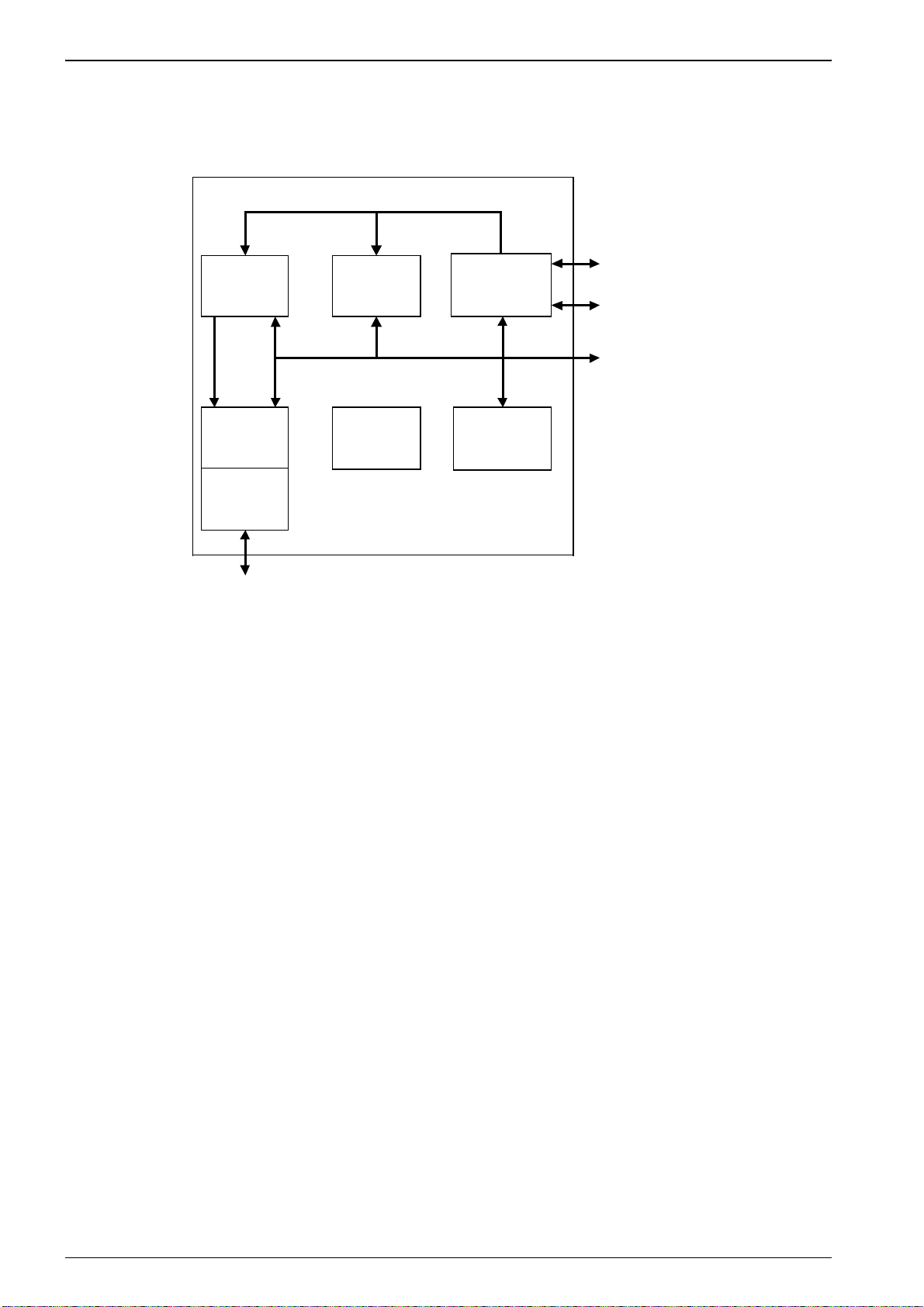
A block diagram of the ARM720T processor is shown in Figure 1-1.
Virtual addres s bus
MMU
8KB cache
Internal data bus
ARM720T core
JTAG debug
inter f ace
ETM interfac e
Coprocess or
inter f ace
Data and
address
buffers
AMBA
inter f ace
AMBA AHB
bus interfac e
Control and
clocking logic
System c ontrol
coproc essor
ARM720T
Figure 1-1 720T Block diagram
1-2 EPSON ARM720T CORE CPU MANUAL
Page 23
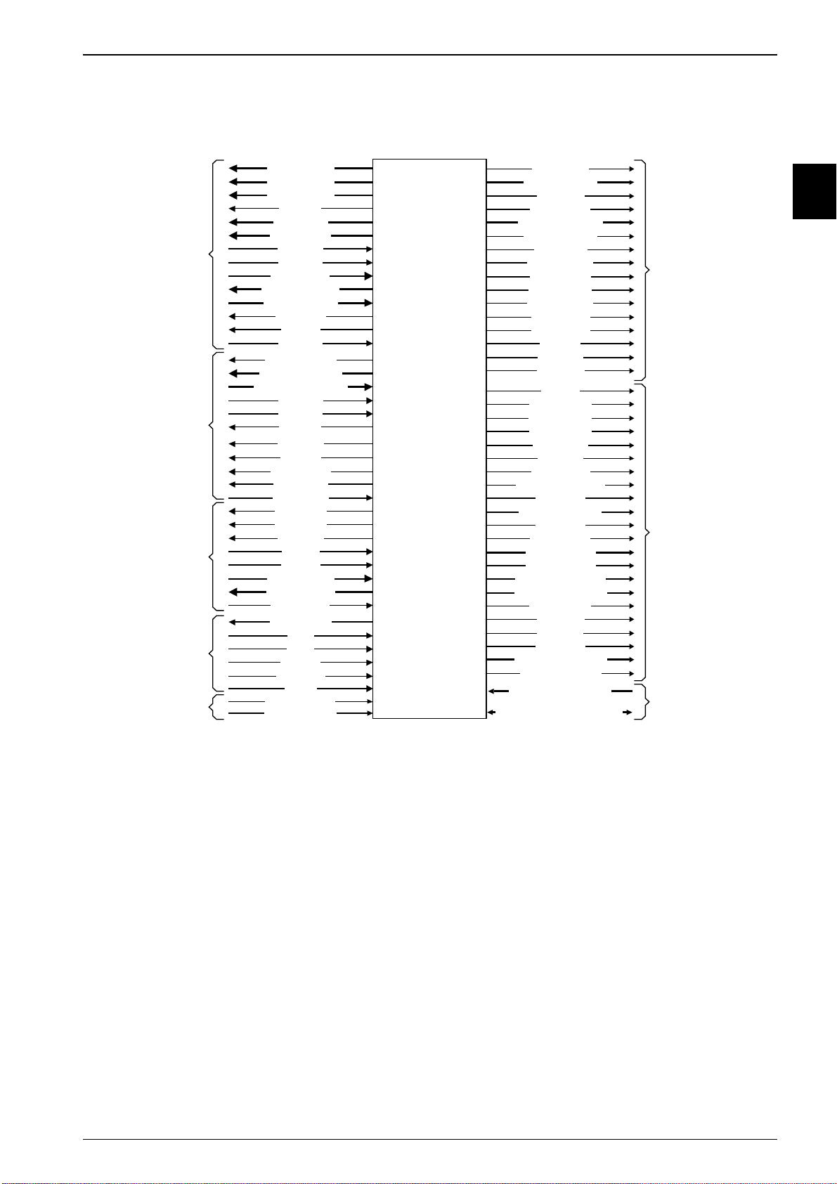
The functional signals on the ARM720T processor are shown in Figure 1-2.
1: Introduction
AMBA
inte r f ace
Coprocess or
inte r f ace
Deb ug
inte r f ace
Mis cellaneous
signals
ATPG
Signals
HADDR[ 31:0 ]
HTRANS[ 1:0]
HBURST [2:0]
HWRI T E
HSIZE[2 :0]
HPROT [3 :0]
HGRA NT
HREADY
HRESP[1:0]
HWDA TA [31 :0]
HRDAT A[ 31:0 ]
HBUSREQ
HLOC K
HCL KEN
EXTCPCLKEN
EXT C P DIN[ 3 1: 0]
EXTCPDOUT[31:0]
EXT C P A
EXT C P B
CPnCPI
CPnOPC
CPTBIT
CPnTRANS
CPnMREQ
EXT CPDBE
COMMRX
COMMTX
DBGA CK
DBGEN
DBGRQ
DBGEXT [1:0]
DBGRNG[ 1:0]
DBGBREAK
BIGENDOUT
nFIQ
nIRQ
VINITHI
HRESETn
HCL K
TESTENABLE
SCANENABLE
ARM720T processor
DBGIR[ 3:0]
DBGSREG[ 3:0]
DBGSDI N
DBGSDO UT
DBGT APS M [3 :0]
DBGC APT URE
DBGSHI FT
DBGUPDA TE
DBGINTEST
DBGEXT EST
DBGn TDOEN
DBGn TRST
DBGT CKEN
DBGT DI
DBGT DO
DBGT MS
ET M EN
ET M BI GEND
ET M HI V ECS
ET M n M REQ
ET M n OP C
ET M SEQ
ET M n EXEC
ETM INSTRVALID
ET M n CP I
ETM ADDR[31 :0]
ET M n RW
ET M C LK EN
ET M SI Z E[1 :0 ]
ETM DBGA CK
ETM RDATA[31 :0]
ET M W DAT A [ 31 :0 ]
ETM ABORT
ET M C PA
ET M C PB
ET M T BIT
ETM PROCID[ 31:0]
ETM PROCIDW R
SCANIN0 - SCANIN6
SCANOUT0 - SCANOUT6
JTAG
inte r f ace
ETM interfac e
ATPG
Signals
Figure 1-2 ARM720T processor functional signals
1.1.1 EmbeddedICE-RT logic
The EmbeddedICE-RT logic provides integrated on-chip debug support for the ARM720T core.
It enables you to program the conditions under which a breakpoint or watchpoint can occur.
The EmbeddedICE-RT logic is an enhanced implementation of EmbeddedICE, and enables
you to perform debugging in monitor mode. In monitor mode, the core takes an exception on a
breakpoint or watchpoint, rather than entering debug state as it does in halt mode.
If the core does not enter debug state when it encounters a watchpoint or breakpoint, it can
continue to service hardware interrupt requests as normal. Debugging in monitor mode is
useful if the core forms part of the feedback loop of a mechanical system, where stopping the
core can potentially lead to system failure.
The EmbeddedICE-RT logic contains a
used to pass information between the target and the host debugger. The EmbeddedICE-RT
logic is controlled through the
ARM720T CORE CPU MANUAL EPSON 1-3
Joint Test Action Group
Debug Communications Channel
(DCC). The DCC is
(JTAG) test access port.
Page 24

1: Introduction
Changes to the programmer’s model
T o provide support for the EmbeddedICE-RT macrocell, the following changes have been made
to the programmer’s model for the ARM720T processor:
Debug Control Register
There are two new bits in the Debug Control Register:
Bit 4 Monitor mode enable. Use this to control how the device reacts on
a breakpoint or watchpoint:
• When set, the core takes the instruction or data abort
exception.
• When clear, the core enters debug state.
Bit 5 EmbeddedICE-RT disable. Use this when changing watchpoints
and breakpoints:
• When set, this bit disables breakpoints and watchpoints,
enabling the breakpoint or watchpoint registers to be
programmed with new values.
• When clear , the new breakpoint or watchpoint values become
operational.
For more information, see
Debug control register
on page 9-39.
Coprocessor register map
A new register, r2, in the coprocessor CP14 register map indicates if the processor
entered the Prefetch or Data Abort exception because of a real abort, or because of a
breakpoint or watchpoint. For more details, see
For more details, see Chapter 9
Debugging Your System
Abort status register
.
on page 9-38.
1-4 EPSON ARM720T CORE CPU MANUAL
Page 25

1: Introduction
1.2 Coprocessors
The ARM720T processor has an internal coprocessor designated CP15 for internal control of
the device (see Chapter 3
The ARM720T processor also includes a port for the connection of on-chip external
coprocessors. This enables extension of the ARM720T functionality in an
architecturally-consistent manner.
Configuration
).
1.3 About the instruction set
The instruction set comprises ten basic instruction types:
• Two types use the on-chip arithmetic logic unit, barrel shifter, and multiplier to
perform high-speed operations on the data in a bank of 31 registers, each 32 bits
wide.
• Three types of instruction control the data transfer between memory and the
registers:
– one optimized for flexibility of addressing
– one for rapid context switching
– one for swapping data.
• Two instructions control the flow and privilege level of execution.
• Three types are dedicated to the control of external coprocessors. These enable you
to extend the functionality of the instruction set off-chip in an open and uniform
way.
The ARM instruction set is a good target for compilers of many different high-level languages.
Where required for critical code segments, assembly code programming is also
straightforward.
ARM720T CORE CPU MANUAL EPSON 1-5
Page 26

1: Introduction
1.3.1 Format summary
This section provides a summary of the ARM and Thumb instruction sets:
•
ARM instruction set
on page 1-7
Thumb instruction set
•
on page 1-14
A key to the instruction set tables is shown in Table 1-1.
The ARM7TDMI-S core on the ARM720T processor is an implementation of the ARM
architecture v4T. For a complete description of both instruction sets, see the
Architecture Reference Manual
.
ARM
Table 1-1 Key to tables
Entry Description
{cond} Refer to Table 1-11 on page 1-13.
<Oprnd2> Refer to Table 1-9 on page 1-12.
{field} Refer to Table 1-10 on page 1-12.
S Sets condition codes (optional).
B Byte operation (optional).
H Halfword operation (optional).
T Forces address translation. Cannot be
used with pre-indexed addresses.
<a_mode2> Refer to Table 1-3 on page 1-10 .
<a_mode2P> Refer to Table 1-4 on page 1-11.
<a_mode3> Refer to Table 1-5 on page 1-11 .
<a_mode4L> Refer to Table 1-6 on page 1-11.
<a_mode4S> Refer to Table 1-7 on page 1-12.
<a_mode5> Refer to Table 1-8 on page 1-12 .
#<32bit_Imm> A 32-bit constant, formed by
right-rotating an 8-bit value by an even
number of bits.
<reglist> A comma-separated list of registers,
enclosed in braces ( { and } ).
1-6 EPSON ARM720T CORE CPU MANUAL
Page 27
1: Introduction
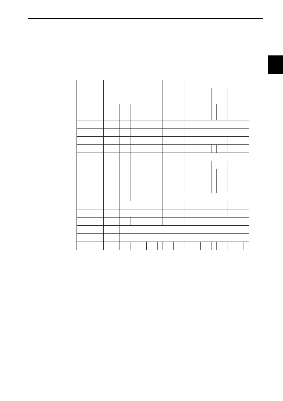
1.3.2 ARM instruction set
This section gives an overview of the ARM instructions available. For full details of these
instructions, see the
The ARM instruction set formats are shown in Figure 1-3.
Data processing
immediate
Data processing
immediate shift
Data processing register
Multiply
Multiply long
Move from status register
Move immediate to status
Move register to status
Load/store immediate
Load/store register offset
Load/store halfword/
Load/store halfword/
Load/store multiple
Coprocessor register
Coprocessor load and
Branch and branch with
register
register
Branch/exchange
instruction set
signed byte
signed byte
Swap/swap byte
Coprocessor data
processing
transfers
Software interrupt
Undefined
ARM Architecture Reference Manual
.
31 30 29 28 27 26 25 24 23 22 21 20 19 18 17 16 15 14 13 12 11 10 09 08 07 06 05 04 03 02 01 00
0 0 1 op S Rn Rd rotate immediatecond
0 0 0 opcode S Rn Rd shift immediate shift 0 Rm
0 0 0 opcode S Rn Rd Rs shift 1 Rm0
0 0 0 0 0 0 A S
0
0
0
0
1
U
A
Rd
S
RdHi
Rn
RdLo
Rs
Rn
1 0 0 1
1 0 0 1
0 0 0 1 0 R 0 0 SBO Rd SBZ
0 0 1 1 0 R 1 0 Mask SBO rotate immediate
0 0 0 1 0 R 1 0 Mask SBO SBZ Rm0
0 0 0 1 0 0 1 0 SBO SBO SBO Rm10 0 0
0 1 0 P U B W L Rn Rd immediate
0 1 1 P U B W L Rn Rd shift immediate shift 0
0
0
0
P
U
1
W
L
Rn
0
0
0
P
U
0
W
L
Rn
Rd
Rd
High offset 1 S H 1
SBZ 1 S H 1
000 1 0 B 0 0 Rn Rd 1 0 0 1SBZ Rm
1
0
0
P U S W L
1
1
1
0
op1
1
1
1
0
op1
1
1
0
P
U N W L Rn
1
0
1
L 24_bit_offset
1
1
1
1
Rn
CRn
L
CRn
CRd
Rd
CRd
Register list
cp_num
cp_num
cp_num
op2
op201
8_bit_offset
swi_number
shift
offset
store
link
cond
cond
cond
cond
cond
cond
cond
cond
cond
cond
cond
cond
cond
cond
cond
cond
cond
cond
cond
0 1 1 x 1x x x x x x x x x x x x x x x x x x x x x x xcond
Rm
Rm
Rm
Low offset
Rm
CRm
CRm
31 30 29 28 27 26 25 24 23 22 21 20 19 18 17 16 15 14 13 12 11 10 09 08 07 06 05 04 03 02 01 00
Figure 1-3 ARM instruction set formats
Note: Some instruction codes are not defined but do not cause the Undefined instruction
trap to be taken, for example, a multiply instruction with bit 6 set. You must not
use these instructions, because their action might change in future ARM
implementations.
ARM720T CORE CPU MANUAL EPSON 1-7
Page 28

1: Introduction
The ARM instruction set summary is shown in Table 1-2.
Table 1-2 ARM instructio n su mm ary
Operation Assembler
Move Move MOV{cond}{S} <Rd>, <Oprnd2>
Move NOT MVN{cond}{S} <Rd>, <Oprnd2>
Move SPSR to register MRS{cond} <Rd>, SPSR
Move CPSR to register MRS{cond} <Rd>, CPSR
Move register to SPSR MSR{cond} SPSR{field}, <Rm>
Move register to CPSR MSR{cond} CPSR{field}, <Rm>
Move immediate to SPSR flags MSR{cond} SPSR_f, #<32bit_Imm>
Move immediate to CPSR flags MSR{cond} CPSR_f, #<32bit_Imm>
Arithmetic Add ADD{cond}{S} <Rd>, <Rn>, <Oprnd2>
Add with carry ADC{cond}{S} <Rd>, <Rn>, <Oprnd2>
Subtract SUB{cond}{S} <Rd>, <Rn>, <Oprnd2>
Subtract with carry SBC{cond}{S} <Rd>, <Rn>, <Oprnd2>
Subtract reverse subtract RSB{cond}{S} <Rd>, <Rn>, <Oprnd2>
Subtract reverse subtract with carry RSC{cond}{S} <Rd>, <Rn>, <Oprnd2>
Multiply MUL{cond}{S} <Rd>, <Rm>, <Rs>
Multiply accumulate MLA{cond}{S} <Rd>, <Rm>, <Rs>, <Rn>
Multiply unsigned long UM UL L { c o n d } { S } <R d L o > , < R d H i>, <Rm>, < R s >
Multiply unsigned accumulate long UMLAL{cond}{S} <RdLo>, <RdHi>, <Rm>, <Rs>
Multiply signed long SMULL{cond}{S} <RdLo>, <RdHi>, <Rm>, <Rs>
Multiply signed accumulate long SMLAL{cond}{S} <RdLo>, <RdHi>, <Rm>, <Rs>
Compare CMP{cond} <Rd>, <Oprnd2>
Compare negative CMN{cond} <Rd>, <Oprnd2>
Logical Test TST{cond} <Rn>, <Oprnd2>
Test equivalence TEQ{cond} <Rn>, <Oprnd2>
AND AND{cond}{S} <Rd>, <Rn>, <Oprnd2>
EOR EOR{cond}{S} <Rd>, <Rn>, <Oprnd2>
ORR ORR{cond}{S} <Rd>, <Rn>, <Oprnd2>
Bit clear BIC{cond}{S} <Rd>, <Rn>, <Oprnd2>
Branch Branch B{cond} <label>
Branch with link BL{cond} <label>
Branch, and exchange instruction
set
1-8 EPSON ARM720T CORE CPU MANUAL
BX{cond} <Rn>
Page 29

Table 1-2 ARM instructio n su mm ary (continue d)
Operation Assembler
Load Word LDR{cond} <Rd>, <a_mode2>
Word with User Mode privilege LDR{cond}T <Rd>, <a_mode2P>
Byte LDR{cond}B <Rd>, <a_mode2>
Byte with User Mode privilege LDR{cond}BT <Rd>, <a_mode2P>
Byte signed LDR{cond}SB <Rd>, <a_mode3>
Halfword LDR{cond}H <Rd>, <a_mode3>
Halfword signed LDR{cond}SH <Rd>, <a_mode3>
1: Introduction
Multiple block
Increment before LDM{cond }IB <Rd>{!}, <reglist>{^}
data
operations
Increment after LDM{cond}IA <Rd>{!}, <reglist>{^}
Decrement before LDM{cond}DB <Rd>{!}, <reglist>{^}
Decrement after LDM{cond}DA <Rd>{!}, <reglist>{^}
Stack operations LDM{cond}<a_mode4L> <Rd>{!}, <reglist>
Stack operations, and restore
LDM{cond}<a_mode4L> <Rd>{!}, <reglist+pc>^
CPSR
User registers LDM{cond}<a_mode4L> <Rd>{!}, <reglist>^
Store Word STR{cond} <Rd>, <a_mode2>
Word with User Mode privilege STR{cond}T <Rd>, <a_mode2P>
Byte STR{cond}B <Rd>, <a_mode2>
Byte with User Mode privilege STR{cond}BT <Rd>, <a_mode2P>
Halfword STR{cond}H <Rd>, <a_mode3>
Multiple block
Increment before STM{cond }IB <Rd>{!}, <reglist>{^}
data
operations
Increment after STM{cond}IA <Rd>{!}, <reg lis t>{^}
Decrement before STM{cond}DB <Rd>{!}, <reglist>{^}
Decrement after STM{cond}DA <Rd>{!}, <reglist>{^}
Stack operations STM{cond}<a_mode4S> <Rd>{!}, <reglist>
User registers STM{cond}<a_mode4S> <Rd>{!}, <reglist>^
Swap Word SWP{cond} <Rd>, <Rm>, [<Rn>]
Byte SWP{cond}B <Rd>, <Rm>, [<Rn>]
ARM720T CORE CPU MANUAL EPSON 1-9
Page 30

1: Introduction
Table 1-2 ARM instruction summary (continued)
Operation Assembler
Coprocessors Data operations CDP{cond} p<cpnum>, <op1>, <CRd>, <CRn>,
<CRm>, <op2>
Move to ARM reg from coproc MRC{cond} p<cpnum>, <op1>, <Rd>, <CRn>,
<CRm>, <op2>
Move to coproc from ARM reg MCR{cond} p<cpnum>, <op1>, <Rd>, <CRn>,
<CRm>, <op2>
Load LDC{cond} p<cpnum>, <CRd>, <a_mode5>
Store STC{cond} p<cpn um>, <C Rd>, <a_mode5>
Software
Interrupt
SWI <24bit_Imm>
Addressing mode 2, <a_mode2>, is shown in Table 1-3.
Table 1-3 Addressing mode 2
Operation Assembler
Immediate offset [<Rn>, #+/-<12bit_Offset>]
Register offset [<Rn>, +/-<Rm>]
Scaled register offset [<Rn>, +/-<Rm>, LSL #<5bit_shift_imm>]
[<Rn>, +/-<Rm>, LSR #<5bit_shift_imm>]
[<Rn>, +/-<Rm>, ASR #<5bit_shift_imm>]
[<Rn>, +/-<Rm>, ROR #<5bit_shift_imm>]
[<Rn>, +/-<Rm>, RRX]
Pre-indexed immediate offset [<Rn>, #+/-<12bit_Offset>]!
Pre-indexed register offset [<Rn>, +/-<Rm>]!
Pre-indexed scaled register offset [<Rn>, +/-<Rm>, LSL #<5bit_shift_imm>]!
[<Rn>, +/-<Rm>, LSR #<5bit_shift_imm>]!
[<Rn>, +/-<Rm>, ASR #<5bit_shift_imm>]!
[<Rn>, +/-<Rm>, ROR #<5bit_shift_imm>]!
[<Rn>, +/-<Rm>, RRX]!
Post-indexed immediate offset [<Rn>], #+/-<12bit_Offset>
Post-indexed register offset [<Rn>], +/-<Rm>
Post-indexed scaled register offset [<Rn>], +/-<Rm>, LSL #<5bit_shift_imm>
[<Rn>], +/-<Rm>, LSR #<5bit_shift_imm>
[<Rn>], +/-<Rm>, ASR #<5bit_shift_imm>
[<Rn>], +/-<Rm>, ROR #<5bit_shift_imm>
[<Rn>, +/-<Rm>, RRX]
1-10 EPSON ARM720T CORE CPU MANUAL
Page 31

Addressing mode 2 (privileged), <a_mode2P>, is shown in Table 1-4.
Table 1-4 Addressing mode 2 (privileged)
Operation Assembler
Immediate offset [<Rn>, #+/-<12bit_Offset>]
Register offset [<Rn>, +/-<Rm>]
Scaled register offset [<Rn>, +/-<Rm>, LSL #<5bit_shift_imm>]
[<Rn>, +/-<Rm>, LSR #<5bit_shift_imm>]
[<Rn>, +/-<Rm>, ASR #<5bit_shift_imm>]
[<Rn>, +/-<Rm>, ROR #<5bit_shift_imm>]
[<Rn>, +/-<Rm>, RRX]
Post-indexed immediate offset [<Rn>], #+/-<12bit_Offset>
Post-indexed register offset [<Rn>], +/-<Rm>
Post-indexed scaled register offset [<Rn>], +/-<Rm>, LSL #<5bit_shift_imm>
1: Introduction
[<Rn>], +/-<Rm>, LSR #<5bit_shift_imm>
[<Rn>], +/-<Rm>, ASR #<5bit_shift_imm>
[<Rn>], +/-<Rm>, ROR #<5bit_shift_imm>
[<Rn>, +/-<Rm>, RRX]
Addressing mode 3 (signed byte, and halfword data transfer), <a_mode3>, is shown in
Table 1-5.
Table 1-5 Addressing mode 3
Operation Assembler
Immediate offset [<Rn>, #+/-<8bit_Offset>]
Pre-indexed [<Rn>, #+/-<8bit_Offset>]!
Post-indexed [<Rn>], #+/-<8bit_Offset>
Register [<Rn>, +/-<Rm>]
Pre-indexed [<Rn>, +/-<Rm>]!
Post-indexed [<Rn>], +/-<Rm>
Addressing mode 4 (load), <a_mode4L>, is shown in Table 1-6.
Table 1-6 Addressing mode 4 (load)
Addressing mode Stack type
IA Increment afte r FD Full descending
IB Increment before ED Empty descending
DA Decrement after FA Full ascending
DB Decrement before EA Empty ascending
ARM720T CORE CPU MANUAL EPSON 1-11
Page 32

1: Introduction
Addressing mode 4 (store), <a_mode4S>, is shown in Table 1-7.
Table 1-7 Addressing mode 4 (store)
Addressing mode Stack type
IA Increment after EA Empty ascending
IB Increment before FA Full ascending
DA Decrement after ED Empty descending
DB Decrement before FD Full descending
Addressing mode 5 (coprocessor data transfer), <a_mode5>, is shown in Table 1-8.
Table 1-8 Addressing mode 5
Operation Assembler
Immediate offset [<Rn>, #+/-<8bit_Offset*4>]
Pre-indexed [<Rn>, #+/-<8bit_Offset*4>]!
Post-indexed [<Rn>], #+/-<8bit_Offset*4>
Operand 2, <Oprnd2>, is shown in Table 1-9.
Table 1-9 Operand 2
Operation Assembler
Immediate value #<32bit_Imm>
Logical shift left <Rm> LSL #<5bit_Imm>
Logical shift right <Rm> LSR #<5bit_Imm>
Arithmetic shift right <Rm> ASR #<5bit_Imm>
Rotate right <Rm> ROR #<5bit_Imm>
Register <Rm>
Logical shift left <Rm> LSL <Rs>
Logical shift right <Rm> LSR <Rs>
Arithmetic shift right <Rm> ASR <Rs>
Rotate right <Rm> ROR <Rs>
Rotate right extended <Rm> RRX
Fields, {field}, are shown in Table 1-10.
Table 1-10 Fields
Suffix Sets
_c Control field mask bit (bit 3)
_f Flags field mask bit (bit 0)
_s Status field mask bit (bit 1)
_x Extension field mask bit (bit 2)
1-12 EPSON ARM720T CORE CPU MANUAL
Page 33

Condition fields, {cond}, are shown in Table 1-11.
Table 1-11 Condition fields
Suffix Description Condition(s)
EQ Equal Z set
NE Not equal Z clear
CS Unsigned higher, or same C set
CC Unsig ned lower C clear
MI Negative N set
PL Positive, or zero N clear
VS Overflow V set
VC No overflow V clear
HI Unsigned higher C set, Z clear
LS Unsigned lower, or same C clear, Z set
1: Introduction
GE Greater, or equal N=V (N and V set or N and V clear)
LT Less than N<>V (N set and V clear) or (N clear and V set)
GT Greater than Z clear, N=V (N and V set or N and V clear)
LE Less than, or equal Z set or N<>V (N set and V clear) or (N clear and V set)
AL Always Always
ARM720T CORE CPU MANUAL EPSON 1-13
Page 34

1: Introduction
1.3.3 Thumb instruction set
This section gives an overview of the Thumb instructions available. For full details of these
instructions, see the
The Thumb instruction set formats are shown in Figure 1-4.
ARM Architecture Reference Manual
15 14 13 12 11 10 09 08 07 06 05 04 03 02 01 00
.
Move shifted register
Add and subtract
Move, compare, add, and subtract
immediate
ALU operation
High register operations and branch
exchange
PC-relative load
Load and store with relative offset
Load and store sign-extended byte and
halfword
Load and store with immediate offset
Load and store halfword
SP-relative load and store
Load address
Add offset to stack pointer
02
0 0 1
03
0 1 0 0 0 0
04
05
0 1 0 0 1
06
0 1 0
07
08
09
10
11
12
13
RdOp
Rd
Rd Word81 L1 0 0
Rd Word80 SP1 0 1
Offset5 RdRsOp00001
Op
Offset5B L0 1 1
Rn/
offset3
Op
H1 H2
Ro1 L B 0
Offset8
Word8
Rb
Rb RdOffset50 L1 0 0
SWord70 0 0 S1 1 01 0
RdRsOp000 111
RdRs
RdHdRs/Hs0 1 0 0 0 1
RdRb
RdRbRo1 H S 10 1 0
Rd
Push and pop registers
Multiple load and store
Conditional branch
Software interrupt
Unconditional branch
Long branch with link OffsetH1 1 11
14
15
16
17
18
19
15 14 13 12 11 10 09 08 07 06 05 04 03 02 01 00
Figure 1-4 Thumb instruction set formats
Rlist1 0 R1 1 L1 0
RlistRb0 0 L1 1
Softset8Cond0 11 1
Value81 1 1 11 0 11
Offset1101 1 01
1-14 EPSON ARM720T CORE CPU MANUAL
Page 35

The Thumb instruction set summary is shown in Table 1-12.
Table 1-12 Thumb instruction summary
Operation Assembler
Move Immediate MOV <Rd>, #<8bit_Imm>
High to Low MOV <Rd>, <Hs>
Low to High MOV <Hd>, <Rs>
High to High MOV <Hd>, <Hs>
Arithmetic Add ADD <Rd>, <Rs>, #<3bit_Imm>
Add Low, and Low ADD <Rd>, <Rs>, <Rn>
Add High to Low ADD <Rd>, <Hs>
Add Low to High ADD <Hd>, <Rs>
Add High to High ADD <Hd>, <Hs>
Add Immediate ADD <Rd>, #<8bit_Imm>
1: Introduction
Add Value to SP ADD SP, #<7bit_Imm>
ADD SP, #-<7bit_Imm>
Add with carry ADC <Rd>, <Rs>
Subtract SUB <Rd>, <Rs>, <Rn>
SUB <Rd>, <Rs>, #<3bit_Imm>
Subtract Immediate SUB <Rd>, #<8bit_Imm>
Subtract with carry SBC <Rd>, <Rs>
Negate NEG <Rd>, <Rs>
Multiply MUL <Rd>, <Rs>
Compare Low, and Low CMP <Rd>, <Rs>
Compare Low, and High CMP <Rd>, <Hs>
Compare High, and Low CMP <Hd>, <Rs>
Compare High, and High CMP <Hd>, <Hs>
Compare Negative CMN <Rd>, <Rs>
Compare Immediate CMP <Rd>, #<8bit_Imm>
Logical AND AND <Rd>, <Rs>
EOR EOR <Rd>, <Rs>
OR ORR <Rd>, <Rs>
Bit clear BIC <Rd>, <Rs>
Move NOT MVN <Rd>, <Rs>
Test bits TST <Rd>, <Rs>
ARM720T CORE CPU MANUAL EPSON 1-15
Page 36

1: Introduction
Table 1-12 Thumb instruction summary (continued)
Operation Assembler
Shift/Rotate Logical shift left LSL <Rd>, <Rs>, #<5bit_shift_imm> LSL
<Rd>, <Rs>
Logical shift right LSR <Rd>, <Rs>, #<5bit_shift_imm> LSR
<Rd>, <Rs>
Arithmetic shift right ASR <Rd>, <Rs>, #<5bit_shift_i mm> ASR
<Rd>, <Rs>
Rotate right ROR <Rd>, <Rs>
Branch Conditional
if Z set BEQ <label>
if Z clear BNE <label>
if C set BCS <label>
if C clear BCC <label>
if N set BMI <label>
if N clear BPL <label>
if V set BVS <label>
if V clear BVC <label>
if C set, and Z clear BHI <label>
if C clear, and Z set BLS <label>
if N set, and V set, or if N
BGE <label>
clear, and V clear
if N set, and V clear, or if
BLT <label>
N clear, and V set
if Z clear, and N, or V set,
BGT <label>
or if Z clear, and N, or V
clear
if Z set, or N set, and V
BLE <label>
clear, or N clear, and V
set
Unconditional B <label>
Long branch with link BL <label>
Optional state change
to address held in Lo reg BX <Rs>
to address held in Hi reg BX <Hs>
Load With immediate offset
word LDR <Rd>, [<Rb>, #<7bit_offset>]
halfword LDRH <Rd>, [<Rb>, #<6bit_offset>]
byte LDRB <Rd>, [<Rb>, #<5bit_offset>]
1-16 EPSON ARM720T CORE CPU MANUAL
Page 37

Table 1-12 Thumb instruction summary (continued)
Operation Assembler
Load With register offset
word LDR <Rd>, [<Rb>, <Ro>]
halfword LDRH <Rd>, [<Rb>, <Ro>]
signed halfword LDRSH <Rd>, [<Rb>, <Ro>]
byte LDRB <Rd>, [<Rb>, <Ro>]
signed byte LDRSB <Rd>, [<Rb>, <Ro>]
PC-relative LDR <Rd>, [PC, #<10bit_offset>]
SP-relative LDR <Rd> , [SP, #<10bit_offset>]
Address
using PC ADD <Rd>, PC, #<10bit_ offset>
using SP ADD <Rd>, SP, #<10bit_offset>
1: Introduction
Multiple LDMIA Rb!, <reglist>
Store With immediate offset
word STR <Rd>, [<Rb>, #<7bit_offset>]
halfword STRH <Rd>, [<Rb>, #<6bit_offset>]
byte STRB <Rd>, [<Rb>, #<5bit_offset>]
With register offset
word STR <Rd>, [<Rb>, <Ro>]
halfword STRH <Rd>, [<Rb>, <Ro>]
byte STRB <Rd>, [<Rb>, <Ro>]
SP-relative STR <Rd>, [SP, #<10bit_offset>]
Multiple STMIA <Rb>!, <reglist>
Push/Pop Push registers onto stack PUSH <re glist>
Push LR, and registers
onto stack
Pop registers from stack POP <reglist>
PUSH <reglist, LR>
Pop registers, and PC
from stack
Software
Interrupt
Note: All thumb fetches are done as 32-bit bus transactions using the 32-bit thumb
POP <reglist, PC>
SWI <8bit_Imm>
prefetch buffer.
ARM720T CORE CPU MANUAL EPSON 1-17
Page 38

1: Introduction
1.4 Silicon revisions
This manual is for revision r4p2 of the ARM720T macrocell. See
page xii for details of revision numbering. There are no functional differences from previous
revisions.
Product revision status
on
1-18 EPSON ARM720T CORE CPU MANUAL
Page 39

2
Programmer’s Model
Page 40

Page 41

2: Programmer’s Model
2 Programmer’ s Model
This chapter describes the programmer’s model for the ARM720T processor. It contains the
following sections:
2.1 Processor operating states......................................................................... 2-1
2.2 Memory formats......................................................................................... 2-2
2.3 Instruction length ........................... ..... .... .... .... .... ..... .... .... .... .... ..... .... .... .... 2-3
2.4 Data types................................................................................................... 2-3
2.5 Operating modes .................................................. ..... .... .... .... .... ..... .... .... .... 2-4
2.6 Registers..................................................................................................... 2-4
2.7 Program status registers ........................................................................... 2-8
2.8 Exceptions................................................................................................. 2-10
2.9 Relocation of low virtual addresses by the FCSE PID........................... 2-15
2.10 Reset.......................................................................................................... 2-16
2.11 Implementation-defined behavior of instructions.................................. 2-17
2.1 Processor operating states
From the point of view of the programmer , the ARM720T processor can be in one of two states:
ARM state This executes 32-bit, word-aligned ARM instructions.
Thumb state This operates with 16-bit, halfword-aligned Thumb instructions. In
this state, the PC uses bit 1 to select between alternate halfwords.
2.1.1 Switching between processor states
Transition between processor states does not affect the processor mode or the contents of the
registers.
Entering Thumb state
Entry into Thumb state can be achieved by executing a BX instruction with the state bit (bit
0) set in the operand register.
T ransition to Thumb state also occurs automatically on return from an exception, for example,
Interrupt ReQuest
Interrupt
Entering ARM state
Entry into ARM state happens:
(SWI) if the exception was entered with the processor in Thumb state.
(IRQ),
Fast Interrupt reQuest
(FIQ), UNDEF, ABORT, and
SoftWare
• On execution of the BX instruction with the state bit clear in the operand register.
• On the processor taking an exception, for example, IRQ, FIQ, RESET, UNDEF,
ABORT, and SWI. In this case, the PC is placed in the link register of the exception
mode, and execution starts at the vector address of the exception.
ARM720T CORE CPU MANUAL EPSON 2-1
Page 42

2: Programmer’s Model
2.2 Memory formats
The ARM720T processor views memory as a linear collection of bytes numbered upwards from
zero, as follows:
Bytes 0 to 3 Hold the first stored word.
Bytes 4 to 7 Hold the second stored word.
Bytes 8 to 11 Hold the third stored word.
Words are stored in memory as big or little-endian, as described in the following sections:
Big-endian format
•
•
Little-endian format
The endianness used depends on the status of the B bit in the Control Register of the system
control coprocessor. See
Control Register
2.2.1 Big-endian format
In big-endian format, the most significant byte of a word is store d at the lowest numbered byte
and the least significant byte at the highest numbered byte. Byte 0 of the memory system is
therefore connected to data lines 31 to 24.
on page 2-3.
on page 3-4 for more information.
Big-endian format is shown in Figure 2-1.
Higher address
Lower address
31 24 23
8
4
0 1 2 3
16 15 8 7 0
9
5
10
6
11
7
Figure 2-1 Big-endian addresses of bytes with words
Note:
• Most significant byte is at lowest address
• Word is addressed by byte address of most significant byte.
Word
address
8
4
0
2-2 EPSON ARM720T CORE CPU MANUAL
Page 43

2: Programmer’s Model
2.2.2 Little-endian format
In little-endian format, the lowest numbered byte in a word is considered the least significant
byte of the word, and the highest numbered byte the most significant. Byte 0 of the memory
system is therefore connected to data lines 7 to 0.
Little-endian format is shown in Figure 2-2.
Higher address
Lower address
31 24 23
11
7
3 2 1 0
16 15 8 7 0
10
6
9
5
8
4
Figure 2-2 Little-endian addresses of bytes with words
Note:
• Least significant byte is at lowest address
• Word is addressed by byte address of least significant byte.
2.3 Instruction length
Instructions are:
• 32 bits long in ARM state
• 16 bits long in Thumb state.
2.4 Data types
Word
address
8
4
0
The ARM720T processor supports the following data types:
•byte (8-bit)
• halfword (16-bit)
• word (32-bit).
You must align these as follows:
• word quantities to 4-byte boundaries
• halfwords quantities to 2-byte boundaries
• byte quantities can be placed on any byte boundary.
ARM720T CORE CPU MANUAL EPSON 2-3
Page 44

2: Programmer’s Model
2.5 Operating modes
The ARM720T processor supports seven modes of operation, as shown in Table 2-1.
Table 2-1 ARM720T modes of operation
Mode Type Description
User usr The normal ARM program execution mode
FIQ fiq Used for most performance-critical interrupts in a system
IRQ irq Used for general-purpose interrupt handling
Supervisor svc Protected mode for the operating system
Abort mode abt Entered after a Data Abort or instruction Prefetch Abort
System sys A privileged User mode for the operating system
Undefined und Entered when an Undefined Instruction is executed
2.5.1 Changing operating modes
Mode changes can be made under software control, by external interrupts or during exception
processing. Most application programs execute in User mode. The non-User modes, known as
privileged modes, are entered in order to service interrupts or exceptions, or to access
protected resources.
2.6 Registers
The ARM720T processor has a total of 37 registers:
• 31 general-purpose 32-bit registers
• six program status registers.
These registers cannot all be seen at once. The processor state and operating mode dictate
which registers are available to the programmer at any one time.
2.6.1 The ARM state register set
In ARM state, 16 general registers and one or two status registers are visible at any one time.
In privileged (non-User) modes, mode-specific banked registers are switched in. Figure 2-3 on
page 2-5 shows which registers are available in each mode. The banked registers are marked
with a shaded triangle.
The ARM state register set contains 16 directly accessible registers, r0 to r15. All of these,
except r15, are general-purpose, and can be used to hold either data or address values.
Registers r14 and r15 also have special roles, as follows:
Register r14 This register is used as the subroutine Link Register . This receives
a copy of r15 when a
executed. At all other times it can be treated as a general-purpose
register. The corresponding banked registers r14_svc, r14_irq,
r14_fiq, r14_abt, and r14_und are similarly used to hold the return
values of r15 when interrupts and exceptions arise, or when BL
instructions are executed within interrupt or exception routines.
Register r15 This register holds the
[1:0] of r15 are zero and bits [31:2] contain the PC. In Thumb state,
bit 0 is zero and bits [31:1] contain the PC.
In addition to these, the
information. It contains condition code flags and the current mode bits.
2-4 EPSON ARM720T CORE CPU MANUAL
Current Program Status Register
Branch and Link
Program Counter
(CPSR) is used to store status
(BL) code instruction is
(PC). In ARM state, bits
Page 45

2: Programmer’s Model
Interrupt modes
FIQ mode has seven banked registers mapped to r8-14 (r8_fiq-r14_fiq). In ARM state, many
FIQ handlers can use these banked registers to avoid having to save any registers onto a stack.
User , IRQ, Supe rvisor, Abort, and Undefined modes each have two banked registers, mapped
to r13 and r14, enabling each of these modes to have a private stack pointer and link registers.
ARM state general registers and program counter
System and User
r0
r1
r2
r3
r4
r5
r6
r7
r8
r9
r10
r11
r12
r13
r14
r15 (PC)
FIQ
r0
r1
r2
r3
r4
r5
r6
r7
r8_fiq
r9_fiq
r10_fiq
r11_fiq
r12_fiq
r13_fiq
r14_fiq
r15 (PC)
Supervisor
r0
r1
r2
r3
r4
r5
r6
r7
r8
r9
r10
r11
r12
r13_svc
r14_svc
r15 (PC)
Abort
r0
r1
r2
r3
r4
r5
r6
r7
r8
r9
r10
r11
r12
r13_abt
r14_abt
r15 (PC)
ARM state program status registers
IRQ
r0
r1
r2
r3
r4
r5
r6
r7
r8
r9
r10
r11
r12
r13_irq
r14_irq
r15 (PC)
Undefined
r0
r1
r2
r3
r4
r5
r6
r7
r8
r9
r10
r11
r12
r13_und
r14_und
r15 (PC)
CPSR CPSR
SPSR_fiq
= banked register
CPSR
SPSR_svc
CPSR
SPSR_abt
Figure 2-3 Register organization in ARM state
CPSR
SPSR_irq
CPSR
SPSR_und
ARM720T CORE CPU MANUAL EPSON 2-5
Page 46

2: Programmer’s Model
2.6.2 The Thumb state register set
The Thumb state register set is a subset of the ARM state set. You have direct access to:
• eight general registers, (r0–r7)
•the PC
•a
•a
Stack Pointer
Link Register
(SP)
(LR)
register
•the CPSR.
There are banked SPs, LRs, and
Saved Program Status Registers
mode. This is shown in Figure 2-4.
Thumb state general registers and program counter
System and User
r0
r1
r2
r3
r4
r5
r6
r7
SP
LR
PC
FIQ
r0
r1
r2
r3
r4
r5
r6
r7
SP_fiq
LR_fiq
PC
Supervisor
r0
r1
r2
r3
r4
r5
r6
r7
SP_svc
LR_svc
PC
Abort
r0
r1
r2
r3
r4
r5
r6
r7
SP_abt
LR_abt
PC
(SPSRs) for each privileged
IRQ
r0
r1
r2
r3
r4
r5
r6
r7
SP_irq
LR_irq
PC
Undefined
r0
r1
r2
r3
r4
r5
r6
r7
SP_und
LR_und
PC
CPSR CPSR
SPSR_fiq
= banked register
Figure 2-4 Register organization in Thumb state
Thumb state program status registers
CPSR
SPSR_svc
CPSR
SPSR_abt
CPSR
SPSR_irq
CPSR
SPSR_und
2-6 EPSON ARM720T CORE CPU MANUAL
Page 47

2: Programmer’s Model
2.6.3 The relationship between ARM and Thumb state registers
The Thumb state registers relate to the ARM state registers in the following ways:
• Thumb state r0–r7, and ARM state r0–r7 are identical
• Thumb state CPSR and SPSRs, and ARM state CPSR and SPSRs are identical
• Thumb state SP maps onto ARM state r13
• Thumb state LR maps onto ARM state r14
• Thumb state PC maps onto ARM state PC (r15).
This relationship is shown in Figure 2-5.
Thumb s tate ARM s tate
r0
r1
r2
r3
r4
r5
r6
r7
SP
LR
PC PC (r15)
CPSR
SPSR
r0
r1
r2
r3
r4
r5
r6
r7
r8
r9
r10
r11
r12
SP (r13)
LR (r14)
CPSR
SPSR
Low
registers
High
registers
Figure 2-5 Mapping of Thumb state registers onto ARM state registers
2.6.4 Accessing high registers in Thumb state
In Thumb state, ARM registers r8–r15 (the high registers) are not part of the standard
register set. However , the assembly language programmer has limited access to them, and can
use them for fast temporary storage.
A value can be transferred from a register in the range r0 – r7 (a
register, and from a high register to a low register, using special variants of the MOV
instruction. High register values can also be compared against or added to low register values
with the CMP and ADD instructions. See the
ARM Architecture Reference Manual
on high register operations.
low register) to a high
for details
ARM720T CORE CPU MANUAL EPSON 2-7
Page 48

2: Programmer’s Model
2.7 Program status registers
The ARM720T processor contains a CPSR, and five SPSRs for use by exception handlers.
These registers:
• hold information about the most recently performed ALU operation
• control the enabling and disabling of interrupts
• set the processor operating mode.
The arrangement of bits is shown in Figure 2-6.
Condition
code flags
313029 28 27 8 6 5 0
Reserved
Overflow (V)
Carry or borrow or extend (C)
Zero (Z)
Negative or less than (N)
Control bits
47
1
23
Mode bits (M[4:0])
State bit (T)
FIQ disable (F)
IRQ disable (I)
Figure 2-6 Program status register format
2.7.1 The condition code flags
The N, Z, C, and V bits are the condition code flags. These can be changed as a result of
arithmetic and logical operations, and tested to determine if an instruction must execute or
not.
In ARM state, all instructions can be executed conditionally. In Thumb state, only the Branch
instruction is capable of conditional execution. See the
for details.
ARM Architecture Reference Manual
2.7.2 The control bits
The bottom eight bits of a PSR (incorporating I, F, T , and M[4:0]) are known collectively as the
control bits. These change when an exception arises. If the processor is operating in a
privileged mode, they can also be manipulated by software:
I and F bits These are the interrupt disable bits. When set, these disable the
IRQ and FIQ interrupts respectively.
The T bit This reflects the operating state. When this bit is set, the processor
is executing in Thumb state, otherwise it is executing in ARM
state. This is reflected on the CPTBIT external signal. Software
must never change the state of the CPTBIT in the CPSR. If this
happens, the processor enters an Unpredictable state.
M[4:0] bits These are the mode bits. These determine the processor operating
mode, as shown in Table 2-2 on page 2-9. Not all combinations of
the mode bits define a valid processor mode. Only those explicitly
described can be used.
Note: If you program any illegal value into the mode bits, M[4:0], then the processor
enters an unrecoverable state. If this occurs, apply reset.
2-8 EPSON ARM720T CORE CPU MANUAL
Page 49

2: Programmer’s Model
2.7.3 Reserved bits
The remaining bits in the PSRs are reserved. When changing flag or control bits of a PSR, you
must ensure that these unused bits are not altered. Also, your program must not rely on them
containing specific values, because in future processors they might read as one or zero.
Table 2-2 PSR mode bit values
M[4:0] Mode Visible Thumb state registers Visible ARM state registers
b10000 User r7 to r0,
LR, SP
PC, CPSR
b10001 FIQ r7 to r0,
LR_fiq, SP_fiq
PC, CPSR, SPSR_fiq
b10010 IRQ r7 to r0,
LR_irq, SP_irq
PC, CPSR, SPSR_irq
b10011 Supervisor r7 to r0,
LR_svc, SP_svc,
PC, CPSR, SPSR_svc
b10111 Abort r7 to r0,
LR_abt, SP_abt,
PC, CPSR, SPSR_abt
b11011 Undefined r7 to r0
LR_und, SP_und,
PC, CPSR, SPSR_und
b11111 System r7 to r0,
LR, SP
PC, CPSR
r14 to r0,
PC, CPSR
r7 to r0,
r14_fiq..r8_fiq,
PC, CPSR, SPSR_fiq
r12 to r0,
r14_irq, r13_irq,
PC, CPSR, SPSR_irq
r12 to r0,
r14_svc, r13_svc,
PC, CPSR, SPSR_svc
r12 to r0,
r14_abt..r13_abt,
PC, CPSR, SPSR_abt
r12 to r0,
r14_und, r13_und,
PC, CPSR, SPSR_und
r14 to r0,
PC, CPSR
ARM720T CORE CPU MANUAL EPSON 2-9
Page 50

2: Programmer’s Model
2.8 Exceptions
Exceptions arise whenever the normal flow of a program has to be halted temporarily, for
example to service an interrupt from a peripheral. Before an exception can be handled, the
current processor state is preserved so that th e original program can resume when the handler
routine has finished.
Several exceptions can arise at the same time. If this happens, they are dealt with in a fixed
order. See
Exception behavior is described in the following sections:
Exception priorities
Action on entering an exception
•
•
Action on leaving an exception
on page 2-14.
on page 2-11
Exception entry and exit summary
•
Fast interrupt request
•
Interrupt request
•
•
Abort
Software interrupt
•
Undefined instruction
•
Exception vectors
•
Exception priorities
•
Exception restrictions
•
on page 2-12
on page 2-12
on page 2-12
on page 2-13
on page 2-13
on page 2-13
on page 2-14
on page 2-14
on page 2-11
2.8.1 Action on entering an exception
When handling an exception, the ARM720T processor behaves as follows:
1 It preserves the address of the next instruction in the appropriate LR.
a. If the exception has been entered from ARM state, the address of the next
instruction is copied into the LR (that is, current PC+4 or PC+8 depending on
the exception). See Table 2-3 on page 2-11 for details).
b. If the exception has been entered from Thumb state, the value written into the
LR is the current PC, offset by a value so that the program resumes from the
correct place on return from the exception. This means that the exception
handler does not have to determine which state the exception was entered
from.
For example, in the case of SWI:
MOVS PC, r14_svc
always returns to the next instruction regardless of whether the SWI was executed
in ARM or Thumb state.
2 It copies the CPSR into the appropriate SPSR.
3 It forces the CPSR mode bits to a value that depends on the exception.
4 It forces the PC to fetch the next instruction from the relevant exception vector.
It can also set the interrupt disable flags to prevent otherwise unmanageable nestings of
exceptions.
If the processor is in Thumb state when an exception occurs, it automatically switches into
ARM state when the PC is loaded with the exception vector address.
2-10 EPSON ARM720T CORE CPU MANUAL
Page 51

2: Programmer’s Model
2.8.2 Action on leaving an exception
On completion, the exception handler:
1 Moves the LR, minus an offset where appropriate, to the PC. The offset varies
depending on the type of exception.
2 Copies the SPSR back to the CPSR.
3 Clears the interrupt disa bl e fl ags , if they were set on ent r y.
Note: An explicit switch back to Thumb state is never necessary, because restoring the
CPSR from the SPSR automatically sets the T bit to the value it held immediately
prior to the exception.
2.8.3 Exception entry and exit summary
T able 2-3 summarizes the PC value preserved in the relevant r14 register on exception entry,
and the recommended instruction for exiting the exception handler.
Table 2-3 Exception en try an d ex it
Exception Return instruction Previous state
ARM r14_x Thumb r14_x
a
BL
a
SWI
UDEF
b
FIQ
b
IRQ
PABT
DABT
RESET
a
a
c
d
MOV PC, r14
MOVS PC, r14_svc
MOVS PC, r14_und
SUBS PC, r14_fiq, #4
SUBS PC, r14_irq, #4
SUBS PC, r14_abt, #4
SUBS PC, r14_abt, #8
PC + 4 PC + 2
PC + 4 PC + 2
PC + 4 PC + 2
PC + 4 PC + 4
PC + 4 PC + 4
PC + 4 PC + 4
PC + 8 PC + 8
NA - -
a. PC is the address of the BL,
SWI, Undefined Instruction, or Fetch, that had the Prefetch Abort.
b. PC is the address of the instruction that was not executed
because the FIQ or IRQ took priority.
c. PC is the address of the Load or Store instruction that
generated the Data Abort.
d. The value saved in r14_svc upon reset is Unpredictable.
ARM720T CORE CPU MANUAL EPSON 2-11
Page 52

2: Programmer’s Model
2.8.4 Fast interrupt request
The FIQ exception is used for most performance-critical interrupts in a system. In ARM state
the processor has sufficient private registers to remove the necessity for register saving,
minimizing the overhead of context switching.
FIQ is externally generated by taking the nFIQ input LOW. nFIQ and nIRQ are considered
asynchronous, and a cycle delay for synchronization is incurred before the interrupt can affect
the processor flow.
Irrespective of whether the exception was entered from ARM or Thumb state, a FIQ handler
must leave the interrupt by executing:
SUBS PC, r14_fiq, #4
FIQ can be disabled by setting the F flag in the CPSR.
Note: This is not possible from User mode.
If the F flag is clear , the ARM720T processor checks for a LOW level on the output of the FIQ
synchronizer at the end of each instruction.
2.8.5 Interrupt request
The IRQ exception is a normal interrupt caused by a LOW level on the nIRQ input. IRQ has
a lower priority than FIQ and is masked out when a FIQ sequence is entered. It can be
disabled at any time by setting the I bit in the CPSR, though this can only be done from a
privileged (non-User) mo de .
Irrespective of whether the exception was entered from ARM or Thumb state, an IRQ handler
must return from the interrupt by executing:
SUBS PC, r14_irq, #4
2.8.6 Abort
An abort indicates that the current memory access cannot be completed. It can be signaled
either by the protection unit, or by the HRESP bus. The ARM720T processor checks for the
abort exception during memory access cycles.
There are two types of abort, as follows:
Prefetch Abort This occurs during an instruction prefetch. The prefetched
instruction is marked as invalid, but the exception is not taken
until the instruction reaches the head of the pipeline. If the
instruction is not executed, for example because a branch occurs
while it is in the pipeline, the abort does not take place.
Data Abort This occurs during a data access. The action taken depends on the
instruction type:
• Single data transfer instructions (LDR, STR) write-back
modified base registers. The Abort handler must be aware of
this.
• The swap instruction (SWP) is aborted as though it had not
been executed.
• Block data transfer instructions (LDM, STM) complete. If
write-back is set, the base is updated. If the instruction
attempts to overwrite the base with data (that is, it has the
base in the transfer list), the overwriting is prevented. All
register overwriting is prevented after an abort is indicated.
This means, in particular , that r15 (always the last register to
be transferred) is preserved in an aborted LDM instruction.
2-12 EPSON ARM720T CORE CPU MANUAL
Page 53

2: Programmer’s Model
After fixing the reason for the abort, the handler must execute the following irrespective of the
processor state (ARM or Thumb):
SUBS PC, r14_abt, #4 for a Prefetch Abort
SUBS PC, r14_abt, #8 for a Data Abort
This restores both the PC and the CPSR, and retries the aborted instruction.
Note: There are restrictions on the use of the external abort signal. See
External aborts
on page 7-21.
2.8.7 Software interrupt
The SWI instruction is used for entering Supervisor mode, usually to request a particular
supervisor function. A SWI handler must return by executing the following irrespective of the
state (ARM or Thumb):
MOV PC, r14_svc
This restores the PC and CPSR, and returns to the instruction following the SWI.
2.8.8 Undefined instruction
When the ARM720T processor encounters an instruction that it cannot handle, it takes the
Undefined Instruction trap. This mechanism can be used to extend either the Thumb or ARM
instruction set by software emulation.
After emulating the failed instruction, the trap handler must execute the following
irrespective of the state (ARM or Thumb):
MOVS PC, r14_und
This restores the CPSR and returns to the instruction following the Undefined Instruction.
2.8.9 Exception vectors
The ARM720T processor can have exception vectors mapped to either low or high addresses,
controlled by the V bit in the Control Register of the system control coprocessor (See
Register
on page 3-4). Table 2-4 shows the exception vector addresses.
Table 2-4 Exception vector addresses
High address Low address Exception Mode on entry
0xFFFF0000 0x00000000 Reset Supervisor
0xFFFF0004 0x00000004 Undefined instruction Undefined
0xFFFF0008 0x00000008 Software interrupt Supervisor
0xFFFF000C 0x0000000C Abort (prefetch) Abort
0xFFFF0010 0x00000010 Abort (data) Abort
0xFFFF0014 0x00000014 Reserved Reserved
0xFFFF0018 0x00000018 IRQ IRQ
0xFFFF001C 0x0000001C FIQ FIQ
Note: The low addresses are the defaults.
Control
ARM720T CORE CPU MANUAL EPSON 2-13
Page 54

2: Programmer’s Model
2.8.10 Exception priorities
When multiple exceptions arise at the same time, a fixed priority system determines the order
in which they are handled:
1 Reset (highest priority).
2 Data Abort.
3FIQ.
4IRQ.
5Prefetch Abort.
6 Undefined Instruction, SWI (lowest priority).
2.8.11 Exception restrictions
Undefined Instruction and SWI are mutually exclusive, because they each correspond to
particular (non-overlapping) decodings of the current instruction.
If a Data Abort occurs at the same time as an FIQ, and FIQs are enabled, the CPSR F flag is
clear , the ARM720T processor enters the Data Abort handler and then immediately proceeds
to the FIQ vector. A normal return from FIQ causes the Data Abort handler to resume
execution. Placing Data Abort at a higher priority than FIQ is necessary to ensure that the
transfer error does not escape detection. The time for this exception entry must be added to
worst-case FIQ latency calculations.
2-14 EPSON ARM720T CORE CPU MANUAL
Page 55

2: Programmer’s Model
2.9 Relocation of low virtual addresses by the FCSE PID
The ARM720T processor provides a mechanism,
translate virtual addresses to physical addresses based on the current value of the FCSE
Process IDentifier
The virtual address produced by the processor core going to the IDC and MMU can be
relocated if it lies in the bottom 32MB of the virtual address. That is, virtual address bits
[31:25] = b0000000 by the substitution of the seven bits [31:25] of the FCSE PID register in
the CP15 coprocessor.
A change to the FCSE PID exhibits similar behavior to a delayed branch if:
• the two instructions fetched immediately following an instruction to change the
FCSE PID are fetched with a relocation to the previous FCSE PID
• the addresses of the instructions being fetched lie within the range of addresses to
be relocated.
On reset, the FCSE PID register bits [31:25] are set to b0000000, disabling all relocatio n. For
this reason, the low address reset exception vector is effectively never relocated by this
mechanism.
Note: All addresses produced by the processor core undergo this translation if they lie in
the appropriate address range. This includes the exception vectors if they are
configured to lie in the bottom of the virtual memory map. This configuration is
determined by the V bit in the CP15 Control Register c1.
(PID).
Fast Context Switch Extension
(FCSE), to
ARM720T CORE CPU MANUAL EPSON 2-15
Page 56

2: Programmer’s Model
2.10 Reset
When the HRESETn signal goes LOW, the ARM720T processor:
1 Abandons the executing instruction.
2 Flushes the cache and
3 Disables the
4 Resets the FCSE PID.
5 Continues to fetch instructions from incrementing word addresses.
When HRESETn is LOW, the processor samples the VINITHI external input and stores the
result in the V bit in CP15 register 1.
When HRESETn goes HIGH again, the ARM720T processor:
1 Overwrites r14_svc and SPSR_svc by copying the current values of the PC and
CPSR into them. The value of the saved PC and SPSR is not defined.
2 Forces M[4:0] to b10011 (Supervisor mode), sets the I and F bits in the CPSR, and
clears the CPSR T bit.
3 Forces the PC to fetch the next instruction from the reset exception vector.
Exception vectors are located at either high or low addresses depending on the state
of the V bit in CP15 register 1 (LOW = low addresses, HIGH = high addresses).
4 Resumes execution in ARM state.
Write Buffer
Translation Lookaside Buffer
(WB), cache, and MMU.
(TLB).
2-16 EPSON ARM720T CORE CPU MANUAL
Page 57

2: Programmer’s Model
2.11 Implementation-defined behavior of instructions
The
ARM Architecture Reference Manual
processor:
defines the instruction set of the ARM720T
• See
• See
Indexed addressing on a Data Abort
identified as implementation-defined in the
Early termination
termination on the ARM720T processor.
for those features that define signed and unsigned early
for the behavior of instructions that are
ARM Architecture Reference Manual
2.11.1 Indexed addressing on a Data Abort
In the event of a Data Abort with pre-indexed or post-indexed addressing, the value left in Rn
is defined to be the updated base register value for the following instructions:
•LDC
•LDM
•LDR
•LDRB
• LDRBT
•LDRH
•LDRSB
•LDRSH
•LDRT
•STC
.
•STM
•STR
•STRB
•STRBT
•STRH
• STRT.
2.11.2 Early termination
On the ARM720T, early termination is defined as:
MLA, MUL Signed early termination.
SMULL, SMLAL Signed early termination.
UMULL, UMLAL Unsigned early termination.
ARM720T CORE CPU MANUAL EPSON 2-17
Page 58

2: Programmer’s Model
THIS PAGE IS BLANK.
2-18 EPSON ARM720T CORE CPU MANUAL
Page 59

3
Configuration
Page 60

Page 61

3: Configuration
3 Configuration
This chapter describes the configuration of the ARM720T processor . It contains the following
sections.
3.1 About configuration.................................................................................... 3-1
3.2 Internal coprocessor instructions.............................................................. 3-2
3.3 Registers..................................................................................................... 3-3
3.1 About configuration
The operation and configuration of ARM720T is controlled:
• directly using coprocessor instructions to CP15, the system control coprocessor
• indirectly using the MMU page tables.
The coprocessor instructions manipulate a number of on-chip registers that control the
configuration of the following:
•cache
• write buffer
•MMU
• other configuration options.
3.1.1 Compatibility
To ensure backwards compatibility of future CPUs:
• all reserved or unused bits in registers and coprocessor instructions must be
programmed to 0
• invalid registers must not be read or written
• the following bits must be programmed to 0:
– Register 1, bits[31:14] and bits [12:10]
– Register 2, bits[13:0]
– Register 5, bits[31:9]
– Register 7, bits[31:0]
– Register 13 FCSE PID, bits[24:0].
3.1.2 Notation
Throughout this section, the following terms and abbreviations are used:
Unpredictable (UNP)
Should Be Zero (SBZ)
ARM720T CORE CPU MANUAL EPSON 3-1
If specified for reads, the data returned when reading from this
location is unpredictable. It can have any value. If specified for
writes, writing to this location causes unpredictable behavior or
change in device configuration.
When writing to this location, all bits of this field should be zero.
Page 62

3: Configuration
3.2 Internal coprocessor instructions
The instruction set for the ARM720T processor enables you to implement specialized
additional instructions using coprocessors. These are separate processing units that are
coupled to the ARM720T processor, although CP15 is built into the ARM720T processor.
Note: The CP15 register map might change in future ARM processors. You are strongly
recommended to structure software so that any code accessing CP15 is contained in
a single module, enabling it to be easily updated.
Y ou can only access CP15 registers with MRC and MCR instructions in a privileged mode. The
instruction bit pattern of the MRC and MCR instructions is shown in Figure 3-1.
31 14 13 12 10 09 08 07 06 05 04 03 02 01 00
UNP V UNP R S B L D P W C A M
Figure 3-1 MRC and MCR bit pattern
CDP, LDC, and STC instructions, as well as unprivileged
MRC and MCR instructions to CP15 cause the Undefined Instruction trap to be taken.
The CRn field of MRC and MCR instructions specifies the coprocessor register to access. The
CRm field and opcode_2 fields specify a particular action when addressing some registers.
In all instructions accessing CP15:
• the opcode_1 field Should Be Zero (SBZ)
• the opcode_2 and CRm fields Should Be Zero except when accessing registers 7, 8,
and 13 when the specified values must be used to select the desired cache, TLB, or
process identifier operations.
3-2 EPSON ARM720T CORE CPU MANUAL
Page 63

3: Configuration
3.3 Registers
The ARM720T processor contains registers that control the cache and MMU operation. You
can access these registers using MCR and MRC instructions to CP15 with the processor in a
privileged mode.
T able 3-1 shows a summary of valid CP15 registers. You must not attempt to read from, or to
write to, an invalid register because it results in Unpredictable behavior.
Table 3-1 Cache and MMU Control Register
Register Register reads Register writes
0 ID Register Reserved
1 Control Register Control Register
2 Translation Table Base Register Translation Table Base Register
3 Domain Access Contro l Register Domain Access Control Register
4 Reserved Reserved
5 Fault Status Register Fault Status Register
6 Fault Address Register Fault Address Register
7 Reserved Cache Operations Register
8 Reserved TLB Operations Register
9 – 12 Reserved Reserved
13 Process Identifier Register Process Identifier Register
14 Reserved Reserved
15 Test Registers Test Registers
3.3.1 ID Register
Reading from CP15 Register 0 returns the value:
0x41807204
Note: The final nibble represents the core revision.
The CRm and opcode_2 fields Should Be Zero when reading CP15 register 0. ID Register read
format is shown in Figure 3-2.
31 30 29 28 27 26 25 24 23 22 21 20 19 18 17 16 15 14 13 12 11 10 09 08 07 06 05 04 03 02 01 00
0 0 0 1 0 0 1 00 1 0 0 1 0 0 0 0 0 0 0 0 1 1 1 0 0 0 0 0 1 0 0
Figure 3-2 ID Register read format
Writing to CP15 register 0 is Unpredictable. ID Register write format is shown in Figure 3-3.
31 30 29 28 27 26 25 24 23 22 21 20 19 18 17 16 15 14 13 12 11 10 09 08 07 06 05 04 03 02 01 00
UNP
Figure 3-3 ID Register write format
ARM720T CORE CPU MANUAL EPSON 3-3
Page 64

3: Configuration
3.3.2 Control Register
Reading from CP15 Register 1 reads the control bits. The CRm and opcode_2 fields Should Be
Zero when reading CP15 Register 1. Control Register read format is shown in Figure 3-4.
31 14 13 12 11 10 09 08 07 06 05 04 03 02 01 00
UNP V UNP R S B L D P W C A M
Figure 3-4 Control Register read format
Writing to CP15 Regis ter 1 sets the control bits. The CRm and opcode_2 fields Should Be Zero
when writing to CP15 Register 1. Control Register write format is shown in Figure 3-5.
31 14 13 12 11 10 09 08 07 06 05 04 03 02 01 00
UNP/SBZ V
Figure 3-5 Control Register write format
UNP/
R S B L D P W C A M
SBZ
With the exception of the V bit, all defined control bits are set to zero on reset. The control bits
have the following functions:
M Bit 0 MMU enable/disable:
0 = MMU disabled
1 = MMU enabled.
A Bit 1 Alignment fault enable/disable:
0 = Address Alignment Fault Checking disabled
1 = Address Alignment Fault Checking enabled.
C Bit 2 Cache enable/disable:
0 = Instruction and/or Data Cache (IDC) disabled
1 = Instruction and/or Data Cache (IDC) enabled.
W Bit 3 Write buffer enable/disable:
0 = Write Buffer disabled
1 = Write Buffer enabled.
P Bit 4 When read, returns 1. When written, is ignored.
D Bit 5 When read, returns 1. When written, is ignored.
L Bit 6 When read, returns 1. When written, is ignored.
B Bit 7 Big-endian/little-endian:
0 = Little-endian operation
1 = Big-endian operation.
S Bit 8 System protection: Modifies the MMU protection system.
R Bit 9 ROM protection: Modifies the MMU protection system.
3-4 EPSON ARM720T CORE CPU MANUAL
Page 65

3: Configuration
Bits 12:10 When read, this returns an Unpredictable value. When written, it
Should Be Zero, or a value read from these bits on the same
processor.
Note: Using a read-write-modify sequence when modifying this register provides the
greatest future compatibility.
V Bit 13 Location of exception vectors:
0 = low addresses
1 = high addresses.
The value of the V bit reflects the state of the VINITHI external
input, sampled while HRESETn is LOW.
Bits 31:14 When read, this returns an Unpredictable value. When written, it
Should Be Zero, or a value read from these bits on the same
processor.
Enabling the MMU
You must take care if the translated address differs from the untranslated address, because
the instructions following the enabling of the MMU are fetched using no address translation.
Enabling the MMU can be considered as a branch with delayed execution.
A similar situation occurs when the MMU is disabled. The correct code sequence for enabling
and disabling the MMU is given
Interaction of the MMU and cache
on page 7-21.
Note:
• When the MMU is disabled the Cache is disabled.
• If the cache and write buffer are enabled when the MMU is not enabled, the results
are Unpredictable.
3.3.3 Translation Table Base Register
Reading from CP15 Register 2 returns the pointer to the currently active first-level
translation table in bits [31:14] and an Unpredictable value in bits [13:0]. The CRm and
opcode_2 fields Should Be Zero when reading CP15 Register 2.
Writing to CP15 Register 2 updates the pointer to the currently active first-level translation
table from the value in bits [31:14] of the written value. Bits [13:0] Should Be Zero. The CRm
and opcode_2 fields Should Be Zero when writing CP15 Register 2. Translation Table Base
Register format is shown in Figure 3-6.
31 14 13 00
Translation base table UNP/SBZ
Figure 3-6 Translation Table Base Register format
ARM720T CORE CPU MANUAL EPSON 3-5
Page 66

3: Configuration
3.3.4 Domain Access Control Register
Reading from CP15 Register 3 returns the value of the Domain Access Control Register.
Writing to CP15 Register 3 writes the value of the Domain Access Control Register.
The Domain Access Control Register consists of 16 2-bit fields, each of which defines the access
permissions for one of the 16 domains (D15-D0).
The CRm and opcode_2 fields Should Be Zero when reading or writing to CP15 Register 3.
Domain Access Control Register format is shown in Figure 3-7.
31 30 29 28 27 26 25 24 23 22 21 20 19 18 17 16 15 14 13 12 11 10 09 08 07 06 05 04 03 02 01 00
D15 D14 D13 D12 D11 D10 D9 D8 D7 D6 D5 D4 D3 D2 D1 D0
Figure 3-7 Domain Access Control Register format
3.3.5 Fault Status Register
Reading CP15 Register 5 returns the value of the
Fault Status Register
(FSR). The FSR
contains the source of the last fault.
Note: Only the bottom 9 bits are returned. The upper 23 bits are Unpredictable.
The FSR indicates the domain and type of access being attempted when an abort occurred:
Bit 8 This is always read as zero. Bit 8 is ignored on writes.
Bits [7:4] These specify which of the 16 domains (D15-D0) was being accessed
when a fault occurred.
Bits [3:1] These indicate the type of access being attempted.
The encoding of these bits is shown in
Fault address and fault status registers
on page 7-16.
The FAR is only updated on data faults. There is no update on prefetch faults.
Writing to CP15 Register 5 sets the FSR to the value of the data written. This is useful when
a debugger has to restore the value of the FSR. The upper 24 bits written Should Be Zero.
The CRm and opcode_2 fields Should Be Zero when reading or writing CP15 Re gister 5. Fault
Status Register format is shown in Figure 3-8.
31 30 09 08 07 06 04 03 00
UNP/SBZ 0 Domain Status
Figure 3-8 Fault Status Register format
3-6 EPSON ARM720T CORE CPU MANUAL
Page 67

3.3.6 Fault Address Register
3: Configuration
Reading CP15 Register 6 returns the value of the
Fault Address Register
(FAR). The FAR
holds the virtual address of the access that was attempted when a fault occurred. The FAR is
only updated on data faults. There is no update on prefetch faults.
Writ ing to CP15 Regist er 6 sets the FAR to the value of the data written. This is useful when
a debugger has to restore the value of the FAR.
The CRm and opcode_2 fields Should Be Zero when reading or writing CP15 Register 6. Fault
Address Register format is shown in Figure 3-9.
31 00
Fault address
Figure 3-9 Fault Address Register format
Note: Register 6 contains a modified virtual address if the FCSE PID register is nonzero.
3.3.7 Cache Operations Register
Writing to CP15 Regist er 7 manages the unified instruction and data cache of the ARM720T.
Only one cache operation is defined using the following opcode_2 and CRm fields in the MCR
instruction that writes the CP15 Register 7.
Caution: The Invalidate ID cache function invalidates all cache data. Use this with caution.
Register 7 is shown in Table 3-2.
Table 3-2 Cache operation
Function opcode_2 value CRm value Data Instruction
Invalidate ID
cache
b000 b0111 SBZ MCR p15, 0, <Rd>, c7, c7, 0
Reading from CP15 Register 7 is undefined.
3.3.8 TLB Operations Register
Writing to CP15 Register 8 controls the
processor implements a unified instruction and data TLB.
T wo TLB operations are defined. The function to be performed is selected by the opcode_2 and
CRm fields in the MCR instruction used to write CP15 Register 8.
The TLB operations and the instructions that you can use are shown in Table 3-3.
Table 3-3 TLB operations
Function opcode_2 value CRm value Data Instruction
Translation Lookaside Buffer
(TLB). The ARM720T
Invalidate TLB b000 b1000 SBZ MCR p15, 0, <Rd>, c8, c5, 0
MCR p15, 0, <Rd>, c8, c6, 0
MCR p15, 0, <Rd>, c8, c7, 0
Invalidate TLB
single entry
ARM720T CORE CPU MANUAL EPSON 3-7
b001 b1000 Modified Virtual
Address
MCR p15, 0, <Rd>, c8, c5, 1
MCR p15, 0, <Rd>, c8, c6, 1
MCR p15, 0, <Rd>, c8, c7, 1
Page 68

3: Configuration
In the instructions shown in Table 3-3, c7 is the preferred value for the CRn field, because it
indicates a unified MMU.
Reading from CP15 Register 8 is undefined.
The Invalidate TLB single entry function invalidates any TLB entry corresponding to the
Modified Virtual Address
(MVA) given in Rd.
3.3.9 Process Identifier Registers
You can access two independent process identifier registers using Register 13:
•
Fast Context Switch Extension Process Identifier Register
•
Trace Process Identifier Register
Fast Context Switch Extension Process Identifier Register
on page 3-8.
Reading from CP15 Register 13 with opcode_2 = 0 returns the value of the
Extension
(FCSE)
Process IDentifier
(PID). FCSCE PID Register format is shown in
Fast Context Switch
Figure 3-10.
31 25 24 00
FCSE PID UNP/SBZ
Figure 3-10 FCSCE PID Register format
Note: Only bits [31:25] are returned. The remaining 25 bits are Unpredictable.
Writing to CP15 Register 13 with opcode_2 = 0 updates the FCSE PID from the value in bits
[31:25]. Bits [24:0] Should Be Zero. The FCSE PID is set to b0000000 on Reset.
The CRm and opcode_2 Should Be Zero when reading or writing the FCSE PID.
Changing FCSE PID
You must take care when changing the FCSE PID because the following instructions have
been fetched with the previous FCSE PID. In this way, changing the FCSE PID has
similarities with a branch with delayed execution. See
the FCSE PID
on page 2-15.
Relocation of low virtual addresses by
Trace Process Identifier Register
A 32-bit read/write register is provided to hold a Trace
PROCess IDentifier
(PROCID) up to
32-bits in length visible to the ETM7. This is achieved by reading from or writing to the
PROCID Register with opcode_2 set to 1. PROCID Register format is shown in Figure 3-11.
31 00
Trace PROCID
Figure 3-11 PROCID Register format
The PROCIDWR signal is exported to notify the ETM7 that the Trace PROCID has been
written.
3-8 EPSON ARM720T CORE CPU MANUAL
Page 69

3: Configuration
3.3.10 Register 14, reserved
Accessing this register is undefined. Writing to Register 14 is Undefined.
3.3.11 Test Register
The CP15 Register 15 is used for device-specific test operations. For more information, see
Chapter 11
Test Support
.
ARM720T CORE CPU MANUAL EPSON 3-9
Page 70

3: Configuration
THIS PAGE IS BLANK.
3-10 EPSON ARM720T CORE CPU MANUAL
Page 71

4
Instruction and
Data Cache
Page 72

Page 73

4: Instruction and Data Cache
4 Instruction and Dat a Cache
This chapter describes the instruction and data cache. It contains the following sections:
4.1 About the instruction and data cache....................................................... 4-1
4.2 IDC validity................................................................................................ 4-2
4.3 IDC enable, disable, and reset................................................................... 4-2
4.1 About the instruction and data cache
The cache only operates on a write-through basis with a read-miss allocation policy and a
random replacement algorithm.
4.1.1 IDC operation
The ARM720T contains an 8KB mixed
The cache comprises four segments of 64 lines each, each line containing eight words. The IDC
is always reloaded a line at a time. The IDC is enabled or disabled using the ARM720T Control
Register and is disabled on HRESETn.
Note: The MMU must never be disabled when the cache is on. However, you can enable
the two devices simultaneously with a single write to the Control Register (see
Control Register
on page 3-4).
Instruction and Data Cache
(IDC).
4.1.2 Cachable bit
The C bit determines if data being read can be placed in the IDC and used for subsequent read
operations. Typically, main memory is marked as cachable to improve system performance,
and I/O space is marked as noncachable to stop the data being stored in the ARM720T cache.
For example, if the processor is polling a hardware flag in I/O space, it is important that the
processor is forced to read data from the external peripheral, and not a copy of the initial data
held in the cache. The cachable bit can be configured for both pages and sections.
Cachable reads (C=1)
A line fetch of eight words is performed when a cache miss occurs in a cachable area of memory ,
and it is randomly placed in a cache bank.
Note: Memory aborts are not supported on cache line fetches and are ignored. Uncachable reads (C=0)
An external memory access is performed and the cache is not written.
ARM720T CORE CPU MANUAL EPSON 4-1
Page 74

4: Instruction and Data Cache
4.1.3 Read-lock-write
The IDC treats the read-lock-write instruction as a special case:
Read phase Always forces a read of external memory , regardless of whether the
data is contained in the cache.
Write phase Is treated as a normal write operation. If the data is already in the
cache, the cache is updated.
Externally, the two phases are flagged as indivisible by asserting the HLOCK signal.
4.2 IDC validity
The IDC operates with virtual addresses, so you must ensure that its contents remain
consistent with the virtual to physical mappings performed by the MMU. If the memory
mappings are changed, the IDC validity must be ensured.
4.2.1 Software IDC flush
The entire IDC can be marked as invalid by writing to the Cache Operations Register c7. The
cache is flushed immediately the register is written, but the following two instruction fetches
can come from the cache before the register is written.
4.2.2 Doubly-mapped space
Because the cache works with virtual addresses, it is assumed that every virtual address maps
to a different physical address. If the same physical location is accessed by more than one
virtual address, the cache cannot maintain consistency. Each virtual address has a separate
entry in the cache, and only one entry can be updated on a processor write operation.
T o avoid any cache inconsistencies, both doubly-mapped virtual addresses must be marked as
uncachable.
4.3 IDC enable, disable, and reset
The IDC is automatically disabled and flushed on HRESETn. When enabled, cachable read
accesses cause lines to be placed in the cache.
To enable the IDC:
1 Make sure that the MMU is enabled first by setting bit 0 in the Control Register.
2 Enable the IDC by setting bit 2 in the Control Register. The MMU and IDC can be
enabled simultaneously with a single write to the Control Register.
To dis able the IDC :
1 Clear bit 2 in the Control Register.
2 Perform a flush by writing to the cache operations register.
4-2 EPSON ARM720T CORE CPU MANUAL
Page 75

5
Write Buffer
Page 76

Page 77

5: Write Buffer
5 Write Buffer
This chapter describes the write buffer. It contains the following sections:
5.1 About the write buffer................................................................................ 5-1
5.2 Write buffer operation................................................................................ 5-2
5.1 About the write buffer
The write buffer of the ARM720T processor is provided to improve system pe rformance. It can
buffer up to:
• eight words of data
• eight independent addresses.
You can enable and disable the write buffer using the W bit, bit 3, in the Control Register . The
buffer is disabled and flushed on reset.
The operation of the write buffer is further controlled by the
in the MMU page tables. For this reason, the MMU must be enabled before using the write
buffer. The two functions can, however, be enabled simultaneously, with a single write to the
Control Register.
For a write to use the write buffer, both the W bit in the Control Register and the B bit in the
corresponding page table must be set.
Note: It is not possible to abort buffered writes externally. The error response on
HRESP[1:0] is ignored. Areas of memory that can generate aborts must be marked
as unbufferable in the MMU page tables.
Bufferable
(B) bit, which is stored
5.1.1 Bufferable bit
This bit controls whether a write operation uses or does not use the write buffer. Typically,
main memory is bufferable and I/O space unbufferable. The B bit can be configured for both
pages and sections.
ARM720T CORE CPU MANUAL EPSON 5-1
Page 78

5: Write Buffer
5.2 Write buffer operation
You control the operation of the write buffer with CP15 register 1, the Control Register (see
Control Register
When the CPU performs a write operation, the translation entry for that address is inspected
and the state of the B bit determines the subsequent action. If the write buffer is disabled
using the Control Register , buffered writes are treated in the same way as unbuffered writes.
To enable the write buffer:
1 Ensure that the MMU is enabled by setting bit 0 in the Control Register.
2 Enable the write buffer by setting bit 3 in the Control Register.
Y ou can enable the MMU and write buffer simultaneously with a single write to the
Control Register.
To disable the write buffer , clear bit 3 in the Control Register . Any writes already in the write
buffer complete normally. The write buffer attempts a write operation as long as there is data
present.
5.2.1 Bufferable write
on page 3-4).
If the write buffer is enabled and the processor performs a write to a bufferable area, the data
is placed in the write buffer at the speed of HCLK, and the CPU continues execution. The write
buffer then performs the external write in parallel.
If the write buffer is full, the processor is stalled until there is an empty line in the buffer.
5.2.2 Unbufferable write
If the write buffer is disabled or the CPU performs a write to an unbufferable area,
the processor is stalled until the write buffer empties and the write completes externally . This
might require synchronization and several external clock cycles.
5.2.3 Read-lock-write
The write phase of a read-lock-write sequence (SWP instruction) is treated as an unbuffered
write, even if it is marked as buffered.
5.2.4 Reading from a noncachable area
If the CPU performs a read from a noncachable area, the write buffer is drained and the
processor is stalled.
5.2.5 Draining the write buffer
You can force a drain of the write buffer by performing a read from a noncachable location.
5.2.6 Multi-word writes
All accesses are treated as nonsequential, which means that writes require an address slot and
a data slot for each word. For this reason, buffered STM accesses could be less efficient than
unbuffered STM accesses. Y ou are advised to disable the write buffe r (by clearing bit 3 in CP15
register 1) before moving large blocks of data.
5-2 EPSON ARM720T CORE CPU MANUAL
Page 79

6
The Bus Interface
Page 80

Page 81

6: The Bus Interface
6 The Bus Interface
This chapter describes the signals on the bus interface of the ARM720T processor . It contains
the following sections:
6.1 About the bus interface.............................................................................. 6-1
6.2 Bus interface signals.. ..... .... .... .... .... ..... .... .... .... .......................................... 6-3
6.3 Transfer types............................................................................................. 6-5
6.4 Address and control signals....................................................................... 6-7
6.5 Slave transfer response signals................................................................. 6-9
6.6 Data buses ................................................................................................ 6-10
6.7 Arbitration................................................................................................ 6-12
6.8 Bus clocking..................... .... .... .... .... ..... .... .... .... .... ..... .... .... .... .... ..... .... ...... 6-13
6.9 Reset.......................................................................................................... 6-13
6.1 About the bus interface
The ARM720T processor is an
reuse of your design with other ARM processors, including different revisions, it is strongly
recommended that you use fully AMBA-compliant peripherals and interfaces early in your
design cycle. The AHB timings described in this chapter are examples only , and do not provide
a complete list of all possible accesses.
For more details on AMBA interface and integration see the
6.1.1 Summary of the AHB transfer mechanism
An AHB transfer comprises the following:
Address phase This lasts only a single cycle. The address cannot be extended, so
Data phase This phase can be extended using the HREADY signal. When LOW,
Advanced High-performance Bus
all slaves must sample the address during the address phase.
HREADY causes wait states to be inserted into the transfer and enables extra
time for a slave to provide or sample data.
A write data bus is used to move data from the master to a slave.
A read data bus is used to move data from a slave to the master.
(AHB) bus master . To ensure
AMBA specification
.
ARM720T CORE CPU MANUAL EPSON 6-1
Page 82

6: The Bus Interface
Figure 6-1 shows a transfer with no wait states (this is the simplest type of transfer).
HCLK
HADDR[31:0]
Control
HWDATA[31:0]
HREADY
HRDATA[31:0]
Address
phase
A
Control
Data
phase
Data
(A)
Data (A)
Figure 6-1 Simple AHB transfer
A granted bus master starts an AHB transfer by driving the address and control signals.
These signals provide the following information about the transfer:
• address
•direction
• width of the transfer
• whether the transfer forms part of a burst
• the type of burst.
A burst is a series of transfers. The ARM720T processor performs the following types of burst:
• Incrementing burst of unspecified length.
• 8-beat incrementing burst only used during linefill.
Incrementing bursts do not wrap at address boundaries. The address of each
transfer in the burst is an increment of the address of the previous transfer in the
burst.
For more information, see
Address and control signals
For a complete description of the AHB transfer mechanism, see the
.
2.0)
on page 6-7.
AMBA Specification (Rev
6-2 EPSON ARM720T CORE CPU MANUAL
Page 83

6: The Bus Interface
6.2 Bus interface signals
The signals in the ARM720T processor bus interface can be grouped into the following
categories:
Transfer type HTRANS[1:0]
See
Address and control
HADDR[31:0]
HWRITE
HSIZE[2:0]
HBURST[2:0]
HPROT[3:0]
See
Slave transfer response
HREADY
HRESP[1:0]
See
Data
HRDATA[31:0]
HWDATA[31:0]
See
Transfer types
Address and control signals
on page 6-5.
on page 6-7.
Slave transfer response signals
Data buses
on page 6-10.
on page 6-9.
Arbitration
HBUSREQ
HGRANT
HLOCK
Arbitration
See
Clock
HCLK
HCLKEN
Bus clocking
See
Reset
HRESETn
Reset
See
Each of these signal groups shares a common timing relationship to the bus interface cycle.
All signals in the ARM720T processor bus interface are generated from or sampled by the
rising edge of HCLK.
on page 6-13.
on page 6-12.
on page 6-13.
ARM720T CORE CPU MANUAL EPSON 6-3
Page 84

6: The Bus Interface
The AHB bus master interface signals are shown in Figure 6-2.
Transfer
respons e
Res et
Cloc k
Dat a
HGRA NTArbiter grant
HREADY
HRESP[1:0]
HRESETn HWRI T E
HCLK
HCLKEN
HRDATA[31 :0]
AHB master
HBUSREQ
HTRANS[ 1:0]
HADDR[31 :0]
HSIZE[2:0]
HBURST [2:0]
HPROT[3:0 ]
HWDAT A[31:0]
Figure 6-2 AHB bus master interface
HLOC K
Arbiter
Transfer type
Address
and c ontrol
Dat a
6-4 EPSON ARM720T CORE CPU MANUAL
Page 85

6: The Bus Interface
6.3 Transfer types
The ARM720T processor bus interface is pipelined, so the address-class signals and the
memory request signals are broadcast in the bus cycle ahead of the bus cycle to which they
refer. This gives the maximum time for a memory cycle to decode the address and respond to
the access request.
A single memory cycle is shown in Figure 3-1.
HCLK
Address-class signals
TRANS[1:0]
WDATA[31:0]
(write)
RDATA[31:0]
(read)
Address
Cycle type
Write data
Read data
Bus cycle
Figure 6-3 Simple memory cycle
There are three types of transfer . The transfer type is indicated by the HTRANS[1:0] signal as
shown in Table 6-1.
Table 6-1 Transfer type encoding
HTRANS[1:0] Transfer type Description
b00 IDLE Indicates that no data transfer is required. The
IDLE transfer type is used when a bus master is
granted the bus, but does not wish to perform a
data transfer.
Slaves must always provide a zero wait state
OKAY response to IDLE transfers and the transfer
must be ignored by the slave.
b10 NONSE Q Indicates the first t ransfer of a burst or a single
transfer. The address and control signals are
unrelated to the previous transfer.
Single transfers on the bus are treated as bursts
that comprise one transfer.
b11 SEQ In a burst, all transfers apart from the first are
SEQUENTIAL.
The address is related to the previous transfer.
The address is equal to the address of the
previous transfer plus the size (in bytes). In the
case of a wrapping burst, the address of the
transfer wraps at the address boundary equal to
the size (in bytes) multiplied by the number of
beats in the transfer (either 4, 8, or 16).
The control information is identical to the previous
transfer.
Note: In the
AMBA Specification (Rev 2.0)
, HTRANS[1:0] = b01 indicates a BUSY cycle,
but these are never inserted by the ARM720T processor.
ARM720T CORE CPU MANUAL EPSON 6-5
Page 86

6: The Bus Interface
Figure 6-4 shows some examples of different transfer types.
HCLK
HTRANS[1:0]
HADDR[31:0]
HBURST[2:0]
HWDATA[31:0]
HREADY
HRDATA[31:0]
NONSEQ SEQ SEQ
0x20 0x24 0x28 0x2C
INCR
Data
Data
Data
0x24
Data
0x24
SEQ
Data Data
0x280x20
Data Data
0x280x20
0x2C
0x2C
Figure 6-4 Transfer type examples
In Figure 6-4:
• The first transfer is the start of a burst and is therefore nonsequential.
• The master performs the second transfer of the burst immediately.
• The master performs the third transfer of the burst immediately, but this time the
slave is unable to complete and uses HREADY to insert a single wait state.
• The final transfer of the burst completes with zero wait states.
6-6 EPSON ARM720T CORE CPU MANUAL
Page 87

6.4 Address and control signals
The address and control signals are described in the following sections:
•
HADDR[31:0]
•
HWRITE
•
HSIZE[2:0]
•
HBURST[2:0]
on page 6-8
6: The Bus Interface
HPROT[3:0]
•
on page 6-8.
6.4.1 HADDR[31:0]
HADDR[31:0] is the 32-bit address bus that specifies the address for the transfer. All
addresses are byte addresses, so a burst of word accesses results in the address bus
incrementing by four for each cycle.
The address bus provides 4GB of linear addressing space. This means that:
• when a word access is signalled, the memory system must ignore the bottom two
bits, HADDR[1:0]
• when a halfword access is signalled the memory system must ignore the bottom bit,
HADDR[0].
6.4.2 HWRITE
HWRITE specifies the direction of the transfer as follows:
HWRITE HIGH Indicates an ARM720T processor write cycle.
HWRITE LOW Indicates an ARM720T processor read cycle.
A burst of S cycles is always either a read burst or a write burst. The direction cannot be
changed in the middle of a burst.
6.4.3 HSIZE[2:0]
The SIZE[2:0] bus encodes the size of the transfer. The ARM720T processor can transfer word,
halfword, and byte quantities. This is encoded on SIZE[2:0] as shown in Table 6-2.
Note: To use the C compiler and the ARM debug tool chain, your system must support the
writing of arbitrary bytes and halfwords. You must provide write enables down to
the level of every individual byte to ensure support for all possible transfer sizes,
up to the bus width.
Table 6-2 Transfer size encodings
HSIZE[2:0] Size Transfer width
b000 8 bits Byte
b001 16 bits Halfword
b010 32 bits Word
ARM720T CORE CPU MANUAL EPSON 6-7
Page 88

6: The Bus Interface
6.4.4 HBURST[2:0]
HBURST[2:0] indicates the type of burst generated by the ARM720T core, as shown in
Table 6-3.
Table 6-3 Burst type encodings
HBURST[2:0] Type Description
b000 SINGLE Single transfer
b001 INCR Incrementing burst of
unspecified length
b101 INCR8 8-beat incrementing burst
For more details of burst operation, see the
AMBA Specification (Rev 2.0)
.
6.4.5 HPROT[3:0]
HPROT[3:0] is the protection control bus. These signals provide additional information about
a bus access and are primarily intended to enable a module to implement an access permission
scheme.
These signals indicate whether the transfer is:
• an opcode fetch or data access
• a privileged-mode access or User-mode access.
For bus masters with a memory management unit, these signals also indicate whether the
current access is cachable or bufferable.
Table 6-4 shows the protection control encodings as produced from the ARM720T core.
Table 6-4 Protection control encodings
HPROT[3]
cachable
- - - 0 Opcode fetch
- - - 1 Data access
HPROT[2]
bufferable
HPROT[1]
privileged
HPROT[0]
data/opcode
Description
- - 0 - User access
- - 1 - Privileged access
- 0 - - Not bufferable
- 1 - - Bufferable
0 - - - Not cachable
1- - - Cachable
Some bus masters are not capable of generating accurate protection information, so it is
recommended that slaves do not use the HPROT[3:0] signals unless strictly necessary.
6-8 EPSON ARM720T CORE CPU MANUAL
Page 89

6: The Bus Interface
6.5 Slave transfer response signals
After a master has started a transfer, the slave determines how the transfer progresses. No
provision is made in the AHB specification for a bus master to cancel a transfer after it has
begun.
Whenever a slave is accessed it must provide a response using the following signals:
HRESP[1:0] Indicates the status of the transfer.
HREADY Used to extend the transfer . This signal works in combination with
HRESP[1:0].
The slave can complete the transfer in a number of ways. It can:
• complete the transfer immediately
• insert one or more wait states to enable time to complete the transfer
• signal an error to indicate that the transfer has failed
• delay the completion of the transfer, but enable the master and slave to back off the
bus, leaving it available for other transfers.
6.5.1 HREADY
The HREADY signal is used to extend the data portion of an AHB transfer, as follows:
HREADY LOW Indicates that the transfer data is to be extended. It causes wait
states to be inserted into the transfer and enables extra time for
the slave to provide or sample data.
HREADY HIGH Indicates that the transfer can complete.
Every slave must have a predetermined maximum number of wait states that it inserts before
it backs off the bus, in order to enable the calculation of the latency of accessing the bus. To
prevent any single access locking the bus for a large number of clock cycles, it is recommended
that slaves do not insert more than 16 wait states.
ARM720T CORE CPU MANUAL EPSON 6-9
Page 90

6: The Bus Interface
6.5.2 HRESP[1:0]
HRESP[1:0] is used by the slave to show the status of a transfer. The HRESP[1:0] encodings
are shown in Table 6-5.
Table 6-5 Response encodings
HRESP[1:0] Response Description
b00 OKAY When HREADY is HIGH, this response indicates that
the transfer has completed successfully.
The OKAY response is also used for any additional
cycles that are inserted, with HREADY LOW, prior to
giving one of the three other responses.
b01 ERROR This response indicates that a transfer error has
occurred and the transfer has been unsuccessful.
Typically this is used for a protection error, such as an
attempt to write to a read-only memory location.The
error condition must be signalled to the bus master so
that it is aware the transfer has been unsuccessful.
A two-cycle response is required for an error condition.
b10 RETRY The RETRY response shows the transfer has not yet
completed, so the bus master should retry the transfer.
The master should continue to retry the transfer until it
completes.
A two-cycle RETRY response is required.
b11 SPLIT The transfer has not yet completed successfully. The
bus master must retry the transfer when it is next
granted access to the bus. The slave will request access
to the bus on behalf of the master when the transfer can
complete.
A two-cycle SPLIT response is required.
For a full description of the slave transfer responses, see the
AMBA Specification (Rev 2.0)
.
6.6 Data buses
T o enable you to implement an AHB system without the use of tristate drivers, separate 32-bit
read and write data buses are required.
6.6.1 HWDATA[31:0]
The write data bus is driven by the bus master during write transfers. If the transfer is
extended, the bus master must hold the data valid until the transfer completes, as indicated
by HREADY HIGH.
All transfers must be aligned to the address boundary equal to the size of the transfer. For
example, word transfers must be aligned to word address boundaries (that is
A[1:0] = b00), and halfword transfers must be aligned to halfword address boundaries
(that is A[0] = 0).
The bus master drives all byte lanes regardless of the size of the transfer:
• For halfword transfers, for example 0x1234, HWDATA[31:0] is driven with the
value 0x12341234, regardless of endianness.
• For byte transfers, for example 0x12, HWDATA[31:0] is driven with the value
0x12121212, regardless of endianness.
6-10 EPSON ARM720T CORE CPU MANUAL
Page 91

6: The Bus Interface
6.6.2 HRDATA[31:0]
The read data bus is driven by the appropriate slave during read transfers. If the slave extends
the read transfer by holding HREADY LOW, the slave has to provide valid data only at the
end of the final cycle of the transfer, as indicated by HREADY HIGH.
For transfers that are narrower than the width of the bus, the slave only has to provide valid
data on the active byte lanes. The bus master is responsible for selecting the data from the
correct byte lanes. The following tables identify active byte lanes:
• Table 6-6 on page 6-11 shows active byte lanes for little-endian systems
• Table 6-7 on page 6-12 shows active byte lanes for big-endian systems.
A slave has to provide valid data only when a transfer completes with an OKAY response on
HRESP[1:0]. SPLIT, RETRY, and ERROR responses do not require valid read data.
6.6.3 Endianness
It is essential that all modules are of the same endianness and also that any data routing or
bridges are of the same endianness.
Dynamic endianness is not supported, because in most embedded systems, this leads to a
significant silicon overhead that is redundant.
It is recommended that only modules that will be used in a wide variety of applications are
made bi-endian, with either a configuration pin or internal control bit to select the endianness.
For more application-specific blocks, fixing the endianness to either little-endian or big-endian
results in a smaller, lower power, higher performance interface.
Table 6-6 shows active byte lanes for little-endian systems.
Table 6-6 Active byte lanes for a 32-bit little-endian data bus
Transfer size
Word 0
Halfword 0 - Halfword 2 - Byte 0 - - Byte 1 - - Byte 2 - - Byte 3 - - -
Address
offset
DATA[31:24] DATA[23:16] DATA[15:8] DATA[7:0]
ARM720T CORE CPU MANUAL EPSON 6-11
Page 92

6: The Bus Interface
Table 6-7 shows active byte lanes for big-endian systems.
Table 6-7 Active byte lanes for a 32-bit big-endian data bus
Transfer size
Word 0
Halfword 0 - Halfword 2 - Byte 0 - - Byte 1 - - Byte 2 - - Byte 3 - - -
Address
offset
DATA[31:24] DATA[23:16] DATA[15:8] DATA[7:0]
6.7 Arbitration
The arbitration mechanism is described fully in the
mechanism is used to ensure that only one master has access to the bus at any one time. The
arbiter performs this function by observing a number of different requests to use the bus and
deciding which is currently the highest priority master requesting the bus. The arbiter also
receives requests from slaves that want to complete SPLIT transfers.
Any slaves that are not capable of performing SPLIT transfers do not have to be aware of the
arbitration process, except that they need to observe the fact that a burst of transfers might
not complete if the ownership of the bus is changed.
AMBA Specification (Rev 2.0)
. This
6.7.1 HBUSREQ
The bus request signal is used by a bus master to request access to the bus. Each bus master
has its own HBUSREQ signal to the arbiter and there can be up to 16 separate bus masters
in any system.
6.7.2 HLOCK
The lock signal is asserted by a master at the same time as the bus request signal. This
indicates to the arbiter that the master is performing a number of indivisible transfers and the
arbiter must not grant any other bus master access to the bus once the first transfer of the
locked transfers has commenced. HLOCK must be asserted at least a cycle before the address
to which it refers, to prevent the arbiter from changing the grant signals.
6.7.3 HGRANT
The grant signal is generated by the arbiter and indicates that the appropriate master is
currently the highest priority master requesting the bus, taking into account locked transfers
and SPLIT transfers.
A master gains ownership of the address bus when HGRANT is HIGH and HREADY is HIGH
at the rising edge of HCLK.
6-12 EPSON ARM720T CORE CPU MANUAL
Page 93

6: The Bus Interface
6.8 Bus clocking
There are two clock inputs on the ARM720T processor bus interface.
6.8.1 HCLK
The bus is clocked by the system clock, HCLK. This clock times all bus transfers. All signal
timings are related to the rising edge of HCLK.
6.8.2 HCLKEN
HCLK is enabled by the HCLKEN signal. You can use HCLKEN to slow the bus transfer rate
by dividing HCLK for the bus interface.
Note: HCLKEN is not a clock enable for the CPU itself, but only for the bus. Use
HREADY to insert wait states on the bus.
6.9 Reset
The bus reset signal is HRESETn. This signal is the global reset, used to reset the system and
the bus. It can be asserted asynchronously, but is deasserted synchronously after the rising
edge of HCLK. Complete system reset is achieved when DBGnTRST is asserted in the same
way as HRESETn.
During reset, all masters must ensure the following:
• the address and control signals are at valid levels
• HTRANS[1:0] indicates IDLE.
HRESETn is the only active LOW signal in the AMBA AHB specification.
ARM720T CORE CPU MANUAL EPSON 6-13
Page 94

6: The Bus Interface
THIS PAGE IS BLANK.
6-14 EPSON ARM720T CORE CPU MANUAL
Page 95

7
Memory Management
Unit
Page 96

Page 97

7: Memory Management Unit
7 Memory Management Unit
This chapter describes the
sections:
7.1 About the MMU.......................................................................................... 7-1
7.2 MMU program-accessible registers........................................................... 7-3
7.3 Address translation.................................................................................... 7-4
7.4 MMU faults and CPU aborts................................................................... 7-15
7.5 Fault address and fault status registers................................................. 7-16
7.6 Domain access control................. .... ..... .... .... .... .... ..... .... .... .... .... ..... .... .... .. 7-17
7.7 Fault checking sequence.......................................................................... 7-19
7.8 External aborts......................................................................................... 7-21
7.9 Interaction of the MMU and cache.......................................................... 7-21
Memory Management Unit
(MMU). It contains the following
7.1 About the MMU
The ARM720T processor implements an enhanced ARM architecture v4 MMU to provide
translation and access permission checks for the instruction and data address ports of the
core. The MMU is controlled from a single set of two-level page tables stored in main memory,
that are enabled by the M bit in CP15 register 1, providing a single address translation and
protection scheme.
The MMU features are:
• standard ARMv4 MMU mapping sizes, domains, and access protection scheme
• mapping sizes are 1MB (sections), 64KB (large pages), 4KB (small pages), and 1KB
(tiny pages)
• access permissions for sections
• access permissions for large pages and small pages can be specified separately for
each quarter of the page (these quarters are called subpages)
• 16 domains implemented in hardware
•64-entry TLB
• hardware page table walks
• round-robin replacement algorithm (also called cyclic)
• invalidate whole TLB, using CP15 Register 8
• invalidate TLB entry, selected by
Register 8.
Modified Virtual Address
(MVA), using CP15
ARM720T CORE CPU MANUAL EPSON 7-1
Page 98

7: Memory Management Unit
7.1.1 Access permissions and domains
For large and small pages, access permissions are defined for each subpage (4KB for small
pages, 16KB for large pages). Sections and tiny pages have a single set of access permissions.
All regions of memory have an associated domain. A domain is the primary access control
mechanism for a region of memory . It defines the conditions necessary for an access to proceed.
The domain determines if:
• the access permissions are used to qualify the access
• the access is unconditionally allowed to proceed
• the access is unconditionally aborted.
In the latter two cases, the access permission attributes are ignored.
There are 16 domains. These are configured using the Domain Access Control Register.
7.1.2 Translated entries
The TLB caches 64 translated entries. During CPU memory accesses, the TLB provides the
protection information to the access control logic.
If the TLB contains a translated entry for the MVA, the access control logic determines if
access is permitted:
• if access is permitted and an off-chip access is required, the MMU outputs the
appropriate physical address corresponding to the MVA
• if access is permitted and an off-chip access is not required, the cache services the
access
• if access is not permitted, the MMU signals the CPU core to abort.
If the TLB misses (it does not contain an entry for the V A) the translation table walk hardware
is invoked to retrieve the translation information from a translation table in physical memory .
When retrieved, the translation information is written into the TLB, possibly overwriting an
existing value.
The entry to be written is chosen by cycling sequentially through the TLB locations.
When the MMU is turned off, as happens on reset, no address mapping occurs and all regions
are marked as noncachable and nonbufferable.
7-2 EPSON ARM720T CORE CPU MANUAL
Page 99

7: Memory Management Unit
7.2 MMU program-accessible registers
Table 7-1 lists the CP15 registers that are used in conjunction with page table descriptors
stored in memory to determine the operation of the MMU.
Table 7-1 CP15 register functions
Register Number Bits Register description
Control register 1 M, A, S, R Contains bits to enable the MMU (M bit), enable data
address alignment checks (A bit), and to control the
access protection scheme (S bit and R bit).
Translation
Table Base
Register
Domain Access
Control
Register
Fault Status
Register
Fault Address
Register
TLB Operations
Register
2 31:14 Holds the physical address of the base of the translation
table maintained in main memory. This base address must
be on a 16KB boundary.
3 31:0 Comprises 16 2-bit fields. Each field defines the access
control attributes for one of 16 domains (D15–D0).
5 7:0 Indicates the cause of a Data or Prefetch Abort, and the
domain number of the aborted access, when an abort
occurs. Bits 7:4 specify which of the 16 domains (D15–D0)
was being accessed when a fault occurred. Bits 3:0
indicate the type of access being attempted. The value of
all other bits is Unpredictable. The encoding of these bits
is shown in Table 7-9 on page 7-16.
6 31:0 Holds the MVA associated with the access that caused the
abort. See Table 7-9 on page 7-16 for details of the
address stored for each type of fault.
You can use banked register c14 to determine the VA
associated with a Prefetch Abort.
8 31:0 You can write to this register to make the MMU perform
TLB maintenance operations. These are:
• invalidating all the entries in the TLB
• invalid ating a specific entry.
All the CP15 MMU registers, except register c8, contain state. You can read them using MRC
instructions, and write to them using MCR instructions. Registers c5 and c6 are also written
by the MMU during all aborts. Writing to register c8 causes the MMU to perform a TLB
operation, to manipulate TLB entries. This register cannot be read.
CP15 is described in Chapter 3
Configuration
, with details of register formats and the
coprocessor instructions you can use to access them.
ARM720T CORE CPU MANUAL EPSON 7-3
Page 100

7: Memory Management Unit
7.3 Address translation
The MMU translates VAs generated by the CPU core, and by CP15 register c13, into physical
addresses to access external memory. It also derives and checks the access permission, using
the TLB.
The MMU table walking hardware is used to add entries to the TLB. The translation
information, that comprises both the address translation data and the access permission data,
resides in a translation table located in physical memory. The MMU provides the logic for you
to traverse this translation table and load entries into the TLB.
There are one or two stages in the hardware table walking, and permission checking, process.
The number of stages depends on whether the address is marked as a section-mapped access
or a page-mapped access.
There are three sizes of page-mapped accesses and one size of section-mapped access. The
page-mapped accesses are for:
• large pages
• small pages
• tiny pages.
The translation process always starts out in the same way, with a level one fetch. A
section-mapped access requires only a level one fetch, but a page-mapped access requires a
subsequent level two fetch.
7.3.1 Translation Table Base Register
The hardware translation process is initiated when the TLB does not contain a translation for
the requested MVA. The
in physical memory that contains section or page descriptors, or both. The 14 low-order bits of
the Translation Table Base Register are set to zero on a read, and the table must reside on a
16KB boundary. Figure 7-1 shows the format of the Translation Table Base Register.
31 14 13 0
Translation Table Base
Translation table base
register points to the base address of a table
Figure 7-1 Translation Table Base Register
7-4 EPSON ARM720T CORE CPU MANUAL
 Loading...