

Page 1

KEEN-3304
33MHz 386™ SYSTEM
ser’s
U
Manual
Page 2

KEEN-3304
Personal Computer
User’s Manual
Edition 1.0
The following does not apply to any country where such provisions are inconsistent
with local law:
We make no warranties with respect to this documentation either express or implied
and provide it ‘as is”. This includes but is not limited to any implied warranties, of
merchantability and fitness for a particular purpose. The information in this document
is subject to change without notice. We assume no responsibility for any errors that
may appear in this document.
IBM PC, IBM PC/XT and IBM PC/AT are registered trademarks of International
Business Machines Corporation. MS-DOS is a registered trademark of Microsoft
Corporation.
All other brand names are registered trademarks of their respective companies.
Documentation design and writing by: Amy Hsieh, Patty Lee and Alan Patterson.
Intel is a registered trademark of the Intel Corporation.
ii
Page 3

Federal Communications Commission (FCC) Statement
Radio Frequency Interference Statement
This equipment has been tested and found to comply with the limits for a
Class B digital device, pursuant to Part 15 of the FCC Rules. These limits
are designed to provide reasonable protection against harmful interference
in a residential installation. This equipment generates, uses and can radiate
radio frequency energy and if not installed and used in accordance with the
instructions, may cause harmful interference to radio communications.
However, there is no guarantee that interference will not occur in a par-
ticular installation. If this equipment does cause harmful interference to
radio or television reception, which can be determined by turning the
equipment off and on, the user is encouraged to try to correct the inter-
ference by one or more of the following measures:
Reorient or relocate the receiving antenna.
Increase the separation between the equipment and receiver.
Connect the equipment into an outlet on a circuit different from
that to which the receiver is connected.
Consult the dealer or an experienced radio/TV technician for
help.
Any special accessories needed for compliance must be specified in the
instruction manual.
Warning:
emission limits and also to prevent interference to nearby radio and
television reception. It is essential that only the attached power cord be
used.
Use only shielded cables to connect I/O devices to this computer.
You are cautioned that changes or modifications not expressly approved by
the party responsible for compliance could void your authority to operate
the equipment.
This digital apparatus does not exceed the Class B limits for radio noise
emissions from digital apparautus as set out in the radio interference
regulations of the Canadian Department of Communication.
Le Present appareil numérique n’émet pas de bruits radioélectriques
dépassant les limites applicables aux appareils numériques de Class B
preescrites dans le règlement sur le brouillage radioélectrique édicté parle
Ministére des Communications du Canada.
A shielded-type power cord is required in order to meet FCC
Page 4

Warning
Reconfiguring
To keep the computer from being damaged, NEVER reconfigure the board while the power is ON.
If you wish to reconfigure the computer at any time, ensure that
the power is turned OFF before changing any hardware settings, such as DIP switches or jumpers.
iii
Page 5

Contents
Chapter 1
SYSTEM OVERVIEW
1-1 Introduction
Operating System
1-2 Quick Start
1-3 Features
1-4 Specifications . . . . . . . . . . . . . . . . . . . . . . . . . . . 5
1-5 Example of a System Configuration . . . . . . . . . . . . . . . . 6
1-6 System Unit . . . . . . . . . . . . . . . . . . . . . . . . . . . . 7
1-7 Control Panel
Reset Button
Turbo Button
Indicator Lights
Keylock
System Power Switch
1-8 Rear Panel
Keyboard Connector
Power Cord Connector
Display Port
Power Voltage Setting
1-9 Other Peripherals . . . . . . . . . . . . . . . . . . . . . . . . .16
1-10 Disk Drives
Floppy Disk Drive
Copy-Protection
Hard Disks
..............................
................................
..................................
............................
..........................
.............................
...........................
.............................
.............................
............................
........................
.............................
.........................
.......................
.............................
.......................
...........................
..........................
..........................
.............................
1
2
2
3
4
8
8
8
8
9
9
10
11
.12
.13
.14
.17
.18
.19
.20
1-11 Keyboard . . . . . . . . . . . . . . . . . . . . . . . . . . . . .21
1-12 Maintaining Your Equipment . . . . . . . . . . . . . . . . . .22
iv
Page 6

Chapter 2
SETTING UP YOUR SYSTEM
............................
1
2-1 PEM-3301 Motherboard
Restrictions
Onboard System Memory Size
Switch Settings
Video Selection
Jumper Options and Connectors of PEM-3301 Mainboard. . . . . . 8
Quick Reference of Jumper Settings for PEM-3301 Mainboard
Jumpers for Cache and Main Memory Configuration
Installing Processor of PEM-3301 Mainboard
Installing Numeric Coprocessor
Shadow RAM
ROM Installation
..............................
............................
..
............................
2-2 PEM-3300 Motherboard
Restrictions
Onboard System Memory Size
Switch Settings
Video Selection
Jumper Options and Connectors of PEM3300 Mainboard
Quick Reference of Jumper Settings for PEM-3300 Mainboard
Jumpers for Cache and Main Memory Configuration
Installing Processor of PEM-3300 Mainboard
Installing Numeric Coprocessor
.............................
...........................
..
......................
....................
.......
..........................
.
......
..................
. . . . . . . . . . .
...
........
...........
.....................
...................
.......
.
.. . . . . . . . . . . . . .
.
. . . .
..30
.......
...........
..................
18
19
21
22
24
25
27
28
31
39
40
2
4
5
7
10
11
17
22
2-3 Installation . . . . . . . . . . . . . . . . . . . . . . . . . . . . .41
2-4 Connection to Power Supply
. . . . . . . . . . . . . . . . . . .42
2
v
Page 7

Chapter 3
Operating Your System
................................
1
3-1 An Introduction to DOS
Loading DOS
System Messages
3-2 Setup Utility
System Setup Program
Calculator
3-3 DOS Operations
Starting MS-DOS
Formatting Disks
Backing up Your Diskettes and Files
Deleting Your Diskettes and Files
Finding Out What is on Your Disk
.............................
..........................
............................
................................
..........................
...........................
...........................
3-4 Hard Disk Drive Format
Preformat
Partition
Format
3-5 Helpful Hints
.............................
..............................
..............................
...........................
......................
........................
................
..................
.................
.....................
2
2
2
3
3
7
8
8
9
.10
11
.12
13
.13
.13
.14
.15
Chapter 4
KEYBOARD . . . . . . . . . . . . . . . . . . . . . . . . . . . . . . . . . . . . . . . 1
4-1 Keyboard Layout
4-2 Getting Acquainted with Your Keyboard
Function Keys
Numeric Keypad
Mode Indicator Lights
Special Keys
QWERTY keys
Cursor Keys
Key Combinations
4-3 Keyboard Tilt Adjustment
..........................
.............
...........................
..........................
.......................
............................
...........................
............................
.........................
.....................
2
3
3
3
5
6
7
8
8
9
vi
Page 8

Chapter 5
TROUBLESHOOTING. . . . . . . . . . . . . . . . . . . . . . . 1
5-1 Command Problems. . . . . . . . . . . . . . . . . . . . . . . . . . . . . . 2
5-2 Electrical Problems
System Error Messages
Examples of System Error Messages
5-3 System BIOS Error Message . . . . . . . . . . . . . . . . . . . 7
........................
.......................
................
4
4
6
Chapter 6
APPENDIX
6-1 Disk Drives
...........................................
.............................
Floppy Disk
Hard Disk
. . . . . . . . . . . . . . . . . . . . . . . . . . . . .
...................................
2
2
6
1
6-2 Memory Expansion with a PEI-306 RAM Card
Card Layout
Card Setup
Total System Memory Size
Installing Your PEI-306 RAM Card
6-3 Moving Your Computer and Peripherals
Short Move
Long Move
6-4 Technical Information
The Intel 80386 Microprocessor
Cache Algorithm
Bus Width
Memory Subsystem
System Memory Map
System Timers
System Interrupts
Interrupts Controllers
DMA Channel
l/O Channel Slots
I/O Channel Signal Description
l/O Address Map
Keyboard Controller
32-Bit Memory Expansion Bus
............................
.............................
.....................
.................
.............................
.............................
......................
..................
..........................
..............................
........................
........................
................
. . . . . . . . . . . . . . . . . . . . . . . . . . .
........................
............................
..........................
..................
..........................
........................
...................
Chapter 7
GLOSSARY
..........
........
...............
..........
.............
...........
.........
10
10
11
13
20
22
22
22
23
23
23
29
29
30
31
31
32
33
33
35
41
42
43
1
vii
Page 9

Chapter 1
SYSTEM OVERVIEW
List of Figures
Figure 1-1: Quick Start
Figure 1-2: System Configuration
Figure 1-3: System Unit Case
Figure 1-4: Front Panel
Figure 1-5: Keylock and Two Security-Lock Keys
Figure 1-6: Rear Panel
Figure 1-7: Connecting the Keyboard Cable
Figure 1-8: System Power Cord
Figure 1-9: Two Kinds of Display Connectors
Figure 1-10: Voltage Switch
Figure 1-11: System Unit Connected to Peripherals
Figure 1-12: Installing Floppy and Hard Disk Drives
Figure 1-13: Copy Protection for 3.5” Floppy Disk
Figure 1-14: Copy Protection for 5.25” Floppy Disk
Figure 1-15: Keyboard
.........................
...................
.....................
........................
.........................
....................
......................
........................
Chapter 2
SETTING UP YOUR SYSTEM
Figure 2-1: PEM-3301 Motherboard Layout
Figure 2-2: DIP-Type Cache RAM
Figure 2-3: SIMM-Type DRAM
Figure 2-4: Six-Switch DIP SW1
Figure 2-5: Location of Jumpers and Connectors
Figure 2-6: Example of Three-Pin Jumper Setting
Figure 2-7: Cache Configurations
Figure 2-8: 1 MB Total Onboard System Memory
Figure 2-9: 2MB Total Onboard System Memory
Figure 2-10: 4MB Total Onboard System Memory
...................
.....................
....................
...................
...........
..............
.............
..........
.........
...........
..........
..............
...........
...........
...........
...........
...........
3
6
7
8
9
10
11
12
13
14
16
17
19
19
.21
3
4
4
5
8
9
12
14
14
14
viii
Page 10

Figure 2-11: 5MB Total Onboard System Memory
Figure 2-12: 8MB Total Onboard System Memory
Figure 2-13: Location of Processor
Figure 2-14: Location of Coprocessor
Figure 2-15: System and Video BIOS
Figure 2-16: ROM Installation
Figure 2-17: PEM-3300 Motherboard Layout
Figure 2-18: DIP-Type Cache RAM
Figure 2-19: SIP-Type DRAM
Figure 2-20: The Six-Switch DIP SW1
Figure 2-21: Location of Jumpers and Connectors of PEM-3300
Figure 2-22: An Example of Three-Pin Jumper Setting
Figure 2-23: Cache Configurations
Figure 2-24: 1 MB Total Onboard System Memory
Figure 2-25: 1 MB Total Onboard System Memory
Figure 2-26: 2MB Total Onboard System Memory
Figure 2-27: 2MB Total Onboard System Memory
Figure 2-28: 2MB Total Onboard System Memory
Figure 2-29: 4MB Total Onboard System Memory
Figure 2-30: 4MB Total Onboard System Memory
Figure 2-31: 5MB Total Onboard System Memory
Figure 2-32: 8MB Total Onboard System Memory
Figure 2-33: Location of Processor
Figure 2-34: Location of Coprocessor
Figure 2-35: Unpacking Your Main System
Figure 2-36: Connecting to a Power Supply
..................
.................
................
....................
.................
....................
................
.................
.................
................
...........
...........
............
..
........
..........
..........
..........
..........
.........
..........
..........
..........
..........
.............
.............
14
14
17
18
19
21
23
24
24
25
28
29
32
34
34
35
35
36
37
37
38
38
39
40
41
42
Chapter 3
Operating Your System
Figure 3-1 : Initial Screen
Figure 3-2: Setup Program Screen
Figure 3-3: Before Restarting
Figure 3-4: Calculator
.........................
........................
..................
.....................
4
5
6
7
ix
Page 11

Chapter 4
KEYBOARD
Figure 4-1: Keyboard Layout
Figure 4-2: Function Keys
Figure 4-3: Numeric Keypad
Figure 4-4: Indicator Lights
Figure 4-5: Special Keys
Figure 4-6: QWERTY Keys
Figure 4-7: Cursor Keys
Figure 4-8: Adjustment of Keyboard Angles
.....................
.......................
......................
......................
........................
......................
........................
..............
Chapter 6
APPENDIX
Figure 6-1: Fastening Brackets on a Floppy Disk Drive
Figure 6-2: Installing a Floppy Disk Drive
Figure 6-3: Connecting a Floppy Disk Drive
Figure 6-4: Connecting a Floppy Disk Drive to an FDC Card
Figure 6-5: Cables for Disk Drives
Figure 6-6: Fastening Brackets on a Hard Disk Drive
Figure 6-7: Installing a Hard Disk Drive
Figure 6-8: Connecting a Hard Disk Drive
Figure 6-9: Connecting a Hard Disk to an HDC Card
Figure 6-10: PEI-306 RAM Card Layout
Figure 6-11: SIMM-Type RAM Module
Figure 6-12: 32-Bit Expansion Slot for PEI-306 RAM Card
Figure 6-13: Installing a PEI-306 RAM Card
Figure 6-14: Direct-Mapped Cache Organization
Figure 6-15: Cache Architecture
Figure 6-16: System Memory Map
Figure 6-17: 62-Pin Expansion Bus I/O Channels
Figure 6-18: 36-Pin Expansion Bus I/O Channels
Figure 6-19: Pin Assignments of the 32-bit Memory Expansion Bus. . . .
...................
...................
.................. 30
...............
..............
................
...............
................
.................
............
........
.....
.........
.........
......
..........
..........
..........
2
3
3
5
6
7
8
9
2
3
4
4
5
6
7
7
8
10
11
20
21
25
28
34
35
44
Page 12

Chapter 1
SYSTEM OVERVIEW
List of Tables
Table 1-1 : Power Cord Specifications
Table 1-2: Floppy Disk Specifications
.................
.................
15
18
Chapter 2
SETTING UP YOUR SYSTEM
Table 2-1: Total 32-Bit Memory
Table 2-2: Onboard 32-Bit Memory . . . . . . . . . . . . . . . . . . . . . . . . . . . . . . . . . . . 6
Table 2-3: SW1-6 Switch Setting
Table 2-4: Cache Memory Configuration
Table 2-5: DRAM Configurations. . . . . . . . . . . . . . . . . . . . . . . . .
Table 2-6: Shadow RAM Control Port. . . . . . . . . . . . . . . . . . . . . . . . . . . . .19
Table 2-7: ROM BIOS Jumper . . . . . . . . . . . . . . . . . . . . . . . 21
Table 2-8: Total 32-Bit Memory . . . . . . . . . . . . . . . . . . . . .
Table 2-9: Onboard 32-Bit Memory. . . . . . . . . . . . . . . . . . . . . . . 26
Table 2-10: SW1-6 Switch Setting . . . . . . . . . . . . . . . . . . .27
Table 2-11: Cache Memory Configuration . . . . . . . . . . . . . . .31
Table 2-12: DRAM Configurations . . . . . . . . . . . . . . . . . . .33
Table 2-13: Power Supply Pinouts . . . . . . . . . . . . . . . . . . .43
. . . . . . . . . . . . . . . . . . . . 7
. . . . . . . . . . . . . . . 11
5
13
25
Chapter 4
KEYBOARD
Table
4-1:
Functions of Numeric Keypad Keys
Table 4-2: Functions of Special Keys
Table 4-3: Functions of Special QWERTY Keys . . . . . . . . . . . . 7
Table 4-4: Special Functions . . . . . . . . . . . . . . . . . . . . . . 8
. . . . . . . . . . . . . . . . .
. . . . . . . . . . . . . 4
6
xi
Page 13

Chapter 6
APPENDIX
Table 6-1: Jumpers W1-W3 Settings . . . . . . . . . . . . . . . . . 12
Table 6-2: DRAM Chip Speed . . . . . . . . . . . . . . . . . . . . .13
Table 6-3: PEM-3301 Total System Memory Configurations - A . . . . 14
Table 6-4: PEM-3301 Total System Memory Configurations - B . . . . 15
Table 6-5: PEM-3300 Total System Memory Configurations - A . . . . 16
Table 6-6: PEM-3300 Total System Memory Configurations - B . . . . 17
Table 6-7: PEM-3300 Total System Memory Configurations - C . . . . 18
Table 6-8: PEM-3300 Total System Memory Configurations - D . . . . 19
Table 6-9: Interrupt Controllers
Table 6-10: DMA Channels . . . . . . . . . . . . . . . . . . . . . .33
Table 6-11: I/O Address Map . . . . . . . . . . . . . . . . . . . . . .41
. . . . . . . . . . . . . . . . . . . .32
xii
Page 14

What’s Inside
Here’s what you’ll find in this manual:
About This Manual
Chapter 1 —
concepts of your system.
Chapter 2 —
upgrade your system.
Chapter 3 —
BIOS program and the MS-DOS functions.
Chapter
and basic functions.
Chapter 5 —
cedures and provides directions for additional help.
Chapter 6 —
your system.
Chapter
“System Overview”, gets you acquainted with the basic
“Setting Up
“Operating
4 — “Keyboard”, explains the keyboard’s features, layout
“Troubleshooting”
“Appendix”,
7 — “Glossary”, explains some microcomputer terms.
Your System”, shows you how to install or
Your System”, shows you the basics of
covers simple troubleshooting pro-
provides some technical specifications for
xiii
Page 15

How to Use this Manual
For the advanced user
If you are an experienced PC user and do not want to upgrade your
system now and you want to start using your personal computer as
quickly as possible, refer to the Quick Start section at the beginning
of chapter one.
Quick Start will provide you all the information you need to set up the
hardware.
For the beginner
Chapter 1 gives you the basic information you need to use this
system. Chapter 2 provides greater detail on the hardware and on
how to upgrade your system. Your system is quite simple to set up.
However if you are unsure of yourself, find an experienced PC hand
to help out.
xiv
Page 16
Page 17

System Overview
This chapter covers:
the basics of your system
■
the system’s features and specifications
■
■
control panel features and connectors outside of the
case
how to maintain your computer
■
If you are an experienced user who wants to get to work as soon as
possible, the Quick Start section at the beginning of this chapter
provides you all the information you need to set up the hardware.
If you want to upgrade your hardware later, read Chapter
LATION.
If you want to gain a more thorough understanding of your computer,
read the entire manual.
Note: You may refer to the “Glossary” section for definitions of computer terminology.
2, INSTAL-
Chapter 1: System Overview
1
Page 18

1-1 Introduction
This manual will guide you through the setup of your computer and
provide the information necessary to tailor the system to fit your needs.
If you are a novice, you will be able to have your computer up and
running with a minimum of fuss. You will also gain valuable hands-on
experience by following the easy step-by-step instructions. If you are
an advanced user, you will appreciate the affordable power of this
system.
Your system uses an Intel Corporation™ 386 microprocessor. While
maintaining complete compatiblity with software written for IBM PC/AT
80286-type computers, your computer vastly exceeds them in
capability and processing power. The PEI-306 RAM Card maintains
the highest performance and flexibility for the whole system. Also, a
wide variety of expansion cards are available for your choice of
peripherals.
Quality, flexibility, and functionality are the key design features of your
system. This system provides optimum performance at an affordable
price.
Operating System
Your computer uses the MS-DOS® operating system. For more details
on this operating system, please refer to the Microsoft®
User’s Guide and User’s
system.
Reference.
MS-DOS
This manual is included with your
2
Chapter 1: System Overview
Page 19
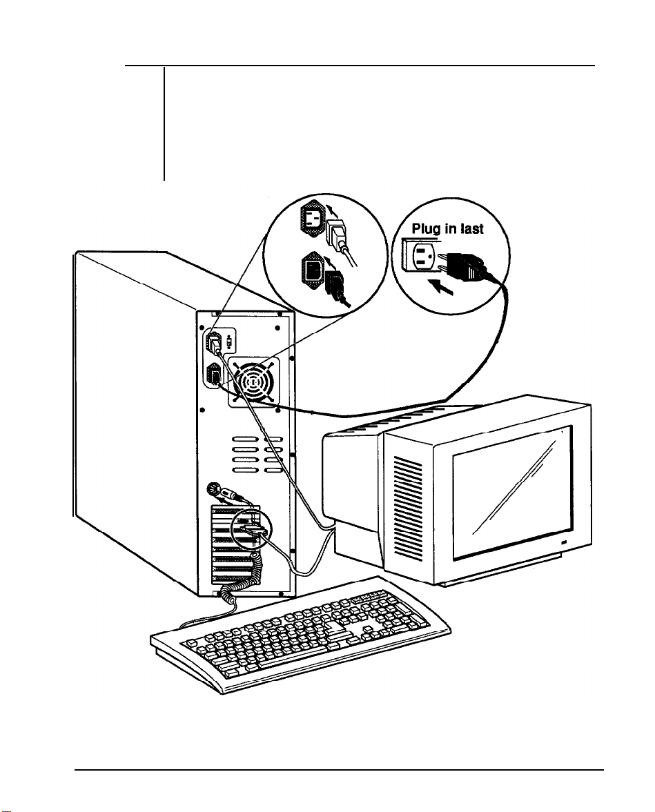
1-2 Quick Start
If you are an experienced user anxious to start using your computer,
observe the figure below to set up your personal computer. You will still
want to use this manual later as a reference book.
Note:
Save all packing materials in case you need to ship or resell your
computer in the future.
Figure 7-7: Quick Start
Chapter 7: System Overview
3
Page 20

1-3 Features
A brief description of your system is given below:
Compatibility with PC/AT
Intel® 80386 - 33 microprocessor
®
Optional 80387 - 33 or Weitek
WTL3167 - 33 coprocessors
Dual speed, 33MHz cache support in ultra-high speed and
emulation without cache in low speed, both switchable by
either software or hardware switches
Discrete components to complete cache functions
l/2/4/5/8 MB 32-Bit DRAM onboard
64/256 KB direct-mapped high-speed SRAM cache memory
Write-Back cache update for 0-watt state memory-write
operations
DTK, Phoenix, Award, or AMI BIOS support
Shadow RAM function for BIOS and video (for PEM-3301
motherboard)
One 32bit memory expansion slot for a PEI-306 32-bit
memory expansion card to provide up to 16MB of 32-bit
memory
Six 16-bit AT compatible I/O slots
One 8-bit AT compatible I/O slots
Standard 8MHz AT bus speed
DALLAS DS1287 chip to maintain system configuration and
real time clock setting
Keyboard and speaker attachments
Seven DMA channels
16 level interrupt
Three programmable timers
4 Chapter 7: System Overview
Page 21

1-4 Specifications
CPU
RAM
ROM
Expansion slots —
— Intel 386™ microprocessor, 33MHz
— Maximum - 16MB with PEI-306 RAM Card
Cycle Time - 80ns
Data Bus Bandwidth - 32 bits
— 32KB legal BIOS
one 32-bit, six 16-bit, one 8-bit
Disk Drive(s) —
— Hard disk drive: 3.5” halt high and 5.25” bay
Power Size —
Options —
165mm X 150mm X 150mm
Math coporocessor - Intel® 387-33
Floppy disk drive: 3.5” and 5.25” bay
®
- Weitek
3167-33
Chapter 1: System Overview
5
Page 22
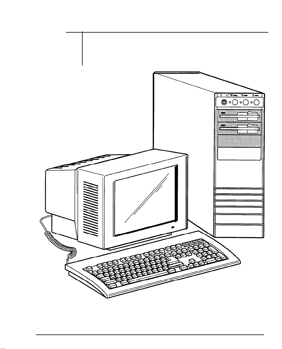
1-5 Example of a System Configuration
The basic system is pictured below. You may choose peripherals and
upgrades for the system as your needs require. Even if your system is
different from the one pictured, it should operate in the same basic
manner.
Figure 1-2: System Configuration
6
Chapter 7: System Overview
Page 23
1-6 System Unit
The system unit may house a motherboard, disk drives, a power supply
and optional expansion cards.
Figure 1-3: System Unit Case
Chapter 1: System Overview
7
Page 24
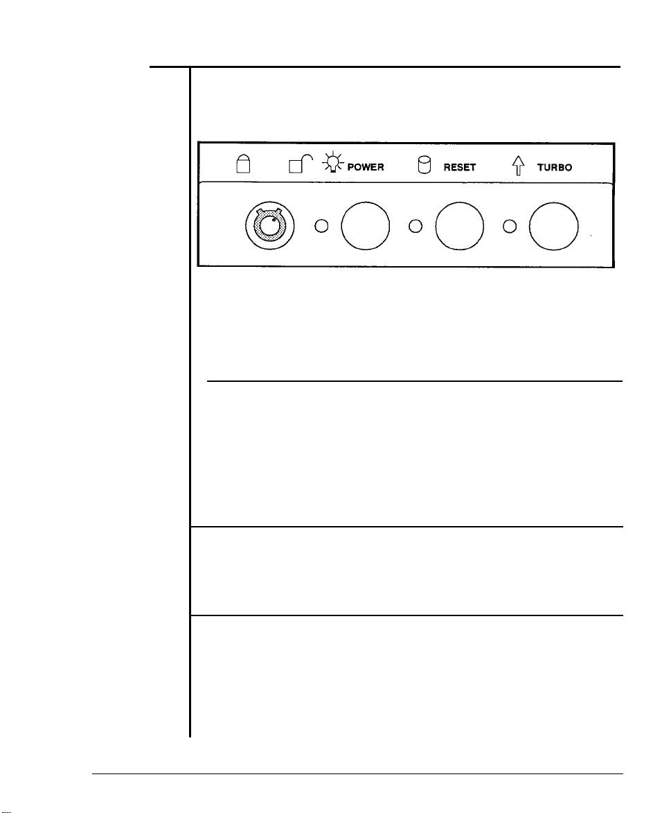
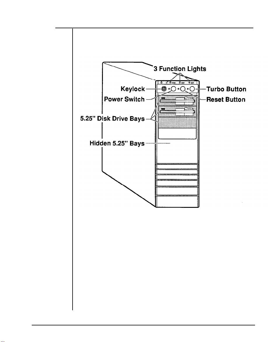
1-7 Control Panel
The control panel provides several useful functions which are explained below. You are likely to use the front panel frequently, so let’s
start there.
F
igure 1-4: Front Panel
Reset Button
The reset button allows you to restart the system without turning the
power off.
you encounter any problems while using unfamiliar software, you can
always restart quickly from the RAM test stage by pressing the reset
button. Note, however, that any data which have not been saved to disk
will be lost.
T
urbo Button
The Turbo button allows you to change the running speed of the
microprocessor to accommodate software requirements. Some
software applications must be run at a slow clock speed.
Indicator Lights
These lights indicate the operation status of your computer. The red
LED comes on when the hard disk is being accessed. The
is lit when the power is on. The yellow LED comes on when Turbo clock
peed is activated.
8
Chapter 7: System Overview
green
LED
Page 25
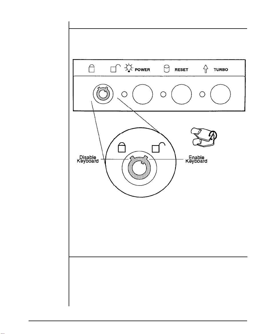
Keylock
Chapter 1: System Overview
The keylock enables or disables the keyboard. In the unlock mode the
keyboard is activated. In the lock mode the keyboard is disabled to
deny unauthorized users access to the computer.
Figure 1-5: Keylock and Two Security-Lock Keys
System Power Switch
The system power switch is located on the control panel.
You should always be certain that the power is turned off before
modifying the hardware configuration in any way.
9
Page 26
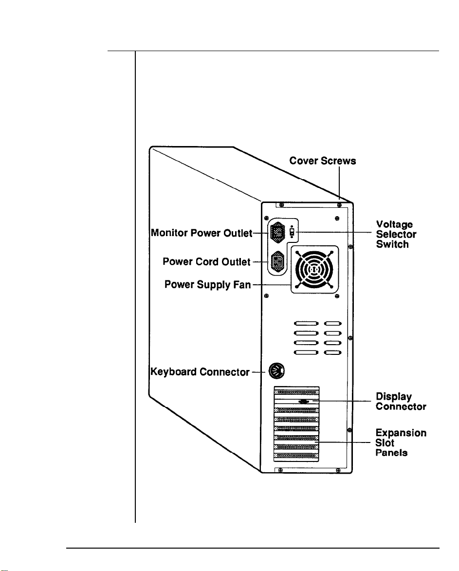
1-8 Rear Panel
1:
The rear panel has all the connections that lead from the system unit
to external peripherals and the power source. Turn off all power
switches before connecting or disconnecting cables/wires! En-
sure that cables/wires are attached to the external device first and
connected to the outlet unit later. Turn the system unit power switch off
before you plug the power cable into an electrical outlet.
10
Chapter
Figure 1-6: Rear Panel
System Overview
Page 27
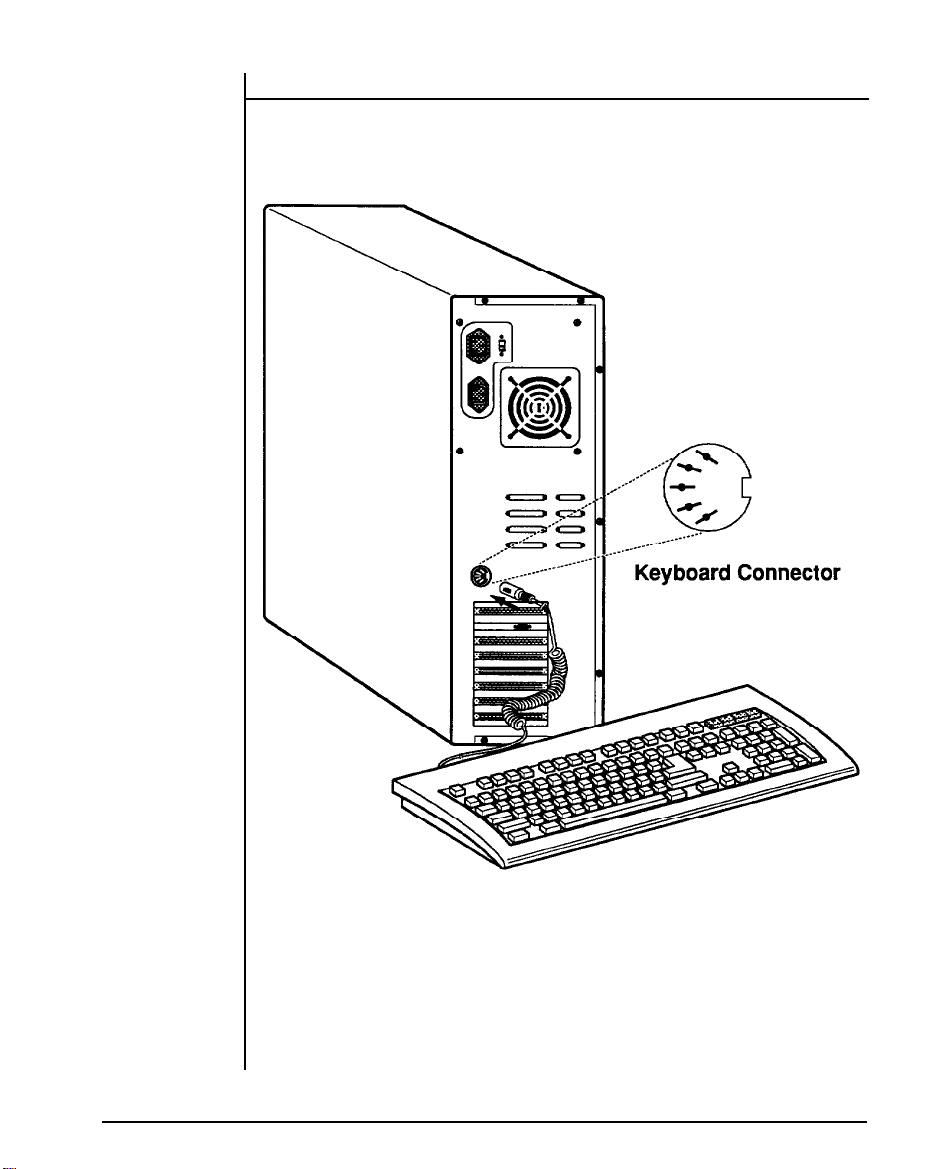
Keyboard Connector
The keyboard supplied with your system can be plugged into sockets
in front of the case. Plug the keyboard cable into the socket shown
below.
Figure 1-7: Connecting the Keyboard Cable
Chapter 7: System Overview
11
Page 28
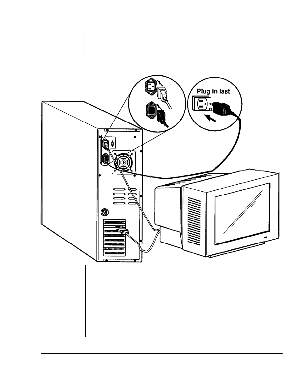
Power Cord Connector
The power supply has two receptacles: one supplies power to a
monitor; the other connects to the main power source.
Figure 1-8: System Power Cord
12
Chapter 1: System Overview
Page 29
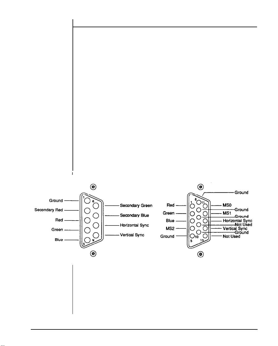
Display Port
You will also need to connect your monitor to the system unit at a
female display port in one of the expansion slots as shown on the
previous page.
To attach the monitor cable to the video port, plug the cable into the
port and screw the cable connector down securely.
Your computer gives you a wide range of video options to meet your
needs.
You have a wide choice of the following video standards.
- MGA (Monochrome Graphics Adapter) also referred to as
Hercules
- CGA (Color Graphics Adapter)
- EGA (Enhanced Graphics Adapter)
- VGA (Video Graphics Adapter)
Your monitor power plug may not fit the system unit’s monitor power
outlet. If not, connect the monitor cable to a wall electrical outlet.
Refer to the figures below for mono and color display connections.
Figure 1-9: Two Kind of Display Connectors
Chapter 1: System Overview
13
Page 30
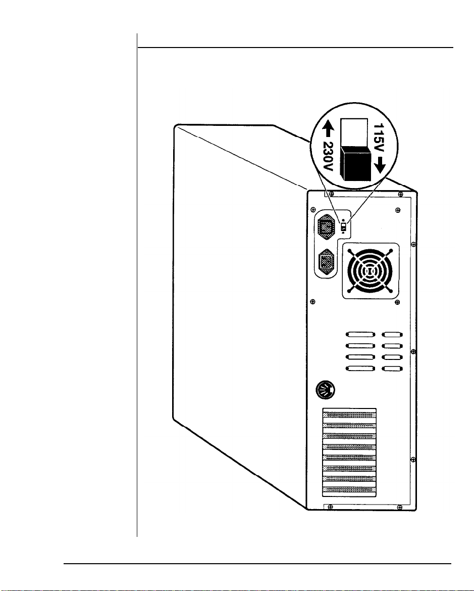
Power Voltage Setting
The system unit can run on either 115V or 230V as indicated in Figure
1-10. The voltage setting switch is located above the monitor power
outlet. Refer to the Table 1-1 for power cord specifications.
Figure 1-10: Voltage Switch
14
Chapter 1: System Overview
Page 31

Table 1-7: Power Cord Specifications
Chapter 1: System Overview
15
Page 32

1-9 Other Peripherals
To connect other peripherals (printers, modems, etc.) determine which
ports are to be used by referring to your expansion card manuals or
peripheral manuals. You may consult your dealer for more about the
expansion cards available for your system. Typical peripherals are
shown in Figure 1-11 below.
Figure 1-17: System Unit Connected to Peripherals
16
Chapter 1: System Overview
Page 33

1-10 Disk Drives
You can install up to six disks drives in the system unit of either with
5.25” or 3.5” sizes. More information about how to install disk drives
may be found in the chpater 6.
Figure 1-12: Installing Floppy and Hard Disk Drives
Chapter 1: System Overview
17
Page 34

Floppy Disk Drive
With a floppy disk drive you can format and use single, double-sided
or high-density floppy disks.
One double-sided 5.25” floppy disk can store up to 360KB of data.
One double-sided high density 5.25” floppy disk can store up to 1.2MB
of data. One standard 3.5” floppy disk can store up to 720KB of data.
One high density 3.5” floppy disk can store up to 1.44MB of data.
Table 1-2: Floppy Disk Specifications
Note:
Only high-density floppy disks can be formatted to high
capacities of either 1.2M for 5.25” or 1.44M for 3.5” floppy
disks. You may lose data if you use a low-density floppy disk
formatted for high density.
You can’t use a high-density disk in a low-density disk drive.
18
Chapter 1: System Overview
Page 35

Copy Protection
Chapter 1: System Overview
You can copy protect a disk to prevent accidental storage of informa-
tion or viral infection onto that disk by covering the notch on the side of
a 5.25” disk with a write-protect tab or by sliding the small tab on a 3.5”
disk to cover the hole. Refer to the figures below on how to copy protect
floppy disks.
When a disk is copy protected, you cannot add new information to it or
change any information on it. To enable copying to the disk, remove
the copy-protect tab.
Figure 1-13: Copy Protection for 3.5” Floppy Disk
Figure 1-14;
Copy Protection for 5.25” Floppy D
isk
19
Page 36

Hard Disks
Chapter 1: System Overview
Your system is very powerful and versatile. To make full use of all its
capabilities, it is best to use a hard disk. A hard disk can raise your
efficiency because the hard disk keeps programs and data available at
your fingertips.
Moreover, your system gives you a wide range of 3.5” half-high or 5.25’
half- and full-high hard disk(s) to meet your needs.
20
Page 37

1-11 Keyboard
Your keyboard has a set of function keys, cursor keys and a numeric
keypad. The figure below shows a typical keyboard. Refer to Chapter
4 for a more detailed description of the keyboard.
Figure 1-15:
Keyboard
Chapter 1: System Overview
21
Page 38

1-12 Maintaining Your Equipment
Read and follow carefully all the instructions and warnings in this
manual and on these products!
Only use a damp cloth to clean your system unit and
monitor case.
Do not use detergents!
Position your system unit, monitor and cables/wires away
from direct sunlight, moisture, dust, oil, and thoroughfares.
Do not submit your equipment to harsh jarring.
Ensure that all ventilation outlets are always free from
obstruction.
In the event of mechanical/power failure or damage, do not
attempt to repair the system unit, monitor/s, cables/wires.
Refer all such problems to experienced service personnel.
Ensure that the back of the system unit is at least 3” away
from anything that might obstruct the ventilation outlets and
cause overheating.
Ensure that the power source is grounded correctly. This
product is equipped with a 3-wire grounding-type plug. This
plug will only fit into a grounded power outlet.
It is recommended not to service this product yourself, as
opening and removing covers exposes dangerous voltage
areas and other risks. Refer all servicing to service per-
sons.
22
Chapter 1: System Overview
Page 39

Chapter 2
Setting Up
Your System
Page 40

Setting Up Your System
In this chapter you will learn about:
how to assemble a knocked-down system
how to upgrade your system
Setting up a system is easy and takes only a short time. If your dealer
has set up your system for you, you can skip this chapter. With the
system set up you are now ready to load your application software and
begin work. This chapter covers topics you are less likely to need to
know right away.
You may also skip this chapter unless you want to add to or alter your
system unit hardware yourself. It is recommended to have your dealer
or technician upgrade your system if you are a novice. Ensure that the
power is off before modifying the hardware configuration!
Note: Your motherboard will be either the PEM-3300 or the PEM-
3301. These two motherboards operate in the same basic manner. In
this manual, you may skip sections concerning the motherboard which
is not yours.
Chapter 2: Setting Up Your System
1
Page 41

2-1 PEM-3301 Motherboard
If your motherboard is the PEM-3301, the layout of your board will be
as pictured on the next page.
The PEM-3301 motherboard uses a cache memory subsystem providing a small amount of fast memory (SRAM) and a large amount of slow
memory (DRAM). This system is configured to so that all system
memory is fast memory and is fast enough to complete bus cycles with
no wait states. The cache memory provides high performance with no
wait states. The cache memory provides high performance with a cost
approaching that of DRAM.
The motherboard contains an Intel® 80386 processor, a 80387 math
coprocessor socket, BIOS chips and expansion slots. The figure on the
next page will familiarize you with the layout of the PEM-3301 Cache386 33MHz Mainboard.
Restrictions
Before installing the PEM-3301, we strongly recommend that you
follow the restrictions mentioned below:
Access Time:
l
27256 EPROM (BIOS) with 150ns access time
9
1 MbitX9 SIMM DRAM with 100ns access time
l
256KbitX9 SIMM DRAM with 80ns access time
9
16Kbit X 4 DIP Cache RAM (SRAM) with Data: 25ns, TAG:
15ns
All the SIMM RAM modules must have leads
.
2
Chapter 2: Setting Up Your System
Page 42

Figure 2-1: PEM-3301 Motherboard Layout
Chapter 2: Setting Up Your System
3
Page 43

Onboard System Memory Size
The PEM-3301 mainboard has two kinds of dual sockets for Cache
RAM and one kind of SIMM socket for DRAM.
Chip Insertion
Remember that when inserting chips/RAM modules, you must make
sure the notched or dotted end of the chip/RAM module is lined up with
the notched end of the socket. Gently push the chip/RAM module into
the socket, and be careful not to bend the pins. See the figures below:
Figure 2-2:
Figure 2-3: SIMM-Type DRAM
4
Chapter 2: Setting Up Your System
DIP-Type Cache RAM
Page 44

Switch Settings
The location of the six-switch DIP SW1 can be seen below. Each
switch has an ON and OFF position (usually the ON position is labeled,
the OFF position is not). SW1 should be set appropriately, based on
the following description.
Figure 2-4:
Table 2-1:
Note:
Total 32-bit memory means onboard 32-bit memory plus that on
The Six-Switch DIP SW1
Total 32-Bit Memory
the PEI-306 32-bit extended memory card.
Chapter 2: Setting Up Your System
5
Page 45

Memory Size (Bank 0, Bank 1)
Switch SW1 (4 - 5)
2MB
4MB
5MB
8MB
Table 2-2:
Note:
The switch setting of the onboard 32-bit memory must correspond to the physical memory installed onboard.
The switch setting of the PEI-306 must correspond to the
physical memory installed on the card.
If you don’t have a 16-bit memory extension card, the switch
setting for total 32-bit memory must be for an amount larger
than or equal to total installed memory (including onboard
32-bit memory and 32-bit memory on the PEI-306).
(1 MB, 1 MB)
(4MB, 0MB)
(1 MB, 4MB)
(4MB, 4MB)
Onboard 32-Bit Memory
For example, if the total memory installed is 8MB (4MB onboard and 4MB on the PEI-306), the switch setting for total
32-bit memory could be 8MB, 12MB or 16MB.
But if you use some other BIOS with the switch settings
(SW1 -1, SW1 -2, SW1 -3) for total 32-bit memory larger than
the physical DRAM installed, there will be an error message.
6
Chapter 2: Setting Up Your System
Page 46

This is caused by different methods of testing memory
among BIOSes. The solution is to set the switches for the
total 32-bit memory in accordance with the physical DRAM
installed. Most of the BlOSes do not have this problem.
If you want to add a 16-bit extension memory card to the
PEM-3301 mainboard, total 32-bit memory must match with
the switch setting for total onboard 32-bit memory plus that
on the PEI-306 32-bit extension memory card.
For example, if the switch setting for total 32-bit memory is
6MB, you’ll need 6MB (on the PEI-306 card and onboard
together in some combination) of actual system memory
before you can add a 16-bit extension memory card. Other-
wise, there will be an address conflict for the memory.
Video Selection
The switch SW1-6 is used to select color or monochrome display
modes. Refer to the figure below for the jumper settings.
Table 2-3:
SW1-6 Switch Settings
Chapter 2: Setting Up Your System
7
Page 47

Jumper Options and Connectors of PEM-3301 Mainboard
After the switches are set correctly, other attachments and jumper
option adjustments on the mainboard have to be made. See the
illustration below for the location of each of the jumpers and connectors. Most of the jumpers are preset at the factory.
Figure 2-5:
8
Chapter 2: Setting Up Your System
Location of Jumpers and Connectors of PEM-3301
Page 48

Jumper
A jumper is a kind of switch which uses a plastic cap with a metal
interior to connect (short) two pins. If a jumper needs to be left open,
you should save the cap for future use by covering one pin only of the
jumper. This has no effect on the function of the board while it keeps
the cap handy. The illustration below shows the side and top views of
a three-pin jumper in which pins two and three are shorted.
Top View
Figure 2-6: An Example of Three-Pin Jumper Setting
With the mainboard oriented in the direction shown in the illustration
above, the pins of each jumper are numbered from left to right in
ascending order.
Chapter 2: Setting Up Your System
9
Page 49

Quick Reference of Jumper Settings for PEM-3301 Mainboard
J1 — Keyboard Lock-/Power LED
J2 — Turbo LED
J3 — Reset connector
J4 — Speaker Connector
J5 — Power Supply Connector
J7 — Keyboard Connector
W1 — Coprocessor installation
short — not installed
open
— installed
W2 — Bank 0 DRAM Type Selection
1-2 short — (1Mbit x 9 SIMM DRAM)
2-3 short — (256Kbit x 9 SIMM DRAM)
W3 — Bank 1 DRAM Type Selection
1-2 short — (1Mbit x 9 SIMM DRAM)
2-3 short — (256Kbit x 9 SIMM DRAM)
W4- W5 — Cache Size Selection
1-2
2-3
W6 — Turbo Connector
1-2 short — normal (hardware)
open — Turbo (hardware)
2-3 short — speed toggled (software)
W7 — EPROM Type Selection
1-2
2-3
W8 — DMA Clock Speed Selection
short
open
10
Chapter 2: Setting Up Your System
short — 64KB cache memory
short — 256KB cache memory
short — 27256
short — 27512
— 8MHz DMA
— 6MHz DMA
Page 50

Jumpers for Cache and Main Memory Configuration
The tables on below indicate the jumper settings required for different
SRAM cache configurations.
The cache configurations are listed below:
64KB:
64KB cache (with eight 16Kbit X 4 cache SRAM chips and two
16Kbit X 4 tag SRAM chips)
256KB:
256KB cache (with eight 64Kbit X 4 cache SRAM chips and
two 64Kbit X 4 tag SRAM chips)
Refer to the figure on the next page for more information.
The following table lists the jumper settings required for each cache
memory configuration listed above.
Table 2-4: Cache Memory Configuration
Table 2-5 shows the jumper and switch settings for different onboard
memory (DRAM) configurations. Jumpers W2, W3 and switch SW1
are located on the mainboard.
To select the proper jumper setting for the RAM size that you want,
refer to the figures on the following pages.
Two banks of main memory are on the PEM-3301 mainboard, BANK
0 and BANK 1. Each bank accommodates the 32-bit wide data bus.
BANK 0 must be installed first.
Chapter
2: Setting Up Your System
11
Page 51

Figure 2-7: Cache Configurations
12
Chapter 2: Setting Up Your System
Page 52

Page 53

Figure 2-8: 1MB Total Onboard Memory
Figure 2-9: 2MB Total Onboard Memory
14
Chapter 2: Setting Up Your System
Page 54

Figure 2-10: 4MB Total Onboard Memory
Figure 2-11: 5MB Total Onboard Memory
Chapter 2: Setting Up Your System
15
Page 55

Figure 2-12: 8MB Total Onboard memory
16
Chapter 2: Setting Up Your System
Page 56

Installing Processor on Mainboard
The PEM-3301 mainboard supports the Intel 80386-33 processor. The
processor chip should be inserted into the processor socket (U12), with
the notch as shown below.
Figure 2-13:
Location of Processor
Chapter 2: Setting Up Your System
17
Page 57

Installing Numeric Coprocessor
If you process numeric data, a math coprocessor will make your work
more efficient.
The PEM-3301 mainboard supports the Intel 80387 and Weitek 3167
numeric coprocessors. The coprocessor chip should be inserted into
the coprocessor socket (U11), with the notch on the package oriented
in the same direction as the corresponding notch on the socket.
Jumper W1 should be SHORTED if an Intel 80387 or Weitek 3167 is
not installed and OPENED if either one of them is installed. The
position of the coprocessor sockets is shown below.
Figure 2-14:
18
Chapter 2: Setting Up Your System
Location of Coprocessors
Page 58

Shadow RAM
For higher performance, the PEM-3301 has two shadow RAM functions. Shadow RAM is one of the features of the PEM-3301. Your BIOS
or diskette will support the following:
A 64KB DRAM space allocated for system BIOS shadow
RAM
A 64KB DRAM space allocated for video BIOS shadow RAM
BIOS and video addresses are allocated for shadow RAM. Both
sections are 64KB in size. Refer to the table below for more information.
Figure 2-15: System and Video BIOS
Note that a reserved 128K DRAM space is allocated for shadow RAM.
You cannot use it for another purpose even if these functions are
disabled. Refer to the table below for more information.
Table 2-6:
Shadow RAM Control Port
Chapter 2: Setting Up Your System
19
Page 59

If you use DTK or Phoenix 1.1002 BIOS, you can enable or disable
these two shadow RAM functions through your BIOS setup.
If your BIOS does not support shadow RAM, you may use the program
on the diskette included with this mainboard to set up the shadow RAM
driver. Follow the steps below:
insert the diskette into drive A and enter a:.
Enter this command:
SH INST
Respond to the prompts on your screen.
The shadow RAM utility is now installed. Your AUTOEXEC.BAT file has
been modified by the installation program. The shadow RAM function
will automatically activate after you reboot your system.
If you want to update your shadow RAM utility, you may run the
“SHADOW.EXE” file and modify shadow RAM as you desire.
Note:
1. Because 128K of DRAM is reserved for shadow RAM, the switch
setting for the starting address on the PEI-306 should be xMB + 256KB
with x representing the onboard installed memory size.
2. if your adapter uses extended memory area as non-cacheabie
memory in the same way as dual-port memory, you have to locate the
non-cacheable memory after the cacheable area is set by means of
SW1-1, SW1-2 and SW1-3.
3. if your adapter BIOS is located at 0C8000H-0CFFFFH (within
0C0000H-0CFFFFH) and cannot be cached, you should move the
address to a non-cacheable area like 0D0000H-0DFFFFH or disable
video shadow function..
4. Cacheable area means physical 32-bit memory installed area and
shadow RAM area (0F0000H
installed.
20
Chapter 2: Setting Up Your System
— 0FFFFFH, 0C0000H — 0CFFFFH) if
Page 60

ROM Installation
To install the ROM chips, refer to the illustration below for the location
of the DIP sockets and ROM selection jumper W7 on the mainboard.
Figure 2-16: ROM Installation of PEM-3301 Mainboard
ROM access time is 15Ons.
Table 2-7: ROM BIOS Jumper
Chapter 2: Setting Up Your System
21
Page 61

2-2 PEM-3300 Motherboard
If your motherboard is the PEM-3300, the layout of your board be as
pictured on the next page.
The PEM-3300 motherboard uses a cache memory subsystem provid-
ing a small amount of fast memory (SRAM) and a large amount of slow
memory (DRAM). This system is configured to so that all system
memory is fast memory — fast enough to complete bus cycles with no
wait states. The cache memory provides high performance with no wait
states. The cache memory provides high performance with a cost
approaching that of DRAM.
The motherboard contains a Intel® 80386 processor, a 80387 math
coprocessor socket, BIOS chips and expansion slots. The figure on the
next page will familiarize you with the layout of the PEM-3300 Cache-
386 33MHz Mainboard.
Restrictions
Before installing the PEM-3300, we strongly recommend that you
follow the restrictions mentioned below:
Access Time:
l
27256 EPROM (BIOS) with 150ns access time
l
1MbitX9 SIP DRAM with 100ns access time
l
256KbitX9 SIP DRAM with 80ns access time
l
256KbitX4 DIP DRAM with 100ns access time
.
256KbitXl DIP DRAM with 80ns access time
l
16Kbit X 4 DIP Cache RAM (SRAM) with 20ns access time
l
All the SIP RAM modules must have leads
22
Chapter 2: Setting Up Your System
Page 62

Figure 2-17: PEM-3300 Motherboard Layout
Chapter 2: Setting Up Your System
23
Page 63

Onboard System Memory Size
The PEM-3300 mainboard has two kinds of dual sockets — one for
Cache RAM and a SIP socket for DRAM.
Chip Insertion
Remember that when inserting chips/RAM modules, you must make
sure the notched or dotted end of the chip/RAM module is lined up with
the notched end of the socket. Gently push the chip/RAM module into
the socket, and be careful not to bend the pins. See the figures below:
Figure 2-18: DIP-Type Cache RAM
Figure 2-19: SIP-Type DRAM
Chapter 2: Setting Up Your System
24
Page 64

Switch Settings
Chapter 2: Setting Up Your System
The location of the six-switch DIP SW1 can be seen below. Each
switch has an ON and OFF position (usually the ON position is labeled,
the OFF position is not). SW1 should be set appropriately, based on
the following description.
Side View
Figure 2-20: The Six-Switch DIP SW1
Top View
Table 2-8: Total 32-Bit Memory
Note:
Total 32-bit memory means onboard 32-bit memory plus that on
the PEI-306 32-bit extended memory card.
25
Page 65

Table 2-9: Onboard 32-Bit Memory
Note:
The switch setting for onboard 32-bit memory must match
the physical memory installed onboard.
The switch setting of the PEI-306 must correspond to the
physical memory installed on the card.
If you don’t have a 16-bit memory extension card in your system, the switch setting for total 32-bit memory must be for
an amount larger than or equal to total installed memory (including onboard 32-bit memory and 32-bit memory on the
PEI-306).
For example, if the total memory installed is 8MB (4MB onboard and 4MB on the PEI-306), the switch setting for total
32-bit memory could be 8MB, 12MB or 16MB.
But if you use some other BIOS with the switch settings
(SW1 -1, SW1 -2, SW1 -3) for total 32-bit memory larger than
the physical DRAM installed, there will be an error message.
26
Chapter 2: Setting Up Your System
Page 66

This is caused by different methods of testing memory
among BIOSes. The solution is to set the switches for the
total 32-bit memory in accordance with the physical DRAM
installed. Most of the BlOSes do not have this problem.
If you want to add a 16-bit extension memory card to the
PEM-3300 mainboard, you have to fill the total 32-bit
memory in accordance with the switch setting for total onboard 32-bit memory plus that on the PEI-306 32-bit extension memory card.
For example, if the switch setting for total 32-bit memory is
6MB, you’ll need 6MB (in some combination on the PEI-306
card and on the motherboard and 2MB) in your system
before you can add a 16-bit extension memory card. Other-
wise, there will be an address conflict for the memory.
Video Selection
Switch SW1-6 is used to select color or monochrome display modes.
Refer to the figure below for the jumper settings.
Table 2-10:
SW1-6 Switch Settings
Chapter 2: Setting Up Your System
27
Page 67

Jumper Options and Connectors of PEM-3300 Mainboard
Chapter 2: Setting Up Your System
I
After the switches are set correctly, other attachments and jumper
option adjustments on the mainboard have to be made. See the
illustration below for the location of each of the jumpers and connec-
tors. Most of the jumpers are preset at the factor).
Figure 2-21:
28
Location of Jumpers and Connectors of PEM-3300
Page 68

Jumper
A jumper is a kind of switch which uses a plastic cap with a metal
interior to connect (short) two pins. If a jumper needs to be left open,
you should save the cap for future use by covering one pin only of the
jumper. This has no effect on the function of the board while it keeps
the cap handy. The illustration below shows the side and top views of
a three-pin jumper in which pins two and three are shorted.
Figure 2-22: Three-Pin Jumper Setting Example
With the mainboard oriented in the direction shown in the illustration
above, the pins of each jumper are numbered from left to right in
ascending order.
Chapter 2: Setting Up Your System
29
Page 69

Quick Reference of Jumper Settings for PEM-3300 Mainboard
J1 — Keyboard Lock/Power LED
J2 — Reset Connector
J3 — Speaker Connector
J4 — Turbo LED Connector
J5 — Turbo Connector
1-2
short
-Normal (hardware)
— Turbo (hardware)
open
2-3
short — speed toggled (software)
J7 — Keyboard Connector
J8 — Power Supply Connector
W1 - W6 — Bank Selection
1-2 short — bank 0
2-3 short — bank
1
W7 — DRAM Type of Bank 0
1-2
2-3
— (1Mbit x 9 SIP DRAM) or (1Mbit x 1 DIP DRAM)
short
short
— (256Kbitx9 SIP DRAM) or (256Kbitx4 DIP RAM)
W8 — DRAM Type of Bank 1
1-2 short — (1Mbit x 9 SIP DRAM) or (1Mbit x 1 DIP DRAM)
2-3
short
— (256Kbitx9 SIP DRAM) or (256Kbitx4 DIP RAM)
W9 - WI0 — Cache Size Selection
1-2
short — 64KB cache memory
2-3
short — 256KB cache memory
W14 — Math Coprocessor
short
-not installed
— installed
open
30 Chapter 2: Setting Up Your System
Page 70

Jumpers for Cache and Main Memory Configuration
The tables on below indicate the jumper settings required for different
SRAM cache configurations.
The cache configurations are listed below:
64KB: 64KB cache (with eight 16Kbit X 4 cache SRAM chips and two
16Kbit X 4 tag SRAM chips)
256KB: 256KB cache (with eight 64Kbit X 4 cache SRAM chips and
two 64Kbit X 4 tag SRAM chips)
Refer to the figure on the next page for more information.
The following table lists the jumper settings required for each cache
memory configuration listed above.
Jumpers W9 & W10
Cache Memory Configuration
64KB
256KB
Table 2- 11: Cache Memory Configuration
Table 2-12 shows the jumper and switch settings for different onboard
memory (DRAM) configurations. Jumpers W1-6, W7, W8 and switch
SW1 are located on the mainboard.
To select the proper jumper setting for the RAM size that you want,
refer to the figures on the following pages.
Two banks of main memory are on the PEM-3300 mainboard, BANK
0 and BANK 1. Each bank accommodates the 32-bit wide data bus.
BANK 0 must be installed first.
Chapter 2: Setting Up Your System
31
Page 71

64KB cache
Figure 2-23: Cache Configurations
256KB cache
32
Chapter 2: Setting Up Your System
Page 72

Table 2-12: DRAM Configurations
Chapter 2: Setting Up Your System
33
Page 73

Figure 2-24:
1MB Total Onboard Memory — Configuration A
Figure 2-25:
34
Chapter 2: Setting Up Your System
1MB Total Onboard Memory — Configuration B
Page 74

Figure 2-26: 2MB Total Onboard Memory — Configuration A
Figure 2-27: 2MB Total Onboard Memory — Configuration B
Chapter 2: Setting Up Your System
35
Page 75

Bank 0 = (266Kbit x 9 RAM module) x 4 pieces
Figure 2-28: 2MB Total Onboard memory — Configuration C
36 Chapter 2: Setting Up Your System
Page 76

Bank 0 = 1Mbit x 36 pieces
Figure 2-29: 4MB Total Onboard memory — Configuration A
Figure 2-30: 4MB Total Onboard memory — Configuration B
Chapter 2: Setting Up Your System
37
Page 77

Figure 2-31: 5MB Total Onboard memory
Bank 0 = 1Mbit x 36 pieces
Bank 1 = (1Mbit x 9 RAM module) x 4 pieces
Figure 2-32: 8MB Total Onboard memory
38
Chapter 2: Setting Up Your System
Page 78

Installing Processor
The PEM-3300 mainboard supports the Intel 80386-33 processor. The
processor chip should be inserted into the processor socket (U161),
with the notches aligned as shown below.
Figure 2-33:
Location of Processor
Chapter 2: Setting Up Your System
39
Page 79

Installing Numeric Coprocessor
If you process numeric data, a math coprocessor will make your work
more efficient.
The PEM-3300 mainboard supports the Intel 80387 and Weitek 3167
numeric coprocessors. The coprocessor chip should be inserted into
the coprocessor socket (U160), with the notch on the package oriented
in the same direction as the corresponding notch on the socket. The
jumper W1 should be SHORTED if an Intel 80387 or Weitek 3167 is
not installed and OPENED if either one of them is installed. The
position of the coprocessor sockets is shown below.
Figure 2-34:
40
Chapter 2: Setting Up Your System
Location of Coprocessors
Page 80

2-3 Installation
The time may come when you want to upgrade your system. To do so,
you may need to remove the cover of the unit. This is easily ac-
complished with the following tools: a small flat-blade screwdriver and
a small Phillips screwdriver.
Be sure that the power to the system is switched OFF before you open
the case. Your computer interior is as shown below:
Figure 2-35: Unpacking Your Main System
Chapter
2: Setting Up Your System
41
Page 81

2-4 Connection to Power Supply
If your power supply has not been attached to your motherboard, you
may need to attach the power supply cable to the mainboard at the
connector beside the power on the motherboard. In this case, you
should connect cables on the power supply to 2 six-pin connectors.
You may also need to attach the four-pin connectors for disk drives.
Be sure the four black wires of the power supply cables are located in
the middle of the power connectors. Refer to the figure below. Pin 1 is
numbered in the picture for your convenience.
Figure 2-38: Connecting to a Power Supply
42
Chapter 2: Setting Up Your System
Page 82

The pinouts for the power supply connectors
are as follows:
Table 2-13: Power Supply Pinouts
Once you have completed connecting the cables the RAM Card is
installed and ready to go. If you have nothing else left to do, close the
case according to the instructions in your system manual.
Chapter 2: Setting Up Your System
43
Page 83

Page 84

Page 85

Operating Your System
In this chapter you will learn:
the basics of system BIOS
a few MS-DOS functions
The software that your system will use falls into two categories. First
there is the operating system, the language that tells the system what
to do. The operating system this computer uses is Microsoft
Corporation’s MS-DOS, the world’s most widely used operating system for PC/XT/ATs.
Next, there is the application software that you use for work and play.
Finding application software is a simple matter of going to your nearest
PC store.
Note: This is not an MS-DOS manual. It mentions only a few of the
DOS functions available. To learn more about DOS, refer to your
MS-DOS User’s Guide and Reference
tem.
manual included with the sys-
Chapter 3: Operating Your System
1
Page 86

3-1 An Introduction to DOS
DOS stands for Disk Operating System. This is a set of commands
used to control the operations of a computer and its peripheral components. DOS makes it easy for you to use applications and create and
manage files on your computer. DOS also lets you use devices with
the computer.
Loading DOS
Loading DOS means to copy all the DOS programs into the computer’s
electronic memory. You should follow the instructions below to start
DOS.
Starting DOS when the computer is off
Insert DOS disk 1 into disk drive A and close the drive lever.
Turn on the computer and respond to the prompts displayed
on the monitor.
Starting DOS with the Computer on
If you don’t have a DOS disk in your disk drive when you start your
computer, you will see the following message on the screen following
the RAM test:
Non-system disk or disk error
Replace and strike any key when ready
You should:
Insert DOS disk 1 into disk drive A and close the drive lever.
Press the reset button on your front panel (hardware reset)
or hold down the <Ctrl>, <Alt> and
time (software reset) to reboot your system.
Starting DOS from your hard disk
If you have a hard disk, install
automatically whenever you turn on the power.
System Messages
Refer to your
mation on system messages.
2
Chapter 3: Operating Your System
<Del>
keys at the same
DOS
on the disk. Your PC will boot
MS-DOS User’s Guide and Reference
manual for infor-
Page 87

3-2 Setup Utility
A system setup program is included in your BIOS on the motherboard.
The setup program is used to key in the configuration you want for your
system. Specifically, you can set the date, time, base memory, expansion memory, number of floppy and hard disk drives and display
configuration as well as get information on hard disk types. Your
system BIOS is fully compatible with IBM BIOS. In addition, many
special functions are supported:
High density disk drives
A password
User-defined hard disk type
System utilities
-timer and calculator
The setup program is simple to use. It is extremely important that you
respond correctly to prompts about your computer.
System Setup Program
You will need to run the setup program in the following situations:
your computer is turned on for the first time,
when adding or removing any hardware, or
when the rechargeable battery is dead.
If the battery for the CMOS chip is dead or the system configuration
was keyed in incorrectly, you will have to rerun the system setup
program. The computer will give you this screen message:
Press Fl key to enter SETUP program or
press any other key to continue
Pressing <F1> will automatically start the SETUP program. You can
also use the DOS DEBUG command as follows:
A:> DEBUG
-g=F000:FF60
<Enter>
<Enter>
Chapter 3: Operating Your System
3
Page 88

If you reconfigure your system, you will need to enter the setup
program. When you restart the system, press the <ESC> key quickly
just after the RAM test. If you miss the chance to do so, press the
hardware reset switch, or just press the software reset switch
<Alt> and
<Del>
simultaneously to enter the setup program. Before the
<Ctrl>,
setup program appears, the following message will be shown on the
screen:
SETUP utility will be starting
When the RAM test is completed, the SETUP program will take over.
Once you have entered the SETUP program, you will see the following
initial screen:
(C) COPYRIGHT DATATECH ENTERPRISES CO., LTD 1988.
CHOOSE ITEM NUMBER : [ ]
ROM SETUP PROGRAM VERSION 1.02
1. SET UP SYSTEM CONFIGURATION.
2. PREFORMAT HARD DISK.
3. SET UP BUILT-IN UTILITY.
4. SET UP PASSWORD.
5. SET UP USER-DEFINED HARD DISK TYPE.
9. QUIT SETUP PROGRAM.
Figure 3-1: Initial Screen
4
Chapter 3: Operating Your System
Page 89

FoIlowing are examples of the setup program screen and prompt
windows you will see in using the program. If you choose item 1 from
The screen on the previous page to configure your system, the following
will appear. You should correctly respond to prompts about your
computer.
Figure 3-2: Setup Program Screen
Chapter 3: Operating Your System
5
Page 90

Once you have entered all appropriate information and exited by
Chapter 3: Operating Your System
choosing item 9, you will be asked to confirm that the configuration
data are correct.
F
igure 3-3: Before Restarting
If at a later date you alter the configuration of your system, you will
need to go through the program again and make the appropriate
changes.
6
Page 91

Calculator
The calculator can be used if you press <Ctrl>, <Alt>, <5> (on the key
pad). Pressing <Esc> will exit this utility.
Note that these two utilities can be used in the 80-column text display
mode only. Refer to the figure below for the Calculator.
Figure 3-4:
Calculator
Chapter 3: Operating Your System
7
Page 92

3-3 DOS Operations
Following is a brief explanation of a few DOS functions. If you want a
detailed explanation of all the DOS commands, refer to your DOS user
manual.
Starting MS-DOS
If you are using a hard disk with DOS already installed, the computer
will “boot” or start itself.
If you are using a floppy disk drive, insert the DOS system disk in drive
“A” and switch on your computer. You will see a message similar to the
following:
Current date is Fri
Enter new date (MM-DD-YY):
For the new date, key in the month, day and year, separated by
hyphens. Press <Enter>.
Time is displayed and corrected as follows:
Current time is 0 : 02 : 15.00
Enter new time: 2:20
Your computer is now booted and ready to run application programs.
01-01-1990
8 Chapter 3: Operating Your System
Page 93

Formatting Disk
You must format a floppy disk before it can be used.
Formatting high-density disk:
To format a high-density disk, type the following at the drive prompt:
C>Format A:
<Enter>
After your disk has been formatted, you will see the following prompt:
Format another diskette (Y/N)?
Press <N> if you do have nothing else to be formatted.
Formattlng a low-density disk:
To format a lowdensity disk, type the following at the drive prompt:
C>Format A:/4
<Enter>
After your disk has been formatted, you will see the following prompt:
Format another diskette (Y/N)?
Press <N> if you have nothing else to be formatted.
Chapter 3: Operating Your System
9
Page 94

Backing up your Diskettes and Files
In order not to lose your files through disk damage or accidental
deletion it is important to back up all your files and diskettes regularly.
Backing up a diskette on a two-floppy disk drive system:
At the A> prompt type the following
A> diskcopy a: b:
Press
<Enter>
and respond to the prompts on your screen.
Backing up a diskette on a single floppy disk drive system:
At the A> prompt type the following-
A> diskcopy
Press
<Enter>
and respond to the prompts on your screen.
After your target disk has been copied, you will see the following
prompt:
Copy another diskette (Y/N)?
Press <N> if you have nothing else to be copied.
Backing up a file:
To back up a single file, key in the backup command and directory as
follows:
70
Chapter 3: Operating Your System
A>backup <path> <filename> <drive>/A
Page 95

Deleting your Diskettes and Files
You may want to erase diskettes or unnecessary files to make room for
other data.
Erasing a diskette:
To erase a whole directory of files, type the following at the drive
prompt:
A>del *,*
<Enter>
All the files in the open directory are now erased.
Deleting a file:
To delete a single file, type the following at the drive prompt:
A>del filename.ext
<Enter>
Chapter 3: Operating Your System
11
Page 96

Listing Disk Files
If you want to find out what files are on a disk, you can list its directory
by using the
<DIR>
command.
If you want to display the directory of
the disk in drive A, you would use the following command:
DIR A:
After you hit the enter key, all the file information will be displayed on
the screen.
If you use the
<DIR>
command without a drive letter, MS-DOS lists the
directory of the disk which was most recently accessed.
There are three ways to stop the screen from scrolling:
pressing the <Ctrl> and the <S> keys simultaneously
pressing
typing
<Pause>
DIR/P to
see one screen each time
12
Chapter 3: Operating Your System
Page 97

3-4 Hard Disk Drive Format
A hard disk must be formatted before it can be read from or written to.
If your hard disk requires this, you should carry out the following steps:
Step 1 — Preformat
The preformat utility is supplied by the system BIOS. You can press
key quickly just after the RAM test to enter the SETUP program.
<Esc>
Choose item 2 from the initial screen to preformat a hard disk. See
Figure 3-1.
Step 2 — Partition
This process creates DOS partitioning on a preformatted hard disk
drive. The DOS command “FDISK” handles this partitioning process.
Insert your DOS diskette in drive A and type a: to get the A prompt.
Then type:
the
A> FDISK
<J>
The “FDISK” command displays a series of menus to help you partition
your hard disk for MS-DOS. With the “FDISK” command, you can...
create a primary partition,
create an extended partition,
change the active partition,
delete a partition,
display partition data, and
select the next fixed disk drive for partitioning on a system
with multiple fixed disks.
If your hard disk is 40MB, you may have partitions of up to 33MB in
size. 33MB is the maximum space for a partition allowed by DOS.
For more information on how to use create DOS partitions, see
dix D
in the
MS-DOS User’s Guide and Reference.
Appen-
Chapter 3: Operating Your System
13
Page 98

Step 3 — Format
The DOS command “Format” verifies the media and moves the system
file onto the hard disk drive. The command should be keyed in as:
A> FORMAT C:/S
If you want to make two partitions, you have to format the new partition
as follows:
A> FORMAT D:
If you want to use partition 1 (drive C) to start DOS, you have to specify
the /S option when formatting the disk. You can use this system disk
to boot your system later.
Note that you don’t need to perform this procedure if you want to use
new partitions for other operating systems like Xenix, Novell or Unix.
Refer to their manuals for details.
14
Chapter 3: Operating Your System
Page 99

3-5 Helpful Hints
This chapter ends with a few hints
-they may save you some time or
help you as you use your computer.
Make copies of your diskettes regularly.
To make sure that a command works, you should:
-
Check your typing (make sure you don’t confuse \ with /).
- Have the correct diskette in the drive.
- Check the contents of the diskette with the DIR command.
- Specify the correct diskette drive.
- Remember to include the colon (:) when specifying the
name of a drive.
- Spell the filename correctly
- Use the appropriate extension (such as .doc or .exe)
Refer to the DOS Reference for additional information if a
command still doesn’t work.
Print contents of a disk (if you have a printer) and keep the
list with the diskette.
All commands (except DISKCOPY and DISKCOMP) are
files that will work on both diskettes and hard disk drives.
The date and time shown with each directory entry are the
date and time of the last addition or change to that file. The
date and time are not changed during a COPY or a DISKCOPY.
Chapter 3: Operating Your System
15
Page 100

Chapter 4
Keyboard
 Loading...