

Page 1
SERVICE MANUAL
Large Format Color Inkjet Printer
Epson Stylus Pro 4900
Epson Stylus Pro 4910
Confidential
SEIJ10007
Page 2

Confidential
PRECAUTIONS
Precautionary notations throughout the text are categorized relative to 1) Personal injury and 2) Damage to equipment.
DANGER Signals a precaution which, if ignored, could result in serious or fatal personal injury. Great caution should be exercised in performing
procedures preceded by DANGER Headings.
WARNING Signals a precaution which, if ignored, could result in damage to equipment.
The precautionary measures itemized below should always be observed when performing repair/maintenance procedures.
DANGER
1. ALWAYS DISCONNECT THE PRODUCT FROM THE POWER SOURCE AND PERIPHERAL DEVICES PERFORMING ANY MAINTENANCE OR
REPAIR PROCEDURES.
2. NO WORK SHOULD BE PERFORMED ON THE UNIT BY PERSONS UNFAMILIAR WITH BASIC SAFETY MEASURES AS DICTATED FOR ALL
ELECTRONICS TECHNICIANS IN THEIR LINE OF WORK.
3. WHEN PERFORMING TESTING AS DICTATED WITHIN THIS MANUAL, DO NOT CONNECT THE UNIT TO A POWER SOURCE UNTIL
INSTRUCTED TO DO SO. WHEN THE POWER SUPPLY CABLE MUST BE CONNECTED, USE EXTREME CAUTION IN WORKING ON POWER
SUPPLY AND OTHER ELECTRONIC COMPONENTS.
4. WHEN DISASSEMBLING OR ASSEMBLING A PRODUCT, MAKE SURE TO WEAR GLOVES TO AVOID INJURY FROM METAL PARTS WITH
SHARP EDGES.
WARNING
1. REPAIRS ON EPSON PRODUCT SHOULD BE PERFORMED ONLY BY AN EPSON CERTIFIED REPAIR TECHNICIAN.
2. MAKE CERTAIN THAT THE SOURCE VOLTAGES IS THE SAME AS THE RATED VOLTAGE, LISTED ON THE SERIAL NUMBER/RATING
PLATE. IF THE EPSON PRODUCT HAS A PRIMARY AC RATING DIFFERENT FROM AVAILABLE POWER SOURCE, DO NOT CONNECT IT TO
THE POWER SOURCE.
3. ALWAYS VERIFY THAT THE EPSON PRODUCT HAS BEEN DISCONNECTED FROM THE POWER SOURCE BEFORE REMOVING OR
REPLACING PRINTED CIRCUIT BOARDS AND/OR INDIVIDUAL CHIPS.
4. IN ORDER TO PROTECT SENSITIVE MICROPROCESSORS AND CIRCUITRY, USE STATIC DISCHARGE EQUIPMENT, SUCH AS ANTI-STATIC
WRIST STRAPS, WHEN ACCESSING INTERNAL COMPONENTS.
5. REPLACE MALFUNCTIONING COMPONENTS ONLY WITH THOSE COMPONENTS BY THE MANUFACTURE; INTRODUCTION OF SECONDSOURCE ICs OR OTHER NON-APPROVED COMPONENTS MAY DAMAGE THE PRODUCT AND VOID ANY APPLICABLE EPSON WARRANTY.
6. WHEN AIR DUSTER IS USED ON THE REPAIR AND THE MAINTENANCE WORK, THE USE OF THE AIR DUSTER PRODUCTS CONTAINING
THE INFLAMMABLE GAS IS PROHIBITED.
7. MAKE SURE AN ANTIVIRUS SOFTWARE IS INSTALLED ON THE COMPUTER USED FOR SERVICE SUPPORT. BE SURE TO HAVE THE
LATEST VIRUS DEFINITION FILE FOR THE SOFTWARE.
Page 3

About This Manual
This manual describes basic functions, theory of electrical and mechanical operations, maintenance and repair procedures of the printer. The instructions and procedures included
herein are intended for the experienced repair technicians, and attention should be given to the precautions on the preceding page.
Manual Configuration
This manual consists of six chapters and Appendix.
CHAPTER 1.PRODUCT DESCRIPTIONS
Provides a general overview and specifications of the product.
CHAPTER 2.TROUBLESHOOTING
Describes the step-by-step procedures for the troubleshooting.
CHAPTER 3.DISASSEMBLY / ASSEMBLY
Describes the step-by-step procedures for disassembling and assembling the product.
CHAPTER 4.ADJUSTMENT
Provides Epson-approved methods for adjustment.
CHAPTER 5.MAINTENANCE
Provides preventive maintenance procedures and the lists of Epson-approved lubricants and
adhesives required for servicing the product.
CHAPTER 6.APPENDIX
Provides the following additional information for reference:
• Connectors
• Panel Menu Maps
Confidential
Page 4

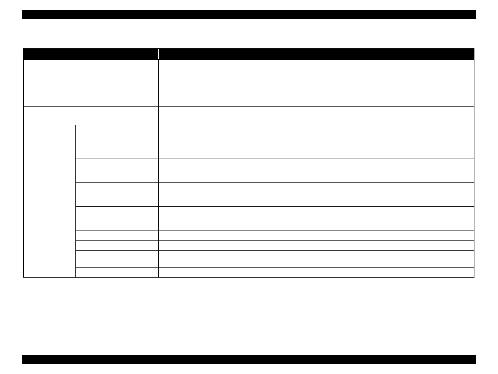
Symbols Used in this Manual
Lubrication Lubrication
Various symbols are used throughout this manual either to provide additional information on a specific topic or to warn of possible danger present during a procedure or an action.
Be aware of all symbols when they are used, and always read NOTE, CAUTION, or WARNING messages.
Indicates an operating or maintenance procedure, practice or condition that is necessary to keep the product’s quality.
Indicates an operating or maintenance procedure, practice, or condition that, if not strictly observed, could result in damage to, or destruction of, equipment.
May indicate an operating or maintenance procedure, practice or condition that is necessary to accomplish a task efficiently. It may also provide additional
information that is related to a specific subject, or comment on the results achieved through a previous action.
Indicates an operating or maintenance procedure, practice or condition that, if not strictly observed, could result in injury or loss of life.
Indicates that a particular task must be carried out according to a certain standard after disassembly and before re-assembly, otherwise the quality of the components
in question may be adversely affected.
Indicates that lubrication is needed for the parts after disassembly, when doing a maintenance or replacing a part with a new one.
Confidential
Page 5

Confidential
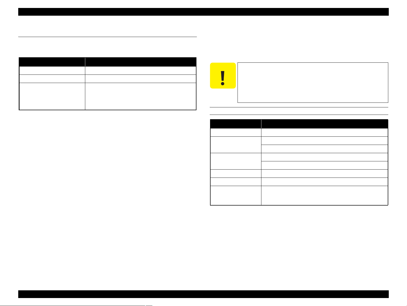
Revision Status
Revision Date of Issue Description
A October 8, 2010 First release
Page 6

Epson Stylus Pro 4900/Epson Stylus Pro 4910 Revision A
Contents
Chapter 1 PRODUCT DESCRIPTION
1.1 Product Description . ........................................................................................... 11
1.2 Basic Specifications . ........................................................................................... 13
1.2.1 Basic Specifications . .................................................................................. 13
1.2.2 Electric Specifications . .............................................................................. 13
1.2.3 Ink Specifications ...................................................................................... 14
1.2.4 General Specifications . .............................................................................. 14
1.2.5 Reliability/Durability . ................................................................................ 15
1.3 Printing Specifications ........................................................................................ 16
1.3.1 Paper Feed Specifications .......................................................................... 16
1.3.2 Paper Specification .................................................................................... 16
1.3.3 Printable Area ............................................................................................ 23
1.3.4 Borderless Printing Specification .............................................................. 24
1.3.5 Cutting of Roll Paper . ................................................................................ 25
1.4 Hardware Specifications . .................................................................................... 26
1.4.1 Dimensions and Weight . ............................................................................ 26
1.4.2 Part Names . ................................................................................................ 27
1.5 Control Panel . ..................................................................................................... 29
1.5.1 Setup Menu . ............................................................................................... 34
1.5.2 Maintenance Mode .................................................................................... 42
1.5.3 Serviceman Mode ...................................................................................... 43
Chapter 2 TROUBLE SHOOTING
2.1 Overview ............................................................................................................ 47
2.1.1 Preliminary Check ..................................................................................... 47
2.1.2 Troubleshooting Procedure . ....................................................................... 48
2.1.3 Procedure after troubleshooting . ................................................................ 48
2.2 Remedies for Maintenance Requests .................................................................. 49
2.3 Remedies for Service Call Error ......................................................................... 51
2.4 Remedies for Error Messages related to SpectroProofer ................................... 74
2.5 Remedies for Print Quality Troubles . ................................................................. 76
2.6 Trouble on Paper Feeding .................................................................................. 83
2.7 Printer does not Operate . .................................................................................... 87
2.8 Abnormal Operations . ........................................................................................ 89
2.9 Problems on SpectroProofer . .............................................................................. 91
2.10 Trouble on Service Program . ............................................................................ 94
2.11 Trouble on NVRAM Viewer . ........................................................................... 97
2.12 Trouble on Colorimetric Calibration Adjustment program .
............................. 98
Chapter 3 DISASSEMBLY & ASSEMBLY
3.1 Overview . ......................................................................................................... 100
3.1.1 Precautions . .............................................................................................. 100
3.1.2 Cautions after assembling . ....................................................................... 102
3.1.3 Orientation Definition . ............................................................................. 102
3.1.4 Recommended Tools ............................................................................... 103
3.2 Parts Diagram . .................................................................................................. 104
3.3 Disassembly Flowchart .................................................................................... 115
3.4 Disassembly and Assembly Procedure . ............................................................ 124
3.4.1 Preparation for servicing ......................................................................... 124
3.4.2 Housing . ................................................................................................... 133
3.4.3 Electric Circuit Components ................................................................... 152
3.4.4 Carriage Mechanism . ............................................................................... 168
3.4.5 Paper Feed Mechanism . ........................................................................... 182
3.4.6 ASF Unit . ................................................................................................. 202
3.4.7 ROLL Unit . .............................................................................................. 216
3.4.8 Cutter Unit . .............................................................................................. 223
3.4.9 Ink System Mechanism ........................................................................... 229
3.4.10 Color Measurement Device and Backing Replacement . ....................... 255
3.4.11 Housing . ................................................................................................. 257
3.4.12 Color Measurement Device Parts . ......................................................... 264
7
Confidential
Page 7

Epson Stylus Pro 4900/Epson Stylus Pro 4910 Revision A
8
Confidential
Chapter 4 ADJUSTMENT
4.1 Overview .......................................................................................................... 278
4.1.1 Precautions ............................................................................................... 278
4.1.2 Adjustment Items and the Order by Repaired Part .................................. 279
4.1.3 Description of Adjustments ..................................................................... 289
4.1.4 Tools/Consumables for Adjustments ....................................................... 299
4.1.5 Service Program Basic Operations .......................................................... 301
4.2 NV-RAM BACKUP UTILITY/NVRAM Viewer ........................................... 302
4.2.1 NVRAM Read Procedure ........................................................................ 302
4.2.2 NVRAM Write Procedure ....................................................................... 302
4.2.3 NVRAM Viewer Basic Operation ........................................................... 303
4.3 ADJUSTMENTS (Individual) .......................................................................... 305
4.4 ADJUSTMENTS (Sequence) ........................................................................... 306
4.5 Installing Firmware .......................................................................................... 307
4.6 Image & Test Print ........................................................................................... 309
4.7 Counter Reset ................................................................................................... 312
4.8 References ........................................................................................................ 314
4.9 Initial Ink Charge Flag ...................................................................................... 315
4.10 CR Related Check & Adjustments ................................................................. 316
4.10.1 FFC Position Check ............................................................................... 316
4.10.2 CR Belt Adjustment ............................................................................... 319
4.10.3 PG Height Check & Adjustment ........................................................... 321
4.10.4 APG Check ............................................................................................ 326
4.10.5 CR Encoder and Scale Check ................................................................ 327
4.10.6 CR Speed Initialize ................................................................................ 328
4.10.7 Active Damper Adjustment ................................................................... 329
4.10.8 Ink Mark Sensor Check & Adjustment ................................................. 330
4.11 Head Related Checks and Adjustments .......................................................... 332
4.11.1 Head ID Check & Input ......................................................................... 332
4.11.2 Nozzle Check ......................................................................................... 334
4.11.3 Cleaning ................................................................................................. 335
4.11.4 CR & PF Direction Head Slant Adjustment .......................................... 336
4.11.5 Auto Bi-D Adjustment ........................................................................... 341
4.11.6 Colorimetric Calibration (Color ID)
with SpectroProofer ................................................................................. 342
4.12 Ink Supply Related Checks and Adjustments ................................................ 356
4.12.1 Wiper and Cap Cleaning & Exchange ................................................... 356
4.12.2 Maintenance Box Remaining Space Check ........................................... 357
4.12.3 Ink Eject and Initial Charge ................................................................... 358
4.12.4 Ink Selector Movement Check .............................................................. 360
4.12.5 ILS & CSIC Check ................................................................................ 361
4.12.6 Tubes Cleaning (and Ink Charge per Two Rows) ................................. 363
4.12.7 Leak Check (visually) ............................................................................ 365
4.13 Media Feed Related Checks and Adjustments ............................................... 366
4.13.1 PF Belt Adjustment ............................................................................... 366
4.13.2 PF Encoder and Scale Check ................................................................. 368
4.13.3 Paper Thickness Sensor Position Adjustment ....................................... 369
4.13.4 Rear AD Adjustment ............................................................................. 372
4.13.5 Media Feed Correction Check & Adjustment ....................................... 373
4.13.6 Media Eject Correction Check & Adjustment ....................................... 376
4.13.7 PW + T&B&S Check & Adjustment .................................................... 378
4.13.8 Cut Position Check & Adjustment ........................................................ 380
4.13.9 Cutter Belt Tension Check .................................................................... 381
4.13.10 Suction Check & Adjustment .............................................................. 383
4.14 Boards Related Checks and Adjustments ....................................................... 385
4.14.1 RTC&USB ID ....................................................................................... 385
4.14.2 Serial Number Check & Input ............................................................... 386
4.14.3 AID Function Check .............................................................................. 387
4.14.4 MAC Address Check & Input ............................................................... 388
4.14.5 USB Port and Network Communication Check .................................... 389
4.14.6 Adjustment Value Reset ........................................................................ 390
4.14.7 Default Reset ......................................................................................... 391
4.14.8 Operation Panel Check (Buttons & LCD) ............................................. 392
4.15 Other Printer Checks and Adjustments .......................................................... 393
4.15.1 Motor Measurement Adjustment ........................................................... 393
4.15.2 Sensor Check ......................................................................................... 394
4.15.3 Encoder Check ....................................................................................... 399
4.16 SpectroProofer Related Adjustments ............................................................. 401
4.16.1 SpectroProofer Sensor Check ................................................................ 401
4.16.2 SpectroProofer Movement Check ......................................................... 404
4.16.3 SpectroProofer Measurement Precision Check ..................................... 406
4.16.4 SpectroProofer Serial Number Check & Input ...................................... 408
Page 8

Epson Stylus Pro 4900/Epson Stylus Pro 4910 Revision A
Chapter 5 MAINTENANCE
5.1 Overview .......................................................................................................... 410
5.2 Setting Up/Storing the Printer . ......................................................................... 412
5.2.1 Setting Up ................................................................................................ 412
5.2.2 Storing the Printer and Cleaning the Ink Path ......................................... 412
5.3 Transportation . .................................................................................................. 413
5.4 Cleaning . ........................................................................................................... 414
5.4.1 Main Unit . ................................................................................................ 414
5.4.2 Auto Color Measurement Device Mounter ............................................. 418
5.5 Lubrication ....................................................................................................... 421
Chapter 6 APPENDIX
6.1 Block Wiring Diagram . .................................................................................... 432
6.1.1 Main Body . .............................................................................................. 432
6.1.2 SpectroProofer ......................................................................................... 433
6.2 Connection Diagram . ........................................................................................ 434
6.2.1 Housing . ................................................................................................... 434
6.2.2 Electric Circuit Components 1 . ................................................................ 434
6.2.3 Electric Circuit Components 2 . ................................................................ 435
6.2.4 Carriage Mechanism . ............................................................................... 435
6.2.5 Paper Feed Mechanism 1 . ........................................................................ 436
6.2.6 Paper Feed Mechanism 2 . ........................................................................ 436
6.2.7 ASF Unit . ................................................................................................. 437
6.2.8 ROLL Unit . .............................................................................................. 437
6.2.9 Cutter Unit . .............................................................................................. 438
6.2.10 Ink System Mechanism 1 ....................................................................... 438
6.2.11 Ink System Mechanism 2 ....................................................................... 439
6.2.12 SpectroProofer ....................................................................................... 439
6.3 Panel Menu Map . .............................................................................................. 440
6.4 Part names used in this manual ........................................................................ 443
9
Confidential
Page 9

Confidential
CHAPTER
1
PRODUCT DESCRIPTION
Page 10
Epson Stylus Pro 4900/Epson Stylus Pro 4910 Revision A
1.1 Product Description
Epson Stylus Pro 4900/4910 is a wide-format color inkjet printer that supports up to 17
inch wide (A2) paper.
The main features are;
Supports very large-sized paper
Maximum available paper width: 432 mm
Maximum available paper size: 17 inch
Ink configuration
Installs the following 11 ink cartridges. The ink selector function is equipped, and
black ink can be switched between Photo Black and Matte Black depending on
media type.
Table 1-1. Ink Colors
Color Abbreviation
Photo Black PK
Matte Black MK
Cyan C
Vivid Magenta VM
Yellow Y
Orange OR
Green GR
Light Cyan LC
Vivid Light Magenta VLM
Light Black LK
Light Light Black LLK
Super high print quality
Achieves high quality printing with 11 colors of ink, resolution of up to 2880 x
1440 dpi, and variable dot sizes (minimal 3.5 picoliter)
Lower running cost
Employs 200 ml super high-capacity independent ink cartridges
Equips the on-demand cleaning function without excessive suction of ink
using the independent ink suction system for every two rows and the AID
function
Media handling
Supports a variety of media
Switches the roll paper and the ASF cassette automatically
Stores roll paper usage history and updates it automatically by reading a
barcode. This enables automatic detection of remaining amount of the paper.
Equips high speed auto cutter for roll paper
Borderless print is supported (for roll paper only)
The latest-type RIP
Supports various RIP made by 3rd parties
Options
SpectroProofer is available. Enables color measurement after printing.
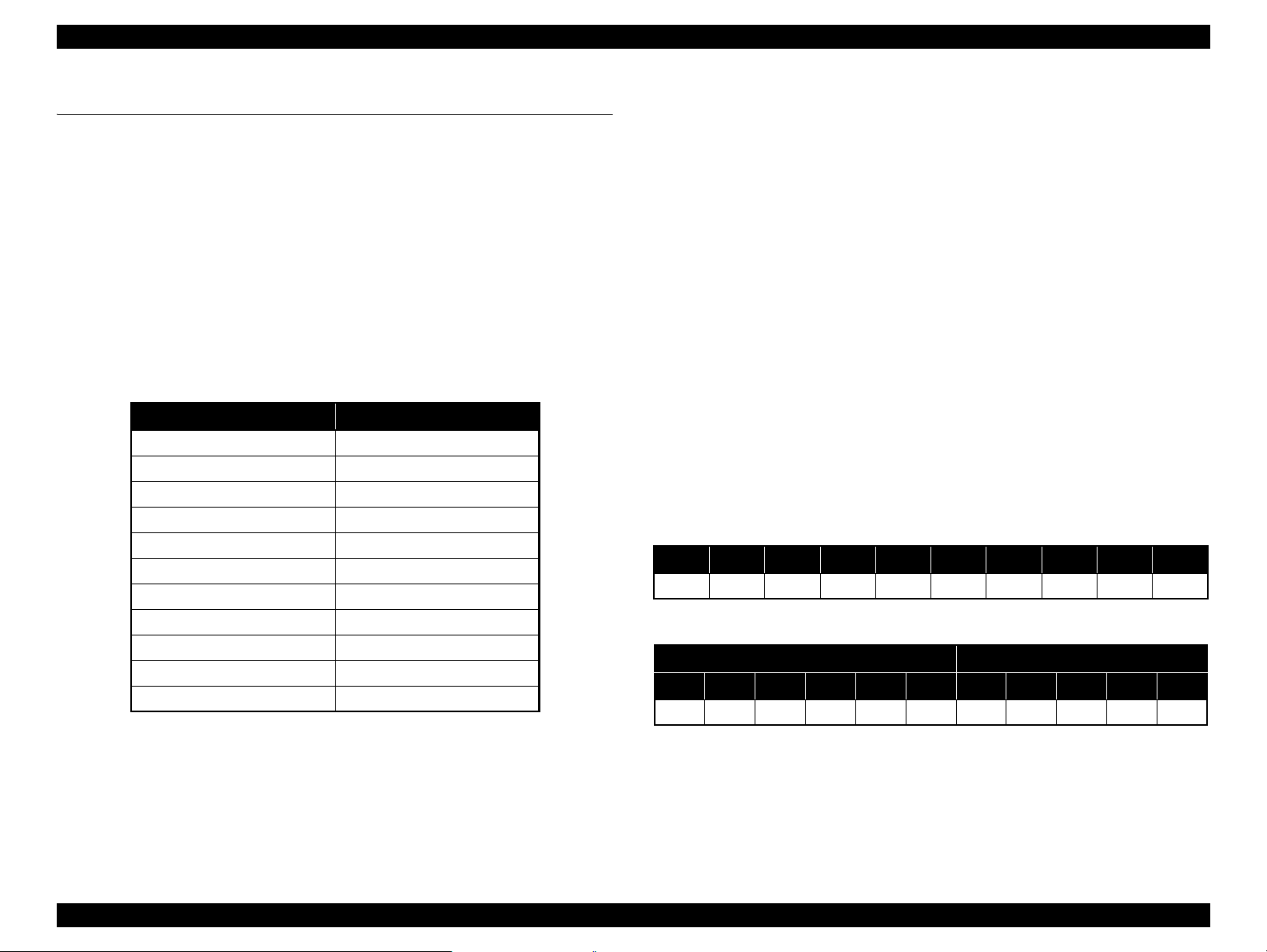
Nozzle set configuration
A-row B-row C-row D-row E-row F-row G-row H-row I-row J-row
C VM PK/MK LK OR GR LLK Y LM LC
Ink configuration
Left Side Right Side
1 2 3 4 5 6 7 8 9 10 11
GR LLK Y LC VLM OR MK VM LK C PK
Note : 1-row starting from the left facing the front of the printer.
PRODUCT DESCRIPTION Product Description 11
Confidential
Page 11

Epson Stylus Pro 4900/Epson Stylus Pro 4910 Revision A
PRODUCT DESCRIPTION Product Description 12
Confidential
SpectroProofer (Option)
Full-fledged spectrophotometer realizes high precision color measurement.
Selectable from specifications with/without the UV filter, which enables the
users to configure colorimetric system adjusted with their workflow.
Drying Fans for drying ink stabilizes color in less than 2 minutes 30 seconds.
Paper pressing function prevents degrading precision of colorimetry caused
by floating of paper.
Selectable from the white backing or the black backing.
Figure 1-1. External View (Main body)
Figure 1-2. External View (SpectroProofer)
Page 12
Epson Stylus Pro 4900/Epson Stylus Pro 4910 Revision A
1.2 Basic Specifications
1.2.1 Basic Specifications
Item Specification
Print method On-demand inkjet
Black system:
360 nozzles x three colors
(Photo Black, Matte Black, Light Black, Light Light Black)
Nozzle configuration
Maximum resolution 2,880dpi x 1,440dpi
Control code ESC/P2 (command is nondisclosure)
Paper feed method Friction
RAM 256 MB for Main, 64 MB for Network
Interface
Color system:
360 nozzles x seven colors
(Green, Yellow, Orange, Cyan, Light Cyan, Vivid Magenta, Vivid
Light Magenta)
USB 2.0 High Speed
Ethernet 10Base-T/100Base-TX
1.2.2 Electric Specifications
Item
Rated voltage 100 to 240 VAC
Input voltage range 90 to 264 VAC
Rated current 0.4 A to 0.7 A
Rated frequency 50 to 60 Hz
Input frequency range 49.5 to 60.5 Hz
Operating Approx. 52 W Approx. 55 W
Power
consumption
Insulation resistance
Dielectric strength
Leek current 0.25 mA or less
Compliance with regulations
Standby 20 W 25 W
Sleep mode Approx. 8.5 W or less Approx. 8.5 W or less
Power off Approx. 0.5 W or less Approx. 0.5 W or less
Main body
10 MΩ or more
(between AC line and chassis at 500 VDC)
1.0 kVrms AC for 1 min. or 1.2 kVrms AC for 1 sec.
(between AC line and chassis)
Conforms to International Energy Star Program
(Category: the harmonic restraint measure guideline)
Conforms to VCCI Class B (with full options installed)
Specification
SpectroProofer is
installed
PRODUCT DESCRIPTION Basic Specifications 13
Confidential
Page 13
Epson Stylus Pro 4900/Epson Stylus Pro 4910 Revision A
PRODUCT DESCRIPTION Basic Specifications 14
Confidential
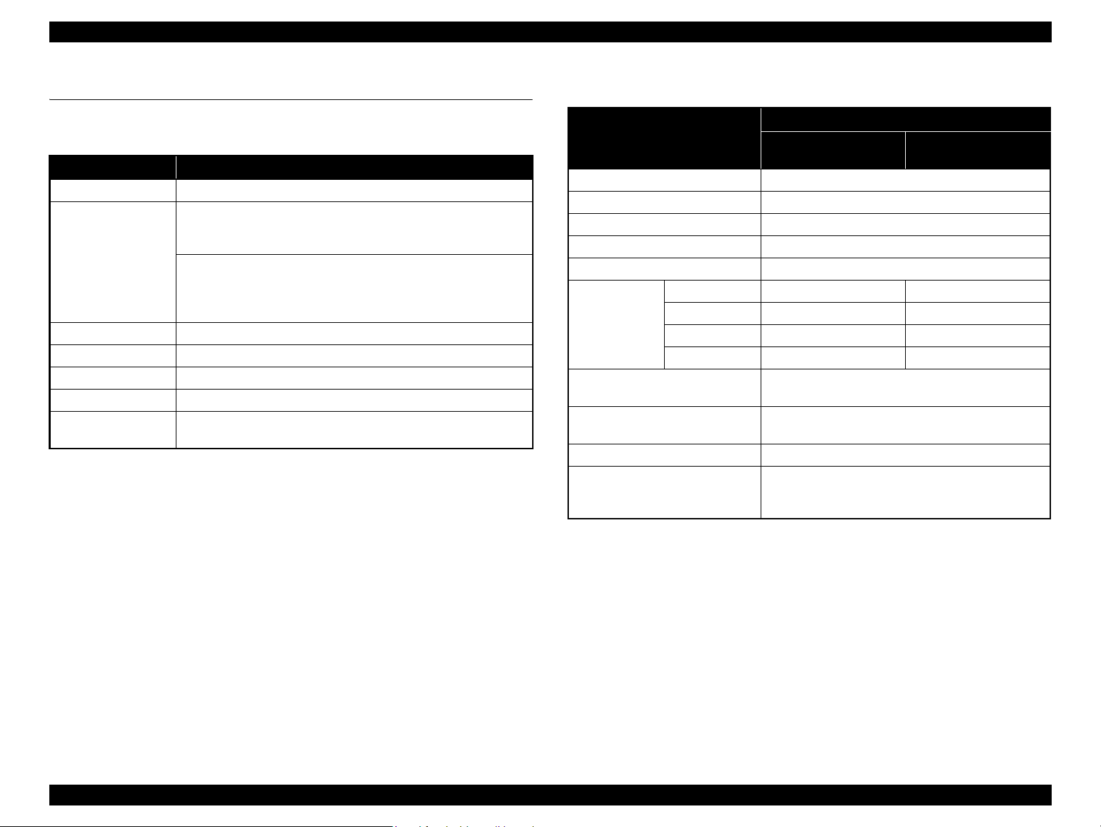
1.2.3 Ink Specifications 1.2.4 General Specifications
Item Specification
Form Exclusive ink cartridge
Pigment Ink colors
Black system:
Photo black, Matte black, Light black, Light light black
Color system:
Cyan, Light Cyan, Vivid magenta, Vivid light magenta,
Yellow, Orange, Green
Cartridge life
200ml: 3 years
80ml: 2 years
Guaranteed life after installation Within 6 months after mounted in the printer
Storage
Uninstalled
(packed)
-20 to 40 °C
(within 1 month under 40 °C)
Installed
-20 to 40 °C
(within 1 month under 40 °C)
Transporting
(packed)
-20 to 60 °C
(within 72 hours under 60 °C, and within 1 month under
40 °C)
Capacity 200ml/80ml (bundled item)
Dimensions 25 (W) x 200 (L) x 100 (H)
Maintenance box/
Maintenance box 2
PXBMB1/PX17MB1
C A U T I O N
Never disassemble ink cartridges or refill ink in them.
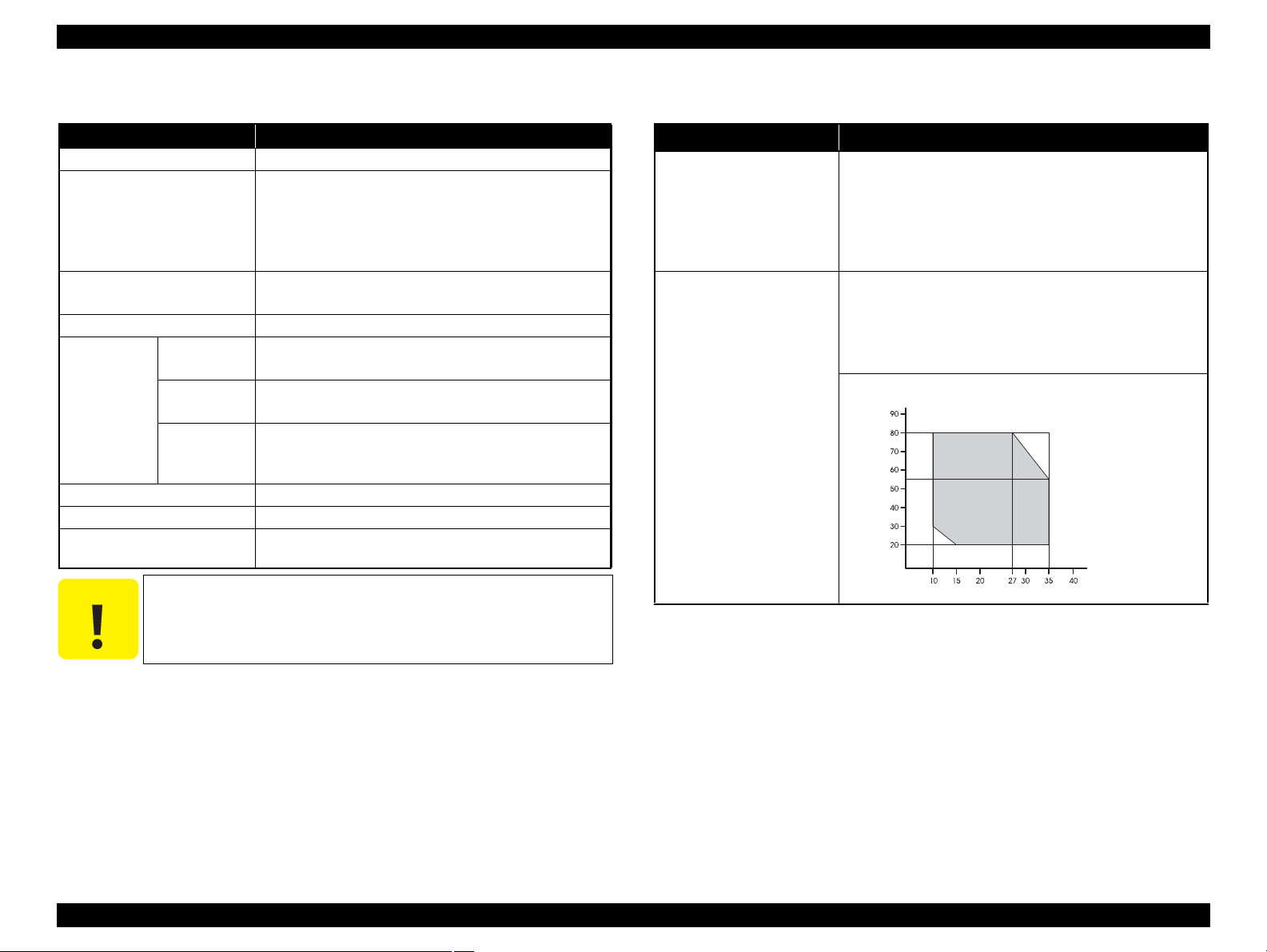
Item Specification
Temperature
Operating: 10 to 35 °C
Storage (before unpacked): -20 to 60 °C
(within 120 hours under 60 °C, and within 1 month under
40 °C)
Storage (after unpacked): -20 to 40 °C
(within 1 month under 40°C)
Humidity
Operating: 20 to 80% (no condensation)
Storage (before unpacked):
-20 to 85% (no condensation)
Storage (after unpacked):
5 to 85% (no condensation)
Temperature (°C)
Humidity (%)
Page 14
Epson Stylus Pro 4900/Epson Stylus Pro 4910 Revision A
1.2.5 Reliability/Durability
Item Specification Remarks
Until any one of the following conditions is met.
5 years
Operating life of the printer
Cutter life (reference)
RTC backup battery 5 years or longer ---
CR Motor Approx. 6,000,000 paths
Head FFC Approx. 6,000,000 paths
Oil Pad Approx. 6,000,000 paths
Parts life
Ink Tube Approx. 6,000,000 paths
Ink Selector Assy 10,000 times 4 times/day x 250days x 5years x 2 (safety factor)
IS Unit 1,200,000 EP EP: revolutions (EP) of the motor for pump suction
Home (Right) Side Cartridge
Holder
Full (Left) Side Cartridge Holder 200,000 times 100,000 times (initial charge to product life) x 2 (safety factor)
Carriage life:
3,000,000 paths
Approx. 25,000 pages
(Super A2 size/Plain paper/Quality mode/720x720 dpi)
Standard paper: approx. 20,000 cuts
Hard cut paper: approx. 5,000 cuts
Approx. 25,000 pages
(Super A2 size/EPSON paper/Quality mode/Continuous printing/
720x720 dpi)
Approx. 25,000 pages
(Super A2 size/EPSON paper/Quality mode/Continuous printing/
720x720 dpi)
Approx. 25,000 pages
(Super A2 size/EPSON paper/Quality mode/Continuous printing/
720x720 dpi)
Approx. 25,000 pages
(Super A2 size/EPSON paper/Quality mode/Continuous printing/
720x720 dpi)
200,000 times 100,000 times (initial charge to product life) x 2 (safety factor)
---
---
PRODUCT DESCRIPTION Basic Specifications 15
Confidential
Page 15
Epson Stylus Pro 4900/Epson Stylus Pro 4910 Revision A
PRODUCT DESCRIPTION Printing Specifications 16
Confidential
1.3 Printing Specifications
1.3.1 Paper Feed Specifications
1.3.2 Paper Specification
1.3.2.1 Supported Paper
The following explains the supported paper sizes and thickness.
ROLL PAPER
Note "* " : Spacer for the borderless printing and 2-inch core are required.
Item Specification
Paper feed method Friction feed
Return pitch 2.2049 μm (1/11,520 inch)
Paper feeder
Roll paper manual feed
Cut sheet manual feed
Cut sheet front manual feed
Cassette paper feed
C A U T I O N
Do not use wrinkled, scuffed, torn, or soiled paper.
Load paper just before printing. Do not leave paper loaded on
the printer when not printing. Store paper properly following
the instruction that comes with the paper.
When large quantities of paper need to be prepared in advance,
make a test print using the paper before purchase.
Item Specification
Paper type Plain paper, recycled paper
Paper size
(within roll paper size)
2-inch core: 203 to 432 mm x to 45 m
3-inch core: 203 to 432 mm x to 30.5 m
Roll paper size
2-inch core: Outer diameter 103 mm or less x 1 roll
3-inch core: Outer diameter 150 mm or less x 1 roll
Paper thickness 0.08 to 0.11mm
Weight 64 to 90g/m
2
Available width for
borderless printing
A4/210 mm, A3/297 mm, Super A3/B/329 mm,
SuperW A3/329 mm, A2/420 mm*, 11 inch*, 17 inch, 8 inch*,
10 inch, 16 inch, 30 cm
Page 16

Epson Stylus Pro 4900/Epson Stylus Pro 4910 Revision A
CUT SHEET
Item Specification
Paper type Plain paper, recycled paper
Paper size
Paper thickness 0.08 to 0.11mm
Weight 64 to 90g/m
Available width for
borderless printing
Width: 203 to 432 mm
Length: 254 to 610 mm
2
A4/210 mm, A3/297 mm, Super A3/B/329 mm, SuperW A3/329
mm, 17 inch, 10 inch, 16 inch, 30 cm
PRODUCT DESCRIPTION Printing Specifications 17
Confidential
Page 17
Epson Stylus Pro 4900/Epson Stylus Pro 4910 Revision A
PRODUCT DESCRIPTION Printing Specifications 18
Confidential
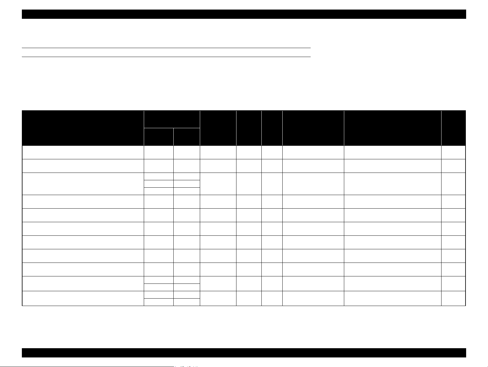
1.3.2.2 Designated Paper
ROLL PAPER
Note "*1": OK!: Recommended for borderless printing
OK: Borderless printing is available
NA: Borderless printing is NOT available
Borderless printing on the borderless printing available paper (OK) may result in drop in print quality or fail to produce complete borderless (white margins may appear) due to expanding of the paper. Borderless
printing can be made on commercially available paper, however, note that the availability is restricted by the paper size.
"*2": Spacer for the borderless printing is required.
Table 1-2. Designated Roll Paper List
Name
Size
Borderless
Print
*1
Thickness
Core
Diameter
Roll Paper Tension ICC Profile Black Ink
mm inch
Premium Glossy Photo Paper (250) 406 16 OK! 0.27 3" Normal
Epson Stylus Pro 4900_4910
PremiumGlossyPhotoPaper250.icc
PK
Premium Semigloss Photo Paper (250) 406 16 OK! 0.27 3" Normal
Epson Stylus Pro 4900_4910
PremiumSemiglossPhotoPaper250.icc
PK
Premium Luster Photo Paper (260)
254 10
OK! 0.27 3" Normal
Epson Stylus Pro 4900_4910
PremiumLusterPhotoPaper260.icc
PK300 ---
406 16
Premium Semimatte Photo Paper (260) 406 16 OK! 0.27 3" Normal
Epson Stylus Pro 4900_4910
PremiumSemimattePhotoPaper260.icc
PK
Photo Paper Gloss 250 432 17 OK! 0.25 3" Normal
Epson Stylus Pro 4900_4910
PhotoPaperGloss250.icc
PK
Premium Glossy Photo Paper (170) 420 (A2) --- OK
*2
0.18 2" ---
Epson Stylus Pro 4900_4910
PremiumGlossyPhotoPaper170.icc
PK
Premium Semigloss Photo Paper (170) 420 (A2) --- OK
*2
0.18 2" ---
Epson Stylus Pro 4900_4910
PremiumSemiglossPhotoPaper170.icc
PK
Enhanced Matte Paper 432 17 OK 0.25 3" Normal
Epson Stylus Pro 4900_4910
EnhancedMattePaper_MK.icc
MK
Singleweight Matte Paper 432 17 OK! 0.14 2" Normal
Epson Stylus Pro 4900_4910
SingleweightMattePaper.icc
MK
Epson Proofing Paper Commercial
329 13
OK 0.20 3" Normal
Epson Stylus Pro 4900_4910
EpsonProofingPaperCommercial.icc
PK
432 17
Epson Proofing Paper White Semimatte
329 13
OK 0.25 3" Normal
Epson Stylus Pro 4900_4910
EpsonProofingPaperWhiteSemimatte.icc
PK
432 17
Page 18
Epson Stylus Pro 4900/Epson Stylus Pro 4910 Revision A
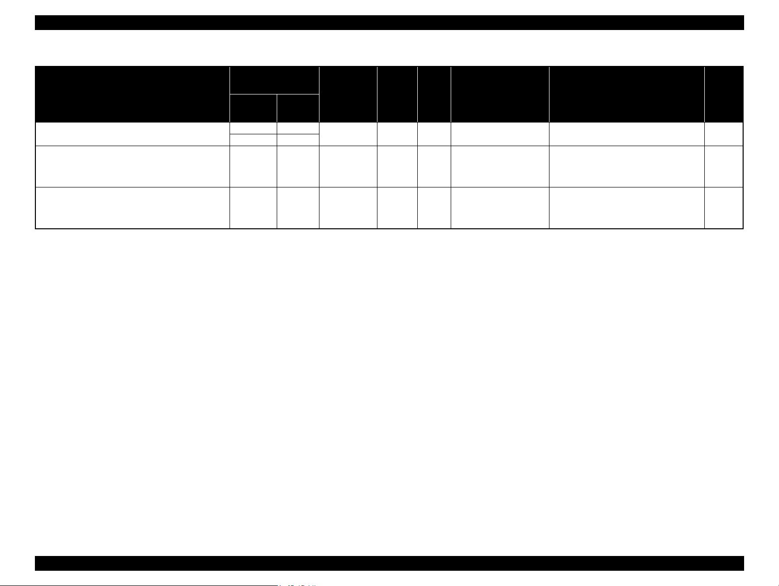
Table 1-2. Designated Roll Paper List
Size
Name
mm inch
Epson Proofing Paper Publication
UltraSmooth Fine Art Paper 432 17 OK 0.46 3” ---
Textured Fine Art Paper 432 17" OK 0.37 3" Normal
329 13
432 17
Borderless
Print
OK 0.20 3" Normal
Thickness
*1
Core
Diameter
Roll Paper Tension ICC Profile Black Ink
Epson Stylus Pro 4900_4910
EpsonProofingPaperPublication.icc
Epson Stylus Pro 4900_4910
UltraSmoothFineArtPaper_PK.icc/
Epson Stylus Pro 4900_4910
UltraSmoothFineArtPaper_MK.icc
Epson Stylus Pro 4900_4910
TexturedFineArtPaper_PK.icc/
Epson Stylus Pro 4900_4910
TexturedFineArtPaper_MK.icc
PK
PK/MK
PK/MK
PRODUCT DESCRIPTION Printing Specifications 19
Confidential
Page 19
Epson Stylus Pro 4900/Epson Stylus Pro 4910 Revision A
PRODUCT DESCRIPTION Printing Specifications 20
Confidential
CUT SHEET
Note "*": OK!: Recommended for borderless printing
OK: Borderless printing is available
NA: Borderless printing is NOT available
Borderless printing on the borderless printing available paper (OK) may result in drop in print quality or fail to produce complete borderless (white margins may appear) due to expanding of the paper. Borderless
printing can be made on commercially available paper, however, note that the availability is restricted by the paper size.
Table 1-3. Designated Cut Sheet List
Name Size Borderless Print
*
Thickness
Print from Paper
Cassette
Sheets per Paper
Cassette (Max.)
ICC Profile Black Ink
Premium Glossy Photo Paper
8" x 10" NA
0.27mm OK!
100
Epson Stylus Pro 4900_4910
PremiumGlossyPhotoPaper.icc
PK
A4 OK!
50
Letter
(8.5" x 11")
NA
11" x 14" NA
20
US B (11" x 17") NA
A3 OK!
Super A3 / B
(329mm x
483mm)
OK!
A2 NA
25
US C (17" x 22") OK!
Premium Semigloss Photo Paper
A4 OK!
0.27mm OK! 100
Epson Stylus Pro 4900_4910
PremiumSemiglossPhotoPaper.icc
PK
Letter
(8.5" x 11")
NA
A3 OK!
Super A3 / B
(329mm x
483mm)
OK!
A2 NA
US C (17" x 22") OK!
Premium Luster Photo Paper
A4 OK!
0.27mm OK! 100
Epson Stylus Pro 4900_4910
PremiumLusterPhotoPaper.icc
PK
Letter
(8.5" x 11")
NA
A3 OK!
Super A3 / B
(329mm x
483mm)
OK!
A2 NA
US C (17" x 22") OK!
Page 20
Epson Stylus Pro 4900/Epson Stylus Pro 4910 Revision A
Table 1-3. Designated Cut Sheet List
Name Size Borderless Print
Archival Matte Paper/
Enhanced Matte Paper
Photo Quality Inkjet Paper
EPSON Proofing Paper
White Semimatte
Watercolor Paper - Radiant White
UltraSmooth Fine Art Paper
Print from Paper
Cassette
A4 OK
Letter
(8.5" x 11")
NA
*
Thickness
*
A3
Super A3 / B
(329mm x
OK
*
0.26mm OK!
483mm)
A2 NA
US C (17" x 22") OK
A4 OK
*
*
Letter
(8.5" x 11")
NA
US B / 11"
A3
Super A3 / B
(329mm x
OK
*
0.12mm OK!
483mm)
A2 NA 30
US C (17" x 22") OK
*
Super A3 / B
(329mm x
483mm)
SuperW A3
OK
*
0.25mm OK! 100
(329mm x
559mm)
Super A3 / B
(329mm x
OK
*
0.29mm --- ---
483mm)
Super A3 / B
(329mm x
483mm)
OK
*
0.32mm --- ---
A2 NA
US C (17" x 22") OK
*
Sheets per Paper
Cassette (Max.)
100
50
100
100
ICC Profile Black Ink
Epson Stylus Pro 4900_4910
ArchivalMattePaper_MK.icc/
Epson Stylus Pro 4900_4910
EnhancedMattePaper_MK.icc
Epson Stylus Pro 4900_4910
PhotoQualityInkJetPaper.icc
Epson Stylus Pro 4900_4910
EpsonProofingPaperWhiteSemimatte.icc
Epson Stylus Pro 4900_4910
WatercolorPaperRadiantWhite_PK.icc/
Epson Stylus Pro 4900_4910
WatercolorPaperRadiantWhite_MK.icc
Epson Stylus Pro 4900_4910
UltraSmoothFineArtPaper_PK.icc/
Epson Stylus Pro 4900_4910
UltraSmoothFineArtPaper_MK.icc
MK
MK
PK
PK/MK
PK/MK
PRODUCT DESCRIPTION Printing Specifications 21
Confidential
Page 21
Epson Stylus Pro 4900/Epson Stylus Pro 4910 Revision A
PRODUCT DESCRIPTION Printing Specifications 22
Confidential
Velvet Fine Art Paper
Letter
(8.5" x 11")
NA
0.48mm --- ---
Epson Stylus Pro 4900_4910
VelvetFineArtPaper_PK.icc/
Epson Stylus Pro 4900_4910
VelvetFineArtPaper_MK.icc
PK/MK
Super A3 / B
(329mm x
483mm)
OK
*
A2 NA
US C (17" x 22") OK
*
Table 1-3. Designated Cut Sheet List
Name Size Borderless Print
*
Thickness
Print from Paper
Cassette
Sheets per Paper
Cassette (Max.)
ICC Profile Black Ink
Page 22

Epson Stylus Pro 4900/Epson Stylus Pro 4910 Revision A
1.3.3 Printable Area
ROLL PAPER
Margins for roll paper depends on the Roll Paper Margin settings in the Printer Setup
menu.
203 to 432mm
3 to 15mm
*1
127mm
to
15m
*1
3 to 15mm
3 to 35mm
3 to 15mm
Note "*1": When the “Roll Paper (Banner)” is selected for the “Source” in the “Paper Settings” of the
printer driver, the top and bottom margins become 0 mm.
"*2": When the Default is selected, “a” becomes 20mm for the following paper types; Premium
Glossy Photo Paper(250), Premium Semigloss Photo Paper(250), and Premium Luster Photo
Paper(260).
CUT SHEET
3mm3mm
203 to 432 mm
3mm
254
to
610mm
3 to 17mm*
Note "* " : The default for printing with border is 14mm. The default for borderless printing is 17mm.
Roll Paper Margin settings Explanation
Default
Top/Bottom 15mm
Top 35/Bottom 15mm
3mm a, b, c, d = 3mm
15mm a, b, c, d = 15mm
a = c = 15mm *2
b = d = 3mm
a = c = 15mm
b = d = 3mm
a = 35mm
c = 15mm
b = d = 3mm
PRODUCT DESCRIPTION Printing Specifications 23
Confidential
Page 23

Epson Stylus Pro 4900/Epson Stylus Pro 4910 Revision A
PRODUCT DESCRIPTION Printing Specifications 24
Confidential
1.3.4 Borderless Printing Specification
AVAILABLE PAPER TYPE
For the paper types and sizes that support the borderless printing, see
"1.3.2.2 Designated Paper" (p18).
BORDERLESS PRINTING MODE
The following types of borderless printing are available with the printer driver.
Note "*1": The cut pages vertical length becomes about 2mm shorter than the specified size.
"*2": Color inconsistencies or ink smudges due to the interruption of printing for cutting off top
margins are likely to occur on the following papers.
• Glossy media such as PGPP250
• Single Weight Matte Paper
Table 1-4. Borderless Printing Mode
Driver Setting Printer Operation Remarks
Normal Cut*
2
Prints an image bleeding it off
the left and right edges of
paper. The top and bottom
margins are determined by
Roll Paper Margin setting.
Default
Single Cut
*
1*2
Prints an image bleeding it off
all the edges of paper.
The cutting methods is as
follows.
The minimum width
required for cutting is
applied as the top margin of
the first page, then the top
margin is cut off during
printing.
No margin is provided between pages, and the
cutting is made on the border between the pages.
When the job is finished, the bottom side of the last
page is cut off without margin.
The minimum width required for cutting is applied
as margins between pages.
Printing is interrupted
for cutting off the top
margin of the first
page. This may cause
color inconsistencies
depending on the print
data.
The cut line between
pages may be slightly
off the border.
Double Cut
*
1*2
Prints an image bleeding it off
all the edges of paper.
The cutting methods is as
follows.
The auto refresh margin is
applied as the top margin of
the first page, then the top
margin is cut off during
printing.
The bottom side of each
page is cut off without margin.
The minimum width required for cutting is applied
as margins between pages.
Printing is interrupted
for cutting off the top
margin of the first
page. This may cause
color inconsistencies
depending on the print
data.
The top and bottom
sides of each page are
cut off at the position
slightly inward the
image edges so that no
white margin appears
on the edges of the cut
pages. This causes the
vertical length of the
cut page about 2mm
shorter than the
specified length.
Table 1-4. Borderless Printing Mode
Driver Setting Printer Operation Remarks
Page 24
Epson Stylus Pro 4900/Epson Stylus Pro 4910 Revision A
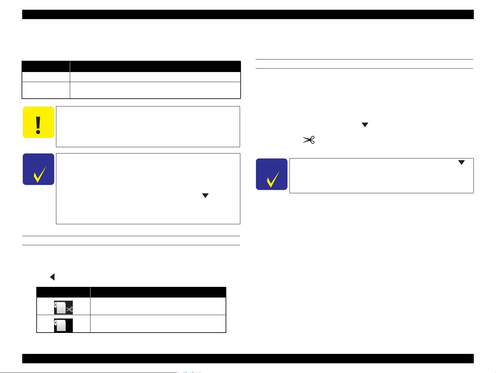
1.3.5 Cutting of Roll Paper
The printer offers two ways of cutting for roll paper.
Cut Method Description
Auto cut The printer automatically cuts paper with the built-in cutter.
Manual cut
C A U T I O N
C H E C K
P O I N T
The user can manually move the built-in cutter to cut paper, or use a
commercially available cutter.
Some types of roll paper cannot be cut with the built-in cutter.
In such cases, cut it manually with a commercially available
cutter or the like.
When cutting Clear Film, please hold it by hands so that it does
not fall on the floor in order to prevent scratches.
It may take time for the cutting operation.
The minimum length of paper you can cut with the built-in
cutter is fixed to 80 or 127 mm and cannot be changed. The
length is 210 mm when the optional SpectroProofer is installed.
When cutting the roll paper of the length which cannot be
automatically cut by the built-in cutter, press the button to
feed paper up to a position where the paper can be cut
manually, and then cut the paper with a commercially-available
cutter or a similar tool.
Setting from the printer
Select “Auto Cut” in the “Paper Setting” window of the printer driver.
HOW TO CUT
Auto cut
The printer automatically cuts paper with the built-in cutter each time a page is
printed.
Manual cut
Follow the procedure below to cut paper at the desired position.
1. After a page is printed, press the button to advance the paper to the cut
position.
2. Press the button. Select [Cut] from the selection screen on the display,
and press [OK] button. The built-in cutter moves and cuts the paper.
C H E C K
P O I N T
If the roll paper cannot be cut by the built-in cutter, press the
button to feed the paper to a position where you can cut it
manually.
SETTING BEFORE PRINTING
The cut method setting can be made by the control panel or the printer driver.
Setting on the computer
Press button to select the cut method.
Icon Description
Roll Auto Cut On
Roll Auto Cut Off
PRODUCT DESCRIPTION Printing Specifications 25
Confidential
Page 25
Epson Stylus Pro 4900/Epson Stylus Pro 4910 Revision A
PRODUCT DESCRIPTION Hardware Specifications 26
Confidential
1.4 Hardware Specifications
This section provides the printer dimensions and shows the main components.
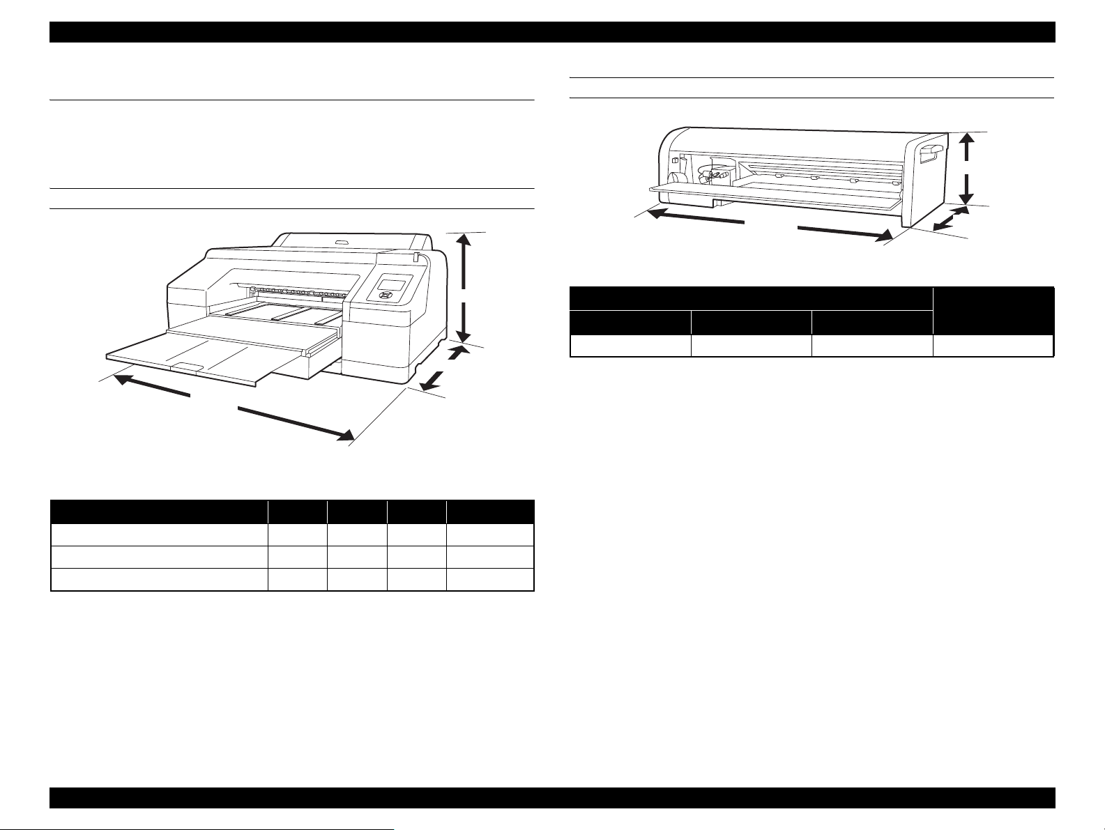
1.4.1 Dimensions and Weight
MAIN UNIT
Figure 1-3. Dimensions
Note *: Excluding the ink cartridges and paper
SPECTROPROOFER MOUNTER
Figure 1-4. Dimensions
Note * : Excluding the accessories and color measurement device.
構成 Width Depth Height Weight*
Body (with Paper Eject Support retracted) 863 mm 766 mm 405 mm Approx. 52 kg
Body (with Paper Eject Support extracted) 863 mm 1134 mm 405 mm Approx. 52 kg
Body & Color Measurement Device 877 mm 1299 mm 405 mm Approx. 60.7 kg
Height
Depth
Width
External Dimensions
Weight*
Width Depth Height
787 mm 199 mm 267 mm Approx. 9.0 kg
267 mm
199 mm
787 mm
Page 26
Epson Stylus Pro 4900/Epson Stylus Pro 4910 Revision A
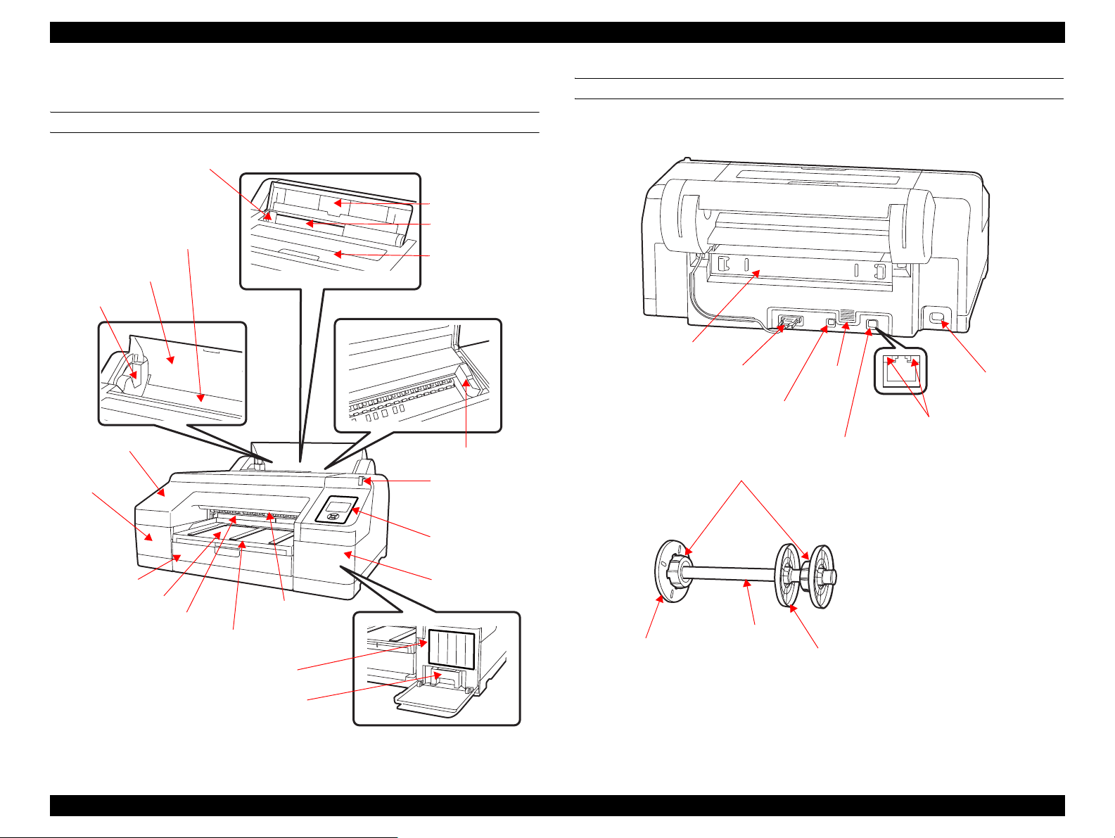
1.4.2 Part Names
FRONT SIDE OF MAIN UNIT
Edge guide
Roll paper feed slot
Roll paper cover
Spindle holders
Front cover
Cartridge
cover (left)
Paper guide
Rear paper feed slot
Printer cover
CR Unit
Large alert light
BACK SIDE OF MAIN UNIT/SPINDLE
Rear unit
Roll paper holder
unit connector
USB interface
connector
LAN connector
Attachment
Airflow
vent
AC inlet
Status light (green, red)
Control panel
Paper cassette
Output tray
Maintenance Box 2
Front paper
feed slot
Paper eject
support
Ink cartridges
Maintenance Box 1
Figure 1-5. Front side of Main Unit
Cartridge
cover (right)
Movable flange (black)
Figure 1-6. Back side of Main Unit/Spindle
Spindle
Spacer
PRODUCT DESCRIPTION Hardware Specifications 27
Confidential
Page 27
Epson Stylus Pro 4900/Epson Stylus Pro 4910 Revision A
PRODUCT DESCRIPTION Hardware Specifications 28
Confidential
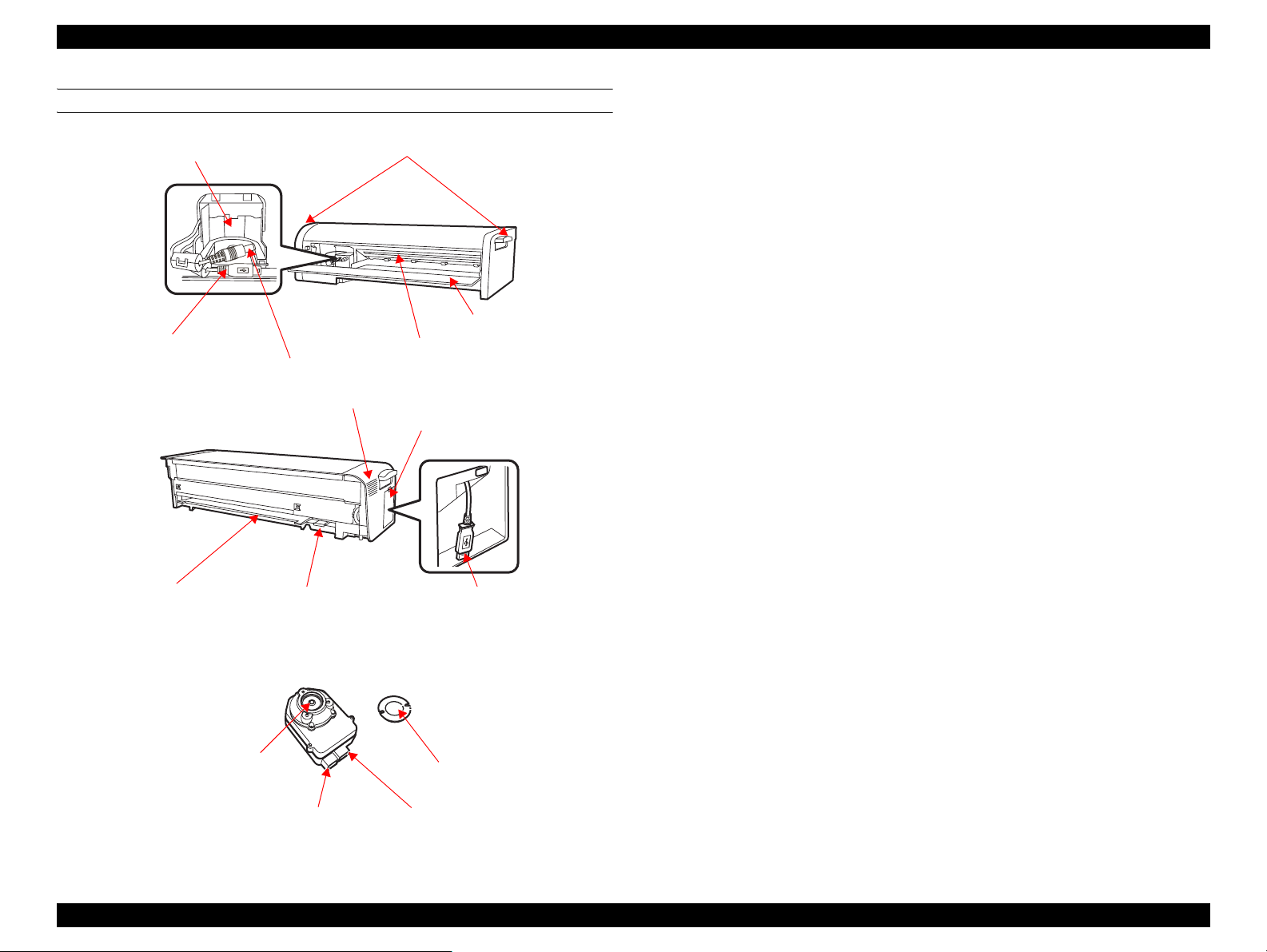
SPECTROPROOFER MOUNTER
Figure 1-7. SpectroProofer Mounter
Handles
Front Cover
Paper Presser
ILS communication cable
ILS DC cable
Color Measurement Device carriage
Side Cover
Printer connection cable
White calibration tile
holder insert slot
Backing insert
slot
Lens
DC connector
Communication connector
White calibration tile
Air vent
Page 28
Epson Stylus Pro 4900/Epson Stylus Pro 4910 Revision A
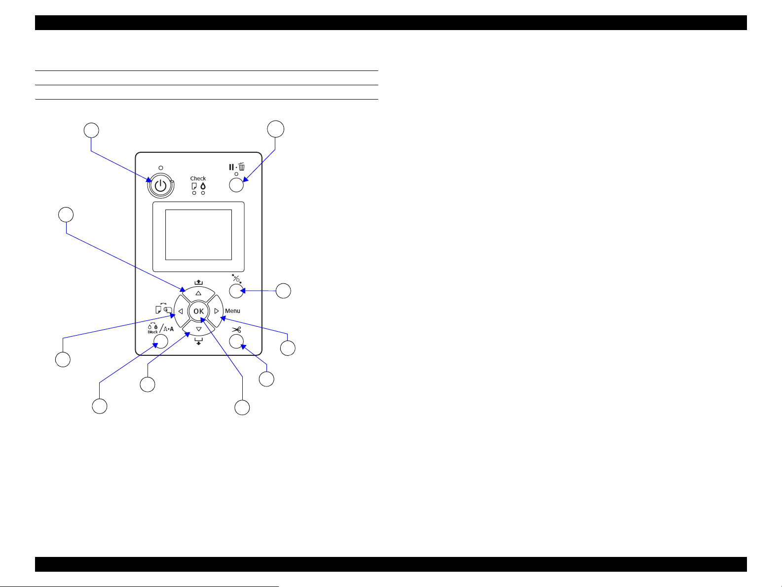
1.5 Control Panel
BUTTONS
1
[Paper Feed]
10
buttons
[Paper Source]
9
button
[Power] button
[Ink menu] button
8
[Paper Feed] buttons
7
[OK] button
6
[Pause/Cancel] button
2
[Paper Set] button
3
[Menu] button
4
[Paper Cut] button
5
Figure 1-8. BUTTONS
PRODUCT DESCRIPTION Control Panel 29
Confidential
Page 29

Epson Stylus Pro 4900/Epson Stylus Pro 4910 Revision A
PRODUCT DESCRIPTION Control Panel 30
Confidential
Button Name
Function
When pressed normally
When pressed down
for 2 sec.
For panel setting
1 [Power] button Turns the printer On or Off. Power-off
2 [Pause/Cancel] button When printing: Pauses the operation --- Cancels the panel settings.
3 [Paper Set] button
• Locks/unlocks the paper presser.
• After printing the roll paper: Releases the paper pressure and rolls the roll paper for removal.
When Remaining Paper Setup is On: Rolls the paper while printing the barcode on the front edge.
--- ---
4 [Menu] button
• Goes to the setting menu.
• When printing: Displays the Printer Status menu.
--- Goes to the lower tier.
5 [Paper Cut] button Cuts the roll paper. --- ---
6 [OK] button During ink drying: Stops the operation. --- Sets/Executes the selected item.
7 [Paper Feed (forward)] buttons
• Feeds the roll paper forward.
• While the paper presser is released: Changes the setting of the suction fan.
• Feeds the cut sheet.
Feeds the paper at high
speed
• Goes to the next item.
• Decreases the set value.
8 [Ink menu] button Goes to the Ink Menu. For the Ink Menu, see “1.5.1.3 Ink Menu (p39) ”. --- ---
9 [Paper Source] button Changes the paper type. --- Goes to the upper tier.
10 [Paper Feed (backward)] buttons
• Feeds the roll paper backward.
• While the paper presser is released: Changes the setting of the suction fan.
Feeds the paper at high
speed
• Goes back to the previous item.
• Increases the set value.
Page 30
Epson Stylus Pro 4900/Epson Stylus Pro 4910 Revision A
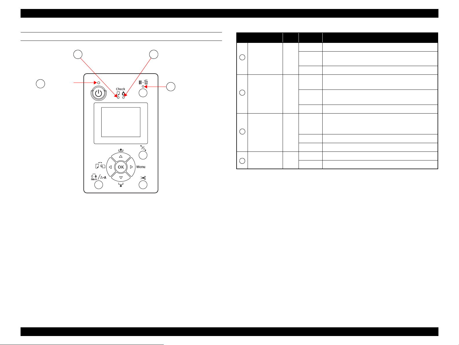
LIGHTS (LED)
Power light
A
Paper Check light
B
Figure 1-9. LED
Ink Check light
C
D
Pause light
Name Color Status Description
ON The printer power is on.
The printer is receiving a data or performing the power-off
A
B
C
D
Note "*1": Repeats turning On and Off every 500 ms. When a maintenance error is occurring, the LED
Note : All the LEDs flash when a service call error is occurring.
Power Green
Paper Check Orange
Ink Check Orange
Pause Green
repeats ON for 100 ms and OFF for 5 seconds.
*1
Flashing
OFF The printer power is off.
Flashing
OFF The printer is ready to print data.
Flashing
OFF The printer is ready to print data.
OFF The printer is ready to print data.
sequence.
ON
ON
ON Pausing/Canceling a job.
• No paper is loaded in the paper source.
• The paper setting is not correct.
• Paper is jammed.
*1
• Paper is not loaded straight.
• The installed ink cartridge is expended.
• The ink cartridge is not installed.
• The wrong ink cartridge is installed.
*1
The installed ink cartridge is nearly expended.
PRODUCT DESCRIPTION Control Panel 31
Confidential
Page 31

Epson Stylus Pro 4900/Epson Stylus Pro 4910 Revision A
PRODUCT DESCRIPTION Control Panel 32
Confidential
LCD
Normal indication
Figure 1-10. LCD (Normal indication)
4
5
7
3
8
6
1
2
9
No. Item Description
1
Message Printer status, operating status, or an error message is displayed.
2
Platen Gap
Displays the setting of “Platen Gap”.
: “Narrow” is selected.
: “Wide” is selected.
: “Wider” is selected.
: “Widest” is selected.
When the selected registered number in “Paper Number” is
displayed, “Platen Gap” is not displayed.
3
Paper Source Selected paper type and roll paper cut settings are displayed.
4
SpectroProofer status SpectroProofer available to use is displayed as an icon.
5
Ink cartridge status The current ink level in each of the nine cartridges is indicated.
6
Black Ink selection The selected black ink level is indicated.
7
Waste ink level in the
maintenance boxes
The free space of the maintenance boxes is indicated.
8
Paper Counter The remaining amount of the paper is displayed.
9
Roll Paper Margin
The setting made by the Roll Paper Margin menu is indicated
beside the [ ].
• Auto: “Default” is selected.
• 15mm: “Top/Bottom 15 mm” is selected.
• 35/15mm: “Top 35/Bottom 15 mm” is selected.
• 3mm: “3mm” is selected.
• 15mm: “15mm” is selected.
Page 32

Epson Stylus Pro 4900/Epson Stylus Pro 4910 Revision A
ICONS ON THE LCD
Remaining ink level of each color
Ink cartridge
No. Ink Color
1
2
3
4
5
6
7
8
9
10
11
Note : “1” on the above table is the left end, and “11” is the right end.
Green (GR)
Light Light Black (LLK)
Yellow (Y)
Light Cyan (LC)
Vivid Light Magenta (VLM)
Orange (OR)
Matte Black (MK)
Vivid Magenta (VM)
Light Black (LK)
Cyan (C)
Photo Black (PK)
Ink remaining
Icon Ink Cartridge
There is enough ink remaining.
Prepare a new ink cartridge.
The ink is expended so you cannot print.
Replace the ink cartridge with a new one.
Cartridge error or no cartridge error has occurred.
Free space of the maintenance box
Icon Free space of maintenance box
There is enough free space in the maintenance box.
Prepare a new maintenance box. (flashing)
The maintenance box becomes full. Replace the box
with a new one. (flashing)
PRODUCT DESCRIPTION Control Panel 33
Confidential
Page 33

Epson Stylus Pro 4900/Epson Stylus Pro 4910 Revision A
PRODUCT DESCRIPTION Control Panel 34
Confidential
1.5.1 Setup Menu
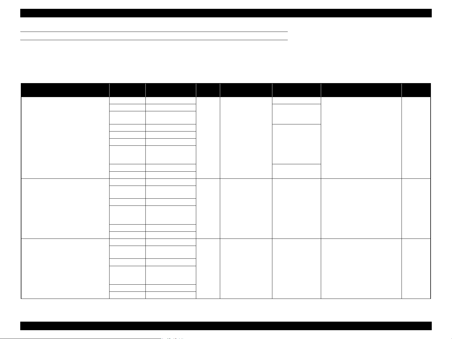
1.5.1.1 Printer Setup Menu
Table 1-5. Menu Mode Settings List
Menu Menu Item
Settings
(shaded one is the default)
Explanation
Printer Setup
Platen Gap
Narrow
Sets the platen gap (gap between the printhead and the platen).
When the “Others” is selected in the Paper Type of the Paper Setup menu, the platen gap designated at the Custom Paper menu has a
priority over the setting made here. ("PG Settings List" on page 40)
Standard
Wide
Wider
Widest
Page Line
On Sets whether to print a page line (line for manual cutting) on roll paper or not. The page line is printed when On is selected.
The vertical line may be printed when the roll paper width that is set in the printer driver is smaller than the width of the roll paper that
is loaded in the printer. This setting is available for roll paper only.
Off
Roll Paper Margin
Default
Sets the margins for roll paper.
When the Default is selected, the top and the bottom margins become 15mm and the right and the left margins become 3mm.
Top/Bottom 15mm
Top 35/Bottom 15mm
3mm
15mm
Paper Size Check
On Sets whether to detect the paper width and the top or not.
Setting to Off deactivates the sensor that detects the paper width when paper is loaded on the printer. This allows the user to use paper
whose width is out of the sensor’s detectable range. It means that the user can print an image larger than the paper size. The user should
know that doing so soils the platen and may cause a print quality or any other trouble.
Off
Paper Skew Check
On This setting is effective for roll paper only.
Sets whether to detect the paper skew or not.
Setting to Off does not carry out the detection and printing is continued even if the paper is skewed. When this setting is set to Off, the
user should have known the risk.
This setting is not available for cut sheet because the skew detection function after printing is not provided for cut sheet.
Off
Refresh Margin
On
This setting is available only when roll paper is used.
When this is set to On, the top edge area of paper soiled by the previous borderless printing is automatically cut off.
Off
Auto Nozzle Check
On: Periodically
Sets the execution timing for the auto nozzle check. When the nozzle clogging is detected, the cleaning starts automatically. You can
set the number of executions for cleaning from “1.5.2 Maintenance Mode (p42) ”.
On: Every Job
Off
Print Nozzle Pattern
Off
The printer prints a nozzle check pattern automatically at the specified timing. This setting is available only when roll paper is used.
When the set number of pages is reached, the nozzle check pattern is printed on the top of the page. The counter for counting the pages
is not reset even by power-off. When this setting is changed, the counter is cleared.
On: Every Page
On: Every 10 Pages
Change Black Ink
Off
When this is set to ON and the type of the black ink differs between the printer and the printer driver, the black ink of the printer is
changed automatically in printing.
On
Page 34

Epson Stylus Pro 4900/Epson Stylus Pro 4910 Revision A
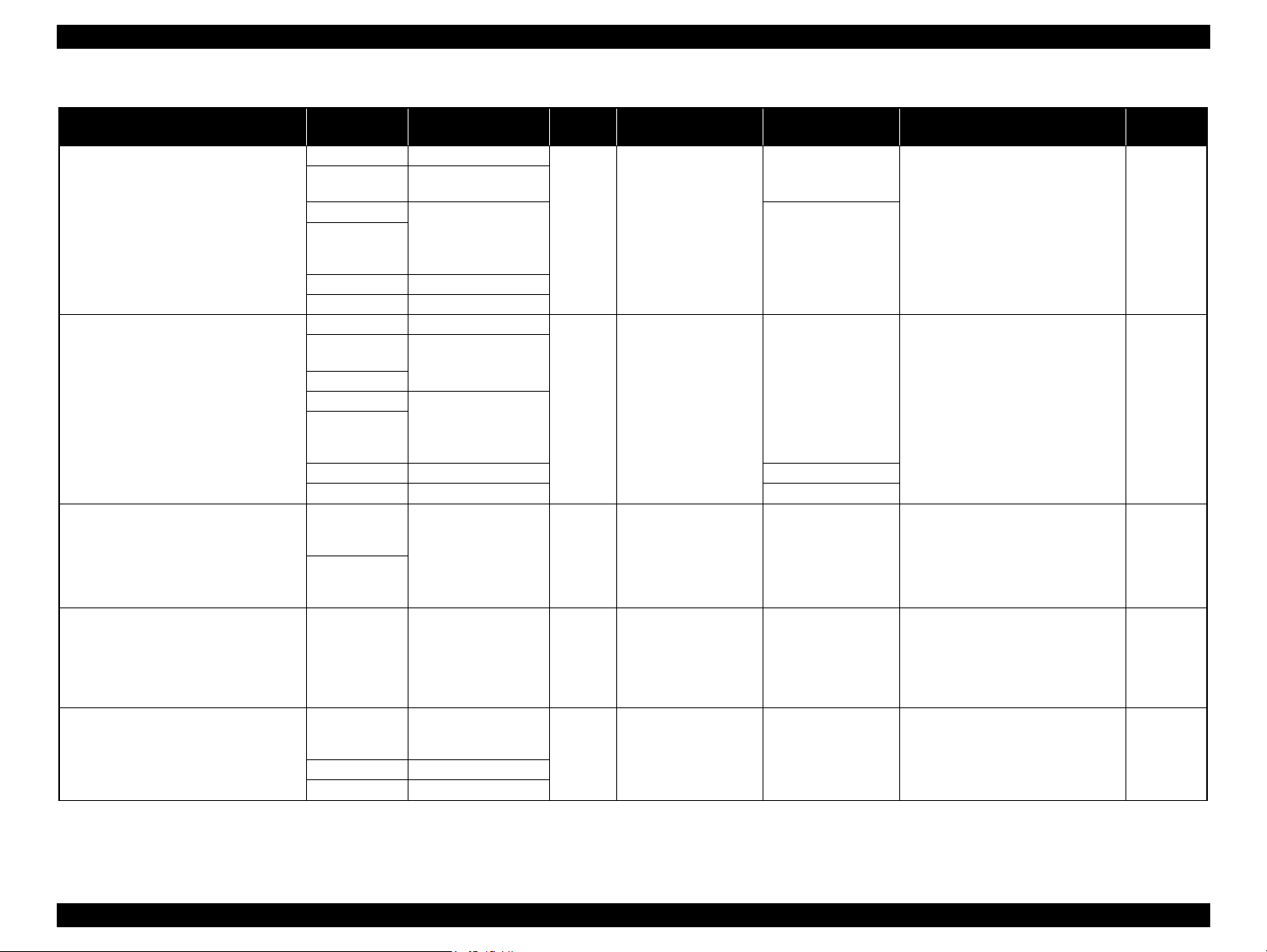
Table 1-5. Menu Mode Settings List
Menu Menu Item
Printer Setup
Test Print
Maintenance
Printer Status
(shaded one is the default)
Auto Roll Feeding
Initialize Settings Print All the settings made using the control panel are returned to their default.
Status Sheet Print Prints information on the printer status.
Network Status Sheet Print Prints information on the network status.
Job Information Print Prints a print job history report (up to 10 jobs) that is stored in the printer.
Custom Paper Print Prints the settings made in the Custom Paper menu.
Cutter Adjustment -3.0mm to +3.0mm Fine tune the cut position when printing to roll paper with no margins in all directions. In increments of 8 mil (0.2 mm) in all directions.
Clock Setting MM/DD/YY HH:MM Sets the date and time for the internal clock.
Version
Ink Level
Maintenance Box
Job History
Total Prints nnnnnn Pages Displays the total printed pages using 6-digit decimal number.
myEpsonPrinter Status
"Firmware version information"
Not Started, Enabled, Disabled
MM/DD/YY HH:MM GMT
Settings
On
Off
on page 41
(Ink color)
[E**********F]
1
[E**********F]
2
[E**********F]
No.0 to No.9
Ink xx.x ml
Paper xxxxxx cm
Last Uploaded:
(Not Uploaded)
When this is set to ON, the paper is fed on the platen from the roll paper standby position.
Displays the firmware version. Refer to "Firmware version information" on page 41.
Displays the ink level in the installed ink cartridges.
Displays the waste ink level in the installed maintenance boxes.
Job No.
Displays the job number that is stored in the printer. The latest job number is 0 (zero).
The amount of ink consumed
Displays the amount of ink consumed for each job.
The amount of paper consumed
2
Displays the total area of paper used for each job.
This function is not supported in some areas or some countries.
Explanation
PRODUCT DESCRIPTION Control Panel 35
Confidential
Page 35

Epson Stylus Pro 4900/Epson Stylus Pro 4910 Revision A
PRODUCT DESCRIPTION Control Panel 36
Confidential
Paper Setup
Roll Paper Remaining
Remaining Paper Setup
Make settings for the remaining roll paper.
[Off] (default)
Disables the roll paper remaining amount count function.
[On]
Displays the roll paper remaining amount on the LCD. When you press the [Paper Set] button, a barcode that includes information on
the amount of remaining roll paper, the Roll Length Alert, and the Paper Type is printed.
When roll paper is replaced with a new one, the printer reads the barcode and automatically applies the read settings for the new roll
paper.
Roll Paper Length You can make these settings only when Remaining Paper Setup above is set to On.
The printer sets roll paper length, and the remaining length of roll paper to be alerted when the set amount is reached.
The printer displays the roll paper remaining amount and the alert for shortage of the remaining on the LCD.
Roll Length Alert
Cut Sheet Remaining
Sheet Number You can make these settings only when Cut Sheet Remaining is set to On.
The printer sets the number of remaining cut sheets, and the number of remaining cut sheets to be alerted when the set number is
reached.
The printer displays the number of remaining cut sheets and the alert for shortage of the remaining on the LCD.
Sheet Number Alert
Paper Type
Photo Paper
Sets the paper type loaded on the printer.
Proofing Paper
Fine Art Paper
Matte Paper
Plain Paper
Others
Custom Paper
No Paper Selected
Custom Paper
(1-10)
Paper No. No.1 to 10
You can select a number (between 1 to 10) to register the settings (such as Paper Type, Platen Gap, Thickness Pattern, Paper Feed
Adjust, Drying Time, Paper Suction) or to recall these settings you have made. The number you select here is displayed on the LCD
panel. For the menu item, see Table 1-6 "Custom Paper Menu List" (p38).
Head Alignment
Paper Thickness
Paper Type Sets thickness of paper to be used.
• When Epson paper is used, select the paper type.
• When not Epson paper is selected, enter the thickness of the selected paper.
Paper Thickness
Alignment
Auto Sets whether to carry out the head alignment adjustment automatically or manually.
[Auto]
The adjustment is carried out automatically after the adjustment pattern is printed.
[Manual]
Select this to carry out the adjustment manually (visually check the patterns and enter selected values) after printing the adjustment
pattern.
Manual
Table 1-5. Menu Mode Settings List
Menu Menu Item
Settings
(shaded one is the default)
Explanation
Page 36

Epson Stylus Pro 4900/Epson Stylus Pro 4910 Revision A
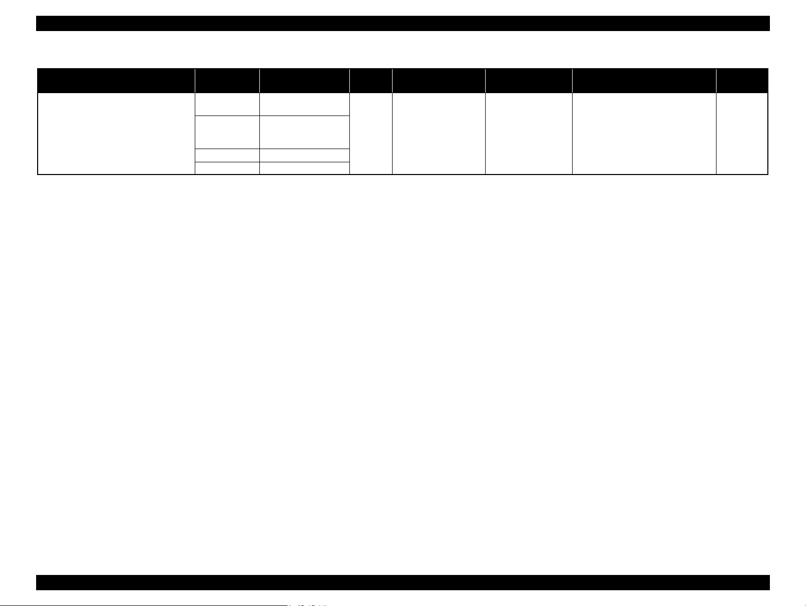
Table 1-5. Menu Mode Settings List
Default
Settings
Hide
Show
Auto
Panel
000.000.000.000
to
255.255.255.255
000.000.000.000
to
255.255.255.255
000.000.000.000
to
255.255.255.255
On
Off
Off
On
Explanation
The Network Setup menu items appear on the LCD only when this is set to Show.
Sets whether to set the IP address automatically or manually.
When the Panel is selected, the IP, SM, DG Setting menu is enabled to enter the address manually.
Sets the IP address manually.
Sets the subnet mask manually.
Sets the default gateway manually.
Enables or disables the Bonjour.
Enables or disables the WSD.
Displays the status of each item of SpectroProofer, such as the version of SpectroProofer, the product numbers of the white calibration
tiles, the temperature of Color Measurement Device (ILS20EP), ambient air temperature, and the color of the backing, and ILS
Calibration Status.
Menu Menu Item
Network Settings
IP Address Setting
Network Setup
SpectroProofer SpectroProofer Status Information
IP,SM,DG Setting
Bonjour
WSD
Init Network Setting Execute Returns the network settings to their default.
(shaded one is the default)
IP Address
Subnet Mask
Gateway
PRODUCT DESCRIPTION Control Panel 37
Confidential
Page 37

Epson Stylus Pro 4900/Epson Stylus Pro 4910 Revision A
PRODUCT DESCRIPTION Control Panel 38
Confidential
1.5.1.2 Custom Paper Menu
Table 1-6. Custom Paper Menu List
Menu Item
Settings
(shaded one is the default)
Explanation
Paper Type
Photo Paper
Sets the paper type loaded on the printer.
Proofing Paper
Fine Art Paper
Matte Paper
Plain Paper
Others
Platen Gap
Narrow
Adjusts the platen gap (gap between the printhead and paper surface) according to the paper thickness.
Standard: use this setting under normal conditions
Narrow: select this when using thin paper.
Wide, Wider, Widest: select this when smudges or blurring appear due to an excess pressure on the paper.
Standard
Wide
Wider
Widest
Thickness Pattern Print Prints a pattern for checking the thickness of the loaded paper.
Paper Feed Adjust A
0.00% Adjusts the paper feed line pitch when banding occurs in the area 1 to 2 cm from the end of paper.
The larger the value is, the more the possibility to cause white bands on printout image.
The smaller the value is, the more the possibility to cause black bands on printout image.
-0.70% to +0.70%
Paper Feed Adjust B
0.00%
Adjusts the paper feed line pitch when banding occurs in the area 1 to 2 cm from the end of paper.
-0.70% to +0.70%
Drying Time
0.0 sec
Sets a time period to pause the carriage movement for drying the printed surface. Depending on paper type and density, drying ink may take
longer. Check the result and set longer time period in such case.
0.0 to 10.0 sec
Paper Suction
Standard
Sets the power level of the suction fan.
-1 to -4
Set Roll Paper Tension
Normal
When using a cloth or thin paper or when winkles appear in the paper during printing, select “High” or “Extra High”.High
Extra High
Remove Skew
On
Sets whether to perform this operation to reduce the paper skew or not.
Off
Page 38

Epson Stylus Pro 4900/Epson Stylus Pro 4910 Revision A
1.5.1.3 Ink Menu
Table 1-7. Ink Menu List
Menu Item Settings Explanation
Auto Cleaning
C/VM, PK (MK)/LK, O/
Manual Cleaning
Nozzle Check
Change Black Ink --- Changes the type of the black ink.
G, LLK/Y, VLM/LC, All
No
Yes
Colors, All Colors
(Powerful)
Auto Nozzle Check
Print Check Pattern Prints the nozzle check pattern.
Selects Yes to execute Auto Nozzle Check and
head cleaning.
Selects the color lines to be cleaned and the
power of cleaning.
Executes Auto Nozzle Check. Displays the result
on the control panel.
PRODUCT DESCRIPTION Control Panel 39
Confidential
Page 39

Epson Stylus Pro 4900/Epson Stylus Pro 4910 Revision A
PRODUCT DESCRIPTION Control Panel 40
Confidential
PG Settings List
The table below shows the actual platen gap amount specified by the printer driver
or the control panel.
Table 1-8. PG Settings List
Paper
Thickness
Sensor
Paper Thickness
Setting by Driver
Menu Setting
Media Table or Printer
Driver PG Setting
PG Value (mm)
Less than
0.4mm
No setting
0.0 to 0.8mm
Narrow
Narrow 0.8
Standard 0.8
Wide 1.2
Wider 1.6
Standard
Narrow 0.8
Standard 1.2
Wide 1.6
Wider 2.1
Wide
Narrow 1.2
Standard 1.6
Wide 2.1
Wider 2.6
Wider
Narrow 1.6
Standard 2.1
Wide 2.6
Wider 2.6
Widest
Narrow 2.1
Standard 2.6
Wide 2.6
Wider 2.6
0.9mm to 1.5mm -- -- 2.6
0.5mm to
0.8mm
No setting
0.0 to 0.8mm
Narrow
Narrow 1.2
Standard 1.2
Wide 1.2
Wider 1.6
Standard
Narrow 1.2
Standard 1.2
Wide 1.6
Wider 2.1
Wide
Narrow 1.2
Standard 1.6
Wide 2.1
Wider 2.6
Wider
Narrow 1.6
Standard 2.1
Wide 2.6
Wider 2.6
Widest
Narrow 2.1
Standard 2.6
Wide 2.6
Wider 2.6
0.9mm to 1.5mm -- -- 2.6
0.9mm to
2.1mm
-- -- -- 2.6
Table 1-8. PG Settings List
Paper
Thickness
Sensor
Paper Thickness
Setting by Driver
Menu Setting
Media Table or Printer
Driver PG Setting
PG Value (mm)
Page 40

Epson Stylus Pro 4900/Epson Stylus Pro 4910 Revision A
Firmware version information
The table below explains the firmware version information printed by selecting the
Version in the Printer Status menu.
<Format>
M0XXXX,xx.xx,IBCC
Table 1-9. Firmware Version Information
Item Explanation
**0
XXXX Indicates the firmware version installed on the printer.
xx.xx Indicates the network firmware version.
I “A” is indicated for this printer.
B “0” is indicated for this printer.
C
The code assigned to this printer: M0
“0” (zero) is assigned to a special version of printer.
A hexadecimal number (00H-FFH) appears to indicate the specified custom
number that registers a special operation setting. When no custom operation
is specified, “00” appears.
PRODUCT DESCRIPTION Control Panel 41
Confidential
Page 41

Epson Stylus Pro 4900/Epson Stylus Pro 4910 Revision A
PRODUCT DESCRIPTION Control Panel 42
Confidential
1.5.2 Maintenance Mode
The maintenance mode allows you to change the environmental settings such as
language and unit settings to be displayed, or to return all the settings to their default.
The user can also access this mode.
HOW TO START & QUIT
1. While holding down the [Pause/Cancel] button, turn the printer on.
2. Turn the printer off to quit the maintenance mode.
MAINTENANCE MODE MENU LIST
Menu Item
Settings
(shaded one is the
default)
Explanation
Language
Japanese
Selects the language used for the control panel
display.
English
French
Italian
German
Portuguese
Spanish
Dutch
Korean
Chinese
Length Units
Metric
Selects the unit of length to be used for various
length information.
Feet/Inch
Temperature Units
°C
Selects the unit of temperature displayed on
the LCD panel.
F
Auto Cleaning Times
1
Sets the number of cleanings when nozzle
clogging is detected at auto nozzle check.
2
3
Maintenance Alert
Disable
Selects the type whose remaining amount is
displayed with the large alert lamp.
Ink
Maintenance Box
Ink Or Maint Box
Papers
All
Cut Sheet Remaining
Off
Displays Cut Sheet Remaining in Setting menu
when setting to On.
On
Time To Low Power
5 minutes
Sets the time to turn to the sleep mode
automatically.
15 minutes
60 minutes
120 minutes
180 minutes
Power Management
Power Off Timer
Sets whether to enable or disable the Power
Off Timer after turning to the sleep mode. The
default is disabled.
Time To Off Sets per hour in a range from 1 to 24 hours.
Default Panel Execute
Returns all the settings made by the control
panel to their default.
Custom 0 to 255 Stores custom settings.
Menu Item
Settings
(shaded one is the
default)
Explanation
Page 42

Epson Stylus Pro 4900/Epson Stylus Pro 4910 Revision A
1.5.3 Serviceman Mode
The Serviceman Mode is intended to be used by a service personnel for servicing the
printer.
HOW TO START & QUIT
1. Turn the printer on by pressing the [OK], [Paper Feed/Down], and [Menu/Right] buttons together.
2. Turn the printer off to quit the Serviceman Mode.
SERVICEMAN MODE MENU LIST
Menu Explanation
Paper Displays the Paper Thickness Sensor response for adjustment.
Rear AD Adjusts the AD value of the Rear Sensor (PE Sensor).
CR Un Cap Unlocks or re-locks the carriage and uncaps/re-caps the Printhead.
Red
Mecha Adjustment
LCD RGB Check
Blue
Panel Check Checks the operation of the Buttons and the LEDs.
Roll Unit
Roll Support
Sensor Check
ASF Cassette
ASF Paper
Front Cover
Checks the operation of the LCD.Green
Checks the operation of sensors.
PRODUCT DESCRIPTION Control Panel 43
Confidential
Page 43

Epson Stylus Pro 4900/Epson Stylus Pro 4910 Revision A
PRODUCT DESCRIPTION Control Panel 44
Confidential
Life
CR
PG
Configures the durability evaluation settings of the mechanism and the printhead.
H to F Speed
F to H Speed
Page Size
Fan
Life Count
PF
Feed Amount 1
Feed Speed 1
Feed Amount 2
Feed Speed 2
Wait
Fan
GS Change Position 1
GS Change Position 2
Life Count
RLS
Wait1
Wait2
Life Count
APG
PG
Wait
Life Count
Cutter
Length
Return Length
GS Change Position 1
GS Change Position 2
Wait
Life Count
Menu Explanation
Page 44

Epson Stylus Pro 9900/7900 Revision A
Menu Explanation
Wait1
Wait2
Wait3
Life Count
Configures the durability evaluation settings of the mechanism and the printhead.
Life
GS
Display Count Display Count
PRODUCT DESCRIPTION Control Panel 45
Confidential
Page 45

Confidential
CHAPTER
2
TROUBLE SHOOTING
Page 46

Epson Stylus Pro 4900/Epson Stylus Pro 4910 Revision A
2.1 Overview
This section explains the basic procedure for troubleshooting problems on the printer
quickly and efficiently.
When carrying out the troubleshooting procedures, take a flexible measure following
your sales company's policy and considering the troubling situation.
2.1.1 Preliminary Check
Make sure to verify or perform the following basic items whenever servicing the
printer.
2.1.1.1 Check for the usage environment
Check the user's usage environment.
Temperature/humidity of the installation site
(For the guaranteed environment, see P.14.)
Drivers/RIP that the user uses
Genuine media or 3rd party's media?
Genuine ink or 3rd party's ink?
F/W version (the latest?)
Check also the following if necessary.
2.1.1.2 Recurrence check of the trouble
Check if the trouble the user claims recurs with the returned printer.
If RIP was used, check if the trouble recurs when the driver is used.
If 3rd party's media were used, check if the trouble recurs when the genuine
media is used.
If 3rd party's ink was used, check if the trouble recurs when the genuine ink is
used.
If the F/W was not the latest, check if the trouble recurs when the latest F/W is
used.
2.1.1.3 Check for the counter values/history
Download NVRAM and check the following with NVRAM Viewer. (For the check
method, see P.303.)
Counter history of the periodic replacement parts. (if any part's life is near.)
Printer's operating history (if any cause for the trouble exists)
Error history (the frequency/history of errors related with the trouble)
2.1.1.4 Test print check
For the trouble related with print quality, carry out “Test Print” and check the current
adjustment status. (For the procedure of test print, see P.309.)
Phenomenon Check Item
The installation site inclined?
Any vibrating equipment near the site?
Bad print quality
Missing dots/bad print quality Near a conditioner's ventilation duct?
The user's panel settings
Is the interior dirty?
Clean it if dirty.
TROUBLE SHOOTING Overview 47
Confidential
Page 47

Epson Stylus Pro 4900/Epson Stylus Pro 4910 Revision A
TROUBLE SHOOTING Overview 48
Confidential
2.1.2 Troubleshooting Procedure
Refer to the following items according to the observed symptom, carry out the
corresponding troubleshooting following the procedures described in the next sections.
1. Trouble with a Maintenance Request or Service Call Error. (See P.49, P. 51)
2. Trouble on print quality (See P.76)
3. Trouble on paper feeding (See P.83)
4. When the printer does not operate (See P.87)
5. Trouble on printer operations (See P.89)
6. Trouble on SpectroProofer (See P.91)
7. Trouble on Service Program (See P.94)
2.1.3 Procedure after troubleshooting
2.1.3.1 If the trouble has been successfully solved
Check if the movement of the covers is normal (without any damage, noises).
If any abnormality is found, lubricate or replace the faulty parts.
Carry out the cleaning after repair.
Prepare a report on the repair. (follow your company/local office's policy.)
2.1.3.2 If necessary to escalate the trouble case
Make a report with the following data.
Backed-up NVRAM data
For bad print quality: a print sample with the marked symptom and a printed
test pattern.
For faulty parts: the faulty parts themselves and a photos of the troubling
section.
Information on the user/the repair listed below
This is a format of the escalation report. At least check out the items on the
list and register the case in the escalation system.
• Model name
• Serial number
• With or without options
• Content of the claim from the user
• Date of occurrence
• Trouble occurrence conditions/recurrence method
• What the service person actually observed
(Check items before check, the content of troubleshooting and repair.)
• Date of escalation
• Purpose of escalation
(Measures which the user/service person)
• Degree of urgency (S/A/B/C)
S: High (those which may cause a death, ignition, etc.)
A: Problems, bugs
B: Strong request
C: Inquiry
• Deadline for the response
• Repair history
• Part-replacement history
Page 48

Epson Stylus Pro 4900/Epson Stylus Pro 4910 Revision A
2.2 Remedies for Maintenance Requests
This section describes the remedies for maintenance requests. Maintenance requests do not effect the printer’s operation; therefore, you can continue the current printing. When a
maintenance request error occurs, the printer displays on the LCD a hexadecimal code of “NNNN” which correspond to the bit numbers assigned to error statuses as shown in the
table below.
Table 2-1. About the Maintenance Request NNNN
Bit assignment (Binary) NNNN
15 14 13 12 11 10 9 8 7 6 5 4 3 2 1 0
0 0 0 0 0 0 0 0 0 0 0 0 0 0 1 0 0002
0 0 0 0 0 0 0 0 0 0 0 0
0 0 0 0 0 0 0 0 0 0 0
0 0 0 0 0 0 0 0 0
0 0 0 0 0 0 0 0
0 0 0 0 0
0 0 0
0
1 0 0 0 0 0 0 0 0 0 0 0 0 0 0 4000 (All nozzle clogging error) See “ Remedy for No. 0010/4000 (p50)”.
0 0 0 0 0 0 0 0
1 0 0 0 0 0 0 0 0 0 0 0 0 1000
1 0 0 0 0 0 0 0 0 0 0 0800
1 0 0 0 0 0 0 0040
1 0 0 0 0 0 0 0 0080 The date has not been set. Set date and time.
1 0 0 0 1 0 0 0 (e.g.) 0088
1 0 0 0 0008
1 0 0 0 0 0010 (Non-recoverable AID error due to breakdown) See “ Remedy for No. 0010/4000 (p50)”.
(Hexa-
decimal)
The CR scan pass counter has come near
the specified life. (Six million passes = the
end of life of the Ink Supply Tube.)
The RTC backup battery on the Main
Board reached the end of its life.
The pump counter has come near the
specified life. (The end of the IS Unit’s
life.)
Operations of the diaphragm in the
Cartridge Holder comes near the specified
life (The end of the Cartridge Holder's life).
The number of operation counter of the Ink
Selector has come near the specified life.
The RTC backup battery becomes
exhausted and the date has not been set.
Cause Remedy
Replace the following parts and reset the counter of the
CR Motor.
Ink Tubes
CR Motor
Head FFC
Oil Pad
Replace the battery and set data and time.
Replace the IS Unit and reset the counter.
Check which Cartridge Holder (the left one or the right
one) has trouble with the NVRAM Viewer. Replace the
Cartridge Holder and reset the counter.
Replace the Ink Selector and reset the counter.
Carry out the remedy for 0008 and 0080.
AID error
(Reserved)
(Reserved)
(Reserved)
Ink selector life
Cartridge Holder like
(Reserved)
(Reserved)
Date not set
Ink System life
AID error
(Reserved)
exhaustion
RTC backup battery
CR life
(Reserved)
(Reserved)
Description
Note : Ex): When “Maintenance Request 0088” is displayed.
As “0088” in hexadecimal means “1000 1000” in binary, you can find out the code is assigned to Bit-3 and Bit-7 referring to the above table. In this case, two errors are
occurring simultaneously. (Bit-3: battery exhaustion/ Bit-7: the date and time has not been set.)
TROUBLE SHOOTING Remedies for Maintenance Requests 49
Confidential
Page 49

Epson Stylus Pro 4900/Epson Stylus Pro 4910 Revision A
TROUBLE SHOOTING Remedies for Maintenance Requests 50
Confidential
REMEDY FOR NO. 0010/4000
If the Maintenance Request No. 0010 or No. 4000 occurs, take the following measure according to the procedure below.
NOTE : There is a priority for occurrence of No. 0010 and No. 4000. Because No. 0010 has the priority, when both No. 0010 and No. 4000 occur at the same time, No. 4000 is not displayed,
but No. 0010 is displayed only. When the cause of No. 0010 is removed, No. 4000 is displayed then.
Table 2-2. Remedy for Maintenance Request No. 0010/4000
Request No. Description Cause Remedy/Check Point
0010
Communication with the AID Board is not established. Connection failure of FFC or FFC is broken.
1
Check the connection to the AID Board, and correct it if
any failure found.
The voltage applied to the Flushing Box does not reach
the specified level.
Due to accumulated ink and such around the Flushing
Box, the electric current is leaking.
2
Check around the Flushing Box, and remove accumulated
ink or dust if any. (Through accumulated ink or dust, the
electric current may leak.)
3
Replace the IS Unit. (See P.233)
High voltage power module in the AID Board is broken.
4
Replace the AID Board. (See P.165)
4000
It detects twice in a row that all the nozzles are clogging.
Printhead is broken.
1
Print the nozzle check pattern to check this. If all the
colors have nozzle clogging, replace the Printhead. (See
P.232)
Connection failure of AID cable or AID cable is broken.
2
Check the connection to the AID Board, and correct it if
any failure found.
3
Replace the IS Unit. (See P.233)
Page 50

Epson Stylus Pro 4900/Epson Stylus Pro 4910 Revision A
2.3 Remedies for Service Call Error
The following tables explains the Service Call error messages and remedies.
Code Error Name Cause Check Item Remedy
Replace the following parts and
reset the counter of the CR Motor.
Ink Tubes
CR Motor
Head FFC
Oil pad
1. Re-install the CR Encoder. (See
P.170)
2. Clean the CR Scale with
ethanol.
3. Replace the CR Scale. (See
P.171)
4. Replace the IS Unit. (See
P.233)
1. Replace the CR Encoder. (See
P.170)
2. Replace the CR Motor. (See
P.168)
3. If the printer does not recover
from the error, it may be caused
by irregular load of the CR
Mechanism. Replace the Printer
Mechanism.
1. Re-install the CR Unit. (See
P.168)
2. Replace the CR Encoder. (See
P.170)
3. Replace the CR Motor. (See
P.168)
1101
1125
1138
113A
CR life error
CR HP detection error
CR Motor
over current error
CR Motor
overload error
The maintenance counter for the Ink Supply Tube exceeded
the threshold value. (CR scan pass counter has reached the
specified value (six million passes)).
The CR Unit cannot track the Home position to set the CR
origin.
False origin detection due to paper jam or the like
Misreading of CR Scale
CR Lock is damaged.
1. Connection failure of the CR Motor or the CR Encoder.
2. Detects accumulatively more than the specified number of
times that the electric current which flows when driving the
motor is irregularly large.
Irregular load
CR Encoder failure
CR Motor failure
The electric current flowing when driving the motor is
irregularly large.
CR Encoder cable is damaged.
CR Motor cable is damaged.
Irregular load
CR Encoder failure
CR Motor failure
---
1. Check if the paper is jammed.
2. Check if the CR Scale is read out properly (See P.171).
Check if the CR Scale is damaged or contaminated.
3. Check if the CR Lock functions normally. (See P.124)
1. Check the following connection for disconnection and
damage.
CR Encoder to SUB Board (CN102)
CR Motor to SUB-B Board (CN204)
2. Carry out “Encoder Check” to check if the CR Encoder
functions normally. (See P.399)
3. Carry out “Motor Measurement Adjustment (CR Motor)” to
check if CR Motor functions normally. (See P.393)
1. Check if the CR Unit is attached correctly.
2. Check if any foreign material exists in CR Unit’s drive
section.
3. Check the following connection for disconnection and
damage.
CR Encoder to SUB Board (CN102)
CR Motor to SUB-B Board (CN204)
4. Carry out “Encoder Check” to check if the CR Encoder
functions normally. (See P.399)
5. Carry out “Motor Measurement Adjustment (CR Motor)” to
check if the CR Motor functions normally. (See P.393)
TROUBLE SHOOTING Remedies for Service Call Error 51
Confidential
Page 51

Epson Stylus Pro 4900/Epson Stylus Pro 4910 Revision A
TROUBLE SHOOTING Remedies for Service Call Error 52
Confidential
113B
CR Motor
over speed error
Detects that it is being driven at an irregularly faster speed
than the specified value just before stopping.
Irregular load
CR Encoder failure
SUB Board is damaged.
CR Motor driver failure
Carry out “Encoder Check” to check if the CR Encoder
functions normally. (See P.399)
1. Replace the CR Encoder. (See
P.170)
2. Replace the SUB-B Board. (See
P.162)
3. Replace the Main Board. (See
P.152)
113C
CR Motor
reversing error
Detects accumulatively more than the specified number of
times that it is being driven in the opposite direction to the
specified driving direction.
The polarity of CR Encoder cable is opposite.
The polarity of CR Motor cable is opposite.
Slipping of the teeth of CR Timing Belt
CR Encoder failure
1. Check the following connection and installation direction.
CR Encoder to SUB Board (CN102)
CR Motor to SUB-B Board (CN204)
2. Check if the tension of the CR Timing Belt is proper. (See
P.319)
3. Carry out “Encoder Check” to check if the CR Encoder
functions normally. (See P.399)
1. Adjust the tension of the CR
Timing Belt. (See P.319)
2. Replace the CR Encoder. (See
P.170)
113D
CR Motor
driving time-out error
Detects that the driving period is irregularly long.
Irregular load
Firmware becomes out of control.
---
Replace the Main Board. (See
P.152)
113E
CR Motor
velocity deviation error
Detects, when accelerating/decelerating the motor, that it is
being driven at an irregularly faster speed than the specified
value.
Irregular load
CR Encoder failure
CR Motor failure
SUB Board is damaged.
CR Motor driver failure
1. Carry out “Encoder Check” to check if the CR Encoder
functions normally. (See P.399)
2. Carry out “Motor Measurement Adjustment (CR Motor)” to
check if the CR Motor functions normally. (See P.393)
1. Replace the CR Encoder. (See
P.170)
2. Replace the CR Motor. (See
P.168)
3. Replace the SUB-B Board. (See
P.162)
4. Replace the Main Board. (See
P.152)
113F
CR Motor
lock error
Detects that it is being driven at an irregularly slower speed
than the specified value.
CR Encoder cable is damaged.
CR Motor cable is damaged.
Irregular load
CR Encoder failure
CR Motor failure
1. Check the following connection for disconnection and
damage.
CR Encoder to SUB Board (CN102)
CR Motor to SUB-B Board (CN204)
2. Carry out “Encoder Check” to check if the CR Encoder
functions normally. (See P.399)
3. Carry out “Motor Measurement Adjustment (CR Motor)” to
check if the CR Motor functions normally. (See P.393)
1. Replace the CR Encoder. (See
P.170)
2. Replace the CR Motor. (See
P.168)
Code Error Name Cause Check Item Remedy
Page 52

Epson Stylus Pro 4900/Epson Stylus Pro 4910 Revision A
Code Error Name Cause Check Item Remedy
1. Replace the PF Encoder. (See
P.183)
2. Replace the PF Motor. (See
P.182)
3. If the printer does not recover
from the error, it may be caused
by irregular load of the PF
Mechanism. Replace the Printer
Mechanism.
1. Replace the PF Encoder. (See
P.183)
2. Replace the SUB-C Board. (See
P.163)
3. Replace the Main Board. (See
P.152)
1. Adjust the tension of the PF
Timing Belt. (See P.366)
2. Replace the PF Encoder. (See
P.183)
Replace the Main Board. (See
P.152)
1. Replace the PF Encoder. (See
P.183)
2. Replace the PF Motor. (See
P.182)
3. Replace the SUB-C Board. (See
P.163)
4. Replace the Main Board. (See
P.152)
122A
122B
122C
122D
122E
PF Motor
overload error
PF Motor
over speed error
PF Motor
reversing error
PF Motor
driving time-out error
PF Motor
velocity deviation error
The electric current flowing when driving the motor is
irregularly large.
PF Encoder cable is damaged.
PF Motor cable is damaged.
Irregular load
PF Encoder failure
PF Motor failure
Detects that it is being driven at an irregularly faster speed
than the specified value just before stopping.
PF irregular load
PF Encoder failure
SUB Board is damaged.
PF Motor driver failure
Detects accumulatively more than the specified number of
times that it is being driven in the opposite direction to the
specified driving direction.
The polarity of PF Encoder cable is opposite.
The polarity of PF Motor cable is opposite.
Slipping of the teeth of PF Timing Belt
PF Encoder failure
Detects that the driving period is irregularly long.
Irregular load
Firmware becomes out of control.
Detects, when accelerating/decelerating the motor, that it is
being driven at an irregularly faster speed than the specified
value.
Irregular load
PF Encoder failure
PF Motor failure
SUB Board is damaged.
PF Motor driver failure
1. Check the following connection for disconnection and
damage.
PF Encoder to SUB-C Board (CN303)
PF Motor to SUB-C Board (CN302)
2. Carry out “Encoder Check” to check if the PF Encoder
functions normally. (See P.399)
3. Carry out “Motor Measurement Adjustment (PF Motor)” to
check if the PF Motor functions normally. (See P.393)
Carry out “Encoder Check” to check if the PF Encoder
functions normally. (See P.399)
1. Check the following connection for disconnection and
installation direction.
PF Encoder to SUB-C Board (CN303)
PF Motor to SUB-C Board (CN302)
2. Check if the tension of the PF Timing Belt is proper. (See
P.366)
3. Carry out “Encoder Check” to check if the PF Encoder
functions normally. (See P.399)
---
1. Carry out “Encoder Check” to check if the PF Encoder
functions normally. (See P.399)
2. Carry out “Motor Measurement Adjustment (PF Motor)” to
check if the PF Motor functions normally. (See P.393)
TROUBLE SHOOTING Remedies for Service Call Error 53
Confidential
Page 53

Epson Stylus Pro 4900/Epson Stylus Pro 4910 Revision A
TROUBLE SHOOTING Remedies for Service Call Error 54
Confidential
122F
PF Motor
lock error
1. The PF Motor or the PF Encoder is not connected correctly.
2. Detects that it is being driven at an irregularly slower speed
than the specified value.
Irregular load
PF Encoder failure
PF Motor failure
1. Check the following connection for disconnection and
damage.
PF Encoder to SUB-C Board (CN303)
PF Motor to SUB-C Board (CN302)
2. Carry out “Encoder Check” to check if the PF Encoder
functions normally. (See P.399)
3. Carry out “Motor Measurement Adjustment (PF Motor)” to
check if the PF Motor functions normally. (See P.393)
1. Replace the PF Encoder. (See
P.183)
2. Replace the PF Motor. (See
P.182)
131B
Head driver
(transmission gate)
overheat error
The temperature of the Head driver rises, and reaches the
specified level.
1. Turn the power off and then on again to check if the printer
recovers from the error.
2. Check the connection of the Head FFC.
Any slant connection or a similar abnormality?
1. Replace the Head FFC. (See
P.249)
2. Replace the Printhead. (See
P.232)
1412
IS Motor
life error
The number of pump operation counter of the IS Unit reached
the specified upper limit.
---
Replace the IS Unit. (See P.233)
141A
IS Motor
overload error
The electric current flowing when driving the motor is
irregularly large.
IS Motor Assy cable is damaged.
Irregular load
IS Motor Assy encoder failure
IS Motor failure
1. Check the following connection for disconnection and
damage.
IS Motor Assy to SUB-B Board (CN228, CN229)
2. Carry out “Encoder Check” to check if the IS Motor Assy
encoder functions normally. (See P.399)
3. Carry out “Motor Measurement Adjustment (IS Motor
Assy)” to check if the IS Motor functions normally. (See
P.393)
Replace the IS Unit. (See P.233)
141B
IS Motor
over speed error
Detects that it is being driven at an irregularly faster speed
than the specified value just before stopping.
Irregular load
IS Motor Assy encoder failure
SUB Board is damaged.
IS Motor driver failure
Carry out “Encoder Check” to check if the IS Motor Assy
encoder functions normally. (See P.399)
1. Replace the IS Unit. (See
P.233)
2. Replace the SUB-B Board. (See
P.162)
3. Replace the Main Board. (See
P.152)
141C
IS Motor
reversing error
Detects accumulatively more than the specified number of
times that it is being driven in the opposite direction to the
specified driving direction.
The polarity of IS Motor Assy cable is opposite.
IS Motor Assy encoder failure
1. Check the following connection and installation direction.
IS Motor Assy to SUB-B Board (CN228, CN229)
2. Carry out “Encoder Check” to check if the IS Motor Assy
encoder functions normally. (See P.399)
Replace the IS Unit. (See P.233)
141D
IS Motor
driving time-out error
Detects that the driving period is irregularly long.
Irregular load
Firmware becomes out of control.
---
Replace the Main Board. (See
P.152)
Code Error Name Cause Check Item Remedy
Page 54

Epson Stylus Pro 4900/Epson Stylus Pro 4910 Revision A
Code Error Name Cause Check Item Remedy
Detects, when accelerating/decelerating the motor, that it is
141E
141F
1431
1432
1433
1494
1496
IS Motor
velocity deviation error
IS Motor
lock error
Ink Selector
life error
Cartridge Holder
life error
IS Unit position
sensor error
Ink Selector error
Ink Selector Sensor
error detection
being driven at an irregularly faster speed than the specified
value.
Irregular load
IS Motor Assy encoder failure
IS Motor failure
SUB Board is damaged.
IS Motor driver failure
1. Connection failure of the IS Motor Assy.
2. Detects that it is being driven at an irregularly slower speed
than the specified value.
Irregular load
IS Motor Assy encoder failure
IS Motor failure
The number of operation counter of the Ink Selector has
reached the specified life. (10,000 times)
Operations of the diaphragm in the Cartridge Holder exceeded
the specified value.
Positions of the ink system components do not match with the
sensor condition.
Connection failure of the sensor
Sensor failure
IS Unit failure
Ink select operation failed.
Ink Selector’s load is abnormal.
Ink Selector Sensor failure
Ink Selector Motor failure
Ink select operation failed.
Ink Selector Sensor failure
1. Carry out “Encoder Check” to check if the IS Motor Assy
encoder functions normally. (See P.399)
2. Carry out “Motor Measurement Adjustment (IS Motor)” to
check if the IS Motor functions normally. (See P.393)
1. Check the following connection for disconnection and
damage.
IS Motor Assy to SUB-B Board (CN228, CN229)
2. Carry out “Encoder Check” to check if the IS Motor Assy
encoder functions normally. (See P.399)
3. Carry out “Motor Measurement Adjustment (IS Motor)” to
check if the IS Motor functions normally. (See P.393)
---
Using NVRAM Viewer, check which Cartridge Holder (the
left one or the right one) has reached the end of the specified
life. (See P.303)
1. Check the connection between the Wiper and the Cap
Sensor (CN231), and conduct “Sensor Check” for function
check (See P.394).
2. Check the connection of IS Unit HP Sensor (CN230), and
conduct “Sensor Check” for function check (See P.394).
Discharge ink, and carry out “Ink Selector Movement Check”
for function check (See P.330).
---
1. Replace the IS Unit. (See
P.233)
2. Replace the SUB-B Board. (See
P.162)
3. Replace the Main Board. (See
P.152)
Replace the IS Unit. (See P.233)
Replace the Ink Selector Assy.
(See P.229)
Replace the Cartridge Holder.
(See P.239) (See P.242)
1. Replace the Wiper and Cap
Sensor.
2. Replace the IS Unit HP Sensor.
3. Replace the IS Unit. (See
P.233)
Replace the Ink Selector Assy.
(See P.229)
Replace the Ink Selector Assy.
(See P.229)
TROUBLE SHOOTING Remedies for Service Call Error 55
Confidential
Page 55

Epson Stylus Pro 4900/Epson Stylus Pro 4910 Revision A
TROUBLE SHOOTING Remedies for Service Call Error 56
Confidential
1497
Ink Selector
Switching time-out
error
1. The Ink Selector Motor or the Ink Selector Sensor is not
connected correctly.
2. Connection between the SUB Board and the Main Board
has an abnormality.
3. Ink selection is not completed after the specified time has
passed.
Ink Selector Motor failure
Ink Selector Sensor failure
1. Check the following connection for disconnection and
damage.
Ink Selector Motor to SUB Board (CN105)
Ink Selector Sensor to SUB Board (CN106)
SUB Board to Main Board (CN100)
2. Discharge ink, and carry out “Ink Selector Movement
Check” for function check (See P.360).
Replace the Ink Selector Assy.
(See P.229)
149D
Ink Selector
driving time-out error
Detects that the driving period is irregularly long.
Ink Selector irregular load
Firmware becomes out of control.
---
Replace the Main Board. (See
P.152)
150C
PG origin detection
error
1. Connection failure of the APG Sensor.
2. When PG is being adjusted, the APG Sensor cannot detect
its origin.
APG Sensor failure
APG Motor failure
Check the connection of the APG Sensor (CN104) for
disconnection and damage.
1. Replace the APG Sensor. (See
P.180)
2. Replace the APG Motor Assy.
(See P.179)
151A
APG Motor
overload error
1. Connection failure of the APG Motor.
2. The electric current flowing when driving the motor is
irregularly large.
APG Motor Assy cable is damaged.
Irregular load
APG Motor Assy encoder failure
APG Motor failure
Check the connection of the APG Motor Assy (CN207,
CN206) for disconnection and damage.
Replace the APG Motor Assy.
(See P.179)
151B
APG Motor
over speed error
Detects that it is being driven at an irregularly faster speed
than the specified value just before stopping.
Irregular load
APG Motor Assy encoder failure
SUB Board is damaged.
APG Motor driver failure
---
1. Replace the APG Motor Assy.
(See P.179)
2. Replace the SUB-B Board. (See
P.162)
3. Replace the Main Board. (See
P.152)
151C
APG Motor
reversing error
Detects accumulatively more than the specified number of
times that it is being driven in the opposite direction to the
specified driving direction.
The polarity of APG Motor Assy cable is opposite.
APG Motor Assy encoder failure
Check the connection of the APG Motor Assy (CN207,
CN206) for disconnection and damage.
Replace the APG Motor Assy.
(See P.179)
151D
APG Motor
driving time-out error
Detects that the driving period is irregularly long.
Irregular load
Firmware becomes out of control.
---
Replace the Main Board. (See
P.152)
Code Error Name Cause Check Item Remedy
Page 56

Epson Stylus Pro 4900/Epson Stylus Pro 4910 Revision A
Code Error Name Cause Check Item Remedy
Detects, when accelerating/decelerating the motor, that it is
151E
151F
1520
1521
1522
1523
APG Motor
velocity deviation error
APG Motor
lock error
Roll Feeding Motor
lock retry error
Roll Lock Sensor
detection error
Roll Feeding Sensor
detection error
Roll Sensor
error
being driven at an irregularly faster speed than the specified
value.
Irregular load
APG Motor Assy encoder failure
APG Motor failure
SUB Board is damaged.
APG Motor driver failure
1. Connection failure of the APG Motor Assy.
2. Detects that it is being driven at an irregularly slower speed
than the specified value.
Irregular load
APG Motor Assy encoder failure
APG Motor failure
1. Detects an irregular load of the Roll Feeding Motor.
Roll Lock Sensor failure
Roll Feeding Motor failure
2. Detects the velocity deviation error of the Roll Feeding
Motor.
Roll Feeding Motor Assy encoder failure
SUB Board is damaged.
Roll Feeding Motor driver failure
1. Connection failure of the Roll Lock Sensor.
2. Cannot detect Roll lock operation.
Roll Lock Sensor failure
Roll Feeding Motor failure
1. Connection failure of the Roll Feeding Sensor.
2. Roll Feeding Sensor does not detect the end of paper.
Roll Feeding Sensor failure
Roll Feeding Motor failure
Cannot detect the end of the roll paper if it is fed.
Connection failure of the Roll Sensor.
Roll Sensor failure
---
Check the connection of the APG Motor Assy (CN207,
CN206) for disconnection and damage.
1. Check if the Spindle is correctly attached to the printer.
2. Carry out “Sensor Check” to check if the Roll Lock Sensor
functions normally. (See P.394)
1. Check the connection of the Roll Lock Sensor (CN607) for
disconnection and damage.
2. Carry out “Sensor Check” to check if the Roll Lock Sensor
functions normally. (See P.394)
1. Check the connection of the Roll Feeding Sensor (CN606)
for disconnection and damage.
2. Carry out “Sensor Check” to check if the Roll Feeding
Sensor functions normally. (See P.394)
1. Check the connection of the Roll Sensor (CN605) for
disconnection and damage.
2. Carry out “Sensor Check” to check if the Roll Sensor
functions normally. (See P.394)
1. Replace the APG Motor Assy.
(See P.179)
2. Replace the SUB-B Board. (See
P.162)
3. Replace the Main Board. (See
P.152)
Replace the APG Motor Assy.
(See P.179)
1. Replace the Roll Lock Sensor.
(See P.217)
2. Replace the Roll Feeding Motor
Assy. (See P.220)
3. Replace the SUB-D Board. (See
P.164)
4. Replace the Main Board. (See
P.152)
1. Replace the Roll Lock Sensor.
(See P.217)
2. Replace the Roll Feeding Motor
Assy. (See P.220)
1. Replace the Roll Feeding
Sensor. (See P.222)
2. Replace the Roll Feeding Motor
Assy. (See P.220)
Replace the Roll Sensor.
TROUBLE SHOOTING Remedies for Service Call Error 57
Confidential
Page 57

Epson Stylus Pro 4900/Epson Stylus Pro 4910 Revision A
TROUBLE SHOOTING Remedies for Service Call Error 58
Confidential
152A
Roll Feeding Motor
overload error
The electric current flowing when driving the motor is
irregularly large.
Roll Feeding Motor Assy cable is damaged.
Irregular load
Roll Feeding Motor Assy encoder failure
Roll Feeding Motor failure
1. Check the connection of the Roll Feeding Motor Assy
(CN601, CN602) for disconnection and damage.
2. Carry out “Encoder Check” to check if the Roll Feeding
Motor Assy encoder functions normally. (See P.399)
Replace the Roll Feeding Motor
Assy. (See P.220)
152B
Roll Feeding Motor
over speed error
Detects that it is being driven at an irregularly faster speed
than the specified value just before stopping.
Irregular load
Roll Feeding Motor Assy encoder failure
SUB Board is damaged.
Roll Feeding Motor driver failure
Carry out “Encoder Check” to check if the Roll Feeding Motor
Assy encoder functions normally. (See P.399)
1. Replace the Roll Feeding Motor
Assy. (See P.220)
2. Replace the SUB-D Board. (See
P.164)
3. Replace the Main Board. (See
P.152)
152C
Roll Feeding Motor
reversing error
Detects accumulatively more than the specified number of
times that it is being driven in the opposite direction to the
specified driving direction.
The polarity of Roll Feeding Motor Assy cable is opposite.
Roll Feeding Motor Assy encoder failure
1. Check the connection of the Roll Feeding Motor Assy
(CN601, CN602) for disconnection and wrong installation.
2. Carry out “Encoder Check” to check if the Roll Feeding
Motor Assy encoder functions normally. (See P.399)
Replace the Roll Feeding Motor
Assy. (See P.220)
152D
Roll Feeding Motor
driving time-out error
Detects that the driving period is irregularly long.
Irregular load
Firmware becomes out of control.
---
Replace the Main Board. (See
P.152)
152E
Roll Feeding Motor
velocity deviation error
Detects, when accelerating/decelerating the motor, that it is
being driven at an irregularly faster speed than the specified
value.
Irregular load
Roll Feeding Motor Assy encoder failure
Roll Feeding Motor failure
SUB Board is damaged.
Roll Feeding Motor driver failure
Carry out “Encoder Check” to check if the Roll Feeding Motor
Assy encoder functions normally. (See P.399)
1. Replace the Roll Feeding Motor
Assy. (See P.220)
2. Replace the SUB-D Board. (See
P.164)
3. Replace the Main Board. (See
P.152)
152F
Roll Feeding Motor
lock error
1. Connection failure of the Roll Feeding Motor Assy.
2. Detects that it is being driven at an irregularly slower speed
than the specified value.
Irregular load
Roll Feeding Motor Assy encoder failure
Roll Feeding Motor failure
1. Check the connection of the Roll Feeding Motor Assy
(CN601, CN602) for disconnection and damage.
2. Carry out “Encoder check” to check if the Roll Feeding
Motor Assy encoder functions normally. (See P.399)
Replace the Roll Feeding Motor
Assy. (See P.220)
Code Error Name Cause Check Item Remedy
Page 58

Epson Stylus Pro 4900/Epson Stylus Pro 4910 Revision A
Code Error Name Cause Check Item Remedy
1530
1531
153A
153B
153C
153D
Release sensor
HP detection error
Release Sensor
error
Release Motor
overload error
Release Motor
over speed error
Release Motor
reversing error
Release Motor
driving time-out error
When detecting the origin of the driven roller (to reset the
driven roller), the status of the Release Sensor and the current
roller position do not match.
Release Sensor failure
Release Motor failure
1. Connection failure of the Release Sensor.
2. Cannot detect the switching operation status of the driven
roller.
Release Sensor failure
Release Motor failure
The electric current flowing when driving the motor is
irregularly large.
Release Motor Assy cable is damaged.
Irregular load
Release Motor Assy encoder failure
Release Motor failure
Detects that it is being driven at an irregularly faster speed
than the specified value just before stopping.
Irregular load
Release Motor Assy encoder failure
SUB Board is damaged.
Release Motor driver failure
Detects accumulatively more than the specified number of
times that it is being driven in the opposite direction to the
specified driving direction.
The polarity of Release Motor Assy cable is opposite.
Release Motor Assy encoder failure
Detects that the driving period is irregularly long.
Irregular load
Firmware becomes out of control.
1. Check the connection of the Release Sensor (CN307) for
disconnection and damage.
2. Carry out “Sensor Check” to check if the Release Sensor
functions normally. (See P.394)
1. Check the connection of the Release Sensor (CN307) for
disconnection and damage.
2. Carry out “Sensor Check” to check if the Release Sensor
functions normally. (See P.394)
1. Check the connection of the Release Motor Assy (CN305,
CN306) for disconnection and damage.
2. Carry out “Encoder Check” to check if the Release Motor
Assy encoder functions normally. (See P.399)
Carry out “Encoder Check” to check if the Release Motor
Assy encoder functions normally. (See P.399)
1. Check the connection of Release Motor Assy (CN305,
CN306) for disconnection and wrong installation.
2. Carry out “Encoder Check” to check if the Release Motor
Assy encoder functions normally. (See P.399)
---
1. Replace the Release Sensor.
(See P.198)
2. Replace the Release Motor
Assy. (See P.197)
1. Replace the Release Sensor.
(See P.198)
2. Replace the Release Motor
Assy. (See P.197)
Replace the Release Motor Assy.
(See P.197)
1. Replace the Release Motor
Assy. (See P.197)
2. Replace the SUB-C Board. (See
P.163)
3. Replace the Main Board. (See
P.152)
Replace the Release Motor Assy.
(See P.197)
Replace the Main Board. (See
P.152)
TROUBLE SHOOTING Remedies for Service Call Error 59
Confidential
Page 59

Epson Stylus Pro 4900/Epson Stylus Pro 4910 Revision A
TROUBLE SHOOTING Remedies for Service Call Error 60
Confidential
153E
Release Motor
velocity deviation error
1. Connection failure of the Release Sensor.
2. Detects, when accelerating/decelerating the motor, that it is
being driven at an irregularly faster speed than the specified
value.
Irregular load
Release Motor Assy encoder failure
Release Motor failure
SUB Board is damaged.
Release Motor driver failure
1. Check the connection of the Release Sensor (CN307) for
disconnection and damage.
2. Carry out “Encoder Check” to check if the Release Motor
Assy encoder functions normally. (See P.399)
1. Replace the Release Motor
Assy. (See P.197)
2. Replace the SUB-B Board. (See
P.162)
3. Replace the Main Board. (See
P.152)
153F
Release Motor
lock error
1. Connection failure of the Release Motor.
2. Connection failure of the Release Encoder.
3. Connection between the SUB-C Board and the Main Board
has an abnormality.
4. Detects that it is being driven at an irregularly slower speed
than the specified value.
Irregular load
Release Encoder failure
Release Motor failure
1. Check the connection of the Release Motor (CN305) for
disconnection and damage.
2. Check the connection of the Release Encoder (CN306) for
disconnection and damage.
3. Check the connection between the SUB-C Board and Main
Board for disconnection and damage (CN301).
4. Carry out “Encoder Check” to check if the Release Motor
Assy encoder functions normally. (See P.399)
Replace the Release Motor Assy.
(See P.197)
1540
Cutter HP Sensor
detection error
The home position of the Cutter is not detected.
Operation failure due to paper jam
Cutter HP Sensor failure
Cutter Motor Assy failure
1. Check if the paper is jammed around the Cutter Unit.
2. Check the connection of the Cutter HP Sensor (CN315) for
disconnection and damage.
3. Carry out “Sensor Check” to check if the Cutter HP Sensor
functions normally. (See P.394)
1. Replace the Cutter HP Sensor.
(See P.271)
2. Replace the Cutter Motor Assy.
(See P.224)
1541
Cutter
return error
The Cutter cannot return to its home position.
Slipping of the teeth of the Cutter Timing Belt.
Cutter HP Sensor failure
1. Check if the tension of the Cutter Timing Belt is proper.
(See P.381)
2. Carry out “Sensor Check” to check if Cutter HP Sensor
functions normally. (See P.394)
Replace the Cutter HP Sensor.
(See P.271)
1549
Cutter Motor
disconnection error
1. Connection between the SUB-B Board and the Main Board
has an abnormality.
2. The Cutter Unit operation is not detected.
Irregular load
Cutter Motor Assy cable is damaged.
Cutter Motor Assy encoder failure
Cutter Motor Assy failure
1. Check the connection between the SUB-B Board and Main
Board for disconnection and damage (CN201).
2. Check the connection of the Cutter Motor Assy (CN222,
CN223) for disconnection and damage.
3. Carry out “Encoder Check” to check if the Cutter Motor
Assy encoder functions normally. (See P.399)
Replace the Cutter Motor Assy.
(See P.224)
Code Error Name Cause Check Item Remedy
Page 60

Epson Stylus Pro 4900/Epson Stylus Pro 4910 Revision A
Code Error Name Cause Check Item Remedy
154A
154B
154C
154D
154E
154F
Cutter Motor
overload error
Cutter Motor
over speed error
Cutter Motor
reversing error
Cutter Motor
driving time-out error
Cutter Motor
velocity deviation error
Cutter Motor
lock error
1. Connection failure of the Cutter HP Sensor.
2. The electric current flowing when driving the motor is
irregularly large.
Irregular load
Cutter Motor Assy cable is damaged.
Cutter Motor Assy encoder failure
Cutter Motor Assy failure
Detects that it is being driven at an irregularly faster speed
than the specified value just before stopping.
Irregular load
Slipping of the teeth of the Cutter Timing Belt.
Cutter Motor Assy encoder failure
SUB Board is damaged.
Cutter Motor Assy driver failure
Detects accumulatively more than the specified number of
times that it is being driven in the opposite direction to the
specified driving direction.
The polarity of Cutter Motor Assy cable is opposite.
Cutter Motor Assy encoder failure
Detects that the driving period is irregularly long.
Irregular load
Firmware becomes out of control.
Detects that it is being driven at an irregularly faster speed
than the specified value.
Irregular load
Slipping of the teeth of the Cutter Timing Belt.
Cutter Motor Assy encoder failure
SUB Board is damaged.
Cutter Motor Assy driver failure
1. Connection failure of the Cutter Motor Assy.
2. Detects that it is being driven at an irregularly slower speed
than the specified value.
Irregular load
Cutter Motor Assy encoder failure
Cutter Motor Assy failure
1. Check the connection of the Cutter HP Sensor (CN315) for
disconnection and damage.
2. Check if any abnormal load is applied to the cutter
mechanism.
3. Carry out “Encoder Check” to check if the Cutter Motor
Assy encoder functions normally. (See P.399)
1. Check if the tension of the Cutter Timing Belt is proper.
(See P.381)
2. Carry out “Encoder Check” to check if the Cutter Motor
Assy encoder functions normally. (See P.399)
1. Check the connection of the Cutter Motor Assy (CN222,
CN223) for disconnection and damage.
2. Carry out “Encoder Check” to check if the Cutter Motor
Assy encoder functions normally. (See P.399)
---
1. Check if the tension of the Cutter Timing Belt is proper.
(See P.381)
2. Carry out “Encoder Check” to check if the Cutter Motor
Assy encoder functions normally. (See P.399)
1. Check the connection of the Cutter Motor Assy (CN222,
CN223) for disconnection and damage.
2. Carry out “Encoder Check” to check if the Cutter Motor
Assy encoder functions normally. (See P.399)
Replace the Cutter Motor Assy.
(See P.224)
1. Replace the Cutter Motor Assy.
(See P.224)
2. Replace the SUB-B Board. (See
P.162)
3. Replace the Main Board. (See
P.152)
Replace the Cutter Motor Assy.
(See P.224)
Replace the Main Board. (See
P.152)
1. Replace the Cutter Motor Assy.
(See P.224)
2. Replace the SUB-B Board. (See
P.162)
3. Replace the Main Board. (See
P.152)
Replace the Cutter Motor Assy.
(See P.224)
TROUBLE SHOOTING Remedies for Service Call Error 61
Confidential
Page 61

Epson Stylus Pro 4900/Epson Stylus Pro 4910 Revision A
TROUBLE SHOOTING Remedies for Service Call Error 62
Confidential
1551
Paper Thickness
Sensor error
1. During detection of paper thickness, the thickness cannot be
determined because the sensor is not stable due to vibration
or the like.
2. The Paper Thickness Sensor is damaged and cannot detect
the paper thickness correctly.
1. Check if the Paper Thickness Sensor is secured firmly.(See
P.195)
2. Check if the cable of the Paper Thickness Sensor is routed
correctly and secured with hooks. (See P.195)
3. Carry out “Sensor Check” to check if the Paper Thickness
Sensor functions normally. (See P.394)
Replace the Paper Thickness
Sensor. (See P.195)
155A
DCP Motor
overload error
The electric current flowing when driving the motor is
irregularly large.
Decompression Pump cable is damaged.
Irregular load
Decompression Pump encoder failure
Decompression Pump failure
1. Check the connection of the Decompression Pump (CN232,
CN233) for disconnection and damage.
2. Carry out “Encoder Check” to check if the Decompression
Pump encoder functions normally. (See P.399)
Replace the Decompression
Pump. (See P.254)
155B
DCP Motor
over speed error
Detects that it is being driven at an irregularly faster speed
than the specified value just before stopping.
Irregular load
Decompression Pump encoder failure
SUB Board is damaged.
Decompression Pump driver failure
Carry out “Encoder Check” to check if the Decompression
Pump encoder functions normally. (See P.399)
1. Replace the Decompression
Pump. (See P.254)
2. Replace the SUB-B Board. (See
P.162)
3. Replace the Main Board. (See
P.152)
155C
DCP Motor
reversing error
Detects accumulatively more than the specified number of
times that it is being driven in the opposite direction to the
specified driving direction.
The polarity of Decompression Pump Assy cable is
opposite.
Decompression Pump Assy encoder failure
1. Check the connection of the Decompression Pump Assy
(CN232, CN233) for disconnection and wrong installation.
2. Carry out “Encoder Check” to check if the Decompression
Pump encoder functions normally. (See P.399)
Replace the Decompression
Pump. (See P.254)
155D
DCP Motor
driving time-out error
Detects that the driving period is irregularly long.
Irregular load
Firmware becomes out of control.
---
Replace the Main Board. (See
P.152)
155E
DCP Motor
velocity deviation error
Detects, when accelerating/decelerating the motor, that it is
being driven at an irregularly faster speed than the specified
value.
Irregular load
Decompression Pump Assy encoder failure
Decompression Pump failure
SUB Board is damaged.
Decompression Pump driver failure
Carry out “Encoder Check” to check if the Decompression
Pump encoder functions normally. (See P.399)
1. Replace the Decompression
Pump. (See P.254)
2. Replace the SUB-B Board. (See
P.162)
3. Replace the Main Board. (See
P.152)
Code Error Name Cause Check Item Remedy
Page 62

Epson Stylus Pro 4900/Epson Stylus Pro 4910 Revision A
Code Error Name Cause Check Item Remedy
1. Connection failure of the Decompression Pump Assy.
155F
1561
1562
156A
156B
156C
DCP Motor
lock error
Paper thickness at
power-on error
ASF Motor
abnormal load
detection error
ASF Motor
overload error
ASF Motor
over speed error
ASF Motor
reversing error
2. Detects that it is being driven at an irregularly slower speed
than the specified value.
Irregular load
Decompression Pump Assy encoder failure
Decompression Pump failure
At power-on, the paper thickness sensor detects more than 2.2
mm paper thickness.
When driving the ASF motor, the electric current to drive the
motor exceeded the threshold value continuously more than
specified times.
Paper feed error at the ASF
Connection between the ASF Motor and the SUB-C Board
has an abnormality.
ASF Motor Assy encoder failure
ASF Motor failure
The electric current flowing when driving the motor is
irregularly large.
Irregular load
ASF Motor Assy cable is damaged.
ASF Motor Assy encoder failure
ASF Motor failure
Detects that it is being driven at an irregularly faster speed
than the specified value just before stopping.
Irregular load
ASF Motor Assy encoder failure
SUB Board is damaged.
ASF Motor driver failure
Detects accumulatively more than the specified number of
times that it is being driven in the opposite direction to the
specified driving direction.
The polarity of ASF Motor Assy cable is opposite.
ASF Motor Assy encoder failure
1. Check the connection of the Decompression Pump (CN232,
CN233) for disconnection and damage.
2. Carry out “Encoder Check” to check if the Decompression
Pump encoder functions normally. (See P.399)
1. Check if the paper with the thickness more than 2.2 mm is
loaded.
2. Carry out “Sensor Check” to check if the Paper Thickness
Sensor functions normally. (See P.394)
3. Check and adjust the position of Paper Thickness Sensor
(See P.369).
1. Check if the paper is correctly loaded into the ASF Cassette.
2. Check the connection of the ASF Motor Assy (CN311,
CN312) for disconnection and damage.
3. Carry out “Encoder Check” to check if the ASF Motor Assy
encoder functions normally. (See P.399)
1. Check the connection of the ASF Motor Assy (CN311,
CN312) for disconnection and damage.
2. Carry out “Encoder Check” to check if the ASF Motor Assy
encoder functions normally. (See P.399)
Carry out “Encoder Check” to check if the ASF Motor Assy
encoder functions normally. (See P.399)
1. Check the connection of the ASF Motor Assy (CN311,
CN312) for disconnection and wrong installation.
2. Carry out “Encoder Check” to check if the ASF Motor Assy
encoder functions normally. (See P.399)
Replace the Decompression
Pump. (See P.254)
Replace the Paper Thickness
Sensor. (See P.195)
Replace the ASF Motor Assy.
(See P.202)
Replace the ASF Motor Assy.
(See P.202)
1. Replace the ASF Motor Assy.
(See P.202)
2. Replace the SUB-C Board. (See
P.163)
3. Replace the Main Board. (See
P.152)
Replace the ASF Motor Assy.
(See P.202)
TROUBLE SHOOTING Remedies for Service Call Error 63
Confidential
Page 63

Epson Stylus Pro 4900/Epson Stylus Pro 4910 Revision A
TROUBLE SHOOTING Remedies for Service Call Error 64
Confidential
156D
ASF Motor
driving time-out error
Detects that the driving period is irregularly long.
Irregular load
Firmware becomes out of control.
---
Replace the Main Board. (See
P.152)
156E
ASF Motor
velocity deviation error
Detects, when accelerating/decelerating the motor, that it is
being driven at an irregularly faster speed than the specified
value.
Irregular load
ASF Motor Assy encoder failure
ASF Motor failure
SUB Board is damaged.
ASF Motor driver failure
Carry out “Encoder Check” to check if the ASF Motor Assy
encoder functions normally. (See P.399)
1. Replace the ASF Motor Assy.
(See P.202)
2. Replace the SUB-C Board. (See
P.163)
3. Replace the Main Board. (See
P.152)
156F
ASF Motor
lock error
Detects that it is being driven at an irregularly slower speed
than the specified value.
Irregular load
ASF Motor Assy encoder failure
ASF Motor failure
Carry out “Encoder Check” to check if the ASF Motor Assy
encoder functions normally. (See P.399)
Replace the ASF Motor Assy.
(See P.202)
1571
ASF Retard Roller
Sensor operation error
ASF Retard Roller is not operating.
Connection failure of the Retard Roller Sensor.
Retard Roller Sensor failure
ASF Sub Motor failure
1. Check the connection of the Retard Roller Sensor (CN216)
for disconnection and damage.
2. Carry out “Sensor Check” to check if the Retard Roller
Sensor functions normally. (See P.394)
1. Replace the Retard Roller
Sensor. (See P.206)
2. Replace the ASF Sub Motor
Assy. (See P.203)
1572
ASF Pickup Roller
operation error
ASF Pickup Roller is not operating.
Connection failure of the Pickup Unit Sensor.
Pickup Unit Sensor failure
ASF Sub Motor failure
1. Check the connection of the Pickup Unit Sensor (CN215)
for disconnection and damage.
2. Carry out “Sensor Check” to check if the Pickup Unit
Sensor functions normally. (See P.394)
1. Replace the Pickup Unit
Sensor. (See P.206)
2. Replace the ASF Sub Motor
Assy. (See P.203).
1573
ASF Assist Roller
operation error
ASF Assist Roller is not operating.
Connection failure of the Assist Roller Sensor.
Assist Roller Sensor failure
ASF Sub Motor failure
1. Check the connection of the Assist Roller Sensor (CN217)
for disconnection and damage.
2. Carry out “Sensor Check” to check if the Assist Roller
Sensor functions normally. (See P.394)
1. Replace the Assist Roller
Sensor. (See P.206)
2. Replace the ASF Sub Motor
Assy. (See P.203)
157A
ASF Sub Motor
overload error
The electric current flowing when driving the motor is
irregularly large.
Irregular load
ASF Sub Motor Assy cable is damaged.
ASF Sub Motor Assy encoder failure
ASF Sub Motor failure
1. Check the connection of the ASF Sub Motor Assy (CN213,
CN214) for disconnection and damage.
2. Carry out “Encoder Check” to check if the ASF Sub Motor
Assy encoder functions normally. (See P.399)
Replace the ASF Sub Motor Assy.
(See P.203)
Code Error Name Cause Check Item Remedy
Page 64

Epson Stylus Pro 4900/Epson Stylus Pro 4910 Revision A
Code Error Name Cause Check Item Remedy
Detects, when accelerating/decelerating the motor, that it is
157B
157C
157D
157E
157F
1581
ASF Sub Motor over
speed error
ASF Sub Motor
reversing error
ASF Sub Motor driving
time-out error
ASF Sub Motor
velocity deviation error
ASF Sub Motor lock
error
Paper eject position
error
being driven at an irregularly faster speed than the specified
value.
Irregular load
ASF Sub Motor Assy encoder failure
ASF Sub Motor failure
SUB Board is damaged.
ASF Sub Motor driver failure
Detects accumulatively more than the specified number of
times that it is being driven in the opposite direction to the
specified driving direction.
The polarity of ASF Sub Motor Assy cable is opposite.
ASF Sub Motor Assy encoder failure
Detects that the driving period is irregularly long.
Irregular load
Firmware becomes out of control.
Detects, when accelerating/decelerating the motor, that it is
being driven at an irregularly faster speed than the specified
value.
Irregular load
ASF Sub Motor Assy encoder failure
ASF Sub Motor failure
SUB Board is damaged.
ASF Sub Motor driver failure
1. Connection failure of the ASF Sub Motor Assy.
2. Detects that it is being driven at an irregularly slower speed
than the specified value.
Irregular load
ASF Sub Motor Assy encoder failure
ASF Sub Motor failure
When paper eject position is shifting, it cannot be shifted
properly or this operation itself cannot be detected (Release =>
low load star wheels => high load star wheels).
Foreign object is stuck.
Connection error of the Eject Star Wheels Position Sensor
Eject Star Wheels Position Sensor failure
Edge Release Assy encoder failure
Edge Release Assy failure
Carry out “Encoder Check” to check if the ASF Sub Motor
Assy encoder functions normally. (See P.399)
1. Check the connection of the ASF Sub Motor Assy (CN213,
CN214) for disconnection and wrong installation.
2. Carry out “Encoder Check” to check if the ASF Sub Motor
Assy encoder functions normally. (See P.399)
---
Carry out “Encoder Check” to check if the ASF Sub Motor
Assy encoder functions normally. (See P.399)
1. Check the connection of the ASF Sub Motor Assy (CN213,
CN214) for disconnection and damage.
2. Carry out “Encoder Check” to check if the ASF Sub Motor
Assy encoder functions normally. (See P.399)
1. Check if any foreign object is stuck in the paper eject
mechanism.
2. Check the connection of the Eject Star Wheels Position
Sensor (CN235) for disconnection and damage.
3. Carry out “Sensor Check” to check if the Eject Star Wheels
Position Sensor functions normally. (See P.394)
4. Carry out “Encoder Check” to check if the Edge Release
Assy encoder functions normally. (See P.399)
1. Replace the ASF Sub Motor
Assy. (See P.203)
2. Replace the SUB-B Board. (See
P.162)
3. Replace the Main Board. (See
P.152)
Replace the ASF Sub Motor Assy.
(See P.203)
Replace the Main Board. (See
P.152)
1. Replace the ASF Sub Motor
Assy. (See P.203)
2. Replace the SUB-B Board. (See
P.162)
3. Replace the Main Board. (See
P.152)
Replace the ASF Sub Motor Assy.
(See P.203)
1. Replace the Eject Star Wheels
Position Sensor.
2. Replace the Edge Release Assy.
(See P.199)
TROUBLE SHOOTING Remedies for Service Call Error 65
Confidential
Page 65

Epson Stylus Pro 4900/Epson Stylus Pro 4910 Revision A
TROUBLE SHOOTING Remedies for Service Call Error 66
Confidential
1582
ASF Edge Guide
open/close error
ASF Edge Guide is not operating. The operation of the ASF
Edge Guide is not detected.
Connection failure of the EG Sensor.
EG Sensor failure
Edge Release Assy encoder failure
Edge Release Assy failure
1. Check the connection of the EG Sensor (CN220) for
disconnection and damage.
2. Check the connection of the Edge Release Assy (CN218,
CN219) for disconnection and damage.
3. Carry out “Sensor Check” to check if the Edge Sensor
functions normally. (See P.394)
4. Carry out “Encoder Check” to check if the Edge Release
Assy encoder functions normally. (See P.399)
1. Replace the Edge Sensor. (See
P.201)
2. Replace the Edge Release Assy.
(See P.199)
158A
EG Motor
overload error
The electric current flowing when driving the motor is
irregularly large.
Irregular load
Edge Release Assy cable is damaged.
Edge Release Assy encoder failure
Edge Release Assy failure
1. Check the connection of the Edge Release Assy (CN218,
CN219) for disconnection and damage.
2. Carry out “Encoder Check” to check if the Edge Release
Assy encoder functions normally. (See P.399)
Replace the Edge Release Assy.
(See P.199)
158B
EG Motor
over speed error
Detects, when accelerating/decelerating the motor, that it is
being driven at an irregularly faster speed than the specified
value.
Irregular load
Edge Release Assy encoder failure
Edge Release Assy failure
SUB Board is damaged.
Edge Release Assy driver failure
Carry out “Encoder Check” to check if the Edge Release Assy
encoder functions normally. (See P.399)
1. Replace the Edge Release Assy.
(See P.199)
2. Replace the SUB-B Board. (See
P.162)
3. Replace the Main Board. (See
P.152)
158C
EG Motor
reversing error
Detects accumulatively more than the specified number of
times that it is being driven in the opposite direction to the
specified driving direction.
The polarity of Edge Release Assy cable is opposite.
Edge Release Assy encoder failure
1. Check the connection of the Edge Release Assy (CN218,
CN219) for disconnection and wrong installation.
2. Carry out “Encoder Check” to check if the Edge Release
Assy encoder functions normally. (See P.399)
Replace the Edge Release Assy.
(See P.199)
158D
EG Motor
driving time-out error
Detects that the driving period is irregularly long.
Irregular load
Firmware becomes out of control.
---
Replace the Main Board. (See
P.152)
158E
EG Motor
velocity deviation error
Detects, when accelerating/decelerating the motor, that it is
being driven at an irregularly faster speed than the specified
value.
Irregular load
Edge Release Assy encoder failure
Edge Release Assy failure
SUB Board is damaged.
Edge Release Assy driver failure
Carry out “Encoder Check” to check if the Edge Release Assy
encoder functions normally. (See P.399)
1. Replace the Edge Release Assy.
(See P.199)
2. Replace the SUB-B Board. (See
P.162)
3. Replace the Main Board. (See
P.152)
Code Error Name Cause Check Item Remedy
Page 66

Epson Stylus Pro 4900/Epson Stylus Pro 4910 Revision A
Code Error Name Cause Check Item Remedy
1. Connection failure of the Edge Release Assy.
158F
159A
159B
159C
159D
159E
EG Motor
lock error
ATC Motor
overload error
ATC Motor
over speed error
ATC Motor
reversing error
ATC Motor
driving time-out error
ATC Motor
velocity deviation error
2. Detects that it is being driven at an irregularly slower speed
than the specified value.
Irregular load
Edge Release Assy encoder failure
Edge Release Assy failure
The electric current flowing when driving the motor is
irregularly large.
Irregular load
ATC Motor Assy cable is damaged.
ATC Motor Assy encoder failure
ATC Motor failure
Detects, when accelerating/decelerating the motor, that it is
being driven at an irregularly faster speed than the specified
value.
Irregular load
ATC Motor Assy encoder failure
ATC Motor failure
SUB Board is damaged.
ATC Motor driver failure
Detects accumulatively more than the specified number of
times that it is being driven in the opposite direction to the
specified driving direction.
The polarity of ATC Motor Assy cable is opposite.
ATC Motor Assy encoder failure
Detects that the driving period is irregularly long.
Irregular load
Firmware becomes out of control.
Detects, when accelerating/decelerating the motor, that it is
being driven at an irregularly faster speed than the specified
value.
Irregular load
ATC Motor Assy encoder failure
ATC Motor failure
SUB Board is damaged.
ATC Motor driver failure
1. Check the connection of the Edge Release Assy (CN218,
CN219) for disconnection and damage.
2. Carry out “Encoder Check” to check if the Edge Release
Assy encoder functions normally. (See P.399)
1. Check the connection of the ATC Motor Assy (CN603,
CN604) for disconnection and damage.
2. Carry out “Encoder Check” to check if the ATC Motor Assy
encoder functions normally. (See P.399)
Carry out “Encoder Check” to check if the ATC Motor Assy
encoder functions normally. (See P.399)
1. Check the connection of the ATC Motor Assy (CN603,
CN604) for disconnection and wrong installation.
2. Carry out “Encoder Check” to check if the ATC Motor Assy
encoder functions normally. (See P.399)
---
Carry out “Encoder Check” to check if the ATC Motor Assy
encoder functions normally. (See P.399)
Replace the Edge Release Assy.
(See P.199)
Replace the ATC Motor Assy.
(See P.219)
1. Replace the ATC Motor Assy.
(See P.219)
2. Replace the SUB-D Board. (See
P.164)
3. Replace the Main Board. (See
P.152)
Replace the ATC Motor Assy.
(See P.219)
Replace the Main Board. (See
P.152)
1. Replace the ATC Motor Assy.
(See P.219)
2. Replace the SUB-D Board. (See
P.164)
3. Replace the Main Board. (See
P.152)
TROUBLE SHOOTING Remedies for Service Call Error 67
Confidential
Page 67

Epson Stylus Pro 4900/Epson Stylus Pro 4910 Revision A
TROUBLE SHOOTING Remedies for Service Call Error 68
Confidential
159F
ATC Motor
lock error
1. There is an error on the Roll Unit.
2. Connection failure of the Roll Lock Sensor.
3. Connection between the SUB-D Board and the Main Board
has an abnormality.
4. Detects that it is being driven at an irregularly slower speed
than the specified value.
Irregular load
ATC Motor Assy encoder failure
ATC Motor failure
1. Check if the Roll Unit and the printer are correctly
connected with the cable.
2. Check the connection of the Roll Lock Sensor (CN607) for
disconnection and damage.
3. Check the connection between the SUB-D Board and Main
Board (CN600) for disconnection and damage.
4. Carry out “Sensor Check” to check if the Roll Lock Sensor
functions normally. (See P.394)
5. Carry out “Encoder Check” to check if the ATC Motor Assy
encoder functions normally. (See P.399)
1. Replace the Roll Lock Sensor.
(See P.217)
2. Replace the ATC Motor Assy.
(See P.219)
1801
AID
communication error
An error occurs during AID communication check.
Connection failure of the AID Board.
AID Board failure
1. Turn the power off and then on again to check if the printer
recovers from the error.
2. Check the connection between the AID Board and Main
Board for disconnection and damage (Main Board side:
CN8, AID Board side: CN1).
3. Carry out “AID Function Check” to check if the AID Board
functions normally. (See P.387)
Replace the AID Board. (See
P.165)
1A23
Incorrect RTC data
error
The value information on various absolute time stored on
NVRAM is abnormal.
Check and adjust the RTC status from “RTC&USB ID Check
and Adjustment” (See P.385).
1. Replace the RTC backup
battery.
2. Replace the Main Board. (See
P.152)
1A26
RTC Access
T/O error
The RTC circuit on the Main Board malfunctions.
---
1. Turn the power off and remove
the RTC backup battery.
2. After several seconds, re-attach
the battery and turn the power
back on.
3. If the printer recovers from the
error, set date and time using
“RTC&USB ID check and
adjustment”. (See P.385)
1A37
Thermistor error
1. The Head FFC is not connected correctly.
2. The thermistor detects a temperature out of the
specification.
3. Head thermistor failure
Check the connecting part of Head FFC if there is any loose or
slant connection, or ripped terminals or the breaking of the
FFC (CN101, 102).
1. Replace the Head FFC. (See
P.249)
2. Replace the Printhead. (See
P.232)
1A38
Transistor
environmental
temperature error
1. Transistor failure
2. The thermistor detects a temperature out of the
specification.
---
Replace the Printhead. (See
P.232)
Code Error Name Cause Check Item Remedy
Page 68

Epson Stylus Pro 4900/Epson Stylus Pro 4910 Revision A
Code Error Name Cause Check Item Remedy
1. Replace the Head FFC. (See
P.249)
2. Replace the Printhead. (See
P.232)
3. If the printer does not recover
from the error after trying 1 and
2, replace the Main Board. (See
P.152)
Configure the Head rank ID again.
Replace the Main Board. (See
P.152)
1. Replace the FFC (CN100)
between the Main Board and
SUB Board.
2. Replace the SUB Board. (See
P.161)
3. Replace the Main Board. (See
P.152)
Replace the Main Board. (See
*
P.152)
Replace the Main Board. (See
*
P.152)
Replace the Main Board. (See
*
P.152)
Replace the Main Board. (See
*
P.152)
Replace the Main Board. (See
*
P.152)
Replace the Main Board. (See
*
P.152)
1A39
1A41
1A50
1A51
1AB0
1AB1
1AB2
1AB3
1AB4
1AB5
Head error
Head rank ID
input error
I2C communication
error (Between
elements on ASIC and
MAIN)
I2C communication
error (Between
elements on ASIC and
SUB)
Main Board
communication error
(0)
Main Board
communication error
(1)
Main Board
communication error
(2)
Main Board
communication error
(3)
Main Board
communication error
(4)
Main Board
communication error
(5)
1. Connection failure of the Head FFC.
2. The head is damaged due to a slant connection of the Head
FFC or the like.
The drive circuit in the Printhead is damaged.
The fuse of the Main Board has blown.
The information of the Head rank ID is wrong.
The I2C communication error has occurred in the Main Board.
The I2C communication error between the Main Board and
SUB Board has occurred.
IC failure has occurred on the Main Board.
IC failure has occurred on the Main Board.
IC failure has occurred on the Main Board.
IC failure has occurred on the Main Board.
IC failure has occurred on the Main Board.
IC failure has occurred on the Main Board.
Check the connecting part of Head FFC if there is any loose or
slant connection, or ripped terminals or the breaking of the
FFC (CN101, 102).
Carry out “Head ID Check & Input” to check the current ID.
(See P.332)
---
Check the connection between the Main Board and the SUB
Board if there is any loose or slant connection, or ripped
terminals or the breaking of the FFC (CN100).
Turn the power off and then on again to check if the printer
recovers from the error.
Turn the power off and then on again to check if the printer
recovers from the error.
Turn the power off and then on again to check if the printer
recovers from the error.
Turn the power off and then on again to check if the printer
recovers from the error.
Turn the power off and then on again to check if the printer
recovers from the error.
Turn the power off and then on again to check if the printer
recovers from the error.
TROUBLE SHOOTING Remedies for Service Call Error 69
Confidential
Page 69

Epson Stylus Pro 4900/Epson Stylus Pro 4910 Revision A
TROUBLE SHOOTING Remedies for Service Call Error 70
Confidential
1AB6
Main Board
communication error
(6)
IC failure has occurred on the Main Board.
Turn the power off and then on again to check if the printer
recovers from the error.
Replace the Main Board. (See
P.152)
*
1AB7
Main Board
communication error
(7)
IC failure has occurred on the Main Board.
Turn the power off and then on again to check if the printer
recovers from the error.
Replace the Main Board. (See
P.152)
*
1F80
ILS error (1)
ILS control error has occurred.
The fuse of the Main Board has blown.
---
Replace the Main Board. (See
P.152)
*
1FB8
ILS error (2)
ILS control error has occurred.
Cartridge Holder Board failure
Main Board failure
---
1. Replace the Cartridge Holder.
(Check both right/left ones
respectively.) (See P.239)(See
P.242)
2. Replace the Main Board. (See
P.152)
*
1FB9
CSIC error (1)
CSIC control error has occurred.
Main Board failure
---
Replace the Main Board. (See
P.152)
*
1FBE
CSIC error (2)
CSIC control error has occurred.
Cartridge Holder Board failure
Main Board failure
---
1. Replace the Cartridge Holder.
(Check both right/left ones
respectively.) (See P.239)(See
P.242)
2. Replace the Main Board. (See
P.152)
*
1FBF
CSIC error (3)
CSIC control error has occurred.
Cartridge Holder Board failure
Main Board failure
---
1. Replace the Cartridge Holder.
(Check both right/left ones
respectively.) (See P.239)(See
P.242)
2. Replace the Main Board. (See
P.152)
*
1FC0
CSIC error (4)
Communication failure between the Cartridge Holder and
Main Board.
Connection failure of the FFC.
Cartridge Holder Board failure
Main Board failure
Check the following connections if there is any loose or slant
connection, or ripped terminals or the breaking of cables.
Cartridge Holder (left) to Main Board (Main Board side:
CN500, IH side: CN1)
Cartridge Holder (right) to Main Board (Main Board side:
CN400, IH side: CN1)
1. Replace the FFC between the
Cartridge Holder and Main
Board. (Check both right/left
ones respectively.)
2. Replace the Cartridge Holder.
(Check both right/left ones
respectively.) (See P.239)(See
P.242)
3. Replace the Main Board. (See
P.152)
*
Code Error Name Cause Check Item Remedy
Page 70

Epson Stylus Pro 4900/Epson Stylus Pro 4910 Revision A
Code Error Name Cause Check Item Remedy
1. Replace the Cartridge Holder.
(Check both right/left ones
respectively.) (See P.239)(See
P.242)
2. Replace the Main Board. (See
*
P.152)
1. Replace the Cartridge Holder.
(Check both right/left ones
respectively.) (See P.239)(See
P.242)
2. Replace the Main Board. (See
*
P.152)
Replace the Main Board. (See
*
P.152)
Replace the Main Board. (See
*
P.152)
Replace the Main Board. (See
*
P.152)
1. Replace the Cartridge Holder.
(Check both right/left ones
respectively.) (See P.239)(See
P.242)
2. Replace the Main Board. (See
*
P.152)
1. Replace the Cartridge Holder.
(Check both right/left ones
respectively.) (See P.239)(See
P.242)
2. Replace the Main Board. (See
*
P.152)
1. Replace the Cartridge Holder.
(Check both right/left ones
respectively.) (See P.239)(See
P.242)
2. Replace the Main Board. (See
*
P.152)
1FC1
1FC2
1FC3
1FC4
1FC5
1FC6
1FC7
1FC8
CSIC error (5)
CSIC error (6)
CSIC error (7)
ILS error (3)
ILS error (4)
ILS error (5)
ILS error (6)
ILS error (7)
CSIC control error has occurred.
Cartridge Holder Board failure
Main Board failure
CSIC control error has occurred.
Cartridge Holder Board failure
Main Board failure
CSIC control error has occurred.
Main Board failure
ILS control error has occurred.
The fuse of the Main Board has blown.
ILS control error has occurred.
The fuse of the Main Board has blown.
ILS control error has occurred.
Cartridge Holder Board failure
Main Board failure
ILS control error has occurred.
Cartridge Holder Board failure
Main Board failure
ILS control error has occurred.
Cartridge Holder Board failure
Main Board failure
---
---
---
---
---
---
---
---
TROUBLE SHOOTING Remedies for Service Call Error 71
Confidential
Page 71

Epson Stylus Pro 4900/Epson Stylus Pro 4910 Revision A
TROUBLE SHOOTING Remedies for Service Call Error 72
Confidential
1FC9
ILS error (8)
ILS control error has occurred.
Cartridge Holder Board failure
Main Board failure
---
1. Replace the Cartridge Holder.
(Check both right/left ones
respectively.) (See P.239)(See
P.242)
2. Replace the Main Board. (See
P.152)
*
1FCA
ILS error (9)
ILS control error has occurred.
Cartridge Holder Board failure
Main Board failure
---
1. Replace the Cartridge Holder.
(Check both right/left ones
respectively.) (See P.239)(See
P.242)
2. Replace the Main Board. (See
P.152)
*
1FCB
ILS error (10)
ILS control error has occurred.
Cartridge Holder Board failure
Main Board failure
---
1. Replace the Cartridge Holder.
(Check both right/left ones
respectively.) (See P.239)(See
P.242)
2. Replace the Main Board. (See
P.152)
*
2000
NVRAM error NVRAM erase or write error has occurred.
---
Replace the Main Board. (See
P.152)
*
2002
SDRAM error
Any value cannot be input when accessing SDRAM to write
the value.
---
Replace the Main Board. (See
P.152)
2003
FLASH BOOT SUM
CHECK error
1. Installation of the firmware has been failed.
2. The Flash ROM is damaged.
---
1. Re-install the firmware. (See
P.307)
2. Replace the Main Board. (See
P.152)
200A
F/W load error Reading/decompressing the firmware has been failed.
---
1. Re-install the firmware. (See
P.307)
2. Replace the Main Board. (See
P.152)
200D
System interrupt
watchdog time-out
error
A system failure such as CPU failure, defective cash or the like
has occurred.
---
Replace the Main Board. (See
P.152)
Code Error Name Cause Check Item Remedy
Page 72

Epson Stylus Pro 4900/Epson Stylus Pro 4910 Revision A
Code Error Name Cause Check Item Remedy
The AC power has been shut off due to a power failure,
3000
Dxxy
Fxxx
Note *: When replacing these parts, collect and send them to SEIKO EPSON CORPORATION to request error analysis (See P.48).
AC shut-off
Service call for FW
debugging
CPU related service
call
unplugged, Power Supply Board failure, or Main Board failure
or the like.
This is an error for debugging in the design stage. However, it
may occur due to unexpected reasons such as external noises.
The firmware has a defect.
The Main Board is broken.
Check if the Power cable is correctly connected.
Turn the power off once and turn it back on to check if the
printer recovers from the error. (Ignore it if the error does not
occur again).
Check if the installed firmware supports this printer.
1. Replace the Power Supply
Board. (See P.159)
2. Replace the Main Board. (See
P.152)
1. Re-install the firmware. (See
P.307)
2. Replace the Main Board. (See
P.152)
1. Re-install the firmware. (See
P.307)
2. Replace the Main Board. (See
P.152)
TROUBLE SHOOTING Remedies for Service Call Error 73
Confidential
Page 73

Epson Stylus Pro 4900/Epson Stylus Pro 4910 Revision A
TROUBLE SHOOTING Remedies for Error Messages related to SpectroProofer 74
Confidential
2.4 Remedies for Error Messages related to SpectroProofer
The Error messages and their corresponding remedies are explained below.
Code Details Cause Check Item Remedy
01
SpectroProofer
uninstallation error
The SpectroProofer or the Backing is not installed
correctly.
1. Turn the power off and re-install the SpectroProofer.
2. Check the connection between the SpectroProofer and
Main Board for disconnection and damage (Main
Board side: CN2, CN7).
---
02
Paper Eject Support
uninstallation error
The Paper Eject Support is not installed correctly.
Turn the power off and re-install the SpectroProofer and
Paper Eject Support.
---
13
Foreign material
detection error in paper
pressing
The Paper Pressing Plate does not work correctly.
Backing is not installed correctly.
Paper that does not meet the specifications is used.
Connection failure of the Paper Pressing Motor
Paper Pressing Motor failure
1. Check the Backing Sensor from “SpectroProofer
Sensor Check”. (See P.401)
2. Check if paper which meets the specifications is used,
and the printer is used in the specified usage
environment.
3. Check the connection of the Paper Pressing Motor for
disconnection and damage.
4. Carry out “Paper Press Function Check” from
“SpectroProofer Movement Check”. (See P.404)
Replace the Paper Pressing Motor. (See
P.269)
If the printer does not recover from the
error, the paper pressing mechanism may
have a phase shifting. Replace the
SpectroProofer.
14
Paper pressing origin
position detection
failure error
Origin position detection was not successfully made.
Paper Pressing Unit failure
---
Replace the SpectroProofer.
15
CR HP Sensor no
detection error
1. CR HP Sensor failure
2. The Paper Pressing Plate does not work correctly.
There is some foreign material within the carriage
movement range.
Backing is not installed correctly.
White calibration tile holder is not installed
correctly.
Paper that does not meet the specifications is used.
Paper Pressing Unit failure
3. Carriage mechanism failure
1. Check the Backing Sensor from “SpectroProofer
Sensor Check”. (See P.401)
2. Check if paper which meets the specifications is used,
and the printer is used in the specified usage
environment.
3. Check if the White calibration tile holder is installed
correctly.
4. Carry out “CR Function Check” from “SpectroProofer
Movement Check”. (See P.404)
1. Replace the CR HP Sensor. (See P.271)
2. Replace the Paper Pressing Motor. (See
P.269)
3. Replace the SpectroProofer.
16
Paper pressing system
abnormal measurement
value error
Detects a load over the specified range when measuring it.
Paper Pressing Motor failure
Paper Pressing Unit failure
Carry out “Paper Press Function Check” from
“SpectroProofer Movement Check”. (See P.404)
1. Replace the Paper Pressing Motor. (See
P.269)
2. Replace the SpectroProofer.
Page 74

Epson Stylus Pro 4900/Epson Stylus Pro 4910 Revision A
Code Details Cause Check Item Remedy
1. Check if there is any foreign material on the fan, and
Drying Fan lock
65
detection error
ILS calibration error
80
CR related drive error
D5
Paper pressing related
D6
operating error
The Drying Fan is not rotating.
There is a foreign object stuck in the fan.
Connection failure of the Drying Fan
Drying Fan failure
Color measurement is not properly conducted.
White calibration tile holder failure
SpectroProofer failure
Detects that the driving period of the CR Motor is
irregularly long.
Irregular load
Firmware becomes out of control.
Fatal error related to the Paper Pressing Motor control
occurred.
the fan can rotate manually.
2. Check the connection of the Drying Fan for
disconnection and damage.
3. Carry out “Fan Function Check” from “SpectroProofer
Movement Check”. (See P.404)
1. Check if the White calibration tile holder is installed,
and the tile is not contaminated.
2. Check if there is any dirt on the lens of the
SpectroProofer.
3. Check if the SpectroProofer lamp burned out.
---
1. Check the following connection for disconnection and
damage, and cable installation is correct.
Encoder for paper pressing motor to Main-C Board
Paper Pressing Motor to Main-C Board
2. Carry out “Paper Press Function Check” from
“SpectroProofer Movement Check”. (See P.404)
Replace the Drying Fan. (See P.268)
Replace the SpectroProofer and White
calibration tile
Replace the Main Board. (See P.152)
1. Replace the encoder for Paper Pressing
Motor. (See P.266)
2. Replace the Paper Pressing Motor. (See
P.269)
3. Replace the Main-C Board. (See P.264)
4. Replace the Main Board. (See P.152)
TROUBLE SHOOTING Remedies for Error Messages related to SpectroProofer 75
Confidential
Page 75

Epson Stylus Pro 4900/Epson Stylus Pro 4910 Revision A
TROUBLE SHOOTING Remedies for Print Quality Troubles 76
Confidential
2.5 Remedies for Print Quality Troubles
This section provides troubleshooting of print quality troubles classifying them by observed symptom. Before performing troubleshooting, refer to “Nozzle Check” (p334) and print
nozzle check pattern. Confirm the printed result of the nozzle check pattern, and if any dot missing is found, perform the cleaning. Carry out “CL1” if nine nozzles or less are found,
and “CL2” if 10 nozzles or more are found.
Table 2-3. Print Quality Troubles
Symptom Cause Check Item Remedy
The nozzles are still clogging after
cleaning.
The Wiper is contaminated. Check if the Wiper or the Wiper Cleaner is contaminated.
Clean the Wiper. (See P.415)
If the printer does not recover from the error after
cleaning, replace the following parts at a time.
Wiper (See P.236)
Wiper Cleaner (See P.237)
The Head Cap is contaminated. Check if the Head Cap is contaminated.
Clean the Head Cap. (See P.238)
If the printer does not recover from the error after
cleaning, replace the Head Cap. (See P.238)
There is some foreign material on the
Printhead.
Check if there is some foreign material on the Printhead.
(See P.414)
Remove the foreign material if any. (See P.414)
There is something wrong in the pump
tube.
Check if the pump tube of the IS Unit is caught.
If the tube is caught, re-install the IS Unit. (See
P.233)
The ink is leaking.
Check if the Cartridge Holder, Ink Tubes and Ink Selector
are connected correctly.
Eject ink, and re-attach the connected parts with a
torque driver. Be sure to attach the O ring correctly
when reattaching them.
There is air in the Ink Tubes. Check if there is air in the Ink Tubes. Perform a cleaning (CL3).
The Head FFC is not connected
correctly.
Check the connection of the Head FFC.
Check if the Head FFC is connected at a slant.
Check if the Head FFC is damaged.
Check if the terminal is peeled off.
Connect the Head FFC again.
If the printer does not recover from the error, the
cause may be the breaking of the Head FFC.
Replace the Head FFC (See P.249).
---
If any of the remedies above does not help, conduct the
remedy in the column on the right.
Replace the following parts in the order below.
Printhead (See P.232)
Main Board (See P.152) (The fuse may has
blown)
Page 76

Epson Stylus Pro 4900/Epson Stylus Pro 4910 Revision A
Table 2-3. Print Quality Troubles
Symptom Cause Check Item Remedy
If it is not correctly adjusted, carry out the
following adjustments.
Auto Bi-D Adjustment (See P.341)
Ink Mark Sensor check & adjustment (See
P.330)
Replace the Ink Mark Sensor if the function check
shows trouble (See P.173).
If it is not correctly adjusted, carry out the
following adjustments.
CR Direction Head Slant Adjustment (See
P.336)
PF Direction Head Slant Adjustment (See
P.339)
1. Correct the paper type setting.
2. Adjust the values of check items in the left
column, if any of them is out of the specified
range.
Gaps can be seen in the borders.
Adjustment failure of the Ink Mark
Sensor
Ink Mark Sensor is damaged.
The printhead has not been adjusted
properly.
Adjustment failure of the height of PG
Carry out “Test Pattern Print” from the Service Program.
(See P.309)
Check if “Auto Bi-D Adjustment” is carried out
properly.
Carry out the function check of the Ink Mark Sensor. (See
P.330)
Check if it functions normally.
Print the following adjustment patterns to check if the
adjustment is correctly made.
CR Direction Head Slant Adjustment (See P.336)
PF Direction Head Slant Adjustment (See P.339)
1. Check if the paper type setting is proper.
2. Check the height of the Printhead. (See P.321) Check if
it is within the specified range.
3. Check the position of the Paper Thickness Sensor. (See
P.369) Check if it is within the specified range.
TROUBLE SHOOTING Remedies for Print Quality Troubles 77
Confidential
Page 77

Epson Stylus Pro 4900/Epson Stylus Pro 4910 Revision A
TROUBLE SHOOTING Remedies for Print Quality Troubles 78
Confidential
Horizontal bandings (black/white lines or
uneven color) can be seen.
The print setting is not proper.
Check the paper type setting screen.
Check if the paper type setting is proper.
Check if the low print quality mode is selected.
1. Correct the paper type setting.
2. Select a higher print quality mode.
The printhead has not been adjusted
properly.
Print the following adjustment patterns to check if the
adjustment is correctly made.
CR Direction Head Slant Adjustment (See P.336)
PF Direction Head Slant Adjustment (See P.339)
If it is not correctly adjusted, carry out the
following adjustments.
CR Direction Head Slant Adjustment (See
P.336)
PF Direction Head Slant Adjustment (See
P.339)
The paper feed amount is not proper.
Check if the Media Feed Correction Check & Adjustment
are made properly (See P.373).
Check if it is in the specified range.
Carry out the adjustment if it is out of the specified
range. (See P.373)
Adjustment failure of the PG
1. Check the PG of the Printhead. (See P.321) Check if it is
within the specified range.
2. Check the position of the Paper Thickness Sensor. (See
P.369) Check if it is within the specified range.
Carry out the following adjustments if it is out of
the specified range.
PG Height Check & Adjustment (See P.321)
Paper Thickness Sensor Position Adjustment
(See P.369)
PF Scale/PF Encoder cannot be
encoded properly.
Carry out “PF Encoder and Scale Check”. (See P.368)
Check if the PF Scale is damaged or contaminated.
Check if the PF Scale is not skewed.
Check if the PF Encoder is installed correctly.
1. Re-attach any parts with trouble (See P.183)(See
P.184).
2. Clean the PF Scale with ethanol if it is
contaminated.
3. Replace it if it is damaged. (See P.183)(See
P.184)
The tension of the PF Timing Belt is not
proper.
Measure the tension of the PF Timing Belt to check if it is
in the specified range. (See P.366)
Carry out “PF Belt Adjustment” if it is out of the
specified range. (See P.366)
Adjustment failure of the PF Motor
Carry out Motor Measurement Adjustment for PF Motor
(See P.393).
If the printer does not recover from the error,
replace the PF Motor (See P.182).
Table 2-3. Print Quality Troubles
Symptom Cause Check Item Remedy
Page 78

Epson Stylus Pro 4900/Epson Stylus Pro 4910 Revision A
Table 2-3. Print Quality Troubles
Symptom Cause Check Item Remedy
Vertical bandings (black/white lines or
uneven color) can be seen.
Check the paper type setting screen.
The print setting is not proper.
Adjustment failure of the Ink Mark
Sensor
Check if the paper type setting is proper.
Check if the low print quality mode is selected.
Carry out “Test Pattern Print” from the Service Program.
(See P.309)
Check if “Gap Adjustment” is carried out properly.
Print the following adjustment patterns to check if the
The printhead has not been adjusted
properly.
adjustment is correctly made.
CR Direction Head Slant Adjustment (See P.336)
PF Direction Head Slant Adjustment (See P.339)
1. Check the PG of the Printhead. (See P.321) Check if it is
Adjustment failure of the PG
within the specified range.
2. Check the position of the Paper Thickness Sensor. (See
P.369) Check if it is within the specified range.
CR Scale/CR Encoder are not properly
encoded.
The tension of the CR Timing Belt is
not proper.
Check the CR Scale encoding status (See P.327).
Check if the CR Scale is damaged or contaminated.
Check if the CR Encoder is installed correctly.
Measure the tension of the CR Timing Belt to check if it is
in the specified range. (See P.399)
Adjustment failure of the motor Check if the calibration of Active Damper is done.
Adjustment failure of the CR Motor
Check if “Motor Measurement Adjustment (CR Motor)” is
carried out (See P.393).
Check the suction setting of the fan from the panel.(See
Adjustment failure of the Suction Fan
P.383)
Check if the paper is not rippled.
Lack of lubrication on CR drive
mechanism
Check if the grease of CR Unit Oil Pad is not dried out (See
P.421).
1. Correct the paper type setting.
2. Select a higher print quality mode.
If it is not correctly adjusted, carry out the
following adjustments.
Auto Bi-D Adjustment (See P.341)
Ink Mark Sensor check & adjustment (See
P.330)
If it is not correctly adjusted, carry out the
following adjustments.
CR Direction Head Slant Adjustment (See
P.336)
PF Direction Head Slant Adjustment (See
P.339)
Carry out the following adjustments if it is out of
the specified range.
PG Height Check & Adjustment (See P.321)
Paper Thickness Sensor Position Adjustment
(See P.369)
1. Re-attach any parts with trouble (See P.171)(See
P.170).
2. Clean the CR Scale with ethanol if it is
contaminated.
3. Replace it if it is damaged. (See P.171)
Carry out “CR Belt Tension Adjustment” if it is
out of the specified range. (See P.399)
Carry out “Active Damper Adjustment” if it is out
of the specified range. (See P.329)
Carry out “Motor Measurement Adjustment (CR
Motor)”. (See P.393)
If the paper is rippled, lower the suction level.
If the printer does not recover from the error, carry
out Suction Check & Adjustment (See P.383).
If it is dried out, lubricate (See P.421).
TROUBLE SHOOTING Remedies for Print Quality Troubles 79
Confidential
Page 79

Epson Stylus Pro 4900/Epson Stylus Pro 4910 Revision A
TROUBLE SHOOTING Remedies for Print Quality Troubles 80
Confidential
Printed side is smeared with ink
Printed side is smudged
The print setting is not proper.
Check the paper type setting screen.
Check if the paper type setting is proper.
Check if the low print quality mode is selected.
1. Correct the paper type setting.
2. Select a higher print quality mode.
The media is not proper.
Check if the paper is not wrinkled, bent, rippled, or
warped.
*Warps under 2.5 mm is within the specification and
will not be a problem.
Check if the paper is not too thick and is reaching the
head.
Check if the paper is not too thin that wrinkles are
formed when feeding it.
Check if the end of paper is not distorted by High Duty
printing.
Replace the paper with paper in a fine state.
Adjust the PG setting depending on the paper
thickness.
Carry out PG Height Adjustment (See P.321).
Make the front/back margin wider to prevent
paper distortion.
Print in lower print quality.
The ink density is not proper.
Check if the paper is not fed before the ink is dry.
Check if the ink of low absorbency or slow-drying
media is used.
Check if the ink density level is not set too high.
Set a longer “Drying Time” from the panel.
Set a lower ink density from “Paper Setup” in
the printer driver, or from the configuration
screen if using RIP.
The PG height is not proper.
Check if the paper touches the Printhead.
Check if the PG is not too narrow for the paper
thickness.
Adjust the PG from Paper Setup depending on the
paper thickness.
The PG height is not proper. Check the PG height (See P.321).
Carry out “PG Height Check” if it is out of the
specified range. (See P.321)
Ink is attached on the star wheels.
Check if the ink is attached on the star wheels.
Also check the items and remedies in “The ink density is
not proper” above.
Print some blank pages with plain paper to clean
the printer.
There is some foreign material on the
Printhead.
Check if there is some foreign material on the Printhead.
(See P.414)
Print some blank pages with plain paper to clean
the printer.
The ink is attached on the Driven
Roller.
Check if the Driven Roller is clean.
Print some blank pages with plain paper to clean
the printer.
Adjustment failure of the Suction Fan
Check the suction setting of the fan from the panel.
Check if the paper is not rippled.
If the paper is rippled, lower the suction level.
If the printer does not recover from the error, carry
out Suction Check & Adjustment (See P.383).
Table 2-3. Print Quality Troubles
Symptom Cause Check Item Remedy
Page 80

Epson Stylus Pro 4900/Epson Stylus Pro 4910 Revision A
Table 2-3. Print Quality Troubles
Symptom Cause Check Item Remedy
Clean the platen if it is contaminated. (See
The backside of paper is contaminated by
ink smear.
Uneven color is shown within the parts/
across the pages of the printed paper.
The printed color differs from the user
expectation.
The color is uneven between several
printers.
Blurred print
The platen is contaminated.
The waste ink pads for borderless
printing are not securely attached and
contaminating paper.
Suction Fan is making the ink mists
drift to the back of the printing paper.
Ink quality is declining.
The ink in the ink cartridge is not
agitated enough.
The PG height is not proper.
The “Color Correction” setting is not
proper.
The color management setting is not
proper.
Colorimetric Calibration Adjustment
has not been carried out.
Too much ink discharge.
The ink dot sizes are not proper.
Check if the ink is attached on the platen.
Check if the setting of the “Paper Size Check” is “On”.
Check if the waste ink pads for borderless printing is
attached correctly.
Check if the suction level of the fan is proper.
Check if the ink is within its expiration date.
Is it within the date on the box?
Is it within six months from the opening of the package?
Check if the ink cartridge has shaken enough before it is
installed.
If the color is uneven within a paper’s left and right side,
check the PG adjustment value (See P.321).
Check if it is within the specified range.
Check the “Color Correction” status from the basic setting
screen of the printer driver.
Check if the Color Correction setting reflects the
expectation.
Check if the color management setting matches the
application software and the OS used.
If the Printhead, Main Board, Power Supply Board of the
printer with trouble has been replaced before, check if the
Colorimetric Calibration Adjustment has been carried out.
Check if the Head ID is input correctly.
Check if “Colorimetric Calibration Adjustment” is
carried out after replacing the Printhead, Main Board
and Power Supply Board.
If using RIP, check if the same symptom occurs when
printing through the printer driver.
P.416)
Set the “Paper Size Check” to On from the
control panel.
Securely attach the ink pads. Replace the ink pads
if badly dirty.
Lower the “Paper Suction” from the control panel.
If it does not help, carry out Suction Check &
Adjustment (See P.383).
Replace the expired ink.
Take out the ink cartridge. Shake it well
horizontally in its long-side-direction.
Carry out PG Height Check to set it within the
specified range (See P.321).
Adjust to reflect the user expectation.
Refer to “Color Management Printing” in the
User’s Guide, and make proper settings.
If the Colorimetric Calibration Adjustment has not
been carried out, check that the Head ID is
correctly input (See P.332), and carry out the
adjustment (See P.342).
Check the Head ID and input the correct one if
necessary. (See P.332)
Carry out “Colorimetric Calibration
Adjustment”. (See P.342)
Does the same thing goes with the printing through
the printer driver?
Yes: Media is most likely the cause.
No: RIP setting is the cause.
TROUBLE SHOOTING Remedies for Print Quality Troubles 81
Confidential
Page 81

Epson Stylus Pro 4900/Epson Stylus Pro 4910 Revision A
TROUBLE SHOOTING Remedies for Print Quality Troubles 82
Confidential
Paper dust is attached or the traces of the
rollers appear.
The UltraSmooth Fine Art Paper is
automatically loaded (even it is not
supported of auto feeding).
Check if the roll paper feeding is set to auto. Set the paper feed setting to manual.
The roll paper was set for a long time
that the Driven roller impressed the
paper.
Check if the printer is left with the roll paper installed.
Remove the paper if the printer is left for a long
time.
The paper dust attached on the roller of
the ink path is transferred to the paper.
Check if the PF rollers do not have paper dust on.
Check the following rollers.
Pickup Roller
Retard Roller Sensor
Intermediate Roller
Driven Roller
Paper Ejection Roller
Print some blank pages with plain paper to
clean the printer.
If cleaning does not help, replace the following
parts.
Pickup Roller (See P.204)
Retard Roller Sensor (See P.206)
Table 2-3. Print Quality Troubles
Symptom Cause Check Item Remedy
Page 82

Epson Stylus Pro 4900/Epson Stylus Pro 4910 Revision A
2.6 Trouble on Paper Feeding
This section describes the possible trouble on paper feeding and its causes, and their remedies.
Table 2-4. Trouble on Paper Feeding
Symptom Cause Check Item Remedy
Remove Paper Cassette once and set the paper
once again. (Make sure not to set the paper with
Paper Cassette attached to the printer.)
Set the sheets again after flipping through them
well.
Do not refill paper.
To “refill paper” is:
To fill new paper on the remaining paper
which you took out from the package and
set in Paper Cassette.
To fill paper from different packages on top
of each other in Paper Cassette.
If any paper dust accumulation on the roller,
feed a plain paper sheet several times to remove
the paper dust.
If not improved even though they are cleaned,
replace the following.
Pickup Roller (See P.204)
Retard Roller Sensor (See P.206)
If not, replace PE Sensor. (See P.188)
Paper is not fed correctly from the paper
cassette.
Paper cannot be fed as rear manual feed
from the roll paper feed slot on the rear
normally.
Multiple-sheet feed occurred because
the sheets stuck to each other.
Paper feed rollers are not working.
Misadjustment of PE Sensor Rear AD Adjustment was done correctly? Perform Rear AD Adjustment. (See P.372)
PE Sensor is not working.
Is paper set correctly in Paper Cassette?
Check Pickup Roller and Retard Roller if any paper dust
accumulation, damage and such.
Perform Sensor Check of the service program to check if
PE Sensor operates normally. (See P.394)
Is the sensor working properly?
TROUBLE SHOOTING Trouble on Paper Feeding 83
Confidential
Page 83

Epson Stylus Pro 4900/Epson Stylus Pro 4910 Revision A
TROUBLE SHOOTING Trouble on Paper Feeding 84
Confidential
Paper feeding or paper ejecting is
abnormal.
PF Encoder cannot encode PF Scale
correctly.
Carry out PF Encoder and Scale Check. (See P.368)
Any dirt or scratch on PF Scale?
Is PF Scale attached obliquely?
Is PF Encoder attached correctly?
If their attachment status is incorrect, install the
parts once again.(See P.183)(See P.184)
If PF Scale is dirty, wipe the dirt off with
ethanol. If any scratches on it, replace PF Scale.
(See P.184)
PF Belt tension is incorrect.
Measure PF Belt tension to check if it falls within the
standard. (See P.366)
If not within the standard, perform the PF Belt
tension adjustment. (See P.366)
Misadjustment of PF Motor
Motor Measurement Adjustment of PF Motor was done?
(See P.393)
Perform Motor Measurement Adjustment of PF
Motor. (See P.393)
Suction is too strong or too weak.
Check the setting of paper suction on the Printer Setup
Menu of Control Panel or the printer driver menu.
Is the suction power appropriate?
Change the setting of paper suction.
If not improved even though the setting is
changed, perform Suction Check &
Adjustment. (See P.383)
Paper feeding or paper ejecting is
abnormal.
There is abnormality of rollers in the
paper path.
Check the following rollers in the paper path if any paper
dust accumulation, damage and such.
Intermediate rollers
Paper feed rollers
Driven rollers
Eject rollers
If any paper dust accumulation on the rollers, feed
a plain paper sheet several times to remove the
paper dust.
Cannot cancel the paper jam.
There is foreign material inside the
printer.
Any foreign material inside the printer or SpectroProofer?
First turn off the printer and remove Paper Cassette
and Rear Unit, then open the printer cover. Check
the inside and remove the foreign material if any.
If SpectroProofer is attached, check the inside for
foreign material.
PE Sensor is not working.
Perform Sensor Check of the service program to check if
PE Sensor operates normally. (See P.394)
Is the sensor operating normally?
If any abnormality is found, replace PE Sensor
with a new one. (See P.394)
Paper is skewing.
Paper Skew Check is not set.
Check the Printer Setup Menu on Control Panel if the
Paper Skew Check setting is set to Off.
Change the Paper Skew Check setting to On.
Paper Size Check is not set.
Check the Printer Setup Menu on Control Panel if the
Paper Size Check setting is set to Off.
Change the Paper Size Check setting to On.
PW Sensor is not working.
Perform Sensor Check of the service program to check if
PW Sensor operates normally. (See P.394)
If any abnormality is found, replace PW Sensor
with a new one. (See P.394)
Table 2-4. Trouble on Paper Feeding
Symptom Cause Check Item Remedy
Page 84

Epson Stylus Pro 4900/Epson Stylus Pro 4910 Revision A
Table 2-4. Trouble on Paper Feeding
Symptom Cause Check Item Remedy
“Auto Roll Feeding” function is
The paper is cut shorter than the current
custom paper size, when printing lengthy
size.
Actual margins differ from the specified
margins.
Actual margins differ from the specified
margins.
enabled.
(If a blank space exists at the end of the
print data, the paper is cut shorter than
the custom set length.)
Paper feed amount is not configured
correctly.
Paper width and/or length cannot be
detected.
Top of paper cannot be detected.
Misadjustment of the cut position
Current paper is not supported for
borderless printing.
Roll paper margin is set to 15mm or 35
mm and is prioritized over the margin
setting of your application software.
SpectroProofer is installed.
If SpectroProofer is installed, the
shortest cut length becomes longer than
that when not installed (80mm =>
210mm).
Default bottom margin for cut sheets is
14mm for borderless printing and
17mm for normal printing.
If the printable area is maximized, the
bottom margin can be set to 3mm
regardless of borderless or normal
printing.
Check in the Paper Setup menu if Auto Roll Feeding is
enabled.
Check if Media Feed Correction Check & Adjustment is
done properly.
Is the adjustment result within the standard?
Check if PW + T&B&S Check & Adjustment is done
properly.
Is the adjustment result within the standard?
Check if Paper Size Check in the Printer Setup menu is set
to Off.
Check if Cut Position Check & Adjustment is done
properly.
Is the adjustment result within the standard?
Consult the User's Guide.
Current paper supported?
Is the roll paper margin is set to 15mm or 35 mm?
--- ---
--- ---
Disable Auto Roll Feeding.
If not, perform the adjustment. (See P.373)
If not, perform the adjustment. (See P.378)
Set Paper Size Check On.
If not, perform the adjustment. (See P.380)
---
Check the roll paper margin settings and specify
appropriate values. (*If “Roll Paper (Banner)” is
selected, the top and bottom margins are set to
0mm.
TROUBLE SHOOTING Trouble on Paper Feeding 85
Confidential
Page 85

Epson Stylus Pro 4900/Epson Stylus Pro 4910 Revision A
TROUBLE SHOOTING Trouble on Paper Feeding 86
Confidential
Roll paper cannot be rewound.
Roll Unit Sensor is not working.
Check the connection of Roll Unit Sensor.
Perform Sensor Check of the service program to check
if Roll Unit Sensor operates normally.
Connect the sensor correctly.
If any abnormality is found, replace Roll Unit
Sensor. (See P.394)
In the following situations, the roll
paper cannot be rewound automatically,
so rewind the roll paper manually.
Previously printed paper is still
uncut and remains inside the printer.
Roll Sensor is not detecting paper.
Remaining roll paper is little and
slipping.
--- ---
Paper cut is not done well.
Cutter blade is dull.
Check the cutter operation counter in NVRAM Viewer if
the counter has come near the specified life.
If so, replace the cutter with a new one.
Cutter belt tension is not appropriate.
Measure the cutter belt tension to check if the value is
within the standard. (See P.381)
If the value is out of standard, perform Cutter Belt
Tension Check. (See P.381)
Misadjustment of the cutter position
Check if Cut Position Check & Adjustment is done
properly.
Is the adjustment result within the standard?
If not, perform the adjustment. (See P.380)
Table 2-4. Trouble on Paper Feeding
Symptom Cause Check Item Remedy
Page 86

Epson Stylus Pro 4900/Epson Stylus Pro 4910 Revision A
2.7 Printer does not Operate
This section describes the possible trouble on inoperative printer and its causes, and their remedies.
Table 2-5. Printer does not Operate
Symptom Cause Check Item Remedy
Power cable is not plugged in to the
outlet. Or, something is wrong with the
power cable.
Problem on the power source (such as
unsteady electrical voltage)
Problem on Power Supply Board
connection
Printer does not turn on
Problem on Operation Panel Board
connection
If none of the remedies above helps,
there is a problem on Power Supply
Board.
Connection cable is not plugged in. Or,
something is wrong with the connection
cable.
Computer specification does not meet
the requirements of connection cable.
Printer not Recognized by Computer
Printer and computer not directly
connected
Printer driver installed incorrectly
Power cable plugged in firmly?
Power cable plugged in straight?
Multi-tapped power source?
Power Supply Board and Main Board connected properly?
(CN1)
Operation Panel Board (CN1) and Main Board (CN9)
connected properly?
Anything abnormal?
FFC damaged?
FFC terminal flipped?
---
Connection cable plugged in properly?
Connection cable damaged?
Connection cable twisted or have something on?
Check if the computer meets the cable specs below:
USB2.0 (High Speed USB)
Ethernet 10Base-T/100Base-TX
Other computers recognized?
Using a printer selector?
Using extension cord?
Using USB hub?
Product name for this printer listed in computer's printer
list?
Printing port set correctly?
Plug in the power cable firmly.
Replace the power cable.
Do not configure any multiple connection (octopus
wiring) from a single outlet. Try to use the wall
outlet directly.
Reconnect the connector.
Reconnect the connector.
Replace the FFC with trouble.
1. Replace AC inlet.
2. If the printer still does not recover, replace
Power Supply Board. (See P.159)
Plug in the connection cable firmly.
Replace the connection cable.
Try different way of connecting.
Change the computer.
Connect computer and printer directly with one
cable.
If the product name is not listed, re-install the
printer driver.
Set the correct port (See the User's Manual for
details).
TROUBLE SHOOTING Printer does not Operate 87
Confidential
Page 87

Epson Stylus Pro 4900/Epson Stylus Pro 4910 Revision A
TROUBLE SHOOTING Printer does not Operate 88
Confidential
Problems on network environment:
Printing unavailable/Printer status not
displayable
Network communication unavailable
Start the Service Program “USB Port and Network
Communication Check” and check if network
communication is available.
Any problems on network communication?
If there are any problems, check the following.
Wrong LAN cable. Using crossing cable? Use straight cable.
LAN cable not plugged in firmly
LAN cable damaged
LAN cable plugged in firmly?
LAN cable damaged?
LAN cable twisted or have something on?
Plug in the LAN cable firmly.
Replace LAN cable.
LAN connector damaged LAN connector is damaged or distorted? If so, replace the broken Network Board.
Incorrect MAC address.
Check the current MAC address setting with Service
Program. (See P.388)
Correct MAC address set?
Set the correct MAC address.
IP address changed
Product name for this printer displayed on computer's port
setting screen?
Set the port to the new IP address.
EPW network module not installed EPW network module installed? Install EPW network module.
Problem on the Network Board
connection
Network Board and Main Board connected properly?
(CN700, CN701)
Anything abnormal?
Reconnect the connector.
If none of the remedies above helps,
there is a problem on the Network
Board.
--- Replace the Network Board. (See P.155)
Power LED on but does not operate.
Printing is paused
Pooled jobs
Check the print job status from computer.
Any paused jobs?
Resume or delete any paused jobs.
Printer does not turn off
Problem on the Network Board
connection
The Network Board and Main Board connected properly?
(CN700, CN701)
Anything abnormal?
Reconnect the connector.
If none of the remedies above helps, There is a problem on Main Board. --- Replace Main Board. (See P.152)
Table 2-5. Printer does not Operate
Symptom Cause Check Item Remedy
Page 88

Epson Stylus Pro 4900/Epson Stylus Pro 4910 Revision A
2.8 Abnormal Operations
This section describes the possible trouble on abnormal printer operations and its causes, and their remedies.
Table 2-6. Abnormal Operations
Symptom Cause Check Item Remedy
Abnormal noise when carriage is in
operation
Abnormal noise in regular intervals while
sending paper
Abnormal metallic sound while sending
paper out.
Improper CR belt tension
Lack of lubrication on the CR Unit and
the carriage shaft.
CR Scale/CR Encoder is not read
properly
Holder, Roller not attached properly
Holder, Roller is damaged
PF Scale/PF Encoder is not read
properly
Improper PF belt tension
PF Scale/PF Encoder is not read
properly
Measure and check if CR belt tension is within the
standards. (See P.319)
Pull CR belt to see if CR Unit moves smoothly.
Check the encoding status of the CR Scale. (See P.327)
CR Scale damaged or dirty?
CR Encoder attached properly?
PF belt tension within standards?
Holder, Roller attached properly?
Any Holder, Roller damaged?
Operate PF Encoder and Scale Check. (See P.368)
PF Scale damaged or dirty?
PF Scale attached straight?
PF Encoder attached properly?
Measure and check if PF belt tension is within standards.
(See P.366)
Operate PF Encoder and Scale Check. (See P.368)
PF Scale damaged or dirty?
PF Scale attached straight?
PF Encoder attached properly?
Adjust CR belt tension if it is out of the standard.
(See P.319)
If it does not move smoothly, lubricate the
following parts.
Carriage shaft (posts, shaft, location where the
CR Unit is attached.) (See P.421)
Oil Pad (See P.421)
Attach the parts properly if there is any
attachment trouble. (See P.171)
Clean CR Scale with ethanol.
Replace it if damaged. (See P.171)
Adjust PF belt tension if not within standards.
(See P.366)
Set the Holder, Roller properly. If the printer
still does not recover, replace the Holder,
Roller. (See P.217)
Operate PF Encoder and Scale Check. (See P.368)
PF Scale damaged or dirty?
PF Scale attached straight?
PF Encoder attached properly?
Adjust PF belt tension if not within standards. (See
P.366)
Attach the parts properly if there are any
attachment troubles. (See P.183)(See P.184)
Clean PF Scale with ethanol.
Replace the part if damaged. (See P.183)(See
P.184)
TROUBLE SHOOTING Abnormal Operations 89
Confidential
Page 89

Epson Stylus Pro 4900/Epson Stylus Pro 4910 Revision A
TROUBLE SHOOTING Abnormal Operations 90
Confidential
Abnormal noise when the driven release is
in operation.
Lack of lubrication on “SHAFT,
RELEASE, PAPER GUIDE, UPPER
UNIT”
Does the driven release move smoothly?
If it does not move smoothly, lubricate “SHAFT,
RELEASE, PAPER GUIDE, UPPER UNIT”. (See
P.421)
Release scale is not encoded properly.
Release scale damaged or dirty?
Release encoder attached properly?
Replace the Release Motor Assy if the release
scale has trouble. (See P.197)
Attach the release encoder properly if there are
any attachment troubles. (See P.198)
If the trouble still remains, replace the release
encoder.
Abnormal noise other than the ones listed
above
Abnormal noise other than the ones
listed above
Unfixed screws?
Springs and hooks fixed at proper positions?
Fix the parts to the same place in same manner as
before disassembly.
Harnesses or FFCs are not secured
properly after reassembly.
Harnesses and FFCs secured properly by clamps or tape?
Fix the parts to the same place in same manner as
before disassembly.
Color inks consumed when printing in
black
This is not a trouble. Both cleaning and
black printing consume color ink.
--- ---
A Maintenance Box is consumed faster
than the other
This is not a trouble. Maintenance Box
2 is rarely consumed except for
borderless printing.
--- ---
Table 2-6. Abnormal Operations
Symptom Cause Check Item Remedy
Page 90

Epson Stylus Pro 4900/Epson Stylus Pro 4910 Revision A
2.9 Problems on SpectroProofer
This section describes the possible trouble on abnormal SpectroProofer operations, their causes, and their remedies.
Table 2-7. Problems on SpectroProofer
Symptom Cause Check Item Remedy
Turn the printer off. Re-insert the
SpectroProofer is not operating/recognized
Paper smeared with ink
Communication cable properly connected?
Not connected to printer properly
Communication cable was connected
while the printer is ON
Paper guide unit is not attached
properly.
Backing not recognized Backing attached properly? Check if Backing Sensor is active. (See P.401)
Full side front corner of Backing
damaged
Power/USB cable not connected to
SpectroProofer
Foreign object in the path of paper
pressing plate initialization.
CR drive mechanism or the paper
pressing plate is damaged
Ink on the paper pressing plate or
Backing is transferred to the paper
Mounter not completely fit to the printer because of a
foreign object?
Was communication cable connected while the printer is
OFF?
Paper guide unit properly attached?
Paper guide unit’s rib for detection damaged? Paper
guide sensor detects whether Paper guide unit is
attached or not.
Any troubles in Backing corner? Replace Backing if damaged.
Power/USB cable not connected to SpectroProofer
Foreign object in the path of paper pressing plate
initialization.
Error message on the panel?
Check if the paper pressing plate or Backing is not dirty.
Check if the paper is set upside-down. Re-set the paper.
communication cable and then turn on the
printer.
Take out any foreign objects and reattach the
mounter.
Turn the printer off. Re-insert the communication
cable and turn on the printer.
Re-attach the paper guide unit.
Replace the paper guide unit if damaged.
Turn the printer off, and connect the cables
properly.
Remove any foreign objects.
If there is a message, refer to Remedies for Error
Messages related to SpectroProofer (P.74)
Backing is dirty:
Wipe off the dirt with a soft dry cloth. If there
are any hard-to-remove stain, wipe with a cloth
damped with water and then wipe off remaining
liquid with a dry cloth.
Paper pressing plate is dirty:
Wipe off the dirt with a soft cloth damped with
diluted mild detergent, and then wipe off
remaining liquid with a dry cloth.
TROUBLE SHOOTING Problems on SpectroProofer 91
Confidential
Page 91

Epson Stylus Pro 4900/Epson Stylus Pro 4910 Revision A
TROUBLE SHOOTING Problems on SpectroProofer 92
Confidential
Roll paper jam A foreign material in the roll paper path
Is the paper eject support of the Stacker raised?
Any foreign object/paper in the paper path?
Any obstacles on the Stacker?
Raise the paper eject support.
Take away the foreign objects
Take away the paper or obstacles from the
Stacker.
Bottom part of the plain paper are bent or
rippled
Obstacle in the paper path for color
measurement (The paper is fed in a
straight path when color is measured.).
Check if any obstacles exist in the back of the printer. Remove the obstacle.
Color measurement failure
Poor quality printings
Check if the printings has no quality problems such as dot
missing or color unevenness.
Adjust the printer if there are any print quality
problem (Refer to Remedies for Print Quality
Troubles (P.76)
Paper set position is not proper (color
measurement fails when the paper is set
too far to the HOME/FULL side, since
the pattern overlaps the paper pressing
plate frame)
Check if the paper is set in proper position. Re-set the paper.
Improper paper settings Check if the paper setting matches the paper set. Re-do the settings.
Improper Backing
Check if a black Backing is not used when measuring a
clear film.
Use a white Backing when measuring a clear film.
White calibration tile is not recognized.
Check if the white calibration tile is attached.
Check if the white calibration tile is not dirty.
Attach white calibration tile properly.
Clean the white calibration tile (See P.418).
SpectroProofer lens is dirty. Check if the SpectroProofer lens has dust or dirt on. Blow away the dust and dirt with air.
SpectroProofer lamp burned out. Check if the SpectroProofer lamp burned out Replace the lamp.
Error in CR HP Sensor
Check if the CR HP Sensor is attached properly.
Carry out “Sensor Check” of the service program to
check if the CR HP Sensor is working properly (See
P.401).
Attach CR HP Sensor properly.
Replace the sensor if it is not working properly.
Color measurement result cannot be saved
Not enough storage capacity in HDD
for saving the color measurement
results
Check if there is enough capacity in HDD for saving the
color measurement results
Increase the disk space.
Improper file attribute
Check if the file attribute is set to “Writable” when
overwriting the file.
Set the file attribute is set to “Writable” when
overwriting the file.
Connection cable not supported Check if a USB2.0 supported cable is used. Replace the cable.
Table 2-7. Problems on SpectroProofer
Symptom Cause Check Item Remedy
Page 92

Epson Stylus Pro 4900/Epson Stylus Pro 4910 Revision A
Table 2-7. Problems on SpectroProofer
Symptom Cause Check Item Remedy
Check the following:
Is the Backing attached to the proper position?
Is the white calibration tile set?
Color calibration not done properly
Is the white calibration tile not dirty?
Is the SpectroProofer calibrated?
Did the SpectroProofer lamp burn out?
Carry out “Sensor Check” of the service program to check
if the CR HP Sensor is working properly (See P.401).
Paper length is out the range of the
guaranteed color measurement
Odd color measurement result
Ripples/warp in the paper
Double feed of plain paper
Paper pressing plate impressing the
paper too much
Check if the paper length is within A2 Portrait (594.0mm).
Are the paper settings and the printing settings proper?
Are the paper not rippled or warped?
Is the ink density proper (not too dense)?
Is the paper setting proper?
Were the paper fanned before set to the paper cassette?
Is the ink density proper (not too dense)?
Is the ink drying time proper (long enough to dry up)?
Do the paper settings match the paper set?
Paper skewed Check if the paper is not skewed. Set the paper properly.
Manual color measurement failure
Paper Out error occurs after paper feeding
operation, when carrying out manual color
measurement
Paper too thick Check if the paper is not too thick.
Is the set paper skewed?
Is the paper position set too far to the FULL side?
Paper not set properly
Is the paper position set too far to the HOME side?
Are the paper smudged at the PE Sensor’s detection
If none of the remedies above helps Problem on SpectroProofer ---
point?
Attach the Backing and the white calibration
tile properly.
Clean the white calibration tile (See P.418).
If the remedies above do not help, replace the
SpectroProofer and the white calibration tile.
Re-attach the sensor if it is not set properly.
Replace the sensor if it is not working properly.
Use paper of the length within A2 Portrait
(594.0mm)
Make the paper/printing/ink density settings
according to the media used.
Replace distorted paper.
If the remedies above do not help, adjust the
printer (Refer toTrouble on Paper Feeding
(P.83)).
Make the paper settings according to the media
used.
Fan the paper well, and re-set them to the paper
cassette.
Adjust ink density if it is too dense.
Adjust ink drying time if it is too short.
Match the paper settings to the paper set.
Change the paper, since color measurement is only
available for feedable paper.
Set the paper properly.
Reprint the paper for color measurement.
Replace the SpectroProofer and the white
calibration tile.
TROUBLE SHOOTING Problems on SpectroProofer 93
Confidential
Page 93

Epson Stylus Pro 4900/Epson Stylus Pro 4910 Revision A
TROUBLE SHOOTING Trouble on Service Program 94
Confidential
2.10 Trouble on Service Program
This section describes possible trouble on Service Program and its causes, and their remedies.
Table 2-8. Trouble on Service Program
Symptom Cause Check Item Remedy
Service Program does not start
The operating system is not supported.
Are you running the program on the following operating
systems?
Windows XP SP3
Windows 7
Run the program on the supported operating
systems.
An error has occurred when
downloading the program.
Check if the program runs normally on another computer.
If not, the program files may have failure because of the
error.
Reload the service program.
Registration error
Check if the program is officially licensed. (Check the
license status displayed on the start screen.)
Download the program file including security files
from the officially licensed site.
Printer driver is not installed. Check if the printer driver is installed correctly. Install the current printer driver of this product.
More than one printers are connected to
the computer.
Is there any printer connected to the USB port on the
computer other than the one for adjustment?
Disconnect the printer which is not necessary for
the adjustment from the USB port (also disconnect
other devices if other than LFP product is
connected) and select the target printer on the
program again.
Printer is not connected correctly to the
computer.
Is the printer connected correctly to the computer with a
USB cable?
Connect the printer correctly.
Cannot operate/select the menus and the
buttons.
Printer name you want to adjust is not
selected.
Is the “Select from below” displayed in the pull-down
menu to select a printer name?
Select the target printer name from the pull-down
menu.
None is selected on the menu items.
The selected item is not appropriate.
Are you selecting the menu items appropriately? Select correct menu items.
Entered value is invalid. Is the value you entered within the standard? Enter a value within the standard.
Page 94

Epson Stylus Pro 4900/Epson Stylus Pro 4910 Revision A
Table 2-8. Trouble on Service Program
Symptom Cause Check Item Remedy
Printer does not operate at all.
Error occurs
Printer does not operate at all.
Printer name is not selected after
changing the USB ID.
Trouble on registering the MAC
address: The printer is connected with a
USB cable. (MAC address must be
registered via network.)
If the response is not appropriate when
reading the current value of serial No.,
MAC address, Head Rank ID, etc., the
parameter may not be registered to
NVRAM.
Error:
“Media is feeding”
Adjustment without printing does not
need to set the media.
Error:
“NOT ENOUGH EMPTY SPACE”
Not enough capacity in Maintenance
Box for ink discharge or cleaning.
Error:
“Colorimetric Calibration Adjustment
file is not found.”
Path setting to the boot file is not
configured.
Colorimetric Calibration Adjustment
tool is not installed.
Is the printer turned on?
Is the printer “Printable” status in user mode, or “Main
menu” status in serviceman mode?
Is any error detected?
Is media for the adjustment set correctly?
Is the printer in communication? (See above)
Is the printer connected correctly to a computer with a
network cable?
Is the parameter registered to NVRAM? Enter a parameter first, then read the parameter.
Is the media set? If the media is set, take it out and click OK.
Carry out “Maintenance Box Remaining Space Check” to
check the remaining capacity.
(For the capacity needed for ink discharge or cleaning,
refer to p357)
Is the Colorimetric Calibration Adjustment tool installed?
Turn on the printer without following errors:
cover is open, out of ink, or no media is set.
Feed the roll paper if you are printing roll paper.
Set more than three cut sheets if you are
printing cut sheet.
Select the correct printer name from the pull-down
menu.
Connect the printer with a network cable, and then
register the MAC address.
Replace the Maintenance Box and continue the
operation (the replaced Maintenance Box can be
reattached to be used again after the operation).
Click the “Execute” button from the “Colorimetric
Calibration Adjustment” menu. Set the path for the
boot file from the pop-up screen. Direct booting
will be available from the next time.
TROUBLE SHOOTING Trouble on Service Program 95
Confidential
Page 95

Epson Stylus Pro 4900/Epson Stylus Pro 4910 Revision A
TROUBLE SHOOTING Trouble on Service Program 96
Confidential
Error occurs
Error:
“Paper feed error”
Media not matching the adjustment
(There are both plain paper/roll paper
requiring patterns)
Check if the current media match the ongoing adjustment. Properly set the media for each adjustment.
Error:
“Too many changes are made for the
adjustment value.”
Number of times of adjustment value
change reached the limit. (Number of
times of the adjustment value can be set
has limitation. This error occurs when it
reaches the limit due to repeated
adjustments.)
---
Reset the adjustment history by executing the
“Adjustment Value Reset”.
Color of the menu is changed in the
adjustment sequence.
In this program, the color of executed
adjustment items changes.
---
The color of all menus is reset after rebooting the
program.
Table 2-8. Trouble on Service Program
Symptom Cause Check Item Remedy
Page 96

Epson Stylus Pro 4900/Epson Stylus Pro 4910 Revision A
2.11 Trouble on NVRAM Viewer
This section describes possible trouble on NVRAM Viewer and its causes, and their remedies.
Table 2-9. Trouble on NVRAM Viewer
Symptom Cause Check Item Remedy
A button to open the NVRAM Viewer is
not displayed.
The contents and the items displayed in the
NVRAM Viewer do not match with each
other.
History of the error and the counter reset
are not displayed on the NVRAM Viewer.
NVRAM Viewer function is set to
Hide.
The Service Program you are running is
different one.
History of the error and the counter
reset are shown only as a CSV file. It
will not be shown in the Viewer,
because they have too many items.
With a text editor, open the ini file (ServPrg.ini) in the
“Common” folder of the Service Program, and check the
setting status of the NVRAM Viewer. (0 = Hide, 1 = Show)
Are you running the Service Program for this product? Use the proper Service Program for this product.
---
Adjust the setting according to the policy of each
local sales subsidiary.
Click the “Send as CSV” button on the lower right
NVRAM Viewer screen to output the CSV file.
These histories are recorded in this file.
TROUBLE SHOOTING Trouble on NVRAM Viewer 97
Confidential
Page 97

Epson Stylus Pro 4900/Epson Stylus Pro 4910 Revision A
TROUBLE SHOOTING Trouble on Colorimetric Calibration Adjustment program 98
Confidential
2.12 Trouble on Colorimetric Calibration Adjustment program
This section describes possible trouble on Colorimetric Calibration Adjustment program and its causes, and their remedies.
Table 2-10. Trouble on Colorimetric Calibration Adjustment program
Symptom Cause Check Item Remedy
A message that says the program folder
may have abnormality is displayed.
The program is not started correctly.
Files or configuration folders of the
program have abnormality.
Did you start the program from a CD or USB memory?
Did you overwrite the configuration files of the tool?
Copy the program files on the computer first and
then start the program.
A message which tells you to check the
SpectroProofer for any trouble is displayed
The SpectroProofer has hardware
trouble.
Check if there are any hardware trouble, using the
diagnosis tool supplied by X-rite, Inc.
Tool: Diagnostics (Downloadable free)
Refer to the diagnosis and the troubleshooting
supplied by X-rite, Inc.
Page 98

DISASSEMBLY & ASSEMBLY
CHAPTER
3
Confidential
Page 99

Epson Stylus Pro 4900/Epson Stylus Pro 4910 Revision A
DISASSEMBLY & ASSEMBLY Overview 100
Confidential
3.1 Overview
This chapter describes procedures for disassembling the main components of Epson
Stylus Pro 4900/Epson Stylus Pro 4910.
Be sure to follow the steps when disassembling the unit.
Unless otherwise specified, disassembled units or components can be reassembled by
reversing the disassembly procedure.
WARNING
Procedures which, if not strictly observed, could result in personal injury are
described under the heading “WARNING”.
CAUTION
“CAUTION” signals a precaution which, if ignored, could result in damage to
equipment.
CHECK POINT
Important tips for procedures are described under the heading “CHECK POINT”.
REASSEMBLY
If the assembly procedure is different from the reversed disassembly procedure,
the correct procedure is described under the heading “REASSEMBLY”.
ADJUSTMENT
Any adjustments required after reassembly of components or parts are described
under the heading “ADJUSTMENT”. Be sure to perform the specified
adjustments with reference to Chapter 4 “ADJUSTMENT”.
LUBRICATION
“LUBRICATION” signals that the part needs to be lubricated when replacing or
maintaining it after disassembling.
3.1.1 Precautions
Before starting the disassembly or reassembly of the product, read the following
precautions given under the headings “WARNING” and “CAUTION”.
W A R N I N G
When the Printer Cover is opened, a safety-interlock
mechanism causes the CR Motor and the PF Motor to stop.
When the interlock function is disabled, be sure to take safety
precautions and turn the function back to enabled after the
operation.
This printer is equipped with a lithium battery. When handling
the lithium battery, the following precautions should be
followed.
• When replacing the battery, replace it only with a specified
type of battery. Using a different type of battery may cause
excess heat or explosion.
Recommended battery: CR2032 (Sony/Panasonic/Maxell)
• Dispose of used batteries according to manufacture’s
instructions and local regulations. Contact your local
government agency for information about battery disposal
and recycling.
• When disposing of the battery, be sure to securely cover its
(+) end with tape to prevent combustion or explosion.
• Do not recharge the battery.
• Do not use the battery if it is discolored or damaged, or if any
leakage of electrolyte is observed.
• Do not dismantle, solder or heat the battery. Doing so could
result in leakage of electrolyte, heat generation, or explosion.
• Do not heat the battery or dispose of it in fire.
• If the electrolyte leaked from the battery contacts with your
skin or gets into your eyes, rinse it off with clean water and
see a doctor immediately.
Page 100

Epson Stylus Pro 4900/Epson Stylus Pro 4910 Revision A
W A R N I N G
The power switch for this printer is installed on the secondary
side of the power circuit; therefore, the power is always
supplied unless the AC Cable is unplugged. To prevent electric
shock and circuit damage during servicing, make sure to follow
the instructions below.
• Before removing a circuit board, make sure to unplug the
AC Cable from the AC outlet and confirm the LEDs are
turned off by pressing the Power button on the Operating
Panel. This operation discharges the residual charge in the
printer.
• Make sure not to place the removed circuit boards on the
metal and such directly.
Always wear gloves for disassembly and reassembly to avoid
injury from sharp metal edges.
Never touch the ink or wasted ink with bare hands. If ink comes
into contact with your skin, wash it off with soap and water
immediately. If irritation occurs, contact a physician.
If ink gets in your eye, flush the eye with fresh water and see a
doctor immediately.
When powering this product, high-voltage current may be
applied on the following parts/components. To prevent
ELECTRIC SHOCK, do not touch the parts/components when
the power is ON. If the shock should happen, the flowing
current is very tiny, about a few hundreds μA, therefore it will
not do any harm on the human body.
• Power Supply Board Assy
• Main Board
• AID Board
• Roll Unit Connector
When replacing the Main Board, Power Supply Board, or
Power harnesses and such, make sure to check visually if any
harness is caught in between or any wrong connection exists.
C A U T I O N
Locate the printer on a stable and flat surface.
Use only recommended tools for disassembly, assembly or
adjustment of the printer.
Apply lubricants and adhesives as specified.
Be careful not to soil the printer or the floor with the leaked ink
when removing the ink-path-related components or parts.
Spread a sheet of paper or cloth on the floor in advance.
Do not touch electrical circuit boards with bare hands as the
elements on the board are so sensitive that they can be easily
damaged by static electricity. If you have to handle the boards
with bare hands, use static electricity discharge equipment such
as anti-static wrist straps.
When the printer has to be operated with the covers removed,
take extra care not to get your fingers or clothes caught in
moving parts.
When you have to remove any parts or components that are
provided as after-service-parts but are not described in this
chapter, carefully observe how they are installed and make
sure to remember it before removing them.
Disassembling the frame and some components (platen, PF
shaft) of the printer is prohibited because they are assembled
with precise measurements in 1/100 mm unit at the factory.
DISASSEMBLY & ASSEMBLY Overview 101
Confidential
 Loading...