

ENERMAX DIGIFANLESS EDF550AWN User Manual

INDEX
Precaution Notice………………………………………………………………………………..1
ENERMAX DIGIFANLESS Power Supply Specification………………………..………...….2
ENGLISH…………….…………………………………………………………………..………..3
DEUTSCH..........................................................................................................................7
ESPAÑOL.........................................................................................................................11
FRANCAIS........................................................................................................................15
ITALIANO..........................................................................................................................19
РУССКИЙ………………………..……………………………………....................................23
POLSKI.............................................................................................................................27
日本語...............................................................................................................................31
한 국 어………………………….……………………………………………….………..…....35
中文..................................................................................................................................39
繁體中文...........................................................................................................................43
INDONESIA......................................................................................................................47
.............................................................................................................................51

1
Precaution Notice
Only a technician, authorized by ENERMAX, is allowed to perform maintenance service!
Warranty is subject to void under unauthorized attempt to open the power case or
modification of any kinds, even attempted only, of the power supply or its components!
ENERMAX will not be responsible for damages caused by following situations:
Opening of the PSU case and/or modification of any component or cable without
ENERMAX’s written authorization.
Ignoring connector’s wrong insertion prevention design by attaching a connector to a
device in wrong orientation.
Connecting too many devices to one cable unit by using additional adaptor (Y
cables).
Usage of non-genuine ENERMAX modular cables.
The serial number label or warranty seal is defaced, modified, or removed.
Damage caused by natural phenomena or uncontrollable forces, such as lightning,
flooding, fire, earthquake, etc.
This ENERMAX Technology Corporation product is warranted to be free from defects in
material and workmanship for a period of five (5) years from the date of purchase.
ENERMAX Technology Corporation agrees to repair or replace the product, at its own
option and at no charge, if, during the warranty period, it is returned to nearest ENERMAX
Technology Corporation subsidiary/agent with all shipping charges prepaid and bearing a
return merchandize authorization (RMA) number, and if inspection reveals that the
product is defective. Charges for removing or installing the product are excluded under
the terms of this warranty agreement. This warranty shall not apply to any product, which
has been subject to connection to a faulty power source, alteration, negligence, or
accident, or to any product, which has been installed other than in accordance with these
instructions. In no case shall ENERMAX Technology Corporation liability exceed the
amount of the purchase price.
If you are uncertain whether or not your ENERMAX PSU is defective, please contact your
dealer/reseller for support!
Web Site: http://www.enermax.com
E-mail: enermax@enermax.com.tw
ENERMAX Technology Corporation, 15F-2, No. 888, Jing-Guo Road, Taoyuan City (330), Taiwan (R.O.C.).
Tel. +886-3-316-1675, Fax. +886-3-346-6640
©2014 ENERMAX Technology Corporation. All rights reserved. Specifications are subject to change without prior notice.
Actual product and accessories may differ from illustrations. Omissions and printing errors excepted. Content of delivery
might differ in different countries or areas. Some trademarks may be claimed as the property of others. Reproduction in
any manner without the written permission of ENERMAX is strictly forbidden.
2
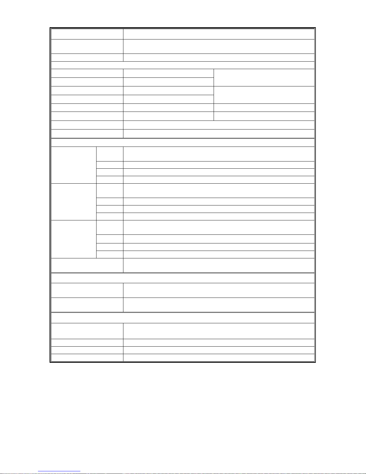
ENERMAX DIGIFANLESS Power Supply Specification
Model Number
EDF550AWN
AC Input Voltage
110-240VAC, 50-60Hz
(Maximum range: 99-265VAC, 47-63Hz)
AC Input Current
6.0-2.5A
RATED DC OUTPUT
3.3V
20A
5V
20A
100W
12V1
30A
12V2
30A
540W (45A)
-12V
0.5A 6W
5Vsb
2.5A 12.5W
Total Power
550W
Peak Power*1
605W
PROTECTION CIRCUIT
DC
Rail
OCP Trigger Range
3.3V
22-32A
5V
22-32 A
Over Current
Protection
12V
35-45A / rail, 50-60A (Single rail mode)
DC
Rail
OVP Trigger Range
3.3V
3.7-4.1V
5V
5.7-6.5V
Over Voltage
Protection
12V1/2
13.1-14.5V
DC
Rail
UVP Trigger Range
3.3V
2.0 – 2.4V
5V
3.3 – 3.7V
(DC) Under
Voltage
Protection
12V1/2
8.5 – 9.5V
Over Temperature
Protection
Activated when PSU heat sink > 90 ~ 120
o
C.
ENVIRONMENT
Temperature
Operation ambient: 0~40
o
C (for full rated output)
Storage ambient: -40~70
o
C
Humidity
Operation: to 85% relative humidity, non-condensing
Storage: to 95% relative humidity, non-condensing
OTHERS
MTBF
> 100,000 hours at 70% of full rated load, 230VAC/50Hz, 25
o
C
(MIL-HDBK-217F standard)
Dimension
150(w) x 86(h) x 175(d) mm
Weight
2kg (without modular cables)±50g
Safety
EAC, CE, FCC, BSMI, CCC, C-tick
*Peak power may last up to 60 seconds
3
User’s Manual
Dear customer,
Thank you for choosing this ENERMAX power supply unit (PSU)! Please read this manual
carefully and follow its instructions before installing the PSU.
We would like to draw your attention that a computer required very specific conditions to work best
for you without failing. To avoid failures and to increase lifetime of the system, we suggest that:
Your system is NOT located near a radiator or any other heat producing device
Your system is NOT located near a magnetic device
Your system is NOT located in a moist and/or dusty and/or vibrating environment
Your system is NOT exposed to direct sunshine
Your system is sufficiently cooled by additional fans
If you use AC extension cables, please make sure it can support all connected appliances’
potential peak power draw. Or redistribute other high power consumption equipment, such as
laser printers or monitors to other AC wall outlets. Exceeding the extension cable’s loading
capacity could trigger its circuit breaker and cut off the power.
If you want to add the UPS (Uninterruptible Power Supply) for your system, please choose
adequate Watts/VA capacity UPS.
Ex.
PSU Model
Suggested minimum UPS output power capacity
(Based on efficiency & PFC at respective load)
EDF550AWN 600W / 1000VA
* Please do not mistake VA capacity as Watts, or use insufficient power UPS. This would result in less
UPS battery runtime or the inability to power the system in battery mode.
* If you intend to add other appliance powered by the same UPS, such as monitor or printer, please use
higher capacity UPS according to all connected devices’ rated power draw.
* Enermax recommends “Pure Sine Wave” output in battery mode UPS with this PSU.
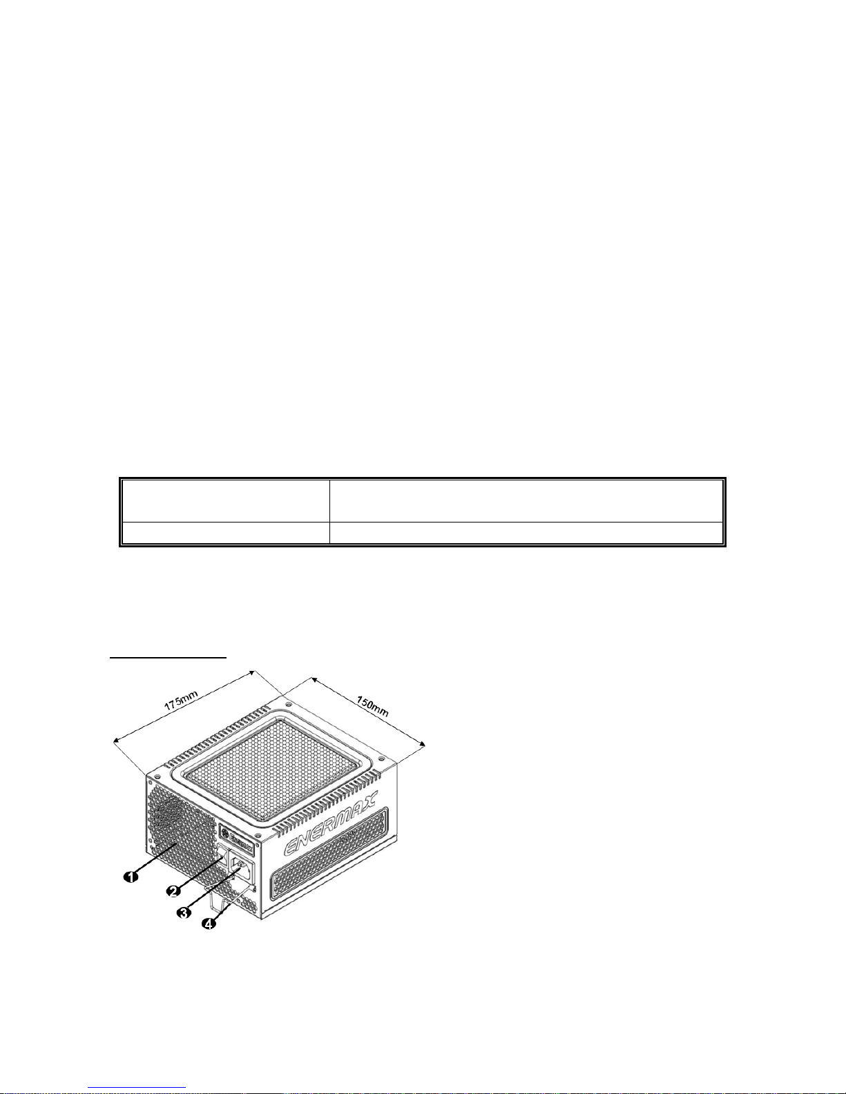
NAME OF PARTS
#1 To ensure best system cooling, do not block PSU air vent area.
#2 When assembling or maintaining the system, please remove AC cord from AC inlet, or turn ON/OFF
switch into “OFF” position. Then you can safely service the system.
#3 AC cord can get loose in many ways. The ENERMAX CordGuard lock can fix your AC cord tightly to the
PSU, so that it will not be easily detached and avoid shut-downs of your PC. The following is CordGuard
installation:
(unit: mm)
1 Honeycomb air vent # 1
2 ON/OFF switch (I=ON, O=OFF) # 2
3 AC Inlet # 2
4 CordGuard #3
4
①
Set your PSU into the bottom chassis
(main air frame should face up), and please
make sure the I/O switch is on “O” position.
②
Press two sides of the CordGuard lock
together, and set it into CordGuard holder
near the AC inlet.
③
Plug the AC cord into your PSU.
④
Lock the CordGuard to latch onto AC
cord.
1. CordGuard is for AC cords supplied with ENERMAX CordGuard-compatible PSUs. Other
AC cords may be incompatible.
2. When assembling or maintaining the system, please remove AC cord from AC inlet, or
turn I/O switch into “O” position.
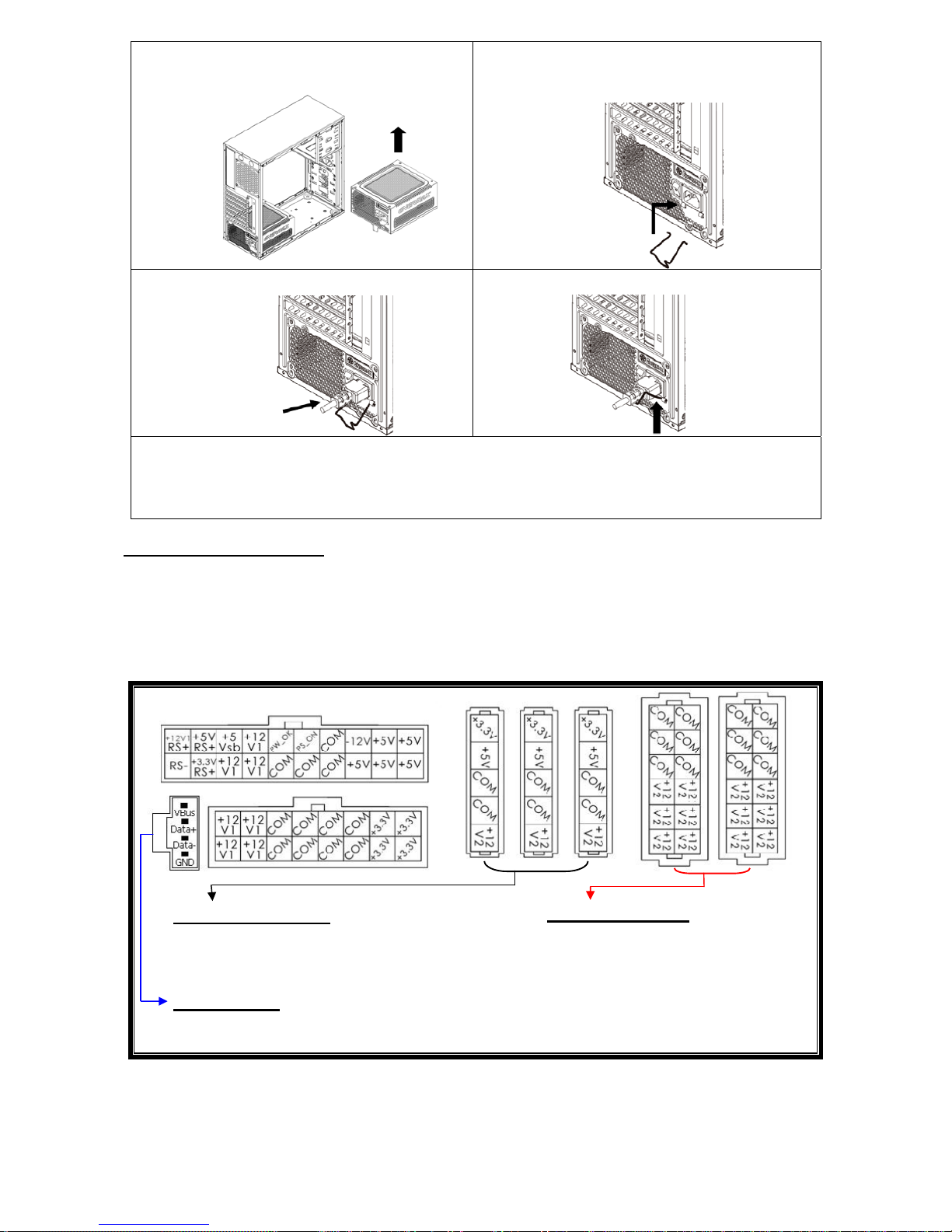
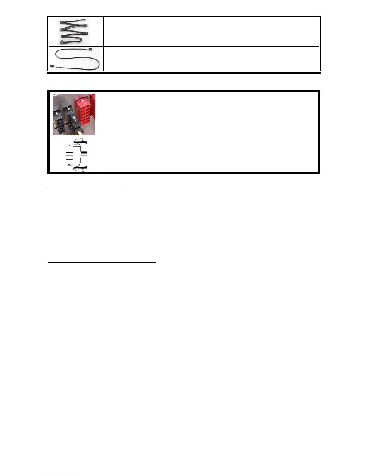
CABLES & CONNECTORS
All connectors are designed to prevent insertion in wrong orientation. If you cannot easily insert a
connector, please check if you are inserting the connector in the right orientation. Do not try by
force to insert it nor modify the connectors. This might damage power supply and system
components, and warranty shall be void.
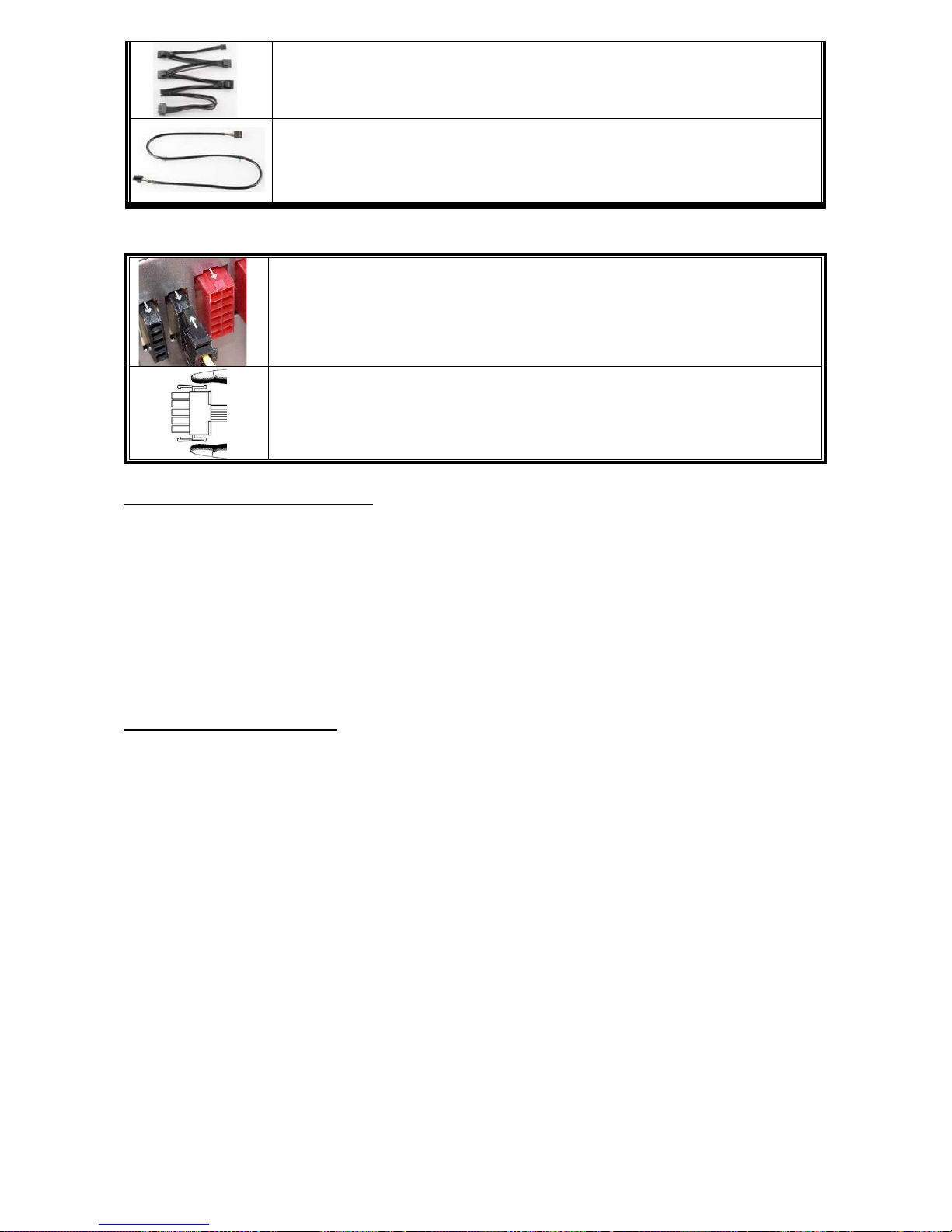
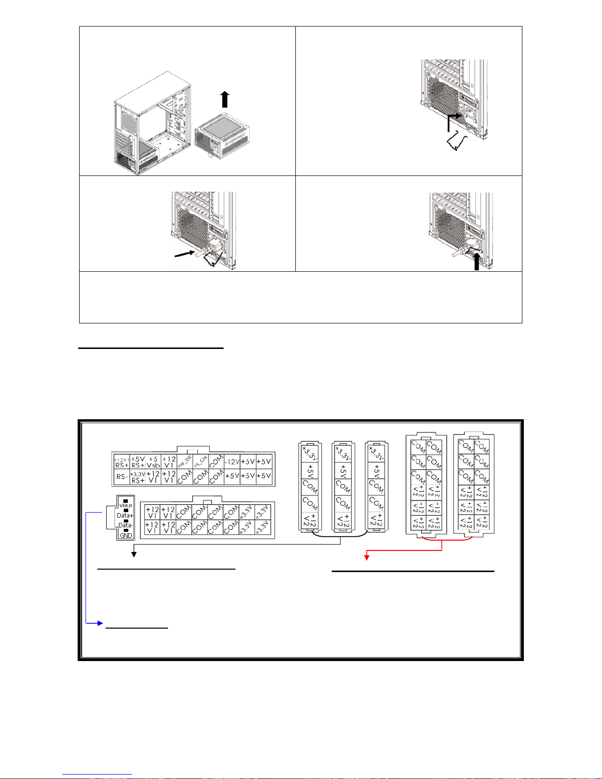
Following graphic illustrates the modular sockets layout and its DC rail distribution.
The black sockets provide 3.3V/5V/12V for
modular cable to power drives or other
peripheral.
The red sockets provide 12V for
modular cable to power graphics
card, CPU/GPU or RAM.
This port provides digital signal to MB’s USB port for further software control.
Please refer to ZDPMS manual for more detail.
* You must connect 16-pin and 20-pin connectors into respective sockets to enable 24-pin MB and 8-pin
CPU connectors.
* This product incorporates multiple 12V rails over current protection. If you let many peripherals consume
the power on only one 12V rail, it may trigger the over current protection and shut down the system.
Please re-direct certain peripheral power cable to other 12V rail to share the current loading to ensure
highest stability and safety.
5P BLACK sockets
12P RED sockets
(this side up)
ZDPMS port:
5
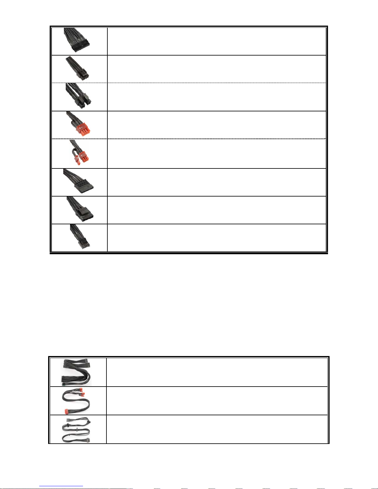
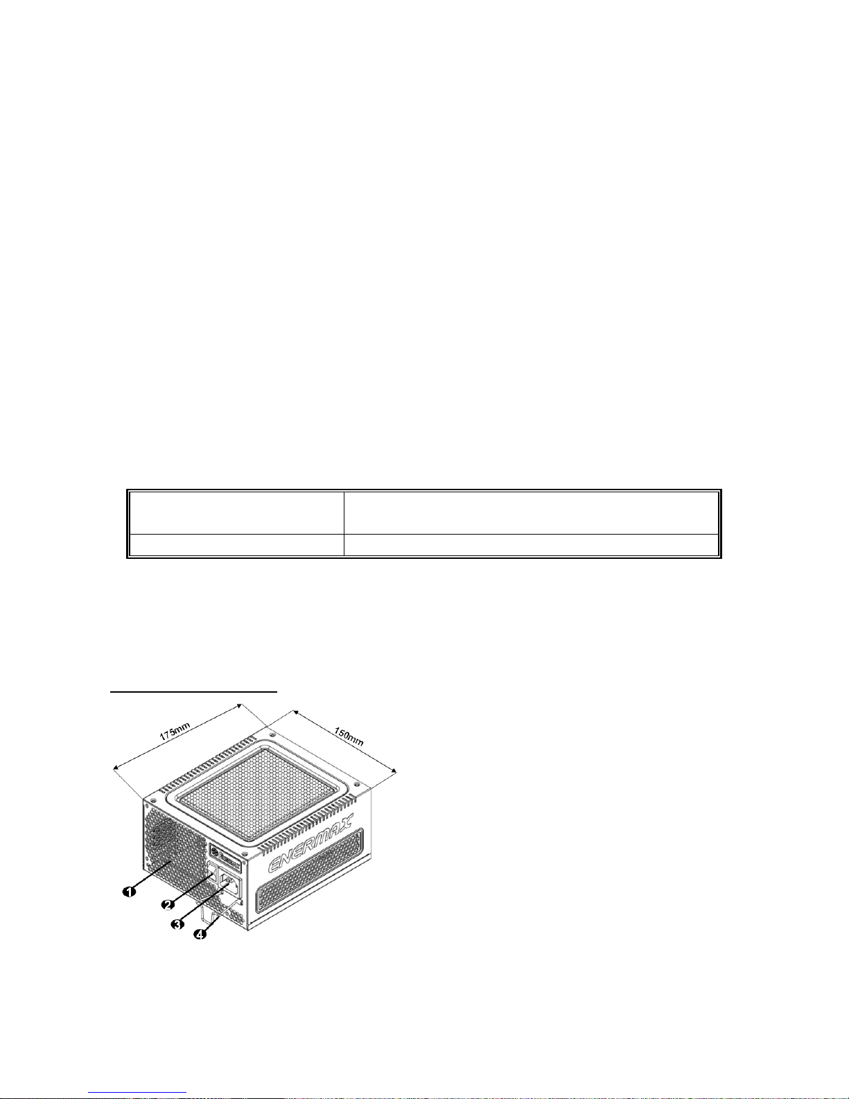
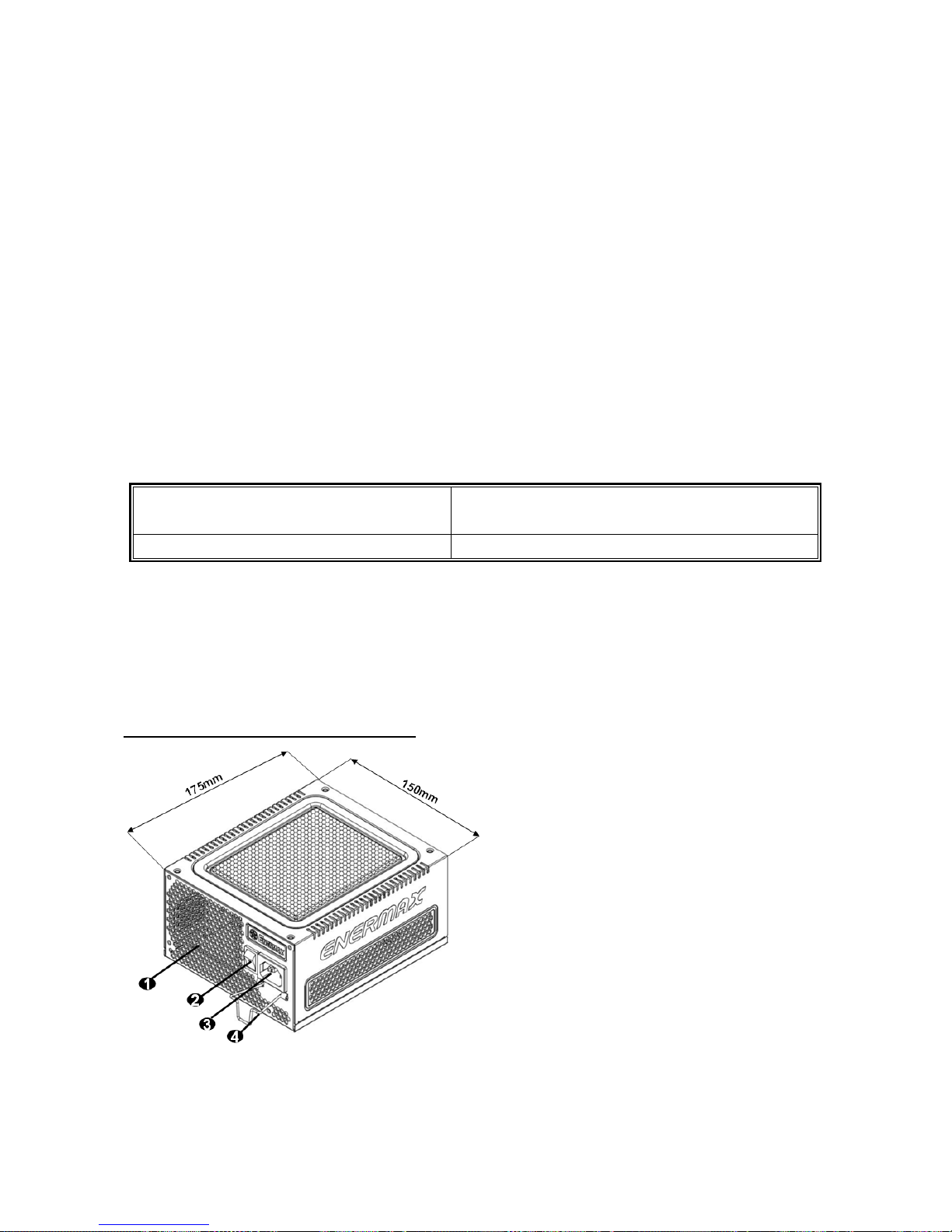
CONNECTOR TYPES
24P Mainboard
For ATX/EEB/CEB server/workstation MB.
4+4P (8P) CPU +12V, in combined mode
8-pin configuration supports multi-CPU server/workstation systems and
some single extreme CPU systems.
4+4P(8P) CPU+12V, in split mode
4-pin configuration supports certain single CPU systems. Some multi-CPU
workstation/server system might also need this extra 4-pin 12V connector.
6+2P (8P) PCI Express, in combined mode
8-pin configuration supports latest extreme graphic cards, which require
8-pin PCI-E connector.
6+2P (8P) PCI Express, in split mode (6P PCI Express)
# 2
6-pin configuration supports most performance PCI-E graphic cards, which
require 6-pin PCI-E connector.
SATA
# 1
For SATA/SAS drives.
4P Molex
# 2
For IDE/SCSI/SAS drives or some AGP graphic card with traditional 4P
power in socket.
FDD
For floppy drive or certain add-on card.
#1 Some SATA drives might accept SATA or 4P Molex power. Normally, use either one of power connector to
power the driver, BUT NOT BOTH! Please check the drive’s manual for details.
#2 If you plan to put in 2 or more high end, power demanding GPU cards, please choose the motherboard
that comes with extra 4P Molex/ 4P FDD / 6P PCI-E power socket(s) on board and connect them with
your power supply. This will prevent the motherboard from overloading and possibly causing damage to
your system including your power supply. The damage to the motherboard and the power supply caused
by failing to do the above instruction will not be covered under Enermax manufacturer’s
warranty. Please refer to your motherboard’s user manual to configure your system properly to prevent
damage to your system and your power supply.
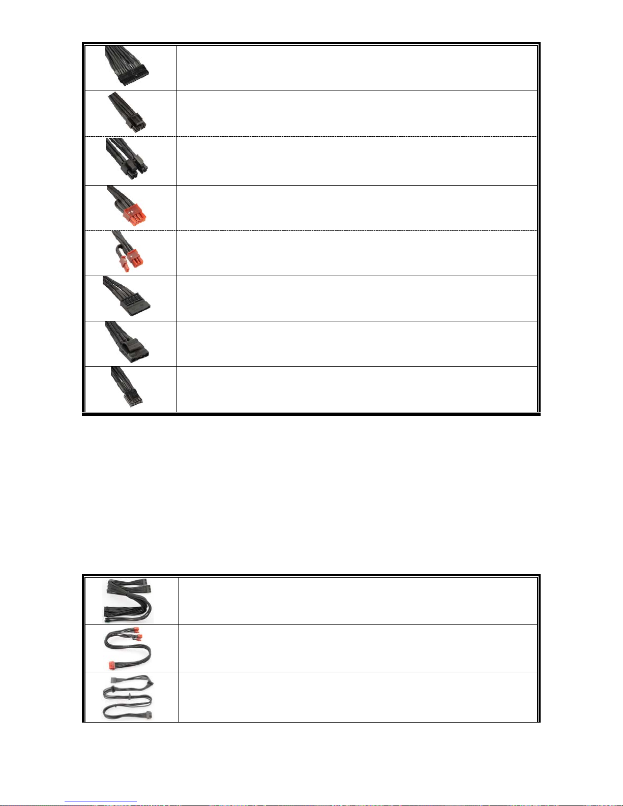
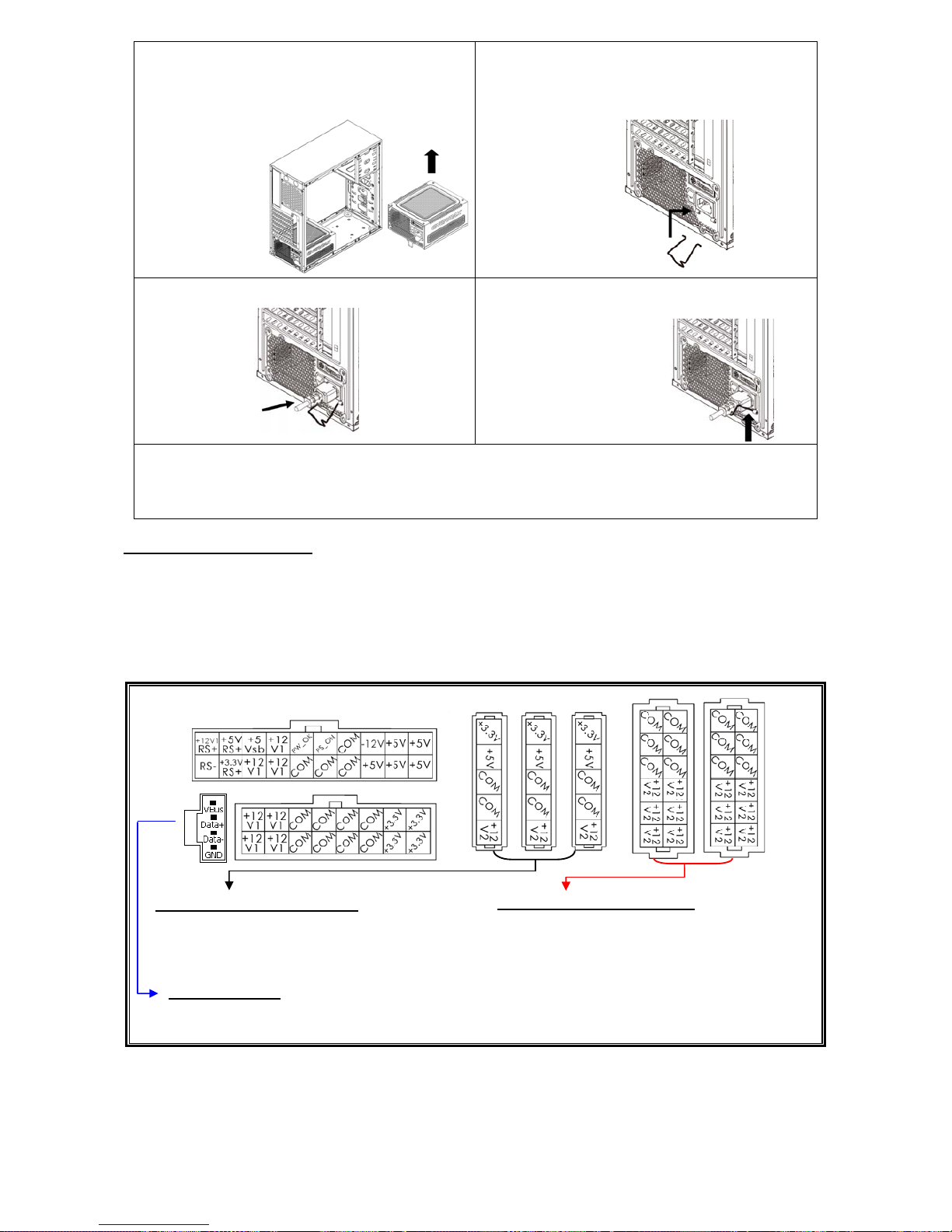
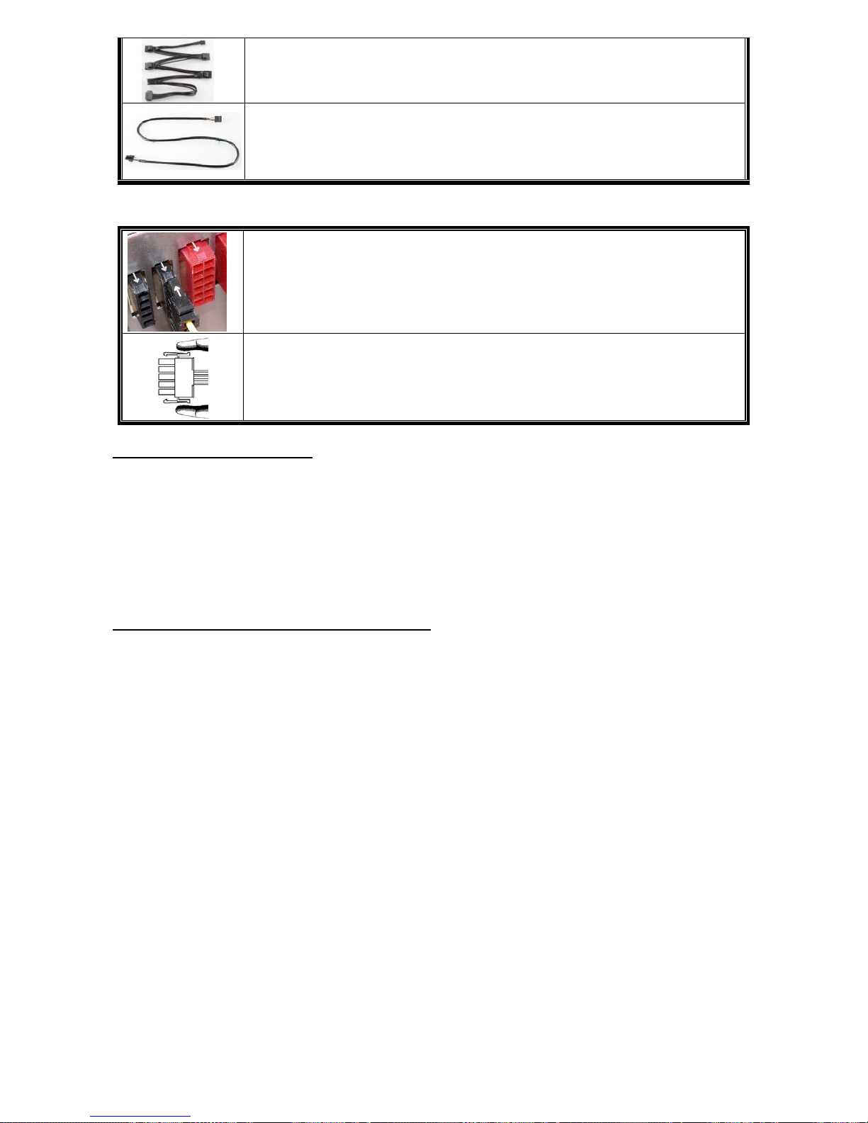
MODULAR CABLES SUPPLIED
Use ONLY genuine ENERMAX modular cables coming with ENERMAX PSU. Third party
cables might not be compatible and might cause damage to your PSU and/or system, and use
of third party cable shall void PSU warranty.
24P MB & 4+4P (8P) CPU
Modular cable for 24P Motherboard and 4+4P (8P) CPU.
2 x 6+2P (8P) PCI-E
Modular cable for 1 or 2 performance PCI Express graphic cards, which
needs 6P or 8P PCI-E connector.
4 x SATA drives
Modular cable for SATA/SAS drives like ODD and HDD.
6
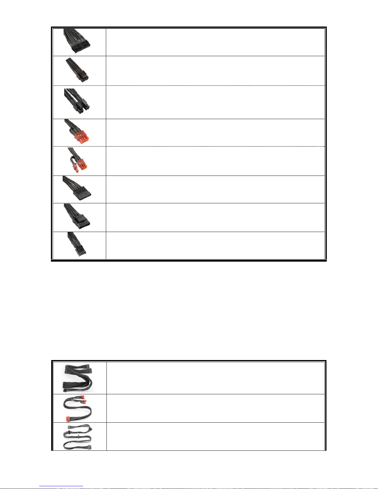
4 x 4P Molex (IDE/SCSI) drives & 1 x FDD connector
Modular cable for IDE/SCSI/SAS drives and peripheral, plus 1 FDD power
connector.
ZDPMS data link
Modular cable to link the PSU and MB to enable the power supply digital
monitor/control function. (ZDPMS software installation required)
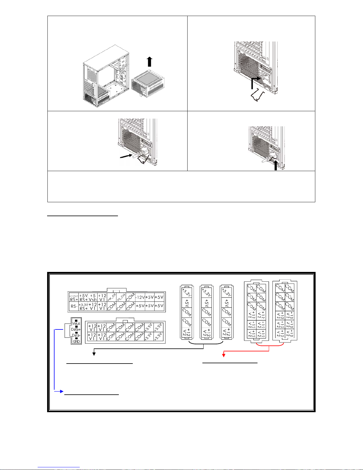
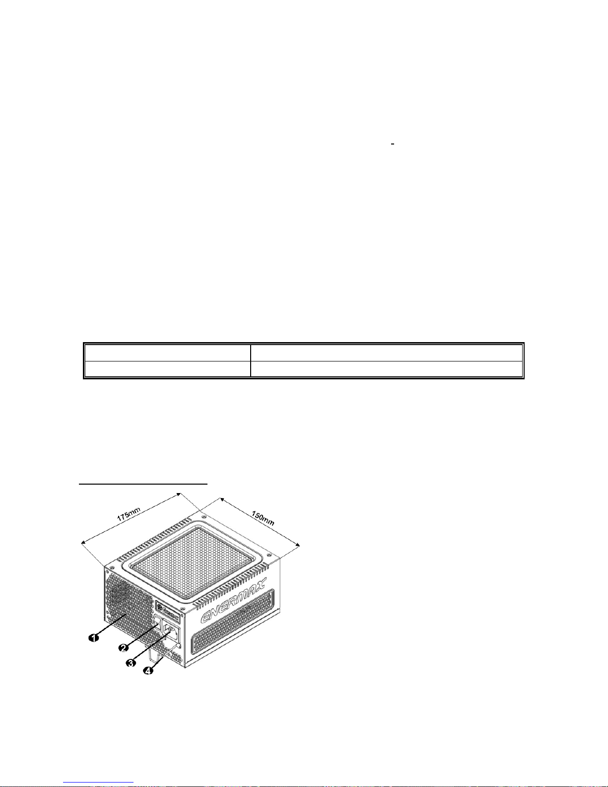
ATTACHING / DETACHING THE MODULAR CABLES
Attaching the modular cable to PSU
5-pin / 12-pin connector on modular cable and PSU’s modular socket has an
arrow mark. To make correct connection is easy:
1. Black connector to black socket, and red to red.
2. Arrow mark to arrow mark.
3. Then you can easily plug in the connector.
Detaching the modular cable from PSU
5-pin / 12-pin connector on modular cable has two hooks to lock with the
PSU’s modular sockets. When unplug the modular cable from PSU, please
press two hooks together and gently pull out the cable.
BOOTING YOUR SYSTEM
Before booting your system, please check that:
1. Main power connector (24P) is properly connected.
2. CPU +12V power connector (4 or 8P configuration), and/or a 4P Molex connector (if
required by MB) is properly connected.
3. All other needed connectors are properly connected.
4. AC cord is properly connected to wall outlet and PSU AC inlet.
5. Close your system chassis.
6. Turn on the PSU by switching the ON/OFF switch to “ON”, and your system is ready.
PROTECTION, SAFETY & SECURITY
This ENERMAX PSU features multiple protections. In case of most abnormal situations, the power
supply will automatically turn off to avoid potential danger to itself and other PC components. It is
usually a malfunction of components or user’s negligence to trigger off a protection event. In such
circumstance, please check your PC devices and working environment for malfunction:
1. Turn I/O switch of power supply into “O” position, or disconnect AC cord from wall plug and
power supply AC inlet.
2. Check PSU for temperature by simply touching it. If it is very hot, this can be caused by
malfunction of case fans or the PSU fan itself and/or wrong positioning of your PC.
3. Wait some minutes until PSU cools off.
4. Reconnect AC cord to wall plug and power supply AC inlet.
5. Turn I/O switch of power supply into “I” position, and reboot your system.
6. Check, if all fans are working.
7. Contact technical support of the respective manufacturer of the component which you think
might be the cause to the problem. (e.g. MB, GPU or PSU)
If you have any question or need support, please contact your reseller or nearest ENERMAX
subsidiary/agent or ENERMAX headquarter service center.
©2014 ENERMAX Technology Corporation. All rights reserved. Specifications are subject to change without prior notice.
Actual product and accessories may differ from illustrations. Omissions and printing errors excepted. Content of delivery
might differ in different countries or areas. Some trademarks may be claimed as the property of others. Reproduction in
any manner without the written permission of ENERMAX is strictly forbidden.
7
Benutzerhandbuch (DE)
Sehr geehrte Kundin, sehr geehrter Kunde,
Vielen Dank, dass Sie sich für dieses ENERMAX-Netzteil (PSU) entschieden haben! Bitte lesen
Sie sich dieses Handbuch sorgfältig durch und folgen Sie bitte seinen Anweisungen bevor Sie das
Netzteil installieren!
Wir möchten Sie darauf hinweisen, dass moderne Systeme sehr empfindlich geworden sind und
genau definierte Bedingungen benötigen, um optimal ohne Ausfälle arbeiten zu können. Um
solche Ausfälle zu vermeiden und die Lebensdauer Ihres Systems zu verlängern, empfehlen wir
Ihnen sicherzustellen, dass:
Ihr System nicht neben einer Heizung oder einer anderen Wärmequelle steht.
Ihr System nicht neben einer magnetischen Quelle steht.
Ihr System nicht in einer feuchten und/oder staubigen und/oder vibrierenden Umgebung steht.
Ihr System nicht dem direkten Sonnenlicht ausgesetzt ist.
Ihr System ausreichend durch Lüfter gekühlt wird.
Falls Sie ein Verlängerungskabel verwenden, stellen Sie bitte sicher, dass dieses dazu
geeignet ist, den maximalen Strombedarf sämtlicher angeschlossenen Geräte zu leisten.
Andernfalls schließen Sie bitte weitere viel Strom verbrauchende Geräte (wie Laserdrucker
oder Monitor) an eine andere Steckdose an. Ein Überschreiten der maximalen
Durchleitungsfähigkeit des Verlängerungskabels könnte zu einem Auslösen der Sicherung
führen.
Falls Sie eine USV (Unterbrechungsfreie Stromversorgung) verwenden möchten, nutzen Sie
bitte eine mit ausreichender Watt/VA-Kapazität.
Z. B.:
PSU Modell
Empfohlene kleinste USV-Kapazität
(gemäß Effizienz & PFC bei entsprechender Last)
EDF550AWN 600W / 1000VA
* Bitte vermeiden Sie Verwechslungen von Watt-(W)- und Voltampere-(VA)-Angabe. Verwenden Sie
ausreichend dimensionierte UPS-Systeme. Andernfalls wird die Laufzeit der UPS-Batterie
beeinträchtigt bzw. die Leistung reicht nicht aus, um den PC im UPS-Batterie-Modus zu betreiben.
* Wenn Sie beabsichtigen weitere Geräte wie Drucker oder Monitor über das UPS-System zu betreiben,
verwenden Sie entsprechend höher dimensionierte UPS-Systeme, die dem Stromverbrauch aller
angeschlossenen Geräte entsprechen.
* Für dieses Netzteil empfiehlt Enermax den Einsatz von UPS-Systemen mit reinen Sinuswelle
(„Pure Sine Wave“).
DETAILBESCHREIBUNG
#1 Bitte blockieren Sie nicht die Lufteinlässe/Luftauslässe, um eine bestmögliche Systemkühlung zu
gewährleisten.
#2 Entfernen Sie immer das Stromkabel vom Netzteil, schalten Sie den I/O-Schalter auf „O“ und warten Sie,
bevor Sie am System arbeiten.
#3 Der Netzstecker kann sich auf unterschiedliche Weise lösen. Der ENERMAX-CordGuard fixiert den
Stecker am Netzteil. Er verhindert unfreiwillige Systemabstürze durch einen versehentlich gezogenen
Netzstecker.
(unit: mm)
1. Honigwabenluftauslass. # 1
2. I/O Schalter*: separater Netzteil An/Aus-Schalter
(I=AN, O=AUS). # 2
3. Stromeingang.# 2
4. CordGuard # 3
8
①
Montieren Sie das Netzteil am Boden des
Gehäuses. Dabei muss das Lüftungsgitter nach
oben ausgerichtet sein. Stellen Sie sicher, dass
der Netzschalter auf der Position „O“ („Aus“)
steht.
②
Drücken Sie die beiden Seiten des
CordGuard zusammen und befestigen Sie
ihn an der dafür vorgesehenen Stelle.
③
Schließen Sie das Netzkabel am Netzteil
an.
④
Klappen Sie den CordGuard herunter
und sichern Sie auf diese Weise den
Netzstecker.
1. Der CordGuard ist nur für Netzkabel geeignet, die mit CordGuard-kompatiblen
ENERMAX-Netzteilen ausgeliefert wurden. Andere Netzkabel sind mit dem
ENERMAX-CordGuard ggf. nicht kompatibel.
2. Beim Zusammenbauen oder bei der Wartung des Systems ziehen Sie bitte immer den
Netzstecker oder stellen Sie den Netzschalter auf “O“(Aus).
KABEL & ANSCHLÜSSE
Alle Sockel und Anschlüsse sind so entworfen, dass ein Anschluss in falscher Ausrichtung nahezu
unmöglich ist. Der Anschluss an die kompatiblen Sockel gestaltet sich leichtgängig und ohne
größeren Widerstand. Wenn Sie einen originalen ENERMAX Anschluss nicht auf Anhieb mit einer
Komponente verbinden können, überprüfen Sie bitte, ob Sie die richtige Ausrichtung gewählt
haben. Versuchen Sie es keinesfalls mit Gewalt! Verändern Sie nicht die Anschlüsse! Dies könnte
das Netzteil beschädigen und hat das Erlöschen der Garantie zur Folge!
Folgende Grafik illustriert das Layout der modularen Sockel und deren DC Leitungsverteilung.
Schwarze Sockel (3.3V/5V/12V) für modulare
Kabel der Laufwerke (HDD, ODD) oder
Peripheriegeräte.
Rote Sockel (12V) für modulare Kabel der
Grafikkarten, CPUs/GPUs oder RAM.
Dieser Anschluss überträgt digitale Signale für den Betrieb der Software-Steuerung zum USB-Port
des Mainboards. Weitere Informationen finden Sie im ZDMPS-Handbuch.
* Um Mainboard und CPU über die 24- und 8-Pin-Stecker mit Strom zu versorgen, müssen Sie die 20- und
16-Pin-Stecker des Kabels an den entsprechenden Sockeln des Netzteils anschließen.
* Dieses Netzteil besitzt eine Überstromsicherung (OCP) auf jeder einzelnen 12V-Leitung. Wenn zu viele
Komponenten an einer 12V-Leitung angeschlossen werden, kann es zur Auslösung der
Überstromsicherung kommen. Daher achten Sie bitte auf eine gleichmäßige Verteilung der Komponenten
auf die einzelnen 12V-Leitungen, um optimale Stabilität und Sicherheit zu gewährleisten.
Schwarze 5-Pin Sockel
Rote 12-Pin Sockel
(Diese Seite nach oben)
ZDMPS-Anschluss
9
Anschlusstypen
24P Mainboard
Für die neueste Generation von ATX/EEB/CEB Server/Workstation MB’s.
4+4P (8P) CPU +12V, in “kombiniertem Modus”
Unterstützt Multi-CPU Server/Workstation-Systeme und einige
Hochleistungs-Einzel-CPU Systeme.
4+4P (8P) CPU +12V, in “getrenntem Modus”
4-Pin Konfiguration unterstützt herkömmliche Einzel-CPU Systeme. Einige
Multi-CPU Systeme benötigen möglicherweise ebenfalls diesen zusätzlich
Stecker.
6+2P (8P) PCI Express, in “kombiniertem Modus”
8-pin Konfiguration unterstützt die neuesten Grafikkarten, welche diesen
8-Pin PCI-E Stecker benötigen.
6+2P (8P) PCI Express, in “getrenntem Modus” / 6P PCI Express
# 2
6-Pin Konfiguration unterstützt die meisten Grafikkarten, welche diesen
6-Pin PCI-E Stecker benötigen.
SATA
# 1
Für SATA/SAS-Laufwerke.
4P Molex
# 2
Für IDE/SCSI/SAS-Laufwerke oder einige AGP Grafikkarten mit
traditionellem 4-Pin Stecker.
FDD
Für Floppy-Laufwerke oder einige Erweiterungskarten.
#1 Einige SATA-Laufwerke unterstützen SATA & 4-Pin Molex Stecker. Schließen Sie nur einen Stecker an!
Lesen Sie ansonsten im Handbuch des Laufwerks nach!
#2 Wenn Sie zwei oder mehr Hochleistungsgrafikkarten in Ihrem System installieren möchten, wählen Sie
bitte ein Mainboard mit zusätzlichen 4-Pin-Molex-, 4-Pin-FDD-, oder 6-Pin-PCI-Express-Sockeln und
verbinden sie diese mit dem Netzteil. Auf diese Weise verhindern Sie, dass das Mainboard überlastetet
wird und andere Systemkomponenten einschließlich des Netzteils Schaden nehmen. Ein Schaden, der
durch Missachtung des obigen Hinweises am Mainboard oder Netzteil entsteht, wird nicht von der
Enermax-Herstellergarantie gedeckt. Bitte lesen Sie sich auch die Betriebsanleitung Ihres Mainboards
gründlich durch, um das System fachgerecht einzurichten und Schäden am Netzteil und den anderen
Komponenten zu verhindern.
MODULARE KABEL (im Lieferumfang enthalten)
Benutzen Sie nur original ENERMAX modulare Kabel für dieses PSU. Andere Kabel könnten
das PSU und Ihr System beschädigen und den Garantieverlust zur Folge haben!
24P MB & 4+4P (8P) CPU
Modulares Kabel mit 24-Pin-Mainboard-Stecker und
4+4(8)-Pin-CPU-Stecker.
2 x 6+2P (8P) PCI-E
Modulares Kabel für 1 oder 2 hochleistungsfähige
PCI-Express-Grafikkarten, die 6-Pin- oder 8-Pin-PCI-E-Stecker benötigen
4 x SATA drives
Modulares Kabel für SATA/SAS-Laufwerke wie ODD und HDD.
10
4 x 4P Molex (IDE/SCSI) drives & 1 x FDD connector
Modulares Kabel für IDE/SCSI/SAS-Laufwerke und Peripheriegeräte + 1x
FDD-Anschluss.
ZDPMS-Datenkabel
Das modulare Kabel verbindet das Netzteil mit dem Mainboard und
ermöglicht den Betrieb der digitalen Steuerungs-/Überwachungssoftware
(Installation der ZDPMS-Software vorausgesetzt).
VERBINDEN & ENTFERNEN VON MODULAREN KABELN
Modulare Kabel an das Netzteil anschließen
Die 5-Pin / 12-Pin Stecker auf den modularen Kabeln und den Sockeln des Netzteils
haben weiße Pfeilmarkierungen.
Folgende Regeln machen die Anwendung einfach:
1. Schwarze Stecker zu schwarzen Sockeln und rote zu roten.
2. Pfeilmarkierung zu Pfeilmarkierung.
Modulare Kabel vom Netzteil entfernen
Alle 5-Pin- / 12-Pin-Stecker an den modularen Kabeln haben zwei Haken,
die an
den Sockeln des Netzteils einrasten. Um ein modulares Kabel zu entfernen,
drücken Sie bitte die beiden Haken und ziehen Sie den Stecker dann sanft
heraus
.
EINSCHALTEN IHRES SYSTEMS
Bevor Sie das System einschalten stellen Sie bitte sicher,
1. dass der Mainboard-Stromanschluss (24-Pin-Stecker) korrekt angeschlossen ist,
2. dass der CPU-Stromanschluss (4- oder 8-Pin-Stecker) (falls für MB erforderlich) oder ein
4-Pin-Molex-Stromanschluss (falls für MB erforderlich) korrekt angeschlossen sind,
3. dass alle anderen erforderlichen Stromanschlüsse korrekt angeschlossen sind,
4. dass das Kaltgerätekabel (Stromkabel) korrekt an der Steckdose und am Netzteil angeschlossen
ist,
5. dass das Systemgehäuse verschlossen und verschraubt ist,
6. und dass der I/O-Schalter am Netzteil auf “I” (ON) steht. Das System ist jetzt bereit!
SICHERHEITSFUNKTIONEN
Dieses ENERMAX Netzteil verfügt über zahlreiche Sicherheitsfunktionen. Im Fall der meisten
abnormen Situationen wird sich das Netzteil zum Schutz Ihres gesamten PC-Systems
automatisch abschalten, um Schäden zu vermeiden. In den meisten Situationen, in denen dies
geschieht, ist eine Komponenten-Fehlfunktion oder Fehlverhalten die Ursache. In einer solchen
Situation prüfen Sie bitte zuerst ihre PC-Komponenten und die Umgebung auf Fehlfunktion(en),
indem Sie folgendes ausschalten und/oder abtrennen:
1. I/O Schalter des Netzteils auf “O“ & Kaltgerätekabel (Stromkabel) von der Steckdose und
vom Netzteil trennen.
2. Berühren Sie das Netzteil vorsichtig, um zu prüfen, ob es stark erhitzt ist. Sollte dies der
Fall sein, kann es eine Folge der Fehlfunktion von Gehäuse-oder Netzteillüftern sein oder
durch eine ungenügende Anzahl von Gehäuselüftern oder eine falsche
PC-Positionierung verursacht worden sein.
3. Warten Sie einige Minuten, bis sich das Netzteil abgekühlt hat.
4. Schliessen Sie wieder das Kaltgerätekabel (Stromkabel) an Steckdose und Netzteil an.
5. Schalten Sie den I/O-Schalter am Netzteil auf “I”.
6. Prüfen Sie nun, ob alle Lüfter Ihres Systems arbeiten.
7. Kontaktieren Sie bitte den technischen Support des Herstellers der Komponente, von der
Sie glauben, dass Sie die Fehlfunktion verursacht (z.B. MB, Grafikkarte oder
ENERMAX-Netzteil).
Falls Sie Fragen haben oder Support benötigen, wenden Sie sich bitte an Ihren Händler, Ihre nächste
ENERMAX-Niederlassung, deren Agenten oder an das ENERMAX Headquarter Service Center!
11
Manual Del Usuario (ES)
Estimado cliente:
Muchas gracias por comprar nuestra fuente ENERMAX . Le recomendamos que se lea bien este
manual para el usuario.
Queremos recordarle que los ordenadores actuales son muy vulnerables y necesitan condiciones
especiales para funcionar sin problemas. Para evitar dichos fallos y maximizar la duración del
sistema, le recomendamos asegurarse que:
Su ordenador no se encuentre al lado de la calefacción ni otro objeto que irradie calor
Su ordenador no se encuentre al lado de un objeto magnético
Su ordenador no se encuentre en un entorno húmedo, con polvo y vibraciones
Su ordenador no reciba radiación solar directa
Su ordenador sea refrigerado lo suficiente por parte de los ventiladores
Si se utiliza un alargador eléctrico, asegúrese de que sea capaz de soportar la carga máxima de
consumo de corriente de todos los dispositivos conectados, de lo contrario redistribuya los
aparatos con alto consumo de energía, como las impresoras láser o monitores, en las otras tomas
de corriente de la pared.
Si utiliza un SAI (Sistemas de Alimentación Ininterrumpida) para su sistema, debe emplear uno
con capacidad de vatios-VA suficiente como:
modelo de la fuente
Capacidad recomendada mínima del SAI:
(se basa por eficiencia y PFC a carga respectiva)
EDF550AWN 600W / 1000VA
* Por favor, no confunda la capacidad VA con los Vatios o utilice sistemas de alimentación ininterrumpida
con potencia insuficiente. Esto daría lugar a una menor autonomía de la batería del SAI o la incapacidad
de alimentar el sistema en modo batería.
* Si se quiere agregar otros dispositivos alimentados por el mismo SAI como un monitor o una impresora,
utilice SAI con mayor capacidad sobre la base del consumo de potencia nominal de todos los dispositivos
conectados.
* Enermax recomienda utilizar junto con la fuente de alimentación unos SAI que, en modo batería,
produzcan "ondas sinusoidales puras" en salida.
NOMENCLATURA DE LAS PARTES
#1 Para asegurar la mejor refrigeración del sistema., no obstruir la ventilación de la fuente.
#2 Al ensamblar el sistema, poner el el interruptor en posición "Apagado/O" y desenchufar el cable de la
toma de corriente.
#3 En las normales fuentes de alimentación, el cable de alimentación puede desconectarse muy fácilmente.
El sistema ENERMAX CordGuard permite fijar el cable de alimentación a la fuente de alimentación
evitando practicamente cualquier tipo de desconexión.
(unit: mm)
1 Salida de aire Honeycomb # 1
2 Interruptor ON/OFF:
(I=ENCENDIDO, O=APAGADO) # 2
3 Toma de corriente # 2
4 CordGuard # 3
12
①
Coloque la fuente de alimentación en
la parte inferior de la caja (la toma de aire
principal debe estar hacia arriba), y
asegúrese de que el interruptor I / O esté en
la posición "O".
②
Apretar al mismo tiempo las dos
solapas de CordGuard y colocarlas en
los huecos correspondientes cerca de donde se
conecta el cable de alimentación.
③
Conectar el cable a la fuente.
④
Se cierra CordGuard haciendo presión.
Esto permite tener siempre en la posición
correcta el dispositivo.
1. CordGuard es un sistema exclusivo de la marca ENERMAX, cualquier intento de
instalación en otro dispositivo distinto puede ocasionar problemas.
2. Cuando se hace mantenimiento del sistema con operaciones internas, el cable
SIEMPRE debe permanecer desconectado.
CABLES Y ENCHUFES
Todos los enchufes están diseñados para que sea imposible conectar cables en la dirección
equivocada. Poner un enchufe en un zócalo tiene que ser fácil. Si no puede poner fácilmente el
cableado modular original de ENERMAX en un zócalo, por favor, revise si está insertado en la
dirección correcta. Nunca lo intente utilizando fuerza ni cambie los pines del voltaje. Eso puede
dañar la fuente e invalidar la garantía.
Ilustración gráfica de los zócalos modulares y la distribución c.c..
Los zócalos negros son para cables
modulares en discos (HDD, ODD) o
periféricos de 3.3V/5V/12V.
Los zócalos rojos son para cables
modulares de tarjetas graficas o CPU/GPU
o RAM de 12V.
Este puerto proporciona una señal digital al puerto USB de la placa base para un control
adicional del software. Consulte el manual para más detalles.
* Conectar los extremos de 20 y 16 pines en la fuente de alimentación y el conector de 24 y 8 pin a la
placa base, para la alimentación de placa base y CPU
* Este producto incluye una protección para sobrecarga para una línea múltipla de 12v. Si se deja que
muchos periféricos utilicen solo una línea de 12v, esto podría accionar la protección y provocar el
apagamiento del sistema.Para repartir la carga de corriente y asegurar la mejor estabilidad y
seguridad aconsejamos reconectar ciertos cables de alimentación de los periféricos a otras líneas de
12v.
Zócalos negros de 5 Pines
Zócalos rojos de 12 Pines
Puerto ZDPMS
(Este lado para)
13
TIPOS DE ENCHUFES
24P placa base
Soporta generaciones nuevas de ATX/EEB/CEB server/workstation.
4+4P CPU +12V, en “modo combinado”
La configuración 8-Pin soporta multi-CPU server/workstation
y algunos
sistemas single-socket extremos
.
4+4P CPU +12V, en “modo separado”
La configuración 4-Pin soporta la mayoría de los sistemas single-socket.
Unos sistemas multi-CPU server/workstation posiblemente necesitan este
enchufe de 4-Pin 12V.
6+2P (8P) PCI Express, en “modo combinado”
La configuración 8-pin soporta las nuevas tarjetas gráficas.
6+2P (8P) PCI Express, en “modo separado” / 6P PCI Express
# 2
La configuración 6-pin configuración soporta la mayoría de las tarjetas
gráficas, que necesitan este enchufe de 6-Pin PCI-E.
SATA
# 1
Para ODD o HDD tipo SATA/SAS.
4P Molex
# 2
Para ODD tipo IDE/SCSI/SAS de ”vieja” generación con enchufe 4-P.
FDD
Para discos “Floppy” o tarjetas de expansión.
#1 Unos discos duros de SATA soportan conectores SATA e 4-Pin Molex. Conecte Vd. solamente un
enchufe! Examine su manual para el disco duro para entrar más en detalle.
#2 Si van a utilizar dos o más tarjetas vídeo de gama alta, escojan una placa base que tenga conectores
4P Molex / FDD 4P / 6P PCI-E extra y conéctenlos con su fuente de alimentación. Esto evitará que la
placa base se sobrecargue y que por lo tanto cause daños a su sistema y a su fuente de alimentación.
Los daños a la placa base y a la fuente provocados por no haber seguido las instrucciones indicadas
no serán cubiertos por la garantía del fabricante Enermax. Por favor controle con cuidado el manual de
usuario de la placa base para configurar correctamente el sistema y para evitar cualquier daño al
sistema y a la fuente de alimentación.
CABLES MODULARES (contenido)
Por favor utilice solamente cables modulares originales de ENERMAX. Otros cables podrían
dañar el sistema e invalidar la garantía.
24P MB & 4+4P (8P) CPU
Cable modular para la conexión a la placa base (24 pines) y a la CPU (8
pines).
2 x 6+2P (8P) PCI-E
Cable modular para una o dos tarjetas gráficas Performance PCI Express,
que necesitan enchufes de 6 o 8-Pin PCI-E.
4 x SATA drives
Cable modular para ODD o HDD tipo SATA/SAS de la generación más
reciente.
14
4 x 4P Molex (IDE/SCSI) drives & 1 x FDD connector
Cable modular para ODD o HDD tipo IDE/SCSI/SAS mas 1x FDD (Floppy).
ZDPMS data link
Cable modular para conectar la fuente de alimentación a la placa base para
habilitar la función de supervisión/control de la fuente de alimentación
(requiere instalación de software ZDPMS)
CONECTAR Y EXTRAER CABLES MODULARES
CONECTAR CABLES MODULARES CON LA FUENTE
5-Pin / 12-Pin enchufes de los cables modulares y los zócalos de la fuente
tienen marcas blancas de flecha.
1. Enchufes negros con zócalos negros y rojos con rojos.
2. Flecha con flecha.
3. Ahora puede conectarlo fácilmente.
RENOVAR CABLES MODULARES DE LA FUENTE
Todos los enchufes 5-Pin / 12-Pin de los cables modulares tienen ganchos
para guardar con los zócalos de la fuente. Para quitar un cable modular
pulse hacia las flechas y desconecte el enchufe cuidadosamente.
ENCENDIENDO EL SISTEMA
Antes de encenderlo por favor asegúrese de que:
1. El enchufe de la placa base está conectado correctamente.
2. El enchufe del CPU (4 o 8 pines) (si es requerido por la placa base) o un enchufe 4-Pin
Molex (si es requerido por la placa base) esté conectado correctamente.
3. Todos los otros enchufes necesarios están conectados correctamente.
4. El cable de la corriente (AC) está conectado correctamente con la fuente y el enchufe.
5. Cierre la caja del sistema
6. Coloque el interruptor de la fuente en la posición “I” (encendido).
FUNCIÓNES DE PROTECCIÓN Y SEGURIDAD
La fuente ENERMAX tiene varias funciones de protección y seguridad. En caso de mal
funcionamiento se detendrá para proteger todo el sistema de daños. En la mayoría de casos eso
será causado por un mal funcionamiento de componentes o mala utilización. En cualquier
situación siempre sigua las instrucciones y desconéctela o apáguela:
1. Ponga el el interruptor de la fuente en la posición "O" y desenchufe el cable de CA
de la toma de corriente de la pared y de la fuente de alimentación.
2. Compruebe la temperatura de la fuente de alimentación por medio del tacto. Si está
demasiado caliente, puede ser que los ventiladores del sistema o de la fuente estén
dañados o su caja no tenga ventiladores suficientes o que la fuente esté en una mala
posición.
3. Espere unos minutos para enfriar la fuente de alimentación.
4. Vuelva a conectar el cable de CA a la toma de corriente y a la fuente de alimentación.
5. Ponga el interruptor de la fuente en “I” y reinicie el sistema.
6. Compruebe que todos los ventiladores están funcionando.
7. Póngase en contacto con el servicio técnico del fabricante del componente que se cree
que es la causa del problema (por ejemplo, MB, GPU o PSU).
Si tiene preguntas o necesita ayuda, por favor póngase en contacto con su tienda o con el
centro asistencia de Enermax
La información contenida en este documento está sujeta a cambios sin previo aviso.
©2014 ENERMAX Technology Corporation. Reservados todos los derechos. Se prohibe estrictamente la reproducción
de este documento en cualquier forma sin permiso en escrito de ENERMAX.
15
Manuel d’utilisateur (FR)
Chers clients,
Merci d’avoir choisi l’alimentation ENERMAX ! Veuillez lire avec attention ce manuel avant de
procéder à l’installation de l’alimentation.
Nous souhaiterions attirer votre attention sur le fait qu’un ordinateur est fragile, et que vous devez
respecter les conditions d'utilisation pour un fonctionnement optimal.
Pour éviter tous problèmes et
augmenter la durée de vie de votre système, nous vous suggérons de :
Ne pas placer votre système près d’un radiateur ou de toutes autres sources de chaleur
Ne pas placer votre système près d’une source magnétique
Ne pas placer votre système dans une pièce humide, et/ou salle, et/ou un environnement
soumis à des vibrations
Ne pas exposer votre système à la lumière directe du soleil
Suffisamment refroidir votre système par l’ajout de ventilateurs supplémentaires si nécessaire
Si vous utilisez une rallonge électrique, assurez-vous qu’elle puisse supporter le courant
nécessaire au bon fonctionnement de tous les appareils connectés. Sinon reportez le
branchement des appareils à forte consommation électrique sur une autre prise murale. Si
vous dépassez les capacités de charge maximale supportées par votre câble électrique, vous
risquez de couper l’alimentation.
Si vous souhaitez ajouter un onduleur à votre système, veuillez choisir la capacité Watts/VA
adéquate. Ex.
Modèle d’alimentation Capacité minimale suggérée pour votre onduleur
EDF550AWN 600W / 1000VA
* Attention: veillez à ne pas confondre VA et Watts, ou utiliser des onduleurs d’une puissance insuffisante.
Cela provoquerait une baisse de rendement de la batterie de l’onduleur ou l'impossibilité de lancer le
système en mode batterie.
* Si vous désirez ajouter un autre appareil alimenté par le même onduleur tels qu'un moniteur ou une
imprimante, veuillez utiliser un onduleur de capacité supérieure en fonction de tous les appareils
connectés.
* Enermax recommande d'utiliser la sortie "Pure Sine Wave" en mode batterie UPS avec cette
alimentation.
ELEMENTS PRATIQUES
#1
Pour assurer un refroidissement optimal de votre système, veillez à ne pas obstruer les entrées et
sorties d’air
de l’alimentation.
#2
Lors de l’assemblage ou de la maintenance de votre système, veuillez débrancher le câble
d’alimentation ou bien positionner le bouton sur OFF. Ainsi vous pourrez travailler en toute sécurité.
#3
Le câble d’alimentation peut se décrocher très facilement. Le système ENERMAX CordGuard permet
de fixer le câble d’alimentation sur l’alimentation, rendant la déconnexion quasi impossible.
(unit: mm)
1 Ventilation en Nid d'abeille. # 1
2 Bouton ON/OFF: (I=ON, O=OFF). # 2
3 Connecteur AC. # 2
4 CordGuard. #3
16
①
Placez l’alimentation dans le châssis
(la grille de ventilation principale doit être
orientée vers le haut) et assurez-vous que
l'interrupteur est sur la position 0.
②
Insérer simultanément les deux côtés du
système de fixation CordGuard dans
l’emplacement prévu à cet effet proche du
connecteur
d’alimentation.
③
Brancher le câble dans l’alimentation.
④
Refermer le système CordGuard pour
bloquer le câble
d’alimentation.
1. CordGuard est compatible avec le câble A.C. fourni avec l’alimentation ENERMAX fonction
CordGuard. Les autres câbles A.C. sont susceptibles d'être incompatibles.
2. Lorsque vous réalisez des manipulations du système, veuillez retirer le câble d’alimentation de la
prise murale ou mettre l’alimentation en position ‘O’.
CABLES & CONNECTEURS
Tous les connecteurs sont étudiés pour éviter une mauvaise insertion. Si vous ne parvenez pas à
insérer facilement un câble dans un connecteur, veuillez vérifier son sens d’insertion. Ne pas
forcer ou modifier les connecteurs. Cela pourrait endommager votre système ou l’alimentation. La
garantie serait annulée.
Veuillez suivre les instructions ci-dessous pour le branchement des câbles modulaires.
Les sockets noirs fournissent aux câbles
modulaires du 3.3V/5V/12V pour les disques
durs et autres périphériques.
Les sockets rouges fournissent aux
câbles modulaires du 12V pour les
cartes graphiques, CPU/GPU ou RAM.
Ce port émet un signal digital vers le port USB de la carte-mère pour un meilleur contrôle
logiciel. Référez-vous au manuel du ZDPMS pour plus d'informations.
* Vous devez brancher les connecteurs 16-pin et 20-pin dans les prises respectives afin d'activer
les connecteurs de la carte-mère 24P et du CPU 8-pin.
* Ce produit intègre plusieurs rails 12V contre la surintensité. Si vous branchez plusieurs
périphériquessur sur un seul rail, cela peut déclencher la protection contre une surintensité et dans
ce cas éteindre le système. Veuillez distribuer les câbles d'alimentation de certains périphériques
vers d'autres rails 12V pour partager la charge afin d'assurer la stabilité et la sécurité.
(ce côté orienté vers le haut)
Sockets NOIR 5P (P=broche)
Sockets ROUGES 12P (P=broche)
Port ZDPMS:
 Loading...