


RC-10

LIMITED WARRANTY POLICY
IN THE UNITED STATES AND CANADA
ENERGY®warrants this product to the retail purchaser against any failure resulting
from original manufacturing defects in workmanship or materials.The warranty is in
effect for a period of: Speaker Section-five (5) years, Subwoofer Section-one (1) year
from date of purchase from an authorized
ENERGY®dealer and is valid only if the
original dated bill of sale is presented when service is required.
The warranty does not cover damage caused during shipment, by accident, misuse,
abuse, neglect, unauthorized product modification, failure to follow the instructions
outlined in the owner’s manual, failure to perform routine maintenance, damage
resulting from unauthorized repairs or claims based upon misrepresentations of the
warranty by the seller.
WARRANTY SERVICE
If you require service for your ENERGY®speaker(s) at any time during the warranty
period, please contact:
1) the dealer from whom you purchased the product(s),
2)
ENERGY NATIONAL SERVICE, 203 Eggert Road, Buffalo, N.Y. 14215
Tel: 716-896-9801 or
3)
ENERGY®, a division of Audio Products International Corp., 3641 McNicoll
Avenue,Toronto, Ontario, Canada, M1X 1G5,
Tel: 416-321-1800.
4) Additional service centers can be found by checking the ENERGY
®
website:
www.energy-speakers.com or, by calling either of the
above numbers.
You will be responsible for transporting the speakers in adequate packaging to
protect them from damage in transit and for the shipping costs to an authorized
ENERGY®service center or to ENERGY®. If the product is returned for repair to
ENERGY®in Toronto or Buffalo, the costs of the return shipment to you will be paid
by
ENERGY®, provided the repairs concerned fall within the Limited Warranty.The
ENERGY®Warranty is limited to repair or replacement of ENERGY®products. It
does not cover any incidental or consequential damage of any kind. If the provisions
in any advertisement, packing cartons or literature differ from those specified in this
warranty, the terms of the Limited Warranty prevail.
GARANTIE
GARANTIE AUX
ÉTATS-UNIS ET AU CANADA
La société ENERGY®garantit cet appareil contre toute défectuosité attribuable aux
pièces d’origine et à la main-d’oeuvre. Cette garantie est valide pendant une
période de cinq (5) ans (enceinte) et d’un (1) an (extreme graves) à partir de la date
d’achat auprès d’un revendeur
ENERGY®agréé ; la garantie ne sera honorée que
sur présentation d’une pièce justificative de la date d’achat.
La garantie ne couvre aucun dommage subi pendant le transport ou imputable à un
accident, à une utilisation impropre ou abusive, à la négligence, à une modification
non autorisée, à la non-observance des instructions décrites dans le manuel de
l’utilisateur ou des directives d’entretien, ni aucun dommage subi par suite de
réparations non autorisées ou de réclamations fondées sur une mauvaise
interprétation des conditions de la présente garantie par le revendeur.
SERVICE SOUS GARANTIE
Dans l’éventualité où une réparation deviendrait nécessaire
pendant la période de couverture de la garantie, communiquez avec :
1) le revendeur auprès de qui l’appareil a été acheté,
2)
ENERGY National Service, 203, Eggert Road, Buffalo, N.Y. 14215,
tél. : 716-896-9801 ou
3)
ENERGY®, 3641, avenue McNicoll,Toronto (Ontario), Canada, M1X 1G5, tél. :
416-321-1800.
4) Pour connaître l'adresse de tous nos centres de service, consultez le site Web de
ENERGY
®
à www.energy-speakers.com ou composez l’un des numéros indiqués plus
haut.
Le propriétaire de l’appareil est responsable de son emballage et de tous frais
d’expédition à un centre de service
ENERGY®agréé ou à ENERGY®.
Si l’appareil est expédié à
ENERGY®à Toronto ou à Buffalo aux fins de réparation,
les frais de réexpédition seront assumés par
ENERGY®à la condition que les
réparations effectuées soient couvertes par la garantie.
La garantie est limitée à la réparation ou au remplacement des appareils fabriqués
et distribués par
ENERGY®. Elle ne couvre aucun dommage indirect ou consécutif
de quelque nature que ce soit. Si les conditions accompagnant toute publicité,
emballage ou documentation divergent de celles de la présente garantie, les
conditions de la présente garantie prévaudront.
WARRANTY
GARANTIE
RC-10, RC-30,
RC-50, RC-70,
RC-LCR, RC-R
Reference
Connoisseur
Series
OWNERS MANUAL
Energy Ref. Conn.-9 lang printers 6/20/05 10:04 AM Page 1
We are proud to welcome you as an owner of ENERGY®Speaker Systems'
Reference Connoisseur Series. ENERGY
®
Speakers are the result of extensive
research into accurate sonic reproduction and represent the leading edge in speaker
design and performance.The finest components and cabinet materials, combined
with sophisticated manufacturing and quality control procedures, ensure many years
of exceptional performance and listening pleasure.
Please take time to read all of the instructions contained in this manual to make
certain your system is properly installed and set up for optimal sound reproduction.
Be sure to unpack your system carefully. Retain the carton and all packing material
for future use.
UNPACKING
Using a knife carefully cut the tape to open the package. Fold the carton flaps back
and slide the speaker and packaging from the box.When removing the RC-30,
RC-50 or RC-70 floorstanding speaker, stand the box upright, cut the tape and slide
the speaker from the box. Remove all inner packaging and parts.
IMPORTANT SAFETY INSTRUCTIONS
The Reference Connoisseur Series floorstanding models RC-30, RC-50 and RC-70
are designed to be used with spikes and feet for the speakers' bottom. It is
important that these are installed properly as they provide stability and also add to
the cosmetic look of the speakers.
Contents:
4 - Self adhesive rubber bumpers
4 - Protective discs (RC-30, RC-50, RC-70 only)
4 - Spikes (RC-30, RC-50, RC-70 only)
4 - Nuts (RC-30, RC-50, RC-70 only)
1 - Wrench (RC-30, RC-50, RC-70 only)
1 - High gloss black plinth/base/base (RC-30, RC-50, RC-70 only)
1 - High density port plug (RC-10)
2 - High density port plugs (RC-LCR)
BREAK-IN PROCEDURES
It is VITAL that your new Reference Connoisseur speakers be allowed to break-in
properly before you perform any precise set up procedures, system adjustments, and
before you play them at higher volume levels.The best method of performing the
break-in is to play a full range musical passage at a moderate level as long as
possible. Utilizing the repeat function on your CD or DVD player can assist greatly.
Optimum sound will not be achieved until approximately 100 hours of playing time.
After break-in, the volume level can be increased. Do not play the speakers at high
levels until the break-in process has been completed. The transducers need to
“loosen up”, and until this occurs, damage can result to the transducers.
PLINTH/BASES
The RC-30, RC-50 and RC-70 floorstanding speakers come out of the box with high
gloss black plinth/bases attached to their bottom. The plinth/bases are removable if
you so choose, by unscrewing the 4 round head machine bolts that attach the
plinth/base to the cabinet. Care should be taken to not damage the speaker or
plinth/base during removal. Plinth/bases ensure a larger surface area, and therefore
provide greater stability to the speaker. Please see diagram 1.
SPIKES
Spikes are included with every floorstanding speaker and are designed to decouple
the speaker from the floor. With the speaker upside-down (be sure to protect the
speaker surface when doing this), insert the spikes into the threaded insert in the
plinth/base. Using the supplied wrench, tighten the nut on each spike, to ensure a
sturdy and stable footing is established. The nuts also allow for the speaker balance
to be fine tuned when the speaker is standing up, ensuring the speaker is level and
plumb. If your flooring is hardwood or a hard surface like tile, laminate flooring, etc,
the included protective discs are designed to be placed between the spike and the
floor, with the padded side down, to protect your flooring. Simply lay the protective
discs on the floor and position the speaker so the point of the spike fits into the
hole in the top of the protective disc. If you have removed the plinth/base, spikes
can be inserted directly into the threaded inserts in the bottom of the speaker. When
using carpeting, ensure no wiring beneath the carpeting is pierced by the spike. If
you do not wish to use spikes or spikes with protective discs, self adhesive rubber
bumpers are included, to protect hardwood or hard surface floors. DO NOT SLIDE
THE SPEAKER WITH THE SPIKES INSTALLED,THIS WILL DAMAGE YOUR FLOORS
AND YOUR SPEAKERS. Please see diagram 2.
MAGNETIC SHIELDING
While all Reference Connoisseur series speakers are magnetically shielded, stray
magnetic fields can still exist. Placing your Reference Connoisseur speakers on top
or beside your CRT based television should not cause any interference. In the case
where there is some minor discoloration, simply move the speaker forward or
backwards or away from the television a few inches, this generally resolves the
issue. Note: LCD, DLP and Plasma displays do not suffer from magnetic interference.
CONNECTING YOUR SPEAKERS
All of the models in the Reference Connoisseur Series have the same high quality
gold plated binding post connectors, so connection to each channel offers the same
options.
You should utilize high quality speaker cables, up to 12 gauge (AWG). The Reference
Connoisseur series will accept a variety of connector types including spade lugs,
banana jacks, or pin type connectors. The best connector in our opinion is the
"Spade lug" as it provides more contact area with the terminal and allows the
binding post to be tightened for a secure connection. Audiophiles and novices alike
have preferences as to which connector type they favor, speak with your Authorized
ENERGY retailer as to which is the best for your Audio Video System. Rest assured,
plain speaker wire is more than acceptable, you can always upgrade your wires
and/or connectors later on.
In the case where you wish to use banana type plugs, simply unscrew
the binding post nut in a counter clock-wise fashion, until it comes
completely off. Remove the plastic red or black insert and reconnect the
binding post nut. The plastic insert is a mandatory security measure, as
dictated by many local and federal government associations. Please see
diagram 3.
To Connect your speaker system: Start at one speaker, and connect one channel at a
time, starting with the front speakers. Always ensure that the entire A/V system is
powered OFF before performing any connections.The positive and negative (red and
black) sides of the speaker terminals MUST match the positive and negative (red
and black) terminals of the receiver or amplifier. If they do not match, abnormal
sound and a lack of bass response will result. After connecting the front speakers,
connect the rest of the speakers to their appropriate channels of the receiver or
amplifier. The three connection methods and their explanations include:
TRADITIONAL CONNECTION METHOD (Please see diagram 4)
1) Using your choice of speaker wire and termination method, connect the speaker
cable (minding the positive and negative polarities), to the lower set of
connectors. Ensure the terminals are tight.The gold “shorting straps” that
connect the lower and upper connections must remain in place.
2) Repeat the procedure for the second speaker.
BI-WIRE METHOD (Please see diagram 5)
This method involves using multiple cables and connectors, to access both sets of
terminals on the Reference Connoisseur loudspeakers simultaneously. The benefit of
bi-wiring is to reduce noise, and reduce the likelihood of grounding problems, as
you will have twice the thickness of cable between the amp and speakers as the
traditional method would provide. For more details on the benefits of bi-wiring,
please discuss this with your authorized ENERGY
®
retailer.
NOTE: Before starting, remove the gold “shorting straps”, which connect the top
and bottom set of input terminals. To remove the straps, loosen all of the
connectors and pull the straps away from the binding posts. Make sure you put
them in a safe place for future use.
owners manual
IMPORTANT SAFETY
INSTRUCTIONS –
READ CAREFULLY!
2
Energy Ref. Conn.-9 lang printers 6/20/05 10:04 AM Page 3
1) Using your choice of speaker wire and termination method, connect one speaker
cable from the amplifier (minding the positive and negative polarities) to the top
set of connectors. Ensure the terminals are tight.
2) Next, connect the second cable,from the same channel of your amplifier to the
lower set of terminals.
3) Repeat the procedure for the second speaker.
BI-AMPLIFICATION METHOD (Please see diagram 6)
This connection system involves the use of two separate two channel amplifiers to
power one set of speakers.The idea is to have one stereo amplifier connected to
one speaker, and another identical amplifier powering the second speaker.This is
often referred to as “Vertical” Bi-amplification. It is the only method ENERGY
®
recommends.
NOTE: Before starting, remove the gold “shorting straps”, which connect the top
and bottom set of input terminals. To remove the straps, loosen all of the
connectors and pull the straps away from the binding posts. Make sure you put
them in a safe place for future use.
1) Using your choice of speaker wire and termination method, connect one speaker
cable from the amplifier (minding the positive and negative polarities) to the top
set of connectors. Ensure the terminals are tight.
2) Next, connect the second cable, from the amplifier's other channel to the bottom
set of terminals, again ensuring a tight connection.
3) Repeat Steps 1 and 2 for the second speaker using the second amplifier.
POSITIONING AND INSTALLING
YOUR SPEAKERS
Left and Right Main Speakers (RC-10, RC-30, RC-50, RC-70, RC-LCR)
The main speakers are usually placed in the front of the room, on either side of the
TV or video projector. They should be placed a minimum of 6 feet apart, and if the
furniture placement allows, keep them at least 12 inches from all walls.To calculate
the best placement, measure the distance between the speakers themselves and the
listening position. Your distance from the speakers should be roughly 1.5 times the
distance the speakers are apart from each other. For example: If the distance
between each speaker and the listening position is 9 feet, then the speakers should
be 6 feet apart from one another. This will provide excellent stereo separation and
imaging for music playback. This is just a starting point, the room's acoustics and
furniture placement will vary the placement of the speaker. Use your best judgment
and experiment with speaker placement. Slight adjustments can provide significant
improvements in performance.
RC-10
The RC-10 is designed to be used as a front left or right speaker, or as a rear channel
speaker. When installing the RC-10 bookshelf speaker to a wall, there is an insert built
into the back of the speaker, located above the input terminals. The threaded insert is
designed specifically for the Energy Macromount
TM
bracket, which is available from
your local authorized Energy retailer. Please see diagram 7.
The RC-10 includes two foam plugs in the carton, which are designed to be inserted
into the ports on the rear of the speaker, should the speaker be installed near a wall
or in a cabinet. Since the RC-10 is a rear ported speaker, placing it too close to a
reinforcing boundary, like a wall, will cause undesirable effects. Placing the speaker in
a bookshelf cabinet will also generate issues with low frequency reproduction. To
solve this problem simply insert a foam plug into the port on the rear of the speaker.
Please see diagram 8.
When the RC-10 is to be installed on a bookshelf or on a stand, please attach the 4
rubber bumpers to the bottom of the speaker, as this will protect both the mounting
surface and the speaker from damage. Simply peel the bumper off its sheet and stick
it in place on the bottom of the speaker, one bumper per corner. The rubber bumpers
also help decouple the speaker from the bookshelf or stand. Please see diagram 9.
RC-LCR
The RC-LCR is a left, center, right speaker, meaning it has been designed to be used in
both a horizontal or vertical fashion. This design means it can be mounted in either
plane, while exhibiting the same dispersion characteristics. Out of the box the Energy
logo is
NOT attached to the grille,as this speaker can be positioned in various
directions. Once the final orientation of the speaker has been determined, select the
appropriate location on the grille, remove the adhesive protector and apply the logo
directly to the grille. Please see diagram 10.
When the RC-LCR is used as a center speaker, it is ideally placed as close to the center
of the TV or video projector as possible. This is to ensure that voices and all sounds
come from the performer's placement on screen. This may be on top, underneath, or
on a shelf within a wall unit or other furniture. Use the position that provides the best
sound quality, but keep in mind safety and room décor as well. The center channel
works best when the front of the speaker is flush with the TV, or the shelf it rests on. If
the center speaker is recessed in its placement, it will sound distant, and undefined in
character. Please see diagram 11.
When installing the RC-LCR into a cabinet, please insert the two included port plugs
into the ports on the rear of the speaker. When the speaker is inserted into a cabinet,
the rear ports will cause an overemphasis of low frequencies and must be plugged, in
order to achieve the best possible sound. Care should also be taken to fill the cabinet,
flush to the front of the speaker, with insulation as this helps to avoid diffraction
issues.Your authorized Energy retailer can assist you further with any issues. Please
see diagram 8.
When the RC-LCR is to be installed on top of a television, in a cabinet or on a shelf,
please attach the 4 rubber bumpers to the bottom of the speaker, as this will protect
both the mounting surface and the speaker from damage. Simply peel the bumper off
its sheet and stick one bumper in each corner on the speaker. Please see diagram 9.
RC-R
The rear speakers can vary greatly in position depending on the room layout, and
the furniture placement. The ideal position is either on the side walls, or rear walls.
Side Wall: This position utilizes the rear walls of the room to reflect sound and
create the "surround" effect.
Rear Wall: This is generally used when the side wall position is not available to you,
due to furniture placement or room dimensions. It is also used in a 6.1 or 7.1
surround configuration.
Both mounting positions have their advantages and disadvantages, the position
offering the best coverage of the entire room should be chosen. The goal of the
surround speakers during movie reproduction is to create an "atmosphere" around
you. The rear channel speakers are ideally placed an equal distance from you as
compared to the front speakers. But this is not always possible in a home
environment. The RC-R will emit sound from both sides of the speaker, and is best
placed where it can use the walls to reflect the sound around the listeners.The best
mounting position for a 5.1 system is the Side Wall position, as it makes use of the
rooms' rear walls, and side walls. It will create a lifelike surround effect and make
the room sound larger than it is. In this position, try to mount the speaker so that it
is beside you or slightly behind you. The height should be above ear level, at
approximately 2/3 of the height of the wall. 6 feet off of the ground is typically a
good starting point, and the speaker should be 2 feet above your head when
seated. These general guidelines should aid in positioning choices. Please see
diagram 12.
You can also achieve excellent results in the rear position.Try not to place the
speakers directly into a corner. Leave 2 or more feet between the edge of the
cabinet and the side wall, so the sound can reflect into the room environment.The
rear position is usually chosen when your room will not accommodate the side wall
position due to unequal walls, a doorway, or a large opening, etc. It is
recommended that the rear center (6.1 system) or dual rear surrounds (7.1) be
placed at the same height as the other two rear surround speakers wherever
possible.
MOUNTING YOUR RC-R SPEAKERS
NOTE: The RC-R features a very simple wall mounting system. Careful attention
must be made to mount it securely as the speaker is heavy and damage to the
product and/or injury could result from improper mounting. Please follow the
directions carefully! Please see diagram 13.
1) Select the mounting position best suited for your room.
2) Place the wall mounting bracket against the wall in the desired mounting
location and mark the center of the two holes with a pencil. This is where you
need to insert the appropriate mounting hardware to securely fasten a load of
15 lbs. Hardware is not included with the speaker, as building materials vary
greatly in different countries, but the recommended screw head size is a #8.
Screw length is to be determined by the wall material.
3) If you are mounting directly to drywall, please ensure that you use the
appropriate anchors, as screws into drywall itself will not provide a secure mount.
Insert the anchors, and then hold the mounting bracket up to the wall. Insert the
screws until tight. Try to locate into wall studs wherever possible.
4) Screw the included bolt into the insert in the back of the RC-R speaker, located
above the terminal cup. Hand tighten the bolt all the way, and then loosen a few
turns counter clockwise. Place the two included rubber bumpers on the back of
the speaker, on either side of the back label.
5) Hold the speaker upright, and insert the bolt head into the large hole. Let the
speaker slide down into place.
owners manual
3
Energy Ref. Conn.-9 lang printers 6/20/05 10:04 AM Page 5
owners manual
12
a
12
d
13
12
b
12
b
14
33
owners manual
ADJUSTING THE SOUNDFIELD
TM
MANAGEMENT CONTROLS - RC-R
The exclusive and patented "SoundfieldTMManagement" System allows adjustment
of the surround field in different room environments, to compensate for different
direct to reflected sound ratios.The controls permit adjustment of the sound field
type, and the relative level of the side firing drivers compared to the front drivers. In
a perfect world, all of the 5 speakers in a home theater would be the same distance
from the listener. But when trying to implement a system into your room
environment, this isn't always possible. The direct to reflected sound ratio is what
allows the ear to judge distance and depth of the sound. There are two controls on
the "Soundfield Management" Control panel which is located behind the speaker
grille on the right side.
MODE SWITCH - RC-R
The first control is the 2-Position Mode Switch. It allows you to customize the type of
sound field the speaker will produce. Note: Regardless of the switches' position, the
two side drivers will continue functioning.
1) In the "Bi-pole" position the two side firing drivers are engaged and are
operating in phase with each other. The resulting sound field is expansive, and
with correct placement, the sound will reflect off of room boundaries to create a
large sounding surround field.
2) In the "Di-pole" position the side drivers are active, but are wired out of phase
from each other. The resulting sound field is even more expansive, and can create
an even larger effect than the bi-pole mode.
3) The RC-R can also be used as a direct radiating or monopole speaker - simply
turn the level control all the way to the "minimum" position. When at the
minimum position the side-firing drivers will emit no sound at all.
LEVEL CONTROL - RC-R
The Level Control adjusts the relative output of the side firing drivers compared to the
front drivers.At the maximum setting the side firing drivers are 1 dB lower in volume
than the front drivers.The minimum setting turns the side firing drivers completely off,
turning the RC-R into a direct radiating speaker.
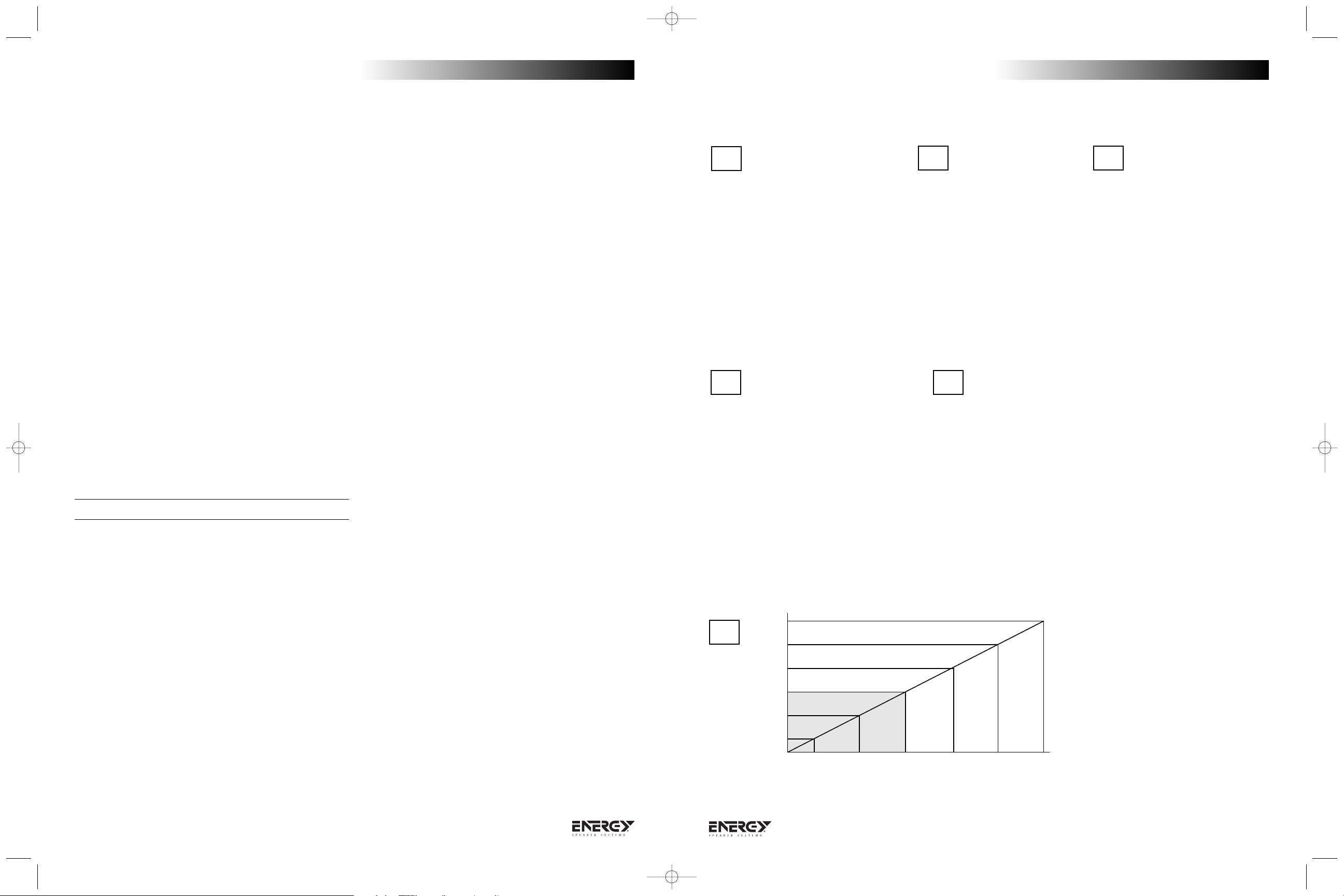
HOW TO SET UP THE CONTROLS - RC-R
1) Measure the distance between the listening position and one of the front
speakers (D1 on Diagram "A"), then measure the distance between the listening
position and the rear speakers, (D2 on Diagram "A"). Subtract the two
measurements, and the resulting number is the difference. The bottom scale of
the chart shows the difference in distance. See Diagram "A" for assistance, and
Diagram "B" for the actual chart.
NOTE: We do not recommend having the distance between the listener and the
rear speakers to be greater than the front measurement.
2) Locate the measured difference on the bottom scale of the graph (Diagram "B"),
then follow the line up to where it intersects with the horizontal line and look to
the left scale to see the level control setting recommendation. The grayed section
shows when the Switch should be in Bi-Polar Mode, and the rest of the chart
shows the Di-Polar Mode as the recommended mode.
3) Always experiment with the controls, and adjust them to your liking, the chart will
give you a good starting point, but each room is different, and depending on the
RC-R's location, furniture placement and materials in the room, adjustments may
be necessary.
FINE TUNING
Before beginning any fine tuning, please ensure all connections are properly made
and your speakers have had the chance to break-in for a minimum of 100 hours.
This will ensure the proper results are achieved.
Your listening room is the final component of your audio system and will be the
difference between mediocre sound and high quality sound. Reflections, which are a
part of every recording and music playback, will have a major effect on your
system's performance. If your room is too “live”, meaning there are many bare
surfaces like glass windows, hard floors and thin furnishings, you might find the
sound overly bright. If your room is “dead”, meaning there is thick pile carpeting,
heavy furniture and a lot of wall coverings, you might find the sound lacks dynamic
energy.To remedy these issues, small changes to your room should be considered as
they generally lead to large improvements in sound quality. Most listening rooms
must balance aesthetics and sound, but patience and small adjustments in
positioning and settings can pay huge acoustic dividends.
The lower bass frequencies are typically the most influenced by your listening room.
If you find the bass in your room to be uneven or exaggerated in certain
frequencies, experimenting with placement of the front speakers or their orientation
towards the listening position can alleviate some of these issues.The proximity of
the speakers to room boundaries, like walls, will also affect the bass frequencies. If
you find your system lacks bass, first check your connections to make sure your
system is in phase, then experiment with placement.The further from the wall, the
less overall bass output your system will have, but the bass will generally be better
defined. If you position your speakers too close to a room boundary, the bass will
typically be exaggerated and ill-defined. Adjusting your speakers to your room will
generate the best results.
If you are experiencing issues with imaging, first ensure your speakers are in phase
with each other. If this is the case and imaging is still an issue, moving the speakers
closer together or toeing them in slightly (angling them towards the listening
position) can aid in this respect.
When installing a surround sound system, all the above holds true. Calibration of
your speaker distances, adjusting delays and balancing your levels with an SPL
meter are necessary to extract the most out of your system.
CARE OF FINISH
The Reference Connoisseur series cabinets should be gently cleaned with only a
damp cloth and warm water from time to time, in order to remove any dust or
fingerprints. Do not use an abrasive cleaner, or any type of ammonia based cleaners,
or window type cleaners.To remove the dust from the grille cloth, use the brush
attachment on your vacuum cleaner or a slightly dampened sponge or dust free
cloth. Do not touch the speaker cones directly or enter them in contact with water
or cleaning materials, as this can cause irreparable damage.
4
Energy Ref. Conn.-9 lang printers 6/20/05 10:04 AM Page 7
Level
Control
Setting
Max
-2
-3
-5
-9
-15
Min
Measured difference between front speaker to listener, and rear speaker to listener
MODE SWITCH
POSITION
DI-POLAR
MODE SWITCH
POSITION
BI-POLAR
1ft 2ft
MODE SWITCH
POSITION
DI-POLAR
3ft
4ft
5ft
6ft

7
8
8
b
a
10
9
11
32
owners manual
DIAGRAMS/FIGURES/DIAGRAMAS
Nous sommes fiers de vous accueillir en tant que nouveau propriétaire d'un système
d'enceintes ENERGY de la série Reference Connoisseur. Les enceintes ENERGY sont
le produit d'une recherche extensive destinée à la reproduction précise des ondes
sonores. Elles représentent l'avant-garde de la performance et du concept : des
composantes et matériaux de la plus haute qualité sont combinés à des processus
de fabrication et un contrôle de la qualité évolués afin d'assurer des années de
performance et d'écoute exceptionnelles.
Veuillez prendre le temps de lire toutes les instructions contenues dans ce manuel
afin que votre système soit installé et ajusté pour produire un son de qualité
optimale. Faites attention en retirant le système de son emballage, et conservez ce
dernier pour usage futur.
DÉBALLAGE DU SYSTÈME
Ouvrez la boîte en coupant doucement le ruban adhésif. Pliez les rabats de carton et
glissez l'enceinte et son emballage protecteur hors de la boîte. Lorsque vous
déballez une enceinte verticale RC 30, RC 50 ou RC 70, placez sa boîte debout,
coupez le ruban adhésif et retirez l'enceinte en la glissant. Enlevez tout emballage
protecteur et retirez les autres composantes.
AVERTISSEMENT IMPORTANT POUR LA
SÉCURITÉ
Les enceintes verticales de la série Reference Connoisseur (modèles RC 30, RC 50
et RC 70) sont conçues pour être posées sur des pieds et des crampons. Il est
important de bien positionner ces supports, car ils stabilisent l'enceinte et servent
d'éléments esthétiques.
Contenu :
4 protecteurs autocollants en caoutchouc
4 disques protecteurs (RC 30, RC 50 et RC 70 seulement)
4 crampons (RC 30, RC 50 et RC 70 seulement)
4 écrous (RC 30, RC 50 et RC 70 seulement)
1 clé (RC 30, RC 50 et RC 70 seulement)
1 base ou socle-base, en noir très lustré (RC 30, RC 50 et RC 70 seulement)
1 bouchon d'évent très dense (RC 10)
2 bouchons d'évents très denses (RC LCR)
PROCÉDURE DE RODAGE
Il est ESSENTIEL que vos nouvelles enceintes Reference Connoisseur soient
correctement rodées avant de leur imposer des réglages ou un positionnement
précis, ou de les faire jouer à haut volume. La meilleure manière de les roder
consiste à jouer un passage musical de pleine gamme à volume moyen, le plus
longtemps possible. L'usage de la fonction de répétition sur votre lecteur CD ou
DVD vous aidera beaucoup pour cette étape. La qualité optimale du son ne sera pas
atteinte avant environ 100 heures de lecture.Après le rodage, vous pourrez
augmenter le volume. Ne faites pas jouer vos enceintes à haut volume avant que la
procédure de rodage ne soit terminée, car les transducteurs peuvent se briser s'ils
n'ont pas eu le temps de se « relâcher ».
SOCLES-BASES
Les enceintes verticales RC 30, RC 50 et RC 70 sont déjà attachées à leur socle-base
noir très lustré à la livraison. Ces socles-bases sont amovibles : vous n'avez qu'à
dévisser les quatre écrous à tête ronde réunissant le socle-base au caisson de
l'enceinte. Faites attention de ne pas endommager l'enceinte ou le socle-base lorsque
vous enlevez ce dernier. Les socles-bases offrent une plus grande superficie sur
laquelle poser l'enceinte, ce qui augmente sa stabilité. Consultez le diagramme 1.
CRAMPONS
Des crampons sont inclus avec toutes les enceintes verticales afin de les séparer du
plancher. Pour utiliser les crampons, placez l'enceinte à l'envers (en vous assurant de
protéger sa surface) et insérez les crampons dans les orifices filetés situés sur le
socle-base. À l'aide de la clé fournie, serrez l'écrou de chaque crampon pour
stabiliser le support au maximum. Les écrous permettent aussi de positionner
l'enceinte d'aplomb et de niveau. Si votre plancher est recouvert d'un matériau dur
tel du bois franc, de la tuile ou des lattes laminées, placez les disques protecteurs
(inclus) entre le crampon et le plancher, avec le côté rembourré face au plancher.
Placez l'enceinte de telle façon que la pointe du crampon s'insère dans le trou sur la
face supérieure du disque. Si vous avez du tapis, assurez-vous qu'aucun fil ne puisse
être transpercé par les crampons. Si vous préférez ne pas utiliser les crampons, des
protecteurs autocollants en caoutchouc sont inclus afin de protéger votre plancher.
NE GLISSEZ JAMAIS L'ENCEINTE SUR CRAMPONS D'UN ENDROIT À L'AUTRE :
VOUS ENDOMMAGEREZ L'ENCEINTE ET VOTRE PLANCHER. Consultez le
diagramme 2.
BLINDAGE MAGNÉTIQUE
Bien que toutes les enceintes Reference Connoisseur soient blindées, un champ de
dispersion peut tout de même exister. Le positionnement de vos enceintes Reference
Connoisseur sur ou près de votre téléviseur CRT ne devrait pas causer
d'interférence. Pour éliminer une légère décoloration du son, déplacez l'enceinte de
quelques centimètres vers l'avant, vers l'arrière, ou plus loin du téléviseur. NOTA : les
téléviseurs ACL, DLP et au plasma ne causent pas d'interférence magnétique.
RACCORDEMENT DES ENCEINTES
Tous les modèles de la série Reference Connoisseur comportent des bornes de
connexion de haute qualité plaquées or. Le raccordement de tous les canaux offre
donc les mêmes options.
Vous devriez utiliser du câblage pour enceintes de haute qualité, d'un calibre allant
jusqu'à 12 (AWG). Les enceintes Reference Connoisseur acceptent une variété de
connecteurs, tels que : connecteurs de type banane, cosses à fourche ou fiches.
Nous estimons que la cosse à fourche est le meilleur connecteur, car sa surface de
contact avec la borne est supérieure et permet à la borne d'être serrée pour
stabiliser la connexion. Les audiophiles et débutants ont tous leur type de
connecteur préféré : communiquez avec votre détaillant ENERGYMD pour savoir
lequel est le plus approprié à votre système audiovisuel. Rassurez-vous, du câble
ordinaire est un choix bien acceptable : vous pourrez toujours changer de câble ou
de connecteurs plus tard.
Si vous désirez utiliser des connecteurs de type banane, dévissez l'écrou
de la borne dans le sens antihoraire et retirez-le. Enlevez le morceau de
plastique rouge ou noir et revissez l'écrou. Le morceau de plastique est
une mesure de sécurité obligatoire d'après les lois et règlements de
plusieurs associations et gouvernements locaux et fédéraux. Consultez le
diagramme 3.
Le raccordement devrait s'effectuer une enceinte à la fois. Commencez par les
enceintes frontales, et raccordez un canal à la fois. Assurez-vous que le système
entier soit HORS TENSION avant d'effectuer les connexions. Les bornes positives et
négatives (rouges et noires) des enceintes DOIVENT concorder avec les bornes
positives et négatives (rouges et noires) du récepteur ou de l'amplificateur. La nonconcordance des bornes résultera en l'anormalité du son et des graves amorphes.
Après le raccordement des enceintes frontales, procédez au raccordement des autres
enceintes à leurs canaux respectifs sur le récepteur ou l'amplificateur. Voici les trois
méthodes de raccordement :
MÉTHODE TRADITIONNELLE (consultez le diagramme 4)
1) En utilisant le câble pour enceintes et les connecteurs de votre choix, raccordez le
câble aux bornes inférieures en faisant attention de respecter les polarités.
Vérifiez la solidité des bornes. Les cordons de court-circuit or qui relient les
bornes supérieures et inférieures doivent demeurer en place.
2) Répétez la procédure pour la deuxième enceinte.
MÉTHODE À DEUX CÂBLES (consultez le diagramme 5)
Cette méthode implique l'utilisation de plusieurs câbles et connecteurs pour
rejoindre simultanément les deux groupes de bornes sur l'enceinte Reference
Connoisseur. La réduction de l'interférence et des problèmes de mise à la terre est
l'avantage de la méthode à deux câbles, puisque vous aurez deux fois l'épaisseur
normale de câble pour relier l'enceinte à l'amplificateur. Communiquez avec votre
détaillant autorisé ENERGYMD pour connaître plus de détails sur les avantages de
cette méthode. NOTA :Avant de procéder au raccordement, enlevez les cordons de
court-circuit or qui relient les bornes inférieures aux bornes supérieures : relâchez
tous les connecteurs et tirez sur les cordons. Conservez-les pour usage futur.
1) En utilisant le câble pour enceintes et les connecteurs de votre choix, raccordez
un câble provenant de l'amplificateur aux bornes supérieures en faisant attention
de respecter les polarités.Vérifiez la solidité du raccordement.
2) Raccordez le second câble provenant du même canal de l'amplificateur vers le
groupe de bornes inférieures.
3) Répétez la procédure pour la deuxième enceinte.
manuel de l’utilisateur
IMPORTANTES
CONSIGNES DE
SÉCURITÉ –
LIRE ATTENTIVEMENT!
5
Energy Ref. Conn.-9 lang printers 6/20/05 10:04 AM Page 9
SubwooferTV or Wall Unit
Center Channel
Front Speakers
Rear Speakers
owners manual
3
3
b
a
3
4
c
5/6
31
MÉTHODE DE BI-AMPLIFICATION (consultez le diagramme 6)
Ce système (appelé aussi « Bi-amplification verticale ») implique l'usage de deux
amplificateurs séparés comportant chacun deux canaux pour alimenter un groupe
d'enceintes. Il s'agit de raccorder un amplificateur stéréophonique à une enceinte, et
d'utiliser un amplificateur identique pour alimenter la deuxième enceinte. Cette
méthode est la seule recommandée par ENERGY.
NOTA : Avant de procéder au raccordement, enlevez les cordons de court-circuit
or qui relient les bornes inférieures aux bornes supérieures : relâchez tous les
connecteurs et tirez sur les cordons. Conservez-les pour usage futur.
1) En utilisant le câble pour enceintes et les connecteurs de votre choix, raccordez
un câble provenant de l'amplificateur aux bornes supérieures en faisant attention
de respecter les polarités.Vérifiez la solidité du raccordement.
2) Raccordez le second câble provenant de l'autre canal de l'amplificateur vers le
groupe de bornes inférieures, en vérifiant la solidité du raccordement.
3) Répétez la procédure pour la deuxième enceinte en utilisant le second
amplificateur.
EMPLACEMENT ET INSTALLATION DE VOS
ENCEINTES
Enceintes principales de droite et de gauche
(RC 10, RC 30, RC 50, RC 70, RC LCR)
Les enceintes principales sont habituellement placées à l'avant de la pièce, de
chaque côté du téléviseur ou du projecteur vidéo. Elles devraient être séparées d'un
minimum de 1,8 m, et, si les meubles le permettent, placez-les à 30 cm ou plus des
murs. Pour calculer le meilleur emplacement, mesurez la distance entre les enceintes
et le point d'écoute. Cette distance devrait correspondre à 1,5 fois la distance
séparant les enceintes. Par exemple : si la distance séparant les enceintes de la
position d'écoute est de 2,7 m, les enceintes devraient être séparées de 1,8 m afin
d'obtenir une séparation stéréophonique et une image adéquates. Cette mesure
n'est qu'un point de départ puisque l'acoustique de la pièce et l'emplacement des
meubles peuvent faire varier la position des enceintes. Utilisez votre bon jugement
et votre expérience : de petits changements peuvent produire de grandes
améliorations de performance.
RC 10
L'enceinte RC 10 est destinée à l'avant gauche ou droite, ou à l'utilisation comme
canal arrière. Lorsque vous fixez l'enceinte d'étagère RC 10 à un mur, vous
remarquerez un orifice situé à l'arrière, au-dessus des bornes d'entrée. L'orifice fileté
est conçu spécialement pour la fixation Energy MacromountMD, offerte chez votre
détaillant autorisé ENERGYMD. Consultez le diagramme 7.
L'enceinte RC 10 vient avec deux bouchons en mousse (à l'intérieur de la boîte). Ces
bouchons sont conçus pour être insérés dans les évents à l'arrière de l'enceinte,
dans le cas où celle-ci doit être installée près d'un mur ou d'une armoire. Puisque
l'enceinte RC 10 comporte des évents arrière, la placer trop près d'une séparation
de renfort (telle un mur) produira des effets indésirables. La placer dans une armoire
à étagères causera des problèmes avec la reproduction des fréquences graves. Pour
éviter ce genre de problème, insérez un bouchon en mousse dans l'évent situé à
l'arrière de l'enceinte. Consultez le diagramme 8.
Si l'enceinte RC 10 doit être installée sur une étagère ou un socle, veuillez fixer les
quatre protecteurs en caoutchouc sous l'enceinte : décollez les protecteurs de la
feuille et placez-en un aux quatre coins.Vous préviendrez ainsi les dommages à
l'enceinte et à la surface de support. Les protecteurs aideront aussi à séparer
l'enceinte du support. Consultez le diagramme 9.
RC LCR
L'enceinte RC LCR peut servir de canal gauche, droit ou central. Elle est donc conçue
pour s'utiliser horizontalement ou verticalement : elle peut être fixée des deux
manières, tout en exhibant les mêmes caractéristiques de dispersion. Le logo ENERGY
n'est PAS fixé à la grille de l'enceinte nouvellement livrée puisque son emplacement
n'est pas prédéfini. Lorsque vous aurez déterminé l'orientation définitive que prendra
l'enceinte, choisissez un emplacement sur la grille, retirez le protecteur d'adhésif du
logo et appliquez-le sur la grille. Consultez le diagramme 10.
Lorsque l'enceinte RC LCR est utilisée comme canal central, elle devrait idéalement
être placée aussi près que possible du centre du téléviseur ou du projecteur vidéo
pour que la provenance des voix et des sons corresponde bien à la position des
acteurs à l'écran. La position idéale peut être sur le dessus, en dessous, ou sur une
étagère à l'intérieur d'une armoire ou d'un meuble. Servez-vous de l'emplacement
qui offre la meilleure qualité, mais n'oubliez pas de prendre la sécurité et
l'esthétique en compte. Le fonctionnement optimal du canal central est atteint en
plaçant le devant de l'enceinte au ras du téléviseur ou de l'étagère la supportant. Si
l'enceinte est placée à l'arrière de son support, le son produit semblera distant et
manquera de définition. Consultez le diagramme 11.
Avant d'installer l'enceinte RC LCR dans une armoire, veuillez placer les deux
bouchons en mousse inclus dans les évents à l'arrière de l'enceinte. Les évents
arrière causent une suremphase des fréquences graves lorsque l'enceinte est dans
une armoire, et doivent donc être bouchés pour assurer une qualité sonore
optimale. Il est recommandé de remplir l'armoire d'isolant, jusqu'au devant de
l'enceinte, afin d'éviter les problèmes de diffraction. Votre détaillant autorisé
ENERGYMD pourra vous fournir plus d'aide en cas de problèmes. Consultez le
diagramme 8.
L'installation de l'enceinte RC LCR sur un téléviseur, dans une armoire ou sur une
étagère requiert la pose des quatre protecteurs en caoutchouc à la base de
l'enceinte afin de prévenir les dommages à l'enceinte et à son support. Consultez le
diagramme 9.
RC R
La position des enceintes arrière peut varier énormément selon la disposition des
meubles et la forme de la pièce, mais elles devraient idéalement être placées sur les
murs latéraux ou arrière.
Mur latéral : L'effet ambiophonique sera créé par le reflet du son sur les murs
arrière.
Mur arrière : L'enceinte est habituellement placée sur un mur arrière quand les
murs latéraux ne sont pas disponibles en raison de la disposition des meubles ou
des dimensions de la pièce. La position arrière est aussi utilisée dans les
configurations à 6,1 ou 7,1 canaux.
Les deux positions de montage ont leurs avantages et inconvénients. Pendant
l'écoute d'un film, le rôle des enceintes arrière est de créer une « atmosphère »
autour de vous. Privilégiez donc la position qui offre la plus grande couverture de la
pièce. La position idéale des enceintes arrière les place à une distance égale de
vous, comparativement aux enceintes frontales, malgré que ce ne soit pas toujours
possible dans une maison. L'enceinte RC R émet du son de ses deux côtés latéraux :
placez-la pour que les murs environnants puissent assurer une bonne réflexion du
son autour des spectateurs. La meilleure position dans un système à 5,1 canaux
demeure celle du mur latéral, car l'enceinte profite des murs latéraux et arrière pour
créer un effet ambiophonique réaliste et faire paraître la pièce plus grande qu'elle
ne l'est en réalité. L'enceinte devrait être placée plus haut que l'oreille, environ aux
2/3 de la hauteur du mur. Une bonne position de départ est à environ 1,8 m du sol.
L'enceinte devrait être 60 cm plus haut que vous en position assise. Ces directives
générales devraient vous aider à déterminer la bonne position. Consultez le
diagramme 12.
Vous pouvez aussi obtenir d'excellents résultats en utilisant l'emplacement arrière.
Essayez de ne pas placer l'enceinte directement dans un coin, et laissez 60 cm ou
plus d'espace entre le bord du cabinet et le mur latéral pour que le son soit
adéquatement reflété. L'emplacement arrière est habituellement préférable lorsque
la pièce ne se prête pas à l'utilisation des murs latéraux en raison d'une différence
de grandeur, de la présence d'une porte ou d'une grande ouverture, etc. Si possible,
il est recommandé que l'enceinte constituant le centre arrière d'un système à 6,1
canaux ou que les deux enceintes ambiophoniques arrière d'un système à 7,1
canaux soient placées à la même hauteur que les deux autres enceintes
ambiophoniques arrière.
FIXER VOS ENCEINTES RC R
NOTA : L'enceinte RC R comporte un système de fixation au mur très simple.Vous
devrez porter une attention particulière à la solidité du montage puisque l'enceinte
est lourde et peut causer des blessures ou être endommagée à la suite d'un
montage incorrect. Veuillez suivre les instructions attentivement! Consultez le
diagramme 13.
1) Choisissez la position de montage adaptée à votre pièce.
2) Placez la fixation contre le mur à l'endroit désiré et marquez le centre des deux
trous à l'aide d'un crayon. Vous devrez utiliser du matériel de montage capable
de supporter une charge de 6,8 kg, non inclus avec l'enceinte puisque les
matériaux de construction varient grandement de pays en pays. Nous
recommandons cependant d'utiliser les vis à tête no 8. La longueur des vis
dépendra du type de mur.
3) Si vous fixez l'enceinte directement sur une cloison sèche, assurez-vous d'utiliser
les papillons appropriés puisque les vis seules n'assureront pas un support
adéquat. Insérez les papillons et tenez la fixation contre le mur. Vissez solidement
dans les poutres, lorsque possible.
manuel de l’utilisateur
6
Energy Ref. Conn.-9 lang printers 6/20/05 10:04 AM Page 11
 Loading...