

Page 1
TI01046D/06/EN/07.17
71380241
Products Solutions Services
Technical Information
Proline Promag W 400
Electromagnetic flowmeter
Sensor with EN ISO 12944 corrosion protection and state‐of‐the‐art
transmitter for Water & Wastewater
Application
• The bidirectional measuring principle is virtually
independent of pressure, density, temperature and viscosity
• The specialist in the water and wastewater industry for the
most demanding applications
Device properties
• International drinking water approvals
• Degree of protection IP68 (Type 6P enclosure)
• Approved for custody transfer to MI-001/OIML R49
• Transmitter housing made of durable polycarbonate or
aluminum
• WLAN access
• Integrated data logger: measured values monitoring
Your benefits
• For direct underground installation or permanent
underwater use
• Safe, reliable long-term operation – robust and completely
welded sensor
• Energy-saving flow measurement – no pressure loss due to
cross-section constriction
• Maintenance-free – no moving parts
• Safe operation – no need to open the device due to display
with touch control, background lighting
• Time‐saving local operation without additional software and
hardware – integrated web server
• Integrated verification – Heartbeat Technology
Page 2

Table of contents
Proline Promag W 400
About this document ........................ 4
Symbols used ................................ 4
Function and system design ................... 5
Measuring principle ............................ 5
Measuring system ............................. 6
Equipment architecture ......................... 7
Safety ..................................... 7
Input ..................................... 8
Measured variable ............................. 8
Measuring range .............................. 8
Operable flow range ........................... 12
Input signal ................................ 12
Output .................................. 12
Output signal ............................... 12
Signal on alarm .............................. 14
Low flow cut off ............................. 15
Galvanic isolation ............................ 15
Protocol-specific data .......................... 16
Power supply ............................. 20
Terminal assignment .......................... 20
Pin assignment, device plug ...................... 22
Supply voltage .............................. 23
Power consumption ........................... 23
Current consumption .......................... 23
Power supply failure .......................... 23
Electrical connection .......................... 24
Potential equalization ......................... 28
terminals .................................. 30
Cable entries ............................... 30
Cable specification ............................ 30
Impact resistance ............................ 42
Mechanical load ............................. 42
Electromagnetic compatibility (EMC) ............... 42
Process .................................. 42
Medium temperature range ...................... 42
Conductivity ................................ 42
Pressure-temperature ratings .................... 42
Pressure tightness ............................ 45
Flow limit ................................. 45
Pressure loss ............................... 45
System pressure ............................. 46
Vibrations ................................. 46
Custody transfer mode ...................... 47
Mechanical construction .................... 47
Dimensions in SI units ......................... 47
Dimensions in US units ......................... 71
Weight ................................... 93
Measuring tube specification .................... 111
Materials ................................. 113
Fitted electrodes ............................ 115
Process connections .......................... 115
Surface roughness ........................... 116
Operability .............................. 116
Operating concept ........................... 116
Languages ................................ 116
Local display ............................... 116
Remote operation ........................... 117
Service interface ............................ 119
Supported operating tools ...................... 120
HistoROM data management .................... 122
Performance characteristics .................. 33
Reference operating conditions ................... 33
Maximum measured error ....................... 33
Repeatability ............................... 34
Influence of ambient temperature ................. 34
Installation ............................... 35
Mounting location ............................ 35
Orientation ................................ 36
Inlet and outlet runs .......................... 37
Adapters .................................. 37
Length of connecting cable ...................... 38
Mounting the transmitter housing ................. 39
Special mounting instructions .................... 39
Certificates and approvals .................. 123
CE mark .................................. 123
C-Tick symbol .............................. 123
Ex approval ............................... 123
Drinking water approval ....................... 123
HART certification ........................... 123
Certification PROFIBUS ........................ 123
Modbus RS485 certification ..................... 123
EtherNet/IP certification ....................... 123
Radio approval ............................. 123
Measuring instrument approval .................. 123
Other standards and guidelines .................. 124
Ordering information ...................... 124
Product generation index ...................... 124
Environment .............................. 40
Ambient temperature range ..................... 40
Storage temperature .......................... 41
Atmosphere ................................ 41
Degree of protection .......................... 41
Vibration resistance ........................... 41
Shock resistance ............................. 41
Application packages ...................... 125
Cleaning ................................. 125
Diagnostics functions ......................... 125
Heartbeat Technology ........................ 125
2 Endress+Hauser
Page 3

Proline Promag W 400
Accessories .............................. 125
Device-specific accessories ...................... 126
Communication-specific accessories ............... 126
Service-specific accessories ..................... 127
System components .......................... 127
Supplementary documentation .............. 128
Standard documentation ....................... 128
Supplementary device-dependent documentation ...... 128
Registered trademarks ..................... 129
Endress+Hauser 3
Page 4
About this document
A
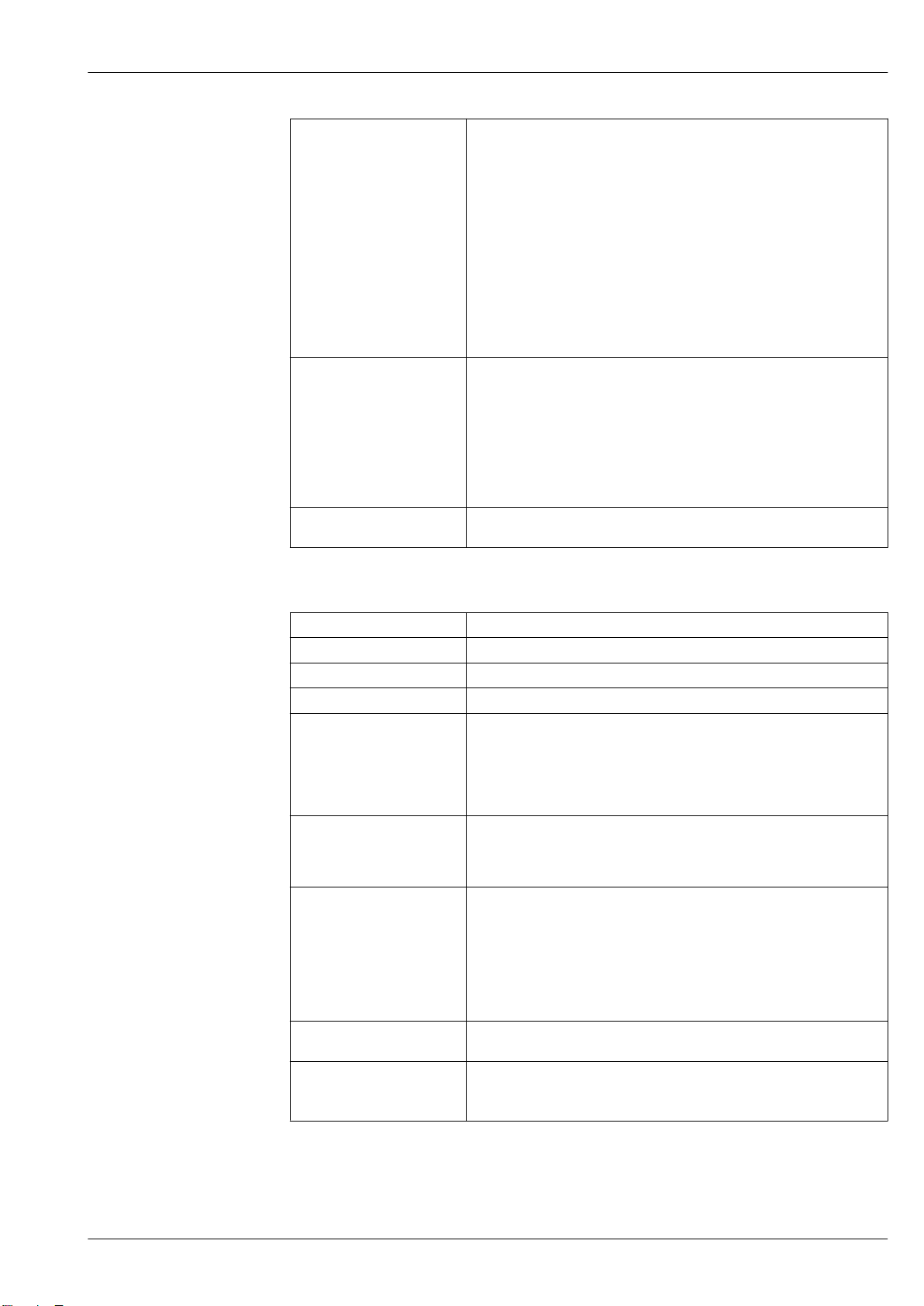
Symbols used Electrical symbols
Symbol Meaning
Proline Promag W 400
Direct current
Alternating current
Direct current and alternating current
Ground connection
A grounded terminal which, as far as the operator is concerned, is grounded via a
grounding system.
Protective Earth (PE)
A terminal which must be connected to ground prior to establishing any other
connections.
The ground terminals are situated inside and outside the device:
• Inner ground terminal: Connects the protectiv earth to the mains supply.
• Outer ground terminal: Connects the device to the plant grounding system.
Communication symbols
Symbol Meaning
Wireless Local Area Network (WLAN)
Communication via a wireless, local network.
Bluetooth
Wireless data transmission between devices over a short distance.
LED
Light emitting diode is off.
LED
Light emitting diode is on.
LED
Light emitting diode is flashing.
Symbols for certain types of information
Symbol Meaning
Permitted
Procedures, processes or actions that are permitted.
Preferred
Procedures, processes or actions that are preferred.
Forbidden
Procedures, processes or actions that are forbidden.
Tip
Indicates additional information.
Reference to documentation.
Reference to page.
Reference to graphic.
Visual inspection.
4 Endress+Hauser
Page 5
Proline Promag W 400
1.
-
.
U
e
L
B
I
I
v
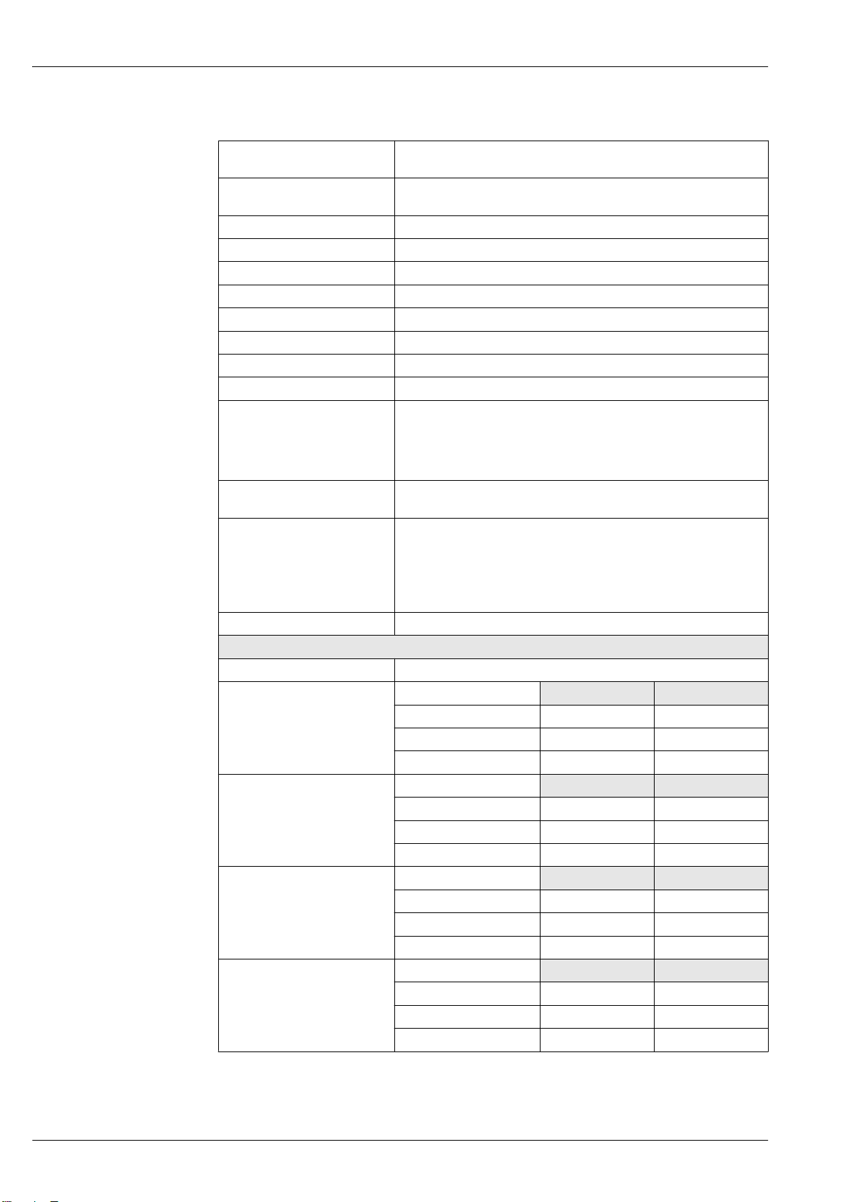
Symbols in graphics
Symbol Meaning
1, 2, 3, ... Item numbers
, 2., 3., … Series of steps
A, B, C, ... Views
A-A, B-B, C-C, ... Sections
Hazardous area
Safe area (non-hazardous area)
Flow direction
Function and system design
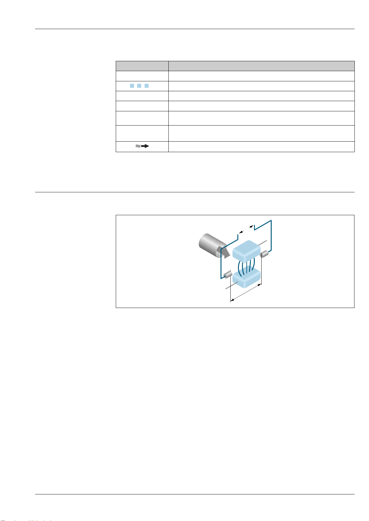
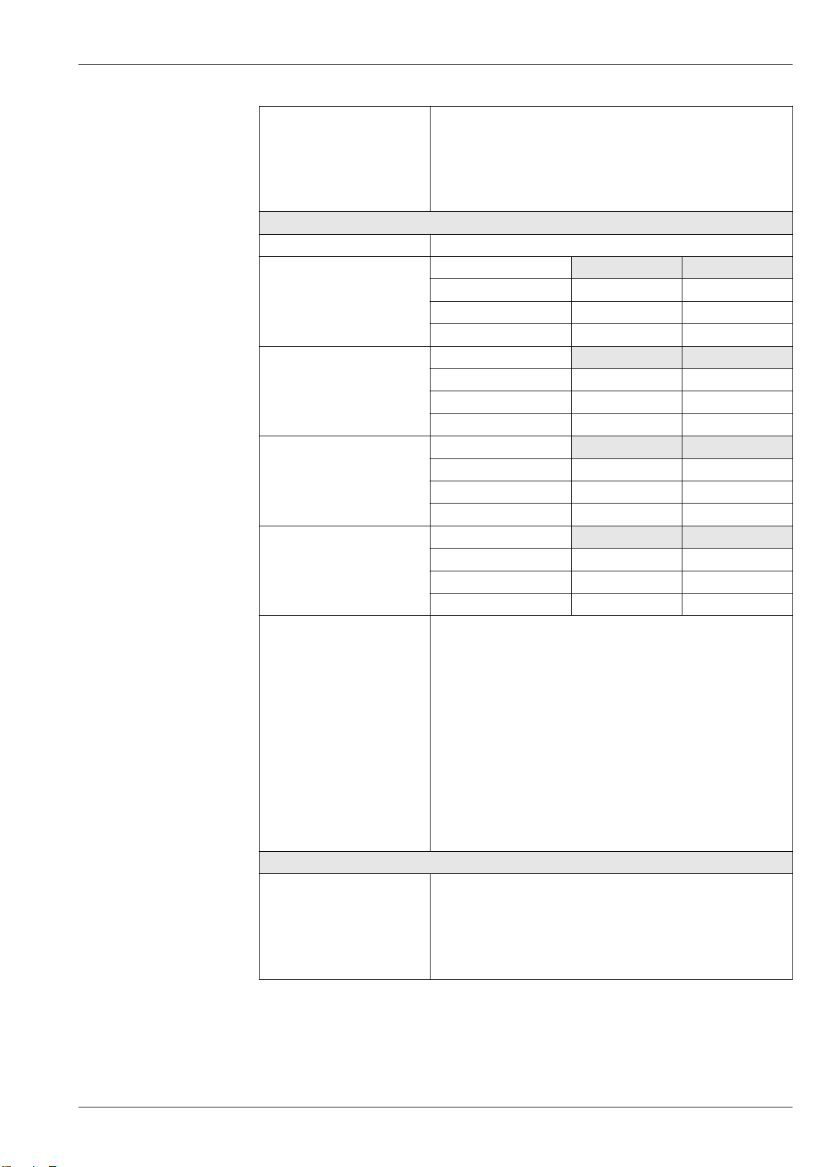
Measuring principle
Following Faraday's law of magnetic induction, a voltage is induced in a conductor moving through a
magnetic field.
A0028962
Ue Induced voltage
B Magnetic induction (magnetic field)
L Electrode spacing
I Current
v Flow velocity
In the electromagnetic measuring principle, the flowing medium is the moving conductor. The
voltage induced (Ue) is proportional to the flow velocity (v) and is supplied to the amplifier by means
of two measuring electrodes. The flow volume (Q) is calculated via the pipe cross-section (A). The DC
magnetic field is created through a switched direct current of alternating polarity.
Formulae for calculation
• Induced voltage Ue = B · L · v
• Volume flow Q = A · v
Endress+Hauser 5
Page 6
Proline Promag W 400
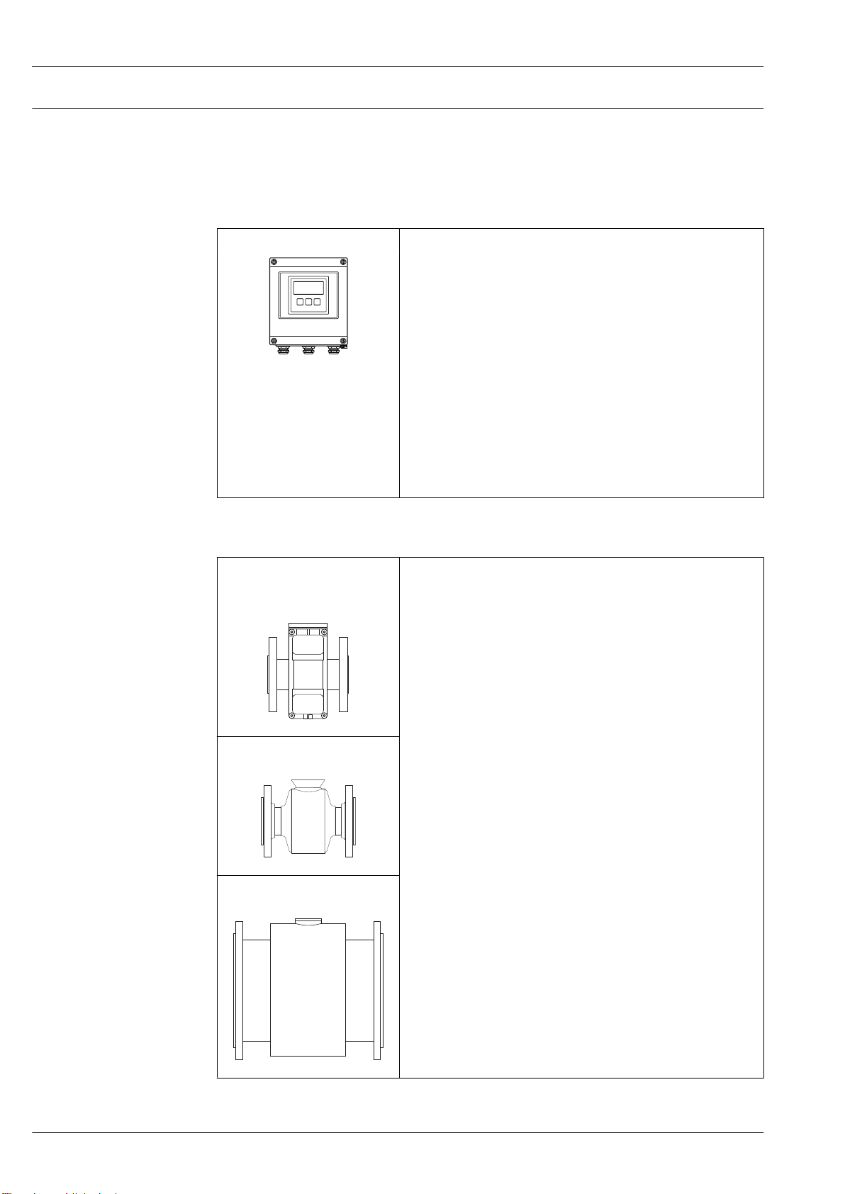
Measuring system
The device consists of a transmitter and a sensor.
Two device versions are available:
• Compact version – transmitter and sensor form a mechanical unit.
• Remote version - transmitter and sensor are mounted in separate locations.
Transmitter
Promag 400 Device versions and materials
• Compact version: compact housing
– Polycarbonate plastic
– Aluminum, AlSi10Mg, coated
• Remote version: wall-mount housing
– Polycarbonate plastic
– Aluminum, AlSi10Mg, coated
Configuration:
• External operation via four-line, illuminated local display with touch
A0017117
control and guided menus ("Make-it-run" wizards) for applications
• Via operating tools (e.g. FieldCare)
• Via Web browser (e.g. Microsoft Internet Explorer)
• Also for device version with EtherNet/IP output:
– Via Add-on Profile Level 3 for automation system from Rockwell
Automation
– Via Electronic Data Sheet (EDS)
• Also for device version with PROFIBUS DP output:
Via PDM driver for Siemens automation system
Sensor
Promag W • Nominal diameter range: DN 25 to 2000 (1 to 78")
A0017040
A0022673
• Materials:
– Sensor housing: aluminum, AlSi10Mg, coated; carbon steel with
protective varnish
– Sensor connection housing (standard): aluminum, AlSi10Mg, coated
Sensor connection housing (option): polycarbonate
– Measuring tubes
1)
:
DN 25 to 300 (1 to 12"): stainless steel, 1.4301/1.4306/304/304L
DN 350 to 2000 (14 to 78"): stainless steel, 1.4301/304
– Liner: hard rubber, polyurethane
– Electrodes: stainless steel, 1.4435 (316L); Alloy C22, 2.4602 (UNS
N06022); tantalum
– Process connections:
Stainless steel, 1.4404/1.4571/F316L
Carbon steel, A105/A181/A515(70)/FE410WB/P250GH/ P235
GH/P265GH/S235JRG2/S235JR+N/S275JR
– Seals: as per DIN EN 1514-1 Form IBC
– Ground disks: stainless steel, 1.4435 (316L); Alloy C22, 2.4602
(UNS N06022); tantalum
Fixed flange: DN 25 to 300 (1 to
12")
Fixed flange: DN 25 to 300 (1 to
12")
Fixed flange: DN 350 to 2000 (14
to 78")
A0017041
1) For carbon steel flange material with Al/Zn protective coating (DN 25 to 300 (1 to 12")), protective varnish
(IP68) (DN 50 to 300 (2 to 12")) or protective varnish ≥ DN 350 (14")
6 Endress+Hauser
Page 7
Proline Promag W 400
2 3
6
7
8
4
1
5
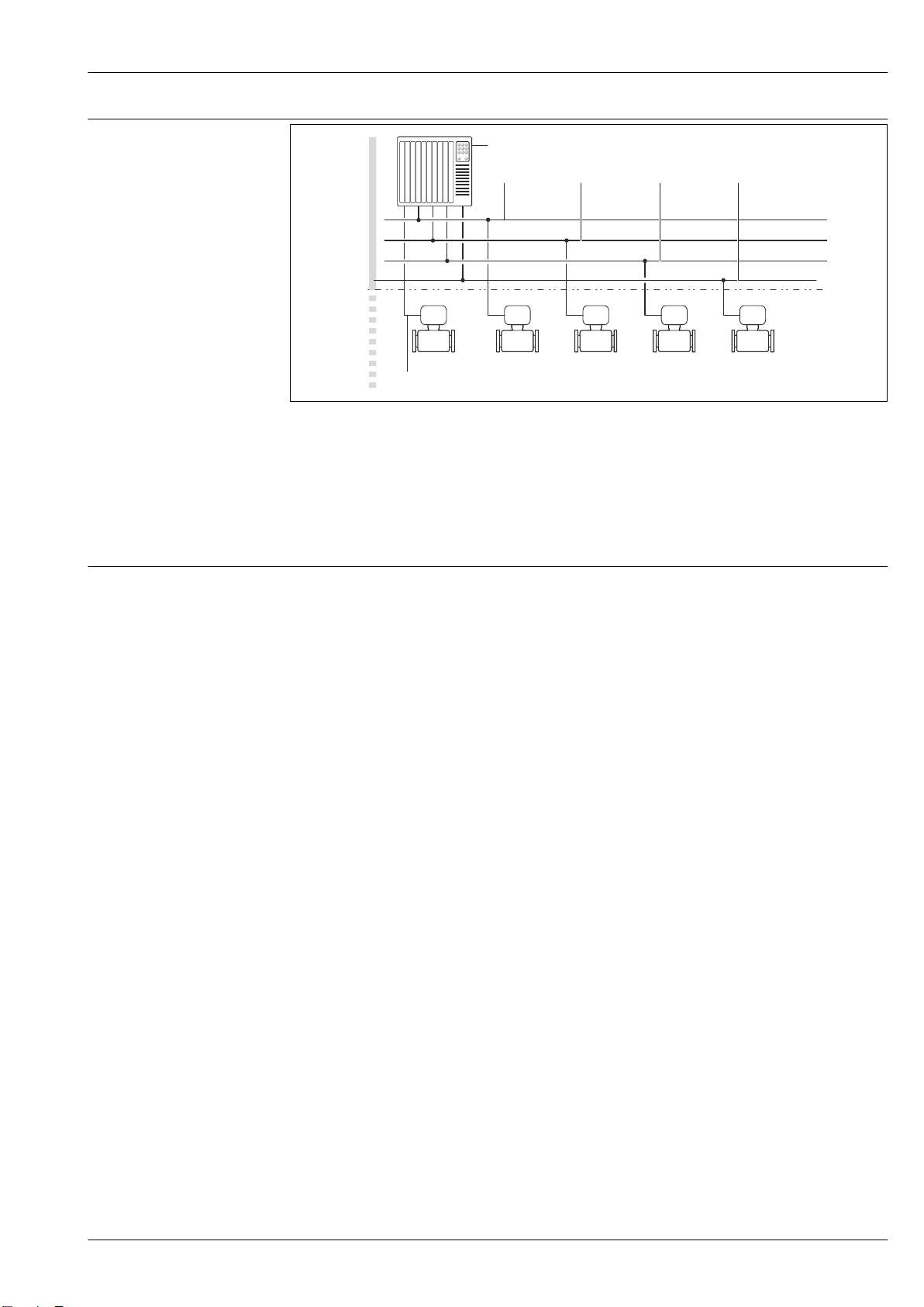
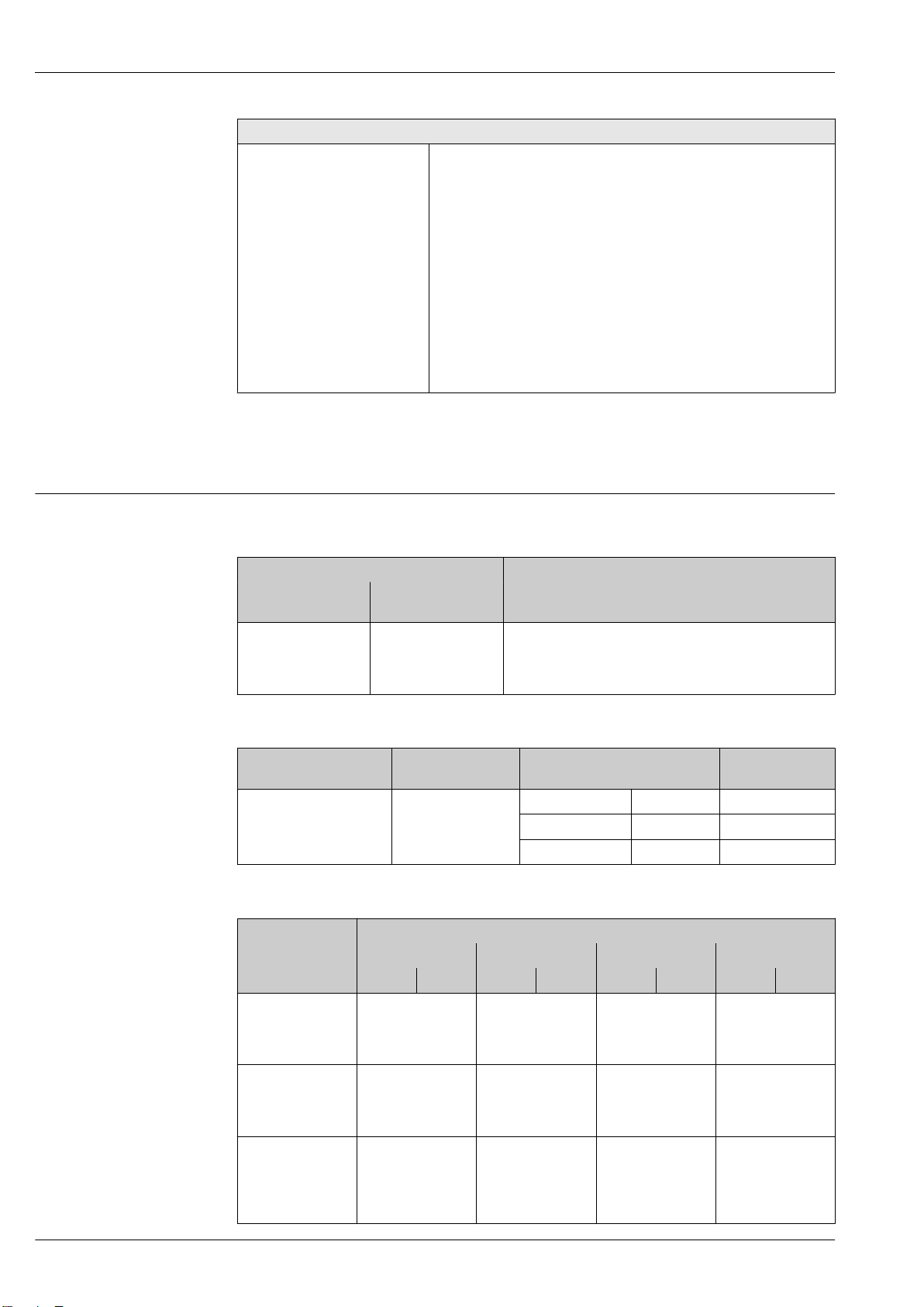
Equipment architecture
A0021560
1 Possibilities for integrating measuring devices into a system
1 Control system (e.g. PLC)
2 EtherNet/IP
3 PROFIBUS DP
4 Modbus RS485
5 4-20 mA HART, pulse/frequency/switch output
6 Non-hazardous area
7 Non-hazardous area and Zone 2/Div. 2
Safety IT security
We only provide a warranty if the device is installed and used as described in the Operating
Instructions. The device is equipped with security mechanisms to protect it against any inadvertent
changes to the device settings.
IT security measures in line with operators' security standards and designed to provide additional
protection for the device and device data transfer must be implemented by the operators themselves.
Device-specific IT security
The device offers a range of specific functions to support protective measures on the operator's side.
These functions can be configured by the user and guarantee greater in-operation safety if used
correctly. An overview of the most important functions is provided in the following section.
Protecting access via hardware write protection
Write access to the device parameters via the local display or operating tool (e.g. FieldCare,
DeviceCare) can be disabled via a write protection switch (DIP switch on the motherboard). When
hardware write protection is enabled, only read access to the parameters is possible.
Hardware write protection is disabled when the device is delivered.
Protecting access via a password
Different passwords are available to protect write access to the device parameters or access to the
device via the WLAN interface.
• User-specific access code
Protect write access to the device parameters via the local display, Web browser or operating tool
(e.g. FieldCare, DeviceCare). Access authorization is clearly regulated through the use of a userspecific access code.
• WLAN passphrase
The network key protects a connection between an operating unit (e.g. notebook or tablet) and the
device via the WLAN interface which can be ordered as an option.
User-specific access code
Write access to the device parameters via the local display or operating tool (e.g. FieldCare,
DeviceCare) can be protected by the modifiable, user-specific access code.
Endress+Hauser 7
Page 8

Proline Promag W 400
WLAN passphrase
A connection between an operating unit (e.g. notebook or tablet) and the device via the WLAN
interface which can be ordered as an option is protected by the network key. The WLAN
authentication of the network key complies with the IEEE 802.11 standard.
When the device is delivered, the network key is pre-defined depending on the device. It can be
changed via the WLAN settings submenu in the WLAN passphrase parameter.
General notes on the use of passwords
• The access code and network key supplied with the device should be changed during
commissioning.
• Follow the general rules for generating a secure password when defining and managing the access
code or network key.
• The user is responsible for the management and careful handling of the access code and network
key.
Access via fieldbus
When communicating via fieldbus, access to the device parameters can be restricted to "Read only"
access. The option can be changed in the Fieldbus writing access parameter.
This does not affect cyclic measured value transmission to the higher-order system, which is always
guaranteed.
For detailed information, see the "Description of Device Parameters" document pertaining to the
device → 128
Access via Web server
The device can be operated and configured via a Web browser with the integrated Web server. The
connection is via the service interface (CDI-RJ45) or the WLAN interface. For device versions with
the EtherNet/IP and PROFINET communication protocols, the connection can also be established via
the terminal connection for signal transmission with EtherNet/IP or PROFINET (RJ45 connector).
The Web server is enabled when the device is delivered. The Web server can be disabled if necessary
(e.g. after commissioning) via the Web server functionality parameter.
The device and status information can be hidden on the login page. This prevents unauthorized
access to the information.
For detailed information, see the "Description of Device Parameters" document pertaining to the
device → 128
Input
Measured variable Direct measured variables
• Volume flow (proportional to induced voltage)
• Electrical conductivity
In custody transfer: only volume flow
Calculated measured variables
Mass flow
Measuring range
Typically v = 0.01 to 10 m/s (0.03 to 33 ft/s) with the specified accuracy
Electrical conductivity: ≥ 5 μS/cm for liquids in general
8 Endress+Hauser
Page 9

Proline Promag W 400
flow
1)
Factory settings
Full scale value current
output
(v ~ 2.5 m/s)
Pulse value
(~ 2 pulse/s)
Low flow cut off
(v ~ 0.04 m/s)
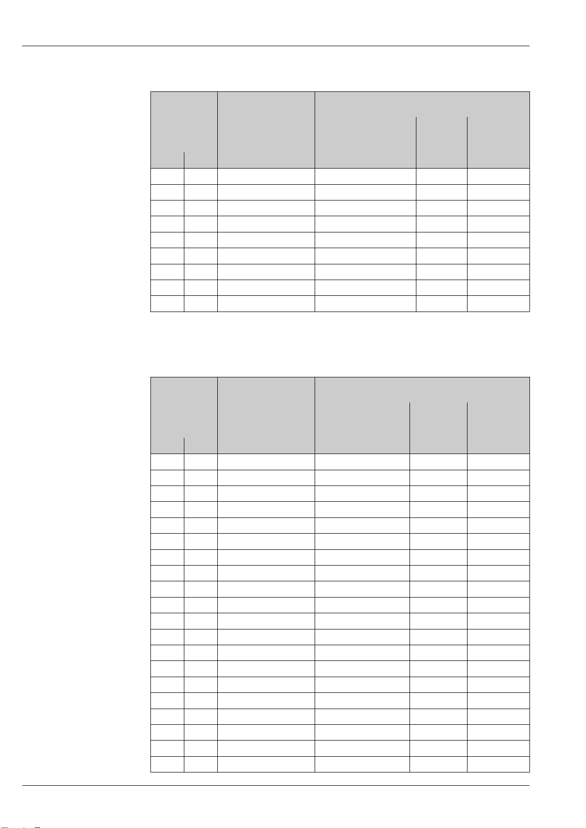
Flow characteristic values in SI units
Nominal
diameter
Recommended
min./max. full scale value
(v ~ 0.3/10 m/s)
[mm] [in] [m3/h] [m3/h] [m3] [m3/h]
25 1 9 to 300 dm3/min 75 dm3/min 0.5 dm
32 – 15 to 500 dm3/min 125 dm3/min 1 dm
40 1 ½ 25 to 700 dm3/min 200 dm3/min 1.5 dm
50 2 35 to 1 100 dm3/min 300 dm3/min 2.5 dm
65 – 60 to 2 000 dm3/min 500 dm3/min 5 dm
80 3 90 to 3 000 dm3/min 750 dm3/min 5 dm
100 4 145 to 4 700 dm3/min 1 200 dm3/min 10 dm
125 – 220 to 7 500 dm3/min 1 850 dm3/min 15 dm
3
3
3
3
3
3
3
3
1 dm3/min
2 dm3/min
3 dm3/min
5 dm3/min
8 dm3/min
12 dm3/min
20 dm3/min
30 dm3/min
150 6 20 to 600 150 0.025 2.5
200 8 35 to 1 100 300 0.05 5
250 10 55 to 1 700 500 0.05 7.5
300 12 80 to 2 400 750 0.1 10
350 14 110 to 3 300 1 000 0.1 15
375 15 140 to 4 200 1 200 0.15 20
400 16 140 to 4 200 1 200 0.15 20
450 18 180 to 5 400 1 500 0.25 25
500 20 220 to 6 600 2 000 0.25 30
600 24 310 to 9 600 2 500 0.3 40
700 28 420 to 13 500 3 500 0.5 50
750 30 480 to 15 000 4 000 0.5 60
800 32 550 to 18 000 4 500 0.75 75
900 36 690 to 22 500 6 000 0.75 100
1 000 40 850 to 28 000 7 000 1 125
– 42 950 to 30 000 8 000 1 125
1 200 48 1 250 to 40 000 10 000 1.5 150
– 54 1 550 to 50 000 13 000 1.5 200
1 400 – 1 700 to 55 000 14 000 2 225
– 60 1 950 to 60 000 16 000 2 250
1 600 – 2 200 to 70 000 18 000 2.5 300
– 66 2 500 to 80 000 20 500 2.5 325
1 800 72 2 800 to 90 000 23 000 3 350
– 78 3 300 to 100 000 28 500 3.5 450
2 000 – 3 400 to 110 000 28 500 3.5 450
1) Order code for "Design", option A "Insertion length short ISO/DVGW until DN400, DN450-2000 1:1" and
order code for "Design", option B "Insertion length long ISO/DVGW until DN400, DN450-2000 1:1.3"
Endress+Hauser 9
Page 10
Proline Promag W 400
flow
1)
Factory settings
Full scale value current
output
(v ~ 2.5 m/s)
Pulse value
(~ 4 pulse/s)
Low flow cut off
(v ~ 0.01 m/s)
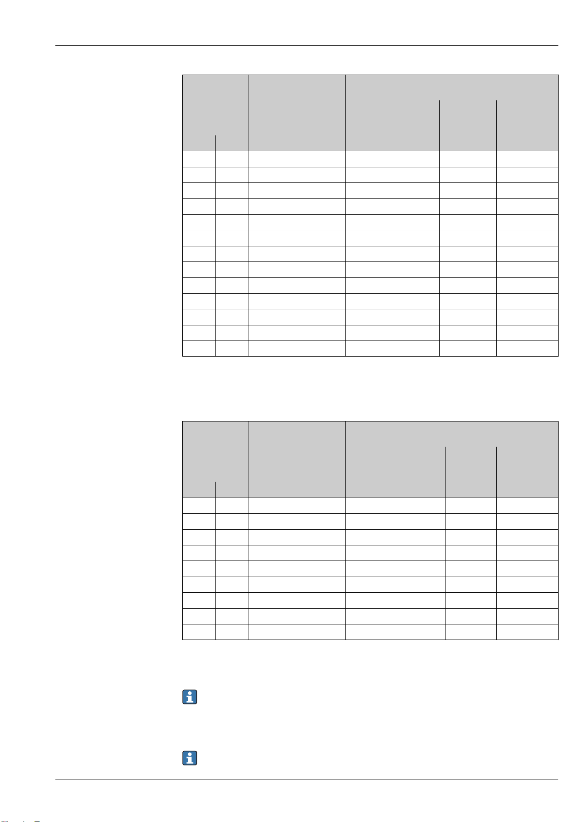
Flow characteristic values in SI units
Nominal
diameter
Recommended
min./max. full scale value
(v ~ 0.12/5 m/s)
[mm] [in] [m3/h] [m3/h] [m3] [m3/h]
50 2 15 to 600 dm3/min 300 dm3/min 1.25 dm
65 – 25 to 1 000 dm3/min 500 dm3/min 2 dm
80 3 35 to 1 500 dm3/min 750 dm3/min 3 dm
100 4 60 to 2 400 dm3/min 1 200 dm3/min 5 dm
125 – 90 to 3 700 dm3/min 1 850 dm3/min 8 dm
150 6 145 to 5 400 dm3/min 2 500 dm3/min 10 dm
200 8 220 to 9 400 dm3/min 5 000 dm3/min 20 dm
3
3
3
3
3
3
3
1.25 dm3/min
2 dm3/min
3.25 dm3/min
4.75 dm3/min
7.5 dm3/min
11 dm3/min
19 dm3/min
250 10 20 to 850 500 0.03 1.75
300 12 35 to 1 300 750 0.05 2.75
1) Order code for "Design", option C "Insertion length short ISO/DVGW until DN300, w/o inlet and outlet runs,
constricted meas.tube"
flow
1)
Factory settings
Full scale value current
output
(v ~ 2.5 m/s)
Pulse value
(~ 2 pulse/s)
Low flow cut off
(v ~ 0.04 m/s)
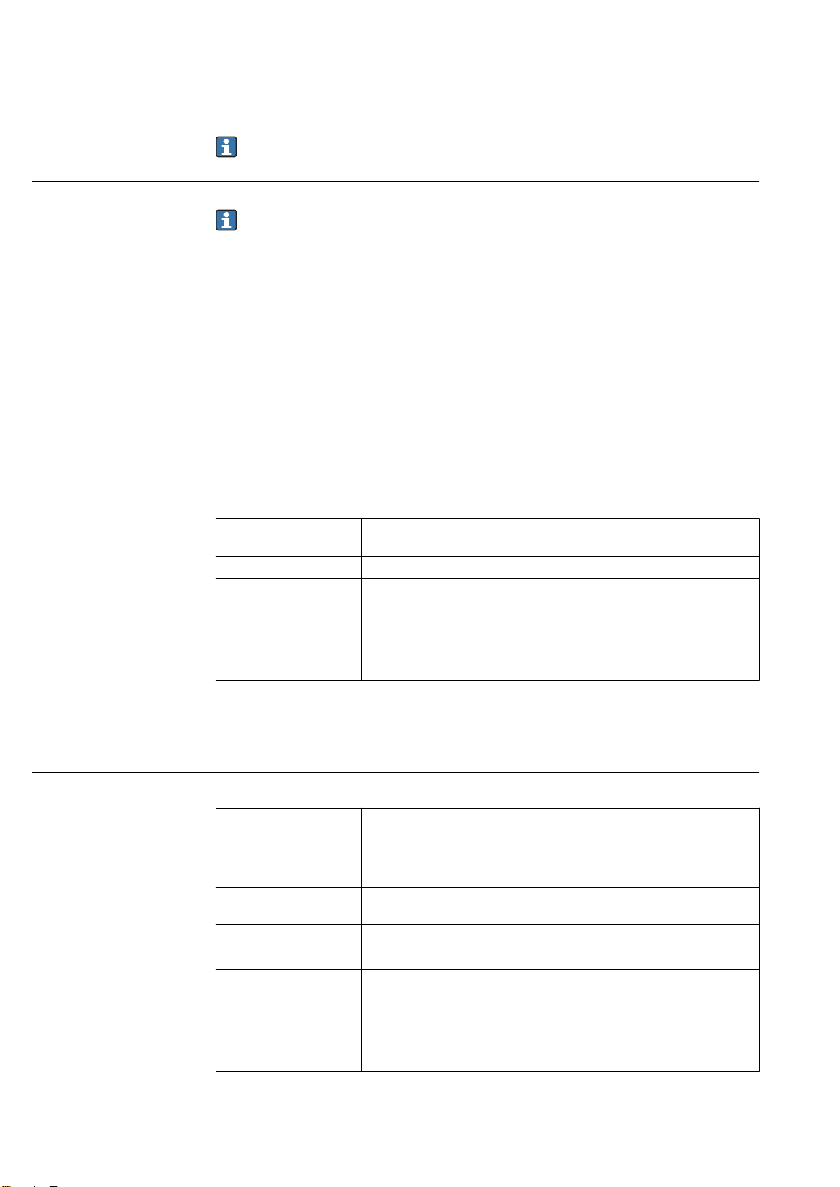
Flow characteristic values in US units
Nominal
diameter
Recommended
min./max. full scale value
(v ~ 0.3/10 m/s)
[in] [mm] [gal/min] [gal/min] [gal] [gal/min]
1 25 2.5 to 80 18 0.2 0.25
– 32 4 to 130 30 0.2 0.5
1 ½ 40 7 to 190 50 0.5 0.75
2 50 10 to 300 75 0.5 1.25
– 65 16 to 500 130 1 2
3 80 24 to 800 200 2 2.5
4 100 40 to 1 250 300 2 4
– 125 60 to 1 950 450 5 7
6 150 90 to 2 650 600 5 12
8 200 155 to 4 850 1 200 10 15
10 250 250 to 7 500 1 500 15 30
12 300 350 to 10 600 2 400 25 45
14 350 500 to 15 000 3 600 30 60
15 375 600 to 19 000 4 800 50 60
16 400 600 to 19 000 4 800 50 60
18 450 800 to 24 000 6 000 50 90
20 500 1 000 to 30 000 7 500 75 120
24 600 1 400 to 44 000 10 500 100 180
28 700 1 900 to 60 000 13 500 125 210
30 750 2 150 to 67 000 16 500 150 270
10 Endress+Hauser
Page 11
Proline Promag W 400
Nominal
diameter
[in] [mm] [gal/min] [gal/min] [gal] [gal/min]
32 800 2 450 to 80 000 19 500 200 300
36 900 3 100 to 100 000 24 000 225 360
40 1 000 3 800 to 125 000 30 000 250 480
42 – 4 200 to 135 000 33 000 250 600
48 1 200 5 500 to 175 000 42 000 400 600
54 – 9 to 300 Mgal/d 75 Mgal/d 0.0005 Mgal/d 1.3 Mgal/d
– 1 400 10 to 340 Mgal/d 85 Mgal/d 0.0005 Mgal/d 1.3 Mgal/d
60 – 12 to 380 Mgal/d 95 Mgal/d 0.0005 Mgal/d 1.3 Mgal/d
– 1 600 13 to 450 Mgal/d 110 Mgal/d 0.0008 Mgal/d 1.7 Mgal/d
66 – 14 to 500 Mgal/d 120 Mgal/d 0.0008 Mgal/d 2.2 Mgal/d
72 1 800 16 to 570 Mgal/d 140 Mgal/d 0.0008 Mgal/d 2.6 Mgal/d
78 – 18 to 650 Mgal/d 175 Mgal/d 0.0010 Mgal/d 3.0 Mgal/d
– 2 000 20 to 700 Mgal/d 175 Mgal/d 0.0010 Mgal/d 2.9 Mgal/d
Recommended
flow
min./max. full scale value
(v ~ 0.3/10 m/s)
Factory settings
Full scale value current
output
(v ~ 2.5 m/s)
Pulse value
(~ 2 pulse/s)
Low flow cut off
(v ~ 0.04 m/s)
1) Order code for "Design", option A "Insertion length short ISO/DVGW until DN400, DN450-2000 1:1" and
order code for "Design", option B "Insertion length long ISO/DVGW until DN400, DN450-2000 1:1.3"
Flow characteristic values in US units
Nominal
diameter
[in] [mm] [gal/min] [gal/min] [gal] [gal/min]
2 50 4 to 160 75 0.3 0.35
– 65 7 to 260 130 0.5 0.6
3 80 10 to 400 200 0.8 0.8
4 100 16 to 650 300 1.2 1.25
– 125 24 to 1 000 450 1.8 2
6 150 40 to 1 400 600 2.5 3
8 200 60 to 2 500 1 200 5 5
10 250 90 to 3 700 1 500 6 8
12 300 155 to 5 700 2 400 9 12
Recommended
flow
min./max. full scale value
(v ~ 0.12/5 m/s)
1)
Factory settings
Full scale value current
output
(v ~ 2.5 m/s)
Pulse value
(~ 4 pulse/s)
Low flow cut off
(v ~ 0.01 m/s)
1) Order code for "Design", option C "Insertion length short ISO/DVGW until DN300, w/o inlet and outlet runs,
constricted meas.tube"
To calculate the measuring range, use the Applicator sizing tool → 127
Recommended measuring range
"Flow limit" section → 45
For custody transfer, the applicable approval determines the permitted measuring range, the
pulse value and the low flow cut off.
Endress+Hauser 11
Page 12
Proline Promag W 400
Operable flow range
Over 1000 : 1
For custody transfer, the operable flow range is 100 : 1 to 250 : 1, depending on the nominal
diameter. Further details are specified by the applicable approval.
Input signal External measured values
Various pressure transmitters and temperature measuring devices can be ordered from Endress
+Hauser: see "Accessories" section → 127
It is recommended to read in external measured values to calculate the following measured variables:
Corrected volume flow
HART protocol
The measured values are written from the automation system to the measuring device via the HART
protocol. The pressure transmitter must support the following protocol-specific functions:
• HART protocol
• Burst mode
Digital communication
The measured values can be written from the automation system to the measuring via:
• PROFIBUS DP
• Modbus RS485
• EtherNet/IP
Status input
Maximum input values • DC 30 V
Response time Adjustable: 5 to 200 ms
Input signal level • Low signal: DC –3 to +5 V
Assignable functions • Off
Output
Output signal Current output
Current output Can be set as:
Maximum output values • DC 24 V (no flow)
Load 0 to 700 Ω
Resolution 0.5 µA
Damping Adjustable: 0.07 to 999 s
Assignable measured
variables
• 6 mA
• High signal: DC 12 to 30 V
• Reset totalizers 1-3 separately
• Reset all totalizers
• Flow override
• 4-20 mA NAMUR
• 4-20 mA US
• 4-20 mA HART
• 0-20 mA
• 22.5 mA
• Volume flow
• Mass flow
• Flow velocity
• Conductivity
• Electronic temperature
12 Endress+Hauser
Page 13
Proline Promag W 400
Pulse/frequency/switch output
Function • With the order code for "Output; Input", option H: output 2 can be set as a pulse
or frequency output
• With the order code for "Output; Input", option I: output 2 and 3 can be set as a
pulse, frequency or switch output
• With the order code for "Output; Input", option J: output 2 firmly assigned as
certified pulse output
Version Passive, open collector
Maximum input values • DC 30 V
• 250 mA
Voltage drop For 25 mA: ≤ DC 2 V
Pulse output
Pulse width Adjustable: 0.05 to 2 000 ms
Maximum pulse rate 10 000 Impulse/s
Pulse value Adjustable
Assignable measured
variables
Frequency output
Output frequency Adjustable: 0 to 12 500 Hz
Damping Adjustable: 0 to 999 s
Pulse/pause ratio 1:1
Assignable measured
variables
Switch output
Switching behavior Binary, conductive or non-conductive
Switching delay Adjustable: 0 to 100 s
Number of switching
cycles
Assignable functions • Off
• Volume flow
• Mass flow
• Volume flow
• Mass flow
• Conductivity
• Flow velocity
• Electronic temperature
Unlimited
• On
• Diagnostic behavior
• Limit value:
– Off
– Volume flow
– Mass flow
– Conductivity
– Flow velocity
– Totalizer 1-3
– Electronic temperature
• Flow direction monitoring
• Status
– Empty pipe detection
– Low flow cut off
PROFIBUS DP
Signal encoding NRZ code
Data transfer 9.6 kBaud…12 MBaud
Endress+Hauser 13
Page 14
Proline Promag W 400
Modbus RS485
Physical interface In accordance with EIA/TIA-485-A standard
Terminating resistor Integrated, can be activated via DIP switch on the transmitter electronics module
EtherNet/IP
Standards In accordance with IEEE 802.3
Signal on alarm
Depending on the interface, failure information is displayed as follows:
Current output 4 to 20 mA
4 to 20 mA
Failure mode Choose from:
• 4 to 20 mA in accordance with NAMUR recommendation NE 43
• 4 to 20 mA in accordance with US
• Min. value: 3.59 mA
• Max. value: 22.5 mA
• Freely definable value between: 3.59 to 22.5 mA
• Actual value
• Last valid value
0 to 20 mA
Failure mode Choose from:
• Maximum alarm: 22 mA
• Freely definable value between: 0 to 22.5 mA
HART current output
Device diagnostics Device condition can be read out via HART Command 48
Pulse/frequency/switch output
Pulse output
Failure mode Choose from:
• Actual value
• No pulses
Frequency output
Failure mode Choose from:
• Actual value
• 0 Hz
• Defined value: 0 to 12 500 Hz
Switch output
Failure mode Choose from:
• Current status
• Open
• Closed
PROFIBUS DP
Status and alarm
messages
Diagnostics in accordance with PROFIBUS PA Profile 3.02
14 Endress+Hauser
Page 15
Proline Promag W 400
Modbus RS485
Failure mode Choose from:
• NaN value instead of current value
• Last valid value
EtherNet/IP
Device diagnostics Device condition can be read out in Input Assembly
Local display
Plain text display With information on cause and remedial measures
Backlight Red backlighting indicates a device error.
Status signal as per NAMUR recommendation NE 107
Interface/protocol
• Via digital communication:
– HART protocol
– PROFIBUS DP
– Modbus RS485
– EtherNet/IP
• Via service interface
– CDI-RJ45 service interface
– WLAN interface
Low flow cut off
Galvanic isolation
Plain text display With information on cause and remedial measures
Additional information on remote operation → 117
Web server
Plain text display With information on cause and remedial measures
Light emitting diodes (LED)
Status information Status indicated by various light emitting diodes
The following information is displayed depending on the device version:
• Supply voltage active
• Data transmission active
• Device alarm/error has occurred
• EtherNet/IP network available
• EtherNet/IP connection established
The switch points for low flow cut off are user-selectable.
The following connections are galvanically isolated from each other:
• Inputs
• Outputs
• Power supply
Endress+Hauser 15
Page 16
Protocol-specific data HART
Manufacturer ID 0x11
Device type ID 0x69
HART protocol revision 7
Device description files
(DTM, DD)
HART load Min. 250 Ω
Dynamic variables Read out the dynamic variables: HART command 3
Device variables Read out the device variables: HART command 9
Proline Promag W 400
Information and files under:
www.endress.com
The measured variables can be freely assigned to the dynamic variables.
Measured variables for PV (primary dynamic variable)
• Off
• Volume flow
• Mass flow
• Conductivity
• Flow velocity
• Electronic temperature
Measured variables for SV, TV, QV (secondary, tertiary and quaternary
dynamic variable)
• Volume flow
• Mass flow
• Conductivity
• Flow velocity
• Electronic temperature
• Totalizer 1
• Totalizer 2
• Totalizer 3
The device variables are permanently assigned.
A maximum of 8 device variables can be transmitted:
• 0 = volume flow
• 1 = mass flow
• 2 = conductivity
• 3 = flow velocity
• 4 = electronic temperature
• 5 = totalizer 1
• 6 = totalizer 2
• 7 = totalizer 3
PROFIBUS DP
Manufacturer ID 0x11
Ident number 0x1562
Profile version 3.02
Device description files (GSD,
DTM, DD)
Output values
(from measuring device to
automation system)
Information and files under:
• www.endress.com
• www.profibus.org
Analog input 1 to 4
• Mass flow
• Volume flow
• Flow velocity
• Conductivity
• Electronic temperature
Digital input 1 to 2
• Empty pipe detection
• Low flow cut off
• Verification status
Totalizer 1 to 3
• Mass flow
• Volume flow
16 Endress+Hauser
Page 17
Proline Promag W 400
Input values
(from automation system to
measuring device)
Supported functions • Identification & Maintenance
Configuration of the device
address
Analog output 1 (fixed assignment)
External density
Digital output 1 to 2 (fixed assignment)
• Digital output 1: switch positive zero return on/off
• Digital output 2: start verification
Totalizer 1 to 3
• Totalize
• Reset and hold
• Preset and hold
• Stop
• Operating mode configuration:
– Net flow total
– Forward flow total
– Reverse flow total
Simplest device identification on the part of the control system and
nameplate
• PROFIBUS upload/download
Reading and writing parameters is up to ten times faster with PROFIBUS
upload/download
• Condensed status
Simplest and self-explanatory diagnostic information by categorizing
diagnostic messages that occur
• DIP switches on the I/O electronics module
• Via operating tools (e.g. FieldCare)
Modbus RS485
Protocol Modbus Applications Protocol Specification V1.1
Device type Slave
Slave address range 1 to 247
Broadcast address range 0
Function codes • 03: Read holding register
• 04: Read input register
• 06: Write single registers
• 08: Diagnostics
• 16: Write multiple registers
• 23: Read/write multiple registers
Broadcast messages Supported by the following function codes:
• 06: Write single registers
• 16: Write multiple registers
• 23: Read/write multiple registers
Supported baud rate • 1 200 BAUD
• 2 400 BAUD
• 4 800 BAUD
• 9 600 BAUD
• 19 200 BAUD
• 38 400 BAUD
• 57 600 BAUD
• 115 200 BAUD
Data transfer mode • ASCII
• RTU
Data access Each device parameter can be accessed via Modbus RS485.
For Modbus register information
Endress+Hauser 17
Page 18
Proline Promag W 400
EtherNet/IP
Protocol • The CIP Networks Library Volume 1: Common Industrial Protocol
• The CIP Networks Library Volume 2: EtherNet/IP Adaptation of CIP
Communication type • 10Base-T
• 100Base-TX
Device profile Generic device (product type: 0x2B)
Manufacturer ID 0x49E
Device type ID 0x1067
Baud rates Automatic ¹⁰⁄₁₀₀ Mbit with half-duplex and full-duplex detection
Polarity Auto-polarity for automatic correction of crossed TxD and RxD pairs
Supported CIP connections Max. 3 connections
Explicit connections Max. 6 connections
I/O connections Max. 6 connections (scanner)
Configuration options for
measuring device
Configuration of the EtherNet
interface
Configuration of the device
address
Device Level Ring (DLR) No
Fix Input
RPI 5 ms to 10 s (factory setting: 20 ms)
Exclusive Owner Multicast Instance Size [byte]
Exclusive Owner Multicast Instance Size [byte]
Input only Multicast Instance Size [byte]
Input only Multicast Instance Size [byte]
• DIP switches on the electronics module for IP addressing
• Manufacturer-specific software (FieldCare)
• Custom Add-on Profile for Rockwell Automation control systems
• Web browser
• Electronic Data Sheet (EDS) integrated in the measuring device
• Speed: 10 MBit, 100 MBit, auto (factory setting)
• Duplex: half-duplex, full-duplex, auto (factory setting)
• DIP switches on the electronics module for IP addressing (last octet)
• DHCP
• Manufacturer-specific software (FieldCare)
• Custom Add-on Profile for Rockwell Automation control systems
• Web browser
• EtherNet/IP tools, e.g. RSLinx (Rockwell Automation)
Instance configuration: 0x68 398
O → T configuration: 0x66 56
T → O configuration: 0x64 32
Instance configuration: 0x69 -
O → T configuration: 0x66 56
T → O configuration: 0x64 32
Instance configuration: 0x68 398
O → T configuration: 0xC7 -
T → O configuration: 0x64 32
Instance configuration: 0x69 -
O → T configuration: 0xC7 -
T → O configuration: 0x64 32
18 Endress+Hauser
Page 19
Proline Promag W 400
Input Assembly • Current device diagnostics
• Volume flow
• Mass flow
• Conductivity
• Totalizer 1
• Totalizer 2
• Totalizer 3
Configurable Input
RPI 5 ms to 10 s (factory setting: 20 ms)
Exclusive Owner Multicast Instance Size [byte]
Instance configuration: 0x68 398
O → T configuration: 0x66 56
T → O configuration: 0x65 88
Exclusive Owner Multicast Instance Size [byte]
Instance configuration: 0x69 -
O → T configuration: 0x66 56
T → O configuration: 0x65 88
Input only Multicast Instance Size [byte]
Instance configuration: 0x68 398
O → T configuration: 0xC7 -
T → O configuration: 0x65 88
Input only Multicast Instance Size [byte]
Instance configuration: 0x69 -
O → T configuration: 0xC7 -
T → O configuration: 0x65 88
Configurable Input Assembly • Volume flow
• Mass flow
• Electronic temperature
• Conductivity
• Totalizer 1 to 3
• Flow velocity
• Volume flow unit
• Mass flow unit
• Temperature unit
• Conductivity unit
• Unit totalizer 1-3
• Flow velocity unit
• Verification result
• Verification status
The range of options increases if the measuring device has one or
more application packages.
Fix Output
Output Assembly • Activation of reset totalizers 1-3
• Activation of reference density compensation
• Reset totalizers 1-3
• External density
• Density unit
• Activation verification
• Start verification
Endress+Hauser 19
Page 20
Configuration
Configuration Assembly Only the most common configurations are listed below.
• Software write protection
• Mass flow unit
• Mass unit
• Volume flow unit
• Volume unit
• Density unit
• Conductivity
• Temperature unit
• Totalizer 1-3:
– Assignment
– Unit
– Operating mode
– Failure mode
• Alarm delay
Power supply
Terminal assignment Transmitter: 0-20 mA/4-20 mA HART
The sensor can be ordered with terminals.
Proline Promag W 400
Connection methods available
Outputs
terminals terminals • Option A: coupling M20x1
Power
supply
Possible options for order code
"Electrical connection"
• Option B: thread M20x1
• Option C: thread G ½"
• Option D: thread NPT ½"
Supply voltage
Order code
"Power supply"
Option L
(wide range power unit)
Terminal numbers terminal voltage Frequency range
DC 24 V ±25% –
1 (L+/L), 2 (L-/N)
AC 24 V ±25% 50/60 Hz, ±4 Hz
AC 100 to 240 V –15 to +10% 50/60 Hz, ±4 Hz
Signal transmission 0-20 mA/4-20 mA HART and additional outputs and inputs
Order code for
"Output" and
"Input"
Option H • 4-20 mA HART
Option I • 4-20 mA HART
Option J • 4-20 mA HART
Output 1 Output 2 Output 3 Input
26 (+) 27 (-) 24 (+) 25 (-) 22 (+) 23 (-) 20 (+) 21 (-)
(active)
• 0-20 mA
(active)
(active)
• 0-20 mA
(active)
(active)
• 0-20 mA
(active)
Pulse/frequency
Pulse/frequency/
Terminal numbers
output
(passive)
switch output
(passive)
Permanently
assigned
Pulse output
adjusted
(passive)
Switch output
(passive)
Pulse/frequency/
switch output
(passive)
Pulse/frequency/
switch output
(passive)
-
Status input
Status input
20 Endress+Hauser
Page 21
Proline Promag W 400
Transmitter: PROFIBUS DP
The sensor can be ordered with terminals.
Connection methods available
Outputs
terminals terminals • Option A: coupling M20x1
Power
supply
Possible options for order code
"Electrical connection"
• Option B: thread M20x1
• Option C: thread G ½"
• Option D: thread NPT ½"
Supply voltage
Order code
"Power supply"
Option L
(wide range power unit)
Terminal numbers terminal voltage Frequency range
DC 24 V ±25% –
1 (L+/L), 2 (L-/N)
AC 24 V ±25% 50/60 Hz, ±4 Hz
AC 100 to 240 V –15 to +10% 50/60 Hz, ±4 Hz
PROFIBUS DP signal transmission
Order code for "Output" and "Input" Terminal numbers
26 (RxD/TxD-P) 27 (RxD/TxD-N)
Option L B A
Order code for "Output":
Option L: PROFIBUS DP, for use in non-hazardous areas and Zone 2/div. 2
Transmitter: Modbus RS485
The sensor can be ordered with terminals.
Connection methods available
Outputs
terminals terminals • Option A: coupling M20x1
Power
supply
Possible options for order code
"Electrical connection"
• Option B: thread M20x1
• Option C: thread G ½"
• Option D: thread NPT ½"
Supply voltage
Order code
"Power supply"
Option L
(wide range power unit)
Terminal numbers terminal voltage Frequency range
DC 24 V ±25% –
1 (L+/L), 2 (L-/N)
AC 24 V ±25% 50/60 Hz, ±4 Hz
AC 100 to 240 V –15 to +10% 50/60 Hz, ±4 Hz
Signal transmission Modbus RS485
Order code for "Output" and "Input" Terminal numbers
26 (+) 27 (-)
Option M B A
Endress+Hauser 21
Page 22
Transmitter: EtherNet/IP
E1
E2
S1
E1
E2
S2
GND
5
7
4
37
42 41
n.c. n.c.
21
1
2
42 41
A
B
6
5
7
8437 36
n.c.
E
E
S
The sensor can be ordered with terminals or a device plug.
Proline Promag W 400
Connection methods available
Outputs
terminals terminals • Option A: coupling M20x1
Device plug terminals • Option L: plug M12x1 + thread NPT ½"
Power
supply
Possible options for order code
"Electrical connection"
• Option B: thread M20x1
• Option C: thread G ½"
• Option D: thread NPT ½"
• Option N: plug M12x1 + coupling M20
• Option P: plug M12x1 + thread G ½"
• Option U: plug M12x1 + thread M20
Supply voltage
Order code
"Power supply"
Option L
(wide range power unit)
Terminal numbers terminal voltage Frequency range
DC 24 V ±25% –
1 (L+/L), 2 (L-/N)
AC 24 V ±25% 50/60 Hz, ±4 Hz
AC 100 to 240 V –15 to +10% 50/60 Hz, ±4 Hz
EtherNet/IP signal transmission
Order code for "Output" Connection via
Option N EtherNet/IP connector
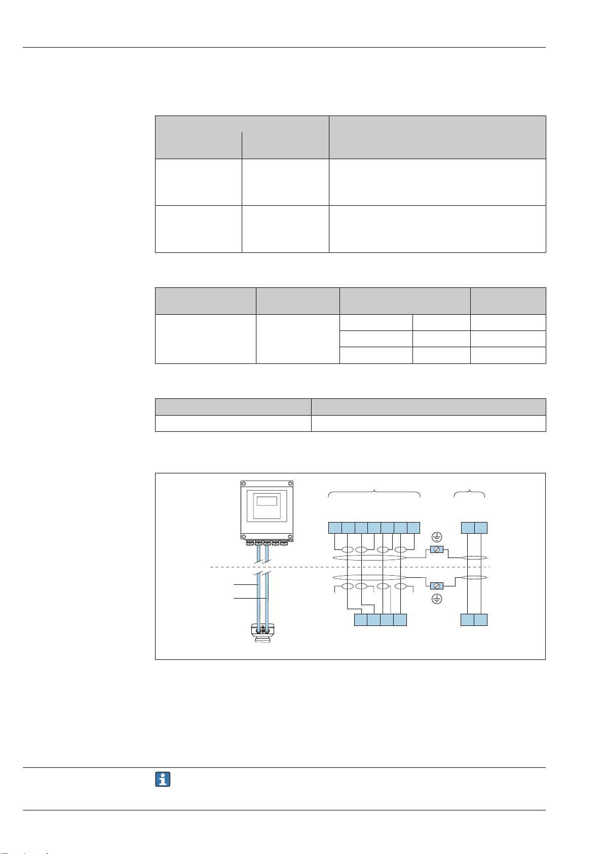
Remote version
A0032059
2 Remote version terminal assignment
A Transmitter wall-mount housing
B Sensor connection housing
1 Electrode cable
2 Coil current cable
n.c. Not connected, insulated cable shields
Terminal No. and cable colors: 6/5 = brown; 7/8 = white; 4 = green; 36/37 = yellow
Pin assignment, device plug
22 Endress+Hauser
Order codes for the M12x1 connectors, see the "Order code for electrical connection" column:
EtherNet/IP → 22
Page 23
Proline Promag W 400
3
2
4
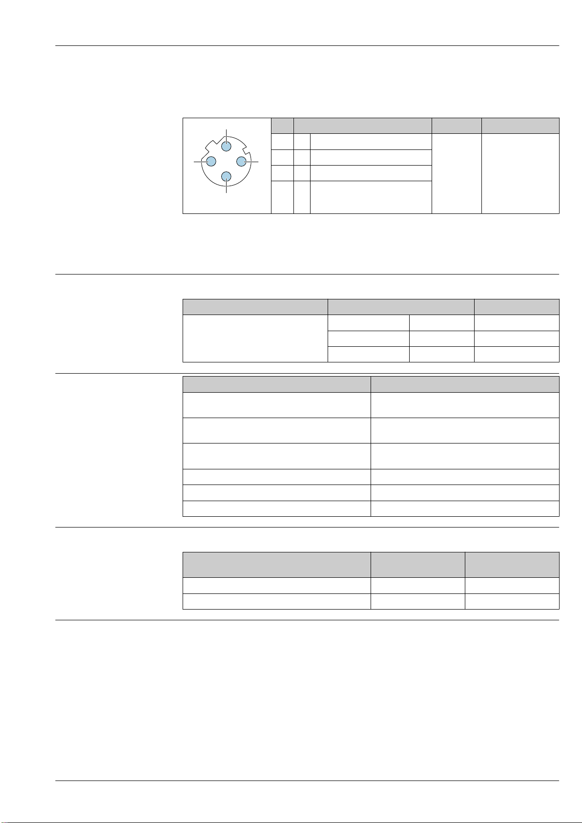
EtherNet/IP
Device plug for signal transmission (device side)
Recommended plug:
• Binder, series 763, part no. 99 3729 810 04
• Phoenix, part no. 1543223 SACC-M12MSD-4Q
• When using the device in a hazardous location, use a suitably certified plug.
Supply voltage Transmitter
Order code for "Power supply" terminal voltage Frequency range
Option L
Pin Assignment Coding Plug/socket
1 + Tx D Socket
2 + Rx
3 - Tx
4 - Rx
A0032047
DC 24 V ±25% –
AC 24 V ±25% 50/60 Hz, ±4 Hz
AC 100 to 240 V –15 to +10% 50/60 Hz, ±4 Hz
Power consumption
Option H: 4-20mA HART, pulse/frequency/switch
output, switch output
Option I: 4-20mA HART, 2 x pulse/frequency/switch
output, status input
Option J: 4-20mA HART, certified pulse output, pulse/
frequency/switch output, status input
Option L: PROFIBUS DP 30 VA/8 W
Option M: Modbus RS485 30 VA/8 W
Option N: EtherNet/IP 30 VA/8 W
Current consumption Transmitter
Order code for "Power supply" Maximum
Option L: AC 100 to 240 V 145 mA 25 A (< 5 ms)
Option L: AC/DC 24 V 350 mA 27 A (< 5 ms)
Power supply failure
• Totalizers stop at the last value measured.
• Configuration is retained in the plug-in memory (HistoROM DAT).
• Error messages (incl. total operated hours) are stored.
Order code for "Output" Maximum power consumption
30 VA/8 W
30 VA/8 W
30 VA/8 W
Maximum
Current consumption
switch-on current
Endress+Hauser 23
Page 24
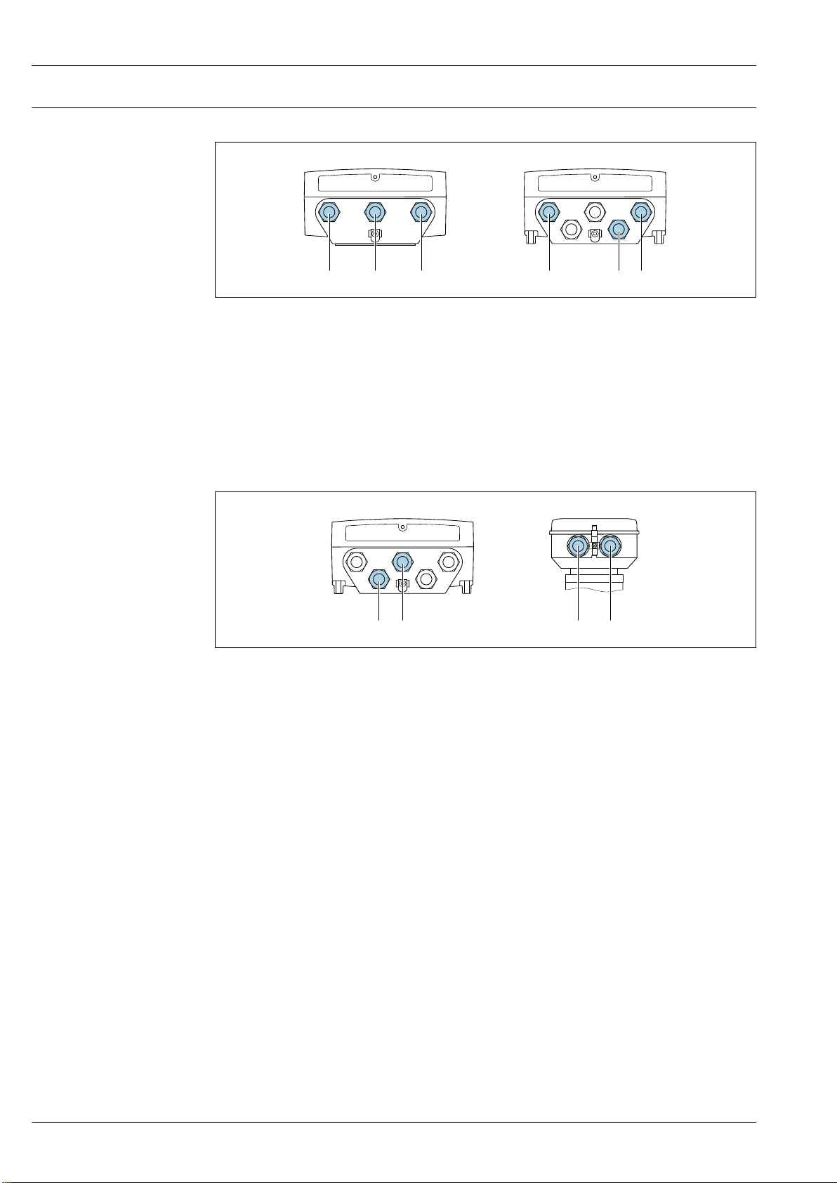
Electrical connection Connecting the transmitter
1
2
1 2 3 3
A B
1
2
A
2
1
B
3 Supply voltage and signal transmission connection
A Compact version
B Remote version wall-mount housing
1 Cable entry for supply voltage
2 Cable entry for signal transmission
3 Cable entry for signal transmission
Remote version connection
Proline Promag W 400
A0032041
Connecting cable
4 Connecting cable connection: electrode and coil current cable
A Transmitter wall-mount housing
B Sensor connection housing
1 Electrode cable
2 Coil current cable
• Fix the cable run or route it in an armored conduit.
Cable movements can influence the measuring signal especially in the case of low fluid
conductivities.
• Route the cable well clear of electrical machines and switching elements.
• Ensure potential equalization between sensor and transmitter .
A0032042
24 Endress+Hauser
Page 25
Proline Promag W 400
4
4...20 mA
5
2
1
3
6
2
3
4...20 mA
41
5
0/4...20 mA
+
–
2
1
3
+
_
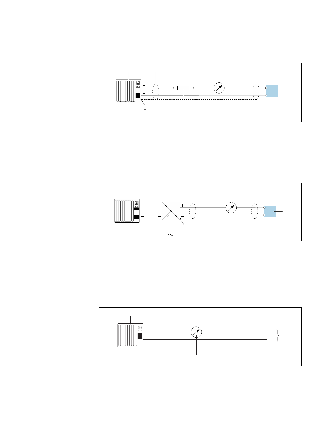
Connection examples
Current output 4 to 20 mA HART
A0029055
5 Connection example for 4 to 20 mA HART current output (active)
1 Automation system with current input (e.g. PLC)
2 Cable shield: the cable shield must be grounded at both ends to comply with EMC requirements; observe cable
specifications → 30
3 Connection for HART operating devices → 117
4 Resistor for HART communication (≥ 250 Ω): observe maximum load → 12
5 Analog display unit: observe maximum load → 12
6 Transmitter
A0028762
6 Connection example for 4 to 20 mA HART current output (passive)
1 Automation system with current input (e.g. PLC)
2 Power supply
3 Cable shield: the cable shield must be grounded at both ends to comply with EMC requirements; observe cable
specifications → 30
4 Analog display unit: observe maximum load → 12
5 Transmitter
Current output 4-20 mA
A0017162
7 Connection example for 0-20 mA current output (active) and 4-20 mA current output (active)
1 Automation system with current input (e.g. PLC)
2 Analog display unit: observe maximum load
3 Transmitter
Endress+Hauser 25
Page 26
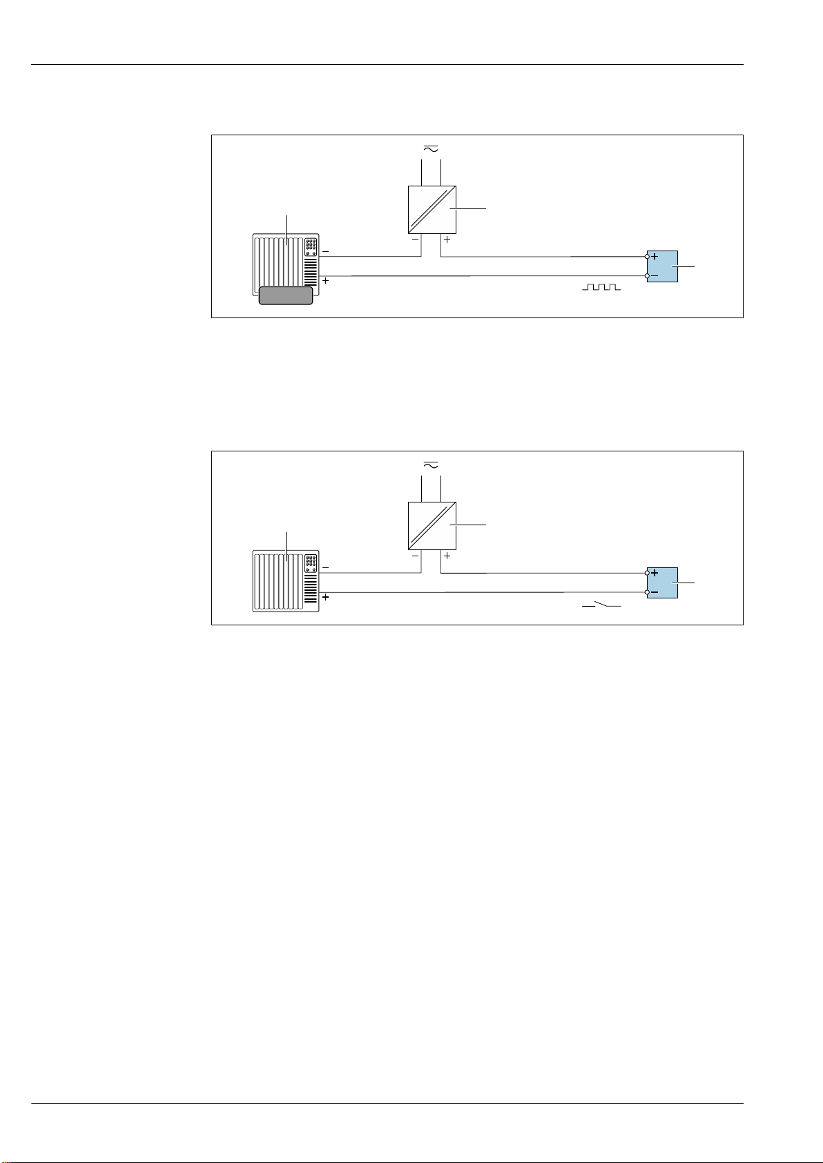
Pulse/frequency output
1
2
3
12345
1
2
3
8 Connection example for pulse/frequency output (passive)
1 Automation system with pulse/frequency input (e.g. PLC)
2 Power supply
3 Transmitter: Observe input values → 13
Switch output
Proline Promag W 400
A0028761
9 Connection example for switch output (passive)
1 Automation system with switch input (e.g. PLC)
2 Power supply
3 Transmitter: Observe input values → 13
A0028760
26 Endress+Hauser
Page 27
Proline Promag W 400
2
1
A
B
3
4
4
A
B
A
B
2
1
A
B
3
4
4
A
B
A
B
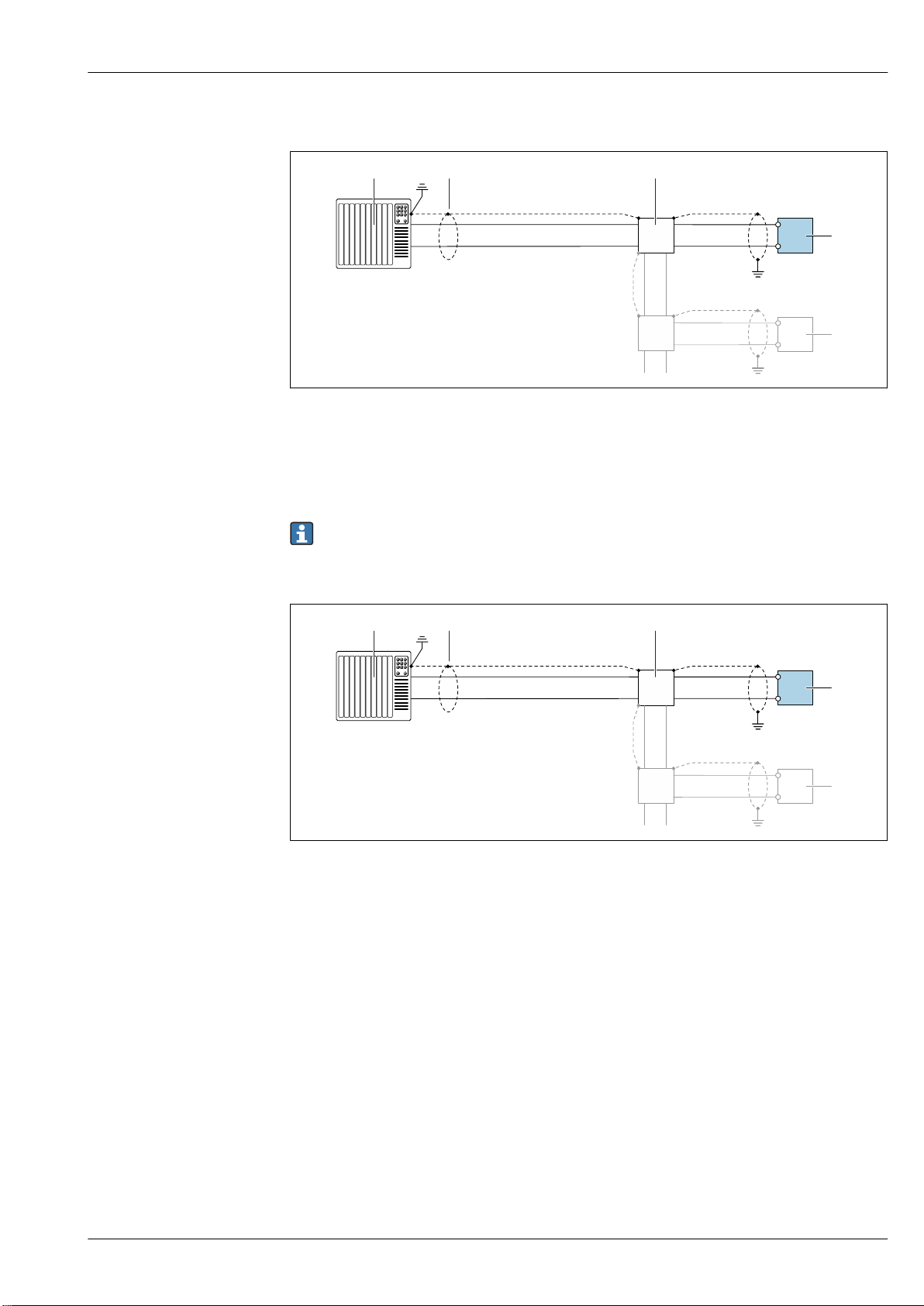
PROFIBUS DP
A0028765
10 Connection example for PROFIBUS DP, non-hazardous area and Zone 2/Div. 2
1 Control system (e.g. PLC)
2 Cable shield: the cable shield must be grounded at both ends to comply with EMC requirements; observe cable
specifications
3 Transmitter
If baud rates > 1.5 MBaud an EMC cable entry must be used and the cable shield must continue
as far as the terminal wherever possible.
Modbus RS485
A0028765
11 Connection example for Modbus RS485, non-hazardous area and Zone 2/Div. 2
1 Control system (e.g. PLC)
2 Cable shield: the cable shield must be grounded at both ends to comply with EMC requirements; observe cable
specifications
3 Distribution box
4 Transmitter
Endress+Hauser 27
Page 28
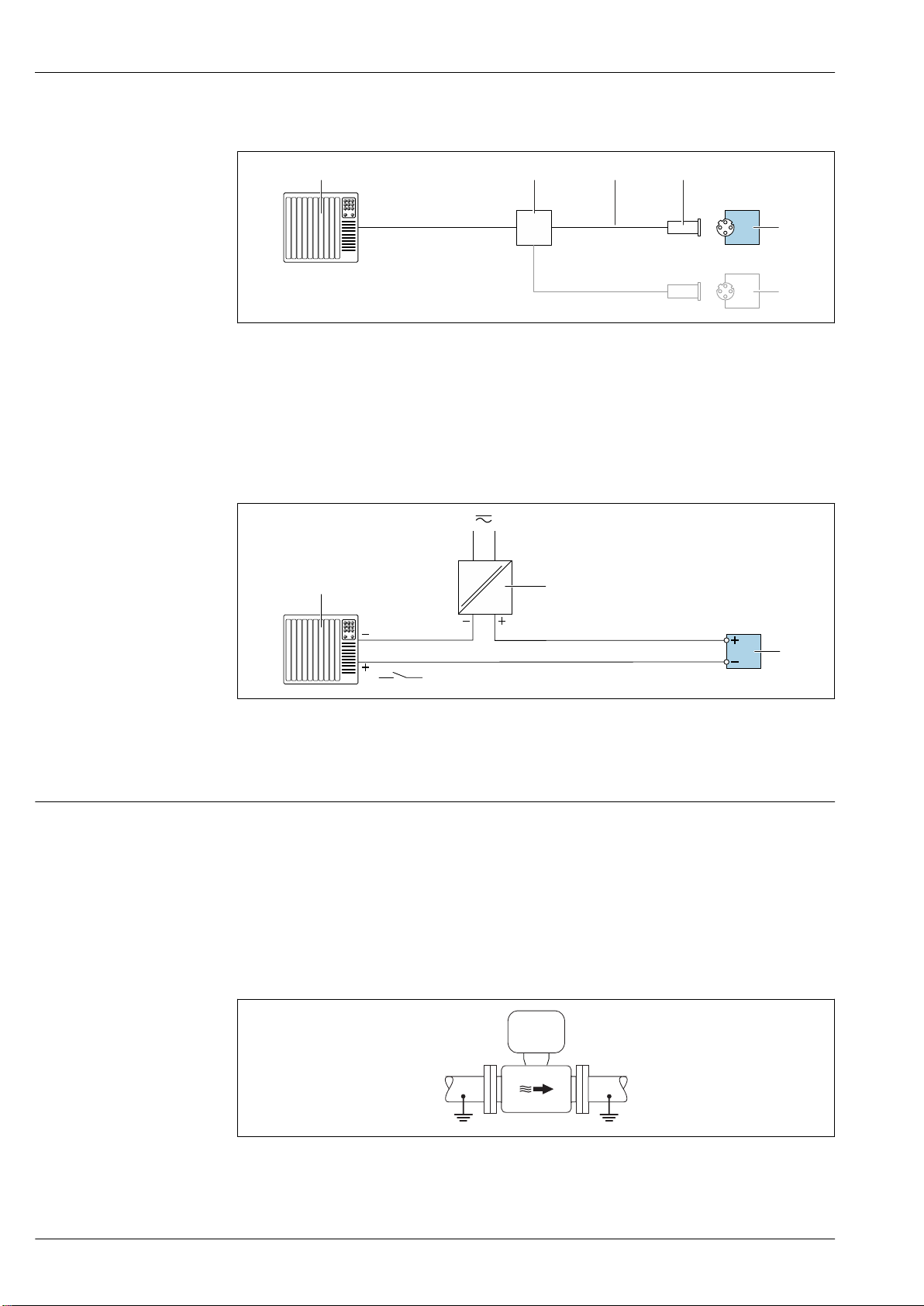
EtherNet/IP
1
2
4
3
5
5
1
2
3
12 Connection example for EtherNet/IP
1 Control system (e.g. PLC)
2 Ethernet switch
3 Observe cable specifications
4 Device plug
5 Transmitter
Status input
Proline Promag W 400
A0028767
13 Connection example for status input
1 Automation system with status output (e.g. PLC)
2 Power supply
3 Transmitter: Observe input values
Potential equalization Requirements
Please consider the following to ensure correct measurement:
• Same electrical potential for the medium and sensor
• Remote version: same electrical potential for the sensor and transmitter
• Company-internal grounding concepts
• Pipe material and grounding
Connection example, standard scenario
Metal, grounded pipe
14 Potential equalization via measuring tube
A0028764
A0016315
28 Endress+Hauser
Page 29
Proline Promag W 400
DN 300≤ DN 350≥
Connection example in special situations
Unlined and ungrounded metal pipe
This connection method also applies in situations where:
• The customary potential equalization is not used
• Equalizing currents are present
Ground cable Copper wire, at least 6 mm2 (0.0093 in2)
A0029338
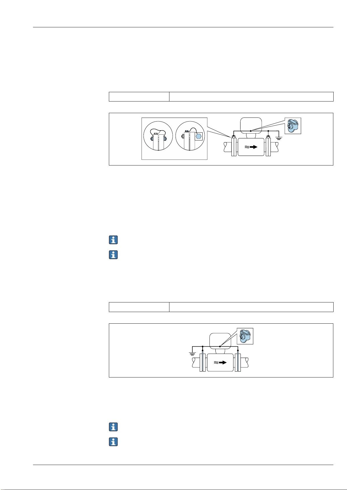
15 Potential equalization via ground terminal and pipe flanges
Note the following when installing:
• Connect both sensor flanges to the pipe flange via a ground cable and ground them.
• Connect the connection housing of the transmitter or sensor to ground potential by means of the
ground terminal provided for the purpose. To mount the ground cable:
– If DN ≤ 300 (12"): Mount the ground cable directly on the conductive flange coating of the
sensor with the flange screws.
– If DN ≥ 350 (14"): Mount the ground cable directly on the metal transport bracket.
For remote device versions, the ground terminal in the example always refers to the sensor and
not to the transmitter.
You can order the necessary ground cable from Endress+Hauser: → 126.
Plastic pipe or pipe with insulating liner
This connection method also applies in situations where:
• The customary potential equalization is not used
• Equalizing currents are present
Ground cable Copper wire, at least 6 mm2 (0.0093 in2)
Endress+Hauser 29
A0029339
16 Potential equalization via ground terminal and ground disks
Note the following when installing:
The ground disks must be connected to the ground terminal via the ground cable and be connected
to ground potential.
For remote device versions, the ground terminal in the example always refers to the sensor and
not to the transmitter.
The ground cable and ground disks can be ordered from Endress+Hauser → 126.
Page 30
Proline Promag W 400
+
–
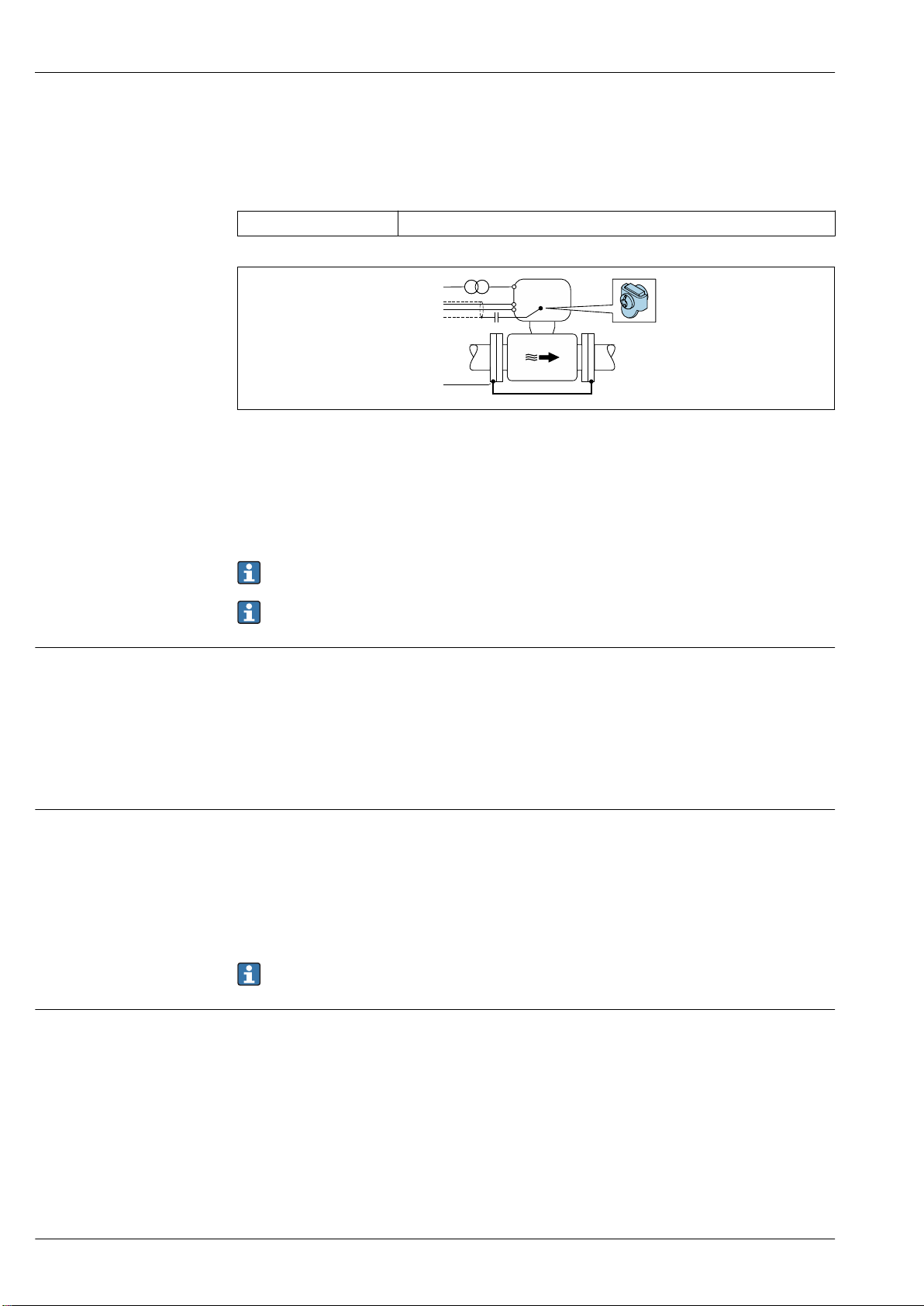
Pipe with a cathodic protection unit
This connection method is only used if the following two conditions are met:
• Metal pipe without liner or pipe with electrically conductive liner
• Cathodic protection is integrated in the personal protection equipment
Ground cable Copper wire, at least 6 mm2 (0.0093 in2)
1 Connection of the two flanges of the pipe via a ground cable
2 Signal line shielding via a capacitor
3 Measuring device connected to power supply such that it is floating in relation to the protective ground
(isolation transformer)
A0030377
terminals
Cable entries
Note the following when installing:
The sensor is installed in the pipe in a way that provides electrical insulation.
For remote device versions, the ground terminal in the example always refers to the sensor and
not to the transmitter.
You can order the necessary ground cable from Endress+Hauser: → 126.
Transmitter
• Supply voltage cable: plug-in spring terminals for wire cross-sections
0.5 to 2.5 mm2 (20 to 14 AWG)
• Signal cable: plug-in spring terminals for wire cross-sections 0.5 to 2.5 mm2 (20 to 14 AWG)
• Electrode cable: spring terminals for wire cross-sections 0.5 to 2.5 mm2 (20 to 14 AWG)
• Coil current cable: spring terminals for wire cross-sections 0.5 to 2.5 mm2 (20 to 14 AWG)
Sensor connection housing
Spring terminals for wire cross-sections0.5 to 2.5 mm2 (20 to 14 AWG)
Cable entry thread
• M20 x 1.5
• Via adapter:
– NPT ½"
– G ½"
Cable gland
• For standard cable: M20 × 1.5 with cable 6 to 12 mm (0.24 to 0.47 in)
• For reinforced cable: M20 × 1.5 with cable 9.5 to 16 mm (0.37 to 0.63 in)
If metal cable entries are used, use a grounding plate.
Cable specification Permitted temperature range
• The installation guidelines that apply in the country of installation must be observed.
• The cables must be suitable for the minimum and maximum temperatures to be expected.
Power supply cable
Standard installation cable is sufficient.
Signal cable
Current output 0/4 to 20 mA
Standard installation cable is sufficient.
30 Endress+Hauser
Page 31

Proline Promag W 400
Current output 4 to 20 mA HART
A shielded cable is recommended. Observe grounding concept of the plant.
Pulse/frequency/switch output
Standard installation cable is sufficient.
Status input
Standard installation cable is sufficient.
PROFIBUS DP
The IEC 61158 standard specifies two types of cable (A and B) for the bus line which can be used for
every transmission rate. Cable type A is recommended.
Cable type A
Characteristic impedance 135 to 165 Ω at a measuring frequency of 3 to 20 MHz
Cable capacitance < 30 pF/m
Wire cross-section
Cable type Twisted pairs
Loop resistance ≤110 Ω/km
Signal damping Max. 9 dB over the entire length of the cable cross-section
Shield Copper braided shielding or braided shielding with foil shield. When grounding
> 0.34 mm2 (22 AWG)
the cable shield, observe the grounding concept of the plant.
Modbus RS485
The EIA/TIA-485 standard specifies two types of cable (A and B) for the bus line which can be used
for every transmission rate. Cable type A is recommended.
Cable type A
Characteristic impedance 135 to 165 Ω at a measuring frequency of 3 to 20 MHz
Cable capacitance < 30 pF/m
Wire cross-section
Cable type Twisted pairs
Loop resistance ≤110 Ω/km
Signal damping Max. 9 dB over the entire length of the cable cross-section
Shield Copper braided shielding or braided shielding with foil shield. When grounding
> 0.34 mm2 (22 AWG)
the cable shield, observe the grounding concept of the plant.
EtherNet/IP
The standard ANSI/TIA/EIA-568-B.2 Annex specifies CAT 5 as the minimum category for a cable
used for EtherNet/IP. CAT 5e and CAT 6 are recommended.
For more information on planning and installing EtherNet/IP networks, please refer to the
"Media Planning and Installation Manual. EtherNet/IP" of ODVA Organization
Connecting cable for remote version
Electrode cable
Standard cable
Cable for empty pipe
detection (EPD)
3 ×0.38 mm2 (20 AWG) with common, braided copper shield
( ~9.5 mm (0.37 in)) and individual shielded cores
4 ×0.38 mm2 (20 AWG) with common, braided copper shield
( ~9.5 mm (0.37 in)) and individual shielded cores
Endress+Hauser 31
Page 32

Conductor resistance ≤50 Ω/km (0.015 Ω/ft)
1
2
3
4
5
6
7
a
b
Capacitance: core/shield ≤420 pF/m (128 pF/ft)
Operating temperature –20 to +80 °C (–68 to +176 °F)
Coil current cable
Proline Promag W 400
Standard cable
Conductor resistance ≤37 Ω/km (0.011 Ω/ft)
Capacitance: core/core,
shield grounded
Operating temperature –20 to +80 °C (–68 to +176 °F)
Test voltage for cable
insulation
17 Cable cross-section
a Electrode cable
b Coil current cable
1 Core
2 Core insulation
3 Core shield
4 Core jacket
5 Core reinforcement
6 Cable shield
7 Outer jacket
3 ×0.75 mm2 (18 AWG) with common, braided copper shield
( ~9 mm (0.35 in))
≤120 pF/m (37 pF/ft)
≤ AC 1433 V r.m.s. 50/60 Hz or ≥ DC 2026 V
A0029151
A connecting cable can be ordered from Endress+Hauser for IP68:
• Pre-terminated cables that are already connected to the sensor.
• Pre-terminated cables, where the cables are connected by the customer onsite (incl. tools for
sealing the connection compartment)
Reinforced connecting cables
Reinforced connecting cables with an additional, reinforcing metal braid should be used for:
• When laying the cable directly in the ground
• Where there is a risk of damage from rodents
• If using the device below IP68 degree of protection
Reinforced connecting cables with an additional, reinforcing metal braid can be ordered from
Endress+Hauser .
Operation in zones of severe electrical interference
The measuring system meets the general safety requirements → 124 and EMC specifications
→ 42.
Grounding is by means of the ground terminal provided for the purpose inside the connection
housing. The stripped and twisted lengths of cable shield to the ground terminal must be as short as
possible.
32 Endress+Hauser
Page 33

Proline Promag W 400
2.5
[%]
2.0
1.5
1.0
0.5
0
0.2 %
0.5 %
0
1
2 4 6 8 10 [m/s]
v
5 10 15 20 25 30 32 [ft/s]0
2.5
[%]
2.0
1.5
1.0
0.5
0
0.2 %
0.5 %
0
[m/s]
v
[ft/s]
v
0.2
v
0.5
0
v
max
Performance characteristics
Reference operating conditions
• Error limits following DIN EN 29104, in future ISO 20456
• Water, typically +15 to +45 °C (+59 to +113 °F); 0.5 to 7 bar (73 to 101 psi)
• Data as indicated in the calibration protocol
• Accuracy based on accredited calibration rigs according to ISO 17025
Maximum measured error Error limits under reference operating conditions
o.r. = of reading
Volume flow
• ±0.5 % o.r. ± 1 mm/s (0.04 in/s)
• Optional: ±0.2 % o.r. ± 2 mm/s (0.08 in/s)
Fluctuations in the supply voltage do not have any effect within the specified range.
A0032069
18 Maximum measured error in % o.r.
A0017051
19 Flat Spec in % o.r.
Endress+Hauser 33
Page 34

Flat Spec flow values0.5 %
Proline Promag W 400
Nominal diameter v
[mm] [in] [m/s] [ft/s] [m/s] [ft/s]
25 to 600
50 to 300
1) Order code for "Design", option A "Insertion length short, ISO/DVGW to DN400, DN450-2000 1:1" and
2) Order code for "Design", option C "Insertion length short ISO/DVGW to DN300, without inlet/outlet runs,
1)
2)
order code for "Design", option B "Insertion length long, ISO/DVGW to DN400, DN450-2000 1:1.3"
constricted meas.tube"
1 to 24 0.5 1.64 10 32
2 to 12 0.25 0.82 5 16
0.5
v
max
Flat Spec flow values0.2 %
Nominal diameter v
[mm] [in] [m/s] [ft/s] [m/s] [ft/s]
25 to 600
50 to 300
1) Order code for "Design", option A "Insertion length short, ISO/DVGW to DN400, DN450-2000 1:1" and
2) Order code for "Design", option C "Insertion length short ISO/DVGW to DN300, without inlet/outlet runs,
1)
2)
order code for "Design", option B "Insertion length long, ISO/DVGW to DN400, DN450-2000 1:1.3"
constricted meas.tube"
1 to 24 1.5 4.92 10 32
2 to 12 0.6 1.97 4 13
0.2
v
max
Electrical conductivity
Max. measured error not specified.
Repeatability
Influence of ambient temperature
Accuracy of outputs
The outputs have the following base accuracy specifications.
Current output
Accuracy Max. ±5 µA
Pulse/frequency output
o.r. = of reading
Accuracy Max. ±50 ppm o.r. (over the entire ambient temperature range)
o.r. = of reading
Volume flow
max. ±0.1 % o.r. ± 0.5 mm/s (0.02 in/s)
Electrical conductivity
Max. ±5 % o.r.
Current output
o.r. = of reading
Temperature coefficient Max. ±0.005 % o.r./°C
Pulse/frequency output
Temperature coefficient No additional effect. Included in accuracy.
34 Endress+Hauser
Page 35

Proline Promag W 400
h
1 1
h
2
1
Mounting location
Installation
No special measures such as supports etc. are necessary. External forces are absorbed by the
construction of the device.
A0029343
Preferably install the sensor in an ascending pipe, and ensure a sufficient distance to the next pipe
elbow: h ≥ 2 × DN
Not necessary in the case of order code for "Design", option C "Insertion length short ISO/DVGW
to DN300, without inlet/outlet runs, constricted meas.tube"
20 Installation of the sensor after a control valve is not recommended
1 Control valve
Installation in down pipes
Install a siphon with a vent valve downstream of the sensor in down pipes whose length h ≥
5 m (16.4 ft). This precaution is to avoid low pressure and the consequent risk of damage to the
measuring tube. This measure also prevents the system losing prime.
21 Installation in a down pipe
1 Vent valve
2 Pipe siphon
h Length of down pipe
Installation in partially filled pipes
A partially filled pipe with a gradient necessitates a drain-type configuration.
A0033017
A0028981
Endress+Hauser 35
Page 36

2 x DN³
5 x DN³
For heavy sensors DN ≥ 350 (14")
Proline Promag W 400
A0029257
Orientation
A0016276
The direction of the arrow on the sensor nameplate helps you to install the sensor according to the
flow direction (direction of medium flow through the piping).
Orientation Recommendation
A Vertical orientation
A0015591
B Horizontal orientation, transmitter at
top
A0015589
C Horizontal orientation, transmitter at
bottom
A0015590
D Horizontal orientation, transmitter at
side
A0015592
1) Applications with low process temperatures may decrease the ambient temperature. To maintain the
minimum ambient temperature for the transmitter, this orientation is recommended.
2) Applications with high process temperatures may increase the ambient temperature. To maintain the
maximum ambient temperature for the transmitter, this orientation is recommended.
3) To prevent the electronics module from overheating in the case of a sharp rise in temperature (e.g. CIP- or
SIP processes), install the device with the transmitter component pointing downwards.
1)
2) 3)
Horizontal
• Ideally, the measuring electrode plane should be horizontal. This prevents brief insulation of the
two measuring electrodes by entrained air bubbles.
• Empty pipe detection only works if the transmitter housing is pointing upwards as otherwise there
is no guarantee that the empty pipe detection function will actually respond to a partially filled or
empty measuring tube.
36 Endress+Hauser
Page 37

Proline Promag W 400
1
2
3
≥ 5 × DN
≥ 2 × DN
≥ 0 × DN
A0029344
1 EPD electrode for empty pipe detection
2 Measuring electrodes for signal detection
3 Reference electrode for potential equalization
Inlet and outlet runs
If possible, install the sensor upstream from fittings such as valves, T-pieces or elbows.
Observe the following inlet and outlet runs to comply with accuracy specifications:
A0028997
22 Order code for "Design", option A "Insertion length short, ISO/DVGW until DN400, DN450-2000 1:1" and
order code for "Design", option B "Insertion length long, ISO/DVGW until DN400, DN450-2000 1:1.3"
A0032859
23 Order code for "Design", option C "Insertion length short ISO/DVGW until DN300, w/o inlet and outlet
runs, constricted meas.tube"
To keep within the in-service maximum permissible errors for custody transfer no additional
requirements apply with regard to the graphic illustrated above.
Adapters
Suitable adapters to DIN EN 545 (double-flange reducers) can be used to install the sensor in largerdiameter pipes. The resultant increase in the rate of flow improves measuring accuracy with very
slow-moving fluids.
The nomogram shown here can be used to calculate the pressure loss caused by reducers and
expanders:
• Calculate the ratio of the diameters d/D.
• From the nomogram read off the pressure loss as a function of flow velocity (downstream from
the reduction) and the d/D ratio.
The nomogram only applies to liquids with a viscosity similar to that of water.
Endress+Hauser 37
Page 38

Proline Promag W 400
100
10
0.5
d / D
[mbar]
0.6 0.7 0.8 0.9
1 m/s
2 m/s
3 m/s
4 m/s
5 m/s
6 m/s
7 m/s
8 m/s
1
D
d
max. 8°
200
100
5
10 100 200
[m]
[ S/cm]µ
L
max
[ ]ft
200 6000 400
L
max
A0029002
Length of connecting cable
To ensure correct measuring results when using the remote version,
observe the maximum permitted length of the connecting cable L
max
the conductivity of the fluid.
If measuring liquids in general: 5 µS/cm
24 Permitted length of connecting cable for remote version
Colored area = permitted range
L
=
length of connecting cable in [m] ([ft])
max
[µS/cm] = fluid conductivity
. This length is determined by
A0016539
38 Endress+Hauser
Page 39

Proline Promag W 400
149 (5.85)
210.5 (8.29)
=
5.8 (0.23)
17 (0.67) =
14 (0.55)
5.8 (0.23)
ø 20…70
( 0.79…2.75)ø
~102 (~ 4.0)
4 x
SW 10
3 x
TX 25
Mounting the transmitter housing
Wall mounting
A0020523
25 Engineering unit mm (in)
Post mounting
26 Engineering unit mm (in)
Special mounting instructions
Display protection
To ensure that the optional display protection can be easily opened, maintain the following
minimum head clearance: 350 mm (13.8 in)
Permanent immersion in water
A fully welded remote version with IP68 protection is optionally available for permanent immersion
in water ≤ 3 m (10 ft) or in exceptional cases for use for up to 48 hours at ≤ 10 m (30 ft). The
measuring device meets the requirements of corrosion categories C5-M and Im1/Im2/Im3. The fully
welded design along with the connection compartment sealing system ensure that moisture cannot
enter the measuring device.
Endress+Hauser 39
A0029051
Page 40

Proline Promag W 400
≤ ≤
3 ( 10)
A0029320
27 Engineering unit in m(ft)
Replacement of cable gland on connection housing
Buried applications
A remote version with IP68 protection is optionally available for buried applications. The measuring
device satisfies the certified corrosion protection Im1/Im2/Im3 in accordance with EN ISO 12944. It
can be used directly underground without the need for additional protective measures. The device is
mounted in accordance with the usual regional installation regulations (e.g. EN DIN 1610).
Ambient temperature range
A0029321
Environment
Transmitter –40 to +60 °C (–40 to +140 °F)
Local display –20 to +60 °C (–4 to +140 °F), the readability of the display may be
impaired at temperatures outside the temperature range.
Sensor • Process connection material, carbon steel:
–10 to +60 °C (+14 to +140 °F)
• Process connection material, stainless steel:
–40 to +60 °C (–40 to +140 °F)
Mount the transmitter separately from the sensor if both the ambient
and fluid temperatures are high.
Liner Do not exceed or fall below the permitted temperature range of the liner .
If operating outdoors:
• Install the measuring device in a shady location.
• Avoid direct sunlight, particularly in warm climatic regions.
• Avoid direct exposure to weather conditions.
40 Endress+Hauser
Page 41

Proline Promag W 400
• If the compact version of the device is insulated at low temperatures, the insulation must also
include the device neck.
• Protect the display against impact.
• Protect the display from abrasion by sand in desert areas.
You can order a display guard from Endress+Hauser : → 126
Temperature tables
Observe the interdependencies between the permitted ambient and fluid temperatures when
operating the device in hazardous areas.
For detailed information on the temperature tables, see the separate document entitled "Safety
Instructions" (XA) for the device.
Storage temperature
Atmosphere
Degree of protection
The storage temperature corresponds to the operating temperature range of the measuring
transmitter and the appropriate measuring sensors.→ 40
• Protect the measuring device against direct sunlight during storage in order to avoid unacceptably
high surface temperatures.
• Select a storage location where moisture cannot collect in the measuring device as fungus or
bacteria infestation can damage the liner.
• If protection caps or protective covers are mounted these should never be removed before
installing the measuring device.
If a plastic transmitter housing is permanently exposed to certain steam and air mixtures, this can
damage the housing.
If you are unsure, please contact your Endress+Hauser Sales Center for clarification.
Transmitter
• As standard: IP66/67, type 4X enclosure
• When housing is open: IP20, type 1 enclosure
Sensor
• As standard: IP66/67, type 4X enclosure
• Optionally available for remote version:
– IP66/67, type 4X enclosure; fully welded, with protective varnish EN ISO 12944 C5-M. Suitable
for use in corrosive atmospheres.
– IP68, type 6P enclosure; fully welded, with protective varnish as per EN ISO 12944 C5-M.
Suitable for permanent immersion in water ≤ 3 m (10 ft) or up to 48 hours at depths ≤
10 m (30 ft).
– IP68, type 6P enclosure; fully welded, with protective varnish as per EN ISO 12944 Im1/Im2/
Im3. Suitable for permanent immersion in saline water ≤ 3 m (10 ft) or up to 48 hours at depths
≤ 10 m (30 ft) or in buried applications.
Vibration resistance
Shock resistance
Compact version
• Vibration, sinusoidal according to IEC 60068-2-6
– 2 to 8.4 Hz, 3.5 mm peak
– 8.4 to 2 000 Hz, 1 g peak
• Vibration broad-band random, according to IEC 60068-2-64
– 10 to 200 Hz, 0.003 g2/Hz
– 200 to 2 000 Hz, 0.001 g2/Hz
– Total: 1.54 g rms
Remote version
• Vibration, sinusoidal according to IEC 60068-2-6
– 2 to 8.4 Hz, 7.5 mm peak
– 8.4 to 2 000 Hz, 2 g peak
• Vibration broad-band random, according to IEC 60068-2-64
– 10 to 200 Hz, 0.01 g2/Hz
– 200 to 2 000 Hz, 0.003 g2/Hz
– Total: 2.70 g rms
Shock, half-sine according to IEC 60068-2-27
6 ms 50 g
Endress+Hauser 41
Page 42

Proline Promag W 400
0
5
10
15
20
25
35
30
40
[bar][psi]
-40
-20
0 20
40 60 80 100 140 180 [°C]
360 [°F]
0-40 100 200 300
200
100
400
300
500
600
0
120 160
PN25
PN16
PN10
PN 6
PN40
PN25
PN16
PN10
PN 6
PN40
Impact resistance
Mechanical load
Electromagnetic compatibility (EMC)
Medium temperature range
Rough handling shocks according to IEC 60068-2-31
• Protect the transmitter housing against mechanical effects, such as shock or impact; the use of the
remote version is sometimes preferable.
• Never use the transmitter housing as a ladder or climbing aid.
• As per IEC/EN 61326 and NAMUR Recommendation 21 (NE 21)
• Complies with emission limits for industry as per EN 55011 (Class A)
• Device version with PROFIBUS DP: Complies with emission limits for industry as per EN 50170
Volume 2, IEC 61784
The following applies for PROFIBUS DP: If baud rates > 1.5 MBaud, an EMC cable entry must be
used and the cable shield must continue as far as the terminal wherever possible.
Details are provided in the Declaration of Conformity.
Process
• 0 to +80 °C (+32 to +176 °F) for hard rubber, DN 50 to 2000 (2 to 78")
• –20 to +50 °C (–4 to +122 °F) for polyurethane, DN 25 to 1200 (1 to 48")
In custody transfer mode, the permitted fluid temperature is 0 to +50 °C (+32 to +122 °F).
Conductivity
Pressure-temperature ratings
42 Endress+Hauser
≥ 5 μS/cm for liquids in general. Stronger filter damping is required for very low conductivity values.
Note that in the case of the remote version, the requisite minimum conductivity also depends
on the cable length → 38.
The following pressure/temperature diagrams apply to all pressure-bearing parts of the device and
not just the process connection. The diagrams show the maximum permissible medium pressure
depending on the specific medium temperature.
Process connection: fixed flange according to EN 1092-1 (DIN 2501)
28 Process connection material: stainless steel, 1.4404/1.4571/F316L; carbon steel, A105/FE410WB/
P250GH/S235JRG2/S235JR+N
A0029390-EN
Page 43

Proline Promag W 400
[bar][psi]
-40
-20
0 20
40 60 80 100 140 180 [°C]
360 [°F]
0-40 100 200 300
200
100
400
300
500
600
0
120 160
Class300
Class150
0
10
20
30
40
50
60
800
700
900
[bar][psi]
-40
-20
0 20
40 60 80 100 140 180 [°C]
360 [°F]
0-40 100 200 300
200
100
400
300
500
600
0
120 160
Class300
Class150
0
10
20
30
40
50
60
800
700
900
ClassD
[bar]
-60
-40
-20
0 20
40 60 80 100 120140160 180 [°C]
0
8
10
9
11
360 [°F]
0-40 100 200 300
1 02
140
160
0
Process connection: fixed flange according to ASME B16.5
A0029394-EN
29 Process connection material: stainless steel, F316L similar to 1.4404
A0029393-EN
30 Process connection material: carbon steel, A105/A515(70)
Process connection: fixed flange according to AWWA C207
Endress+Hauser 43
31 Process connection material: carbon steel, A105/A181/P265GH/S275JR
A0029818-EN
Page 44

Proline Promag W 400
[bar][psi]
-40
-20
0 20
40 60 80 100 140 180 [°C]
360 [°F]
0-40 100 200 300
100
200
300
0
120 160
0
10
20
30
400
TableE
PN16
[bar]
-60
-40
-20
0 20
40 60 80 100 120140160 180 [°C]
0
5
15
10
20
25
360 [°F]
0-40 100 200 300
100
200
300
0
[bar][psi]
-40
-20
0 20
40 60 80 100 140 180 [°C]
360 [°F]
0-40 100 200 300
100
200
300
0
120 160
0
10
20
30
400
20K
10K
Process connection: fixed flange according to AS 2129
32 Process connection material: carbon steel, A105/FE410WB/P235GH/P265GH/S235JRG2
Process connection: fixed flange according to AS 4087
A0029398-EN
33 Process connection material: carbon steel, A105/P265GH/S275JR
Process connection: fixed flange according to JIS B2220
44 Endress+Hauser
34 Process connection material: stainless steel, F316L similar to 1.4404; carbon steel, A105/A350LF2
A0029817-EN
A0029397-EN
Page 45

Proline Promag W 400
DN80
(3")
DN65
(2½")
DN50
(2")
500
450
400
350
300
250
200
150
100
50
0
0 10 20 30 40 50 60 70 80 90 100 110 120
[mbar]
[m /h]³
0 100 200 300 400 50050 150 250 350 450
[gal/min]
7
0
1
2
3
4
5
6
Pressure tightness
Flow limit
Liner: hard rubber
Nominal diameter Limit values for absolute pressure in [mbar] ([psi]) for fluid temperatures:
[mm] [in] +25 °C (+77 °F) +50 °C (+122 °F) +80 °C (+176 °F)
50…2000 2…78 0 (0) 0 (0) 0 (0)
Liner: polyurethane
Nominal diameter Limit values for absolute pressure in [mbar] ([psi]) for fluid temperatures:
[mm] [in] +25 °C (+77 °F) +50 °C (+122 °F)
25…1200 1…48 0 (0) 0 (0)
The diameter of the pipe and the flow rate determine the nominal diameter of the sensor. The
optimum flow velocity is between 2 to 3 m/s (6.56 to 9.84 ft/s). Also match the velocity of flow (v)
to the physical properties of the fluid:
• v < 2 m/s (6.56 ft/s): for abrasive fluids (e.g. potter's clay, lime milk, ore slurry)
• v > 2 m/s (6.56 ft/s): for fluids producing buildup (e.g. wastewater sludge)
A necessary increase in the flow velocity can be achieved by reducing the sensor nominal
diameter.
For an overview of the full scale values for the measuring range, see the "Measuring range"
section → 8
For custody transfer, the applicable approval determines the permitted measuring range.
Pressure loss
• No pressure loss occurs if the sensor is installed in a pipe with the same nominal diameter.
• Pressure losses for configurations incorporating adapters according to DIN EN 545 → 37
35 Pressure loss DN 50 to 80 (2 to 3") in the case of order code for "Design", option C "Insertion length short
ISO/DVGW to DN300, without inlet/outlet runs, constricted meas.tube"
A0032667-EN
Endress+Hauser 45
Page 46

Proline Promag W 400
DN300
(12")
DN100
(4")
DN250
(10")
DN200
(8")
DN150
(6")
DN125
(5")
[mbar]
900
800
700
600
500
400
300
200
100
0
0 200 400 600 800 1000 1200 1400 1600 1800
[m /h]³
0
13
12
11
10
9
8
7
6
5
4
3
2
1
0 1000 2000 3000 4000 5000 6000 7000 8000
[gal/min]
L
A0032668-EN
36 Pressure loss DN 100 to 300 (4 to 12") in the case of order code for "Design", option C "Insertion length
short ISO/DVGW to DN300, without inlet/outlet runs, constricted meas.tube"
System pressure
Never install the sensor on the pump suction side in order to avoid the risk of low pressure, and thus
damage to the liner.
Furthermore, install pulse dampers if reciprocating, diaphragm or peristaltic pumps are used.
• Information on the liner's resistance to partial vacuum → 45
• Information on the shock resistance of the measuring system → 42
• Information on the vibration resistance of the measuring system → 41
Vibrations
46 Endress+Hauser
37 Measures to avoid device vibrations (L > 10 m (33 ft))
In the event of very strong vibrations, the pipe and sensor must be supported and fixed.
It is also advisable to mount the sensor and transmitter separately.
• Information on the shock resistance of the measuring system → 42
• Information on the vibration resistance of the measuring system → 41
A0028777
A0029004
Page 47

Proline Promag W 400
A
H
B
C
E
G
D
F
J
K
Custody transfer mode
The measuring device is optionally tested in accordance with OIML R137 and has an EU typeexamination certificate according to Measuring Instruments Directive 2014/32/EU for service
subject to legal metrological control ("custody transfer") for cold water (Annex III).
The permitted fluid temperature in these applications is 0 to +50 °C (+32 to +122 °F).
The device is used with a legally controlled totalizer on the local display and optionally with legally
controlled outputs.
Measuring devices subject to legal metrological control totalize in both directions, i.e. all the outputs
consider flow components in the positive (forward) and negative (reverse) flow direction.
Generally a measuring device subject to legal metrological control is secured against tampering by
seals on the transmitter or sensor. These seals may normally only be opened by a representative of
the competent authority for legal metrology controls.
After putting the device into circulation or after sealing the device, operation is only possible to a
limited extent.
Detailed ordering information is available from your local Endress+Hauser sales center for national
approvals (outside Europe) as cold water meters based on OIML R49.
Mechanical construction
Dimensions in SI units Compact version
Order code for "Housing", option M "Compact, polycarbonate" or option A "Compact, aluminum, coated"
A0020352
Order code for "Design", option A "Insertion length short, ISO/DVGW to DN400, DN450-2000 1:1" and
order code for "Design", option B "Insertion length long, ISO/DVGW to DN400, DN450-2000 1:1.3"
1)
DN
[mm] [mm] [mm] [mm] [mm] [mm] [mm] [mm] [mm] [mm] [mm]
25 193 103 90 167 201 84 285 120 94 200
32 193 103 90 167 201 84 285 120 94 200
40 193 103 90 167 201 84 285 120 94 200
50 193 103 90 167 201 84 285 120 94 200
65 193 103 90 167 226 109 335 180 94 200
80 193 103 90 167 226 109 335 180 94 200
100 193 103 90 167 226 109 335 180 94 250
A B C D E F G H J K
2)
Endress+Hauser 47
Page 48

Proline Promag W 400
H
K
J
E
G
F
A
B
D
C
1)
DN
[mm] [mm] [mm] [mm] [mm] [mm] [mm] [mm] [mm] [mm] [mm]
125 193 103 90 167 266 150 416 260 140 250
150 193 103 90 167 266 150 416 260 140 300
200 193 103 90 167 291 180 471 324 156 350
250 193 103 90 167 316 205 521 400 166 450
300 193 103 90 167 341 230 571 460 166 500
1) EN (DIN), AS, JIS; For flanges according to AS, only nominal diameters DN 80, 100 and 150 to 300 are
2) The length is independent of the selected pressure rating. Length in accordance with DVGW/ISO.
A B C D E F G H J K
available.
Order code for "Design", option C "Insertion length short ISO/DVGW to DN300, without inlet/outlet
runs, constricted meas.tube"
1)
DN
[mm] [mm] [mm] [mm] [mm] [mm] [mm] [mm] [mm] [mm] [mm]
50 193 103 90 167 201 84 285 120 94 200
65 193 103 90 167 201 84 285 120 94 200
80 193 103 90 167 226 109 335 180 94 200
100 193 103 90 167 226 109 335 180 94 250
125 193 103 90 167 226 109 335 180 94 250
150 193 103 90 167 226 109 335 180 94 300
200 193 103 90 167 266 150 416 260 140 350
250 193 103 90 167 266 150 416 260 140 450
300 193 103 90 167 291 180 471 324 156 500
A B C D E F G H J K
2)
2)
1) EN (DIN), AS, JIS; For flanges according to AS, only nominal diameters DN 80, 100 and 150 to 300 are
available.
2) The length is independent of the selected pressure rating. Length in accordance with DVGW/ISO.
A0017154
48 Endress+Hauser
Page 49

Proline Promag W 400
G
J
H
E
F
A
B
D
C
1)
DN
[mm] [mm] [mm] [mm] [mm] [mm] [mm] [mm] [mm] [mm] [mm]
350 193 103 90 167 432 282 714 564 288 550
375 193 103 90 167 458 308 766 616 288 600
400 193 103 90 167 458 308 766 616 288 600
450 193 103 90 167 483 333 816 666 292 650
500 193 103 90 167 508 359 867 717 292 650
600 193 103 90 167 560 410 970 821 402 780
700 193 103 90 167 662 512 1174 1024 589 910
750 193 103 90 167 662 512 1174 1024 626 975
800 193 103 90 167 683 534 1217 1067 647 1040
900 193 103 90 167 760 610 1370 1220 785 1170
1000 193 103 90 167 836 686 1522 1372 862 1300
1050 193 103 90 167 862 712 1574 1424 912 1365
1200 193 103 90 167 961 811 1772 1622 992 1560
1350 193 103 90 167 1062 912 1974 1824 1252 1755
1400 193 103 90 167 1137 987 2124 1974 1252 1820
1500 193 103 90 167 1161 1011 2172 2022 1392 1950
1600 193 103 90 167 1206 1056 2262 2112 1482 2080
1650 193 103 90 167 1243 1093 2336 2186 1482 2145
1800 193 103 90 167 1338 1188 2526 2376 1632 2340
2000 193 103 90 167 1388 1238 2626 2476 1732 2600
A B C D E F G H J K
2)
1) EN (DIN), AS; For flanges according to AS, only nominal diameters DN 350, 400, 500 and 600 are
available.
2) The length is independent of the selected pressure rating. Length in accordance with DVGW/ISO.
Order code for "Housing", option M "Compact, polycarbonate" or option A "Compact, aluminum, coated";
order code for "Design", option A "Insertion length short"
A0017153
Endress+Hauser 49
Page 50

Proline Promag W 400
DN A B C D E H J
[mm] [mm] [mm] [mm] [mm] [mm] [mm] [mm]
350 193 103 90 167 386 290 550
375 193 103 90 167 412 290 600
400 193 103 90 167 412 290 600
450 193 103 90 167 440 290 600
500 193 103 90 167 465 290 600
600 193 103 90 167 506 290 600
700 193 103 90 167 571 424 700
750 193 103 90 167 608 454 750
800 193 103 90 167 627 500 800
900 193 103 90 167 677 580 900
1000 193 103 90 167 727 664 1000
1050 193 103 90 167 763 759 1050
1200 193 103 90 167 841 832 1200
1350 193 103 90 167 953 1008 1350
1400 193 103 90 167 953 1008 1400
1500 193 103 90 167 1053 1147 1500
1600 193 103 90 167 1053 1147 1600
1650 193 103 90 167 1104 1284 1650
1800 193 103 90 167 1161 1379 1800
2000 193 103 90 167 1272 1569 2000
Dimension F Dimension G
EN (DIN) ASME AS JIS EN (DIN) ASME AS JIS
DN PN 6 PN 10 PN 16 AWWA 10K 20K PN 6 PN 10 PN 16 AWWA 10K 20K
[mm] [mm] [mm] [mm] [mm] [mm] [mm] [mm] [mm] [mm] [mm] [mm] [mm] [mm] [mm]
350 631 638 702 653 648 603 653 490 505 520 533 525 490 540
375 – – – – 687 – – – – – – 550 – –
400 682 694 760 710 702 673 718 540 565 580 597 580 560 605
450 737 747 823 757 760 733 788 595 615 640 635 640 620 675
500 787 800 926 814 817 788 843 645 670 715 699 705 675 730
600 883 896 1026 912 918 908 958 755 780 840 813 825 795 845
700 1001 1018 1145 1034 1026 1018 – 860 895 910 927 910 905 –
750 – – – 1100 1106 1083 – – – – 984 995 970 –
800 1115 1135 1240 1157 1157 – – 975 1015 1025 1060 1060 – –
900 1215 1235 1240 1261 1265 – – 1075 1115 1125 1168 1175 – –
1000 1315 1342 1355 1372 1355 – – 1175 1230 1255 1289 1255 – –
1050 – – – 1436 – – – – – – 1346 – – –
1200 1544 1569 1584 1597 1586 – – 1405 1455 1485 1511 1490 – –
1350 – – – 1795 – – – – – – 1683 – – –
1400 1768 1791 1796 – – – – 1630 1675 1685 – – – –
1500 – – – 1980 – – – – – – 1854 – – –
50 Endress+Hauser
Page 51

Proline Promag W 400
22.5°
E
F
G
H K
J
A
B
D
C
Dimension F Dimension G
EN (DIN) ASME AS JIS EN (DIN) ASME AS JIS
DN PN 6 PN 10 PN 16 AWWA 10K 20K PN 6 PN 10 PN 16 AWWA 10K 20K
[mm] [mm] [mm] [mm] [mm] [mm] [mm] [mm] [mm] [mm] [mm] [mm] [mm] [mm] [mm]
1600 1968 2011 2019 – – – – 1830 1915 1930 – – – –
1650 – – – 2120 – – – – – – 2032 – – –
1800 2183 2218 2226 2259 – – – 2045 2115 2130 2197 – – –
2000 2404 2434 2444 2453 – – – 2265 2325 2345 2362 – – –
Order code for "Housing", option Q "Compact, polycarbonate, inclined" or option R "Compact, aluminum,
coated, inclined"
A0020353
Order code for "Design", option A "Insertion length short, ISO/DVGW to DN400, DN450-2000 1:1" and
order code for "Design", option B "Insertion length long, ISO/DVGW to DN400, DN450-2000 1:1.3"
1)
DN
[mm] [mm] [mm] [mm] [mm] [mm] [mm] [mm] [mm] [mm] [mm]
25 199 119 80 167 248 84 332 120 94 200
32 199 119 80 167 248 84 332 120 94 200
40 199 119 80 167 248 84 332 120 94 200
50 199 119 80 167 248 84 332 120 94 200
65 199 119 80 167 273 109 382 180 94 200
80 199 119 80 167 273 109 382 180 94 200
100 199 119 80 167 273 109 382 180 94 250
125 199 119 80 167 313 150 463 260 140 250
150 199 119 80 167 313 150 463 260 140 300
200 199 119 80 167 338 180 518 324 156 350
250 199 119 80 167 363 205 568 400 166 450
300 199 119 80 167 388 230 618 460 166 500
1) EN (DIN), AS, JIS; For flanges according to AS, only nominal diameters DN 80, 100 and 150 to 300 are
2) The length is independent of the selected pressure rating. Length in accordance with DVGW/ISO.
A B C D E F G H J K
available.
2)
Endress+Hauser 51
Page 52

Proline Promag W 400
22.5°
H
K
J
E
G
F
A
B
D
C
Order code for "Design", option C "Insertion length short ISO/DVGW to DN300, without inlet/outlet
runs, constricted meas.tube"
1)
DN
[mm] [mm] [mm] [mm] [mm] [mm] [mm] [mm] [mm] [mm] [mm]
50 199 119 80 167 248 84 332 120 94 200
65 199 119 80 167 248 84 332 120 94 200
80 199 119 80 167 273 109 382 180 94 200
100 199 119 80 167 273 109 382 180 94 250
125 199 119 80 167 273 109 382 180 94 250
150 199 119 80 167 273 109 382 180 94 300
200 199 119 80 167 313 150 463 260 140 350
250 199 119 80 167 313 150 463 260 140 450
300 199 119 80 167 338 180 518 324 156 500
1) EN (DIN), AS, JIS; For flanges according to AS, only nominal diameters DN 80, 100 and 150 to 300 are
2) The length is independent of the selected pressure rating. Length in accordance with DVGW/ISO.
A B C D E F G H J K
available.
2)
A0020396
1)
DN
[mm] [mm] [mm] [mm] [mm] [mm] [mm] [mm] [mm] [mm] [mm]
350 199 119 80 167 477 282 759 564 288 550
375 199 119 80 167 503 308 811 616 288 600
400 199 119 80 167 503 308 811 616 288 600
450 199 119 80 167 528 333 861 666 292 650
500 199 119 80 167 553 359 912 717 292 650
600 199 119 80 167 605 410 1015 821 402 780
700 199 119 80 167 707 512 1219 1024 589 910
750 199 119 80 167 707 512 1219 1024 626 975
800 199 119 80 167 728 534 1262 1067 647 1040
52 Endress+Hauser
A B C D E F G H J K
2)
Page 53

Proline Promag W 400
G
J
H
E
F
22.5°
A
B
D
C
1)
DN
[mm] [mm] [mm] [mm] [mm] [mm] [mm] [mm] [mm] [mm] [mm]
900 199 119 80 167 805 610 1415 1220 785 1170
1000 199 119 80 167 881 686 1567 1372 862 1300
1050 199 119 80 167 907 712 1619 1424 912 1365
1200 199 119 80 167 1006 811 1817 1622 992 1560
1350 199 119 80 167 1107 912 2019 1824 1252 1755
1400 199 119 80 167 1182 987 2169 1974 1252 1820
1500 199 119 80 167 1206 1011 2217 2022 1392 1950
1600 199 119 80 167 1251 1056 2307 2112 1482 2080
1650 199 119 80 167 1288 1093 2381 2186 1482 2145
1800 199 119 80 167 1383 1188 2571 2376 1632 2340
2000 199 119 80 167 1433 1238 2671 2476 1732 2600
1) EN (DIN), AS; For flanges according to AS, only nominal diameters DN 350, 400, 500 and 600 are
2) The length is independent of the selected pressure rating. Length in accordance with DVGW/ISO.
A B C D E F G H J K
available.
2)
Order code for "Housing", option Q "Compact, polycarbonate, inclined" or option R "Compact, aluminum,
coated, inclined"; order code for "Design", option A "Insertion length short"
Endress+Hauser 53
DN A B C D E H J
[mm] [mm] [mm] [mm] [mm] [mm] [mm] [mm]
350 199 119 80 167 431 290 550
375 199 119 80 167 457 290 600
400 199 119 80 167 457 290 600
450 199 119 80 167 485 290 600
500 199 119 80 167 510 290 600
600 199 119 80 167 551 290 600
700 199 119 80 167 616 424 700
A0020393
Page 54

Proline Promag W 400
DN A B C D E H J
[mm] [mm] [mm] [mm] [mm] [mm] [mm] [mm]
750 199 119 80 167 653 454 750
800 199 119 80 167 672 500 800
900 199 119 80 167 722 580 900
1000 199 119 80 167 772 664 1000
1050 199 119 80 167 808 759 1050
1200 199 119 80 167 886 832 1200
1350 199 119 80 167 998 1008 1350
1400 199 119 80 167 953 1008 1400
1500 199 119 80 167 1098 1147 1500
1600 199 119 80 167 1098 1147 1600
1650 199 119 80 167 1149 1284 1650
1800 199 119 80 167 1206 1379 1800
2000 199 119 80 167 1317 1569 2000
Dimension F Dimension G
EN (DIN) ASME AS JIS EN (DIN) ASME AS JIS
DN PN 6 PN 10 PN 16 AWWA 10K 20K PN 6 PN 10 PN 16 AWWA 10K 20K
[mm] [mm] [mm] [mm] [mm] [mm] [mm] [mm] [mm] [mm] [mm] [mm] [mm] [mm] [mm]
350 676 683 618 698 693 603 653 490 505 520 533 525 490 540
375 – – – – 732 – – – – – – 550 – –
400 727 739 672 755 747 673 718 540 565 580 597 580 560 605
450 782 792 732 802 805 733 788 595 615 640 635 640 620 675
500 832 845 795 859 862 788 843 645 670 715 699 705 675 730
600 928 941 898 957 963 908 958 755 780 840 813 825 795 845
700 1046 1063 1008 1079 1071 1018 – 860 895 910 927 910 905 –
750 – – – 1145 1151 1083 – – – – 984 995 970 –
800 1160 1180 1112 1202 1202 – – 975 1015 1025 1060 1060 – –
900 1260 1280 1212 1306 1310 – – 1075 1115 1125 1168 1175 – –
1000 1360 1387 1327 1417 1400 – – 1175 1230 1225 1289 1255 – –
1050 – – – 1481 – – – – – – 1346 – – –
1200 1589 1614 1556 1642 1631 – – 1405 1455 1255 1511 1490 – –
1350 – – – 1840 – – – – – – 1683 – – –
1400 1813 1836 1768 – – – – 1630 1675 1685 – – – –
1500 – – – 2025 – – – – – – 1854 – – –
1600 2013 2056 1991 – – – – 1830 1915 1930 – – – –
1650 – – – 2165 – – – – – – 2032 – – –
1800 2228 2263 2198 2304 – – – 2045 2115 2130 2197 – – –
2000 2449 2479 2416 2498 – – – 2265 2325 2345 2362 – – –
54 Endress+Hauser
Page 55

Proline Promag W 400
E
F
G
H
A
B
C
D
Order code for "Sensor option", option CA in combination with order code for "Calibration flow", options
A/B/D/E/F/G/H/K/M/N
• Order code for "Calibration flow", options A/B/D/E/F/G/H/K/M/N available for order in
conjunction with order code for "Housing", option M "Compact, polycarbonate"
• Order code for "Calibration flow", options H/K also available for order in conjunction with
order code for "Housing", option A "Compact, aluminum, coated"
A0021328
Order code for "Design", option A "Insertion length short, ISO/DVGW to DN400, DN450-2000 1:1" and
order code for "Design", option B "Insertion length long, ISO/DVGW to DN400, DN450-2000 1:1.3"
DN A B C D F G
[mm] [mm] [mm] [mm] [mm] [mm] [mm]
25 193 103 90 167 200 211
32 193 103 90 167 200 211
40 193 103 90 167 200 211
50 193 103 90 167 200 211
65 193 103 90 167 200 224
80 193 103 90 167 200 229
100 193 103 90 167 250 241
125 193 103 90 167 250 254
150 193 103 90 167 300 276
200 193 103 90 167 350 301
250 193 103 90 167 450 335
300 193 103 90 167 500 360
Order code for "Design", option C "Insertion length short ISO/DVGW to DN300, without inlet/outlet
runs, constricted meas.tube"
DN A B C D F G
[mm] [mm] [mm] [mm] [mm] [mm] [mm]
50 193 103 90 167 200 211
65 193 103 90 167 200 224
80 193 103 90 167 200 229
100 193 103 90 167 250 229
125 193 103 90 167 250 229
150 193 103 90 167 300 241
200 193 103 90 167 350 254
Endress+Hauser 55
Page 56

Proline Promag W 400
DN A B C D F G
[mm] [mm] [mm] [mm] [mm] [mm] [mm]
250 193 103 90 167 450 276
300 193 103 90 167 500 301
Dimension E
EN (DIN) ASME AS JIS
DN PN 10 PN 16 PN 25 PN 40 Class
150
[mm] [mm] [mm] [mm] [mm] [mm] [mm] [mm] [mm] [mm] [mm]
25 – – – 140 140 140 140 – 140 140
32 – – – 140 – – – – 140 140
40 – – – 150 140 155 – – 140 140
50 – – – 165 153 165 150 150 155 155
65 – 185 – 185 – – – – 175 175
80 – 200 – 200 191 210 185 185 185 200
100 – 220 – 235 229 254 215 215 210 225
125 – 250 – 270 – – – – 250 270
150 – 285 – 300 280 318 280 280 280 305
200 340 340 360 – 343 – 335 335 330 350
250 395 405 425 – 407 – 405 405 400 430
300 445 460 485 – 483 – 455 455 445 480
Class
300
Table E PN 16 10K 20K
Order code for "Design", option A "Insertion length short, ISO/DVGW to DN400, DN450-2000 1:1" and
order code for "Design", option B "Insertion length long, ISO/DVGW to DN400, DN450-2000 1:1.3"
Dimension H
EN (DIN) ASME AS JIS
DN PN 10 PN 16 PN 25 PN 40 Class
150
[mm] [mm] [mm] [mm] [mm] [mm] [mm] [mm] [mm] [mm] [mm]
25 – – – 282 281 258 – – 282 258
32 – – – 282 – – – – 282 258
40 – – – 286 281 265 – – 282 258
50 – – – 294 286 270 – – 289 265
65 – 316 – – – – – – 311 288
80 – 329 – – 324 309 321 321 321 305
100 – 351 – – 356 344 349 349 346 330
125 – 379 – – – – – – 379 365
150 – 418 – – 416 410 416 416 416 404
200 448 471 458 – 474 – 469 469 466 452
250 508 537 523 – 537 – 537 537 535 526
300 558 590 578 – 602 – 587 587 582 576
Class
300
Table E PN 16 10K 20K
56 Endress+Hauser
Page 57

Proline Promag W 400
E F
G
H
22.5°
A
B
C
D
Order code for "Design", option C "Insertion length short ISO/DVGW to DN300, without inlet/outlet
runs, constricted meas.tube"
Dimension H
EN (DIN) ASME AS JIS
DN PN 16 PN 40 Class 150 Table E PN 16 10K
[mm] [mm] [mm] [mm] [mm] [mm] [mm]
50 – 294 286 – – 289
65 316 – – – – 311
80 329 – 324 321 321 321
100 334 – 339 331 331 329
125 354 – – – – 354
150 384 – 381 381 381 381
200 424 – 427 422 422 419
250 478 – 478 478 478 476
300 531 – 544 529 529 524
Order code for "Sensor option", option CA in combination with order code for "Calibration flow", options
A/B/D/E/F/G/H/K/M/N
• Order code for "Calibration flow", options A/B/D/E/F/G/H/K/M/N available for order in
conjunction with order code for "Housing", option Q "Compact, polycarbonate, inclined"
• Order code for "Calibration flow", options H/K also available for order in conjunction with
order code for "Housing", option R "Compact, aluminum, coated, inclined"
A0021329
Order code for "Design", option A "Insertion length short, ISO/DVGW to DN400, DN450-2000 1:1" and
order code for "Design", option B "Insertion length long, ISO/DVGW to DN400, DN450-2000 1:1.3"
Endress+Hauser 57
DN A B C D F G
[mm] [mm] [mm] [mm] [mm] [mm] [mm]
25 199 119 80 167 200 268
32 199 119 80 167 200 268
40 199 119 80 167 200 268
50 199 119 80 167 200 268
65 199 119 80 167 200 281
80 199 119 80 167 200 286
100 199 119 80 167 250 298
Page 58

Proline Promag W 400
DN A B C D F G
[mm] [mm] [mm] [mm] [mm] [mm] [mm]
125 199 119 80 167 250 311
150 199 119 80 167 300 333
200 199 119 80 167 350 358
250 199 119 80 167 450 392
300 199 119 80 167 500 417
Order code for "Design", option C "Insertion length short ISO/DVGW to DN300, without inlet/outlet
runs, constricted meas.tube"
DN A B C D F G
[mm] [mm] [mm] [mm] [mm] [mm] [mm]
50 199 119 80 167 200 268
65 199 119 80 167 200 281
80 199 119 80 167 200 286
100 199 119 80 167 250 281
125 199 119 80 167 250 286
150 199 119 80 167 300 298
200 199 119 80 167 350 311
250 199 119 80 167 450 333
300 199 119 80 167 500 358
Dimension E
EN (DIN) ASME AS JIS
DN PN 10 PN 16 PN 25 PN 40 Class
150
[mm] [mm] [mm] [mm] [mm] [mm] [mm] [mm] [mm] [mm] [mm]
25 – – – 140 140 140 140 – 140 140
32 – – – 140 – – – – 140 140
40 – – – 150 140 155 – – 140 140
50 – – – 165 153 165 150 150 155 155
65 – 185 – 185 – – – – 175 175
80 – 200 – 200 191 210 185 185 185 200
100 – 220 – 235 229 254 215 215 210 225
125 – 250 – 270 – – – – 250 270
150 – 285 – 300 280 318 280 280 280 305
200 340 340 360 – 343 – 335 335 330 350
250 395 405 425 – 407 – 405 405 400 430
300 445 460 485 – 483 – 455 455 445 480
Class
300
Table E PN 16 10K 20K
58 Endress+Hauser
Page 59

Proline Promag W 400
Order code for "Design", option A "Insertion length short, ISO/DVGW to DN400, DN450-2000 1:1" and
order code for "Design", option B "Insertion length long, ISO/DVGW to DN400, DN450-2000 1:1.3"
Dimension H
EN (DIN) ASME AS JIS
DN PN 10 PN 16 PN 25 PN 40 Class
150
[mm] [mm] [mm] [mm] [mm] [mm] [mm] [mm] [mm] [mm] [mm]
25 – – – 338 336 312 – – 338 312
32 – – – 338 – – – – 338 312
40 – – – 343 336 320 – – 338 312
50 – – – 351 343 325 – – 346 320
65 – 373 – – – – – – 368 342
80 – 386 – – 381 364 378 378 378 359
100 – 408 – – 413 399 406 406 403 385
125 – 436 – – – – – – 436 420
150 – 475 – – 473 465 473 473 473 459
200 502 528 512 – 531 – 526 526 523 507
250 563 594 578 – 594 – 594 594 592 580
300 613 647 633 – 659 – 644 644 639 630
Class
300
Table E PN 16 10K 20K
Order code for "Design", option C "Insertion length short ISO/DVGW to DN300, without inlet/outlet
runs, constricted meas.tube"
Dimension H
EN (DIN) ASME AS JIS
DN PN 16 PN 40 Class 150 Table E PN 16 10K
[mm] [mm] [mm] [mm] [mm] [mm] [mm]
50 – 351 345 – – 346
65 373 – – – – 368
80 386 – 382 378 378 378
100 391 – 396 388 388 386
125 411 – – – – 411
150 441 – 438 438 438 438
200 481 – 483 479 479 476
250 535 – 537 536 536 533
300 588 – 600 586 586 581
Endress+Hauser 59
Page 60

Proline Promag W 400
C
B
D
E
F
A
F
G
D
C
B
E
A
Remote version
Transmitter remote version
Order code for "Housing", option N "Remote, polycarbonate" or option P "Remote, aluminum coated"
A
[mm]
167 21 187 24 232 80
B
[mm]
C
[mm]
D
[mm]
E
[mm]
Sensor remote version
A0020522
F
[mm]
A0017282
Order code for "Design", option A "Insertion length short, ISO/DVGW to DN400, DN450-2000 1:1" and
order code for "Design", option B "Insertion length long, ISO/DVGW to DN400, DN450-2000 1:1.3"
1)
DN
[mm] [mm] [mm] [mm] [mm] [mm] [mm] [mm]
25 136 200 84 284 120 94 200
32 136 200 84 284 120 94 200
40 136 200 84 284 120 94 200
50 136 200 84 284 120 94 200
65 136 225 109 334 180 94 200
80 136 225 109 334 180 94 200
A B C D E F G
2)
60 Endress+Hauser
Page 61

Proline Promag W 400
A
E G
F
B
D
C
DN
1)
A B C D E F G
2)
[mm] [mm] [mm] [mm] [mm] [mm] [mm] [mm]
100 136 225 109 334 180 94 250
125 136 265 150 415 260 140 250
150 136 265 150 415 260 140 300
200 136 290 180 470 324 156 350
250 136 315 205 520 400 156 450
300 136 340 230 570 460 166 500
1) EN (DIN), AS, JIS; For flanges according to AS, only nominal diameters DN 80, 100 and 150 to 300 are
available.
2) The length is independent of the selected pressure rating. Length in accordance with DVGW/ISO.
Order code for "Design", option C "Insertion length short ISO/DVGW to DN300, without inlet/outlet
runs, constricted meas.tube"
1)
DN
A B C D E F G
[mm] [mm] [mm] [mm] [mm] [mm] [mm] [mm]
50 136 200 84 284 120 94 200
65 136 200 84 284 120 94 200
80 136 225 109 334 180 94 200
100 136 225 109 334 180 94 250
125 136 225 109 334 180 94 250
150 136 225 109 334 180 94 300
200 136 265 150 415 260 140 350
250 136 265 150 415 260 140 450
300 136 290 180 470 324 156 500
2)
1) EN (DIN), AS, JIS; For flanges according to AS, only nominal diameters DN 80, 100 and 150 to 300 are
available.
2) The length is independent of the selected pressure rating. Length in accordance with DVGW/ISO.
A0017283
Endress+Hauser 61
Page 62

Proline Promag W 400
D
F
E
B
C
A
1)
DN
[mm] [mm] [mm] [mm] [mm] [mm] [mm] [mm]
350 136 407 282 689 564 288 550
375 136 433 308 741 616 288 600
400 136 433 308 741 616 288 600
450 136 458 333 791 666 292 650
500 136 483 359 842 717 292 650
600 136 535 411 946 821 402 780
700 136 637 512 1149 1024 589 910
750 136 637 512 1149 1024 626 975
800 136 658 534 1192 1067 647 1040
900 136 735 610 1345 1220 785 1170
1000 136 811 686 1497 1372 862 1300
1050 136 837 712 1549 1424 912 1365
1200 136 936 811 1747 1622 992 1560
1350 136 1037 912 1949 1824 1252 1755
1400 136 1112 987 2099 1974 1252 1820
1500 136 1136 1011 2147 2022 1392 1950
1600 136 1181 1056 2237 2112 1482 2080
1650 136 1218 1093 2311 2186 1482 2145
1800 136 1313 1188 2501 2376 1632 2340
2000 136 1363 1238 2601 2476 1732 2600
A B C D E F G
2)
1) EN (DIN), AS; For flanges according to AS, only nominal diameters DN 350, 400, 500 and 600 are
available.
2) The length is independent of the selected pressure rating. Length in accordance with DVGW/ISO.
Order code for "Design", option A "Insertion length short"
A0017284
62 Endress+Hauser
Page 63

Proline Promag W 400
DN A B E F
[mm] [mm] [mm] [mm] [mm]
350 136 358 290 550
375 136 384 290 600
400 136 384 290 600
450 136 412 290 600
500 136 437 290 600
600 136 478 290 600
700 136 543 424 700
750 136 579 454 750
800 136 599 500 800
900 136 649 580 900
1000 136 699 664 1000
1050 136 735 759 1050
1200 136 813 832 1200
1350 136 925 1008 1350
1400 136 925 1008 1400
1500 136 1025 1147 1500
1600 136 1025 1147 1600
1650 136 1076 1284 1650
1800 136 1133 1379 1800
2000 136 1244 1569 2000
Dimension C Dimension D
EN (DIN) ASME AS JIS EN (DIN) ASME AS JIS
DN PN 6 PN 10 PN 16 AWWA 10K 20K PN 6 PN 10 PN 16 AWWA 10K 20K
[mm] [mm] [mm] [mm] [mm] [mm] [mm] [mm] [mm] [mm] [mm] [mm] [mm] [mm] [mm]
350 603 610 616 625 620 603 653 490 505 520 533 525 490 540
375 – – – – 659 – – – – – – 550 – –
400 654 666 672 682 674 673 718 540 565 580 597 580 560 605
450 709 719 729 729 732 733 788 595 615 640 635 640 620 675
500 759 772 791 786 789 788 843 645 670 715 699 705 675 730
600 855 868 903 884 890 908 958 755 780 840 813 825 795 845
700 973 990 1009 1006 998 1018 – 860 895 910 927 910 905 –
750 – – – 1072 1078 1083 – – – – 984 995 970 –
800 1087 1107 1123 1129 1129 – – 975 1015 1025 1060 1060 – –
900 1187 1207 1223 1233 1237 – – 1075 1115 1125 1168 1175 – –
1000 1287 1314 1338 1344 1327 – – 1175 1230 1225 1289 1255 – –
1050 – – – 1408 – – – – – – 1346 – – –
1200 1516 1541 1567 1569 1558 – – 1405 1455 1255 1511 1490 – –
1350 – – – 1767 – – – – – – 1683 – – –
1400 1740 1763 1779 – – – – 1630 1675 1685 – – – –
1500 – – – 1952 – – – – – – 1854 – – –
Endress+Hauser 63
Page 64

Proline Promag W 400
C
A
L
B
D
Dimension C Dimension D
EN (DIN) ASME AS JIS EN (DIN) ASME AS JIS
DN PN 6 PN 10 PN 16 AWWA 10K 20K PN 6 PN 10 PN 16 AWWA 10K 20K
[mm] [mm] [mm] [mm] [mm] [mm] [mm] [mm] [mm] [mm] [mm] [mm] [mm] [mm] [mm]
1600 1940 1983 2002 – – – – 1830 1915 1930 – – – –
1650 – – – 2092 – – – – – – 2032 – – –
1800 2155 2190 2209 2231 – – – 2045 2115 2130 2197 – – –
2000 2376 2406 2427 2425 – – – 2265 2325 2345 2362 – – –
Order code for "Sensor option", option CA…CE "Corrosion protection"
Option Description
CA IP66/67, Type 4X, fully welded; corrosion protection EN ISO 12944 C5-M
CB IP68, Type 6P, fact-potted; corrosion protection EN ISO 12944 C5-M/Im1/Im2/Im3
CC IP68, Type 6P, cust-potted; corrosion protection EN ISO 12944 C5-M/Im1/Im2/Im3
CD Buried IP68, Type 6P, fact-potted; corrosion protection EN ISO 12944 Im2/Im3
CE Buried IP68, Type 6P, cust-potted; corrosion protection EN ISO 12944 Im2/Im3
A0020399
Order code for "Design", option A "Insertion length short, ISO/DVGW to DN400, DN450-2000 1:1" and
order code for "Design", option B "Insertion length long, ISO/DVGW to DN400, DN450-2000 1:1.3"
DN A B L
[mm] [mm] [mm] [mm]
25 112 188 200
32 112 188 200
40 112 188 200
50 112 188 200
65 112 201 200
80 112 206 200
100 112 218 250
125 112 231 250
150 112 253 300
200 112 278 350
250 112 312 450
300 112 337 500
64 Endress+Hauser
Page 65

Proline Promag W 400
Order code for "Design", option C "Insertion length short ISO/DVGW to DN300, without inlet/outlet
runs, constricted meas.tube"
DN A B L
[mm] [mm] [mm] [mm]
50 112 188 200
65 112 201 200
80 112 206 200
100 112 201 250
125 112 206 250
150 112 218 300
200 112 231 350
250 112 253 450
300 112 278 500
Dimension C
EN (DIN) ASME AS JIS
DN PN 10 PN 16 PN 25 PN 40 Class
150
[mm] [mm] [mm] [mm] [mm] [mm] [mm] [mm] [mm] [mm] [mm]
25 – – – 140 110 140 140 – 140 140
32 – – – 140 – – – – 140 140
40 – – – 150 125 155 – – 140 140
50 – – – 165 150 165 150 150 155 155
65 – 185 – 185 – – – – 175 175
80 – 200 – 200 190 209.6 185 185 185 200
100 – 220 – 325 230 254 215 215 210 225
125 – 250 – 270 – – – – 250 270
150 – 285 – 300 280 317.5 280 280 280 305
200 340 340 360 – 345 – 335 335 330 350
250 395 405 425 – 405 – 405 405 400 430
300 445 460 485 – 485 – 455 455 445 480
Class
300
Table E PN 16 10K 20K
Order code for "Design", option A "Insertion length short, ISO/DVGW to DN400, DN450-2000 1:1" and
order code for "Design", option B "Insertion length long, ISO/DVGW to DN400, DN450-2000 1:1.3"
Dimension D
EN (DIN) ASME AS JIS
DN PN 10 PN 16 PN 25 PN 40 Class
150
[mm] [mm] [mm] [mm] [mm] [mm] [mm] [mm] [mm] [mm] [mm]
25 – – – 259 258 260 – – 259 260
32 – – – 259 – – – – 259 260
40 – – – 263 258 267 – – 259 260
50 – – – 271 263 272 – – 266 267
65 – 293 – – – – – – 288 290
80 – 306 – – 301 311 298 298 298 307
Class
300
Table E PN 16 10K 20K
Endress+Hauser 65
Page 66

Proline Promag W 400
E
G
F
B
D
A
C
Dimension D
EN (DIN) ASME AS JIS
DN PN 10 PN 16 PN 25 PN 40 Class
150
[mm] [mm] [mm] [mm] [mm] [mm] [mm] [mm] [mm] [mm] [mm]
100 – 328 – – 333 346 326 326 323 332
125 – 356 – – – – – – 356 367
150 – 395 – – 393 412 393 393 393 406
200 450 448 460 – 451 – 446 446 443 454
250 510 514 525 – 514 – 514 514 512 528
300 560 567 580 – 579 – 564 564 559 578
Order code for "Design", option C "Insertion length short ISO/DVGW to DN300, without inlet/outlet
runs, constricted meas.tube"
Dimension D
EN (DIN) ASME AS JIS
DN PN 16 PN 40 Class 150 Table E PN 16 10K
[mm] [mm] [mm] [mm] [mm] [mm] [mm]
50 – 271 263 – – 266
65 293 – – – – 288
80 306 – 301 298 298 298
100 311 – 316 308 308 306
125 331 – – – – 331
150 361 – 358 358 358 358
200 401 – 404 399 399 396
250 455 – 455 455 455 453
300 508 – 521 506 506 501
Class
300
Table E PN 16 10K 20K
A0020435
66 Endress+Hauser
Page 67

Proline Promag W 400
DN A B C D E F G
[mm] [mm] [mm] [mm] [mm] [mm] [mm] [mm]
350 112 395 282 677 564 288 550
375 112 421 308 729 616 288 600
400 112 421 308 729 616 288 600
450 112 446 333 779 666 292 650
500 112 472 359 830 717 292 650
600 112 524 411 934 821 402 780
700 112 625 512 1137 1024 589 910
750 112 625 512 1137 1024 626 975
800 112 647 534 1180 1067 647 1040
900 112 723 610 1333 1220 785 1170
1000 112 799 686 1485 1372 862 1300
1050 112 825 712 1537 1424 912 1365
1200 112 924 811 1735 1622 992 1560
1350 112 1025 912 1937 1824 1252 1755
1400 112 1100 987 2087 1974 1252 1820
1500 112 1124 1011 2135 2022 1392 1950
1600 112 1169 1056 2225 2112 1482 2080
1650 112 1206 1093 2299 2186 1482 2145
1800 112 1301 1188 2489 2376 1632 2340
2000 112 1351 1238 2589 2476 1732 2600
1)
1) The length is independent of the selected pressure rating. Length in accordance with DVGW/ISO.
Order code for "Design", option A "Insertion length short" and order code for "Sensor option", option
CA…CE "Corrosion protection"
Option Description
CA IP66/67, Type 4X, fully welded; corrosion protection EN ISO 12944 C5-M
CB IP68, Type 6P, fact-potted; corrosion protection EN ISO 12944 C5-M/Im1/Im2/Im3
CC IP68, Type 6P, cust-potted; corrosion protection EN ISO 12944 C5-M/Im1/Im2/Im3
CD Buried IP68, Type 6P, fact-potted; corrosion protection EN ISO 12944 Im2/Im3
CE Buried IP68, Type 6P, cust-potted; corrosion protection EN ISO 12944 Im2/Im3
Endress+Hauser 67
Page 68

Proline Promag W 400
A
D
F
E
B
C
A0018158
DN A B E F
[mm] [mm] [mm] [mm] [mm]
350 112 350 290 550
375 112 376 290 600
400 112 376 290 600
450 112 403 290 600
500 112 428 290 600
600 112 478 290 600
700 112 549 424 700
750 112 586 454 750
800 112 605 500 800
900 112 655 580 900
1000 112 705 664 1000
1050 112 741 759 1050
1200 112 819 832 1200
1350 112 931 1008 1350
1400 112 931 1008 1400
1500 112 1031 1147 1500
1600 112 1031 1147 1600
1650 112 1082 1284 1650
1800 112 1139 1379 1800
2000 112 1250 1569 2000
Dimension C Dimension D
EN (DIN) ASME AS JIS EN (DIN) ASME AS JIS
DN PN 6 PN 10 PN 16 AWWA 10K 20K PN 6 PN 10 PN 16 AWWA 10K 20K
[mm] [mm] [mm] [mm] [mm] [mm] [mm] [mm] [mm] [mm] [mm] [mm] [mm] [mm] [mm]
350 595 603 610 – 613 603 653 490 505 520 – 525 490 540
375 – – – – 651 – – – – – – 550 – –
68 Endress+Hauser
Page 69

Proline Promag W 400
DN 300 (12")≤
H
H
H
DN 300…600 (14…24")
t = 2 (0.08)
! 9 (0.35)
DN 700 (28")≥
! 6.5 (0.26)
! B
! A
! D
! 6.4 (0.25)
! B
! A
! D
! A
! D
t = 2 (0.08)t = 2 (0.08)
Dimension C Dimension D
EN (DIN) ASME AS JIS EN (DIN) ASME AS JIS
DN PN 6 PN 10 PN 16 AWWA 10K 20K PN 6 PN 10 PN 16 AWWA 10K 20K
[mm] [mm] [mm] [mm] [mm] [mm] [mm] [mm] [mm] [mm] [mm] [mm] [mm] [mm] [mm]
400 646 659 666 – 666 673 718 540 565 580 – 580 560 605
450 701 711 723 – 723 733 788 595 615 640 – 640 620 675
500 751 763 786 – 781 788 843 645 670 715 – 705 675 730
600 856 868 898 – 891 908 958 755 780 840 – 825 795 845
700 979 996 1004 1012 1004 1018 – 860 895 910 927 910 905 –
750 – – – 1078 1084 1083 – – – – 984 995 970 –
800 1093 1113 1118 1135 1135 – – 975 1015 1025 1060 1060 – –
900 1193 1213 1218 1239 1243 – – 1075 1115 1125 1168 1175 – –
1000 1293 1320 1333 1350 1333 – – 1175 1230 1225 1289 1255 – –
1050 – – – 1414 – – – – – – 1346 – – –
1200 1522 1547 1562 1575 1564 – – 1405 1455 1255 1511 1490 – –
1350 – – – 1773 – – – – – – 1683 – – –
1400 1746 1769 1774 – – – – 1630 1675 1685 – – – –
1500 – – – 1958 – – – – – – 1854 – – –
1600 1946 1989 1997 – – – – 1830 1915 1930 – – – –
1650 – – – 2098 – – – – – – 2032 – – –
1800 2161 2196 2204 2237 – – – 2045 2115 2130 2197 – – –
2000 2382 2412 2422 2431 – – – 2265 2325 2345 2362 – – –
Accessories
Ground disks for flange connections
A0015442
38 Engineering unit mm (in)
DN Pressure rating A B D H
[mm] [mm] [mm] [mm] [mm]
25
32
40
1)
1)
1)
26 62 77.5 87.5
35 80 87.5 94.5
41 82 101 103
Endress+Hauser 69
Page 70

Proline Promag W 400
DN Pressure rating A B D H
[mm] [mm] [mm] [mm] [mm]
50
65
80
100
125
150
200
250
300
350 DIN, PN 6 343 433 479 365
350 DIN, PN 10 343 400 479 365
350 ASME,
400 DIN, PN 6 393 470 542 395
400 DIN, PN 10 393 469 542 395
400 ASME,
450 DIN, PN 6 439 525 583 417
450 DIN, PN 10 439 535 583 417
450 ASME,
500 DIN, PN 6 493 575 650 460
500 DIN, PN 10 493 588 650 460
500 ASME,
600 DIN, PN 6 593 676 766 522
600 DIN, PN 10 593 688 766 522
600 ASME,
700 DIN, PN 6 697 – 786 460
700 DIN, PN 10 693 – 813 480
700 AS, PN 16 687 – 807 490
700 AWWA, Class D 693 – 832 494
750 AWWA, Class D 743 – 833 523
800 DIN, PN 6 799 – 893 520
800 DIN, PN 10 795 – 920 540
800 AS, PN 16 789 – 914 550
800 AWWA, Class D 795 – 940 561
900 DIN, PN 6 897 – 993 570
900 DIN, PN 10 893 – 1 020 590
900 AS, PN 16 886 – 1 014 595
900 AWWA, Class D 893 – 1 048 615
1 000 DIN, PN 6 999 – 1 093 620
1 000 DIN, PN 10 995 – 1 127 650
1)
1)
1)
1)
1)
1)
1)
1)
1)
Class 150
Class 150
Class 150
Class 150
Class 150
52 101 115.5 108
68 121 131.5 118
80 131 154.5 135
104 156 186.5 153
130 187 206.5 160
158 217 256 184
206 267 288 205
260 328 359 240
312 375 413 273
343 400 479 365
393 469 542 395
439 535 583 417
493 588 650 460
593 688 766 522
70 Endress+Hauser
Page 71

Proline Promag W 400
A
H
B
C
E
G
D
F
J
K
DN Pressure rating A B D H
[mm] [mm] [mm] [mm] [mm]
1 000 AS, PN 16 988 – 1 131 660
1 000 AWWA, Class D 995 – 1 163 675
1 050 AWWA, Class D 1 044 – 1 220 704
1 200 DIN, PN 6 1 203 – 1 310 733
1) Ground disks can be used for all the flange standards/pressure ratings which can be supplied in the
standard version.
Dimensions in US units Compact version
Order code for "Housing", option M "Compact, polycarbonate" or option A "Compact, aluminum, coated"
A0020352
Order code for "Design", option A "Insertion length short, ISO/DVGW to DN400, DN450-2000 1:1" and
order code for "Design", option B "Insertion length long, ISO/DVGW to DN400, DN450-2000 1:1.3"
1)
DN
[in] [in] [in] [in] [in] [in] [in] [in] [in] [in] [in]
1 7.60 4.06 3.54 6.57 7.91 3.31 11.2 4.72 3.70 7.87
1 ½ 7.60 4.06 3.54 6.57 7.91 3.31 11.2 4.72 3.70 7.87
2 7.60 4.06 3.54 6.57 7.91 3.31 11.2 4.72 3.70 7.87
3 7.60 4.06 3.54 6.57 8.90 4.29 13.2 7.09 3.70 7.87
4 7.60 4.06 3.54 6.57 8.90 4.29 13.2 7.09 3.70 9.84
6 7.60 4.06 3.54 6.57 10.5 5.91 16.4 10.2 5.51 11.8
8 7.60 4.06 3.54 6.57 11.5 7.09 18.5 12.8 6.14 13.8
10 7.60 4.06 3.54 6.57 12.4 8.07 20.5 15.8 6.14 17.7
12 7.60 4.06 3.54 6.57 13.4 9.06 22.5 18.1 6.54 19.7
1) ASME
2) The length is independent of the selected pressure rating. Length in accordance with DVGW/ISO.
A B C D E F G H J K
2)
Endress+Hauser 71
Page 72

Proline Promag W 400
H
K
J
E
G
F
A
B
D
C
Order code for "Design", option C "Insertion length short ISO/DVGW to DN300, without inlet/outlet
runs, constricted meas.tube"
1)
DN
[in] [in] [in] [in] [in] [in] [in] [in] [in] [in] [in]
2 7.60 4.06 3.54 6.57 7.91 3.31 11.2 4.72 3.70 7.87
3 7.60 4.06 3.54 6.57 8.90 4.29 13.2 7.09 3.70 7.87
4 7.60 4.06 3.54 6.57 8.90 4.29 13.2 7.09 3.70 9.84
6 7.60 4.06 3.54 6.57 8.90 4.29 13.2 7.09 3.70 11.8
8 7.60 4.06 3.54 6.57 10.5 5.91 16.4 10.2 5.51 13.8
10 7.60 4.06 3.54 6.57 10.5 5.91 16.4 10.2 5.51 17.7
12 7.60 4.06 3.54 6.57 11.5 7.09 18.5 12.8 6.14 19.7
1) ASME
2) The length is independent of the selected pressure rating. Length in accordance with DVGW/ISO.
A B C D E F G H J K
2)
A0017154
1)
DN
[in] [in] [in] [in] [in] [in] [in] [in] [in] [in] [in]
14 7.60 4.06 3.54 6.57 17.0 11.1 28.1 22.2 11.3 21.7
15 7.60 4.06 3.54 6.57 18.0 12.1 30.1 24.2 11.3 23.6
16 7.60 4.06 3.54 6.57 18.0 12.1 30.1 24.2 11.3 23.6
18 7.60 4.06 3.54 6.57 19.0 13.1 32.1 26.2 11.5 25.6
20 7.60 4.06 3.54 6.57 20.0 14.1 34.1 28.2 11.5 25.6
24 7.60 4.06 3.54 6.57 22.1 16.2 38.3 32.3 15.8 30.7
28 7.60 4.06 3.54 6.57 26.1 20.1 46.2 40.3 23.2 35.8
30 7.60 4.06 3.54 6.57 26.1 20.1 46.2 40.3 24.6 38.4
32 7.60 4.06 3.54 6.57 26.9 21.0 47.9 42.0 25.5 40.9
36 7.60 4.06 3.54 6.57 29.9 24.0 53.9 48.0 30.9 46.0
40 7.60 4.06 3.54 6.57 32.9 27.0 59.9 54.0 33.9 51.2
42 7.60 4.06 3.54 6.57 33.9 28.0 61.9 56.0 35.9 53.7
72 Endress+Hauser
A B C D E F G H J K
2)
Page 73

Proline Promag W 400
G
J
H
E
F
A
B
D
C
1)
DN
[in] [in] [in] [in] [in] [in] [in] [in] [in] [in] [in]
48 7.60 4.06 3.54 6.57 37.8 31.9 69.7 63.8 39.0 61.4
54 7.60 4.06 3.54 6.57 41.8 35.9 77.7 71.8 42.3 69.1
60 7.60 4.06 3.54 6.57 45.7 39.8 85.5 79.6 54.8 76.8
66 7.60 4.06 3.54 6.57 48.9 43.0 91.9 86.0 58.4 84.4
72 7.60 4.06 3.54 6.57 52.7 46.8 99.5 93.5 64.2 92.1
78 7.60 4.06 3.54 6.57 54.7 48.7 103.4 97.5 68.2 102.3
1) ASME, AWWA; flanges ≤ 24 in only available according to ASME, flanges ≥ 28 in only available according
2) The length is independent of the selected pressure rating. Length in accordance with DVGW/ISO.
A B C D E F G H J K
to AWWA.
2)
Order code for "Housing", option M "Compact, polycarbonate" or option A "Compact, aluminum, coated";
order code for "Design", option A "Insertion length short"
DN A B C D E H J
[in] [in] [in] [in] [in] [in] [in] [in]
14 7.60 4.06 3.54 6.57 15.2 11.4 21.6
15 7.60 4.06 3.54 6.57 16.2 11.4 23.6
16 7.60 4.06 3.54 6.57 16.2 11.4 23.6
18 7.60 4.06 3.54 6.57 17.3 11.4 23.6
Endress+Hauser 73
20 7.60 4.06 3.54 6.57 18.3 11.4 23.6
24 7.60 4.06 3.54 6.57 19.9 11.4 23.6
28 7.60 4.06 3.54 6.57 22.5 16.7 27.6
30 7.60 4.06 3.54 6.57 23.9 17.9 29.5
32 7.60 4.06 3.54 6.57 24.7 19.7 31.5
36 7.60 4.06 3.54 6.57 26.6 22.8 35.4
40 7.60 4.06 3.54 6.57 28.6 26.2 39.4
42 7.60 4.06 3.54 6.57 30.0 29.9 41.3
48 7.60 4.06 3.54 6.57 33.1 32.8 47.2
A0017153
Page 74

Proline Promag W 400
DN A B C D E H J
[in] [in] [in] [in] [in] [in] [in] [in]
54 7.60 4.06 3.54 6.57 37.5 39.7 53.1
60 7.60 4.06 3.54 6.57 41.4 45.2 59.0
66 7.60 4.06 3.54 6.57 43.4 50.6 64.9
72 7.60 4.06 3.54 6.57 45.7 54.3 70.8
78 7.60 4.06 3.54 6.57 50.1 61.8 78.7
Dimension F Dimension G
EN (DIN) ASME AS JIS EN (DIN) ASME AS JIS
DN PN 6 PN 10 PN 16 AWWA 10K 20K PN 6 PN 10 PN 16 AWWA 10K 20K
[in] [in] [in] [in] [in] [in] [in] [in] [in] [in] [in] [in] [in] [in] [in]
14 24.8 25.1 27.6 25.7 25.5 23.74 25.71 19.3 19.9 20.5 21.0 20.7 19.29 21.26
15 – – – – 27 – – – – – – 21.7 – –
16 26.8 27.3 30.0 27.0 27.6 26.50 28.27 21.3 22.2 22.8 23.5 22.8 22.05 23.82
18 29.0 29.4 32.4 29.8 29.9 28.86 31.02 23.4 24.2 25.2 25.0 25.2 24.41 26.57
20 31.0 31.5 36.5 32.0 32.1 31.02 33.19 25.4 26.4 28.1 27.5 27.8 26.57 28.74
24 34.7 35.3 40.4 35.9 36.1 35.75 37.72 29.7 30.7 33.1 32.0 32.5 31.30 33.27
28 39.4 40.1 45.1 40.7 40.4 40.08 – 33.9 35.2 35.8 36.5 35.8 35.63 –
30 – – – 43.3 43.5 42.64 – – – – 38.7 39.2 38.19 –
32 43.9 44.7 48.8 45.5 45.5 – – 38.4 40.0 40.4 41.7 41.7 – –
36 47.8 48.6 48.8 49.6 49.8 – – 42.3 43.9 44.3 46.0 46.3 – –
40 51.7 52.8 53.4 54.0 53.3 – – 46.3 48.4 49.4 50.7 49.4 – –
42 – – – 56.5 – – – – – – 53.0 – – –
48 60.8 61.7 62.4 62.9 62.4 – – 55.3 57.3 58.5 59.5 58.7 – –
54 – – – 70.6 – – – – – – 66.3 – – –
60 – – – 77.9 – – – – – – 73.0 – – –
66 – – – 83.4 – – – – – – 80.0 – – –
72 85.9 87.3 87.6 88.9 – – – 80.5 83.3 83.9 86.5 – – –
78 94.6 95.8 96.2 96.6 – – – 89.2 91.5 92.3 93.0 – – –
74 Endress+Hauser
Page 75

Proline Promag W 400
22.5°
E
F
G
H K
J
A
B
D
C
Order code for "Housing", option Q "Compact, polycarbonate, inclined" or option R "Compact, aluminum,
coated, inclined"
A0020353
Order code for "Design", option A "Insertion length short, ISO/DVGW to DN400, DN450-2000 1:1" and
order code for "Design", option B "Insertion length long, ISO/DVGW to DN400, DN450-2000 1:1.3"
1)
DN
[in] [in] [in] [in] [in] [in] [in] [in] [in] [in] [in]
1 7.83 4.69 3.15 6.57 9.76 3.31 13.1 4.72 3.70 7.87
1 ½ 7.83 4.69 3.15 6.57 9.76 3.31 13.1 4.72 3.70 7.87
2 7.83 4.69 3.15 6.57 9.76 3.31 13.1 4.72 3.70 7.87
3 7.83 4.69 3.15 6.57 10.7 4.29 15.0 7.09 3.70 7.87
4 7.83 4.69 3.15 6.57 10.7 4.29 15.0 7.09 3.70 9.84
6 7.83 4.69 3.15 6.57 12.3 5.91 18.2 10.2 5.51 11.8
8 7.83 4.69 3.15 6.57 13.3 7.09 20.4 12.8 6.14 13.8
10 7.83 4.69 3.15 6.57 14.3 8.07 22.4 15.8 6.14 17.7
12 7.83 4.69 3.15 6.57 15.3 9.06 24.3 18.1 6.54 19.7
1) ASME
2) The length is independent of the selected pressure rating. Length in accordance with DVGW/ISO.
A B C D E F G H J K
2)
Order code for "Design", option C "Insertion length short ISO/DVGW to DN300, without inlet/outlet
runs, constricted meas.tube"
1)
DN
[in] [in] [in] [in] [in] [in] [in] [in] [in] [in] [in]
2 7.83 4.69 3.15 6.57 9.76 3.31 13.1 4.72 3.70 7.87
3 7.83 4.69 3.15 6.57 10.7 4.29 15.0 7.09 3.70 7.87
4 7.83 4.69 3.15 6.57 10.7 4.29 15.0 7.09 3.70 9.84
6 7.83 4.69 3.15 6.57 10.7 4.29 15.0 7.09 3.70 11.8
8 7.83 4.69 3.15 6.57 12.3 5.91 18.2 10.2 5.51 13.8
10 7.83 4.69 3.15 6.57 12.3 5.91 18.2 10.2 5.51 17.7
12 7.83 4.69 3.15 6.57 13.3 7.09 20.4 12.8 6.14 19.7
A B C D E F G H J K
2)
1) ASME
2) The length is independent of the selected pressure rating. Length in accordance with DVGW/ISO.
Endress+Hauser 75
Page 76

Proline Promag W 400
22.5°
H
K
J
E
G
F
A
B
D
C
A0020396
1)
DN
[in] [in] [in] [in] [in] [in] [in] [in] [in] [in] [in]
14 7.83 4.69 3.15 6.57 18.8 11.1 29.9 22.2 11.3 21.7
15 7.83 4.69 3.15 6.57 19.8 12.1 31.9 24.2 11.3 23.6
16 7.83 4.69 3.15 6.57 19.8 12.1 31.9 24.2 11.3 23.6
18 7.83 4.69 3.15 6.57 20.8 13.1 33.9 26.2 11.5 25.6
20 7.83 4.69 3.15 6.57 21.8 14.1 35.9 28.2 11.5 25.6
24 7.83 4.69 3.15 6.57 23.8 16.2 40.0 32.3 15.8 30.7
28 7.83 4.69 3.15 6.57 27.8 20.2 48.0 40.3 23.2 35.8
30 7.83 4.69 3.15 6.57 27.8 20.2 48.0 40.3 24.6 38.4
32 7.83 4.69 3.15 6.57 28.7 21.0 49.7 42.0 25.5 40.9
36 7.83 4.69 3.15 6.57 32.7 24.0 55.7 48.0 30.9 46.0
40 7.83 4.69 3.15 6.57 34.7 27.0 61.7 54.0 33.9 51.2
42 7.83 4.69 3.15 6.57 35.7 28.0 63.7 56.0 35.9 53.7
48 7.83 4.69 3.15 6.57 39.6 31.9 71.5 63.8 39.0 61.4
54 7.83 4.69 3.15 6.57 43.6 35.9 79.5 71.8 42.3 69.1
60 7.83 4.69 3.15 6.57 47.5 39.8 87.3 79.6 54.8 76.8
66 7.83 4.69 3.15 6.57 50.7 43.0 93.7 86.0 58.4 84.4
72 7.83 4.69 3.15 6.57 54.4 46.8 101.2 93.5 64.2 92.1
78 7.83 4.69 3.15 6.57 56.4 48.8 105.2 97.5 68.2 102.3
A B C D E F G H J K
2)
1) ASME, AWWA; flanges ≤ 24 in only available according to ASME, flanges ≥ 28 in only available according
to AWWA.
2) The length is independent of the selected pressure rating. Length in accordance with DVGW/ISO.
76 Endress+Hauser
Page 77

Proline Promag W 400
G
J
H
E
F
22.5°
A
B
D
C
Order code for "Housing", option Q "Compact, polycarbonate, inclined" or option R "Compact, aluminum,
coated, inclined"; order code for "Design", option A "Insertion length short"
A0020393
DN A B C D E H J
[in] [in] [in] [in] [in] [in] [in] [in]
14 7.83 4.69 3.15 6.57 17.0 11.4 21.6
15 7.83 4.69 3.15 6.57 18.0 11.4 23.6
16 7.83 4.69 3.15 6.57 18.0 11.4 23.6
18 7.83 4.69 3.15 6.57 19.1 11.4 23.6
20 7.83 4.69 3.15 6.57 20.1 11.4 23.6
24 7.83 4.69 3.15 6.57 21.7 11.4 23.6
28 7.83 4.69 3.15 6.57 24.3 16.7 27.6
30 7.83 4.69 3.15 6.57 25.7 17.9 29.5
32 7.83 4.69 3.15 6.57 26.5 19.7 31.5
36 7.83 4.69 3.15 6.57 28.4 22.8 35.4
40 7.83 4.69 3.15 6.57 30.4 26.2 39.4
42 7.83 4.69 3.15 6.57 31.8 29.9 41.3
48 7.83 4.69 3.15 6.57 34.9 32.8 47.2
54 7.83 4.69 3.15 6.57 39.3 39.7 53.1
60 7.83 4.69 3.15 6.57 43.2 45.2 59.0
66 7.83 4.69 3.15 6.57 45.2 50.6 64.9
72 7.83 4.69 3.15 6.57 47.5 54.3 70.8
78 7.83 4.69 3.15 6.57 51.9 61.8 78.7
Endress+Hauser 77
Page 78

Proline Promag W 400
E
F
G
H
A
B
C
D
Dimension F Dimension G
EN (DIN) ASME AS JIS EN (DIN) ASME AS JIS
DN PN 6 PN 10 PN 16 AWWA 10K 20K PN 6 PN 10 PN 16 AWWA 10K 20K
[in] [in] [in] [in] [in] [in] [in] [in] [in] [in] [in] [in] [in] [in] [in]
14 26.6 26.9 24.3 27.5 27.3 23.74 25.71 19.3 19.9 20.5 21.0 20.7 19.29 21.26
15 – – – – 28.8 – – – – – – 21.7 – –
16 28.6 29.1 26.5 28.8 29.4 26.50 28.27 21.3 22.2 22.8 23.5 22.8 22.05 23.82
18 30.8 31.2 28.8 31.6 31.7 28.86 31.02 23.4 24.2 25.2 25.0 25.2 24.41 26.57
20 32.8 33.3 31.3 33.8 33.9 31.02 33.19 25.4 26.4 28.1 27.5 27.8 26.57 28.74
24 36.5 37.1 35.4 37.7 37.9 35.75 37.72 29.7 30.7 33.1 32.0 32.5 31.30 33.27
28 41.2 41.9 39.7 42.5 42.2 40.08 – 33.9 35.2 35.8 36.5 35.8 35.63 –
30 – – – 45.1 45.3 42.64 – – – – 38.7 39.2 38.19 –
32 45.7 46.5 43.8 47.3 47.3 – – 38.4 40.0 40.4 41.7 41.7 – –
36 49.6 50.4 47.7 51.4 49.8 – – 42.3 43.9 44.3 46.0 46.3 – –
40 53.5 54.6 52.2 55.8 55.1 – – 46.3 48.4 48.2 50.7 49.4 – –
42 – – – 58.3 – – – – – – 53.0 – – –
48 62.6 63.5 61.3 64.7 64.2 – – 55.3 57.3 49.4 59.5 58.7 – –
54 – – – 72.4 – – – – – – 66.3 – – –
60 – – – 79.7 – – – – – – 73.0 – – –
66 – – – 85.2 – – – – – – 80.0 – – –
72 87.7 89.1 86.5 90.7 – – – 80.5 83.3 83.9 86.5 – – –
78 96.4 97.6 95.1 98.4 – – – 89.2 91.5 92.3 93.0 – – –
Order code for "Sensor option", option CA in combination with order code for "Calibration flow", options
A/B/D/E/F/G/H/K/M/N
• Order code for "Calibration flow", options A/B/D/E/F/G/H/K/M/N available for order in
conjunction with order code for "Housing", option M "Compact, polycarbonate"
• Order code for "Calibration flow", options H/K also available for order in conjunction with
order code for "Housing", option A "Compact, aluminum, coated"
A0021328
78 Endress+Hauser
Page 79

Proline Promag W 400
Order code for "Design", option A "Insertion length short, ISO/DVGW to DN400, DN450-2000 1:1" and
order code for "Design", option B "Insertion length long, ISO/DVGW to DN400, DN450-2000 1:1.3"
DN A B C D F G
[in] [in] [in] [in] [in] [in] [in]
1 7.60 4.06 3.54 6.57 7.87 8.31
2 7.60 4.06 3.54 6.57 7.87 8.31
3 7.60 4.06 3.54 6.57 7.87 9.00
4 7.60 4.06 3.54 6.57 9.84 9.49
6 7.60 4.06 3.54 6.57 11.8 10.8
8 7.60 4.06 3.54 6.57 13.8 11.9
10 7.60 4.06 3.54 6.57 17.7 13.2
12 7.60 4.06 3.54 6.57 19.7 14.2
Order code for "Design", option C "Insertion length short ISO/DVGW to DN300, without inlet/outlet
runs, constricted meas.tube"
DN A B C D F G
[in] [in] [in] [in] [in] [in] [in]
2 7.60 4.06 3.54 6.57 7.87 8.31
3 7.60 4.06 3.54 6.57 7.87 9.00
4 7.60 4.06 3.54 6.57 9.84 9.00
6 7.60 4.06 3.54 6.57 11.8 9.49
8 7.60 4.06 3.54 6.57 13.8 10.0
10 7.60 4.06 3.54 6.57 17.7 10.8
12 7.60 4.06 3.54 6.57 19.7 11.9
Dimension E
EN (DIN) ASME AS JIS
DN PN 10 PN 16 PN 25 PN 40 Class
150
[in] [in] [in] [in] [in] [in] [in] [in] [in] [in] [in]
1 – – – 5.51 5.51 5.51 5.51 – 5.51 5.51
2 – – – 6.50 6.02 6.50 5.91 5.91 6.10 6.10
3 – 7.87 – 7.87 7.52 8.27 7.28 7.28 7.28 7.87
4 – 8.66 – 9.25 9.02 10.0 8.46 8.46 8.27 8.86
6 – 11.2 – 11.8 11.0 12.5 11.0 11.0 11.0 12.0
8 13.4 13.4 14.2 – 13.5 – 13.2 13.2 13.0 13.8
10 15.6 15.9 16.7 – 16.0 – 15.9 15.9 15.8 16.9
12 17.5 18.1 19.1 – 19.0 – 17.9 17.9 17.5 18.9
Class
300
Table E PN 16 10K 20K
Endress+Hauser 79
Page 80

Proline Promag W 400
Order code for "Design", option A "Insertion length short, ISO/DVGW to DN400, DN450-2000 1:1" and
order code for "Design", option B "Insertion length long, ISO/DVGW to DN400, DN450-2000 1:1.3"
Dimension H
EN (DIN) ASME AS JIS
DN PN 10 PN 16 PN 25 PN 40 Class
150
[in] [in] [in] [in] [in] [in] [in] [in] [in] [in] [in]
1 – – – 11.1 11.1 10.2 – – 11.1 10.2
2 – – – 11.6 11.3 10.6 – – 11.4 10.4
3 – 12.9 – – 12.7 12.2 12.6 12.6 12.6 12
4 – 13.8 – – 14.0 13.5 13.7 13.7 13.6 13
6 – 16.5 – – 16.4 16.1 16.4 16.4 16.4 15.9
8 17.6 18.5 18 – 18.6 – 18.4 18.4 18.3 17.8
10 20 21.1 20.6 – 21.1 – 21.1 21.1 21.0 20.7
12 22 23.2 22.8 – 23.7 – 23.1 23.1 22.9 22.7
Class
300
Table E PN 16 10K 20K
Order code for "Design", option C "Insertion length short ISO/DVGW to DN300, without inlet/outlet
runs, constricted meas.tube"
Dimension H
EN (DIN) ASME AS JIS
DN PN 16 PN 40 Class 150 Table E PN 16 10K
[in] [in] [in] [in] [in] [in] [in]
2 – 11.6 11.3 – – 11.4
3 12.9 – 12.7 12.6 12.6 12.6
4 13.1 – 13.3 13.0 13.0 12.9
6 15.1 – 15.0 15.0 15.0 15.0
8 16.7 – 16.8 16.6 16.6 16.5
10 18.8 – 18.8 18.8 18.8 18.7
12 20.9 – 21.4 20.8 20.8 20.6
Order code for "Sensor option", option CA in combination with order code for "Calibration flow", options
A/B/D/E/F/G/H/K/M/N
• Order code for "Calibration flow", options A/B/D/E/F/G/H/K/M/N available for order in
conjunction with order code for "Housing", option Q "Compact, polycarbonate, inclined"
• Order code for "Calibration flow", options H/K also available for order in conjunction with
order code for "Housing", option R "Compact, aluminum, coated, inclined"
80 Endress+Hauser
Page 81

Proline Promag W 400
E F
G
H
22.5°
A
B
C
D
A0021329
Order code for "Design", option A "Insertion length short, ISO/DVGW to DN400, DN450-2000 1:1" and
order code for "Design", option B "Insertion length long, ISO/DVGW to DN400, DN450-2000 1:1.3"
DN A B C D F G
[in] [in] [in] [in] [in] [in] [in]
1 7.83 4.69 3.15 6.57 7.87 10.6
2 7.83 4.69 3.15 6.57 7.87 10.6
3 7.83 4.69 3.15 6.57 7.87 11.2
4 7.83 4.69 3.15 6.57 9.84 11.7
6 7.83 4.69 3.15 6.57 11.8 13.1
8 7.83 4.69 3.15 6.57 13.8 14.1
10 7.83 4.69 3.15 6.57 17.7 15.4
12 7.83 4.69 3.15 6.57 19.7 16.4
Order code for "Design", option C "Insertion length short ISO/DVGW to DN300, without inlet/outlet
runs, constricted meas.tube"
DN A B C D F G
[in] [in] [in] [in] [in] [in] [in]
2 7.83 4.69 3.15 6.57 7.87 10.6
3 7.83 4.69 3.15 6.57 7.87 11.2
4 7.83 4.69 3.15 6.57 9.84 11.1
6 7.83 4.69 3.15 6.57 11.8 11.7
8 7.83 4.69 3.15 6.57 13.8 12.2
10 7.83 4.69 3.15 6.57 17.7 13.1
12 7.83 4.69 3.15 6.57 19.7 14.1
Dimension E
EN (DIN) ASME AS JIS
DN PN 10 PN 16 PN 25 PN 40 Class
150
[in] [in] [in] [in] [in] [in] [in] [in] [in] [in] [in]
1 – – – 5.51 5.51 5.51 5.51 – 5.51 5.51
2 – – – 6.50 6.02 6.50 5.91 5.91 6.10 6.10
Class
300
Table E PN 16 10K 20K
Endress+Hauser 81
Page 82

Proline Promag W 400
Dimension E
EN (DIN) ASME AS JIS
DN PN 10 PN 16 PN 25 PN 40 Class
150
[in] [in] [in] [in] [in] [in] [in] [in] [in] [in] [in]
3 – 7.87 – 7.87 7.52 8.27 7.28 7.28 7.28 7.87
4 – 8.66 – 9.25 9.02 10.0 8.46 8.46 8.27 8.86
6 – 11.2 – 11.8 11.0 12.5 11.0 11.0 11.0 12.0
8 13.4 13.4 14.2 – 13.5 – 13.2 13.2 13.0 13.8
10 15.6 15.9 16.7 – 16.0 – 15.9 15.9 15.7 16.9
12 17.5 18.1 19.1 – 19.0 – 17.9 17.9 17.5 18.9
Order code for "Design", option A "Insertion length short, ISO/DVGW to DN400, DN450-2000 1:1" and
order code for "Design", option B "Insertion length long, ISO/DVGW to DN400, DN450-2000 1:1.3"
Dimension H
EN (DIN) ASME AS JIS
DN PN 10 PN 16 PN 25 PN 40 Class
150
[in] [in] [in] [in] [in] [in] [in] [in] [in] [in] [in]
1 – – – 13.3 13.2 12.3 – – 13.3 12.3
2 – – – 13.8 13.5 12.8 – – 13.6 12.6
3 – 15.2 – – 15.0 14.3 14.9 14.9 14.9 14.1
4 – 16.1 – – 16.3 15.7 16.0 16.0 15.9 15.2
6 – 18.7 – – 18.6 18.3 18.6 18.6 18.6 18.1
8 19.8 20.8 20.2 – 20.9 – 20.7 20.7 20.6 20.0
10 22.2 23.4 22.8 – 23.4 – 23.4 23.4 23.3 22.8
12 24.1 25.5 24.9 – 26.0 – 25.4 25.4 25.2 24.8
Class
300
Class
300
Table E PN 16 10K 20K
Table E PN 16 10K 20K
Order code for "Design", option C "Insertion length short ISO/DVGW to DN300, without inlet/outlet
runs, constricted meas.tube"
Dimension H
EN (DIN) ASME AS JIS
DN PN 16 PN 40 Class 150 Table E PN 16 10K
[in] [in] [in] [in] [in] [in] [in]
2 – 13.8 13.6 – – 13.6
3 15.2 – 15.0 14.9 14.9 14.9
4 15.4 – 15.6 15.3 15.3 15.2
6 17.3 – 17.3 17.3 17.3 17.3
8 18.9 – 19.0 18.9 18.9 18.7
10 21.1 – 21.1 21.1 21.1 21.0
12 23.2 – 23.6 23.1 23.1 22.9
82 Endress+Hauser
Page 83

Proline Promag W 400
C
B
D
E
F
A
F
G
D
C
B
E
A
Remote version
Transmitter remote version
Order code for "Housing", option N "Remote, polycarbonate" or option P "Remote, aluminum coated"
A
[in]
6.57 0.83 7.36 0.94 9.13 3.15
B
[in]
C
[in]
D
[in]
E
[in]
Sensor remote version
A0020522
F
[in]
A0017282
Order code for "Design", option A "Insertion length short, ISO/DVGW to DN400, DN450-2000 1:1" and
order code for "Design", option B "Insertion length long, ISO/DVGW to DN400, DN450-2000 1:1.3"
1)
DN
[in] [in] [in] [in] [in] [in] [in] [in]
1 5.35 7.87 3.31 11.2 4.72 3.70 7.87
1 ½ 5.35 7.87 3.31 11.2 4.72 3.70 7.87
2 5.35 7.87 3.31 11.2 4.72 3.70 7.87
3 5.35 8.86 4.29 13.1 7.09 3.70 7.87
4 5.35 8.86 4.29 13.1 7.09 3.70 9.84
6 5.35 10.4 5.91 16.3 10.2 5.51 11.8
A B C D E F G
2)
Endress+Hauser 83
Page 84

Proline Promag W 400
A
E G
F
B
D
C
DN
1)
A B C D E F G
2)
[in] [in] [in] [in] [in] [in] [in] [in]
8 5.35 11.4 7.09 18.5 12.8 6.14 13.8
10 5.35 12.4 8.07 20.5 15.8 6.14 17.7
12 5.35 13.4 9.06 22.4 18.1 6.54 19.7
1) ASME
2) The length is independent of the selected pressure rating. Length in accordance with DVGW/ISO.
Order code for "Design", option C "Insertion length short ISO/DVGW to DN300, without inlet/outlet
runs, constricted meas.tube"
1)
DN
A B C D E F G
[in] [in] [in] [in] [in] [in] [in] [in]
2 5.35 7.87 3.31 11.2 4.72 3.70 7.87
3 5.35 8.86 4.29 13.1 7.09 3.70 7.87
4 5.35 8.86 4.29 13.1 7.09 3.70 9.84
6 5.35 8.86 4.29 13.1 7.09 3.70 11.8
8 5.35 10.4 5.91 16.3 10.2 5.51 13.8
10 5.35 10.4 5.91 16.3 10.2 5.51 17.7
12 5.35 11.4 7.09 18.5 12.8 6.14 19.7
2)
1) ASME
2) The length is independent of the selected pressure rating. Length in accordance with DVGW/ISO.
1)
DN
A B C D E F G
A0017283
2)
[in] [in] [in] [in] [in] [in] [in] [in]
14 5.35 16.0 11.1 29.3 22.2 11.3 21.7
15 5.35 17.0 12.1 31.3 24.2 11.3 23.6
16 5.35 17.0 12.1 31.3 24.2 11.3 23.6
18 5.35 18.0 13.1 33.3 26.2 11.5 25.6
20 5.35 19.0 14.1 35.3 28.2 11.5 25.6
84 Endress+Hauser
Page 85

Proline Promag W 400
D
F
E
B
C
A
1)
DN
[in] [in] [in] [in] [in] [in] [in] [in]
24 5.35 21.1 16.2 39.4 32.3 15.8 30.7
28 5.35 25.1 20.1 45.2 40.3 23.2 35.8
30 5.35 25.1 20.1 45.2 40.3 24.6 38.4
32 5.35 25.9 21.0 46.9 42.0 25.5 40.9
36 5.35 28.9 24.0 52.9 48.0 30.9 46.0
40 5.35 31.9 27.0 58.9 54.0 33.9 51.2
42 5.35 32.9 28.0 60.9 56.0 35.9 53.7
48 5.35 36.8 31.9 68.7 63.8 39.0 61.4
54 5.35 40.8 35.9 76.7 71.8 42.3 69.1
60 5.35 44.7 39.8 84.5 79.6 54.8 76.8
66 5.35 47.9 43.0 91.0 86.0 58.4 84.4
72 5.35 51.7 46.8 98.4 93.5 64.2 92.1
78 5.35 53.6 48.7 102.4 97.5 68.2 102.3
1) ASME, AWWA; flanges ≤ 24 in only available according to ASME, flanges ≥ 28 in only available according
to AWWA.
2) The length is independent of the selected pressure rating. Length in accordance with DVGW/ISO.
A B C D E F G
2)
Order code for "Design", option A "Insertion length short"
A0017284
DN A B E F
[in] [in] [in] [in] [in]
14 5.35 14.1 11.4 21.6
15 5.35 15.1 11.4 23.6
16 5.35 15.1 11.4 23.6
18 5.35 16.2 11.4 23.6
20 5.35 17.2 11.4 23.6
24 5.35 18.8 11.4 23.6
28 5.35 21.6 16.7 27.6
Endress+Hauser 85
Page 86

Proline Promag W 400
DN A B E F
[in] [in] [in] [in] [in]
30 5.35 23.0 17.9 29.5
32 5.35 23.6 19.7 31.5
36 5.35 25.6 22.8 35.4
40 5.35 27.5 26.2 39.4
42 5.35 28.9 29.9 41.3
48 5.35 32.0 32.8 47.2
54 5.35 36.4 39.6 53.1
60 5.35 40.4 45.2 59.0
66 5.35 42.4 50.6 64.9
72 5.35 44.6 54.2 70.8
78 5.35 49.0 61.8 78.7
Dimension C Dimension D
EN (DIN) ASME AS JIS EN (DIN) ASME AS JIS
DN PN 6 PN 10 PN 16 AWWA 10K 20K PN 6 PN 10 PN 16 AWWA 10K 20K
[in] [in] [in] [in] [in] [in] [in] [in] [in] [in] [in] [in] [in] [in] [in]
14 23.7 24.0 24.3 24.6 24.4 23.74 25.71 19.3 19.9 20.5 21.0 20.7 19.29 21.26
15 – – – – 25.9 – – – – – – 21.7 – –
16 25.8 26.2 26.5 26.9 26.5 26.50 28.27 21.3 22.2 22.8 23.5 22.8 22.05 23.82
18 27.9 28.3 28.7 28.7 28.8 28.86 31.02 23.4 24.2 25.2 25.0 25.2 24.41 26.57
20 29.9 30.4 31.1 30.9 31.1 31.02 33.19 25.4 26.4 28.1 27.5 27.8 26.57 28.74
24 33.7 34.2 35.6 34.8 35.0 35.75 37.72 29.7 30.7 33.1 32.0 32.5 31.30 33.27
28 38.5 39.2 39.7 39.8 39.5 40.08 – 33.9 35.2 35.8 36.5 35.8 35.63 –
30 – – – 42.4 42.4 42.64 – – – – 38.7 39.2 38.19 –
32 43.0 43.8 44.2 44.6 44.6 – – 38.4 40.0 40.4 41.7 41.7 – –
36 46.9 47.7 48.2 48.7 48.9 – – 42.3 43.9 44.3 46.0 46.3 – –
40 50.8 51.9 52.7 53.1 52.4 – – 46.3 48.4 48.2 50.7 49.4 – –
42 – – – 55.6 – – – – – – 53.0 – – –
48 59.9 60.8 61.7 62.0 61.5 – – 55.3 57.3 49.4 59.5 58.7 – –
54 – – – 69.6 – – – – – – 66.3 – – –
60 – – – 76.9 – – – – – – 73.0 – – –
66 – – – 82.4 – – – – – – 80.0 – – –
72 84.9 86.3 87.0 87.9 – – – 80.5 83.3 83.9 86.5 – – –
78 93.6 94.7 95.6 95.5 – – – 89.2 91.5 92.3 93.0 – – –
Order code for "Sensor option", option CA…CE "Corrosion protection"
Option Description
CA IP66/67, Type 4X, fully welded; corrosion protection EN ISO 12944 C5-M
CB IP68, Type 6P, fact-potted; corrosion protection EN ISO 12944 C5-M/Im1/Im2/Im3
CC IP68, Type 6P, cust-potted; corrosion protection EN ISO 12944 C5-M/Im1/Im2/Im3
86 Endress+Hauser
Page 87

Proline Promag W 400
C
A
L
B
D
Option Description
CD Buried IP68, Type 6P, fact-potted; corrosion protection EN ISO 12944 Im2/Im3
CE Buried IP68, Type 6P, cust-potted; corrosion protection EN ISO 12944 Im2/Im3
A0020399
Order code for "Design", option A "Insertion length short, ISO/DVGW to DN400, DN450-2000 1:1" and
order code for "Design", option B "Insertion length long, ISO/DVGW to DN400, DN450-2000 1:1.3"
DN A B E
[in] [in] [in] [in]
1 4.41 7.40 7.87
2 4.41 7.40 7.87
3 4.41 8.11 7.87
4 4.41 8.58 9.84
6 4.41 9.96 11.8
8 4.41 10.9 13.8
10 4.41 12.3 17.7
12 4.41 13.3 19.7
Order code for "Design", option C "Insertion length short ISO/DVGW to DN300, without inlet/outlet
runs, constricted meas.tube"
DN A B E
[in] [in] [in] [in]
2 4.41 7.40 7.87
3 4.41 8.11 7.87
4 4.41 7.91 9.84
6 4.41 8.58 11.8
8 4.41 9.09 13.8
10 4.41 9.96 17.7
12 4.41 10.9 19.7
Endress+Hauser 87
Page 88

Proline Promag W 400
Dimension C
EN (DIN) ASME AS JIS
DN PN 10 PN 16 PN 25 PN 40 Class
150
[in] [in] [in] [in] [in] [in] [in] [in] [in] [in] [in]
1 – – – 5.51 4.33 5.51 5.51 – 5.51 5.51
2 – – – 6.50 5.91 6.50 5.91 5.91 6.10 6.10
3 – 7.87 – 7.87 7.48 8.25 7.28 7.28 7.28 7.87
4 – 8.66 – 12.8 9.06 10.0 8.46 8.46 8.27 8.86
6 – 11.2 – 11.8 11.0 12.5 11.0 11.0 11.0 12.0
8 13.4 13.4 14.2 – 13.6 – 13.2 13.2 13.0 13.8
10 15.6 15.9 16.7 – 16.0 – 15.9 15.9 15.8 16.9
12 17.5 18.1 19.1 – 19.1 – 17.9 17.9 17.5 18.9
Order code for "Design", option A "Insertion length short, ISO/DVGW to DN400, DN450-2000 1:1" and
order code for "Design", option B "Insertion length long, ISO/DVGW to DN400, DN450-2000 1:1.3"
Class
300
Table E PN 16 10K 20K
Dimension D
EN (DIN) ASME AS JIS
DN PN 10 PN 16 PN 25 PN 40 Class
150
[in] [in] [in] [in] [in] [in] [in] [in] [in] [in] [in]
1 – – – 10.2 10.2 10.2 – – 10.2 10.2
2 – – – 10.6 10.4 10.7 – – 10.5 10.5
3 – 12.0 – – 11.8 12.2 11.7 11.7 11.7 12.1
4 – 12.9 – – 13.1 13.6 12.8 12.8 12.7 13.1
6 – 15.6 – – 15.5 16.2 15.5 15.5 15.5 16.0
8 17.7 17.6 18.1 – 17.7 – 17.5 17.5 17.4 17.9
10 20.1 20.2 20.7 – 20.2 – 20.2 20.2 20.1 20.8
12 22.0 22.3 22.8 – 22.8 – 22.2 22.2 22.0 22.8
Class
300
Table E PN 16 10K 20K
Order code for "Design", option C "Insertion length short ISO/DVGW to DN300, without inlet/outlet
runs, constricted meas.tube"
Dimension D
EN (DIN) ASME AS JIS
DN PN 16 PN 40 Class 150 Table E PN 16 10K
[in] [in] [in] [in] [in] [in] [in]
2 – 10.6 10.4 – – 10.5
3 12.0 – 11.8 11.7 11.7 11.7
4 12.2 – 12.4 12.1 12.1 12.0
6 14.2 – 14.1 14.1 14.1 14.1
8 15.8 – 15.9 15.7 15.7 15.6
10 17.9 – 17.9 17.9 17.9 17.8
12 20.0 – 20.5 19.9 19.9 19.7
88 Endress+Hauser
Page 89

Proline Promag W 400
E
G
F
B
D
A
C
A0020435
DN A B C D E F G
[in] [in] [in] [in] [in] [in] [in] [in]
14 4.41 15.6 11.1 26.7 22.2 11.3 21.7
15 4.41 16.6 12.1 28.7 24.2 11.3 23.6
16 4.41 16.6 12.1 28.7 24.2 11.3 23.6
18 4.41 17.6 13.1 30.7 26.2 11.5 25.6
20 4.41 18.6 14.1 32.7 28.2 11.5 25.6
24 4.41 20.6 16.2 36.8 32.3 15.8 30.7
28 4.41 24.6 20.2 44.8 40.3 23.2 35.8
30 4.41 24.6 20.2 44.8 40.3 24.6 38.4
32 4.41 25.5 21.0 46.5 42.0 25.5 40.9
36 4.41 28.5 24.0 52.5 48.0 30.9 46.0
40 4.41 31.5 27.0 58.5 54.0 33.9 51.2
42 4.41 32.5 28.0 60.5 56.0 35.9 53.7
48 4.41 36.4 31.9 68.3 63.8 39.0 61.4
54 4.41 40.4 35.9 76.3 71.8 42.3 69.1
60 4.41 44.3 39.8 84.1 79.6 54.8 76.8
66 4.41 47.5 43.0 90.5 86.0 58.4 84.4
72 4.41 51.2 46.8 98.0 93.5 64.2 92.1
78 4.41 53.2 48.7 101.9 97.5 68.2 102.3
1)
1) The length is independent of the selected pressure rating. Length in accordance with DVGW/ISO.
Order code for "Design", option A "Insertion length short" and order code for "Sensor option", option
CA…CE "Corrosion protection"
Option Description
CA IP66/67, Type 4X, fully welded; corrosion protection EN ISO 12944 C5-M
CB IP68, Type 6P, fact-potted; corrosion protection EN ISO 12944 C5-M/Im1/Im2/Im3
CC IP68, Type 6P, cust-potted; corrosion protection EN ISO 12944 C5-M/Im1/Im2/Im3
Endress+Hauser 89
Page 90

Proline Promag W 400
A
D
F
E
B
C
Option Description
CD Buried IP68, Type 6P, fact-potted; corrosion protection EN ISO 12944 Im2/Im3
CE Buried IP68, Type 6P, cust-potted; corrosion protection EN ISO 12944 Im2/Im3
A0018158
DN A B E F
[in] [in] [in] [in] [in]
14 4.41 13.8 11.4 21.7
15 4.41 14.8 11.4 23.6
16 4.41 14.8 11.4 23.6
18 4.41 15.9 11.4 23.6
20 4.41 16.9 11.4 23.6
24 4.41 18.8 11.4 23.6
28 4.41 21.6 16.7 27.6
30 4.41 23.1 17.9 29.5
32 4.41 23.8 19.7 31.5
36 4.41 25.8 22.8 35.4
40 4.41 27.8 26.2 39.4
42 4.41 29.2 29.9 41.3
48 4.41 32.2 32.8 47.2
54 4.41 36.7 39.7 53.2
60 4.41 40.6 45.2 59.1
66 4.41 42.6 50.6 65.0
72 4.41 44.8 54.3 70.9
78 4.41 49.2 61.8 78.7
90 Endress+Hauser
Page 91

Proline Promag W 400
DN 300 (12")≤
H
H
H
DN 300…600 (14…24")
t = 2 (0.08)
! 9 (0.35)
DN 700 (28")≥
! 6.5 (0.26)
! B
! A
! D
! 6.4 (0.25)
! B
! A
! D
! A
! D
t = 2 (0.08)t = 2 (0.08)
Dimension C Dimension D
EN (DIN) ASME AS JIS EN (DIN) ASME AS JIS
DN PN 6 PN 10 PN 16 AWWA 10K 20K PN 6 PN 10 PN 16 AWWA 10K 20K
[in] [in] [in] [in] [in] [in] [in] [in] [in] [in] [in] [in] [in] [in] [in]
14 23.4 23.7 24.0 – 24.1 23.74 25.71 19.3 19.9 20.5 – 20.7 19.29 21.26
15 – – – – 25.6 – – – – – – 21.7 – –
16 25.4 25.9 26.2 – 26.2 26.50 28.27 21.3 22.2 22.8 – 22.8 22.05 23.82
18 27.6 28.0 28.5 – 28.5 28.86 31.02 23.4 24.2 25.2 – 25.2 24.41 26.57
20 29.6 30.0 30.9 – 30.7 31.02 33.19 25.4 26.4 28.1 – 27.8 26.57 28.74
24 33.7 34.2 35.4 – 35.1 35.75 37.72 29.7 30.7 33.1 – 32.5 31.30 33.27
28 38.5 39.2 39.5 39.8 39.5 40.08 – 33.9 35.2 35.8 36.5 35.8 35.63 –
30 – – – 42.4 42.7 42.64 – – – – 38.7 39.2 38.19 –
32 43.0 43.8 44.0 44.7 44.7 – – 38.4 40.0 40.4 41.7 41.7 – –
36 47.0 47.8 48.0 48.8 48.9 – – 42.3 43.9 44.3 46.0 46.3 – –
40 50.9 52.0 52.5 53.1 52.5 – – 46.3 48.4 48.2 50.7 49.4 – –
42 – – – 55.7 – – – – – – 53.0 – – –
48 59.9 60.9 61.5 62.0 61.6 – – 55.3 57.3 49.4 59.5 58.7 – –
54 – – – 69.8 – – – – – – 66.3 – – –
60 – – – 77.1 – – – – – – 73.0 – – –
66 – – – 82.6 – – – – – – 80.0 – – –
72 85.1 86.5 86.8 88.1 – – – 80.5 83.3 83.9 86.5 – – –
78 93.8 95.0 95.4 95.7 – – – 89.2 91.5 92.3 93.0 – – –
Accessories
Ground disks for flange connections
A0015442
39 Engineering unit mm (in)
DN Pressure rating A B D H
[in] [in] [in] [in] [in]
1
1 ¼
1 ½
1)
1)
1)
1.02 2.44 3.05 3.44
1.38 3.15 3.44 3.72
1.61 3.23 3.98 4.06
Endress+Hauser 91
Page 92

Proline Promag W 400
DN Pressure rating A B D H
[in] [in] [in] [in] [in]
2
2 ½
3
4
5
6
8
10
12
14 DIN, PN 6 13.5 16.5 18.9 14.4
14 DIN, PN 10 13.5 15.8 18.9 14.4
14 ASME,
16 DIN, PN 6 15.5 18.5 21.3 15.6
16 DIN, PN 10 15.5 18.5 21.3 15.6
16 ASME,
18 DIN, PN 6 17.3 20.7 23.0 16.4
18 DIN, PN 10 17.3 21.1 23.0 16.4
18 ASME,
20 DIN, PN 6 19.4 23.3 25.6 18.1
20 DIN, PN 10 19.4 23.2 25.6 18.1
20 ASME,
24 DIN, PN 6 23.4 27.3 30.2 20.6
24 DIN, PN 10 23.4 27.1 30.2 20.6
24 ASME,
28 DIN, PN 6 27.4 – 30.9 18.1
28 DIN, PN 10 27.3 – 32.0 18.9
28 AS, PN 16 27.1 – 31.8 19.3
28 AWWA, Class D 27.3 – 32.8 19.5
30 AWWA, Class D 29.3 – 32.8 20.6
32 DIN, PN 6 31.5 – 35.2 20.5
32 DIN, PN 10 31.3 – 36.2 21.3
32 AS, PN 16 31.1 – 36.0 21.7
32 AWWA, Class D 31.3 – 37.0 22.1
36 DIN, PN 6 35.3 – 39.1 22.4
36 DIN, PN 10 35.2 – 40.2 23.2
36 AS, PN 16 34.9 – 39.9 23.4
36 AWWA, Class D 35.2 – 41.3 24.2
40 DIN, PN 6 39.3 – 43.0 24.4
40 DIN, PN 10 39.2 – 44.4 25.6
1)
1)
1)
1)
1)
1)
1)
1)
1)
Class 150
Class 150
Class 150
Class 150
Class 150
2.05 3.98 4.55 4.25
2.68 4.76 5.18 4.65
3.15 5.16 6.08 5.31
4.09 6.14 7.34 6.02
5.12 7.36 8.13 6.30
6.22 8.54 10.1 7.24
8.11 10.5 11.3 8.07
10.2 12.9 14.1 9.45
12.3 14.8 16.3 10.8
13.5 15.8 18.9 14.4
15.5 18.5 21.3 15.6
17.3 21.1 23.0 16.4
19.4 23.2 25.6 18.1
23.4 27.1 30.2 20.6
92 Endress+Hauser
Page 93

Proline Promag W 400
DN Pressure rating A B D H
[in] [in] [in] [in] [in]
40 AS, PN 16 38.9 – 44.5 26.0
40 AWWA, Class D 39.2 – 45.8 26.6
42 AWWA, Class D 41.1 – 48.0 27.7
48 DIN, PN 6 47.4 – 51.6 28.9
1) Ground disks can be used for all the flange standards/pressure ratings which can be supplied in the
standard version.
Weight
All values (weight exclusive of packaging material) refer to devices for standard pressure ratings.
Different values due to different transmitter versions:
Compact version
Weight data:
• Including the transmitter
– Order code for "Housing", option M, Q: 1.3 kg (2.9 lb)
– Order code for "Housing", option A, R: 2.0 kg (4.4 lb)
• Excluding packaging material
Weight in SI units
Standard version
Order code for "Design", option A "Insertion length short, ISO/DVGW to DN400, DN450-2000 1:1" and
order code for "Design", option B "Insertion length long, ISO/DVGW to DN400, DN450-2000 1:1.3"
EN 1092-1
DN
[mm]
25 PN 40 5
32 PN 40 6
40 PN 40 8
50 PN 40 9
65 PN 16 10
80 PN 16 12
100 PN 16 14
125 PN 16 20
150 PN 16 24
200 PN 10 43
250 PN 10 63
300 PN 10 68
350 PN 6 105
375 PN 6 120
400 PN 6 120
450 PN 6 161
500 PN 6 156
600 PN 6 208
700 PN 6 304
800 PN 6 357
Pressure rating Weight [kg]
Order code for "Housing", option M, Q
Polycarbonate plastic
1)
Endress+Hauser 93
Page 94

Proline Promag W 400
EN 1092-1
DN
[mm]
900 PN 6 485
1 000 PN 6 589
1 200 PN 6 850
1 400 PN 6 1 300
1 600 PN 6 1 700
1 800 PN 6 2 200
2 000 PN 6 2 800
1) Values for aluminum transmitter, AlSi10Mg, coated: + 0.7 kg
Order code for "Design", option C "Insertion length short ISO/DVGW to DN300, without inlet/outlet
runs, constricted meas.tube"
EN 1092-1 (DIN 2501)
DN
[mm]
50 PN 40 9.6
65 PN 16 11.0
80 PN 16 13.4
100 PN 16 15.0
125 PN 16 24.0
150 PN 16 29.3
200 PN 16 51.3
250 PN 16 80.1
300 PN 16 93.7
Pressure rating Weight [kg]
Order code for "Housing", option M, Q
Polycarbonate plastic
Pressure rating Weight [kg]
Order code for "Housing", option M, Q
Polycarbonate plastic
1)
1)
1) Values for aluminum transmitter, AlSi10Mg, coated: + 0.7 kg
Order code for "Design", option A "Insertion length short, ISO/DVGW to DN400, DN450-2000 1:1" and
order code for "Design", option B "Insertion length long, ISO/DVGW to DN400, DN450-2000 1:1.3"
AS 4087, PN 16
DN
[mm]
80 12
100 14
150 24
1) Values for aluminum transmitter, AlSi10Mg, coated: + 0.7 kg
Order code for "Housing", option M, Q
Weight [kg]
Polycarbonate plastic
1)
94 Endress+Hauser
Page 95

Proline Promag W 400
Order code for "Design", option C "Insertion length short ISO/DVGW to DN300, without inlet/outlet
runs, constricted meas.tube"
AS 4087, PN 16
DN
[mm]
80 13.4
100 15.0
150 29.3
1) Values for aluminum transmitter, AlSi10Mg, coated: + 0.7 kg
Order code for "Housing", option M, Q
Weight [kg]
Polycarbonate plastic
1)
Order code for "Design", option A "Insertion length short, ISO/DVGW to DN400, DN450-2000 1:1" and
order code for "Design", option B "Insertion length long, ISO/DVGW to DN400, DN450-2000 1:1.3"
JIS B2220, 10K
DN
[mm]
25 5
32 5
40 6
50 7
65 9
80 11
100 13
125 19
150 23
200 40
250 68
300 70
350 79
400 100
450 128
500 142
600 188
700 280
750 331
Order code for "Housing", option M, Q
Weight [kg]
Polycarbonate plastic
1)
1) Values for aluminum transmitter, AlSi10Mg, coated: + 0.7 kg
Endress+Hauser 95
Page 96

Proline Promag W 400
Order code for "Design", option C "Insertion length short ISO/DVGW to DN300, without inlet/outlet
runs, constricted meas.tube"
JIS B2220, 10K
DN
[mm]
50 7.6
65 10.0
80 12.4
100 14.8
125 23.4
150 30.0
200 49.2
250 82.9
300 88.2
1) Values for aluminum transmitter, AlSi10Mg, coated: + 0.7 kg
Order code for "Housing", option M, Q
Weight [kg]
Polycarbonate plastic
1)
Order code for "Design", option A
Option A "Insertion length short; ISO/DVGW to DN400, DN450-2000 1:1"
EN 1092-1
DN
[mm]
PN 6 PN 10 PN 16
450 100 115 145
500 115 133 185
600 156 166 274
700 198 253 307
800 262 343 416
900 345 431 525
1 000 446 560 725
1 200 639 837 1192
1 400 1036 1 348 1 713
1 600 1 384 1 985 2 448
1 800 1 829 2 570 3 300
2 000 2 506 3 178 4 168
Order code for "Housing", option M, Q
Polycarbonate plastic
Weight [kg]
1)
1) Values for aluminum transmitter, AlSi10Mg, coated: + 0.7 kg
AS 2129, Table E
DN
[mm]
450 147
500 183
Order code for "Housing", option M, Q
Weight [kg]
Polycarbonate plastic
1)
96 Endress+Hauser
Page 97

Proline Promag W 400
AS 2129, Table E
DN
[mm]
600 267
700 347
750 434
800 494
900 691
1 000 786
1 200 1 246
1) Values for aluminum transmitter, AlSi10Mg, coated: + 0.7 kg
AS 4087, PN 16
DN
[mm]
450 137
500 185
600 265
700 368
750 446
800 523
900 703
1 000 784
1 200 1 228
Order code for "Housing", option M, Q
Order code for "Housing", option M, Q
Weight [kg]
Polycarbonate plastic
Weight [kg]
Polycarbonate plastic
1)
1)
1) Values for aluminum transmitter, AlSi10Mg, coated: + 0.7 kg
Order code for "Calibration flow", options H and K, or options H/K or order code for "Sensor option",
option CA
Option Description
H MID Type Examination Cert MI-001
K OIML R49 Class 2
CA IP66/67, Type 4X, fully welded; corrosion protection EN ISO 12944 C5-M
Order code for "Design", option A "Insertion length short, ISO/DVGW to DN400, DN450-2000 1:1" and
order code for "Design", option B "Insertion length long, ISO/DVGW to DN400, DN450-2000 1:1.3"
EN 1092-1
DN
[mm]
25 PN 40 9
32 PN 40 10
40 PN 40 11
Pressure rating Weight [kg]
Order code for "Housing", option M, Q
Polycarbonate plastic
1)
Endress+Hauser 97
Page 98

Proline Promag W 400
EN 1092-1
DN
[mm]
50 PN 40 12
65 PN 16 13
80 PN 16 15
100 PN 16 17
125 PN 16 22
150 PN 16 27
200 PN 10 38
250 PN 10 51
300 PN 10 60
1) Values for aluminum transmitter, AlSi10Mg, coated: + 0.7 kg
Order code for "Design", option C "Insertion length short ISO/DVGW to DN300, without inlet/outlet
runs, constricted meas.tube"
Pressure rating Weight [kg]
Order code for "Housing", option M, Q
Polycarbonate plastic
1)
EN 1092-1 (DIN 2501)
DN
[mm]
50 PN 40 12.6
65 PN 16 14.0
80 PN 16 16.4
100 PN 16 18.0
125 PN 16 26.0
150 PN 16 32.3
200 PN 16 46.3
250 PN 16 68.1
300 PN 16 85.7
1) Values for aluminum transmitter, AlSi10Mg, coated: + 0.7 kg
Pressure rating Weight [kg]
Order code for "Housing", option M, Q
Polycarbonate plastic
1)
Order code for "Design", option A "Insertion length short, ISO/DVGW to DN400, DN450-2000 1:1" and
order code for "Design", option B "Insertion length long, ISO/DVGW to DN400, DN450-2000 1:1.3"
AS 2129, PN 16
DN
[mm]
80 15
100 17
150 27
Order code for "Housing", option M, Q
Weight [kg]
Polycarbonate plastic
1)
1) Values for aluminum transmitter, AlSi10Mg, coated: + 0.7 kg
98 Endress+Hauser
Page 99

Proline Promag W 400
Order code for "Design", option C "Insertion length short ISO/DVGW to DN300, without inlet/outlet
runs, constricted meas.tube"
AS 2129, PN 16
DN
[mm]
80 16.4
100 18.0
150 32.3
1) Values for aluminum transmitter, AlSi10Mg, coated: + 0.7 kg
Order code for "Housing", option M, Q
Weight [kg]
Polycarbonate plastic
1)
Order code for "Design", option A "Insertion length short, ISO/DVGW to DN400, DN450-2000 1:1" and
order code for "Design", option B "Insertion length long, ISO/DVGW to DN400, DN450-2000 1:1.3"
JIS B2220, 10K
DN
[mm]
25 9
32 10
40 10
50 11
65 12
80 13
100 15
125 20
150 25
200 34
250 50
300 57
350 79
400 100
450 128
500 142
600 188
700 280
750 331
Order code for "Housing", option M, Q
Weight [kg]
Polycarbonate plastic
1)
1) Values for aluminum transmitter, AlSi10Mg, coated: + 0.7 kg
Endress+Hauser 99
Page 100

Proline Promag W 400
Order code for "Design", option C "Insertion length short ISO/DVGW to DN300, without inlet/outlet
runs, constricted meas.tube"
JIS B2220, 10K
DN
[mm]
50 11.6
65 13.0
80 14.4
100 16.8
125 24.4
150 32.0
200 43.2
250 64.9
300 75.2
1) Values for aluminum transmitter, AlSi10Mg, coated: + 0.7 kg
Order code for "Housing", option M, Q
Weight [kg]
Polycarbonate plastic
1)
Weight in US units
Standard version
Order code for "Design", option A "Insertion length short, ISO/DVGW to DN400, DN450-2000 1:1" and
order code for "Design", option B "Insertion length long, ISO/DVGW to DN400, DN450-2000 1:1.3"
ASME B16.5, Class 150
DN
[in]
1 11
1½ 18
2 20
3 26
4 31
6 53
8 95
10 161
12 238
14 386
16 452
18 562
20 628
24 893
Order code for "Housing", option M, Q
Weight [lbs]
Polycarbonate plastic
1)
1) Values for aluminum transmitter, AlSi10Mg, coated: + 1.5 lbs
100 Endress+Hauser
 Loading...